


3
Reference
Introduction
Thank you for purchasing the Yamaha QY700 music sequencer.
The QY700 is a 20 song / 32 track sequencer with 1/480th quarter note resolution featuring a built-in XG- and GM-compatible high-
quality AWM2 tone generator, all contained in a newly-designed package. The Style Sequencer functions that were so popular on the
QY300 etc. have been enhanced and made easier to use. A large LCD display also makes operation easier and more intuitive.
In order to take full advantage of the QY700’s functionality, please make good use of this owner’s manual. Once you have read it, keep it
in a safe and convenient place for reference should any questions arise later.
Owner’s Manual

4
Features of the QY700
Features of the QY700
Powerful sequencer functionality
The sequencer of the QY700 provides 32 sequence tracks and 16 pattern tracks, and up to 110,000 notes of storage
capacity for professional-level sequencing power. Note timing resolution is 1/480th of a quarter note. Memory is
backed up, so your data will not disappear when the power is turned off. Play Effect functions and a full complement
of editing jobs allow you to edit and modify your data as desired. Play Effects provide a Groove Quantize function that
lets you instantly produce a variety of different groove feelings. Also provided are jobs such as Chord Sort and Chord
Separate, convenient for entering guitar strokes.
Functional music production environment with Songs, Patterns, and Phrases
The QY700’s Auto-Accompaniment functionality provides a highly practical music production environment that lets
you use patterns and phrases to create your song.
Easy operation with large display, dials, function buttons, and direct buttons
The large 320 × 240 dot full-graphic display provides you with plenty of information for efficient music-making. For
example, playback data can be viewed not only as an event list, but also graphically in a track-view or piano-roll
display.
The jog dial provides an easy way to modify data, and the shuttle dial lets you rewind/fast-forward intuitively through
data just as on a VTR.
Full assortment of preset phrases
The QY700 provides a vast 3,876 types of preset phrases from all musical genres. All preset phrases have been care-
fully selected for immediate musical usefulness. Simply by combining preset phrases into patterns, you can create
backing data with infinite variety.
Undo/redo function
The QY700 provides an Undo/Redo job. Even if recording, editing, or job execution has caused your important data to
disappear, you will always be able to recover it.

5
Features of the QY700
XG tone generator for rich expressiveness
The QY700 features an XG-compatible tone generator with 491 high-quality voices and 3 high-quality effect systems,
providing the rich expressiveness that you expect from XG.
Wide range of compatibility
The QY700’s tone generator section is compatible with XG and with the GM system level 1 tone generator format. The
sequencer section is compatible with ESEQ and SMF (Standard MIDI File) formats 0/1. Playback data that was
created on the QS300 music synthesizer can also be played back on the QY700. You can also playback commercially
available “XG-compatible song data” for additional enjoyment.
GM System Level 1
“GM System Level 1” is a standard specification that defines the arrangement of voices in a tone generator and its
MIDI functionality, ensuring that data can be played back with substantially the same sounds on any GM-compatible
tone generator, regardless of its manufacturer or model.
Tone generators and song data that meet the “GM System Level 1” bear this GM logo.
XG
“XG” is a tone generator format that expands the voice arrangement of the “GM System Level 1” specification to meet
the ever-increasing demands of today’s computer peripheral environment, providing richer expressive power while
maintaining upward compatibility of data. “XG” greatly expands “GM System Level 1” by defining the ways in which
voices are expanded or edited and the structure and type of effects.
When commercially available song data bearing the XG logo is played back on a tone generator which bears the XG
logo, you will enjoy a full musical experience that includes unlimited expansion voices and effect functions.

6
How to use the manuals
How to use the manuals
The documentation for the QY700 consists of the following two manuals. Understand the role of each manual, and refer to them as necessary.
Owner’s Manual: Reference (this manual)
This explains precautions for use, how to make connections, and all parameters and commands. Use this manual like a dictionary whenever
you need to.
Chapter 1. BASIC CONCEPTS
Chapter 2. SONG MODE
Chapter 3. VOICE MODE
Chapter 4. EFFECT MODE
Chapter 5. PATTERN MODE
Chapter 6. UTILITY MODE
Chapter 7. DISK MODE
“Song mode” and “Pattern mode” have several functions in common.
In this manual, explanations for these common functions is given in greatest detail in chapter 2 “SONG MODE”. Some of the overlapping
explanation in chapter 5 “PATTERN MODE” is omitted. In such cases, the appropriate page of chapter 2 “SONG MODE” is indicated so that
you can refer to it.
Owner’s Manual: QY700 Reference Listings
This is a booklet that contains various lists such as the Voice list, Preset Phrase list, Effect list, Chord Type list, MIDI data format, and MIDI
implementation chart.
Printing conventions in this manual
This manual uses the following icons to indicate buttons and to distinguish different types of information.
s This indicates a panel button. The characters in the box indicate the characters printed on the panel. Buttons for which there are no
characters printed on the panel are indicated by the symbol printed on the panel, such as l. In the case of the function buttons 1
– 6, the function corresponding to each button is also given; for example, 3 (Effect).
[Explanation]
This icon indicates an explanation of the function.
0101
1101
[Setting values]
This icon indicates the range of values that can be set for that function.

7
[Procedure]
This icon indicates the actual procedure for using the function.
[Supplementary comments]
This icon indicates supplementary explanations related to the function, examples of use, and hints.
[Caution]
This icon indicates a caution. To avoid erasing or damaging important data, be sure to read such sections.
+ This icon means that an operation needs to be performed while doing something else. For example, s + y means “hold down
s and press y”.
/ This icon means “or”. For example,n/ymeans that you should press either thenor theykey.
→ This icon indicates the sequence in which buttons must be pressed. For example, numeric keys → e means that you must use the
numeric keys to select a value and then press the e button.
▼ This icon indicates the result of an operation.
→ p.● ● This indicates the page on which a related function or item is explained. Refer to these pages as necessary.
Printing conventions in this manual

8
Finding the information that you need
Finding the information that you need
In order to find the information that you need, you can make use of the following pages.
Table of contents (→ p.9)
Locate the desired information within the flow of the entire manual.
Front and rear panels (→ p.12)
Here you can read about the name and location of each button and control, and read about their function.
Function tree (→ p.34)
This lets you locate the desired information within the structure of the command hierarchy.
Glossary (→ p.324)
This section contains unfamiliar terms or phrases in alphabetical order with their explanations.
Index (→ p.328)
This lets you search alphabetically for unfamiliar terms to find pages on which they are discussed and pages on which related topics appear.

9
Table of contents
Table of contents
Introduction
Features of the QY700........................................................................................................................................................................................4
How to use the manuals......................................................................................................................................................................................6
Printing conventions in this manual ...................................................................................................................................................................6
Finding the information that you need ...............................................................................................................................................................8
SETUP
1. Front and rear panels ...................................................................................................................................................................................12
Top panel................................................................................................................................................................................12
Rear panel ..............................................................................................................................................................................16
Floppy disk drive ...................................................................................................................................................................17
2. Connections.................................................................................................................................................................................................18
Power supply connections......................................................................................................................................................18
Audio equipment connections ...............................................................................................................................................19
Connecting a foot switch .......................................................................................................................................................20
Connecting external MIDI devices ........................................................................................................................................20
Connecting an MTR (multi-track recorder)...........................................................................................................................21
Connecting two or more devices............................................................................................................................................21
3. Using the Style and Demonstration disk .....................................................................................................................................................22
Contents of the disk ...............................................................................................................................................................22
Listening to the demo playback .............................................................................................................................................22
Restoring the factory settings ................................................................................................................................................23
Chapter 1. BASIC CONCEPTS
1. Mode structure ............................................................................................................................................................................................26
2. Function tree................................................................................................................................................................................................34
3. How the QY700 is organized ......................................................................................................................................................................36
4. Sequencer block ..........................................................................................................................................................................................37
5. The tone generator block.............................................................................................................................................................................43
6. Controller block ..........................................................................................................................................................................................46
7. Effect block .................................................................................................................................................................................................47
8. Basic operation............................................................................................................................................................................................51
9. Song creation procedure..............................................................................................................................................................................56
Create pattrens .......................................................................................................................................................................57
Editing a pattern.....................................................................................................................................................................59
Pattern track recording...........................................................................................................................................................60
Chord track recording ............................................................................................................................................................61
Voice settings .........................................................................................................................................................................62
Realtime record of track 2 .....................................................................................................................................................62
Step recording of track 1........................................................................................................................................................63
Editing tracks 1 and 2 ............................................................................................................................................................65
Modifying the voice of track 1 ..............................................................................................................................................66
Save to floppy disk.................................................................................................................................................................67
Chapter 2. SONG MODE
SONG MODE Overview ..................................................................................................................................................................................70
1. SONG PLAY ...............................................................................................................................................................................................72
2. Play Effects ..................................................................................................................................................................................................80
Groove Quantizing .................................................................................................................................................................82
Clock Shift, Gate Time, and Velocity ....................................................................................................................................90
Transposition..........................................................................................................................................................................94
Drum Table Edit.....................................................................................................................................................................97
3. Track View ................................................................................................................................................................................................100
4. Output Channels........................................................................................................................................................................................103

10
Table of contents
5. Song Recording .........................................................................................................................................................................................106
Recording Standby...............................................................................................................................................................108
Realtime Recording: Sequence Tracks (TR1,...,TR32) .......................................................................................................112
Realtime Recording: PATTERN Track................................................................................................................................113
Realtime Recording: CHORD Track ...................................................................................................................................115
Realtime Recording: TEMPO Track....................................................................................................................................117
Punch Recording..................................................................................................................................................................118
Step Recording: Sequence Tracks (TR1,...,TR32)...............................................................................................................120
Step Recording: PATTERN track ........................................................................................................................................125
Step Recording: CHORD track............................................................................................................................................127
6. Song Editing..............................................................................................................................................................................................129
1 (Graphic) Graphic screen .......................................................................................................................................135
7. Song Jobs ..................................................................................................................................................................................................138
Chapter 3. VOICE MODE
About voice mode...........................................................................................................................................................................................168
1. Mixer .........................................................................................................................................................................................................170
2. Tune...........................................................................................................................................................................................................174
3. Voice edit...................................................................................................................................................................................................176
4. Drum Setup Edit........................................................................................................................................................................................182
Chapter 4. EFFECT MODE
About effect mode ..........................................................................................................................................................................................188
1. Connection ................................................................................................................................................................................................190
2. Reverb edit, Chorus edit, Variation edit ....................................................................................................................................................193
Chapter 5. PATTERN MODE
PATTERN MODE Overview..........................................................................................................................................................................198
1. PATCH ......................................................................................................................................................................................................200
Phrase Table .........................................................................................................................................................................209
2. Play Effects ...............................................................................................................................................................................................212
Groove Quantizing ...............................................................................................................................................................214
Clock Shift, Gate Time, and Velocity ..................................................................................................................................217
Transposition........................................................................................................................................................................219
Drum Table Edit ...................................................................................................................................................................222
3. Pattern Voice submode ..............................................................................................................................................................................225
Mixer....................................................................................................................................................................................227
Voice Edit.............................................................................................................................................................................232
Drum-Setup Edit ..................................................................................................................................................................235
4. Pattern Effects ...........................................................................................................................................................................................239
Connection ...........................................................................................................................................................................241
Reverb Edit, Chorus Edit, and Variation Edit ......................................................................................................................244
5. Phrase Recording ......................................................................................................................................................................................247
Recording Standby...............................................................................................................................................................248
Realtime Recording .............................................................................................................................................................252
Step Recording.....................................................................................................................................................................253
6. Phrase Editing ...........................................................................................................................................................................................254
7. Pattern Jobs ...............................................................................................................................................................................................256
Chapter 6. UTILITY MODE
About Utility mode.........................................................................................................................................................................................288
1. System .......................................................................................................................................................................................................289
2. MIDI..........................................................................................................................................................................................................291
3. MIDI filter .................................................................................................................................................................................................293
4. Sequencer ..................................................................................................................................................................................................295
5. Click ..........................................................................................................................................................................................................297
6. Fingered chord zone ..................................................................................................................................................................................299

11
Table of contents
Chapter 7. DISK MODE
About floppy disks..........................................................................................................................................................................................302
About Disk mode............................................................................................................................................................................................304
1. Save ...........................................................................................................................................................................................................307
2. Load...........................................................................................................................................................................................................310
3. Rename......................................................................................................................................................................................................312
4. Delete ........................................................................................................................................................................................................314
5. Format .......................................................................................................................................................................................................316
APPENDIX
1. Specifications ............................................................................................................................................................................................318
2. Troubleshooting ........................................................................................................................................................................................320
3. Error messages ..........................................................................................................................................................................................322
4. Glossary.....................................................................................................................................................................................................324
5. Index..........................................................................................................................................................................................................328

12
SETUP
1. Front and rear panels
Top panel
1. PITCH wheel
This controller is used to continuously modify the pitch or tone etc. while you play. The controller will return to the center position when you
release it. (→ p.290)
2. ASSIGNABLE wheel
This controller is used to continuously modify the tone etc. while you play. You can specify how this controller will affect the sound. (→ p.290)
3. Mode keys
Use these buttons to switch between modes.
s key
Switch to Song mode. (→ p.70)
p key
Switch to Pattern mode. (→ p.198)
u key
Switch to Utility mode. (→ p.288)
v key
Switch to Voice mode. (→ p.168)
e key
Switch to Effect mode. (→ p.188)
d key
Switch to Disk mode. (→ p.302)
7. PLAY indicator
CONTRAST
OUT BOUT AIN B
IN B
MIDI
MIDI
OUT BOUT A
IN A
IN A
PLAYREC
VOICE
SHIFT F1 F2 F3 F4 F5 F6 SHIFT EXIT
MAX
VOLUME
EFFECT
DISK
SONG
PITCH ASSIGNABLE
PATTERN
UTILITY
FOOT SWRL/MONO
OUTPUT
MUSIC SEQUENCER
1. PITCH wheel 13. MIDI Data monitors
2. ASSIGNABLE wheel 8. LCD display
3. Mode keys
4. VOLUME control
5. CONTRAST control
14. Shuttle dial
15. Data dial
6. REC (recording) indicator
11. EXIT key
10. Function keys
9. SHIFT key
12. Direct Cursor
keys

13
SETUP
4. VOLUME control
Use this to adjust the volume of the output jacks and the headphone jack.
5. CONTRAST control
Use this to adjust the contrast of the display.
6. REC (recording) indicator
This indicator will light when the e key is pressed, indicating that you are in recording mode.
7. PLAY indicator
During playback, this indicator will blink in time with the tempo.
8. LCD display
Various types of information are displayed in this 320 x 240 pixel backlit liquid crystal display. The time after which the backlight will
automatically turn off can be set in Utility mode. (→ p.289)
9. s key
This button works in conjunction with other keys to perform various functions.
10.1–6 function keys
Use these keys to select from the menu that appears in the bottom line of the screen.
11.e key
This key moves from a sub mode or page display to the next higher level in the command hierarchy.
12.d [D1] –d [D5] direct keys
Use these keys to move the cursor to the setting items that are shown in the right side of the display.
13.MIDI Data monitors
The corresponding indicator will blink when MIDI data is transmitted or received at the four MIDI connectors (IN-A, IN-B, OUT-A, OUT-B).
This provides a way to confirm MIDI communications.
(Note) Since MIDI Clock messages are normally being transmitted, the MIDI OUT-A/B indicators will be blinking lightly.
14.Shuttle dial
Use this to fast-forward or rewind songs or patterns. Depending on the angle to which you rotate the dial, the speed of fast-forward or rewind
will change in four steps.
15.Data dial
Use this to select voices or to continuously increase/decrease a numerical value.

14
SETUP
16.Sequencer keys
Use these keys to playback or record songs, patterns, and phrases. The layout of the buttons is similar to that of a conventional tape recorder.
t (Top) Return to the first measure of a song or pattern.
r (Rewind) Rewind the playback measure.
f (Forward) Advance the playback measure.
e (Recording) Enter recording standby mode.
s (Stop) Stop playback/recording.
p (Play) Begin playback/recording.
17.e key
Switch to Song Edit (→ p.129) or Phrase Edit (→ p.254).
18.j key
Access the Song jobs (→ p.138) or Pattern jobs (→ p.256).
19.1 (Locate 1) key
2 (Locate 2) key
In Song mode, these keys are used to move to a previously specified measure. Use s + 1/2 to store the current measure in the
corresponding locate key.
OCT
DOWN
OCT
UP
OCT
DOWN
OCT
UP
ON
BASS
F
#
E
FGAB C
D
M
add9
M7
add9
a
m
mM7
m6
c
C
#
D
#
REST
TRACK
DOWN
TRACK
UP
SOLOMUTE
EDIT JOB
LOC 2LOC 1
TIE
7
(
#
5)
7
(
b
5)
7
(
#
9)
7
sus4
sus4
SECTION
A
G
b
D
b
E
b
7
(
b
9)
m7
(
b
5
)
M7
(9)
6
6
(9)
7
7
(9)
m7
(9)
m7
dim
ZWV
/
HGF
UTSRQPO
#
N
CBA
?
MLK
_
!
S
%
&
E
)
D
(
_
YX
aug
7
(
b
13
)
7
(13)
7
(
#
11)
JI
m7
(11)
ORG
BASS
CAPS
SHIFT
SPACE
3
DEL
YESNO
c
G
#
A
b
A
#
B
b
789
456
123
0
-
-1 +1
3
B C D E F G H
16. Sequencer keys 18. JOB key
19. Locate keys 20. Track keys
22. Decrement key, Increment key
17. EDIT key
21. Cursor keys 23. Numeric keypad
24. Enter key26. Microkeyboard25. Octave keys 25. Octave keys

15
SETUP
20.Track keys
Use these keys to change the currently selected track, or to mute or solo specific tracks.
d key These keys switch the currently selected track.
u key
m key This mutes the playback of the currently selected track. Press the key once again to un-
mute the track.
s key This mutes the playback of all tracks other than the selected track. Press the key once
again to restore playback of the other tracks. Use this button when you want to hear only
the selected track.
21.Cursor keys
Use these keys to move the cursor location within the display.
22.n (Decrement) key
y (Increment) key
In various setting displays you can use these buttons to increase (increment) / decrease (decrement) values, or switch settings on/off. These
keys are also used to reply YES or NO to an “Are you sure?” prompt.
23.Numeric keypad
Use these to enter numerical values or note values.
24.e (Enter) key
Use this key to finalize a number entered by the numeric keypad, to enter the job selected by the cursor, or to execute a job etc.
25.Octave keys
These keys modify the pitch of the microkeyboard in steps of an octave.
In addition, the left octave button sets On Bass or Original Bass for a chord, and the right octave button sets chord Syncopation.
d[OCT DOWN] (Octave Down) key Lowers the pitch of the keyboard buttons in one-octave steps.
u[OCT UP] (Octave Up) key Raises the pitch of the keyboard buttons in one-octave steps.
26.Microkeyboard
These function as a keyboard for entering your performance. They are not sensitive to velocity or aftertouch. The microkeyboard are also used
to specify chords and pattern sections, and to input characters.

16
SETUP
Rear panel
1. MIDI connectors
These connectors are used to connect external MIDI devices via a MIDI cable. There are four MIDI connectors: IN-A, IN-B, OUT-A, and
OUT-B. IN-A and IN-B are inputs, and OUT-A and OUT-B are outputs. (→ p.20)
2. FOOT SW (Foot switch) jack
A foot switch (FC4, FC5: option) can be connected to this jack. A connected foot switch can be used during performance as a sustain pedal or
as a start/stop switch. (→ p.290)
3. OUTPUT jacks
These jacks are for line connections to powered speakers or a mixer. When playing in stereo, connect both jacks. When playing in mono,
connect the L/MONO jack. (→ p.19)
4. PHONES (Headphones) jack
A set of headphones with a stereo phone plug can be connected to this jack. (HPE-170 or other Yamaha recommended headphones: impedance
8 – 150 ohms.) The headphone volume is adjusted by the Volume control. (→ p.19)
5. DC IN (Power supply) jack
Connect the included PA-5B AC adaptor to this jack. (→ p.18)
• Before connecting the AC adaptor, make sure that the power switch of the QY700 is turned off. First connect the AC adaptor
to the power supply jack, and then plug it into an AC outlet.
• Use only the included PA-5B AC adaptor. Using other AC adaptors will cause malfunctions. Also, be sure to unplug the AC
adaptor from the AC outlet if you will not be using the unit for an extended period of time.
6. Cable clip
Wrap the AC adaptor power cable around this clip as shown in the diagram. This will decrease the possibility of the power cable being pulled
out accidentally.
7. POWER switch
This switch turns the power on/off. The power is on when the switch is pressed in. (→ p.18)
POWER
ON
INDCPHONESL/MONORSWFOOT
IN-AIN-BOUT-AOUT-B
MIDI
OUTPUT
OFF
1. MIDI connectors
3. OUTPUT jacks
2. FOOT SW (Foot switch) jack
5. DC IN (Power supply) jack
7. POWER switch
4. PHONES (Headphones) jack
6. Cable clip
Cable clip

17
SETUP
Floppy disk drive
1. Floppy disk slot
This is where floppy disks are inserted for loading or saving data. 3.5 inch 2HD (MF2HD) or 2DD (MF2DD) floppy disks can be used. (→
p.302)
2. Disk-in-use indicator
This indicator will light while data is being read from or written to the floppy disk. Never attempt to remove the disk while this indicator is lit.
3. Eject button
Press this button to remove the floppy disk. Disks must be inserted or removed gently and firmly, and only while the access indicator is dark.
• The back of a floppy disk contains a write protect tab as shown in the following illustration. When this tab is in the downward position (with
the window open), it will not be possible to modify, add, or delete data. When you wish to protect important data, you should leave the tab
in this position.
• Be aware that Yamaha can make no guarantee regarding data damage that results from improper use.
1. Floppy disk slot
2. Disk-in-use indicator 3. Eject button
Write protect tab
Write permit
Write prohibit

18
SETUP
2. Connections
In order to use the QY700, the included AC adaptor and an amp system etc. must be connected. If you use external MIDI devices or controllers, these
must also be connected.
This sections explains how to make these connections.
• Be sure to turn off the power before making any connections. If you make connections while the power is on, you risk damag-
ing external equipment such as the amp or speakers.
Power supply connections
1. Make sure that the power switch of the QY700 is turned off, and connect the included AC adaptor (PA-5B) to the power supply jack.
2. Plug the AC adaptor into an AC outlet, and turn on the QY700 power switch.
• Use only the included PA-5B AC adaptor. Using other AC adaptors will cause malfunctions. Also, be sure to unplug the AC
adaptor from the AC outlet if you will not be using the unit for an extended period of time.

19
SETUP
Audio equipment connections
To output the sound of the QY700, connect an amp or mixer to the output jacks.
Connection to powered speakers
Connect two powered speakers (left and right) to the output jacks (L/MONO, R).
If you are connecting only one powered speaker, use the L/MONO jack.
Connection to a mixer
Connect the output jacks (L/MONO, R) to two channels of the mixer. The channel connected to the L/MONO jack should be panned left, and
the channel connected to the R jack should be panned right.
Make the same type of connections if you are connecting the QY700 to an MTR or cassette deck.
Using headphones
If you are using headphones, connect them to the rear panel PHONES (headphones) jack.
When using headphones, adjust the volume to an appropriate level that will not harm your hearing.
• Do not connect the output jacks of the QY700 to the mic input jacks of an amp or cassette deck etc. If they are connected to mic
inputs, the sound quality may be impaired, and the device may be damaged. Also, when connecting the QY700 to a mixer or
similar device, set the mixer channels to the Line Input position.
POWER
ON
INDCPHONESL/MONORSWFOOT
OUTPUT
OFF
6
0
5
10
0
5
10
20
6
0
5
10
0
5
10
20
6
0
5
10
0
5
10
20
6
0
5
10
0
5
10
20
6
0
5
10
0
5
10
20
6
0
5
10
0
5
10
20
6
0
5
10
0
5
10
20
6
0
5
10
0
5
10
20
6
0
5
10
0
5
10
20
6
0
5
10
0
5
10
20
6
0
5
10
0
5
10
20
6
0
5
10
0
5
10
20
6
0
5
10
0
5
10
20
6
0
5
10
0
5
10
20
6
0
5
10
0
5
10
20
6
0
5
10
0
5
10
20
6
0
5
10
0
5
10
20
6
0
5
10
0
5
10
20
6
0
5
10
0
5
10
20
6
0
5
10
0
5
10
20
1 2 4 5 6 7 8 9 10 12 13 14 15 16
ST
R
ST ST
2
6016
6016
6016
6016
6016
6016
6016
6016
6016
2
6016
6016
6016
6016
6016
6016
6016
6016
6016
2
6016
6016
6016
6016
6016
6016
6016
6016
6016
2
6016
6016
6016
6016
6016
6016
6016
6016
6016
2
6016
6016
6016
6016
6016
6016
6016
6016
6016
2
6016
6016
6016
6016
6016
6016
6016
6016
6016
2
6016
6016
6016
6016
6016
6016
6016
6016
6016
2
6016
6016
6016
6016
6016
6016
6016
6016
6016
2
6016
6016
6016
6016
6016
6016
6016
6016
2
6016
6016
6016
6016
6016
6016
6016
6016
2
6016
6016
6016
6016
6016
6016
6016
6016
2
6016
6016
6016
6016
6016
6016
6016
6016
2
6016
6016
6016
6016
6016
6016
6016
6016
2
6016
6016
6016
6016
6016
6016
6016
6016
2
6016
6016
6016
6016
6016
6016
6016
6016
2
6016
6016
6016
6016
6016
6016
6016
6016
6016
6016
6016
6016
6016
6016
6016
6016
6016
6016
6
0
5
6
0
5
6
0
5
6
0
5
6
0
5
6
0
5
6
0
5
6
0
5
6
0
5
6
0
5
POWER
ON
INDCPHONESL/MONORSWFOOT
OUTPUT
OFF

20
SETUP
Connecting a foot switch
When using a separately sold FC4 or FC5 foot switch, insert the foot switch plug into the foot switch jack located on the rear panel.
Connecting external MIDI devices
Connecting a MIDI keyboard
Realtime recording or fingered chord input will be easier if you use a MIDI keyboard.
Use a MIDI cable to connect the MIDI OUT of the external MIDI keyboard to the MIDI IN-A or IN-B connector on the rear panel.
Connecting a tone generator module
QY700 song and pattern playback data can be used to play an external tone generator module.
Use a MIDI cable to connect the MIDI OUT-A or OUT-B connector on the rear panel to the MIDI IN connector of the external MIDI device.
IN-AIN-BOUT-AOUT-B
MIDI
MIDI
OUT
ABCD
IN-AIN-BOUT-AOUT-B
MIDI
MIDI IN
A/D
INPUT
PHONES POWER/VOL
PUSH ON/OFF
PART MIDI BANK/PGM# VOL EXP PAN REV CHO VAR KEY
XG
TG300B
C/M
PERFORM
PLAY EDIT
UTIL EFFECT
MODE EQ
MUTE/
SOLO
ENTER
EXIT
PART
SELECT
VALUE
ALL
POWER
ON
INDCPHONESL/MONORSWFOOT
OUTPUT
OFF
FC4 or FC5

21
SETUP
OCT
DOWN
OCT
UP
OCT
DOWN
OCT
UP
ON
BASS
F
#
E
FGAB C
D
M
add9
M7
add9
a
m
mM7
m6
c
C
#
D
#
REST
TRACK
DOWN
TRACK
UP
SOLOMUTE
EDIT
CONTRAST
OUT BOUT AIN B
IN B
MIDI
MIDI
OUT BOUT A
IN A
IN A
PLAYREC
JOB
LOC 2LOC 1
TIE
7
(
#
5)
7
(
b
5)
7
(
#
9)
7
sus4
sus4
SECTION
A
G
b
D
b
E
b
7
(
b
9)
m7
(
b
5
)
M7
(9)
6
6
(9)
7
7
(9)
m7
(9)
m7
dim
ZWV
/
HGF
UTSRQPO
#
N
CBA
?
MLK
_
!
S
%
&
E
)
D
(
_
YX
aug
7
(
b
13
)
7
(13)
7
(
#
11)
JI
m7
(11)
ORG
BASS
CAPS
SHIFT
SPACE
3
DEL
YESNO
c
G
#
A
b
A
#
B
b
789
456
123
0
-
VOICE
SHIFT F1 F2 F3 F4 F5 F6 SHIFT EXIT
-1 +1
MAX
VOLUME
EFFECT
DISK
SONG
PITCH ASSIGNABLE
PATTERN
UTILITY
3
B C D E F G H
FOOT SWRL/MONO
OUTPUT
MUSIC SEQUENCER
MTR
(MTC,MMC-compatible)
MIDI OUT
MIDI IN-A
or IN-B
OCT
DOWN
OCT
UP
OCT
DOWN
OCT
UP
ON
BASS
F
#
E
FGAB C
D
M
add9
M7
add9
a
m
mM7
m6
c
C
#
D
#
REST
TRACK
DOWN
TRACK
UP
SOLOMUTE
EDIT
CONTRAST
OUT BOUT AIN B
IN B
MIDI
MIDI
OUT BOUT A
IN A
IN A
PLAYREC
JOB
LOC 2LOC 1
TIE
7
(
#
5)
7
(
b
5)
7
(
#
9)
7
sus4
sus4
SECTION
A
G
b
D
b
E
b
7
(
b
9)
m7
(
b
5
)
M7
(9)
6
6
(9)
7
7
(9)
m7
(9)
m7
dim
ZWV
/
HGF
UTSRQPO
#
N
CBA
?
MLK
_
!
S
%
&
E
)
D
(
_
YX
aug
7
(
b
13
)
7
(13)
7
(
#
11)
JI
m7
(11)
ORG
BASS
CAPS
SHIFT
SPACE
3
DEL
YESNO
c
G
#
A
b
A
#
B
b
789
456
123
0
-
VOICE
SHIFT F1 F2 F3 F4 F5 F6 SHIFT EXIT
-1 +1
MAX
VOLUME
EFFECT
DISK
SONG
PITCH ASSIGNABLE
PATTERN
UTILITY
3
B C D E F G H
FOOT SWRL/MONO
OUTPUT
MUSIC SEQUENCER
MTR
(MTC,MMC-compatible)
MIDI IN
MIDI OUT-A
or OUT-B
Synchronizing the QY700 by MTC from an external device
Controlling an external device via MMC from the QY700
ABCD
A/D
INPUT
PHONES POWER/VOL
PUSH ON/OFF
PART MIDI BANK/PGM# VOL EXP PAN REV CHO VAR KEY
XG
TG300B
C/M
PERFORM
PLAY EDIT
UTIL EFFECT
MODE EQ
MUTE/
SOLO
ENTER
EXIT
PART
SELECT
VALUE
ALL
OCT
DOWN
OCT
UP
OCT
DOWN
OCT
UP
ON
BASS
F
#
E FGAB C
D
M
add9
M7
add9
a
m
mM7
m6
c
C
#
D
#
REST
TRACK
DOWN
TRACK
UP
SOLOMUTE
EDIT
CONTRAST
OUT BOUT AIN B
IN B
MIDI
MIDI
OUT BOUT A
IN A
IN A
PLAYREC
JOB
LOC 2LOC 1
TIE
7
(
#
5)
7
(
b
5)
7
(
#
9)
7
sus4
sus4
SECTION
A
G
b
D
b
E
b
7
(
b
9)
m7
(
b
5
)
M7
(9)
6
6
(9)
7
7
(9)
m7
(9)
m7
dim
ZWV
/
HGF
UTSRQPO
#
N
CBA
?
MLK
_
!
S
%
&
E
)
D
(
_
YX
aug
7
(
b
13
)
7
(13)
7
(
#
11)
JI
m7
(11)
ORG
BASS
CAPS
SHIFT
SPACE
3
DEL
YESNO
c
G
#
A
b
A
#
B
b
789
456
123
0
-
VOICE
SHIFT F1 F2 F3 F4 F5 F6 SHIFT EXIT
-1 +1
MAX
VOLUME
EFFECT
DISK
SONG
PITCH ASSIGNABLE
PATTERN
UTILITY
3
B C D E F G H
FOOT SWRL/MONO
OUTPUT
MUSIC SEQUENCER
MTR
(MTC/MMC-compatible)
MIDI OUT
MIDI OUT
MIDI IN
MIDI IN
MIDI OUT-B
MIDI IN-B
MIDI IN-A
MIDI OUT-A
Connecting an MTR (multi-track recorder)
Since the QY700 implements MTC (MIDI Time Code) and MMC (MIDI Machine Control), you can produce music while synchronized to an
MTC- or MMC-compatible multi-track recorder.
Since the QY700 does not output MTC, you will need a device that is able to output MTC (such as the Yamaha MD4) if you wish to use MTC
for synchronization. In this case, use a MIDI cable to connect the MIDI IN-A or IN-B connector of the QY700 to the MIDI OUT connector of
the external device. MTC messages will be transmitted from the external device to the QY700, and the QY700 will synchronize to the clock
of the external device.
If you wish to remotely control operations such as start/stop and fast-forward/rewind on an external MMC-compatible device, use a MIDI
cable to connect the MIDI OUT-A or OUT-B connector of the QY700 to the MIDI IN connector of the external device. MMC messages will
be transmitted from the QY700 to the external device, and the QY700 will remotely control the external device.
In this case, set MIDI Sync to “MTC:MIDI-A” or “MTC:MIDI-B” in the MIDI page of Utility mode. (→ p.291)
Connecting two or more devices
Since the QY700 provides two sets of MIDI connectors, you can connect two or more MIDI devices.
In the example below, the rear panel MIDI IN-A is connected to a MIDI keyboard, the MIDI OUT-A to a tone generator module, and MIDI IN-
B and OUT-B are connected to an MTR.
If you use MTC or MMC to control an MTR, set the Utility mode MIDI page MIDI Sync setting to “MTC:MIDI-B.” (→ p.291)
If you wish to use the MIDI keyboard to record parts which use the tone generator module, set the Utility mode MIDI page Echo Back setting
to “RecMonitor.” (→ p.292)

22
SETUP
3. Using the Style and Demonstration disk
Here’s how to use the included “STYLE & DEMONSTRATION” disk.
Contents of the disk
• The included disk contains “STYLE,” “DEMO 1” and
“DEMO 2.”
• “DEMO 1” and “DEMO 2” allow you to enjoy demo play-
back, and to playback songs while adjusting the Play Ef-
fects or Multi to experience the possibilities of the QY700.
• “STYLE” allows you to restore the factory settings of the
QY700.
Listening to the demo playback
• Here’s how to load a demo song file from disk and enjoy
the demo playback.
• When “DEMO 1” or “DEMO 2” is loaded from disk, all
internal memory will be rewritten by the demo play-
back data. If internal memory contains any important
data that you wish to keep, save the data before load-
ing the demo.
1. With the label facing upward, insert the disk into the
floppy disk slot.
▼ Insert the disk all the way until it clicks into place.
2. Press d.
▼ You will enter Disk mode.
3. Press 2 (Load).
▼ You will enter Load sub-mode, and the top line of the dis-
play will indicate “DISK -- LOAD --”.
4. Press d [D1] (All Data).
▼ The Load All Data page will appear, and the filenames will
be displayed.
5. Use the cursor keys / data dial to move the cursor to
“DEMO 1” or “DEMO 2” and press e.
▼ A message of “Are You Sure? (Y/N)” will appear, asking
whether it is OK to erase the data in internal memory and
load the data from disk.
• If you do not wish to erase the data currently in memory,
press n to halt loading. Then save the data in memory to
a disk, and perform the loading procedure once again. (→
p.307)

23
SETUP
6. Press y.
▼ The display will indicate “Executing...” and the data will be
loaded.
7. Press s.
▼ You will return to the Song mode display.
8. Use the cursor keys to move the cursor to the song
number, and use the data dial, n/y or the numeric
keypad → e to set the song number to 01.
9. Press r to playback the demo song.
▼ Playback will begin, so use the volume control to adjust the
volume to a suitable level.
• Pressing s will stop playback.
• By changing the song number in step 8 you can playback
other songs.
Restoring the factory settings
• Here’s how to restore the QY700 to the factory settings.
• When you load “STYLE” from the disk, all internal
memory will be rewritten to the factory settings. If in-
ternal memory contains any data that you wish to keep,
save the data before loading the “STYLE” data.
1. With the label facing upward, insert the disk into the
floppy disk slot.
▼ Insert the disk all the way until it clicks into place.
2. Press d.
▼ You will enter Disk mode.
3. Press 2 (Load).
▼ You will enter Load sub-mode, and the top line of the dis-
play will indicate “DISK -- LOAD --”.

24
SETUP
4. Press d [D1] (All Data).
▼ The Load All Data page will appear, and the filenames will
be displayed.
5. Use the cursor keys / data dial to move the cursor to
“STYLE” and press e.
▼ A message of “Are You Sure? (Y/N)” will appear, asking
whether it is OK to erase the data in internal memory and
load the data from disk.
• If you do not wish to erase the data currently in memory,
press n to halt loading. Then save the data in memory to
a disk, and perform the loading procedure once again. (→
p.307)
6. Press y.
▼ The display will indicate “Executing...” and the data will be
loaded.

Chapter 1. BASIC CONCEPTS
This chapter explains the basic concepts that you need to know be-
fore use, such as the mode structure and the internal structure of
the QY700.
1
1. Mode structure ........................................... 26
2. Function tree .............................................. 34
3. How the QY700 is organized...................... 36
4. Sequencer block ........................................ 37
5. The tone generator block ........................... 43
6. Controller block .......................................... 46
7. Effect block................................................. 47
8. Basic operation .......................................... 51
9. Song creating procedure............................ 56

26
BASIC CONCEPTS
Chapter 1
1. Mode structure
About modes
• The many functions of the QY700 are grouped by type into
modes, sub-modes, and pages (see the diagram below).
When operating the QY700, you will arrive at the desired
function by first selecting the mode, then the sub-mode, and
finally the page.
• Modes are the largest division of functions. Use the Mode
buttons to switch between modes.
• Sub-modes are broad divisions of the functions within each
mode. If the bottom line of the display shows a menu shaped
like buttons, you can press the corresponding function but-
ton to select the desired sub-mode. In some cases, you will
enter a sub-mode by pressing the s, e, or j
keys.
• Pages contain groups of related parameters within a sub-
mode. If the bottom line of the sub-mode display shows a
tab-shaped menu, you can press the corresponding function
button to switch pages. In some sub-modes, you can select
sub-pages within a page, or move to a special page to make
settings.
• The following example shows the Song (mode) Play Effect
(sub-mode) Groove Quantize (page) display.
Modes and sub-modes
The QY700 has the following modes and sub-modes.
■ Song mode
Here you can record or playback songs. (→ p.70)
The Auto-accompaniment functions allow you to create music
efficiently.
Press s to enter this mode.
Song Play
Here you can select and playback songs. (→ p.72)
This is the first sub-mode you will enter when you press s.
Mode
Sub-mode
Sub-mode
Mode
Sub-mode
Sub-mode
Special page
Page
Page
Page
Sub-page
Sub-page
Mode name Sub-mode name
Page name
Sub-page name
Special page name

27
BASIC CONCEPTS
Chapter 1
1
Song Recording
Here you can record song data onto the tracks of a song. (→
p.106)
In Song Play, press e to enter this sub-mode.
Song Edit
Here you can modify the song data of a song, or insert new
data. (→ p.129)
In Song Play, press e to enter this sub-mode.
Song Job
Here you select and execute song jobs to edit or modify a song.
(→ p.138)
In Song Play, press j to enter this sub-mode.
Play Effect
Here you can make temporary adjustments to the note timing
and dynamics for song playback. (→ p.80)
In Song Play, press 1 (PlayFx) to enter this sub-mode.
Track View
This display shows the measures in which data has been input
in each track. (→ p.100)
In Song Play, press 2 (TrView) to enter this sub-mode.
Out Channel
Here you can set the output channel for each of the tracks and
patterns which make up the song, determining how they will
be transmitted to the tone generator block and to the MIDI OUT
connectors. (→ p.103)
In Song Play, press 3 (OutCh.) to enter this sub-mode.

28
BASIC CONCEPTS
Chapter 1
■ Voice mode
Here you can make tone generator settings such as voice and
volume for each part, determining how each part will sound
when the song is played back. (→ p.168)
Press v to enter this mode.
Mixer
Here you can make tone generator settings such as voice, pan
and volume for each part. (→ p.170)
In Voice mode, press 1 (Mixer) to enter this sub-mode.
Tune
Here you can transpose or tune each part. (→ p.174)
In Voice mode, press 2 (Tune) to enter this sub-mode.
Voice Edit
Here you can modify parameter values for each part to modify
the voice. (→ p.176)
In Voice mode, press 3 (VoicEdit) to enter this sub-mode.
Drum Setup Edit
Here you can edit Drum Setup 1 and 2 to indirectly modify
drum voices. (→ p.182)
After selecting Drum Setup 1 or 2 as the voice category in Voice
mode, press 4 or 5 to enter this sub-mode.
■ Effect mode
Here you can make settings for the effects used in a song. (→
p.188)
Press e to enter this mode.
Effect Connection
Here you can select the way in which the Variation effect is
connected. (→ p.190)
In Effect mode, press 1 (Connect) to enter this sub-mode.

29
BASIC CONCEPTS
Chapter 1
1
Effect Reverb Edit
Here you can make settings for the Reverb effect. (→ p.193)
In Effect mode, press 2 (Reverb) to enter this sub-mode.
Effect Chorus Edit
Here you can make settings for the Chorus effect. (→ p.193)
In Effect mode, press 3 (Chorus) to enter this sub-mode.
Effect Variation Edit
Here you can make settings for the Variation effect. (→ p.193)
In Effect mode, press 4 (Vari.) to enter this sub-mode.
■ Pattern mode
Here you can create and playback patterns or phrases. (→ p.200)
Press p to enter this mode.
Patch
Here you can select and playback patterns. Patterns are created
by assigning phrases to each track of the pattern. (→ p.200)
This is the sub-mode that you will enter when you first press
p .
Play Effect
Here you can make temporary changes in the timing and dy-
namics of pattern playback. (→ p.212)
In Patch, press 1 (PlayFx) to enter this sub-mode.

30
BASIC CONCEPTS
Chapter 1
Pattern Voice
Here you can make tone generator settings such as voice or
volume for each pattern track. (→ p.225)
In Patch, press 2 (Voice) to enter this sub-mode.
Pattern Effect
Here you can make settings for the effects used in the pattern.
(→ p.239)
In Patch, press 3 (Effect) to enter this sub-mode.
Phrase Recording
Here you can record musical data into the selected User Phrase.
(→ p.247)
In Patch, move the cursor to User Phrase and press e to enter
this sub-mode.
Phrase Edit
Here you can modify or insert data in a Preset Phrase or User
Phrase. (It is possible to enter Edit mode even with a preset
phrase, but the data cannot be edited.) (→ p.254)
In Patch, move the cursor to User Phrase, and press e to
enter this sub-mode.
Pattern Job
Here you can select and execute jobs to edit or modify a pat-
tern. (→ p.256)
In Patch, press j to enter this sub-mode.

31
BASIC CONCEPTS
Chapter 1
1
■ Utility mode
Here you can make basic settings for the QY700 and MIDI-
related settings. (→ p.288)
Press u to enter this mode.
System
Here you can make basic settings for the QY700 such as mas-
ter tuning and controller settings. (→ p.289)
In Utility mode, press 1 (System) to enter this sub-mode.
MIDI
Here you can make MIDI-related settings. (→ p.291)
In Utility mode, press 2 (MIDI) to enter this sub-mode.
MIDI Filter
Here you can specify whether or not various categories of MIDI
message will be transmitted or received via the MIDI connec-
tors. (→ p.293)
In Utility mode, press 3 (MIDI Fltr) to enter this sub-
mode.
Sequencer
Here you can make basic settings related to the sequencer block.
(→ p.295)
In Utility mode, press 4 (Seqencr) to enter this sub-mode.
Click
Here you can make basic settings for the click sound. (→ p.297)
In Utility mode, press 5 (Click) to enter this sub-mode.

32
BASIC CONCEPTS
Chapter 1
Fingered Chord Zone
Here you can specify the range of the keyboard in which Fin-
gered Chord will function. (→ p.299)
In Utility mode, press 6 (FngZone) to enter this sub-mode.
■ Disk mode
In this mode you can transfer data to and from the floppy disk.
(→ p.302)
Press d to enter this mode.
Save
Here you can save internal memory data to floppy disk. (→
p.307)
In Disk mode, press 1 (Save) to enter this sub-mode.
Load
Here you can load data from floppy disk into internal memory.
(→ p.310)
In Disk mode, press 2 (Load) to enter this sub-mode.
Rename
Here you can change the filename of a file on floppy disk. (→
p.312)
In Disk mode, press 4 (Rename) to enter this sub-mode.
Delete
Here you can delete a file from the floppy disk. (→ p.314)
In Disk mode, press 5 (Delete) to enter this sub-mode.

33
BASIC CONCEPTS
Chapter 1
1
Format
Here you can format a floppy disk. (→ p.316)
In Disk mode, press 6 (Format) to enter this sub-mode.

34
BASIC CONCEPTS
Chapter 1
2. Function tree
Song mode
sSong Play............................................................................. p.72
1Play Effect ............................................................... p.80
1Groove ......................................................... p.82
4Groove View .................................... p.82
5Copy Template................................. p.89
2Clock Shift / Gate Time / Velocity............... p.90
3Transpose ..................................................... p.94
4Drum Table Edit .............................. p.97
2Track View............................................................. p.100
3Out Channel........................................................... p.103
5Save Song .............................................................. p.307
6Load Song.............................................................. p.310
s+5 Save Song SMF....................................... p.307
s+6 Load Song ............................................... p.310
e Song Recording ..................................................... p.106
1Multi .......................................................... p.110
3Replace ...................................................... p.112
4Overdub ..................................................... p.112
5Punch ......................................................... p.118
6Step ............................................................ p.120
eSong Edit ............................................................... p.129
1Graphic, Event List .................................... p.135
2XG View .................................................... p.132
3Track Name ............................................... p.132
4View Filter ................................................. p.133
5Delete......................................................... p.133
6Insert .......................................................... p.133
jSong Job ................................................................ p.138
00 Undo/Redo........................................................ p.141
01 Quantize............................................................ p.142
02 Modify Velocity ................................................ p.145
03 Modify Gate Time ............................................ p.147
04 Crescendo ......................................................... p.148
05 Transpose .......................................................... p.149
06 Shift Note.......................................................... p.150
07 Shift Clock........................................................ p.150
08 Chord Sort ........................................................ p.151
09 Chord Separate ................................................. p.152
10 Shift Event ........................................................ p.153
11 Copy Event ....................................................... p.154
12 Erase Event ....................................................... p.155
13 Extract Event .................................................... p.155
14 Thin Out............................................................ p.157
15 Time Stretch...................................................... p.158
16 Create Measure ................................................. p.158
17 Delete Measure ................................................. p.159
18 Copy Track ....................................................... p.160
19 Mix Track ......................................................... p.161
20 Clear Track ....................................................... p.162
21 Expand Backing................................................ p.162
22 Normalize Play Effect ...................................... p.163
23 Copy Song ........................................................ p.164
24 Clear Song ........................................................ p.164
25 Song Name ....................................................... p.165
Voice mode
v ........................................................................................... p.168
1Mixer ..................................................................... p.170
2Tune ....................................................................... p.174
3Voice Edit .............................................................. p.176
4Drum Setup 1 Edit ................................................. p.182
5Drum Setup 2 Edit ................................................. p.182
Effect mode
e ....................................................................................... p.188
1Effect Connection .................................................. p.190
2Effect Reverb Edit ................................................. p.193
3Effect Chorus Edit ................................................. p.193
4Effect Variation Edit .............................................. p.193
Pattern mode
p Patch.............................................................................. p.200
1Play Effect ............................................................. p.212
1Groove ....................................................... p.214
4Groove View .................................. p.214
2Clock Shift / Gate Time / Velocity............. p.217
3Transpose ................................................... p.219
4Drum Table Edit ............................ p.222
5Pattern Voice .............................................. p.225
6Pattern Effect ............................................. p.239
2Pattern Voice .......................................................... p.225
1Mixer ......................................................... p.227
2Voice Edit .................................................. p.232
3Drum Setup 3 Edit ..................................... p.235
5Play Effect ................................................. p.212
6Pattern Effect ............................................. p.239
3Pattern Effect ......................................................... p.239
1Connection................................................. p.241
2Reverb........................................................ p.244
3Chorus........................................................ p.244
4Variation .................................................... p.244
5Play Effect ................................................. p.212
6Pattern Voice .............................................. p.225

35
BASIC CONCEPTS
Chapter 1
1
4Phrase Solo ............................................................ p.208
6Phrase Table............................................... p.209
5Rest ................................................................... p.208
6Clear ................................................................... p.208
e Phrase Recording................................................... p.247
4Replace ...................................................... p.252
5Overdub ..................................................... p.252
6Step ............................................................ p.253
ePhrase Edit Change................................................ p.254
1Graphic / Event List................................... p.254
2XG View .................................................... p.254
4View Filter ................................................. p.254
5Delete......................................................... p.254
6Insert .......................................................... p.254
jPattern Job ............................................................. p.256
00 Undo/Redo........................................................ p.259
01 Quantize............................................................ p.260
02 Modify Velocity ................................................ p.261
03 Modify Gate Time ............................................ p.262
04 Crescendo ......................................................... p.263
05 Transpose .......................................................... p.263
06 Shift Note.......................................................... p.264
07 Shift Clock........................................................ p.265
08 Chord Sort ........................................................ p.265
09 Chord Separate ................................................. p.266
10 Shift Event ........................................................ p.267
11 Copy Event ....................................................... p.268
12 Erase Event ....................................................... p.269
13 Extract Event .................................................... p.269
14 Thin Out............................................................ p.271
15 Time Stretch...................................................... p.272
16 Copy Phrase...................................................... p.272
17 Mix Phrase........................................................ p.274
18 Append Phrase .................................................. p.275
19 Split Phrase ....................................................... p.276
20 Get Phrase......................................................... p.277
21 Put Phrase ......................................................... p.278
22 Clear Phrase...................................................... p.279
23 Phrase Name ..................................................... p.279
24 Clear Track ....................................................... p.280
25 Copy Pattern ..................................................... p.281
26 Append Pattern ................................................. p.282
27 Split Pattern ...................................................... p.283
28 Clear Pattern ..................................................... p.284
29 Pattern Name .................................................... p.284
30 Style Icon.......................................................... p.285
Utility mode
u ....................................................................................... p.288
1System ................................................................... p.289
2MIDI ...................................................................... p.291
3MIDI Filter ............................................................ p.293
4Sequencer .............................................................. p.295
5Click ...................................................................... p.297
6Fingered Chord Zone............................................. p.299
Disk mode
d ........................................................................................... p.302
1Save ........................................................................ p.307
2Load ....................................................................... p.310
4Rename .................................................................. p.312
5Delete..................................................................... p.314
6Format.................................................................... p.316

36
BASIC CONCEPTS
Chapter 1
3. How the QY700 is organized
Four blocks
• The QY700 consists of four blocks: the sequencer block,
the tone generator block, the controller block, and the ef-
fect block.
Sequencer block (→ p.37)
• This block lets you create songs by recording/editing musi-
cal performances recorded from an external MIDI device
or from the controller block, and then plays back this data,
transmitting it to the tone generator block or to an external
MIDI tone generator as MIDI messages.
• The sequencer block can be operated in two modes: Song
mode (→ p.70) and Pattern mode (→ p.198).
• Using the Auto-Accompaniment function (→ p.37) allows
you to create music efficiently.
• By recording one track at a time to create a multi-track re-
cording, you can create songs which use up to 32 tracks (up
to 48 tracks if you use the Auto-Accompaniment function).
• When songs or patterns are played back, the musical data is
output to the tone generator block and to the MIDI OUT
connectors. The output destination of the musical data can
be specified for each track by setting the Out Channel (→
p.103).
Tone generator block (→ p.43)
• This block produces sound in response to the MIDI mes-
sages that it receives from the sequencer block, controller
block, and from the MIDI IN connectors.
• Settings for this block can be made in Voice mode (→ p.168).
• This is a 32 part 32 note polyphonic multi-timbral XG-com-
patible tone generator.
Controller block (→ p.46)
• This block contains the microkeyboard, pitch wheel, assign-
able wheel, and foot switch that you use to perform, and
from which MIDI messages are transmitted to the sequencer
block and to the tone generator block.
• The functions of the pitch wheel, assignable wheel, and foot
switch can be set in Utility mode (→ p.288).
• The output destination of the musical data transmitted from
the controller block is specified by the Keyboard Track set-
ting (→ p.74) of the sequencer block. The musical data is
output as specified by the Out Channel setting of the key-
board track, either to one of the parts of the tone generator
or to the MIDI OUT connectors.
Effect block (→ p.47)
• This block processes the audio signal that is output from
the tone generator block, adding reverberation or ambiance
etc.
• This block provides three XG-compatible effects: reverb
effect, chorus effect, and variation effect.
• Settings for this block can be made in Effect mode (→
p.188).
How the blocks are connected
• The four blocks are connected as follows.
audio
signals
MIDI messages
MIDI IN
MIDI OUT
audio
signals
Controller block
Tone Generator
block
Effect block
Sequencer block
external MIDI device,
MIDI keyboard
external MIDI device,
MIDI tone generator
MIDI
messages

37
BASIC CONCEPTS
Chapter 1
1
4. Sequencer block
Song
001 002 003 004 005 006 007 008 009 010 011 012 013 014 015 016 017 018
Track 1
Track 32
•
•
•
Sequence
tracks
Em7 Em7
Tempo=90 Tempo=96
Em7 • • • Am7 Bm7
• • •
Pattern number
Pattern
Phrase number
Phrase
Pattern
track
Chord
track
Tempo
track
1. About the sequencer block
• This block lets you create songs by recording/editing the
musical performance that is recorded from an external MIDI
device or from the controller block, and then plays back the
data, transmitting it to the tone generator block or to an ex-
ternal MIDI tone generator as MIDI messages.
• The sequencer block can be operated in two modes: Song
mode and Pattern mode.
• Using the Auto-Accompaniment function allows you to cre-
ate song efficiently by joining together patterns and phrases.
Patterns and phrases will be explained below.
• By recording one track at a time to create a multi-track re-
cording, you can create songs which use up to 32 tracks (up
to 48 tracks if you use the Auto-Accompaniment function).
• When songs or patterns are played back, the musical data is
output to the tone generator block and to the MIDI OUT
connectors. The output destination of the musical data can
be specified for each track by setting the Out Channel.
• “Tracks” are memory areas in which musical performances
are recorded. Musical data can be recorded, edited, and
played back independently for each track.
2. Auto-Accompaniment
• Auto-Accompaniment is a function that lets you specify
chords for the phrases or patterns created in Pattern mode,
creating an accompaniment that is played back automati-
cally.
• The accompaniment created using the Auto-Accompaniment
function consists of three types of elements: phrases, pat-
terns, and songs.
• “Phrases” are musical accompaniment phrases for a single
instrument, such as a rhythm pattern for the rhythm part, a
bass line for the bass part, or a chord backing for the guitar
part. Phrases are the smallest unit that makes up the accom-
paniment of a song.
• “Patterns” are created by joining two or more Phrases hori-
zontally, or by joining up to 16 parts vertically to create an
accompaniment with drums, bass, and chord backing. While
phrases contain musical data for a single instrument, pat-
terns combine two or more phrases to create a single back-
ing pattern. Patterns are the basic unit with which the ac-
companiment of a song is created.
• In order to create the accompaniment for an entire song,
you will need to create different patterns for the various
parts of the song, such as the intro, theme, fill-ins, breaks,
and ending.
• Song mode provides a Pattern track in which patterns can
be arranged, and a Chord track in which chords can be ar-
ranged. When you place patterns and chords in these tracks
as appropriate for the changes in your song, the accompani-
ment patterns will automatically be converted for playback
with the chords you specify.
audio
signals
MIDI messages
audio
signals
Controller block
Tone Generator
block
Effect block
Sequencer block
Phrase
Pattern
Song
MIDI IN
MIDI OUT
external MIDI device,
MIDI keyboard
MIDI
messages
external MIDI device,
MIDI tone generator

38
BASIC CONCEPTS
Chapter 1
3. Phrases
• “Phrases” are musical accompaniment phrases for a single
instrument, such as a rhythm pattern for the rhythm part, a
bass line for the bass part, or a chord backing for the guitar
part. Phrases are the smallest unit that makes up the accom-
paniment of a song.
• The QY700 provides 3,876 Preset Phrases, and 99 User
Phrases for each Style.
• Preset phrases and user phrases are categorized by three
parameters: “instrument category,” “beat” and “number.”
This lets you efficiently find desired phrases without hav-
ing to be familiar with each individual phrase.
Instrument category
• Instrument category refers to the type of instrument or play-
ing technique. There are the following 15 instrument cat-
egories. “US” indicates a “User Phrase,” and all others are
preset phrases.
Beat
• Beat categorizes phrases by their basic rhythm, into the fol-
lowing three types.
Number
• Number specifies phrases within Instrument Category and
Beat by a number 001 – 256. (User phrases are numbered
001 – 099.)
4. How chord conversion works
Chord conversion table
• The QY700’s “chord conversion table” allows phrases to
be developed and played according to the Chord Root and
Chord Type that you specify.
• The chord conversion table provides pitch data correspond-
ing to 12 chord roots and 28 chord types. The data played
back by a phrase passes through the chord conversion table
and is converted to the pitches that correspond to the chord
root and chord type. In this way, the phrase is developed
into the specified chord.
• The Source Chord indicates the chord with which the phrase
was originally recorded. The source chord plays an impor-
tant role in the chord conversion of phrases. This is because
the original chords must be known in order for the chords
of a phrase to be converted into the specified chords.
• In other words, chord conversion is performed by reading
relative pitch differences between the source chord and the
specified chord from the chord conversion table.
• You can specify the Phrase Type of each phrase so that chord
conversion will be performed in a manner appropriate for
the instrument. There are seven phrase types: melody 1 and
2, chord 1 and 2, bass, bypass, and parallel. The chord con-
version table is switched according to the phrase type.
• The Phrase Type and Source Chord can be set for each phrase
in the phrase table (→ p.209).
Da Drum-a Drum phrases
Db Drum-b(General) Drum phrases
Fa Drum Fill-a(Pop & Rock) Drum fill-in phrases
Fb Drum Fill-b(Specific) Drum fill-in phrases
Fc Drum Fill-c(General) Drum fill-in phrases
DP Durm Parts Drum phrases separated by instrument
PC Percussion Percussion phrases
PF Percussion Fill Percussion fill-in phrases
Ba Bass-a Bass phrases
Bb Bass-b(General) Bass phrases
GC Guitar Chord Guitar chord backing phrases
GA Guitar Arpeggio Guitar arpeggio phrases
GR Guitar Riff Guitar riff phrases
KC Keyboard Chord Keyboard chord backing phrases
KA Kbd Arpeggio Keyboard arpeggio phrases
KR Keyboard Riff Keyboard riff phrases
PD Pad Pad-type phrases
BR Brass Brass phrases
SE Sound Effect Sound effect phrases
US User User phrases
Display Category
16 16 beat : 16-beat phrases
08 8 beat : 8-beat phrases
34 3/4 beat : 3/4 time or 6/8 time phrases
Display Type
Chord root
Chord type
Instrument category Beat Number Phrase name

39
BASIC CONCEPTS
Chapter 1
1
Phrase type
Source chord
On Bass and Original Bass
• In addition to Chord Root and Chord Type, chord settings
also allow you to specify On Bass and Original Bass.
• On Bass and Original Bass are effective only for phrases
whose Phrase Type is set to Bass.
• On Bass lets you specify a root note for the bass that is
separate from the chord, so that when the pattern or phrase
is played back, phrases with a phrase type of Bass will be
fixed at the root note. For example if On Bass G is specified
for a CM7 chord, the display will be “CM7onG”, and phrases
whose phrase type is set to Bass will all be played as “G”.
• Original Bass lets you specify a chord for the bass that is
separate from the chord, so that when the pattern or phrase
is played back, phrases with a phrase type of Bass will be
played with a separate bass chord. For example if a CM7
chord is set to an Original Bass of G7, the display will be
“CM7/G7” and phrases whose phrase type is Bass will be
played back just as though the chord had been set to G7.
• For details on inputting chords, refer to “7. Chord input
methods” (→ p.42).
5. Patterns
• “Patterns” are created by joining two or more Phrases hori-
zontally, or by joining up to 16 parts vertically to create an
accompaniment with drums, bass, and chord backing. While
phrases contain musical data for a single instrument, pat-
terns combine two or more phrases to create a single back-
ing pattern. Patterns are the basic unit with which the ac-
companiment of a song is created.
• Patterns are created in the Patch display of Pattern mode.
(→ p.200)
• The QY700 manages patterns by Style and by Block.
• “Styles” are groups of patterns for each song. The QY700
provides 64 styles.
• “Blocks” are groups of patterns within a song that provide
changing accompaniment such as for intros, themes, fill-
ins, breaks, and endings. For each style, the QY700 pro-
vides eight blocks A – H.
• The QY700 provides 64 × 8 = 512 patterns.
• When you specify a chord for a pattern, each of the various
phrases that make up that pattern will be processed by chord
conversion, meaning that in effect, chord conversion is per-
formed for the entire pattern.
ä
Original phrase
ä
Converted phrase
Chord
conversion
table
Chord root
Chord type
#
#
#
#
#
#
##
On Bass Original Bass
A
BC
D
EFG
H
8 sections
User Styles x 64

40
BASIC CONCEPTS
Chapter 1
Track structure within each pattern
• Patterns are organized as a matrix of tracks and measures,
as shown in the diagram below.
• A phrase or a rest can be specified for each measure in each
track of the pattern.
Playback channel of each track
• When a pattern is played back, the musical data of each
track in the pattern is transmitted to the tone generator block
and the MIDI OUT connectors according to the Out Chan-
nel settings of Song mode. (→ p.103)
• The data is transmitted to the tone generator block as speci-
fied by the “TO TG” setting, and to the MIDI OUT connec-
tors as specified by the “MIDI OUT-A” / “MIDI OUT-B”
settings.
6. Songs
• “Songs” are songs that have been created by recording mu-
sical data to tracks in the QY700’s Song mode.
• The QY700’s song memory can hold 20 songs.
• Each song consists of a total of 35 tracks: 32 sequence tracks,
the pattern track, the chord track, and the tempo track.
• In addition to creating songs in the same way as on a con-
ventional sequencer by recording only sequence tracks, you
can also create a song by using the auto-accompaniment
function to create the backing portion of a song, and then
adding melody and other parts to complete the song.
Track structure of a song
• Each song consists of 32 sequence tracks (TR1 – TR32), a
pattern track (PATTERN), a chord track (CHORD), and a
tempo track (TEMPO).
• The sequence tracks are used to record musical data. Data
can be recorded from the controller block etc. using realtime
recording or step recording etc. The QY700 has 32 sequence
tracks, and each track can record musical data for one Part.
• To use the auto-accompaniment function, you will arrange
patterns in the pattern track. This track also allows you to
input the time signature for each measure. Pattern track in-
put is performed in Song Recording.
• The chord track contains the chords that are used to play-
back the pattern track. In addition to chords, this track also
allows you to input the On Bass, Original Bass, and Synco-
pation etc. Chord track input is performed in Song Record-
ing.
• The tempo track contains tempo changes that are applied
when the song is played back. This lets you create changes
in song tempo, such as accelerando and ritardando. Tempo
track input is performed in Song Recording.
TR 1
Phrase number Phrase number
• • •
TR 2
Phrase number
• • •
TR 3
Phrase number
• • •
TR 16
Phrase number
• • •
M1 M2 M3 • • •
TR 1
Phrase
TR 2
Phrase
TR 3
Phrase
TR 16
Phrase
M001 M002 • • •
Part 1
Part 16
Part 17
Part 32
MIDI
OUT-A
MIDI
OUT-B
MIDI OUT-A MIDI OUT-B
TO TG
Sequencer block (Pattern)
Tone generator
block

41
BASIC CONCEPTS
Chapter 1
1
TR 1 musical data
TR 2 musical data
TR 3 musical data
Sequence tracks
TR 31 musical data
TR 32 musical data
Pattern track PATTERN Patterns, time signatures
Chord track CHORD Chord Root, Chord Name, On Bass,
Original Bass, Syncopation
Tempo track TEMPO Tempo changes
Sequence track playback channels
• When a song is played back, the musical data of each se-
quence track and the musical data of each pattern specified
by the pattern track is transmitted to the tone generator block
and the MIDI OUT connectors according to the Out Chan-
nel settings of Song mode. (→ p.103)
• The data is transmitted to the tone generator block as speci-
fied by the Out Channel “TO TG” setting, and to the MIDI
OUT connectors on the channels specified by the “MIDI
OUT-A” / “MIDI OUT-B” settings.
• Since the tone generator block has only 32 parts, it is not
able to simultaneously produce the sounds for the sequence
tracks of the sequencer block (32 tracks) as well as all of
the pattern tracks (16 tracks). However if you use an exter-
nal tone generator, you can make Out Channel settings so
that any 16 of the tracks are played back by the external
MIDI tone generator so that all tracks will playback simul-
taneously.
Sequence track
Pattern track
Tempo track
Chord track
TR 1 musical data
TR 2 musical data
TR 16 musical data
TR 17 musical data
TR 32 musical data
Sequence tracks
Sequencer block
Sequence tracks
TR 1 Phrase
TR 2 Phrase
TR 3 Phrase
TR 16 Phrase
M001 M002 • • •
Part 1
Part 16
Part 17
Part 32
MIDI
OUT-A
MIDI
OUT-B
MIDI OUT-A MIDI OUT-B
TO TG
Pattern
Tone generator
block
Out Channel (Sequencer tracks)
Out Channel (Pattern track)
• • •
• • •

42
BASIC CONCEPTS
Chapter 1
7. Chord input methods
• This block explains how to input the chords in Song mode
or Pattern mode so that you can use the auto-accompani-
ment function.
Using Chord Root and Chord Type to input
chords
• You can use the symbols printed on the microkeyboard to
enter the Chord Root and Chord Type.
• For the Chord Root, use the E2 – D
#
3 keys to specify the
root of the chord.
• For the Chord Type, use the E3 – F4 keyboard buttons to
select from the 28 chord types printed on the buttons.
• By combining the Chord Root and Chord Type you can
specify 336 different chords. You can also specify On Bass
chords or Original Bass chords, for even more variation.
Using the Fingered Chord function to input
chords
• Fingered Chord is one of the functions included in auto-
accompaniment, that automatically detects the chord from
the combination of notes that you press on the keyboard, so
that the pattern or phrase is converted into that chord at the
time of playback.
• When the QY700’s fingered chord function is used, chords
that you play in the Fingered Chord Zone will be automati-
cally analyzed as a chord, and specified.
• It is also possible to use the microkeyboard below the Fin-
gered Chord Zone to specify the On Bass or the Original
Bass at the same time that you play the chord. A single note
that you play below the Fingered Chord Zone will be de-
tected and set as the On Bass, and a chord will be detected
as the Original Bass.
• The fingered chord function can be used not only from the
QY700’s microkeyboard, but also from a MIDI keyboard
connected to the MIDI IN connector.
Turning the Fingered Chord Zone on/off
• In order to use the fingered chord function to input chords,
you must first make Fingered Chord Zone settings in Util-
ity mode to specify the range of the keyboard in which this
function will operate. (→ p.299)
• A Fingered Chord function on/off setting is provided in the
Patch displays of Song Play and Pattern modes, and in the
Utility mode Fingered Chord Zone setting display. The set-
tings in these three displays are linked.
• When Fingered Chord is on (FINGRD), the keys below the
Zone High key of the fingered chord zone will no longer be
usable as conventional keys for performance or recording.
• When Fingered Chord is off (OFF), the fingered chord func-
tion will not operate, and you can input the Chord Root and
Chord Type using the symbols printed on the keyboard but-
tons.
F
#
E
FGAB C
D
M
add9
M7
add9
a
m
mM7
m6
c
C
#
D
#
7
(
#
5)
7
(
b
5)
7
(
#
9)
7
sus4
sus4
SECTION
A
G
b
D
b
E
b
7
(
b
9)
m7
(
b
5
)
M7
(9)
6
6
(9)
7
7
(9)
m7
(9)
m7
dim
ZWV
/
HGF
UTSRQPO
#
N
CBA
?
MLK
_
!
S
%
&
E
)
D
(
_
YX
aug
7
(
b
13
)
7
(13)
7
(
#
11)
JI
m7
(11)
c
G
#
A
b
A
#
B
b
B C D E F G H
Chord Root in
p
ut Chord Ty
p
ein
p
ut

43
BASIC CONCEPTS
Chapter 1
1
5. The tone generator block
About the tone generator block
• The tone generator block is what actually produces sound
in response to the MIDI messages received from the
sequencer block, the controller block, and from the MIDI
IN connectors.
• The tone generator block always functions as a 32 part multi-
timbral tone generator.
• The tone generator block of the QY700 is GM and XG com-
patible. It is able to playback any song data bearing the GM
logo or XG logo, including extension voices and effect set-
tings.
Voices
• “Voices” are the individual sound programs that you can
edit, which are used by the tone generator to produce sound.
• There are two types of voices: normal voices which change
their pitch as you play different notes on the keyboard, and
drum voices which produce a different rhythm instrument
sound for each note of the keyboard.
• Normal voices consist of 1 or 2 “elements.” By using two
elements you can produce a richer sound, or create a voice
that produces different sounds depending on the pitch or
velocity.
• Drum voices are special voices in which different sounds
are assigned to each note. You can make detailed modifica-
tions to the sound of each note.
• Elements are the building blocks that each voice is made
of, and are made from sampled waveforms. You can make
detailed modifications to the pitch, tone and volume.
Voice Category, Program Number, and Bank
Number
• The QY700 contains 480 normal voices and 11 drum voices.
This is more voices than can be selected by a program
number of 1 – 128. Thus, voices are selected on the QY700
using a combination of the Voice Category, Program
Number, and Bank Number.
Voice Category
• The Voice Category is a broad classification of the type of
voice. The QY700 uses four voice categories: normal voices
, SFX voices , SFX kits and drum voices .
In addition to these four voice categories, you can select
drum setup 1
and drum setup 2 in Voice mode, and
drum setup 3
in Pattern mode. These three categories
are used to select drum setups, and are used in a different
way than the first four categories.
• Normal voice
is the voice category that specifies nor-
mal voices.
• SFX voice
is a voice category that specifies sound ef-
fects. The sound effects in this category have the same ele-
ment structure as normal voices, and their pitch will change
as different notes of the keyboard are played.
• SFX kit
is a voice category that specifies sound effect.
The sound effects in this category have the same element
structure as drum voices, and will produce different types
of sound effect as different notes of the keyboard are played.
audio
signals
MIDI messages
audio
signals
Controller block
MIDI IN
MIDI OUT
external MIDI device,
MIDI keyboard
external MIDI device,
MIDI tone generator
MIDI
messages
Sequencer block
Tone Generator
block
Effect block
F
#
E FGAB C
D
M
add9
M7
add9
a
m
mM7
m6
c
C
#
D
#
7
(
#
5)
7
(
b
5)
7
(
#
9)
7
sus4
sus4
SECTION
A
G
b
D
b
E
b
7
(
b
9)
m7
(
b
5
)
M7
(9)
6
6
(9)
7
7
(9)
m7
(9)
m7
dim
ZWV
/
HGF
UTSRQPO
#
N
CBA
?
MLK
_
!
S
%
&
E
)
D
(
_
YX
aug
7
(
b
13
)
7
(13)
7
(
#
11)
JI
m7
(11)
c
G
#
A
b
A
#
B
b
B C D E F G H
F
#
E FGAB C
D
M
add9
M7
add9
a
m
mM7
m6
c
C
#
D
#
7
(
#
5)
7
(
b
5)
7
(
#
9)
7
sus4
sus4
SECTION
A
G
b
D
b
E
b
7
(
b
9)
m7
(
b
5
)
M7
(9)
6
6
(9)
7
7
(9)
m7
(9)
m7
dim
ZWV
/
HGF
UTSRQPO
#
N
CBA
?
MLK
_
!
S
%
&
E
)
D
(
_
YX
aug
7
(
b
13
)
7
(13)
7
(
#
11)
JI
m7
(11)
c
G
#
A
b
A
#
B
b
B C D E F G H
performance performance
all elements sound
Normal Voice
specific element sounds
Drum Voice
Element
Element
keyboard keyboard

44
BASIC CONCEPTS
Chapter 1
• Drum voice is the voice category that specifies drum
voices. In this category, drum voices can be freely assigned,
and you can select a different drum voice for each part.
However it will not be possible to edit the drum voice.
• If you wish to edit a drum voice, you can use the three voice
categories drum setup 1
– drum setup 3 . These
categories “overlay” a drum voice with a drum setup that
can be edited. This means that by editing the drum setup for
a part that is set to this category, you can indirectly edit a
drum voice. However if you specify the same drum setup
for two or more parts, editing one of the parts will auto-
matically edit the drum voice for the other part.
Program number
• The program number specifies the voice number to select
the voice. The voices selected by the program number will
depend on the voice category setting.
• If the voice category is set to a Normal
voice, program
numbers 1 – 128 will allow you to select the 128 voices of
the XG basic bank (= GM System Level 1).
• If the voice category is other than Normal
voice, it will
not necessarily be the case that each program number se-
lects a different voice. Also, if SFX voice
is selected as
the category, some program numbers will produce no sound.
• For lists of voices, refer to the List Book.
Bank number
• Bank number is effective only for parts whose voice cat-
egory is set to Normal voice
.
• The Bank number specifies the XG expansion banks to se-
lect variation voices relative to the 128 voices of the XG
basic bank (= GM System Level 1).
• For example with program number 17 “DrawOrgn”, varia-
tion voices can be selected by changing the bank number to
64 to select “Organ Ba”, 65 to select “70sDrOr2”, 66 to
select “CheezOrg,” or 67 to select “DrawOrg3.”
Selecting voices via MIDI
• Voice Category, Program Number, and Bank Number re-
spectively correspond to the MIDI messages Bank Select
MSB, Program Change, and Bank Select LSB. When using
MIDI to select a voice, transmit these three MIDI messages
in the order of Bank Select MSB, Bank Select LSB, and
Program Change.
• The voice categories Drum Setup 1
– Drum Setup 3
are selected using MIDI System Exclusive messages.
• Each voice is placed in a three-dimensional space with the
three axes being the Bank Select MSB, LSB, and Program
Change (see diagram below).
• The Bank Select MSB and LSB are used to manage 105
voice banks.
MSB=000 : LSB=000 (Normal voices: XG basic bank
= GM System Level 1)
MSB=000 : LSB-001 – 101 (Normal voices: XG extension banks)
MSB=064 : LSB=000 (SFX voices)
MSB=126 : LSB=000 (SFX kits)
MSB=127 : LSB=000 (Drum voices)
• The voices within the bank specified by the Bank Select
messages are selected by Program Change messages.
Program Change=000 – 127
Voice Category
MSB=000–127
Program Change=000–127
LSB=000–127
Bank Number

45
BASIC CONCEPTS
Chapter 1
1
Maximum polyphony
• The tone generator block has a maximum polyphony of 32
notes, in element units. I.e., 32 notes can be played simulta-
neously if you are using normal voices that consist of one
element or drum voices, and 16 notes can be played simul-
taneously with normal voices that consist of two elements.
• The number of elements used by each voice is given in the
voice lists of the separate “QY700 Reference Listings”.
• If MIDI messages are received which request more than the
available maximum polyphony, currently-sounding notes
will be turned off, and the later arrivals will be played. This
type of note assignment is called “last-note priority.”
• The note priority of each part of the tone generator is fixed
as follows, and when the maximum polyphony is exceeded,
notes will be turned off starting with the lower-priority parts.
You should use high-priority parts for musically important
parts such as the melody or bass, so that these important
lines will not be interrupted even if the maximum polyphony
is exceeded.
• It is possible to use MIDI System Exclusive messages to
specify Element Reserve settings for each part. If you specify
an Element Reserve setting, the specified number of notes
will be reserved for that part, so that no further notes will be
“stolen” from that part when the maximum polyphony is
exceeded. It is a good idea to make Element Reserve set-
tings for musically important parts such as the melody or
bass, whose notes must not be interrupted.
Connections between the sequencer block and
the tone generator block
• The sequencer block is internally connected to the tone gen-
erator block via MIDI.
• The connections between each track of the sequencer block
and each part of the tone generator block can be specified
by the Song mode Out Channel ( → p.103) setting “TO
TG.”
• The MIDI channels of the 32 parts of the tone generator
block can be set to any desired setting via MIDI System
Exclusive messages. With the default settings, these are set
to the same MIDI channel number as the part number, as
shown in the following table.
• When setting the Song mode Out Channel “TO TG” pa-
rameter, you must first check the MIDI channel of the tone
generator block.
• Unless you have something special in mind such as layer-
ing multiple parts, it is best to use the System Exclusive XG
System On message to restore the MIDI channel of each
tone generator part to the default value before making “TO
TG” settings.
TR 1 musical data
TR 2 musical data
TR 16 musical data
TR 17 musical data
TR 32 musical data
Sequence tracks
Sequencer block
Sequence tracks
TR 1 Phrase
TR 2 Phrase
TR 3 Phrase
TR 16 Phrase
M001 M002 • • •
Part 1
Part 16
Part 17
Part 32
MIDI
OUT-A
MIDI
OUT-B
MIDI OUT-A MIDI OUT-B
TO TG
Pattern
Tone generator
block
Note priority order
1 2 10 11 16 17 18 26 27 32
Part number 10 1 9 11 16 26 17 25 27 32
Tone generator number
1 2 16 17 18 32
MIDI channel 1(A01) 2(A02) 16(A16) 17(B01) 18(B02) 32(B16)

46
BASIC CONCEPTS
Chapter 1
audio
signals
MIDI messages
audio
signals
Controller block
MIDI IN
MIDI OUT
external MIDI device,
MIDI tone generator
external MIDI device,
MIDI keyboard
MIDI
messages
Sequencer block
Tone Generator
block
Effect block
6. Controller block
About the controller block
• The controller block lets you use the microkeyboard, pitch
wheel, assignable wheel, foot switch etc. to play music and
control the tone generator block via the sequencer block, or
to directly control the tone generator block or effect block.
• In addition to transmitting note data to the tone generator
block and to the sequencer block, the microkeyboard are
also used to specify chord roots or chord types, and to input
fingered chords.
• Utility mode System settings allow you to specify the con-
trol numbers that the pitch wheel and the assignable wheel
will output.
Relationship to other blocks
• In Song mode and Pattern mode, the controller block is con-
nected to the various parts of the tone generator and to the
MIDI OUT connectors via the keyboard track (recording
track) of the sequencer block.
• Data from the controller block passes from the keyboard
track to the parts of the tone generator block and to external
MIDI devices in accordance with the Out Channel settings
“TO TG,” “MIDI OUT-A” and “MIDI OUT-B.”
• From the controller block, you can record sequence tracks
or user phrases, or play the tone generator block or external
MIDI devices.
• When Fingered Chord is ON (FINGRD), musical data will
not be output from the keyboard range below the specified
Fingered Zone (→ p.299) area.
• The “keyboard track” is the track which is highlighted in
the Song Play and Pattern Play pages.
• The “recording track” is the track selected by the cursor in
the Recording Standby page. If the cursor is in a location
other than the track display, the track number will be high-
lighted.
Keyboard track /
Recording track
Controller block
Part
Tone generator
block
Effect block
Part
Track
Sequencer block
Track

47
BASIC CONCEPTS
Chapter 1
1
7. Effect block
About the effect block
• This block processes the audio signals from the tone gen-
erator block, adding reverberation or ambiance etc.
• The QY700 has three types of effect: the reverb effect, the
chorus effect, and the variation effect.
• Effect settings for Song mode can be made in Effect mode
and in Voice mode.
In Effect mode, you can store the effect type and other de-
tailed settings of the three effects for each song, allowing
you to create the ideal acoustical ambiance for the song.
In Voice mode, you can store the effect send level settings
of the three effects for each part of the song.
• Effect settings for Pattern mode can be made in Pattern Ef-
fect and Pattern Voice.
In Pattern Effect, you can store the effect type and other
detailed settings of the three effects for each pattern, allow-
ing you to create the ideal acoustical ambiance for the pat-
tern.
In Pattern Voice, you can store the effect send level settings
of the three effects for each part of the pattern.
Pattern setup
• When a song that uses patterns is played back in Song mode,
you must choose in Pattern Setup the group of settings which
will be used: Effect mode or Pattern Effect.
• Pattern Setup settings are made in the Song Play page (→
p.73).
• When Pattern Setup = OFF, the Effect mode settings will
be used, and the Pattern Effect settings will be ignored. This
means that the pattern playback may sound different than
when in Pattern mode.
However, you can make Voice mode settings so that the ef-
fects specified in Effect mode are applied to a pattern.
• When Pattern Setup = ON, the Pattern Effect settings will
be used, and the Effect mode settings will be ignored. Also,
the effect settings will change each time the pattern is
switched.
In this case, the Pattern Effect settings will be transmitted
as MIDI data to the effect block and to the MIDI OUT con-
nectors each time the pattern is switched. When using ef-
fects on a sequence track, you will need to check the Pat-
tern Effect settings of the pattern that you are using, and set
the Effect Send levels of Voice mode.
Reverb effect
• The reverb effect is dedicated to reverb. It adds reverbera-
tion to the sound.
• In Effect mode, you can select one of 11 Effect Types, and
modify parameter values to adjust the character of the reverb.
Effect mode settings are remembered independently for each
song.
• In Pattern mode, you can use Pattern Effect settings to se-
lect one of 11 Effect Types for each pattern, and modify
parameter values to adjust the character of the reverb.
audio
signals
MIDI messages
MIDI
messages
MIDI IN
MIDI OUT
audio
signals
Controller block
Tone generator
block
Sequencer block
external MIDI device,
MIDI tone generator
Effect block
Reverb
Chorus
Variation
external MIDI device,
MIDI keyboard
Part 1
Part 16
Part 17
Part 32
Part 1
Part 16
Part 17
Part 32
Voice mode settings Pattern Voice settings
Settings are changed
Settings are changed
Always changed each time
the pattern is switched
Changed only
if Pattern Setup = ON
Effect mode settings Pattern Effect settings

48
BASIC CONCEPTS
Chapter 1
Insertion effect
System effects
Chorus effect
• The chorus effect is dedicated to chorus. It adds spacious-
ness and depth to the sound.
• In Effect mode, you can select one of 11 Effect Types, and
modify parameter values to adjust the character of the cho-
rus. Effect mode settings are remembered independently for
each song.
• In Pattern mode, you can use Pattern Effect settings to se-
lect one of 11 Effect Types for each pattern, and modify
parameter values to adjust the character of the chorus.
Variation effect
• The variation effect provides 43 types of effect including
reverb and chorus, and also distortion and overdrive etc.
• In Effect mode, you can select one of 43 Effect Types, and
modify parameter values to adjust the character of the ef-
fect. Effect mode settings are remembered independently
for each song.
• In Pattern mode, you can use Pattern Effect settings to se-
lect one of 43 Effect Types for each pattern, and modify
parameter values to adjust the character of the effect.
System Effects and Insertion Effects
• The effects of the effect block are divided into two types of
effect which function in completely different ways: system
effects and insertion effects.
• On the QY700, the reverb effect and the chorus effect are
system effects, and the variation effect can be set either as a
system effect or an insertion effect.
• In the case of a system effect, effect processing is performed
by using the mixer Send and Return controls to send sig-
nals from each tone generator Part to the effect and then
return the processed signal to the mixer.
• In the case of an insertion effect, the effect is connected in
series between the instrument and the mixer, and adjusted
using the Dry/Wet Balance. On the QY700, an insertion
effect can be used on any one specified Part.
• System effects and insertion effects are defined within “XG.”
This means that if you use a tone generator bearing the XG
logo, you can use effects not only in a “minimal” way by
simply applying chorus and reverb, but also in a more ag-
gressive way to create the fundamental character of the
sounds.
How the effects work
Variation mode = Insertion
• When Variation mode is set to Insertion, the three effects
will be connected as shown in the diagram below.
• Of the 32 parts of the tone generator block, the signals of
the part specified by the Voice mode Variation Switch 1
will be input to the variation effect, and the variation effect
will be applied here.
• The signals of all tone generator parts including the above-
mentioned part will be sent to the reverb effect and the cho-
rus effect according to the Voice mode settings Reverb Send
Level 2 and Chorus Send Level 3. Here you can adjust
the depth of the effect for each part.
• To adjust the overall depth of each effect, use the Effect
mode settings Reverb Return Level 4 and Chorus Return
Level 5. Here you can adjust the amount of the signal re-
turned from each effect, determining the overall depth of
each effect.
• The stereo location of the effect output is determined by the
Effect mode settings Reverb Pan 6 and Chorus Pan 7.
• A bus line called Send Chorus To Reverb 8 connects the
chorus effect to the reverb effect. By using this bus line you
can connect the chorus effect and reverb effect in series.

49
BASIC CONCEPTS
Chapter 1
1
Variation mode = System
• When Variation mode is set to System, the three effects will
be connected as shown in the diagram below.
• The signals from all tone generator parts will be sent to the
reverb effect, chorus effect, and variation effect according
to the Voice mode settings Reverb Send Level 1, Chorus
Send Level 2, and Variation Send Level 3. Here you can
adjust the effect depth for each part.
• The overall depth of each effect can be adjusted by the Ef-
fect mode settings Reverb Return Level 4, Chorus Return
Level 5, and Variation Return Level 6. Here you can set
the amount of the signal that is returned from each effect, to
adjust the overall depth of the effect.
• The stereo location of the effect output is determined by the
Effect mode settings Reverb Pan 7, Chorus Pan 8, and
Variation Pan 9.
• If Variation Mode = System, three bus lines will be con-
nected.
Send Chorus To Reverb 0 is a bus line that connects the
Chorus Effect to the Reverb Effect.
Send Variation To Chorus A is a bus line that connects the
Variation Effect to the Chorus Effect.
Send Variation To Reverb B is a bus line that connects the
Variation Effect to the Reverb Effect.
By using these three bus lines, you can use the effects in a
variety of ways, such as connecting the three effects in se-
ries, or dividing them.
Effect blocks diagram in Song mode (Variation mode= INS)
1
16
2
Reverb effect
Chorus effect
1
8
46
57
3
2
17
32
Variation effect
Effect blocks diagram in Song mode (Variation mode = SYS)
1
16
2
0
5
A
B
6
7
9
17
32
Chorus effect
Reverb effect
Variation effect
1
2
3
4
8
1
3
2
Voice mode (mixer)
Effect mode (Effect Connection)
4
5
6
7
8

50
BASIC CONCEPTS
Chapter 1
3
2
1
Voice mode (Mixer)
Effect mode (Effect Connection)
4
5
6
7
8
9
0
A
B

51
BASIC CONCEPTS
Chapter 1
1
8. Basic operation
• When you press a mode key, the mode indicator above that
key will light.
• It is not possible to switch modes during recording.
Selecting sub-modes
• This refers to moving within a mode to a sub-mode.
• To select sub-modes, use the following keys.
1 –6
• These keys will select the sub-modes which are displayed
in the key line of each mode. For details refer to the Func-
tion Tree (→ p.34).
e
• In Song mode this key selects Song Edit. In Pattern mode
this key selects Phrase Edit.
j
• In Song mode this key selects Song Jobs. In Pattern mode
this key selects Pattern Jobs.
e
• In Song mode this key selects Song Recording. In Pattern
mode this key selects Phrase Recording.
Selecting pages
• This refers to changing pages within the sub-mode.
• To select pages, use the function keys that correspond to
the tab menu.
1. Moving the cursor
• You will notice a black, highlighted location in the display.
This is referred to as the cursor, and the location of the cur-
sor will be the currently-selected command or data.
• Use the cursor keys to move the cursor.
• The direction(s) in which the cursor will move is fixed for
each screen, and the cursor will not move to locations other
than this.
• If the cursor does not move as you expect, try moving it in
a different direction.
• The cursor will not move to commands or data which can-
not be set.
2. Moving to modes, submodes, and pages
Selecting modes
• This refers to switching between Song mode, Pattern mode,
Utility mode, Voice mode, Effect mode, and Disk mode.
• To switch modes, use the following 6 keys.
s Move to Song mode.
p Move to Pattern mode.
u Move to Utility mode.
v Move to Voice mode.
e Move to Effect mode.
d Move to Disk mode.
VOICE
EFFECT
DISK
SONG
PATTERN
UTILITY
F1 F2 F3 F4 F5 F6

52
BASIC CONCEPTS
Chapter 1
• This example is of selecting pages within Song (mode) Play
Effect (sub-mode).
• In this display, 1 – 3 are assigned to pages,
4 is assigned to a sub-page, and 6 is assigned to
a special page. The sub-pages and special pages will differ
depending on the page.
• The page will change when you press the function key that
corresponds to the desired page.
1 Move to the Groove page.
2 Move to the Clock Shift / Gate Time / Veloc-
ity page.
3 Move to the Transpose page.
4 Move to the Groove View sub-page.
6 Switch the displayed tracks to tracks 17 – 32.
Selecting parameters
• To select parameters, move the cursor in the page.
• The parameter name and setting value of the selected pa-
rameter will be shown in the top line of the display.
3. Menu selections
• In the Song Job and Pattern Job screens, a menu of the avail-
able jobs will appear.
• This example is of selecting a job from the Song Job list.
• Jobs can be selected in the following four ways.
u/d → e
• Use the cursor keys to move the cursor up or down to select
the desired job, and press e.
Data dial → e
• Rotate the data dial to move the cursor to the desired job,
and press e.
• Rotating the data dial clockwise will move the cursor in the
order of 00 → 01 → 02 etc. Rotating it counterclockwise
will move in the opposite order.
n/y → e
• Use n/y to move the cursor to the desired job, and press
e .
• Pressing y will move the cursor in the order of 00 → 01
→ 02 etc. Pressing n will move in the opposite order.
Numeric keypad → e
• Use the numeric keypad to directly enter the number of the
desired job, and press e.
• When you use the numeric keypad to enter a number, the
number will be shown in the upper right of the display.
• This method is convenient when you already know the de-
sired job number.
• For example in order to enter the “01 Quantize” page, press
numeric key [1] and then e.
• Pressing e will return to the Job menu, and pressing
e once again will return to the previous mode.

53
BASIC CONCEPTS
Chapter 1
1
4. Inputting numbers
• Here’s how to enter a number for an item you wish to specify.
• A number can be specified in the following three ways.
Data dial
• You can input a number by rotating the data dial.
• Rotating the data dial clockwise will increase the number,
and rotating it counterclockwise will decrease the number.
n/y
• You can input a number by pressing n/y.
• Pressing y will increase the number in steps of 1, and
pressing n will decrease the number in steps of 1.
Numeric keypad → e
• You can input a number by using the numeric keypad and
then pressing e.
• Use the numeric keypad to input a number, and while the
number you input is blinking, press e to finalize the
number.
5. On/off selections
• Some items have an on/off setting.
• On/off settings can be made in the following two ways.
Data dial
• You can make an on/off setting by rotating the data dial.
• Rotating the data dial clockwise will turn the setting on,
and rotating it counterclockwise will turn the setting off.
n/y
• You can make an on/off setting by usingn/y.
• Press y to turn the setting on, or press n to turn it off.
6. Inputting characters
• Some items such as song name, voice name, track name,
style name, pattern name, and file name require you to en-
ter characters.
• Characters are always entered using the same procedure.
• When you press a microkeyboard, the character printed at
the left side of the microkeyboard will be input as a lowercase
character.
• If you hold down the left d [OCT DOWN] (CAPS) key as
you press the microkeyboard, the character will be input as
an uppercase character.
• If you hold down the left u [OCT UP] (SHIFT) key as you
press the microkeyboard, the symbol printed at the left of
the microkeyboard will be input.
• You can use the numeric keypad to enter numerals.
• The right d [OCT DOWN] (SPACE) key will enter a blank
space.
• The right u [OCT UP] (DEL) key will delete the character
at the cursor location, and the characters to the right of the
deleted character will be shifted to the left to close up the
gap.
• Use the cursor keys to move the cursor.
• The number of characters in the character input area will
depend on the situation.
• When entering a filename in Disk mode Save, there are re-
strictions on the types of characters which can be entered.
Also, entering all spaces in the character input area will cause
an error. You must use characters other than spaces.
7. Used Memory display
• Here’s how to check the amount of currently used memory,
so that you can see about how much more recording can be
done.
• Simultaneously press the right d [OCT DOWN] and u
[OCT UP].
• The Used Memory display will appear as long as you con-
tinue holding these keys.
OCT
DOWN
OCT
UP
OCT
DOWN
OCT
UP
ON
BASS
F
#
E
FGAB C
D
M
add9
M7
add9
a
m
mM7
m6
c
C
#
D
#
7
(
#
5)
7
(
b
5)
7
(
#
9)
7
sus4
sus4
SECTION
A
G
b
D
b
E
b
7
(
b
9)
m7
(
b
5
)
M7
(9)
6
6
(9)
7
7
(9)
m7
(9)
m7
dim
ZWV
/
HGF
UTSRQPO
#
N
CBA
?
MLK
_
!
S
%
&
E
)
D
(
_
YX
aug
7
(
b
13
)
7
(13)
7
(
#
11)
JI
m7
(11)
ORG
BASS
CAPS
SHIFT
SPACE
3
DEL
c
G
#
A
b
A
#
B
b
3
B C D E F G H
OCT
DOWN
OCT
UP
SPACE
3
DEL
3

54
BASIC CONCEPTS
Chapter 1
8. Drum Map display
• Here’s how to view the drum instruments that are assigned
to the microkeyboard.
• The keyboard will be displayed vertically, and the instru-
ment names will be shown to the right and left of the notes.
The bottom of the display is the lowest note, and the top of
the display is the highest note.
• The note names will be shown inside the C notes. This lets
you see the octave relationships.
• By using the d [OCT DOWN] and u [OCT UP] keys to
change the octave of the microkeyboard, you can shift the
range of the keyboard that is displayed.
• Simultaneously press the left d [OCT DOWN] and u
[OCT UP] keys.
• The drum map will be displayed as long as you continue
pressing the keys.
9. Undo/Redo
• Undo is a function that cancels the last-executed recording,
edit, or job operation, and restores the data to its previous
condition.
• Redo is a function that cancels the Undo operation, and re-
executes the operation.
• These jobs are very convenient when important data has
been damaged because of recording, editing, or a job.
• These jobs can be used for recording, editing, and job (ex-
cept Name) operations in Song and Pattern mode, and for
Patch operations in Pattern mode.
• Hold down s and press j.
• After a recording, editing, or job operation has been per-
formed, it will always be possible to execute Undo. Like-
wise, it will always be possible to execute Redo after Undo
has been executed, and Undo and Redo will alternate.
• This procedure does the same thing as the Undo/Redo job
in Song Job (→ p.141) and Pattern Job (→ p.259).
10. Initialization
• If you wish to reset the QY700’s settings to the factory
condition, you can perform the Initialization operation.
• While holding down the left d [OCT DOWN] and u [OCT
UP] keys and the [F
#
/G
b
] key located at their right, turn on
the power switch.
• When initialization has been performed and “QY700” ap-
pears in the display, release the keys. If you continue hold-
ing the three buttons, the drum map display accessed by d
[OCT DOWN] + u [OCT UP] will appear.
• When the QY700 was shipped, the contents of the included
demonstration disk were loaded into memory, but these con-
tents will disappear when initialization is performed. If you
want the contents of the demonstration disk to be in memory,
re-load it from the disk.
• When initialization is performed, all the data you cre-
ated will be erased. If you wish to keep any of your
data, you must save it to floppy disk before initializing.
OCT
DOWN
OCT
UP
ON
BASS
ORG
BASS
CAPS
SHIFT
OCT
DOWN
OCT
UP
ON
BASS
F
#
E
FGAB
SECTION
A
G
b
O
#
N
CBA
?
MLK
_
!
ORG
BASS
CAPS
SHIFT
G
#
A
b
A
#
B
b
B C D E
POWER
ON OFF

55
BASIC CONCEPTS
Chapter 1
1
11. Other key operations
Here are some convenient key operations that you should know.
Auto Repeat function
• The cursor keys, n/y, and r/f will Auto Repeat.
• If you continue holding them, the value or item being con-
trolled by the key will change continuously.
r/f
• In Song mode or Pattern mode, these keys will rewind/fast-
forward measures regardless of the cursor location.
s
• s + data dial or s + n/y will increase/de-
crease common parameters in the display by the same value.
• s + numeric keypad → e will specify the same value
for common parameters in the display.

56
BASIC CONCEPTS
Chapter 1
9. Song creation procedure
• This section will take you through the steps of actually creating a song, providing a practical demonstration of the relation between phrases,
patterns and songs, the procedure for using Auto-Accompaniment to create a song, and recording procedure in Song mode.
• Before you create the song, use the procedure given in “8. Basic operation” (→ p.51) to initialize the data.
• In this example, we will use the following procedure to create a song.
Create patterns → Edit patterns → Input the pattern track → Input the chord track → Specify voices → Realtime recording of track 2 →
Step recording of track 1 → Edit tracks 1 and 2 → Edit voices → Save to disk
=106
Track 1
Melody
Track 2
Organ
D3 E3 F3D3 E3 F3
D3 E3
Î Î Î
G3 G3 F3 A3
D3
G3 G3 F3 A3 A3
G3F3
E3
D3 E3 F3 D3 A3
G3 A3 G3C4 A3 G3 A3
F3 D3 A3 G3 C3 A3 G3 D3 E3 F3D3 E3 F3
A3
G3
A3
E3D3 F3 D3 E3 F3 D3 E3 F3 D3 A3
Î Î Î
A3 A3
E3
A3 A3 G3 G3 G3B3B3 A3
F3 D3 A3 D3E3 F3 D3
F3 D3
A3
A3
ÎÎ
A3 G3 F3 A3 F3 F3 G3 G3
D3
D3 A3D3 E3 F3 E3D3 F3 D3 E3 G3 C4 A3 G3
G3 C4 A3 G3 A3
Î Î
Î
G3 F3 A3 F3 G3
G3
A3 G3 B3 G3 G3
D3

57
BASIC CONCEPTS
Chapter 1
1
Create patterns
Patterns to be created
Style 01, Section A
"intro"
Style 01, Section B
"normal1"
Style 01, Section C
"normal2"
Style 01, Section D
"
fill1
"
Style 01, Section E
"
fill2
"
Style 01, Section F
"
ending
"
Pattern creation procedure
• The procedure for creating a pattern will be explained as
we create the Style 01 Section A “intro” pattern.
1. Enter Pattern mode.
• Press p to enter Pattern mode.
2. Select a pattern.
(1)Move the cursor to the Style number or Section (→ p.202).
(2)Use the data dial, n/y or the numeric keypad → e to
select Style 01 and Section A.
3. Specify the number of measures in the pattern.
(1)Press d [D1] twice to move the cursor to the number
of measures.
(2)Use the data dial, n/y, or numeric keypad → e to set
the number of measures to 02.
4. Set the Section Connection (→ p.202).
(1)Move the cursor to Section Connection.
(2) Use the jog dial or n/y to set the Section Connection to
C.
5. Move the cursor to the location where the phrase or
rest will be entered.
• Refer to the diagram for the pattern you are creating, to
check the location where the phrase will be placed.
• First, move the cursor to M002 of track 1.
SHIFT F1 F2 F3 F4 F5 F6 SHIFT EXIT
Section connection
Style number Section
Measure number
[D1]

58
BASIC CONCEPTS
Chapter 1
6. Enter the phrase.
(1)Use the data dial or n/y to display the phrase.
(2)Move the cursor to the phrase Instrument Category, Beat,
and Number (→ p.38), and use the data dial, n/y, or
numeric keypad → e to select the phrase.
(3) For track 1 M002, specify Instrument Category Fa, Beat
16, and Number 004.
7. Enter a rest.
(1)Move the cursor to track 1 M001.
(2)Press 5 (Rest) and a rest will be entered.
■ Refer to “Patterns to be created” (→ p.57), and enter
all phrases and rests for Style 01 Sections A – F.
8. Specify the style name and pattern names
(1)Press j to enter the Pattern Jobs.
(2)Use the data dial, n/y or the numeric keypad to move
the cursor to “29 Pattern Name.”
(3)Press e to access the Pattern Name display.
(4) Move the cursor to the Style Name, and enter “FunkDeGo”.
• Use the microkeyboard to enter characters. For details refer
to “8. Basic operation” (→ p.53).
(5)Move the cursor between the Section and Pattern Name,
and enter the pattern names for each section A – F. Refer to
“Patterns to be created,” and input the appropriate pattern
names “intro” – ”ending.”
(6)Press e twice to return to the Patch display.
• To erase a phrase or rest that you have input by mis-
take, use the following procedure.
(1)Move the cursor to the phrase or rest that you wish to de-
lete.
(2)Press 6 (Clear) to erase the phrase or rest.
• If you wish to modify the phrase, there is no need to erase
it.
Now let’s playback.
• Press the sequencer key r to playback the pattern.
• To create an original pattern, you can layer phrases while
playing back.
Instrument category Beat Number
Style name
Pattern nameSection

59
BASIC CONCEPTS
Chapter 1
1
Editing a pattern
Pattern voice mixer settings
• The pattern voice mixer lets you adjust effect send levels,
pan, and volume etc. for each track.
Values marked with an “*” must be left unmodified from the default
values.
1. Select the pattern voice mixer.
(1)In Pattern mode Patch, press 2 (Voice) to enter Pat-
tern Voice.
(2)In Pattern Voice, press 1 (Mixer) to access the mixer
display.
2. Move the cursor.
• Move the cursor to the parameter that you wish to set.
• As an example, let’s move the cursor to the track 1 volume
setting.
3. Use the numeric keypad to enter the value, and press
e .
• For track 1 volume, enter 115 from the numeric keypad,
and press e.
• The value that you input will appear in the data display field.
■ Enter all the parameters from the above table.
4. After you have finished entering all the values, press
e to return to the Patch display.
Play Effect Groove Quantize settings
• Groove Quantize is a function that allows you to apply cer-
tain rules to the timing, velocity, and gate time of the note
data, producing subtle feelings of rhythmic nuance or
“groove” in the playback data.
1. Access the Play Effect Groove Quantize display.
(1) In Pattern mode Patch, press 1 (PlayFx) to access Play
Effect.
(2)In Play Effect, press 1 (Groove) to access the Groove
Quantize display.
2. Move the cursor.
• Move the cursor to the parameter that you wish to set.
• As an example, let’s move the cursor to the track 1 template
setting.
3. Use the numeric keypad to enter the value, and press
e .
• Here we will set Template = 4 and Strength = 65 for all
tracks.
• To specify the same value for all tracks, hold down s,
and use the numeric keypad to enter the value and then press
e .
4. After you have finished entering the values, press
e to return to the Patch display.
Now let’s playback.
• Press sequencer key p and the pattern will playback.
• To create an original pattern, you can modify the Pattern
Voice or Play Effect settings while playing back.
Data display
Template
Strength
TRACK 12345678
REVERB *0*0****
PAN * *88*5078*50
VOLUME 115 * * * 90 90 * 115
•
•
•
•
•
•
•
•
•
•
•
•
•
•
•
•
•
•
•
•
•
•
•
•
•
•
•
•
•
•
•
•
•
•
•
•
•
•
•
•
•
•
Data display

60
BASIC CONCEPTS
Chapter 1
Pattern track recording
Style Section
001 01 FuncDeGo [A] intro
:: :
010 [E] fill2
:: :
022 [D] fill1
:: :
031 [F] ending
Recording the Song mode Pattern track
• You will record styles and sections on the Pattern track of
Song mode.
• If Styles and Sections have been entered into the Pattern
track, patterns will change automatically when the song is
played back.
• Here we will use Step Recording to record Styles and Sec-
tions on the Pattern track.
1. Enter Song mode.
• Press s to enter Song mode.
2. Select the song number.
• Move the cursor to the song number, and use the data dial,
n/y or numeric keypad → e to enter 01.
3. Press d/u to move the cursor to
the Pattern track.
4. Press e to enter Recording Standby condition.
5. Press 6 (STEP) to select Step Recording as the
recording mode.
6. Press r to start step recording on the Pattern track.
7. Move the cursor.
• Move the cursor to the locations for entering Style and Sec-
tion.
• First move the cursor to the Section for measure 001.
8. Enter the styles and sections.
• Use the data dial or n/y to enter the styles and sec-
tions.
• Styles can also be enter using numeric keypad → e.
• Sections can also be enter using the E2 – E3 microkeyboard.
• For locations which are blank, the pattern that was speci-
fied for the previous measure will be repeated.
• For the measure 001 Section, specify [A]intro.
■ Repeat steps 7 – 8 to input all the items from the above
table.
9. When all record has been completed, press s to stop
recording.
Song number
Pattern track

61
BASIC CONCEPTS
Chapter 1
1
Chord track recording
Recording the Song mode Chord track
1. Press d/u to move the cursor to
the Chord track.
2. Press e to enter Recording Standby condition.
3. Press 6 (STEP) to select Step Recording as the
recording mode.
4. Press p to start step recording on the Chord track.
5. Move the cursor.
• Move the cursor to the location where you wish to enter the
chord.
• In this example, move the cursor to the first beat of measure
001.
6. Enter the chord.
• Use the microkeyboard E2 – D
#
3 to enter the Chord Root.
• Use the microkeyboard E3 – F4 to enter the Chord Type.
• As an example, select a Chord Root of D and a Chord Type
of m7(9) to specify a Dm7(9) chord. Select the m7(9) Chord
Type by pressing the C4 microkeyboard twice in succes-
sion.
• For beats which are left blank, the previously-specified pat-
tern will be repeated.
■ Repeat steps 5 – 6 to enter all of the items in the fol-
lowing table of chords.
7. When all enter has been completed, press s to stop
recording.
Now let’s playback.
• Press the sequencer key r and the song will playback.
• After you have finished entering the Pattern track and Chord
track, return to Song Play and playback.
001 Dm7(9)
002
003 Em7(9) A7(
b
13)
004 Dm7(9) G7(13)
005 Em7(9) A7(
b
13)
006 Dm7(9) G7(13)
007 Em7(9) A7(
b
13)
008 Dm7(9) G7(13)
009 Em7(9) A7(
b
13)
010 Dm7(9) G7(13)
011 Dm7(9)
012 G7(13)
013 Dm7(9)
014 G7(13)
015 Em7(9)
016 A7(
b
13)
017 Em7(9)
018 A7(
b
13)
019 Dm7(9)
020 G7(13)
021 Dm7(9)
022 A7(
#
15)
023 Em7(9) A7(
b
13)
024 Dm7(9) G7(13)
025 Em7(9) A7(
b
13)
026 Dm7(9) G7(13)
027 Em7(9) A7(
b
13)
028 Dm7(9) G7(13)
029 Em7(9) A7(
b
13)
030 Dm7(9) G7(13)
031 A7(
#
15)
032 Dm7(9)
F
#
E
FGAB C
D
M
add9
M7
add9
a
m
mM7
m6
c
C
#
D
#
7
(
#
5)
7
(
b
5)
7
(
#
9)
7
sus4
sus4
SECTION
A
G
b
D
b
E
b
7
(
b
9)
m7
(
b
5
)
M7
(9)
6
6
(9)
7
7
(9)
m7
(9)
m7
dim
ZWV
/
HGF
UTSRQPO
#
N
CBA
?
MLK
_
!
S
%
&
E
)
D
(
_
YX
aug
7
(
b
13
)
7
(13)
7
(
#
11)
JI
m7
(11)
c
G
#
A
b
A
#
B
b
B C D E F G H
enter Chord Root enter Chord Type
Measure 001
First beat

62
BASIC CONCEPTS
Chapter 1
Realtime record of track 2
Voice settings
• Here we will record the track 2 organ part in realtime from
the musical score on page 56.
• Before you begin record , press s to return to Song
Play.
1. Press s to enter Song mode.
2. Press d/u to move the cursor to
track 2.
3. Press e to enter Recording Standby condition.
4. Press 3 (REPLACE) or 4 (OVERDUB) to
select either Replace or Overdub realtime recording.
• For the difference between Replace and Overdub record-
ing, refer to “Chapter 2. SONG MODE” (→ p.109).
• In this example, press 3 (REPLACE) to select Re-
place recording, so that you will be able to re-do the record-
ing repeatedly as desired.
5. Press p to start realtime recording of track 2.
• The play indicator will blink in time to the tempo, and after
a count of several measures, recording will begin. With the
default settings, there will be one measure of quarter-note
clicks.
• While listening to the previously-record patterns, record your
performance.
• Before you start recording, press t to set the measure to
001:1.
6. Press s to end recording.
• Press p to playback.
• In Voice mode you will specify the voices that tracks 1 and
2 will use.
1. Press v to enter Voice mode.
2. Press 1 (Mixer) to select the mixer.
3. Move the cursor.
• Move the cursor to the program number and bank number
of parts 1 and 2.
4. Select voices.
• Uses the data dial, n/y or the numeric keypad → e
to specify the program number and bank number.
• For part 1, specify
Program number = 81
Bank number = 18
“Hollow”
• For part 2, specify
Program number = 18
Bank number = 33
“LiteOrg”
Tempo
Click mode
Click beat
Tempo count
Program number
Bank number

63
BASIC CONCEPTS
Chapter 1
1
Changing the tempo
• Here’s how to change the tempo so that it will be comfort-
able for you to play.
(1)Press d [D3] to move the cursor to Tempo.
(2)Use the data dial, n/y or numeric keypad → e to set
the desired tempo.
Changing the Click Beat, Click Mode, and
Count
• Here’s how to change the click or count.
(1)Press d [D4] several times to move the cursor to Click
Beat, Click Mode, or Count.
(2)Use the data dial, n/y or numeric keypad → e to set
the desired values.
Now let’s playback.
• Press the sequencer key p to playback the song.
• Listen to the performance of track 2.
Step recording of track 1
• Here we will use step recording to record the melody part
for track 1 from the musical score printed on page 56.
1. Press d/u to move the cursor to
track 1.
2. Press e to enter Recording Standby.
3. Press 6 (STEP) to select Step Recording.
4. Press p to start step recording on track 1.
5. Move the song position pointer to the location where
you wish to enter a note.
• Use the data dial or n/y to move the song position
pointer.
• If the cursor is located elsewhere than the song position
pointer ▼, you must first press l to move the cursor to
the song position pointer.
• You can move in steps of 1 measure by pressing r/f.
• Since the first note of track 2 is in the first beat of measure
3, press f twice.
6. Select the note length.
(1)Press d [D2] to move the cursor to the note value.
(2)Use the numeric keypad to select the type of note that you
wish to enter.
• Since the first note in track 2 is a dotted 8th note, press
numeric keypad [4] and then [0].
7. Check the octave setting of the microkeyboard.
• Use d [OCT DOWN]/u [OCT UP] to change the octave.
• The middle “C” of the keyboard graphic shown in the left
edge of the display is the lowest “C” of the microkeyboard.
• In this case since the first-entered note is D3, use d [OCT
DOWN]/u [OCT UP] to set middle “C” to C3.
789
456
123
0
quarter note
triplet (64 clocks)
8th note triplet
(32 clocks)
16th note triplet
(16 clocks)
8th note
(48 clocks)
16th note
(24 clocks)
32nd note
(12 clocks)
whole note
(384 clocks)
half note
(192 clocks)
quarter note
(96 clocks)
dot
Location of the
lowest "C" of
the micro-
keyboard
Measure:
Beat :Clock
Note value
(Step Time)
Playing strength
(Velocity)
Note length
(Gate Time)
Song position pointer

64
BASIC CONCEPTS
Chapter 1
8. Enter notes.
• Press microkeyboard to enter notes.
• A line of a length corresponding to the length of the speci-
fied note will appear, and the song position pointer will move
to the right.
• In this example, press the middle “D” microkeyboard (D3).
9. Enter a tie.
• The note to be entered next is connected to the following
note by a tie.
(1)Set the note value to a 16th note, and enter an “E” (E3).
(2)Set the note value to an 8th note, and press s (TIE).
The note length will be extended by an 8th note, and the
song position pointer will move.
■ Repeat steps 6 through 9, and enter all the notes of
track 1.
10. Press s to stop recording.
• Press p to playback.
Deleting a mistakenly-entered note
• To delete the note that was entered immediately before, press
5 (BkDelete). The note that was entered will disap-
pear, and the song position pointer will move back, allow-
ing you to re-enter the note.
• To delete any undesired note, move the cursor to the note
that you wish to delete, and press 6 (Delete). All notes
located at the same timing will be deleted.
Using Jobs
• In track 1, measures 3 – 10 are identical to measures 23 –
30. In such cases, you can use the Song job Copy Event for
more efficient data entry.
(1)Press s to stop Step Recording.
(2)Press j to access the Job menu.
(3)Use the data dial, n/y, the cursor keys, or the numeric
keypad to select “11 Copy Event” and press e to access
the Copy Event job.
(4) Set the upper line to Song 01, TR=01, M003:1 – 010:4, the
lower line to Song 01, TR=01, M 023 × 1, and press e.
Now let’s playback.
• Press the sequencer key p to playback the song.
• Make sure that the performance of track 1 is correct.
the same "C" note
Note that was entered
Song position pointer

65
BASIC CONCEPTS
Chapter 1
1
Editing tracks 1 and 2
Quantize
• Quantize is a job that corrects the timing of notes. Let’s
quantize to track 2, which was recorded using realtime re-
cording.
1. Press j to access the Job menu.
2. Select the Quantize job.
(1)Use the data dial, n/y, or the cursor keys to move the
cursor to “01 Quantize.”
(2)Press e to access the Quantize job.
3. Specify the track which will be Quantized, and the note
value that will be the basis for quantization.
(1)Move the cursor.
(2)Use the data dial, n/y, or the numeric keypad to set the
values. If you wish to set other values, move the cursor with-
out pressing e. If you press e the job will be executed.
(3)When you have made all settings, press e to execute the
job.
• For track 2, set TR=02 and Quantize=
Play Effect Groove Quantize settings
• The same type of Groove Quantization that you used on the
pattern can also be applied to song tracks 1 and 2.
1. Access the Play Effect Groove Quantize display.
(1)From Song Play, press 1 (PlayFx) to access Play Ef-
fect.
(2)In Play Effect, press 1 (Groove) to access the Groove
Quantize display.
2. Move the cursor.
• Move the cursor to set.
• For this example, set Template and Strength.
3. Use the numeric keypad to enter the values, and press
e .
• Set both tracks 1 and 2 to a Template of 4.
• Set Strength to 50 for track 1, and 18 for track 2.
4. When you finish entering the values, press e to
return to Song Play.
Now let’s playback.
• Press the sequencer key p to playback the song.
• Listen to the changes in the performance that are produced
by Quantization and Play Effect.
Track to be quantized
Note value
that will be the basis
for quantization

66
BASIC CONCEPTS
Chapter 1
Modifying the voice of track 1
• Let’s modify the voice that is being used by the track 1
melody.
1. Press v to enter Voice mode.
2. Press 3 (VoicEdit) to enter Voice Edit.
3. Press d to set Part to 1.
4. Move the cursor.
• Move the cursor to the parameter that you wish to modify.
5. Modify the value.
• Use the data dial, n/y, or the numeric keypad → e to
modify the value.
• Use the following table as a guideline for modifying the
values.
Now let’s playback.
• Press the sequencer key p to playback the song.
• Playback the song while you modify the voice, and notice
how the voice changes.
Portamento
Data display
EG attackResonance
Cutoff
Mono/Poly
PORTAMENT FILTER EG
MONO/POLY SW TIME CUTOFF RESNANCE ATTACK
MONO ON 07 +16 +43 -64

67
BASIC CONCEPTS
Chapter 1
1
Save to floppy disk
• Let’s save the patterns and song that you created to a floppy
disk.
1. Prepare a new disk.
• The QY700 can use 3.5 inch floppy disks of either 2HD or
2DD types.
• For details on types of disk, refer to “Chapter 7. DISK
MODE” (→ p.302).
2. Insert the floppy disk into the floppy disk drive.
• For details on inserting floppy disks, refer to “Chapter 7.
DISK MODE” (→ p.302).
3. Format the floppy disk.
• Press d to enter Disk mode.
• For the formatting procedure, refer to “Chapter 7. DISK
MODE” (→ p.306).
4. Save the data.
(1) Press 1 (Save), and then press d [D1] (All Data)
to access the Save All Data page.
(2)Use the microkeyboard to input the filename.
• Pressing 6 will enter “ALL-DATA” as the filename.
(3) Press e.
▼ The display will indicate “Executing...” and the data will be
saved.
• With this procedure, all data of the song that you created
has been saved to floppy disk.
Filename
• The song data will remain in memory even if the power is
turned off, but even if it is erased when you create a differ-
ent song etc., you will always be able to recall it by loading
the file “ALL-DATA” from the floppy disk.

68
BASIC CONCEPTS
Chapter 1
Memo

Chapter 2. SONG MODE
You use SONG mode to play, edit, and record your songs. This chap-
ter explains all SONG-mode operations.
2
SONG MODE Overview ................................. 70
1. SONG PLAY............................................... 72
2. Play Effects ................................................ 80
3. Track View ................................................ 100
4. Output Channels ...................................... 103
5. Song Recording ....................................... 106
6. Song Editing............................................. 129
7. Song Jobs ................................................ 138

70 Chapter 2. SONG MODE
• The PATTERN track stores the pattern list for the auto-ac-
companiment feature. The track can also include meter (time
signature) settings. You set up the patterns by entering ap-
propriate styles and sections, again using either realtime or
step recording.
• The CHORD track stores the chords used for replaying the
patterns. When entering a chord, you can also set an “on-
bass” or original bass setting, and a syncopation.
• The TEMPO track sets the tempo (and tempo changes) for
the song. You set these values using realtime or step record-
ing. The TEMPO track controls accelerando, ritardando, and
other such tempo changes.
SONG MODE Overview
• You use SONG mode to record, edit, and play songs.
•A song is a set of playable performance data that you create
by recording onto the QY700 tracks under SONG mode.
• The QY700’s song memory has room for 20 songs.
• Each song can comprise as many as 32 sequence tracks,
together with a PATTERN track, a CHORD track, and a
TEMPO track.
• If you wish to record songs in the same way as on a conven-
tional sequencer, you can do so by working with the se-
quence tracks only. But in many cases you will want to use
the auto-accompaniment feature to set up a backing. You
can then play the backing while creating the melody and
other parts.
Track Configuration
• As mentioned above, each song comprises up to 32 sequence
tracks, together with a PATTERN track, a CHORD track,
and a TEMPO track.
• The sequence tracks store your performance data, with each
track storing a single part. Each part consists of a full set of
performance data (note data, controller data, and so on).
You can create each part using either realtime or step re-
cording.
SONG MODE Overview
Sequence tracks
TR 1 Performance data
TR 2 Performance data
TR 3 Performance data
TR 31 Performance data
TR 32 Performance data
PATTERN track PATTERN Patterns, meters
CHORD track CHORD
Chord roots, types, on-bass,
original bass, syncopation
TEMPO track TEMPO Tempo changes
1ÊPlay Effects
2Track View
3Output Channels
5Save
6Load
eSong Recording
eSong Edit
jSong Jobs
sSONG PLAY

71Chapter 2. SONG MODE
2
Track Output Channels
• During song replay, the QY700 transmits sequence data
(from the sequence tracks) and pattern data (from the 16
pattern tracks) to both the tone generator block and the MIDI
OUT connectors. You can set up the track/channel corre-
spondence using the SONG mode’s Output Channel func-
tion (→ p.103).
• The tone generator block supports a maximum of 32 parts,
and cannot reproduce data from all 32 sequence and 16 pat-
tern tracks at the same time. But you can reproduce all 48
tracks at once by assigning any 16 of the tracks to an exter-
nal MIDI tone generator.
SONG MODE Overview
Sequence tracks
TEMPO track
PATTERN track
CHORD track
TR 1 Phrase
TR 2 Phrase
TR 3 Phrase
TR 16 Phrase
M001 M002 • • •
Part 1
Part 16
Part 17
Part 32
MIDI OUT-A
MIDI OUT-B
Sequencer block (patterns)
TR 1
Performance data
TR 2
Performance data
TR 16
Performance data
TR 17
Performance data
TR 32
Performance data
Sequence tracks
Sequencer block
(Sequence tracks)
TO TG
MIDI
OUT-A
MIDI
OUT-B
Tone generator block

72 Chapter 2. SONG MODE
1. SONG PLAY
12. Click mode,
click beat,
and count
6. Chord root and type
SHIFT F1 F2 F3 F4 F5 F6 SHIFT EXIT
Track name
10. Loop switch;
locations 1, 2
9. Measure and beat
11. Tempo and meter
8. Keyboard image
13. Transposition
5. Style number, style name, section, pattern name
7. Fingered-chord switch
4. Track status
3. Track numbers; keyboard-track setting (highlighted)
1.Song number and name
2. Pattern setup
1Play Effects
2Track View
3Output Channels
5Save
6Load
eSong Recording
eSong Edit
jSong Jobs
sSONG PLAY
Selects song for recording or replay.
Name of selected song.
Selects whether the pattern’s effect is used during song replay.
Shows track numbers.
The keyboard track is indicated in reverse video.
Indicates whether track contains data.
Also indicates/selects SOLO or MUTE operation.
Sets initial style for backing.
Name of selected style.
Selects one of the style’s 8 sections.
Name of selected section.
Sets the chord root for pattern play.
Sets the chord type.
Selects use or nonuse of fingered-chord input.
Wheel/keyboard image monitors the data played from the key-
board track.
Sets location (measure) for start of song playback, and monitors
current playback location.
Selects use or nonuse of looped play.
a) Sets jump points within song, by measure number. (To jump,
press 1 or 2.)
b) For looped play: sets start and end points for loop.
Sets tempo for song play.
Shows meter of selected song.
Selects use of acoustic click.
Selects the click interval.
Sets number of lead-in measures to recording start.
Sets transposition for song playback, in semitones.
01,..., 20
View only
OFF, ON
View only
[Seq] 1,...,32, [Pat] 1,...,16
[ ] : no data [ _ ] : data exists
: MUTE : SOLO
00 (=off),...,65
View only
A,...,H
View only
C, C
#
, D, E
b
, E, F, F
#
, G, A
b
, A, B
b
, B
M, M7, 6, 7, m, m7, m6, mM7, m7(
b
5),
dim, aug, sus4, add9, M7(9), 6(9), 7(9), madd9,
m7(9), m7(11), 7(
b
5), 7(
#
5),
7(
b
9), 7(
#
9), 7(13), 7(
b
13), 7sus4, 7(
#
11)
--- (=THRU)
OFF, FINGRD
View only
001,...,999
1,...,16
OFF, LOOP
001,...,999
25.0,...,300.0
View only
Off, Rec, Ply, All
x, e, q, h, ú
Off, 1,...,8Ms
-24,...,+00,...,+24
1 Song no.
Song name
2 Pattern setup
3 Track numbers
Keyboard-track setting
4 Track status (data, MUTE, SOLO)
5 Style no.
Style name
Section
Pattern name
6 Chord root
Chord type
7 Fingered-chord switch
8 Keyboard image
9 Measure
Beat
10Loop switch
Locations 1, 2
11Tempo
Meter
12Click mode
Click beat
Count
13Transposition
Parameter Values Function See page
P.73
P.73
P.74
P.74
P.75
P.75
P.76
P.77
P.77
P.78
P.78
P.78
P.78
1. SONG PLAY

73Chapter 2. SONG MODE
2
• You use SONG PLAY mode to select songs for replay, to
start and stop the replay, and to set the various replay pa-
rameters.
• You can switch into VOICE mode and make adjustments in
track voices and track balances while playback is in progress.
• By selecting playback of an empty song (a song without
data), you can use the auto-accompaniment feature as back-
ground for normal keyboard play. (→ p.106)
• SONG PLAY includes eight submodes. You can switch from
SONG PLAY into any of these submodes by pressing the
appropriate key, as follows.
1(PlayFx) Move to Play Effects submode. (→ p.80)
2(TrView) Move to Track View submode. (→ p.100)
3(OutCh.) Move to Output Channel submode.
(→ p.103)
5(Save) Move to Save Song submode. (→ p.307)
s+5(Save) Move to Save Song submode
(SMF save). (→ p.307)
6(Load ) Move to Load Song submode. (→ p.310)
s+6(Load) Move to Load Song submode.
(→ p.310)
e Move to Record submode. (→ p.109)
e Move to Song Edit submode. (→ p.129)
j Move to Song Job submode. (→ p.138)
1. Press s.
▼ The indicator above the key comes on, and the QY700 en-
ters SONG mode (SONG PLAY).
2. Move the cursor onto the song number on the screen,
and select the song using the data dial, n/y, or the
numeric keypad.
3. Press p to start playback.
▼ The PLAY indicator comes on, and playback begins.
4. To stop the playback, press s.
• If you start song replay from a point other than the begin-
ning, you may find that some of the song’s PATTERN-
track and CHORD-track data drops out. You can solve the
problem by moving the start point to a measure at which a
full pattern change occurs.
1. Song number and name
• You use the song number to select a song for playback or
recording.
• The screen displays the song name (if any) directly to the
right of the song number.
• To set or change the song name, you use the SONG NAME
job (→ p.165).
0101
1101
Song no.: 01,...,20
1. Move the cursor onto the song number on the screen.
2. Select a song number using the data dial, n/y, or
the numeric keypad.
2. Pattern setup
• This parameter determines whether the QY700 uses the pat-
tern effects (the effects set up within each pattern) during
song replay.
• If you set this to OFF, the QY700 will not use the pattern
effects. Instead, it uses the effects that you have selected
under the EFFECT mode.
• If you set this to ON, the QY700 uses the effects set up
within the current pattern. In this case, the pattern’s effect
settings overwrite the EFFECT-mode settings. The EFFECT-
mode settings therefore changes each time the pattern
changes.
1. SONG PLAY

74 Chapter 2. SONG MODE
0101
1101
OFF, ON
1. Move the cursor to the PATT SETUP area on the
screen.
2. Select the setting using either the data dial or n/y.
3. Track numbers; keyboard-track setting
• Each sequence track and pattern track is identified by a track
number.
• The highlighted track number identifies the current keyboard
track. Note that the highlight is not related to cursor action.
• The keyboard track (unlike all other tracks) is connected
internally to the keyboard. This means that you can add key-
board play to the track while song replay is in progress.
Your keyboard play will be transmitted (along with the
track’s other data) to the tone generator block and MIDI
OUT destinations selected by the track’s Output Channel
settings. (→ p.105)
0101
1101
1,...,32 [sequence tracks], 1,...,16 [pattern tracks]
Press u or d as necessary to select
the keyboard track.
▼ The keyboard track is indicated by highlight.
4. Track status (data, MUTE, SOLO)
• This area shows you the current status of each track. An
underscore indicates that the track contains data.
• The
symbol appears to indicate that a track is muted.
You can use the m key to mute one or more tracks.
• The
symbol appears to indicate that the track is selected
for solo play. When you select a track for solo play (by press-
ing the s key), all other tracks are switched off. The
underscore under other tracks changes appearance (to a
dashed line) to indicate that these tracks are switched off.
• SOLO and MUTE options can be used with all tracks: the
32 sequence tracks and the 16 pattern tracks.
• You can select and store SOLO and MUTE settings sepa-
rately for each song.
1. First select a track using the u or
d key, so that the track number is high-
lighted. (Note that this also becomes the keyboard
track.)
2.
To mute the track
: Press the m key once, so that
the
appears.
To release a mute
: Press m once again.
3.
To select a track for SOLO play
: Press s, so that
the
appears.
To deselect
: Press s once again.
• You can easily use this feature to listen to your tracks one
by one. Begin by playing one of the tracks solo, then press
u or d to select the next track, then
press s again. Note that each time you press s,
any previous SOLO selection is automatically canceled.
Track contains data.
Track is empty.
Track is muted.
Track is set to SOLO.
1. SONG PLAY

75Chapter 2. SONG MODE
2
4. You can also use the solo feature to select multiple
“solo” tracks, so that only the selected tracks are pro-
duced (with all other tracks silent). Begin by setting
one of the tracks to SOLO as described above. Then
use u / d to select another track,
and then press s +s.
• To cancel all of these solo selections at once : Use
u or d to move to any one of the
solo tracks, and then press s.
To switch off only one of the solo selections : Move to the
corresponding track, and then press s +s.
5. Style number, style name, section, and
pattern name
• This area sets the style and section for the initial (default)
backing pattern.
• If your song’s PATTERN track includes data (style and sec-
tion settings), these settings will automatically become ef-
fective as playback proceeds. The content of this display
area will change to indicate the effective settings.
• For general information about styles and sections, refer to
Chapter 1. (→ p.39)
0101
1101
Style no.: 00,...,65 (where 00=off; 65=end)
Section: A,...,H
1. Move the cursor onto the style number on the screen.
Select the desired style using the data dial, n/y, or
the numeric keypad.
2. Move the cursor onto the section indicator. Select a
new section using the data dial, n/y, or a
microkeyboard key between E2 and E3.
• If you are working with sequence tracks only (TR1 to TR32),
you should set the style number to 00 (off).
6. Chord root and type
• This area sets the chord root and type for the initial back-
ing.
• If your song’s CHORD track includes its own chord set-
tings, these will automatically become effective as playback
proceeds. The content of this display area will change to
indicate the effective settings.
• For each chord, you can select from among 12 roots and 28
types.
• For each chord, you can also select a separate on-bass or
original bass setting. (→ p.115)
On-bass: Sets fixed tone for bass phrases. Bass
phrases will produce the on-bass tone only.
Original bass: Sets alternative chord (root and type) for
bass phrases. Bass phrases will reproduce
this alternative chord only.
• For a full chord listing, refer to the QY700 Reference List-
ings.
0101
1101
Chord root:
C, C
#
, D, E
b
, E, F, F
#
, G, A
b
, A, B
b
, B
Chord type:
M, M7, 6, 7, m, m7, m6, mM7, m7 (
b
5), dim, aug, sus4,
add9, m7 (9), 6 (9), 7 (9), madd9, m7 (9), m7 (11), 7 (
b
5),
7 (
#
5), 7 (
b
9), 7 (
#
9), 7 (13), 7 (
b
13), 7sus4, 7 (
#
11), ---
(=THRU)
1. SONG PLAY

76 Chapter 2. SONG MODE
■
If you do not want to use fingered chording:
1. Set the fingered-chord switch to OFF. (See Section 7.,
below.)
2. Move the cursor to the chord root/type area on the
screen.
3. Select the root by pressing a microkeyboard key from
E2 to D
#
3.
4. Select the type by pressing a key from E3 to F4.
5.
To set an on-bass
: Hold down the left-side d [OCT
DOWN] key and press a key from E2 to D
#
3.
To set an original bass
: Hold down the left-side
u[OCT UP] key and press a key from E3 to F4.
6. Press e to register your entry.
■
If you want to use fingered chording:
1. Go to UTILITY mode and set up the fingered-chord
zone. (→ p.299)
2. Return to the SONG PLAY screen. Move the cursor to
the fingered-chord switch area, and set the value to
FINGRD (see Section 7 below).
Leave the cursor in this area as you proceed.
3. Press down the keys for the appropriate chord, using
either the QY700 microkeyboard or a remote MIDI key-
board. Be sure that all the keys you press are within
the fingered-chord zone. The QY700 will automatically
detect and register the root and type values.
• To select the on-bass or original bass value: Continue to
hold down the chord notes within the fingered-chord zone,
while pressing one note (for the on-bass setting) or multi-
ple notes (for the original-bass setting) in the keyboard area
to the left of the zone.
• For information about how to enter chords, refer to Chapter
1. (→ p.42)
7. Fingered-chord switch
• This setting enables or disables the fingered-chord feature.
• If you enable this feature (by setting the value to FINGRD),
you will be able to enter chord values directly by playing
the appropriate chord either at the microkeyboard or at a
remote MIDI keyboard. Specifically, you can enter the root
and type by playing the keys within the keyboard’s fingered-
chord zone (→ p.299), and you can enter the on-bass or
original-bass value by playing the appropriate key(s) in the
area to the left of the zone. See the procedure given in Sec-
tion 6., directly above.
• For general information about the fingered chord feature,
refer to Chapter 1. (→ p.42)
0101
1101
OFF, FINGRD
1. Move the cursor to the fingered-chord switch area.
2. Use the data dial or n/y to select the setting.
• You can use the fingered-chord feature to set up an auto-
accompaniment for live-action keyboard play. First set the
fingered-chord switch to FINGRD, and then select an empty
song. You can then play the chord notes (for the accompa-
niment) in the fingered-zone area (→ p.299), while using
the area to the right of the zone for normal play. The QY700
will produce your performance in the keyboard track’s cur-
rent voice. (But note that the area to the left of the zone is
not available.)
1. SONG PLAY
F
#
E
FGAB C
D
M
add9
M7
add9
a
m
mM7
m6
c
C
#
D
#
7
(
#
5)
7
(
b
5)
7
(
#
9)
7
sus4
sus4
SECTION
A
G
b
D
b
E
b
7
(
b
9)
m7
(
b
5
)
M7
(9)
6
6
(9)
7
7
(9)
m7
(9)
m7
dim
ZWV
/
HGF
UTSRQPO
#
N
CBA
?
MLK
_
!
S
%
&
E
)
D
(
_
YX
aug
7
(
b
13
)
7
(13)
7
(
#
11)
JI
m7
(11)
c
G
#
A
b
A
#
B
b
B C D E F G H
Enter the chord root here. Enter the chord type here.

77Chapter 2. SONG MODE
2
8. Keyboard image
• This area presents an animated display of the playback of
the keyboard track’s recorded data.
• Black markings appear on the keyboard graphic to indicate
notes as they are replayed.
• Note that the entire keyboard image does not fit on the
screen. But you can shift the displayed area of the image up
or down an octave by pressing u [OCT UP] or d [OCT
DOWN].
• The pitch wheel image moves in accordance with the track’s
pitch events.
• The control-wheel image moves in accordance with control
change events recorded on the track.
• The u [OCT UP] and d [OCT DOWN] keys apply both to
the keyboard image and to the QY700’s microkeyboard. This
means that you can use the image as a reference to check
the microkeyboard’s current octave range, the third C on
the keyboard image (counting from the left) corresponds to
the first C key on the microkeyboard.
9. Measure and beat
• The measure value sets the start point for song playback.
• The measure and beat values increment during playback,
indicating the current song location.
0101
1101
Measure: 001,...,999
Beat: View only
1. Press d [D1] to move the cursor to the measure
setting area.
2. Set the measure value using the data dial, n/y, or
the numeric keypad.
• You can change the measure value while song playback is
in progress. Playback will immediately jump to the new lo-
cation.
• There are three ways to change the measure during play-
back, as follows.
• Press d[D1] to move the cursor to the measure
display area, and then change the value as described
above.
• Rotate the shuttle dial, or press r or f.
• Press t to return to the top of the song (measure 1,
beat 1).
• When you select a new song, the measure value automati-
cally switches to 001.
1. SONG PLAY
OCT
DOWN
OCT
UP
OCT
DOWN
OCT
UP
ON
BASS
F
#
E
FGAB C
D
M
add9
M7
add9
a
m
mM7
m6
c
C
#
D
#
7
(
#
5)
7
(
b
5)
7
(
#
9)
7
sus4
sus4
SECTION
A
G
b
D
b
E
b
7
(
b
9)
m7
(
b
5
)
M7
(9)
6
6
(9)
7
7
(9)
m7
(9)
m7
dim
ZWV
/
HGF
UTSRQPO
#
N
CBA
?
MLK
_
!
S
%
&
E
)
D
(
_
YX
aug
7
(
b
13
)
7
(13)
7
(
#
11)
JI
m7
(11)
ORG
BASS
CAPS
SHIFT
SPACE
3
DEL
c
G
#
A
b
A
#
B
b
3
B C D E F G H
Same pitch

78 Chapter 2. SONG MODE
10. Loop switch; locations 1 and 2
• Set the loop feature ON when you want to repeatedly play a
specific area of the selected song.
• When loop play is in effect, locations 1 and 2 set the start
and end points of the loop (by measure number). Even when
loop play is not in effect, you can jump to location 1 or 2 at
any time by pressing 1 or 2, respectively.
0101
1101
Loop on LOOP
Loop off OFF
Locations 1/2 001,...,999
1. Press d [D2] as necessary to move the cursor to
the loop-switch area or either of the location values.
2. Switch the value using the data dial or n/y .
• To set location 1 or 2 equal to the value of the current meas-
ure, hold down s and press 1 or 2.
11. Tempo and meter
• The tempo value sets the tempo for recording or playback
of the song.
• Each song stores its own tempo value.
• The meter setting area shows the meter for the current meas-
ure.
0101
1101
Tempo 25.0,...,300.0 (=q )
Meter View only
1. Press d [D3] to move the cursor to the tempo
area.
2. Set the appropriate value using the data dial, n/y,
or the numeric keypad.
• The meter values are set in Song Recording. (→ p.111)
12. Click mode, click beat, and count
• These parameters set up the sequencer’s click sound.
• The beat value sets the click interval.
• The mode setting determines when the click feature is
used.
• The count value sets the number of preliminary meas-
ures used at start of realtime recording.
0101
1101
Click mode:
Off Disables the click feature.
Rec Use click for realtime and punch recording only.
Ply Use click for realtime recording, punch recording,
and playback.
All Always use click.
Click beat:
x, e, q, h, w
Count:
Off, 1,...,8Ms
1. Press d [D4] as necessary to move the cursor to
the appropriate click parameter.
2. Set the value using the data dial or n/y.
1. SONG PLAY

79Chapter 2. SONG MODE
2
• If the QY700 fails to produce a click sound even when the
mode setting is All, you may need to change the click set-
ting within UTILITY mode. See page 297 for details.
13. Transposition
• You use this feature to transpose the song being played.
The transposition is set in semitone increments.
• The setting operates on pattern tracks as well as sequence
tracks.
• Transposition has no effect on drum voices and SFX kits.
• Transposition does not operate on bypassed pattern phrases
(that is, on phrases whose type is set to Bypas).
0101
1101
– 24,...,+00,...,+24
1. Press d [D5] to move the cursor to the transposi-
tion area.
2. Set the value using the data dial, n/y, or the nu-
meric keypad.
1. SONG PLAY

80 Chapter 2. SONG MODE
2. Play Effects
2. Play Effects
1ÊGroove Quantize
4ÊGroove View
3ÊTranspose
2ÊClock Shift, Gate Time,
and Velocity
4ÊDrum Table Edit
sSONG PLAY
1ÊPlay Effects

81Chapter 2. SONG MODE
2
• The Play Effects submode allows you to adjust various song-
play parameters, including quantizing, gate timing, and ve-
locity. This makes it possible to control and adjust timing
and articulation while playback is in progress. Note that
these adjustments do not cause changes in your recorded
data.
• Song playback remains available while you are in the Play
Effects submode. In particular, the p, s, t, r, and
f keys continue to function normally.
• If you want to modify the actual recorded data to reflect
your Play Effects adjustments, you can do so using the Nor-
malize Play Effects song job. (→ p.163.)
• Each song stores its own Play Effect settings. When you
change to a different song, the new song’s settings auto-
matically become effective.
• The Play Effects submode comprises three main pages to-
gether with two supplementary pages. You access the main
pages by pressing the appropriate function keys (1,
2, 3). You can access the supplementary page
(where available) by pressing 4.
• 1(Groove) displays the “Groove Quantize” page. You
use this page to set up the rhythm quantizing for each track.
• 2(Shf|GT|Vel) selects the “Clock Shift, Gate Time,
and Velocity” page. You use this page to set the correspond-
ing values. Again, values are set separately for each track.
• 3(Transpose) selects the “Transpose” page. You use
this page to set transposition values for each track. You
also use it to access the “Drum Table Edit” page; see be-
low.
• 6{(TR1~16) or (TR17~32)} switches the tracks dis-
played on the current page.
• 4(GrovView), accessible only from the “Groove
Quantize” page, switches the display to the “Groove View”
page. You use the “Groove View” page to view the groove
templates, and to view or adjust your user templates.
• 4(DrTabEdit), accessible only from the “Transpose”
page, switches you to the “Drum Table Edit” page. You can
then use this page to adjust drum table settings.
1. At the SONG PLAY screen, press 1 (PlayFx).
▼ The QY700 enters the Play Effects submode.
2. If necessary, change the page by pressing the appro-
priate function key: 1 (Groove), 2
(Shf|GT|Vel), or 3 (Transpose).
• Note that the screen only has room to display 16 tracks
(tracks 1 to 16, or tracks 17 to 32). You can toggle between
these two groupings by pressing 6.
3. After making the necessary settings, presse to
return to the main SONG PLAY screen.
• Editing Shortcut 1: You can simultaneously adjust values
for all 32 tracks by an equal amount by holding down the
s key while rotating the data dial or pressing n or
y .
• Editing Shortcut 2: You can set all values for all 32 tracks to
the same value by holding downs, then entering the
value at the numeric keypad.
2. Play Effects

82 Chapter 2. SONG MODE
Groove Quantizing
2. Play Effects
3.Voice program
2.Measure and beat
1. Track numbers
Track name
Keyboard-track setting
4.Play-effects THRU setting
5.Groove template
6.Quantizing value
7.Strength
8.Groove timing
9.Groove gate time
10.Groove velocity
SHIFT F1 F2 F3 F4 F5 F6 SHIFT EXIT
SHIFT F1 F2 F3 F4 F5 F6 SHIFT EXIT
Data display
11.Grid 12.Clock shift
13.Gate-time multiplier
14.Velocity offset
s
SONG PLAY
1Ê
Play Effects
1Ê
Groove Quantize
4Ê
Groove View

83Chapter 2. SONG MODE
2
• You use the groove quantize (rhythm quantization) feature
to impart a swing, or “groove,” to the song data as it is played
back. The feature operates by making specified adjustments
in note-event timing, velocities, and gate times. Effective
use of this feature makes it possible to convert mechanical-
sounding song data into driving, meaningful music.
• The QY700 comes equipped with 100 preset groove tem-
plates, each corresponding to a different musical genre:
swing, beat rock, acid jazz, and so on. The QY700 also al-
lows you to create your own, customized templates (called
user templates).
• Each template contains data for quantizing one measure of
recorded data. Quantizing is executed by reapplying the tem-
plate values to each measure of the recorded track.
• Because you can select a different template for each track,
you can combine a wide variety of different rhythms within
a single song. You can also select how strongly each track’s
template will act on the track’s data — so that it is possible
to get a wide range of different “grooves” even when using
the same template.
• You use the Groove View page to view the preset templates,
and to view or create your own user templates. The page
displays the template settings in an easy-to-follow graphi-
cal form.
2. Play Effects
Shows track number.
Shows name of selected track.
Selects track for editing.
Sets location (measure) for beginning of song playback, and in-
dicates current playback location.
Identifies the voice program, as selected under VOICE mode.
Sets the play effects ON or OFF for each track.
Sets the groove template, for each track.
Timing interval used as basis for quantization.
(Selectable in Groove View screen only if template type = US.)
Sets degree by which notes are pulled toward nearest quantizing
line.
Sets degree by which performance data’s original timing is af-
fected by the groove template.
Sets degree by which performance data’s gate timing is affected
by the groove template.
Sets degree by which performance data’s velocity values are af-
fected by the groove template.
Sets the dimensional unit for the groove template’s parameter set-
tings. The grid changes to match the selected quantization value.
Sets/shows final time shift applied after quantizing by template is
completed. (Value is in clock cycles.)
Sets gate-time adjustment at each interval, by percent.
Sets velocity offset at each interval.
View only
View only
1,...,32
001,...,999
View only
, T
-- (=off),1,...,100,US
-- (=off),
, , , , , , ,
,
000%,...,100%
000%,...,200%
000%,...,200%
000%,...,200%
View only
Setting range varies according to quantization
value.
000%,...,200%
-99,...,+00,...,+99
1 Track number
Track name
Keyboard track
2 Measure
3 Voice program
4 THRU setting
5 Groove template
6 Quantizing value
7 Quantize strength
8 Groove timing
9 Groove gate time
10Groove velocity
11Grid
12Clock shift
13Gate-time multiplier
14Velocity offset
Parameter Values Function See page
P.84
P.85
P.85
P.85
P.86
P.86
P.86
P.87
P.87
P.88
P.88
P.88
P.89
P.89

84 Chapter 2. SONG MODE
• Each groove template is divided into equal quantizing in-
tervals: eighth-note intervals, eighth-note triplet intervals,
sixteenth-note intervals, or some other such value. On the
Groove View page, these intervals are represented by a grid
pattern.
• The quantizing template sets separate adjustment values for
each interval, allowing for subtle but swinging nuances. For
example, the template might increase the gate times and
velocities in the first half of the first beat, while delaying
the timing of notes that occur in the second half of the sec-
ond beat.
• You can create your own user templates by copying any of
the preset templates, then adjusting the various values to
create your own customized variations.
■ Setting the Groove Quantize Parameters
1. From the SONG PLAY screen, press 1 (PlayFx).
▼ The QY700 enters the Play Effects submode.
2. Press 1 (Groove).
▼ The Groove Quantize page appears.
3. Press u or d as necessary to se-
lect the track you want to work on.
• Note that a single screen can only display 16 tracks (tracks
1 to 16, or tracks 17 to 32). You can toggle between these
two groupings by pressing 6.
4. Move the cursor to the TEMPLATE line.
5. Select the template using the data dial, n/y, or the
numeric keypad.
6. Move the cursor to each of the parameters you want
to change, and set the new value using the data dial,
n/y, or the numeric keypad.
7. When you have finished making changes, press e
to return to the SONG PLAY screen.
■ Viewing or Creating a Groove Template
1. From the Groove Quantize page, press 4
(GrovView).
▼ The QY700 displays the Groove View page.
2. Press u or d as necessary to se-
lect the appropriate track.
• Each screen displays 16 tracks (tracks 1 to 16, or tracks 17
to 32). You can toggle between these two groupings by press-
ing 6.
3. Move the cursor to the TEMPLATE setting. Select the
template using the data dial, n/y, or the numeric
keypad.
4. If you have selected the user template (US), you can
now set the desired quantizing interval. To do so, move
the cursor to the QNT VALUE line, then set the inter-
val using the data dial, or n/y.
• Note that it is not possible to change the Quantize Value on
the preset templates (templates 1 to 100).
5. Now move the cursor to any parameter line or (if US
template) to any of the parameters in the grid area,
and adjust as necessary using the data dial, n/y,
or the numeric keypad.
6. When you have finished making changes, press e
to return to the Groove Quantize page.
7. Press e again to return to the SONG PLAY
screen.
• You can change the template and the template parameter
values even while song playback is in progress.
1. Track numbers, track name,
and keyboard-track setting
• Each sequence track is identified by a track number.
• The highlighted track number selects the track for
quantization editing. It also selects the keyboard track —
the track that connects internally to the QY700’s keyboard/
controller section.
• The upper right of the screen indicates the selected track,
both by its number and by its name. You can set up your
own track names from within SONG EDIT mode.
(→ p.132)
0101
1101
1,...,32
2. Play Effects

85Chapter 2. SONG MODE
2
• Press u or d until the track
number for the desired track is highlighted.
• Note that the screen only shows tracks 1 to 16 or tracks
17 to 32. You can toggle between these two groupings
by pressing 6.
2. Measure and beat
• The measure value sets the start point for song playback.
• The measure and beat values increase during playback, in-
dicating the current song location.
0101
1101
Measure: 001,...,999
1. Press d [D1] to move the cursor to the measure
display area.
2. Set the measure value using the data dial, n/y, or
the numeric keypad → e.
• You can change the measure value while song playback is
in progress. Playback will immediately jump to the new
location.
• There are three ways to change the measure during play-
back, as follows.
• Press d [D1] to move the cursor to the measure
display area, and then change the value as described
above.
• Rotate the shuttle dial, or press r or f.
• Press t to return to the top of the song (measure 001,
beat 1).
• When you select a new song, the measure value automati-
cally switches to 001.
3. Voice program
• The icons indicate the voice program assigned to each track.
• You select the voices using VOICE mode. (→ p.168)
4. Play-effects THRU setting
• You use this setting to determine whether or not to apply
the play effects to the corresponding track. If you set the
value to
, the QY700 will play the track without using
the play effects.
• The QY700 memorizes the THRU settings separately for
each song
0101
1101
Apply play effects to the track.
Do not apply play effects to the track.
1. Move the cursor to the P.FX.THRU line for the track
you want to set.
2. Change the setting using the data dial or the n or
y key.
2. Play Effects

86 Chapter 2. SONG MODE
5. Groove template
• You use groove templates to set up the basic rhythm
quantization settings for each track. Use of these templates
allows you to impart a swing, or “groove,” to the song data
as it is replayed.
• Each template contains quantizing parameters for one meas-
ure of the recorded data. Quantizing is executed by
reapplying the values to each successive measure of the re-
corded track.
• Note that each template actually contains parameter values
sufficient to cover eight beats. If the song’s time signature
calls for less than eight beats per measure, the excess tem-
plate values are not used. If the time signature is 4/4, for
example, the template values for beats 5 to 8 are meaning-
less.
• The QY700 comes equipped with 100 preset templates, each
corresponding to a different musical genre, such as swing,
beat rock, and acid jazz. For a full template listing, refer to
the QY700 Reference Listings (separately bound).
• The QY700 also allows you to create your own, custom-
ized templates (called user templates). (→ p.84)
• You can use the Groove View page to view the preset tem-
plates, and to view or create our own user templates.
(→ p.84)
0101
1101
-- No template
1,...,100 Preset template
US User template
1. Move the cursor to the TEMPLATE line for the track
you want to set.
2. Select the template icon using the data dial, n/y,
or the numeric keypad.
6. Quantizing value
(Accessible only on user templates)
• The quantizing value sets the interval between the quantizing
lines. (If you select an eighth-note as the value, for exam-
ple, then a quantizing line will exist at every eighth-note
interval, with the first line at the very beginning of the meas-
ure).
• Quantization is carried out by shifting note timing toward
the nearest quantizing line. The STRENGTH parameter de-
termines how strongly note-event timing is adjusted in this
manner; again, see below.
• The quantizing interval sets the scale of the groove-tem-
plate grid (as viewable on the Groove View page). Each
template provides separate adjustment values (such as gate-
time and velocity adjustment values) for each interval. Re-
fer also to page 88.
• You can use the “Groove View” page to edit the quantizing
value for the user template. Note that it is not possible to
change the values for the 100 preset templates.
0101
1101
-- off 32nd
16th-triplet 16th
8th-triplet 8th
Quarter-triplet Quarter note
16th and 16th triplet
8th and 8th-triplet
7. Strength
• This value sets the degree by which performance events (note
events) are pulled toward the nearest quantizing line. (For
more information about quantizing lines, refer to page 88,
and also to page 142.)
2. Play Effects

87Chapter 2. SONG MODE
2
• A setting of 100% produces the strongest quantizing, so
that all notes are pulled directly onto the nearest line. A
setting of 0% effectively switches off all quantizing.
0101
1101
000%,...,100%
1. Move the cursor to the STRENGTH line for the track
you want to set.
2. Set the value using the data dial, n/y, or the nu-
meric keypad.
8. Groove timing
• This value sets the effectiveness of the groove template’s
CLOCK SHIFT settings.
• The formula for the timing adjustment at each interval is as
follows:
Adjusted timing = original timing + (CLOCK SHIFT × GROOVE
TIMING).
• A GROOVE TIMING value of 100% will therefore apply
the template’s clock shift value without change. A value of
200% will double the clock shift, while a setting of 0% will
cancel it completely.
0101
1101
000%,...,100%,...,200%
1. Move the cursor to the GROOVE TIMING line for the
track you want to set.
2. Set the value using the data dial, n/y, or the nu-
meric keypad.
9. Groove gate time
• This value determines how strongly the groove template’s
“gate-time multiplier” (see Section 13 below) affects the
note gate timing.
• The formula for the applied gate-time adjustment at each
interval is as follows:
Adjusted gate time =original gate time × (100 + (gatetime multi-
plier -100) × GROOVE GATETIME).
• If GROOVE GATETIME is 100%, the QY700 will adjust
the note gate times for each interval exactly in accordance
with the template’s multiplier value for that interval. If
GROOVE GATETIME is 0%, the original gate times will
be reproduced without change. If GROOVE GATETIME is
200%, the original gate times will be adjusted by double
the template’s multiplier.
• If the adjusted gate time is less than 1, the QY700 auto-
matically uses a value of 1.
0101
1101
000%,...,100%,...,200%
1. Move the cursor to the GROOVE GATETIME line for
the track you want to set.
2. Set the value using the data dial, n/y, or the nu-
meric keypad.
2. Play Effects
Original (recorded) data
(Assuming that the quantizing value is set to
If STRENGTH = 50%:
If STRENGTH = 100%:
, and meter is 4/4)
1:1 1:2 1:3 1:4 2:1
1:1 1:2 1:3 1:4 2:1
1:1 1:2 1:3 1:4 2:1

88 Chapter 2. SONG MODE
10. Groove velocity
• This value determines how strongly the groove template’s
interval-specific offset values (see section 14 below) affect
the recorded note velocities.
• The formula for the applied adjustment is as follows:
Adjusted velocity = original velocity + (template’s velocity offset ×
GROOVE VELOCITY).
• A GROOVE VELOCITY value of 100% will therefore ap-
ply the template’s offset values without change. A value of
200% will applies twice the offset, while a setting of 0%
leaves the original velocity unchanged.
• If the adjusted velocity is less than 1, the QY700 automati-
cally uses a velocity of 1.
• If the adjusted velocity is greater than 127, the QY700 uses
127.
0101
1101
000%,...,100%,...,200%
1. Move the cursor to the GROOVE VELOCITY line for
the track you want to set.
2. Set the value using the data dial, n/y, or the nu-
meric keypad.
11. Grid
• The grid display shows the quantization timing scheme. The
graphic area (with the diamonds and the lines) shows the
quantization intervals, while the numerical values show the
currently selected grid position (by measure, beat, and clock
cycle).
• The diamond-shaped figures along the top of the grid indi-
cate the position of the quantizing lines. If the quantizing
value is “eighth-note,” then there will be 16 quantizing lines
across the screen, each spaced one eighth-note apart. The
first line will be at Measure 1, Beat 1; the second line (not
drawn) will be halfway between Beat 1 and Beat 2; the third
line will be directly on Beat 2; and so on.
• All templates contain parameter values sufficient to cover
eight beats (1:1 to 1:8). If the song’s time signature selects
less than eight beats per measure, the excess template val-
ues are not used. If the signature is 4/4, for example, the
template values for beats 5 to 8 are meaningless.
• The template parameters determine the adjustments carried
out at each quantizing interval. The template may call for
increased velocities and strong timing adjustments in the
first interval, with decreased velocities and weaker adjust-
ment in the second interval, and so on. You can use the grid
to view the template’s parameter values at each interval, so
that you can see what the template is actually doing.
• Note that it is not possible to edit the interval-specific pa-
rameters of the preset templates. But it is possible to set or
edit these values on the user templates.
0101
1101
Interval-line positions: 1:1:000,...,1:8:420
12. Clock shift
• The clock-shift value sets the number of cycles that notes
are shifted after initial quantization is completed. In other
words, the QY700 will first quantize the notes (pulling them
toward the nearest quantizing line) in accordance with the
STRENGTH setting. It will then shift the notes by the speci-
fied number of clock cycles, in accordance with the clock-
shift setting. Note that the clock-shift value may be differ-
ent for each quantizing interval.
• If you are using a preset template, you will not be able to
change these values (although you can view them). If you
are using a user template, you can edit the values as de-
scribed below.
0101
1101
The maximum clock shift displacement is equal to half the
quantize interval in either direction. The range can be given as
follows:
-1/2 × (interval time),...,000,...+1/2 × (interval time)
2. Play Effects

89Chapter 2. SONG MODE
2
where “interval time” refers to the number of clock cycles be-
tween interval lines. Note that positive values shift notes to-
ward the end of the song, while negative values shift them to-
ward the beginning.
1. Move the cursor to the clock-shift setting (in the grid
area) for the appropriate interval.
2. Adjust the value using the data dial, n/y , or the
numeric keypad.
13. Gate-time multiplier
• This value adjusts the gate times for each interval.
• If you are using a preset template, you can not change these
values. If you are using a user template, you can edit the
values as described below.
• The multiplier is only one of the factors determining the
final gate-time adjustment. Specifically, the gate time is
adjusted by the combined action of the multiplier and the
GROOVE GATETIME setting (see Section 9 above).
0101
1101
000%,...,100%,...,200%
1. Move the cursor to the gate-time multiplier setting (in
the grid area) for the appropriate interval.
2. Set the value using the data dial, n/y, or the nu-
meric keypad.
14. Velocity offset
• This value applies offsets to the velocity values. Again, off-
sets can be different for each interval.
• If you are using a preset template, you can not change these
values. If you are using a user template, you can edit the
values as described below.
• This offset is only one of the factors determining the final
velocity adjustment. Specifically, the velocity is adjusted
by the combined action of the offset and the GROOVE VE-
LOCITY setting (see Section 10 above).
0101
1101
–99%,...,00%,...,+99%
1. Move the cursor to the velocity-offset setting (in the
grid area) for the appropriate interval.
2. Set the value using the data dial, n/y, or the nu-
meric keypad.
5
(CopyTmp)
Copy template
• This function copies the currently selected groove template
into the user template for a designated song or style.
• You can set up one user template for each song, and one for
each style.
• The values in the window select the destination.
0101
1101
Destination: Song 01,...,20; Patt 01,...,64
1. At the “Groove View” page, select 5 (CopyTmp).
▼ The screen displays the Copy to User Template window.
2. Select the destination values (Song or Patt in the left
box, and the appropriate number in the right box) us-
ing the data dial, n/y, and numeric keypad.
2. Play Effects
Currently selected
groove template
User template for
selected destination
(song or style)
Copy

90 Chapter 2. SONG MODE
Clock Shift, Gate Time, and Velocity
2. Play Effects
Shows track number.
Shows name of selected track.
Selects track for editing.
Sets location (measure) for start of song playback, and monitors
current playback location.
Identifies the voice program, as selected under VOICE mode.
Sets the play effects ON or OFF for each track.
Shifts playback timing, in clock-cycle increments .
Gate-time modifier, used to adjust the original gate times.
Velocity modifier, used to adjust the original velocity values.
Offset value, applied to the original velocities.
View only
View only
1,...,32
001,...,999
View only
, T
-999,...,+999
000%,...,200%
000%,...,200%
-99,...,+99
1 Track number
Track name
Keyboard track
2 Measure; beat
3 Voice program
4 THRU setting
15Clock shift
16Gate-time modifier
17Velocity rate
18Velocity offset
Parameter Values Function See page
P.84
P.85
P.85
P.85
P.91
P.91
P.92
P.93
SHIFT F1 F2 F3 F4 F5 F6 SHIFT EXIT
Data display1.Keyboard track 1.Track number and name
1.Track number
2. Measure and beat
15.Clock shift modifie
4.Play-effects THRU
setting
16.Gate-time modifier
17.Velocity rate
18.Velocity offset
3.Voice program
sSONG PLAY
1ÊPlay Effects
2ÊClock Shift, Gate Time,
and Velocity

91Chapter 2. SONG MODE
2
• You use this page to set the following play-effect param-
eters: clock shift, gate-time modifier, velocity rate, and ve-
locity offset.
• Settings are different for each track. Use of this feature there-
fore allows you to adjust note-event timing, gate times, and
velocities separately for each track.
1. At the SONG PLAY screen, press 1 (PlayFx).
▼ The QY700 enters the Play Effects submode.
2. Press 2 (Shf|GT|Vel).
▼ The “Clock Shift, Gate Time, and Velocity” page appears.
3. Press u or d as necessary to se-
lect the track whose values you want to set.
• Note that the screen only has room to display 16 tracks
(tracks 1 to 16, or tracks 17 to 32). You can toggle between
these two groupings by pressing 6.
4. Move the cursor to the line corresponding to the pa-
rameter that you want to set.
5. Change the value using the data dial, n/y, or the
numeric keypad.
6. When you have finished making changes, presse
to return to the SONG PLAY screen.
• You can change these parameter values even while song
playback is in progress.
The first four parameters listed in the table above are identical to
those on the “Groove Quantize” page, and are explained on pages
84 and 85. The remaining parameters are described below.
15. Clock shift
• You use this parameter to shift the playback timing by a
specified number of clock cycles.
• On the QY700, one clock cycle is equivalent to 1/480 quar-
ter note.
• A negative value shifts the timing backward (toward the
beginning of the song), while a positive value shifts the tim-
ing forward. A setting of +480, for example, will effectively
delay the playback timing by one beat.
• For more information about clock usage, refer to page 131.
0101
1101
–999,...,000,...,+999
1. Move the cursor to the CLOCK SHIFT line of the track
you want to set.
2. Set the value using the data dial, n/y, or the nu-
meric keypad.
• It is not possible to shift the playback timing backwards
past the song’s original start point. If you set the value to
–300, for instance, all song data in the first 300 clock cycles
of the recording will be shifted back exactly to the start
point.
16. Gate-time modifier
• This value adjusts the gate times of the notes on the track.
Adjustment is made by multiplying the original gate time
by the modifier value (percentage).
2. Play Effects
Original data
CLOCK SHIFT = +240
CLOCK SHIFT = -240

92 Chapter 2. SONG MODE
• The gate time denotes the length of time that a note is held.
For non-percussive voices, the gate time is equal to the ac-
tual playback time span.
• If you set this value to 100%, the original gate times will be
used. Setting the value below 100% will lower the gate times,
while higher values will increase them.
• If an adjusted gate-time value is less than 1, the QY700 will
use a value of 1.
0101
1101
000%,...,100%,...,200%
1. Move the cursor to the GATETIME setting of the track
you want to adjust.
2. Set the value using the data dial, n/y , or the nu-
meric keypad.
17. Velocity rate
• You use this parameter to apply a proportional change to
the track’s original velocity values.
• If you set this value to 100%, playback will be at the origi-
nal velocities. If you set this value below 100%, velocities
will be adjusted downward at playback. If you set the value
above 100%, velocities will be adjusted upward.
0101
1101
000%,...,100%,...,200%
1. Move the cursor to the VELOCITY RATE setting of the
track you want to adjust.
2. Set the value using the data dial,n/y, or the nu-
meric keypad.
• In electronic music applications, velocity indicates how
forcefully a note is struck. (The term “velocity” is used be-
cause, in keyboard instruments, the force is determined by
measuring the speed at which the key is depressed). Chang-
ing the velocity may affect both the loudness and the tim-
bre, although the relationship varies according to the voice.
• The VELOCITY RATE (described here) and the VELOC-
ITY OFFSET (described below) work together to determine
the actual adjustment applied to the track’s velocities. The
relation is as follows:
Playback velocity = (original velocity × VELOCITY RATE)
+ VELOCITY OFFSET.
• If an adjusted velocity is less than 1, the QY700 automati-
cally uses a velocity of 1.
• If an adjusted velocity is greater than 127, the QY700 uses
127.
2. Play Effects
Original data
Velocity rate = 50%
(Vel)
96 64 32 127 96
Velocity rate = 150%
(Vel)
127 96 48 127 127
(Vel)
48 32 16 63 48
Original data
Gate time modifier = 50%
Gate-time modifier = 150%
(Gate)
(Gate)
(Gate)
48 48 95 86 48
24 24 47 43 24
72 72 142 129 72

93Chapter 2. SONG MODE
2
18. Velocity offset
• You use this parameter to apply an offset to the track’s rate-
adjusted velocity values. Note that the offset is applied af-
ter the VELOCITY RATE adjustment described above.
• Positive values increase the playback velocity, while nega-
tive values decrease it.
0101
1101
–99,...,+00,...,+99
1. Move the cursor to the VELOCITY OFFSET line of the
track you want to set.
2. Set the value using the data dial, the n/y key, or
the numeric keypad.
• The VELOCITY OFFSET (described here) and the VELOC-
ITY RATE (described above) work together to determine
the actual adjustment applied to the track’s velocities. The
relation is:
Playback velocity = (original velocity × VELOCITY RATE)
+ VELOCITY OFFSET.
• If an adjusted velocity is less than 1, the QY700 automati-
cally uses a velocity of 1.
• If an adjusted velocity is greater than 127, the QY700 uses
127.
2. Play Effects
Original data
VELOCITY OFFSET = -20
(Vel)
96 64 32 127 96
VELOCITY OFFSET = +20
(Vel)
116 84 52 127 116
(Vel)
76 44 12 107 76

94 Chapter 2. SONG MODE
2. Play Effects
Transposition
Shows track number.
Shows name of selected track.
Selects track for editing.
Sets location (measure) for start of song playback, and monitors
current playback location.
Identifies the voice program, as selected under VOICE mode.
Sets the play effects ON or OFF for each track.
Selects the drum table.
Sets track transposition, in semitone increments.
View only
View only
1,...,32
001,...,999
View only
, T
-- (=none),1,...,8
-99,...,+99
1 Track number
Track name
Keyboard track
2 Measure; beat
3 Voice program
4 THRU setting
19Drum table
20Transposition
Parameter Values Function See page
P.84
P.85
P.85
P.85
P.95
P.95
Data display1.Keyboard track 1.Track number and name
1.Track number
2.Measure and beat
20.Transposition
19.Drum table
4.
Play-effects THRU setting
3.Voice program
SHIFT F1 F2 F3 F4 F5 F6 SHIFT EXIT
s
SONG PLAY
1Ê
Play Effects
3Ê
Transpose
4Ê
Drum-Table Edit

95Chapter 2. SONG MODE
2
• You use this page to select the drum table and transposition
used for track playback.
• You can access and edit the drum-table data by pressing
4 (DrTabEdit).
1. At the SONG PLAY screen, press 4 (PlayFx).
▼ The QY700 enters the Play Effects submode.
2. Press 3 (Transpose).
▼ The Transpose page appears.
3. Press u or d as necessary to se-
lect the track you want to work on.
• The screen can only display 16 tracks at one time (tracks 1
to 16, or tracks 17 to 32). You can toggle between these two
groupings by pressing 6.
4. Move the cursor to the appropriate parameter setting
for the track you want to adjust.
5. Change the value using the data dial, n/y, or the
numeric keypad.
6. If you wish to view or edit the drum-table values, press
4 (DrTabEdit).
7. When you have finished making changes, presse
to return to the SONG PLAY screen.
• You can change these parameter values even while song
playback is in progress.
The first four parameters listed in the table above are identical to
those on the “Groove Quantize” page, and are explained on pages
84 and 85. The remaining parameters are described below.
19. Drum table
• Drum tables are required to handle sequence data produced
by drum machines that are not XG or GM compatible. As
these machines may use different numbering arrangements
to identify the various rhythm instruments, it becomes nec-
essary to make appropriate substitutions when playing back
the recorded data. Failure to make these substitutions will
cause the “wrong” instruments to be produced.
• Each drum table therefore contains a list of rhythm-instru-
ment substitutions. You can select the table separately for
each track.
• The QY700 provides eight different tables. To view or edit
the contents of a drum table you must press 4
(DrTabEdit) to move into the Drum-Table Edit page (→
p.98).
0101
1101
-- (=none),1,...,8
1. Move the cursor to the DR TABLE setting for the ap-
propriate track.
2. Set the value using the data dial, n/y, or the nu-
meric keypad.
2. Play Effects

96 Chapter 2. SONG MODE
20. Transposition
• You can use this feature to change the key (alter the pitch)
of any track. You can set transposition separately for each
track.
• Transposition is in semitone increments. Setting the value
to +12, therefore, will raise the pitch of all notes on the
track by exactly one octave. A setting of -12 would drop the
pitch by exactly one octave.
0101
1101
–99,...,+99
1. Move the cursor to the TRANSPOSE setting for the
track you want to transpose.
2. Set the value using the data dial, n/y, or the nu-
meric keypad.
2. Play Effects

97Chapter 2. SONG MODE
2
Drum Table Edit
2. Play Effects
Shows track number.
Shows name of selected track.
Selects track for editing.
Sets location (measure) for start of song playback, and monitors
current playback location.
Identifies the voice program, as selected under VOICE mode.
Sets the play effects ON or OFF for each track.
Selects the drum table.
List of drum-voice replacements.
Adjusts the velocity of the replacement voice. This parameter
allows you to correct for volume imbalance that may be caused
by the replacement.
View only
View only
1,...,32
001,...,999
View only
View only
, T
-- (=none),1,...,8
000%,...,100%,...,200%
1 Track number
Track name
Keyboard track
2 Measure
Beat
3 Voice program
4 THRU setting
19Drum table
21Replacement list
22Velocity rate
Parameter Values Function See page
P.84
P.85
P.85
P.85
P.95
P.98
P.98
Data display1.Keyboard track 1.Track number and name
1.Track number
2.Measure and beat
19.Drum table
4. Play-effects THRU setting
3.Voice program
22.Velocity rate
21.Replacement
list
SHIFT F1 F2 F3 F4 F5 F6 SHIFT EXIT
sSONG PLAY
1ÊPlay Effects
3ÊTranspose
4ÊDrum-Table Edit

98 Chapter 2. SONG MODE
• You use this page to edit the selected drum table. This fea-
ture is useful when you need to set the QY700 to replay
rhythm-instrument data generated by a machine that was
not compatible with the XG or GM protocol.
• You can use the Velocity Rate parameter to adjust the loud-
ness balance.
1. At the SONG PLAY screen, press 1 (PlayFx).
▼ The QY700 enters the Play Effects submode.
2. Press 3 (Transpose).
▼ The Transpose page appears.
3. Press4 (DrTabEdit).
▼ The Drum-Table Edit page appears.
4. Press u or d as necessary to se-
lect the appropriate track.
• The screen can only display 16 tracks at one time (tracks 1
to 16, or tracks 17 to 32). You can toggle between these two
groupings by pressing 6.
5. With the cursor on the DR TABLE line, select the de-
sired drum table.
6. Move the cursor to the list entry or Velocity Rate value
that you want to set.
7. Set the value using the data dial, n/y, or the nu-
meric keypad.
8. When you have finished making changes, press e
to return to the Transpose screen.
• You can change these parameter values even while song
playback is in progress.
The first five parameters listed in the table above (numbered 1, 2,
3, 4, and 19) are identical to those on the “Transpose” page; see
page 94. The remaining parameters are described below.
21. Replacement List
• This list sets up the rhythm-instrument replacements.
• If this drum table is selected for a track during replay, the
QY700 will replace any rhythm instrument designated in
the From column (when encountered in the performance
data for that track) with the instrument named in the corre-
sponding To line.
• A “No” entry in the From column actually means “All but”.
A “No Snares” entry, for example, instructs the QY700 to
substitute the to instrument for all voices other than snare
voices.
• An “All” specification in the From column (for example,
“All Shakers”) tells the QY700 to replace all instruments of
the specified type with the item named in the To entry.
• If different lines contain contradictory specifications, the
lower line is effective.
0101
1101
[From]
No Shakers, No Congas&Bongos, No Crash Sym., No
Ride Sym., No Hi-Hat, No Tom, No Brush Snare, No
Kick, No Snare, All Shakers, Congas&Bongos, All Crash
Sym., All Ride Sym., All Hi-Hat, All Tom, All Brush Snare,
All kick, All Snare, All drum Kit, All Perc., C5 Bell Tree
~ C
#
1 Surdo Mute
[To]
C5 Bell Tree,..., C
#
1 Surdo Mute
1. Move the cursor to the parameter you want to set (From
entry, To entry, or Velocity Rate).
2. Set the value using the data dial, the n or y key, or
the numeric keypad.
3. When you have finished making changes, press e
to return to the Transpose screen.
22. Velocity rate
• This Velocity Rate parameter adjusts the velocity of the re-
placement rhythm instrument (the instrument named in the
To column).
• To calculate the adjusted velocity, the QY700 multiplies the
original velocity value by the Velocity Rate value. A Veloc-
ity Rate of 100% produces no adjustment, while larger val-
ues increase the velocity and lower values reduce it.
• This parameter allows you to adjust for loudness imbalances
that may occur when you replace one instrument with an-
other.
2. Play Effects

99Chapter 2. SONG MODE
2
0101
1101
000%,...,100%,...,200%
1. Move the cursor to the Velocity Rate icon for the list
entry you want to adjust.
2. Set the value using the data dial, the n or y key, or
the numeric keypad.
1 (Clear)
• Press 1 (Clear) to delete the entry on the selected line
of the table.
• If you press 1 while the cursor is in the From column,
the QY700 will delete both the From and the To entries for
that line.
• If you press 1 while the cursor is in the To column,
only the To item will be deleted. (If the To entry is left blank,
the “From” instrument will be muted.)
1. Move the cursor to the appropriate entry.
2. Press 1 (Clear).
2 (Default)
• Press 2 (Default) to reset the drum table to its default
values. All of the From, To, and Velocity Rate settings will
return to their defaults.
Press 2 (Default).
▼ The table resets to its defaults.
2. Play Effects
Original data
Velocity rate = 50%
(Vel)
96 64 32 127 96
Velocity rate = 150%
(Vel)
127 96 48 127 127
(Vel)
48 32 16 63 48

100 Chapter 2. SONG MODE
3. Track View
3. Track View
Shows track number.
Shows name of selected track.
Selects the track that can be played by the keyboard.
Indicates whether track contains data.
Also indicates/selects SOLO or MUTE operation.
Shows the voice program, as selected under VOICE mode.
Sets playback start position, and indicates current playback lo-
cation.
Sets tempo for song play.
Shows meter for each measure.
View only
View only
1,...,32
[ ] : no data [| ] : data exists
: MUTE : SOLO
View only
001,...,999
25.0,...,300.0
View only
1 Track number
Track name
Keyboard track
2 Track status
(data, SOLO, MUTE)
3 Voice program
4 Measure
5 Tempo
6 Meter
Parameter Values Function See page
P.101
P.101
P.102
P.102
P.102
P.102
3.Voice program
2.Track status (data, MUTE, SOLO)
1.Track number and name1.Track numbers; keyboard track
4.Measure
5.Tempo
6.Meter
4.Measure
More than 4 events
in this measure
Between 1 and 4
events in this measure
2ÊTrack View
sSONG PLAY

101Chapter 2. SONG MODE
2
• The Track View feature lets you see which measures of
which tracks contain recorded data. This makes it easy to
check the general sound structure of each track, or of the
entire song.
• A gray rectangle indicates that the measure contains be-
tween 1 and 4 recorded events. A black rectangle means
that the measure contains more than 4 events.
• If you press e, the QY700 will display a list of the
events in the currently selected track and measure.
1. At the SONG PLAY screen, press 2 (TrView).
▼ The QY700 displays the Track view screen.
2. Press p to begin song playback.
▼ The PLAY indicator begins flashing, and the QY700 starts
playback.
3. If you like, you can press s to stop playback and
freeze the screen. You can then press p to resume
playback.
4. When you are finished viewing the tracks, press e
to return to the SONG PLAY screen.
1. Track numbers, track name, and key-
board track
• The numbers running down the left of the screen identify
the different sequence tracks (tracks 1 to 32). Each track is
identified by its track number. (You can scroll the display
using the up/down cursor keys.)
• The highlighted track number identifies the keyboard track.
• The keyboard track is internally connected to the QY700
controller section.
0101
1101
1,...,32
• You can set the keyboard track using the u/d cur-
sor key, or the u or d key.
• The keyboard track is indicated by highlight.
2. Track status (data, SOLO, MUTE)
• The space to the immediate right of the track number shows
you the track’s status. If there is no entry, then the track is
empty. A [| ] mark indicates that the track contains data. An
means that the track is muted, while an means that it
is set to SOLO.
• You can use the m key to mute one or more tracks.
(See the procedure below.)
• You can use the s key to select a track for solo play,
so that playback from all other tracks is switched off. An
symbol appears to indicate that the track is selected for solo
play, and all [| ] markers change appearance to indicate that
these other tracks are temporarily switched off.
1. First select a track using the up or down cursor key or
the u or d key.
2. To mute the track: Press the m key once, so that
the
appears.
To release a mute: Press m once again.
3.
To select the track for SOLO play
: Press s, so
that the
appears.
To deselect SOLO play
, press s once again.
• You can easily use this feature to listen to your tracks one
by one. Begin by playing one of the tracks solo, then move
the cursor to another track and press s again. Note
that each time you press s, any previous SOLO selec-
tion is automatically canceled.
3. Track View
e

102 Chapter 2. SONG MODE
4. You can also use the solo feature to select multiple
“solo” tracks, so that only the selected tracks are pro-
duced (with all other tracks silent). Begin by setting
one of the tracks to SOLO as described above. Then
move the cursor to another track and press s +
s
• To cancel all of these solo selections at once : Move the
cursor to any one of these tracks and press s.
To switch off only one of the solo selections : Move to the
corresponding track, and then press s + s.
3. Voice program
• Each icon indicates the voice program assigned to the cor-
responding track. (→ p.172)
• You can make the voice settings from VOICE mode.
(→ p.167)
4. Measure
• The measure value selects the start point for song playback.
• The measure and beat values increment during playback to
indicate the current song location.
0101
1101
001,...,999
1. Press d [D1] to move the cursor to the measure
setting area.
2. Set the measure value using the data dial, n/y, or
the numeric keypad → e.
• You can change the measure value while song playback is
in progress. Playback will immediately jump to the new
location.
• There are three ways to change the measure during play-
back, as follows.
• Press d [D1] to move the cursor to the measure
display area, and then change the value as described
above.
• Rotate the shuttle dial, or press r or f.
• Press t to return to the top of the song.
5. Tempo
• The tempo value sets the tempo for recording or playback
of the song.
• The tempo setting applies to all tracks of the song.
0101
1101
25.0,...,300.0 (=q )
1. Press d [D1] to move the cursor to the tempo
area.
2. Set the appropriate value using the data dial, n/y,
or the numeric keypad.
6. Meter
• This value shows the time signature set for each measure.
• You can set these values from the Recording Standby page
(→ p.108) or during step recording of the PATTERN track
(→ p.125).
3. Track View3. Track View

103Chapter 2. SONG MODE
2
4. Output Channels
4. Output Channels
Shows track number.
Shows name of selected track.
Selects track for channel-assignment editing.
Sets location (measure) for start of song playback, and monitors
current playback location.
Sets up channel transmission to the tone generator block.
Sets up channel transmission to the MIDI OUT-A connector.
Sets up channel transmission to the MIDI OUT-B connector.
View only
View only
[Seq] 1,...,32, [Pat] 1,...,16
001,...,999
View only
Off,1,...,32
Off,1,...,16
Off,1,...,16
1 Track number
Track name
Keyboard track
2. Measure
Beat
3 TO TG Channel setup
4 MIDI OUT-A Channel setup
MIDI OUT-B Channel setup
Parameter Values Function See page
P.104
P.104
P.105
P.105
SHIFT F1 F2 F3 F4 F5 F6 SHIFT EXIT
SHIFT F1 F2 F3 F4 F5 F6 SHIFT EXIT
4.MIDI OUT-B channel setup
4.MIDI OUT-A channel setup
3.TO TG channel setup
Data display
Data display
1.Track number
1.Keyboard track
1.Keyboard track 1.Track number and name
2.Measure and beat
4.MIDI OUT-B channel setup
4.MIDI OUT-A channel setup
3.TO TG channel setup
1.Track number
4.MIDI OUT-B channel setup
4.MIDI OUT-A channel setup
3.TO TG channel setup
1.Track number
2.Measure and beat
sSONG PLAY
3Output Channels

104 Chapter 2. SONG MODE
• You use these two pages to select the output locations for
each track. The SEQ OUT CH. page sets up channel output
for the sequence tracks. The PATTERN OUT CH. page sets
up the output for the pattern tracks.
• You use the TO TG setting to set the track’s output channel
to the tone generator block.
• You use the MIDI OUT-A and MIDI OUT-B settings to
assign each track to a MIDI OUT channel.
• The QY700 stores separate channel arrangements for each
song. The assignments automatically change each time you
switch to a different song.
1. At the SONG PLAY screen, press 3 (OutCh).
▼ The Output Channel setup screen appears.
2. Press u or d as necessary to se-
lect the track you want to work on.
• Note that the sequence-track settings and pattern-track set-
tings are shown on different pages. You can toggle between
the pages by pressing 6.
3. Move the cursor to the appropriate channel-setting
entry.
4. Change the value using the data dial, n/y, or the
numeric keypad.
5. When you have finished making changes, presse
to return to the SONG PLAY screen.
1. Track numbers, track name, and key-
board track
• Each track is identified by a track number.
• The highlighted track number identifies the keyboard track.
The keyboard track is internally connected to the QY700
controller section.
0101
1101
Sequence track: 1,...,32
Pattern track: 1,...,16
Press u or d until the track number
for the desired track is highlighted.
• Use 6 as necessary to switch between the sequence-
track page and the pattern-track page.
• The keyboard track is indicated by highlight.
2. Measure and beat
• The measure value sets the start point for song playback.
• The measure and beat values increment during playback to
indicate the current song location
0101
1101
Measure: 001,...,999
1. Press d [D1] to move the cursor to the measure
setting area.
2. Set the measure value using the data dial, n/y, or
the numeric keypad.
• You can change the measure value while song playback is
in progress. Playback will immediately jump to the new
location.
• There are three ways to change the measure during play-
back, as follows.
• Press d [D1] to move the cursor to the measure
display area, and then change the value as described
above.
• Rotate the shuttle dial, or press r or f.
• Press t to return to the top of the song.
4. Output Channels

105Chapter 2. SONG MODE
2
3. TO TG channel setup
• You use this parameter to set the channel over which each
track transmits to the tone-generator block.
• The figure below shows the relationship between the
sequencer block (sequence and pattern tracks) and the tone-
generator block.
• It is permissible to assign multiple tracks to the same TG
part (the same channel number).
• If you want to direct a track’s data to an external MIDI de-
vice only (and not to the tone generator block), set this value
to Off.
• All output-channel settings are stored separately for each
song.
0101
1101
Off Track data not sent to TG block.
1,...,32 Track data sent to corresponding TG part.
1. Move the cursor to the TO TG area for the track you
want to set.
2. Set the value using the data dial, n/y, or the nu-
meric keypad.
4. MIDI OUT-A and MIDI OUT-B channel
setup
• You use these settings to assign tracks to MIDI channels.
• During playback, the QY700 adds corresponding MIDI
OUT channel identification data to each track’s perform-
ance data, and sends the result to the corresponding MIDI
OUT connector (A or B). Refer to the illustration below.
• If you do not want to transmit the track data to the MIDI
OUT connectors, set both MIDI-OUT values (MIDI OUT-
A and MIDI OUT-B) to Off. Note that you can still produce
the track data through the tone generator block, by setting
an appropriate value on the TO TG line.
• All output-channel settings are stored separately for each
song.
0101
1101
Off QY700 does not send data to MIDI OUT.
1,...,16 QY700 sends data out over corresponding
MIDI channel, via corresponding MIDI OUT
connector (A or B)
1. Move the cursor to the MIDI OUT-A or MIDI OUT-B
area for the track you want to set.
2. Set the value using the data dial, n/y , or the nu-
meric keypad → e.
4. Output Channels
1
2
16
MIDI OUT-B
1
2
16
MIDI OUT-A
1
2
16
17
18
32
1
2
16
Off
Off
Off
MIDI OUT-A
MIDI OUT-B
Sequencer block
Sequence tracksPattern tracks
Track
Track TO TG
11
22
16 16
17 off
18 off
32 off
117
218
16 32
1
2
16
17
18
32
Part
Sequencer block
Tone generator (TG) block
Sequence tracks
Pattern tracks

106 Chapter 2. SONG MODE
5. Song Recording
Recording Songs on the QY700
The QY700 offers two general methods for recording songs:
realtime recording and step recording.
• With realtime recording, the QY700 operates as a multitrack
recorder, recording the performance data as it is played. This
allows you to catch all the nuances of an actual perform-
ance.
• With step recording, you input your music one note at a
time, almost as if you were writing the notes down on a
music sheet. This allows you to create complex phrases
without having to play them in real time at the keyboard.
The general procedure that you use to make the recording will
vary according to whether or not you are using the QY700’s
auto-accompaniment feature.
• If you are using auto-accompaniment, you begin by enter-
ing the required accompaniment settings. You can then lis-
ten to the accompaniment while recording the other parts
onto the sequence tracks.
• If you are not using auto-accompaniment, you can skip the
accompaniment setup steps, so that the procedure is shorter.
Both of these procedures are outlined below.
If using auto-accompaniment:
1. At the SONG PLAY screen, select the destination song
for the recording. (→ p.73)
2. Press e to enter Recording Standby. Select the ap-
propriate recording values. (→ p.109)
3. Record the styles and sections for the PATTERN track.
Use either the realtime method (→ p.112) or the step
method (→ p.120).
4. Record the chords into the CHORD track, using either
the realtime method (→ p.112) or the step method (→
p.120).
5. Enter VOICE mode and make provisional mixer set-
tings for all of the parts that will be used to reproduce
your recorded tracks. (→ p.170)
6. Record on track 1, again using either the realtime
(→ p.112) or step (→ p.120) approach. If you are us-
ing the realtime method, you can listen to auto-accom-
paniment while making the recording.
7. Now record track 2. (If using the realtime method, you
can listen to track 1 together with auto-accompaniment
as you record.) Then proceed to record the subsequent
tracks in the same way.
8. Go to SONG mode’s Play Effects submode, and ad-
just the play-effect settings to get the right rhythms
and nuances. You can listen to the recording as you
make the adjustments. (→ p.80)
9. Go to SONG EDIT mode, and edit the sequence tracks
as necessary. (→ p.129)
10.If necessary, use appropriate song jobs to make other
types of editing changes. (→ p.138)
11.Return to VOICE mode, and adjust the tone-genera-
tor settings as necessary. Listen to the recording as
you make these adjustments.
12.When you are satisfied with the results, save the song
to disk.
5. Song Recording
sSONG PLAY
3Replace
4Overdub
5Punch
6Step Recording
e
Recording Standby

107Chapter 2. SONG MODE
2
If not using auto-accompaniment:
1. At the SONG PLAY screen, select the destination song
for the recording. (→ p.73)
2. Enter VOICE mode and make provisional mixer set-
tings for all of the parts that will be used to reproduce
your recorded tracks. (→ p.170)
3. Press e to enter Recording Standby. Set the appro-
priate recording values. (→ p.109)
4. Record on track 1, using either the realtime (→ p.112)
or step (→ p.120) approach.
5. Now record track 2. (If using the realtime method, you
can listen to track 1 as you record.) Then proceed to
record the subsequent tracks in the same way.
6. Go to SONG mode’s Play Effects submode, and ad-
just the play-effect settings to get the right rhythms
and nuances. You can listen to the recording as you
make the adjustments. (→ p.80)
7. Go to SONG EDIT mode, and edit the sequence tracks
as necessary. (→ p.129)
8. If necessary, use appropriate song jobs to make other
types of editing changes. (→ p.138)
9. Return to VOICE mode, and adjust the tone-genera-
tor settings as necessary. Listen to the recording as
you make these adjustments.
10.When you are satisfied with the results, save the song
to disk.
5. Song Recording

108 Chapter 2. SONG MODE
5. Song Recording
Recording Standby
3.Song number and name
7.Style number, style name,
section, pattern name
SHIFT F1 F2 F3 F4 F5 F6 SHIFT EXIT
5.Recording track 4.Pattern setup
6.Track status
(data, MUTE, SOLO)
11.Tempo and meter
12.Click mode, click
beat, and count
13.Transposition
9.Fingered-chord switch
10.Measure and beat
1.Recording mode
2.Multitrack switch
8.Chord root and type
sSONG PLAY
3Replace
4Overdub
5Punch
6Step Recording
eRecording Standby
Selects the recording method.
Allows you to record onto all sequence tracks (1 to 16) at the
same time.
Selects song for recording.
Shows name of selected song.
Selects whether the pattern’s effect is used during song replay.
Selects the track to be recorded.
Indicates whether track contains data.
Also indicates/selects SOLO or MUTE operation.
Sets initial style for backing.
Shows name of selected style.
Selects one of the style’s 8 sections.
Sets the chord root for pattern play.
Sets the chord type.
Selects use or nonuse of fingered-chord input.
Sets location for start of recording, and indicates current
recording/playback location.
Sets tempo for recording.
Sets meter for selected song.
Selects use of acoustic click.
Sets the click interval.
Sets number of lead-in measures to recording start.
Sets transposition for song playback, in semitones.
3(REPLACE), 4(OVERDUB),
5(PUNCH), 6(STEP)
1(MULTI)
01,..., 20
View only
OFF, ON
1,...,32, PATTERN, CHORD, TEMPO
[ ] : no data [ _ ] : data exists
: MUTE : SOLO
00,...,65 (where 00=off; 65=end)
View only
A,...,H
C, C
#
, D, E
b
, E, F, F
#
, G, A
b
, A, B
b
, B
M, M7, 6, 7, m, m7, m6, mM7, m7(
b
5),
dim, aug, sus4, add9, M7(9), 6(9), 7(9), madd9,
m7(9), m7(11), 7(
b
5), 7(
#
5),
7(
b
9), 7(
#
9), 7(13), 7(
b
13), 7sus4, 7(
#
11),
--- (=THRU)
OFF, FINGRD
001,...,999
1,...,16
25.0,...,300.0
1/16,...,16/16; 1/8,...,16/8; 1/4,...,8/4
Off, Rec, Ply, All
x, e, q, h, ú
Off, 1,...,8Ms
24,...,+00,...,+24
1 Recording mode
2 Multitrack switch
3 Song number
Song name
4 Pattern setup
5 Recording track
6 Track status
(data, SOLO, MUTE)
7 Style no.
Style name
Section
8 Chord root
Chord type
9 Fingered-chord switch
10Measure
Beat
11Tempo
Meter
12Click mode
Click beat
Count
13Transposition
Parameter Values Function See page
P.109
P.110
P.109
P.109
P.109
P.109
P.109
P.109
P.109
P.109
P.111
P.109
P.109

109Chapter 2. SONG MODE
2
• You use SONG RECORDING mode to record your songs.
• You start a recording session from the SONG PLAY screen
by pressing the e key. This puts you into Recording
Standby. You can then select the recording method and set
the relevant parameters, before beginning the actual record-
ing.
• If you are using realtime recording, you can use the
MULTITRACK feature to simultaneously record all incom-
ing MIDI channels (1 to 16) onto the corresponding sequence
tracks. This is useful when you want to record a multipart
recording from a computer or another sequencer in real time.
(→ p.110)
1. At the SONG PLAY screen, select the destination song
(by song number). Also set up the voice and the ef-
fects.
2. Again at the SONG PLAY screen, press e to enter
Recording Standby.
3. Set the recording mode, and the relevant recording
parameters. Parameters include: track, meter, start-
ing point (by measure), tempo, click beat, click mode,
count, and transposition.
4. Press p to start recording.
▼ The PLAY indicator comes on (either solid or blinking).
• You can now record on any track. Tracks that are already
recorded can be played back while you record on some other
track.
• If you want to use patterns, you should begin by recording
the PATTERN and CHORD tracks.
5. When you are ready, press s to terminate recording
and return to the SONG PLAY screen.
6. You can now edit or manipulate your recorded data
using SONG EDIT mode (→ p.129) and any of the
song jobs (→ p.138).
7. When you are satisfied with the results, save your re-
corded song to disk. (→ p.307)
• If you press e while in Recording Standby, the QY700
returns to SONG PLAY screen.
Most of the parameters listed in the table above are described in
the explanations for the SONG PLAY screen (→ p.72). Below are
described only those parameters that have not yet been explained:
the recording mode, the multitrack switch, the recording track, and
the meter.
1. Recording mode
• The QY700 offers four different recording modes. The first
three modes (REPLACE, OVERDUB, and PUNCH) are
realtime modes, while the STEP mode is used for step re-
cording.
• With realtime recording, the QY700 operates as a multitrack
recorder, recording the performance data as it is played. With
step recording, you input the music one note at a time (→
p.120).
• You use REPLACE mode when you want to overwrite an
already recorded track with new data. The first recording is
lost, and the new one takes its place. You use this mode, for
example, when you are unsatisfied with the results of the
first recording and want to redo it.
• You use OVERDUB when you want to add more data to a
track that already contains data. This feature lets you build
up a complex phrase out of a series of realtime recordings.
• You use PUNCH mode when you want to record (in real
time) over a specific area of the track only. In this case, you
must set the start and end points before you begin the re-
cording. This feature allows you to redo segments that you
don’t like, while retaining the segments that you do like.
Note that PUNCH mode always replaces (destroys) the origi-
nal data over the specified area. (→ p.118)
5. Song Recording

110 Chapter 2. SONG MODE
0101
1101
3 (REPLACE) Record in real time, overwriting already
recorded data.
4 (OVERDUB) Record in real time, retaining already
recorded data.
5 (PUNCH) Record in real time over specified seg-
ment of the track, overwriting any data
already recorded in that area.
6 (STEP) Step recording
• Press the corresponding function key: 3 (RE-
PLACE), 4 (OVERDUB), 5 (PUNCH), or
6 (STEP).
• The multitrack recording feature is available with all realtime
recording modes. If you are using step recording, the MULTI
option will not appear on the screen. (→ p.110)
2. Multitrack switch
• This feature is available with all realtime recording modes
(REPLACE, OVERDUB, and PUNCH). It is not available
with STEP recording.
• If you select this feature, the QY700 will simultaneously
record data received over MIDI channels 1 to 16 onto the
corresponding sequence tracks (tracks 1 to 16). This is use-
ful when you want to record (copy) a multipart recording
from a computer or another sequencer in real time, or when
you want to record from a MIDI instrument (such as a MIDI
guitar) that outputs over multiple channels.
0101
1101
The Multitrack function is OFF. The QY700
records to one selected track only.
The Multitrack function is ON.
1. At the Recording Standby page, select one of the
realtime recording modes (REPLACE, OVERDUB, or
PUNCH).
2. Press 1 (MULTI) to set the Multitrack feature ON.
The 1 indicator appears highlighted (
) to
indicate that multitrack recording is selected.
3. You can switch the function off by pressing 1
(MULTI) once again.
• Before starting a realtime recording from an external
sequencer or computer, be sure that MIDI SYNC, MIDI
CONTROL, and other relevant MIDI parameters are set cor-
rectly. (→ p.291)
5. Recording Track
• This parameter selects the track to be recorded.
• The track number of the selected track is highlighted on the
screen.
0101
1101
TR1,...,TR32 Sequence track 1 to 32
PATTERN Pattern track
CHORD Chord track
TEMPO Tempo track
• Press u or d until the track
number of the desired track is highlighted.
• For TEMPO recording, you can use only realtime (RE-
PLACE or PUNCH) recording modes. But you can use the
SONG EDIT mode to apply step changes to the track.
• To record pattern data into the 16 pattern tracks, use PAT-
TERN mode. (→ p.197)
5. Song Recording

111Chapter 2. SONG MODE
2
11. Meter
• This parameter sets the meter for each measure of the song.
The selected meter applies to all tracks.
• Although you will generally set these values before starting
to record, you are also free to set or change them after re-
cording is completed. If your song will include time
changes, you can record the whole song in a standard meter
such 4/4 and then make the required adjustments later.
• You can use step recording of the PATTERN track (→ p.125)
to adjust each measure’s meter value.
0101
1101
1/16,...,16/16, 1/8,...,16/8, 1/4,...,8/4
1. Press d [D3] to move the cursor to the meter set-
ting area.
2. Set the value using the data dial or the n or y key.
• To change the meter at some internal point within the song:
First select the measure at which you want to make the
change, and then set the meter value.
5. Song Recording

112 Chapter 2. SONG MODE
5. Song Recording
Realtime Recording: Sequence Tracks (TR1,...,TR32)
6. When you are ready to stop recording, press s.
▼ The QY700 returns to the SONG PLAY screen.
• You can use song job 00 (UNDO/REDO) to cancel a re-
cording that you have just made. This allows you to recover
data that you have inadvertently over-recorded. (→ p.141)
• Remember to set the appropriate parameters (such as meas-
ure, tempo, meter, click beat, click mode, count, and trans-
position) before beginning the recording. (→ p.109)
• If you have selected a style number and section, the QY700
will start pattern replay at the same time that it starts to
record. If you don’t want to hear a pattern, set the style
number to 00.
• If you have selected a pattern whose section connection is
set to End, the QY700 will automatically stop recording
when the pattern playback reaches its end. If you do not
want this to happen, select a different pattern or else change
the section connection setting. (→ p.202)
• You can use the 1 (MULTI) function to make a si-
multaneous recording of multiple MIDI channels.
(→ p.110)
• Sequence tracks can record system-exclusive data, subject
to memory constraints. (You can use your QY700 as a MIDI
data filer.)
• If you input your recording using the QY700 keyboard keys,
the velocity for each note is set to 88( f ). If you want true
recording of velocity values, use a remote MIDI keyboard
for the input.
• Before recording onto the QY700 from a remote keyboard,
go to UTILITY mode and set the MIDI “echoback” setting
to “RecMonitor”. (→ p.292)
• You use this function to record a performance in real time.
You can input the performance using the QY700
microkeyboard, a remote MIDI keyboard, or some other
type of remote MIDI device
• This section describes the 3 (REPLACE ) and 4
(OVERDUB) realtime recording methods. The 5
(PUNCH) method, which is also realtime, is described on a
later page.
• You use the 3 (REPLACE) method when you want to
overwrite any data already existing on the track – for exam-
ple, when you want to redo a phrase that you are not satis-
fied with.
• You use 4 (OVERDUB) when you want to add your
new performance data to the data already contained in the
track. This allows you to build up a complex phrase by re-
cording it as a combination of several parts.
1. At the SONG PLAY screen, press e.
▼ The QY700 displays the Recording Standby page. The RE-
CORDING indicator comes on.
2. Press 3 (REPLACE) or 4 (OVERDUB) to
select the recording method.
3. Press u or d as necessary to
select the track you want to record.
4. Press p.
▼ The PLAY indicator begins flashing. The QY700 counts
out the specified number of lead-in measures (as set by the
COUNT parameter; see page 78), and then begins the re-
cording.
5. Input the performance data from the microkeyboard
or your remote MIDI instrument.
SHIFT F1 F2 F3 F4 F5 F6 SHIFT EXIT
Recording track
Recording mode
sSONG PLAY
3Replace
4Overdub
e
Song recording
TR1~TR32
PATTERN
CHORD
TEMPO

113Chapter 2. SONG MODE
2
5. Song Recording
Realtime Recording: PATTERN Track
3. Press u or d as necessary to set
the recording track to PATTERN.
4. Move the cursor to the style number entry on the
screen. Use n, y, or the numeric keypad to select
the style number for the first measure. Then set the
section by pressing a key from E2(A) to E3(H) on the
microkeyboard.
5. Press p.
▼ The PLAY indicator begins flashing. The QY700 counts
out the specified number of lead-in measures (as set by the
COUNT parameter; see page 78), and then begins the re-
cording.
6. Leave the cursor positioned at the style-number area
as the recording proceeds. To switch the style number,
use n, y, or the numeric keypad. To switch the
section, press a key from E2(A) to E3(H).
• The changes that you make become effective starting from
the next measure. (The QY700 does not change patterns in
the middle of a measure.) In other words, the screen always
indicates the style and section to be recorded into the
upcoming measure.
7. When you are ready to stop recording, press s.
▼ The QY700 returns to the SONG PLAY screen.
• You use this function to select patterns (styles and sections)
in real time.
• This section describes the 3 (REPLACE) realtime
method. When you record with this method, you overwrite
any data already existing on the track. This is useful when
you want to redo an arrangement that you are not satisfied
with.
• Note that it is not possible to select the 4 (OVERDUB)
method for PATTERN-track recording.
• The “section connection” setting may cause automatic sec-
tion switching or automatic termination of the song.
(→ p.202)
0101
1101
• Style number: 00 (=off), 01,...,64, 65 (=end)
• Section: A,...,H
1. At the SONG PLAY screen, press e.
▼ The QY700 displays the Recording Standby page. The RE-
CORDING indicator comes on.
2. Press 3 (REPLACE).
SHIFT F1 F2 F3 F4 F5 F6 SHIFT EXIT
Recording track
Recording mode
Style no.
Section
sSONG PLAY
3Replace
4Overdub
e
Song Recording
TR1~TR32
PATTERN
CHORD
TEMPO

114 Chapter 2. SONG MODE
• You can use song job 00 (UNDO/REDO) to cancel a re-
cording that you have just made. This allows you to recover
data that you have inadvertently over-recorded. (→ p.141)
• Remember to set the appropriate parameters (such as meas-
ure, tempo, meter, click beat, click mode, count, and trans-
position) before beginning the recording. (→ p.109)
• It is a good idea to select a slow tempo. This will make it
easier to enter the style and section values at the right time.
• Set the style number at the end of the song to 65 (=end). If
you set a different value, the song will not end. (→ p.113)
• You can use step recording of the PATTERN track to re-
view or modify the recorded style and section values.
(→ p.125)
5. Song Recording

115Chapter 2. SONG MODE
2
5. Song Recording
Realtime Recording: CHORD Track
1. Starting from the SONG PLAY screen, press e.
▼ The QY700 displays the Recording Standby page. The RE-
CORDING indicator comes on.
2. Press 3 (REPLACE).
3. Press u or d as necessary to set
the recording track to CHORD.
4. If necessary, move the cursor to the fingered-chord
switch area, and use the data dial or n/y to select
whether to use the fingered chording.
5. Press p.
▼ The PLAY indicator begins flashing. The QY700 counts
out the specified number of lead-in measures (as set by the
COUNT parameter; see page 78), and then begins the re-
cording.
6. Record the chords.
• If you are not using fingered chords, enter chords
as follows.
To select the chord root:
Press a microkeyboard between E2 and D
#
3.
To select the chord type:
Press a microkeyboard between E3 and F4.
To set the “on-bass”:
Hold down the left-side d [OCT DOWN] and press a
microkeyboard key between E2 and D
#
3.
To set the “original bass”:
Hold down the left-side u [OCT UP] and press a
microkeyboard key between E2 and D
#
3, followed by a
key between E3 to F4.
Press e at the precise time that you want to record the
chord onto the track. (The chord is recorded at the instant
that this is pressed.)
• You use this function to record chord values (root, type, on-
bass, and original bass) onto the CHORD track in real time.
• This section describes the 3 (REPLACE) realtime re-
cording method. When you record with this method, you
overwrite any data already existing on the track. This is use-
ful when you want to redo a phrase that you are not satis-
fied with.
• Note that it is not possible to select the 4(OVERDUB)
method for CHORD-track recording.
0101
1101
Chord root:
C, C
#
, D, E
b
, E, F, F
#
, G, A
b
, A, B
b
, B
Chord type:
M, M7, 6, 7, m, m7, m6, mM7, m7 (
b
5), dim, aug, sus4,
add9, m7 (9), 6 (9), 7 (9), madd9, m7 (9), m7 (11), 7 (
b
5),
7 (
#
5), 7 (
b
9), 7 (
#
9), 7 (13), 7 (
b
13), 7sus4, 7 (
#
11),
--- (=THRU)
Note that you can set an “on-bass” or “original bass” value for
each chord.
SHIFT F1 F2 F3 F4 F5 F6 SHIFT EXIT
Recording track
Recording mode
Chord root
Chord type
Fingered-chord
switch
sSONG PLAY
3Replace
4Overdub
e
Song recording
TR1~TR32
PATTERN
CHORD

116 Chapter 2. SONG MODE
• If you are using fingered chords, enter as follows.
1) Be sure that the cursor is at the fingered-chord ON/OFF
area, and that the setting is FNGRD. Leave the cursor in
this area.
2) Play the desired chord within the “fingered-chord zone” on
your external MIDI keyboard (→ p.299). The QY700 will
automatically set the chord root and type.
3) While continuing to hold down the chord in the keyboard
zone, press a single note to the left of the zone to set the
“on-bass,” or play a chord to the left of the zone to set the
“original bass.”
4) Release the notes to record the chord. (The chord is recorded
at the instant that the notes are released.)
7. When you are ready to stop recording, press s.
▼ The QY700 returns to the SONG PLAY screen.
• Entering the syncopation
Although chords generally cover a single full beat, it is pos-
sible to time the recording so that you get an eighth- or
sixteenth-note syncopated lead-in. To get an eighth-note lead
in, enter the chord at least one eighth-note ahead of the beat.
To get the 16th-note syncopation, enter the chord one 16th-
note ahead of the beat.
• You can use song job 00 (UNDO/REDO) to cancel a re-
cording that you have just made. This allows you to recover
data that you have inadvertently over-recorded. (→ p.141)
• Remember to set the appropriate parameters (such as meas-
ure, tempo, meter, click beat, click mode, count, and trans-
position) before beginning the recording. (→ p.109)
• It is a good idea to select a slow tempo. This will make it
easier to enter the chord values at the right time.
• You can use step recording of the PATTERN track to re-
view or modify the recorded chords. (→ p.127)
5. Song Recording
F
#
E
FGAB C
D
M
add9
M7
add9
a
m
mM7
m6
c
C
#
D
#
7
(
#
5)
7
(
b
5)
7
(
#
9)
7
sus4
sus4
SECTION
A
G
b
D
b
E
b
7
(
b
9)
m7
(
b
5
)
M7
(9)
6
6
(9)
7
7
(9)
m7
(9)
m7
dim
ZWV
/
HGF
UTSRQPO
#
N
CBA
?
MLK
_
!
S
%
&
E
)
D
(
_
YX
aug
7
(
b
13
)
7
(13)
7
(
#
11)
JI
m7
(11)
c
G
#
A
b
A
#
B
b
B C D E F G H
Enter the chord type here.
Enter the chord root here.
On-bass
Original bass
Chord root
Chord type
Melody
Fingered-chord zone
Syncopation (eighth) Syncopation (sixteenth)

117Chapter 2. SONG MODE
2
Realtime Recording: TEMPO Track
5. Song Recording
SHIFT F1 F2 F3 F4 F5 F6 SHIFT EXIT
Recording track
Recording mode
5. Make the required tempo changes using the data dial,
n/y, or the numeric keypad.
▼ The tempo changes are recorded as you make them.
6. When you are finished recording the tempo changes,
press s.
▼ The QY700 returns to the SONG PLAY screen.
• You use this function to record tempo changes for the song.
• This section describes the 3 (REPLACE ) realtime
recording method. When you record with this method, you
overwrite any data already existing on the track.
• Note that it is not possible to select the 4 (OVERDUB)
method for TEMPO-track recording.
0101
1101
Tempo: q = 25.0,...,300.0
1. Starting from the SONG PLAY page, press e.
▼ The QY700 displays the Recording Standby page. The RE-
CORDING indicator comes on.
2. Press 3 (REPLACE).
3. Press u or d as necessary to set
the recording track to TEMPO.
4. Press p.
▼ The PLAY indicator begins flashing. The QY700 counts
out the specified number of lead-in measures (as set by the
COUNT parameter; see page 78), and then begins the re-
cording. The cursor automatically moves to the tempo en-
try area.
sSONG PLAY
3Replace
4Overdub
e
Song Recording
TR1~TR32
PATTERN
CHORD
TEMPO

118 Chapter 2. SONG MODE
Punch Recording
5. Song Recording
5. Press d [D1] to move the cursor to the song-
measure entry area. Set the measure at which you
want playback to begin.
• You will generally want to start playback several measures
before the punch-in point.
6. Press p.
▼ The PLAY indicator begins flashing, and song playback be-
gins from the measure you specified at Step 5 above. The
QY700 then automatically switches into recording opera-
tion when the song reaches the punch-in point. It then
resumes playback upon reaching the punch-out point.
7. Input the data you wish to record, in real time. When
you are finished, press s to return to the SONG PLAY
screen.
Punch-In Point
• This is the point within the song at which the QY700 be-
gins realtime recording operation. You set this point by speci-
fying its measure and beat.
Punch-Out Point
• This is the point within the song at which recording stops,
and the QY700 resumes song playback. You set this point
by measure and beat.
• With punch recording, you record over (replace) a specific
area in an already recorded track. You begin by setting up
the start and end points (the punch-in and punch-out points)
for the area you want to replace. You then record over the
area in real time.
• You set the punch-in and punch-out points by specifying
the measure and beat.
• With the exception of the punch-in and punch-out settings,
this method is identical to the REPLACE method for
realtime recording. For additional information, see page 112.
1. Starting from the SONG PLAY screen, press e.
▼ The QY700 displays the Recording Standby page. The RE-
CORDING indicator comes on.
2. Press 5 (PUNCH).
3. Press u or d as necessary to
select the track you want to record. You can select any
of the sequence tracks (TR1,...,TR32) or the PATTERN,
CHORD, or TEMPO track.
4. Press d [D2] to position the cursor in the punch-
point entry area. Set the punch-in and punch-out val-
ues (both measure and beat) using the data dial, n/
y, or the numeric keypad.
SHIFT F1 F2 F3 F4 F5 F6 SHIFT EXIT
Recording
track
Recording mode
Punch-in point
Punch-out point
Song measure
s
SONG PLAY
5
PUNCH
e
Song Recording
TR1~TR32
PATTERN
CHORD
TEMPO

119Chapter 2. SONG MODE
2
• The figure below illustrates the process. The QY700
switches from PLAY to RECORD at the punch-in point,
then returns to PLAY at the punch-out point.
5. Song Recording
If settings are:
→ 013: 1
← 016: 1
Then:
Punch-in point
Operation switches from
playback to recording at
Measure 13, Beat 1 of the song.
Punch-out point
Recording stops and
playback resumes at
Measure 16, Beat 1.
RecordPlay Play

120 Chapter 2. SONG MODE
Step Recording: Sequence Tracks (TR1,...,TR32)
5. Song Recording
8. If you make an incorrect entry, you can delete it as
follows.
• To delete the last note you entered, press 5
(BkDelete). The location pointer moves back to posi-
tion it had just before you entered the note.
• To delete some other note: Move the location pointer to
the note’s location and press 6 (Delete). All notes
that start at that position will be deleted.
9. When you have finished making your entries, press
s to terminate the recording and return to the SONG
PLAY screen.
• Under step recording, note registration occurs when you
release the key(s), rather than when you press them. This
makes it easy to enter a block chord: you can pick out the
notes one by one and then release them all at the same time.
• You may want to enter rough velocity values at this point
(using only f, p, and mp, for example). You can then use one
of the song jobs (such as Crescendo or Modify Velocity) to
adjust the values later. (→ p.138)
• Step recording supports entry of note data only. You can
add other types of data using the SONG EDIT mode’s In-
sert function (→ p.133).
The remainder of this section describes the step recording param-
eters (the parameters displayed on the screen) and the use of the
m and s keys,.
• You use this method to create a recording one note at a time,
setting appropriate values for each note’s length, velocity,
and so on.
1. Starting from the SONG PLAY screen, press e.
▼ The QY700 displays the Recording Standby page. The RE-
CORDING indicator comes on.
2. Press 6 (STEP) to select step recording.
3. Press u or d as necessary to se-
lect the sequence track you want to record on
(TR1,...,TR32).
4. Press p.
▼ The PLAY indicator comes on. The QY700 displays the
step recording page for sequence-track recording.
5. Move the location pointer to the point where you want
to enter a note, using n/y, the data dial, or the
shuttle dial.
• To jump to a distant measure: Press d [D1] to move
the cursor to the location-setting area, then enter the meas-
ure number with the numeric keypad.
6. Set the step time, velocity, and gate time. To set each
value, press the corresponding key (d [D2] for
step time, d [D3] for velocity, d [D4] for gate
time) to move the cursor to the entry area, then enter
the value using the data dial, n/y, or numeric
keypad.
7. Now enter the note itself. You can select the note us-
ing either the microkeyboard or an external MIDI key-
board. If you want to enter a rest, press the m
key. If you want to enter a tie, press the s key.
Back delete
SHIFT F1 F2 F3 F4 F5 F6 SHIFT EXIT
Piano roll
Gate time
Velocity
Step time
Location pointerBeat graph
Location
sSONG PLAY
6Step Recording
e
Song Recording
TR1~TR32
PATTERN
CHORD

121Chapter 2. SONG MODE
2
Beat Graph
• The beat graph is a useful guide for setting up the timing
for your recording.
• Each dash (–) on the graph represents a 32nd-note interval.
Eight consecutive dashes correspond to a quarter note, while
32 consecutive dashes correspond to a whole note.
•A ● mark appears in the beat graph to indicate that at least
one note begins at that point.
• As an example, assume that you are recording in 4/4 time
and your first measure contains the following note pattern:
q | q | e xx | e e . In this case, the beat graph will appear
as shown below.
• The beat graph cannot accurately indicate notes shorter than
a 32nd. You can check the status of these notes using SONG
EDIT mode (→ p.130).
Location Pointer
• The location pointer is the small triangular mark that ap-
pears just above the beat graph. The pointer points down at
the current input location.
• If you move the location pointer so that it comes above one
of the note markings on the beat graph, the QY700 will
play out the corresponding note(s).
• When selected by the cursor, the pointer appears highlighted
on the screen. When the pointer is in this condition, you can
move it using the l or r key, the data dial, or the n or
y key.
• Regardless of the cursor position, you can always move the
pointer using the shuttle dial or the r or f keys.
• When you enter a note, a rest, or a tie, the pointer automati-
cally advances by one step.
Piano Roll
• This graphical representation shows the pitch, timing, and
length (gate time) of each recorded note. The horizontal
gridlines represent pitch, the vertical gridlines correspond
to time, and the horizontal bars indicate individual notes.
• You can scroll the piano roll up or down an octave by press-
ing the u [OCT UP] or d [OCT DOWN] key.
• The piano roll automatically scrolls in the horizontal direc-
tion as you move the location pointer.
5. Song Recording
eqq exxe

122 Chapter 2. SONG MODE
Location
• The location area indicates the current position of the loca-
tion pointer. The first number gives the measure, the second
gives the beat, and the third gives the number of clock cy-
cles following the beat (the clock count).
• Note that each beat is divided into 480 clock cycles (000 to
479). A clock count of 000 indicates that the pointer is at
the start of the beat; a value of 240 indicates that it is at the
center of the beat.
• You can use the location setting to jump the location pointer
to a different measure, as described in the following proce-
dure.
1. Press d [D1] to move the cursor into the location
area.
2. Select the new location using the data dial, n/y, or
the numeric keypad.
Step Time
• This parameter sets the step time for the next note to be
input, clock cycles.
• You can use the upper setting area to set the step time by
note type. The easiest way to make this setting is by press-
ing the appropriate numeric key, as shown below. Note that
after entering a note type (by pressing a key between [1]
and [9]), you can change it into the corresponding dotted
note by pressing [0] once. Or you can change it to a double-
dotted note by pressing [0] twice. When you select the note
type, the clock-cycle value (in the lower setting area) sets
accordingly.
• The lower part of the step-time entry area sets the step time
by clock cycles. You can set to any value from 0001 to 9999.
If the input value matches the cycle length of any of the
notes indicated above (or the corresponding dotted note),
the note image will appear in the upper part of the entry
area.
1. Press d [D2] to move the cursor to the upper part
of the step time entry area.
2. To set the step time by note type, select the desired
note image. You can make your selection using the
data dial or n/y, or by pressing the appropriate
note-image key on the numeric keypad.
3. If you want to set the step by number of cycles, press
d [D2] again to move the cursor to the lower part
of the area.
4. Set the cycle value, using the data dial, n/y, or the
numeric keypad.
5. Song Recording
000 120 360240
789
456
123
0
Quarter-note triplet
(320 cycles)
Eighth-note triplet
(160 cycles)
16th-note triplet
(80 cycles)
Eighth note
(240 cycles)
16th note
(120 cycles)
32nd note
(60 cycles)
Whole note
(1920 cycles)
Half note
(960 cycles)
Quarter note
(480 cycles)
Dotted note

123Chapter 2. SONG MODE
2
Velocity
• This velocity entry area sets the velocity (force) for the next
note to be input.
• The upper part of the entry area sets the velocity by its mu-
sical notation. Again, the easiest way to make the setting is
by pressing one of the numeric keys. When you select the
notation, the corresponding velocity value (see illustration
below) automatically appears in the lower setting area.
• You can use the lower entry area to set an actual MIDI ve-
locity value (from 001 to 127). When you enter a value, a
corresponding notation will appear in the upper entry area.
(If you set the value to 0 (EXT), the QY700 sets the veloci-
ties according to the keyboard input.)
1. Press d [D3] to move the cursor to the upper part
of the velocity entry area.
2. To set the value by notation, select the notation (such
as ff or mp) using the data dial or n/y, or by press-
ing the appropriate numeric key.
3. If you want to set a numerical velocity value, press
d [D3] again to move the cursor to the lower part
of the area.
4. Set the value using the data dial, n/y, or the nu-
meric keypad.
Gate Time
• This value sets the note length (time that the note is actually
sounded), as a percentage of the step time. For example,
you can set the note to play staccato, so that its sound
switches off well before its step time is over. Or you can
hold it right up to the start of the next step (so that it slurs
into the next note).
• You can use the upper part of the entry area to set the gate
time by type. (When you make your selection, the corre-
sponding percentage value will appear in the lower part of
the entry area.) Three types are available, as follows.
Stac (staccato) The gate time is 50% of the step time.
Norm (normal) The gate time is 90% of the step time.
Slur The gate time is 99% of the step time.
• You can use the lower part of the setting area to set the gate
time as an explicit percentage (from 001% to 120%) of the
gate time.
1. Press d [D4] to move the cursor to the upper part
of the gate-time entry area.
2. To set the step time by type, select the appropriate
type value (Step, Norm, or Slur) using the data dial or
the n or y key.
5. Song Recording
Step time
Gate time
Stac
Norm
Slur
240=480×50%
480 clock cycles
432=480×90%
475=480×99%
789
456
123
0
f : (088) ff : (104) fff : (120)
mp : (056) (064) mf: (072)
p
pp : (008) pp : (024) p : (040)
EXT (Keyboard velocity)

124 Chapter 2. SONG MODE
3. If you want to set an explicit percentage, press d
[D4] again to move the cursor to the lower part of the
area.
4. Set the percentage value, using the data dial, n/y,
or the numeric keypad.
m/REST
• You use this key to enter a rest. First set the step value to the
rest time that you want to use, and then press m. The
rest is entered, and the location pointer advances accord-
ingly.
•
Example To enter a quarter-note rest: Set the step time to
quarter note, then press m.
s/TIE
• You use this key to enter a musical tie. This extends the
length of the note you just entered, by adding an additional
step time.
• To use this feature, you begin by setting the step time for
the first note in the tie, and entering the note. You then set
the step time for extension note. You then press s.
•
Example Assume that you want to set up the tie illustrated
below.
1. Set the step time to quarter note.
2. Enter the C.
3. Set the step time to eighth note.
4. Press s
(TIE).
▼ The original quarter note is extended by an eighth-note in-
terval. (The note bar on the piano roll indicates the extended
length.)
5 (BkDelete)
Back delete
• You use this function to delete the last note or rest that you
entered. This provides a simple way to remove your incor-
rect entries.
• When you press 5 (BkDelete), the QY700 deletes the
last note entry and moves the location pointer back by one
step. You can then enter the correct value.
6 (Delete)
• This function deletes all notes that begin directly under the
location pointer.
5. Song Recording
Removes the last entered note,
and moves location pointer one step back.
Tie

125Chapter 2. SONG MODE
2
5. Song Recording
Step Recording: PATTERN track
7. You can delete any incorrect entries by moving the
cursor back to the entry area and pressing 6
(Clear).
8. When you have finished, press s to terminate the
session and return to the SONG PLAY screen.
• Set the style number at the end of the song to 65 (=end). If
you set a different value, the song will not end. (→ p.113)
The remainder of this section describes the various screen set-
tings, and the use of the 6 (Clear) function.
Location
• The location area indicates the measure at which the cursor
is located.
• You can jump the cursor to a different measure by entering
the corresponding measure number into this area.
1. Press d [D1] to move the cursor into the loca-
tion-setting area.
2. Select the new location using the data dial, n/y, or
the numeric keypad.
• You use this method to write settings into the PATTERN
track one item at a time. For each measure you can set the
meter, the style, and the section.
1. Starting from the SONG PLAY screen, press e.
▼ The QY700 displays the Recording Standby page. The RE-
CORDING indicator comes on.
2. Press 6 (STEP) to select step recording.
3. Press u or d as necessary to set
the recording track to PATTERN.
4. Press p.
▼ The PLAY indicator comes on. The QY700 displays the
step recording page for PATTERN-track recording.
5. Select the measure you want to work on, using either
of the following methods.
• Press d [D1] to move to the location parameter.
Select the measure using the data dial, n/y, or the
numeric keypad.
• With the cursor in the Meter, Section, or Style column,
press u or d to scroll up or down.
6. Press r or l to move the cursor to the appropriate
Meter, Section, or Style entry area, and enter the de-
sired value. You can enter any of these values using
the data dial or n/y. In addition:
• You can enter the style number using the numeric keypad.
• You can enter the section letter by pressing a
microkeyboard key from E2(A) to E3(H).
Location
SHIFT F1 F2 F3 F4 F5 F6 SHIFT EXIT
Style no. SectionMeterMeasure no.
sSONG PLAY
6Step Recording
e
Song Recording
TR1~TR32
PATTERN
CHORD

126 Chapter 2. SONG MODE
Meter
• The Meter column sets the meter for the corresponding
measure.
• You can use this feature to adjust meter values for sequence
tracks that have already been recorded.
• Each meter setting applies to all tracks
• You can set the value to any of the following: 1/16,...,16/16,
1/8,...,16/8, 1/4,...,4/4.
Style and Section
• These columns select the style and section for each meas-
ure.
• If you want to continue the style or section from the previ-
ous measure, leave the entry space blank.
• If you leave the Style or Section column completely empty,
the Q700 will use the style or section selected at the SONG
PLAY screen.
0101
1101
Style 00 (=off), 01,...,64, 65 (=end)
Section A,...,H
6 (Clear)
• This function clears the Style or Section entry selected by
the cursor.
5. Song Recording

127Chapter 2. SONG MODE
2
Syncopation
SHIFT F1 F2 F3 F4 F5 F6 SHIFT EXIT
Location
On-bass
Original bass
Chord root and type
Measure
Meter
5. Song Recording
Step Recording: CHORD track
5. Select the measure you want to work on, using either
of the following methods.
• Press d [D1] to move the cursor to the location
entry area. Select the measure using the data dial, n/
y, or the numeric keypad.
• With the cursor in the chord entry area, press u or d
to move to the next measure.
6. Press l or r to move the cursor to the beat at
which you want to enter the chord.
7. Enter the chord.
■ If you are not using fingered chords, enter chords as
follows.
To select the chord root: Press a microkeyboard key be-
tween E2 and D
#
3.
To select the chord type: Press a key between E3 and F4.
To set an “on-bass”: Hold down the left-sided [OCT
DOWN] key and press a
microkeyboard key between E2
and D
#
3.
To set an “original bass”: Hold down the left u [OCT UP]
key and press a key between E2
and D
#
3, followed by a key be-
tween E3 to F4.
• You use this method to write chord data into the CHORD
track. There are five data types: chord type, chord root, on-
bass, original bass, and syncopation.
0101
1101
Chord root:
C, C
#
, D, E
b
, E, F, F
#
, G, A
b
, A, B
b
, B
Chord type:
M, M7, 6, 7, m, m7, m6, mM7, m7 (
b
5), dim, aug, sus4,
add9, m7 (9), 6 (9), 7 (9), madd9, m7 (9), m7 (11), 7 (
b
5),
7 (
#
5), 7 (
b
9), 7 (
#
9), 7 (13), 7 (
b
13), 7sus4, 7 (
#
11), ---
(=THRU)
Syncopation:
, , ,
1. Starting from the SONG PLAY screen, press e.
▼ The QY700 displays the Recording Standby page. The RE-
CORDING indicator comes on.
2. Press 6 (STEP) to select step recording.
3. Press u or d as necessary to set
the recording track to CHORD.
4. Press p.
▼ The PLAY indicator comes on. The QY700 displays the
step recording page for CHORD-track recording.
F
#
E
FGAB C
D
M
add9
M7
add9
a
m
mM7
m6
c
C
#
D
#
7
(
#
5)
7
(
b
5)
7
(
#
9)
7
sus4
sus4
SECTION
A
G
b
D
b
E
b
7
(
b
9)
m7
(
b
5
)
M7
(9)
6
6
(9)
7
7
(9)
m7
(9)
m7
dim
ZWV
/
HGF
UTSRQPO
#
N
CBA
?
MLK
_
!
S
%
&
E
)
D
(
_
YX
aug
7
(
b
13
)
7
(13)
7
(
#
11)
JI
m7
(11)
c
G
#
A
b
A
#
B
b
B C D E F G H
Enter the chord type here.
Enter the chord root here.
sSONG PLAY
6Step Recording
e
Song Recording
TR1~TR32
PATTERN
CHORD

128 Chapter 2. SONG MODE
■ If you are using fingered chords, enter as follows.
1) The fingered-chord switch must be set on in the SONG
PLAY page. If necessary, return to that page and set the
switch on (and leave the cursor in the switch area).
2) Play the desired chord within the “fingered-chord zone” on
your external MIDI keyboard (→ p.299). The QY700 will
automatically set the chord root and type.
3) While continuing to hold down the chord in the keyboard
zone, press a single note to the left of the zone to set the
“on-bass,” or play a chord to the left of the zone to set the
“original bass.”
8. Set the syncopation.
Move the cursor the chord for which you want to add syn-
copation.
• Press the right u [OCT UP] key once or twice to select
eighth-note or eighth-note-triplet syncopation. The first press
selects eighth-note, the second press selects the triplet, and
the third press switches syncopation back off. (
→ →
off)
• Press the right d [OCT DOWN] key once or twice to se-
lect 16th-note or 16th-note-triplet syncopation. (
→
→ off)
The remainder of this section describes the various screen set-
tings and the use of the 6 (Clear) function.
Chord Root and Chord Type
• You can set a different chord (root and type) for each beat.
(→ p.127)
• If you want to continue the chord from the preceding beat,
you can leave the entry space blank.
• You can use the fingered-chord feature to simplify chord
input.
On-Bass
• The “on-bass” value sets a fixed pitch for bass-type phrases.
Bass-type phrases will produce this single tone only.
(→ p.39)
• You can set this value separately for each chord entry.
(→ p.115)
Original Bass
• The “original bass” value sets an alternative chord (root and
type) for bass-type phrases. Bass-type phrases will produce
this alternative chord only. (→ p.39)
• You can set this value separately for each chord entry.
(→ p.115)
Syncopation
You use this feature when you want the chord to change slightly
ahead of the beat, for a syncopated feel. Settings are as fol-
lows.
•
Chord-change occurs one eighth-note ahead of the
beat.
•
Chord-change occurs one eighth-note-triplet ahead
of the beat.
•
Chord-change occurs one 16th-note ahead of the beat.
•
Chord-change occurs one 16th-note-triplet ahead of
the beat.
Note that you must enter the chord before you can set its
syncopation.
6 (Clear)
• This function deletes the chord at the cursor position. All of
the chord’s values (root, type, on-bass or original bass, and
syncopation) are deleted.
5. Song Recording
On-bass
Original bass
Chord root
Chord type
Melody
Fingered-chord zone
Syncopation (eighth) Syncopation (sixteenth)
Syncopation (eighth) Syncopation (sixteenth)

129
2
Chapter 2. SONG MODE
6. Song Editing
6. Song Editing
2.Location
7.MUTE and SOLO marks
3.Measure: Beat: Clock count
6.XG Viewer mark
5.View Filter mark
SHIFT F1 F2 F3 F4 F5 F6 SHIFT EXIT
1.Track number and name
4.Event name,
parameter values
sSONG PLAY
eÊSong Edit
1ÊGraphic
1ÊEvent list
3ÊTrack name
2ÊXG View
4ÊView Filter
5ÊDelete
6ÊInsert
Indicates the currently selected track.
Shows the name of the track.
Shows/sets cursor location (measure and beat)
Shows/changes time of indicated event.
Shows/sets MIDI event.
Event-related arguments.
Mark appears if View Filter is ON.
Mark appears if XG Viewer is ON.
Mark appears if mute or solo is ON.
01,...,32, PATTERN, CHORD, TEMPO
character string
001,...,999
001,..., 999
1,...,8
000,...,239
Note, Bend, PC, CC, ChAT, KeyAT, Excl, Tmp
Varies by event type
,
1 Track number
Track name
2 Location
3 Measure
Beat
Clock count
4 Event name
Parameter values
5 View Filter mark
6 XG Viewer mark
7 MUTE and SOLO marks
Parameter Values Function See page
P.130
P.130
P.131
P.131
P.132
P.132
P.132

130 Chapter 2. SONG MODE
• You use the SONG EDIT submode to edit the contents of a
song. You can adjust or delete any of the MIDI events that
constitute the song, and you can add new events.
• The QY700 offers two different sequence-track editing
screens: an event list and a graphic display. You can toggle
between these screens by pressing 1.
• The event list presents a listing of the track’s MIDI events,
in order of their occurrence. Each entry shows an event’s
location in time, its name, and its numerical arguments. You
are free to adjust the location or any of the argument values.
You can delete any of the events, or insert new ones. The
event-list screen is described in detail directly below.
• The graphic display consists of a piano-roll section and a
point-graph section. You can edit the event values on this
screen, but you cannot insert or delete events. Description
of the graphic display begins on page 135.
• You can also use SONG EDIT submode for measure-by-
measure editing of the PATTERN and CHORD tracks. The
edit page presents a list-type display that you can use to
make changes, additions, and deletions.
1. At the SONG PLAY screen, press u or
d to select the track you want to edit.
• On the SONG PLAY screen, the selected track (the “key-
board track”) is indicated by highlight.
2. Press e to enter SONG EDIT submode (Event
List screen).
3. Move the cursor to the event that you want to edit. You
can use various methods, as follows.
• Press d [D1] to move the location entry area. Se-
lect the measure using the data dial, n/y, or the nu-
meric keypad.
• Regardless of the cursor position, you can always move
the cursor rapidly across the screen using the shuttle dial
or the r or f keys. If you move the cursor more
slowly with the shuttle dial, the QY700 will play out
note events as the cursor passes.
• You can move up or down one event at a time by press-
ing u or d. Again, the QY700 will reproduce note
events when the cursor lands on them.
4. When you reach an event that you want to edit, use
l or r to move the cursor along the line to each
value you want to change (the measure, the beat, the
clock count, or any of the arguments). Change the
values using the data dial, n/y, or the numeric
keypad. Regardless of the entry method, you must
press e to register the value.
• The new settings will blink on the screen until you press
e to register them. If you move the graph cursor before
pressing e, the original values will remain in effect.
5. If you wish to insert a new event, press6 (Insert)
and proceed as described on page 133. If you wish to
delete an entire event, move the cursor to the corre-
sponding line and press 5 (Delete).
6. When you have finished editing, press e to re-
turn to the SONG PLAY screen.
• If you make an error during editing, you can cancel all
changes made during the current SONG EDIT ses-
sion by executing the UNDO song job (job 00).
(→ p.141)
1. Track number and name
• This area identifies the track that you are editing. The first
value gives the track’s number, and the second value gives
its name.
• You can you use 3 (TrName) to set or change the
track’s name. (→ p.132)
• You can change to a different track by pressing u
or d.
2. Location
• The location area indicates the measure and beat at which
the cursor is located.
• You can jump the cursor to a different measure by entering
the corresponding measure number into this area. You can
select any measure between song start (001:1) and song end.
6. Song Editing

131
2
Chapter 2. SONG MODE
1. Press d [D1] to move the cursor into the location
area.
2. Select the target measure using the data dial, n/y,
or the numeric keypad.
• When you change the measure, the beat automatically sets
to 1.
3. Measure, Beat, and Clock count
• These values give the precise location of the MIDI event
within the song.
• By changing the measure, beat, or clock count, you change
the time at which the event occurs.
Measure: Indicates the measure at which the event oc-
curs.
Beat: Indicates the beat (within the measure) at
which the event occurs.
Clock count: Indicates the place within the beat at which
the event occurs. Each beat is divided into 480
clock cycles (000 to 479). A clock count of
000 indicates that the event occurs at the ex-
act start of the beat. A value of 240 indicates
that the event occurs at the middle of the beat.
0101
1101
Measure 001,...,999
Beat 01,...,08 (but varies according to meter)
Clock count 000,...,479 (but varies according to meter)
1. Move the cursor to the measure, beat, or clock-count
entry for the event whose time you want to change.
2. Enter the new value using the data dial, n/y, or
the numeric keypad.
▼ The event line flashes on the screen. The value is not regis-
tered until you press e .
3. Press e to register the change.
▼ The line stops flashing, and the new timing values are shown.
• If you move the cursor while the line is still flashing, the
change is canceled.
4. Event name and parameter values
• When you record a performance onto a sequence track, you
are recording it as a series of MIDI events. Each event cor-
responds to a specific MIDI action. The striking of a note is
a “note event”, the switching of a voice is a “program change
event”, and so on.
• Most event specifications must include information indi-
cating how the event is to be carried out. A note-event speci-
fication, for example, must identify the note (the note name),
the note’s time span (the gate time), and the note’s force
(the velocity). Each of these information requirements is
referred to as a parameter. (The actual value that a param-
eter takes is referred to as a parameter value or argument.)
• The first item on the event list is Top, while the last item is
End. These items are for marking purposes only; they do
not represent events, and they cannot be edited.
0101
1101
Events:
• Note, PB (Pitch Bend), PC (Program Change), CC (Con-
trol Change), CAT (Channel Aftertouch), PAT (Polyphonic
Aftertouch), RPN (Registered Parameter Number), NRPN
(Non-Registered Parameter Number), Exc (System Exclu-
sive), XG Parameter, Tempo Change
Parameters
• Vary according to event type.
1. Move the cursor to the parameter value you want to
change.
2. Enter the new value using the data dial, n/y, or
the numeric keypad.
▼ The event line flashes on the screen. The value is not regis-
tered until you press e.
6. Song Editing

132 Chapter 2. SONG MODE
3. Press e to register the change.
▼ The line stops flashing, and the new timing is indicated.
• If you move the cursor while the line is still flashing, the
change is canceled.
5. View Filter mark
6. XG Viewer mark
7. MUTE and SOLO marks
• The QY700 includes a “View Filter” that can limit the event
types that appear on the event list, so that you can “filter
out” the types that are not of interest. The “View Filter mark”
appears at the top of the event-list display to indicate that
you have set the filter to block out certain types. The mark
warns you that you may not be looking at a complete list of
all events.
• You can access the View Filter by pressing 4
(ViwFiltr). See page 133 for details.
• The XG Viewer mark comes on to indicate that you are cur-
rently using the QY700’s XG viewer. When you use this
viewer, XG-defined events (such as RPN events, NRPN
events, and XG system exclusives) are listed by their XG
parameter names. This is useful when you are generating
XG-compatible song data. You can toggle the viewer ON
and OFF by pressing 2(XGView).
• The MUTE mark indicates that you have switched on the
mute for the track that you are editing. You can set or re-
lease the mute by pressing the m key.
• The SOLO mark indicates that you have switched the track
you are editing to SOLO play. You can set and release SOLO
operation by pressing the s key.
2 (XGView)
XG Viewer ON/OFF
• The XG Viewer lists XG-defined events (such as RPN,
NRPN, and XG system exclusives) by their XG parameter
names. This feature is useful when you are working with
XG-compatible song data.
• Note that there are some XG system exclusives that the
viewer does not display by XG name.
• The XG Viewer mark comes on to indicate that the XG
viewer is currently ON.
• Toggle the XG Viewer ON or OFF by pressing 2
(XGView).
3 (TrName)
Track Name
• You can use this function to enter a name (up to eight char-
acters) for the currently selected track.
• The QY700 displays the track name on the SONG PLAY
and TRACK VIEW screens. You may therefore find it help-
ful to use a descriptive name, such as a name that identifies
the track’s voice or part.
1. Press 3 (TrName).
▼ The TrName indicator (above the 3 key) becomes
highlighted, and a cursor appears in the track-name area at
the upper right of the screen.
2. Use the microkeyboard to enter the track name.
• For information about how to input the characters, refer to
Chapter 1. (→ p.53)
3. When you have finished entering the name, press
3 (TrName) again to return to normal editing.
6. Song Editing

133
2
Chapter 2. SONG MODE
4 (ViwFiltr)
View Filter
• The QY700’s “View Filter” lets you select the event types
that appear on the editing screens (both the event list and
the graphic screen). To select an event for display, place a
checkmark in the box next to the event name. To filter out
an event type (so that it does not appear on the list), remove
the checkmark so that the box is empty.
• Under the default setup all event types are shown, and the
View Filter mark does not appear. If you choose to filter out
one or more event types, the View Filter mark appears at
the top of the editing screens to remind you that the filter is
on.
• As an example, assume that you want to work on note events
only. In this case, you will probably want to filter out all
other event types from the event list — since this will make
the list easier to follow, and will protect against accidental
changes to other events. To set the filter to block out all
non-note events, remove checkmarks from all boxes other
than the Note box.
• You can remove all checkmarks at once by pressing 5
(ClearAll). To set checkmarks into all boxes, press 6
(Set All).
1. At the Event List screen, press 4 (ViwFiltr).
2. Move the cursor to the appropriate event types, and
use the data dial or n/y to set the filter on or off for
each type.
• Remember that you can use 5 (ClearAll) or 6
(Set All) to clear or restore all checkmarks at one time.
3. When you are finished, press e to return to the
Edit List page.
5 (Delete)
• You use this function to delete an unwanted event.
1. Move the cursor to the event that you want to delete.
2. Press5 (Delete).
6 (Insert)
• You use this function to insert a new event into the event
list.
• When inserting an event, you need to set the event name,
the event time (measure, beat, and clock count), and the
parameter values. Each of these are described below.
Event name
• As explained above, all MIDI performances are recorded
as a series of events. Each event is defined by its name and
its accompanying parameters. The event name describes the
type of action to be performed. A “Note” event, for exam-
ple, indicates that a note is to be played; a “Program Change”
event indicates that the voice must be changed.
• You can use the 6 (Insert) function to insert any of the
following 10 event types onto the track: Note, Pitch Bend,
Program Change, Control Change, Channel Aftertouch,
Polyphonic Aftertouch, RPN, NRPN, Exclusive, and XG
Parameter.
Measure, Beat, and Clock Count
• These values define the time at which the event is inserted.
Measure: Sets the measure at which the event will oc-
cur.
Beat: Sets the beat (within the measure) at which
the event will occur.
Clock count: Sets the precise point within the beat at which
the event will occur. Each beat is divided into
480 clock cycles (000 to 479). A clock count
of 000 places the event at the exact start of the
beat. A value of 240 places the event at the
dead center of the beat.
6. Song Editing

134 Chapter 2. SONG MODE
• On the QY700, you can set the measure to any value be-
tween 001 and 999. The allowable beat and time values vary
according to the selected time meter. The maximum range
for the beat is 01 to 16. The maximum range for the clock
count is 000 to 479.
Parameter values
• As described above (→ p.131), each event is defined by its
type and by its accompanying parameter values. When en-
tering an event type, you must include parameter values in-
dicating how it is to be carried out. If entering a note event,
for example, you must include values for velocity (note
force) and gate time (note playback time).
• Required parameters are different for each event type.
1. At the Event List screen, press 6 (Insert).
▼ The QY700 displays the “INSERT” window.
2. Move the cursor to the item that you want to set (event
name, measure, beat, clock count, or parameter).
3. Set the value using the data dial, n/y, or the nu-
meric keypad.
• If you are using the numeric keypad, do not press e until
you have finished entering all values and have checked them
for correctness. Let the values remain flashing on the screen
until you have completed all of the settings.
4. When you have finished entering all values for the
event, press e to record the event onto the track.
• As a shortcut, you can press e as many times as you like
to insert multiple copies of the same event. You can then go
back to the event-list page and edit these entries as neces-
sary.
• If you wish to set up and insert another event, return to Step
2 above.
5. When you have finished, press e to return to the
EVENT LIST page. Check the listing to make sure that
the events were correctly inserted.
Entering a System Exclusive at the INSERT window.
• Use the following procedure to insert a system exclusive
when working at the INSERT window.
1. Select Exc as the event name. Set the measure, beat,
and clock count at which you want the exclusive to
occur.
2. Move the cursor to the parameter area. Enter the hexa-
decimal values, moving the cursor from value to value
as necessary.
• You can enter the hexadecimal numbers using n/y or
the data dial. You can also enter them with the numeric
keypad: use the pad keys to enter digits from 0 to 9, and
microkeyboard keys [F
#
2], [G
#
2], [A
#
2], [C
#
3], [D
#
3], [F
#
3]
to input digits A to F, respectively. (But don’t press e
until you have completed entry of all values.)
• Be sure to enter value F7 (“End of Exclusive”) as the final
data item.
3. When you have entered all values for the system ex-
clusive, presse to record it onto the track.
• As a shortcut, you can press e to insert multiple copies of
the same system exclusive. You can then go back to the event-
list page and edit the values as necessary.
• If you wish to insert another, different system exclusive,
return to Step 2 above.
4. When you have finished, press e to return to the
EVENT LIST page. Check the listing to make sure that
the new system exclusives are correct.
6. Song Editing

135
2
Chapter 2. SONG MODE
1 (Graphic)
Graphic screen
6. Song Editing
4. Move the graph cursor to the event that you want to
edit. You can use various methods, as follows. Notice
that the location pointer along the top of the screen
always points to the current position of the graph cur-
sor.
• Press d [D1] to move the location entry area. Select
the measure using the data dial, n, y, or the numeric
keypad.
• You can always move the graph cursor rapidly across the
screen using the shuttle dial or the r or f key. If you
move the cursor more slowly with the shuttle dial, the QY700
will play out note events as the cursor passes.
• You can move the graph cursor one event at a time by press-
ing u or d. Again, the QY700 will reproduce note events
when the cursor lands on them.
5. When you reach an event that you want to edit, use
l or r to move the edit cursor (on the bottom line)
to the value you want to change: the measure, the
beat, the clock count, or any of the arguments. Then
change the selected value using the data dial, n/
y, or the numeric keypad. Regardless of the entry
method, you must press e to register the value.
• The new settings will blink on the screen until you press
e to register them. If you move the graph cursor before
pressing e, the original values will remain in effect.
6. When you are finished, press 1 (EvntList) to re-
turn to the Event List screen, or press e to return
to the SONG PLAY screen.
• The graphic editing page shows the following data in graphi-
cal form: note events, velocity values, pitchbend events, and
control changes. The page is divided into three different
graphs: a beat graph, a piano roll, and a point graph. In
addition, an event line along the bottom of the screen indi-
cates the values for the currently selected event.
• The screen presents two cursors. The graph cursor, in the
graphical part of the screen, selects the event to be edited.
The edit cursor, along the bottom line, selects the value to
be edited.
• Note that a location pointer along the top of the screen al-
ways points to the current location of the graph cursor.
• You adjust the various values (such as gate times and
pitchbend levels) by entering changes directly on the event
line along the bottom of the page, using the same proce-
dures that you use when working at the Event List screen
(→ p.131). The changes that you make produce correspond-
ing changes in the graphical part of the screen.
• It is not possible to insert or delete events at this screen. If
you wish to make an insertion or deletion, you must return
to the Event List screen.
• You can return to the Event List screen by pressing 1
(EvntList). You can change the track being edited at any
time by pressing u or d.
1. At the SONG PLAY screen, press u or
d to select the track you want to edit.
• On the SONG PLAY screen, the selected track (the “key-
board track”) is indicated by highlight.
2. Press e to enter SONG EDIT submode (Event
List screen).
3. Press 1 (Graphic) to move to the graphical edit
screen.
sSONG PLAY
eÊSong Edit
1ÊGraphic
1ÊEvent list
3ÊTrack name
2ÊXG View
4ÊView Filter
5ÊDelete
6ÊInsert
5.Velocity
6.Pitchbend
7.Control change
Control number
4.Event line
1.Beat graph 2.Piano roll
SHIFT F1 F2 F3 F4 F5 F6 SHIFT EXIT
3.Point graph

136 Chapter 2. SONG MODE
1. Beat Graph
• The beat graph indicates the start point for each note event.
• Each dash (–) on the graph represents a 32nd-note interval.
Eight consecutive dashes therefore correspond to a quarter
note, while 32 consecutive dashes correspond to a whole
note.
•A ● mark appears in the beat graph to indicate that at least
one note begins at that point.
• As an example, assume that you are recording in 4/4 time
and your first measure contains the following note pattern:
q | q | e xx | e e . In this case, the beat graph for this
measure will appear as shown below.
2. Piano Roll
• This graphical representation shows the pitch, timing, and
length (gate time) of each recorded note. The vertical scale
represents pitch, the horizontal scale represents time (meas-
ures and beats), and the horizontal bars indicate individual
notes.
• When you select a note (for editing), the graph cursor ap-
pears (as a square highlight) at the left edge of the note bar.
• The left edge of the note bar corresponds to the point at
which the note is “struck,” the right end indicates its point
of release, and the vertical position indicates its pitch.
• You can scroll the piano roll up or down an octave by press-
ing u [OCT UP] or d [OCT DOWN].
3. Point Graph
• This area illustrates the numerical values for note velocities
and for pitchbend and control-change events. For velocity
and controller events, the scale runs from 0 or 1 (bottom) to
127 (top). For pitchbend events, the scale runs from -8192
to +8191, with the center of the graph (the dashed line) cor-
responding to 0.
• Note that the graph will only show values for one type of
control-change event. You can select the type by entering
the appropriate control-change number into the CONTRL
box, as described below.
• On the graph, velocity values are indicated by
, pitchbend
values by
, and control-change values by . Note that
you can filter out any of these indications by removing the
checkmark from the corresponding area along the right of
the screen; see below.
• You can select a pitchbend or controller event for editing by
moving the graph cursor to the event point on the graph.
4. Event Line
• This line indicates the position (measure, beat, and clock
count), the name, and the parameter values for the currently
selected event. The content is identical to the correspond-
ing entry in the Event List screen.
• You use this line to edit the values that you want to change.
The editing procedure is the same as that for the Event List
screen. (→ p.131)
6. Song Editing
eqq exxe

137
2
Chapter 2. SONG MODE
5. Velocity
6. Pitch Bend
7. Control Change
• The VELCTY box lets you select whether or not to display
velocity values on the point graph. If you choose to display
these values, they are indicated by a
symbol that appears
directly under the start point of each note. The scale runs
vertically from 1 (at the bottom) to 127 (at the top).
• The P.BEND box lets you select whether to display
pitchbend values on the point graph. If you choose to dis-
play these values, they are indicated by a
symbol. The
scale runs from -8192 (bottom) to +8191 (top), with the
center of the graph (the dashed line) corresponding to 0.
• The point graph will only display one type of control-change
event. You use the CONTRL box to select the type, as well
as to enable or disable the display. You enable/disable the
display by setting or removing the checkmark. You select
the event type by entering the control-change number: for
example, 001 to show modulation-wheel events, or 011 to
display expression events. Occurrences of the selected con-
trol change event are indicated on the graph by the
sym-
bol. The scale (for the control change argument) runs from
0 (bottom) to 127 (top).
0101
1101
To display on point graph:
To suppress from graph:
Control change number : #001,...,#031,#033,...,#119
1. Press d [D2], d [D3], or d [D4] to move
the cursor into the checkmark area of the VELCTY,
P.BEND, or CONTRL box.
2. Use n/y or the data dial to set or remove the
checkmark.
3. To change the control-change number: Press d
[D4] once or twice to move the cursor to the number-
setting area. Set the number using n/y or the data
dial.
6. Song Editing

138 Chapter 2. SONG MODE
7. Song Jobs
7. Song Jobs
00 Undo/Redo
25 Song Name
sSONG PLAY
jSong Job

139
2
Chapter 2. SONG MODE
7. Song Jobs
Song Job Purpose See page
00 Undo/Redo If UNDO: Cancel the last operation. P.141
If REDO: Cancel the last UNDO.
01 Quantize Quantize the note events within the selected range. P.142
02 Modify Velocity Change velocities in selected range. P.145
03 Modify Gate Time Change gate times in selected range. P.147
04 Crescendo Gradually increase or decrease velocity over selected range. P.148
05 Transpose Transpose all notes over selected range. P.149
06 Shift Note Replace all instances of selected note (pitch) with specified replacement, over designated range. P.150
07 Shift Clock Shift all data over selected range, by specified number of clock cycles. P.150
08 Chord Sort Sort chordal note events, by pitch, over specified range of selected track. P.151
09 Chord Separate Play chord notes one at a time, introducing specified delay between consecutive notes. P.152
10 Shift Event Change one event type into another, over specified range of specified track. P.153
11 Copy Event Copy all events over selected range into specified target. P.154
12 Erase Event Erase all events over selected range, and replace with rests. P.155
13 Extract Event Move events of specified type from selected range of one track into same range on another. P.155
14 Thin Out Reduce data quantity utilized by specified event type in specified track. P.157
15 Time Stretch Expand or compress all timing over specified range, in accordance with specified time ratio. P.158
16 Create Measure Insert empty measures into all tracks. P.158
17 Delete Measure Delete specified measures from all tracks. P.159
18 Copy Track Copy track data into another track. (Target track can be in a different song.) P.160
19 Mix Track Mix one track into another. (Target track can be in a different song.) P.161
20 Clear Track Clear all data from selected track. P,162
21 Expand Backing
Expand PATTERN- and CHORD-track data into performance data, and write results into sequence tracks 17 to 32.
P.162
22 Normalize Play Effect Rewrite sequence track(s) so that play-effect settings are internalized. P.163
23 Copy Song Copy all content of another song. P,164
24 Clear Song Delete all of a song’s data. P.164
25 Song Name Assign a name to the song. P.165

140 Chapter 2. SONG MODE
• You use the QY700 song jobs to perform various opera-
tions on the songs that you have recorded.
• You select the job from the job menu using u, d, or the
data dial. As an alternative, you can select a job by entering
the job number at the numeric keypad. You can also make
your selection using the function keys, as described below.
• Note that the job menu is too large to fit entirely on the
screen. But you can scroll through the list using u, d,
or the data dial.
• The menu is divided into four groupings, in accordance with
job type: event-related, measure-related, track-related, and
song-related. You can jump the cursor to the first job in any
of these grouping by pressing the corresponding key on the
side of the screen.
d [D1](Event)......... jumps to 01 Quantize.
d [D2](Measure) .... jumps to 16 Create Measure.
d [D3](Track) ......... jumps to 18 Copy Track.
d [D4](Song).......... jumps to 23 Copy Song.
• As the factory default, function keys 1 to 6 on
the menu page automatically switch you into the job execu-
tion screens for jobs 00 to 05, respectively. But you can
reassign each function key so that it accesses a job of your
choice: just move the cursor to the job you want to assign,
then hold down s and press the function key. Note
that the function key assignments are displayed along the
bottom line of the screen.
1. Go to the SONG PLAY screen and select the song
and track that you want to work on.
2. Press j.
▼ The screen displays the job menu.
3. Move the cursor to the job you want to execute, or
else enter the job number using the numeric keypad.
Then press e to open the job-execution screen.
4. Move the cursor to the various entry spaces on the
job execution screen, and enter the required values
using the data dial, n/y, or the numeric keypad.
Do not press the e key until you are ready to execute
the job. Even when entering values with the numeric
keypad, you do not need to press e.
5. When you have entered all the values and are ready
to execute the job, press e.
▼ The QY700 executes the job. The screen displays “Execut-
ing...”, and then “Completed”.
6. Press e twice to return to the SONG PLAY
screen.
• Most jobs operate on a specified segment of the track, which
you designate by selecting the start and end points (by meas-
ure and beat). If you make an invalid specification, the screen
may return the message “No Data”. If you see this mes-
sage, press e to clear it.
• You can use job 00 (Undo/Redo) to undo the results of a job
that you have just executed (see next page). This allows you
to recover from an incorrect job operation. Once you have
“undone” a job, you can then “redo” it. In some cases you
may find it useful to do successively “undo” and “redo” a
job so that you can compare the pre-job and post-job ver-
sions of your data.
• If you select a job that requires you to enter a segment des-
ignation, the screen will display boxes in which you can set
the start point and end point (with a ~ character between the
boxes). If you want the operation to begin at Measure 5
Beat 1 and terminate at Measure 8 Beat 4, for example,
your specification would look like this: 005:1 ~ 008:4.
• The number of beats per measure depends on the meter. If
the meter is 4/4, for example, you can use a beat value of 1
to 4 when specifying the segment. If the meter is 8/4, then
(since there are eight beats per measure) you can set the
beat to any value between 1 and 8.
• Note that the beat setting is linked to the measure setting. If
you continuously increment (or decrement) the beat setting,
the measure setting will change accordingly.
Do not switch off the power while a job is executing (while
the “Executing...” message is on the screen), as this may
cause destruction of your song data.
7. Song Jobs

141
2
Chapter 2. SONG MODE
7. Song Jobs
JOB 00 UNDO/REDO
1. Undo/Redo indication
• The screen displays the word Undo or Redo to indicate the
job that is currently available.
2. UNDO/REDO target
• The two entries at the right of the screen identify the data-
change currently available for UNDOing or REDOing. This
will be the most recently executed editing, recording, or
job-related data change. (In the example above, the most
recent change was made by running the THIN OUT job
under SONG mode.)
• The UNDO job cancels the changes you made in your most
recent recording session, editing session, or job, restoring
the data to its previous state. This allows you to recover
from accidental data loss.
• The REDO job, which becomes available only after you
execute an UNDO, cancels the UNDO and restores the
changes.
• The UNDO/REDO job is effective on recording sessions,
editing sessions, and jobs (with the exception of the SONG
NAME and PATTERN NAME jobs) carried out under
SONG, PATTERN, and PHRASE modes. It is also effec-
tive on PATTERN-mode patch operations.
• The UNDO job is effective only on the most recent data
changes. If you run a recording session and then an editing
session, for example, the UNDO will be available only for
the editing session. (But note that if you move to a record-
ing, editing, or job screen and then quit without making any
changes, this does not count as a session.)
• As soon as you execute an UNDO, the job name changes to
REDO. The REDO will remain available until you change
data again.
• You can undo and then redo the same change as many times
as you like (provided that you don’t make any other changes
in between). This can be useful when you want to compare
two versions of your data.
• Check the JOB 00 UNDO/REDO execution screen to
make sure that the details are correct, and then press
e .
• As a shortcut, it is often possible to execute an UNDO/
REDO job immediately – without moving into the cor-
responding job screens – by pressing s+j.
This feature is available, for example, from the SONG
PLAY screen.

142 Chapter 2. SONG MODE
7. Song Jobs
JOB 01 QUANTIZE
• Finally, you can further improve the swing by adjusting the
velocities and gate times of the notes in every other inter-
val.
1. Track setting: TR
• Sets the track to which quantizing is applied.
0101
1101
01,...,32, All
• 01,...,32 Apply quantizing to the corresponding track.
• All Apply quantizing to all 32 sequence tracks.
2. Segment and notes (M and Note=)
• The two boxes at the top of the screen (to the right of the M)
select the area of the track to be quantized. The first box
sets the measure and beat for the start point; the second box
sets the end point. The Note boxes select the range of notes
(pitches) to which quantizing is applied; notes outside of
this range are not adjusted.
0101
1101
Measure: beat 001:1,...,999:8
Note range C-2,...,G8
• This job quantizes note events over a specified segment of a
specified track. Quantizing is the process of adjusting the
timing of note events by pulling them closer to the nearest
interval boundary (or quantizing line). You can use this fea-
ture, for example, to improve the timing of a performance
you recorded in real time.
• Before running the job, you must set the musical interval
(or quantizing value) that you want to use. This value sets
the distance between adjacent quantizing lines. The figure
below illustrates the concept for quarter-note and eighth-
note quantizing values.
• The quantizing strength determines how closely notes are
pulled toward the nearest quantizing line, while the sensi-
tivity selects which notes are targeted (based on distance
from the nearest line). You can combine these settings, for
example, to direct the QY700 to slightly adjust only those
notes that are far away from the nearest line, while leaving
the closer notes untouched.
• The swing rate can be used to slightly delay the note events
in every even-numbered interval, thereby adding a “swing”
to the music. If you are using an eighth-note quantizing
value, for example, the delay applies to all notes starting
within the second, fourth, sixth, or eighth interval of the
measures, as illustrated.
Original note data
Quarter-note length
Result when quantizing value is (at 100% strength)
Result when quantizing value is (at 100% strength)
Original timing
Quantizing value = , Swing rate = 50% (no delay)
Quantizing value = , Swing rate = 60% (delay applied)
Quarter-note length

143
2
Chapter 2. SONG MODE
3. Quantizing value
• The Quantize setting selects the quantizing interval. You
can set the value using n/y or the data dial, or by press-
ing the appropriate note key on the numeric keypad.
• Notice that the
settings create both “normal” and “tri-
plet” intervals over the same space. The
, for example,
sets quantizing lines at every eighth-note spacing and at
every eighth-note-triplet spacing.
0101
1101
32nd-note intervals
16th-triplet intervals 16th-note intervals
8th-triplet intervals 8th-note intervals
Quarter-note-triplet intervals Quarter-note intervals
16th-note and 16th-triplet intervals
8th-note and 8th-triplet intervals
4. Strength
• The Strength value sets the degree by which note events are
pulled toward the nearest quantizing line.
• A setting of 100% pulls each note event all the way to the
nearest quantizing line. A setting of 50% pulls each note
only halfway to the nearest quantizing line.
0101
1101
000%,...,100%
5. Sensitivity
• You can use the Sensitivity setting to limit quantization to
only those notes that are at a certain distance from the
quantizing line. You can choose, for example, to quantize
only those notes that are close to the nearest quantizing line,
or only those notes that are far away.
• The full quantizing range extends from 1/2 interval to the
left through 1/2 interval to the right of the quantizing line.
(See figure below.) If you were to apply quantizing at 100%
sensitivity and 100% strength, for example, then all notes
over this range would be pulled exactly onto the quantizing
line.
• If you set Sensitivity to 100% (or -100%), then all notes
within the range are pulled toward the quantizing line. If
you set the value to 50%, then quantizing applies only to
the notes in the half-interval span surrounding the line (start-
ing 1/4-interval to the left of the line, and extending to 1/4-
interval to the right). If you use 50% sensitivity with a “quar-
ter-note” quantizing value, for example, then all notes within
a 16th-note to either side of the line are shifted, while notes
that are farther away are left untouched.
• You use the negative values when you want to shift only
notes that are farthest away from the line. A sensitivity of
-50%, for example, applies quantizing to the notes in the
far 1/4-interval to the left and the far 1/4-interval to the right.
Assuming a “quarter-note” quantizing value, this would
quantize all notes that are more than a 16th-note away from
the quantizing line, while leaving closer notes unaffected.
0101
1101
-100%,...,+000%,...,+100%
• Use of the feature allows you to correct notes that are mark-
edly off time while retaining the more subtle discrepancies
characteristic of an authentic performance. To achieve this
kind of result, you would generally want to set the sensitiv-
ity between approximately -30% and -50%.
7. Song Jobs
Sensitivity = +100%
Sensitivity = +50%
Sensitivity = +30%
Sensitivity =
-30%
Sensitivity =
-50%
Sensitivity =
-100%
100%
Quantizing line
100%
30 3050 5070 70
Time length of Quantize value
Original data (assuming 4/4 meter)
Quantizing strength = 50% (where quantize value = q)
Quantizing strength = 100% (where quantize value = q)

144 Chapter 2. SONG MODE
6. Swing rate
• This setting lets you apply a delay to the notes in every
even-numbered quantizing interval (but see below) to pro-
duce a more swinging rhythm. This adjustment is carried
out after quantizing is completed: first the notes are
quantized, and then the swing delay (if any) is applied.
• If you are using a 32nd, 16th, 8th, or quarter-note quantizing
value, the QY700 applies the delay to every even-numbered
interval. If you are using an 8th-note, for example, then the
notes in the first 8th-note interval are normal, the notes in
the second 8th-note interval are delayed, the notes in third
interval are normal, and so on.
• If you are using one of the triplet quantizing values, then
the QY700 applies the delay to the notes in every third in-
terval. If you are using the
or quantizing value, the
QY700 applies the delay to the non-triplet part of the rhythm
only (to the
or rhythm only).
• The “swing rate” is given as a scale value indicating the
position for the shifted “beat.” For non-triplet rhythms, a
value of 50% leaves the position unchanged, while higher
values apply a delay. (In this case, 100% represents double
the length of the quantizing interval.) The available settings
depend on the rhythm type, as described below.
• For the quantizing values indicated above, a 50% setting
produces no adjustment, so that the even-numbered inter-
val remains exactly centered. Higher values shift the inter-
val to the right, to produce an added swing. The maximum
setting is 75%, which shifts the interval by an amount equal
to one-half the quantizing value.
• With the triplet quantizing values (see above), the QY700
applies the shift to the third interval only. In this case, a
66% setting produces no adjustment (so that the third inter-
val remains at its original position). Higher values shift the
interval to the right. The maximum setting is 83%, which
shifts the interval by an amount equal to one-half the
quantizing value. (Notice that in this case, the 100% scale
represents three times the quantizing length.)
7. Song Jobs
• In the case of normal-plus-triplet quantizing values, the
QY700 applies the shift only to the non-triplet part of the
rhythm, as illustrated above. In this case, a setting of 50%
produces no shift, while higher values shift the even inter-
val to the right. Note that the maximum setting is 66%, which
moves the interval all the way up to the position of the third
note in the triplet rhythm. (The 100% scale represents dou-
ble the
or quantizing length.)
0101
1101
• If quantizing value is , , , : 50%,...,75%
• If quantizing value is
, or : 66%,...,83%
• If quantizing value is
or : 50%,...,66%
• If you set STRENGTH below 100%, notes may lie at arbi-
trary locations within the interval prior to the “swing-rate”
shift. In this case, the QY700 will slide all of the notes within
the interval by an equal amount.
• Where STRENGTH is less than 100%, therefore, it is pos-
sible that the swing adjustment may push some notes into
the next interval. If the QY700 must push a note beyond
one or more notes lying in the next interval, it will shift
these other notes to the same location as well.
7. Swing Gate Time
• This value applies a proportional adjustment to the gate tim-
ing of the notes within the swing-adjusted intervals.
• The gate time is the length of time that a note is held. You
can use this setting, therefore, to lengthen or shorten the
notes in the swing-adjusted intervals.
• A setting of 100% leaves the original gate time unchanged.
Higher settings increase the gate time, while lower settings
shorten it.
• If an adjusted gate-time value is less than 1, the QY700 sets
the value to 1.
0101
1101
000%,...,100%,...,200%
Where quantizing value is , , or :
0% 50% 75% 100%
Setting range
Where quantizing value is , or :
0% 66%33% 83% 100%
Setting range
Where quantizing value is , :
0% 50%33% 66% 100%
Setting range

145
2
Chapter 2. SONG MODE
8. Swing velocity
• This value applies a proportional adjustment to the note
velocities within the swing-adjusted intervals.
• Remember that velocity is a measure of the note’s force.
You can use this setting, therefore, to increase or reduce the
force of the notes within the swing-adjusted intervals.
• A setting of 100% leaves the original velocities unchanged.
Higher settings increase the velocity, while lower settings
decrease it.
• If an adjusted value is less than 1 or higher than 127, the
QY700 sets the velocity to 1 or 127, respectively.
0101
1101
000%,...,100%,...,200%
7. Song Jobs
JOB 02 MODIFY VELOCITY
• This job alters the velocity values of the specified range of
notes (pitches) in the specified segment of the designated
track. Remember that velocity refers to the force with which
a note is struck. The precise effect of a velocity change var-
ies according to the voice: in most cases a higher velocity
produces a louder sound.
• Using this job, you can choose to set all targeted notes to an
identical velocity value, or you can apply a relative (linear)
adjustment to the original velocity values.
• If making a relative adjustment, you use two parameters:
the Rate and the Offset. The Rate value applies a propor-
tional change to the velocity value, while the Offset value
(which is applied after the Rate adjustment) adds a fixed
value. The relation is as follows:
Adjusted velocity = (original velocity X Rate) + Offset.
• If the adjustment result is less than 1, the QY700 sets the
value to 1. If the result is higher than 127, the QY700 sets
the value to 127.
1. Track setting: TR
• This parameter selects the sequence track to which adjust-
ment is applied.
0101
1101
01,...,32

146 Chapter 2. SONG MODE
2. Segment and notes (M and Note=)
• The two boxes at the top of the screen (to the right of the
M) select the track segment over which adjustment is car-
ried out. The first box sets the measure and beat for the start
point; the second box sets the end point. The Note boxes
select the range of notes (pitches) to be targeted by the ad-
justment: notes with pitches outside this range are not af-
fected.
0101
1101
Measure: beat 001:1,...,999:8
Note range C-2,...,G8
3. Set all
• Use this parameter if you want to set the velocities of all
targeted notes to the same fixed value (1 to 127). If you do
not want to use this feature (if you want to make the linear
adjustment instead), set the value to Off.
• Note that if the setting is other than Off, the Rate and Offset
values are ignored.
0101
1101
Off (0), 001,...,127
4. Rate
• The Rate parameter applies a proportional change to the
velocities of all targeted notes. A setting of 100% produces
no change; a setting of 50% cuts the velocities in half; a
setting of 200% causes the velocities to double.
0101
1101
000%,...,100%,...,200%
5. Offset
• This parameter adds a fixed value to each of the Rate-ad-
justed velocity values. A setting of 0 produces no change.
Positive values increase the velocity, while negative values
decrease it.
0101
1101
-99,...,+00,...,+99
7. Song Jobs
Original velocities
Rate = 50%
(Vel)
96 64 32 127 96
Rate = 150%
(Vel)
127 96 48 127 127
(Vel)
48 32 16 63 48
Original velocities
Offset = -20
(Vel)
96 64 32 127 96
Offset = +20
(Vel)
116 84 52 127 116
(Vel)
76 44 12 107 76

147
2
Chapter 2. SONG MODE
7. Song Jobs
JOB 03 MODIFY GATE TIME
3. Set all
• Use this parameter if you want to set all targeted notes to
some identical gate time (1 to 9999). If you do not want to
use this feature (if you want to make the linear adjustment
instead), set the value to Off.
• Note that if the setting is other than Off, the Rate and Offset
values are ignored.
0101
1101
Off (0), 0001,...,9999
4. Rate
• The Rate parameter applies a proportional change to the
gate timing of all targeted notes. A setting of 100% pro-
duces no change; a setting of 50% cuts the gate time in half;
a setting of 200% causes the gate time to double.
0101
1101
000%,...,100%,...,200%
• This job alters the gate times of the specified range of notes
(pitches) in the specified segment of the designated track.
The gate time refers to the length of time that a note is held.
For non-percussive voices, the gate time is equal to the ac-
tual playback time span.
• Using this job, you can choose to change all targeted notes
to some fixed gate time, or you can apply a relative (linear)
adjustment to the original gate times.
• If making a relative adjustment, you use two parameters:
the Rate and the Offset. The Rate value applies a propor-
tional change to the gate time, while the Offset value (which
is applied after the Rate adjustment) adds a fixed value. The
relation is as follows:
Adjusted gate time = (original gate time X Rate) + Offset.
• If the adjustment result is less than 1, the QY700 sets the
value to 1.
1. Track setting: TR
• This parameter selects the sequence track to which adjust-
ment is applied.
0101
1101
01,...,32
2. Segment and notes (M and Note=)
• The two boxes at the top of the screen (to the right of the M)
select the track segment over which adjustment is carried
out. The first box sets the measure and beat for the start
point; the second box sets the end point. The Note boxes
select the range of notes (pitches) to be targeted by the ad-
justment: notes with pitches outside this range are not af-
fected.
0101
1101
Measure: beat 001:1,...,999:8
Note range C-2,...,G8
Original gate timing
Rate = 50%
Rate = 150%
(Gate)
(Gate)
(Gate)
32 32 32 48 48
16 16 16 24 24
48 48 48 72 72

148 Chapter 2. SONG MODE
5. Offset
• This parameter adds a fixed value to each of the Rate-ad-
justed gate times. A setting of 0 produces no change. Posi-
tive values increase the gate time, while negative values
decrease it.
0101
1101
-9999,...,+0000,...,+9999
7. Song Jobs
JOB 04 CRESCENDO
• You use this job to apply a crescendo or decrescendo to the
specified range of notes (pitches) in the specified segment
of the designated track. The QY700 produces the effect by
applying a slight velocity adjustment (offset) at the begin-
ning of the segment, with the offset increasing gradually up
until the end of the segment.
1. Track setting: TR
• This parameter selects the sequence track to which adjust-
ment is applied.
0101
1101
01,...,32
2. Segment and notes (M and Note=)
• The two boxes at the top of the screen (to the right of the M)
select the track segment over which the crescendo or di-
minuendo is created. The first box sets the measure and beat
for the start point; the second box sets the end point. The
Note boxes select the range of notes (pitches) to be targeted
by the adjustment: notes with pitches outside this range are
not affected.
0101
1101
Measure: beat 001:1,...,999:8
Note range C-2,...,G8
3. Range
• You use the Range parameter to set the intensity of the cre-
scendo.
• The Range setting selects the value added to the velocities
of notes at the final meter and beat of the segment. The
QY700 gradually increases the amount added to (or sub-
tracted from) the velocities within the segment, beginning
with a “0” amount at the beginning of the segment, and
ending with the full Range amount at the end of the seg-
ment.
• Velocity cannot be less than 1 or higher than 127. Adjusted
valves below 1 are raised to 1, adjusted values above 127
are set to 127.
Original gate timing
Offset = -20
Offset = +20
(Gate)
(Gate)
(Gate)
32 32 32 48 48
12 12 12 28 28
52 52 52 68 68

149
2
Chapter 2. SONG MODE
0101
1101
-99,...,+00,...,+99
7. Song Jobs
JOB 05 TRANSPOSE
• You use this job to tranpose a specified range of notes
(pitches) in a specified segment of the designated track. You
set the transposition level in semitone increments.
1. Track setting: TR
• This parameter selects the track.
0101
1101
01,...,32,Chd
• 01,...,32 Apply transposition to the corresponding se-
quence track.
• Chd Apply transposition to the CHORD track.
2. Segment and notes (M and Note=)
• The two boxes to the right of the M select the track segment
containing the notes to be transposed. The first box sets the
measure and beat for the start point; the second box sets the
end point. The Note boxes select the range of notes (pitches)
to be targeted: notes with pitches outside this range are not
affected.
0101
1101
Measure: beat 001:1,...,999:8
Note range C-2,...,G8
3. Transposition amount
• The Transpose value sets the number of transposition inter-
vals (semitones). A value of +12 would transpose all tar-
geted notes up by exactly one octave, while a value of -12
would transpose down by an octave.
0101
1101
-99,...,+00,...,+99
Original velocities
Range = +50 (M: 001:1 ~ 003:1)
(Vel)
64 64 64 64 6464
64 74 84 94 114104
64 54 44 34 1421
Range = –50 (M: 001:1 ~ 003:1)
(Vel)
(Vel)

150 Chapter 2. SONG MODE
JOB 06 SHIFT NOTE
3. Source pitch
• The first box to the right of “Note =” indicates the note
(pitch) to be changed. Each of these notes will be converted
to an equivalent note of the destination pitch.
0101
1101
C-2,...,G8
4. Destination pitch
• The second box to the right of “Note=” selects the new pitch
for the transposed notes.
0101
1101
C-2,...,G8
7. Song Jobs
• This job replaces all occurrences of a specified pitch (within
the selected segment of the selected sequence track) with
some other pitch.
1. Track setting: TR
• This parameter selects the track.
0101
1101
01,...,32
2. Segment and notes (M)
• The two boxes to the right of the M select the track segment
over which notes are to be changed. The first box sets the
measure and beat for the start point; the second box sets the
end point.
0101
1101
Measure: beat 001:1,...,999:8
JOB 07 SHIFT CLOCK
• This job executes a time shift of all data events on the se-
lected segment of the selected track. The shift is executed
in clock-cycle increments.
• If you wish to move events by one or more full beats or
measures, you may find it easier to use the COPY EVENT
job. (→ p.154)

151
2
Chapter 2. SONG MODE
• Note that this job will never move an event past the desig-
nated segment’s start or end points; any event that would
otherwise move past this point is instead deposited at the
segment’s border.
1. Track setting: TR
• This parameter selects the track.
0101
1101
01,...,32, Tmp
• 01,...,32 Apply the shift to the corresponding sequence
track.
• Tmp Apply the shift to the TEMPO track.
2. Segment
• The two boxes to the right of the M select the track segment
for the shift. The first box sets the measure and beat for the
start point; the second box sets the end point.
0101
1101
Measure: beat 001:1,...,999:8
3. Clock cycles
• The Clock value sets the number of clock cycles for the
data shift. Positive values shift events toward the right (to-
ward the end of the song), while negative events shift them
back.
• Note that there are 480 cycles per beat.
0101
1101
-9999,...,+0000,...,+9999
7. Song Jobs
JOB 08 CHORD SORT
• This job “sorts” chord events (simultaneous note events) by
order of pitch. The sort is reflected in the EDIT page list-
ing, and determines the separation sequence used by the
CHORD SEPARATE job (see next page).
• Sorting is by pitch. If notes E3, C3, and G3 all begin at the
same time, the job adjusts the sequence to C3, E3, G3 (if
the setting is Normal) to G3, E3, C3 (if Reverse).
1. Track setting: TR
• This parameter selects track containing the data to be sorted.
0101
1101
01,...,32
2. Segment
• The two boxes to the right of the M select the track segment
over which the chord sort is executed. The first box sets the
measure and beat for the start point; the second box sets the
end point.
0101
1101
Measure: beat 001:1,...,999:8
3. Type
0101
1101
Normal Sort from low pitch to high.
Reverse Sort from high pitch to low.

152 Chapter 2. SONG MODE
JOB 09 CHORD SEPARATE
7. Song Jobs
3. Clock cycles
• The Clock value sets the number of clock cycles inserted
between adjacent chord notes.
• Note that there are 480 clock cycles per beat.
0101
1101
000,...,999
• This job plays opens each chord formation (within the speci-
fied segment of the specified track) into its individual notes,
inserting a specified delay between each note.
• If the Clock value is set to 30, a block chord consisting of
elements C3, E3, G3 will be played as a C3 (at the chord’s
original timing) followed 30 cycles later by the E3, and then
another 30 cycles later by the G3. This feature is useful, for
example, when you want to open up guitar strokes.
• Note that it is not possible to break chords over the next
measure boundary or into the next chord.
1. Track setting: TR
• This parameter selects the target track.
0101
1101
01,...,32
2. Segment
• The two boxes to the right of the M select the track segment
over which chord separations are executed. The first box
sets the measure and beat for the start point; the second box
sets the end point.
0101
1101
Measure: beat 001:1,...,999:8

153
2
Chapter 2. SONG MODE
7. Song Jobs
JOB 10 SHIFT EVENT
4. Destination event
• The two boxes at the bottom select the event type that re-
places the “source” event.
0101
1101
CC 001,...,031,033,...,127 Control-change event
CAT Channel aftertouch
PB MSB Pitch bend (With the LSB
argument set to 00)
Note Note event (where original
argument gives the new note
number; velocity is set to 64;
and gate time is set to 108.)
Note Note event (where original
argument gives the new ve-
locity; the note is set to C3;
and gate time is set to 108.)
• This job replaces all occurrences of a specified event type
(within the selected segment of the selected sequence track)
with some other designated event type. Although the event
type itself is replaced, the accompanying argument (param-
eter value) is retained and applied to the new event type.
• As an example, you can use this function to change breath-
controller events into channel-aftertouch events, while leav-
ing the magnitude of the event unchanged.
1. Track setting: TR
• This parameter selects the target track.
0101
1101
01,...,32
2. Segment
• The two boxes to the right of the M select the target track
segment.
0101
1101
Measure: beat 001:1,...,999:8
3. Source event
• The two boxes at the center select the event type to be re-
placed.
0101
1101
CC 001,...,031,033,...,127 Control-change event
CAT Channel aftertouch
PB MSB Pitch bend MSB
Note Note event (where the note-
number argument is re-
tained.)
Note Note event (where the veloc-
ity argument is retained.)
Note (Velo=64)
Note (Velo=64)
Velo# (Note=C3)
Velo# (Note=C3)

154 Chapter 2. SONG MODE
JOB 11 COPY EVENT
7. Song Jobs
0101
1101
Measure: beat 001:1,...,999:8
4. Destination song
• The lower Song value selects the destination song.
0101
1101
01,...,20
5. Destination track
• The lower TR value selects the destination track.
0101
1101
01,...,32, Pat, Chd, Tmp, All
• 01,...,32 Sequence track
• Pat PATTERN track
• Chd CHORD track
• Tmp TEMPO track
• All All tracks
NOTE: The source and destination tracks must be the same
type. If you set the above value to Pat, Chd, Tmp, or
All, the source track setting will automatically take the
same value. If you set the above to a sequence track,
the source must also be a sequence track.
6. Start point of destination segment
• The first box to the right of the M (on the lower line of the
screen) selects the start point for the copy on the destina-
tion track.
0101
1101
Measure: beat 001:1,...,999:8
7. Copy iterations
• The final entry on the job page sets the number of times the
copy is executed.
0101
1101
01,...,99
• This job copies all data from a specified source area (song,
track, and segment) to a specified destination, overwriting
any data already existing at the destination.
• This job is useful when you want to copy data from one
song to another, or when you want to copy or move data
from one area of a track to another.
• Note that this job does not operate on voice settings and
play-effect settings.
• You can choose to copy more than one iteration of the source
data. If you select three iterations, for example, the source
data will be repeated three times on the destination side.
1. Source song
• The upper Song value selects the song from which the data
are to be copied.
0101
1101
01,...,20
2. Source track
• The upper TR value selects the track from which the data
are copied.
0101
1101
01,...,32, Pat, Chd, Tmp, All
• 01,...,32 Sequence track
• Pat PATTERN track
• Chd CHORD track
• Tmp TEMPO track
• All All tracks
NOTE: The source and destination tracks must be the same
type. If you set the above value to Pat, Chd, Tmp, or
All, the destination track setting will automatically take
the same value. If you copy from a sequence track, the
destination must also be a sequence track.
3. Source segment
• The two boxes to the right of the M (on the upper line of the
screen) select the track segment from which data are copied.

155
2
Chapter 2. SONG MODE
7. Song Jobs
JOB 12 ERASE EVENT
2. Segment
• The two boxes to the right of the M select the track segment
to be cleared.
0101
1101
Measure: beat 001:1,...,999:8
• This job clears all data from the specified segment of the
designated song, so that the segment becomes silent.
1. Track setting
• This TR value selects the track from which data are to be
cleared.
0101
1101
01,...,32, Pat, Chd, Tmp
• 01,...,32 Sequence track
• Pat PATTERN track
• Chd CHORD track
• Tmp TEMPO track
JOB 13 EXTRACT EVENT
• This job moves all instances of specified event data from a
selected segment of a sequence track to the same segment
on a different sequence track. Following the operation, the
targeted events no longer exist in the source segment.
• You can use the Spot Clock setting to target only those events
that occur within a certain interval of each of the segment’s
measures. For example, you can choose to extract only
events that fall between the second and third beats of each
of the targeted measures.
• If data already exist at the destination side, the extracted
data and existing data are mixed.
• You can also use this job to delete the specified event data
rather than moving it. (You can do this by setting the sec-
ond TR value to “Off”.)

156 Chapter 2. SONG MODE
1. Source track
• The first TR setting selects the track from which events are
to be extracted.
0101
1101
01,...,32
2. Source segment
• The two boxes to the right of the M select the track segment
for the extraction.
0101
1101
Measure: beat 001:1,...,999:8
3. Spot clock
• The Spot Clock parameter selects the interval of each meas-
ure from which data are to be extracted.
• The interval is set by clock cycles, where each measure starts
at cycle 0000. There are 480 cycles per quarter note.
• For example, assume that timing is set to 4/4. In this
case, if you want to extract data only from the first half
of each measure, you would set the range to 0000 – 0959.
If you wanted to copy only those events that fall exactly
on the fourth beat, you would set the range to 1440 –
1440.
0101
1101
0000,...,3840
4. Destination track
• The lower TR setting selects the destination track.
0101
1101
01,...,32, Off
• 01,...,32 Sequence track
• Off No destination. (Extract and delete)
5. Event
• The third pair of boxes (at the center of the screen) select
the event type to be extracted.
0101
1101
Note, PC, PB, CC (000,...,127, All), CAT, PAT, EXC
• Note Note events (C2,...,G8, All)
•PC Program change
•PB Pitch bend
• CC(000,...,127,All) Control change (Any single control-
change message type 000 to 127, or
all control-change messages)
•CAT Channel aftertouch
•PAT Polyphonic aftertouch
• EXC System exclusive
6. Argument range
• The lowest two boxes on the screen select the argument
range. The QY700 will extract only those note events whose
arguments fall within the specified range.
• If you are extracting note events, for example, you can use
this setting to limit extraction to all note events within a
certain pitch range (for example, C3 to C4). If extracting
program-change events, you can limit extraction to events
with a certain range of program numbers only.
• Note that the EXC event type does not accept an argument-
range value.
• The values listed below show the maximum ranges. In all
cases you can set a smaller range. Note that the first value
of the range must be less than or equal to the second value.
0101
1101
C-2,...,G8 Maximum range for note events
-8192,...,+8191 Maximum range for pitchbend events
000,..,127 Maximum range for all event types other than
note and pitchbend.
7. Song Jobs
0000 0480 0960 1440 1919
4/4
0000 04800240 09600720 1200 1439
6/8

157
2
Chapter 2. SONG MODE
JOB 14 THIN OUT
7. Song Jobs
• You use this job to remove some occurrences of a specified
non-note event within the designated segment of a selected
track. The purpose is to reduce the data volume and free up
additional memory.
• Specifically, the job will remove every other occurrence of
the event in areas where the event recurs within 60 clock
cycles. The job will not remove an event that is separated
from the previous occurrence by at least 60 clock cycles.
1. Track setting
• The TR value selects the target track.
0101
1101
01,...,32, Tmp
• 01,...,32 Sequence track
• Tmp TEMPO track
2. Segment
• The two boxes to the right of the M select the track segment
to be thinned.
0101
1101
Measure: beat 001:1,...,999:8
3. Event
• The bottom pair of boxes select the targeted event type.
• Note that these settings are available only when you are
working on a sequence track. If you have selected the
TEMPO track, the QY700 will automatically target tempo-
change events.
0101
1101
PB, CC (000,...,127), CAT, PAT
•PB Pitch bend
• CC(000,...,127) Control change (Any single control-
change message type, 000 to 127)
•CAT Channel aftertouch
•PAT Polyphonic aftertouch

158 Chapter 2. SONG MODE
7. Song Jobs
JOB 15 TIME STRETCH
2. Segment
• The two boxes to the right of the M select the target seg-
ment of the track.
0101
1101
Measure: beat 001:1,...,999:8
3. Time
• The Time parameter sets the time multiplier.
0101
1101
050%,...,200%
• This job expands or compresses the timing over the selected
segment on the selected track.
• The operation affects all event timing, note step times, and
note gate times.
1. Track setting
• The TR value selects the target track.
0101
1101
01,...,32, All
• 01,...,32 Corresponding sequence track
• All All sequence tracks
JOB 16 CREATE MEASURE
• This job inserts one or more empty measures into the same
location on all tracks (all 32 sequence tracks, as well as the
PATTERN, CHORD, and TEMPO tracks).
1. Insertion point
• The M value sets the position for the insertion. Specifically,
the value sets the measure number (within the song) for the
first inserted measure. A value of 001, for example, inserts
the measures at the very beginning (so that the first inserted
measure becomes Measure 1).

159
2
Chapter 2. SONG MODE
0101
1101
001,...,999
• If you set the insertion point past the end of the song, the
QY700 will append the empty measure(s) to the end of Track
1 only.
2. Meter
• The middle box on the screen sets the meter for the new
measure.
• You can select any meter that you like. You may find it con-
venient to use this job when you need to create a song that
incorporates meter changes.
0101
1101
1/16,...,16/16; 1/8,...,16/8; 1/4,...,8/4
3. Number of measures to insert
• The final box on the screen sets the number of measures to
be inserted.
0101
1101
01,...,99
7. Song Jobs
JOB 17 DELETE MEASURE
• This job removes a segment consisting of one or more meas-
ures. The segment is removed from all tracks (all 32 se-
quence tracks, as well as the PATTERN, CHORD, and
TEMPO tracks).
• The area that trails the deleted segment shifts forward (to-
ward the start of the song) to fill in the gap.
1. Range
• The M values set the segment to be removed. The first value
gives the number of the first measure of the segment; the
second value gives the number of the final measure.
0101
1101
001,...,999

160 Chapter 2. SONG MODE
JOB 18 COPY TRACK
7. Song Jobs
4. Destination track
• The second TR setting selects the destination track.
0101
1101
01,...,32, Pat, Chd, Tmp
• 01,...,32 Sequence track
• Pat PATTERN track
• Chd CHORD track
• Tmp TEMPO track
NOTE: The source and destination tracks must be the same
type. If you set the destination to Pat, Chd, or Tmp, the
source track setting will automatically take the same
value. If you copy from a sequence track, the destina-
tion must also be a sequence track.
5. Data type
• The last three items on the screen allow you to select the
type of data to be targeted. You can select one or more of
these types by placing checkmarks into the corresponding
boxes.
• If you select Event, the job copies all event data from
the source track to the destination track.
• If you select Play Effect, the job copies all of the source
track’s SONG-mode play effect settings.
• If you select Voice, the job copies all of the source track’s
associated VOICE-mode settings.
• The checkmark settings have no meaning if the track is set
to Pat, Chd, or Tmp.
0101
1101
Copy the corresponding data type.
Do not copy this data type.
• This job copies all data (or a selected type of data; see be-
low) from one track onto another. The source and destina-
tion tracks may be in the same song, or in different songs.
• Note that the source track’s transmission-channel and me-
ter settings are not copied.
• This operation overwrites any data already existing on the
destination track.
1. Source song
• The first Song setting selects the song containing the source
track.
0101
1101
01,...,20
2. Source track
• The first TR setting selects the track containing the data to
be copied.
0101
1101
01,...,32, Pat, Chd, Tmp
• 01,...,32 Sequence track
• Pat PATTERN track
• Chd CHORD track
• Tmp TEMPO track
NOTE: The source and destination tracks must be the same
type. If you set the above value to Pat, Chd, or Tmp,
the destination track setting will automatically take the
same value. If you copy from a sequence track, the
destination must also be a sequence track.
3. Destination song
• The second Song setting selects the song containing the des-
tination track.
0101
1101
01,...,20

161
2
Chapter 2. SONG MODE
7. Song Jobs
JOB 19 MIX TRACKS
5. Play Effect and Voice source
• The final two items let you select which play-effect and
voice settings to apply to the destination track (track “b”).
For both Play Effect and Voice, you can choose to apply the
values from track “a” or to retain the values already in ef-
fect at track “b”.
0101
1101
a, b
• a Use the settings from track “a”.
• b Use the settings from track “b”.
• This job mixes all data from a selected sequence track onto
another sequence track. The two tracks do not have to be in
the same song.
• When the operation is completed, the source track remains
unchanged, while the destination track contains both its
original data and a copy of the source track’s data.
1. Source song
• The first Song value selects the song containing the source
track.
0101
1101
01,...,20
2. Source track (Track “a”)
• The first TR value selects the source track. This is the track
containing the data to be mixed into the destination track.
Following the mix, the source track’s content will remain
unchanged.
0101
1101
01,...,32
3. Destination song
• The second Song value selects the song containing the des-
tination track (track “b”).
0101
1101
01,...,20
4. Destination track (Track “b”)
• The second TR value selects the destination track. The origi-
nal content of this track becomes mixed with the content
from Track “a.”
0101
1101
01,...,32

162 Chapter 2. SONG MODE
7. Song Jobs
JOB 20 CLEAR TRACK
0101
1101
01,...,32, Pat, Chd, Tmp, All
• 01,...,32 Sequence track
• Pat PATTERN track
• Chd CHORD track
• Tmp TEMPO track
• All All tracks
2. Data type
• Check the box containing the data type(s) that you want to
delete.
0101
1101
Delete the corresponding data type.
Do not delete this data type.
• This job deletes all data (of the selected type) from the se-
lected track.
• To select a data type for deletion, place a checkmark in the
corresponding box.
• If you select Event, the job will delete all event data from
the track.
• If you select Play Effect, the job will initialize all play-ef-
fect settings for that track.
• If you select Voice, the job will initialize the track’s VOICE-
mode settings.
1. Track
• The TR setting selects the track to be cleared.
JOB 21 EXPAND BACKING
• This job expands pattern-track and chord-track data into
pattern performance data (event data), and places the re-
sults into sequence tracks 17 to 32.
Pattern TR1 2 3 4 5 6 ··· 15 16
↓ ↓↓↓↓↓↓↓↓
Song TR17 18 19 20 21 22 ··· 31 32

163
2
Chapter 2. SONG MODE
7. Song Jobs
• Note that the job will cause loss of any data already exist-
ing in tracks 17 to 32.
• Expanded pattern data includes program change messages.
There is no need to make explicit VOICE mode settings.
• The PATTERN mode’s play effects are incorporated into
the expanded data.
JOB 22 NORMALIZE PLAY EFFECTS
• This job rewrites the data in the selected sequence track so
that the new data incorporates the current play-effect set-
tings (→ p.80). In other words, the external play-effect val-
ues are internalized into the track’s MIDI event data.
• After rewriting the track’s sequence data, the job reinitializes
the track’s play-effect parameters.
1. Track
• The TR value selects the track to be normalized.
0101
1101
01,...,32, All
• 01,...,32 Normalize the corresponding sequence track.
• All Normalize all sequence tracks.

164 Chapter 2. SONG MODE
7. Song Jobs
JOB 23 COPY SONG
• This job copies the selected song (including play effects
and VOICE-mode settings) into another song location. Fol-
lowing the copy, the selected song will exist at two song
locations.
• The copy operation causes loss of any data already existing
in the destination song.
1. Source song
• The first Song value selects the song to be copied.
0101
1101
01,...,20
2. Destination song
• The second Song value selects the destination.
0101
1101
01,...,20
JOB 24 CLEAR SONG
• This job deletes all data from the selected song, and
reinitializes the song’s play effects and VOICE-mode set-
tings.
1. Song
• The Song value selects the song to be deleted.
0101
1101
1,...,20

165
2
Chapter 2. SONG MODE
7. Song Jobs
JOB 25 SONG NAME
• You use this job to set or change the name for the currently
selected song.
1. Song name
0101
1101
Supported characters:
0,...,9, a,...,z, A,...,Z “ ‘ ^ ( ) < = > @ | \ _ ! ? # $ % &
* + - / , . : ; space
1. Use the numeric keypad and the microkeyboard to in-
put each character. You can use the l and r keys
to move the cursor left and right as necessary.
• For information about how to input characters, refer to Chap-
ter 1.(→ p.53)
2. When you have finished entering the name, press
e twice to return to the SONG PLAY screen.
Check that the name appears correctly on the second
line of the display.
• Note that you do not need to press e to enter the name.

166 Chapter 2. SONG MODE
7. Song Jobs
Memo

Chapter 3. VOICE MODE
3
About Voice mode ........................................ 168
1. Mixer......................................................... 170
2. Tune.......................................................... 174
3. Voice Edit.................................................. 176
4. Drum Setup Edit ....................................... 182
This chapter explains mixer, tune, and voice edit settings.
Voice mode is where you will select the voices used by a song, and
edit voices.

168 Chapter 3. VOICE MODE
• If the Recording Mode (→ p.106) is set either to Realtime
Recording or to Punch Recording, you will also be able to
record from this mode.
• Voice mode has five sub-mode pages, and these are selected
using function keys 1 – 5.
Pressing 1 (Mixer) accesses the Mixer page. Here you
can set voice, pan and volume etc. for each part. (→ p.170)
Pressing 2 (Tune) accesses the Tune page. Here you
can make transposition and tuning settings for each part.
(→ p.174)
Pressing 3 (VoicEdit) accesses the Voice Edit page.
Here you can make settings to modify the voice. (→ p.176)
Pressing 4 (DrS1Edit) accesses the Drum Setup 1 Edit
page. Here you can make settings to modify a drum set voice.
(→ p.182) This sub-mode can be selected only if Drum Setup
1 is selected as the voice category for the part where the
cursor is located.
Pressing 5 (DrS2Edit) accesses the Drum Setup 2 Edit
page. Here you can make settings to modify a drum set voice.
(→ p.182) This submode can be selected only if Drum Setup
2 is selected as the voice category for the part where the
cursor is located.
About voice mode
• Voice mode is the mode in which you can select and edit
the voices that are used in a song.
• Voice mode does not have a single fixed “top” display which
will always appear when you press the MODE key. (The
last-selected display will appear.)
• In the QY700, the tracks of the sequencer block and the
parts of the tone generator block are connected according
to the Song mode Out Channel TO TG settings, as shown in
the following diagram. Before you make voice settings,
check the Song mode Out Channel TO TG settings, and
understand the relation between tracks and parts. (→ p.105)
• The settings of the part which is connected to the pattern
track by the Out Channel TO TG setting will automatically
be overwritten whenever the pattern is switched by the Pat-
tern Voice settings (→ p.225).
About voice mode
1Mixer
2Tune
3Voice Edit
4Drum Setup 1 Edit
5Drum Setup 2 Edit
vVoice Mode
Track TO TG
11
22
16 16
17 off
18 off
32 off
117
218
16 32
1
2
16
17
18
32
Part
Sequencer block
Tone generator
block
Sequencer tracks
Pattern tracks

169
3
Chapter 3. VOICE MODE
• If the song contains “GM Mode On”, “XG System On”, or
control change or exclusive messages which set program
changes, the settings of Voice mode will be ignored.
• If you want your Voice mode settings to be reflected in the
data, highlight the XG Header item in the Save page of Disk
mode when saving the song to a Standard MIDI File etc.
(→ p.307)
About voice mode

170 Chapter 3. VOICE MODE
1. Mixer
1. Mixer
Data display
2.Location
3.Part number
4.Velocity meter
5.Voice category
6.Program number
7.Bank number
8.Reverb send
9.Chorus send
10.Variation switch/
Variation send
11.Pan
12.Volume
13.Expression
SHIFT F1 F2 F3 F4 F5 F6 SHIFT EXIT
Displays the data selected by the cursor.
Indicates the playback location of the song in measures and beats.
The part number for which settings are being made is highlighted.
Graphically indicates the velocity value of the note data sent from
the song.
Specify the general category of the voice for each part. This indi-
cates the Bank Select MSB value.
Select the voice for each part.
Specify the voice bank for each part. This indicates the Bank
Select LSB value.
Adjust the level sent to the Reverb effect from each part.
Adjust the level sent to the Chorus effect from each part.
Specify the part that will use the Variation effect.
Adjust the level sent to the Variation effect from each part.
Specify the position of the sound when stereo playback is used.
Adjust the volume setting of each part.
Adjust the expression setting of each part.
display only
001 – 999
1 – 32
[ ], [_], [
], [ ]
[
], [ ], [ ], [ ], [ ], [ ], Off
001 – 128
000 – 101
000 – 127
000 – 127
on, off
000 – 127
Random, Left63 – Center – Right63
000 – 127
000 – 127
Parameter Values Function See page
P.171
P.171
P.171
P.171
P.172
P.172
P.173
P.173
P.173
P.173
P.173
P.173
P.173
1 Data display
2 Location
3 Part number
4 Velocity meter
5 Voice category
6 Program number
7 Bank number
8 Reverb send
9 Chorus send
10Variation switch
Variation send
11Pan
12Volume
13Expression
2Tune
3Voice Edit
4Drum Setup 1 Edit
5Drum Setup 2 Edit
vVoice Mode
1Mixer

171
3
Chapter 3. VOICE MODE
• Here you can make settings such as voice, effect, pan and
volume for each part, that will apply when playing back or
recording a song.
• It is also possible to make settings while playing back a
song, and you can also solo or mute tracks just as in Song
mode.
1. Press v.
▼ The indicator above v will light, and you will enter
Voice mode.
2. Press 1 (Mixer) to access the mixer.
3. Use d/u or l/r to select a
part. You can switch between the screens for parts 1–
16 and parts 17–32 by pressing 6.
4. Move the cursor to the parameter that you wish to set.
5. Use n/y, the data dial, or the numeric keypad →
e to set the value.
• In Voice mode, keys such as r, e, s, t and r/
f will function in the same way as in Song Play mode.
You can use these keys to listen to the playback while you
modify the settings in realtime. If the Recording Mode for
song recording (→ p.106) is set either to Realtime Record-
ing Replace or Overdub, or to Punch Recording, song re-
cording can also be performed in Voice mode.
• s + data dial or s + n/y will increase or
decrease the setting of all parts by the same value.
• s + numeric keypad → e will set all parts to the
same value.
1. Data display
• The upper line shows the Voice Category / Program Number
/ Bank Number / Voice Name for the part where the cursor
is located.
• The lower line shows the name and value of the parameter
where the cursor is located.
2. Location
• Location indicates the playback location of the song in meas-
ures and beats.
• To change the playback location of the song, press d
[D1] to move the cursor to Location, and use n/y, the
data dial, or numeric keypad → e to specify the desired
measure.
3. Part number
• This indicates the part number of the QY700’s tone genera-
tor block.
• On the QY700, the Track of the sequencer block and the
Part of the tone generator block are connected according to
the Song mode Out Channel setting TO TG. Before making
voice settings, check the Song mode Out Channel TO TG
setting, and be sure that you understand the relation between
tracks and parts. (→ p.105)
• The settings of the part which is connected to the pattern
track by the Out Channel TO TG setting will automatically
be overwritten whenever the pattern is switched by the Pat-
tern Voice settings (→ p.225).
• Highlight the part number (1–32) for which you wish to
make settings.
0101
1101
1 – 32
4. Velocity meter
• When you start playback, the velocity meter will appear.
The velocity meter graphically indicates the velocity val-
ues of the musical notes that are transmitted from the song.
• Mute or solo settings can be made independently for each
track. Mute temporarily silences a track. Solo mutes the other
tracks, allowing you to hear only the playback of a certain
track.
1. Mixer

172 Chapter 3. VOICE MODE
1. Use d/u or the cursor keys to
move the cursor to the desired track.
2. Press m, and the display will indicate and the
track will be muted.
If you press m once again for a muted track, it will be
un-muted.
3. Press s, and the display will indicate
and all
other tracks will be displayed as dashed lines, and only
the sound of the track located at the cursor will be
heard.
When a track is being soloed, moving the cursor to another
track and pressing s will switch the soloed track. In
this way, you can successively audition the playback of each
track.
When a track is being soloed, moving the cursor to another
track and pressing s + s will add the selected
track to the playback, allowing you to solo two or more
tracks.
4. When you press s on a soloed track, all solo set-
tings will be canceled simultaneously.
When you press s + s on a soloed track, solo
will be canceled only for that track.
5. Voice category
• Voice Category allows you to change the Bank Select MSB
value to specify the general category of the voice.
• Normal Voice is the voice category that specifies normal
voices (instrumental sounds). Specify a Bank Select MSB
of 000.
• SFX Voice is a voice category that specifies sound effects.
Sounds effects in this category change their pitch when
played from different notes of the keyboard. Specify a Bank
Select MSB of 064.
• SFX Kit is a voice category that specifies sound effects.
Sounds effects in this category produce a different type of
sound effect for each note of the keyboard, similarly to a
drum voice. Specify a Bank Select MSB of 126.
• Drum Voice is the voice category that specifies drum voices.
In this category, you can specify Drum Voice for two or
more parts, and select a different drum set voice for each
part. However it is not possible to modify the drum sounds.
Specify a Bank Select MSB of 127.
• Drum S1 and Drum S2 are voice categories that specify
Drum Setups. The drum voices in this category can be modi-
fied using Drum Setup Edit. However if Drum S1 is speci-
fied for two or more parts, selecting a drum set voice or
modifying the sound for one of the parts will automatically
change the settings for the other parts as well.
0101
1101
Normal Voice
SFX Voice
SFX Kit
Drum Voice
Drum Setup 1
Drum Setup 2
Off Part off
6. Program number
• Program Number specifies the voice number that will be
used by each part.
• Voices are selected by three values: Voice Category, Bank
Number (see following item) and Program Number.
• A voice icon will be displayed at the cursor location. The
data display location will show the specified program
number and the name of the selected voice.
• The available program numbers will depend on the Voice
Category.
• During playback, this setting will change according to the
Program Change data that was recorded into each track of
the sequencer block.
0101
1101
001–128
• For details on voice selection, refer to “Chapter 1. BASIC
CONCEPTS”. (→ p.43)
• For voice names and numbers, refer to the separate “QY700
Reference Listings”.
1. Mixer

173
3
Chapter 3. VOICE MODE
7. Bank number
• Bank Number specifies the Bank Select LSB of the voice
that will be used by each part.
• Voices are selected by three values: Voice Category, Bank
Number and Program Number.
• If the Voice Category is other than
(Normal Voice), the
Bank Number will be fixed at 000.
0101
1101
000–101 (discontinuous)
• For details on bank selection, refer to “Chapter 1. BASIC
CONCEPTS”. (→ p.43)
• For bank numbers, refer to the separate “QY700 Reference
Listings”.
8. Reverb send
• This specifies the amount that will be sent from each part to
the Reverb effect, adjusting the reverb depth.
• When making this setting, take into consideration the Ef-
fect mode Reverb Return setting (→ p.191).
0101
1101
000–127
9. Chorus send
• This specifies the amount that will be sent from each part to
the Chorus effect, adjusting the chorus depth.
• When making this setting, take into consideration the Ef-
fect mode Chorus Return setting (→ p.192).
0101
1101
000–127
10. Variation switch / Variation send
• If the Effect mode Variation Mode (→ p.190) is set to Inser-
tion, this setting functions as the Variation Switch, specify-
ing the part which will use the Variation effect.
Only one selected part can be turned on.
• If the Effect mode Variation Mode (→ p.190) is set to Sys-
tem, this setting functions as the Variation Send Level, set-
ting the amount that will be sent from each part to the Vari-
ation effect, and thus adjusting the depth of the effect.
• When making this setting, take into consideration the Ef-
fect mode Variation Return setting.
0101
1101
• Variation Switch
Off, On (Insertion)
• Variation Send Level
000–127 (System)
11. Pan
• This sets the pan position (stereo location) for stereo play-
back.
• During playback, this value will follow the Pan data con-
tained in the track.
• If a Drum Voice is selected, the pan setting specified here
will function as an offset relative to the pan setting speci-
fied for each drum instrument.
• Settings of Left63–Center–Right63 will place the sound to-
ward the left, in the center, or toward the right.
• A setting of Random will produce a special effect in which
the sound be move between left and right randomly for each
note.
0101
1101
Random (0), Left63(1)–Center(64)–Right63(127)
12. Volume
• This sets the volume for each part.
• The slider located at the left edge of the display is the mas-
ter volume.
• During playback, this value will follow the Volume data
contained in the track.
0101
1101
000–127
13. Expression
• This sets the expression level for each part.
• During playback, this value will follow the Expression data
contained in the track.
0101
1101
000–127
1. Mixer

174 Chapter 3. VOICE MODE
2. Tune
2. Tune
3.Part number
4.Velocity meter
5.Voice category
6.Program number
7.Bank number
8.Detune
9.Note shift
SHIFT F1 F2 F3 F4 F5 F6 SHIFT EXIT
10.Transpose 1.Data display 2.Location
Displays the data selected by the cursor.
Indicates the playback location of the song in measures and beats.
The part number for which settings are being made is highlighted.
Graphically indicates the velocity value of the note data sent from
the song.
Specify the general category of the voice for each part. This indi-
cates the Bank Select MSB value.
Select the voice for each part.
Specify the voice bank for each part. This indicates the Bank
Select LSB value.
Detune the tuning relative to standard pitch (440 Hz).
Modify the pitch of each part in semitone steps.
Modify the pitch of all parts in semitone steps.
display only
001 – 999
1 – 32
[ ], [_], [
], [ ]
[
], [ ], [ ], [ ], [ ], [ ], Off
001 – 128
000 – 101
-12.8 – +00.0 – +12.7
-24 – +00 – +24
-24 – +00 – +24
Parameter Values Function See page
P.175
P.175
P.175
P.175
P.175
P.175
P.175
P.175
P.175
P.175
1 Data display
2 Location
3 Part number
4 Velocity meter
5 Voice category
6 Program number
7 Bank number
8 Detune
9 Note shift
10Transpose
3Voice Edit
4Drum Setup 1 Edit
5Drum Setup 2 Edit
vVoice Mode
1Mixer
2Tune

175
3
Chapter 3. VOICE MODE
• Here you can make detune and note shift settings for each
part that will apply during song playback or recording.
• These settings can be made while the song is playing back,
and tracks can also be muted or soloed, just as in Song mode.
1. Press v.
▼ The indicator above v will light, and you will enter
Voice mode.
2. Press 2 (Tune) to access the Tune page.
3. Use d/u or l/r to select a
part. You can switch between the screens for parts 1–
16 and parts 17–32 by pressing 6.
4. Move the cursor to the parameter that you wish to set.
5. Use n/y, the data dial, or the numeric keypad →
e to set the value.
• In Voice mode, keys such as r, s, t and r/f
will function in the same way as in Song Play mode. You
can use these keys to listen to the playback while you modify
the settings in realtime.
• s + data dial or s + n/y will increase or
decrease the setting of all parts by the same value.
• s + numeric keypad → e will set all parts to the
same value.
Operations for “1. Data display” – “7. Bank number” are the same
as in the Mixer page. For details on these parameters, refer to the
explanations for the Mixer page (→ p.170).
8. Detune
• This detunes the tuning relative to the standard pitch (440
Hz).
• This lets you make fine changes in the pitch of each part.
• Setting the melody part slightly sharp will make the melody
stand out, and setting the bass part slightly flat will give it
additional weight.
0101
1101
-12.8–+00.0–+12.7
9. Note shift
• This adjusts the pitch of each part in semitone steps.
0101
1101
-24–+00–+24
10. Transpose
• This adjusts the pitch of all parts in semitone steps.
0101
1101
-24–+00–+24
2. Tune

176 Chapter 3. VOICE MODE
3. Voice edit
3. Voice edit
SHIFT F1 F2 F3 F4 F5 F6 SHIFT EXIT
2.Location
13.Dry level
12.Pitch bend control
3.Part number
10.EG attack /
EG decay /
EG release
11.Vibrato rate /
Vibrato depth /
Vibrato delay
9.Filter cutoff /
Filter cutoff resonance
4.Mono/Poly
5.Element reserve
6.Velocity sensitivity depth /
Velocity sensitivity offset
7.Portamento switch /
Portamento time
1.Data display
8.MW LFO depth pitch modulation /
MW LFO filter modulation /
MW LFO amplitude modulation
Parameter Values Function See page
P.177
P.177
P.177
P.177
P.177
P.178
P.179
P.179
P.179
P.180
P.180
P.181
P.181
1 Data display
2 Location
3 Part number
4 Mono/Poly
5 Element reserve
6 Velocity sensitivity depth
Velocity sensitivity offset
7 Portamento switch
Portamento time
8 MW LFO depth pitch modulation
MW LFO filter modulation
MW LFO amplitude modulation
9 Filter cutoff
Filter cutoff resonance
10EG attack
EG decay
EG release
11Vibrato rate
Vibrato depth
Vibrato delay
12Pitch bend control
13Dry level (Only when the Effect parameter
Variation Mode=System.)
Displays the data selected by the cursor.
Indicates the playback location of the song in measures and beats.
The part number for which settings are being made is highlighted.
Select the Play mode for each part.
Specify the number of elements that must be reserved for each
part so that the sound does not disappear when the maximum
polyphony is exceeded.
Specify how velocity will affect the volume.
Increase or decrease the overall effect of velocity on the volume.
Specify whether or not portamento will be applied to each part.
Specify how portamento will be applied to each part.
Specify for each part how deeply the LFO effect controlled by the
modulation wheel will affect pitch, filter, and amplitude.
Adjust the frequency at which the filter will take effect, to modify
the tone of each part.
Adjust the filter resonance to modify the tone of each part.
Adjust the time from when a note is played until the maximum
volume is reached.
Adjust the time over which the volume falls from the maximum
level to the sustain level.
Adjust the time over which the volume diminishes to silence after
the note is released.
Adjust the speed at which vibrato will modulate the pitch.
Adjust the depth with which vibrato will modulate the pitch.
Adjust the time from when a note is played to when vibrato be-
gins to take effect.
Specify the range of the pitch change controlled by the PITCH
wheel in semitone units, for each part.
Specify for each part the amount that is sent to the Dry line of the
effect.
display only
001 – 999
1 – 32
MONO/POLY
00 – 32
000 – 127
000 – 127
OFF/ON
000 – 127
000 – 127
000 – 127
000 – 127
-64 – +00 – +63
-64 – +00 – +63
-64 – +00 – +63
-64 – +00 – +63
-64 – +00 – +63
-64 – +00 – +63
-64 – +00 – +63
-64 – +00 – +63
-24 – +00 – +24
000 – 127
4Drum Setup 1 Edit
5Drum Setup 2 Edit
vVoice Mode
1Mixer
2Tune
3Voice Edit

177
3
Chapter 3. VOICE MODE
• The Voice Edit page lets you freely modify the voice of
each part.
• Voice Edit parameters are made for the Part, not for indi-
vidual voices. When a different voice is selected, the voice
edit settings will still apply to the newly selected voice.
• Of the voice edit parameters, the filter, EG, and vibrato pa-
rameters are adjustments relative to the parameters of the
voice. Voice edit parameters other than these modify the
voice by overwriting the parameters of the voice.
1. Press v.
▼ The indicator above v will light, and you will enter
Voice mode.
2. Press 3 (VoicEdit) to access the Voice Edit page.
3. Use d/u or l/r to select a
part.
You can switch between the screens for parts 1–16 and parts
17–32 by pressing 6.
4. Move the cursor to the parameter that you wish to set.
5. Use n/y, the data dial, or the numeric keypad →
e to set the value.
• In Voice mode, keys such as r, e, s, t and r/
f will function in the same way as in Song Play mode.
You can use these keys to listen to the playback while you
modify the settings in realtime. If the Recording Mode for
song recording (→ p.106) is set either to Realtime Record-
ing Replace or Overdub, or to Punch Recording, song re-
cording can also be performed in Voice mode.
Operation of “1. Data display” – “3. Part number” is the same as in
the Mixer page. For details on these parameters, refer to the ex-
planation for the Mixer page. (→ p.170)
4. Mono/Poly
• This selects either Mono mode or Poly mode for each part.
• In Mono mode, only one note can be sounded at a time, and
chords cannot be played. In Poly mode, chords may be
played.
• This setting is ignored for parts for which a Drum Set voice
is selected.
0101
1101
MONO, POLY
5. Element reserve
• On the QY700, when the total number of voice elements
sounding for each part would exceed the maximum po-
lyphony of 32 notes, currently-sounding notes will be turned
off, starting with the first-played voice (i.e., last-note prior-
ity).
• Element Reserve allows you to specify a minimum number
of elements that will be reserved for each part, so that even
if the maximum polyphony is exceeded, the sound of that
part will not disappear.
• For example if Element Reserve is set to 10 for a part, no
notes will be turned off for that part as long as it uses 10 or
fewer elements, even if a total of more than 32 notes are
being requested by all parts.
0101
1101
00 – 32
3. Voice edit

178 Chapter 3. VOICE MODE
3. Voice edit
An Offset value less than 64 will produce an overall de-
crease in the velocity values applied by the tone generator,
meaning that until the received velocity exceeds a certain
level, the minimum velocity value (1) will be applied by the
tone generator, and that even if the received velocity value
is high, a low velocity value will be applied by the tone
generator.
0101
1101
Velocity Sensitivity Depth 000 – 127
Velocity Sensitivity Offset 000 – 127
• Some settings of these parameters can cause the volume to
be lowered. If this occurs, set both Velocity Sensitivity Depth
and Velocity Sensitivity Offset to 64. This will, of course,
restore the normal velocity response.
• Velocity Sensitivity Depth and Velocity Sensitivity Offset
settings allow you widely vary the way in which the tone
generator responds to keyboard playing dynamics.
• Here are several examples of possible settings which you
can refer to as you make your own settings.
• Velocity Sensitivity Depth = 64
• Velocity Sensitivity Offset = 64
• This is the standard keyboard setting.
• Velocity Sensitivity Depth = 127
• Velocity Sensitivity Offset = 32
• This setting allows small variations in play-
ing strength to produce large variations in
the sound.
6. Velocity sensitivity depth,
Velocity sensitivity offset
• By adjusting the sensitivity of the voice to note velocity
(keyboard playing strength), this setting modifies the way
in which note velocity affects the tone generator.
• Velocity Sensitivity Depth controls the depth (slope) of the
change that occurs in the tone generator relative to the ac-
tual velocity value that is received.
Higher settings of Depth will cause the tone generator to
respond more greatly to changes in the received velocity
values. Lowering the Depth setting will cause the tone gen-
erator to respond less to changes in the received velocity
values. With a Depth setting of 0, the tone generator will
not respond at all to differences in the received velocity val-
ues.
• Velocity Sensitivity Offset creates a fixed increase or de-
crease in the velocity that is applied by the tone generator.
With an Offset value of 64, the received velocity value will
be applied by the tone generator without change. An Offset
value greater than 64 will produce an overall increase in the
velocity values applied by the tone generator, meaning that
even if the received velocity value is low, a high velocity
value will be applied by the tone generator. Playing the key-
board with more than a given force will produce velocity
values that are fixed at the maximum (127).
How Depth affects the velocity curve
(when Depth is fixed at 64)
Received velocity
Offset=96
Depth=64
Velocity applied by tone generator
(Offset=96)
(Offset=64)
(Offset=32)
Offset=64
Depth=64
Offset=32
Depth=64
(Offset=127)
increase/
decrease
caused by
Offset
increase/
decrease
caused by
Offset
Keyboard playing strength
Velocity applied by tone generator
Keyboard playing strength
Velocity applied by tone generator
Ho
w Depth affects the velocity curve
(when Offset is fixed at 64)
Offset=64
Velocity appli
ed by tone generator
Depth=64 Offset=64
Depth=127, Offset=64
Depth=32, Offset=64
Depth=0, Offset=64
Received velocit
y

179
3
Chapter 3. VOICE MODE
• Velocity Sensitivity Depth = 0
• Velocity Sensitivity Offset = 112
• This setting causes the tone generator to
apply a fixed velocity, regardless of the key-
board playing strength.
• This setting is convenient for organ-type
voices.
• By raising or lowering the Velocity Sensi-
tivity Offset, you can vary the velocity that
is applied by the tone generator. A setting
of 64 produces a velocity of 1. A setting of
127 produces the maximum velocity.
• Velocity Sensitivity Depth = 32
• Velocity Sensitivity Offset = 96
• This setting is suitable when you want ve-
locity to change in response to keyboard
playing dynamics, but you don’t want the
velocity value to drop too low.
• This setting is useful for brass riffs or for
solo instruments.
7. Portamento switch, Portamento time
• Portamento is a function that smoothly changes the pitch
between two notes of different pitch.
• Portamento Switch specifies whether or not portamento will
be applied to each part.
• Portamento Time specifies the way in which portamento is
applied to each part. Higher values will cause the pitch to
change more slowly. Lower values will produce a faster
change.
• Portamento will not apply to drum voices or SFX kit voices.
0101
1101
Portamento Switch Off, On
Portamento Time 000–127
8. Modulation Wheel LFO depth pitch modulation,
Modulation Wheel LFO depth filter modulation,
Modulation Wheel LFO depth amplitude modulation
• For each part, these parameters specify the depth of the LFO
effect on pitch, filter, and amplitude that is controlled by
the modulation wheel.
• Pitch modulation is vibrato, filter modulation is wah, am-
plitude modulation is tremolo.
• Higher values will produce a deeper effect.
0101
1101
000 – 127
9. Filter cutoff, Filter cutoff resonance
• For each part, these parameters adjust the cutoff frequency
of the filter, modifying the tone.
• Since the filters of the QY700 are low pass filters, the por-
tion of the sound above the cutoff frequency will be cut.
• A low cutoff frequency will remove many of the overtones,
causing the sound to be darker and mellower.
• A high cutoff frequency will cut few or none of the over-
tones, allowing the original bright sound of the waveform
to be output.
3. Voice edit
Keyboard playing strength
Velocity applied by tone generator
Ke
y
board pla
y
in
g
stren
g
th
Velocity applied by tone generator

180 Chapter 3. VOICE MODE
• The filter resonance can be specified for each part to modify
the sound.
• Resonance boosts the volume in the area of the cutoff fre-
quency, emphasizing the overtones in that area. By appro-
priate settings of Resonance, you can simulate the body reso-
nance of stringed instruments etc., or produce sounds typi-
cal of analog synthesizers.
0101
1101
Filter Cutoff -64–+00–+63
Filter Resonance -64–+00–+63
10. EG attack time,
EG decay time,
EG release time
• These parameters adjust the time-based changes that occur
between the moment that a note is played to when the sound
disappears.
• Attack Time adjusts the time over which the volume rises
from zero (when the note is played) to reach the maximum
level.
Smaller values will produce a faster attack.
• Decay Time adjusts the time over which the volume falls
from the maximum to reach the sustain level.
Smaller values will produce a more sharply defined sound.
3. Voice edit
• Release Time adjusts the time over which the volume falls
from the sustain level (when the note is released) to reach a
level of 0.
Smaller values will cause the sound to reach silence more
quickly.
0101
1101
• EG Attack Time -64–+00–+63
• EG Decay Time -64–+00–+63
• EG Release Time -64–+00–+63
11. Vibrato rate, Vibrato depth, Vibrato delay
• These parameters are the vibrato settings.
• Rate adjusts the speed at which pitch is modulated, Depth
adjust the depth of modulation, and Delay adjusts the time
from when the note is played until vibrato begins to occur.
0101
1101
Rate -64–+00–+63
Depth -64–+00–+63
Delay -64–+00–+63
Frequency
Volume
Cutoff fre
q
uenc
y
Overtones
portion that is cut
portion that is
passed
Attack Time Decay Time
Release Time
Rate
Depth
Delay
Resonance
Cutoff
Frequency
Volume

181
3
Chapter 3. VOICE MODE
3. Voice edit
12. Pitch bend control
• For each part, this sets the width of the pitch change that
can be controlled by pitch bend.
• With a setting of +12, the pitch will change one octave when
pitch bend is fully raised or lowered.
• With negative settings, the direction of pitch change will be
inverted.
0101
1101
-24–+00–+24
13. Dry level
• This parameter can be set only if the Effect mode Variation
Mode is set to System. If Variation Mode is set to Insertion,
this parameter will not be displayed.
• For each part, this sets the amount that will be sent to the
dry line of the effect.
• Increasing the Dry Level will decrease the effect.
• Decreasing the Dry Level will cause the stereo position of
sounds which pass through that effect to gather in one loca-
tion.
0101
1101
000 – 127

182 Chapter 3. VOICE MODE
4. Drum Setup Edit
4. Drum Setup Edit
Parameter Values Function See page
P.183
P.183
P.184
P.184
P.184
P.184
P.184
P.184
P.184
P.184
P.185
P.185
P.185
P.185
P.185
P.185
1 Data display
2 Location
3 Note name
4 Drum kit
5 Reverb send
6 Chorus send
7 Variation send
8Pan
9Level
10Pitch fine
11Pitch coarse
12Alternate group
13Key assign
14Receive note off
15Filter cutoff
Filter resonance
16EG attack
EG decay 1
EG decay 2
Displays the data specified for the currently selected part.
Displays the playback location of the song in measures and beats.
Specify the note to select the instrument that you wish to edit.
Select the drum kit that will be the basis for setup editing.
Specify the amount sent from each instrument to the Reverb effect.
Specify the amount sent from each instrument to the Chorus effect.
Specify the amount sent from each instrument to the Variation effect.
Specify the stereo location of each instrument.
Specify the volume of each instrument.
Make fine adjustments to the pitch of each instrument.
Adjust the pitch of each instrument in semitone steps.
Prevent instruments which should not sound simultaneously from
sounding simultaneously.
Specify how multiple MIDI Note On messages of the same note
which are received while a note is sounding will be handled by
each instrument.
Specify whether or not MIDI Note Off messages will be received
by each instrument.
Adjust the filter cutoff frequency for each instrument to modify the tone.
Adjust the filter resonance for each instrument to modify the tone.
Adjust the time from when the note is played until the maximum
volume is reached.
Adjust the time from when the maximum volume is reached to
when the volume reaches the decay level.
Adjust the time from when the decay level is reached to when the
volume reaches zero.
display only
001 – 999
C# - 1 – C5
001 StandKit, 002 Stnd2Kit, 009 Room Kit, 017
Rock Kit, 025 ElectKit, 026 AnalgKit, 033 Jazz
Kit, 041 BrushKit, 049 ClascKit, 001 SFX1 Kit,
002 SFX2 Kit
000 – 127
000 – 127
000 – 127
Random, Left63 – Center – Right63
000 – 127
-64 – +00 – +63
-64 – +00 – +63
000 – 127
SINGLE, MULTI
OFF, ON
-64 – +00 – +63
-64 – +00 – +63
-64 – +00 – +63
-64 – +00 – +63
-64 – +00 – +63
SHIFT F1 F2 F3 F4 F5 F6 SHIFT EXIT
16.EG attack /
EG decay 1 /
EG decay 2
15.Filter cutoff /
Filter resonance
11.Pitch coarse
3.Note name
4.Drum kit
5.Reverb send
6.Chorus send
7.Variation send
8.Pan
9.Level
1.Data display10.Pitch fine
2.Location
12.Alternate
group
13.Key
assign
14.Receive
note off
vVoice Mode
1Mixer
2Tune
3Voice Edit
4Drum Setup 1 Edit
5Drum Setup 2 Edit

183
3
Chapter 3. VOICE MODE
• By editing a drum setup, you can indirectly modify the drum
voice.
• The Drum Setup Edit menu will appear in the 4 and
5 positions in the bottom line, only if Drum Setup
(Drum S1, Drum S2) is selected as the Voice Category.
• If the same drum setup is selected for two or more parts,
editing one drum setup will cause the other to be modified
simultaneously.
• Unlike normal voices, drum voices have a special structure
in which different waves are assigned to each note C
#
-1–
C5. Also, each note to which a wave form is assigned is
referred to as an instrument, and various parameters can be
set for each instrument.
• The types of instrument which are assigned to each note
will depend on the drum kit. For the arrangements of each
drum kit, refer to the separate “QY700 Reference Listings”.
• When you change drum kits, all instrument settings will be
initialized. When editing a drum setup, you must first select
the drum kit, and then select an instrument and set its pa-
rameters.
• Of these parameters, the filter and EG parameters are rela-
tive adjustments to the voice which function by adding the
specified value to the original value of the voice. Param-
eters other than these modify the voice by overwriting the
original values of the voice.
1. Press v.
▼ The indicator located above v will light, and you will
enter Voice mode.
2. In the Mixer page, select either Drum Setup 1 or Drum
Setup 2 as the Voice Category.
▼ Either (DrsS1Edit) or (DrsS2Edit) will be displayed above
4 or 5.
3. Press either 4 (DrsS1Edit) or 5 (DrsS2Edit)
to access the Drum Setup Edit page.
4. Move the cursor to Drum Kit and select the drum kit
that will be the basis for your editing.
5. Use the microkeyboard to select the drum instrument
that you wish to edit.
6. Move the cursor to the parameter that you wish to
modify.
7. Use n/y, the data dial, or numeric keypad → e
to specify the value.
4. Drum Setup Edit
• In Voice mode, keys such as r, e, s, t and r/
f will function in the same way as in Song Play mode.
You can use these keys to listen to the playback while you
modify the settings in realtime. If the Recording Mode for
song recording (→ p.109) is set either to Realtime Record-
ing Replace or Overdub, or to Punch Recording, song re-
cording can also be performed in Voice mode.
1. Data display
• The upper line shows the drum setup and the currently se-
lected instrument.
• The lower line shows the program number of the currently
selected drum voice.
2. Location
• This indicates the playback location of the song in meas-
ures and beats.
• To change the playback location of the song, press d
[D1] to move the cursor to Location, and use n/y, the
data dial, or numeric keypad → e to specify the measure.

184 Chapter 3. VOICE MODE
3. Note name
• Specify the note to select the instrument that you wish to
edit.
• The types of instrument which are assigned to each note
will depend on the drum kit. For the arrangements of each
drum kit, refer to the separate “QY700 Reference Listings”.
0101
1101
C
#
-1 – C5
4. Drum kit
• Select the drum kit that will be the basis of your setup edit-
ing. When you change drum kits, the instruments which are
assigned to each note will also change.
• When you change drum kits, all Drum Setup Edit param-
eters will be initialized. Select a drum kit first, and then
modify the parameters.
0101
1101
001 StandKit, 002 Stnd2Kit, 009 Room Kit,
017 Rock Kit, 025 ElectKit, 026 AnalgKit,
033 Jazz Kit, 041 BrushKit, 049 ClascKit,
001 SFX1 Kit, 002 SFX2 Kit
5. Reverb send
• Specify the amount that will be sent to the Reverb effect
from each instrument.
• The actual depth of the reverb will also be affected by the
mixer setting Reverb Send (→ p.170) and by the Effect mode
setting Reverb Return (→ p.191). As you adjust this param-
eter, keep in mind the relationship to these other param-
eters.
0101
1101
000 – 127
6. Chorus send
• Specify the amount that will be sent to the Chorus effect
from each instrument.
• The actual depth of the chorus will also be affected by the
mixer setting Chorus Send (→ p.170) and by the Effect mode
setting Chorus Return (→ p.192). As you adjust this pa-
rameter, keep in mind the relationship to these other param-
eters.
0101
1101
000 – 127
7. Variation send
• When the Effect mode parameter Variation Mode (→ p.191)
is set to System, this parameter functions as the Variation
Send Level.
This specifies the amount that will be sent to the Variation
effect from each instrument, adjusting the depth of the ef-
fect.
As you adjust this parameter, you should also keep in mind
the setting of the Effect mode parameter Variation Return.
• When the Effect mode parameter Variation Mode (→ p.191)
is set to Insertion, setting this parameter to 000 will turn
Variation=Off, and setting it to 1–127 will turn Variation=On.
0101
1101
Variation Send Level
000 – 127
8. Pan
• This specifies the stereo location of each instrument.
• Arranging the instruments in the same stereo locations as a
real drum set will produce the most natural result.
0101
1101
Random, Left63–Center–Right63
• Random produces a special effect in which the stereo loca-
tion of the sound varies randomly for each note.
• Left63 (far left)–Center (center)–Right63 (far right)
9. Level
• Set the volume of each instrument.
0101
1101
000 – 127
10. Pitch fine
• Make fine adjustments to the pitch of each instrument.
• This setting is made in steps of 1 cent (1 cent is 1/100th of
a semitone).
0101
1101
-64–+00–+63
4. Drum Setup Edit

185
3
Chapter 3. VOICE MODE
11. Pitch coarse
• Adjust the pitch of each instrument in semitone steps.
• With a value of +00, the instrument will sound at the same
pitch at which it was sampled.
• By modifying the pitch, you can make an instrument sound
heavier, or create melodic toms, etc.
• For fine tuning, use 10. Pitch fine.
0101
1101
-64–+00–+63
12. Alternate group
• This setting lets you prevent instruments which should not
sound simultaneously from sounding simultaneously.
• Instruments which are set to the same Alternate Group
number will not sound simultaneously.
• Instruments which would never sound simultaneously in real
life (such as closed and open hi-hat sounds) should be set to
the same number.
• Instruments for which an Alternate Group is specified will
always have a Key Assign Mode setting of Single.
0101
1101
Off, 001 – 127
13. Key assign
• Specify how multiple MIDI Note On messages of the same
note which are received while a note is sounding will be
handled by each instrument.
• With a Key Assign setting of Single, the currently-sound-
ing note will be damped (will stop sounding) before the
note is re-triggered.
• With a Key Assign setting of Multi, the currently-sounding
note will continue sounding, and the next note will be played
together with the currently-sounding note.
• This effect is particularly noticeable for sounds with a slow
decay, such as cymbals. In general, a Key Assign setting of
Multi will sound more natural.
0101
1101
Single, Multi
14. Receive note off
• Specify whether or not MIDI Note Off messages will be
received by each instrument.
• If this is on, MIDI Note Off messages will be received to
damp (turn off) the currently-sounding note.
• If this is off, MIDI Note Off messages will be ignored, and
the note will continue sounding until it ends naturally. Nor-
mally you will use a setting of “off.”
• Use a setting of “on” if you wish to damp cymbals while
they are still sounding, etc.
0101
1101
Off, On
15. Filter cutoff, Filter resonance
• Cutoff adjusts the filter cutoff frequency of each instrument.
• By modifying the cutoff, you can brighten or darken the
tone.
• Resonance adjusts the filter resonance for each instrument.
• By modifying the resonance, you can adjust the emphasis
of the overtones in the region of the cutoff frequency, creat-
ing a more distinctive tone.
0101
1101
Filter Cutoff -64–+00–+63
Filter Resonance -64–+00–+63
16. EG attack, EG decay 1, EG decay 2
• These parameters adjust the way in which the volume of
each instrument changes over time.
4. Drum Setup Edit
Attack
Decay 1
Decay Level
Decay 2
time at which the ke
y
was pressed

186 Chapter 3. VOICE MODE
• Attack
Adjust the time over which the volume rises from 0 (when
the note is played) until it reaches the maximum volume.
Excessively high settings may mean that the wave will fin-
ish playing before the maximum volume is reached, pro-
ducing an unnatural effect.
• Decay 1
Adjust the time from when the maximum volume is reached
until it falls to the decay level.
• Decay 2
Adjust the time from when the decay level is reached until
the volume falls to zero.
• Increasing the value will result in slower change, and de-
creasing the value will result in faster change.
• Level is fixed for each instrument, and cannot be adjusted.
• For some voices, these settings may have no effect.
• SFX-type voices will not be affected by any of these pa-
rameters.
0101
1101
EG Attack -64–+00–+63
EG Decay 1 -64–+00–+63
EG Decay 2 -64–+00–+63
4. Drum Setup Edit

Chapter 4. EFFECT MODE
This chapter explains connections, reverb, chorus, and variation.
In Effect mode, you can select the effects used in a song and modify
effect settings.
About effect mode ........................................ 188
1. Connection............................................... 190
2. Reverb edit
Chorus edit
Variation edit ............................................ 193
4

188 Chapter 4. EFFECT MODE
About effect mode
About effect mode
• In Effect mode, you can select the effects used in a song
and modify effect settings.
• Effect mode does not have a “top” page which always ap-
pears first when you press the MODE key. (The previously-
selected page will appear.)
• Effect mode has four sub-mode pages, and these are se-
lected by the 1 – 4 function keys.
Pressing 1 (Connect) accesses the Connection page.
Here you can specify the connection mode, the Effect Type
for each effect, and the return levels etc. (→ p.190)
Pressing 2 (Reverb) accesses the Reverb Edit page.
Here you can select the Reverb Type, and make reverb pa-
rameter settings. (→ p.193)
Pressing 3 (Chorus) accesses the Chorus Edit page.
Here you can select the Chorus Type, and make chorus pa-
rameter settings. (→ p.193)
Pressing 4 (Vari.) accesses the Variation Edit page.
Here you can select the Variation Type, and make variation
parameter settings. (→ p.193)
• The structure of the QY700’s effects is greatly dependent
on the Variation Mode setting of the Connection page.
• If exclusive messages such as “GM Mode On” or “XG Sys-
tem On” that make effect settings are included in a song,
settings made in Effect mode or by control changes will be
ignored.
• If you want the settings of Effect mode to be reflected in the
data, highlight XG Header in the Save page of Disk mode
when saving the song to a Standard MIDI File etc. (→ p.307)
• For details on Variation mode and effect structure, refer to
“Chapter 1. BASIC CONCEPTS” (→ p.47).
2Reverb edit
3Chorus edit
4Variation edit
eEffect mode
1Ê Connection

189Chapter 4. EFFECT MODE
4
About effect mode
When Variation Mode = Insertion
rev send
cho send
dry
reverb
return
chorus
return
send chorus to reverb
DRY LINE
PAN
reverb
pan
chorus
pan
OUTPUT
thick line indicates a stereo signal
rev send
cho send
dry
rev send
cho send
dry
rev send
cho send
dry
variation part
part 3
part 32
Variation can be used only by one part
part 1
part 2
VAR
VAR
VAR
VAR
variation on/off
variation on/off
variation on/off
variation on/off
PAN
volume expression
PAN
volume expression
PAN
volume expression
PAN
volume expression
REVERB
CHORUS
PAN
Although some freedom is sacrificed, this structure is easier to understand.
part 1
VARIATION
REVERB
send chorus to reverb
send variation to chorus
send variation to reverb
DRY LINE
PAN
reverb
return
reverb
pan
OUTPUT
thick line indicates a stereo signal
CHORUS
part 2
part 3
part 32
chorus
return
chorus
pan
variation
return
variation
pan
var send
var send
var send
rev send
rev send
rev send
cho send
cho send
cho send
dry level
dry level
dry level
dry level
var send
rev send
cho send
PAN
PAN
PAN
volume expression
PAN
volume expression
PAN
volume expression
PAN
volume expression
thick line indicates a stereo signal
When Variation Mode = System
Although this structure gives you more freedom, it is slightly more complex.

190 Chapter 4. EFFECT MODE
1. Connection
1. Connection
3.Reverb type
5.Reverb pan
6.Chorus type
8.Chorus pan
9.Send chorus to
reverb
4.Reverb return
7.Chorus return
SHIFT F1 F2 F3 F4 F5 F6 SHIFT EXIT
10.Variation type 1.Data display 2.Variation mode
This indicates the parameter setting at the cursor location.
Specify whether the Variation effect will be used as an Insertion
effect or as a System effect.
Select the reverb type.
Specify the amount of return from the reverb effect.
Set the stereo location of the sound processed by reverb.
Select the chorus type.
Specify the amount of return from the chorus effect.
Set the stereo location of the sound processed by chorus.
Specify the amount sent from chorus to reverb.
Select the variation type.
Specify the amount of return from the variation effect.
Set the stereo location of the sound processed by variation.
Specify the amount sent from variation to chorus.
Specify the amount sent from variation to reverb.
display only
Insertion, System
11 types
000 – 127
Left63 – Center – Right63
11 types
000 – 127
Left63 – Center – Right63
000 – 127
43 types
000 – 127
Left63 – Center – Right63
000 – 127
000 – 127
Parameter Values Function See page
P.191
P.191
P.191
P.191
P.191
P.191
P.192
P.192
P.192
P.192
P.192
P.192
P.192
P.192
1 Data display
2 Variation mode
3 Reverb type
4 Reverb return
5 Reverb pan
6 Chorus type
7 Chorus return
8 Chorus pan
9 Send chorus to reverb
10Variation type
11Variation return
12Variation pan
13Send variation to chorus
14Send variation to reverb
2Reverb edit
3Chorus edit
4Variation edit
eEffect mode
1ÊConnection
*11-14 are available only when Variation Mode = “System”
12.Variation pan
13.Send variation to chorus
SHIFT F1 F2 F3 F4 F5 F6 SHIFT EXIT
11.Variation return
14. Send variation to reverb

191Chapter 4. EFFECT MODE
4
• In the Connection page you can make settings such as the
Variation Mode, the effect type for each effect, and return
levels.
• For details on how the effects work, refer to “Chapter 1.
BASIC CONCEPTS” (→ p.47).
1. Press e.
▼ The indicator located above e will light, and one of
the four sub-modes of Effect mode (the last-selected sub-
mode) will appear.
2. Press 1 (Connect) to access the Connection
page.
3. Move the cursor to the parameter that you wish to set.
4. Use n/y, the data dial, or numeric keypad → e
to specify the value.
• In Effect mode, keys such as p, s, t, and r/f
will function in the same way as in Song Play. Using these
keys, you can modify settings in realtime while you listen
to the playback.
1. Data display
• This displays the settings of the parameter where the cursor
is located.
2. Variation mode
• This parameter lets you specify whether the Variation ef-
fect will function as an Insertion effect or as a System ef-
fect. (→ p.48)
• If the Variation effect is used as an insertion effect, it can be
used only by one specific part. In this case, a modulation
wheel or foot controller can be used to control specified
parameters.
• If the Variation effect is used as a system effect, it can be
used by all parts in the same way as the Reverb and Chorus
effects, with adjustable Send Level and Return Level. In
this case, it will not be possible to use controllers to control
specific parameters.
0101
1101
Insertion, System
• Insertion The Variation effect will function as an inser-
tion effect.
• System The Variation effect will function as a system
effect.
3. Reverb type
• This sets the effect type of the reverb.
0101
1101
NO EFFECT, HALL 1, HALL 2, ROOM 1, ROOM 2, ROOM
3, STAGE 1, STAGE 2, PLATE, WHITE ROOM, TUNNEL,
BASEMENT
4. Reverb return
• This sets the amount that is returned from the reverb, ad-
justing the overall reverb effect for all parts.
0101
1101
000 – 127
5. Reverb pan
• This sets the stereo location of the signal from the reverb
effect (the processed sound).
0101
1101
Left63 – Center –␣ Right63
• Left settings move the sound toward the left of the stereo
image, and Right settings toward the right. A setting of
Center places the sound in the center.
6. Chorus type
• This sets the effect type of the chorus.
0101
1101
NO EFFECT, CHORUS 1, CHORUS 2, CHORUS 3, CHO-
RUS 4, CELESTE 1, CELESTE 2, CELESTE 3, CELESTE 4,
FLANGER 1, FLANGER 2, FLANGER 3
1. Connection

192 Chapter 4. EFFECT MODE
7. Chorus return
• This sets the amount that is returned from the chorus, ad-
justing the overall chorus effect for all parts.
0101
1101
000 – 127
8. Chorus pan
• This sets the stereo location of the signal from the chorus
effect (the processed sound).
0101
1101
Left63 –␣ Center – Right63
• Left settings move the sound toward the left of the stereo
image, and Right settings toward the right. A setting of
Center places the sound in the center.
9. Send chorus to reverb
• This sets the amount that is sent on the bus line connecting
the chorus effect to the reverb effect.
0101
1101
000 – 127
10. Variation type
• This selects the Variation effect type.
0101
1101
NO EFFECT, HALL 1, HALL 2, ROOM 1, ROOM 2, ROOM
3, STAGE 1, STAGE 2, PLATE, DELAY LCR, DELAY L,R,
ECHO, CROSSDELAY, ER1, ER2, GATE REV, REVRS GATE,
KARAOKE 1, KARAOKE 2, KARAOKE 3, THRU, CHORUS
1, CHORUS 2, CHORUS 3, CHORUS 4, CELESTE 1,
CELESTE 2, CELESTE 3, CELESTE 4, FLANGER 1, FLANGER
2, FLANGER 3, SYMPHONIC, ROTARY SP, TREMOLO,
AUTO PAN, PHASER 1, PHASER 2, DISTORTION,
OVERDRIVE, AMP SIM, 3-BAND EQ, 2-BAND EQ, AUTO
WAH
11. Variation return
(Available only if variation mode = System)
• This sets the amount that is returned from the variation, ad-
justing the overall variation effect for all parts.
0101
1101
000 – 127
12. Variation pan
(Available only if variation mode = System)
• This sets the stereo location of the signal from the variation
effect (the processed sound).
0101
1101
Left63 – Center – Right63
• Left settings move the sound toward the left of the stereo
image, and Right settings toward the right. A setting of
Center places the sound in the center.
13. Send variation to chorus
(Available only if variation mode = System)
• This sets the amount that is sent on the bus line connecting
the variation effect to the chorus effect.
0101
1101
000 – 127
14. Send variation to reverb
(Available only if variation mode = System)
• This sets the amount that is sent on the bus line connecting
the variation effect to the reverb effect.
0101
1101
000 – 127
1. Connection

193Chapter 4. EFFECT MODE
4
2. Reverb edit, Chorus edit, Variation edit
2. Reverb edit, Chorus edit, Variation edit
eEffect mode
1ÊConnection
2Reverb edit
3Chorus edit
4Variation edit

194 Chapter 4. EFFECT MODE
2. Reverb edit, Chorus edit, Variation edit
Specify the effect type for each effect
Make detailed settings for each effect.
When the Variation Type is set to Insertion, set the balance be-
tween the sound processed by the Variation effect (the “Wet”
sound), and the unprocessed sound (the “Dry” sound).
A control symbol will be displayed to indicate a parameter that
can be controlled by Control Change messages.
Specify the depth with which AC1 can be used to control the
parameter indicated by the control symbol.
D63>W – D=W – D<W63
display only
-64 – +0 – +63
Parameter Values Function See page
P.194
P.195
P.195
P.195
P.195
1 Effect type
2 Effect parameters
3 Dry/Wet (only for Variation edit)
4 Control (only for Variation edit)
5 AC1 control (only for Variation edit)
• Here you can make effect parameter settings for reverb, cho-
rus, and variation.
• By setting effect parameters, you can make detailed adjust-
ments to the sound of each effect.
1. Press e.
▼ The indicator located above e will light, and you
will enter Effect mode.
2. Press 2 (Reverb) – 4 (Vari) to access the
edit page for the desired effect.
3. Move the cursor to the parameter that you wish to set.
4. Use n/y, the data dial, or numeric keypad → e
to specify the value.
• In Effect mode, keys such as p, s, t, and r/f
will function in the same way as in Song Play. Using these
keys, you can modify settings in realtime while you listen
to the playback.
1. Effect type
• This sets the effect type for the reverb, chorus, and varia-
tion effects.
• The settings here are linked to the effect type settings in the
Connection page. (→ p.190)
0101
1101
Reverb
NO EFFECT, HALL 1, HALL 2, ROOM 1, ROOM 2,
ROOM 3, STAGE 1, STAGE 2, PLATE, WHITE ROOM,
TUNNEL, BASEMENT
Chorus
NO EFFECT, CHORUS 1, CHORUS 2, CHORUS 3,
CHORUS 4, CELESTE 1, CELESTE 2, CELESTE 3,
CELESTE 4, FLANGER 1, FLANGER 2, FLANGER 3
Variation
NO EFFECT, HALL 1, HALL 2, ROOM 1, ROOM 2,
ROOM 3, STAGE 1, STAGE 2, PLATE, DELAY LCR, DE-
LAY L,R, ECHO, CROSSDELAY, ER1, ER2, GATE REV,
REVRS GATE, KARAOKE 1, KARAOKE 2, KARAOKE 3,
THRU, CHORUS 1, CHORUS 2, CHORUS 3, CHO-
RUS 4, CELESTE 1, CELESTE 2, CELESTE 3, CELESTE 4,
FLANGER 1, FLANGER 2, FLANGER 3, SYMPHONIC,
ROTARY SP, TREMOLO, AUTO PAN, PHASER 1,
PHASER 2, DISTORTION, OVERDRIVE, AMP SIM, 3-
BAND EQ, 2-BAND EQ, AUTO WAH

195Chapter 4. EFFECT MODE
4
• If Variation Mode is set to Insertion, setting the Effect Type
of the Variation effect to “No Effect” will mean that the part
whose Variation Switch is ON will not sound.
2. Effect parameters
• Here you can make detailed settings for each effect.
• Each effect type has different parameters.
3. Dry/Wet (only for Variation edit)
• This sets the balance between the sound processed by the
Variation effect (the “Wet” sound), and the unprocessed
sound (the “Dry” sound).
• This can be set only if Variation Type = Insertion. If Varia-
tion Mode = System, this will be fixed at D32>W.
0101
1101
D63>W – D=W – D<W63
4. Control (only for Variation edit)
•A symbol will be displayed to indicate a parameter that
can be controlled using control change messages.
• When Variation Type is set to Insertion, this can be used for
parts whose Variation switch is ON.
5. AC1 control (only for Variation edit)
• This specifies the depth with which AC1 (assignable con-
troller) can be used to control the parameter indicated by
the control symbol.
• With a setting of 0, control will not be possible. As this
setting is increased, a greater amount of control will be pos-
sible. With negative settings, raising the controller will lower
the parameter value.
• Assignable controllers are controllers whose control number
can be set freely. The QY700 provides two assignable con-
trollers: AC1 and AC2. Assignable controller settings are
made using Exclusive messages.
• This can be set only when Variation Type = Insertion. This
parameter will not be displayed when Variation Mode = Sys-
tem.
0101
1101
-64 – +0 –␣ +63
2. Reverb edit, Chorus edit, Variation edit

196 Chapter 4. EFFECT MODE
Memo

Chapter 5. PATTERN MODE
PATTERN MODE Overview.......................... 198
1. PATCH...................................................... 200
2. Play Effects .............................................. 212
3. Pattern Voice Submode............................ 225
4. Pattern Effects.......................................... 239
5. Phrase Recording .................................... 247
6. Phrase Editing.......................................... 254
7. Pattern Jobs............................................. 256
5
You use PATTERN mode to record and edit user phrases, to assem-
ble preset and user phrases into patterns, and to set up the pattern
playback characteristics.
This chapter describes all PATTERN-mode operations: pattern ar-
rangement (style and sections), pattern play effects, voice and ef-
fects settings, phrase recording and editing, and pattern jobs.

198 Chapter 5. PATTERN MODE
PATTERN MODE Overview
• You use PATTERN mode to record and edit user phrases, to
assemble phrases into patterns, and to set up the playback
characteristics for your patterns.
• The phrase is the basic unit of song-accompaniment pat-
terns. A single phrase, for example, might provide a bass
line for a bass part, a rhythm line for a rhythm part, or a
chord backing for a guitar part.
• The QY700 includes 3,876 built-in phrases (preset phrases)
that you can use to build your patterns. In addition, you can
record and edit your own, original user phrases: up to 99
user phrases for each of the 64 available pattern styles. For
general information about phrases, see Chapter 1. (→ p.37)
• During replay, the QY700 can modulate (transpose) phrases
to match a specified chord type and root. To do this, the
QY700 uses an internal chord conversion table to convert
the phrase’s original chord/pitch relationships in accordance
with the target chord type (28 types) and root (12 roots).
For general information about the chord conversion setup,
see Chapter 1. (→ p.38)
•A pattern is a multitrack arrangement of phrases. The pat-
tern can consist of up to 16 tracks (or parts), with each part
producing its own phrase sequence. Although each phrase
reproduces a single instrument (voice), the pattern combines
these phrases to produce a multivoice accompaniment —
which may include, for example, multiple drum phrases, a
bass phrase, chord comps, and so on.
• The pattern is the basic unit of song accompaniment. At
any given instant the QY700 can play a single pattern only
(consisting of up to 16 tracks of independent phrase se-
quences). During replay, the QY700 switches from pattern
to pattern in accordance with the pattern sequence you have
specified.
• The QY700 organizes patterns within styles and sections.
More precisely, each pattern exists as a section within a style.
•A style is a general accompaniment type, such as “TECHNO
1” or “Hip Hop.” Each style consists of eight sections (A
through H), which give different segments of the accompa-
niment: intro section, first melody section, fill-in, ending,
and so on. Each section is equivalent to one pattern. (Thus,
“Style 1 Section A,” “Style 1 Section B,” and “Style 9 Sec-
tion D” all identify distinct patterns.)
PATTERN MODE Overview
2Pattern Voice Setup
3Pattern Effects
4Phrase Solo
ePhrase Recording
ePhrase Edit
jPattern Job
1ÊPlay Effects
6Phrase Table
pPATCH
ä
Original phrase
ä
Converted phrase
Chord
conversion
table
Chord root
and type data
#
#
#
#
#
#
##

199Chapter 5. PATTERN MODE
5
• The QY700 provides 64 styles. Since you can set up 8 sec-
tions for each style, you can create, store, and access up to
512 patterns.
• You can transpose (modulate) an entire pattern by changing
its source-chord value. The QY700 executes the modula-
tion by transposing all of the phrase’s patterns accordingly
(using the chord conversion table).
• For more information about patterns, refer to Chapter 1.
(→ p.39)
Track Output Channels
• During pattern replay, the QY700 transmits pattern-track
data to both the tone generator block and the MIDI OUT
connectors. You can set up the track/channel correspond-
ence using the SONG mode’s Output Channel function. (→
p.103)
• PATTERN mode consists of a main screen (PATCH screen),
and six submodes. You can access the submodes from the
PATCH screen by pressing 1, 2, 3, e,
e, or j.
• Key operation from the PATCH screen is as follows.
1(PlayFx) Move to Play Effects submode. (→ p.212)
2(Voice) Move to Pattern Voice submode. (→
p.225)
3(Effect) Move to Pattern Effects submode. (→
p.239)
4(PhrSolo) Select “phrase solo” operation: The
QY700 begins repeated playback of the
cursor-selected phrase.
5(Rest) Enter a rest at the cursor-selected phrase
position.
6(Clear) Delete the cursor-selected phrase or rest.
e Move to Phrase Recording submode.
e Move to Phrase Editing submode.
j Move to Pattern Job submode.
PATTERN MODE Overview
TR 1 Phrase no. Phrase no. • • •
TR 2 Phrase no. • • •
TR 3 Phrase no. • • •
TR 16
Phrase no. • • •
M1 M2 M3 • • •
TR 1 Phrase
TR 2 Phrase
TR 3 Phrase
TR 16
Phrase
M001 M002 • • •
Part 1
Part 16
Part 17
Part 32
MIDI OUT-A
MIDI OUT-B
Sequencer block (pattern tracks)
TR 1
Performance data
TR 2
Performance data
TR 16
Performance data
TR 17
Performance data
TR 32
Performance data
Sequence tracks
Sequencer block
(Sequence tracks)
TO TG
MIDI
OUT-A
MIDI
OUT-B
Tone generator (TG) block

200 Chapter 5. PATTERN MODE
1. PATCH
1. PATCH
Selects the style.
Name of selected style.
Selects the section (pattern).
Name of pattern.
Selects next section.
Selects initial (default) chord root and type for pattern replay.
Selects use or nonuse of fingered-chord input.
Sets playback start location; or shows current playback location.
Shows total length of pattern.
Sets tempo for pattern playback.
Sets the pattern’s time signature.
Selects use of acoustic click.
Selects the click interval.
Sets number of lead-in measures to recording start.
Shows scale time, beat shift, or phrase name.
Pattern track.
Determines phrase location within pattern (by measure).
Indicates/selects track SOLO or track MUTE.
Proportionally adjusts playback length of phrases on track.
Shifts playback timing of phrases on track, in 16th-note incre-
ments.
Identifies/selects phrase.
01,...,64
View only
A,...,H
View only
A,...,H
C, C
#
, D, E
b
, E, F, F
#
, G, A
b
, A, B
b
, B
M, M7, 6, 7, m, m7, m6, mM7, m7(
b
5),
dim, aug, sus4, add9, M7(9), 6(9), 7(9),
madd9, M9, m7(9), m7(11), 7(
b
5), 7(
#
5),
7(
b
9), 7(
#
9), 7(13), 7(
b
13), 7sus4, 7(
#
11),
--- (THRU)
OFF, FINGRD
001,...,pattern length
Pattern length (in measures)
25.0,...,300.0
1/16,...,16/16; 1/8,..., 16/8; 1/4,...,8/4
Off, Rec, Ply, All
x, e, q, h, ú
Off, 1,...,8Ms
View only
1,...,16
M001,...,pattern length
: MUTE : SOLO
050%, 066%, 075%, 100%, 133%, 150%, 200%
-32,...,+00,...,+32 (*x)
Da,Db,Fa,Fb,Fc,DP,PC,PF,Ba,Bb,GC,GA,
GR,KC,KA,KR,PD,BR,SE,US
16,08,34
001,...,256 (preset); 001,...,099 (user)
1 Style number
Style name
2 Section
Pattern name
3 Section connection
4 Chord root
Chord type
5 Fingered-chord switch
6 Current measure
Measure length
7 Tempo
Meter (time signature)
8 Click mode
Click beat
Count
9 Data display
10Track number
11Measure
12Track status
13Scale time
14Beat shift
15Phrase number
Instrument category
Beat
Sequential no.
Parameter Values Function See page
P.202
P.202
P.202
P.203
P.204
P.204
P.204
P.205
P.205
P.205
P.205
P.206
P.206
P.207
P.207
SHIFT F1 F2 F3 F4 F5 F6 SHIFT EXIT
6. Current measure;
pattern length
11. Measure
9.
Data display
8. Click beat,
click mode, and count
7. Tempo and meter
10.
Track number
1. Style number and name
2. Section, and pattern name 3. Section connection 5. Fingered-chord switch
4. Chord root and type
12. Track status
15. Phrase number,
Phrase name
14. Beat shift13. Scale time
2Pattern Voice Setup
3Pattern Effects
4Phrase Solo
ePhrase Recording
ePhrase Edit
jPattern Job
1ÊPlay Effects
6Phrase Table
pPATCH

201Chapter 5. PATTERN MODE
5
1. PATCH
• When you enter PATTERN mode, the QY700 displays the
PATCH screen. You can use this screen to create a pattern
(by arranging phrases onto the 16 pattern tracks), or to se-
lect and replay an existing pattern.
• During pattern playback, you can change the chord setting
so that the pattern modulates. If you enable the fingered-
chord switch, you can make the changes by playing appro-
priate chords at the microkeyboard or at an external MIDI
keyboard.
• The lower half of the PATCH screen shows the pattern’s
phrase arrangement, by measure and by track. You can
change the phrase settings directly at this screen. By select-
ing different voices for each track, you can easily build and
try out a wide number of multipart variations (drum plus
guitar plus bass, and so on).
To select and play a pattern
1. Press p.
▼ The QY700 enters PATTERN mode. The PATTERN indi-
cator lamp comes on.
2. Select the pattern. (→ p.202)
• Move the cursor to the style-number and section-letter ar-
eas on the screen, and make your selection using the data
dial, n/y, or the numeric keypad.
3. Press p to start playback.
• The PLAY indicator lamp comes on, and the QY700 begins
playback of the selected pattern. The QY700 repeats the
pattern until you change the selection or switch playback
off.
4. Press s to stop the playback.
To create a pattern
1. Press p.
▼ The QY700 enters PATTERN mode. The PATTERN indi-
cator lamp comes on.
2. Select the pattern that you want to work on.
• Move the cursor to the style-number and section-letter ar-
eas on the screen, and make your selection using the data
dial, n/y, or the numeric keypad.
3. Set the pattern length and time signature. (→ p.204.)
• Press d [D1] or d [D2] to move the cursor into
the appropriate setting area. Set the values using the data
dial, n/y, or the numeric keypad.
4. Move the cursor to the appropriate phrase-entry loca-
tion.
• Move the cursor to the appropriate track and measure loca-
tion (lower half of the screen).
5. Make an initial selection using the data dial or n/y.
▼ The QY700 displays the phrase name and number.
6. Complete the selection. (→ p.207)
• The phrase number consists of three sections: the instru-
ment category, the beat value, and a sequential number. Move
the cursor to each of these sections as necessary, and make
your selection using the data dial, n/y, or the numeric
keypad.
• To enter a rest rather than a phrase: Press 5 (Rest).
• To delete a phrase or rest setting: Move the cursor to the
setting, and press 6 (Clear).
7. Set the beat shift and scale time (→ p.206, 207)
• Move the cursor to the beat-shift and scale-time entry ar-
eas, and set the values using the data dial, n/y, or the
numeric keypad.
• Note that the following controls continue to be effective
while you are working at the PATCH screen: t, r/f,
s, p, and the shuttle dial.
• If you want to hear one of the phrases playing alone, select
the phrase with the cursor and then press 4 (PhrSolo).
The QY700 will begin repeated solo play of the selected
phrase.

202 Chapter 5. PATTERN MODE
1. Style number and name
2. Section, and pattern name
• Each pattern exists as a section within a style. You select the
pattern by selecting the style (by number: 01 to 64) and
section (by letter: A to H). The QY700 displays the corre-
sponding style and section names next to your entries. If
you select an empty style or section, the QY700 displays a
blank string (********) in the name area.
• You can use the Pattern Name job to set or edit the style and
section names. Explanation of pattern jobs begins on page
256.
• For general information about styles and sections, refer to
page 39.
0101
1101
Style number 01,...,64
Section A,...,H
1. Move the cursor to the style-number or section-letter
entry area.
2. Enter the appropriate value using the data dial, n/
y, or the numeric keypad → e.
• For the section letter, you can also make your selection by
pressing one of the first eight keys on the microkeyboard
(section keys “A” to “H”: the section letter appears under
the key).
• If you change the style or section setting while playback is
in progress, the QY700 will change the sound at the begin-
ning of the next measure.
3. Section connection
• This setting sets up automatic section switching. If the
QY700 encounters this section during SONG replay, it plays
the section once and then automatically switches into the
section indicated at the right of the arrow (unless explicitly
instructed otherwise by a PATTERN-track entry).
• Note that the setting operates only during playback under
SONG mode. Automatic pattern switching does not occur
while you are working in PATTERN mode.
• If the setting is A → B, for example, then if the QY700
encounters section A during song playback, it plays the sec-
tion once and then proceeds to Section B (of the same style).
If the setting is A → A, then the QY700 continues to repeat
section A until instructed otherwise.
• A connection value of
corresponds to “end of playback.”
If the setting is A →
, then upon encountering section A
the QY700 will play it once and then terminate the song
play.
0101
1101
A,...,H, (= end)
1. Move the cursor to the section-connection setting (the
entry to the right of the arrow).
2. Enter the appropriate value using the data dial, n/
y, or the microkeyboard.
1. PATCH
E
FGAB C
D
M
add9
SECTION
A
c
B C D E F G H

203Chapter 5. PATTERN MODE
5
4. Chord root and type
• This area sets the chord root and type for the initial (de-
fault) playback of the pattern.
• For each chord, you can select from among 12 roots and 28
types.
• For each chord, you can also select a separate on-bass or
original bass setting.
On-bass: Converts all bass-type phrases into repeti-
tions of the selected on-bass pitch. (All bass-
phrase notes automatically transpose into the
selected pitch.)
Original bass: Causes all bass-type phrases to transpose to
the selected “original bass” chord (root and
type). All notes within the bass phrase trans-
pose to constituent notes of the “original
bass” chord.
• For a full chord listing, refer to the QY700 Reference List-
ings (separately bound).
0101
1101
Chord root
C, C
#
, D, E
b
, E, F, F
#
, G, A
b
, A, B
b
, B
Chord type
M, M7, 6, 7, m, m7, m6, mM7, m7(
b
5), dim, aug, sus4,
add9, M7(9), 6(9), 7(9), madd9, m7(9), m7(11), 7(
b
5),
7(
#
5), 7(
b
9), 7(
#
9), 7(13), 7(
b
13), 7sus4, 7(
#
11),--- (THRU)
If you do not want to use fingered chording
1. Set the fingered-chord switch to OFF. (See next page.)
2. Move the cursor to the chord root/type area on the
screen.
3. Select the root by pressing a microkeyboard key from
E2 to D
#
3.
4. Select the type by pressing a key from E3 to F4.
5. To set an on-bass pitch: Hold down the left-side
d [OCT DOWN] key and press a key from E2 to D
#
3.
-or-
To set an original bass: Hold down the left-side
u [OCT UP] key and press a key from E3 to F4.
6. Press e to register your entries.
If you want to use fingered chording
1. Go to UTILITY mode and set up the fingered-chord
zone. (→ p.299)
2. Move the cursor to the fingered-chord switch area, and
set the value to FINGRD (see next page). Leave the
cursor in this area as you proceed.
3. Press down the keys for the appropriate chord, using
either the microkeyboard or a remote MIDI keyboard.
Be sure that all the keys you press are within the fin-
gered-chord zone
. The QY700 will automatically de-
tect and register the root and type values.
• To select an on-bass or original-bass value: Continue to
hold down the chord notes within the fingered-chord zone,
while pressing one note (to set an on-bass) or multiple notes
(to set an original bass) in the keyboard area to the left of
the zone.
• For more information about how to enter chords, refer to
Chapter 1. (→ p.42)
1. PATCH
F
#
E
FGAB C
D
M
add9
M7
add9
m
mM7
m6
c
C
#
D
#
7
(
#
5)
7
(
b
5)
7
(
#
9)
7
sus4
sus4
G
b
D
b
E
b
7
(
b
9)
m7
(
b
5
)
M7
(9)
6
6
(9)
7
7
(9)
m7
(9)
m7
dim
aug
7
(
b
13
)
7
(13)
7
(
#
11)
m7
(11)
c
G
#
A
b
A
#
B
b
Enter the chord root here.
Hold down to enter on-bass or original bass
Enter chord type here.
OCT
DOWN
OCT
UP
ON
BASS
ORG
BASS
Enter the
chord here.
Fingered-chord zone
Enter on-bass
or original
bass here.

204 Chapter 5. PATTERN MODE
5. Fingered-chord switch
• This setting enables or disables the fingered-chord feature.
• If you enable this feature (by setting the value to FINGRD),
you will be able to enter chord values directly by playing
the appropriate chord either at the microkeyboard or at a
remote MIDI keyboard. Specifically, you can enter the root
and type by playing the keys within the keyboard’s fingered-
chord zone (→ p.299), and you can enter an on-bass or origi-
nal-bass value by playing the appropriate key(s) in the area
to the left of the zone. See the procedure given on the previ-
ous page.
• For general information about the fingered chord feature,
refer to Chapter 1. (→ p.42)
0101
1101
OFF, FINGRD
1. Move the cursor to the fingered-chord switch area.
2. Use the data dial or n/y to select the setting.
• If you have selected fingered chording, you can use the area
to the right of the zone for normal play while using the rest
of the keyboard for your chord input. But remember that all
keyboard area from the chord downward is reserved for
chord input only.
6. Current measure; pattern length
• The top value sets the measure from which playback be-
gins. The value then increments as playback proceeds.
• The lower value indicates the pattern’s length, in measures.
• There are three ways to jump to a different measure while
playback is in progress, as follows.
1. Press d [D1] to move the cursor into this measure
area, and then change the current-measure value.
2. Rotate the shuttle dial, or press r or f.
3. Press t to return to the top of the song.
0101
1101
Current length 001,...,
pattern length (in measures)
1. Press d [D1] once to move the cursor to the cur-
rent-measure area, or twice to move it to the pattern-
length area.
2. Set the value using the data dial, n/y, or the nu-
meric keypad.
7. Tempo and meter
• The values set the tempo and meter (time signature) for
pattern playback.
• The meter setting applies to all sections within in the style.
• Each style retains its own tempo and meter settings within
memory.
1. PATCH

205Chapter 5. PATTERN MODE
5
0101
1101
Tempo 25.0,...,300.0 (=q )
Meter 1/16,...,16/16; 1/8,...,16/8; 1/4,...,8/4
1. Press d [D2] as necessary to move the cursor to
the tempo or meter setting.
2. Set the value using the data dial, n/y, or the nu-
meric keypad.
8. Click beat, click mode, and count
• These parameters set up the sequencer’s click sound.
• The beat value sets the click interval.
• The mode setting determines when the click feature is used.
• The count value sets the number of preliminary measures
used as a lead-in for realtime recording.
0101
1101
Click mode:
Off Disables the click feature.
Rec Use click for realtime and punch recording only.
Ply Use click for realtime recording, punch recording,
and playback.
All Always use click.
Click beat
x, e, q, h, w
Count
Off, 1,...,8Ms
1. Press d [D4] as necessary to move the cursor to
the appropriate click parameter.
2. Set the value using the data dial or n/y. (For the
click beat, you can also set the value by pressing the
appropriate note key on the numeric keypad.)
9. Data display
• This area shows the name of the currently selected phrase,
or the value of the currently selected scale-time or beat-
shift setting.
10. Track number
11. Measure
• The lower half of the PATCH screen presents a matrix show-
ing the pattern’s phrase arrangement, with the track num-
bers running down the left side and the measure numbers
running across the top.
• The track numbers run from 1 to 16. The measure numbers
run from M001 (measure 1) to the final measure in the pat-
tern. The entire arrangement cannot fit on the screen, but
you can scroll in any direction as required.
• You can edit the pattern by entering any phrase, or a rest
value, at any location on the matrix.
0101
1101
Track 1,...,16
Measure M001,...,
pattern length
(where pattern length is set by the second value
in the [D1] entry area; see page 204.)
• Move to the appropriate matrix position using
u/d, and/or the cursor keys.
1. PATCH

206 Chapter 5. PATTERN MODE
12. Track status
• You can choose to mute out one or more tracks, or to set
one or more tracks to SOLO play. An
mark appears to
indicate that a track is muted; an
mark indicates that it is
set to SOLO.
• If you set one or more tracks to SOLO, the QY700 auto-
matically switches off playback from all other tracks. (The
track-number borders change appearance to indicate the
tracks that are temporarily switched off.)
• During playback, the track-status area operates as a veloc-
ity meter that monitors the playback level of each track in
real time.
1. Select a non-empty track by pressing u/
d or the up or down cursor key.
2.
To mute the track
: Press m once, so that the
appears.
To release a mute
: Press m once again.
3.
To set the track to SOLO
: Press s, so that the
appears.
To deselect SOLO
: Press s once again.
• You can easily use this feature to listen to your tracks one
by one. Begin by playing one of the tracks solo, then move
the cursor to select the next track, then press s again.
Note that each time you press s, any previous SOLO
selection is automatically canceled.
4. You can also use the solo feature to select multiple
tracks “solo”, so that only the selected tracks are pro-
duced (with all other tracks silent). Begin by setting
one of the tracks to SOLO as described above. Then
move to each of the other tracks and press
s+s.
• To cancel all of these solo selections at once : Move the
cursor to any one of the tracks, and press s.
To switch off only one of the solo selections : Move to the
corresponding track, and press s+s.
13. Scale time
• You use this value to speed up or slow down the playing
speed of the phrases on the corresponding track. The scale-
time value acts as a multiplier.
• If the meter is set to 4/4, for example, then setting the scale
time to 50% compresses the meter to 2/4, while setting it to
75% compresses the meter to 3/4. A 150% scale time ex-
pands the meter to 6/4; a 200% time expands it to 8/4.
• Note timing also changes accordingly. At 50% scale, a quar-
ter note in the original phrase converts into into an eighth
note; at 66%, into a quarter-note triplet; at 75%, into a dot-
ted eighth; at 133%, into a quarter plus eighth-triplet; at
150%, into a dotted quarter; at 200%, into a half note.
• This scaling feature makes it easy to set up complex rhythms
within your patterns.
0101
1101
050%, 066%, 075%, 100%, 133%, 150%, 200%
1. PATCH

207Chapter 5. PATTERN MODE
5
14. Beat shift
• You use this feature to shift the entire pattern backwards or
forwards in time, by 16th-note increments.
• A setting of +01*x, for example, shifts the phrase forward
(toward the end of the pattern) by one 16th note, while a
setting of -01*x shifts the phrase backwards by that amount.
• This feature lets you produce a wide range of variations
from a single phrase. This, in turn, increases the range of
patterns that you can build.
0101
1101
-32*x,...,+00*x,..., +32*x
15. Phrase number and name
• As mentioned above, you can freely enter or change phrases
within the matrix area of the PATCH screen. You select each
phrase by its phrase number, as described below.
• If a selected phrase is longer than one measure, the box
surrounding the phrase number will extend horizontally
across the measure boundary.
• A phrase starts playing at the measure at which it is en-
tered, and continues until the last measure of the pattern or
until a subsequent entry is encountered on the same line
(track).
• You select a phrase by moving the cursor to the matrix po-
sition, then setting the phrase number as described immedi-
ately below. Note that the data area (above the matrix) shows
the phrase number, phrase name, and instrument category
for the cursor-selected phrase.
• The QY700 provides two types of phrases: preset phrases
and user phrases.
• The phrase number for a preset phrase consists of three
fields: the instrument category, the beat value, and a sequen-
tial number. You select the phrase by choosing values for
each of these fields. You can select from a total of 3,876
preset phrases.
• The phrase number for a user phrase consists of two fields.
It starts with the characters US (in the instrument-category
field), which are followed by a sequential number. (The beat
field is left blank.)
0101
1101
Instrument category
Beat value
Sequential number
Preset phrase: 001,...,256
User phrase: 001,...,099
1. PATCH
Instrument category
Da Drum-a 1
Db Drum-b(General) 2
Fa Drum Fill-a(Pop&Rock) 3
Fb Drum Fill-b (Specific) 4
Fc Drum Fill-c(General) 5
DP Drum Parts 6
PC Percussion 7
PF Percussion Fill 8
Ba Bass-a 9
Bb Bass-b(General) 10
GC Guitar Chord 11
GA Guitar Arpeggio 12
GR Guitar Riff 13
KC Keyboard Chord 14
KA Kbd Arpeggio 15
KR Keyboard Riff 16
PD Pad 17
BR Brass 18
SE Sound Effect 19
US User 20
Numeric-
keypad
entry
Beat category
16
16 beats
5
08
8 beats
4
34
3/4 beat
3
Numeric-
keypad
entry
Phrase number
Instrument
category
Phrase name
Beat

208 Chapter 5. PATTERN MODE
1. Move the cursor to an appropriate space in the matrix
area.
2. Press n/y or rotate the data dial to cause a phrase
number to appear.
3. Move the cursor to each of the fields of the phrase
number (instrument category, beat value, and sequen-
tial number) in turn. For each field, select the appro-
priate value using the data dial, n/y, or the nu-
meric keypad.
• Phrase numbers for user phrases do not include a beat value.
• You can record new user phrases using the Phrase Record-
ing submode. (→ p.247)
5 (Rest)
• You use this function to enter a rest into the cursor-selected
space on the matrix.
• The rest causes any phrase that is already playing on that
track to stop, so that the track becomes silent. The track
remains silent until the next phrase entry appears.
6 (Clear)
• Use this function to delete any entry (phrase or rest) from
the matrix. Simply move the cursor to the entry, and then
press 6 (Clear).
4 (PhrSolo)
• The “phrase-solo” feature lets you play a single phrase re-
peatedly. Just move the cursor to the phrase you want to
hear, and then press 4 (PhrSolo). All other phrases
immediately stop playing, and the selected phrase plays re-
peatedly.
• While this feature remains selected, you can switch play
from one phrase to another by moving the cursor. Phrase-
solo operation continues in effect until you press 4
(PhrSolo) once again to switch it off.
• Once you have moved into phrase-solo operation, you can
press 6 (PhrTable) (→ p.209) to access the phrase
table for the selected phrase. This table shows the various
internal settings for the phrase, as described immediately
below.
1. PATCH

209Chapter 5. PATTERN MODE
5
Phrase Table
1. PATCH
Identifies the currently selected phrase.
Shows the length of the phrase, in measures.
Shows/selects phrase type, for purposes of chord conversion.
Shows/selects how in-play phrase responds to chord change. If
OFF, the phrase stops; if ON, it transposes and continues.
Pitch range for modulated phrase playback. (Notes outside this
range are shifted by octave as necessary.)
Highest key for upward transposition of root.(Applies to Mldy1,
Chrd1, and Bass phrase types only.)
Shows/selects the voice used for playing the phrase.
Phrase’s original key (chord).
View only
View only
Mldy1, Mldy2, Chrd1, Chrd2, Bass,
Bypas, Para
OFF, ON
Low: C-2,...,G8
High: C-1,...,G8
C,...,B
001,...,128
000,...,127
Chord root and type
1 Phrase number, name
2 Length
3 Phrase type
4 Retrigger
5 Low and high limits
6 High key
7 Voice category
Program number
Bank number
8 Source chord
Parameter Values Function See page
P.210
P.210
P.210
P.210
P.210
P.211
P.211
P.211
4Phrase Solo
pPATCH
6Phrase Table
SHIFT F1 F2 F3 F4 F5 F6 SHIFT EXIT
3. Phrase type
4. Retrigger
2. Length
1. Phrase number and name
5. Low and high limits
6. High key
8. Source chord
7. Voice category, program number, and bank number

210 Chapter 5. PATTERN MODE
• You use the phrase table to access the parameters for the
currently selected phrase.
• Note that it is not possible to edit the parameter values for
preset phrases. But you are free to edit the values on your
user phrases.
• If you wish to change the values for a preset phrase, you
can copy it into a user phrase, and then edit the copy.
1. Select the phrase at the PATCH screen. (→ p.208)
2. Press 4 (PhrSolo) once, to set the PATCH screen
into “phrase solo” mode.
3. Press 6 (PhrTable) to move to the Phrase Table
screen.
4. If you have selected a user phrase: Move the cursor to
each of the settings you want to change, and enter the
appropriate value using n/y or the data dial.
5. When you have finished, press e to return to the
“phrase solo” screen.
6. When you are ready, press e again to release
“phrase solo” and resume normal PATCH-screen op-
eration.
1. Phrase number and name
• These values identify the currently selected phrase.
• You can use the Phrase Name job to set or change the names
for your user phrases. (→ p.279)
2. Phrase length
• This value shows the phrase’s length, in measures.
• It is not possible to change this value for existing phrases.
Before recording a new user phrase, however, you can set
the length value from the Recording Standby screen. (→
p.249)
3. Phrase type
• The TYPE value selects the kind of chord conversion used
when modulating (transposing) the phrase. Different TYPE
settings result in different conversion results, as follows.
• The “Melody” types (Mdly1, Mldy2) generate relatively
slight, subtle changes in the playback sound.
• The “Chord” types (Chrd1, Chrd2) generate relatively large
changes in the playback sound.
• For Mldy1 and Chrd1 transpositions, the QY700 first con-
verts the original phrase line according to the chord type,
and then transposes according to the chord root. For Mldy2
and Chrd2 transpositions, the QY700 attempts to remain
closer to the original sound, so that the chord change is some-
what smoother.
• The Bass type is used for bass phrases. For these phrases,
the QY700 always produces the root note at the start of any
chord change. In addition, transposition is always accord-
ing to the target chord’s on-bass or original-bass setting (if
any).
• The Bypas (Bypass) setting disables all phrase transposi-
tion – the phrase always bypasses the conversion process
and plays out in its original sound. (Note that drum and
percussion voices are always Bypas type.)
• The Para (parallel) type transposes by root only; the chord
type is ignored. This is useful for phrases that contain im-
plicit internal chord changes, since chord type conversion
in this case may produce unpredictable or clashing results.
0101
1101
Mldy1, Mldy2, Chrd1, Chrd2, Bass, Bypas, Para
4. Retrigger
• This setting determines how the phrase responds to chord
changes that occur while the phrase is already playing. If
the setting is OFF, the phrase switches off when the chord
change occurs. If ON, the QY700 transposes the phrase (in
accordance with the chord-conversion parameters) and con-
tinues the playback.
0101
1101
OFF, ON
5. Low and high limits
• These values select the highest and lowest notes that can be
used for replay of the transposed phrase. If transposition
produces a note that is outside the limit, the QY700 shifts
the note (by octave) to bring it into range.
0101
1101
Low limit C-2,...,G8
High limit C-1,...,G8
1. PATCH

211Chapter 5. PATTERN MODE
5
6. High key
• This setting determines the highest key that the chord root
can take following transposition. The setting applies only
to phrases of the following types: Mldy1, Chrd1, and Bass.
• To transpose any of these phrase types, the QY700 normally
shifts the root upwards by the number of semitones separat-
ing the source chord’s root and the new chord’s root. Be-
cause too large a shift upward can cause the phrase to lose
its original character, however, the QY700 will automati-
cally shift downward, by one octave, any transposition that
would move to a root higher than the value set here.
0101
1101
C,...,B
7. Voice category, program number, bank
number, and voice name
• The first three values (voice category, program number, and
bank number) select the voice used to play the phrase. The
screen also displays the selected voice’s name.
• The voice category selects the general voice class, as given
by the Bank Select MSB (the most significant byte of the
Bank Select value).
• The program number selects the voice within the category.
• The bank number (or Bank Select LSB) can be used to se-
lect one of the alternative voices assigned to the program
number. This value is effective only with respect to voices
in the “normal” category; the value is fixed at 000 for all
other categories.
0101
1101
Voice category
Normal voice (Bank Select MSB = 000).
SFX voice (Bank Select MSB = 064). This type of SFX
voice (sound-effects voice) has the same character over
the full range of the keyboard, but different keys pro-
duce the sound in different pitches (as with a normal
voice).
SFX kit (Bank Select MSB = 126). This type of voice
exists as a collection of different sounds, so that each
key produces a different kind of sound effect.
Drum voice (Bank Select MSB = 127). As with the SFX
kit, each key produces a different type of drum sound.
Note that these sounds cannot be changed directly by
editing.
Program number
001,...,128
Bank number
000,...,127
• For more information above voice and bank settings, refer
to Chapter 1. (→ p.43)
• For a listing of voice names, voice numbers, and bank set-
tings, refer to the QY700 Reference Listings.
8. Source chord
• This value shows the phrase’s original key (the key and chord
value under which the phrase was originally played). The
QY700 uses this value as the basis for executing chord con-
versions on the phrase.
• You can set this value only when recording a new user
phrase. Be sure to set the value correctly, as an incorrect
setting may lead to improper transpositions.
0101
1101
Chord root
C, C
#
, D, E
b
, E, F, F
#
, G, A
b
, A, B
b
, B
(Where C
#
is equivalent to D
b
, etc.)
Chord type
M, M7, 6, 7, m, m7, m6, mM7, m7(
b
5), dim, aug, sus4,
add9, M7(9), 6(9), 7(9), madd9, m7(9), m7(11), 7(
b
5),
7(
#
5), 7(
b
9), 7(
#
9), 7(13), 7(
b
13), 7sus4, 7(
#
11),--- (THRU)
• For information about setting up chords, refer to Chapter 1.
(→ p.61)
1. PATCH

212 Chapter 5. PATTERN MODE
2. Play Effects
2. Play Effects
1Groove Quantize
2Clock Shift, Gate Time,
and Velocity
1ÊPlay Effects
4Groove View
3Transpose
4Drum Table Edit
pPATCH

213Chapter 5. PATTERN MODE
5
• The Play Effects submode allows you to adjust various pat-
tern-playback parameters, including note timing, gate tim-
ing, and velocities. The submode gives you a high level of
control over playback timing and articulation. Note that these
adjustments are fully reversible and do not cause changes
in your recorded data.
• Each style stores its own play-effect settings. When you
change to a different style, the new style’s settings auto-
matically become effective. Note that the play-effect set-
tings apply to all eight sections within the style.
• You can use the “Expand Backing” job (song job 21;
→ p.162) to convert your pattern data (as adjusted by the
Play Effects settings) into MIDI sequence data. The job
stores the results onto sequence tracks 17 to 32.
• You can continue to replay the selected pattern while work-
ing in the Play Effects submode. The playback keys (p,
s, t, r/f) continue to operate. This means that
you can monitor the results of your changes as you make
them.
• The Play Effects submode comprises three main pages to-
gether with two supplementary pages. You access the main
pages by pressing the appropriate function keys (1,
2, 3). You can access the supplementary page
(where available) by pressing 4. You can also switch
to a different submode by pressing 5 or 6.
• 1 (Groove) displays the “Groove Quantize” page. You
use this page to set up the rhythm quantizing for each track.
• 2 (Shf|GT|Vel) selects the “Clock Shift, Gate Time,
and Velocity” page. You use this page to set the correspond-
ing values. Again, values are set separately for each track.
• 3 (Transpose) selects the “Transpose” page. You use
this page to set transposition values for each track. You also
use it to access the “Drum Table Edit” page; see below.
• 5 (→ Voice) switches you into Pattern Voice submode,
where you can set up the voicing for each style. (→ p.225)
• 6 (→ Effect) switches you into Pattern Effects
submode, where you can set up the effects for each style.
(→ p.239.)
• 4 (GrovView), accessible only from the “Groove
Quantize” page, switches the display to the “Groove View”
screen. You can use this screen to view the groove templates,
and to view or adjust your user templates.
• 4 (DrTabEdit), accessible only from the “Transpose”
page, switches you to the “Drum Table Edit” page. You can
use this page to adjust the drum table settings.
1. At the PATCH screen in Pattern mode, press 1
(PlayFx).
▼ The QY700 enters the Play Effects submode.
2. If necessary, change the page by pressing the appro-
priate function key: 1 (Groove), 2
(Shf|GT|Vel), or 3 (Transpose). Listen to the play-
back while making the various adjustments.
3. When you have finished, press e to return to the
PATCH screen.
• Adjustment shortcut 1: To adjust the cursor-selected param-
eter by an equal amount on all tracks, hold down s
while rotating the data dial or pressing n or y.
• Adjustment Shortcut 2: To set the cursor-selected param-
eter to the same value on all tracks, hold down s and
enter the value at the numeric keypad.
2. Play Effects

214 Chapter 5. PATTERN MODE
2. Play Effects
Groove Quantizing
Shows track numbers. (Track number at top right, and highlighted
track-number box, show track selected for editing.)
Sets location (measure) for beginning of pattern playback, and
indicates current playback location.
Identifies the voice program, as selected under VOICE mode.
Sets the play effects ON or OFF for each track.
Sets the groove template, for each track.
Timing interval used as basis for quantization.
01,...,16
001,...,256
View only
(=off), T (=on)
-- (=off),1,...,100,US
(Selectable only if template type = US.)
1 Track number
2 Measure
3 Voice program
4 THRU setting
5 Groove template
6 Quantizing value
Parameter Values Function See page
P.216
P.85
P.85
P.85
P.86
P.86
SHIFT F1 F2 F3 F4 F5 F6 SHIFT EXIT
2. Measure
1. Track number
1. Track numbers
10. Groove velocity
9. Groove gate time
8. Groove timing
7. Strength
6. Quantizing value
5. Groove template
4. Play-effects THRU setting
3. Voice program
11. Grid
12. Clock shift
13. Gate-time multiplier
14. Velocity offset
SHIFT F1 F2 F3 F4 F5 F6 SHIFT EXIT
11. Grid position 12. Clock shift
13. Gate-time multiplier
14. Velocity offset
1ÊPlay Effects
pPATCH
1Groove Quantize
4Groove View

215Chapter 5. PATTERN MODE
5
2. Play Effects
Sets degree by which notes are pulled toward nearest quantizing
line.
Sets degree by which note data’s original timing is adjusted by
the groove template.
Sets degree by which note data’s gate time is adjusted by the
groove template.
Sets degree by which note data’s velocity values are adjusted by
the groove template.
The grid illustrates the interval arrangement for quantization. The
numerical position value shows the location of the cursor-selected
quantizing line.
Sets/shows final time shift applied after quantizing by template is
completed. (Value is in clock cycles.)
Gate time adjustment applied at each interval, by percent.
Velocity offset applied at each interval.
000%,...,100%
000%,...,200%
000%,...,200%
000%,...,200%
View only
Setting range varies according to quantization
value.
000%,...,200%
-99,...,+00,...,+99
7 Strength
8 Groove timing
9 Groove gate time
10Groove velocity
11Grid, and grid position
12Clock shift
13Gate-time multiplier
14Velocity offset
P.86
P.87
P.87
P.88
P.88
P.88
P.89
P.89
• You use the groove quantize (rhythm quantization) feature
to impart a swing, or “groove,” to the note data as it is played
back. The feature operates by making specified adjustments
in note-event timing, velocities, and gate times. Effective
use of this feature makes it possible to convert mechanical-
sounding note data into driving, meaningful music.
• The QY700 comes equipped with 100 preset groove tem-
plates, each corresponding to a different musical genre. You
can therefore get good quantization results simply by se-
lecting the appropriate template. But the QY700 also lets
you create your own, customized templates (user templates).
• Each template contains data for quantizing one measure of
recorded data. Quantizing is executed by reapplying the tem-
plate values to each measure of the track.
• Because you can select a different template for each track,
you can combine a wide variety of different rhythms within
a single pattern. You can also select how strongly each track’s
template will act on the track’s data – so that you can get a
wide range of variations even when working with the same
template.
• You use the Groove View page to view the preset templates,
and to view or create your own user templates. The page
displays the template settings in an easy-to-follow graphi-
cal form.
• Each groove template is divided into equal quantizing in-
tervals: eighth-note intervals, eighth-note triplet intervals,
sixteenth-note intervals, or some other such value. On the
Groove View page, these intervals are represented by a grid
pattern.
• The groove template sets separate adjustment values for each
interval, allowing for subtle but swinging nuances. For ex-
ample, the template might increase the gate times and ve-
locities in the first half of the first beat, while delaying the
timing of notes that occur in the second half of the second
beat.
1. At the Play Effects screen, press 1 (Groove).
▼ The Groove Quantize page appears.
2. Move the cursor to each of the parameters you want
to change, and set the new value using the data dial,
n/y, or the numeric keypad.
3. When you have finished making changes, press e
to return to the PATCH screen.
• The playback keys (p, s, t, r/f) continue to
function while you are adjusting the groove settings, so that
you can monitor the results of your changes as you make
them.
• Adjustment shortcut 1: To adjust the cursor-selected pa-
rameter by an equal amount on all tracks, hold down s
while rotating the data dial or pressing n or y.
• Adjustment Shortcut 2: To set the cursor-selected param-
eter to the same value on all tracks, hold down s and
enter the value at the numeric keypad.

216 Chapter 5. PATTERN MODE
1. Track number
• The numbers running horizontally across the screen iden-
tify the different tracks. The highlighted number (and the
number value at the top right of the screen) indicates the
track currently selected for editing.
0101
1101
Selected track: 1,...,16
2. Measure
3. Voice program
4. Play-effects THRU setting
5. Groove template
6. Quantizing value
7. Strength
8. Groove timing
9. Groove gate time
10. Groove velocity
11. Grid
12. Clock shift
13. Gate-time multiplier
14. Velocity offset
5 (CopyTmp)
[appears on Groove View only]
• The parameters listed above, as well as the 5
(CopyTmp) switch, are functionally equivalent to the iden-
tically named items in the SONG mode’s Play Effects
submode. For information, refer to explanations on page
85 - 89.
2. Play Effects

217Chapter 5. PATTERN MODE
5
2. Play Effects
Clock Shift, Gate Time, and Velocity
Shows track numbers. (The track number at top right, and the high-
lighted track-number box, indicate the track selected for editing.)
Sets location (measure) for beginning of pattern playback, and
indicates current playback location
Sets the play effects ON or OFF for each track.
Shifts playback timing of all notes on track, in clock-cycle incre-
ments.
Mutiplier, applied to all gate times on track.
Multiplier, applied to all velocities on track.
Offset, applied to all velocities on track.
1,...,16
001,...,256
(=off), T (=on)
-999,...,+999
000%,...,200%
000%,...,200%
-99,...,+99
1 Track number
2 Measure
4 THRU setting
15Clock shift
16Gate-time modifier
17Velocity rate
18Velocity offset
Parameter Values Function See page
P.216
P.216
P.216
P.218
P.218
P.218
P.218
18. Velocity offset
17. Velocity rate
16. Gate-time modifier
15. Clock shift
4. Play-effects THRU setting
1. Track number
1. Track
numbers
2. Measure
SHIFT F1 F2 F3 F4 F5 F6 SHIFT EXIT
1ÊPlay Effects
pPATCH
2Clock Shift, Gate Time,
and Velocity

218 Chapter 5. PATTERN MODE
• You use this page to set the following play-effect param-
eters: clock shift, gate-time modifier, velocity rate, and ve-
locity offset.
1. At the Play Effects screen, press 2 (Shf|GT|Vel).
▼ The “Clock Shift, Gate Time, and Velocity” page appears.
2. Move the cursor to each of the parameters you want
to change, and set the new value using the data dial,
n/y, or the numeric keypad.
3. When you have finished making changes, press e
to return to the PATCH screen.
• The playback keys (p, s, t, r/f) continue to
function while you are adjusting the settings, so that you
can monitor the results of your changes as you make them.
• Adjustment shortcut 1: To adjust the cursor-selected pa-
rameter by an equal amount on all tracks, hold down s
while rotating the data dial or pressing n or y .
• Adjustment Shortcut 2: To set the cursor-selected param-
eter to the same value on all tracks, hold down s and
enter the value at the numeric keypad.
15. Clock shift
16. Gate-time modifier
17. Velocity rate
18. Velocity offset
• The parameters listed above are functionally equivalent to
the identically named parameters in the SONG mode’s Play
Effects submode. Refer to Chapter 2, page 90 for details.
• For additional information about the clock shift parameter,
see directly below.
• If you apply a negative clock shift value that would move a
note past the beginning of the pattern, the note will sound at
the precise start of the pattern when the pattern begins its
replay. If you set the value to -200, for instance, all notes
within the first 200 cycles of the track will sound together
when the pattern starts up.
• For second and subsequent rounds of the pattern, however,
all clock-shifts are applied correctly.
2. Play Effects

219Chapter 5. PATTERN MODE
5
2. Play Effects
Transposition
Shows track numbers. (The track number at top right, and the high-
lighted track-number box, indicate the track selected for editing.)
Sets location (measure) for beginning of pattern playback, and
indicates current playback location
Sets the play effects ON or OFF for each track.
Selects the drum table.
Transposes all notes on track.
Applies chord-based transposition.
Opens or closes chord voicings produced by track.
1,...,16
001,...,256
(=off), T (=on)
-- (=none),1,...,8
-99,...,+99
-64,...,+00,...,+63
-15,...,+00,...,+15
1 Track number
2 Measure
4 THRU setting
19Drum table
20Transposition
21Inversion transposition
22Open harmony
Parameter Values Function See page
P.220
P.220
P.220
P.220
P.220
P.220
P.221
SHIFT F1 F2 F3 F4 F5 F6 SHIFT EXIT
1. Track number
1. Track
numbers
2. Measure
22. Open harmony
21. Inversion
transposition
20. Transposition
19. Drum table
4. Play-effects
THRU setting
1ÊPlay Effects
pPATCH
3Transpose
4Drum-Table Edit

220 Chapter 5. PATTERN MODE
• You use this page to adjust note pitches and chord develop-
ment on each track. These settings allow you to obtain a
wide range of variations in the pattern’s sound.
• You can access and edit the drum-table data by pressing
4 (DrTabEdit).
1. At the Play Effects screen, press 3 (Transpose).
▼ The Transpose page appears.
2. Move the cursor to each of the parameters you want
to change, and set the new value using the data dial,
n/y, or the numeric keypad.
3. When you have finished making changes, press e
to return to the PATCH screen.
• The playback keys (p, s, t, r/f) continue to
function while you are adjusting the settings, so that you
can monitor the results of your changes as you make them.
• Adjustment shortcut 1: To adjust the cursor-selected pa-
rameter by an equal amount on all tracks, hold down s
while rotating the data dial or pressing n or y.
• Adjustment Shortcut 2: To set the cursor-selected param-
eter to the same value on all tracks, hold down s and
enter the value at the numeric keypad.
The first three parameters listed in the table above (“track number,”
“measure,” and “THRU”) are identical to those on the Groove
Quantize page; refer to page 214. The remaining parameters are
described below.
19. Drum table
• Drum tables are required to handle rhythm data produced
by drum machines that are not XG or GM compatible. As
these machines may use different numbering arrangements
to identify the various rhythm instruments, it becomes nec-
essary to make appropriate substitutions when playing back
the recorded data. Failure to make these substitutions will
cause the “wrong” instruments to be produced.
• Each drum table therefore contains a list of rhythm-instru-
ment substitutions. You can select the table separately for
each track.
• You can also use the drum table to experiment with your
own customized substitutions. This can be an easy way to
try out different instrument combinations.
• The QY700 stores eight different drum tables. To view or
edit the contents of a drum table you must press 4
(DrTabEdit) to move into the Drum-Table Edit page. (→
p.222)
0101
1101
-- (=none),1,...,8
1. Move the cursor to the DR TABLE setting for the ap-
propriate track.
2. Set the value using the data dial, n/y, or the nu-
meric keypad.
20. Transposition
• You use this setting to transpose all notes on the track.
• Transposition is in semitone increments. Setting the value
to +12, therefore, raises the pitch of all notes on the track
by exactly one octave. A setting of -12 drops the pitch by
exactly one octave.
0101
1101
-99,...,+99
1. Move the cursor to the TRANSPOSE setting for the
track you want to transpose.
2. Set the value using the data dial,n/y, or the nu-
meric keypad.
21. Inversion transposition
• This parameter implements chord-based transposition on
each track.
• This feature allows you to adjust chord pitch while retain-
ing the original sense of the chord. The adjustment is dis-
tinct from the TRANSPOSE adjustment, which can cause a
noticeable change in the chord’s feeling.
0101
1101
-64,...,+00,...,+63
1. Move the cursor to the INVERSION TRANSPOSE
setting for the track you want to adjust.
2. Set the value using the data dial, n/y, or the nu-
meric keypad.
• For Mldy1, Chrd1, and Bass-type phrases, each increment
of the INVERSION TRANSPOSE value produces a whole-
tone increment in the phrase table’s low and high limit val-
ues. An inversion transposition value of +1, for example,
would raise the both limit values by one whole tone (two
semitones) each.
• For Mldy2 and Chrd2 phrases, each increment of the IN-
VERSION TRANSPOSE value produces a whole-tone in-
crement in the original phrase’s pitch values, and in the root
of the phrase-table source chord.
2. Play Effects

221Chapter 5. PATTERN MODE
5
22. Open harmony
• This adjustment opens or closes the chord voicings on the
track.
• This feature lets you adjust chord resonance characteristics
without changing the essential character of the chords.
0101
1101
-15,...,+00,...,+15
1. Move the cursor to the OPEN HARMONY setting for
the track you want to adjust.
2. Set the value using the data dial, n/y, or the nu-
meric keypad.
2. Play Effects

222 Chapter 5. PATTERN MODE
2. Play Effects
Drum Table Edit
Shows track numbers. (The track number at top right, and the
highlighted track-number box, show track selected for editing.)
Sets location (measure) for start of pattern playback, and moni-
tors current playback location.
Identifies the track’s voice program, as selected under VOICE
mode.
Sets the play effects ON or OFF for each track.
Selects the drum table.
List of drum-voice replacements.
Adjusts the velocity of the replacement voice. This parameter
allows you to correct for volume imbalance that may be caused
by the replacement.
1,...,16
001,...,pattern length
View only
(=off), T (=on)
-- (=none),1,...,8
000%,...,100%,...,200%
1 Track number
2 Measure
3 Voice program
4 Play-effects THRU setting
19Drum table
23Replacement list
24Velocity rate
Parameter Values Function See page
P.223
P.223
P.223
P.223
P.223
P.223
P.223
1ÊPlay Effects
pPATCH
3Transpose
4Drum-Table Edit
SHIFT F1 F2 F3 F4 F5 F6 SHIFT EXIT
1. Track number
1. Track numbers
2. Measure
4. Play-effects
THRU setting
19. Drum table
24. Velocity rate
23. Replacement
list

223Chapter 5. PATTERN MODE
5
• You use this page to edit the selected drum table.
• Drum tables are required to handle rhythm data produced
by drum machines that are not XG or GM compatible. As
these machines may use different numbering arrangements
to identify the various rhythm instruments, it becomes nec-
essary to make appropriate substitutions when playing back
the recorded data. Failure to make these substitutions will
cause the “wrong” instruments to be produced.
• Each drum table therefore provides a list of rhythm-instru-
ment substitutions. The QY700 stores eight different tables.
You can select the table separately for each track. You can
also edit the contents of each table as required.
• The table also allows you to adjust velocities for each of
your substitutions, so that you can maintain appropriate
volume balance.
• You may also want to use these table to experiment with
your own customized substitutions. This can be any easy
way to try out different instrument combinations.
1. At the PATCH screen, press 1 (PlayFx).
▼ The QY700 enters the Play Effects submode.
2. Press 3 (Transpose).
▼ The Transpose page appears.
3. Press 4 (DrTabEdit).
▼ The Drum-Table Edit page appears.
4. Press u or d as necessary to
select the appropriate track.
5. With the cursor on the DR TABLE line, select the de-
sired drum table. (→ p.220)
6. Move the cursor to the list entry or Velocity Rate value
that you want to set.
7. Set the value using the data dial, n/y, or the nu-
meric keypad.
8. When you have finished making changes, press e
to return to the PATCH screen.
• The playback keys (p, s, t, r/f) continue to
function while you are adjusting the settings, so that you
can monitor the results of your changes as you make them.
• Adjustment shortcut: To select the same drum table for all
tracks, hold down s and select the value (at any one
of the tracks) with the numeric keypad. To change all drum-
table settings by an equal amount, hold down s and
use the data dial or n/y.
The first five parameters listed in the table above (numbered 1, 2,
3, 4, and 19) are identical to those on the “Transpose” page; see
page 219. The remaining parameters are described below.
23. Replacement List
• This list sets up the rhythm-instrument replacements.
• If this drum table is selected for a track during replay, the
QY700 will replace any rhythm instrument designated in
the From column (when encountered in the performance
data for that track) with the instrument named in the corre-
sponding To line.
• A “No” entry in the From column actually means “All but.”
A “No Snares” entry, for example, instructs the QY700 to
substitute the To instrument for all voices other than snare
voices.
• An “All” specification in the From column (for example,
“All Shakers”) tells the QY700 to replace all instruments of
the specified type with the item named in the To entry.
0101
1101
[From]
No Shakers, No Congas&Bongos, No Crash Sym., No Ride
Sym., No Hi-Hat, No Tom, No Brush Snare, No Kick, No
Snare, All Shakers, Congas&Bongos, All Crash Sym., All
Ride Sym., All Hi-Hat, All Tom, All Brush Snare, All kick,
All snare, All drum Kit, All Perc., C5 Bell Tree ~ C
#
-1 Surdo
Mute
[To]
C5 Bell Tree,..., C
#
-1 Surdo Mute
1. Move the cursor to the parameter you want to set (From
entry, To entry, or Velocity Rate).
2. Set the value using the data dial, n/y, or the nu-
meric keypad.
3. When you have finished making changes, press e
to return to the Transpose screen.
2. Play Effects

224 Chapter 5. PATTERN MODE
24. Velocity rate
• This Velocity Rate parameter adjusts the velocity of the re-
placement rhythm instrument (the instrument named in the
To column).
• To calculate the adjusted velocity, the QY700 multiplies the
original velocity value by the Velocity Rate value. A Veloc-
ity Rate of 100% produces no adjustment, while larger val-
ues increase the velocity and lower values reduce it.
• This parameter allows you to adjust for loudness imbalances
that may occur when you replace one instrument with an-
other. You may also want to use it to experiment with your
own customized velocity adjustments.
0101
1101
000%,...,100%,...,200%
1. Move the cursor to the Velocity Rate icon for the list
entry you want to adjust.
2. Set the value using the data dial, n/y, or the nu-
meric keypad.
1 (Clear)
• Press 1 (Clear) to delete the entry on the selected line
of the table.
• If you press 1 while the cursor is in the From column,
the QY700 deletes both the From and the To entries for that
line.
• If you press 1 while the cursor is in the To column,
only the To item will be deleted. (If the To entry is left blank,
the “From” instrument will be muted.)
1. Move the cursor to the appropriate entry.
2. Press 1 (Clear).
2 (Default)
• Press 2 (Default) to reset the drum table to its default
values. All of the From, To, and Velocity Rate settings re-
turn to their defaults.
1. Press 2 (Default).
▼ The table resets to its defaults.
2. Play Effects
Original velocities
Velocity Rate = 50%
(Vel)
96 64 32 96 96
Velocity Rate = 150%
(Vel)
115 76 38 115 115
(Vel)
48 16 48 48
32

225Chapter 5. PATTERN MODE
5
3. Pattern Voice submode
3. Pattern Voice submode
• You use the Pattern Voice submode to assign voices to your
patterns, and to edit the various voice settings.
• You can set pattern-voice values separately for each style.
The values apply to all sections (Sections A to H) of the
style.
• These settings are effective during all PATTERN-mode op-
eration. You can choose whether or not to apply them dur-
ing SONG-mode operation by setting the PATTERN SETUP
switch (on the SONG PLAY screen). See Chapter 1, page
47 for more information.
• The illustration at right shows how sequencer-block tracks
correspond to “parts” in the tone generator block. You can
set up the TO TG assignments using the SONG mode’s
Output Channels function. Before making your pattern-voice
settings, it is a good idea to go to SONG mode to review (or
revise) these settings. (→ p.103)
• When you change the pattern or the voice settings for a
track, the new voice settings overwrite the voice parameters
for the corresponding tone generator part. (You can see the
new settings reflected in the VOICE-mode screens; see
Chapter 3.)
• The Pattern Voice submode consists of three pages. You
access these pages using function keys 1, 2, and
3 .
• 1 (Mixer) selects the Mixer page. You use this page to
set voice, pan, volume, and other such parameters for each
track. (→ p.227)
• 2 (VoicEdit) selects the Voice Edit page. You can use
this page to edit (redesign) the sound of the selected voice.
(→ p.232)
• 3 (DrS3Edit) selects the “Drum Setup-3 Edit” page.
You can use this page to edit the drum-set voices. (→ p.235)
Note that this submode is available only for tracks whose
voice category is set to “Drum Setup-3”.
Track TO TG
11
22
16 16
17 off
18 off
32 off
117
218
16 32
1
2
16
17
18
32
Part
Sequencer block Tone generator (TG) block
Sequence tracks
Pattern tracks
1ÊMixer
2ÊVoice Edit
3ÊDrum Setup-3 Edit
pPATCH
2ÊVoice

226 Chapter 5. PATTERN MODE
1. At the PATCH screen, press 2 (Voice).
▼ The Pattern Voice Setup page appears.
2. Press 1 (Mixer), 2 (VoicEdit), or 3
(DrS3Edit) to move to the page you want to work on.
3. Move the cursor to any parameter you need to change,
and set the value using the data dial, n/y, or the
numeric keypad.
4. When you have finished working at these pages, press
e to return to the PATCH screen.
3. Pattern Voice submode

227Chapter 5. PATTERN MODE
5
3. Pattern Voice submode
Mixer
Shows data values for selected track.
Shows current playback position, by measure.
Highlighted track number indicates track currently selected for
editing.
Indicates/selects track SOLO or track MUTE.
Selects which voice to use: either the phrase setting voice, or
else the voice selected at this screen.
Selects the voice category
Selects the voice (voice number).
Selects the voice bank.
Sets signal level to reverb-effect block.
Sets signal level to chorus-effect block.
Selects use/nonuse of variation effect.
Sets signal level to variation-effect block.
Sets sound positioning for stereo playback.
Sets sound volume.
View only
001,...,256
1,...,16
: MUTE : SOLO
Phr, Pat
[
], [ ], [ ], [ ], [ ], [ ]
001,...,128
001,...,101
000,...,127
000,...,127
On, Off
000,...,127
Random, Left=63,...,Center,...,Right=63
000,...,127
1 Data display
2 Location
3 Track numbers
4 Track status
5 Voice select
6 Voice category
7 Program number
8 Bank number
9 Reverb send level
10Chorus send level
11Variation switch (if mode=insertion)
Variation send level (if mode=system)
12Pan
13Volume
Parameter Values Function See page
P.228
P.228
P.228
P.228
P.229
P.229
P.230
P.230
P.230
P.230
P.230
P.230
P.231
1. Data display
SHIFT F1 F2 F3 F4 F5 F6 SHIFT EXIT
13. Volume
12. Pan
11. Variation depth
10. Chorus send
9. Reverb send
8. Bank number
7. Program number
6. Voice category
5. Voice select
4. Track status
3. Track numbers
2. Location
1ÊMixer
2ÊVoice Edit
3ÊDrum Setup-3 Edit
pPATCH
2ÊVoice

228 Chapter 5. PATTERN MODE
• You use the Mixer page to set various parameters (such as
voice, effects, pan, and volume) for each of the pattern tracks.
1. At the PATCH screen, press 2 (Voice).
▼ The Pattern Voice Setup page appears.
2. If necessary, press 1 (Mixer) to select the Mixer
page.
3. Press u/d or cursor keys as nec-
essary to select the track (part) that you want to work
on.
4. Move the cursor to the appropriate parameters, and
set the values using the data dial, n/y, or the nu-
meric keypad.
5. When you have finished, press e to return to the
PATCH screen.
• The playback keys (p, s, t, r/f) continue to
function while you are adjusting the settings, so that you
can monitor the results of your changes as you make them.
• Adjustment shortcut 1: To adjust the cursor-selected pa-
rameter by an equal amount for all parts, hold down s
while rotating the data dial or pressing n or y.
• Adjustment Shortcut 2: To set the cursor-selected param-
eter to the same value on all parts, hold down s and
enter the value at the numeric keypad.
1. Data display
• The upper line of this area identifies the voice for the cur-
rently selected track (by voice category, program number,
bank number, and voice name).
• The second line of the area shows the current numerical
value of the cursor-selected parameter.
2. Location
• The location area shows the pattern’s current playback lo-
cation.
• You can jump to a different location during playback by
changing this value: Press d [D1] to move the cursor
into this area, then select the new location using the data
dial, n/y, or the numeric keypad.
3. Track number
• The highlighted track number, and the track number at the
top right of the screen, indicate the pattern track currently
selected for editing.
0101
1101
1,...,16
4. Track status
• You can choose to mute out one or more tracks, or to set
one or more tracks for SOLO play. An
mark appears to
indicate that a track is muted; an
mark indicates that it is
set to SOLO.
• If you set one or more tracks to SOLO, the QY700 auto-
matically switches off playback from all other tracks. (The
track-number borders change appearance to indicate the
tracks that are temporarily switched off.)
• During playback, the track-status area operates as a veloc-
ity meter, indicating the playback level of each track in real
time.
3. Pattern Voice submode

229Chapter 5. PATTERN MODE
5
1. Select a non-empty track using u/
d or the left or right cursor key.
2.
To mute the track
: Press m key once, so that an
appears.
To release a mute
: Press m once again.
3.
To set the track to SOLO
: Press s, so that an
appears.
To deselect SOLO
: Press s once again.
• You can easily use this feature to listen to your tracks one
by one. Begin by playing one of the tracks solo, then move
the cursor to select the next track, then press s again.
Note that each time you press s, any previous SOLO
selection is automatically canceled.
4. You can also use the solo feature to select multiple
tracks for “solo” play, so that only the selected tracks
are produced (with all other tracks silent). Begin by
setting one of the tracks to SOLO as described above.
Then move the cursor to another track and then
s+s.
• To cancel all of these solo selections at once : Move the
cursor to any one of the tracks, and press s.
To switch off only one of the solo selections : Move to the
corresponding track, and press s+s.
5. Voice select
• This parameter determines whether each phrase on the track
uses its own voice, or whether all phrases on the track use
the voice selected at this Mixer page.
• If you set the value to Phr (Phrase), then each phrase is
produced in its own voice, and the mixer’s voice settings
(voice category, program-number, and bank-number set-
tings) are disabled – and are blanked out on the screen.
• If you set the value to Pat (Pattern), then all phrases on the
track are produced using voice selected by the mixer’s voice-
category, program-number, and bank-number settings (see
below).
0101
1101
Phr, Pat
6. Voice category
• This value selects the general voice category, as given by
the bank-select MSB (the most significant byte of the two-
byte bank value). Available choices are as follows.
• The
icon selects the “normal voice” category (MSB
000).
• The
icon selects the “SFX voice” category (MSB 064).
(Note that SFX is an acronym for “sound effects”.) Each
voice in this category produces a single effect-type sound
over the full range of the keyboard, with different keys pro-
ducing the sound in different pitches (as with a normal
voice).
• The
icon selects the “SFX kit” category (MSB 126).
Each voice in this category provides a full range of effect-
type sounds, with a different sound assigned to each key of
the keyboard (as with a drum voice).
• The
icon selects the “drum voice” category. Each voice
in this category consists of a “drum kit” of percussion
sounds. This gives you access to multiple drum kits — so
that you can assign a different kit to each of your drum tracks.
• The
icon selects the special “drum setup-3” category.
This is a special category that allows you to implement note-
by-note editing for any one of your drum kits. (You edit the
sound using the Drum-Setup Edit screen; see page 235.)
The category consists of a single voice only (as selected
and edited by you); all tracks set to this category will there-
fore produce the same voice.
0101
1101
Normal Voice
SFX Voice
SFX Kit
Drum Voice
Drum setup-3
Off (No selection)
3. Pattern Voice submode

230 Chapter 5. PATTERN MODE
7. Program number
• This number selects the voice within the category. (Note
that the voice selection is determined by all three values:
category, program number, and bank number.)
• To change this value, you must move the cursor to the PRO-
GRAM line. Notice that the PROGRAM line displays the
selections in icon form; you must look up at the data dis-
play line (at the top of the screen) to view the actual pro-
gram number and voice name.
• Available selections vary according to the voice category.
• During playback, the program setting changes in accord-
ance with program change messages recorded on the track.
0101
1101
001,...,128
• For general information about voice selection, refer to Chap-
ter 1. (→ p.43)
• For a full listing of voice names and numbers, refer to the
QY700 Reference Listings.
8. Bank Number
• This is the third and last parameter used in selecting the
voice. This parameter gives the bank LSB for the voice (the
least significant byte of the bank-select argument).
• Remember that the voice selection is determined by the com-
bination of the three values: the category (bank MSB), the
program number, and the bank number (bank LSB).
• The bank number is meaningful only with voices in the
normal category (
). For all other categories, the number
is fixed at 0.
0101
1101
000,...,101 (but many values unavailable)
• For general information about bank selection, refer to Chap-
ter 1. (→ p.44)
• For a full bank listing, refer to the QY700 Reference List-
ings.
9. Reverb send level
• This value sets the level of the signal sent to the reverb block.
• Use this value in conjunction with the PATTERN EFFECTS
“reverb return” setting. (→ p.241, 242)
0101
1101
000,...,127
10. Chorus send level
• This value sets the level of the signal sent to the chorus
block.
• Use this value in conjunction with the PATTERN EFFECTS
“chorus return” setting (→ p.241, 242).
0101
1101
000,...,127
11. Variation switch/variation send level
• The type of setting you can make here depends on whether
the variation mode is set to “insertion” or “system.”
• If the mode is “insertion,” then this setting is an ON/OFF
switch. The switch determines which one (if any) of the
parts receives the variation effect. Note that you can set the
switch ON for one part (track) only. (When you set the value
to ON, any other ON setting automatically changes to OFF.
• If the mode is “system,” then this setting sets the signal level
to the variation. In this case, you can set the level separately
for each track (part).
• Use this value in conjunction with the PATTERN EFFECTS
“variation return” setting. (→ p.241, 243)
0101
1101
Variation switch (if variation mode = “insertion”)
Off, On
Variation send level (if variation mode = “system”)
000,...,127
12. Pan
• This value sets the sound positioning for stereo playback.
• The pan value changes during replay in accordance with
the track’s MIDI pan data.
• If the track is set for a drum voice, the pan setting that you
make here is applied as an offset to the pan value set inter-
nally for each of the voice’s instrument sounds.
• Left=63 sets the position all the way to the left; Right=63
sets it all the way to the right.
• If you set the pan to Random, the position changes at ran-
dom each time a new note is sounded.
0101
1101
Random [0], Left=63 [1],...,Center [64],...,Right=63 [127]
3. Pattern Voice submode

231Chapter 5. PATTERN MODE
5
13. Volume
• This parameter sets the volume for the part.
• During replay, the volume changes in accordance with the
track’s MIDI volume data.
0101
1101
000,...,127
3. Pattern Voice submode

232 Chapter 5. PATTERN MODE
3. Pattern Voice submode
Shows data values for selected track.
Shows current playback position, by measure.
Indicates track currently selected for editing.
Sets part’s filter cutoff frequency.
Sets part’s filter resonance.
Sets time from note strike to peak volume.
Sets level-drop time: from peak volume to sustain level.
Sets time that sound continues after note is released.
View only
001,...,256
1,...,16
-64,...,+00,...,+63
-64,...,+00,...,+63
-64,...,+00,...,+63
-64,...,+00,...,+63
-64,...,+00,...,+63
1 Data display
2 Location
3 Track number
4 Filter
Cutoff
Resonance
5EG
Attack
Decay
Release
Parameter Values Function See page
P.228
P.228
P.228
P.233
P.234
Voice Edit
1. Data display
3. Track number
SHIFT F1 F2 F3 F4 F5 F6 SHIFT EXIT
2. Location
4. Filter cutoff, filter resonance 5. EG attack, EG decay, EG release
1ÊMixer
2ÊVoice Edit
3ÊDrum Setup-3 Edit
pPATCH
2ÊVoice

233Chapter 5. PATTERN MODE
5
• You use this page to edit the sound characteristics of the
voice(s) played on the selected track. You can make sepa-
rate edit settings for each track.
• Settings do not apply to the voices themselves, but only to
the track. If the track’s voice changes, the settings operate
on the new voice. If you use the same voice on different
tracks with different edit settings, the sound characteristics
may be quite different.
• These settings are applied as offsets to the voice’s original,
internal settings.
1. At the PATCH screen, press 2 (Voice).
▼ The Pattern Voice Setup page appears.
2. If necessary, press 2 (VoicEdit) to select the Voice
Edit page.
3. Press u or d as necessary to
select the track.
4. Move the cursor to the parameter values you want to
change, and set the values using the data dial, n/
y, or the numeric keypad.
5. When you have finished editing, press e to re-
turn to the PATCH screen.
• The playback keys (p, s, t, r/f) continue to
function while you are adjusting the settings, so that you
can monitor the results of your changes as you make them.
The first three parameters listed in the table above (“data display,”
“location,” and “track number”) are the same as on the Mixer page;
refer to page 228. The remaining parameters are described below.
4. Filter cutoff, and filter resonance
• The CUTOFF value sets the cutoff frequency for the
QY700’s low-pass filter. Adjusting this value changes the
voice’s timbre. Settings are stored separately for each track.
• Note that the filter is a low-pass type: it filters out the fre-
quencies above (higher than) the cutoff point.
• Setting the cutoff to a high value will allow the high-fre-
quency harmonics (overtones) to pass, producing a relatively
bright sound that is true to the voice’s waveform.
• Setting the cutoff to a low value will block out the higher
harmonics, producing a darker and smoother sound.
• The RESONANCE value sets the resonance for the low-
pass filter. As with the CUTOFF value, the RESONANCE
setting affects the voice’s timbre. Again, you can set the
value separately for each track.
• The term resonance here refers to the amplification (boost)
applied to the frequencies in the vicinity of the cutoff point.
A boost to the overtones within this range can have a sig-
nificant impact on the sound. With careful adjustment, you
can get very effective resonance characteristics – such as
the body resonance of a string instrument, or the distinctive
slur of an analog synthesizer.
3. Pattern Voice submode
Filter cutoff Filter resonance
Frequency
Loudness
Cutoff frequency
Harmonics
These compo-
nents pass.
These components
are eliminated.
Cutoff frequency
Resonance
Frequency
Volume

234 Chapter 5. PATTERN MODE
0101
1101
Filter cutoff -64,...,+00,...,+63
Resonance -64,...,+00,...,+63
5. EG attack, decay, and release times
• These values control how volume changes over time, start-
ing with the initial note strike and ending at the point where
the sound dies out. (Note that “EG” stand for envelope gen-
erator.)
• The attack time sets the time it takes for the sound to climb
to its peak volume, starting from its initial level of 0 (at the
moment when the “key” is first “struck”). Low values pro-
duce a rapid volume rise, while higher values produce a
more gradual climb.
• The decay time sets the time it takes for the volume to drop
from its peak level to its “sustain” level. Lower values pro-
duce crisper, clearer sounds.
• The release time sets the time it takes for the volume to fall
to 0 following the “physical” release of the note. The lower
the value, the faster the sound will go off.
0101
1101
EG attack time -64,...,+00,...,+63
EG decay time -64,...,+00,...,+63
EG release time -64,...,+00,...,+63
3. Pattern Voice submode
EG attack
Decay
Release times
Attack time Decay time
Release time

235Chapter 5. PATTERN MODE
5
3. Pattern Voice submode
Drum-Setup Edit
Shows data values for selected track.
Shows current playback position, by measure.
Selects note (instrument) for editing.
Selects voice (drum kit) for editing.
Sets signal level to reverb block.
Sets signal level to chorus block.
Sets signal level to variation-effect block.
Sets instrument positioning for stereo playback.
Sets sound volume for instrument.
Fine-tunes instrument’s pitch.
Coarse-tunes instrument’s pitch.
Sets filter cutoff frequency for instrument.
Sets filter resonance for instrument.
Sets time from note strike to peak volume.
Sets drop time from peak level to decay level.
Sets drop time from decay level to 0 level.
View only
001,...,pattern length
C
#
-1,...,C5
001 StandKit, 002 Stnd2Kit, 009 Room Kit, 017
Rock Kit, 025 ElectKit, 026 AnalgKit, 033 Jazz
Kit, 041 BrushKit, 049 ClascKit, 001 SFX1 Kit,
002 SFX2 Kit
000,...,127
000,...,127
000,...,127
Random, Left=63,...,Center,...,Right=63
000,...,127
-64,...,+00,...,+63
-64,...,+00,...,+63
-64,...,+00,...,+63
-64,...,+00,...,+63
-64,...,+00,...,+63
-64,...,+00,...,+63
-64,...,+00,...,+63
Parameter Values Function See page
P.236
P.236
P.236
P.237
P.237
P.237
P.237
P.237
P.237
P.237
P.237
P.238
P.238
1 Data display
2 Location
3 Note
4 Drum kit
5 Reverb send level
6 Chorus send level
7 Variation send level
8Pan
9Level
10Pitch fine-tuning
11Pitch coarse-tuning
12Filter
Cutoff
Resonance
13EG
Attack
Decay-1
Decay-2
13. EG attack, EG decay-1, EG decay-2
12. Filter cutoff, filter resonance
SHIFT F1 F2 F3 F4 F5 F6 SHIFT EXIT
11. Pitch coarse-
tuning
10. Pitch fine-tuning
9. Level
8. Pan
7. Variation send level
6. Chorus send level
5. Reverb send level
1. Data display
3. Note
4. Drum kit
2. Location
1ÊMixer
2ÊVoice Edit
3ÊDrum Setup-3 Edit
pPATCH
2ÊVoice

236 Chapter 5. PATTERN MODE
• This Drum-Setup Edit feature lets you select one drum voice
for note-by-note (instrument by instrument) editing. You can
edit the sound characteristic of each instrument by adjust-
ing its filter values, EG values, pitch, and so on.
• This Drum Setup Edit page is available only for tracks whose
voice category has been set to “drum setup-3.” (On the Voice
and Mixer pages, the 3 (DrS3Edit) switch appears only
while the cursor is at a track that is set to this category.)
• The “drum setup-3” category consists of one voice only –
the voice you create at this Drum Setup Edit page. If two or
more tracks are set to this category, all of these tracks will
play the same voice. If you change the edit values at the
Drum Setup Edit page, the changes will apply to all of these
tracks.
• A drum voice (or “drum kit”) consists of a collection of
different “instruments,” with each instrument assigned to a
different key on the keyboard, starting at key C
#
-1 and ex-
tending to C5. (This is in contrast with a “normal voice,”
where a single instrument applies across the entire key-
board.) For a listing of the various drum voices and their
instrument arrangements, refer to the QY700 Reference List-
ings.
• When you work at the Drum Setup Edit page, you work on
a single drum-voice only. If you change the drum-voice se-
lection while you are editing, all of the edit settings return
to their defaults. Be sure that you have selected the correct
drum kit before you begin your editing.
• Note that the filter and EG settings made at this page are
applied as offsets to the voice’s internal filter/EG settings.
The other settings that you make at this page (PITCH, CHO-
RUS, and so on) are used as replacements for the voice’s
original settings.
1. At the PATCH screen, press 2 (Voice). Then press
1 (Mixer) to display the Mixer page.
2. Move the cursor to a track whose voice category is set
to “drum setup-3.” (If necessary, move the cursor to
the VOICE CAT. line and set the category to this value.)
▼ The 3 (DrS3Edit) switch appears (on the bottom line
of the screen).
3. Press 3 (DrS3Edit) to move to the Drum Setup
Edit page.
4. Move the cursor to the drum-kit setting and select the
drum voice you want to use.
5. Now edit each of the instruments in the kit by repeat-
ing the following steps.
a) Press the appropriate key on the microkeyboard to se-
lect the instrument (note) that you want to edit.
b) Move the cursor to each of the parameter values that
you want to change.
c) Enter your change using the data dial, n/y, or the
numeric keypad.
6. When you have finished, press e to return to the
PATCH screen, or press one of the function buttons to
move to a different screen.
• The playback keys (p, s, t, r/f) continue to
function while you are adjusting the settings, so that you
can monitor the results of your changes as you make them.
1. Data display
• The top line of the data-display area shows the name of the
instrument currently selected for editing. This value changes
each time you press a different key on the microkeyboard.
• The lower line shows the program number of the selected
drum voice.
2. Location
• This location area shows the pattern’s current playback lo-
cation (measure).
• You can jump to a different location during playback by
changing this value: Press d [D1] to move the cursor
into this area, then select the new location using the data
dial, n/y, or the numeric keypad.
0101
1101
001,...,
pattern length
3. Note
• This area shows the currently selected note. (You select the
note by pressing the appropriate key on the microkeyboard.)
Each note corresponds to a different instrument in the kit.
• The note/instrument correspondence is different for each
drum voice. For complete listings of the instrument arrange-
ments within each voice, refer to the QY700 Reference List-
ings.
0101
1101
C
#
-1,...,C5
3. Pattern Voice submode

237Chapter 5. PATTERN MODE
5
4. Drum kit
• This area selects the drum voice (drum kit) to be edited.
Each voice consists of a kit of instruments, with each in-
strument assigned to a different note on the keyboard.
• As explained above, you can apply editing to one drum kit
only. If you change the kit setting (either purposely or by
accident), all editing parameters on this page immediately
return to their defaults. Be sure to select the correct kit be-
fore making your editing changes; do not change the kit
unless you wish to restart the entire editing process.
0101
1101
001 StandKit, 002 Stnd2Kit, 009 Room Kit,
017 Rock Kit, 025 ElectKit, 026 AnalgKit,
033 Jazz Kit, 041 BrushKit, 049 ClascKit,
001 SFX1 Kit, 002 SFX2 Kit
5. Reverb send level
• This value sets the signal level to the reverb block. Raising
this value increases the amount of reverb applied to the in-
strument.
• Keep in mind that total reverb application depends also on
the mixer’s reverb send level (→ p.230) and the PATTERN
EFFECTS reverb return level. (→ p.241, 242)
0101
1101
000,...,127
6. Chorus send level
• This value sets the signal level to the chorus block. Raising
this value increases the amount of chorus effect applied to
the instrument.
• Note that total chorus-effect application depends also on
the mixer’s chorus send level (→ p.230) and the PATTERN
EFFECTS chorus return level. (→ p.241, 242)
0101
1101
000,...,127
7.Variation send level
• This value sets the signal level to the variation-effect block.
The numerical setting is effective only if the variation mode
(→ p.242) is set to “system” (see below). Provided that the
mode is “system”, you can use this feature to set a different
variation-effect level for each instrument in the kit.
• Note that the actual effect application depends also on the
EFFECT mode’s variation-return setting.
• If the variation mode is “system,” then the level to the vari-
ation-effect block varies according to the numerical value
you set here. If the mode is “insertion,” however, then a
setting of 000 switches the variation-effect off, while any
other value (from 001 to 127) switches the effect on. (See
page 242 for information about the variation-mode setting.)
0101
1101
000,...,127
8. Pan
• This value sets the instrument position for stereo playback.
(The position is determined relative to the left and right
speakers.)
• You can get the most natural effect by setting instrument
positions to match the arrangement of a true drum set.
0101
1101
Random, Left=63,...,Center,...,Right=63
(where Random causes the instrument’s position to change at
random each time it is played.)
9. Level
• This value sets the instrument’s volume.
0101
1101
000,...,127
10. Pitch fine-tuning
• This setting fine-tunes the instrument’s pitch, in 1-cent in-
crements (where 1 cent corresponds to 1/100 semitone).
0101
1101
-64,...,+00,...,+63
11. Pitch coarse-tuning
• This setting coarse-tunes the instrument’s pitch, in semi-
tone increments.
• A value of 00 retains the instrument’s original pitch (the
pitch recorded when the instrument was sampled).
• You can use this adjustment to set up melodic toms or other
kinds of pitched drum play. Note that changes to the pitch
may cause changes in the instrument’s sound characteris-
tics.
• After setting the coarse pitch, you can apply fine tuning by
adjusting the “pitch fine-tuning” value described above.
0101
1101
-64,...,+00,...,+63
3. Pattern Voice submode

238 Chapter 5. PATTERN MODE
12. Filter cutoff, and filter resonance
• The CUTOFF value sets the cutoff frequency for the
QY700’s low-pass filter. Adjustments to this value general
cause the sound to become brighter or darker.
• The RESONANCE value sets the filter’s resonance. You
can use this adjustment to accentuate (or suppress) the over-
tones in the vicinity of the cutoff point. The value is par-
ticularly effective on the attack part of the sound.
0101
1101
Filter cutoff -64,...,+00,...,+63
Filter resonance -64,...,+00,...,+63
13. EG attack, EG decay-1, and EG decay-2
• These values determines how the instrument’s loudness
changes over time. Loudness development is controlled by
the envelope generator (EG). The following graph shows
the development sequence.
• ATTACK
This value sets the time it takes for the sound to rise to its
peak volume, starting from its initial level of 0 (at the mo-
ment when the “drum” is first “struck”). Note that exces-
sively high values can produce an unnatural sound, since
the peak may be delayed until after the waveform has
reached its end.
• DECAY-1
This value sets the time it takes for the sound to fall from its
peak level to the internally set “decay level.” (The decay
level itself cannot be edited.)
• DECAY-2
This value sets the time it takes for the sound to fall from
the decay level to the 0 level. Higher values cause the sound
to linger for a longer time.
• Note that some of these settings are ineffective on certain
instruments.
• Although it is possible to select an SFX-kit voice for edit-
ing, the edit settings are not effective on these voices.
0101
1101
EG attack -64,...,+00,...,+63
EG decay-1 -64,...,+00,...,+63
EG decay-2 -64,...,+00,...,+63
3. Pattern Voice submode
Attack
Decay-1
Decay level
Decay-2
Strike point
Time
Volume

239Chapter 5. PATTERN MODE
5
4. Pattern Effects
4. Pattern Effects
• You use the Pattern Effects submode to select and set up the
effects applied to the pattern.
• The Pattern Effects submode comprises four pages. You
access these pages by pressing the corresponding function
keys (1, 2, 3,4). Note that you can
exit to a different submode by pressing 5 or 6.
• 1 (Connect) displays the “Effect Connection Setup”
page. You use this page to set up the effect connection con-
figuration: the variation mode, the effect type, the return
level, and so on. (→ p.241)
• 2 (Reverb) calls the “Reverb Edit” page. This page
selects the reverb type and sets the various reverb param-
eters. (→ p.244)
• 3 (Chorus) calls the “Chorus Edit” page. This page
selects the chorus-effect type and sets the various chorus
parameters. (→ p.244)
• 4 (Vari.) calls the “Variation Edit” page. This page
selects and sets up the variation effect. (→ p.244)
• 5 (→ PlayFx) switches you into Play Effects submode,
where you can set up the playback effects applied to each
style. (→ p.212)
• 6 (→ Voice) switches you into Pattern Voice submode,
where you can set up the voicing for each style. (→ p.225)
• The variation mode setting (accessible from the Effect Con-
nection Setup screen) determines how the QY700 handles
effects processing. The illustration on the next page shows
the two possibilities. For more information, refer to Chap-
ter 1. (→ p.48)
• The playback keys (p, s, t, r/f) continue to
function while you are adjusting the settings, so that you
can monitor the results of your changes as you make them.
3Pattern Effects
1ÊEffect Connection Setup
2ÊReverb Edit
3Chorus Edit
4Variation Edit
pPATCH

240 Chapter 5. PATTERN MODE
4. Pattern Effects
Where variation mode = Insertion:
Offers much greater control, but more difficult to set up.
rev send
cho send
dry
reverb
return
chorus
return
send chorus to reverb
DRY LINE
PAN
reverb
pan
chorus
pan
OUTPUT
Bold line indicates stereo transmission.
rev send
cho send
dry
rev send
cho send
dry
rev send
cho send
dry
variation part
part 3
part 32
Variation is effective on one part only
part 1
part 2
VAR
VAR
VAR
VAR
variation on/off
variation on/off
variation on/off
variation on/off
PAN
volume expression
PAN
volume expression
PAN
volume expression
PAN
volume expression
REVERB
CHORUS
PAN
Easy to set up, but less flexible than system type.
Where variation mode = System:
part 1
VARIATION
REVERB
send chorus to reverb
send variation to chorus
send variation to reverb
DRY LINE
PAN
reverb
return
reverb
pan
OUTPUT
Bold line indicates stereo transmission.
CHORUS
part 2
part 3
part 32
chorus
return
chorus
pan
variation
return
variation
pan
var send
var send
var send
rev send
rev send
rev send
cho send
cho send
cho send
dry level
dry level
dry level
dry level
var send
rev send
cho send
PAN
PAN
PAN
volume expression
PAN
volume expression
PAN
volume expression
PAN
volume expression

241Chapter 5. PATTERN MODE
5
Connection
4. Pattern Effects
Shows name and value of cursor-selected parameter.
Selects handling of variation effect.
Selects the reverb-effect type.
Sets return level from reverb block.
Sets stereo positioning of signal from reverb block.
Selects the chorus-effect type.
Sets return level from chorus block.
Sets stereo positioning of signal from chorus block.
Sets level on bus from chorus block to reverb block.
Selects the variation effect type.
Sets return level from variation-effect block.
Sets stereo positioning of signal from variation-effect block.
Sets level on bus from variation-effect block to chorus block.
Sets level on bus from variation-effect block to reverb block.
View only
Insertion, System
Any of 11 types.
000,...,127
Left=63,...,Center,...,Right=63
Any of 11 types.
000,...,127
Left=63,...,Center,...,Right=63
000,...,127
Any of 43 types.
000,...,127
Left=63,...,Center,...,Right=63
000,...,127
000,...,127
Parameter Values Function See page
P.242
P.242
P.242
P.242
P.242
P.242
P.242
P.242
P.243
P.243
P.243
P.243
P.243
P.243
1 Data display
2 Variation mode
3 Reverb type
4 Reverb return
5 Reverb pan
6 Chorus type
7 Chorus return
8 Chorus pan
9 Chorus-to-reverb
10Variation type
11Variation return
12Variation pan
13Variation-to-chorus
14Variation-to-reverb
3Pattern Effects
1ÊEffect Connection Setup
2ÊReverb Edit
3Chorus Edit
4Variation Edit
pPATCH
11. Variation return
14. Variation-to-reverb
level
13. Variation-to-chorus level
12. Variation pan
SHIFT F1 F2 F3 F4 F5 F6 SHIFT EXIT
SHIFT F1 F2 F3 F4 F5 F6 SHIFT EXIT
9. Chorus-to-reverb level
8. Chorus pan
6. Chorus type7. Chorus return
4. Reverb return
1. Display data
10. Variation type
3. Reverb type
5. Reverb pan
2. Variation mode

242 Chapter 5. PATTERN MODE
• The Effect Connection Setup page selects the variation
mode, and the pan and transmission levels for each of the
three effects (variation, chorus, and reverb). You can also
use it to set the effect types themselves, although these set-
tings are also accessible from the corresponding edit pages
(→ p.244).
1. At the PATCH screen, press 3 (Effect).
▼ The QY700 enters the Pattern Effects submode.
2. If necessary, press 1 (Connect) to move to the
Effect Connection Setup screen.
3. Move the cursor to the parameters that you need to
set, and change the values using the data dial, n/
y, or the numeric keypad.
4. When you are ready to return to the PATCH screen,
press e.
• The playback keys (p, s, t, r/f) continue to
function while you are adjusting the settings, so that you
can monitor the results of your changes as you make them.
1. Data display
• The data-display area shows the name and value of the cur-
rently selected parameter.
2. Variation mode
• This setting determines whether the variation effect is han-
dled as an insertion effect or as a system effect. (See the
illustrations on page 240.)
• If you set this value to Insertion, then you can apply the
variation effect to no more than a single part. In this case,
you can also use an assignable controller to control one of
the parameters for the effect in real time.
• If you set the value to System, then the variation effect op-
erates in the same way as the chorus and reverb effects —
so that you can apply it to all parts, and set values for the
send and return levels. But in this case you can not use a
controller to control the effect.
0101
1101
Insertion, System
• Insertion: Variation effect is handled as an insertion ef-
fect.
• System: Variation effect is handled as a system effect.
3. Reverb type
• This parameter selects the reverb effect type.
0101
1101
NO EFFECT, HALL 1, HALL 2, ROOM 1, ROOM 2, ROOM
3, STAGE 1, STAGE 2, PLATE, WHITE ROOM, TUNNEL,
BASEMENT
4. Reverb return
• This parameter sets the signal level returned from the reverb
block. You use this setting to adjust the reverb level for all
parts at the same time.
0101
1101
000,...,127
5. Reverb pan
• This parameter sets the stereo positioning of the signal from
the reverb block.
0101
1101
Left=63,...,Center,...,Right=63
6. Chorus Type
• This parameter selects the chorus effect type.
0101
1101
NO EFFECT, CHORUS 1, CHORUS 2, CHORUS 3, CHO-
RUS 4, CELESTE 1, CELESTE 2, CELESTE 3, CELESTE 4,
FLANGER 1, FLANGER 2, FLANGER 3
7. Chorus return
• This parameter sets the signal level returned from the cho-
rus block. You use this setting to adjust the chorus level for
all parts at the same time.
0101
1101
000,...,127
8. Chorus pan
• This parameter sets the stereo positioning of the signal from
the chorus block.
0101
1101
Left=63,...,Center,...,Right=63
4. Pattern Effects

243Chapter 5. PATTERN MODE
5
9. Chorus-to-reverb
• The Send Chorus to Reverb parameter sets the signal level
on the bus from the chorus block to the reverb block.
0101
1101
001,...,127
10. Variation Type
• This parameter selects the variation effect type.
0101
1101
NO EFFECT, HALL 1, HALL 2, ROOM 1, ROOM 2,
ROOM3, STAGE 1, STAGE 2, PLATE, DELAY LCR, DELAY
L, R, ECHO, CROSSDELAY, ER1, ER2, GATE REV, REVRS
GATE, KARAOKE 1, KARAOKE 2, KARAOKE 3, THRU,
CHORUS 1, CHORUS 2, CHORUS 3, CHORUS 4, CE-
LESTE 1, CELESTE 2, CELESTE 3, CELESTE 4, FLANGER 1,
FLANGER 2, FLANGER 3, SYMPHONIC, ROTARY SP,
TREMOLO, AUTO PAN, PHASER 1, PHASER 2, DISTOR-
TION, OVERDRIVE, AMP SIM, 3-BAND EQ, 2-BAND EQ,
AUTO WAH
11. Variation return
(Available only if variation mode = System)
• This parameter sets the signal level returned from the vari-
ation-effect block. You use this setting to adjust the varia-
tion-effect level for all parts at the same time.
0101
1101
000,...,127
12. Variation pan
(Available only if variation mode = System)
• This parameter sets the stereo positioning the signal from
the variation-effect block.
0101
1101
Left=63,...,Center,...,Right=63
13. Variation-to-chorus
(Available only if variation mode = System)
• The Send Variation to Chorus parameter sets the signal level
on the bus from the variation-effect block to the chorus block.
0101
1101
000,...,127
14. Variation-to-reverb
(Available only if variation mode = System)
• The Send Variation to Reverb parameter sets the signal level
on the bus from the variation-effect block to the reverb.
0101
1101
000,...,127
4. Pattern Effects

244 Chapter 5. PATTERN MODE
Reverb Edit, Chorus Edit, and Variation Edit
4. Pattern Effects
1. Data display
2. Effect type
3. Effect parameters
1. Data display
2. Effect type
3. Effect parameters
1. Data display
2. Effect type
5. Controllable-parameter indicator
4. Dry/wet balance
6. AC1 control depth
3. Effect parameters
3Pattern Effects
1ÊEffect Connection Setup
2ÊReverb Edit
3Chorus Edit
4Variation Edit
pPATCH

245Chapter 5. PATTERN MODE
5
4. Pattern Effects
Shows name and value of cursor-selected parameter.
Selects the effect type.
Various parameter values for the selected effect.
Sets balance between wet sound (sound passed through varia-
tion effect) and dry (non-effected) sound. Setting appears only if
variation mode is set to Insertion.
Appears beside parameter that can be controlled with AC1 (As-
signable Controller 1).
Sets AC1 control depth for the controllable parameter.
View only
D63>W,...,D=W,...,D<W63
View only
-64,...,+0,...,+63
Parameter Values Function See page
P.245
P.245
P.245
P.245
P.245
P.246
1 Data display
2 Effect type
3 Effect parameters
4 Dry/wet balance
(On Variation Edit page, if mode = Insertion)
5 Controllable parameter
(On Variation Edit page, if mode = Insertion)
6 AC1 control depth
(On Variation Edit page, if mode = Insertion)
• These three pages set the various parameters for the reverb
effect, chorus effect, and variation effect.
1. At the PATCH screen, press 3 (Effect).
▼ The QY700 enters the Pattern Effects submode.
2. Press 2 (Reverb), 3 (Chorus), or 4
(Vari.) to move to the editing page for the effect that
you need to edit.
3. Move the cursor to the parameters you need to set,
and enter the values using the data dial, n/y, or
the numeric keypad.
4. When you are ready to return to the main PATCH
screen, press e.
• The playback keys (p, s, t, r/f) continue to
function while you are adjusting the settings, so that you
can monitor the results of your changes as you make them.
1. Data display
• The data-display area shows the name and current value of
the parameter selected by the cursor.
2. Effect type
• This parameter selects the effect type. Note that you can
also view or change these values at the Effect Connection
Setup screen. (→ p.241)
• If the variation mode is Insertion and the variation effect
type is NO EFFECT, the QY700 will not produce any sound
at all for the part whose variation switch is turned ON.
3. Effect parameters
• These values adjust the operation of the selected effect type.
Available parameters vary according to the type.
4. Dry/wet balance
(Only on Variation Edit page; only if mode is Insertion)
• This parameter sets the balance between the wet sound (the
sound that receives the variation effect) and the dry sound
(the sound that does not).
• This parameter appears only if the variation mode is set to
Insertion. The dry/wet balance for System-mode operation
is fixed at D32>W.
0101
1101
D63>W,...,D=W,...,D<W63
5. Controllable parameter
(Only on Variation Edit page; only if mode is Insertion)
• The mark identifies the parameter that can be controlled
in real time with AC1 (Assignable Controller 1).
• This type of control is available only if the variation mode
is set to Insertion, and applies only to the part whose varia-
tion switch is set on.

246 Chapter 5. PATTERN MODE
6. AC1 control depth
(Only on Variation Edit page; only if mode is Insertion)
• This parameter determines how strongly AC1 (Assignable
Controller 1) affects the value of the controllable param-
eter.
• If you set the depth to 0, then AC1 has no effect. Higher
magnitudes increase the sensitivity of the AC1 control. The
sign of the setting determines the AC1 directionality: a posi-
tive sign means that upward displacement of AC1 raises the
value of the controllable parameter, while a negative sign
means that upward displacement reduces the value.
• Note that an assignable controller is a controller (such as a
control wheel) whose function can be set by the user. The
QY700 provides two assignable controllers, AC1 and AC2.
(You select the function by assigning the appropriate “con-
trol number” to the controller. You make these assignments
by issuing System Exclusive messages.)
• Note that this setting appears only if the variation mode is
set to Insertion.
0101
1101
-64,...,+0,...,+63
4. Pattern Effects

247Chapter 5. PATTERN MODE
5
5. Phrase Recording
5. Phrase Recording
• Although the QY700 comes equipped with many preset
phrases, it also allows you to record your own user phrases.
You use the Phrase Recording submode to make these re-
cordings.
• The QY700 offers two general recording methods: realtime
recording and step recording.
• With realtime recording, the QY700 operates as a tape re-
corder, recording the performance data as it is played. This
allows you to catch all the nuances of an actual perform-
ance.
• With step recording, you input the phrase one note at a time,
almost as if you were writing the notes down on a music
sheet. This allows you to create complex phrases without
having to play them in real time at the keyboard.
1. Go to the PATCH screen (→ p.200) and select the
phrase number for the user phrase that you want to
record. (The “phrase number” consists of the prefix
US followed by a sequential number).
2. Go to the Recording Standby screen, and set the nec-
essary recording parameters. (→ p.248)
3. Record the phrase, using either realtime recording (→
p.252) or step recording. (→ p.253)
4. Edit or otherwise modify the results using Phrase Edit
(→ p.254) and pattern jobs. (→ p.256)
5. When you are satisfied with the results, save the re-
corded phrase to disk. (→ p.307)
e
Recording Standby
4ÊReplace
5ÊOverdub
6ÊStep Recording
pPATCH

248 Chapter 5. PATTERN MODE
5. Phrase Recording
Recording Standby
Identifies the currently selected phrase.
Sets phrase length, in measures. (Phrase length cannot exceed
the pattern length.)
Selects phrase type. (The type setting determines how chord
conversions are handled.)
Selects whether phrase will modulate and continue if chord
change occurs while phrase is playing.
Pitch range for chord-converted phrase playback. (Notes out-
side this range are shifted by octave as necessary.)
Highest key for upward transposition of root.(Applies to Mldy1,
Chrd1, and Bass phrase types only.)
Selects the voice to be used for playing the phrase.
Shows name of selected voice.
Phrase’s original key (chord).
Selects the recording method.
View only
001,...,256
Mldy1, Mldy2, Chrd1, Chrd2, Bass,
Bypas, Para
OFF, ON
Low: C-2,...,G8
High: C-1,...,G8
C,...,B
[
], [ ], [ ], [ ], [ ], [ ]
001,...,128
000,...,127
Chord root and type
4(REPLACE), 5(OVERDUB),
6(STEP)
1 Phrase number, name
2 Length
3 Phrase type
4 Retrigger
5 Low and high limits
6 High key
7 Voice category
Program number
Bank number
Voice name
8 Source chord
9 Recording mode
Parameter Values Function See page
P.249
P.249
P.249
P.249
P.250
P.250
P.250
P.250
P.251
7. Voice category, program number,
bank number, and voice name
8. Source chord
2. Phrase length
5. Low and high limits
6. High key
3. Phrase type
4. Retrigger
1. Phrase number;
phrase name
1. Phrase number
9. Recording mode
SHIFT F1 F2 F3 F4 F5 F6 SHIFT EXIT
4ÊReplace
5ÊOverdub
6ÊStep Recording
pPATCH
e
ÊRecording Standby

249Chapter 5. PATTERN MODE
5
• Before starting actual recording, you must set the relevant
recording parameters at the Recording Standby screen.
1. Go to the PATCH screen (→ p.200) and select the
phrase number for the user phrase that you want to
record. (The “phrase number” consists of the prefix
US followed by a sequential number.)
2. Press e to move to the Recording Standby screen.
3. Set the recording parameters (phrase length, retrigger,
and so on) and select the recording mode (4 (RE-
PLACE), 5 (OVERDUB), or 6 (STEP)).
4. Press p to begin recording.
▼ The PLAY indicator comes on (either solid or blinking).
5. When you are finished, press s to stop recording
and return to the PATCH screen.
6. Edit or otherwise manipulate the recording results us-
ing Phrase Edit (→ p.254) and pattern jobs (→ p.256).
7. When you are satisfied with the results, store the re-
corded phrase to disk. (→ p.307)
• If you press e while in Recording Standby, the QY700
returns to the PATCH screen.
1. Phrase number; phrase name
• The phrase is identified by its phrase number. You select
the number at the PATCH screen. (→ p.200)
• You can use the Phrase Name pattern job to assign the phrase
an arbitrary phrase name. (→ p.279)
2. Length
• This parameter sets the length (in measures) for the phrase.
• The maximum phrase length is equivalent to the length of
the currently selected pattern (the “of” value appearing in
the upper right box area on the display.)
0101
1101
001,...,
pattern length
(where maximum pattern length = 256)
3. Phrase type
• The TYPE value selects the kind of chord conversion used
when modulating (transposing) the phrase. Different type
settings result in different conversion results, as follows.
• The “Melody” types (Mdly1, Mldy2) generate relatively
slight, subtle changes in the playback sound.
• The “Chord” types (Chrd1, Chrd2) generate relatively large
changes in the playback sound.
• For Mldy1 and Chrd1 transpositions, the QY700 first con-
verts the original phrase line according to the chord type,
and then transposes according to the chord root. For Mldy2
and Chrd2 transpositions, the QY700 remains closer to the
original sound, so that chord changes are somewhat
smoother.
• The Bass type is designed for bass phrases. For these phrases,
the QY700 always produces the root note at the start of any
chord change. In addition, transposition is always accord-
ing to the target chord’s on-bass or original-bass setting (if
any).
• Use the Bypas (Bypass) setting if you do not want the phrase
to be converted at all. In this case, the phrase bypasses the
conversion process and plays out in its original sound.
• The Para (parallel) type transposes by root only; the chord
type is ignored. This is useful for phrases that contain im-
plicit internal chord changes, since type conversion in this
case may produce unpredictable or clashing results.
0101
1101
Mldy1, Mldy2, Chrd1, Chrd2, Bass, Bypas, Para
4. Retrigger
• This setting determines how the phrase responds to chord
changes that occur while the phrase is already playing. If
the setting is OFF, the phrase switches off when the chord
change occurs. If ON, the QY700 transposes the phrase (in
accordance with the chord-conversion parameters) and con-
tinues the playback.
0101
1101
OFF, ON
5. Phrase Recording

250 Chapter 5. PATTERN MODE
5. Low and high limits
• These values select the highest and lowest pitches that can
be used for replay of a transposed phrase. If transposition
produces a note that is outside the limit, the QY700 shifts
the note (by octave) to bring it into range.
0101
1101
Low limit C-2,...,G8
High limit C-1,...,G8
6. High key
• This setting determines the highest key that the chord root
can take following transposition. The setting applies only
to phrases of the following types: Mldy1, Chrd1, and Bass.
• To transpose any of these phrase types, the QY700 normally
shifts the root upwards by the number of semitones separat-
ing the source chord’s root and the new chord’s root. Be-
cause too large a shift upward can cause the phrase to lose
its original character, however, the QY700 will automati-
cally shift downward, by one octave, any transposition that
would move to a root higher than the value set here.
0101
1101
C,...,B
7. Voice category, program number, bank
number, and voice name
• The first three values (voice category, program number, and
bank number) select the voice used to play the phrase. The
screen also displays the selected voice’s name.
• The voice category selects the general voice class, as given
by the Bank Select MSB (the most significant byte of the
Bank Select value).
• The program number selects the voice within the category.
• The bank number(or Bank Select LSB) can be used to se-
lect one of the alternative voices assigned to the program
number. This value is effective only with respect to voices
in the “normal” category; the value is fixed at 000 for all
other categories.
0101
1101
Voice category
Normal voice (Bank Select MSB = 000).
SFX voice (Bank Select MSB = 064). This type of
SFX voice (sound-effects voice) has the same char-
acter over the full range of the keyboard, but differ-
ent keys produce the sound in different pitches (as
with a normal voice).
SFX kit (Bank Select MSB = 126). This type of
voice exists as a collection of different sounds, so
that each key produces a different kind of sound
effect.
Drum voice (Bank Select MSB = 127). As with the
SFX kit, each key produces a different type of drum
sound. Note that these sounds cannot be changed
directly by editing.
Program number
001,...,128
Bank number
000,...,127
• For more information above voice and bank settings, refer
to Chapter 1. (→ p.43)
• For a listing of voice names, voice numbers, and bank set-
tings, refer to the QY700 Reference Listings.
8. Source chord
• This value sets the phrase’s original key (the key and chord
value under which the phrase was originally played). The
QY700 takes this value into account when executing chord
conversions on the phrase.
• You can set this value only when recording a new user
phrase. Be sure to set the value correctly; an incorrect set-
ting may make it impossible for the QY700 to transpose the
phrase.
0101
1101
Chord root
C, C
#
, D, E
b
, E, F, F
#
, G, A
b
, A, B
b
, B
(Where C
#
is equivalent to D
b
, etc.)
Chord type
M, M7, 6, 7, m, m7, m6, mM7, m7(
b
5), dim, aug, sus4,
add9, M7(9), 6(9), 7(9), madd9, m7(9), m7(11), 7(
b
5),
7(
#
5), 7(
b
9), 7(
#
9), 7(13), 7(
b
13), 7sus4, 7(
#
11), --- (THRU)
• For information about setting up chords, refer to Chapter 1.
(→ p.61)
5. Phrase Recording

251Chapter 5. PATTERN MODE
5
9. Recording mode
• The QY700 offers three different phrase recording modes:
two realtime modes and one step mode.
• The 4 (REPLACE) mode records performance data
in real time, overwriting any data already present in the des-
tination user phrase. The new data replaces the previous
data. This is the mode to use when you wish to redo a phrase
that you are not satisfied with or that you no longer need.
(See next page.)
• The 5 (OVERDUB) mode – the second realtime mode
– records onto the selected phrase while leaving its previ-
ous data in place. The phrase continues to loop while re-
cording is in progress, so that you can add a new layer of
performance data with each round, while listening to the
results as they accumulate. This is the method to use when
you need to create a complex, multilayer phrase. (See next
page.)
• The 6 (STEP) mode lets you compose your perform-
ance by “writing” it down one event at a time. This is a non-
realtime, step recording method – similar to the process of
writing musical notations onto music paper. (→ p.253) This
method supports “overdubbing,” since events are not re-
moved unless you explicitly erase them.
0101
1101
4 (REPLACE)
5 (OVERDUB)
6 (STEP)
• Press 4 (REPLACE), 5 (OVERDUB), or
6 (STEP) to select the recording mode.
5. Phrase Recording

252 Chapter 5. PATTERN MODE
Realtime Recording
5. Phrase Recording
• You use this recording method when you want to input your
phrase in real time. You can input the phrase directly either
at the microkeybaord, or else through a remote MIDI key-
board or other such MIDI device. Or you can record (copy)
a phrase from a computer or from another sequencer.
• The QY700 offers two realtime phrase recording methods:
4 (REPLACE) and 5 (OVERDUB).
• You use the 4 (REPLACE) method when you want to
create a entirely new phrase or overwrite an existing phrase.
This method erases any data already existing in the selected
phrase.
• You use 5 (OVERDUB) when you want to overdub
new data onto the phrase’s existing data. This allows you to
build up a complex, multilayered phrases.
1. Starting from the PATCH screen, press e.
• The QY700 displays the Recording Standby page. The
RECORDING indicator comes on.
2. Press 4 (REPLACE) or 5 (OVERDUB) to
select the recording method.
3. Press p to begin recording.
▼ The PLAY indicator begins flashing. The QY700 counts
out the specified number of lead-in measures (as set by the
COUNT parameter; see page 78), and then starts recording.
• The QY700 loops over the recording area until you press
s to stop, so that you can record multiple layers in a sin-
gle session. The QY700 starts recording at measure 1, con-
tinues to the final measure of the phrase, then jumps back
to measure 1 and begins another round.
If you input an incorrect note, you can remove it on a
subsequent round by holding down s together with
the same note key – hold both of these keys down as the
recording passes the point where the original (bad) note was
entered.
4. When you have finished recording, press s to return
to the PATCH screen.
• You can use pattern job 00 (UNDO/REDO) to cancel a re-
cording that you have just made. This allows you to recover
data that you have inadvertently over-recorded. (→ p.259)
• Remember to set other appropriate parameters (such as
tempo, click beat, click mode, and count; see page 78) be-
fore beginning the recording.
• If you input your recording using the microkeyboard, the
velocity for each note is set to 88( f ). If you want true re-
cording of velocity values, enter the data from a remote MIDI
keyboard.
4ÊReplace
5ÊOverdub
pPATCH
e
ÊRecording Standby

253Chapter 5. PATTERN MODE
5
Step Recording
7. If you make an incorrect entry, you can delete it as
follows.
• To delete the last note you entered, press 5 (BkDelete).
The location pointer moves back to position it had just be-
fore you entered that note.
• To delete some other note: Move the location pointer to the
note’s location and press 6 (Delete). The QY700 de-
letes all notes that start at that position.
8. When you have finished making your entries, press
s to terminate the session and return to the PATCH
screen.
• Under step recording, note registration occurs when you
release the key(s), rather than when you press them. This
makes it easy to enter a block chord: you can pick out the
notes one by one and then release them all at the same time.
• You may want to enter rough velocity values only (using
only the f, p, and mp selections from the numeric keypad,
for example). You can then use one of the pattern jobs (such
as Crescendo or Modify Velocity) to adjust the values later.
(See explanations starting on page 256.)
• Step recording supports entry of note data only. You can
add other types of data using the Phrase Edit Insert func-
tion.
Step recording of phrases (PATTERN mode) is essentially the same
as step recording of songs (SONG mode). In particular, the re-
cording procedures and screen parameters are the same. For more
detailed operational information, refer to the explanation of song
recording that begins on page 106.
5. Phrase Recording
• You use this recording mode to create a recording one note
at a time, setting appropriate values for each note’s length,
velocity, and so on.
1. Starting from the PATCH screen, press e.
• The QY700 displays the Recording Standby page. The RE-
CORDING indicator comes on.
2. Press 6 (STEP) to select step recording.
3. Press p.
▼ The PLAY indicator comes on. The screen displays the step
recording page.
4. Move the location pointer to the location where you
want to enter a note, using n/y, the data dial, or
the shuttle dial. (To jump to a distant measure: Press
d [D1] to move the cursor to the location-setting
area, then enter the measure number with the numeric
keypad.)
5. Set the step time, velocity, and gate time. To set each
value, press the corresponding key (d [D2] for
step time, d [D3] for velocity, d [D4] for gate
time) to move the cursor to the entry area, then enter
the value using the data dial, n/y, or numeric
keypad.
6. Now enter the note itself. You can select the note us-
ing either the microkeyboard or an external MIDI key-
board. If you want to enter a rest, press the
m(REST) key. If you want to enter a tie, press the
s (TIE) key.
8. Back delete
SHIFT F1 F2 F3 F4 F5 F6 SHIFT EXIT
7. Piano roll
6. Gate time
5. Velocity
4. Step time
2. Location pointer
3. Location1. Beat graph
9. Delete
6Step Recording
pPATCH
e
ÊRecording Standby

254 Chapter 5. PATTERN MODE
6. Phrase Editing
6. Phrase Editing
Mark appears if View Filter is ON.
Shows/sets cursor location (by measure).
Shows/changes time of indicated note event.
Shows/sets MIDI event.
Event parameter values.
View only
001,...,999
001,..., 999
1,...,8
000,...,239
Note, Bend, PC, CC, ChAT, KeyAT, Excl, Tmp
Varies by event type
1 View Filter mark
2 Location
3 Measure
Beat
Clock count
4 Event name
5 Event parameters
Parameter Values Function See page
P.132
P.130
P.131
P.131
P.131
SHIFT F1 F2 F3 F4 F5 F6 SHIFT EXIT
2. Location
3. Measure: Beat: Clock count 1. View Filter mark
4. Event
name
5. Event parameters
eÊPhrase Edit
4View Filter
2XG View
5Delete
6Insert
pPATCH
1Graphic
1Event list

255Chapter 5. PATTERN MODE
5
• You use the PHRASE EDIT submode to edit the contents
of a user phrase. You can adjust or delete any of the MIDI
events that constitute the phrase, and you can add new events.
• The QY700 offers two different editing screens: an event
list and a graphic display. You can toggle between these
screens by pressing 1.
• The event list presents a listing of the track’s MIDI events,
in order of their occurrence. Each entry shows an event’s
location in time, its name, and its numerical arguments. You
are free to adjust the location or any of the argument values.
You can delete any of the events, or insert new ones.
• The graphic display consists of a piano-roll section and a
point-graph section. You can edit the event values on this
screen, but you cannot insert or delete events. (→ p.135)
1. Go to the PATCH screen and select the user phrase
that you want to edit.
2. Press e to enter PHRASE EDIT submode (Event
List screen).
3. Move the cursor to the event that you want to edit. You
can use various methods, as follows.
• Press d [D1] to move the location entry area. Select
the measure using the data dial, n/y, or the numeric
keypad.
• Regardless of the cursor position, you can always move the
cursor rapidly across the screen using the shuttle dial or the
r/f keys. If you move the cursor more slowly with the
shuttle dial, the QY700 will play out note events as the cur-
sor passes.
• You can move up or down one event at a time by pressing
u/d. Again, the QY700 will reproduce note events when
the cursor lands on them.
4. When you reach an event that you want to edit, use
l/r to move the cursor along the event line to each
value you want to change. Enter your changes using
the data dial, n/y, or the numeric keypad. Regard-
less of the entry method, you must press e to regis-
ter the value.
▼ The new settings will blink on the screen until you press
e to register them. If you move the cursor before you
press e, the original values will remain in effect.
5. When you have finished editing, press e to re-
turn to the PATCH screen.
• If you make an error during editing, you can undo all edit-
ing changes by executing the UNDO pattern job (job #00).
(→ p.259)
• For detailed explanation of the editing procedures, refer to
the discussion of the SONG EDIT function, starting on page
129. Phrase editing is essentially identical to song editing,
with the following restrictions: (a) the phrase is recorded
onto one track only, (b) the phrase cannot be longer than
the pattern, and (c) phrase editing does not offer tempo-
change settings.
6. Phrase Editing

256 Chapter 5. PATTERN MODE
7. Pattern Jobs
7. Pattern Jobs
00 Undo/Redo
30 Style Icon
jÊPATTERN JOB
pPATCH

257Chapter 5. PATTERN MODE
5
7. Pattern Jobs
Pattern Job Purpose See page
00 Undo/Redo If UNDO: Cancel the last operation. If REDO: Cancel the last UNDO P.259
01 Quantize Quantize note events within selected segment of selected user phrase. P.260
02 Modify Velocity Change velocities in selected segment of selected user phrase. P.261
03 Modify Gate Time Change gate times in selected segment of selected user phrase. P.262
04 Crescendo Gradually increase/decrease velocity over selected segment. P.263
05 Transpose Transpose all notes over selected segment. P.263
06 Shift Note Replace all instances of specified note with specified replacement note, over designated segment. P.264
07 Shift Clock Shift all data (within specified segment) by specified number of clock cycles. P.265
08 Chord Sort Sort each chordal note event (within specified segment) by pitch. P.265
09 Chord Separate Break each chordal note event (within specified segment) into individual notes, separated by designated delay time. P.266
10 Shift Event Replace all occurrences of selected event type (within specified segment) with some other type. P.267
11 Copy Event Copy all events in specified segment to designated destination. P.268
12 Erase Event Erase all events over selected segment (and replaces with rests). P.269
13 Extract Event Move events of specified type from specified segment of one phrase to same segment in another. P.269
14 Thin Out Reduce repetitions of specified event type (within specified segment). P.271
15 Time Stretch Expand or compress timing over specified segment. P.272
16 Copy Phrase Copy phrase into specified destination. P.272
17 Mix Phrase Mix one phrase into another. P.274
18 Append Phrase Append one phrase to another. P.275
19 Split Phrase Split phrase into two phrases. P.276
20 Get Phrase Create user phrase from selected song data. P.277
21 Put Phrase Copy user phrase into song. P.278
22 Clear Phrase Delete all data from user phrase. P.279
23 Phrase Name Assign name to user phrase. P.279
24 Clear Track Delete all data from selected track, cancel voice setting, and reinitialize play effects. P.280
25 Copy Pattern Copy data from selected pattern track into destination pattern track. P.281
26 Append Pattern Append one pattern to another. P.282
27 Split Pattern Split pattern into two patterns. P.283
28 Clear Pattern Delete all data from selected pattern. P.284
29 Pattern Name Assign style and section names. P.284
30 Style Icon Assign icon to currently selected style. P.285

258 Chapter 5. PATTERN MODE
• You use the QY700’s pattern jobs to perform various op-
erations on phrases and patterns.
• You select the job from the job menu using u, d, or the
data dial. As an alternative, you can select a job by entering
the job number at the numeric keypad. You can also make
your selection using the function keys, as described below.
• Note that the job menu is too large to fit entirely on the
screen. But you can scroll through the list using u, d,
or the data dial.
• The menu is divided into four groupings, in accordance with
job type: event-related, phrase-related, track-related, and
pattern-related. You can jump the cursor to the first job in
any of these grouping by pressing the corresponding key on
the side of the screen.
d [D1](Event)............jumps to 01 Quantize.
d [D2](Phrase) ..........jumps to 16 Copy Phrase.
d [D3](Track) ............jumps to 24 Clear Track.
d [D4](Pattern)..........jumps to 25 Copy Pattern.
• As the factory default, function keys 1 to 6 on
the menu page automatically switch you into the job execu-
tion screens for jobs 00 to 05, respectively. But you can
reassign each function key so that it accesses a job of your
choice: just move the cursor to the job you want to assign,
then hold down s and press the function key. Note
that the function key assignments are displayed along the
bottom line of the screen.
1. Go to the PATCH screen and select the pattern or
phrase you want to work on.
2. Press j.
▼ The screen displays the job menu.
3. Move the cursor to the job you want to execute, or
else enter the job number using the numeric keypad.
Then press e to open the job-execution screen.
• Note that you can use keys d [D1] to d [D4] to
jump the cursor to different areas on the menu.
4. Move the cursor to the various entry spaces on the
job execution screen, and enter the required values
using the data dial, n/y, or the numeric keypad.
• Do not press the e key until you are ready to ex-
ecute the job. Be especially careful when using the
numeric keypad: do not press e until you have fin-
ished inputting
all
values.
5. When you have entered all the values and are ready
to execute the job, press e.
▼ The QY700 executes the job. The screen displays “Execut-
ing...,” and then “Completed.”
6. Press e twice to return to the PATCH screen.
• If you attempt to execute a job on an empty phrase or seg-
ment, the screen returns the “No Data” error message. If
you see this message, press e to clear it.
• You can use job 00 (Undo/Redo) to undo the results of a job
that you have just executed (see next page). This allows you
to recover from an incorrect job operation. Once you have
“undone” a job, you can then “redo” it. In some cases you
may find it useful to successively “undo” and “redo” a job
so that you can compare the pre-job and post-job versions
of your data. (→ p.259.)
• If you select a job that requires you to enter a segment des-
ignation, the screen will display boxes in which you can set
the start point and end point (with a ~ character between the
boxes). If you want the operation to begin at Measure 5
Beat 1 and terminate at Measure 8 Beat 4, for example,
your specification would look like this: 005:1 ~ 008:4.
• The number of beats per measure depends on the meter. If
the meter is 4/4, for example, you can use a beat value of 1
to 4 when specifying the segment. If the meter is 8/4, then
(since there are eight beats per measure) you can set the
beat to any value between 1 and 8.
• Note that the beat setting is linked to the measure setting. If
you continuously increment (or decrement) the beat setting,
the measure setting changes accordingly.
• Do not switch off the power while a job is executing
(while the “Executing...” message is on the screen),
as this may cause destruction of your recorded data.
7. Pattern Jobs

259Chapter 5. PATTERN MODE
5
Job 00 Undo/Redo
7. Pattern Jobs
2. UNDO/REDO target
• The two entries at the right of the screen identify the data-
change currently available for UNDOing or REDOing. This
will be the most recently executed patch, editing, record-
ing, or job-related data change. (In the example above, the
most recent change was a PATTERN-mode editing change.)
• The UNDO job cancels the changes you made in your most
recent patch session, recording session, editing session, or
job, restoring the data to its previous state. This allows you
to recover from accidental data loss.
• The REDO job, which becomes available only after you
execute an UNDO, cancels the UNDO and restores the
changes.
• The UNDO/REDO job is effective on PATTERN-mode
patch sessions, and on PATTERN-mode and SONG-mode
recording sessions, editing sessions, and jobs (with the ex-
ception of the SONG NAME and PHRASE NAME jobs).
• The UNDO job is effective only on the most recent data
changes. If you run a recording session and then an editing
session, for example, the UNDO will be available only for
the editing session. (But note that if you move to a record-
ing, editing, or job screen and then quit without making any
changes, this does not count as a session.)
• As soon as you execute an UNDO, the job name changes to
REDO. The REDO will remain available until you change
data again.
• You can undo and then redo the same change as many times
as you like (provided that you don’t make any other changes
in between). This can be useful when you want to compare
two versions of your data.
• Check the JOB 00 Undo/Redo execution screen to
make sure that the details are correct, and then press
e .
• As a shortcut, it is possible to execute an UNDO/REDO
job immediately — without moving into the correspond-
ing job screens — by pressing s+j. This
feature is available, for example, from the PATCH
screen.
1. Undo/Redo indication
• The screen displays the word Undo or Redo to indicate the
job that is currently available.

260 Chapter 5. PATTERN MODE
Job 01 Quantize
7. Pattern Jobs
• This job quantizes note events over a specified segment of
the specified user phrase. Quantizing is the process of ad-
justing the timing of note events by pulling them closer to
the nearest interval boundary (or quantizing line). You can
use this feature, for example, to improve the timing of a
phrase you recorded in real time.
• For full information about this job’s parameters and opera-
tion, refer to the explanation for the SONG-mode version
of the job, on page 142. Note the following differences,
however: the PATTERN-mode job applies to a user phrase
rather than a sequence track, and the maximum segment
length is 256 measures.
1. Phrase
• The Phrase value selects the user phrase to be quantized.
0101
1101
01,...,99
2. Segment and notes
0101
1101
Measure: beat 001:1,...,256:8
Note range C-2,...,G8
3. Quantizing value
0101
1101
32nd-note intervals
16th-triplet intervals
16th-note intervals
8th-triplet intervals
8th-note intervals
Quarter-note-triplet intervals
Quarter-note intervals
16th-note and 16th-triplet intervals
8th-note and 8th-triplet intervals
4. Strength
0101
1101
000%,...,100%
5. Sensitivity
0101
1101
-100%,...,+000%,...,+100%
6. Swing rate
0101
1101
• If quantizing value is q, e, x, or r : 50%,...,75%
• If quantizing value is q
3
, e
3
, or x
3
: 66%,...,83%
• If quantizing value is e
+3
, or x
+3
: 50%,...,66%
7. Swing gate time
0101
1101
000%,...,100%,...,200%
8. Swing velocity
0101
1101
000%,...,100%,...,200%

261Chapter 5. PATTERN MODE
5
3. Set all
0101
1101
Off (0), 001,...,127
4. Rate
0101
1101
000%,...,100%,...,200%
5. Offset
0101
1101
-99,...,+00,...,+99
7. Pattern Jobs
Job 02 Modify Velocity
• This job alters the velocity values of the specified range of
notes (pitches) in the specified segment of the designated
user phrase. Remember that velocity refers to the force with
which a note is struck. The precise effect of a velocity change
varies according to the voice: in most cases a higher veloc-
ity produces a louder sound.
• Using this job, you can choose to set all targeted notes to an
identical velocity value, or you can apply a relative (linear)
adjustment to the original velocity values.
• If making a relative adjustment, you use two parameters:
the Rate and the Offset. The Rate value applies a propor-
tional change to the velocity value, while the Offset value
(which is applied after the Rate adjustment) adds a fixed
value. The relation is as follows:
Adjusted velocity = (original velocity X Rate) + Offset.
• If the adjustment result is less than 1, the QY700 sets the
value to 1. If the result is higher than 127, the QY700 sets
the value to 127.
• For full information about this job’s parameters and opera-
tion, refer to the explanation for the SONG-mode version
of the job, on page 145. But note that the PATTERN-mode
job applies to a user phrase rather than a sequence track,
and that maximum segment length for a phrase is 256 meas-
ures.
1. Phrase
• The Phrase value selects the user phrase to be adjusted.
0101
1101
01,...,99
2. Segment and notes
0101
1101
Measure: beat 001:1,...,256:8
Note range C-2,...,G8

262 Chapter 5. PATTERN MODE
Job 03 Modify Gate Time
4. Rate
0101
1101
000%,...,100%,...,200%
5. Offset
0101
1101
-9999,...,+0000,...,+9999
7. Pattern Jobs
• This job alters the gate times of the designated range of
notes (pitches) in the specified segment of the selected user
phrase. The gate time refers to the length of time that a note
is held. For non-percussive voices, the gate time is equal to
the actual playback time span.
• Using this job, you can choose to change all targeted notes
to some fixed gate time, or you can apply a relative (linear)
adjustment to the original gate times.
• If making a relative adjustment, you use two parameters:
the Rate and the Offset. The Rate value applies a propor-
tional change to the gate time, while the Offset value (which
is applied after the Rate adjustment) adds a fixed value. The
relation is as follows:
Adjusted gate time = (original gate time X Rate) + Offset.
• If the adjustment result is less than 1, the QY700 sets the
value to 1.
• For full information about this job’s parameters and opera-
tion, refer to the explanation for the SONG-mode version
of the job, on page 147. But note that the PATTERN-mode
job applies to a user phrase rather than a sequence track,
and that maximum segment length for a phrase is 256 meas-
ures.
1. Phrase
• The Phrase value selects the user phrase to be adjusted.
0101
1101
01,...,99
2. Segment and notes (M and Note=)
0101
1101
Measure: beat 001:1,...,256:8
Note range C-2,...,G8
3. Set all
0101
1101
Off (0), 0001,...,9999

263Chapter 5. PATTERN MODE
5
Job 04 Crescendo
1. Phrase
• The Phrase value selects the user phrase to be adjusted.
0101
1101
01,...,99
2. Segment and notes
0101
1101
Measure: beat 001:1,...,256:8
Note range C-2,...,G8
3. Range
0101
1101
-99,...,+00,...,+99
7. Pattern Jobs
• You use this job to apply a crescendo or decrescendo to the
specified range of notes (pitches) in the specified user phrase.
The QY700 produces the effect by applying a slight veloc-
ity adjustment (offset) at the beginning of the segment, with
the offset increasing gradually up until the end of the seg-
ment.
• For full information about this job’s parameters and opera-
tion, refer to the explanation for the SONG-mode version of
the job, on page 148. But note that the PATTERN-mode job
applies to a user phrase rather than a sequencer track, and
that maximum segment length for a phrase is 256 measures.
1. Phrase
• This Phrase value selects the user phrase.
0101
1101
01,...,99
Job 05 Transpose
• You use this job to transpose a specified range of notes
(pitches) within a specified segment of a designated user
phrase. You set the transposition level in semitone increments.

264 Chapter 5. PATTERN MODE
2. Segment and notes (M and Note=)
• The two boxes to the right of the M select the phrase seg-
ment to be transposed. The first box sets the measure and
beat for the start point; the second box sets the end point.
The Note boxes select the range of notes (pitches) to be
targeted: notes with pitches outside this range are not af-
fected.
0101
1101
Measure: beat 001:1,...,256:8
Note range C-2,...,G8
3. Transposition amount
• The Transpose value sets the number of transposition inter-
vals (semitones). A value of +12 would transpose all tar-
geted notes up by exactly one octave, while a value of -12
would transpose down by an octave.
0101
1101
-99,...,+00,...,+99
7. Pattern Jobs
Job 06 Shift Note
• This job replaces all occurrences of a specified pitch (within
the selected segment of the selected user phrase) with some
other selected pitch.
1. Phrase
• The Phrase value selects the user phrase.
0101
1101
01,...,99
2. Segment and notes (M)
• The two boxes to the right of the M select the phrase seg-
ment over which notes are to be changed. The first box sets
the measure and beat for the start point; the second box sets
the end point.
0101
1101
Measure: beat 001:1,...,256:8
3. Source pitch
• The first box to the right of “Note =” indicates the note
(pitch) to be changed. Each occurrence of this note will be
converted to an equivalent note of the destination pitch.
0101
1101
C-2,...,G8
4. Destination pitch
• The second box to the right of “Note=” selects the new pitch
for the transposed notes.
0101
1101
C-2,...,G8

265Chapter 5. PATTERN MODE
5
Job 07 Shift Clock
2. Segment
• The two boxes to the right of the M select the phrase seg-
ment. The first box sets the measure and beat for the start
point; the second box sets the end point.
0101
1101
Measure: beat 001:1,...,256:8
3. Clock cycles
• The Clock value sets the number of clock cycles for the
data shift. Positive values shift events toward toward the
end of the phrase, while negative events shift them back.
• Note that there are 480 clock cycles per beat.
0101
1101
-9999,...,+0000,...,+9999
7. Pattern Jobs
• This job executes a time shift of all data events within the
selected segment of the selected phrase. The shift is executed
in clock-cycle increments.
• If you wish to move by one or more full beats or measures,
you may find it easier to use the COPY EVENT job. (→
p.268)
• Note that this job will never move an event past the desig-
nated segment’s start or end points; any event that would
otherwise move past this point is instead deposited at the
segment’s border.
1. Phrase
• The Phrase value selects the user phrase.
0101
1101
01,...,99
Job 08 Chord Sort
• This job “sorts” chord events (simultaneous note events) by
order of pitch. The sort is reflected in the EDIT page list-
ing, and determines the separation sequence used by the
CHORD SEPARATE job (see next page).
• Sorting is by pitch. If notes E3, C3, and G3 all begin at the
same time, the job adjusts the sequence to C3, E3, G3 (if
the setting is Normal) to G3, E3, C3 (if Reverse).

266 Chapter 5. PATTERN MODE
1. Phrase
• The Phrase value selects the user phrase.
0101
1101
01,...,99
2. Segment
• The two boxes to the right of the M select the phrase seg-
ment over which chord sorts are executed. The first box
sets the measure and beat for the start point; the second box
sets the end point.
0101
1101
Measure: beat 001:1,...,256:8
3. Type
0101
1101
Normal Sort from low pitch to high.
Reverse Sort from high pitch to low.
7. Pattern Jobs
Job 09 Chord Separate
• This job opens each chord formation (within the specified
segment of the specified phrase) into its individual notes,
inserting a specified delay between adjacent notes.
• If the Clock value is set to 30, for example, then a block
chord consisting of elements C3, E3, G3 will be played as a
C3 (at the chord’s original timing) followed 30 cycles later
by the E3, and then another 30 cycles later by the G3. This
feature is useful, for example, when you want to open up
guitar chords stroking.
• Note that the QY700 will shorten chord breaks as neces-
sary to avoid playing over the next measure boundary or
into the next chord.
1. Phrase
• The Phrase value selects the user phrase.
0101
1101
01,...,99
2. Segment
• The two boxes to the right of the M select the phrase seg-
ment over which chord separations are executed. The first
box sets the measure and beat for the start point; the second
box sets the end point.
0101
1101
Measure: beat 001:1,...,256:8
3. Clock cycles
• The Clock value sets the number of clock cycles inserted
between adjacent chord notes.
• Note that there are 480 clock cycles per beat.
0101
1101
000,...,999

267Chapter 5. PATTERN MODE
5
4. Destination event
• The two boxes at the bottom select the event type that re-
places the “source” event.
0101
1101
CC 001,...,031,033,...,127 Control-change event
CAT Channel aftertouch
PB MSB Pitch bend (With the LSB
argument set to 00.)
Note Note event (where original
argument gives the new note
number; velocity is set to 64;
and gate time is set to 108.)
Note Note event (where original
argument gives the new ve-
locity; the new note becomes
C3; and gate time is set to
108.)
7. Pattern Jobs
Job 10 Shift Event
• This job replaces all occurrences of a specified event type
(within the selected segment of the selected phrase) with
some other designated event type. Although the event type
itself is replaced, its accompanying argument (parameter
value) is retained and applied to the new event type.
• As an example, you can use this function to change every
breath-controller event into a channel-aftertouch event, while
leaving the magnitude of the event unchanged.
1. Phrase
• The Phrase value selects the user phrase.
0101
1101
01,...,99
2. Segment
• The two boxes to the right of the M select the phrase seg-
ment over which the substitutions are executed.
0101
1101
Measure:beat 001:1,...,256:8
3. Source event
• The two boxes at the center select the event type to be re-
placed.
0101
1101
CC 001,...,031,033,...,127 Control-change event
CAT Channel aftertouch
PB MSB Pitch bend MSB
Note Note event (where the note-
number argument is re-
tained.)
Note Note event (where the ve-
locity argument is retained.)
Note (Velo=64)
Velo# (Note=C3)
Note (Velo=64)
Velo# (Note=C3)

268 Chapter 5. PATTERN MODE
Job 11 Copy Event
7. Pattern Jobs
• This job copies a specified segment of a selected user phrase
into a different area of the same phrase.
• You can choose to copy more than one iteration of the seg-
ment. If you select three iterations, for example, the seg-
ment will be copied three times, with the copies placed one
after the other.
1. Style
• The Style value selects the style containing the desired
phrase.
0101
1101
01,...,64
2. Phrase
• The Phrase value selects the user phrase.
0101
1101
01,...,99
3. Source segment
• The upper “M” values select the phrase area that you want
to copy.
0101
1101
Measure: beat 001:1,...,256:8
4. Start point of destination
• The lower “M” value selects the start point of the copy des-
tination.
0101
1101
Measure: beat 001:1,...,256:8
5. Copy iterations
• The final entry on the page sets the number of times the
segment is copied.
0101
1101
01,...,99

269Chapter 5. PATTERN MODE
5
7. Pattern Jobs
2. Segment
• The two boxes to the right of the M select the phrase seg-
ment to be erased.
0101
1101
Measure: beat 001:1,...,256:8
Job 12 Erase Event
• This job clears all data from the specified segment of the
designated user phrase, and replaces the data with “rests”
(so that the segment becomes silent).
1. Phrase
• The Phrase value selects the user phrase.
0101
1101
01,...,99
Job 13 Extract Event
• This job moves all instances of specified event data from a
selected segment of a user phrase to the same segment on a
different user phrase. Following the operation, the targeted
events no longer exist in the source segment.
• You can use the Spot Clock setting to target only those events
that occur within a certain interval of each of the segment’s
measures. For example, you can choose to extract only
events that fall between the second and third beats of each
of the targeted measures.
• If data already exist at the destination side, the extracted
data and existing data are mixed.
• You can also use this job to delete the specified event data
from the source segment, without transferring it to any des-
tination. (You can do this by setting the second Phrase value
to “Off.”)
1. Source phrase
• The first Phrase value selects the source phrase (user phrase).
0101
1101
01,...,99

270 Chapter 5. PATTERN MODE
7. Pattern Jobs
2. Source segment
• The two boxes to the right of the M select the source seg-
ment.
0101
1101
Measure: beat 001:1,...,256:16
3. Spot clock
• The Spot Clock value selects the interval of each measure
from which data are to be extracted.
• The interval is set by clock cycles, where each measure starts
at cycle 0000. There are 480 cycles per quarter note.
• For example, assume that the meter is set to 4/4. In this
case, if you want to extract data only from the first half of
each measure, you would set the range to 0000~0959. If
you wanted to copy only those events that fall exactly on
the fourth beat, you would set the range to 1440~1440.
0101
1101
0000,...,3840
4. Destination phrase
• The second Phrase value selects the destination phrase (user
phrase).
0101
1101
Off, 01,...,99
Off No destination. (Erase only.)
01,...,99 Selects destination phrase.
5. Event
• The third pair of boxes (at the center of the screen) selects
the event type to be extracted.
0101
1101
Note, PC, PB, CC (000,...,127, All), CAT, PAT, EXC
Note Note events (C-2,...,G8, All)
PC Program change
PB Pitch bend
CC(000,...,127,All) Control change (Any single control-
change message type 000 to 127, or
all control-change messages)
CAT Channel aftertouch
PAT Polyphonic aftertouch
EXC System exclusive
6. Argument range
• The lowest two boxes on the screen select the argument
range. The QY700 will extract only those events whose ar-
gument falls within the specified range.
• If you are extracting note events, for example, you can use
this setting to limit extraction to all note events within a
certain pitch range (for example, C3 to C4). If extracting
program-change events, you can limit extraction to events
with a certain range of program numbers.
• Note that the EXC event type does not accept an argument-
range value.
• The values listed below show the maximum ranges. In all
cases you can set a smaller range. Note that the first value
of the range must be less than or equal to the second value.
0101
1101
C-2,...,G8 Maximum range for note events.
-8192,...,+8191 Maximum range for pitchbend events.
000,...,127 Maximum range for all event types
other than note and pitchbend.
0000 0480 0960 1440 1919
4/4
0000 04800240 09600720 1200 1439
6/8

271Chapter 5. PATTERN MODE
5
Job 14 Thin Out
7. Pattern Jobs
• You use this job to remove repeated occurrences of a speci-
fied non-note event within the designated segment of a se-
lected user phrase. The purpose is to reduce the data vol-
ume and free up additional memory.
• Specifically, the job will remove every other occurrence of
the event in areas where the event recurs within 60 clock
cycles. The job will not remove an event that is separated
from the previous occurrence by at least 60 clock cycles.
1. Phrase
• The Phrase value selects the target phrase.
0101
1101
01,...,99
2. Segment
• The two boxes to the right of the M select the phrase area to
be thinned.
0101
1101
Measure: beat 001:1,...,256:16
3. Event
• The lower pair of boxes selects the targeted event type.
0101
1101
PB, CC (000,...,127, All), CAT, PAT
PB Pitch bend
CC(000,...,127,All) Control change (Any single control-
change message type 000 to 127, or
all control-change messages)
CAT Channel aftertouch
PAT Polyphonic aftertouch

272 Chapter 5. PATTERN MODE
Job 15 Time Stretch
2. Segment
• The two boxes to the right of the M select the target seg-
ment of the phrase.
0101
1101
Measure: beat 001:1,...,256:8
3. Time
• The Time value sets the magnification/compression ratio.
0101
1101
050%,...,200%
• This job expands or compresses the timing over the selected
segment of the selected user phrase.
• The operation affects all event timing, note step times, and
note gate times.
1. Phrase
• The Phrase value selects the target phrase.
0101
1101
01,...,99
Job 16 Copy Phrase
• This job copies a selected phrase (either user phrase or pre-
set phrase) to the designated user phrase.
• The source-side Style parameter is meaningful only if you
are copying from a user phrase.
• If the destination phrase does not yet exist, this job will
create it. If it does exist, the job will delete its original data.
7. Pattern Jobs

273Chapter 5. PATTERN MODE
5
1. Source style
• The first Style value selects the style containing the user
phrase to be copied. The value is meaningful only if you are
copying a user phrase; the QY700 ignores the setting if you
are copying a preset phrase.
0101
1101
01,...,64
2. Source phrase
• The first Phrase value selects the phrase to be copied.
0101
1101
Any preset phrase, or user phrase 01 to 99
3. Destination style
• The second Style value selects the style that will contain
the destination phrase.
0101
1101
01,...,64
4. Destination phrase
• The second Phrase value selects the destination phrase (user
phrase).
0101
1101
01,...,99
5. Data type
• The final two items on the screen let you select the type of
data to be targeted. You can select one or both types by plac-
ing a checkmark into the corresponding box(es).
• If you select Event, the job copies all event data from the
source to the destination.
• If you select Phrase Table, the job copies the content of the
source side’s phrase table into the destination’s phrase ta-
ble.
0101
1101
Copy the corresponding data type.
Do not copy this data type.
7. Pattern Jobs

274 Chapter 5. PATTERN MODE
5. Phrase Table source
• The final item on the screen lets you select which phrase
table to use for the destination phrase. If you select “a”, the
QY700 copies the phrase-table data from the source phrase
to the destination. If you choose “b”, the phrase table at the
destination side remains unchanged.
0101
1101
a, b
a Use table data from phrase “a”.
b Use table data from phrase “b”.
7. Pattern Jobs
Job 17 Mix Phrase
• This job mixes all data from two selected user phrases into
the second of these phrases.
1. Source style
• The first Style value selects the style containing the source
phrase (phrase “a”).
0101
1101
01,...,64
2. Source phrase (Phrase “a”)
• The first Phrase value selects the source phrase. This is the
phrase containing the data to be mixed into the destination
phrase. Following the mix, the content of the source phrase
remains unchanged.
0101
1101
01,...,99
3. Destination style
• The second Style value selects the style containing the des-
tination phrase (phrase “b”).
0101
1101
01,...,64
4. Destination phrase (Phrase “b”)
• The second Phrase value selects the destination phrase. The
original content of this phrase becomes mixed with the con-
tent from phrase “a”.
0101
1101
01,...,99

275Chapter 5. PATTERN MODE
5
4. Destination phrase (Phrase “b”)
• The second Phrase value selects the phrase to which the
source phrase is attached.
0101
1101
01,...,99
5. Phrase Table source
• The final item on the screen lets you select which phrase
table to use for the destination phrase. If you select “a”, the
QY700 copies the phrase-table data from the source phrase
to the destination phrase. If you choose “b”, the phrase ta-
ble at the destination side remains unchanged.
0101
1101
a, b
a Use table data from phrase “a”.
b Use table data from phrase “b”.
7. Pattern Jobs
Job 18 Append Phrase
• This job attaches the content of a selected user phrase (phrase
“a”) onto the end of another user phrase (phrase “b”). After
completion of the job, phrase “a” remains unchanged.
• If you attempt to append data such that phrase “b” would
become longer than 256 measures (the maximum phrase
length), the QY700 returns the “Illegal Input” message and
the job does not execute.
1. Source style
• The first Style value selects the style containing the source
user phrase (phrase “a”).
0101
1101
01,...,64
2. Source phrase (Phrase “a”)
• The first Phrase value selects the source phrase (user phrase).
Following job execution, the content of the source phrase
remains unchanged.
0101
1101
01,...,99
3. Destination style
• The second Style value selects the style containing the des-
tination phrase (phrase “b”).
0101
1101
01,...,64

276 Chapter 5. PATTERN MODE
7. Pattern Jobs
4. Destination style
• The second Style value selects the destination style.
0101
1101
01,...,64
5. Destination phrase
• The second Phrase value selects the split destination.
0101
1101
01,...,99
Job 19 Split Phrase
• This job splits a selected user phrase into two user phrases.
• The job splits the phrase at the first beat of the specified
measure. The initial portion of the phrase (up to the split)
remains in its original location, while the remainder of the
phrase moves into the specified destination.
• The job overwrites any data already existing in the destina-
tion phrase.
• The phrase table from the original phrase is copied to the
destination phase.
1. Source style
• The first Style value selects the style containing the user
phrase to be split.
0101
1101
01,...,64
2. Source phrase
• The first Phrase value selects the user phrase to be split.
0101
1101
01,...,99
3. Split point
• The M value selects the measure at which the phrase is split.
This becomes the start point of the destination phrase.
0101
1101
001,...,
source-phrase length

277Chapter 5. PATTERN MODE
5
7. Pattern Jobs
4. Destination style
• The Style value selects the style that will contain the new
user phrase.
0101
1101
01,...,64
5. Destination phrase
• The Phrase value sets the phrase number for the destination
user phrase.
0101
1101
01,...,99
Job 20 Get Phrase
• This job creates a user phrase from a specified segment of
song data. Specifically, it copies a segment of sequence-
track data from a song into the designated destination phrase.
• The QY700 sets the time signature (meter) for the new
phrase equal to the meter recorded in the initial measure of
the source segment. (Note that meter value applies to the
entire phrase. Any meter changes that occur within subse-
quent measures of the source segment are ignored.)
• Maximum phrase length is 256 measures. If you attempt to
copy a segment that is longer than 256 measures, the screen
returns the “Illegal Input” message and the job does not
execute.
• The job overwrites any data already existing in the destina-
tion phrase.
• The job does not copy voice and tempo settings.
1. Source song
• The Song value selects the song containing the source data.
0101
1101
01,...,20
2. Source track
• The Track value selects the sequence track containing the
source data.
0101
1101
01,...,32
3. Segment
• The M values select the source segment, by its location (in
measures) on the source track. The first value gives the ini-
tial measure; the second value gives the final measure.
0101
1101
Initial measure: 001,...,999
Final measure: 001,...,999
(where final measure – initial measure
<
=
256,
and final measure
>
=
initial measure)

278 Chapter 5. PATTERN MODE
7. Pattern Jobs
Job 21 Put Phrase
• This job copies a selected user phrase into a specified area
of a selected song. Any data previously existing in the des-
tination area is erased.
• You select the source phrase by its style and phrase num-
bers. You select the destination by song number, track
number (sequence track), and measure number (location on
track).
• The job does not copy meter, voice, or tempo settings. The
phrase’s meter (time signature) has no effect on the copy.
1. Source style
• The Style value selects the style containing the source
phrase.
0101
1101
01,...,64
2. Source phrase
• The Phrase value selects the user phrase to be copied.
0101
1101
01,...,99
3. Destination song
• The Song value selects the destination song.
0101
1101
01,..,20
4. Destination track
• The Track value selects the sequence track onto which the
phrase is to be copied.
0101
1101
01,...,32
5. Track location
• The M value selects the starting measure, on the sequence
track, for the copy.
0101
1101
001,...,999

279Chapter 5. PATTERN MODE
5
Job 22 Clear Phrase
1. Phrase
• The Phrase value selects the user phrase to be deleted.
0101
1101
01,...,99
• This job deletes all data from the selected user phrase, and
reinitializes the phrase table.
Job 23 Phrase Name
• You use this job to set or change the name for a (non-empty)
user phrase. The name can be up to 12 characters long.
1. Phrase
• The Phrase value selects the user phrase to be named.
• You cannot assign a name to an empty phrase. If you select
an empty phrase, a string of asterisks (************) ap-
pears in the name entry area.
0101
1101
01,...,99
7. Pattern Jobs

280 Chapter 5. PATTERN MODE
2. Phrase name
• Enter the phrase name into the entry space to the right of
the number.
0101
1101
Supported characters:
0,...,9, a,...,z, A,...,Z " ' ^ ( ) < = > @ | \ _ ! ? # $ % &
* + - / , . : ; space
1. Move the cursor into the entry area.
2. Use the numeric keypad and the microkeyboard to in-
put each character. Use the l and r keys to move
the cursor left and right as necessary.
• For information about how to input characters, refer to Chap-
ter 1. (→ p.53)
3. When you have finished entering the name, press
e twice to return to the PATCH screen. Move the
cursor onto the phrase entry in the matrix, and check
that the name appears correctly in the data-display
area.
• Note that you do not need to press e to enter the name.
7. Pattern Jobs
Job 24 Clear Track
• This job deletes all data (of the selected type) from the se-
lected pattern track, or from all pattern tracks.
1. Track
• The TR setting selects the track to be cleared.
0101
1101
01,...,16, All
2. Data type
Check the box containing the data type(s) that you want to de-
lete.
• If you select Patch, the job deletes all data stored in the
track.
• If you select Play Effect, the job deletes all play-effect set-
tings for that track.
• If you select Voice, the job deletes the track’s pattern-voice
setting.
0101
1101
Delete the corresponding data type.
Do not delete this data type.

281Chapter 5. PATTERN MODE
5
3. Data type
Check the box(es) containing the data type(s) that you want to
copy.
• Select Patch to copy the phrase settings from the selected
track(s).
• Select User Phrase to copy user phrases from the selected
track(s).
• Select Play Effect to copy the track play-effect settings.
• Select Voice to copy the pattern-voice setting(s).
0101
1101
Copy the corresponding data type.
Do not copy this data type.
7. Pattern Jobs
Job 25 Copy Pattern
• This job copies all data (of a selected type) from selected
source track(s) to selected pattern track(s). You can copy
track data from a single section of a selected style, or from
all sections of the style.
• The copy operation overwrites any data previously existing
on the destination track(s).
1. Source style, section, and track
• The first three settings select the source track(s).
• If you set Section or Track to “All”, the QY700 automati-
cally sets the corresponding destination value to “All”. (If
you change an “All” setting to a number or letter, the QY700
automatically deselects the “All” setting at the destination
side.)
0101
1101
Style 01,...,64
Section A,...,H, All
Track 1,...,16, All
2. Destination style, section, and track
• The second group of settings selects the destination track(s).
• Again, if you set Section or Track to “All”, the QY700 au-
tomatically sets the corresponding source value to “All”.
(And if you change an “All” setting to a number or letter,
the QY700 automatically deselects the “All” setting at the
source side.)
0101
1101
Style 01,...,64
Section A,...,H, All
Track 1,...,16, All

282 Chapter 5. PATTERN MODE
Job 26 Append Pattern
7. Pattern Jobs
4. Pattern Voice selection
• The Pattern Voice entry lets you select which pattern voices
to apply to the destination pattern.
0101
1101
a, b
a Use pattern voices from pattern “a”.
b Retain pattern voices from original pattern “b”.
• This job attaches a copy of the selected user pattern (pat-
tern “a”) onto the end of another user pattern (pattern “b”).
After completion of the job, the original pattern “a” remains
unchanged.
• If you attempt to append data such that pattern “b” would
become longer than 256 measures, the QY700 returns the
“Illegal Input” message and the job does not execute.
1. Source pattern (pattern “a”)
• The first Style and Section settings select the source pat-
tern.
0101
1101
Style 01,...,64
Section A,...,H
2. Destination pattern (pattern “b”)
• The second Style and Section settings select the pattern to
which the source pattern is attached.
0101
1101
Style 01,...,64
Section A,...,H
3. Play Effect selection
• The Play Effect entry lets you select which play-effect set-
tings to apply to the destination pattern. If you select “a”,
the QY700 copies the play effects from the source phrase
to the destination phrase. If you choose “b”, the destination
side’s original play-effect settings remain in effect.
0101
1101
a, b
a Use play effects from pattern “a”.
b Retain play effects from original pattern “b”.

283Chapter 5. PATTERN MODE
5
7. Pattern Jobs
3. Destination pattern
• The second Style and Section select the new location for
the portion of the pattern that begins at the split point.
0101
1101
Style 01,...,64
Section A,...,H
4. Play Effect and Pattern Voice copy
• The last two entries on the screen let you select whether or
not to copy the source’s play-effect and pattern-voice set-
tings to the destination side when making the split.
0101
1101
Include the corresponding data.
Do not include this data.
Job 27 Split Pattern
• This job splits a selected pattern into two patterns.
• The job splits the pattern at the first beat of the specified
measure. The initial portion of the pattern (up to the split
point) remains in its original location, while the portion start-
ing after the split point is moved and becomes the destina-
tion pattern. (If no phrases start after the split point, the
destination pattern becomes empty.)
• The job overwrites any data already existing in the destina-
tion pattern.
1. Source pattern
• The first Style and Section settings select the pattern to be
split.
0101
1101
Style 01,...,64
Section A,...,H
2. Split point
• The M value selects the measure at which the pattern is
split. This becomes the start point of the destination phrase.
0101
1101
001,...,
source-pattern length

284 Chapter 5. PATTERN MODE
Job 28 Clear Pattern
7. Pattern Jobs
1. Style and section
• The style and section values select the pattern(s) to be de-
leted.
• If you set Style to “All”, then Section is also forced to “All”.
0101
1101
Style 01,...,64, All
Section A,...,H, All
• This job deletes all data from the selected pattern(s).
• If you set Style to “All”, the job executes a total deletion –
removing all sections of all styles. In this case, the job also
reinitializes all play-effect and pattern-voice settings for all
styles.
• Note that it is not possible to UNDO a total deletion. Be
sure that you really want to delete all patterns before ex-
ecuting a Style=All deletion.
• If you set Style to a numerical value and set Section to “All”,
the job deletes all sections (all patterns) within the selected
style. It also reinitializes all play-effect and pattern-voice
settings for that style. (If you make an error with this type
of deletion, however, you can recover by running an UNDO.)
Job 29 Pattern Name
• You use this job to set or change the style name and section
names for the currently selected style.
• Maximum length for these names is 8 characters.

285Chapter 5. PATTERN MODE
5
7. Pattern Jobs
1. Style name
• When the screen first appears, the Style entry shows the
name of the currently selected style. You can overwrite as
necessary to create the new name.
0101
1101
Supported characters:
0,...,9, a,...,z, A,...,Z " ' ^ ( ) < = > @ | \ _ ! ? # $ % &
* + - / , . : ; space
2. Section
• You can use the Section setting (in the square box) to select
the section that you want to name.
0101
1101
A,...,H
3. Pattern name
• After selecting the section, move the cursor into the rectan-
gular area to the right, and enter or change the pattern name
as necessary .
0101
1101
Supported characters:
0,...,9, a,...,z, A,...,Z " ' ^ ( ) < = > @ | \ _ ! ? # $ % &
* + - / , . : ; space
1. Move the cursor into the name-entry area for the name
you want to set.
2. Use the numeric keypad and the microkeyboard to
enter each character. You can use the l and r
keys to move the cursor left or right as necessary.
• For information about how to enter characters, refer to Chap-
ter 1. (→ p.53)
3. When you have finished entering the names, press
e twice to return to the PATCH screen. You can
then check whether the names appear correctly.
• Note that you do not need to press e to enter the name.
Job 30 Style Icon
• You use this job to change the icon for the currently se-
lected style. You can choose from 160 icons.
Move the cursor to the desired icon, then press e.

286 Chapter 5. PATTERN MODE
Memo

Chapter 6. UTILITY MODE
This chapter explains Utility mode.
Utility mode is where you can make system settings and MIDI-
related settings.
About Utility mode .........................................288
1. System......................................................289
2. MIDI ..........................................................291
3. MIDI filter ..................................................293
4. Sequencer ................................................295
5. Click ..........................................................297
6. Fingered chord zone.................................299
6

288 Chapter 6. UTILITY MODE
About Utility mode
About Utility mode
• Utility mode is where you can make system settings and
MIDI settings.
• Utility mode does not have a “top” page which will always
appear when the MODE key is pressed. (The last-selected
page will appear.)
• Utility mode has six sub-modes, and these are accessed by
pressing the 1 – 6 function keys.
Pressing 1 (System) will access the System page.
(→ p.289)
Pressing 2 (MIDI) will access the MIDI page.
(→ p.291)
Pressing 3 (MIDI Fltr) will access the MIDI filter
page. (→ p.293)
Pressing 4 (Seqencr) will access the sequencer page.
(→ p.295)
Pressing 5 (Click) will access the click page.
(→ p.297)
Pressing 6 (FngZone) will access the fingered chord
zone page. (→ p.299)
• The settings made in Utility mode are backed up by the
internal battery, and will not disappear when the power is
turned off.
1ÊSystem
2ÊMIDI
3ÊMIDI filter
4ÊSequencer
5ÊClick
6ÊFingered chord zone
u

289Chapter 6. UTILITY MODE
6
1. System
2. Backlite saver
• This function automatically turns off the display backlight
when the power has been left on for a certain time without
any operations being performed.
• Like any fluorescent light, the backlight of the QY700 has
a finite lifespan. Turning the unit off when it will not be
used for an extended time will extend its life as long as
possible. However there may be times when the unit will be
left on and unused for an extended time. In such cases, you
can set Backlite Saver so that the backlight will automati-
cally turn off when the specified time elapses, to conserve
the lifespan of the backlight.
0101
1101
Off, 1 Hours, 2 Hours, 3 Hours, 4 Hours, 5 Hours, 6 Hours,
7 Hours, 8 Hours
1. System
• Here you can make settings for system-related parameters,
such as Master Tune and controller settings.
1. Press u.
▼ The indicator located above u will light, and you
will enter Utility mode.
2. Press 1 (System) to access the system page.
3. Move the cursor to the parameter that you wish to set.
4. Use n/y, the data dial, or numeric keypad → e
to set the value.
1. Master tune
• This sets the overall tuning of the entire QY700 in 0.1 cent
steps.
• The pitch of drum voices cannot be adjusted here. (→ p.182)
• One cent is 1/100th of a semitone.
0101
1101
-102.4 – +000.0 – +102.3
F1 F2 F3 F4 F5 F6
1ÊSystem
2ÊMIDI
3ÊMIDI filter
4ÊSequencer
5ÊClick
6ÊFingered chord zone
u

290 Chapter 6. UTILITY MODE
3. Footswitch
• This sets the function of the footswitch connected to the
rear panel FOOT SW connector.
0101
1101
Start/Stop, Section, Sustain, Sostenuto
Start/Stop Each time the footswitch is pressed, the song
or pattern will alternately start or stop.
Section Each time the footswitch is pressed, the Sec-
tion of the pattern will be switched in the or-
der of A – H.
Sustain All notes played while the footswitch is held
will be sustained until the footswitch is re-
leased.
Sostenuto All notes which were being held on the key-
board when the footswitch was pressed will
be sustained until the footswitch is released.
4. Pitch bend wheel, Assignable wheel
• These settings specify the MIDI messages that are output
when the PITCH wheel and ASSIGNABLE wheel located
on the QY700’s top panel are operated.
• Since the PITCH wheel will automatically return to the
center position when it is released, it is suitable for control-
ling Pitch Bend.
• The ASSIGNABLE wheel is detented in the center posi-
tion.
0101
1101
OFF, P.B., Ctrl#001␣ – 119, CAT, VEL, TMP
OFF
The wheel will have no function.
P.B. (Pitch Bend)
Pitch Bend messages.
Ctrl#001 (Modulation) – 119 (ContrlChng)
Control Change messages. You can choose the control
number. However, Ctrl#032 cannot be selected.
CAT (Ch After)
Channel aftertouch messages
VEL (Velocity)
Velocity
TMP (Tempo)
Tempo
1. System

291Chapter 6. UTILITY MODE
6
2. MIDI
• With a setting of MTC:MIDI-A or MTC:MIDI-B, the
QY700 will synchronize to MTC messages received from
MIDI IN-A or MIDI IN-B, and will transmit MMC mes-
sages from the corresponding MIDI OUT connector (MIDI
OUT-A for MTC:MIDI-A, or MIDI OUT-B for MTC:MIDI-
B).
• MTC is an acronym for MIDI Time Code, and is a type of
timecode that can be exchanged between MIDI device via a
MIDI cable. MTC consists of “hour:minute:second:frame”
units.
The QY700 does not output MTC. If you wish to synchro-
nize using MTC, you will need a device that is able to out-
put MTC such as the Yamaha MD4.
• MMC is an acronym for MIDI Machine Control, and is a
specification for controlling devices such as multi-track re-
corders from MIDI sequencers etc. When operations such
as start/stop or rewind/fast-forward are performed on the
sequencer, the corresponding operation will automatically
be performed on the MMC-compatible multi-track recorder,
so that playback on the recorder will always occur from the
same location of the song as on the sequencer.
• Select this setting if you are using the QY700 as a slave
device for MTC synchronization, or if you are using the
QY700 together with an external device such as an MMC-
compatible multi-track recorder.
0101
1101
Internal, MIDI-A, MIDI-B, MTC:MIDI-A, MTC:MIDI-B
2. MIDI
• The MIDI page lets you make MIDI settings for the QY700.
1. Press u.
▼ The indicator located above u will light, and you
will enter Utility mode.
2. Press 2 (MIDI) to access the MIDI page.
3. Move the cursor to the parameter that you wish to set.
4. Use n/y, the data dial, or numeric keypad → e
to set the value.
1. MIDI sync
• This selects whether the QY700 will use its own internal
clock or whether it will use MIDI Clock or MTC messages
received from the MIDI IN connector.
• You will need to make these settings when synchronizing
the QY700 with external MIDI devices.
• With a setting of Internal, the QY700 will use its own inter-
nal clock. Select this setting if you are using the QY700 by
itself or as the master device in a system that is synchro-
nized by MIDI Clock messages.
• With a setting of MIDI-A or MIDI-B, the QY700 will be
controlled by MIDI Clock messages received from MIDI
IN-A or MIDI IN-B. Select this setting if you are using the
QY700 as a slave device for synchronized play.
This is the setting to use when synchronizing the QY700 to
an external MIDI device.
F1 F2 F3 F4 F5 F6
1ÊSystem
2ÊMIDI
3ÊMIDI filter
4ÊSequencer
5ÊClick
6ÊFingered chord zone
u

292 Chapter 6. UTILITY MODE
2. MIDI control in/out
• These settings determine whether the MIDI messages Start,
Stop, Continue Start, Song Position/Pointer, and MIDI Clock
will be transmitted or received. (MIDI Clock is only trans-
mitted.)
• MIDI Control In is the reception setting, and MIDI Control
Out is the transmission setting.
0101
1101
MIDI Control In
Off, In-A, In-B, In-A,B
Off
Messages will not be received.
In-A, In-B
Messages arriving at the MIDI IN-A connector or at
the MIDI IN-B connector will be received.
In-A,B
Message arriving at either the MIDI IN-A or the MIDI
IN-B connector will be received.
MIDI Control Out
Off, Out-A, Out-B, Out-A,B
Off
Messages will not be transmitted.
Out-A, Out-B
Messages will be transmitted from either the MIDI
OUT-A connector or from the MIDI OUT-B connec-
tor.
Out-A,B
Messages will be transmitted from both the MIDI
OUT-A and B connectors.
3. XG parameter out
• When parameter values are modified in Voice mode or Ef-
fect mode, this setting specifies whether the operation will
be transmitted in realtime from the MIDI OUT connectors
as MIDI data.
• When using the QY700 together with another XG tone gen-
erator, this setting allows the external XG tone generator’s
voice and effect parameters to be controlled from the QY700.
0101
1101
Off, Out-A, Out-B, Out-A,B
Off MIDI will not be output.
Out-A, Out-B MIDI will be output from the MIDI OUT-
A connector or from the MIDI OUT-B con-
nector.
Out-A,B MIDI will be output from both the MIDI
OUT-A and B connectors.
4. MIDI echo back In-A/In-B
• Echo Back is a function by which data received at a MIDI
IN connector is re-transmitted from a MIDI OUT connec-
tor. These parameters are the echo back settings.
• MIDI Echo Back In A sets echo back for data received at
the MIDI IN-A connector, and MIDI Echo Back In B for
data received at the MIDI IN-B connector.
• If you wish to use the QY700’s MIDI OUT connectors as
MIDI THRU connectors, select Thru A, Thru B, or Thru
A,B.
• When using an external MIDI keyboard and external MIDI
tone generator to record on QY700 tracks, select
RecMonitor.
• When connecting the QY700’s MIDI IN and MIDI OUT
connectors to an external MIDI device, select Off.
0101
1101
Off, Thru A, Thru B, Thru A,B, RecMonitor
Off
Echo back will not be performed.
Thru A, Thru B, Thru A, B
Echo back will be performed respectively from the MIDI
OUT-A connector or the OUT-B connector, or from both
OUT-A and OUT-B connectors.
RecMonitor
Echo back will be performed according to the Out Chan-
nel MIDI OUT-A and MIDI OUT-B settings of the Key-
board Track or the Recording Track.
• System exclusive messages of 128 bytes or longer will not
be echoed back.
5. MTC start offset
• Specify the delay from when MIDI Time Code is received
until when the sequencer is started, in hours:minutes:
seconds:frames.
• When synchronizing with an MTC-compatible MTR etc.,
use this setting to make the song begin simultaneously.
0101
1101
hours:minutes:seconds:frames
Hours 00 – 23
Minutes 00 – 59
Seconds 00 – 59
Frames 00 – 29
2. MIDI

293Chapter 6. UTILITY MODE
6
3. MIDI filter
3. MIDI filter
• MIDI Filter settings allow you to strip out specified types
of MIDI events from the stream of MIDI data that passes
through the MIDI IN connectors or MIDI OUT connectors.
• MIDI Filter settings apply to recording and playback of the
sequencer block. They have no effect on the tone generator
block.
• The display indicates whether the corresponding type of
MIDI event will be passed or cut.
(Cut) The specified MIDI event will not be passed.
(Pass) The specified MIDI event will be passed.
1. Press u.
▼ The indicator located above u will light, and you
will enter Utility mode.
2. Press 3 (MIDIFltr) to access the MIDI Filter page.
3. Move the cursor to the parameter that you wish to set.
4. Use n/y or the data dial to make the setting.
1. Note
• Specify whether or not MIDI Note On and Note Off mes-
sages will be passed.
• MIDI Note On messages are produced when a note of the
keyboard is pressed, and Note Off messages when a note is
released. If these MIDI messages are cut, there will be no
sound.
2. Pitch Bend
• Specify whether or not MIDI Pitch Bend messages will be
passed.
• MIDI Pitch Bend messages are produced when the PITCH
wheel is operated. They are used to smoothly change the
pitch.
3. Control Change
• Specify whether or not MIDI Control Change messages will
be passed.
• MIDI Control Change messages convey many types of in-
formation, such as Modulation Wheel, Pan, and Volume.
F1 F2 F3 F4 F5 F6
1ÊSystem
2ÊMIDI
3ÊMIDI filter
4ÊSequencer
5ÊClick
6ÊFingered chord zone
u

294 Chapter 6. UTILITY MODE
4. Program Change
• Specify whether or not MIDI Program Change messages
and the control change messages Bank Select MSB and LSB
will be passed.
• Program Change, and Bank Select MSB and LSB are MIDI
messages used to select voices.
5. Polyphonic After Touch
• Specify whether or not MIDI Polyphonic After Touch mes-
sages will be passed.
6. Channel Aftertouch
• Specify whether or not MIDI Channel Aftertouch messages
will be passed.
7. System Exclusive
• Specify whether or not MIDI System Exclusive messages
will be passed.
• MIDI System Exclusive messages are used to reset the tone
generator and to operate internal parameters.
3. MIDI filter

295Chapter 6. UTILITY MODE
6
2. Event chase
• Event Chase is a function that rapidly plays back the speci-
fied types of event when a song, pattern, or phrase is played
back from the middle or when it is rewound or fast-for-
warded. This ensures that voice selections and pitch changes
etc. will be correct for the location when playback begins.
• If a song or phrase which uses program changes or pitch
bend changes is played back from the middle or is rewound
or fast-forwarded, the playback may use unexpected voices
or the wrong pitch. Such problems can occur if the section
of the song or phrase that was skipped over contains events
such as program changes or pitch bends.
• If the Event Chase function is used, the specified type(s) of
event will be played back at high speed from the beginning
whenever a song or phrase is played back from the middle.
This will mean that a certain length of time may elapse from
the moment the Start command is given until playback ac-
tually begins, or that the rewind/fast-forward speed will be
slower.
• If Event Chase is set to ALL, large amounts of MIDI data
will be transmitted from the MIDI OUT connector, which
can cause MIDI errors to occur on the external MIDI de-
vice that is receiving this data.
0101
1101
Off, PC, PC,PB,Ctrl, ALL
Off Event Chase will not be performed.
PC Program Change messages
PC,PB,Ctrl Program Change, Pitch Bend, and Control
Change messages
ALL All events other than notes
4. Sequencer
• Here are the setup parameters for the sequencer block.
1. Press u.
▼ The indicator located above u will light, and you
will enter Utility mode.
2. Press4 (Seqencr) to access the Sequencer page.
3. Move the cursor to the parameter that you wish to set.
4. Use n/y, the data dial, or numeric keypad → e
to set the value.
1. Mute tracks level
• This setting specifies how much the volume (velocity) will
be reduced when a track is muted.
• This setting will also affect the other tracks that are muted
when a track is soloed.
0101
1101
Off, 01% – 99%
Off There will be no sound.
01% – 99% The velocity values will be reduced by the
specified percentage.
The muted volume will be (original veloc-
ity) x (mute track setting).
4. Sequencer
F1 F2 F3 F4 F5 F6
1ÊSystem
2ÊMIDI
3ÊMIDI filter
4ÊSequencer
5ÊClick
6ÊFingered chord zone
u

296 Chapter 6. UTILITY MODE
3. Interval time
• When system exclusive data (bulk data) recorded in a se-
quence track is played back, an interval of the duration speci-
fied by this setting will be inserted between each 1 KB (kilo-
byte) of data.
• When bulk data that was recorded is re-transmitted to an
external MIDI device, limitations of the receiving device’s
bulk data processing power may result in MIDI errors. By
setting an appropriate Interval Time, you can transmit bulk
data at a rate that the receiving device is able to process.
• In sequence tracks, each unit of system exclusive data is
recorded in a single location of time. However when this
data is played back, the Interval Time function will insert a
delay between each 1 KB of data. The delay is specified in
units of 100 ms (1/10 second).
• If MIDI errors occur on the receiving device, increase the
Interval Time setting and try transmitting the data again.
0101
1101
0 – 9 * 100 (msec)
• Interval Time settings may cause playback to be delayed.
4. Sequencer

297Chapter 6. UTILITY MODE
6
5. Click
5. Click
• Here you can make settings for the Click sound that uses
the QY700’s tone generator block or an external MIDI tone
generator.
• Since the QY700 does not have a dedicated tone generator
for the click, simply outputting a click signal does not nec-
essarily mean that a click will sound. Also, the click sound
will change depending on the Voice mode settings.
• Find a part for which a drum voice is selected, and then set
the channel here so that that part will sound. Then specify
the note(s) of the drum voice with which the click will be
sounded.
1. Press u.
▼ The indicator located above u will light, and you
will enter Utility mode.
2. Press5 (Click) to access the Click page.
3. Move the cursor to the parameter that you wish to set.
4. Usen/y, the data dial, or numeric keypad → e to
set the value.
• The initial settings are as shown in the screen above.
1. Channel
• Specify the part and the tone generator on which the click
will be played.
• Find a part for which a drum voice is selected, and set this
channel setting so that that part will be played.
• So that you can check whether or not the click will sound,
set the song play Click Mode to “All” so that the click will
always be played. (→ p.72)
• To avoid problems, set the Channel to “Off” for TG or MIDI
OUT if they are not being used for the click.
0101
1101
TG: Off, 01 – 32 Sound the click using the QY700’s tone
generator block.
MIDI A: Off, 01 – 16 Sound the click on an external MIDI
tone generator connected to the MIDI
OUT-A connector.
MIDI B: Off, 01 – 16 Sound the click on an external MIDI
tone generator connected to the MIDI
OUT-B connector.
F1 F2 F3 F4 F5 F6
1ÊSystem
2ÊMIDI
3ÊMIDI filter
4ÊSequencer
5ÊClick
6ÊFingered chord zone
u

298 Chapter 6. UTILITY MODE
2. Accent note/level
3. Normal note/level
• Accent specifies the click note and level for the first beat,
and Normal specifies the click note and level for the second
and later beats.
• If you are using a drum voice to sound the click, you can
use the Note setting to select instruments within the drum
voice.
• For the correspondence between notes and instrument, re-
fer to the separate “QY700 Reference Listings”.
• Level sets the volume by specifying the velocity.
0101
1101
Note C-2 – G8
Level 000 – 127
5. Click

299Chapter 6. UTILITY MODE
6
6. Fingered chord zone
6. Fingered chord zone
• The chord detection function of the QY700’s Auto-Accom-
paniment is referred to as Fingered Chord, and the range in
which chord detection is performed is called the Fingered
Chord Zone.
• Here you can make on/off settings for Fingered Chord, and
specify the Fingered Chord Zone etc.
1. Press u.
▼ The indicator located above u will light, and you
will enter Utility mode.
2. Press 6 (FngZone) to access the Fingered Chord
Zone page.
3. Move the cursor to the parameter that you wish to set.
4. Use n/y, the data dial, or numeric keypad → e
to set the value.
1. Fingered chord
• Specify whether or not Fingered Chord will be active.
• This setting is linked with the “Fingered Chord” settings
displayed in Song mode Song Play and in Pattern mode
Patch.
0101
1101
OFF (Off), FINGRD (On)
2. Zone low/high
• The Fingered Chord Zone is specified by the lowest (Low)
and highest (High) note.
• Fingered Chord will operate in the keyboard area between
the Low and High Zone settings.
• Notes below the Zone Low are used to specify On Bass or
Original Bass.
• Zone settings can be made using n/y or the data dial,
and also using the microkeyboard of the QY700.
0101
1101
Zone Low C-2 – G8
Zone High C-2 – G8
(Zone Low
<
=
Zone High)
• When Fingered Chord is selected (FINGRD), the keyboard
below Zone High will be dedicated to the Fingered Chord
function, and cannot be played normally.
• These settings are not affected by the Keyboard Transpose
setting.
• For details on Fingered Chord, refer to “Chapter 1. BASIC
CONCEPTS”. (→ p.42)
F1 F2 F3 F4 F5 F6
1ÊSystem
2ÊMIDI
3ÊMIDI filter
4ÊSequencer
5ÊClick
6ÊFingered chord zone
u

300 Chapter 6. UTILITY MODE
6. Fingered chord zone
3. MIDI port/channel
• When using an external MIDI keyboard for Fingered Chord
input, specify the MIDI IN connector(s) to which the key-
board is connected.
0101
1101
MIDI Port In-A, In-B, In-A,B
MIDI Channel ALL, 01 – 16

Chapter 7. DISK MODE
This chapter explains Disk mode.
Disk mode is where data can be transferred to and from floppy disk.
About floppy disks ........................................ 302
About Disk mode .......................................... 304
1. Save......................................................... 307
2. Load......................................................... 310
3. Rename ................................................... 312
4. Delete....................................................... 314
5. Format...................................................... 316
7

302 Chapter 7. DISK MODE
About floppy disks
About floppy disks
Removing a floppy disk
• After making sure that the floppy disk drive is not in use,
firmly press the eject button, make sure that the floppy disk
has been completely ejected, and remove it from the drive.
• If the disk catches inside and does not slide out smoothly,
firmly press the eject button once again, or re-insert the
floppy disk and then press the eject button once again.
• While the disk-in-use indicator is lit, data is being trans-
ferred between the floppy disk and the QY700. While the
disk-in-use indicator is lit, never turn off the power or at-
tempt to remove the floppy disk.
Doing so could damage not only the floppy disk but also
the floppy disk drive.
Regular cleaning of the disk drive heads
• Floppy disk drives contain a high-precision magnetic head.
When a floppy disk drive is used for an extended period,
the heads will become soiled by magnetic particles from
the floppy disk. This will increase the chance of errors oc-
curring when data is read or written.
• In order to keep the floppy disk drive in good condition, we
recommend that you clean the heads regularly (once a
month).
Floppy disk handling and storage
• Floppy disks should not be placed in locations of direct sun-
light or temperature extremes, or in excessively damp or
dusty locations.
• Do not allow floppy disks to come near objects that have a
strong magnetic field, such as televisions or speakers.
• Before turning off the power, remove the floppy disk from
the disk drive. Leaving a floppy disk in the drive for a long
period with the power turned off can cause the disk to be-
come dirty, producing read/write errors.
On the QY700, floppy disks are used to save data that you cre-
ate, or to exchange data with other devices. This section ex-
plains the types of floppy disks that the QY700 can use, and
things you should know about floppy disk handling.
Types of floppy disk
• The QY700 can use two types of floppy disk: 3.5 inch 2HD
and 3.5 inch 2DD.
• Before data files can be stored on a floppy disk, the disk
must be formatted (initialized). (→ p.316)
• The QY700 formats 2HD disks to 1.44 MB (megabytes)
and 2DD disks to 720 KB (kilobytes) MS-DOS format. (MS-
DOS is a registered trademark of Microsoft Corporation.)
Since this format is common to computers as well as to
Yamaha products and the products of other manufacturers,
it allows disk compatibility.
Inserting a floppy disk
• With the label side of the floppy disk facing upward, insert
it into the floppy disk drive starting with the end with the
shutter.
• Push the disk gently in until it clicks into place.
3.5 inch 2HD
1.44 MB
3.5 inch 2DD
720 KB
Push disk gently in until it clicks into place
Press the eject button firmly and accurately,
and make sure that the disk is ejected

303Chapter 7. DISK MODE
7
About floppy disks
Preventing accidental erasure
• Floppy disks have a write-protect slide which can be used
to prevent accidental erasure of data. On floppy disks which
contain important data, move the write-protect slide to the
write-protect position (the window open) so that data can-
not be written to the disk.
Data backup
• The data on a floppy disk can be damaged by unforeseen
accidents. If you have especially important data that you
wish to keep, we suggest that you take the time to make a
backup copy.
write-protect slide
write permit
write prohibit

304 Chapter 7. DISK MODE
About Disk mode
Types of file used by the QY700
1. All Data
• These files handle all data of the QY700’s internal memory
as a single file.
• All Data includes the following data.
Songs 20
Styles 64
System Setup 1
• Song data includes the musical data for songs 01 – 20 of
Song mode, the Voice mode and Effect mode settings for
each song, and the Song mode Play Effect and Out Channel
settings.
• Style data includes data for the eight Patterns of each Style
(64 × 8 = 512), and 99 User Phrases for each Style (64 × 99
= 6336).
The data for each Pattern includes Play Effect, Pattern Voice,
and Pattern Effect settings in addition to the musical data.
• System Setup contains the settings of Utility mode.
• Song data that was created by using the automatic accom-
paniment functions to join patterns with the song must be
saved and loaded as All Data.
About Disk mode
• In Disk mode, data can be transferred between a floppy disk
and the QY700.
• Disk mode contains the following five groups of operations,
which are accessed by the function keys 1 (save) –
6 (Format).
1 (Save) lets you save data to floppy disk. (→ p.307)
2 (Load) lets you load files from floppy disk. (→
p.310)
4 (Rename) lets you modify a filename. (→ p.312)
5 (Delete) lets you delete a file from floppy disk. (→
p.314)
6 (Format) lets you format (initialize) a floppy disk.
(→ p.316)
• The various operations in 1 – 6 handle 3 – 5
different types of data. Use the direct cursor keys d
[D1] (All Data) – d [D5] (Song SMF) to select from
the applicable types of data.
d [D1] (All Data) handles all data of the QY700’s
internal memory as a single file.
d [D2] (Style) handles data such as the 8 patterns
within a style or 99 phrases as a single file.
d [D3] (Song) handles the musical data for one song
together with voice and effect settings etc. as a single file.
However in the 2 (Load), 4 (Rename), and
5 (Delete) pages, ESEQ and SMF song files are also
handled.
d [D4] (Song ESEQ) handles only the musical data
for one song as an ESEQ file.
d [D5] (Song SMF) handles only the musical data for
one song as an SMF format file.
1ÊSave
2ÊLoad
4ÊRename
5ÊDelete
6ÊFormat
d

305Chapter 7. DISK MODE
7
2. Style
• Style files contain all the data included in a style of Pattern
mode.
• Style files contain the following data.
Patterns 8 (sections)
User Phrases 99 (user phrases)
• Pattern data also contains the Play Effect, Pattern Voice,
and Pattern Effect settings in addition to the musical data.
3. Song
• Song files handle all data included in one song of Song mode
as a single file.
• Song files include the following data.
Musical data recorded in the song
Pattern track, Chord track, and Tempo track data
Play Effect, Out Channel settings
Voice mode settings
Effect mode settings
4. Song ESEQ
• ESEQ is a sequencer format developed by Yamaha that is
used on many Yamaha products including digital musical
instruments such as the QY300 and QS300, Clavinovas and
piano players. ESEQ-compatible models can exchange se-
quence data via floppy disk. (If you plan to exchange data
with another Yamaha product, we suggest that you use 2DD
disks to ensure disk drive compatibility.)
• Song ESEQ handles as a single file only the musical data of
TR1 – TR16 and the tempo track from one song in Song
mode.
• Play Effect, Out Channel, Voice mode and Effect mode set-
tings are not included in an ESEQ file.
• Disks which are commercially available for use on the
Clavinova or piano players are protected for reasons of copy-
right, and cannot be loaded into the QY700.
5. Song SMF
• SMF (Standard MIDI File) is defined as a suggested format
for MIDI musical data, and is a sequencer data format used
by many musical instrument manufacturers and computer
software companies. Devices that are Standard MIDI File
compatible can exchange sequence data via floppy disk, etc.
• Song SMF handles one Song mode file as a single file.
• Play Effect, Out Channel, Voice mode and Effect mode set-
tings are not included in an SMF file.
• The QY700 can use the following two types of Standard
MIDI Files.
Format 0
This format combines data of two or more MIDI channels
into a single track. This format can handle the musical data
of QY700 Tr1 – Tr16 and the tempo track.
If a song in which music is recorded on Tr1 – Tr32 is saved
as format 0, all of the data in Tr17 – Tr32 will be mixed to
Tr1 – Tr16 when it is saved. If your song uses tracks 17 and
later, use the following format 1 to save it.
Format 1
This format allows an unlimited number of tracks, and each
track can contain data of multiple MIDI channels. This for-
mat can handle the musical data of all QY700 sequence
tracks (Tr1 – Tr32) plus the tempo track.
Format 1 was defined as an extension of format 0. This
means that some SMF-compatible devices are able to han-
dle only format 0, and cannot handle format 1. If compat-
ibility is a concern, songs created with 16 or fewer tracks
should be saved in format 0.
About Disk mode

306 Chapter 7. DISK MODE
XG header
• When saving a song in Song ESEQ and Song SMF formats,
you can press 4 (XG HEADR) to highlight it, so that
1 or 2 setup measures will be added to the beginning of the
musical data when it is saved. The QY700’s Voice mode
and Effect mode data that is required to set up the tone gen-
erator will be inserted in the form of MIDI System Exclu-
sive data into these setup measures.
• This function lets you create setup measure easily, without
requiring an advanced knowledge of MIDI.
• Since MIDI data that sets up the tone generator is contained
at the beginning of song data that was saved with an XG
header, the song can be played back using another sequencer
and XG-compatible tone generator to produce the same
musical result.
• When a file saved with an XG header is loaded and then
saved once again with the XG Header setting highlighted,
tone generator setup data will again be inserted at the be-
ginning of the song, resulting in duplicate data. For this rea-
son, before saving the data for the second time, you should
use the Song job Delete Measure to delete the previous setup
measures that were added.
• When a file saved with an XG header is loaded and played
back, the tempo may lag slightly during measures 1 – 2.
This is because the setup measures that were added contain
bulk data. However this will have no effect on the playback
of the original portion of the song data.
• When a file saved with an XG header is loaded and played
back, all settings of Voice mode and Effect mode will be
ignored. If you wish to keep the Voice mode and Effect mode
settings, use the Song job Delete Measure to delete the setup
measures that were added.
Data filename extensions
• When the above-mentioned five types of data are saved by
the QY700, a filename extension (three characters indicat-
ing the type of file) will be automatically added to the name
of the file as follows.
1. All Data .Q7A
2. Style .Q7P
3. Song .Q7S
4. Song ESEQ .ESQ
5. Song SMF .MID
About Disk mode

307Chapter 7. DISK MODE
7
1. Save
1. Save
1ÊSave
2ÊLoad
4ÊRename
5ÊDelete
6ÊFormat
d
Type of data Screen display Setting items
1. Specify the filename
1. Select the Style to be saved
2. Specify the filename
1. Select the Song to be saved
2. Specify the filename
1. Select the Song to be saved
2. Turn XG Header on/off
3. Specify the filename
1. Select the Song to be saved
2. Turn XG Header on/off
3. Format 0/1
4. Specify the filename
[D1]
[D2]
[D3]
[D4]
[D5]
All Data
Save all data from QY700 memory to floppy disk.
Style
Save all data included in one Style of Pattern
mode to floppy disk.
Song
Save all data included in one song of Song mode
to floppy disk.
Song ESEQ
Save only the musical data of TR1 – TR16 and the
tempo track of one song of Song mode to floppy
disk in ESEQ format.
Song SMF
Save only the musical data of one song of Song
mode to floppy disk in SMF format.

308 Chapter 7. DISK MODE
• The Save operation saves data from internal memory to
floppy disk.
• Select one of five types of data to be saved. For details on
the different file types, refer to “Types of file used by the
QY700.” (→ p.304)
• The “DISK INFORMATION” area located in the lower right
of the screen shows the total number of files on the floppy
disk, the total size of all files, and the free area on the disk.
The area below this shows the number of files of the se-
lected type that are on the floppy disk, and the total size.
Refer to this information when saving your data.
• Before a floppy disk can be used to save data, it must first
be formatted. (→ p.316)
• If the size of the data to be saved is greater than the free
area of the floppy disk, a message of “Disk Full” will ap-
pear. If this occurs, delete unwanted files from the disk, and
try the Save operation once again.
• Be careful that you do not accidentally delete impor-
tant data from the disk.
1. Press 1 (Save).
▼ The top line of the display will indicate “DISK -- SAVE --”.
2. Press d [D1] (All Data) – d [D5] (Song SMF)
to select the type of data that will be saved.
▼ The corresponding Save page will appear.
3. If Song ESEQ or Song SMF was selected as the data
type, use 4 (XG HEADR) to specify whether or
not an XG header will be added.
If you press 4 (XG HEADR) to highlight the display,
1 – 2 measures of setup data will be added to the beginning
of the playback data when it is saved. For details on the XG
header, refer to “XG header” (→ p.306).
4. If Song SMF was selected as the data type, use 1
(FORMAT0) or 2 (FORMAT1) to select the for-
mat of the Standard MIDI File.
For details on Standard MIDI File formats, refer to “Types
of file used by the QY700”. (→ p.304)
5. In the left side of the display, select the style or song
number that you wish to save.
• If you are saving All Data, there will not be a number selec-
tion at this point.
6. Press the r key to move the cursor to the right, and
specify a filename.
• The filename is what distinguishes between files on the same
floppy disk. It is not possible to specify the same filename
for two or more different files on the same disk.
• For character input, refer to “Chapter 1. BASIC CON-
CEPTS”. (→ p.53)
• If you press 6 (DeflName), the name previously speci-
fied for the selected of song or style will be copied to the
filename.
• When you access the Save page, the filename display will
show the name of the file that was saved last. This means
that if you press e without modifying the filename, the
previous file will be overwritten.
7. Make sure that the settings are correct, and press e.
▼ The display will indicate “Executing...”, and the data will
be saved.
• If the data will be overwritten, a confirmation message will
appear. To execute saving, press y. To cancel saving, press
n .
1. Save

309Chapter 7. DISK MODE
7
8. Press e to close the Save page.
• When saving a style or song, memory numbers for which
there is no data will be displayed as “********” If you at-
tempt to save such styles or songs, a message of “No Data”
will appear, and it will not be possible to execute the Save
operation.
• It is not possible to use “*” or “?” characters in a filename.
• If a filename includes characters such as spaces or periods
which are not permitted by MS-DOS, computers or other
devices may not be able to read that file. (MS-DOS is a
registered trademark of Microsoft Corporation.)
1. Save

310 Chapter 7. DISK MODE
2. Load
2. Load
1ÊSave
2ÊLoad
4ÊRename
5ÊDelete
6ÊFormat
d
Type of data Screen display Setting items
1. Select the file to be loaded
1. Select the file to be loaded
2. Select the loading destination style
1. Select the file to be loaded
2. Select the loading destination song
[D1]
[D2]
[D3]
All Data
A file that was saved as QY700 All Data format
will be loaded from floppy disk into internal
memory.
Style
A file that was saved as QY700 Style format will
be loaded from floppy disk into internal memory.
Song
A file that was saved in QY700 Song format or as
ESEQ format or SMF format will be loaded from
floppy disk into internal memory.

311Chapter 7. DISK MODE
7
• The Load operation loads data from floppy disk into the
QY700.
• You can select one of three types of file to be loaded. For
details on the types of file, refer to “Types of file used by
the QY700.” (→ p.304)
• The “DISK INFORMATION” area located in the lower right
of the screen shows the total number of files on the floppy
disk, the total size of all files, and the free area on the disk.
The area below this shows the number of files of the se-
lected type that are on the floppy disk, and the total size.
Refer to this information when loading data.
• When an All Data file is loaded, all data in memory
such as Songs, Patterns, Phrases, and System setup
data will be overwritten. If internal memory contains
data that you wish to save, save it to disk before load-
ing other data.
1. Press 2 (Load).
▼ The top line of the display will indicate “DISK -- LOAD --”.
2. Press d [D1] (All Data) – d [D3] (Song) to
select the type of data that you wish to load.
▼ The load execute page will appear.
3. In the left side of the display, select the file that you
wish to load.
Preplay function
• If you have selected Song as the data type, and if a Standard
MIDI File format 0 song file is selected, you can press
6 (Preplay) to playback the file before you execute
loading.
• This is a convenient way to check the contents of the file.
4. Press r to move the cursor to the memory number
area in the right side of the display, and use n/y,
the data dial or the numeric keypad → e to specify a
memory number as the loading destination.
• If you are loading All Data, this setting will not appear.
• Vacant memory numbers will be displayed with a name of
“********”.
5. Check the settings, and press e.
▼ The display will indicate “Executing...”, and the data will
be loaded.
• If the data will overwrite existing data, a confirmation mes-
sage will appear. To load the data, press y. To cancel,
press n.
6. Press e to close the Load execute page.
• If the data to be loaded is larger than the remaining free
memory, a message of “Memory Full” will appear. If this
occurs, delete unneeded data and repeat the Load opera-
tion.
2. Load

312 Chapter 7. DISK MODE
3. Rename
3. Rename
• Rename modifies the filename of a file that was saved on
floppy disk.
• You can select from three types of file to rename. For de-
tails on each type of file, refer to “Types of file used by the
QY700.” (→ p.304)
• If you select “Song” as the file type, you will be able to
modify the filenames of files that were saved by devices
other than the QY700.
• The “DISK INFORMATION” area located in the lower right
of the screen shows the total number of files on the floppy
disk, the total size of all files, and the free area on the disk.
• The area below this shows the number of files of the se-
lected type that are on the floppy disk, the total size, and the
size of the selected file.
1. Press 4 (Rename).
▼ The top line of the screen will indicate “DISK -- RENAME
--”.
2. Press d [D1] (All Data) – d [D3] (Song) to
select the type of data that you wish to rename.
▼ The Rename execute page will appear.
3. In the left side of the display, select the file that you
wish to rename.
1ÊSave
2ÊLoad
4ÊRename
5ÊDelete
6ÊFormat
d
Modify the filename of a file that was saved as QY700 All Data
Modify the filename of a file that was saved as QY700 Style data
Modify the filename of any file including files that were saved in QY700 Song format, ESEQ format, or SMF format
[D1]
[D2]
[D3]
All Data
Style
Song
FunctionTypes of data

313Chapter 7. DISK MODE
7
3. Rename
4. Press r to move the cursor to the right, and modify
the filename.
• For details on inputting characters, refer to “Chapter 1. BA-
SIC CONCEPTS”. (→ p.53)
5. Check the settings, and press e.
▼ The display will indicate “Executing...” and the filename
will be changed.
• If you press e without modifying the filename, the dis-
play will indicate “Can’t Change File Name,” and the Re-
name operation cannot be executed.
6. Press e to close the Rename execute page.
• If the filename extension of an ESEQ/SMF file is renamed,
it may become impossible to load the file.

314 Chapter 7. DISK MODE
4. Delete
• Delete allows you to delete files from floppy disk.
• You can select from three types of file to delete. For details
on each type of file, refer to “Types of file used by the
QY700.” (→ p.304)
• If you select “Song” as the file type, you will be able to
delete files that were saved by devices other than the QY700.
• The “DISK INFORMATION” area located in the lower right
of the screen shows the total number of files on the floppy
disk, the total size of all files, and the free area on the disk.
The area below this shows the number of files of the se-
lected type that are on the floppy disk, the total size, and the
size of the selected file. You can refer to this area when
deciding which files to delete.
• If Delete is executed, the specified file will be lost for-
ever and cannot be recovered. Before executing this
operation, be sure that you really want to delete the
file.
1. Press 5 (Delete).
▼ The top line of the screen will indicate “DISK -- DELETE --”.
2. Press d [D1] (All Data) – d [D3] (Song) to
select the type of data that you wish to delete.
▼ The Delete execute page will appear.
4. Delete
1ÊSave
2ÊLoad
4ÊRename
5ÊDelete
6ÊFormat
d
Type of data Function
Delete a file that was saved as QY700 All Data
Delete a file that was saved as QY700 Style data
Delete any file including files that were saved in QY700 Song format, ESEQ format, or SMF format
[D1]
[D2]
[D3]
All Data
Style
Song

315Chapter 7. DISK MODE
7
4. Delete
3. Use u/d to select the file that you wish to delete.
4. Check the display, and press e.
▼ A message will ask for confirmation.
5. Pressy.
▼ The display will indicate “Executing...” and the file will be
deleted.
• To cancel without deleting, press n.
6. Press e to close the Delete execute page.

316 Chapter 7. DISK MODE
5. Format
5. Format
• The Format operation formats (initializes) a floppy disk.
• Before a new floppy disk can be used, it must be formatted.
1. Press 6 (Format).
▼ The Format page will appear.
2. Insert a floppy disk into the floppy disk drive slot.
3. Press e.
▼ A message will ask for confirmation.
4. Press y.
▼ The display will indicate “Executing...” and formatting will
begin. After the disk has been formatted, you will return to
the Format page.
• To cancel without formatting, press n.
• The QY700 can use two types of floppy disk: 3.5 inch 2HD
and 3.5 inch 2DD.
• The QY700 will format 2HD disks to 18 sectors (1.44 mega-
byte MS-DOS format) and 2DD disks to 9 sectors (720 kilo-
byte MS-DOS format). (MS-DOS is a registered trademark
of Microsoft Corporation.)
• When the Format operation is executed, the entire
contents of the floppy disk will be lost. Be careful not
to format an important floppy disk by mistake.
1ÊSave
2ÊLoad
4ÊRename
5ÊDelete
6ÊFormat
d

APPENDIX
1. Specifications........................................... 318
2. Troubleshooting........................................ 320
3. Error messages........................................ 322
4. Glossary................................................... 324
5. Index ........................................................ 328
APPENDIX
INDEX

318 APPENDIX
1. Specifications
Sequencer block
Data capacity approximately 110,000 notes
Note resolution 480 clocks per quarter note
Polyphony 64 notes
Tempo 25.0 – 300.0
Record modes Realtime Recording, Punch Recording, Step Recording
Tracks Song: 35 tracks (TR1 – TR32, Pattern, Chord, Tempo)
Pattern: 16 tracks (TR1 – TR16)
Songs 20 songs
Patterns 64 user styles x 8 sections (512 user styles)
Phrases 3,876 preset phrases
up to 99 user phrases for each style
Chord Presets 12 × 28 types (including Thru)
Edit Voice edit
Drum Setup edit
Song edit
Phrase edit
Jobs Song jobs: 25
Pattern jobs: 30
Play effects Groove Quantize, Clock Shift / Gate Time / Velocity, Transpose
Fingered Chord functions Chord Root, Chord Type, On Bass, Original Bass
Sequence file formats QY700 native sequence format, ESEQ, SMF formats 0/1
Tone generator block
Type AWM2 tone generator
Maximum polyphony 32 notes
Multi-timbral capability 32 timbres (with DVA)
Preset voices Normal voices 480
Drum voices 11
Effects 3 systems (Reverb effect, Chorus effect, Variation effect)
Reverb 11 types
Chorus 11 types
Variation 43 types
Controls
Power switch (POWER ON/OFF)
Volume control (VOLUME)
Pitch wheel
Assignable wheel
Shuttle dial
Data dial
Mode keys (s, p, u, v, e, d)
Sub-mode keys (e, j)
Function keys (1 – 6)
Direct keys (d D1 – d D5)
SHIFT × 2, EXIT × 1
CONTRAST control
1. Specifications

319APPENDIX
APPENDIX
INDEX
Sequencer keys (e, s, p, t, r, f)
Locate keys (1, 2)
Track keys (d, u, m, s)
Data entry keys (n, y)
Cursor keys (u, d, l, r)
Numeric keypad (0 – 9, -), Enter key (e)
Octave keys (d OCT DOWN × 2, u OCT UP × 2)
Microkeyboard (E2 – F4)
Floppy disk drive
Display (LCD) 320 × 240 dot graphic LCD (with CFL backlight, adjustable contrast)
LED indicators MODE × 6 (green)
REC × 1 (red)
PLAY × 1 (green)
MIDI IN-A (red), MIDI IN-B × 1 (red), MIDI OUT-A × 1 (green), MIDI OUT-B x 1 (green)
Connectors PHONES (stereo phone jack)
Nominal output: +7.0 ± 2 dBm (output impedance 33 ohms)
OUTPUT (phone jack) × 2 (L/MONO, R)
Nominal output: +6.5 ± 2 dBm (output impedance 1 k-ohm)
FOOT SWITCH
DC IN
MIDI × 4 (IN-A, IN-B, OUT-A, OUT-B)
Floppy disk drive 3.5 inch 2HD (MF2HD) and 2DD (MF2DD) types
Power supply AC adaptor (PA-5B)
Dimensions 353 (W) × 305 (D) × 90 (H) (mm)
Weight 3.5 kg
Included items STYLE & DEMONSTRATION (floppy disk)
Power adaptor (PA-5B)
Owner’s manual set: Reference + QY700 Reference Listings
1. Specifications
* Specifications and appearance are subject to change without notice for improvement of the
product.

320 APPENDIX
2. Troubleshooting
2. Troubleshooting
If you experience problems such as “no sound,” “incorrect sound,” or “sequencer does not operate,” please check the following points before deciding
that the unit is malfunctioning. In many cases, checking these points will help you solve the problem.
If this does not solve the problem, contact your nearest Yamaha dealer or the authorized distributor for your country.
Problem Possible causes Refer to page
No sound Is the volume raised sufficiently? ..........................................................................................................(→ p.13)
Is the volume of each track raised? ..................................................................................................... (→ p.170)
Are the effect settings wrong? .............................................................................................................(→ p.190)
Is Fingered Chord turned on? ................................................................................................................(→ p.76)
Are tracks muted?..................................................................................................................................(→ p.74)
Is the TO TG channel turned off?........................................................................................................(→ p.103)
Have the speakers been disconnected? ..................................................................................................(→ p.19)
Does the playback data contain inappropriate Volume or Expression data? ....................................... (→ p.129)
Sound is distorted Have unneeded effects been set? ......................................................................................................... (→ p.190)
Volume is low Has MIDI Volume or Expression been lowered? ................................................................................ (→ p.170)
Pitch is different than the keyboard note that was played
Is the Note Shift setting other than 0? ................................................................................................. (→ p.175)
Is the Detune setting other than 0? ...................................................................................................... (→ p.174)
Is the Transpose setting other than 0?.................................................................................................. (→ p.175)
Notes are intermittently broken Does the number of currently sounding notes exceed the maximum polyphony? ................................(→ p.44)
(notes sputter or stutter)
Playback does not start when you press p
Does the selected song, pattern, or phrase contain data? ......................................................(→ p.72, 200, 247)
Is the MIDI Sync setting other than “Internal”?.................................................................................. (→ p.291)
Can’t change the length of a phrase
Are you attempting to change the length of an already-recorded phrase? .......................................... (→ p.249)
When a song is played back, it stops in the middle
Does the Pattern track contain style 65 “end”? ................................................................................... (→ p.126)
Does the Pattern track contain a Section Connection
pattern? ...................................................... (→ p.202)
Volume does not diminish significantly when a track is muted
Is the Utility mode Sequencer setting Mute Track Level set to 0? ...................................................... (→ p.295)
No sound when chords are changed in the middle of a measure
Is Retrigger turned Off for that phrase?...............................................................................................(→ p.210)
Rhythm or note timing are played back differently than when recorded
Are Play Effect settings being used? .............................................................................................(→ p.82, 214)

321APPENDIX
APPENDIX
INDEX
2. Troubleshooting
Cannot use the Fingered Chord function
Is Fingered Chord turned off? ....................................................................................................... (→ p.76, 204)
Are you pressing keys within the Fingered Chord Zone? ................................................................... (→ p.299)
Can’t load a disk created by the QY300
Are you using an MF2DD type disk?..................................................................................................(→ p.302)
Can’t load phrases or patterns created on the QY300 or QS300 into the QY700
The patterns and phrases of the QY700 are structured differently than the patterns and phrases
of the QY300 and QS300, and are not compatible.
Can’t hear the click sound
Is the Song Play setting Click turned off? .............................................................................................(→ p.78)
In the Utility mode Click page, is the TG Channel turned off?........................................................... (→ p.297)
In the Voice mode Mixer page, has the part that is sounding the click been set to a volume of 0?..... (→ p.170)
When the song starts, the voice or effect settings that you have made disappear
Does the beginning of the song contain data which resets the tone generator? .................................. (→ p.129)
Has data which was saved with “XG Header” highlighted been loaded and then saved again?.........(→ p.306)
(Voice mode and Effect mode settings will be affected by the Control Change or Exclusive data
within a song.)
Are the voice settings for a part to which a Pattern track is assigned?.................................................. (→ p.47)
(For a part to which a Pattern track is assigned, the voice settings will change each time the pattern
changes.)
Is the Song mode Pattern Setup turned on?...........................................................................................(→ p.73)
(If Pattern Setup is on, voice and effect settings will change each time the pattern changes.)
The memory is full even though there are still unused songs
Are there songs or phrases containing large amounts of data?.............................................................. (→ p.53)
(The memory capacity of the QY700 (approximately 110,000 notes) is for the total data of all songs
and phrases. This means that if there are songs or phrases which contain large amounts of data,
the memory may be full even though there are still unused songs or patterns.)

322 APPENDIX
3. Error messages
3. Error messages
Monitor
Illegal Input
This will appear in response to inappropriate operation or input. Check
your input method.
Preset Phrase
This will appear when you attempt to edit a Preset Phrase. If you wish to
edit a preset phrase, you must first copy it to a User Phrase.
No Data
When a job is executed, this will appear if the selected track or area con-
tains no data, making the job invalid. Re-select the area.
Time Sig. Mismatch
In Pattern mode, this will appear when you attempt to input a phrase
whose time signature is different than the time signature of the pattern.
Change the time signature of the pattern, and try the operation again.
Exceed Pat Meas
In Pattern mode, this will appear when you attempt to input a phrase that
is longer than the number of measures in the pattern. Specify the number
of measures in the pattern, and try the operation again.
MIDI
XG Data Error
This indicates that MIDI data sent to the QY700 contained an error. Check
MIDI settings and MIDI cables etc., and transmit the data once again.
MIDI Buffer Full
This indicates that the MIDI reception buffer of the QY700 has filled up,
and processing was not possible. Transmit the data once again.
XG Adrs Error
XG Data Error
XG Size Error
XG Checksum Error
These will appear when the received XG data contains an error. Transmit
the data once again.
Disk
No Data
When saving data to floppy disk, this will appear if the selected song or
style contains no data, and the save operation is invalid. Select a different
song or style.
No Disk
This indicates that the floppy disk is not correctly inserted into the QY700.
Insert the floppy disk correctly.
Illegal Format
This will appear if the floppy disk is of a format which the QY700 is not
able to handle. Check the contents of the disk.
Unformat
This will appear if the floppy disk is not formatted. Format the disk.
Bad Disk
The floppy disk is faulty. Use a different floppy disk.
Bad File
This will appear when you attempt to load a defective file.
File Not Found
When loading, this will appear if the specified file does not exist in the
floppy disk. Insert the disk once again, and try the operation again.
Write Protected
This will appear if the write-protect slider of the floppy disk is in the
write prohibit position. Remove the floppy disk, close the write-protect
slider, and try the operation once again.
Disk Full
This will appear if the floppy disk is full and has no room to save the file.
Either use a new floppy disk, or delete unneeded files before trying the
operation once again.

323APPENDIX
APPENDIX
INDEX
3. Error messages
Disk Changed
This will appear if you have exchanged disks when you should not have.
Try the operation once again from the beginning.
Illegal File
When loading, this will appear if the specified file cannot be handled by
the QY700. Check the contents of the file.
Can’t Change File Name
When renaming, this will appear if the floppy disk already contains a file
with a name identical to the specified filename. Specify a different
filename.
System
Memory Full
This will appear when internal memory is full and it is not possible to
record, edit, execute a job, receive MIDI, or load from floppy disk. De-
lete unneeded songs, patterns, or user phrases, and try the operation once
again.
Battery Low
This will appear when the internal backup battery of the QY700 has run
down. Contact nearest Yamaha dealer or the authorized distributer for
your country to have the battery replaced.
Messages other than error messages
Can’t Undo. Ok? (Y/N)
If executing a job would fill up the internal memory so that Undo will not
be available, this message will appear. If you are sure that you will not
need to Undo this job, press y. To cancel without executing the job,
press n, and delete unneeded songs, patterns, or user phrases before
trying the operation once again.
Executing...
When loading, saving, or formatting, this message will appear while the
job is being executed. Please wait.
Completed
This will appear when the current process has been completed. Press any
key and the message will disappear.
Are you sure? (Y/N)
Before an operation is executed, this message will ask you for confirma-
tion. Use n/y to either cancel or execute.

324 APPENDIX
Clock: A unit of timing resolution. On the QY700, one clock is a length
of 1/480th of a quarter note.
Control change: A group of MIDI messages that are output when a
controller (modulation wheel, foot controller etc.) is operated.
Each controller has its own control number.
Cutoff frequency: Filters work by allowing the portion of the signal
lower than a given frequency to pass, and cutting the portion of
the signal above that frequency. This frequency is referred to as
the cutoff frequency.
D
Decay time: The time from when the maximum volume of a note is
reached until it falls to the sustain level.
Delay: An effect (or device) that delays an audio signal. The QY700’s
Variation effect allows a delay to be applied.
Depth: The amount or degree of a setting or effect.
Dry sound: The audio signal that is not processed by an effect. Normally
when using an effect, not all of the audio signal is passed through
the effect. Rather, the degree of the effect is adjusted by mixing
the sound that passes through the effect (the wet sound) with the
sound that bypasses the effect (the dry sound).
Dump out: The process of transmitting bulk data as MIDI System Ex-
clusive messages.
E
Echo back: The action or process in which data received at the MIDI IN
connector is re-transmitted from the MIDI OUT connector.
Edit: The action of modifying or editing data.
Effect: A block (device) that processes the sound to add various effects.
The QY700 provides two system effects (reverb and chorus),
and one effect (variation) which can be used either as a system
effect or as insertion effect.
Element: A block within the AWM2 tone generator that generates a sound.
The voices of the QY700 consist of 1 to 2 elements.
Envelope Generator (EG): A block that modifies the level of the tone
generator from the moment that a note is played until the sound
decays to silence. The AEG controls the volume, the PEG con-
trols the pitch, and the FEG controls the filter.
ESEQ: A sequence data file format developed by Yamaha. ESEQ-com-
patible products can exchange sequence data via floppy disk.
(Disks commercially available for Clavinovas and piano players
are exceptions.)
Event: A single piece (such as Note On/Off or Program Change mes-
sages) of the data which makes up a sequence.
Exclusive: See the entry for System Exclusive.
Expression: A MIDI control change message used to control the vol-
ume of a part.
4. Glossary
A
Aftertouch: MIDI messages which are transmitted when additional pres-
sure is applied to the keyboard after notes are played.
Attack time: The time over which the volume rises from 0 when a note is
played until the maximum volume is reached.
AWM2 tone generation: A method of generating sound developed by
Yamaha which is based on digitally recorded waveforms. Since
it generates the complex waveform of actual acoustic instruments,
it provides extremely realistic sounds. Digital filtering is also
built-in, allowing precise control over the tone. AWM2 is an ac-
ronym for Advanced Wave Memory 2.
B
Bank number: A number which selects a variation voice from an XG
extension bank, relative to the voice selected by the Program
Number from the 128 voices of the XG basic bank (GM system
level 1)
Beat: When playing back or recording a song, one “beat” (a rhythmic
subdivision of a measure).
Beat graph: When using step recording on the QY700 to input notes, a
graphic display that indicates the input location.
Brilliance: A control or parameter that regulates the brightness of the
tone. The cutoff frequency of the QY700’s filters can be control-
led to adjust the brilliance.
Bulk data: A type of System Exclusive message which contains a collec-
tion of data for the internal settings of a device.
Bus line: A route (line) that carries audio signals from each part or block.
The bus lines of the QY700 include “SendVar → Cho,” “SendVar
→ Rev” and “SendCho → Rev,” and the stereo bus line that col-
lects the stereo output of each block.
Bypass: An alternative to the usual route. When the QY700’s effects are
used with a setting of Variation Mode = System, “bypass” refers
to the bus line that allows the outputs of the chorus and variation
effects to be re-input into a different effect.
C
Channel: The means by which the receiver receives only those MIDI
messages that are sent from the specified transmitter.
Chord conversion table: The section which contains data that specifies
how the 12 types of Chord Root × 28 types of Chord Type will
modify the notes in the scale.
Chord root: An alphabetical letter which indicates the root of a chord.
The QY700 lets you specify 12 different chord roots.
Chord track: A track that lets you record and playback Chord Roots and
Chord Types.
Chord type: A symbolic or numerical indication of how a chord is com-
posed. The QY700 allows you to select from 28 chord types.
Chorus: A type of effect that adds richness and depth to the sound, simi-
lar to what happens when multiple sound sources are heard si-
multaneously.
Click: A metronome that is sounded when playing back or recording on a
sequencer.
4. Glossary

325APPENDIX
APPENDIX
INDEX
F
Filter: A block which modifies the tone by cutting the output of a specific
frequency portion of the sound. The QY700 has low pass filters
for each element of a voice, allowing the tone to be made more
mellow by cutting the higher overtones, or brighter by allowing
them to pass.
Fingered chord: A function that automatically detects chords based on
the combination of notes that are played on the keyboard, and
converts the playback of patterns or phrases to the chords that
are detected.
Floppy disk: A type of data storage media, available in varieties such as
2DD and 2HD. In order for a device to be able to write and read
data to/from a floppy disk, the disk must be formatted appropri-
ately for that device.
Foot controller: A control device that can be used to control tone, vol-
ume or effects etc. during a performance.
Formatting: The action of initializing a floppy disk so that it can be used
by a specific device.
G
Gate time: The length of time that a note actually sounds.
GM: A specification approved by the MIDI Standards Committee, stand-
ardizing the basic functionality of a tone generator, and defining
the number of voices and sounds, etc.
H
Hexadecimal: A system of numbering based on 16, in which the digits
increment in units of n-th powers of 16. The alphabetical charac-
ters A – F are used to express the numbers 10 – 15.
I
IBM-PC/AT series: This is a type of personal computer manufactured
and sold by the International Business Machine Corporation.
Compatible computers are manufactured and sold by many com-
panies.
Insertion (effect): An effect used in Voice mode as a major factor in the
character of a sound. In Song mode, an insertion effect will ap-
ply only to the specified part (unlike a system effect), meaning
that you can use the insertion effect “aggressively.”
Instrument: One of the individual instruments such as snare or bass drum
that makes up a drum voice. In a drum voice, a different instru-
ment is assigned to each note of the keyboard.
Instrument category: A classification of voice by type of instrument or
playing technique.
Interval time: A delay time that is inserted at regular intervals when
transmitting bulk data that was recorded in a sequence track.
L
Length: On the QY700 this indicates the number of measures in the
selected phrase.
LFO: An acronym for Low Frequency Oscillator, a block that produces a
signal at a low frequency. The signal from the LFO can be used
to modulate pitch, volume or tone to produce effects such as
vibrato, tremolo and wah.
Load: The process of reading data from floppy disk into internal memory.
Location: The place within a song at which notes will be input or play-
back will be started, indicated as measure, beat, and clock.
Low pass filter: A type of filter which cuts the high frequencies. The
sound can be brightened by raising the cutoff frequency of the
filter, or darkened by lowering it.
LSB: An acronym for Least Significant Byte, referring to the lower byte
of data when MIDI control change data is divided into two bytes
for transmission.
M
Master tune: A parameter that adjust the overall tuning of the entire
device.
Maximum polyphony: The maximum number of notes that can be played
at once. The QY700 can produce 32 simultaneous notes (counted
in 1-element units). If MIDI messages are received requesting
more notes than the maximum polyphony allows, currently sound-
ing notes will be turned off, and the later-received notes will be
played.
MDF2: The product name of a MIDI data filter. This device receives data
for the internal settings of a MIDI device in the form of System
Exclusive messages, and stores them to floppy disk.
Measure: A unit of musical duration consisting of several beats.
MIDI: An acronym for Musical Instruments Digital Interface, a standard
for transferring data between musical instruments. Most elec-
tronic musical instruments today implement the MIDI specifica-
tion and provide MIDI connectors. Such instruments can be con-
nected together to create remote performance or automatic per-
formance systems.
MIDI data filer: A MIDI device that receives data for the internal set-
tings of a MIDI device in the form of System Exclusive mes-
sages, and stores them to floppy disk. An example is the Yamaha
MDF2 MIDI data filer.
Mixer: On the QY700, the display page in which you can make settings
such as voice, pan, effect and volume etc. for the voice of each
part, when recording or playing back.
Modulation wheel: A controller that can be used to smoothly modify
the volume, tone or pitch while you perform.
MSB: An acronym for Most Significant Byte, referring to the upper byte
of data when MIDI control change data is divided into two bytes
for transmission.
Multi-timbral tone generator: A tone generator that can simultaneously
produce more than one type of sound.
Mute: A function that temporarily silences a track or reduces its volume.
N
Note name: The name which specifies the pitch of a note, expressed as
a character, a sharp or flat symbol, and a number indicating the
octave.
NRPN: An acronym for Non Registered Parameter Number. These are a
type of MIDI control change message, and are used to edit sounds
via MIDI, allowing you to edit filter or EG settings, or adjust the
pitch or level for each instrument of a drum voice.
4. Glossary

326 APPENDIX
O
Offset (Relative) editing: A type of editing in which data is added with-
out changing the actual setting; the added data is referred to as
the “offset value.”
On bass: A function that lets you specify a root note for the bass inde-
pendently of the chord, so that the playback of a phrase whose
Phrase Type is Bass will be fixed on that root note.
Original bass: A function that lets you specify the Chord Root and Chord
Type for the bass, so that only a phrase whose Phrase Type is
Bass will playback using the bass chord.
Oscillator: A block or device that produces the waveform on which the
sound is based, or a frequency that modulates the sound.
Overdub: A method of realtime recording in which new material is re-
corded without erasing previously recorded tracks.
P
Pan: The parameter that sets the stereo location of a sound when it is
played back in stereo. (“Pan” or “panpot” are abbreviations of
“panoramic potentiometer.”) The pan parameters found in Voice
Edit, song play Multi, and Effect Edit are linked.
Parameter: A setting or data item which you can modify in the various
mode and sub-mode displays.
Patch: A screen page in Pattern mode that allows you to select and play-
back patterns, and to create patterns by assigning phrases to each
track of the pattern.
Pattern: An accompaniment pattern consisting of drums, bass and chord
backing, created by connecting phrases end-to-end or by verti-
cally stacking up to16 parts.
Pattern track: The track which records and plays back pattern data.
Phrase: A unit of musical accompaniment played by a accompaniment
part; e.g., a rhythm pattern for the rhythm part, a bass line for the
bass part, or chord backing for the guitar part. Phrases are the
smallest unit from which the accompaniment of a song is cre-
ated.
Piano roll: When using step recording to input notes, a graphic display
that indicates the pitch and gate time of the notes, with pitch
represented by the vertical axis, and measures and beats as the
horizontal axis.
Pitch bend: A type of MIDI message that smoothly modifies the pitch.
Pitch wheel: A controller that smoothly changes the pitch. The PITCH
wheel of the QY700 can be assigned to control aspects of the
sound other than pitch, such as volume or tone.
Portamento: An effect that smoothly changes the pitch from one note to
another note. Higher settings of Portamento Time will produce a
slower change, and there will be no effect with a setting of 0.
Preset: A type of memory that is built into a device. The QY700 has
preset memories for voices, phrases, and patterns.
Program change: A MIDI message that selects a voice.
Program number: On the QY700, a number specifying one of the GM-
defined sounds.
Punch recording: A method of realtime recording in which the uses
specifies the punch-in and punch-out points, so that recording
takes place only in that area.
Q
Quantization: A function which “tightens up” the inexact timing of notes
or other events that were entered in realtime.
R
Rate: A type of parameter that controls EG or scaling. For example in
the case of an EG on the QY700, two rates can be adjusted.
Realtime recording: A method of recording in which your performance
is recorded just as you play, similar to a conventional multi-track
recorder. Since the performance is recorded as you play, the
musical expression and nuances of your performance will be
accurately recorded.
Release time: The time over which the volume falls from the sustain
level (beginning at the moment a note is released) until it reaches
silence.
Replace: A method of realtime recording or punch recording in which
previously recorded data is erased (replaced) as new material is
recorded.
Resonance: A parameter that boosts the level of the signal in the area of
the cutoff frequency. By emphasizing the overtones in this area,
this can produce a distinctive “peaky” tone, making the sound
brighter and harder.
Reverb: An effect that simulates the acoustical reverberance of a room
or space. The sound that reaches our ear usually includes not
only the direct sound, but also sound that was reflected off the
walls or ceiling. Reverb creates these indirect reflections artifi-
cially. Although some reflections can be perceived individually
as distinct echoes, the term “reverb” usually refers only to the
indistinct “wash” of reflected sound.
RPN: An acronym for Registered Parameter Number. These MIDI mes-
sages are used to set Part settings such as Pitch Bend Sensitivity
or Tuning.
S
Save: The process of saving data or songs from internal memory to floppy
disk.
Section: A term referring to each of the eight types of patterns that com-
prise a style. Patterns are selected by specifying the style and the
section.
Send level: The amount of signal that is sent to a specified bus line for
processing by an effect. The amount of signal that is returned
from the effect is the “return level.”
Sensitivity: The degree to which an aspect of the sound (e.g., volume)
responds to a control (e.g., note velocity).
Sequencer: A block (or device) that records, edits, modifies, and plays
back a musical performance in the form of MIDI messages.
Sequence tracks: Tracks which record and playback normal MIDI se-
quence data.
SMF: See the entry for Standard MIDI File.
Song: A musical composition created by recording performance data on
one or more tracks.
4. Glossary4. Glossary

327APPENDIX
APPENDIX
INDEX
Standard MIDI File (SMF): SMF is an acronym for Standard MIDI
File; a format that allows easy exchange of song data between
different sequencers. Most of today’s software and hardware
manufacturers provide software/hardware that can read and write
Standard MIDI Files.
Step recording: The method of recording in which music is input by
entering notes once by one, specifying the note length, velocity,
and pitch etc. of each note.
Stereo location: The location within the stereo field from which a sound
is heard. This can be modified by the Pan setting.
Store: In Voice mode, the process in which a voice created in the edit
buffer is saved to internal memory.
Style: The collective name for a set of eight sections (intro, fill-in, end-
ing, etc.). Sections are put together to create a backing pattern.
Synchronization: The function or process of matching the playback or
recording tempo of a device with a separate, external device such
as another sequencer or a rhythm machine.
Sync: See Synchronization.
System (effect): An effect which can be applied to all parts by adjusting
the Send Levels and Return Level. System effects allow reverb
or chorus etc. to be applied to the overall music. The QY700
provides Reverb and Chorus as system effects. The Variation ef-
fect can also be used as a system effect.
System exclusive message: A type of MIDI message used to exchange
data unique to a specific model or type of device.
T
Tempo track: The track containing data that determines the playback
tempo of the song.
Track: A location where musical performance data is recorded.
Transpose: Shifting the pitch in semitone steps.
Tremolo: An effect produced by cyclically modulating the volume.
Tuning: The process of matching the pitch of two or more instruments
when playing in an ensemble. Normally, A3 is tuned to 440 Hz.
U
Utility mode: A mode on the QY700 in which system or MIDI settings
can be made.
V
Variation effect: One of the QY700’s effects. In Voice mode, this effect
can be used aggressively as a major component of a sound. The
Variation effect can function either as an insertion effect or as a
system effect, and provides a wide variety of effect programs
such as delay, rotary speaker, auto pan, amp simulation and auto
wah in addition to reverb and chorus.
Velocity: A numerical value indicating the speed (force) with which a
note was played.
Vibrato: A performance effect produced by cyclically modifying the pitch.
Voice: A sound that is built into the tone generator that can be selected
and played.
Voice category: On the QY700, a broad classification of voices that
groups them as Normal voices, Drum voices, SFX voices etc.
Volume: A parameter or control that adjusts the volume. Track Volume
adjusts the volume of each track, and Master Volume adjusts the
overall volume.
W
Wah effect: An effect that cyclically modulates the tone. The QY700
produces this effect by using an LFO signal to modulate the cut-
off frequency of the filter.
Waves: Digitally recorded waveforms of various instruments, which are
the basis for AWM2 tone generation.
Wet sound: The audio signal that is processed by an effect. Normally
when using an effect, not all of the audio signal is passed through
the effect. Rather, the degree of the effect is adjusted by mixing
the sound that passes through the effect (the wet sound) with the
sound that bypasses the effect (the dry sound).
X
XG: A tone generator format developed by Yamaha which expands the
GM specification to provide the richer expressiveness and up-
ward data compatibility that is demanded by today’s more so-
phisticated computer peripheral environment.
4. Glossary4. Glossary

328 APPENDIX
5. Index
y key ............................................................................................... 15
n key ............................................................................................... 15
2Band EQ (2 band equalizer) ........................................................... 192
2DD .......................................................................................... 302, 316
2HD .......................................................................................... 302, 316
3Band EQ (3 band equalizer) ........................................................... 192
A
AC1 control .............................................................................. 195, 246
ACCENT note .................................................................................. 298
All Data ............................................................................................ 304
Alternate group ................................................................................. 185
AMP SIM ......................................................................................... 192
Append Pattern ................................................................................. 282
Append Phrase.................................................................................. 275
ASSINABLE WHEEL ..................................................................... 290
ASSINABLE wheel............................................................................ 12
Auto Pan ........................................................................................... 192
AUTO WAH ..................................................................................... 192
Auto-accompaniment ....................................................................... 106
B
BACKLITE SAVER ......................................................................... 289
Bank number .................................................................................... 173
BASEMENT..................................................................................... 194
Beat Graph................................................................................ 121, 136
Beat shift........................................................................................... 207
BEND CNTRL (Pitch bend control) ................................................ 181
BkDelete (Back delete)............................................................. 120, 124
C
Cable clip............................................................................................ 16
CAT (channel aftertouch) ......................................................... 290, 294
CC (control change) ......................................................................... 293
CELESTE ......................................................................................... 191
CHORD .............................................................................. 70, 110, 127
Chord root........................................................................... 75, 128, 203
Chord Separate ......................................................................... 152, 266
Chord Sort ................................................................................ 151, 265
CHORD Track .......................................................................... 115, 127
Chord type .......................................................................... 75, 128, 203
Chorus....................................................................................... 188, 135
Chorus Edit ....................................................................................... 244
Chorus pan........................................................................................ 192
Chorus return .................................................................................... 192
Chorus send .............................................................................. 173, 184
Chorus type....................................................................................... 191
Chorus-to-reverb............................................................................... 243
Clear ........................................................................... 99, 126, 208, 224
Clear All............................................................................................ 133
Clear Pattern ..................................................................................... 284
Clear Phrase...................................................................................... 279
Clear Song ........................................................................................ 164
Clear Track ............................................................................... 162, 280
Click ................................................................................................. 297
Click beat.......................................................................................... 205
Click mode........................................................................................ 205
Clock shift .................................................................................... 88, 91
Cnnect (connection).................................................................. 188, 242
Connection........................................................................................ 190
CONTRAST control........................................................................... 13
CONTRL (Control Change) ............................................................. 137
Control .............................................................................................. 195
Controllable parameter ..................................................................... 245
Copy Event ............................................................................... 154, 268
Copy Pattern ..................................................................................... 281
Copy Phrase...................................................................................... 272
Copy Song ................................................................................ 140, 164
Copy Track ............................................................................... 140, 160
CopyTmp (Copy template)................................................................. 89
Count ................................................................................................ 205
Create Measure ......................................................................... 140, 158
Crescendo ................................................................................. 148, 263
CROSSDELAY ................................................................................ 192
Current measure................................................................................ 204
Cursor keys ......................................................................................... 15
D
Data dial.............................................................................................. 13
DC IN jack.......................................................................................... 16
Decay (EG decay time) .................................................................... 234
Default ........................................................................................ 99, 224
DELAY ............................................................................................. 192
Delete........................................................................................ 120, 134
Delete Measure ......................................................................... 124, 159
Detune............................................................................................... 175
Direct keys.......................................................................................... 13
DISK key ............................................................................................ 12
Disk mode......................................................................................... 301
Disk-in-use indicator .......................................................................... 17
DISTORTION .................................................................................. 192
DrS1Edit ........................................................................................... 183
DrS3Edit ........................................................................................... 236
DrTabEdit (drum table edit) ....................................................... 98, 223
Drum kit............................................................................................ 184
Drum Setup Edit ............................................................................... 182
Drum table .................................................................................. 95, 220
DRY LEVEL .................................................................................... 181
Dry/Wet ............................................................................................ 195
E
ECHO ............................................................................................... 192
ECHO BACK ................................................................................... 292
EDIT ................................................................................................. 130
EDIT key ............................................................................................ 14
EFFECT............................................................................................ 191
EFFECT key ....................................................................................... 12
Effect mode....................................................................................... 187
5. Index

329APPENDIX
APPENDIX
INDEX
Effect parameters .............................................................................. 195
Effect type......................................................................................... 194
EG ATTCK (EG attack time) ................................... 180, 185, 234, 238
EG DCAY1/2 (EG decay time 1/2) .................................................. 185
EG DECAY (EG decay time) ........................................................... 180
EG RLESE (EG release time) .......................................................... 180
Eject button......................................................................................... 17
Element reserve ................................................................................ 177
ENTER key......................................................................................... 15
ER ..................................................................................................... 192
Erase Event ............................................................................... 155, 269
Error messages.................................................................................. 322
Event................................................................................................. 140
EVENT CHASE ............................................................................... 295
EvntList ............................................................................................ 135
Exc (system exclusive) ..................................................................... 131
Expand Backing................................................................................ 162
Expression ........................................................................................ 173
Extract Event ............................................................................ 155, 269
F
FILTER CUTOFF..................................................................... 179, 185
FILTER RESONANCE ............................................................ 179, 185
Fingered chord zone ......................................................................... 299
FINGRD (Fingered-chord switch) ..................................................... 76
Floppy disk slot .................................................................................. 17
FngZone (fingered chord zone) ........................................................ 299
FOOT SW jack ................................................................................... 16
FOOTSWITCH ................................................................................ 290
Format............................................................................................... 316
Format 0............................................................................................ 305
Format 1............................................................................................ 305
FLANGER........................................................................................ 191
From ................................................................................................... 98
Front panel.......................................................................................... 12
Function keys...................................................................................... 13
Function tree ....................................................................................... 34
G
GATE REV ....................................................................................... 192
Gate Time ......................................................................................... 123
Gate-time multiplier ..................................................................... 89, 91
Get Phrase......................................................................................... 277
Glossary ............................................................................................ 324
GM On (GM mode on)..................................................................... 169
Graphic ............................................................................................. 135
Groove ........................................................................................ 84, 214
Groove gate time ................................................................................ 87
Groove quantizing ...................................................................... 82, 214
Groove template ................................................................................. 86
Groove velocity .................................................................................. 88
GrovView (groove view) .................................................................... 84
H
HALL ............................................................................................... 192
High key ........................................................................................... 211
I
Icon ....................................................................................................... 6
Index ................................................................................................. 328
Insert ................................................................................................. 130
INTERVAL TIME ............................................................................ 296
Inversion Transpose .......................................................................... 220
J
JOB ................................................................................................... 258
JOB key .............................................................................................. 14
K
KARAOKE....................................................................................... 192
Key assign......................................................................................... 185
Keyboard track ................................................................................... 74
L
LCD display........................................................................................ 13
Level ................................................................................................. 184
Load .................................................................................................. 310
LOC 1/2 keys...................................................................................... 14
Location ............................................................................ 122, 171, 183
Location Pointer ............................................................................... 121
Loop Off ............................................................................................. 78
Loop On.............................................................................................. 78
Low/High limits................................................................................ 210
LSB..................................................................................................... 44
M
Master Tune ...................................................................................... 289
Measure ............................................................................................ 140
Meter................................................................................. 102, 111, 204
Microkeyboard.................................................................................... 15
MIDI ................................................................................................. 291
MIDI connectors................................................................................. 16
MIDI CONTROL IN/OUT............................................................... 292
MIDI data monitors ............................................................................ 13
MIDI echo back ................................................................................ 292
MIDI filter ........................................................................................ 293
MIDI OUT-A/B channel setup ......................................................... 105
MIDI PORT/CHANNEL.................................................................. 300
MIDI sync......................................................................................... 291
Mix Phrase........................................................................................ 274
Mix Track ......................................................................................... 161
Mixer ........................................................................................ 171, 227
MMC .......................................................................................... 21, 291
Mode keys........................................................................................... 12
Modify Gate Time .................................................................... 147, 262
Modify Velocity ........................................................................ 145, 261
MONO/POLY................................................................................... 177
MSB.................................................................................................... 44
MTC ........................................................................................... 21, 291
MTC start offset................................................................................ 292
MULTI .............................................................................................. 110
Multitrack switch.............................................................................. 110
5. Index

330 APPENDIX
MUTE................................................................................................. 74
MUTE key .......................................................................................... 15
MUTE mark...................................................................................... 132
MUTE TRACKS LEVEL................................................................. 295
MW LFO DEPTH A.MOD(Modulation Wheel LFO depth
amplitude modulation)...................................................................... 179
MW LFO DEPTH F.MOD(Modulation Wheel LFO depth filter
modulation)....................................................................................... 179
MW LFO DEPTH P.MOD(Modulation Wheel LFO depth pitch
modulation)....................................................................................... 179
N
Normal .............................................................................................. 151
NORMAL note ................................................................................. 298
Normalize Play Effect ...................................................................... 163
Note .................................................................................................. 293
Note name......................................................................................... 184
Note shift .......................................................................................... 175
Numeric keypad.................................................................................. 15
O
OCT DOWN key ................................................................................ 15
OCT UP key ....................................................................................... 15
Octave keys......................................................................................... 15
On-Bass ............................................................................................ 128
Open harmony .................................................................................. 221
Original Bass .................................................................................... 128
OutCh. .............................................................................................. 104
Output Channels ............................................................................... 103
OUTPUT jacks ................................................................................... 16
OVERDRIVE ................................................................................... 192
OVERDUB ....................................................................... 110, 112, 252
P
P.BEND (Pitch Bend) ....................................................................... 293
P.FX THRU (Play-effects THRU setting)........................................... 85
Pan ............................................................................................ 173, 184
Para (Pararell) ................................................................................... 210
Part number ...................................................................................... 171
PAT (polyphonic aftertouch) ............................................................ 294
PATCH .............................................................................................. 200
PATT SETUP (Pattern setup) ............................................................. 73
Pattern Jobs...................................................................................... 256
Pattern Effects................................................................................... 239
PATTERN key .................................................................................... 12
Pattern length............................................................................ 204, 210
Pattern mode ..................................................................................... 197
Pattern name ............................................................................. 202, 284
Pattern Track............................................................................. 113, 125
PC (program change)........................................................................ 294
PHASER........................................................................................... 192
PHONES jack ..................................................................................... 16
Phrase Editing................................................................................... 254
Phrase Name ..................................................................................... 210
Phrase number .......................................................................... 207, 210
Phrase Recording.............................................................................. 247
Phrase type........................................................................................ 210
PhrSolo (phrase solo) ....................................................................... 208
PhrTable (phrase table) ..................................................................... 209
PITCH BEND WHEEL.................................................................... 290
Pitch coarse....................................................................................... 185
Pitch fine........................................................................................... 184
PITCH wheel ...................................................................................... 12
PLATE .............................................................................................. 192
PLAY indicator ................................................................................... 13
PlayFx (Play Effects).................................................................. 81, 213
Point Graph....................................................................................... 136
POWER switch..................................................................................... 8
Program number ............................................................................... 172
PORTAMENTO SW (Portamento switch) ....................................... 179
PORTAMENTO TIME..................................................................... 179
PUNCH..................................................................................... 110, 118
Punch Recording .............................................................................. 118
Put Phrase ......................................................................................... 278
Q
Quantize............................................................................ 140, 142, 260
Quantizing value................................................................................. 86
R
Realtime Recording .......................................................................... 112
Realtime Recording .......................................................................... 252
Rear panel ........................................................................................... 16
REC indicator ..................................................................................... 13
Receive note off ................................................................................ 185
Recording mode........................................................................ 109, 251
Recording Standby ................................................................... 108, 248
Recording Track ............................................................................... 110
Release (EG release time) ................................................................ 234
Rename ............................................................................................. 312
REPLACE ........................................................................ 110, 112, 252
Replacement List ........................................................................ 98, 223
REST ................................................................................................ 208
Retrigger ........................................................................................... 210
Reverb....................................................................................... 188, 235
Reverb Edit ....................................................................................... 244
Reverb pan ........................................................................................ 191
Reverb return .................................................................................... 191
Reverb Send.............................................................................. 173, 184
Reverb type....................................................................................... 191
Reverse ............................................................................................. 151
REVRS GATE .................................................................................. 192
ROOM .............................................................................................. 192
ROTARY SP (rotary speaker)........................................................... 192
S
Save .................................................................................................. 307
Scale time ......................................................................................... 206
Section ........................................................................................ 75, 202
Section connection............................................................................ 202
Send chorus to reberb ....................................................................... 192
Send variation to chorus ................................................................... 192
5. Index

331APPENDIX
APPENDIX
INDEX
Send variation to reverb .................................................................... 192
Sequence Tracks ....................................................................... 112, 120
Sequencer ......................................................................................... 295
Sequencer keys ................................................................................... 14
SetAll ................................................................................................ 133
SFX kit.............................................................................................. 172
SFX voice ......................................................................................... 172
SHF/GT/Vel ........................................................................................ 91
Shift Clock................................................................................ 150, 265
Shift Event ................................................................................ 153, 267
SHIFT key .......................................................................................... 13
Shift Note.................................................................................. 150, 264
Shuttle dial.......................................................................................... 13
Slur ................................................................................................... 123
Solo..................................................................................................... 74
SOLO key ........................................................................................... 15
SOLO mark ...................................................................................... 132
SONG key........................................................................................... 12
Song Editing ..................................................................................... 129
Song ESEQ ....................................................................................... 305
Song Jobs.......................................................................................... 138
SONG key........................................................................................... 12
Song mode .......................................................................................... 69
Song Name ....................................................................................... 165
Song Recording ................................................................................ 106
Song SMF ......................................................................................... 305
Sostenuto .......................................................................................... 290
Source chord ..................................................................................... 211
Specifications ................................................................................... 318
Split Pattern ...................................................................................... 283
Split Phrase ....................................................................................... 276
stac (staccato) ................................................................................... 123
STAGE.............................................................................................. 192
Stereo Recording .............................................................................. 253
STEP......................................................................... 110, 120, 127, 253
Step Recording ................................................................................. 120
Step Time.......................................................................................... 122
Strength............................................................................................... 86
Style .................................................................................................. 305
Style Icon.......................................................................................... 285
Style name ........................................................................................ 202
Style number..................................................................................... 202
SYMPHONIC................................................................................... 192
Syncopation ...................................................................................... 128
System .............................................................................................. 289
T
Table of contents................................................................................... 9
TEMPO....................................................................................... 70, 110
TEMPO Track .................................................................................. 117
Thin Out.................................................................................... 157, 271
THRU ................................................................................................. 85
TIE .................................................................................................... 124
Time Stretch ............................................................................. 158, 271
TO....................................................................................................... 98
TO TG channel setup........................................................................ 105
Track ................................................................................................... 15
TRACK DOWN key........................................................................... 15
Track status................................................................................. 74, 206
TRACK UP key .................................................................................. 15
Track View........................................................................................ 100
Transpose ............................................................................ 98, 149, 263
Transposition .................................................................. 79, 94, 96, 219
TREMOLO....................................................................................... 192
TrNAME (Track name) .................................................................... 132
Troubleshooting ................................................................................ 320
TrView .............................................................................................. 101
Tune .................................................................................................. 175
TUNNEL .......................................................................................... 194
U
Undo/Redo................................................................................ 141, 259
US ..................................................................................................... 207
UTILITY .......................................................................................... 288
UTILITY key...................................................................................... 12
Utility mode...................................................................................... 287
V
Variation ................................................................................... 188, 235
Variation Edit .................................................................................... 244
Variation mode.................................................................................. 190
Variation pan..................................................................................... 192
Variation return ................................................................................. 192
Variation send ........................................................................... 173, 184
Variation switch ................................................................................ 173
Variation type.................................................................................... 192
Variation-to-chorus ........................................................................... 243
Variation-to-reverb............................................................................ 243
VELCTY SENS DEPTH (Velocity sensitivity) ............................... 178
VELCTY SENS OFFST (Velocity sensitivity offset) ...................... 178
VELCTY (Velocity) ......................................................................... 137
VELOC (Velocity) ............................................................................ 123
Velocity meter................................................................................... 171
Velocity offset............................................................................... 89, 93
Velocity rate ................................................................................ 92, 224
VIBRATO DELAY........................................................................... 180
VIBRATO DEPTH ........................................................................... 180
VIBRATO RATE .............................................................................. 180
View Filet mark ................................................................................ 132
ViwFiltr (View Filter) ....................................................................... 133
VOICE .............................................................................................. 171
Voice category .................................................................................. 171
Voice Edit ......................................................................................... 232
VOICE key ......................................................................................... 12
Voice mode ....................................................................................... 167
Voice program ............................................................................ 85, 105
VoicEdit (Voice edit) ................................................................ 177, 232
Volume.............................................................................................. 173
VOLUME control ............................................................................... 13
5. Index

332 APPENDIX
W
WHITE ROOM ................................................................................ 194
X
XG ........................................................................................................ 5
XG header......................................................................................... 306
XG On (XG system on) .................................................................... 169
XG parameter out ............................................................................. 292
XG View ........................................................................................... 132
XG Viewer mark ............................................................................... 132
Z
ZONE LOW/HIGH .......................................................................... 299
5. Index

Documenttranscriptie
Owner’s Manual Reference Introduction Thank you for purchasing the Yamaha QY700 music sequencer. The QY700 is a 20 song / 32 track sequencer with 1/480th quarter note resolution featuring a built-in XG- and GM-compatible highquality AWM2 tone generator, all contained in a newly-designed package. The Style Sequencer functions that were so popular on the QY300 etc. have been enhanced and made easier to use. A large LCD display also makes operation easier and more intuitive. In order to take full advantage of the QY700’s functionality, please make good use of this owner’s manual. Once you have read it, keep it in a safe and convenient place for reference should any questions arise later. 3 Features of the QY700 Features of the QY700 Powerful sequencer functionality The sequencer of the QY700 provides 32 sequence tracks and 16 pattern tracks, and up to 110,000 notes of storage capacity for professional-level sequencing power. Note timing resolution is 1/480th of a quarter note. Memory is backed up, so your data will not disappear when the power is turned off. Play Effect functions and a full complement of editing jobs allow you to edit and modify your data as desired. Play Effects provide a Groove Quantize function that lets you instantly produce a variety of different groove feelings. Also provided are jobs such as Chord Sort and Chord Separate, convenient for entering guitar strokes. Functional music production environment with Songs, Patterns, and Phrases The QY700’s Auto-Accompaniment functionality provides a highly practical music production environment that lets you use patterns and phrases to create your song. Easy operation with large display, dials, function buttons, and direct buttons The large 320 × 240 dot full-graphic display provides you with plenty of information for efficient music-making. For example, playback data can be viewed not only as an event list, but also graphically in a track-view or piano-roll display. The jog dial provides an easy way to modify data, and the shuttle dial lets you rewind/fast-forward intuitively through data just as on a VTR. Full assortment of preset phrases The QY700 provides a vast 3,876 types of preset phrases from all musical genres. All preset phrases have been carefully selected for immediate musical usefulness. Simply by combining preset phrases into patterns, you can create backing data with infinite variety. Undo/redo function The QY700 provides an Undo/Redo job. Even if recording, editing, or job execution has caused your important data to disappear, you will always be able to recover it. 4 Features of the QY700 XG tone generator for rich expressiveness The QY700 features an XG-compatible tone generator with 491 high-quality voices and 3 high-quality effect systems, providing the rich expressiveness that you expect from XG. Wide range of compatibility The QY700’s tone generator section is compatible with XG and with the GM system level 1 tone generator format. The sequencer section is compatible with ESEQ and SMF (Standard MIDI File) formats 0/1. Playback data that was created on the QS300 music synthesizer can also be played back on the QY700. You can also playback commercially available “XG-compatible song data” for additional enjoyment. GM System Level 1 “GM System Level 1” is a standard specification that defines the arrangement of voices in a tone generator and its MIDI functionality, ensuring that data can be played back with substantially the same sounds on any GM-compatible tone generator, regardless of its manufacturer or model. Tone generators and song data that meet the “GM System Level 1” bear this GM logo. XG “XG” is a tone generator format that expands the voice arrangement of the “GM System Level 1” specification to meet the ever-increasing demands of today’s computer peripheral environment, providing richer expressive power while maintaining upward compatibility of data. “XG” greatly expands “GM System Level 1” by defining the ways in which voices are expanded or edited and the structure and type of effects. When commercially available song data bearing the XG logo is played back on a tone generator which bears the XG logo, you will enjoy a full musical experience that includes unlimited expansion voices and effect functions. 5 How to use the manuals How to use the manuals The documentation for the QY700 consists of the following two manuals. Understand the role of each manual, and refer to them as necessary. Owner’s Manual: Reference (this manual) This explains precautions for use, how to make connections, and all parameters and commands. Use this manual like a dictionary whenever you need to. Chapter 1. BASIC CONCEPTS Chapter 2. SONG MODE Chapter 3. VOICE MODE Chapter 4. EFFECT MODE Chapter 5. PATTERN MODE Chapter 6. UTILITY MODE Chapter 7. DISK MODE “Song mode” and “Pattern mode” have several functions in common. In this manual, explanations for these common functions is given in greatest detail in chapter 2 “SONG MODE”. Some of the overlapping explanation in chapter 5 “PATTERN MODE” is omitted. In such cases, the appropriate page of chapter 2 “SONG MODE” is indicated so that you can refer to it. Owner’s Manual: QY700 Reference Listings This is a booklet that contains various lists such as the Voice list, Preset Phrase list, Effect list, Chord Type list, MIDI data format, and MIDI implementation chart. Printing conventions in this manual This manual uses the following icons to indicate buttons and to distinguish different types of information. s This indicates a panel button. The characters in the box indicate the characters printed on the panel. Buttons for which there are no characters printed on the panel are indicated by the symbol printed on the panel, such as l. In the case of the function buttons 1 – 6, the function corresponding to each button is also given; for example, 3 (Effect). [Explanation] This icon indicates an explanation of the function. 0101 1101 6 [Setting values] This icon indicates the range of values that can be set for that function. Printing conventions in this manual [Procedure] This icon indicates the actual procedure for using the function. [Supplementary comments] This icon indicates supplementary explanations related to the function, examples of use, and hints. [Caution] This icon indicates a caution. To avoid erasing or damaging important data, be sure to read such sections. + This icon means that an operation needs to be performed while doing something else. For example, s + y means “hold down s and press y”. / This icon means “or”. For example,n/ymeans that you should press either thenor theykey. → This icon indicates the sequence in which buttons must be pressed. For example, numeric keys → e means that you must use the numeric keys to select a value and then press the e button. ▼ This icon indicates the result of an operation. → p.● ● This indicates the page on which a related function or item is explained. Refer to these pages as necessary. 7 Finding the information that you need Finding the information that you need In order to find the information that you need, you can make use of the following pages. Table of contents (→ p.9) Locate the desired information within the flow of the entire manual. Front and rear panels (→ p.12) Here you can read about the name and location of each button and control, and read about their function. Function tree (→ p.34) This lets you locate the desired information within the structure of the command hierarchy. Glossary (→ p.324) This section contains unfamiliar terms or phrases in alphabetical order with their explanations. Index (→ p.328) This lets you search alphabetically for unfamiliar terms to find pages on which they are discussed and pages on which related topics appear. 8 Table of contents Table of contents Introduction Features of the QY700 ........................................................................................................................................................................................ 4 How to use the manuals ...................................................................................................................................................................................... 6 Printing conventions in this manual ................................................................................................................................................................... 6 Finding the information that you need ............................................................................................................................................................... 8 SETUP 1. Front and rear panels ................................................................................................................................................................................... 12 Top panel ................................................................................................................................................................................ 12 Rear panel .............................................................................................................................................................................. 16 Floppy disk drive ................................................................................................................................................................... 17 2. Connections ................................................................................................................................................................................................. 18 Power supply connections ...................................................................................................................................................... 18 Audio equipment connections ............................................................................................................................................... 19 Connecting a foot switch ....................................................................................................................................................... 20 Connecting external MIDI devices ........................................................................................................................................ 20 Connecting an MTR (multi-track recorder) ........................................................................................................................... 21 Connecting two or more devices ............................................................................................................................................ 21 3. Using the Style and Demonstration disk ..................................................................................................................................................... 22 Contents of the disk ............................................................................................................................................................... 22 Listening to the demo playback ............................................................................................................................................. 22 Restoring the factory settings ................................................................................................................................................ 23 Chapter 1. BASIC CONCEPTS 1. 2. 3. 4. 5. 6. 7. 8. 9. Mode structure ............................................................................................................................................................................................ 26 Function tree ................................................................................................................................................................................................ 34 How the QY700 is organized ...................................................................................................................................................................... 36 Sequencer block .......................................................................................................................................................................................... 37 The tone generator block ............................................................................................................................................................................. 43 Controller block .......................................................................................................................................................................................... 46 Effect block ................................................................................................................................................................................................. 47 Basic operation ............................................................................................................................................................................................ 51 Song creation procedure .............................................................................................................................................................................. 56 Create pattrens ....................................................................................................................................................................... 57 Editing a pattern ..................................................................................................................................................................... 59 Pattern track recording ........................................................................................................................................................... 60 Chord track recording ............................................................................................................................................................ 61 Voice settings ......................................................................................................................................................................... 62 Realtime record of track 2 ..................................................................................................................................................... 62 Step recording of track 1 ........................................................................................................................................................ 63 Editing tracks 1 and 2 ............................................................................................................................................................ 65 Modifying the voice of track 1 .............................................................................................................................................. 66 Save to floppy disk ................................................................................................................................................................. 67 Chapter 2. SONG MODE SONG MODE Overview .................................................................................................................................................................................. 70 1. SONG PLAY ............................................................................................................................................................................................... 72 2. Play Effects .................................................................................................................................................................................................. 80 Groove Quantizing ................................................................................................................................................................. 82 Clock Shift, Gate Time, and Velocity .................................................................................................................................... 90 Transposition .......................................................................................................................................................................... 94 Drum Table Edit ..................................................................................................................................................................... 97 3. Track View ................................................................................................................................................................................................ 100 4. Output Channels ........................................................................................................................................................................................ 103 9 Table of contents 5. Song Recording ......................................................................................................................................................................................... 106 Recording Standby ............................................................................................................................................................... 108 Realtime Recording: Sequence Tracks (TR1,...,TR32) ....................................................................................................... 112 Realtime Recording: PATTERN Track ................................................................................................................................ 113 Realtime Recording: CHORD Track ................................................................................................................................... 115 Realtime Recording: TEMPO Track .................................................................................................................................... 117 Punch Recording .................................................................................................................................................................. 118 Step Recording: Sequence Tracks (TR1,...,TR32) ............................................................................................................... 120 Step Recording: PATTERN track ........................................................................................................................................ 125 Step Recording: CHORD track ............................................................................................................................................ 127 6. Song Editing .............................................................................................................................................................................................. 129 1 (Graphic) Graphic screen ....................................................................................................................................... 135 7. Song Jobs .................................................................................................................................................................................................. 138 Chapter 3. VOICE MODE About voice mode ........................................................................................................................................................................................... 168 1. Mixer ......................................................................................................................................................................................................... 170 2. Tune ........................................................................................................................................................................................................... 174 3. Voice edit ................................................................................................................................................................................................... 176 4. Drum Setup Edit ........................................................................................................................................................................................ 182 Chapter 4. EFFECT MODE About effect mode .......................................................................................................................................................................................... 188 1. Connection ................................................................................................................................................................................................ 190 2. Reverb edit, Chorus edit, Variation edit .................................................................................................................................................... 193 Chapter 5. PATTERN MODE PATTERN MODE Overview .......................................................................................................................................................................... 198 1. PATCH ...................................................................................................................................................................................................... 200 Phrase Table ......................................................................................................................................................................... 209 2. Play Effects ............................................................................................................................................................................................... 212 Groove Quantizing ............................................................................................................................................................... 214 Clock Shift, Gate Time, and Velocity .................................................................................................................................. 217 Transposition ........................................................................................................................................................................ 219 Drum Table Edit ................................................................................................................................................................... 222 3. Pattern Voice submode .............................................................................................................................................................................. 225 Mixer .................................................................................................................................................................................... 227 Voice Edit ............................................................................................................................................................................. 232 Drum-Setup Edit .................................................................................................................................................................. 235 4. Pattern Effects ........................................................................................................................................................................................... 239 Connection ........................................................................................................................................................................... 241 Reverb Edit, Chorus Edit, and Variation Edit ...................................................................................................................... 244 5. Phrase Recording ...................................................................................................................................................................................... 247 Recording Standby ............................................................................................................................................................... 248 Realtime Recording ............................................................................................................................................................. 252 Step Recording ..................................................................................................................................................................... 253 6. Phrase Editing ........................................................................................................................................................................................... 254 7. Pattern Jobs ............................................................................................................................................................................................... 256 Chapter 6. UTILITY MODE About Utility mode ......................................................................................................................................................................................... 288 1. System ....................................................................................................................................................................................................... 289 2. MIDI .......................................................................................................................................................................................................... 291 3. MIDI filter ................................................................................................................................................................................................. 293 4. Sequencer .................................................................................................................................................................................................. 295 5. Click .......................................................................................................................................................................................................... 297 6. Fingered chord zone .................................................................................................................................................................................. 299 10 Table of contents Chapter 7. DISK MODE About floppy disks .......................................................................................................................................................................................... 302 About Disk mode ............................................................................................................................................................................................ 304 1. Save ........................................................................................................................................................................................................... 307 2. Load ........................................................................................................................................................................................................... 310 3. Rename ...................................................................................................................................................................................................... 312 4. Delete ........................................................................................................................................................................................................ 314 5. Format ....................................................................................................................................................................................................... 316 APPENDIX 1. 2. 3. 4. 5. Specifications ............................................................................................................................................................................................ 318 Troubleshooting ........................................................................................................................................................................................ 320 Error messages .......................................................................................................................................................................................... 322 Glossary ..................................................................................................................................................................................................... 324 Index .......................................................................................................................................................................................................... 328 11 SETUP 1. Front and rear panels Top panel 2. ASSIGNABLE wheel 1. PITCH wheel 8. LCD display 13. MIDI Data monitors L/MONO OUTPUT R IN A FOOT SW IN B MIDI OUT A OUT B IN A MUSIC SEQUENCER PITCH IN B OUT A OUT B MIDI ASSIGNABLE SONG PATTERN UTILITY VOICE EFFECT DISK 12. Direct Cursor keys 3. Mode keys MAX VOLUME SHIFT REC PLAY F1 F2 F3 F4 F5 F6 SHIFT EXIT CONTRAST 15. Data dial 14. Shuttle dial 5. CONTRAST control 4. VOLUME control 7. PLAY indicator 6. REC (recording) indicator 11. EXIT key 10. Function keys 9. SHIFT key 1. PITCH wheel This controller is used to continuously modify the pitch or tone etc. while you play. The controller will return to the center position when you release it. (→ p.290) 2. ASSIGNABLE wheel This controller is used to continuously modify the tone etc. while you play. You can specify how this controller will affect the sound. (→ p.290) 3. Mode keys Use these buttons to switch between modes. s key Switch to Song mode. (→ p.70) p key Switch to Pattern mode. (→ p.198) u key Switch to Utility mode. (→ p.288) v key Switch to Voice mode. (→ p.168) e key Switch to Effect mode. (→ p.188) d key Switch to Disk mode. (→ p.302) 12 SETUP 4. VOLUME control Use this to adjust the volume of the output jacks and the headphone jack. 5. CONTRAST control Use this to adjust the contrast of the display. 6. REC (recording) indicator This indicator will light when the e key is pressed, indicating that you are in recording mode. 7. PLAY indicator During playback, this indicator will blink in time with the tempo. 8. LCD display Various types of information are displayed in this 320 x 240 pixel backlit liquid crystal display. The time after which the backlight will automatically turn off can be set in Utility mode. (→ p.289) 9. s key This button works in conjunction with other keys to perform various functions. 10. 1–6 function keys Use these keys to select from the menu that appears in the bottom line of the screen. 11. e key This key moves from a sub mode or page display to the next higher level in the command hierarchy. 12. d [D1] –d [D5] direct keys Use these keys to move the cursor to the setting items that are shown in the right side of the display. 13. MIDI Data monitors The corresponding indicator will blink when MIDI data is transmitted or received at the four MIDI connectors (IN-A, IN-B, OUT-A, OUT-B). This provides a way to confirm MIDI communications. (Note) Since MIDI Clock messages are normally being transmitted, the MIDI OUT-A/B indicators will be blinking lightly. 14. Shuttle dial Use this to fast-forward or rewind songs or patterns. Depending on the angle to which you rotate the dial, the speed of fast-forward or rewind will change in four steps. 15. Data dial Use this to select voices or to continuously increase/decrease a numerical value. 13 SETUP 22. Decrement key, Increment key 19. Locate keys 20. Track keys 17. EDIT key 16. Sequencer keys 18. JOB key A OCT UP OCT DOWN ON BASS F# B G# C Gb Ab Bb ! M ? N # O ORG BASS E A 5 6 TIE 1 2 3 0 - LOC 2 MUTE REST ) E D# Db Eb % Q & R F # 7( 5) b 7( 5) G # 7( 9) b 7( 9) H b 7( 13) a I 7sus4 7 (13) sus4 F G A B B C D E 25. Octave keys DEL SPACE J m7(11) # 7( 11) 3 OCT DOWN OCT UP 3 c S P C D _ S add9 M SECTION 4 LOC 1 c _ L K SOLO TRACK UP C# YES 9 TRACK DOWN ( D +1 NO 8 JOB A# -1 23. Numeric keypad 7 EDIT SHIFT CAPS 21. Cursor keys F G M7 (9) T 6 (9) M7 U 6 7 (9) 7 / V W X Y add9 m7 (9) mM7 m m7 m6 Z dim ( b 5) m7 aug H 26. Microkeyboard 25. Octave keys 24. Enter key 16. Sequencer keys Use these keys to playback or record songs, patterns, and phrases. The layout of the buttons is similar to that of a conventional tape recorder. t (Top) Return to the first measure of a song or pattern. r (Rewind) Rewind the playback measure. f (Forward) Advance the playback measure. e (Recording) Enter recording standby mode. s (Stop) Stop playback/recording. p (Play) Begin playback/recording. 17. e key Switch to Song Edit (→ p.129) or Phrase Edit (→ p.254). 18. j key Access the Song jobs (→ p.138) or Pattern jobs (→ p.256). 19. 1 (Locate 1) key 2 (Locate 2) key In Song mode, these keys are used to move to a previously specified measure. Use s + 1/2 to store the current measure in the corresponding locate key. 14 SETUP 20. Track keys Use these keys to change the currently selected track, or to mute or solo specific tracks. d key u key These keys switch the currently selected track. m key This mutes the playback of the currently selected track. Press the key once again to unmute the track. s key This mutes the playback of all tracks other than the selected track. Press the key once again to restore playback of the other tracks. Use this button when you want to hear only the selected track. 21. Cursor keys Use these keys to move the cursor location within the display. 22. n (Decrement) key y (Increment) key In various setting displays you can use these buttons to increase (increment) / decrease (decrement) values, or switch settings on/off. These keys are also used to reply YES or NO to an “Are you sure?” prompt. 23. Numeric keypad Use these to enter numerical values or note values. 24. e (Enter) key Use this key to finalize a number entered by the numeric keypad, to enter the job selected by the cursor, or to execute a job etc. 25. Octave keys These keys modify the pitch of the microkeyboard in steps of an octave. In addition, the left octave button sets On Bass or Original Bass for a chord, and the right octave button sets chord Syncopation. d[OCT DOWN] (Octave Down) key Lowers the pitch of the keyboard buttons in one-octave steps. u[OCT UP] (Octave Up) key Raises the pitch of the keyboard buttons in one-octave steps. 26. Microkeyboard These function as a keyboard for entering your performance. They are not sensitive to velocity or aftertouch. The microkeyboard are also used to specify chords and pattern sections, and to input characters. 15 SETUP Rear panel MIDI OUT-B OUT-A IN-B 1. MIDI connectors IN-A FOOT SW R OUTPUT L/MONO PHONES 2. FOOT SW (Foot switch) jack DC IN POWER ON OFF 6. Cable clip 5. DC IN (Power supply) jack 4. PHONES (Headphones) jack 3. OUTPUT jacks 7. POWER switch 1. MIDI connectors These connectors are used to connect external MIDI devices via a MIDI cable. There are four MIDI connectors: IN-A, IN-B, OUT-A, and OUT-B. IN-A and IN-B are inputs, and OUT-A and OUT-B are outputs. (→ p.20) 2. FOOT SW (Foot switch) jack A foot switch (FC4, FC5: option) can be connected to this jack. A connected foot switch can be used during performance as a sustain pedal or as a start/stop switch. (→ p.290) 3. OUTPUT jacks These jacks are for line connections to powered speakers or a mixer. When playing in stereo, connect both jacks. When playing in mono, connect the L/MONO jack. (→ p.19) 4. PHONES (Headphones) jack A set of headphones with a stereo phone plug can be connected to this jack. (HPE-170 or other Yamaha recommended headphones: impedance 8 – 150 ohms.) The headphone volume is adjusted by the Volume control. (→ p.19) 5. DC IN (Power supply) jack Connect the included PA-5B AC adaptor to this jack. (→ p.18) • Before connecting the AC adaptor, make sure that the power switch of the QY700 is turned off. First connect the AC adaptor to the power supply jack, and then plug it into an AC outlet. • Use only the included PA-5B AC adaptor. Using other AC adaptors will cause malfunctions. Also, be sure to unplug the AC adaptor from the AC outlet if you will not be using the unit for an extended period of time. 6. Cable clip Wrap the AC adaptor power cable around this clip as shown in the diagram. This will decrease the possibility of the power cable being pulled out accidentally. Cable clip 7. POWER switch This switch turns the power on/off. The power is on when the switch is pressed in. (→ p.18) 16 SETUP Floppy disk drive 1. Floppy disk slot This is where floppy disks are inserted for loading or saving data. 3.5 inch 2HD (MF2HD) or 2DD (MF2DD) floppy disks can be used. (→ p.302) 2. Disk-in-use indicator This indicator will light while data is being read from or written to the floppy disk. Never attempt to remove the disk while this indicator is lit. 3. Eject button Press this button to remove the floppy disk. Disks must be inserted or removed gently and firmly, and only while the access indicator is dark. 2. Disk-in-use indicator 3. Eject button 1. Floppy disk slot • The back of a floppy disk contains a write protect tab as shown in the following illustration. When this tab is in the downward position (with the window open), it will not be possible to modify, add, or delete data. When you wish to protect important data, you should leave the tab in this position. Write permit Write prohibit Write protect tab • Be aware that Yamaha can make no guarantee regarding data damage that results from improper use. 17 SETUP 2. Connections In order to use the QY700, the included AC adaptor and an amp system etc. must be connected. If you use external MIDI devices or controllers, these must also be connected. This sections explains how to make these connections. • Be sure to turn off the power before making any connections. If you make connections while the power is on, you risk damaging external equipment such as the amp or speakers. Power supply connections 1. Make sure that the power switch of the QY700 is turned off, and connect the included AC adaptor (PA-5B) to the power supply jack. 2. Plug the AC adaptor into an AC outlet, and turn on the QY700 power switch. • Use only the included PA-5B AC adaptor. Using other AC adaptors will cause malfunctions. Also, be sure to unplug the AC adaptor from the AC outlet if you will not be using the unit for an extended period of time. 18 SETUP Audio equipment connections To output the sound of the QY700, connect an amp or mixer to the output jacks. Connection to powered speakers Connect two powered speakers (left and right) to the output jacks (L/MONO, R). If you are connecting only one powered speaker, use the L/MONO jack. FOOT SW R OUTPUT L/MONO PHONES DC IN POWER ON OFF Connection to a mixer Connect the output jacks (L/MONO, R) to two channels of the mixer. The channel connected to the L/MONO jack should be panned left, and the channel connected to the R jack should be panned right. Make the same type of connections if you are connecting the QY700 to an MTR or cassette deck. 2 FOOT SW R OUTPUT L/MONO PHONES DC IN POWER ON OFF 2 2 2 2 2 2 2 2 2 2 2 2 2 2 2 6 0 5 6 0 5 6 0 5 6 0 5 6 0 5 6 0 5 6 0 5 6 0 5 6 0 5 6 0 5 16 60 16 60 16 60 16 60 16 60 16 60 16 60 16 60 16 60 16 60 16 60 16 60 16 60 16 60 16 60 16 60 16 60 16 60 16 60 16 60 16 60 16 60 16 60 16 60 16 60 16 60 16 60 16 60 16 60 16 60 16 60 16 60 16 60 16 60 16 60 16 60 16 60 16 60 16 60 16 60 16 60 16 60 16 60 16 60 16 60 16 60 16 60 16 60 16 60 16 60 16 60 16 60 16 60 16 60 16 60 16 60 16 60 16 60 16 60 16 60 16 60 16 60 16 60 16 60 16 60 16 60 16 60 16 60 16 60 16 60 16 60 16 60 16 60 16 60 16 60 16 60 16 60 16 60 16 60 16 60 16 60 16 60 16 60 16 60 16 60 16 60 16 60 16 60 16 60 16 60 16 60 16 60 16 60 16 60 16 60 16 60 16 60 16 60 16 60 16 60 16 60 16 60 16 60 16 60 16 60 16 60 16 60 16 60 16 60 16 60 16 60 16 60 16 60 16 60 16 60 16 60 16 60 16 60 16 60 16 60 16 60 16 60 16 60 16 60 16 60 16 60 16 60 16 60 16 60 16 60 16 60 16 60 16 60 16 60 16 60 16 60 16 60 16 60 16 60 16 60 16 60 16 60 16 60 16 60 16 60 16 60 6 0 6 0 5 5 5 5 5 5 5 5 5 5 5 5 5 5 5 5 5 5 5 10 6 0 10 6 0 10 10 10 10 10 10 10 10 10 10 10 10 10 10 10 10 10 0 6 0 0 5 6 0 0 5 6 0 0 5 6 0 0 5 6 0 0 5 6 0 0 5 6 0 0 5 6 0 0 5 6 0 0 5 6 0 0 5 6 0 0 5 6 0 0 5 6 0 0 5 6 0 0 5 6 0 0 5 0 5 5 0 0 5 5 6 0 5 10 0 5 10 10 10 10 10 10 10 10 10 10 10 10 10 10 10 10 10 10 10 10 20 20 20 20 20 20 20 20 20 20 20 20 20 20 20 20 20 20 20 20 1 2 4 5 6 7 8 9 10 12 13 14 15 16 ST R ST ST Using headphones If you are using headphones, connect them to the rear panel PHONES (headphones) jack. When using headphones, adjust the volume to an appropriate level that will not harm your hearing. • Do not connect the output jacks of the QY700 to the mic input jacks of an amp or cassette deck etc. If they are connected to mic inputs, the sound quality may be impaired, and the device may be damaged. Also, when connecting the QY700 to a mixer or similar device, set the mixer channels to the Line Input position. 19 SETUP Connecting a foot switch When using a separately sold FC4 or FC5 foot switch, insert the foot switch plug into the foot switch jack located on the rear panel. FC4 or FC5 FOOT SW R OUTPUT L/MONO PHONES DC IN POWER ON OFF Connecting external MIDI devices Connecting a MIDI keyboard Realtime recording or fingered chord input will be easier if you use a MIDI keyboard. Use a MIDI cable to connect the MIDI OUT of the external MIDI keyboard to the MIDI IN-A or IN-B connector on the rear panel. A MIDI OUT-B OUT-A IN-B B C D IN-A MIDI OUT Connecting a tone generator module QY700 song and pattern playback data can be used to play an external tone generator module. Use a MIDI cable to connect the MIDI OUT-A or OUT-B connector on the rear panel to the MIDI IN connector of the external MIDI device. MIDI IN MIDI OUT-B OUT-A IN-B PHONES XG TG300B C/M PERFORM POWER/VOL PART PUSH ON/OFF 20 PLAY EDIT MUTE/ SOLO PART UTIL EFFECT ENTER SELECT EXIT VALUE ALL A/D INPUT IN-A MIDI BANK/PGM# VOL EXP PAN REV CHO VAR KEY MODE EQ SETUP Connecting an MTR (multi-track recorder) Since the QY700 implements MTC (MIDI Time Code) and MMC (MIDI Machine Control), you can produce music while synchronized to an MTC- or MMC-compatible multi-track recorder. Since the QY700 does not output MTC, you will need a device that is able to output MTC (such as the Yamaha MD4) if you wish to use MTC for synchronization. In this case, use a MIDI cable to connect the MIDI IN-A or IN-B connector of the QY700 to the MIDI OUT connector of the external device. MTC messages will be transmitted from the external device to the QY700, and the QY700 will synchronize to the clock of the external device. If you wish to remotely control operations such as start/stop and fast-forward/rewind on an external MMC-compatible device, use a MIDI cable to connect the MIDI OUT-A or OUT-B connector of the QY700 to the MIDI IN connector of the external device. MMC messages will be transmitted from the QY700 to the external device, and the QY700 will remotely control the external device. In this case, set MIDI Sync to “MTC:MIDI-A” or “MTC:MIDI-B” in the MIDI page of Utility mode. (→ p.291) Synchronizing the QY700 by MTC from an external device L/MONO OUTPUT R IN A FOOT SW IN B OUT A MIDI OUT B IN A IN B MUSIC SEQUENCER PITCH MIDI OUT OUT A OUT B MIDI ASSIGNABLE SONG PATTERN UTILITY VOICE EFFECT DISK MIDI IN-A or IN-B MTR (MTC,MMC-compatible) MAX VOLUME SHIFT REC PLAY F1 F2 F3 EDIT TRACK DOWN JOB LOC 1 A OCT UP OCT DOWN F# B Gb G# ( D A# C MUTE LOC 2 ) E C# Bb Ab Db ORG BASS D# ! M ? N F6 SHIFT -1 +1 NO YES EXIT SOLO TIE G # 7( 9) b 7( 9) H a I 7sus4 b 7( 13) 7(13) m7(11) # 7( 11) OCT DOWN 3 8 9 4 5 6 1 2 3 0 - DEL SPACE J sus4 7 OCT UP 3 c % Q S # O P _ & R E F G A B C D A B C D E F G S add9 M SECTION # 7( 5) b 7( 5) F Eb c _ L K F5 TRACK UP REST SHIFT CAPS ON BASS F4 CONTRAST T / V U W X Y M7(9) 6(9) 7(9) add9 m7 (9) mM7 M7 6 7 m m7 m6 Z dim m7( b 5) aug H Controlling an external device via MMC from the QY700 L/MONO OUTPUT R IN A FOOT SW IN B OUT A MIDI OUT B IN A IN B MUSIC SEQUENCER PITCH OUT A OUT B MIDI ASSIGNABLE SONG PATTERN UTILITY VOICE EFFECT DISK MTR (MTC,MMC-compatible) MAX VOLUME SHIFT REC PLAY F1 F2 F3 EDIT TRACK DOWN JOB LOC 1 A OCT DOWN OCT UP F# B Gb G# ( D A# C Bb Ab E MUTE LOC 2 C# ) E Db ORG BASS D# F Eb ! M F ? N G A B C F6 SHIFT P B D E -1 +1 NO YES EXIT SOLO TIE G # 7( 9) b 7( 9) H a I 7sus4 b 7( 13) 7(13) m7(11) # 7( 11) 3 8 9 4 5 6 1 2 3 0 - DEL SPACE J sus4 7 OCT DOWN OCT UP MIDI OUT-A or OUT-B MIDI IN 3 c % Q S # O A C _ & R D S add9 M SECTION # 7( 5) b 7( 5) c _ L K F5 TRACK UP REST SHIFT CAPS ON BASS F4 CONTRAST F G T / V U W X Y M7(9) 6(9) 7(9) add9 m7 (9) mM7 M7 6 7 m m7 m6 Z dim m7( b 5) aug H Connecting two or more devices Since the QY700 provides two sets of MIDI connectors, you can connect two or more MIDI devices. In the example below, the rear panel MIDI IN-A is connected to a MIDI keyboard, the MIDI OUT-A to a tone generator module, and MIDI INB and OUT-B are connected to an MTR. If you use MTC or MMC to control an MTR, set the Utility mode MIDI page MIDI Sync setting to “MTC:MIDI-B.” (→ p.291) If you wish to use the MIDI keyboard to record parts which use the tone generator module, set the Utility mode MIDI page Echo Back setting to “RecMonitor.” (→ p.292) A B C D MIDI IN-A L/MONO OUTPUT R IN A FOOT SW IN B OUT A MIDI OUT B IN A MIDI IN-B IN B MUSIC SEQUENCER PITCH MIDI OUT OUT A OUT B MIDI SONG PATTERN UTILITY VOICE EFFECT DISK MIDI IN MIDI OUT-B MAX VOLUME SHIFT REC PLAY MUTE/ SOLO MIDI OUT-A PART ALL ENTER SELECT EXIT VALUE TRACK DOWN A OCT DOWN OCT UP F# B Gb G# C ( D A# Bb Ab LOC 2 XG TG300B C/M PERFORM POWER/VOL PART MIDI MODE EQ MIDI IN SECTION F4 F5 TRACK UP ) E MUTE D# F Eb # 7( 5) b 7( 5) ! M F6 SHIFT EXIT ? N +1 NO YES TIE # 7( 9) b 7( 9) H a I 7sus4 b 7( 13) 7(13) m7(11) # 7( 11) 3 8 9 4 5 6 1 2 3 0 - MTR (MTC/MMC-compatible) DEL SPACE J sus4 7 OCT DOWN OCT UP 3 c % Q S # O -1 SOLO G c _ L K C# Db ORG BASS P _ & R E F G A B C D A B C D E F G S add9 M PHONES F3 REST SHIFT CAPS ON BASS UTIL EFFECT F2 JOB LOC 1 PLAY EDIT F1 CONTRAST EDIT A/D INPUT MIDI OUT ASSIGNABLE T / V U W X Y Z M7(9) 6(9) 7(9) add9 m7 (9) mM7 dim M7 6 7 m m7 m6 m7( b 5) aug H BANK/PGM# VOL EXP PAN REV CHO VAR KEY PUSH ON/OFF 21 SETUP 3. Using the Style and Demonstration disk Here’s how to use the included “STYLE & DEMONSTRATION” disk. Contents of the disk 3. Press 2 (Load). ▼ You will enter Load sub-mode, and the top line of the display will indicate “DISK -- LOAD --”. • The included disk contains “STYLE,” “DEMO 1” and “DEMO 2.” • “DEMO 1” and “DEMO 2” allow you to enjoy demo playback, and to playback songs while adjusting the Play Effects or Multi to experience the possibilities of the QY700. • “STYLE” allows you to restore the factory settings of the QY700. Listening to the demo playback • Here’s how to load a demo song file from disk and enjoy the demo playback. • When “DEMO 1” or “DEMO 2” is loaded from disk, all internal memory will be rewritten by the demo playback data. If internal memory contains any important data that you wish to keep, save the data before loading the demo. 4. Press d [D1] (All Data). ▼ The Load All Data page will appear, and the filenames will be displayed. 1. With the label facing upward, insert the disk into the floppy disk slot. ▼ Insert the disk all the way until it clicks into place. 2. Press d. ▼ You will enter Disk mode. 22 5. Use the cursor keys / data dial to move the cursor to “DEMO 1” or “DEMO 2” and press e. ▼ A message of “Are You Sure? (Y/N)” will appear, asking whether it is OK to erase the data in internal memory and load the data from disk. • If you do not wish to erase the data currently in memory, press n to halt loading. Then save the data in memory to a disk, and perform the loading procedure once again. (→ p.307) SETUP 6. Press y. ▼ The display will indicate “Executing...” and the data will be loaded. 7. Press s. ▼ You will return to the Song mode display. Restoring the factory settings • Here’s how to restore the QY700 to the factory settings. • When you load “STYLE” from the disk, all internal memory will be rewritten to the factory settings. If internal memory contains any data that you wish to keep, save the data before loading the “STYLE” data. 1. With the label facing upward, insert the disk into the floppy disk slot. ▼ Insert the disk all the way until it clicks into place. 8. Use the cursor keys to move the cursor to the song number, and use the data dial, n/y or the numeric keypad → e to set the song number to 01. 9. Press r to playback the demo song. ▼ Playback will begin, so use the volume control to adjust the volume to a suitable level. • Pressing s will stop playback. 2. Press d. ▼ You will enter Disk mode. • By changing the song number in step 8 you can playback other songs. 3. Press 2 (Load). ▼ You will enter Load sub-mode, and the top line of the display will indicate “DISK -- LOAD --”. 23 SETUP 4. Press d [D1] (All Data). ▼ The Load All Data page will appear, and the filenames will be displayed. 5. Use the cursor keys / data dial to move the cursor to “STYLE” and press e. ▼ A message of “Are You Sure? (Y/N)” will appear, asking whether it is OK to erase the data in internal memory and load the data from disk. • If you do not wish to erase the data currently in memory, press n to halt loading. Then save the data in memory to a disk, and perform the loading procedure once again. (→ p.307) 6. Press y. ▼ The display will indicate “Executing...” and the data will be loaded. 24 1 Chapter 1. BASIC CONCEPTS This chapter explains the basic concepts that you need to know before use, such as the mode structure and the internal structure of the QY700. 1. 2. 3. 4. 5. 6. 7. 8. 9. Mode structure ........................................... 26 Function tree .............................................. 34 How the QY700 is organized ...................... 36 Sequencer block ........................................ 37 The tone generator block ........................... 43 Controller block .......................................... 46 Effect block ................................................. 47 Basic operation .......................................... 51 Song creating procedure ............................ 56 BASIC CONCEPTS 1. Mode structure Mode name About modes • The many functions of the QY700 are grouped by type into modes, sub-modes, and pages (see the diagram below). When operating the QY700, you will arrive at the desired function by first selecting the mode, then the sub-mode, and finally the page. • Modes are the largest division of functions. Use the Mode buttons to switch between modes. • Sub-modes are broad divisions of the functions within each mode. If the bottom line of the display shows a menu shaped like buttons, you can press the corresponding function button to select the desired sub-mode. In some cases, you will enter a sub-mode by pressing the s, e, or j keys. • Pages contain groups of related parameters within a submode. If the bottom line of the sub-mode display shows a tab-shaped menu, you can press the corresponding function button to switch pages. In some sub-modes, you can select sub-pages within a page, or move to a special page to make settings. Sub-mode Sub-mode Page Sub-page Page Sub-page Page Special page Sub-mode Sub-mode • The following example shows the Song (mode) Play Effect (sub-mode) Groove Quantize (page) display. 26 Page name Sub-page name Special page name Modes and sub-modes The QY700 has the following modes and sub-modes. ■ Song mode Here you can record or playback songs. (→ p.70) The Auto-accompaniment functions allow you to create music efficiently. Press s to enter this mode. Song Play Here you can select and playback songs. (→ p.72) This is the first sub-mode you will enter when you press s. Mode Mode Sub-mode name Chapter 1 BASIC CONCEPTS Play Effect Here you can make temporary adjustments to the note timing and dynamics for song playback. (→ p.80) In Song Play, press 1 (PlayFx) to enter this sub-mode. Song Recording Here you can record song data onto the tracks of a song. (→ p.106) In Song Play, press e to enter this sub-mode. Track View This display shows the measures in which data has been input in each track. (→ p.100) In Song Play, press 2 (TrView) to enter this sub-mode. Song Edit Here you can modify the song data of a song, or insert new data. (→ p.129) In Song Play, press e to enter this sub-mode. Out Channel Here you can set the output channel for each of the tracks and patterns which make up the song, determining how they will be transmitted to the tone generator block and to the MIDI OUT connectors. (→ p.103) In Song Play, press 3 (OutCh.) to enter this sub-mode. Song Job Here you select and execute song jobs to edit or modify a song. (→ p.138) In Song Play, press j to enter this sub-mode. Chapter 1 27 1 BASIC CONCEPTS ■ Voice mode Here you can make tone generator settings such as voice and volume for each part, determining how each part will sound when the song is played back. (→ p.168) Press v to enter this mode. Drum Setup Edit Here you can edit Drum Setup 1 and 2 to indirectly modify drum voices. (→ p.182) After selecting Drum Setup 1 or 2 as the voice category in Voice mode, press 4 or 5 to enter this sub-mode. Mixer Here you can make tone generator settings such as voice, pan and volume for each part. (→ p.170) In Voice mode, press 1 (Mixer) to enter this sub-mode. ■ Effect mode Here you can make settings for the effects used in a song. (→ p.188) Press e to enter this mode. Tune Here you can transpose or tune each part. (→ p.174) In Voice mode, press 2 (Tune) to enter this sub-mode. Voice Edit Here you can modify parameter values for each part to modify the voice. (→ p.176) In Voice mode, press 3 (VoicEdit) to enter this sub-mode. 28 Chapter 1 Effect Connection Here you can select the way in which the Variation effect is connected. (→ p.190) In Effect mode, press 1 (Connect) to enter this sub-mode. BASIC CONCEPTS Effect Reverb Edit Here you can make settings for the Reverb effect. (→ p.193) In Effect mode, press 2 (Reverb) to enter this sub-mode. ■ Pattern mode Here you can create and playback patterns or phrases. (→ p.200) Press p to enter this mode. Patch Here you can select and playback patterns. Patterns are created by assigning phrases to each track of the pattern. (→ p.200) This is the sub-mode that you will enter when you first press p. Effect Chorus Edit Here you can make settings for the Chorus effect. (→ p.193) In Effect mode, press 3 (Chorus) to enter this sub-mode. Play Effect Here you can make temporary changes in the timing and dynamics of pattern playback. (→ p.212) In Patch, press 1 (PlayFx) to enter this sub-mode. Effect Variation Edit Here you can make settings for the Variation effect. (→ p.193) In Effect mode, press 4 (Vari.) to enter this sub-mode. Chapter 1 29 1 BASIC CONCEPTS Pattern Voice Here you can make tone generator settings such as voice or volume for each pattern track. (→ p.225) In Patch, press 2 (Voice) to enter this sub-mode. Pattern Effect Here you can make settings for the effects used in the pattern. (→ p.239) In Patch, press 3 (Effect) to enter this sub-mode. Phrase Recording Here you can record musical data into the selected User Phrase. (→ p.247) In Patch, move the cursor to User Phrase and press e to enter this sub-mode. 30 Chapter 1 Phrase Edit Here you can modify or insert data in a Preset Phrase or User Phrase. (It is possible to enter Edit mode even with a preset phrase, but the data cannot be edited.) (→ p.254) In Patch, move the cursor to User Phrase, and press e to enter this sub-mode. Pattern Job Here you can select and execute jobs to edit or modify a pattern. (→ p.256) In Patch, press j to enter this sub-mode. BASIC CONCEPTS ■ Utility mode Here you can make basic settings for the QY700 and MIDIrelated settings. (→ p.288) Press u to enter this mode. System Here you can make basic settings for the QY700 such as master tuning and controller settings. (→ p.289) In Utility mode, press 1 (System) to enter this sub-mode. MIDI Here you can make MIDI-related settings. (→ p.291) In Utility mode, press 2 (MIDI) to enter this sub-mode. MIDI Filter Here you can specify whether or not various categories of MIDI message will be transmitted or received via the MIDI connectors. (→ p.293) In Utility mode, press 3 (MIDI Fltr) to enter this submode. Sequencer Here you can make basic settings related to the sequencer block. (→ p.295) In Utility mode, press 4 (Seqencr) to enter this sub-mode. Click Here you can make basic settings for the click sound. (→ p.297) In Utility mode, press 5 (Click) to enter this sub-mode. Chapter 1 31 1 BASIC CONCEPTS Fingered Chord Zone Here you can specify the range of the keyboard in which Fingered Chord will function. (→ p.299) In Utility mode, press 6 (FngZone) to enter this sub-mode. Rename Here you can change the filename of a file on floppy disk. (→ p.312) In Disk mode, press 4 (Rename) to enter this sub-mode. ■ Disk mode In this mode you can transfer data to and from the floppy disk. (→ p.302) Press d to enter this mode. Delete Here you can delete a file from the floppy disk. (→ p.314) In Disk mode, press 5 (Delete) to enter this sub-mode. Save Here you can save internal memory data to floppy disk. (→ p.307) In Disk mode, press 1 (Save) to enter this sub-mode. Load Here you can load data from floppy disk into internal memory. (→ p.310) In Disk mode, press 2 (Load) to enter this sub-mode. 32 Chapter 1 BASIC CONCEPTS Format Here you can format a floppy disk. (→ p.316) In Disk mode, press 6 (Format) to enter this sub-mode. Chapter 1 1 33 BASIC CONCEPTS 2. Function tree Song mode sSong Play ............................................................................. p.72 1Play Effect ............................................................... p.80 1Groove ......................................................... p.82 4Groove View .................................... p.82 5Copy Template ................................. p.89 2Clock Shift / Gate Time / Velocity ............... p.90 3Transpose ..................................................... p.94 4Drum Table Edit .............................. p.97 2Track View ............................................................. p.100 3Out Channel ........................................................... p.103 5Save Song .............................................................. p.307 6Load Song .............................................................. p.310 s+5 Save Song SMF ....................................... p.307 s+6 Load Song ............................................... p.310 e Song Recording ..................................................... p.106 1Multi .......................................................... p.110 3Replace ...................................................... p.112 4Overdub ..................................................... p.112 5Punch ......................................................... p.118 6Step ............................................................ p.120 eSong Edit ............................................................... p.129 1Graphic, Event List .................................... p.135 2XG View .................................................... p.132 3Track Name ............................................... p.132 4View Filter ................................................. p.133 5Delete ......................................................... p.133 6Insert .......................................................... p.133 jSong Job ................................................................ p.138 00 Undo/Redo ........................................................ p.141 01 Quantize ............................................................ p.142 02 Modify Velocity ................................................ p.145 03 Modify Gate Time ............................................ p.147 04 Crescendo ......................................................... p.148 05 Transpose .......................................................... p.149 06 Shift Note .......................................................... p.150 07 Shift Clock ........................................................ p.150 08 Chord Sort ........................................................ p.151 09 Chord Separate ................................................. p.152 10 Shift Event ........................................................ p.153 11 Copy Event ....................................................... p.154 12 Erase Event ....................................................... p.155 13 Extract Event .................................................... p.155 14 Thin Out ............................................................ p.157 15 Time Stretch ...................................................... p.158 16 Create Measure ................................................. p.158 17 Delete Measure ................................................. p.159 18 Copy Track ....................................................... p.160 19 Mix Track ......................................................... p.161 34 20 Clear Track ....................................................... 21 Expand Backing ................................................ 22 Normalize Play Effect ...................................... 23 Copy Song ........................................................ 24 Clear Song ........................................................ 25 Song Name ....................................................... p.162 p.162 p.163 p.164 p.164 p.165 Voice mode v ........................................................................................... p.168 1Mixer ..................................................................... p.170 2Tune ....................................................................... p.174 3Voice Edit .............................................................. p.176 4Drum Setup 1 Edit ................................................. p.182 5Drum Setup 2 Edit ................................................. p.182 Effect mode e ....................................................................................... p.188 1Effect Connection .................................................. p.190 2Effect Reverb Edit ................................................. p.193 3Effect Chorus Edit ................................................. p.193 4Effect Variation Edit .............................................. p.193 Pattern mode p Patch .............................................................................. p.200 1Play Effect ............................................................. p.212 1Groove ....................................................... p.214 4Groove View .................................. p.214 2Clock Shift / Gate Time / Velocity ............. p.217 3Transpose ................................................... p.219 4Drum Table Edit ............................ p.222 5Pattern Voice .............................................. p.225 6Pattern Effect ............................................. p.239 2Pattern Voice .......................................................... p.225 1Mixer ......................................................... p.227 2Voice Edit .................................................. p.232 3Drum Setup 3 Edit ..................................... p.235 5Play Effect ................................................. p.212 6Pattern Effect ............................................. p.239 3Pattern Effect ......................................................... p.239 1Connection ................................................. p.241 2Reverb ........................................................ p.244 3Chorus ........................................................ p.244 4Variation .................................................... p.244 5Play Effect ................................................. p.212 6Pattern Voice .............................................. p.225 Chapter 1 BASIC CONCEPTS 4Phrase Solo ............................................................ p.208 6Phrase Table ............................................... p.209 5Rest ................................................................... p.208 6Clear ................................................................... p.208 e Phrase Recording ................................................... p.247 4Replace ...................................................... p.252 5Overdub ..................................................... p.252 6Step ............................................................ p.253 ePhrase Edit Change ................................................ p.254 1Graphic / Event List ................................... p.254 2XG View .................................................... p.254 4View Filter ................................................. p.254 5Delete ......................................................... p.254 6Insert .......................................................... p.254 jPattern Job ............................................................. p.256 00 Undo/Redo ........................................................ p.259 01 Quantize ............................................................ p.260 02 Modify Velocity ................................................ p.261 03 Modify Gate Time ............................................ p.262 04 Crescendo ......................................................... p.263 05 Transpose .......................................................... p.263 06 Shift Note .......................................................... p.264 07 Shift Clock ........................................................ p.265 08 Chord Sort ........................................................ p.265 09 Chord Separate ................................................. p.266 10 Shift Event ........................................................ p.267 11 Copy Event ....................................................... p.268 12 Erase Event ....................................................... p.269 13 Extract Event .................................................... p.269 14 Thin Out ............................................................ p.271 15 Time Stretch ...................................................... p.272 16 Copy Phrase ...................................................... p.272 17 Mix Phrase ........................................................ p.274 18 Append Phrase .................................................. p.275 19 Split Phrase ....................................................... p.276 20 Get Phrase ......................................................... p.277 21 Put Phrase ......................................................... p.278 22 Clear Phrase ...................................................... p.279 23 Phrase Name ..................................................... p.279 24 Clear Track ....................................................... p.280 25 Copy Pattern ..................................................... p.281 26 Append Pattern ................................................. p.282 27 Split Pattern ...................................................... p.283 28 Clear Pattern ..................................................... p.284 29 Pattern Name .................................................... p.284 30 Style Icon .......................................................... p.285 Utility mode u ....................................................................................... 1System ................................................................... 2MIDI ...................................................................... 3MIDI Filter ............................................................ 4Sequencer .............................................................. 5Click ...................................................................... 6Fingered Chord Zone ............................................. p.288 p.289 p.291 p.293 p.295 p.297 p.299 Disk mode d ........................................................................................... 1Save ........................................................................ 2Load ....................................................................... 4Rename .................................................................. 5Delete ..................................................................... 6Format .................................................................... Chapter 1 p.302 p.307 p.310 p.312 p.314 p.316 35 1 BASIC CONCEPTS 3. How the QY700 is organized Effect block (→ p.47) Four blocks • This block processes the audio signal that is output from the tone generator block, adding reverberation or ambiance etc. • This block provides three XG-compatible effects: reverb effect, chorus effect, and variation effect. • Settings for this block can be made in Effect mode (→ p.188). • The QY700 consists of four blocks: the sequencer block, the tone generator block, the controller block, and the effect block. Sequencer block (→ p.37) • This block lets you create songs by recording/editing musical performances recorded from an external MIDI device or from the controller block, and then plays back this data, transmitting it to the tone generator block or to an external MIDI tone generator as MIDI messages. • The sequencer block can be operated in two modes: Song mode (→ p.70) and Pattern mode (→ p.198). • Using the Auto-Accompaniment function (→ p.37) allows you to create music efficiently. • By recording one track at a time to create a multi-track recording, you can create songs which use up to 32 tracks (up to 48 tracks if you use the Auto-Accompaniment function). • When songs or patterns are played back, the musical data is output to the tone generator block and to the MIDI OUT connectors. The output destination of the musical data can be specified for each track by setting the Out Channel (→ p.103). How the blocks are connected • The four blocks are connected as follows. external MIDI device, MIDI tone generator external MIDI device, MIDI keyboard MIDI IN MIDI OUT Sequencer block Tone Generator block MIDI messages MIDI messages Tone generator block (→ p.43) Controller block • This block produces sound in response to the MIDI messages that it receives from the sequencer block, controller block, and from the MIDI IN connectors. • Settings for this block can be made in Voice mode (→ p.168). • This is a 32 part 32 note polyphonic multi-timbral XG-compatible tone generator. Controller block (→ p.46) • This block contains the microkeyboard, pitch wheel, assignable wheel, and foot switch that you use to perform, and from which MIDI messages are transmitted to the sequencer block and to the tone generator block. • The functions of the pitch wheel, assignable wheel, and foot switch can be set in Utility mode (→ p.288). • The output destination of the musical data transmitted from the controller block is specified by the Keyboard Track setting (→ p.74) of the sequencer block. The musical data is output as specified by the Out Channel setting of the keyboard track, either to one of the parts of the tone generator or to the MIDI OUT connectors. 36 Chapter 1 Effect block audio signals audio signals BASIC CONCEPTS 4. Sequencer block 1. About the sequencer block 2. Auto-Accompaniment • This block lets you create songs by recording/editing the musical performance that is recorded from an external MIDI device or from the controller block, and then plays back the data, transmitting it to the tone generator block or to an external MIDI tone generator as MIDI messages. • The sequencer block can be operated in two modes: Song mode and Pattern mode. • Using the Auto-Accompaniment function allows you to create song efficiently by joining together patterns and phrases. Patterns and phrases will be explained below. • By recording one track at a time to create a multi-track recording, you can create songs which use up to 32 tracks (up to 48 tracks if you use the Auto-Accompaniment function). • When songs or patterns are played back, the musical data is output to the tone generator block and to the MIDI OUT connectors. The output destination of the musical data can be specified for each track by setting the Out Channel. • “Tracks” are memory areas in which musical performances are recorded. Musical data can be recorded, edited, and played back independently for each track. • Auto-Accompaniment is a function that lets you specify chords for the phrases or patterns created in Pattern mode, creating an accompaniment that is played back automatically. • The accompaniment created using the Auto-Accompaniment function consists of three types of elements: phrases, patterns, and songs. • “Phrases” are musical accompaniment phrases for a single instrument, such as a rhythm pattern for the rhythm part, a bass line for the bass part, or a chord backing for the guitar part. Phrases are the smallest unit that makes up the accompaniment of a song. • “Patterns” are created by joining two or more Phrases horizontally, or by joining up to 16 parts vertically to create an accompaniment with drums, bass, and chord backing. While phrases contain musical data for a single instrument, patterns combine two or more phrases to create a single backing pattern. Patterns are the basic unit with which the accompaniment of a song is created. • In order to create the accompaniment for an entire song, you will need to create different patterns for the various parts of the song, such as the intro, theme, fill-ins, breaks, and ending. • Song mode provides a Pattern track in which patterns can be arranged, and a Chord track in which chords can be arranged. When you place patterns and chords in these tracks as appropriate for the changes in your song, the accompaniment patterns will automatically be converted for playback with the chords you specify. external MIDI device, MIDI tone generator external MIDI device, MIDI keyboard Sequencer block MIDI IN Song Pattern Phrase Tone Generator block Song Effect block 001 002 003 004 005 006 007 008 009 010 011 012 013 014 015 016 017 018 MIDI OUT MIDI messages audio signals audio signals Sequence tracks MIDI messages Track 1 • • • Track 32 Pattern track Controller block Pattern number Chord track Em7 Em7 Tempo track Tempo=90 Tempo=96 Am7 Bm7 Em7 •••••• Pattern Phrase number Phrase Chapter 1 37 1 BASIC CONCEPTS Beat 3. Phrases Instrument category • Beat categorizes phrases by their basic rhythm, into the following three types. Beat Number Phrase name Display • “Phrases” are musical accompaniment phrases for a single instrument, such as a rhythm pattern for the rhythm part, a bass line for the bass part, or a chord backing for the guitar part. Phrases are the smallest unit that makes up the accompaniment of a song. • The QY700 provides 3,876 Preset Phrases, and 99 User Phrases for each Style. • Preset phrases and user phrases are categorized by three parameters: “instrument category,” “beat” and “number.” This lets you efficiently find desired phrases without having to be familiar with each individual phrase. Display Drum phrases Db Drum-b(General) Drum phrases Fa Drum Fill-a(Pop & Rock) Drum fill-in phrases Fb Drum Fill-b(Specific) Drum fill-in phrases Fc Drum Fill-c(General) Drum fill-in phrases DP Durm Parts 38 Category Da Drum-a Percussion phrases PF Percussion Fill Percussion fill-in phrases Ba Bass-a Bass phrases Bb Bass-b(General) Bass phrases GC Guitar Chord Guitar chord backing phrases GA Guitar Arpeggio Guitar arpeggio phrases GR Guitar Riff Guitar riff phrases KC Keyboard Chord Keyboard chord backing phrases KA Kbd Arpeggio Keyboard arpeggio phrases KR Keyboard Riff Keyboard riff phrases PD Pad Pad-type phrases BR Brass Brass phrases SE Sound Effect Sound effect phrases US User User phrases : 16-beat phrases 08 8 beat : 8-beat phrases 34 3/4 beat : 3/4 time or 6/8 time phrases • Number specifies phrases within Instrument Category and Beat by a number 001 – 256. (User phrases are numbered 001 – 099.) 4. How chord conversion works Chord conversion table Chord root Chord type Drum phrases separated by instrument PC Percussion 16 beat Number Instrument category • Instrument category refers to the type of instrument or playing technique. There are the following 15 instrument categories. “US” indicates a “User Phrase,” and all others are preset phrases. Type 16 Chapter 1 • The QY700’s “chord conversion table” allows phrases to be developed and played according to the Chord Root and Chord Type that you specify. • The chord conversion table provides pitch data corresponding to 12 chord roots and 28 chord types. The data played back by a phrase passes through the chord conversion table and is converted to the pitches that correspond to the chord root and chord type. In this way, the phrase is developed into the specified chord. • The Source Chord indicates the chord with which the phrase was originally recorded. The source chord plays an important role in the chord conversion of phrases. This is because the original chords must be known in order for the chords of a phrase to be converted into the specified chords. • In other words, chord conversion is performed by reading relative pitch differences between the source chord and the specified chord from the chord conversion table. • You can specify the Phrase Type of each phrase so that chord conversion will be performed in a manner appropriate for the instrument. There are seven phrase types: melody 1 and 2, chord 1 and 2, bass, bypass, and parallel. The chord conversion table is switched according to the phrase type. • The Phrase Type and Source Chord can be set for each phrase in the phrase table (→ p.209). BASIC CONCEPTS Phrase type 1 On Bass Original Bass Source chord Original phrase # ä 5. Patterns Chord root Chord type • “Patterns” are created by joining two or more Phrases horizontally, or by joining up to 16 parts vertically to create an accompaniment with drums, bass, and chord backing. While phrases contain musical data for a single instrument, patterns combine two or more phrases to create a single backing pattern. Patterns are the basic unit with which the accompaniment of a song is created. • Patterns are created in the Patch display of Pattern mode. (→ p.200) • The QY700 manages patterns by Style and by Block. • “Styles” are groups of patterns for each song. The QY700 provides 64 styles. • “Blocks” are groups of patterns within a song that provide changing accompaniment such as for intros, themes, fillins, breaks, and endings. For each style, the QY700 provides eight blocks A – H. • The QY700 provides 64 × 8 = 512 patterns. • When you specify a chord for a pattern, each of the various phrases that make up that pattern will be processed by chord conversion, meaning that in effect, chord conversion is performed for the entire pattern. Chord conversion table Converted phrase # ## ## ä # # On Bass and Original Bass • In addition to Chord Root and Chord Type, chord settings also allow you to specify On Bass and Original Bass. • On Bass and Original Bass are effective only for phrases whose Phrase Type is set to Bass. • On Bass lets you specify a root note for the bass that is separate from the chord, so that when the pattern or phrase is played back, phrases with a phrase type of Bass will be fixed at the root note. For example if On Bass G is specified for a CM7 chord, the display will be “CM7onG”, and phrases whose phrase type is set to Bass will all be played as “G”. • Original Bass lets you specify a chord for the bass that is separate from the chord, so that when the pattern or phrase is played back, phrases with a phrase type of Bass will be played with a separate bass chord. For example if a CM7 chord is set to an Original Bass of G7, the display will be “CM7/G7” and phrases whose phrase type is Bass will be played back just as though the chord had been set to G7. • For details on inputting chords, refer to “7. Chord input methods” (→ p.42). User Styles x 64 Chapter 1 A B C D E F G H 8 sections 39 BASIC CONCEPTS Track structure within each pattern 6. Songs • Patterns are organized as a matrix of tracks and measures, as shown in the diagram below. • A phrase or a rest can be specified for each measure in each track of the pattern. M1 M2 TR 1 Phrase number M3 • • • Phrase number • • • TR 2 Phrase number • • • TR 3 Phrase number • • • TR 16 Phrase number • • • Track structure of a song Playback channel of each track • When a pattern is played back, the musical data of each track in the pattern is transmitted to the tone generator block and the MIDI OUT connectors according to the Out Channel settings of Song mode. (→ p.103) • The data is transmitted to the tone generator block as specified by the “TO TG” setting, and to the MIDI OUT connectors as specified by the “MIDI OUT-A” / “MIDI OUT-B” settings. Sequencer block (Pattern) M001 TR 1 Phrase TR 2 Phrase TR 3 Phrase TR 16 Phrase TO TG Part 1 M002 • • • MIDI OUT-A MIDI OUT-B MIDI OUT-A MIDI OUT-B Part 16 Part 17 Part 32 Tone generator block 40 • “Songs” are songs that have been created by recording musical data to tracks in the QY700’s Song mode. • The QY700’s song memory can hold 20 songs. • Each song consists of a total of 35 tracks: 32 sequence tracks, the pattern track, the chord track, and the tempo track. • In addition to creating songs in the same way as on a conventional sequencer by recording only sequence tracks, you can also create a song by using the auto-accompaniment function to create the backing portion of a song, and then adding melody and other parts to complete the song. Chapter 1 • Each song consists of 32 sequence tracks (TR1 – TR32), a pattern track (PATTERN), a chord track (CHORD), and a tempo track (TEMPO). • The sequence tracks are used to record musical data. Data can be recorded from the controller block etc. using realtime recording or step recording etc. The QY700 has 32 sequence tracks, and each track can record musical data for one Part. • To use the auto-accompaniment function, you will arrange patterns in the pattern track. This track also allows you to input the time signature for each measure. Pattern track input is performed in Song Recording. • The chord track contains the chords that are used to playback the pattern track. In addition to chords, this track also allows you to input the On Bass, Original Bass, and Syncopation etc. Chord track input is performed in Song Recording. • The tempo track contains tempo changes that are applied when the song is played back. This lets you create changes in song tempo, such as accelerando and ritardando. Tempo track input is performed in Song Recording. BASIC CONCEPTS TR 1 TR 2 TR 3 Pattern track Chord track TR 31 TR 32 PATTERN CHORD Tempo track TEMPO Sequence track musical data musical data Patterns, time signatures Chord Root, Chord Name, On Bass, Original Bass, Syncopation Tempo changes TR 1 musical data TR 2 musical data TR 16 musical data TR 17 musical data TR 32 musical data Pattern Tempo track M001 TR 1 Phrase TR 2 Phrase TR 3 Phrase TR 16 Phrase TO TG Part 1 Pattern track 1 Sequence tracks ••• ••• Sequence tracks Sequencer block Sequence tracks musical data musical data musical data M002 • • • MIDI OUT-A MIDI OUT-B MIDI OUT-A MIDI OUT-B Chord track Part 16 Part 17 Sequence track playback channels • When a song is played back, the musical data of each sequence track and the musical data of each pattern specified by the pattern track is transmitted to the tone generator block and the MIDI OUT connectors according to the Out Channel settings of Song mode. (→ p.103) • The data is transmitted to the tone generator block as specified by the Out Channel “TO TG” setting, and to the MIDI OUT connectors on the channels specified by the “MIDI OUT-A” / “MIDI OUT-B” settings. • Since the tone generator block has only 32 parts, it is not able to simultaneously produce the sounds for the sequence tracks of the sequencer block (32 tracks) as well as all of the pattern tracks (16 tracks). However if you use an external tone generator, you can make Out Channel settings so that any 16 of the tracks are played back by the external MIDI tone generator so that all tracks will playback simultaneously. Part 32 Tone generator block Out Channel (Sequencer tracks) Out Channel (Pattern track) Chapter 1 41 BASIC CONCEPTS Turning the Fingered Chord Zone on/off 7. Chord input methods • This block explains how to input the chords in Song mode or Pattern mode so that you can use the auto-accompaniment function. Using Chord Root and Chord Type to input chords • You can use the symbols printed on the microkeyboard to enter the Chord Root and Chord Type. # • For the Chord Root, use the E2 – D 3 keys to specify the root of the chord. • For the Chord Type, use the E3 – F4 keyboard buttons to select from the 28 chord types printed on the buttons. • By combining the Chord Root and Chord Type you can specify 336 different chords. You can also specify On Bass chords or Original Bass chords, for even more variation. A F# B G# C ( D A# Gb Ab Bb ! M ? N # O C# ) E Db D# F Eb # 7 ( 5) b 7 ( 5) G # 7 ( 9) b 7 ( 9) H b 7( 13) a I 7sus4 7 (13) sus4 c _ L K E F G A C _ & R D S add9 M SECTION A B C D E Chord Root input m7(11) # 7( 11) c % Q S P B J F G M7 (9) M7 T 6 (9) 6 U 7 (9) 7 / V W X Y add9 m7 (9) mM7 m m7 m6 Z dim m7( b 5) aug H Chord Type input Using the Fingered Chord function to input chords • Fingered Chord is one of the functions included in autoaccompaniment, that automatically detects the chord from the combination of notes that you press on the keyboard, so that the pattern or phrase is converted into that chord at the time of playback. • When the QY700’s fingered chord function is used, chords that you play in the Fingered Chord Zone will be automatically analyzed as a chord, and specified. • It is also possible to use the microkeyboard below the Fingered Chord Zone to specify the On Bass or the Original Bass at the same time that you play the chord. A single note that you play below the Fingered Chord Zone will be detected and set as the On Bass, and a chord will be detected as the Original Bass. • The fingered chord function can be used not only from the QY700’s microkeyboard, but also from a MIDI keyboard connected to the MIDI IN connector. 42 Chapter 1 • In order to use the fingered chord function to input chords, you must first make Fingered Chord Zone settings in Utility mode to specify the range of the keyboard in which this function will operate. (→ p.299) • A Fingered Chord function on/off setting is provided in the Patch displays of Song Play and Pattern modes, and in the Utility mode Fingered Chord Zone setting display. The settings in these three displays are linked. • When Fingered Chord is on (FINGRD), the keys below the Zone High key of the fingered chord zone will no longer be usable as conventional keys for performance or recording. • When Fingered Chord is off (OFF), the fingered chord function will not operate, and you can input the Chord Root and Chord Type using the symbols printed on the keyboard buttons. BASIC CONCEPTS 5. The tone generator block all elements sound About the tone generator block • The tone generator block is what actually produces sound in response to the MIDI messages received from the sequencer block, the controller block, and from the MIDI IN connectors. • The tone generator block always functions as a 32 part multitimbral tone generator. • The tone generator block of the QY700 is GM and XG compatible. It is able to playback any song data bearing the GM logo or XG logo, including extension voices and effect settings. Element Element A B G# C ( D A# Bb Ab C# ) E Db D# F Eb # 7( 5) b 7( 5) G # 7 ( 9) b 7( 9) H b 7( 13) a I 7sus4 7 (13) sus4 c _ L K E ! M F ? N G P B SECTION A B C D E J m7(11) # 7( 11) A F# B Gb G# C ( D A# Bb Ab C _ & R D S add9 F G M7 (9) M7 T 6 (9) 6 U 7 (9) 7 / V C# ) E Db c % Q S # O A M D# F Eb # 7 ( 5) b 7 ( 5) G # 7 ( 9) b 7 ( 9) H a I 7sus4 b 7( 13) 7 (13) X Y m7 (9) mM7 m m7 m6 Z m7( b 5) _ L K dim E aug H ! M F ? N G P B C _ & R D S add9 M SECTION A B C D E m7(11) # 7( 11) c % Q S # O A J sus4 c W add9 keyboard F G M7 (9) M7 T 6 (9) 6 U 7 (9) / V W X Y add9 m7 (9) mM7 m m7 m6 7 Z dim m7( b 5) aug H keyboard performance performance Normal Voice Drum Voice • The QY700 contains 480 normal voices and 11 drum voices. This is more voices than can be selected by a program number of 1 – 128. Thus, voices are selected on the QY700 using a combination of the Voice Category, Program Number, and Bank Number. external MIDI device, MIDI keyboard Sequencer block F# Gb Voice Category, Program Number, and Bank Number external MIDI device, MIDI tone generator MIDI IN 1 specific element sounds Voice Category Tone Generator block Effect block MIDI OUT MIDI messages audio signals audio signals MIDI messages Controller block Voices • “Voices” are the individual sound programs that you can edit, which are used by the tone generator to produce sound. • There are two types of voices: normal voices which change their pitch as you play different notes on the keyboard, and drum voices which produce a different rhythm instrument sound for each note of the keyboard. • Normal voices consist of 1 or 2 “elements.” By using two elements you can produce a richer sound, or create a voice that produces different sounds depending on the pitch or velocity. • Drum voices are special voices in which different sounds are assigned to each note. You can make detailed modifications to the sound of each note. • Elements are the building blocks that each voice is made of, and are made from sampled waveforms. You can make detailed modifications to the pitch, tone and volume. Chapter 1 • The Voice Category is a broad classification of the type of voice. The QY700 uses four voice categories: normal voices , SFX voices , SFX kits and drum voices . In addition to these four voice categories, you can select drum setup 1 and drum setup 2 in Voice mode, and drum setup 3 in Pattern mode. These three categories are used to select drum setups, and are used in a different way than the first four categories. • Normal voice is the voice category that specifies normal voices. • SFX voice is a voice category that specifies sound effects. The sound effects in this category have the same element structure as normal voices, and their pitch will change as different notes of the keyboard are played. • SFX kit is a voice category that specifies sound effect. The sound effects in this category have the same element structure as drum voices, and will produce different types of sound effect as different notes of the keyboard are played. 43 BASIC CONCEPTS Selecting voices via MIDI • Drum voice is the voice category that specifies drum voices. In this category, drum voices can be freely assigned, and you can select a different drum voice for each part. However it will not be possible to edit the drum voice. • If you wish to edit a drum voice, you can use the three voice categories drum setup 1 – drum setup 3 . These categories “overlay” a drum voice with a drum setup that can be edited. This means that by editing the drum setup for a part that is set to this category, you can indirectly edit a drum voice. However if you specify the same drum setup for two or more parts, editing one of the parts will automatically edit the drum voice for the other part. • Voice Category, Program Number, and Bank Number respectively correspond to the MIDI messages Bank Select MSB, Program Change, and Bank Select LSB. When using MIDI to select a voice, transmit these three MIDI messages in the order of Bank Select MSB, Bank Select LSB, and Program Change. • The voice categories Drum Setup 1 – Drum Setup 3 are selected using MIDI System Exclusive messages. • Each voice is placed in a three-dimensional space with the three axes being the Bank Select MSB, LSB, and Program Change (see diagram below). • The Bank Select MSB and LSB are used to manage 105 voice banks. Program number • The program number specifies the voice number to select the voice. The voices selected by the program number will depend on the voice category setting. • If the voice category is set to a Normal voice, program numbers 1 – 128 will allow you to select the 128 voices of the XG basic bank (= GM System Level 1). • If the voice category is other than Normal voice, it will not necessarily be the case that each program number selects a different voice. Also, if SFX voice is selected as the category, some program numbers will produce no sound. • For lists of voices, refer to the List Book. MSB=000 : LSB=000 MSB=000 MSB=064 MSB=126 MSB=127 : : : : LSB-001 – 101 LSB=000 LSB=000 LSB=000 (Normal voices: XG basic bank = GM System Level 1) (Normal voices: XG extension banks) (SFX voices) (SFX kits) (Drum voices) • The voices within the bank specified by the Bank Select messages are selected by Program Change messages. Program Change=000 – 127 Bank number • Bank number is effective only for parts whose voice category is set to Normal voice . • The Bank number specifies the XG expansion banks to select variation voices relative to the 128 voices of the XG basic bank (= GM System Level 1). • For example with program number 17 “DrawOrgn”, variation voices can be selected by changing the bank number to 64 to select “Organ Ba”, 65 to select “70sDrOr2”, 66 to select “CheezOrg,” or 67 to select “DrawOrg3.” Voice Category MSB=000–127 LSB=000–127 Bank Number Program Change=000–127 44 Chapter 1 BASIC CONCEPTS Maximum polyphony • The tone generator block has a maximum polyphony of 32 notes, in element units. I.e., 32 notes can be played simultaneously if you are using normal voices that consist of one element or drum voices, and 16 notes can be played simultaneously with normal voices that consist of two elements. • The number of elements used by each voice is given in the voice lists of the separate “QY700 Reference Listings”. • If MIDI messages are received which request more than the available maximum polyphony, currently-sounding notes will be turned off, and the later arrivals will be played. This type of note assignment is called “last-note priority.” • The note priority of each part of the tone generator is fixed as follows, and when the maximum polyphony is exceeded, notes will be turned off starting with the lower-priority parts. You should use high-priority parts for musically important parts such as the melody or bass, so that these important lines will not be interrupted even if the maximum polyphony is exceeded. • When setting the Song mode Out Channel “TO TG” parameter, you must first check the MIDI channel of the tone generator block. • Unless you have something special in mind such as layering multiple parts, it is best to use the System Exclusive XG System On message to restore the MIDI channel of each tone generator part to the default value before making “TO TG” settings. Sequencer block Sequence tracks Sequence tracks TR 1 musical data TR 2 musical data TR 16 musical data TR 17 musical data TR 32 musical data Pattern Note priority order 1 Part number 10 2 10 11 16 17 18 26 27 32 1 9 16 26 17 25 27 32 11 • It is possible to use MIDI System Exclusive messages to specify Element Reserve settings for each part. If you specify an Element Reserve setting, the specified number of notes will be reserved for that part, so that no further notes will be “stolen” from that part when the maximum polyphony is exceeded. It is a good idea to make Element Reserve settings for musically important parts such as the melody or bass, whose notes must not be interrupted. M001 TR 1 Phrase TR 2 Phrase TR 3 Phrase TR 16 Phrase TO TG Part 1 M002 • • • MIDI OUT-A MIDI OUT-B MIDI OUT-A MIDI OUT-B Part 16 Part 17 Connections between the sequencer block and the tone generator block Part 32 • The sequencer block is internally connected to the tone generator block via MIDI. • The connections between each track of the sequencer block and each part of the tone generator block can be specified by the Song mode Out Channel ( → p.103) setting “TO TG.” • The MIDI channels of the 32 parts of the tone generator block can be set to any desired setting via MIDI System Exclusive messages. With the default settings, these are set to the same MIDI channel number as the part number, as shown in the following table. Tone generator number MIDI channel 1 2 1(A01) 2(A02) 16 17 18 16(A16) 17(B01) 18(B02) Tone generator block 32 32(B16) Chapter 1 45 1 BASIC CONCEPTS 6. Controller block About the controller block Sequencer block • The controller block lets you use the microkeyboard, pitch wheel, assignable wheel, foot switch etc. to play music and control the tone generator block via the sequencer block, or to directly control the tone generator block or effect block. Tone generator block Track Part Track Part Effect block Keyboard track / Recording track Controller block external MIDI device, MIDI tone generator external MIDI device, MIDI keyboard MIDI IN MIDI OUT Sequencer block Tone Generator block MIDI messages Effect block audio signals audio signals MIDI messages Controller block • In addition to transmitting note data to the tone generator block and to the sequencer block, the microkeyboard are also used to specify chord roots or chord types, and to input fingered chords. • Utility mode System settings allow you to specify the control numbers that the pitch wheel and the assignable wheel will output. Relationship to other blocks • In Song mode and Pattern mode, the controller block is connected to the various parts of the tone generator and to the MIDI OUT connectors via the keyboard track (recording track) of the sequencer block. • Data from the controller block passes from the keyboard track to the parts of the tone generator block and to external MIDI devices in accordance with the Out Channel settings “TO TG,” “MIDI OUT-A” and “MIDI OUT-B.” • From the controller block, you can record sequence tracks or user phrases, or play the tone generator block or external MIDI devices. 46 Chapter 1 • When Fingered Chord is ON (FINGRD), musical data will not be output from the keyboard range below the specified Fingered Zone (→ p.299) area. • The “keyboard track” is the track which is highlighted in the Song Play and Pattern Play pages. • The “recording track” is the track selected by the cursor in the Recording Standby page. If the cursor is in a location other than the track display, the track number will be highlighted. BASIC CONCEPTS 7. Effect block About the effect block • This block processes the audio signals from the tone generator block, adding reverberation or ambiance etc. • The QY700 has three types of effect: the reverb effect, the chorus effect, and the variation effect. • Effect settings for Song mode can be made in Effect mode and in Voice mode. In Effect mode, you can store the effect type and other detailed settings of the three effects for each song, allowing you to create the ideal acoustical ambiance for the song. In Voice mode, you can store the effect send level settings of the three effects for each part of the song. • Effect settings for Pattern mode can be made in Pattern Effect and Pattern Voice. In Pattern Effect, you can store the effect type and other detailed settings of the three effects for each pattern, allowing you to create the ideal acoustical ambiance for the pattern. In Pattern Voice, you can store the effect send level settings of the three effects for each part of the pattern. • When Pattern Setup = OFF, the Effect mode settings will be used, and the Pattern Effect settings will be ignored. This means that the pattern playback may sound different than when in Pattern mode. However, you can make Voice mode settings so that the effects specified in Effect mode are applied to a pattern. • When Pattern Setup = ON, the Pattern Effect settings will be used, and the Effect mode settings will be ignored. Also, the effect settings will change each time the pattern is switched. In this case, the Pattern Effect settings will be transmitted as MIDI data to the effect block and to the MIDI OUT connectors each time the pattern is switched. When using effects on a sequence track, you will need to check the Pattern Effect settings of the pattern that you are using, and set the Effect Send levels of Voice mode. Voice mode settings Part 1 Part 16 Part 17 external MIDI device, MIDI tone generator Pattern Voice settings Settings are changed Always changed each time the pattern is switched Part 32 Part 16 Part 17 Part 32 Effect mode settings external MIDI device, MIDI keyboard Part 1 Pattern Effect settings Settings are changed Effect block MIDI IN Sequencer block MIDI OUT Tone generator block MIDI messages Reverb Chorus Variation audio signals Changed only if Pattern Setup = ON audio signals MIDI messages Reverb effect Controller block Pattern setup • When a song that uses patterns is played back in Song mode, you must choose in Pattern Setup the group of settings which will be used: Effect mode or Pattern Effect. • Pattern Setup settings are made in the Song Play page (→ p.73). Chapter 1 • The reverb effect is dedicated to reverb. It adds reverberation to the sound. • In Effect mode, you can select one of 11 Effect Types, and modify parameter values to adjust the character of the reverb. Effect mode settings are remembered independently for each song. • In Pattern mode, you can use Pattern Effect settings to select one of 11 Effect Types for each pattern, and modify parameter values to adjust the character of the reverb. 47 1 BASIC CONCEPTS Chorus effect How the effects work • The chorus effect is dedicated to chorus. It adds spaciousness and depth to the sound. • In Effect mode, you can select one of 11 Effect Types, and modify parameter values to adjust the character of the chorus. Effect mode settings are remembered independently for each song. • In Pattern mode, you can use Pattern Effect settings to select one of 11 Effect Types for each pattern, and modify parameter values to adjust the character of the chorus. Variation effect • The variation effect provides 43 types of effect including reverb and chorus, and also distortion and overdrive etc. • In Effect mode, you can select one of 43 Effect Types, and modify parameter values to adjust the character of the effect. Effect mode settings are remembered independently for each song. • In Pattern mode, you can use Pattern Effect settings to select one of 43 Effect Types for each pattern, and modify parameter values to adjust the character of the effect. System Effects and Insertion Effects • The effects of the effect block are divided into two types of effect which function in completely different ways: system effects and insertion effects. • On the QY700, the reverb effect and the chorus effect are system effects, and the variation effect can be set either as a system effect or an insertion effect. • In the case of a system effect, effect processing is performed by using the mixer Send and Return controls to send signals from each tone generator Part to the effect and then return the processed signal to the mixer. • In the case of an insertion effect, the effect is connected in series between the instrument and the mixer, and adjusted using the Dry/Wet Balance. On the QY700, an insertion effect can be used on any one specified Part. • System effects and insertion effects are defined within “XG.” This means that if you use a tone generator bearing the XG logo, you can use effects not only in a “minimal” way by simply applying chorus and reverb, but also in a more aggressive way to create the fundamental character of the sounds. Insertion effect System effects 48 Chapter 1 Variation mode = Insertion • When Variation mode is set to Insertion, the three effects will be connected as shown in the diagram below. • Of the 32 parts of the tone generator block, the signals of the part specified by the Voice mode Variation Switch 1 will be input to the variation effect, and the variation effect will be applied here. • The signals of all tone generator parts including the abovementioned part will be sent to the reverb effect and the chorus effect according to the Voice mode settings Reverb Send Level 2 and Chorus Send Level 3. Here you can adjust the depth of the effect for each part. • To adjust the overall depth of each effect, use the Effect mode settings Reverb Return Level 4 and Chorus Return Level 5. Here you can adjust the amount of the signal returned from each effect, determining the overall depth of each effect. • The stereo location of the effect output is determined by the Effect mode settings Reverb Pan 6 and Chorus Pan 7. • A bus line called Send Chorus To Reverb 8 connects the chorus effect to the reverb effect. By using this bus line you can connect the chorus effect and reverb effect in series. BASIC CONCEPTS Effect blocks diagram in Song mode (Variation mode= INS) Variation mode = System 2 • When Variation mode is set to System, the three effects will be connected as shown in the diagram below. • The signals from all tone generator parts will be sent to the reverb effect, chorus effect, and variation effect according to the Voice mode settings Reverb Send Level 1, Chorus Send Level 2, and Variation Send Level 3. Here you can adjust the effect depth for each part. • The overall depth of each effect can be adjusted by the Effect mode settings Reverb Return Level 4, Chorus Return Level 5, and Variation Return Level 6. Here you can set the amount of the signal that is returned from each effect, to adjust the overall depth of the effect. • The stereo location of the effect output is determined by the Effect mode settings Reverb Pan 7, Chorus Pan 8, and Variation Pan 9. • If Variation Mode = System, three bus lines will be connected. Send Chorus To Reverb 0 is a bus line that connects the Chorus Effect to the Reverb Effect. Send Variation To Chorus A is a bus line that connects the Variation Effect to the Chorus Effect. Send Variation To Reverb B is a bus line that connects the Variation Effect to the Reverb Effect. 3 1 2 6 4 7 5 Reverb effect 1 Variation effect 8 Chorus effect 16 17 32 Voice mode (mixer) 2 3 1 By using these three bus lines, you can use the effects in a variety of ways, such as connecting the three effects in series, or dividing them. 4 6 Effect blocks diagram in Song mode (Variation mode = SYS) 1 2 3 7 4 Reverb effect 1 8 2 5 0 8 5 Effect mode (Effect Connection) 7 Chorus effect 16 A 17 9 6 B Variation effect 32 Chapter 1 49 1 BASIC CONCEPTS Voice mode (Mixer) 1 2 3 7 4 8 0 B 5 6 A Effect mode (Effect Connection) 50 9 Chapter 1 BASIC CONCEPTS 8. Basic operation 1. Moving the cursor • You will notice a black, highlighted location in the display. This is referred to as the cursor, and the location of the cursor will be the currently-selected command or data. • Use the cursor keys to move the cursor. • When you press a mode key, the mode indicator above that key will light. • It is not possible to switch modes during recording. Selecting sub-modes • This refers to moving within a mode to a sub-mode. • To select sub-modes, use the following keys. • The direction(s) in which the cursor will move is fixed for each screen, and the cursor will not move to locations other than this. • If the cursor does not move as you expect, try moving it in a different direction. • The cursor will not move to commands or data which cannot be set. 2. Moving to modes, submodes, and pages Selecting pages Selecting modes • This refers to switching between Song mode, Pattern mode, Utility mode, Voice mode, Effect mode, and Disk mode. • To switch modes, use the following 6 keys. s p u v e d Move to Song mode. Move to Pattern mode. Move to Utility mode. Move to Voice mode. Move to Effect mode. Move to Disk mode. SONG PATTERN UTILITY VOICE EFFECT DISK 1–6 • These keys will select the sub-modes which are displayed in the key line of each mode. For details refer to the Function Tree (→ p.34). e • In Song mode this key selects Song Edit. In Pattern mode this key selects Phrase Edit. j • In Song mode this key selects Song Jobs. In Pattern mode this key selects Pattern Jobs. e • In Song mode this key selects Song Recording. In Pattern mode this key selects Phrase Recording. • This refers to changing pages within the sub-mode. • To select pages, use the function keys that correspond to the tab menu. F1 Chapter 1 F2 F3 F4 F5 F6 51 1 BASIC CONCEPTS • This example is of selecting pages within Song (mode) Play Effect (sub-mode). • In this display, 1 – 3 are assigned to pages, 4 is assigned to a sub-page, and 6 is assigned to a special page. The sub-pages and special pages will differ depending on the page. • The page will change when you press the function key that corresponds to the desired page. 1 Move to the Groove page. 2 Move to the Clock Shift / Gate Time / Velocity page. 3 Move to the Transpose page. 4 Move to the Groove View sub-page. 6 Switch the displayed tracks to tracks 17 – 32. 3. Menu selections Selecting parameters • To select parameters, move the cursor in the page. • The parameter name and setting value of the selected parameter will be shown in the top line of the display. • In the Song Job and Pattern Job screens, a menu of the available jobs will appear. • This example is of selecting a job from the Song Job list. • Jobs can be selected in the following four ways. u/d → e • Use the cursor keys to move the cursor up or down to select the desired job, and press e. Data dial → e • Rotate the data dial to move the cursor to the desired job, and press e. • Rotating the data dial clockwise will move the cursor in the order of 00 → 01 → 02 etc. Rotating it counterclockwise will move in the opposite order. n/y → e • Use n/y to move the cursor to the desired job, and press e. • Pressing y will move the cursor in the order of 00 → 01 → 02 etc. Pressing n will move in the opposite order. Numeric keypad → e • Use the numeric keypad to directly enter the number of the desired job, and press e. • When you use the numeric keypad to enter a number, the number will be shown in the upper right of the display. • This method is convenient when you already know the desired job number. • For example in order to enter the “01 Quantize” page, press numeric key [1] and then e. • Pressing e will return to the Job menu, and pressing e once again will return to the previous mode. 52 Chapter 1 BASIC CONCEPTS 4. Inputting numbers • When you press a microkeyboard, the character printed at the left side of the microkeyboard will be input as a lowercase character. • If you hold down the left d [OCT DOWN] (CAPS) key as you press the microkeyboard, the character will be input as an uppercase character. • If you hold down the left u [OCT UP] (SHIFT) key as you press the microkeyboard, the symbol printed at the left of the microkeyboard will be input. • You can use the numeric keypad to enter numerals. • The right d [OCT DOWN] (SPACE) key will enter a blank space. • The right u [OCT UP] (DEL) key will delete the character at the cursor location, and the characters to the right of the deleted character will be shifted to the left to close up the gap. • Use the cursor keys to move the cursor. • Here’s how to enter a number for an item you wish to specify. • A number can be specified in the following three ways. Data dial • You can input a number by rotating the data dial. • Rotating the data dial clockwise will increase the number, and rotating it counterclockwise will decrease the number. n/y • You can input a number by pressing n/y. • Pressing y will increase the number in steps of 1, and pressing n will decrease the number in steps of 1. Numeric keypad → e • You can input a number by using the numeric keypad and then pressing e. • Use the numeric keypad to input a number, and while the number you input is blinking, press e to finalize the number. • The number of characters in the character input area will depend on the situation. • When entering a filename in Disk mode Save, there are restrictions on the types of characters which can be entered. Also, entering all spaces in the character input area will cause an error. You must use characters other than spaces. 5. On/off selections • Some items have an on/off setting. • On/off settings can be made in the following two ways. 7. Used Memory display Data dial • You can make an on/off setting by rotating the data dial. • Rotating the data dial clockwise will turn the setting on, and rotating it counterclockwise will turn the setting off. • Here’s how to check the amount of currently used memory, so that you can see about how much more recording can be done. n/y • You can make an on/off setting by usingn/y. • Press y to turn the setting on, or press n to turn it off. • Simultaneously press the right d [OCT DOWN] and u [OCT UP]. • The Used Memory display will appear as long as you continue holding these keys. 6. Inputting characters • Some items such as song name, voice name, track name, style name, pattern name, and file name require you to enter characters. • Characters are always entered using the same procedure. SPACE 3 SHIFT CAPS A OCT UP OCT DOWN ON BASS F# B Gb G# C ( D A# Bb Ab Db ORG BASS E D# F A G # 7( 9) H b 7( 9) b 7( 5) Eb b 7( 13) 7 (13) ! M F ? N G A % Q S # O P B B C D E J sus4 m7(11) # 7( 11) 3 OCT DOWN OCT UP 3 DEL SPACE OCT DOWN OCT UP 3 c C _ & R D S add9 M SECTION # 7( 5) a I 7sus4 c _ L K C# ) E DEL F G M7 (9) M7 T 6 (9) 6 U 7 (9) 7 / V W X Y add9 m7 (9) mM7 m m7 m6 Z dim m7( b 5) aug H Chapter 1 53 1 BASIC CONCEPTS 8. Drum Map display • Here’s how to view the drum instruments that are assigned to the microkeyboard. • The keyboard will be displayed vertically, and the instrument names will be shown to the right and left of the notes. The bottom of the display is the lowest note, and the top of the display is the highest note. • The note names will be shown inside the C notes. This lets you see the octave relationships. • By using the d [OCT DOWN] and u [OCT UP] keys to change the octave of the microkeyboard, you can shift the range of the keyboard that is displayed. • This procedure does the same thing as the Undo/Redo job in Song Job (→ p.141) and Pattern Job (→ p.259). 10. Initialization • • While holding down the left d [OCT DOWN] and u [OCT # UP] keys and the [F /Gb] key located at their right, turn on the power switch. POWER ON OFF SHIFT CAPS A • Simultaneously press the left d [OCT DOWN] and u [OCT UP] keys. • The drum map will be displayed as long as you continue pressing the keys. OCT DOWN ON BASS ON BASS F# B G# C A# Gb Ab Bb ! M ? N # O ORG BASS _ L K E F G A B A B C D E • When initialization has been performed and “QY700” appears in the display, release the keys. If you continue holding the three buttons, the drum map display accessed by d [OCT DOWN] + u [OCT UP] will appear. • When the QY700 was shipped, the contents of the included demonstration disk were loaded into memory, but these contents will disappear when initialization is performed. If you want the contents of the demonstration disk to be in memory, re-load it from the disk. SHIFT OCT UP ORG BASS 9. Undo/Redo • Undo is a function that cancels the last-executed recording, edit, or job operation, and restores the data to its previous condition. • Redo is a function that cancels the Undo operation, and reexecutes the operation. • These jobs are very convenient when important data has been damaged because of recording, editing, or a job. • These jobs can be used for recording, editing, and job (except Name) operations in Song and Pattern mode, and for Patch operations in Pattern mode. • Hold down s and press j. • After a recording, editing, or job operation has been performed, it will always be possible to execute Undo. Likewise, it will always be possible to execute Redo after Undo has been executed, and Undo and Redo will alternate. 54 OCT UP OCT DOWN SECTION CAPS If you wish to reset the QY700’s settings to the factory condition, you can perform the Initialization operation. Chapter 1 • When initialization is performed, all the data you created will be erased. If you wish to keep any of your data, you must save it to floppy disk before initializing. BASIC CONCEPTS 11. Other key operations Here are some convenient key operations that you should know. 1 Auto Repeat function • The cursor keys, n/y, and r/f will Auto Repeat. • If you continue holding them, the value or item being controlled by the key will change continuously. r/f • In Song mode or Pattern mode, these keys will rewind/fastforward measures regardless of the cursor location. s • s + data dial or s + n/y will increase/decrease common parameters in the display by the same value. • s + numeric keypad → e will specify the same value for common parameters in the display. Chapter 1 55 BASIC CONCEPTS 9. Song creation procedure • This section will take you through the steps of actually creating a song, providing a practical demonstration of the relation between phrases, patterns and songs, the procedure for using Auto-Accompaniment to create a song, and recording procedure in Song mode. • Before you create the song, use the procedure given in “8. Basic operation” (→ p.51) to initialize the data. • In this example, we will use the following procedure to create a song. Create patterns → Edit patterns → Input the pattern track → Input the chord track → Specify voices → Realtime recording of track 2 → Step recording of track 1 → Edit tracks 1 and 2 → Edit voices → Save to disk =106 Track 1 Melody D3 E3 F3 D3 E3 D3 A3 G3 C4 A3 F3 D3 E3 F3 D3 A3 D3 E3 F3 D3 A3 G3 C4 A3 G3 A3 Track 2 Organ D3 E3 F3 D3 E3 F3 D3 E3 F3 D3 A3 G3 A3 G3 F3 A3 F3 F3 G3 Î G3 F3 A3 F3 G3 Î G3 D3 E3 56 G3 F3 A3 Î F3 D3 A3 A3 G3 G3 G3 G3 C3 D3 A3 Î G3 A3 G3 A3 A3 E3 Î Î F3 B3 G3 G3 G3 D3 E3 F3 A3 Î F3 D3 E3 A3 G3 F3 D3 E3 Chapter 1 A3 Î A3 F3 D3 A3 G3 D3 G3 A3 F3 D3 E3 G3 C4 A3 Î G3 A3 Î D3 E3 A3 G3 B3 B3 G3 Î F3 D3 E3 G3 A3 F3 D3 A3 BASIC CONCEPTS Create patterns 1 Patterns to be created Style 01, Section A "intro" Style 01, Section B "normal1" Style 01, Section C "normal2" Style 01, Section D "fill1" Style 01, Section E "fill2" Style 01, Section F "ending" Pattern creation procedure • The procedure for creating a pattern will be explained as we create the Style 01 Section A “intro” pattern. Section connection Style number Section Measure number [D1] (2) Use the data dial, n/yor the numeric keypad → e to select Style 01 and Section A. 3. Specify the number of measures in the pattern. (1) Press d [D1] twice to move the cursor to the number of measures. (2) Use the data dial, n/y, or numeric keypad → e to set the number of measures to 02. 4. Set the Section Connection (→ p.202). (1) Move the cursor to Section Connection. (2) Use the jog dial or n/y to set the Section Connection to C. SHIFT F1 F2 F3 F4 F5 F6 SHIFT 5. Move the cursor to the location where the phrase or rest will be entered. • Refer to the diagram for the pattern you are creating, to check the location where the phrase will be placed. • First, move the cursor to M002 of track 1. EXIT 1. Enter Pattern mode. • Press p to enter Pattern mode. 2. Select a pattern. (1) Move the cursor to the Style number or Section (→ p.202). Chapter 1 57 BASIC CONCEPTS 6. Enter the phrase. (1) Use the data dial or n/y to display the phrase. (2) Move the cursor to the phrase Instrument Category, Beat, and Number (→ p.38), and use the data dial, n/y, or numeric keypad → e to select the phrase. (3) For track 1 M002, specify Instrument Category Fa, Beat 16, and Number 004. • To erase a phrase or rest that you have input by mistake, use the following procedure. (1) Move the cursor to the phrase or rest that you wish to delete. (2) Press 6 (Clear) to erase the phrase or rest. • If you wish to modify the phrase, there is no need to erase it. Now let’s playback. Instrument category Beat • Press the sequencer key r to playback the pattern. • To create an original pattern, you can layer phrases while playing back. Number 7. Enter a rest. (1) Move the cursor to track 1 M001. (2) Press 5 (Rest) and a rest will be entered. ■ Refer to “Patterns to be created” (→ p.57), and enter all phrases and rests for Style 01 Sections A – F. 8. Specify the style name and pattern names (1) Press j to enter the Pattern Jobs. (2) Use the data dial, n/y or the numeric keypad to move the cursor to “29 Pattern Name.” (3) Press e to access the Pattern Name display. Style name Section Pattern name (4) Move the cursor to the Style Name, and enter “FunkDeGo”. • Use the microkeyboard to enter characters. For details refer to “8. Basic operation” (→ p.53). (5) Move the cursor between the Section and Pattern Name, and enter the pattern names for each section A – F. Refer to “Patterns to be created,” and input the appropriate pattern names “intro” – ”ending.” (6) Press e twice to return to the Patch display. 58 Chapter 1 BASIC CONCEPTS Editing a pattern Pattern voice mixer settings Play Effect Groove Quantize settings • The pattern voice mixer lets you adjust effect send levels, pan, and volume etc. for each track. TRACK 1 2 3 4 5 6 7 8 • • • • • • • • • • • • • • • • • • REVERB * 0 * 0 * * * * • • • • • • • • • • • • • • • • • • PAN VOLUME * 115 * * 88 * * * 50 90 78 90 * * 50 115 Values marked with an “*” must be left unmodified from the default values. • Groove Quantize is a function that allows you to apply certain rules to the timing, velocity, and gate time of the note data, producing subtle feelings of rhythmic nuance or “groove” in the playback data. 1. Access the Play Effect Groove Quantize display. (1) In Pattern mode Patch, press 1 (PlayFx) to access Play Effect. (2) In Play Effect, press 1 (Groove) to access the Groove Quantize display. Data display 1. Select the pattern voice mixer. (1) In Pattern mode Patch, press 2 (Voice) to enter Pattern Voice. (2) In Pattern Voice, press 1 (Mixer) to access the mixer display. Template Strength Data display 2. Move the cursor. • Move the cursor to the parameter that you wish to set. • As an example, let’s move the cursor to the track 1 template setting. 2. Move the cursor. • Move the cursor to the parameter that you wish to set. • As an example, let’s move the cursor to the track 1 volume setting. 3. Use the numeric keypad to enter the value, and press e. • For track 1 volume, enter 115 from the numeric keypad, and press e. • The value that you input will appear in the data display field. ■ Enter all the parameters from the above table. 3. Use the numeric keypad to enter the value, and press e. • Here we will set Template = 4 and Strength = 65 for all tracks. • To specify the same value for all tracks, hold down s, and use the numeric keypad to enter the value and then press e. 4. After you have finished entering the values, press e to return to the Patch display. Now let’s playback. • Press sequencer key p and the pattern will playback. • To create an original pattern, you can modify the Pattern Voice or Play Effect settings while playing back. 4. After you have finished entering all the values, press e to return to the Patch display. Chapter 1 59 1 BASIC CONCEPTS Pattern track recording Recording the Song mode Pattern track • You will record styles and sections on the Pattern track of Song mode. • If Styles and Sections have been entered into the Pattern track, patterns will change automatically when the song is played back. • Here we will use Step Recording to record Styles and Sections on the Pattern track. 5. Press 6 (STEP) to select Step Recording as the recording mode. 6. Press r to start step recording on the Pattern track. 1. Enter Song mode. • Press s to enter Song mode. Song number 7. Move the cursor. • Move the cursor to the locations for entering Style and Section. • First move the cursor to the Section for measure 001. Pattern track 001 : 010 : 022 : 031 Style 01 FuncDeGo : : : 8. Enter the styles and sections. • Use the data dial or n/y to enter the styles and sections. • Styles can also be enter using numeric keypad → e. • Sections can also be enter using the E2 – E3 microkeyboard. • For locations which are blank, the pattern that was specified for the previous measure will be repeated. • For the measure 001 Section, specify [A]intro. Section [A] intro : [E] fill2 : [D] fill1 : [F] ending ■ Repeat steps 7 – 8 to input all the items from the above table. 9. When all record has been completed, press s to stop recording. 2. Select the song number. • Move the cursor to the song number, and use the data dial, n/y or numeric keypad → e to enter 01. 3. Press d/u to move the cursor to the Pattern track. 4. Press e to enter Recording Standby condition. 60 Chapter 1 BASIC CONCEPTS Chord track recording Recording the Song mode Chord track • For beats which are left blank, the previously-specified pattern will be repeated. 1. Press d/u to move the cursor to the Chord track. ■ Repeat steps 5 – 6 to enter all of the items in the following table of chords. 2. Press e to enter Recording Standby condition. 7. When all enter has been completed, press s to stop recording. 3. Press 6 (STEP) to select Step Recording as the recording mode. 4. Press p to start step recording on the Chord track. Measure 001 First beat 5. Move the cursor. • Move the cursor to the location where you wish to enter the chord. • In this example, move the cursor to the first beat of measure 001. 6. Enter the chord. # • Use the microkeyboard E2 – D 3 to enter the Chord Root. • Use the microkeyboard E3 – F4 to enter the Chord Type. A F# B G# C ( D A# Gb Ab Bb ! M ? N # O C# ) E D# Db Eb % Q & R F # 7 ( 5) b 7 ( 5) G # 7 ( 9) b 7 ( 9) H a I 7sus4 b 7( 13) 7 (13) sus4 c _ L K E F G A P C D _ S add9 M SECTION A B C D E m7(11) # 7( 11) c S B J F enter Chord Root G M7 (9) M7 T 6 (9) 6 U 7 (9) 7 / V W X Y add9 m7 (9) mM7 m m7 m6 Z dim m7( b 5) aug H enter Chord Type • As an example, select a Chord Root of D and a Chord Type of m7(9) to specify a Dm7(9) chord. Select the m7(9) Chord Type by pressing the C4 microkeyboard twice in succession. 001 002 003 004 005 006 007 008 009 010 011 012 013 014 015 016 017 018 019 020 021 022 023 024 025 026 027 028 029 030 031 032 Dm7(9) Em7(9) Dm7(9) Em7(9) Dm7(9) Em7(9) Dm7(9) Em7(9) Dm7(9) Dm7(9) G7(13) Dm7(9) G7(13) Em7(9) A7(b13) Em7(9) A7(b13) Dm7(9) G7(13) Dm7(9) A7(#15) Em7(9) Dm7(9) Em7(9) Dm7(9) Em7(9) Dm7(9) Em7(9) Dm7(9) A7(#15) Dm7(9) A7(b13) G7(13) A7(b13) G7(13) A7(b13) G7(13) A7(b13) G7(13) A7(b13) G7(13) A7(b13) G7(13) A7(b13) G7(13) A7(b13) G7(13) Now let’s playback. • Press the sequencer key r and the song will playback. • After you have finished entering the Pattern track and Chord track, return to Song Play and playback. Chapter 1 61 1 BASIC CONCEPTS Voice settings • In Voice mode you will specify the voices that tracks 1 and 2 will use. 3. Move the cursor. • Move the cursor to the program number and bank number of parts 1 and 2. 1. Press v to enter Voice mode. 4. Select voices. • Uses the data dial, n/y or the numeric keypad → e to specify the program number and bank number. • For part 1, specify Program number = 81 Bank number = 18 “Hollow” 2. Press 1 (Mixer) to select the mixer. Program number Bank number • For part 2, specify Program number = 18 Bank number = 33 “LiteOrg” Realtime record of track 2 • Here we will record the track 2 organ part in realtime from the musical score on page 56. • Before you begin record , press s to return to Song Play. 1. Press s to enter Song mode. 2. Press d/u to move the cursor to track 2. 3. Press e to enter Recording Standby condition. Tempo Click mode Click beat Tempo count 62 Chapter 1 4. Press 3 (REPLACE) or 4 (OVERDUB) to select either Replace or Overdub realtime recording. • For the difference between Replace and Overdub recording, refer to “Chapter 2. SONG MODE” (→ p.109). • In this example, press 3 (REPLACE) to select Replace recording, so that you will be able to re-do the recording repeatedly as desired. 5. Press p to start realtime recording of track 2. • The play indicator will blink in time to the tempo, and after a count of several measures, recording will begin. With the default settings, there will be one measure of quarter-note clicks. • While listening to the previously-record patterns, record your performance. • Before you start recording, press t to set the measure to 001:1. 6. Press s to end recording. • Press p to playback. BASIC CONCEPTS Changing the tempo • Here’s how to change the tempo so that it will be comfortable for you to play. (1) Press d [D3] to move the cursor to Tempo. (2) Use the data dial, n/y or numeric keypad → e to set the desired tempo. (1) Press d [D4] several times to move the cursor to Click Beat, Click Mode, or Count. (2) Use the data dial, n/y or numeric keypad → e to set the desired values. Now let’s playback. • Press the sequencer key p to playback the song. • Listen to the performance of track 2. Changing the Click Beat, Click Mode, and Count • Here’s how to change the click or count. Step recording of track 1 • Here we will use step recording to record the melody part for track 1 from the musical score printed on page 56. 1. Press d/u to move the cursor to track 1. 6. Select the note length. (1) Press d [D2] to move the cursor to the note value. (2) Use the numeric keypad to select the type of note that you wish to enter. • Since the first note in track 2 is a dotted 8th note, press numeric keypad [4] and then [0]. 2. Press e to enter Recording Standby. 3. Press 6 (STEP) to select Step Recording. 7 4. Press p to start step recording on track 1. 8 quarter note 8th note triplet triplet (64 clocks) (32 clocks) 9 16th note triplet (16 clocks) Song position pointer 4 Measure: Beat :Clock Location of the lowest "C" of the microkeyboard Note value (Step Time) Playing strength (Velocity) Note length (Gate Time) 8th note (48 clocks) 1 whole note (384 clocks) 5 16th note (24 clocks) 2 half note (192 clocks) 6 32nd note (12 clocks) 3 quarter note (96 clocks) 0 5. Move the song position pointer to the location where you wish to enter a note. • Use the data dial or n/y to move the song position pointer. • If the cursor is located elsewhere than the song position pointer ▼, you must first press l to move the cursor to the song position pointer. • You can move in steps of 1 measure by pressing r/f. • Since the first note of track 2 is in the first beat of measure 3, press f twice. Chapter 1 dot 7. Check the octave setting of the microkeyboard. • Use d [OCT DOWN]/u [OCT UP] to change the octave. • The middle “C” of the keyboard graphic shown in the left edge of the display is the lowest “C” of the microkeyboard. • In this case since the first-entered note is D3, use d [OCT DOWN]/u [OCT UP] to set middle “C” to C3. 63 1 BASIC CONCEPTS Deleting a mistakenly-entered note • To delete the note that was entered immediately before, press 5 (BkDelete). The note that was entered will disappear, and the song position pointer will move back, allowing you to re-enter the note. • To delete any undesired note, move the cursor to the note that you wish to delete, and press 6 (Delete). All notes located at the same timing will be deleted. the same "C" note Using Jobs 8. Enter notes. • Press microkeyboard to enter notes. • A line of a length corresponding to the length of the specified note will appear, and the song position pointer will move to the right. • In this example, press the middle “D” microkeyboard (D3). Song position pointer • In track 1, measures 3 – 10 are identical to measures 23 – 30. In such cases, you can use the Song job Copy Event for more efficient data entry. (1) Press s to stop Step Recording. (2) Press j to access the Job menu. (3) Use the data dial, n/y, the cursor keys, or the numeric keypad to select “11 Copy Event” and press e to access the Copy Event job. (4) Set the upper line to Song 01, TR=01, M003:1 – 010:4, the lower line to Song 01, TR=01, M 023 × 1, and press e. Note that was entered 9. Enter a tie. • The note to be entered next is connected to the following note by a tie. (1) Set the note value to a 16th note, and enter an “E” (E3). (2) Set the note value to an 8th note, and press s (TIE). The note length will be extended by an 8th note, and the song position pointer will move. ■ Repeat steps 6 through 9, and enter all the notes of track 1. 10. Press s to stop recording. • Press p to playback. 64 Chapter 1 Now let’s playback. • Press the sequencer key p to playback the song. • Make sure that the performance of track 1 is correct. BASIC CONCEPTS Editing tracks 1 and 2 1 Quantize • Quantize is a job that corrects the timing of notes. Let’s quantize to track 2, which was recorded using realtime recording. 1. Press j to access the Job menu. 2. Select the Quantize job. (1) Use the data dial, n/y, or the cursor keys to move the cursor to “01 Quantize.” (2) Press e to access the Quantize job. 3. Specify the track which will be Quantized, and the note value that will be the basis for quantization. Note value that will be the basis for quantization 2. Move the cursor. • Move the cursor to set. • For this example, set Template and Strength. 3. Use the numeric keypad to enter the values, and press e. • Set both tracks 1 and 2 to a Template of 4. • Set Strength to 50 for track 1, and 18 for track 2. 4. When you finish entering the values, press e to return to Song Play. Now let’s playback. Track to be quantized (1) Move the cursor. (2) Use the data dial, n/y, or the numeric keypad to set the values. If you wish to set other values, move the cursor without pressing e. If you press e the job will be executed. (3) When you have made all settings, press e to execute the job. • For track 2, set TR=02 and Quantize= • Press the sequencer key p to playback the song. • Listen to the changes in the performance that are produced by Quantization and Play Effect. Play Effect Groove Quantize settings • The same type of Groove Quantization that you used on the pattern can also be applied to song tracks 1 and 2. 1. Access the Play Effect Groove Quantize display. (1) From Song Play, press 1 (PlayFx) to access Play Effect. (2) In Play Effect, press 1 (Groove) to access the Groove Quantize display. Chapter 1 65 BASIC CONCEPTS Modifying the voice of track 1 • Let’s modify the voice that is being used by the track 1 melody. 1. Press v to enter Voice mode. 2. Press 3 (VoicEdit) to enter Voice Edit. Portamento Data display Mono/Poly Cutoff Resonance EG attack 3. Press d to set Part to 1. 4. Move the cursor. • Move the cursor to the parameter that you wish to modify. 5. Modify the value. • Use the data dial, n/y, or the numeric keypad → e to modify the value. • Use the following table as a guideline for modifying the values. PORTAMENT FILTER EG MONO/POLY SW TIME CUTOFF RESNANCE ATTACK MONO ON 07 +16 +43 -64 Now let’s playback. • Press the sequencer key p to playback the song. • Playback the song while you modify the voice, and notice how the voice changes. 66 Chapter 1 BASIC CONCEPTS Save to floppy disk • Let’s save the patterns and song that you created to a floppy disk. 1. Prepare a new disk. • The QY700 can use 3.5 inch floppy disks of either 2HD or 2DD types. • For details on types of disk, refer to “Chapter 7. DISK MODE” (→ p.302). • The song data will remain in memory even if the power is turned off, but even if it is erased when you create a different song etc., you will always be able to recall it by loading the file “ALL-DATA” from the floppy disk. 2. Insert the floppy disk into the floppy disk drive. • For details on inserting floppy disks, refer to “Chapter 7. DISK MODE” (→ p.302). 3. Format the floppy disk. • Press d to enter Disk mode. • For the formatting procedure, refer to “Chapter 7. DISK MODE” (→ p.306). 4. Save the data. (1) Press 1 (Save), and then press d [D1] (All Data) to access the Save All Data page. Filename (2) Use the microkeyboard to input the filename. • Pressing 6 will enter “ALL-DATA” as the filename. (3) Press e. ▼ The display will indicate “Executing...” and the data will be saved. • With this procedure, all data of the song that you created has been saved to floppy disk. Chapter 1 67 1 BASIC CONCEPTS Memo 68 Chapter 1 Chapter 2. SONG MODE You use SONG mode to play, edit, and record your songs. This chapter explains all SONG-mode operations. SONG MODE Overview ................................. 70 1. SONG PLAY ............................................... 72 2. Play Effects ................................................ 80 3. Track View ................................................ 100 4. Output Channels ...................................... 103 5. Song Recording ....................................... 106 6. Song Editing ............................................. 129 7. Song Jobs ................................................ 138 2 SONG MODE Overview SONG MODE Overview sSONG PLAY 1ÊPlay Effects 2Track View 3Output Channels 5Save 6Load eSong Recording eSong Edit jSong Jobs • You use SONG mode to record, edit, and play songs. • A song is a set of playable performance data that you create by recording onto the QY700 tracks under SONG mode. • The QY700’s song memory has room for 20 songs. • Each song can comprise as many as 32 sequence tracks, together with a PATTERN track, a CHORD track, and a TEMPO track. • If you wish to record songs in the same way as on a conventional sequencer, you can do so by working with the sequence tracks only. But in many cases you will want to use the auto-accompaniment feature to set up a backing. You can then play the backing while creating the melody and other parts. • The PATTERN track stores the pattern list for the auto-accompaniment feature. The track can also include meter (time signature) settings. You set up the patterns by entering appropriate styles and sections, again using either realtime or step recording. • The CHORD track stores the chords used for replaying the patterns. When entering a chord, you can also set an “onbass” or original bass setting, and a syncopation. • The TEMPO track sets the tempo (and tempo changes) for the song. You set these values using realtime or step recording. The TEMPO track controls accelerando, ritardando, and other such tempo changes. Track Configuration • As mentioned above, each song comprises up to 32 sequence tracks, together with a PATTERN track, a CHORD track, and a TEMPO track. • The sequence tracks store your performance data, with each track storing a single part. Each part consists of a full set of performance data (note data, controller data, and so on). You can create each part using either realtime or step recording. 70 TR 1 Performance data TR 2 Performance data TR 3 Performance data TR 31 Performance data TR 32 Performance data Sequence tracks PATTERN track PATTERN Patterns, meters Chord roots, types, on-bass, CHORD track CHORD TEMPO track TEMPO Chapter 2. SONG MODE original bass, syncopation Tempo changes SONG MODE Overview TEMPO track Sequence tracks PATTERN track 2 CHORD track Track Output Channels • During song replay, the QY700 transmits sequence data (from the sequence tracks) and pattern data (from the 16 pattern tracks) to both the tone generator block and the MIDI OUT connectors. You can set up the track/channel correspondence using the SONG mode’s Output Channel function (→ p.103). • The tone generator block supports a maximum of 32 parts, and cannot reproduce data from all 32 sequence and 16 pattern tracks at the same time. But you can reproduce all 48 tracks at once by assigning any 16 of the tracks to an external MIDI tone generator. Sequencer block (Sequence tracks) Tone generator block Sequence tracks Part 1 TR 1 Performance data TR 2 Performance data TR 16 Performance data TR 17 Performance data TR 32 Performance data TO TG Part 16 Part 17 Part 32 MIDI OUT-A Sequencer block (patterns) M001 TR 1 Phrase TR 2 Phrase TR 3 Phrase TR 16 Phrase M002 MIDI OUT-A • • • MIDI OUT-B MIDI OUT-B Chapter 2. SONG MODE 71 1. SONG PLAY 1. SONG PLAY 3. Track numbers; keyboard-track setting (highlighted) 4. Track status 1.Song number and name sSONG PLAY 2. Pattern setup 1Play Effects Track name 2Track View 9. Measure and beat 3Output Channels 5Save 10. Loop switch; locations 1, 2 6Load eSong Recording 11. Tempo and meter eSong Edit 12. Click mode, click beat, and count jSong Jobs 13. Transposition SHIFT F1 F2 F3 F4 F5 F6 8. Keyboard image 6. Chord root and type SHIFT EXIT 7. Fingered-chord switch 5. Style number, style name, section, pattern name Parameter Values Function See page 01,..., 20 Selects song for recording or replay. Song name View only Name of selected song. 2 Pattern setup OFF, ON Selects whether the pattern’s effect is used during song replay. P.73 3 Track numbers View only Shows track numbers. P.74 [Seq] 1,...,32, [Pat] 1,...,16 The keyboard track is indicated in reverse video. [ ] : no data [ _ ] : data exists Indicates whether track contains data. 1 Song no. Keyboard-track setting 4 Track status (data, MUTE, SOLO) : MUTE : SOLO 00 (=off),...,65 Sets initial style for backing. View only Name of selected style. Section A,...,H Selects one of the style’s 8 sections. Pattern name View only C, C#, D, Eb, E, F, F#, G, Ab, A, Bb, B Name of selected section. 6 Chord root Chord type M, M7, 6, 7, m, m7, m6, mM7, m7(b5), P.74 Also indicates/selects SOLO or MUTE operation. Style name 5 Style no. P.73 Sets the chord root for pattern play. P.75 P.75 Sets the chord type. dim, aug, sus4, add9, M7(9), 6(9), 7(9), madd9, m7(9), m7(11), 7(b5), 7(#5), 7(b9), 7(#9), 7(13), 7(b13), 7sus4, 7(#11) --- (=THRU) 7 Fingered-chord switch OFF, FINGRD Selects use or nonuse of fingered-chord input. P.76 8 Keyboard image View only Wheel/keyboard image monitors the data played from the key- P.77 board track. 9 Measure Beat 10 Loop switch Locations 1, 2 001,...,999 Sets location (measure) for start of song playback, and monitors 1,...,16 current playback location. OFF, LOOP Selects use or nonuse of looped play. 001,...,999 a) Sets jump points within song, by measure number. (To jump, P.77 P.78 press 1 or 2.) b) For looped play: sets start and end points for loop. 11 Tempo Meter 25.0,...,300.0 Sets tempo for song play. View only Shows meter of selected song. Off, Rec, Ply, All Selects use of acoustic click. Click beat x, e, q, h, ú Selects the click interval. Count Off, 1,...,8Ms Sets number of lead-in measures to recording start. -24,...,+00,...,+24 Sets transposition for song playback, in semitones. 12 Click mode 13 Transposition 72 Chapter 2. SONG MODE P.78 P.78 P.78 1. SONG PLAY • You use SONG PLAY mode to select songs for replay, to start and stop the replay, and to set the various replay parameters. • You can switch into VOICE mode and make adjustments in track voices and track balances while playback is in progress. • By selecting playback of an empty song (a song without data), you can use the auto-accompaniment feature as background for normal keyboard play. (→ p.106) • SONG PLAY includes eight submodes. You can switch from SONG PLAY into any of these submodes by pressing the appropriate key, as follows. 1(PlayFx) Move to Play Effects submode. (→ p.80) 2(TrView) Move to Track View submode. (→ p.100) 3(OutCh.) Move to Output Channel submode. (→ p.103) 5(Save) Move to Save Song submode. (→ p.307) s+5(Save) Move to Save Song submode (SMF save). (→ p.307) 6(Load ) Move to Load Song submode. (→ p.310) s+6(Load) Move to Load Song submode. (→ p.310) e Move to Record submode. (→ p.109) e Move to Song Edit submode. (→ p.129) j Move to Song Job submode. (→ p.138) 1. Press s. ▼ The indicator above the key comes on, and the QY700 enters SONG mode (SONG PLAY). 1. Song number and name 2 • You use the song number to select a song for playback or recording. • The screen displays the song name (if any) directly to the right of the song number. • To set or change the song name, you use the SONG NAME job (→ p.165). 0101 1101 Song no.: 01,...,20 1. Move the cursor onto the song number on the screen. 2. Select a song number using the data dial, n/y, or the numeric keypad. 2. Pattern setup 2. Move the cursor onto the song number on the screen, and select the song using the data dial, n/y, or the numeric keypad. 3. Press p to start playback. ▼ The PLAY indicator comes on, and playback begins. 4. To stop the playback, press s. • If you start song replay from a point other than the beginning, you may find that some of the song’s PATTERNtrack and CHORD-track data drops out. You can solve the problem by moving the start point to a measure at which a full pattern change occurs. • This parameter determines whether the QY700 uses the pattern effects (the effects set up within each pattern) during song replay. • If you set this to OFF, the QY700 will not use the pattern effects. Instead, it uses the effects that you have selected under the EFFECT mode. • If you set this to ON, the QY700 uses the effects set up within the current pattern. In this case, the pattern’s effect settings overwrite the EFFECT-mode settings. The EFFECTmode settings therefore changes each time the pattern changes. Chapter 2. SONG MODE 73 1. SONG PLAY 0101 1101 OFF, ON 4. Track status (data, MUTE, SOLO) 1. Move the cursor to the PATT SETUP area on the screen. Track is empty. Track contains data. Track is set to SOLO. 2. Select the setting using either the data dial or n/y. 3. Track numbers; keyboard-track setting Track is muted. • Each sequence track and pattern track is identified by a track number. • The highlighted track number identifies the current keyboard track. Note that the highlight is not related to cursor action. • The keyboard track (unlike all other tracks) is connected internally to the keyboard. This means that you can add keyboard play to the track while song replay is in progress. Your keyboard play will be transmitted (along with the track’s other data) to the tone generator block and MIDI OUT destinations selected by the track’s Output Channel settings. (→ p.105) 0101 1101 1,...,32 [sequence tracks], 1,...,16 [pattern tracks] Press u or d as necessary to select the keyboard track. ▼ The keyboard track is indicated by highlight. 74 • This area shows you the current status of each track. An underscore indicates that the track contains data. • The symbol appears to indicate that a track is muted. You can use the m key to mute one or more tracks. • The symbol appears to indicate that the track is selected for solo play. When you select a track for solo play (by pressing the s key), all other tracks are switched off. The underscore under other tracks changes appearance (to a dashed line) to indicate that these tracks are switched off. • SOLO and MUTE options can be used with all tracks: the 32 sequence tracks and the 16 pattern tracks. • You can select and store SOLO and MUTE settings separately for each song. 1. First select a track using the u or d key, so that the track number is highlighted. (Note that this also becomes the keyboard track.) 2. To mute the track : Press the m key once, so that the appears. To release a mute : Press m once again. 3. To select a track for SOLO play : Press s, so that the appears. To deselect : Press s once again. • You can easily use this feature to listen to your tracks one by one. Begin by playing one of the tracks solo, then press u or d to select the next track, then press s again. Note that each time you press s, any previous SOLO selection is automatically canceled. Chapter 2. SONG MODE 1. SONG PLAY 6. Chord root and type 4. You can also use the solo feature to select multiple “solo” tracks, so that only the selected tracks are produced (with all other tracks silent). Begin by setting one of the tracks to SOLO as described above. Then use u / d to select another track, and then press s +s. • To cancel all of these solo selections at once : Use u or d to move to any one of the solo tracks, and then press s. To switch off only one of the solo selections : Move to the corresponding track, and then press s +s. 2 5. Style number, style name, section, and pattern name • This area sets the chord root and type for the initial backing. • If your song’s CHORD track includes its own chord settings, these will automatically become effective as playback proceeds. The content of this display area will change to indicate the effective settings. • For each chord, you can select from among 12 roots and 28 types. • For each chord, you can also select a separate on-bass or original bass setting. (→ p.115) On-bass: Sets fixed tone for bass phrases. Bass phrases will produce the on-bass tone only. Original bass: Sets alternative chord (root and type) for bass phrases. Bass phrases will reproduce this alternative chord only. • This area sets the style and section for the initial (default) backing pattern. • If your song’s PATTERN track includes data (style and section settings), these settings will automatically become effective as playback proceeds. The content of this display area will change to indicate the effective settings. • For general information about styles and sections, refer to Chapter 1. (→ p.39) 0101 1101 Style no.: Section: 00,...,65 (where 00=off; 65=end) A,...,H 1. Move the cursor onto the style number on the screen. Select the desired style using the data dial, n/y, or the numeric keypad. 2. Move the cursor onto the section indicator. Select a new section using the data dial, n/y, or a microkeyboard key between E2 and E3. • If you are working with sequence tracks only (TR1 to TR32), you should set the style number to 00 (off). • For a full chord listing, refer to the QY700 Reference Listings. 0101 1101 Chord root: # # C, C , D, Eb, E, F, F , G, Ab, A, Bb, B Chord type: M, M7, 6, 7, m, m7, m6, mM7, m7 (b5), dim, aug, sus4, add9, m7 (9), 6 (9), 7 (9), madd9, m7 (9), m7 (11), 7 (b5), # # # 7 ( 5), 7 (b9), 7 ( 9), 7 (13), 7 (b13), 7sus4, 7 ( 11), --(=THRU) Chapter 2. SONG MODE 75 1. SONG PLAY ■ If you do not want to use fingered chording: 1. Set the fingered-chord switch to OFF. (See Section 7., below.) 2. Move the cursor to the chord root/type area on the screen. 3. Select the root by pressing a microkeyboard key from # E2 to D 3. 4. Select the type by pressing a key from E3 to F4. • For information about how to enter chords, refer to Chapter 1. (→ p.42) 5. To set an on-bass : Hold down the left-side d[OCT # DOWN] key and press a key from E2 to D 3. 7. Fingered-chord switch To set an original bass : Hold down the left-side u[OCT UP] key and press a key from E3 to F4. 6. Press e to register your entry. A F# B Gb G# C ( D A# Bb Ab C# ) E Db D# # 7 ( 5) b 7 ( 5) F Eb G # 7( 9) b 7 ( 9) H b 7( 13) a I 7sus4 7 (13) sus4 c _ L K E ! M F ? N G P B C _ & R D S add9 M SECTION A B C D E m7(11) # 7( 11) c % Q S # O A J F Enter the chord root here. G M7 (9) M7 T 6 (9) 6 U 7 (9) 7 / V W X Y add9 m7 (9) mM7 m m7 m6 Z dim m7( b 5) aug H Enter the chord type here. • This setting enables or disables the fingered-chord feature. • If you enable this feature (by setting the value to FINGRD), you will be able to enter chord values directly by playing the appropriate chord either at the microkeyboard or at a remote MIDI keyboard. Specifically, you can enter the root and type by playing the keys within the keyboard’s fingeredchord zone (→ p.299), and you can enter the on-bass or original-bass value by playing the appropriate key(s) in the area to the left of the zone. See the procedure given in Section 6., directly above. • For general information about the fingered chord feature, refer to Chapter 1. (→ p.42) ■ If you want to use fingered chording: 1. Go to UTILITY mode and set up the fingered-chord zone. (→ p.299) 2. Return to the SONG PLAY screen. Move the cursor to the fingered-chord switch area, and set the value to FINGRD (see Section 7 below). Leave the cursor in this area as you proceed. 3. Press down the keys for the appropriate chord, using either the QY700 microkeyboard or a remote MIDI keyboard. Be sure that all the keys you press are within the fingered-chord zone. The QY700 will automatically detect and register the root and type values. • To select the on-bass or original bass value: Continue to hold down the chord notes within the fingered-chord zone, while pressing one note (for the on-bass setting) or multiple notes (for the original-bass setting) in the keyboard area to the left of the zone. 76 0101 1101 OFF, FINGRD 1. Move the cursor to the fingered-chord switch area. 2. Use the data dial or n/y to select the setting. • You can use the fingered-chord feature to set up an autoaccompaniment for live-action keyboard play. First set the fingered-chord switch to FINGRD, and then select an empty song. You can then play the chord notes (for the accompaniment) in the fingered-zone area (→ p.299), while using the area to the right of the zone for normal play. The QY700 will produce your performance in the keyboard track’s current voice. (But note that the area to the left of the zone is not available.) Chapter 2. SONG MODE 1. SONG PLAY 8. Keyboard image 9. Measure and beat 2 • This area presents an animated display of the playback of the keyboard track’s recorded data. • Black markings appear on the keyboard graphic to indicate notes as they are replayed. • Note that the entire keyboard image does not fit on the screen. But you can shift the displayed area of the image up or down an octave by pressing u[OCT UP] or d[OCT DOWN]. • The pitch wheel image moves in accordance with the track’s pitch events. • The control-wheel image moves in accordance with control change events recorded on the track. • The u[OCT UP] and d[OCT DOWN] keys apply both to the keyboard image and to the QY700’s microkeyboard. This means that you can use the image as a reference to check the microkeyboard’s current octave range, the third C on the keyboard image (counting from the left) corresponds to the first C key on the microkeyboard. Same pitch SHIFT CAPS A OCT DOWN OCT UP ON BASS F# B G# C ( D A# Gb Ab Bb ! M ? N # O ORG BASS E ) E D# Db Eb % Q & R F A G # 7 ( 9) b 7 ( 9) H a I 7sus4 b 7( 13) 7 (13) sus4 F G A P B B C D E m7(11) # 7( 11) 3 Measure: Beat: 001,...,999 View only 1. Press d [D1] to move the cursor to the measure setting area. 2. Set the measure value using the data dial, n/y, or the numeric keypad. • You can change the measure value while song playback is in progress. Playback will immediately jump to the new location. • There are three ways to change the measure during playback, as follows. • Press d[D1] to move the cursor to the measure display area, and then change the value as described above. • Rotate the shuttle dial, or press r or f. • Press t to return to the top of the song (measure 1, beat 1). • When you select a new song, the measure value automatically switches to 001. DEL SPACE J 0101 1101 OCT DOWN OCT UP 3 c S C D _ S add9 M SECTION # 7 ( 5) b 7 ( 5) c _ L K C# • The measure value sets the start point for song playback. • The measure and beat values increment during playback, indicating the current song location. F G M7 (9) M7 T 6 (9) 6 U 7 (9) 7 / V W X Y add9 m7 (9) mM7 m m7 m6 Z dim m7( b 5) aug H Chapter 2. SONG MODE 77 1. SONG PLAY 10. Loop switch; locations 1 and 2 0101 1101 Tempo Meter 25.0,...,300.0 (=q ) View only 1. Press d [D3] to move the cursor to the tempo area. 2. Set the appropriate value using the data dial, n/y, or the numeric keypad. • The meter values are set in Song Recording. (→ p.111) 12. Click mode, click beat, and count • Set the loop feature ON when you want to repeatedly play a specific area of the selected song. • When loop play is in effect, locations 1 and 2 set the start and end points of the loop (by measure number). Even when loop play is not in effect, you can jump to location 1 or 2 at any time by pressing 1 or 2, respectively. 0101 1101 Loop on Loop off Locations 1/2 LOOP OFF 001,...,999 1. Press d [D2] as necessary to move the cursor to the loop-switch area or either of the location values. • These parameters set up the sequencer’s click sound. • The beat value sets the click interval. • The mode setting determines when the click feature is used. • The count value sets the number of preliminary measures used at start of realtime recording. 2. Switch the value using the data dial or n/y . • To set location 1 or 2 equal to the value of the current measure, hold down s and press 1 or 2. 0101 1101 11. Tempo and meter Click mode: Off Disables the click feature. Rec Use click for realtime and punch recording only. Ply Use click for realtime recording, punch recording, and playback. All Always use click. Click beat: x, e, q, h, w Count: Off, 1,...,8Ms 1. Press d [D4] as necessary to move the cursor to the appropriate click parameter. • The tempo value sets the tempo for recording or playback of the song. • Each song stores its own tempo value. • The meter setting area shows the meter for the current measure. 78 2. Set the value using the data dial or n/y. Chapter 2. SONG MODE 1. SONG PLAY • If the QY700 fails to produce a click sound even when the mode setting is All, you may need to change the click setting within UTILITY mode. See page 297 for details. 13. Transposition 2 • You use this feature to transpose the song being played. The transposition is set in semitone increments. • The setting operates on pattern tracks as well as sequence tracks. • Transposition has no effect on drum voices and SFX kits. • Transposition does not operate on bypassed pattern phrases (that is, on phrases whose type is set to Bypas). 0101 1101 – 24,...,+00,...,+24 1. Press d [D5] to move the cursor to the transposition area. 2. Set the value using the data dial, n/y, or the numeric keypad. Chapter 2. SONG MODE 79 2. Play Effects 2. Play Effects sSONG PLAY 1ÊPlay Effects 1ÊGroove Quantize 4ÊGroove View 2ÊClock Shift, Gate Time, and Velocity 3ÊTranspose 4ÊDrum Table Edit 80 Chapter 2. SONG MODE 2. Play Effects • The Play Effects submode allows you to adjust various songplay parameters, including quantizing, gate timing, and velocity. This makes it possible to control and adjust timing and articulation while playback is in progress. Note that these adjustments do not cause changes in your recorded data. • Song playback remains available while you are in the Play Effects submode. In particular, the p, s, t, r, and f keys continue to function normally. • If you want to modify the actual recorded data to reflect your Play Effects adjustments, you can do so using the Normalize Play Effects song job. (→ p.163.) • Each song stores its own Play Effect settings. When you change to a different song, the new song’s settings automatically become effective. • The Play Effects submode comprises three main pages together with two supplementary pages. You access the main pages by pressing the appropriate function keys (1, 2, 3). You can access the supplementary page (where available) by pressing 4. • 1(Groove) displays the “Groove Quantize” page. You use this page to set up the rhythm quantizing for each track. • 2(Shf|GT|Vel) selects the “Clock Shift, Gate Time, and Velocity” page. You use this page to set the corresponding values. Again, values are set separately for each track. • 3(Transpose) selects the “Transpose” page. You use this page to set transposition values for each track. You also use it to access the “Drum Table Edit” page; see below. • 6{(TR1~16) or (TR17~32)} switches the tracks displayed on the current page. • 4(GrovView), accessible only from the “Groove Quantize” page, switches the display to the “Groove View” page. You use the “Groove View” page to view the groove templates, and to view or adjust your user templates. • 4(DrTabEdit), accessible only from the “Transpose” page, switches you to the “Drum Table Edit” page. You can then use this page to adjust drum table settings. • Editing Shortcut 1: You can simultaneously adjust values for all 32 tracks by an equal amount by holding down the s key while rotating the data dial or pressing n or y. • Editing Shortcut 2: You can set all values for all 32 tracks to the same value by holding downs, then entering the value at the numeric keypad. 2 1. At the SONG PLAY screen, press 1 (PlayFx). ▼ The QY700 enters the Play Effects submode. 2. If necessary, change the page by pressing the appropriate function key: 1(Groove), 2 (Shf|GT|Vel), or 3(Transpose). • Note that the screen only has room to display 16 tracks (tracks 1 to 16, or tracks 17 to 32). You can toggle between these two groupings by pressing 6. 3. After making the necessary settings, presse to return to the main SONG PLAY screen. Chapter 2. SONG MODE 81 2. Play Effects Groove Quantizing Data display 3.Voice program sSONG PLAY 2.Measure and beat 1. Track numbers Track name Keyboard-track setting 4.Play-effects THRU setting 5.Groove template 6.Quantizing value 7.Strength 8.Groove timing 9.Groove gate time 10.Groove velocity SHIFT F1 F2 F3 11.Grid F4 12.Clock shift F5 F6 SHIFT EXIT 13.Gate-time multiplier 14.Velocity offset SHIFT 82 F1 F2 F3 F4 F5 F6 SHIFT EXIT Chapter 2. SONG MODE 1ÊPlay Effects 1ÊGroove Quantize 4ÊGroove View 2. Play Effects Parameter Values Function 1 Track number View only Shows track number. Track name View only Shows name of selected track. Keyboard track 1,...,32 Selects track for editing. 001,...,999 Sets location (measure) for beginning of song playback, and in- 2 Measure See page P.84 P.85 dicates current playback location. 3 Voice program 4 THRU setting View only ,T 5 Groove template -- (=off),1,...,100,US 6 Quantizing value -- (=off), , , , , , , , P.85 Sets the play effects ON or OFF for each track. P.85 Sets the groove template, for each track. P.86 Timing interval used as basis for quantization. P.86 2 (Selectable in Groove View screen only if template type = US.) , 7 Quantize strength Identifies the voice program, as selected under VOICE mode. Sets degree by which notes are pulled toward nearest quantizing 000%,...,100% P.86 line. 8 Groove timing Sets degree by which performance data’s original timing is af- 000%,...,200% P.87 fected by the groove template. 9 Groove gate time Sets degree by which performance data’s gate timing is affected 000%,...,200% P.87 by the groove template. 10 Groove velocity Sets degree by which performance data’s velocity values are af- 000%,...,200% P.88 fected by the groove template. 11 Grid Sets the dimensional unit for the groove template’s parameter set- View only P.88 tings. The grid changes to match the selected quantization value. P.88 Setting range varies according to quantization Sets/shows final time shift applied after quantizing by template is value. completed. (Value is in clock cycles.) 13 Gate-time multiplier 000%,...,200% Sets gate-time adjustment at each interval, by percent. P.89 14 Velocity offset -99,...,+00,...,+99 Sets velocity offset at each interval. P.89 12 Clock shift • You use the groove quantize (rhythm quantization) feature to impart a swing, or “groove,” to the song data as it is played back. The feature operates by making specified adjustments in note-event timing, velocities, and gate times. Effective use of this feature makes it possible to convert mechanicalsounding song data into driving, meaningful music. • The QY700 comes equipped with 100 preset groove templates, each corresponding to a different musical genre: swing, beat rock, acid jazz, and so on. The QY700 also allows you to create your own, customized templates (called user templates). • Each template contains data for quantizing one measure of recorded data. Quantizing is executed by reapplying the template values to each measure of the recorded track. • Because you can select a different template for each track, you can combine a wide variety of different rhythms within a single song. You can also select how strongly each track’s template will act on the track’s data — so that it is possible to get a wide range of different “grooves” even when using the same template. • You use the Groove View page to view the preset templates, and to view or create your own user templates. The page displays the template settings in an easy-to-follow graphical form. Chapter 2. SONG MODE 83 2. Play Effects 3. Move the cursor to the TEMPLATE setting. Select the template using the data dial, n/y, or the numeric keypad. • Each groove template is divided into equal quantizing intervals: eighth-note intervals, eighth-note triplet intervals, sixteenth-note intervals, or some other such value. On the Groove View page, these intervals are represented by a grid pattern. • The quantizing template sets separate adjustment values for each interval, allowing for subtle but swinging nuances. For example, the template might increase the gate times and velocities in the first half of the first beat, while delaying the timing of notes that occur in the second half of the second beat. • You can create your own user templates by copying any of the preset templates, then adjusting the various values to create your own customized variations. 4. If you have selected the user template (US), you can now set the desired quantizing interval. To do so, move the cursor to the QNT VALUE line, then set the interval using the data dial, or n/y. • Note that it is not possible to change the Quantize Value on the preset templates (templates 1 to 100). 5. Now move the cursor to any parameter line or (if US template) to any of the parameters in the grid area, and adjust as necessary using the data dial, n/y, or the numeric keypad. ■ Setting the Groove Quantize Parameters 1. From the SONG PLAY screen, press 1 (PlayFx). ▼ The QY700 enters the Play Effects submode. 6. When you have finished making changes, press e to return to the Groove Quantize page. 2. Press 1 (Groove). ▼ The Groove Quantize page appears. 7. Press e again to return to the SONG PLAY screen. 3. Press u or d as necessary to select the track you want to work on. • Note that a single screen can only display 16 tracks (tracks 1 to 16, or tracks 17 to 32). You can toggle between these two groupings by pressing 6. • You can change the template and the template parameter values even while song playback is in progress. 1. Track numbers, track name, and keyboard-track setting 4. Move the cursor to the TEMPLATE line. 5. Select the template using the data dial, n/y, or the numeric keypad. 6. Move the cursor to each of the parameters you want to change, and set the new value using the data dial, n/y, or the numeric keypad. 7. When you have finished making changes, press e to return to the SONG PLAY screen. • Each sequence track is identified by a track number. • The highlighted track number selects the track for quantization editing. It also selects the keyboard track — the track that connects internally to the QY700’s keyboard/ controller section. • The upper right of the screen indicates the selected track, both by its number and by its name. You can set up your own track names from within SONG EDIT mode. (→ p.132) ■ Viewing or Creating a Groove Template 1. From the Groove Quantize page, press 4 (GrovView). ▼ The QY700 displays the Groove View page. 2. Press u or d as necessary to select the appropriate track. • Each screen displays 16 tracks (tracks 1 to 16, or tracks 17 to 32). You can toggle between these two groupings by pressing 6. 84 0101 1101 1,...,32 Chapter 2. SONG MODE 2. Play Effects • Press u or d until the track number for the desired track is highlighted. • Note that the screen only shows tracks 1 to 16 or tracks 17 to 32. You can toggle between these two groupings by pressing 6. 3. Voice program 2. Measure and beat 2 • The icons indicate the voice program assigned to each track. • You select the voices using VOICE mode. (→ p.168) 4. Play-effects THRU setting • The measure value sets the start point for song playback. • The measure and beat values increase during playback, indicating the current song location. 0101 1101 Measure: 001,...,999 1. Press d [D1] to move the cursor to the measure display area. 2. Set the measure value using the data dial, n/y, or the numeric keypad → e. • You can change the measure value while song playback is in progress. Playback will immediately jump to the new location. • There are three ways to change the measure during playback, as follows. • Press d [D1] to move the cursor to the measure display area, and then change the value as described above. • Rotate the shuttle dial, or press r or f. • Press t to return to the top of the song (measure 001, beat 1). • When you select a new song, the measure value automatically switches to 001. • You use this setting to determine whether or not to apply the play effects to the corresponding track. If you set the value to , the QY700 will play the track without using the play effects. • The QY700 memorizes the THRU settings separately for each song Apply play effects to the track. Do not apply play effects to the track. 0101 1101 1. Move the cursor to the P.FX.THRU line for the track you want to set. 2. Change the setting using the data dial or the n or y key. Chapter 2. SONG MODE 85 2. Play Effects 5. Groove template 6. Quantizing value (Accessible only on user templates) • You use groove templates to set up the basic rhythm quantization settings for each track. Use of these templates allows you to impart a swing, or “groove,” to the song data as it is replayed. • Each template contains quantizing parameters for one measure of the recorded data. Quantizing is executed by reapplying the values to each successive measure of the recorded track. • Note that each template actually contains parameter values sufficient to cover eight beats. If the song’s time signature calls for less than eight beats per measure, the excess template values are not used. If the time signature is 4/4, for example, the template values for beats 5 to 8 are meaningless. • The QY700 comes equipped with 100 preset templates, each corresponding to a different musical genre, such as swing, beat rock, and acid jazz. For a full template listing, refer to the QY700 Reference Listings (separately bound). • The QY700 also allows you to create your own, customized templates (called user templates). (→ p.84) • You can use the Groove View page to view the preset templates, and to view or create our own user templates. (→ p.84) 0101 1101 -1,...,100 US No template Preset template User template • The quantizing value sets the interval between the quantizing lines. (If you select an eighth-note as the value, for example, then a quantizing line will exist at every eighth-note interval, with the first line at the very beginning of the measure). • Quantization is carried out by shifting note timing toward the nearest quantizing line. The STRENGTH parameter determines how strongly note-event timing is adjusted in this manner; again, see below. • The quantizing interval sets the scale of the groove-template grid (as viewable on the Groove View page). Each template provides separate adjustment values (such as gatetime and velocity adjustment values) for each interval. Refer also to page 88. • You can use the “Groove View” page to edit the quantizing value for the user template. Note that it is not possible to change the values for the 100 preset templates. 0101 1101 -- off 16th-triplet 8th-triplet Quarter-triplet 16th and 16th triplet 8th and 8th-triplet 32nd 16th 8th Quarter note 7. Strength 1. Move the cursor to the TEMPLATE line for the track you want to set. 2. Select the template icon using the data dial, n/y, or the numeric keypad. • This value sets the degree by which performance events (note events) are pulled toward the nearest quantizing line. (For more information about quantizing lines, refer to page 88, and also to page 142.) 86 Chapter 2. SONG MODE 2. Play Effects • A setting of 100% produces the strongest quantizing, so that all notes are pulled directly onto the nearest line. A setting of 0% effectively switches off all quantizing. 0101 1101 1. Move the cursor to the GROOVE TIMING line for the track you want to set. Original (recorded) data 1:1 1:2 1:3 (Assuming that the quantizing value is set to 1:4 2. Set the value using the data dial, n/y, or the numeric keypad. 2:1 , and meter is 4/4) 9. Groove gate time If STRENGTH = 100%: 1:1 1:2 000%,...,100%,...,200% 1:3 1:4 2:1 1:3 1:4 2:1 2 If STRENGTH = 50%: 1:1 0101 1101 1:2 000%,...,100% 1. Move the cursor to the STRENGTH line for the track you want to set. • This value determines how strongly the groove template’s “gate-time multiplier” (see Section 13 below) affects the note gate timing. • The formula for the applied gate-time adjustment at each interval is as follows: 2. Set the value using the data dial, n/y, or the numeric keypad. 8. Groove timing Adjusted gate time = original gate time × (100 + (gatetime multiplier -100) × GROOVE GATETIME). • This value sets the effectiveness of the groove template’s CLOCK SHIFT settings. • The formula for the timing adjustment at each interval is as follows: Adjusted timing = original timing + (CLOCK SHIFT × GROOVE TIMING). • A GROOVE TIMING value of 100% will therefore apply the template’s clock shift value without change. A value of 200% will double the clock shift, while a setting of 0% will cancel it completely. • If GROOVE GATETIME is 100%, the QY700 will adjust the note gate times for each interval exactly in accordance with the template’s multiplier value for that interval. If GROOVE GATETIME is 0%, the original gate times will be reproduced without change. If GROOVE GATETIME is 200%, the original gate times will be adjusted by double the template’s multiplier. • If the adjusted gate time is less than 1, the QY700 automatically uses a value of 1. 0101 1101 000%,...,100%,...,200% 1. Move the cursor to the GROOVE GATETIME line for the track you want to set. 2. Set the value using the data dial, n/y, or the numeric keypad. Chapter 2. SONG MODE 87 2. Play Effects 10. Groove velocity • The diamond-shaped figures along the top of the grid indicate the position of the quantizing lines. If the quantizing value is “eighth-note,” then there will be 16 quantizing lines across the screen, each spaced one eighth-note apart. The first line will be at Measure 1, Beat 1; the second line (not drawn) will be halfway between Beat 1 and Beat 2; the third line will be directly on Beat 2; and so on. • All templates contain parameter values sufficient to cover eight beats (1:1 to 1:8). If the song’s time signature selects less than eight beats per measure, the excess template values are not used. If the signature is 4/4, for example, the template values for beats 5 to 8 are meaningless. • The template parameters determine the adjustments carried out at each quantizing interval. The template may call for increased velocities and strong timing adjustments in the first interval, with decreased velocities and weaker adjustment in the second interval, and so on. You can use the grid to view the template’s parameter values at each interval, so that you can see what the template is actually doing. • Note that it is not possible to edit the interval-specific parameters of the preset templates. But it is possible to set or edit these values on the user templates. • This value determines how strongly the groove template’s interval-specific offset values (see section 14 below) affect the recorded note velocities. • The formula for the applied adjustment is as follows: Adjusted velocity = original velocity + (template’s velocity offset × GROOVE VELOCITY). • A GROOVE VELOCITY value of 100% will therefore apply the template’s offset values without change. A value of 200% will applies twice the offset, while a setting of 0% leaves the original velocity unchanged. • If the adjusted velocity is less than 1, the QY700 automatically uses a velocity of 1. • If the adjusted velocity is greater than 127, the QY700 uses 127. 0101 1101 Interval-line positions: 1:1:000,...,1:8:420 0101 1101 12. Clock shift 000%,...,100%,...,200% 1. Move the cursor to the GROOVE VELOCITY line for the track you want to set. 2. Set the value using the data dial, n/y, or the numeric keypad. 11. Grid • The clock-shift value sets the number of cycles that notes are shifted after initial quantization is completed. In other words, the QY700 will first quantize the notes (pulling them toward the nearest quantizing line) in accordance with the STRENGTH setting. It will then shift the notes by the specified number of clock cycles, in accordance with the clockshift setting. Note that the clock-shift value may be different for each quantizing interval. • If you are using a preset template, you will not be able to change these values (although you can view them). If you are using a user template, you can edit the values as described below. • The grid display shows the quantization timing scheme. The graphic area (with the diamonds and the lines) shows the quantization intervals, while the numerical values show the currently selected grid position (by measure, beat, and clock cycle). 88 0101 1101 The maximum clock shift displacement is equal to half the quantize interval in either direction. The range can be given as follows: -1/2 × (interval time),...,000,...+1/2 × (interval time) Chapter 2. SONG MODE 2. Play Effects where “interval time” refers to the number of clock cycles between interval lines. Note that positive values shift notes toward the end of the song, while negative values shift them toward the beginning. • This value applies offsets to the velocity values. Again, offsets can be different for each interval. • If you are using a preset template, you can not change these values. If you are using a user template, you can edit the values as described below. • This offset is only one of the factors determining the final velocity adjustment. Specifically, the velocity is adjusted by the combined action of the offset and the GROOVE VELOCITY setting (see Section 10 above). 1. Move the cursor to the clock-shift setting (in the grid area) for the appropriate interval. 2. Adjust the value using the data dial, n/y , or the numeric keypad. 0101 1101 –99%,...,00%,...,+99% 13. Gate-time multiplier 1. Move the cursor to the velocity-offset setting (in the grid area) for the appropriate interval. 2. Set the value using the data dial, n/y, or the numeric keypad. 5(CopyTmp) Copy template • This value adjusts the gate times for each interval. • If you are using a preset template, you can not change these values. If you are using a user template, you can edit the values as described below. • The multiplier is only one of the factors determining the final gate-time adjustment. Specifically, the gate time is adjusted by the combined action of the multiplier and the GROOVE GATETIME setting (see Section 9 above). 0101 1101 • This function copies the currently selected groove template into the user template for a designated song or style. • You can set up one user template for each song, and one for each style. • The values in the window select the destination. 000%,...,100%,...,200% 1. Move the cursor to the gate-time multiplier setting (in the grid area) for the appropriate interval. 2. Set the value using the data dial, n/y, or the numeric keypad. Copy Currently selected groove template User template for selected destination (song or style) 14. Velocity offset 0101 1101 Destination: Song 01,...,20; Patt 01,...,64 1. At the “Groove View” page, select 5 (CopyTmp). ▼ The screen displays the Copy to User Template window. 2. Select the destination values (Song or Patt in the left box, and the appropriate number in the right box) using the data dial, n/y, and numeric keypad. Chapter 2. SONG MODE 89 2 2. Play Effects Clock Shift, Gate Time, and Velocity 1.Keyboard track Data display 1.Track number and name sSONG PLAY 2. Measure and beat 1ÊPlay Effects 1.Track number 2ÊClock Shift, Gate Time, and Velocity 3.Voice program 4.Play-effects THRU setting 15.Clock shift modifie 16.Gate-time modifier 17.Velocity rate 18.Velocity offset SHIFT F1 F2 F3 F4 Parameter F5 F6 SHIFT EXIT Values Function 1 Track number View only Shows track number. Track name View only Shows name of selected track. Keyboard track 1,...,32 Selects track for editing. 001,...,999 Sets location (measure) for start of song playback, and monitors 2 Measure; beat See page P.84 P.85 current playback location. 3 Voice program 4 THRU setting View only ,T Identifies the voice program, as selected under VOICE mode. P.85 Sets the play effects ON or OFF for each track. P.85 15 Clock shift -999,...,+999 Shifts playback timing, in clock-cycle increments . P.91 16 Gate-time modifier 000%,...,200% Gate-time modifier, used to adjust the original gate times. P.91 17 Velocity rate 000%,...,200% Velocity modifier, used to adjust the original velocity values. P.92 18 Velocity offset -99,...,+99 Offset value, applied to the original velocities. P.93 90 Chapter 2. SONG MODE 2. Play Effects • On the QY700, one clock cycle is equivalent to 1/480 quarter note. • A negative value shifts the timing backward (toward the beginning of the song), while a positive value shifts the timing forward. A setting of +480, for example, will effectively delay the playback timing by one beat. • For more information about clock usage, refer to page 131. • You use this page to set the following play-effect parameters: clock shift, gate-time modifier, velocity rate, and velocity offset. • Settings are different for each track. Use of this feature therefore allows you to adjust note-event timing, gate times, and velocities separately for each track. 1. At the SONG PLAY screen, press 1 (PlayFx). ▼ The QY700 enters the Play Effects submode. Original data 2. Press 2 (Shf|GT|Vel). ▼ The “Clock Shift, Gate Time, and Velocity” page appears. CLOCK SHIFT = +240 3. Press u or d as necessary to select the track whose values you want to set. • Note that the screen only has room to display 16 tracks (tracks 1 to 16, or tracks 17 to 32). You can toggle between these two groupings by pressing 6. 4. Move the cursor to the line corresponding to the parameter that you want to set. 5. Change the value using the data dial, n/y, or the numeric keypad. 6. When you have finished making changes, presse to return to the SONG PLAY screen. • You can change these parameter values even while song playback is in progress. The first four parameters listed in the table above are identical to those on the “Groove Quantize” page, and are explained on pages 84 and 85. The remaining parameters are described below. 2 CLOCK SHIFT = -240 0101 1101 –999,...,000,...,+999 1. Move the cursor to the CLOCK SHIFT line of the track you want to set. 2. Set the value using the data dial, n/y, or the numeric keypad. • It is not possible to shift the playback timing backwards past the song’s original start point. If you set the value to –300, for instance, all song data in the first 300 clock cycles of the recording will be shifted back exactly to the start point. 16. Gate-time modifier 15. Clock shift • This value adjusts the gate times of the notes on the track. Adjustment is made by multiplying the original gate time by the modifier value (percentage). • You use this parameter to shift the playback timing by a specified number of clock cycles. Chapter 2. SONG MODE 91 2. Play Effects Original data • The gate time denotes the length of time that a note is held. For non-percussive voices, the gate time is equal to the actual playback time span. • If you set this value to 100%, the original gate times will be used. Setting the value below 100% will lower the gate times, while higher values will increase them. • If an adjusted gate-time value is less than 1, the QY700 will use a value of 1. (Vel) 96 64 32 127 96 16 63 48 48 127 127 Velocity rate = 50% Original data (Gate) (Vel) 48 48 95 86 48 48 Gate time modifier = 50% 32 Velocity rate = 150% (Gate) 24 24 47 43 24 (Vel) Gate-time modifier = 150% 127 96 (Gate) 72 72 142 129 72 0101 1101 0101 1101 000%,...,100%,...,200% 000%,...,100%,...,200% 1. Move the cursor to the GATETIME setting of the track you want to adjust. 2. Set the value using the data dial, n/y , or the numeric keypad. 1. Move the cursor to the VELOCITY RATE setting of the track you want to adjust. 2. Set the value using the data dial,n/y, or the numeric keypad. • In electronic music applications, velocity indicates how forcefully a note is struck. (The term “velocity” is used because, in keyboard instruments, the force is determined by measuring the speed at which the key is depressed). Changing the velocity may affect both the loudness and the timbre, although the relationship varies according to the voice. • The VELOCITY RATE (described here) and the VELOCITY OFFSET (described below) work together to determine the actual adjustment applied to the track’s velocities. The relation is as follows: 17. Velocity rate Playback velocity = (original velocity × VELOCITY RATE) + VELOCITY OFFSET. • You use this parameter to apply a proportional change to the track’s original velocity values. • If you set this value to 100%, playback will be at the original velocities. If you set this value below 100%, velocities will be adjusted downward at playback. If you set the value above 100%, velocities will be adjusted upward. 92 • If an adjusted velocity is less than 1, the QY700 automatically uses a velocity of 1. • If an adjusted velocity is greater than 127, the QY700 uses 127. Chapter 2. SONG MODE 2. Play Effects 18. Velocity offset • The VELOCITY OFFSET (described here) and the VELOCITY RATE (described above) work together to determine the actual adjustment applied to the track’s velocities. The relation is: Playback velocity = (original velocity × VELOCITY RATE) + VELOCITY OFFSET. • If an adjusted velocity is less than 1, the QY700 automatically uses a velocity of 1. • If an adjusted velocity is greater than 127, the QY700 uses 127. • You use this parameter to apply an offset to the track’s rateadjusted velocity values. Note that the offset is applied after the VELOCITY RATE adjustment described above. • Positive values increase the playback velocity, while negative values decrease it. Original data (Vel) 96 64 32 127 96 12 107 76 52 127 116 VELOCITY OFFSET = -20 (Vel) 76 44 VELOCITY OFFSET = +20 (Vel) 116 0101 1101 84 –99,...,+00,...,+99 1. Move the cursor to the VELOCITY OFFSET line of the track you want to set. 2. Set the value using the data dial, the n/y key, or the numeric keypad. Chapter 2. SONG MODE 93 2 2. Play Effects Transposition 1.Keyboard track Data display 1.Track number and name sSONG PLAY 2.Measure and beat 1ÊPlay Effects 1.Track number 3ÊTranspose 3.Voice program 4.Play-effects THRU setting 4ÊDrum-Table Edit 19.Drum table 20.Transposition SHIFT F1 F2 F3 F4 F5 Parameter F6 SHIFT EXIT Values Function 1 Track number View only Shows track number. Track name View only Shows name of selected track. Keyboard track 1,...,32 Selects track for editing. 001,...,999 Sets location (measure) for start of song playback, and monitors 2 Measure; beat See page P.84 P.85 current playback location. 3 Voice program 4 THRU setting View only ,T Identifies the voice program, as selected under VOICE mode. P.85 Sets the play effects ON or OFF for each track. P.85 19 Drum table -- (=none),1,...,8 Selects the drum table. P.95 20 Transposition -99,...,+99 Sets track transposition, in semitone increments. P.95 94 Chapter 2. SONG MODE 2. Play Effects 19. Drum table • You use this page to select the drum table and transposition used for track playback. • You can access and edit the drum-table data by pressing 4 (DrTabEdit). • Drum tables are required to handle sequence data produced by drum machines that are not XG or GM compatible. As these machines may use different numbering arrangements to identify the various rhythm instruments, it becomes necessary to make appropriate substitutions when playing back the recorded data. Failure to make these substitutions will cause the “wrong” instruments to be produced. • Each drum table therefore contains a list of rhythm-instrument substitutions. You can select the table separately for each track. • The QY700 provides eight different tables. To view or edit the contents of a drum table you must press 4 (DrTabEdit) to move into the Drum-Table Edit page (→ p.98). 1. At the SONG PLAY screen, press 4 (PlayFx). ▼ The QY700 enters the Play Effects submode. 2. Press 3 (Transpose). ▼ The Transpose page appears. 3. Press u or d as necessary to select the track you want to work on. • The screen can only display 16 tracks at one time (tracks 1 to 16, or tracks 17 to 32). You can toggle between these two groupings by pressing 6. 4. Move the cursor to the appropriate parameter setting for the track you want to adjust. 5. Change the value using the data dial, n/y, or the numeric keypad. 6. If you wish to view or edit the drum-table values, press 4 (DrTabEdit). 0101 1101 -- (=none),1,...,8 1. Move the cursor to the DR TABLE setting for the appropriate track. 2. Set the value using the data dial, n/y, or the numeric keypad. 7. When you have finished making changes, presse to return to the SONG PLAY screen. • You can change these parameter values even while song playback is in progress. The first four parameters listed in the table above are identical to those on the “Groove Quantize” page, and are explained on pages 84 and 85. The remaining parameters are described below. Chapter 2. SONG MODE 95 2 2. Play Effects 20. Transposition • You can use this feature to change the key (alter the pitch) of any track. You can set transposition separately for each track. • Transposition is in semitone increments. Setting the value to +12, therefore, will raise the pitch of all notes on the track by exactly one octave. A setting of -12 would drop the pitch by exactly one octave. 0101 1101 –99,...,+99 1. Move the cursor to the TRANSPOSE setting for the track you want to transpose. 2. Set the value using the data dial, n/y, or the numeric keypad. 96 Chapter 2. SONG MODE 2. Play Effects Drum Table Edit 1.Keyboard track Data display 1.Track number and name sSONG PLAY 2.Measure and beat 1ÊPlay Effects 1.Track number 3ÊTranspose 3.Voice program 4. Play-effects THRU setting 4ÊDrum-Table Edit 19.Drum table 21.Replacement list 22.Velocity rate SHIFT F1 F2 F3 F4 Parameter F5 F6 SHIFT EXIT Values Function 1 Track number View only Shows track number. Track name View only Shows name of selected track. Keyboard track See page P.84 1,...,32 Selects track for editing. 2 Measure 001,...,999 Sets location (measure) for start of song playback, and monitors Beat View only current playback location. View only Identifies the voice program, as selected under VOICE mode. P.85 Sets the play effects ON or OFF for each track. P.85 Selects the drum table. P.95 List of drum-voice replacements. P.98 Adjusts the velocity of the replacement voice. This parameter P.98 3 Voice program 4 THRU setting 19 Drum table ,T -- (=none),1,...,8 21 Replacement list 22 Velocity rate 000%,...,100%,...,200% P.85 allows you to correct for volume imbalance that may be caused by the replacement. Chapter 2. SONG MODE 97 2 2. Play Effects 21. Replacement List • You use this page to edit the selected drum table. This feature is useful when you need to set the QY700 to replay rhythm-instrument data generated by a machine that was not compatible with the XG or GM protocol. • You can use the Velocity Rate parameter to adjust the loudness balance. • This list sets up the rhythm-instrument replacements. • If this drum table is selected for a track during replay, the QY700 will replace any rhythm instrument designated in the From column (when encountered in the performance data for that track) with the instrument named in the corresponding To line. • A “No” entry in the From column actually means “All but”. A “No Snares” entry, for example, instructs the QY700 to substitute the to instrument for all voices other than snare voices. • An “All” specification in the From column (for example, “All Shakers”) tells the QY700 to replace all instruments of the specified type with the item named in the To entry. • If different lines contain contradictory specifications, the lower line is effective. 1. At the SONG PLAY screen, press 1 (PlayFx). ▼ The QY700 enters the Play Effects submode. 2. Press 3 (Transpose). ▼ The Transpose page appears. 3. Press4 (DrTabEdit). ▼ The Drum-Table Edit page appears. 4. Press u or d as necessary to select the appropriate track. • The screen can only display 16 tracks at one time (tracks 1 to 16, or tracks 17 to 32). You can toggle between these two groupings by pressing 6. 5. With the cursor on the DR TABLE line, select the desired drum table. 6. Move the cursor to the list entry or Velocity Rate value that you want to set. 7. Set the value using the data dial, n/y, or the numeric keypad. 8. When you have finished making changes, press e to return to the Transpose screen. • You can change these parameter values even while song playback is in progress. The first five parameters listed in the table above (numbered 1, 2, 3, 4, and 19) are identical to those on the “Transpose” page; see page 94. The remaining parameters are described below. 98 0101 1101 [From] No Shakers, No Congas&Bongos, No Crash Sym., No Ride Sym., No Hi-Hat, No Tom, No Brush Snare, No Kick, No Snare, All Shakers, Congas&Bongos, All Crash Sym., All Ride Sym., All Hi-Hat, All Tom, All Brush Snare, All kick, All Snare, All drum Kit, All Perc., C5 Bell Tree # ~ C 1 Surdo Mute [To] # C5 Bell Tree,..., C 1 Surdo Mute 1. Move the cursor to the parameter you want to set (From entry, To entry, or Velocity Rate). 2. Set the value using the data dial, the n or y key, or the numeric keypad. 3. When you have finished making changes, press e to return to the Transpose screen. 22. Velocity rate • This Velocity Rate parameter adjusts the velocity of the replacement rhythm instrument (the instrument named in the To column). • To calculate the adjusted velocity, the QY700 multiplies the original velocity value by the Velocity Rate value. A Velocity Rate of 100% produces no adjustment, while larger values increase the velocity and lower values reduce it. • This parameter allows you to adjust for loudness imbalances that may occur when you replace one instrument with another. Chapter 2. SONG MODE 2. Play Effects Original data (Vel) 96 64 32 127 96 Velocity rate = 50% 2 (Vel) 48 32 16 63 48 48 127 127 Velocity rate = 150% (Vel) 127 0101 1101 96 000%,...,100%,...,200% 1. Move the cursor to the Velocity Rate icon for the list entry you want to adjust. 2. Set the value using the data dial, the n or y key, or the numeric keypad. 1 (Clear) • Press 1 (Clear) to delete the entry on the selected line of the table. • If you press 1 while the cursor is in the From column, the QY700 will delete both the From and the To entries for that line. • If you press 1 while the cursor is in the To column, only the To item will be deleted. (If the To entry is left blank, the “From” instrument will be muted.) 1. Move the cursor to the appropriate entry. 2. Press 1 (Clear). 2 (Default) • Press 2 (Default) to reset the drum table to its default values. All of the From, To, and Velocity Rate settings will return to their defaults. Press 2 (Default). ▼ The table resets to its defaults. Chapter 2. SONG MODE 99 3. Track View 3. Track View 1.Track numbers; keyboard track 1.Track number and name sSONG PLAY 4.Measure 2ÊTrack View 5.Tempo 4.Measure 6.Meter More than 4 events in this measure Between 1 and 4 events in this measure 3.Voice program 2.Track status (data, MUTE, SOLO) Parameter Values Function 1 Track number View only Shows track number. Track name View only Shows name of selected track. Keyboard track 1,...,32 Selects the track that can be played by the keyboard. 2 Track status (data, SOLO, MUTE) [ ] : no data [| ] : data exists : MUTE : SOLO Indicates whether track contains data. See page P.101 P.101 Also indicates/selects SOLO or MUTE operation. 3 Voice program View only Shows the voice program, as selected under VOICE mode. P.102 4 Measure 001,...,999 Sets playback start position, and indicates current playback lo- P.102 cation. 5 Tempo 25.0,...,300.0 Sets tempo for song play. P.102 6 Meter View only Shows meter for each measure. P.102 100 Chapter 2. SONG MODE 3. Track View • The Track View feature lets you see which measures of which tracks contain recorded data. This makes it easy to check the general sound structure of each track, or of the entire song. • A gray rectangle indicates that the measure contains between 1 and 4 recorded events. A black rectangle means that the measure contains more than 4 events. • If you press e, the QY700 will display a list of the events in the currently selected track and measure. 2. Track status (data, SOLO, MUTE) 2 e 1. At the SONG PLAY screen, press 2 (TrView). ▼ The QY700 displays the Track view screen. 2. Press p to begin song playback. ▼ The PLAY indicator begins flashing, and the QY700 starts playback. 3. If you like, you can press s to stop playback and freeze the screen. You can then press p to resume playback. 4. When you are finished viewing the tracks, press e to return to the SONG PLAY screen. 1. Track numbers, track name, and keyboard track • The numbers running down the left of the screen identify the different sequence tracks (tracks 1 to 32). Each track is identified by its track number. (You can scroll the display using the up/down cursor keys.) • The highlighted track number identifies the keyboard track. • The keyboard track is internally connected to the QY700 controller section. 0101 1101 1,...,32 • You can set the keyboard track using the u/d cursor key, or the u or d key. • The keyboard track is indicated by highlight. • The space to the immediate right of the track number shows you the track’s status. If there is no entry, then the track is empty. A [| ] mark indicates that the track contains data. An means that the track is muted, while an means that it is set to SOLO. • You can use the m key to mute one or more tracks. (See the procedure below.) • You can use the s key to select a track for solo play, so that playback from all other tracks is switched off. An symbol appears to indicate that the track is selected for solo play, and all [| ] markers change appearance to indicate that these other tracks are temporarily switched off. 1. First select a track using the up or down cursor key or the u or d key. 2. To mute the track: Press the m key once, so that the appears. To release a mute: Press m once again. 3. To select the track for SOLO play : Press s, so that the appears. To deselect SOLO play, press s once again. • You can easily use this feature to listen to your tracks one by one. Begin by playing one of the tracks solo, then move the cursor to another track and press s again. Note that each time you press s, any previous SOLO selection is automatically canceled. Chapter 2. SONG MODE 101 3. Track View 4. You can also use the solo feature to select multiple “solo” tracks, so that only the selected tracks are produced (with all other tracks silent). Begin by setting one of the tracks to SOLO as described above. Then move the cursor to another track and press s + s • To cancel all of these solo selections at once : Move the cursor to any one of these tracks and press s. To switch off only one of the solo selections : Move to the corresponding track, and then press s + s. • The tempo value sets the tempo for recording or playback of the song. • The tempo setting applies to all tracks of the song. 0101 1101 25.0,...,300.0 (=q ) 1. Press d [D1] to move the cursor to the tempo area. 2. Set the appropriate value using the data dial, n/y, or the numeric keypad. 3. Voice program • Each icon indicates the voice program assigned to the corresponding track. (→ p.172) • You can make the voice settings from VOICE mode. (→ p.167) 4. Measure • The measure value selects the start point for song playback. • The measure and beat values increment during playback to indicate the current song location. 0101 1101 5. Tempo 6. Meter • This value shows the time signature set for each measure. • You can set these values from the Recording Standby page (→ p.108) or during step recording of the PATTERN track (→ p.125). 001,...,999 1. Press d [D1] to move the cursor to the measure setting area. 2. Set the measure value using the data dial, n/y, or the numeric keypad → e. • You can change the measure value while song playback is in progress. Playback will immediately jump to the new location. • There are three ways to change the measure during playback, as follows. • Press d [D1] to move the cursor to the measure display area, and then change the value as described above. • Rotate the shuttle dial, or press r or f. • Press t to return to the top of the song. 102 Chapter 2. SONG MODE 4. Output Channels 4. Output Channels 1.Keyboard track Data display 1.Track number and name sSONG PLAY 2.Measure and beat 3Output Channels 1.Track number 3.TO TG channel setup 2 4.MIDI OUT-A channel setup 4.MIDI OUT-B channel setup 1.Track number 3.TO TG channel setup 4.MIDI OUT-A channel setup 4.MIDI OUT-B channel setup SHIFT F1 F2 1.Keyboard track F3 F4 F5 F6 SHIFT EXIT Data display 2.Measure and beat 1.Track number 3.TO TG channel setup 4.MIDI OUT-A channel setup 4.MIDI OUT-B channel setup SHIFT F1 F2 F3 F4 Parameter F5 F6 SHIFT EXIT Values Function 1 Track number View only Shows track number. Track name View only Shows name of selected track. Keyboard track See page P.104 [Seq] 1,...,32, [Pat] 1,...,16 Selects track for channel-assignment editing. 2. Measure 001,...,999 Sets location (measure) for start of song playback, and monitors Beat View only current playback location. 3 TO TG Channel setup Off,1,...,32 Sets up channel transmission to the tone generator block. P.105 4 MIDI OUT-A Channel setup Off,1,...,16 Sets up channel transmission to the MIDI OUT-A connector. P.105 MIDI OUT-B Channel setup Off,1,...,16 Sets up channel transmission to the MIDI OUT-B connector. Chapter 2. SONG MODE P.104 103 4. Output Channels • You use these two pages to select the output locations for each track. The SEQ OUT CH. page sets up channel output for the sequence tracks. The PATTERN OUT CH. page sets up the output for the pattern tracks. • You use the TO TG setting to set the track’s output channel to the tone generator block. • You use the MIDI OUT-A and MIDI OUT-B settings to assign each track to a MIDI OUT channel. • The QY700 stores separate channel arrangements for each song. The assignments automatically change each time you switch to a different song. 1. At the SONG PLAY screen, press 3 (OutCh). ▼ The Output Channel setup screen appears. 2. Press u or d as necessary to select the track you want to work on. • Note that the sequence-track settings and pattern-track settings are shown on different pages. You can toggle between the pages by pressing 6. 3. Move the cursor to the appropriate channel-setting entry. 2. Measure and beat • The measure value sets the start point for song playback. • The measure and beat values increment during playback to indicate the current song location 0101 1101 Measure: 1. Press d [D1] to move the cursor to the measure setting area. 2. Set the measure value using the data dial, n/y, or the numeric keypad. • You can change the measure value while song playback is in progress. Playback will immediately jump to the new location. • There are three ways to change the measure during playback, as follows. • Press d [D1] to move the cursor to the measure display area, and then change the value as described above. • Rotate the shuttle dial, or press r or f. • Press t to return to the top of the song. 4. Change the value using the data dial, n/y, or the numeric keypad. 5. When you have finished making changes, presse to return to the SONG PLAY screen. 1. Track numbers, track name, and keyboard track • Each track is identified by a track number. • The highlighted track number identifies the keyboard track. The keyboard track is internally connected to the QY700 controller section. 0101 1101 Sequence track: Pattern track: 1,...,32 1,...,16 Press u or d until the track number for the desired track is highlighted. • Use 6 as necessary to switch between the sequencetrack page and the pattern-track page. • The keyboard track is indicated by highlight. 104 001,...,999 Chapter 2. SONG MODE 4. Output Channels 3. TO TG channel setup 4. MIDI OUT-A and MIDI OUT-B channel setup • You use this parameter to set the channel over which each track transmits to the tone-generator block. • The figure below shows the relationship between the sequencer block (sequence and pattern tracks) and the tonegenerator block. • It is permissible to assign multiple tracks to the same TG part (the same channel number). • If you want to direct a track’s data to an external MIDI device only (and not to the tone generator block), set this value to Off. • All output-channel settings are stored separately for each song. 0101 1101 Tone generator (TG) block Track TO TG Part 1 1 1 Track 2 2 2 1 Off 1 2 Off 2 16 Off 16 16 17 off 17 18 off 18 32 off 32 1 17 2 18 16 32 Off 1,...,32 Sequence tracks 16 Sequencer block MIDI OUT-A MIDI OUT-A 16 17 MIDI OUT-B 18 1 MIDI OUT-B 2 32 Pattern tracks Pattern tracks Sequence tracks Sequencer block • You use these settings to assign tracks to MIDI channels. • During playback, the QY700 adds corresponding MIDI OUT channel identification data to each track’s performance data, and sends the result to the corresponding MIDI OUT connector (A or B). Refer to the illustration below. • If you do not want to transmit the track data to the MIDI OUT connectors, set both MIDI-OUT values (MIDI OUTA and MIDI OUT-B) to Off. Note that you can still produce the track data through the tone generator block, by setting an appropriate value on the TO TG line. • All output-channel settings are stored separately for each song. Track data not sent to TG block. Track data sent to corresponding TG part. 1 16 2 16 Off 1,...,16 1. Move the cursor to the TO TG area for the track you want to set. QY700 does not send data to MIDI OUT. QY700 sends data out over corresponding MIDI channel, via corresponding MIDI OUT connector (A or B) 2. Set the value using the data dial, n/y, or the numeric keypad. 1. Move the cursor to the MIDI OUT-A or MIDI OUT-B area for the track you want to set. 0101 1101 2. Set the value using the data dial, n/y , or the numeric keypad → e. Chapter 2. SONG MODE 105 2 5. Song Recording 5. Song Recording sSONG PLAY eRecording Standby 3Replace 4Overdub 5Punch 6Step Recording Recording Songs on the QY700 The QY700 offers two general methods for recording songs: realtime recording and step recording. • With realtime recording, the QY700 operates as a multitrack recorder, recording the performance data as it is played. This allows you to catch all the nuances of an actual performance. • With step recording, you input your music one note at a time, almost as if you were writing the notes down on a music sheet. This allows you to create complex phrases without having to play them in real time at the keyboard. The general procedure that you use to make the recording will vary according to whether or not you are using the QY700’s auto-accompaniment feature. • If you are using auto-accompaniment, you begin by entering the required accompaniment settings. You can then listen to the accompaniment while recording the other parts onto the sequence tracks. • If you are not using auto-accompaniment, you can skip the accompaniment setup steps, so that the procedure is shorter. Both of these procedures are outlined below. 5. Enter VOICE mode and make provisional mixer settings for all of the parts that will be used to reproduce your recorded tracks. (→ p.170) 6. Record on track 1, again using either the realtime (→ p.112) or step (→ p.120) approach. If you are using the realtime method, you can listen to auto-accompaniment while making the recording. 7. Now record track 2. (If using the realtime method, you can listen to track 1 together with auto-accompaniment as you record.) Then proceed to record the subsequent tracks in the same way. 8. Go to SONG mode’s Play Effects submode, and adjust the play-effect settings to get the right rhythms and nuances. You can listen to the recording as you make the adjustments. (→ p.80) 9. Go to SONG EDIT mode, and edit the sequence tracks as necessary. (→ p.129) If using auto-accompaniment: 1. At the SONG PLAY screen, select the destination song for the recording. (→ p.73) 2. Press e to enter Recording Standby. Select the appropriate recording values. (→ p.109) 3. Record the styles and sections for the PATTERN track. Use either the realtime method (→ p.112) or the step method (→ p.120). 106 4. Record the chords into the CHORD track, using either the realtime method (→ p.112) or the step method (→ p.120). 10.If necessary, use appropriate song jobs to make other types of editing changes. (→ p.138) 11.Return to VOICE mode, and adjust the tone-generator settings as necessary. Listen to the recording as you make these adjustments. 12.When you are satisfied with the results, save the song to disk. Chapter 2. SONG MODE 5. Song Recording If not using auto-accompaniment: 1. At the SONG PLAY screen, select the destination song for the recording. (→ p.73) 2. Enter VOICE mode and make provisional mixer settings for all of the parts that will be used to reproduce your recorded tracks. (→ p.170) 2 3. Press e to enter Recording Standby. Set the appropriate recording values. (→ p.109) 4. Record on track 1, using either the realtime (→ p.112) or step (→ p.120) approach. 5. Now record track 2. (If using the realtime method, you can listen to track 1 as you record.) Then proceed to record the subsequent tracks in the same way. 6. Go to SONG mode’s Play Effects submode, and adjust the play-effect settings to get the right rhythms and nuances. You can listen to the recording as you make the adjustments. (→ p.80) 7. Go to SONG EDIT mode, and edit the sequence tracks as necessary. (→ p.129) 8. If necessary, use appropriate song jobs to make other types of editing changes. (→ p.138) 9. Return to VOICE mode, and adjust the tone-generator settings as necessary. Listen to the recording as you make these adjustments. 10.When you are satisfied with the results, save the song to disk. Chapter 2. SONG MODE 107 5. Song Recording Recording Standby 5.Recording track 3.Song number and name 4.Pattern setup sSONG PLAY eRecording Standby 10.Measure and beat 3Replace 6.Track status (data, MUTE, SOLO) 4Overdub 5Punch 9.Fingered-chord switch 6Step Recording 11.Tempo and meter 12.Click mode, click beat, and count 13.Transposition 1.Recording mode SHIFT F1 F2 2.Multitrack switch F3 F4 F5 F6 SHIFT EXIT 8.Chord root and type 7.Style number, style name, section, pattern name Parameter 1 Recording mode Values 3(REPLACE), 4(OVERDUB), Function See page Selects the recording method. P.109 Allows you to record onto all sequence tracks (1 to 16) at the P.110 5(PUNCH), 6(STEP) 2 Multitrack switch 1(MULTI) same time. 3 Song number 01,..., 20 Selects song for recording. Song name View only Shows name of selected song. 4 Pattern setup OFF, ON Selects whether the pattern’s effect is used during song replay. P.109 5 Recording track 1,...,32, PATTERN, CHORD, TEMPO Selects the track to be recorded. P.109 6 Track status [ ] : no data [ _ ] : data exists Indicates whether track contains data. P.109 (data, SOLO, MUTE) : MUTE : SOLO Also indicates/selects SOLO or MUTE operation. 00,...,65 (where 00=off; 65=end) Sets initial style for backing. Style name View only Shows name of selected style. Section A,...,H C, C#, D, Eb, E, F, F#, G, Ab, A, Bb, B Selects one of the style’s 8 sections. 7 Style no. 8 Chord root Chord type M, M7, 6, 7, m, m7, m6, mM7, m7(b5), P.109 Sets the chord root for pattern play. P.109 P.109 Sets the chord type. dim, aug, sus4, add9, M7(9), 6(9), 7(9), madd9, m7(9), m7(11), 7(b5), 7(#5), 7(b9), 7(#9), 7(13), 7(b13), 7sus4, 7(#11), --- (=THRU) 9 Fingered-chord switch OFF, FINGRD Selects use or nonuse of fingered-chord input. P.109 10 Measure 001,...,999 Sets location for start of recording, and indicates current P.109 1,...,16 recording/playback location. 25.0,...,300.0 Sets tempo for recording. 1/16,...,16/16; 1/8,...,16/8; 1/4,...,8/4 Sets meter for selected song. Beat 11 Tempo Meter Off, Rec, Ply, All Selects use of acoustic click. Click beat x, e, q, h, ú Sets the click interval. Count Off, 1,...,8Ms Sets number of lead-in measures to recording start. 24,...,+00,...,+24 Sets transposition for song playback, in semitones. 12 Click mode 13 Transposition 108 Chapter 2. SONG MODE P.111 P.109 P.109 5. Song Recording • You use SONG RECORDING mode to record your songs. • You start a recording session from the SONG PLAY screen by pressing the e key. This puts you into Recording Standby. You can then select the recording method and set the relevant parameters, before beginning the actual recording. • If you are using realtime recording, you can use the MULTITRACK feature to simultaneously record all incoming MIDI channels (1 to 16) onto the corresponding sequence tracks. This is useful when you want to record a multipart recording from a computer or another sequencer in real time. (→ p.110) 1. At the SONG PLAY screen, select the destination song (by song number). Also set up the voice and the effects. 2. Again at the SONG PLAY screen, press e to enter Recording Standby. 3. Set the recording mode, and the relevant recording parameters. Parameters include: track, meter, starting point (by measure), tempo, click beat, click mode, count, and transposition. 4. Press p to start recording. ▼ The PLAY indicator comes on (either solid or blinking). • You can now record on any track. Tracks that are already recorded can be played back while you record on some other track. • If you want to use patterns, you should begin by recording the PATTERN and CHORD tracks. 5. When you are ready, press s to terminate recording and return to the SONG PLAY screen. 1. Recording mode 2 • The QY700 offers four different recording modes. The first three modes (REPLACE, OVERDUB, and PUNCH) are realtime modes, while the STEP mode is used for step recording. • With realtime recording, the QY700 operates as a multitrack recorder, recording the performance data as it is played. With step recording, you input the music one note at a time (→ p.120). • You use REPLACE mode when you want to overwrite an already recorded track with new data. The first recording is lost, and the new one takes its place. You use this mode, for example, when you are unsatisfied with the results of the first recording and want to redo it. • You use OVERDUB when you want to add more data to a track that already contains data. This feature lets you build up a complex phrase out of a series of realtime recordings. • You use PUNCH mode when you want to record (in real time) over a specific area of the track only. In this case, you must set the start and end points before you begin the recording. This feature allows you to redo segments that you don’t like, while retaining the segments that you do like. Note that PUNCH mode always replaces (destroys) the original data over the specified area. (→ p.118) 6. You can now edit or manipulate your recorded data using SONG EDIT mode (→ p.129) and any of the song jobs (→ p.138). 7. When you are satisfied with the results, save your recorded song to disk. (→ p.307) • If you press e while in Recording Standby, the QY700 returns to SONG PLAY screen. Most of the parameters listed in the table above are described in the explanations for the SONG PLAY screen (→ p.72). Below are described only those parameters that have not yet been explained: the recording mode, the multitrack switch, the recording track, and the meter. Chapter 2. SONG MODE 109 5. Song Recording 3 (REPLACE) 1. At the Recording Standby page, select one of the realtime recording modes (REPLACE, OVERDUB, or PUNCH). Record in real time, overwriting already recorded data. 4 (OVERDUB) Record in real time, retaining already recorded data. 5 (PUNCH) Record in real time over specified segment of the track, overwriting any data already recorded in that area. 6 (STEP) Step recording 0101 1101 2. Press 1 (MULTI) to set the Multitrack feature ON. The 1 indicator appears highlighted ( ) to indicate that multitrack recording is selected. 3. You can switch the function off by pressing 1 (MULTI) once again. • Press the corresponding function key: 3 (REPLACE), 4 (OVERDUB), 5 (PUNCH), or 6 (STEP). • Before starting a realtime recording from an external sequencer or computer, be sure that MIDI SYNC, MIDI CONTROL, and other relevant MIDI parameters are set correctly. (→ p.291) • The multitrack recording feature is available with all realtime recording modes. If you are using step recording, the MULTI option will not appear on the screen. (→ p.110) 5. Recording Track 2. Multitrack switch • This feature is available with all realtime recording modes (REPLACE, OVERDUB, and PUNCH). It is not available with STEP recording. • If you select this feature, the QY700 will simultaneously record data received over MIDI channels 1 to 16 onto the corresponding sequence tracks (tracks 1 to 16). This is useful when you want to record (copy) a multipart recording from a computer or another sequencer in real time, or when you want to record from a MIDI instrument (such as a MIDI guitar) that outputs over multiple channels. 0101 1101 110 The Multitrack function is OFF. The QY700 records to one selected track only. The Multitrack function is ON. • This parameter selects the track to be recorded. • The track number of the selected track is highlighted on the screen. 0101 1101 TR1,...,TR32 PATTERN CHORD TEMPO Sequence track 1 to 32 Pattern track Chord track Tempo track • Press u or d until the track number of the desired track is highlighted. • For TEMPO recording, you can use only realtime (REPLACE or PUNCH) recording modes. But you can use the SONG EDIT mode to apply step changes to the track. • To record pattern data into the 16 pattern tracks, use PATTERN mode. (→ p.197) Chapter 2. SONG MODE 5. Song Recording 11. Meter 2 • This parameter sets the meter for each measure of the song. The selected meter applies to all tracks. • Although you will generally set these values before starting to record, you are also free to set or change them after recording is completed. If your song will include time changes, you can record the whole song in a standard meter such 4/4 and then make the required adjustments later. • You can use step recording of the PATTERN track (→ p.125) to adjust each measure’s meter value. 0101 1101 1/16,...,16/16, 1/8,...,16/8, 1/4,...,8/4 1. Press d [D3] to move the cursor to the meter setting area. 2. Set the value using the data dial or the n or y key. • To change the meter at some internal point within the song: First select the measure at which you want to make the change, and then set the meter value. Chapter 2. SONG MODE 111 5. Song Recording Realtime Recording: Sequence Tracks (TR1,...,TR32) sSONG PLAY Recording track eSong recording 3Replace 4Overdub TR1~TR32 PATTERN CHORD TEMPO Recording mode SHIFT F1 F2 F3 F4 F5 • You use this function to record a performance in real time. You can input the performance using the QY700 microkeyboard, a remote MIDI keyboard, or some other type of remote MIDI device • This section describes the 3 (REPLACE ) and 4 (OVERDUB) realtime recording methods. The 5 (PUNCH) method, which is also realtime, is described on a later page. • You use the 3 (REPLACE) method when you want to overwrite any data already existing on the track – for example, when you want to redo a phrase that you are not satisfied with. • You use 4 (OVERDUB) when you want to add your new performance data to the data already contained in the track. This allows you to build up a complex phrase by recording it as a combination of several parts. 1. At the SONG PLAY screen, press e. ▼ The QY700 displays the Recording Standby page. The RECORDING indicator comes on. 2. Press 3 (REPLACE) or 4 (OVERDUB) to select the recording method. 3. Press u or d as necessary to select the track you want to record. 4. Press p. ▼ The PLAY indicator begins flashing. The QY700 counts out the specified number of lead-in measures (as set by the COUNT parameter; see page 78), and then begins the recording. F6 SHIFT EXIT 6. When you are ready to stop recording, press s. ▼ The QY700 returns to the SONG PLAY screen. • You can use song job 00 (UNDO/REDO) to cancel a recording that you have just made. This allows you to recover data that you have inadvertently over-recorded. (→ p.141) • Remember to set the appropriate parameters (such as measure, tempo, meter, click beat, click mode, count, and transposition) before beginning the recording. (→ p.109) • If you have selected a style number and section, the QY700 will start pattern replay at the same time that it starts to record. If you don’t want to hear a pattern, set the style number to 00. • If you have selected a pattern whose section connection is set to End, the QY700 will automatically stop recording when the pattern playback reaches its end. If you do not want this to happen, select a different pattern or else change the section connection setting. (→ p.202) • You can use the 1 (MULTI) function to make a simultaneous recording of multiple MIDI channels. (→ p.110) • Sequence tracks can record system-exclusive data, subject to memory constraints. (You can use your QY700 as a MIDI data filer.) • If you input your recording using the QY700 keyboard keys, the velocity for each note is set to 88( f ). If you want true recording of velocity values, use a remote MIDI keyboard for the input. • Before recording onto the QY700 from a remote keyboard, go to UTILITY mode and set the MIDI “echoback” setting to “RecMonitor”. (→ p.292) 5. Input the performance data from the microkeyboard or your remote MIDI instrument. 112 Chapter 2. SONG MODE 5. Song Recording Realtime Recording: PATTERN Track sSONG PLAY eSong Recording 3Replace 4Overdub Recording track 2 TR1~TR32 Style no. PATTERN CHORD TEMPO Section Recording mode SHIFT F1 F2 F3 F4 F5 • You use this function to select patterns (styles and sections) in real time. • This section describes the 3 (REPLACE) realtime method. When you record with this method, you overwrite any data already existing on the track. This is useful when you want to redo an arrangement that you are not satisfied with. • Note that it is not possible to select the 4 (OVERDUB) method for PATTERN-track recording. • The “section connection” setting may cause automatic section switching or automatic termination of the song. (→ p.202) 0101 1101 • Style number: • Section: 00 (=off), 01,...,64, 65 (=end) A,...,H 1. At the SONG PLAY screen, press e. ▼ The QY700 displays the Recording Standby page. The RECORDING indicator comes on. 2. Press 3 (REPLACE). F6 SHIFT EXIT 3. Press u or d as necessary to set the recording track to PATTERN. 4. Move the cursor to the style number entry on the screen. Use n, y, or the numeric keypad to select the style number for the first measure. Then set the section by pressing a key from E2(A) to E3(H) on the microkeyboard. 5. Press p. ▼ The PLAY indicator begins flashing. The QY700 counts out the specified number of lead-in measures (as set by the COUNT parameter; see page 78), and then begins the recording. 6. Leave the cursor positioned at the style-number area as the recording proceeds. To switch the style number, use n, y, or the numeric keypad. To switch the section, press a key from E2(A) to E3(H). • The changes that you make become effective starting from the next measure. (The QY700 does not change patterns in the middle of a measure.) In other words, the screen always indicates the style and section to be recorded into the upcoming measure. 7. When you are ready to stop recording, press s. ▼ The QY700 returns to the SONG PLAY screen. Chapter 2. SONG MODE 113 5. Song Recording • You can use song job 00 (UNDO/REDO) to cancel a recording that you have just made. This allows you to recover data that you have inadvertently over-recorded. (→ p.141) • Remember to set the appropriate parameters (such as measure, tempo, meter, click beat, click mode, count, and transposition) before beginning the recording. (→ p.109) • It is a good idea to select a slow tempo. This will make it easier to enter the style and section values at the right time. • Set the style number at the end of the song to 65 (=end). If you set a different value, the song will not end. (→ p.113) • You can use step recording of the PATTERN track to review or modify the recorded style and section values. (→ p.125) 114 Chapter 2. SONG MODE 5. Song Recording Realtime Recording: CHORD Track sSONG PLAY eSong recording 3Replace Recording track 4Overdub 2 TR1~TR32 PATTERN Fingered-chord switch CHORD Chord root Chord type Recording mode SHIFT F1 F2 F3 F4 F5 • You use this function to record chord values (root, type, onbass, and original bass) onto the CHORD track in real time. • This section describes the 3 (REPLACE) realtime recording method. When you record with this method, you overwrite any data already existing on the track. This is useful when you want to redo a phrase that you are not satisfied with. • Note that it is not possible to select the 4(OVERDUB) method for CHORD-track recording. 0101 1101 Chord root: # # C, C , D, Eb, E, F, F , G, Ab, A, Bb, B Chord type: M, M7, 6, 7, m, m7, m6, mM7, m7 (b5), dim, aug, sus4, add9, m7 (9), 6 (9), 7 (9), madd9, m7 (9), m7 (11), 7 (b5), # # # 7 ( 5), 7 (b9), 7 ( 9), 7 (13), 7 (b13), 7sus4, 7 ( 11), --- (=THRU) Note that you can set an “on-bass” or “original bass” value for each chord. F6 SHIFT EXIT 1. Starting from the SONG PLAY screen, press e. ▼ The QY700 displays the Recording Standby page. The RECORDING indicator comes on. 2. Press 3 (REPLACE). 3. Press u or d as necessary to set the recording track to CHORD. 4. If necessary, move the cursor to the fingered-chord switch area, and use the data dial or n/y to select whether to use the fingered chording. 5. Press p. ▼ The PLAY indicator begins flashing. The QY700 counts out the specified number of lead-in measures (as set by the COUNT parameter; see page 78), and then begins the recording. 6. Record the chords. • If you are not using fingered chords, enter chords as follows. To select the chord root: # Press a microkeyboard between E2 and D 3. To select the chord type: Press a microkeyboard between E3 and F4. To set the “on-bass”: Hold down the left-side d [OCT DOWN] and press a # microkeyboard key between E2 and D 3. To set the “original bass”: Hold down the left-side u [OCT UP] and press a # microkeyboard key between E2 and D 3, followed by a key between E3 to F4. Press e at the precise time that you want to record the chord onto the track. (The chord is recorded at the instant that this is pressed.) Chapter 2. SONG MODE 115 5. Song Recording A F# B G# C ( D A# Gb Ab Bb ! M ? N # O C# ) E D# Db Eb % Q & R # 7 ( 5) b 7 ( 5) F G # 7( 9) b 7 ( 9) H b 7( 13) a I 7sus4 7 (13) sus4 c _ L K E F G A C D _ S add9 M SECTION A B C D E m7(11) # 7( 11) c S P B J F G Enter the chord root here. M7 (9) M7 T 6 (9) 6 U 7 (9) 7 / V W X Y add9 m7 (9) mM7 m m7 m6 Z dim m7( b 5) aug H Enter the chord type here. • If you are using fingered chords, enter as follows. 1) Be sure that the cursor is at the fingered-chord ON/OFF area, and that the setting is FNGRD. Leave the cursor in this area. 2) Play the desired chord within the “fingered-chord zone” on your external MIDI keyboard (→ p.299). The QY700 will automatically set the chord root and type. 3) While continuing to hold down the chord in the keyboard zone, press a single note to the left of the zone to set the “on-bass,” or play a chord to the left of the zone to set the “original bass.” 4) Release the notes to record the chord. (The chord is recorded at the instant that the notes are released.) Fingered-chord zone On-bass Original bass Chord root Chord type • Entering the syncopation Although chords generally cover a single full beat, it is possible to time the recording so that you get an eighth- or sixteenth-note syncopated lead-in. To get an eighth-note lead in, enter the chord at least one eighth-note ahead of the beat. To get the 16th-note syncopation, enter the chord one 16thnote ahead of the beat. Syncopation (eighth) • You can use song job 00 (UNDO/REDO) to cancel a recording that you have just made. This allows you to recover data that you have inadvertently over-recorded. (→ p.141) • Remember to set the appropriate parameters (such as measure, tempo, meter, click beat, click mode, count, and transposition) before beginning the recording. (→ p.109) • It is a good idea to select a slow tempo. This will make it easier to enter the chord values at the right time. • You can use step recording of the PATTERN track to review or modify the recorded chords. (→ p.127) Melody 7. When you are ready to stop recording, press s. ▼ The QY700 returns to the SONG PLAY screen. 116 Syncopation (sixteenth) Chapter 2. SONG MODE 5. Song Recording Realtime Recording: TEMPO Track sSONG PLAY eSong Recording 3Replace Recording track 4Overdub 2 TR1~TR32 PATTERN CHORD TEMPO Recording mode SHIFT F1 F2 F3 F4 F5 • You use this function to record tempo changes for the song. • This section describes the 3 (REPLACE ) realtime recording method. When you record with this method, you overwrite any data already existing on the track. • Note that it is not possible to select the 4 (OVERDUB) method for TEMPO-track recording. 0101 1101 Tempo: F6 SHIFT EXIT 5. Make the required tempo changes using the data dial, n/y, or the numeric keypad. ▼ The tempo changes are recorded as you make them. 6. When you are finished recording the tempo changes, press s. ▼ The QY700 returns to the SONG PLAY screen. q = 25.0,...,300.0 1. Starting from the SONG PLAY page, press e. ▼ The QY700 displays the Recording Standby page. The RECORDING indicator comes on. 2. Press 3 (REPLACE). 3. Press u or d as necessary to set the recording track to TEMPO. 4. Press p. ▼ The PLAY indicator begins flashing. The QY700 counts out the specified number of lead-in measures (as set by the COUNT parameter; see page 78), and then begins the recording. The cursor automatically moves to the tempo entry area. Chapter 2. SONG MODE 117 5. Song Recording Punch Recording sSONG PLAY Song measure eSong Recording Recording track Punch-in point Punch-out point 5PUNCH TR1~TR32 PATTERN CHORD TEMPO Recording mode SHIFT F1 F2 F3 F4 F5 F6 • With punch recording, you record over (replace) a specific area in an already recorded track. You begin by setting up the start and end points (the punch-in and punch-out points) for the area you want to replace. You then record over the area in real time. • You set the punch-in and punch-out points by specifying the measure and beat. • With the exception of the punch-in and punch-out settings, this method is identical to the REPLACE method for realtime recording. For additional information, see page 112. 1. Starting from the SONG PLAY screen, press e. ▼ The QY700 displays the Recording Standby page. The RECORDING indicator comes on. 2. Press 5 (PUNCH). 118 SHIFT EXIT 5. Press d [D1] to move the cursor to the songmeasure entry area. Set the measure at which you want playback to begin. • You will generally want to start playback several measures before the punch-in point. 6. Press p. ▼ The PLAY indicator begins flashing, and song playback begins from the measure you specified at Step 5 above. The QY700 then automatically switches into recording operation when the song reaches the punch-in point. It then resumes playback upon reaching the punch-out point. 7. Input the data you wish to record, in real time. When you are finished, press s to return to the SONG PLAY screen. 3. Press u or d as necessary to select the track you want to record. You can select any of the sequence tracks (TR1,...,TR32) or the PATTERN, CHORD, or TEMPO track. Punch-In Point 4. Press d [D2] to position the cursor in the punchpoint entry area. Set the punch-in and punch-out values (both measure and beat) using the data dial, n/ y, or the numeric keypad. Punch-Out Point • This is the point within the song at which the QY700 begins realtime recording operation. You set this point by specifying its measure and beat. • This is the point within the song at which recording stops, and the QY700 resumes song playback. You set this point by measure and beat. Chapter 2. SONG MODE 5. Song Recording • The figure below illustrates the process. The QY700 switches from PLAY to RECORD at the punch-in point, then returns to PLAY at the punch-out point. If settings are: → 013: 1 ← 016: 1 Then: Play Punch-in point Operation switches from playback to recording at Measure 13, Beat 1 of the song. Record Play 2 Punch-out point Recording stops and playback resumes at Measure 16, Beat 1. Chapter 2. SONG MODE 119 5. Song Recording Step Recording: Sequence Tracks (TR1,...,TR32) Beat graph Location pointer sSONG PLAY Location eSong Recording 6Step Recording Step time TR1~TR32 PATTERN CHORD Velocity Gate time Piano roll Back delete SHIFT F1 F2 F3 F4 F5 F6 • You use this method to create a recording one note at a time, setting appropriate values for each note’s length, velocity, and so on. 1. Starting from the SONG PLAY screen, press e. ▼ The QY700 displays the Recording Standby page. The RECORDING indicator comes on. SHIFT EXIT 8. If you make an incorrect entry, you can delete it as follows. • To delete the last note you entered, press 5 (BkDelete). The location pointer moves back to position it had just before you entered the note. • To delete some other note: Move the location pointer to the note’s location and press 6 (Delete). All notes that start at that position will be deleted. 2. Press 6 (STEP) to select step recording. 3. Press u or d as necessary to select the sequence track you want to record on (TR1,...,TR32). 4. Press p. ▼ The PLAY indicator comes on. The QY700 displays the step recording page for sequence-track recording. 5. Move the location pointer to the point where you want to enter a note, using n/y, the data dial, or the shuttle dial. • To jump to a distant measure: Press d [D1] to move the cursor to the location-setting area, then enter the measure number with the numeric keypad. 6. Set the step time, velocity, and gate time. To set each value, press the corresponding key (d [D2] for step time, d [D3] for velocity, d [D4] for gate time) to move the cursor to the entry area, then enter the value using the data dial, n/y, or numeric keypad. 9. When you have finished making your entries, press s to terminate the recording and return to the SONG PLAY screen. • Under step recording, note registration occurs when you release the key(s), rather than when you press them. This makes it easy to enter a block chord: you can pick out the notes one by one and then release them all at the same time. • You may want to enter rough velocity values at this point (using only f, p, and mp, for example). You can then use one of the song jobs (such as Crescendo or Modify Velocity) to adjust the values later. (→ p.138) • Step recording supports entry of note data only. You can add other types of data using the SONG EDIT mode’s Insert function (→ p.133). The remainder of this section describes the step recording parameters (the parameters displayed on the screen) and the use of the m and s keys,. 7. Now enter the note itself. You can select the note using either the microkeyboard or an external MIDI keyboard. If you want to enter a rest, press the m key. If you want to enter a tie, press the s key. 120 Chapter 2. SONG MODE 5. Song Recording Beat Graph Location Pointer • The beat graph is a useful guide for setting up the timing for your recording. 2 • Each dash (–) on the graph represents a 32nd-note interval. Eight consecutive dashes correspond to a quarter note, while 32 consecutive dashes correspond to a whole note. • A ● mark appears in the beat graph to indicate that at least one note begins at that point. • As an example, assume that you are recording in 4/4 time and your first measure contains the following note pattern: q | q | e xx | e e . In this case, the beat graph will appear as shown below. q q e x x e • The location pointer is the small triangular mark that appears just above the beat graph. The pointer points down at the current input location. • If you move the location pointer so that it comes above one of the note markings on the beat graph, the QY700 will play out the corresponding note(s). • When selected by the cursor, the pointer appears highlighted on the screen. When the pointer is in this condition, you can move it using the l or r key, the data dial, or the n or y key. • Regardless of the cursor position, you can always move the pointer using the shuttle dial or the r or f keys. • When you enter a note, a rest, or a tie, the pointer automatically advances by one step. Piano Roll e • The beat graph cannot accurately indicate notes shorter than a 32nd. You can check the status of these notes using SONG EDIT mode (→ p.130). • This graphical representation shows the pitch, timing, and length (gate time) of each recorded note. The horizontal gridlines represent pitch, the vertical gridlines correspond to time, and the horizontal bars indicate individual notes. • You can scroll the piano roll up or down an octave by pressing the u [OCT UP] or d [OCT DOWN] key. • The piano roll automatically scrolls in the horizontal direction as you move the location pointer. Chapter 2. SONG MODE 121 5. Song Recording Location • You can use the upper setting area to set the step time by note type. The easiest way to make this setting is by pressing the appropriate numeric key, as shown below. Note that after entering a note type (by pressing a key between [1] and [9]), you can change it into the corresponding dotted note by pressing [0] once. Or you can change it to a doubledotted note by pressing [0] twice. When you select the note type, the clock-cycle value (in the lower setting area) sets accordingly. 7 Quarter-note triplet Eighth-note triplet (320 cycles) (160 cycles) • The location area indicates the current position of the location pointer. The first number gives the measure, the second gives the beat, and the third gives the number of clock cycles following the beat (the clock count). • Note that each beat is divided into 480 clock cycles (000 to 479). A clock count of 000 indicates that the pointer is at the start of the beat; a value of 240 indicates that it is at the center of the beat. • You can use the location setting to jump the location pointer to a different measure, as described in the following procedure. 000 120 240 8 4 Eighth note (240 cycles) 1 Whole note (1920 cycles) 5 16th note (120 cycles) 2 Half note (960 cycles) 9 16th-note triplet (80 cycles) 6 32nd note (60 cycles) 3 Quarter note (480 cycles) 0 360 Dotted note 1. Press d [D1] to move the cursor into the location area. 2. Select the new location using the data dial, n/y, or the numeric keypad. Step Time • The lower part of the step-time entry area sets the step time by clock cycles. You can set to any value from 0001 to 9999. If the input value matches the cycle length of any of the notes indicated above (or the corresponding dotted note), the note image will appear in the upper part of the entry area. 1. Press d [D2] to move the cursor to the upper part of the step time entry area. 2. To set the step time by note type, select the desired note image. You can make your selection using the data dial or n/y, or by pressing the appropriate note-image key on the numeric keypad. 3. If you want to set the step by number of cycles, press d [D2] again to move the cursor to the lower part of the area. 4. Set the cycle value, using the data dial, n/y, or the numeric keypad. • This parameter sets the step time for the next note to be input, clock cycles. 122 Chapter 2. SONG MODE 5. Song Recording Velocity Gate Time 2 • This velocity entry area sets the velocity (force) for the next note to be input. • The upper part of the entry area sets the velocity by its musical notation. Again, the easiest way to make the setting is by pressing one of the numeric keys. When you select the notation, the corresponding velocity value (see illustration below) automatically appears in the lower setting area. 7 f : (088) 4 mp : (056) 1 ppp : (008) 8 ff : (104) 5 (064) 2 pp : (024) 9 • This value sets the note length (time that the note is actually sounded), as a percentage of the step time. For example, you can set the note to play staccato, so that its sound switches off well before its step time is over. Or you can hold it right up to the start of the next step (so that it slurs into the next note). • You can use the upper part of the entry area to set the gate time by type. (When you make your selection, the corresponding percentage value will appear in the lower part of the entry area.) Three types are available, as follows. fff : (120) Stac (staccato) The gate time is 50% of the step time. Norm (normal) The gate time is 90% of the step time. Slur The gate time is 99% of the step time. 6 mf: (072) Step time 3 480 clock cycles Gate time Stac 240=480×50% Norm 432=480×90% Slur 475=480×99% p : (040) 0 EXT (Keyboard velocity) • You can use the lower entry area to set an actual MIDI velocity value (from 001 to 127). When you enter a value, a corresponding notation will appear in the upper entry area. (If you set the value to 0 (EXT), the QY700 sets the velocities according to the keyboard input.) 1. Press d [D3] to move the cursor to the upper part of the velocity entry area. • You can use the lower part of the setting area to set the gate time as an explicit percentage (from 001% to 120%) of the gate time. 1. Press d [D4] to move the cursor to the upper part of the gate-time entry area. 2. To set the step time by type, select the appropriate type value (Step, Norm, or Slur) using the data dial or the n or y key. 2. To set the value by notation, select the notation (such as ff or mp) using the data dial or n/y, or by pressing the appropriate numeric key. 3. If you want to set a numerical velocity value, press d [D3] again to move the cursor to the lower part of the area. 4. Set the value using the data dial, n/y, or the numeric keypad. Chapter 2. SONG MODE 123 5. Song Recording 3. If you want to set an explicit percentage, press d [D4] again to move the cursor to the lower part of the area. 4. Set the percentage value, using the data dial, n/y, or the numeric keypad. m/REST 5 (BkDelete) Back delete • You use this function to delete the last note or rest that you entered. This provides a simple way to remove your incorrect entries. • When you press 5 (BkDelete), the QY700 deletes the last note entry and moves the location pointer back by one step. You can then enter the correct value. • You use this key to enter a rest. First set the step value to the rest time that you want to use, and then press m. The rest is entered, and the location pointer advances accordingly. • Example To enter a quarter-note rest: Set the step time to quarter note, then press m. Removes the last entered note, and moves location pointer one step back. s/TIE • You use this key to enter a musical tie. This extends the length of the note you just entered, by adding an additional step time. • To use this feature, you begin by setting the step time for the first note in the tie, and entering the note. You then set the step time for extension note. You then press s. 6 (Delete) • This function deletes all notes that begin directly under the location pointer. Tie • Example Assume that you want to set up the tie illustrated below. 1. Set the step time to quarter note. 2. Enter the C. 3. Set the step time to eighth note. 4. Press s(TIE). ▼ The original quarter note is extended by an eighth-note interval. (The note bar on the piano roll indicates the extended length.) 124 Chapter 2. SONG MODE 5. Song Recording Step Recording: PATTERN track Measure no. Meter Style no. Section sSONG PLAY Location eSong Recording 6Step Recording TR1~TR32 2 PATTERN CHORD SHIFT F1 F2 F3 F4 F5 F6 SHIFT EXIT • You use this method to write settings into the PATTERN track one item at a time. For each measure you can set the meter, the style, and the section. 7. You can delete any incorrect entries by moving the cursor back to the entry area and pressing 6 (Clear). 1. Starting from the SONG PLAY screen, press e. ▼ The QY700 displays the Recording Standby page. The RECORDING indicator comes on. 8. When you have finished, press s to terminate the session and return to the SONG PLAY screen. 2. Press 6 (STEP) to select step recording. 3. Press u or d as necessary to set the recording track to PATTERN. 4. Press p. ▼ The PLAY indicator comes on. The QY700 displays the step recording page for PATTERN-track recording. 5. Select the measure you want to work on, using either of the following methods. • Press d [D1] to move to the location parameter. Select the measure using the data dial, n/y, or the numeric keypad. • With the cursor in the Meter, Section, or Style column, press u or d to scroll up or down. • Set the style number at the end of the song to 65 (=end). If you set a different value, the song will not end. (→ p.113) The remainder of this section describes the various screen settings, and the use of the 6(Clear) function. Location • The location area indicates the measure at which the cursor is located. • You can jump the cursor to a different measure by entering the corresponding measure number into this area. 1. Press d [D1] to move the cursor into the location-setting area. 2. Select the new location using the data dial, n/y, or the numeric keypad. 6. Press r or l to move the cursor to the appropriate Meter, Section, or Style entry area, and enter the desired value. You can enter any of these values using the data dial or n/y. In addition: • You can enter the style number using the numeric keypad. • You can enter the section letter by pressing a microkeyboard key from E2(A) to E3(H). Chapter 2. SONG MODE 125 5. Song Recording Meter • The Meter column sets the meter for the corresponding measure. • You can use this feature to adjust meter values for sequence tracks that have already been recorded. • Each meter setting applies to all tracks • You can set the value to any of the following: 1/16,...,16/16, 1/8,...,16/8, 1/4,...,4/4. Style and Section • These columns select the style and section for each measure. • If you want to continue the style or section from the previous measure, leave the entry space blank. • If you leave the Style or Section column completely empty, the Q700 will use the style or section selected at the SONG PLAY screen. 0101 1101 Style Section 00 (=off), 01,...,64, 65 (=end) A,...,H 6 (Clear) • This function clears the Style or Section entry selected by the cursor. 126 Chapter 2. SONG MODE 5. Song Recording Step Recording: CHORD track Location sSONG PLAY eSong Recording Measure 6Step Recording Meter TR1~TR32 2 PATTERN CHORD On-bass Original bass SHIFT F1 F2 Syncopation F3 F4 F5 F6 SHIFT EXIT Chord root and type 5. Select the measure you want to work on, using either of the following methods. • Press d [D1] to move the cursor to the location entry area. Select the measure using the data dial, n/ y, or the numeric keypad. • With the cursor in the chord entry area, press u or d to move to the next measure. • You use this method to write chord data into the CHORD track. There are five data types: chord type, chord root, onbass, original bass, and syncopation. 0101 1101 Chord root: # # C, C , D, Eb, E, F, F , G, Ab, A, Bb, B Chord type: M, M7, 6, 7, m, m7, m6, mM7, m7 (b5), dim, aug, sus4, add9, m7 (9), 6 (9), 7 (9), madd9, m7 (9), m7 (11), 7 (b5), # # # 7 ( 5), 7 (b9), 7 ( 9), 7 (13), 7 (b13), 7sus4, 7 ( 11), --(=THRU) Syncopation: , , , 6. Press l or r to move the cursor to the beat at which you want to enter the chord. 7. Enter the chord. ■ If you are not using fingered chords, enter chords as follows. To select the chord root: Press a microkeyboard key be# tween E2 and D 3. To select the chord type: Press a key between E3 and F4. To set an “on-bass”: Hold down the left-sided [OCT DOWN] key and press a microkeyboard key between E2 # and D 3. To set an “original bass”: Hold down the left u [OCT UP] key and press a key between E2 # and D 3, followed by a key between E3 to F4. 1. Starting from the SONG PLAY screen, press e. ▼ The QY700 displays the Recording Standby page. The RECORDING indicator comes on. 2. Press 6 (STEP) to select step recording. 3. Press u or d as necessary to set the recording track to CHORD. 4. Press p. ▼ The PLAY indicator comes on. The QY700 displays the step recording page for CHORD-track recording. A F# B Gb G# C ( D A# Bb Ab C# ) E Db D# # 7 ( 5) b 7 ( 5) F Eb G # 7 ( 9) b 7 ( 9) H a I 7sus4 b 7( 13) 7 (13) _ L K E ! M F ? N G % Q P B C _ & R D S add9 M SECTION A B C D E F Enter the chord root here. Chapter 2. SONG MODE m7(11) # 7( 11) c S # O A J sus4 c G M7 (9) M7 T 6 (9) 6 U 7 (9) 7 / V W X Y add9 m7 (9) mM7 m m7 m6 Z dim m7( b 5) H Enter the chord type here. 127 aug 5. Song Recording ■ If you are using fingered chords, enter as follows. 1) The fingered-chord switch must be set on in the SONG PLAY page. If necessary, return to that page and set the switch on (and leave the cursor in the switch area). 2) Play the desired chord within the “fingered-chord zone” on your external MIDI keyboard (→ p.299). The QY700 will automatically set the chord root and type. 3) While continuing to hold down the chord in the keyboard zone, press a single note to the left of the zone to set the “on-bass,” or play a chord to the left of the zone to set the “original bass.” Fingered-chord zone On-bass Original bass Chord root Chord type • You can set a different chord (root and type) for each beat. (→ p.127) • If you want to continue the chord from the preceding beat, you can leave the entry space blank. • You can use the fingered-chord feature to simplify chord input. On-Bass • The “on-bass” value sets a fixed pitch for bass-type phrases. Bass-type phrases will produce this single tone only. (→ p.39) • You can set this value separately for each chord entry. (→ p.115) Original Bass Melody 8. Set the syncopation. Move the cursor the chord for which you want to add syncopation. • Press the right u [OCT UP] key once or twice to select eighth-note or eighth-note-triplet syncopation. The first press selects eighth-note, the second press selects the triplet, and the third press switches syncopation back off. ( → → off) • Press the right d [OCT DOWN] key once or twice to select 16th-note or 16th-note-triplet syncopation. ( → → off) Syncopation (eighth) Chord Root and Chord Type • The “original bass” value sets an alternative chord (root and type) for bass-type phrases. Bass-type phrases will produce this alternative chord only. (→ p.39) • You can set this value separately for each chord entry. (→ p.115) Syncopation You use this feature when you want the chord to change slightly ahead of the beat, for a syncopated feel. Settings are as follows. • Chord-change occurs one eighth-note ahead of the beat. • Chord-change occurs one eighth-note-triplet ahead of the beat. • Chord-change occurs one 16th-note ahead of the beat. • Chord-change occurs one 16th-note-triplet ahead of the beat. Syncopation (sixteenth) Syncopation (eighth) The remainder of this section describes the various screen settings and the use of the 6 (Clear) function. Syncopation (sixteenth) Note that you must enter the chord before you can set its syncopation. 6 (Clear) • This function deletes the chord at the cursor position. All of the chord’s values (root, type, on-bass or original bass, and syncopation) are deleted. 128 Chapter 2. SONG MODE 6. Song Editing 6. Song Editing 3.Measure: Beat: Clock count 6.XG Viewer mark 7.MUTE and SOLO marks sSONG PLAY 1.Track number and name eÊSong Edit 2.Location 1ÊGraphic 5.View Filter mark 1ÊEvent list 2 2ÊXG View 3ÊTrack name 4ÊView Filter 5ÊDelete 4.Event name, parameter values SHIFT F1 F2 F3 F4 F5 Parameter 1 Track number F6 SHIFT 6ÊInsert EXIT Values Function See page 01,...,32, PATTERN, CHORD, TEMPO Indicates the currently selected track. character string Shows the name of the track. 2 Location 001,...,999 Shows/sets cursor location (measure and beat) P.130 3 Measure 001,..., 999 Shows/changes time of indicated event. P.131 Note, Bend, PC, CC, ChAT, KeyAT, Excl, Tmp Shows/sets MIDI event. P.131 Varies by event type Event-related arguments. Track name Beat 1,...,8 Clock count 000,...,239 4 Event name Parameter values P.130 5 View Filter mark Mark appears if View Filter is ON. P.132 6 XG Viewer mark Mark appears if XG Viewer is ON. P.132 Mark appears if mute or solo is ON. P.132 7 MUTE and SOLO marks , Chapter 2. SONG MODE 129 6. Song Editing • You use the SONG EDIT submode to edit the contents of a song. You can adjust or delete any of the MIDI events that constitute the song, and you can add new events. • The QY700 offers two different sequence-track editing screens: an event list and a graphic display. You can toggle between these screens by pressing 1. • The event list presents a listing of the track’s MIDI events, in order of their occurrence. Each entry shows an event’s location in time, its name, and its numerical arguments. You are free to adjust the location or any of the argument values. You can delete any of the events, or insert new ones. The event-list screen is described in detail directly below. • The graphic display consists of a piano-roll section and a point-graph section. You can edit the event values on this screen, but you cannot insert or delete events. Description of the graphic display begins on page 135. • You can also use SONG EDIT submode for measure-bymeasure editing of the PATTERN and CHORD tracks. The edit page presents a list-type display that you can use to make changes, additions, and deletions. 5. If you wish to insert a new event, press6 (Insert) and proceed as described on page 133. If you wish to delete an entire event, move the cursor to the corresponding line and press 5 (Delete). 6. When you have finished editing, press e to return to the SONG PLAY screen. • If you make an error during editing, you can cancel all changes made during the current SONG EDIT session by executing the UNDO song job (job 00). (→ p.141) 1. Track number and name 1. At the SONG PLAY screen, press u or d to select the track you want to edit. • On the SONG PLAY screen, the selected track (the “keyboard track”) is indicated by highlight. 2. Press e to enter SONG EDIT submode (Event List screen). 3. Move the cursor to the event that you want to edit. You can use various methods, as follows. • Press d [D1] to move the location entry area. Select the measure using the data dial, n/y, or the numeric keypad. • Regardless of the cursor position, you can always move the cursor rapidly across the screen using the shuttle dial or the r or f keys. If you move the cursor more slowly with the shuttle dial, the QY700 will play out note events as the cursor passes. • You can move up or down one event at a time by pressing u or d. Again, the QY700 will reproduce note events when the cursor lands on them. 4. When you reach an event that you want to edit, use l or r to move the cursor along the line to each value you want to change (the measure, the beat, the clock count, or any of the arguments). Change the values using the data dial, n/y, or the numeric keypad. Regardless of the entry method, you must press e to register the value. • The new settings will blink on the screen until you press e to register them. If you move the graph cursor before pressing e, the original values will remain in effect. 130 • This area identifies the track that you are editing. The first value gives the track’s number, and the second value gives its name. • You can you use 3 (TrName) to set or change the track’s name. (→ p.132) • You can change to a different track by pressing u or d. 2. Location • The location area indicates the measure and beat at which the cursor is located. • You can jump the cursor to a different measure by entering the corresponding measure number into this area. You can select any measure between song start (001:1) and song end. Chapter 2. SONG MODE 6. Song Editing 1. Press d [D1] to move the cursor into the location area. 4. Event name and parameter values 2. Select the target measure using the data dial, n/y, or the numeric keypad. • When you change the measure, the beat automatically sets to 1. 3. Measure, Beat, and Clock count 2 • These values give the precise location of the MIDI event within the song. • By changing the measure, beat, or clock count, you change the time at which the event occurs. Measure: Indicates the measure at which the event occurs. Beat: Indicates the beat (within the measure) at which the event occurs. Clock count: Indicates the place within the beat at which the event occurs. Each beat is divided into 480 clock cycles (000 to 479). A clock count of 000 indicates that the event occurs at the exact start of the beat. A value of 240 indicates that the event occurs at the middle of the beat. 0101 1101 Measure Beat Clock count 001,...,999 01,...,08 (but varies according to meter) 000,...,479 (but varies according to meter) 1. Move the cursor to the measure, beat, or clock-count entry for the event whose time you want to change. 2. Enter the new value using the data dial, n/y, or the numeric keypad. ▼ The event line flashes on the screen. The value is not registered until you press e . • When you record a performance onto a sequence track, you are recording it as a series of MIDI events. Each event corresponds to a specific MIDI action. The striking of a note is a “note event”, the switching of a voice is a “program change event”, and so on. • Most event specifications must include information indicating how the event is to be carried out. A note-event specification, for example, must identify the note (the note name), the note’s time span (the gate time), and the note’s force (the velocity). Each of these information requirements is referred to as a parameter. (The actual value that a parameter takes is referred to as a parameter value or argument.) • The first item on the event list is Top, while the last item is End. These items are for marking purposes only; they do not represent events, and they cannot be edited. 0101 1101 Events: • Note, PB (Pitch Bend), PC (Program Change), CC (Control Change), CAT (Channel Aftertouch), PAT (Polyphonic Aftertouch), RPN (Registered Parameter Number), NRPN (Non-Registered Parameter Number), Exc (System Exclusive), XG Parameter, Tempo Change Parameters • Vary according to event type. 1. Move the cursor to the parameter value you want to change. 2. Enter the new value using the data dial, n/y, or the numeric keypad. ▼ The event line flashes on the screen. The value is not registered until you press e. 3. Press e to register the change. ▼ The line stops flashing, and the new timing values are shown. • If you move the cursor while the line is still flashing, the change is canceled. Chapter 2. SONG MODE 131 6. Song Editing 3. Press e to register the change. ▼ The line stops flashing, and the new timing is indicated. • If you move the cursor while the line is still flashing, the change is canceled. 5. View Filter mark 6. XG Viewer mark 7. MUTE and SOLO marks • Note that there are some XG system exclusives that the viewer does not display by XG name. • The XG Viewer mark comes on to indicate that the XG viewer is currently ON. • Toggle the XG Viewer ON or OFF by pressing 2 (XGView). 3 (TrName) Track Name • The QY700 includes a “View Filter” that can limit the event types that appear on the event list, so that you can “filter out” the types that are not of interest. The “View Filter mark” appears at the top of the event-list display to indicate that you have set the filter to block out certain types. The mark warns you that you may not be looking at a complete list of all events. • You can access the View Filter by pressing 4 (ViwFiltr). See page 133 for details. • The XG Viewer mark comes on to indicate that you are currently using the QY700’s XG viewer. When you use this viewer, XG-defined events (such as RPN events, NRPN events, and XG system exclusives) are listed by their XG parameter names. This is useful when you are generating XG-compatible song data. You can toggle the viewer ON and OFF by pressing 2(XGView). • The MUTE mark indicates that you have switched on the mute for the track that you are editing. You can set or release the mute by pressing the m key. • The SOLO mark indicates that you have switched the track you are editing to SOLO play. You can set and release SOLO operation by pressing the s key. • You can use this function to enter a name (up to eight characters) for the currently selected track. • The QY700 displays the track name on the SONG PLAY and TRACK VIEW screens. You may therefore find it helpful to use a descriptive name, such as a name that identifies the track’s voice or part. 1. Press 3 (TrName). ▼ The TrName indicator (above the 3 key) becomes highlighted, and a cursor appears in the track-name area at the upper right of the screen. 2. Use the microkeyboard to enter the track name. • For information about how to input the characters, refer to Chapter 1. (→ p.53) 2 (XGView) XG Viewer ON/OFF • The XG Viewer lists XG-defined events (such as RPN, NRPN, and XG system exclusives) by their XG parameter names. This feature is useful when you are working with XG-compatible song data. 132 3. When you have finished entering the name, press 3 (TrName) again to return to normal editing. Chapter 2. SONG MODE 6. Song Editing 4 (ViwFiltr) View Filter 5 (Delete) • You use this function to delete an unwanted event. 1. Move the cursor to the event that you want to delete. 2. Press5 (Delete). 6 (Insert) • The QY700’s “View Filter” lets you select the event types that appear on the editing screens (both the event list and the graphic screen). To select an event for display, place a checkmark in the box next to the event name. To filter out an event type (so that it does not appear on the list), remove the checkmark so that the box is empty. • Under the default setup all event types are shown, and the View Filter mark does not appear. If you choose to filter out one or more event types, the View Filter mark appears at the top of the editing screens to remind you that the filter is on. • As an example, assume that you want to work on note events only. In this case, you will probably want to filter out all other event types from the event list — since this will make the list easier to follow, and will protect against accidental changes to other events. To set the filter to block out all non-note events, remove checkmarks from all boxes other than the Note box. • You can remove all checkmarks at once by pressing 5 (ClearAll). To set checkmarks into all boxes, press 6 (Set All). 1. At the Event List screen, press 4 (ViwFiltr). 2. Move the cursor to the appropriate event types, and use the data dial or n/y to set the filter on or off for each type. • Remember that you can use 5 (ClearAll) or 6 (Set All) to clear or restore all checkmarks at one time. 3. When you are finished, press e to return to the Edit List page. 2 • You use this function to insert a new event into the event list. • When inserting an event, you need to set the event name, the event time (measure, beat, and clock count), and the parameter values. Each of these are described below. Event name • As explained above, all MIDI performances are recorded as a series of events. Each event is defined by its name and its accompanying parameters. The event name describes the type of action to be performed. A “Note” event, for example, indicates that a note is to be played; a “Program Change” event indicates that the voice must be changed. • You can use the 6 (Insert) function to insert any of the following 10 event types onto the track: Note, Pitch Bend, Program Change, Control Change, Channel Aftertouch, Polyphonic Aftertouch, RPN, NRPN, Exclusive, and XG Parameter. Measure, Beat, and Clock Count • These values define the time at which the event is inserted. Measure: Sets the measure at which the event will occur. Beat: Sets the beat (within the measure) at which the event will occur. Clock count: Sets the precise point within the beat at which the event will occur. Each beat is divided into 480 clock cycles (000 to 479). A clock count of 000 places the event at the exact start of the beat. A value of 240 places the event at the dead center of the beat. Chapter 2. SONG MODE 133 6. Song Editing • On the QY700, you can set the measure to any value between 001 and 999. The allowable beat and time values vary according to the selected time meter. The maximum range for the beat is 01 to 16. The maximum range for the clock count is 000 to 479. Parameter values • As described above (→ p.131), each event is defined by its type and by its accompanying parameter values. When entering an event type, you must include parameter values indicating how it is to be carried out. If entering a note event, for example, you must include values for velocity (note force) and gate time (note playback time). • Required parameters are different for each event type. 1. At the Event List screen, press 6 (Insert). ▼ The QY700 displays the “INSERT” window. 2. Move the cursor to the item that you want to set (event name, measure, beat, clock count, or parameter). 3. Set the value using the data dial, n/y, or the numeric keypad. • If you are using the numeric keypad, do not press e until you have finished entering all values and have checked them for correctness. Let the values remain flashing on the screen until you have completed all of the settings. 1. Select Exc as the event name. Set the measure, beat, and clock count at which you want the exclusive to occur. 2. Move the cursor to the parameter area. Enter the hexadecimal values, moving the cursor from value to value as necessary. • You can enter the hexadecimal numbers using n/y or the data dial. You can also enter them with the numeric keypad: use the pad keys to enter digits from 0 to 9, and # # # # # # microkeyboard keys [F 2], [G 2], [A 2], [C 3], [D 3], [F 3] to input digits A to F, respectively. (But don’t press e until you have completed entry of all values.) • Be sure to enter value F7 (“End of Exclusive”) as the final data item. 3. When you have entered all values for the system exclusive, presse to record it onto the track. • As a shortcut, you can press e to insert multiple copies of the same system exclusive. You can then go back to the eventlist page and edit the values as necessary. • If you wish to insert another, different system exclusive, return to Step 2 above. 4. When you have finished, press e to return to the EVENT LIST page. Check the listing to make sure that the new system exclusives are correct. 4. When you have finished entering all values for the event, press e to record the event onto the track. • As a shortcut, you can press e as many times as you like to insert multiple copies of the same event. You can then go back to the event-list page and edit these entries as necessary. • If you wish to set up and insert another event, return to Step 2 above. 5. When you have finished, press e to return to the EVENT LIST page. Check the listing to make sure that the events were correctly inserted. Entering a System Exclusive at the INSERT window. • Use the following procedure to insert a system exclusive when working at the INSERT window. 134 Chapter 2. SONG MODE 6. Song Editing 1 (Graphic) Graphic screen 1.Beat graph 2.Piano roll 3.Point graph sSONG PLAY eÊSong Edit 1ÊGraphic 5.Velocity 1ÊEvent list 2 2ÊXG View 6.Pitchbend 3ÊTrack name 4ÊView Filter 7.Control change Control number 5ÊDelete 6ÊInsert 4.Event line SHIFT F1 F2 F3 F4 F5 F6 SHIFT • The graphic editing page shows the following data in graphical form: note events, velocity values, pitchbend events, and control changes. The page is divided into three different graphs: a beat graph, a piano roll, and a point graph. In addition, an event line along the bottom of the screen indicates the values for the currently selected event. • The screen presents two cursors. The graph cursor, in the graphical part of the screen, selects the event to be edited. The edit cursor, along the bottom line, selects the value to be edited. • Note that a location pointer along the top of the screen always points to the current location of the graph cursor. • You adjust the various values (such as gate times and pitchbend levels) by entering changes directly on the event line along the bottom of the page, using the same procedures that you use when working at the Event List screen (→ p.131). The changes that you make produce corresponding changes in the graphical part of the screen. • It is not possible to insert or delete events at this screen. If you wish to make an insertion or deletion, you must return to the Event List screen. • You can return to the Event List screen by pressing 1 (EvntList). You can change the track being edited at any time by pressing u or d. 1. At the SONG PLAY screen, press u or d to select the track you want to edit. • On the SONG PLAY screen, the selected track (the “keyboard track”) is indicated by highlight. EXIT 4. Move the graph cursor to the event that you want to edit. You can use various methods, as follows. Notice that the location pointer along the top of the screen always points to the current position of the graph cursor. • Press d [D1] to move the location entry area. Select the measure using the data dial, n, y, or the numeric keypad. • You can always move the graph cursor rapidly across the screen using the shuttle dial or the r or f key. If you move the cursor more slowly with the shuttle dial, the QY700 will play out note events as the cursor passes. • You can move the graph cursor one event at a time by pressing u or d. Again, the QY700 will reproduce note events when the cursor lands on them. 5. When you reach an event that you want to edit, use l or r to move the edit cursor (on the bottom line) to the value you want to change: the measure, the beat, the clock count, or any of the arguments. Then change the selected value using the data dial, n/ y, or the numeric keypad. Regardless of the entry method, you must press e to register the value. • The new settings will blink on the screen until you press e to register them. If you move the graph cursor before pressing e, the original values will remain in effect. 6. When you are finished, press 1 (EvntList) to return to the Event List screen, or press e to return to the SONG PLAY screen. 2. Press e to enter SONG EDIT submode (Event List screen). 3. Press 1(Graphic) to move to the graphical edit screen. Chapter 2. SONG MODE 135 6. Song Editing 1. Beat Graph • You can scroll the piano roll up or down an octave by pressing u [OCT UP] or d [OCT DOWN]. 3. Point Graph • The beat graph indicates the start point for each note event. • Each dash (–) on the graph represents a 32nd-note interval. Eight consecutive dashes therefore correspond to a quarter note, while 32 consecutive dashes correspond to a whole note. • A ● mark appears in the beat graph to indicate that at least one note begins at that point. • As an example, assume that you are recording in 4/4 time and your first measure contains the following note pattern: q | q | e xx | e e . In this case, the beat graph for this measure will appear as shown below. q q e x x e e 2. Piano Roll • This area illustrates the numerical values for note velocities and for pitchbend and control-change events. For velocity and controller events, the scale runs from 0 or 1 (bottom) to 127 (top). For pitchbend events, the scale runs from -8192 to +8191, with the center of the graph (the dashed line) corresponding to 0. • Note that the graph will only show values for one type of control-change event. You can select the type by entering the appropriate control-change number into the CONTRL box, as described below. • On the graph, velocity values are indicated by , pitchbend values by , and control-change values by . Note that you can filter out any of these indications by removing the checkmark from the corresponding area along the right of the screen; see below. • You can select a pitchbend or controller event for editing by moving the graph cursor to the event point on the graph. 4. Event Line • This graphical representation shows the pitch, timing, and length (gate time) of each recorded note. The vertical scale represents pitch, the horizontal scale represents time (measures and beats), and the horizontal bars indicate individual notes. • When you select a note (for editing), the graph cursor appears (as a square highlight) at the left edge of the note bar. • The left edge of the note bar corresponds to the point at which the note is “struck,” the right end indicates its point of release, and the vertical position indicates its pitch. 136 • This line indicates the position (measure, beat, and clock count), the name, and the parameter values for the currently selected event. The content is identical to the corresponding entry in the Event List screen. • You use this line to edit the values that you want to change. The editing procedure is the same as that for the Event List screen. (→ p.131) Chapter 2. SONG MODE 6. Song Editing 5. Velocity 6. Pitch Bend 7. Control Change 2 • The VELCTY box lets you select whether or not to display velocity values on the point graph. If you choose to display these values, they are indicated by a symbol that appears directly under the start point of each note. The scale runs vertically from 1 (at the bottom) to 127 (at the top). • The P.BEND box lets you select whether to display pitchbend values on the point graph. If you choose to display these values, they are indicated by a symbol. The scale runs from -8192 (bottom) to +8191 (top), with the center of the graph (the dashed line) corresponding to 0. • The point graph will only display one type of control-change event. You use the CONTRL box to select the type, as well as to enable or disable the display. You enable/disable the display by setting or removing the checkmark. You select the event type by entering the control-change number: for example, 001 to show modulation-wheel events, or 011 to display expression events. Occurrences of the selected control change event are indicated on the graph by the symbol. The scale (for the control change argument) runs from 0 (bottom) to 127 (top). 0101 1101 To display on point graph: To suppress from graph: Control change number : #001,...,#031,#033,...,#119 1. Press d [D2], d [D3], or d [D4] to move the cursor into the checkmark area of the VELCTY, P.BEND, or CONTRL box. 2. Use n/y or the data dial to set or remove the checkmark. 3. To change the control-change number: Press d [D4] once or twice to move the cursor to the numbersetting area. Set the number using n/y or the data dial. Chapter 2. SONG MODE 137 7. Song Jobs 7. Song Jobs sSONG PLAY jSong Job 00 Undo/Redo 25 Song Name 138 Chapter 2. SONG MODE 7. Song Jobs Song Job 00 Undo/Redo Purpose If UNDO: Cancel the last operation. If REDO: Cancel the last UNDO. See page P.141 01 Quantize Quantize the note events within the selected range. P.142 02 Modify Velocity Change velocities in selected range. P.145 03 Modify Gate Time Change gate times in selected range. P.147 04 Crescendo Gradually increase or decrease velocity over selected range. P.148 05 Transpose Transpose all notes over selected range. P.149 06 Shift Note Replace all instances of selected note (pitch) with specified replacement, over designated range. P.150 07 Shift Clock Shift all data over selected range, by specified number of clock cycles. P.150 08 Chord Sort Sort chordal note events, by pitch, over specified range of selected track. P.151 09 Chord Separate Play chord notes one at a time, introducing specified delay between consecutive notes. P.152 10 Shift Event Change one event type into another, over specified range of specified track. P.153 11 Copy Event Copy all events over selected range into specified target. P.154 12 Erase Event Erase all events over selected range, and replace with rests. P.155 13 Extract Event Move events of specified type from selected range of one track into same range on another. P.155 14 Thin Out Reduce data quantity utilized by specified event type in specified track. P.157 15 Time Stretch Expand or compress all timing over specified range, in accordance with specified time ratio. P.158 16 Create Measure Insert empty measures into all tracks. P.158 17 Delete Measure Delete specified measures from all tracks. P.159 18 Copy Track Copy track data into another track. (Target track can be in a different song.) P.160 19 Mix Track Mix one track into another. (Target track can be in a different song.) P.161 20 Clear Track Clear all data from selected track. P,162 21 Expand Backing Expand PATTERN- and CHORD-track data into performance data, and write results into sequence tracks 17 to 32. P.162 22 Normalize Play Effect Rewrite sequence track(s) so that play-effect settings are internalized. P.163 23 Copy Song Copy all content of another song. P,164 24 Clear Song Delete all of a song’s data. P.164 25 Song Name Assign a name to the song. P.165 Chapter 2. SONG MODE 139 2 7. Song Jobs • You use the QY700 song jobs to perform various operations on the songs that you have recorded. • You select the job from the job menu using u, d, or the data dial. As an alternative, you can select a job by entering the job number at the numeric keypad. You can also make your selection using the function keys, as described below. • Note that the job menu is too large to fit entirely on the screen. But you can scroll through the list using u, d, or the data dial. • The menu is divided into four groupings, in accordance with job type: event-related, measure-related, track-related, and song-related. You can jump the cursor to the first job in any of these grouping by pressing the corresponding key on the side of the screen. d [D1](Event) ......... jumps to 01 Quantize. d [D2](Measure) .... jumps to 16 Create Measure. d [D3](Track) ......... jumps to 18 Copy Track. d [D4](Song) .......... jumps to 23 Copy Song. • As the factory default, function keys 1 to 6 on the menu page automatically switch you into the job execution screens for jobs 00 to 05, respectively. But you can reassign each function key so that it accesses a job of your choice: just move the cursor to the job you want to assign, then hold down s and press the function key. Note that the function key assignments are displayed along the bottom line of the screen. 1. Go to the SONG PLAY screen and select the song and track that you want to work on. 2. Press j. ▼ The screen displays the job menu. 3. Move the cursor to the job you want to execute, or else enter the job number using the numeric keypad. Then press e to open the job-execution screen. 140 4. Move the cursor to the various entry spaces on the job execution screen, and enter the required values using the data dial, n/y, or the numeric keypad. Do not press the e key until you are ready to execute the job. Even when entering values with the numeric keypad, you do not need to press e. 5. When you have entered all the values and are ready to execute the job, press e. ▼ The QY700 executes the job. The screen displays “Executing...”, and then “Completed”. 6. Press e twice to return to the SONG PLAY screen. • Most jobs operate on a specified segment of the track, which you designate by selecting the start and end points (by measure and beat). If you make an invalid specification, the screen may return the message “No Data”. If you see this message, press e to clear it. • You can use job 00 (Undo/Redo) to undo the results of a job that you have just executed (see next page). This allows you to recover from an incorrect job operation. Once you have “undone” a job, you can then “redo” it. In some cases you may find it useful to do successively “undo” and “redo” a job so that you can compare the pre-job and post-job versions of your data. • If you select a job that requires you to enter a segment designation, the screen will display boxes in which you can set the start point and end point (with a ~ character between the boxes). If you want the operation to begin at Measure 5 Beat 1 and terminate at Measure 8 Beat 4, for example, your specification would look like this: 005:1 ~ 008:4. • The number of beats per measure depends on the meter. If the meter is 4/4, for example, you can use a beat value of 1 to 4 when specifying the segment. If the meter is 8/4, then (since there are eight beats per measure) you can set the beat to any value between 1 and 8. • Note that the beat setting is linked to the measure setting. If you continuously increment (or decrement) the beat setting, the measure setting will change accordingly. Do not switch off the power while a job is executing (while the “Executing...” message is on the screen), as this may cause destruction of your song data. Chapter 2. SONG MODE 7. Song Jobs JOB 00 UNDO/REDO 2 • The UNDO job cancels the changes you made in your most recent recording session, editing session, or job, restoring the data to its previous state. This allows you to recover from accidental data loss. • The REDO job, which becomes available only after you execute an UNDO, cancels the UNDO and restores the changes. • The UNDO/REDO job is effective on recording sessions, editing sessions, and jobs (with the exception of the SONG NAME and PATTERN NAME jobs) carried out under SONG, PATTERN, and PHRASE modes. It is also effective on PATTERN-mode patch operations. • The UNDO job is effective only on the most recent data changes. If you run a recording session and then an editing session, for example, the UNDO will be available only for the editing session. (But note that if you move to a recording, editing, or job screen and then quit without making any changes, this does not count as a session.) • As soon as you execute an UNDO, the job name changes to REDO. The REDO will remain available until you change data again. • You can undo and then redo the same change as many times as you like (provided that you don’t make any other changes in between). This can be useful when you want to compare two versions of your data. 1. Undo/Redo indication • The screen displays the word Undo or Redo to indicate the job that is currently available. 2. UNDO/REDO target • The two entries at the right of the screen identify the datachange currently available for UNDOing or REDOing. This will be the most recently executed editing, recording, or job-related data change. (In the example above, the most recent change was made by running the THIN OUT job under SONG mode.) • Check the JOB 00 UNDO/REDO execution screen to make sure that the details are correct, and then press e. • As a shortcut, it is often possible to execute an UNDO/ REDO job immediately – without moving into the corresponding job screens – by pressing s+j. This feature is available, for example, from the SONG PLAY screen. Chapter 2. SONG MODE 141 7. Song Jobs JOB 01 QUANTIZE Quarter-note length • This job quantizes note events over a specified segment of a specified track. Quantizing is the process of adjusting the timing of note events by pulling them closer to the nearest interval boundary (or quantizing line). You can use this feature, for example, to improve the timing of a performance you recorded in real time. • Before running the job, you must set the musical interval (or quantizing value) that you want to use. This value sets the distance between adjacent quantizing lines. The figure below illustrates the concept for quarter-note and eighthnote quantizing values. Original note data Original timing Quarter-note length Result when quantizing value is Quantizing value = , Swing rate = 50% (no delay) Quantizing value = , Swing rate = 60% (delay applied) • Finally, you can further improve the swing by adjusting the velocities and gate times of the notes in every other interval. (at 100% strength) 1. Track setting: TR • Sets the track to which quantizing is applied. Result when quantizing value is (at 100% strength) 0101 1101 • The quantizing strength determines how closely notes are pulled toward the nearest quantizing line, while the sensitivity selects which notes are targeted (based on distance from the nearest line). You can combine these settings, for example, to direct the QY700 to slightly adjust only those notes that are far away from the nearest line, while leaving the closer notes untouched. • The swing rate can be used to slightly delay the note events in every even-numbered interval, thereby adding a “swing” to the music. If you are using an eighth-note quantizing value, for example, the delay applies to all notes starting within the second, fourth, sixth, or eighth interval of the measures, as illustrated. 142 01,...,32, All • 01,...,32 • All Apply quantizing to the corresponding track. Apply quantizing to all 32 sequence tracks. 2. Segment and notes (M and Note=) • The two boxes at the top of the screen (to the right of the M) select the area of the track to be quantized. The first box sets the measure and beat for the start point; the second box sets the end point. The Note boxes select the range of notes (pitches) to which quantizing is applied; notes outside of this range are not adjusted. 0101 1101 Measure: beat Note range Chapter 2. SONG MODE 001:1,...,999:8 C-2,...,G8 7. Song Jobs 3. Quantizing value a 16th-note to either side of the line are shifted, while notes that are farther away are left untouched. • You use the negative values when you want to shift only notes that are farthest away from the line. A sensitivity of -50%, for example, applies quantizing to the notes in the far 1/4-interval to the left and the far 1/4-interval to the right. Assuming a “quarter-note” quantizing value, this would quantize all notes that are more than a 16th-note away from the quantizing line, while leaving closer notes unaffected. • The Quantize setting selects the quantizing interval. You can set the value using n/y or the data dial, or by pressing the appropriate note key on the numeric keypad. • Notice that the settings create both “normal” and “triplet” intervals over the same space. The , for example, sets quantizing lines at every eighth-note spacing and at every eighth-note-triplet spacing. 0101 1101 32nd-note intervals 16th-triplet intervals 16th-note intervals 8th-triplet intervals 8th-note intervals Quarter-note-triplet intervals Quarter-note intervals 16th-note and 16th-triplet intervals 8th-note and 8th-triplet intervals Quantizing line 100% 50 30 30 50 70 100% Sensitivity = +100% Sensitivity = +50% Sensitivity = +30% Sensitivity = -30% 4. Strength Sensitivity = -50% • The Strength value sets the degree by which note events are pulled toward the nearest quantizing line. • A setting of 100% pulls each note event all the way to the nearest quantizing line. A setting of 50% pulls each note only halfway to the nearest quantizing line. Sensitivity = -100% Time length of Quantize value 0101 1101 Original data (assuming 4/4 meter) -100%,...,+000%,...,+100% • Use of the feature allows you to correct notes that are markedly off time while retaining the more subtle discrepancies characteristic of an authentic performance. To achieve this kind of result, you would generally want to set the sensitivity between approximately -30% and -50%. Quantizing strength = 100% (where quantize value = q) Quantizing strength = 50% (where quantize value = q) 0101 1101 70 000%,...,100% 5. Sensitivity • You can use the Sensitivity setting to limit quantization to only those notes that are at a certain distance from the quantizing line. You can choose, for example, to quantize only those notes that are close to the nearest quantizing line, or only those notes that are far away. • The full quantizing range extends from 1/2 interval to the left through 1/2 interval to the right of the quantizing line. (See figure below.) If you were to apply quantizing at 100% sensitivity and 100% strength, for example, then all notes over this range would be pulled exactly onto the quantizing line. • If you set Sensitivity to 100% (or -100%), then all notes within the range are pulled toward the quantizing line. If you set the value to 50%, then quantizing applies only to the notes in the half-interval span surrounding the line (starting 1/4-interval to the left of the line, and extending to 1/4interval to the right). If you use 50% sensitivity with a “quarter-note” quantizing value, for example, then all notes within Chapter 2. SONG MODE 143 2 7. Song Jobs 6. Swing rate • This setting lets you apply a delay to the notes in every even-numbered quantizing interval (but see below) to produce a more swinging rhythm. This adjustment is carried out after quantizing is completed: first the notes are quantized, and then the swing delay (if any) is applied. • If you are using a 32nd, 16th, 8th, or quarter-note quantizing value, the QY700 applies the delay to every even-numbered interval. If you are using an 8th-note, for example, then the notes in the first 8th-note interval are normal, the notes in the second 8th-note interval are delayed, the notes in third interval are normal, and so on. • If you are using one of the triplet quantizing values, then the QY700 applies the delay to the notes in every third interval. If you are using the or quantizing value, the QY700 applies the delay to the non-triplet part of the rhythm only (to the or rhythm only). • The “swing rate” is given as a scale value indicating the position for the shifted “beat.” For non-triplet rhythms, a value of 50% leaves the position unchanged, while higher values apply a delay. (In this case, 100% represents double the length of the quantizing interval.) The available settings depend on the rhythm type, as described below. Where quantizing value is 0% , , or 50% Where quantizing value is 0% 0101 1101 100% or 33% 66% 000%,...,100%,...,200% 100% Setting range • With the triplet quantizing values (see above), the QY700 applies the shift to the third interval only. In this case, a 66% setting produces no adjustment (so that the third interval remains at its original position). Higher values shift the interval to the right. The maximum setting is 83%, which shifts the interval by an amount equal to one-half the quantizing value. (Notice that in this case, the 100% scale represents three times the quantizing length.) 144 50%,...,75% : 66%,...,83% 50%,...,66% • This value applies a proportional adjustment to the gate timing of the notes within the swing-adjusted intervals. • The gate time is the length of time that a note is held. You can use this setting, therefore, to lengthen or shorten the notes in the swing-adjusted intervals. • A setting of 100% leaves the original gate time unchanged. Higher settings increase the gate time, while lower settings shorten it. • If an adjusted gate-time value is less than 1, the QY700 sets the value to 1. : 83% • If quantizing value is , , , : • If quantizing value is , or • If quantizing value is or : 7. Swing Gate Time 0101 1101 0% 100% • If you set STRENGTH below 100%, notes may lie at arbitrary locations within the interval prior to the “swing-rate” shift. In this case, the QY700 will slide all of the notes within the interval by an equal amount. • Where STRENGTH is less than 100%, therefore, it is possible that the swing adjustment may push some notes into the next interval. If the QY700 must push a note beyond one or more notes lying in the next interval, it will shift these other notes to the same location as well. • For the quantizing values indicated above, a 50% setting produces no adjustment, so that the even-numbered interval remains exactly centered. Higher values shift the interval to the right, to produce an added swing. The maximum setting is 75%, which shifts the interval by an amount equal to one-half the quantizing value. , 66% • In the case of normal-plus-triplet quantizing values, the QY700 applies the shift only to the non-triplet part of the rhythm, as illustrated above. In this case, a setting of 50% produces no shift, while higher values shift the even interval to the right. Note that the maximum setting is 66%, which moves the interval all the way up to the position of the third note in the triplet rhythm. (The 100% scale represents double the or quantizing length.) Setting range Where quantizing value is 50% : Setting range : 75% 33% , Chapter 2. SONG MODE 7. Song Jobs 8. Swing velocity • This value applies a proportional adjustment to the note velocities within the swing-adjusted intervals. • Remember that velocity is a measure of the note’s force. You can use this setting, therefore, to increase or reduce the force of the notes within the swing-adjusted intervals. • A setting of 100% leaves the original velocities unchanged. Higher settings increase the velocity, while lower settings decrease it. • If an adjusted value is less than 1 or higher than 127, the QY700 sets the velocity to 1 or 127, respectively. 0101 1101 2 000%,...,100%,...,200% JOB 02 MODIFY VELOCITY • This job alters the velocity values of the specified range of notes (pitches) in the specified segment of the designated track. Remember that velocity refers to the force with which a note is struck. The precise effect of a velocity change varies according to the voice: in most cases a higher velocity produces a louder sound. • Using this job, you can choose to set all targeted notes to an identical velocity value, or you can apply a relative (linear) adjustment to the original velocity values. • If making a relative adjustment, you use two parameters: the Rate and the Offset. The Rate value applies a proportional change to the velocity value, while the Offset value (which is applied after the Rate adjustment) adds a fixed value. The relation is as follows: Adjusted velocity = (original velocity X Rate) + Offset. • If the adjustment result is less than 1, the QY700 sets the value to 1. If the result is higher than 127, the QY700 sets the value to 127. 1. Track setting: TR • This parameter selects the sequence track to which adjustment is applied. 0101 1101 01,...,32 Chapter 2. SONG MODE 145 7. Song Jobs 2. Segment and notes (M and Note=) 5. Offset • The two boxes at the top of the screen (to the right of the M) select the track segment over which adjustment is carried out. The first box sets the measure and beat for the start point; the second box sets the end point. The Note boxes select the range of notes (pitches) to be targeted by the adjustment: notes with pitches outside this range are not affected. Measure: beat Note range 0101 1101 • This parameter adds a fixed value to each of the Rate-adjusted velocity values. A setting of 0 produces no change. Positive values increase the velocity, while negative values decrease it. Original velocities 001:1,...,999:8 C-2,...,G8 (Vel) 96 3. Set all 64 32 127 96 44 12 107 76 84 52 127 116 Offset = -20 • Use this parameter if you want to set the velocities of all targeted notes to the same fixed value (1 to 127). If you do not want to use this feature (if you want to make the linear adjustment instead), set the value to Off. • Note that if the setting is other than Off, the Rate and Offset values are ignored. (Vel) 76 Offset = +20 Off (0), 001,...,127 0101 1101 4. Rate • The Rate parameter applies a proportional change to the velocities of all targeted notes. A setting of 100% produces no change; a setting of 50% cuts the velocities in half; a setting of 200% causes the velocities to double. (Vel) 116 0101 1101 -99,...,+00,...,+99 Original velocities (Vel) 96 64 32 127 96 32 16 63 48 96 48 127 127 Rate = 50% (Vel) 48 Rate = 150% (Vel) 127 0101 1101 146 000%,...,100%,...,200% Chapter 2. SONG MODE 7. Song Jobs JOB 03 MODIFY GATE TIME 2 • This job alters the gate times of the specified range of notes (pitches) in the specified segment of the designated track. The gate time refers to the length of time that a note is held. For non-percussive voices, the gate time is equal to the actual playback time span. • Using this job, you can choose to change all targeted notes to some fixed gate time, or you can apply a relative (linear) adjustment to the original gate times. • If making a relative adjustment, you use two parameters: the Rate and the Offset. The Rate value applies a proportional change to the gate time, while the Offset value (which is applied after the Rate adjustment) adds a fixed value. The relation is as follows: 3. Set all • Use this parameter if you want to set all targeted notes to some identical gate time (1 to 9999). If you do not want to use this feature (if you want to make the linear adjustment instead), set the value to Off. • Note that if the setting is other than Off, the Rate and Offset values are ignored. 0101 1101 4. Rate • The Rate parameter applies a proportional change to the gate timing of all targeted notes. A setting of 100% produces no change; a setting of 50% cuts the gate time in half; a setting of 200% causes the gate time to double. Adjusted gate time = (original gate time X Rate) + Offset. • If the adjustment result is less than 1, the QY700 sets the value to 1. Original gate timing (Gate) 1. Track setting: TR 32 • This parameter selects the sequence track to which adjustment is applied. 0101 1101 Off (0), 0001,...,9999 01,...,32 48 48 16 16 24 24 48 48 72 72 (Gate) 2. Segment and notes (M and Note=) • The two boxes at the top of the screen (to the right of the M) select the track segment over which adjustment is carried out. The first box sets the measure and beat for the start point; the second box sets the end point. The Note boxes select the range of notes (pitches) to be targeted by the adjustment: notes with pitches outside this range are not affected. Measure: beat Note range 32 Rate = 50% 16 0101 1101 32 Rate = 150% (Gate) 48 0101 1101 000%,...,100%,...,200% 001:1,...,999:8 C-2,...,G8 Chapter 2. SONG MODE 147 7. Song Jobs 5. Offset Original gate timing • This parameter adds a fixed value to each of the Rate-adjusted gate times. A setting of 0 produces no change. Positive values increase the gate time, while negative values decrease it. (Gate) 32 32 32 48 48 12 12 12 28 28 52 52 68 68 Offset = -20 (Gate) Offset = +20 (Gate) 52 0101 1101 -9999,...,+0000,...,+9999 0101 1101 Measure: beat Note range JOB 04 CRESCENDO • You use this job to apply a crescendo or decrescendo to the specified range of notes (pitches) in the specified segment of the designated track. The QY700 produces the effect by applying a slight velocity adjustment (offset) at the beginning of the segment, with the offset increasing gradually up until the end of the segment. 1. Track setting: TR • This parameter selects the sequence track to which adjustment is applied. 01,...,32 0101 1101 2. Segment and notes (M and Note=) • The two boxes at the top of the screen (to the right of the M) select the track segment over which the crescendo or diminuendo is created. The first box sets the measure and beat for the start point; the second box sets the end point. The Note boxes select the range of notes (pitches) to be targeted by the adjustment: notes with pitches outside this range are not affected. 148 001:1,...,999:8 C-2,...,G8 3. Range • You use the Range parameter to set the intensity of the crescendo. • The Range setting selects the value added to the velocities of notes at the final meter and beat of the segment. The QY700 gradually increases the amount added to (or subtracted from) the velocities within the segment, beginning with a “0” amount at the beginning of the segment, and ending with the full Range amount at the end of the segment. • Velocity cannot be less than 1 or higher than 127. Adjusted valves below 1 are raised to 1, adjusted values above 127 are set to 127. Chapter 2. SONG MODE 7. Song Jobs Original velocities 0101 1101 -99,...,+00,...,+99 (Vel) 64 64 64 64 64 64 Range = +50 (M: 001:1 ~ 003:1) 2 (Vel) 64 74 84 94 104 114 34 21 14 Range = –50 (M: 001:1 ~ 003:1) (Vel) 64 54 44 JOB 05 TRANSPOSE to be targeted: notes with pitches outside this range are not affected. • You use this job to tranpose a specified range of notes (pitches) in a specified segment of the designated track. You set the transposition level in semitone increments. 0101 1101 1. Track setting: TR • This parameter selects the track. 0101 1101 Measure: beat Note range 001:1,...,999:8 C-2,...,G8 3. Transposition amount 01,...,32,Chd • 01,...,32 Apply transposition to the corresponding sequence track. • Chd Apply transposition to the CHORD track. 2. Segment and notes (M and Note=) • The Transpose value sets the number of transposition intervals (semitones). A value of +12 would transpose all targeted notes up by exactly one octave, while a value of -12 would transpose down by an octave. 0101 1101 -99,...,+00,...,+99 • The two boxes to the right of the M select the track segment containing the notes to be transposed. The first box sets the measure and beat for the start point; the second box sets the end point. The Note boxes select the range of notes (pitches) Chapter 2. SONG MODE 149 7. Song Jobs JOB 06 SHIFT NOTE 3. Source pitch • This job replaces all occurrences of a specified pitch (within the selected segment of the selected sequence track) with some other pitch. • The first box to the right of “Note =” indicates the note (pitch) to be changed. Each of these notes will be converted to an equivalent note of the destination pitch. 1. Track setting: TR • This parameter selects the track. 0101 1101 01,...,32 0101 1101 4. Destination pitch • The second box to the right of “Note=” selects the new pitch for the transposed notes. 2. Segment and notes (M) • The two boxes to the right of the M select the track segment over which notes are to be changed. The first box sets the measure and beat for the start point; the second box sets the end point. 0101 1101 Measure: beat C-2,...,G8 0101 1101 C-2,...,G8 001:1,...,999:8 JOB 07 SHIFT CLOCK • This job executes a time shift of all data events on the selected segment of the selected track. The shift is executed in clock-cycle increments. 150 • If you wish to move events by one or more full beats or measures, you may find it easier to use the COPY EVENT job. (→ p.154) Chapter 2. SONG MODE 7. Song Jobs 2. Segment • Note that this job will never move an event past the designated segment’s start or end points; any event that would otherwise move past this point is instead deposited at the segment’s border. 1. Track setting: TR • The two boxes to the right of the M select the track segment for the shift. The first box sets the measure and beat for the start point; the second box sets the end point. 0101 1101 001:1,...,999:8 Measure: beat • This parameter selects the track. 3. Clock cycles 0101 1101 01,...,32, Tmp • 01,...,32 Apply the shift to the corresponding sequence track. • Tmp Apply the shift to the TEMPO track. • The Clock value sets the number of clock cycles for the data shift. Positive values shift events toward the right (toward the end of the song), while negative events shift them back. • Note that there are 480 cycles per beat. 0101 1101 -9999,...,+0000,...,+9999 JOB 08 CHORD SORT • This job “sorts” chord events (simultaneous note events) by order of pitch. The sort is reflected in the EDIT page listing, and determines the separation sequence used by the CHORD SEPARATE job (see next page). • Sorting is by pitch. If notes E3, C3, and G3 all begin at the same time, the job adjusts the sequence to C3, E3, G3 (if the setting is Normal) to G3, E3, C3 (if Reverse). 2. Segment • The two boxes to the right of the M select the track segment over which the chord sort is executed. The first box sets the measure and beat for the start point; the second box sets the end point. 0101 1101 1. Track setting: TR 01,...,32 001:1,...,999:8 3. Type • This parameter selects track containing the data to be sorted. 0101 1101 Measure: beat 0101 1101 Normal Reverse Chapter 2. SONG MODE Sort from low pitch to high. Sort from high pitch to low. 151 2 7. Song Jobs JOB 09 CHORD SEPARATE • This job plays opens each chord formation (within the specified segment of the specified track) into its individual notes, inserting a specified delay between each note. • If the Clock value is set to 30, a block chord consisting of elements C3, E3, G3 will be played as a C3 (at the chord’s original timing) followed 30 cycles later by the E3, and then another 30 cycles later by the G3. This feature is useful, for example, when you want to open up guitar strokes. • Note that it is not possible to break chords over the next measure boundary or into the next chord. 3. Clock cycles • The Clock value sets the number of clock cycles inserted between adjacent chord notes. • Note that there are 480 clock cycles per beat. 0101 1101 000,...,999 1. Track setting: TR • This parameter selects the target track. 01,...,32 0101 1101 2. Segment • The two boxes to the right of the M select the track segment over which chord separations are executed. The first box sets the measure and beat for the start point; the second box sets the end point. 0101 1101 152 Measure: beat 001:1,...,999:8 Chapter 2. SONG MODE 7. Song Jobs JOB 10 SHIFT EVENT 2 • This job replaces all occurrences of a specified event type (within the selected segment of the selected sequence track) with some other designated event type. Although the event type itself is replaced, the accompanying argument (parameter value) is retained and applied to the new event type. • As an example, you can use this function to change breathcontroller events into channel-aftertouch events, while leaving the magnitude of the event unchanged. 1. Track setting: TR • This parameter selects the target track. 0101 1101 01,...,32 2. Segment • The two boxes to the right of the M select the target track segment. 0101 1101 Measure: beat 4. Destination event • The two boxes at the bottom select the event type that replaces the “source” event. 0101 1101 CC 001,...,031,033,...,127 Control-change event CAT Channel aftertouch PB MSB Pitch bend (With the LSB argument set to 00) Note Note event (where original Note (Velo=64) argument gives the new note number; velocity is set to 64; and gate time is set to 108.) Note Note event (where original argument gives the new veVelo# (Note=C3) locity; the note is set to C3; and gate time is set to 108.) 001:1,...,999:8 3. Source event • The two boxes at the center select the event type to be replaced. 0101 1101 CC 001,...,031,033,...,127 CAT PB MSB Note Note (Velo=64) Note Velo# (Note=C3) Control-change event Channel aftertouch Pitch bend MSB Note event (where the notenumber argument is retained.) Note event (where the velocity argument is retained.) Chapter 2. SONG MODE 153 7. Song Jobs JOB 11 COPY EVENT • This job copies all data from a specified source area (song, track, and segment) to a specified destination, overwriting any data already existing at the destination. • This job is useful when you want to copy data from one song to another, or when you want to copy or move data from one area of a track to another. • Note that this job does not operate on voice settings and play-effect settings. • You can choose to copy more than one iteration of the source data. If you select three iterations, for example, the source data will be repeated three times on the destination side. 0101 1101 • The lower Song value selects the destination song. 0101 1101 • The lower TR value selects the destination track. • The upper Song value selects the song from which the data are to be copied. 01,...,20 2. Source track • The upper TR value selects the track from which the data are copied. 01,...,32, Pat, Chd, Tmp, All • 01,...,32 Sequence track • Pat PATTERN track • Chd CHORD track • Tmp TEMPO track • All All tracks NOTE: The source and destination tracks must be the same type. If you set the above value to Pat, Chd, Tmp, or All, the destination track setting will automatically take the same value. If you copy from a sequence track, the destination must also be a sequence track. 01,...,32, Pat, Chd, Tmp, All • 01,...,32 Sequence track • Pat PATTERN track • Chd CHORD track • Tmp TEMPO track • All All tracks NOTE: The source and destination tracks must be the same type. If you set the above value to Pat, Chd, Tmp, or All, the source track setting will automatically take the same value. If you set the above to a sequence track, the source must also be a sequence track. 6. Start point of destination segment • The first box to the right of the M (on the lower line of the screen) selects the start point for the copy on the destination track. 0101 1101 Measure: beat • The final entry on the job page sets the number of times the copy is executed. 01,...,99 • The two boxes to the right of the M (on the upper line of the screen) select the track segment from which data are copied. 154 001:1,...,999:8 7. Copy iterations 0101 1101 3. Source segment 01,...,20 5. Destination track 1. Source song 0101 1101 001:1,...,999:8 4. Destination song 0101 1101 0101 1101 Measure: beat Chapter 2. SONG MODE 7. Song Jobs JOB 12 ERASE EVENT 2 2. Segment • This job clears all data from the specified segment of the designated song, so that the segment becomes silent. • The two boxes to the right of the M select the track segment to be cleared. 1. Track setting • This TR value selects the track from which data are to be cleared. 0101 1101 0101 1101 Measure: beat 001:1,...,999:8 01,...,32, Pat, Chd, Tmp • 01,...,32 Sequence track • Pat PATTERN track • Chd CHORD track • Tmp TEMPO track JOB 13 EXTRACT EVENT • This job moves all instances of specified event data from a selected segment of a sequence track to the same segment on a different sequence track. Following the operation, the targeted events no longer exist in the source segment. • You can use the Spot Clock setting to target only those events that occur within a certain interval of each of the segment’s measures. For example, you can choose to extract only events that fall between the second and third beats of each of the targeted measures. • If data already exist at the destination side, the extracted data and existing data are mixed. • You can also use this job to delete the specified event data rather than moving it. (You can do this by setting the second TR value to “Off”.) Chapter 2. SONG MODE 155 7. Song Jobs 1. Source track 5. Event • The first TR setting selects the track from which events are to be extracted. 01,...,32 0101 1101 • The third pair of boxes (at the center of the screen) select the event type to be extracted. 0101 1101 2. Source segment • The two boxes to the right of the M select the track segment for the extraction. 001:1,...,999:8 Measure: beat 0101 1101 3. Spot clock • The Spot Clock parameter selects the interval of each measure from which data are to be extracted. • The interval is set by clock cycles, where each measure starts at cycle 0000. There are 480 cycles per quarter note. • For example, assume that timing is set to 4/4. In this case, if you want to extract data only from the first half of each measure, you would set the range to 0000 – 0959. If you wanted to copy only those events that fall exactly on the fourth beat, you would set the range to 1440 – 1440. 0000 4/4 0000 6/8 0480 0240 0480 0960 0720 0960 1440 1200 6. Argument range • The lowest two boxes on the screen select the argument range. The QY700 will extract only those note events whose arguments fall within the specified range. • If you are extracting note events, for example, you can use this setting to limit extraction to all note events within a certain pitch range (for example, C3 to C4). If extracting program-change events, you can limit extraction to events with a certain range of program numbers only. • Note that the EXC event type does not accept an argumentrange value. • The values listed below show the maximum ranges. In all cases you can set a smaller range. Note that the first value of the range must be less than or equal to the second value. 1919 1439 0101 1101 0000,...,3840 0101 1101 Note, PC, PB, CC (000,...,127, All), CAT, PAT, EXC • Note Note events (C2,...,G8, All) • PC Program change • PB Pitch bend • CC(000,...,127,All) Control change (Any single controlchange message type 000 to 127, or all control-change messages) • CAT Channel aftertouch • PAT Polyphonic aftertouch • EXC System exclusive C-2,...,G8 Maximum range for note events -8192,...,+8191 Maximum range for pitchbend events 000,..,127 Maximum range for all event types other than note and pitchbend. 4. Destination track • The lower TR setting selects the destination track. 0101 1101 156 01,...,32, Off • 01,...,32 • Off Sequence track No destination. (Extract and delete) Chapter 2. SONG MODE 7. Song Jobs JOB 14 THIN OUT 2 • You use this job to remove some occurrences of a specified non-note event within the designated segment of a selected track. The purpose is to reduce the data volume and free up additional memory. • Specifically, the job will remove every other occurrence of the event in areas where the event recurs within 60 clock cycles. The job will not remove an event that is separated from the previous occurrence by at least 60 clock cycles. 1. Track setting • The TR value selects the target track. 0101 1101 01,...,32, Tmp • 01,...,32 Sequence track • Tmp TEMPO track 2. Segment • The two boxes to the right of the M select the track segment to be thinned. 0101 1101 Measure: beat 001:1,...,999:8 3. Event • The bottom pair of boxes select the targeted event type. • Note that these settings are available only when you are working on a sequence track. If you have selected the TEMPO track, the QY700 will automatically target tempochange events. 0101 1101 PB, CC (000,...,127), CAT, PAT • PB Pitch bend • CC(000,...,127) Control change (Any single controlchange message type, 000 to 127) • CAT Channel aftertouch • PAT Polyphonic aftertouch Chapter 2. SONG MODE 157 7. Song Jobs JOB 15 TIME STRETCH 2. Segment • This job expands or compresses the timing over the selected segment on the selected track. • The operation affects all event timing, note step times, and note gate times. • The two boxes to the right of the M select the target segment of the track. 0101 1101 1. Track setting 01,...,32, All • 01,...,32 • All 001:1,...,999:8 3. Time • The TR value selects the target track. 0101 1101 Measure: beat • The Time parameter sets the time multiplier. Corresponding sequence track All sequence tracks 0101 1101 050%,...,200% JOB 16 CREATE MEASURE • This job inserts one or more empty measures into the same location on all tracks (all 32 sequence tracks, as well as the PATTERN, CHORD, and TEMPO tracks). 158 1. Insertion point • The M value sets the position for the insertion. Specifically, the value sets the measure number (within the song) for the first inserted measure. A value of 001, for example, inserts the measures at the very beginning (so that the first inserted measure becomes Measure 1). Chapter 2. SONG MODE 7. Song Jobs 0101 1101 001,...,999 3. Number of measures to insert • If you set the insertion point past the end of the song, the QY700 will append the empty measure(s) to the end of Track 1 only. • The final box on the screen sets the number of measures to be inserted. 0101 1101 01,...,99 2. Meter • The middle box on the screen sets the meter for the new measure. • You can select any meter that you like. You may find it convenient to use this job when you need to create a song that incorporates meter changes. 0101 1101 2 1/16,...,16/16; 1/8,...,16/8; 1/4,...,8/4 JOB 17 DELETE MEASURE • This job removes a segment consisting of one or more measures. The segment is removed from all tracks (all 32 sequence tracks, as well as the PATTERN, CHORD, and TEMPO tracks). • The area that trails the deleted segment shifts forward (toward the start of the song) to fill in the gap. 1. Range • The M values set the segment to be removed. The first value gives the number of the first measure of the segment; the second value gives the number of the final measure. 0101 1101 001,...,999 Chapter 2. SONG MODE 159 7. Song Jobs JOB 18 COPY TRACK • This job copies all data (or a selected type of data; see below) from one track onto another. The source and destination tracks may be in the same song, or in different songs. • Note that the source track’s transmission-channel and meter settings are not copied. • This operation overwrites any data already existing on the destination track. 4. Destination track • The second TR setting selects the destination track. 0101 1101 1. Source song • The first Song setting selects the song containing the source track. 01,...,20 0101 1101 2. Source track 5. Data type • The first TR setting selects the track containing the data to be copied. • The last three items on the screen allow you to select the type of data to be targeted. You can select one or more of these types by placing checkmarks into the corresponding boxes. • If you select Event, the job copies all event data from the source track to the destination track. • If you select Play Effect, the job copies all of the source track’s SONG-mode play effect settings. • If you select Voice, the job copies all of the source track’s associated VOICE-mode settings. • The checkmark settings have no meaning if the track is set to Pat, Chd, or Tmp. 01,...,32, Pat, Chd, Tmp • 01,...,32 Sequence track • Pat PATTERN track • Chd CHORD track • Tmp TEMPO track NOTE: The source and destination tracks must be the same type. If you set the above value to Pat, Chd, or Tmp, the destination track setting will automatically take the same value. If you copy from a sequence track, the destination must also be a sequence track. 0101 1101 01,...,32, Pat, Chd, Tmp • 01,...,32 Sequence track • Pat PATTERN track • Chd CHORD track • Tmp TEMPO track NOTE: The source and destination tracks must be the same type. If you set the destination to Pat, Chd, or Tmp, the source track setting will automatically take the same value. If you copy from a sequence track, the destination must also be a sequence track. 0101 1101 3. Destination song • The second Song setting selects the song containing the destination track. 0101 1101 160 01,...,20 Chapter 2. SONG MODE Copy the corresponding data type. Do not copy this data type. 7. Song Jobs JOB 19 MIX TRACKS 2 5. Play Effect and Voice source • This job mixes all data from a selected sequence track onto another sequence track. The two tracks do not have to be in the same song. • When the operation is completed, the source track remains unchanged, while the destination track contains both its original data and a copy of the source track’s data. 1. Source song 0101 1101 • The first Song value selects the song containing the source track. 0101 1101 • The final two items let you select which play-effect and voice settings to apply to the destination track (track “b”). For both Play Effect and Voice, you can choose to apply the values from track “a” or to retain the values already in effect at track “b”. a, b • a • b Use the settings from track “a”. Use the settings from track “b”. 01,...,20 2. Source track (Track “a”) • The first TR value selects the source track. This is the track containing the data to be mixed into the destination track. Following the mix, the source track’s content will remain unchanged. 0101 1101 01,...,32 3. Destination song • The second Song value selects the song containing the destination track (track “b”). 0101 1101 01,...,20 4. Destination track (Track “b”) • The second TR value selects the destination track. The original content of this track becomes mixed with the content from Track “a.” 0101 1101 01,...,32 Chapter 2. SONG MODE 161 7. Song Jobs JOB 20 CLEAR TRACK • This job deletes all data (of the selected type) from the selected track. • To select a data type for deletion, place a checkmark in the corresponding box. • If you select Event, the job will delete all event data from the track. • If you select Play Effect, the job will initialize all play-effect settings for that track. • If you select Voice, the job will initialize the track’s VOICEmode settings. 1. Track 0101 1101 01,...,32, Pat, Chd, Tmp, All • 01,...,32 Sequence track • Pat PATTERN track • Chd CHORD track • Tmp TEMPO track • All All tracks 2. Data type • Check the box containing the data type(s) that you want to delete. 0101 1101 • The TR setting selects the track to be cleared. Delete the corresponding data type. Do not delete this data type. JOB 21 EXPAND BACKING • This job expands pattern-track and chord-track data into pattern performance data (event data), and places the results into sequence tracks 17 to 32. Pattern Song 162 Chapter 2. SONG MODE TR1 2 3 4 5 6 ··· 15 16 ↓ ↓ ↓ ↓ ↓ ↓ ↓ ↓ ↓ TR17 18 19 20 21 22 ··· 31 32 7. Song Jobs • Note that the job will cause loss of any data already existing in tracks 17 to 32. • Expanded pattern data includes program change messages. There is no need to make explicit VOICE mode settings. • The PATTERN mode’s play effects are incorporated into the expanded data. JOB 22 NORMALIZE PLAY EFFECTS 2 • This job rewrites the data in the selected sequence track so that the new data incorporates the current play-effect settings (→ p.80). In other words, the external play-effect values are internalized into the track’s MIDI event data. • After rewriting the track’s sequence data, the job reinitializes the track’s play-effect parameters. 1. Track • The TR value selects the track to be normalized. 0101 1101 01,...,32, All • 01,...,32 • All Normalize the corresponding sequence track. Normalize all sequence tracks. Chapter 2. SONG MODE 163 7. Song Jobs JOB 23 COPY SONG • This job copies the selected song (including play effects and VOICE-mode settings) into another song location. Following the copy, the selected song will exist at two song locations. • The copy operation causes loss of any data already existing in the destination song. 2. Destination song • The second Song value selects the destination. 0101 1101 01,...,20 1. Source song • The first Song value selects the song to be copied. 0101 1101 01,...,20 JOB 24 CLEAR SONG 1. Song • This job deletes all data from the selected song, and reinitializes the song’s play effects and VOICE-mode settings. • The Song value selects the song to be deleted. 0101 1101 164 1,...,20 Chapter 2. SONG MODE 7. Song Jobs JOB 25 SONG NAME 2 • You use this job to set or change the name for the currently selected song. 1. Song name 0101 1101 Supported characters: 0,...,9, a,...,z, A,...,Z “ ‘ ^ ( ) < = > @ | \ _ ! ? # $ % & * + - / , . : ; space 1. Use the numeric keypad and the microkeyboard to input each character. You can use the l and r keys to move the cursor left and right as necessary. • For information about how to input characters, refer to Chapter 1.(→ p.53) 2. When you have finished entering the name, press e twice to return to the SONG PLAY screen. Check that the name appears correctly on the second line of the display. • Note that you do not need to press e to enter the name. Chapter 2. SONG MODE 165 7. Song Jobs Memo 166 Chapter 2. SONG MODE Chapter 3. VOICE MODE 3 This chapter explains mixer, tune, and voice edit settings. Voice mode is where you will select the voices used by a song, and edit voices. About Voice mode ........................................ 168 1. Mixer ......................................................... 170 2. Tune .......................................................... 174 3. Voice Edit .................................................. 176 4. Drum Setup Edit ....................................... 182 About voice mode About voice mode vVoice Mode 1Mixer 2Tune 3Voice Edit 4Drum Setup 1 Edit 5Drum Setup 2 Edit • Voice mode is the mode in which you can select and edit the voices that are used in a song. • Voice mode does not have a single fixed “top” display which will always appear when you press the MODE key. (The last-selected display will appear.) • In the QY700, the tracks of the sequencer block and the parts of the tone generator block are connected according to the Song mode Out Channel TO TG settings, as shown in the following diagram. Before you make voice settings, check the Song mode Out Channel TO TG settings, and understand the relation between tracks and parts. (→ p.105) • The settings of the part which is connected to the pattern track by the Out Channel TO TG setting will automatically be overwritten whenever the pattern is switched by the Pattern Voice settings (→ p.225). Pattern tracks Sequencer tracks Sequencer block 168 Tone generator block Track TO TG Part 1 1 1 2 2 2 16 16 16 17 off 17 18 off 18 32 off 32 1 17 2 18 16 32 • If the Recording Mode (→ p.106) is set either to Realtime Recording or to Punch Recording, you will also be able to record from this mode. • Voice mode has five sub-mode pages, and these are selected using function keys 1 – 5. Pressing 1 (Mixer) accesses the Mixer page. Here you can set voice, pan and volume etc. for each part. (→ p.170) Pressing 2 (Tune) accesses the Tune page. Here you can make transposition and tuning settings for each part. (→ p.174) Pressing 3 (VoicEdit) accesses the Voice Edit page. Here you can make settings to modify the voice. (→ p.176) Pressing 4 (DrS1Edit) accesses the Drum Setup 1 Edit page. Here you can make settings to modify a drum set voice. (→ p.182) This sub-mode can be selected only if Drum Setup 1 is selected as the voice category for the part where the cursor is located. Pressing 5 (DrS2Edit) accesses the Drum Setup 2 Edit page. Here you can make settings to modify a drum set voice. (→ p.182) This submode can be selected only if Drum Setup 2 is selected as the voice category for the part where the cursor is located. Chapter 3. VOICE MODE About voice mode • If the song contains “GM Mode On”, “XG System On”, or control change or exclusive messages which set program changes, the settings of Voice mode will be ignored. • If you want your Voice mode settings to be reflected in the data, highlight the XG Header item in the Save page of Disk mode when saving the song to a Standard MIDI File etc. (→ p.307) 3 Chapter 3. VOICE MODE 169 1. Mixer 1. Mixer Data display vVoice Mode 2.Location 1Mixer 3.Part number 4.Velocity meter 5.Voice category 6.Program number 7.Bank number 8.Reverb send 9.Chorus send 10.Variation switch/ Variation send 11.Pan 12.Volume 13.Expression SHIFT F1 F2 F3 F4 F5 Parameter F6 SHIFT 2Tune 3Voice Edit 4Drum Setup 1 Edit 5Drum Setup 2 Edit EXIT Values Function See page 1 Data display display only Displays the data selected by the cursor. P.171 2 Location 001 – 999 Indicates the playback location of the song in measures and beats. P.171 3 Part number 1 – 32 The part number for which settings are being made is highlighted. P.171 4 Velocity meter [ ], [_], [ Graphically indicates the velocity value of the note data sent from P.171 ], [ ] the song. 5 Voice category [ ], [ ], [ ], [ ], [ ], [ ], Off Specify the general category of the voice for each part. This indi- P.172 cates the Bank Select MSB value. 6 Program number 001 – 128 Select the voice for each part. P.172 7 Bank number 000 – 101 Specify the voice bank for each part. This indicates the Bank P.173 Select LSB value. 8 Reverb send 000 – 127 Adjust the level sent to the Reverb effect from each part. P.173 9 Chorus send 000 – 127 Adjust the level sent to the Chorus effect from each part. P.173 10 Variation switch on, off Specify the part that will use the Variation effect. P.173 000 – 127 Adjust the level sent to the Variation effect from each part. 11 Pan Random, Left63 – Center – Right63 Specify the position of the sound when stereo playback is used. P.173 12 Volume 000 – 127 Adjust the volume setting of each part. P.173 13 Expression 000 – 127 Adjust the expression setting of each part. P.173 Variation send 170 Chapter 3. VOICE MODE 1. Mixer • Here you can make settings such as voice, effect, pan and volume for each part, that will apply when playing back or recording a song. • It is also possible to make settings while playing back a song, and you can also solo or mute tracks just as in Song mode. • The upper line shows the Voice Category / Program Number / Bank Number / Voice Name for the part where the cursor is located. • The lower line shows the name and value of the parameter where the cursor is located. 2. Location 1. Press v. ▼ The indicator above v will light, and you will enter Voice mode. • Location indicates the playback location of the song in measures and beats. • To change the playback location of the song, press d [D1] to move the cursor to Location, and use n/y, the data dial, or numeric keypad → e to specify the desired measure. 2. Press 1 (Mixer) to access the mixer. 3. Use d/u or l/r to select a part. You can switch between the screens for parts 1– 16 and parts 17–32 by pressing 6. 3. Part number • This indicates the part number of the QY700’s tone generator block. • On the QY700, the Track of the sequencer block and the Part of the tone generator block are connected according to the Song mode Out Channel setting TO TG. Before making voice settings, check the Song mode Out Channel TO TG setting, and be sure that you understand the relation between tracks and parts. (→ p.105) • The settings of the part which is connected to the pattern track by the Out Channel TO TG setting will automatically be overwritten whenever the pattern is switched by the Pattern Voice settings (→ p.225). • Highlight the part number (1–32) for which you wish to make settings. 4. Move the cursor to the parameter that you wish to set. 5. Use n/y, the data dial, or the numeric keypad → e to set the value. • In Voice mode, keys such as r, e, s, t and r/ f will function in the same way as in Song Play mode. You can use these keys to listen to the playback while you modify the settings in realtime. If the Recording Mode for song recording (→ p.106) is set either to Realtime Recording Replace or Overdub, or to Punch Recording, song recording can also be performed in Voice mode. • s + data dial or s + n/y will increase or decrease the setting of all parts by the same value. • s + numeric keypad → e will set all parts to the same value. 0101 1101 1 – 32 4. Velocity meter 1. Data display • When you start playback, the velocity meter will appear. The velocity meter graphically indicates the velocity values of the musical notes that are transmitted from the song. • Mute or solo settings can be made independently for each track. Mute temporarily silences a track. Solo mutes the other tracks, allowing you to hear only the playback of a certain track. Chapter 3. VOICE MODE 171 3 1. Mixer 1. Use d/u or the cursor keys to move the cursor to the desired track. • SFX Kit is a voice category that specifies sound effects. Sounds effects in this category produce a different type of sound effect for each note of the keyboard, similarly to a drum voice. Specify a Bank Select MSB of 126. • Drum Voice is the voice category that specifies drum voices. In this category, you can specify Drum Voice for two or more parts, and select a different drum set voice for each part. However it is not possible to modify the drum sounds. Specify a Bank Select MSB of 127. • Drum S1 and Drum S2 are voice categories that specify Drum Setups. The drum voices in this category can be modified using Drum Setup Edit. However if Drum S1 is specified for two or more parts, selecting a drum set voice or modifying the sound for one of the parts will automatically change the settings for the other parts as well. 2. Press m, and the display will indicate and the track will be muted. If you press m once again for a muted track, it will be un-muted. 3. Press s, and the display will indicate and all other tracks will be displayed as dashed lines, and only the sound of the track located at the cursor will be heard. When a track is being soloed, moving the cursor to another track and pressing s will switch the soloed track. In this way, you can successively audition the playback of each track. When a track is being soloed, moving the cursor to another track and pressing s + s will add the selected track to the playback, allowing you to solo two or more tracks. 0101 1101 4. When you press s on a soloed track, all solo settings will be canceled simultaneously. When you press s + s on a soloed track, solo will be canceled only for that track. Off 6. Program number • Program Number specifies the voice number that will be used by each part. • Voices are selected by three values: Voice Category, Bank Number (see following item) and Program Number. • A voice icon will be displayed at the cursor location. The data display location will show the specified program number and the name of the selected voice. • The available program numbers will depend on the Voice Category. • During playback, this setting will change according to the Program Change data that was recorded into each track of the sequencer block. 5. Voice category 0101 1101 • Voice Category allows you to change the Bank Select MSB value to specify the general category of the voice. • Normal Voice is the voice category that specifies normal voices (instrumental sounds). Specify a Bank Select MSB of 000. • SFX Voice is a voice category that specifies sound effects. Sounds effects in this category change their pitch when played from different notes of the keyboard. Specify a Bank Select MSB of 064. 172 Normal Voice SFX Voice SFX Kit Drum Voice Drum Setup 1 Drum Setup 2 Part off 001–128 • For details on voice selection, refer to “Chapter 1. BASIC CONCEPTS”. (→ p.43) • For voice names and numbers, refer to the separate “QY700 Reference Listings”. Chapter 3. VOICE MODE 1. Mixer 7. Bank number 11. Pan • Bank Number specifies the Bank Select LSB of the voice that will be used by each part. • Voices are selected by three values: Voice Category, Bank Number and Program Number. • If the Voice Category is other than (Normal Voice), the Bank Number will be fixed at 000. 0101 1101 • This sets the pan position (stereo location) for stereo playback. • During playback, this value will follow the Pan data contained in the track. • If a Drum Voice is selected, the pan setting specified here will function as an offset relative to the pan setting specified for each drum instrument. • Settings of Left63–Center–Right63 will place the sound toward the left, in the center, or toward the right. • A setting of Random will produce a special effect in which the sound be move between left and right randomly for each note. 000–101 (discontinuous) • For details on bank selection, refer to “Chapter 1. BASIC CONCEPTS”. (→ p.43) • For bank numbers, refer to the separate “QY700 Reference Listings”. 0101 1101 Random (0), Left63(1)–Center(64)–Right63(127) 3 8. Reverb send 12. Volume • This specifies the amount that will be sent from each part to the Reverb effect, adjusting the reverb depth. • When making this setting, take into consideration the Effect mode Reverb Return setting (→ p.191). 0101 1101 • This sets the volume for each part. • The slider located at the left edge of the display is the master volume. • During playback, this value will follow the Volume data contained in the track. 000–127 9. Chorus send 0101 1101 • This specifies the amount that will be sent from each part to the Chorus effect, adjusting the chorus depth. • When making this setting, take into consideration the Effect mode Chorus Return setting (→ p.192). 0101 1101 000–127 13. Expression • This sets the expression level for each part. • During playback, this value will follow the Expression data contained in the track. 000–127 0101 1101 000–127 10. Variation switch / Variation send • If the Effect mode Variation Mode (→ p.190) is set to Insertion, this setting functions as the Variation Switch, specifying the part which will use the Variation effect. Only one selected part can be turned on. • If the Effect mode Variation Mode (→ p.190) is set to System, this setting functions as the Variation Send Level, setting the amount that will be sent from each part to the Variation effect, and thus adjusting the depth of the effect. • When making this setting, take into consideration the Effect mode Variation Return setting. 0101 1101 • Variation Switch Off, On (Insertion) • Variation Send Level 000–127 (System) Chapter 3. VOICE MODE 173 2. Tune 2. Tune 10.Transpose 1.Data display 2.Location vVoice Mode 3.Part number 1Mixer 2Tune 4.Velocity meter 5.Voice category 6.Program number 7.Bank number 8.Detune 3Voice Edit 4Drum Setup 1 Edit 5Drum Setup 2 Edit 9.Note shift SHIFT F1 F2 F3 F4 Parameter F5 F6 SHIFT EXIT Values Function See page 1 Data display display only Displays the data selected by the cursor. P.175 2 Location 001 – 999 Indicates the playback location of the song in measures and beats. P.175 3 Part number 1 – 32 The part number for which settings are being made is highlighted. P.175 4 Velocity meter [ ], [_], [ Graphically indicates the velocity value of the note data sent from P.175 ], [ ] the song. 5 Voice category [ ], [ ], [ ], [ ], [ ], [ ], Off Specify the general category of the voice for each part. This indi- P.175 cates the Bank Select MSB value. 6 Program number 001 – 128 Select the voice for each part. P.175 7 Bank number 000 – 101 Specify the voice bank for each part. This indicates the Bank P.175 Select LSB value. 8 Detune -12.8 – +00.0 – +12.7 Detune the tuning relative to standard pitch (440 Hz). P.175 9 Note shift -24 – +00 – +24 Modify the pitch of each part in semitone steps. P.175 10 Transpose -24 – +00 – +24 Modify the pitch of all parts in semitone steps. P.175 174 Chapter 3. VOICE MODE 2. Tune • Here you can make detune and note shift settings for each part that will apply during song playback or recording. • These settings can be made while the song is playing back, and tracks can also be muted or soloed, just as in Song mode. 9. Note shift • This adjusts the pitch of each part in semitone steps. 0101 1101 1. Press v. ▼ The indicator above v will light, and you will enter Voice mode. 2. Press 2 (Tune) to access the Tune page. -24–+00–+24 10. Transpose • This adjusts the pitch of all parts in semitone steps. 0101 1101 -24–+00–+24 3. Use d/u or l/r to select a part. You can switch between the screens for parts 1– 16 and parts 17–32 by pressing 6. 3 4. Move the cursor to the parameter that you wish to set. 5. Use n/y, the data dial, or the numeric keypad → e to set the value. • In Voice mode, keys such as r, s, t and r/f will function in the same way as in Song Play mode. You can use these keys to listen to the playback while you modify the settings in realtime. • s + data dial or s + n/y will increase or decrease the setting of all parts by the same value. • s + numeric keypad → e will set all parts to the same value. Operations for “1. Data display” – “7. Bank number” are the same as in the Mixer page. For details on these parameters, refer to the explanations for the Mixer page (→ p.170). 8. Detune • This detunes the tuning relative to the standard pitch (440 Hz). • This lets you make fine changes in the pitch of each part. • Setting the melody part slightly sharp will make the melody stand out, and setting the bass part slightly flat will give it additional weight. 0101 1101 -12.8–+00.0–+12.7 Chapter 3. VOICE MODE 175 3. Voice edit 3. Voice edit 6.Velocity sensitivity depth / Velocity sensitivity offset 4.Mono/Poly 5.Element reserve 7.Portamento switch / Portamento time 8.MW LFO depth pitch modulation / MW LFO filter modulation / MW LFO amplitude modulation 1.Data display vVoice Mode 1Mixer 2.Location 2Tune 3Voice Edit 3.Part number 4Drum Setup 1 Edit 5Drum Setup 2 Edit 12.Pitch bend control 13.Dry level SHIFT F1 F2 9.Filter cutoff / Filter cutoff resonance F3 F4 F5 10.EG attack / EG decay / EG release Parameter F6 SHIFT EXIT 11.Vibrato rate / Vibrato depth / Vibrato delay Values Function See page 1 Data display display only Displays the data selected by the cursor. P.177 2 Location 001 – 999 Indicates the playback location of the song in measures and beats. P.177 3 Part number 1 – 32 The part number for which settings are being made is highlighted. P.177 4 Mono/Poly MONO/POLY Select the Play mode for each part. P.177 5 Element reserve 00 – 32 Specify the number of elements that must be reserved for each P.177 part so that the sound does not disappear when the maximum polyphony is exceeded. 6 Velocity sensitivity depth 000 – 127 Specify how velocity will affect the volume. Velocity sensitivity offset 000 – 127 Increase or decrease the overall effect of velocity on the volume. 7 Portamento switch OFF/ON Specify whether or not portamento will be applied to each part. Portamento time 000 – 127 Specify how portamento will be applied to each part. 8 MW LFO depth pitch modulation 000 – 127 Specify for each part how deeply the LFO effect controlled by the MW LFO filter modulation 000 – 127 modulation wheel will affect pitch, filter, and amplitude. MW LFO amplitude modulation 000 – 127 9 Filter cutoff -64 – +00 – +63 Adjust the frequency at which the filter will take effect, to modify P.178 P.179 P.179 P.179 the tone of each part. Filter cutoff resonance 10 EG attack -64 – +00 – +63 Adjust the filter resonance to modify the tone of each part. -64 – +00 – +63 Adjust the time from when a note is played until the maximum P.180 volume is reached. EG decay -64 – +00 – +63 EG release -64 – +00 – +63 11 Vibrato rate -64 – +00 – +63 Adjust the speed at which vibrato will modulate the pitch. Vibrato depth -64 – +00 – +63 Adjust the depth with which vibrato will modulate the pitch. Vibrato delay -64 – +00 – +63 Adjust the time from when a note is played to when vibrato be- Adjust the time over which the volume falls from the maximum level to the sustain level. Adjust the time over which the volume diminishes to silence after the note is released. P.180 gins to take effect. 12 Pitch bend control -24 – +00 – +24 Specify the range of the pitch change controlled by the PITCH P.181 wheel in semitone units, for each part. 13 Dry level (Only when the Effect parameter Variation Mode=System.) 176 000 – 127 Specify for each part the amount that is sent to the Dry line of the effect. Chapter 3. VOICE MODE P.181 3. Voice edit 4. Mono/Poly • The Voice Edit page lets you freely modify the voice of each part. • Voice Edit parameters are made for the Part, not for individual voices. When a different voice is selected, the voice edit settings will still apply to the newly selected voice. • Of the voice edit parameters, the filter, EG, and vibrato parameters are adjustments relative to the parameters of the voice. Voice edit parameters other than these modify the voice by overwriting the parameters of the voice. 1. Press v. ▼ The indicator above v will light, and you will enter Voice mode. • This selects either Mono mode or Poly mode for each part. • In Mono mode, only one note can be sounded at a time, and chords cannot be played. In Poly mode, chords may be played. • This setting is ignored for parts for which a Drum Set voice is selected. 2. Press 3 (VoicEdit) to access the Voice Edit page. 3. Use d/u or l/r to select a part. You can switch between the screens for parts 1–16 and parts 17–32 by pressing 6. 0101 1101 MONO, POLY 4. Move the cursor to the parameter that you wish to set. 5. Element reserve 5. Use n/y, the data dial, or the numeric keypad → e to set the value. • In Voice mode, keys such as r, e, s, t and r/ f will function in the same way as in Song Play mode. You can use these keys to listen to the playback while you modify the settings in realtime. If the Recording Mode for song recording (→ p.106) is set either to Realtime Recording Replace or Overdub, or to Punch Recording, song recording can also be performed in Voice mode. Operation of “1. Data display” – “3. Part number” is the same as in the Mixer page. For details on these parameters, refer to the explanation for the Mixer page. (→ p.170) • On the QY700, when the total number of voice elements sounding for each part would exceed the maximum polyphony of 32 notes, currently-sounding notes will be turned off, starting with the first-played voice (i.e., last-note priority). • Element Reserve allows you to specify a minimum number of elements that will be reserved for each part, so that even if the maximum polyphony is exceeded, the sound of that part will not disappear. • For example if Element Reserve is set to 10 for a part, no notes will be turned off for that part as long as it uses 10 or fewer elements, even if a total of more than 32 notes are being requested by all parts. 0101 1101 00 – 32 Chapter 3. VOICE MODE 177 3 3. Voice edit 6. Velocity sensitivity depth, Velocity sensitivity offset An Offset value less than 64 will produce an overall decrease in the velocity values applied by the tone generator, meaning that until the received velocity exceeds a certain level, the minimum velocity value (1) will be applied by the tone generator, and that even if the received velocity value is high, a low velocity value will be applied by the tone generator. How Depth affects the velocity curve (when Depth is fixed at 64) Velocity applied by tone generator (Offset=127) Offset=96 Depth=64 • By adjusting the sensitivity of the voice to note velocity (keyboard playing strength), this setting modifies the way in which note velocity affects the tone generator. • Velocity Sensitivity Depth controls the depth (slope) of the change that occurs in the tone generator relative to the actual velocity value that is received. Higher settings of Depth will cause the tone generator to respond more greatly to changes in the received velocity values. Lowering the Depth setting will cause the tone generator to respond less to changes in the received velocity values. With a Depth setting of 0, the tone generator will not respond at all to differences in the received velocity values. (Offset=96) (Offset=64) increase/ decrease caused by Offset increase/ decrease caused by Offset Offset=64 Depth=64 Received velocity Offset=32 Depth=64 (Offset=32) 0101 1101 How Depth affects the velocity curve (when Offset is fixed at 64) Velocity Sensitivity Depth Velocity Sensitivity Offset 000 – 127 000 – 127 Velocity applied by tone generator Depth=127, Offset=64 • Some settings of these parameters can cause the volume to be lowered. If this occurs, set both Velocity Sensitivity Depth and Velocity Sensitivity Offset to 64. This will, of course, restore the normal velocity response. • Velocity Sensitivity Depth and Velocity Sensitivity Offset settings allow you widely vary the way in which the tone generator responds to keyboard playing dynamics. • Here are several examples of possible settings which you can refer to as you make your own settings. Depth=64 Offset=64 Depth=32, Offset=64 • Velocity Sensitivity Offset creates a fixed increase or decrease in the velocity that is applied by the tone generator. With an Offset value of 64, the received velocity value will be applied by the tone generator without change. An Offset value greater than 64 will produce an overall increase in the velocity values applied by the tone generator, meaning that even if the received velocity value is low, a high velocity value will be applied by the tone generator. Playing the keyboard with more than a given force will produce velocity values that are fixed at the maximum (127). 178 • Velocity Sensitivity Depth = 64 • Velocity Sensitivity Offset = 64 • This is the standard keyboard setting. Keyboard playing strength Velocity applied by tone generator Received velocity Velocity applied by tone generator Depth=0, Offset=64 Offset=64 • Velocity Sensitivity Depth = 127 • Velocity Sensitivity Offset = 32 • This setting allows small variations in playing strength to produce large variations in the sound. Keyboard playing strength Chapter 3. VOICE MODE Velocity applied by tone generator 3. Voice edit Velocity applied by tone generator Keyboard playing strength Keyboard playing strength 8. Modulation Wheel LFO depth pitch modulation, Modulation Wheel LFO depth filter modulation, Modulation Wheel LFO depth amplitude modulation • Velocity Sensitivity Depth = 0 • Velocity Sensitivity Offset = 112 • This setting causes the tone generator to apply a fixed velocity, regardless of the keyboard playing strength. • This setting is convenient for organ-type voices. • By raising or lowering the Velocity Sensitivity Offset, you can vary the velocity that is applied by the tone generator. A setting of 64 produces a velocity of 1. A setting of 127 produces the maximum velocity. • Velocity Sensitivity Depth = 32 • Velocity Sensitivity Offset = 96 • This setting is suitable when you want velocity to change in response to keyboard playing dynamics, but you don’t want the velocity value to drop too low. • This setting is useful for brass riffs or for solo instruments. 7. Portamento switch, Portamento time • For each part, these parameters specify the depth of the LFO effect on pitch, filter, and amplitude that is controlled by the modulation wheel. • Pitch modulation is vibrato, filter modulation is wah, amplitude modulation is tremolo. • Higher values will produce a deeper effect. 0101 1101 000 – 127 9. Filter cutoff, Filter cutoff resonance • Portamento is a function that smoothly changes the pitch between two notes of different pitch. • Portamento Switch specifies whether or not portamento will be applied to each part. • Portamento Time specifies the way in which portamento is applied to each part. Higher values will cause the pitch to change more slowly. Lower values will produce a faster change. • Portamento will not apply to drum voices or SFX kit voices. 0101 1101 Portamento Switch Off, On Portamento Time 000–127 • For each part, these parameters adjust the cutoff frequency of the filter, modifying the tone. • Since the filters of the QY700 are low pass filters, the portion of the sound above the cutoff frequency will be cut. • A low cutoff frequency will remove many of the overtones, causing the sound to be darker and mellower. • A high cutoff frequency will cut few or none of the overtones, allowing the original bright sound of the waveform to be output. Chapter 3. VOICE MODE 179 3 3. Voice edit Volume portion that is passed • Release Time adjusts the time over which the volume falls from the sustain level (when the note is released) to reach a level of 0. Smaller values will cause the sound to reach silence more quickly. portion that is cut Frequency Overtones Cutoff frequency • The filter resonance can be specified for each part to modify the sound. • Resonance boosts the volume in the area of the cutoff frequency, emphasizing the overtones in that area. By appropriate settings of Resonance, you can simulate the body resonance of stringed instruments etc., or produce sounds typical of analog synthesizers. Release Time Attack Time 0101 1101 Decay Time • EG Attack Time -64–+00–+63 • EG Decay Time -64–+00–+63 • EG Release Time -64–+00–+63 11. Vibrato rate, Vibrato depth, Vibrato delay Volume Resonance Frequency Cutoff Filter Cutoff Filter Resonance 0101 1101 -64–+00–+63 -64–+00–+63 10. EG attack time, EG decay time, EG release time • These parameters are the vibrato settings. • Rate adjusts the speed at which pitch is modulated, Depth adjust the depth of modulation, and Delay adjusts the time from when the note is played until vibrato begins to occur. Depth Delay Rate • These parameters adjust the time-based changes that occur between the moment that a note is played to when the sound disappears. • Attack Time adjusts the time over which the volume rises from zero (when the note is played) to reach the maximum level. Smaller values will produce a faster attack. • Decay Time adjusts the time over which the volume falls from the maximum to reach the sustain level. Smaller values will produce a more sharply defined sound. 180 0101 1101 Rate Depth Delay Chapter 3. VOICE MODE -64–+00–+63 -64–+00–+63 -64–+00–+63 3. Voice edit 12. Pitch bend control • For each part, this sets the width of the pitch change that can be controlled by pitch bend. • With a setting of +12, the pitch will change one octave when pitch bend is fully raised or lowered. • With negative settings, the direction of pitch change will be inverted. 0101 1101 3 -24–+00–+24 13. Dry level • This parameter can be set only if the Effect mode Variation Mode is set to System. If Variation Mode is set to Insertion, this parameter will not be displayed. • For each part, this sets the amount that will be sent to the dry line of the effect. • Increasing the Dry Level will decrease the effect. • Decreasing the Dry Level will cause the stereo position of sounds which pass through that effect to gather in one location. 0101 1101 000 – 127 Chapter 3. VOICE MODE 181 4. Drum Setup Edit 4. Drum Setup Edit 10.Pitch fine 2.Location 1.Data display vVoice Mode 1Mixer 3.Note name 4.Drum kit 2Tune 12.Alternate group 14.Receive note off 13.Key assign 5.Reverb send 6.Chorus send 7.Variation send 3Voice Edit 4Drum Setup 1 Edit 5Drum Setup 2 Edit 8.Pan 9.Level SHIFT F1 F2 F3 11.Pitch coarse F4 F5 15.Filter cutoff / Filter resonance Parameter F6 SHIFT EXIT 16.EG attack / EG decay 1 / EG decay 2 Values Function See page 1 Data display display only Displays the data specified for the currently selected part. P.183 2 Location 001 – 999 Displays the playback location of the song in measures and beats. P.183 3 Note name C# - 1 – C5 Specify the note to select the instrument that you wish to edit. P.184 4 Drum kit 001 StandKit, 002 Stnd2Kit, 009 Room Kit, 017 Select the drum kit that will be the basis for setup editing. P.184 Rock Kit, 025 ElectKit, 026 AnalgKit, 033 Jazz Kit, 041 BrushKit, 049 ClascKit, 001 SFX1 Kit, 002 SFX2 Kit 5 Reverb send 000 – 127 Specify the amount sent from each instrument to the Reverb effect. P.184 6 Chorus send 000 – 127 Specify the amount sent from each instrument to the Chorus effect. P.184 7 Variation send 000 – 127 Specify the amount sent from each instrument to the Variation effect. P.184 8 Pan Random, Left63 – Center – Right63 Specify the stereo location of each instrument. P.184 9 Level 000 – 127 Specify the volume of each instrument. P.184 10 Pitch fine -64 – +00 – +63 Make fine adjustments to the pitch of each instrument. P.184 11 Pitch coarse -64 – +00 – +63 Adjust the pitch of each instrument in semitone steps. P.185 12 Alternate group 000 – 127 Prevent instruments which should not sound simultaneously from P.185 sounding simultaneously. 13 Key assign SINGLE, MULTI Specify how multiple MIDI Note On messages of the same note P.185 which are received while a note is sounding will be handled by each instrument. 14 Receive note off OFF, ON Specify whether or not MIDI Note Off messages will be received P.185 by each instrument. 15 Filter cutoff -64 – +00 – +63 Adjust the filter cutoff frequency for each instrument to modify the tone. -64 – +00 – +63 Adjust the filter resonance for each instrument to modify the tone. -64 – +00 – +63 Adjust the time from when the note is played until the maximum volume is reached. EG decay 1 -64 – +00 – +63 Adjust the time from when the maximum volume is reached to when the volume reaches the decay level. EG decay 2 -64 – +00 – +63 Adjust the time from when the decay level is reached to when the volume reaches zero. Filter resonance 16 EG attack 182 Chapter 3. VOICE MODE P.185 P.185 4. Drum Setup Edit • By editing a drum setup, you can indirectly modify the drum voice. • The Drum Setup Edit menu will appear in the 4 and 5 positions in the bottom line, only if Drum Setup (Drum S1, Drum S2) is selected as the Voice Category. • If the same drum setup is selected for two or more parts, editing one drum setup will cause the other to be modified simultaneously. • Unlike normal voices, drum voices have a special structure # in which different waves are assigned to each note C -1– C5. Also, each note to which a wave form is assigned is referred to as an instrument, and various parameters can be set for each instrument. • The types of instrument which are assigned to each note will depend on the drum kit. For the arrangements of each drum kit, refer to the separate “QY700 Reference Listings”. • When you change drum kits, all instrument settings will be initialized. When editing a drum setup, you must first select the drum kit, and then select an instrument and set its parameters. • Of these parameters, the filter and EG parameters are relative adjustments to the voice which function by adding the specified value to the original value of the voice. Parameters other than these modify the voice by overwriting the original values of the voice. • In Voice mode, keys such as r, e, s, t and r/ f will function in the same way as in Song Play mode. You can use these keys to listen to the playback while you modify the settings in realtime. If the Recording Mode for song recording (→ p.109) is set either to Realtime Recording Replace or Overdub, or to Punch Recording, song recording can also be performed in Voice mode. 3 1. Data display 1. Press v. ▼ The indicator located above v will light, and you will enter Voice mode. 2. In the Mixer page, select either Drum Setup 1 or Drum Setup 2 as the Voice Category. ▼ Either (DrsS1Edit) or (DrsS2Edit) will be displayed above 4 or 5. 3. Press either 4 (DrsS1Edit) or 5 (DrsS2Edit) to access the Drum Setup Edit page. 4. Move the cursor to Drum Kit and select the drum kit that will be the basis for your editing. 5. Use the microkeyboard to select the drum instrument that you wish to edit. • The upper line shows the drum setup and the currently selected instrument. • The lower line shows the program number of the currently selected drum voice. 2. Location • This indicates the playback location of the song in measures and beats. • To change the playback location of the song, press d [D1] to move the cursor to Location, and use n/y, the data dial, or numeric keypad → e to specify the measure. 6. Move the cursor to the parameter that you wish to modify. 7. Use n/y, the data dial, or numeric keypad → e to specify the value. Chapter 3. VOICE MODE 183 4. Drum Setup Edit 3. Note name 7. Variation send • Specify the note to select the instrument that you wish to edit. • The types of instrument which are assigned to each note will depend on the drum kit. For the arrangements of each drum kit, refer to the separate “QY700 Reference Listings”. • When the Effect mode parameter Variation Mode (→ p.191) is set to System, this parameter functions as the Variation Send Level. This specifies the amount that will be sent to the Variation effect from each instrument, adjusting the depth of the effect. As you adjust this parameter, you should also keep in mind the setting of the Effect mode parameter Variation Return. • When the Effect mode parameter Variation Mode (→ p.191) is set to Insertion, setting this parameter to 000 will turn Variation=Off, and setting it to 1–127 will turn Variation=On. # C -1 – C5 0101 1101 4. Drum kit • Select the drum kit that will be the basis of your setup editing. When you change drum kits, the instruments which are assigned to each note will also change. • When you change drum kits, all Drum Setup Edit parameters will be initialized. Select a drum kit first, and then modify the parameters. 0101 1101 8. Pan 001 StandKit, 002 Stnd2Kit, 009 Room Kit, 017 Rock Kit, 025 ElectKit, 026 AnalgKit, 033 Jazz Kit, 041 BrushKit, 049 ClascKit, 001 SFX1 Kit, 002 SFX2 Kit 0101 1101 • This specifies the stereo location of each instrument. • Arranging the instruments in the same stereo locations as a real drum set will produce the most natural result. 0101 1101 5. Reverb send • Specify the amount that will be sent to the Reverb effect from each instrument. • The actual depth of the reverb will also be affected by the mixer setting Reverb Send (→ p.170) and by the Effect mode setting Reverb Return (→ p.191). As you adjust this parameter, keep in mind the relationship to these other parameters. • Set the volume of each instrument. 0101 1101 • Specify the amount that will be sent to the Chorus effect from each instrument. • The actual depth of the chorus will also be affected by the mixer setting Chorus Send (→ p.170) and by the Effect mode setting Chorus Return (→ p.192). As you adjust this parameter, keep in mind the relationship to these other parameters. 184 000 – 127 10. Pitch fine • Make fine adjustments to the pitch of each instrument. • This setting is made in steps of 1 cent (1 cent is 1/100th of a semitone). 6. Chorus send 0101 1101 Random, Left63–Center–Right63 • Random produces a special effect in which the stereo location of the sound varies randomly for each note. • Left63 (far left)–Center (center)–Right63 (far right) 9. Level 000 – 127 0101 1101 Variation Send Level 000 – 127 0101 1101 -64–+00–+63 000 – 127 Chapter 3. VOICE MODE 4. Drum Setup Edit 11. Pitch coarse 14. Receive note off • Adjust the pitch of each instrument in semitone steps. • With a value of +00, the instrument will sound at the same pitch at which it was sampled. • By modifying the pitch, you can make an instrument sound heavier, or create melodic toms, etc. • For fine tuning, use 10. Pitch fine. 0101 1101 • Specify whether or not MIDI Note Off messages will be received by each instrument. • If this is on, MIDI Note Off messages will be received to damp (turn off) the currently-sounding note. • If this is off, MIDI Note Off messages will be ignored, and the note will continue sounding until it ends naturally. Normally you will use a setting of “off.” • Use a setting of “on” if you wish to damp cymbals while they are still sounding, etc. -64–+00–+63 12. Alternate group • This setting lets you prevent instruments which should not sound simultaneously from sounding simultaneously. • Instruments which are set to the same Alternate Group number will not sound simultaneously. • Instruments which would never sound simultaneously in real life (such as closed and open hi-hat sounds) should be set to the same number. • Instruments for which an Alternate Group is specified will always have a Key Assign Mode setting of Single. 0101 1101 0101 1101 15. Filter cutoff, Filter resonance • Cutoff adjusts the filter cutoff frequency of each instrument. • By modifying the cutoff, you can brighten or darken the tone. • Resonance adjusts the filter resonance for each instrument. • By modifying the resonance, you can adjust the emphasis of the overtones in the region of the cutoff frequency, creating a more distinctive tone. Off, 001 – 127 0101 1101 13. Key assign • Specify how multiple MIDI Note On messages of the same note which are received while a note is sounding will be handled by each instrument. • With a Key Assign setting of Single, the currently-sounding note will be damped (will stop sounding) before the note is re-triggered. • With a Key Assign setting of Multi, the currently-sounding note will continue sounding, and the next note will be played together with the currently-sounding note. • This effect is particularly noticeable for sounds with a slow decay, such as cymbals. In general, a Key Assign setting of Multi will sound more natural. 0101 1101 Off, On Filter Cutoff Filter Resonance -64–+00–+63 -64–+00–+63 16. EG attack, EG decay 1, EG decay 2 • These parameters adjust the way in which the volume of each instrument changes over time. Attack Decay 1 Decay Level Decay 2 Single, Multi time at which the key was pressed Chapter 3. VOICE MODE 185 3 4. Drum Setup Edit • Attack Adjust the time over which the volume rises from 0 (when the note is played) until it reaches the maximum volume. Excessively high settings may mean that the wave will finish playing before the maximum volume is reached, producing an unnatural effect. • Decay 1 Adjust the time from when the maximum volume is reached until it falls to the decay level. • Decay 2 Adjust the time from when the decay level is reached until the volume falls to zero. • Increasing the value will result in slower change, and decreasing the value will result in faster change. • Level is fixed for each instrument, and cannot be adjusted. • For some voices, these settings may have no effect. • SFX-type voices will not be affected by any of these parameters. 0101 1101 186 EG Attack EG Decay 1 EG Decay 2 -64–+00–+63 -64–+00–+63 -64–+00–+63 Chapter 3. VOICE MODE Chapter 4. EFFECT MODE This chapter explains connections, reverb, chorus, and variation. In Effect mode, you can select the effects used in a song and modify effect settings. About effect mode ........................................ 188 1. Connection ............................................... 190 2. Reverb edit Chorus edit Variation edit ............................................ 193 4 About effect mode About effect mode eEffect mode 1Ê Connection 2Reverb edit 3Chorus edit 4Variation edit • In Effect mode, you can select the effects used in a song and modify effect settings. • Effect mode does not have a “top” page which always appears first when you press the MODE key. (The previouslyselected page will appear.) • Effect mode has four sub-mode pages, and these are selected by the 1 – 4 function keys. Pressing 1 (Connect) accesses the Connection page. Here you can specify the connection mode, the Effect Type for each effect, and the return levels etc. (→ p.190) Pressing 2 (Reverb) accesses the Reverb Edit page. Here you can select the Reverb Type, and make reverb parameter settings. (→ p.193) Pressing 3 (Chorus) accesses the Chorus Edit page. Here you can select the Chorus Type, and make chorus parameter settings. (→ p.193) Pressing 4 (Vari.) accesses the Variation Edit page. Here you can select the Variation Type, and make variation parameter settings. (→ p.193) 188 • The structure of the QY700’s effects is greatly dependent on the Variation Mode setting of the Connection page. • If exclusive messages such as “GM Mode On” or “XG System On” that make effect settings are included in a song, settings made in Effect mode or by control changes will be ignored. • If you want the settings of Effect mode to be reflected in the data, highlight XG Header in the Save page of Disk mode when saving the song to a Standard MIDI File etc. (→ p.307) • For details on Variation mode and effect structure, refer to “Chapter 1. BASIC CONCEPTS” (→ p.47). Chapter 4. EFFECT MODE About effect mode When Variation Mode = Insertion thick line indicates a stereo signal Variation can be used only by one part variation part dry VAR volume expression part 1 reverb pan PAN rev send PAN variation on/off REVERB cho send reverb return dry VAR volume expression part 2 rev send PAN variation on/off cho send send chorus to reverb dry VAR part 3 volume expression rev send PAN variation on/off cho send CHORUS PAN chorus pan chorus return OUTPUT dry VAR volume part 32 expression rev send PAN cho send variation on/off 4 DRY LINE Although some freedom is sacrificed, this structure is easier to understand. When Variation Mode = System thick line indicates a stereo signal thick line indicates a stereo signal dry level volume expression part 1 rev send PAN REVERB cho send PAN var send reverb pan reverb return dry level volume expression part 2 send chorus to reverb rev send PAN cho send var send dry level volume expression part 3 PAN CHORUS rev send PAN cho send chorus pan var send chorus return OUTPUT send variation to chorus send variation to reverb dry level volume part 32 expression VARIATION rev send PAN cho send PAN var send variation pan variation return DRY LINE Although this structure gives you more freedom, it is slightly more complex. Chapter 4. EFFECT MODE 189 1. Connection 1. Connection 10.Variation type 1.Data display 2.Variation mode eEffect mode 3.Reverb type 1ÊConnection 5.Reverb pan 2Reverb edit 6.Chorus type 3Chorus edit 4Variation edit 8.Chorus pan 9.Send chorus to reverb 4.Reverb return 7.Chorus return SHIFT F1 F2 F3 F4 F5 F6 SHIFT EXIT 12.Variation pan 13.Send variation to chorus 14. Send variation to reverb SHIFT F1 F2 F3 F4 F5 F6 SHIFT EXIT 11.Variation return Parameter Values Function See page 1 Data display display only This indicates the parameter setting at the cursor location. P.191 2 Variation mode Insertion, System Specify whether the Variation effect will be used as an Insertion P.191 effect or as a System effect. 3 Reverb type 11 types Select the reverb type. P.191 4 Reverb return 000 – 127 Specify the amount of return from the reverb effect. P.191 5 Reverb pan Left63 – Center – Right63 Set the stereo location of the sound processed by reverb. P.191 6 Chorus type 11 types Select the chorus type. P.191 7 Chorus return 000 – 127 Specify the amount of return from the chorus effect. P.192 8 Chorus pan Left63 – Center – Right63 Set the stereo location of the sound processed by chorus. P.192 9 Send chorus to reverb 000 – 127 Specify the amount sent from chorus to reverb. P.192 10 Variation type 43 types Select the variation type. P.192 11 Variation return 000 – 127 Specify the amount of return from the variation effect. P.192 12 Variation pan Left63 – Center – Right63 Set the stereo location of the sound processed by variation. P.192 13 Send variation to chorus 000 – 127 Specify the amount sent from variation to chorus. P.192 14 Send variation to reverb 000 – 127 Specify the amount sent from variation to reverb. P.192 *11-14 are available only when Variation Mode = “System” 190 Chapter 4. EFFECT MODE 1. Connection • In the Connection page you can make settings such as the Variation Mode, the effect type for each effect, and return levels. • For details on how the effects work, refer to “Chapter 1. BASIC CONCEPTS” (→ p.47). 3. Reverb type • This sets the effect type of the reverb. 0101 1101 1. Press e. ▼ The indicator located above e will light, and one of the four sub-modes of Effect mode (the last-selected submode) will appear. 2. Press 1 (Connect) to access the Connection page. 4. Reverb return • 0101 1101 This sets the amount that is returned from the reverb, adjusting the overall reverb effect for all parts. 000 – 127 5. Reverb pan 3. Move the cursor to the parameter that you wish to set. • This sets the stereo location of the signal from the reverb effect (the processed sound). 4. Use n/y, the data dial, or numeric keypad → e to specify the value. • In Effect mode, keys such as p, s, t, and r/f will function in the same way as in Song Play. Using these keys, you can modify settings in realtime while you listen to the playback. NO EFFECT, HALL 1, HALL 2, ROOM 1, ROOM 2, ROOM 3, STAGE 1, STAGE 2, PLATE, WHITE ROOM, TUNNEL, BASEMENT 0101 1101 Left63 – Center –␣ Right63 • Left settings move the sound toward the left of the stereo image, and Right settings toward the right. A setting of Center places the sound in the center. 6. Chorus type 1. Data display • This sets the effect type of the chorus. • This displays the settings of the parameter where the cursor is located. 2. Variation mode 0101 1101 NO EFFECT, CHORUS 1, CHORUS 2, CHORUS 3, CHORUS 4, CELESTE 1, CELESTE 2, CELESTE 3, CELESTE 4, FLANGER 1, FLANGER 2, FLANGER 3 • This parameter lets you specify whether the Variation effect will function as an Insertion effect or as a System effect. (→ p.48) • If the Variation effect is used as an insertion effect, it can be used only by one specific part. In this case, a modulation wheel or foot controller can be used to control specified parameters. • If the Variation effect is used as a system effect, it can be used by all parts in the same way as the Reverb and Chorus effects, with adjustable Send Level and Return Level. In this case, it will not be possible to use controllers to control specific parameters. 0101 1101 Insertion, System • Insertion The Variation effect will function as an insertion effect. • System The Variation effect will function as a system effect. Chapter 4. EFFECT MODE 191 4 1. Connection 7. Chorus return 11. Variation return (Available only if variation mode = System) • This sets the amount that is returned from the chorus, adjusting the overall chorus effect for all parts. • This sets the amount that is returned from the variation, adjusting the overall variation effect for all parts. 000 – 127 0101 1101 0101 1101 000 – 127 8. Chorus pan 12. Variation pan (Available only if variation mode = System) • This sets the stereo location of the signal from the chorus effect (the processed sound). Left63 –␣ Center – Right63 • Left settings move the sound toward the left of the stereo image, and Right settings toward the right. A setting of Center places the sound in the center. 0101 1101 • This sets the stereo location of the signal from the variation effect (the processed sound). 0101 1101 9. Send chorus to reverb • This sets the amount that is sent on the bus line connecting the chorus effect to the reverb effect. 13. Send variation to chorus (Available only if variation mode = System) 000 – 127 0101 1101 • This sets the amount that is sent on the bus line connecting the variation effect to the chorus effect. 10. Variation type • This selects the Variation effect type. 0101 1101 192 Left63 – Center – Right63 • Left settings move the sound toward the left of the stereo image, and Right settings toward the right. A setting of Center places the sound in the center. 0101 1101 NO EFFECT, HALL 1, HALL 2, ROOM 1, ROOM 2, ROOM 3, STAGE 1, STAGE 2, PLATE, DELAY LCR, DELAY L,R, ECHO, CROSSDELAY, ER1, ER2, GATE REV, REVRS GATE, KARAOKE 1, KARAOKE 2, KARAOKE 3, THRU, CHORUS 1, CHORUS 2, CHORUS 3, CHORUS 4, CELESTE 1, CELESTE 2, CELESTE 3, CELESTE 4, FLANGER 1, FLANGER 2, FLANGER 3, SYMPHONIC, ROTARY SP, TREMOLO, AUTO PAN, PHASER 1, PHASER 2, DISTORTION, OVERDRIVE, AMP SIM, 3-BAND EQ, 2-BAND EQ, AUTO WAH 000 – 127 14. Send variation to reverb (Available only if variation mode = System) • This sets the amount that is sent on the bus line connecting the variation effect to the reverb effect. 0101 1101 000 – 127 Chapter 4. EFFECT MODE 2. Reverb edit, Chorus edit, Variation edit 2. Reverb edit, Chorus edit, Variation edit eEffect mode 1ÊConnection 2Reverb edit 3Chorus edit 4Variation edit 4 Chapter 4. EFFECT MODE 193 2. Reverb edit, Chorus edit, Variation edit Parameter Values Function See page 1 Effect type Specify the effect type for each effect P.194 2 Effect parameters Make detailed settings for each effect. P.195 When the Variation Type is set to Insertion, set the balance be- P.195 3 Dry/Wet (only for Variation edit) D63>W – D=W – D<W63 tween the sound processed by the Variation effect (the “Wet” sound), and the unprocessed sound (the “Dry” sound). 4 Control (only for Variation edit) A control symbol will be displayed to indicate a parameter that display only P.195 can be controlled by Control Change messages. 5 AC1 control (only for Variation edit) Specify the depth with which AC1 can be used to control the -64 – +0 – +63 P.195 parameter indicated by the control symbol. • Here you can make effect parameter settings for reverb, chorus, and variation. • By setting effect parameters, you can make detailed adjustments to the sound of each effect. 1. Press e. ▼ The indicator located above e will light, and you will enter Effect mode. 2. Press 2 (Reverb) – 4 (Vari) to access the edit page for the desired effect. 3. Move the cursor to the parameter that you wish to set. 4. Use n/y, the data dial, or numeric keypad → e to specify the value. • In Effect mode, keys such as p, s, t, and r/f will function in the same way as in Song Play. Using these keys, you can modify settings in realtime while you listen to the playback. 0101 1101 Reverb NO EFFECT, HALL 1, HALL 2, ROOM 1, ROOM 2, ROOM 3, STAGE 1, STAGE 2, PLATE, WHITE ROOM, TUNNEL, BASEMENT Chorus NO EFFECT, CHORUS 1, CHORUS 2, CHORUS 3, CHORUS 4, CELESTE 1, CELESTE 2, CELESTE 3, CELESTE 4, FLANGER 1, FLANGER 2, FLANGER 3 Variation NO EFFECT, HALL 1, HALL 2, ROOM 1, ROOM 2, ROOM 3, STAGE 1, STAGE 2, PLATE, DELAY LCR, DELAY L,R, ECHO, CROSSDELAY, ER1, ER2, GATE REV, REVRS GATE, KARAOKE 1, KARAOKE 2, KARAOKE 3, THRU, CHORUS 1, CHORUS 2, CHORUS 3, CHORUS 4, CELESTE 1, CELESTE 2, CELESTE 3, CELESTE 4, FLANGER 1, FLANGER 2, FLANGER 3, SYMPHONIC, ROTARY SP, TREMOLO, AUTO PAN, PHASER 1, PHASER 2, DISTORTION, OVERDRIVE, AMP SIM, 3BAND EQ, 2-BAND EQ, AUTO WAH 1. Effect type • This sets the effect type for the reverb, chorus, and variation effects. • The settings here are linked to the effect type settings in the Connection page. (→ p.190) 194 Chapter 4. EFFECT MODE 2. Reverb edit, Chorus edit, Variation edit • 5. AC1 control (only for Variation edit) If Variation Mode is set to Insertion, setting the Effect Type of the Variation effect to “No Effect” will mean that the part whose Variation Switch is ON will not sound. • This specifies the depth with which AC1 (assignable controller) can be used to control the parameter indicated by the control symbol. • With a setting of 0, control will not be possible. As this setting is increased, a greater amount of control will be possible. With negative settings, raising the controller will lower the parameter value. • Assignable controllers are controllers whose control number can be set freely. The QY700 provides two assignable controllers: AC1 and AC2. Assignable controller settings are made using Exclusive messages. • This can be set only when Variation Type = Insertion. This parameter will not be displayed when Variation Mode = System. 2. Effect parameters • Here you can make detailed settings for each effect. • Each effect type has different parameters. 3. Dry/Wet (only for Variation edit) • This sets the balance between the sound processed by the Variation effect (the “Wet” sound), and the unprocessed sound (the “Dry” sound). • This can be set only if Variation Type = Insertion. If Variation Mode = System, this will be fixed at D32>W. 0101 1101 D63>W – D=W – D<W63 0101 1101 -64 – +0 –␣ +63 4. Control (only for Variation edit) • A symbol will be displayed to indicate a parameter that can be controlled using control change messages. • When Variation Type is set to Insertion, this can be used for parts whose Variation switch is ON. Chapter 4. EFFECT MODE 4 195 Memo 196 Chapter 4. EFFECT MODE Chapter 5. PATTERN MODE You use PATTERN mode to record and edit user phrases, to assemble preset and user phrases into patterns, and to set up the pattern playback characteristics. This chapter describes all PATTERN-mode operations: pattern arrangement (style and sections), pattern play effects, voice and effects settings, phrase recording and editing, and pattern jobs. 5 PATTERN MODE Overview .......................... 198 1. PATCH ...................................................... 200 2. Play Effects .............................................. 212 3. Pattern Voice Submode ............................ 225 4. Pattern Effects .......................................... 239 5. Phrase Recording .................................... 247 6. Phrase Editing .......................................... 254 7. Pattern Jobs ............................................. 256 PATTERN MODE Overview PATTERN MODE Overview pPATCH 1ÊPlay Effects 2Pattern Voice Setup 3Pattern Effects 4Phrase Solo 6Phrase Table ePhrase Recording ePhrase Edit jPattern Job • You use PATTERN mode to record and edit user phrases, to assemble phrases into patterns, and to set up the playback characteristics for your patterns. • The phrase is the basic unit of song-accompaniment patterns. A single phrase, for example, might provide a bass line for a bass part, a rhythm line for a rhythm part, or a chord backing for a guitar part. • The QY700 includes 3,876 built-in phrases (preset phrases) that you can use to build your patterns. In addition, you can record and edit your own, original user phrases: up to 99 user phrases for each of the 64 available pattern styles. For general information about phrases, see Chapter 1. (→ p.37) • During replay, the QY700 can modulate (transpose) phrases to match a specified chord type and root. To do this, the QY700 uses an internal chord conversion table to convert the phrase’s original chord/pitch relationships in accordance with the target chord type (28 types) and root (12 roots). For general information about the chord conversion setup, see Chapter 1. (→ p.38) 198 Original phrase # ä Chord root and type data Chord conversion table Converted phrase # ## ## ä # # • A pattern is a multitrack arrangement of phrases. The pattern can consist of up to 16 tracks (or parts), with each part producing its own phrase sequence. Although each phrase reproduces a single instrument (voice), the pattern combines these phrases to produce a multivoice accompaniment — which may include, for example, multiple drum phrases, a bass phrase, chord comps, and so on. • The pattern is the basic unit of song accompaniment. At any given instant the QY700 can play a single pattern only (consisting of up to 16 tracks of independent phrase sequences). During replay, the QY700 switches from pattern to pattern in accordance with the pattern sequence you have specified. • The QY700 organizes patterns within styles and sections. More precisely, each pattern exists as a section within a style. • A style is a general accompaniment type, such as “TECHNO 1” or “Hip Hop.” Each style consists of eight sections (A through H), which give different segments of the accompaniment: intro section, first melody section, fill-in, ending, and so on. Each section is equivalent to one pattern. (Thus, “Style 1 Section A,” “Style 1 Section B,” and “Style 9 Section D” all identify distinct patterns.) Chapter 5. PATTERN MODE PATTERN MODE Overview 4(PhrSolo) Select “phrase solo” operation: The QY700 begins repeated playback of the cursor-selected phrase. 5(Rest) Enter a rest at the cursor-selected phrase position. 6(Clear) Delete the cursor-selected phrase or rest. e Move to Phrase Recording submode. e Move to Phrase Editing submode. j Move to Pattern Job submode. • The QY700 provides 64 styles. Since you can set up 8 sections for each style, you can create, store, and access up to 512 patterns. • You can transpose (modulate) an entire pattern by changing its source-chord value. The QY700 executes the modulation by transposing all of the phrase’s patterns accordingly (using the chord conversion table). • For more information about patterns, refer to Chapter 1. (→ p.39) M1 M2 M3 • • • Phrase no. • • • TR 1 Phrase no. TR 2 Phrase no. • • • TR 3 Phrase no. • • • TR 16 Phrase no. • • • Track Output Channels • During pattern replay, the QY700 transmits pattern-track data to both the tone generator block and the MIDI OUT connectors. You can set up the track/channel correspondence using the SONG mode’s Output Channel function. (→ p.103) Sequencer block (Sequence tracks) Tone generator (TG) block Sequence tracks Part 1 TR 1 Performance data TR 2 Performance data TR 16 Performance data TR 17 Performance data 5 Part 16 TO TG Part 17 Part 32 TR 32 Performance data MIDI OUT-A Sequencer block (pattern tracks) M001 TR 1 Phrase TR 2 Phrase TR 3 Phrase TR 16 Phrase M002 MIDI OUT-A • • • MIDI OUT-B MIDI OUT-B • PATTERN mode consists of a main screen (PATCH screen), and six submodes. You can access the submodes from the PATCH screen by pressing 1, 2, 3, e, e, or j. • Key operation from the PATCH screen is as follows. 1(PlayFx) Move to Play Effects submode. (→ p.212) 2(Voice) Move to Pattern Voice submode. (→ p.225) 3(Effect) Move to Pattern Effects submode. (→ p.239) Chapter 5. PATTERN MODE 199 1. PATCH 1. PATCH 1. Style number and name 2. Section, and pattern name 4. Chord root and type 3. Section connection 5. Fingered-chord switch pPATCH 1ÊPlay Effects 9. Data display 6. Current measure; pattern length 2Pattern Voice Setup 7. Tempo and meter 3Pattern Effects 4Phrase Solo 8. Click beat, click mode, and count 10. Track number 6Phrase Table 11. Measure ePhrase Recording ePhrase Edit jPattern Job 15. Phrase number, Phrase name SHIFT F1 F2 13. Scale time F3 F4 F5 F6 SHIFT EXIT 14. Beat shift 12. Track status Parameter 1 Style number Style name 2 Section Pattern name 3 Section connection 4 Chord root Chord type Values Function See page 01,...,64 Selects the style. View only Name of selected style. P.202 A,...,H Selects the section (pattern). View only Name of pattern. A,...,H C, C#, D, Eb, E, F, F#, G, Ab, A, Bb, B Selects next section. P.202 Selects initial (default) chord root and type for pattern replay. P.203 P.202 M, M7, 6, 7, m, m7, m6, mM7, m7(b5), dim, aug, sus4, add9, M7(9), 6(9), 7(9), madd9, M9, m7(9), m7(11), 7(b5), 7(#5), 7(b9), 7(#9), 7(13), 7(b13), 7sus4, 7(#11), --- (THRU) 5 Fingered-chord switch OFF, FINGRD Selects use or nonuse of fingered-chord input. P.204 6 Current measure 001,...,pattern length Sets playback start location; or shows current playback location. P.204 Pattern length (in measures) Shows total length of pattern. 25.0,...,300.0 Sets tempo for pattern playback. 1/16,...,16/16; 1/8,..., 16/8; 1/4,...,8/4 Sets the pattern’s time signature. Measure length 7 Tempo Meter (time signature) Off, Rec, Ply, All Selects use of acoustic click. Click beat x, e, q, h, ú Selects the click interval. Count 8 Click mode P.204 P.205 Off, 1,...,8Ms Sets number of lead-in measures to recording start. 9 Data display View only Shows scale time, beat shift, or phrase name. P.205 10 Track number 1,...,16 Pattern track. P.205 11 Measure M001,...,pattern length Determines phrase location within pattern (by measure). P.205 Indicates/selects track SOLO or track MUTE. P.206 12 Track status : MUTE : SOLO 13 Scale time 050%, 066%, 075%, 100%, 133%, 150%, 200% Proportionally adjusts playback length of phrases on track. P.206 14 Beat shift -32,...,+00,...,+32 (*x) Shifts playback timing of phrases on track, in 16th-note incre- P.207 ments. Identifies/selects phrase. 15 Phrase number Instrument category Da,Db,Fa,Fb,Fc,DP,PC,PF,Ba,Bb,GC,GA, GR,KC,KA,KR,PD,BR,SE,US Beat 16,08,34 Sequential no. 001,...,256 (preset); 001,...,099 (user) 200 Chapter 5. PATTERN MODE P.207 1. PATCH • When you enter PATTERN mode, the QY700 displays the PATCH screen. You can use this screen to create a pattern (by arranging phrases onto the 16 pattern tracks), or to select and replay an existing pattern. • During pattern playback, you can change the chord setting so that the pattern modulates. If you enable the fingeredchord switch, you can make the changes by playing appropriate chords at the microkeyboard or at an external MIDI keyboard. • The lower half of the PATCH screen shows the pattern’s phrase arrangement, by measure and by track. You can change the phrase settings directly at this screen. By selecting different voices for each track, you can easily build and try out a wide number of multipart variations (drum plus guitar plus bass, and so on). To select and play a pattern 1. Press p. ▼ The QY700 enters PATTERN mode. The PATTERN indicator lamp comes on. 2. Select the pattern. (→ p.202) • Move the cursor to the style-number and section-letter areas on the screen, and make your selection using the data dial, n/y, or the numeric keypad. 3. Press p to start playback. • The PLAY indicator lamp comes on, and the QY700 begins playback of the selected pattern. The QY700 repeats the pattern until you change the selection or switch playback off. To create a pattern 1. Press p. ▼ The QY700 enters PATTERN mode. The PATTERN indicator lamp comes on. 2. Select the pattern that you want to work on. • Move the cursor to the style-number and section-letter areas on the screen, and make your selection using the data dial, n/y, or the numeric keypad. 3. Set the pattern length and time signature. (→ p.204.) • Press d [D1] or d [D2] to move the cursor into the appropriate setting area. Set the values using the data dial, n/y, or the numeric keypad. 4. Move the cursor to the appropriate phrase-entry location. • Move the cursor to the appropriate track and measure location (lower half of the screen). 5. Make an initial selection using the data dial or n/y. ▼ The QY700 displays the phrase name and number. 6. Complete the selection. (→ p.207) • The phrase number consists of three sections: the instrument category, the beat value, and a sequential number. Move the cursor to each of these sections as necessary, and make your selection using the data dial, n/y, or the numeric keypad. • To enter a rest rather than a phrase: Press 5 (Rest). • To delete a phrase or rest setting: Move the cursor to the setting, and press 6 (Clear). 4. Press s to stop the playback. 7. Set the beat shift and scale time (→ p.206, 207) • Move the cursor to the beat-shift and scale-time entry areas, and set the values using the data dial, n/y, or the numeric keypad. • Note that the following controls continue to be effective while you are working at the PATCH screen: t, r/f, s, p, and the shuttle dial. • If you want to hear one of the phrases playing alone, select the phrase with the cursor and then press 4 (PhrSolo). The QY700 will begin repeated solo play of the selected phrase. Chapter 5. PATTERN MODE 201 5 1. PATCH 1. Style number and name 2. Section, and pattern name 3. Section connection • Each pattern exists as a section within a style. You select the pattern by selecting the style (by number: 01 to 64) and section (by letter: A to H). The QY700 displays the corresponding style and section names next to your entries. If you select an empty style or section, the QY700 displays a blank string (********) in the name area. • You can use the Pattern Name job to set or edit the style and section names. Explanation of pattern jobs begins on page 256. • For general information about styles and sections, refer to page 39. • This setting sets up automatic section switching. If the QY700 encounters this section during SONG replay, it plays the section once and then automatically switches into the section indicated at the right of the arrow (unless explicitly instructed otherwise by a PATTERN-track entry). • Note that the setting operates only during playback under SONG mode. Automatic pattern switching does not occur while you are working in PATTERN mode. • If the setting is A → B, for example, then if the QY700 encounters section A during song playback, it plays the section once and then proceeds to Section B (of the same style). If the setting is A → A, then the QY700 continues to repeat section A until instructed otherwise. • A connection value of corresponds to “end of playback.” If the setting is A → , then upon encountering section A the QY700 will play it once and then terminate the song play. 0101 1101 A,...,H, (= end) c E F G A B C D add9 M 0101 1101 Style number Section 01,...,64 A,...,H SECTION B C D E F G H 1. Move the cursor to the style-number or section-letter entry area. 1. Move the cursor to the section-connection setting (the entry to the right of the arrow). 2. Enter the appropriate value using the data dial, n/ y, or the numeric keypad → e. 2. Enter the appropriate value using the data dial, n/ y, or the microkeyboard. • For the section letter, you can also make your selection by pressing one of the first eight keys on the microkeyboard (section keys “A” to “H”: the section letter appears under the key). • If you change the style or section setting while playback is in progress, the QY700 will change the sound at the beginning of the next measure. 202 A Chapter 5. PATTERN MODE 1. PATCH 4. Chord root and type 4. Select the type by pressing a key from E3 to F4. 5. To set an on-bass pitch: Hold down the left-side # d [OCT DOWN] key and press a key from E2 to D 3. -orTo set an original bass: Hold down the left-side u [OCT UP] key and press a key from E3 to F4. 6. Press e to register your entries. Hold down to enter on-bass or original bass OCT DOWN • This area sets the chord root and type for the initial (default) playback of the pattern. • For each chord, you can select from among 12 roots and 28 types. • For each chord, you can also select a separate on-bass or original bass setting. On-bass: Converts all bass-type phrases into repetitions of the selected on-bass pitch. (All bassphrase notes automatically transpose into the selected pitch.) Original bass: Causes all bass-type phrases to transpose to the selected “original bass” chord (root and type). All notes within the bass phrase transpose to constituent notes of the “original bass” chord. • For a full chord listing, refer to the QY700 Reference Listings (separately bound). 0101 1101 Chord root # # C, C , D, Eb, E, F, F , G, Ab, A, Bb, B Chord type M, M7, 6, 7, m, m7, m6, mM7, m7(b5), dim, aug, sus4, add9, M7(9), 6(9), 7(9), madd9, m7(9), m7(11), 7(b5), # # # 7( 5), 7(b9), 7( 9), 7(13), 7(b13), 7sus4, 7( 11),--- (THRU) If you do not want to use fingered chording 1. Set the fingered-chord switch to OFF. (See next page.) OCT UP F# G# A# C# D# Gb Ab Bb Db Eb ORG BASS ON BASS E F # 7 ( 9) b 7 ( 9) # 7 ( 5) b 7 ( 5) b 7( 13) 7sus4 7 (13) sus4 c G A B m7(11) # 7( 11) c C D add9 M Enter the chord root here. M7 (9) 6 (9) 7 (9) add9 m7 (9) mM7 dim M7 6 7 m m7 m6 m7( b 5) aug Enter chord type here. If you want to use fingered chording 1. Go to UTILITY mode and set up the fingered-chord zone. (→ p.299) 2. Move the cursor to the fingered-chord switch area, and set the value to FINGRD (see next page). Leave the cursor in this area as you proceed. 3. Press down the keys for the appropriate chord, using either the microkeyboard or a remote MIDI keyboard. Be sure that all the keys you press are within the fingered-chord zone. The QY700 will automatically detect and register the root and type values. • To select an on-bass or original-bass value: Continue to hold down the chord notes within the fingered-chord zone, while pressing one note (to set an on-bass) or multiple notes (to set an original bass) in the keyboard area to the left of the zone. Fingered-chord zone Enter on-bass or original bass here. Enter the chord here. • For more information about how to enter chords, refer to Chapter 1. (→ p.42) 2. Move the cursor to the chord root/type area on the screen. 3. Select the root by pressing a microkeyboard key from # E2 to D 3. Chapter 5. PATTERN MODE 203 5 1. PATCH 5. Fingered-chord switch 6. Current measure; pattern length • This setting enables or disables the fingered-chord feature. • If you enable this feature (by setting the value to FINGRD), you will be able to enter chord values directly by playing the appropriate chord either at the microkeyboard or at a remote MIDI keyboard. Specifically, you can enter the root and type by playing the keys within the keyboard’s fingeredchord zone (→ p.299), and you can enter an on-bass or original-bass value by playing the appropriate key(s) in the area to the left of the zone. See the procedure given on the previous page. • For general information about the fingered chord feature, refer to Chapter 1. (→ p.42) 0101 1101 • The top value sets the measure from which playback begins. The value then increments as playback proceeds. • The lower value indicates the pattern’s length, in measures. • There are three ways to jump to a different measure while playback is in progress, as follows. 1. Press d [D1] to move the cursor into this measure area, and then change the current-measure value. 2. Rotate the shuttle dial, or press r or f. 3. Press t to return to the top of the song. 0101 1101 Current length 001,...,pattern length (in measures) 1. Press d [D1] once to move the cursor to the current-measure area, or twice to move it to the patternlength area. OFF, FINGRD 1. Move the cursor to the fingered-chord switch area. 2. Use the data dial or n/y to select the setting. • If you have selected fingered chording, you can use the area to the right of the zone for normal play while using the rest of the keyboard for your chord input. But remember that all keyboard area from the chord downward is reserved for chord input only. 2. Set the value using the data dial, n/y, or the numeric keypad. 7. Tempo and meter • The values set the tempo and meter (time signature) for pattern playback. • The meter setting applies to all sections within in the style. • Each style retains its own tempo and meter settings within memory. 204 Chapter 5. PATTERN MODE 1. PATCH 0101 1101 Tempo Meter 25.0,...,300.0 (=q ) 1/16,...,16/16; 1/8,...,16/8; 1/4,...,8/4 9. Data display • This area shows the name of the currently selected phrase, or the value of the currently selected scale-time or beatshift setting. 1. Press d [D2] as necessary to move the cursor to the tempo or meter setting. 10. Track number 11. Measure 2. Set the value using the data dial, n/y, or the numeric keypad. 8. Click beat, click mode, and count • • • • 0101 1101 • The lower half of the PATCH screen presents a matrix showing the pattern’s phrase arrangement, with the track numbers running down the left side and the measure numbers running across the top. • The track numbers run from 1 to 16. The measure numbers run from M001 (measure 1) to the final measure in the pattern. The entire arrangement cannot fit on the screen, but you can scroll in any direction as required. • You can edit the pattern by entering any phrase, or a rest value, at any location on the matrix. These parameters set up the sequencer’s click sound. The beat value sets the click interval. The mode setting determines when the click feature is used. The count value sets the number of preliminary measures used as a lead-in for realtime recording. Click mode: Off Disables the click feature. Rec Use click for realtime and punch recording only. Ply Use click for realtime recording, punch recording, and playback. All Always use click. Click beat x, e, q, h, w Count Off, 1,...,8Ms 0101 1101 Track Measure 1,...,16 M001,...,pattern length (where pattern length is set by the second value in the [D1] entry area; see page 204.) • Move to the appropriate matrix position using u/d, and/or the cursor keys. 1. Press d [D4] as necessary to move the cursor to the appropriate click parameter. 2. Set the value using the data dial or n/y. (For the click beat, you can also set the value by pressing the appropriate note key on the numeric keypad.) Chapter 5. PATTERN MODE 205 5 1. PATCH 12. Track status 4. You can also use the solo feature to select multiple tracks “solo”, so that only the selected tracks are produced (with all other tracks silent). Begin by setting one of the tracks to SOLO as described above. Then move to each of the other tracks and press s+s. • To cancel all of these solo selections at once : Move the cursor to any one of the tracks, and press s. To switch off only one of the solo selections : Move to the corresponding track, and press s+s. • You can choose to mute out one or more tracks, or to set one or more tracks to SOLO play. An mark appears to indicate that a track is muted; an mark indicates that it is set to SOLO. • If you set one or more tracks to SOLO, the QY700 automatically switches off playback from all other tracks. (The track-number borders change appearance to indicate the tracks that are temporarily switched off.) • During playback, the track-status area operates as a velocity meter that monitors the playback level of each track in real time. 1. Select a non-empty track by pressing u/ d or the up or down cursor key. 13. Scale time • You use this value to speed up or slow down the playing speed of the phrases on the corresponding track. The scaletime value acts as a multiplier. • If the meter is set to 4/4, for example, then setting the scale time to 50% compresses the meter to 2/4, while setting it to 75% compresses the meter to 3/4. A 150% scale time expands the meter to 6/4; a 200% time expands it to 8/4. • Note timing also changes accordingly. At 50% scale, a quarter note in the original phrase converts into into an eighth note; at 66%, into a quarter-note triplet; at 75%, into a dotted eighth; at 133%, into a quarter plus eighth-triplet; at 150%, into a dotted quarter; at 200%, into a half note. • This scaling feature makes it easy to set up complex rhythms within your patterns. 0101 1101 050%, 066%, 075%, 100%, 133%, 150%, 200% 2. To mute the track: Press m once, so that the appears. To release a mute: Press m once again. 3. To set the track to SOLO: Press s, so that the appears. To deselect SOLO: Press s once again. • You can easily use this feature to listen to your tracks one by one. Begin by playing one of the tracks solo, then move the cursor to select the next track, then press s again. Note that each time you press s, any previous SOLO selection is automatically canceled. 206 Chapter 5. PATTERN MODE 1. PATCH 14. Beat shift • The phrase number for a preset phrase consists of three fields: the instrument category, the beat value, and a sequential number. You select the phrase by choosing values for each of these fields. You can select from a total of 3,876 preset phrases. • The phrase number for a user phrase consists of two fields. It starts with the characters US (in the instrument-category field), which are followed by a sequential number. (The beat field is left blank.) 0101 1101 Instrument category • You use this feature to shift the entire pattern backwards or forwards in time, by 16th-note increments. • A setting of +01*x, for example, shifts the phrase forward (toward the end of the pattern) by one 16th note, while a setting of -01*x shifts the phrase backwards by that amount. • This feature lets you produce a wide range of variations from a single phrase. This, in turn, increases the range of patterns that you can build. 0101 1101 Da Db Fa Fb Fc DP PC PF Ba Bb GC GA GR KC KA KR PD BR SE US -32*x,...,+00*x,..., +32*x 15. Phrase number and name Phrase number Phrase name Instrument category Beat Instrument category Numerickeypad entry Drum-a Drum-b(General) Drum Fill-a(Pop&Rock) Drum Fill-b (Specific) Drum Fill-c(General) Drum Parts Percussion Percussion Fill Bass-a Bass-b(General) Guitar Chord Guitar Arpeggio Guitar Riff Keyboard Chord Kbd Arpeggio Keyboard Riff Pad Brass Sound Effect User 1 2 3 4 5 6 7 8 9 10 11 12 13 14 15 16 17 18 19 20 Beat category Numerickeypad entry 5 Beat value • As mentioned above, you can freely enter or change phrases within the matrix area of the PATCH screen. You select each phrase by its phrase number, as described below. • If a selected phrase is longer than one measure, the box surrounding the phrase number will extend horizontally across the measure boundary. • A phrase starts playing at the measure at which it is entered, and continues until the last measure of the pattern or until a subsequent entry is encountered on the same line (track). • You select a phrase by moving the cursor to the matrix position, then setting the phrase number as described immediately below. Note that the data area (above the matrix) shows the phrase number, phrase name, and instrument category for the cursor-selected phrase. • The QY700 provides two types of phrases: preset phrases and user phrases. 16 16 beats 08 8 beats 34 3/4 beat 5 4 3 Sequential number Preset phrase: 001,...,256 User phrase: 001,...,099 Chapter 5. PATTERN MODE 207 1. PATCH 1. Move the cursor to an appropriate space in the matrix area. 4 (PhrSolo) 2. Press n/y or rotate the data dial to cause a phrase number to appear. 3. Move the cursor to each of the fields of the phrase number (instrument category, beat value, and sequential number) in turn. For each field, select the appropriate value using the data dial, n/y, or the numeric keypad. • Phrase numbers for user phrases do not include a beat value. • You can record new user phrases using the Phrase Recording submode. (→ p.247) 5 (Rest) • The “phrase-solo” feature lets you play a single phrase repeatedly. Just move the cursor to the phrase you want to hear, and then press 4 (PhrSolo). All other phrases immediately stop playing, and the selected phrase plays repeatedly. • While this feature remains selected, you can switch play from one phrase to another by moving the cursor. Phrasesolo operation continues in effect until you press 4 (PhrSolo) once again to switch it off. • Once you have moved into phrase-solo operation, you can press 6 (PhrTable) (→ p.209) to access the phrase table for the selected phrase. This table shows the various internal settings for the phrase, as described immediately below. • You use this function to enter a rest into the cursor-selected space on the matrix. • The rest causes any phrase that is already playing on that track to stop, so that the track becomes silent. The track remains silent until the next phrase entry appears. 6 (Clear) • Use this function to delete any entry (phrase or rest) from the matrix. Simply move the cursor to the entry, and then press 6 (Clear). 208 Chapter 5. PATTERN MODE 1. PATCH Phrase Table 5. Low and high limits 2. Length 1. Phrase number and name pPATCH 4Phrase Solo 6Phrase Table 4. Retrigger 6. High key 3. Phrase type 8. Source chord SHIFT F1 F2 F3 F4 F5 F6 SHIFT EXIT 7. Voice category, program number, and bank number Parameter Values Function See page 1 Phrase number, name View only Identifies the currently selected phrase. P.210 2 Length View only Shows the length of the phrase, in measures. P.210 3 Phrase type Mldy1, Mldy2, Chrd1, Chrd2, Bass, Shows/selects phrase type, for purposes of chord conversion. P.210 Shows/selects how in-play phrase responds to chord change. If P.210 Bypas, Para 4 Retrigger OFF, ON OFF, the phrase stops; if ON, it transposes and continues. 5 Low and high limits 6 High key Low: C-2,...,G8 Pitch range for modulated phrase playback. (Notes outside this High: C-1,...,G8 range are shifted by octave as necessary.) C,...,B Highest key for upward transposition of root.(Applies to Mldy1, P.210 P.211 Chrd1, and Bass phrase types only.) 7 Voice category Program number 001,...,128 Bank number 000,...,127 8 Source chord Chord root and type Shows/selects the voice used for playing the phrase. P.211 Phrase’s original key (chord). P.211 Chapter 5. PATTERN MODE 209 5 1. PATCH • The Bass type is used for bass phrases. For these phrases, the QY700 always produces the root note at the start of any chord change. In addition, transposition is always according to the target chord’s on-bass or original-bass setting (if any). • The Bypas (Bypass) setting disables all phrase transposition – the phrase always bypasses the conversion process and plays out in its original sound. (Note that drum and percussion voices are always Bypas type.) • The Para (parallel) type transposes by root only; the chord type is ignored. This is useful for phrases that contain implicit internal chord changes, since chord type conversion in this case may produce unpredictable or clashing results. • You use the phrase table to access the parameters for the currently selected phrase. • Note that it is not possible to edit the parameter values for preset phrases. But you are free to edit the values on your user phrases. • If you wish to change the values for a preset phrase, you can copy it into a user phrase, and then edit the copy. 1. Select the phrase at the PATCH screen. (→ p.208) 2. Press 4 (PhrSolo) once, to set the PATCH screen into “phrase solo” mode. 3. Press 6 (PhrTable) to move to the Phrase Table screen. 0101 1101 4. Retrigger 4. If you have selected a user phrase: Move the cursor to each of the settings you want to change, and enter the appropriate value using n/y or the data dial. • This setting determines how the phrase responds to chord changes that occur while the phrase is already playing. If the setting is OFF, the phrase switches off when the chord change occurs. If ON, the QY700 transposes the phrase (in accordance with the chord-conversion parameters) and continues the playback. 5. When you have finished, press e to return to the “phrase solo” screen. 6. When you are ready, press e again to release “phrase solo” and resume normal PATCH-screen operation. Mldy1, Mldy2, Chrd1, Chrd2, Bass, Bypas, Para 0101 1101 OFF, ON 5. Low and high limits • These values select the highest and lowest notes that can be used for replay of the transposed phrase. If transposition produces a note that is outside the limit, the QY700 shifts the note (by octave) to bring it into range. 1. Phrase number and name • These values identify the currently selected phrase. • You can use the Phrase Name job to set or change the names for your user phrases. (→ p.279) 0101 1101 2. Phrase length Low limit High limit • This value shows the phrase’s length, in measures. • It is not possible to change this value for existing phrases. Before recording a new user phrase, however, you can set the length value from the Recording Standby screen. (→ p.249) 3. Phrase type • The TYPE value selects the kind of chord conversion used when modulating (transposing) the phrase. Different TYPE settings result in different conversion results, as follows. • The “Melody” types (Mdly1, Mldy2) generate relatively slight, subtle changes in the playback sound. • The “Chord” types (Chrd1, Chrd2) generate relatively large changes in the playback sound. • For Mldy1 and Chrd1 transpositions, the QY700 first converts the original phrase line according to the chord type, and then transposes according to the chord root. For Mldy2 and Chrd2 transpositions, the QY700 attempts to remain closer to the original sound, so that the chord change is somewhat smoother. 210 Chapter 5. PATTERN MODE C-2,...,G8 C-1,...,G8 1. PATCH 6. High key 8. Source chord • This setting determines the highest key that the chord root can take following transposition. The setting applies only to phrases of the following types: Mldy1, Chrd1, and Bass. • To transpose any of these phrase types, the QY700 normally shifts the root upwards by the number of semitones separating the source chord’s root and the new chord’s root. Because too large a shift upward can cause the phrase to lose its original character, however, the QY700 will automatically shift downward, by one octave, any transposition that would move to a root higher than the value set here. 0101 1101 C,...,B 7. Voice category, program number, bank number, and voice name • The first three values (voice category, program number, and bank number) select the voice used to play the phrase. The screen also displays the selected voice’s name. • The voice category selects the general voice class, as given by the Bank Select MSB (the most significant byte of the Bank Select value). • The program number selects the voice within the category. • The bank number (or Bank Select LSB) can be used to select one of the alternative voices assigned to the program number. This value is effective only with respect to voices in the “normal” category; the value is fixed at 000 for all other categories. 0101 1101 • This value shows the phrase’s original key (the key and chord value under which the phrase was originally played). The QY700 uses this value as the basis for executing chord conversions on the phrase. • You can set this value only when recording a new user phrase. Be sure to set the value correctly, as an incorrect setting may lead to improper transpositions. 0101 1101 Chord root # # C, C , D, Eb, E, F, F , G, Ab, A, Bb, B # (Where C is equivalent to Db, etc.) Chord type M, M7, 6, 7, m, m7, m6, mM7, m7(b5), dim, aug, sus4, add9, M7(9), 6(9), 7(9), madd9, m7(9), m7(11), 7(b5), # # # 7( 5), 7(b9), 7( 9), 7(13), 7(b13), 7sus4, 7( 11),--- (THRU) • For information about setting up chords, refer to Chapter 1. (→ p.61) 5 Voice category Normal voice (Bank Select MSB = 000). SFX voice (Bank Select MSB = 064). This type of SFX voice (sound-effects voice) has the same character over the full range of the keyboard, but different keys produce the sound in different pitches (as with a normal voice). SFX kit (Bank Select MSB = 126). This type of voice exists as a collection of different sounds, so that each key produces a different kind of sound effect. Drum voice (Bank Select MSB = 127). As with the SFX kit, each key produces a different type of drum sound. Note that these sounds cannot be changed directly by editing. Program number 001,...,128 Bank number 000,...,127 • For more information above voice and bank settings, refer to Chapter 1. (→ p.43) • For a listing of voice names, voice numbers, and bank settings, refer to the QY700 Reference Listings. Chapter 5. PATTERN MODE 211 2. Play Effects 2. Play Effects pPATCH 1ÊPlay Effects 1Groove Quantize 4Groove View 2Clock Shift, Gate Time, and Velocity 3Transpose 4Drum Table Edit 212 Chapter 5. PATTERN MODE 2. Play Effects • The Play Effects submode allows you to adjust various pattern-playback parameters, including note timing, gate timing, and velocities. The submode gives you a high level of control over playback timing and articulation. Note that these adjustments are fully reversible and do not cause changes in your recorded data. • Each style stores its own play-effect settings. When you change to a different style, the new style’s settings automatically become effective. Note that the play-effect settings apply to all eight sections within the style. • You can use the “Expand Backing” job (song job 21; → p.162) to convert your pattern data (as adjusted by the Play Effects settings) into MIDI sequence data. The job stores the results onto sequence tracks 17 to 32. • You can continue to replay the selected pattern while working in the Play Effects submode. The playback keys (p, s, t, r/f) continue to operate. This means that you can monitor the results of your changes as you make them. • The Play Effects submode comprises three main pages together with two supplementary pages. You access the main pages by pressing the appropriate function keys (1, 2, 3). You can access the supplementary page (where available) by pressing 4. You can also switch to a different submode by pressing 5 or 6. • 1 (Groove) displays the “Groove Quantize” page. You use this page to set up the rhythm quantizing for each track. • 2 (Shf|GT|Vel) selects the “Clock Shift, Gate Time, and Velocity” page. You use this page to set the corresponding values. Again, values are set separately for each track. • 3 (Transpose) selects the “Transpose” page. You use this page to set transposition values for each track. You also use it to access the “Drum Table Edit” page; see below. • 5 (→ Voice) switches you into Pattern Voice submode, where you can set up the voicing for each style. (→ p.225) • 6 (→ Effect) switches you into Pattern Effects submode, where you can set up the effects for each style. (→ p.239.) • 4 (GrovView), accessible only from the “Groove Quantize” page, switches the display to the “Groove View” screen. You can use this screen to view the groove templates, and to view or adjust your user templates. • 4 (DrTabEdit), accessible only from the “Transpose” page, switches you to the “Drum Table Edit” page. You can use this page to adjust the drum table settings. 1. At the PATCH screen in Pattern mode, press 1 (PlayFx). ▼ The QY700 enters the Play Effects submode. 2. If necessary, change the page by pressing the appropriate function key: 1 (Groove), 2 (Shf|GT|Vel), or 3 (Transpose). Listen to the playback while making the various adjustments. 3. When you have finished, press e to return to the PATCH screen. • Adjustment shortcut 1: To adjust the cursor-selected parameter by an equal amount on all tracks, hold down s while rotating the data dial or pressing n or y. • Adjustment Shortcut 2: To set the cursor-selected parameter to the same value on all tracks, hold down s and enter the value at the numeric keypad. Chapter 5. PATTERN MODE 5 213 2. Play Effects Groove Quantizing 1. Track number pPATCH 2. Measure 1ÊPlay Effects 1. Track numbers 1Groove Quantize 3. Voice program 4Groove View 5. Groove template 7. Strength 8. Groove timing 9. Groove gate time 10. Groove velocity SHIFT F1 F2 F3 F4 F5 F6 SHIFT EXIT 6. Quantizing value 4. Play-effects THRU setting 13. Gate-time multiplier 11. Grid position 12. Clock shift 14. Velocity offset 11. Grid 12. Clock shift 13. Gate-time multiplier 14. Velocity offset SHIFT F1 F2 F3 F4 Parameter 1 Track number F5 F6 SHIFT EXIT Values Function Shows track numbers. (Track number at top right, and highlighted 01,...,16 See page P.216 track-number box, show track selected for editing.) 2 Measure Sets location (measure) for beginning of pattern playback, and 001,...,256 P.85 indicates current playback location. 3 Voice program 4 THRU setting View only (=off), T (=on) Identifies the voice program, as selected under VOICE mode. P.85 Sets the play effects ON or OFF for each track. P.85 5 Groove template -- (=off),1,...,100,US Sets the groove template, for each track. P.86 6 Quantizing value (Selectable only if template type = US.) Timing interval used as basis for quantization. P.86 214 Chapter 5. PATTERN MODE 2. Play Effects 7 Strength Sets degree by which notes are pulled toward nearest quantizing 000%,...,100% P.86 line. 8 Groove timing Sets degree by which note data’s original timing is adjusted by 000%,...,200% P.87 the groove template. 9 Groove gate time Sets degree by which note data’s gate time is adjusted by the 000%,...,200% P.87 groove template. 10 Groove velocity Sets degree by which note data’s velocity values are adjusted by 000%,...,200% P.88 the groove template. 11 Grid, and grid position The grid illustrates the interval arrangement for quantization. The View only P.88 numerical position value shows the location of the cursor-selected quantizing line. Setting range varies according to quantization Sets/shows final time shift applied after quantizing by template is value. completed. (Value is in clock cycles.) 13 Gate-time multiplier 000%,...,200% Gate time adjustment applied at each interval, by percent. P.89 14 Velocity offset -99,...,+00,...,+99 Velocity offset applied at each interval. P.89 12 Clock shift • You use the groove quantize (rhythm quantization) feature to impart a swing, or “groove,” to the note data as it is played back. The feature operates by making specified adjustments in note-event timing, velocities, and gate times. Effective use of this feature makes it possible to convert mechanicalsounding note data into driving, meaningful music. • The QY700 comes equipped with 100 preset groove templates, each corresponding to a different musical genre. You can therefore get good quantization results simply by selecting the appropriate template. But the QY700 also lets you create your own, customized templates (user templates). • Each template contains data for quantizing one measure of recorded data. Quantizing is executed by reapplying the template values to each measure of the track. • Because you can select a different template for each track, you can combine a wide variety of different rhythms within a single pattern. You can also select how strongly each track’s template will act on the track’s data – so that you can get a wide range of variations even when working with the same template. • You use the Groove View page to view the preset templates, and to view or create your own user templates. The page displays the template settings in an easy-to-follow graphical form. P.88 • Each groove template is divided into equal quantizing intervals: eighth-note intervals, eighth-note triplet intervals, sixteenth-note intervals, or some other such value. On the Groove View page, these intervals are represented by a grid pattern. • The groove template sets separate adjustment values for each interval, allowing for subtle but swinging nuances. For example, the template might increase the gate times and velocities in the first half of the first beat, while delaying the timing of notes that occur in the second half of the second beat. 1. At the Play Effects screen, press 1 (Groove). ▼ The Groove Quantize page appears. 2. Move the cursor to each of the parameters you want to change, and set the new value using the data dial, n/y, or the numeric keypad. 3. When you have finished making changes, press e to return to the PATCH screen. • The playback keys (p, s, t, r/f) continue to function while you are adjusting the groove settings, so that you can monitor the results of your changes as you make them. • Adjustment shortcut 1: To adjust the cursor-selected parameter by an equal amount on all tracks, hold down s while rotating the data dial or pressing n or y. • Adjustment Shortcut 2: To set the cursor-selected parameter to the same value on all tracks, hold down s and enter the value at the numeric keypad. Chapter 5. PATTERN MODE 215 5 2. Play Effects 1. Track number • The numbers running horizontally across the screen identify the different tracks. The highlighted number (and the number value at the top right of the screen) indicates the track currently selected for editing. Selected track: 0101 1101 1,...,16 2. Measure 3. Voice program 4. Play-effects THRU setting 5. Groove template 6. Quantizing value 7. Strength 8. Groove timing 9. Groove gate time 10. Groove velocity 11. Grid 12. Clock shift 13. Gate-time multiplier 14. Velocity offset 5 (CopyTmp) [appears on Groove View only] • The parameters listed above, as well as the 5 (CopyTmp) switch, are functionally equivalent to the identically named items in the SONG mode’s Play Effects submode. For information, refer to explanations on page 85 - 89. 216 Chapter 5. PATTERN MODE 2. Play Effects Clock Shift, Gate Time, and Velocity 1. Track number pPATCH 2. Measure 1ÊPlay Effects 1. Track numbers 2Clock Shift, Gate Time, and Velocity 4. Play-effects THRU setting 15. Clock shift 16. Gate-time modifier 17. Velocity rate 18. Velocity offset SHIFT F1 F2 F3 F4 F5 Parameter F6 SHIFT EXIT Values 1 Track number 1,...,16 2 Measure 001,...,256 Function Shows track numbers. (The track number at top right, and the high- See page P.216 lighted track-number box, indicate the track selected for editing.) Sets location (measure) for beginning of pattern playback, and P.216 indicates current playback location 4 THRU setting 15 Clock shift (=off), T (=on) -999,...,+999 Sets the play effects ON or OFF for each track. P.216 Shifts playback timing of all notes on track, in clock-cycle incre- P.218 ments. 16 Gate-time modifier 000%,...,200% Mutiplier, applied to all gate times on track. P.218 17 Velocity rate 000%,...,200% Multiplier, applied to all velocities on track. P.218 18 Velocity offset -99,...,+99 Offset, applied to all velocities on track. P.218 Chapter 5. PATTERN MODE 217 5 2. Play Effects • You use this page to set the following play-effect parameters: clock shift, gate-time modifier, velocity rate, and velocity offset. 1. At the Play Effects screen, press 2 (Shf|GT|Vel). ▼ The “Clock Shift, Gate Time, and Velocity” page appears. 2. Move the cursor to each of the parameters you want to change, and set the new value using the data dial, n/y, or the numeric keypad. 3. When you have finished making changes, press e to return to the PATCH screen. • The playback keys (p, s, t, r/f) continue to function while you are adjusting the settings, so that you can monitor the results of your changes as you make them. • Adjustment shortcut 1: To adjust the cursor-selected parameter by an equal amount on all tracks, hold down s while rotating the data dial or pressing n or y . • Adjustment Shortcut 2: To set the cursor-selected parameter to the same value on all tracks, hold down s and enter the value at the numeric keypad. 15. Clock shift 16. Gate-time modifier 17. Velocity rate 18. Velocity offset • The parameters listed above are functionally equivalent to the identically named parameters in the SONG mode’s Play Effects submode. Refer to Chapter 2, page 90 for details. • For additional information about the clock shift parameter, see directly below. • If you apply a negative clock shift value that would move a note past the beginning of the pattern, the note will sound at the precise start of the pattern when the pattern begins its replay. If you set the value to -200, for instance, all notes within the first 200 cycles of the track will sound together when the pattern starts up. • For second and subsequent rounds of the pattern, however, all clock-shifts are applied correctly. 218 Chapter 5. PATTERN MODE 2. Play Effects Transposition 1. Track number pPATCH 2. Measure 1. Track numbers 1ÊPlay Effects 3Transpose 4. Play-effects THRU setting 19. Drum table 4Drum-Table Edit 20. Transposition 21. Inversion transposition 22. Open harmony SHIFT F1 F2 F3 F4 Parameter F5 F6 SHIFT EXIT Values 1 Track number 1,...,16 2 Measure 001,...,256 Function Shows track numbers. (The track number at top right, and the high- See page P.220 lighted track-number box, indicate the track selected for editing.) Sets location (measure) for beginning of pattern playback, and P.220 indicates current playback location Sets the play effects ON or OFF for each track. P.220 19 Drum table -- (=none),1,...,8 Selects the drum table. P.220 20 Transposition -99,...,+99 Transposes all notes on track. P.220 21 Inversion transposition -64,...,+00,...,+63 Applies chord-based transposition. P.220 22 Open harmony -15,...,+00,...,+15 Opens or closes chord voicings produced by track. P.221 4 THRU setting (=off), T (=on) Chapter 5. PATTERN MODE 219 5 2. Play Effects 1. Move the cursor to the DR TABLE setting for the appropriate track. • You use this page to adjust note pitches and chord development on each track. These settings allow you to obtain a wide range of variations in the pattern’s sound. • You can access and edit the drum-table data by pressing 4 (DrTabEdit). 2. Set the value using the data dial, n/y, or the numeric keypad. 1. At the Play Effects screen, press 3 (Transpose). ▼ The Transpose page appears. 20. Transposition • You use this setting to transpose all notes on the track. • Transposition is in semitone increments. Setting the value to +12, therefore, raises the pitch of all notes on the track by exactly one octave. A setting of -12 drops the pitch by exactly one octave. 2. Move the cursor to each of the parameters you want to change, and set the new value using the data dial, n/y, or the numeric keypad. 3. When you have finished making changes, press e to return to the PATCH screen. 0101 1101 1. Move the cursor to the TRANSPOSE setting for the track you want to transpose. • The playback keys (p, s, t, r/f) continue to function while you are adjusting the settings, so that you can monitor the results of your changes as you make them. • Adjustment shortcut 1: To adjust the cursor-selected parameter by an equal amount on all tracks, hold down s while rotating the data dial or pressing n or y. • Adjustment Shortcut 2: To set the cursor-selected parameter to the same value on all tracks, hold down s and enter the value at the numeric keypad. 2. Set the value using the data dial,n/y, or the numeric keypad. 21. Inversion transposition • This parameter implements chord-based transposition on each track. • This feature allows you to adjust chord pitch while retaining the original sense of the chord. The adjustment is distinct from the TRANSPOSE adjustment, which can cause a noticeable change in the chord’s feeling. The first three parameters listed in the table above (“track number,” “measure,” and “THRU”) are identical to those on the Groove Quantize page; refer to page 214. The remaining parameters are described below. 0101 1101 19. Drum table • Drum tables are required to handle rhythm data produced by drum machines that are not XG or GM compatible. As these machines may use different numbering arrangements to identify the various rhythm instruments, it becomes necessary to make appropriate substitutions when playing back the recorded data. Failure to make these substitutions will cause the “wrong” instruments to be produced. • Each drum table therefore contains a list of rhythm-instrument substitutions. You can select the table separately for each track. • You can also use the drum table to experiment with your own customized substitutions. This can be an easy way to try out different instrument combinations. • The QY700 stores eight different drum tables. To view or edit the contents of a drum table you must press 4 (DrTabEdit) to move into the Drum-Table Edit page. (→ p.222) 0101 1101 220 -99,...,+99 -64,...,+00,...,+63 1. Move the cursor to the INVERSION TRANSPOSE setting for the track you want to adjust. 2. Set the value using the data dial, n/y, or the numeric keypad. • For Mldy1, Chrd1, and Bass-type phrases, each increment of the INVERSION TRANSPOSE value produces a wholetone increment in the phrase table’s low and high limit values. An inversion transposition value of +1, for example, would raise the both limit values by one whole tone (two semitones) each. • For Mldy2 and Chrd2 phrases, each increment of the INVERSION TRANSPOSE value produces a whole-tone increment in the original phrase’s pitch values, and in the root of the phrase-table source chord. -- (=none),1,...,8 Chapter 5. PATTERN MODE 2. Play Effects 22. Open harmony • This adjustment opens or closes the chord voicings on the track. • This feature lets you adjust chord resonance characteristics without changing the essential character of the chords. 0101 1101 -15,...,+00,...,+15 1. Move the cursor to the OPEN HARMONY setting for the track you want to adjust. 2. Set the value using the data dial, n/y, or the numeric keypad. 5 Chapter 5. PATTERN MODE 221 2. Play Effects Drum Table Edit 1. Track number pPATCH 2. Measure 1ÊPlay Effects 1. Track numbers 4. Play-effects THRU setting 19. Drum table 3Transpose 4Drum-Table Edit 23. Replacement list 24. Velocity rate SHIFT F1 F2 F3 F4 Parameter 1 Track number F5 F6 SHIFT EXIT Values Function Shows track numbers. (The track number at top right, and the 1,...,16 See page P.223 highlighted track-number box, show track selected for editing.) 2 Measure 001,...,pattern length Sets location (measure) for start of pattern playback, and moni- P.223 tors current playback location. 3 Voice program Identifies the track’s voice program, as selected under VOICE View only P.223 mode. 4 Play-effects THRU setting 19 Drum table (=off), T (=on) -- (=none),1,...,8 23 Replacement list 24 Velocity rate 000%,...,100%,...,200% Sets the play effects ON or OFF for each track. P.223 Selects the drum table. P.223 List of drum-voice replacements. P.223 Adjusts the velocity of the replacement voice. This parameter P.223 allows you to correct for volume imbalance that may be caused by the replacement. 222 Chapter 5. PATTERN MODE 2. Play Effects • You use this page to edit the selected drum table. • Drum tables are required to handle rhythm data produced by drum machines that are not XG or GM compatible. As these machines may use different numbering arrangements to identify the various rhythm instruments, it becomes necessary to make appropriate substitutions when playing back the recorded data. Failure to make these substitutions will cause the “wrong” instruments to be produced. • Each drum table therefore provides a list of rhythm-instrument substitutions. The QY700 stores eight different tables. You can select the table separately for each track. You can also edit the contents of each table as required. • The table also allows you to adjust velocities for each of your substitutions, so that you can maintain appropriate volume balance. • You may also want to use these table to experiment with your own customized substitutions. This can be any easy way to try out different instrument combinations. 1. At the PATCH screen, press 1 (PlayFx). ▼ The QY700 enters the Play Effects submode. 2. Press 3 (Transpose). ▼ The Transpose page appears. 3. Press 4 (DrTabEdit). ▼ The Drum-Table Edit page appears. 23. Replacement List • This list sets up the rhythm-instrument replacements. • If this drum table is selected for a track during replay, the QY700 will replace any rhythm instrument designated in the From column (when encountered in the performance data for that track) with the instrument named in the corresponding To line. • A “No” entry in the From column actually means “All but.” A “No Snares” entry, for example, instructs the QY700 to substitute the To instrument for all voices other than snare voices. • An “All” specification in the From column (for example, “All Shakers”) tells the QY700 to replace all instruments of the specified type with the item named in the To entry. 0101 1101 [From] No Shakers, No Congas&Bongos, No Crash Sym., No Ride Sym., No Hi-Hat, No Tom, No Brush Snare, No Kick, No Snare, All Shakers, Congas&Bongos, All Crash Sym., All Ride Sym., All Hi-Hat, All Tom, All Brush Snare, All kick, # All snare, All drum Kit, All Perc., C5 Bell Tree ~ C -1 Surdo Mute [To] # C5 Bell Tree,..., C -1 Surdo Mute 1. Move the cursor to the parameter you want to set (From entry, To entry, or Velocity Rate). 4. Press u or d as necessary to select the appropriate track. 5. With the cursor on the DR TABLE line, select the desired drum table. (→ p.220) 2. Set the value using the data dial, n/y, or the numeric keypad. 3. When you have finished making changes, press e to return to the Transpose screen. 6. Move the cursor to the list entry or Velocity Rate value that you want to set. 7. Set the value using the data dial, n/y, or the numeric keypad. 8. When you have finished making changes, press e to return to the PATCH screen. • The playback keys (p, s, t, r/f) continue to function while you are adjusting the settings, so that you can monitor the results of your changes as you make them. • Adjustment shortcut: To select the same drum table for all tracks, hold down s and select the value (at any one of the tracks) with the numeric keypad. To change all drumtable settings by an equal amount, hold down s and use the data dial or n/y. The first five parameters listed in the table above (numbered 1, 2, 3, 4, and 19) are identical to those on the “Transpose” page; see page 219. The remaining parameters are described below. Chapter 5. PATTERN MODE 223 5 2. Play Effects 1 (Clear) 24. Velocity rate • This Velocity Rate parameter adjusts the velocity of the replacement rhythm instrument (the instrument named in the To column). • To calculate the adjusted velocity, the QY700 multiplies the original velocity value by the Velocity Rate value. A Velocity Rate of 100% produces no adjustment, while larger values increase the velocity and lower values reduce it. • This parameter allows you to adjust for loudness imbalances that may occur when you replace one instrument with another. You may also want to use it to experiment with your own customized velocity adjustments. • Press 1 (Clear) to delete the entry on the selected line of the table. • If you press 1 while the cursor is in the From column, the QY700 deletes both the From and the To entries for that line. • If you press 1 while the cursor is in the To column, only the To item will be deleted. (If the To entry is left blank, the “From” instrument will be muted.) 1. Move the cursor to the appropriate entry. 2. Press 1 (Clear). Original velocities 2 (Default) • Press 2 (Default) to reset the drum table to its default values. All of the From, To, and Velocity Rate settings return to their defaults. (Vel) 96 64 32 96 96 1. Press 2 (Default). ▼ The table resets to its defaults. Velocity Rate = 50% (Vel) 48 32 16 48 48 Velocity Rate = 150% (Vel) 115 0101 1101 76 38 115 115 000%,...,100%,...,200% 1. Move the cursor to the Velocity Rate icon for the list entry you want to adjust. 2. Set the value using the data dial, n/y, or the numeric keypad. 224 Chapter 5. PATTERN MODE 3. Pattern Voice submode 3. Pattern Voice submode pPATCH 2ÊVoice 1ÊMixer 2ÊVoice Edit 3ÊDrum Setup-3 Edit Sequencer block Track Sequence tracks 1 Pattern tracks • You use the Pattern Voice submode to assign voices to your patterns, and to edit the various voice settings. • You can set pattern-voice values separately for each style. The values apply to all sections (Sections A to H) of the style. • These settings are effective during all PATTERN-mode operation. You can choose whether or not to apply them during SONG-mode operation by setting the PATTERN SETUP switch (on the SONG PLAY screen). See Chapter 1, page 47 for more information. • The illustration at right shows how sequencer-block tracks correspond to “parts” in the tone generator block. You can set up the TO TG assignments using the SONG mode’s Output Channels function. Before making your pattern-voice settings, it is a good idea to go to SONG mode to review (or revise) these settings. (→ p.103) • When you change the pattern or the voice settings for a track, the new voice settings overwrite the voice parameters for the corresponding tone generator part. (You can see the new settings reflected in the VOICE-mode screens; see Chapter 3.) Tone generator (TG) block TO TG 1 2 16 Part 1 2 5 2 16 16 17 off 17 18 off 18 32 off 32 1 17 2 18 16 32 • The Pattern Voice submode consists of three pages. You access these pages using function keys 1, 2, and 3. • 1 (Mixer) selects the Mixer page. You use this page to set voice, pan, volume, and other such parameters for each track. (→ p.227) • 2 (VoicEdit) selects the Voice Edit page. You can use this page to edit (redesign) the sound of the selected voice. (→ p.232) • 3 (DrS3Edit) selects the “Drum Setup-3 Edit” page. You can use this page to edit the drum-set voices. (→ p.235) Note that this submode is available only for tracks whose voice category is set to “Drum Setup-3”. Chapter 5. PATTERN MODE 225 3. Pattern Voice submode 1. At the PATCH screen, press 2 (Voice). ▼ The Pattern Voice Setup page appears. 2. Press 1 (Mixer), 2 (VoicEdit), or 3 (DrS3Edit) to move to the page you want to work on. 3. Move the cursor to any parameter you need to change, and set the value using the data dial, n/y, or the numeric keypad. 4. When you have finished working at these pages, press e to return to the PATCH screen. 226 Chapter 5. PATTERN MODE 3. Pattern Voice submode Mixer pPATCH 2. Location 1. Data display 2ÊVoice 4. Track status 3. Track numbers 1ÊMixer 5. Voice select 2ÊVoice Edit 3ÊDrum Setup-3 Edit 6. Voice category 7. Program number 8. Bank number 9. Reverb send 10. Chorus send 11. Variation depth 12. Pan 13. Volume SHIFT F1 F2 F3 F4 Parameter F5 F6 SHIFT EXIT Values Function See page 1 Data display View only Shows data values for selected track. P.228 2 Location 001,...,256 Shows current playback position, by measure. P.228 3 Track numbers 1,...,16 Highlighted track number indicates track currently selected for P.228 editing. 4 Track status 5 Voice select : MUTE : SOLO Phr, Pat Indicates/selects track SOLO or track MUTE. P.228 Selects which voice to use: either the phrase setting voice, or P.229 else the voice selected at this screen. 6 Voice category [ Selects the voice category P.229 7 Program number 001,...,128 Selects the voice (voice number). P.230 8 Bank number 001,...,101 Selects the voice bank. P.230 9 Reverb send level 000,...,127 Sets signal level to reverb-effect block. P.230 10 Chorus send level 000,...,127 Sets signal level to chorus-effect block. P.230 11 Variation switch (if mode=insertion) On, Off Selects use/nonuse of variation effect. P.230 000,...,127 Sets signal level to variation-effect block. 12 Pan Random, Left=63,...,Center,...,Right=63 Sets sound positioning for stereo playback. P.230 13 Volume 000,...,127 Sets sound volume. P.231 Variation send level (if mode=system) ], [ ], [ ], [ ], [ ], [ ] Chapter 5. PATTERN MODE 227 5 3. Pattern Voice submode 2. Location • You use the Mixer page to set various parameters (such as voice, effects, pan, and volume) for each of the pattern tracks. • The location area shows the pattern’s current playback location. • You can jump to a different location during playback by changing this value: Press d [D1] to move the cursor into this area, then select the new location using the data dial, n/y, or the numeric keypad. 1. At the PATCH screen, press 2 (Voice). ▼ The Pattern Voice Setup page appears. 2. If necessary, press 1 (Mixer) to select the Mixer page. 3. Track number 3. Press u/d or cursor keys as necessary to select the track (part) that you want to work on. 4. Move the cursor to the appropriate parameters, and set the values using the data dial, n/y, or the numeric keypad. • The highlighted track number, and the track number at the top right of the screen, indicate the pattern track currently selected for editing. 0101 1101 1,...,16 4. Track status 5. When you have finished, press e to return to the PATCH screen. • The playback keys (p, s, t, r/f) continue to function while you are adjusting the settings, so that you can monitor the results of your changes as you make them. • Adjustment shortcut 1: To adjust the cursor-selected parameter by an equal amount for all parts, hold down s while rotating the data dial or pressing n or y. • Adjustment Shortcut 2: To set the cursor-selected parameter to the same value on all parts, hold down s and enter the value at the numeric keypad. 1. Data display • The upper line of this area identifies the voice for the currently selected track (by voice category, program number, bank number, and voice name). • The second line of the area shows the current numerical value of the cursor-selected parameter. 228 • You can choose to mute out one or more tracks, or to set one or more tracks for SOLO play. An mark appears to indicate that a track is muted; an mark indicates that it is set to SOLO. • If you set one or more tracks to SOLO, the QY700 automatically switches off playback from all other tracks. (The track-number borders change appearance to indicate the tracks that are temporarily switched off.) • During playback, the track-status area operates as a velocity meter, indicating the playback level of each track in real time. Chapter 5. PATTERN MODE 3. Pattern Voice submode 1. Select a non-empty track using u/ d or the left or right cursor key. 6. Voice category 2. To mute the track : Press m key once, so that an appears. To release a mute : Press m once again. 3. To set the track to SOLO : Press s, so that an appears. To deselect SOLO : Press s once again. • You can easily use this feature to listen to your tracks one by one. Begin by playing one of the tracks solo, then move the cursor to select the next track, then press s again. Note that each time you press s, any previous SOLO selection is automatically canceled. • This value selects the general voice category, as given by the bank-select MSB (the most significant byte of the twobyte bank value). Available choices are as follows. • The icon selects the “normal voice” category (MSB 000). • The icon selects the “SFX voice” category (MSB 064). (Note that SFX is an acronym for “sound effects”.) Each voice in this category produces a single effect-type sound over the full range of the keyboard, with different keys producing the sound in different pitches (as with a normal voice). • The icon selects the “SFX kit” category (MSB 126). Each voice in this category provides a full range of effecttype sounds, with a different sound assigned to each key of the keyboard (as with a drum voice). • The icon selects the “drum voice” category. Each voice in this category consists of a “drum kit” of percussion sounds. This gives you access to multiple drum kits — so that you can assign a different kit to each of your drum tracks. • The icon selects the special “drum setup-3” category. This is a special category that allows you to implement noteby-note editing for any one of your drum kits. (You edit the sound using the Drum-Setup Edit screen; see page 235.) The category consists of a single voice only (as selected and edited by you); all tracks set to this category will therefore produce the same voice. 4. You can also use the solo feature to select multiple tracks for “solo” play, so that only the selected tracks are produced (with all other tracks silent). Begin by setting one of the tracks to SOLO as described above. Then move the cursor to another track and then s+s. • To cancel all of these solo selections at once : Move the cursor to any one of the tracks, and press s. To switch off only one of the solo selections : Move to the corresponding track, and press s+s. 5. Voice select • This parameter determines whether each phrase on the track uses its own voice, or whether all phrases on the track use the voice selected at this Mixer page. • If you set the value to Phr (Phrase), then each phrase is produced in its own voice, and the mixer’s voice settings (voice category, program-number, and bank-number settings) are disabled – and are blanked out on the screen. • If you set the value to Pat (Pattern), then all phrases on the track are produced using voice selected by the mixer’s voicecategory, program-number, and bank-number settings (see below). 0101 1101 Phr, Pat 0101 1101 Off Chapter 5. PATTERN MODE Normal Voice SFX Voice SFX Kit Drum Voice Drum setup-3 (No selection) 229 5 3. Pattern Voice submode 7. Program number 10. Chorus send level • This number selects the voice within the category. (Note that the voice selection is determined by all three values: category, program number, and bank number.) • To change this value, you must move the cursor to the PROGRAM line. Notice that the PROGRAM line displays the selections in icon form; you must look up at the data display line (at the top of the screen) to view the actual program number and voice name. • Available selections vary according to the voice category. • During playback, the program setting changes in accordance with program change messages recorded on the track. • This value sets the level of the signal sent to the chorus block. • Use this value in conjunction with the PATTERN EFFECTS “chorus return” setting (→ p.241, 242). 0101 1101 11. Variation switch/variation send level • The type of setting you can make here depends on whether the variation mode is set to “insertion” or “system.” • If the mode is “insertion,” then this setting is an ON/OFF switch. The switch determines which one (if any) of the parts receives the variation effect. Note that you can set the switch ON for one part (track) only. (When you set the value to ON, any other ON setting automatically changes to OFF. • If the mode is “system,” then this setting sets the signal level to the variation. In this case, you can set the level separately for each track (part). • Use this value in conjunction with the PATTERN EFFECTS “variation return” setting. (→ p.241, 243) 001,...,128 0101 1101 • For general information about voice selection, refer to Chapter 1. (→ p.43) • For a full listing of voice names and numbers, refer to the QY700 Reference Listings. 8. Bank Number • This is the third and last parameter used in selecting the voice. This parameter gives the bank LSB for the voice (the least significant byte of the bank-select argument). • Remember that the voice selection is determined by the combination of the three values: the category (bank MSB), the program number, and the bank number (bank LSB). • The bank number is meaningful only with voices in the normal category ( ). For all other categories, the number is fixed at 0. 0101 1101 • This value sets the sound positioning for stereo playback. • The pan value changes during replay in accordance with the track’s MIDI pan data. • If the track is set for a drum voice, the pan setting that you make here is applied as an offset to the pan value set internally for each of the voice’s instrument sounds. • Left=63 sets the position all the way to the left; Right=63 sets it all the way to the right. • If you set the pan to Random, the position changes at random each time a new note is sounded. • For general information about bank selection, refer to Chapter 1. (→ p.44) • For a full bank listing, refer to the QY700 Reference Listings. 9. Reverb send level • This value sets the level of the signal sent to the reverb block. • Use this value in conjunction with the PATTERN EFFECTS “reverb return” setting. (→ p.241, 242) 0101 1101 230 Variation switch (if variation mode = “insertion”) Off, On Variation send level (if variation mode = “system”) 000,...,127 12. Pan 000,...,101 (but many values unavailable) 0101 1101 000,...,127 0101 1101 Random [0], Left=63 [1],...,Center [64],...,Right=63 [127] 000,...,127 Chapter 5. PATTERN MODE 3. Pattern Voice submode 13. Volume • This parameter sets the volume for the part. • During replay, the volume changes in accordance with the track’s MIDI volume data. 0101 1101 000,...,127 5 Chapter 5. PATTERN MODE 231 3. Pattern Voice submode Voice Edit pPATCH 2. Location 1. Data display 2ÊVoice 3. Track number 1ÊMixer 2ÊVoice Edit 3ÊDrum Setup-3 Edit SHIFT F1 F2 F3 F4 F5 4. Filter cutoff, filter resonance Parameter F6 SHIFT EXIT 5. EG attack, EG decay, EG release Values Function See page 1 Data display View only Shows data values for selected track. P.228 2 Location 001,...,256 Shows current playback position, by measure. P.228 3 Track number 1,...,16 Indicates track currently selected for editing. P.228 Cutoff -64,...,+00,...,+63 Sets part’s filter cutoff frequency. Resonance -64,...,+00,...,+63 Sets part’s filter resonance. Attack -64,...,+00,...,+63 Sets time from note strike to peak volume. Decay -64,...,+00,...,+63 Sets level-drop time: from peak volume to sustain level. Release -64,...,+00,...,+63 Sets time that sound continues after note is released. P.233 4 Filter P.234 5 EG 232 Chapter 5. PATTERN MODE 3. Pattern Voice submode • You use this page to edit the sound characteristics of the voice(s) played on the selected track. You can make separate edit settings for each track. • Settings do not apply to the voices themselves, but only to the track. If the track’s voice changes, the settings operate on the new voice. If you use the same voice on different tracks with different edit settings, the sound characteristics may be quite different. • These settings are applied as offsets to the voice’s original, internal settings. 4. Filter cutoff, and filter resonance 1. At the PATCH screen, press 2 (Voice). ▼ The Pattern Voice Setup page appears. 2. If necessary, press 2 (VoicEdit) to select the Voice Edit page. 3. Press u or d as necessary to select the track. 4. Move the cursor to the parameter values you want to change, and set the values using the data dial, n/ y, or the numeric keypad. Filter cutoff • The CUTOFF value sets the cutoff frequency for the QY700’s low-pass filter. Adjusting this value changes the voice’s timbre. Settings are stored separately for each track. • Note that the filter is a low-pass type: it filters out the frequencies above (higher than) the cutoff point. • Setting the cutoff to a high value will allow the high-frequency harmonics (overtones) to pass, producing a relatively bright sound that is true to the voice’s waveform. • Setting the cutoff to a low value will block out the higher harmonics, producing a darker and smoother sound. 5. When you have finished editing, press e to return to the PATCH screen. • The playback keys (p, s, t, r/f) continue to function while you are adjusting the settings, so that you can monitor the results of your changes as you make them. Filter resonance Loudness These components pass. The first three parameters listed in the table above (“data display,” “location,” and “track number”) are the same as on the Mixer page; refer to page 228. The remaining parameters are described below. These components are eliminated. 5 Frequency Harmonics Cutoff frequency • The RESONANCE value sets the resonance for the lowpass filter. As with the CUTOFF value, the RESONANCE setting affects the voice’s timbre. Again, you can set the value separately for each track. • The term resonance here refers to the amplification (boost) applied to the frequencies in the vicinity of the cutoff point. A boost to the overtones within this range can have a significant impact on the sound. With careful adjustment, you can get very effective resonance characteristics – such as the body resonance of a string instrument, or the distinctive slur of an analog synthesizer. Resonance Volume Frequency Cutoff frequency Chapter 5. PATTERN MODE 233 3. Pattern Voice submode Filter cutoff Resonance 0101 1101 -64,...,+00,...,+63 -64,...,+00,...,+63 5. EG attack, decay, and release times EG attack Release times Decay • These values control how volume changes over time, starting with the initial note strike and ending at the point where the sound dies out. (Note that “EG” stand for envelope generator.) • The attack time sets the time it takes for the sound to climb to its peak volume, starting from its initial level of 0 (at the moment when the “key” is first “struck”). Low values produce a rapid volume rise, while higher values produce a more gradual climb. • The decay time sets the time it takes for the volume to drop from its peak level to its “sustain” level. Lower values produce crisper, clearer sounds. • The release time sets the time it takes for the volume to fall to 0 following the “physical” release of the note. The lower the value, the faster the sound will go off. Release time Attack time 0101 1101 234 EG attack time EG decay time EG release time Decay time -64,...,+00,...,+63 -64,...,+00,...,+63 -64,...,+00,...,+63 Chapter 5. PATTERN MODE 3. Pattern Voice submode Drum-Setup Edit pPATCH 2. Location 1. Data display 2ÊVoice 1ÊMixer 3. Note 4. Drum kit 2ÊVoice Edit 5. Reverb send level 3ÊDrum Setup-3 Edit 6. Chorus send level 7. Variation send level 8. Pan 9. Level SHIFT F1 F2 F3 F4 11. Pitch coarsetuning 10. Pitch fine-tuning F5 F6 SHIFT EXIT 13. EG attack, EG decay-1, EG decay-2 12. Filter cutoff, filter resonance Parameter Values Function See page 1 Data display View only Shows data values for selected track. P.236 2 Location 001,...,pattern length C#-1,...,C5 Shows current playback position, by measure. P.236 3 Note Selects note (instrument) for editing. P.236 4 Drum kit 001 StandKit, 002 Stnd2Kit, 009 Room Kit, 017 Selects voice (drum kit) for editing. P.237 Rock Kit, 025 ElectKit, 026 AnalgKit, 033 Jazz Kit, 041 BrushKit, 049 ClascKit, 001 SFX1 Kit, 002 SFX2 Kit 5 Reverb send level 000,...,127 Sets signal level to reverb block. P.237 6 Chorus send level 000,...,127 Sets signal level to chorus block. P.237 7 Variation send level 000,...,127 Sets signal level to variation-effect block. P.237 8 Pan Random, Left=63,...,Center,...,Right=63 Sets instrument positioning for stereo playback. P.237 9 Level 000,...,127 Sets sound volume for instrument. P.237 10 Pitch fine-tuning -64,...,+00,...,+63 Fine-tunes instrument’s pitch. P.237 11 Pitch coarse-tuning -64,...,+00,...,+63 Coarse-tunes instrument’s pitch. P.237 Cutoff -64,...,+00,...,+63 Sets filter cutoff frequency for instrument. Resonance -64,...,+00,...,+63 Sets filter resonance for instrument. Attack -64,...,+00,...,+63 Sets time from note strike to peak volume. Decay-1 -64,...,+00,...,+63 Sets drop time from peak level to decay level. Decay-2 -64,...,+00,...,+63 Sets drop time from decay level to 0 level. 12 Filter P.238 13 EG P.238 Chapter 5. PATTERN MODE 235 5 3. Pattern Voice submode 6. When you have finished, press e to return to the PATCH screen, or press one of the function buttons to move to a different screen. • This Drum-Setup Edit feature lets you select one drum voice for note-by-note (instrument by instrument) editing. You can edit the sound characteristic of each instrument by adjusting its filter values, EG values, pitch, and so on. • This Drum Setup Edit page is available only for tracks whose voice category has been set to “drum setup-3.” (On the Voice and Mixer pages, the 3 (DrS3Edit) switch appears only while the cursor is at a track that is set to this category.) • The “drum setup-3” category consists of one voice only – the voice you create at this Drum Setup Edit page. If two or more tracks are set to this category, all of these tracks will play the same voice. If you change the edit values at the Drum Setup Edit page, the changes will apply to all of these tracks. • A drum voice (or “drum kit”) consists of a collection of different “instruments,” with each instrument assigned to a # different key on the keyboard, starting at key C -1 and extending to C5. (This is in contrast with a “normal voice,” where a single instrument applies across the entire keyboard.) For a listing of the various drum voices and their instrument arrangements, refer to the QY700 Reference Listings. • When you work at the Drum Setup Edit page, you work on a single drum-voice only. If you change the drum-voice selection while you are editing, all of the edit settings return to their defaults. Be sure that you have selected the correct drum kit before you begin your editing. • Note that the filter and EG settings made at this page are applied as offsets to the voice’s internal filter/EG settings. The other settings that you make at this page (PITCH, CHORUS, and so on) are used as replacements for the voice’s original settings. • The playback keys (p, s, t, r/f) continue to function while you are adjusting the settings, so that you can monitor the results of your changes as you make them. 1. Data display • The top line of the data-display area shows the name of the instrument currently selected for editing. This value changes each time you press a different key on the microkeyboard. • The lower line shows the program number of the selected drum voice. 2. Location • This location area shows the pattern’s current playback location (measure). • You can jump to a different location during playback by changing this value: Press d [D1] to move the cursor into this area, then select the new location using the data dial, n/y, or the numeric keypad. 1. At the PATCH screen, press 2 (Voice). Then press 1 (Mixer) to display the Mixer page. 2. Move the cursor to a track whose voice category is set to “drum setup-3.” (If necessary, move the cursor to the VOICE CAT. line and set the category to this value.) ▼ The 3 (DrS3Edit) switch appears (on the bottom line of the screen). 0101 1101 001,...,pattern length 3. Note • This area shows the currently selected note. (You select the note by pressing the appropriate key on the microkeyboard.) Each note corresponds to a different instrument in the kit. • The note/instrument correspondence is different for each drum voice. For complete listings of the instrument arrangements within each voice, refer to the QY700 Reference Listings. 3. Press 3 (DrS3Edit) to move to the Drum Setup Edit page. 4. Move the cursor to the drum-kit setting and select the drum voice you want to use. 0101 1101 # C -1,...,C5 5. Now edit each of the instruments in the kit by repeating the following steps. a) Press the appropriate key on the microkeyboard to select the instrument (note) that you want to edit. b) Move the cursor to each of the parameter values that you want to change. c) Enter your change using the data dial, n/y, or the numeric keypad. 236 Chapter 5. PATTERN MODE 3. Pattern Voice submode 4. Drum kit 8. Pan • This area selects the drum voice (drum kit) to be edited. Each voice consists of a kit of instruments, with each instrument assigned to a different note on the keyboard. • As explained above, you can apply editing to one drum kit only. If you change the kit setting (either purposely or by accident), all editing parameters on this page immediately return to their defaults. Be sure to select the correct kit before making your editing changes; do not change the kit unless you wish to restart the entire editing process. 0101 1101 001 StandKit, 002 Stnd2Kit, 009 Room Kit, 017 Rock Kit, 025 ElectKit, 026 AnalgKit, 033 Jazz Kit, 041 BrushKit, 049 ClascKit, 001 SFX1 Kit, 002 SFX2 Kit • This value sets the instrument position for stereo playback. (The position is determined relative to the left and right speakers.) • You can get the most natural effect by setting instrument positions to match the arrangement of a true drum set. 0101 1101 9. Level • This value sets the instrument’s volume. 0101 1101 5. Reverb send level • This setting fine-tunes the instrument’s pitch, in 1-cent increments (where 1 cent corresponds to 1/100 semitone). 0101 1101 -64,...,+00,...,+63 11. Pitch coarse-tuning 000,...,127 • This setting coarse-tunes the instrument’s pitch, in semitone increments. • A value of 00 retains the instrument’s original pitch (the pitch recorded when the instrument was sampled). • You can use this adjustment to set up melodic toms or other kinds of pitched drum play. Note that changes to the pitch may cause changes in the instrument’s sound characteristics. • After setting the coarse pitch, you can apply fine tuning by adjusting the “pitch fine-tuning” value described above. 6. Chorus send level • This value sets the signal level to the chorus block. Raising this value increases the amount of chorus effect applied to the instrument. • Note that total chorus-effect application depends also on the mixer’s chorus send level (→ p.230) and the PATTERN EFFECTS chorus return level. (→ p.241, 242) 0101 1101 000,...,127 10. Pitch fine-tuning • This value sets the signal level to the reverb block. Raising this value increases the amount of reverb applied to the instrument. • Keep in mind that total reverb application depends also on the mixer’s reverb send level (→ p.230) and the PATTERN EFFECTS reverb return level. (→ p.241, 242) 0101 1101 Random, Left=63,...,Center,...,Right=63 (where Random causes the instrument’s position to change at random each time it is played.) 000,...,127 0101 1101 7.Variation send level -64,...,+00,...,+63 • This value sets the signal level to the variation-effect block. The numerical setting is effective only if the variation mode (→ p.242) is set to “system” (see below). Provided that the mode is “system”, you can use this feature to set a different variation-effect level for each instrument in the kit. • Note that the actual effect application depends also on the EFFECT mode’s variation-return setting. • If the variation mode is “system,” then the level to the variation-effect block varies according to the numerical value you set here. If the mode is “insertion,” however, then a setting of 000 switches the variation-effect off, while any other value (from 001 to 127) switches the effect on. (See page 242 for information about the variation-mode setting.) 0101 1101 000,...,127 Chapter 5. PATTERN MODE 237 5 3. Pattern Voice submode 12. Filter cutoff, and filter resonance • The CUTOFF value sets the cutoff frequency for the QY700’s low-pass filter. Adjustments to this value general cause the sound to become brighter or darker. • The RESONANCE value sets the filter’s resonance. You can use this adjustment to accentuate (or suppress) the overtones in the vicinity of the cutoff point. The value is particularly effective on the attack part of the sound. -64,...,+00,...,+63 -64,...,+00,...,+63 Filter cutoff Filter resonance 0101 1101 13. EG attack, EG decay-1, and EG decay-2 • These values determines how the instrument’s loudness changes over time. Loudness development is controlled by the envelope generator (EG). The following graph shows the development sequence. Volume Attack Decay-1 Decay level Decay-2 Time Strike point • ATTACK This value sets the time it takes for the sound to rise to its peak volume, starting from its initial level of 0 (at the moment when the “drum” is first “struck”). Note that excessively high values can produce an unnatural sound, since the peak may be delayed until after the waveform has reached its end. • DECAY-1 This value sets the time it takes for the sound to fall from its peak level to the internally set “decay level.” (The decay level itself cannot be edited.) • DECAY-2 This value sets the time it takes for the sound to fall from the decay level to the 0 level. Higher values cause the sound to linger for a longer time. • Note that some of these settings are ineffective on certain instruments. • Although it is possible to select an SFX-kit voice for editing, the edit settings are not effective on these voices. 0101 1101 238 EG attack EG decay-1 EG decay-2 -64,...,+00,...,+63 -64,...,+00,...,+63 -64,...,+00,...,+63 Chapter 5. PATTERN MODE 4. Pattern Effects 4. Pattern Effects pPATCH 3Pattern Effects 1ÊEffect Connection Setup 2ÊReverb Edit 3Chorus Edit 4Variation Edit • You use the Pattern Effects submode to select and set up the effects applied to the pattern. • The Pattern Effects submode comprises four pages. You access these pages by pressing the corresponding function keys (1, 2, 3,4). Note that you can exit to a different submode by pressing 5 or 6. • 1 (Connect) displays the “Effect Connection Setup” page. You use this page to set up the effect connection configuration: the variation mode, the effect type, the return level, and so on. (→ p.241) • 2 (Reverb) calls the “Reverb Edit” page. This page selects the reverb type and sets the various reverb parameters. (→ p.244) • 3 (Chorus) calls the “Chorus Edit” page. This page selects the chorus-effect type and sets the various chorus parameters. (→ p.244) • 4 (Vari.) calls the “Variation Edit” page. This page selects and sets up the variation effect. (→ p.244) • 5 (→ PlayFx) switches you into Play Effects submode, where you can set up the playback effects applied to each style. (→ p.212) • 6 (→ Voice) switches you into Pattern Voice submode, where you can set up the voicing for each style. (→ p.225) • The variation mode setting (accessible from the Effect Connection Setup screen) determines how the QY700 handles effects processing. The illustration on the next page shows the two possibilities. For more information, refer to Chapter 1. (→ p.48) • The playback keys (p, s, t, r/f) continue to function while you are adjusting the settings, so that you can monitor the results of your changes as you make them. Chapter 5. PATTERN MODE 239 5 4. Pattern Effects Where variation mode = Insertion: Bold line indicates stereo transmission. Variation is effective on one part only variation part dry volume VAR expression part 1 reverb pan rev send PAN variation on/off cho send REVERB reverb return PAN dry volume VAR expression part 2 rev send PAN variation on/off cho send send chorus to reverb dry volume VAR part 3 expression rev send PAN variation on/off cho send CHORUS PAN chorus pan chorus return OUTPUT dry volume VAR expression part 32 rev send PAN cho send variation on/off DRY LINE Easy to set up, but less flexible than system type. Where variation mode = System: Bold line indicates stereo transmission. dry level volume expression part 1 rev send PAN REVERB cho send PAN var send reverb pan reverb return dry level volume expression part 2 send chorus to reverb rev send PAN cho send var send dry level volume expression part 3 PAN CHORUS rev send PAN cho send chorus pan var send chorus return OUTPUT send variation to chorus send variation to reverb dry level volume part 32 expression VARIATION rev send PAN cho send PAN var send variation pan variation return DRY LINE Offers much greater control, but more difficult to set up. 240 Chapter 5. PATTERN MODE 4. Pattern Effects Connection 4. Reverb return pPATCH 1. Display data 2. Variation mode 3Pattern Effects 1ÊEffect Connection Setup 10. Variation type 3. Reverb type 2ÊReverb Edit 3Chorus Edit 5. Reverb pan 4Variation Edit SHIFT F1 F2 F3 7. Chorus return F4 F5 6. Chorus type F6 SHIFT EXIT 9. Chorus-to-reverb level 8. Chorus pan 5 14. Variation-to-reverb level SHIFT F1 F2 F3 F4 F5 11. Variation return F6 SHIFT EXIT 13. Variation-to-chorus level 12. Variation pan Parameter Values Function See page 1 Data display View only Shows name and value of cursor-selected parameter. P.242 2 Variation mode Insertion, System Selects handling of variation effect. P.242 3 Reverb type Any of 11 types. Selects the reverb-effect type. P.242 4 Reverb return 000,...,127 Sets return level from reverb block. P.242 5 Reverb pan Left=63,...,Center,...,Right=63 Sets stereo positioning of signal from reverb block. P.242 6 Chorus type Any of 11 types. Selects the chorus-effect type. P.242 7 Chorus return 000,...,127 Sets return level from chorus block. P.242 8 Chorus pan Left=63,...,Center,...,Right=63 Sets stereo positioning of signal from chorus block. P.242 9 Chorus-to-reverb 000,...,127 Sets level on bus from chorus block to reverb block. P.243 10 Variation type Any of 43 types. Selects the variation effect type. P.243 11 Variation return 000,...,127 Sets return level from variation-effect block. P.243 12 Variation pan Left=63,...,Center,...,Right=63 Sets stereo positioning of signal from variation-effect block. P.243 13 Variation-to-chorus 000,...,127 Sets level on bus from variation-effect block to chorus block. P.243 14 Variation-to-reverb 000,...,127 Sets level on bus from variation-effect block to reverb block. P.243 Chapter 5. PATTERN MODE 241 4. Pattern Effects • The Effect Connection Setup page selects the variation mode, and the pan and transmission levels for each of the three effects (variation, chorus, and reverb). You can also use it to set the effect types themselves, although these settings are also accessible from the corresponding edit pages (→ p.244). 3. Reverb type • This parameter selects the reverb effect type. 0101 1101 1. At the PATCH screen, press 3 (Effect). ▼ The QY700 enters the Pattern Effects submode. 4. Reverb return • This parameter sets the signal level returned from the reverb block. You use this setting to adjust the reverb level for all parts at the same time. 2. If necessary, press 1 (Connect) to move to the Effect Connection Setup screen. 3. Move the cursor to the parameters that you need to set, and change the values using the data dial, n/ y, or the numeric keypad. 0101 1101 1. Data display • This parameter sets the stereo positioning of the signal from the reverb block. 0101 1101 • This parameter selects the chorus effect type. 0101 1101 2. Variation mode NO EFFECT, CHORUS 1, CHORUS 2, CHORUS 3, CHORUS 4, CELESTE 1, CELESTE 2, CELESTE 3, CELESTE 4, FLANGER 1, FLANGER 2, FLANGER 3 7. Chorus return • This setting determines whether the variation effect is handled as an insertion effect or as a system effect. (See the illustrations on page 240.) • If you set this value to Insertion, then you can apply the variation effect to no more than a single part. In this case, you can also use an assignable controller to control one of the parameters for the effect in real time. • If you set the value to System, then the variation effect operates in the same way as the chorus and reverb effects — so that you can apply it to all parts, and set values for the send and return levels. But in this case you can not use a controller to control the effect. 242 Left=63,...,Center,...,Right=63 6. Chorus Type • The data-display area shows the name and value of the currently selected parameter. 0101 1101 000,...,127 5. Reverb pan 4. When you are ready to return to the PATCH screen, press e. • The playback keys (p, s, t, r/f) continue to function while you are adjusting the settings, so that you can monitor the results of your changes as you make them. NO EFFECT, HALL 1, HALL 2, ROOM 1, ROOM 2, ROOM 3, STAGE 1, STAGE 2, PLATE, WHITE ROOM, TUNNEL, BASEMENT • This parameter sets the signal level returned from the chorus block. You use this setting to adjust the chorus level for all parts at the same time. 0101 1101 000,...,127 8. Chorus pan • This parameter sets the stereo positioning of the signal from the chorus block. 0101 1101 Left=63,...,Center,...,Right=63 Insertion, System • Insertion: Variation effect is handled as an insertion effect. • System: Variation effect is handled as a system effect. Chapter 5. PATTERN MODE 4. Pattern Effects 9. Chorus-to-reverb 14. Variation-to-reverb (Available only if variation mode = System) • The Send Chorus to Reverb parameter sets the signal level on the bus from the chorus block to the reverb block. 0101 1101 • The Send Variation to Reverb parameter sets the signal level on the bus from the variation-effect block to the reverb. 001,...,127 0101 1101 000,...,127 10. Variation Type • This parameter selects the variation effect type. 0101 1101 NO EFFECT, HALL 1, HALL 2, ROOM 1, ROOM 2, ROOM3, STAGE 1, STAGE 2, PLATE, DELAY LCR, DELAY L, R, ECHO, CROSSDELAY, ER1, ER2, GATE REV, REVRS GATE, KARAOKE 1, KARAOKE 2, KARAOKE 3, THRU, CHORUS 1, CHORUS 2, CHORUS 3, CHORUS 4, CELESTE 1, CELESTE 2, CELESTE 3, CELESTE 4, FLANGER 1, FLANGER 2, FLANGER 3, SYMPHONIC, ROTARY SP, TREMOLO, AUTO PAN, PHASER 1, PHASER 2, DISTORTION, OVERDRIVE, AMP SIM, 3-BAND EQ, 2-BAND EQ, AUTO WAH 11. Variation return (Available only if variation mode = System) • This parameter sets the signal level returned from the variation-effect block. You use this setting to adjust the variation-effect level for all parts at the same time. 0101 1101 5 000,...,127 12. Variation pan (Available only if variation mode = System) • This parameter sets the stereo positioning the signal from the variation-effect block. 0101 1101 Left=63,...,Center,...,Right=63 13. Variation-to-chorus (Available only if variation mode = System) • The Send Variation to Chorus parameter sets the signal level on the bus from the variation-effect block to the chorus block. 0101 1101 000,...,127 Chapter 5. PATTERN MODE 243 4. Pattern Effects Reverb Edit, Chorus Edit, and Variation Edit pPATCH 1. Data display 3Pattern Effects 2. Effect type 3. Effect parameters 1ÊEffect Connection Setup 2ÊReverb Edit 3Chorus Edit 4Variation Edit 1. Data display 2. Effect type 3. Effect parameters 1. Data display 2. Effect type 3. Effect parameters 6. AC1 control depth 4. Dry/wet balance 5. Controllable-parameter indicator 244 Chapter 5. PATTERN MODE 4. Pattern Effects Parameter 1 Data display Values Function See page Shows name and value of cursor-selected parameter. P.245 2 Effect type Selects the effect type. P.245 3 Effect parameters Various parameter values for the selected effect. P.245 Sets balance between wet sound (sound passed through varia- P.245 4 Dry/wet balance View only D63>W,...,D=W,...,D<W63 (On Variation Edit page, if mode = Insertion) tion effect) and dry (non-effected) sound. Setting appears only if variation mode is set to Insertion. 5 Controllable parameter Appears beside parameter that can be controlled with AC1 (As- View only (On Variation Edit page, if mode = Insertion) 6 AC1 control depth P.245 signable Controller 1). Sets AC1 control depth for the controllable parameter. -64,...,+0,...,+63 P.246 (On Variation Edit page, if mode = Insertion) 3. Effect parameters • These three pages set the various parameters for the reverb effect, chorus effect, and variation effect. • These values adjust the operation of the selected effect type. Available parameters vary according to the type. 1. At the PATCH screen, press 3 (Effect). ▼ The QY700 enters the Pattern Effects submode. 4. Dry/wet balance (Only on Variation Edit page; only if mode is Insertion) 2. Press 2 (Reverb), 3 (Chorus), or 4 (Vari.) to move to the editing page for the effect that you need to edit. • This parameter sets the balance between the wet sound (the sound that receives the variation effect) and the dry sound (the sound that does not). • This parameter appears only if the variation mode is set to Insertion. The dry/wet balance for System-mode operation is fixed at D32>W. 3. Move the cursor to the parameters you need to set, and enter the values using the data dial, n/y, or the numeric keypad. 4. When you are ready to return to the main PATCH screen, press e. • The playback keys (p, s, t, r/f) continue to function while you are adjusting the settings, so that you can monitor the results of your changes as you make them. 1. Data display • The data-display area shows the name and current value of the parameter selected by the cursor. 0101 1101 D63>W,...,D=W,...,D<W63 5. Controllable parameter (Only on Variation Edit page; only if mode is Insertion) • The mark identifies the parameter that can be controlled in real time with AC1 (Assignable Controller 1). • This type of control is available only if the variation mode is set to Insertion, and applies only to the part whose variation switch is set on. 2. Effect type • This parameter selects the effect type. Note that you can also view or change these values at the Effect Connection Setup screen. (→ p.241) • If the variation mode is Insertion and the variation effect type is NO EFFECT, the QY700 will not produce any sound at all for the part whose variation switch is turned ON. Chapter 5. PATTERN MODE 245 5 4. Pattern Effects 6. AC1 control depth (Only on Variation Edit page; only if mode is Insertion) • This parameter determines how strongly AC1 (Assignable Controller 1) affects the value of the controllable parameter. • If you set the depth to 0, then AC1 has no effect. Higher magnitudes increase the sensitivity of the AC1 control. The sign of the setting determines the AC1 directionality: a positive sign means that upward displacement of AC1 raises the value of the controllable parameter, while a negative sign means that upward displacement reduces the value. • Note that an assignable controller is a controller (such as a control wheel) whose function can be set by the user. The QY700 provides two assignable controllers, AC1 and AC2. (You select the function by assigning the appropriate “control number” to the controller. You make these assignments by issuing System Exclusive messages.) • Note that this setting appears only if the variation mode is set to Insertion. 0101 1101 246 -64,...,+0,...,+63 Chapter 5. PATTERN MODE 5. Phrase Recording 5. Phrase Recording pPATCH eRecording Standby 4ÊReplace 5ÊOverdub 6ÊStep Recording • Although the QY700 comes equipped with many preset phrases, it also allows you to record your own user phrases. You use the Phrase Recording submode to make these recordings. • The QY700 offers two general recording methods: realtime recording and step recording. • With realtime recording, the QY700 operates as a tape recorder, recording the performance data as it is played. This allows you to catch all the nuances of an actual performance. • With step recording, you input the phrase one note at a time, almost as if you were writing the notes down on a music sheet. This allows you to create complex phrases without having to play them in real time at the keyboard. 5 1. Go to the PATCH screen (→ p.200) and select the phrase number for the user phrase that you want to record. (The “phrase number” consists of the prefix US followed by a sequential number). 2. Go to the Recording Standby screen, and set the necessary recording parameters. (→ p.248) 3. Record the phrase, using either realtime recording (→ p.252) or step recording. (→ p.253) 4. Edit or otherwise modify the results using Phrase Edit (→ p.254) and pattern jobs. (→ p.256) 5. When you are satisfied with the results, save the recorded phrase to disk. (→ p.307) Chapter 5. PATTERN MODE 247 5. Phrase Recording Recording Standby 5. Low and high limits 1. Phrase number; 2. Phrase length phrase name pPATCH eÊRecording Standby 4ÊReplace 4. Retrigger 6. High key 3. Phrase type 5ÊOverdub 6ÊStep Recording 8. Source chord 1. Phrase number 9. Recording mode SHIFT F1 F2 F3 F4 F5 F6 SHIFT EXIT 7. Voice category, program number, bank number, and voice name Parameter Values Function See page 1 Phrase number, name View only Identifies the currently selected phrase. P.249 2 Length 001,...,256 Sets phrase length, in measures. (Phrase length cannot exceed P.249 the pattern length.) 3 Phrase type 4 Retrigger Mldy1, Mldy2, Chrd1, Chrd2, Bass, Selects phrase type. (The type setting determines how chord Bypas, Para conversions are handled.) OFF, ON Selects whether phrase will modulate and continue if chord P.249 P.249 change occurs while phrase is playing. 5 Low and high limits 6 High key Low: C-2,...,G8 Pitch range for chord-converted phrase playback. (Notes out- High: C-1,...,G8 side this range are shifted by octave as necessary.) C,...,B Highest key for upward transposition of root.(Applies to Mldy1, P.250 P.250 Chrd1, and Bass phrase types only.) 7 Voice category [ ], [ Program number 001,...,128 Bank number 000,...,127 ], [ ], [ ], [ ], [ ] Voice name 8 Source chord 9 Recording mode 248 Selects the voice to be used for playing the phrase. P.250 Shows name of selected voice. Chord root and type 4(REPLACE), 5(OVERDUB), 6(STEP) Phrase’s original key (chord). P.250 Selects the recording method. P.251 Chapter 5. PATTERN MODE 5. Phrase Recording 3. Phrase type • Before starting actual recording, you must set the relevant recording parameters at the Recording Standby screen. • The TYPE value selects the kind of chord conversion used when modulating (transposing) the phrase. Different type settings result in different conversion results, as follows. • The “Melody” types (Mdly1, Mldy2) generate relatively slight, subtle changes in the playback sound. • The “Chord” types (Chrd1, Chrd2) generate relatively large changes in the playback sound. • For Mldy1 and Chrd1 transpositions, the QY700 first converts the original phrase line according to the chord type, and then transposes according to the chord root. For Mldy2 and Chrd2 transpositions, the QY700 remains closer to the original sound, so that chord changes are somewhat smoother. • The Bass type is designed for bass phrases. For these phrases, the QY700 always produces the root note at the start of any chord change. In addition, transposition is always according to the target chord’s on-bass or original-bass setting (if any). • Use the Bypas (Bypass) setting if you do not want the phrase to be converted at all. In this case, the phrase bypasses the conversion process and plays out in its original sound. • The Para (parallel) type transposes by root only; the chord type is ignored. This is useful for phrases that contain implicit internal chord changes, since type conversion in this case may produce unpredictable or clashing results. 1. Go to the PATCH screen (→ p.200) and select the phrase number for the user phrase that you want to record. (The “phrase number” consists of the prefix US followed by a sequential number.) 2. Press e to move to the Recording Standby screen. 3. Set the recording parameters (phrase length, retrigger, and so on) and select the recording mode (4 (REPLACE), 5 (OVERDUB), or 6 (STEP)). 4. Press p to begin recording. ▼ The PLAY indicator comes on (either solid or blinking). 5. When you are finished, press s to stop recording and return to the PATCH screen. 6. Edit or otherwise manipulate the recording results using Phrase Edit (→ p.254) and pattern jobs (→ p.256). 7. When you are satisfied with the results, store the recorded phrase to disk. (→ p.307) • If you press e while in Recording Standby, the QY700 returns to the PATCH screen. 0101 1101 1. Phrase number; phrase name 4. Retrigger • The phrase is identified by its phrase number. You select the number at the PATCH screen. (→ p.200) • You can use the Phrase Name pattern job to assign the phrase an arbitrary phrase name. (→ p.279) • This setting determines how the phrase responds to chord changes that occur while the phrase is already playing. If the setting is OFF, the phrase switches off when the chord change occurs. If ON, the QY700 transposes the phrase (in accordance with the chord-conversion parameters) and continues the playback. 2. Length • This parameter sets the length (in measures) for the phrase. • The maximum phrase length is equivalent to the length of the currently selected pattern (the “of” value appearing in the upper right box area on the display.) 0101 1101 5 Mldy1, Mldy2, Chrd1, Chrd2, Bass, Bypas, Para 0101 1101 OFF, ON 001,...,pattern length (where maximum pattern length = 256) Chapter 5. PATTERN MODE 249 5. Phrase Recording 5. Low and high limits Program number 001,...,128 • These values select the highest and lowest pitches that can be used for replay of a transposed phrase. If transposition produces a note that is outside the limit, the QY700 shifts the note (by octave) to bring it into range. Low limit High limit 0101 1101 Bank number 000,...,127 • For more information above voice and bank settings, refer to Chapter 1. (→ p.43) • For a listing of voice names, voice numbers, and bank settings, refer to the QY700 Reference Listings. C-2,...,G8 C-1,...,G8 6. High key • This setting determines the highest key that the chord root can take following transposition. The setting applies only to phrases of the following types: Mldy1, Chrd1, and Bass. • To transpose any of these phrase types, the QY700 normally shifts the root upwards by the number of semitones separating the source chord’s root and the new chord’s root. Because too large a shift upward can cause the phrase to lose its original character, however, the QY700 will automatically shift downward, by one octave, any transposition that would move to a root higher than the value set here. 7. Voice category, program number, bank number, and voice name • The first three values (voice category, program number, and bank number) select the voice used to play the phrase. The screen also displays the selected voice’s name. • The voice category selects the general voice class, as given by the Bank Select MSB (the most significant byte of the Bank Select value). • The program number selects the voice within the category. • The bank number(or Bank Select LSB) can be used to select one of the alternative voices assigned to the program number. This value is effective only with respect to voices in the “normal” category; the value is fixed at 000 for all other categories. 0101 1101 250 • This value sets the phrase’s original key (the key and chord value under which the phrase was originally played). The QY700 takes this value into account when executing chord conversions on the phrase. • You can set this value only when recording a new user phrase. Be sure to set the value correctly; an incorrect setting may make it impossible for the QY700 to transpose the phrase. 0101 1101 C,...,B 0101 1101 8. Source chord Chord root # # C, C , D, Eb, E, F, F , G, Ab, A, Bb, B # (Where C is equivalent to Db, etc.) Chord type M, M7, 6, 7, m, m7, m6, mM7, m7(b5), dim, aug, sus4, add9, M7(9), 6(9), 7(9), madd9, m7(9), m7(11), 7(b5), # # # 7( 5), 7(b9), 7( 9), 7(13), 7(b13), 7sus4, 7( 11), --- (THRU) • For information about setting up chords, refer to Chapter 1. (→ p.61) Voice category Normal voice (Bank Select MSB = 000). SFX voice (Bank Select MSB = 064). This type of SFX voice (sound-effects voice) has the same character over the full range of the keyboard, but different keys produce the sound in different pitches (as with a normal voice). SFX kit (Bank Select MSB = 126). This type of voice exists as a collection of different sounds, so that each key produces a different kind of sound effect. Drum voice (Bank Select MSB = 127). As with the SFX kit, each key produces a different type of drum sound. Note that these sounds cannot be changed directly by editing. Chapter 5. PATTERN MODE 5. Phrase Recording 9. Recording mode • The QY700 offers three different phrase recording modes: two realtime modes and one step mode. • The 4 (REPLACE) mode records performance data in real time, overwriting any data already present in the destination user phrase. The new data replaces the previous data. This is the mode to use when you wish to redo a phrase that you are not satisfied with or that you no longer need. (See next page.) • The 5 (OVERDUB) mode – the second realtime mode – records onto the selected phrase while leaving its previous data in place. The phrase continues to loop while recording is in progress, so that you can add a new layer of performance data with each round, while listening to the results as they accumulate. This is the method to use when you need to create a complex, multilayer phrase. (See next page.) • The 6 (STEP) mode lets you compose your performance by “writing” it down one event at a time. This is a nonrealtime, step recording method – similar to the process of writing musical notations onto music paper. (→ p.253) This method supports “overdubbing,” since events are not removed unless you explicitly erase them. 0101 1101 5 4 (REPLACE) 5 (OVERDUB) 6 (STEP) • Press 4 (REPLACE), 5 (OVERDUB), or 6 (STEP) to select the recording mode. Chapter 5. PATTERN MODE 251 5. Phrase Recording Realtime Recording pPATCH eÊRecording Standby 4ÊReplace 5ÊOverdub • You use this recording method when you want to input your phrase in real time. You can input the phrase directly either at the microkeybaord, or else through a remote MIDI keyboard or other such MIDI device. Or you can record (copy) a phrase from a computer or from another sequencer. • The QY700 offers two realtime phrase recording methods: 4 (REPLACE) and 5 (OVERDUB). • You use the 4 (REPLACE) method when you want to create a entirely new phrase or overwrite an existing phrase. This method erases any data already existing in the selected phrase. • You use 5 (OVERDUB) when you want to overdub new data onto the phrase’s existing data. This allows you to build up a complex, multilayered phrases. 1. Starting from the PATCH screen, press e. • The QY700 displays the Recording Standby page. The RECORDING indicator comes on. 2. Press 4 (REPLACE) or 5 (OVERDUB) to select the recording method. 3. Press p to begin recording. ▼ The PLAY indicator begins flashing. The QY700 counts out the specified number of lead-in measures (as set by the COUNT parameter; see page 78), and then starts recording. 252 • The QY700 loops over the recording area until you press s to stop, so that you can record multiple layers in a single session. The QY700 starts recording at measure 1, continues to the final measure of the phrase, then jumps back to measure 1 and begins another round. If you input an incorrect note, you can remove it on a subsequent round by holding down s together with the same note key – hold both of these keys down as the recording passes the point where the original (bad) note was entered. 4. When you have finished recording, press s to return to the PATCH screen. • You can use pattern job 00 (UNDO/REDO) to cancel a recording that you have just made. This allows you to recover data that you have inadvertently over-recorded. (→ p.259) • Remember to set other appropriate parameters (such as tempo, click beat, click mode, and count; see page 78) before beginning the recording. • If you input your recording using the microkeyboard, the velocity for each note is set to 88( f ). If you want true recording of velocity values, enter the data from a remote MIDI keyboard. Chapter 5. PATTERN MODE 5. Phrase Recording Step Recording 1. Beat graph 3. Location pPATCH eÊRecording Standby 2. Location pointer 6Step Recording 4. Step time 5. Velocity 6. Gate time 7. Piano roll 8. Back delete SHIFT 9. Delete F1 F2 F3 F4 F5 • You use this recording mode to create a recording one note at a time, setting appropriate values for each note’s length, velocity, and so on. 1. Starting from the PATCH screen, press e. • The QY700 displays the Recording Standby page. The RECORDING indicator comes on. F6 SHIFT EXIT 7. If you make an incorrect entry, you can delete it as follows. • To delete the last note you entered, press 5 (BkDelete). The location pointer moves back to position it had just before you entered that note. • To delete some other note: Move the location pointer to the note’s location and press 6 (Delete). The QY700 deletes all notes that start at that position. 2. Press 6 (STEP) to select step recording. 3. Press p. ▼ The PLAY indicator comes on. The screen displays the step recording page. 4. Move the location pointer to the location where you want to enter a note, using n/y, the data dial, or the shuttle dial. (To jump to a distant measure: Press d[D1] to move the cursor to the location-setting area, then enter the measure number with the numeric keypad.) 5. Set the step time, velocity, and gate time. To set each value, press the corresponding key (d [D2] for step time, d [D3] for velocity, d [D4] for gate time) to move the cursor to the entry area, then enter the value using the data dial, n/y, or numeric keypad. 6. Now enter the note itself. You can select the note using either the microkeyboard or an external MIDI keyboard. If you want to enter a rest, press the m(REST) key. If you want to enter a tie, press the s (TIE) key. 8. When you have finished making your entries, press s to terminate the session and return to the PATCH screen. • Under step recording, note registration occurs when you release the key(s), rather than when you press them. This makes it easy to enter a block chord: you can pick out the notes one by one and then release them all at the same time. • You may want to enter rough velocity values only (using only the f, p, and mp selections from the numeric keypad, for example). You can then use one of the pattern jobs (such as Crescendo or Modify Velocity) to adjust the values later. (See explanations starting on page 256.) • Step recording supports entry of note data only. You can add other types of data using the Phrase Edit Insert function. Step recording of phrases (PATTERN mode) is essentially the same as step recording of songs (SONG mode). In particular, the recording procedures and screen parameters are the same. For more detailed operational information, refer to the explanation of song recording that begins on page 106. Chapter 5. PATTERN MODE 253 5 6. Phrase Editing 6. Phrase Editing 3. Measure: Beat: Clock count 1. View Filter mark pPATCH 2. Location eÊPhrase Edit 1Graphic 1Event list 2XG View 4View Filter 5Delete 6Insert 4. Event name SHIFT 5. Event parameters F1 F2 F3 F4 Parameter F5 F6 SHIFT EXIT Values Function See page 1 View Filter mark View only Mark appears if View Filter is ON. P.132 2 Location 001,...,999 Shows/sets cursor location (by measure). P.130 3 Measure 001,..., 999 Shows/changes time of indicated note event. P.131 Beat 1,...,8 Clock count 000,...,239 4 Event name Note, Bend, PC, CC, ChAT, KeyAT, Excl, Tmp Shows/sets MIDI event. P.131 5 Event parameters Varies by event type Event parameter values. P.131 254 Chapter 5. PATTERN MODE 6. Phrase Editing • You use the PHRASE EDIT submode to edit the contents of a user phrase. You can adjust or delete any of the MIDI events that constitute the phrase, and you can add new events. • The QY700 offers two different editing screens: an event list and a graphic display. You can toggle between these screens by pressing 1. • The event list presents a listing of the track’s MIDI events, in order of their occurrence. Each entry shows an event’s location in time, its name, and its numerical arguments. You are free to adjust the location or any of the argument values. You can delete any of the events, or insert new ones. • The graphic display consists of a piano-roll section and a point-graph section. You can edit the event values on this screen, but you cannot insert or delete events. (→ p.135) • If you make an error during editing, you can undo all editing changes by executing the UNDO pattern job (job #00). (→ p.259) • For detailed explanation of the editing procedures, refer to the discussion of the SONG EDIT function, starting on page 129. Phrase editing is essentially identical to song editing, with the following restrictions: (a) the phrase is recorded onto one track only, (b) the phrase cannot be longer than the pattern, and (c) phrase editing does not offer tempochange settings. 1. Go to the PATCH screen and select the user phrase that you want to edit. 2. Press e to enter PHRASE EDIT submode (Event List screen). 3. Move the cursor to the event that you want to edit. You can use various methods, as follows. • Press d [D1] to move the location entry area. Select the measure using the data dial, n/y, or the numeric keypad. • Regardless of the cursor position, you can always move the cursor rapidly across the screen using the shuttle dial or the r/f keys. If you move the cursor more slowly with the shuttle dial, the QY700 will play out note events as the cursor passes. • You can move up or down one event at a time by pressing u/d. Again, the QY700 will reproduce note events when the cursor lands on them. 5 4. When you reach an event that you want to edit, use l/r to move the cursor along the event line to each value you want to change. Enter your changes using the data dial, n/y, or the numeric keypad. Regardless of the entry method, you must press e to register the value. ▼ The new settings will blink on the screen until you press e to register them. If you move the cursor before you press e, the original values will remain in effect. 5. When you have finished editing, press e to return to the PATCH screen. Chapter 5. PATTERN MODE 255 7. Pattern Jobs 7. Pattern Jobs pPATCH jÊPATTERN JOB 00 Undo/Redo 30 Style Icon 256 Chapter 5. PATTERN MODE 7. Pattern Jobs Pattern Job Purpose See page 00 Undo/Redo If UNDO: Cancel the last operation. If REDO: Cancel the last UNDO P.259 01 Quantize Quantize note events within selected segment of selected user phrase. P.260 02 Modify Velocity Change velocities in selected segment of selected user phrase. P.261 03 Modify Gate Time Change gate times in selected segment of selected user phrase. P.262 04 Crescendo Gradually increase/decrease velocity over selected segment. P.263 05 Transpose Transpose all notes over selected segment. P.263 06 Shift Note Replace all instances of specified note with specified replacement note, over designated segment. P.264 07 Shift Clock Shift all data (within specified segment) by specified number of clock cycles. P.265 08 Chord Sort Sort each chordal note event (within specified segment) by pitch. P.265 09 Chord Separate Break each chordal note event (within specified segment) into individual notes, separated by designated delay time. P.266 10 Shift Event Replace all occurrences of selected event type (within specified segment) with some other type. P.267 11 Copy Event Copy all events in specified segment to designated destination. P.268 12 Erase Event Erase all events over selected segment (and replaces with rests). P.269 13 Extract Event Move events of specified type from specified segment of one phrase to same segment in another. P.269 14 Thin Out Reduce repetitions of specified event type (within specified segment). P.271 15 Time Stretch Expand or compress timing over specified segment. P.272 16 Copy Phrase Copy phrase into specified destination. P.272 17 Mix Phrase Mix one phrase into another. P.274 18 Append Phrase Append one phrase to another. P.275 19 Split Phrase Split phrase into two phrases. P.276 20 Get Phrase Create user phrase from selected song data. P.277 21 Put Phrase Copy user phrase into song. P.278 22 Clear Phrase Delete all data from user phrase. P.279 23 Phrase Name Assign name to user phrase. P.279 24 Clear Track Delete all data from selected track, cancel voice setting, and reinitialize play effects. P.280 25 Copy Pattern Copy data from selected pattern track into destination pattern track. P.281 26 Append Pattern Append one pattern to another. P.282 27 Split Pattern Split pattern into two patterns. P.283 28 Clear Pattern Delete all data from selected pattern. P.284 29 Pattern Name Assign style and section names. P.284 30 Style Icon Assign icon to currently selected style. P.285 Chapter 5. PATTERN MODE 257 5 7. Pattern Jobs • You use the QY700’s pattern jobs to perform various operations on phrases and patterns. • You select the job from the job menu using u, d, or the data dial. As an alternative, you can select a job by entering the job number at the numeric keypad. You can also make your selection using the function keys, as described below. • Note that the job menu is too large to fit entirely on the screen. But you can scroll through the list using u, d, or the data dial. • The menu is divided into four groupings, in accordance with job type: event-related, phrase-related, track-related, and pattern-related. You can jump the cursor to the first job in any of these grouping by pressing the corresponding key on the side of the screen. d [D1](Event) ............ jumps to 01 Quantize. d [D2](Phrase) .......... jumps to 16 Copy Phrase. d [D3](Track) ............ jumps to 24 Clear Track. d [D4](Pattern) .......... jumps to 25 Copy Pattern. • As the factory default, function keys 1 to 6 on the menu page automatically switch you into the job execution screens for jobs 00 to 05, respectively. But you can reassign each function key so that it accesses a job of your choice: just move the cursor to the job you want to assign, then hold down s and press the function key. Note that the function key assignments are displayed along the bottom line of the screen. 1. Go to the PATCH screen and select the pattern or phrase you want to work on. 2. Press j. ▼ The screen displays the job menu. 3. Move the cursor to the job you want to execute, or else enter the job number using the numeric keypad. Then press e to open the job-execution screen. • Note that you can use keys d [D1] to d [D4] to jump the cursor to different areas on the menu. 4. Move the cursor to the various entry spaces on the job execution screen, and enter the required values using the data dial, n/y, or the numeric keypad. • Do not press the e key until you are ready to execute the job. Be especially careful when using the numeric keypad: do not press e until you have finished inputting all values. 5. When you have entered all the values and are ready to execute the job, press e. ▼ The QY700 executes the job. The screen displays “Executing...,” and then “Completed.” 6. Press e twice to return to the PATCH screen. • If you attempt to execute a job on an empty phrase or segment, the screen returns the “No Data” error message. If you see this message, press e to clear it. • You can use job 00 (Undo/Redo) to undo the results of a job that you have just executed (see next page). This allows you to recover from an incorrect job operation. Once you have “undone” a job, you can then “redo” it. In some cases you may find it useful to successively “undo” and “redo” a job so that you can compare the pre-job and post-job versions of your data. (→ p.259.) • If you select a job that requires you to enter a segment designation, the screen will display boxes in which you can set the start point and end point (with a ~ character between the boxes). If you want the operation to begin at Measure 5 Beat 1 and terminate at Measure 8 Beat 4, for example, your specification would look like this: 005:1 ~ 008:4. • The number of beats per measure depends on the meter. If the meter is 4/4, for example, you can use a beat value of 1 to 4 when specifying the segment. If the meter is 8/4, then (since there are eight beats per measure) you can set the beat to any value between 1 and 8. • Note that the beat setting is linked to the measure setting. If you continuously increment (or decrement) the beat setting, the measure setting changes accordingly. • Do not switch off the power while a job is executing (while the “Executing...” message is on the screen), as this may cause destruction of your recorded data. 258 Chapter 5. PATTERN MODE 7. Pattern Jobs Job 00 Undo/Redo • The UNDO job cancels the changes you made in your most recent patch session, recording session, editing session, or job, restoring the data to its previous state. This allows you to recover from accidental data loss. • The REDO job, which becomes available only after you execute an UNDO, cancels the UNDO and restores the changes. • The UNDO/REDO job is effective on PATTERN-mode patch sessions, and on PATTERN-mode and SONG-mode recording sessions, editing sessions, and jobs (with the exception of the SONG NAME and PHRASE NAME jobs). • The UNDO job is effective only on the most recent data changes. If you run a recording session and then an editing session, for example, the UNDO will be available only for the editing session. (But note that if you move to a recording, editing, or job screen and then quit without making any changes, this does not count as a session.) • As soon as you execute an UNDO, the job name changes to REDO. The REDO will remain available until you change data again. • You can undo and then redo the same change as many times as you like (provided that you don’t make any other changes in between). This can be useful when you want to compare two versions of your data. 2. UNDO/REDO target • The two entries at the right of the screen identify the datachange currently available for UNDOing or REDOing. This will be the most recently executed patch, editing, recording, or job-related data change. (In the example above, the most recent change was a PATTERN-mode editing change.) 5 • Check the JOB 00 Undo/Redo execution screen to make sure that the details are correct, and then press e. • As a shortcut, it is possible to execute an UNDO/REDO job immediately — without moving into the corresponding job screens — by pressing s+j. This feature is available, for example, from the PATCH screen. 1. Undo/Redo indication • The screen displays the word Undo or Redo to indicate the job that is currently available. Chapter 5. PATTERN MODE 259 7. Pattern Jobs Job 01 Quantize • This job quantizes note events over a specified segment of the specified user phrase. Quantizing is the process of adjusting the timing of note events by pulling them closer to the nearest interval boundary (or quantizing line). You can use this feature, for example, to improve the timing of a phrase you recorded in real time. • For full information about this job’s parameters and operation, refer to the explanation for the SONG-mode version of the job, on page 142. Note the following differences, however: the PATTERN-mode job applies to a user phrase rather than a sequence track, and the maximum segment length is 256 measures. 5. Sensitivity 0101 1101 -100%,...,+000%,...,+100% 6. Swing rate 0101 1101 • If quantizing value is q, e, x, or r : 50%,...,75% • If quantizing value is q3, e3, or x3 : 66%,...,83% • If quantizing value is e+3, or x+3 : 50%,...,66% 7. Swing gate time 0101 1101 000%,...,100%,...,200% 8. Swing velocity 1. Phrase 0101 1101 000%,...,100%,...,200% • The Phrase value selects the user phrase to be quantized. 01,...,99 0101 1101 2. Segment and notes Measure: beat 001:1,...,256:8 Note range C-2,...,G8 0101 1101 3. Quantizing value 32nd-note intervals 16th-triplet intervals 16th-note intervals 8th-triplet intervals 8th-note intervals Quarter-note-triplet intervals Quarter-note intervals 16th-note and 16th-triplet intervals 8th-note and 8th-triplet intervals 0101 1101 4. Strength 0101 1101 260 000%,...,100% Chapter 5. PATTERN MODE 7. Pattern Jobs Job 02 Modify Velocity • This job alters the velocity values of the specified range of notes (pitches) in the specified segment of the designated user phrase. Remember that velocity refers to the force with which a note is struck. The precise effect of a velocity change varies according to the voice: in most cases a higher velocity produces a louder sound. • Using this job, you can choose to set all targeted notes to an identical velocity value, or you can apply a relative (linear) adjustment to the original velocity values. • If making a relative adjustment, you use two parameters: the Rate and the Offset. The Rate value applies a proportional change to the velocity value, while the Offset value (which is applied after the Rate adjustment) adds a fixed value. The relation is as follows: 3. Set all 0101 1101 Off (0), 001,...,127 4. Rate 0101 1101 000%,...,100%,...,200% 5. Offset 0101 1101 -99,...,+00,...,+99 5 Adjusted velocity = (original velocity X Rate) + Offset. • If the adjustment result is less than 1, the QY700 sets the value to 1. If the result is higher than 127, the QY700 sets the value to 127. • For full information about this job’s parameters and operation, refer to the explanation for the SONG-mode version of the job, on page 145. But note that the PATTERN-mode job applies to a user phrase rather than a sequence track, and that maximum segment length for a phrase is 256 measures. 1. Phrase • The Phrase value selects the user phrase to be adjusted. 0101 1101 01,...,99 2. Segment and notes 0101 1101 Measure: beat Note range 001:1,...,256:8 C-2,...,G8 Chapter 5. PATTERN MODE 261 7. Pattern Jobs Job 03 Modify Gate Time • This job alters the gate times of the designated range of notes (pitches) in the specified segment of the selected user phrase. The gate time refers to the length of time that a note is held. For non-percussive voices, the gate time is equal to the actual playback time span. • Using this job, you can choose to change all targeted notes to some fixed gate time, or you can apply a relative (linear) adjustment to the original gate times. • If making a relative adjustment, you use two parameters: the Rate and the Offset. The Rate value applies a proportional change to the gate time, while the Offset value (which is applied after the Rate adjustment) adds a fixed value. The relation is as follows: 4. Rate 0101 1101 000%,...,100%,...,200% 5. Offset 0101 1101 -9999,...,+0000,...,+9999 Adjusted gate time = (original gate time X Rate) + Offset. • If the adjustment result is less than 1, the QY700 sets the value to 1. • For full information about this job’s parameters and operation, refer to the explanation for the SONG-mode version of the job, on page 147. But note that the PATTERN-mode job applies to a user phrase rather than a sequence track, and that maximum segment length for a phrase is 256 measures. 1. Phrase • The Phrase value selects the user phrase to be adjusted. 01,...,99 0101 1101 2. Segment and notes (M and Note=) Measure: beat Note range 0101 1101 001:1,...,256:8 C-2,...,G8 3. Set all 0101 1101 262 Off (0), 0001,...,9999 Chapter 5. PATTERN MODE 7. Pattern Jobs Job 04 Crescendo • You use this job to apply a crescendo or decrescendo to the specified range of notes (pitches) in the specified user phrase. The QY700 produces the effect by applying a slight velocity adjustment (offset) at the beginning of the segment, with the offset increasing gradually up until the end of the segment. • For full information about this job’s parameters and operation, refer to the explanation for the SONG-mode version of the job, on page 148. But note that the PATTERN-mode job applies to a user phrase rather than a sequencer track, and that maximum segment length for a phrase is 256 measures. 1. Phrase • The Phrase value selects the user phrase to be adjusted. 0101 1101 01,...,99 2. Segment and notes 0101 1101 Measure: beat Note range 001:1,...,256:8 C-2,...,G8 5 3. Range 0101 1101 -99,...,+00,...,+99 Job 05 Transpose 1. Phrase • You use this job to transpose a specified range of notes (pitches) within a specified segment of a designated user phrase. You set the transposition level in semitone increments. • This Phrase value selects the user phrase. 0101 1101 01,...,99 Chapter 5. PATTERN MODE 263 7. Pattern Jobs 2. Segment and notes (M and Note=) • The two boxes to the right of the M select the phrase segment to be transposed. The first box sets the measure and beat for the start point; the second box sets the end point. The Note boxes select the range of notes (pitches) to be targeted: notes with pitches outside this range are not affected. Measure: beat Note range 0101 1101 3. Transposition amount • The Transpose value sets the number of transposition intervals (semitones). A value of +12 would transpose all targeted notes up by exactly one octave, while a value of -12 would transpose down by an octave. 0101 1101 -99,...,+00,...,+99 001:1,...,256:8 C-2,...,G8 Job 06 Shift Note 3. Source pitch • This job replaces all occurrences of a specified pitch (within the selected segment of the selected user phrase) with some other selected pitch. • The first box to the right of “Note =” indicates the note (pitch) to be changed. Each occurrence of this note will be converted to an equivalent note of the destination pitch. 1. Phrase • The Phrase value selects the user phrase. 0101 1101 01,...,99 0101 1101 4. Destination pitch • The second box to the right of “Note=” selects the new pitch for the transposed notes. 2. Segment and notes (M) • The two boxes to the right of the M select the phrase segment over which notes are to be changed. The first box sets the measure and beat for the start point; the second box sets the end point. 0101 1101 264 Measure: beat C-2,...,G8 0101 1101 C-2,...,G8 001:1,...,256:8 Chapter 5. PATTERN MODE 7. Pattern Jobs Job 07 Shift Clock • This job executes a time shift of all data events within the selected segment of the selected phrase. The shift is executed in clock-cycle increments. • If you wish to move by one or more full beats or measures, you may find it easier to use the COPY EVENT job. (→ p.268) • Note that this job will never move an event past the designated segment’s start or end points; any event that would otherwise move past this point is instead deposited at the segment’s border. 2. Segment • The two boxes to the right of the M select the phrase segment. The first box sets the measure and beat for the start point; the second box sets the end point. 0101 1101 • The Clock value sets the number of clock cycles for the data shift. Positive values shift events toward toward the end of the phrase, while negative events shift them back. • Note that there are 480 clock cycles per beat. • The Phrase value selects the user phrase. 0101 1101 01,...,99 001:1,...,256:8 3. Clock cycles 1. Phrase 0101 1101 Measure: beat -9999,...,+0000,...,+9999 Job 08 Chord Sort • This job “sorts” chord events (simultaneous note events) by order of pitch. The sort is reflected in the EDIT page listing, and determines the separation sequence used by the CHORD SEPARATE job (see next page). • Sorting is by pitch. If notes E3, C3, and G3 all begin at the same time, the job adjusts the sequence to C3, E3, G3 (if the setting is Normal) to G3, E3, C3 (if Reverse). Chapter 5. PATTERN MODE 265 5 7. Pattern Jobs 1. Phrase 3. Type • The Phrase value selects the user phrase. 0101 1101 Normal Reverse Sort from low pitch to high. Sort from high pitch to low. 01,...,99 0101 1101 2. Segment • The two boxes to the right of the M select the phrase segment over which chord sorts are executed. The first box sets the measure and beat for the start point; the second box sets the end point. Measure: beat 0101 1101 001:1,...,256:8 Job 09 Chord Separate • This job opens each chord formation (within the specified segment of the specified phrase) into its individual notes, inserting a specified delay between adjacent notes. • If the Clock value is set to 30, for example, then a block chord consisting of elements C3, E3, G3 will be played as a C3 (at the chord’s original timing) followed 30 cycles later by the E3, and then another 30 cycles later by the G3. This feature is useful, for example, when you want to open up guitar chords stroking. • Note that the QY700 will shorten chord breaks as necessary to avoid playing over the next measure boundary or into the next chord. 2. Segment • The two boxes to the right of the M select the phrase segment over which chord separations are executed. The first box sets the measure and beat for the start point; the second box sets the end point. 0101 1101 0101 1101 266 001:1,...,256:8 3. Clock cycles • The Clock value sets the number of clock cycles inserted between adjacent chord notes. • Note that there are 480 clock cycles per beat. 1. Phrase • The Phrase value selects the user phrase. Measure: beat 0101 1101 000,...,999 01,...,99 Chapter 5. PATTERN MODE 7. Pattern Jobs Job 10 Shift Event • This job replaces all occurrences of a specified event type (within the selected segment of the selected phrase) with some other designated event type. Although the event type itself is replaced, its accompanying argument (parameter value) is retained and applied to the new event type. • As an example, you can use this function to change every breath-controller event into a channel-aftertouch event, while leaving the magnitude of the event unchanged. 1. Phrase • The Phrase value selects the user phrase. 0101 1101 01,...,99 2. Segment • The two boxes to the right of the M select the phrase segment over which the substitutions are executed. 0101 1101 Measure:beat 4. Destination event • The two boxes at the bottom select the event type that replaces the “source” event. 0101 1101 CC 001,...,031,033,...,127 Control-change event CAT Channel aftertouch PB MSB Pitch bend (With the LSB argument set to 00.) Note Note event (where original argument gives the new note Note (Velo=64) number; velocity is set to 64; and gate time is set to 108.) Note Note event (where original argument gives the new veVelo# (Note=C3) locity; the new note becomes C3; and gate time is set to 108.) 001:1,...,256:8 3. Source event • The two boxes at the center select the event type to be replaced. 0101 1101 CC 001,...,031,033,...,127 CAT PB MSB Note Note (Velo=64) Note Velo# (Note=C3) Control-change event Channel aftertouch Pitch bend MSB Note event (where the notenumber argument is retained.) Note event (where the velocity argument is retained.) Chapter 5. PATTERN MODE 267 5 7. Pattern Jobs Job 11 Copy Event • This job copies a specified segment of a selected user phrase into a different area of the same phrase. • You can choose to copy more than one iteration of the segment. If you select three iterations, for example, the segment will be copied three times, with the copies placed one after the other. 1. Style • The Style value selects the style containing the desired phrase. 01,...,64 0101 1101 2. Phrase • The Phrase value selects the user phrase. 01,...,99 0101 1101 3. Source segment • The upper “M” values select the phrase area that you want to copy. Measure: beat 0101 1101 001:1,...,256:8 4. Start point of destination • The lower “M” value selects the start point of the copy destination. Measure: beat 0101 1101 001:1,...,256:8 5. Copy iterations • The final entry on the page sets the number of times the segment is copied. 0101 1101 268 01,...,99 Chapter 5. PATTERN MODE 7. Pattern Jobs Job 12 Erase Event 2. Segment • This job clears all data from the specified segment of the designated user phrase, and replaces the data with “rests” (so that the segment becomes silent). 1. Phrase • The two boxes to the right of the M select the phrase segment to be erased. 0101 1101 Measure: beat 001:1,...,256:8 • The Phrase value selects the user phrase. 0101 1101 01,...,99 5 Job 13 Extract Event • This job moves all instances of specified event data from a selected segment of a user phrase to the same segment on a different user phrase. Following the operation, the targeted events no longer exist in the source segment. • You can use the Spot Clock setting to target only those events that occur within a certain interval of each of the segment’s measures. For example, you can choose to extract only events that fall between the second and third beats of each of the targeted measures. • If data already exist at the destination side, the extracted data and existing data are mixed. • You can also use this job to delete the specified event data from the source segment, without transferring it to any destination. (You can do this by setting the second Phrase value to “Off.”) 1. Source phrase • The first Phrase value selects the source phrase (user phrase). 0101 1101 01,...,99 Chapter 5. PATTERN MODE 269 7. Pattern Jobs 2. Source segment 6. Argument range • The two boxes to the right of the M select the source segment. Measure: beat 0101 1101 • The lowest two boxes on the screen select the argument range. The QY700 will extract only those events whose argument falls within the specified range. • If you are extracting note events, for example, you can use this setting to limit extraction to all note events within a certain pitch range (for example, C3 to C4). If extracting program-change events, you can limit extraction to events with a certain range of program numbers. • Note that the EXC event type does not accept an argumentrange value. • The values listed below show the maximum ranges. In all cases you can set a smaller range. Note that the first value of the range must be less than or equal to the second value. 001:1,...,256:16 3. Spot clock • The Spot Clock value selects the interval of each measure from which data are to be extracted. • The interval is set by clock cycles, where each measure starts at cycle 0000. There are 480 cycles per quarter note. • For example, assume that the meter is set to 4/4. In this case, if you want to extract data only from the first half of each measure, you would set the range to 0000~0959. If you wanted to copy only those events that fall exactly on the fourth beat, you would set the range to 1440~1440. 0000 4/4 0000 6/8 0480 0240 0480 0960 0720 0960 1440 1200 0101 1101 C-2,...,G8 -8192,...,+8191 000,...,127 1919 1439 0000,...,3840 0101 1101 4. Destination phrase • The second Phrase value selects the destination phrase (user phrase). Off, 01,...,99 Off 01,...,99 0101 1101 No destination. (Erase only.) Selects destination phrase. 5. Event • The third pair of boxes (at the center of the screen) selects the event type to be extracted. 0101 1101 270 Note, PC, PB, CC (000,...,127, All), CAT, PAT, EXC Note Note events (C-2,...,G8, All) PC Program change PB Pitch bend CC(000,...,127,All) Control change (Any single controlchange message type 000 to 127, or all control-change messages) CAT Channel aftertouch PAT Polyphonic aftertouch EXC System exclusive Chapter 5. PATTERN MODE Maximum range for note events. Maximum range for pitchbend events. Maximum range for all event types other than note and pitchbend. 7. Pattern Jobs Job 14 Thin Out • You use this job to remove repeated occurrences of a specified non-note event within the designated segment of a selected user phrase. The purpose is to reduce the data volume and free up additional memory. • Specifically, the job will remove every other occurrence of the event in areas where the event recurs within 60 clock cycles. The job will not remove an event that is separated from the previous occurrence by at least 60 clock cycles. 5 1. Phrase • The Phrase value selects the target phrase. 0101 1101 01,...,99 2. Segment • The two boxes to the right of the M select the phrase area to be thinned. 0101 1101 Measure: beat 001:1,...,256:16 3. Event • The lower pair of boxes selects the targeted event type. 0101 1101 PB, CC (000,...,127, All), CAT, PAT PB Pitch bend CC(000,...,127,All) Control change (Any single controlchange message type 000 to 127, or all control-change messages) CAT Channel aftertouch PAT Polyphonic aftertouch Chapter 5. PATTERN MODE 271 7. Pattern Jobs Job 15 Time Stretch 2. Segment • This job expands or compresses the timing over the selected segment of the selected user phrase. • The operation affects all event timing, note step times, and note gate times. • The two boxes to the right of the M select the target segment of the phrase. 0101 1101 1. Phrase • The Time value sets the magnification/compression ratio. 01,...,99 0101 1101 050%,...,200% Job 16 Copy Phrase • This job copies a selected phrase (either user phrase or preset phrase) to the designated user phrase. • The source-side Style parameter is meaningful only if you are copying from a user phrase. • If the destination phrase does not yet exist, this job will create it. If it does exist, the job will delete its original data. 272 001:1,...,256:8 3. Time • The Phrase value selects the target phrase. 0101 1101 Measure: beat Chapter 5. PATTERN MODE 7. Pattern Jobs 1. Source style • The first Style value selects the style containing the user phrase to be copied. The value is meaningful only if you are copying a user phrase; the QY700 ignores the setting if you are copying a preset phrase. 0101 1101 01,...,64 2. Source phrase • The first Phrase value selects the phrase to be copied. 0101 1101 Any preset phrase, or user phrase 01 to 99 3. Destination style • The second Style value selects the style that will contain the destination phrase. 0101 1101 01,...,64 4. Destination phrase • The second Phrase value selects the destination phrase (user phrase). 0101 1101 01,...,99 5. Data type 5 • The final two items on the screen let you select the type of data to be targeted. You can select one or both types by placing a checkmark into the corresponding box(es). • If you select Event, the job copies all event data from the source to the destination. • If you select Phrase Table, the job copies the content of the source side’s phrase table into the destination’s phrase table. 0101 1101 Copy the corresponding data type. Do not copy this data type. Chapter 5. PATTERN MODE 273 7. Pattern Jobs Job 17 Mix Phrase 5. Phrase Table source • This job mixes all data from two selected user phrases into the second of these phrases. • The final item on the screen lets you select which phrase table to use for the destination phrase. If you select “a”, the QY700 copies the phrase-table data from the source phrase to the destination. If you choose “b”, the phrase table at the destination side remains unchanged. 1. Source style • The first Style value selects the style containing the source phrase (phrase “a”). 01,...,64 0101 1101 0101 1101 2. Source phrase (Phrase “a”) a, b a b • The first Phrase value selects the source phrase. This is the phrase containing the data to be mixed into the destination phrase. Following the mix, the content of the source phrase remains unchanged. 01,...,99 0101 1101 3. Destination style • The second Style value selects the style containing the destination phrase (phrase “b”). 01,...,64 0101 1101 4. Destination phrase (Phrase “b”) • The second Phrase value selects the destination phrase. The original content of this phrase becomes mixed with the content from phrase “a”. 0101 1101 274 01,...,99 Chapter 5. PATTERN MODE Use table data from phrase “a”. Use table data from phrase “b”. 7. Pattern Jobs Job 18 Append Phrase • This job attaches the content of a selected user phrase (phrase “a”) onto the end of another user phrase (phrase “b”). After completion of the job, phrase “a” remains unchanged. • If you attempt to append data such that phrase “b” would become longer than 256 measures (the maximum phrase length), the QY700 returns the “Illegal Input” message and the job does not execute. 4. Destination phrase (Phrase “b”) • The second Phrase value selects the phrase to which the source phrase is attached. 0101 1101 5. Phrase Table source • The final item on the screen lets you select which phrase table to use for the destination phrase. If you select “a”, the QY700 copies the phrase-table data from the source phrase to the destination phrase. If you choose “b”, the phrase table at the destination side remains unchanged. 1. Source style • The first Style value selects the style containing the source user phrase (phrase “a”). 0101 1101 01,...,64 0101 1101 2. Source phrase (Phrase “a”) • The first Phrase value selects the source phrase (user phrase). Following job execution, the content of the source phrase remains unchanged. 0101 1101 01,...,99 a, b a b Use table data from phrase “a”. Use table data from phrase “b”. 01,...,99 3. Destination style • The second Style value selects the style containing the destination phrase (phrase “b”). 0101 1101 01,...,64 Chapter 5. PATTERN MODE 275 5 7. Pattern Jobs Job 19 Split Phrase • This job splits a selected user phrase into two user phrases. • The job splits the phrase at the first beat of the specified measure. The initial portion of the phrase (up to the split) remains in its original location, while the remainder of the phrase moves into the specified destination. • The job overwrites any data already existing in the destination phrase. • The phrase table from the original phrase is copied to the destination phase. 4. Destination style • The second Style value selects the destination style. 0101 1101 01,...,64 5. Destination phrase • The second Phrase value selects the split destination. 0101 1101 01,...,99 1. Source style • The first Style value selects the style containing the user phrase to be split. 01,...,64 0101 1101 2. Source phrase • The first Phrase value selects the user phrase to be split. 01,...,99 0101 1101 3. Split point • The M value selects the measure at which the phrase is split. This becomes the start point of the destination phrase. 0101 1101 276 001,...,source-phrase length Chapter 5. PATTERN MODE 7. Pattern Jobs Job 20 Get Phrase • This job creates a user phrase from a specified segment of song data. Specifically, it copies a segment of sequencetrack data from a song into the designated destination phrase. • The QY700 sets the time signature (meter) for the new phrase equal to the meter recorded in the initial measure of the source segment. (Note that meter value applies to the entire phrase. Any meter changes that occur within subsequent measures of the source segment are ignored.) • Maximum phrase length is 256 measures. If you attempt to copy a segment that is longer than 256 measures, the screen returns the “Illegal Input” message and the job does not execute. • The job overwrites any data already existing in the destination phrase. • The job does not copy voice and tempo settings. 4. Destination style • The Style value selects the style that will contain the new user phrase. 0101 1101 01,...,64 5. Destination phrase • The Phrase value sets the phrase number for the destination user phrase. 0101 1101 01,...,99 1. Source song • The Song value selects the song containing the source data. 0101 1101 01,...,20 2. Source track • The Track value selects the sequence track containing the source data. 0101 1101 01,...,32 3. Segment • The M values select the source segment, by its location (in measures) on the source track. The first value gives the initial measure; the second value gives the final measure. 0101 1101 Initial measure: 001,...,999 Final measure: 001,...,999 (where final measure – initial measure < = 256, and final measure > = initial measure) Chapter 5. PATTERN MODE 277 5 7. Pattern Jobs Job 21 Put Phrase • This job copies a selected user phrase into a specified area of a selected song. Any data previously existing in the destination area is erased. • You select the source phrase by its style and phrase numbers. You select the destination by song number, track number (sequence track), and measure number (location on track). • The job does not copy meter, voice, or tempo settings. The phrase’s meter (time signature) has no effect on the copy. 4. Destination track • The Track value selects the sequence track onto which the phrase is to be copied. 0101 1101 5. Track location • The M value selects the starting measure, on the sequence track, for the copy. 1. Source style • The Style value selects the style containing the source phrase. 01,...,32 0101 1101 001,...,999 01,...,64 0101 1101 2. Source phrase • The Phrase value selects the user phrase to be copied. 01,...,99 0101 1101 3. Destination song • The Song value selects the destination song. 0101 1101 278 01,..,20 Chapter 5. PATTERN MODE 7. Pattern Jobs Job 22 Clear Phrase 1. Phrase • This job deletes all data from the selected user phrase, and reinitializes the phrase table. • The Phrase value selects the user phrase to be deleted. 0101 1101 01,...,99 Job 23 Phrase Name 5 • You use this job to set or change the name for a (non-empty) user phrase. The name can be up to 12 characters long. 1. Phrase • The Phrase value selects the user phrase to be named. • You cannot assign a name to an empty phrase. If you select an empty phrase, a string of asterisks (************) appears in the name entry area. 0101 1101 01,...,99 Chapter 5. PATTERN MODE 279 7. Pattern Jobs 2. Phrase name 1. Move the cursor into the entry area. • Enter the phrase name into the entry space to the right of the number. Supported characters: 0,...,9, a,...,z, A,...,Z " ' ^ ( ) < = > @ | \ _ ! ? # $ % & * + - / , . : ; space 0101 1101 2. Use the numeric keypad and the microkeyboard to input each character. Use the l and r keys to move the cursor left and right as necessary. • For information about how to input characters, refer to Chapter 1. (→ p.53) 3. When you have finished entering the name, press e twice to return to the PATCH screen. Move the cursor onto the phrase entry in the matrix, and check that the name appears correctly in the data-display area. • Note that you do not need to press e to enter the name. Job 24 Clear Track • This job deletes all data (of the selected type) from the selected pattern track, or from all pattern tracks. 1. Track • The TR setting selects the track to be cleared. 01,...,16, All 0101 1101 2. Data type Check the box containing the data type(s) that you want to delete. • If you select Patch, the job deletes all data stored in the track. • If you select Play Effect, the job deletes all play-effect settings for that track. • If you select Voice, the job deletes the track’s pattern-voice setting. 0101 1101 280 Delete the corresponding data type. Do not delete this data type. Chapter 5. PATTERN MODE 7. Pattern Jobs Job 25 Copy Pattern 3. Data type • This job copies all data (of a selected type) from selected source track(s) to selected pattern track(s). You can copy track data from a single section of a selected style, or from all sections of the style. • The copy operation overwrites any data previously existing on the destination track(s). Check the box(es) containing the data type(s) that you want to copy. • Select Patch to copy the phrase settings from the selected track(s). • Select User Phrase to copy user phrases from the selected track(s). • Select Play Effect to copy the track play-effect settings. • Select Voice to copy the pattern-voice setting(s). 1. Source style, section, and track • The first three settings select the source track(s). • If you set Section or Track to “All”, the QY700 automatically sets the corresponding destination value to “All”. (If you change an “All” setting to a number or letter, the QY700 automatically deselects the “All” setting at the destination side.) 0101 1101 Style Section Track 0101 1101 Copy the corresponding data type. Do not copy this data type. 01,...,64 A,...,H, All 1,...,16, All 2. Destination style, section, and track • The second group of settings selects the destination track(s). • Again, if you set Section or Track to “All”, the QY700 automatically sets the corresponding source value to “All”. (And if you change an “All” setting to a number or letter, the QY700 automatically deselects the “All” setting at the source side.) 0101 1101 Style Section Track 01,...,64 A,...,H, All 1,...,16, All Chapter 5. PATTERN MODE 281 5 7. Pattern Jobs Job 26 Append Pattern • This job attaches a copy of the selected user pattern (pattern “a”) onto the end of another user pattern (pattern “b”). After completion of the job, the original pattern “a” remains unchanged. • If you attempt to append data such that pattern “b” would become longer than 256 measures, the QY700 returns the “Illegal Input” message and the job does not execute. 4. Pattern Voice selection • The Pattern Voice entry lets you select which pattern voices to apply to the destination pattern. 0101 1101 a, b a b 1. Source pattern (pattern “a”) • The first Style and Section settings select the source pattern. Style Section 0101 1101 01,...,64 A,...,H 2. Destination pattern (pattern “b”) • The second Style and Section settings select the pattern to which the source pattern is attached. Style Section 0101 1101 01,...,64 A,...,H 3. Play Effect selection • The Play Effect entry lets you select which play-effect settings to apply to the destination pattern. If you select “a”, the QY700 copies the play effects from the source phrase to the destination phrase. If you choose “b”, the destination side’s original play-effect settings remain in effect. 0101 1101 282 a, b a b Use play effects from pattern “a”. Retain play effects from original pattern “b”. Chapter 5. PATTERN MODE Use pattern voices from pattern “a”. Retain pattern voices from original pattern “b”. 7. Pattern Jobs Job 27 Split Pattern • This job splits a selected pattern into two patterns. • The job splits the pattern at the first beat of the specified measure. The initial portion of the pattern (up to the split point) remains in its original location, while the portion starting after the split point is moved and becomes the destination pattern. (If no phrases start after the split point, the destination pattern becomes empty.) • The job overwrites any data already existing in the destination pattern. 3. Destination pattern • The second Style and Section select the new location for the portion of the pattern that begins at the split point. 0101 1101 0101 1101 Style Section 01,...,64 A,...,H 4. Play Effect and Pattern Voice copy • The last two entries on the screen let you select whether or not to copy the source’s play-effect and pattern-voice settings to the destination side when making the split. 1. Source pattern • The first Style and Section settings select the pattern to be split. Style Section 0101 1101 01,...,64 A,...,H Include the corresponding data. Do not include this data. 2. Split point • The M value selects the measure at which the pattern is split. This becomes the start point of the destination phrase. 0101 1101 001,...,source-pattern length Chapter 5. PATTERN MODE 283 5 7. Pattern Jobs Job 28 Clear Pattern • This job deletes all data from the selected pattern(s). • If you set Style to “All”, the job executes a total deletion – removing all sections of all styles. In this case, the job also reinitializes all play-effect and pattern-voice settings for all styles. • Note that it is not possible to UNDO a total deletion. Be sure that you really want to delete all patterns before executing a Style=All deletion. • If you set Style to a numerical value and set Section to “All”, the job deletes all sections (all patterns) within the selected style. It also reinitializes all play-effect and pattern-voice settings for that style. (If you make an error with this type of deletion, however, you can recover by running an UNDO.) 1. Style and section • The style and section values select the pattern(s) to be deleted. • If you set Style to “All”, then Section is also forced to “All”. 0101 1101 Style Section Job 29 Pattern Name • You use this job to set or change the style name and section names for the currently selected style. • Maximum length for these names is 8 characters. 284 Chapter 5. PATTERN MODE 01,...,64, All A,...,H, All 7. Pattern Jobs 1. Style name 3. Pattern name • When the screen first appears, the Style entry shows the name of the currently selected style. You can overwrite as necessary to create the new name. 0101 1101 Supported characters: 0,...,9, a,...,z, A,...,Z " ' ^ ( ) < = > @ | \ _ ! ? # $ % & * + - / , . : ; space 2. Section • You can use the Section setting (in the square box) to select the section that you want to name. 0101 1101 A,...,H • After selecting the section, move the cursor into the rectangular area to the right, and enter or change the pattern name as necessary . 0101 1101 Supported characters: 0,...,9, a,...,z, A,...,Z " ' ^ ( ) < = > @ | \ _ ! ? # $ % & * + - / , . : ; space 1. Move the cursor into the name-entry area for the name you want to set. 2. Use the numeric keypad and the microkeyboard to enter each character. You can use the l and r keys to move the cursor left or right as necessary. • For information about how to enter characters, refer to Chapter 1. (→ p.53) 3. When you have finished entering the names, press e twice to return to the PATCH screen. You can then check whether the names appear correctly. • Note that you do not need to press e to enter the name. Job 30 Style Icon 5 • You use this job to change the icon for the currently selected style. You can choose from 160 icons. Move the cursor to the desired icon, then press e. Chapter 5. PATTERN MODE 285 Memo 286 Chapter 5. PATTERN MODE Chapter 6. UTILITY MODE This chapter explains Utility mode. Utility mode is where you can make system settings and MIDIrelated settings. 6 About Utility mode .........................................288 1. System ......................................................289 2. MIDI .......................................................... 291 3. MIDI filter .................................................. 293 4. Sequencer ................................................295 5. Click .......................................................... 297 6. Fingered chord zone ................................. 299 About Utility mode About Utility mode u 1ÊSystem 2ÊMIDI 3ÊMIDI filter 4ÊSequencer 5ÊClick 6ÊFingered chord zone • Utility mode is where you can make system settings and MIDI settings. • Utility mode does not have a “top” page which will always appear when the MODE key is pressed. (The last-selected page will appear.) • Utility mode has six sub-modes, and these are accessed by pressing the 1 – 6 function keys. Pressing 1 (System) will access the System page. (→ p.289) Pressing 2 (MIDI) will access the MIDI page. (→ p.291) Pressing 3 (MIDI Fltr) will access the MIDI filter page. (→ p.293) Pressing 4 (Seqencr) will access the sequencer page. (→ p.295) Pressing 5 (Click) will access the click page. (→ p.297) Pressing 6 (FngZone) will access the fingered chord zone page. (→ p.299) • The settings made in Utility mode are backed up by the internal battery, and will not disappear when the power is turned off. 288 Chapter 6. UTILITY MODE 1. System 1. System u 1ÊSystem 2ÊMIDI 3ÊMIDI filter 4ÊSequencer 5ÊClick 6ÊFingered chord zone F1 F2 F3 F4 F5 F6 2. Backlite saver • Here you can make settings for system-related parameters, such as Master Tune and controller settings. • This function automatically turns off the display backlight when the power has been left on for a certain time without any operations being performed. • Like any fluorescent light, the backlight of the QY700 has a finite lifespan. Turning the unit off when it will not be used for an extended time will extend its life as long as possible. However there may be times when the unit will be left on and unused for an extended time. In such cases, you can set Backlite Saver so that the backlight will automatically turn off when the specified time elapses, to conserve the lifespan of the backlight. 1. Press u. ▼ The indicator located above u will light, and you will enter Utility mode. 2. Press 1 (System) to access the system page. 3. Move the cursor to the parameter that you wish to set. 4. Use n/y, the data dial, or numeric keypad → e to set the value. 0101 1101 1. Master tune Off, 1 Hours, 2 Hours, 3 Hours, 4 Hours, 5 Hours, 6 Hours, 7 Hours, 8 Hours • This sets the overall tuning of the entire QY700 in 0.1 cent steps. • The pitch of drum voices cannot be adjusted here. (→ p.182) • One cent is 1/100th of a semitone. 0101 1101 -102.4 – +000.0 – +102.3 Chapter 6. UTILITY MODE 289 6 1. System 3. Footswitch • This sets the function of the footswitch connected to the rear panel FOOT SW connector. Start/Stop, Section, Sustain, Sostenuto Start/Stop Each time the footswitch is pressed, the song or pattern will alternately start or stop. Section Each time the footswitch is pressed, the Section of the pattern will be switched in the order of A – H. Sustain All notes played while the footswitch is held will be sustained until the footswitch is released. Sostenuto All notes which were being held on the keyboard when the footswitch was pressed will be sustained until the footswitch is released. 0101 1101 4. Pitch bend wheel, Assignable wheel • These settings specify the MIDI messages that are output when the PITCH wheel and ASSIGNABLE wheel located on the QY700’s top panel are operated. • Since the PITCH wheel will automatically return to the center position when it is released, it is suitable for controlling Pitch Bend. • The ASSIGNABLE wheel is detented in the center position. 0101 1101 290 OFF, P.B., Ctrl#001␣ – 119, CAT, VEL, TMP OFF The wheel will have no function. P.B. (Pitch Bend) Pitch Bend messages. Ctrl#001 (Modulation) – 119 (ContrlChng) Control Change messages. You can choose the control number. However, Ctrl#032 cannot be selected. CAT (Ch After) Channel aftertouch messages VEL (Velocity) Velocity TMP (Tempo) Tempo Chapter 6. UTILITY MODE 2. MIDI 2. MIDI u 1ÊSystem 2ÊMIDI 3ÊMIDI filter 4ÊSequencer 5ÊClick 6ÊFingered chord zone F1 F2 F3 F4 F5 F6 • The MIDI page lets you make MIDI settings for the QY700. • With a setting of MTC:MIDI-A or MTC:MIDI-B, the QY700 will synchronize to MTC messages received from MIDI IN-A or MIDI IN-B, and will transmit MMC messages from the corresponding MIDI OUT connector (MIDI OUT-A for MTC:MIDI-A, or MIDI OUT-B for MTC:MIDIB). • MTC is an acronym for MIDI Time Code, and is a type of timecode that can be exchanged between MIDI device via a MIDI cable. MTC consists of “hour:minute:second:frame” units. The QY700 does not output MTC. If you wish to synchronize using MTC, you will need a device that is able to output MTC such as the Yamaha MD4. • MMC is an acronym for MIDI Machine Control, and is a specification for controlling devices such as multi-track recorders from MIDI sequencers etc. When operations such as start/stop or rewind/fast-forward are performed on the sequencer, the corresponding operation will automatically be performed on the MMC-compatible multi-track recorder, so that playback on the recorder will always occur from the same location of the song as on the sequencer. • Select this setting if you are using the QY700 as a slave device for MTC synchronization, or if you are using the QY700 together with an external device such as an MMCcompatible multi-track recorder. 1. Press u. ▼ The indicator located above u will light, and you will enter Utility mode. 2. Press 2 (MIDI) to access the MIDI page. 3. Move the cursor to the parameter that you wish to set. 4. Use n/y, the data dial, or numeric keypad → e to set the value. 1. MIDI sync • This selects whether the QY700 will use its own internal clock or whether it will use MIDI Clock or MTC messages received from the MIDI IN connector. • You will need to make these settings when synchronizing the QY700 with external MIDI devices. • With a setting of Internal, the QY700 will use its own internal clock. Select this setting if you are using the QY700 by itself or as the master device in a system that is synchronized by MIDI Clock messages. • With a setting of MIDI-A or MIDI-B, the QY700 will be controlled by MIDI Clock messages received from MIDI IN-A or MIDI IN-B. Select this setting if you are using the QY700 as a slave device for synchronized play. This is the setting to use when synchronizing the QY700 to an external MIDI device. 0101 1101 Internal, MIDI-A, MIDI-B, MTC:MIDI-A, MTC:MIDI-B Chapter 6. UTILITY MODE 291 6 2. MIDI 2. MIDI control in/out 4. MIDI echo back In-A/In-B • These settings determine whether the MIDI messages Start, Stop, Continue Start, Song Position/Pointer, and MIDI Clock will be transmitted or received. (MIDI Clock is only transmitted.) • MIDI Control In is the reception setting, and MIDI Control Out is the transmission setting. MIDI Control In Off, In-A, In-B, In-A,B Off Messages will not be received. In-A, In-B Messages arriving at the MIDI IN-A connector or at the MIDI IN-B connector will be received. In-A,B Message arriving at either the MIDI IN-A or the MIDI IN-B connector will be received. 0101 1101 • Echo Back is a function by which data received at a MIDI IN connector is re-transmitted from a MIDI OUT connector. These parameters are the echo back settings. • MIDI Echo Back In A sets echo back for data received at the MIDI IN-A connector, and MIDI Echo Back In B for data received at the MIDI IN-B connector. • If you wish to use the QY700’s MIDI OUT connectors as MIDI THRU connectors, select Thru A, Thru B, or Thru A,B. • When using an external MIDI keyboard and external MIDI tone generator to record on QY700 tracks, select RecMonitor. • When connecting the QY700’s MIDI IN and MIDI OUT connectors to an external MIDI device, select Off. 0101 1101 MIDI Control Out Off, Out-A, Out-B, Out-A,B Off Messages will not be transmitted. Out-A, Out-B Messages will be transmitted from either the MIDI OUT-A connector or from the MIDI OUT-B connector. Out-A,B Messages will be transmitted from both the MIDI OUT-A and B connectors. • System exclusive messages of 128 bytes or longer will not be echoed back. 3. XG parameter out 5. MTC start offset • When parameter values are modified in Voice mode or Effect mode, this setting specifies whether the operation will be transmitted in realtime from the MIDI OUT connectors as MIDI data. • When using the QY700 together with another XG tone generator, this setting allows the external XG tone generator’s voice and effect parameters to be controlled from the QY700. 0101 1101 292 Off, Thru A, Thru B, Thru A,B, RecMonitor Off Echo back will not be performed. Thru A, Thru B, Thru A, B Echo back will be performed respectively from the MIDI OUT-A connector or the OUT-B connector, or from both OUT-A and OUT-B connectors. RecMonitor Echo back will be performed according to the Out Channel MIDI OUT-A and MIDI OUT-B settings of the Keyboard Track or the Recording Track. Off, Out-A, Out-B, Out-A,B Off MIDI will not be output. Out-A, Out-B MIDI will be output from the MIDI OUTA connector or from the MIDI OUT-B connector. Out-A,B MIDI will be output from both the MIDI OUT-A and B connectors. • Specify the delay from when MIDI Time Code is received until when the sequencer is started, in hours:minutes: seconds:frames. • When synchronizing with an MTC-compatible MTR etc., use this setting to make the song begin simultaneously. 0101 1101 hours:minutes:seconds:frames Hours 00 – 23 Minutes 00 – 59 Seconds 00 – 59 Frames 00 – 29 Chapter 6. UTILITY MODE 3. MIDI filter 3. MIDI filter u 1ÊSystem 2ÊMIDI 3ÊMIDI filter 4ÊSequencer 5ÊClick 6ÊFingered chord zone F1 F2 F3 F4 F5 • MIDI Filter settings allow you to strip out specified types of MIDI events from the stream of MIDI data that passes through the MIDI IN connectors or MIDI OUT connectors. • MIDI Filter settings apply to recording and playback of the sequencer block. They have no effect on the tone generator block. • The display indicates whether the corresponding type of MIDI event will be passed or cut. (Cut) The specified MIDI event will not be passed. (Pass) The specified MIDI event will be passed. 1. Press u. ▼ The indicator located above u will light, and you will enter Utility mode. F6 1. Note • Specify whether or not MIDI Note On and Note Off messages will be passed. • MIDI Note On messages are produced when a note of the keyboard is pressed, and Note Off messages when a note is released. If these MIDI messages are cut, there will be no sound. 2. Pitch Bend • Specify whether or not MIDI Pitch Bend messages will be passed. • MIDI Pitch Bend messages are produced when the PITCH wheel is operated. They are used to smoothly change the pitch. 2. Press 3 (MIDIFltr) to access the MIDI Filter page. 3. Control Change 3. Move the cursor to the parameter that you wish to set. 4. Use n/y or the data dial to make the setting. • Specify whether or not MIDI Control Change messages will be passed. • MIDI Control Change messages convey many types of information, such as Modulation Wheel, Pan, and Volume. Chapter 6. UTILITY MODE 293 6 3. MIDI filter 4. Program Change • Specify whether or not MIDI Program Change messages and the control change messages Bank Select MSB and LSB will be passed. • Program Change, and Bank Select MSB and LSB are MIDI messages used to select voices. 5. Polyphonic After Touch • Specify whether or not MIDI Polyphonic After Touch messages will be passed. 6. Channel Aftertouch • Specify whether or not MIDI Channel Aftertouch messages will be passed. 7. System Exclusive • Specify whether or not MIDI System Exclusive messages will be passed. • MIDI System Exclusive messages are used to reset the tone generator and to operate internal parameters. 294 Chapter 6. UTILITY MODE 4. Sequencer 4. Sequencer u 1ÊSystem 2ÊMIDI 3ÊMIDI filter 4ÊSequencer 5ÊClick 6ÊFingered chord zone F1 F2 F3 F4 F5 F6 2. Event chase • Here are the setup parameters for the sequencer block. • Event Chase is a function that rapidly plays back the specified types of event when a song, pattern, or phrase is played back from the middle or when it is rewound or fast-forwarded. This ensures that voice selections and pitch changes etc. will be correct for the location when playback begins. • If a song or phrase which uses program changes or pitch bend changes is played back from the middle or is rewound or fast-forwarded, the playback may use unexpected voices or the wrong pitch. Such problems can occur if the section of the song or phrase that was skipped over contains events such as program changes or pitch bends. • If the Event Chase function is used, the specified type(s) of event will be played back at high speed from the beginning whenever a song or phrase is played back from the middle. This will mean that a certain length of time may elapse from the moment the Start command is given until playback actually begins, or that the rewind/fast-forward speed will be slower. • If Event Chase is set to ALL, large amounts of MIDI data will be transmitted from the MIDI OUT connector, which can cause MIDI errors to occur on the external MIDI device that is receiving this data. 1. Press u. ▼ The indicator located above u will light, and you will enter Utility mode. 2. Press4 (Seqencr) to access the Sequencer page. 3. Move the cursor to the parameter that you wish to set. 4. Use n/y, the data dial, or numeric keypad → e to set the value. 1. Mute tracks level • This setting specifies how much the volume (velocity) will be reduced when a track is muted. • This setting will also affect the other tracks that are muted when a track is soloed. 0101 1101 Off, 01% – 99% Off There will be no sound. 01% – 99% The velocity values will be reduced by the specified percentage. The muted volume will be (original velocity) x (mute track setting). 0101 1101 Off, PC, PC,PB,Ctrl, ALL Off Event Chase will not be performed. PC Program Change messages PC,PB,Ctrl Program Change, Pitch Bend, and Control Change messages ALL All events other than notes Chapter 6. UTILITY MODE 295 6 4. Sequencer 3. Interval time • When system exclusive data (bulk data) recorded in a sequence track is played back, an interval of the duration specified by this setting will be inserted between each 1 KB (kilobyte) of data. • When bulk data that was recorded is re-transmitted to an external MIDI device, limitations of the receiving device’s bulk data processing power may result in MIDI errors. By setting an appropriate Interval Time, you can transmit bulk data at a rate that the receiving device is able to process. • In sequence tracks, each unit of system exclusive data is recorded in a single location of time. However when this data is played back, the Interval Time function will insert a delay between each 1 KB of data. The delay is specified in units of 100 ms (1/10 second). • If MIDI errors occur on the receiving device, increase the Interval Time setting and try transmitting the data again. 0101 1101 0 – 9 * 100 (msec) • Interval Time settings may cause playback to be delayed. 296 Chapter 6. UTILITY MODE 5. Click 5. Click u 1ÊSystem 2ÊMIDI 3ÊMIDI filter 4ÊSequencer 5ÊClick 6ÊFingered chord zone F1 F2 F3 F4 F5 F6 1. Channel • Here you can make settings for the Click sound that uses the QY700’s tone generator block or an external MIDI tone generator. • Since the QY700 does not have a dedicated tone generator for the click, simply outputting a click signal does not necessarily mean that a click will sound. Also, the click sound will change depending on the Voice mode settings. • Find a part for which a drum voice is selected, and then set the channel here so that that part will sound. Then specify the note(s) of the drum voice with which the click will be sounded. 1. Press u. ▼ The indicator located above u will light, and you will enter Utility mode. 2. Press5 (Click) to access the Click page. 3. Move the cursor to the parameter that you wish to set. • Specify the part and the tone generator on which the click will be played. • Find a part for which a drum voice is selected, and set this channel setting so that that part will be played. • So that you can check whether or not the click will sound, set the song play Click Mode to “All” so that the click will always be played. (→ p.72) • To avoid problems, set the Channel to “Off” for TG or MIDI OUT if they are not being used for the click. 0101 1101 TG: Off, 01 – 32 Sound the click using the QY700’s tone generator block. MIDI A: Off, 01 – 16 Sound the click on an external MIDI tone generator connected to the MIDI OUT-A connector. MIDI B: Off, 01 – 16 Sound the click on an external MIDI tone generator connected to the MIDI OUT-B connector. 4. Usen/y, the data dial, or numeric keypad → e to set the value. • The initial settings are as shown in the screen above. Chapter 6. UTILITY MODE 297 6 5. Click 2. Accent note/level 3. Normal note/level • Accent specifies the click note and level for the first beat, and Normal specifies the click note and level for the second and later beats. • If you are using a drum voice to sound the click, you can use the Note setting to select instruments within the drum voice. • For the correspondence between notes and instrument, refer to the separate “QY700 Reference Listings”. • Level sets the volume by specifying the velocity. 0101 1101 298 Note Level C-2 – G8 000 – 127 Chapter 6. UTILITY MODE 6. Fingered chord zone 6. Fingered chord zone u 1ÊSystem 2ÊMIDI 3ÊMIDI filter 4ÊSequencer 5ÊClick 6ÊFingered chord zone F1 F2 F3 F4 F5 F6 2. Zone low/high • The chord detection function of the QY700’s Auto-Accompaniment is referred to as Fingered Chord, and the range in which chord detection is performed is called the Fingered Chord Zone. • Here you can make on/off settings for Fingered Chord, and specify the Fingered Chord Zone etc. • The Fingered Chord Zone is specified by the lowest (Low) and highest (High) note. • Fingered Chord will operate in the keyboard area between the Low and High Zone settings. • Notes below the Zone Low are used to specify On Bass or Original Bass. • Zone settings can be made using n/y or the data dial, and also using the microkeyboard of the QY700. 1. Press u. ▼ The indicator located above u will light, and you will enter Utility mode. 2. Press 6 (FngZone) to access the Fingered Chord Zone page. 3. Move the cursor to the parameter that you wish to set. 4. Use n/y, the data dial, or numeric keypad → e to set the value. 1. Fingered chord • Specify whether or not Fingered Chord will be active. • This setting is linked with the “Fingered Chord” settings displayed in Song mode Song Play and in Pattern mode Patch. 0101 1101 0101 1101 Zone Low C-2 – G8 Zone High C-2 – G8 (Zone Low < Zone High) = • When Fingered Chord is selected (FINGRD), the keyboard below Zone High will be dedicated to the Fingered Chord function, and cannot be played normally. • These settings are not affected by the Keyboard Transpose setting. • For details on Fingered Chord, refer to “Chapter 1. BASIC CONCEPTS”. (→ p.42) OFF (Off), FINGRD (On) Chapter 6. UTILITY MODE 299 6 6. Fingered chord zone 3. MIDI port/channel • When using an external MIDI keyboard for Fingered Chord input, specify the MIDI IN connector(s) to which the keyboard is connected. 0101 1101 300 MIDI Port In-A, In-B, In-A,B MIDI Channel ALL, 01 – 16 Chapter 6. UTILITY MODE Chapter 7. DISK MODE This chapter explains Disk mode. Disk mode is where data can be transferred to and from floppy disk. About floppy disks ........................................ About Disk mode .......................................... 1. Save ......................................................... 2. Load ......................................................... 3. Rename ................................................... 4. Delete ....................................................... 5. Format ...................................................... 302 304 307 310 312 314 316 7 About floppy disks About floppy disks On the QY700, floppy disks are used to save data that you create, or to exchange data with other devices. This section explains the types of floppy disks that the QY700 can use, and things you should know about floppy disk handling. Removing a floppy disk • After making sure that the floppy disk drive is not in use, firmly press the eject button, make sure that the floppy disk has been completely ejected, and remove it from the drive. Types of floppy disk • The QY700 can use two types of floppy disk: 3.5 inch 2HD and 3.5 inch 2DD. • Before data files can be stored on a floppy disk, the disk must be formatted (initialized). (→ p.316) • The QY700 formats 2HD disks to 1.44 MB (megabytes) and 2DD disks to 720 KB (kilobytes) MS-DOS format. (MSDOS is a registered trademark of Microsoft Corporation.) Since this format is common to computers as well as to Yamaha products and the products of other manufacturers, it allows disk compatibility. 3.5 inch 2HD 1.44 MB 3.5 inch 2DD 720 KB Press the eject button firmly and accurately, and make sure that the disk is ejected • If the disk catches inside and does not slide out smoothly, firmly press the eject button once again, or re-insert the floppy disk and then press the eject button once again. • While the disk-in-use indicator is lit, data is being transferred between the floppy disk and the QY700. While the disk-in-use indicator is lit, never turn off the power or attempt to remove the floppy disk. Doing so could damage not only the floppy disk but also the floppy disk drive. Regular cleaning of the disk drive heads Inserting a floppy disk • With the label side of the floppy disk facing upward, insert it into the floppy disk drive starting with the end with the shutter. • Push the disk gently in until it clicks into place. • Floppy disk drives contain a high-precision magnetic head. When a floppy disk drive is used for an extended period, the heads will become soiled by magnetic particles from the floppy disk. This will increase the chance of errors occurring when data is read or written. • In order to keep the floppy disk drive in good condition, we recommend that you clean the heads regularly (once a month). Floppy disk handling and storage Push disk gently in until it clicks into place 302 • Floppy disks should not be placed in locations of direct sunlight or temperature extremes, or in excessively damp or dusty locations. • Do not allow floppy disks to come near objects that have a strong magnetic field, such as televisions or speakers. • Before turning off the power, remove the floppy disk from the disk drive. Leaving a floppy disk in the drive for a long period with the power turned off can cause the disk to become dirty, producing read/write errors. Chapter 7. DISK MODE About floppy disks Preventing accidental erasure • Floppy disks have a write-protect slide which can be used to prevent accidental erasure of data. On floppy disks which contain important data, move the write-protect slide to the write-protect position (the window open) so that data cannot be written to the disk. write permit write prohibit write-protect slide Data backup • The data on a floppy disk can be damaged by unforeseen accidents. If you have especially important data that you wish to keep, we suggest that you take the time to make a backup copy. 7 Chapter 7. DISK MODE 303 About Disk mode About Disk mode d 1ÊSave 2ÊLoad 4ÊRename 5ÊDelete 6ÊFormat • In Disk mode, data can be transferred between a floppy disk and the QY700. • Disk mode contains the following five groups of operations, which are accessed by the function keys 1 (save) – 6 (Format). 1 (Save) lets you save data to floppy disk. (→ p.307) 2 (Load) lets you load files from floppy disk. (→ p.310) 4 (Rename) lets you modify a filename. (→ p.312) 5 (Delete) lets you delete a file from floppy disk. (→ p.314) 6 (Format) lets you format (initialize) a floppy disk. (→ p.316) • The various operations in 1 – 6 handle 3 – 5 different types of data. Use the direct cursor keys d [D1] (All Data) – d [D5] (Song SMF) to select from the applicable types of data. d [D1] (All Data) handles all data of the QY700’s internal memory as a single file. d [D2] (Style) handles data such as the 8 patterns within a style or 99 phrases as a single file. d [D3] (Song) handles the musical data for one song together with voice and effect settings etc. as a single file. However in the 2 (Load), 4 (Rename), and 5 (Delete) pages, ESEQ and SMF song files are also handled. d [D4] (Song ESEQ) handles only the musical data for one song as an ESEQ file. d [D5] (Song SMF) handles only the musical data for one song as an SMF format file. 304 Types of file used by the QY700 1. All Data • These files handle all data of the QY700’s internal memory as a single file. • All Data includes the following data. Songs 20 Styles 64 System Setup 1 • Song data includes the musical data for songs 01 – 20 of Song mode, the Voice mode and Effect mode settings for each song, and the Song mode Play Effect and Out Channel settings. • Style data includes data for the eight Patterns of each Style (64 × 8 = 512), and 99 User Phrases for each Style (64 × 99 = 6336). The data for each Pattern includes Play Effect, Pattern Voice, and Pattern Effect settings in addition to the musical data. • System Setup contains the settings of Utility mode. • Song data that was created by using the automatic accompaniment functions to join patterns with the song must be saved and loaded as All Data. Chapter 7. DISK MODE About Disk mode 2. Style 5. Song SMF • Style files contain all the data included in a style of Pattern mode. • Style files contain the following data. Patterns 8 (sections) User Phrases 99 (user phrases) • Pattern data also contains the Play Effect, Pattern Voice, and Pattern Effect settings in addition to the musical data. • SMF (Standard MIDI File) is defined as a suggested format for MIDI musical data, and is a sequencer data format used by many musical instrument manufacturers and computer software companies. Devices that are Standard MIDI File compatible can exchange sequence data via floppy disk, etc. • Song SMF handles one Song mode file as a single file. • Play Effect, Out Channel, Voice mode and Effect mode settings are not included in an SMF file. • The QY700 can use the following two types of Standard MIDI Files. 3. Song • Song files handle all data included in one song of Song mode as a single file. • Song files include the following data. Musical data recorded in the song Pattern track, Chord track, and Tempo track data Play Effect, Out Channel settings Voice mode settings Effect mode settings 4. Song ESEQ • ESEQ is a sequencer format developed by Yamaha that is used on many Yamaha products including digital musical instruments such as the QY300 and QS300, Clavinovas and piano players. ESEQ-compatible models can exchange sequence data via floppy disk. (If you plan to exchange data with another Yamaha product, we suggest that you use 2DD disks to ensure disk drive compatibility.) • Song ESEQ handles as a single file only the musical data of TR1 – TR16 and the tempo track from one song in Song mode. • Play Effect, Out Channel, Voice mode and Effect mode settings are not included in an ESEQ file. • Disks which are commercially available for use on the Clavinova or piano players are protected for reasons of copyright, and cannot be loaded into the QY700. Format 0 This format combines data of two or more MIDI channels into a single track. This format can handle the musical data of QY700 Tr1 – Tr16 and the tempo track. If a song in which music is recorded on Tr1 – Tr32 is saved as format 0, all of the data in Tr17 – Tr32 will be mixed to Tr1 – Tr16 when it is saved. If your song uses tracks 17 and later, use the following format 1 to save it. Format 1 This format allows an unlimited number of tracks, and each track can contain data of multiple MIDI channels. This format can handle the musical data of all QY700 sequence tracks (Tr1 – Tr32) plus the tempo track. Format 1 was defined as an extension of format 0. This means that some SMF-compatible devices are able to handle only format 0, and cannot handle format 1. If compatibility is a concern, songs created with 16 or fewer tracks should be saved in format 0. 7 Chapter 7. DISK MODE 305 About Disk mode XG header • When saving a song in Song ESEQ and Song SMF formats, you can press 4 (XG HEADR) to highlight it, so that 1 or 2 setup measures will be added to the beginning of the musical data when it is saved. The QY700’s Voice mode and Effect mode data that is required to set up the tone generator will be inserted in the form of MIDI System Exclusive data into these setup measures. • This function lets you create setup measure easily, without requiring an advanced knowledge of MIDI. • Since MIDI data that sets up the tone generator is contained at the beginning of song data that was saved with an XG header, the song can be played back using another sequencer and XG-compatible tone generator to produce the same musical result. • When a file saved with an XG header is loaded and then saved once again with the XG Header setting highlighted, tone generator setup data will again be inserted at the beginning of the song, resulting in duplicate data. For this reason, before saving the data for the second time, you should use the Song job Delete Measure to delete the previous setup measures that were added. • When a file saved with an XG header is loaded and played back, the tempo may lag slightly during measures 1 – 2. This is because the setup measures that were added contain bulk data. However this will have no effect on the playback of the original portion of the song data. • When a file saved with an XG header is loaded and played back, all settings of Voice mode and Effect mode will be ignored. If you wish to keep the Voice mode and Effect mode settings, use the Song job Delete Measure to delete the setup measures that were added. Data filename extensions • When the above-mentioned five types of data are saved by the QY700, a filename extension (three characters indicating the type of file) will be automatically added to the name of the file as follows. 1. All Data .Q7A 2. Style .Q7P 3. Song .Q7S 4. Song ESEQ .ESQ 5. Song SMF .MID 306 Chapter 7. DISK MODE 1. Save 1. Save d 1ÊSave 2ÊLoad 4ÊRename 5ÊDelete 6ÊFormat Type of data Screen display Setting items [D1] All Data Save all data from QY700 memory to floppy disk. 1. Specify the filename [D2] Style Save all data included in one Style of Pattern 1. Select the Style to be saved mode to floppy disk. 2. Specify the filename [D3] Song Save all data included in one song of Song mode 1. Select the Song to be saved to floppy disk. 2. Specify the filename 7 [D4] Song ESEQ 1. Select the Song to be saved Save only the musical data of TR1 – TR16 and the 2. Turn XG Header on/off tempo track of one song of Song mode to floppy 3. Specify the filename disk in ESEQ format. [D5] Song SMF 1. Select the Song to be saved Save only the musical data of one song of Song 2. Turn XG Header on/off mode to floppy disk in SMF format. 3. Format 0/1 4. Specify the filename Chapter 7. DISK MODE 307 1. Save • The Save operation saves data from internal memory to floppy disk. • Select one of five types of data to be saved. For details on the different file types, refer to “Types of file used by the QY700.” (→ p.304) • The “DISK INFORMATION” area located in the lower right of the screen shows the total number of files on the floppy disk, the total size of all files, and the free area on the disk. The area below this shows the number of files of the selected type that are on the floppy disk, and the total size. Refer to this information when saving your data. • Before a floppy disk can be used to save data, it must first be formatted. (→ p.316) • If the size of the data to be saved is greater than the free area of the floppy disk, a message of “Disk Full” will appear. If this occurs, delete unwanted files from the disk, and try the Save operation once again. • Be careful that you do not accidentally delete important data from the disk. 1. Press 1 (Save). ▼ The top line of the display will indicate “DISK -- SAVE --”. 2. Press d [D1] (All Data) – d [D5] (Song SMF) to select the type of data that will be saved. ▼ The corresponding Save page will appear. 3. If Song ESEQ or Song SMF was selected as the data type, use 4 (XG HEADR) to specify whether or not an XG header will be added. If you press 4 (XG HEADR) to highlight the display, 1 – 2 measures of setup data will be added to the beginning of the playback data when it is saved. For details on the XG header, refer to “XG header” (→ p.306). 5. In the left side of the display, select the style or song number that you wish to save. • If you are saving All Data, there will not be a number selection at this point. 6. Press the r key to move the cursor to the right, and specify a filename. • The filename is what distinguishes between files on the same floppy disk. It is not possible to specify the same filename for two or more different files on the same disk. • For character input, refer to “Chapter 1. BASIC CONCEPTS”. (→ p.53) • If you press 6 (DeflName), the name previously specified for the selected of song or style will be copied to the filename. • When you access the Save page, the filename display will show the name of the file that was saved last. This means that if you press e without modifying the filename, the previous file will be overwritten. 4. If Song SMF was selected as the data type, use 1 (FORMAT0) or 2 (FORMAT1) to select the format of the Standard MIDI File. For details on Standard MIDI File formats, refer to “Types of file used by the QY700”. (→ p.304) 7. Make sure that the settings are correct, and press e. ▼ The display will indicate “Executing...”, and the data will be saved. • If the data will be overwritten, a confirmation message will appear. To execute saving, press y. To cancel saving, press n. 308 Chapter 7. DISK MODE 1. Save 8. Press e to close the Save page. • When saving a style or song, memory numbers for which there is no data will be displayed as “********” If you attempt to save such styles or songs, a message of “No Data” will appear, and it will not be possible to execute the Save operation. • It is not possible to use “*” or “?” characters in a filename. • If a filename includes characters such as spaces or periods which are not permitted by MS-DOS, computers or other devices may not be able to read that file. (MS-DOS is a registered trademark of Microsoft Corporation.) 7 Chapter 7. DISK MODE 309 2. Load 2. Load d 1ÊSave 2ÊLoad 4ÊRename 5ÊDelete 6ÊFormat Type of data Screen display Setting items [D1] All Data 1. Select the file to be loaded A file that was saved as QY700 All Data format will be loaded from floppy disk into internal memory. [D2] Style A file that was saved as QY700 Style format will 1. Select the file to be loaded be loaded from floppy disk into internal memory. 2. Select the loading destination style [D3] Song A file that was saved in QY700 Song format or as 1. Select the file to be loaded ESEQ format or SMF format will be loaded from 2. Select the loading destination song floppy disk into internal memory. 310 Chapter 7. DISK MODE 2. Load • The Load operation loads data from floppy disk into the QY700. • You can select one of three types of file to be loaded. For details on the types of file, refer to “Types of file used by the QY700.” (→ p.304) • The “DISK INFORMATION” area located in the lower right of the screen shows the total number of files on the floppy disk, the total size of all files, and the free area on the disk. The area below this shows the number of files of the selected type that are on the floppy disk, and the total size. Refer to this information when loading data. • When an All Data file is loaded, all data in memory such as Songs, Patterns, Phrases, and System setup data will be overwritten. If internal memory contains data that you wish to save, save it to disk before loading other data. 1. Press 2 (Load). ▼ The top line of the display will indicate “DISK -- LOAD --”. 4. Press r to move the cursor to the memory number area in the right side of the display, and use n/y, the data dial or the numeric keypad → e to specify a memory number as the loading destination. • If you are loading All Data, this setting will not appear. • Vacant memory numbers will be displayed with a name of “********”. 5. Check the settings, and press e. ▼ The display will indicate “Executing...”, and the data will be loaded. • If the data will overwrite existing data, a confirmation message will appear. To load the data, press y. To cancel, press n. 6. Press e to close the Load execute page. • If the data to be loaded is larger than the remaining free memory, a message of “Memory Full” will appear. If this occurs, delete unneeded data and repeat the Load operation. 2. Press d [D1] (All Data) – d [D3] (Song) to select the type of data that you wish to load. ▼ The load execute page will appear. 3. In the left side of the display, select the file that you wish to load. Preplay function 7 • If you have selected Song as the data type, and if a Standard MIDI File format 0 song file is selected, you can press 6 (Preplay) to playback the file before you execute loading. • This is a convenient way to check the contents of the file. Chapter 7. DISK MODE 311 3. Rename 3. Rename d 1ÊSave 2ÊLoad 4ÊRename 5ÊDelete 6ÊFormat Types of data Function [D1] All Data Modify the filename of a file that was saved as QY700 All Data [D2] Style Modify the filename of a file that was saved as QY700 Style data [D3] Song Modify the filename of any file including files that were saved in QY700 Song format, ESEQ format, or SMF format • Rename modifies the filename of a file that was saved on floppy disk. • You can select from three types of file to rename. For details on each type of file, refer to “Types of file used by the QY700.” (→ p.304) • If you select “Song” as the file type, you will be able to modify the filenames of files that were saved by devices other than the QY700. • The “DISK INFORMATION” area located in the lower right of the screen shows the total number of files on the floppy disk, the total size of all files, and the free area on the disk. • The area below this shows the number of files of the selected type that are on the floppy disk, the total size, and the size of the selected file. 312 1. Press 4 (Rename). ▼ The top line of the screen will indicate “DISK -- RENAME --”. 2. Press d [D1] (All Data) – d [D3] (Song) to select the type of data that you wish to rename. ▼ The Rename execute page will appear. 3. In the left side of the display, select the file that you wish to rename. Chapter 7. DISK MODE 3. Rename 4. Press r to move the cursor to the right, and modify the filename. • For details on inputting characters, refer to “Chapter 1. BASIC CONCEPTS”. (→ p.53) 5. Check the settings, and press e. ▼ The display will indicate “Executing...” and the filename will be changed. • If you press e without modifying the filename, the display will indicate “Can’t Change File Name,” and the Rename operation cannot be executed. 6. Press e to close the Rename execute page. • If the filename extension of an ESEQ/SMF file is renamed, it may become impossible to load the file. 7 Chapter 7. DISK MODE 313 4. Delete 4. Delete d 1ÊSave 2ÊLoad 4ÊRename 5ÊDelete 6ÊFormat Type of data Function [D1] All Data Delete a file that was saved as QY700 All Data [D2] Style Delete a file that was saved as QY700 Style data [D3] Song Delete any file including files that were saved in QY700 Song format, ESEQ format, or SMF format • Delete allows you to delete files from floppy disk. • You can select from three types of file to delete. For details on each type of file, refer to “Types of file used by the QY700.” (→ p.304) • If you select “Song” as the file type, you will be able to delete files that were saved by devices other than the QY700. • The “DISK INFORMATION” area located in the lower right of the screen shows the total number of files on the floppy disk, the total size of all files, and the free area on the disk. The area below this shows the number of files of the selected type that are on the floppy disk, the total size, and the size of the selected file. You can refer to this area when deciding which files to delete. 314 • If Delete is executed, the specified file will be lost forever and cannot be recovered. Before executing this operation, be sure that you really want to delete the file. 1. Press 5 (Delete). ▼ The top line of the screen will indicate “DISK -- DELETE --”. 2. Press d [D1] (All Data) – d [D3] (Song) to select the type of data that you wish to delete. ▼ The Delete execute page will appear. Chapter 7. DISK MODE 4. Delete 3. Use u/d to select the file that you wish to delete. 4. Check the display, and press e. ▼ A message will ask for confirmation. 5. Pressy. ▼ The display will indicate “Executing...” and the file will be deleted. • To cancel without deleting, press n. 6. Press e to close the Delete execute page. 7 Chapter 7. DISK MODE 315 5. Format 5. Format d 1ÊSave 2ÊLoad 4ÊRename 5ÊDelete 6ÊFormat • The Format operation formats (initializes) a floppy disk. • Before a new floppy disk can be used, it must be formatted. • When the Format operation is executed, the entire contents of the floppy disk will be lost. Be careful not to format an important floppy disk by mistake. 1. Press 6 (Format). ▼ The Format page will appear. 2. Insert a floppy disk into the floppy disk drive slot. 3. Press e. ▼ A message will ask for confirmation. 4. Press y. ▼ The display will indicate “Executing...” and formatting will begin. After the disk has been formatted, you will return to the Format page. • To cancel without formatting, press n. • The QY700 can use two types of floppy disk: 3.5 inch 2HD and 3.5 inch 2DD. • The QY700 will format 2HD disks to 18 sectors (1.44 megabyte MS-DOS format) and 2DD disks to 9 sectors (720 kilobyte MS-DOS format). (MS-DOS is a registered trademark of Microsoft Corporation.) 316 Chapter 7. DISK MODE APPENDIX Specifications ........................................... Troubleshooting ........................................ Error messages ........................................ Glossary ................................................... Index ........................................................ 318 320 322 324 328 APPENDIX INDEX 1. 2. 3. 4. 5. 1. Specifications 1. Specifications Sequencer block Data capacity Note resolution Polyphony Tempo Record modes Tracks Songs Patterns Phrases Chord Presets Edit Jobs Play effects Fingered Chord functions Sequence file formats approximately 110,000 notes 480 clocks per quarter note 64 notes 25.0 – 300.0 Realtime Recording, Punch Recording, Step Recording Song: 35 tracks (TR1 – TR32, Pattern, Chord, Tempo) Pattern: 16 tracks (TR1 – TR16) 20 songs 64 user styles x 8 sections (512 user styles) 3,876 preset phrases up to 99 user phrases for each style 12 × 28 types (including Thru) Voice edit Drum Setup edit Song edit Phrase edit Song jobs: 25 Pattern jobs: 30 Groove Quantize, Clock Shift / Gate Time / Velocity, Transpose Chord Root, Chord Type, On Bass, Original Bass QY700 native sequence format, ESEQ, SMF formats 0/1 Tone generator block Type Maximum polyphony Multi-timbral capability Preset voices Effects AWM2 tone generator 32 notes 32 timbres (with DVA) Normal voices 480 Drum voices 11 3 systems (Reverb effect, Chorus effect, Variation effect) Reverb 11 types Chorus 11 types Variation 43 types Controls Power switch (POWER ON/OFF) Volume control (VOLUME) Pitch wheel Assignable wheel Shuttle dial Data dial Mode keys (s, p, u, v, e, d) Sub-mode keys (e, j) Function keys (1 – 6) Direct keys (d D1 – d D5) SHIFT × 2, EXIT × 1 CONTRAST control 318 APPENDIX 1. Specifications Sequencer keys (e, s, p, t, r, f) Locate keys (1, 2) Track keys (d, u, m, s) Data entry keys (n, y) Cursor keys (u, d, l, r) Numeric keypad (0 – 9, -), Enter key (e) Octave keys (d OCT DOWN × 2, u OCT UP × 2) Microkeyboard (E2 – F4) Floppy disk drive Display (LCD) 320 × 240 dot graphic LCD (with CFL backlight, adjustable contrast) LED indicators MODE × 6 (green) REC × 1 (red) PLAY × 1 (green) MIDI IN-A (red), MIDI IN-B × 1 (red), MIDI OUT-A × 1 (green), MIDI OUT-B x 1 (green) Connectors PHONES (stereo phone jack) Nominal output: +7.0 ± 2 dBm (output impedance 33 ohms) OUTPUT (phone jack) × 2 (L/MONO, R) Nominal output: +6.5 ± 2 dBm (output impedance 1 k-ohm) FOOT SWITCH DC IN MIDI × 4 (IN-A, IN-B, OUT-A, OUT-B) Floppy disk drive 3.5 inch 2HD (MF2HD) and 2DD (MF2DD) types Power supply AC adaptor (PA-5B) Dimensions 353 (W) × 305 (D) × 90 (H) (mm) Weight 3.5 kg Included items STYLE & DEMONSTRATION (floppy disk) Power adaptor (PA-5B) Owner’s manual set: Reference + QY700 Reference Listings APPENDIX INDEX * Specifications and appearance are subject to change without notice for improvement of the product. APPENDIX 319 2. Troubleshooting 2. Troubleshooting If you experience problems such as “no sound,” “incorrect sound,” or “sequencer does not operate,” please check the following points before deciding that the unit is malfunctioning. In many cases, checking these points will help you solve the problem. If this does not solve the problem, contact your nearest Yamaha dealer or the authorized distributor for your country. Problem Possible causes Refer to page No sound Is the volume raised sufficiently? .......................................................................................................... (→ p.13) Is the volume of each track raised? ..................................................................................................... (→ p.170) Are the effect settings wrong? ............................................................................................................. (→ p.190) Is Fingered Chord turned on? ................................................................................................................ (→ p.76) Are tracks muted? .................................................................................................................................. (→ p.74) Is the TO TG channel turned off? ........................................................................................................ (→ p.103) Have the speakers been disconnected? .................................................................................................. (→ p.19) Does the playback data contain inappropriate Volume or Expression data? ....................................... (→ p.129) Sound is distorted Have unneeded effects been set? ......................................................................................................... (→ p.190) Volume is low Has MIDI Volume or Expression been lowered? ................................................................................ (→ p.170) Pitch is different than the keyboard note that was played Is the Note Shift setting other than 0? ................................................................................................. (→ p.175) Is the Detune setting other than 0? ...................................................................................................... (→ p.174) Is the Transpose setting other than 0? .................................................................................................. (→ p.175) Notes are intermittently broken (notes sputter or stutter) Does the number of currently sounding notes exceed the maximum polyphony? ................................ (→ p.44) Playback does not start when you press p Does the selected song, pattern, or phrase contain data? ...................................................... (→ p.72, 200, 247) Is the MIDI Sync setting other than “Internal”? .................................................................................. (→ p.291) Can’t change the length of a phrase Are you attempting to change the length of an already-recorded phrase? .......................................... (→ p.249) When a song is played back, it stops in the middle Does the Pattern track contain style 65 “end”? ................................................................................... (→ p.126) Does the Pattern track contain a Section Connection pattern? ...................................................... (→ p.202) Volume does not diminish significantly when a track is muted Is the Utility mode Sequencer setting Mute Track Level set to 0? ...................................................... (→ p.295) No sound when chords are changed in the middle of a measure Is Retrigger turned Off for that phrase? ............................................................................................... (→ p.210) Rhythm or note timing are played back differently than when recorded Are Play Effect settings being used? ............................................................................................. (→ p.82, 214) 320 APPENDIX 2. Troubleshooting Cannot use the Fingered Chord function Is Fingered Chord turned off? ....................................................................................................... (→ p.76, 204) Are you pressing keys within the Fingered Chord Zone? ................................................................... (→ p.299) Can’t load a disk created by the QY300 Are you using an MF2DD type disk? .................................................................................................. (→ p.302) Can’t load phrases or patterns created on the QY300 or QS300 into the QY700 The patterns and phrases of the QY700 are structured differently than the patterns and phrases of the QY300 and QS300, and are not compatible. Can’t hear the click sound Is the Song Play setting Click turned off? ............................................................................................. (→ p.78) In the Utility mode Click page, is the TG Channel turned off? ........................................................... (→ p.297) In the Voice mode Mixer page, has the part that is sounding the click been set to a volume of 0? ..... (→ p.170) When the song starts, the voice or effect settings that you have made disappear Does the beginning of the song contain data which resets the tone generator? .................................. (→ p.129) Has data which was saved with “XG Header” highlighted been loaded and then saved again? ......... (→ p.306) (Voice mode and Effect mode settings will be affected by the Control Change or Exclusive data within a song.) Are the voice settings for a part to which a Pattern track is assigned? .................................................. (→ p.47) (For a part to which a Pattern track is assigned, the voice settings will change each time the pattern changes.) Is the Song mode Pattern Setup turned on? ........................................................................................... (→ p.73) (If Pattern Setup is on, voice and effect settings will change each time the pattern changes.) APPENDIX INDEX The memory is full even though there are still unused songs Are there songs or phrases containing large amounts of data? .............................................................. (→ p.53) (The memory capacity of the QY700 (approximately 110,000 notes) is for the total data of all songs and phrases. This means that if there are songs or phrases which contain large amounts of data, the memory may be full even though there are still unused songs or patterns.) APPENDIX 321 3. Error messages 3. Error messages Monitor Disk Illegal Input No Data This will appear in response to inappropriate operation or input. Check your input method. When saving data to floppy disk, this will appear if the selected song or style contains no data, and the save operation is invalid. Select a different song or style. Preset Phrase No Disk This will appear when you attempt to edit a Preset Phrase. If you wish to edit a preset phrase, you must first copy it to a User Phrase. This indicates that the floppy disk is not correctly inserted into the QY700. Insert the floppy disk correctly. No Data Illegal Format When a job is executed, this will appear if the selected track or area contains no data, making the job invalid. Re-select the area. This will appear if the floppy disk is of a format which the QY700 is not able to handle. Check the contents of the disk. Time Sig. Mismatch Unformat In Pattern mode, this will appear when you attempt to input a phrase whose time signature is different than the time signature of the pattern. Change the time signature of the pattern, and try the operation again. This will appear if the floppy disk is not formatted. Format the disk. Bad Disk Exceed Pat Meas The floppy disk is faulty. Use a different floppy disk. In Pattern mode, this will appear when you attempt to input a phrase that is longer than the number of measures in the pattern. Specify the number of measures in the pattern, and try the operation again. Bad File This will appear when you attempt to load a defective file. MIDI File Not Found XG Data Error This indicates that MIDI data sent to the QY700 contained an error. Check MIDI settings and MIDI cables etc., and transmit the data once again. MIDI Buffer Full This indicates that the MIDI reception buffer of the QY700 has filled up, and processing was not possible. Transmit the data once again. When loading, this will appear if the specified file does not exist in the floppy disk. Insert the disk once again, and try the operation again. Write Protected This will appear if the write-protect slider of the floppy disk is in the write prohibit position. Remove the floppy disk, close the write-protect slider, and try the operation once again. Disk Full XG Adrs Error XG Data Error XG Size Error XG Checksum Error This will appear if the floppy disk is full and has no room to save the file. Either use a new floppy disk, or delete unneeded files before trying the operation once again. These will appear when the received XG data contains an error. Transmit the data once again. 322 APPENDIX 3. Error messages Disk Changed Are you sure? (Y/N) This will appear if you have exchanged disks when you should not have. Try the operation once again from the beginning. Before an operation is executed, this message will ask you for confirmation. Use n/y to either cancel or execute. Illegal File When loading, this will appear if the specified file cannot be handled by the QY700. Check the contents of the file. Can’t Change File Name When renaming, this will appear if the floppy disk already contains a file with a name identical to the specified filename. Specify a different filename. System Memory Full This will appear when internal memory is full and it is not possible to record, edit, execute a job, receive MIDI, or load from floppy disk. Delete unneeded songs, patterns, or user phrases, and try the operation once again. Battery Low This will appear when the internal backup battery of the QY700 has run down. Contact nearest Yamaha dealer or the authorized distributer for your country to have the battery replaced. Messages other than error messages Can’t Undo. Ok? (Y/N) If executing a job would fill up the internal memory so that Undo will not be available, this message will appear. If you are sure that you will not need to Undo this job, press y. To cancel without executing the job, press n, and delete unneeded songs, patterns, or user phrases before trying the operation once again. Executing... APPENDIX INDEX When loading, saving, or formatting, this message will appear while the job is being executed. Please wait. Completed This will appear when the current process has been completed. Press any key and the message will disappear. APPENDIX 323 4. Glossary 4. Glossary A Aftertouch: MIDI messages which are transmitted when additional pressure is applied to the keyboard after notes are played. Attack time: The time over which the volume rises from 0 when a note is played until the maximum volume is reached. AWM2 tone generation: A method of generating sound developed by Yamaha which is based on digitally recorded waveforms. Since it generates the complex waveform of actual acoustic instruments, it provides extremely realistic sounds. Digital filtering is also built-in, allowing precise control over the tone. AWM2 is an acronym for Advanced Wave Memory 2. B Bank number: A number which selects a variation voice from an XG extension bank, relative to the voice selected by the Program Number from the 128 voices of the XG basic bank (GM system level 1) Beat: When playing back or recording a song, one “beat” (a rhythmic subdivision of a measure). Beat graph: When using step recording on the QY700 to input notes, a graphic display that indicates the input location. Brilliance: A control or parameter that regulates the brightness of the tone. The cutoff frequency of the QY700’s filters can be controlled to adjust the brilliance. Bulk data: A type of System Exclusive message which contains a collection of data for the internal settings of a device. Bus line: A route (line) that carries audio signals from each part or block. The bus lines of the QY700 include “SendVar → Cho,” “SendVar → Rev” and “SendCho → Rev,” and the stereo bus line that collects the stereo output of each block. Bypass: An alternative to the usual route. When the QY700’s effects are used with a setting of Variation Mode = System, “bypass” refers to the bus line that allows the outputs of the chorus and variation effects to be re-input into a different effect. C Channel: The means by which the receiver receives only those MIDI messages that are sent from the specified transmitter. Chord conversion table: The section which contains data that specifies how the 12 types of Chord Root × 28 types of Chord Type will modify the notes in the scale. Chord root: An alphabetical letter which indicates the root of a chord. The QY700 lets you specify 12 different chord roots. Chord track: A track that lets you record and playback Chord Roots and Chord Types. Chord type: A symbolic or numerical indication of how a chord is composed. The QY700 allows you to select from 28 chord types. Clock: A unit of timing resolution. On the QY700, one clock is a length of 1/480th of a quarter note. Control change: A group of MIDI messages that are output when a controller (modulation wheel, foot controller etc.) is operated. Each controller has its own control number. Cutoff frequency: Filters work by allowing the portion of the signal lower than a given frequency to pass, and cutting the portion of the signal above that frequency. This frequency is referred to as the cutoff frequency. D Decay time: The time from when the maximum volume of a note is reached until it falls to the sustain level. Delay: An effect (or device) that delays an audio signal. The QY700’s Variation effect allows a delay to be applied. Depth: The amount or degree of a setting or effect. Dry sound: The audio signal that is not processed by an effect. Normally when using an effect, not all of the audio signal is passed through the effect. Rather, the degree of the effect is adjusted by mixing the sound that passes through the effect (the wet sound) with the sound that bypasses the effect (the dry sound). Dump out: The process of transmitting bulk data as MIDI System Exclusive messages. E Echo back: The action or process in which data received at the MIDI IN connector is re-transmitted from the MIDI OUT connector. Edit: The action of modifying or editing data. Effect: A block (device) that processes the sound to add various effects. The QY700 provides two system effects (reverb and chorus), and one effect (variation) which can be used either as a system effect or as insertion effect. Element: A block within the AWM2 tone generator that generates a sound. The voices of the QY700 consist of 1 to 2 elements. Envelope Generator (EG): A block that modifies the level of the tone generator from the moment that a note is played until the sound decays to silence. The AEG controls the volume, the PEG controls the pitch, and the FEG controls the filter. ESEQ: A sequence data file format developed by Yamaha. ESEQ-compatible products can exchange sequence data via floppy disk. (Disks commercially available for Clavinovas and piano players are exceptions.) Event: A single piece (such as Note On/Off or Program Change messages) of the data which makes up a sequence. Exclusive: See the entry for System Exclusive. Expression: A MIDI control change message used to control the volume of a part. Chorus: A type of effect that adds richness and depth to the sound, similar to what happens when multiple sound sources are heard simultaneously. Click: A metronome that is sounded when playing back or recording on a sequencer. 324 APPENDIX 4. Glossary F Load: The process of reading data from floppy disk into internal memory. Filter: A block which modifies the tone by cutting the output of a specific frequency portion of the sound. The QY700 has low pass filters for each element of a voice, allowing the tone to be made more mellow by cutting the higher overtones, or brighter by allowing them to pass. Location: The place within a song at which notes will be input or playback will be started, indicated as measure, beat, and clock. Fingered chord: A function that automatically detects chords based on the combination of notes that are played on the keyboard, and converts the playback of patterns or phrases to the chords that are detected. LSB: An acronym for Least Significant Byte, referring to the lower byte of data when MIDI control change data is divided into two bytes for transmission. Foot controller: A control device that can be used to control tone, volume or effects etc. during a performance. Formatting: The action of initializing a floppy disk so that it can be used by a specific device. G Gate time: The length of time that a note actually sounds. GM: A specification approved by the MIDI Standards Committee, standardizing the basic functionality of a tone generator, and defining the number of voices and sounds, etc. H Hexadecimal: A system of numbering based on 16, in which the digits increment in units of n-th powers of 16. The alphabetical characters A – F are used to express the numbers 10 – 15. I IBM-PC/AT series: This is a type of personal computer manufactured and sold by the International Business Machine Corporation. Compatible computers are manufactured and sold by many companies. Insertion (effect): An effect used in Voice mode as a major factor in the character of a sound. In Song mode, an insertion effect will apply only to the specified part (unlike a system effect), meaning that you can use the insertion effect “aggressively.” M Master tune: A parameter that adjust the overall tuning of the entire device. Maximum polyphony: The maximum number of notes that can be played at once. The QY700 can produce 32 simultaneous notes (counted in 1-element units). If MIDI messages are received requesting more notes than the maximum polyphony allows, currently sounding notes will be turned off, and the later-received notes will be played. MDF2: The product name of a MIDI data filter. This device receives data for the internal settings of a MIDI device in the form of System Exclusive messages, and stores them to floppy disk. Measure: A unit of musical duration consisting of several beats. MIDI: An acronym for Musical Instruments Digital Interface, a standard for transferring data between musical instruments. Most electronic musical instruments today implement the MIDI specification and provide MIDI connectors. Such instruments can be connected together to create remote performance or automatic performance systems. MIDI data filer: A MIDI device that receives data for the internal settings of a MIDI device in the form of System Exclusive messages, and stores them to floppy disk. An example is the Yamaha MDF2 MIDI data filer. Mixer: On the QY700, the display page in which you can make settings such as voice, pan, effect and volume etc. for the voice of each part, when recording or playing back. Modulation wheel: A controller that can be used to smoothly modify the volume, tone or pitch while you perform. Instrument: One of the individual instruments such as snare or bass drum that makes up a drum voice. In a drum voice, a different instrument is assigned to each note of the keyboard. MSB: An acronym for Most Significant Byte, referring to the upper byte of data when MIDI control change data is divided into two bytes for transmission. Instrument category: A classification of voice by type of instrument or playing technique. Multi-timbral tone generator: A tone generator that can simultaneously produce more than one type of sound. Interval time: A delay time that is inserted at regular intervals when transmitting bulk data that was recorded in a sequence track. Mute: A function that temporarily silences a track or reduces its volume. L N Length: On the QY700 this indicates the number of measures in the selected phrase. Note name: The name which specifies the pitch of a note, expressed as a character, a sharp or flat symbol, and a number indicating the octave. LFO: An acronym for Low Frequency Oscillator, a block that produces a signal at a low frequency. The signal from the LFO can be used to modulate pitch, volume or tone to produce effects such as vibrato, tremolo and wah. NRPN: An acronym for Non Registered Parameter Number. These are a type of MIDI control change message, and are used to edit sounds via MIDI, allowing you to edit filter or EG settings, or adjust the pitch or level for each instrument of a drum voice. APPENDIX 325 APPENDIX INDEX Floppy disk: A type of data storage media, available in varieties such as 2DD and 2HD. In order for a device to be able to write and read data to/from a floppy disk, the disk must be formatted appropriately for that device. Low pass filter: A type of filter which cuts the high frequencies. The sound can be brightened by raising the cutoff frequency of the filter, or darkened by lowering it. 4. Glossary O Q Offset (Relative) editing: A type of editing in which data is added without changing the actual setting; the added data is referred to as the “offset value.” Quantization: A function which “tightens up” the inexact timing of notes or other events that were entered in realtime. On bass: A function that lets you specify a root note for the bass independently of the chord, so that the playback of a phrase whose Phrase Type is Bass will be fixed on that root note. Original bass: A function that lets you specify the Chord Root and Chord Type for the bass, so that only a phrase whose Phrase Type is Bass will playback using the bass chord. Oscillator: A block or device that produces the waveform on which the sound is based, or a frequency that modulates the sound. Overdub: A method of realtime recording in which new material is recorded without erasing previously recorded tracks. P Pan: The parameter that sets the stereo location of a sound when it is played back in stereo. (“Pan” or “panpot” are abbreviations of “panoramic potentiometer.”) The pan parameters found in Voice Edit, song play Multi, and Effect Edit are linked. Parameter: A setting or data item which you can modify in the various mode and sub-mode displays. Patch: A screen page in Pattern mode that allows you to select and playback patterns, and to create patterns by assigning phrases to each track of the pattern. Pattern: An accompaniment pattern consisting of drums, bass and chord backing, created by connecting phrases end-to-end or by vertically stacking up to16 parts. Pattern track: The track which records and plays back pattern data. Phrase: A unit of musical accompaniment played by a accompaniment part; e.g., a rhythm pattern for the rhythm part, a bass line for the bass part, or chord backing for the guitar part. Phrases are the smallest unit from which the accompaniment of a song is created. Piano roll: When using step recording to input notes, a graphic display that indicates the pitch and gate time of the notes, with pitch represented by the vertical axis, and measures and beats as the horizontal axis. Pitch bend: A type of MIDI message that smoothly modifies the pitch. Pitch wheel: A controller that smoothly changes the pitch. The PITCH wheel of the QY700 can be assigned to control aspects of the sound other than pitch, such as volume or tone. Portamento: An effect that smoothly changes the pitch from one note to another note. Higher settings of Portamento Time will produce a slower change, and there will be no effect with a setting of 0. R Rate: A type of parameter that controls EG or scaling. For example in the case of an EG on the QY700, two rates can be adjusted. Realtime recording: A method of recording in which your performance is recorded just as you play, similar to a conventional multi-track recorder. Since the performance is recorded as you play, the musical expression and nuances of your performance will be accurately recorded. Release time: The time over which the volume falls from the sustain level (beginning at the moment a note is released) until it reaches silence. Replace: A method of realtime recording or punch recording in which previously recorded data is erased (replaced) as new material is recorded. Resonance: A parameter that boosts the level of the signal in the area of the cutoff frequency. By emphasizing the overtones in this area, this can produce a distinctive “peaky” tone, making the sound brighter and harder. Reverb: An effect that simulates the acoustical reverberance of a room or space. The sound that reaches our ear usually includes not only the direct sound, but also sound that was reflected off the walls or ceiling. Reverb creates these indirect reflections artificially. Although some reflections can be perceived individually as distinct echoes, the term “reverb” usually refers only to the indistinct “wash” of reflected sound. RPN: An acronym for Registered Parameter Number. These MIDI messages are used to set Part settings such as Pitch Bend Sensitivity or Tuning. S Save: The process of saving data or songs from internal memory to floppy disk. Section: A term referring to each of the eight types of patterns that comprise a style. Patterns are selected by specifying the style and the section. Send level: The amount of signal that is sent to a specified bus line for processing by an effect. The amount of signal that is returned from the effect is the “return level.” Sensitivity: The degree to which an aspect of the sound (e.g., volume) responds to a control (e.g., note velocity). Sequencer: A block (or device) that records, edits, modifies, and plays back a musical performance in the form of MIDI messages. Preset: A type of memory that is built into a device. The QY700 has preset memories for voices, phrases, and patterns. Sequence tracks: Tracks which record and playback normal MIDI sequence data. Program change: A MIDI message that selects a voice. SMF: See the entry for Standard MIDI File. Program number: On the QY700, a number specifying one of the GMdefined sounds. Song: A musical composition created by recording performance data on one or more tracks. Punch recording: A method of realtime recording in which the uses specifies the punch-in and punch-out points, so that recording takes place only in that area. 326 APPENDIX 4. Glossary Standard MIDI File (SMF): SMF is an acronym for Standard MIDI File; a format that allows easy exchange of song data between different sequencers. Most of today’s software and hardware manufacturers provide software/hardware that can read and write Standard MIDI Files. Step recording: The method of recording in which music is input by entering notes once by one, specifying the note length, velocity, and pitch etc. of each note. Stereo location: The location within the stereo field from which a sound is heard. This can be modified by the Pan setting. Store: In Voice mode, the process in which a voice created in the edit buffer is saved to internal memory. Style: The collective name for a set of eight sections (intro, fill-in, ending, etc.). Sections are put together to create a backing pattern. Synchronization: The function or process of matching the playback or recording tempo of a device with a separate, external device such as another sequencer or a rhythm machine. Sync: See Synchronization. System (effect): An effect which can be applied to all parts by adjusting the Send Levels and Return Level. System effects allow reverb or chorus etc. to be applied to the overall music. The QY700 provides Reverb and Chorus as system effects. The Variation effect can also be used as a system effect. Volume: A parameter or control that adjusts the volume. Track Volume adjusts the volume of each track, and Master Volume adjusts the overall volume. W Wah effect: An effect that cyclically modulates the tone. The QY700 produces this effect by using an LFO signal to modulate the cutoff frequency of the filter. Waves: Digitally recorded waveforms of various instruments, which are the basis for AWM2 tone generation. Wet sound: The audio signal that is processed by an effect. Normally when using an effect, not all of the audio signal is passed through the effect. Rather, the degree of the effect is adjusted by mixing the sound that passes through the effect (the wet sound) with the sound that bypasses the effect (the dry sound). X XG: A tone generator format developed by Yamaha which expands the GM specification to provide the richer expressiveness and upward data compatibility that is demanded by today’s more sophisticated computer peripheral environment. System exclusive message: A type of MIDI message used to exchange data unique to a specific model or type of device. T Tempo track: The track containing data that determines the playback tempo of the song. Track: A location where musical performance data is recorded. Transpose: Shifting the pitch in semitone steps. Tremolo: An effect produced by cyclically modulating the volume. Tuning: The process of matching the pitch of two or more instruments when playing in an ensemble. Normally, A3 is tuned to 440 Hz. U Utility mode: A mode on the QY700 in which system or MIDI settings can be made. V APPENDIX INDEX Variation effect: One of the QY700’s effects. In Voice mode, this effect can be used aggressively as a major component of a sound. The Variation effect can function either as an insertion effect or as a system effect, and provides a wide variety of effect programs such as delay, rotary speaker, auto pan, amp simulation and auto wah in addition to reverb and chorus. Velocity: A numerical value indicating the speed (force) with which a note was played. Vibrato: A performance effect produced by cyclically modifying the pitch. Voice: A sound that is built into the tone generator that can be selected and played. Voice category: On the QY700, a broad classification of voices that groups them as Normal voices, Drum voices, SFX voices etc. APPENDIX 327 5. Index 5. Index y key ............................................................................................... 15 n key ............................................................................................... 15 2Band EQ (2 band equalizer) ........................................................... 192 2DD .......................................................................................... 302, 316 2HD .......................................................................................... 302, 316 3Band EQ (3 band equalizer) ........................................................... 192 A AC1 control .............................................................................. 195, 246 ACCENT note .................................................................................. 298 All Data ............................................................................................ 304 Alternate group ................................................................................. 185 AMP SIM ......................................................................................... 192 Append Pattern ................................................................................. 282 Append Phrase .................................................................................. 275 ASSINABLE WHEEL ..................................................................... 290 ASSINABLE wheel ............................................................................ 12 Auto Pan ........................................................................................... 192 AUTO WAH ..................................................................................... 192 Auto-accompaniment ....................................................................... 106 B BACKLITE SAVER ......................................................................... 289 Bank number .................................................................................... 173 BASEMENT ..................................................................................... 194 Beat Graph ................................................................................ 121, 136 Beat shift ........................................................................................... 207 BEND CNTRL (Pitch bend control) ................................................ 181 BkDelete (Back delete) ............................................................. 120, 124 C Cable clip ............................................................................................ 16 CAT (channel aftertouch) ......................................................... 290, 294 CC (control change) ......................................................................... 293 CELESTE ......................................................................................... 191 CHORD .............................................................................. 70, 110, 127 Chord root ........................................................................... 75, 128, 203 Chord Separate ......................................................................... 152, 266 Chord Sort ................................................................................ 151, 265 CHORD Track .......................................................................... 115, 127 Chord type .......................................................................... 75, 128, 203 Chorus ....................................................................................... 188, 135 Chorus Edit ....................................................................................... 244 Chorus pan ........................................................................................ 192 Chorus return .................................................................................... 192 Chorus send .............................................................................. 173, 184 Chorus type ....................................................................................... 191 Chorus-to-reverb ............................................................................... 243 Clear ........................................................................... 99, 126, 208, 224 Clear All ............................................................................................ 133 Clear Pattern ..................................................................................... 284 Clear Phrase ...................................................................................... 279 Clear Song ........................................................................................ 164 Clear Track ............................................................................... 162, 280 328 Click ................................................................................................. 297 Click beat .......................................................................................... 205 Click mode ........................................................................................ 205 Clock shift .................................................................................... 88, 91 Cnnect (connection) .................................................................. 188, 242 Connection ........................................................................................ 190 CONTRAST control ........................................................................... 13 CONTRL (Control Change) ............................................................. 137 Control .............................................................................................. 195 Controllable parameter ..................................................................... 245 Copy Event ............................................................................... 154, 268 Copy Pattern ..................................................................................... 281 Copy Phrase ...................................................................................... 272 Copy Song ................................................................................ 140, 164 Copy Track ............................................................................... 140, 160 CopyTmp (Copy template) ................................................................. 89 Count ................................................................................................ 205 Create Measure ......................................................................... 140, 158 Crescendo ................................................................................. 148, 263 CROSSDELAY ................................................................................ 192 Current measure ................................................................................ 204 Cursor keys ......................................................................................... 15 D Data dial .............................................................................................. 13 DC IN jack .......................................................................................... 16 Decay (EG decay time) .................................................................... 234 Default ........................................................................................ 99, 224 DELAY ............................................................................................. 192 Delete ........................................................................................ 120, 134 Delete Measure ......................................................................... 124, 159 Detune ............................................................................................... 175 Direct keys .......................................................................................... 13 DISK key ............................................................................................ 12 Disk mode ......................................................................................... 301 Disk-in-use indicator .......................................................................... 17 DISTORTION .................................................................................. 192 DrS1Edit ........................................................................................... 183 DrS3Edit ........................................................................................... 236 DrTabEdit (drum table edit) ....................................................... 98, 223 Drum kit ............................................................................................ 184 Drum Setup Edit ............................................................................... 182 Drum table .................................................................................. 95, 220 DRY LEVEL .................................................................................... 181 Dry/Wet ............................................................................................ 195 E ECHO ............................................................................................... 192 ECHO BACK ................................................................................... 292 EDIT ................................................................................................. 130 EDIT key ............................................................................................ 14 EFFECT ............................................................................................ 191 EFFECT key ....................................................................................... 12 Effect mode ....................................................................................... 187 APPENDIX 5. Index F FILTER CUTOFF ..................................................................... 179, 185 FILTER RESONANCE ............................................................ 179, 185 Fingered chord zone ......................................................................... 299 FINGRD (Fingered-chord switch) ..................................................... 76 Floppy disk slot .................................................................................. 17 FngZone (fingered chord zone) ........................................................ 299 FOOT SW jack ................................................................................... 16 FOOTSWITCH ................................................................................ 290 Format ............................................................................................... 316 Format 0 ............................................................................................ 305 Format 1 ............................................................................................ 305 FLANGER ........................................................................................ 191 From ................................................................................................... 98 Front panel .......................................................................................... 12 Function keys ...................................................................................... 13 Function tree ....................................................................................... 34 G GATE REV ....................................................................................... 192 Gate Time ......................................................................................... 123 Gate-time multiplier ..................................................................... 89, 91 Get Phrase ......................................................................................... 277 Glossary ............................................................................................ 324 GM On (GM mode on) ..................................................................... 169 Graphic ............................................................................................. 135 Groove ........................................................................................ 84, 214 Groove gate time ................................................................................ 87 Groove quantizing ...................................................................... 82, 214 Groove template ................................................................................. 86 Groove velocity .................................................................................. 88 GrovView (groove view) .................................................................... 84 H HALL ............................................................................................... 192 High key ........................................................................................... 211 I Icon ....................................................................................................... 6 Index ................................................................................................. 328 Insert ................................................................................................. 130 INTERVAL TIME ............................................................................ 296 Inversion Transpose .......................................................................... 220 J JOB ................................................................................................... 258 JOB key .............................................................................................. 14 K KARAOKE ....................................................................................... 192 Key assign ......................................................................................... 185 Keyboard track ................................................................................... 74 L LCD display ........................................................................................ 13 Level ................................................................................................. 184 Load .................................................................................................. 310 LOC 1/2 keys ...................................................................................... 14 Location ............................................................................ 122, 171, 183 Location Pointer ............................................................................... 121 Loop Off ............................................................................................. 78 Loop On .............................................................................................. 78 Low/High limits ................................................................................ 210 LSB ..................................................................................................... 44 M Master Tune ...................................................................................... 289 Measure ............................................................................................ 140 Meter ................................................................................. 102, 111, 204 Microkeyboard .................................................................................... 15 MIDI ................................................................................................. 291 MIDI connectors ................................................................................. 16 MIDI CONTROL IN/OUT ............................................................... 292 MIDI data monitors ............................................................................ 13 MIDI echo back ................................................................................ 292 MIDI filter ........................................................................................ 293 MIDI OUT-A/B channel setup ......................................................... 105 MIDI PORT/CHANNEL .................................................................. 300 MIDI sync ......................................................................................... 291 Mix Phrase ........................................................................................ 274 Mix Track ......................................................................................... 161 Mixer ........................................................................................ 171, 227 MMC .......................................................................................... 21, 291 Mode keys ........................................................................................... 12 Modify Gate Time .................................................................... 147, 262 Modify Velocity ........................................................................ 145, 261 MONO/POLY ................................................................................... 177 MSB .................................................................................................... 44 MTC ........................................................................................... 21, 291 MTC start offset ................................................................................ 292 MULTI .............................................................................................. 110 Multitrack switch .............................................................................. 110 APPENDIX 329 APPENDIX INDEX Effect parameters .............................................................................. 195 Effect type ......................................................................................... 194 EG ATTCK (EG attack time) ................................... 180, 185, 234, 238 EG DCAY1/2 (EG decay time 1/2) .................................................. 185 EG DECAY (EG decay time) ........................................................... 180 EG RLESE (EG release time) .......................................................... 180 Eject button ......................................................................................... 17 Element reserve ................................................................................ 177 ENTER key ......................................................................................... 15 ER ..................................................................................................... 192 Erase Event ............................................................................... 155, 269 Error messages .................................................................................. 322 Event ................................................................................................. 140 EVENT CHASE ............................................................................... 295 EvntList ............................................................................................ 135 Exc (system exclusive) ..................................................................... 131 Expand Backing ................................................................................ 162 Expression ........................................................................................ 173 Extract Event ............................................................................ 155, 269 5. Index MUTE ................................................................................................. 74 MUTE key .......................................................................................... 15 MUTE mark ...................................................................................... 132 MUTE TRACKS LEVEL ................................................................. 295 MW LFO DEPTH A.MOD(Modulation Wheel LFO depth amplitude modulation) ...................................................................... 179 MW LFO DEPTH F.MOD(Modulation Wheel LFO depth filter modulation) ....................................................................................... 179 MW LFO DEPTH P.MOD(Modulation Wheel LFO depth pitch modulation) ....................................................................................... 179 N Normal .............................................................................................. 151 NORMAL note ................................................................................. 298 Normalize Play Effect ...................................................................... 163 Note .................................................................................................. 293 Note name ......................................................................................... 184 Note shift .......................................................................................... 175 Numeric keypad .................................................................................. 15 O OCT DOWN key ................................................................................ 15 OCT UP key ....................................................................................... 15 Octave keys ......................................................................................... 15 On-Bass ............................................................................................ 128 Open harmony .................................................................................. 221 Original Bass .................................................................................... 128 OutCh. .............................................................................................. 104 Output Channels ............................................................................... 103 OUTPUT jacks ................................................................................... 16 OVERDRIVE ................................................................................... 192 OVERDUB ....................................................................... 110, 112, 252 P P.BEND (Pitch Bend) ....................................................................... 293 P.FX THRU (Play-effects THRU setting) ........................................... 85 Pan ............................................................................................ 173, 184 Para (Pararell) ................................................................................... 210 Part number ...................................................................................... 171 PAT (polyphonic aftertouch) ............................................................ 294 PATCH .............................................................................................. 200 PATT SETUP (Pattern setup) ............................................................. 73 Pattern Jobs ...................................................................................... 256 Pattern Effects ................................................................................... 239 PATTERN key .................................................................................... 12 Pattern length ............................................................................ 204, 210 Pattern mode ..................................................................................... 197 Pattern name ............................................................................. 202, 284 Pattern Track ............................................................................. 113, 125 PC (program change) ........................................................................ 294 PHASER ........................................................................................... 192 PHONES jack ..................................................................................... 16 Phrase Editing ................................................................................... 254 Phrase Name ..................................................................................... 210 Phrase number .......................................................................... 207, 210 Phrase Recording .............................................................................. 247 330 Phrase type ........................................................................................ 210 PhrSolo (phrase solo) ....................................................................... 208 PhrTable (phrase table) ..................................................................... 209 PITCH BEND WHEEL .................................................................... 290 Pitch coarse ....................................................................................... 185 Pitch fine ........................................................................................... 184 PITCH wheel ...................................................................................... 12 PLATE .............................................................................................. 192 PLAY indicator ................................................................................... 13 PlayFx (Play Effects) .................................................................. 81, 213 Point Graph ....................................................................................... 136 POWER switch ..................................................................................... 8 Program number ............................................................................... 172 PORTAMENTO SW (Portamento switch) ....................................... 179 PORTAMENTO TIME ..................................................................... 179 PUNCH ..................................................................................... 110, 118 Punch Recording .............................................................................. 118 Put Phrase ......................................................................................... 278 Q Quantize ............................................................................ 140, 142, 260 Quantizing value ................................................................................. 86 R Realtime Recording .......................................................................... 112 Realtime Recording .......................................................................... 252 Rear panel ........................................................................................... 16 REC indicator ..................................................................................... 13 Receive note off ................................................................................ 185 Recording mode ........................................................................ 109, 251 Recording Standby ................................................................... 108, 248 Recording Track ............................................................................... 110 Release (EG release time) ................................................................ 234 Rename ............................................................................................. 312 REPLACE ........................................................................ 110, 112, 252 Replacement List ........................................................................ 98, 223 REST ................................................................................................ 208 Retrigger ........................................................................................... 210 Reverb ....................................................................................... 188, 235 Reverb Edit ....................................................................................... 244 Reverb pan ........................................................................................ 191 Reverb return .................................................................................... 191 Reverb Send .............................................................................. 173, 184 Reverb type ....................................................................................... 191 Reverse ............................................................................................. 151 REVRS GATE .................................................................................. 192 ROOM .............................................................................................. 192 ROTARY SP (rotary speaker) ........................................................... 192 S Save .................................................................................................. 307 Scale time ......................................................................................... 206 Section ........................................................................................ 75, 202 Section connection ............................................................................ 202 Send chorus to reberb ....................................................................... 192 Send variation to chorus ................................................................... 192 APPENDIX 5. Index T Table of contents ................................................................................... 9 TEMPO ....................................................................................... 70, 110 TEMPO Track .................................................................................. 117 Thin Out .................................................................................... 157, 271 THRU ................................................................................................. 85 TIE .................................................................................................... 124 Time Stretch ............................................................................. 158, 271 TO ....................................................................................................... 98 TO TG channel setup ........................................................................ 105 Track ................................................................................................... 15 TRACK DOWN key ........................................................................... 15 Track status ................................................................................. 74, 206 TRACK UP key .................................................................................. 15 Track View ........................................................................................ 100 Transpose ............................................................................ 98, 149, 263 Transposition .................................................................. 79, 94, 96, 219 TREMOLO ....................................................................................... 192 TrNAME (Track name) .................................................................... 132 Troubleshooting ................................................................................ 320 TrView .............................................................................................. 101 Tune .................................................................................................. 175 TUNNEL .......................................................................................... 194 U Undo/Redo ................................................................................ 141, 259 US ..................................................................................................... 207 UTILITY .......................................................................................... 288 UTILITY key ...................................................................................... 12 Utility mode ...................................................................................... 287 V Variation ................................................................................... 188, 235 Variation Edit .................................................................................... 244 Variation mode .................................................................................. 190 Variation pan ..................................................................................... 192 Variation return ................................................................................. 192 Variation send ........................................................................... 173, 184 Variation switch ................................................................................ 173 Variation type .................................................................................... 192 Variation-to-chorus ........................................................................... 243 Variation-to-reverb ............................................................................ 243 VELCTY SENS DEPTH (Velocity sensitivity) ............................... 178 VELCTY SENS OFFST (Velocity sensitivity offset) ...................... 178 VELCTY (Velocity) ......................................................................... 137 VELOC (Velocity) ............................................................................ 123 Velocity meter ................................................................................... 171 Velocity offset ............................................................................... 89, 93 Velocity rate ................................................................................ 92, 224 VIBRATO DELAY ........................................................................... 180 VIBRATO DEPTH ........................................................................... 180 VIBRATO RATE .............................................................................. 180 View Filet mark ................................................................................ 132 ViwFiltr (View Filter) ....................................................................... 133 VOICE .............................................................................................. 171 Voice category .................................................................................. 171 Voice Edit ......................................................................................... 232 VOICE key ......................................................................................... 12 Voice mode ....................................................................................... 167 Voice program ............................................................................ 85, 105 VoicEdit (Voice edit) ................................................................ 177, 232 Volume .............................................................................................. 173 VOLUME control ............................................................................... 13 APPENDIX 331 APPENDIX INDEX Send variation to reverb .................................................................... 192 Sequence Tracks ....................................................................... 112, 120 Sequencer ......................................................................................... 295 Sequencer keys ................................................................................... 14 SetAll ................................................................................................ 133 SFX kit .............................................................................................. 172 SFX voice ......................................................................................... 172 SHF/GT/Vel ........................................................................................ 91 Shift Clock ................................................................................ 150, 265 Shift Event ................................................................................ 153, 267 SHIFT key .......................................................................................... 13 Shift Note .................................................................................. 150, 264 Shuttle dial .......................................................................................... 13 Slur ................................................................................................... 123 Solo ..................................................................................................... 74 SOLO key ........................................................................................... 15 SOLO mark ...................................................................................... 132 SONG key........................................................................................... 12 Song Editing ..................................................................................... 129 Song ESEQ ....................................................................................... 305 Song Jobs .......................................................................................... 138 SONG key........................................................................................... 12 Song mode .......................................................................................... 69 Song Name ....................................................................................... 165 Song Recording ................................................................................ 106 Song SMF ......................................................................................... 305 Sostenuto .......................................................................................... 290 Source chord ..................................................................................... 211 Specifications ................................................................................... 318 Split Pattern ...................................................................................... 283 Split Phrase ....................................................................................... 276 stac (staccato) ................................................................................... 123 STAGE .............................................................................................. 192 Stereo Recording .............................................................................. 253 STEP ......................................................................... 110, 120, 127, 253 Step Recording ................................................................................. 120 Step Time .......................................................................................... 122 Strength ............................................................................................... 86 Style .................................................................................................. 305 Style Icon .......................................................................................... 285 Style name ........................................................................................ 202 Style number ..................................................................................... 202 SYMPHONIC ................................................................................... 192 Syncopation ...................................................................................... 128 System .............................................................................................. 289 5. Index W WHITE ROOM ................................................................................ 194 X XG ........................................................................................................ 5 XG header ......................................................................................... 306 XG On (XG system on) .................................................................... 169 XG parameter out ............................................................................. 292 XG View ........................................................................................... 132 XG Viewer mark ............................................................................... 132 Z ZONE LOW/HIGH .......................................................................... 299 332 APPENDIX-
 1
1
-
 2
2
-
 3
3
-
 4
4
-
 5
5
-
 6
6
-
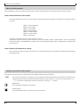 7
7
-
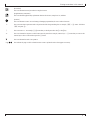 8
8
-
 9
9
-
 10
10
-
 11
11
-
 12
12
-
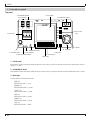 13
13
-
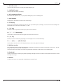 14
14
-
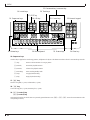 15
15
-
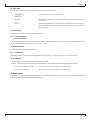 16
16
-
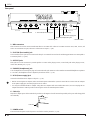 17
17
-
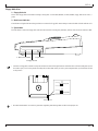 18
18
-
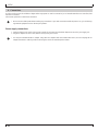 19
19
-
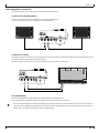 20
20
-
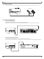 21
21
-
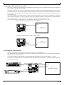 22
22
-
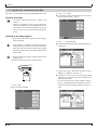 23
23
-
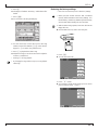 24
24
-
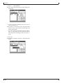 25
25
-
 26
26
-
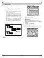 27
27
-
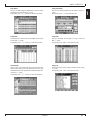 28
28
-
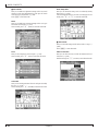 29
29
-
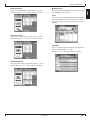 30
30
-
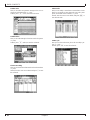 31
31
-
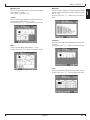 32
32
-
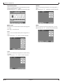 33
33
-
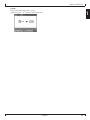 34
34
-
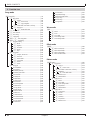 35
35
-
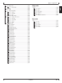 36
36
-
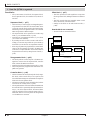 37
37
-
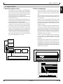 38
38
-
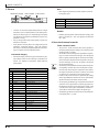 39
39
-
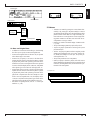 40
40
-
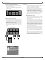 41
41
-
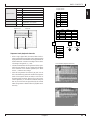 42
42
-
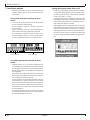 43
43
-
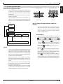 44
44
-
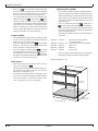 45
45
-
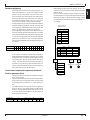 46
46
-
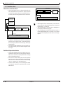 47
47
-
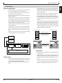 48
48
-
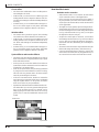 49
49
-
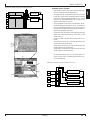 50
50
-
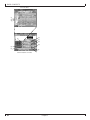 51
51
-
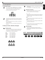 52
52
-
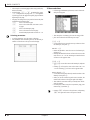 53
53
-
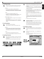 54
54
-
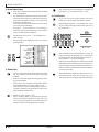 55
55
-
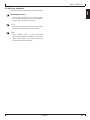 56
56
-
 57
57
-
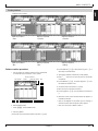 58
58
-
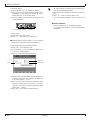 59
59
-
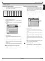 60
60
-
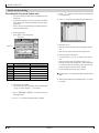 61
61
-
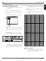 62
62
-
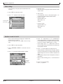 63
63
-
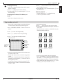 64
64
-
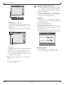 65
65
-
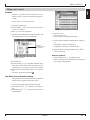 66
66
-
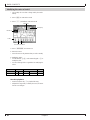 67
67
-
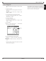 68
68
-
 69
69
-
 70
70
-
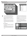 71
71
-
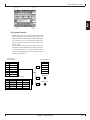 72
72
-
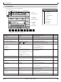 73
73
-
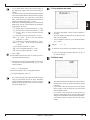 74
74
-
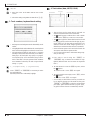 75
75
-
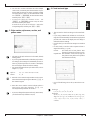 76
76
-
 77
77
-
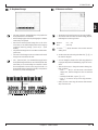 78
78
-
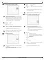 79
79
-
 80
80
-
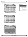 81
81
-
 82
82
-
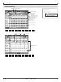 83
83
-
 84
84
-
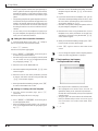 85
85
-
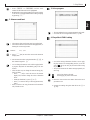 86
86
-
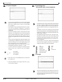 87
87
-
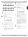 88
88
-
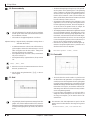 89
89
-
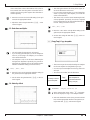 90
90
-
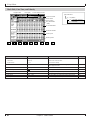 91
91
-
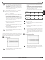 92
92
-
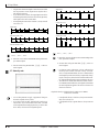 93
93
-
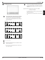 94
94
-
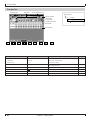 95
95
-
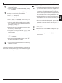 96
96
-
 97
97
-
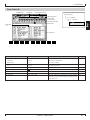 98
98
-
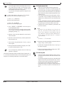 99
99
-
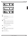 100
100
-
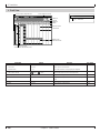 101
101
-
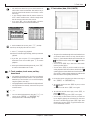 102
102
-
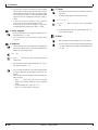 103
103
-
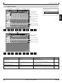 104
104
-
 105
105
-
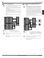 106
106
-
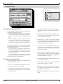 107
107
-
 108
108
-
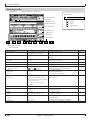 109
109
-
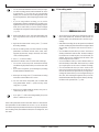 110
110
-
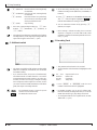 111
111
-
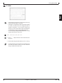 112
112
-
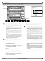 113
113
-
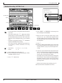 114
114
-
 115
115
-
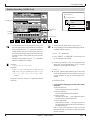 116
116
-
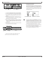 117
117
-
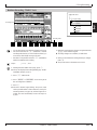 118
118
-
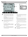 119
119
-
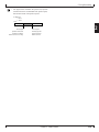 120
120
-
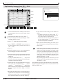 121
121
-
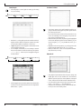 122
122
-
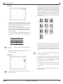 123
123
-
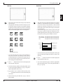 124
124
-
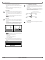 125
125
-
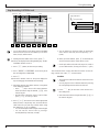 126
126
-
 127
127
-
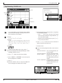 128
128
-
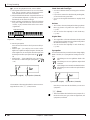 129
129
-
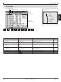 130
130
-
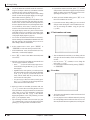 131
131
-
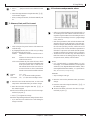 132
132
-
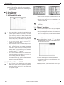 133
133
-
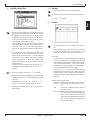 134
134
-
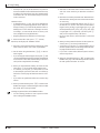 135
135
-
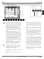 136
136
-
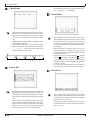 137
137
-
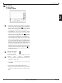 138
138
-
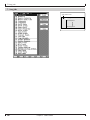 139
139
-
 140
140
-
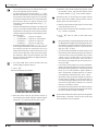 141
141
-
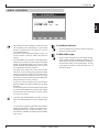 142
142
-
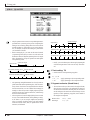 143
143
-
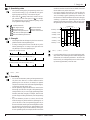 144
144
-
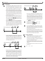 145
145
-
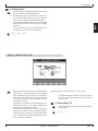 146
146
-
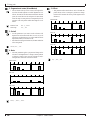 147
147
-
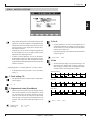 148
148
-
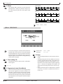 149
149
-
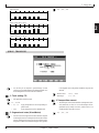 150
150
-
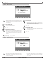 151
151
-
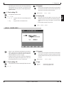 152
152
-
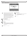 153
153
-
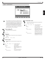 154
154
-
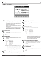 155
155
-
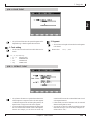 156
156
-
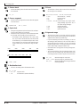 157
157
-
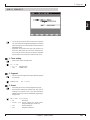 158
158
-
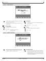 159
159
-
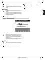 160
160
-
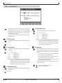 161
161
-
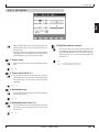 162
162
-
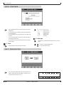 163
163
-
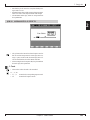 164
164
-
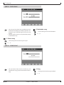 165
165
-
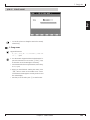 166
166
-
 167
167
-
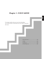 168
168
-
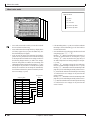 169
169
-
 170
170
-
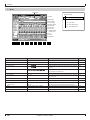 171
171
-
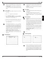 172
172
-
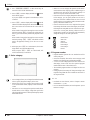 173
173
-
 174
174
-
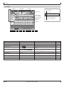 175
175
-
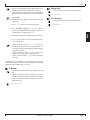 176
176
-
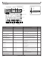 177
177
-
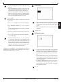 178
178
-
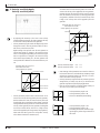 179
179
-
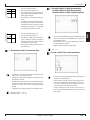 180
180
-
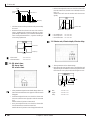 181
181
-
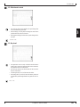 182
182
-
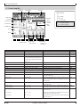 183
183
-
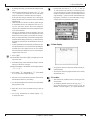 184
184
-
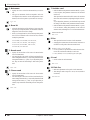 185
185
-
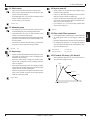 186
186
-
 187
187
-
 188
188
-
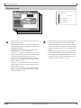 189
189
-
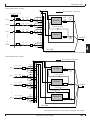 190
190
-
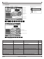 191
191
-
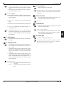 192
192
-
 193
193
-
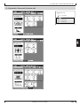 194
194
-
 195
195
-
 196
196
-
 197
197
-
 198
198
-
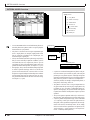 199
199
-
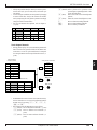 200
200
-
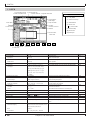 201
201
-
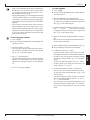 202
202
-
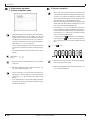 203
203
-
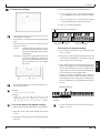 204
204
-
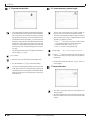 205
205
-
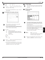 206
206
-
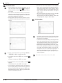 207
207
-
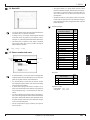 208
208
-
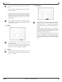 209
209
-
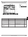 210
210
-
 211
211
-
 212
212
-
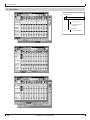 213
213
-
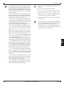 214
214
-
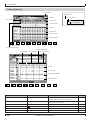 215
215
-
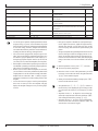 216
216
-
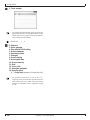 217
217
-
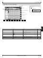 218
218
-
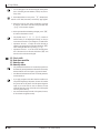 219
219
-
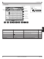 220
220
-
 221
221
-
 222
222
-
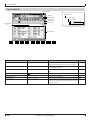 223
223
-
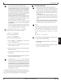 224
224
-
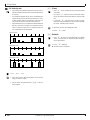 225
225
-
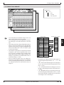 226
226
-
 227
227
-
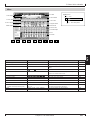 228
228
-
 229
229
-
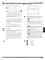 230
230
-
 231
231
-
 232
232
-
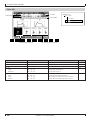 233
233
-
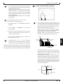 234
234
-
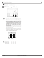 235
235
-
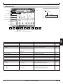 236
236
-
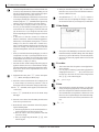 237
237
-
 238
238
-
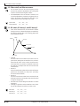 239
239
-
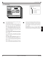 240
240
-
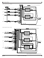 241
241
-
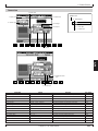 242
242
-
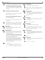 243
243
-
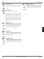 244
244
-
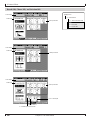 245
245
-
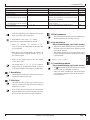 246
246
-
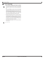 247
247
-
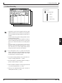 248
248
-
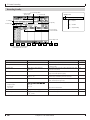 249
249
-
 250
250
-
 251
251
-
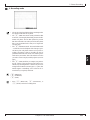 252
252
-
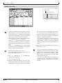 253
253
-
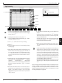 254
254
-
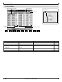 255
255
-
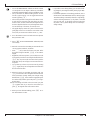 256
256
-
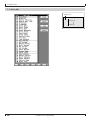 257
257
-
 258
258
-
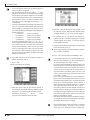 259
259
-
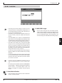 260
260
-
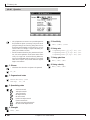 261
261
-
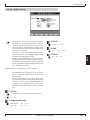 262
262
-
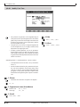 263
263
-
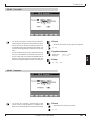 264
264
-
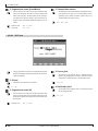 265
265
-
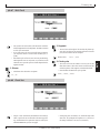 266
266
-
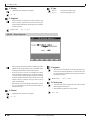 267
267
-
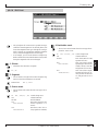 268
268
-
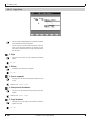 269
269
-
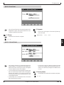 270
270
-
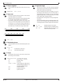 271
271
-
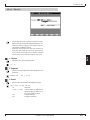 272
272
-
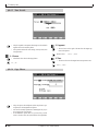 273
273
-
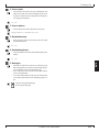 274
274
-
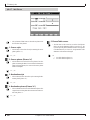 275
275
-
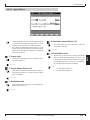 276
276
-
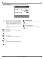 277
277
-
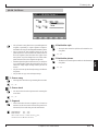 278
278
-
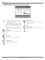 279
279
-
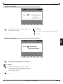 280
280
-
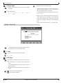 281
281
-
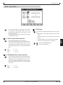 282
282
-
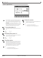 283
283
-
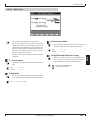 284
284
-
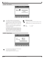 285
285
-
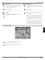 286
286
-
 287
287
-
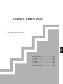 288
288
-
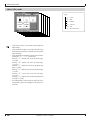 289
289
-
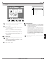 290
290
-
 291
291
-
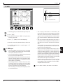 292
292
-
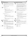 293
293
-
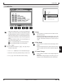 294
294
-
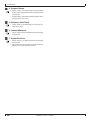 295
295
-
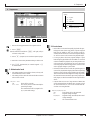 296
296
-
 297
297
-
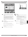 298
298
-
 299
299
-
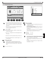 300
300
-
 301
301
-
 302
302
-
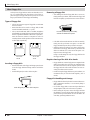 303
303
-
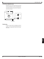 304
304
-
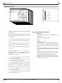 305
305
-
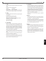 306
306
-
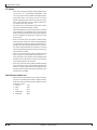 307
307
-
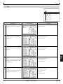 308
308
-
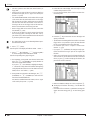 309
309
-
 310
310
-
 311
311
-
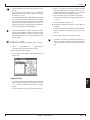 312
312
-
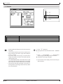 313
313
-
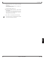 314
314
-
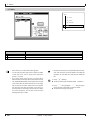 315
315
-
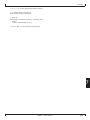 316
316
-
 317
317
-
 318
318
-
 319
319
-
 320
320
-
 321
321
-
 322
322
-
 323
323
-
 324
324
-
 325
325
-
 326
326
-
 327
327
-
 328
328
-
 329
329
-
 330
330
-
 331
331
-
 332
332
-
 333
333
-
 334
334


in andere talen
- English: Yamaha QY700 User manual
- italiano: Yamaha QY700 Manuale utente
- русский: Yamaha QY700 Руководство пользователя
- français: Yamaha QY700 Manuel utilisateur
- español: Yamaha QY700 Manual de usuario
- Deutsch: Yamaha QY700 Benutzerhandbuch
- português: Yamaha QY700 Manual do usuário
- dansk: Yamaha QY700 Brugermanual
- čeština: Yamaha QY700 Uživatelský manuál
- svenska: Yamaha QY700 Användarmanual
- Türkçe: Yamaha QY700 Kullanım kılavuzu
- polski: Yamaha QY700 Instrukcja obsługi
- română: Yamaha QY700 Manual de utilizare