
Das sekundäre Schalten der LEDs im Betrieb ist nicht erlaubt.
Nach dem Abschalten des Geräts liegt am Sekundärausgang für einige Zeit
weiterhin Spannung an, die sich innerhalb von ca. 10 min abbaut. In dieser
Phase dürfen Sie keine LED anschließen, da diese sonst beschädigt werden.
Um diese Restspannung zu entfernen schließen Sie die Kontakte am
Sekundärausgang kurz (LED dürfen nicht angeschlossen sein).
Wir empfehlen grundsätzlich vor dem Anschluss von LED, am abgeschalteten
Gerät, die Kontakte am Sekundärausgang kurzzuschließen.
The secondary switching of the LEDs in operation is not allowed.
When the device has been switched off, there is some temporary voltage
remaining on the secondary output, which decomposes within about 10
minutes. At this stage, no LEDs may be connected, as they will be damaged
otherwise. In order to remove the residual voltage, short-circuit the contacts on
the secondary output (LEDs may not be connected).
In principle, we recommend short-circuiting the contacts on the secondary
output before connecting LEDs with the device switched off.
L’allumage secondaire des DEL en cours defonctionnement n’est pas autorisé.
Une fois l’appareil éteint, la tension reste présente durant un moment sur la
sortie secondaire, avant de décroître en l’espace de 10 min. environ. Durant
cette phase, vous ne devez connecter aucune LED, sous peine de les
endommager. Afin d’éliminer la tension résiduelle, court-circuitez les contacts
sur la sortie secondaire (les LED ne doivent pas être connectées).
De façon générale, nous vous recommandons de court-circuiter les contacts
de la sortie secondaire sur l’appareil éteint, avant de connecter les LED.
La conmutación secundaria de los indicadores LED no es posible durante el
funcionamiento. Después de desconectar el equipo, todavía existen tensiónes
temporales en la salida secundaria, las que se deshacen dentro de unos 10
minutos. En esta fase no se deben conectar los LEDs ya que éstos se
pueden dañar. Para eliminar las tensiones residuales, se ponen en
cortocircuito los contactos en la salida secundaria (LEDs no deben estar
conectados). De principio, antes de conectar los LEDs, con el equipo
desconectado, recomendamos poner en cortocircuito los contactos en la
salida secundaria.
Secundair omschakelen van de LED’s is niet toegestaan.
Na het uitschakelen van het apparaat zit er voor enige tijd nog steeds
spanning op de secundairuitgang, die binnen ca. 10. min afneemt. In deze
fase mag u geen LED aansluiten, omdat deze anders beschadigt. Om deze
restspanning te verwijderen, moet u de contacten op de secundairuitgang
kortsluiten (LED mag niet aangesloten zijn).
Wij bevelen in principe aan voor het aansluiten van de LED, op het
uitgeschakelde apparaat, de contacten op de secundairuitgang te kortsluiten.
E
F
D

Art.-Nr. 1006457, 1006458 11/2022
© SLV GmbH
Daimlerstr. 21-23, 52531 Übach-Palenberg, Deutschland
Tel. +49 (0)2451 4833-0
Technische Änderungen vorbehalten. UCB-LBDWC12W350NLR-SL-AB01
Beschreibung und Einbauanweisung
Dimmbarer LED Driver mit DALI Steuereingang und einstellbarem Konstant-Ausgangsstrom zum Betreiben von LEDs
Optional mit anschließbarem RF-Modul
(Elektronisches Schaltnetzteil)
Typen: 1006457, 1006458
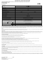
1. Technische Daten:
Art.-Nr.
1006457
1006458
LBDWC12W350NLR
Nennspannung
220–240 V~ 50–60 Hz
Nennstrom
75 mA
Netzleistungsfaktor
0,5–0,9 C
Gleichspannungsbereich (Betrieb)
186–280 V
Gleichspannung (Start)
186 V
Konstanter Ausgangsstrombereich
150–350 mA
Ausgangsleistungsbereich
1,5–12 W
Voreingestellter Ausgangsstrom
200 mA
250 mA
Teillastbereich
2–8 W
2,5–10 W
Sekundäre Spannung
10–40 Vdc SELV
Leerlaufspannung
< 60 V
Leerlaufsicherheit
gewährleistet
Dimmbereich
1–100 %
Dimmart
Amplitude (AM)
Standby Leistung
< 0,5 W
Schutzklasse
II
Kurzschluss- und Überlastschutz
elektronische Abschaltung mit automatischem Wiederanlauf
Umgebungstemperatur ta
-20 °C – +50 °C
Gehäusetemperatur tc-Punkt
max. 85 °C
Normen
EN 61347, EN 62384, EN 62493
EN 55015, EN 61547, EN 61000-3-2, EN 61000-3-3
EN 62386-101, EN 62386-102, EN 62386-207
Leitungs-
konfektionierung
(Klemmen)
Leitungsquerschnitt /
Abisolierlänge
PRI
SEC
DALI
0,5–1,5 mm² / 9 mm
Sekundäre Ausgangsleitung
Leitung mit Stecker SMP-2Y
Kennzeichnung
Gelb
Orange
Max. Leitungslänge
SEC
max. 2 m
2. NFC / Stromeinstellung
Das NFC-Interface bietet eine drahtlose Kommunikation mit dem LED-Treiber.Mit der Software NFC Application für Android / iOS oder Microsoft Windows und entsprechendem NFC-Interface, optional HEP
NFC-Reader SANF-01 (Windows), kann der Ausgangsstrom entsprechend den in der Tabelle angegebenen Ausgangsstrombereiches konfiguriert werden. Eine korrekte Kommunikation zwischen dem LED-
Treiber und der NFC-Antenne kann nur sichergestellt werden, wenn die NFC-Antenne direkt an den Treiber angelegt wird. Das NFC entspricht dem ISO/IEC 15693 Standard. Die HEP Group übernimmt
keine Haftung für Produkte von Drittanbietern. Bei falsch eingestelltem Ausgangsstrom können die LEDs und/oder der Treiber zerstört werden. Hierfür wird keine Garantie übernommen.
3. DALI
Der DALI-Steuereingang ist basis-isoliert zum Netzeingang. Zudem ist er verpolungssicher für digitale Steuersignale. Der Eingang ist geprüft Normkonform zu DALI-2 DT6. Das Gerät enthält keine DALI-
Busspannungsversorgung. Wird der LED Treiber mit TouchDim betrieben, hat der LED Ausgang eine DimToWarm Funktion.
4. Wireless-Modul
Das RF-Modul ist eine drahtlose Steuereinheit, über welches der LED-Treiber gesteuert werden kann. Dieses Modul wird auf der sekundären Seite des LED Treibers mittels eines Steckkonnektor
angeschlossen. Metallisch Gegenstände können das Funksignal beeinträchtigen (z. B. Rahmen einer Leuchte). In diesem Fall ist unter Umständen ein Ausschnitt unterhalb der Antenne erforderlich. Auch
sollte das Gerät so weit wie möglich entfernt von anderen Metallgegenständen verbaut werden.
Die RESET-Funktion des Zigbee-Dongles hängt von der Wartungszeit nach dem Ausschalten der Stromversorgung ab. Das folgende Verfahren stellt sicher, dass das Modul in den Pairing-Modus wechselt.
Wiederholen Sie "EIN für eine Sekunde und AUS für 3 Sekunden" fünfmal, im Anschluss blinkt die angeschlossene LED am Ausgang.
5. Einbauhinweise
Die Installation darf nur durch eine Elektrofachkraft in Übereinstimmung mit internationalen und nationalen Normen ausgeführt werden.
Der Schutz gegen elektrischen Schlag ist bei Arbeiten an elektrischen Anlagen durch Freischalten der Anlage sicherzustellen.
Primär- und Sekundärleitungen kreuzungsfrei verlegen (Funkschutz). Die Verdrahtung so kurz wie möglich halten.
Die maximale Länge der Ausgangsleitung von 2 m darf nicht überschritten werden.
Vor der Einschaltung der Netzspannung ist dafür zu sorgen, dass alle LEDs komplett verdrahtet und angeschlossen sind!
Die Treiber sind nicht „Hot-Plug“ fähig (anschließen des LED-Moduls während des Betriebes) und können auch nicht sekundär geschaltet werden.
Die LED Driver sind nur zur Verwendung mit LEDs bestimmt, die einen Konstantstrom benötigen.
Beim Anschließen der LEDs ist darauf zu achten, dass + und – auf die richtigen Klemmen beim LED Driver aufgelegt werden.
Das LED-Betriebsgerät besitzt keinen sekundärseitigen Verpolschutz. LED-Module können bei Verpolung zerstört werden.
Bei außerhalb von Leuchten montiertem LED Driver ist auf eine korrekte Befestigung der Primär- und Sekundärleitungen in den Zugentlastungen zu achten.
Die ta- oder die tc-Temperatur darf in keiner Einbauweise überschritten werden. Die angegebenen Mindestabstände sind Richtlinien und von der eingesetzten
Leuchte bzw. Umgebung abhängig (siehe letzte Seite).
Die Geräte enthalten keine servicefähigen Bauteile und dürfen daher nicht geöffnet werden. Es besteht keine Garantie wenn das Gerät geöffnet wurde!
Der LED Treiber ist nicht über elnen Phasenan- oder abschnittdimmer regelbar!
6. Gleichspannungsbereich
Das oben aufgeführte Gerät kann in dem oben angegebenen Gleichspannungsbereich betrieben werden. Der Test ist keine Freigabe im Sinne der Notlichtverordnung (EL).
7. Überspannung
Die LED Treiber sind surgespannungsfest entsprechend der von der einschlägigen Norm vorgeschriebenen Werte. Zum Schutz vor höheren Überspannungen, die z.B. beim Schalten von Leuchtstofflampen
und Entladungslampen mit induktivem Vorschaltgerät, Motoren (Ventilatoren, usw.) und anderen induktiven Lasten auftreten, sind die Lastkreise für diese Gerätegruppen deutlich voneinander zu trennen und
unter Umständen weitere Massnahmen (überspannungsableiter) erforderlich.
8. Kurzschluss / Überlast
Der LED Treiber schaltet bei Kurzschluss oder Überlast automatisch ab. Er besitzt keine Sicherung herkömmlicher Art. Der Laststromkreis wird folglich nicht aufgetrennt! Nach Beheben des Fehlers schaltet
der LED Driver automatisch wieder ein.
9. Übertemperatur
Bei Übertemperatur durch externe Wärmequellen oder unzulässige Abdeckungen erfolgt eine Funktionsunterbrechung bzw eine Leistungsreduzierung. Eine Netzfreischaltung erfolgt nicht. Nach Abkühlung
schaltet der LED Driver automatisch wieder ein.
10. Wärmeableitung bzw. Wärmeübergang
Ein Betrieb in überhöhter Umgebungstemperatur oder durch Fremderwärmung verkürzt die Lebensdauer. Beim Einbau (vor allem in Leuchten) ist durch geeignete Maßnahmen für eine Wärmeabfuhr
(Wärmeübergang) zu sorgen. Die Umgebungstemperatur ta und/oder die tc-Punkt Temperatur darf zu keinem Zeitpunkt überschritten werden. Für Schäden, die aus entsprechend unsachgemäßem Gebrauch
entstehen, wird keine Haftung übernommen.

Art.-No. 1006457, 1006458 11/2022
© SLV GmbH
Daimlerstr. 21-23, 52531 Übach-Palenberg, Germany
Tel. +49 (0)2451 4833-0
Technical properties subject to modification.
Description and Mounting Instructions
Dimmable LED Driver with DALI control input and adjustable constant output current for the operation of LED
Optional with connectable RF-module
(Electronic power supply unit)
Types: 1006457, 1006458
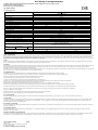
1. Technical Data:
Art.-No.
1006457
1006458
LBDWC12W350NLR
Rated voltage
220–240 V~ 50–60 Hz
Rated current
75 mA
Power Factor
0.5–0.9 C
DC voltage range (operation)
186–280 V
DC voltage (start)
186 V
Constant output current range
150–350 mA
Output power range
1.5–12 W
Preset output current
200 mA
250 mA
Shared load operation
2–8 W
2,5–10 W
Secondary voltage
10–40 Vdc SELV
Open circuit voltage
< 60 V
Open circuit safety
guaranteed
Dimming Range
1–100 %
Dimming technique
Amplitude (AM)
Standby power
< 0.5 W
Protection class
II
Short circuit and overload protection
electronic disconnection with automatic restart
Ambient temperature ta
-20 °C – +50 °C
Case temperature tc-point
max. 85 °C
Standards
EN 61347, EN 62384, EN 62493
EN 55015, EN 61547, EN 61000-3-2, EN 61000-3-3
EN 62386-101, EN 62386-102, EN 62386-207
Cable
(Terminals)
Diameter of wires /
Bared wire end
PRI
SEC
DALI
0.5–1.5 mm² / 9 mm
Secondary output cable
Cable with connector SMP-2Y
Labelling
Yellow
Orange
Max. Wire length
SEC
max. 2 m
2. NFC / Current setting
The NFC interface provides a wireless communication with the LED driver. With the NFC Application software Android / iOS or Microsoft Windows and corresponding NFC interface, optional HEP NFC reader
SANF-01 (Microsoft Windows), the output current can be configured according to the output current range given in the table. Correct communication between the LED driver and the NFC antenna can only be
ensured if the NFC antenna is applied directly to the driver. The NFC complies with the ISO / IEC 15693 standard. The HEP Group assumes no liability for third-party products. Due to incorrect setup of output
current, the LEDs and /or the driver may be destroyed. Thus no guarantee is given.
3. DALI
The DALI control input is basic-isolated to the mains input. In addition, it is protected against mains voltage and is reverse polarity protected for digital control signals. The input is tested in compliance with
DALI-2 DT6 standard. The device does not contain a DALI bus voltage supply.
4. RF-Modul
The RF module is a wireless control unit that controls the LED driver. This module is connected to the secondary side of the LED driver by means of a plug connector. Metallic objects can impair the radio
signal (e.g. the frame of a lamp). In this case, a cutout may be required below the antenna. The device should also be installed as far away as possible from other metal objects. The antenna is in the position
shown on the last page.
About the RESET function of the Zigbee dongle, it depends on the maintenance time after the power is turned off. The following procedure ensures that the module enters pairing mode.
Repeat “ON for one second and OFF for 3 seconds“ for five times, then the output will flash.
5. Installation Instructions
The installation may only be carried out by an electrical specialist in accordance with international and national standards.
When working on electrical systems, protection against electric shock is to be ensured by disconnecting the system.
Install primary and secondary mains intersection-free (RFI protection). Keep the wiring as short as possible.
The maximum output wire length of 2 m must not be exceeded.
Before switching on the supply voltage all LED must be completely wired and connected!
The driver are not "hot plug" capable (connecting the LED module during operation) and secondary switching of the LEDs in operation is not allowed.
The LED Driver is strictly suited for the use with LED that requires a constant current.
When connecting the LED, careful attention should be paid to connecting + and - to the right terminals on the LED Driver.
The LED control gear has no secondary reverse polarity protection. LED modules can be destroyed in reverse polarity.
If LED Drivers mounted outside of luminaires, careful attention is to be paid to the connecting cables and the lamp cables being fastened securely in the strain relief.
The ta or tc temperature may not be exceeded for any kind of mounting. The specified minimum distances are guidelines and dependent upon of the used
luminaire or environment (see last page).
The devices do not contain any serviceable components and may not be opened. No warranty if device was opened!
The LED Driver cannot be regulated via a phase cut-on or cut-off dimmer!
6. DC voltage range
The device listed above can be operated in the DC voltage range specified above. The test is not a release in the sense of the Emergency Lighting regulation (EL).
7. Overvoltage
Our LED Drivers are surge-voltage-stable with values above those prescribed by the respective standards. As a protection against high voltage surges, as they occur e.g. when switching fluorescent
lamps and discharge lamps with an inductive ballast, motors (fans, etc.) and other inductive charges, the load circuits for devices of this kind are to be clearly separated from each other.
8. Short circuit / overload
In case of a short circuit or overload the LED Driver will automatically cut off. It does not have a fuse of the conventional kind. Thus the load circuit is not separated! As soon as the defect has been repaired,
the LED Driver will automatically cut back in.
9. Excess Temperature
In case of excess temperature through external heat sources or impermissible covers the function will be interrupted. The mains will not be disconnected. As soon as the LED Driver has cooled off, it will
automatically cut back in.
10. Heat Dissipation and Heat Transfer
Operation in excess ambient temperature or through external heating will reduce the service life. During the installation process (particularly into luminaires), heat dissipation (heat transfer) is to be
provided through suitable measures. The ambient temperature and/or tc temperature may not be exceeded at any time. We are not liable for damage resulting from improper use.

No. de commande 1006457, 1006458 11/2022
© SLV GmbH
Daimlerstr. 21-23, 52531 Übach-Palenberg, Allemagne
Tel. +49 (0)2451 4833-0
Sous réserve de modifications techniques.
Description et instructions de montage
Pilote de LED à gradation avec contrôle d’entrée DALI et courant de sortie constant réglable pour le fonctionnement des LED
En option avec un module RF connectable
(Bloc d’alimentation électronique)
Type: 1006457, 1006458
1. Caractéristiques techniques :
N° d’art.
1006457
1006458
LBDWC12W350NLR
Tension nominale
220–240 V~ 50–60 Hz
Courant nominal
75 mA
Facteur de puissance
0,5–0,9 C
Plage de tension continue (fonctionnement)
186–280 V
Tension continue (démarrage)
186 V
Plage de courant de sortie constante
150–350 mA
Plage de puissance de sortie
1,5–12 W
Courant de sortie préréglé
200 mA
250 mA
Fonctionnement en charge partagée
2–8 W
2,5–10 W
Tension secondaire
10–40 Vdc SELV
Tension de circuit ouvert
< 60 V
Sécurité de circuit ouvert
garantie
Gamme de gradation
1–100 %
Technique de gradation
Amplitude (AM)
Alimentation en veille
< 0,5 W
Classe de protection
II
Protection contre les courts-circuits et les surcharges
Déconnexion électronique avec redémarrage automatique
Température ambiante ta
-20 °C – +50 °C
Température du boîtier point tc
max. 85 °C
Normes
EN 61347, EN 62384, EN 62493
EN 55015, EN 61547, EN 61000-3-2, EN 61000-3-3
EN 62386-101, EN 62386-102, EN 62386-207
Câble
(Bornes)
Diamètre de conducteur /
Longeur d’alimentation
PRI
SEC
DALI
0,5–1,5 mm² / 9 mm
Câble de sortie secondaire
Câble avec connecteur SMP-2Y
Marquage
Jaune
Orange
Max. Longueur de câble
SEC
max. 2 m
2. NFC / Réglage actuel
L’interface NFC fournit une communication sans fil avec le pilote de LED. Avec le logiciel d’application NFC et l’interface NFC correspondante, et le lecteur optionnel HEP NFC SANF-01, le courant de sortie
peut être ajusté en fonction de la plage de courant de sortie indiquée dans le tableau. Une communication correcte entre le pilote de LED et l’antenne NFC ne peut être assurée que lorsque l’antenne NFC est
installée directement sur le pilote. Le NFC est conforme à la norme ISO / IEC 15693. HEP Group n’assume aucune responsabilité pour les produits de tiers. En raison de la configuration incorrecte du courant
de sortie, les LED et /ou le pilote peuvent être détruits. Aussi, aucune garantie n’est accordée.
3. DALI
Le contrôle d’entrée DALI est directement isolée de l’entrée du courant secteur. Il est également protégé contre la tension du courant secteur et est protégé contre l’inversion de la polarité pour les signaux de
commande numériques. L’entrée a été testée conformément à la norme DALI-2 DT6. L’appareil ne contient pas d’alimentation en tension de bus DALI.
4. Module RF
Le module RF est une unité de commande sans fil qui contrôle le pilote de LED. Ce module est connecté au côté secondaire du pilote LED au moyen d'un connecteur enfichable. Les objets métalliques
peuvent altérer le signal radio (par exemple, le cadre d’une lampe). Le cas échéant, une découpe peut être nécessaire au-dessous de l’antenne. L’appareil doit également être installé aussi loin que possible
des objets métalliques. L’antenne se trouve à la position indiquée à la dernière page.
Concernant la fonction RESET du dongle Zigbee, elle dépend du temps de maintenance après la mise hors tension. La procédure suivante permet de s'assurer que le module entre en mode d'appairage.
Répétez "ON pendant 1 seconde et OFF pendant 3 secondes" pendant cinq fois, puis la sortie clignote.
5. Instructions d’installation
L'installation ne doit être effectuée que par un expert en électrotechnique et en conformité avec les normes nationales et internationales.
Lors de travaux aux installations électriques, la protection contre les décharges électriques doit être assurée en mettant l'installation hors tension.
Monter les circuits primaires et secondaires en évitant qu'ils ne se croissent (protection contre le parasitage).
La sortie maximale d‘un câble de 2 m de long ne doit pas être dépassée.
Avant de mettre sous tension, toutes les LED doivent être complètement câblées et connectées!
Les pilotes ne sont pas "hot-plug" (connexion du module de LED pendant le fonctionnement) et la commutation secondaire des LED en fonctionnement n'est pas autorisée.
Le driver de LED est strictement adapté à une utilisation avec des LED nécessitant un courant constant.
Lors du raccordement de la LED, veillez à connecter les bornes + et - aux bornes de droite du driver de LED.
Le ballast LED n’a aucune protection secondaire contre la polarité inversée. Les modules LED peuvent être détruits en polarité inverse.
Lorsque le Convertisseur LED est fixé à l’extérieur du luminaire, veiller à ce que les circuits primaire et secondaire soient correctement fixés dans les colliers.
La température ta ou tc ne doit pas être dépassée pour tout type de montage. Les distances minimales spécifiées sont indicatives et dépendent de l’utilisation
luminaire ou environnement (voir dernière page).
Les appareils ne contiennent aucun composant réparable et ne peuvent pas être ouverts. Le LED Driver ne peut pas être régulé via un gradateur à découpage de phase ou à découpage!
6. Tension continue
L'appareil susmentionné peut être utilisé dans la plage de tension continue indiquée ci-dessus. Le test ne constitue pas une autorisation au sens de l'ordonnance sur l'éclairage de secours (EL).
7. Surtension
Nos LED drivers résistent à la tension surge au-delà des valeurs prescrites par la norme afférente. Pour assurer la protection contre les surtensions supérieures qui se forment, par ex. lors de l'allumage de
lampes fluorescentes et de lampes à décharge à ballast à induction, de moteurs (ventilateurs, etc.) et autres charges inductives, les circuits de charge de ces groupes d'appareils doivent être clairement
séparés les uns par rapport aux autres.
8. court-circuit / surcharge
Le LED-Driver se déclenche automatiquement en cas de court-circuit ou de surcharge. Il n'est pas équipé d'un fusible classique. De ce fait, le circuit de charge n'est pas défait ! Dès que la panne est réparée,
le LED Driver se réenclenche automatiquement.
9. Température excessive
En cas de température excessive par des sources extérieures de chaleur ou des couvertures interdites la fonction sera interrompue. Les forces ne seront pas déconnectées. LED driver se réenclenche
automatiquement.
10. Dissipation thermique et transfert de chaleur
Toute utilisation en cas de température d'ambiance excessive, ou de réchauffement extérieur, réduit la durée de vie. En cas d'encastrement (notamment dans des luminaires), il faut assurer la dissipation (le
transfert) thermique en prenant des mesures adéquates. La température ambiante et/ou la température point tc ne peuvent être dépassées en aucun cas. Nous n'assumons aucune responsabilité pour des
dégâts survenus suite à une utilisation non conforme.

No. Ped. 1006457, 1006458 11/2022
© SLV GmbH
Daimlerstr. 21-23, 52531 Übach-Palenberg, Alemania
Tel. +49 (0)2451 4833-0
Salvo modificaciónes técnicas.
Especificación y instrucciones de montaje
Excitador de LED regulable con entrada de control DALI y corriente de salida constante ajustable para el funcionamiento del LED
Opcional con módulo RF conectable
(Convertidor electrónico)
Tipos: 1006457, 1006458
1. Datos técnicos:
N.º de artículo
1006457
1006458
LBDWC12W350NLR
Voltaje nominal
220–240 V~ 50–60 Hz
Corriente nominal
75 mA
Factor de potencia
0,5–0,9 C
Rango de tensión continua (funcionamiento)
186–280 V
Tensión continua (inicio)
186 V
Rango de corriente de salida constante
150–350 mA
Rango de potencia de salida
1,5–12 W
Corriente de salida preestablecida
200 mA
250 mA
Rango de carga parcial
2–8 W
2,5–10 W
Voltaje secundario
10–40 Vdc SELV
Voltaje en circuito abierto
< 60 V
Seguridad de circuito abierto
garantizada
Intervalo de atenuación
1–100 %
Técnica de atenuación
Amplitude (AM)
Potencia en el modo de espera
< 0,5 W
Clase de protección
II
Protección contra cortocircuito y sobrecarga
Desconexión electrónica con reinicio automático
Temperatura ambiente (ta)
-20 °C – +50 °C
Temperatura del revestimiento (punto tc)
max. 85 °C
Estándares
EN 61347, EN 62384, EN 62493
EN 55015, EN 61547, EN 61000-3-2, EN 61000-3-3
EN 62386-101, EN 62386-102, EN 62386-207
Cable
(Borna)
Diámetro de los cables
/ Extremo del hilo
pelado
PRI
SEC
DALI
0,5–1,5 mm² / 9 mm
Cable de salida secundario
Cable con conector SMP-2Y
Etiquetado
Amarillo
Naranja
Max. Longitud de cable
SEC
2 m máximo
2. NFC / Configuración actual
La interfaz NFC proporciona una comunicación inalámbrica con el excitador de LED. Con el software de aplicación NFC y la interfaz NFC correspondiente, el lector NFC HEP opcional SANF-01, la corriente
de salida se puede configurar de acuerdo con el intervalo de corriente de salida que se indica en la tabla. La comunicación correcta entre el excitador de LED y la antena NFC solo se puede garantizar si la
antena NFC se aplica directamente al excitador. NFC cumple el estándar ISO/IEC 15693. HEP Group no asume ninguna responsabilidad por productos de terceros. Si se ajusta la corriente de salida de
forma incorrecta, los LED y/o el controlador pueden sufrir graves daños. Por lo tanto, no se proporciona ninguna garantía.
3. DALI
La entrada de control DALI tiene un aislamiento básico de la entrada de red. Además, cuenta con protección contra la tensión de la red eléctrica y contra la polaridad inversa para señales de control digital.
La entrada se prueba de acuerdo con el estándar DALI-2 DT6. El dispositivo no contiene alimentación de tensión de bus DALI.
4. Módulo de RF
El módulo de RF es una unidad de control inalámbrica que gobierna el controlador LED. Este módulo se conecta al lado secundario del controlador LED mediante un conector enchufable. Los objetos
metálicos pueden dañar la señal de radio (por ejemplo, el marco de una lámpara). En este caso, es posible que se requiera un corte debajo de la antena. El dispositivo también debe instalarse lo más lejos
posible de otros objetos metálicos. La antena está en la posición que se muestra en la última página.
Acerca de la función RESET del dongle Zigbee, depende del tiempo de mantenimiento después de apagar la alimentación. El siguiente procedimiento garantiza que el módulo entre en el modo de
emparejamiento. Repita "ON durante 1 segundo y OFF durante 3 segundos" durante cinco veces, entonces la salida parpadeará.
5. Instrucciones de instalación
La instalación sólo debe realizarse por un electricista conforme a las normas nacionales e internacionales.
Para la protección contra eléctrochoques hay que desconectar los equipos eléctricos durante los trabajos en ellos.
Tender las líneas primarias y secundarias sin cruzarlas. (Protección contra radiointerferencias).
La longitud máxima del hilo de salida no se debe superar 2 m.
¡Antes de encender la tensión de alimentación, todos los LED deben estar completamente cableados y conectados!
El controlador no tiene capacidad de "conexión en caliente" (conecta el módulo LED durante el funcionamiento) y no se permite la conmutación secundaria de los LED en funcionamiento.
El controlador LED es estrictamente adecuado para el uso con LED que requiere una corriente constante.
Al conectar el LED, se debe prestar especial atención a la conexión de + y - a los terminales correctos en el controlador del LED.
El equipo de control LED no tiene protección secundaria de polaridad inversa. Los módulos LED pueden destruirse en polaridad inversa.
Para los convertidores de LED montados fuera de la luminaria hay que estar pendiente de la fijación correcta de las lineas primarias y secundarias en los puestos de Sujeción de tracción.
No se puede exceder la temperatura ta o tc para ningún tipo de montaje. Las distancias mínimas especificadas son pautas y dependen de las utilizadas
luminaria o ambiente (ver última página).
Los dispositivos no contienen componentes reparables y no se pueden abrir. ¡El controlador LED no se puede regular a través de un atenuador de corte o de fase!
6. Tensión continua
El dispositivo mencionado puede funcionar en el rango de tensión continua especificado anteriormente. La prueba no es una liberación en el sentido de la Ordenanza de Alumbrado de Emergencia (EL).
7. Sobretensión
Los convertidores de LED son resistentes contra las sobretensiónes transitorias hasta valores que pasan con mucho aquellos especificados por las normas correspondientes. Para la protección contra
sobretensiones que se presentan por ejemplo cuando se conmutan lámparas fluorescentes y lámparas de descarga con balasto inductivo, motores (ventiladores, etc.) y otras cargas inductivas, hay que
separar claramente los circuitos de carga para esta serie de equipos uno de otro.
8. Cortocircuito / sobrecarga
El convertidor de LED se desconecta automáticamente en caso de un cortocircuito o de sobrecarga. No tiene ningun cortacircuito convencional. ¡En consecuencia, el circuito de carga no se separa! Al
remediar el fallo el convertidor de LED se conecta automáticamente de nuevo.
9. Exceso de temperatura
En caso de exceso de temperatura a través de fuentes de calor externas o de cubiertas inadmisible la función sera interrumpida. La red no sera desconectada.. Después del enfriamiento el convertidor de
LED se conecta automáticamente de nueveo.
10. Disipación de calor y transferencia de calor
La operación en temperatura ambiente muy elevada o por calentamiento externo reduce la vida. Durante el montaje ( sobre todo en luminarias ) hay que procurar, por medidas apropiadas, una disipación de
calor ( transferencia de calor ). No se debe pasar en ningún momento la temperatura ambiente y / o la temperatura punto tc. No se asume ninguna responsabilidad de daños originados por uso inadecuado.

Type Nr. 1006457, 1006458 11/2022
© SLV GmbH
Daimlerstr. 21-23, 52531 Übach-Palenberg, Duitsland
Tel. +49 (0)2451 4833-0
Technische veranderingen onder voorbehoud.
Beschrijving en montageaanwijzing
Te dimmen LED-driver met DALI-ingangsregeling en aanpasbare constante uitgangsstroom voor de werking van LED
Optioneel met aan te sluiten RF-module
(Elektronische schakelaar nettransformator)
Type: 1006457, 1006458
1. Technische gegevens:
Art.-nr.
1006457
1006458
LBDWC12W350NLR
Nominale spanning
220–240 V~ 50–60 Hz
Nominale stroom
75 mA
Vermogensfactor
0,5–0,9 C
DC spanningsbereik (werking)
186–280 V
DC spanning (start)
186 V
Constant uitgangsstroombereik
150–350 mA
Bereik uitgangsvermogen
1,5–12 W
Vooraf ingestelde uitgangsstroom
200 mA
250 mA
Bereik gedeeltelijke belasting
2–8 W
2,5–10 W
Secundaire spanning
10–40 Vdc SELV
Open circuitspanning
< 60 V
Open circuitveiligheid
gegarandeerd
Dimbereik
1–100 %
Dimtechniek
Amplitude (AM)
Stand-byvoeding
< 0,5 W
Beschermingsklasse
II
Kortsluiting- en overbelastingsbeveiliging
elektronische loskoppeling met automatische herstart
Omgevingstemperatuur ta
-20 °C – +50 °C
Temperatuur van behuizing tc-punt
max. 85 °C
Normen
EN 61347, EN 62384, EN 62493
EN 55015, EN 61547, EN 61000-3-2, EN 61000-3-3
EN 62386-101, EN 62386-102, EN 62386-207
Kabel
(Klemmen)
Draaddiameter /
Striplengte
PRI SEC
DALI
0,5–1,5 mm² / 9 mm
Secundaire uitgangskabel
Kabel met connector SMP-2Y
Etikettering
Geel
Oranje
Max. Lengte van de kabel
SEC
max. 2 m.
2. NFC / stroominstelling
De NFC-interface biedt een draadloze communicatie met de LED-driver. Met de NFC-toepassingssoftware en bijbehorende NFC-interface, optionele HEP NFC-lezer SANF-01, kan de uitgangsstroom worden
geconfigureerd overeenkomstig het uitgangsstroombereik dat wordt gegeven in de tabel. Juiste communicatie tussen de LED-driver en de NFC-antenne kan alleen worden verzekerd als de NFC-antenne
direct op de driver wordt toegepast. De NFC voldoet aan de ISO / IEC 15693-norm. De HEP Group neemt geen aansprakelijkheid voor producten van derden. Bij een onjuiste instelling van de uitvoerstroom
kan de LED en/of de driver worden beschadigd. In dat geval is de garantie niet van toepassing.
3. DALI
De DALI-ingangsregeling is standaard geïsoleerd van de netspanning. Het is bovendien beschermd tegen netspanning en is beveiligd tegen omgekeerde polariteit voor digitale regelsignalen. De ingang is
getest in overeenstemming met de DALI-2 DT6-norm. Het apparaat bevat geen DALI-busspanningstoevoer.
4. RF-Modul
De RF-module is een draadloze besturingseenheid die de LED-driver. Deze module wordt door middel van een connector aangesloten op de secundaire zijde van de LED driver. Metalen objecten kunnen het
radiosignaal verzwakken (bijv. het frame van een lamp). In dit geval kan een uitsparing nodig zijn onder de antenne. Het apparaat moet tevens zo ver mogelijk van andere metalen objecten worden
geïnstalleerd. De antenne staat in de positie getoond op de laatste pagina.
De RESET functie van de Zigbee dongle is afhankelijk van de onderhoudstijd nadat de stroom is uitgeschakeld. De volgende procedure zorgt ervoor dat de module in de koppelingsmodus komt. Herhaal "ON
for 1 second and OFF for 3 seconds" gedurende vijf keer, dan zal de uitgang knipperen.
5. Installatie-instructies
De installatie mag alleen worden uitgevoerd door een vakkundige elektricien en overeenkomstig met de internationale en nationale normen.
De bescherming tegen elektrische schokken is tijdens het werken met elektrische installaties door het afkoppelen van de installatie te waarborgen.
Primaire en secundaire leidingen niet kruisgewijs aansluiten (elektromagnetische storingen).
De maximale lengte van de uitgangsdraad van 2 m mag niet worden overschreden.
Voordat u de voedingsspanning inschakelt, moet alle LED volledig bedraad en aangesloten zijn!
De driver is niet "hot plug" geschikt (tijdens gebruik de LED-module aansluiten) en secundaire omschakeling van de LED's tijdens bedrijf is niet toegestaan.
De LED Driver is strikt geschikt voor het gebruik met LED die een constante stroom vereist.
Bij het aansluiten van de LED moet zorgvuldig worden gelet op het aansluiten van + en - op de juiste klemmen op de LED Driver.
De LED-voorschakelapparatuur heeft geen secundaire beveiliging tegen omgekeerde polariteit. LED-modules kunnen in omgekeerde polariteit worden vernietigd.
Als de LED driver buiten de lamp geinstalleerd wordt moet erop worden gelet dat de primaire en secundaire leidingen in de trekontlasting correct gemonteerd worden.
De Ta- of TC-temperatuur mag voor geen enkele montage worden overschreden. De opgegeven minimale afstanden zijn richtlijnen en afhankelijk van de gebruikte
armatuur of omgeving (zie laatste pagina).
De apparaten bevatten geen onderdelen die kunnen worden onderhouden en mogen niet worden geopend.
De LED-driver kan niet worden geregeld via een fase-inschakeling of uitschakeling-dimmer!
6. DC spanningsbereik
Het bovenvermelde apparaat kan worden gebruikt in het hierboven gespecificeerde gelijkspanningsbereik. De test is geen vrijgave in de zin van de noodverlichtingsverordening (EL).
7. Overspanning
Onze LED drivers zijn beschermd tegen overspanning tot over de van de desbetreffende norm voorgeschreven waarden. Als bescherming tegen hogere overspanningen, die bijv. kunnen ontstaan bij het
inschakelen van tl-buizen en ontladingslampen met inductieve voorschakelapparaten, motoren (ventilatoren, etc.) en andere inductieve apparaten, moeten de belastingscircuits voor deze groepen van
apparaten duidelijk van elkaar gescheiden worden.
8. Kortsluiting / overbelasting
In geval van kortsluiting of overbelasting schakelt de LED Driver automatisch uit. Het heeft geen conventionele lont. Het belastingscircuit is dus niet gescheiden! Zodra het defect is gerepareerd, schakelt de
LED-driver automatisch in.
9. Overtollige temperatuur
Bij te hoge temperaturen, veroorzaakt door extrene warmtebronnen, of ontoelaatbare afdekking, zal de ingebouwde temperatuurcontrole het vermogen verlagen. Na het afkoelen wordt de LED driver
automatisch weer ingeschakeld.
10. Warmte consumptie en warmteoverdracht
Het bedrijf in een te hoge omgevingstemperatuur of externe verwarming verkort de levensduur. Bij het inbouwen (vooral in lichten), moet door passende maatregelen voor warmteafvoer (warmteovergang)
gezorgd worden. De omgevingstemperatuur en/of de temperatuur tc-punt mag nooit worden overschreden. Wij zijn niet verantwoordelijk voor schade als gevolg van onjuiste gebruik.

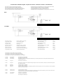
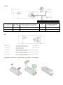
Anschlussbild - Installation diagram - Esquema de conexión - Schéma de connexion – Aansluitschema
DALI:
Gelb / Yellow / Jaune / Amarillo / Geel
200 mA
1006457
Orange / Orange / Orange / Naranja / Oranje
250 mA
1006458
TouchDIM:
Gelb / Yellow / Jaune / Amarillo / Geel
200 mA
1006457
Orange / Orange / Orange / Naranja / Oranje
250 mA
1006458
Kurz drücken (< 0.6 s)
Lange drücken (> 0.6 s)
Drücken um AN-AUS zu schalten
Hoch oder runter dimmen
Max. Leitungslänge TouchDIM
Max. Anzahl Geräten
20 m
15 Stück
Short push (< 0.6 s)
Long push (> 0.6 s)
Push to turn ON-OFF
Dimming up or down
Max. lead lenght TouchDIM
Max. parallel units
20 m
15 pcs
Pression courte (< 0.6 s)
Appui long (> 0.6 s)
Appuyez pour allumer / éteindre
Gradation vers le haut ou le bas
Longueur maximale du câble TouchDIM
Max. unités parallèles
20 m
15 pièces
Presión corta (< 0.6 s)
Empuje largo (> 0.6 s)
Presione para encender-apagar
Atenuación hacia arriba o hacia abajo
Longitud máxima del cable TouchDIM
Max. unidades paralelas
20 m
15 piezas
Kort indrukken (< 0,6 s)
Lang indrukken (> 0,6 s)
Druk om AAN / UIT te zetten
Omhoog of omlaag dimmen
Max. Kabellengte TouchDIM
Max. parallelle eenheden
20 m
15 stuks
Synchronisation von einer großen Anzahl von Treibern von TouchDIM
Synchronization of a large number of driver of TouchDIM
Synchronisation d'un grand nombre de pilotes de TouchDIM
Sincronización de un gran número de excitadores de TouchDIM
Synchronisatie van een groot aantal stuurprogramma's van TouchDIM
1. Schritt:
Lange drücken
Alle Lampen sind eingeschaltet
2. Schritt:
Kurz drücken
Alle Lampen sind ausgeschaltet
3. Schritt:
Lange drücken
Alle Lampen schalten sich auf minimaler Dimmeinstellung ein und steigen kontinuierlich auf die gewünschte Dimmstufe bis der
Schalter losgelassen wird.
1. Step:
Long push
All the lamps are switched on
2. Step:
Short push
All the lamps are switched off
3. Step:
Long push
All the lamps are switched on the minimum dimming setting of the drivers and continuously. Fade up to the desired dimming level,
then release push button.
1. Pas :
Appui long
Toutes les lampes sont allumées
2. Pas :
Appui court
Toutes les lampes sont éteintes
3. Pas :
Appui long
Toutes les lampes sont allumées sur le réglage de gradation minimum des pilotes et en continu. Augmentez le niveau de gradation
souhaité, puis relâchez le bouton.
1. Paso:
Pulsación breve
Todas las lámparas se encienden
2. Paso:
Pulsación corta
Todas las lámparas se apagan
3. Paso:
Pulsación breve
Todas las lámparas se encienden en la configuración de atenuación mínima de los excitadores y de forma continua. Oscile hacia
arriba hasta el nivel de atenuación deseado, luego suelte el pulsados.
1. Stap:
Lang indrukken
Alle lampen zijn ingeschakeld
2. Stap:
Kort drukken
Alle lampen zijn uitgeschakeld
3. Stap:
Lang indrukken
Alle lampen worden ingeschakeld op de minimale diminstelling van de drivers en vervagen continu tot het gewenste dimniveau en
laat vervolgens de drukknop los.
DALI ist basis-isoliert zu PRI und doppelt isoliert zu SEC
DALI is basic insulated to PRI and double insulated to SEC
DALI est isolé de base selon PRI et doublement isolé selon SEC
DALI tiene aislamiento básico para PRI y doble aislamiento para SEC
DALI is basis geïsoleerd tot PRI en dubbel geïsoleerd tot SEC
Die maximale Länge der Ausgangsleitung von 2 m darf nicht überschritten werden.
The maximum output wire length of 2 m must not be exceeded.
Lasortiemaled’uncâble de 2 m de long ne doit pas être dépassée.
La longitud máxima del hilo de salida no se debe superar 2 m.
De maximale lengte van de uitgangsdraad van 2 m mag niet worden overschreden.

Wireless:
Gelb / Yellow / Jaune / Amarillo / Geel
200 mA
1006457
Orange / Orange / Orange / Naranja / Oranje
250 mA
1006458
Art.-Nr. – Art.-no. –
N° d’art. – N.º de artículo –
Art.-nr.
Modul – Module
Modules – Módulos
Funkprotokoll – Wireless protocol – Protocole sans fil –
Protocolo inalámbrico – Draadloos protocol
APP
Verfügbar für – Available for
Disponible pour – Disponible para –
Beschikbaar voor
1006199 (WZSB)
SLV
ZigBee 3.0
SLV VALETO
Android / iOS
1006454 (WBSD)
CASAMBI
Bluetooth Low Energy (LE)
CASAMBI
Android / iOS
NFC:
NFC:
Programmierbar mit: HEP NFC Reader SANF und HEP Software NFCApplication (Microsoft Windows)
Android / iOS smartphone app HEPxNFC
Programmable with: HEP NFC Reader SANF and HEP Software NFCApplication (Microsoft Windows)
Android / iOS smartphone app HEPxNFC
Programmable avec: HEP NFC Reader SANF et HEP Software NFCApplication (Microsoft Windows)
Android / iOS smartphone app HEPxNFC
Programable con: Lector NFC HEP SANF y aplicación NFC para software HEP (Microsoft Windows)
Android / iOS smartphone app HEPxNFC
Te programmeren met: HEP NFC-lezer SANF en HEP-software NFC-toepassing (Microsoft Windows)
Android / iOS smartphone app HEPxNFC
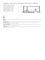
Zugentlastung – Strain relief – Collier de serrage – Prensacable – Snoerontlasting

Einbaubedingungen – Installation condition – Conditions d'installation – Condiciones de instalación – Installatiecondities
Die angegebenen Mindestabstände sind Richtlinien und
von der eingesetzten Leuchte bzw. Umgebung abhängig.
The specified minimum distances are guidelines and
dependent upon of the used luminaire or environment.
Les distances minimales spécifiées sont indicatives et
dépendent de l’utilisation luminaire ou environnement
Las distancias mínimas especificadas son pautas y
dependen de las utilizadas luminaria o ambiente
De opgegeven minimale afstanden zijn richtlijnen en
afhankelijk van de gebruikte armatuur of omgeving
A >50 mm B >50 mm C > 100 mm
(WEEE)
Entsorgung
Produkt nicht im Hausmüll entsorgen! Produkte mit diesem Symbol sind entsprechend der Richtlinie über Elektro- und Elektronik-Altgeräte über die örtlichen Sammelstellen für Elektro-Altgeräte
zu entsorgen!
Disposal
Do not dispose the product with the regular household waste! Products marked with this sign must be disposed according to the directive on electrical and electronic devices at local collection
points for such devices!
Information de recyclage
Ne recyclez pas le produit avec les ordures ménagères ! Les produits qui présentent ce symbole sont à recycler suivant la directive relative aux déchets d'équipements électriques et
électroniques, via des points de collecte pour appareils électriques usagés !
Indicaciones para la eliminación
¡No tirar el producto con la basura doméstica! Los productos con este símbolo deben eliminarse, de acuerdo con la directiva sobre residuos de aparatos eléctricos y electrónicos, llevándolos a
los puntos de recogida selectiva de aparatos eléctricos y electrónicos locales.
Afvalverwijdering
Het product niet via het huishoudelijk afval weggooien! Producten met dit symbool dienen in overeenstemming met richtlijn via elektrische en elektronische apparatuur bij de plaatselijke
inzamelpunten voor elektrisch afval te worden verwijderd.
A
B
C
ECG Leuchte
Luminaire
-
 1
1
-
 2
2
-
 3
3
-
 4
4
-
 5
5
-
 6
6
-
 7
7
-
 8
8
-
 9
9


in andere talen
- English: SVL 1006457 Owner's manual
- français: SVL 1006457 Le manuel du propriétaire
- español: SVL 1006457 El manual del propietario
- Deutsch: SVL 1006457 Bedienungsanleitung
Gerelateerde papieren
Andere documenten
-
FireAngel ZB-MODULE P-LINE Installatie gids
-
iGuzzini N469 Installatie gids
-
LED s light Universal Dimmer Handleiding
-
 EcoDim Smart Dimmer Switch 200W LED Eco-Dim.07 Zigbee Pro Handleiding
-
-
TRILUX 2330 G3 M73 Handleiding
-
Eaton HVLD-2L-CGL Installation Instructions Manual
-
ZIGBEE Eco-Dim Handleiding
-
-
