Electrolux EFT630B/GB Handleiding
- Categorie
- Afzuigkappen
- Type
- Handleiding

Montage- und Gebrauchsanweisung , Installatie- en gebruiksaanwijzing, Notice dutilisation et dinstallation
EFT 9460 - EFT 6460
EFT 630 - EFT 635
EFT 530 - EFT 531 - EFT 535
NL
D
Operating and Installation Instructions, Manual de Instruções, Instrucciones de montaje y manejo
UK
F
P E

Inhalt
D
Bevor Sie jedoch Ihre neue Dunsthaube in Betrieb nehmen, lesen Sie erst diese Bedienungs- und
Montageanleitung.
Um Risiken zu vermeiden, die der Betrieb elektrischer Geräte mit sich bringt, ist es wichtig, daß die Dunsthaube
korrekt installiert wird und Sie die Sicherheitsvorschriften beachten.
Heben Sie die Bedienungsanleitung an einem Ort auf, an dem Sie sie jederzeit greifen können.
Inhalt Seite 2
Inhoud pagina 12
Sommaire page 23
Contents page 34
Índice página 47
Indice pagina 58
D
NL
UK
F
Sicherheitshinweise............................................................................................................................................. 3
für den Küchenmöbel-Monteur ............................................................................................................................... 3
für den Benutzer ......................................................................................................................................................4
Allgemeines.......................................................................................................................................................... 5
Abluftbetrieb ............................................................................................................................................................ 5
Umluftbetrieb ...........................................................................................................................................................5
Bedienung der Dunstabzugshaube ................................................................................................................... 6
Korrekte Belüftung ..................................................................................................................................................6
Wartung und Pflege ............................................................................................................................................. 7
Reinigung .................................................................................................................................................................7
Metallfettfilter ..........................................................................................................................................................7
Fettvliesfilter ............................................................................................................................................................7
Aktivkohlefilter.........................................................................................................................................................8
Austausch der Lampe(n) .........................................................................................................................................8
Sonderzubehör ..................................................................................................................................................... 9
Kundendienst ....................................................................................................................................................... 9
Technische Daten .............................................................................................................................................. 10
Installation .......................................................................................................................................................... 10
Auspacken ............................................................................................................................................................. 10
Plazierung .............................................................................................................................................................. 10
Elektroanschluß ..................................................................................................................................................... 10
Zubehör/Montagematerial...................................................................................................................................... 11
Montage am Oberschrank ..................................................................................................................................... 11
Befestigung an der Wand ...................................................................................................................................... 11
P
E

Sicherheitshinweise
für den Küchenmöbel-Monteur
Das Abluftrohr muss bei Abluftbetrieb
vorzugsweise den Originaldurchmesser des
Gerätes haben.
Achtung! Das Abluftrohr und die
Befestigungsmanschetten sind nicht im
Lieferumfang inbegriffen und müssen gesondert
erworben werden.
Bei Montage der Dunstabzugshaube sind
folgende Mindestabstände von der
Kochstellen-Oberkante bis Unterkante der
Dunstabzugshaube einzuhalten:
Elektroherde 500 mm
Gasherde 700 mm
Wenn die Installationsanweisungen des
Gaskochgeräts einen größeren Abstand
vorgeben, ist dieser zu berücksichtigen.
Bei gleichzeitigem Betrieb einer
Dunstabzugshaube im Abluftbetrieb und
Feuerstätten darf im Aufstellraum der
Feuerstätte der Unterdruck nicht größer als 4Pa
(4x10
-5
bar) sein.
Die Abluft darf nicht in einen Rauch- oder
Abgasschornstein eingeleitet werden. Das
Einleiten der Abluft in einen Schacht, der der
Entlüftung von Aufstellungsräumen von
Feuerstätten dient, ist nicht zulässig.
Für die Abluftführung sind grundsätzlich die
behördlichen Vorschriften einzuhalten.
Bei Betrieb als Abluftgerät ist für eine
ausreichende
Zuluftöffnung in etwa der Größe der
Abluftöffnung zu sorgen.
Aufgrund von Länder-Bauvorschriften
unterliegt der gemeinsame Betrieb von
Dunstabzugshauben und kamingebundenen
Feuerungsstätten, wie Kohle- oder Ölöfen und
Gas-Thermen im selben Raum, bestimmten
Einschränkungen.
Der gemeinsame, gefahrlose Betrieb von
kamingebundenen Geräten und
Dunstabzugshauben ist nur gewährleistet, wenn
Raum und/oder Wohnung (Raum-Luftverbund)
durch eine geeignete Zuluftöffnung von ca.
500-600 cm
2
von außen belüftet sind und
dadurch bei laufender Dunstabzugshaube
Unterdruck vermieden wird.
Im Zweifelsfalle Rat und Zustimmung des
zuständigen Bezirks-Schornsteinfegermeisters
oder der örtlichen Baubehörde einholen.
Da in Räumen ohne Feuerungsstätte die Regel
gilt: Zuluftöffnung so groß wie Abluftöffnung,
kann durch eine größere Öffnung als 500-600
cm
2
der Wirkungsgrad der Ablufteinrichtung
beeinträchtigt werden.
Der Betrieb der Dunstabzugshaube als
Umlufthaube ist unter den genannten
Umständen gefahrlos und unterliegt nicht den
obengenannten Vorschriften.
Die Funktion der Dunstabzugshaube bei
Abluftbetrieb ist nur dann optimal, wenn
folgendes beachtet wird:
kurze, gerade Abluftstrecken
möglichst wenige Rohrbögen
Verlegung der Rohre nicht in spitzen
Winkeln, sondern in flachen Bögen
möglichst große Rohrdurchmesser
(vorzugsweise Originalauslass-
Durchmesser beibehalten).
Bei Nichtbeachtung dieser Grundsätze muß mit
drastischen Leistungsverlusten und erhöhten
Betriebsgeräuschen gerechnet werden.

für den Benutzer
Es muß darauf geachtet werden, daß
Kochstellen bei Betrieb stets abgedeckt sind,
damit nicht durch zu starke Hitzeentwicklung
das Gerät beschädigt wird. Unbedingt zu
vermeiden sind offene Feuerstellen bei Öl-,
Gas- und Kohleherden.
Außerdem ist beim Fritieren über Herd/Mulde
das zum Fritieren verwendete Gerät während
des Betriebes zu beaufsichtigen.
Das im Fritiergerät enthaltene Öl kann sich
durch Überhitzung selbst entzünden- akute
Brandgefahr!
Bei Verwendung von verschmutztem Öl kann
noch leichter Selbstentzündung entstehen.
Flambieren ist unter der Dunstabzugshaube
nicht erlaubt.
Bei allen Arbeiten an der
Dunstabzugshaube, auch beim
Lampenwechsel, ist das Gerät vom Stromnetz
zu trennen. (Schraubsicherungen aus der
Fassung herausnehmen bzw.
Sicherungsautomaten abschalten oder
Netzstecker ziehen).
Es ist wichtig, die Filterwechsel bzw.
Reinigungsintervalle einzuhalten.
Bei Nichtbeachtung besteht infolge von
Fettablagerung Feuergefahr.
In Übereinstimmung mit den Anforderungen der
Europäischen Richtlinie 2002/96/EG über Elektro-
und Elektronik-Altgeräte (WEEE) ist vorliegendes
Gerät mit einer Markierung versehen.
Sie leisten einen positiven Beitrag für den Schutz
der Umwelt und die Gesundheit des Menschen,
wenn Sie dieses Gerät einer gesonderten
Abfallsammlung zuführen. Im unsortierten
Siedlungsmüll könnte ein solches Gerät durch
unsachgemäße Entsorgung negative
Konsequenzen nach sich ziehen.
Auf dem Produkt oder der beiliegenden
Produktdokumentation ist folgendes Symbol
einer durchgestrichenen Abfalltonne abgebildet.
Es weist darauf hin, dass eine Entsorgung im
normalen Haushaltsabfall nicht zulässig ist.
Entsorgen Sie dieses Produkt im Recyclinghof mit
einer getrennten Sammlung für Elektro- und
Elektronikgeräte.
Die Entsorgung muss gemäß den örtlichen
Bestimmungen zur Abfallbeseitigung erfolgen.
Bitte wenden Sie sich an die zuständigen Behörden
Ihrer Gemeindeverwaltung, an den lokalen
Recyclinghof für Haushaltsmüll oder an den
Händler, bei dem Sie dieses Gerät erworben haben,
um weitere Informationen über Behandlung,
Verwertung und Wiederverwendung dieses
Produkts zu erhalten.

Allgemeines
Die Dunstabzugshaube wird als Abluftgerät
ausgeliefert und kann durch den Einsatz eines
Aktivkohlefilters (Sonderzubehör) als
Umluftgerät verwendet werden.
Für den Umluftbetrieb wird der Original-
Aktivkohlefilter aus dem Sonderzubehör
benötigt.
Nur für: EFT 630 W/GB / 942 120 776
EFT 630 B/GB / 942 120 777
EFT 635 X/GB / 942 120 779
EFT 9460 - EFT 6460
Die Dunstabzugshaube ist mit einem
Aktivkohlefilter bereits ausgestattet.
Falls die Abluftversion erwünscht ist, bitte
den Kohlefilter entfernen.
Abluftbetrieb
Die Luft wird mit Hilfe eines an den
Abluftstutzen anzubringenden Rohres ins
Freie geleitet.
Achtung! Das Abluftrohr und die
Befestigungsmanschetten sind nicht im
Lieferumfang inbegriffen und müssen gesondert
erworben werden.
Das Abluftrohr muß bei Abluftbetrieb
denselben Durchmesser wie der
Gebläseaustrittstutzen haben, um die
spezifizierten Leistungswerte zu erreichen.
Umluftbetrieb
Die Luft wird gefiltert und durch das
Frontgitter in den Raum zurückgeführt.
Hebel in Stellung F bringen
Für den Umluftbetrieb wird der Original
Aktivkohlefilter TYPE 10 aus dem
Sonderzubehör benötigt.
Bild 1 - Abluftbetrieb
Bild 2 - Umluftbetrieb
... ins Freie geleitet
Abluftrohr
Abluftstutzen
(Bajonett-anschluss
mit Schraube)
A
F
Aktivkohlefilter
Hebel
Frontgitter

Bedienung der Dunstabzugshaube
Die Dunstabzugshaube ist mit regelbarer
Drehzahl ausgerüstet. Es ist ratsam, die
Dunstabzugshaube einige Minuten vor
Beginn des Kochens einzuschalten und sie
ungefähr 15 Minuten nach dem Kochen
weiterlaufen zu lassen, damit alle Gerüche
sicher entfernt werden.
Auf der Vorderseite des Gerätes befinden sich die
Schalter:
Lichtschalter: Der Schalter dient dazu, die
Lampe, mit der die Dunstabzugshaube
ausgestattet ist, ein- und auszuschalten.
Motorschalter: Dieser dient zum Einschalten
und Ausschalten und zum Wählen der
Geschwindigkeiten des Gebläses.
Korrekte Belüftung
Damit die Dunsthabue richtig arbeitet, sollten die
Küchenfenster geschlossen sein.Bei Abluftbetrieb
sollte jedoch ein Fenster in einem anderen Raum
geöffnet sein, damit ein Luftaustausch stattfinden
kann.
Bild 3 - Bedienfeld
Motorschalter
Lichtschalter

Achtung
Nichtbeachtung dieser Anweisungen zur
Reinigung des Gerätes und zum Wechsel bzw.
zur Reinigung der Filter kann zum Brand
führen. Diese Anweisungen sind unbedingt zu
beachten!
Der Hersteller übernimmt keine Haftung für
irgendwelche Schäden am Motor oder aus
Feuergründen, die auf eine unsachgemäße
Wartung oder Nichteinhaltung der oben
angeführten Sicherheitsvorschriften
zurückzuführen sind.
Reinigung
Achtung: Zum Reinigen der Dunstabzugshaube
Gerät vom Stromnetz trennen.
Nicht mit spitzen Gegenständen in das Schutzgitter
des Motors eindringen.
Äußere Teile mit milder Spüllauge reinigen. Scharfe
Reinigungsmittel, Bürste oder Scheuersand
vermeiden.
Die Schalterblende und das Fettfiltergitter nur mit
feuchtem Tuch und milden Spülmitteln reinigen.
Es ist wichtig, die Filterwechsel sowie die
Reinigungsintervalle einzuhalten. Bei
Nichtbeachtung besteht infolge von
Fettablagerungen Feuergefahr!
Metallfettfilter
EFT 635-535-531-9460-6460 (1 oder 2 Filter)
Metallfettfilter haben die Aufgabe, Fettpartikel, die
beim Kochen entstehen, aufzusaugen. Sie werden in
jedem Fall, d.h. sowohl bei Abluft- als auch bei
Umluftbetrieb, verwendet.
Metallfettfilter sollen alle 4 Wochen im
Geschirrspüler bzw. von Hand gereinigt werden.
Öffnen der Metallfettfilter
Die Verriegelung des Fettfilters zuerst nach hinten
dann nach unten herausnehmen.
Zum Ausbau in umgekehrter Reihenfolge vorgehen.
Innengehäuse nur mit warmer Spülmittellauge
reinigen. Keine scharfe Reinigungsmittel, Bürste
oder Scheuersand verwenden!
Fettvliesfilter (EFT 630-530)
Die Fettfilter haben die Aufgabe, die Fettpartikel, die
beim Kochen entstehen, aufzusaugen und werden in
jedem Fall, d.h. sowohl bei Abluft- als auch bei
Umluftbetrieb, verwendet.
Der Fettvliesfilter kann nicht gereinigt werden und
muß einmal pro Monat ausgewechselt werden.
Wenn man den Fettfilter austauscht, auch das
Fettfilterblech mit lauwarmem Wasser und einem
flüssigen, nicht scheuernden Spülmittel reinigen.
Die Fettfilter können beim Kundendienst bestellt
werden.
Öffnen des Gitters
Die Verriegelung des Gitters zuerst nach hinten, dann
nach unten herausnehmen.
Zum Herausnehmen das Gitter rechts nach vorne
ziehen und aushaken.
Entfernen der Fettfilter
Zum Herausnehmen des Filters öffnen Sie das Gitter
und nehmen die Haltestops heraus.
Bevor irgendwelche Wartungsarbeiten ausgeführt werden, muss die Dunstabzugshaube vom
Stromnetz getrennt werden.
Wartung und Pflege
a
b
b
a
a
a
Bild 4 - Öffnen der Metallfettfilter
Verriegelung EFT 635-535-531-9460-6460
Verriegelung - EFT 630-530
Bild 5 - Fettvliesfilter (EFT 630 - EFT 530)
1
2
3
Fettvliesfilter
Haltestops
Verriegelung
Verriegelung
Gitter

Aktivkohlefilter
Der Aktivkohlefilter muß dann verwendet
werden, wenn man die Dunstabzugshaube als
Umluftgerät einsetzen möchte.
Dazu wird der Original Aktivkohlefilter (siehe
Sonderzubehör) benötigt.
Austausch des Aktivkohlefilters
Im allgemeinen müssen Aktivkohlefilter
zumindest einmal alle vier Monate
ausgewechselt werden.
Dieser Filter kann weder gewaschen noch
wiederverwendet werden. Um eine
einwandfreie Aufnahme der Gerüche zu
garantieren, muss das Aktivkohlevolumen auf
die Luftleistung der Haube abgestimmt sein. In
diesem Fall garantiert die hohe Qualität der
Aktivkohle bei normalem Einsatz der
Dunstabzugshaube eine effiziente Aufnahme
von Küchengerüchen für cirka vier Monate.
Deshalb sollten nur Originalfilter verwendet
werden, die regelmäßig ausgetauscht werden
müssen.
Montage
Durch Drehen der Knäufe um 90° die
Abdeckung entfernen.
In das dafür vorgesehene Fach den Kohlefilter
einsetzen und ihn durch Drehen der Knäufe um
90° befestigen, dann die Abdeckung wieder
schließen.
Zum Ausbau in umgekehrter Reihenfolge
vorgehen.
Innengehäuse nur mit warmer Spülmittellauge
reinigen. Keine scharfen Reinigungsmittel,
Bürste oder Scheuersand verwenden!
Bei Bestellung eines Ersatzfilters die
Modellbezeichnung und die E-Nr. angeben.
Diese Daten sind auf dem Typenschild an der
Innenseite des Gerätes zu finden.
Der Aktivkohlefilter kann beim Kundendienst
bestellt werden.
Austausch der Lampe(n)
Dunstabzugshaube vom Stromnetz trennen.
Öffnen Sie das Absauggitter bzw. entfernen Sie
den Metallfettfilter.
Defekte Lampe herausnehmen und durch neue
eines gleichwertigen Typs ersetzen.
Bauen Sie das Absauggitter bzw. den Fettfilter
wieder ein.
Bevor der Kundendienst gerufen wird, weil die
Glühlampe nicht brennt, erst prüfen, ob sie fest
eingeschraubt ist.
Bild 6 - Aktivkohlefilter - Montage
90°
Knäufe
Abdeckung
Knäufe
Knäufe
Hebel in Stellung
F bringen
Aktivkohlefilter

Sonderzubehör
Aktivkohlefilter TYPE 10
Mauerkasten Beim Kundendienst erfragen
Abluftrohr Beim Kundendienst erfragen
Kundendienst
Bei eventuellen Rückfragen und Störungen Kundendienst anrufen (siehe Kundendienst-Stellenverzeichnis).
Folgende Daten beim Anruf angeben:
1. Modellbezeichnung
2. E-Nr.
3. F-Nr.
Diese Daten befinden sich auf dem Typenschild auf der Innenseite des Gerätes hinter den Fettfiltern.
Konstruktions- und Farbänderungen im Rahmen der technischen Entwicklung bleiben vorbehalten.
SERVICE
Handelt es sich um eine technische Störung?
Dann wenden Sie sich an Ihre Kundendienststelle. (Adressen und Telefonnummern befinden sich im Abschnitt
Kundendienststellen.)
Bereiten Sie das Gespräch in jedem Fall gut vor. Sie erleichtern so die
Diagnose und die Entscheidung, ob ein Kundendienstbesuch nötig ist:
Halten Sie möglichst genau fest:
Wie äußert sich die Störung?
Unter welchen Umständen tritt die Störung auf?
Notieren Sie für das Gespräch unbedingt folgende Kennziffern Ihres
Gerätes auf dem Typenschild:
E-Nr. (9 Stellen),
F-Nr. (8 Stellen).
Das Typenschild ist nach Ausbau der Metallfettfilter auf der Innenseite
des Gerätes zugänglich.
Wir empfehlen, die Kennziffern hier einzutragen, damit Sie sie stets zur Hand haben:
E-Nr . . . . . . . . . F-Nr . . . . . . . . .
Wann entstehen Ihnen auch während der Garantiezeit Kosten?
wenn Sie die Störung mit Hilfe dieser Gebrauchsanweisung selbst hätten beseitigen können,
wenn mehrere Anfahrten des Kundendienst-Technikers erforderlich sind, weil er vor seinem Besuch nicht
alle wichtigen Informationen erhalten hat und daher z.B. Ersatzteile holen muß. Diese Mehrfahrten können
Sie vermeiden, wenn Sie Ihren Telefonanruf in der oben beschriebenen Weise gut vorbereiten.

Technische Daten
Modell EFT 630 EFT 530 EFT 630/GB EFT 9460 EFT 6460
EFT 635 EFT 535 EFT 635/GB
EFT 531
Maße (in cm):
Höhe 13,2 13,2 13,2 13,2 13,2
Breite 59,9 49,9 59,9 89,9 56,9
Tiefe 51 51 51 51 51
Gesamtanschlußwerte: 140W 140 W 180 W 240 W 240 W
Lüftermotor: 1 x 100 W 1 x 100 W 1 x 100 W 1 x 160 W 1 x 160 W
Beleuchtung: 1 x 40 W 1 x 40 W 2 x 40 W 2 x 40 W 2 x 40 W
Länge des Netzkabels: 150 cm 150 cm 150 cm 150 cm 150 cm
Elektroanschluß: 220 - 240 V 220 - 240 V 220 - 240 V 220 - 240 V 220 - 240 V
50/60 Hz 50/60 Hz
Konstruktions- und Farbänerungen im Rahmen der technischen Entwicklung bleiben vorbehalten.
Installation
Auspacken
Überprüfen Sie bei Auspacken, ob das Gerät nicht
beschädigt ist und ob alle Zubehörteile vollständig
vorhanden sind
Plazierung
Die Dunsthaube muß in einen Mindestabstand von
50 cm bei Elektroherden und von 70 cm bei Gas-
bzw. Gaskombiherden angebracht werden. Bild. 7.
Wenn die Installationsanweisungen des
Gaskochgeräts einen größeren Abstand vorgeben,
ist dieser zu berücksichtigen.
Elektroanschluß
Sicherheitshinweise für den Elektro-
Installateur
Vor dem Anschluß des Gerätes darauf achten, daß
die auf dem Typenschild verzeichnete Spannung
der tatsächlichen Netzspannung entspricht.Falls
das Gerät mit Stecker ausgerüstet ist, kann es an
jede vorschriftsmäßig installierte und gut
zugängliche Steckdose angeschlossen werden.
Bei erforderlichem Festanschluß darf die
Dunstabzugshaube nur durch einen beim
zuständigen Elektrizitäts-Versorgungsunternehmen
eingetragenen Elektro-Installateur angeschlossen
werden. Installationsseitig ist eine allpolige
Trennvorrichtung mit mind. 3mm
Kontaktöffnungsweite vorzusehen.
Für Störungen, die wegen Nichtbeachtung der o.g.
Anweisungen auftreten, wird nicht gehaftet.
Bild 7 - Plazierung
Min
70 cm
Min
50 cm

2
3
4
4
4
5
5
3
1
6
6
8
7
1cm
5
!
9
7
Installation
Bild 9 - Befestigung an der Wand
Zubehör/Montagematerial
4 Holzschrauben 5 x 45 mm
4 Dübel Ø 8 mm
4 Holzschrauben 4,2 x 35 mm
1 Abluftstutzen Ø 125 mm
1 Schlüssel (zum Festziehen von Schrauben mit
Kopf des Typs TORX)
1 Blechschraube 2.9 x 13
Montage am Oberschrank
An der Unterseite des Hängeschrankes, unter
Verwendung der Bohrschablone (1) die Löcher
bohren (2).
Das Bohrloch für das Abluftrohr (4) ist nur
dann erforderlich, wenn die Haube mit
Abluftbetrieb betrieben werden soll (3).
Vom Inneren des Hängeschrankes her die 4
mitgelieferten Schrauben einsetzen (5) und in
die am Gerät ausgearbeiteten Löcher
einschrauben.
Befestigung an der Wand
Mittellinie an der Wand kennzeichnen, um das
Montageverfahren zu erleichtern (1).
Die Bohrschablone an der Wand befestigen (2).
3 Löcher von Ø 8 mm in die Wand bohren (3),
2 Löcher an den oberen Punkten, 1 Loch
wahlweise an den unteren Punkten.
3 Wanddübel von Ø 8 mm einsetzen (4).
2 Schrauben 5x45 einsetzen (5) (nicht
vollkommen festschrauben) und Gerät daran
aufhängen (6).
Die Schrauben festziehen (7).
In der Innenseite der Haube die dritte 5x45
Schraube in die unteren Öffnung einsetzen (8)
und festziehen (9).
Bild 8 - Montage am Oberschrank
1
2
5
4
5
5
5
3

Inhoud
NL
Veiligheidsaanwijzingen .................................................................................................................................... 13
voor de keukenmeubel-monteur............................................................................................................................. 13
voor de gebruiker ................................................................................................................................................... 14
Algemeen............................................................................................................................................................ 15
Gebruik als afzuigkap ............................................................................................................................................. 15
Gebruik als recirculatiekap.....................................................................................................................................15
Bediening van de afzuigkap ............................................................................................................................. 16
Ventilatie ................................................................................................................................................................ 16
Onderhoud .......................................................................................................................................................... 17
Reiniging ................................................................................................................................................................ 17
Metalen vetfilters ................................................................................................................................................... 17
Vetfilter .................................................................................................................................................................. 18
Koolfilter ................................................................................................................................................................ 18
Vervangen van de lamp(en) ................................................................................................................................... 18
Extra leverbare accessoires ............................................................................................................................ 19
Klantenservice ................................................................................................................................................... 19
Technische gegevens........................................................................................................................................ 21
Installatie ............................................................................................................................................................ 21
Uitpakken ...............................................................................................................................................................21
Plaats ..................................................................................................................................................................... 21
Elektrische aansluiting ............................................................................................................................................21
Toebehoren/Montagemateriaal .............................................................................................................................. 22
Montage aan een bovenkastje ...............................................................................................................................22
Bevestiging aan de wand ....................................................................................................................................... 22
U bent nu in het bezit van een Electrolux product. Vanzelfsprekend kunt u ook tijdens het gebruik van uw product
op Electrolux rekenen. Daarom nodigen wij u van harte uit u te registreren op onze internetsite electrolux.nl. Wij
kunnen u dan nog beter van dienst zijn met informatie over producten, tips, innovaties, oplossingen voor storingen
etc. U vindt de Electrolux productregistratie onder Consumentenbelangen op de homepage van
www.electrolux.nl.
Voordat u uw nieuwe afzuigkap in gebruik neemt, dient u eerst deze gebruiks- en installatie-aanwijzing door te
lezen.
Om gevaren die het gebruik van elektrische apparaten met zich meebrengt te voorkomen, is het belangrijk dat de
kap correct wordt geïnstalleerd en dat u de veiligheidsvoorschriften opvolgt. Houd de gebruiksaanwijzing bij de
hand, zodat u nog eens iets kunt nalezen.

Veiligheidsaanwijzingen
voor de keukenmeubel-monteur
De afvoerbuis moet bij gebruik als afzuigkap
een diameter van 125 mm hebben.
Indien nodig zijn op bestelling buizen in
verschillende vormen en diameters en
afvoersystemen naar buiten (telescoop-
muurkast) verkrijgbaar. Neem daarvoor contact
op met onze service-afdeling.
Let op! De afvoerbuis en de
bevestigingsringen worden niet bijgeleverd
en moeten apart worden aangeschaft.
Bij de montage van de afzuigkap moeten de
volgende minimale afstanden van de
bovenkant van de kookzones of gasbranders
tot de onderkant van de afzuigkap worden
aangehouden:
elektrisch fornuis 500 mm
gasfornuis 700 mm
Indien in de installatie-aanwijzing van het
gaskooktoestel een grotere afstand wordt
aangegeven moet hiermee rekening worden
gehouden.
Bij gelijktijdig gebruik van het apparaat als
afzuigkap en stookplaatsen mag in de ruimte
waar de stookplaats zich bevindt de onderdruk
niet groter dan 4PA (4x10
-5
bar) zijn.
De afgewerkte lucht mag niet in een kanaal dat
bestemd is voor de afvoer van rook-/
verbrandingsgassen of een schacht die dient
voor de ontluchting van ruimten met
stookplaatsen geleid worden.
Voor het afvoeren van de afgewerkte lucht
moeten de plaatselijke voorschriften in acht
genomen worden.
Bij gebruik als afzuigkap moet gezorgd worden
voor een voldoende grote toevoeropening, die
ongeveer even groot als de afvoeropening moet
zijn.
Op grond van landelijke bouwvoorschriften
gelden voor het gemeenschappelijk gebruik van
afzuigkappen en toestellen die zijn aangesloten
op een verbrandingsgaskanaal/schoorsteen,
zoals kolen - of oliekachels en gasovens in
dezelfde ruimte, bepaalde beperkingen.
Het gemeenschappelijke, ongevaarlijke gebruik
van schoorsteengebonden toestellen en
afzuigkappen is alleen gewaarborgd, als ruimte
en/of woning door een geschikte
toevoeropening van ca. 500-600 cm
2
van buiten
geventileerd zijn, waardoor bij lopende
afzuigkap een onderdruk vermeden wordt.
Omdat in ruimten zonder rookkanaalafvoer de
regel geldt toevoeropening even groot als
afvoeropening kan door de grotere opening van
500-600 cm
2
de werking van de afvoerinrichting
nadelig beïnvloed worden.
Het gebruik van het apparaat als recirculatiekap
is onder de genoemde omstandigheden zonder
gevaar en valt niet onder bovengenoemde
voorschriften.
Het apparaat functioneert als afzuigkap alleen
optimaal als u het volgende in acht neemt:
- korte, rechte afvoerverbindingen
- zo min mogelijk bochten in de buis
- buizen niet met scherpe hoeken maar met
flauwe bochten laten verlopen
- zo groot mogelijke buisdiameter (bij
voorkeur dezelfde diameter als de
afvoeropening).
Als u deze basisregels niet in acht neemt, moet
u rekening houden met aanzienlijk
vermogensverlies en verhoogd bedrijfsgeluid.

voor de gebruiker
U dient erop te letten dat op ingeschakelde
kookzones en gasbranders altijd een pan staat,
opdat het apparaat niet door te sterke hitte-
ontwikkeling wordt beschadigd. Bij olie-, gas- en
kolenfornuizen dient open vuur beslist te worden
vermeden.
Bovendien moet bij het frituren op een fornuis
of kookplaat de frituurpan tijdens het gebruik
altijd in het oog worden gehouden.
De olie in de frituurpan kan door oververhitting
vlam vatten.
Bij gebruik van verontreinigde olie kan nog
makkelijker zelfontbranding ontstaan.
Wij wijzen u erop dat door oververhitting brand
kan ontstaan.
Flamberen onder de afzuigkap is niet
toegestaan.
Bij alle werkzaamheden aan de afzuigkap, ook
bij het vervangen van de lamp, moet het
apparaat spanningloos worden gemaakt
(zekering in de huisinstallatie uitschakelen).
Het is belangrijk dat u tijdig de filters vervangt
resp. reinigt.
Anders bestaat ten gevolge van vetafzetting
brandgevaar.
Dit apparaat is voorzien van het merkteken volgens
de Europese richtlijn 2002/96/EG inzake
Afgedankte elektrische en elektronische apparaten
(AEEA).
Door ervoor te zorgen dat dit product op de juiste
manier als afval wordt verwerkt, helpt u mogelijk
negatieve consequenties voor het milieu en de
menselijke gezondheid te voorkomen die anders
zouden kunnen worden veroorzaakt door onjuiste
verwerking van dit product als afval.
Het symbool
op het product of op de
bijbehorende documentatie geeft aan dat dit
product niet als huishoudelijk afval mag worden
behandeld. In plaats daarvan moet het worden
afgegeven bij een verzamelpunt voor recycling van
elektrische en elektronische apparaten.
Afdanking moet worden uitgevoerd in
overeenstemming met de plaatselijke
milieuvoorschriften voor afvalverwerking.
Voor nadere informatie over de behandeling,
terugwinning en recycling van dit product wordt u
verzocht contact op te nemen met het stadskantoor
in uw woonplaats, uw afvalophaaldienst of de
winkel waar u het product heeft aangeschaft.

Algemeen
Het apparaat wordt als afzuigkap geleverd en
kan in combinatie met een koolfilter (extra
leverbaar accessoire) als recirculatiekap worden
gebruikt.
Daarvoor is een origineel koolfilter nodig (zie
Extra leverbare accessoires).
Alleen voor: EFT 630 W/GB / 942 120 776
EFT 630 B/GB / 942 120 777
EFT 635 X/GB / 942 120 779
EFT 9460 - EFT 6460
De kap is al uitgerust met een koolfilter.
Verwijder dit filter als u de kap als afzuigkap
gaat gebruiken.
Gebruik als afzuigkap
De lucht wordt met behulp van een op de
afvoeropening aan te brengen buis naar buiten
afgevoerd.
Let op! De afvoerbuis en de
bevestigingsringen worden niet bijgeleverd
en moeten apart worden aangeschaft.
Voor de beste afzuigprestaties moet de
afvoerbuis dezelfde diameter hebben als de
afvoeropening.
Gebruik als recirculatiekap
De lucht wordt gefilterd en teruggevoerd naar
de ruimte door het rooster aan de voorzijde.
Breng hendel in positie F.
Voor gebruik als recirculatiekap is een origineel
koolfilter TYPE 10 (extra leverbaar
accessoire) nodig.
afb. 1 - Gebruik als afzuigkap
afb. 2 - Gebruik als recirculatiekap
... naar buiten afgevoerd
afvoerbuis
afvoeropening
(bajonetsluiting met
schroef)
A
F
koolfilter
hendel
rooster

Bediening van de afzuigkap
De afzuigkap is voorzien van een motor met
regelbaar toerental. Wij raden u aan de kap
enkele minuten voordat u met koken begint in
te schakelen en ca. 15 minuten nadat u klaar
bent met koken verder te laten lopen, opdat alle
luchtjes worden verwijderd.
De schakelaars bevinden zich aan de voorkant van
de kap:
Lichtschakelaar: hiermee kan de verlichting
van de afzuigkap worden in- en uitgeschakeld.
Motorschakelaar: voor in- en uitschakelen van
de motor resp. om één van de drie standen te
kiezen.
Ventilatie
Voor een goede werking van de kap moeten ramen
in de keuken tijdens het koken gesloten zijn.
Bij gebruik als afzuigkap moet echter een raam in
een andere kamer geopend zijn, opdat
luchtuitwisseling kan plaatsvinden.
afb. 3 - Bedieningspaneel
motorschakelaar
lichtschakelaar

Attentie
Als u deze aanwijzingen m.b.t. reiniging van
het apparaat en vervanging resp. reiniging van
de filters niet opvolgt, kan dat tot brand leiden.
Deze aanwijzingen beslist opvolgen!
De fabrikant is niet aansprakelijk voor schade
aan de motor of schade t.g.v. brand die het
gevolg zijn van ondeskundig onderhoud of niet
opvolgen van de bovengenoemde
veiligheidsvoorschriften.
Reiniging
Attentie: eerst de stekker uit het stopcontact
trekken.
Geen spitse voorwerpen in het beschermrooster
van de motor steken.
De buitenkant van het apparaat met een mild
sopje reinigen. Gebruik geen scherpe
reinigingsmiddelen, borstels of schuurmiddel.
Het bedieningspaneel en het vetfilterrooster
alleen met een vochtige doek en mild
afwasmiddel reinigen.
Het is belangrijk om op tijd de filters te
vervangen resp. te reinigen. Als u deze
aanwijzingen niet opvolgt, kan t.g.v.
vetafzetting brandgevaar ontstaan.
Metalen vetfilters
EFT 635-535-531-9460-6460 (1 of 2 filters)
De metalen vetfilters hebben de taak om de
vetdeeltjes die bij het koken ontstaan, op te
zuigen en worden altijd, d.w.z. zowel bij
gebruik als afzuigkap als bij gebruik als
recirculatiekap, gebruikt.
De metalen vetfilters moeten elke 4 weken
worden gedemonteerd en in de afwasautomaat
of met de hand worden schoongemaakt.
Demonteren van de metalen vetfilters
Trek eerst de hendels naar achteren (a), trek dan
het rooster naar buiten (b).
Reinigen met de hand
Metaalfiltercassette ca. 1 uur in heet water met
een vetoplossend schoonmaakmiddel weken en
daarna met heet water afspoelen. Proces evt.
herhalen. Cassette afdrogen en weer inzetten.
Afwasautomaat
Metaalfiltercassette in de afwasautomaat zetten.
Sterkste programma en hoogste temperatuur
(min. 65°C) kiezen. Proces evt. herhalen.
Cassette afdrogen en weer inzetten.
Machinaal reinigen van de metalen vetfilters
kan tot lichte verkleuringen leiden, die
echter geen invloed op de werking hebben.
De binnenkant van de kap alleen met een warm
sopje reinigen. Geen scherpe
reinigingsmiddelen, borstels of schuurmiddelen
gebruiken!
Voordat u werkzaamheden aan het apparaat gaat uitvoeren, eerst de stekker uit het stopcontact
trekken.
Onderhoud
a
b
b
a
a
a
afb. 4 - Demonteren van de metalen
vetfilters
vergrendeling EFT
EFT 635-535-531-9460-6460
vergrendeling - EFT 630-530

Vetfilter (EFT 630-530)
Het vetfilter heeft de taak om de vetdeeltjes die
bij het koken ontstaan, op te zuigen en wordt
altijd, d.w.z. zowel bij gebruik als afzuigkap als
bij gebruik als recirculatiekap, gebruikt.
Het filter kan niet worden gereinigd en moet
één maal per maand worden vervangen.
Als u het vetfilter vervangt, ook het filterrooster
met lauw water en een vloeibaar, niet schurend
reinigingsmiddel schoonmaken.
Het vetfilter kunt u bestellen bij de service-
afdeling.
Openen van het rooster
De vergrendeling van het rooster eerst naar
achteren klappen en dan naar beneden
losnemen.
Het rooster rechts naar voren trekken en
loshaken.
Losnemen van het filter
Om het filter los te nemen opent u het rooster
en verwijdert u de bevestigingspallen.
Koolfilter
Het koolfilter moet worden gebruikt, als het
apparaat als recirculatiekap wordt gebruikt.
Daarvoor is een origineel koolfilter nodig (zie
Extra leverbare accessoires).
Vervangen van het koolfilter
Bij normaal gebruik moet het koolfilter elke 4
maanden worden vervangen. Dit filter kan niet
worden gewassen en hergebruikt. Om een
onberispelijke opname van de kookluchtjes te
garanderen, moet het volume aan actieve kool
zijn afgestemd op de luchtgeleiding van de kap.
In dit geval garandeert de hoge kwaliteit van de
actieve kool bij normaal gebruik van het
apparaat een efficiënte opname van luchtjes
voor ca. 4 maanden. Daarom moeten alleen
originele filters worden gebruikt, die regelmatig
moeten worden vervangen.
Montage
Het deksel verwijderen door de knoppen 90°
te draaien.
Koolfilter in de daarvoor bestemde ruimte
plaatsen en bevestigen door de knoppen 90° te
draaien, dan het deksel weer sluiten.
Om het filter los te nemen in omgekeerde
volgorde te werk gaan.
Bij bestelling van een nieuw filter modelnaam
en E-nr. opgeven. Deze gegevens vindt u op het
typeplaatje aan de binnenzijde van het apparaat.
Het koolfilter kunt u bestellen bij de service-
afdeling.
afb. 6 - Koolfilter - Montage
Vervangen van de lamp(en)
Stekker uit het stopcontact trekken.
Rooster verwijderen.
Defecte lamp door een gelijkwaardige lamp
vervangen.
Rooster weer monteren.
Voordat u contact opneemt met onze service-
afdeling, omdat de gloeilamp niet brandt, eerst
controleren of de lamp stevig vast zit.
1
2
3
vetfilter
bevestigingspallen
vergrendelingvergrendeling
rooster
afb. 5 - Vetfilter (EFT 630 - EFT 530)
90°
knoppen
deksel
knoppen
knoppen
Hendel in
positie F brengen
koolfilter

Extra leverbare accessoires
koolfilter TYPE 10
muurkast Neem contact op met
onze service-afdeling
afvoerbuis Neem contact op met
onze service-afdeling
Klantenservice
Als u vragen hebt waar deze gebruiksaanwijzing geen antwoord op geeft, kunt u de volgende afdelingen
raadplegen:
Service-informatielijn (0172) 468 300
(voor bezoek servicetechnicus en onderdelen)
Consumentenbelangen (0172) 468 172
(voor algemene, product- of gebruiksinformatie)
Belangrijk!
Houd bij het opgeven van een storing altijd modelaanduiding, E-nummer en F-nummer van uw apparaat bij de
hand. Deze nummers vindt u op de binnenzijde van de afzuigkap, nadat u de vetfilters hebt losgenomen en kunt
u het beste hieronder noteren.
modelaanduiding ........
E-nr. ......
F-nr. ......
Bereid het gesprek altijd goed voor. Zo vergemakkelijkt u de diagnose en de beslissing of bezoek van een
servicetechnicus nodig is.
Geef zo nauwkeurig mogelijk op:
- Hoe doet de storing zich voor?
- Onder welke omstandigheden treedt de storing op?
Aan de hand van deze informatie kan onze service-afdeling de juiste
voorbereidingen treffen, zodat het apparaat bij het eerste bezoek van de
servicetechnicus weer hersteld kan worden. Op deze manier hoeft u slechts één maal thuis te blijven.
Constructie- en kleurwijzigingen in het kader van de technische ontwikkeling voorbehouden.

Reparatievoorwaarden
Onze reparatievoorwaarden zijn conform de afspraak tussen de
Consumentenbond en Vlehan*.
Art. 1 Aan de consument zal na een melding van een storing zo mogelijk direct, doch uiterlijk binnen één werkdag worden
medegedeeld op welke dag het bezoek van de technicus zal plaatsvinden.
De reparatie zal als regel binnen zeven werkdagen na de melding zijn uitgevoerd.
Art. 2 a) Alvorens de reparatie wordt verricht zal de technicus een onderzoek uitvoeren naar de vermoedelijke oorzaak van de gemelde
storing. Aan de hand hiervan zal hij een zo nauwkeurig mogelijke, gespecificeerde begroting maken van de totale reparatiekosten
inclusief voorrijkosten en diagnose-kosten.
Desgevraagd zal deze begroting door de technicus schriftelijk worden vastgelegd.
b) Indien de consument met het begrote bedrag niet akkoord gaat, zal op verzoek het te repareren toestel worden teruggebracht in
de staat waarin het aan de technicus werd aangeboden. Nadat dit is geschied, zullen alleen de kosten van voorrijden en
arbeidsloon in rekening worden gebracht op basis van de werkelijke bestede tijd, danwel van een vooraf vastgesteld tarief.
Art. 3 Indien tijdens het uitvoeren van de reparatie duidelijk wordt dat:
a) de oorspronkelijke reparatie door redelijkerwijs niet te voorziene omstandigheden niet tegen het begrote bedrag kan worden
uitgevoerd, of
b) ook andere dan in de begroting voorziene reparaties noodzakelijk zijn, zal overleg met de consument plaatsvinden en een
herziene kostenbegroting worden gemaakt.
In geval de consument daarmee alsnog niet akkoord gaat, geldt eveneens het in artikel 2b bepaalde.
Art. 4 De reparatie zal zoveel mogelijk tijdens het eerste bezoek worden uitgevoerd. Indien om het toestel in werkende staat te brengen
een tweede bezoek noodzakelijk is, zal:
a) direct, doch uiterlijk binnen één werkdag door de betreffende service-organisatie of door de technicus met de consument de
datum voor een tweede bezoek worden afgesproken.
b) een herhalingsbezoek zal als regel binnen tien werkdagen na de melding plaatsvinden.
c) voor een tweede of daaropvolgend bezoek zal geen voorrijtarief in rekening worden gebracht, tenzij de noodzaak voor een
herhalingsbezoek aan de consument is toe te schrijven.
Art. 5 De consument ontvangt een gespecificeerde rekening met vermelding van type en serienummer van het apparaat, omschrijving
van de diagnose, toegepaste tarieven, gebruikte onderdelen en materialen en een korte omschrijving van de verrichte
werkzaamheden. De betaling van de rekening dient tegen afgifte van een reparatienota direct contant of door middel van een
gegarandeerd betaalmiddel plaats te vinden.
Art. 6 Op elke uitgevoerde en betaalde reparatie zal bij normaal huishoudelijk gebruik een volledige garantie van minimaal 3 maanden
worden gegeven. Deze garantie omvat het kosteloos uitvoeren van een hernieuwde reparatie. Op de uitgewisselde en betaalde
onderdelen geldt een garantietermijn van 12 maanden.
Bij een beroep op garantie op de reparatie dient de consument op verzoek de gespecificeerde rekening van de voorgaande
reparatie aan de technicus te overleggen.
Art. 7 Indien na driemaal uitvoeren van eenzelfde reparatie hetzelfde defect bij normaal huishoudelijk gebruik opnieuw optreedt binnen
de onder art. 6 bedoelde garantietermijn en redelijkerwijs een afdoend resultaat bij het opnieuw uitvoeren van de reparatie niet
verwacht kan worden, zal aan de consument een nieuw exemplaar of soortgelijk toestel van hetzelfde merk worden aangeboden
tegen bijbetaling op basis van een per product te bepalen jaarlijks afschrijvingspercentage.
Art. 8 Vervangen onderdelen stelt de technicus weer ter beschikking van de consument, met uitzondering van de onder garantie of tegen
een gereduceerde prijs vervangen onderdelen.
Art. 9 Een reparatie dient op zodanige wijze te worden uitgevoerd, dat een toestel daarna weer volledig voldoet aan de
veiligheidsvoorschriften, die op grond van een van fabriekswege aangebracht veiligheidskeurmerk gelden, danwel bij het
ontbreken daarvan, aan de wettelijke vereisten terzake.
Dit houdt ondermeer in, dat reparaties moeten worden uitgevoerd met originele en door de fabrikant ook terzake van
veiligheidskeurmerken en -voorschriften gegarandeerde onderdelen.
* Vereniging Leveranciers van Huishoudelijke Apparaten in Nederland.

Technische gegevens
Model: EFT 630 EFT 530 EFT 630/GB EFT 9460 EFT 6460
EFT 635 EFT 535 EFT 635/GB
EFT 531
Afmetingen (in cm):
Hoogte 13,2 13,2 13,2 13,2 13,2
Breedte 59,9 49,9 59,9 89,9 56,9
Diepte 51 51 51 51 51
Totale aansluitwaarde: 140W 140 W 180 W 240 W 240 W
Ventilatormotor: 1 x 100 W 1 x 100 W 1 x 100 W 1 x 160 W 1 x 160 W
Verlichting: 1 x 40 W 1 x 40 W 2 x 40 W 2 x 40 W 2 x 40 W
Lengte van het
aansluitsnoer: 150 cm 150 cm 150 cm 150 cm 150 cm
Elektrische aansluiting: 220 - 240 V 220 - 240 V 220 - 240 V 220-240 V 220-240 V
50/60 Hz 50/60 Hz
Constructie- en kleurwijzigingen in het kader van de technische ontwikkeling voorbehouden.
Installatie
Uitpakken
Overtuig u ervan dat de afzuigkap compleet en niet
beschadigd is. Meld ontbrekend materiaal of
schade direct aan uw leverancier. Laat kinderen
niet met het verpakkingsmateriaal spelen.
Plaats
Bij de montage moet tussen de onderkant van de
kap en de bovenkant van het fornuis een afstand
van min. 50 cm (elektrisch fornuis) resp. 70 cm
(gasfornuis) worden aangehouden. Afb. 7.
Indien in de installatie-aanwijzing van het
gaskooktoestel een grotere afstand wordt
aangegeven moet hiermee rekening worden
gehouden.
Elektrische aansluiting
Veiligheidsaanwijzingen voor de elektro-
installateur
Controleer vóór het in gebruik nemen of de
spanning op het typeplaatje overeenkomt met de
netspanning. Als het apparaat is voorzien van een
stekker, kan het aan elk volgens de voorschriften
geïnstalleerd en goed bereikbaar stopcontact
worden aangesloten.
Als vaste aansluiting noodzakelijk is, mag het
apparaat alleen door een erkend elektro-installateur
worden aangesloten. In de elektrische installatie
moet een inrichting zijn aangebracht die het
mogelijk maakt om met een contactopening van
min. 3 mm alle polen van het net te scheiden.
Voor storingen die het gevolg zijn van niet opvolgen
afb. 7 - Plaats
Min
70 cm
Min
50 cm
van bovengenoemde aanwijzingen is de fabrikant
niet aansprakelijk.
Vaste aansluiting alleen door een erkend elektro-
installateur!

Installatie
afb. 9 - Bevestiging aan de wand
Toebehoren/Montagemateriaal
4 houtschroeven 5 x 45 mm
4 pluggen Ø 8 mm
4 houtschroeven 4,2 x 35 mm
1 afvoerbuis Ø 125 mm
1 sleutel om de schroeven (type TORX) vast te
draaien
1 plaatschroef 2.9 x 13
Montage aan een bovenkastje
Aan de onderkant van het hangkastje m.b.v. het
boorsjabloon (1) de gaten boren (2).
Het gat voor de afvoerbuis (4) is ALLEEN
nodig als de kap als afzuigkap moet worden
gebruikt (3).
Vanuit de binnenkant van het kastje de 4
meegeleverde schroeven aanbrengen (5) en in
de gaten in het apparaat draaien.
Bevestiging aan de wand
De middellijn op de wand aangeven (1).
Het boorsjabloon op de wand bevestigen (2).
3 gaten van Ø 8 mm in de muur boren (3), 2
gaten op de bovenste punten, 1 gat naar keuze
op één van de onderste punten.
3 wandpluggen van Ø 8 mm aanbrengen (4).
2 schroeven 5x45 aanbrengen (5) (niet helemaal
aandraaien) en apparaat daaraan ophangen (6).
De schroeven vastdraaien (7).
In de binnenkant van de kap de derde schroef
5x45 in de onderste opening aanbrengen (8) en
vastdraaien (9).
afb. 8 - Bevestiging aan een keukenkastje
2
3
4
4
4
5
5
3
1
6
6
8
7
1cm
5
!
9
7
1
2
5
4
5
5
5
3

Pour les appareils commercialises par la France
Lors de sa fabrication, cet appareil a été construit selon des normes, directives et/ou décrets pour une utilisation sur le territoire français.
Pour la sécurité des biens et des personnes ainsi que pour le respect de lenvironnement, vous devez dabord lire impérative-
ment les préconisations suivantes avant toute utilisation de votre appareil.
Pour éviter tout risque de détérioration de lappareil, transportez-le dans sa position dutilisation muni de ses cales de transport
(selon modèle).
Au déballage de celui-ci, et pour empêcher des risques dasphyxie et corporel, tenez les matériaux demballage hors de la portée des
enfants.
Pour éviter tout risque (mobilier, immobilier, corporel,...), linstallation, les raccordements (eau, gaz, électricité, évacuation selon
modèle), la mise en service et la maintenance de votre appareil doivent être
effectuées par un professionnel qualifié.
Votre appareil a été conçu pour être utilisé par des adultes. Il est destiné à un usage domestique normal. Ne lutilisez pas
à des fins
commerciales ou industrielles ou pour dautres buts que ceux pour lesquels il a été conçu. Vous éviterez ainsi des risques
matériel et corporel.
Débranchez votre appareil avant toute opération de nettoyage manuel. Nutilisez que des produits du commerce non corrosifs ou
non inflammables. Toute projection deau ou de vapeur est proscrite pour écarter le risque délectrocution.
Si votre appareil est équipé dun éclairage, débranchez lappareil avant de procéder au changement de lampoule (ou du néon, etc.)
pour éviter de sélectrocuter.
Afin dempêcher des risques dexplosion et dincendie, ne placez pas de produits inflammables ou déléments imbibés de produits
inflammables
à lintérieur, à proximité ou sur lappareil.
Lors de la mise au rebut de votre appareil, et pour écarter tout risque corporel, mettez hors dusage ce qui pourrait présenter un
danger : coupez le câble dalimentation au ras de lappareil.
Informez-vous auprès des services de votre commune des endroits autorisés pour la mise au rebut de lappareil.
Veuillez maintenant lire attentivement cette notice pour une utilisation optimale de votre appareil.

Sommaire
F
Consignes de sécurité ...................................................................................................................................... 25
pour linstallateur....................................................................................................................................................25
pour lutilisateur ..................................................................................................................................................... 26
Généralités ......................................................................................................................................................... 27
Version évacuation extérieure................................................................................................................................27
Version recyclage .................................................................................................................................................. 27
Utilisation de la hotte ........................................................................................................................................ 28
Pour une ventilation optimale ................................................................................................................................. 28
Entretien.................................................................................................................................................................29
Nettoyage .............................................................................................................................................................. 29
Filtre à graisse métallique ...................................................................................................................................... 29
Filtre à graisses ...................................................................................................................................................... 30
Filtre à charbon ...................................................................................................................................................... 30
Remplacement de l´ampoule déclairage ............................................................................................................... 30
Accessoires (en option) .................................................................................................................................... 31
Service Après-vente.......................................................................................................................................... 31
Caractéristiques techniques ............................................................................................................................ 31
Installation .......................................................................................................................................................... 32
Déballage ............................................................................................................................................................... 32
Montage .................................................................................................................................................................32
Branchement électrique .........................................................................................................................................32
Accessoires/Matériel de montage ......................................................................................................................... 33
Fixation à un élément ............................................................................................................................................. 33
Fixation murale ....................................................................................................................................................... 33

Consignes de sécurité
Cet appareil doit être installé par une personne
qualifiée et selon les normes en vigueur.
pour linstallateur
Le tuyau dévacuation doit présenter un
diamètre de 125 mm en version évacuation.
Attention ! Le conduit dévacuation et les
colliers de fixation ne sont pas fournis et
doivent être achetés à part.
Lors de linstallation de la hotte, respectez
les distances minimales suivantes entre le
plan de cuisson et le bord inférieur de la
hotte:
Cuisinière électrique 500 mm
Cuisinière à gaz 700 mm
Si les instructions dinstallation du dispositif de
cuisson au gaz spécifient une plus grande
distance, il faut en tenir compte.
L'appareil doit être débranché pendant
l'installation ou dans l'éventualité d'une
intervention.
L'installation de votre appareil doit être réalisée
par un technicien qualifié.
Vérifiez que la tension du réseau correspond à
la tension mentionnée sur la plaque signalétique
sur la hotte.
Si l'installation électrique de votre habitation
nécessite une modification pour le branchement
de votre appareil, faites appel à un électricien
qualifié.
Le conduit d'évacuation, quel qu'il soit, ne doit
pas déboucher dans les combles.
Dans le cas où l'appareil est relié directement à
l'installation électrique, interposez un
interrupteur bipolaire ayant une distance d'ou-
verture des contacts d'au moins 3 mm.
La dépression de lair dans la pièce où se
trouvent des systèmes de chauffage ne doit pas
être supérieure à 4Pa (4x10
-5
bar) lors du
fonctionnement simultané de la hotte aspirante
en version évacuation et des systèmes de
chauffage.
Si la hotte est utilisée en version évacuation, ne
raccordez pas l'appareil à un conduit
d'évacuation de fumées de combustion
(chaudière, cheminée, etc.) ou à une VMC
(ventilation mécanique contrôlée).
Lévacuation de lair aspiré doit se faire selon
les prescriptions locales en vigueur.
Lors du fonctionnement en Version évacuation,
il faudra veiller à réaliser une ouverture dentrée
dair suffisante, environ de la taille de louvertu-
re dévacuation.
Selon les prescriptions de construction locales,
des restrictions sont imposées à lutilisation
simultanée dans une même pièce de hottes
aspirantes et de systèmes de chauffage reliés à
une cheminée tels que des poêles à charbon, à
mazout ou à gaz.
Le fonctionnement simultané et sans danger
dappareils reliés à une cheminée et de hottes
aspirantes nest assuré que si le local et/ou
lappartement (pièces communicantes) possède
une entrée dair adaptée denv. 500 à 600 cm
2
,
empêchant ainsi une dépression lorsque la hotte
est en service.
Comme dans les pièces sans systèmes de
chauffage la règle suivante est de mise : «Ou-
verture dentrée dair aussi importante que
louverture dévacuation», le rendement de
linstallation dévacuation peut être réduit si
lentrée dair est supérieure à 500 à 600 cm
2
.
Le fonctionnement de la hotte en recyclage ne
présente aucun danger dans des conditions
connues et nest donc pas soumis aux
prescriptions mentionnées ci-dessus.
Le fonctionnement de la hotte en version
évacuation nest optimal que si les conditions
suivantes sont respectées :
parcours dévacuation court et direct
nombre de coudes minimal sur les tuyaux
pose des tuyaux avec des courbes plutôt
que des angles nets
diamètres des tuyaux les plus grands
possibles (de préférence le même diamètre
que celui de louverture dévacuation).
Le non respect de ces règles de base entraînera
des pertes de puissance significatives et une
augmentation du niveau sonore.

pour lutilisateur
Il est recommandé de ne jamais laisser les
foyers de cuisson sans récipient dessus. En cas
de cuisinières à gaz, à mazout ou à charbon il
faut absolument éviter toute flamme libre.
Par ailleurs, en cas de friture il faut faire
attention à la friteuse placée sur le plan de
cuisson. En effet lhuile pourrait prendre feu à
cause dune surchauffe.
Le risque augmente si lon utilise de lhuile
usagée.
Il est rappelé que toute surchauffe peut
provoquer un incendie.
Lutilisation dhuile usagée peut entraîner plus
facilement une auto-inflammation.
Flamber est strictement interdit sous la
hotte.
Pour toute intervention sur la hotte, y com-
pris pour le remplacement dune ampoule
électrique, mettez lappareil hors tension
(retirez les fusibles ou ouvrez les disjoncteurs).
Respectez les intervalles de remplacement du
filtre et de nettoyage.
Le non respect des consignes dentretien et de
nettoyage peut entraîner un risque dincendie
suite à laccumulation de graisse dans le filtre.
Cet appareil a été conçu pour être utilisé par des
adultes. Veillez à ce que les enfants ny
touchent pas et ne lutilisent pas comme un
jouet.
Votre appareil est destiné à lusage domestique
normal. Ne lutilisez pas à des fins
commerciales ou industrielles ou pour dautres
buts que celui pour lequel il a été conçu.
Ne modifiez pas ou nessayez pas de modifier
les caractéristiques de cet appareil. Cela
représenterait un danger pour vous.
Débranchez toujours la hotte avant de procéder
à son nettoyage et son entretien.
Aérez convenablement la pièce en cas de
fonctionnement simultané de la hotte et dautres
appareils alimentés par une source dénergie
différente de lénergie électrique. Ceci afin que
la hotte naspire pas le gaz de combustion.
Cet appareil porte le symbole du recyclage
conformément à la Directive Européenne 2002/96/
CE concernant les Déchets dÉquipements
Électriques et Électroniques (DEEE ou WEEE).
En procédant correctement à la mise au rebut de
cet appareil, vous contribuerez à empêcher toute
conséquence nuisible pour lenvironnement et la
santé de lhomme.
Le symbole
présent sur lappareil ou sur la
documentation qui laccompagne indique que ce
produit ne peut en aucun cas être traité comme
déchet ménager. Il doit par conséquent être remis
à un centre de collecte des déchets chargé du
recyclage des équipements électriques et
électroniques.
Pour la mise au rebut, respectez les normes
relatives à lélimination des déchets en vigueur
dans le pays dinstallation.
Pour obtenir de plus amples détails au sujet du
traitement, de la récupération et du recyclage de
cet appareil, veuillez vous adresser au bureau
compétent de votre commune, à la société de
collecte des déchets ou directement à votre
revendeur.

Généralités
La hotte est livrée en version évacuation mais
peut, grâce à lemploi dun filtre à charbon actif
(en option), être utilisée en version recyclage.
Pour cela, il faudra vous procurer le filtre à
charbon actif dorigine (voir Accessoires).
Seulement pour:
EFT 630 W/GB / 942 120 776
EFT 630 B/GB / 942 120 777
EFT 635 X/GB / 942 120 779
EFT 9460 - EFT 6460
La hotte est déjà fournie avec le filtre à
charbon actif. Pour utiliser la hotte en
version évacuation extérieure enlevez le filtre
à charbon actif.
Version évacuation extérieure
Lair est rejeté à lair libre par un conduit
raccordé sur le tuyau dévacuation.
Attention ! Le conduit dévacuation et les
colliers de fixation ne sont pas fournis et
doivent être achetés à part.
Pour obtenir des performances optimales lors
de laspiration, le tuyau dévacuation doit avoir
un diamètre équivalent à celui de louverture
dévacuation.
Version recyclage
Lair est filtré puis réintroduit dans
lenvironnement à travers la grille frontale.
Placer le levier en position F.
En version recyclage utilisez le filtre à
charbon actif TYPE 10 dorigine (voir
Accessoires) que vous pourrez vous procurer
en option auprès de votre magasin vendeur.
Fig. 1 - Version évacuation extérieure
Fig. 2 - Version recyclage
.... à lair libre
Conduit
Tuyau dévacuation
(Fermeteure à
baïonnette avec vis)
A
F
Filtre à charbon actif
Levier
Grille frontale

Utilisation de la hotte
La hotte est équipée de vitesse réglable. Il est
conseillé de mettre en marche la hotte quelques
minutes avant le début de la cuisson et de la
laisser fonctionner env. une quinzaine de
minutes après la cuisson afin déliminer toutes
les odeurs.
Le bandeau de commandes de la hotte se trouve
sur lavant de lappareil.
Interrupteur déclairage : Cet interrupteur
permet de mettre en fonctionnement ou à larrêt
léclairage dont est équipée la hotte.
Interrupteur du moteur : Cet interrupteur
permet de sélectionner et de mettre en
fonctionnement ou à larrêt les différentes
vitesses.
Pour une ventilation optimale
Pour assurer le bon fonctionnement de la hotte,
fermez la fenêtre de la cuisine. En revanche, vous
pouvez ouvrir une fenêtre dune pièce contiguë .
Fig. 3 - bandeau de commandes
Interrupteur du
moteur
Interrupteur
déclairage

Attention
Il y a risque dincendie si vous ne respectez pas
les instructions concernant le nettoyage de
lappareil et le remplacement ou le nettoyage du
filtre.
La responsabilité du constructeur ne peut en
aucun cas être engagée dans le cas dun
endommagement du moteur ou dincendie liés à
un entretien négligé ou au non respect des
consignes de sécurité précédemment
mentionnées.
Nettoyage
Attention: Débranchez lappareil avant le
nettoyage.
Nintroduisez pas dobjets pointus dans la grille de
protection du moteur.
Nettoyez les parties extérieures avec un détergent
doux.
Nutilisez jamais de produits abrasifs ou
caustiques, de détergents corrosifs, de brosses ou
de sablons à récurer.
Nettoyez le bandeau des commandes et la grille du
filtre à graisse avec un chiffon légèrement imbibé
dun détergent doux.
Il est très important de respecter les intervalles de
remplacement du filtre et de nettoyage. Le non
respect peut entraîner un risque dincendie suite à
laccumulation de graisse dans le filtre.
Filtre à graisse métallique
EFT 635-535-531-9460-6460 (1 ou 2 filtres)
Le filtre à graisse métallique a pour but de piéger
les particules de graisse produites durant la
cuisson des aliments et est utilisé aussi bien durant
le fonctionnement en version évacuation quen
version recyclage.
Le filtre à graisse métallique doit être extrait
toutes les 4 semaines et lavé soit à la main, soit
dans un lave-vaisselle.
Ouverture du filtre à graisse métallique
Poussez le loquet du filtre à graisse métallique
vers l'arrière, puis sortez le filtre vers le bas.
Nettoyage à la main
Laissez tremper la cassette du filtre à graisse
métallique durant env. 1 heure dans de leau
chaude avec un détergent doux puis rincez à leau
chaude. Remettez en place la cassette
soigneusement séchée.
Lave-vaisselle
Placez la cassette du filtre à graisse métallique
dans le lave-vaisselle.
Vérifiez que la rotation du bras de lavage du lave
vaisselle ne puisse pas être gêné par le filtre à
graisse.
Lavez avec un programme pour vaisselles très
sales et une température dau moins 65°C.
Recommencez éventuellement lopération.
Remettez en place la cassette après séchage.
Il se peut quil y ait quelques modifications de la
teinte de la cassette du filtre à graisse métallique
lors du passage dans le lave-vaisselle,
modifications qui nont aucune influence sur le
fonctionnement de la cassette.
Nettoyez lintérieur du logement de la cassette
avec de leau chaude contenant du détergent
(nemployez jamais de détergents corrosifs ou de
brosses à récurer!).
Débranchez la hotte avant tout entretien.
Entretien
a
b
b
a
a
a
Fig. 4 - Ouverture du filtre
à graisse métallique
Loquet EFT
EFT 635-535-531-9460-6460
Loquet - EFT 630-530

Filtre à graisses (EFT 630-530)
Le filtre anti-graisse a pour tâche daspirer les
particules de graisse qui se forment au cours de
la cuisson; il doit toujours être utilisé, que le
fonctionnement de la hotte soit à évacuation
extérieure ou à recyclage intérieur.
Le filtre synthétique est très mince (1 mm env.)
et est placé sur la partie interne de la grille de
support.
Le filtre doit être changé une fois par mois.
Lorsquon change le filtre il faut aussi nettoyer
la grille avec de leau tiède et un détergent
liquide non abrasif.
Le filtre des graisses peut être commandé
auprès du Service Assistance.
Ouverture de la grille
Ouvrir le loquet , puis tourner la grille vers le
bas.
Pour enlever la grille, la tirer en avant sur la
droite, puis la décrocher.
Démontage du filtre
Pour retirer le filtre ouvrir la grille et enlever
les taquets.
Filtre à charbon
Le filtre à charbon doit être mis en place
lorsque la hotte est utilisée en version recyclage.
Pour cela, il faudra utiliser le filtre à charbon
actif dorigine (voir Accessoires).
Remplacement du filtre à charbon
Le filtre à charbon actif doit généralement être
remplacé tous les quatre mois (en fonction des
conditions dutilisation). Ce filtre ne peut être ni
lavé ni réutilisé.
Montage
Enlever le couvercle en tournant les
pommeaux de 90°.
Insérer le filtre à charbon à lintérieur du
logement approprié et le fixer en tournant le
pommeau de 90°, refermer le couvercle.
Pour le démontage, procéder dans lordre
inverse.
Lors de la commande dun filtre de rechange,
veuillez préciser la désignation du modèle et la
référence du produit. Ces données sont
indiquées sur la plaque signalétique à lintérieur
de lappareil.
Vous pouvez commander le filtre à charbon
auprès de votre magasin vendeur.
Remplacement de l´ampoule
déclairage
Mettez la hotte hors tension.
Ouvrez la grille daspiration ou retirez le filtre à
graisses autoportant.
Remplacez l'ampoule défectueuse par une
ampoule du même type.
Remontez la grille daspiration ou le filtre à
graisses.
Si l'ampoule ne s'allume pas, vérifiez qu'elle est
correctement installée avant d'appeler le
Service Après-Vente.
Fig. 6 - Filtre à charbon - Montage
Fig. 5 - Filtre à graisses (EFT 630-530)
1
2
3
Filtre à
graisses
Taquets
Loquet
Loquet
Grille
90°
Pommeau
Couvercle
Filtre à charbon
Pommeau
Pommeau
Placer le levier en
position F.

Accessoires (en option)
Filtre à charbon TYPE 10
Service Après-vente
Dans le cas de demandes de renseignement ou de pannes, veuillez appeler notre service après-vente (voir la liste
de nos différents points de service après-vente).
Lors de lappel, préciser :
1. La désignation du modèle
2. La référence
3. Le numéro de lappareil
Ces données sont indiquées sur la plaque signalétique située à lintérieur de lappareil et visible après
ouverture de la grille du filtre à graisse.
Sous réserve de modifications de construction et de coloris dans le cadre du développement technique.
Service Après-vente
Pour les appareils commercialisés en France
Si une intervention savère nécessaire, le vendeur de votre appareil est le premier habilité à intervenir. A défaut
(déménagement de votre part, fermeture du magasin où vous avez effectué lachat,) veuillez consulter le
Centre Contact Consommateurs qui vous communiquera alors ladresse dun service après vente.
Signalez au service après vente le numéro PNC et le S-No (numéro de série), que vous trouverez sur la plaque
signalétique située sur votre appareil.
Afin de répondre rapidement, nous vous recommandons de linscrire à cet endroit.
PNC:
S-No:
Caractéristiques techniques
Modèle:
EFT 630 EFT 530 EFT 630/GB EFT 9460 EFT 6460
EFT 635 EFT 535 EFT 635/GB
EFT 531
Dimensions (en cm):
Hauteur:
13,2 13,2 13,2 13,2 13,2
Largeur:
59,9 49,9 59,9 89,9 56,9
Profondeur:
51 51 51 51 51
Puissance nominale totale:
140W 140 W 180 W 240 W 240 W
Puissance moteur:
1 x 100 W 1 x 100 W 1 x 100 W 1 x 160 W 1 x 160 W
Eclairage:
1 x 40 W 1 x 40 W 2 x 40 W 2 x 40 W 2 x 40 W
Longueur du câble dalimentation:
150 cm 150 cm 150 cm 150 cm 150 cm
Branchement électrique:
220 - 240 V 220 - 240 V 220 - 240 V 220-240 V 220-240 V
50/60 Hz 50/60 Hz
Nous nous réservons dapporter toute modification en termes constructifs et chromatiques qui se révélera
nécessaire au vu de lévolution technologique.

Installation
Déballage
Vérifiez que la hotte nest pas endommagée.
Signalez immédiatement tout dégât dû au transport
à la personne compétente et tout défaut ou manque
au fabricant.
Ne laissez pas traîner le matériel demballage pour
éviter que les enfants ne jouent avec lui.
Montage
Une fois installée, elle doit être à au moins 50 cm
des corps de chauffe électriques et 70 cm des
brûleurs à gaz et mixtes. Fig. 7.
Si les instructions dinstallation du dispositif de
cuisson au gaz spécifient une plus grande distance,
il faut en tenir compte.
Branchement électrique
Consignes de sécurité pour lélectricien
Avant de brancher lappareil, vérifier que la
tension indiquée sur la plaque signalétique
correspond à celle du secteur. Si lappareil est
muni dune fiche de courant, il pourra être branché
sur nimporte quelle prise de courant installée
conformément aux normes et facile daccès.
Si un branchement permanent est nécessaire, la
hotte devra être branchée par un électricien
travaillant pour une entreprise délectricité agréée.
Côté installation, il faudra prévoir un dispositif de
protection sur tous les pôles avec une course
douverture de contact dau moins 3 mm.
Notre responsabilité ne peut être engagée pour les
défauts résultants du non respect des instructions
précédemment mentionnées.
Branchement permanent uniquement par un
électricien agréé!
Pour les appareils
commercialisés par la France
Branchement électrique
Votre appareil ne peut être branché quen 230 V
monophasé.
Vérifiez que la puissance de linstallation est
suffisante et que les lignes sont en bon état et
peuvent supporter lintensité absorbée par
lappareil, compte tenu des autres appareils
branchés.
Calibre des fusibles en ligne (un par phase) 10 A
en 230 V.
Important
Linstallation doit être réalisée conformément aux
règles de lart, aux prescriptions de la norme NF.C
15.100 et aux prescriptions de lE.D.F.
Dans le cas où lappareil est relié aux canalisations
électriques fixes, un dispositif de séparation
bipolaire ayant une distance douverture des
contacts dau moins 3 mm doit être prévu dans
linstallation fixe.
Le cordon secteur est à 2 conducteurs (double
isolation).
Si le câble dalimentation est endommagé, il doit
être remplacé par un câble dalimentation certifié.
Cette opération ne peut être effectuée que par une
personne habilitée, par votre vendeur, ou par le
fabricant.
NE PAS RACCORDER LAPPAREIL A LA
TERRE.
Si vous disposez dun socle de prise de courant
comportant une mise à la terre, vous pouvez
lutiliser pour le branchement, mais en aucun cas
le câble dalimentation de lappareil ne devra être
relié à la terre.
Lappareil ne doit pas être raccordé à laide dun
prolongateur ou dune prise multiple.
Notre responsabilité ne saurait être engagée pour
tout incident ou accident provoqué par un
raccordement électrique non conforme.
Fig. 7 - Montage
Min
70 cm
Min
50 cm

Installation
Fig. 9 - Fixation murale
Fig. 8 - Fixation à un élément
Accessoires/Matériel de montage
4 vis à bois 5 x 45 mm
4 chevilles Ø 8 mm
4 vis à bois 4,2 x 35 mm
1 bride de raccord Ø 125 mm
1 clé
1 vis à tôle 2.9 x 13
Fixation à un élément
Percez les trous (2) à la base de lélément
suspendu en utilisant le gabarit de perçage (1).
Préparer un trou pour le tube dévacuation (4)
UNIQUEMENT si lon souhaite utiliser la hotte
avec évacuation à lextérieur (3).
De l'intérieur du meuble insérer les 4 vis
fournies (5) avec l'appareil e visser-les sur les
trous qui se trouvent dans le côté supérieur de
la hotte.
Fixation murale
Marquer laxe sur la paroi (1).
Fixer le gabarit de perçage au mur (2).
Percer 3 trous de Ø 8 mm. (3) sur la paroi, dont
2 en correspondance des points supérieurs et 1
au choix sur lun des points inférieurs.
Insérer 3 chevilles à mur de Ø 8 mm. (4).
Visser 2 vis 5x45 (5) (sans les serrer à fond)
puis suspendre lappareil sur ces dernières (6).
Serrer à fond les vis (7).
Insérer la troisième vis 5x45 dans le trou
inférieur (8) depuis lintérieur de la hotte puis
serrer à fond (9).
2
3
4
4
4
5
5
3
1
6
6
8
7
1cm
5
!
9
7
1
2
5
4
5
5
5
3

Contents
GB
Before installing or using this appliance please read this instruction book carefully paying particular attention to
the safety warnings on the following page.
If you have any queries regarding this appliance please contact Customer Care for advice.
Please keep this instruction book for future reference and pass it on to any future owner of the appliance.
Safety warnings................................................................................................................................................... 35
For the installer ......................................................................................................................................................35
For the user ............................................................................................................................................................ 36
Description of the Appliance............................................................................................................................ 37
Extractor version....................................................................................................................................................37
Recirculation Version ............................................................................................................................................. 37
Control Panel...................................................................................................................................................... 38
Correct ventilation ..................................................................................................................................................38
Maintenance and Care ...................................................................................................................................... 39
Cleaning the hood ..................................................................................................................................................39
Metal grease filter .................................................................................................................................................. 39
Paper grease filter ................................................................................................................................................. 40
Charcoal filter ........................................................................................................................................................ 40
Changing the light bulb ...........................................................................................................................................40
Something Not Working ................................................................................................................................... 41
Special accessories............................................................................................................................................ 41
Service and Spare Parts .................................................................................................................................... 42
Guarantee Conditions ....................................................................................................................................... 43
Technical Specifications .................................................................................................................................... 44
Installation .......................................................................................................................................................... 44
Unpacking .............................................................................................................................................................. 44
Fitting ..................................................................................................................................................................... 44
Electrical connection .............................................................................................................................................. 45
Mounting accessories included .............................................................................................................................. 46
Wall unit mounting..................................................................................................................................................46
Wall mounting ........................................................................................................................................................46

Safety warnings
For the installer
When used as an extractor unit, the hood must
be fitted with a 125mm diameter hose.
Attention: The hose is not supplied and must
be purchased separately.
When installing the hood, make sure you
respect the following minimum distance
from the top edge of the cooking hob/ring
surfaces:
electric cookers 500 mm
gas cookers 700 mm
The hood can be installed above these heights
but for optimum performance it should be
installed at the distance quoted for the
appropriate heat source.
The national Standard on fuel-burning systems
specifies a maximum depression of 0.04 mbar
in such rooms.
The air outlet must not be connected to
chimney flues or combustion gas ducts. The air
outlet must under no circumstances be
connected to ventilation ducts for rooms in
which fuel-burning appliances are installed.
The air outlet installation must comply with the
regulations laid down by the relevant
authorities.
When the unit is used in its extractor version, a
sufficiently large ventilation hole must be
provided, with dimensions that are approxi-
mately the same as the outlet hole.
National and regional building regulations
impose a number of restrictions on using hoods
and fuel-burning appliances connected to a
chimney, such as coal or oil room-heaters and
gas fires, in the same room.
Hoods can only be used safely with appliances
connected to a chimney if the room and/or flat
(air/environment combination) is ventilated
from outside using a suitable ventilation hole
approximately 500-600 cm
2
large to avoid the
possibility of a depression being created during
operation of the hood.
If you have any doubts, contact the relevant
controlling authority or building inspectors
office.
Since the rule for rooms with fuel burning
appliances is outlet hole of the same size as
the ventilation hole, a hole of 500-600 cm
2
,
which is to say a larger hole, could reduce the
performance of the extractor hood.
If the hood is used in its filtering function, it
will operate simply and safely in the above
conditions without the need for any of the
aforementioned measures.
When the hood is used in its extractor function,
the following rules must be followed to obtain
optimal operation:
short and straight outlet hose
keep bends in outlet hose to a minimum
never install the hoses with an acute angle,
they must always follow a gentle curve.
keep the hose as large as possible
(preferably the same diameter as the
outlet hole).
Failure to observe these basic instructions will
drastically reduce the performance and increase
the noise levels of the extractor hood.

For the user
The cooker hood is designed to extract
unpleasant odours from the kitchen, it will
not extract steam.
Always cover lighted elements, to prevent
excess heat from damaging the appliance. In
the case of oil, gas and coal fired cookers it is
essential to avoid open flames.
Also, when frying, keep the deep frying pan on
the cooker top/cooker under careful control.
The hot oil in the frying pan might ignite due to
overheating.
The risk of self-ignition increases when the oil
being used is dirty.
It is extremely important to note that
overheating can cause a fire.
Never carry out any flambé cooking under
the hood.
Always disconnect the unit from the power
supply before carrying out any work on the
hood, including replacing the light bulb (take
the cartridge fuse out of the fuse holder or
switch off the automatic circuit breaker).
It is very important to clean the hood and
replace the filter at the recommended
intervals. Failure to do so could cause grease
deposits to build up, resulting in a fire
hazard.
The appliance is not intended for use by young
children or infirm persons without supervision.
Young children should be supervised to ensure
that they do not play with the appliance.
WARNING - Ensure that the appliance is
switched off before replacing the lamp to avoid
the possibility of electric shock.
This appliance is marked according to the
European directive 2002/96/EC on Waste Electrical
and Electronic Equipment (WEEE).
By ensuring this product is disposed of correctly,
you will help prevent potential negative
consequences for the environment and human
health, which could otherwise be caused by
inappropriate waste handling of this product.
The symbol
on the product, or on the
documents accompanying the product, indicates
that this appliance may not be treated as household
waste. Instead it shall be handed over to the
applicable collection point for the recycling of
electrical and electronic equipment.
Disposal must be carried out in accordance with
local environmental regulations for waste disposal.
For more detailed information about treatment,
recovery and recycling of this product, please
contact your local city office, your household waste
disposal service or the shop where you purchased
the product.

Description of the Appliance
The hood is supplied as an extractor unit and
can also be used with a filtering function by
fitting one charcoal filter.
You will need an original charcoal filter for this
function (Available from your local Service
Force Centre).
ONLY for: EFT 630 W/GB / 942 120 776
EFT 630 B/GB / 942 120 777
EFT 635 X/GB / 942 120 779
EFT 9460 - EFT 6460
The cooker hood is supplied ready for use
as a recirculation hood and may be used for
extraction by removing the charcoal filter
which has been fitted inside the cooker
hood.
Extractor version
In this version fumes are extracted to the
outside via a hose connected to the coupling
ring.
Attention: The hose is not supplied and must
be purchased separately.
In order to obtain the best performance the hose
should have a diameter equal to the outlet hole.
Recirculation Version
The air is filtered through a charcoal filter and
returned to the kitchen through the front grid.
Move the lever to position F.
You will need an original charcoal filter for this
function (Available from your local Service
Force Centre).
Fig. 1 - Extractor version
Fig. 2 - Recirculation version
To the outside
Hose
Coupling ring
(Bayonet and screw
fitting)
A
F
Charcoal Filter
Lever
Front grid

Control Panel
Best results are obtained by using a low speed
for normal conditions and a high speed when
odours are more concentrated.
Turn the hood on a few minutes before you start
cooking, you will then get an under pressure in
the kitchen. The hood should be left on after
cooking for about 15 minutes or until all the
odours have disappeared. The control switches
are located on the units front panel:
the light switch switches the hood lamp on and
off
the motor switch switches the motor on and
off, enabling you to select one of the three
different speeds.
Correct ventilation
If the cooker hood is to work correctly there must
be an under pressure in the kitchen. It is important
to keep the kitchen windows closed and have a
window in an adjacent room open.
Fig. 3 - Control panel
Motor switch
Light switch

Warning
Failure to observe the instructions on cleaning
the unit and changing the filters will cause a
fire hazard. You are therefore strongly
recommended to follow these instructions.
The manufacturer declines all responsibility for
any damage to the motor or any fire damage
linked to inappropriate maintenance or failure
to observe the above safety recommendations.
Cleaning the hood
Clean the outside of the hood using a damp
cloth and a mild detergent.
Never use corrosive, abrasive or flammable
cleaning products.
Never insert pointed objects in the motors
protective grid.
Wash the outside surfaces using a delicate
detergent solution. Never use caustic detergents
or abrasive brushes or powders.
Only ever clean the switch panel and filter
grille using a damp cloth and delicate
detergents.
It is extremely important to clean the unit and
change the filters at the recommended intervals.
Failure to do so will cause grease deposits to
build up that could constitute a fire hazard.
Metal grease filter
EFT 635-535-531-9460-6460 (1 or 2 filters)
The purpose of the grease filters is to absorb
grease particles which form during cooking and
it must always be used, either in the external
extraction or internal recycling function.
Attention: the metal grease filters must be
removed and washed, either by hand or in the
dishwasher, every four weeks.
Removing the metal grease filter
First pull the latches backwards (a), then
extract the grille outwards (b).
Hand washing
Soak grease filters for about one hour in hot
water with a little washing-up liquid added,
then rinse off thoroughly with hot water. Repeat
the process if necessary. Refit the grease filters
when they are dry.
Dishwasher
Place grease filters in the dishwasher. Select
most powerful washing programme and highest
temperature, at least 65°C. Repeat the process.
Refit the grease filters when they are dry.
When washing the metal grease filter in the
dishwasher a slight discolouration of the filter
can occur, this does not have any impact on its
performance.
Clean the inner housing using a hot detergent
solution only (never use caustic detergents,
abrasive powders or brushes).
The hood must always be disconnected from the electricity supply before beginning any maintenance
work.
Maintenance and Care
a
b
b
a
a
a
Fig. 4 -Removing the metal grease filter
Latch -
EFT 635-535-531-9460-6460
Latch - EFT 630-530
Fig. 5 - Paper Grease filter
1
2
3
Grease
filter
Stops
Latch
Latch
Grid

Paper grease filter (EFT 630-530)
The purpose of the grease filters is to absorb
grease particles which form during cooking and
it must always be used, either in the external
evacuation or internal recycling function.
The paper grease filter is very thin (approx. 1
mm) and positioned on the inside of its related
support grille.
The filter should be changed once a month.
The grille should be cleaned with luke warm
water and non-abrasive detergent when you
change the filter.
The grease filter can be ordered from your local
Service Force Centre.
Opening the grille
Open the latch and swing the grille downwards.
To remove the grille, pull it forwards from the
right and release it.
Removing the filter
Open the grille and remove the stops to take
out the filter.
Charcoal filter
The charcoal filter should only be used if you
want to use the hood in the recirculation
function.
To do this you will need an original charcoal
filter (available from your local Service Force
Centre).
Replacing the charcoal filter
The charcoal filter cannot be washed nor
regenerated.
The charcoal filter should be replaced every 4
months under normal use.
Replacement filters are available from your
local Service Force Centre.
Fitting
Remove the cover by rotating the knobs to
90°, put the charcoal filter inside and fix it by
rotating the knob to 90° then close the cover.
To remove proceed in the reverse order.
Always specify the hood model code number
and serial number when ordering replacement
filters. This information is shown on the
registration plate located on the inside of the
unit.
The charcoal filter can be ordered from your
local Service Force Centre.
Changing the light bulb
Disconnect the cooker hood from the mains
supply.
Remove the grid or the metal grease filter.
Replace the old bulb with a new one of the
same type.
Remount the grid or the metal grease filter.
If the light does not come on, make sure the
bulb has been inserted correctly before
contacting your local Service Force Centre.
Fig. 6 - Charcoal Filter - Fitting
90°
Knobs
Cover
Charcoal filter
Knobs
knob
Move the lever
to position F
Fig. 5 - Paper Grease filter
1
2
3
Grease
filter
Stops
Latch
Latch
Grille

Something Not Working
If your appliance fails to work properly please carry out the following checks.
Symptom Solution
The cooker hood will not start. Check that: The hood is connected to the electricity supply.
Check that a fan speed has been selected
The cooker hood is not working Check that: The fan speed is set high enough for the task.
The grease filters are clean.
The kitchen is adequately vented to allow the entry of fresh air.
If set up for recirculation, check that the charcoal filter is still effective.
If set up for extraction, check that the ducting and outlets are not blocked.
The cooker hood has The safety cut-out device has been tripped.
switched off during operation. Turn off the hob and then wait for the device to reset.
If the hood has been installed below the heights indicated in the
installation instructions the motor will cut-out frequently which will
damage the hood.
If after all these checks, the problem persists, contact your local Service Force Centre, quoting the model and
serial number.
Please note that it will be necessary to provide proof of purchase for any in-guarantee service calls.
In-guarantee customers should ensure that the above checks have been made as the engineer will make a charge
if the fault is not a mechanical or electrical breakdown.
Special accessories
Charcoal filter TYPE 10

Service and Spare Parts
In the event of your appliance requiring service, or if you wish to purchase spare parts, contact your local
Electrolux Service Force Centre by telephoning:
08705 929 929
Your telephone call will be automatically routed to the Service Centre covering your post code area. For the
address of your local Service Force Centre and further information about Service Force, please visit the website
at www.serviceforce.co.uk
Please ensure that you have read the section Something Not Working as the engineer will make a charge if the
fault is not a mechanical or electrical breakdown even the appliance is under warranty. Please note that proof
of purchase is required for in-guarantee service calls.
Help us to help you
Please determine your type of enquiry before writing or telephoning.
When you contact us we need to know:
Your name
Address and post code
Telephone number
Clear and concise details of the fault
Name and model of the appliance*
E number*
* This information can be found on the rating plate, which can be seen when the grease filters are removed.
CUSTOMER CARE DEPARTMENT
For general enquiries concerning your Electrolux appliance or for further information on Electrolux products,
please contact our Customer Care Department by letter or telephone at the address below or visit our website at
www.electrolux.co.uk
Customer Services Department
Major Appliances
Electrolux
Addington Way
Luton
Bedfordshire
LU4 9QQ
08705 950 950 (*)
* calls to this number may be recorded for training purposes.

Guarantee Conditions
Standard guarantee conditions
We, Electrolux, undertake that if within 12 months of the date of the purchase this Electrolux appliance or any
part thereof is proved to be defective by reason only of faulty workmanship or materials, we will, at our option
repair or replace the same FREE OF CHARGE for labour, materials or carriage on condition that:
The appliance has been correctly installed and used only on the electricity supply stated on the rating plate.
The appliance has been used for normal domestic purposes only, and in accordance with the manufacturers
instructions.
The appliance has not been serviced, maintained, repaired, taken apart or tampered with by any person not
authorised by us.
All service work under this guarantee must be undertaken by an Electrolux Service Force Centre. Any appliance
or defective part replaced shall become the Companys property.
This guarantee is in addition to your statutory and other legal rights.
Home visits are made between 8.30am and 5.30pm Monday to Friday.
Visits may be available outside these hours in which case a premium will be charged.
Exclusions
This guarantee does not cover:
Damage or calls resulting from transportation, improper use or neglect, the replacement of any light bulbs or
removable parts of glass or plastic.
Costs incurred for calls to put right an appliance which is improperly installed or calls to appliances outside the
European Community (EC) or European Free Trade Area.
Appliances found to be in use within a commercial environment, plus those which are subject to rental
agreements.
Products of Electrolux manufacture which are not marketed by Electrolux.
European Guarantee
If you should move to another country within Europe then your guarantee moves with you to your new home
subject to the following qualifications:
The guarantee starts from the date you first purchased your product.
The guarantee is for the same period and to the same extent for labour and parts as exists in the new country of
use for this brand or range of products.
This guarantee relates to you and cannot be transferred to another user.
Your new home is within the European Community (EC) or European Free Trade Area.
The product is installed and used in accordance with our instructions and is only used domestically, i.e. a
normal household.
The product is installed taking into account regulations in your new country.
Before you move please contact your nearest Customer Care centre, listed below, to give them details of your
new home. They will then ensure that the local Service Organisation is aware of your move and able to look
after you and your appliances.
France Senlis +33 (0)3 44 62 20 13
Germany Nürnberg +49 (0)800 234 7378
Italy Pordenone +39 (0) 800 117511
Sweden Stockholm +46 (0)20 78 77 50
UK Luton +44 (0) 8705 950 950

Technical Specifications
Model EFT 630 EFT 530 EFT 630/GB EFT 9460 EFT 6460
EFT 635 EFT 535 EFT 635/GB
EFT 531
Dimensions (in cm):
Height 13,2 13,2 13,2 13,2 13,2
Width 59,9 49,9 59,9 89,9 56,9
Depth 51 51 51 51 51
Maximum absorbed
power: 140W 140 W 180 W 240 W 240 W
Motor absorption: 1 x 100 W 1 x 100 W 1 x 100 W 1 x 160 W 1 x 160 W
Lighting: 1 x 40 W 1 x 40 W 2 x 40 W 2 x 40 W 2 x 40 W
Length of the cable: 150 cm 150 cm 150 cm 150 cm 150 cm
Electrical connection: 220 - 240 V 220 - 240 V 220 - 240 V 220-240 V 220-240 V
50/60 Hz 50/60 Hz
Subject to change without notice.
Installation
Unpacking
Check that the cooker hood has no damages.
Transportation damages should immediately be
reported to the company responsible for the
transportation.
Damages, faults and eventually missing details
should immediately be reported to the retailer.
Take care of the packing materials so that small
children cannot play with them.
Fitting
When installed, the hood must be not less than 50
cm. above electric burners or 70 cm. above gas or
mixed-fuel burners. Fig. 7.
The hood can be installed above these heights but
for optimum performance it should be installed at
the distance quoted for the appropriate heat source.
Fig. 7 - Fitting
Min
70 cm
Min
50 cm

Electrical connection (not for UK)
Safety warnings for the electrician
Before connecting the appliance to the power
supply, check that the voltage indicated on the
rating plate corresponds to the mains power supply
available. Appliances fitted with a plug can be
connected to any standard power socket within
easy access. Should it be necessary to provide a
fixed connection, the hood must only be installed by
an electrician authorised by the local electricity
board. When installing, an omnipolar disconnector
with a distance of at least 3 mm between contacts
must be provided.
Fixed connection of the appliance must only be
carried out by an authorised electrician.
Electrical connection for UK only
WARNING: DOUBLE INSULATED
DO NOT EARTH
Electrical Requirements
Any permanent electrical installation must comply
with the latest I.E.E. Regulations and local
Electricity Board regulations. For your own safety
this should be undertaken by a qualified electrician
e.g. your local Electricity Board, or a contractor
who is on the roll of the National Inspection
Council for Electrical Installation Contracting
(NICEIC) or a suitably competent person.
Electrical Connection
Before connecting to the mains supply ensure that
the mains voltage corresponds to the voltage on the
rating plate inside the cooker hood.
This appliance is fitted with a 2 core mains cable
and must be permanently connected to the
electricity supply via a double-pole switch having
3mm minimum contact gap on each pole. A
Switched Fuse Connection Unit to BS1363 Part 4,
fitted with a 5 Amp time delay fuse, is a
recommended mains supply connection accessory
to ensure compliance with the Safety Requirements
applicable to fixed wiring instructions.
This appliance conforms to BS 800: 1988 and EEC
Directive No. 78 308 regarding suppression of
radio and television interference.
Safety warnings for the electrician
The following is valid in Ireland only:
- the wire which is coloured blue must be
connected to the terminal which is marked with
the letter N,
- the wire which is coloured brown must be
connected to the terminal which is marked with
the letter L.

Installation
Fig. 9 - Wall mounting
Mounting accessories included
4 screws 5 x 45 mm
4 wall plugs (brick fixing) Ø 8 mm
4 screws 4,2 x 35 mm
1 flange Ø 125 mm
1 allen spanner (for TORX screws)
1 screw 2.9 x 13
Wall unit mounting
Make the holes on the bottom of the cupboard
(2), using the drilling template (1).
Make a hole for the exhaust pipe (4) if the hood
is to be used in the extraction version (3).
From inside the cupboard, insert the 4 supplied
screws (5) and tighten them in the appropriate
holes on the appliance.
Wall mounting
Mark a centre line on the wall (1).
Fit the template onto the wall (2).
Fix the drilling template to the wall.
Make 3 Ø 8mm holes in the wall (3), 2 at upper
points, 1 as desired at lower points.
Insert the three Ø 8mm expansion plugs into the
wall (4) (brick fixing only)..
Insert 2 5x45 screws (5) but do not tighten them
completely, hang the hood (6).
Tighten the 2 upper screws (7).
From inside the hood, insert the third 5x45
screw into the lower hole (8) and tighten (9).
Fig. 8 - Wall unit mounting
2
3
4
4
4
5
5
3
1
6
6
8
7
1cm
5
!
9
7
1
2
5
4
5
5
5
3

Índice
P
Aconselhamos ler atentamente este manual de uso e, nomeadamente, o capítulo Indicações de segurança que
poderá encontrar nas primeiras páginas.
Em caso de dúvidas quanto a esta aplicação favor contactar o Serviço de Assistência para obter os
esclarecimentos necessários.
Conserve este manual de uso para consultas futuras e entregue-o ao eventual proprietário seguinte do aparelho.
Indicações de segurança ................................................................................................................................. 48
para o instalador dos móveis de cozinha ............................................................................................................... 48
para o utilizador ..................................................................................................................................................... 49
Informações gerais ........................................................................................................................................... 50
Sistema de aspiração do ar ...................................................................................................................................50
Sistema de circulação do ar ..................................................................................................................................50
Uso do exaustor ................................................................................................................................................ 51
Ventilação correcta ...............................................................................................................................................51
Manutenção ....................................................................................................................................................... 52
Filtro metálico antigordura ....................................................................................................................................52
Filtro de papel para gorduras ................................................................................................................................52
Filtro de carvão activo .......................................................................................................................................... 53
Substituição da lâmpada........................................................................................................................................ 53
Filtro de carvão activado....................................................................................................................................... 53
Substituição da lâmpada........................................................................................................................................ 53
Limpeza .............................................................................................................................................................. 54
Acessórios ......................................................................................................................................................... 54
Serviço de assistência...................................................................................................................................... 54
Se o exaustor não funcionar ............................................................................................................................ 55
Antes de contactar Assistência Técnica............................................................................................................... 55
Mudança do cabo ................................................................................................................................................. 55
Assistência Técnica e peças sobressalentes ........................................................................................................55
Technic Details.................................................................................................................................................. 56
Instalação ........................................................................................................................................................... 56
Desembalar........................................................................................................................................................... 56
Colocação ............................................................................................................................................................. 56
Ligação eléctrica...................................................................................................................................................56
Acessórios incluídos .............................................................................................................................................. 57
Montagem sob um pênsil ...................................................................................................................................... 57
Fixação à parede................................................................................................................................................... 57

Indicações de segurança
para o instalador dos móveis de
cozinha
O tubo de evacuação do ar deve ter um
diâmetro de 125 mm se o aparelho for utilizado
para evacuar o ar para o exterior.
Atenção: O tubo não é fornecido e deve
ser adquirido separadamente.
No momento da montagem do exaustor
respeite as distâncias mínimas indicadas a
seguir entre a superfície da placa de
cozedura e a borda inferior do exaustor:
Placa de cozedura eléctrica 500 mm
Placa de cozedura a gás 700 mm
Se as instruções de instalação do dispositivo de
cozimento a gás especificarem uma distância
maior, deve-se levar em conta esta indicação.
A depressão do ar no ambiente onde são
instalados sistemas de aquecimento não deve
ser superior a 4 Pa (4x10
-5
bars), quando
funcionam simultaneamente quer o exaustor
com evacuação do ar, quer os sistemas de
aquecimento.
O ar aspirado não deve ser eliminado através de
chaminés. Além disso, é proibido evacuar o ar
através de condutas de ventilação dos
ambientes dentro das quais estejam instalados
sistemas de aquecimento.
Para evacuar o ar aspirado através de uma
chaminé não utilizada há muito tempo, será
preciso obter o parecer positivo de um limpa-
chaminés qualificado.
A evacuação do ar aspirado deverá ser feita de
acordo com as prescrições das normas locais
vigentes.
Quando o exaustor for utilizado no modo de
evacuação, será necessário prever no ambiente
uma abertura, com dimensões suficientes, para
a entrada do ar (aproximadamente as mesmas
dimensões do furo de evacuação).
Algumas normas locais da construção civil
apresentam restrições para o uso simultâneo,
num mesmo ambiente, de exaustores de
aspiração e de sistemas de aquecimento ligados
a uma chaminé, tais como aquecedores a
carvão, a nafta ou a gás.
O funcionamento simultâneo e sem riscos de
aparelhos ligados a chaminés e de exaustores só
pode ser garantido se o ambiente e/ ou o
apartamento (com aposentos comunicantes)
tiver uma entrada de ar adequada de cerca de
500-600 cm
2
, para impedir uma depressão
durante o funcionamento do exaustor.
Se tiver dúvidas, solicite o parecer e a
aprovação de um limpa- chaminés qualificado
da sua região ou da entidade local competente.
Visto que para os ambientes onde não estão
instalados sistemas de aquecimento vale a regra
de prever uma abertura para a entrada do ar de
dimensões iguais às da abertura de evacuação,
o rendimento do sistema de evacuação pode
resultar reduzido se a entrada do ar for superior
a 500-600 cm
2
.
O funcionamento do exaustor com circulação
do ar não apresenta nenhum tipo de perigo nas
condições conhecidas, não estando por isto
sujeito a nenhuma das prescrições indicadas
acima.
As condições óptimas para o funcionamento do
exaustor com evacuação do ar são garantidas
se forem respeitadas as seguintes indicações:
- prever um traçado breve e directo
- utilizar o menor número possível de
cotovelos nos tubos
- instalar os tubos com curvas de raio largo
em vez de usar ângulos rectos
- utilizar tubos com o maior diâmetro possível
(mín. Ø 125 mm).
O não cumprimento destas regras de base
provocará uma perda sensível de potência e um
aumento do ruído emitido pelo aparelho.

para o utilizador
Todas as reparações devem ser feitas
exclusivamente por um técnico especializado.
Em caso de avaria, dirija-se ao nosso Serviço de
Assistência Pós-venda ou ao seu revendedor.
Certifique-se de que a chama fique coberta
durante o funcionamento do exaustor para
evitar que o calor excessivamente intenso possa
danificá-lo. É terminantemente proibido usar o
exaustor com a chama não coberta nos fogões a
gás, a nafta e a carvão.
Durante o funcionamento do exaustor é
necessário manter as frigideiras sempre sob
controlo.
O óleo e a gordura aquecidos inflamam-se com
extrema facilidade Tome sempre muito
cuidado durante o funcionamento do exaustor.
A utilização de óleo usado pode provocar mais
facilmente fenómenos de autocombustão.
Lembre-se de que os fenómenos de
aquecimento excessivo podem ser causa de
incêndios.
É terminantemente proibido flambear
alimentos em baixo do exaustor.
Antes de mexer no exaustor, inclusive para a
substituição de uma lâmpada, é necessário
desligar isolar o aparelho da fonte de
alimentação eléctrica (extraia os fusíveis ou
abra os interruptores automáticos).
É muito importante respeitar os intervalos
de limpeza e de substituição do filtro.
O não cumprimento desta indicação pode ser
causa de incêndios decorrentes da
acumulação de gorduras no filtro.
Este aparelho está classificado de acordo com a
Directiva Europeia 2002/96/EC sobre Resíduos de
equipamento eléctrico e electrónico (REEE).
Ao garantir a eliminação adequada deste produto,
estará a ajudar a evitar potenciais consequências
negativas para o ambiente e para a saúde pública,
que poderiam derivar de um manuseamento de
desperdícios inadequado deste produto.
O símbolo
no produto, ou nos documentos que
acompanham o produto, indica que este aparelho
não pode receber um tratamento semelhante ao de
um desperdício doméstico.
Pelo contrário, deverá ser depositado no respectivo
centro de recolha para a reciclagem de
equipamento eléctrico e electrónico.
A eliminação deverá ser efectuada em
conformidade com as normas ambientais locais
para a eliminação de desperdícios.
Para obter informações mais detalhadas sobre o
tratamento, a recuperação e a reciclagem deste
produto, contacte o Departamento na sua
localidade, o seu serviço de eliminação de
desperdícios domésticos ou a loja onde adquiriu o
produto.

Informações gerais
O exaustor de aspiração destina-se à
evacuação do ar mas, graças ao uso de um
filtro de carvão activo (acessório), pode ser
utilizado como aparelho para a circulação do ar.
Neste último caso, será preciso utilizar um filtro
de carvão activo original (ver Acessórios).
SOMENTE para:
EFT 630 W/GB / 942 120 776
EFT 630 B/GB / 942 120 777
EFT 635 X/GB / 942 120 779
EFT 9460 - EFT 6460
A coifa é fornecida pronta para o uso como
uma coifa de recirculação e pode ser usada na
versão aspirante removendo-se o filtro de
carvão activado que foi instalado no interior da
mesma.
Sistema de aspiração do ar
O ar é evacuado para o exterior através de uma
conduta ligada ao anel de conexão.
Atenção: O tubo não é fornecido e deve ser
adquirido separadamente.
Para obter a melhor performance, o tubo de
descarga deveria ter um diâmetro idêntico
àquele do anel de conexão.
Sistema de circulação do ar
O ar é filtrado através do filtro de carvão
activado e retorna para a cozinha por meio da
grelha frontal.
Deslocar a alavanca para a posição F.
Para o funcionamento filtrante utilizar um filtro
de carvão activo TYPE10 (Ver Acessórios).
Fig. 1 - Sistema de aspiração do ar
Fig. 2 - Sistema de circulação do ar
......para o exterior
Conduta
Anel de conexão
(Montagem com baioneta
e parafusos)
A
F
Filtro de carvão
activado
Alavanca
Grelha
frontal

Uso do exaustor
A coifa é dotada de um motor com velocidade
regulável. Aconselha-se ligar a coifa alguns
minutos antes de iniciar o cozimento e faze-la
funcionar por mais 15 minutos após o fim do
cozimento de modo a eliminar com segurança
todos os odores. Os comandos se encontram na
parte frontal da coifa:
O interruptor luzes acende e apaga a lâmpada
da coifa
O interruptor motor liga e desliga o motor,
permitindo seleccionar uma das três
velocidades.
Ventilação correcta
Se a coifa trabalha correctamente deve haver uma
depressão na cozinha. É importante manter as
janelas da cozinha fechadas e manter aberta uma
janela de um aposento adjacente.
Fig. 3 - Painel de controlo
interruptor motor
interruptor luzes

Filtro metálico antigordura
EFT 635-535-531-9460-6460 (1 ou 2 filtros)
A finalidade dos filtros metálicos é a de reter as
partículas de gordura que se formam durante a
cozedura dos alimentos. Os filtros podem ser utilizados
quer no modo de funcionamento com evacuação, quer
no modo de funcionamento com circulação do ar. Os
filtros metálicos antigordura devem ser removidos de
quatro em quatro semanas e lavados manualmente ou
na máquina de lavar louça.
Remoção do filtro metálico de gorduras
Primeiramente puxar os trincos para trás (a), então,
extrair a grelha (b).
Limpeza manual
Deixe a caixa do filtro mergulhada
em água quente com detergente durante cerca de uma
hora; em seguida, passe-a por água quente a correr.
Repita a operação se for necessário. Recoloque a caixa
seca na sua sede.
Lavagem em máquina de lavar louça
Coloque a caixa do filtro metálico na máquina de lavar
louça. Efectue uma lavagem para loiça muito suja a
uma temperatura de pelo menos 65 °C. Repita a
operação se for necessário.
Recoloque a caixa seca na sua sede.
A lavagem em máquinas de lavar louça pode provocar
uma mudança de cor da caixa do filtro metálico. Este
fenómeno não prejudica de nenhuma maneira o seu
funcionamento.
Limpe cuidadosamente a parte interior do alojamento
da caixa com água quente e detergente (evite sempre o
uso de detergentes abrasivos, escovas ou palhas de
aço).
Filtro de papel para gorduras
(EFT 630-530)
A função dos filtros de gorduras é aquela de absorver
as partículas de gordura que se formam durante o
cozimento e deve ser sempre usado, tanto na versão
com descarga para o exterior quanto naquela com a
função de recirculação interna. O filtro de papel é
muito fino (aproximadamente 1 mm) e é posicionado
na parte interna em sua grelha de suporte. O filtro deve
ser trocado mensalmente.
A grelha deve ser limpa com água morna e detergente
não abrasivo sempre que o filtro for trocado.
O filtro para gorduras pode ser encomendado junto ao
seu Serviço de Assistência local.
Abertura da grelha
Abrir o trinco e bascular a grelha para baixo.
Para remover a grelha, puxar pelo seu lado direito e
soltá-la.
Remoção do filtro
Abrir a grelha e remover as travas para retirar o filtro.
Isole o exaustor da fonte de alimentação eléctrica antes de efectuar qualquer operação de manutenção.
Manutenção
a
b
b
a
a
a
Fig. 4
Remoção do filtro metálico de gorduras
Trinco - EFT
EFT 635-535-531-9460-6460
Trinco - EFT 630-530
Fig. 5 Filtro de gorduras em papel
1
2
3
Filtro de
gorduras
Travas
Trinco
Trinco
Grelha

Filtro de carvão activo
O filtro de carvão activo é utilizado quando o
exaustor funciona na
versão com circulação do ar.
Deverão sempre ser utilizados filtros de carvão
activo originais (ver Acessórios).
Substituição do filtro de carvão activo
Geralmente o filtro de carvão activado deve ser
substituído pelo menos uma vez a cada 4 meses.
Este filtro não é lavável, nem regenerável.
Para garantir uma boa absorção dos odores é
necessário que o volume funcional dos carvões
activados seja proporcional a condução do ar da
coifa. Neste caso a alta qualidade dos carvões
activados garante uma absorção eficaz dos
odores de cozimento por cerca 4 meses,
pressupondo uma utilização normal da coifa.
Portanto deve-se usar exclusivamente filtros
originais e sobretudo não esquecer de substituí-
los.
Montagem
Remover a cobertura girando a manopla de
90°, colocar o filtro de carvão activado no
interior e fixá-lo girando a manopla de 90°
então, fechar a cobertura.
Para a remoção efectue as operações descritas
acima na ordem inversa.
No momento de encomendar um filtro de
reposição, indique o modelo e o número de
referência do produto. Estes dados estão
indicados na placa posta no interior do
aparelho.
Os filtros de reposição podem ser
encomendados ao Serviço de Assistência Pós-
venda da.
Atenção
O não cumprimento das instruções fornecidas
para a limpeza do aparelho e para a limpeza ou
substituição do filtro pode provocar riscos de
incêndio.
O fabricante declina toda e qualquer
responsabilidade pelos danos ao motor ou
decorrentes de incêndio, provocados por uma
manutenção inadequada ou pelo não
cumprimento das indicações de segurança
citadas anteriormente.
Substituição da lâmpada
Desligue o exaustor da rede eléctrica de
alimentação tirando a ficha da tomada de
corrente.
Remover a grelha ou o filtro metálico de
gorduras.
Substitua a lâmpada defeituosa por outra do
mesmo tipo.
Remontar a grelha ou o filtro metálico de
gorduras.
Se a lâmpada não se acender, verifique se está
fixada correctamente antes de se dirigir ao
Serviço de Assistência Pós-venda.
Fig. 6 Filtro de carvão activado
Montagem
90°
Manopla
Cobertura
Filtro de carvão
activado
Manopla
Manopla
Mover a alavanca
para a posição F

Atenção: desligue o exaustor da alimentação
eléctrica antes de efectuar as operações de
limpeza.
Não introduza objectos pontiagudos na grade de
protecção do motor.
Limpe as partes exteriores com um detergente
delicado. Evite o uso de detergentes corrosivos,
escovas ou palhas de aço.
Limpe o painel de comando e a grade do filtro
antigordura com um pano levemente embebido
num detergente líquido delicado.
É muito importante que sejam respeitados os
intervalos de limpeza e de substituição do filtro.
O não cumprimento destas regras pode provo-
car riscos de incêndio causados pela
acumulação de substâncias gordurosas no filtro.
Limpeza
Serviço de assistência
Acessórios
Filtro de carvão activo TYPE 10
Para obter informações ou solicitar a assistência
em caso de avaria, dirija-se ao nosso Serviço de
Assistência Pós-venda (ver a lista dos pontos de
serviço).
No momento da chamada indique:
1. O modelo do aparelho
2. O número de referência
3. O número do aparelho
Estes dados estão indicados na placa de
referência posta no interior do aparelho, visível
removendo a grade do filtro antigordura.
Visando o desenvolvimento técnico do produto,
o fabricante reserva-se o direito de efectuar as
modificações de fabrico e nas cores que consi-
derar necessárias.

Se o exaustor não funcionar
Antes de contactar Assistência
Técnica
Verificar se a ficha está ligada à tomada da parede
e que não há nenhum fusível queimado. Não
proceder a quaisquer operações que possam causar
perigos ou danificar o produto. Se o problema
persistir, contacte o seu distribuidor ou uma
empresa de serviço aprovada.
Mudança do cabo
Se o cabo para o exaustor estiver danificado, deve
ser substituido por um concessionário da marca,
uma vez que são necessárias ferramentas especiais
para efectuar o trabalho.
Assistência Técnica e peças
sobressalentes
A Assistência Técnica e as peças sobressalentes
poderão ser obtidas através do seu distribuidor ou
do Electroservice. Quando pede assistência ou
encomenda peças sobressalentes deverá estar apto
a indicar o número do produto e a denominação do
modelo. Encontra esta informação na etiqueta de
identificação. Se remover o filtro para gordura,
encontra a etiqueta de identificação por trás.
Electroservice
Quinta da Fonte
Ed. Gonçalves Zarco - Q 35
2774-518 Paço d'Arcos
Telefone: 21 440 39 00

Características Técnicas
Modelo EFT 630 EFT 530 EFT 630/GB EFT 9460 EFT 6460
EFT 635 EFT 535 EFT 635/GB
EFT 531
Dimensões (in cm):
Altura 13,2 13,2 13,2 13,2 13,2
Largura 59,9 49,9 59,9 89,9 56,9
Profund. 51 51 51 51 51
Potência nominal total: 140W 140 W 180 W 240 W 240 W
Potência ventilação: 1 x 100 W 1 x 100 W 1 x 100 W 1 x 160 W 1 x 160 W
Iluminação: 1 x 40 W 1 x 40 W 2 x 40 W 2 x 40 W 2 x 40 W
Cabo de alimentação: 150 cm 150 cm 150 cm 150 cm 150 cm
Ligação: 220 - 240 V 220 - 240 V 220 - 240 V 220 - 240 V 220 - 240 V
50/60 Hz 50/60 Hz
Sujeito a modificações sem aviso prévio.
Instalação
Desembalar
Verificar se o exaustor não está danificado. Os danos de
transporte deverão ser imediatamente transmitidos a um
responsável do sector de Danos de Transporte, falhas e
eventuais pormenores em falta deverão ser
imediatamente transmitidos ao vendedor. É favor guar-
dar o material de embalagem para que as crianças
pequenas não possam brincar com ele.
Colocação
Depois de instalado, o exaustor deverá ficar pelo menos
50 cm acima dos queimadores eléctricos e 70 cm acima
de queimadores a gás ou queimadores mistos. Fig. 7.
Se as instruções de instalação do dispositivo de
cozimento a gás especificarem uma distância maior,
deve-se levar em conta esta indicação.
Ligação eléctrica
Indicações de segurança para o electricista
Antes de ligar o aparelho verifique se a tensão indicada
na placa de identificação coincide com a tensão da rede.
Se o aparelho estiver equipado com uma ficha de
alimentação eléctrica, esta poderá ser introduzida numa
tomada qualquer que tenha sido instalada em
conformidade com as normas, num local de fácil acesso.
Se for necessário efectuar uma ligação fixa, esta deverá
ser feita por um electricista qualificado. A ligação
deverá ser feita através de um dispositivo de protecção
que actua em todos os pólos cujos contactos tenham
uma abertura não inferior a 3 mm.
O fabricante declina toda e qualquer responsabilidade
pelos defeitos decorrentes do não cumprimento das
instruções acima indicadas.
Fig. 7 - Colocação
Min
70 cm
Min
50 cm

Instalação
Fig. 9 - Montagem do exaustor na parede
Acessórios incluídos
4 parafusos para madeira 5 x 45 mm
4 buchas Ø 8 mm
4 parafusos para metal 4,2 x 35 mm
1 flange Ø 125 mm
1 chave Allen (para parafusos TORX)
1 parafusos para metal 2.9 x 13
Montagem sob um pênsil
Executar os furos no fundo do pênsil (2), utilizar
o gabarito em dotação (1).
Executar também um furo no tubo de descarga
dos gases (4) somente se decidiu-se utilizar a
coifa na versão aspirante (3).
Inserir, a partir do interior do pênsil, os 4
parafusos em dotação (5) e aparafusá-los na
coifa para a fixação.
Fixação à parede
Desenhar um eixo na parede (1).
Posicionar o gabarito de furação na parede (2).
Efectuar 3 furos Ø 8 mm na parede (3) com a
furadeira, 2 furos nos pontos superiores,
facultativamente, 1 furo nos pontos inferiores.
Colocar 3 buchas de Ø 8 mm (4) na parede.
Colocar 2 parafusos 5x45 (5) (não aparafusar
completamente) e pendurar o aparelho aos
parafusos (6).
Apertar firmemente os parafusos (7).
Colocar os três parafusos 5x45 no furo inferior
(8) na parte interna da coifa e apertá-los
firmemente (9).
Fig. 8 - Montagem sob um armário
2
3
4
4
4
5
5
3
1
6
6
8
7
1cm
5
!
9
7
1
2
5
4
5
5
5
3

Índice
P
Antes de hacer uso de la campana, le aconsejamos leer con atención este libro de instrucciones que le
proporcionará una descripción clara del funcionamiento del aparato y de sus múltiples funciones.
Para evitar riesgos que se corren cuando se usan aparatos electricos, es importante que usted instale la campana
aspirante de forma correcta y que lea las instrucciones con atención para evitar un uso inadecuado y riesgos
inútiles.
Tenga siempre a mano este manual de instrucciones cuando utilice su campana.
Recomendaciones de seguridad...................................................................................................................... 59
para el montador de muebles ................................................................................................................................. 59
para el usuario ........................................................................................................................................................ 60
Descripción del aparato .................................................................................................................................... 61
Funcionamiento extractor ...................................................................................................................................... 61
Funcionamiento de recirculación............................................................................................................................ 61
Funcionamiento de la campana ........................................................................................................................ 62
Ventilación adecuada .............................................................................................................................................62
Mantenimiento y cuidado ................................................................................................................................. 63
Filtro antigrasa metálico .........................................................................................................................................63
Filtro antigrasa de papel .........................................................................................................................................63
Filtro de carbón activado........................................................................................................................................ 64
Sustitución de la bombilla ....................................................................................................................................... 64
Limpieza .............................................................................................................................................................. 65
Accesorios especiales....................................................................................................................................... 65
Servicio de asistencia técnica .......................................................................................................................... 65
Si la campana no funciona ................................................................................................................................. 66
Características técnicas .................................................................................................................................... 67
Instalación........................................................................................................................................................... 67
Desembalaje .......................................................................................................................................................... 67
Ubicación ...............................................................................................................................................................67
Conexión eléctrica ................................................................................................................................................. 67
Accesorios/Piezas de montaje incluidas ................................................................................................................ 68
Fijación a un armario colgante ...............................................................................................................................68
Fijación a la pared .................................................................................................................................................. 68

Recomendaciones de seguridad
para el montador de muebles
En caso de funcionamiento de aspiración, salida
libre, el tubo de descarga debe tener el mismo
diámetro del anillo de conexión.
Atención: tubo no suministrado, se puede
adquirir separadamente.
Al montar la campana, respetar las
siguientes distancias mínimas desde el
borde superior de los quemadores o
placas:
cocinas eléctricas 500 mm
cocinas de gas 700 mm
Si las instrucciones para la instalación del
dispositivo para cocinar con gas especifican una
distancia mayor, hay que tenerlo en considera-
ción.
El decreto sobre equipos de combustión admite,
para estos ambientes, una depresión máxima de
0,04 mbar.
La salida de aire no debe conectarse a chime-
neas ni a conductos de evacuación de gases de
combustión. No se debe bajo ninguna circuns-
tancia conectar la salida de aire a un conducto
que sirva para ventilar habitaciones donde
funcionen aparatos de combustión.
Ante la posibilidad de conexión de la salida de
aire a una chimenea o conducto de evacuación
de gases de combustión fuera de servicio,
solicite la autorización del organismo de control
competente. Para la conducción de la salida de
aire, atengase a las prescripciones de las autori-
dades competentes.
Si el aparato se utiliza para funcionamiento de
aspiración, preparar un orificio de ventilación de
diámetro suficiente, prácticamente igual al de
descarga.
Las disposiciones nacionales y locales de
construcción, imponen unas serie de normas
para la instalación conjunta en la misma habita-
ción de una campana y otros aparatos de
combustión conectados a chimeneas (tales
como estufas de carbón, gasóleo o gas).
El uso conjunto de campanas y aparatos de
combustión conectados a chimeneas tiene
garantía de seguridad sólo si la habitación y/o
piso (combinación aire/ambiente) reciben
ventilación del exterior a través de un orificio
adecuado (aproximadamente 500-600 cm
2
),
para evitar que se genere una depresión durante
el funcionamiento de la campana.
En caso de dudas, dirigirse al organismo de
control competente o al departamento de obras
de construcción.
En los ambientes donde haya aparatos de
combustión instalados, se aplica la regla :
medida del orificio de salida = a la medida del
orificio de ventilación o sea un orificio de 500-
600 cm
2
, por lo que un orificio mayor puede
perjudicar el funcionamiento de la campana.
El uso de la campana en el modo de
recirculación resulta sencillo y seguro, no
haciendo falta respetar las prescripciones
antedichas.
El funcionamiento de la campana en modo
extractor resultará óptimo siempre que se
respeten la siguientes condiciones :
- montar el tubo de salida con tramos cortos y
rectos
- realizar el menor número de codos posible
- no colocar los tubos en ángulos agudos, sino
ligeramente arqueados
- si es posible, utilizar tubo de diámetro grande
(mínimo el mismo diámetro del anillo de
conexión).
La no observación de estas reglas básicas
provocará drásticas disminuciones de rendi-
miento y un funcionamiento más ruidoso.

para el usuario
Se recomienda no dejar los fuegos encendidos
sin cubrir, ya que el
excesivo calor dañaría el aparato. En caso de
cocinas de gas, gasóleo o carbón, evitar absolu-
tamente las llamas libres.
De colocarse una freidora encima de la cocina
o del plano de
cocción, mantenerla bajo control.
El aceite que contiene la freidora podría incen-
diarse espontáneamente a causa de un exceso
de temperatura.
El riesgo de autocombustión aumenta si se
utiliza aceite sucio.
Tener siempre presente que el exceso de
temperatura puede ser causa de incendio.
No cocinar a la llama (flambé) bajo la
encimera.
Para realizar cualquier operación en la
campana, aun la simple sustitución de la bombi-
lla, desconectar el aparato de la alimenta-
ción eléctrica (extraer los fusibles de tapón del
portafusibles o desconectar el interruptor
automático).
Es importante respetar los intervalos de
limpieza y sustitución del filtro. De no
hacerse así, la grasa depositada puede
causar un incendio.
Este aparato lleva el marcado CE en conformidad
con la Directiva 2002/96/EC del Parlamento
Europeo y del Consejo sobre residuos de aparatos
eléctricos y electrónicos (RAEE).
La correcta eliminación de este producto evita
consecuencias negativas para el medioambiente y
la salud.
El símbolo
en el producto o en los documentos
que se incluyen con el producto, indica que no se
puede tratar como residuo doméstico. Es necesario
entregarlo en un punto de recogida para reciclar
aparatos eléctricos y electrónicos.
Deséchelo con arreglo a las normas
medioambientales para eliminación de residuos.
Para obtener información más detallada sobre el
tratamiento, recuperación y reciclaje de este
producto, póngase en contacto con el ayuntamiento,
con el servicio de eliminación de residuos urbanos o
la tienda donde adquirió el producto.

Descripción del aparato
La campana se entrega en modo extractor,
pudiendo utilizarla también en modo de
recirculación, instalando para ello un filtro de
carbón activado (accesorio especial).
Para esta función, es necesario un filtro de
carbón activo original (véase el párrafo
«Accesorios especiales»).
Sólo para:
EFT 630 W/GB / 942 120 776
EFT 630 B/GB / 942 120 777
EFT 635 X/GB / 942 120 779
EFT 9460 - EFT 6460
El filtro de carbón activo se entrega con el
suministro, la campana puede utilizarse
rápidamente en versión filtrante, para utilizar la
campana en funcionamiento aspirante se
aconseja de quitar el filtro de carbón activo.
Funcionamiento extractor
El aire se extrae al exterior mediante un tubo
conectado al anillo de conexión . Fig. 1.
Para un mejor rendimiento , el tubo tiene que
tener el mismo diámetro que el orificio de
salida.
Funcionamiento de
recirculación
El aire se filtra y se devuelve al ambiente a
través de la rejilla central.
Colocar la palanca en la posición F - Fig. 2.
Para esta función, es necesario un filtro de
carbón activo original (véase el párrafo
«Accesorios especiales»).
Fig. 1 - Funcionamiento extractor
Fig. 2 - Funcionamiento de recirculación
......al exterior
Tubo
anillo de conexión
(Montaye a
bayoneta y tornillo)
A
F
filtro de carbón
activo
Palanca
rejilla
central

Funcionamiento de la campana
La campana está dotada de velocidad regulable.
Se aconseja activar la campana unos minutos
antes de comenzar la cocción y dejarla en
marcha hasta 15 minutos después de terminarla
para desalojar completamente los olores.
Los interruptores se encuentran en el frontal del
aparato :
Interruptor de la luz : sirve para encende y
apagar la bombilla.
Interruptor del motor : sirve para encender y
apagar el motor de aspiración de los humos y
vapores de cocción y para seleccionar una de
las tres velocidades disponibles.
Ventilación adecuada
Para que la campana actúe adecuadamente deberá
mantener las ventanas de la cocina cerradas. En su
lugar abra la ventana de una habitación adyacente.
Fig. 3
Interruptor
del motor
Interruptor
de la luz

Filtro antigrasa metálico
EFT 635-535-531-9460-6460 (1 o 2 filtros)
El propósito del filtro antigrasas es la absorción de
partículas de grasa que se forman durante la cocción y
éste debe utilizarse siempre, sea en modo extractor al
exterior o en modo de recirculación interna.
Atención: el filtro antigrasa metálico tiene que extraer-
se y lavarse a mano o en el lavavajillas cada cuatro
semanas.
Extracción del filtro antigrasa metálico
Apretar las manillas de bloqueo del filtro antigrasa
primero hacia el lado opuesto (a) y, luego, hacia abajo
(b). Fig. 4.
Lavado a mano
Sumergir el filtro antigrasa en agua caliente con un
detergente desengrasante y dejarlo sumergido durante
una media hora antes de aclararlo con abundante agua
caliente. Si es necesario, repetir el procedimiento.
Volver a montar el filtro antigrasa cuando esté seco.
Lavavajillas
Poner el filtro antigrasa en el lavavajillas. Seleccionar el
programa de lavado más enérgico y la temperatura más
elevada (al menos 65°C). Si es necesario, repetir el
procedimiento. Montar el filtro cuando esté seco. Con
el lavado en lavavajillas, el filtro antigrasa puede
descolorearse ligeramente pero no pierde su eficacia.
Limpiar el alojamiento interior del filtro exclusivamente
con una solución de detergente y agua caliente (no
utilizar detergentes cáusticos, polvo abrasivo o cepillos).
Filtro antigrasa de papel
(EFT 630-530)
La finalidad de este filtro es la de absorber las
particulas de grasa que se forman durante la cocción y
debe usarse siempre, tanto cuando la campana trabaja
en modalidad aspirante que en filtrante.
El filtro antigrasa en papel es muy delgado ( aprox, 1
mm ) y se ubica en el interior de su relativa rejilla de
soporte.
El filtro debería sustituirse una vez al mes.
La rejilla debería lavarse en agua tibia usando
detergentes no abrasivos, al momento de la sustitución
del filtro.
El filtro antigrasa puede ser pedido en el Servicio de
Asistencia Técnica más cercano.
Apertura de la rejilla
Apretar las manillas de bloqueo del filtro antigrasa
primero hacia el lado opuesto y tenga suspendida la
rejilla hacia abajo.
Para quitar la rejilla, tirarla hacia adelante desde la
derecha y desengancharla. Fig. 5.
Retiro del filtro
Para quitar el filtro, abra la rejilla y quite los topes.
Fig. 5.
Antes de realizar cualquier trabajo de mantenimiento, desconectar la campana de la alimentación
eléctrica.
Mantenimiento y cuidado
a
b
b
a
a
a
Fig. 4 Extracción del filtro antigrasa
metálico
Manilla - EFT
EFT 635-535-531-9460-6460
Manilla - EFT 630-530
Fig. 5 Filtro antigrasa de papel
1
2
3
Filtro de
papel
Topes
Manillas de
bloqueo
Manillas
de bloqueo
rejilla

Filtro de carbón activado
El filtro de carbón activado solo se utiliza para la
función de recirculación.
Instalar siempre un filtro de carbón activado
original. (véase el párrafo «Accesorios
especiales»).
El filtro de carbón tiene que ser reemplazado
cada 4 meses cuando la campana se usa nor-
malmente.
Montaje
Quite la tapa girando 90° los soportes.
Introduzca filtro de carbón activado en su sitio y
sujétela girando 90° el pomo, vuelva a cerrar la
tapa. Fig. 6.
Para el desmontaje, efectuar las operaciones
anteriores en orden inverso.
Cuando se vaya a pedir un filtro de recambio,
indicar el modelo y el número de producto.
Estos datos pueden leerse en la placa de
características colocada en la parte interna del
aparato.
El filtro de carbón activado puede solicitarse al
servicio de asistencia técnica.
Atención
De no observarse las instrucciones dadas para
limpiar el aparato y sustituir el filtro, puede
producirse un incendio. El fabricante recomien-
da leerlas y respetarlas atentamente.
El fabricante no se hace responsable por los
daños al motor o los incendios provocados en el
aparato debido a intervenciones de manteni-
miento incorrectas o al incumplimiento de las
normas de seguridad proporcionadas.
Sustitución de la bombilla
Desconectar el aparato de la alimentación
eléctrica.
Quitar los filtros antigrasa.
Sustituir la lámpara vieja con otra nueva del
mismo tipo.
Volver a montar los filtros antigrasa.
Si la bombilla no se enciende, antes de llamar al
servicio de asistencia técnica, controlar que esté
bien ajustada.
Fig. 6 Filtro de carbón activado
90°
Soportes
Tapa
Filtro de
carbón
activado
Soportes
Soportes
Colocar la palanca
en la posición F

Atención : antes de limpiar la campana,
desconectarla de la alimentación eléctrica. No
introducir objetos con punta en la rejilla de
protección del motor.
Lavar las partes externas con una solución
detergente suave.
Evitar el uso de detergentes cáusticos, cepillos y
polvos abrasivos.
Limpiar el panel de los interruptores y la rejilla
del filtro únicamente con un paño húmedo y
detergentes suaves.
Es importante respetar los intervalos de limpieza
y de sustitución del filtro. De no hacerse así, la
grasa depositada puede causar un incendio.
Limpieza
Servicio de asistencia técnica
Accesorios especiales
Filtro de carbón activado TYPE 10
En caso de dudas o desperfectos, ponerse en
contacto con nuestro centro de asistencia técnica
(ver lista).
En caso de avería se ruega indicar:
1. Modelo
2. E-Nr.
3. F-Nr.
Estos datos pueden leerse en la placa de
características colocada en la parte interna del
aparato, quitando la rejilla del filtro para
grasas.
El fabricante se reserva el derecho de realizar las
modificaciones de construcción o color que estime
necesarias por razones de la evolución tecnológica.

Si la campana no funciona
Antes de llamar al servicio técnico
Compruebe si está enchufada y que los fusibles no
estén fundidos. No
haga nada que pueda causar daños físicos en el
aparato. Si el
problema continúa, contacte con su vendedor o el
servicio técnico
adecuado.
Servicio técnico y recambios
Cuando solicite asistencia técnica o recambios,
tenga a mano el número
de producto (PNC) y la denominación del modelo.
Encontrará estos
datos en la placa de características.
Retire el filtro de grasa y encontrará la placa de
características.
Modelo:
Nr. de producto
Fecha de adquisición
Llame al teléfono 902 11 63 88

Características técnicas
Modelo EFT 630 EFT 530 EFT 630/GB EFT 9460 EFT 6460
EFT 635 EFT 535 EFT 635/GB
EFT 531
Dimensiones (en cm):
Altura 13,2 13,2 13,2 13,2 13,2
Ancho 59,9 49,9 59,9 89,9 56,9
Profund. 51 51 51 51 51
Consumo total: 140W 140 W 180 W 240 W 240 W
Absorción de motor: 1 x 100 W 1 x 100 W 1 x 100 W 1 x 160 W 1 x 160 W
Iluminación: 1 x 40 W 1 x 40 W 2 x 40 W 2 x 40 W 2 x 40 W
Longitud de cable: 150 cm 150 cm 150 cm 150 cm 150 cm
Conexión eléctrica: 220 - 240 V 220 - 240 V 220 - 240 V 220 - 240 V 220 - 240 V
50/60 Hz 50/60 Hz
Nos reservamos el derecho a realizar cambios cromáticos o de fabricación siguiendo los cambios de la
tecnología.
Instalación
Desembalaje
Compruebe que la campana no haya sufrido ningún
daño. Daños de transporte deben ser comunicados
inmediatamente al responsable del transporte. En caso
de fallos o elementos que falten diríjase inmediatamente
a su vendedor.
Cuide de que niños pequeños no puedan jugar con el
material de embalaje.
Ubicación
La campana, una vez instalada, no debe haber una
distancia inferior a 50 cm de quemadores eléctricos o a
70 cm de quemadores a gas o mixtos (fig. 7). Si las
instrucciones para la instalación del dispositivo para
cocinar con gas especifican una distancia mayor, hay
que tenerlo en consideración.
Conexión eléctrica
Recomendaciones para el electricista
Antes de conectar el aparato, controlar que la tensión de
la red y la indicada en la placa de características sean
iguales. Si el aparato es conectado a un enchufe, se
puede conectar a cualquier toma accesible que esté
instalada según normas. Si fuera necesario realizar una
conexión fija, confiar el trabajo exclusivamente a un
electricista autorizado por la compañía de electricidad
competente. Para la instalación se requiere un
interruptor bipolar con una separación mínima de los
contactos de 3 mm.
El fabricante no asume responsabilidad alguna por
anomalías que deriven de la no observación de las
indicaciones dadas.
La conexión fija debe ser realizada exclusivamente por
un electricista autorizado.
Fig. 7 - Ubicación
Min
70 cm
Min
50 cm

Instalación
Fig. 9 - Fijación a la pared
Accesorios/Piezas de montaje
incluidas
4 tornillos 5 x 45 mm
4 tacos Ø 8 mm
4 tornillos 4,2 x 35 mm
1 arandela Ø 125 mm
1 llave inglesa (para tornillos TORX)
1 tornillo 2,9 x 13 mm
Fijación a un armario colgante
Realizar los orificios en el fondo del colgante
(2), utilizando como referencia la plantilla de
taladrado (1).
Realizar también un orificio para el tubo de
descarga (4) SÓLO si se desea utilizar la
campana con expulsión al exterior (3).
Desde el interior del colgante, poner los 4
tornillos suministrados (5) y apretarlos en los
correspondientes orificios del aparato.
Fijación a la pared
Trazar el eje de simetría en la pared (1) y
aplicar y fijar la plantilla (2) a la pared.
Realizar 3 orificios de Ø 8mm (3) en la pared: 2
en correspondencia de los puntos superiores y 1
donde se desee en correspondencia de los
puntos inferiores.
Introducir los tres tacos de expansión con Ø
8mm (4) en la pared.
Introducir 2 tornillos de 5x45 (5) sin apretarlos
completamente y, luego, colgar la campana (6).
Apretar los 2 tornillos superiores (7).
Desde el interior de la campana, poner el tercer
tornillo de 5x45 en el orificio inferior (8) y,
luego, apretar el tornillo (9).
Fig. 8 - Fijación a un armario colgante
2
3
4
4
4
5
5
3
1
6
6
8
7
1cm
5
!
9
7
1
2
5
4
5
5
5
3


LI12QJ Ed. 11/05
© Electrolux plc 2003
The Electrolux Group. The world´s No.1 choice.
The Electrolux Group is the world´s largest producer of powered appliances for kitchen, cleaning and outdoor use. More than 55 million Electrolux
Group products (such as refrigerators, cookers, washing machines,vacuum cleaners, chain saws and lawn mowers) are sold each year to a value of
approx. USD 14 billion in more than 150 countries around the world.
-
 1
1
-
 2
2
-
 3
3
-
 4
4
-
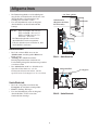 5
5
-
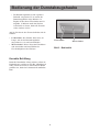 6
6
-
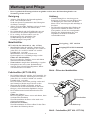 7
7
-
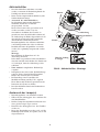 8
8
-
 9
9
-
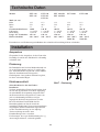 10
10
-
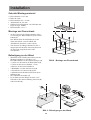 11
11
-
 12
12
-
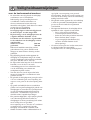 13
13
-
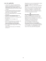 14
14
-
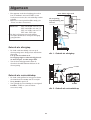 15
15
-
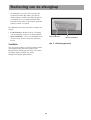 16
16
-
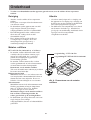 17
17
-
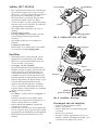 18
18
-
 19
19
-
 20
20
-
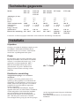 21
21
-
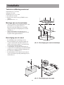 22
22
-
 23
23
-
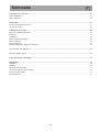 24
24
-
 25
25
-
 26
26
-
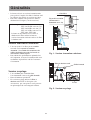 27
27
-
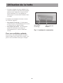 28
28
-
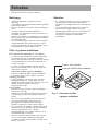 29
29
-
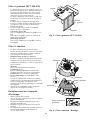 30
30
-
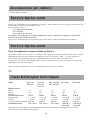 31
31
-
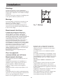 32
32
-
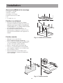 33
33
-
 34
34
-
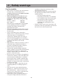 35
35
-
 36
36
-
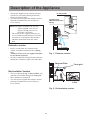 37
37
-
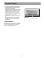 38
38
-
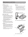 39
39
-
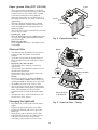 40
40
-
 41
41
-
 42
42
-
 43
43
-
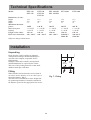 44
44
-
 45
45
-
 46
46
-
 47
47
-
 48
48
-
 49
49
-
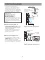 50
50
-
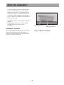 51
51
-
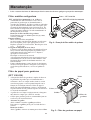 52
52
-
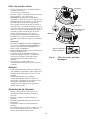 53
53
-
 54
54
-
 55
55
-
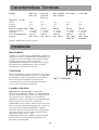 56
56
-
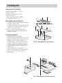 57
57
-
 58
58
-
 59
59
-
 60
60
-
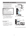 61
61
-
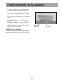 62
62
-
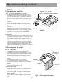 63
63
-
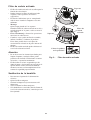 64
64
-
 65
65
-
 66
66
-
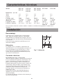 67
67
-
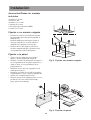 68
68
-
 69
69
-
 70
70
-
 71
71
-
 72
72


Electrolux EFT630B/GB Handleiding
- Categorie
- Afzuigkappen
- Type
- Handleiding
in andere talen
- English: Electrolux EFT630B/GB User manual
- français: Electrolux EFT630B/GB Manuel utilisateur
- español: Electrolux EFT630B/GB Manual de usuario
- Deutsch: Electrolux EFT630B/GB Benutzerhandbuch
- português: Electrolux EFT630B/GB Manual do usuário