

MG16/4, MG12/4
2
Precautions
—For safe operation—
WARNING
●
Connect this unit’s AC power adaptor only to an AC outlet of the
type stated in this Owner’s Manual or as marked on the unit.
Failure to do so is a fire and electrical shock hazard.
●
Do not allow water to enter this unit or allow the unit to become
wet. Fire or electrical shock may result.
●
Do not place a container with liquid or small metal objects on
top of this unit. Liquid or metal objects inside this unit are a fire
and electrical shock hazard.
●
Do not place heavy objects, including this unit, on top of the
power cord. A damaged power cord is a fire and electrical shock
hazard. In particular, be careful not to place heavy objects on a
power cord covered by a carpet.
●
Do not scratch, bend, twist, pull, or heat the power cord. A dam-
aged power cord is a fire and electrical shock hazard.
●
Do not remove the unit’s cover. You could receive an electrical
shock. If you think internal inspection, maintenance, or repair is
necessary, contact your dealer.
●
Do not modify the unit. Doing so is a fire and electrical shock
hazard.
●
If lightning begins to occur, turn off the power switch of the unit
as soon as possible, and unplug the power plug from the electri-
cal outlet.
●
If there is a possibility of lightning, do not touch the power plug
if it is still connected. Doing so may be an electrical shock haz-
ard.
●
Use only the included AC power adaptor (PA-20) for this unit.
Using other types may be a fire and electrical shock hazard.
●
If the power cord is damaged (i.e., cut or a bare wire is exposed),
ask your dealer for a replacement. Using the unit with a damaged
power cord is a fire and electrical shock hazard.
●
Should this unit and AC adaptor be dropped or the cabinet be
damaged, turn the power switch off, remove the power plug from
the AC outlet, and contact your dealer. If you continue using the
unit without heeding this instruction, fire or electrical shock may
result.
●
If you notice any abnormality, such as smoke, odor, or noise, or
if a foreign object or liquid gets inside the unit, turn it off imme-
diately. Remove the power plug from the AC outlet. Consult your
dealer for repair. Using the unit in this condition is a fire and
electrical shock hazard.
CAUTION
●
Keep this unit away from the following locations:
- Locations exposed to oil splashes or steam, such as near cook-
ing stoves, humidifiers, etc.
- Unstable surfaces, such as a wobbly table or slope.
- Locations exposed to excessive heat, such as inside a car with
all the windows closed, or places that receive direct sunlight.
- Locations subject to excessive humidity or dust accumulation.
●
Hold the power plug when disconnecting it from an AC outlet.
Never pull the cord. A damaged power cord is a potential fire and
electrical shock hazard.
●
Do not touch the power plug with wet hands. Doing so is a
potential electrical shock hazard.
●
To relocate the unit, turn the power switch off, remove the power
plug from the AC outlet, and remove all connecting cables. Dam-
aged cables may cause fire or electrical shock.
●
Do not cover or wrap the AC power adaptor with a cloth or blan-
ket. Heat may build up under the cloth or blanket, melting the
case, or causing fire. Use only in a well-ventilated environment.
●
If you know you will not use this unit for a log period of time,
such as when going on vacation, remove the power plug from the
AC outlet. Leaving it connected is a potential fire hazard.
Installation
Operation
In case an abnormality occurs during operation
Installation
Operation
MG12-16_E.book Page 2 Monday, May 26, 2003 1:14 PM

Precautions
MG16/4, MG12/4
3
—For correct operation —
●
XLR-type connectors are wired as follows: pin 1: ground, pin 2:
hot (+), and pin 3: cold (–).
●
Insert TRS phone jacks are wired as follows: sleeve: ground, tip:
send, and ring: return.
●
The performance of components with moving contacts, such
switches, rotary controls, faders, and connectors, deteriorates
over time. The rate of deterioration depends on the operating
environment and is unavoidable. Consult your dealer about
replacing defective components.
●
Using a cell phone (mobile telephone) near this unit may induce
noise. If noise occurs, use the telephone away from the unit.
Copying of the commercially available music data and/or digital audio files is strictly prohibited except for your personal use.
Illustration examples shown herein are for explanatory purposes only, and may not match actual appearance during operation.
The company names and product names in this Owner’s Manual are the trademarks or registered trademarks of their respective companies.
• This applies only to products distributed by Yamaha-Kemble Music (U.K.) Ltd. (2 wires)
Connector pin assignments
Replacing abrasive parts
Influence on cell phone usage
●
Always turn the power off when the mixer is not in use.
●
Even when the power switch is in the “STANDBY” position, electricity is still flowing to the mixer at the minimum level. When you are
not using the mixer for a long time, make sure you unplug the AC power adaptor from the wall AC outlet.
IMPORTANT NOTICE FOR THE UNITED KINGDOM
Connecting the Plug and Cord
IMPORTANT. The wires in this mains lead are coloured in accordance with the following code:
BLUE : NEUTRAL
BROWN : LIVE
As the colours of the wires in the mains lead of this apparatus may not correspond with the coloured makings identifying the terminals in your
plug proceed as follows:
The wire which is coloured BLUE must be connected to the terminal which is marked with the letter N or coloured BLACK.
The wire which is coloured BROWN must be connected to the terminal which is marked with the letter L or coloured RED.
Making sure that neither core is connected to the earth terminal of the three pin plug.
MG12-16_E.book Page 3 Monday, May 26, 2003 1:14 PM

MG16/4, MG12/4
4
Introduction
Thank you for your purchase of the YAMAHA MG16/4 or MG12/4 mixing console. This mixing
console combines ease of operation with support for multiple usage environments, and is
ideal for SR setups, installed systems, and many other such applications.
Please read through this Owner’s Manual carefully before beginning use, so that you will be
able to take full advantage of the mixer’s superlative features and enjoy trouble-free operation
for years to come.
●
The MG16/4 provides 16 input channels that can assign to Ste-
reo or Group output.
●
The MG12/4 provides 12 input channels that can assign to Ste-
reo or Group output.
●
The monitor includes a convenient C-R OUT jack. This jack can
be used to monitor the main Stereo output, the PFL signal, or the
Group 1-2 signals.
●
The mixer includes dual AUX SEND jacks and a single
RETURN jack. The two independent AUX buses may be used as
sends to external effectors and monitor systems.
●
Phantom power supply enables easy connection to condenser
microphones that run on external power.
●
The mixer provides channel-specific INSERT I/O jacks for input
channels 1 to 8 (MG16/4) or 1 to 4 (MG12/4). These jacks make
it possible to insert different effectors into different channels.
●
Input channels 1 to 8, 9/10, and 11/12 (MG16/4), and 1 to 4, 5/6,
and 7/8 (MG12/4) are each equipped with both an XLR mic
input jack and a TRS phone-type line jack. Input channels 13/14
and 15/16 (MG16/4), and 9/10 and 11/12 (MG12/4) are each
equipped with both a TRS line input jack and an RCA line input
jack. This wide assortment of connectors enables connection to
many different devices, from microphones to line-level devices
to stereo-output synthesizers.
Introduction ............................................................... 4
Features ............................................................... 4
Contents .............................................................. 4
Before Turning on the Mixer ................................. 5
Turning the Power On .......................................... 5
Making the Most Of Your Mixer ................................. 6
1
A Place For Everything and Everything
In Its Place ....................................................... 7
2
Where Your Signal Goes Once It’s Inside
the Box .......................................................... 10
3
The First Steps in Achieving Great Sound .... 11
4
External Effects, Monitor Mixes,
and Groups .................................................... 13
5
Making Better Mixes....................................... 16
Front & Rear Panels ................................................ 18
Channel Control Section .................................... 18
Master Control Section ...................................... 20
Rear Input/Output Section ................................. 22
Setting Up ............................................................... 24
Setup Procedure ................................................ 24
Setup Examples ................................................ 24
Rack Mounting ................................................... 26
Appendix ................................................................. 27
Specifications .................................................... 27
Dimensional Diagrams ....................................... 29
Block Diagram and Level Diagram .................... 30
Features
Contents
MG12-16_E.book Page 4 Monday, May 26, 2003 1:14 PM

Introduction
MG16/4, MG12/4
5
(1) Be sure that the mixer’s power switch is in the STANDBY
position.
Use only the PA-20 adaptor included with this mixer.
Use of a different adaptor may result in equipment
damage, overheating, or fire.
(2) Connect the power adaptor to the AC ADAPTOR IN con-
nector (
1
) on the rear of the mixer, and then turn the fas-
tening ring clockwise (
2
) to secure the connection.
(3) Plug the power adaptor into a standard household power outlet.
• Be sure to unplug the adaptor from the outlet when
not using the mixer, or when there are lightning
storms in the area.
• To avoid generating unwanted noise, make sure
there is adequate distance between the power
adaptor and the mixer.
Press the mixer’s power switch to the ON position. When you are
ready to turn the power off, press the power switch to the
STANDBY position.
Note that trace current continues to flow while the
switch is in the STANDBY position. If you do not plan
to use the mixer again for a long while, please be sure
to unplug the adaptor from the wall outlet.
Before Turning on the Mixer
1
2
Turning the Power On
MG12-16_E.book Page 5 Monday, May 26, 2003 1:14 PM

MG16/4, MG12/4
6
Making the Most Of Your Mixer
An Introduction
You’ve got yourself a mixer and now you’re ready to use it.
Just plug everything in, twiddle the controls, and away you go … right?
Well, if you’ve done this before you won’t have any problems, but if this is
the first time you’ve ever used a mixer you might want to read through this
little tutorial and pick up a few basics that will help you get better
performance and make better mixes.
MG12-16_E.book Page 6 Monday, May 26, 2003 1:14 PM

Making the Most Of Your Mixer
MG16/4, MG12/4
7
A Place For Everything and Everything In Its Place
1-1. A Plethora Of Connectors—What Goes Where?
Questions you’re likely to encounter when setting up a system for the first time might include “Why all
these different types of connectors on the back of my mixer?” and “What’s the difference?”.
Let’s start by taking a look at the most common connector types.
The Venerable RCA Pin Jack
This is the “consumer connector,” and the one that has been most commonly used
on home audio gear for many years. Also known as “phono” jacks (short for
”phonogram”), but the term isn’t used much these days—besides, it’s too easily
confusable with “phone” jacks, below. RCA pin jacks are always unbalanced, and
generally carry a line-level signal at –10 dB, nominal. You’re most likely to use this
type of connector when connecting a CD player or other home audio type source
to your mixer, or when connecting the output of your mixer to a cassette recorder
or similar gear.
The Versatile Phone Jack
The name “phone jack” arose simply because this configuration was first
used in telephone switchboards. Phone jacks can be tricky because you
can’t always tell what type of signal they’re designed to handle just by
looking at them. It could be unbalanced mono, unbalanced stereo,
balanced mono, or an insert patch point. The connector’s label will
usually tell you what type of signal it handles, as will the owner’s manual
(you
do
keep your manuals in a safe place, don’t you?). A phone jack that
is set up to handle balanced signals is also often referred to as a “TRS”
phone jack. “TRS” stands for Tip-Ring-Sleeve, which describes the
configuration of the phone plug used.
The Sturdy XLR
This type of connector is generally referred to as “XLR-type,” and almost always
carries a balanced signal. If the corresponding circuitry is designed properly,
however, XLR-type connectors will also handle unbalanced signals with no
problem. Microphone cables usually have this type of connector, as do the inputs
and outputs of most professional audio gear.
1
White
Red
Stereo/TRS phone plug
Mono phone plug
Male
Female
MG12-16_E.book Page 7 Monday, May 26, 2003 1:14 PM

Making the Most Of Your Mixer
MG16/4, MG12/4
8
1-2. Balanced, Unbalanced—What’s the Difference?
In a word: “noise.” The whole point of balanced lines is noise rejection, and it’s something they’re very
good at. Any length of wire will act as an antenna to pick up the random electromagnetic radiation we’re
constantly surrounded by: radio and TV signals as well as spurious electromagnetic noise generated by
power lines, motors, electric appliances, computer monitors, and a variety of other sources. The longer
the wire, the more noise it is likely to pick up. That’s why balanced lines are the best choice for long
cable runs. If your “studio” is basically confined to your desktop and all connections are no more than a
meter or two in length, then unbalanced lines are fine—unless you’re surrounded by extremely high lev-
els of electromagnetic noise. Another place balanced lines are almost always used is in microphone
cables. The reason for this is that the output signal from most microphones is very small, so even a tiny
amount of noise will be relatively large, and will be amplified to an alarming degree in the mixer’s high-
gain head amplifier.
To summarize:
Microphones: Use balanced lines.
Short line-level runs: Unbalanced lines are fine if you’re in a relatively noise-free environment.
Long line-level runs: The ambient electromagnetic noise level will be the ultimate deciding factor, but
balanced is best.
■
How Do Balanced Lines Reject Noise?
** Skip this section if technical details make you queasy. **
Balanced lines work on the principle of “phase cancellation”: if you add two identical signals out of
phase (i.e. one signal is inverted so its peaks coincide with the troughs in the other signal), the result is …
nothing. A flat line. The signals cancel each other out.
A balanced cable has three conductors:
1) A ground conductor which carries no signal, just the “ground” or “0” reference against which the
signal in the other conductors fluctuates.
2) A “hot” or “+” conductor which carries the normal-phase audio signal.
3) A “cold” or “–” conductor which carries the reverse-phase audio signal.
While the desired audio signals in the hot and cold conductors are out of phase, any noise induced in
the line will be exactly the same in both conductors, and thus in phase. The trick is that the phase of
one signal is reversed at the receiving end of the line so that the desired audio signals become in-
phase, and the induced noise suddenly finds itself out of phase. The out-of-phase noise signal is effec-
tively canceled while the audio signal is left intact. Clever, eh?
Normal-phase signal.
Reverse-phase signal.
No signal.
(Phase cancellation)
Normal-phase signal
+ normal-phase noise.
Normal-phase signal
+ reverse-phase noise.
Desired signal
with no noise.
MG12-16_E.book Page 8 Monday, May 26, 2003 1:14 PM

Making the Most Of Your Mixer
MG16/4, MG12/4
9
1-3. Signal Levels—Decibel Do’s and Don’ts
From the moment you start dealing with things audio, you’ll have to deal with the term “decibel” and its
abbreviation, “dB”. Things can get confusing because decibels are a very versatile unit of measure used
to describe acoustic sound pressure levels as well as electronic signal levels. To make matters worse there
are a number of variations: dBu, dBV, dBm. Fortunately, you don’t need to be an expert to make things
work. Here are a few basics you should keep in mind:
●
“Consumer” gear (such as home audio equipment) usually has line inputs and outputs with a nomi-
nal (average) level of –10 dB.
●
Professional audio gear usually has line inputs and outputs with a nominal level of +4 dB.
●
You should always feed –10 dB inputs with a –10 dB signal. If you feed a +4 dB signal into a –10 dB
input you are likely to overload the input.
●
You should always feed +4 dB inputs with a +4 dB signal. A –10 dB signal is too small for a +4 dB
input, and will result in less-than-optimum performance.
●
Many professional and semi-professional devices have level switches on the inputs and/or outputs
that let you select –10 or +4 dB. Be sure to set these switches to match the level of the connected
equipment.
●
Inputs that feature a “Gain” control—such as the mono-channel inputs on your Yamaha mixer—will
accept a very wide range of input levels because the control can be used to match the input’s sensi-
tivity to the signal. More on this later.
MG12-16_E.book Page 9 Monday, May 26, 2003 1:14 PM

Making the Most Of Your Mixer
MG16/4, MG12/4
10
Where Your Signal Goes Once It’s Inside the Box
At first glance the block diagram of even a modest mixer can look like a space-station schematic. In reality,
block diagrams are a great aid in understanding how the signal flows in any mixer. Here’s a greatly simplified
block diagram of a generic mixer to help you become familiar with the way these things work.
2-1. Greatly Simplified Mixer Block Diagram
■
Input Channel
1
Head Amp
The very first stage in any mixer, and
usually the only stage with significant
“gain” or “amplification.” The head
amp has a “gain” control that adjusts
the mixer’s input sensitivity to match the
level of the source. Small signals (e.g.
mics) are amplified, and large signals
are attenuated.
2
Equalizer
Could be simple bass and treble con-
trols or a full-blown 4-band parametric
EQ. When boost is applied the EQ stage
also has gain. You can actually overload
the input channel by applying too much
EQ boost. It’s usually better to cut than
boost.
3
Channel Peak LED & Fader
The channel peak LED is your most
valuable tool for setting the input “gain”
control for optimum performance. Note
that it is located after the head amp and
EQ stage.
■
Master Section
4
Summing Amplifier
This is where the actual “mixing” takes
place. Signals from all of the mixer’s
input channels are “summed” (mixed)
together here.
5
Master Fader & Level Meter
A stereo, mono, or bus master fader and
the mixer’s main output level meter.
There could be several master faders
depending on the design of the mixer—
i.e. the number of buses or outputs it
provides.
2
1234 5
Input Channel Master Section
Signals from the mixer’s
other input channels (if
they are assigned to this
master output or “bus”).
MG12-16_E.book Page 10 Monday, May 26, 2003 1:14 PM

Making the Most Of Your Mixer
MG16/4, MG12/4
11
The First Steps in Achieving Great Sound
Before you even consider EQ and effects, or even the overall mix, it is important to make sure that levels are
properly set for each individual source. This can’t be stressed enough—initial level setup is vitally important for
achieving optimum performance from your mixer! Here’s why … and how.
3-1. The Head Amplifier “Gain” Control Is the Key!
Let’s review our simplified mixer block diagram:
Each and every “stage” in the mixer’s signal path will add a certain amount of noise to the signal: the
head amp, the EQ stage, the summing amplifier, and the other buffer and gain stages that exist in the
actual mixer circuit (this applies to analog mixers in particular). The thing to keep in mind is that the
amount of noise added by each stage is usually not dependent to any significant degree on the level of
the audio signal passing through the circuit. This means that the bigger the desired signal, the smaller the
added noise will be in relation to it. In tech-speak this gives us a better “signal-to-noise ratio”—often
abbreviated as “S/N ratio.” All of this leads to the following basic rule:
In our mixer, that means the head amplifier. If you don’t get the signal up to the desired level at the head
amplifier stage, you will need to apply more gain at later stages, which will only amplify the noise con-
tributed by the preceding stages. Just remember that too much initial gain is bad too, because it will over-
load our channel circuitry and cause clipping.
To achieve the best overall system S/N ratio, amplify the input to the desired average
level as early as possible in the signal path.
3
MG12-16_E.book Page 11 Monday, May 26, 2003 1:14 PM

Making the Most Of Your Mixer
MG16/4, MG12/4
12
3-2. Level Setup Procedure For Optimum Performance
Now that we know what we have to do, how do we do it? If you take another quick look at the mixer
block diagram you’ll notice that there’s a peak indicator located right after the head amplifier and EQ
stages, and therein lays our answer! Although the exact procedure you use will depend on the type of
mixer you use and the application, as well as your personal preferences, here’s a general outline:
That’s basically all there is to it. But do keep your eyes on the main output level meters while setting up
the mix to be sure you don’t stay in the “peak zone” all the time. If the output level meters are peaking
constantly you will need to lower the channel faders until the overall program falls within a good range—
and this will depend on the “dynamic range” of your program material.
1
Start by setting all level controls to their minimum: master fad-
ers, group faders (if provided), channel faders, and input gain
controls. Also make sure that no EQ is applied (no boost or
cut), and that all effects and dynamic processors included in
the system are defeated or bypassed.
2
Apply the source signal to each channel one at a time: have
singers sing, players play, and playback devices play back at
the loudest expected level. Gradually turn up the input gain
control while the signal is being applied to the corresponding
channel until the peak indicator begins to flash, then back off
a little so that the peak indicator flashes only occasionally.
Repeat for each active channel.
3
Raise your master fader(s)—and group faders if available—to
their nominal levels (this will be the “0” markings on the fader
scale).
4
Now, with all sources playing, you can raise the channel fad-
ers and set up an initial rough mix.
MG12-16_E.book Page 12 Monday, May 26, 2003 1:14 PM

Making the Most Of Your Mixer
MG16/4, MG12/4
13
External Effects, Monitor Mixes, and Groups
4-1. AUX Buses For Monitor Sends and
Overall Effects
There are a number of reasons why you might
want to “tap” the signal flowing through your
mixer at some point before the main outputs: the
two most common being 1) to create a monitor
mix that is separate from the main mix, and 2) to
process the signal via an external effect unit and
then bring it back into the mix. Both of these func-
tions, and more, can be handled by the mixer’s
AUX (Auxiliary) buses and level controls. If the
mixer has two AUX buses, then it can handle both
functions at the same time. Larger mixing con-
soles can have 6, 8, or even more auxiliary buses
to handle a variety of monitoring and processing
needs.
Using the AUX buses and level controls is pretty
straightforward. The only thing you need to con-
sider is whether you need a “pre-fader” or “post-
fader” send. AUX sends often feature a switch that
allows you to configure them for pre- or post-
fader operation.
Pre/Post—What’s the difference?
4
pre post
A “pre-fader” signal is taken
from a point before the
channel fader, so the send
level is affected only by the
AUX send level control and
not by the channel fader.
Pre-fader sends are most
commonly used to provide
monitor mixes.
A “post-fader” signal is
taken from a point after the
channel fader, so its level
will be affected by both the
AUX send level control and
the channel fader.
Post-fader sends are most
commonly used in conjunc-
tion with the mixer’s AUX or
effect returns for external
effect processing.
Pre-fader send for a monitor mix. The send signal is fed to the monitor power amplifier and speaker system.
The channel fader does not affect the send level so the monitor mix remains independent of the main mix. No
return signal is used in this case.
Post-fader send for external effects processing. The send signal is fed to the external effect unit—a reverb
unit, for example—and the output from the effect unit is returned to the AUX Return jack and mixed back into the
main program. The send level is affected by the channel fader so the effect level always remains in proportion to
the channel signal.
Channel
Fader
Master
Fader
AUX Send
Level
AUX Send Level AUX Return Level
MG12-16_E.book Page 13 Monday, May 26, 2003 1:14 PM

Making the Most Of Your Mixer
MG16/4, MG12/4
14
4-2. Using Groups
Group buses and faders can greatly simplify the mixing process—particularly in live situations in which
changes have to be made as quickly as possible. If you have a group of channels that need to be adjusted
all together while maintaining their relative levels, grouping is the way to go. Simply assign the group to a
group bus, and make sure that group is also assigned to the main program bus. Then you can adjust the
overall level of the group using a single group fader, rather than having to attempt to control multiple
channels faders simultaneously.
Group buses usually also have their own outputs, so you can send the group signal to a different external
destination from the main mix.
Channel faders Assigned to Group
(Controlled As a Group)
Stereo
Master
Fader
Group
Fader
Channel faders Assigned to Stereo
(Controlled Individually)
A group of channels whose levels need to
maintain the same relationship—a drum mix, for
example—can be assigned to a group bus.
Usually the group bus signal can be output
independently via “Group” outputs, or it can be
assigned to the main program (stereo) bus to be
mixed in with the main stereo program.
Once the mix between the channels assigned to
the group is established via the channel faders,
the overall level of the entire group can be
conveniently adjusted via a single group fader.
MG12-16_E.book Page 14 Monday, May 26, 2003 1:14 PM

Making the Most Of Your Mixer
MG16/4, MG12/4
15
4-3. Channel Inserts for Channel-specific Processing
Another way to get the mixer’s signal outside the box is to use the channel inserts. The channel inserts are
almost always located before the channel fader and, when used, actually “break” the mixer’s internal sig-
nal path. Unlike the AUX sends and returns, the channel insert only applies to the corresponding chan-
nel. Channel inserts are most commonly used for applying a dynamics processor such as a compressor or
limiter to a specific channel—although they can be used with just about any type of in/out processor.
Channel insert jacks must be used with a special insert cable that has a TRS phone jack on one end and
mono phone jacks on the split “Y” end. One of the mono phone jacks carries the “send” signal to be fed
to the input of the external processor, and the other carries the “return” signal from the output of the pro-
cessor.
Channel
Fader
When a plug is inserted into the channel insert jack, the inter-
nal signal path is interrupted and sent outside the mixer for
external processing.
Tip
Ring
Sleeve
To the INSERT I/O jack
To the input jack of the
external processor
To the output jack of
the external processor
TipSleeve
MG12-16_E.book Page 15 Monday, May 26, 2003 1:14 PM

Making the Most Of Your Mixer
MG16/4, MG12/4
16
Making Better Mixes
5-1. Approaching the Mix—Where Do
You Start?
Mixing is easy, right? Just move the faders around
until it sounds right? Well, you can do it that way,
but a more systematic approach that is suited to
the material you’re mixing will produce much
better results, and faster. There are no rules, and
you’ll probably end up developing a system that
works best for you. But the key is to develop a
system rather than working haphazardly. Here are
a few ideas to get you started:
Faders Down
It might sound overly simple, but it is usually a
good idea to start with all channel faders off—all
the way down. It’s also possible to start with all
faders at their nominal settings, but it’s too easy to
lose perspective with this approach. Start with all
faders down, then bring them up one by one to fill
out the mix. But which channel should you start
with?
Example1:
Vocal Ballad Backed by Piano Trio
What are you mixing? Is it a song in which the
vocals are the most important element? If so you
might want to build the mix around the vocals.
This means bringing the vocal channel up to
nominal first (if your level setup procedure has
been done properly this will be a good starting
point), and then adding the other instruments.
What you add next will depend on the type of
material you are working with and your approach
to it. If the vocals are backed by a piano trio and
the song is a ballad, for example, you might want
to bring in the piano next and get the vocal/piano
relationship just right, then bring in the bass and
drums to support the overall sound.
Example2:
Funky R&B Groove
The approach will be totally different if you’re
mixing a funky R&B number that centers on the
groove. In this case most engineers will start with
the drums, and then add the bass. The relation-
ship between the drums and bass is extremely
important to achieve the “drive” or groove the
music rides on. Pay particular attention to how
the bass works with the kick (bass drum). They
should almost sound like a single instrument—
with the kick supplying the punch and the bass
supplying the pitch. Once again, there are no
rules, but these are concepts that have been
proven to work well.
Music First—Then Mix
In any case, the music comes first. Think about
the music and let it guide the mix, rather than try-
ing to do things the other way around. What is the
music saying and what instrument or technique is
being used to drive the message? That’s where the
focus of your mix should be. You’re using a high-
tech tool to do the mixing, but the mix itself is as
much art as the music. Approach it that way and
your mixes will become a vital part of the music.
5-2. Panning For Cleaner Mixes
Not only does the way you pan your individual
channels determine where the instruments appear
in the stereo sound field, but it is also vital to give
each instrument it’s own “space” so that it doesn’t
conflict with other instruments. Unlike live sound
in a real acoustic space, recorded stereo sound is
basically 2-dimensional (although some types of
surround sound are actually very 3-dimensional),
and instruments positioned right on top of each
other will often get in each other’s way—particu-
larly if they are in the same frequency range or
have a similar sound.
5
MG12-16_E.book Page 16 Monday, May 26, 2003 1:14 PM

Making the Most Of Your Mixer
MG16/4, MG12/4
17
Spread them Out!
Position your instruments so they have room to
“breathe,” and connect in the most musical way
with other instruments. Sometimes, however,
you’ll want to deliberately pan sounds close
together, or even right on top of one another, to
emphasize their relationship. There are no hard-
and-fast rules. Normally (but this is not a rule),
bass and lead vocals will be panned to center, as
will the kick drum if the drums are in stereo.
5-3. To EQ Or Not To EQ
In general: less is better. There are many situations
in which you’ll need to cut certain frequency
ranges, but use boost sparingly, and with caution.
Proper use of EQ can eliminate interference
between instruments in a mix and give the overall
sound better definition. Bad EQ—and most com-
monly bad boost—just sounds terrible.
Cut For a Cleaner Mix
For example: cymbals have a lot of energy in the
mid and low frequency ranges that you don’t
really perceive as musical sound, but which can
interfere with the clarity of other instruments in
these ranges. You can basically turn the low EQ
on cymbal channels all the way down without
changing the way they sound in the mix. You’ll
hear the difference, however, in the way the mix
sounds more “spacious,” and instruments in the
lower ranges will have better definition. Surpris-
ingly enough, piano also has an incredibly power-
ful low end that can benefit from a bit of low-
frequency roll-off to let other instruments—nota-
bly drums and bass—do their jobs more effec-
tively. Naturally you won’t want to do this if the
piano is playing solo.
The reverse applies to kick drums and bass gui-
tars: you can often roll off the high end to create
more space in the mix without compromising the
character of the instruments. You’ll have to use
your ears, though, because each instrument is dif-
ferent and sometimes you’ll want the “snap” of a
bass guitar, for example, to come through.
Boost With Caution
If you’re trying to create special or unusual
effects, go ahead and boost away as much as you
like. But if you’re just trying to achieve a good-
sounding mix, boost only in very small incre-
ments. A tiny boost in the midrange can give
vocals more presence, or a touch of high boost
can give certain instruments more “air.” Listen,
and if things don’t sound clear and clean try using
cut to remove frequencies that are cluttering up
the mix rather than trying to boost the mix into
clarity.
One of the biggest problems with too much boost
is that it adds gain to the signal, increasing noise
and potentially overloading the subsequent cir-
cuitry.
5-4. Ambience
Judicious application of reverb and/or delay via
the mixer’s AUX busses can really polish a mix,
but too much can “wash out” the mix and reduce
overall clarity. The way you set up your reverb
sound can make a huge difference in the way it
meshes with the mix.
Reverb/Delay Time
Different reverb/delay units offer different capabil-
ities, but most offer some means of adjusting the
reverb time. A little extra time spent matching the
reverb time to the music being mixed can mean
the difference between great and merely average
sound. The reverb time you choose will depend
to a great degree on the tempo and “density” of
the mix at hand. Slower tempos and lower densi-
ties (i.e. sparser mixes with less sonic activity) can
sound good with relatively long reverb times. But
long reverb times can completely wash out a
faster more active piece of music. Similar princi-
ples applies to delay.
Reverb Tone
How “bright” or “bassy” a reverb sound is also
has a huge impact on the sound of your mix. Dif-
ferent reverb units offer different means of con-
trolling this—balance between the high- and low-
frequency reverb times, simple EQ, and others. A
reverb that is too bright will not only sound unnat-
ural, but it will probably get in the way of delicate
highs you want to come through in your mix. If
you find yourself hearing more high-end reverb
than mix detail, try reducing the brightness of the
reverb sound. This will allow you to get full-bod-
ied ambience without compromising clarity.
Reverb Level
It’s amazing how quickly your ears can lose per-
spective and fool you into believing that a totally
washed-out mix sounds perfectly fine. To avoid
falling into this trap start with reverb level all the
way down, then gradually bring the reverb into
the mix until you can just hear the difference. Any
more than this normally becomes a “special
effect.” You don’t want reverb to dominate the
mix unless you are trying to create the effect of a
band in a cave—which is a perfectly legitimate
creative goal if that’s the sort of thing you’re aim-
ing for.
MG12-16_E.book Page 17 Monday, May 26, 2003 1:14 PM

MG16/4, MG12/4
18
Front & Rear Panels
Note: Within this manual, all panel illustrations show the
MG16/4 panel.
1 GAIN Control
Adjusts the input signal level.
To get the best balance between the S/N ratio and the dynamic
range, adjust the level so that the peak indicator (
2) comes on
only at about maximum input level.
The –60 to –16 scale indicates the MIC input adjustment level.
The –34 to +10 scale indicates the LINE input adjustment
level.
2 PEAK Indicator
Detects the peak level of the post-EQ signal, and lights up red
when the level reaches 3 dB below the clipping level. For
XLR-equipped stereo input channels (9/10 and 11/12 on the
MG16/4; 5/6 and 7/8 on the MG12/4), detects both post-EQ
and post-mic-amp peak levels, and lights red if either of these
levels reaches 3 dB below the clipping level.
3 Switch (High Pass Filter)
This switch toggles the HPF on or off. To turn the HPF on,
press the switch in ( ). The HPF cuts frequencies below
80 Hz. (But note that regardless of the switch setting, the mixer
does not apply this HPF to the line inputs of stereo input chan-
nels.)
4 Equalizer (HIGH, MID, and LOW)
This three-band equalizer adjusts the channel’s high, mid, and
low frequency bands. Setting the knob to the position pro-
duces a flat frequency response. Turning the knob to the right
boosts the corresponding frequency band, while turning to the
left attenuates the band. The following table shows the EQ
type, base frequency, and maximum cut/boost for each of the
three bands.
5 AUX1 and AUX2 Controls
The AUX1 knob controls the signal level that the channel sends
to the AUX1 bus; the AUX2 knob controls the signal level to
the AUX2 bus. The knob should generally be set close to the
position.
If you are using stereo channels, the signals from the L (odd)
and R (even) channels are mixed and sent to the AUX1 and
AUX2 buses.
Allows you to output the signal to the buses regard-
less of the setting of the ST switch 8.
Channel Control Section
1
7
8
9
5 5 5
6 6 6
A
0
7
8
9
0
7
8
9
0
A A
3
4
2
Channels
1 to 8 (MG16/4)
1 to 4 (MG12/4)
(Monaural)
Channels
13/14 and 15/16
(MG16/4)
9/10 and 11/12
(MG12/4)
(Stereo)
Channels
9/10 and 11/12
(MG16/4)
5/6 and 7/8
(MG12/4)
(Stereo)
Band Type Base Frequency Maximum Cut/Boost
HIGH Shelving 10 kHz
±15 dBMID Peaking 2.5 kHz
LOW Shelving 100 Hz
NOTE
MG12-16_E.book Page 18 Monday, May 26, 2003 1:14 PM

Front & Rear Panels
MG16/4, MG12/4
19
6 PRE Switch
Selects whether the pre-fader or the post-fader signal is fed to
the AUX1 bus. If you set the switch on ( ), the mixer sends
the pre-fader signal (the signal prior to passage though channel
fader
A) to the AUX1 bus, so that AUX1 output is not affected
by the fader. If you set the switch off ( ) the mixer sends the
post-fader signal to the AUX1 bus.
Note that this switch applies to AUX1 only. The signal to the
AUX2 bus always passes through the channel fader first.
7 PAN Control (MG16/4: CHs 1 to 8.
MG12/4: 1 to 4.)
PAN/BAL Control (MG16/4: 9/10 and 11/12.
MG12/4: 5/6 and 7/8.)
BAL Control (MG16/4: 13/14 and 15/16.
MG12/4: 9/10 and 11/12.)
The PAN control determines the positioning of the channel’s
signal on the Group 1 and 2 buses or on the Stereo L and R
buses.
The BAL control knob sets the balance between left and right
channels. Signals into to the L input (odd channel) feed to the
Group 1 bus or to the Stereo L bus; signals into the R input
(even channel) feed to the Group 2 bus or the Stereo R bus.
On channels where this knob provides both PAN
and BAL controls (9/10 and 11/12 on the MG16/4;
5/6 and 7/8 on the MG12/4), the knob operates as a
PAN control if you are inputting through the MIC
jack or into the L (MONO) input only, and operates
as a BAL control if you are inputting into both L and
R inputs.
8 ST Switch
This switch assigns the channel’s signal to the Stereo L and R
buses. To send the signal to the Stereo bus, set the switch on by
pressing it in ( ). The switch lights up orange to indicate that
it is on.
9 PFL (Pre-Fader Listen) Switch
This switch lets you monitor the channel’s pre-fader signal. To
set the switch on, press it in ( ) so that it lights up. When the
switch is on, the mixer outputs the channel’s pre-fader signal to
the PHONES and C-R OUT jacks, for monitoring.
0 GROUP Switch
Use this switch to assign the channel’s signal to the Group out-
put. Press the switch in ( ) to output the signal to the Group
1 and 2 buses.
Allows you to output the signal to the buses regard-
less of the setting of the ST switch
8.
A Channel Fader
Adjusts the output level of the signal being input to the chan-
nel. Use these faders to adjust the volume balance among the
various channels.
To reduce noise, set the fader sliders for unused
channels all the way down.
NOTE
NOTE
NOTE
MG12-16_E.book Page 19 Monday, May 26, 2003 1:14 PM

Front & Rear Panels
MG16/4, MG12/4
20
1
ST Master Fader
Adjusts the signal level to the ST OUT jacks.
2
GROUP 1-2 Fader
Adjusts the signal level to the GROUP OUT 1 and GROUP
OUT 2 jacks.
3
TO ST Switch
If this switch is on ( ), the mixer sends the signals processed
by the GROUP 1-2 fader (
2
) onto the Stereo bus. The Group 1
signal goes to Stereo L and the Group 2 signal goes to Stereo
R.
4
Master SEND (AUX1 and AUX2 Controls)
Adjust the signal level, respectively. These are the signals that
are output to the AUX1 and AUX2 SEND jacks.
5
RETURN (AUX1, AUX2, and ST Controls)
•AUX1 and AUX2 Controls
Adjust the level of the mixed L/R signal sent from the
RETURN jacks (L (MONO) and R) to the AUX1 and AUX2
buses.
• ST Control
Adjust the level of the signal sent from the RETURN jacks (L
(MONO) and R) to the Stereo bus.
If you supply a signal to the RETURN L (MONO)
jack only, the mixer outputs the identical signal to
both the L and R Stereo buses.
6
2TR IN Control
Adjusts the level of the signal sent from the 2TR IN jack to the
Stereo bus.
7
PHANTOM +48 V Switch
This switch toggles phantom power on and off. If you set the
switch on, the mixer supplies power to all channels that provide
XLR mic input jacks (CHs 1–8, 9/10, 11/12 on MG16/4, 1–4,
5/6, 7/8 on MG12/4). Set this switch on when using one or
more condenser microphones.
When this switch is on, the mixer supplies DC +48 V
power to pins 2 and 3 of all XLR-type MIC INPUT
jacks.
• Be sure to leave this switch OFF when you are not
using phantom power. Humming or damage may
result if you connect to an unbalanced device or to
an ungrounded transformer while this switch is on.
But note that the switch may be left on without
problem when connecting to balanced dynamic
microphones.
•To avoid damage to speakers, be sure to turn off
amplifiers (or powered speakers) before turning this
switch on or off.
Master Control Section
B
76
A
9
4
3
2
1
5
0
8
NOTE
NOTE
MG12-16.fm Page 20 Thursday, December 11, 2003 9:03 AM

Front & Rear Panels
MG16/4, MG12/4
21
8 Level-Meter Signal Switches (ST-GROUP Toggle
Switch and 2TR IN Switch)
These level-meter switches, together with the channel PFL
switches, select the signal that is sent through the
C-R/PHONES control to the C-R OUT jacks, the PHONES
jack, and the level meter.
The following illustration shows how the switch settings corre-
spond to the signal selection.
1
If the input channel’s PFL switch is on ( ), then only the
channel’s PFL output it sent to the C-R OUT jacks, PHONES
jacks, and level meter.
2
If the 2TR IN switch is ON ( ), the signal supplied to the 2TR
IN jack is sent to the C-R OUT jacks, PHONE jacks, and level
meter. If the 2TR IN switch is OFF, then the Group or Stereo
signal is sent instead (as determined by the ST-GROUP toggle
switch).
9 C-R/PHONES Control
Controls the level of the signal output to the PHONES jack and
the C-R L and R jacks.
0 Level Meter
This LED display shows the level of the signal selected by the
selection switches described in
8 above (the level to the C-R
OUT and PHONES jacks). The “0” point corresponds to the
standard output level. The indicator lights up red when the out-
put hits the clipping level.
A POWER Indicator
This indicator lights up when the mixer’s power is ON.
B PHONES jack
Connector for headphones. This is a stereo phone-type output
jack.
The signal monitored by these jacks is selected by
the settings of the ST-GROUP toggle switch, the
2TR IN switch, and the PFL switches on the input
channels.
2TR IN
2TR IN
PFL
PFL
GROUP
ST-GROUP
ST
ON
OFF
ON
ON
OFF
OFF
C-R OUT
&
PHONES
Switch
Signal
12
NOTE
MG12-16_E.book Page 21 Monday, May 26, 2003 1:14 PM

Front & Rear Panels
MG16/4, MG12/4
22
1 Channel Input jacks
• MIC jacks (MG16/4: CHs 1 to 8, 9/10, 11/12. MG12/4:
CHs 1 to 4, 5/6, 7/8)
These are balanced XLR-type microphone input jacks
(1:Ground; 2:Hot; 3:Cold).
• LINE jacks (MG16/4: CHs 1 to 8. MG12/4: CHs 1 to 4)
These are balanced TRS phone-type line input jacks (T: Hot;
R: Cold; S: Ground).
You can connect either balanced or unbalanced phone plugs
to these jacks.
Where an input channel provides both a MIC INPUT
jack and a LINE INPUT jack, you may use either
one of these jacks but you may not use both at the
same time. Please connect to only one of these
jacks on each channel.
2 INSERT I/O Jacks
Each of these jacks is positioned between the equalizer and
fader of the corresponding input channel (MG16/4: CHs 1 to 8;
MG12/4: CHs 1 to 4). These jacks can be used to indepen-
dently connect these channels to devices such as graphic equal-
izers, compressors, and noise filters. These are TRS (tip, ring,
sleeve) phone jacks that support bidirectional operation.
Connection to an INSERT I/O jack requires a spe-
cial separately-sold insertion cable such as illus-
trated below.
The signal output from the INSERT I/O jacks is
reverse-phased. This will not be a problem if con-
necting the jack to an effector. If using the jack to out-
put to an external device, however, please be aware
of possible phase conflicts with other signals.
3 Channel Input jacks
These are unbalanced stereo line input jacks. Two jack types
are provided: phone type (MG16/4: CHs 9/10 to 15/16;
MG12/4: CHs 5/6 to 11/12) and RCA pin type (MG16/4: CHs
13/14, 15/16; MG12/4: CHs 9/10, 11/12).
Where a channel provides both a phone jack and an
RCA pin jack, you may use either one of these jacks
but you may not use both at the same time. Please
connect to only of these jacks on each channel.
4 GROUP OUT (1, 2) Jacks
These are impedance-balanced phone-type output jacks that
output the Group 1-2 signals. Use these jacks to connect to the
input jacks of an MTR, external mixer, or other such device.
5 ST OUT (L, R) Jacks
These jacks deliver stereo output of the mixed signal. You use
these jacks, for example, to connect to the power amplifier
driving your main speakers. You also use these jacks when you
wish to record the signal utilizing the level control applied by
the ST fader in the Master Control section.
• XLR jacks
XLR-type balanced output jacks.
• Line jacks
TRS phone-type balanced output jacks.
6 C-R OUT Jacks
Use these stereo phone-type output jacks to connect to your
monitor system.
The signal monitored by these jacks is selected by
the settings of the ST-GROUP toggle switch, the
2TR IN switch, and the PFL switches on the input
channels.
7 SEND Jacks
• AUX1, AUX2
These are impedance balanced phone-type output jacks.
These jacks output the signals from the AUX1 and AUX2,
respectively. Use these jacks to output these signals to an
effector or a cue box or other such monitor system.
Rear Input/Output Section
4 15
6 37 8
AB
9 0 2
NOTE
NOTE
To the INSERT I/O jack
To the input jack of the external processor
To the output jack of the external processor
Ring
Sleeve
Tip
Sleeve
Tip
NOTE
NOTE
MG12-16_E.book Page 22 Monday, May 26, 2003 1:14 PM

Front & Rear Panels
MG16/4, MG12/4
23
8 RETURN L (MONO), R Jacks
These are unbalanced phone-type line input jacks. The signal
received by these jacks is sent to the Stereo bus and the AUX1
and AUX2 buses. These jacks are typically used to receive a
return signal from an external effector (reverb, delay, etc.).
These jacks can also be used as an auxiliary stereo
input. If you connect to the L(MONO) jack only, the
mixer will recognize the signal as monaural and will
propagate the identical signal on both L and R
jacks.
9 REC OUT (L, R) Jacks
By connecting these jacks to an external DAT recorder or cas-
sette recorder, you can record the same signal that is being out-
put from the ST OUT jacks.
The mixer’s ST Master Fader has no affect on the
signal output from these jacks. Be sure to make
appropriate level adjustments at the recording
device side.
0 2TR IN Jacks
These RCA pin jacks input a stereo sound source. Use these
jacks when you want to connect a CD or DAT directly to the
mixer for monitoring.
You can adjust the signal level using the 2TR IN
control in the Master Control section.
A POWER Switch
Use this switch to set mixer power to ON or STANDBY.
Note that trace current continues to flow while the
switch is in the STANDBY position. If you do not plan
to use the mixer again for a long while, be sure to
unplug the adaptor from the wall outlet.
B AC ADAPTOR IN Connector
Connects to the included PA-20 power adaptor (see page 5).
Use only the PA-20 adaptor included with this mixer.
Use of a different adaptor may result in fire or electric
shock.
Connector Polarities
* These jacks will also accept connection to monaural phone plugs. If you use monaural plugs, the connection will be unbalanced.
NOTE
NOTE
NOTE
MIC INPUT, ST OUT
Pin 1: Ground
Pin 2: Hot (+)
Pin 3: Cold (–)
LINE INPUT (monaural channels),
GROUP OUT, ST OUT, C-R OUT
AUX1, AUX2 *
Tip: Hot (+)
Ring: Cold (–)
Sleeve: Ground
INSERT I/O
Tip: Output
Ring: Input
Sleeve: Ground
PHONES
Tip: L
Ring: R
Sleeve: Ground
RETURN
LINE INPUT (stereo channels)
Tip: Hot
Sleeve: Ground
INPUT OUTPUT
Ring
Sleeve Tip
Sleeve Tip
MG12-16_E.book Page 23 Monday, May 26, 2003 1:14 PM

MG16/4, MG12/4
24
Setting Up
(1) Before connecting to microphones and instruments, be sure
that all devices are turned off. Also be sure that all of the
mixer’s channel faders and master control faders are set all the
way down.
(2) For each connection, connect one end of the cable to the rele-
vant microphone or instrument and connect the other end to the
appropriate LINE or MIC jack on the mixer.
(LINE jacks on MG16/4: CHs 1 to 8; on MG12/4: 1 to 4. MIC
jacks on MG16/4: CHs 1 to 8, 9/10, 11/12; on MG12/4: 1 to 4,
5/6.)
Where an input channel provides both a MIC INPUT
jack and a LINE INPUT jack, you may use either
one of these jacks but you may not use both at the
same time. Please connect to only one of these
jacks on each channel.
(3) To avoid causing damage to speakers, power up the devices in
the following order: Peripheral devices → mixer → power
amps (or powered speakers).
When shutting the system down, turn off the power
in the opposite order: Power amps (powered speak-
ers) → mixer → peripheral devices.
■ Home Recording
Setup Procedure
NOTE
NOTE
Setup Examples
Rhythm Machine
Effector
Effector
Effector
Synthesizer
MTR
Guitar
Powered Monitor
Speakers
Master Recorder
(MD, CD-R, DAT, etc.)
Sound Source (CD, MD,
DAT, cassette, video, etc.)
MTR
Microphone
Headphones
Personal Computer
MG12-16_E.book Page 24 Monday, May 26, 2003 1:14 PM

Setting Up
MG16/4, MG12/4
25
■ Sound Reinforcement for Live Performance
( )
ST
AUX 1
(
PRE
)
ST
DI
DI
Microphones
Monitor Speakers
(Internal)
Power Amp
Effector
Synthesizer
Effector
Bass
Guitar
CD, Cassette, or DAT
Recorder
Microphones
Headphones
Guitar
Main Speakers
(External)
Example of Speaker Arrangement
Audience (External)
Stage (Internal)
Drums
CD Player
Power Amp
MG12-16_E.book Page 25 Monday, May 26, 2003 1:14 PM

Setting Up
MG16/4, MG12/4
26
■ Mounting the MG16/4
(1) Two metal rack-mount supports are screwed onto the unit. Use
a screwdriver to remove these supports.
(2) Turn the supports over, and fasten them into place again using
the same screws.
(3) Mount the unit into the rack, and fasten it into place.
If you wish you may move the left support to the
right side and the right support to the left side, as
shown in the drawing.
Do not install the mixer near power amps or other
heat-generating devices.
■ Mounting the MG12/4
(1) Two metal rack-mount supports are screwed onto the unit. Use
a screwdriver to remove these supports.
(2) Turn the supports over, and fasten them into place again using
the same screws.
(3) Mount the unit into the rack, and fasten it into place.
Do not install the mixer near power amps or other
heat-generating devices.
Rack Mounting
NOTE
MG12-16_E.book Page 26 Monday, May 26, 2003 1:14 PM

MG16/4, MG12/4
27
Appendix
■
General Specifications
Where 0 dBu = 0.775 V and 0 dBV = 1 V
1
Measured with 12.7 kHz, –6 dB/oct. low pass filter (equivalent to 20 kHz, –
∞
filter).
(CH MIC INPUT to ST, GROUP OUT/AUX, EFFECT SEND)
2
Turning PAN/BAL to left or right.
3
Shelving turnover/rolloff frequency: 3 dB before maximum cut or boost.
Specifications
Frequency Characteristics (ST OUT) 20 Hz–20 kHz +1 dB, –3 dB @+4 dBu, 600
Ω
(with gain control at minimum level)
Total Harmonic Distortion (ST OUT)
0.1 % (THD+N) @+14 dBu, 20 Hz–20 kHz, 600
Ω
(with gain control at maximum level)
(MG16/4 CH1-8, MG12/4 CH1-4)
Hum and Noise
1
–128 dBu
Equivalent input noise 150
Ω
(MG16/4: CHs 1 to 8,
MG12/4: CHs 1 to 4)
–100 dBu Residual output noise (ST OUT)
–88 dBu (92 dB S/N)
ST, GROUP Master fader at nominal level and all Ch
assign SW’s off.
–81 dBu (85 dB S/N)
AUX master control at nominal level; all channel mix
controls at minimum level.
–64 dBu (68 dB S/N)
ST, GROUP Master fader and one Ch fader at nominal
level. (MG16/4 CH1–8, MG12/4 CH1–4)
Maximum Voltage Gain
2
60 dB CH MIC INPUT
→
CH INSERT OUT
84 dB CH MIC INPUT
→
GROUP OUT/ST OUT (CH to ST)
94 dB CH MIC INPUT
→
ST OUT (GROUP to ST)
62.2 dB CH MIC INPUT
→
REC OUT (CH to ST)
76 dB CH MIC INPUT
→
AUX SEND (PRE)
86 dB CH MIC INPUT
→
AUX SEND (POST)
58 dB CH LINE INPUT
→
GROUP OUT/ST OUT (CH to ST)
84 dB ST CH MIC INPUT
→
GROUP OUT/ST OUT (CH to ST)
58 dB ST CH LINE INPUT
→
GROUP OUT/ST OUT (ST CH to ST)
47 dB ST CH LINE INPUT
→
AUX SEND (PRE)
57 dB ST CH LINE INPUT
→
AUX SEND (POST)
34 dB ST CH INPUT
→
GROUP OUT/ST OUT (ST CH to ST)
16 dB RETURN
→
ST OUT
9 dB RETURN
→
AUX SEND
27.8 dB 2TR INPUT
→
ST OUT
Monaural/Stereo Input Gain Control 44 dB variable
Monaural/Stereo High Pass Filter 80 Hz 12 dB/octave
Crosstalk (1 kHz)
–70 dB between input channels
–70 dB between input/output channels (CH INPUT)
Monaural/Stereo Input Channel Equalization:
Max. Variation
3
±15 dB
HIGH 10 kHz shelving
MID 2.5 kHz peaking
LOW 100 Hz shelving
Monaural/Stereo Input Peak Indicator
On each channel: red indicator lights if post-EQ signal (on ST channels, if either post-EQ sig-
nal or post-mic-amp signal) comes within 3 dB of the clipping level.
Level Meters
Two 12-point LED meters
Peak point: red indicator
+5, +3, +1, and 0 points: yellow indicators
–1, –3, –5, –7, –10, –15, –20: green indicators
Phantom +48 VDC Power (Balanced input) Supplied when Phantom +48 V switch is ON.
Included Accessory Power adaptor (PA-20)
Power Supply
USA and Canada: 120 V AC, 60 Hz
Europe: 230 V AC, 50 Hz
Australia: 240 V AC, 50 Hz
Korea: 220 V AC, 60 Hz
Power Consumption MG16/4: 36 W MG12/4: 29 W
Max. Dimensions (W
×
H
×
D) MG16/4: 423
×
108
×
416.6 mm MG12/4: 322
×
108
×
416.6 mm
Weight MG16/4: 5.2 kg MG12/4: 5.0 kg
MG12-16.fm Page 27 Thursday, July 3, 2003 4:44 PM

Appendix
MG16/4, MG12/4
28
■ Input Specifications
Where 0 dBu = 0.775 V and 0 dBV= 1 V
* Input sensitivity: the lowest level that will produce the nominal output level when the unit is set to maximum gain.
■ Output Specifications
Where 0 dBu = 0.775 V and 0 dBV= 1 V
Specifications and descriptions in this owner’s manual are for information purposes only. Yamaha Corp. reserves the right to change or modify
products or specifications at any time without prior notice. Since specifications, equipment or options may not be the same in every locale,
please check with your Yamaha dealer.
For European Model
Purchaser/User Information specified in EN55103-1 and EN55103-2.
Inrush Current: 6A
Conformed Environment: E1, E2, E3 and E4
Input Connector Gain
Input
Impedance
Appropriate
Impedance
Sensitivity* Rated Level
Max. Before
Clipping
Connector
Specifications
MIC INPUT
(MG16/4: CHs 1 to 8)
(MG12/4: CHs 1 to 4)
–60
3 kΩ 50–600 Ω mic
–80 dBu
(0.078 mV)
–60 dBu
(0.775 mV)
–40 dBu
(7.75 mV)
XLR-3-31 type (balanced)
–16
–36 dBu
(12.3 mV)
–16 dBu
(123 mV)
+4 dBu
(1.23 V)
LINE INPUT
(MG16/4: CHs 1 to 8)
(MG12/4: CHs 1 to 4)
–34
10 kΩ 600 Ω line
–54 dBu
(1.55 mV)
–34 dBu
(15.5 mV)
–14 dBu
(155 mV)
Phone jack (TRS)
(balanced [T: hot; R: cold;
S: ground])
+10
–10 dBu
(245 mV)
+10 dBu
(2.45 V)
+30 dBu
(24.5 V)
ST CH MIC INPUT
(MG16/4: CH9(L)/CH10(R),
CH11(L)/CH12(R))
(MG12/4: CH5(L)/CH6(R),
CH7(L)/CH8(R))
–60
3 kΩ 50–600 Ω mic
–80 dBu
(0.078 mV)
–60 dBu
(0.775 mV)
–40 dBu
(7.75 mV)
XLR-3-31 type (balanced)
–16
–36 dBu
(12.3 mV)
–16 dBu
(123 mV)
–10 dBu
(245 mV)
ST CH LINE INPUT
(MG16/4: CH9(L)/CH10(R),
CH11(L)/CH12(R))
(MG12/4: CH5(L)/CH6(R),
CH7(L)/CH8(R))
–34
10 kΩ 600 Ω line
–54 dBu
(1.55 mV)
–34 dBu
(15.5 mV)
–14 dBu
(155 mV)
Phone jack (unbalanced)
+10
–10 dBu
(245 mV)
+10 dBu
(2.45 V)
+30 dBu
(24.5 V)
ST CH INPUT
(MG16/4: CH13(L)/CH14(R),
CH15(L)/CH16(R))
(MG12/4: CH9(L)/CH10(R),
CH11(L)/CH12(R))
10 kΩ 600 Ω line
–30 dBu
(24.5 mV)
–10 dBu
(245 mV)
+10 dBu
(2.45 V)
Phone jack (unbalanced);
RCA pin jack
CH INSERT IN
(MG16/4: CHs 1 to 8)
(MG12/4: CHs 1 to 4)
10 kΩ 600 Ω line
–20 dBu
(77.5 mV)
0 dBu
(0.775 V)
+20 dBu
(7.75 V)
Phone jack (TRS)
(unbalanced [T: out; R: in;
S: ground])
RETURN (L, R) 10 kΩ 600 Ω line
–12 dBu
(195 mV)
+4 dBu
(1.23 V)
+24 dBu
(12.3 V)
Phone jack (TRS) (unbalanced
[T: hot; S: ground])
2TR IN (L, R) 10 kΩ 600 Ω line
–26 dBV
(50.1 mV)
–10 dBV
(316 mV)
+10 dBV
(3.16 V)
RCA pin jack
Output Connectors
Output
Impedance
Appropriate
Impedance
Rated Level
Max. Before
Clipping
Connector Specifications
ST OUT (L, R) 150 Ω 600 Ω line +4 dBu (1.23 V) +24 dBu (12.3 V)
XLR-3-32 type (balanced)
Phone jack (TRS)
(balanced [T: hot; R: cold; S: ground])
GROUP OUT (1-2)
AUX SEND (1-2)
150 Ω 10 kΩ line +4 dBu (1.23 V) +20 dBu (7.75 V)
Phone jack (TRS)
(impedance balanced [T: hot; R: cold; S:
ground])
CH INSERT OUT
(MG16/4: CHs 1 to 8)
(MG12/4: CHs 1 to 4)
150 Ω 10 kΩ line 0 dBu (0.775 V) +20 dBu (7.75 V)
Phone jack (TRS)
(unbalanced [T: out; R: in; S: ground])
REC OUT (L, R) 600 Ω 10 kΩ line –10 dBV (316 mV) +10 dBV (3.16 V) RCA pin jack
C-R OUT (L, R) 150 Ω 10 kΩ line +4 dBu (1.23 V) +20 dBu (7.75 V)
Phone jack (TRS)
(impedance balanced [T: hot; R: cold; S:
ground])
PHONES 100 Ω 40 Ω phone 3 mW 75 mW Stereo phone jack
MG12-16_E.book Page 28 Monday, May 26, 2003 1:14 PM

Appendix
MG16/4, MG12/4
29
■ MG16/4
■ MG12/4
Dimensional Diagrams
393
31.5
309.6
D 416.6
H 108
101.3 3
W 423
428
27.5
480
When mounted on rack
317.4
D 416.6
325.6
102.6
2
H 108
W 322
480
322
When mounted on rack
MG12-16_E.book Page 29 Monday, May 26, 2003 1:14 PM

Appendix
MG16/4, MG12/4
30
Block Diagram and Level Diagram
MG12-16_E.book Page 30 Monday, May 26, 2003 1:14 PM

For details of products, please contact your nearest Yamaha
representative or the authorized distributor listed below.
Pour plus de détails sur les produits, veuillez-vous adresser à Yamaha ou
au distributeur le plus proche de vous figurant dans la liste suivante.
Die Einzelheiten zu Produkten sind bei Ihrer unten aufgeführten
Niederlassung und bei Yamaha Vertragshändlern in den jeweiligen
Bestimmungsländern erhältlich.
Para detalles sobre productos, contacte su tienda Yamaha más cercana
o el distribuidor autorizado que se lista debajo.
CANADA
Yamaha Canada Music Ltd.
135 Milner Avenue, Scarborough, Ontario,
M1S 3R1, Canada
Tel: 416-298-1311
U.S.A.
Yamaha Corporation of America
6600 Orangethorpe Ave., Buena Park, Calif. 90620,
U.S.A.
Tel: 714-522-9011
MEXICO
Yamaha de Mexico S.A. De C.V.,
Departamento de ventas
Javier Rojo Gomez No.1149, Col. Gpe Del
Moral, Deleg. Iztapalapa, 09300 Mexico, D.F.
Tel: 55-5804-0600
BRAZIL
Yamaha Musical do Brasil LTDA.
Av. Rebouças 2636, São Paulo, Brasil
Tel: 011-3085-1377
ARGENTINA
Yamaha Music Latin America, S.A.
Sucursal de Argentina
Viamonte 1145 Piso2-B 1053,
Buenos Aires, Argentina
Tel: 1-4371-7021
PANAMA AND OTHER LATIN
AMERICAN COUNTRIES/
CARIBBEAN COUNTRIES
Yamaha Music Latin America, S.A.
Torre Banco General, Piso 7, Urbanización Marbella,
Calle 47 y Aquilino de la Guardia,
Ciudad de Panamá, Panamá
Tel: +507-269-5311
THE UNITED KINGDOM
Yamaha-Kemble Music (U.K.) Ltd.
Sherbourne Drive, Tilbrook, Milton Keynes,
MK7 8BL, England
Tel: 01908-366700
GERMANY
Yamaha Music Central Europe GmbH
Siemensstraße 22-34, 25462 Rellingen, Germany
Tel: 04101-3030
SWITZERLAND/LIECHTENSTEIN
Yamaha Music Central Europe GmbH,
Branch Switzerland
Seefeldstrasse 94, 8008 Zürich, Switzerland
Tel: 01-383 3990
AUSTRIA
Yamaha Music Central Europe GmbH,
Branch Austria
Schleiergasse 20, A-1100 Wien, Austria
Tel: 01-60203900
THE NETHERLANDS
Yamaha Music Central Europe,
Branch Nederland
Clarissenhof 5-b, 4133 AB Vianen, The Netherlands
Tel: 0347-358 040
BELGIUM/LUXEMBOURG
Yamaha Music Central Europe GmbH,
Branch Belgium
Rue de Geneve (Genevastraat) 10, 1140 - Brussels,
Belgium
Tel: 02-726 6032
FRANCE
Yamaha Musique France
BP 70-77312 Marne-la-Vallée Cedex 2, France
Tel: 01-64-61-4000
ITALY
Yamaha Musica Italia S.P.A.
Combo Division
Viale Italia 88, 20020 Lainate (Milano), Italy
Tel: 02-935-771
SPAIN/PORTUGAL
Yamaha-Hazen Música, S.A.
Ctra. de la Coruna km. 17, 200, 28230
Las Rozas (Madrid), Spain
Tel: 91-639-8888
SWEDEN
Yamaha Scandinavia AB
J. A. Wettergrens Gata 1
Box 30053
S-400 43 Göteborg, Sweden
Tel: 031 89 34 00
DENMARK
YS Copenhagen Liaison Office
Generatorvej 8B
DK-2730 Herlev, Denmark
Tel: 44 92 49 00
NORWAY
Norsk filial av Yamaha Scandinavia AB
Grini Næringspark 1
N-1345 Østerås, Norway
Tel: 67 16 77 70
OTHER EUROPEAN COUNTRIES
Yamaha Music Central Europe GmbH
Siemensstraße 22-34, 25462 Rellingen, Germany
Tel: +49-4101-3030
Yamaha Corporation,
Asia-Pacific Music Marketing Group
Nakazawa-cho 10-1, Hamamatsu, Japan 430-8650
Tel: +81-53-460-2313
TURKEY/CYPRUS
Yamaha Music Central Europe GmbH
Siemensstraße 22-34, 25462 Rellingen, Germany
Tel: 04101-3030
OTHER COUNTRIES
Yamaha Music Gulf FZE
LB21-128 Jebel Ali Freezone
P.O.Box 17328, Dubai, U.A.E.
Tel: +971-4-881-5868
THE PEOPLE’S REPUBLIC OF CHINA
Yamaha Music & Electronics (China) Co.,Ltd.
25/F., United Plaza, 1468 Nanjing Road (West),
Jingan, Shanghai, China
Tel: 021-6247-2211
INDONESIA
PT. Yamaha Music Indonesia (Distributor)
PT. Nusantik
Gedung Yamaha Music Center, Jalan Jend. Gatot
Subroto Kav. 4, Jakarta 12930, Indonesia
Tel: 21-520-2577
KOREA
Yamaha Music Korea Ltd.
Tong-Yang Securities Bldg. 16F 23-8 Yoido-dong,
Youngdungpo-ku, Seoul, Korea
Tel: 02-3770-0660
MALAYSIA
Yamaha Music Malaysia, Sdn., Bhd.
Lot 8, Jalan Perbandaran, 47301 Kelana Jaya,
Petaling Jaya, Selangor, Malaysia
Tel: 3-78030900
SINGAPORE
Yamaha Music Asia Pte., Ltd.
No.11 Ubi Road 1, No.06-02,
Meiban Industrial Building, Singapore
Tel: 747-4374
TAIWAN
Yamaha KHS Music Co., Ltd.
3F, #6, Sec.2, Nan Jing E. Rd. Taipei.
Taiwan 104, R.O.C.
Tel: 02-2511-8688
THAILAND
Siam Music Yamaha Co., Ltd.
891/1 Siam Motors Building, 15-16 floor
Rama 1 road, Wangmai, Pathumwan
Bangkok 10330, Thailand
Tel: 02-215-2626
OTHER ASIAN COUNTRIES
Yamaha Corporation,
Asia-Pacific Music Marketing Group
Nakazawa-cho 10-1, Hamamatsu, Japan 430-8650
Tel: +81-53-460-2317
AUSTRALIA
Yamaha Music Australia Pty. Ltd.
Level 1, 99 Queensbridge Street, Southbank,
Victoria 3006, Australia
Tel: 3-9693-5111
COUNTRIES AND TRUST
TERRITORIES IN PACIFIC OCEAN
Yamaha Corporation,
Asia-Pacific Music Marketing Group
Nakazawa-cho 10-1, Hamamatsu, Japan 430-8650
Tel: +81-53-460-2313
NORTH AMERICA
CENTRAL & SOUTH AMERICA
EUROPE
AFRICA
MIDDLE EAST
ASIA
OCEANIA
HEAD OFFICE
Yamaha Corporation, Pro Audio & Digital Musical Instrument Division
Nakazawa-cho 10-1, Hamamatsu, Japan 430-8650
Tel: +81-53-460-2441
PA09
MG12-16.fm Page 31 Thursday, December 11, 2003 9:03 AM

U.R.G., Pro Audio & Digital Musical Instrument Division, Yamaha Corporation
© 2002 Yamaha Corporation
V981800 312CRCR68.2-06D0
Printed in China
Yamaha Manual Library
http://www2.yamaha.co.jp/manual/english/
Hyo4.fm Page 32 Thursday, December 11, 2003 9:07 AM
Documenttranscriptie
MG12-16_E.book Page 1 Monday, May 26, 2003 1:14 PM MIXING CONSOLE Owner’s Manual MG16/4 MG12/4 Making the Most Of Your Mixer Pages 6 to 17 E MG12-16_E.book Page 2 Monday, May 26, 2003 1:14 PM Precautions —For safe operation— WARNING ● Installation ● ● ● ● Connect this unit’s AC power adaptor only to an AC outlet of the type stated in this Owner’s Manual or as marked on the unit. Failure to do so is a fire and electrical shock hazard. Do not allow water to enter this unit or allow the unit to become wet. Fire or electrical shock may result. Do not place a container with liquid or small metal objects on top of this unit. Liquid or metal objects inside this unit are a fire and electrical shock hazard. Do not place heavy objects, including this unit, on top of the power cord. A damaged power cord is a fire and electrical shock hazard. In particular, be careful not to place heavy objects on a power cord covered by a carpet. ● ● In case an abnormality occurs during operation ● ● Operation ● ● ● Do not scratch, bend, twist, pull, or heat the power cord. A damaged power cord is a fire and electrical shock hazard. Do not remove the unit’s cover. You could receive an electrical shock. If you think internal inspection, maintenance, or repair is necessary, contact your dealer. Do not modify the unit. Doing so is a fire and electrical shock hazard. If lightning begins to occur, turn off the power switch of the unit as soon as possible, and unplug the power plug from the electrical outlet. If there is a possibility of lightning, do not touch the power plug if it is still connected. Doing so may be an electrical shock hazard. Use only the included AC power adaptor (PA-20) for this unit. Using other types may be a fire and electrical shock hazard. ● If the power cord is damaged (i.e., cut or a bare wire is exposed), ask your dealer for a replacement. Using the unit with a damaged power cord is a fire and electrical shock hazard. Should this unit and AC adaptor be dropped or the cabinet be damaged, turn the power switch off, remove the power plug from the AC outlet, and contact your dealer. If you continue using the unit without heeding this instruction, fire or electrical shock may result. If you notice any abnormality, such as smoke, odor, or noise, or if a foreign object or liquid gets inside the unit, turn it off immediately. Remove the power plug from the AC outlet. Consult your dealer for repair. Using the unit in this condition is a fire and electrical shock hazard. CAUTION Installation ● ● ● 2 Keep this unit away from the following locations: - Locations exposed to oil splashes or steam, such as near cooking stoves, humidifiers, etc. - Unstable surfaces, such as a wobbly table or slope. - Locations exposed to excessive heat, such as inside a car with all the windows closed, or places that receive direct sunlight. - Locations subject to excessive humidity or dust accumulation. Hold the power plug when disconnecting it from an AC outlet. Never pull the cord. A damaged power cord is a potential fire and electrical shock hazard. Do not touch the power plug with wet hands. Doing so is a potential electrical shock hazard. MG16/4, MG12/4 ● To relocate the unit, turn the power switch off, remove the power plug from the AC outlet, and remove all connecting cables. Damaged cables may cause fire or electrical shock. Operation ● ● Do not cover or wrap the AC power adaptor with a cloth or blanket. Heat may build up under the cloth or blanket, melting the case, or causing fire. Use only in a well-ventilated environment. If you know you will not use this unit for a log period of time, such as when going on vacation, remove the power plug from the AC outlet. Leaving it connected is a potential fire hazard. MG12-16_E.book Page 3 Monday, May 26, 2003 1:14 PM Precautions —For correct operation — Connector pin assignments ● ● XLR-type connectors are wired as follows: pin 1: ground, pin 2: hot (+), and pin 3: cold (–). Insert TRS phone jacks are wired as follows: sleeve: ground, tip: send, and ring: return. Influence on cell phone usage ● Using a cell phone (mobile telephone) near this unit may induce noise. If noise occurs, use the telephone away from the unit. Replacing abrasive parts ● The performance of components with moving contacts, such switches, rotary controls, faders, and connectors, deteriorates over time. The rate of deterioration depends on the operating environment and is unavoidable. Consult your dealer about replacing defective components. ● ● Always turn the power off when the mixer is not in use. Even when the power switch is in the “STANDBY” position, electricity is still flowing to the mixer at the minimum level. When you are not using the mixer for a long time, make sure you unplug the AC power adaptor from the wall AC outlet. Copying of the commercially available music data and/or digital audio files is strictly prohibited except for your personal use. Illustration examples shown herein are for explanatory purposes only, and may not match actual appearance during operation. The company names and product names in this Owner’s Manual are the trademarks or registered trademarks of their respective companies. IMPORTANT NOTICE FOR THE UNITED KINGDOM Connecting the Plug and Cord IMPORTANT. The wires in this mains lead are coloured in accordance with the following code: BLUE : NEUTRAL BROWN : LIVE As the colours of the wires in the mains lead of this apparatus may not correspond with the coloured makings identifying the terminals in your plug proceed as follows: The wire which is coloured BLUE must be connected to the terminal which is marked with the letter N or coloured BLACK. The wire which is coloured BROWN must be connected to the terminal which is marked with the letter L or coloured RED. Making sure that neither core is connected to the earth terminal of the three pin plug. • This applies only to products distributed by Yamaha-Kemble Music (U.K.) Ltd. (2 wires) MG16/4, MG12/4 3 MG12-16_E.book Page 4 Monday, May 26, 2003 1:14 PM Introduction Thank you for your purchase of the YAMAHA MG16/4 or MG12/4 mixing console. This mixing console combines ease of operation with support for multiple usage environments, and is ideal for SR setups, installed systems, and many other such applications. Please read through this Owner’s Manual carefully before beginning use, so that you will be able to take full advantage of the mixer’s superlative features and enjoy trouble-free operation for years to come. Features Contents Introduction ............................................................... 4 ● The MG16/4 provides 16 input channels that can assign to Stereo or Group output. ● The MG12/4 provides 12 input channels that can assign to Stereo or Group output. ● The monitor includes a convenient C-R OUT jack. This jack can be used to monitor the main Stereo output, the PFL signal, or the Group 1-2 signals. Before Turning on the Mixer ................................. 5 The mixer includes dual AUX SEND jacks and a single RETURN jack. The two independent AUX buses may be used as sends to external effectors and monitor systems. Making the Most Of Your Mixer ................................. 6 ● ● Phantom power supply enables easy connection to condenser microphones that run on external power. ● The mixer provides channel-specific INSERT I/O jacks for input channels 1 to 8 (MG16/4) or 1 to 4 (MG12/4). These jacks make it possible to insert different effectors into different channels. ● Input channels 1 to 8, 9/10, and 11/12 (MG16/4), and 1 to 4, 5/6, and 7/8 (MG12/4) are each equipped with both an XLR mic input jack and a TRS phone-type line jack. Input channels 13/14 and 15/16 (MG16/4), and 9/10 and 11/12 (MG12/4) are each equipped with both a TRS line input jack and an RCA line input jack. This wide assortment of connectors enables connection to many different devices, from microphones to line-level devices to stereo-output synthesizers. Features ............................................................... 4 Contents .............................................................. 4 Turning the Power On .......................................... 5 1 A Place For Everything and Everything In Its Place ....................................................... 7 2 Where Your Signal Goes Once It’s Inside the Box .......................................................... 10 3 The First Steps in Achieving Great Sound .... 11 4 External Effects, Monitor Mixes, and Groups .................................................... 13 5 Making Better Mixes....................................... 16 Front & Rear Panels ................................................ 18 Channel Control Section .................................... 18 Master Control Section ...................................... 20 Rear Input/Output Section ................................. 22 Setting Up ............................................................... 24 Setup Procedure ................................................ 24 Setup Examples ................................................ 24 Rack Mounting ................................................... 26 Appendix ................................................................. 27 Specifications .................................................... 27 Dimensional Diagrams ....................................... 29 Block Diagram and Level Diagram .................... 30 4 MG16/4, MG12/4 MG12-16_E.book Page 5 Monday, May 26, 2003 1:14 PM Introduction Before Turning on the Mixer (1) Be sure that the mixer’s power switch is in the STANDBY position. Use only the PA-20 adaptor included with this mixer. Use of a different adaptor may result in equipment damage, overheating, or fire. (2) Connect the power adaptor to the AC ADAPTOR IN connector ( 1) on the rear of the mixer, and then turn the fastening ring clockwise ( 2) to secure the connection. Turning the Power On Press the mixer’s power switch to the ON position. When you are ready to turn the power off, press the power switch to the STANDBY position. Note that trace current continues to flow while the switch is in the STANDBY position. If you do not plan to use the mixer again for a long while, please be sure to unplug the adaptor from the wall outlet. 2 1 (3) Plug the power adaptor into a standard household power outlet. • Be sure to unplug the adaptor from the outlet when not using the mixer, or when there are lightning storms in the area. • To avoid generating unwanted noise, make sure there is adequate distance between the power adaptor and the mixer. MG16/4, MG12/4 5 MG12-16_E.book Page 6 Monday, May 26, 2003 1:14 PM Making the Most Of Your Mixer An Introduction You’ve got yourself a mixer and now you’re ready to use it. Just plug everything in, twiddle the controls, and away you go … right? Well, if you’ve done this before you won’t have any problems, but if this is the first time you’ve ever used a mixer you might want to read through this little tutorial and pick up a few basics that will help you get better performance and make better mixes. 6 MG16/4, MG12/4 MG12-16_E.book Page 7 Monday, May 26, 2003 1:14 PM Making the Most Of Your Mixer 1 A Place For Everything and Everything In Its Place 1-1. A Plethora Of Connectors—What Goes Where? Questions you’re likely to encounter when setting up a system for the first time might include “Why all these different types of connectors on the back of my mixer?” and “What’s the difference?”. Let’s start by taking a look at the most common connector types. The Venerable RCA Pin Jack White Red This is the “consumer connector,” and the one that has been most commonly used on home audio gear for many years. Also known as “phono” jacks (short for ”phonogram”), but the term isn’t used much these days—besides, it’s too easily confusable with “phone” jacks, below. RCA pin jacks are always unbalanced, and generally carry a line-level signal at –10 dB, nominal. You’re most likely to use this type of connector when connecting a CD player or other home audio type source to your mixer, or when connecting the output of your mixer to a cassette recorder or similar gear. The Versatile Phone Jack The name “phone jack” arose simply because this configuration was first used in telephone switchboards. Phone jacks can be tricky because you can’t always tell what type of signal they’re designed to handle just by looking at them. It could be unbalanced mono, unbalanced stereo, balanced mono, or an insert patch point. The connector’s label will usually tell you what type of signal it handles, as will the owner’s manual (you do keep your manuals in a safe place, don’t you?). A phone jack that is set up to handle balanced signals is also often referred to as a “TRS” phone jack. “TRS” stands for Tip-Ring-Sleeve, which describes the configuration of the phone plug used. Stereo/TRS phone plug Mono phone plug The Sturdy XLR Male This type of connector is generally referred to as “XLR-type,” and almost always carries a balanced signal. If the corresponding circuitry is designed properly, however, XLR-type connectors will also handle unbalanced signals with no problem. Microphone cables usually have this type of connector, as do the inputs and outputs of most professional audio gear. Female MG16/4, MG12/4 7 MG12-16_E.book Page 8 Monday, May 26, 2003 1:14 PM Making the Most Of Your Mixer 1-2. Balanced, Unbalanced—What’s the Difference? In a word: “noise.” The whole point of balanced lines is noise rejection, and it’s something they’re very good at. Any length of wire will act as an antenna to pick up the random electromagnetic radiation we’re constantly surrounded by: radio and TV signals as well as spurious electromagnetic noise generated by power lines, motors, electric appliances, computer monitors, and a variety of other sources. The longer the wire, the more noise it is likely to pick up. That’s why balanced lines are the best choice for long cable runs. If your “studio” is basically confined to your desktop and all connections are no more than a meter or two in length, then unbalanced lines are fine—unless you’re surrounded by extremely high levels of electromagnetic noise. Another place balanced lines are almost always used is in microphone cables. The reason for this is that the output signal from most microphones is very small, so even a tiny amount of noise will be relatively large, and will be amplified to an alarming degree in the mixer’s highgain head amplifier. To summarize: Microphones: Short line-level runs: Long line-level runs: Use balanced lines. Unbalanced lines are fine if you’re in a relatively noise-free environment. The ambient electromagnetic noise level will be the ultimate deciding factor, but balanced is best. ■ How Do Balanced Lines Reject Noise? ** Skip this section if technical details make you queasy. ** Balanced lines work on the principle of “phase cancellation”: if you add two identical signals out of phase (i.e. one signal is inverted so its peaks coincide with the troughs in the other signal), the result is … nothing. A flat line. The signals cancel each other out. Normal-phase signal. No signal. (Phase cancellation) Reverse-phase signal. A balanced cable has three conductors: 1) A ground conductor which carries no signal, just the “ground” or “0” reference against which the signal in the other conductors fluctuates. 2) A “hot” or “+” conductor which carries the normal-phase audio signal. 3) A “cold” or “–” conductor which carries the reverse-phase audio signal. While the desired audio signals in the hot and cold conductors are out of phase, any noise induced in the line will be exactly the same in both conductors, and thus in phase. The trick is that the phase of one signal is reversed at the receiving end of the line so that the desired audio signals become inphase, and the induced noise suddenly finds itself out of phase. The out-of-phase noise signal is effectively canceled while the audio signal is left intact. Clever, eh? Normal-phase signal + normal-phase noise. Desired signal with no noise. Normal-phase signal + reverse-phase noise. 8 MG16/4, MG12/4 MG12-16_E.book Page 9 Monday, May 26, 2003 1:14 PM Making the Most Of Your Mixer 1-3. Signal Levels—Decibel Do’s and Don’ts From the moment you start dealing with things audio, you’ll have to deal with the term “decibel” and its abbreviation, “dB”. Things can get confusing because decibels are a very versatile unit of measure used to describe acoustic sound pressure levels as well as electronic signal levels. To make matters worse there are a number of variations: dBu, dBV, dBm. Fortunately, you don’t need to be an expert to make things work. Here are a few basics you should keep in mind: ● “Consumer” gear (such as home audio equipment) usually has line inputs and outputs with a nomi- nal (average) level of –10 dB. ● Professional audio gear usually has line inputs and outputs with a nominal level of +4 dB. ● You should always feed –10 dB inputs with a –10 dB signal. If you feed a +4 dB signal into a –10 dB input you are likely to overload the input. ● You should always feed +4 dB inputs with a +4 dB signal. A –10 dB signal is too small for a +4 dB input, and will result in less-than-optimum performance. ● Many professional and semi-professional devices have level switches on the inputs and/or outputs that let you select –10 or +4 dB. Be sure to set these switches to match the level of the connected equipment. ● Inputs that feature a “Gain” control—such as the mono-channel inputs on your Yamaha mixer—will accept a very wide range of input levels because the control can be used to match the input’s sensitivity to the signal. More on this later. MG16/4, MG12/4 9 MG12-16_E.book Page 10 Monday, May 26, 2003 1:14 PM Making the Most Of Your Mixer 2 Where Your Signal Goes Once It’s Inside the Box At first glance the block diagram of even a modest mixer can look like a space-station schematic. In reality, block diagrams are a great aid in understanding how the signal flows in any mixer. Here’s a greatly simplified block diagram of a generic mixer to help you become familiar with the way these things work. 2-1. Greatly Simplified Mixer Block Diagram Input Channel Master Section Signals from the mixer’s other input channels (if they are assigned to this master output or “bus”). 1 2 3 ■ Input Channel 1 Head Amp The very first stage in any mixer, and usually the only stage with significant “gain” or “amplification.” The head amp has a “gain” control that adjusts the mixer’s input sensitivity to match the level of the source. Small signals (e.g. mics) are amplified, and large signals are attenuated. 2 Equalizer Could be simple bass and treble controls or a full-blown 4-band parametric EQ. When boost is applied the EQ stage also has gain. You can actually overload the input channel by applying too much EQ boost. It’s usually better to cut than boost. 10 MG16/4, MG12/4 4 5 3 Channel Peak LED & Fader The channel peak LED is your most valuable tool for setting the input “gain” control for optimum performance. Note that it is located after the head amp and EQ stage. ■ Master Section 4 Summing Amplifier This is where the actual “mixing” takes place. Signals from all of the mixer’s input channels are “summed” (mixed) together here. 5 Master Fader & Level Meter A stereo, mono, or bus master fader and the mixer’s main output level meter. There could be several master faders depending on the design of the mixer— i.e. the number of buses or outputs it provides. MG12-16_E.book Page 11 Monday, May 26, 2003 1:14 PM Making the Most Of Your Mixer 3 The First Steps in Achieving Great Sound Before you even consider EQ and effects, or even the overall mix, it is important to make sure that levels are properly set for each individual source. This can’t be stressed enough—initial level setup is vitally important for achieving optimum performance from your mixer! Here’s why … and how. 3-1. The Head Amplifier “Gain” Control Is the Key! Let’s review our simplified mixer block diagram: Each and every “stage” in the mixer’s signal path will add a certain amount of noise to the signal: the head amp, the EQ stage, the summing amplifier, and the other buffer and gain stages that exist in the actual mixer circuit (this applies to analog mixers in particular). The thing to keep in mind is that the amount of noise added by each stage is usually not dependent to any significant degree on the level of the audio signal passing through the circuit. This means that the bigger the desired signal, the smaller the added noise will be in relation to it. In tech-speak this gives us a better “signal-to-noise ratio”—often abbreviated as “S/N ratio.” All of this leads to the following basic rule: To achieve the best overall system S/N ratio, amplify the input to the desired average level as early as possible in the signal path. In our mixer, that means the head amplifier. If you don’t get the signal up to the desired level at the head amplifier stage, you will need to apply more gain at later stages, which will only amplify the noise contributed by the preceding stages. Just remember that too much initial gain is bad too, because it will overload our channel circuitry and cause clipping. MG16/4, MG12/4 11 MG12-16_E.book Page 12 Monday, May 26, 2003 1:14 PM Making the Most Of Your Mixer 3-2. Level Setup Procedure For Optimum Performance Now that we know what we have to do, how do we do it? If you take another quick look at the mixer block diagram you’ll notice that there’s a peak indicator located right after the head amplifier and EQ stages, and therein lays our answer! Although the exact procedure you use will depend on the type of mixer you use and the application, as well as your personal preferences, here’s a general outline: 1 Start by setting all level controls to their minimum: master faders, group faders (if provided), channel faders, and input gain controls. Also make sure that no EQ is applied (no boost or cut), and that all effects and dynamic processors included in the system are defeated or bypassed. 2 Apply the source signal to each channel one at a time: have singers sing, players play, and playback devices play back at the loudest expected level. Gradually turn up the input gain control while the signal is being applied to the corresponding channel until the peak indicator begins to flash, then back off a little so that the peak indicator flashes only occasionally. Repeat for each active channel. 3 Raise your master fader(s)—and group faders if available—to their nominal levels (this will be the “0” markings on the fader scale). 4 Now, with all sources playing, you can raise the channel faders and set up an initial rough mix. That’s basically all there is to it. But do keep your eyes on the main output level meters while setting up the mix to be sure you don’t stay in the “peak zone” all the time. If the output level meters are peaking constantly you will need to lower the channel faders until the overall program falls within a good range— and this will depend on the “dynamic range” of your program material. 12 MG16/4, MG12/4 MG12-16_E.book Page 13 Monday, May 26, 2003 1:14 PM Making the Most Of Your Mixer 4 External Effects, Monitor Mixes, and Groups 4-1. AUX Buses For Monitor Sends and Overall Effects There are a number of reasons why you might want to “tap” the signal flowing through your mixer at some point before the main outputs: the two most common being 1) to create a monitor mix that is separate from the main mix, and 2) to process the signal via an external effect unit and then bring it back into the mix. Both of these functions, and more, can be handled by the mixer’s AUX (Auxiliary) buses and level controls. If the mixer has two AUX buses, then it can handle both functions at the same time. Larger mixing consoles can have 6, 8, or even more auxiliary buses to handle a variety of monitoring and processing needs. Pre/Post—What’s the difference? pre post A “pre-fader” signal is taken from a point before the channel fader, so the send level is affected only by the AUX send level control and not by the channel fader. A “post-fader” signal is taken from a point after the channel fader, so its level will be affected by both the AUX send level control and the channel fader. Pre-fader sends are most commonly used to provide monitor mixes. Post-fader sends are most commonly used in conjunction with the mixer’s AUX or effect returns for external effect processing. Using the AUX buses and level controls is pretty straightforward. The only thing you need to consider is whether you need a “pre-fader” or “postfader” send. AUX sends often feature a switch that allows you to configure them for pre- or postfader operation. Pre-fader send for a monitor mix. The send signal is fed to the monitor power amplifier and speaker system. The channel fader does not affect the send level so the monitor mix remains independent of the main mix. No return signal is used in this case. Channel Fader Master Fader AUX Send Level AUX Send Level AUX Return Level Post-fader send for external effects processing. The send signal is fed to the external effect unit—a reverb unit, for example—and the output from the effect unit is returned to the AUX Return jack and mixed back into the main program. The send level is affected by the channel fader so the effect level always remains in proportion to the channel signal. MG16/4, MG12/4 13 MG12-16_E.book Page 14 Monday, May 26, 2003 1:14 PM Making the Most Of Your Mixer 4-2. Using Groups Group buses and faders can greatly simplify the mixing process—particularly in live situations in which changes have to be made as quickly as possible. If you have a group of channels that need to be adjusted all together while maintaining their relative levels, grouping is the way to go. Simply assign the group to a group bus, and make sure that group is also assigned to the main program bus. Then you can adjust the overall level of the group using a single group fader, rather than having to attempt to control multiple channels faders simultaneously. Group buses usually also have their own outputs, so you can send the group signal to a different external destination from the main mix. A group of channels whose levels need to maintain the same relationship—a drum mix, for example—can be assigned to a group bus. Usually the group bus signal can be output independently via “Group” outputs, or it can be assigned to the main program (stereo) bus to be mixed in with the main stereo program. Channel faders Assigned to Group (Controlled As a Group) Group Fader Once the mix between the channels assigned to the group is established via the channel faders, the overall level of the entire group can be conveniently adjusted via a single group fader. Channel faders Assigned to Stereo (Controlled Individually) Stereo Master Fader 14 MG16/4, MG12/4 MG12-16_E.book Page 15 Monday, May 26, 2003 1:14 PM Making the Most Of Your Mixer 4-3. Channel Inserts for Channel-specific Processing Another way to get the mixer’s signal outside the box is to use the channel inserts. The channel inserts are almost always located before the channel fader and, when used, actually “break” the mixer’s internal signal path. Unlike the AUX sends and returns, the channel insert only applies to the corresponding channel. Channel inserts are most commonly used for applying a dynamics processor such as a compressor or limiter to a specific channel—although they can be used with just about any type of in/out processor. Channel Fader When a plug is inserted into the channel insert jack, the internal signal path is interrupted and sent outside the mixer for external processing. Channel insert jacks must be used with a special insert cable that has a TRS phone jack on one end and mono phone jacks on the split “Y” end. One of the mono phone jacks carries the “send” signal to be fed to the input of the external processor, and the other carries the “return” signal from the output of the processor. To the input jack of the external processor To the INSERT I/O jack Sleeve Sleeve Ring Tip Tip To the output jack of the external processor MG16/4, MG12/4 15 MG12-16_E.book Page 16 Monday, May 26, 2003 1:14 PM Making the Most Of Your Mixer 5 Making Better Mixes 5-1. Approaching the Mix—Where Do You Start? Mixing is easy, right? Just move the faders around until it sounds right? Well, you can do it that way, but a more systematic approach that is suited to the material you’re mixing will produce much better results, and faster. There are no rules, and you’ll probably end up developing a system that works best for you. But the key is to develop a system rather than working haphazardly. Here are a few ideas to get you started: Faders Down It might sound overly simple, but it is usually a good idea to start with all channel faders off—all the way down. It’s also possible to start with all faders at their nominal settings, but it’s too easy to lose perspective with this approach. Start with all faders down, then bring them up one by one to fill out the mix. But which channel should you start with? Example1: Vocal Ballad Backed by Piano Trio What are you mixing? Is it a song in which the vocals are the most important element? If so you might want to build the mix around the vocals. This means bringing the vocal channel up to nominal first (if your level setup procedure has been done properly this will be a good starting point), and then adding the other instruments. What you add next will depend on the type of material you are working with and your approach to it. If the vocals are backed by a piano trio and the song is a ballad, for example, you might want to bring in the piano next and get the vocal/piano relationship just right, then bring in the bass and drums to support the overall sound. Example2: Funky R&B Groove The approach will be totally different if you’re mixing a funky R&B number that centers on the groove. In this case most engineers will start with the drums, and then add the bass. The relationship between the drums and bass is extremely important to achieve the “drive” or groove the music rides on. Pay particular attention to how the bass works with the kick (bass drum). They should almost sound like a single instrument— with the kick supplying the punch and the bass supplying the pitch. Once again, there are no rules, but these are concepts that have been proven to work well. 16 MG16/4, MG12/4 Music First—Then Mix In any case, the music comes first. Think about the music and let it guide the mix, rather than trying to do things the other way around. What is the music saying and what instrument or technique is being used to drive the message? That’s where the focus of your mix should be. You’re using a hightech tool to do the mixing, but the mix itself is as much art as the music. Approach it that way and your mixes will become a vital part of the music. 5-2. Panning For Cleaner Mixes Not only does the way you pan your individual channels determine where the instruments appear in the stereo sound field, but it is also vital to give each instrument it’s own “space” so that it doesn’t conflict with other instruments. Unlike live sound in a real acoustic space, recorded stereo sound is basically 2-dimensional (although some types of surround sound are actually very 3-dimensional), and instruments positioned right on top of each other will often get in each other’s way—particularly if they are in the same frequency range or have a similar sound. MG12-16_E.book Page 17 Monday, May 26, 2003 1:14 PM Making the Most Of Your Mixer Spread them Out! Position your instruments so they have room to “breathe,” and connect in the most musical way with other instruments. Sometimes, however, you’ll want to deliberately pan sounds close together, or even right on top of one another, to emphasize their relationship. There are no hardand-fast rules. Normally (but this is not a rule), bass and lead vocals will be panned to center, as will the kick drum if the drums are in stereo. 5-3. To EQ Or Not To EQ In general: less is better. There are many situations in which you’ll need to cut certain frequency ranges, but use boost sparingly, and with caution. Proper use of EQ can eliminate interference between instruments in a mix and give the overall sound better definition. Bad EQ—and most commonly bad boost—just sounds terrible. Cut For a Cleaner Mix For example: cymbals have a lot of energy in the mid and low frequency ranges that you don’t really perceive as musical sound, but which can interfere with the clarity of other instruments in these ranges. You can basically turn the low EQ on cymbal channels all the way down without changing the way they sound in the mix. You’ll hear the difference, however, in the way the mix sounds more “spacious,” and instruments in the lower ranges will have better definition. Surprisingly enough, piano also has an incredibly powerful low end that can benefit from a bit of lowfrequency roll-off to let other instruments—notably drums and bass—do their jobs more effectively. Naturally you won’t want to do this if the piano is playing solo. The reverse applies to kick drums and bass guitars: you can often roll off the high end to create more space in the mix without compromising the character of the instruments. You’ll have to use your ears, though, because each instrument is different and sometimes you’ll want the “snap” of a bass guitar, for example, to come through. Boost With Caution If you’re trying to create special or unusual effects, go ahead and boost away as much as you like. But if you’re just trying to achieve a goodsounding mix, boost only in very small increments. A tiny boost in the midrange can give vocals more presence, or a touch of high boost can give certain instruments more “air.” Listen, and if things don’t sound clear and clean try using cut to remove frequencies that are cluttering up the mix rather than trying to boost the mix into clarity. One of the biggest problems with too much boost is that it adds gain to the signal, increasing noise and potentially overloading the subsequent circuitry. 5-4. Ambience Judicious application of reverb and/or delay via the mixer’s AUX busses can really polish a mix, but too much can “wash out” the mix and reduce overall clarity. The way you set up your reverb sound can make a huge difference in the way it meshes with the mix. Reverb/Delay Time Different reverb/delay units offer different capabilities, but most offer some means of adjusting the reverb time. A little extra time spent matching the reverb time to the music being mixed can mean the difference between great and merely average sound. The reverb time you choose will depend to a great degree on the tempo and “density” of the mix at hand. Slower tempos and lower densities (i.e. sparser mixes with less sonic activity) can sound good with relatively long reverb times. But long reverb times can completely wash out a faster more active piece of music. Similar principles applies to delay. Reverb Tone How “bright” or “bassy” a reverb sound is also has a huge impact on the sound of your mix. Different reverb units offer different means of controlling this—balance between the high- and lowfrequency reverb times, simple EQ, and others. A reverb that is too bright will not only sound unnatural, but it will probably get in the way of delicate highs you want to come through in your mix. If you find yourself hearing more high-end reverb than mix detail, try reducing the brightness of the reverb sound. This will allow you to get full-bodied ambience without compromising clarity. Reverb Level It’s amazing how quickly your ears can lose perspective and fool you into believing that a totally washed-out mix sounds perfectly fine. To avoid falling into this trap start with reverb level all the way down, then gradually bring the reverb into the mix until you can just hear the difference. Any more than this normally becomes a “special effect.” You don’t want reverb to dominate the mix unless you are trying to create the effect of a band in a cave—which is a perfectly legitimate creative goal if that’s the sort of thing you’re aiming for. MG16/4, MG12/4 17 MG12-16_E.book Page 18 Monday, May 26, 2003 1:14 PM Front & Rear Panels 1 GAIN Control Channel Control Section Channels 1 to 8 (MG16/4) 1 to 4 (MG12/4) (Monaural) Channels 9/10 and 11/12 (MG16/4) 5/6 and 7/8 (MG12/4) (Stereo) Adjusts the input signal level. To get the best balance between the S/N ratio and the dynamic range, adjust the level so that the peak indicator (2) comes on only at about maximum input level. Channels 13/14 and 15/16 (MG16/4) 9/10 and 11/12 (MG12/4) (Stereo) The –60 to –16 scale indicates the MIC input adjustment level. The –34 to +10 scale indicates the LINE input adjustment level. 2 PEAK Indicator Detects the peak level of the post-EQ signal, and lights up red when the level reaches 3 dB below the clipping level. For XLR-equipped stereo input channels (9/10 and 11/12 on the MG16/4; 5/6 and 7/8 on the MG12/4), detects both post-EQ and post-mic-amp peak levels, and lights red if either of these levels reaches 3 dB below the clipping level. 1 3 2 3 Switch (High Pass Filter) This switch toggles the HPF on or off. To turn the HPF on, press the switch in ( ). The HPF cuts frequencies below 80 Hz. (But note that regardless of the switch setting, the mixer does not apply this HPF to the line inputs of stereo input channels.) 4 5 5 6 6 7 7 7 8 8 8 9 9 0 4 Equalizer (HIGH, MID, and LOW) 5 6 9 0 0 This three-band equalizer adjusts the channel’s high, mid, and low frequency bands. Setting the knob to the position produces a flat frequency response. Turning the knob to the right boosts the corresponding frequency band, while turning to the left attenuates the band. The following table shows the EQ type, base frequency, and maximum cut/boost for each of the three bands. Band Type Base Frequency Maximum Cut/Boost HIGH Shelving 10 kHz MID Peaking 2.5 kHz LOW Shelving 100 Hz ±15 dB 5 AUX1 and AUX2 Controls The AUX1 knob controls the signal level that the channel sends to the AUX1 bus; the AUX2 knob controls the signal level to the AUX2 bus. The knob should generally be set close to the position. If you are using stereo channels, the signals from the L (odd) and R (even) channels are mixed and sent to the AUX1 and AUX2 buses. A A Note: Within this manual, all panel illustrations show the MG16/4 panel. 18 MG16/4, MG12/4 A NOTE Allows you to output the signal to the buses regardless of the setting of the ST switch 8. MG12-16_E.book Page 19 Monday, May 26, 2003 1:14 PM Front & Rear Panels 6 PRE Switch Selects whether the pre-fader or the post-fader signal is fed to the AUX1 bus. If you set the switch on ( ), the mixer sends the pre-fader signal (the signal prior to passage though channel fader A) to the AUX1 bus, so that AUX1 output is not affected by the fader. If you set the switch off ( post-fader signal to the AUX1 bus. ) the mixer sends the Note that this switch applies to AUX1 only. The signal to the AUX2 bus always passes through the channel fader first. 7 PAN Control (MG16/4: CHs 1 to 8. MG12/4: 1 to 4.) PAN/BAL Control (MG16/4: 9/10 and 11/12. MG12/4: 5/6 and 7/8.) BAL Control (MG16/4: 13/14 and 15/16. MG12/4: 9/10 and 11/12.) The PAN control determines the positioning of the channel’s signal on the Group 1 and 2 buses or on the Stereo L and R buses. The BAL control knob sets the balance between left and right channels. Signals into to the L input (odd channel) feed to the Group 1 bus or to the Stereo L bus; signals into the R input (even channel) feed to the Group 2 bus or the Stereo R bus. NOTE 8 On channels where this knob provides both PAN and BAL controls (9/10 and 11/12 on the MG16/4; 5/6 and 7/8 on the MG12/4), the knob operates as a PAN control if you are inputting through the MIC jack or into the L (MONO) input only, and operates as a BAL control if you are inputting into both L and R inputs. ST Switch This switch assigns the channel’s signal to the Stereo L and R buses. To send the signal to the Stereo bus, set the switch on by pressing it in ( ). The switch lights up orange to indicate that it is on. 9 PFL (Pre-Fader Listen) Switch This switch lets you monitor the channel’s pre-fader signal. To set the switch on, press it in ( ) so that it lights up. When the switch is on, the mixer outputs the channel’s pre-fader signal to the PHONES and C-R OUT jacks, for monitoring. 0 GROUP Switch Use this switch to assign the channel’s signal to the Group output. Press the switch in ( ) to output the signal to the Group 1 and 2 buses. NOTE Allows you to output the signal to the buses regardless of the setting of the ST switch 8. A Channel Fader Adjusts the output level of the signal being input to the channel. Use these faders to adjust the volume balance among the various channels. NOTE To reduce noise, set the fader sliders for unused channels all the way down. MG16/4, MG12/4 19 MG12-16.fm Page 20 Thursday, December 11, 2003 9:03 AM Front & Rear Panels 1 ST Master Fader Master Control Section Adjusts the signal level to the ST OUT jacks. 2 GROUP 1-2 Fader B 6 7 Adjusts the signal level to the GROUP OUT 1 and GROUP OUT 2 jacks. 3 TO ST Switch A If this switch is on ( ), the mixer sends the signals processed by the GROUP 1-2 fader (2) onto the Stereo bus. The Group 1 signal goes to Stereo L and the Group 2 signal goes to Stereo R. 4 Master SEND (AUX1 and AUX2 Controls) Adjust the signal level, respectively. These are the signals that are output to the AUX1 and AUX2 SEND jacks. 0 5 RETURN (AUX1, AUX2, and ST Controls) • AUX1 and AUX2 Controls Adjust the level of the mixed L/R signal sent from the RETURN jacks (L (MONO) and R) to the AUX1 and AUX2 buses. • ST Control Adjust the level of the signal sent from the RETURN jacks (L (MONO) and R) to the Stereo bus. 9 4 NOTE 8 5 6 2TR IN Control Adjusts the level of the signal sent from the 2TR IN jack to the Stereo bus. 3 2 If you supply a signal to the RETURN L (MONO) jack only, the mixer outputs the identical signal to both the L and R Stereo buses. 1 7 PHANTOM +48 V Switch This switch toggles phantom power on and off. If you set the switch on, the mixer supplies power to all channels that provide XLR mic input jacks (CHs 1–8, 9/10, 11/12 on MG16/4, 1–4, 5/6, 7/8 on MG12/4). Set this switch on when using one or more condenser microphones. NOTE When this switch is on, the mixer supplies DC +48 V power to pins 2 and 3 of all XLR-type MIC INPUT jacks. • Be sure to leave this switch OFF when you are not using phantom power. Humming or damage may result if you connect to an unbalanced device or to an ungrounded transformer while this switch is on. But note that the switch may be left on without problem when connecting to balanced dynamic microphones. • To avoid damage to speakers, be sure to turn off amplifiers (or powered speakers) before turning this switch on or off. 20 MG16/4, MG12/4 MG12-16_E.book Page 21 Monday, May 26, 2003 1:14 PM Front & Rear Panels 8 Level-Meter Signal Switches (ST-GROUP Toggle Switch and 2TR IN Switch) These level-meter switches, together with the channel PFL switches, select the signal that is sent through the C-R/PHONES control to the C-R OUT jacks, the PHONES jack, and the level meter. The following illustration shows how the switch settings correspond to the signal selection. Switch Signal PFL 1 2 2TR IN ST-GROUP ON PFL ON 2TR IN OFF GROUP ON C-R OUT & PHONES OFF OFF ST 1 If the input channel’s PFL switch is on ( ), then only the channel’s PFL output it sent to the C-R OUT jacks, PHONES jacks, and level meter. 2 If the 2TR IN switch is ON ( ), the signal supplied to the 2TR IN jack is sent to the C-R OUT jacks, PHONE jacks, and level meter. If the 2TR IN switch is OFF, then the Group or Stereo signal is sent instead (as determined by the ST-GROUP toggle switch). 9 C-R/PHONES Control Controls the level of the signal output to the PHONES jack and the C-R L and R jacks. 0 Level Meter This LED display shows the level of the signal selected by the selection switches described in 8 above (the level to the C-R OUT and PHONES jacks). The “0” point corresponds to the standard output level. The indicator lights up red when the output hits the clipping level. A POWER Indicator This indicator lights up when the mixer’s power is ON. B PHONES jack Connector for headphones. This is a stereo phone-type output jack. NOTE The signal monitored by these jacks is selected by the settings of the ST-GROUP toggle switch, the 2TR IN switch, and the PFL switches on the input channels. MG16/4, MG12/4 21 MG12-16_E.book Page 22 Monday, May 26, 2003 1:14 PM Front & Rear Panels Rear Input/Output Section 6 A B 7 8 90 5 3 2 4 1 1 Channel Input jacks 3 Channel Input jacks • MIC jacks (MG16/4: CHs 1 to 8, 9/10, 11/12. MG12/4: CHs 1 to 4, 5/6, 7/8) These are balanced XLR-type microphone input jacks (1:Ground; 2:Hot; 3:Cold). • LINE jacks (MG16/4: CHs 1 to 8. MG12/4: CHs 1 to 4) These are balanced TRS phone-type line input jacks (T: Hot; R: Cold; S: Ground). These are unbalanced stereo line input jacks. Two jack types are provided: phone type (MG16/4: CHs 9/10 to 15/16; MG12/4: CHs 5/6 to 11/12) and RCA pin type (MG16/4: CHs 13/14, 15/16; MG12/4: CHs 9/10, 11/12). NOTE You can connect either balanced or unbalanced phone plugs to these jacks. NOTE Where an input channel provides both a MIC INPUT jack and a LINE INPUT jack, you may use either one of these jacks but you may not use both at the same time. Please connect to only one of these jacks on each channel. 4 GROUP OUT (1, 2) Jacks These are impedance-balanced phone-type output jacks that output the Group 1-2 signals. Use these jacks to connect to the input jacks of an MTR, external mixer, or other such device. 5 ST OUT (L, R) Jacks 2 INSERT I/O Jacks Each of these jacks is positioned between the equalizer and fader of the corresponding input channel (MG16/4: CHs 1 to 8; MG12/4: CHs 1 to 4). These jacks can be used to independently connect these channels to devices such as graphic equalizers, compressors, and noise filters. These are TRS (tip, ring, sleeve) phone jacks that support bidirectional operation. NOTE Where a channel provides both a phone jack and an RCA pin jack, you may use either one of these jacks but you may not use both at the same time. Please connect to only of these jacks on each channel. Connection to an INSERT I/O jack requires a special separately-sold insertion cable such as illustrated below. To the input jack of the external processor These jacks deliver stereo output of the mixed signal. You use these jacks, for example, to connect to the power amplifier driving your main speakers. You also use these jacks when you wish to record the signal utilizing the level control applied by the ST fader in the Master Control section. • XLR jacks XLR-type balanced output jacks. • Line jacks TRS phone-type balanced output jacks. 6 C-R OUT Jacks Use these stereo phone-type output jacks to connect to your monitor system. To the INSERT I/O jack Sleeve Tip NOTE Sleeve Ring To the output jack of the external processor Tip The signal monitored by these jacks is selected by the settings of the ST-GROUP toggle switch, the 2TR IN switch, and the PFL switches on the input channels. 7 SEND Jacks The signal output from the INSERT I/O jacks is reverse-phased. This will not be a problem if connecting the jack to an effector. If using the jack to output to an external device, however, please be aware of possible phase conflicts with other signals. 22 MG16/4, MG12/4 • AUX1, AUX2 These are impedance balanced phone-type output jacks. These jacks output the signals from the AUX1 and AUX2, respectively. Use these jacks to output these signals to an effector or a cue box or other such monitor system. MG12-16_E.book Page 23 Monday, May 26, 2003 1:14 PM Front & Rear Panels 8 RETURN L (MONO), R Jacks 0 2TR IN Jacks These are unbalanced phone-type line input jacks. The signal received by these jacks is sent to the Stereo bus and the AUX1 and AUX2 buses. These jacks are typically used to receive a return signal from an external effector (reverb, delay, etc.). NOTE These jacks can also be used as an auxiliary stereo input. If you connect to the L(MONO) jack only, the mixer will recognize the signal as monaural and will propagate the identical signal on both L and R jacks. 9 REC OUT (L, R) Jacks By connecting these jacks to an external DAT recorder or cassette recorder, you can record the same signal that is being output from the ST OUT jacks. NOTE The mixer’s ST Master Fader has no affect on the signal output from these jacks. Be sure to make appropriate level adjustments at the recording device side. These RCA pin jacks input a stereo sound source. Use these jacks when you want to connect a CD or DAT directly to the mixer for monitoring. NOTE You can adjust the signal level using the 2TR IN control in the Master Control section. A POWER Switch Use this switch to set mixer power to ON or STANDBY. Note that trace current continues to flow while the switch is in the STANDBY position. If you do not plan to use the mixer again for a long while, be sure to unplug the adaptor from the wall outlet. B AC ADAPTOR IN Connector Connects to the included PA-20 power adaptor (see page 5). Use only the PA-20 adaptor included with this mixer. Use of a different adaptor may result in fire or electric shock. Connector Polarities INPUT MIC INPUT, ST OUT Pin 1: Ground Pin 2: Hot (+) Pin 3: Cold (–) LINE INPUT (monaural channels), GROUP OUT, ST OUT, C-R OUT AUX1, AUX2 * Tip: Hot (+) Ring: Cold (–) Sleeve: Ground INSERT I/O Tip: Output Ring: Input Sleeve: Ground PHONES Tip: L Ring: R Sleeve: Ground RETURN LINE INPUT (stereo channels) Tip: Hot Sleeve: Ground OUTPUT Ring Sleeve Tip Sleeve Tip * These jacks will also accept connection to monaural phone plugs. If you use monaural plugs, the connection will be unbalanced. MG16/4, MG12/4 23 MG12-16_E.book Page 24 Monday, May 26, 2003 1:14 PM Setting Up Setup Procedure (1) Before connecting to microphones and instruments, be sure that all devices are turned off. Also be sure that all of the mixer’s channel faders and master control faders are set all the way down. (2) For each connection, connect one end of the cable to the relevant microphone or instrument and connect the other end to the appropriate LINE or MIC jack on the mixer. (LINE jacks on MG16/4: CHs 1 to 8; on MG12/4: 1 to 4. MIC jacks on MG16/4: CHs 1 to 8, 9/10, 11/12; on MG12/4: 1 to 4, 5/6.) NOTE Where an input channel provides both a MIC INPUT jack and a LINE INPUT jack, you may use either one of these jacks but you may not use both at the same time. Please connect to only one of these jacks on each channel. (3) To avoid causing damage to speakers, power up the devices in the following order: Peripheral devices → mixer → power amps (or powered speakers). NOTE When shutting the system down, turn off the power in the opposite order: Power amps (powered speakers) → mixer → peripheral devices. Setup Examples ■ Home Recording Effector Rhythm Machine Synthesizer MTR Effector Effector Guitar Sound Source (CD, MD, DAT, cassette, video, etc.) Microphone Powered Monitor Speakers Headphones Personal Computer Master Recorder (MD, CD-R, DAT, etc.) MTR 24 MG16/4, MG12/4 MG12-16_E.book Page 25 Monday, May 26, 2003 1:14 PM Setting Up ■ Sound Reinforcement for Live Performance Monitor Speakers (Internal) Drums Power Amp Effector Microphones CD, Cassette, or DAT Recorder DI Synthesizer Bass ( ) CD Player Effector DI Guitar Microphones Power Amp Headphones Guitar Main Speakers (External) Example of Speaker Arrangement Stage (Internal) AUX 1 (PRE ) ST Audience (External) ST MG16/4, MG12/4 25 MG12-16_E.book Page 26 Monday, May 26, 2003 1:14 PM Setting Up Rack Mounting ■ Mounting the MG16/4 ■ Mounting the MG12/4 (1) Two metal rack-mount supports are screwed onto the unit. Use a screwdriver to remove these supports. (1) Two metal rack-mount supports are screwed onto the unit. Use a screwdriver to remove these supports. (2) Turn the supports over, and fasten them into place again using the same screws. (2) Turn the supports over, and fasten them into place again using the same screws. (3) Mount the unit into the rack, and fasten it into place. (3) Mount the unit into the rack, and fasten it into place. NOTE If you wish you may move the left support to the right side and the right support to the left side, as shown in the drawing. Do not install the mixer near power amps or other heat-generating devices. 26 MG16/4, MG12/4 Do not install the mixer near power amps or other heat-generating devices. MG12-16.fm Page 27 Thursday, July 3, 2003 4:44 PM Appendix Specifications ■ General Specifications Frequency Characteristics (ST OUT) Total Harmonic Distortion (ST OUT) Hum and Noise1 Maximum Voltage Gain2 Monaural/Stereo Input Gain Control Monaural/Stereo High Pass Filter Crosstalk (1 kHz) Monaural/Stereo Input Channel Equalization: Max. Variation3 Monaural/Stereo Input Peak Indicator Level Meters Phantom +48 VDC Power (Balanced input) Included Accessory Power Supply Power Consumption Max. Dimensions (W × H × D) Weight 20 Hz–20 kHz +1 dB, –3 dB @+4 dBu, 600 Ω (with gain control at minimum level) 0.1 % (THD+N) @+14 dBu, 20 Hz–20 kHz, 600 Ω (with gain control at maximum level) (MG16/4 CH1-8, MG12/4 CH1-4) Equivalent input noise 150 Ω (MG16/4: CHs 1 to 8, –128 dBu MG12/4: CHs 1 to 4) –100 dBu Residual output noise (ST OUT) ST, GROUP Master fader at nominal level and all Ch –88 dBu (92 dB S/N) assign SW’s off. AUX master control at nominal level; all channel mix –81 dBu (85 dB S/N) controls at minimum level. ST, GROUP Master fader and one Ch fader at nominal –64 dBu (68 dB S/N) level. (MG16/4 CH1–8, MG12/4 CH1–4) 60 dB CH MIC INPUT → CH INSERT OUT 84 dB CH MIC INPUT → GROUP OUT/ST OUT (CH to ST) 94 dB CH MIC INPUT → ST OUT (GROUP to ST) 62.2 dB CH MIC INPUT → REC OUT (CH to ST) 76 dB CH MIC INPUT → AUX SEND (PRE) 86 dB CH MIC INPUT → AUX SEND (POST) 58 dB CH LINE INPUT → GROUP OUT/ST OUT (CH to ST) 84 dB ST CH MIC INPUT → GROUP OUT/ST OUT (CH to ST) 58 dB ST CH LINE INPUT → GROUP OUT/ST OUT (ST CH to ST) 47 dB ST CH LINE INPUT → AUX SEND (PRE) 57 dB ST CH LINE INPUT → AUX SEND (POST) 34 dB ST CH INPUT → GROUP OUT/ST OUT (ST CH to ST) 16 dB RETURN → ST OUT 9 dB RETURN → AUX SEND 27.8 dB 2TR INPUT → ST OUT 44 dB variable 80 Hz 12 dB/octave –70 dB between input channels –70 dB between input/output channels (CH INPUT) ±15 dB HIGH 10 kHz shelving MID 2.5 kHz peaking LOW 100 Hz shelving On each channel: red indicator lights if post-EQ signal (on ST channels, if either post-EQ signal or post-mic-amp signal) comes within 3 dB of the clipping level. Two 12-point LED meters Peak point: red indicator +5, +3, +1, and 0 points: yellow indicators –1, –3, –5, –7, –10, –15, –20: green indicators Supplied when Phantom +48 V switch is ON. Power adaptor (PA-20) USA and Canada: 120 V AC, 60 Hz Europe: 230 V AC, 50 Hz Australia: 240 V AC, 50 Hz Korea: 220 V AC, 60 Hz MG16/4: 36 W MG12/4: 29 W MG16/4: 423 × 108 × 416.6 mm MG12/4: 322 × 108 × 416.6 mm MG16/4: 5.2 kg MG12/4: 5.0 kg Where 0 dBu = 0.775 V and 0 dBV = 1 V 1 Measured with 12.7 kHz, –6 dB/oct. low pass filter (equivalent to 20 kHz, –∞ filter). (CH MIC INPUT to ST, GROUP OUT/AUX, EFFECT SEND) 2 Turning PAN/BAL to left or right. 3 Shelving turnover/rolloff frequency: 3 dB before maximum cut or boost. MG16/4, MG12/4 27 MG12-16_E.book Page 28 Monday, May 26, 2003 1:14 PM Appendix ■ Input Specifications Rated Level Max. Before Clipping –80 dBu (0.078 mV) –60 dBu (0.775 mV) –40 dBu (7.75 mV) –16 –36 dBu (12.3 mV) –16 dBu (123 mV) +4 dBu (1.23 V) –34 –54 dBu (1.55 mV) –34 dBu (15.5 mV) –14 dBu (155 mV) +10 –10 dBu (245 mV) +10 dBu (2.45 V) +30 dBu (24.5 V) ST CH MIC INPUT (MG16/4: CH9(L)/CH10(R), CH11(L)/CH12(R)) (MG12/4: CH5(L)/CH6(R), CH7(L)/CH8(R)) –60 –80 dBu (0.078 mV) –60 dBu (0.775 mV) –40 dBu (7.75 mV) –16 –36 dBu (12.3 mV) –16 dBu (123 mV) –10 dBu (245 mV) ST CH LINE INPUT (MG16/4: CH9(L)/CH10(R), CH11(L)/CH12(R)) (MG12/4: CH5(L)/CH6(R), CH7(L)/CH8(R)) –34 –54 dBu (1.55 mV) –34 dBu (15.5 mV) –14 dBu (155 mV) –10 dBu (245 mV) +10 dBu (2.45 V) +30 dBu (24.5 V) Input Connector MIC INPUT (MG16/4: CHs 1 to 8) (MG12/4: CHs 1 to 4) LINE INPUT (MG16/4: CHs 1 to 8) (MG12/4: CHs 1 to 4) Gain Input Appropriate Impedance Impedance –60 3 kΩ Sensitivity* 50–600 Ω mic 10 kΩ 3 kΩ XLR-3-31 type (balanced) 600 Ω line 50–600 Ω mic 10 kΩ Connector Specifications Phone jack (TRS) (balanced [T: hot; R: cold; S: ground]) XLR-3-31 type (balanced) 600 Ω line Phone jack (unbalanced) +10 ST CH INPUT (MG16/4: CH13(L)/CH14(R), CH15(L)/CH16(R)) (MG12/4: CH9(L)/CH10(R), CH11(L)/CH12(R)) 10 kΩ 600 Ω line –30 dBu (24.5 mV) –10 dBu (245 mV) +10 dBu (2.45 V) Phone jack (unbalanced); RCA pin jack CH INSERT IN (MG16/4: CHs 1 to 8) (MG12/4: CHs 1 to 4) 10 kΩ 600 Ω line –20 dBu (77.5 mV) 0 dBu (0.775 V) +20 dBu (7.75 V) Phone jack (TRS) (unbalanced [T: out; R: in; S: ground]) RETURN (L, R) 10 kΩ 600 Ω line –12 dBu (195 mV) +4 dBu (1.23 V) +24 dBu (12.3 V) Phone jack (TRS) (unbalanced [T: hot; S: ground]) 2TR IN (L, R) 10 kΩ 600 Ω line –26 dBV (50.1 mV) –10 dBV (316 mV) +10 dBV (3.16 V) RCA pin jack Where 0 dBu = 0.775 V and 0 dBV= 1 V * Input sensitivity: the lowest level that will produce the nominal output level when the unit is set to maximum gain. ■ Output Specifications Output Connectors Output Impedance Appropriate Impedance Rated Level Max. Before Clipping Connector Specifications ST OUT (L, R) 150 Ω 600 Ω line +4 dBu (1.23 V) XLR-3-32 type (balanced) +24 dBu (12.3 V) Phone jack (TRS) (balanced [T: hot; R: cold; S: ground]) GROUP OUT (1-2) AUX SEND (1-2) 150 Ω 10 kΩ line +4 dBu (1.23 V) Phone jack (TRS) +20 dBu (7.75 V) (impedance balanced [T: hot; R: cold; S: ground]) CH INSERT OUT (MG16/4: CHs 1 to 8) (MG12/4: CHs 1 to 4) 150 Ω 10 kΩ line 0 dBu (0.775 V) jack (TRS) +20 dBu (7.75 V) Phone (unbalanced [T: out; R: in; S: ground]) REC OUT (L, R) 600 Ω 10 kΩ line –10 dBV (316 mV) +10 dBV (3.16 V) RCA pin jack C-R OUT (L, R) 150 Ω 10 kΩ line +4 dBu (1.23 V) Phone jack (TRS) +20 dBu (7.75 V) (impedance balanced [T: hot; R: cold; S: ground]) PHONES 100 Ω 40 Ω phone 3 mW 75 mW Stereo phone jack Where 0 dBu = 0.775 V and 0 dBV= 1 V Specifications and descriptions in this owner’s manual are for information purposes only. Yamaha Corp. reserves the right to change or modify products or specifications at any time without prior notice. Since specifications, equipment or options may not be the same in every locale, please check with your Yamaha dealer. For European Model Purchaser/User Information specified in EN55103-1 and EN55103-2. Inrush Current: 6A Conformed Environment: E1, E2, E3 and E4 28 MG16/4, MG12/4 MG12-16_E.book Page 29 Monday, May 26, 2003 1:14 PM Appendix Dimensional Diagrams ■ MG16/4 27.5 H 108 101.3 393 428 W 423 480 3 D 416.6 309.6 31.5 When mounted on rack ■ MG12/4 H 108 102.6 2 W 322 322 D 416.6 325.6 317.4 480 When mounted on rack MG16/4, MG12/4 29 MG12-16_E.book Page 30 Monday, May 26, 2003 1:14 PM Appendix Block Diagram and Level Diagram 30 MG16/4, MG12/4 MG12-16.fm Page 31 Thursday, December 11, 2003 9:03 AM For details of products, please contact your nearest Yamaha representative or the authorized distributor listed below. Pour plus de détails sur les produits, veuillez-vous adresser à Yamaha ou au distributeur le plus proche de vous figurant dans la liste suivante. NORTH AMERICA CANADA Yamaha Canada Music Ltd. 135 Milner Avenue, Scarborough, Ontario, M1S 3R1, Canada Tel: 416-298-1311 Die Einzelheiten zu Produkten sind bei Ihrer unten aufgeführten Niederlassung und bei Yamaha Vertragshändlern in den jeweiligen Bestimmungsländern erhältlich. Para detalles sobre productos, contacte su tienda Yamaha más cercana o el distribuidor autorizado que se lista debajo. Yamaha Music Central Europe GmbH, Branch Belgium Rue de Geneve (Genevastraat) 10, 1140 - Brussels, Belgium Tel: 02-726 6032 FRANCE U.S.A. Yamaha Corporation of America 6600 Orangethorpe Ave., Buena Park, Calif. 90620, U.S.A. Tel: 714-522-9011 CENTRAL & SOUTH AMERICA MEXICO Yamaha de Mexico S.A. De C.V., Departamento de ventas Javier Rojo Gomez No.1149, Col. Gpe Del Moral, Deleg. Iztapalapa, 09300 Mexico, D.F. Tel: 55-5804-0600 BRAZIL Yamaha Musical do Brasil LTDA. Av. Rebouças 2636, São Paulo, Brasil Tel: 011-3085-1377 ARGENTINA Yamaha Music Latin America, S.A. Sucursal de Argentina Viamonte 1145 Piso2-B 1053, Buenos Aires, Argentina Tel: 1-4371-7021 PANAMA AND OTHER LATIN AMERICAN COUNTRIES/ CARIBBEAN COUNTRIES Yamaha Music Latin America, S.A. Torre Banco General, Piso 7, Urbanización Marbella, Calle 47 y Aquilino de la Guardia, Ciudad de Panamá, Panamá Tel: +507-269-5311 EUROPE Yamaha Musique France BP 70-77312 Marne-la-Vallée Cedex 2, France Tel: 01-64-61-4000 ITALY Yamaha Musica Italia S.P.A. Combo Division Viale Italia 88, 20020 Lainate (Milano), Italy Tel: 02-935-771 SPAIN/PORTUGAL Yamaha-Hazen Música, S.A. Ctra. de la Coruna km. 17, 200, 28230 Las Rozas (Madrid), Spain Tel: 91-639-8888 SWEDEN Yamaha Scandinavia AB J. A. Wettergrens Gata 1 Box 30053 S-400 43 Göteborg, Sweden Tel: 031 89 34 00 GERMANY Yamaha Music Central Europe GmbH Siemensstraße 22-34, 25462 Rellingen, Germany Tel: 04101-3030 SWITZERLAND/LIECHTENSTEIN Yamaha Music Central Europe GmbH, Branch Switzerland Seefeldstrasse 94, 8008 Zürich, Switzerland Tel: 01-383 3990 YS Copenhagen Liaison Office Generatorvej 8B DK-2730 Herlev, Denmark Tel: 44 92 49 00 NORWAY Norsk filial av Yamaha Scandinavia AB Grini Næringspark 1 N-1345 Østerås, Norway Tel: 67 16 77 70 OTHER EUROPEAN COUNTRIES Yamaha Music Central Europe GmbH Siemensstraße 22-34, 25462 Rellingen, Germany Tel: +49-4101-3030 AUSTRIA Yamaha Music Central Europe GmbH, Branch Austria Schleiergasse 20, A-1100 Wien, Austria Tel: 01-60203900 AFRICA Yamaha Corporation, Asia-Pacific Music Marketing Group Nakazawa-cho 10-1, Hamamatsu, Japan 430-8650 Tel: +81-53-460-2313 MIDDLE EAST TURKEY/CYPRUS Yamaha Music Central Europe GmbH Siemensstraße 22-34, 25462 Rellingen, Germany Tel: 04101-3030 Yamaha Music Gulf FZE LB21-128 Jebel Ali Freezone P.O.Box 17328, Dubai, U.A.E. Tel: +971-4-881-5868 Yamaha Music & Electronics (China) Co.,Ltd. 25/F., United Plaza, 1468 Nanjing Road (West), Jingan, Shanghai, China Tel: 021-6247-2211 INDONESIA PT. Yamaha Music Indonesia (Distributor) PT. Nusantik Gedung Yamaha Music Center, Jalan Jend. Gatot Subroto Kav. 4, Jakarta 12930, Indonesia Tel: 21-520-2577 KOREA Yamaha Music Korea Ltd. Tong-Yang Securities Bldg. 16F 23-8 Yoido-dong, Youngdungpo-ku, Seoul, Korea Tel: 02-3770-0660 MALAYSIA Yamaha Music Malaysia, Sdn., Bhd. Lot 8, Jalan Perbandaran, 47301 Kelana Jaya, Petaling Jaya, Selangor, Malaysia Tel: 3-78030900 Yamaha Music Asia Pte., Ltd. No.11 Ubi Road 1, No.06-02, Meiban Industrial Building, Singapore Tel: 747-4374 DENMARK OTHER COUNTRIES THE PEOPLE’S REPUBLIC OF CHINA SINGAPORE THE UNITED KINGDOM Yamaha-Kemble Music (U.K.) Ltd. Sherbourne Drive, Tilbrook, Milton Keynes, MK7 8BL, England Tel: 01908-366700 ASIA BELGIUM/LUXEMBOURG TAIWAN Yamaha KHS Music Co., Ltd. 3F, #6, Sec.2, Nan Jing E. Rd. Taipei. Taiwan 104, R.O.C. Tel: 02-2511-8688 THAILAND Siam Music Yamaha Co., Ltd. 891/1 Siam Motors Building, 15-16 floor Rama 1 road, Wangmai, Pathumwan Bangkok 10330, Thailand Tel: 02-215-2626 OTHER ASIAN COUNTRIES Yamaha Corporation, Asia-Pacific Music Marketing Group Nakazawa-cho 10-1, Hamamatsu, Japan 430-8650 Tel: +81-53-460-2317 OCEANIA AUSTRALIA Yamaha Music Australia Pty. Ltd. Level 1, 99 Queensbridge Street, Southbank, Victoria 3006, Australia Tel: 3-9693-5111 COUNTRIES AND TRUST TERRITORIES IN PACIFIC OCEAN Yamaha Corporation, Asia-Pacific Music Marketing Group Nakazawa-cho 10-1, Hamamatsu, Japan 430-8650 Tel: +81-53-460-2313 THE NETHERLANDS Yamaha Music Central Europe, Branch Nederland Clarissenhof 5-b, 4133 AB Vianen, The Netherlands Tel: 0347-358 040 HEAD OFFICE Yamaha Corporation, Pro Audio & Digital Musical Instrument Division Nakazawa-cho 10-1, Hamamatsu, Japan 430-8650 Tel: +81-53-460-2441 PA09 Hyo4.fm Page 32 Thursday, December 11, 2003 9:07 AM Yamaha Manual Library http://www2.yamaha.co.jp/manual/english/ U.R.G., Pro Audio & Digital Musical Instrument Division, Yamaha Corporation © 2002 Yamaha Corporation V981800 312CRCR68.2-06D0 Printed in China-
 1
1
-
 2
2
-
 3
3
-
 4
4
-
 5
5
-
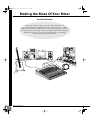 6
6
-
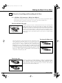 7
7
-
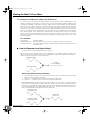 8
8
-
 9
9
-
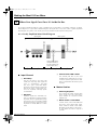 10
10
-
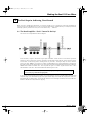 11
11
-
 12
12
-
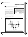 13
13
-
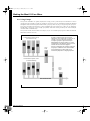 14
14
-
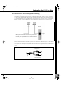 15
15
-
 16
16
-
 17
17
-
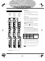 18
18
-
 19
19
-
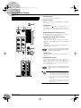 20
20
-
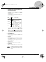 21
21
-
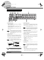 22
22
-
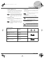 23
23
-
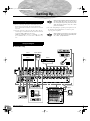 24
24
-
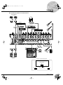 25
25
-
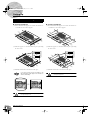 26
26
-
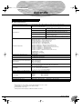 27
27
-
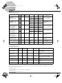 28
28
-
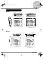 29
29
-
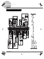 30
30
-
 31
31
-
 32
32


Yamaha MG12 Handleiding
- Categorie
- Audiomixers
- Type
- Handleiding
in andere talen
- English: Yamaha MG12 User manual
- italiano: Yamaha MG12 Manuale utente
- русский: Yamaha MG12 Руководство пользователя
- français: Yamaha MG12 Manuel utilisateur
- español: Yamaha MG12 Manual de usuario
- Deutsch: Yamaha MG12 Benutzerhandbuch
- português: Yamaha MG12 Manual do usuário
- dansk: Yamaha MG12 Brugermanual
- čeština: Yamaha MG12 Uživatelský manuál
- svenska: Yamaha MG12 Användarmanual
- Türkçe: Yamaha MG12 Kullanım kılavuzu
- polski: Yamaha MG12 Instrukcja obsługi
- română: Yamaha MG12 Manual de utilizare
Gerelateerde papieren
-
Yamaha MG8/2FX de handleiding
-
-
-
Yamaha MG102C - 10 Input Stereo Mixer de handleiding
-
-
Yamaha MG06 Handleiding
-
-
Yamaha MG16XU Handleiding
-
-