Yamaha DM7 Gebruikershandleiding
- Categorie
- Audio-equalizers
- Type
- Gebruikershandleiding

EN
DIGITAL MIXING CONSOLE
DM7 StageMix User Guide

Table of contents
Introduction 4
DM7 StageMix...........................................................................................4
Software requirements..............................................................................5
Preparation 6
Wi-Fi setup...............................................................................................6
Network setting for the DM7 series..............................................................7
Configuring iPad network settings.. ............................................................ 8
Using DHCP.. ..............................................................................................................................................................................8
Using a fixed IP address.............................................................................................................................................................9
Configuring StageMix...............................................................................10
Controls and functions 12
HOME screen.. ........................................................................................ 12
HOME screen.. ..........................................................................................................................................................................12
FADER MODE.. ..........................................................................................................................................................................15
SCENE screen..........................................................................................23
UTILITY screen........................................................................................25
UTILITY screen..........................................................................................................................................................................25
CONNECT screen......................................................................................................................................................................26
MUTE/TEMPO screen.. .............................................................................................................................................................27
OSCILLATOR screen.. ...............................................................................................................................................................28
CUSTOM FADER BANK screen..................................................................................................................................................30
USER DEFINED BUTTONS screen.. ..........................................................................................................................................32
PREFERENCE screen.. ..............................................................................................................................................................34
ABOUT screen...........................................................................................................................................................................37
SELECTED CH indicator.............................................................................38
SELECTED CH indicator.. .........................................................................................................................................................38
EQ screen..................................................................................................................................................................................39
DYN screen.. .............................................................................................................................................................................42
INSERT screen.. ........................................................................................................................................................................46
DELAY Screen.. .........................................................................................................................................................................49
CH NAME screen.......................................................................................................................................................................50
RACK Screen...........................................................................................52
2
Table of contents


Introduction
DM7 StageMix
DM7 StageMix is an iPad application for wirelessly controlling DM7 series equipment.
DM7 StageMix gives the sound engineer the freedom to directly and remotely control parameters of the DM7
Series console from the stage, while listening to the results from the vantage point of the performers. And
because it's an iPad with its simple, direct style of interaction, you'll find setup faster and making the live
sound settings for the DM7 all the more pleasant.
Note
(
(
(
(
(
(
(
(
(
The software and this document are the exclusive copyrights of Yamaha Corporation.
Copying or modifying the software or reproduction of this document, by any means, whether in whole or
in part, is expressly forbidden without the written consent of Yamaha Corporation.
Yamaha Corporation makes no representations or warranties with regard to the use of the software and
documentation and cannot be held responsible for the results of the use of the software and this
document.
Copying of commercially available music sequence data and/or digital audio files is strictly prohibited
except for your personal use. If you plan to use such data or files, consult a copyright specialist.
Illustrations of product screens that appear in this document are for instructional purposes only, and may
appear somewhat different from the screens that are displayed on your computer.
Information about system software and changes to certain product functions or specification due to
updates to the software can be found in the related documentation.
Apple, theApple logo, and iPadare trademarks of Apple Inc., registered in the U.S. and other countries.
IOS is a trademark or registered trademark of Cisco Systems, Inc. in the U.S. and other countries, and used
under license.
The company names and product names in this document are the trademarks or registered trademarks of
their respective companies.
4
Introduction > DM7 StageMix

Software requirements
Following is an explanation of the operating environment for DM7 StageMix.
(Apple iPad 5th generation or later
(Supported OS: iPadOS
(Yamaha digital mixing console DM7 Series V1.0 or later
(Wi-Fi access point
(Ethernet cable (used to connect the DM7 Series to the Wi-Fi access point)
5
Introduction > Software requirements

Preparation
Wi-Fi setup
Refer to the instruction manual for your device to set up the Wi-Fi access point. Although no special settings
are required, we recommend that you configure security settings, such as WPA, to prevent any outside
intrusion into the network.
6
Preparation > Wi-Fi setup

Network setting for the DM7 series
1Use an Ethernet cable to connect the network port of the DM7 series to the Wi-Fi
access point.
If you plan to connect it to a legacy access point that does not feature the AUTO-MDIX
function, you will need to use a cross cable. Since many newer device models support the
AUTO-MDIX function, you will be able to use either a straight cable or a cross cable.
2Make sure that the Ethernet cable is connected to the LAN port of the Wi-Fi device.
(Do not connect the cable to the WAN port.)
3Open the SETUP screen on the DM7 series .
4Touch the NETWORK popup button in the CONSOLE STATUS field to open the
NETWORK screen.
5On the FOR MIXER CONTROL tab, set the CONSOLE IP SETTING to ENABLE, and then
specify the IP address in the IP address segment for the Wi-Fi access point.
Network switching
You can connect to a network using a wired connection in addition to a wireless connection. A Lightning to
USB 3 Camera Adapter (or a USB- C-USB adapter) and a USB Ethernet Adapter are required to use a wired
connection. You can switch between a wireless and wired connection when offline.
7
Preparation > Network setting for the DM7 series

Configuring iPad network settings
Using DHCP
DHCP (Dynamic Host Configuration Protocol) is a network protocol that enables the server to automatically
assign an IP address to the devices. Follow the steps below to set up the iPad using DHCP.
1Open the Settings menu on the iPad.
2Select Wi-Fi, and then select the proper network.
3Tap the blue icon located to the right of the currently-selected network name to
display a screen that enables you to edit the IP address.
4Select [DHCP], and then make sure that the iPad has received IP Address, Subnet
Mask, Router, and DNS data.
5If the data is not displayed, select Renew Lease.
6Once the setting is complete, exit the Settings menu.
NOTE
(When connecting with AUTO (“CONNECT screen”(p.26)), make sure that the IP address uses the same subnet for the DM7 series.
(If the DHCP setting is not enabled after Step 5, check your DHCP server settings. Alternatively, use a fixed IP address to set up your
iPad.
8
Preparation > Configuring iPad network settings

Using a fixed IP address
1Open the Settings menu on the iPad.
2Select Wi-Fi, and then select the proper network.
3Tap the blue icon located to the right of the currently-selected network name to
display a screen that enables you to edit the IP address.
4Select [Static].
5Set IP address. When connecting with AUTO (“CONNECT screen”(p.26)), enter only
the last set of numbers (4th octet) of the IP address that is included in the IP
address of the DM7 series.
(Example: If the IP address for the DM7 series is “192.168.0.128”, enter “192.168.0.127” for the
iPad.)
6Subnet Mask: Enter “255.255.255.0”.
7Router: Enter the IP address for the Wi-Fi access point.
This IP address is usually labeled on the bottom of the Wi-Fi device, or printed in the
instruction manual.
8DNS: Enter the IP address for the Wi-Fi access point. (Same as explained in Step 7.)
9Press the Home button on your iPad and exit the Settings menu.
9
Preparation > Configuring iPad network settings

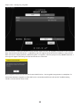
Configuring StageMix
Launch StageMix.
The SELECT MIXER screen appears. This screen enables you to do the following:
(Engage Offline Demo mode, use the StageMix features, and navigate the user interface.
(Select the DM7 series on the network and start using StageMix.
Offline Demo mode
Press the OFFLINE button in the SELECT MIXER screen to engage Offline Demo mode to navigate the
StageMix application while the DM7 series is offline (that is, not connected to StageMix). Please note that the
level meters and most scene memory features will be disabled in this mode.
Selecting a console and starting the operation
Once the iPad is set up to link to the DM7 series , select the system from the list, and then press the
[CONNECT]button.
10
Preparation > Configuring StageMix

If the maximum number per control surface/console (two instances) of StageMix installations have already
been connected to the DM7 series , a prohibiting icon will appear to the left of the IP Address. If you select a
DM7 series that is displayed with a prohibiting icon in StageMix, and then you press the [CONNECT]button, a
message will appear indicating that the connection was not made.
Once StageMix receives parameter data from the DM7 series , the StageMix setup process is complete. If a
connection between StageMix and the DM7 series cannot be established, refer to the Troubleshooting
section at the end of this User Guide.
11
Preparation > Configuring StageMix

Controls and functions
HOME screen
HOME screen
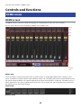
The HOME screen is the main screen of StageMix. It is displayed each time you start StageMix.
You can return to this screen by tapping [HOME] in the Toolbar area.
Meter
area
Main
area
Toolbar
area
Meter area
This area displays input level, output level, and fader levels. In SENDS ON FADER mode, it displays send
levels. The Meter area offers INPUT mode, OUTPUT mode, and CUSTOM mode. Use the switch button on the
left side or swipe the Meter area upward repeatedly to switch these modes in sequence. The Meter area is in
INPUT mode when you start StageMix for the first time. The next time you start StageMix, the area will be in
the mode that was used most recently.
INPUT mode
OUTPUT mode
12
Controls and functions > HOME screen

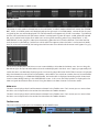
CUSTOM mode
The screen in each mode is divided into 12 channel blocks. In INPUT mode and OUTPUT mode, the STEREO
OUT, CUE A, and CUE B meters will be displayed on the right end. In CUSTOM mode, a meter for the channel
assigned by the user will be displayed. The CUE A/B meters will appear only if CUE is turned on. Tap CUE A/B
to clear CUE and hide the CUE A/B meters. Meters are displayed in green for up to –18 dB, yellow for up to 0
dB, and in red for levels higher than 0 dB. You can change the metering point using “Meter Point” in the
PREFERENCE screen (page 27). Note that the metering point for DCA is fixed at Post On. The fader level for
each channel is indicated by a white line. A thick white line appears when the fader is at the nominal (0 dB)
level. If a channel is turned off, the background of the meter turns black and the meter itself appears in gray.
The channels displayed in the Main area are surrounded by a white box in the Meter area. You can drag this
box left or right, or tap it to select other channels to be displayed in the Main area. Tapping it repeatedly will
switch the Main area between displaying each 12-channel group. While the SELECTED CH screen is displayed,
only the selected channel will be surrounded by a white box. If you switch to another channel, the white box
will move accordingly. In SENDS ON FADER mode, the level meter is displayed according to the Show Send
Levels in Meter Bridge setting in the PREFERENCE screen. In this case, the fader level bar is displayed in the
color assigned to the destination channel. Drag the Meter area down to enter Full Screen mode.
Main area
The Main area displays details of the content selected in the Toolbar area. Each screen you can access from
the Main area is explained in the section that describes the Toolbar buttons.
The Main area displays details of the content selected in the Toolbar area. Each screen you can access from
the Main area is explained in the section that describes the Toolbar buttons.
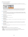
Toolbar area
This area is always displayed near the bottom of the HOME screen.
g4 7M
S
D
13
Controls and functions > HOME screen

aFader mode switch buttons
These buttons enable you to select the Fader display mode in the Main area of the HOME screen. If none of the
options is selected, NORMAL mode will be used. If you select SENDS, the channel ID, name, icon, and color of the send
destination will appear to the right of the SENDS button.
Tap this send destination indicator to display the send destination list (page 13), which enables you to change the
send destination. Press and hold down the send destination indicator to display the send destination channels
horizontally. Press and hold down the SENDS button to switch the control target between the send level and send
pan. Press and hold down the GAIN button to switch the control target between analog gain and digital gain.
bScene indicator
This area displays the number and name of the scene that is currently selected. If a scene other than the currently-
applied scene is selected, the scene number will flash. Tap this area to display the SCENE screen. While the SCENE
screen is open, tap this area again to close the SCENE screen. If you change a parameter of the recalled scene, an Edit
indicator will appear in the upper-right corner of the area.
cUtility button
Tap this button to display the UTILITY screen.
dONLINE indicator
This indicator lights up while the system is online.
eHOME button
Tap this button to return to the HOME screen. If you have changed the Fader mode, the HOME screen will open in the
selected Fader mode.
fTool buttons
Tap each button to switch the display in the Main area. The tapped button will light up steadily. Tap the INSERT
button displays the plug-in, FX, and GEQ/PEQ buttons inserted into the selected channel. The button will not be
displayed if it is not inserted.
gMenu button
Tap this button to open the context menu that is applicable to the current screen. For more information on the menu,
refer to the section on each screen.
HOME screen menu
The following items are available in the context menu of the HOME screen.
(CH Copy: Stores the settings for the currently-selected channel in the copy buffer.
(CH Paste: Pastes the channel settings stored in the copy buffer to the currently-selected channel.
(CH Default: Initializes the settings for the currently-selected channel.
14
Controls and functions > HOME screen

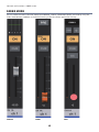
FADER MODE
You can select the fader indication mode from NORMAL, SENDS (SENDS ON FADER) and GAIN by using the
Fader mode buttons. NORMAL is the default setting at the time of the application startup.
NORMAL SENDS GAIN
15
Controls and functions > HOME screen

When the fader indication mode is set to NORMAL or GAIN, a stereo channel is shown at the right edge of the
main area. By swiping this area to the left or right, you can switch the indication between ST A and ST B.
When the fader indication mode is set to SENDS, the send-destination output channel is shown at the right
edge of the main area.
When NORMAL or GAIN is selected When SENDS is selected
16
Controls and functions > HOME screen

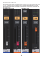
NORMAL
aProcessing area
Displays the channel EQ, DYN, INSERT, DELAY, PAN. For EQ, DYN, INSERT or DELAY, tap this area to switch to a screen
that enables you to edit parameters for the SELECTED CH screen.
EQ DYN INSERT DELAY
For PAN, press and hold down the PAN value, and then drag the value to edit
bON button
Switches the channel on or off. This button lights up when it is turned on. While the channel is turned on, the button
will flash if a mute group (that includes this channel) is turned on. The button will also flash if a DCA group (that
includes this channel) is turned off.
17
Controls and functions > HOME screen

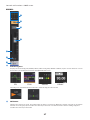
cCUE button
Tap this button to turn the channel’s cue on or off. The button lights up when it is turned on. To edit the cue, use the
Cue Operation Mode setting in the PREFERENCE screen. This button works as the SOLO button in Solo In Place mode,
and lights up red when it is turned on.
dFader
Drag the fader’s knob up or down to adjust the fader level. The fader stops at the nominal level (0 dB). You can then
continue to drag it up or down as desired. You can drag the fader left and right and then up and down to adjust it
more precisely. You can adjust multiple faders at the same time.
eMeter display
Two meters are displayed for paired channels.
fFader value
Displays the value of the current fader level. You can tap the value and then increase or decrease it by tapping the up
or down arrow.
gChannel name area
Displays the channel’s ID number, name, icon, and color. If two channels are assigned as a stereo pair, you can tap
this area repeatedly to toggle the displayed channel name. Double-tap the area to open the CH NAME screen.
18
Controls and functions > HOME screen

SENDS (SENDS ON FADER)
aPRE button
Switches between Pre Fader and Post Fader. The button lights up when it is turned on.
(On:Pre Fader
(Off:Post Fader
Press and hold down the button to display the following menu items: Select one of the menu items. The confirmation
message will appear. Tap the OK button to select Pre or Post for the desired channel(s) all together as a group.
All Mix/Matrix busses PRE for this channel
All Mix/Matrix busses POST for this channel
Current Mix/Matrix bus PRE for all channels
Current Mix/Matrix bus POST for all channels
bSEND ON button
The SEND ON button switches the send for the specified destination channel on or off. The CH ON button switches
the channel on or off.
cCUE button
Tap this button to turn the channel’s cue on or off. The button lights up when it is turned on. To edit the cue, use the
Cue Operation Mode setting in the PREFERENCE screen. This button works as the SOLO button in Solo In Place mode,
and lights up red when it is turned on.
19
Controls and functions > HOME screen

dFader
>Enables you to adjust the send level or send pan for the specified destination channel.
eSend level value
Displays the current send level or send pan value. You can tap the value and then increase or decrease it by tapping
the up or down arrow.
fChannel name area
Displays the channel’s ID number, name, icon, and color.
Send destination list
Tap the send destination indicator next to the Fader mode switch button to display the send destination list.
hMIX/MATRIX switch buttons
Switches the send destination list. The button for the currently-selected channel lights up. Stereo pair channels will
be surrounded by a white box
20
Controls and functions > HOME screen

GAIN
aInput assign area
Indicates the assigned port name. Tap this area to display the INPUT PATCH screen.
b+48V button
Switches on or off the phantom power (+48V) supplied to the analog input jack.
(On:Phantom power is turned on.
(Off:Phantom power is turned off.
This button is disabled if the Enable Phantom Power Switching setting in the PREFERENCE screen is set to off.
cΦ (Phase) button
Reverses the phase of the signal input to digital gain. When the button is turned on, the input signal’s phase is
reversed.
dON button
Switches the channel on or off. This button lights up when it is turned on.
eCUE button
Tap this button to turn the channel’s cue on or off. The button lights up when it is turned on. To edit the cue, use the
Cue Operation Mode setting in the PREFERENCE screen. This button works as the SOLO button in Solo In Place mode,
and lights up red when it is turned on.
21
Controls and functions > HOME screen

fGC button
Displayed on the analog gain fader if the channel’s Gain Compensation function is turned on. Tap this button to
enable the function. A triangle icon will appear at the gain level position, indicating the level obtained when the
function is turned on. If you turn off the button, the gain level will return to the value at the triangle icon.
gSlider
Adjusts the gain level. The slider is displayed in red for analog gain, and white for digital gain. The slider will not
appear if an I/O card that features analog gain is not patched.
hGain value
Indicates the gain value.
iChannel name area
Displays the channel’s ID number, name, icon, and color.
22
Controls and functions > HOME screen

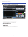
SCENE screen
Tap the SCENE indicator in the Toolbar area to display the SCENE screen.
aScene list
Displays the scenes saved in the selected Scene list.
You can tap a column header in the list to sort the items based on that header.
To select a scene, simply tap it. The selected scene is highlighted, and can then be recalled.
An orange triangle appears next to a scene that is currently recalled.
Locked scenes are indicated by a lock icon and cannot be edited.
bDEC RECALL/INC RECALL buttons
Recall scenes in sequence.
cINFORMATION area
Displays the title, comment, status, and time stamp of the scene selected in the scene list. You can edit the title and
comment by tapping the corresponding area to open the keyboard screen.
23
Controls and functions > SCENE screen

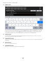
dSTORE button
Saves a scene. Tap this button to display the keyboard screen.
You can edit the scene numbers by using the number keys to directly enter a number, or by tapping the up or down
arrow to increase or decrease the number. The TITLE and COMMENT fields support only ASCII characters. The TITLE
field accepts up to 16 characters, and the COMMENT field accepts up to 128 characters. To return to the previous
screen without saving the scene, tap the CANCEL button. To save the scene, tap the DONE button.
eUPDATE button
Press this button to overwrite the current scene after editing the parameters. If there is no current scene, or if the
current scene is locked, this button will be disabled.
fUNDO UPDATE button
Undoes the previous update operation. If there is no current scene, or if the current scene is locked, this button will
be disabled.
gRECALL button
Recalls the currently-selected scene.
hUNDO RECALL button
Undoes the recall operation performed immediately before.
24
Controls and functions > SCENE screen

UTILITY screen
UTILITY screen
The bottom of this screen features the CONNECT, MUTE/TEMPO, OSCILLATOR, CUSTOM FADER, USER
DEFINED BUTTONS, PREFERENCE, and ABOUT tab buttons.
25
Controls and functions > UTILITY screen

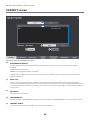
CONNECT screen
The screen contains the following items.
aAUTO/MANUAL buttons
You can switch between automatically detecting a DM7 Series console to connect to, or setting an IP Address
manually.
AUTO: detects automatically.
MANUAL: for setting the IP Address manually.
The DM7 Series console can be connected to even if set up on a different subnet, but the level meter information
cannot be displayed.
bDevice list
Displays a list of control surfaces for the DM7 series that have been detected on the network. Tap to highlight a
control surface to which you want to connect. If the maximum number (two instances) of StageMix have already been
connected to the control surface, a prohibiting icon will appear to the left of the IP Address, and you will be unable to
connect more.
cSplit Mode
Select A/B side in split mode.
dOFFLINE button
Tap this button to engage Offline Demo mode. Connection between StageMix and DM7 series, if any, will be cut off.
eCONNECT button
Tap this button to connect to the DM7 series selected in the device list.
26
Controls and functions > UTILITY screen

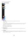
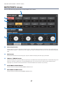
MUTE/TEMPO screen
You can set the mute group on/off and tap tempo in this screen.
aMute Group buttons
Switch mute on or off for each of the 12 mute groups. This button lights up when it is turned on. The button lights up
red if the Dim setting is –∞. Other than that, it lights up orange. Each button indicates the corresponding mute group
label.
bDim buttons
Specify the Dim level for each mute group. Tap each button to display the fader pop-up window.
cTEMPO1 - TEMPO4 buttons
Tap these buttons to set up four different tap tempos. The BPM value will be displayed next to each button.Drag each
button up or down to adjust the corresponding BPM value. You can also increase or decrease the BPM value by
tapping the up or down arrow located above or below the BPM value indication respectively.
dMUTE GROUP ASSIGN buttons
Tap this button to display the MUTE GROUP ASSIGN screen.
eDCA GROUP ASSIGN buttons
Tap this button to display the DCA GROUP ASSIGN screen.
27
Controls and functions > UTILITY screen

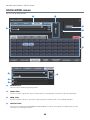
OSCILLATOR screen
You can set up the oscillator.
aMODE buttons
Select one of the oscillator operating modes.
bLEVEL slider
Sets the oscillator output level. If the oscillator mode is set to SINE 2CH, two sliders (L/R) will be displayed.
cFREQ slider
Sets the oscillator frequency. This slider is displayed if the oscillator mode is set to SINE or SINE 2CH.
dLPF/HPF slider
These sliders are displayed if PINK NOISE or BURST NOISE is selected. They adjust the cutoff frequency of the
oscillator’s low and high pass filters.
28
Controls and functions > UTILITY screen

eLPF ON button/HPF ON button
Turns the LPF/HPF on or off.
fWidth slider
This slider is displayed if BURST NOISE is selected. It adjusts the length of noise being output intermittently.
gInterval slider
This slider is displayed if BURST NOISE is selected. It adjusts a gap between noises.
hOUTPUT button
Turns the oscillator on or off.
iOUTPUT level meter
Displays the oscillator output level. If the oscillator mode is set to SINE 2CH, two meters (L/R) will be displayed.
jASSIGN button
Enable you to select a channel to which the oscillator signal will be sent. Tap one of the buttons in the first row to
select channels that will be displayed in the list below, and then tap the desired channel buttons. You can drag to
select multiple channels simultaneously.
kCLEAR ALL button
Excludes all output channels from the oscillator signal destination.
29
Controls and functions > UTILITY screen

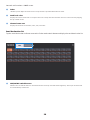
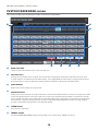
CUSTOM FADER BANK screen
This screen enables you to configure custom fader bank assignments.
aBank name edit
Tap this field to edit the bank name in the overview area.
bOverview area
Displays the list of faders to be assigned. This list contains small graphics of the faders (for which the associated
channel numbers are indicated on the fader buttons), and is highlighted by a white frame. Drag this white frame to
the left and right, or tap it, to switch the channel numbers that will be indicated on the fader buttons.
cFader buttons
Enable you to select a fader to assign a bank.
dChannel buttons
Enable you to select channels to assign to the faders selected via the fader buttons. If a channel is assigned to a fader,
a small triangle will appear in the upper-right corner of the corresponding channel button. If a channel has already
been assigned to the fader (selected via the corresponding fader button), tapping the corresponding channel button
will cancel the assignment of that particular channel. Drag horizontally through these buttons to assign multiple
channels sequentially starting with the selected fader button.
eCLEAR button
Cancels fader assignment.
fIMPORT button
Imports CUSTOM FADER BANK settings from the DM7 series console when a BANK is specified.
30
Controls and functions > UTILITY screen

gLOAD button
Tap this button to open the Load File view, in which you can load CUSTOM FADER BANK settings from a file. Tap Edit
to delete a file or edit the file name.
hSAVE button
Tap this button to open the Save File view, in which you can save CUSTOM FADER BANK settings into a file.
31
Controls and functions > UTILITY screen

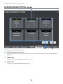
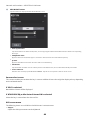
USER DEFINED BUTTONS screen
4
D
The screen contains the following items.
aBUTTONS configuration buttons
Tapping this button calls up the Function Selection screen for selecting functions to be assigned to USER DEFINED
BUTTONS.
bLOAD button
Loads the USER DEFINED BUTTONS that have been saved.
cSAVE button
Saves the current USER DEFINED BUTTONS settings.
32
Controls and functions > UTILITY screen

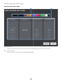
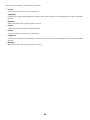
Function selection screen
4
a Edit Label
Tapping the text box allows you to enter the label name with the keyboard. You can also set the color.
b Function selection
Select the function to be assigned to USER DEFINED BUTTONS.
33
Controls and functions > UTILITY screen

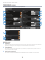
PREFERENCE screen
This screen enables you to configure the StageMix application.
GENERAL section
aFader Delay
Enables you to adjust the amount of delay between when you touch a fader control to adjust the value and when the
adjustment is actually applied. This setting helps prevent unintended fader control movement.
bFader 0dB Detent
If this switch is turned on, and you adjust a fader or pan, the fader or pan operation will stop at 0 dB or center. You
can then continue to drag it as desired.
cEnable Inc/Dec Scene Recall
If this switch is turned off, the INC RECALL button and DEC RECALL button in the SCENE screen will be hidden.
34
Controls and functions > UTILITY screen

dEnable Phantom Power Switching
Enables or disables the +48 phantom power button that is displayed in the GAIN screen. If this switch is turned on, the
button will be highlighted in red. If this switch is turned off, the +48V button in the GAIN screen will be disabled.
eSet DCA to 0dB with Double-tap
If this switch is turned on, double-tapping a DCA fader knob will set it to 0 dB.
f[ON] Keys Function During SOF
Determines whether the [ON] keys in SENDS ON FADER mode function as a SEND ON button (that turns the send for
the specified destination channel on or off), or a CH ON button (that turns the corresponding channel on or off).
gShow Send Levels in Meter Bridge
Switches the level meters in SENDS ON FADER mode.
Send: Send level is displayed in the meter area.
Fader: Fader level is displayed in the meter area.
Off: Neither level is displayed in the meter area.
hDisable Screen Auto-Lock
Turn this on to disable the iPad Auto-Lock function.
iDisplay Delay Scale
Specifies the display delay scale.
jFrame Rate
If frame is selected for the delay scale, this rate determines the number of frame per second.
CONFIRMATION section
kRecall/Store/Update
If this switch is turned on, a confirmation message will be displayed when you recall, save, or overwrite a scene in the
SCENE screen.
CH SELECTエリア
lStageMix Follows Console
If this switch is turned on, the channel you select on the control surface will also be selected in StageMix.
mConsole Follows StageMix
If this switch is turned on, the channel you select in StageMix will also be selected on the console.
nLink Bay Selected
Select the L, C, or R bay to link to the Selected Channel. You can also use the Import function on the CUSTOM FADER
BANK screen to load the settings for the selected bay.
NOTE
This item is not displayed when connecting with the DM7 Compact.
35
Controls and functions > UTILITY screen

CUE section
oCue Operation Mode
Enables you to select the desired cue operation mode. Select Cue A, Cue B, or Cue A+B.
pCue A Mode/Cue B Mode
Enable you to set Cue A and Cue B to one of the following modes. In Mix Cue mode, multiple channels will be
monitored simultaneously. In Last Cue mode, only one channel will be monitored.
qSolo in Place Mode
Turn on this switch to enable Solo in Place mode.
METERS section
rInput Meter Point/Output Meter Point
Determines the input/output level metering point.
RTAsection
sPeak Hold Mode
Determines the type of peak hold displayed on the RTA graph.
(Freeze: The RTA display freezes when you turn on the Hold button. The display refreshes when you turn off the
Hold button.
(All Peaks: The maximum value of each RTA frequency band is displayed in red.
(High Peak: Only the frequency band with the highest value is displayed in red.
tInput Gain
Enables you to adjust the mic input gain of the iPad used for the RTA (Real-Time Analyzer).
uNumber of Bands
Determines the number of frequency bands displayed on the RTA graph.
36
Controls and functions > UTILITY screen

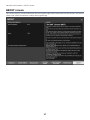
ABOUT screen
This screen displays version information for the StageMix app and the connected surface control, and license
information about the software used by the StageMix app.
37
Controls and functions > UTILITY screen

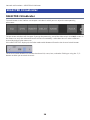
SELECTED CH indicator
SELECTED CH indicator
Tap each button in the Toolbar area to open a window in which you can adjust the corresponding
parameters.
The parameter windows will also open if you tap the processing area of the fader strip in the HOME screen. In
the meter area, only the selected channels will be surrounded by a white box. You can select a different
channel by dragging the meter area.
If the SELECTED CH is displayed, the Fader mode switch button will work as the channel switch button.
The channel switch button will indicate the channel ID, name, icon, and color. Flicking or using the </>
buttons enables you to switch channels.
38
Controls and functions > SELECTED CH indicator

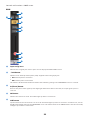
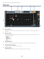
EQ screen
aHPF/LPF buttons
Tap the buttons to turn the high-pass filter or low-pass filter on or off respectively. The button lights up when it is
turned on.
bEQ Type selector
Tap here to select an EQ type. Each type features a unique frequency curve and a different color for a part of the
outside frame of the graph.
(PRECISE: gray
(SMOOTH: blue
(AGGRESSIVE: red
(LEGACY: black
cA/B switch buttons
These buttons enable you to switch between A and B as the storing destination for the EQ parameters.
dProcess Order switch button
This button enable you to switch the order of the effects.
eEQ ON/OFF button
Tap this button to switch the EQ on or off. The button lights up when it is turned on.
39
Controls and functions > SELECTED CH indicator

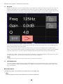
fEQ graph
Displays the parameter values for the EQ and filters. As you adjust the settings for each band and gain, the results are
reflected in the graph. You can drag the handles displayed in the graph to adjust the corresponding settings. When
using the bell-type filter or if the EQ is a shelving type in the PRECISE category, you can adjust the Q value by pinching
the curve on the graph. The parameters for the selected band are displayed in a popup over the handle.
In the popup, you can use the Bypass button to turn bypass on or off, and the Shelf button to turn shelving on or off.
Turn on the Lock button to fix the specified frequency and gain, and drag the handle. You can reset the EQ gain to its
default value by double-tapping the handle.
If you tap an area of the graph at 0 dB or lower where there is no parameter, the RTA display or a keyboard will
appear. This is useful in understanding the relationship between sound range and frequency. When you open the EQ
screen for the first time, a message is displayed asking whether you want to use the iPad mic for the RTA graph.
If you tap “Don’t Allow,” the RTA graph will not appear in the future. If you want to display the RTA graph later, open
the iOS Settings screen, select Privacy → Microphone, and then turn StageMix on.
NOTE
StageMix will analyze the sound from the iPad microphone and display the RTA graph.
gRTA HOLD button
Turn on this button to display the peak value in the RTA graph. You can change how the peak is displayed by using
the Peak Hold Mode setting in the PREFERENCE screen. When the RTA graph is turned off, this button is displayed in
gray and is disabled.
EQ screen menu
The following items are available in the context menu of the EQ screen.
(Copy:
Copies the EQ parameters of the selected channel to the clipboard.
40
Controls and functions > SELECTED CH indicator

(Paste:
Pastes the EQ parameters in the clipboard to the selected channel.
(Compare:
Enables you to compare the EQ parameters of the selected channel with the EQ parameters in the
clipboard by switching between the two.
(Gain Flat:
Sets the EQ gain of the current channel to the flat position.
(Default :
Resets EQ settings to default values.
41
Controls and functions > SELECTED CH indicator

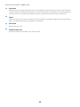
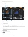
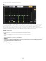
DYN screen
Displays two dynamics selections: DYN1 and DYN2. For output channels, only DYN1 will be displayed.
aA/B switch buttons
These buttons enable you to switch between A and B as the storing destination for the EQ parameters.
bDYN ON/OFF button
Tap this button to switch the dynamics processor on or off. The button lights up when it is turned on.
cDynamics processor type select button
Enables you to select the dynamics processor type from the following:
LEGACY COMP, COMP260, GATE, DE-ESSER, EXPANDER, DUCKING, FET Limiter(Input channel DYN2 and output
channel DYN1 only)、Diode Bridge Comp(Input channel DYN2 and output channel DYN1 only).
dKEY IN level meter
Indicates the KEY IN level. A triangle icon indicates the threshold level for the KEY IN filter. If the KEY IN source is
paired channels, the meter will indicate the higher level between L and R.
eThreshold slider
Specifies the dynamics threshold.
fGraph
Displays the input/output frequency response.
42
Controls and functions > SELECTED CH indicator

gRange slider
Specifies the amount of attenuation when the GATE/DUCKING effect is applied.
hMix slider
Adjusts the mix balance.
iDynamics parameter sliders
Indicate the dynamics parameter values. The type of parameters will vary depending on the currently-selected
dynamics processor type.
(Legacy Comp, COMP260, or Expander:
Threshold, Ratio, Attack, Release, Outgain, Knee
(Gate or Ducking:
Threshold, Range, Attack, Hold, Decay
(De-Esser:
Threshold, Frequency, Type, Q
(FET Limiter:
INPUT, OUTPUT, RATIO、ATTACK、RELEASE、In To Out Link
(Diode Bridge Comp:
Threshold, Ratio, Gain, Recovery
jGR meter
Indicates the amount of dynamics gain reduction.
INPUT level meter/OUTPUT level meter
Display the peak level for the front and rear stages respectively of the dynamics processor.
kKEY IN SOURCE display
Indicates the currently-selected KEY IN SOURCE. If DE-ESSER has been selected, it will be fixed to SELF POST EQ.
43
Controls and functions > SELECTED CH indicator

lKEY IN EDIT button
Tap this button to display the KEY IN FILTER edit screen.
(
(
(
(
(
Filter type buttons
Tap these buttons to switch to HPF, BPF, or LPF. Tapping the illuminated button will turn off the corresponding
filter type.
FREQUENCY slider
Appears when one of the filter types is turned on. Use this slider to set the filter frequency.
Q slider
Appears when BPF is turned on. Use this slider to set the filter Q.
CUE button
Tap this button to switch cue on or off. If you close the DYN screen, the cue will automatically turned off.
Source indicator
Indicates the currently-specified KEY IN SOURCE. Tap this area to open the Source select screen.
Source select screen
This screen enables you to select the key in source. Additional items that might be displayed vary depending
on the selected source.
If SELF is selected:
No additional items will be displayed.
If OTHER PRE EQ or Mix Out or External IN is selected:
Select the key in source from the channel list.
DYN screen menu
The following items are available in the DYN screen’s context menu.
( Copy1:
Copies the DYN1 parameters to the clipboard.
44
Controls and functions > SELECTED CH indicator

(Paste1:
Pastes the DYN parameters in the clipboard.
(Compare1:
Enables you to compare the DYN1 parameters with the parameters in the clipboard by switching between
the two.
(Default1 :
Resets the DYN1 settings to their default values.
(Copy2:
Copies the DYN2 parameters to the clipboard.
(Paste2:
Pastes the DYN parameters in the clipboard.
(Compare2:
Enables you to compare the DYN2 parameters with the parameters in the clipboard by switching between
the two.
(Default2 :
Resets the DYN2 settings to their default values.
45
Controls and functions > SELECTED CH indicator

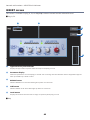
INSERT screen
This screen is available if a plug-in, FX, or GEQ/PEQ has been inserted into the selected channel.
■Plug-in, FX
4
D
M
7
aType and insert point indicator
Displays the type and insert point of the currently inserted plug-in or FX
bParameter display
Shows the parameters of inserted plug-ins and FX. You can change the value with the numeric keypad that appears
when you double-tap a knob or value.
cBYPASS button
Switches BYPASS on or off. The button lights up when it is turned on.
dCUE button
Switches CUE on or off. The button lights up when it is turned on.
eLevel meters
Displays the level for the front and rear stages respectively of the plug-in or FX.
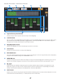
■GEQ
46
Controls and functions > SELECTED CH indicator

aType and insert point indicator
Displays the type and insert point of the currently-inserted GEQ/PEQ.
bL/R Link button
Appears if odd-A/even-A GEQ RACKs of 31band GEQ or a pair of Flex15GEQs/PEQs have been inserted as A/B in stereo
pair channels. Tap this button repeatedly to toggle between L and R. Tap the LINK icon in the middle to apply the
settings for the currently-selected channel to the other channel.
cGEQ/PEQ ON/OFF button
Switches the GEQ/PEQ on or off. The button lights up when it is turned on.
dLevel meters
Displays the peak level for the rear stage of the GEQ/PEQ.
eRTA HOLD button
Turn on this button to display the peak value in red over the RTA graph. You can change how the peak is displayed by
using the Peak Hold Mode setting in the PREFERENCE screen.
fOVERVIEW area
Displays the frequency response of the entire GEQ. The range covered by the EQ graph is indicated in green. You can
tap this area to draw the EQ graph and center in on the frequency of the location where you tapped the screen.
gEQ graph
Drag the handle up and down to adjust the gain of each band. Double-tap the handle to set the EQ Gain to 0 dB.
Swipe left or right on an empty area to scroll the frequency bands to be displayed. For Flex15 GEQ, the available
number of bands will be displayed as “Available Bands” next to the LIMIT button.
hLIMIT button
Enables you to select the range of gain adjustment from the following options: ±15 dB, ±12 dB, ±6 dB (these are valid
in both the boost and cut directions), or –24 dB (valid only in the cut direction).
47
Controls and functions > SELECTED CH indicator

■PEQ
You can configure eight bands for PEQ. Out of these eight bands, you can set shelving for Band1 and Band8.
In addition to eight bands, you can also set four notch filters. Control these notch filters using the upside-
down triangles shown at the bottom of the screen. Tap the handle to display the popup window that
indicates the frequency, Q, and on/off status of the notch filters. Drag the handle left and right to adjust the
frequency. To enable the notch filters, tap the ON button. Adjust the Q value by pinching it.
INSERT screen menu
The following items are available in the context menu of the INSERT screen.
(Copy :
Copies the GEQ/PEQ parameters of the selected channel to the clipboard.
(Paste :
Pastes the GEQ/PEQ parameters in the clipboard.
(Compare :
Enables you to compare the GEQ/PEQ parameters of the selected channel with the GEQ/PEQ parameters
in the clipboard by switching between the two.
(Default :
Resets the GEQ/PEQ settings to default values.
48
Controls and functions > SELECTED CH indicator

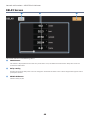
DELAY Screen
The screen contains the following items.
aGANG button
This button is displayed when channels are paired. If this is on, the difference between the delay time values are
maintained and linked.
bDelay setting
Displays the channel delay value. You can change the value with the slider or the numeric keypad that appears when
you tap the number.
cDELAY ON button
Switches delay on/off.
49
Controls and functions > SELECTED CH indicator

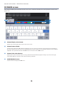
CH NAME screen
This screen enables you to set the channel name, icon, and channel color that are displayed in the channel
name area.
aChannel display select button
Switches the channel that you want to view on the screen.
bChannel name edit box
Tap this box to display the iOS software keyboard screen. As you enter characters, they will appear immediately in
the name edit box. You can enter up to eight ASCII code characters. When you are finished, tap Done on the software
keyboard. The system will close the CH NAME screen and return to the HOME screen.
cChannel color select buttons
Enable you to select a channel color. Pressing a button will immediately apply the change. If you select the right-
most button (OFF), the channel color and icon will be grayed out.
dON(KEYBOARD) button
Tap this button to display the ICON area.
50
Controls and functions > SELECTED CH indicator

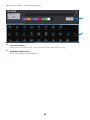
eIcon select buttons
Enable you to select a channel icon. Pressing a button will immediately apply the change.
fKEYBOARD (ICON) button
Tap this button to display the KEYBOARD area.
51
Controls and functions > SELECTED CH indicator

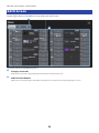
RACK Screen
Tap the Rack button in the Toolbar area to display the Rack screen.
The screen contains the following items.
aCategory select tabs
Allows you to select the category of plug-in that will be mounted in the rack.
bPLUG-IN select buttons
Allows you to select the plug-in that will be mounted. Press to open the corresponding plug-in screen.
52
Controls and functions > RACK Screen

Troubleshooting
Troubleshooting
DHCP server setup of the wireless access point/router
1Use a web browser to access the web administrator page for your wireless access
point or router.
2Enable the wireless access point’s DHCP feature.
3Configure the range of addresses that the DHCP feature will assign to connected
devices.
4Confirm that the IP address assigned to the DM7 series is outside the range of IP
addresses that the DHCP feature will assign to connected devices. If it is within this
range, change the IP address of the system.
(For example, if the IP address for the DM7 series is 192.168.1.2, set the DHCP feature to assign
an address between 192.168.1.3 and 192.168.1.128.)
NOTE
Not all wireless access points support a DHCP server feature. If yours does not, assign an IP address manually to the iPad.
If the DM7 series is not displayed in the SELECT MIXER screen
If your wireless access point’s IGMP snooping feature is enabled, StageMix may not be able to find the
system. Disable your wireless access point’s IGMP snooping feature and try again. Set STAGEMIX
CONNECTIVITY to ENABLE on the FOR STAGEMIX tab in the NETWORK screen of the DM7 series .
Check and try the firmware update for the Wi-Fi device.
If a “cannot connect to the Internet” message is displayed
When you select a wireless network using your iPad, the iPad may try to access the Internet. If your wireless
access point cannot connect to the Internet, a “cannot connect to the Internet” message may be displayed
on the iPad, and StageMix may not be able to connect to the DM7 series . An Internet connection is not
needed to connect StageMix to the DM7 series . However, you may need to change the settings on your
wireless access point so that this message is no longer displayed. If this message is displayed, typically you
will need to disable your wireless access point’s “redirect feature”. For details, refer to your device’s
operating instructions or contact the manufacturer.
If you cannot move four or more faders at the same time
If the Multitasking Gestures setting of your iPad is turned on, you may not be able to move four or more
faders in StageMix at the same time. When using StageMix, be sure to turn the Multitasking Gestures feature
off.
53
Troubleshooting > Troubleshooting

1Open the Settings screen on the iPad.
2Tap [General] and then turn [Multitasking Gestures] off.
If you cannot move three or more faders at the same time
If the Zoom feature in the Accessibility settings of your iPad is turned on, you may not be able to move three
or more faders in StageMix at the same time. When using StageMix, be sure to turn the Zoom feature off.
1Open the Settings screen on the iPad.
2Tap [General] → [Accessibility] and then turn [Zoom] off.
If the RTA graph is not displayed
When you open the EQ screen, GEQ screen, or PEQ screen for the first time, a message appears asking
whether you want to use the iPad mic for the Real-Time Analyzer. If you tap “Don’t Allow,” the RTA graph will
not be displayed in the future. If you want to display the RTA graph later, open the iOS Settings screen, select
Privacy → Microphone, and then turn StageMix on.
If the StageMix performance is too slow
When selecting the “EDITOR/STAGEMIX” option for the COMMUNICATION QUALITY of the NETWORK
connector for StageMix, which results in greater communication load and slower performance of StageMix,
enable IGMP Snooping on the Wi-Fi device.
54
Troubleshooting > Troubleshooting

Yamaha Pro Audio global website
https://www.yamahaproaudio.com/
Yamaha Downloads
https://download.yamaha.com/
© 2023 Yamaha Corporation
Published 06/2023 YJMK-A0
Layout Folder: YMH_PDF_Manual_A5_PA
Stylesheet Name: 01_YMH_PDF_Manual_A5_PA_En-Multi
Stylesheet Version: 2022.12.12
-
 1
1
-
 2
2
-
 3
3
-
 4
4
-
 5
5
-
 6
6
-
 7
7
-
 8
8
-
 9
9
-
 10
10
-
 11
11
-
 12
12
-
 13
13
-
 14
14
-
 15
15
-
 16
16
-
 17
17
-
 18
18
-
 19
19
-
 20
20
-
 21
21
-
 22
22
-
 23
23
-
 24
24
-
 25
25
-
 26
26
-
 27
27
-
 28
28
-
 29
29
-
 30
30
-
 31
31
-
 32
32
-
 33
33
-
 34
34
-
 35
35
-
 36
36
-
 37
37
-
 38
38
-
 39
39
-
 40
40
-
 41
41
-
 42
42
-
 43
43
-
 44
44
-
 45
45
-
 46
46
-
 47
47
-
 48
48
-
 49
49
-
 50
50
-
 51
51
-
 52
52
-
 53
53
-
 54
54
-
 55
55


Yamaha DM7 Gebruikershandleiding
- Categorie
- Audio-equalizers
- Type
- Gebruikershandleiding
in andere talen
- English: Yamaha DM7 User guide
- italiano: Yamaha DM7 Guida utente
- русский: Yamaha DM7 Руководство пользователя
- français: Yamaha DM7 Mode d'emploi
- español: Yamaha DM7 Guía del usuario
- Deutsch: Yamaha DM7 Benutzerhandbuch
- português: Yamaha DM7 Guia de usuario
- dansk: Yamaha DM7 Brugervejledning
- suomi: Yamaha DM7 Käyttöohjeet
- čeština: Yamaha DM7 Uživatelská příručka
- 日本語: Yamaha DM7 ユーザーガイド
- svenska: Yamaha DM7 Användarguide
- polski: Yamaha DM7 instrukcja
- română: Yamaha DM7 Manualul utilizatorului