

COMPLIANCE INFORMATION STATEMENT
(DECLARATION OF CONFORMITY PROCEDURE)
Responsible Party: YAMAHA CORPORATION OF AMERICA
Address: 6600 Orangethorpe Avenue, Buena Park, Calif. 90620 U.S.A.
Telephone: 1-714-522-9011
FAX: 1-714-739-2680
Type of Equipment: AUDIO EXPANSION UNIT
Model Name: AX44
This device complies with Part 15 of the FCC Rules.
Operation is subject to the following conditions:
1) this device may not cause harmful interference, and
2) this device must accept any interference received including interference that may cause undesired operation.
Contents
Introduction - - - - - - - - - - - - - - - - - - - - - - - - - - - - - - - - - - - 1
Packing List - - - - - - - - - - - - - - - - - - - - - - - - - - - - - - - - - 1
System Requirements - - - - - - - - - - - - - - - - - - - - - - - - - - - 1
Controls & Connections - - - - - - - - - - - - - - - - - - - - - - - - - - 2
Front Panel - - - - - - - - - - - - - - - - - - - - - - - - - - - - - - - - - - 2
Rear Panel - - - - - - - - - - - - - - - - - - - - - - - - - - - - - - - - - - 3
Installing the AX44 - - - - - - - - - - - - - - - - - - - - - - - - - - - - - - 4
Installing a Second AX44 - - - - - - - - - - - - - - - - - - - - - - - - - 4
Troubleshooting - - - - - - - - - - - - - - - - - - - - - - - - - - - - - - - - 5
Specifications - - - - - - - - - - - - - - - - - - - - - - - - - - - - - - - - - - 6
General - - - - - - - - - - - - - - - - - - - - - - - - - - - - - - - - - - - - 6
Analog Inputs - - - - - - - - - - - - - - - - - - - - - - - - - - - - - 7
Analog Outputs - - - - - - - - - - - - - - - - - - - - - - - - - - - - - - - 7
DC IN Connector - - - - - - - - - - - - - - - - - - - - - - - - - - - - - 7
Dimensions - - - - - - - - - - - - - - - - - - - - - - - - - - - - - - - - - 8
FCC INFORMATION (U.S.A.)
1. IMPORTANT NOTICE: DO NOT MODIFY THIS UNIT! This product, when installed as indicated in the instructions contained in this manual, meets FCC
requirements. Modifications not expressly approved by Yamaha may void your authority, granted by the FCC, to use the product.
2. IMPORTANT: When connecting this product to accessories and/or another product use only high quality shielded cables. Cable/s supplied with this product MUST
be used. Follow all installation instructions. Failure to follow instructions could void your FCC authorization to use this product in the USA.
3. NOTE: This product has been tested and found to comply with the requirements listed in FCC Regulations, Part 15 for Class “B” digital devices. Compliance with
these requirements provides a reasonable level of assurance that your use of this product in a residential environment will not result in harmful interference with
other electronic devices. This equipment generates/uses radio frequencies and, if not installed and used according to the instructions found in the users manual, may
cause interference harmful to the operation of other electronic devices. Compliance with FCC regulations does not guarantee that interference will not occur in all
installations. If this product is found to be the source of interference, which can be determined by turning the unit “OFF” and “ON”, please try to eliminate the
problem by using one of the following measures: Relocate either this product or the device that is being affected by the interference. Utilize power outlets that are on
different branch (circuit breaker or fuse) circuits or install AC line filter/s. In the case of radio or TV interference, relocate/reorient the antenna. If the antenna lead-in
is 300 ohm ribbon lead, change the lead-in to coaxial type cable. If these corrective measures do not produce satisfactory results, please contact the local retailer
authorized to distribute this type of product. If you can not locate the appropriate retailer, please contact Yamaha Corporation of America, Electronic Service
Division, 6600 Orangethorpe Ave, Buena Park, CA 90620
The above statements apply ONLY to those products distributed by Yamaha Corporation of America or its subsidiaries.

Introduction
1
AX44—Owner’s Manual
Introduction
Thank you for purchasing the Yamaha AX44 Audio Expansion Unit. The
AX44 is an input and output expander for the Yamaha DS2416 Digital Mixing
Card and provides four 1/4-inch analog inputs—two of which can be used
with microphones—four 1/4-inch analog outputs and a stereo headphone
jack. The 20-bit 128-times oversampling A/D converters and 18-bit 8-times
oversampling D/A converters provide a typical dynamic range of 100 dB. Two
AX44s can be used with a single DS2416 card, providing up to eight analog
inputs and outputs.
Packing List
• AX44 Audio Expansion Unit
• DS2416 20-pin connection cable
• M3 x 6 mm fixing screws x4
• This manual
System Requirements
• IBM PC compatible Windows 95 computer
• Yamaha DS2416 Digital Mixing Card
• DS2416 compatible audio software
No part of the AX44
Owner’s Manual
may be reproduced or distributed in
any form or by any means without the prior written authorization of Yamaha
Corporation, Inc.
IBM PC is a registered trademarks of International Business Machines, Inc.
Yamaha is a trademark of Yamaha Corporation, Inc. All other trademarks are
the property of their respective holders and are hereby acknowledged.
© 1998 Yamaha Corporation. All rights reserved.

2
Controls & Connections
AX44—Owner’s Manual
Controls & Connections
Front Panel
A
Inputs 1 & 2
Analog inputs 1 and 2 feature 1/4-inch unbalanced phone jacks with individ-
ual Line/Mic switches for –10 dBV or –50 dBV operation. Analog to digital
conversion features 20-bit 128-times oversampling techniques.
B
Inputs 3 & 4
Analog inputs 3 and 4 feature 1/4-inch unbalanced phone jacks with a nomi-
nal input level of –10 dBV. Use with line-level sources. Analog to digital con-
version uses 20-bit 128-times oversampling techniques.
C
Power Indicator
The Power indicator lights up when the AX44 is ready for use, that is, when
the computer is turned on and the AX44 is receiving power, and the connec-
tion to the DS2416 is functioning correctly. (It’s also used to identify AX44s
from the software, useful when two units are installed.)
D
Outputs 1–4
Outputs 1 through 4 feature 1/4-inch unbalanced phone jacks with a nominal
output level of –10 dBV. Digital to analog conversion features 18-bit 8-times
oversampling.
E
Headphone Jack
Outputs 3 and 4 can be monitored by connecting a pair of stereo headphones
to this 1/4-inch stereo jack.
F
Headphone Level Control
This control adjusts the volume level of the headphones.
INPUT 1 2 3 4
1234
OUTPUT
POWER
LINE MIC
–10dBV –50dBV –10dBV –50dBV
LINE MIC
AX44
4
21
3 5 6

Rear Panel
3
AX44—Owner’s Manual
Rear Panel
A
IO connector
This connector connects to the DS2416 via the supplied 20-pin cable and car-
ries digital data between the AX44 and DS2416.
B
DC IN connector
This connector connects to a power connector from the computer’s power
supply and supplies power to the AX44.
IO DC IN
1 2

4
Installing the AX44
AX44—Owner’s Manual
Installing the AX44
The AX44 installs into a single 5.25-inch drive bay, and is secured using the
four screws supplied. There are three sets of fixing holes in the AX44: two on
the sides and one underneath. Use the set that matches your computer’s drive
bay. If you need to replace a screw, look for M3 x 6 mm machine screws. Do
not use screws longer than 6 mm as they may damage the AX44.
See your computer’s manual for full details on installing drive bay devices.
1
Turn off the computer and disconnect the power cord.
2
Remove the computer’s cover.
3
Install the AX44 into a 5.25-inch drive bay, as explained in your
computer’s manual.
4
Connect an unused power connector from the computer’s power
supply to the AX44 DC IN connector.
5
Connect the AX44 to DS2416 connector “IO-A ( )” using the
supplied 20-pin cable (connect the end with the ferrite core to the
DS2416).
Installing a Second AX44
Two AX44 units can be connected to a single DS2416 card.
1
Install the second AX44 into a 5.25-inch drive bay, as explained in
your computer’s manual.
2
Connect an unused power connector from the computer’s power
supply to the AX44 DC IN connector.
3
Connect the second AX44 to DS2416 connector “IO-B ( )” using
the supplied 20-pin cable.
A
AB

Troubleshooting
5
AX44—Owner’s Manual
Troubleshooting
Trouble Advice
Lost the AX44 fixing screws?
Replace with M3 x 6 mm machine screws.
Do not use screws longer than 6 mm as they
may damage the AX44.
The AX44 does not work and the Power
indicator is off?
Make sure that the computer is turned on.
Make sure the power connector is properly
connected to the AX44.
Make sure the supplied 20-pin cable is con-
nected properly between the AX44 and
DS2416.
The Power indicator is on but the AX44 still
doesn’t work?
A single AX44 should be connected to
DS2416 connector “IO-A”; the second AX44
to connector “IO-B”.
The input signal sounds distorted?
Reduce the level of the input signal.
When connecting line-level equipment to
inputs 1 and 2, set the Mic/Line switches to
Line.
The input signal is too quiet?
Low-level signal sources such as micro-
phones should be connected to inputs 1 and
2 and the Mic/Line switch set to Mic.
Cannot hear anything in the headphones?
The headphone signal is derived from out-
puts 3 and 4, so you must assign signals to
these outputs in order to use the head-
phones.

6
Specifications
AX44—Owner’s Manual
Specifications
General
1. Syncs to external wordclock. AX44 has no internal clock.
2. Bandwidth filter
±
0.1 dB (20 Hz–20 kHz), –60 dB (more than 24.1 kHz)
3. Bandwidth filter as above plus Weighting Filter (IEC60651 A curve, Tolerance: Type 0)
Sampling rate
1
30.08 to 50.88 kHz
Signal delay
(fs = 48 kHz)
A/D
610
µ
s typical
D/A
1,330
µ
s typical
Total harmonic distortion
2
(fs = 48 kHz, +6 dBV, analog input to output)
Less than 0.01% (20 Hz–20 kHz)
Frequency response
(fs = 48 kHz, Line, Mic, analog input to output)
20 Hz–20 kHz, –3, +1 dB
Dynamic range
3
(fs = 48 kHz)
D/A
Typically 106 dB
A/D + D/A
Typically 100 dB
Equivalent input noise
3
(Gain = Mic, input + output)
Typically –120 dBV
Residual output noise
3
(D/A input = digital 0)
Typically –100 dBV
Input
INPUT 1–4 20-bit 128-times oversampling A/D
INPUT 1, 2 MIC/LINE switch
Output
OUTPUT 1–4 18-bit 8-times oversampling D/A
Phones Source: outputs 3 and 4
Phones level control
Rotary pot
Power indicator
LED
Power on/off
Identity flag from DS2416
Power supply
+5 V (180 mA max)
+12 V (200 mA max)
Temperature
Operating
+10˚C to +40˚C
Storage
–20˚C to +55˚C
Dimensions (W x D x H)
148 x 183 x 42.6 mm
(5.8 x 7.2 x 1.7 inch)
For half-height 5.25" drive bay
Weight
1 kg (2.2 lbs)
Supplied accessories
20-pin DS2416 connecting cable x1
M3 x 6 mm fixing screws x4

Analog Outputs
7
AX44—Owner’s Manual
Analog Inputs
Analog Outputs
DC IN Connector
1. Input channels 1–4 feature linear 20-bit 128-times oversampling A/D converters.
2. Where dBV represents a specific voltage, 0 dBV is referenced to 1 V rms.
1. Output channels 1–4 feature linear 18-bit 8-times oversampling D/A converters.
2. Where dBV represents a specific voltage, 0 dBV is referenced to 1 V rms.
3. The Phones stereo phone jack is wired: tip = left, ring = right, sleeve = ground.
Connection Pad
Actual load
impedance
For use
with
nominal
Input level
Connector
Nominal
Max. before
clip
INPUT 1, 2
1
MIC
10k
Ω
50–600
Ω
mics &
600
Ω
lines
–50 dBV
2
(3.16 mV)
–34 dBV
(19.95 mV)
Phone jack
(unbalanced)
LINE
–10 dBV
(316 mV)
+6 dBV
(1.995 V)
INPUT 3, 4
10k Ω 600 Ω lines
–10 dBV
(316 mV)
+6 dBV
(1.995 V)
Connection
Actual
source
impedance
For use with
nominal
Output level
Connector
Nominal
Max. before
clip
OUTPUT 1–4
1
600 Ω 10k Ω lines
–10 dBV
2
(316 mV)
+6 dBV
(1.995 V)
Phone jack
(unbalanced)
Phones
3
22 Ω
8 Ω phones 1 mW 14 mW
Stereo phone
jack
40 Ω phones 1 mW 23 mW
Pin Signal
1 +12 V
2 GND
3 GND
4 +5 V

8 Specifications
AX44—Owner’s Manual
Dimensions
Specifications subject to change without notice.
M3 fixing holes (12 off)
139.711.8 10.65
D: 183
79.252.2
H: 42.6
W:148
5
188

AX44
BOÎTIER D’EXTENSION
Mode d’emploi
Français

Sommaire
Introduction - - - - - - - - - - - - - - - - - - - - - - - - - - - - - - - - - - - 1
Contenu de l’emballage - - - - - - - - - - - - - - - - - - - - - - - - - - 1
Configuration requise - - - - - - - - - - - - - - - - - - - - - - - - - - - 1
Commandes & connexions - - - - - - - - - - - - - - - - - - - - - - - - 2
Face avant - - - - - - - - - - - - - - - - - - - - - - - - - - - - - - - - - - 2
Face arrière - - - - - - - - - - - - - - - - - - - - - - - - - - - - - - - - - - 3
Installation de l’AX44 - - - - - - - - - - - - - - - - - - - - - - - - - - - - 4
Installation d’un deuxième AX44 - - - - - - - - - - - - - - - - - - - 4
Dépannage - - - - - - - - - - - - - - - - - - - - - - - - - - - - - - - - - - - - 5
Fiche technique - - - - - - - - - - - - - - - - - - - - - - - - - - - - - - - - - 6
Caractéristiques générales - - - - - - - - - - - - - - - - - - - - - - - - 6
Entrées analogiques - - - - - - - - - - - - - - - - - - - - - - - - - 7
Sorties analogiques - - - - - - - - - - - - - - - - - - - - - - - - - - - - - 7
Connecteur DC IN - - - - - - - - - - - - - - - - - - - - - - - - - - - - - 7
Dimensions - - - - - - - - - - - - - - - - - - - - - - - - - - - - - - - - - 8

Introduction
1
AX44—Mode d’emploi
Introduction
Nous vous remercions d’avoir opté pour le boîtier d’extension Yamaha AX44.
L’AX44 est un boîtier d’extension entrées/sorties pour la Yamaha DS2416
Digital Mixing Card qui propose quatre sorties analogiques 1/4 de pouce
(dont deux peuvent servir pour des microphones), quatre sorties analogiques
1/4 de pouce et une borne pour casque stéréo. Les convertisseurs A/N 20 bits
avec suréchantillonnage à 128 fois et les convertisseurs N/A 18 bits avec suré-
chantillonnage à 8 fois offrent une plage dynamique typique de 100 dB. Il est
possible d’utiliser deux AX44 avec une seule carte DS2416 afin de disposer de
huit entrées et sorties analogiques.
Contenu de l’emballage
• Boîtier d’extension AX44 (Audio Expansion Unit)
• Câble de connexion à 20 broches du DS2416
• Vis de fixation M3 x 6 mm x4
•Ce manuel
Configuration requise
• Ordinateur compatible IBM PC avec Windows 95
• Yamaha DS2416 Digital Mixing Card
• Logiciel audio compatible DS2416
Il est interdit de reproduire ou de distribuer le
Mode d’emploi
de l’AX44 en
tout ou en partie, sous quelque forme ou par quelque moyen que ce soit sans
autorisation préalable et écrite de Yamaha Corporation, Inc.
IBM PC est une marque déposée de International Business Machines, Inc.
Yamaha est une marque commerciale de Yamaha Corporation, Inc. Toutes les
autres marques sont la propriété de leurs détenteurs respectifs et sont recon-
nues par la présente.
© 1998 Yamaha Corporation. Tous droits réservés.

2
Commandes & connexions
AX44—Mode d’emploi
Commandes & connexions
Face avant
A
Entrées 1 & 2
Les entrées analogiques 1 et 2 sont pourvues de jacks 1/4 asymétriques avec
un commutateur Line/Mic individuel leur permettant de sélectionner
–10 dBV ou –50 dBV. La conversion analogique/numérique se fait avec un
suréchantillonnage 20 bits à 128 fois.
B
Entrées 3 & 4
Les entrées analogiques 3 et 4 sont pourvues de jacks 1/4 asymétriques d’un
niveau d’entrée nominal de –10 dBV et sont prévues pour des sources de
niveau ligne. La conversion analogique/numérique se fait avec un suréchan-
tillonnage 20 bits à 128 fois.
C
Témoin POWER
Le témoin POWER s’allume lorsque l’ordinateur est sous tension et indique
que l’AX44 est alimenté et prêt à l’usage et que la connexion avec la carte
DS2416 fonctionne correctement. (Il permet également d’identifier les AX44
à partir du logiciel, ce qui est pratique lorsque vous utilisez deux boîtiers).
D
Sorties 1~4
Les sorties 1 à 4 sont pourvues de jacks 1/4 asymétriques d’un niveau de sortie
nominal de –10 dBV. La conversion numérique/analogique se fait avec un
suréchantillonnage 18 bits à 8 fois.
INPUT 1 2 3 4
1234
OUTPUT
POWER
LINE MIC
–10dBV –50dBV –10dBV –50dBV
LINE MIC
AX44
4
21
3 5 6

Face arrière
3
AX44—Mode d’emploi
E
Prise pour casque
Vous pouvez écouter les sorties 3 et 4 en branchant un casque à cette prise sté-
réo.
F
Commande de volume du casque
Cette commande permet de régler le volume du casque.
Face arrière
A
Connecteur IO
Ce connecteur permet de relier la carte DS2416 avec le câble fourni à 20 bro-
ches et permet le transfert de données numériques entre l’AX44 et le DS2416.
B
Connecteur DC IN
Ce connecteur permet de relier l’AX44 à un connecteur d’alimentation de
l’ordinateur afin d’alimenter l’AX44.
IO DC IN
1 2

4
Installation de l’AX44
AX44—Mode d’emploi
Installation de l’AX44
L’AX44 s’insère dans une baie simple de 5,25 pouces. Fixez-la avec les quatre
vis fournies. Il y a trois séries d’orifices de fixation dans l’AX44: deux sur les
côtés et un en-dessous. Servez-vous des orifices qui correspondent à ceux de
la baie de votre ordinateur. Si vous devez remplacer une vis, demandez une vis
pour machine M3 x 6 mm. N’utilisez pas de vis plus longues que 6 mm car
elles risqueraient d’endommager l’AX44.
Veuillez consulter le manuel de votre ordinateur pour en savoir davantage sur
l’installation d’appareils dans les baies.
1
Coupez l’ordinateur et débranchez le cordon d’alimentation.
2
Enlevez le cache de l’ordinateur.
3
Installez l’AX44 dans une baie de 5,25 pouces en suivant les expli-
cations données dans le manuel de votre ordinateur.
4
Branchez un connecteur d’alimentation inutilisé de l’ordinateur au
connecteur DC IN de l’AX44.
5
Branchez l’AX44 au connecteur “IO-A ( )” du DS2416 avec le
câble à 20 broches fourni (Connectez le côté en ferrite à la
DS2416).
Installation d’un deuxième AX44
Vous pouvez brancher deux boîtiers AX44 à une seule carte DS2416.
1
Installez le deuxième AX44 dans une baie de 5,25 pouces en sui-
vant les explications données dans le manuel de votre ordinateur.
2
Branchez un connecteur d’alimentation inutilisé de l’ordinateur au
connecteur DC IN de l’AX44.
3
Branchez le deuxième AX44 au connecteur “IO-B ( )” du DS2416
avec le câble à 20 broches fourni.
A
AB

Dépannage
5
AX44—Mode d’emploi
Dépannage
Problème Conseil
Les vis de fixations de l’AX44 sont égarées.
Remplacez-les par des vis machine M3 x
6 mm. N’utilisez pas de vis plus longues que
6 mm car elles pourraient endommager
l’AX44.
L’AX44 ne fonctionne pas et l’indicateur
POWER est éteint.
Assurez-vous que l’ordinateur est sous ten-
sion.
Assurez-vous que le connecteur d’alimenta-
tion est correctement raccordé à l’AX44.
Assurez-vous que le câble à 20 broches est
correctement relié à l’AX44 et à la carte
DS2416.
L’indicateur POWER est allumé mais l’AX44
ne fonctionne toujours pas.
Un boîtier AX44 unique doit être branché au
connecteur “IO-A” de la carte DS2416; bran-
chez le second au connecteur “IO-B”.
Le signal d’entrée est saturé?
Réduisez le niveau du signal d’entrée.
Lorsque vous branchez du matériel de niveau
ligne aux entrées 1 et 2, réglez les commuta-
teurs Mic/Line sur Line.
Le signal d’entrée est-il trop faible?
Les sources de signaux de faible niveau tels
que des microphones doivent être branchées
aux entrées 1 et 2 et le commutateur
Mic/Line doit être réglé sur Mic.
Vous n’entendez rien via le casque?
Le signal du casque est dérivé des sorties 3 et
4; il faut donc assigner les signaux à ces sor-
ties pour pouvoir utiliser le casque.

6
Fiche technique
AX44—Mode d’emploi
Fiche technique
Caractéristiques générales
1. Synchronisation sur horloge externe. L’AX44 n’a pas d’horloge interne.
2. Largeur de bande du filtre
±
0,1 dB (20 Hz–20 kHz), –60 dB (plus de 24,1 kHz)
3. Largeur de bande du filtre comme ci-dessus plus Filtre de pondération (IEC60651 courbe A,
Tolérance: Type 0)
Fréquence d’échantillonnage
1
30,08 à 50,88 kHz
Retard de signal
(fs = 48 kHz)
A/N
610
µ
s typique
N/A
1,330
µ
s typique
Distorsion harmonique totale
2
(fs = 48 kHz, +6 dBV, entrée vers sortie
analogique)
Moins de 0,01% (20 Hz–20 kHz)
Réponse en fréquence
(fs = 48 kHz, Ligne, Mic, entrée vers sortie
analogique)
20 Hz–20 kHz, –3, +1 dB
Plage dynamique
3
(fs = 48 kHz)
D/A
Typiquement 106 dB
A/D + D/A
Typiquement 100 dB
Bruit d’entrée équivalent
3
(Gain = Mic, entrée + sortie)
Typiquement –120 dBV
Bruit de sortie résiduel
3
(entrée N/A = numérique 0)
Typiquement –100 dBV
Entrée
INPUT 1~4
A/N 20 bits suréchantillonnage à 128
fois
INPUT 1, 2 Commutateur MIC/LINE
Sortie
OUTPUT 1~4
N/A 18 bits suréchantillonnage à 8
fois
Casque Source: sorties 3 et 4
Commande de volume du casque
Potentiomètre rotatif
Témoin POWER
Diode
Sous/hors tension
Flag d’identité du DS2416
Alimentation
+5 V (180 mA max)
+12 V (200 mA max)
Température
Fonctionnement
+10˚C à +40˚C
Stockage
–20˚C à +55˚C
Dimensions (L x P x H)
148 x 183 x 42,6 mm
(5,8 x 7,2 x 1,7 inch)
Pour baie mi-hauteur de 5,25 pouces
Poids
1 kg (2,2 lbs)
Accessoires fournis
Câble de connexion à 20 broches
pour DS2416 x1
Vis de fixation M3 x 6 mm x4

Sorties analogiques
7
AX44—Mode d’emploi
Entrées analogiques
Sorties analogiques
Connecteur DC IN
1. Les canaux d’entrée 1~4 disposent de convertisseurs A/N linéaires 20 bits avec suréchan-
tillonnage à 128 fois.
2. Lorsque dBV représente une tension spécifique, 0 dBV est référencé à 1 V rms.
1. Les canaux de sortie 1~4 disposent de convertisseurs N/A linéaires 18 bits avec suréchan-
tillonnage à 8 fois.
2. Lorsque dBV représente une tension spécifique, 0 dBV est référencé à 1 V rms.
3. Voici le câblage du jack du casque: pointe = gauche, anneau = droite, gaine = masse.
Connexion Att.
Impédance
de charge
réelle
Niveau
nominal
Niveau d’entrée
Connecteur
Nominal
Max. avant
saturation
INPUT 1, 2
1
MIC
10k
Ω
50–600
Ω
micro &
600
Ω
ligne
–50 dBV
2
(3,16 mV)
–34 dBV
(19,95 mV)
Jack
(asymétrique)
LINE
–10 dBV
(316 mV)
+6 dBV
(1,995 V)
INPUT 3, 4
10k
Ω
600
Ω
ligne
–10 dBV
(316 mV)
+6 dBV
(1,995 V)
Connexion
Impédance
de source
réelle
Niveau
nominal
Niveau de sortie
Connecteur
Nominal
Max. avant
saturation
OUTPUT 1~4
1
600 Ω 10k Ω ligne
–10 dBV
2
(316 mV)
+6 dBV
(1,995 V)
Jack
(asymétrique)
Casque
3
22 Ω
8 Ω casque 1 mW 14 mW
Prise pour cas-
que stéréo
40 Ω casque 1 mW 23 mW
Broche Signal
1 +12 V
2 Masse
3 Masse
4 +5 V

8 Fiche technique
AX44—Mode d’emploi
Dimensions
Caractéristiques susceptibles d’être modifiées sans préavis.
Orifices M3 (renfoncés 12)
139.711.8 10.65
P: 183
79.252.2
H: 42.6
L: 148
5
188

AX44
AUDIO EXPANSION UNIT
Bedienungsanleitung
Deutsch

Inhalt
Vorweg - - - - - - - - - - - - - - - - - - - - - - - - - - - - - - - - - - - - - - - 1
Lieferumfang - - - - - - - - - - - - - - - - - - - - - - - - - - - - - - - - 1
Systemanforderungen - - - - - - - - - - - - - - - - - - - - - - - - - - - 1
Bedienelemente & Anschlüsse - - - - - - - - - - - - - - - - - - - - - - 2
Frontplatte - - - - - - - - - - - - - - - - - - - - - - - - - - - - - - - - - - 2
Rückseite - - - - - - - - - - - - - - - - - - - - - - - - - - - - - - - - - - - 3
Einbau der AX44 - - - - - - - - - - - - - - - - - - - - - - - - - - - - - - - - 4
Einbau einer weiteren AX44 - - - - - - - - - - - - - - - - - - - - - - - 4
Problembehebung - - - - - - - - - - - - - - - - - - - - - - - - - - - - - - 5
Spezifikationen - - - - - - - - - - - - - - - - - - - - - - - - - - - - - - - - - 6
Allgemein - - - - - - - - - - - - - - - - - - - - - - - - - - - - - - - - - - - 6
Analog-Eingänge - - - - - - - - - - - - - - - - - - - - - - - - - - - 7
Analog-Ausgänge - - - - - - - - - - - - - - - - - - - - - - - - - - - - - - 7
DC IN-Anschluß - - - - - - - - - - - - - - - - - - - - - - - - - - - - - - 7
Abmessungen - - - - - - - - - - - - - - - - - - - - - - - - - - - - - - - - 8

Vorweg
1
AX44—Bedienungsanleitung
Vorweg
Vielen Dank, daß Sie sich für die Audio-Erweiterung AX44 von Yamaha ent-
schieden haben. Hierbei handelt es sich um eine Ein- und Ausgangserweite-
rung für die Digital-Mischpultkarte DS2416 mit vier 1/4-Zoll-Analog-
Eingängen –darunter zwei für Mikrofonsignale–, vier Analog-Ausgängen und
einem Stereo-Kopfhöreranschluß. Dank der 20-Bit A/D-Wandler mit
128fachem Oversampling und der 18-Bit D/A-Wandler mit 8fachem Over-
sampling verfügen Sie über einen Dynamikumfang von 100dB. Es können
zwei AX44 mit einer DS2416-Karte verbunden werden, so daß Sie insgesamt
8 Analog-Ein- und acht Analog-Ausgänge ansprechen können.
Lieferumfang
• AX44 Audio-Erweiterung
• DS2416 20-Pin-Anschlußkabel
• Befestigungsschrauben M3 x 6mm x4
• Diese Bedienungsanleitung
Systemanforderungen
• IBM PC-kompatibler Rechner mit Windows 95
• Yamaha DS2416 Digital-Mischpultkarte
• DS2416-kompatibles Audio-Programm
Nichts aus dieser AX44
Bedienungsanleitung
darf ohne die schriftliche Geneh-
migung der Yamaha Corporation, Inc vervielfältigt oder anderweitig verwen-
det werden.
IBM PC ist ein eingetragenes Warenzeichen der International Business Mach-
ines, Inc. Yamaha ist ein eingetragenes Warenzeichen der Yamaha Corpora-
tion, Inc. Alle anderen Warenzeichen sind Eigentum der betreffenden Firmen
und werden ausdrücklich anerkannt.
© 1998 Yamaha Corporation. Alle Rechte vorbehalten.

2
Bedienelemente & Anschlüsse
AX44—Bedienungsanleitung
Bedienelemente & Anschlüsse
Frontplatte
A
Eingang (Input) 1 & 2
Die Analog-Eingänge 1 und 2 sind als asymmetrische 1/4"-Klinkenbuchsen
mit LINE/MIC-Schaltern ausgeführt und erlauben einen Eingangspegel von
–10dBV oder –50dBV. Die dahintergeschalteten A/D-Wandler sind vom Typ
20 Bit mit 128fachem Oversampling.
B
Eingang (Input) 3 & 4
Die Analog-Eingänge 3 und 4 sind als asymmetrische 1/4"-Klinkenbuchsen
mit einem Nenneingangspegel von –10dBV ausgeführt. Schließen Sie hier
Signale mit Line-Pegel an. Die dahintergeschalteten A/D-Wandler sind vom
Typ 20 Bit mit 128fachem Oversampling.
C
POWER-Diode
Diese Diode leuchtet, sobald Sie den Rechner einschalten und zeigt an, daß
die AX44 mit Strom versorgt wird und ordnungsgemäß mit der DS2416 ver-
bunden ist. (Außerdem können Sie sie verwenden, um vom Audio-Pro-
gramm aus zu kontrollieren, ob die Karte angesprochen wird, was vor allem
bei Verwendung zweier AX44 hilfreich sein kann.)
D
Ausgänge (Output) 1~4
Die Ausgänge 1~4 sind als asymmetrische 1/4"-Klinkenbuchsen mit einem
Nennausgangspegel von –10dBV ausgeführt. Die davor geschalteten D/A-
Wandler sind vom Typ 18 Bit mit 8fachem Oversampling.
INPUT 1 2 3 4
1234
OUTPUT
POWER
LINE MIC
–10dBV –50dBV –10dBV –50dBV
LINE MIC
AX44
4
21
3 5 6

Rückseite
3
AX44—Bedienungsanleitung
E
Kopfhöreranschluß
Das Signal von Ausgang 3 und 4 kann auch über einen an diese 1/4"-Stereo-
Klinkenbuchse angeschlossenen Kopfhörer überwacht werden.
F
Lautstärkeregler für den Kopfhöreranschluß
Hiermit können Sie die Lautstärke im Kopfhörer einstellen.
Rückseite
A
E/A-Anschluß (IO )
Verbinden Sie diesen Anschluß über das beiliegende 20-Pin-Kabel mit der
DS2416 Karte. Über dieses Kabel werden die Daten von und zur Karte über-
tragen.
B
DC IN-Anschluß
Verbinden Sie diesen Anschluß mit der Stromversorgung des Rechners, um
die AX44 mit Strom zu versorgen.
IO DC IN
1 2

4
Einbau der AX44
AX44—Bedienungsanleitung
Einbau der AX44
Die AX44 kann in einen einfachen 5,25"-Schacht des Rechners geschoben
und mit den vier beiliegenden Schrauben befestigt werden. Die AX44 ist mit
drei Bohrungssätzen versehen: zwei an den Seiten und einer an der Unterseite.
Falls Sie eine Schraube verlieren, können Sie eine beliebige andere M3 x
6mm-Schraube verwenden. Gebrauchen Sie niemals längere Schrauben, weil
die AX44 sonst beschädigt werden könnte.
Wie man ein Gerät in einen Schacht einbaut, entnehmen Sie bitte der Bedie-
nungsanleitung Ihres Rechners.
1
Schalten Sie den Rechner aus und lösen Sie den Netzanschluß.
2
Öffnen Sie das Gehäuse des Rechners.
3
Schieben Sie die AX44 in einen 5,25”-Schacht. Beachten Sie dabei
die Hinweise in der Bedienungsanleitung des Rechners.
4
Verbinden Sie ein noch freies Stromkabel des Rechners mit dem
DC IN-Anschluß der AX44.
5
Verbinden Sie den 20-Pin-Anschluß der AX44 mit der “IO-A ( )”-
Buchse der DS2416 (Schließen Sie das Ende mit der Ferritleitung
an die DS2416 an).
Einbau einer weiteren AX44
Es können jeweils zwei AX44 mit einer DS2416-Karte verbunden werden.
1
Schieben Sie die zweite AX44 in einen noch freien 5,25”-Schacht.
Beachten Sie dabei die Hinweise in der Bedienungsanleitung des
Rechners.
2
Verbinden Sie ein noch freies Stromkabel des Rechners mit dem
DC IN-Anschluß der AX44.
3
Verbinden Sie den 20-Pin-Anschluß der Zweiten AX44 mit der “IO-
B ( )”-Buchse der DS2416.
A
B

Problembehebung
5
AX44—Bedienungsanleitung
Problembehebung
Problem Lösung
Finden Sie die Befestigungsschrauben der
AX44 nicht mehr?
Kein Problem, nehmen Sie einfach andere
M3 x 6mm-Metallschrauben. Verwenden
aber niemals Schrauben, die länger sind als
6mm.
Die AX44 funktioniert nicht und die POWER-
Diode leuchtet nicht.
Schauen Sie nach, ob der Rechner einge-
schaltet ist.
Schauen Sie nach, ob das Stromkabel des
Rechners ordnungsgemäß mit der AX44 ver-
bunden ist.
Schauen Sie nach, ob das 20-Pin-Kabel ord-
nungsgemäß mit der AX44 und der DS2416
verbunden ist.
Die POWER-Diode leuchtet, aber die AX44
kann nicht angesprochen werden.
Wenn Sie nur eine AX44 verwenden, müssen
Sie die mit der “IO/A”-Buchse der DS2416
verbinden. Schließen Sie eine weitere AX44
an die “IO/B”-Buchse an.
Das Eingangssignal verzerrt.
Verringern Sie den Pegel des Eingangssignals.
Wenn Sie Signalquellen mit Line-Pegel an Ein-
gang 1 oder 2 anschließen, müssen Sie sei-
nen LINE/MIC-Schalter auf LINE stellen.
Das Eingangssignal ist zu schwach.
Niederpegelige Signale, wie z.B. Mikrofone
müssen mit Eingang 1 oder 2 verbunden
werden. Stellen Sie den betreffenden LINE/
MIC-Schalter dann auf MIC.
Der Kopfhörer gibt kein Signal wieder.
Der Kopfhörer führt nur das Signal von Aus-
gang 3 und 4. Legen Sie die betreffenden
Signale also an diese Buchsen an, um sie über
Kopfhörer überwachen zu können.

6
Spezifikationen
AX44—Bedienungsanleitung
Spezifikationen
Allgemein
1. Synchronisation mit externem Wordclock-Takt. Die AX44 enthält keinen Taktgeber.
2. Bandbreite des Filters
±
0,1 dB (20 Hz~20 kHz), –60 dB (mehr als 24,1 kHz)
3. Bandbreite des Filters wie oben, dazu ein gewichtetes Filter (IEC60651 A-Kurve, Toleranz:
Typ 0)
Sampling-Frequenz
1
30,08~50,88 kHz
Signalverzögerung
(fs = 48 kHz)
A/D
610
µ
s typisch
D/A
1,330
µ
s typisch
Klirrfaktor
2
(fs = 48 kHz, +6 dBV, Analog-Ein- zu -Ausgang)
Weniger als 0,01% (20 Hz–20 kHz)
Frequenzgang
(fs = 48 kHz, LINE, MIC, Analog-Ein- zu -
Ausgang)
20 Hz~20 kHz, –3, +1 dB
Dynamikumfang
3
(fs = 48 kHz)
D/A
Typisch 106 dB
A/D + D/A
Typisch 100 dB
Äquivalentes Eingangsrauschen
3
(Gain = MIC, Eingang + Ausgang)
Typisch –120 dBV
Restausgangsrauschen
3
(D/A-Eingang = Digital-Ausgang)
Typisch –100 dBV
Eingänge
INPUT 1~4 A/D 20 Bit, 128faches Oversampling
INPUT 1, 2 LINE/MIC-Schalter
Ausgänge
OUTPUT 1~4 D/A 18 Bit, 8faches Oversampling
Phones Quelle: Eingang 3 und 4
Kopfhörerlautstärke
Drehpotentiometer
Stromanzeige
LED
Ein-/ausgeschaltet
Identitäts-Flag der DS2416
Stromversorgung
+5 V (180 mA max.)
+12 V (200 mA max.)
Empfohlene Temperatur
Bei Verwendung
+10˚C ~+40˚C
Lagerung
–20˚C~+55˚C
Abmessungen (B x T x H)
148 x 183 x 42,6 mm
Für halbhohen 5,25"-Schacht
Gewicht
1kg
Lieferumfang
20-Pin DS2416-Anschlußkabel x1
M3 x 6mm Schrauben x4

Analog-Ausgänge
7
AX44—Bedienungsanleitung
Analog-Eingänge
Analog-Ausgänge
DC IN-Anschluß
1. Die Eingangskanäle 1~4 sind mit 20-Bit D/A-Wandlern mit 128fachem Oversampling aus-
gestattet.
2. Wenn dBV einen Spannungswert vertritt, entspricht 0dBV dem Wert 1V rms.
1. Die Ausgangskanäle 1~4 sind mit 18-Bit D/A-Wandlern mit 8fachem Oversampling ausge-
stattet.
2. Wenn dBV einen Spannungswert vertritt, entspricht 0dBV dem Wert 1V rms.
3. Bedrahtung der Stereo-Klinkenbuchse: Spitze= links, Ring= rechts, Mantel= Masse.
Anschluß Pad
Tats. Last-
impedanz
Bei Verw.
mit Nenn-
pegel
Eingangspegel
Anschlußtyp
Nennwert
Max. vor
Verzerrung
INPUT 1, 2
1
MIC
10k
Ω
50–600
Ω
Mikrofon &
600
Ω
Line
–50 dBV
2
(3,16 mV)
–34 dBV
(19,95 mV)
Klinkenbuchse
(asymmetrisch)
LINE
–10 dBV
(316 mV)
+6 dBV
(1,995 V)
INPUT 3, 4
10k
Ω
600
Ω
Line
–10 dBV
(316 mV)
+6 dBV
(1,995 V)
Anschluß
Tats. Quel-
lenimpe-
danz
Bei Verw.
mit Nenn-
wert
Ausgangspegel
Anschlußtyp
Nennwert
Max. vor
Verzerrung
OUTPUT 1~4
1
600 Ω 10k Ω Line
–10 dBV
2
(316 mV)
+6 dBV
(1,995 V)
Klinkenbuchse
(asymmetrisch)
Phones
3
22 Ω
8 Ω Kopfh. 1 mW 14 mW
Stereo-Klinken-
buchse
40 Ω Kopfh. 1 mW 23 mW
Stift Signal
1 +12 V
2 GND (Masse)
3 GND (Masse)
4 +5 V

8 Spezifikationen
AX44—Bedienungsanleitung
Abmessungen
Änderungen der technischen Daten ohne Vorankündigung jederzeit vorbehalten.
M3-Bohrungen (12 versetzt)
139.711.8 10.65
T: 183
79.252.2
H: 42.6
B:148
5
188

AX44
AUDIO EXPANSION UNIT
Manual de instrucciones
Español

Indice
Introducción - - - - - - - - - - - - - - - - - - - - - - - - - - - - - - - - - - - 1
Lista de envío - - - - - - - - - - - - - - - - - - - - - - - - - - - - - - - - 1
Requisitos del sistema - - - - - - - - - - - - - - - - - - - - - - - - - - - 1
Contoles y conexiones - - - - - - - - - - - - - - - - - - - - - - - - - - - - 2
Panel frontal - - - - - - - - - - - - - - - - - - - - - - - - - - - - - - - - - 2
Panel posterior - - - - - - - - - - - - - - - - - - - - - - - - - - - - - - - 3
Instalación de la AX44 - - - - - - - - - - - - - - - - - - - - - - - - - - - - 4
Instalación de una segunda AX44 - - - - - - - - - - - - - - - - - - - 4
Solución de problemas - - - - - - - - - - - - - - - - - - - - - - - - - - - 5
Especificaciones - - - - - - - - - - - - - - - - - - - - - - - - - - - - - - - - 6
Generales - - - - - - - - - - - - - - - - - - - - - - - - - - - - - - - - - - - 6
Entradas analógicas - - - - - - - - - - - - - - - - - - - - - - - - - 7
Salidas analógicas - - - - - - - - - - - - - - - - - - - - - - - - - - - - - - 7
Conector DC IN - - - - - - - - - - - - - - - - - - - - - - - - - - - - - - 7
Dimensiones - - - - - - - - - - - - - - - - - - - - - - - - - - - - - - - - - 8

Introducción
1
AX44—Manual de instrucciones
Introducción
Muchas gracias por la adquisición de la unidad de expansión de audio AX44
Yamaha. La AX44 es un expansor de entrada y salida para la tarjeta de mezcla
digital DS2416 Yamaha que proporciona cuatro entradas analógicas de 1/4
pulgadas – dos de las cuales podrán utilizarse con micrófonos – cuatro salidas
analógicas de 2/4 pulgadas, y una toma para auriculares estéreo. Los converti-
dores A/D con sobremuestreo de 128 veces de 20 bits y los convertidores A/D
con sobremuestreo de 8 veces de 18 bits proporcionan una gama dinámica
típica de 100 dB. Usted podrá utilizar dos AX44 con una sola tarjeta DS2416
para obtener hasta ocho entradas y salidas analógicas.
Lista de envío
• Unidad de expansión de audio AX44
• Cable conector DS2416 de 20 contactos
• 4 tornillos de fijación M3 x 6 mm
• Este manual
Requisitos del sistema
• PC con Windows 95 compatible con IBM PC
• Tarjeta de mezcla digital DS2416 Yamaha
• Software de audio compatible con DS2416
Ninguna parte de este Manual de instrucciones de la unidad AX44 deberá
reproducir ni distribuirse en ninguna forma o mediante ningún medio sin la
autorización por escrito de Yamaha Corporation, Inc.
IBM PC es marca registrada de International Business Machines, Inc.
Yamaha es marca comercial de Yamaha Corporation, Inc. Todas las demás
marcas son propiedad de sus respectivos propietarios y aquí están reconoci-
das como tal.
© 1998 Yamaha Corporation. Reservados todos los derechos.

2
Contoles y conexiones
AX44—Manual de instrucciones
Contoles y conexiones
Panel frontal
A
Entradas 1 y 2
Las entradas analógicas 1 y 2 se caracterizan por tomas telefónicas desequili-
bradas de 1/4 pulgadas con selectores individuales de línea/micrófono apara
la operación con –10 dBV o –50 dBV. La conversión analógica a digital se
caracteriza por técnicas de sobremuestreo de 128 veces de 20 bits.
B
Entradas 3 y 4
Las entradas analógicas 3 y 4 se caracterizan por tomas telefónicas desequili-
bradas de 1/4 pulgadas con un nivel nominal de entrada de –10 dBV.
C
Indicador de alimentación
El indicador de alimentación se encenderá cuando la AX44 esté preparada
para utilizarse, es decir, cuando conecte la alimentación del PC, la unidad
AX44 reciba alimentación y la conexión a DS2416 esté funcionando correcta-
mente. (También se utiliza para identificar unidades AX44 desde el software,
lo que resultará muy útil cuando haya instalado dos unidades.)
D
Salidas 1-4
Las salidas 1 a 4 se caracterizan por tomas telefónicas desequilibradas de 1/4
pulgadas con un nivel nominal de salida de –10 dBV. la conversión digital a
analógica se caracteriza por sobremuestreo de 8 veces de 18 bits.
E
Toma para auriculares
Las salidas 3 y 4 podrán monitorearse conectando unos auriculares estéreo a
esta toma estéreo de 1/4 pulgadas.
F
Control de nivel de los auriculares
Este control ajusta el nivel del volumen de los auriculares.
INPUT 1 2 3 4
1234
OUTPUT
POWER
LINE MIC
–10dBV –50dBV –10dBV –50dBV
LINE MIC
AX44
4
21
3 5 6

Panel posterior
3
AX44—Manual de instrucciones
Panel posterior
A
Conector de entrada/salida (IO )
Este conector permite la conexión a la tarjeta DS2416 a través del cable de 20
contactos suministrado y sirve para trnsferir datos de digitales entre la AX44 y
la DS2416.
B
Conector de entrada de CC (DC IN)
Este conector permite la conexión a un conector de alimentación del PC y
suministra alimentación a la AX44.
IO DC IN
1 2

4
Instalación de la AX44
AX44—Manual de instrucciones
Instalación de la AX44
La AX44 se instala en una ranura para unidad de disco de 5,25 pulgadas, y se
asegura utilizando los cuatro tornillos suministrados. Existen tres juegos de
orificios de fijación en la AX44, dos a ambos lados y otro en la base. Utilice el
juego adecuado a la ranura de su PC. Si necesita reemplazar un tornillo, uti-
lice uno para metal de M3 x 6 mm. No use tornillos de más de 6 mm ya que
podrían dañar la unidad AX44.
Con respecto a los detalles completos sobre la instalación de dispositivos en la
ranura para unidades de disco, consulte el manual de su PC.
1
Desconecte la alimentación del ordenador y desenchufe el cable
de alimentación.
2
Extraiga la cubierta del PC.
3
Instale la AX44 en la ranura para unidad de disco de 5,325 pulga-
das, como se explica en el manual de su PC.
4
Conecte un conector de alimentación no usado de la fuente de ali-
mentación de su PC en el conector DC IN de la AX44.
5
Conecte la AX44 al conector “IO-A ( )” de la DS2416 utilizando
el cable con conector de 20 contactos suministrado (Conecte el
extremo con núcleo de ferrita a la DS2416).
Instalación de una segunda AX44
Usted podrá conectar dos unidades AX44 a una sola tarjeta DS2416.
1
Instale la segunda AX44 en la ranura para unidad de disco de 5,25
pulgadas, como se explica en el manual de su PC.
2
Conecte un conector de alimentación no usado de la fuente de ali-
mentación de su PC en el conector DC IN de la AX44.
3
Conecte la AX44 al conector “IO-B ( )” de la DS2416 utilizando
el cable con conector de 20 contactos suministrado.
A
AB

Solución de problemas
5
AX44—Manual de instrucciones
Solución de problemas
Problema
Sugerencia
¿Ha perdido los tornillos de fijación de la
AX44?
Utilice otros tornillos M3 x 6 mm.
No use tornillos de más de 6 mm, ya que
podría dañar la AX44.
¿La AX44 no funciona y el indicador de ali-
mentación permanece apagado?
Cerciórese de que la alimentación de su PC
esté conectada.
Cerciórese de que el conector de aliment-
ación esté correctamente conectado a la
AX44.
Cerciórese de que el cable con conector de
20 contactos esté correctamente conectado
entre la AX44 y la DS2416.
¿El indicador de alimentación está encen-
dido pero la AX44 sigue sin funcionar?
Si utiliza una sola AX44, deberá conectarla al
conector “IO-A” de la DS2416, y si utiliza
dos, la segunda deberá conectarla al conec-
tor “IO-B”.
¿Se oyen distorsionado el sonido de la señal
de entrada?
Reduzca el nivel de la señal de entrada.
Cuando haya conectado un equipo de nivel
de línea a las entradas 1 y 2, ponga los selec-
tores de micrófono/línea en línea.
¿Es demasiado débil la señal de entrada?
Las fuentes de señal de bajo nivel, como
micrófonos, deberán conectarse a las entra-
das 1 y 2, y tendrá que poner el selector de
micrófono/línea en micrófono.
¿No es posible escuchar nada a través de los
auriculares?
La señal de los auriculares se deriva de las
salidas 3 y 4, motivo por el que usted tendrá
que asignar señales a estas salida a fin de
poder utilizar los auriculares.

6
Especificaciones
AX44—Manual de instrucciones
Especificaciones
Generales
1. El sincronismo con el reloj de palabra AX44 no tiene reloj interno
2. Filtro de anchura de banda
±
0,1 dB (20 Hz–20 kHz), –60 dB (más de 24,1 kHz)
3. Filtro de anchura de banda como arriba más filtro de ponderación (IEC60651 curva A,
Tolerancia: tipo 0)
Frecuencia de muestreo
1
30,08 a 50,88 kHz
Retardo de la señal
(fs = 48 kHz)
A/D
610
µ
s típica
D/A
1.330
µ
s típica
Distorsión armónica total
2
(fs = 48 kHz, +6 dBV, Entradas analógicas a salidas)
Menos de 0,01%
(20 Hz–20 kHz)
Respuesta en frecuencia
(fs = 48 kHz, Línea, Mic, Entradas analógicas a
salidas)
20 Hz–20 kHz, –3, +1 dB
Gama dinámica
3
(fs = 48 kHz)
D/A
Típica 106 dB
A/D + D/A
Típica 100 dB
Ruido de entrada equivalente
3
(Gain = Mic, entrada + salida)
Típica –120 dBV
Ruido de salida residual
3
(D/A entrada = digital 0)
Típica –100 dBV
Entrada
INPUT 1–4
Lineal de 20 bitios, A/D con
sobremuestreo de 128 veces
INPUT 1, 2 Interruptor MIC/LINE
Salida
OUTPUT 1–4
Lineal de 18 bitios, A/D con
sobremuestreo de 8 veces
Auriculares Fuente: Salidas 3 y 4
Control de nivel de los auriculares
Potenciómetro giratorio
Indicador de alimentación
LED
Conexión/desconexión de la
alimentación
Bandera de identificación desde
DS2416
Alimentación
+5 V (180 mA máx)
+12 V (200 mA máx)
Temperatura
Funcionamiento
+10˚C a +40˚C
Almacenamiento
–20˚C a +55˚C
Dimensiones (An x Al x Prf)
148 x 183 x 42,6 mm
Ranura para unidad de 5,25" de
media altura
Peso
1 kg (2,2 librs)
Accesorios suministrados
1 cable conector de DS2416 de
20 contactos
4 tornillos de fijación M3 x 6 mm

Salidas analógicas
7
AX44—Manual de instrucciones
Entradas analógicas
Salidas analógicas
Conector DC IN
1. Los canales de entrada 1–4 utilizan convertidores A/D con sobremuestreo de 128 veces de
20 bitos.
2. Cuando dBV representa una tensión específica, 0 dBV hace referencia a 1 V eficaces.
1. Los canales de entrada 1–4 utilizan convertidores A/D con sobremuestreo de 18 veces de
8 bitos.
2. Cuando dBV representa una tensión específica, 0 dBV hace referencia a 1 V eficaces.
3. La toma telefónica estéreo PHONES está equilibrada: punta = canal izquierdo, anillo =
canal derecho, manguito = masa.
Conexión Pad
Impedancia
de carga
actual
Para
utilización
con valor
nominal
Nival de entrada
Conector
Nominal
Máxima
antes del
descresta
miento
INPUT 1, 2
1
Mic
10k
Ω
50–600
Ω
mic &
600
Ω
línea
–50 dBV
2
(3,16 mV)
–34 dBV
(19,95 mV)
Toma
telefónica
(desequili-
brada)
Línea
–10 dBV
(316 mV)
+6 dBV
(1,995 V)
INPUT 3, 4
10k
Ω
600
Ω
línea
–10 dBV
(316 mV)
+6 dBV
(1,995 V)
Conexión
Impedancia
de la
fuente
actual
Para
utilización
con valor
nominal
Nival de salida
Conector
Nominal
Máxima
antes del
descrestami
ento
OUTPUT 1–4
1
600
Ω
10k
Ω
línea
–10 dBV
2
(316 mV)
+6 dBV
(1,995 V)
Toma telefónica
(desequilibrada)
Auriculares
3
22
Ω
8
Ω
auricu-
lares
1 mW 14 mW
Toma
telefónica
estéreo
40
Ω
auricu-
lares
1 mW 23 mW
Contacto Señal
1 +12 V
2 GND
3 GND
4 +5 V

8
Especificaciones
AX44—Manual de instrucciones
Dimensiones
Las especificaciones y el aspecto externo están sometidos a cambio sin previo
aviso.
Tornillos de fijación M3 (12 fuera)
139.711.8 10.65
Al: 183
79.252.2
Prf: 42.6
An:148
5
188

AX44
M
☎


©

INPUT 1 2 3 4
1234
OUTPUT
POWER
LINE MIC
–10dBV –50dBV –10dBV –50dBV
LINE MIC
AX44
4
21
3 5 6

IO DC IN
1 2

A
B


µ
µ


139.711.8 10.65
79.252.2
5
188

Documenttranscriptie
AX44 AUDIO EXPANSION UNIT Owner’s Manual Mode d’emploi Bedienungsanleitung Manual de instrucciones M YAMAHA CORPORATION P.O. Box 1, Hamamatsu, Japan COMPLIANCE INFORMATION STATEMENT (DECLARATION OF CONFORMITY PROCEDURE) Responsible Party: Address: Telephone: FAX: Type of Equipment: Model Name: YAMAHA CORPORATION OF AMERICA 6600 Orangethorpe Avenue, Buena Park, Calif. 90620 U.S.A. 1-714-522-9011 1-714-739-2680 AUDIO EXPANSION UNIT AX44 This device complies with Part 15 of the FCC Rules. Operation is subject to the following conditions: 1) this device may not cause harmful interference, and 2) this device must accept any interference received including interference that may cause undesired operation. FCC INFORMATION (U.S.A.) 1. IMPORTANT NOTICE: DO NOT MODIFY THIS UNIT! This product, when installed as indicated in the instructions contained in this manual, meets FCC requirements. Modifications not expressly approved by Yamaha may void your authority, granted by the FCC, to use the product. 2. IMPORTANT: When connecting this product to accessories and/or another product use only high quality shielded cables. Cable/s supplied with this product MUST be used. Follow all installation instructions. Failure to follow instructions could void your FCC authorization to use this product in the USA. 3. NOTE: This product has been tested and found to comply with the requirements listed in FCC Regulations, Part 15 for Class “B” digital devices. Compliance with these requirements provides a reasonable level of assurance that your use of this product in a residential environment will not result in harmful interference with other electronic devices. This equipment generates/uses radio frequencies and, if not installed and used according to the instructions found in the users manual, may cause interference harmful to the operation of other electronic devices. Compliance with FCC regulations does not guarantee that interference will not occur in all installations. If this product is found to be the source of interference, which can be determined by turning the unit “OFF” and “ON”, please try to eliminate the problem by using one of the following measures: Relocate either this product or the device that is being affected by the interference. Utilize power outlets that are on different branch (circuit breaker or fuse) circuits or install AC line filter/s. In the case of radio or TV interference, relocate/reorient the antenna. If the antenna lead-in is 300 ohm ribbon lead, change the lead-in to coaxial type cable. If these corrective measures do not produce satisfactory results, please contact the local retailer authorized to distribute this type of product. If you can not locate the appropriate retailer, please contact Yamaha Corporation of America, Electronic Service Division, 6600 Orangethorpe Ave, Buena Park, CA 90620 The above statements apply ONLY to those products distributed by Yamaha Corporation of America or its subsidiaries. Contents Introduction - - - - - - - - - - - - - - - - - - - - - - - - - - - - - - - - - - - 1 Packing List - - - - - - - - - - - - - - - - - - - - - - - - - - - - - - - - - 1 System Requirements - - - - - - - - - - - - - - - - - - - - - - - - - - - 1 Controls & Connections - - - - - - - - - - - - - - - - - - - - - - - - - - 2 Front Panel - - - - - - - - - - - - - - - - - - - - - - - - - - - - - - - - - - 2 Rear Panel - - - - - - - - - - - - - - - - - - - - - - - - - - - - - - - - - - 3 Installing the AX44 - - - - - - - - - - - - - - - - - - - - - - - - - - - - - - 4 Installing a Second AX44 - - - - - - - - - - - - - - - - - - - - - - - - - 4 Troubleshooting - - - - - - - - - - - - - - - - - - - - - - - - - - - - - - - - 5 Specifications - - - - - - - - - - - - - - - - - - - - - - - - - - - - - - - - - - 6 General - - - - - - - - - - - - - - - - - - - - - - - - - - - - - - - - - - - - 6 Analog Inputs - - - - - - - - - - - - - - - - - - - - - - - - - - - - - 7 Analog Outputs - - - - - - - - - - - - - - - - - - - - - - - - - - - - - - - 7 DC IN Connector - - - - - - - - - - - - - - - - - - - - - - - - - - - - - 7 Dimensions - - - - - - - - - - - - - - - - - - - - - - - - - - - - - - - - - 8 Introduction 1 Introduction Thank you for purchasing the Yamaha AX44 Audio Expansion Unit. The AX44 is an input and output expander for the Yamaha DS2416 Digital Mixing Card and provides four 1/4-inch analog inputs—two of which can be used with microphones—four 1/4-inch analog outputs and a stereo headphone jack. The 20-bit 128-times oversampling A/D converters and 18-bit 8-times oversampling D/A converters provide a typical dynamic range of 100 dB. Two AX44s can be used with a single DS2416 card, providing up to eight analog inputs and outputs. Packing List • AX44 Audio Expansion Unit • DS2416 20-pin connection cable • M3 x 6 mm fixing screws x4 • This manual System Requirements • IBM PC compatible Windows 95 computer • Yamaha DS2416 Digital Mixing Card • DS2416 compatible audio software No part of the AX44 Owner’s Manual may be reproduced or distributed in any form or by any means without the prior written authorization of Yamaha Corporation, Inc. IBM PC is a registered trademarks of International Business Machines, Inc. Yamaha is a trademark of Yamaha Corporation, Inc. All other trademarks are the property of their respective holders and are hereby acknowledged. © 1998 Yamaha Corporation. All rights reserved. AX44—Owner’s Manual 2 Controls & Connections Controls & Connections Front Panel 1 2 –10dBV –50dBV INPUT 1 OUTPUT 1 –10dBV –50dBV 2 LINE MIC 3 LINE MIC 2 3 4 4 POWER AX44 3 4 5 6 A Inputs 1 & 2 Analog inputs 1 and 2 feature 1/4-inch unbalanced phone jacks with individual Line/Mic switches for –10 dBV or –50 dBV operation. Analog to digital conversion features 20-bit 128-times oversampling techniques. B Inputs 3 & 4 Analog inputs 3 and 4 feature 1/4-inch unbalanced phone jacks with a nominal input level of –10 dBV. Use with line-level sources. Analog to digital conversion uses 20-bit 128-times oversampling techniques. C Power Indicator The Power indicator lights up when the AX44 is ready for use, that is, when the computer is turned on and the AX44 is receiving power, and the connection to the DS2416 is functioning correctly. (It’s also used to identify AX44s from the software, useful when two units are installed.) D Outputs 1–4 Outputs 1 through 4 feature 1/4-inch unbalanced phone jacks with a nominal output level of –10 dBV. Digital to analog conversion features 18-bit 8-times oversampling. E Headphone Jack Outputs 3 and 4 can be monitored by connecting a pair of stereo headphones to this 1/4-inch stereo jack. F Headphone Level Control This control adjusts the volume level of the headphones. AX44—Owner’s Manual Rear Panel 3 Rear Panel IO 1 DC IN 2 A IO connector This connector connects to the DS2416 via the supplied 20-pin cable and carries digital data between the AX44 and DS2416. B DC IN connector This connector connects to a power connector from the computer’s power supply and supplies power to the AX44. AX44—Owner’s Manual 4 Installing the AX44 Installing the AX44 The AX44 installs into a single 5.25-inch drive bay, and is secured using the four screws supplied. There are three sets of fixing holes in the AX44: two on the sides and one underneath. Use the set that matches your computer’s drive bay. If you need to replace a screw, look for M3 x 6 mm machine screws. Do not use screws longer than 6 mm as they may damage the AX44. See your computer’s manual for full details on installing drive bay devices. 1 Turn off the computer and disconnect the power cord. 2 Remove the computer’s cover. 3 Install the AX44 into a 5.25-inch drive bay, as explained in your computer’s manual. 4 Connect an unused power connector from the computer’s power supply to the AX44 DC IN connector. 5 Connect the AX44 to DS2416 connector “IO-A ( A )” using the supplied 20-pin cable (connect the end with the ferrite core to the DS2416). Installing a Second AX44 Two AX44 units can be connected to a single DS2416 card. 1 Install the second AX44 into a 5.25-inch drive bay, as explained in your computer’s manual. 2 Connect an unused power connector from the computer’s power supply to the AX44 DC IN connector. 3 Connect the second AX44 to DS2416 connector “IO-B ( the supplied 20-pin cable. AX44—Owner’s Manual B A )” using Troubleshooting 5 Troubleshooting Trouble Lost the AX44 fixing screws? Advice Replace with M3 x 6 mm machine screws. Do not use screws longer than 6 mm as they may damage the AX44. Make sure that the computer is turned on. The AX44 does not work and the Power indicator is off? The Power indicator is on but the AX44 still doesn’t work? Make sure the power connector is properly connected to the AX44. Make sure the supplied 20-pin cable is connected properly between the AX44 and DS2416. A single AX44 should be connected to DS2416 connector “IO-A”; the second AX44 to connector “IO-B”. Reduce the level of the input signal. The input signal sounds distorted? When connecting line-level equipment to inputs 1 and 2, set the Mic/Line switches to Line. The input signal is too quiet? Low-level signal sources such as microphones should be connected to inputs 1 and 2 and the Mic/Line switch set to Mic. Cannot hear anything in the headphones? The headphone signal is derived from outputs 3 and 4, so you must assign signals to these outputs in order to use the headphones. AX44—Owner’s Manual 6 Specifications Specifications General Sampling rate1 Signal delay (fs = 48 kHz) 30.08 to 50.88 kHz A/D 610 µs typical D/A 1,330 µs typical Total harmonic distortion2 (fs = 48 kHz, +6 dBV, analog input to output) Less than 0.01% (20 Hz–20 kHz) Frequency response (fs = 48 kHz, Line, Mic, analog input to output) 20 Hz–20 kHz, –3, +1 dB Dynamic range3 (fs = 48 kHz) D/A Typically 106 dB A/D + D/A Typically 100 dB Equivalent input noise3 (Gain = Mic, input + output) Typically –120 dBV Residual output noise3 (D/A input = digital 0) Typically –100 dBV Input Output INPUT 1–4 20-bit 128-times oversampling A/D INPUT 1, 2 MIC/LINE switch OUTPUT 1–4 18-bit 8-times oversampling D/A Phones Source: outputs 3 and 4 Phones level control Power indicator Rotary pot LED +5 V (180 mA max) +12 V (200 mA max) Power supply Temperature Power on/off Identity flag from DS2416 Operating +10˚C to +40˚C Storage –20˚C to +55˚C Dimensions (W x D x H) 148 x 183 x 42.6 mm (5.8 x 7.2 x 1.7 inch) For half-height 5.25" drive bay Weight 1 kg (2.2 lbs) Supplied accessories 20-pin DS2416 connecting cable x1 M3 x 6 mm fixing screws x4 1. Syncs to external wordclock. AX44 has no internal clock. 2. Bandwidth filter ±0.1 dB (20 Hz–20 kHz), –60 dB (more than 24.1 kHz) 3. Bandwidth filter as above plus Weighting Filter (IEC60651 A curve, Tolerance: Type 0) AX44—Owner’s Manual Analog Outputs 7 Analog Inputs Actual load Connection Pad impedance MIC INPUT 1, 21 10k Ω 50–600 Ω mics & 600 Ω lines 10k Ω 600 Ω lines LINE INPUT 3, 4 For use with nominal Input level Nominal Max. before clip –50 dBV2 (3.16 mV) –34 dBV (19.95 mV) –10 dBV (316 mV) +6 dBV (1.995 V) –10 dBV (316 mV) +6 dBV (1.995 V) Connector Phone jack (unbalanced) 1. Input channels 1–4 feature linear 20-bit 128-times oversampling A/D converters. 2. Where dBV represents a specific voltage, 0 dBV is referenced to 1 V rms. Analog Outputs Connection Actual For use with source nominal impedance OUTPUT 1–41 600 Ω Phones3 22 Ω Output level Nominal Max. before clip Connector 10k Ω lines –10 dBV2 (316 mV) +6 dBV (1.995 V) Phone jack (unbalanced) 8 Ω phones 1 mW 14 mW 40 Ω phones 1 mW 23 mW Stereo phone jack 1. Output channels 1–4 feature linear 18-bit 8-times oversampling D/A converters. 2. Where dBV represents a specific voltage, 0 dBV is referenced to 1 V rms. 3. The Phones stereo phone jack is wired: tip = left, ring = right, sleeve = ground. DC IN Connector Pin Signal 1 +12 V 2 GND 3 GND 4 +5 V AX44—Owner’s Manual 8 Specifications 79.2 M3 fixing holes (12 off) 5 52.2 188 D: 183 Dimensions 11.8 10.65 H: 42.6 W:148 Specifications subject to change without notice. AX44—Owner’s Manual 139.7 BOÎTIER D’EXTENSION Mode d’emploi Français AX44 Sommaire Introduction - - - - - - - - - - - - - - - - - - - - - - - - - - - - - - - - - - - 1 Contenu de l’emballage - - - - - - - - - - - - - - - - - - - - - - - - - - 1 Configuration requise - - - - - - - - - - - - - - - - - - - - - - - - - - - 1 Commandes & connexions - - - - - - - - - - - - - - - - - - - - - - - - 2 Face avant - - - - - - - - - - - - - - - - - - - - - - - - - - - - - - - - - - 2 Face arrière - - - - - - - - - - - - - - - - - - - - - - - - - - - - - - - - - - 3 Installation de l’AX44 - - - - - - - - - - - - - - - - - - - - - - - - - - - - 4 Installation d’un deuxième AX44 - - - - - - - - - - - - - - - - - - - 4 Dépannage - - - - - - - - - - - - - - - - - - - - - - - - - - - - - - - - - - - - 5 Fiche technique - - - - - - - - - - - - - - - - - - - - - - - - - - - - - - - - - 6 Caractéristiques générales - - - - - - - - - - - - - - - - - - - - - - - - 6 Entrées analogiques - - - - - - - - - - - - - - - - - - - - - - - - - 7 Sorties analogiques - - - - - - - - - - - - - - - - - - - - - - - - - - - - - 7 Connecteur DC IN - - - - - - - - - - - - - - - - - - - - - - - - - - - - - 7 Dimensions - - - - - - - - - - - - - - - - - - - - - - - - - - - - - - - - - 8 Introduction 1 Introduction Nous vous remercions d’avoir opté pour le boîtier d’extension Yamaha AX44. L’AX44 est un boîtier d’extension entrées/sorties pour la Yamaha DS2416 Digital Mixing Card qui propose quatre sorties analogiques 1/4 de pouce (dont deux peuvent servir pour des microphones), quatre sorties analogiques 1/4 de pouce et une borne pour casque stéréo. Les convertisseurs A/N 20 bits avec suréchantillonnage à 128 fois et les convertisseurs N/A 18 bits avec suréchantillonnage à 8 fois offrent une plage dynamique typique de 100 dB. Il est possible d’utiliser deux AX44 avec une seule carte DS2416 afin de disposer de huit entrées et sorties analogiques. Contenu de l’emballage • Boîtier d’extension AX44 (Audio Expansion Unit) • Câble de connexion à 20 broches du DS2416 • Vis de fixation M3 x 6 mm x4 • Ce manuel Configuration requise • Ordinateur compatible IBM PC avec Windows 95 • Yamaha DS2416 Digital Mixing Card • Logiciel audio compatible DS2416 Il est interdit de reproduire ou de distribuer le Mode d’emploi de l’AX44 en tout ou en partie, sous quelque forme ou par quelque moyen que ce soit sans autorisation préalable et écrite de Yamaha Corporation, Inc. IBM PC est une marque déposée de International Business Machines, Inc. Yamaha est une marque commerciale de Yamaha Corporation, Inc. Toutes les autres marques sont la propriété de leurs détenteurs respectifs et sont reconnues par la présente. © 1998 Yamaha Corporation. Tous droits réservés. AX44—Mode d’emploi 2 Commandes & connexions Commandes & connexions Face avant 1 2 –10dBV –50dBV INPUT 1 OUTPUT 1 –10dBV –50dBV 2 LINE MIC 2 3 LINE MIC 3 4 4 POWER AX44 3 4 5 6 A Entrées 1 & 2 Les entrées analogiques 1 et 2 sont pourvues de jacks 1/4 asymétriques avec un commutateur Line/Mic individuel leur permettant de sélectionner –10 dBV ou –50 dBV. La conversion analogique/numérique se fait avec un suréchantillonnage 20 bits à 128 fois. B Entrées 3 & 4 Les entrées analogiques 3 et 4 sont pourvues de jacks 1/4 asymétriques d’un niveau d’entrée nominal de –10 dBV et sont prévues pour des sources de niveau ligne. La conversion analogique/numérique se fait avec un suréchantillonnage 20 bits à 128 fois. C Témoin POWER Le témoin POWER s’allume lorsque l’ordinateur est sous tension et indique que l’AX44 est alimenté et prêt à l’usage et que la connexion avec la carte DS2416 fonctionne correctement. (Il permet également d’identifier les AX44 à partir du logiciel, ce qui est pratique lorsque vous utilisez deux boîtiers). D Sorties 1~4 Les sorties 1 à 4 sont pourvues de jacks 1/4 asymétriques d’un niveau de sortie nominal de –10 dBV. La conversion numérique/analogique se fait avec un suréchantillonnage 18 bits à 8 fois. AX44—Mode d’emploi Face arrière 3 E Prise pour casque Vous pouvez écouter les sorties 3 et 4 en branchant un casque à cette prise stéréo. F Commande de volume du casque Cette commande permet de régler le volume du casque. Face arrière IO 1 DC IN 2 A Connecteur IO Ce connecteur permet de relier la carte DS2416 avec le câble fourni à 20 broches et permet le transfert de données numériques entre l’AX44 et le DS2416. B Connecteur DC IN Ce connecteur permet de relier l’AX44 à un connecteur d’alimentation de l’ordinateur afin d’alimenter l’AX44. AX44—Mode d’emploi 4 Installation de l’AX44 Installation de l’AX44 L’AX44 s’insère dans une baie simple de 5,25 pouces. Fixez-la avec les quatre vis fournies. Il y a trois séries d’orifices de fixation dans l’AX44: deux sur les côtés et un en-dessous. Servez-vous des orifices qui correspondent à ceux de la baie de votre ordinateur. Si vous devez remplacer une vis, demandez une vis pour machine M3 x 6 mm. N’utilisez pas de vis plus longues que 6 mm car elles risqueraient d’endommager l’AX44. Veuillez consulter le manuel de votre ordinateur pour en savoir davantage sur l’installation d’appareils dans les baies. 1 Coupez l’ordinateur et débranchez le cordon d’alimentation. 2 Enlevez le cache de l’ordinateur. 3 Installez l’AX44 dans une baie de 5,25 pouces en suivant les expli- cations données dans le manuel de votre ordinateur. 4 Branchez un connecteur d’alimentation inutilisé de l’ordinateur au connecteur DC IN de l’AX44. 5 Branchez l’AX44 au connecteur “IO-A ( A )” du DS2416 avec le câble à 20 broches fourni (Connectez le côté en ferrite à la DS2416). Installation d’un deuxième AX44 Vous pouvez brancher deux boîtiers AX44 à une seule carte DS2416. 1 Installez le deuxième AX44 dans une baie de 5,25 pouces en sui- vant les explications données dans le manuel de votre ordinateur. 2 Branchez un connecteur d’alimentation inutilisé de l’ordinateur au connecteur DC IN de l’AX44. 3 Branchez le deuxième AX44 au connecteur “IO-B ( avec le câble à 20 broches fourni. AX44—Mode d’emploi B A )” du DS2416 Dépannage 5 Dépannage Problème Les vis de fixations de l’AX44 sont égarées. Conseil Remplacez-les par des vis machine M3 x 6 mm. N’utilisez pas de vis plus longues que 6 mm car elles pourraient endommager l’AX44. Assurez-vous que l’ordinateur est sous tension. L’AX44 ne fonctionne pas et l’indicateur POWER est éteint. Assurez-vous que le connecteur d’alimentation est correctement raccordé à l’AX44. Assurez-vous que le câble à 20 broches est correctement relié à l’AX44 et à la carte DS2416. L’indicateur POWER est allumé mais l’AX44 ne fonctionne toujours pas. Un boîtier AX44 unique doit être branché au connecteur “IO-A” de la carte DS2416; branchez le second au connecteur “IO-B”. Réduisez le niveau du signal d’entrée. Le signal d’entrée est saturé? Lorsque vous branchez du matériel de niveau ligne aux entrées 1 et 2, réglez les commutateurs Mic/Line sur Line. Le signal d’entrée est-il trop faible? Les sources de signaux de faible niveau tels que des microphones doivent être branchées aux entrées 1 et 2 et le commutateur Mic/Line doit être réglé sur Mic. Vous n’entendez rien via le casque? Le signal du casque est dérivé des sorties 3 et 4; il faut donc assigner les signaux à ces sorties pour pouvoir utiliser le casque. AX44—Mode d’emploi 6 Fiche technique Fiche technique Caractéristiques générales Fréquence d’échantillonnage1 Retard de signal (fs = 48 kHz) 30,08 à 50,88 kHz A/N 610 µs typique N/A 1,330 µs typique Distorsion harmonique totale2 (fs = 48 kHz, +6 dBV, entrée vers sortie analogique) Moins de 0,01% (20 Hz–20 kHz) Réponse en fréquence (fs = 48 kHz, Ligne, Mic, entrée vers sortie analogique) 20 Hz–20 kHz, –3, +1 dB Plage dynamique3 (fs = 48 kHz) D/A Typiquement 106 dB A/D + D/A Typiquement 100 dB équivalent3 Bruit d’entrée (Gain = Mic, entrée + sortie) Typiquement –120 dBV Bruit de sortie résiduel3 (entrée N/A = numérique 0) Typiquement –100 dBV Entrée Sortie INPUT 1~4 A/N 20 bits suréchantillonnage à 128 fois INPUT 1, 2 Commutateur MIC/LINE OUTPUT 1~4 N/A 18 bits suréchantillonnage à 8 fois Casque Source: sorties 3 et 4 Commande de volume du casque Potentiomètre rotatif Témoin POWER Sous/hors tension Flag d’identité du DS2416 Diode +5 V (180 mA max) +12 V (200 mA max) Alimentation Température Fonctionnement +10˚C à +40˚C Stockage –20˚C à +55˚C Dimensions (L x P x H) 148 x 183 x 42,6 mm (5,8 x 7,2 x 1,7 inch) Pour baie mi-hauteur de 5,25 pouces Poids 1 kg (2,2 lbs) Accessoires fournis Câble de connexion à 20 broches pour DS2416 x1 Vis de fixation M3 x 6 mm x4 1. Synchronisation sur horloge externe. L’AX44 n’a pas d’horloge interne. 2. Largeur de bande du filtre ±0,1 dB (20 Hz–20 kHz), –60 dB (plus de 24,1 kHz) 3. Largeur de bande du filtre comme ci-dessus plus Filtre de pondération (IEC60651 courbe A, Tolérance: Type 0) AX44—Mode d’emploi Sorties analogiques 7 Entrées analogiques Connexion Impédance Att. de charge réelle MIC INPUT 1, 21 10k Ω 50–600 Ω micro & 600 Ω ligne 10k Ω 600 Ω ligne LINE INPUT 3, 4 Niveau nominal Niveau d’entrée Nominal Max. avant saturation –50 dBV2 (3,16 mV) –34 dBV (19,95 mV) –10 dBV (316 mV) +6 dBV (1,995 V) –10 dBV (316 mV) +6 dBV (1,995 V) Connecteur Jack (asymétrique) 1. Les canaux d’entrée 1~4 disposent de convertisseurs A/N linéaires 20 bits avec suréchantillonnage à 128 fois. 2. Lorsque dBV représente une tension spécifique, 0 dBV est référencé à 1 V rms. Sorties analogiques Impédance de source réelle Niveau nominal OUTPUT 1~41 600 Ω Casque3 22 Ω Connexion Niveau de sortie Nominal Max. avant saturation Connecteur 10k Ω ligne –10 dBV2 (316 mV) +6 dBV (1,995 V) Jack (asymétrique) 8 Ω casque 1 mW 14 mW 40 Ω casque 1 mW 23 mW Prise pour casque stéréo 1. Les canaux de sortie 1~4 disposent de convertisseurs N/A linéaires 18 bits avec suréchantillonnage à 8 fois. 2. Lorsque dBV représente une tension spécifique, 0 dBV est référencé à 1 V rms. 3. Voici le câblage du jack du casque: pointe = gauche, anneau = droite, gaine = masse. Connecteur DC IN Broche Signal 1 +12 V 2 Masse 3 Masse 4 +5 V AX44—Mode d’emploi 8 Fiche technique 79.2 Orifices M3 (renfoncés 12) 5 52.2 188 P: 183 Dimensions 11.8 10.65 H: 42.6 L: 148 Caractéristiques susceptibles d’être modifiées sans préavis. AX44—Mode d’emploi 139.7 AUDIO EXPANSION UNIT Bedienungsanleitung Deutsch AX44 Inhalt Vorweg - - - - - - - - - - - - - - - - - - - - - - - - - - - - - - - - - - - - - - - 1 Lieferumfang - - - - - - - - - - - - - - - - - - - - - - - - - - - - - - - - 1 Systemanforderungen - - - - - - - - - - - - - - - - - - - - - - - - - - - 1 Bedienelemente & Anschlüsse - - - - - - - - - - - - - - - - - - - - - - 2 Frontplatte - - - - - - - - - - - - - - - - - - - - - - - - - - - - - - - - - - 2 Rückseite - - - - - - - - - - - - - - - - - - - - - - - - - - - - - - - - - - - 3 Einbau der AX44 - - - - - - - - - - - - - - - - - - - - - - - - - - - - - - - - 4 Einbau einer weiteren AX44 - - - - - - - - - - - - - - - - - - - - - - - 4 Problembehebung - - - - - - - - - - - - - - - - - - - - - - - - - - - - - - 5 Spezifikationen - - - - - - - - - - - - - - - - - - - - - - - - - - - - - - - - - 6 Allgemein - - - - - - - - - - - - - - - - - - - - - - - - - - - - - - - - - - - 6 Analog-Eingänge - - - - - - - - - - - - - - - - - - - - - - - - - - - 7 Analog-Ausgänge - - - - - - - - - - - - - - - - - - - - - - - - - - - - - - 7 DC IN-Anschluß - - - - - - - - - - - - - - - - - - - - - - - - - - - - - - 7 Abmessungen - - - - - - - - - - - - - - - - - - - - - - - - - - - - - - - - 8 Vorweg 1 Vorweg Vielen Dank, daß Sie sich für die Audio-Erweiterung AX44 von Yamaha entschieden haben. Hierbei handelt es sich um eine Ein- und Ausgangserweiterung für die Digital-Mischpultkarte DS2416 mit vier 1/4-Zoll-AnalogEingängen –darunter zwei für Mikrofonsignale–, vier Analog-Ausgängen und einem Stereo-Kopfhöreranschluß. Dank der 20-Bit A/D-Wandler mit 128fachem Oversampling und der 18-Bit D/A-Wandler mit 8fachem Oversampling verfügen Sie über einen Dynamikumfang von 100dB. Es können zwei AX44 mit einer DS2416-Karte verbunden werden, so daß Sie insgesamt 8 Analog-Ein- und acht Analog-Ausgänge ansprechen können. Lieferumfang • AX44 Audio-Erweiterung • DS2416 20-Pin-Anschlußkabel • Befestigungsschrauben M3 x 6mm x4 • Diese Bedienungsanleitung Systemanforderungen • IBM PC-kompatibler Rechner mit Windows 95 • Yamaha DS2416 Digital-Mischpultkarte • DS2416-kompatibles Audio-Programm Nichts aus dieser AX44 Bedienungsanleitung darf ohne die schriftliche Genehmigung der Yamaha Corporation, Inc vervielfältigt oder anderweitig verwendet werden. IBM PC ist ein eingetragenes Warenzeichen der International Business Machines, Inc. Yamaha ist ein eingetragenes Warenzeichen der Yamaha Corporation, Inc. Alle anderen Warenzeichen sind Eigentum der betreffenden Firmen und werden ausdrücklich anerkannt. © 1998 Yamaha Corporation. Alle Rechte vorbehalten. AX44—Bedienungsanleitung 2 Bedienelemente & Anschlüsse Bedienelemente & Anschlüsse Frontplatte 1 2 –10dBV –50dBV INPUT 1 OUTPUT 1 –10dBV –50dBV 2 LINE MIC 3 LINE MIC 2 3 4 4 POWER AX44 3 4 5 6 A Eingang (Input) 1 & 2 Die Analog-Eingänge 1 und 2 sind als asymmetrische 1/4"-Klinkenbuchsen mit LINE/MIC-Schaltern ausgeführt und erlauben einen Eingangspegel von –10dBV oder –50dBV. Die dahintergeschalteten A/D-Wandler sind vom Typ 20 Bit mit 128fachem Oversampling. B Eingang (Input) 3 & 4 Die Analog-Eingänge 3 und 4 sind als asymmetrische 1/4"-Klinkenbuchsen mit einem Nenneingangspegel von –10dBV ausgeführt. Schließen Sie hier Signale mit Line-Pegel an. Die dahintergeschalteten A/D-Wandler sind vom Typ 20 Bit mit 128fachem Oversampling. C POWER-Diode Diese Diode leuchtet, sobald Sie den Rechner einschalten und zeigt an, daß die AX44 mit Strom versorgt wird und ordnungsgemäß mit der DS2416 verbunden ist. (Außerdem können Sie sie verwenden, um vom Audio-Programm aus zu kontrollieren, ob die Karte angesprochen wird, was vor allem bei Verwendung zweier AX44 hilfreich sein kann.) D Ausgänge (Output) 1~4 Die Ausgänge 1~4 sind als asymmetrische 1/4"-Klinkenbuchsen mit einem Nennausgangspegel von –10dBV ausgeführt. Die davor geschalteten D/AWandler sind vom Typ 18 Bit mit 8fachem Oversampling. AX44—Bedienungsanleitung Rückseite 3 E Kopfhöreranschluß Das Signal von Ausgang 3 und 4 kann auch über einen an diese 1/4"-StereoKlinkenbuchse angeschlossenen Kopfhörer überwacht werden. F Lautstärkeregler für den Kopfhöreranschluß Hiermit können Sie die Lautstärke im Kopfhörer einstellen. Rückseite IO 1 DC IN 2 A E/A-Anschluß (IO ) Verbinden Sie diesen Anschluß über das beiliegende 20-Pin-Kabel mit der DS2416 Karte. Über dieses Kabel werden die Daten von und zur Karte übertragen. B DC IN-Anschluß Verbinden Sie diesen Anschluß mit der Stromversorgung des Rechners, um die AX44 mit Strom zu versorgen. AX44—Bedienungsanleitung 4 Einbau der AX44 Einbau der AX44 Die AX44 kann in einen einfachen 5,25"-Schacht des Rechners geschoben und mit den vier beiliegenden Schrauben befestigt werden. Die AX44 ist mit drei Bohrungssätzen versehen: zwei an den Seiten und einer an der Unterseite. Falls Sie eine Schraube verlieren, können Sie eine beliebige andere M3 x 6mm-Schraube verwenden. Gebrauchen Sie niemals längere Schrauben, weil die AX44 sonst beschädigt werden könnte. Wie man ein Gerät in einen Schacht einbaut, entnehmen Sie bitte der Bedienungsanleitung Ihres Rechners. 1 Schalten Sie den Rechner aus und lösen Sie den Netzanschluß. 2 Öffnen Sie das Gehäuse des Rechners. 3 Schieben Sie die AX44 in einen 5,25”-Schacht. Beachten Sie dabei die Hinweise in der Bedienungsanleitung des Rechners. 4 Verbinden Sie ein noch freies Stromkabel des Rechners mit dem DC IN-Anschluß der AX44. 5 Verbinden Sie den 20-Pin-Anschluß der AX44 mit der “IO-A ( A )”Buchse der DS2416 (Schließen Sie das Ende mit der Ferritleitung an die DS2416 an). Einbau einer weiteren AX44 Es können jeweils zwei AX44 mit einer DS2416-Karte verbunden werden. 1 Schieben Sie die zweite AX44 in einen noch freien 5,25”-Schacht. Beachten Sie dabei die Hinweise in der Bedienungsanleitung des Rechners. 2 Verbinden Sie ein noch freies Stromkabel des Rechners mit dem DC IN-Anschluß der AX44. 3 Verbinden Sie den 20-Pin-Anschluß der Zweiten AX44 mit der “IO- B( B AX44—Bedienungsanleitung )”-Buchse der DS2416. Problembehebung 5 Problembehebung Problem Finden Sie die Befestigungsschrauben der AX44 nicht mehr? Lösung Kein Problem, nehmen Sie einfach andere M3 x 6mm-Metallschrauben. Verwenden aber niemals Schrauben, die länger sind als 6mm. Schauen Sie nach, ob der Rechner eingeschaltet ist. Die AX44 funktioniert nicht und die POWERDiode leuchtet nicht. Schauen Sie nach, ob das Stromkabel des Rechners ordnungsgemäß mit der AX44 verbunden ist. Schauen Sie nach, ob das 20-Pin-Kabel ordnungsgemäß mit der AX44 und der DS2416 verbunden ist. Die POWER-Diode leuchtet, aber die AX44 kann nicht angesprochen werden. Wenn Sie nur eine AX44 verwenden, müssen Sie die mit der “IO/A”-Buchse der DS2416 verbinden. Schließen Sie eine weitere AX44 an die “IO/B”-Buchse an. Verringern Sie den Pegel des Eingangssignals. Das Eingangssignal verzerrt. Wenn Sie Signalquellen mit Line-Pegel an Eingang 1 oder 2 anschließen, müssen Sie seinen LINE/MIC-Schalter auf LINE stellen. Das Eingangssignal ist zu schwach. Niederpegelige Signale, wie z.B. Mikrofone müssen mit Eingang 1 oder 2 verbunden werden. Stellen Sie den betreffenden LINE/ MIC-Schalter dann auf MIC. Der Kopfhörer gibt kein Signal wieder. Der Kopfhörer führt nur das Signal von Ausgang 3 und 4. Legen Sie die betreffenden Signale also an diese Buchsen an, um sie über Kopfhörer überwachen zu können. AX44—Bedienungsanleitung 6 Spezifikationen Spezifikationen Allgemein Sampling-Frequenz1 Signalverzögerung (fs = 48 kHz) 30,08~50,88 kHz A/D 610 µs typisch D/A 1,330 µs typisch Klirrfaktor2 (fs = 48 kHz, +6 dBV, Analog-Ein- zu -Ausgang) Weniger als 0,01% (20 Hz–20 kHz) Frequenzgang (fs = 48 kHz, LINE, MIC, Analog-Ein- zu Ausgang) 20 Hz~20 kHz, –3, +1 dB Dynamikumfang3 (fs = 48 kHz) D/A Typisch 106 dB A/D + D/A Typisch 100 dB Eingangsrauschen3 Äquivalentes (Gain = MIC, Eingang + Ausgang) Typisch –120 dBV Restausgangsrauschen3 (D/A-Eingang = Digital-Ausgang) Typisch –100 dBV Eingänge Ausgänge INPUT 1~4 A/D 20 Bit, 128faches Oversampling INPUT 1, 2 LINE/MIC-Schalter OUTPUT 1~4 D/A 18 Bit, 8faches Oversampling Phones Quelle: Eingang 3 und 4 Kopfhörerlautstärke Drehpotentiometer Stromanzeige LED Ein-/ausgeschaltet Identitäts-Flag der DS2416 +5 V (180 mA max.) +12 V (200 mA max.) Stromversorgung Empfohlene Temperatur Bei Verwendung +10˚C ~+40˚C Lagerung –20˚C~+55˚C Abmessungen (B x T x H) 148 x 183 x 42,6 mm Für halbhohen 5,25"-Schacht Gewicht 1kg Lieferumfang 20-Pin DS2416-Anschlußkabel x1 M3 x 6mm Schrauben x4 1. Synchronisation mit externem Wordclock-Takt. Die AX44 enthält keinen Taktgeber. 2. Bandbreite des Filters ±0,1 dB (20 Hz~20 kHz), –60 dB (mehr als 24,1 kHz) 3. Bandbreite des Filters wie oben, dazu ein gewichtetes Filter (IEC60651 A-Kurve, Toleranz: Typ 0) AX44—Bedienungsanleitung Analog-Ausgänge 7 Analog-Eingänge Anschluß Pad Tats. Lastimpedanz Bei Verw. mit Nennpegel 10k Ω 50–600 Ω Mikrofon & 600 Ω Line 10k Ω 600 Ω Line MIC INPUT 1, 21 LINE INPUT 3, 4 Eingangspegel Nennwert Max. vor Verzerrung –50 dBV2 (3,16 mV) –34 dBV (19,95 mV) –10 dBV (316 mV) +6 dBV (1,995 V) –10 dBV (316 mV) +6 dBV (1,995 V) Anschlußtyp Klinkenbuchse (asymmetrisch) 1. Die Eingangskanäle 1~4 sind mit 20-Bit D/A-Wandlern mit 128fachem Oversampling ausgestattet. 2. Wenn dBV einen Spannungswert vertritt, entspricht 0dBV dem Wert 1V rms. Analog-Ausgänge Tats. Quellenimpedanz Bei Verw. mit Nennwert OUTPUT 1~41 600 Ω Phones3 22 Ω Anschluß Ausgangspegel Nennwert Max. vor Verzerrung Anschlußtyp 10k Ω Line –10 dBV2 (316 mV) +6 dBV (1,995 V) Klinkenbuchse (asymmetrisch) 8 Ω Kopfh. 1 mW 14 mW 40 Ω Kopfh. 1 mW 23 mW Stereo-Klinkenbuchse 1. Die Ausgangskanäle 1~4 sind mit 18-Bit D/A-Wandlern mit 8fachem Oversampling ausgestattet. 2. Wenn dBV einen Spannungswert vertritt, entspricht 0dBV dem Wert 1V rms. 3. Bedrahtung der Stereo-Klinkenbuchse: Spitze= links, Ring= rechts, Mantel= Masse. DC IN-Anschluß Stift Signal 1 +12 V 2 GND (Masse) 3 GND (Masse) 4 +5 V AX44—Bedienungsanleitung 8 Spezifikationen 79.2 M3-Bohrungen (12 versetzt) 5 52.2 188 T: 183 Abmessungen 11.8 10.65 139.7 H: 42.6 B:148 Änderungen der technischen Daten ohne Vorankündigung jederzeit vorbehalten. AX44—Bedienungsanleitung AX44 Español AUDIO EXPANSION UNIT Manual de instrucciones Indice Introducción - - - - - - - - - - - - - - - - - - - - - - - - - - - - - - - - - - - 1 Lista de envío - - - - - - - - - - - - - - - - - - - - - - - - - - - - - - - - 1 Requisitos del sistema - - - - - - - - - - - - - - - - - - - - - - - - - - - 1 Contoles y conexiones - - - - - - - - - - - - - - - - - - - - - - - - - - - - 2 Panel frontal - - - - - - - - - - - - - - - - - - - - - - - - - - - - - - - - - 2 Panel posterior - - - - - - - - - - - - - - - - - - - - - - - - - - - - - - - 3 Instalación de la AX44 - - - - - - - - - - - - - - - - - - - - - - - - - - - - 4 Instalación de una segunda AX44 - - - - - - - - - - - - - - - - - - - 4 Solución de problemas - - - - - - - - - - - - - - - - - - - - - - - - - - - 5 Especificaciones - - - - - - - - - - - - - - - - - - - - - - - - - - - - - - - - 6 Generales - - - - - - - - - - - - - - - - - - - - - - - - - - - - - - - - - - - 6 Entradas analógicas - - - - - - - - - - - - - - - - - - - - - - - - - 7 Salidas analógicas - - - - - - - - - - - - - - - - - - - - - - - - - - - - - - 7 Conector DC IN - - - - - - - - - - - - - - - - - - - - - - - - - - - - - - 7 Dimensiones - - - - - - - - - - - - - - - - - - - - - - - - - - - - - - - - - 8 Introducción 1 Introducción Muchas gracias por la adquisición de la unidad de expansión de audio AX44 Yamaha. La AX44 es un expansor de entrada y salida para la tarjeta de mezcla digital DS2416 Yamaha que proporciona cuatro entradas analógicas de 1/4 pulgadas – dos de las cuales podrán utilizarse con micrófonos – cuatro salidas analógicas de 2/4 pulgadas, y una toma para auriculares estéreo. Los convertidores A/D con sobremuestreo de 128 veces de 20 bits y los convertidores A/D con sobremuestreo de 8 veces de 18 bits proporcionan una gama dinámica típica de 100 dB. Usted podrá utilizar dos AX44 con una sola tarjeta DS2416 para obtener hasta ocho entradas y salidas analógicas. Lista de envío • Unidad de expansión de audio AX44 • Cable conector DS2416 de 20 contactos • 4 tornillos de fijación M3 x 6 mm • Este manual Requisitos del sistema • PC con Windows 95 compatible con IBM PC • Tarjeta de mezcla digital DS2416 Yamaha • Software de audio compatible con DS2416 Ninguna parte de este Manual de instrucciones de la unidad AX44 deberá reproducir ni distribuirse en ninguna forma o mediante ningún medio sin la autorización por escrito de Yamaha Corporation, Inc. IBM PC es marca registrada de International Business Machines, Inc. Yamaha es marca comercial de Yamaha Corporation, Inc. Todas las demás marcas son propiedad de sus respectivos propietarios y aquí están reconocidas como tal. © 1998 Yamaha Corporation. Reservados todos los derechos. AX44—Manual de instrucciones 2 Contoles y conexiones Contoles y conexiones Panel frontal 1 2 –10dBV –50dBV INPUT 1 OUTPUT 1 –10dBV –50dBV 2 LINE MIC 3 LINE MIC 2 3 4 4 POWER AX44 3 4 5 6 A Entradas 1 y 2 Las entradas analógicas 1 y 2 se caracterizan por tomas telefónicas desequilibradas de 1/4 pulgadas con selectores individuales de línea/micrófono apara la operación con –10 dBV o –50 dBV. La conversión analógica a digital se caracteriza por técnicas de sobremuestreo de 128 veces de 20 bits. B Entradas 3 y 4 Las entradas analógicas 3 y 4 se caracterizan por tomas telefónicas desequilibradas de 1/4 pulgadas con un nivel nominal de entrada de –10 dBV. C Indicador de alimentación El indicador de alimentación se encenderá cuando la AX44 esté preparada para utilizarse, es decir, cuando conecte la alimentación del PC, la unidad AX44 reciba alimentación y la conexión a DS2416 esté funcionando correctamente. (También se utiliza para identificar unidades AX44 desde el software, lo que resultará muy útil cuando haya instalado dos unidades.) D Salidas 1-4 Las salidas 1 a 4 se caracterizan por tomas telefónicas desequilibradas de 1/4 pulgadas con un nivel nominal de salida de –10 dBV. la conversión digital a analógica se caracteriza por sobremuestreo de 8 veces de 18 bits. E Toma para auriculares Las salidas 3 y 4 podrán monitorearse conectando unos auriculares estéreo a esta toma estéreo de 1/4 pulgadas. F Control de nivel de los auriculares Este control ajusta el nivel del volumen de los auriculares. AX44—Manual de instrucciones Panel posterior 3 Panel posterior IO 1 DC IN 2 A Conector de entrada/salida (IO ) Este conector permite la conexión a la tarjeta DS2416 a través del cable de 20 contactos suministrado y sirve para trnsferir datos de digitales entre la AX44 y la DS2416. B Conector de entrada de CC (DC IN) Este conector permite la conexión a un conector de alimentación del PC y suministra alimentación a la AX44. AX44—Manual de instrucciones 4 Instalación de la AX44 Instalación de la AX44 La AX44 se instala en una ranura para unidad de disco de 5,25 pulgadas, y se asegura utilizando los cuatro tornillos suministrados. Existen tres juegos de orificios de fijación en la AX44, dos a ambos lados y otro en la base. Utilice el juego adecuado a la ranura de su PC. Si necesita reemplazar un tornillo, utilice uno para metal de M3 x 6 mm. No use tornillos de más de 6 mm ya que podrían dañar la unidad AX44. Con respecto a los detalles completos sobre la instalación de dispositivos en la ranura para unidades de disco, consulte el manual de su PC. 1 Desconecte la alimentación del ordenador y desenchufe el cable de alimentación. 2 Extraiga la cubierta del PC. 3 Instale la AX44 en la ranura para unidad de disco de 5,325 pulga- das, como se explica en el manual de su PC. 4 Conecte un conector de alimentación no usado de la fuente de ali- mentación de su PC en el conector DC IN de la AX44. 5 Conecte la AX44 al conector “IO-A ( A )” de la DS2416 utilizando el cable con conector de 20 contactos suministrado (Conecte el extremo con núcleo de ferrita a la DS2416). Instalación de una segunda AX44 Usted podrá conectar dos unidades AX44 a una sola tarjeta DS2416. 1 Instale la segunda AX44 en la ranura para unidad de disco de 5,25 pulgadas, como se explica en el manual de su PC. 2 Conecte un conector de alimentación no usado de la fuente de ali- mentación de su PC en el conector DC IN de la AX44. 3 Conecte la AX44 al conector “IO-B ( B )” de la DS2416 utilizando A el cable con conector de 20 contactos suministrado. AX44—Manual de instrucciones Solución de problemas 5 Solución de problemas Problema ¿Ha perdido los tornillos de fijación de la AX44? Sugerencia Utilice otros tornillos M3 x 6 mm. No use tornillos de más de 6 mm, ya que podría dañar la AX44. Cerciórese de que la alimentación de su PC esté conectada. ¿La AX44 no funciona y el indicador de alimentación permanece apagado? Cerciórese de que el conector de alimentación esté correctamente conectado a la AX44. Cerciórese de que el cable con conector de 20 contactos esté correctamente conectado entre la AX44 y la DS2416. ¿El indicador de alimentación está encendido pero la AX44 sigue sin funcionar? Si utiliza una sola AX44, deberá conectarla al conector “IO-A” de la DS2416, y si utiliza dos, la segunda deberá conectarla al conector “IO-B”. Reduzca el nivel de la señal de entrada. ¿Se oyen distorsionado el sonido de la señal de entrada? Cuando haya conectado un equipo de nivel de línea a las entradas 1 y 2, ponga los selectores de micrófono/línea en línea. ¿Es demasiado débil la señal de entrada? Las fuentes de señal de bajo nivel, como micrófonos, deberán conectarse a las entradas 1 y 2, y tendrá que poner el selector de micrófono/línea en micrófono. ¿No es posible escuchar nada a través de los auriculares? La señal de los auriculares se deriva de las salidas 3 y 4, motivo por el que usted tendrá que asignar señales a estas salida a fin de poder utilizar los auriculares. AX44—Manual de instrucciones 6 Especificaciones Especificaciones Generales Frecuencia de muestreo1 Retardo de la señal (fs = 48 kHz) 30,08 a 50,88 kHz A/D 610 µs típica D/A 1.330 µs típica total2 Distorsión armónica (fs = 48 kHz, +6 dBV, Entradas analógicas a salidas) Menos de 0,01% (20 Hz–20 kHz) Respuesta en frecuencia (fs = 48 kHz, Línea, Mic, Entradas analógicas a salidas) 20 Hz–20 kHz, –3, +1 dB Gama dinámica3 (fs = 48 kHz) D/A Típica 106 dB A/D + D/A Típica 100 dB Ruido de entrada equivalente3 (Gain = Mic, entrada + salida) Típica –120 dBV Ruido de salida residual3 (D/A entrada = digital 0) Típica –100 dBV Entrada INPUT 1–4 INPUT 1, 2 Salida OUTPUT 1–4 Auriculares Control de nivel de los auriculares Indicador de alimentación LED Alimentación Temperatura Funcionamiento Almacenamiento Lineal de 20 bitios, A/D con sobremuestreo de 128 veces Interruptor MIC/LINE Lineal de 18 bitios, A/D con sobremuestreo de 8 veces Fuente: Salidas 3 y 4 Potenciómetro giratorio Conexión/desconexión de la alimentación Bandera de identificación desde DS2416 +5 V (180 mA máx) +12 V (200 mA máx) +10˚C a +40˚C –20˚C a +55˚C Dimensiones (An x Al x Prf) 148 x 183 x 42,6 mm Ranura para unidad de 5,25" de media altura Peso 1 kg (2,2 librs) Accesorios suministrados 1 cable conector de DS2416 de 20 contactos 4 tornillos de fijación M3 x 6 mm 1. El sincronismo con el reloj de palabra AX44 no tiene reloj interno 2. Filtro de anchura de banda ±0,1 dB (20 Hz–20 kHz), –60 dB (más de 24,1 kHz) 3. Filtro de anchura de banda como arriba más filtro de ponderación (IEC60651 curva A, Tolerancia: tipo 0) AX44—Manual de instrucciones Salidas analógicas 7 Entradas analógicas Para Impedancia utilización Pad de carga con valor actual nominal Conexión Mic INPUT 1, 21 10k Ω 50–600 Ω mic & 600 Ω línea 10k Ω 600 Ω línea Línea INPUT 3, 4 Nival de entrada Nominal Máxima antes del descresta miento –50 dBV2 (3,16 mV) –34 dBV (19,95 mV) –10 dBV (316 mV) +6 dBV (1,995 V) –10 dBV (316 mV) +6 dBV (1,995 V) Conector Toma telefónica (desequilibrada) 1. Los canales de entrada 1–4 utilizan convertidores A/D con sobremuestreo de 128 veces de 20 bitos. 2. Cuando dBV representa una tensión específica, 0 dBV hace referencia a 1 V eficaces. Salidas analógicas Conexión OUTPUT 1–41 Impedancia de la fuente actual Para utilización con valor nominal 600 Ω Auriculares3 22 Ω Nival de salida Nominal Máxima antes del descrestami ento 10k Ω línea –10 dBV2 (316 mV) +6 dBV (1,995 V) Toma telefónica (desequilibrada) 8 Ω auriculares 1 mW 14 mW 40 Ω auriculares 1 mW 23 mW Toma telefónica estéreo Conector 1. Los canales de entrada 1–4 utilizan convertidores A/D con sobremuestreo de 18 veces de 8 bitos. 2. Cuando dBV representa una tensión específica, 0 dBV hace referencia a 1 V eficaces. 3. La toma telefónica estéreo PHONES está equilibrada: punta = canal izquierdo, anillo = canal derecho, manguito = masa. Conector DC IN Contacto Señal 1 +12 V 2 GND 3 GND 4 +5 V AX44—Manual de instrucciones 8 Especificaciones 79.2 Tornillos de fijación M3 (12 fuera) 5 52.2 188 Al: 183 Dimensiones 11.8 10.65 139.7 Prf: 42.6 An:148 Las especificaciones y el aspecto externo están sometidos a cambio sin previo aviso. AX44—Manual de instrucciones AX44 オーディオエクスパンションユニット 取扱説明書 V222720 R1 1 IP 52 98 03 2000 AP Printed in Japan M 音響システム事業部 営業部 ☎ 053-460-2455 〒430-8650 浜松市中沢町10-1 この装置は情報処理装置等電波障害自主規制協議会(VCCI)の基準に基づくクラスB情報 技術装置です。この装置は、家庭環境で使用することを目的としていますが、この装置が、 ラジオやテレビジョン受信機に近接して使用されると、受信障害を引き起こすことがあり ます。 この説明書に従って正しい取扱いをしてください。 目 次 はじめに ...................................................................................................... 1 梱包内容 .................................................................................................................................... 1 システム環境 ........................................................................................................................... 1 各部の名称と機能 ........................................................................................ 2 フロントパネル ....................................................................................................................... 2 リアパネル ................................................................................................................................ 3 AX44 の取付け ............................................................................................. 4 2 台の AX44 の取付け ............................................................................................................ 4 トラブルシューティング .............................................................................. 5 仕 様 ............................................................................................................. 6 一般仕様 .................................................................................................................................... 6 アナログ入力仕様 ................................................................................................................... 7 アナログ出力仕様 ................................................................................................................... 7 DC IN 端子仕様 ........................................................................................................................ 7 寸法 図 ........................................................................................................................................ 8 はじめに 1 はじめに このたびはヤマハ オーディオエクスパンションユニットAX44をお買い上げいただ きありがとうございます。 AX44はヤマハデジタルミキシングカードDS2416用の入 出力エキスパンダーで、 1/4インチアナログ入力×4(うち2つはマイクロフォンにも 使用可能)、1/4インチアナログ出力×4、ステレオヘッドフォンジャック×1を備え ています。 20ビット・128倍オーバーサンプリングA/Dコンバーターと、 18ビット・8倍オーバー サンプリングD/Aコンバータを使用、 ダイナミックレンジは標準100dBです。2台の AX44を1台のDS2416に使用すると、 最大で8系統のアナログ入出力が得られます。 梱包内容 * AX44 オーディオエクスパンションユニット * DS2416 用 20 ピン接続ケーブル * M3 × 6mm 固定ネジ4本 * 本取扱説明書 システム環境 * IBM PC 互換、Windows 95 コンピューター * ヤマハデジタルミキシングカード DS2416 * ヤマハデジタルミキシングカード DS2416 対応のオーディオソフトウェア 本取扱説明書のどの部分のいかなる方法での複製・配布も、 ヤマハ株式会社の文書に よる承認がない限り、 これを禁じます。 IBM PCはInternational Business Machines, Incの登録商標です。 YamahaはYamaha Corporation, Incの商標です。 その他の商標は各商標所有者の財 産であり、承認されています。 ©1998 Yamaha Corporation.版権所有。 AX44 −取扱説明書 2 各部の名称と機能 各部の名称と機能 フロントパネル 1 2 –10dBV –50dBV INPUT 1 OUTPUT 1 –10dBV –50dBV 2 LINE MIC 3 LINE MIC 2 3 4 4 POWER AX44 3 4 5 6 ① INPUT1、 INPUT2 LINE(−10dBV) /MIC(−50dBV) スイッチ付き1/4インチアンバランスフォン端子 です。アナログ/デジタル変換は、20ビット・128倍オーバーサンプリングです。 ② INPUT3、 INPUT4 定格入力レベル−10dBVの1/4インチアンバランスフォン端子です。ラインレベル のソースを接続します。 アナログ/デジタル変換は、 20ビット・128倍オーバーサンプ リングです。 ③ POWER (パワー) インジケーター このインジケーターが点灯すると、 AX44は動作可能な状態になったことを示します。 動作可能な状態とはコンピューターより電源が供給され、 かつ、 リアパネルのIOコネ クターの接続が確認された状態をいいます。 (AX44のルーティングを認識する際の インジケーターとしても使用でき、2台のAX44を使うときにも便利です。) ④ OUTPUT1〜4 定格出力レベル−10dBVの1/4インチアンバランスフォン端子です。 デジタル/アナ ログ変換は、18ビット・8倍オーバーサンプリングです。 ⑤ ヘッドフォンジャック ステレオヘッドフォン用の1/4インチステレオ端子です。 OUTPUT3、 4のモニターに 使用します。 ⑥ ヘッドフォンレベルコントロール ヘッドフォンのボリュームレベルを調整します。 AX44 −取扱説明書 リアパネル 3 リアパネル IO 1 DC IN 2 ① IO(入出力) コネクター 付属の20ピンケーブルでデジタルミキシングカードDS2416とAX44を接続します。 AX44とDS2416との間でデジタルデータを送受信します。 ② DC INコネクター コンピューターの電源とこのDC INコネクターを接続し、 AX44に電源を供給します。 AX44 −取扱説明書 4 AX44 の取り付け AX44 の取付け AX44はコンピューターの5.25インチドライブベイに付属の4本のネジを使用して取 付けます。 AX44には3種類の取付け用ネジ穴があり、側面に2つ、 また底面に1つあり ます。 お使いのコンピューターのドライブベイに合ったネジ穴をご使用ください。 別 のネジをご使用になる場合は、 付属のM3×6mm小ネジをお使いください。6mmを越 える長さのネジは、AX44を損傷させる恐れがあるので、使用しないでください。 ドライブベイへの取付け、 取り外しについての詳細は、コンピューターの取扱説明書 をご参照ください。 1 コンピューターの電源を切り、電源コードを抜いてください。 2 コンピューターのカバーを取り外してください。 3 コンピューターの取扱説明書に従って、 AX44を5.25インチドライブベイに取付け てください。 4 コンピューターの未使用の電源コネクターをAX44のDC INコネクターに接続し てください。 5 付属の20ピンケーブルを使用して、 デジタルミキシングカードDS2416のコネク (フェライトコアがついている方の ター IO-A ( A )にAX44を接続してください。 端子をDS2416カードに接続してください。 ) 2 台目の AX44 の取付け 2台のAX44を1台のDS2416カードに接続することができます。 1 コンピューターの取扱説明書に従って、 2台目のAX44を、 コンピューターの5.25イ ンチドライブベイに取付けてください。 2 コンピューターの未使用の電源コネクターをAX44のDC INコネクターに接続し てください。 3 付属の20ピンケーブルを使用して、 デジタルミキシングカードDS2416のコネク ター IO-B ( B )に2台目のAX44を接続してください。 AX44 −取扱説明書 トラブルシューティング 5 トラブルシューティング トラブル アドバイス AX44固定ネジを紛失した。 M3×6mm小ネジをお求めください。6mmを 越える長さのネジは、 AX44を損傷させる恐れ があるので、使用しないでください。 AX44が動作せず、POWER(パワー) コンピューターの電源を必ずオンにしてください。 インジケーターが点灯しない。 DC INコネクターをAX44に確実に接続してく ださい。 AX44とDS2416を付属の20ピンケーブルで 正しく接続してください。 POWER(パワー)インジケーターは点灯して DS2416の IO-A コネクターに接続するのは いるが、AX44が動作しない。 1台めのAX44です。 2台めのAX44は IO-B コ ネクターに接続してください。 入力信号に歪みがある。 入力信号のレベルを下げてください。 ラインレベル機器をINPUT1、 2端子に接続す る場合は、MIC/LINEスイッチをLINEに設定 してください。 入力信号の音が小さすぎる。 マイクロフォン等の低レベル信号ソースは INPUT1、2端子に接続し、MIC/LINEスイッチ をMICに設定してください。 ヘッドフォンから何も音が聞こえない。 ヘッドフォン信号はOUTPUT3、 4端子から送 られるので、 ヘッドフォンを使用する場合は OUTPUT3、 4端子に出力信号を割り当ててく ださい。 AX44 −取扱説明書 6 仕様 仕様 一般仕様 サンプリング周波数1 シグナルディレイ (fs=48 kHz) 30.08〜50.88kHz A/D 610µs D/A 1,330µs 全高調波歪率2 (fs=48kHz、 +6dBV、 アナログ入力→出力) 標準 標準 0.01%以下(20Hz〜20kHz) 周波数特性 20Hz〜20kHz、−3、+1dB (fs=48kHz、 LINE、MIC、アナログ入力→出力) ダイナミックレンジ3 (fs=48kHz) D/A 106dB 標準 A/D+D/A 100dB 標準 3 −120dBV 標準 3 −100dBV 標準 等価ノイズ(Gain=Mic、入力+出力) 残留ノイズ(D/A input=digital 0) 入力 出力 INPUT1−4 20ビット・128倍オーバーサンプリン グA/D INPUT1、 2 MIC/LINEスイッチ OUTPUT1−4 18ビット・8倍オーバーサンプリングD/ A ヘッドフォン 信号ソース:OUTPUT3、4 ヘッドフォンレベルコントロール ロータリー式 POWERインジケーター 電源オン/オフ DS2416からのルーティング認識 LED 電源 +5V(180 mA 最大) +12V(200 mA 最大) 使用環境 操作環境 +10℃〜+40℃ 設置環境 −20℃〜+55℃ 最大外形寸法(幅×奥行×高さ) 148×183×42.6mm 5.25インチハーフハイトドライブベイ 使用 重量 1kg 付属品 DS2416用20ピン接続ケーブル×1 M3×6mm固定ネジ×4 1. 外部ワードクロックに同期、AX44は内部クロック無し 2. 帯域制限フィルターとして±0.1dB(20Hz〜20kHz)、−60dB(24.1kHz以上)を使用 3. 上記2.に聴感補正フィルターを追加(IEC60651 Aカーブ、Tolerance:タイプ0) AX44 −取扱説明書 アナログ出力仕様 7 アナログ入力仕様 入力端子 Pad インピー 適合インピー ダンス ダンス MIC INPUT1、21 10kΩ LINE INPUT3、4 10kΩ 入力レベル 定格レベル コネクター 最大ノン クリップレベル −50dBV2 −34dBV ( 3 . 1 6 m V ) ( 1 9.95mV) 50-600Ωmics Phone jack &600Ωlines −10dBV +6dBV (アンバラ (316mV) (1.995V) ンス型) −10dBV +6dBV 600Ωlines (316mV) (1.995V) 1. INPUT1〜4:20ビット・128倍オーバーサンプリングA/Dコンバーター 2. 0dBV=1Vrms. アナログ出力仕様 出力端子 出力レベル インピー 適合インピー 最大ノンクリップ ダンス ダンス 定格レベル レベル OUTPUT1〜41 600Ω ヘッドフォン3 22Ω 10kΩlines −10dBV2 (316mV) +6dBV (1.995V) 8Ωphones 1mW 14mW 40Ωphones 1mW 23mW コネクター Phone jack (アンバラン ス型) Stereo phone jack 1. OUTPUT1〜4:18ビット・8倍オーバーサンプリングD/Aコンバーター 2. 0dBV=1Vrms. 3. ステレオヘッドフォンジャック:Tip:左、Ring:右、Sleeve:アース DC IN 端子仕様 ピン 信号 1 +12V 2 GND 3 GND 4 +5V AX44 −取扱説明書 8 仕様 79.2 12-M3取付け用ネジ穴 5 52.2 188 奥行: 183 寸法図 11.8 10.65 139.7 高さ: 42.6 幅:148 仕様および外観は改良のため予告なく変更することがあります。 AX44 −取扱説明書 サービスについて ■ 保証書 ■ 調整・故障の修理 この商品には保証書がついています。販売店でお渡ししてい ますから、 ご住所・お名前・お買上げ年月日・販売店名など所定 事項の記入および記載内容をおたしかめの上、大切に保管して ください。 保証書は当社がお客様に保証期間内の無償サービスをお約 束するもので、 この商品の保証期間はお買上げ日より1年です。 保証期間内の転居や、 ご贈答用に購入された場合などで、記 載事項の変更が必要なときは、事前・事後を問わずお買上げ販 売店かお客様ご相談窓口、 またはヤマハ電気音響製品サービス 拠点へご連絡ください。継続してサービスできるように手配いた します。 「故障かな?」 と思われる症状のときは、 この説明書をもう一度 よくお読みになり、電源・接続・操作などをおたしかめください。 そ れでもなお改善されないときには、お買上げ販売店へご連絡く ださい。調整・修理いたします。 調整・修理に際しては保証書をご用意ください。 保証規定によ り、調整・修理サービスをいたします。 また、故障した製品をお持 ちいただくか、サービスにお伺いするのかも保証書に書かれて います。 修理サービスは保証期間が過ぎた後も引き続きおこなわれ、 そのための補修用性能部品が用意されています。性能部品とは 製品の機能を維持するために不可欠な部品のことをいい、PA製 品ではその最低保有期間は製造打切後8年です。 この期間は経 済産業省の指導によるものです。 ■ 損害に対する責任 この商品 (搭載プログラムを含む) の使用または使用不能に より、お客様に生じた損害 (事業利益の損失、事業の中断、事業 情報の損失、 その他の特別損失や逸失利益) については、当社は 一切その責任を負わないものとします。 また、如何なる場合でも、 当社が負担する損害賠償額は、お客様がお支払になったこの商 品の代価相当額をもって、 その上限とします。 ■ お客様ご相談窓口 ヤマハPA製品に関するご質問・ご相談は下記のお客様ご相 談窓口へ、 アフターサービスについてのお問合わせはヤマハ電 気音響製品サービス拠点へおよせください。 ●お客様ご相談窓口 : ヤマハプロオーディオ製品に対するお問合せ窓口 ヤマハ・プロオーディオ・インフォメーションセンター Tel: 03-5791-7678 Fax: 03-5488-6663(電話受付=祝祭日を除く月〜金/11:00〜19:00) E-mail: [email protected] ●EM営業統括部(営業窓口) PAグループ PA東京 PA北海道 PA仙台 PA大阪 PA名古屋 PA九州 03-5488-5480 011-512-6113 022-222-6214 06-6252-5405 052-232-5744 092-412-5556 〒108-8568 〒064-0810 〒980-0804 〒542-0081 〒460-8588 〒812-8508 東京都港区高輪2-17-11 札幌市中央区南十条西1-1-50 仙台市青葉区大町2-2-10 大阪市中央区南船場3-12-9 名古屋市中区錦1-18-28 福岡市博多区博多駅前2-11-4 企画推進室(プロオーディオ) 03-5488-5472 〒108-8568 東京都港区高輪2-17-11 053-460-2455 〒430-8650 浜松市中沢町10-1 ●PA・DMI事業部 PE営業部PA国内推進室 ●ヤマハ電気音響製品サービス拠点 : 修理受付および修理品お預かり窓口 北海道サービスステーション 仙 台サービスステーション 首都圏サービスセンター 浜 松サービスステーション 名古屋サービスセンター 大 阪サービスセンター 四 国サービスステーション 広 島サービスステーション 九 州サービスステーション 本 社/CSセンター 011-512-6108 022-236-0249 03-5762-2121 053-465-6711 052-652-2230 06-6877-5262 087-822-3045 082-874-3787 092-472-2134 053-465-1158 〒064-8543 〒984-0015 〒143-0006 〒435-0016 〒454-0058 〒565-0803 〒760-0029 〒731-0113 〒812-8508 〒435-0016 札幌市中央区南十条西1-1-50 ヤマハセンター内 仙台市若林区卸町5-7 仙台卸商共同配送センター 3F 東京都大田区平和島2-1-1 京浜トラックターミナル14号棟A-5F 浜松市和田町200 ヤマハ(株)和田工場6号館2階 名古屋市中川区玉川町2-1-2 ヤマハ(株)名古屋流通センター3F 吹田市新芦屋下1-16 ヤマハ(株)千里丘センター内 高松市丸亀町8-7 (株)ヤマハミュージック神戸 高松店内 広島市安佐南区西原6-14-14 福岡市博多区博多駅前2-11-4 浜松市和田町200 ヤマハ(株)和田工場6号館2階 ※ 所在地・電話番号などは変更されることがあります。 ※ 2001年10月現在-
 1
1
-
 2
2
-
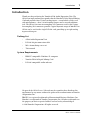 3
3
-
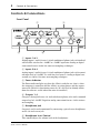 4
4
-
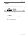 5
5
-
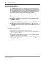 6
6
-
 7
7
-
 8
8
-
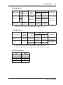 9
9
-
 10
10
-
 11
11
-
 12
12
-
 13
13
-
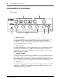 14
14
-
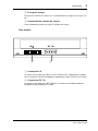 15
15
-
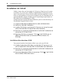 16
16
-
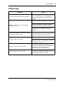 17
17
-
 18
18
-
 19
19
-
 20
20
-
 21
21
-
 22
22
-
 23
23
-
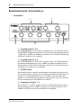 24
24
-
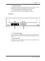 25
25
-
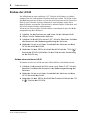 26
26
-
 27
27
-
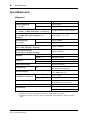 28
28
-
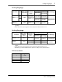 29
29
-
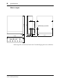 30
30
-
 31
31
-
 32
32
-
 33
33
-
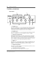 34
34
-
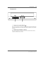 35
35
-
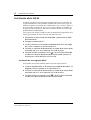 36
36
-
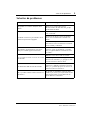 37
37
-
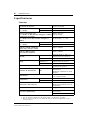 38
38
-
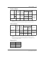 39
39
-
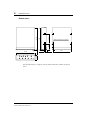 40
40
-
 41
41
-
 42
42
-
 43
43
-
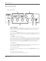 44
44
-
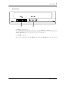 45
45
-
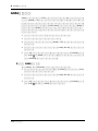 46
46
-
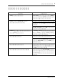 47
47
-
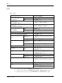 48
48
-
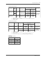 49
49
-
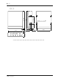 50
50
-
 51
51


in andere talen
- English: Yamaha AX44 Owner's manual
- italiano: Yamaha AX44 Manuale del proprietario
- русский: Yamaha AX44 Инструкция по применению
- français: Yamaha AX44 Le manuel du propriétaire
- español: Yamaha AX44 El manual del propietario
- Deutsch: Yamaha AX44 Bedienungsanleitung
- português: Yamaha AX44 Manual do proprietário
- dansk: Yamaha AX44 Brugervejledning
- čeština: Yamaha AX44 Návod k obsluze
- 日本語: Yamaha AX44 取扱説明書
- svenska: Yamaha AX44 Bruksanvisning
- Türkçe: Yamaha AX44 El kitabı
- polski: Yamaha AX44 Instrukcja obsługi
- română: Yamaha AX44 Manualul proprietarului