
DSP-AZ1
AV Amplifier
OWNER’S MANUAL
B
STANDBY
/ON
INPUT MODE
INPUT SELECTOR
VOLUME
SPEAKERS
BASS
SILENT
PHONES
A B
NEXT
PROCESSOR
DIRECT
BASS
EXTENSION
6CH
INPUT
STEREO
EFFECT
ON
S VIDEO VIDEO
OFF
LR
PHONO
CD
TUNER
CD–R
MD/TAPE
DVD
SOURCE/REMOTE
D–TV/LD
CABLE
SAT
VCR 1
VCR 2
VCR 3/DVR
VIDEO AUX
SET MENU
TREBLE
VIDEO AUX
L AUDIO
OPTICAL
R
PROGRAM
BALANCE
REC OUT/ZONE 2

CAUTION
CAUTION: READ THIS BEFORE OPERATING YOUR UNIT.
1 To assure the finest performance, please read this manual
carefully. Keep it in a safe place for future reference.
2 Install this unit in a well ventilated, cool, dry, clean place with at
least 30 cm on the top, 10 cm on the right and left, and 10 cm at
the back of this unit — away from direct sunlight, heat sources,
vibration, dust, moisture, and/or cold.
3 Locate this unit away from other electrical appliances, motors,
or transformers to avoid humming sounds. To prevent fire or
electrical shock, do not place this unit where it may get exposed
to rain, water, and/or any type of liquid.
4 Do not expose this unit to sudden temperature changes from
cold to hot, and do not locate this unit in a environment with
high humidity (i.e. a room with a humidifier) to prevent
condensation inside this unit, which may cause an electrical
shock, fire, damage to this unit, and/or personal injury.
5 On the top of this unit, do not place:
– Other components, as they may cause damage and/or discolora-
tion on the surface of this unit.
– Burning objects (i.e. candles), as they may cause fire, damage
to this unit, and/or personal injury.
– Containers with liquid in them, as they may cause electrical
shock to the user and/or damage to this unit.
6 Do not cover this unit with a newspaper, tablecloth, curtain, etc.
in order not to obstruct heat radiation. If the temperature inside
this unit rises, it may cause fire, damage to this unit, and/or
personal injury.
7 Do not plug in this unit to a wall outlet until all connections are
complete.
8 Do not operate this unit upside-down. It may overheat, possibly
causing damage.
9 Do not use force on switches, knobs and/or cords.
10 When disconnecting the power cord from the wall outlet, grasp
the plug; do not pull the cord.
11 Do not clean this unit with chemical solvents; this might
damage the finish. Use a clean, dry cloth.
12 Only voltage specified on this unit must be used. Using this unit
with a higher voltage than specified is dangerous and may cause
fire, damage to this unit, and/or personal injury. YAMAHA will
not be held responsible for any damage resulting from use of
this unit with a voltage other than specified.
13 To prevent damage by lightning, disconnect the power cord
from the wall outlet during an electrical storm.
14 Take care of this unit so that no foreign objects and/or liquid
drops inside this unit.
15 Do not attempt to modify or fix this unit. Contact qualified
YAMAHA service personnel when any service is needed. The
cabinet should never be opened for any reasons.
16 When not planning to use this unit for long periods of time (i.e.
vacation), disconnect the AC power plug from the wall outlet.
17 Be sure to read the “TROUBLESHOOTING” section on
common operating errors before concluding that this unit is
faulty.
18 Before moving this unit, press STANDBY/ON to set this unit in
the standby mode, and disconnect the AC power plug from the
wall outlet.
19 VOLTAGE SELECTOR (China and General models only)
The VOLTAGE SELECTOR on the rear panel of this unit must
be set for your local main voltage BEFORE plugging into the
AC main supply.
Voltages are 110/120/220/240 V AC, 50/60 Hz.
This unit is not disconnected from the AC power source as long
as it is connected to the wall outlet, even if this unit itself is
turned off. This state is called the standby mode. In this state,
this unit is designed to consume a very small quantity of power.
■ For U.K. customers
If the socket outlets in the home are not suitable for the plug
supplied with this appliance, it should be cut off and an appropriate
3 pin plug fitted. For details, refer to the instructions described
below.
Note
• The plug severed from the mains lead must be destroyed, as a plug
with bared flexible cord is hazardous if engaged in a live socket
outlet.
■ Special Instructions for U.K. Model
IMPORTANT
THE WIRES IN MAINS LEAD ARE COLOURED IN
ACCORDANCE WITH THE FOLLOWING CODE:
Blue: NEUTRAL
Brown: LIVE
As the colours of the wires in the mains lead of this apparatus
may not correspond with the coloured markings identifying the
terminals in your plug, proceed as follows:
The wire which is coloured BLUE must be connected to the
terminal which is marked with the letter N or coloured BLACK.
The wire which is coloured BROWN must be connected to the
terminal which is marked with the letter L or coloured RED.
Making sure that neither core is connected to the earth terminal
of the three pin plug.

INTRODUCTION
English
E-1
PREPARATIONS
BASIC OPERATIONS
ADVANCED
OPERATION
SOUND FIELD
PROGRAMS
APPENDIX
Contents
Contents
INTRODUCTION 3
Features ......................................................................................................................... 4
Controls and functions .................................................................................................. 6
PREPARATIONS 13
Speaker system configurations ................................................................................... 14
Speaker placement ...................................................................................................... 16
Connections ................................................................................................................ 18
On-screen displays (OSD) .......................................................................................... 33
Speaker mode settings ................................................................................................ 34
Speaker output levels .................................................................................................. 38
BASIC OPERATIONS 41
Basic playback ............................................................................................................ 42
Basic recording ........................................................................................................... 50
ADVANCED OPERATION 51
Set menu items ............................................................................................................ 52
Remote control features .............................................................................................. 64
Adjusting the levels of the effect speakers .................................................................. 81
Sleep timer .................................................................................................................. 82
Zone 2 ......................................................................................................................... 83
SOUND FIELD PROGRAMS 85
Digital sound field processing (DSP) ......................................................................... 86
Hi-Fi DSP-sound field program .................................................................................. 88
CINEMA-DSP sound field program ........................................................................... 90
Sound field program parameter editing ...................................................................... 95
Digital sound field parameter descriptions ................................................................. 96
APPENDIX 101
Troubleshooting ........................................................................................................ 102
CINEMA EQ frequency characteristics.................................................................... 105
Reference chart for the input and output jacks ......................................................... 106
Specifications ............................................................................................................ 107

E-2
CHECKING THE PACKAGE CONTENTS
Check your package to make sure it has the following items.
PUSH
TRANSMIT RE–NAME
CLEAR LEARN MACRO OFF ON
MACRO
SYSTEM
POWER
STANDBY
V–AUX TUNER PHONO
CABLE SAT MD/TAPE CD–R CD
D–TV/LD VCR 1 VCR 2 VCR3/DVR DVD
6CH INPUT
TITLE
DISPLAY
MENU
SOUND
ENTER
SOURCE
SEARCH
POWER STOP PAUSE PLAYREC
CHAPTER
SELECT
10KEY DSP
1
HALL 1
2
HALL 2
3
CHURCH
4
5678
JAZZ CLUB
0
CHP/INDEX
+
10
+
100
ROCK
CONCERT
ENTER–
TAINMENT
CONCERT
VIDEO 1
CONCERT
VIDEO 2
9101112
TV
THEATER
EX/ES
MOVIE
THEATER 1
MOVIE
THEATER 2
/DTS
SUR.
TV VOL CH
VOLUME
DISC
PRESET
A/B/C/D/E
TV MUTE
TV INPUT
MUTE
EFFECT
STEREO
ON SCREEN
SLEEP
LEVEL
TEST
SET MENU
PARAMETER
Remote control
Batteries (3) (LR6)
Power cord
(except for U.K. model)

E-3
INTRODUCTION
English
Introduction
Introduction
This section describes the features of the DSP-AZ1, and its controls and functions.
FEATURES ........................................................................................................... 4
CONTROLS AND FUNCTIONS............................................................................ 6
Front panel .................................................................................................................... 6
Remote control .............................................................................................................. 8
Front panel display ...................................................................................................... 11
Rear panel ................................................................................................................... 12

E-4
FEATURES
■ Built-in 8-channel power amplifier
• Main: 130 W + 130 W (8Ω) RMS Output Power, 0.015% THD, 20 – 20,000 Hz
• Center: 130 W (8Ω) RMS Output Power, 0.015% THD, 20 – 20,000 Hz
• Rear: 130 W + 130 W (8Ω) RMS Output Power, 0.015% THD, 20 – 20,000 Hz
• Front: 45 W + 45 W (8Ω) RMS Output Power, 0.05% THD, 1 kHz
• Rear center: 130 W (8Ω) RMS Output Power, 0.015% THD, 20 – 20,000 Hz
■ Digital Sound Fields (DSP)
Technological advances in sound reproduction over the last 30 years have enhanced the listening experience with improved clarity, precision,
and power. However, something has been missing: the atmosphere and acoustic ambience of the public venue. Our Yamaha engineers have
extensively researched the nature of sound acoustics and the way sound reflects inside a room. We sent these engineers to famous theaters
and concert halls around the world to measure the acoustics of those venues with sophisticated microphones. The data they collected is used
to recreate these environments in digital sound fields. Some of these digital sound fields have been created using data measured at the
original venue; others have been created from combinations of data to form unique environments for specific purposes. Some have been
designed especially for music, and others especially for movies. Of course, this only solves half of the problem. Because these engineers have
no way of knowing the acoustics of your entertainment room, we have made it possible for you to adjust the various parameters of this data
to tailor each virtual venue to your taste. You can use these sound fields to enhance any source and in combination with any of the following
surround sound technologies.
■ CINEMA-DSP: Dolby Digital + DSP and DTS + DSP
The Dolby Digital system and DTS system show their full capability in large movie theaters, because feature film soundtracks are designed
to be reproduced in such environments. It is difficult to recreate a sound environment similar to a movie theater in your entertainment room
because of the room size, wall materials, and the number of speakers in your entertainment system. Yamaha DSP technology makes it
possible for you to enjoy nearly the same sound experience as that of a large movie theater in your entertainment room by compensating for
lack of presence and dynamics in your entertainment room with Yamaha's original digital sound fields combined with Dolby Digital or DTS
soundtracks.
■ Virtual CINEMA DSP and SILENT CINEMA DSP
Yamaha developed the Virtual CINEMA DSP algorithm which allows you to experience the virtual sound fields without surround speakers.
This makes it possible for the DSP-AZ1 to produce a full surround sound catering to the number of speakers you have. The DSP-AZ1 also
has a SILENT CINEMA DSP algorithm which is achieved by the crosstalk processing applying the precise Head Related Transfer Function.
You can therefore enjoy listening to the CINEMA DSP soundfields on headphones.
■ Various decoders to support the newest sound effect technology
This unit is equipped with the following signal format decoders.
• Dolby Digital and Dolby Digital EX
The Matrix decoder enables 6.1-channel playback of the 5.1-channel sources by extracting the rear center channel signals from the rear L/R
channel signals.
• DOLBY PRO LOGIC
• DOLBY PRO LOGIC
DOLBY PRO LOGIC is the improved technique to decode vast numbers of existing Dolby Surround programs. This new technology
enables a discrete 5-channel playback with two left and right main channels, a center channel, and two left and right rear channels compared
with one limited rear channel for the conventional Pro Logic technology. Also the music mode is available for 2-channel sources in addition
to the movie mode.
• DTS and DTS ES
The DSP-AZ1 is also equipped with a DTS decoder, which uses a 5.1-channel system to create a full surround sound environment. It was
developed as a way to replace the analog soundtracks of movies with six channels of digital sound. In comparison with Dolby Digital, DTS
uses less compression to store the sound information. The newly presented DTS ES system reproduces digital sound similar to Dolby Digital
EX. The use of the rear center speaker along with the existing 5.1-channel speakers provides a fully immersive cinematic audio experience.
• DTS Neo: 6
Neo: 6 decodes the conventional 2-channel sources for 6-channel playback by the specific decoder. It enables playback with the full-range
channels with higher separation just like digital discrete signal playback. Two modes are available; “Music mode” for playing music sources
and “Cinema mode” for movies.
• DTS 96/24
DTS 96/24 achieves the high quality playback with all 5.1 channels at the sampling frequency 96 kHz/24 bit.

E-5
INTRODUCTION
English
■ Various input and output jacks
The DSP-AZ1 has various output jacks for audio and video signals as well as a digital recording output jack. Many input jacks are also
available for connection to multiple audio-video sources. All the video inputs and outputs have S-video jacks in addition to standard
composite video jacks for improved video picture quality. Component video input and output jacks are also available to deliver the excellent
video signals from DVD players and other high quality video sources. The coaxial and optical digital signal jacks (provided for direct
transmission of digital signals) automatically detect Dolby Digital, DTS, and PCM signals. A demodulator circuit is built into the Dolby
Digital RF input so you can connect it directly to the Dolby Digital RF signal output on your LD player. Additionally, there are six audio
inputs for discrete multichannel reproduction from an external decoder.
The DSP-AZ1 also comes with a monaural subwoofer jack and split subwoofer jacks which can reproduce delicate but powerful low
frequency effects.
■ Multi-function remote control
The remote control can operate other audio-video components once you program the remote control using the manufacturer code and Learn
feature.
FEATURES
Manufactured under license from Dolby Laboratories.
“Dolby”, “Pro Logic”, and the double-D symbol are trademarks of Dolby Laboratories.
“DTS”, “DTS-ES Extended Surround” and “Neo: 6” are trademarks of Digital Theater System, Inc.

E-6
CONTROLS AND FUNCTIONS
Front panel
STANDBY
/ON
INPUT MODE
INPUT SELECTOR
VOLUME
SPEAKERS
BASS
SILENT
PHONES
A B
NEXT
PROCESSOR
DIRECT
BASS
EXTENSION
6CH
INPUT
STEREO
EFFECT
ON
S VIDEO VIDEO
OFF
LR
PHONO
CD
TUNER
CD–R
MD/TAPE
DVD
SOURCE/REMOTE
D–TV/LD
CABLE
SAT
VCR 1
VCR 2
VCR 3/DVR
VIDEO AUX
SET MENU
TREBLE
VIDEO AUX
L AUDIO
OPTICAL
R
BALANCE
REC OUT/ZONE 2
PROGRAM
123 4567890qwer t
yui o p
1 STANDBY/ON
Turns this unit on (On mode) and off (Standby mode). When you
turn on this unit, you will hear a click and there will be a 4 to
5-second delay before this unit can reproduce sound.
In Standby mode, this unit consumes a small amount of power so it
can respond to the remote control.
2 INPUT MODE
Selects the mode of input for sources that output two or more types
of signals to this unit (see page 44).
Caution
• You cannot control the input mode when you select 6CH INPUT
as the input source.
3 INPUT SELECTOR
Selects the input source (D-TV/LD, CABLE, SAT, VCR 1, VCR 2,
VCR3/DVR, V-AUX, DVD, MD/TAPE, CD-R, TUNER, CD,
PHONO) you want to listen to or watch (see page 42).
4 Remote control sensor
Receives signals from the remote control.
5 SPEAKERS A/B
When pushed in (ON), these buttons turn on the set of main
speakers connected to the A and/or B terminals on the rear panel.
6 Front panel display
Shows information about the operational status of this unit (see
page 11).
7 SET MENU +/–
Adjusts the settings and parameter values of SET MENU items.
8 PROCESSOR DIRECT ON/OFF
When pushed in (ON), BASS, TREBLE, BALANCE, and BASS
EXTENSION are bypassed, eliminating any alteration of the
original signal.
9 NEXT
Displays SET MENU items. This button works like
on the remote
control when using the SET MENU (see page 53).
0 6CH INPUT
Switches between 6CH INPUT mode and normal input modes. 6CH
INPUT mode takes priority over the source selected with INPUT
SELECTOR.
You cannot use DSP sound field programs while using an external
decoder.
q STEREO/EFFECT
Switches the effect speakers (center, front effect, rear and rear
center) on and off. If you turn off the output of these speakers using
STEREO/EFFECT, all DTS and Dolby Digital audio signals are
directed to the main left and right channels except for the LFE
channel.
Cautions
• When DTS or Dolby Digital signals are mixed, the left and right
main channel signal levels may not match.
• If “1B MAIN SP” on the SET MENU is set to “SMALL” and “1E
LFE/BASS OUT” is set to “SW”, or “1E LFE/BASS OUT” is set
to “BOTH”, the LFE signals will be output from the subwoofer.

E-7
INTRODUCTION
English
w BASS EXTENSION ON/OFF
When pushed in (ON), this feature boosts the bass frequency of the
left and right main channels by +6 dB (60 Hz) while maintaining
overall tonal balance. This boost is useful if you do not use a
subwoofer.
However, this boost may not be noticeable if the main speakers are
set to “SMALL” and the bass output mode is set to “SW.”
e PROGRAM q/w
Selects the sound field program (see page 46).
Selecting a sound field program turns on the effect.
r BALANCE
Controls the balance of the sound levels coming from the left and
right main speaker(s). Setting this control to the center position is
appropriate for most situations.
t VOLUME
Controls the output level of all audio channels.
This does not affect the REC OUT level.
y BASS
Adjusts the low frequency response for the left and right main
speaker channels.
Turn the control to the right to increase the low frequency response
and turn the control to the left to decrease the low frequency
response.
Caution
• If you increase or decrease the low frequency sound to an extreme
level, the tonal quality from the center, front effect, rear center,
and rear speakers may not match that of the left and right main
speakers.
u PHONES
Outputs audio signals for private listening using headphones.
Cautions
• When you connect headphones, no signals are output to the
PREOUT jacks or the speakers.
• When the signal input into the 6CH INPUT jack is being played
back, only the left and right channel signals are output through the
headphones.
i TREBLE
Adjusts the high frequency response for the left and right main
channels.
Turn the control to the right to increase the high frequency response
and turn the control to the left to decrease the high frequency
response.
Caution
• If you increase or decrease the high frequency sound to an extreme
level, the tonal quality from the center, front effect, rear center,
and rear speakers may not match that of the left and right main
speakers.
o VIDEO AUX
Inputs audio and video signals from a portable external source such
as a video camera.
p REC OUT/ZONE 2
Selects the source you want to direct to the audio/video recorder and
ZONE 2 outputs independent of the source you are listening to in
the main room. When set to the SOURCE/REMOTE position, the
input source is directed to all outputs.
CONTROLS AND FUNCTIONS
■ Opening and closing the front panel door
When you are not operating the controls behind the front panel
door, close the door.
N
A
T
U
R
A
L
S
O
U
N
D
A
V
A
M
P
L
IF
IE
R
D
S
P
–
A
Z
1

E-8
CONTROLS AND FUNCTIONS
Remote control
1 Infrared window
Outputs infrared control signals. Aim this window at the component
you want to operate.
2 TRANSMIT
Flashes while the remote control is sending signals.
3 STANDBY
Sets this unit in the standby mode.
4 SYSTEM POWER
Turns on the power of this unit.
5 Display window
Shows the source component that you select to control.
6 SOURCE SELECT /
Selects the source component without switching the input.
7 LIGHT
Turns the light on or off.
When you press this button once, the light turns on for about 10
seconds. Press again to turn off the light.
8 Operation section
Provides functions such as play, stop, skip, etc. for operating your
other components.
Caution
• You can operate the other components that are not Yamaha with
this remote control after programming their remote control
functions (Learn) or setting the manufacturer code.
9 10KEY/DSP
Selects the numeric button (10KEY) mode or DSP mode. You can
use the 13 buttons to select numbers or DSP programs directly
according to the position of this switch.
0 EX/ES
Turns on or off the Dolby Digital EX or DTS ES decoder with
10KEY/DSP set to the DSP position.
q LEVEL
Selects the effect speaker channels (center, front, rear and
subwoofer) so you can adjust their level independently. Press this
button repeatedly to select the effect speaker channel you want to
adjust, then use + or – to adjust the level.
PUSH
TRANSMIT RE–NAME
CLEAR LEARN MACRO OFF ON
MACRO
SYSTEM
POWER
STANDBY
V–AUX TUNER PHONO
CABLE SAT MD/TAPE CD–R CD
D–TV/LD VCR 1 VCR 2 VCR3/DVR DVD
6CH INPUT
TITLE
DISPLAY
MENU
SOUND
ENTER
SOURCE
SEARCH
POWER
STOP PAUSE PLAYREC
CHAPTER
SELECT
10KEY DSP
1
HALL 1
2
HALL 2
3
CHURCH
4
5678
JAZZ CLUB
0
CHP/INDEX
+
10
+
100
ROCK
CONCERT
ENTER–
TAINMENT
CONCERT
VIDEO 1
CONCERT
VIDEO 2
9101112
TV
THEATER
EX/ES
MOVIE
THEATER 1
MOVIE
THEATER 2
/DTS
SUR.
TV VOL CH
VOLUME
DISC
PRESET
A/B/C/D/E
TV MUTE
TV INPUT
MUTE
EFFECT
STEREO
ON SCREEN
SLEEP
LEVEL
TEST
SET MENU
PARAMETER
1
t
y
u
i
o
p
a
s
d
f
2
3
4
5
6
7
9
0
q
w
e
r
8

E-9
INTRODUCTION
English
CONTROLS AND FUNCTIONS
w ON SCREEN
Selects the On-Screen Display mode for your video monitor (see
page 33).
e SLEEP
Sets the sleep timer.
r TEST
Selects the test mode.
t Remote control programming function buttons/
MACRO switch
Programs new remote control functions, sets manufacturer codes,
renames the input source names, or uses the Macro feature.
y Input section
Selects the input source.
Press an input selector button repeatedly to select the input mode.
u 6CH INPUT
Switches to the 6CH INPUT mode when using an external decoder
(see page 42).
i DSP program group/numeric buttons
Select DSP programs or numbers according to the position of
10KEY/DSP. (Press a button repeatedly to select a DSP program
within that group.)
o MUTE
Mutes the sound. While the mute function is on, “MUTE ON”
appears on the front panel display.
p VOLUME +/–
Increases or decreases the volume level.
a STEREO/EFFECT
Switches the effect speakers (center, front, rear, and rear center) on
and off. If the output of these speakers is switched off, all DTS and
Dolby Digital audio signals are directed to the main left and right
channels except for the LFE channel.
s PARAMETER/SET MENU
Selects the PARAMETER mode or SET MENU mode.
You can use / /+/– to adjust DSP program parameter values or
SET MENU items according to the position of this switch.
d / /+/–
Selects and adjusts DSP program parameters and SET MENU items
according to the position of PARAMETER/SET MENU.
f Cover
Slides down to show the setup buttons.

E-10
CONTROLS AND FUNCTIONS
■ Installing batteries in the remote control
1
1
Open the battery compartment cover.
2
2
Insert three supplied batteries (LR6) in the correct
direction by aligning the + and – marks on the
batteries with the polarity markings (+ and –) on the
inside of the battery compartment.
3
3
Replace the cover as pressing until it snaps into
place.
Cautions
• Insert the batteries in the correct direction by aligning the + and –
marks on the batteries with the polarity illustrations (+ and –)
inside the battery compartment.
• Change the batteries periodically.
• Do not use old batteries together with new ones.
• Do not use different types of batteries (such as alkaline and
manganese batteries) together. Read the packaging carefully as
these different types of batteries may have the same shape and
color.
RESET
■ About changing batteries
As the batteries wear out, the operating range of the remote control
decreases and the TRANSMIT indicator does not flash or its light
becomes dim. When you notice any of these conditions, change all
of the batteries. After you insert new batteries, be sure to push
RESET in the battery compartment using a ball point pen or similar
object before using the remote control. (This does not clear the
contents of the memory.)
Caution
• If the remote control is without batteries for more than 3 minutes,
or if exhausted batteries remain in the remote control, the contents
of the memory may be cleared. When the memory is cleared,
insert new batteries, set up the manufacturer code and program
any acquired functions that may have been cleared.
■ Using the remote control
The remote control transmits a directional infrared beam. Be sure to
aim the remote control directly at the remote control sensor on the
main unit during operation.
Cautions
• When the sensor is covered or there is a large object between the
remote control and the main unit, the sensor cannot receive
signals.
• The sensor may not be able to receive signals properly when it is
exposed to direct sunlight or a strong artificial light (such as a
fluorescent or strobe light). In this case, change the direction of
the light or reposition the main unit to avoid direct lighting.
• Handle the remote control with care.
• Do not spill water or other liquids on the remote control.
• Do not drop the remote control.
• Do not leave or store the remote control in the following types of
conditions:
1 high humidity or temperature such as near a heater, stove or
bath
2 dusty places
3 in places subject to extremely low temperatures
STANDBY
/ON
INPUT MODE
INPUT SELECTOR
VOLUME
NATURAL SOUND AV AMPLIFIER DSP–AZ1
30° 30°
Approximately 6 m (20 feet)
Remote control

E-11
INTRODUCTION
English
CONTROLS AND FUNCTIONS
Front panel display
1 Input source indicator
Shows the current input source with the arrow-shaped cursor.
2
DSP
indicator
Lights up when you select a digital sound field program.
3
96kHz
/
24bit
indicator
Lights up when the DTS 96/24 signal is input to this unit.
4 Processor indicators
When any function of DTS, MATRIX, DISCRETE, g,
and
PRO LOGIC
/
is activated, its indicator lights up.
5 Multi-information display
Shows the current DSP program and other information when
adjusting or changing settings.
6 VOLUME level indicator
Indicates the volume level.
7 SLEEP indicator
Lights up while the sleep timer is on.
D–TV/LD DVD
CABLE
MD/TAPE
SAT
CD–R
VCR 1 TUNER
VCR 2 CD
VCR3/DVR
PHONO
V–AUX
SLEEP
VIRTUAL
MATRIX
DISCRETE
DIGITAL
PRO LOGIC
/
96kHz
/
24bit
DSP
PCM
VOLUME
LFE
L C R
RL
SP
AB
SILENT
RC RR
1
789 0qwer
234 5 6
8 VIRTUAL indicator
Lights up when using Virtual CINEMA DSP (see page 49).
9
PCM
indicator
Lights up when this unit is reproducing PCM (Pulse Code Modula-
tion) digital audio signals.
0 Headphones indicator
Lights up when headphones are connected.
q SPEAKERS A/B indicator
Lights up according to which set of main speakers are selected.
Both indicators light up when both sets of speakers are selected.
w SILENT indicator
Lights up when headphones are connected with the sound effect
(see “SILENT CINEMA DSP” on page 49).
e Input channel indicator
Indicates the channel components of input signals being received.
r
LFE
indicator
Lights up when the input signal contains the LFE signal.

E-12
CONTROLS AND FUNCTIONS
Rear panel
1 DIGITAL OPTICAL/COAXIAL jacks
See page 19 for detailed information.
2 Audio component jacks
See pages 19 and 20 for connection information.
3 Video component jacks
See pages 21 to 28 for connection information.
4 Speaker terminals
See pages 29 and 30 for connection information.
5 MAINS
Use this inlet to plug in the supplied power cord.
6 IMPEDANCE SELECTOR
Use this switch to match the amplifier output to your speaker
impedance. Turn off the power before you change the setting of this
switch (see page 30).
AC OUTLETS
IMPEDANCE SELECTOR
SET BEFORE POWER ON
MAINS
SWITCHED
SPEAKERS
R L
FRONT
R
R L
L
REAR
CENTER
MAIN
B
R L
A
REAR CENTER
(
SURROUND
)
CAUTION
SEE INSTRUCTION MANUAL FOR CORRECT SETTING.
A
DVD
COMPONENT VIDEO
AUDIOAUDIODIGITAL
ZONE 2 OUTDIGITAL
VIDEO
B
D–TV
/LD
C
SAT
MONITOR
OUT
FRONT
IN
FRONT
OUT
REAR
(
SURROUND
)
SUB
WOOFER
SPLIT
MONO
REAR CTR
IN
OUT
REMOTE 1
IN
CTRL
OUT
+12V
10mA
MAX.
RS–
232C
REMOTE 2
CENTER
IN
CENTER
OUT
YP
B
/C
B
P
R
/C
R
R L
PREOUT/MAIN IN
CONTROL
MAIN
IN
MAIN
OUT
R L
VIDEO
DVD
PHONO
GND
CD
S VIDEO
LRR L
CABLE
SAT
IN
VCR 1
OUT
IN
VCR 2
OUT
IN
VCR 3
/DVR
OUT
VIDEO
6CH INPUT
CENTER
SUB
WOOFER
VCR 3
/DVR
1
MONITOR
OUT
2
D–TV
/LD
L
SURROUND
MAIN
R
1
TUNER
CD–R
2
IN
(PLAY)
3
OUT
(REC)
4
MD/TAPE
IN
(PLAY)
3
OUT
(REC)
4
OPTICAL
IN
OPTICAL
OUT
COAXIAL
IN
w
D–TV
/LD
0
MD/
TAPE
6
SAT
q
DVD
9
CD–R
8
CD
7
CD–R
5
CABLE
4
DVD
3
CD
2
LD
LD
RF
(AC–3)
1
VOLTAGE SELECTOR
FRONT
REAR
REAR CENTER
CENTER
MAIN A OR B
A + B
:
6Ω
MIN. /SPEAKER
:
4Ω
MIN. /SPEAKER
:
4Ω
MIN. /SPEAKER
:
4Ω
MIN. /SPEAKER
:
4Ω
MIN. /SPEAKER
:
8Ω
MIN. /SPEAKER
FRONT
REAR
REAR CENTER
CENTER
MAIN A OR B
A + B
:
8Ω
MIN. /SPEAKER
:
8Ω
MIN. /SPEAKER
:
8Ω
MIN. /SPEAKER
:
8Ω
MIN. /SPEAKER
:
8Ω
MIN. /SPEAKER
:
16 Ω
MIN. /SPEAKER
12 3 4 5 6
78 0q w
e9
7 6CH INPUT jacks
See page 32 for connection information.
8 ZONE 2 OUT jacks
See page 83 for connection information.
9 REMOTE 1 IN/OUT/REMOTE 2 IN jacks
See page 83 for connection information.
0 RS-232C/CTRL OUT +12V terminals
These are control expansion terminals for commercial use. Consult
your dealer for details.
q PREOUT/MAIN IN jacks
See page 31 for connection information.
w AC OUTLET(S)
Use these outlets to supply power to your other audio/video
component.
e VOLTAGE SELECTOR (General and China models)
See page 32.
(General and China models)

PREPARATIONS
English
E-13
Preparations
Preparations
This section explains how to make preparations (speaker selection and placement, subwoofer
usage, connection with other components, speaker mode setting, and speaker level adjustment) to
fully use the DSP-AZ1.
SPEAKER SYSTEM CONFIGURATIONS .......................................................... 14
SPEAKER PLACEMENT .................................................................................... 16
CONNECTIONS .................................................................................................. 18
Before connecting components ................................................................................... 18
Connecting digital jacks .............................................................................................. 19
Connecting audio components .................................................................................... 19
Connecting video components .................................................................................... 21
Connecting speakers ................................................................................................... 29
Connecting other components .................................................................................... 31
Connecting the power supply cords ............................................................................ 32
ON-SCREEN DISPLAYS (OSD) ......................................................................... 33
OSD modes ................................................................................................................. 33
Selecting the OSD mode ............................................................................................. 33
SPEAKER MODE SETTINGS ............................................................................ 34
SPEAKER OUTPUT LEVELS ............................................................................ 38
TEST DOLBY SUR. .................................................................................................. 39
TEST DSP ................................................................................................................... 40

E-14
SPEAKER SYSTEM CONFIGURATIONS
The most complete speaker configuration consists of eight speakers: the left and right main speakers, a center speaker, the left and right rear
speakers, the left and right front effect speakers, and a rear center speaker. If you do not use eight speakers, you can direct the signals for
speakers that are not in your system to other speakers in your configuration. A subwoofer can be used with any of these configurations to
produce a fuller sound.
■ 8-speaker configuration –full CINEMA-DSP–
When you reproduce feature film software, this configuration fully expresses the powerful and realistic sound qualities of 70 mm multitrack
audio. The dialogue is positioned as if it were coming from directly on the screen, the sound effect is positioned slightly behind the screen,
and the soundtrack music is positioned even further behind the screen to express the width and depth of the overall presentation. This
configuration makes the most of this unit's capability.
■ 6-speaker configuration –Hi-Fi DSP–
This configuration is used the most for audio playback with Hi-Fi DSP. It does not position the dialogue sound as well as a 7- or 8-speaker
configuration. However, it creates a dynamic DSP (Digital Sound Field Processor) sound field which adds depth to the sound.
For this speaker configuration, change SET MENU item “1A CENTER SP” to “NONE” and “1D REAR CT SP” to “NONE”.
Front effect speaker (FL)
TV (monitor)
Front effect speaker (FR)
Main speaker (R)
Rear effect speaker (RR)
1.5 – 1.8 m
(5 – 6 feet)
Center speaker (C)
Rear center speaker (RC)
Main speaker (L)
Rear effect speaker (RL)
Speakers to be used
• Main L/R
• Center
• Rear L/R
• Front effect L/R
• Rear center
RL
FR
RR
FL
L
C
R
RC
RL
FR
RR
FL
L
R
(L+C) (R+C)
Speakers to be used
• Main L/R
• Rear L/R
• Front effect L/R

E-15
PREPARATIONS
English
SPEAKER SYSTEM CONFIGURATIONS
■ 5-speaker configuration –standard 5.1 channel–
This configuration does not express the height of the sound field as well as the 7- or 8-speaker configuration. However, it positions the
dialogue sound as coming directly from the screen.
For this speaker configuration, change SET MENU item “1F FRONT EFCT SP” to “NONE” and “1D REAR CT SP” to “NONE”.
■ 4-speaker configuration –minimum requirement–
In this configuration, the center speaker signals and front effect speaker signals are directed to the left and right main speakers.
For this speaker configuration, change SET MENU item “1A CENTER SP” to “NONE”, item “1F FRONT EFCT SP” to “NONE”, and item
“1D REAR CT SP” to “NONE”.
■ Speaker configurations and speaker mode
Select the appropriate speaker mode depending on the speaker configuration. See “SPEAKER MODE SETTINGS” on page 34 for details.
Speakers to be used
• Main L/R
• Center
• Rear L/R
RL
RR
L
R
C
(L+FL) (R+FR)
RL
RR
L
R
(L+C+FL) (R+C+FR)
Speakers to be used
• Main L/R
• Rear L/R
1A CENTER SP
(Center)
1B MAIN SP
(Main L/R)
1C REAR L/R SP
(Rear L/R)
1D REAR CT SP
(Rear center)
1F FRONT EFCT SP
(Front effect L/R)
Note
• As a guideline, select “LARGE” for the larger speaker diameter than 16 cm, and “SMALL” for the smaller speaker diameter than 15 cm.
Change the speaker mode setting as listening to the actual playback sound if it does not meet your expectation.
8 speakers
LRG/SML
LARGE/SMALL
LRG/SML
LRG/SML
YES
7 speakers
LRG/SML
LARGE/SMALL
LRG/SML
NONE
YES
6 speakers
NONE
LARGE/SMALL
LRG/SML
NONE
YES
5 speakers
LRG/SML
LARGE/SMALL
LRG/SML
NONE
NONE
4 speakers
NONE
LARGE/SMALL
LRG/SML
NONE
NONE

E-16
SPEAKER PLACEMENT
Refer to the following diagram when you place the speakers.
Caution
• Use magnetically shielded speakers. If this type of speakers still creates the interference with a monitor, place the speakers away from the
monitor.
■ Placing the main speakers
Place the left and right main speakers an equal distance from the main listening position.
If you have a TV or video monitor in your system, the distance of each speaker from each
side of the TV or video monitor should be the same.
■ Placing the center speaker
If you have a TV or video monitor in your system, align the front face of the center
speaker with the front face of the monitor. Place the speaker as close to the monitor as
possible, such as directly over or under the monitor. If you place the speaker under the
monitor, the front effect speakers can adjust the height of the sound to correspond with the
action on the screen (depending on the listener’s position). If you have a projection screen
in your system, place the center speaker under the screen. Be sure to align the speaker
with the center of the screen.
Main
speaker
Main
speaker
TV or video
monitor
Center speaker
TV or video
monitor
■ Placing the front effect, rear and rear center speakers
These speakers should be placed about 0.5 – 1 m (1 – 3 feet) outside the main speakers
and in the front of the room. They should be turned toward the main listening position.
Place the rear speakers in the back of the room so they face the main listening position.
The rear speakers can be placed farther apart than the front effect speakers. Place these
speakers at the height of 1.5 m when listening as sitting on the floor or 1.8 m when
listening as sitting on the chair.
Once you begin listening to programs, continue to adjust the speaker placement until you
obtain a balanced sound from the main speakers and the front effect and rear speakers.
This distance can be farther than the front
effect speakers’.
RL
FR
RR
FL
L
C
R
RC
1m 0.5 - 1m 1.5 - 3m 0.5 - 1m 1m
(3ft) (1 - 3ft) (5 - 15ft) (1 - 3ft) (3ft)
■ When you use a projection screen
Place the speakers as shown in the illustration.
The main speakers should be placed about one-quarter of the way up from the bottom of
the screen.
Place the center speaker in the center and directly under the screen. The center speaker
provides precise dialogue localization.
When you use a projection screen with your system, the front effect speakers provide
better effect quality. The CINEMA-DSP sound field programs (see pages 90 to 94) raise
the sound from the center speaker upward and provide natural sound corresponding with
the video images.
L
C
R
1/4
1
Screen

E-17
PREPARATIONS
English
SPEAKER PLACEMENT
■ Placing the subwoofers
Place the front subwoofer near the main speakers. Turn it slightly toward the center of the room to reduce wall reflections.
If you use a rear subwoofer, place it behind the main listening position. The placement of the rear subwoofer is not critical because of the
ultra low frequencies of the sound being reproduced.
By adding a high quality subwoofer to the speaker configurations shown on page 14, you can enjoy more powerful and realistic movie
effects, even if your main speakers are large.
Note
• If you use different brands of speakers (with different tonal qualities) in your configuration, the tone of a moving human voice and other
types of sound may not shift smoothly. We recommend that you use speakers from the same manufacturer or speakers with the same tonal
quality.
You can also adjust the output levels and equalization of your effect speakers using the SET MENU (see pages 56 and 57).
If you are using small speakers, the addition of a subwoofer will reinforce the sound effects of movies.
Front subwoofer
Rear subwoofer

E-18
CONNECTIONS
Before connecting components
CAUTION
Never connect this unit and other components to mains power until all connections between components have been completed.
• Some components require different connection methods and have different jack names. Refer to the operation instructions for each
component also.
• Input and output jacks for the pin jacks are color-coded depending on the signal type.
• When connecting input and output jacks, use commercially available cables (pin-plug cable, fiber-optic cable, coaxial cable and S-Video
cable).
• When this unit interferes with the other components (such as a TV and tuner), replace this unit apart from those components. To prevent the
interference with a TV or tuner, it is recommended that an external antenna is placed and coaxial cables are used for connections.
AC OUTLETS
IMPEDANCE SELECTOR
SET BEFORE POWER ON
MAINS
SWITCHED
SPEAKERS
R L
FRONT
R
R L
L
REAR
CENTER
MAIN
B
R L
A
REAR CENTER
(
SURROUND
)
CAUTION
SEE INSTRUCTION MANUAL FOR CORRECT SETTING.
A
DVD
COMPONENT VIDEO
AUDIOAUDIODIGITAL
ZONE 2 OUTDIGITAL
VIDEO
B
D–TV
/LD
C
SAT
MONITOR
OUT
FRONT
IN
FRONT
OUT
REAR
(
SURROUND
)
SUB
WOOFER
SPLIT
MONO
REAR CTR
IN
OUT
REMOTE 1
IN
CTRL
OUT
+12V
10mA
MAX.
RS–
232C
REMOTE 2
CENTER
IN
CENTER
OUT
YPB/CB PR/CR
R L
PREOUT/MAIN IN
CONTROL
MAIN
IN
MAIN
OUT
R L
VIDEO
DVD
PHONO
GND
CD
S VIDEO
LRR L
CABLE
SAT
IN
VCR 1
OUT
IN
VCR 2
OUT
IN
VCR 3
/DVR
OUT
VIDEO
6CH INPUT
CENTER
SUB
WOOFER
VCR 3
/DVR
1
MONITOR
OUT
2
D–TV
/LD
L
SURROUND
MAIN
R
1
TUNER
CD–R
2
IN
(PLAY)
3
OUT
(REC)
4
MD/TAPE
IN
(PLAY)
3
OUT
(REC)
4
OPTICAL
IN
OPTICAL
OUT
COAXIAL
IN
w
D–TV
/LD
0
MD/
TAPE
6
SAT
q
DVD
9
CD–R
8
CD
7
CD–R
5
CABLE
4
DVD
3
CD
2
LD
LD
RF
(AC–3)
1
VOLTAGE SELECTOR
FRONT
REAR
REAR CENTER
CENTER
MAIN A OR B
A + B
:
6Ω
MIN. /SPEAKER
:
4Ω
MIN. /SPEAKER
:
4Ω
MIN. /SPEAKER
:
4Ω
MIN. /SPEAKER
:
4Ω
MIN. /SPEAKER
:
8Ω
MIN. /SPEAKER
FRONT
REAR
REAR CENTER
CENTER
MAIN A OR B
A + B
:
8Ω
MIN. /SPEAKER
:
8Ω
MIN. /SPEAKER
:
8Ω
MIN. /SPEAKER
:
8Ω
MIN. /SPEAKER
:
8Ω
MIN. /SPEAKER
:
16 Ω
MIN. /SPEAKER
Connecting digital jacks
^ P.19
Connecting audio
components ^ P.19
Connecting video
components ^ P.21
Connecting the power
supply cords ^ P.32
Connecting other
components ^ P.31
Connecting speakers
^ P.29

E-19
PREPARATIONS
English
CONNECTIONS
Connecting digital jacks
This unit has digital jacks for direct transmission of digital signals through either coaxial or fiber optic cables.
Notes
• DIGITAL OUTPUT jacks and analog OUT (REC) jacks are independent. Only digital signals are output from DIGITAL OUTPUT jacks
and analog signals from OUT (REC) jacks.
• You can use the digital jacks to input PCM, Dolby Digital and DTS bitstreams.
• When you connect components to both the COAXIAL and OPTICAL jacks, priority is given to the input signals from the COAXIAL jack.
• The OPTICAL jacks on this unit conform to the EIA standard. If you use a fiber optic cable that does not conform to this standard, this unit
may not function properly.
• You can designate the input for each digital jacks according to your component by using “8 I/O ASSIGNMENT” on the SET MENU (see
page 58 for details).
Digital input jacks of this unit support the following sampling frequency.
• 32 kHz
• 44.1 kHz: CD, CD-R and MD
• 48 kHz: DVD (48 kHz mode)
• 96 kHz: DVD (96 kHz mode)
• 192 kHz (coaxial input only): DVD audio (2-channel)
Connecting audio components
Before you connect any components, disconnect the power supply to all the components you plan to connect including this unit and deter-
mine which jacks are for the left and right channels and for input and output.
When you connect other YAMAHA audio component (such as a CD player or changer, MD deck, or tape deck), connect to terminals with the
same number labels. Yamaha applies this labelling system to all its products.
■ Connecting an FM/AM tuner ■ Connecting a CD recorder
AUDIOAUDIODIGITAL VIDEO
VIDEO
DVD
PHONO
GND
CD
S VIDEO
LRR L
CABLE
SAT
D–TV
/LD
1
TUNER
2
N
3
COAXIAL
IN
CAB E
4
DVD
3
CD
2
LD
LD
RF
(AC–3)
1
AUDIO OUT
FM/AM tuner
AUDIOAUDIODIGITAL VIDEO
VIDEO
DVD
PHONO
GND
CD
S VIDEO
LRR L
CABLE
SAT
IN
VCR 1
OUT
IN
VCR 2
OUT
IN
D–TV
/LD
SURROUND
MAIN
1
TUNER
CD–R
2
IN
(PLAY)
3
OUT
(REC)
4
MD/TAPE
IN
(PLAY)
3
OUT
(REC)
4
OPTICAL
OUT
COAXIAL
IN
MD/
TAPE
6
DVD
9
CD–R
8
CD
7
CD–R
5
CABLE
4
DVD
3
CD
2
LD
LD
RF
(AC–3)
1
ANALOG AUDIO
OUT
ANALOG AUDIO IN
OPTICAL IN
OPTICAL OUT
CD recorder

E-20
CONNECTIONS
■ Connecting a CD player
The COAXIAL CD and OPTICAL CD jacks are available for a CD
player which has coaxial or optical digital outputs.
■ Connecting an MD recorder/tape deck
Note
• To connect the OPTICAL (COAXIAL) output jack for an MD
recorder with this unit, you can use any of the OPTICAL
(COAXIAL) IN jacks by changing the setting for “8 I/O ASSIGN-
MENT” on the SET MENU.
AUDIOAUDIODIGITAL VIDEO
VIDEO
DVD
PHONO
GND
CD
S VIDEO
LRR L
CABLE
SAT
IN
VCR 1
OUT
IN
VCR 2
OUT
D–TV
/LD
MAIN
1
TUNER
CD–R
2
IN
(PLAY)
3
OUT
(REC)
4
MD/TAPE
IN
(PLAY)
3
OUT
(REC)
4
OPTICAL
OUT
COAXIAL
IN
MD/
TAPE
6
CD–R
8
CD
7
CD–R
5
CABLE
4
DVD
3
CD
2
LD
LD
RF
(AC–3)
1
ANALOG AUDIO OUTCOAXIAL OUT
OPTICAL OUT
CD Player
AUDIOAUDIODIGITAL VIDEO
VIDEO
DVD
PHONO
GND
CD
S VIDEO
LRR L
CABLE
SAT
IN
VCR 1
OUT
IN
VCR 2
OUT
D–TV
/LD
MAIN
1
TUNER
CD–R
2
IN
(PLAY)
3
OUT
(REC)
4
MD/TAPE
IN
(PLAY)
3
OUT
(REC)
4
OPTICAL
OUT
COAXIAL
IN
MD/
TAPE
6
CD–R
8
CD
7
CD–R
5
CABLE
4
DVD
3
CD
2
LD
LD
RF
(AC–3)
1
ANALOG AUDIO
IN
ANALOG AUDIO
OUT
OPTICAL IN
MD recorder/tape deck
■ Connecting a turntable
These jacks are for connecting a turntable with an MM or high
output MC cartridge. If you have a turntable with a low output MC
cartridge, use an inline boosting transformer or MC-head amplifier
when connecting to these jacks.
Caution
• The GND terminal does not electrically ground the turntable. It
simply reduces noise in the signal. In some cases, you may hear
less noise if you do not connect to the GND terminal.
Ground
AUDIOAUDIODIGITAL VIDEO
VIDEO
DVD
PHONO
GND
CD
S VIDEO
LRR L
CABLE
SAT
D–TV
/LD
1
TUNER
2
N
3
COAXIAL
IN
CABLE
4
DVD
3
CD
2
LD
LD
RF
(AC–3)
1
AUDIO OUT
Turntable

E-21
PREPARATIONS
English
CONNECTIONS
Connecting video components
Before you connect any components, disconnect the power supply to all the components you plan to connect including this unit and deter-
mine which jacks are for the left and right channels and for input and output. After you finish all connections, check them again to make sure
they are correct.
■ About the video jacks
There are three types of video jacks.
AC OUTLETS
IMPEDANCE SELECTOR
SET BEFORE POWER ON
MAINS
SWITCHED
SPEAKERS
R L
FRONT
R
R L
L
REAR
CENTER
MAIN
B
R L
A
REAR CENTER
(
SURROUND
)
CAUTION
SEE INSTRUCTION MANUAL FOR CORRECT SETTING.
A
DVD
COMPONENT VIDEO
AUDIOAUDIODIGITAL
ZONE 2 OUTDIGITAL
VIDEO
B
D–TV
/LD
C
SAT
MONITOR
OUT
FRONT
IN
FRONT
OUT
REAR
(
SURROUND
)
SUB
WOOFER
SPLIT
MONO
REAR CTR
IN
OUT
REMOTE 1
IN
CTRL
OUT
+12V
10mA
MAX.
RS–
232C
REMOTE 2
CENTER
IN
CENTER
OUT
YP
B
/C
B
P
R
/C
R
R L
PREOUT/MAIN IN
CONTROL
MAIN
IN
MAIN
OUT
R L
VIDEO
DVD
PHONO
GND
CD
S VIDEO
LRR L
CABLE
SAT
IN
VCR 1
OUT
IN
VCR 2
OUT
IN
VCR 3
/DVR
OUT
VIDEO
6CH INPUT
CENTER
SUB
WOOFER
VCR 3
/DVR
1
MONITOR
OUT
2
D–TV
/LD
L
SURROUND
MAIN
R
1
TUNER
CD–R
2
IN
(PLAY)
3
OUT
(REC)
4
MD/TAPE
IN
(PLAY)
3
OUT
(REC)
4
OPTICAL
IN
OPTICAL
OUT
COAXIAL
IN
w
D–TV
/LD
0
MD/
TAPE
6
SAT
q
DVD
9
CD–R
8
CD
7
CD–R
5
CABLE
4
DVD
3
CD
2
LD
LD
RF
(AC–3)
1
VOLTAGE SELECTOR
FRONT
REAR
REAR CENTER
CENTER
MAIN A OR B
A + B
:
6Ω
MIN. /SPEAKER
:
4Ω
MIN. /SPEAKER
:
4Ω
MIN. /SPEAKER
:
4Ω
MIN. /SPEAKER
:
4Ω
MIN. /SPEAKER
:
8Ω
MIN. /SPEAKER
FRONT
REAR
REAR CENTER
CENTER
MAIN A OR B
A + B
:
8Ω
MIN. /SPEAKER
:
8Ω
MIN. /SPEAKER
:
8Ω
MIN. /SPEAKER
:
8Ω
MIN. /SPEAKER
:
8Ω
MIN. /SPEAKER
:
16 Ω
MIN. /SPEAKER
12 3
1 Composite VIDEO jack
Video signals input through the VIDEO jacks are the conventional
composite video signals.
2 S VIDEO jack
Video signals input through the S VIDEO jacks are separated into
luminance (Y) and color (C) video signals. The S-video signals
achieve high quality color reproduction. When you are using the S
VIDEO jacks, check the details in the owner’s manual that came
with the component being connected.
3 COMPONENT VIDEO jacks
Video signals input through the COMPONENT VIDEO jacks are
separated into luminance (Y) and color difference (PB/CB, PR/CR)
video signals. The jacks are also separated into three for each signal.
The labels of the component video jacks may be different depend-
ing on the component (e.g. Y, C
B, CR / Y, PB, PR / Y, B-Y, R-Y/ etc.).
Component video signals provide the best quality in picture
reproduction. When you are using the COMPONENT VIDEO
jacks, check the details in the owner’s manual that came with the
component being connected.
Cautions
• Use a commercially available S-video cable when connecting to
the S VIDEO jacks, and commercially available video cables
when connecting to the COMPONENT VIDEO jacks.
• Each type of video jack works independently. Signals input
through the composite video, S-video, and component jacks are
output through the corresponding composite video, S-video, and
component jacks respectively.
• If your video monitor is connected only to the COMPONENT
VIDEO jacks of this unit, the OSD is not shown.
Note
• You can designate the input for the COMPONENT VIDEO A, B
and C jacks according to your component by using “8 I/O
ASSIGNMENT” on the SET MENU (see page 58 for details).

E-22
CONNECTIONS
■ Connecting a DVD player
• Connect the left and right analog signal output jacks on your DVD player to the DVD L and R jacks. Connect the composite video signal
output jack on your DVD player to the DVD VIDEO jack.
• If your DVD player has an S-video output or component video output, you can connect it to this unit. Connect the S-video signal output
jack on your DVD player to the DVD S VIDEO jack or connect the component video signal output jacks on your DVD player to the DVD
COMPONENT VIDEO jacks.
• Connect the optical digital signal output jack on your DVD player to the OPTICAL DVD jack.
• Connect the coaxial digital signal output jack on your DVD player to the COAXIAL DVD jack.
A
DVD
COMPONENT VIDEO
AUDIOAUDIODIGITAL
ZONE 2 OUTDIGITAL
VIDEO
B
D–TV
/LD
C
SAT
MONITOR
OUT
FRONT
IN
FRONT
OUT
REAR
(
SURROUND
)
SUB
WOOFER
SPLIT
MONO
REAR CTR
IN
OUT
REMOTE 1
IN
CTRL
OUT
+12V
10mA
MAX.
RS–
232C
REMOTE 2
CENTER
IN
CENTER
OUT
YPB/CB PR/CR
R L
PREOUT/MAIN IN
CONTROL
MAIN
IN
MAIN
OUT
R L
VIDEO
DVD
PHONO
GND
CD
S VIDEO
LRR L
CABLE
SAT
IN
VCR 1
OUT
IN
VCR 2
OUT
IN
VCR 3
/DVR
OUT
VIDEO
6CH INPUT
CENTER
SUB
WOOFER
VCR 3
/DVR
1
MONITOR
OUT
2
D–TV
/LD
L
SURROUND
MAIN
R
1
TUNER
CD–R
2
IN
(PLAY)
3
OUT
(REC)
4
MD/TAPE
IN
(PLAY)
3
OUT
(REC)
4
OPTICAL
IN
OPTICAL
OUT
COAXIAL
IN
w
D–TV
/LD
0
MD/
TAPE
6
SAT
q
DVD
9
CD–R
8
CD
7
CD–R
5
CABLE
4
DVD
3
CD
2
LD
LD
RF
(AC–3)
1
ANALOG AUDIO
OUT
COMPONENT VIDEO OUT
VIDEO
OUT
S VIDEO
OUT
COAXIAL OUT
OPTICAL OUT
DVD player

E-23
PREPARATIONS
English
CONNECTIONS
■ Connecting a digital TV/TV
• Connect the left and right analog signal output jacks on your digital TV/TV to the D-TV/LD L and R jacks. Connect the composite video
signal output jack on your digital TV/TV to the D-TV/LD VIDEO jack.
• If your digital TV/TV has an S-video output or component video output, you can connect it to this unit. Connect the S-video signal output
jack on your digital TV/TV to the D-TV/LD S VIDEO jack or connect the component video signal output jacks on your digital TV/TV to
the D-TV/LD COMPONENT VIDEO jacks.
• Connect the optical digital signal output jack on your digital TV/TV to the OPTICAL D-TV/LD jack.
A
DVD
COMPONENT VIDEO
AUDIOAUDIODIGITAL
ZONE 2 OUTDIGITAL
VIDEO
B
D–TV
/LD
C
SAT
MONITOR
OUT
FRONT
IN
FRONT
OUT
REAR
(
SURROUND
)
SUB
WOOFER
SPLIT
MONO
REAR CTR
IN
OUT
REMOTE 1
IN
CTRL
OUT
+12V
10mA
MAX.
RS–
232C
REMOTE 2
CENTER
IN
CENTER
OUT
YP
B
/C
B
P
R
/C
R
R L
PREOUT/MAIN IN
CONTROL
MAIN
IN
MAIN
OUT
R L
VIDEO
DVD
PHONO
GND
CD
S VIDEO
LRR L
CABLE
SAT
IN
VCR 1
OUT
IN
VCR 2
OUT
IN
VCR 3
/DVR
OUT
VIDEO
6CH INPUT
CENTER
SUB
WOOFER
VCR 3
/DVR
1
MONITOR
OUT
2
D–TV
/LD
L
SURROUND
MAIN
R
1
TUNER
CD–R
2
IN
(PLAY)
3
OUT
(REC)
4
MD/TAPE
IN
(PLAY)
3
OUT
(REC)
4
OPTICAL
IN
OPTICAL
OUT
COAXIAL
IN
w
D–TV
/LD
0
MD/
TAPE
6
SAT
q
DVD
9
CD–R
8
CD
7
CD–R
5
CABLE
4
DVD
3
CD
2
LD
LD
RF
(AC–3)
1
ANALOG AUDIO
OUT
COMPONENT VIDEO OUT
VIDEO
OUT
S VIDEO
OUT
OPTICAL OUT
Digital TV/TV

E-24
CONNECTIONS
■ Connecting a cable TV tuner
• Connect the left and right analog signal output jacks on your cable TV tuner to the CABLE L and R jacks. Connect the composite video
signal output jack on your cable TV tuner to the CABLE VIDEO jack.
• If your cable TV tuner has an S-video output or component video output, you can connect it to this unit. Connect the S-video signal output
jack on your cable TV tuner to the CABLE S VIDEO jack or connect the component video signal output jacks on your cable TV tuner to
the SAT COMPONENT VIDEO jacks.
• Connect the optical digital signal output jack on your cable TV tuner to the OPTICAL SAT jack.
• Connect the coaxial digital signal output jack on your cable TV tuner to the COAXIAL CABLE jack.
Cautions
• When connecting the optical digital signal output jack on your cable TV tuner, it is necessary to change the setting for the OPTICAL SAT
jack of “8 I/O ASSIGNMENT” on the SET MENU in order to connect the digital audio signals to the SAT jack and the video signals to
CABLE jack. (See page 58.)
• When connecting the component video signal output jacks on your cable TV tuner, it is necessary to change the setting for SAT COMPO-
NENT VIDEO jacks of “8 I/O ASSIGNMENT” on the SET MENU in order to connect the audio signals to the CABLE jack and the
component video signal to the SAT jack. (See page 58.)
A
DVD
COMPONENT VIDEO
AUDIOAUDIODIGITAL
ZONE 2 OUTDIGITAL
VIDEO
B
D–TV
/LD
C
SAT
MONITOR
OUT
FRONT
IN
FRONT
OUT
REAR
(
SURROUND
)
SUB
WOOFER
SPLIT
MONO
REAR CTR
IN
OUT
REMOTE 1
IN
CTRL
OUT
+12V
10mA
MAX.
RS–
232C
REMOTE 2
CENTER
IN
CENTER
OUT
YP
B
/C
B
P
R
/C
R
R L
PREOUT/MAIN IN
CONTROL
MAIN
IN
MAIN
OUT
R L
VIDEO
DVD
PHONO
GND
CD
S VIDEO
LRR L
CABLE
SAT
IN
VCR 1
OUT
IN
VCR 2
OUT
IN
VCR 3
/DVR
OUT
VIDEO
6CH INPUT
CENTER
SUB
WOOFER
VCR 3
/DVR
1
MONITOR
OUT
2
D–TV
/LD
L
SURROUND
MAIN
R
1
TUNER
CD–R
2
IN
(PLAY)
3
OUT
(REC)
4
MD/TAPE
IN
(PLAY)
3
OUT
(REC)
4
OPTICAL
IN
OPTICAL
OUT
COAXIAL
IN
w
D–TV
/LD
0
MD/
TAPE
6
SAT
q
DVD
9
CD–R
8
CD
7
CD–R
5
CABLE
4
DVD
3
CD
2
LD
LD
RF
(AC–3)
1
ANALOG AUDIO
OUT
COMPONENT VIDEO OUT
VIDEO
OUT
S VIDEO
OUT
OPTICAL OUT
COAXIAL OUT
Cable TV tuner

E-25
PREPARATIONS
English
CONNECTIONS
■ Connecting a satellite tuner
• Connect the left and right analog signal output jacks on your satellite tuner to the SAT L and R jacks. Connect the composite video signal
output jack on your satellite tuner to the SAT VIDEO jack.
• If your satellite tuner has an S-video output or component video output, you can connect it to this unit. Connect the S-video signal output
jack on your satellite tuner to the SAT S VIDEO jack or connect the component video signal output jacks on your satellite tuner to the SAT
COMPONENT VIDEO jacks.
• Connect the optical digital signal output jack on your satellite tuner to the OPTICAL SAT jack.
• Connect the coaxial digital signal output jack on your satellite tuner to the COAXIAL CABLE jack.
Caution
• When connecting the coaxial digital signal output jack on your satellite tuner, it is necessary to change the setting for the COAXIAL
CABLE jack of “8 I/O ASSIGNMENT” on the SET MENU in order to connect the digital audio signals to the CABLE jack and the video
signals to SAT jack. (See page 58.)
A
DVD
COMPONENT VIDEO
AUDIOAUDIODIGITAL
ZONE 2 OUTDIGITAL
VIDEO
B
D–TV
/LD
C
SAT
MONITOR
OUT
FRONT
IN
FRONT
OUT
REAR
(
SURROUND
)
SUB
WOOFER
SPLIT
MONO
REAR CTR
IN
OUT
REMOTE 1
IN
CTRL
OUT
+12V
10mA
MAX.
RS–
232C
REMOTE 2
CENTER
IN
CENTER
OUT
YP
B
/C
B
P
R
/C
R
R L
PREOUT/MAIN IN
CONTROL
MAIN
IN
MAIN
OUT
R L
VIDEO
DVD
PHONO
GND
CD
S VIDEO
LRR L
CABLE
SAT
IN
VCR 1
OUT
IN
VCR 2
OUT
IN
VCR 3
/DVR
OUT
VIDEO
6CH INPUT
CENTER
SUB
WOOFER
VCR 3
/DVR
1
MONITOR
OUT
2
D–TV
/LD
L
SURROUND
MAIN
R
1
TUNER
CD–R
2
IN
(PLAY)
3
OUT
(REC)
4
MD/TAPE
IN
(PLAY)
3
OUT
(REC)
4
OPTICAL
IN
OPTICAL
OUT
COAXIAL
IN
w
D–TV
/LD
0
MD/
TAPE
6
SAT
q
DVD
9
CD–R
8
CD
7
CD–R
5
CABLE
4
DVD
3
CD
2
LD
LD
RF
(AC–3)
1
ANALOG AUDIO
OUT
COMPONENT VIDEO OUT
VIDEO
OUT
S VIDEO
OUT
OPTICAL OUT
COAXIAL OUT
Satellite tuner

E-26
CONNECTIONS
■ Connecting a VCR
• Connect the left and right audio signal output jacks on your VCR to the VCR 1 IN L and R jacks. Connect the left and right audio signal
input jacks on your VCR to the VCR 1 OUT L and R jacks. Connect the composite video signal output jack on your VCR to the VCR 1
VIDEO IN jack. Connect the composite video signal input jack on your VCR to the VCR 1 VIDEO OUT jack.
• If your VCR has an S-video output, you can connect it to this unit. Connect the S-video signal output jack on your VCR to the VCR 1 IN S
VIDEO jack. If your VCR has an S-video input, you can connect it to this unit. Connect the S-video signal input jack on your VCR to the
VCR 1 OUT S VIDEO jack.
• If your VCR has an optical digital signal output jack, connect it to the OPTICAL VCR 3/DVR jack.
Note
• You can connect other VCRs to the this unit using the VCR 2 and VCR 3/DVR jacks.
A
DVD
COMPONENT VIDEO
AUDIOAUDIODIGITAL
ZONE 2 OUTDIGITAL
VIDEO
B
D–TV
/LD
C
SAT
MONITOR
OUT
FRONT
IN
FRONT
OUT
REAR
(
SURROUND
)
SUB
WOOFER
SPLIT
MONO
REAR CTR
IN
OUT
REMOTE 1
IN
CTRL
OUT
+12V
10mA
MAX.
RS–
232C
REMOTE 2
CENTER
IN
CENTER
OUT
YP
B
/C
B
P
R
/C
R
R L
PREOUT/MAIN IN
CONTROL
MAIN
IN
MAIN
OUT
R L
VIDEO
DVD
PHONO
GND
CD
S VIDEO
LRR L
CABLE
SAT
IN
VCR 1
OUT
IN
VCR 2
OUT
IN
VCR 3
/DVR
OUT
VIDEO
6CH INPUT
CENTER
SUB
WOOFER
VCR 3
/DVR
1
MONITOR
OUT
2
D–TV
/LD
L
SURROUND
MAIN
R
1
TUNER
CD–R
2
IN
(PLAY)
3
OUT
(REC)
4
MD/TAPE
IN
(PLAY)
3
OUT
(REC)
4
OPTICAL
IN
OPTICAL
OUT
COAXIAL
IN
w
D–TV
/LD
0
MD/
TAPE
6
SAT
q
DVD
9
CD–R
8
CD
7
CD–R
5
CABLE
4
DVD
3
CD
2
LD
LD
RF
(AC–3)
1
AUDIO OUT VIDEO IN
S VIDEO IN
AUDIO IN
VIDEO
OUT
S VIDEO
OUT
This jack is for connecting with the
component that has an optical digital output
jack such as a DVD recorder.
VCR

E-27
PREPARATIONS
English
CONNECTIONS
■ Connecting an LD player
• Connect the left and right audio signal output jacks on your LD player to the D-TV/LD L and R jacks. Connect the composite video signal
output jack on your LD player to the D-TV/LD VIDEO jack.
• If your LD player has an S-video output, you can connect it to this unit. Connect the S-video signal output jack on your LD player to the D-
TV/LD S VIDEO jack.
• Connect the optical digital signal output jack on your LD player to the OPTICAL D-TV/LD jack.
• Connect the RF signal output jack on your LD player to the LD q RF (AC-3) jack.
A
DVD
COMPONENT VIDEO
AUDIOAUDIODIGITAL
ZONE 2 OUTDIGITAL
VIDEO
B
D–TV
/LD
C
SAT
MONITOR
OUT
FRONT
IN
FRONT
OUT
REAR
(
SURROUND
)
SUB
WOOFER
SPLIT
MONO
REAR CTR
IN
OUT
REMOTE 1
IN
CTRL
OUT
+12V
10mA
MAX.
RS–
232C
REMOTE 2
CENTER
IN
CENTER
OUT
YPB/CB PR/CR
R L
PREOUT/MAIN IN
CONTROL
MAIN
IN
MAIN
OUT
R L
VIDEO
DVD
PHONO
GND
CD
S VIDEO
LRR L
CABLE
SAT
IN
VCR 1
OUT
IN
VCR 2
OUT
IN
VCR 3
/DVR
OUT
VIDEO
6CH INPUT
CENTER
SUB
WOOFER
VCR 3
/DVR
1
MONITOR
OUT
2
D–TV
/LD
L
SURROUND
MAIN
R
1
TUNER
CD–R
2
IN
(PLAY)
3
OUT
(REC)
4
MD/TAPE
IN
(PLAY)
3
OUT
(REC)
4
OPTICAL
IN
OPTICAL
OUT
COAXIAL
IN
w
D–TV
/LD
0
MD/
TAPE
6
SAT
q
DVD
9
CD–R
8
CD
7
CD–R
5
CABLE
4
DVD
3
CD
2
LD
LD
RF
(AC–3)
1
ANALOG AUDIO
OUT
VIDEO
OUT
S VIDEO OUT
OPTICAL OUT
q RF OUT
LD player

E-28
CONNECTIONS
■ Connecting a video monitor
• Connect the composite video signal input jack on your video monitor to MONITOR OUT 1 VIDEO jack.
• If your video monitor has an S-video input or component video input, you can connect it to this unit. Connect the S-video signal input jack
on your video monitor to the MONITOR OUT 1 S VIDEO jack or connect the component video signal input jacks on your video monitor
to the COMPONENT VIDEO MONITOR OUT jacks.
Note
• You can connect another monitor to this unit using the MONITOR OUT 2 jacks.
A
DVD
COMPONENT VIDEO
AUDIOAUDIODIGITAL
ZONE 2 OUTDIGITAL
VIDEO
B
D–TV
/LD
C
SAT
MONITOR
OUT
FRONT
IN
FRONT
OUT
REAR
(
SURROUND
)
SUB
WOOFER
SPLIT
MONO
REAR CTR
IN
OUT
REMOTE 1
IN
CTRL
OUT
+12V
10mA
MAX.
RS–
232C
REMOTE 2
CENTER
IN
CENTER
OUT
YP
B
/C
B
P
R
/C
R
R L
PREOUT/MAIN IN
CONTROL
MAIN
IN
MAIN
OUT
R L
VIDEO
DVD
PHONO
GND
CD
S VIDEO
LRR L
CABLE
SAT
IN
VCR 1
OUT
IN
VCR 2
OUT
IN
VCR 3
/DVR
OUT
VIDEO
6CH INPUT
CENTER
SUB
WOOFER
VCR 3
/DVR
1
MONITOR
OUT
2
D–TV
/LD
L
SURROUND
MAIN
R
1
TUNER
CD–R
2
IN
(PLAY)
3
OUT
(REC)
4
MD/TAPE
IN
(PLAY)
3
OUT
(REC)
4
OPTICAL
IN
OPTICAL
OUT
COAXIAL
IN
w
D–TV
/LD
0
MD/
TAP E
6
SAT
q
DVD
9
CD–R
8
CD
7
CD–R
5
CABLE
4
DVD
3
CD
2
LD
LD
RF
(AC–3)
1
COMPONENT VIDEO IN
VIDEO IN
S VIDEO
IN
Video monitor
These jacks can be used to
connect another monitor.

E-29
PREPARATIONS
English
Connecting speakers
• Be sure to connect the left channel (L), right channel (R), “+”
(red) and “–” (black) properly. If the connections are faulty, no
sound will be heard from the speakers, and if the polarity of the
speaker connections is incorrect, the sound will be unnatural and
lack bass.
• Connect the speaker cables with care to avoid creating a short
circuit. If you turn on the power and there is a short circuit, this
unit may be damaged even though the protection circuit automati-
cally shuts off the power.
After you finish connecting your speakers, use the SET MENU to
change the signal output settings according to the number and size
of the speakers in your configuration.
CONNECTIONS
SPEAKERS
R L
FRONT
R
R L
L
REAR
CENTER
MAIN
B
R L
A
REAR CENTER
(
SURROUND
)
CAUTION
SEE INSTRUCTION MANUAL FOR CORRECT SETTING.
Center speaker
Front effect speakers
Right Left
Rear speakers
Right Left
Main B speakers
Right Left
Main A speakers
Right Left Rear center
speaker
Banana plug
10mm
Speaker cable
Good No good
■ Connecting the SPEAKERS terminals
A speaker cable is actually a pair of insulated cables running side by
side. One of the cables is colored or shaped differently, perhaps with
a stripe, groove or ridge.
1
1
Strip off 10 mm (3/8˝ ) of insulation from the ends of
the cables.
2
2
Twist the exposed wires of the cable together to
prevent short circuits.
3
3
Loosen the terminal knob by turning it counterclock-
wise.
4
4
Insert only the exposed portion of the cable into the
slot in the side of the terminal, and tighten the
terminal knob.
Note
• If your speaker cables have banana plugs, tighten the terminal
knob and insert the plug into the end of the terminal. (Except for
Europe and U.K. models)

E-30
CONNECTIONS
■ Connecting a front subwoofer
Connect the signal input jack on your subwoofer to the PREOUT/
MAIN IN SUBWOOFER MONO jack.
By connecting two subwoofers to the SUBWOOFER SPLIT jacks,
this unit can reproduce subtle directional changes in the low
frequency sounds.
When you use two subwoofers, connect both of them to the
SUBWOOFER SPLIT jacks using pin plugs.
FRONT
IN
FRONT
OUT
REAR
(
SURROUND
)
SUB
WOOFER
SPLIT
MONO
REAR CTR
IN
OUT
REMOTE 1
IN
CTRL
OUT
+12V
10mA
MAX.
RS–
232C
REMOTE 2
CENTER
IN
CENTER
OUT
R L
PREOUT/MAIN IN
CONTROL
MAIN
IN
MAIN
OUT
R L
Subwoofer system
Right
Subwoofer system
Left
Subwoofer system
SPEAKERS
R L
FRONT
R L
REAR
CENTER REAR CENTER
(
SURROUND
)
Right rear speaker Left rear speaker
Subwoofer system
■ Impedance selector switch
Select the position whose requirements your speaker system meets.
(Upper position)
Front effect: The impedance of each speaker must be 6Ω or
higher.
Rear: The impedance of each speaker must be 4Ω or
higher.
Rear Center: The impedance of the speaker must be 4Ω or higher.
Center: The impedance of the speaker must be 4Ω or higher.
Main: If you use one pair of main speakers, the impedance
of each speaker must be 4Ω or higher. If you use
two pairs of main speakers, the impedance of each
speaker must be 8Ω or higher.
(Lower position)
Front effect: The impedance of each speaker must be 8Ω or
higher.
Rear: The impedance of each speaker must be 8Ω or
higher.
Rear Center: The impedance of the speaker must be 8Ω or higher.
Center: The impedance of the speaker must be 8Ω or higher.
Main: If you use one pair of main speakers, the impedance
of each speaker must be 8Ω or higher. If you use
two pairs of main speakers, the impedance of each
speaker must be 16Ω or higher.
AC OUTLETS
IMPEDANCE SELECTOR
SET BEFORE POWER ON
MAINS
SWITCHED
FRONT
REAR
REAR CENTER
CENTER
MAIN A OR B
A + B
:
6Ω
MIN. /SPEAKER
:
4Ω
MIN. /SPEAKER
:
4Ω
MIN. /SPEAKER
:
4Ω
MIN. /SPEAKER
:
4Ω
MIN. /SPEAKER
:
8Ω
MIN. /SPEAKER
FRONT
REAR
REAR CENTER
CENTER
MAIN A OR B
A + B
:
8Ω
MIN. /SPEAKER
:
8Ω
MIN. /SPEAKER
:
8Ω
MIN. /SPEAKER
:
8Ω
MIN. /SPEAKER
:
8Ω
MIN. /SPEAKER
:
16 Ω
MIN. /SPEAKER
WARNING
Do not change the IMPEDANCE SELECTOR switch setting
while the power to this unit is on, otherwise this unit may be
damaged.
IF THIS UNIT FAILS TO TURN ON WHEN THE STANDBY/
ON SWITCH IS PRESSED:
The IMPEDANCE SELECTOR switch may not be set to either
end. If so, set the switch to either end when this unit is in the
standby mode.
■ Connecting a rear subwoofer
By using both front and rear subwoofers, the CINEMA-DSP sound
field programs can produce realistic movie effects with powerful,
dynamic sound. To take advantage of this dynamic sound, be sure to
set the “1C REAR L/R SP” item in the SET MENU to “LARGE”
(see page 36).
Caution
• Adjust the speaker volume for the subwoofer with the controls on
the subwoofers, not on this unit.

E-31
PREPARATIONS
English
CONNECTIONS
Connecting other components
■ Connecting external amplifiers
If you want to increase the power output to the speakers, or want to use another amplifier, connect an external amplifier to the PREOUT/
MAIN IN terminals as follows.
Caution
• When an RCA pin-plug cable is connected to the PREOUT jack in order to output to the external amplifier, do not connect speakers to this
unit. If you do, the sound will be output from both speakers connected to the external amplifier and this unit.
FRONT
IN
FRONT
OUT
REAR
(
SURROUND
)
SUB
WOOFER
SPLIT
MONO
REAR CTR
CENTER
IN
CENTER
OUT
R L
PREOUT/MAIN IN
MAIN
IN
MAIN
OUT
R L
6
4
3
5
2
1
1 MAIN jacks
MAIN OUT jacks
Main channel line output jacks. The signals output through
these jacks are affected by VOLUME, BASS, TREBLE, and
BASS EXTENSION settings.
MAIN IN jacks
Line input to this unit’s main channel amplifiers. When
connecting to these jacks, signals input to the preamplifier of
this unit will not be output from the main amplifier of this unit.
2 CENTER jacks
CENTER OUT jack
Center channel line output jacks.
CENTER IN jack
Line input to this unit’s center channel amplifier. When
connecting to these jacks, signals input to the preamplifier of
this unit will not be output from the center amplifier of this unit.
3 REAR CTR jack
Rear center channel line output jack.
4 SUBWOOFER jacks
Subwoofers reinforce very low frequencies.
MONO
Main, center and rear channel frequencies below 90 Hz are
output through this jack. You can also direct DTS and Dolby
Digital LFE signals to this output.
SPLIT
The SPLIT jacks output stereo separation for the main and rear
channels and a split mono signal for the center and LFE
channels.
Adjust the volume level of the subwoofer with the control on the
subwoofer. Depending on the settings in SET MENU item
“1 SPEAKER SET”, some signals may not be output from the
SUBWOOFER jacks.
5 REAR (SURROUND) jacks
Rear channel line output jacks.
6 FRONT jacks
FRONT OUT jacks
Front effect channel line output jacks.
FRONT IN jacks
Line input to this unit’s front effect channel amplifiers. When
connecting to these jacks, signals input to the preamplifier of
this unit will not be output from the front effect amplifier of this
unit.

E-32
CONNECTIONS
■ Connecting an external decoder
This unit is equipped with six additional input jacks (left and right
MAIN, CENTER, left and right SURROUND and
SUBWOOFER) for discrete multi-channel input from an external
decoder, sound processor, or pre-amplifier. Connect the output jacks
on your external decoder to the 6CH INPUT jacks.
Notes
• When you select “6CH INPUT” as the input source, this unit
automatically turns off the digital sound field processor, and you
cannot listen to DSP programs.
• When you select “6CH INPUT” as the input source, settings of “1
SPEAKER SET” on the SET MENU do not apply (except for “1G
MAIN LEVEL”).
ZONE 2 OUTDIGITAL
VIDEO
6CH INPUT
CENTER
SUB
WOOFER
VCR 3
/DVR
L
SURROUND
MAIN
R
OPTICAL
IN
w
D–TV
/LD
0
SAT
q
DVD
9
CD–R
8
CENTER OUTPUT
SUBWOOFER
OUTPUT
MAIN OUTPUTSURROUND
OUTPUT
External decoder
S VIDEO VIDEO
VIDEO AUX
L AUDIO
OPTICAL
R
AUDIO OUT R
AUDIO OUT L
VIDEO OUT
OPTICAL OUT
S VIDEO OUT
■ Connecting a game console
These jacks are used to connect any video input source such as a
game console and a video camera to this unit.
Game console or video camera
Connecting the power supply cords
■ Connecting the AC power cord
Plug the power cord into the AC inlet when all connections are
complete, and then plug in the AC power cord to the wall outlet.
Caution
• Do not use other AC power cords than the one provided. Other-
wise it may result in causing fire or an electrical shock.
[U.K. model]
Plug in this unit to the wall outlet.
■ AC OUTLET(S)
Europe, General and China models ............................... 3 OUTLETS
U.K. model ...................................................................... 1 OUTLET
Use these outlets to connect the power cords from your components
to this unit. The power to the AC OUTLET(S) is controlled by this
unit’s STANDBY/ON (or SYSTEM POWER and STANDBY).
These outlets will supply power to any connected component
whenever this unit is turned on. The maximum power (total power
consumption of components) that can be connected to the AC
OUTLET(S) is 100 W.
■ VOLTAGE SELECTOR
(General and China models)
The voltage selector on the rear panel of this unit must be set for
your local voltage before plugging into the AC main supply.
Voltages are 110/120/220/240 V AC, 50/60 Hz.
(General and China models)
AC OUTLETS
IMPEDANCE SELECTOR
SET BEFORE POWER ON
MAINS
SWITCHED
SWITCHED
100W MAX. TOTAL
VOLTAGE SELECTOR
FRONT
REAR
REAR CENTER
CENTER
MAIN A OR B
A + B
:
6Ω
MIN. /SPEAKER
:
4Ω
MIN. /SPEAKER
:
4Ω
MIN. /SPEAKER
:
4Ω
MIN. /SPEAKER
:
4Ω
MIN. /SPEAKER
:
8Ω
MIN. /SPEAKER
FRONT
REAR
REAR CENTER
CENTER
MAIN A OR B
A + B
:
8Ω
MIN. /SPEAKER
:
8Ω
MIN. /SPEAKER
:
8Ω
MIN. /SPEAKER
:
8Ω
MIN. /SPEAKER
:
8Ω
MIN. /SPEAKER
:
16 Ω
MIN. /SPEAKER
To AC outlet
VOLTAGE SELECTOR
AC OUTLET(S)

E-33
PREPARATIONS
English
ON-SCREEN DISPLAYS (OSD)
You can display the operation information for this unit on a video monitor. If you display the SET MENU and DSP sound field program
parameter settings on a screen, it is much easier to see the available options and parameters than it is by reading this information on the front
panel display.
Notes
• If a video source is being reproduced, the OSD is superimposed over the image.
• The OSD signal is not output through the REC OUT selector, and will not be recorded with any video signal.
OSD modes
You can change the amount of information the OSD shows.
Full display: This mode always shows the sound field program parameter settings on the video monitor (see page 95).
Short display: This mode briefly shows the same contents as the front panel display at the bottom of the screen, then disappears.
Display off: This mode briefly shows the “DISPLAY OFF” message at the bottom of the screen, then disappears. Afterwards, no
changes to operations appear on the screen except those of the ON SCREEN.
Notes
• The SET MENU, “TEST DOLBY SUR.” and “TEST DSP” appear regardless of the OSD mode.
• When you choose the Full Display mode, INPUT SELECTOR, VOLUME and some other types of operation information are displayed at
the bottom of the screen in the same format as the front panel display.
Selecting the OSD mode
1
1
Turn on the video monitor connected to this unit.
2
2
Press ON SCREEN on the remote control repeatedly
to change the display mode.
The OSD mode changes in the following order: full display,
short display, and display off.
Cautions
• If your video monitor is connected only to the COMPONENT
VIDEO terminals of this unit, the OSD is not shown.
• If you choose a video input source that has component connected
to both the S VIDEO IN and composite VIDEO IN jacks, and both
the S VIDEO OUT and composite VIDEO OUT jacks are
connected to a video monitor, the video signal is output to both the
S VIDEO OUT and VIDEO OUT jacks. However, the OSD is
carried only on the S-video signal. If no video signal is input, the
OSD is carried on both the S-video and composite video signals.
• Playing back video software that has an anti-copy signal or video
signals with a lot of noise may produce unstable images.
≥ 70mm Spectacle
EFCT TRIM…………0dB
P.INIT.DLY……13ms
P.ROOM SIZE……1.0
S.DELAY……………23ms
S.ROOM SIZE……1.0
P10 MOVIE THEATER 1
P10 MOVIE THEATER 1
70mm Spectacle
Full display Short display
PUSH
TV VOL CH
VOLUME
DISC
PRESET
A/B/C/D/E
TV MUTE
TV INPUT
MUTE
EFFECT
STEREO
ON SCREEN
SLEEP
LEVEL
TEST
SET MENU
PARAMETER
2

E-34
SPEAKER MODE SETTINGS
This unit has seven SPEAKER SET items in the SET MENU that you must set according to the number of speakers in your configuration
and their size. The following table summarizes these SPEAKER SET items, and shows the initial settings as well as other possible settings. If
the initial settings are not appropriate for your speaker configuration, change the settings in the SET MENU.
■ Summary of SPEAKER SET items 1A through 1G
Item
1A CENTER SP
1B MAIN SP
1C REAR L/R SP
1D REAR CT SP
1E LFE/BASS OUT
1F FRONT EFCT SP
1G MAIN LEVEL
Cautions
• When you select 6CH INPUT as the input source, settings of “1 SPEAKER SET” on the SET MENU do not apply (except for “1G MAIN
LEVEL”).
• When the digital signals with over 96 kHz sampling frequency are input, only the “1G MAIN LEVEL” setting is effective.
Description
Selects the output mode according to whether or not a center speaker is being used and its
performance.
Selects the output mode according to the performance of the main speakers.
Selects the output mode according to whether or not rear L/R speakers are being used and
their performance.
Selects the output mode according to whether or not a rear center speaker is being used and its
performance.
Selects the speaker according to use for LFE signal output and low bass signal.
Selects the output mode according to whether or not front effect speakers are being used.
Selects the main speaker level.
Control value (default
setting indicated in bold)
LRG/SML/NONE
LARGE/SMALL
LRG/SML/NONE
LRG/SML/NONE
SW/MAIN/BOTH
YES/NONE
Normal/–10dB
■ Mode setting
Adjustment should be made with the remote control.
1
1
Set PARAMETER/SET MENU to SET MENU.
2
2
Select “1 SPEAKER SET” on the SET MENU.
Press
/ on the remote control to display the SET MENU on
the monitor. Press
/ repeatedly to select “1 SPEAKER SET”
on the SET MENU.
SET MENU
PARAMETER
≥ 1 SPEAKER SET
2 LOW FREQ.TEST
3 HP TONE CTRL
4 CENTER GEQ
/ : Up/Down
-/+ : Enter
SET MENU 1/5
3
3
Enter the setting mode.
Press +/– on the remote control to enter the setting mode. The
current setting is shown on the front panel display and the
video monitor. Select the item (1A – 1G) to be set by pressing
/ on the remote control.
4
4
Change the setting.
Press +/– on the remote control repeatedly to change the setting
for the selected item.
5
5
Close the SET MENU.
Press
/ repeatedly until the DSP program name appears to
close SET MENU or press one of the DSP program buttons on
the remote control.
Note
• This setting operation can be done by using NEXT and SET
MENU +/– on the front panel.
“LRG SML NONE
1A CENTER SP
1
HALL 1
2
HALL 2
3
CHURCH
4
5678
JAZZ CLUB
0
+
10
+
100
ROCK
CONCERT
ENTER–
TAINMENT
CONCERT
VIDEO 1
CONCERT
VIDEO 2
9101112
TV
THEATER
MOVIE
THEATER 1
MOVIE
THEATER 2
/DTS
SUR.

E-35
PREPARATIONS
English
SPEAKER MODE SETTINGS
■ 1A CENTER SP (center speaker mode)
By adding a center speaker to your speaker configuration, this unit can provide good dialogue localization for many listeners and superior
synchronization of sound and images. The OSD shows a large, small, or no center speaker depending on how you set this item. The initial
setting is “LRG”.
LRG: Select the “LRG” (Large) setting if you have a large center speaker. The entire range of center channel signals is sent to the center
speaker.
SML: Select the “SML” (Small) setting if you have a small center speaker. Center channel low frequency signals of 90 Hz and below
are directed to the speakers selected with the “1E LFE/BASS OUT” item.
NONE: Select the “NONE” setting if you do not have a center speaker. All of the center channel signals are directed to the left and right
main speakers.
■ 1B MAIN SP (main speaker mode)
The display shows small or large main speakers depending on how you set this item. The initial setting is “LARGE”.
LARGE: Select the “LARGE” setting if you have large main speakers. The entire range of left and right main channel signals is directed to
the left and right main speakers.
SMALL: Select the “SMALL” setting if you have small main speakers. The main channel low frequency signals of 90 Hz and below are
directed to the speakers selected with the “1E LFE/BASS OUT” item.
Caution
• When you select the “MAIN” setting for the “1E LFE/BASS OUT” item, the main channel low frequency signals of 90 Hz and below are
directed to the main speakers even if you select the “SMALL” setting for the main speaker mode.
“LRG SML NONE
1A CENTER SP
LRG “SML NONE
1A CENTER SP
LRG SML “NONE
1A CENTER SP
“LARGE SMALL
1B MAIN SP
LARGE “SMALL
1B MAIN SP

E-36
SPEAKER MODE SETTINGS
■ 1C REAR L/R SP (rear speaker mode)
The OSD shows large, small, or no rear speakers depending on how you set this item. The initial setting is “LRG”.
LRG: Select the “LRG” setting if you have large left and right rear speakers or if you use a rear subwoofer. The entire range of rear
channel signals is sent to the left and right rear speakers.
SML: Select the “SML” setting if you have small left and right rear speakers. Rear channel low frequency signals of 90 Hz and below
are directed to the speakers selected with the “1E LFE/BASS OUT” item.
NONE: Select the “NONE” setting if you do not have rear speakers. All of the rear channel signals are directed to the left and right main
speakers.
Caution
• In this case, the rear center speaker will automatically be set to “NONE” and the “1D REAR CT SP” item will be skipped.
■ 1D REAR CT SP (rear center speaker mode)
By adding a rear center speaker to your speaker configuration, this unit can provide more realistic front-to-back and back-to-front transitions.
The initial setting is “LRG”.
LRG: Select the “LRG” setting if you have a large rear center speaker. The entire range of rear center channel signals is sent to the rear
center speakers.
SML: Select the “SML” (small) setting if you have a small rear center speaker. Rear center channel low frequency signals of 90 Hz and
below are distributed to speakers selected with the “1E LFE/BASS OUT” item.
NONE: Select the “NONE” setting if you do not have a rear center speaker. The rear center signal is directed to the rear L/R speakers.
Caution
• If “1C REAR L/R SP” is set to “NONE”, “1D REAR CT SP” will be skipped from the SET MENU and the setting cannot be changed.
“LRG SML NONE
1C REAR L/R SP
LRG “SML NONE
1C REAR L/R SP
LRG SML “NONE
1C REAR L/R SP
“LRG SML NONE
1D REAR CT SP
LRG “SML NONE
1D REAR CT SP
LRG SML “NONE
1D REAR CT SP

E-37
PREPARATIONS
English
SPEAKER MODE SETTINGS
■ 1E LFE/BASS OUT (bass output mode)
LFE signals carry low frequency effects when this unit decodes DTS or Dolby Digital signals. Low frequency signals are defined as 90 Hz
and below. The initial setting is “BOTH”.
SW: Select the “SW” (subwoofer) setting if you use a subwoofer. The LFE signals are directed to the subwoofer.
MAIN: Select the “MAIN” setting if you do not use a subwoofer. The LFE signals are directed to the main speakers.
BOTH: Select the “BOTH” setting if you use a subwoofer and you want to mix the main channel low frequency sound signals with the
LFE signals.
Caution
• The low frequency signals of 90 Hz and below from all main, center, rear, and rear center channels are directed to the LFE channel when
you select the small speaker setting in items 1A, 1B, 1C, and 1D.
■ 1F FRONT EFCT SP (front effect speaker mode)
This unit uses front effect speakers to localize the virtual sound sources of the sound field programs. If you do not use front effect speakers,
you can direct the front effect signals to the main speakers.
The OSD shows small or no front effect speakers depending on how you set this item. The initial setting is “YES”.
YES: Select the “YES” setting if you use front effect speakers.
NONE: Select the “NONE” setting if you do not use front effect speakers. The front effect signals are mixed with the main channels.
■ 1G MAIN LEVEL
Change this setting if you cannot match the sound volume of the front effect, rear, center, and rear center speakers with the main speakers
because of the unusually high efficiency performance of the main speakers. The initial setting is “Normal”.
Normal: Select the “Normal” setting if you can match the volume of your effect speakers with the volume of your main speakers using the
“TEST DOLBY SUR.”.
–10dB: Select the “–10dB” setting if you cannot match the volume of your effect speakers with the volume of your main speakers using
the “TEST DOLBY SUR.”.
“SW MAIN BOTH
1E LFE/BASS OUT
SW “MAIN BOTH
1E LFE/BASS OUT
SW MAIN “BOTH
1E LFE/BASS OUT
“YES NONE
1F FRONT EFCT SP
YES “NONE
1F FRONT EFCT SP
“Normal -10dB
1G MAIN LEVEL
Normal “-10dB
1G MAIN LEVEL

E-38
SPEAKER OUTPUT LEVELS
This section explains how to set the speaker output levels using the test tone generator. The “TEST DOLBY SUR.” is for balancing the
output levels of the six speakers required for surround sound systems. The “TEST DSP” is for balancing the front effect speakers with the
main speakers for the DSP sound field programs.
■ Button/switch to be used for adjustment ■ Before you begin
1 Set BASS, TREBLE and BALANCE on the front panel
to the center position.
2 Turn off BASS EXTENSION.
3 Set PARAMETER/SET MENU on the remote control to
PARAMETER.
Cautions
• Since this unit cannot enter the test mode while headphones are
connected to this unit, be sure to unplug the headphones from the
PHONES jack when using the test tone.
• If the headphone is connected while “TEST DOLBY SUR.” or
“TEST DSP” is being used, the testing mode will be cancelled.
PUSH
TV VOL CH
VOLUME
DISC
PRESET
A/B/C/D/E
TV MUTE
TV INPUT
MUTE
EFFECT
STEREO
ON SCREEN
SLEEP
LEVEL
TEST
SET MENU
PARAMETER
PARAMETER/SET
MENU
TEST
BASS TREBLE
LR
BALANCE
BASS
EXTENSION
SET MENU
PARAMETER

E-39
PREPARATIONS
English
SPEAKER OUTPUT LEVELS
TEST DOLBY SUR.
Select “TEST DOLBY SUR.” to match the output levels of the center, rear center and left and right rear speakers to the left and right main
speakers.
1
1
Press TEST on the remote control.
“TEST DOLBY SUR.” appears on the video monitor and front
panel display.
The test tone is produced from the left main speaker, center
speaker, right main speaker, right rear speaker, rear center
speaker and left rear speaker in order. The tone is produced for
2.5 seconds each time. You can also select the speaker to be
adjusted by pressing
/ .
Caution
• Speakers whose settings are set to “NONE” in “1 SPEAKER
SET” (except for “1A CENTER SP”) on the SET MENU will
be skipped and no test tone will be output.
2
2
Adjust VOLUME +/– so you can hear the test tone.
Caution
• If the test tone cannot be heard, turn down the volume, set
this unit in the standby mode and check the speaker connec-
tions.
TEST
LEFT
TEST DOLBY SUR.
TEST DOLBY SUR.
LEFT
RL
FR
RR
FL
L
C
RC
R
3
3
Press +/– repeatedly to adjust the output level of the
effect speakers so that the output level coming from
each speaker is the same.
Each speaker level can be adjusted in the range of –10 to +10
dB.
While adjusting, the test tone is heard from the selected
speaker.
Cautions
• If “1A CENTER SP” on the SET MENU is set to “NONE”,
the center channel sound is automatically output from the left
and right main speakers.
• If “1C REAR L/R SP” on the SET MENU is set to “NONE”,
the output level of the rear left, right and center speakers
cannot be adjusted in step 3.
• If “1D REAR CT SP” on the SET MENU is set to “NONE”,
the output level of the rear center speaker cannot be adjusted
in step 3.
• Main L/R speaker level cannot be adjusted by itself. Use
VOLUME to adjust the main volume.
4
4
Press TEST to enter the TEST DSP mode.
Press TEST again to stop the test tone and the DSP program
name appears on the front panel display and the video monitor.
Notes
• The tonal quality of the speakers can be adjusted using the “4
CENTER GEQ”, “5 REAR CT GEQ”, and “6 CINEMA EQ”
items in the SET MENU (see pages 55 to 57).
• You can increase the output levels of the effect channels (left rear,
right rear, rear renter and center) to +10 dB. If the output level of
the center, rear, and rear center speakers is lower than that from
the main speakers even after you have increased the sound volume
level of the center, rear, and rear center speakers up to +10 dB, set
the “1G MAIN LEVEL” item in the SET MENU to “–10dB”.
Setting the “1G MAIN LEVEL” item to this setting decreases the
main speaker volume level to about one-third the normal level.
After you set the “1G MAIN LEVEL” item in the SET MENU to
“–10dB”, adjust the levels for the center, rear, and rear center
speakers again.
• The adjustment of output levels of the center speaker, and left and
right rear speakers is also effective to the speaker output level
during the playback of the source connected to 6CH INPUT jacks.

E-40
SPEAKER OUTPUT LEVELS
TEST DSP
Select “TEST DSP” to match the output levels of the front effect speakers to the main speakers.
Caution
• You cannot enter the TEST DSP mode if “1F FRONT EFCT SP” is set to “NONE”.
1
1
Press TEST repeatedly.
“TEST DSP” appears on the video monitor and front panel
display.
The test tone is produced alternately from the front effect
speakers and main speakers. The tone is produced for 2.5
seconds each time. Press
to hear the test tone from the front
effect L speaker (FRONT L), and
to hear the test tone from
the front effect R speaker (FRONT R).
2
2
Adjust VOLUME +/– so you can hear the test tone.
Caution
• If the test tone cannot be heard, turn down the volume, set
this unit in the standby mode and check the speaker connec-
tions.
3
3
Press +/– repeatedly to adjust the output level of the
front effect speakers so that the output level coming
from each speaker is the same.
The front effect speaker level can be adjusted in the range of
–10 to +10 dB. Test tone is output only from the front effect
speakers.
Caution
• Main L/R speaker level cannot be adjusted.
TEST
MAIN
TEST DSP
TEST DSP
MAIN
RL
FR
RR
FL
L
C
R
RC
4
4
Press TEST to close TEST DSP.
The test tone stops and the DSP program name appears on the
front panel display and the video monitor.
Notes
• The tonal quality of the speakers can be adjusted using the “6
CINEMA EQ” item in the SET MENU (see pages 56 and 57).
• If the sound volume of the front effect speakers is lower than
that of the main speakers, even after you have increased the
output level up to +10 dB, set the “1G MAIN LEVEL” item
in the SET MENU to “–10dB”. Setting the “1G MAIN
LEVEL” item to “–10dB” decreases the main speaker output
level to about one-third of the normal level. After you set the
“1G MAIN LEVEL” item in the SET MENU to “–10dB”,
repeat the “TEST DOLBY SUR.” procedure on the previous
page.

BASIC OPERATIONS
English
E-41
Basic operations
Basic operations
This section explains the playback operation, DSP program selection and recording operation.
BASIC PLAYBACK ............................................................................................. 42
Input modes and indications ....................................................................................... 44
Selecting a sound field program ................................................................................. 46
BASIC RECORDING .......................................................................................... 50

E-42
BASIC PLAYBACK
1
1
Press STANDBY/ON (SYSTEM POWER on the remote
control) to turn on the power.
The front panel (and the monitor screen) shows the level of the
volume for a few seconds and then switches to show the current
sound field program.
2
2
Press SPEAKERS A or B to select the main speakers
to be used.
If you are using two sets of main speakers, press both A and B.
The speaker indicator(s) for the selected set(s) lights up on the
front panel display.
3
3
Select the source using INPUT SELECTOR, or press
one of the input selector buttons on the remote
control.
The current source name and input mode appear on the front
panel display and the video monitor for a few seconds.
TRANSMIT RE–NAME
CLEAR LEARN MACRO OFF ON
MACRO
SYSTEM
POWER
STANDBY
V–AUX TUNER PHONO
CABLE SAT MD/TAPE CD–R CD
D–TV/LD VCR 1 VCR 2 VCR3/DVR DVD
6CH INPUT
TITLE
SOURCE
SEARCH
POWER
STOP PAUSE PLAYREC
CHAPTER
SELECT
10KEY DSP
HALL 1 HALL 2 CHURCH JAZZ CLUB
0
CHP/INDEX
+
10
+
100
ROCK
CONCERT
ENTER–
TAINMENT
CONCERT
VIDEO 1
CONCERT
VIDEO 2
TV
THEATER
EX/ES
MOVIE
THEATER 1
MOVIE
THEATER 2
/DTS
SUR.
TV VOL CH
VOLUME
DISC
PRESET
A/B/C/D/E
TV MUTE
TV INPUT
MUTE
EFFECT
STEREO
ENTER
DISPLAY
MENU
SOUND
1234
5678
9101112
1
3
3
6
5
STANDBY
/ON
INPUT MODE
INPUT SELECTOR
VOLUME
SPEAKERS
BASS
SILENT
PHONES
A B
NEXT
PROCESSOR
DIRECT
BASS
EXTENSION
6CH
INPUT
STEREO
EFFECT
ON
S VIDEO VIDEO
OFF
LR
PHONO
CD
TUNER
CD–R
MD/TAPE
DVD
SOURCE/REMOTE
D–TV/LD
CABLE
SAT
VCR 1
VCR 2
VCR 3/DVR
VIDEO AUX
SET MENU
TREBLE
VIDEO AUX
L AUDIO
OPTICAL
R
BALANCE
REC OUT/ZONE 2
PROGRAM
132 36
5
55
5
To select a source connected to the 6CH INPUT jacks, press
6CH INPUT until “6CH INPUT” appears on the front panel
display.
Cautions
• If “6CH INPUT” is shown on the front panel display, no other
source can be played. To select another input source with
INPUT SELECTOR (one of the input selector buttons),
press 6CH INPUT to turn off “6CH INPUT” from the front
panel display.
• The input source name corresponds to the jack name to which
the input component is connected. If the component is not
connected to its corresponding jack, input source name and
the playback component do not match. (For example, if a CD
player is connected to the MD input jack and MD is selected
as an input source, the playback sound will be output from the
CD player.) In this case, the input source name can be
changed with “7 INPUT RENAME” on the SET MENU.
4
4
Start playback or select a broadcast station on the
source component.
Refer to the operation instructions for the component.
STANDBY
/ON
SYSTEM
POWER
SPEAKERS
A
B
INPUT SELECTOR
V–AUX TUNER PHONO
CABLE SAT MD/TAPE CD–R CD
D–TV/LD VCR 1 VCR 2 VCR3/DVR DVD
D–TV/LD DVD
CABLE
MD/TAPE
SAT
CD–R
VCR 1 TUNER
VCR 2 CD
VCR3/DVR
PHONO
V–AUX
DSP
INPUT DVD
AUTO:DTS
VOLUME
LFE
L C R
RL
SP
A
RC RR
Selected input source
6CH
INPUT
6CH INPUT
6CH INPUT

E-43
BASIC OPERATIONS
English
5
5
Adjust the volume to the desired output level.
If desired, use BASS, TREBLE, BASS EXTENSION and
BALANCE. These controls are only effective for sound from
the main speakers.
Cautions
• If the component connected to the VCR 1 OUT, VCR 2
OUT, VCR 3/DVR OUT, CD-R OUT and MD/TAPE OUT
jacks is turned off, the reproduced sound may be distorted or
the volume may be lowered for the characteristics of A/V
component. In this case, turn on the component.
• While PROCESSOR DIRECT is tuned on, tone controls
(BASS and TREBLE) or/and BASS EXTENSION cannot
be activated.
6
6
Select a DSP program if desired.
Use PROGRAM q/w (DSP program buttons on the remote
control) to select a DSP program. See pages 86 to 94 for details
about the DSP program.
BASIC PLAYBACK
VOLUME
VOLUME
BASS TREBLE
BASS
EXTENSION
LR
BALANCE
PROGRAM
1
HALL 1
2
HALL 2
3
CHURCH
4
5678
JAZZ CLUB
0
CHP/INDEX
+
10
+
100
ROCK
CONCERT
ENTER–
TAINMENT
CONCERT
VIDEO 1
CONCERT
VIDEO 2
9101112
TV
THEATER
EX/ES
MOVIE
THEATER 1
MOVIE
THEATER 2
/DTS
SUR.
■ BGV (Back Ground Video) function
The BGV (Back Ground Video) function allows you to combine a
video signal from a video source with a sound signal from an audio
source. (For example, you can listen to classical music while you
are watching a video.)
Using the remote control, select a source from the video group, then
select a source from the audio group. Use the input selector buttons
on the remote control to make your selections.
Note
• The BGV function does not work if you select the sources using
INPUT SELECTOR on the front panel.
■ To mute the sound
Press MUTE on the remote control. To resume the audio output,
press MUTE again.
Notes
• You can also cancel mute to press any operation buttons such as
VOLUME +/–.
• While the mute function is on, “MUTE ON” appears on the front
panel display.
• When this unit enters the standby mode, the mute function will be
cancelled.
■ When you have finished using this unit
Press STANDBY/ON (STANDBY on the remote control) to set
this unit in the standby mode.
V–AUX TUNER PHONO
CABLE SAT MD/TAPE CD–R CD
D–TV/LD VCR 1 VCR 2 VCR3/DVR DVD
MUTE
STANDBY
STANDBY
/ON

E-44
BASIC PLAYBACK
Input modes and indications
This unit comes with various input jacks. If your external compo-
nent is connected to more than one type of input jack, you can set
the priority of the input signal. Press INPUT MODE on the front
panel or an input selector button (press it repeatedly) on the remote
control to display or change the input mode.
AUTO: This mode is automatically selected when you turn on the
power of this unit. In this mode, the input signal is automatically
selected in the following order.
1 Digital signals
2 Analog signals
<When D-TV/LD is selected as the input source>
1 Dolby Digital RF encoded signals
2 Digital signals
3 Analog signals
D.D. RF: This unit only selects Dolby Digital RF signals (when D-
TV/LD is selected as the input source).
DTS: In this mode, only digital input signals encoded with DTS are
selected even if other signals are input at the same time.
DGTL: This unit only selects digital signals input through the
OPTICAL or COAXIAL jacks (when D-TV/LD is selected as the
input source).
ANALOG: In this mode, only analog input signals are selected
even if digital signals are input at the same time.
Cautions
• When you turn on the power of this unit, the input mode is set
according to “9 INPUT MODE” on the SET MENU (see page 59
for details).
• When you connect components to both the COAXIAL and
OPTICAL jacks, priority is given to the input signals from the
COAXIAL jack.
Input mode
INPUT MODE
V–AUX TUNER PHONO
CABLE SAT MD/TAPE CD–R CD
D–TV/LD VCR 1 VCR 2 VCR3/DVR DVD
D–TV/LD DVD
CABLE
MD/TAPE
SAT
CD–R
VCR 1 TUNER
VCR 2 CD
VCR3/DVR
PHONO
V–AUX
DSP
INPUT DVD
AUTO:DTS
VOLUME
LFE
L C R
RL
SP
A
RC RR
■ Notes on the digital signal
The digital input jacks of this unit can handle up to 192 kHz
sampling digital signal. Both OPTICAL and COAXIAL input jacks
can be used to input the digital signal up to 96 kHz. However when
inputting the higher digital signals than 96 kHz, be aware the
following points.
• DSP programs cannot be selected. Sound will be output as normal
2-channel stereo sound from only the left and right main speakers.
• Use the coaxial input (COAXIAL IN) jack to input over 96 kHz
digital signal. The signals may not be correctly played back if the
optical input (OPTICAL IN) jack is used.
Sound effects will be added to 96 kHz sampling digital signals after
converted to 48 kHz.

E-45
BASIC OPERATIONS
English
BASIC PLAYBACK
■ Notes on playing DTS-CD/LDs
• If the digital output data of the player has been processed in any
way, you may not be able to perform DTS decoding even if you
make a digital connection between this unit and the player.
• If you play a source encoded with a DTS signal and set the input
mode to “ANALOG”, this unit may reproduce the noise of an
unprocessed DTS signal. In this case, connect the source to a
digital input jack and set the input mode to “AUTO” or “DTS”.
• If you switch the input mode to “ANALOG” while playing a
source encoded with a DTS signal, this unit reproduces no sound.
• If you play a source encoded with a DTS signal with the input
mode set to “AUTO”, this unit automatically switches to the DTS-
decoding mode (The “t” indicator lights up.) after having
detected the DTS signal. When playback of the DTS source is
completed, the “t” indicator may flash. While this indicator is
flashing, only DTS source can be played. If you want to play a
normal PCM source soon, set the input mode back to “AUTO”.
• If you play a source encoded with a DTS signal with the input
mode set to “AUTO”, the “t” indicator may flash when a
search or skip operation is performed while the DTS source is
playing back with the input mode set to “AUTO”. If this status
continues for longer than 30 seconds, this unit will automatically
switch from “DTS-decoding” mode to PCM digital signal input
mode. The “t” indicator will turn off.
■ Notes on playing an LD source
• For LD software that does not contain a digital soundtrack,
connect the LD player to the analog jacks and set the input mode
to “AUTO” or “ANALOG”.
• If the LD player is transmitting a signal by a non-standard method,
this unit cannot detect the Dolby Digital or DTS signal. In this
case, the decoder automatically switches to PCM or analog.
• Some A/V components such as LD players output different audio
signals through their analog and digital jacks. Change the input
mode as necessary.
• While you are operating the LD player and playing a disc encoded
with a Dolby Digital signal, if you switch from the pause or
chapter forwarding function to normal playback, you may hear the
PCM or analog sound an instant before the Dolby Digital signal is
played. In this case, set the input mode to “D.D.RF”.

E-46
BASIC PLAYBACK
Selecting a sound field program
You can enhance your listening experience by selecting a DSP program. There are 12 programs with sub-programs available with this unit.
However the selection depends on the input signal format and not all the sub-programs are possible for all input signal formats. For details
about each program, see pages 86 to 94.
1
1
Set 10KEY/DSP to DSP on the remote control.
2
2
Press PROGRAM q/w (one of the DSP program
buttons on the remote control) to select the desired
program.
After selecting the desired program, press the same button
repeatedly to select the desired sub-program if available.
• Example: Each time MOVIE THEATER 1 is pressed the
subprograms (“Spectacle” and “Sci-Fi”) switch.
Cautions
• If a Dolby Digital or DTS signal is input when the input mode
is set to “AUTO”, the DSP program automatically switches to
the appropriate decoding program.
• Choose a DSP program based on your listening preference,
and not on the name of the program. The acoustics of your
listening room affect the DSP program. Minimize the sound
reflections in your room to maximize the effect created by the
program.
• When you select an input source, this unit automatically
selects the last DSP program used with that source.
• When you set this unit in the standby mode, the current
source and DSP program are memorized and are automati-
cally selected when you turn on the power again.
• When a source connected to the 6CH INPUT jacks of this
unit is selected, the digital sound field processor cannot be
used.
• While the over 96 kHz sampling digital signals are being
input, sound effects cannot be added and only normal stereo
playback is possible.
• Sound effects will be added to 96 kHz sampling digital
signals after converted to 48 kHz.
STANDBY
/ON
INPUT MODE
INPUT SELECTOR
VOLUME
SPEAKERS
BASS
SILENT
PHONES
A B
NEXT
PROCESSOR
DIRECT
BASS
EXTENSION
6CH
INPUT
STEREO
EFFECT
ON
S VIDEO VIDEO
OFF
LR
PHONO
CD
TUNER
CD–R
MD/TAPE
DVD
SOURCE/REMOTE
D–TV/LD
CABLE
SAT
VCR 1
VCR 2
VCR 3/DVR
VIDEO AUX
SET MENU
TREBLE
VIDEO AUX
L AUDIO
OPTICAL
R
BALANCE
REC OUT/ZONE 2
PROGRAM
2
TRANSMIT RE–NAME
CLEAR LEARN MACRO OFF ON
MACRO
SYSTEM
POWER
STANDBY
V–AUX TUNER PHONO
CABLE SAT MD/TAPE CD–R CD
D–TV/LD VCR 1 VCR 2 VCR3/DVR DVD
6CH INPUT
TITLE
SOURCE
SEARCH
POWER
STOP PAUSE PLAYREC
CHAPTER
SELECT
10KEY DSP
HALL 1 HALL 2 CHURCH JAZZ CLUB
0
CHP/INDEX
+10 +100
ROCK
CONCERT
ENTER–
TAINMENT
CONCERT
VIDEO 1
CONCERT
VIDEO 2
TV
THEATER
EX/ES
MOVIE
THEATER 1
MOVIE
THEATER 2
/DTS
SUR.
TV VOL CH
VOLUME
DISC
PRESET
A/B/C/D/E
TV MUTE
TV INPUT
MUTE
EFFECT
STEREO
ENTER
DISPLAY
MENU
SOUND
1234
5678
9101112
1
2
10KEY DSP
PROGRAM
1
HALL 1
2
HALL 2
3
CHURCH
4
5678
JAZZ CLUB
0
CHP/INDEX
+
10
+
100
ROCK
CONCERT
ENTER–
TAINMENT
CONCERT
VIDEO 1
CONCERT
VIDEO 2
9101112
TV
THEATER
EX/ES
MOVIE
THEATER 1
MOVIE
THEATER 2
/DTS
SUR.
D–TV/LD DVD
CABLE
MD/TAPE
SAT
CD–R
VCR 1 TUNER
VCR 2 CD
VCR3/DVR
PHONO
V–AUX
DSP
MOVIE THEATER 1
DTS Spectacle
VOLUME
LFE
L C R
RL
SP
A
RC RR

E-47
BASIC OPERATIONS
English
BASIC PLAYBACK
■ Normal stereo reproduction
Press STEREO/EFFECT to turn off the sound effect for normal
stereo reproduction.
When “STEREO” is selected while Dolby Digital, DTS, or PCM
signals are being played, the following information will be shown
on the front panel display.
When Dolby Digital signals are played:
“Dolby D” + the number of channels (front/rear/ LFE signal)
When DTS signals are played:
“DTS” + the number of channels (front/rear/ LFE signal)
When PCM signals are played:
“PCM” + sampling frequency
When analog signals are played:
STEREO
EFFECT
EFFECT
STEREO
STEREO
DTS 3/2/LFE
STEREO
Dolby D 2/0/---
STEREO
DTS 3/2/LFE
STEREO
PCM 48kHz
STEREO
Analog
Cautions
• If you turn off the sound effect, no sound is output from the center
speaker, rear speakers, rear center speaker and front effect
speakers.
• If you turn off the sound effect while a Dolby Digital or DTS
signal is being output, the dynamic range of the signal is automati-
cally compressed and the sounds of the center and rear speaker
channels are mixed and output from the main speakers.
• The volume may be greatly reduced when you turn off the sound
effect or if you set “12 DYNAMIC RANGE” on the SET MENU
to “MIN”. In this case turn on the sound effect.
■ Displaying the information about the input
source
During the stereo reproduction, information about the signal being
played back can be displayed by setting PARAMETER/SET
MENU to PARAMETER and then pressing / . The three types of
information shown below are displayed as switched every time
is
pressed.
fs (Sampling frequency):
“unknown” is displayed when the sampling frequency for the input
signal is not known.
rate (Bit rate):
“unknown” is displayed when the bit rate of the input signal is not
known.
flg (Identification flag):
“None” is displayed when the flag contained in the input signal to
be used for signal process cannot be detected.
STEREO
fs:48kHz
STEREO
rate:1920kbps
STEREO
flg:ES Mtrx 6.1

E-48
BASIC PLAYBACK
■ Playing the Dolby Digital EX or DTS ES
software
Press EX/ES to turn on the Dolby Digital EX or DTS ES decoder to
listen to the Dolby Digital EX and DTS ES software with a rear
center speaker.
The display changes AUTO ^ Discrete 6.1 ^ Matrix 6.1 ^ OFF
each time the EX/ES is pressed.
AUTO: This mode automatically switches Dolby Digital EX/DTS
ES Matrix 6.1/DTS ES Discrete 6.1 depending on the signal in the
input source that this unit can detect. Rear center speaker does not
work for 5.1 channel sources.
Discrete 6.1: This mode can be selected when the source with
DTS ES Discrete format has been detected. (The “DISCRETE”
indicator lights up.)
Matrix 6.1: This mode makes 6-channel playback of the input
source with Matrix or Matrix compatible format through the Matrix
6.1 decoder. (The “MATRIX” indicator lights up.)
OFF: Rear center speaker does not work in this mode.
Cautions
• Some 6.1-channel compatible discs do not have the signal (flag)
which this unit can automatically detect. When playing this kind
of discs with 6.1 channel, select “Matrix 6.1”.
• 6.1-channel playback is not possible even if EX/ES is pressed in
the following cases:
1 when “1C REAR L/R SP” is set to “NONE”
2 when the sound effect is turned off
3 when the source connected to the 6CH INPUT jack is being
played
4 when Dolby Digital KARAOKE source is being played
CHP/INDEX
EX/ES
D–TV/LD DVD
CABLE
MD/TAPE
SAT
CD–R
VCR 1 TUNER
VCR 2 CD
VCR3/DVR
PHONO
V–AUX
DISCRETE
DSP
EX/ES
AUTO:Disc 6.1
VOLUME
LFE
L C R
RL
SP
A
RC RR
MATRIX
MATRIX/DISCRETE indicator
■
Selecting PRO LOGIC, PRO LOGIC or Neo: 6
You can enjoy the 2-channel sources decoded into five or six
discrete channels by selecting PRO LOGIC, PRO LOGIC
or Neo:
6 in the program No. 12.
1
1
Select a 2-channel source and start playback on the
source component.
2
2
Press the numeric button 12 repeatedly to select the
decoder; PRO LOGIC, PRO LOGIC
or Neo: 6.
The decoder selection switches among PRO LOGIC, PRO
LOGIC and Neo: 6 on the front panel display.
Cautions
• Playback using DOLBY PRO LOGIC
and DTS Neo: 6 decoders
is possible only for 2-channel signals.
• PROGRAM q/w on the front panel can be also used to select
these programs.
DOLBY PRO LOGIC decoder
+
100
12
/DTS
SUR.
PRO LOGIC
Normal
PRO LOGIC
Enhanced
PRO LOGIC
Movie
PRO LOGIC
Music
Neo:6
Cinema
Neo:6
Music
DOLBY PRO LOGIC
decoder
DTS Neo: 6 decoder

E-49
BASIC OPERATIONS
English
BASIC PLAYBACK
■ Virtual CINEMA DSP
With the Virtual CINEMA DSP, you can enjoy all the DSP
programs without rear speakers. It creates the virtual speakers to
reproduce the natural sound field.
The sound field processing is changed to the Virtual CINEMA DSP
mode according to the selected DSP program by setting “1C REAR
L/R SP” on the SET MENU to “NONE”.
Caution
• This unit is not set in the virtual CINEMA DSP mode even if “1C
REAR L/R SP” is set to “NONE” in the following cases:
1 when the 8ch Stereo, DOLBY DIGITAL Normal, PRO
LOGIC Normal, PRO LOGIC
, DTS Normal or Neo: 6
program is selected;
2 when the sound effect is turned off
3 when connecting the headphones
4 when 6CH INPUT is selected as the input source
5 when over 96 kHz sampling digital signals are being input
■ SILENT CINEMA DSP
You can enjoy the powerful sound field as if there were actual
speakers with the SILENT CINEMA DSP. You can listen to
SILENT CINEMA DSP by connecting your headphones to the
PHONES jack while the digital sound field processor is on. Enjoy
all the DSP program using the headphones. The “SILENT”
indicator lights up on the front panel display. (If the sound effect is
off, you listen to the source with normal stereo reproduction.)
Caution
• This unit is not set in the SILENT CINEMA DSP mode even if the
sound effect is on in the following cases:
1 when over 96 kHz sampling digital signals are being input
2 when 6CH INPUT is selected as the input source
■ DTS 96/24
Be aware the following points when the DTS 96/24 signal is being
input.
• Select the subprogram “NORMAL” in “DOLBY DIGITAL/DTS
SURROUND” among CINEMA DSP programs in order to decode
the DTS 96/24 signals correctly.
• Press EX/ES while the DTS 96/24 signals are being input for
matrix 6.1 playback.
• DTS 96/24 decoder functions only for those two cases described
above. In other cases, necessary process such as sound effect
addition and down mixing is given depending on the sampling
frequency of the input signals.
96kHz
/
24bit
indicator lights up when the DTS 96/24 signal is input
to this unit.

E-50
BASIC RECORDING
REC OUT/ZONE 2 allows you to record one source while viewing and/or listening to another source.
1
1
Turn on the power to this unit and all connected
components.
2
2
Select the source component you want to record
from by using REC OUT/ZONE 2.
To record the current input source that you are watching or
listening to, set REC OUT/ZONE 2 to SOURCE/REMOTE.
To record the other source than the one that you are watching
or listening to, set REC OUT/ZONE 2 to the source you want
to record.
3
3
Start playback (or select a broadcast station) on the
source component.
4
4
Start recording on the recording component.
Notes
• Do a test recording before you start an actual recording.
• It is not possible to record the sound effect created by this unit’s
DSP processing.
• When this unit is set in the standby mode, you cannot record
between other components connected to this unit.
• Operating BASS and TREBLE, BASS EXTENSION, BAL-
ANCE, VOLUME, and DSP programs do not affect the recorded
signal.
• Setting REC OUT/ZONE 2 to SOURCE/REMOTE and using
the BGV function (see page 43) allows the recording of audio and
video from a different source.
• Use INPUT SELECTOR to switch the source from the one you
are watching or listening to while making recordings with REC
OUT/ZONE 2 set to the source component you are recording
from.
STANDBY
/ON
INPUT MODE
INPUT SELECTOR
VOLUME
SPEAKERS
BASS
SILENT
PHONES
A B
NEXT
PROCESSOR
DIRECT
BASS
EXTENSION
6CH
INPUT
STEREO
EFFECT
ON
S VIDEO VIDEO
OFF
LR
PHONO
CD
TUNER
CD–R
MD/TAPE
DVD
SOURCE/REMOTE
D–TV/LD
CABLE
SAT
VCR 1
VCR 2
VCR 3/DVR
VIDEO AUX
SET MENU
TREBLE
VIDEO AUX
L AUDIO
OPTICAL
R
BALANCE
REC OUT/ZONE 2
PROGRAM
12
PHONO
CD
TUNER
CD–R
MD/TAPE
DVD
SOURCE/REMOTE
D–TV/LD
CABLE
SAT
VCR 1
VCR 2
VCR 3/DVR
VIDEO AUX
REC OUT/ZONE 2
Cautions
• A given input source is not output on the same REC OUT
channel. (For example, the signal input from VCR 1 IN is not
output on VCR 1 OUT.)
• S-video and composite video signals pass independently through
this unit’s video circuits. Therefore, when recording or dubbing
video signals, if your video source component is connected to
provide only an S-video (or only a composite video) signal, you
can record only an S-video (or only a composite video) signal by
your VCR.
• DIGITAL OUTPUT jacks and analog OUT (REC) jacks are
independent. Only digital signals are output from DIGITAL
OUTPUT jacks and analog signals from OUT (REC) jacks.
• A source connected to the 6CH INPUT jacks of this unit cannot
be recorded.
• The LD q RF (AC-3) input signal cannot be output using REC
OUT/ZONE 2.
• Check the copyright laws in your country to record from records,
CDs, radio, etc. Recording of copyrighted material may infringe
copyright laws.
■ Special considerations when recording DTS
software
The DTS signal is a digital bitstream. Attempting to digitally record
the DTS bitstream will result in noise being recorded. Therefore, if
you want to use this unit to record sources that have DTS signals
recorded on them, the following considerations and adjustments
need to be made. For LDs, DVDs and CDs encoded with DTS,
when your player is compatible with the DTS format, follow its
operation instruction to make a setting so that the analog signal will
be output from the player.

ADVANCED
OPERATION
English
E-51
Advanced operation
Advanced operation
This section explains SET MENU setting, remote control features and the other
functions.
SET MENU ITEMS .............................................................................................. 52
Operating the SET MENU .......................................................................................... 53
1 SPEAKER SET ........................................................................................................ 54
2 LOW FREQ. TEST .................................................................................................. 54
3 HP TONE CTRL (headphone tone control) ............................................................ 55
4 CENTER GEQ (center graphic equalizer) ............................................................... 55
5 REAR CT GEQ (rear center graphic equalizer) ...................................................... 55
6 CINEMA EQ ........................................................................................................... 56
7 INPUT RENAME .................................................................................................... 57
8 I/O ASSIGNMENT .................................................................................................. 58
9 INPUT MODE (initial input mode) ......................................................................... 59
10 PARAMETER INI (parameter initialization) ........................................................ 59
11 LFE LEVEL ........................................................................................................... 59
12 DYNAMIC RANGE .............................................................................................. 60
13 SP DELAY ............................................................................................................. 60
14 AUDIO DELAY ..................................................................................................... 61
15 DISPLAY SET ....................................................................................................... 62
16 MEMORY GUARD ............................................................................................... 62
17 ZONE2 SET ........................................................................................................... 63
18 6CH INPUT SET ................................................................................................... 63
REMOTE CONTROL FEATURES ...................................................................... 64
Using the remote control ............................................................................................. 64
Setting the manufacturer code .................................................................................... 66
Programming a new remote control function (Learn feature) .................................... 68
Each component control area ...................................................................................... 70
Using the Macro feature ............................................................................................. 75
Changing the source name in the display window...................................................... 78
Clearing a learned function or macro ......................................................................... 79
Clearing learned functions, macros, renamed source names, and setup manufacturer
codes ...........................................................................................................................80
ADJUSTING THE LEVELS OF THE EFFECT SPEAKERS ............................... 81
SLEEP TIMER ..................................................................................................... 82
ZONE 2 ............................................................................................................... 83
Connections ................................................................................................................ 83
Remote control in ZONE 2 ......................................................................................... 84

E-52
SET MENU ITEMS
The SET MENU consists of eighteen items including the Speaker Set, Center Graphic Equalizer and Parameter Initialization features.
Choose the appropriate item and adjust or select the values as necessary.
Notes
• You can adjust the items in the SET MENU while reproducing a source.
• We recommend that you adjust the items in the SET MENU while using a video monitor. It is easier to see the video monitor screen than it
is to see the front panel display on this unit while adjusting SET MENU items.
1 SPEAKER SET 1A CENTER SP
1B MAIN SP
1C REAR L/R SP
1D REAR CT SP
1E LFE/BASS OUT
1F FRONT EFCT SP
1G MAIN LEVEL
2 LOW FREQ. TEST
3 HP TONE CTRL
4 CENTER GEQ
5 REAR CT GEQ
6 CINEMA EQ
7 INPUT RENAME
8 I/O ASSIGNMENT
9 INPUT MODE
10 PARAMETER INI
11 LFE LEVEL
12 DYNAMIC RANGE
13 SP DELAY
14 AUDIO DELAY
15 DISPLAY SET
16 MEMORY GUARD
17 ZONE2 SET
18 6CH INPUT SET
Selects the output mode suitable for your center speaker.
Selects the output mode suitable for your main speakers.
Selects the output mode suitable for your rear speakers.
Selects the output mode suitable for your rear center speaker.
Selects the speakers for your LFE/BASS signal output.
Selects the output mode for your front effect speakers.
Selects the output level for your main channels.
Matches the subwoofer level with the level of the other speakers.
Adjusts the tonal balance of the headphones.
Matches the center speaker tonal quality with the main speakers.
Matches the rear center speaker tonal quality with the rear speakers.
Adjusts the tonal balance of the main and center speakers, front effect speakers, rear speakers and rear center speaker
separately.
Changes the name of the inputs.
Assigns the I/O terminals to the designated input sources.
Selects the initial input mode of the sources.
Initializes the parameters of a group of DSP programs.
Adjusts the output level of the LFE channel for Dolby Digital or DTS signals.
Adjusts the dynamic range for Dolby Digital signals.
Adjusts the delay time for center and rear center speakers.
Adjusts the delay time for all channels.
Sets the background or position of on screen displays and changes the brightness of this unit’s front panel display.
Locks DSP program parameters and other SET MENU settings.
Selects the mode of Zone 2.
Sets the destination of the center channel and subwoofer channel signals that are input into the 6CH INPUT jacks.

E-53
ADVANCED
OPERATION
English
SET MENU ITEMS
Operating the SET MENU
Adjustment should be performed with the remote control.
Notes
• Some items require extra steps to change to the desired setting.
• NEXT and SET MENU +/– on the front panel can be also used.
1
1
Set PARAMETER/SET MENU to SET MENU.
2
2
Press / repeatedly to select the item (1 to 18) you want to adjust.
3
3
Press +/– once to enter the setup mode of the selected item.
The last setting you adjusted appears on the video monitor or on the front panel
display. Depending on the item, press / to select a sub item.
4
4
Press +/– repeatedly to change the setting of the item.
5
5
Press / repeatedly until the current DSP program appears or simply
press one of the DSP program buttons to exit from the SET MENU.
PUSH
10KEY DSP
HALL 1 HALL 2 CHURCH JAZZ CLUB
0
CHP/INDEX
+
10
+
100
ROCK
CONCERT
ENTER–
TAINMENT
CONCERT
VIDEO 1
CONCERT
VIDEO 2
TV
THEATER
EX/ES
MOVIE
THEATER 1
MOVIE
THEATER 2
/DTS
SUR.
TV VOL CH
VOLUME
DISC
PRESET
A/B/C/D/E
TV MUTE
TV INPUT
MUTE
EFFECT
STEREO
ON SCREEN
SLEEP
LEVEL
TEST
SET MENU
PARAMETER
1234
5678
9101112
5
2, 3, 5
1
3, 4
SET MENU
PARAMETER
≥ 1 SPEAKER SET
2 LOW FREQ.TEST
3 HP TONE CTRL
4 CENTER GEQ
/ : Up/Down
-/+ : Enter
SET MENU 1/5
“LRG SML NONE
1A CENTER SP
1
HALL 1
2
HALL 2
3
CHURCH
4
5678
JAZZ CLUB
0
+
10
+
100
ROCK
CONCERT
ENTER–
TAINMENT
CONCERT
VIDEO 1
CONCERT
VIDEO 2
9101112
TV
THEATER
MOVIE
THEATER 1
MOVIE
THEATER 2
/DTS
SUR.

E-54
SET MENU ITEMS
1 SPEAKER SET
Set the speaker mode depending on your speaker system. See “SPEAKER MODE SETTINGS” on pages 34 to 37 for details about the
setting items.
2 LOW FREQ. TEST
Use this feature to adjust the output level of the subwoofer so it matches that of the other speakers in your configuration.
1
1
Press +/– to set “TEST TONE” to “ON”.
Cautions
• “ON” cannot be selected when the headphones are being used.
• Setting turns to “OFF” if the headphones are connected during testing.
• While the test tone is being output, the source sound cannot be output.
2
2
Adjust the volume with VOLUME +/– so you can hear the tone.
Cautions
• Do not turn up the volume too high.
• If no test tone is heard, turn down the volume, set this unit in the standby mode and
make sure all the necessary connections are correct.
3
3
Press to go to “OUTPUT” and press +/– to select the speaker you
want to compare with the subwoofer.
If “SWFR” is selected, the test tone above 90 Hz will not be output from the
subwoofer. The test tone will not necessarily be output from the selected speakers.
The output mode of the test tone depends on the settings of “1 SPEAKER SET” on
the SET MENU.
4
4
Press to go to “FREQ.” and press +/– to select the frequency you want
to use.
Set the center frequency (35 – 250 Hz or “35-250Hz”) to check that the subwoofer
level matches that of the other speakers.
5
5
Adjust the volume of the subwoofer with the controls on the subwoofer
so it matches that of the speaker you are comparing it to.
■ About the test tone
• The test tone is produced by the tone generator.
The tone generator produces a narrow-band noise centered on a specified frequency by
the band pass filter.
• You can change this center frequency from 35 Hz through 250 Hz in one-sixth octave
steps.
• You can use the test tone not only for adjusting the subwoofer level, but also for
checking the low-frequency characteristics of your listening room. Low-frequency
sounds are especially affected by the listener’s position, speaker placement, subwoofer
polarity and other conditions.
2 LOW FREQ.TEST
≥ TEST TONE………OFF
OUTPUT…MAIN L/R
FREQ.………………88Hz
Digital generator
(wide band noise produced)
Noise
FREQ.
Band pass filter
35 Hz – 250 Hz
Center freq.

E-55
ADVANCED
OPERATION
English
SET MENU ITEMS
3 HP TONE CTRL (headphone tone control)
Use this feature to adjust the level of the bass and treble when you use your headphones.
Control range (dB): –6 – +3 for both BASS and TRBL (treble)
Initial setting: 0 dB for both BASS and TRBL (treble)
1
1
Select “BASS” or “TRBL”.
2
2
Press +/– to change each level.
4 CENTER GEQ (center graphic equalizer)
Use this feature to adjust the built-in 5-band graphic equalizer so that the center speaker tonal quality matches that of the left and right main
speakers.
Control range (dB): –6 – +6
Initial setting: 0 dB for 5-band
1
1
Press to select a higher frequency and to select a lower frequency.
You can select the 100 Hz, 300 Hz, 1 kHz, 3 kHz, or 10 kHz frequencies.
2
2
Press +/– to adjust the level of that frequency.
Note
• You can monitor the center speaker sound while adjusting this item by using the test
tone. Press TEST before starting the foregoing procedure. “TEST DOLBY SUR.” (or
“TEST DSP”) appears on the video monitor, and the test tone starts alternating among
the speakers. Once you begin this procedure, the test tone remains at the center speaker
and you can hear how the sound changes as you adjust the various frequency levels. To
stop the test tone, press TEST (see pages 39 and 40).
5 REAR CT GEQ (rear center graphic equalizer)
Use this feature to adjust the built-in 5-band graphic equalizer so the rear center speaker tone matches that of the left and right rear speakers.
Control range (dB): –6 – +6
Initial setting: 0 dB for 5-band
1
1
Press to select a higher frequency and to select a lower frequency.
You can select the 100 Hz, 300 Hz, 1 kHz, 3 kHz, or 10 kHz frequencies.
2
2
Press +/– to adjust the level of that frequency.
Note
• You can monitor the rear center speaker sound while adjusting this item by using the test
tone. Press TEST before starting the foregoing procedure. “TEST DOLBY SUR.” (or
“TEST DSP”) appears on the video monitor, and the test tone starts alternating among
the speakers. Once you begin this procedure, the test tone remains at the rear center
speaker and you can hear how the sound changes as you adjust the various frequency
levels. To stop the test tone, press TEST (see pages 39 and 40).
3 HP TONE CTRL
≥ BASS |
TRBL |
-+
0dB
4 CENTER GEQ
≥ 100Hz |
300Hz |
1kHz |
3kHz |
10kHz |
-+
0dB
5 REAR CT GEQ
≥ 100Hz |
300Hz |
1kHz |
3kHz |
10kHz |
-+
0dB

E-56
SET MENU ITEMS
6 CINEMA EQ
Use this feature to match the tonal quality of four groups of speakers: the main and center speaker group, the front effect speakers group, the
rear speakers group, and the rear center speaker group. CINEMA-EQ consists of a high-shelving equalizer (HIGH) and a parametric
equalizer (PEQ). The high-shelving equalizer changes high frequency characteristics, and the parametric equalizer boosts or cuts any selected
frequency. The equalizer can be used for a variety of purposes, such as adjusting the tonal quality of differing types of speakers, adjusting the
tonal quality in different installation environments, or adjusting the source sound to your liking.
1
1
Press / repeatedly to select one of the speaker groups and press +/–
to select “ON”.
2
2
Press / several times to display the setting screen for the channel to
be set.
There are 4 groups (6A – 6D) to be set.
Caution
• If “OFF” is selected in step 1, the setting screen for that group will not be dis-
played.
3
3
Press / to select the item to be adjusted.
Select one item at each time from “FRQ”/”GAIN” for “HIGH” and “FRQ”/”GAIN”
for “PEQ”.
4
4
Adjust the value for the item by pressing +/–.
“FRQ” (frequency) for “HIGH” is to set the turn over frequency and “PEQ” for the
band central frequency. The amplification increases for higher “GAIN” value while
the attenuation increases for lower “GAIN” value.
Notes
• When any change has been made on the initial setting,
*
(asterisk) will be placed in front
of its parameter name.
• CINEMA-EQ does not work when you press STEREO/EFFECT to turn off the effect.
• While “TEST DOLBY SUR.” or “TEST DSP” is being activated, the test tones are
output as described below.
1 6A L,C,R EQ: The test tones are output from the main L/R and center channels.
(When “1A CENTER SP” is set to “NONE”, the test tones are output from the
main L/R only.)
2 6B FRNT EFCT EQ: The test tones are output from the front effect channels.
3 6C REAR L/R EQ: The test tones are output from the rear L/R channels.
4 6D REAR CT EQ: The test tones are output from the rear center channels.
■ 6A L, C, R EQ (main L/center/main R equalizer)
Use this feature to adjust the tonal quality of the main L/R and center channels.
Control range: 1.0 kHz – 12.7 kHz (HIGH: FRQ, PEQ: FRQ),
–9 dB – +6 dB (HIGH: GAIN, PEQ: GAIN)
Initial setting: 12.7 kHz (HIGH: FRQ, PEQ: FRQ), –3 dB (HIGH: GAIN),
–4 dB (PEQ: GAIN)
6 CINEMA EQ
≥ L,C,R…………………OFF
FRNT EFCT………OFF
REAR L/R…………OFF
REAR CT……………OFF
6A L,C,R EQ
≥ HIGH:FRQ…12.7kHz
GAIN………-3dB
PEQ :FRQ…12.7kHz
GAIN………-4dB

E-57
ADVANCED
OPERATION
English
SET MENU ITEMS
■ 6B FRNT EFCT EQ (front effect equalizer)
Use this feature to adjust the tonal quality of the front effect channels.
Control range: 1.0 kHz – 12.7 kHz (HIGH: FRQ, PEQ: FRQ),
–9 dB – +6 dB (HIGH: GAIN, PEQ: GAIN)
Initial setting: 12.7 kHz (HIGH: FRQ), 8.0 kHz (PEQ: FRQ),
0 dB (HIGH: GAIN), –3 dB (PEQ: GAIN)
■ 6C REAR L/R EQ (rear L/R equalizer)
Use this feature to adjust the tonal quality of the rear L/R channels.
Control range: 1.0 kHz – 12.7 kHz (HIGH: FRQ, PEQ: FRQ),
–9 dB – +6 dB (HIGH: GAIN, PEQ: GAIN)
Initial setting: 12.7 kHz (HIGH: FRQ), 8.0 kHz (PEQ: FRQ),
0 dB (HIGH: GAIN), –3 dB (PEQ: GAIN)
■ 6D REAR CT EQ (rear center equalizer)
Use this feature to adjust the tonal quality of the rear center channel.
Control range: 1.0 kHz – 12.7 kHz (HIGH: FRQ, PEQ: FRQ),
–9 dB – +6 dB (HIGH: GAIN, PEQ: GAIN)
Initial setting: 12.7 kHz (HIGH: FRQ), 8.0 kHz (PEQ: FRQ),
0 dB (HIGH: GAIN), –3 dB (PEQ: GAIN)
7 INPUT RENAME
Use this feature to change the name of the input which appears on the OSD or the front panel display.
1
1
Select the input you want to change the name of by pressing an input
selector button.
2
2
Press +/– to place the “
^
” under the space or the character you want to
edit.
3
3
Press / to select the character you want to use.
Press
to change the character in the following order, or press to go in the reverse
order.
A – Z, a space, 0 – 9, a space, a – z, a space, #, *, +, and so on.
4
4
Press +/– to move to the next one.
5
5
Press +/– repeatedly to exit the INPUT RENAME mode.
6B FRNT EFCT EQ
≥ HIGH:FRQ…12.7kHz
GAIN…………0dB
PEQ :FRQ……8.0kHz
GAIN………-3dB
6C REAR L/R EQ
≥ HIGH:FRQ…12.7kHz
GAIN…………0dB
PEQ :FRQ……8.0kHz
GAIN………-3dB
6D REAR CT EQ
≥ HIGH:FRQ…12.7kHz
GAIN…………0dB
PEQ :FRQ……8.0kHz
GAIN………-3dB
7 INPUT RENAME
DVD -> DVD
^
-/+ : Position
/ : Character

E-58
SET MENU ITEMS
8 I/O ASSIGNMENT
It is possible to assign jacks according to the component to be used if this unit’s COMPONENT VIDEO INPUT jack or DIGITAL INPUT/
OUTPUT jack settings (component names for jacks) differ from that component. This makes it possible to change the jack assignment and
effectively connect more component.
Once you assign, you can select that component with INPUT SELECTOR (the input selector buttons on the remote control).
Caution
• You cannot assign the same component for different jacks of each item (8A – 8D).
■ 8A <1> to <4> COAXIAL INPUT jacks
Choices: LD RF (<1> only), V-AUX, VCR3/DVR, VCR2, VCR1, SAT,
CABLE, D-TV/LD, DVD, MD/TAPE, CD-R, TUNER, CD,
PHONO
Initial settings: <1> LD RF, <2> CD, <3> DVD, <4> CABLE
■ 8B <5> and <6> OPTICAL OUTPUT jacks
Choices: CD-R, TUNER, CD, PHONO, V-AUX, VCR3/DVR, VCR2,
VCR1, SAT, CABLE, D-TV/LD, DVD, MD/TAPE
Initial settings: <5> CD-R, <6> MD/TAPE
■ 8C <7> to <12> OPTICAL INPUT jacks
Choices: CD, PHONO, VCR3/DVR, VCR2, VCR1, SAT, CABLE, D-TV/
LD, DVD, MD/TAPE, CD-R, TUNER
Initial settings: <7> CD, <8> CD-R, <9> DVD, <10> D-TV/LD, <11> SAT,
<12> VCR3/DVR
■ 8D [A] to [C] COMPONENT VIDEO INPUT jacks
Choices: DVD, V-AUX, VCR3/DVR, VCR2, VCR1, SAT, CABLE, D-TV/
LD
Initial settings: [A] DVD, [B] D-TV/LD, [C] SAT
8A COAXIAL IN
≥ <1>………… LD RF
<2>………… CD
<3>………… DVD
<4>………… CABLE
8B OPTICAL OUT
≥ <5>………… CD-R
<6>………… MD/TAPE
8C OPTICAL IN
≥ <7>………… CD
<8>………… CD-R
<9>………… DVD
<10>……… D-TV/LD
<11>……… SAT
<12>……… VCR3/DVR
8D CMPNT-V INPUT
≥ [A]………… DVD
[B]………… D-TV/LD
[C]………… SAT

E-59
ADVANCED
OPERATION
English
SET MENU ITEMS
9 INPUT MODE (initial input mode)
Use this feature to designate the input mode for sources connected to the COAXIAL (OPTICAL) IN jacks when you turn on this unit (see
page 44 for details about the input mode).
Choices: AUTO, LAST
Initial setting: AUTO
AUTO: Select this to allow this unit to automatically detect the type of input signal and
select the appropriate input mode.
LAST: Select this to set this unit to automatically select the last input mode used for that
source.
Caution
• Even if “LAST” is selected, the setting for EX/ES is not stored in memory.
10 PARAMETER INI (parameter initialization)
Use this feature to initialize the parameters for each DSP program within a DSP program group. When you initialize a DSP program group,
all of the parameter values within that group revert to their initial settings.
Press the corresponding numeric button for the DSP program that you want to initialize.
The asterisk (*) next to the program number means that the parameter values have been
changed.
Cautions
• You cannot initialize the individual DSP programs within a group separately.
• The parameter values of the DSP programs do not change if you initialize a program
group that does not have the asterisk mark (*).
• When “16 MEMORY GUARD” is set to “ON” (see page 62), you cannot initialize any
program groups.
• Once you initialize a DSP program group, you cannot automatically revert to the
previous parameter settings.
11 LFE LEVEL
Use this feature to adjust the output level of the LFE (low-frequency effect) channel when playing back a Dolby Digital or DTS signal. The
LFE signal carries the low-frequency special effect sound which is only added to certain scenes.
Control range (dB): –20 – 0 for both SPEAKER and HEADPHONE
Initial setting: 0 dB for both SPEAKER and HEADPHONE
1
1
Press / to select the item to be adjusted.
2
2
Press +/– to adjust the LFE level.
Note
• Adjust the LFE level according to the capacity of your subwoofer or headphones.
9 INPUT MODE
“AUTO LAST
-/+ : Select
/ : Exit
10 PARAMETER INI
1234
5678
9101112
Press No. Key
11 LFE LEVEL
≥ SPEAKER……………0dB
HEADPHONE………0dB

E-60
12 DYNAMIC RANGE
Use this feature to adjust the dynamic range. This setting is effective only when this unit decodes Dolby Digital signals.
Choices: MAX, STD, MIN
Initial setting: MAX (for both speakers and headphones)
Caution
• Some types of the Dolby Digital software do not support “MIN” for the dynamic range.
If “MIN” is selected to play this type of software, the volume may be extremely
lowered. If this problem occurs, select “MAX” or “STD”.
13 SP DELAY
Use this feature to adjust the delay of the center and the rear center channel sounds. This feature works when there is sound output from the
center speakers, with a source like Dolby Digital or DTS, etc.
Ideally, the center speaker and the rear center speaker should be the same distance from
the main listening position as the left and right main speakers. However, in most home
situations, the center speaker or the rear center speaker is placed in line with the main
speakers or the rear speakers. By delaying the sound from the center speaker and the rear
center speaker, the apparent distance from the center speaker and the rear center speaker
to the main listening position can be adjusted to make it seem the same as the distance
between the left and right main speaker, and the left and right rear speakers to the listening
position. Adjusting the delay time for the center speaker is especially important for giving
depth to the dialogue.
1
1
Press / to select “UNIT”.
2
2
Press +/– to select the unit to be used for setting.
Select one from “msec”, “meters”, and “feet”.
Notes
• Setting items change depending on the unit chosen.
• When “meters” or “feet” is selected, enter the distance from your listening position
to each speaker.
3
3
Press / to select the speaker for which the delay is adjusted.
4
4
Press +/– to set the delay.
Press + for higher value and – for lower value.
SET MENU ITEMS
MAX: Select the “MAX” setting for feature films.
STD: Select the “STD” (Standard) setting for general use.
MIN: Select the “MIN” setting for listening to sources at
extremely low volume levels.
MAX
STD
MIN
MIN
STD
MAX
Dialog level
Output level
Input level
12 DYNAMIC RANGE
≥ SP:“MAX STD MIN
HP:“MAX STD MIN
13 SP DELAY
≥ UNIT……………meters
MAIN L/R……3.04m
CENTER…………3.04m
REAR L/R……3.04m
REAR CT………2.13m
L
C
C
R
RL RC
RC
RR
Center speaker image
Rear center speaker image

E-61
ADVANCED
OPERATION
English
SET MENU ITEMS
■ Setting by “msec”
Control range: 0 – 5.0 ms (for center), 0 – 30.0 ms (for rear center)
Initial settings: 0 ms (for center), 3.0 ms (for rear center)
■ Setting by “meters”
Control range: 0.15 – 30.48 m (for main L/R, center, rear L/R, rear center)
Initial settings: 3.04 m (for main L/R, center, rear L/R), 2.13 m (for rear center)
■ Setting by “feet”
Control range: 0.5 – 100 ft (for main L/R, center, rear L/R, rear center)
Initial settings: 10.0 ft (for main L/R, center, rear L/R), 7.0 ft (for rear center)
Caution
• No delay will be set if the same distance is set for the main L/R and center, or the rear L/
R and rear center with “meters” or “feet” selected.
14 AUDIO DELAY
Use this feature to adjust the delay time of all channel sounds, when this unit decodes DTS or Dolby Digital signals. Adjusting “AUDIO
DELAY” is especially important for matching the sounds to screen pictures.
Control range: 0 – 160 ms
Initial setting: 0 ms
Note
• This feature is effective when the Dolby Digital, DTS or PCM (with the sampling
frequency lower than 96 kHz) signal is being played. The set value can be used for either
format and applies to all channels.
13 SP DELAY
≥ UNIT…………………msec
CENTER………………0ms
REAR CT………3.0ms
13 SP DELAY
≥ UNIT……………meters
MAIN L/R……3.04m
CENTER…………3.04m
REAR L/R……3.04m
REAR CT………2.13m
13 SP DELAY
≥ UNIT…………………feet
MAIN L/R…10.0ft
CENTER………10.0ft
REAR L/R…10.0ft
REAR CT………7.0ft
14 AUDIO DELAY
0ms

E-62
SET MENU ITEMS
15 DISPLAY SET
Use this feature to set the background and the location of the OSD, and the brightness of this unit’s front panel display.
■ DIMMER
You can adjust the brightness of the front panel display.
Control range: –4 – 0
Initial setting: 0
■ OSD SHIFT (OSD off-set position)
This setting is used to adjust the vertical position of the OSD.
Control range: +5 (downward) – –5 (upward)
Initial setting: 0
Press + to lower the position of the OSD. Press – to raise the position of the OSD.
■ BLUE BACK
This item sets the OSD background.
Choices: AUTO, OFF
Initial setting: AUTO
AUTO: Blue background is displayed when no video signal is being input.
OFF: Nothing is displayed when no video signal is being input.
Caution
• With “OFF” selected, no on-screen display is shown on the video monitor when no
video signal is being input.
16 MEMORY GUARD
Use this feature to prevent accidental changes to DSP program parameter values and other settings on this unit.
Initial setting: OFF
Select “ON” to protect the following features:
• DSP program parameters
• All SET MENU items except “16 MEMORY GUARD”
• Center, front effect, rear speakers, rear center, and subwoofer levels
• The on-screen display (OSD) mode
Cautions
• When “16 MEMORY GUARD” is set to “ON”, you cannot select any other SET MENU
items.
• When “16 MEMORY GUARD” is set to “ON”, you cannot use the test tone.
15 DISPLAY SET
≥ DIMMER………………………0
OSD SHIFT………………0
BLUE BACK………AUTO
16 MEMORY GUARD
“OFF ON
-/+ : Select
/ : Exit

E-63
ADVANCED
OPERATION
English
SET MENU ITEMS
17 ZONE2 SET
Use this feature to change the volume control setting for audio output to ZONE 2 OUT.
Choices: VAR., FIX
Initial setting: FIX
VAR.: To adjust the ZONE 2 OUT volume with VOLUME +/– on the remote control.
FIX: To fix the ZONE 2 OUT volume to the volume level of this unit.
18 6CH INPUT SET
Use this feature to set the direction of the signals input into the center and subwoofer channels when the source component is connected to
the 6CH INPUT jacks.
■ 18A CENTER to (direction of the center channel signals)
This item sets the direction of the signals input into the CENTER jack.
Choices: CENTER, MAIN
Initial setting: CENTER
CENTER: The input signals are output from the center speaker.
MAIN: The input signals are directed to the main L/R speakers with same level.
■ 18B SWFR to (direction of the signals input into the subwoofer)
This item sets the direction of the signals input into the SUBWOOFER jack.
Choices: SWFR, MAIN
Initial setting: SWFR
SWFR: The input signals are output from the subwoofer.
MAIN: The input signals are directed to the main L/R speakers with same level.
17 ZONE2 SET
ZONE2 OUT………FIX
18A CENTER to
“CENTER MAIN
18B SWFR to
“SWFR MAIN

E-64
REMOTE CONTROL FEATURES
The remote control can operate not only the main unit but also other Yamaha and other manufactures’ audio and video components by using
the Learning function and other manufactures’ code settings. The Macro feature also improves the operability of this unit allowing you to
program a series of operations in sequence onto a single button.
Using the remote control
■ Main unit control area
The main unit control area is the shaded area shown below. It is for
controlling this unit. You can use functions within this area no
matter which component control area is selected.
■ Component control area
The component control area is the shaded area shown below. Each
component has different functions for operation buttons in the
component control area. The component, which was chosen by
pressing an input selector button, can be controlled and the display
window shows the corresponding name of the input.
Input selector
PUSH
TRANSMIT RE–NAME
CLEAR LEARN MACRO OFF ON
MACRO
SYSTEM
POWER
STANDBY
V–AUX TUNER PHONO
CABLE SAT MD/TAPE CD–R CD
D–TV/LD VCR 1 VCR 2 VCR3/DVR DVD
6CH INPUT
TITLE
DISPLAY
MENU
SOUND
ENTER
SOURCE
SEARCH
POWER
STOP PAUSE PLAYREC
CHAPTER
SELECT
10KEY DSP
1
HALL 1
2
HALL 2
3
CHURCH
4
5678
JAZZ CLUB
0
CHP/INDEX
+10 +100
ROCK
CONCERT
ENTER–
TAINMENT
CONCERT
VIDEO 1
CONCERT
VIDEO 2
9 101112
TV
THEATER
EX/ES
MOVIE
THEATER 1
MOVIE
THEATER 2
/DTS
SUR.
TV VOL CH
VOLUME
DISC
PRESET
A/B/C/D/E
TV MUTE
TV INPUT
MUTE
EFFECT
STEREO
ON SCREEN
SLEEP
LEVEL
TEST
SET MENU
PARAMETER
10KEY/DSP
(DSP is selected)
PUSH
TRANSMIT RE–NAME
CLEAR LEARN MACRO OFF ON
MACRO
SYSTEM
POWER
STANDBY
V–AUX TUNER PHONO
CABLE SAT MD/TAPE CD–R CD
D–TV/LD VCR 1 VCR 2 VCR3/DVR DVD
6CH INPUT
TITLE
DISPLAY
MENU
SOUND
ENTER
SOURCE
SEARCH
POWER
STOP PAUSE PLAYREC
CHAPTER
SELECT
10KEY DSP
1
HALL 1
2
HALL 2
3
CHURCH
4
5678
JAZZ CLUB
0
CHP/INDEX
+
10
+
100
ROCK
CONCERT
ENTER–
TAINMENT
CONCERT
VIDEO 1
CONCERT
VIDEO 2
9101112
TV
THEATER
EX/ES
MOVIE
THEATER 1
MOVIE
THEATER 2
/DTS
SUR.
TV VOL CH
VOLUME
DISC
PRESET
A/B/C/D/E
TV MUTE
TV INPUT
MUTE
EFFECT
STEREO
10KEY/DSP
(10KEY is selected)
There are 14 component
control areas. You can setup
the manufacturer code and
program other remote control
functions in each area (Cannot
setup the manufacturer code in
the OPTN area). See pages 66
to 69.

E-65
ADVANCED
OPERATION
English
■ Source select
You can control another component independently from the input you selected by pressing an input selector button.
Press SOURCE SELECT
/ to choose a component and set the remote control to be used for it.
■ About Zone2
When you make up a second audio-video room with this unit’s Zone2 system, you might want to use this remote control. Pressing SOURCE
SELECT
selects Zone2 first. See page 84 for details.
■ About OPTN
OPTN is an extra component control area to be programmed with other remote control functions. (You cannot setup the manufacturer code in
this area.) Pressing SOURCE SELECT
selects OPTN first.
Caution
• You cannot set the manufacturer code in the OPTN area.
■ Light up function
The buttons which are active and the display window light up for 10 seconds after pressing LIGHT.
REMOTE CONTROL FEATURES
SOURCE
SELECT
SOURCE
SELECT
Zone2
SOURCE
SELECT
OPTN
TRANSMIT RE–NAME
CLEAR LEARN MACRO OFF ON
MACRO
SYSTEM
POWER
STANDBY
V–AUX TUNER PHONO
CABLE SAT MD/TAPE CD–R CD
D–TV/LD VCR 1 VCR 2 VCR3/DVR DVD
6CH INPUT
TITLE
DISPLAY
MENU
SOUND
ENTER
SOURCE
SEARCH
POWER STOP PAUSE PLAYREC
CHAPTER
SELECT
10KEY DSP
1
HALL 1
2
HALL 2
3
CHURCH
4
JAZZ CLUB
PUSH
10KEY DSP
1
HALL 1
2
HALL 2
3
CHURCH
4
5678
JAZZ CLUB
0
CHP/INDEX
+
10
+
100
ROCK
CONCERT
ENTER–
TAINMENT
CONCERT
VIDEO 1
CONCERT
VIDEO 2
9101112
TV
THEATER
EX/ES
MOVIE
THEATER 1
MOVIE
THEATER 2
/DTS
SUR.
TV VOL CH
VOLUME
DISC
PRESET
A/B/C/D/E
TV MUTE
TV INPUT
MUTE
EFFECT
STEREO
Buttons that light up
Only buttons that send the
signals light up in orange.
These buttons light up in red
regardless of input source
selection.

E-66
REMOTE CONTROL FEATURES
Setting the manufacturer code
You can control other components by setting a manufacturer code. A code can be set up in each component control area except for the OPTN
area. The Yamaha code is factory preset for TUNER, MD/TAPE, CD-R, CD and DVD.
1
1
Select the source component you want to preset by
using the input selector buttons.
2
2
Press and hold LEARN for about 3 seconds by using
a ballpoint pen or similar object.
“SETUP” and the selected component name appear alternately
in the display window.
Cautions
• If you do not press any button within 30 seconds during step
3, the setup process is canceled. If this happens, start over
from step 2.
• Press LEARN for at least 3 seconds, otherwise the learning
process is started.
3
3
Press / to select the name of your component’s
manufacturer.
You will find the names of most worldwide audio-video
manufacturers in alphabetical order in the display window.
TRANSMIT RE–NAME
CLEAR LEARN MACRO OFF ON
MACRO
SYSTEM
POWER
STANDBY
V–AUX TUNER PHONO
CABLE SAT MD/TAPE CD–R CD
D–TV/LD VCR 1 VCR 2 VCR3/DVR DVD
6CH INPUT
TITLE
SOURCE
SEARCH
POWER
STOP PAUSE PLAYREC
CHAPTER
SELECT
ENTER
DISPLAY
MENU
SOUND
2, 5
1
3
4
LEARN
SETUP
DVD
ENTER
4
4
Press POWER (or any other button) on the remote
control while pointing it at the component to check if
you have set up the code correctly.
If the component cannot be controlled by the remote control,
try entering another code for the same manufacturer.
5
5
Press LEARN again to exit from the setup mode.
Cautions
• Supplied remote control does not store all the manufacturer codes
for commercially available AV components (including Yamaha AV
components). Therefore it may not work to operate your AV
component. If operation is not possible with any of the manufac-
turer codes, program the new remote control function with the
Learn feature (see pages 68 and 69) or use the remote control for
the component.
• Only one manufacturer code can be set for each input selector
button.
• If you have already programmed a remote control function for a
button, the function by learning or macro programming takes
priority over the setup manufacturer code’s function.
• “ERROR” appears in the display window under the following
circumstances:
1 when pressing more than one button at once
2 when MACRO ON/OFF, 10KEY/DSP or PARAMETER/
SET MENU is switched to another position
LEARN

E-67
ADVANCED
OPERATION
English
REMOTE CONTROL FEATURES
■ Changing the component category (Library)
Although a component category (Library) is preset for each input
selector button, you can change it. For example, “VCR” is preset in
V-AUX. If you want to operate your TV with V-AUX, you can
change Library to TV.
1
1
Repeat steps 1 and 2 of the procedure in “Setting the
manufacturer code”.
2
2
Select a Library (component category) by using q/w.
There are 13 Libraries to set up a manufacturer code; L:AMP,
L:TV, L:CAB (CABLE), L:DBS, L:SAT, L:VCR, L:DVD,
L:LD, L:CD, L:CDR (CD-R), L:MD, L:TAP (TAPE), L:TUN
(TUNER).
3
3
Repeat steps 3 and 4 of the procedure in “Setting the
manufacturer code”.
ENTER
■ Amplifier Library (L:AMP)
The code to operate this unit has been preset in the supplied remote
control. However you can change the code in Amplifier Library if
necessary.
Amplifier Library has the following three codes;
YPC: Code to operate this unit
DSP: Code to operate other Yamaha DSP amplifiers that cannot be
operated with the YPC code
No: Code to operate other manufacturers’ amplifier using this
unit’s remote control
■ Factory setting for Library and manufacturer
Input area
V-AUX
TUNER
PHONO
CABLE
SAT
MD/TAPE
CD-R
CD
D-TV/LD
VCR1
VCR2
VCR3/DVR
DVD
Component category
(Library)
VCR
TUN
TV
CAB
SAT
MD
CDR
CD
TV
VCR
VCR
VCR
DVD
Manufacturer
—
YAMAHA
—
—
—
YAMAHA
YAMAHA
YAMAHA
—
—
—
—
YAMAHA

E-68
REMOTE CONTROL FEATURES
Programming a new remote control function (Learn feature)
If you want to program functions not included in the basic operations covered by the manufacturer code, or a manufacturer code is not
available, the following procedure needs to be performed. The possible programming area is the same as a component control area, so the
buttons are programmable independently for each source component area.
TRANSMIT RE–NAME
CLEAR LEARN MACRO OFF ON
MACRO
SYSTEM
POWER
STANDBY
V–AUX TUNER PHONO
CABLE SAT MD/TAPE CD–R CD
D–TV/LD VCR 1 VCR 2 VCR3/DVR DVD
6CH INPUT
TITLE
SOURCE
SEARCH
POWER STOP PAUSE PLAYREC
CHAPTER
SELECT
10KEY DSP
HALL 1 HALL 2 CHURCH JAZZ CLUB
ROCK
CONCERT
ENTER–
TA NMENT
CONCERT
V DEO 1
CONCERT
V DEO 2
ENTER
DISPLAY
MENU
SOUND
1234
4, 8
2
1
1
1
Set 10KEY/DSP to 10KEY.
Caution
• It is also possible to program in the control area of this unit
with 10KEY/DSP set to DSP. However, if you program
functions in this area, you cannot control this unit and select a
DSP program.
2
2
Press an input selector button to select a source
component.
3
3
Place this remote control and the other remote
control about 5 to 10 cm apart on a flat surface so
that their infrared transmitters are aimed at each
other.
4
4
Press LEARN by using a ballpoint pen or similar
object.
“LEARN” and the selected component name appear alternately
in the display window.
10KEY DSP
TRANSMIT RE–NAME
CLEAR LEARN MACRO OFF ON
MACRO
SYSTEM
POWER
STANDBY
V–AUX TUNER PHONO
CABLE SAT MD/TAPE CD–R CD
D–TV/LD VCR 1 VCR 2 VCR3/DVR DVD
6CH INPUT
TITLE
5 to 10 cm (2 to 4 inch)
LEARN
LEARN
DVD
Cautions
• If you do not press any button within 30 seconds during steps
5 and 6, the learning process is canceled. If this happens, start
over from step 4.
• Do not press and hold LEARN longer than 3 seconds.
Otherwise this unit enters the manufacturer code setting
mode.
5
5
Press the button for which you want to program the
new function.
“LEARN” is displayed.
6
6
Press and hold the button on the other remote
control that has the function you want to program
into this remote control until “OK” appears in the
display window.
Cautions
• “NG” appears in the display window when programming has
not been done correctly. In this case, start over from step 5.
• When the memory is full, “FULL” appears in the display
window, and this remote control cannot acquire any more
functions. Clear unnecessary programmed functions to allow
the unit to acquire new functions.
7
7
Repeat steps 5 and 6 to program additional func-
tions.
8
8
Press LEARN again to exit from the learning mode.
Cautions
• Learning may not be possible in the following cases:
1 when the batteries in the remote control for this unit or other
component are weak
2 when the distance between the two remote controls is too
much or too little
3 when the remote control infrared windows are not facing with
appropriate angle
4 when the remote control is exposed to the direct sunlight
5 when the function to be programmed is continuous or
uncommon
• “ERROR” appears in the display window in the following
circumstances:
1 when pressing more than one button at once
2 when MACRO ON/OFF is switched to another position
LEARN

E-69
ADVANCED
OPERATION
English
REMOTE CONTROL FEATURES
■ Programmable buttons
The shaded area shown below shows the buttons can be used for
programming (Learn) for each component selected by the input
selector button.
TRANSMIT RE–NAME
CLEAR LEARN MACRO OFF ON
MACRO
SYSTEM
POWER
STANDBY
V–AUX TUNER PHONO
CABLE SAT MD/TAPE CD–R CD
D–TV/LD VCR 1 VCR 2 VCR3/DVR DVD
6CH INPUT
TITLE
SOURCE
SEARCH
POWER
STOP PAUSE PLAYREC
CHAPTER
SELECT
10KEY DSP
HALL 1 HALL 2 CHURCH JAZZ CLUB
0
CHP/INDEX
+
10
+
100
ROCK
CONCERT
ENTER–
TAINMENT
CONCERT
VIDEO 1
CONCERT
VIDEO 2
TV
THEATER
EX/ES
MOVIE
THEATER 1
MOVIE
THEATER 2
/DTS
SUR.
TV VOL CH
VOLUME
DISC
PRESET
A/B/C/D/E
TV MUTE
TV INPUT
MUTE
EFFECT
STEREO
ENTER
DISPLAY
MENU
SOUND
1234
5678
9101112

E-70
REMOTE CONTROL FEATURES
Each component control area
The general operational buttons are shown for each area. Some of them may not function depending on the component you have. After
setting the manufacturer code, press an input selector button, or SOURCE SELECT
/ to select a component you want to control.
Caution
• “Yamaha” is factory-set in TUNER, CD, CD-R, MD, and DVD for their manufacturer code. It is necessary to change the manufacturer
code if you would like to use the other manufacturers’ component. For other components than the ones listed above, you need to change the
component category (Library) and then set the manufacturer code. See “Setting the manufacturer code” on pages 66 and 67 for details.
■ Operating a tuner (TUNER area)
Operation example
1 POWER
2 Preset group A/B/C/D/E
3 Preset number 1 to 8
4 Preset group A through E from left
5 PRESET +/–
PUSH
TRANSMIT RE–NAME
CLEAR LEARN MACRO OFF ON
MACRO
SYSTEM
POWER
STANDBY
V–AUX TUNER PHONO
CABLE SAT MD/TAPE CD–R CD
D–TV/LD VCR 1 VCR 2 VCR3/DVR DVD
6CH INPUT
TITLE
DISPLAY
MENU
SOUND
ENTER
SOURCE
SEARCH
POWER
STOP PAUSE PLAYREC
CHAPTER
SELECT
10KEY DSP
1
HALL 1
2
HALL 2
3
CHURCH
4
JAZZ CLUB
0
CHP/INDEX
+
10
+
100
ROCK
CONCERT
ENTER–
TAINMENT
CONCERT
VIDEO 1
CONCERT
VIDEO 2
TV
THEATER
EX/ES
MOVIE
THEATER 1
MOVIE
THEATER 2
/DTS
SUR.
TV VOL CH
VOLUME
DISC
PRESET
A/B/C/D/E
TV MUTE
TV INPUT
MUTE
EFFECT
STEREO
5678
9101112
1
2
3
4
5

E-71
ADVANCED
OPERATION
English
REMOTE CONTROL FEATURES
■ Operating a CD player/CD recorder (CD and CD-R areas)
Operation example
1 DISPLAY
2 SEARCH
3 POWER
4 STOP
5 INDEX
6 TV INPUT *
7 TV VOL +/– *
8 TV MUTE *
9 Skip
0 PLAY
q PAUSE
w Numeric buttons
e Clear
r DISC +/– (disc skip)
Note
• For a Yamaha CD player, if you press d or a once, it pauses. It
stops if pressed again.
* TV VOL +/–, TV INPUT, and TV MUTE function to operate your TV
without switching the input if the manufacturer code is set in D-TV/LD or
PHONO.
■ Operating an MD recorder (MD/TAPE area)
Operation example
1 DISPLAY
2 SEARCH
3 POWER
4 REC
5 STOP
6 TV INPUT *
7 TV VOL +/– *
8 TV MUTE
9 Skip
0 PLAY
q PAUSE
w Numeric buttons
* TV VOL +/–, TV INPUT, and TV MUTE function to operate your TV
without switching the input if the manufacturer code is set in D-TV/LD or
PHONO.
PUSH
TRANSMIT RE–NAME
CLEAR LEARN MACRO OFF ON
MACRO
SYSTEM
POWER
STANDBY
V–AUX TUNER PHONO
CABLE SAT MD/TAPE CD–R CD
D–TV/LD VCR 1 VCR 2 VCR3/DVR DVD
6CH INPUT
TITLE
DISPLAY
MENU
SOUND
ENTER
SOURCE
SEARCH
POWER
STOP PAUSE PLAYREC
CHAPTER
SELECT
10KEY DSP
1
HALL 1
2
HALL 2
3
CHURCH
4
JAZZ CLUB
0
CHP/INDEX
+
10
+
100
ROCK
CONCERT
ENTER–
TAINMENT
CONCERT
VIDEO 1
CONCERT
VIDEO 2
TV
THEATER
EX/ES
MOVIE
THEATER 1
MOVIE
THEATER 2
/DTS
SUR.
TV VOL CH
VOLUME
DISC
PRESET
A/B/C/D/E
TV MUTE
TV INPUT
MUTE
EFFECT
STEREO
5678
9101112
3
4
5
2
1
6
7
8
w
e
9
0
q
r
PUSH
TRANSMIT RE–NAME
CLEAR LEARN MACRO OFF ON
MACRO
SYSTEM
POWER
STANDBY
V–AUX TUNER PHONO
CABLE SAT MD/TAPE CD–R CD
D–TV/LD VCR 1 VCR 2 VCR3/DVR DVD
6CH INPUT
TITLE
DISPLAY
MENU
SOUND
ENTER
SOURCE
SEARCH
POWER
STOP PAUSE PLAYREC
CHAPTER
SELECT
10KEY DSP
1
HALL 1
2
HALL 2
3
CHURCH
4
JAZZ CLUB
0
CHP/INDEX
+10 +100
ROCK
CONCERT
ENTER–
TAINMENT
CONCERT
VIDEO 1
CONCERT
VIDEO 2
TV
THEATER
EX/ES
MOVIE
THEATER 1
MOVIE
THEATER 2
/DTS
SUR.
TV VOL CH
VOLUME
DISC
PRESET
A/B/C/D/E
TV MUTE
TV INPUT
MUTE
EFFECT
STEREO
5678
9101112
3
4
5
2
1
6
7
8
w
9
0
q

E-72
REMOTE CONTROL FEATURES
■ Operating a DVD player (DVD area)
Operation example
1 TITLE
2 MENU
3 DISPLAY
4 SEARCH
5 POWER
6 Return
7 STOP
8 Title/Index
9 TV INPUT *
0 TV VOL +/– *
q TV MUTE *
w Menu cursor/ENTER
e Audio
r Skip
t PLAY
y PAUSE
u Numeric buttons
i Clear
o DISC +/– (disc skip)
* TV VOL +/–, TV INPUT, and TV MUTE function to operate your TV
without switching the input if the manufacturer code is set in D-TV/LD or
PHONO.
■ Operating an LD player (D-TV/LD area)
Operation example
1 DISPLAY
2 SEARCH
3 POWER
4 STOP
5 Chapter/Time
6 TV INPUT *
7 TV VOL +/– *
8 TV MUTE *
9 SOUND
0 CHAPTER +/–
q PLAY
w PAUSE
e Numeric buttons
r Clear
* TV VOL +/–, TV INPUT, and TV MUTE function to operate your TV
without switching the input if the manufacturer code is set in D-TV/LD or
PHONO.
PUSH
TRANSMIT RE–NAME
CLEAR LEARN MACRO OFF ON
MACRO
SYSTEM
POWER
STANDBY
V–AUX TUNER PHONO
CABLE SAT MD/TAPE CD–R CD
D–TV/LD VCR 1 VCR 2 VCR3/DVR DVD
6CH INPUT
TITLE
DISPLAY
MENU
SOUND
ENTER
SOURCE
SEARCH
POWER
STOP PAUSE PLAYREC
CHAPTER
SELECT
10KEY DSP
1
HALL 1
2
HALL 2
3
CHURCH
4
JAZZ CLUB
0
CHP/INDEX
+10 +100
ROCK
CONCERT
ENTER–
TAINMENT
CONCERT
VIDEO 1
CONCERT
VIDEO 2
TV
THEATER
EX/ES
MOVIE
THEATER 1
MOVIE
THEATER 2
/DTS
SUR.
TV VOL CH
VOLUME
DISC
PRESET
A/B/C/D/E
TV MUTE
TV INPUT
MUTE
EFFECT
STEREO
5678
9101112
5
6
8
4
3
1
2
9
0
q
u
i
r
w
e
t
y
o
7
PUSH
TRANSMIT RE–NAME
CLEAR LEARN MACRO OFF ON
MACRO
SYSTEM
POWER
STANDBY
V–AUX TUNER PHONO
CABLE SAT MD/TAPE CD–R CD
D–TV/LD VCR 1 VCR 2 VCR3/DVR DVD
6CH INPUT
TITLE
DISPLAY
MENU
SOUND
ENTER
SOURCE
SEARCH
POWER
STOP PAUSE PLAYREC
CHAPTER
SELECT
10KEY DSP
1
HALL 1
2
HALL 2
3
CHURCH
4
JAZZ CLUB
0
CHP/INDEX
+10 +100
ROCK
CONCERT
ENTER–
TAINMENT
CONCERT
VIDEO 1
CONCERT
VIDEO 2
TV
THEATER
EX/ES
MOVIE
THEATER 1
MOVIE
THEATER 2
/DTS
SUR.
TV VOL CH
VOLUME
DISC
PRESET
A/B/C/D/E
TV MUTE
TV INPUT
MUTE
EFFECT
STEREO
5678
9101112
3
5
2
1
6
7
8
e
r
0
9
q
w
4

E-73
ADVANCED
OPERATION
English
REMOTE CONTROL FEATURES
■ Operating a VCR (VCR 1, VCR 2 and VCR3/DVR areas)
Operation example
1 SEARCH
2 POWER
3 REC (Press twice to start recording)
4 STOP
5 TV/Video input
6 TV INPUT *
7 TV VOL +/– *
8 TV MUTE *
9 PLAY
0 PAUSE
q Numeric buttons
w CH +/– (channel)
Note
• If more than two manufacturer codes for your VCRs are set up in
any of the V-AUX, VCR 1, VCR 2 and VCR3/DVR respectively,
the only VCR whose manufacturer code is set up in the VCR 1
area can be operated in the other components’ operation mode.
* TV VOL +/–, TV INPUT, and TV MUTE function to operate your TV
without switching the input if the manufacturer code is set in D-TV/LD or
PHONO.
■ Operating a TV/digital TV (D-TV/LD area)
Operation example
1 DISPLAY
2 SEARCH *
3 POWER
4 REC (Press twice to start recording) *
5 STOP *
6 Enter
7 TV INPUT
8 TV VOL +/–
9 TV MUTE
0 PLAY *
q PAUSE *
w Numeric buttons
e CH +/– (channel)
Note
• If two manufacturer codes for your TVs are set up in PHONO and
D-TV/LD, the only TV whose manufacturer code is set up in the
D-TV/LD area can be operated in the other components’ operation
mode.
* SEARCH, REC, STOP, PAUSE and PLAY function to operate your
VCR without switching the input to VCR 1 if the manufacturer code is set
in VCR 1.
PUSH
TRANSMIT RE–NAME
CLEAR LEARN MACRO OFF ON
MACRO
SYSTEM
POWER
STANDBY
V–AUX TUNER PHONO
CABLE SAT MD/TAPE CD–R CD
D–TV/LD VCR 1 VCR 2 VCR3/DVR DVD
6CH INPUT
TITLE
DISPLAY
MENU
SOUND
ENTER
SOURCE
SEARCH
POWER
STOP PAUSE PLAYREC
CHAPTER
SELECT
10KEY DSP
1
HALL 1
2
HALL 2
3
CHURCH
4
JAZZ CLUB
0
CHP/INDEX
+
10
+
100
ROCK
CONCERT
ENTER–
TAINMENT
CONCERT
VIDEO 1
CONCERT
VIDEO 2
TV
THEATER
EX/ES
MOVIE
THEATER 1
MOVIE
THEATER 2
/DTS
SUR.
TV VOL CH
VOLUME
DISC
PRESET
A/B/C/D/E
TV MUTE
TV INPUT
MUTE
EFFECT
STEREO
5678
9101112
2
3
5
1
6
7
8
q
9
0
w
4
PUSH
TRANSMIT RE–NAME
CLEAR LEARN MACRO OFF ON
MACRO
SYSTEM
POWER
STANDBY
V–AUX TUNER PHONO
CABLE SAT MD/TAPE CD–R CD
D–TV/LD VCR 1 VCR 2 VCR3/DVR DVD
6CH INPUT
TITLE
DISPLAY
MENU
SOUND
ENTER
SOURCE
SEARCH
POWER
STOP PAUSE PLAYREC
CHAPTER
SELECT
10KEY DSP
1
HALL 1
2
HALL 2
3
CHURCH
4
JAZZ CLUB
0
CHP/INDEX
+10 +100
ROCK
CONCERT
ENTER–
TAINMENT
CONCERT
VIDEO 1
CONCERT
VIDEO 2
TV
THEATER
EX/ES
MOVIE
THEATER 1
MOVIE
THEATER 2
/DTS
SUR.
TV VOL CH
VOLUME
DISC
PRESET
A/B/C/D/E
TV MUTE
TV INPUT
MUTE
EFFECT
STEREO
5678
9101112
3
4
6
2
1
7
8
9
w
0
q
e
5

E-74
REMOTE CONTROL FEATURES
■ Operating a cable or satellite TV tuner (CABLE and SAT areas)
Operation example
1 MENU
2 DISPLAY
3 POWER
4 Enter
5 TV INPUT *
6 TV VOL +/– *
7 TV MUTE *
8 Menu cursor/ENTER
9 Numeric buttons
0 Recall
q CH +/– (channel)
* TV VOL +/–, TV INPUT, and TV MUTE function to operate your TV
without switching the input if the manufacturer code is set in D-TV/LD or
PHONO.
PUSH
TRANSMIT RE–NAME
CLEAR LEARN MACRO OFF ON
MACRO
SYSTEM
POWER
STANDBY
V–AUX TUNER PHONO
CABLE SAT MD/TAPE CD–R CD
D–TV/LD VCR 1 VCR 2 VCR3/DVR DVD
6CH INPUT
TITLE
DISPLAY
MENU
SOUND
ENTER
SOURCE
SEARCH
POWER
STOP PAUSE PLAYREC
CHAPTER
SELECT
10KEY DSP
1
HALL 1
2
HALL 2
3
CHURCH
4
JAZZ CLUB
0
CHP/INDEX
+10 +100
ROCK
CONCERT
ENTER–
TAINMENT
CONCERT
VIDEO 1
CONCERT
VIDEO 2
TV
THEATER
EX/ES
MOVIE
THEATER 1
MOVIE
THEATER 2
/DTS
SUR.
TV VOL CH
VOLUME
DISC
PRESET
A/B/C/D/E
TV MUTE
TV INPUT
MUTE
EFFECT
STEREO
5678
9101112
3
4
2
5
6
7
9
0
q
8
1

E-75
ADVANCED
OPERATION
English
REMOTE CONTROL FEATURES
Using the Macro feature
The Macro feature makes it possible to perform a series of operations by pressing just one button. For example, when you want to play a CD,
normally you would turn on the components, select the CD input, and press the play button to start playback. The Macro feature lets you
perform all those operations by simply pressing the CD macro button. The macro buttons (the input selector buttons, SYSTEM POWER and
STANDBY) are factory set with macro programs. You can also program your own macros (see pages 76 and 77).
Macro buttons
SYSTEM POWER
STANDBY
V-AUX
TUNER
PHONO
CABLE
SAT
MD/TAPE
CD-R
CD
D-TV/LD
VCR1
VCR2
VCR3/DVR
DVD
*
1
In order to turn on some components (including YAMAHA components) connected to this unit, connect those components to the AC
OUTLET(S) on the rear panel. (Power control may not be synchronized with this unit depending on the component. For details, please
refer to the operation instruction for the connected component.)
*
2
If the macro you select includes power control functions, the component may be turned off if it is already on when you press the macro
button. For example, if your TV is on and you press the SYSTEM POWER macro button, the TV is turned off.
*
3
Playback can be started with any YAMAHA remote control-compatible MD recorders, CD players, CD recorders and DVD players. When
using macros to operate other components, it is either necessary to program PLAY on the control area of that component (see pages 68
and 69) or to set up a manufacturer code (see page 66).
*
4
When TUNER is selected as the input source, this unit receives the last station when this unit is set in the standby mode.
First
This unit turns on. (The components
connected to this unit turn on.) *
1
This unit enters the standby mode.
This unit turns on. (The components
connected to this unit turn on.) *
1
Second
TV turns on. (the TV whose manufac-
turer code is set up in the D-TV/LD
area) *
2
—
Input source is selected. (V-AUX)
Input source is selected. (TUNER) *
4
Input source is selected. (PHONO)
Input source is selected. (CABLE)
Input source is selected. (SAT)
Input source is selected. (MD/TAPE)
Input source is selected. (CD-R)
Input source is selected. (CD)
Input source is selected. (D-TV/LD)
Input source is selected. (VCR1)
Input source is selected. (VCR2)
Input source is selected. (VCR3/DVR)
Input source is selected. (DVD)
Third
—
—
—
—
—
—
—
Playback of MD/TAPE starts. *
3
Playback of CD-R starts. *
3
Playback of CD starts. *
3
—
Playback of VCR 1 starts.
Playback of VCR 2 starts. *
3
Playback of VCR3/DVR starts. *
3
Playback of DVD starts. *
3

E-76
REMOTE CONTROL FEATURES
■ Operating the macro
1
1
Set MACRO ON/OFF to ON.
2
2
Press a macro button.
Cautions
• When you have finished using the Macro feature, set MACRO
ON/OFF to OFF.
• While this unit is carrying out a macro program, this unit does not
receive any other button’s function until the macro operation has
been completed (the TRANSMIT indicator stops flashing).
• Continue to aim the remote control at the component the macro is
operating until the macro operation has been completed.
TRANSMIT RE–NAME
CLEAR LEARN MACRO OFF ON
MACRO
SYSTEM
POWER
STANDBY
V–AUX TUNER PHONO
CABLE SAT MD/TAPE CD–R CD
D–TV/LD VCR 1 VCR 2 VCR3/DVR DVD
6CH INPUT
TT E
1
2
OFF ON
MACRO
SYSTEM
POWER
STANDBY
V–AUX TUNER PHONO
CABLE SAT MD/TAPE CD–R CD
D–TV/LD VCR 1 VCR 2 VCR3/DVR DVD
■ Programming a macro
You can program your own macros and use the Macro feature to
transmit many remote control commands by pressing a single
button.
Cautions
• The factory-set macro is not cleared when a new macro is
programmed for a button. The factory-set macro can be used again
when the programmed macro is cleared.
• It is not possible to add a new signal (macro step) to the factory-
set macro. Programming a macro changes all macro contents.
• A macro programming is used to transmit learning or setup (or
YAMAHA preset) button signals of this remote control to a macro
button. If necessary, set up the manufacturer code or program a
function with the remote control for your component.
• This remote control handles button signals that operate continu-
ously, such as volume control, as short time interval codes. Macro
programming that include these types of macro steps are therefore
not recommended.
1
1
Press MACRO by using a ballpoint pen or similar
object.
“MCR ?” appears in the display window.
Caution
• If you do not press any button within 30 seconds during steps
2 and 3, the macro programming process is canceled. If this
happens, start over from step 1.
2
2
Press a macro button for which you want to program
the macro operation.
The button you chose for programming the macro operation
and the selected component name appear alternately in the
display window.
Example: Programming a macro for DVD
“M:DVD” and “DVD” appear alternately.
TRANSMIT RE–NAME
CLEAR LEARN MACRO OFF ON
MACRO
SYSTEM
POWER
STANDBY
V–AUX TUNER PHONO
CABLE SAT MD/TAPE CD–R CD
D–TV/LD VCR 1 VCR 2 VCR3/DVR DVD
6CH INPUT
TT E
1, 4
2
MACRO
MCR ?
SYSTEM
POWER
STANDBY
V–AUX TUNER PHONO
CABLE SAT MD/TAPE CD–R CD
D–TV/LD VCR 1 VCR 2 VCR3/DVR DVD
M:DVD
DVD

E-77
ADVANCED
OPERATION
English
REMOTE CONTROL FEATURES
Cautions
•“AGAIN” appears in the display window when a button other
than the macro buttons is pressed.
• If you want to change the source component, use SOURCE
SELECT
/ or input selector buttons. When you use the
input selector buttons, selecting the input is programmed as a
macro step, whereas SOURCE SELECT
/ only changes
the component.
3
3
Press the buttons of the functions that you want to
include in the macro operation sequence in order.
You can set up to 10 steps (10 functions). After you have set 10
steps, “FULL” appears and the remote control automatically
exits from the macro mode.
Example: Programming a macro for DVD
If the button that you want to program as the first macro step is
pressed, “MCR 1” appears. In a few seconds, “M:DVD” and
“DVD” appear and you can program the next button.
Caution
•“NG” appears in the display window when programming has
not been done correctly. In this case, start over from step 2.
4
4
Press MACRO again when the operation sequence
you want to program is complete.
Caution
•“ERROR” appears in the display window under the following
circumstances:
1 when pressing more than one button at once
2 when MACRO ON/OFF is switched to another position
MACRO

E-78
REMOTE CONTROL FEATURES
Changing the source name in the display window
You can change the name that appears in the display window on the remote control if you want to use the different name from the original
input selector button names. This is useful when different component is set in the input selector button.
TRANSMIT RE–NAME
CLEAR LEARN MACRO OFF ON
MACRO
SYSTEM
POWER
STANDBY
V–AUX TUNER PHONO
CABLE SAT MD/TAPE CD–R CD
D–TV/LD VCR 1 VCR 2 VCR3/DVR DVD
6CH INPUT
TITLE
SOURCE
SEARCH
POWER
STOP PAUSE PLAYREC
CHAPTER
SELECT
ENTER
DISPLAY
MENU
SOUND
2, 5
1
3
4
1
1
Press an input selector button to select the source
component you want to rename.
2
2
Press RE-NAME by using a ballpoint pen or similar
object.
The cursor flashes on the left end.
3
3
Press / to select and enter a character.
You can use any of capital and lower case letters of the
alphabet (A – Z and a – z), numbers (0 – 9), /(slash) and -
(hyphen).
V–AUX TUNER PHONO
CABLE SAT MD/TAPE CD–R CD
D–TV/LD VCR 1 VCR 2 VCR3/DVR DVD
Cursor
RE–NAME
_DVD
ENTER
4
4
Press q/w to move the cursor to the next position.
Repeat steps 3 and 4 if necessary. Up to five characters can be
entered at maximum.
Note
• If you continuously want to rename another source compo-
nent, press ENTER and repeat steps 1, 3 and 4.
5
5
Press RE-NAME again to exit from the renaming
mode.
ENTER
RE–NAME

E-79
ADVANCED
OPERATION
English
REMOTE CONTROL FEATURES
Clearing a learned function or macro
■ To clear a learned function
1
1
Press an input selector button to select the source
component you want to clear the function.
2
2
Press LEARN by using a ballpoint pen or similar
object.
“LEARN” and the selected component name appear alternately
in the display window.
Caution
• If you do not press any button within 30 seconds after step 2,
the clearing process is canceled. If this happens, start over
from step 2.
3
3
Press the button that you want to clear for 3 seconds
as pressing CLEAR by using a ballpoint pen or
similar object.
“C:OK” appears in the display window.
Caution
•“C:NG” appears in the display window if the operation is
unsuccessful. In this case, try step 3 again.
Note
• You can clear other learned functions at this time by holding
down CLEAR again and pressing the other buttons for which
those learned functions have been programmed.
4
4
Press LEARN again to exit from the clearing mode.
Once you have cleared a learned function for a button, the
button reverts to the factory setting.
LEARN
LEARN
DVD
CLEAR
C:OK
LEARN
■ To clear the macro function
1
1
Press an input selector button to select the source
component for which you want to clear the function.
2
2
Press MACRO to clear a programmed macro by using
a ballpoint pen or similar object.
Caution
• If you do not press any button within 30 seconds after step 2,
the clearing process is canceled. If this happens, start over
from step 2.
3
3
Press and hold CLEAR by using a ballpoint pen or
similar object, and at the same time press the button
for which you want to clear the macro for about
3 seconds.
“C:OK” appears in the display window.
Caution
•“C:NG” appears in the display window if the operation is
unsuccessful. In this case, try step 3 again.
Note
• You can clear other macros at this time by holding down
CLEAR again and pressing the other buttons for which those
macros have been programmed.
4
4
Press MACRO again to exit from the clearing mode.
Once you have cleared a macro for a button, the button reverts
to the factory setting.
MACRO
MCR ?
CLEAR
C:OK
MACRO

E-80
REMOTE CONTROL FEATURES
Clearing learned functions, macros, renamed source names, and setup
manufacturer codes
You can reset the remote control to its factory setting by clearing the changed Libraries, programmed macros, set manufacturer codes and
learned functions.
1
1
Press CLEAR by using a ballpoint pen or similar
object.
Caution
• If you do not press any button within 30 seconds after step 1,
the clearing process is canceled. If this happen, start over
from step 1.
2
2
Press / to select the clear mode.
There are six clearing modes as shown below.
L:(name of a component) :
Clears all learned functions for the component area.
Press the input selector button to select the compo-
nent.
L:AMP : Clears all learned functions for this unit control
area.
L:ALL : Clears all learned functions.
M:ALL : Clears all programmed macros.
RNAME : Clears all renamed source names in the display
window.
FCTRY : Clears all programmed functions including setup
manufacturer codes. This returns to the factory
settings.
TRANSMIT RE–NAME
CLEAR LEARN MACRO OFF ON
MACRO
SYSTEM
POWER
STANDBY
V–AUX TUNER PHONO
CABLE SAT MD/TAPE CD–R CD
D–TV/LD VCR 1 VCR 2 VCR3/DVR DVD
6CH INPUT
TITLE
SOURCE
SEARCH
POWER
STOP PAUSE PLAYREC
CHAPTER
SELECT
ENTER
DISPLAY
MENU
SOUND
1, 3, 4
2
CLEAR
CLEAR
ENTER
3
3
Press and hold CLEAR again for about 3 seconds.
“C:OK” appears in the display window.
Caution
•“C:NG” appears in the display window if the operation is
unsuccessful. In this case, start over from step 2.
4
4
Press CLEAR to exit from the clearing mode.
Once you have cleared a learned function or macro for a
button, the button reverts to the factory setting.
Caution
•“ERROR” appears in the display window under the following
circumstances:
1 when pressing a button other than the cursor and ENTER
2 when pressing more than one button at once
3 when MACRO ON/OFF, 10KEY/DSP or PARAMETER/
SET MENU is switched to another position
CLEAR
C:OK
CLEAR

E-81
ADVANCED
OPERATION
English
ADJUSTING THE LEVELS OF THE EFFECT SPEAKERS
You can adjust the volume level of each effect speaker (center, right rear, rear center, left rear, front effect, and subwoofer) while listening to
a music source.
PUSH
ON SCREEN
SLEEP
LEVEL
TEST
SET MENU
PARAMETER
2
1
3
1
1
Set PARAMETER/SET MENU to PARAMETER.
2
2
Press LEVEL to select the speaker(s) you want to
adjust.
Each time you press this button the selected speaker changes
and appears in the front panel display only as follows:
Note
• Once you press LEVEL, you can also select the speaker(s) to
be adjusted by pressing / .
SET MENU
PARAMETER
Center speaker output level
LEVEL
CENTER 0dB
R SUR. 0dB
REAR CT 0dB
L SUR. 0dB
FRONT 0dB
SWFR 0dB
Right rear speaker output level
Rear center speaker output level
Left rear speaker output level
Front effect speakers output level
Subwoofer output level
3
3
Press +/– to adjust the speaker output level.
• The control range for the center, left and right rear or rear
center speakers is from +10 dB to –10 dB.
• The control range for the subwoofer is from –20 dB to 0 dB.
Cautions
• When you adjust the output level with LEVEL, the settings you
made with the test tone will be changed.
• When PARAMETER/SET MENU is set to SET MENU, you
cannot adjust the output level by using LEVEL. However, each
time you press LEVEL, the current level of each speaker appears
on the front panel display and you can check the speaker level.
• When the speaker output modes for “1A CENTER SP”, “1C
REAR L/R SP”, “1D REAR CT SP” and “1F FRONT EFCT SP”
are set to “NONE”, and “1E LFE/BASS OUT” to “MAIN”, the
output level of those speakers cannot be adjusted because there is
no sound coming from these speakers.

E-82
SLEEP TIMER
Use this feature to automatically set this unit in the standby mode after the amount of time you have set. The sleep timer is useful when you
are going to sleep while this unit is playing or recording a source. The sleep timer also automatically turns off the external components
connected to AC OUTLET(S).
PUSH
ON SCREEN
SLEEP
LEVEL
TEST
SET MENU
PARAMETER
2
■ Setting the sleep timer
1
1
Select a source and start playback on the source
component.
2
2
Press SLEEP repeatedly to set the amount of time.
Each time you press SLEEP, the front panel display changes as
shown below.
The “SLEEP” indicator soon lights up on the front panel display
after the sleep timer has been set. The display then returns to the
previous indication.
SLEEP
SLEEP 120min.
SLEEP 90min.
SLEEP 60min.
SLEEP 30min.
SLEEP OFF
SLEEP indicator
D–TV/LD DVD
CABLE
MD/TAPE
SAT
CD–R
VCR 1 TUNER
VCR 2 CD
VCR3/DVR
PHONO
V–AUX
SLEEP
DSP
SLEEP 120min.
VOLUME
LFE
L C R
RL
SP
A
RC RR
■ Canceling the sleep timer
Press SLEEP repeatedly until “SLEEP OFF” appears on the front
panel display.
After a few seconds, “SLEEP OFF” disappears, the “SLEEP”
indicator goes off and the display returns to the previous indication.
Note
• The sleep timer setting can also be canceled by setting this unit in
the standby mode by using STANDBY on the remote control (or
STANDBY/ON on the front panel) or by disconnecting the AC
power cord from the AC outlet.

E-83
ADVANCED
OPERATION
English
ZONE 2
You can make up a multi-room audio-video system with this unit. With this feature, you can set this unit to reproduce separate input sources
in the main room and second (Zone 2) room using the supplied remote control in the second room.
ONLY ANALOG SIGNALS ARE SENT TO THE SECOND ROOM. FOR ANY SOURCE YOU WISH TO LISTEN TO IN THE
SECOND ROOM, YOU MUST CONNECT THE ANALOG OUTPUT FROM THE SOURCE TO THE CORRESPONDING ANA-
LOG INPUT ON THIS UNIT.
Connections
To use the multi-room functions of this unit, you need the following additional equipment:
• An infrared signal receiver in the second room
• An infrared emitter in the main room
This emitter transmits the infrared signals from the remote control in the second room to the main room (for example, to a CD player or LD
player).
• An amplifier and speakers for the second room
• A video monitor for the second room
Cautions
• Since there are so many ways to connect and use this unit in a
multi-room installation, we recommend that you consult with a
custom installation specialist for the Zone 2 connections which
will best meet your requirements.
• Some Yamaha models are able to connect directly to the RE-
MOTE 1 OUT jacks of this unit. If you own these products, you
may not need to use an infrared emitter. Up to six Yamaha
components can be connected as shown.
■ A sample of system configuration and connections
■ Special considerations when using DTS software
The DTS signal is a digital bitstream. Therefore, if you attempt to send the DTS signal to Zone 2, you will only be able to hear the digital
noise that could damage your loudspeakers.
Due to this characteristic of DTS encoded discs, the following considerations and adjustments need to be made.
For DTS encoded LDs or DVDs
Only 2-channel audio signals may be sent to Zone 2. Set your Laser Disc/DVD player’s left and right outputs to the analog sound track.
For DTS encoded compact discs
DO NOT USE the Zone 2 feature with DTS encoded compact discs.
OUT IN OUT
REMOTE 1
OUTIN
This unit
REMOTE 1 OUT REMOTE 1 IN
AUDIO SIGNAL ZONE 2 OUT
VIDEO SIGNAL ZONE 2 OUT
Main room Second room
DVD Player
(or other component)
This unit
Infrared emitter
Amplifier
Video monitor
Remote control
(in the Zone 2 mode)
Infrared signal receiver

E-84
ZONE 2
Remote control in ZONE 2
In the second (Zone 2) room, the supplied remote control can be used as the Zone 2 remote control. You can select the input source and
control the component which is located in the main room directly from the second room regardless of the listening condition in the main
room.
1
1
Press SOURCE SELECT to display “Zone2” in the display window.
2
2
Use the input selector buttons to select the input source you want to listen to.
The display window shows “2: name of selected input” if the remote control is in the Zone 2 mode.
Example: When DVD is selected
3
3
You can control the component using the component control area buttons.
Note
• VOLUME +/– can be used to adjust the volume if you set the SET MENU item “17 ZONE2 SET”, “ZONE2 OUT” to “VAR.” (see page
63).
SOURCE
SELECT
Zone2
V–AUX TUNER PHONO
CABLE SAT MD/TAPE CD–R CD
D–TV/LD VCR 1 VCR 2 VCR3/DVR DVD
2:DVD

SOUND FIELD
PROGRAMS
English
E-85
Sound field programs
Sound field programs
This section explains the sound field programs and its parameters.
DIGITAL SOUND FIELD PROCESSING (DSP) ................................................. 86
Understanding sound fields......................................................................................... 86
Recreating a sound field.............................................................................................. 87
Illustration of the virtual sound sources and echo patterns ......................................... 87
HI-FI DSP-SOUND FIELD PROGRAM ............................................................... 88
Programs and features ................................................................................................. 88
CONCERT HALL 1 ................................................................................................... 89
CONCERT HALL 2 ................................................................................................... 89
CHURCH .................................................................................................................... 89
JAZZ CLUB ................................................................................................................ 89
ROCK CONCERT ...................................................................................................... 89
ENTERTAINMENT ................................................................................................... 89
CINEMA-DSP SOUND FIELD PROGRAM ......................................................... 90
The sound design of CINEMA-DSP sound field programs ........................................ 90
Sound field images of the CINEMA-DSP programs .................................................. 90
Programs and features ................................................................................................. 91
MOVIE THEATER programs ..................................................................................... 93
ENTERTAINMENT ................................................................................................... 94
CONCERT VIDEO 1 .................................................................................................. 94
CONCERT VIDEO 2 .................................................................................................. 94
TV THEATER ............................................................................................................ 94
MOVIE THEATER 1 .................................................................................................. 94
MOVIE THEATER 2 .................................................................................................. 94
DOLBY DIGITAL/DTS SURROUND ...................................................................... 94
SOUND FIELD PROGRAM PARAMETER EDITING ......................................... 95
Changing parameter settings ....................................................................................... 95
DIGITAL SOUND FIELD PARAMETER DESCRIPTIONS .................................. 96

E-86
DIGITAL SOUND FIELD PROCESSING (DSP)
Understanding sound fields
A sound field is defined as the “characteristic sound reflections of a particular space”. In
concert halls and other music venues, we hear early reflections and reverberations as well
as the direct sound produced by the artist(s). The variations in the early reflections and
other reverberations among the different music venues is what gives each venue its special
and recognizable sound quality.
Yamaha sent teams of sound engineers all around the world to measure the sound
reflections of famous concert halls and music venues, and collect detailed sound field
information such as the direction, strength, range, and delay time of those reflections.
Then we stored this enormous amount of data in the ROM chips of this unit.
■ Early reflections
Reflected sounds reach our ears extremely rapidly (50 ms – 80 ms after the direct sound), after reflecting from one surface only — for
example, from the ceiling or a wall. These reflections provide vital information to our ears. Early reflections actually add clarity to the direct
sound.
■ Reverberations
These are caused by reflections from more than one surface — walls, ceiling, the back of the room — so numerous that they merge together
to form a continuous sonic “afterglow”. They are non-directional, and lessen the clarity of the direct sound.
Reflected sounds image

E-87
SOUND FIELD
PROGRAMS
English
DIGITAL SOUND FIELD PROCESSING (DSP)
Recreating a sound field
Recreating the sound field of a concert hall or an opera house requires localizing the
virtual sound sources in your listening room. The traditional stereo system that uses only
two speakers is not capable of recreating a realistic sound field. Yamaha’s DSP requires
four effect speakers to recreate sound fields based on the measured sound field data. The
processor controls the strength and delay time of the signals output from the four effect
speakers to localize the virtual sound sources in a full circle around the listener.
The DSP sound field programs can be classified in two types based on the sound field
processing method: programs that use early reflections only and programs that use both
early reflections and reverberation.
Illustration of the virtual sound sources and echo patterns
The virtual sound sources and echo patterns for the DSP sound field programs are shown below. The illustration of the virtual sound sources
shows early reflection sound only and the illustration of the echo patterns shows both reflected sound and reverberation.
■ Virtual sound sources
■ Echo patterns
RL
FR
RR
FL
The center of these circles represent the
virtual sound source.
The size of the circle indicates the strength of
the virtual sound source.
The direct sound source
The listening position
Direct sound source
Early reflections Reverberation
50 – 80 msec

E-88
HI-FI DSP-SOUND FIELD PROGRAM
Programs and features
• These programs are the most suitable for the stereo music sources such as CDs.
• Sound field is created using four effect speakers (front L, front R, rear L and rear R) in addition to the main speakers.
• When “8ch Stereo” is selected, input signals are output from the all speakers that have been set on the SET MENU.
• Appropriate decoders automatically turn on depending on the input signals.
Caution
• The sound field programs for this unit are designed based upon the detailed information that Yamaha sound engineers have collected by
measuring the sound effect characteristics at the actual concert halls and music venues all over the world. Therefore you may find some
difference in reverberation and volume of the sounds that are output from each of your speakers.
No.
1
2
3
4
5
6
CONCERT HALL 1
CONCERT HALL 2
CHURCH
JAZZ CLUB
ROCK CONCERT
ENTERTAINMENT
Europe Hall A
Europe Hall B
Europe Hall C
U.S.A. Hall D
Europe Hall E
Live Concert
Tokyo
Freiburg
Royaumont
Village Gate
Village Vanguard
The Bottom Line
Roxy Theatre
Warehouse Loft
Arena
Disco
Party
8ch Stereo
Features
A large fan-shaped concert hall
A large shoe-box type concert hall that has a solid, powerful sound
A classic shoe-box type concert hall that creates complex reflections for a full, rich sound
A large concert hall where the middle and high frequencies are richly and beautifully
reinforced
A large classic shoe-box type concert hall that produces rich sounds
Near the center of a large round concert hall, where rich surround effect is produced
An ordinary church with moderate reverberations
A church with a high ceiling that has the long reverberation delay
The refectory (dining hall) of a beautiful medieval Gothic monastery
A famous New York jazz club that has with a spacious floor
A traditional jazz club in New York
A famous New York jazz club “The Bottom Line”
LA’s “hottest” rock club
A concrete-built warehouse
A classic shoe-box type concert hall that creates the spacious feel of a large arena
High-energy, “hot” disco
For background music at home parties
Program

E-89
SOUND FIELD
PROGRAMS
English
HI-FI DSP-SOUND FIELD PROGRAM
CONCERT HALL 1
■ Europe Hall A
This is a large fan-shaped concert hall in
Munich which has approximately 2500
seats. Almost the whole interior is made of
wood. There is relatively little reflection
from the walls, and sound spreads finely
and beautifully.
■ Europe Hall B
This is a large shoe-box type concert hall
with less than 2400 seats located in
Frankfurt. This hall has a very solid,
powerful sound. The listener’s virtual seat
is in the center-right section on the first
floor.
■ Europe Hall C
A classic shoe-box type concert hall with
approximately 1700 seats. Pillars and
ornate carvings create extremely complex
reflections which produce a very full, rich
sound.
CONCERT HALL 2
■ U.S.A. Hall D
This is a large 2600 seat concert hall in the
United States which features a fairly
traditional European design. The interior is
relatively simple, in the American style.
The middle and high frequencies are richly
and beautifully reinforced.
■ Europe Hall E
This is a large 2200 seat shoe-box type
concert hall in Amsterdam. It has a circular
stage with seats located behind the stage.
■ Live Concert
A large round concert hall with a rich
surround effect. Pronounced reflections
from all directions emphasize the extension
of sounds. The sound field has a great deal
of presence, and your virtual seat is near the
center, close to the stage.
CHURCH
■ Tokyo
The acoustic environment of an ordinary
church with moderate reverberations. The
reverberation lasts 2.5 seconds. This is ideal
for reproducing church organ and choral
music.
■ Freiburg
This program recreates the acoustic
environment of a big church located in
south Germany. The reverberation delay is
very long while the early reflections are
smaller than with other sound field
programs.
■ Royaumont
This program features the sound field
created by the refectory (dining hall) of a
beautiful medieval Gothic monastery
located in Royaumont on the outskirts of
Paris.
JAZZ CLUB
■ Village Gate
This is the sound field at a jazz club in New
York. It is in a basement and has a
relatively spacious floor area. The listener’s
virtual seat is at the center left of the hall.
■ Village Vanguard
A traditional jazz club in New York, located
on 7th Avenue. This room has a low ceiling,
and the “stage” is located in a corner. This
program creates an intimate “close-to-the
music” feel.
■ The Bottom Line
This is the sound field at stage front in “The
Bottom Line”, a famous New York jazz
club. The floor can seat 300 people to the
left and right in a sound field offering a real
and vibrant sound.
ROCK CONCERT
■ Roxy Theatre
The ideal program for lively, dynamic rock
music. The data for this program was
recorded at LA’s “hottest” rock club. The
listener’s virtual seat is at the center-left of
the hall.
■ Warehouse Loft
This program simulates a space enclosed by
concrete. An energetic sound field is
created with relatively clear reflections
from the walls.
■ Arena
A classic shoe-box type concert hall. This
program gives you long delays between
direct sounds and effect sounds, with the
extraordinarily spacious feel of a large
arena.
ENTERTAINMENT
■ Disco
This program recreates the acoustic
environment of a lively disco in the heart of
a big city. The sound is dense and highly
concentrated. It is also characterized by a
high-energy, “immediate” sound.
■ Party
This is a sound field suitable for back-
ground music at parties where you can hear
the sound directly from the rear as well,
thus realizing music enjoyment over a wide
area.
■ 8ch Stereo
This is a sound field suitable for back-
ground music at parties where you can hear
the sound directly from the rear as well.
The number of speakers to output depends
on “1 SPEAKER SET” in SET MENU.

E-90
CINEMA-DSP SOUND FIELD PROGRAM
The sound design of CINEMA-DSP sound field programs
Filmmakers intend the dialog to be located right on the screen, the effect sound a little farther back, the music spread even farther back, and
the surround sound around the listener. Of course, all of these sounds must be synchronized with the images on the screen.
CINEMA-DSP is an upgraded version of YAMAHA DSP specially designed for movie soundtracks. CINEMA-DSP integrates the DTS,
Dolby Digital, and DOLBY PRO LOGIC surround sound technologies with YAMAHA DSP sound field programs to provide the surround
sound field. It recreates the most complete movie sound design in your audio room. In CINEMA-DSP sound field programs, Yamaha’s
exclusive DSP processing is added to the front left, center, and right channels, so the listener can enjoy realistic dialogue, depth of sound,
smooth transition between sound sources, and a surround sound field that goes beyond the screen.
When a DTS or Dolby Digital signal is detected, the CINEMA-DSP sound field processor automatically chooses the most suitable sound
field program for that signal.
Sound field images of the CINEMA-DSP programs
Each CINEMA-DSP program has its own type of sound field processing block. The sound field data, including the presence and surround
sound fields, are based on actual measured data. The presence and surround sound fields can be expressed in the distribution of virtual sound
sources and echo patterns. However, as these two types of sound fields are processed with complex elements such as energy balance and
mixing signal ratios, they are expressed as a sound field based on auditory perception.
L SURROUND SOUND FIELD
PRESENCE SOUND FIELD
R SURROUND SOUND FIELD
DIALOG EFFECT MUSIC
AV ROOM
Stereo input Dolby Digital or DTS input
Presence sound field
Sound source
Screen
Listening position
Listening room
Surround sound field
Reverberation
Presence sound field
Front sound source
Listening position
Listening room
Left surround sound source
Left surround sound field
Right surround sound source
Right surround sound field
Reverberation

E-91
SOUND FIELD
PROGRAMS
English
CINEMA-DSP SOUND FIELD PROGRAM
Programs and features
If a Dolby Digital signal or DTS signal is input when the input mode is set to “AUTO”, the DSP program will be automatically switched to
the Dolby Digital playback sound field or DTS playback sound field.
Features
A deep and spatial feeling to reinforce lively video game sounds
An enthusiastic atmosphere of an actual rock or jazz concert
Clearer voice of a disc jockey sound
Great presence and beautiful sounds
A feel of the spaciousness of a pavilion
Natural reproduction of old monaural movies with moderate DSP processing
For various TV programs such as variety shows or sports programs
Ideal for any kind of Dolby Surround video sources, especially large-scale movie productions
For the newest science fiction films
Ideal for the newest 70 mm and multichannel soundtrack films
Reproduction of sounds from 70 mm and multichannel soundtrack films with soft and
extensive sound field
To reproduce the Dolby Digital or DTS sources with excellent channel separation and stable
decoding
To add DSP effects to the Dolby Digital and DTS surround signals
To reproduce 2 channel sources as creating virtual multichannels
Cautions
• The “
DSP
” indicator does not light up when selecting the program No. 12 except for the “Enhanced” mode.
• No sound will be output from the main speakers when a monaural source is played with sound field Program Groups 6 (Game) and 7 – 12.
• No surround signals will be output when a monaural source is played with the CINEMA DSP program No.12.
No.
6
7
8
9
10
11
12
ENTERTAINMENT
CONCERT VIDEO 1
CONCERT VIDEO 2
TV THEATER
MOVIE THEATER 1
MOVIE THEATER 2
DOLBY DIGITAL/
DTS SURROUND
DOLBY PRO LOGIC
DOLBY PRO LOGIC
DTS Neo: 6
Game
Pop/Rock
DJ
Classical/Opera
Pavilion
Mono Movie
Variety/Sports
Spectacle
Sci-Fi
Adventure
General
Normal/EX/DTS-ES/
ES Matrix 6.1/ES
Discrete 6.1
Enhanced/EX/ES
Normal
Enhanced
Movie
Music
Cinema
Music
Program

E-92
CINEMA-DSP SOUND FIELD PROGRAM
■ Table of program names for each input format
According to the input signal format, this unit automatically chooses the appropriate decoder and DSP sound field pattern.
*1 means the EX/ES decoder is ON.
*2 means the DOLBY DIGITAL EX software is input.
*3 means the DTS ES software is input.
*4 means the DTS ES software encoded with Matrix 6.1 is input.
*5 means the DTS ES software encoded with Discrete 6.1 is input.
*6 means the DTS 96/24 software is input.
No.
10
11
12
Input
Program
MOVIE THEATER 1
MOVIE THEATER 2
DOLBY DIGITAL
DTS DIGITAL SUR
PRO LOGIC
PRO LOGIC
DTS Neo: 6
2 channel
Stereo
70 mm Spectacle
70 mm Sci-Fi
70 mm Adventure
70 mm General
—
—
—
—
Normal
Enhanced
Movie
Music
Cinema
Music
DOLBY DIGITAL
DGTL Spectacle
DGTL Sci-Fi
DGTL Adventure
DGTL General
Normal
Enhanced
—
—
—
—
—
—
—
—
DTS
DTS Spectacle
DTS Sci-Fi
DTS Adventure
DTS General
—
—
Normal
96/24 Normal *
6
Enhanced
—
—
—
—
—
—
DOLBY DIGITAL EX *
2
Spectacle EX
Sci-Fi EX
Adventure EX
General EX
EX
Enhanced EX
—
—
—
—
—
—
—
—
DTS ES
*
3
Spectacle ES
Sci-Fi ES
Adventure ES
General ES
—
—
ES Matrix 6.1 *
4
ES Discrete 6.1 *
5
96/24 DTS-ES *
6
Enhanced ES
—
—
—
—
—
—
5.1 channel 6.1 channel *
1

E-93
SOUND FIELD
PROGRAMS
English
CINEMA-DSP SOUND FIELD PROGRAM
MOVIE THEATER programs
Most movie software has four-channel (left, center, right and surround) sound information encoded using Dolby Surround matrix processing
and stored on the left and right tracks. These signals are processed by the DOLBY PRO LOGIC decoder. The MOVIE THEATER programs
are designed to recreate the spaciousness and delicate nuances of sound that tend to be lost in the encoding and decoding processes.
The six-channel soundtracks found on 70 mm film produce precise sound field localization and rich, deep sound without using matrix
processing. This unit’s MOVIE THEATER 70 mm Programs provide the same quality of sound and sound localization that six-channel
soundtracks do. The built-in Dolby Digital decoder brings the professional quality sound designed for movie theaters into your home. With
this unit’s MOVIE THEATER program, you can recreate a dynamic sound that gives you the feeling of being at a public theater in your
living room using the Dolby Digital technology.
■ DOLBY PRO LOGIC + DSP sound field effect
These programs express an immense sound field and a large surround effect. They also
give depth to the sound from the main speakers to recreate the realistic sound of a Dolby
Stereo theater.
• 70mm Spectacle
• 70mm Sci-Fi
• 70mm Adventure
• 70mm General
■ Dolby Digital/DTS + DSP sound field effect
These programs use Yamaha’s tri-field DSP process on each of the Dolby Digital or DTS
signals for the front, left surround, and right surround channels. This processing enables
this unit to reproduce the immense sound field and surround expression of a Dolby Digital
or DTS equipped movie theater without sacrificing the clear separation of all channels.
• DGTL/DTS Spectacle
• DGTL/DTS Sci-Fi
• DGTL/DTS Adventure
• DGTL/DTS General
Note
• If a Dolby Digital signal or DTS signal is input when the input mode is set to “AUTO”,
the DSP program will be automatically switched to the Dolby Digital playback sound
field or DTS playback sound field.
■ Dolby Digital EX/DTS ES + DSP sound field effect
These programs provide you the maximum experience of the spacious surround effects since an extra rear center DSP sound field created
from the rear center channel is added.
Presence DSP sound field
Surround DSP sound field
Presence DSP
sound field
Left surround DSP
sound field
Right surround DSP
sound field

E-94
CINEMA-DSP SOUND FIELD PROGRAM
ENTERTAINMENT
■ Game
This program adds a deep and spatial feeling to video game sounds
and is also suitable for karaoke.
CONCERT VIDEO 1
■ Pop/Rock
This program produces an enthusiastic atmosphere and lets you feel
as if you are at an actual jazz or rock concert.
■ DJ
The sound field makes the voice of a disc jockey sound clearer.
CONCERT VIDEO 2
■ Classical/Opera
This program provides excellent vocal depth and overall clarity by
restraining excessive reverberation.
The surround sound field is relatively moderate but it reproduces
beautiful sound using data collected from a concert hall.
■ Pavilion
This program reproduces vocals clearly, letting you feel the
spaciousness of a pavilion. Reverberation, which is somewhat
delayed, reproduces the live acoustics unique to a pavilion, and
helps to make concert scenes more exciting.
TV THEATER
■ Mono Movie
This program is provided for reproducing monaural video sources
(such as old movies). The program produces the optimum rever-
beration to create sound depth using only the presence sound field.
■ Variety/Sports
Though the presence sound field is relatively narrow, the surround
sound field employs the sound environment of a large concert hall.
With this program, you can enjoy watching various TV programs
such as news, variety shows, music programs or sports programs.
MOVIE THEATER 1
■ Spectacle
This program creates the extremely wide sound field of a 70 mm
movie theater. It precisely reproduces the source sound in detail,
making both the video and the sound fields incredibly real. This
program is ideal for any kind of Dolby Surround video source
(especially large-scale movie productions).
■ Sci-Fi
This program clearly reproduces the broad and expansive cinematic
space from the soundtracks of the latest science fiction films.
MOVIE THEATER 2
■ Adventure
This program is ideal for precisely reproducing the sound design of
the newest 70 mm and multichannel soundtrack films. The sound
field is made to be similar to that of the newest movie theaters, so
the reverberations of the sound field itself are restrained as much as
possible.
■ General
This program is for reproducing sounds from 70 mm and multichan-
nel soundtrack films, and is characterized by a soft and extensive
sound field. The presence sound field is relatively narrow. It
spatially spreads all around and toward the screen, restraining the
effect of conversations without losing clarity.
DOLBY DIGITAL/DTS SURROUND
■ Normal/EX/DTS-ES/ES Matrix 6.1/ES Dis-
crete 6.1
The built-in decoder precisely reproduces sounds and sound effects
from sources. The highly efficient decoding process improves
crosstalk and channel separation and makes sound positioning
smoother and more precise.
In this program, no DSP effect is applied.
■ Enhanced/EX/ES
This program ideally simulates the multiple surround speaker
systems of 35 mm film theaters. The Dolby Surround decoding and
the digital sound field processing create precise effects without
altering the original sound orientation. The surround effects
produced by this sound field wrap around the viewer naturally from
the back to the left and right and toward the screen.

E-95
SOUND FIELD
PROGRAMS
English
SOUND FIELD PROGRAM PARAMETER EDITING
You can enjoy good quality sound with the preset parameters. Although you do not have to change the initial settings, you can change some
of the parameters to better suit the input source or your listening room.
Changing parameter settings
PUSH
TV VOL CH
VOLUME
DISC
PRESET
A/B/C/D/E
TV MUTE
TV INPUT
MUTE
EFFECT
STEREO
ON SCREEN
SLEEP
LEVEL
TEST
SET MENU
PARAMETER
5
3
6
2
1
1
Turn on the video monitor.
2
2
Press ON SCREEN repeatedly to select the full
display mode.
3
3
Set PARAMETER/SET MENU to PARAMETER.
4
4
Select a DSP program you want to adjust.
5
5
Press / to select the parameter.
ON SCREEN
SET MENU
PARAMETER
≥ 70mm Spectacle
EFCT TRIM…………0dB
P.INIT.DLY……13ms
P.ROOM SIZE……1.0
S.DELAY……………23ms
S.ROOM SIZE……1.0
P10 MOVIE THEATER 1
6
6
Press +/– to change the parameter value.
When you set the parameter to a value other than the factory-
set value, an asterisk mark (*) appears by the parameter name
on the video monitor.
7
7
Repeat steps 4 to 6 above as necessary to change
other program parameters.
Cautions
• The available parameters may be displayed on more than one
OSD page for some of the programs. To scroll through pages,
press
/ .
• You cannot change parameter values when “16 MEMORY
GUARD” on the SET MENU is set to “ON”. If you want to
change the parameter values, set “16 MEMORY GUARD” to
“OFF” (see page 62).
■ To reset some of the parameters to the
factory-set values
Select the parameter you want to reset. Then press and hold +/–
until the value temporarily stops at the factory-set value. The
asterisk mark (*) by the parameter name disappears on the video
monitor.
■ To reset all of the parameters to the factory-
set values
Use “10 PARAMETER INI” on the SET MENU to reset all of the
parameter values of all DSP programs within the selected group to
the factory-set values (see page 59). This operation resets all of the
parameter values of all DSP programs within that group to the
factory-set values.

E-96
DIGITAL SOUND FIELD PARAMETER DESCRIPTIONS
You can adjust the values of certain digital sound field parameters so the sound fields are recreated accurately in your listening room. Not all
of the following parameters are found in every program.
■ EFCT TRIM (Effect Trim)
Function This parameter adjusts the level of all the effect sounds within a narrow range.
Control range –3 dB – +3 dB
Description Depending on the acoustics of your listening room, you may want to increase or decrease the effect level relative to the
direct sound.
■ INIT. DLY (Initial Delay)
Function This parameter changes the apparent distance from the source sound by adjusting the delay between the direct sound and
the first reflection heard by the listener.
Control range 1 – 99 ms
Description The smaller the value, the closer the sound source seems to the listener. The larger the value, the farther the apparent
distance seems. For a small room, this parameter would be set to a small value, for a large room, set it to a large value.
■ ROOM SIZE/P. ROOM SIZE for the presence sound field
Function This parameter adjusts the apparent size of the surround sound field. The larger the value, the larger the surround sound
field becomes.
Control range 0.1 – 2.0
Description As the sound is repeatedly reflected around a room, the larger the hall is, the longer the time between the original reflected
sound and the subsequent reflections. By controlling the time between the reflected sounds, you can change the apparent
size of the virtual venue. Changing this parameter from one to two, doubles the apparent length of the room.
Level
INIT. DLY
Time
Source sound
Primary reflected sound
Small value = 1 ms
Sound source
Reflection face
Large value = 99 ms
Level
INIT. DLY
Time
Level
INIT. DLY
Time
Level
Time
Small value
Source sound
Primary reflected sound
Level
Time
Level
Time
Large value
Sound source
Small value = 0.1 Large value = 2.0

E-97
SOUND FIELD
PROGRAMS
English
DIGITAL SOUND FIELD PARAMETER DESCRIPTIONS
■ LIVENESS
Function This parameter adjusts the reflectivity of the virtual walls in the hall by changing the rate at which the early reflections
decay.
Control range 0 – 10
Description The early reflections of a sound source decay much faster in a room with acoustically absorbent wall surfaces than in one
which has highly reflective surfaces. A room with acoustically absorbent surfaces is referred to as “dead,” while a room
with highly reflective surfaces is referred to as “live”. The LIVENESS parameter lets you adjust the early reflection decay
rate, and thus the “liveness” of the room.
■ P. INIT. DLY (Presence Initial Delay)
Function This parameter adjusts the delay between the direct sound and the first reflection in the presence sound field.
Control range 1 – 99 ms
Description The larger the value, the later the first reflection begins.
■ S. INIT. DLY (Surround Initial Delay)
Function This parameter adjusts the delay between the direct sound and the first reflection on the surround side of the sound field.
You can only adjust this parameter when at least two front channels and two rear channels are used.
Control range 1 – 49 ms
Description The larger the value, the later the first reflection begins. You can only adjust this parameter for the Dolby Digital and DTS
signals.
Level
Time
Dead
Source sound
Level
Time
Level
Time
Live
Sound source
Small reflected
sound
Large
reflected sound
Small value = 0 Large value = 10

E-98
DIGITAL SOUND FIELD PARAMETER DESCRIPTIONS
■ S. DELAY (Surround Delay)
Function This parameter adjusts the delay between the direct sound and the first reflection in the surround sound field.
Control range 0 – 49 ms (The range depends on the signal format.)
Description When Dolby Digital signals are decoded: the larger the parameter, the later the surround sound source begins.
When a non-Dolby Digital program is decoded: the larger the parameter, the later the surround sound field begins.
No surround sound source is produced.
■ S. ROOM SIZE (Surround Room Size)
Function This parameter adjusts the apparent size of the surround sound field.
Control range 0.1 – 2.0
Description The larger the value, the larger the surround sound field becomes.
■ S. LIVENESS (Surround Liveness)
Function This parameter adjusts the apparent reflectivity of the virtual walls in the surround sound field.
Control range 0 – 10
Description The larger the value, the more reflective the surround sound field walls become.
■ RC INI. DLY (Rear Center Initial Delay)
Function This parameter adjusts the delay between the direct sound and the first reflection in the rear center sound field.
Control range 1 – 49 ms
Description The larger the value, the later the first reflection begins.
■ RC ROOM SIZE (Rear Center Room Size)
Function This parameter adjusts the apparent size of the rear center sound field.
Control range 0.1 – 2.0
Description The larger the value, the more reflective the presence sound field walls become.
■ RC LIVENESS (Rear Center Liveness)
Function This parameter adjusts the apparent reflectivity of the virtual wall in the rear center sound field.
Control range 0 – 10
Description The larger the value, the more reflective the surround sound field walls become.
Dolby Digital or DTS
(multichannel) input
Direct sound
PCM, analog, Dolby Digital or DTS
(2-channel) input
The surround sound field is not
reproduced.
SURROUND (LS/RS)
S sound field
Time
S. DELAY S. INIT. DELAY
Direct sound
S sound field
Time
S. DELAY
Level
Level

E-99
SOUND FIELD
PROGRAMS
English
DIGITAL SOUND FIELD PARAMETER DESCRIPTIONS
■ REV. TIME (Reverberation Time)
Function This parameter adjusts the amount of time it takes for the dense, subsequent reverberation sound to decay by 60 dB (at 1
kHz). This changes the apparent size of the acoustic environment over an extremely wide range.
Control range 1.0 – 5.0 s
Description Set a longer reverberation time for “dead” sources and listening room environments and a shorter time for “live” sources
and listening room environments.
■ REV. DELAY (Reverberation Delay)
Function This parameter adjusts the time difference between the beginning of the direct sound and the beginning of the reverbera-
tion sound.
Control range 0 – 250 ms
Description The larger the value, the later the reverberation sound begins. A later reverberation sound makes you feel like you are in a
larger acoustic environment.
■ REV. LEVEL (Reverberation Level)
Function This parameter adjusts the volume of the reverberation sound.
Control range 0 – 100%
Description The larger the value, the stronger the reverberation becomes.
Level
Source sound
REV. LEVEL
Time
Time
60 dB 60 dB 60 dB
Reverberation
Source sound
Primary reflected sound
Time Time
Reverberation
REV. TIME REV. TIME REV. TIME
Short reverberation
Sound source
Long reverberation
Small value = 1.0 s Large value = 5.0 s
Level
Level
Level
Time
(dB)
60 dB
Level
Source sound
Reverberation
REV. DELAY
REV. TIME

E-100
DIGITAL SOUND FIELD PARAMETER DESCRIPTIONS
For 8ch Stereo
■ CT LEVEL (Center Level)
■ RL LEVEL (Rear Left Level)
■ RC LEVEL (Rear Center Level)
■ RR LEVEL (Rear Right Level)
■ FL LEVEL (Front Left Level)
■ FR LEVEL (Front Right Level)
Function These parameters adjust the volume level for each channel in 8-channel stereo mode.
Control range 0 – 100 %
For PRO LOGIC Music
■ PANORAMA
Function This parameter extends the front stereo image to include the surround speakers for wraparound effect.
Control range OFF/ON
■ DIMENSION
Function This parameter gradually adjusts the soundfield either towards the front or towards the rear.
Control range –3 – STD – +3
■ CENTER WIDTH
Function This parameter adjusts the center image from all three front speakers to varying degrees.
Control range 0 – 7
For DTS Neo: 6 Music
■ C. IMAGE (Center Image)
Function This parameter adjusts the center image from all three front speakers to varying degrees.
Control range 0 – 0.5

APPENDIX
English
E-101
Appendix
Appendix
TROUBLESHOOTING ...................................................................................... 102
CINEMA EQ FREQUENCY CHARACTERISTICS ........................................... 105
REFERENCE CHART FOR THE INPUT AND OUTPUT JACKS ..................... 106
SPECIFICATIONS ............................................................................................. 107

E-102
TROUBLESHOOTING
Refer to the chart below when this unit does not function properly. If the problem you are experiencing is not listed below or if the instruction
below does not help, set this unit in the standby mode, disconnect the power cord, and contact the nearest authorized YAMAHA dealer or
service center.
■ General
Problem
This unit fails to turn on when
STANDBY/ON (or SYSTEM
POWER) is pressed, or enters in
the standby mode soon after the
power has been turned on.
On-screen display does not
appear.
No sound and/or no picture.
The sound suddenly goes off.
Only the speaker on one side can
be heard.
Cause
The power cord is not connected or the plug is not
completely inserted.
IMPEDANCE SELECTOR on the rear panel is not
fully set to the upper or lower position.
The protection circuitry has been activated.
This unit has been exposed to a strong external electric
shock (such as lightning and strong static electricity).
The setting for the on-screen display is set to
“DISPLAY OFF”.
The BLUE BACK setting under “15 DISPLAY SET”
on the SET MENU is set to “OFF”, and no video
signal is input to this unit.
Incorrect input or output cable connections.
An appropriate input source has not been selected.
The speaker connections are not secure.
The main speakers to be used have not been selected
properly.
The volume is turned down.
The sound is muted.
The signals that this unit cannot reproduce such as a
CD-ROM are being input.
The output and input for the picture are connected to
different types of video jacks.
The protection circuit has been activated because of a
short circuit, etc.
The sleep timer has functioned.
The sound is muted.
Incorrect cable connections.
BALANCE is turned to the left or right end.
Remedy
Firmly connect the power cord.
Set the switch fully to the upper or lower position
when this unit is in the standby mode.
Make sure all speaker wire connections on this unit
and on all speakers are secure and that the wire for
each connection does not touch anything other than its
respective connection.
Set this unit in the standby mode, disconnect the
power cord, plug it back in after 30 seconds, and start
operating.
Select the full display or short display mode (see page
33).
Set BLUE BACK to “AUTO” to always show the
OSD (see page 62).
Connect the cables properly. If the problem persists,
the cables may be defective.
Select an appropriate input source with INPUT
SELECTOR or 6CH INPUT (or the input selector
buttons) (see page 42).
Secure the connections.
Select the main speakers with SPEAKERS A and/or
B (see page 42).
Turn up the volume.
Press MUTE or any operation buttons of this unit to
cancel a mute and adjust the volume.
Play a source whose signals this unit can reproduce.
Make connections using the same type of jack
(between S VIDEO, VIDEO (composite), or
COMPONENT VIDEO jacks) for both the input and
output.
Check IMPEDANCE SELECTOR is set to the
appropriate position and then turn this unit back on.
Check the speaker wires are not touching each other
and then turn this unit back on.
Turn on the power, and play the source again.
Press MUTE or any operation buttons of this unit to
cancel a mute and adjust the volume.
Connect the cables properly. If the problem persists,
the cables may be defective.
Adjust it to the appropriate position.

E-103
APPENDIX
English
Cause
The input source is being played with normal stereo
reproduction. (“STEREO” is shown in the front panel
display.)
Digital signals that are over 96 kHz sampling
frequency are input into this unit.
“1A CENTER SP” on the SET MENU is set to
“NONE”.
One of the Hi-Fi DSP programs (1 to 6 except for
Game and 8ch Stereo) has been selected.
“1C REAR L/R SP” on the SET MENU is set to
“NONE”.
A monaural source is being played with the program
12.
“1C REAR L/R SP” on the SET MENU is set to
“NONE”.
“1D REAR CT SP” on the SET MENU is set to
“NONE”.
“1E LFE/BASS OUT” on the SET MENU is set to
“MAIN” when a Dolby Digital or DTS signal is being
played.
“1E LFE/BASS OUT” on the SET MENU is set to
“SW” or “MAIN” when a 2-channel source is being
played.
The source does not contain low bass signals (90 Hz
and below).
“1E LFE/BASS OUT” on the SET MENU is set to
“SW” or “BOTH” and your system does not include a
subwoofer.
The output mode for each speaker (main, center, rear,
or rear center) on the SET MENU does not match
your speaker configuration.
Incorrect cable connections.
No connection from the turntable to the GND
terminal.
The record is being played on a turntable with an MC
cartridge.
The component connected to the OUT (REC) jacks of
this unit is turned off.
A source component is connected to the analog input
jacks of this unit for digital recording.
Digital connections are not made between this unit
and other components for playback or recording.
A source component is connected to the digital input
jacks of this unit for analog recording.
Analog connections are not made between this unit
and other components for playback or recording.
Some recording components cannot record the Dolby
Digital or DTS sources.
Remedy
Press STEREO/EFFECT to turn on the sound effect
(see page 47).
Select the appropriate mode for your center speaker
(see page 35).
Select another DSP program.
Select the appropriate speaker mode for the rear L/R
speakers (see page 36).
Select another DSP program.
If the speaker mode for the rear L/R speakers is set to
“NONE”, the speaker mode for the rear center speaker
is automatically set to “NONE”. Select the appropriate
speaker mode for the rear L/R speaker mode (see page
36).
Select “LRG” or “SML” (see page 36).
Select “SW” or “BOTH” (see page 37).
Select “BOTH” (see page 37).
Select “MAIN” (see page 37).
Select the appropriate output mode for each speaker
based on the size of the speakers in your configura-
tion.
Firmly connect the audio plugs. If the problem
persists, the cables may be defective.
Connect the grounding cord of your turntable to the
GND terminal of this unit (see page 20).
The turntable should be connected to this unit through
an MC-head amplifier.
Turn on the power to the component.
Connect a source component to the digital input jacks.
Make digital connections.
Connect a source component to the analog input jacks.
Make analog connections.
Problem
No sound from the effect speak-
ers.
No sound from the center speaker.
No sound from the rear speakers.
No sound from the rear center
speaker.
No sound from the subwoofer.
Poor bass reproduction.
A “humming” sound can be heard.
The volume level is low while
playing a record.
The volume level cannot be
increased, or the sound is
distorted.
A source cannot be recorded.
TROUBLESHOOTING

E-104
Problem
The sound field parameters and
some other settings on this unit
cannot be changed.
This unit does not operate
properly.
“CHECK SP WIRES” appears on
the front panel display.
The sound is degraded when
listening with headphones
connected to a tape deck or CD
player that is connected to this
unit.
There is noise interference from
digital or high-frequency equip-
ment, or this unit.
This unit suddenly turns into the
standby mode.
Cause
“16 MEMORY GUARD” on the SET MENU is set to
“ON”.
The internal microcomputer has been frozen by an
external electric shock (such as lightning or excessive
static electricity) or by a power supply with low
voltage.
Speaker cables are short circuited.
This unit is in the standby mode.
This unit is too close to the digital or high-frequency
equipment.
The internal temperature becomes too high and the
overheat protection circuitry has been activated.
Remedy
Select “OFF” (see page 62).
Disconnect the AC power cord from the outlet and
then plug it in again after about 30 seconds.
Make sure all speaker cables are connected correctly.
Turn on the power of this unit.
Move this unit further away from such equipment.
Wait until this unit cools down and then turn it back
on.
TROUBLESHOOTING
■ Remote control
Problem
The remote control does not work
nor function properly.
The remote control does not
“learn” new functions.
Cause
Wrong distance or angle.
Direct sunlight or lighting (from an inverter type of
fluorescent lamp, etc.) is striking the remote control
sensor of this unit.
The batteries are weak.
The manufacturer code has not been correctly set.
Even if the manufacturer code is correctly set, there
are some models that do not respond to the remote
control.
The batteries of this remote control and/or the other
remote control are too weak.
The distance between the two remote controls is too
much or too little.
The signal coding or modulation of the other remote
control is not compatible with this remote control.
Memory capacity is full.
Remedy
The remote control will function within a maximum
range of 6 m (20 feet) and no more than 30 degrees
off-axis from the front panel (see page 10).
Reposition this unit.
Replace all batteries with new ones and press RESET.
Set the manufacturer code correctly (see page 66).
Try to set the other codes of the same manufacturer
(see page 66).
Program the necessary functions independently into
the programmable buttons on this unit’s remote
control using the Learn feature.
Replace the batteries.
Place the remote controls at the proper distance (see
page 68).
Learning is not possible.
Further learning is not possible without deleting
unnecessary functions (see page 79).

E-105
APPENDIX
English
CINEMA EQ FREQUENCY CHARACTERISTICS
■ L, C, R preset value
HIGH: FRQ 12.7 kHz/GAIN –3 dB
PEQ: FRQ 12.7 kHz/GAIN –4 dB
■ FRONT and REAR preset value
HIGH: FRQ 12.7 kHz/GAIN 0 dB
PEQ: FRQ 8.0 kHz/GAIN –3 dB
+6
+3
0
–3
–6
–9
20 50 100 200 500 1k 2k 5k 10k 20k
PEQ
HIGH
HIGH
+
PEQ
GAIN
FRQ
+6
+3
0
–3
–6
–9
20 50 100 200 500 1k 2k 5k 10k 20k
PEQ
HIGH
GAIN
FRQ
■ HIGH frequency
FRQ 1.0 kHz/GAIN +6 – –9 dB
FRQ 1.0 – 12.7 kHz/GAIN +6/–9 dB
+6
+3
0
–3
–6
–9
20 50 100 200 500 1k 2k 5k 10k 20k
GAIN
FRQ
+6
+3
0
–3
–6
–9
20 50 100 200 500 1k 2k 5k 10k 20k
1.0k
1.2k
1.6k
2.0k
2.5k
3.2k
4.0k
5.0k
5.7k
6.3k
7.1k
8.0k
9.0k
10.1k
11.3k
12.7kHz
GAIN
FRQ
■ PEQ frequency
FRQ 1.0 kHz/GAIN +6 – –9 dB/Q 1.85 (fixed) FRQ 1.0 – 12.7 kHz/GAIN +6/–9 dB/Q 1.85 (fixed)
+6
+3
0
–3
–6
–9
20 50 100 200 500 1k 2k 5k 10k 20k
GAIN
FRQ
+6
+3
0
–3
–6
–9
20 50 100 200 500 1k 2k 5k 10k 20k
1.0k
1.2k
1.6k
2.0k
2.5k
3.2k
4.0k
5.0k
5.7k
6.3k
7.1k
8.0k
9.0k
10.1k
11.3k
12.7kHz
GAIN
FRQ

E-106
PHONO
CD
TUNER
CD-R
MD/TAPE
DVD
D-TV/LD
CABLE
SAT
VCR 1
VCR 2
VCR 3/DVR
VIDEO AUX
6CH INPUT
MAIN
SURROUND
CENTER
SUBWOOFER
PREOUT/MAIN IN
MAIN
REAR (SURROUND)
CENTER
REAR CTR
SUBWOOFER
FRONT
MONITOR OUT
ZONE 2 OUT
PHONES
SPEAKERS MAIN A/B, REAR (SURROUND), CENTER, REAR CENTER, FRONT
OUT
✓
✓
✓
✓
✓
✓
✓
✓
✓
✓
✓
✓
✓
IN
✓
✓
✓
✓
✓
✓
✓
✓
✓
✓
✓
✓
✓
✓
✓
✓
✓
✓
✓
✓
OUTIN
✓
✓
✓*
2
✓
OUT
✓
✓
IN
✓
✓
✓
✓
✓
✓
✓
REFERENCE CHART FOR THE INPUT AND OUTPUT JACKS
COAXIAL OPTICAL
ANALOG DIGITAL *
1
AUDIO
OUT
✓
✓
✓
✓
✓
IN
✓
✓
✓
✓
✓
✓
✓
✓
OUT
✓
✓
✓
✓
IN
✓
✓
✓
✓
✓
✓
✓
✓
OUT
✓
IN
✓*
1
✓*
1
✓*
1
COMPOSITE S VIDEO COMPONENT
VIDEO
*
1
You can designate the input for these jacks according to your component by using “8 I/O ASSIGNMENT” on the SET MENU (see page
58 for details).
*
2
You can switch the setting of this jack between LD q RF (AC-3) and COAXIAL LD by using “8 I/O ASSIGNMENT” on the SET
MENU (see page 58 for details).

E-107
APPENDIX
English
SPECIFICATIONS
■ Audio Section
Minimum RMS Output Power per Channel
MAIN L/R, CENTER, REAR L/R/C
(20 Hz to 20 kHz, 0.015% THD, 8 Ω) ............................... 130 W
FRONT L/R (1 kHz, 0.05% THD, 8 Ω) ............................... 45 W
Maximum Power [for General and China models]
MAIN L/R, CENTER, REAR L/R/C
(1 kHz, 10% THD, 8 Ω) ..................................................... 200 W
FRONT L/R (1 kHz, 10% THD, 8 Ω) .................................. 65 W
Dynamic Power (IHF) [for General and China models]
MAIN L/R (8/6/4/2 Ω) .................................. 160/200/260/360 W
Dynamic Headroom [for General and China models]
MAIN L/R (8 Ω) ................................................................ 1.3 dB
DIN Standard Output Power per Channel
[for Europe and U.K. models]
MAIN L/R (1 kHz, 0.7% THD, 4 Ω) ................................. 210 W
IEC Power [for Europe and U.K. models]
MAIN L/R (1 kHz, 0.015% THD, 8 Ω) ............................. 140 W
Power Band Width
MAIN L/R (55 W, 0.04% THD, 8 Ω) ................. 10 Hz to 50 kHz
Damping Factor
MAIN L/R (20 Hz to 20 kHz, 8 Ω) ........................... 200 or more
Input Sensitivity/Impedance (100 W/8 Ω)
CD, etc. ................................................................. 150 mV/47 kΩ
PHONO MM ......................................................... 2.5 mV/47 kΩ
MAIN IN ...................................................................... 1 V/47 kΩ
Output Level/Impedance
REC OUT ............................................................. 150 mV/600 Ω
MAIN OUT ................................................................. 1 V/1.2 kΩ
SUBWOOFER
[SPLIT L/R] ................................................................ 2 V/1.2 kΩ
[MONO] ...................................................................... 4 V/1.2 kΩ
PHONES Output ....................................................... 150 mV/100 Ω
Frequency Response (10 Hz to 100 kHz)
CD, etc. to MAIN L/R SP. OUT .......................................... –3 dB
Total Harmonic Distortion (20 Hz to 20 kHz)
CD, etc. to MAIN OUT (1 V) ............................... 0.005% or less
MAIN IN to SP OUT (65 W/8 Ω) ......................... 0.005% or less
Signal to Noise Ratio (IHF-A network)
(Input shorted, EFFECT off, 250 mV) ................ 100 dB or more
Residual Noise (IHF-A network)
MAIN L/R SP. OUT .............................................. 150 µV or less
Channel Separation (Vol –30 dB, 5.1 kΩ terminated)
1 kHz/10 kHz ............................................... 70 dB/60 dB or more
Tone Control (MAIN L/R)
Bass Boost/Cut .................................................... ±10 dB (50 Hz)
Treble Boost/Cut ............................................... ±10 dB (20 kHz)
Bass Extension ...................................................... +6 dB (60 Hz)
■ Video Section
Video Signal Type
[Europe and U.K. models] ..................................................... PAL
[General and China models] ....................................... NTSC/PAL
Composite Video Signal Level ...................................... 1 Vp-p/75 Ω
S-Video Signal Level
Y ............................................................................... 1 Vp-p/75 Ω
C ........................................................................ 0.286 Vp-p/75 Ω
Component Video Signal Level
Y ............................................................................... 1 Vp-p/75 Ω
P
B/CB, PR/CR .......................................................... 0.7 Vp-p/75 Ω
Maximum Input Level .......................................................... 1.5 Vp-p
Signal to Noise Ratio .................................................. 50 dB or more
Frequency Response (MONITOR OUT)
VIDEO, S VIDEO ................................... 5 Hz to 10 MHz, –3 dB
COMPONENT VIDEO ........................... DC to 100 MHz, –3 dB
■ General
Power Supply
[Europe and U.K. models] ................................. AC 230 V, 50 Hz
[General and China models] .... AC 110/120/220/240 V, 50/60 Hz
Power Consumption ................................................................ 650 W
Standby Mode [Europe and U.K. models] .......................... 1.2 W
Standby Mode [General and China models] ....................... 1.5 W
AC Outlets (Total 100 W maximum)
[U.K. model] ............................................................. 1 (Switched)
[Other models] .......................................................... 3 (Switched)
Dimensions (W x H x D) .................................. 435 x 211 x 473 mm
(17-1/8” x 8-1/4” x 18-5/8”)
Weight ................................................................. 28 kg (61 lbs 11 oz)
Accessories ................................................................ Remote control
Batteries (3) (LR6)
Power cord (except for U.K. model)
* Specifications are subject to change without notice.

YAMAHA ELECTRONICS CORPORATION, USA 6660 ORANGETHORPE AVE., BUENA PARK, CALIF. 90620, U.S.A.
YAMAHA CANADA MUSIC LTD. 135 MILNER AVE., SCARBOROUGH, ONTARIO M1S 3R1, CANADA
YAMAHA ELECTRONIK EUROPA G.m.b.H. SIEMENSSTR. 22-34, 25462 RELLINGEN BEI HAMBURG, F.R. OF GERMANY
YAMAHA ELECTRONIQUE FRANCE S.A. RUE AMBROISE CROIZAT BP70 CROISSY-BEAUBOURG 77312 MARNE-LA-VALLEE CEDEX02, FRANCE
YAMAHA ELECTRONICS (UK) LTD. YAMAHA HOUSE, 200 RICKMANSWORTH ROAD WATFORD, HERTS WD1 7JS, ENGLAND
YAMAHA SCANDINAVIA A.B. J A WETTERGRENS GATA 1, BOX 30053, 400 43 VÄSTRA FRÖLUNDA, SWEDEN
YAMAHA MUSIC AUSTRALIA PTY, LTD. 17-33 MARKET ST., SOUTH MELBOURNE, 3205 VIC., AUSTRALIA
Printed in Japan V844660
Documenttranscriptie
B DSP-AZ1 AV Amplifier VOLUME INPUT SELECTOR INPUT MODE STANDBY /ON SPEAKERS A B SET MENU NEXT 6CH INPUT STEREO PROGRAM REC OUT/ZONE 2 EFFECT TREBLE BASS BALANCE SOURCE/REMOTE D–TV/LD DVD CABLE PROCESSOR BASS DIRECT EXTENSION SAT VCR 1 ON VCR 2 OFF VCR 3/DVR L MD/TAPE CD–R TUNER CD PHONO VIDEO AUX VIDEO AUX SILENT PHONES R S VIDEO VIDEO L AUDIO R OPTICAL OWNER’S MANUAL CAUTION: READ THIS BEFORE OPERATING YOUR UNIT. 1 To assure the finest performance, please read this manual carefully. Keep it in a safe place for future reference. 2 Install this unit in a well ventilated, cool, dry, clean place with at least 30 cm on the top, 10 cm on the right and left, and 10 cm at the back of this unit — away from direct sunlight, heat sources, vibration, dust, moisture, and/or cold. 3 Locate this unit away from other electrical appliances, motors, or transformers to avoid humming sounds. To prevent fire or electrical shock, do not place this unit where it may get exposed to rain, water, and/or any type of liquid. 4 5 6 Do not expose this unit to sudden temperature changes from cold to hot, and do not locate this unit in a environment with high humidity (i.e. a room with a humidifier) to prevent condensation inside this unit, which may cause an electrical shock, fire, damage to this unit, and/or personal injury. On the top of this unit, do not place: – Other components, as they may cause damage and/or discoloration on the surface of this unit. – Burning objects (i.e. candles), as they may cause fire, damage to this unit, and/or personal injury. – Containers with liquid in them, as they may cause electrical shock to the user and/or damage to this unit. Do not cover this unit with a newspaper, tablecloth, curtain, etc. in order not to obstruct heat radiation. If the temperature inside this unit rises, it may cause fire, damage to this unit, and/or personal injury. 7 Do not plug in this unit to a wall outlet until all connections are complete. 8 Do not operate this unit upside-down. It may overheat, possibly causing damage. 9 Do not use force on switches, knobs and/or cords. 10 When disconnecting the power cord from the wall outlet, grasp the plug; do not pull the cord. 11 Do not clean this unit with chemical solvents; this might damage the finish. Use a clean, dry cloth. 12 Only voltage specified on this unit must be used. Using this unit with a higher voltage than specified is dangerous and may cause fire, damage to this unit, and/or personal injury. YAMAHA will not be held responsible for any damage resulting from use of this unit with a voltage other than specified. 13 To prevent damage by lightning, disconnect the power cord from the wall outlet during an electrical storm. 14 Take care of this unit so that no foreign objects and/or liquid drops inside this unit. 15 Do not attempt to modify or fix this unit. Contact qualified YAMAHA service personnel when any service is needed. The cabinet should never be opened for any reasons. 16 When not planning to use this unit for long periods of time (i.e. vacation), disconnect the AC power plug from the wall outlet. 17 Be sure to read the “TROUBLESHOOTING” section on common operating errors before concluding that this unit is faulty. 18 Before moving this unit, press STANDBY/ON to set this unit in the standby mode, and disconnect the AC power plug from the wall outlet. 19 VOLTAGE SELECTOR (China and General models only) The VOLTAGE SELECTOR on the rear panel of this unit must be set for your local main voltage BEFORE plugging into the AC main supply. Voltages are 110/120/220/240 V AC, 50/60 Hz. CAUTION This unit is not disconnected from the AC power source as long as it is connected to the wall outlet, even if this unit itself is turned off. This state is called the standby mode. In this state, this unit is designed to consume a very small quantity of power. ■ For U.K. customers If the socket outlets in the home are not suitable for the plug supplied with this appliance, it should be cut off and an appropriate 3 pin plug fitted. For details, refer to the instructions described below. Note • The plug severed from the mains lead must be destroyed, as a plug with bared flexible cord is hazardous if engaged in a live socket outlet. ■ Special Instructions for U.K. Model IMPORTANT THE WIRES IN MAINS LEAD ARE COLOURED IN ACCORDANCE WITH THE FOLLOWING CODE: Blue: NEUTRAL Brown: LIVE As the colours of the wires in the mains lead of this apparatus may not correspond with the coloured markings identifying the terminals in your plug, proceed as follows: The wire which is coloured BLUE must be connected to the terminal which is marked with the letter N or coloured BLACK. The wire which is coloured BROWN must be connected to the terminal which is marked with the letter L or coloured RED. Making sure that neither core is connected to the earth terminal of the three pin plug. INTRODUCTION PREPARATIONS BASIC OPERATIONS Contents INTRODUCTION 3 Features ......................................................................................................................... 4 Controls and functions .................................................................................................. 6 13 Speaker system configurations ................................................................................... 14 Speaker placement ...................................................................................................... 16 Connections ................................................................................................................ 18 On-screen displays (OSD) .......................................................................................... 33 Speaker mode settings ................................................................................................ 34 Speaker output levels .................................................................................................. 38 BASIC OPERATIONS 41 51 Set menu items ............................................................................................................ 52 Remote control features .............................................................................................. 64 Adjusting the levels of the effect speakers .................................................................. 81 Sleep timer .................................................................................................................. 82 Zone 2 ......................................................................................................................... 83 85 Digital sound field processing (DSP) ......................................................................... 86 Hi-Fi DSP-sound field program .................................................................................. 88 CINEMA-DSP sound field program ........................................................................... 90 Sound field program parameter editing ...................................................................... 95 Digital sound field parameter descriptions ................................................................. 96 APPENDIX APPENDIX SOUND FIELD PROGRAMS SOUND FIELD PROGRAMS Basic playback ............................................................................................................ 42 Basic recording ........................................................................................................... 50 ADVANCED OPERATION ADVANCED OPERATION PREPARATIONS 101 E-1 English Troubleshooting ........................................................................................................ 102 CINEMA EQ frequency characteristics .................................................................... 105 Reference chart for the input and output jacks ......................................................... 106 Specifications ............................................................................................................ 107 CHECKING THE PACKAGE CONTENTS Check your package to make sure it has the following items. Remote control MACRO TRANSMIT RE–NAME CLEAR LEARN MACRO OFF ON SYSTEM POWER STANDBY V–AUX TUNER PHONO CABLE SAT MD/TAPE CD–R CD D–TV/LD VCR 1 VCR 2 VCR3/DVR DVD 6CH INPUT TITLE ENTER SOURCE DISPLAY SELECT 10KEY MENU DSP CHAPTER REC STOP PAUSE PLAY HALL 1 HALL 2 CHURCH JAZZ CLUB 1 2 3 4 ROCK CONCERT ENTER– TAINMENT CONCERT VIDEO 1 CONCERT VIDEO 2 5 EX/ES SOUND SEARCH POWER TV THEATER 6 7 MOVIE MOVIE THEATER 1 THEATER 2 9 CHP/INDEX 8 /DTS SUR. 10 11 12 0 +10 +100 A/B/C/D/E PRESET MUTE TV INPUT TV VOL CH VOLUME STEREO TV MUTE DISC EFFECT PARAMETER ON SCREEN LEVEL SLEEP TEST SET MENU PUSH E-2 Batteries (3) (LR6) Power cord (except for U.K. model) INTRODUCTION Introduction This section describes the features of the DSP-AZ1, and its controls and functions. FEATURES ........................................................................................................... 4 CONTROLS AND FUNCTIONS ............................................................................ 6 Front panel .................................................................................................................... 6 Remote control .............................................................................................................. 8 Front panel display ...................................................................................................... 11 Rear panel ................................................................................................................... 12 English E-3 FEATURES ■ Built-in 8-channel power amplifier • Main: • Center: • Rear: • Front: • Rear center: 130 W + 130 W (8Ω) RMS Output Power, 0.015% THD, 20 – 20,000 Hz 130 W (8Ω) RMS Output Power, 0.015% THD, 20 – 20,000 Hz 130 W + 130 W (8Ω) RMS Output Power, 0.015% THD, 20 – 20,000 Hz 45 W + 45 W (8Ω) RMS Output Power, 0.05% THD, 1 kHz 130 W (8Ω) RMS Output Power, 0.015% THD, 20 – 20,000 Hz ■ Digital Sound Fields (DSP) Technological advances in sound reproduction over the last 30 years have enhanced the listening experience with improved clarity, precision, and power. However, something has been missing: the atmosphere and acoustic ambience of the public venue. Our Yamaha engineers have extensively researched the nature of sound acoustics and the way sound reflects inside a room. We sent these engineers to famous theaters and concert halls around the world to measure the acoustics of those venues with sophisticated microphones. The data they collected is used to recreate these environments in digital sound fields. Some of these digital sound fields have been created using data measured at the original venue; others have been created from combinations of data to form unique environments for specific purposes. Some have been designed especially for music, and others especially for movies. Of course, this only solves half of the problem. Because these engineers have no way of knowing the acoustics of your entertainment room, we have made it possible for you to adjust the various parameters of this data to tailor each virtual venue to your taste. You can use these sound fields to enhance any source and in combination with any of the following surround sound technologies. ■ CINEMA-DSP: Dolby Digital + DSP and DTS + DSP The Dolby Digital system and DTS system show their full capability in large movie theaters, because feature film soundtracks are designed to be reproduced in such environments. It is difficult to recreate a sound environment similar to a movie theater in your entertainment room because of the room size, wall materials, and the number of speakers in your entertainment system. Yamaha DSP technology makes it possible for you to enjoy nearly the same sound experience as that of a large movie theater in your entertainment room by compensating for lack of presence and dynamics in your entertainment room with Yamaha's original digital sound fields combined with Dolby Digital or DTS soundtracks. ■ Virtual CINEMA DSP and SILENT CINEMA DSP Yamaha developed the Virtual CINEMA DSP algorithm which allows you to experience the virtual sound fields without surround speakers. This makes it possible for the DSP-AZ1 to produce a full surround sound catering to the number of speakers you have. The DSP-AZ1 also has a SILENT CINEMA DSP algorithm which is achieved by the crosstalk processing applying the precise Head Related Transfer Function. You can therefore enjoy listening to the CINEMA DSP soundfields on headphones. ■ Various decoders to support the newest sound effect technology This unit is equipped with the following signal format decoders. • Dolby Digital and Dolby Digital EX The Matrix decoder enables 6.1-channel playback of the 5.1-channel sources by extracting the rear center channel signals from the rear L/R channel signals. • DOLBY PRO LOGIC • DOLBY PRO LOGIC DOLBY PRO LOGIC is the improved technique to decode vast numbers of existing Dolby Surround programs. This new technology enables a discrete 5-channel playback with two left and right main channels, a center channel, and two left and right rear channels compared with one limited rear channel for the conventional Pro Logic technology. Also the music mode is available for 2-channel sources in addition to the movie mode. • DTS and DTS ES The DSP-AZ1 is also equipped with a DTS decoder, which uses a 5.1-channel system to create a full surround sound environment. It was developed as a way to replace the analog soundtracks of movies with six channels of digital sound. In comparison with Dolby Digital, DTS uses less compression to store the sound information. The newly presented DTS ES system reproduces digital sound similar to Dolby Digital EX. The use of the rear center speaker along with the existing 5.1-channel speakers provides a fully immersive cinematic audio experience. • DTS Neo: 6 Neo: 6 decodes the conventional 2-channel sources for 6-channel playback by the specific decoder. It enables playback with the full-range channels with higher separation just like digital discrete signal playback. Two modes are available; “Music mode” for playing music sources and “Cinema mode” for movies. • DTS 96/24 DTS 96/24 achieves the high quality playback with all 5.1 channels at the sampling frequency 96 kHz/24 bit. E-4 FEATURES ■ Various input and output jacks INTRODUCTION The DSP-AZ1 has various output jacks for audio and video signals as well as a digital recording output jack. Many input jacks are also available for connection to multiple audio-video sources. All the video inputs and outputs have S-video jacks in addition to standard composite video jacks for improved video picture quality. Component video input and output jacks are also available to deliver the excellent video signals from DVD players and other high quality video sources. The coaxial and optical digital signal jacks (provided for direct transmission of digital signals) automatically detect Dolby Digital, DTS, and PCM signals. A demodulator circuit is built into the Dolby Digital RF input so you can connect it directly to the Dolby Digital RF signal output on your LD player. Additionally, there are six audio inputs for discrete multichannel reproduction from an external decoder. The DSP-AZ1 also comes with a monaural subwoofer jack and split subwoofer jacks which can reproduce delicate but powerful low frequency effects. ■ Multi-function remote control The remote control can operate other audio-video components once you program the remote control using the manufacturer code and Learn feature. Manufactured under license from Dolby Laboratories. “Dolby”, “Pro Logic”, and the double-D symbol are trademarks of Dolby Laboratories. “DTS”, “DTS-ES Extended Surround” and “Neo: 6” are trademarks of Digital Theater System, Inc. English E-5 CONTROLS AND FUNCTIONS Front panel 1 23 45 6 78 9 0 q w e r t VOLUME INPUT SELECTOR INPUT MODE STANDBY /ON SPEAKERS A B SET MENU NEXT 6CH INPUT STEREO PROGRAM REC OUT/ZONE 2 EFFECT BASS TREBLE BALANCE SOURCE/REMOTE D–TV/LD DVD CABLE PROCESSOR BASS DIRECT EXTENSION MD/TAPE SAT CD–R VCR 1 ON TUNER VCR 2 OFF CD VCR 3/DVR L SILENT PHONES R PHONO VIDEO AUX VIDEO AUX S VIDEO y u i VIDEO L AUDIO R OPTICAL o p 1 STANDBY/ON 7 SET MENU +/– Turns this unit on (On mode) and off (Standby mode). When you turn on this unit, you will hear a click and there will be a 4 to 5-second delay before this unit can reproduce sound. In Standby mode, this unit consumes a small amount of power so it can respond to the remote control. Adjusts the settings and parameter values of SET MENU items. 2 INPUT MODE Selects the mode of input for sources that output two or more types of signals to this unit (see page 44). Caution • You cannot control the input mode when you select 6CH INPUT as the input source. 3 INPUT SELECTOR Selects the input source (D-TV/LD, CABLE, SAT, VCR 1, VCR 2, VCR3/DVR, V-AUX, DVD, MD/TAPE, CD-R, TUNER, CD, PHONO) you want to listen to or watch (see page 42). 4 Remote control sensor Receives signals from the remote control. 5 SPEAKERS A/B When pushed in (ON), these buttons turn on the set of main speakers connected to the A and/or B terminals on the rear panel. 6 Front panel display Shows information about the operational status of this unit (see page 11). E-6 8 PROCESSOR DIRECT ON/OFF When pushed in (ON), BASS, TREBLE, BALANCE, and BASS EXTENSION are bypassed, eliminating any alteration of the original signal. 9 NEXT Displays SET MENU items. This button works like control when using the SET MENU (see page 53). on the remote 0 6CH INPUT Switches between 6CH INPUT mode and normal input modes. 6CH INPUT mode takes priority over the source selected with INPUT SELECTOR. You cannot use DSP sound field programs while using an external decoder. q STEREO/EFFECT Switches the effect speakers (center, front effect, rear and rear center) on and off. If you turn off the output of these speakers using STEREO/EFFECT, all DTS and Dolby Digital audio signals are directed to the main left and right channels except for the LFE channel. Cautions • When DTS or Dolby Digital signals are mixed, the left and right main channel signal levels may not match. • If “1B MAIN SP” on the SET MENU is set to “SMALL” and “1E LFE/BASS OUT” is set to “SW”, or “1E LFE/BASS OUT” is set to “BOTH”, the LFE signals will be output from the subwoofer. CONTROLS AND FUNCTIONS w BASS EXTENSION ON/OFF ■ Opening and closing the front panel door When you are not operating the controls behind the front panel door, close the door. INTRODUCTION When pushed in (ON), this feature boosts the bass frequency of the left and right main channels by +6 dB (60 Hz) while maintaining overall tonal balance. This boost is useful if you do not use a subwoofer. However, this boost may not be noticeable if the main speakers are set to “SMALL” and the bass output mode is set to “SW.” e PROGRAM q/w Selects the sound field program (see page 46). Selecting a sound field program turns on the effect. NA TUR AL SOU ND AV AM PLI FIE r BALANCE R DS P–A Z1 Controls the balance of the sound levels coming from the left and right main speaker(s). Setting this control to the center position is appropriate for most situations. t VOLUME Controls the output level of all audio channels. This does not affect the REC OUT level. y BASS Adjusts the low frequency response for the left and right main speaker channels. Turn the control to the right to increase the low frequency response and turn the control to the left to decrease the low frequency response. Caution • If you increase or decrease the low frequency sound to an extreme level, the tonal quality from the center, front effect, rear center, and rear speakers may not match that of the left and right main speakers. u PHONES Outputs audio signals for private listening using headphones. Cautions • When you connect headphones, no signals are output to the PREOUT jacks or the speakers. • When the signal input into the 6CH INPUT jack is being played back, only the left and right channel signals are output through the headphones. i TREBLE Adjusts the high frequency response for the left and right main channels. Turn the control to the right to increase the high frequency response and turn the control to the left to decrease the high frequency response. Caution • If you increase or decrease the high frequency sound to an extreme level, the tonal quality from the center, front effect, rear center, and rear speakers may not match that of the left and right main speakers. o VIDEO AUX Inputs audio and video signals from a portable external source such as a video camera. p REC OUT/ZONE 2 English Selects the source you want to direct to the audio/video recorder and ZONE 2 outputs independent of the source you are listening to in the main room. When set to the SOURCE/REMOTE position, the input source is directed to all outputs. E-7 CONTROLS AND FUNCTIONS Remote control 1 Infrared window 1 2 3 4 Outputs infrared control signals. Aim this window at the component you want to operate. MACRO TRANSMIT RE–NAME CLEAR LEARN MACRO OFF ON t 2 TRANSMIT Flashes while the remote control is sending signals. SYSTEM POWER STANDBY V–AUX TUNER PHONO CABLE SAT MD/TAPE CD–R CD 3 STANDBY Sets this unit in the standby mode. y D–TV/LD VCR 1 VCR 2 VCR3/DVR DVD 4 SYSTEM POWER Turns on the power of this unit. 6CH INPUT u TITLE 5 5 Display window Shows the source component that you select to control. ENTER 6 7 6 SOURCE SELECT / SOURCE DISPLAY SELECT DSP STOP PAUSE PLAY HALL 1 HALL 2 CHURCH JAZZ CLUB 1 2 3 4 ROCK CONCERT ENTER– TAINMENT CONCERT VIDEO 1 CONCERT VIDEO 2 6 7 5 EX/ES TV THEATER 0 MOVIE MOVIE THEATER 1 THEATER 2 9 CHP/INDEX 8 10 11 12 0 +10 +100 CH VOLUME STEREO TV MUTE DISC q i EFFECT p a PARAMETER ON SCREEN s LEVEL w SET MENU SLEEP d TEST e r Turns the light on or off. When you press this button once, the light turns on for about 10 seconds. Press again to turn off the light. o MUTE TV INPUT 7 LIGHT /DTS SUR. A/B/C/D/E PRESET TV VOL Selects the source component without switching the input. CHAPTER REC 9 8 SOUND SEARCH POWER 10KEY MENU 8 Operation section Provides functions such as play, stop, skip, etc. for operating your other components. Caution • You can operate the other components that are not Yamaha with this remote control after programming their remote control functions (Learn) or setting the manufacturer code. 9 10KEY/DSP Selects the numeric button (10KEY) mode or DSP mode. You can use the 13 buttons to select numbers or DSP programs directly according to the position of this switch. 0 EX/ES Turns on or off the Dolby Digital EX or DTS ES decoder with 10KEY/DSP set to the DSP position. PUSH f q LEVEL Selects the effect speaker channels (center, front, rear and subwoofer) so you can adjust their level independently. Press this button repeatedly to select the effect speaker channel you want to adjust, then use + or – to adjust the level. E-8 CONTROLS AND FUNCTIONS w ON SCREEN INTRODUCTION Selects the On-Screen Display mode for your video monitor (see page 33). e SLEEP Sets the sleep timer. r TEST Selects the test mode. t Remote control programming function buttons/ MACRO switch Programs new remote control functions, sets manufacturer codes, renames the input source names, or uses the Macro feature. y Input section Selects the input source. Press an input selector button repeatedly to select the input mode. u 6CH INPUT Switches to the 6CH INPUT mode when using an external decoder (see page 42). i DSP program group/numeric buttons Select DSP programs or numbers according to the position of 10KEY/DSP. (Press a button repeatedly to select a DSP program within that group.) o MUTE Mutes the sound. While the mute function is on, “MUTE ON” appears on the front panel display. p VOLUME +/– Increases or decreases the volume level. a STEREO/EFFECT Switches the effect speakers (center, front, rear, and rear center) on and off. If the output of these speakers is switched off, all DTS and Dolby Digital audio signals are directed to the main left and right channels except for the LFE channel. s PARAMETER/SET MENU Selects the PARAMETER mode or SET MENU mode. You can use / /+/– to adjust DSP program parameter values or SET MENU items according to the position of this switch. d / /+/– Selects and adjusts DSP program parameters and SET MENU items according to the position of PARAMETER/SET MENU. f Cover Slides down to show the setup buttons. English E-9 CONTROLS AND FUNCTIONS ■ Installing batteries in the remote control 1 Open the battery compartment cover. ■ About changing batteries As the batteries wear out, the operating range of the remote control decreases and the TRANSMIT indicator does not flash or its light becomes dim. When you notice any of these conditions, change all of the batteries. After you insert new batteries, be sure to push RESET in the battery compartment using a ball point pen or similar object before using the remote control. (This does not clear the contents of the memory.) Caution 2 Insert three supplied batteries (LR6) in the correct direction by aligning the + and – marks on the batteries with the polarity markings (+ and –) on the inside of the battery compartment. • If the remote control is without batteries for more than 3 minutes, or if exhausted batteries remain in the remote control, the contents of the memory may be cleared. When the memory is cleared, insert new batteries, set up the manufacturer code and program any acquired functions that may have been cleared. ■ Using the remote control The remote control transmits a directional infrared beam. Be sure to aim the remote control directly at the remote control sensor on the main unit during operation. VOLUME INPUT SELECTOR INPUT MODE 3 STANDBY /ON Replace the cover as pressing until it snaps into place. NATURAL SOUND AV AMPLIFIER DSP–AZ1 30° 30° Approximately 6 m (20 feet) Remote control RESET Cautions Cautions • Insert the batteries in the correct direction by aligning the + and – marks on the batteries with the polarity illustrations (+ and –) inside the battery compartment. • Change the batteries periodically. • Do not use old batteries together with new ones. • Do not use different types of batteries (such as alkaline and manganese batteries) together. Read the packaging carefully as these different types of batteries may have the same shape and color. E-10 • When the sensor is covered or there is a large object between the remote control and the main unit, the sensor cannot receive signals. • The sensor may not be able to receive signals properly when it is exposed to direct sunlight or a strong artificial light (such as a fluorescent or strobe light). In this case, change the direction of the light or reposition the main unit to avoid direct lighting. • Handle the remote control with care. • Do not spill water or other liquids on the remote control. • Do not drop the remote control. • Do not leave or store the remote control in the following types of conditions: 1 high humidity or temperature such as near a heater, stove or bath 2 dusty places 3 in places subject to extremely low temperatures CONTROLS AND FUNCTIONS Front panel display D–TV/LD CABLE SAT VCR 1 VCR 2 VCR3/DVR V–AUX 2 DVD MD/TAPE CD–R TUNER CD PHONO 3 4 5 6 VOLUME MATRIX DISCRETE DIGITAL LFE PRO LOGIC/ 96kHz/24bit L DSP RL RC RR PCM SLEEP SP AB VIRTUAL 7 8 9 0 C R SILENT q w er 1 Input source indicator 8 VIRTUAL indicator Shows the current input source with the arrow-shaped cursor. Lights up when using Virtual CINEMA DSP (see page 49). 2 9 DSP indicator Lights up when you select a digital sound field program. 3 96kHz/24bit indicator Lights up when the DTS 96/24 signal is input to this unit. 4 Processor indicators When any function of DTS, MATRIX, DISCRETE, g, PRO LOGIC/ and is activated, its indicator lights up. 5 Multi-information display Shows the current DSP program and other information when adjusting or changing settings. 6 VOLUME level indicator Indicates the volume level. 7 SLEEP indicator Lights up while the sleep timer is on. INTRODUCTION 1 PCM indicator Lights up when this unit is reproducing PCM (Pulse Code Modulation) digital audio signals. 0 Headphones indicator Lights up when headphones are connected. q SPEAKERS A/B indicator Lights up according to which set of main speakers are selected. Both indicators light up when both sets of speakers are selected. w SILENT indicator Lights up when headphones are connected with the sound effect (see “SILENT CINEMA DSP” on page 49). e Input channel indicator Indicates the channel components of input signals being received. r LFE indicator Lights up when the input signal contains the LFE signal. English E-11 CONTROLS AND FUNCTIONS Rear panel 1 2 DIGITAL LD RF (AC–3) 1 GND CD 3 DVD 4 CABLE 5 CD–R OPTICAL OUT AUDIO PHONO R AUDIO L R 6 MD/ TAPE 7 CD 1 CD 2 TUNER 3 4 VIDEO S VIDEO DVD D–TV /LD B D–TV /LD CABLE C SAT q R 5 SPEAKERS FRONT L IMPEDANCE SELECTOR SET BEFORE POWER ON REAR R L FRONT : 6ΩMIN. /SPEAKER REAR : 4ΩMIN. /SPEAKER REAR CENTER : 4ΩMIN. /SPEAKER CENTER : 4ΩMIN. /SPEAKER MAIN A OR B : 4ΩMIN. /SPEAKER A + B : 8ΩMIN. /SPEAKER SWITCHED IN OUT (REC) VCR 1 3 IN (PLAY) FRONT : 8ΩMIN. /SPEAKER REAR : 8ΩMIN. /SPEAKER REAR CENTER : 8ΩMIN. /SPEAKER CENTER : 8ΩMIN. /SPEAKER MAIN A OR B : 8ΩMIN. /SPEAKER A + B : 16ΩMIN. /SPEAKER AC OUTLETS PREOUT/MAIN IN 4 6 MAINS MONITOR OUT SAT IN (PLAY) FRONT IN CONTROL R L OUT FRONT OUT IN REAR (SURROUND) (SURROUND) MD/TAPE 4 OUT (REC) VCR 2 MAIN IN 6CH INPUT RS– 232C CENTER CENTER IN R REAR CTR OUT CENTER OUT 1 MAIN IN B L MAIN R REAR CENTER A L CENTER SAT VIDEO R L MONITOR OUT w VCR 3 /DVR ZONE 2 OUT 7 8 MAIN OUT CTRL OUT 2 DIGITAL MONO IN IN VCR 3 /DVR SUB WOOFER SUB WOOFER SPLIT OUT REMOTE 2 SURROUND VOLTAGE SELECTOR REMOTE 1 OUT 0 D–TV /LD PR/CR A 9 DVD OPTICAL IN COMPONENT VIDEO Y PB/CB DVD CD–R 8 CD–R VIDEO L LD 2 COAXIAL IN 3 +12V 10mA MAX. 9 0 R L CAUTION SEE INSTRUCTION MANUAL FOR CORRECT SETTING. q w e (General and China models) 1 DIGITAL OPTICAL/COAXIAL jacks 7 6CH INPUT jacks See page 19 for detailed information. See page 32 for connection information. 2 Audio component jacks 8 ZONE 2 OUT jacks See pages 19 and 20 for connection information. See page 83 for connection information. 3 Video component jacks 9 REMOTE 1 IN/OUT/REMOTE 2 IN jacks See pages 21 to 28 for connection information. See page 83 for connection information. 4 Speaker terminals 0 RS-232C/CTRL OUT +12V terminals See pages 29 and 30 for connection information. These are control expansion terminals for commercial use. Consult your dealer for details. 5 MAINS Use this inlet to plug in the supplied power cord. 6 IMPEDANCE SELECTOR Use this switch to match the amplifier output to your speaker impedance. Turn off the power before you change the setting of this switch (see page 30). q PREOUT/MAIN IN jacks See page 31 for connection information. w AC OUTLET(S) Use these outlets to supply power to your other audio/video component. e VOLTAGE SELECTOR (General and China models) See page 32. E-12 PREPARATIONS Preparations This section explains how to make preparations (speaker selection and placement, subwoofer usage, connection with other components, speaker mode setting, and speaker level adjustment) to fully use the DSP-AZ1. SPEAKER SYSTEM CONFIGURATIONS .......................................................... 14 SPEAKER PLACEMENT .................................................................................... 16 CONNECTIONS .................................................................................................. 18 Before connecting components ................................................................................... 18 Connecting digital jacks .............................................................................................. 19 Connecting audio components .................................................................................... 19 Connecting video components .................................................................................... 21 Connecting speakers ................................................................................................... 29 Connecting other components .................................................................................... 31 Connecting the power supply cords ............................................................................ 32 ON-SCREEN DISPLAYS (OSD) ......................................................................... 33 OSD modes ................................................................................................................. 33 Selecting the OSD mode ............................................................................................. 33 SPEAKER MODE SETTINGS ............................................................................ 34 SPEAKER OUTPUT LEVELS ............................................................................ 38 TEST DOLBY SUR. .................................................................................................. 39 TEST DSP ................................................................................................................... 40 English E-13 SPEAKER SYSTEM CONFIGURATIONS The most complete speaker configuration consists of eight speakers: the left and right main speakers, a center speaker, the left and right rear speakers, the left and right front effect speakers, and a rear center speaker. If you do not use eight speakers, you can direct the signals for speakers that are not in your system to other speakers in your configuration. A subwoofer can be used with any of these configurations to produce a fuller sound. Front effect speaker (FR) Front effect speaker (FL) TV (monitor) Main speaker (R) Rear effect speaker (RR) 1.5 – 1.8 m (5 – 6 feet) Center speaker (C) Main speaker (L) Rear center speaker (RC) Rear effect speaker (RL) ■ 8-speaker configuration –full CINEMA-DSP– When you reproduce feature film software, this configuration fully expresses the powerful and realistic sound qualities of 70 mm multitrack audio. The dialogue is positioned as if it were coming from directly on the screen, the sound effect is positioned slightly behind the screen, and the soundtrack music is positioned even further behind the screen to express the width and depth of the overall presentation. This configuration makes the most of this unit's capability. FL FR C R R R L Speakers to be used • Main L/R • Center • Rear L/R • Front effect L/R • Rear center R L RC ■ 6-speaker configuration –Hi-Fi DSP– This configuration is used the most for audio playback with Hi-Fi DSP. It does not position the dialogue sound as well as a 7- or 8-speaker configuration. However, it creates a dynamic DSP (Digital Sound Field Processor) sound field which adds depth to the sound. For this speaker configuration, change SET MENU item “1A CENTER SP” to “NONE” and “1D REAR CT SP” to “NONE”. FL FR R R (R+C) R L R E-14 L (L+C) Speakers to be used • Main L/R • Rear L/R • Front effect L/R SPEAKER SYSTEM CONFIGURATIONS ■ 5-speaker configuration –standard 5.1 channel– This configuration does not express the height of the sound field as well as the 7- or 8-speaker configuration. However, it positions the dialogue sound as coming directly from the screen. For this speaker configuration, change SET MENU item “1F FRONT EFCT SP” to “NONE” and “1D REAR CT SP” to “NONE”. L (R+FR) Speakers to be used • Main L/R • Center • Rear L/R ■ 4-speaker configuration –minimum requirement– In this configuration, the center speaker signals and front effect speaker signals are directed to the left and right main speakers. For this speaker configuration, change SET MENU item “1A CENTER SP” to “NONE”, item “1F FRONT EFCT SP” to “NONE”, and item “1D REAR CT SP” to “NONE”. L R Speakers to be used • Main L/R • Rear L/R L R R R (L+C+FL) (R+C+FR) PREPARATIONS L R R R (L+FL) R C ■ Speaker configurations and speaker mode Select the appropriate speaker mode depending on the speaker configuration. See “SPEAKER MODE SETTINGS” on page 34 for details. 1A CENTER SP (Center) 1B MAIN SP (Main L/R) 1C REAR L/R SP (Rear L/R) 1D REAR CT SP (Rear center) 1F FRONT EFCT SP (Front effect L/R) 8 speakers LRG/SML 7 speakers LRG/SML 6 speakers NONE 5 speakers LRG/SML 4 speakers NONE LARGE/SMALL LARGE/SMALL LARGE/SMALL LARGE/SMALL LARGE/SMALL LRG/SML LRG/SML LRG/SML LRG/SML LRG/SML LRG/SML NONE NONE NONE NONE YES YES YES NONE NONE Note • As a guideline, select “LARGE” for the larger speaker diameter than 16 cm, and “SMALL” for the smaller speaker diameter than 15 cm. Change the speaker mode setting as listening to the actual playback sound if it does not meet your expectation. English E-15 SPEAKER PLACEMENT Refer to the following diagram when you place the speakers. Caution • Use magnetically shielded speakers. If this type of speakers still creates the interference with a monitor, place the speakers away from the monitor. ■ Placing the main speakers TV or video monitor Main speaker Main speaker Place the left and right main speakers an equal distance from the main listening position. If you have a TV or video monitor in your system, the distance of each speaker from each side of the TV or video monitor should be the same. ■ Placing the center speaker If you have a TV or video monitor in your system, align the front face of the center speaker with the front face of the monitor. Place the speaker as close to the monitor as possible, such as directly over or under the monitor. If you place the speaker under the monitor, the front effect speakers can adjust the height of the sound to correspond with the action on the screen (depending on the listener’s position). If you have a projection screen in your system, place the center speaker under the screen. Be sure to align the speaker with the center of the screen. TV or video monitor Center speaker ■ Placing the front effect, rear and rear center speakers 1m 0.5 - 1m 1.5 - 3m 0.5 - 1m 1m (3ft) (1 - 3ft) (5 - 15ft) (1 - 3ft) (3ft) FR L C R RL RR FL These speakers should be placed about 0.5 – 1 m (1 – 3 feet) outside the main speakers and in the front of the room. They should be turned toward the main listening position. Place the rear speakers in the back of the room so they face the main listening position. The rear speakers can be placed farther apart than the front effect speakers. Place these speakers at the height of 1.5 m when listening as sitting on the floor or 1.8 m when listening as sitting on the chair. Once you begin listening to programs, continue to adjust the speaker placement until you obtain a balanced sound from the main speakers and the front effect and rear speakers. RC This distance can be farther than the front effect speakers’. ■ When you use a projection screen Screen 1 L R 1/4 C E-16 Place the speakers as shown in the illustration. The main speakers should be placed about one-quarter of the way up from the bottom of the screen. Place the center speaker in the center and directly under the screen. The center speaker provides precise dialogue localization. When you use a projection screen with your system, the front effect speakers provide better effect quality. The CINEMA-DSP sound field programs (see pages 90 to 94) raise the sound from the center speaker upward and provide natural sound corresponding with the video images. SPEAKER PLACEMENT ■ Placing the subwoofers Place the front subwoofer near the main speakers. Turn it slightly toward the center of the room to reduce wall reflections. If you use a rear subwoofer, place it behind the main listening position. The placement of the rear subwoofer is not critical because of the ultra low frequencies of the sound being reproduced. By adding a high quality subwoofer to the speaker configurations shown on page 14, you can enjoy more powerful and realistic movie effects, even if your main speakers are large. PREPARATIONS Front subwoofer Rear subwoofer Note • If you use different brands of speakers (with different tonal qualities) in your configuration, the tone of a moving human voice and other types of sound may not shift smoothly. We recommend that you use speakers from the same manufacturer or speakers with the same tonal quality. You can also adjust the output levels and equalization of your effect speakers using the SET MENU (see pages 56 and 57). If you are using small speakers, the addition of a subwoofer will reinforce the sound effects of movies. English E-17 CONNECTIONS Before connecting components CAUTION Never connect this unit and other components to mains power until all connections between components have been completed. • Some components require different connection methods and have different jack names. Refer to the operation instructions for each component also. • Input and output jacks for the pin jacks are color-coded depending on the signal type. • When connecting input and output jacks, use commercially available cables (pin-plug cable, fiber-optic cable, coaxial cable and S-Video cable). • When this unit interferes with the other components (such as a TV and tuner), replace this unit apart from those components. To prevent the interference with a TV or tuner, it is recommended that an external antenna is placed and coaxial cables are used for connections. Connecting digital jacks ^ P.19 DIGITAL LD RF (AC–3) 1 GND CD 3 DVD 4 CABLE 5 CD–R OPTICAL OUT AUDIO L R 6 MD/ TAPE 7 CD 1 CD 2 TUNER 3 B D–TV /LD CABLE C SAT q L MAINS IMPEDANCE SELECTOR SET BEFORE POWER ON REAR R L VCR 1 3 FRONT : 8ΩMIN. /SPEAKER REAR : 8ΩMIN. /SPEAKER REAR CENTER : 8ΩMIN. /SPEAKER : 8ΩMIN. /SPEAKER CENTER MAIN A OR B : 8ΩMIN. /SPEAKER A + B : 16ΩMIN. /SPEAKER SWITCHED FRONT IN CONTROL R L OUT IN (PLAY) FRONT : 6ΩMIN. /SPEAKER REAR : 4ΩMIN. /SPEAKER REAR CENTER : 4ΩMIN. /SPEAKER : 4ΩMIN. /SPEAKER CENTER MAIN A OR B : 4ΩMIN. /SPEAKER A + B : 8ΩMIN. /SPEAKER AC OUTLETS IN (SURROUND) FRONT OUT MD/TAPE 4 IN OUT (REC) VCR 2 MAIN 6CH INPUT MONO IN IN VCR 3 /DVR SUB WOOFER VOLTAGE SELECTOR SUB WOOFER SPLIT OUT REMOTE 2 SURROUND REAR (SURROUND) IN REMOTE 1 OUT RS– 232C CENTER CENTER IN R REAR CTR OUT CENTER OUT 1 MAIN IN B L MAIN R REAR CENTER A CENTER VIDEO R L w VCR 3 /DVR MONITOR OUT MAIN OUT CTRL OUT 2 ZONE 2 OUT +12V Connecting other components ^ P.31 E-18 SPEAKERS FRONT PREOUT/MAIN IN 4 OUT (REC) SAT DIGITAL R MONITOR OUT SAT IN (PLAY) Connecting the power supply cords ^ P.32 PR/CR D–TV /LD CD–R 0 D–TV /LD COMPONENT VIDEO Y PB/CB DVD 9 DVD OPTICAL IN VIDEO S VIDEO Connecting video components ^ P.21 A DVD 8 CD–R VIDEO L LD 2 COAXIAL IN AUDIO PHONO R Connecting audio components ^ P.19 10mA MAX. R L CAUTION SEE INSTRUCTION MANUAL FOR CORRECT SETTING. Connecting speakers ^ P.29 L CONNECTIONS Connecting digital jacks This unit has digital jacks for direct transmission of digital signals through either coaxial or fiber optic cables. Notes Digital input jacks of this unit support the following sampling frequency. • 32 kHz • 44.1 kHz: CD, CD-R and MD • 48 kHz: DVD (48 kHz mode) • 96 kHz: DVD (96 kHz mode) • 192 kHz (coaxial input only): DVD audio (2-channel) PREPARATIONS • DIGITAL OUTPUT jacks and analog OUT (REC) jacks are independent. Only digital signals are output from DIGITAL OUTPUT jacks and analog signals from OUT (REC) jacks. • You can use the digital jacks to input PCM, Dolby Digital and DTS bitstreams. • When you connect components to both the COAXIAL and OPTICAL jacks, priority is given to the input signals from the COAXIAL jack. • The OPTICAL jacks on this unit conform to the EIA standard. If you use a fiber optic cable that does not conform to this standard, this unit may not function properly. • You can designate the input for each digital jacks according to your component by using “8 I/O ASSIGNMENT” on the SET MENU (see page 58 for details). Connecting audio components Before you connect any components, disconnect the power supply to all the components you plan to connect including this unit and determine which jacks are for the left and right channels and for input and output. When you connect other YAMAHA audio component (such as a CD player or changer, MD deck, or tape deck), connect to terminals with the same number labels. Yamaha applies this labelling system to all its products. ■ Connecting an FM/AM tuner ■ Connecting a CD recorder OPTICAL OUT FM/AM tuner OPTICAL IN AUDIO OUT DIGITAL LD RF (AC–3) 1 GND 3 DVD 4 CAB E AUDIO PHONO AUDIO L R L VIDEO DVD 2 CD COAXIAL IN R LD 1 CD 2 TUNER 3 N VIDEO S VIDEO DIGITAL LD RF (AC–3) 1 CD 3 CABLE GND COAXIAL IN DVD 4 SAT CABLE 5 CD–R OPTICAL OUT R 6 MD/ TAPE 7 CD 1 CD 2 TUNER 3 AUDIO L R VIDEO L VIDEO S VIDEO IN (PLAY) D–TV /LD CABLE SAT CD–R 4 OUT (REC) 3 IN (PLAY) IN VCR 1 OUT MD/TAPE 4 OUT (REC) 8 CD–R AUDIO PHONO ANALOG AUDIO OUT DVD LD 2 D–TV /LD ANALOG AUDIO IN CD recorder IN VCR 2 MAIN OUT SURROUND IN 9 DVD English E-19 CONNECTIONS ■ Connecting a CD player ■ Connecting a turntable The COAXIAL CD and OPTICAL CD jacks are available for a CD player which has coaxial or optical digital outputs. These jacks are for connecting a turntable with an MM or high output MC cartridge. If you have a turntable with a low output MC cartridge, use an inline boosting transformer or MC-head amplifier when connecting to these jacks. OPTICAL OUT CD Player COAXIAL OUT Turntable ANALOG AUDIO OUT AUDIO OUT Ground DIGITAL GND 1 LD RF (AC–3) AUDIO PHONO R AUDIO L R VIDEO L 2 1 CD 3 DIGITAL D–TV /LD CD 2 DVD COAXIAL IN VIDEO S VIDEO DVD LD LD RF (AC–3) CABLE TUNER 1 3 CABLE 3 COAXIAL IN CD–R 5 4 CD–R OPTICAL OUT SAT IN (PLAY) IN OUT (REC) 6 4 MD/TAPE 7 4 MAIN OUT ■ Connecting an MD recorder/tape deck MD recorder/tape deck ANALOG AUDIO OUT DIGITAL LD RF (AC–3) 1 GND 3 DVD 4 CABLE 5 CD–R OPTICAL OUT 6 MD/ TAPE 7 CD 1 CD 2 TUNER 3 AUDIO L R VIDEO L VIDEO S VIDEO IN (PLAY) D–TV /LD CABLE SAT CD–R 4 OUT (REC) 3 IN (PLAY) IN VCR 1 OUT MD/TAPE 4 OUT (REC) 8 CD–R AUDIO PHONO ANALOG AUDIO IN DVD 2 CD COAXIAL IN R LD MAIN IN VCR 2 OUT Note • To connect the OPTICAL (COAXIAL) output jack for an MD recorder with this unit, you can use any of the OPTICAL (COAXIAL) IN jacks by changing the setting for “8 I/O ASSIGNMENT” on the SET MENU. E-20 R L VIDEO VIDEO S VIDEO 1 CD 2 TUNER 3 N D–TV /LD CABLE SAT • The GND terminal does not electrically ground the turntable. It simply reduces noise in the signal. In some cases, you may hear less noise if you do not connect to the GND terminal. VCR 2 8 OPTICAL IN AUDIO L Caution IN OUT (REC) CD–R AUDIO PHONO OUT IN (PLAY) CD DVD CABLE VCR 1 3 MD/ TAPE R DVD 2 CD 4 GND LD CONNECTIONS Connecting video components Before you connect any components, disconnect the power supply to all the components you plan to connect including this unit and determine which jacks are for the left and right channels and for input and output. After you finish all connections, check them again to make sure they are correct. ■ About the video jacks There are three types of video jacks. 1 1 GND CD 3 DVD 4 CABLE 5 CD–R OPTICAL OUT AUDIO L R 6 MD/ TAPE 7 CD 1 CD 2 TUNER 3 q PR/CR D–TV /LD B D–TV /LD CABLE C SAT R SPEAKERS FRONT L MAINS IMPEDANCE SELECTOR SET BEFORE POWER ON REAR R MONITOR OUT SAT IN (PLAY) L 3 FRONT IN CONTROL R L OUT IN (PLAY) FRONT : 8ΩMIN. /SPEAKER REAR : 8ΩMIN. /SPEAKER REAR CENTER : 8ΩMIN. /SPEAKER : 8ΩMIN. /SPEAKER CENTER MAIN A OR B : 8ΩMIN. /SPEAKER A + B : 16ΩMIN. /SPEAKER SWITCHED IN VCR 1 FRONT : 6ΩMIN. /SPEAKER REAR : 4ΩMIN. /SPEAKER REAR CENTER : 4ΩMIN. /SPEAKER : 4ΩMIN. /SPEAKER CENTER MAIN A OR B : 4ΩMIN. /SPEAKER A + B : 8ΩMIN. /SPEAKER AC OUTLETS PREOUT/MAIN IN 4 OUT (REC) (SURROUND) FRONT OUT MD/TAPE 4 IN OUT (REC) VCR 2 MAIN SUB WOOFER SPLIT OUT MONO IN IN VCR 3 /DVR SUB WOOFER VOLTAGE SELECTOR REMOTE 1 REMOTE 2 SURROUND REAR (SURROUND) IN OUT 0 D–TV /LD COMPONENT VIDEO Y PB/CB DVD 9 DVD OPTICAL IN VIDEO S VIDEO A CD–R 8 CD–R VIDEO L DVD 2 COAXIAL IN AUDIO PHONO R LD 3 PREPARATIONS DIGITAL LD RF (AC–3) 2 RS– 232C 6CH INPUT CENTER CENTER IN R REAR CTR OUT B L MAIN R REAR CENTER A L CENTER OUT CENTER SAT VIDEO R L w VCR 3 /DVR DIGITAL MAIN IN 1 MONITOR OUT 2 ZONE 2 OUT MAIN OUT CTRL OUT +12V 10mA MAX. R L 1 Composite VIDEO jack Video signals input through the VIDEO jacks are the conventional composite video signals. 2 S VIDEO jack Video signals input through the S VIDEO jacks are separated into luminance (Y) and color (C) video signals. The S-video signals achieve high quality color reproduction. When you are using the S VIDEO jacks, check the details in the owner’s manual that came with the component being connected. 3 COMPONENT VIDEO jacks Video signals input through the COMPONENT VIDEO jacks are separated into luminance (Y) and color difference (PB/CB, PR/CR) video signals. The jacks are also separated into three for each signal. The labels of the component video jacks may be different depending on the component (e.g. Y, CB, CR / Y, PB, PR / Y, B-Y, R-Y/ etc.). Component video signals provide the best quality in picture reproduction. When you are using the COMPONENT VIDEO jacks, check the details in the owner’s manual that came with the component being connected. CAUTION SEE INSTRUCTION MANUAL FOR CORRECT SETTING. Cautions • Use a commercially available S-video cable when connecting to the S VIDEO jacks, and commercially available video cables when connecting to the COMPONENT VIDEO jacks. • Each type of video jack works independently. Signals input through the composite video, S-video, and component jacks are output through the corresponding composite video, S-video, and component jacks respectively. • If your video monitor is connected only to the COMPONENT VIDEO jacks of this unit, the OSD is not shown. Note • You can designate the input for the COMPONENT VIDEO A, B and C jacks according to your component by using “8 I/O ASSIGNMENT” on the SET MENU (see page 58 for details). English E-21 CONNECTIONS ■ Connecting a DVD player • Connect the left and right analog signal output jacks on your DVD player to the DVD L and R jacks. Connect the composite video signal output jack on your DVD player to the DVD VIDEO jack. • If your DVD player has an S-video output or component video output, you can connect it to this unit. Connect the S-video signal output jack on your DVD player to the DVD S VIDEO jack or connect the component video signal output jacks on your DVD player to the DVD COMPONENT VIDEO jacks. • Connect the optical digital signal output jack on your DVD player to the OPTICAL DVD jack. • Connect the coaxial digital signal output jack on your DVD player to the COAXIAL DVD jack. OPTICAL OUT DVD player COAXIAL OUT ANALOG AUDIO OUT DIGITAL LD RF (AC–3) 1 GND R 3 DVD 4 CABLE 5 CD–R 6 MD/ TAPE 7 CD 1 CD 2 TUNER 3 q DVD B D–TV /LD CABLE C SAT MONITOR OUT IN VCR 1 3 FRONT IN CONTROL R L OUT IN (PLAY) FRONT OUT MD/TAPE 4 IN OUT (REC) VCR 2 MAIN 6CH INPUT MONO IN IN VCR 3 /DVR SUB WOOFER SUB WOOFER SPLIT OUT REMOTE 2 SURROUND REAR (SURROUND) IN REMOTE 1 OUT RS– 232C CENTER IN REAR CTR OUT CENTER OUT 1 MAIN IN CENTER VIDEO R L w VCR 3 /DVR E-22 PR/CR PREOUT/MAIN IN 4 OUT (REC) SAT DIGITAL COMPONENT VIDEO Y PB/CB SAT IN (PLAY) 0 D–TV /LD VIDEO S VIDEO D–TV /LD 9 DVD OPTICAL IN S VIDEO OUT A CD–R 8 CD–R VIDEO L DVD 2 OPTICAL OUT AUDIO L LD CD COAXIAL IN AUDIO PHONO R VIDEO OUT COMPONENT VIDEO OUT MONITOR OUT MAIN OUT CTRL OUT 2 ZONE 2 OUT +12V 10mA MAX. R L CONNECTIONS ■ Connecting a digital TV/TV • Connect the left and right analog signal output jacks on your digital TV/TV to the D-TV/LD L and R jacks. Connect the composite video signal output jack on your digital TV/TV to the D-TV/LD VIDEO jack. • If your digital TV/TV has an S-video output or component video output, you can connect it to this unit. Connect the S-video signal output jack on your digital TV/TV to the D-TV/LD S VIDEO jack or connect the component video signal output jacks on your digital TV/TV to the D-TV/LD COMPONENT VIDEO jacks. • Connect the optical digital signal output jack on your digital TV/TV to the OPTICAL D-TV/LD jack. PREPARATIONS Digital TV/TV OPTICAL OUT COMPONENT VIDEO OUT ANALOG AUDIO OUT DIGITAL LD RF (AC–3) 1 GND CD 3 DVD 4 CABLE 5 CD–R OPTICAL OUT AUDIO L R 6 MD/ TAPE 7 CD 1 CD 2 TUNER 3 q PR/CR DVD B CABLE C SAT MONITOR OUT SAT IN (PLAY) PREOUT/MAIN IN 4 IN OUT (REC) VCR 1 3 FRONT IN CONTROL R L OUT IN (PLAY) FRONT OUT MD/TAPE 4 IN OUT (REC) VCR 2 MAIN 6CH INPUT MONO IN IN VCR 3 /DVR SUB WOOFER SUB WOOFER SPLIT OUT REMOTE 2 SURROUND REAR (SURROUND) IN REMOTE 1 OUT RS– 232C CENTER IN REAR CTR OUT CENTER OUT 1 MAIN IN CENTER SAT VIDEO R L w VCR 3 /DVR DIGITAL COMPONENT VIDEO Y PB/CB D–TV /LD CD–R 0 D–TV /LD VIDEO S VIDEO D–TV /LD 9 DVD OPTICAL IN S VIDEO OUT A DVD 8 CD–R VIDEO L LD 2 COAXIAL IN AUDIO PHONO R VIDEO OUT MONITOR OUT MAIN OUT CTRL OUT 2 ZONE 2 OUT +12V 10mA MAX. R L English E-23 CONNECTIONS ■ Connecting a cable TV tuner • Connect the left and right analog signal output jacks on your cable TV tuner to the CABLE L and R jacks. Connect the composite video signal output jack on your cable TV tuner to the CABLE VIDEO jack. • If your cable TV tuner has an S-video output or component video output, you can connect it to this unit. Connect the S-video signal output jack on your cable TV tuner to the CABLE S VIDEO jack or connect the component video signal output jacks on your cable TV tuner to the SAT COMPONENT VIDEO jacks. • Connect the optical digital signal output jack on your cable TV tuner to the OPTICAL SAT jack. • Connect the coaxial digital signal output jack on your cable TV tuner to the COAXIAL CABLE jack. OPTICAL OUT Cable TV tuner COAXIAL OUT ANALOG AUDIO OUT DIGITAL LD RF (AC–3) 1 GND CD 3 DVD 4 CABLE 5 CD–R OPTICAL OUT AUDIO L R 6 MD/ TAPE 7 CD 1 CD 2 TUNER 3 q PR/CR DVD D–TV /LD B D–TV /LD CABLE C SAT MONITOR OUT PREOUT/MAIN IN 4 IN OUT (REC) VCR 1 3 FRONT IN CONTROL R L OUT IN (PLAY) FRONT OUT MD/TAPE 4 IN OUT (REC) VCR 2 MAIN 6CH INPUT MONO IN IN VCR 3 /DVR SUB WOOFER SUB WOOFER SPLIT OUT REMOTE 2 SURROUND REAR (SURROUND) IN REMOTE 1 OUT RS– 232C CENTER IN REAR CTR OUT CENTER OUT 1 MAIN IN CENTER SAT VIDEO R L w VCR 3 /DVR DIGITAL COMPONENT VIDEO Y PB/CB SAT IN (PLAY) 0 D–TV /LD VIDEO S VIDEO A 9 DVD OPTICAL IN S VIDEO OUT DVD CD–R 8 CD–R VIDEO L LD 2 COAXIAL IN AUDIO PHONO R VIDEO OUT COMPONENT VIDEO OUT MONITOR OUT MAIN OUT CTRL OUT 2 ZONE 2 OUT +12V 10mA MAX. R L Cautions • When connecting the optical digital signal output jack on your cable TV tuner, it is necessary to change the setting for the OPTICAL SAT jack of “8 I/O ASSIGNMENT” on the SET MENU in order to connect the digital audio signals to the SAT jack and the video signals to CABLE jack. (See page 58.) • When connecting the component video signal output jacks on your cable TV tuner, it is necessary to change the setting for SAT COMPONENT VIDEO jacks of “8 I/O ASSIGNMENT” on the SET MENU in order to connect the audio signals to the CABLE jack and the component video signal to the SAT jack. (See page 58.) E-24 CONNECTIONS ■ Connecting a satellite tuner • Connect the left and right analog signal output jacks on your satellite tuner to the SAT L and R jacks. Connect the composite video signal output jack on your satellite tuner to the SAT VIDEO jack. • If your satellite tuner has an S-video output or component video output, you can connect it to this unit. Connect the S-video signal output jack on your satellite tuner to the SAT S VIDEO jack or connect the component video signal output jacks on your satellite tuner to the SAT COMPONENT VIDEO jacks. • Connect the optical digital signal output jack on your satellite tuner to the OPTICAL SAT jack. • Connect the coaxial digital signal output jack on your satellite tuner to the COAXIAL CABLE jack. OPTICAL OUT ANALOG AUDIO OUT DIGITAL LD RF (AC–3) 1 GND CD 3 DVD 4 CABLE 5 CD–R OPTICAL OUT AUDIO L R 6 MD/ TAPE 7 CD 1 CD 2 TUNER 3 q COMPONENT VIDEO Y PB/CB PR/CR DVD D–TV /LD B D–TV /LD CABLE C SAT MONITOR OUT PREOUT/MAIN IN 4 IN OUT (REC) VCR 1 3 FRONT IN CONTROL R L OUT IN (PLAY) FRONT OUT MD/TAPE 4 IN OUT (REC) VCR 2 MAIN 6CH INPUT MONO IN IN VCR 3 /DVR SUB WOOFER SUB WOOFER SPLIT OUT REMOTE 2 SURROUND REAR (SURROUND) IN REMOTE 1 OUT RS– 232C CENTER IN REAR CTR OUT CENTER OUT 1 MAIN IN CENTER SAT VIDEO R L w VCR 3 /DVR DIGITAL VIDEO S VIDEO SAT IN (PLAY) 0 D–TV /LD S VIDEO OUT A 9 DVD OPTICAL IN COMPONENT VIDEO OUT DVD CD–R 8 CD–R VIDEO L LD 2 COAXIAL IN AUDIO PHONO R VIDEO OUT PREPARATIONS Satellite tuner COAXIAL OUT MONITOR OUT MAIN OUT CTRL OUT 2 ZONE 2 OUT +12V 10mA MAX. R L Caution • When connecting the coaxial digital signal output jack on your satellite tuner, it is necessary to change the setting for the COAXIAL CABLE jack of “8 I/O ASSIGNMENT” on the SET MENU in order to connect the digital audio signals to the CABLE jack and the video signals to SAT jack. (See page 58.) English E-25 CONNECTIONS ■ Connecting a VCR • Connect the left and right audio signal output jacks on your VCR to the VCR 1 IN L and R jacks. Connect the left and right audio signal input jacks on your VCR to the VCR 1 OUT L and R jacks. Connect the composite video signal output jack on your VCR to the VCR 1 VIDEO IN jack. Connect the composite video signal input jack on your VCR to the VCR 1 VIDEO OUT jack. • If your VCR has an S-video output, you can connect it to this unit. Connect the S-video signal output jack on your VCR to the VCR 1 IN S VIDEO jack. If your VCR has an S-video input, you can connect it to this unit. Connect the S-video signal input jack on your VCR to the VCR 1 OUT S VIDEO jack. • If your VCR has an optical digital signal output jack, connect it to the OPTICAL VCR 3/DVR jack. S VIDEO IN AUDIO IN VCR AUDIO OUT VIDEO OUT DIGITAL 1 LD RF (AC–3) GND AUDIO PHONO R AUDIO L R 3 DVD COAXIAL IN 4 CABLE 5 CD–R OPTICAL OUT 6 MD/ TAPE 7 CD 1 CD 2 TUNER VIDEO S VIDEO 3 DVD B D–TV /LD CABLE C PREOUT/MAIN IN 4 IN OUT (REC) VCR 1 3 q 4 FRONT OUT IN OUT (REC) VCR 2 MAIN 6CH INPUT MONO IN IN VCR 3 /DVR SUB WOOFER SUB WOOFER SPLIT OUT REMOTE 2 SURROUND REAR (SURROUND) IN REMOTE 1 OUT RS– 232C CENTER IN REAR CTR OUT CENTER OUT 1 MAIN IN CENTER VIDEO R L w VCR 3 /DVR MONITOR OUT MAIN OUT CTRL OUT 2 ZONE 2 OUT +12V 10mA MAX. This jack is for connecting with the component that has an optical digital output jack such as a DVD recorder. Note • You can connect other VCRs to the this unit using the VCR 2 and VCR 3/DVR jacks. E-26 L OUT IN (PLAY) SAT DIGITAL FRONT IN R CONTROL MD/TAPE 0 D–TV /LD SAT MONITOR OUT SAT IN (PLAY) PR/CR D–TV /LD 9 DVD OPTICAL IN COMPONENT VIDEO Y PB/CB A CD–R 8 CD–R S VIDEO OUT DVD 2 CD VIDEO L LD VIDEO IN R L CONNECTIONS ■ Connecting an LD player • Connect the left and right audio signal output jacks on your LD player to the D-TV/LD L and R jacks. Connect the composite video signal output jack on your LD player to the D-TV/LD VIDEO jack. • If your LD player has an S-video output, you can connect it to this unit. Connect the S-video signal output jack on your LD player to the DTV/LD S VIDEO jack. • Connect the optical digital signal output jack on your LD player to the OPTICAL D-TV/LD jack. • Connect the RF signal output jack on your LD player to the LD q RF (AC-3) jack. OPTICAL OUT LD player q RF OUT DIGITAL LD RF (AC–3) 1 GND CD 3 DVD 4 CABLE 5 CD–R OPTICAL OUT AUDIO L R 6 MD/ TAPE 7 CD 1 CD 2 TUNER 3 q IN (PLAY) PR/CR DVD B D–TV /LD CABLE C CD–R SAT MONITOR OUT PREOUT/MAIN IN 4 IN OUT (REC) VCR 1 3 FRONT IN CONTROL R L OUT IN (PLAY) FRONT OUT MD/TAPE 4 IN OUT (REC) VCR 2 MAIN SUB WOOFER MONO IN IN VCR 3 /DVR 6CH INPUT SUB WOOFER SPLIT OUT REMOTE 2 SURROUND REAR (SURROUND) IN REMOTE 1 OUT RS– 232C CENTER IN REAR CTR OUT CENTER OUT 1 MAIN IN CENTER SAT VIDEO R L w VCR 3 /DVR DIGITAL COMPONENT VIDEO Y PB/CB SAT 0 D–TV /LD VIDEO S VIDEO D–TV /LD 9 DVD OPTICAL IN S VIDEO OUT A DVD 8 CD–R VIDEO L LD 2 COAXIAL IN AUDIO PHONO R VIDEO OUT PREPARATIONS ANALOG AUDIO OUT MONITOR OUT MAIN OUT CTRL OUT 2 ZONE 2 OUT +12V 10mA MAX. R L English E-27 CONNECTIONS ■ Connecting a video monitor • Connect the composite video signal input jack on your video monitor to MONITOR OUT 1 VIDEO jack. • If your video monitor has an S-video input or component video input, you can connect it to this unit. Connect the S-video signal input jack on your video monitor to the MONITOR OUT 1 S VIDEO jack or connect the component video signal input jacks on your video monitor to the COMPONENT VIDEO MONITOR OUT jacks. Video monitor VIDEO IN COMPONENT VIDEO IN S VIDEO IN DIGITAL LD RF (AC–3) 1 GND CD 3 DVD 4 CABLE 5 CD–R OPTICAL OUT AUDIO L R 6 MD/ TAPE 7 CD 1 CD 2 TUNER COMPONENT VIDEO Y PB/CB VIDEO S VIDEO 3 DVD D–TV /LD B D–TV /LD CABLE C PREOUT/MAIN IN 4 IN OUT (REC) FRONT IN VCR 1 3 CONTROL q 4 FRONT OUT IN OUT (REC) MAIN REMOTE 1 REMOTE 2 6CH INPUT MONO IN IN VCR 3 /DVR SUB WOOFER SUB WOOFER SPLIT OUT OUT SURROUND REAR (SURROUND) IN VCR 2 RS– 232C CENTER IN REAR CTR OUT CENTER OUT 1 MAIN IN CENTER SAT VIDEO R L w VCR 3 /DVR DIGITAL MONITOR OUT MAIN OUT CTRL OUT 2 ZONE 2 OUT +12V 10mA MAX. R These jacks can be used to connect another monitor. Note • You can connect another monitor to this unit using the MONITOR OUT 2 jacks. E-28 L OUT IN (PLAY) 0 D–TV /LD R MD/TAPE 9 DVD OPTICAL IN SAT MONITOR OUT SAT IN (PLAY) PR/CR A CD–R 8 CD–R VIDEO L DVD 2 COAXIAL IN AUDIO PHONO R LD L CONNECTIONS Connecting speakers Front effect speakers Right Left Rear speakers Right Left Center speaker R SPEAKERS FRONT L After you finish connecting your speakers, use the SET MENU to change the signal output settings according to the number and size of the speakers in your configuration. L PREPARATIONS REAR R • Be sure to connect the left channel (L), right channel (R), “+” (red) and “–” (black) properly. If the connections are faulty, no sound will be heard from the speakers, and if the polarity of the speaker connections is incorrect, the sound will be unnatural and lack bass. • Connect the speaker cables with care to avoid creating a short circuit. If you turn on the power and there is a short circuit, this unit may be damaged even though the protection circuit automatically shuts off the power. (SURROUND) CENTER R B CAUTION Right L MAIN R REAR CENTER A L SEE INSTRUCTION MANUAL FOR CORRECT SETTING. Left Right Main B speakers Left Main A speakers Rear center speaker ■ Connecting the SPEAKERS terminals Good A speaker cable is actually a pair of insulated cables running side by side. One of the cables is colored or shaped differently, perhaps with a stripe, groove or ridge. No good 10mm Speaker cable 1 Strip off 10 mm (3/8˝ ) of insulation from the ends of the cables. 2 Twist the exposed wires of the cable together to prevent short circuits. 3 Loosen the terminal knob by turning it counterclockwise. 4 Insert only the exposed portion of the cable into the slot in the side of the terminal, and tighten the terminal knob. Note Banana plug • If your speaker cables have banana plugs, tighten the terminal knob and insert the plug into the end of the terminal. (Except for Europe and U.K. models) English E-29 CONNECTIONS Subwoofer system Right Subwoofer system Left PREOUT/MAIN IN FRONT IN CONTROL R L FRONT OUT REAR (SURROUND) IN REMOTE 1 SUB WOOFER SPLIT OUT REMOTE 2 MONO IN RS– 232C ■ Connecting a front subwoofer Connect the signal input jack on your subwoofer to the PREOUT/ MAIN IN SUBWOOFER MONO jack. By connecting two subwoofers to the SUBWOOFER SPLIT jacks, this unit can reproduce subtle directional changes in the low frequency sounds. When you use two subwoofers, connect both of them to the SUBWOOFER SPLIT jacks using pin plugs. CENTER IN REAR CTR CENTER OUT MAIN IN MAIN OUT CTRL OUT 10mA MAX. +12V R L Subwoofer system ■ Connecting a rear subwoofer Right rear speaker R SPEAKERS FRONT Left rear speaker L Subwoofer system REAR R By using both front and rear subwoofers, the CINEMA-DSP sound field programs can produce realistic movie effects with powerful, dynamic sound. To take advantage of this dynamic sound, be sure to set the “1C REAR L/R SP” item in the SET MENU to “LARGE” (see page 36). Caution • Adjust the speaker volume for the subwoofer with the controls on the subwoofers, not on this unit. L (SURROUND) CENTER REAR CENTER ■ Impedance selector switch WARNING Do not change the IMPEDANCE SELECTOR switch setting while the power to this unit is on, otherwise this unit may be damaged. IF THIS UNIT FAILS TO TURN ON WHEN THE STANDBY/ ON SWITCH IS PRESSED: The IMPEDANCE SELECTOR switch may not be set to either end. If so, set the switch to either end when this unit is in the standby mode. MAINS IMPEDANCE SELECTOR SET BEFORE POWER ON FRONT : 6ΩMIN. /SPEAKER REAR : 4ΩMIN. /SPEAKER REAR CENTER : 4ΩMIN. /SPEAKER : 4ΩMIN. /SPEAKER CENTER MAIN A OR B : 4ΩMIN. /SPEAKER A + B : 8ΩMIN. /SPEAKER FRONT : 8ΩMIN. /SPEAKER REAR : 8ΩMIN. /SPEAKER REAR CENTER : 8ΩMIN. /SPEAKER : 8ΩMIN. /SPEAKER CENTER MAIN A OR B : 8ΩMIN. /SPEAKER A + B : 16ΩMIN. /SPEAKER AC OUTLETS SWITCHED E-30 Select the position whose requirements your speaker system meets. (Upper position) Front effect: The impedance of each speaker must be 6Ω or higher. Rear: The impedance of each speaker must be 4Ω or higher. Rear Center: The impedance of the speaker must be 4Ω or higher. Center: The impedance of the speaker must be 4Ω or higher. Main: If you use one pair of main speakers, the impedance of each speaker must be 4Ω or higher. If you use two pairs of main speakers, the impedance of each speaker must be 8Ω or higher. (Lower position) Front effect: The impedance of each speaker must be 8Ω or higher. Rear: The impedance of each speaker must be 8Ω or higher. Rear Center: The impedance of the speaker must be 8Ω or higher. Center: The impedance of the speaker must be 8Ω or higher. Main: If you use one pair of main speakers, the impedance of each speaker must be 8Ω or higher. If you use two pairs of main speakers, the impedance of each speaker must be 16Ω or higher. CONNECTIONS Connecting other components ■ Connecting external amplifiers If you want to increase the power output to the speakers, or want to use another amplifier, connect an external amplifier to the PREOUT/ MAIN IN terminals as follows. Caution • When an RCA pin-plug cable is connected to the PREOUT jack in order to output to the external amplifier, do not connect speakers to this unit. If you do, the sound will be output from both speakers connected to the external amplifier and this unit. PREOUT/MAIN IN L 6 PREPARATIONS FRONT IN R FRONT OUT REAR (SURROUND) 4 5 SUB WOOFER SPLIT MONO CENTER IN REAR CTR 3 2 CENTER OUT MAIN IN 1 MAIN OUT R 1 MAIN jacks MAIN OUT jacks Main channel line output jacks. The signals output through these jacks are affected by VOLUME, BASS, TREBLE, and BASS EXTENSION settings. MAIN IN jacks Line input to this unit’s main channel amplifiers. When connecting to these jacks, signals input to the preamplifier of this unit will not be output from the main amplifier of this unit. 2 CENTER jacks CENTER OUT jack Center channel line output jacks. CENTER IN jack Line input to this unit’s center channel amplifier. When connecting to these jacks, signals input to the preamplifier of this unit will not be output from the center amplifier of this unit. 3 REAR CTR jack Rear center channel line output jack. L 4 SUBWOOFER jacks Subwoofers reinforce very low frequencies. MONO Main, center and rear channel frequencies below 90 Hz are output through this jack. You can also direct DTS and Dolby Digital LFE signals to this output. SPLIT The SPLIT jacks output stereo separation for the main and rear channels and a split mono signal for the center and LFE channels. Adjust the volume level of the subwoofer with the control on the subwoofer. Depending on the settings in SET MENU item “1 SPEAKER SET”, some signals may not be output from the SUBWOOFER jacks. 5 REAR (SURROUND) jacks Rear channel line output jacks. 6 FRONT jacks FRONT OUT jacks Front effect channel line output jacks. FRONT IN jacks Line input to this unit’s front effect channel amplifiers. When connecting to these jacks, signals input to the preamplifier of this unit will not be output from the front effect amplifier of this unit. English E-31 CONNECTIONS SUBWOOFER OUTPUT External decoder SURROUND OUTPUT CENTER OUTPUT MAIN OUTPUT ■ Connecting an external decoder This unit is equipped with six additional input jacks (left and right MAIN, CENTER, left and right SURROUND and SUBWOOFER) for discrete multi-channel input from an external decoder, sound processor, or pre-amplifier. Connect the output jacks on your external decoder to the 6CH INPUT jacks. Notes • When you select “6CH INPUT” as the input source, this unit automatically turns off the digital sound field processor, and you cannot listen to DSP programs. • When you select “6CH INPUT” as the input source, settings of “1 SPEAKER SET” on the SET MENU do not apply (except for “1G MAIN LEVEL”). 8 CD–R MAIN 9 DVD OPTICAL IN SURROUND 0 D–TV /LD q SUB WOOFER 6CH INPUT CENTER SAT VIDEO R L w VCR 3 /DVR DIGITAL ZONE 2 OUT ■ Connecting a game console VIDEO AUX S VIDEO VIDEO L AUDIO R These jacks are used to connect any video input source such as a game console and a video camera to this unit. OPTICAL OPTICAL OUT AUDIO OUT R AUDIO OUT L VIDEO OUT S VIDEO OUT Game console or video camera Connecting the power supply cords ■ Connecting the AC power cord Plug the power cord into the AC inlet when all connections are complete, and then plug in the AC power cord to the wall outlet. To AC outlet Caution • Do not use other AC power cords than the one provided. Otherwise it may result in causing fire or an electrical shock. [U.K. model] Plug in this unit to the wall outlet. MAINS ■ AC OUTLET(S) IMPEDANCE SELECTOR SET BEFORE POWER ON FRONT : 6ΩMIN. /SPEAKER REAR : 4ΩMIN. /SPEAKER REAR CENTER : 4ΩMIN. /SPEAKER CENTER : 4ΩMIN. /SPEAKER MAIN A OR B : 4ΩMIN. /SPEAKER A + B : 8ΩMIN. /SPEAKER FRONT : 8ΩMIN. /SPEAKER REAR : 8ΩMIN. /SPEAKER REAR CENTER : 8ΩMIN. /SPEAKER CENTER : 8ΩMIN. /SPEAKER MAIN A OR B : 8ΩMIN. /SPEAKER A + B : 16ΩMIN. /SPEAKER Europe, General and China models ............................... 3 OUTLETS U.K. model ...................................................................... 1 OUTLET AC OUTLETS SWITCHED SWITCHED AC OUTLET(S) 100W MAX. TOTAL VOLTAGE SELECTOR VOLTAGE SELECTOR (General and China models) Use these outlets to connect the power cords from your components to this unit. The power to the AC OUTLET(S) is controlled by this unit’s STANDBY/ON (or SYSTEM POWER and STANDBY). These outlets will supply power to any connected component whenever this unit is turned on. The maximum power (total power consumption of components) that can be connected to the AC OUTLET(S) is 100 W. ■ VOLTAGE SELECTOR (General and China models) The voltage selector on the rear panel of this unit must be set for your local voltage before plugging into the AC main supply. Voltages are 110/120/220/240 V AC, 50/60 Hz. E-32 ON-SCREEN DISPLAYS (OSD) You can display the operation information for this unit on a video monitor. If you display the SET MENU and DSP sound field program parameter settings on a screen, it is much easier to see the available options and parameters than it is by reading this information on the front panel display. Notes • If a video source is being reproduced, the OSD is superimposed over the image. • The OSD signal is not output through the REC OUT selector, and will not be recorded with any video signal. OSD modes You can change the amount of information the OSD shows. PREPARATIONS Full display: Short display: Display off: This mode always shows the sound field program parameter settings on the video monitor (see page 95). This mode briefly shows the same contents as the front panel display at the bottom of the screen, then disappears. This mode briefly shows the “DISPLAY OFF” message at the bottom of the screen, then disappears. Afterwards, no changes to operations appear on the screen except those of the ON SCREEN. P10 MOVIE THEATER 1 ≥ 70mm Spectacle EFCT TRIM…………0dB P.INIT.DLY……13ms P.ROOM SIZE……1.0 S.DELAY……………23ms S.ROOM SIZE……1.0 P10 MOVIE THEATER 1 70mm Spectacle Full display Short display Notes • The SET MENU, “TEST DOLBY SUR.” and “TEST DSP” appear regardless of the OSD mode. • When you choose the Full Display mode, INPUT SELECTOR, VOLUME and some other types of operation information are displayed at the bottom of the screen in the same format as the front panel display. Selecting the OSD mode A/B/C/D/E PRESET MUTE TV INPUT TV VOL CH VOLUME STEREO TV MUTE DISC EFFECT PARAMETER ON SCREEN LEVEL SLEEP TEST 2 1 2 Turn on the video monitor connected to this unit. Press ON SCREEN on the remote control repeatedly to change the display mode. The OSD mode changes in the following order: full display, short display, and display off. SET MENU Cautions PUSH • If your video monitor is connected only to the COMPONENT VIDEO terminals of this unit, the OSD is not shown. • If you choose a video input source that has component connected to both the S VIDEO IN and composite VIDEO IN jacks, and both the S VIDEO OUT and composite VIDEO OUT jacks are connected to a video monitor, the video signal is output to both the S VIDEO OUT and VIDEO OUT jacks. However, the OSD is carried only on the S-video signal. If no video signal is input, the OSD is carried on both the S-video and composite video signals. • Playing back video software that has an anti-copy signal or video signals with a lot of noise may produce unstable images. English E-33 SPEAKER MODE SETTINGS This unit has seven SPEAKER SET items in the SET MENU that you must set according to the number of speakers in your configuration and their size. The following table summarizes these SPEAKER SET items, and shows the initial settings as well as other possible settings. If the initial settings are not appropriate for your speaker configuration, change the settings in the SET MENU. ■ Summary of SPEAKER SET items 1A through 1G Item 1A CENTER SP 1B MAIN SP 1C REAR L/R SP 1D REAR CT SP 1E LFE/BASS OUT 1F FRONT EFCT SP 1G MAIN LEVEL Description Selects the output mode according to whether or not a center speaker is being used and its performance. Selects the output mode according to the performance of the main speakers. Selects the output mode according to whether or not rear L/R speakers are being used and their performance. Selects the output mode according to whether or not a rear center speaker is being used and its performance. Selects the speaker according to use for LFE signal output and low bass signal. Selects the output mode according to whether or not front effect speakers are being used. Selects the main speaker level. Control value (default setting indicated in bold) LRG/SML/NONE LARGE/SMALL LRG/SML/NONE LRG/SML/NONE SW/MAIN/BOTH YES/NONE Normal/–10dB Cautions • When you select 6CH INPUT as the input source, settings of “1 SPEAKER SET” on the SET MENU do not apply (except for “1G MAIN LEVEL”). • When the digital signals with over 96 kHz sampling frequency are input, only the “1G MAIN LEVEL” setting is effective. ■ Mode setting Adjustment should be made with the remote control. 1 3 Set PARAMETER/SET MENU to SET MENU. PARAMETER Enter the setting mode. Press +/– on the remote control to enter the setting mode. The current setting is shown on the front panel display and the video monitor. Select the item (1A – 1G) to be set by pressing / on the remote control. SET MENU 2 1A CENTER SP Select “1 SPEAKER SET” on the SET MENU. Press / on the remote control to display the SET MENU on the monitor. Press / repeatedly to select “1 SPEAKER SET” on the SET MENU. SET MENU 1/5 ≥ 1 2 3 4 SPEAKER SET LOW FREQ.TEST HP TONE CTRL CENTER GEQ / : Up/Down -/+ : Enter “LRG SML NONE 4 Change the setting. Press +/– on the remote control repeatedly to change the setting for the selected item. 5 Close the SET MENU. Press / repeatedly until the DSP program name appears to close SET MENU or press one of the DSP program buttons on the remote control. HALL 1 HALL 2 CHURCH 2 3 4 ENTER– TAINMENT CONCERT VIDEO 1 CONCERT VIDEO 2 6 7 5 TV THEATER 9 MOVIE MOVIE THEATER 1 THEATER 2 8 /DTS SUR. 10 11 12 0 +10 +100 Note • This setting operation can be done by using NEXT and SET MENU +/– on the front panel. E-34 JAZZ CLUB 1 ROCK CONCERT SPEAKER MODE SETTINGS ■ 1A CENTER SP (center speaker mode) By adding a center speaker to your speaker configuration, this unit can provide good dialogue localization for many listeners and superior synchronization of sound and images. The OSD shows a large, small, or no center speaker depending on how you set this item. The initial setting is “LRG”. LRG: SML: NONE: Select the “LRG” (Large) setting if you have a large center speaker. The entire range of center channel signals is sent to the center speaker. Select the “SML” (Small) setting if you have a small center speaker. Center channel low frequency signals of 90 Hz and below are directed to the speakers selected with the “1E LFE/BASS OUT” item. Select the “NONE” setting if you do not have a center speaker. All of the center channel signals are directed to the left and right main speakers. “LRG SML 1A CENTER SP NONE LRG “SML 1A CENTER SP NONE LRG PREPARATIONS 1A CENTER SP SML “NONE ■ 1B MAIN SP (main speaker mode) The display shows small or large main speakers depending on how you set this item. The initial setting is “LARGE”. LARGE: Select the “LARGE” setting if you have large main speakers. The entire range of left and right main channel signals is directed to the left and right main speakers. SMALL: Select the “SMALL” setting if you have small main speakers. The main channel low frequency signals of 90 Hz and below are directed to the speakers selected with the “1E LFE/BASS OUT” item. 1B MAIN SP “LARGE SMALL 1B MAIN SP LARGE “SMALL Caution • When you select the “MAIN” setting for the “1E LFE/BASS OUT” item, the main channel low frequency signals of 90 Hz and below are directed to the main speakers even if you select the “SMALL” setting for the main speaker mode. English E-35 SPEAKER MODE SETTINGS ■ 1C REAR L/R SP (rear speaker mode) The OSD shows large, small, or no rear speakers depending on how you set this item. The initial setting is “LRG”. LRG: SML: NONE: Select the “LRG” setting if you have large left and right rear speakers or if you use a rear subwoofer. The entire range of rear channel signals is sent to the left and right rear speakers. Select the “SML” setting if you have small left and right rear speakers. Rear channel low frequency signals of 90 Hz and below are directed to the speakers selected with the “1E LFE/BASS OUT” item. Select the “NONE” setting if you do not have rear speakers. All of the rear channel signals are directed to the left and right main speakers. 1C REAR L/R SP “LRG SML NONE 1C REAR L/R SP LRG “SML NONE 1C REAR L/R SP LRG SML “NONE Caution • In this case, the rear center speaker will automatically be set to “NONE” and the “1D REAR CT SP” item will be skipped. ■ 1D REAR CT SP (rear center speaker mode) By adding a rear center speaker to your speaker configuration, this unit can provide more realistic front-to-back and back-to-front transitions. The initial setting is “LRG”. LRG: SML: NONE: Select the “LRG” setting if you have a large rear center speaker. The entire range of rear center channel signals is sent to the rear center speakers. Select the “SML” (small) setting if you have a small rear center speaker. Rear center channel low frequency signals of 90 Hz and below are distributed to speakers selected with the “1E LFE/BASS OUT” item. Select the “NONE” setting if you do not have a rear center speaker. The rear center signal is directed to the rear L/R speakers. 1D REAR CT SP “LRG SML NONE 1D REAR CT SP LRG “SML NONE 1D REAR CT SP LRG SML “NONE Caution • If “1C REAR L/R SP” is set to “NONE”, “1D REAR CT SP” will be skipped from the SET MENU and the setting cannot be changed. E-36 SPEAKER MODE SETTINGS ■ 1E LFE/BASS OUT (bass output mode) LFE signals carry low frequency effects when this unit decodes DTS or Dolby Digital signals. Low frequency signals are defined as 90 Hz and below. The initial setting is “BOTH”. SW: MAIN: BOTH: Select the “SW” (subwoofer) setting if you use a subwoofer. The LFE signals are directed to the subwoofer. Select the “MAIN” setting if you do not use a subwoofer. The LFE signals are directed to the main speakers. Select the “BOTH” setting if you use a subwoofer and you want to mix the main channel low frequency sound signals with the LFE signals. 1E LFE/BASS OUT MAIN BOTH SW “MAIN BOTH 1E LFE/BASS OUT SW MAIN “BOTH Caution • The low frequency signals of 90 Hz and below from all main, center, rear, and rear center channels are directed to the LFE channel when you select the small speaker setting in items 1A, 1B, 1C, and 1D. PREPARATIONS “SW 1E LFE/BASS OUT ■ 1F FRONT EFCT SP (front effect speaker mode) This unit uses front effect speakers to localize the virtual sound sources of the sound field programs. If you do not use front effect speakers, you can direct the front effect signals to the main speakers. The OSD shows small or no front effect speakers depending on how you set this item. The initial setting is “YES”. YES: NONE: Select the “YES” setting if you use front effect speakers. Select the “NONE” setting if you do not use front effect speakers. The front effect signals are mixed with the main channels. 1F FRONT EFCT SP “YES NONE 1F FRONT EFCT SP YES “NONE ■ 1G MAIN LEVEL Change this setting if you cannot match the sound volume of the front effect, rear, center, and rear center speakers with the main speakers because of the unusually high efficiency performance of the main speakers. The initial setting is “Normal”. Normal: Select the “Normal” setting if you can match the volume of your effect speakers with the volume of your main speakers using the “TEST DOLBY SUR.”. –10dB: Select the “–10dB” setting if you cannot match the volume of your effect speakers with the volume of your main speakers using the “TEST DOLBY SUR.”. 1G MAIN LEVEL “Normal -10dB 1G MAIN LEVEL Normal “-10dB English E-37 SPEAKER OUTPUT LEVELS This section explains how to set the speaker output levels using the test tone generator. The “TEST DOLBY SUR.” is for balancing the output levels of the six speakers required for surround sound systems. The “TEST DSP” is for balancing the front effect speakers with the main speakers for the DSP sound field programs. ■ Button/switch to be used for adjustment 1 Set BASS, TREBLE and BALANCE on the front panel A/B/C/D/E PRESET to the center position. MUTE TV INPUT TV VOL ■ Before you begin CH VOLUME BASS STEREO TV MUTE DISC TREBLE BALANCE EFFECT PARAMETER ON SCREEN LEVEL SLEEP TEST SET MENU TEST PUSH PARAMETER/SET MENU L R 2 Turn off BASS EXTENSION. BASS EXTENSION 3 Set PARAMETER/SET MENU on the remote control to PARAMETER. PARAMETER SET MENU Cautions • Since this unit cannot enter the test mode while headphones are connected to this unit, be sure to unplug the headphones from the PHONES jack when using the test tone. • If the headphone is connected while “TEST DOLBY SUR.” or “TEST DSP” is being used, the testing mode will be cancelled. E-38 SPEAKER OUTPUT LEVELS TEST DOLBY SUR. Select “TEST DOLBY SUR.” to match the output levels of the center, rear center and left and right rear speakers to the left and right main speakers. 1 Press TEST on the remote control. “TEST DOLBY SUR.” appears on the video monitor and front panel display. 3 TEST DOLBY SUR. TEST Cautions • If “1A CENTER SP” on the SET MENU is set to “NONE”, the center channel sound is automatically output from the left and right main speakers. • If “1C REAR L/R SP” on the SET MENU is set to “NONE”, the output level of the rear left, right and center speakers cannot be adjusted in step 3. • If “1D REAR CT SP” on the SET MENU is set to “NONE”, the output level of the rear center speaker cannot be adjusted in step 3. • Main L/R speaker level cannot be adjusted by itself. Use VOLUME to adjust the main volume. LEFT TEST DOLBY SUR. LEFT The test tone is produced from the left main speaker, center speaker, right main speaker, right rear speaker, rear center speaker and left rear speaker in order. The tone is produced for 2.5 seconds each time. You can also select the speaker to be adjusted by pressing / . FL FR L C 4 R PREPARATIONS Press +/– repeatedly to adjust the output level of the effect speakers so that the output level coming from each speaker is the same. Each speaker level can be adjusted in the range of –10 to +10 dB. While adjusting, the test tone is heard from the selected speaker. Press TEST to enter the TEST DSP mode. Press TEST again to stop the test tone and the DSP program name appears on the front panel display and the video monitor. RL RC RR Notes Caution • Speakers whose settings are set to “NONE” in “1 SPEAKER SET” (except for “1A CENTER SP”) on the SET MENU will be skipped and no test tone will be output. 2 Adjust VOLUME +/– so you can hear the test tone. Caution • If the test tone cannot be heard, turn down the volume, set this unit in the standby mode and check the speaker connections. • The tonal quality of the speakers can be adjusted using the “4 CENTER GEQ”, “5 REAR CT GEQ”, and “6 CINEMA EQ” items in the SET MENU (see pages 55 to 57). • You can increase the output levels of the effect channels (left rear, right rear, rear renter and center) to +10 dB. If the output level of the center, rear, and rear center speakers is lower than that from the main speakers even after you have increased the sound volume level of the center, rear, and rear center speakers up to +10 dB, set the “1G MAIN LEVEL” item in the SET MENU to “–10dB”. Setting the “1G MAIN LEVEL” item to this setting decreases the main speaker volume level to about one-third the normal level. After you set the “1G MAIN LEVEL” item in the SET MENU to “–10dB”, adjust the levels for the center, rear, and rear center speakers again. • The adjustment of output levels of the center speaker, and left and right rear speakers is also effective to the speaker output level during the playback of the source connected to 6CH INPUT jacks. English E-39 SPEAKER OUTPUT LEVELS TEST DSP Select “TEST DSP” to match the output levels of the front effect speakers to the main speakers. Caution • You cannot enter the TEST DSP mode if “1F FRONT EFCT SP” is set to “NONE”. 1 Press TEST repeatedly. “TEST DSP” appears on the video monitor and front panel display. TEST DSP TEST MAIN TEST DSP MAIN The test tone is produced alternately from the front effect speakers and main speakers. The tone is produced for 2.5 seconds each time. Press to hear the test tone from the front effect L speaker (FRONT L), and to hear the test tone from the front effect R speaker (FRONT R). RL 2 L C RC R FR RR FL Adjust VOLUME +/– so you can hear the test tone. Caution • If the test tone cannot be heard, turn down the volume, set this unit in the standby mode and check the speaker connections. 3 Press +/– repeatedly to adjust the output level of the front effect speakers so that the output level coming from each speaker is the same. The front effect speaker level can be adjusted in the range of –10 to +10 dB. Test tone is output only from the front effect speakers. Caution • Main L/R speaker level cannot be adjusted. E-40 4 Press TEST to close TEST DSP. The test tone stops and the DSP program name appears on the front panel display and the video monitor. Notes • The tonal quality of the speakers can be adjusted using the “6 CINEMA EQ” item in the SET MENU (see pages 56 and 57). • If the sound volume of the front effect speakers is lower than that of the main speakers, even after you have increased the output level up to +10 dB, set the “1G MAIN LEVEL” item in the SET MENU to “–10dB”. Setting the “1G MAIN LEVEL” item to “–10dB” decreases the main speaker output level to about one-third of the normal level. After you set the “1G MAIN LEVEL” item in the SET MENU to “–10dB”, repeat the “TEST DOLBY SUR.” procedure on the previous page. BASIC OPERATIONS Basic operations This section explains the playback operation, DSP program selection and recording operation. BASIC PLAYBACK ............................................................................................. 42 Input modes and indications ....................................................................................... 44 Selecting a sound field program ................................................................................. 46 BASIC RECORDING .......................................................................................... 50 English E-41 BASIC PLAYBACK MACRO TRANSMIT RE–NAME CLEAR LEARN MACRO OFF ON 1 SYSTEM POWER STANDBY V–AUX TUNER PHONO CABLE SAT MD/TAPE CD–R CD D–TV/LD VCR 1 VCR 2 VCR3/DVR DVD 1 3 2 3 5 6 3 VOLUME 6CH INPUT INPUT SELECTOR 3 TITLE INPUT MODE STANDBY /ON ENTER SOURCE DISPLAY SELECT MENU SPEAKERS A B SOUND SEARCH SET MENU NEXT 6CH INPUT STEREO PROGRAM REC OUT/ZONE 2 EFFECT CHAPTER TREBLE BASS BALANCE SOURCE/REMOTE D–TV/LD DVD CABLE PROCESSOR BASS DIRECT EXTENSION SAT VCR 1 POWER REC STOP PAUSE PLAY ON VCR 2 OFF VCR 3/DVR L DSP HALL 1 HALL 2 CHURCH JAZZ CLUB 1 2 3 4 ROCK CONCERT ENTER– TAINMENT CONCERT VIDEO 1 CONCERT VIDEO 2 6 7 5 EX/ES TV THEATER CHP/INDEX /DTS SUR. 10 11 12 0 +10 +100 MUTE TV INPUT CH DISC 1 L VIDEO OPTICAL AUDIO R 5 5 5 VOLUME STEREO TV MUTE S VIDEO 5 A/B/C/D/E PRESET TV VOL TUNER CD 6 8 MOVIE MOVIE THEATER 1 THEATER 2 9 PHONES CD–R VIDEO AUX VIDEO AUX SILENT 10KEY R MD/TAPE PHONO EFFECT Press STANDBY/ON (SYSTEM POWER on the remote control) to turn on the power. The front panel (and the monitor screen) shows the level of the volume for a few seconds and then switches to show the current sound field program. To select a source connected to the 6CH INPUT jacks, press 6CH INPUT until “6CH INPUT” appears on the front panel display. 6CH INPUT 6CH INPUT SYSTEM POWER STANDBY /ON 2 Press SPEAKERS A or B to select the main speakers to be used. If you are using two sets of main speakers, press both A and B. The speaker indicator(s) for the selected set(s) lights up on the front panel display. 6CH INPUT Cautions • If “6CH INPUT” is shown on the front panel display, no other source can be played. To select another input source with INPUT SELECTOR (one of the input selector buttons), press 6CH INPUT to turn off “6CH INPUT” from the front panel display. • The input source name corresponds to the jack name to which the input component is connected. If the component is not connected to its corresponding jack, input source name and the playback component do not match. (For example, if a CD player is connected to the MD input jack and MD is selected as an input source, the playback sound will be output from the CD player.) In this case, the input source name can be changed with “7 INPUT RENAME” on the SET MENU. SPEAKERS A B 3 Select the source using INPUT SELECTOR, or press one of the input selector buttons on the remote control. The current source name and input mode appear on the front panel display and the video monitor for a few seconds. V–AUX TUNER PHONO INPUT SELECTOR CABLE SAT MD/TAPE CD–R CD D–TV/LD VCR 1 VCR 2 VCR3/DVR DVD Selected input source D–TV/LD CABLE SAT VCR 1 VCR 2 VCR3/DVR V–AUX E-42 DVD MD/TAPE CD–R TUNER CD PHONO DSP INPUT DVD AUTO:DTS VOLUME LFE L C R RL RC RR SP A 4 Start playback or select a broadcast station on the source component. Refer to the operation instructions for the component. BASIC PLAYBACK 5 ■ BGV (Back Ground Video) function Adjust the volume to the desired output level. VOLUME VOLUME If desired, use BASS, TREBLE, BASS EXTENSION and BALANCE. These controls are only effective for sound from the main speakers. BASS The BGV (Back Ground Video) function allows you to combine a video signal from a video source with a sound signal from an audio source. (For example, you can listen to classical music while you are watching a video.) Using the remote control, select a source from the video group, then select a source from the audio group. Use the input selector buttons on the remote control to make your selections. BALANCE TREBLE BASS EXTENSION L TUNER PHONO CABLE SAT MD/TAPE CD–R CD D–TV/LD VCR 1 VCR 2 VCR3/DVR DVD R Cautions Note Select a DSP program if desired. Use PROGRAM q/w (DSP program buttons on the remote control) to select a DSP program. See pages 86 to 94 for details about the DSP program. HALL 1 PROGRAM JAZZ CLUB 3 4 CONCERT VIDEO 1 CONCERT VIDEO 2 6 7 TV THEATER 9 CHP/INDEX CHURCH 2 ENTER– TAINMENT 5 EX/ES HALL 2 1 ROCK CONCERT MOVIE MOVIE THEATER 1 THEATER 2 8 /DTS SUR. 10 11 12 0 +10 +100 • The BGV function does not work if you select the sources using INPUT SELECTOR on the front panel. ■ To mute the sound Press MUTE on the remote control. To resume the audio output, press MUTE again. MUTE Notes • You can also cancel mute to press any operation buttons such as VOLUME +/–. • While the mute function is on, “MUTE ON” appears on the front panel display. • When this unit enters the standby mode, the mute function will be cancelled. BASIC OPERATIONS • If the component connected to the VCR 1 OUT, VCR 2 OUT, VCR 3/DVR OUT, CD-R OUT and MD/TAPE OUT jacks is turned off, the reproduced sound may be distorted or the volume may be lowered for the characteristics of A/V component. In this case, turn on the component. • While PROCESSOR DIRECT is tuned on, tone controls (BASS and TREBLE) or/and BASS EXTENSION cannot be activated. 6 V–AUX ■ When you have finished using this unit Press STANDBY/ON (STANDBY on the remote control) to set this unit in the standby mode. STANDBY STANDBY /ON English E-43 BASIC PLAYBACK Input modes and indications This unit comes with various input jacks. If your external component is connected to more than one type of input jack, you can set the priority of the input signal. Press INPUT MODE on the front panel or an input selector button (press it repeatedly) on the remote control to display or change the input mode. INPUT MODE D–TV/LD CABLE SAT VCR 1 VCR 2 VCR3/DVR V–AUX DVD MD/TAPE CD–R TUNER CD PHONO DSP V–AUX TUNER PHONO CABLE SAT MD/TAPE CD–R CD D–TV/LD VCR 1 VCR 2 VCR3/DVR DVD INPUT DVD AUTO:DTS LFE C R RL RC RR SP A Input mode AUTO: This mode is automatically selected when you turn on the power of this unit. In this mode, the input signal is automatically selected in the following order. 1 Digital signals 2 Analog signals <When D-TV/LD is selected as the input source> 1 Dolby Digital RF encoded signals 2 Digital signals 3 Analog signals D.D. RF: This unit only selects Dolby Digital RF signals (when DTV/LD is selected as the input source). DTS: In this mode, only digital input signals encoded with DTS are selected even if other signals are input at the same time. DGTL: This unit only selects digital signals input through the OPTICAL or COAXIAL jacks (when D-TV/LD is selected as the input source). ANALOG: In this mode, only analog input signals are selected even if digital signals are input at the same time. Cautions • When you turn on the power of this unit, the input mode is set according to “9 INPUT MODE” on the SET MENU (see page 59 for details). • When you connect components to both the COAXIAL and OPTICAL jacks, priority is given to the input signals from the COAXIAL jack. E-44 The digital input jacks of this unit can handle up to 192 kHz sampling digital signal. Both OPTICAL and COAXIAL input jacks can be used to input the digital signal up to 96 kHz. However when inputting the higher digital signals than 96 kHz, be aware the following points. • DSP programs cannot be selected. Sound will be output as normal 2-channel stereo sound from only the left and right main speakers. • Use the coaxial input (COAXIAL IN) jack to input over 96 kHz digital signal. The signals may not be correctly played back if the optical input (OPTICAL IN) jack is used. Sound effects will be added to 96 kHz sampling digital signals after converted to 48 kHz. VOLUME L ■ Notes on the digital signal BASIC PLAYBACK ■ Notes on playing an LD source • If the digital output data of the player has been processed in any way, you may not be able to perform DTS decoding even if you make a digital connection between this unit and the player. • If you play a source encoded with a DTS signal and set the input mode to “ANALOG”, this unit may reproduce the noise of an unprocessed DTS signal. In this case, connect the source to a digital input jack and set the input mode to “AUTO” or “DTS”. • If you switch the input mode to “ANALOG” while playing a source encoded with a DTS signal, this unit reproduces no sound. • If you play a source encoded with a DTS signal with the input mode set to “AUTO”, this unit automatically switches to the DTSdecoding mode (The “t” indicator lights up.) after having detected the DTS signal. When playback of the DTS source is completed, the “t” indicator may flash. While this indicator is flashing, only DTS source can be played. If you want to play a normal PCM source soon, set the input mode back to “AUTO”. • If you play a source encoded with a DTS signal with the input mode set to “AUTO”, the “t” indicator may flash when a search or skip operation is performed while the DTS source is playing back with the input mode set to “AUTO”. If this status continues for longer than 30 seconds, this unit will automatically switch from “DTS-decoding” mode to PCM digital signal input mode. The “t” indicator will turn off. • For LD software that does not contain a digital soundtrack, connect the LD player to the analog jacks and set the input mode to “AUTO” or “ANALOG”. • If the LD player is transmitting a signal by a non-standard method, this unit cannot detect the Dolby Digital or DTS signal. In this case, the decoder automatically switches to PCM or analog. • Some A/V components such as LD players output different audio signals through their analog and digital jacks. Change the input mode as necessary. • While you are operating the LD player and playing a disc encoded with a Dolby Digital signal, if you switch from the pause or chapter forwarding function to normal playback, you may hear the PCM or analog sound an instant before the Dolby Digital signal is played. In this case, set the input mode to “D.D.RF”. BASIC OPERATIONS ■ Notes on playing DTS-CD/LDs English E-45 BASIC PLAYBACK Selecting a sound field program You can enhance your listening experience by selecting a DSP program. There are 12 programs with sub-programs available with this unit. However the selection depends on the input signal format and not all the sub-programs are possible for all input signal formats. For details about each program, see pages 86 to 94. MACRO TRANSMIT RE–NAME CLEAR LEARN MACRO OFF ON SYSTEM POWER STANDBY V–AUX TUNER PHONO CABLE SAT MD/TAPE CD–R CD D–TV/LD VCR 1 VCR 2 VCR3/DVR DVD 2 VOLUME 6CH INPUT TITLE INPUT SELECTOR INPUT MODE STANDBY /ON ENTER SOURCE DISPLAY SELECT MENU SOUND SPEAKERS A B CHAPTER SEARCH SET MENU NEXT 6CH INPUT STEREO PROGRAM REC OUT/ZONE 2 EFFECT TREBLE BASS REC POWER STOP PAUSE BALANCE SOURCE/REMOTE D–TV/LD DVD CABLE PROCESSOR BASS DIRECT EXTENSION PLAY SAT VCR 1 ON VCR 2 OFF VCR 3/DVR L 10KEY DSP EX/ES HALL 1 HALL 2 CHURCH 2 3 4 ENTER– TAINMENT CONCERT VIDEO 1 CONCERT VIDEO 2 5 6 7 8 MOVIE MOVIE THEATER 1 THEATER 2 9 CHP/INDEX TUNER CD JAZZ CLUB 1 ROCK CONCERT TV THEATER CD–R VIDEO AUX VIDEO AUX SILENT 1 R MD/TAPE PHONO PHONES /DTS SUR. 10 11 12 0 +10 +100 S VIDEO VIDEO L AUDIO R OPTICAL 2 A/B/C/D/E PRESET MUTE TV INPUT TV VOL CH DISC 1 VOLUME STEREO TV MUTE EFFECT Set 10KEY/DSP to DSP on the remote control. 10KEY 2 Cautions DSP Press PROGRAM q/w (one of the DSP program buttons on the remote control) to select the desired program. After selecting the desired program, press the same button repeatedly to select the desired sub-program if available. • Example: Each time MOVIE THEATER 1 is pressed the subprograms (“Spectacle” and “Sci-Fi”) switch. HALL 1 PROGRAM D–TV/LD CABLE SAT VCR 1 VCR 2 VCR3/DVR V–AUX E-46 DVD MD/TAPE CD–R TUNER CD PHONO DSP JAZZ CLUB 3 4 CONCERT VIDEO 1 CONCERT VIDEO 2 6 7 TV THEATER 9 CHP/INDEX CHURCH 2 ENTER– TAINMENT 5 EX/ES HALL 2 1 ROCK CONCERT 8 MOVIE MOVIE THEATER 1 THEATER 2 /DTS SUR. 10 11 12 0 +10 +100 MOVIE THEATER 1 DTS Spectacle VOLUME LFE L C R RL RC RR SP A • If a Dolby Digital or DTS signal is input when the input mode is set to “AUTO”, the DSP program automatically switches to the appropriate decoding program. • Choose a DSP program based on your listening preference, and not on the name of the program. The acoustics of your listening room affect the DSP program. Minimize the sound reflections in your room to maximize the effect created by the program. • When you select an input source, this unit automatically selects the last DSP program used with that source. • When you set this unit in the standby mode, the current source and DSP program are memorized and are automatically selected when you turn on the power again. • When a source connected to the 6CH INPUT jacks of this unit is selected, the digital sound field processor cannot be used. • While the over 96 kHz sampling digital signals are being input, sound effects cannot be added and only normal stereo playback is possible. • Sound effects will be added to 96 kHz sampling digital signals after converted to 48 kHz. BASIC PLAYBACK ■ Normal stereo reproduction Press STEREO/EFFECT to turn off the sound effect for normal stereo reproduction. STEREO STEREO EFFECT EFFECT STEREO DTS 3/2/LFE When “STEREO” is selected while Dolby Digital, DTS, or PCM signals are being played, the following information will be shown on the front panel display. When Dolby Digital signals are played: “Dolby D” + the number of channels (front/rear/ LFE signal) STEREO Dolby D 2/0/--- Cautions • If you turn off the sound effect, no sound is output from the center speaker, rear speakers, rear center speaker and front effect speakers. • If you turn off the sound effect while a Dolby Digital or DTS signal is being output, the dynamic range of the signal is automatically compressed and the sounds of the center and rear speaker channels are mixed and output from the main speakers. • The volume may be greatly reduced when you turn off the sound effect or if you set “12 DYNAMIC RANGE” on the SET MENU to “MIN”. In this case turn on the sound effect. ■ Displaying the information about the input source During the stereo reproduction, information about the signal being played back can be displayed by setting PARAMETER/SET MENU to PARAMETER and then pressing / . The three types of information shown below are displayed as switched every time is pressed. fs (Sampling frequency): STEREO DTS 3/2/LFE “unknown” is displayed when the sampling frequency for the input signal is not known. rate (Bit rate): When PCM signals are played: “PCM” + sampling frequency STEREO PCM 48kHz When analog signals are played: STEREO Analog STEREO rate:1920kbps BASIC OPERATIONS STEREO fs:48kHz When DTS signals are played: “DTS” + the number of channels (front/rear/ LFE signal) “unknown” is displayed when the bit rate of the input signal is not known. flg (Identification flag): STEREO flg:ES Mtrx 6.1 “None” is displayed when the flag contained in the input signal to be used for signal process cannot be detected. English E-47 BASIC PLAYBACK ■ Playing the Dolby Digital EX or DTS ES software ■ Selecting PRO LOGIC, PRO LOGIC Press EX/ES to turn on the Dolby Digital EX or DTS ES decoder to listen to the Dolby Digital EX and DTS ES software with a rear center speaker. The display changes AUTO ^ Discrete 6.1 ^ Matrix 6.1 ^ OFF each time the EX/ES is pressed. EX/ES CHP/INDEX or Neo: 6 You can enjoy the 2-channel sources decoded into five or six discrete channels by selecting PRO LOGIC, PRO LOGIC or Neo: 6 in the program No. 12. 1 Select a 2-channel source and start playback on the source component. 2 Press the numeric button 12 repeatedly to select the decoder; PRO LOGIC, PRO LOGIC or Neo: 6. The decoder selection switches among PRO LOGIC, PRO LOGIC and Neo: 6 on the front panel display. /DTS SUR. MATRIX/DISCRETE indicator 12 D–TV/LD CABLE SAT VCR 1 VCR 2 VCR3/DVR V–AUX DVD MD/TAPE CD–R TUNER CD PHONO MATRIX DISCRETE DSP EX/ES AUTO:Disc 6.1 +100 VOLUME LFE L C RL RC RR R SP A PRO LOGIC Normal AUTO: This mode automatically switches Dolby Digital EX/DTS ES Matrix 6.1/DTS ES Discrete 6.1 depending on the signal in the input source that this unit can detect. Rear center speaker does not work for 5.1 channel sources. DOLBY PRO LOGIC decoder PRO LOGIC Enhanced Discrete 6.1: This mode can be selected when the source with DTS ES Discrete format has been detected. (The “DISCRETE” indicator lights up.) Matrix 6.1: This mode makes 6-channel playback of the input source with Matrix or Matrix compatible format through the Matrix 6.1 decoder. (The “MATRIX” indicator lights up.) PRO LOGIC Movie DOLBY PRO LOGIC decoder OFF: Rear center speaker does not work in this mode. PRO LOGIC Music Cautions • Some 6.1-channel compatible discs do not have the signal (flag) which this unit can automatically detect. When playing this kind of discs with 6.1 channel, select “Matrix 6.1”. • 6.1-channel playback is not possible even if EX/ES is pressed in the following cases: 1 when “1C REAR L/R SP” is set to “NONE” 2 when the sound effect is turned off 3 when the source connected to the 6CH INPUT jack is being played 4 when Dolby Digital KARAOKE source is being played Neo:6 Cinema DTS Neo: 6 decoder Neo:6 Music Cautions • Playback using DOLBY PRO LOGIC and DTS Neo: 6 decoders is possible only for 2-channel signals. • PROGRAM q/w on the front panel can be also used to select these programs. E-48 BASIC PLAYBACK ■ Virtual CINEMA DSP ■ SILENT CINEMA DSP With the Virtual CINEMA DSP, you can enjoy all the DSP programs without rear speakers. It creates the virtual speakers to reproduce the natural sound field. The sound field processing is changed to the Virtual CINEMA DSP mode according to the selected DSP program by setting “1C REAR L/R SP” on the SET MENU to “NONE”. You can enjoy the powerful sound field as if there were actual speakers with the SILENT CINEMA DSP. You can listen to SILENT CINEMA DSP by connecting your headphones to the PHONES jack while the digital sound field processor is on. Enjoy all the DSP program using the headphones. The “SILENT” indicator lights up on the front panel display. (If the sound effect is off, you listen to the source with normal stereo reproduction.) Caution • This unit is not set in the virtual CINEMA DSP mode even if “1C REAR L/R SP” is set to “NONE” in the following cases: 1 when the 8ch Stereo, DOLBY DIGITAL Normal, PRO LOGIC Normal, PRO LOGIC , DTS Normal or Neo: 6 program is selected; 2 when the sound effect is turned off 3 when connecting the headphones 4 when 6CH INPUT is selected as the input source 5 when over 96 kHz sampling digital signals are being input Caution • This unit is not set in the SILENT CINEMA DSP mode even if the sound effect is on in the following cases: 1 when over 96 kHz sampling digital signals are being input 2 when 6CH INPUT is selected as the input source ■ DTS 96/24 96kHz/24bit indicator lights up when the DTS 96/24 signal is input to this unit. BASIC OPERATIONS Be aware the following points when the DTS 96/24 signal is being input. • Select the subprogram “NORMAL” in “DOLBY DIGITAL/DTS SURROUND” among CINEMA DSP programs in order to decode the DTS 96/24 signals correctly. • Press EX/ES while the DTS 96/24 signals are being input for matrix 6.1 playback. • DTS 96/24 decoder functions only for those two cases described above. In other cases, necessary process such as sound effect addition and down mixing is given depending on the sampling frequency of the input signals. English E-49 BASIC RECORDING REC OUT/ZONE 2 allows you to record one source while viewing and/or listening to another source. 1 2 VOLUME INPUT SELECTOR INPUT MODE STANDBY /ON SPEAKERS A B SET MENU NEXT 6CH INPUT STEREO PROGRAM REC OUT/ZONE 2 EFFECT TREBLE BASS BALANCE SOURCE/REMOTE D–TV/LD DVD CABLE PROCESSOR BASS DIRECT EXTENSION SAT VCR 1 ON VCR 2 OFF VCR 3/DVR L 1 2 S VIDEO Turn on the power to this unit and all connected components. Select the source component you want to record from by using REC OUT/ZONE 2. REC OUT/ZONE 2 SOURCE/REMOTE D–TV/LD DVD CABLE SAT VCR 1 VCR 2 VCR 3/DVR MD/TAPE CD–R TUNER CD PHONO VIDEO AUX To record the current input source that you are watching or listening to, set REC OUT/ZONE 2 to SOURCE/REMOTE. To record the other source than the one that you are watching or listening to, set REC OUT/ZONE 2 to the source you want to record. 3 Start playback (or select a broadcast station) on the source component. 4 Start recording on the recording component. Notes • Do a test recording before you start an actual recording. • It is not possible to record the sound effect created by this unit’s DSP processing. • When this unit is set in the standby mode, you cannot record between other components connected to this unit. • Operating BASS and TREBLE, BASS EXTENSION, BALANCE, VOLUME, and DSP programs do not affect the recorded signal. • Setting REC OUT/ZONE 2 to SOURCE/REMOTE and using the BGV function (see page 43) allows the recording of audio and video from a different source. • Use INPUT SELECTOR to switch the source from the one you are watching or listening to while making recordings with REC OUT/ZONE 2 set to the source component you are recording from. E-50 MD/TAPE CD–R TUNER CD PHONO VIDEO AUX VIDEO AUX SILENT PHONES R VIDEO L AUDIO R OPTICAL Cautions • A given input source is not output on the same REC OUT channel. (For example, the signal input from VCR 1 IN is not output on VCR 1 OUT.) • S-video and composite video signals pass independently through this unit’s video circuits. Therefore, when recording or dubbing video signals, if your video source component is connected to provide only an S-video (or only a composite video) signal, you can record only an S-video (or only a composite video) signal by your VCR. • DIGITAL OUTPUT jacks and analog OUT (REC) jacks are independent. Only digital signals are output from DIGITAL OUTPUT jacks and analog signals from OUT (REC) jacks. • A source connected to the 6CH INPUT jacks of this unit cannot be recorded. • The LD q RF (AC-3) input signal cannot be output using REC OUT/ZONE 2. • Check the copyright laws in your country to record from records, CDs, radio, etc. Recording of copyrighted material may infringe copyright laws. ■ Special considerations when recording DTS software The DTS signal is a digital bitstream. Attempting to digitally record the DTS bitstream will result in noise being recorded. Therefore, if you want to use this unit to record sources that have DTS signals recorded on them, the following considerations and adjustments need to be made. For LDs, DVDs and CDs encoded with DTS, when your player is compatible with the DTS format, follow its operation instruction to make a setting so that the analog signal will be output from the player. Advanced operation This section explains SET MENU setting, remote control features and the other functions. SET MENU ITEMS .............................................................................................. 52 ADVANCED OPERATION Operating the SET MENU .......................................................................................... 53 1 SPEAKER SET ........................................................................................................ 54 2 LOW FREQ. TEST .................................................................................................. 54 3 HP TONE CTRL (headphone tone control) ............................................................ 55 4 CENTER GEQ (center graphic equalizer) ............................................................... 55 5 REAR CT GEQ (rear center graphic equalizer) ...................................................... 55 6 CINEMA EQ ........................................................................................................... 56 7 INPUT RENAME .................................................................................................... 57 8 I/O ASSIGNMENT .................................................................................................. 58 9 INPUT MODE (initial input mode) ......................................................................... 59 10 PARAMETER INI (parameter initialization) ........................................................ 59 11 LFE LEVEL ........................................................................................................... 59 12 DYNAMIC RANGE .............................................................................................. 60 13 SP DELAY ............................................................................................................. 60 14 AUDIO DELAY ..................................................................................................... 61 15 DISPLAY SET ....................................................................................................... 62 16 MEMORY GUARD ............................................................................................... 62 17 ZONE2 SET ........................................................................................................... 63 18 6CH INPUT SET ................................................................................................... 63 REMOTE CONTROL FEATURES ...................................................................... 64 Using the remote control ............................................................................................. 64 Setting the manufacturer code .................................................................................... 66 Programming a new remote control function (Learn feature) .................................... 68 Each component control area ...................................................................................... 70 Using the Macro feature ............................................................................................. 75 Changing the source name in the display window ...................................................... 78 Clearing a learned function or macro ......................................................................... 79 Clearing learned functions, macros, renamed source names, and setup manufacturer codes ........................................................................................................................... 80 ADJUSTING THE LEVELS OF THE EFFECT SPEAKERS ............................... 81 SLEEP TIMER ..................................................................................................... 82 Connections ................................................................................................................ 83 Remote control in ZONE 2 ......................................................................................... 84 E-51 English ZONE 2 ............................................................................................................... 83 SET MENU ITEMS The SET MENU consists of eighteen items including the Speaker Set, Center Graphic Equalizer and Parameter Initialization features. Choose the appropriate item and adjust or select the values as necessary. Notes • You can adjust the items in the SET MENU while reproducing a source. • We recommend that you adjust the items in the SET MENU while using a video monitor. It is easier to see the video monitor screen than it is to see the front panel display on this unit while adjusting SET MENU items. 1 SPEAKER SET 1A CENTER SP Selects the output mode suitable for your center speaker. 1B MAIN SP Selects the output mode suitable for your main speakers. 1C REAR L/R SP Selects the output mode suitable for your rear speakers. 1D REAR CT SP Selects the output mode suitable for your rear center speaker. 1E LFE/BASS OUT Selects the speakers for your LFE/BASS signal output. 1F FRONT EFCT SP Selects the output mode for your front effect speakers. 1G MAIN LEVEL Selects the output level for your main channels. 2 LOW FREQ. TEST Matches the subwoofer level with the level of the other speakers. 3 HP TONE CTRL Adjusts the tonal balance of the headphones. 4 CENTER GEQ Matches the center speaker tonal quality with the main speakers. 5 REAR CT GEQ Matches the rear center speaker tonal quality with the rear speakers. 6 CINEMA EQ Adjusts the tonal balance of the main and center speakers, front effect speakers, rear speakers and rear center speaker separately. 7 INPUT RENAME Changes the name of the inputs. 8 I/O ASSIGNMENT Assigns the I/O terminals to the designated input sources. 9 INPUT MODE Selects the initial input mode of the sources. 10 PARAMETER INI Initializes the parameters of a group of DSP programs. 11 LFE LEVEL Adjusts the output level of the LFE channel for Dolby Digital or DTS signals. 12 DYNAMIC RANGE Adjusts the dynamic range for Dolby Digital signals. 13 SP DELAY Adjusts the delay time for center and rear center speakers. 14 AUDIO DELAY Adjusts the delay time for all channels. 15 DISPLAY SET Sets the background or position of on screen displays and changes the brightness of this unit’s front panel display. 16 MEMORY GUARD Locks DSP program parameters and other SET MENU settings. 17 ZONE2 SET Selects the mode of Zone 2. 18 6CH INPUT SET Sets the destination of the center channel and subwoofer channel signals that are input into the 6CH INPUT jacks. E-52 SET MENU ITEMS Operating the SET MENU 10KEY DSP HALL 1 HALL 2 3 4 CONCERT VIDEO 1 CONCERT VIDEO 2 6 7 TV THEATER MOVIE MOVIE THEATER 1 THEATER 2 9 CHP/INDEX Adjustment should be performed with the remote control. JAZZ CLUB 2 ENTER– TAINMENT 5 EX/ES CHURCH 1 ROCK CONCERT 8 5 /DTS SUR. 10 11 12 0 +10 +100 A/B/C/D/E PRESET MUTE TV INPUT TV VOL CH VOLUME STEREO TV MUTE DISC 2, 3, 5 EFFECT PARAMETER ON SCREEN LEVEL SLEEP TEST Notes • Some items require extra steps to change to the desired setting. • NEXT and SET MENU +/– on the front panel can be also used. SET MENU 1 3, 4 PUSH 1 Set PARAMETER/SET MENU to SET MENU. PARAMETER SET MENU SET MENU 1/5 ≥ 1 2 3 4 2 Press / 3 Press +/– once to enter the setup mode of the selected item. The last setting you adjusted appears on the video monitor or on the front panel display. Depending on the item, press / to select a sub item. 4 5 Press +/– repeatedly to change the setting of the item. repeatedly to select the item (1 to 18) you want to adjust. SPEAKER SET LOW FREQ.TEST HP TONE CTRL CENTER GEQ / : Up/Down -/+ : Enter “LRG SML ADVANCED OPERATION 1A CENTER SP NONE Press / repeatedly until the current DSP program appears or simply press one of the DSP program buttons to exit from the SET MENU. HALL 1 HALL 2 CHURCH JAZZ CLUB 1 2 3 4 ROCK CONCERT ENTER– TAINMENT CONCERT VIDEO 1 CONCERT VIDEO 2 6 7 5 TV THEATER 9 MOVIE MOVIE THEATER 1 THEATER 2 8 /DTS SUR. 10 11 12 0 +10 +100 English E-53 SET MENU ITEMS 1 SPEAKER SET Set the speaker mode depending on your speaker system. See “SPEAKER MODE SETTINGS” on pages 34 to 37 for details about the setting items. 2 LOW FREQ. TEST Use this feature to adjust the output level of the subwoofer so it matches that of the other speakers in your configuration. 2 LOW FREQ.TEST 1 Press +/– to set “TEST TONE” to “ON”. Cautions ≥ TEST TONE………OFF OUTPUT…MAIN L/R FREQ.………………88Hz • “ON” cannot be selected when the headphones are being used. • Setting turns to “OFF” if the headphones are connected during testing. • While the test tone is being output, the source sound cannot be output. 2 Adjust the volume with VOLUME +/– so you can hear the tone. Cautions • Do not turn up the volume too high. • If no test tone is heard, turn down the volume, set this unit in the standby mode and make sure all the necessary connections are correct. 3 Press to go to “OUTPUT” and press +/– to select the speaker you want to compare with the subwoofer. If “SWFR” is selected, the test tone above 90 Hz will not be output from the subwoofer. The test tone will not necessarily be output from the selected speakers. The output mode of the test tone depends on the settings of “1 SPEAKER SET” on the SET MENU. 4 Press to go to “FREQ.” and press +/– to select the frequency you want to use. Set the center frequency (35 – 250 Hz or “35-250Hz”) to check that the subwoofer level matches that of the other speakers. 5 Adjust the volume of the subwoofer with the controls on the subwoofer so it matches that of the speaker you are comparing it to. ■ About the test tone Digital generator (wide band noise produced) Noise FREQ. Band pass filter 35 Hz – 250 Hz Center freq. E-54 • The test tone is produced by the tone generator. The tone generator produces a narrow-band noise centered on a specified frequency by the band pass filter. • You can change this center frequency from 35 Hz through 250 Hz in one-sixth octave steps. • You can use the test tone not only for adjusting the subwoofer level, but also for checking the low-frequency characteristics of your listening room. Low-frequency sounds are especially affected by the listener’s position, speaker placement, subwoofer polarity and other conditions. SET MENU ITEMS 3 HP TONE CTRL (headphone tone control) Use this feature to adjust the level of the bass and treble when you use your headphones. Control range (dB): –6 – +3 for both BASS and TRBL (treble) Initial setting: 0 dB for both BASS and TRBL (treble) 3 HP TONE CTRL ≥ BASS TRBL | | - 1 2 + 0dB Select “BASS” or “TRBL”. Press +/– to change each level. 4 CENTER GEQ (center graphic equalizer) Use this feature to adjust the built-in 5-band graphic equalizer so that the center speaker tonal quality matches that of the left and right main speakers. Control range (dB): –6 – +6 Initial setting: 0 dB for 5-band 4 CENTER GEQ ≥ 100Hz 300Hz 1kHz 3kHz 10kHz | | | | | - + 0dB 1 Press to select a higher frequency and to select a lower frequency. You can select the 100 Hz, 300 Hz, 1 kHz, 3 kHz, or 10 kHz frequencies. 2 Press +/– to adjust the level of that frequency. Note • You can monitor the center speaker sound while adjusting this item by using the test tone. Press TEST before starting the foregoing procedure. “TEST DOLBY SUR.” (or “TEST DSP”) appears on the video monitor, and the test tone starts alternating among the speakers. Once you begin this procedure, the test tone remains at the center speaker and you can hear how the sound changes as you adjust the various frequency levels. To stop the test tone, press TEST (see pages 39 and 40). Use this feature to adjust the built-in 5-band graphic equalizer so the rear center speaker tone matches that of the left and right rear speakers. Control range (dB): –6 – +6 Initial setting: 0 dB for 5-band 5 REAR CT GEQ ≥ 100Hz 300Hz 1kHz 3kHz 10kHz | | | | | - ADVANCED OPERATION 5 REAR CT GEQ (rear center graphic equalizer) 1 Press to select a higher frequency and to select a lower frequency. You can select the 100 Hz, 300 Hz, 1 kHz, 3 kHz, or 10 kHz frequencies. 2 Press +/– to adjust the level of that frequency. + 0dB Note • You can monitor the rear center speaker sound while adjusting this item by using the test tone. Press TEST before starting the foregoing procedure. “TEST DOLBY SUR.” (or “TEST DSP”) appears on the video monitor, and the test tone starts alternating among the speakers. Once you begin this procedure, the test tone remains at the rear center speaker and you can hear how the sound changes as you adjust the various frequency levels. To stop the test tone, press TEST (see pages 39 and 40). English E-55 SET MENU ITEMS 6 CINEMA EQ Use this feature to match the tonal quality of four groups of speakers: the main and center speaker group, the front effect speakers group, the rear speakers group, and the rear center speaker group. CINEMA-EQ consists of a high-shelving equalizer (HIGH) and a parametric equalizer (PEQ). The high-shelving equalizer changes high frequency characteristics, and the parametric equalizer boosts or cuts any selected frequency. The equalizer can be used for a variety of purposes, such as adjusting the tonal quality of differing types of speakers, adjusting the tonal quality in different installation environments, or adjusting the source sound to your liking. 6 CINEMA EQ ≥ L,C,R…………………OFF FRNT EFCT………OFF REAR L/R…………OFF REAR CT……………OFF 1 Press / repeatedly to select one of the speaker groups and press +/– to select “ON”. 2 Press / several times to display the setting screen for the channel to be set. There are 4 groups (6A – 6D) to be set. Caution • If “OFF” is selected in step 1, the setting screen for that group will not be displayed. 3 Press / to select the item to be adjusted. Select one item at each time from “FRQ”/”GAIN” for “HIGH” and “FRQ”/”GAIN” for “PEQ”. 4 Adjust the value for the item by pressing +/–. “FRQ” (frequency) for “HIGH” is to set the turn over frequency and “PEQ” for the band central frequency. The amplification increases for higher “GAIN” value while the attenuation increases for lower “GAIN” value. Notes • When any change has been made on the initial setting, * (asterisk) will be placed in front of its parameter name. • CINEMA-EQ does not work when you press STEREO/EFFECT to turn off the effect. • While “TEST DOLBY SUR.” or “TEST DSP” is being activated, the test tones are output as described below. 1 6A L,C,R EQ: The test tones are output from the main L/R and center channels. (When “1A CENTER SP” is set to “NONE”, the test tones are output from the main L/R only.) 2 6B FRNT EFCT EQ: The test tones are output from the front effect channels. 3 6C REAR L/R EQ: The test tones are output from the rear L/R channels. 4 6D REAR CT EQ: The test tones are output from the rear center channels. ■ 6A L, C, R EQ (main L/center/main R equalizer) Use this feature to adjust the tonal quality of the main L/R and center channels. 6A L,C,R EQ ≥ HIGH:FRQ…12.7kHz GAIN………-3dB PEQ :FRQ…12.7kHz GAIN………-4dB E-56 Control range: Initial setting: 1.0 kHz – 12.7 kHz (HIGH: FRQ, PEQ: FRQ), –9 dB – +6 dB (HIGH: GAIN, PEQ: GAIN) 12.7 kHz (HIGH: FRQ, PEQ: FRQ), –3 dB (HIGH: GAIN), –4 dB (PEQ: GAIN) SET MENU ITEMS ■ 6B FRNT EFCT EQ (front effect equalizer) Use this feature to adjust the tonal quality of the front effect channels. 6B FRNT EFCT EQ ≥ HIGH:FRQ…12.7kHz GAIN…………0dB PEQ :FRQ……8.0kHz GAIN………-3dB Control range: Initial setting: 1.0 kHz – 12.7 kHz (HIGH: FRQ, PEQ: FRQ), –9 dB – +6 dB (HIGH: GAIN, PEQ: GAIN) 12.7 kHz (HIGH: FRQ), 8.0 kHz (PEQ: FRQ), 0 dB (HIGH: GAIN), –3 dB (PEQ: GAIN) ■ 6C REAR L/R EQ (rear L/R equalizer) Use this feature to adjust the tonal quality of the rear L/R channels. 6C REAR L/R EQ ≥ HIGH:FRQ…12.7kHz GAIN…………0dB PEQ :FRQ……8.0kHz GAIN………-3dB Control range: Initial setting: 1.0 kHz – 12.7 kHz (HIGH: FRQ, PEQ: FRQ), –9 dB – +6 dB (HIGH: GAIN, PEQ: GAIN) 12.7 kHz (HIGH: FRQ), 8.0 kHz (PEQ: FRQ), 0 dB (HIGH: GAIN), –3 dB (PEQ: GAIN) ■ 6D REAR CT EQ (rear center equalizer) Use this feature to adjust the tonal quality of the rear center channel. 6D REAR CT EQ ≥ HIGH:FRQ…12.7kHz GAIN…………0dB PEQ :FRQ……8.0kHz GAIN………-3dB Control range: Initial setting: 1.0 kHz – 12.7 kHz (HIGH: FRQ, PEQ: FRQ), –9 dB – +6 dB (HIGH: GAIN, PEQ: GAIN) 12.7 kHz (HIGH: FRQ), 8.0 kHz (PEQ: FRQ), 0 dB (HIGH: GAIN), –3 dB (PEQ: GAIN) ADVANCED OPERATION 7 INPUT RENAME Use this feature to change the name of the input which appears on the OSD or the front panel display. 7 INPUT RENAME DVD -> ^ DVD -/+ : Position / : Character 1 Select the input you want to change the name of by pressing an input selector button. 2 Press +/– to place the “^” under the space or the character you want to edit. 3 Press / to select the character you want to use. Press to change the character in the following order, or press order. A – Z, a space, 0 – 9, a space, a – z, a space, #, *, +, and so on. 4 5 Press +/– to move to the next one. to go in the reverse Press +/– repeatedly to exit the INPUT RENAME mode. English E-57 SET MENU ITEMS 8 I/O ASSIGNMENT It is possible to assign jacks according to the component to be used if this unit’s COMPONENT VIDEO INPUT jack or DIGITAL INPUT/ OUTPUT jack settings (component names for jacks) differ from that component. This makes it possible to change the jack assignment and effectively connect more component. Once you assign, you can select that component with INPUT SELECTOR (the input selector buttons on the remote control). Caution • You cannot assign the same component for different jacks of each item (8A – 8D). ■ 8A <1> to <4> COAXIAL INPUT jacks 8A COAXIAL IN ≥ <1>………… <2>………… <3>………… <4>………… LD RF CD DVD CABLE Choices: Initial settings: LD RF (<1> only), V-AUX, VCR3/DVR, VCR2, VCR1, SAT, CABLE, D-TV/LD, DVD, MD/TAPE, CD-R, TUNER, CD, PHONO <1> LD RF, <2> CD, <3> DVD, <4> CABLE ■ 8B <5> and <6> OPTICAL OUTPUT jacks 8B OPTICAL OUT ≥ <5>………… CD-R <6>………… MD/TAPE Choices: Initial settings: CD-R, TUNER, CD, PHONO, V-AUX, VCR3/DVR, VCR2, VCR1, SAT, CABLE, D-TV/LD, DVD, MD/TAPE <5> CD-R, <6> MD/TAPE ■ 8C <7> to <12> OPTICAL INPUT jacks 8C OPTICAL IN ≥ <7>………… CD <8>………… CD-R <9>………… DVD <10>……… D-TV/LD <11>……… SAT <12>……… VCR3/DVR Choices: Initial settings: CD, PHONO, VCR3/DVR, VCR2, VCR1, SAT, CABLE, D-TV/ LD, DVD, MD/TAPE, CD-R, TUNER <7> CD, <8> CD-R, <9> DVD, <10> D-TV/LD, <11> SAT, <12> VCR3/DVR ■ 8D [A] to [C] COMPONENT VIDEO INPUT jacks 8D CMPNT-V INPUT ≥ [A]………… DVD [B]………… D-TV/LD [C]………… SAT E-58 Choices: Initial settings: DVD, V-AUX, VCR3/DVR, VCR2, VCR1, SAT, CABLE, D-TV/ LD [A] DVD, [B] D-TV/LD, [C] SAT SET MENU ITEMS 9 INPUT MODE (initial input mode) Use this feature to designate the input mode for sources connected to the COAXIAL (OPTICAL) IN jacks when you turn on this unit (see page 44 for details about the input mode). Choices: Initial setting: 9 INPUT MODE “AUTO LAST AUTO, LAST AUTO AUTO: Select this to allow this unit to automatically detect the type of input signal and select the appropriate input mode. LAST: Select this to set this unit to automatically select the last input mode used for that source. -/+ : Select / : Exit Caution • Even if “LAST” is selected, the setting for EX/ES is not stored in memory. 10 PARAMETER INI (parameter initialization) Use this feature to initialize the parameters for each DSP program within a DSP program group. When you initialize a DSP program group, all of the parameter values within that group revert to their initial settings. 10 PARAMETER INI 1 2 3 4 5 6 7 8 9 10 11 12 Press No. Key Press the corresponding numeric button for the DSP program that you want to initialize. The asterisk (*) next to the program number means that the parameter values have been changed. Cautions • You cannot initialize the individual DSP programs within a group separately. • The parameter values of the DSP programs do not change if you initialize a program group that does not have the asterisk mark (*). • When “16 MEMORY GUARD” is set to “ON” (see page 62), you cannot initialize any program groups. • Once you initialize a DSP program group, you cannot automatically revert to the previous parameter settings. Use this feature to adjust the output level of the LFE (low-frequency effect) channel when playing back a Dolby Digital or DTS signal. The LFE signal carries the low-frequency special effect sound which is only added to certain scenes. 11 LFE LEVEL ≥ SPEAKER……………0dB HEADPHONE………0dB ADVANCED OPERATION 11 LFE LEVEL Control range (dB): –20 – 0 for both SPEAKER and HEADPHONE Initial setting: 0 dB for both SPEAKER and HEADPHONE 1 2 Press / to select the item to be adjusted. Press +/– to adjust the LFE level. Note • Adjust the LFE level according to the capacity of your subwoofer or headphones. English E-59 SET MENU ITEMS 12 DYNAMIC RANGE Use this feature to adjust the dynamic range. This setting is effective only when this unit decodes Dolby Digital signals. 12 DYNAMIC RANGE Output level ≥ SP:“MAX STD MIN HP:“MAX STD MIN Choices: Initial setting: MAX, STD, MIN MAX (for both speakers and headphones) MAX: Select the “MAX” setting for feature films. Dialog level MAX STD: Select the “STD” (Standard) setting for general use. STD MIN MIN: Select the “MIN” setting for listening to sources at extremely low volume levels. MIN STD MAX Input level Caution • Some types of the Dolby Digital software do not support “MIN” for the dynamic range. If “MIN” is selected to play this type of software, the volume may be extremely lowered. If this problem occurs, select “MAX” or “STD”. 13 SP DELAY Use this feature to adjust the delay of the center and the rear center channel sounds. This feature works when there is sound output from the center speakers, with a source like Dolby Digital or DTS, etc. Ideally, the center speaker and the rear center speaker should be the same distance from the main listening position as the left and right main speakers. However, in most home situations, the center speaker or the rear center speaker is placed in line with the main speakers or the rear speakers. By delaying the sound from the center speaker and the rear center speaker, the apparent distance from the center speaker and the rear center speaker to the main listening position can be adjusted to make it seem the same as the distance between the left and right main speaker, and the left and right rear speakers to the listening position. Adjusting the delay time for the center speaker is especially important for giving depth to the dialogue. 13 SP DELAY ≥ UNIT……………meters MAIN L/R……3.04m CENTER…………3.04m REAR L/R……3.04m REAR CT………2.13m Center speaker image C L C 1 2 R Press / to select “UNIT”. Press +/– to select the unit to be used for setting. Select one from “msec”, “meters”, and “feet”. Notes • Setting items change depending on the unit chosen. • When “meters” or “feet” is selected, enter the distance from your listening position to each speaker. 3 4 RL RC RR RC Rear center speaker image E-60 Press / to select the speaker for which the delay is adjusted. Press +/– to set the delay. Press + for higher value and – for lower value. SET MENU ITEMS ■ Setting by “msec” 13 SP DELAY Control range: Initial settings: 0 – 5.0 ms (for center), 0 – 30.0 ms (for rear center) 0 ms (for center), 3.0 ms (for rear center) Control range: Initial settings: 0.15 – 30.48 m (for main L/R, center, rear L/R, rear center) 3.04 m (for main L/R, center, rear L/R), 2.13 m (for rear center) Control range: Initial settings: 0.5 – 100 ft (for main L/R, center, rear L/R, rear center) 10.0 ft (for main L/R, center, rear L/R), 7.0 ft (for rear center) ≥ UNIT…………………msec CENTER………………0ms REAR CT………3.0ms ■ Setting by “meters” 13 SP DELAY ≥ UNIT……………meters MAIN L/R……3.04m CENTER…………3.04m REAR L/R……3.04m REAR CT………2.13m ■ Setting by “feet” 13 SP DELAY ≥ UNIT…………………feet MAIN L/R…10.0ft CENTER………10.0ft REAR L/R…10.0ft REAR CT………7.0ft Caution • No delay will be set if the same distance is set for the main L/R and center, or the rear L/ R and rear center with “meters” or “feet” selected. Use this feature to adjust the delay time of all channel sounds, when this unit decodes DTS or Dolby Digital signals. Adjusting “AUDIO DELAY” is especially important for matching the sounds to screen pictures. 14 AUDIO DELAY Control range: Initial setting: ADVANCED OPERATION 14 AUDIO DELAY 0 – 160 ms 0 ms 0ms Note • This feature is effective when the Dolby Digital, DTS or PCM (with the sampling frequency lower than 96 kHz) signal is being played. The set value can be used for either format and applies to all channels. English E-61 SET MENU ITEMS 15 DISPLAY SET Use this feature to set the background and the location of the OSD, and the brightness of this unit’s front panel display. 15 DISPLAY SET ≥ DIMMER………………………0 OSD SHIFT………………0 BLUE BACK………AUTO ■ DIMMER You can adjust the brightness of the front panel display. Control range: Initial setting: –4 – 0 0 ■ OSD SHIFT (OSD off-set position) This setting is used to adjust the vertical position of the OSD. Control range: Initial setting: +5 (downward) – –5 (upward) 0 Press + to lower the position of the OSD. Press – to raise the position of the OSD. ■ BLUE BACK This item sets the OSD background. Choices: Initial setting: AUTO, OFF AUTO AUTO: Blue background is displayed when no video signal is being input. OFF: Nothing is displayed when no video signal is being input. Caution • With “OFF” selected, no on-screen display is shown on the video monitor when no video signal is being input. 16 MEMORY GUARD Use this feature to prevent accidental changes to DSP program parameter values and other settings on this unit. 16 MEMORY GUARD “OFF ON -/+ : Select / : Exit Initial setting: OFF Select “ON” to protect the following features: • DSP program parameters • All SET MENU items except “16 MEMORY GUARD” • Center, front effect, rear speakers, rear center, and subwoofer levels • The on-screen display (OSD) mode Cautions • When “16 MEMORY GUARD” is set to “ON”, you cannot select any other SET MENU items. • When “16 MEMORY GUARD” is set to “ON”, you cannot use the test tone. E-62 SET MENU ITEMS 17 ZONE2 SET Use this feature to change the volume control setting for audio output to ZONE 2 OUT. 17 ZONE2 SET ZONE2 OUT………FIX Choices: Initial setting: VAR., FIX FIX VAR.: To adjust the ZONE 2 OUT volume with VOLUME +/– on the remote control. FIX: To fix the ZONE 2 OUT volume to the volume level of this unit. 18 6CH INPUT SET Use this feature to set the direction of the signals input into the center and subwoofer channels when the source component is connected to the 6CH INPUT jacks. ■ 18A CENTER to (direction of the center channel signals) This item sets the direction of the signals input into the CENTER jack. 18A CENTER to Choices: Initial setting: CENTER, MAIN CENTER CENTER: The input signals are output from the center speaker. MAIN: The input signals are directed to the main L/R speakers with same level. “CENTER MAIN ■ 18B SWFR to (direction of the signals input into the subwoofer) This item sets the direction of the signals input into the SUBWOOFER jack. Choices: Initial setting: SWFR, MAIN SWFR ADVANCED OPERATION 18B SWFR to SWFR: The input signals are output from the subwoofer. MAIN: The input signals are directed to the main L/R speakers with same level. “SWFR MAIN English E-63 REMOTE CONTROL FEATURES The remote control can operate not only the main unit but also other Yamaha and other manufactures’ audio and video components by using the Learning function and other manufactures’ code settings. The Macro feature also improves the operability of this unit allowing you to program a series of operations in sequence onto a single button. Using the remote control ■ Main unit control area ■ Component control area The main unit control area is the shaded area shown below. It is for controlling this unit. You can use functions within this area no matter which component control area is selected. The component control area is the shaded area shown below. Each component has different functions for operation buttons in the component control area. The component, which was chosen by pressing an input selector button, can be controlled and the display window shows the corresponding name of the input. MACRO TRANSMIT RE–NAME CLEAR LEARN MACRO OFF ON SYSTEM POWER STANDBY V–AUX TUNER PHONO CABLE SAT MD/TAPE CD–R CD MACRO TRANSMIT RE–NAME CLEAR LEARN MACRO OFF ON SYSTEM Input selector D–TV/LD VCR 1 VCR 2 VCR3/DVR POWER STANDBY V–AUX TUNER PHONO CABLE SAT MD/TAPE CD–R CD D–TV/LD VCR 1 VCR 2 VCR3/DVR DVD DVD 6CH INPUT TITLE 6CH INPUT ENTER TITLE SOURCE DISPLAY SELECT MENU SOUND ENTER CHAPTER SEARCH SOURCE REC POWER STOP PAUSE DISPLAY PLAY SELECT 10KEY DSP 10KEY/DSP (DSP is selected) HALL 1 HALL 2 JAZZ CLUB 2 3 4 ENTER– TAINMENT CONCERT VIDEO 1 CONCERT VIDEO 2 6 7 5 EX/ES CHURCH 1 ROCK CONCERT TV THEATER MOVIE MOVIE THEATER 1 THEATER 2 9 CHP/INDEX POWER 8 /DTS SUR. 10 11 12 0 +10 +100 10KEY EX/ES MUTE TV INPUT CH VOLUME STEREO TV MUTE DISC EFFECT PARAMETER ON SCREEN LEVEL SLEEP TEST SET MENU PUSH E-64 REC There are 14 component control areas. You can setup the manufacturer code and program other remote control functions in each area (Cannot setup the manufacturer code in the OPTN area). See pages 66 to 69. SOUND HALL 1 CHAPTER STOP HALL 2 PAUSE PLAY CHURCH JAZZ CLUB 1 2 3 4 ROCK CONCERT ENTER– TAINMENT CONCERT VIDEO 1 CONCERT VIDEO 2 5 A/B/C/D/E PRESET TV VOL DSP 10KEY/DSP (10KEY is selected) MENU SEARCH TV THEATER 6 7 MOVIE MOVIE THEATER 1 THEATER 2 9 CHP/INDEX 8 /DTS SUR. 10 11 12 0 +10 +100 A/B/C/D/E PRESET MUTE TV INPUT TV VOL CH VOLUME STEREO TV MUTE DISC PUSH EFFECT REMOTE CONTROL FEATURES ■ Source select You can control another component independently from the input you selected by pressing an input selector button. Press SOURCE SELECT / to choose a component and set the remote control to be used for it. SOURCE SELECT ■ About Zone2 When you make up a second audio-video room with this unit’s Zone2 system, you might want to use this remote control. Pressing SOURCE SELECT selects Zone2 first. See page 84 for details. SOURCE Zone2 SELECT ■ About OPTN OPTN is an extra component control area to be programmed with other remote control functions. (You cannot setup the manufacturer code in this area.) Pressing SOURCE SELECT selects OPTN first. SOURCE OPTN SELECT Caution • You cannot set the manufacturer code in the OPTN area. ■ Light up function The buttons which are active and the display window light up for 10 seconds after pressing LIGHT. RE–NAME CLEAR LEARN MACRO OFF DSP ON SYSTEM POWER STANDBY V–AUX TUNER PHONO CABLE SAT MD/TAPE CD–R CD EX/ES HALL 1 HALL 2 CHURCH JAZZ CLUB 1 2 3 4 ROCK CONCERT ENTER– TAINMENT CONCERT VIDEO 1 CONCERT VIDEO 2 5 6 7 8 TV THEATER MOVIE MOVIE THEATER 1 THEATER 2 9 CHP/INDEX ADVANCED OPERATION 10KEY MACRO TRANSMIT /DTS SUR. 10 11 12 0 +10 +100 A/B/C/D/E PRESET D–TV/LD VCR 1 VCR 2 VCR3/DVR DVD MUTE TV INPUT TV VOL CH VOLUME STEREO TV MUTE 6CH INPUT TITLE DISC EFFECT PUSH ENTER Buttons that light up SOURCE DISPLAY SELECT POWER 10KEY DSP MENU SOUND SEARCH CHAPTER REC STOP PAUSE PLAY HALL 1 HALL 2 CHURCH JAZZ CLUB 1 2 3 4 Only buttons that send the signals light up in orange. These buttons light up in red regardless of input source selection. English E-65 REMOTE CONTROL FEATURES Setting the manufacturer code You can control other components by setting a manufacturer code. A code can be set up in each component control area except for the OPTN area. The Yamaha code is factory preset for TUNER, MD/TAPE, CD-R, CD and DVD. MACRO TRANSMIT RE–NAME CLEAR LEARN MACRO OFF ON 4 Press POWER (or any other button) on the remote control while pointing it at the component to check if you have set up the code correctly. If the component cannot be controlled by the remote control, try entering another code for the same manufacturer. 5 Press LEARN again to exit from the setup mode. 2, 5 SYSTEM POWER STANDBY V–AUX TUNER PHONO CABLE SAT MD/TAPE CD–R CD D–TV/LD VCR 1 VCR 2 VCR3/DVR DVD 1 LEARN 6CH INPUT TITLE 3 ENTER Cautions SOURCE DISPLAY SELECT POWER MENU SEARCH REC STOP SOUND CHAPTER PAUSE PLAY 4 1 Select the source component you want to preset by using the input selector buttons. 2 Press and hold LEARN for about 3 seconds by using a ballpoint pen or similar object. “SETUP” and the selected component name appear alternately in the display window. SETUP LEARN DVD Cautions • If you do not press any button within 30 seconds during step 3, the setup process is canceled. If this happens, start over from step 2. • Press LEARN for at least 3 seconds, otherwise the learning process is started. 3 Press / to select the name of your component’s manufacturer. You will find the names of most worldwide audio-video manufacturers in alphabetical order in the display window. ENTER E-66 • Supplied remote control does not store all the manufacturer codes for commercially available AV components (including Yamaha AV components). Therefore it may not work to operate your AV component. If operation is not possible with any of the manufacturer codes, program the new remote control function with the Learn feature (see pages 68 and 69) or use the remote control for the component. • Only one manufacturer code can be set for each input selector button. • If you have already programmed a remote control function for a button, the function by learning or macro programming takes priority over the setup manufacturer code’s function. • “ERROR” appears in the display window under the following circumstances: 1 when pressing more than one button at once 2 when MACRO ON/OFF, 10KEY/DSP or PARAMETER/ SET MENU is switched to another position REMOTE CONTROL FEATURES ■ Changing the component category (Library) ■ Amplifier Library (L:AMP) Although a component category (Library) is preset for each input selector button, you can change it. For example, “VCR” is preset in V-AUX. If you want to operate your TV with V-AUX, you can change Library to TV. The code to operate this unit has been preset in the supplied remote control. However you can change the code in Amplifier Library if necessary. 1 Repeat steps 1 and 2 of the procedure in “Setting the manufacturer code”. 2 Select a Library (component category) by using q/w. There are 13 Libraries to set up a manufacturer code; L:AMP, L:TV, L:CAB (CABLE), L:DBS, L:SAT, L:VCR, L:DVD, L:LD, L:CD, L:CDR (CD-R), L:MD, L:TAP (TAPE), L:TUN (TUNER). Amplifier Library has the following three codes; YPC: Code to operate this unit DSP: Code to operate other Yamaha DSP amplifiers that cannot be operated with the YPC code No: Code to operate other manufacturers’ amplifier using this unit’s remote control ■ Factory setting for Library and manufacturer ENTER Manufacturer V-AUX VCR — TUNER TUN YAMAHA 3 Repeat steps 3 and 4 of the procedure in “Setting the manufacturer code”. PHONO TV — CABLE CAB — SAT SAT — MD/TAPE MD YAMAHA CD-R CDR YAMAHA CD CD YAMAHA D-TV/LD TV — VCR1 VCR — VCR2 VCR — VCR3/DVR VCR — DVD DVD YAMAHA ADVANCED OPERATION Component category (Library) Input area English E-67 REMOTE CONTROL FEATURES Programming a new remote control function (Learn feature) If you want to program functions not included in the basic operations covered by the manufacturer code, or a manufacturer code is not available, the following procedure needs to be performed. The possible programming area is the same as a component control area, so the buttons are programmable independently for each source component area. Cautions MACRO TRANSMIT RE–NAME CLEAR LEARN MACRO OFF ON 4, 8 • If you do not press any button within 30 seconds during steps 5 and 6, the learning process is canceled. If this happens, start over from step 4. • Do not press and hold LEARN longer than 3 seconds. Otherwise this unit enters the manufacturer code setting mode. SYSTEM POWER STANDBY V–AUX TUNER PHONO CABLE SAT MD/TAPE CD–R CD D–TV/LD VCR 1 VCR 2 VCR3/DVR DVD 2 6CH INPUT TITLE 5 Press the button for which you want to program the new function. “LEARN” is displayed. 6 Press and hold the button on the other remote control that has the function you want to program into this remote control until “OK” appears in the display window. ENTER SOURCE DISPLAY SELECT POWER 10KEY MENU SOUND SEARCH REC DSP HALL 1 1 CHAPTER STOP HALL 2 PAUSE PLAY CHURCH JAZZ CLUB 1 2 3 4 ROCK CONCERT ENTER– TA NMENT CONCERT V DEO 1 CONCERT V DEO 2 Cautions 1 • “NG” appears in the display window when programming has not been done correctly. In this case, start over from step 5. • When the memory is full, “FULL” appears in the display window, and this remote control cannot acquire any more functions. Clear unnecessary programmed functions to allow the unit to acquire new functions. Set 10KEY/DSP to 10KEY. 10KEY DSP Caution • It is also possible to program in the control area of this unit with 10KEY/DSP set to DSP. However, if you program functions in this area, you cannot control this unit and select a DSP program. 2 Press an input selector button to select a source component. 3 Place this remote control and the other remote control about 5 to 10 cm apart on a flat surface so that their infrared transmitters are aimed at each other. V–AUX CD–R TUNER MACRO CD PHONO OFF TRANSMIT STANDBY MD/TAPE SYSTEM POWER SAT VCR3/DVR RE–NAME CLEAR LEARN ON MACRO DVD CABLE VCR 2 6CH INPUT VCR 1 TITLE D–TV/LD 5 to 10 cm (2 to 4 inch) 4 Press LEARN by using a ballpoint pen or similar object. “LEARN” and the selected component name appear alternately in the display window. LEARN LEARN DVD E-68 7 Repeat steps 5 and 6 to program additional functions. 8 Press LEARN again to exit from the learning mode. LEARN Cautions • Learning may not be possible in the following cases: 1 when the batteries in the remote control for this unit or other component are weak 2 when the distance between the two remote controls is too much or too little 3 when the remote control infrared windows are not facing with appropriate angle 4 when the remote control is exposed to the direct sunlight 5 when the function to be programmed is continuous or uncommon • “ERROR” appears in the display window in the following circumstances: 1 when pressing more than one button at once 2 when MACRO ON/OFF is switched to another position REMOTE CONTROL FEATURES ■ Programmable buttons The shaded area shown below shows the buttons can be used for programming (Learn) for each component selected by the input selector button. MACRO TRANSMIT RE–NAME CLEAR LEARN MACRO OFF ON SYSTEM POWER STANDBY V–AUX TUNER PHONO CABLE SAT MD/TAPE CD–R CD D–TV/LD VCR 1 VCR 2 VCR3/DVR DVD 6CH INPUT TITLE ENTER SOURCE DISPLAY SELECT POWER 10KEY DSP EX/ES MENU SOUND SEARCH REC HALL 1 CHAPTER STOP HALL 2 PAUSE PLAY CHURCH JAZZ CLUB 1 2 3 4 ROCK CONCERT ENTER– TAINMENT CONCERT VIDEO 1 CONCERT VIDEO 2 5 6 7 TV THEATER MOVIE MOVIE THEATER 1 THEATER 2 9 CHP/INDEX 8 /DTS SUR. 10 11 12 0 +10 +100 A/B/C/D/E PRESET MUTE TV INPUT TV VOL CH VOLUME STEREO TV MUTE DISC EFFECT ADVANCED OPERATION English E-69 REMOTE CONTROL FEATURES Each component control area The general operational buttons are shown for each area. Some of them may not function depending on the component you have. After setting the manufacturer code, press an input selector button, or SOURCE SELECT / to select a component you want to control. Caution • “Yamaha” is factory-set in TUNER, CD, CD-R, MD, and DVD for their manufacturer code. It is necessary to change the manufacturer code if you would like to use the other manufacturers’ component. For other components than the ones listed above, you need to change the component category (Library) and then set the manufacturer code. See “Setting the manufacturer code” on pages 66 and 67 for details. ■ Operating a tuner (TUNER area) Operation example 1 POWER MACRO TRANSMIT RE–NAME CLEAR LEARN MACRO OFF ON 2 Preset group A/B/C/D/E SYSTEM POWER STANDBY V–AUX TUNER PHONO CABLE SAT MD/TAPE CD–R CD D–TV/LD VCR 1 VCR 2 VCR3/DVR DVD 3 Preset number 1 to 8 4 Preset group A through E from left 5 PRESET +/– 6CH INPUT TITLE ENTER SOURCE DISPLAY SELECT 1 POWER 10KEY DSP MENU REC HALL 1 STOP HALL 2 CHURCH JAZZ CLUB 2 3 4 ENTER– TAINMENT CONCERT VIDEO 1 CONCERT VIDEO 2 TV THEATER 6 7 MOVIE MOVIE THEATER 1 THEATER 2 CHP/INDEX 11 12 0 +10 +100 MUTE CH VOLUME STEREO TV MUTE DISC PUSH 4 5 A/B/C/D/E PRESET TV VOL 3 8 /DTS SUR. 10 TV INPUT E-70 PLAY 1 9 2 PAUSE ROCK CONCERT 5 EX/ES SOUND CHAPTER SEARCH EFFECT REMOTE CONTROL FEATURES ■ Operating a CD player/CD recorder (CD and CD-R areas) Operation example 1 DISPLAY MACRO TRANSMIT RE–NAME CLEAR LEARN MACRO OFF ON 2 SEARCH SYSTEM POWER STANDBY V–AUX TUNER PHONO CABLE SAT MD/TAPE CD–R CD D–TV/LD VCR 1 VCR 2 VCR3/DVR DVD 3 POWER 4 STOP 5 INDEX 6 TV INPUT * 6CH INPUT TITLE 1 7 TV VOL +/– * ENTER 8 TV MUTE * SOURCE DISPLAY 2 SELECT 3 4 POWER 10KEY MENU DSP STOP HALL 1 EX/ES CHP/INDEX 7 TV VOL PAUSE HALL 2 PLAY CHURCH JAZZ CLUB 1 2 3 4 ROCK CONCERT ENTER– TAINMENT CONCERT VIDEO 1 CONCERT VIDEO 2 6 7 5 5 6 CHAPTER SEARCH REC TV THEATER 9 0 PLAY 0 q w q PAUSE 8 MOVIE MOVIE THEATER 1 THEATER 2 9 9 Skip SOUND /DTS SUR. 10 11 12 0 +10 +100 e r A/B/C/D/E PRESET MUTE TV INPUT CH VOLUME STEREO TV MUTE DISC 8 w Numeric buttons e Clear r DISC +/– (disc skip) Note • For a Yamaha CD player, if you press d or a once, it pauses. It stops if pressed again. * TV VOL +/–, TV INPUT, and TV MUTE function to operate your TV without switching the input if the manufacturer code is set in D-TV/LD or PHONO. EFFECT PUSH ■ Operating an MD recorder (MD/TAPE area) Operation example TRANSMIT RE–NAME CLEAR LEARN MACRO OFF 1 DISPLAY 2 SEARCH SYSTEM POWER STANDBY V–AUX TUNER PHONO CABLE SAT MD/TAPE CD–R CD D–TV/LD VCR 1 VCR 2 VCR3/DVR DVD ADVANCED OPERATION ON MACRO 3 POWER 4 REC 5 STOP 6 TV INPUT * 6CH INPUT TITLE 7 TV VOL +/– * 1 ENTER DISPLAY 2 SELECT 3 4 POWER 10KEY DSP 5 MENU 8 CHAPTER 9 REC STOP PAUSE PLAY HALL 1 HALL 2 CHURCH JAZZ CLUB 1 2 3 4 ROCK CONCERT ENTER– TAINMENT CONCERT VIDEO 1 CONCERT VIDEO 2 6 7 TV THEATER MOVIE MOVIE THEATER 1 THEATER 2 9 7 SOUND SEARCH 5 EX/ES 6 8 TV MUTE SOURCE CHP/INDEX 8 /DTS SUR. 10 11 12 0 +10 +100 0 q w 9 Skip 0 PLAY q PAUSE w Numeric buttons * TV VOL +/–, TV INPUT, and TV MUTE function to operate your TV without switching the input if the manufacturer code is set in D-TV/LD or PHONO. A/B/C/D/E PRESET MUTE TV INPUT TV VOL CH VOLUME STEREO TV MUTE DISC EFFECT PUSH English E-71 REMOTE CONTROL FEATURES ■ Operating a DVD player (DVD area) Operation example 1 TITLE MACRO TRANSMIT RE–NAME CLEAR LEARN MACRO OFF ON 2 MENU SYSTEM POWER STANDBY V–AUX TUNER PHONO CABLE SAT MD/TAPE CD–R CD D–TV/LD VCR 1 VCR 2 VCR3/DVR DVD 3 DISPLAY 4 SEARCH 1 2 5 POWER 6 Return 6CH INPUT TITLE 3 w ENTER SOURCE DISPLAY 4 SELECT 5 6 POWER 10KEY EX/ES CHP/INDEX 0 TV VOL CHAPTER REC STOP PAUSE PLAY HALL 1 HALL 2 CHURCH JAZZ CLUB 1 2 3 4 ROCK CONCERT ENTER– TAINMENT CONCERT VIDEO 1 CONCERT VIDEO 2 6 7 5 8 9 SOUND SEARCH DSP 7 MENU TV THEATER 9 /DTS SUR. 10 11 12 0 +10 +100 9 TV INPUT * t y u q TV MUTE * i o A/B/C/D/E PRESET MUTE TV INPUT CH STEREO DISC q 0 TV VOL +/– * w Menu cursor/ENTER e Audio r Skip t PLAY y PAUSE u Numeric buttons VOLUME TV MUTE 8 Title/Index e r 8 MOVIE MOVIE THEATER 1 THEATER 2 7 STOP i Clear EFFECT o DISC +/– (disc skip) PUSH * TV VOL +/–, TV INPUT, and TV MUTE function to operate your TV without switching the input if the manufacturer code is set in D-TV/LD or PHONO. ■ Operating an LD player (D-TV/LD area) Operation example 1 DISPLAY MACRO TRANSMIT RE–NAME CLEAR LEARN MACRO OFF ON 2 SEARCH SYSTEM POWER STANDBY V–AUX TUNER PHONO CABLE SAT MD/TAPE CD–R CD D–TV/LD VCR 1 VCR 2 VCR3/DVR DVD 3 POWER 4 STOP 5 Chapter/Time 6 TV INPUT * 6CH INPUT TITLE 7 TV VOL +/– * 1 ENTER 8 TV MUTE * SOURCE DISPLAY 2 SELECT 3 POWER 10KEY DSP 4 MENU SEARCH CHP/INDEX 7 TV VOL 8 E-72 EX/ES CHAPTER REC STOP PAUSE PLAY HALL 1 HALL 2 CHURCH JAZZ CLUB 1 2 3 4 ROCK CONCERT ENTER– TAINMENT CONCERT VIDEO 1 CONCERT VIDEO 2 6 7 5 5 6 SOUND TV THEATER MOVIE MOVIE THEATER 1 THEATER 2 9 11 12 0 +10 +100 A/B/C/D/E PRESET MUTE CH VOLUME STEREO TV MUTE DISC PUSH EFFECT 9 SOUND q w e q PLAY 8 /DTS SUR. 10 TV INPUT 9 0 r 0 CHAPTER +/– w PAUSE e Numeric buttons r Clear * TV VOL +/–, TV INPUT, and TV MUTE function to operate your TV without switching the input if the manufacturer code is set in D-TV/LD or PHONO. REMOTE CONTROL FEATURES ■ Operating a VCR (VCR 1, VCR 2 and VCR3/DVR areas) Operation example 1 SEARCH MACRO TRANSMIT RE–NAME CLEAR LEARN MACRO OFF ON 2 POWER SYSTEM POWER STANDBY V–AUX TUNER PHONO CABLE SAT MD/TAPE CD–R CD D–TV/LD VCR 1 VCR 2 VCR3/DVR DVD 3 REC (Press twice to start recording) 4 STOP 5 TV/Video input 6 TV INPUT * 6CH INPUT TITLE 7 TV VOL +/– * ENTER 8 TV MUTE * SOURCE DISPLAY 1 SELECT 2 3 POWER MENU REC DSP 4 STOP HALL 1 EX/ES PAUSE HALL 2 PLAY CHURCH JAZZ CLUB 1 2 3 4 ROCK CONCERT ENTER– TAINMENT CONCERT VIDEO 1 CONCERT VIDEO 2 6 7 5 7 CHAPTER SEARCH 0 PAUSE 10KEY 5 6 9 PLAY SOUND TV THEATER 9 /DTS SUR. 10 11 12 0 +10 +100 w A/B/C/D/E PRESET MUTE TV INPUT TV VOL CH q Numeric buttons w CH +/– (channel) Note 8 MOVIE MOVIE THEATER 1 THEATER 2 CHP/INDEX 9 0 q VOLUME • If more than two manufacturer codes for your VCRs are set up in any of the V-AUX, VCR 1, VCR 2 and VCR3/DVR respectively, the only VCR whose manufacturer code is set up in the VCR 1 area can be operated in the other components’ operation mode. STEREO TV MUTE DISC 8 * TV VOL +/–, TV INPUT, and TV MUTE function to operate your TV without switching the input if the manufacturer code is set in D-TV/LD or PHONO. EFFECT PUSH ■ Operating a TV/digital TV (D-TV/LD area) Operation example 1 DISPLAY MACRO TRANSMIT RE–NAME CLEAR LEARN MACRO OFF ON STANDBY V–AUX TUNER PHONO CABLE SAT MD/TAPE CD–R CD D–TV/LD VCR 1 VCR 2 VCR3/DVR DVD ADVANCED OPERATION 2 SEARCH * SYSTEM POWER 3 POWER 4 REC (Press twice to start recording) * 5 STOP * 6 Enter 6CH INPUT TITLE 7 TV INPUT 1 ENTER 8 TV VOL +/– SOURCE DISPLAY 2 SELECT 3 4 POWER 10KEY DSP 5 MENU STOP PAUSE PLAY HALL 1 HALL 2 CHURCH JAZZ CLUB 1 2 3 4 ROCK CONCERT ENTER– TAINMENT CONCERT VIDEO 1 CONCERT VIDEO 2 6 7 6 7 CHP/INDEX 8 TV VOL 9 TV THEATER MOVIE MOVIE THEATER 1 THEATER 2 9 9 TV MUTE CHAPTER REC 5 EX/ES SOUND SEARCH 11 12 0 +10 +100 MUTE CH VOLUME STEREO TV MUTE DISC PUSH q PAUSE * w Numeric buttons Note e A/B/C/D/E PRESET 0 PLAY * e CH +/– (channel) 8 /DTS SUR. 10 TV INPUT 0 q w • If two manufacturer codes for your TVs are set up in PHONO and D-TV/LD, the only TV whose manufacturer code is set up in the D-TV/LD area can be operated in the other components’ operation mode. EFFECT * SEARCH, REC, STOP, PAUSE and PLAY function to operate your VCR without switching the input to VCR 1 if the manufacturer code is set in VCR 1. English E-73 REMOTE CONTROL FEATURES ■ Operating a cable or satellite TV tuner (CABLE and SAT areas) Operation example 1 MENU MACRO TRANSMIT RE–NAME CLEAR LEARN MACRO OFF ON 2 DISPLAY SYSTEM POWER STANDBY V–AUX TUNER PHONO CABLE SAT MD/TAPE CD–R CD D–TV/LD VCR 1 VCR 2 VCR3/DVR DVD 3 POWER 4 Enter 5 TV INPUT * 6 TV VOL +/– * 6CH INPUT 1 TITLE 2 8 ENTER SOURCE DISPLAY SELECT POWER MENU CHAPTER REC STOP PAUSE PLAY HALL 1 HALL 2 CHURCH JAZZ CLUB 0 Recall 3 q CH +/– (channel) 10KEY DSP 1 2 3 4 ROCK CONCERT ENTER– TAINMENT CONCERT VIDEO 1 CONCERT VIDEO 2 6 7 5 E-74 EX/ES 4 5 CHP/INDEX 6 TV VOL 7 8 Menu cursor/ENTER 9 Numeric buttons SOUND SEARCH 7 TV MUTE * TV THEATER MOVIE MOVIE THEATER 1 THEATER 2 9 8 /DTS SUR. 10 11 12 0 +10 +100 A/B/C/D/E PRESET MUTE TV INPUT CH VOLUME STEREO TV MUTE DISC PUSH EFFECT 9 0 q * TV VOL +/–, TV INPUT, and TV MUTE function to operate your TV without switching the input if the manufacturer code is set in D-TV/LD or PHONO. REMOTE CONTROL FEATURES Using the Macro feature The Macro feature makes it possible to perform a series of operations by pressing just one button. For example, when you want to play a CD, normally you would turn on the components, select the CD input, and press the play button to start playback. The Macro feature lets you perform all those operations by simply pressing the CD macro button. The macro buttons (the input selector buttons, SYSTEM POWER and STANDBY) are factory set with macro programs. You can also program your own macros (see pages 76 and 77). Macro buttons First SYSTEM POWER This unit turns on. (The components connected to this unit turn on.) *1 STANDBY This unit enters the standby mode. V-AUX This unit turns on. (The components connected to this unit turn on.) *1 Second TV turns on. (the TV whose manufacturer code is set up in the D-TV/LD area) *2 — Third — — Input source is selected. (V-AUX) — TUNER Input source is selected. (TUNER) *4 — PHONO Input source is selected. (PHONO) — CABLE Input source is selected. (CABLE) — SAT Input source is selected. (SAT) — MD/TAPE Input source is selected. (MD/TAPE) Playback of MD/TAPE starts. *3 CD-R Input source is selected. (CD-R) Playback of CD-R starts. *3 CD Input source is selected. (CD) Playback of CD starts. *3 D-TV/LD Input source is selected. (D-TV/LD) VCR1 Input source is selected. (VCR1) Playback of VCR 1 starts. VCR2 Input source is selected. (VCR2) Playback of VCR 2 starts. *3 VCR3/DVR Input source is selected. (VCR3/DVR) Playback of VCR3/DVR starts. *3 DVD Input source is selected. (DVD) Playback of DVD starts. *3 — ADVANCED OPERATION *1 In order to turn on some components (including YAMAHA components) connected to this unit, connect those components to the AC OUTLET(S) on the rear panel. (Power control may not be synchronized with this unit depending on the component. For details, please refer to the operation instruction for the connected component.) *2 If the macro you select includes power control functions, the component may be turned off if it is already on when you press the macro button. For example, if your TV is on and you press the SYSTEM POWER macro button, the TV is turned off. *3 Playback can be started with any YAMAHA remote control-compatible MD recorders, CD players, CD recorders and DVD players. When using macros to operate other components, it is either necessary to program PLAY on the control area of that component (see pages 68 and 69) or to set up a manufacturer code (see page 66). *4 When TUNER is selected as the input source, this unit receives the last station when this unit is set in the standby mode. English E-75 REMOTE CONTROL FEATURES ■ Operating the macro ■ Programming a macro MACRO TRANSMIT RE–NAME CLEAR LEARN MACRO OFF ON 1 You can program your own macros and use the Macro feature to transmit many remote control commands by pressing a single button. SYSTEM POWER STANDBY V–AUX TUNER PHONO CABLE SAT MD/TAPE CD–R CD MACRO 2 D–TV/LD VCR 1 VCR 2 VCR3/DVR TRANSMIT DVD RE–NAME CLEAR LEARN MACRO OFF SYSTEM 6CH INPUT POWER STANDBY V–AUX TUNER PHONO CABLE SAT MD/TAPE CD–R CD D–TV/LD VCR 1 VCR 2 VCR3/DVR DVD 2 TT E 1 1, 4 ON Set MACRO ON/OFF to ON. 6CH INPUT MACRO OFF TT E ON Cautions 2 Press a macro button. SYSTEM POWER STANDBY V–AUX TUNER PHONO CABLE SAT MD/TAPE CD–R CD D–TV/LD VCR 1 VCR 2 VCR3/DVR DVD Cautions • When you have finished using the Macro feature, set MACRO ON/OFF to OFF. • While this unit is carrying out a macro program, this unit does not receive any other button’s function until the macro operation has been completed (the TRANSMIT indicator stops flashing). • Continue to aim the remote control at the component the macro is operating until the macro operation has been completed. • The factory-set macro is not cleared when a new macro is programmed for a button. The factory-set macro can be used again when the programmed macro is cleared. • It is not possible to add a new signal (macro step) to the factoryset macro. Programming a macro changes all macro contents. • A macro programming is used to transmit learning or setup (or YAMAHA preset) button signals of this remote control to a macro button. If necessary, set up the manufacturer code or program a function with the remote control for your component. • This remote control handles button signals that operate continuously, such as volume control, as short time interval codes. Macro programming that include these types of macro steps are therefore not recommended. 1 Press MACRO by using a ballpoint pen or similar object. “MCR ?” appears in the display window. MACRO MCR ? Caution • If you do not press any button within 30 seconds during steps 2 and 3, the macro programming process is canceled. If this happens, start over from step 1. 2 Press a macro button for which you want to program the macro operation. The button you chose for programming the macro operation and the selected component name appear alternately in the display window. Example: Programming a macro for DVD “M:DVD” and “DVD” appear alternately. SYSTEM POWER STANDBY V–AUX TUNER PHONO CABLE SAT MD/TAPE CD–R CD D–TV/LD VCR 1 VCR 2 VCR3/DVR DVD M:DVD DVD E-76 REMOTE CONTROL FEATURES Cautions • “AGAIN” appears in the display window when a button other than the macro buttons is pressed. • If you want to change the source component, use SOURCE SELECT / or input selector buttons. When you use the input selector buttons, selecting the input is programmed as a macro step, whereas SOURCE SELECT / only changes the component. 3 Press the buttons of the functions that you want to include in the macro operation sequence in order. You can set up to 10 steps (10 functions). After you have set 10 steps, “FULL” appears and the remote control automatically exits from the macro mode. Example: Programming a macro for DVD If the button that you want to program as the first macro step is pressed, “MCR 1” appears. In a few seconds, “M:DVD” and “DVD” appear and you can program the next button. Caution • “NG” appears in the display window when programming has not been done correctly. In this case, start over from step 2. 4 Press MACRO again when the operation sequence you want to program is complete. MACRO Caution ADVANCED OPERATION • “ERROR” appears in the display window under the following circumstances: 1 when pressing more than one button at once 2 when MACRO ON/OFF is switched to another position English E-77 REMOTE CONTROL FEATURES Changing the source name in the display window You can change the name that appears in the display window on the remote control if you want to use the different name from the original input selector button names. This is useful when different component is set in the input selector button. 4 2, 5 Press q/w to move the cursor to the next position. MACRO TRANSMIT RE–NAME CLEAR LEARN MACRO OFF ON SYSTEM POWER STANDBY V–AUX TUNER PHONO CABLE SAT MD/TAPE CD–R CD D–TV/LD VCR 1 VCR 2 VCR3/DVR DVD ENTER 1 Repeat steps 3 and 4 if necessary. Up to five characters can be entered at maximum. 6CH INPUT TITLE 3 ENTER SOURCE DISPLAY SELECT MENU SEARCH POWER REC STOP SOUND 4 Note • If you continuously want to rename another source component, press ENTER and repeat steps 1, 3 and 4. CHAPTER PAUSE PLAY 5 1 2 Press an input selector button to select the source component you want to rename. V–AUX TUNER PHONO CABLE SAT MD/TAPE CD–R CD D–TV/LD VCR 1 VCR 2 VCR3/DVR DVD Press RE-NAME by using a ballpoint pen or similar object. The cursor flashes on the left end. _DVD RE–NAME Cursor 3 Press / to select and enter a character. You can use any of capital and lower case letters of the alphabet (A – Z and a – z), numbers (0 – 9), /(slash) and (hyphen). ENTER E-78 Press RE-NAME again to exit from the renaming mode. RE–NAME REMOTE CONTROL FEATURES Clearing a learned function or macro ■ To clear a learned function ■ To clear the macro function 1 Press an input selector button to select the source component you want to clear the function. 1 Press an input selector button to select the source component for which you want to clear the function. 2 Press LEARN by using a ballpoint pen or similar object. “LEARN” and the selected component name appear alternately in the display window. 2 Press MACRO to clear a programmed macro by using a ballpoint pen or similar object. MACRO MCR ? LEARN LEARN Caution • If you do not press any button within 30 seconds after step 2, the clearing process is canceled. If this happens, start over from step 2. DVD 3 Caution • If you do not press any button within 30 seconds after step 2, the clearing process is canceled. If this happens, start over from step 2. 3 Press the button that you want to clear for 3 seconds as pressing CLEAR by using a ballpoint pen or similar object. “C:OK” appears in the display window. CLEAR CLEAR C:OK Caution • “C:NG” appears in the display window if the operation is unsuccessful. In this case, try step 3 again. C:OK Note Caution Note • You can clear other learned functions at this time by holding down CLEAR again and pressing the other buttons for which those learned functions have been programmed. 4 Press MACRO again to exit from the clearing mode. Once you have cleared a macro for a button, the button reverts to the factory setting. ADVANCED OPERATION • You can clear other macros at this time by holding down CLEAR again and pressing the other buttons for which those macros have been programmed. • “C:NG” appears in the display window if the operation is unsuccessful. In this case, try step 3 again. 4 Press and hold CLEAR by using a ballpoint pen or similar object, and at the same time press the button for which you want to clear the macro for about 3 seconds. “C:OK” appears in the display window. MACRO Press LEARN again to exit from the clearing mode. Once you have cleared a learned function for a button, the button reverts to the factory setting. LEARN English E-79 REMOTE CONTROL FEATURES Clearing learned functions, macros, renamed source names, and setup manufacturer codes You can reset the remote control to its factory setting by clearing the changed Libraries, programmed macros, set manufacturer codes and learned functions. 1, 3, 4 3 MACRO TRANSMIT RE–NAME CLEAR LEARN MACRO OFF Press and hold CLEAR again for about 3 seconds. “C:OK” appears in the display window. ON CLEAR SYSTEM POWER STANDBY V–AUX TUNER PHONO CABLE SAT MD/TAPE CD–R CD D–TV/LD VCR 1 VCR 2 VCR3/DVR DVD Caution • “C:NG” appears in the display window if the operation is unsuccessful. In this case, start over from step 2. 6CH INPUT TITLE 2 ENTER SOURCE DISPLAY SELECT POWER MENU SEARCH REC STOP SOUND CHAPTER PAUSE C:OK 4 Press CLEAR to exit from the clearing mode. Once you have cleared a learned function or macro for a button, the button reverts to the factory setting. PLAY CLEAR 1 Press CLEAR by using a ballpoint pen or similar object. CLEAR CLEAR Caution • If you do not press any button within 30 seconds after step 1, the clearing process is canceled. If this happen, start over from step 1. 2 Press / to select the clear mode. ENTER There are six clearing modes as shown below. L:(name of a component) : Clears all learned functions for the component area. Press the input selector button to select the component. L:AMP : Clears all learned functions for this unit control area. L:ALL : Clears all learned functions. M:ALL : Clears all programmed macros. RNAME : Clears all renamed source names in the display window. FCTRY : Clears all programmed functions including setup manufacturer codes. This returns to the factory settings. E-80 Caution • “ERROR” appears in the display window under the following circumstances: 1 when pressing a button other than the cursor and ENTER 2 when pressing more than one button at once 3 when MACRO ON/OFF, 10KEY/DSP or PARAMETER/ SET MENU is switched to another position ADJUSTING THE LEVELS OF THE EFFECT SPEAKERS You can adjust the volume level of each effect speaker (center, right rear, rear center, left rear, front effect, and subwoofer) while listening to a music source. 3 PARAMETER 2 ON SCREEN LEVEL SLEEP TEST SET MENU 1 3 Press +/– to adjust the speaker output level. • The control range for the center, left and right rear or rear center speakers is from +10 dB to –10 dB. • The control range for the subwoofer is from –20 dB to 0 dB. PUSH Cautions 1 Set PARAMETER/SET MENU to PARAMETER. PARAMETER SET MENU 2 Press LEVEL to select the speaker(s) you want to adjust. Each time you press this button the selected speaker changes and appears in the front panel display only as follows: • When you adjust the output level with LEVEL, the settings you made with the test tone will be changed. • When PARAMETER/SET MENU is set to SET MENU, you cannot adjust the output level by using LEVEL. However, each time you press LEVEL, the current level of each speaker appears on the front panel display and you can check the speaker level. • When the speaker output modes for “1A CENTER SP”, “1C REAR L/R SP”, “1D REAR CT SP” and “1F FRONT EFCT SP” are set to “NONE”, and “1E LFE/BASS OUT” to “MAIN”, the output level of those speakers cannot be adjusted because there is no sound coming from these speakers. LEVEL 0dB Center speaker output level R SUR. 0dB Right rear speaker output level REAR CT 0dB Rear center speaker output level L SUR. 0dB Left rear speaker output level FRONT 0dB Front effect speakers output level SWFR 0dB Subwoofer output level ADVANCED OPERATION CENTER Note • Once you press LEVEL, you can also select the speaker(s) to be adjusted by pressing / . English E-81 SLEEP TIMER Use this feature to automatically set this unit in the standby mode after the amount of time you have set. The sleep timer is useful when you are going to sleep while this unit is playing or recording a source. The sleep timer also automatically turns off the external components connected to AC OUTLET(S). ■ Canceling the sleep timer PARAMETER ON SCREEN LEVEL SLEEP TEST Press SLEEP repeatedly until “SLEEP OFF” appears on the front panel display. After a few seconds, “SLEEP OFF” disappears, the “SLEEP” indicator goes off and the display returns to the previous indication. SET MENU 2 PUSH Note • The sleep timer setting can also be canceled by setting this unit in the standby mode by using STANDBY on the remote control (or STANDBY/ON on the front panel) or by disconnecting the AC power cord from the AC outlet. ■ Setting the sleep timer 1 Select a source and start playback on the source component. 2 Press SLEEP repeatedly to set the amount of time. Each time you press SLEEP, the front panel display changes as shown below. SLEEP SLEEP 120min. SLEEP 90min. SLEEP 60min. SLEEP 30min. SLEEP OFF The “SLEEP” indicator soon lights up on the front panel display after the sleep timer has been set. The display then returns to the previous indication. D–TV/LD CABLE SAT VCR 1 VCR 2 VCR3/DVR V–AUX DVD MD/TAPE CD–R TUNER CD PHONO SLEEP VOLUME LFE L DSP SLEEP SLEEP indicator E-82 120min. C R RL RC RR SP A ZONE 2 You can make up a multi-room audio-video system with this unit. With this feature, you can set this unit to reproduce separate input sources in the main room and second (Zone 2) room using the supplied remote control in the second room. ONLY ANALOG SIGNALS ARE SENT TO THE SECOND ROOM. FOR ANY SOURCE YOU WISH TO LISTEN TO IN THE SECOND ROOM, YOU MUST CONNECT THE ANALOG OUTPUT FROM THE SOURCE TO THE CORRESPONDING ANALOG INPUT ON THIS UNIT. Connections To use the multi-room functions of this unit, you need the following additional equipment: • An infrared signal receiver in the second room • An infrared emitter in the main room This emitter transmits the infrared signals from the remote control in the second room to the main room (for example, to a CD player or LD player). • An amplifier and speakers for the second room • A video monitor for the second room Cautions OUT IN OUT IN • Since there are so many ways to connect and use this unit in a multi-room installation, we recommend that you consult with a custom installation specialist for the Zone 2 connections which will best meet your requirements. • Some Yamaha models are able to connect directly to the REMOTE 1 OUT jacks of this unit. If you own these products, you may not need to use an infrared emitter. Up to six Yamaha components can be connected as shown. REMOTE 1 OUT This unit ■ A sample of system configuration and connections VIDEO SIGNAL ZONE 2 OUT AUDIO SIGNAL ZONE 2 OUT ADVANCED OPERATION Main room Second room Amplifier Video monitor DVD Player (or other component) This unit Remote control (in the Zone 2 mode) Infrared emitter REMOTE 1 OUT Infrared signal receiver REMOTE 1 IN ■ Special considerations when using DTS software The DTS signal is a digital bitstream. Therefore, if you attempt to send the DTS signal to Zone 2, you will only be able to hear the digital noise that could damage your loudspeakers. Due to this characteristic of DTS encoded discs, the following considerations and adjustments need to be made. For DTS encoded LDs or DVDs Only 2-channel audio signals may be sent to Zone 2. Set your Laser Disc/DVD player’s left and right outputs to the analog sound track. For DTS encoded compact discs DO NOT USE the Zone 2 feature with DTS encoded compact discs. English E-83 ZONE 2 Remote control in ZONE 2 In the second (Zone 2) room, the supplied remote control can be used as the Zone 2 remote control. You can select the input source and control the component which is located in the main room directly from the second room regardless of the listening condition in the main room. 1 Press SOURCE SELECT to display “Zone2” in the display window. SOURCE SELECT 2 Zone2 Use the input selector buttons to select the input source you want to listen to. The display window shows “2: name of selected input” if the remote control is in the Zone 2 mode. Example: When DVD is selected V–AUX TUNER PHONO CABLE SAT MD/TAPE CD–R CD D–TV/LD VCR 1 VCR 2 VCR3/DVR DVD 2:DVD 3 You can control the component using the component control area buttons. Note • VOLUME +/– can be used to adjust the volume if you set the SET MENU item “17 ZONE2 SET”, “ZONE2 OUT” to “VAR.” (see page 63). E-84 Sound field programs This section explains the sound field programs and its parameters. DIGITAL SOUND FIELD PROCESSING (DSP) ................................................. 86 Understanding sound fields ......................................................................................... 86 Recreating a sound field .............................................................................................. 87 Illustration of the virtual sound sources and echo patterns ......................................... 87 HI-FI DSP-SOUND FIELD PROGRAM ............................................................... 88 CINEMA-DSP SOUND FIELD PROGRAM ......................................................... 90 SOUND FIELD PROGRAMS Programs and features ................................................................................................. 88 CONCERT HALL 1 ................................................................................................... 89 CONCERT HALL 2 ................................................................................................... 89 CHURCH .................................................................................................................... 89 JAZZ CLUB ................................................................................................................ 89 ROCK CONCERT ...................................................................................................... 89 ENTERTAINMENT ................................................................................................... 89 The sound design of CINEMA-DSP sound field programs ........................................ 90 Sound field images of the CINEMA-DSP programs .................................................. 90 Programs and features ................................................................................................. 91 MOVIE THEATER programs ..................................................................................... 93 ENTERTAINMENT ................................................................................................... 94 CONCERT VIDEO 1 .................................................................................................. 94 CONCERT VIDEO 2 .................................................................................................. 94 TV THEATER ............................................................................................................ 94 MOVIE THEATER 1 .................................................................................................. 94 MOVIE THEATER 2 .................................................................................................. 94 DOLBY DIGITAL/DTS SURROUND ...................................................................... 94 SOUND FIELD PROGRAM PARAMETER EDITING ......................................... 95 DIGITAL SOUND FIELD PARAMETER DESCRIPTIONS .................................. 96 E-85 English Changing parameter settings ....................................................................................... 95 DIGITAL SOUND FIELD PROCESSING (DSP) Understanding sound fields A sound field is defined as the “characteristic sound reflections of a particular space”. In concert halls and other music venues, we hear early reflections and reverberations as well as the direct sound produced by the artist(s). The variations in the early reflections and other reverberations among the different music venues is what gives each venue its special and recognizable sound quality. Yamaha sent teams of sound engineers all around the world to measure the sound reflections of famous concert halls and music venues, and collect detailed sound field information such as the direction, strength, range, and delay time of those reflections. Then we stored this enormous amount of data in the ROM chips of this unit. ■ Early reflections Reflected sounds reach our ears extremely rapidly (50 ms – 80 ms after the direct sound), after reflecting from one surface only — for example, from the ceiling or a wall. These reflections provide vital information to our ears. Early reflections actually add clarity to the direct sound. ■ Reverberations These are caused by reflections from more than one surface — walls, ceiling, the back of the room — so numerous that they merge together to form a continuous sonic “afterglow”. They are non-directional, and lessen the clarity of the direct sound. Reflected sounds image E-86 DIGITAL SOUND FIELD PROCESSING (DSP) Recreating a sound field L R R R FL FR Recreating the sound field of a concert hall or an opera house requires localizing the virtual sound sources in your listening room. The traditional stereo system that uses only two speakers is not capable of recreating a realistic sound field. Yamaha’s DSP requires four effect speakers to recreate sound fields based on the measured sound field data. The processor controls the strength and delay time of the signals output from the four effect speakers to localize the virtual sound sources in a full circle around the listener. The DSP sound field programs can be classified in two types based on the sound field processing method: programs that use early reflections only and programs that use both early reflections and reverberation. Illustration of the virtual sound sources and echo patterns The virtual sound sources and echo patterns for the DSP sound field programs are shown below. The illustration of the virtual sound sources shows early reflection sound only and the illustration of the echo patterns shows both reflected sound and reverberation. ■ Virtual sound sources The center of these circles represent the virtual sound source. The size of the circle indicates the strength of the virtual sound source. The direct sound source The listening position ■ Echo patterns Direct sound source Early reflections Reverberation 50 – 80 msec SOUND FIELD PROGRAMS English E-87 HI-FI DSP-SOUND FIELD PROGRAM Programs and features • These programs are the most suitable for the stereo music sources such as CDs. • Sound field is created using four effect speakers (front L, front R, rear L and rear R) in addition to the main speakers. • When “8ch Stereo” is selected, input signals are output from the all speakers that have been set on the SET MENU. • Appropriate decoders automatically turn on depending on the input signals. No. 1 2 3 4 5 6 Program CONCERT HALL 1 CONCERT HALL 2 CHURCH JAZZ CLUB ROCK CONCERT ENTERTAINMENT Features Europe Hall A A large fan-shaped concert hall Europe Hall B A large shoe-box type concert hall that has a solid, powerful sound Europe Hall C A classic shoe-box type concert hall that creates complex reflections for a full, rich sound U.S.A. Hall D A large concert hall where the middle and high frequencies are richly and beautifully reinforced Europe Hall E A large classic shoe-box type concert hall that produces rich sounds Live Concert Near the center of a large round concert hall, where rich surround effect is produced Tokyo An ordinary church with moderate reverberations Freiburg A church with a high ceiling that has the long reverberation delay Royaumont The refectory (dining hall) of a beautiful medieval Gothic monastery Village Gate A famous New York jazz club that has with a spacious floor Village Vanguard A traditional jazz club in New York The Bottom Line A famous New York jazz club “The Bottom Line” Roxy Theatre LA’s “hottest” rock club Warehouse Loft A concrete-built warehouse Arena A classic shoe-box type concert hall that creates the spacious feel of a large arena Disco High-energy, “hot” disco Party For background music at home parties 8ch Stereo Caution • The sound field programs for this unit are designed based upon the detailed information that Yamaha sound engineers have collected by measuring the sound effect characteristics at the actual concert halls and music venues all over the world. Therefore you may find some difference in reverberation and volume of the sounds that are output from each of your speakers. E-88 HI-FI DSP-SOUND FIELD PROGRAM CONCERT HALL 1 ■ Europe Hall A ■ Europe Hall B ■ Europe Hall C This is a large fan-shaped concert hall in Munich which has approximately 2500 seats. Almost the whole interior is made of wood. There is relatively little reflection from the walls, and sound spreads finely and beautifully. This is a large shoe-box type concert hall with less than 2400 seats located in Frankfurt. This hall has a very solid, powerful sound. The listener’s virtual seat is in the center-right section on the first floor. A classic shoe-box type concert hall with approximately 1700 seats. Pillars and ornate carvings create extremely complex reflections which produce a very full, rich sound. ■ U.S.A. Hall D ■ Europe Hall E ■ Live Concert This is a large 2600 seat concert hall in the United States which features a fairly traditional European design. The interior is relatively simple, in the American style. The middle and high frequencies are richly and beautifully reinforced. This is a large 2200 seat shoe-box type concert hall in Amsterdam. It has a circular stage with seats located behind the stage. A large round concert hall with a rich surround effect. Pronounced reflections from all directions emphasize the extension of sounds. The sound field has a great deal of presence, and your virtual seat is near the center, close to the stage. ■ Tokyo ■ Freiburg ■ Royaumont The acoustic environment of an ordinary church with moderate reverberations. The reverberation lasts 2.5 seconds. This is ideal for reproducing church organ and choral music. This program recreates the acoustic environment of a big church located in south Germany. The reverberation delay is very long while the early reflections are smaller than with other sound field programs. This program features the sound field created by the refectory (dining hall) of a beautiful medieval Gothic monastery located in Royaumont on the outskirts of Paris. ■ Village Gate ■ Village Vanguard ■ The Bottom Line This is the sound field at a jazz club in New York. It is in a basement and has a relatively spacious floor area. The listener’s virtual seat is at the center left of the hall. A traditional jazz club in New York, located on 7th Avenue. This room has a low ceiling, and the “stage” is located in a corner. This program creates an intimate “close-to-the music” feel. This is the sound field at stage front in “The Bottom Line”, a famous New York jazz club. The floor can seat 300 people to the left and right in a sound field offering a real and vibrant sound. ■ Roxy Theatre ■ Warehouse Loft ■ Arena The ideal program for lively, dynamic rock music. The data for this program was recorded at LA’s “hottest” rock club. The listener’s virtual seat is at the center-left of the hall. This program simulates a space enclosed by concrete. An energetic sound field is created with relatively clear reflections from the walls. A classic shoe-box type concert hall. This program gives you long delays between direct sounds and effect sounds, with the extraordinarily spacious feel of a large arena. ■ Disco ■ Party ■ 8ch Stereo This program recreates the acoustic environment of a lively disco in the heart of a big city. The sound is dense and highly concentrated. It is also characterized by a high-energy, “immediate” sound. This is a sound field suitable for background music at parties where you can hear the sound directly from the rear as well, thus realizing music enjoyment over a wide area. This is a sound field suitable for background music at parties where you can hear the sound directly from the rear as well. The number of speakers to output depends on “1 SPEAKER SET” in SET MENU. CONCERT HALL 2 CHURCH JAZZ CLUB SOUND FIELD PROGRAMS ROCK CONCERT ENTERTAINMENT English E-89 CINEMA-DSP SOUND FIELD PROGRAM The sound design of CINEMA-DSP sound field programs Filmmakers intend the dialog to be located right on the screen, the effect sound a little farther back, the music spread even farther back, and the surround sound around the listener. Of course, all of these sounds must be synchronized with the images on the screen. CINEMA-DSP is an upgraded version of YAMAHA DSP specially designed for movie soundtracks. CINEMA-DSP integrates the DTS, Dolby Digital, and DOLBY PRO LOGIC surround sound technologies with YAMAHA DSP sound field programs to provide the surround sound field. It recreates the most complete movie sound design in your audio room. In CINEMA-DSP sound field programs, Yamaha’s exclusive DSP processing is added to the front left, center, and right channels, so the listener can enjoy realistic dialogue, depth of sound, smooth transition between sound sources, and a surround sound field that goes beyond the screen. When a DTS or Dolby Digital signal is detected, the CINEMA-DSP sound field processor automatically chooses the most suitable sound field program for that signal. L SURROUND SOUND FIELD PRESENCE SOUND FIELD DIALOG R SURROUND SOUND FIELD EFFECT MUSIC AV ROOM Sound field images of the CINEMA-DSP programs Each CINEMA-DSP program has its own type of sound field processing block. The sound field data, including the presence and surround sound fields, are based on actual measured data. The presence and surround sound fields can be expressed in the distribution of virtual sound sources and echo patterns. However, as these two types of sound fields are processed with complex elements such as energy balance and mixing signal ratios, they are expressed as a sound field based on auditory perception. Stereo input Dolby Digital or DTS input Presence sound field Presence sound field Sound source Front sound source Screen Listening position Listening position Listening room Left surround sound source Listening room Left surround sound field Surround sound field Reverberation E-90 Right surround sound source Right surround sound field Reverberation CINEMA-DSP SOUND FIELD PROGRAM Programs and features If a Dolby Digital signal or DTS signal is input when the input mode is set to “AUTO”, the DSP program will be automatically switched to the Dolby Digital playback sound field or DTS playback sound field. No. Features Program 6 ENTERTAINMENT Game A deep and spatial feeling to reinforce lively video game sounds 7 CONCERT VIDEO 1 Pop/Rock An enthusiastic atmosphere of an actual rock or jazz concert DJ Clearer voice of a disc jockey sound Classical/Opera Great presence and beautiful sounds Pavilion A feel of the spaciousness of a pavilion Mono Movie Natural reproduction of old monaural movies with moderate DSP processing Variety/Sports For various TV programs such as variety shows or sports programs Spectacle Ideal for any kind of Dolby Surround video sources, especially large-scale movie productions Sci-Fi For the newest science fiction films Adventure Ideal for the newest 70 mm and multichannel soundtrack films General Reproduction of sounds from 70 mm and multichannel soundtrack films with soft and extensive sound field Normal/EX/DTS-ES/ ES Matrix 6.1/ES Discrete 6.1 To reproduce the Dolby Digital or DTS sources with excellent channel separation and stable decoding Enhanced/EX/ES To add DSP effects to the Dolby Digital and DTS surround signals Normal To reproduce 2 channel sources as creating virtual multichannels 8 9 10 11 12 CONCERT VIDEO 2 TV THEATER MOVIE THEATER 1 MOVIE THEATER 2 DOLBY DIGITAL/ DTS SURROUND DOLBY PRO LOGIC Enhanced DOLBY PRO LOGIC Movie Music DTS Neo: 6 Cinema Music Cautions SOUND FIELD PROGRAMS • The “ DSP ” indicator does not light up when selecting the program No. 12 except for the “Enhanced” mode. • No sound will be output from the main speakers when a monaural source is played with sound field Program Groups 6 (Game) and 7 – 12. • No surround signals will be output when a monaural source is played with the CINEMA DSP program No.12. English E-91 CINEMA-DSP SOUND FIELD PROGRAM ■ Table of program names for each input format According to the input signal format, this unit automatically chooses the appropriate decoder and DSP sound field pattern. Input No. Program 10 MOVIE THEATER 1 11 12 MOVIE THEATER 2 DOLBY DIGITAL 2 channel Stereo DOLBY DIGITAL DTS DOLBY DIGITAL EX *2 DTS ES *3 70 mm Spectacle DGTL Spectacle DTS Spectacle Spectacle EX Spectacle ES 70 mm Sci-Fi DGTL Sci-Fi DTS Sci-Fi Sci-Fi EX Sci-Fi ES 70 mm Adventure DGTL Adventure DTS Adventure Adventure EX Adventure ES 70 mm General DGTL General DTS General General EX General ES — Normal — EX — — Enhanced — Enhanced EX — — — Normal 96/24 Normal *6 — ES Matrix 6.1 *4 ES Discrete 6.1 *5 96/24 DTS-ES *6 — — Enhanced — Enhanced ES Normal — — — — Enhanced — — — — Movie — — — — Music — — — — Cinema — — — — Music — — — — DTS DIGITAL SUR PRO LOGIC PRO LOGIC DTS Neo: 6 *1 means the EX/ES decoder is ON. *2 means the DOLBY DIGITAL EX software is input. *3 means the DTS ES software is input. *4 means the DTS ES software encoded with Matrix 6.1 is input. *5 means the DTS ES software encoded with Discrete 6.1 is input. *6 means the DTS 96/24 software is input. E-92 6.1 channel *1 5.1 channel CINEMA-DSP SOUND FIELD PROGRAM MOVIE THEATER programs Most movie software has four-channel (left, center, right and surround) sound information encoded using Dolby Surround matrix processing and stored on the left and right tracks. These signals are processed by the DOLBY PRO LOGIC decoder. The MOVIE THEATER programs are designed to recreate the spaciousness and delicate nuances of sound that tend to be lost in the encoding and decoding processes. The six-channel soundtracks found on 70 mm film produce precise sound field localization and rich, deep sound without using matrix processing. This unit’s MOVIE THEATER 70 mm Programs provide the same quality of sound and sound localization that six-channel soundtracks do. The built-in Dolby Digital decoder brings the professional quality sound designed for movie theaters into your home. With this unit’s MOVIE THEATER program, you can recreate a dynamic sound that gives you the feeling of being at a public theater in your living room using the Dolby Digital technology. ■ DOLBY PRO LOGIC + DSP sound field effect Presence DSP sound field Surround DSP sound field These programs express an immense sound field and a large surround effect. They also give depth to the sound from the main speakers to recreate the realistic sound of a Dolby Stereo theater. • 70mm Spectacle • 70mm Sci-Fi • 70mm Adventure • 70mm General ■ Dolby Digital/DTS + DSP sound field effect Presence DSP sound field Left surround DSP sound field Right surround DSP sound field These programs use Yamaha’s tri-field DSP process on each of the Dolby Digital or DTS signals for the front, left surround, and right surround channels. This processing enables this unit to reproduce the immense sound field and surround expression of a Dolby Digital or DTS equipped movie theater without sacrificing the clear separation of all channels. • DGTL/DTS Spectacle • DGTL/DTS Sci-Fi • DGTL/DTS Adventure • DGTL/DTS General Note • If a Dolby Digital signal or DTS signal is input when the input mode is set to “AUTO”, the DSP program will be automatically switched to the Dolby Digital playback sound field or DTS playback sound field. ■ Dolby Digital EX/DTS ES + DSP sound field effect These programs provide you the maximum experience of the spacious surround effects since an extra rear center DSP sound field created from the rear center channel is added. SOUND FIELD PROGRAMS English E-93 CINEMA-DSP SOUND FIELD PROGRAM ENTERTAINMENT ■ Game This program adds a deep and spatial feeling to video game sounds and is also suitable for karaoke. CONCERT VIDEO 1 ■ Pop/Rock ■ DJ This program produces an enthusiastic atmosphere and lets you feel as if you are at an actual jazz or rock concert. The sound field makes the voice of a disc jockey sound clearer. CONCERT VIDEO 2 ■ Classical/Opera ■ Pavilion This program provides excellent vocal depth and overall clarity by restraining excessive reverberation. The surround sound field is relatively moderate but it reproduces beautiful sound using data collected from a concert hall. This program reproduces vocals clearly, letting you feel the spaciousness of a pavilion. Reverberation, which is somewhat delayed, reproduces the live acoustics unique to a pavilion, and helps to make concert scenes more exciting. TV THEATER ■ Mono Movie ■ Variety/Sports This program is provided for reproducing monaural video sources (such as old movies). The program produces the optimum reverberation to create sound depth using only the presence sound field. Though the presence sound field is relatively narrow, the surround sound field employs the sound environment of a large concert hall. With this program, you can enjoy watching various TV programs such as news, variety shows, music programs or sports programs. MOVIE THEATER 1 ■ Spectacle ■ Sci-Fi This program creates the extremely wide sound field of a 70 mm movie theater. It precisely reproduces the source sound in detail, making both the video and the sound fields incredibly real. This program is ideal for any kind of Dolby Surround video source (especially large-scale movie productions). This program clearly reproduces the broad and expansive cinematic space from the soundtracks of the latest science fiction films. MOVIE THEATER 2 ■ Adventure ■ General This program is ideal for precisely reproducing the sound design of the newest 70 mm and multichannel soundtrack films. The sound field is made to be similar to that of the newest movie theaters, so the reverberations of the sound field itself are restrained as much as possible. This program is for reproducing sounds from 70 mm and multichannel soundtrack films, and is characterized by a soft and extensive sound field. The presence sound field is relatively narrow. It spatially spreads all around and toward the screen, restraining the effect of conversations without losing clarity. DOLBY DIGITAL/DTS SURROUND ■ Normal/EX/DTS-ES/ES Matrix 6.1/ES Discrete 6.1 The built-in decoder precisely reproduces sounds and sound effects from sources. The highly efficient decoding process improves crosstalk and channel separation and makes sound positioning smoother and more precise. In this program, no DSP effect is applied. E-94 ■ Enhanced/EX/ES This program ideally simulates the multiple surround speaker systems of 35 mm film theaters. The Dolby Surround decoding and the digital sound field processing create precise effects without altering the original sound orientation. The surround effects produced by this sound field wrap around the viewer naturally from the back to the left and right and toward the screen. SOUND FIELD PROGRAM PARAMETER EDITING You can enjoy good quality sound with the preset parameters. Although you do not have to change the initial settings, you can change some of the parameters to better suit the input source or your listening room. Changing parameter settings A/B/C/D/E PRESET TV VOL CH TEST Repeat steps 4 to 6 above as necessary to change other program parameters. 5 EFFECT PARAMETER LEVEL 7 VOLUME DISC SLEEP Press +/– to change the parameter value. When you set the parameter to a value other than the factoryset value, an asterisk mark (*) appears by the parameter name on the video monitor. STEREO TV MUTE ON SCREEN 6 MUTE TV INPUT 2 SET MENU 3 6 PUSH Cautions 1 2 Turn on the video monitor. Press ON SCREEN repeatedly to select the full display mode. ON SCREEN 3 ■ To reset some of the parameters to the factory-set values Set PARAMETER/SET MENU to PARAMETER. PARAMETER SET MENU 4 Select a DSP program you want to adjust. P10 MOVIE THEATER 1 ≥ 70mm Spectacle EFCT TRIM…………0dB P.INIT.DLY……13ms P.ROOM SIZE……1.0 S.DELAY……………23ms S.ROOM SIZE……1.0 Press / Select the parameter you want to reset. Then press and hold +/– until the value temporarily stops at the factory-set value. The asterisk mark (*) by the parameter name disappears on the video monitor. ■ To reset all of the parameters to the factoryset values Use “10 PARAMETER INI” on the SET MENU to reset all of the parameter values of all DSP programs within the selected group to the factory-set values (see page 59). This operation resets all of the parameter values of all DSP programs within that group to the factory-set values. SOUND FIELD PROGRAMS 5 • The available parameters may be displayed on more than one OSD page for some of the programs. To scroll through pages, press / . • You cannot change parameter values when “16 MEMORY GUARD” on the SET MENU is set to “ON”. If you want to change the parameter values, set “16 MEMORY GUARD” to “OFF” (see page 62). to select the parameter. English E-95 DIGITAL SOUND FIELD PARAMETER DESCRIPTIONS You can adjust the values of certain digital sound field parameters so the sound fields are recreated accurately in your listening room. Not all of the following parameters are found in every program. ■ EFCT TRIM (Effect Trim) Function Control range Description This parameter adjusts the level of all the effect sounds within a narrow range. –3 dB – +3 dB Depending on the acoustics of your listening room, you may want to increase or decrease the effect level relative to the direct sound. ■ INIT. DLY (Initial Delay) Function Control range Description This parameter changes the apparent distance from the source sound by adjusting the delay between the direct sound and the first reflection heard by the listener. 1 – 99 ms The smaller the value, the closer the sound source seems to the listener. The larger the value, the farther the apparent distance seems. For a small room, this parameter would be set to a small value, for a large room, set it to a large value. Primary reflected sound Time Level Level Level Source sound Time INIT. DLY Time INIT. DLY INIT. DLY Sound source Reflection face Small value = 1 ms Large value = 99 ms ■ ROOM SIZE/P. ROOM SIZE for the presence sound field Function Control range Description This parameter adjusts the apparent size of the surround sound field. The larger the value, the larger the surround sound field becomes. 0.1 – 2.0 As the sound is repeatedly reflected around a room, the larger the hall is, the longer the time between the original reflected sound and the subsequent reflections. By controlling the time between the reflected sounds, you can change the apparent size of the virtual venue. Changing this parameter from one to two, doubles the apparent length of the room. Time Small value Primary reflected sound Level Level Level Source sound Time Time Large value Sound source Small value = 0.1 E-96 Large value = 2.0 DIGITAL SOUND FIELD PARAMETER DESCRIPTIONS ■ LIVENESS Function Control range Description This parameter adjusts the reflectivity of the virtual walls in the hall by changing the rate at which the early reflections decay. 0 – 10 The early reflections of a sound source decay much faster in a room with acoustically absorbent wall surfaces than in one which has highly reflective surfaces. A room with acoustically absorbent surfaces is referred to as “dead,” while a room with highly reflective surfaces is referred to as “live”. The LIVENESS parameter lets you adjust the early reflection decay rate, and thus the “liveness” of the room. Dead Time Level Level Level Source sound Live Time Time Sound source Small reflected sound Small value = 0 Large reflected sound Large value = 10 ■ P. INIT. DLY (Presence Initial Delay) Function Control range Description This parameter adjusts the delay between the direct sound and the first reflection in the presence sound field. 1 – 99 ms The larger the value, the later the first reflection begins. ■ S. INIT. DLY (Surround Initial Delay) Function Control range Description This parameter adjusts the delay between the direct sound and the first reflection on the surround side of the sound field. You can only adjust this parameter when at least two front channels and two rear channels are used. 1 – 49 ms The larger the value, the later the first reflection begins. You can only adjust this parameter for the Dolby Digital and DTS signals. SOUND FIELD PROGRAMS English E-97 DIGITAL SOUND FIELD PARAMETER DESCRIPTIONS ■ S. DELAY (Surround Delay) This parameter adjusts the delay between the direct sound and the first reflection in the surround sound field. 0 – 49 ms (The range depends on the signal format.) When Dolby Digital signals are decoded: the larger the parameter, the later the surround sound source begins. When a non-Dolby Digital program is decoded: the larger the parameter, the later the surround sound field begins. No surround sound source is produced. Dolby Digital or DTS (multichannel) input PCM, analog, Dolby Digital or DTS (2-channel) input The surround sound field is not reproduced. Direct sound Level SURROUND (LS/RS) S sound field Direct sound Level Function Control range Description S sound field Time S. DELAY S. INIT. DELAY Time S. DELAY ■ S. ROOM SIZE (Surround Room Size) Function Control range Description This parameter adjusts the apparent size of the surround sound field. 0.1 – 2.0 The larger the value, the larger the surround sound field becomes. ■ S. LIVENESS (Surround Liveness) Function Control range Description This parameter adjusts the apparent reflectivity of the virtual walls in the surround sound field. 0 – 10 The larger the value, the more reflective the surround sound field walls become. ■ RC INI. DLY (Rear Center Initial Delay) Function Control range Description This parameter adjusts the delay between the direct sound and the first reflection in the rear center sound field. 1 – 49 ms The larger the value, the later the first reflection begins. ■ RC ROOM SIZE (Rear Center Room Size) Function Control range Description This parameter adjusts the apparent size of the rear center sound field. 0.1 – 2.0 The larger the value, the more reflective the presence sound field walls become. ■ RC LIVENESS (Rear Center Liveness) Function Control range Description E-98 This parameter adjusts the apparent reflectivity of the virtual wall in the rear center sound field. 0 – 10 The larger the value, the more reflective the surround sound field walls become. DIGITAL SOUND FIELD PARAMETER DESCRIPTIONS ■ REV. TIME (Reverberation Time) Function Control range Description This parameter adjusts the amount of time it takes for the dense, subsequent reverberation sound to decay by 60 dB (at 1 kHz). This changes the apparent size of the acoustic environment over an extremely wide range. 1.0 – 5.0 s Set a longer reverberation time for “dead” sources and listening room environments and a shorter time for “live” sources and listening room environments. Source sound Reverberation Reverberation 60 dB 60 dB Time 60 dB Time REV. TIME Sound source Level Level Level Primary reflected sound Time REV. TIME REV. TIME Long reverberation Short reverberation Small value = 1.0 s Large value = 5.0 s ■ REV. DELAY (Reverberation Delay) Function Level Control range Description This parameter adjusts the time difference between the beginning of the direct sound and the beginning of the reverberation sound. 0 – 250 ms The larger the value, the later the reverberation sound begins. A later reverberation sound makes you feel like you are in a larger acoustic environment. Source sound (dB) 60 dB Reverberation Time REV. DELAY REV. TIME SOUND FIELD PROGRAMS ■ REV. LEVEL (Reverberation Level) This parameter adjusts the volume of the reverberation sound. 0 – 100% The larger the value, the stronger the reverberation becomes. Level Function Control range Description Source sound REV. LEVEL Time English E-99 DIGITAL SOUND FIELD PARAMETER DESCRIPTIONS For 8ch Stereo ■ CT LEVEL (Center Level) ■ RL LEVEL (Rear Left Level) ■ RC LEVEL (Rear Center Level) ■ RR LEVEL (Rear Right Level) ■ FL LEVEL (Front Left Level) ■ FR LEVEL (Front Right Level) Function Control range These parameters adjust the volume level for each channel in 8-channel stereo mode. 0 – 100 % For PRO LOGIC ■ PANORAMA Function Control range Music This parameter extends the front stereo image to include the surround speakers for wraparound effect. OFF/ON ■ DIMENSION Function Control range This parameter gradually adjusts the soundfield either towards the front or towards the rear. –3 – STD – +3 ■ CENTER WIDTH Function Control range This parameter adjusts the center image from all three front speakers to varying degrees. 0–7 For DTS Neo: 6 Music ■ C. IMAGE (Center Image) Function Control range E-100 This parameter adjusts the center image from all three front speakers to varying degrees. 0 – 0.5 Appendix TROUBLESHOOTING ...................................................................................... 102 CINEMA EQ FREQUENCY CHARACTERISTICS ........................................... 105 REFERENCE CHART FOR THE INPUT AND OUTPUT JACKS ..................... 106 SPECIFICATIONS ............................................................................................. 107 APPENDIX English E-101 TROUBLESHOOTING Refer to the chart below when this unit does not function properly. If the problem you are experiencing is not listed below or if the instruction below does not help, set this unit in the standby mode, disconnect the power cord, and contact the nearest authorized YAMAHA dealer or service center. ■ General Problem This unit fails to turn on when STANDBY/ON (or SYSTEM POWER) is pressed, or enters in the standby mode soon after the power has been turned on. On-screen display does not appear. No sound and/or no picture. The sound suddenly goes off. Cause Remedy The power cord is not connected or the plug is not completely inserted. Firmly connect the power cord. IMPEDANCE SELECTOR on the rear panel is not fully set to the upper or lower position. Set the switch fully to the upper or lower position when this unit is in the standby mode. The protection circuitry has been activated. Make sure all speaker wire connections on this unit and on all speakers are secure and that the wire for each connection does not touch anything other than its respective connection. This unit has been exposed to a strong external electric shock (such as lightning and strong static electricity). Set this unit in the standby mode, disconnect the power cord, plug it back in after 30 seconds, and start operating. The setting for the on-screen display is set to “DISPLAY OFF”. Select the full display or short display mode (see page 33). The BLUE BACK setting under “15 DISPLAY SET” on the SET MENU is set to “OFF”, and no video signal is input to this unit. Set BLUE BACK to “AUTO” to always show the OSD (see page 62). Incorrect input or output cable connections. Connect the cables properly. If the problem persists, the cables may be defective. An appropriate input source has not been selected. Select an appropriate input source with INPUT SELECTOR or 6CH INPUT (or the input selector buttons) (see page 42). The speaker connections are not secure. Secure the connections. The main speakers to be used have not been selected properly. Select the main speakers with SPEAKERS A and/or B (see page 42). The volume is turned down. Turn up the volume. The sound is muted. Press MUTE or any operation buttons of this unit to cancel a mute and adjust the volume. The signals that this unit cannot reproduce such as a CD-ROM are being input. Play a source whose signals this unit can reproduce. The output and input for the picture are connected to different types of video jacks. Make connections using the same type of jack (between S VIDEO, VIDEO (composite), or COMPONENT VIDEO jacks) for both the input and output. The protection circuit has been activated because of a short circuit, etc. Check IMPEDANCE SELECTOR is set to the appropriate position and then turn this unit back on. Check the speaker wires are not touching each other and then turn this unit back on. Only the speaker on one side can be heard. E-102 The sleep timer has functioned. Turn on the power, and play the source again. The sound is muted. Press MUTE or any operation buttons of this unit to cancel a mute and adjust the volume. Incorrect cable connections. Connect the cables properly. If the problem persists, the cables may be defective. BALANCE is turned to the left or right end. Adjust it to the appropriate position. TROUBLESHOOTING Problem No sound from the effect speakers. Cause Remedy The input source is being played with normal stereo reproduction. (“STEREO” is shown in the front panel display.) Press STEREO/EFFECT to turn on the sound effect (see page 47). Digital signals that are over 96 kHz sampling frequency are input into this unit. No sound from the center speaker. No sound from the rear speakers. No sound from the rear center speaker. No sound from the subwoofer. “1A CENTER SP” on the SET MENU is set to “NONE”. Select the appropriate mode for your center speaker (see page 35). One of the Hi-Fi DSP programs (1 to 6 except for Game and 8ch Stereo) has been selected. Select another DSP program. “1C REAR L/R SP” on the SET MENU is set to “NONE”. Select the appropriate speaker mode for the rear L/R speakers (see page 36). A monaural source is being played with the program 12. Select another DSP program. “1C REAR L/R SP” on the SET MENU is set to “NONE”. If the speaker mode for the rear L/R speakers is set to “NONE”, the speaker mode for the rear center speaker is automatically set to “NONE”. Select the appropriate speaker mode for the rear L/R speaker mode (see page 36). “1D REAR CT SP” on the SET MENU is set to “NONE”. Select “LRG” or “SML” (see page 36). “1E LFE/BASS OUT” on the SET MENU is set to “MAIN” when a Dolby Digital or DTS signal is being played. Select “SW” or “BOTH” (see page 37). “1E LFE/BASS OUT” on the SET MENU is set to “SW” or “MAIN” when a 2-channel source is being played. Select “BOTH” (see page 37). The source does not contain low bass signals (90 Hz and below). Poor bass reproduction. Select “MAIN” (see page 37). The output mode for each speaker (main, center, rear, or rear center) on the SET MENU does not match your speaker configuration. Select the appropriate output mode for each speaker based on the size of the speakers in your configuration. Incorrect cable connections. Firmly connect the audio plugs. If the problem persists, the cables may be defective. No connection from the turntable to the GND terminal. Connect the grounding cord of your turntable to the GND terminal of this unit (see page 20). The volume level is low while playing a record. The record is being played on a turntable with an MC cartridge. The turntable should be connected to this unit through an MC-head amplifier. The volume level cannot be increased, or the sound is distorted. The component connected to the OUT (REC) jacks of this unit is turned off. Turn on the power to the component. A source cannot be recorded. A source component is connected to the analog input jacks of this unit for digital recording. Connect a source component to the digital input jacks. Digital connections are not made between this unit and other components for playback or recording. Make digital connections. A source component is connected to the digital input jacks of this unit for analog recording. Connect a source component to the analog input jacks. Analog connections are not made between this unit and other components for playback or recording. Make analog connections. A “humming” sound can be heard. APPENDIX “1E LFE/BASS OUT” on the SET MENU is set to “SW” or “BOTH” and your system does not include a subwoofer. Some recording components cannot record the Dolby Digital or DTS sources. English E-103 TROUBLESHOOTING Problem Remedy Cause The sound field parameters and some other settings on this unit cannot be changed. “16 MEMORY GUARD” on the SET MENU is set to “ON”. Select “OFF” (see page 62). This unit does not operate properly. The internal microcomputer has been frozen by an external electric shock (such as lightning or excessive static electricity) or by a power supply with low voltage. Disconnect the AC power cord from the outlet and then plug it in again after about 30 seconds. “CHECK SP WIRES” appears on the front panel display. Speaker cables are short circuited. Make sure all speaker cables are connected correctly. The sound is degraded when listening with headphones connected to a tape deck or CD player that is connected to this unit. This unit is in the standby mode. Turn on the power of this unit. There is noise interference from digital or high-frequency equipment, or this unit. This unit is too close to the digital or high-frequency equipment. Move this unit further away from such equipment. This unit suddenly turns into the standby mode. The internal temperature becomes too high and the overheat protection circuitry has been activated. Wait until this unit cools down and then turn it back on. ■ Remote control Problem The remote control does not work nor function properly. Cause Remedy Wrong distance or angle. The remote control will function within a maximum range of 6 m (20 feet) and no more than 30 degrees off-axis from the front panel (see page 10). Direct sunlight or lighting (from an inverter type of fluorescent lamp, etc.) is striking the remote control sensor of this unit. Reposition this unit. The batteries are weak. Replace all batteries with new ones and press RESET. The manufacturer code has not been correctly set. Set the manufacturer code correctly (see page 66). Try to set the other codes of the same manufacturer (see page 66). The remote control does not “learn” new functions. E-104 Even if the manufacturer code is correctly set, there are some models that do not respond to the remote control. Program the necessary functions independently into the programmable buttons on this unit’s remote control using the Learn feature. The batteries of this remote control and/or the other remote control are too weak. Replace the batteries. The distance between the two remote controls is too much or too little. Place the remote controls at the proper distance (see page 68). The signal coding or modulation of the other remote control is not compatible with this remote control. Learning is not possible. Memory capacity is full. Further learning is not possible without deleting unnecessary functions (see page 79). CINEMA EQ FREQUENCY CHARACTERISTICS ■ FRONT and REAR preset value HIGH: FRQ 12.7 kHz/GAIN –3 dB PEQ: FRQ 12.7 kHz/GAIN –4 dB HIGH: FRQ 12.7 kHz/GAIN 0 dB PEQ: FRQ 8.0 kHz/GAIN –3 dB +6 +6 +3 +3 0 PEQ HIGH –3 GAIN GAIN ■ L, C, R preset value HIGH 0 PEQ –3 HIGH + PEQ –6 –6 –9 –9 20 50 100 200 500 1k 2k 5k 10k 20k 20 50 100 200 FRQ 500 1k 2k 5k 10k 20k 1k 2k 5k 10k 20k 5k 10k 20k FRQ ■ HIGH frequency FRQ 1.0 – 12.7 kHz/GAIN +6/–9 dB +6 +6 +3 +3 0 0 GAIN GAIN FRQ 1.0 kHz/GAIN +6 – –9 dB –3 –3 –6 –6 –9 20 –9 50 100 200 500 1k 2k 5k 10k 20k 1.0k 1.2k 1.6k 2.0k 2.5k 3.2k 4.0k 5.0k 5.7k 6.3k 7.1k 8.0k 9.0k 10.1k 11.3k 12.7kHz 20 50 100 200 FRQ 500 FRQ ■ PEQ frequency FRQ 1.0 – 12.7 kHz/GAIN +6/–9 dB/Q 1.85 (fixed) +6 +6 +3 +3 0 0 GAIN GAIN FRQ 1.0 kHz/GAIN +6 – –9 dB/Q 1.85 (fixed) –3 –3 –6 –6 –9 20 –9 50 100 200 500 FRQ 1k 2k 5k 10k 20k 20 1.0k 1.2k 1.6k 2.0k 2.5k 3.2k 4.0k 5.0k 5.7k 6.3k 7.1k 8.0k 9.0k 10.1k 11.3k 12.7kHz 50 100 200 500 1k 2k FRQ APPENDIX English E-105 REFERENCE CHART FOR THE INPUT AND OUTPUT JACKS AUDIO ANALOG PHONO CD TUNER CD-R MD/TAPE DVD D-TV/LD CABLE SAT VCR 1 VCR 2 VCR 3/DVR VIDEO AUX 6CH INPUT MAIN SURROUND CENTER SUBWOOFER PREOUT/MAIN IN MAIN REAR (SURROUND) CENTER REAR CTR SUBWOOFER FRONT MONITOR OUT ZONE 2 OUT PHONES SPEAKERS IN ✓ ✓ ✓ ✓ ✓ ✓ ✓ ✓ ✓ ✓ ✓ ✓ ✓ OUT VIDEO DIGITAL *1 COAXIAL OPTICAL IN OUT IN OUT ✓ ✓ ✓ ✓ ✓ ✓ ✓ ✓ ✓ S VIDEO IN OUT COMPONENT IN OUT ✓ ✓ ✓ ✓*2 ✓ COMPOSITE IN OUT ✓ ✓ ✓ ✓ ✓ ✓ ✓ ✓ ✓ ✓ ✓ ✓ ✓ ✓ ✓ ✓ ✓ ✓ ✓ ✓ ✓ ✓ ✓ ✓*1 ✓*1 ✓*1 ✓ ✓ ✓ ✓ ✓ ✓ ✓ ✓ ✓ ✓ ✓ ✓ ✓ ✓ ✓ ✓ ✓ ✓ MAIN A/B, REAR (SURROUND), CENTER, REAR CENTER, FRONT ✓ ✓ ✓ ✓ *1 You can designate the input for these jacks according to your component by using “8 I/O ASSIGNMENT” on the SET MENU (see page 58 for details). *2 You can switch the setting of this jack between LD q RF (AC-3) and COAXIAL LD by using “8 I/O ASSIGNMENT” on the SET MENU (see page 58 for details). E-106 SPECIFICATIONS ■ Audio Section ■ Video Section Minimum RMS Output Power per Channel MAIN L/R, CENTER, REAR L/R/C (20 Hz to 20 kHz, 0.015% THD, 8 Ω) ............................... 130 W FRONT L/R (1 kHz, 0.05% THD, 8 Ω) ............................... 45 W Video Signal Type [Europe and U.K. models] ..................................................... PAL [General and China models] ....................................... NTSC/PAL Maximum Power [for General and China models] MAIN L/R, CENTER, REAR L/R/C (1 kHz, 10% THD, 8 Ω) ..................................................... 200 W FRONT L/R (1 kHz, 10% THD, 8 Ω) .................................. 65 W S-Video Signal Level Y ............................................................................... 1 Vp-p/75 Ω C ........................................................................ 0.286 Vp-p/75 Ω Composite Video Signal Level ...................................... 1 Vp-p/75 Ω Dynamic Power (IHF) [for General and China models] MAIN L/R (8/6/4/2 Ω) .................................. 160/200/260/360 W Component Video Signal Level Y ............................................................................... 1 Vp-p/75 Ω PB/CB, PR/CR .......................................................... 0.7 Vp-p/75 Ω Dynamic Headroom [for General and China models] MAIN L/R (8 Ω) ................................................................ 1.3 dB Maximum Input Level .......................................................... 1.5 Vp-p DIN Standard Output Power per Channel [for Europe and U.K. models] MAIN L/R (1 kHz, 0.7% THD, 4 Ω) ................................. 210 W IEC Power [for Europe and U.K. models] MAIN L/R (1 kHz, 0.015% THD, 8 Ω) ............................. 140 W Power Band Width MAIN L/R (55 W, 0.04% THD, 8 Ω) ................. 10 Hz to 50 kHz Damping Factor MAIN L/R (20 Hz to 20 kHz, 8 Ω) ........................... 200 or more Input Sensitivity/Impedance (100 W/8 Ω) CD, etc. ................................................................. 150 mV/47 kΩ PHONO MM ......................................................... 2.5 mV/47 kΩ MAIN IN ...................................................................... 1 V/47 kΩ Output Level/Impedance REC OUT ............................................................. 150 mV/600 Ω MAIN OUT ................................................................. 1 V/1.2 kΩ SUBWOOFER [SPLIT L/R] ................................................................ 2 V/1.2 kΩ [MONO] ...................................................................... 4 V/1.2 kΩ PHONES Output ....................................................... 150 mV/100 Ω Signal to Noise Ratio .................................................. 50 dB or more Frequency Response (MONITOR OUT) VIDEO, S VIDEO ................................... 5 Hz to 10 MHz, –3 dB COMPONENT VIDEO ........................... DC to 100 MHz, –3 dB ■ General Power Supply [Europe and U.K. models] ................................. AC 230 V, 50 Hz [General and China models] .... AC 110/120/220/240 V, 50/60 Hz Power Consumption ................................................................ 650 W Standby Mode [Europe and U.K. models] .......................... 1.2 W Standby Mode [General and China models] ....................... 1.5 W AC Outlets (Total 100 W maximum) [U.K. model] ............................................................. 1 (Switched) [Other models] .......................................................... 3 (Switched) Dimensions (W x H x D) .................................. 435 x 211 x 473 mm (17-1/8” x 8-1/4” x 18-5/8”) Weight ................................................................. 28 kg (61 lbs 11 oz) Accessories ................................................................ Remote control Batteries (3) (LR6) Power cord (except for U.K. model) Frequency Response (10 Hz to 100 kHz) CD, etc. to MAIN L/R SP. OUT .......................................... –3 dB Total Harmonic Distortion (20 Hz to 20 kHz) CD, etc. to MAIN OUT (1 V) ............................... 0.005% or less MAIN IN to SP OUT (65 W/8 Ω) ......................... 0.005% or less * Specifications are subject to change without notice. Signal to Noise Ratio (IHF-A network) (Input shorted, EFFECT off, 250 mV) ................ 100 dB or more Residual Noise (IHF-A network) MAIN L/R SP. OUT .............................................. 150 µV or less Channel Separation (Vol –30 dB, 5.1 kΩ terminated) 1 kHz/10 kHz ............................................... 70 dB/60 dB or more Tone Control (MAIN L/R) Bass Boost/Cut .................................................... ±10 dB (50 Hz) Treble Boost/Cut ............................................... ±10 dB (20 kHz) Bass Extension ...................................................... +6 dB (60 Hz) APPENDIX English E-107 YAMAHA YAMAHA YAMAHA YAMAHA YAMAHA YAMAHA YAMAHA ELECTRONICS CORPORATION, USA 6660 ORANGETHORPE AVE., BUENA PARK, CALIF. 90620, U.S.A. CANADA MUSIC LTD. 135 MILNER AVE., SCARBOROUGH, ONTARIO M1S 3R1, CANADA ELECTRONIK EUROPA G.m.b.H. SIEMENSSTR. 22-34, 25462 RELLINGEN BEI HAMBURG, F.R. OF GERMANY ELECTRONIQUE FRANCE S.A. RUE AMBROISE CROIZAT BP70 CROISSY-BEAUBOURG 77312 MARNE-LA-VALLEE CEDEX02, FRANCE ELECTRONICS (UK) LTD. YAMAHA HOUSE, 200 RICKMANSWORTH ROAD WATFORD, HERTS WD1 7JS, ENGLAND SCANDINAVIA A.B. J A WETTERGRENS GATA 1, BOX 30053, 400 43 VÄSTRA FRÖLUNDA, SWEDEN MUSIC AUSTRALIA PTY, LTD. 17-33 MARKET ST., SOUTH MELBOURNE, 3205 VIC., AUSTRALIA Printed in Japan V844660-
 1
1
-
 2
2
-
 3
3
-
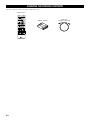 4
4
-
 5
5
-
 6
6
-
 7
7
-
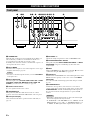 8
8
-
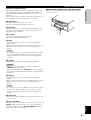 9
9
-
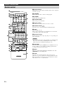 10
10
-
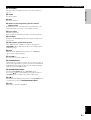 11
11
-
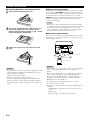 12
12
-
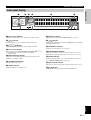 13
13
-
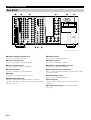 14
14
-
 15
15
-
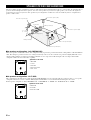 16
16
-
 17
17
-
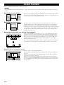 18
18
-
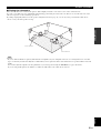 19
19
-
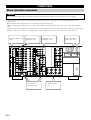 20
20
-
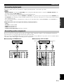 21
21
-
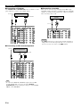 22
22
-
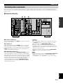 23
23
-
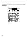 24
24
-
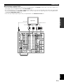 25
25
-
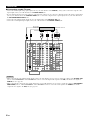 26
26
-
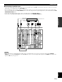 27
27
-
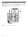 28
28
-
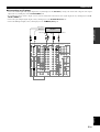 29
29
-
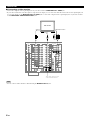 30
30
-
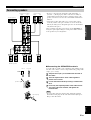 31
31
-
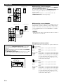 32
32
-
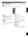 33
33
-
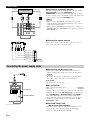 34
34
-
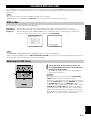 35
35
-
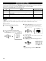 36
36
-
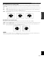 37
37
-
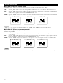 38
38
-
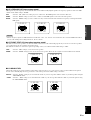 39
39
-
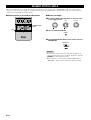 40
40
-
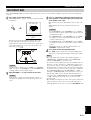 41
41
-
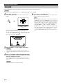 42
42
-
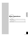 43
43
-
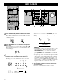 44
44
-
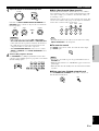 45
45
-
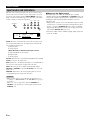 46
46
-
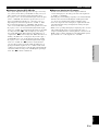 47
47
-
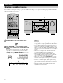 48
48
-
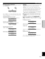 49
49
-
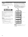 50
50
-
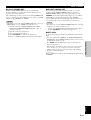 51
51
-
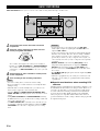 52
52
-
 53
53
-
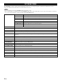 54
54
-
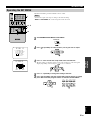 55
55
-
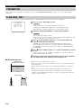 56
56
-
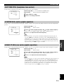 57
57
-
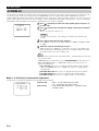 58
58
-
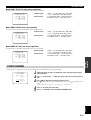 59
59
-
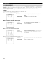 60
60
-
 61
61
-
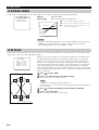 62
62
-
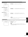 63
63
-
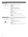 64
64
-
 65
65
-
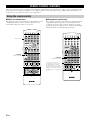 66
66
-
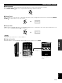 67
67
-
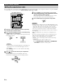 68
68
-
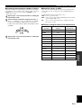 69
69
-
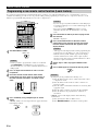 70
70
-
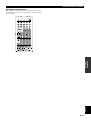 71
71
-
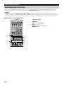 72
72
-
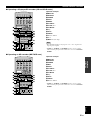 73
73
-
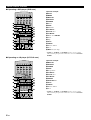 74
74
-
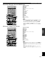 75
75
-
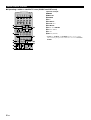 76
76
-
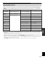 77
77
-
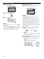 78
78
-
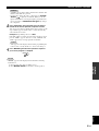 79
79
-
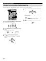 80
80
-
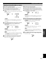 81
81
-
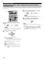 82
82
-
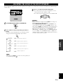 83
83
-
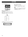 84
84
-
 85
85
-
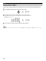 86
86
-
 87
87
-
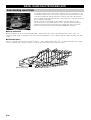 88
88
-
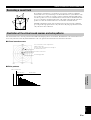 89
89
-
 90
90
-
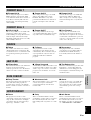 91
91
-
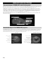 92
92
-
 93
93
-
 94
94
-
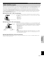 95
95
-
 96
96
-
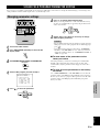 97
97
-
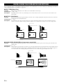 98
98
-
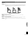 99
99
-
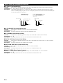 100
100
-
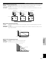 101
101
-
 102
102
-
 103
103
-
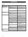 104
104
-
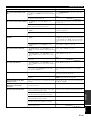 105
105
-
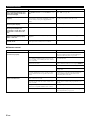 106
106
-
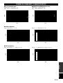 107
107
-
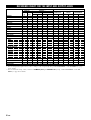 108
108
-
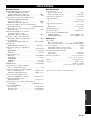 109
109
-
 110
110


in andere talen
- English: Yamaha DSP-AZ1 Owner's manual
- italiano: Yamaha DSP-AZ1 Manuale del proprietario
- русский: Yamaha DSP-AZ1 Инструкция по применению
- français: Yamaha DSP-AZ1 Le manuel du propriétaire
- español: Yamaha DSP-AZ1 El manual del propietario
- Deutsch: Yamaha DSP-AZ1 Bedienungsanleitung
- português: Yamaha DSP-AZ1 Manual do proprietário
- dansk: Yamaha DSP-AZ1 Brugervejledning
- suomi: Yamaha DSP-AZ1 Omistajan opas
- čeština: Yamaha DSP-AZ1 Návod k obsluze
- svenska: Yamaha DSP-AZ1 Bruksanvisning
- Türkçe: Yamaha DSP-AZ1 El kitabı
- polski: Yamaha DSP-AZ1 Instrukcja obsługi
- română: Yamaha DSP-AZ1 Manualul proprietarului