
EN
DIGITAL MIXING CONSOLE
Reference Manual

Table of Contents
Introduction 11
About the Product...................................................................................11
About Available Documentation................................................................ 12
About the Utility Software Configuration....................................................13
Firmware Updates...................................................................................14
Installation of Option Cards......................................................................15
Connections.. ......................................................................................... 18
Analog input connections.. .............................................................................................18
Analog output connections.. ...........................................................................................19
I/O device connections.. .................................................................................................20
Daisy-chain connections.................................................................................................21
Star connections.. .........................................................................................................23
Redundant connections..................................................................................................25
Part Names & Functions 28
Top Panel...............................................................................................28
Rear Panel..............................................................................................31
Front Panel.. .......................................................................................... 35
Basic Operations 36
Basic Operations on the Top Panel.............................................................36
Basic Screen Operations...........................................................................37
On-screen User Interface..........................................................................38
Screen Overview 41
Tool Bar.................................................................................................41
About the SELECTED CHANNEL VIEW Screen................................................ 43
About the OVERVIEW Screen.. ................................................................... 50
2
Table of Contents

Screens 53
EQ Screen...............................................................................................53
DYNAMICS Screen....................................................................................58
AUTOMIXER Screen..................................................................................62
SCENE Screen.. ....................................................................................... 66
Scene List screen...........................................................................................................66
Scene List screen (Comment).. ........................................................................................69
Scene List screen (Focus)................................................................................................70
FOCUS screen................................................................................................................71
Scene List screen (Fade Time)..........................................................................................73
FADE TIME screen.. ........................................................................................................74
Scene List screen (GPI).. .................................................................................................75
Scene List screen (Playback Link).. ..................................................................................76
Scene List screen (Scene Link).........................................................................................77
Recall Safe screen..........................................................................................................78
Global Paste screen.. .....................................................................................................80
GENERAL Screen......................................................................................82
DELAY COMPENSATION Screen.. ................................................................ 85
USER SETUP Screen................................................................................. 87
USER SETUP screen........................................................................................................87
PREFERENCE screen.......................................................................................................90
Surface screen (DM7 only).. ............................................................................................92
CUSTOM FADER screen.. .................................................................................................93
USER DEFINED KNOBS screen.. ........................................................................................95
USER DEFINED KEYS screen.............................................................................................97
CREATE USER KEY screen.. ..............................................................................................99
GUEST USER LEVEL screen.. ..........................................................................................102
BUS SETUP screen..................................................................................103
BUS SETUP screen.. .....................................................................................................103
BUS SETUP (Send Point) screen.. ...................................................................................104
WORD CLOCK Screen.............................................................................. 106
3
Table of Contents

MIDI/GPI Screen.....................................................................................109
MIDI/GPI (MIDI Setup) screen.........................................................................................109
MIDI/GPI (Program Change) screen.. ..............................................................................111
MIDI/GPI (Control Change) screen.. ................................................................................114
MIDI/GPI (GPI) screen.. .................................................................................................115
MIDI/GPI (Fader Start) screen........................................................................................ 117
DATE/TIME Screen..................................................................................120
NETWORK Screen...................................................................................121
NETWORK (For Mixer Control) screen.. ...........................................................................121
NETWORK (For Device Control) screen.. ..........................................................................123
PY Slot screen.. ..................................................................................... 125
PY Slot screen.. ...........................................................................................................125
PY64-MD screen........................................................................................................... 126
PY8-AE screen.. ...........................................................................................................130
PATCH Screen.. ..................................................................................... 132
Grid screen.. ...............................................................................................................132
Input patch screen (list screen).. ...................................................................................134
Output patch screen (list screen).. .................................................................................136
Output port patch screen.............................................................................................. 137
Recording patch screen.. ..............................................................................................138
Sub In patch screen...................................................................................................... 139
4
Table of Contents

I/O DEVICE Screen..................................................................................140
DANTE SETUP (Setup) screen......................................................................................... 140
DANTE SETUP (Device Mount) screen..............................................................................142
DEVICE SELECT screen.................................................................................................. 143
DEVICE LIST screen.. ....................................................................................................144
SUPPORTED DEVICE screen.. .........................................................................................145
DVS or MANUAL screen.. ...............................................................................................146
DANTE I/O DEVICE screen.. ............................................................................................147
CONSOLE I/O screen..................................................................................................... 149
OMNI IN screen............................................................................................................151
OMNI OUT screen......................................................................................................... 153
AES/EBU INPUT screen (DM7 only)..................................................................................154
AES/EBU OUTPUT screen...............................................................................................155
I/O DEVICE screen: HA................................................................................................... 156
I/O DEVICE screen: WIRELESS.. ......................................................................................158
I/O DEVICE Screen: Amplifier.. .......................................................................................160
DANTE PATCH (Input) screen.. .......................................................................................162
DANTE PATCH (Output) screen....................................................................................... 163
RECORDER screen..................................................................................164
RECORDER screen........................................................................................................164
RECORDER screen........................................................................................................166
RECORDER screen........................................................................................................168
LIVE REC screen........................................................................................................... 170
DAW REMOTE screen.. ..................................................................................................172
DAW REMOTE SETUP screen.. ........................................................................................175
CH JOB Screen.......................................................................................176
DCA GROUP ASSIGN screen............................................................................................ 176
MUTE GROUP ASSIGN screen.. .......................................................................................177
CH LINK screen............................................................................................................ 179
CH LINK SET screen...................................................................................................... 180
CH COPY screen........................................................................................................... 181
CH DEFAULT screen......................................................................................................182
5
Table of Contents

MONITOR screen....................................................................................183
MONITOR screen.. .......................................................................................................183
MONITOR screen.. .......................................................................................................185
MONITOR SOURCE DEFINE screen.. ................................................................................188
MONITOR (CUE) screen.. ...............................................................................................189
CUE screen.. ...............................................................................................................191
PHONES screen.. .........................................................................................................194
CUE SETTINGS screen................................................................................................... 196
MONITOR (OSCILLATOR) screen..................................................................................... 197
OSCILLATOR screen.. ...................................................................................................198
MONITOR (TALKBACK) screen........................................................................................ 201
TALKBACK screen.. ......................................................................................................202
RACK Screen.. ....................................................................................... 204
RACK screen.. .............................................................................................................204
GEQ Edit screen...........................................................................................................205
PEQ Edit screen.. .........................................................................................................208
FX screen.................................................................................................................... 211
Premium screen.. ........................................................................................................213
CH PARAMETER Screen...........................................................................215
1ch GAIN screen...........................................................................................................215
12ch GAIN screen......................................................................................................... 217
12ch D.Out screen........................................................................................................ 219
Insert screen...............................................................................................................220
Delay screen.. .............................................................................................................221
Send screen.. ..............................................................................................................223
To Stereo screen.......................................................................................................... 225
Fader screen.. .............................................................................................................227
NAME Screen.........................................................................................228
CH LIBRARY Screen.. .............................................................................. 229
UTILITY Screen 231
Utility Screen........................................................................................231
USER DEFINED KEYS screen.....................................................................233
MONITOR screen....................................................................................234
SAVE/LOAD Screen.................................................................................235
ASSIST Screen.......................................................................................238
6
Table of Contents

SCENE LIST Screen.................................................................................239
SYSTEM Screen......................................................................................241
UNIT MODE Screen.................................................................................242
MAINTENANCE Screen.. .......................................................................... 243
Initialize All Memory Screen....................................................................245
Initialize Current Memory Screen.............................................................246
Initialize Dante Screen.. ......................................................................... 247
FADER CALIBRATION Screen....................................................................248
INPUT PORT TRIM Screen........................................................................249
OUTPUT PORT TRIM Screen.....................................................................250
LED CALIBRATION Screen........................................................................251
Sound Operations 253
Controlling GAIN via the OVERVIEW Screen................................................253
Controlling the EQ via the OVERVIEW Screen.. ........................................... 254
Controlling the EQ via the SELECTED CHANNEL VIEW Screen........................ 255
Controlling the Dynamics Processor via the OVERVIEW Screen.....................256
Controlling the Dynamics Processor via the SELECTED CHANNEL VIEW Screen..
...........................................................................................................257
Controlling Inserts via the OVERVIEW Screen.............................................258
Controlling Inserts via the SELECTED CHANNEL VIEW Screen........................259
Directly Outputting an Input Channel.......................................................260
Controlling the Delay via the OVERVIEW Screen.. ....................................... 261
Controlling the Delay via the SELECTED CHANNEL VIEW Screen....................262
SENDS TO.. ........................................................................................... 263
Using the Faders to Adjust the Sends (SENDS ON FADER Mode).....................264
ST Mode and LCR Mode........................................................................... 265
Sending Signals to the STEREO Bus.. ........................................................ 266
About DCA.. .......................................................................................... 267
Assigning Channels to the DCA.................................................................268
Using DCAs............................................................................................269
About MUTE Groups.. ............................................................................. 270
7
Table of Contents

Temporary Unmute Function During Mute.................................................271
Assigning Channels to a Mute Group.........................................................272
Channel Link.........................................................................................273
Types of Channel Links...........................................................................274
Copying Channel Parameters.. ................................................................ 275
Initializing Channel Parameters...............................................................276
GEQ/PEQ.. ............................................................................................ 277
DSP Resource Management for GEQ..........................................................278
Inserting a GEQ/PEQ into a Channel via the SELECTED CHANNEL VIEW Screen..
...........................................................................................................279
About Automixer................................................................................... 280
About Plug-ins.......................................................................................282
Live Rec................................................................................................286
Other Operations 287
Storing a scene......................................................................................287
Recalling a Scene...................................................................................288
Deleting a Scene....................................................................................289
Duplicating Scenes.................................................................................290
Modifying the Scene Number and Title......................................................291
Using the Focus Function........................................................................292
Using the Fade Function.. ....................................................................... 294
Outputting a Control Signal to an External Device in Tandem with Scene Recall
(GPI OUT).. ........................................................................................... 295
Using the Global Paste Function...............................................................296
Using the Recall Safe Function.................................................................297
Saving Settings Data on a USB Drive.........................................................298
Loading a File from a USB Drive.. ............................................................. 299
Editing a File.........................................................................................300
Creating a Directory...............................................................................301
Using the Monitor Function.....................................................................302
Using the Cue Function...........................................................................304
8
Table of Contents

Using the Solo Function..........................................................................306
Using the Oscillators..............................................................................307
Using Talkback......................................................................................308
Using PHONES.......................................................................................309
About Meter Area...................................................................................310
Controlling the METER Screen.. ............................................................... 311
Assigning a Function to a User Defined Knob..............................................315
The Functions that can be Assigned to User Defined Knobs.. ........................ 316
Assigning a Function to a User Defined Key................................................321
The Functions that can be Assigned to User Defined Keys.. .......................... 322
Setting a Custom Fader Bank...................................................................332
Using the Assist Function........................................................................333
Using Split Mode....................................................................................337
About Dante..........................................................................................340
Configuring Dante Controller.. ................................................................ 341
Mounting an I/O DEVICE..........................................................................342
Patching an I/O DEVICE...........................................................................343
DM7 Editor 344
About DM7 Editor...................................................................................344
File Menu..............................................................................................345
Setup Menu...........................................................................................346
Window Menu.. ..................................................................................... 347
Help Menu.. .......................................................................................... 348
Editor Operation Overview.. ................................................................... 349
Operation during Editor Startup..............................................................350
Editor and Unit Synchronization..............................................................351
Editor's Offline Edit Function.................................................................. 352
Appendix 353
FX Parameters.......................................................................................353
Premium Parameters.............................................................................370
9
Table of Contents

Appendix..............................................................................................382
General specifications.................................................................................................. 382
Audio characteristics.. .................................................................................................383
Analog input standards.. ..............................................................................................386
Analog output standards .............................................................................................. 387
Digital I/O standards.. ..................................................................................................388
Control I/O standards................................................................................................... 389
Pin assignment table.. .................................................................................................390
10
Table of Contents

Introduction
About the Product
Target users
This product is intended for users who can perform mixing operations on PA systems in halls,
event spaces, studios, etc.
Purpose of use
This product is used for mixing at halls and event spaces and in broadcast/production.
About model differences
Number of analog
inputs
Monaural input
channel AES/EBU Channel strip
DM7 32 120 4-in/4-out
Channel Strip
section: 24
Main section: 4
DM7 COMPACT 16 72 0-in/2-out
Channel Strip
section: 12
Main section: 4
NOTE
Illustrations are for the DM7 unless otherwise noted.
11
Introduction > About the Product

About Available Documentation
The DM7 Series manual can be downloaded from the Yamaha Pro Audio website in PDF format.
The manual can also be viewed in HTML format.
https://www.yamahaproaudio.com/
nOwner’s Manual
This mainly provides explanations of the names of the various parts on the panel and their basic
operation.
nDM7 Series Reference Manual (this document)
This manual provides detailed explanations of all screens and functions, and includes step-by-
step procedures and a system set-up procedure to help you operate the DM7 Series.
https://manual.yamaha.com/pa/mixers/dm7/rm/
nDM7 Editor Installation Guide
This guide explains how to install the DM7 Editor.
https://manual.yamaha.com/pa/mixers/dm7/ig/
nDM7 StageMix User Guide
This guide explains an iPad application that allows you to control the DM7 Series system
wirelessly.
https://manual.yamaha.com/pa/mixers/dm7/ug/
12
Introduction > About Available Documentation

About the Utility Software Configuration
The DM7 Series can be used with a variety of utility software. Detailed information about the
software is available on the Yamaha Pro Audio website.
https://www.yamahaproaudio.com/
For information regarding how to download or install the software, as well as setting details,
refer to the website listed above or to the downloaded Installation Guide.
nDM7 Editor
This application software allows you to set up and operate the unit from a connected computer.
You can also back up the unit settings, or set up the unit at a remote site where access to the unit
is limited.
nDM7 StageMix
This is software that allows remote operation of the main unit using an iPad.
nMonitorMix
This application software allows you to remotely control the monitor mix balance of any DM7-
series unit from a smart device connected via Wi-Fi.
nConsole File Converter
This application software allows you to convert settings file formats between the Yamaha
RIVAGE PM series, CLseries, QL series and DM7 Series.
nProVisionaire Series
This application software allows you to create a control panel that suits the setup environment
or operational procedure, and to remotely control and monitor devices.
13
Introduction > About the Utility Software Configuration

Firmware Updates
You can update the unit's firmware to improve the operability, add functions, and correct
possible malfunctions.
Information on updating the firmware can be found on the following website.
https://www.yamahaproaudio.com/
For information on updating and setting up the unit, please refer to the firmware update guide
available on the website.
14
Introduction > Firmware Updates

Installation of Option Cards
Installation of PY cards
Before you install a PY card, you must check the Yamaha Pro Audio global website to see
whether the DM7 Series supports your card.
https://www.yamahaproaudio.com/
1Make sure that the power to this product is turned off.
CAUTION
Installing or removing a card while the power is on may lead to electric shock or component failure.
2Remove the screws that fasten the [PY] card slot cover and remove the slot cover.
The removed screws will be used again to install the PY card. Keep the slot cover in a safe
place for future use.
15
Introduction > Installation of Option Cards

3Align both edges of the PY card with the guide rails inside the slot, and then insert
the PY card into the slot.
Push the PY card all the way into the slot so that the connector at the end of the PY card is
correctly inserted into the connector inside the slot.
NOTICE
(When inserting the PY card, align both sides of the PY card with the guide rails in the slot of the host
device.
4Use the screws removed in Step 2 to fasten the PY card.
Do not use the card unless it is securely affixed with the screws. Be aware that component
failure or malfunction may occur if the PY card is not fastened.
16
Introduction > Installation of Option Cards

Removing the PY card
1Make sure that the power to this product is turned off.
CAUTION
Installing or removing a card while the power is on may lead to electric shock or component failure.
2Completely loosen and remove the screws that hold the PY card in place.
3Pull the PY card toward you while holding the peg-shaped handles (see the figure
below) on the card.
4Replace the stored slot cover and affix it with the screws.
Do not use the unit while the slot cover is removed. Component failure or malfunction may
occur.
17
Introduction > Installation of Option Cards

Connections
Analog input connections
The INPUT terminals on the DM7 Series and I/O devices are used primarily for connecting
microphones and line-level devices.
Rio3224-D2
The PATCH screen is used to set the switching of patches. Patches can also be switched using the
PATCH button on the SELECTED CHANNEL VIEW screen.
18
Introduction > Connections

Analog output connections
The OMNI OUT terminal on the DM7 Series and the OUTPUT terminals on the I/O devices can be
used to patch output signals from output channels (MIX, MATRIX, STEREO (L/R)), monitor signals
(MONITOR OUT L/R channels), and direct output signals from INPUT channels.
The front panel of the DM7 Series is equipped with a PHONES output jack for monitoring,
enabling constant monitoring of the signal selected as the monitor source. The same signal can
also be monitored through external speakers by assigning the MONITOR OUT L/R channels to
any desired output terminal.
Rio3224-D2
Monitor speaker
Main speaker(Powered speaker)
The PATCH screen is used to set the switching of patches. Patches can also be switched using the
PATCH button on the SELECTED CHANNEL VIEW screen.
19
Introduction > Connections

I/O device connections
When connecting the DM7 to I/O devices (Rio3224-D2, etc.) there are 2 options: daisy-chain
connection and star connection.
In addition, devices equipped with two ports, one for the main circuit (PRIMARY) and the other
for the secondary circuit (SECONDARY), can be redundantly connected to each other in the
unlikely event of a failure.
Related links
(Dante
(“Daisy-chain connections”(p.21)
(“Star connections”(p.23)
(“Redundant connections”(p.25)
20
Introduction > Connections

Daisy-chain connections
Daisy-chain connect devices by linking them together in a row. Building the network is easy and
no network switches are required. It is used on simple systems when the number of devices to be
connected is small.
As the number of connected devices increases, the latency must be increased. In addition, if the
system fails due to a cable break or other cause, the network will be divided at that point and
transmission to and from the devices beyond that point will not be possible.
nExample of DM7 and I/O device connection
Use the Dante terminals on the DM7 and the I/O device and connect as shown below.
21
Introduction > Connections

nI/O device settings
Use the following settings when connecting the DM7 to Rio3224-D2 or DZR-D/DXS-XLF-D.
[Rio3224-D2 settings]
(UNIT ID = 1
(SECONDARY PORT = DAISY CHAIN
(START UP MODE = REFRESH
[DZR-D/DXS-XLF-D settings]
(UNIT ID = Desired ID
(MODE (DANTE MODE) = STANDARD
The UNIT ID for the DZR-D/DXS-XLF-D is set using the DANTE SETUP screen on the DZR-D/DXS-
XLF-D unit.
[DM7 settings]
The Dante network settings are made using the Setup screen and the Device Mount screen in
DANTE SETUP.
NOTE
The DZR Dante does not have the SECONDARY function.
Related links
(“DANTE SETUP (Setup) screen”(p.140)
(“DANTE SETUP (Device Mount) screen”(p.142)
22
Introduction > Connections

Star connections
The star connection is a method of connecting devices centered around a network switch. A
network switch that includes a variety of features to control/monitor the network (e.g., clock
synchronization for any chosen data line, QoS to prioritize voice transmission, etc.) is
recommended.
nExample of DM7 and I/O device connection
Use the Dante terminals on the DM7 and the I/O device and connect as shown below.
23
Introduction > Connections

nI/O device settings
Use the following settings when connecting the DM7 to Rio3224-D2 or DZR-D/DXS-XLF-D.
[Rio3224-D2 settings]
(UNIT ID = 1
(SECONDARY PORT = DAISY CHAIN
(START UP MODE = REFRESH
[DZR-D/DXS-XLF-D settings]
(UNIT ID = Desired ID
(MODE (DANTE MODE) = STANDARD
The UNIT ID for the DZR-D/DXS-XLF-D is set using the DANTE SETUP screen on the DZR-D/DXS-
XLF-D unit.
[DM7 settings]
The Dante network settings are made using the Setup screen and the Device Mount screen in
DANTE SETUP.
NOTE
The DZR Dante does not have the SECONDARY function.
Related links
(“DANTE SETUP (Setup) screen”(p.140)
(“DANTE SETUP (Device Mount) screen”(p.142)
24
Introduction > Connections

Redundant connections
A redundant connection is a network consisting of two circuits, a primary circuit (PRIMARY) and a
secondary circuit (SECONDARY). Normally, communication is performed on the PRIMARY circuit
but in the event of a disconnection or other problem on the PRIMARY circuit, communication is
automatically switched to the SECONDARY circuit. When using a star connection, this method
creates an environment that is more resilient to network failures than a daisy-chain network.
nExample of DM7 and I/O device connection
Use the Dante terminals on the DM7 and the I/O device and connect as shown below.
25
Introduction > Connections

nI/O device settings
Use the following settings when connecting the DM7 to a Rio3224-D2.
[Rio3224-D2 settings]
(UNIT ID = 1
(SECONDARY PORT = REDUNDANT
26
Introduction > Connections


Part Names & Functions
Top Panel
This will explain the functions and names of the components on the top panel of the DM7 Series.
aa
b
a
b
c
d d
ee
ff
g g
h h
iij
kl
c
aTouch screen
These are capacitive multi-touch screens. The unit will not work properly if operated when wearing
gloves.
NOTICE
(Do not operate the screen with sharp-pointed objects or fingernails. It may damage the screen or
make it impossible to operate the touchscreen.
NOTE
A clear protective film is installed on the touchscreen at the factory, please remove before use.
b[HOME]
Recalls and toggles between the OVERVIEW and SELECTED CHANNEL VIEW screens.
28
Part Names & Functions > Top Panel

c[FADER BANK]
Switches fader assignments on the panel.
d[SENDS ON FADER]
Turns SENDS ON FADER mode on/off. When this mode is turned on, you can use the channel strips to
adjust the send level of signals sent to the MIX/MATRIX bus.
e[ENCODER MODE]
Use these keys to display the screen on the corresponding Bay screen to switch between functions for
the encoders located below the touch screen. These encoders feature the following two functions:
Screen Encoder function:
Up to 12 parameters can be assigned to the encoders via the touch screen.
Channel Encoder function:
Parameters for 12 channels on the channel strips can be assigned to the encoders.
fChannel Strip section
Controls the main parameters for the currently-selected channels.
g[TOUCH AND TURN]
Controls the parameter of the knob selected via the touch screens.
h[SHIFT]
Combine with another key to perform certain functions.
i[USER DEFINED KEYS]
Operates a pre-assigned function.
In addition, this switches the bank to be operated via [BANK] as the Fader Bank.
29
Part Names & Functions > Top Panel

jMain Section
This section allows you to adjust main parameters for the assigned channels. By default, STEREO A
and STEREO B are assigned to channel C and D respectively.
NOTE
The areas in the diagram below are called Bay L (DM7 only) and Bay C.
Bay L (DM7 only) Bay C
kLED lighting bar
Illuminates the operation panel when using in a dark location.
lUSB port
This port is used to connect USB drives.
■ USB drive format
The supported format types are FAT16 and FAT32.
■ Write protection
Some USB drives can be write-protected to prevent accidental deletion of data. If your USB drive
contains important data, we suggest that you use write protection to prevent accidental erasure. On
the other hand, you will need to make sure that your USB drive’s write-protect setting is turned off
before you save data to it.
For information about USB drives that can be used with the system, visit the Yamaha Pro Audio
website at:
http://www.yamahaproaudio.com/
NOTICE
(Do not remove the USB drive from the USB port or turn off the power to the unit while the unit is
accessing data, e.g., saving, loading or deleting data. Doing so may damage your drive, or may
damage the data in the unit or on the media device.
30
Part Names & Functions > Top Panel

Rear Panel
This will explain the functions and names of the components on the rear panel of the DM7 Series.
ab
c
d
efg
hi
j
k
l m
n o
p
a[OMNI OUT]
Balanced XLR 3-pin chassis output connectors for analog audio signals.
b[INPUT]
Balanced XLR 3-hole chassis input connectors for analog audio signals from line-level devices or
microphones.
cExhaust vent
This product is equipped with a cooling fan. This vent lets warm air escape from the unit. Make sure
that the vent is not blocked with obstructions or other objects. Intake air is provided through vents on
the lower front and rear sides.
CAUTION
(Do not block the ventilation ports (heat dissipating slits) on this product. To prevent increased
internal temperature, there are ventilation holes on the front and rear of the product. If the
ventilation ports are blocked, heat will be trapped inside the product, which may cause
malfunction or fire.
31
Part Names & Functions > Rear Panel

dAC IN connectors [A]/[B]
Connects to the supplied power cords. Connect the power cords to this unit, then connect the plug
ends into the outlet. When connecting the power cords, insert all the way until they lock in place
securely. The supplied AC power cords feature a V-lock mechanism with a latch, which prevents the
power cords from disconnecting accidentally.
CAUTION
(Ensure that the power to the unit is turned off before connecting or disconnecting the power
cord.
To disconnect a power cord, remove it while pressing the latch on the plug.
e[ | ]/[ z] (Power switch)
Toggles the power between ON ( | ) and OFF (z). If the unit will not be used for a long time, be sure
to remove the power cord from the AC outlet.
When the switch is (z), the power is off.
NOTICE
(Turning the unit on/off in rapid succession can cause it to malfunction. After turning the unit off,
wait at least six seconds before turning it on again.
NOTE
This product will operate normally when one or both power supplies [A] and [B] are on. If both power
supplies are on and one of the power supplies fails during operation, the unit automatically switches
to the other power supply.
f[AES/EBU]
The DM7 is equipped with a sampling rate converter on both the [IN] and [OUT] chassis connectors.
Please note that the DM7 COMPACT, which features only the [OUT] chassis connectors, is not equipped
with a sampling rate converter.
[IN] (DM7 only)
These are balanced XLR 3-hole chassis input connectors that accept digital audio signals in the AES/
EBU format.
[OUT]
These are balanced XLR 3-pin chassis output connectors for outputting digital audio signals in the AES/
EBU format.
g[TC IN]
This balanced XLR 3-hole chassis input connectors accepts time code signals from the connected
external device.
h[WORD CLOCK OUT/IN]
These are BNC connectors used to transmit/receive word clock signals to/from an external device. The
[WORD CLOCK IN] connector is internally terminated by a 75-ohm resistor.
32
Part Names & Functions > Rear Panel

i[GPI]
This is a D-sub 15-hole chassis connector that allows communication (5-in/5-out) with a GPI-
compatible external device.
j[PY]
This card slot allows you to install a PY card (sold separately) to expand the number of I/O ports.
kDante [PRIMARY]/[SECONDARY]
These terminals are used to connect to I/O devices such as the Rio3224-D2 to a Dante audio network.
Use RJ-45 connectors that are compatible with Neutrik etherCON CAT5e connectors.
NOTE
Use an STP (Shielded Twisted Pair) cable to prevent electromagnetic interference. Make sure that the
metal components of the connectors are electrically connected to the STP cable’s shield by
conductive tape or other similar methods.
Do not use the network switch's EEE function(*) within a Dante network. Although power management
should be negotiated automatically in switches that support EEE, some switches do not perform the
negotiation properly. This may cause EEE to be enabled in the Dante network when it is not
appropriate, resulting in poor synchronization performance and occasional dropouts. Therefore, we
strongly recommend that:
(When using a managed switch, turn off the EEE function on all ports used for Dante. Do not use
switches that cannot turn off the EEE function.
(When using unmanaged switches, do not use switches that support the EEE function. The EEE
function cannot be turned off on these switches.
*The EEE (Energy Efficient Ethernet) function is a technology that reduces switch power consumption
during periods of low network traffic. It is also known as Green Ethernet or IEEE802.3az.
l[LINK/ACT]
[PRIMARY] and [SECONDARY] indicators show the respective communication status. If the Ethernet
cables are connected properly, the indicators will flash rapidly.
m[1G]
These indicators light up when the Dante network is functioning as Gigabit Ethernet.
n[USB TO HOST]
This is a USB Type-C (USB2.0) port.
By connecting a computer with a USB cable, the console can function as a 96kHz/32-bit or 48 kHz/32-
bit audio interface with a maximum of 18 inputs and 18 outputs. It also allows you to use USB-MIDI to
control a DM7 Series unit and remotely control DAW software.
The Yamaha Steinberg USB Driver must be installed to communicate with the computer.
NOTICE
(Use USB cables less than 3 meters in length.
(Leave an interval of at least 6 seconds between plugging and unplugging the USB cable.
33
Part Names & Functions > Rear Panel

oNetwork connector
This RJ-45 connector allows the unit to be connected to a computer via an Ethernet cable (CAT5 or
higher recommended).
NOTE
Use an STP (Shielded Twisted Pair) cable to prevent electromagnetic interference.
pGrounding screw
Each supplied power cord has a three-prong plug. If the AC outlets are grounded, this product will be
properly grounded through the power cords. Also, grounding this screw may effectively eliminate
noise such as hum and interference.
34
Part Names & Functions > Rear Panel

Front Panel
This will explain the functions and names of the components on the front panel of the DM7
Series.
1 2
a[PHONES LEVEL]
This adjusts the level of the signal output from the PHONES OUT socket.
b[PHONES]
This is a headphone socket for monitoring the MONITOR or CUE signals.
35
Part Names & Functions > Front Panel

Basic Operations
Basic Operations on the Top Panel
This section explains the basic operations that are performed on the top panel.
Bay encoder operations
The [ENCODER MODE] key is used to switch between functions.
Screen encoder
Up to 12 parameters can be controlled using the touchscreen.
Channel encoder
This controls the assigned parameters for the 12 channels lined up in the channel strips.
[TOUCH AND TURN] knob operation
Press the parameter you want to control on the touchscreen and use the [TOUCH AND TURN]
knob to immediately control it. At this time, a pink frame will appear over the parameters that
can be controlled on the touchscreen.
36
Basic Operations > Basic Operations on the Top Panel

Basic Screen Operations
Switching screens
On the bay screen, when the in the upper right is pressed, the menu bar is displayed.
Press the desired button on the menu bar to switch to the corresponding screen. In the Utility
screen, press the desired button on the HOME screen to switch to the corresponding screen.
When the HOME button is pressed, you will return to the HOME screen.
NOTE
On the screen, the area with a pink frame when selected contains the parameters that can be controlled with
the [TOUCH AND TURN] knob.
Controlling parameters with the [TOUCH AND TURN] knob
After selecting the parameter to be controlled by tapping on it, use the [TOUCH AND TURN] knob
to perform operations. A pink frame appears around the selected parameter.
Setting parameter values on the screen
After selecting the parameter to be controlled by tapping on it, use the vertical or horizontal
slider to set the parameter value. A pink frame appears around the selected parameter.
Scrolling
On screens that feature a scroll bar, slide your finger up and down or left and right to scroll the
screen. Swiping the screen allows you to scroll quickly. You can also manipulate the screen as
follows:
(Pinching or spreading fingers
The EQ's Q can be controlled.
(Sliding three fingers up and down
The amount of cut/boost of EQ gain for multiple bands can be adjusted simultaneously.
(Sliding four fingers up and down / Pinching or spreading three fingers in and out
The amount of EQ gain for multiple bands can be increased or decreased all at once.
37
Basic Operations > Basic Screen Operations

On-screen User Interface
This section explains various user interface components shown in the touch screens, and how to
use them.
Tabs
Tabs are used when switching between multiple pages. The page name is displayed on the tab.
Buttons
Buttons are used to execute specific functions, to switch parameters on/off, or to select one of
multiple choices. Buttons that perform on/off operations appear in solid colors while they are
turned on, and are dark when turned off.
When you press the button, a separate popup window will open, allowing you to make
detailed settings.
When you press the button, a pull-down menu will appear.
When you press the expand button or collapse button, windows such as the
EQ or dynamic will expand or collapse.
List screens
Windows similar to the following are displayed to allow you to select items from a list, such as
the USER DEFINED knob setting window.
38
Basic Operations > On-screen User Interface

The blue item in the list is the item that is selected for operation. Use the [TOUCH AND TURN]
knob to scroll up and down the list.
Keyboard screen
The following keyboard window will appear when you need to assign a name or comment to a
scene or library, or when you need to assign a channel name. Press the character buttons on the
screen to enter the desired characters.
Dialog boxes
Dialog boxes similar to the following allow you to confirm operations you just performed. Press
the OK button to execute the operation. The operation will be canceled if you press the CANCEL
button.
39
Basic Operations > On-screen User Interface

40
Basic Operations > On-screen User Interface

Screen Overview
Tool Bar
The toolbar has icons for frequently used functions and screens for system settings. The toolbar
is always visible, even when the main area display has been switched.
ab c d e
aDisplays the “SCENE Screen”(p.66).
bDisplays the p.311.
cDisplays the “PATCH Screen”(p.132).
dDisplays the “RACK Screen”(p.204).
41
Screen Overview > Tool Bar

e
Displays the menu bar.
Press to open a pull-down menu to access each function.
42
Screen Overview > Tool Bar

About the SELECTED CHANNEL VIEW Screen
This screen shows all mix parameters of the currently-selected channel.
aSelected channel
This area shows the number, name, icon, and channel color of the channel that is currently selected
for operation. Press < to switch to the previous channel and > to switch to the next channel. Press ∨ to
display a list of channels and you can switch to any channel.
bInput Select button
Press to open the Input Select screen, where you can switch between Input A and B and change the
patches.
43
Screen Overview > About the SELECTED CHANNEL VIEW Screen

cHA indicator
Displays the on/off status of the HA's phantom power (+48V) and the input phase. When pressed, a
popup screen is displayed that allows you to turn the phantom power on/off and switch between
forward (gray) or reverse (orange) phase.
dA.Gain
Displays the HA analog gain. If the Gain Compensation function is turned on, a blue indicator appears,
showing the analog gain position at the time the function was turned on. The level immediately after
the analog HA is displayed on the right. When the screen is pressed to select, the value can be changed
by sliding vertically or horizontally or using the [TOUCH AND TURN] knob; the Gain screen is displayed
by pressing it again.
eD.Gain
Displays the digital gain setting value. The on/off status of the Direct Out is displayed in the upper
area. When the screen is pressed to select, the value can be changed by sliding vertically or
horizontally or using the [TOUCH AND TURN] knob; the Gain screen is displayed by pressing it again.
fSwitches between the expanded display and collapsed display of DYN1.
gSwitches between the expanded display and collapsed display of EQ. If you touch and hold EQ or DYN2
and slide to the side, the order of EQ and DYN2 will be switched.
hSwitches between the expanded display and collapsed display of DYN2.
iPress this to display the screen for effects and inserts.
jDelay
Displays the delay time. When the screen is pressed to select, the value can be changed by sliding
vertically or horizontally or using the [TOUCH AND TURN] knob; the Delay screen is displayed by
pressing it again.
44
Screen Overview > About the SELECTED CHANNEL VIEW Screen

kPan/Balance
Displays the signal location. When the screen is pressed to select, the value can be changed by sliding
vertically or horizontally or using the [TOUCH AND TURN] knob; the To Stereo screen is displayed by
pressing it again.
lST A/B
Displays the on/off for signals sent to the STEREO A bus and B bus. Press to display the popup window
used to switch on/off.
mFader
Displays the fader level. When the screen is pressed to select, the value can be changed by sliding
vertically or horizontally or using the [TOUCH AND TURN] knob; the Fader screen is displayed by
pressing it again.
nON/CUE
The channel and cue out on/off and the selected cue bus are displayed. Press to display the pop-up
window used to switch on/off.
oOpens the “CH LIBRARY Screen”(p.229).
45
Screen Overview > About the SELECTED CHANNEL VIEW Screen

pLEVEL meter
The signal level set in the channel Metering Point is displayed.
When A.Gain is present and the Metering Point is Pre GC or Pre D.Gain, the input level distribution is
displayed next to the meter as a histogram. The width is displayed thicker as the levels being observed
in an area increases.
When pressed, a popup screen is displayed to switch Metering Point, turn Peak Hold on/off, and reset
the histogram.
qPair setting popup button
When pressed, the screen used for CHANNEL PAIRING is displayed.
rInsert button
Press this to display the screen for effects and inserts.
46
Screen Overview > About the SELECTED CHANNEL VIEW Screen

sAutomixer button
Opens the “AUTOMIXER Screen”(p.62).
tEQ
Displays the EQ graph, bank, type, HPF, LPF, EQ ATT, etc. Pressing this field displays the parameter
name and value, and they can be adjusted using the screen encoder. Pressing the expand button
displays the EQ screen.
47
Screen Overview > About the SELECTED CHANNEL VIEW Screen

uDYN1
Displays the selected dynamics type, threshold value, input/output frequency response graph, GR
(gain reduction) meter, and input/output level indicators for Dynamics 1. Pressing this field displays
the parameter name and value in the upper portion of the channel name area, and they can be
adjusted using the screen encoder. Pressing the expand button displays the DYN1 screen.
vDYN2
Displays the selected dynamics type, threshold value, input/output frequency response graph, GR
(gain reduction) meter, and input/output level indicators for Dynamics 2. Pressing this field displays
the parameter name and value in the upper portion of the channel name area, and they can be
adjusted using the screen encoder. Pressing the expand button displays the DYN2 screen.
48
Screen Overview > About the SELECTED CHANNEL VIEW Screen

wMIX/MATRIX Sends
Displays the level of the signal sent from the channel selected as the input channel to the MIX and
MATRIX bus. The send parameters can be adjusted using the screen encoder by pressing this. Pressing
again switches to the Send screen.
xSafe
The Recall Safe, Solo Safe and Mute Safe statuses are displayed. Press to display the pop-up window
used to switch on/off.
yDCA/Mute
Displays the DCA and mute group to which the selected channel is assigned. The DCA/Mute Assign
screen is displayed by pressing this.
NOTE
When MUTE GROUP CONTROL is on and the channel is muted and DCA MAIN is off, each indicator blinks.
49
Screen Overview > About the SELECTED CHANNEL VIEW Screen

About the OVERVIEW Screen
This screen simultaneously displays the main parameters of the parts of the 12 channels
for which layers are selected.
b
a
c
d
aPress this to display the 12ch D.Out screen.
bPress this to display the Delay screen.
cPress this to open the AUTOMIXER screen.
dLEVEL meter
The signal level set in the channel Metering Point is displayed.
50
Screen Overview > About the OVERVIEW Screen

eSend
Press this to displays the level of the signal sent from the selected channel the MIX and MATRIX bus.
fA.Gain/D.Gain
Displays the HA analog gain. If the Gain Compensation function is turned on, a blue indicator appears,
showing the analog gain position at the time the function was turned on. When the screen is pressed
to select, the value can be changed by sliding vertically or horizontally or using the [TOUCH AND TURN]
knob; the Gain screen is displayed by pressing it again.
If there is no analog gain, the digital gain is displayed.
gHA indicator
Displays the on/off status of the HA's phantom power (+48V) and the input phase. When pressed, a
pop-up screen is displayed that allows you to turn the phantom power on/off and switch between
forward (gray) or reverse (orange) phase.
hPress this to open the “DYNAMICS Screen”(p.58).
iPress this to open the “EQ Screen”(p.53).
jPress this to open the “DYNAMICS Screen”(p.58).
kOpens the “Insert screen”(p.220).
lPan/Balance
Displays the signal location. When the screen is pressed to select, the value can be changed by sliding
vertically or horizontally or using the [TOUCH AND TURN] knob; the To Stereo screen is displayed by
pressing it again.
51
Screen Overview > About the OVERVIEW Screen

mST A/B
Displays the on/off for signals sent to the STEREO A bus and B bus. Press to display the pop-up window
used to switch on/off.
nDCA/Mute
Displays the DCA and mute group to which the selected channel is assigned. The DCA/Mute Assign
screen is displayed by pressing this.
NOTE
When MUTE GROUP CONTROL is on and the channel is muted and DCA MAIN is off, each indicator blinks.
52
Screen Overview > About the OVERVIEW Screen

Screens
EQ Screen
All the EQ parameters of the currently-selected channel can be changed. This is convenient if you
want to make detailed EQ settings for a specific channel.
The screen contains the following items.
aExpand/collapse button
Expands or collapses the screen.
bBank button
Allows you to switch between A and B as the store destination for the EQ parameters.
cType button
Switches the EQ type to PRECISE, AGGRESSIVE, SMOOTH, or LEGACY.
The type of each channel can be set through Global Setting.
dEQ FLAT button
When this is pressed, a confirmation screen appears, and when OK is pressed, the GAIN parameters for
all EQ bands are reset to 0dB.
eProcess Order button
Switches the EQ and DYN2 order.
fMulti Ch View button
Opens the Multi Ch View screen.
53
Screens > EQ Screen

gRTA button
If this button is on, a semi-opaque frequency response graph of the EQ processed input signal will be
superimposed on top of the EQ frequency response graph.
hPEAK HOLD
The peak in the graph displaying the RTA is held.
iHOLD button
When this button is on, the frequency response graph will display and hold the result of the frequency
analysis.
jBALLISTICS field
(BALLISTICS button
When this is on, attenuation rate can be added to the graph plotting.
(FAST/SLOW toggle button
Switches the attenuation rate (FAST/SLOW).
kOffset
Sets the offset for the RTA display.
lEQ graph
Displays the parameter values for the EQ and filters.
mEQ ON/OFF button
Switches the EQ on/off.
nEQ IN/OUT level meter
Displays the peak level of signals before and after the EQ. For a stereo channel, these meters indicate
the level of both the L and R channels.
oLIBRARY button
Press this to display the CH LIBRARY screen.
pCOPY button
Copies the EQ parameter settings stored in the bank (selected via the A/B switching buttons) to buffer
memory.
qPASTE button
Press this to paste the settings copied in buffer memory to the EQ of the currently-selected bank. If
valid data has not been copied into buffer memory, pasting is not possible.
rCOMPARE button
Press this to switch between and compare the settings stored in buffer memory and the currently-
selected settings. If valid data is not stored in the buffer memory, comparison is not possible.
54
Screens > EQ Screen

sDEFAULT button
When this is pressed, a confirmation screen appears, and when OK is pressed, and the EQ/filters for all
parameters are reset to their initial setting values.
tHPF type select button
Allows setting of the HPF attenuation per octave to −6 dB/oct, −12 dB/oct, −18 dB/oct, or −24 dB/oct.
uHPF FREQUENCY
Displays the HPF cutoff frequency. When the screen is pressed to select, the value can be changed by
sliding vertically or horizontally or using the [TOUCH AND TURN] knob.
vHPF ON/OFF button
Switches HPF on/off.
wLPF type select button
Allows setting of the LPF attenuation per octave to –6dB/oct or –12dB/oct.
xLPF FREQUENCY
Displays the LPF cutoff frequency. When the screen is pressed to select, the value can be changed by
sliding vertically or horizontally or using the [TOUCH AND TURN] knob.
yLPF ON/OFF button
Switches LPF on/off.
zEQ ATT
Adjusts attenuator. When the screen is pressed to select, the value can be changed by sliding vertically
or horizontally or using the [TOUCH AND TURN] knob.
ALOW SHELVING ON/OFF button
Turn this button on to switch the LOW band to a shelving type filter.
BBYPASS button
Sets the EQ band to bypass status.
CHIGH SHELVING ON/OFF button
Turn on this button to switch the HIGH band to a shelving type filter.
DEQ parameter setting
Displays the Q, FREQUENCY, and GAIN parameters for the LOW, LOW MID, HIGH MID, and HIGH bands.
When the screen is pressed to select, the value can be changed by sliding vertically or horizontally or
using the [TOUCH AND TURN] knob.
55
Screens > EQ Screen

Touch Operation
This section explains the EQ operations performed by touching the EQ screen.
1 finger touch operations
aPeak of selection band
Drag the band's ball to adjust frequency and gain.
The gain is reset by double tapping the ball.
If the balls for multiple bands are overlapping, the selection can be changed by tapping.
bG axis
Drag up or down to fix the frequency and adjust the gain.
cF axis
Drag left or right to fix the gain and adjust the frequency.
dHPF/LPF
Drag to adjust the frequency. Double tap to turn on/off.
Multi-touch operations
(PINCH
Pinch to adjust the Q for the selected band.
Multi-band operations
The parameters for multiple bands can be adjusted all at once.
・Boost band Bands set in the boost area (the area above 0 dB). The boost amount for a band
can be changed using multi-touch operation.
・Cut band Bands set in the cut area (the area below 0 dB). The cut amount for a band can be
changed using multi-touch operation.
(BOOST
With three fingers, tap and hold the area above 0 dB and slide up or down to increase or
decrease the amount of boost for all boosted bands.
56
Screens > EQ Screen

(CUT
With three fingers, tap and hold the area below 0 dB and slide up or down to increase or
decrease the amount of cut for all bands being cut at once.
(EXPAND
With four fingers, tap and hold and slide up or down to expand or reduce the gain adjustment
amount for all bands at once. The same operation can be performed by placing three fingers
across the 0 dB line and pinching.
57
Screens > EQ Screen

DYNAMICS Screen
This allows for all dynamics parameters to be displayed and edited. This is convenient when you
want to make detailed dynamics settings for a specific channel.
aExpand/collapse button
Expands or collapses the screen.
bBank button
This allows you to switch between A and B as the store destination for the dynamics parameters.
cType button
Switches dynamics type between LEGACY COMP, COMP260, GATE, DE-ESSER, EXPANDER, DUCKING,
FET Limiter (input channel DYN2 and output channel DYN1 only), and Diode Bridge Comp (input
channel DYN2 and output channel DYN1 only).
dMulti Ch View button
Opens the Multi Ch View screen.
eDynamics ON/OFF button
Switches dynamics on/off.
fHistory button
When this is pressed, the last 10 seconds of history of the dynamics graph is displayed.
58
Screens > DYNAMICS Screen

gKey In Filter field (This area is not displayed if the dynamics type is De-Esser)
This function sets the filter settings for the key-in signal pass.
(Filter selection button
Select the type of filter from HPF, BPF, or LPF. Press a button that is on to disable the filter.
(Q
Displays the filter Q setting. When the screen is pressed to select, the value can be changed by
sliding vertically or horizontally or using the [TOUCH AND TURN] knob.
(FREQUENCY
Display the cutoff frequency setting of the filter. When the screen is pressed to select, the value can
be changed by sliding vertically or horizontally or using the [TOUCH AND TURN] knob.
hDynamics graph
Displays the input/output characteristics of the dynamics processors.
iMix Balance
The balance with the input signal can be adjusted.
jDynamics IN/OUT level meters, GR meter
These meters display the peak level of the signals before and after the dynamics processing, and the
amount of gain reduction. For a stereo channel, these meters display the level of both the L and R
channels.
kLIBRARY button
Press this to display the CH LIBRARY screen.
lCOPY button
Copies the dynamics parameter settings stored in the bank (selected via the A/B switching buttons) to
buffer memory.
mPASTE button
Press this button to paste the settings that were copied in buffer memory to the dynamics of the
currently-selected bank. If valid data has not been copied into buffer memory, pasting is not possible.
nCOMPARE button
Press this to switch between and compare the settings stored in buffer memory and the currently-
selected settings. If valid data is not stored in the buffer memory, comparison is not possible.
oDEFAULT button
Press this button to reset all dynamics parameters to the initial values.
59
Screens > DYNAMICS Screen

pKEY IN CUE button
This button cue-monitors the signal that is selected as the KEY IN SOURCE. The CUE will be canceled
when you move to a different screen.
NOTE
Even if the Cue mode is set to MIX CUE (the mode in which all channels whose [CUE] key is on are
mixed and monitored), turning on the KEY IN CUE button will cause only the signal of the
corresponding channel to be monitored. All [CUE] keys that had been turned on at that time will be
forcibly canceled.
qKEY IN SOURCE selection button
Allows you to select one of the following as the key-in signal that will trigger dynamics processing.
(Self ..............Signal from the same channel.
(Other Pre DYN1 ...........Pre-DYN1 signals on other channels (selected from a group of 24 channels
each) (only Input Ch DYN1)
(Other Pre Proc ..........Pre-Proc signals on other channels (selected from a group of 24 channels
each) (only Input Ch DYN2)
(MX Out ...........MIX channel output signal
(EXT IN 1-4 ...........Signal selected as EXT IN 1-4
rType button
Select the type of dynamics from the following.
(Legacy Comp .............. This is a standard compressor that has been equipped with many of
Yamaha’s legacy digital mixers, such as PM1D and PM5D.
(Comp 260 ...........This is an analog-flavored compressor built using Yamaha’s proprietary VCM
(Virtual Circuitry Modeling) technology. The compression curve setting (Knee) can be selected from
6 levels: Hard / Soft-1 / Soft-2 / Soft-3 / Soft-4 / Soft-5. Although the attack/release times can also be
adjusted, the preset settings reproduce the fixed characteristics of the original unit being modeled.
(Gate ..........This dynamics type reduces the output by a fixed value (Range) when a signal smaller
than the Threshold level is input.
(De-Esser ...........This dynamics type detects only the sibilants and other high-frequency consonants
of the vocal, and compresses its bandwidth.
(Expander ........... This dynamics type reduces the output by a fixed ratio when a signal smaller than
the Threshold level is input.
(Ducking ........... This dynamics type reduces the output by a fixed value (Range) when a signal
greater than the Threshold level is input. This is effective if you want to lower the volume level of
background music using the Key In Source signal.
(FET Limiter ........... This is a model of a FET compressor/limiter commonly used in studios. Because
THRESHOLD is fixed internally, the degree of compression is adjusted by adjusting the INPUT level.
(Input channel DYN2 and output channel DYN1 only)
(Diode Bridge Comp ........... This is compressor modeling using Diode Bridge.(Input channel DYN2
and output channel DYN1 only)
60
Screens > DYNAMICS Screen

sDynamics parameter settings
Displays the dynamics parameter values. These can be adjusted using the screen encoder. The type of
parameters will vary depending on the currently-selected dynamics processor type.
61
Screens > DYNAMICS Screen

AUTOMIXER Screen
The screen contains the following items.
■ Master field
aChannel display select buttons
Displays the automix gain meters and mode indicators (manual (yellow), auto (green), or mute (red))
for each channel. Press one of these buttons to select channels to be displayed in the channel control
field below.
bOVERRIDE/PRESET/MUTE buttons
These buttons are used to set up each group (a/b/c/d/e) selected in the channel control field. Only the
buttons for the selected groups will be displayed.
(OVERRIDE
Press this button to smoothly fade-in the levels of the channels (for which the override buttons are
turned on) to 0 dB (unity gain). All channels for which the override buttons are turned off will be
muted.
(PRESET
Press this button to place the corresponding group of channels into a mode (manual, auto, or mute)
as indicated next to the lit preset indicator.
(MUTE
Press this button to fade out all channels immediately (in 0.5 seconds).
creset button
Initializes the Automixer settings.
62
Screens > AUTOMIXER Screen

dmeters button
Switches the meter indicators displayed in the channel control field. Pressing the button repeatedly
will switch among gain (automix gain), input (input level), and output (output level).
NOTICE
(Normally, the meter should be set to display gain
■ Channel control field
Each channel is always in either man, auto, or mute mode. The indicators for the active channel
mode will light up. To select a mode, press the corresponding mode button or the PRESET
button in the master field.
aLevel indicator
Lights up green when the audio signal reaches the level appropriate for automatic mixing.
NOTICE
(If the level indicator is flashing, raise the input gain. If the level indicator is illuminated red, lower
the input gain.
bMeter indicator
The meter indicator features three display modes. The mode will change each time the meters button
in the master field is pressed.
gain (Green): Displays the Automixer gain
input (Yellow): Displays the input level
output (Blue): Displays the output level
NOTICE
(Normally, the meter should be set to display gain
63
Screens > AUTOMIXER Screen

cweight
The weight adjusts the correlated sensitivity between input channels. Balance the weight controls so
that the automix gain meters display approximately equal levels when no one is talking. For example,
if there is ongoing noise near one microphone (e.g., computer fan or air vent), suppress it by reducing
that channel’s weight. To change the channel’s weight setting, use the [TOUCH AND TURN] knob to
adjust the weight slider.
Automixer calculates the ratios of the input levels of a specific channel against all input channels
within the group. The following example explains how the weight control works.
■ Raising the weight control for one channel:
(Increases that channel’s automix gain, and slightly decreases the automix gain on other channels.
(Channels with higher weight settings are more likely to gain automix gain (making it easier to be
heard) than other channels.
■ Lowering the weight control for one channel:
(Decreases that channel’s automix gain, and increases the automix gain for other channels.
(Makes it more difficult for that channel’s mic to be differentiated from others when people are
speaking on multiple microphones at the same time.
dgroup
Each channel can be assigned to one of five groups (a/b/c/d/e). This group function is helpful in the
following applications:
(When using multiple rooms: Assign the microphones in each room to different groups so that they
can function as separate automixers.
(Stereo panning: Assign the microphones panned left, right, and center to separate groups to
maintain a stable stereo presence.
eoverride
Turning on the OVERRIDE button in the master field will place the corresponding channels into man
mode or mute mode, depending on the override button status of the channel.
(When the channel’s override buttons are on, turning on the OVERRIDE button in the master field will
place the corresponding channels into manual (man) mode.
(When the channel's override buttons are off, turning on the OVERRIDE button in the master field will
place the corresponding channels into mute mode.
(Turn off the Master OVERRIDE button to restore the previous mode for that channel.
The Override function is useful when the panel discussion leader wants to control the system.
Follow the steps below.
1. Turn on the OVERRIDE button on the channel for the leader.
2. Turn off the OVERRIDE button on all other channels.
3. Turn on the OVERRIDE button in the master field as necessary.
fChannel number
The channel number and channel name to be inserted are displayed.
Press to set the channel to be inserted.
64
Screens > AUTOMIXER Screen

gpreset button
Press this button to select a channel mode (man, auto, or mute) that will be engaged if the PRESET
button in the master field is turned on. The indicator will light up indicating when preset has been
programmed for that channel.
hman/auto/mute buttons
Switches between man/auto/mute.
man: There is no automixing, and the audio signal passes through at unity gain. Use this mode for
singing through a microphone.
auto: Automixing is turned on. Use this mode for dialog or speeches.
mute: The channel’s output is muted.
65
Screens > AUTOMIXER Screen

SCENE Screen
Scene List screen
This screen is used to manage scenes with saved mixer settings.
b
a
h
i
j
k
l
n
o
q
m
c d eg
f
p
aScene list
This area displays information about the scenes stored in memory.
bSort buttons
The list will be sorted as follows, according to the column header you pressed.
(No.
Sorts the list in order of scene number.
(Title
Sorts the list in numerical/alphabetical order by title.
(Comment
Sorts the list in numerical/alphabetical order of comments.
(Time Stamp
Sorts the list by date and time of creation.
NOTE
By pressing the same location again, you can change the direction (ascending or descending order) in
which the list is sorted.
cCurrent scene select button
Press this button to select the scene that was recalled or stored most recently. The current scene is
highlighted in green in the list.
66
Screens > SCENE Screen

dScene number
Displays the current scene number.
eScene title button
Displays the title assigned to the scene. Press to display the keyboard to edit the title. The maximum
number of characters in a scene title is 16.
fProtect (lock) symbol
Displays the write protect enabled/disabled status. Press to write-protect the scene, and the button
lights up. Press it again to cancel write protection.
gSelected scene
The scene highlighted in blue in the list is the currently selected scene.
hClear Mix Data button
Press this button to initialize the current scene.
iDelete button
Press this button to erase the selected scene.
jDuplicate button
Press this button to duplicate the selected scene.
kDelete Duplicate Undo button
Undoes the delete and duplicated operations. This function is valid only immediately after you
perform these actions.
lStore button
Creates a new stores for the current mix data. Press to display the SCENE Store screen used to name
and save the scene.
mUpdate button
Updates scene data by overwriting the scene (that has been recalled or stored most recently) with the
current mix data.
nUpdate Undo button
Undoes the store operation. This is valid only if the immediately previous action was an overwrite
save.
oRecall button
Press this button to recall the currently-selected scene.
pRecall Undo button
Undoes the recall operation. This is valid only if the immediately previous action was a recall
operation.
67
Screens > SCENE Screen

qTotal Scene Usage Display
Displays the state of scene resource usage. The maximum number of scene data is 500.
68
Screens > SCENE Screen

Scene List screen (Comment)
This screen is used to manage scenes with saved mixer settings.
a b c
aComment field
Press this to display the keyboard to input scene comments.
The maximum number of characters in a comment is 32.
bStatus field
Indicators in this field display the settings for Focus, Fade, Play (Playback link: a function which plays a
desired song a certain period of time after a scene is recalled), and GPI (general-purpose interface).
cTime Stamp field
Displays the date and time a scene was saved. For details about the Time Stamp display format, refer
to "Setting the date and time of the internal clock".
69
Screens > SCENE Screen

Scene List screen (Focus)
When recalling a scene, this screen allows you to select which part of the data is to be recalled.
a b c
aFocus button
Enables or disables the Focus function for each scene
bSet button
Press this button to access the FOCUS screen, which allows you to select the parameters to be
recalled.
cFocus parameter display section
These indicators display the Focus settings that are specified for each scene (green: all parameters;
blue: selected parameters).
70
Screens > SCENE Screen

FOCUS screen
When recalling a scene, this screen allows you to select which part of the data is to be recalled.
k
i
j
l
a
c e
b
g
d f
h
aChannel display
Displays the channel name.
bCategory select list
Selects the category of parameters to be displayed on screen. You can press the + or − button located
beneath the list to expand or collapse the channel parameter display for each category.
cALL channel Focus ON button
Specifies whether you want to apply the Focus function to all channels.
dChannel Focus ON button
Turn Focus on/off for each channel.
eAll on button
Turns Focus on for all parameters on all channels.
fAll parameter settings ON button
Turns on/off the Focus setting for all parameters that are associated with the corresponding channels.
gAll channel settings ON button
Turns the Focus setting on/off for all channels associated to the selected parameter.
hParameter setting ON button
Turns the Focus setting on/off for parameters on each channel.
71
Screens > SCENE Screen

iRevert button
Press this to cancel the change and revert to before the change.
jApply button
Press this to reflect the changed settings.
kSet by SEL button
When this is on, the [SEL] key can be used to turn on/off the channel focus setting.
lAll On button/All Off button
Turns all the settings on/off.
mInput, Output/DCA Tab
Press this to display the screen for setting the recall safe for each channel.
nRack Tab
Press this to display the screen for setting the recall safe for each Rack (Premium, FX, EQ, Automixer).
oBus/Others Tab
Press this to display the screen for setting the recall safe for the Mix bus type, channel link and fader
layer positions.
72
Screens > SCENE Screen

Scene List screen (Fade Time)
When a scene has been recalled, this screen allows you to set the function to continuously
change the fader for any channel over a certain period of time until the fader reaches the desired
value.
a b c
aFade button
Enables or disables the Fade function for each scene.
bSet button
Press to display the Fade Time setting screen where you can select a channel to use the fade function
and set the fade time (the time it takes for the fader to reach the new value).
cFade Time display
This area displays the fade time set for each scene.
73
Screens > SCENE Screen

FADE TIME screen
This screen allows you to select the channel to which the fade effect will be applied and to adjust
the fade time.
e
c
d
a
b
aChannel display field
Displays as a highlight the channel/DCA to which the Fade effect will be applied, as selected in Channel
select fieldb.
bChannel select field
Allows you to select the channels/DCAs to which Fade is applied.
cSet by SEL button
When this button is on, you can add a channel by using the corresponding [SEL] key.
dFade Time setting display
This sets and displays the Fade time. Use the corresponding screen encoder to adjust the value.
eAll On button/All Off button
Turns all the settings on/off.
74
Screens > SCENE Screen

Scene List screen (GPI)
This screen is used to set the output of control signals from the GPI to external devices when a
scene is recalled.
a b
aGPI button
If this is on and the selected scene is recalled, a control signal will be output.
bGPI parameter display section
This indicator displays the GPI setting status (Local and PY Slot) set for each scene. Press this section
and then set in the popup window that is displayed.
75
Screens > SCENE Screen

Scene List screen (Playback Link)
This screen allows you to set a link so that a specific audio file on a USB flash drive will play when
a scene is recalled.
a b c
aPlay button
Enables or disables the Playback Link function for each scene.
bSong selection button
Press this button to display the Playback Link screen, where you can select a song and set the offset
time (the time between recalling a scene and starting playback). The title of the selected song will be
displayed on the button.
cOffset time display
This displays the time duration from scene recall until the start of playback of the specified audio file.
The offset time is set on the Playback Link screen.
76
Screens > SCENE Screen

Scene List screen (Scene Link)
In “Using Split Mode”(p.337), this screen is used to set the link between the A side scene and
the B side scene.
a b
aScene button
Enables or disables the Link function for each scene.
bScene title button
Displays the title assigned to the scene. Press this button to display the SCENE Store screen where you
can edit the title.
77
Screens > SCENE Screen

Recall Safe screen
This sets the Recall Safe when a scene or preset is recalled.
The "Recall Safe" is a function that excludes only parameters/channels (DCA groups) from Recall
operations.
i
a
c e
b
g
d f
h
aChannel display
Displays the channel name.
bCategory select list
Selects the category of parameters to be displayed on screen. You can press the + or − button located
above the list to expand or collapse the channel parameter display for each category.
cALL channel Recall Safe ON button
Sets whether the Recall Safe function is applied to all channels.
dChannel Recall Safe ON button
Turns Recall Safe on/off for each channel.
eAll ON button
Turns Recall Safe settings on/off for all parameters on all channels.
fAll parameter settings ON button
Turns the Recall Safe settings on/off for all parameters belonging to the channel.
gAll channel settings ON button
Turns the Recall Safe settings on/off for all channels related to the selected parameter.
78
Screens > SCENE Screen

hParameter setting ON button
Turns the Recall Safe settings on/off for parameters on each channel.
iSet by SEL button
When this is on, the [SEL] key can be used to turn the Recall Safe settings on/off for the channel.
jInput, Output, DCA tab
Press this to display the screen for setting the recall safe for each channel.
kRack Tab
Press this to display the screen for setting the recall safe for each Rack (Premium, FX, EQ, Automixer).
lBus/Others Tab
Press this to display the screen for setting the recall safe for the Mix bus type, channel link and fader
layer positions.
79
Screens > SCENE Screen

Global Paste screen
Sets the function to copy-and-paste the settings of a desired channel or parameter to the scene
data in memory.
a
b
c
e
d
j k l m
g
h
f
i
Status field
aStatus
This displays the parameter to be copied from and the scene it will be pasted into.
bPaste button
Press this button to paste the selected item(s) to the scene in memory.
Parameter field
cSet by Edit button
When this is set to on, you can select channels and parameters by operating the panel or touch screen.
dClear button
This can cancel the selected parameter. This is displayed when the Set by Edit button is set to on.
eManual button
Press the Manual button to display the Global Paste Parameter screen. On this screen, select the
channel and parameter to be copied from.
fBank button
Press this to recall the parameter settings stored in the Bank button. Press the selected Bank button
again to display the keyboard screen.
80
Screens > SCENE Screen

Destination Scene field
gSUM button
When this is on, SUM mode is enabled. In SUM mode, multiple Scene Group settings can be deployed.
hScene Group button
Press this to deploy the saved settings to the Destination Scene in the SCENE LIST. Press the selected
Scene Group button again to display the keyboard screen.
iScene list
Select the scene being pasted into the (Destination Scene). The selected scene will be displayed with a
highlight.
Press the Scene Group List in the Group column to display only the groups to which each scene is
associated.
jSave button
When this is on, Save mode is enabled. In Save mode, the contents of the scene list can be save to the
selected Scene Group.
kAll button
Selects all the scenes in a scene list.
lClear button
Clears the highlighted selection in the scene list.
mSelected scene display
This displays the number of selected scenes.
81
Screens > SCENE Screen

GENERAL Screen
This displays the version, license, and log.
This sets the brightness of the touchscreen, top panel LEDs, USER DEFINED KEYS display, and
LED lighting bar.
d
e
fg
h i
a
b
c
The screen contains the following items.
aVersion
This shows the version of the system software.
bLicense button
Press this to open the LICENSE screen which shows the system software license.
cDelay Compensation button
Pressing this to open the Delay Compensation screen, which automatically adjusts the delay (timing)
caused by inserts or DSP processing resulting from routing.
d+48V Active button
Switches phantom power (+48V) on/off. When this button is off, phantom power will not be supplied
even if the +48V button for the channel with the [INPUT] connector is on.
82
Screens > GENERAL Screen

NOTE
(Phantom Power
(Follow the important precautions below, in order to prevent noise and possible damage to external
devices as well as the mixer if you turn this switch on.
(- Be sure to leave this switch off if you do not need phantom power.
(- Be sure to leave this switch off when you connect a device that does not support phantom power to the
[INPUT] connector.
(- Make sure to turn this switch off when connecting/disconnecting a cable to/from the [INPUT] connector
(- When you turn the phantom power on or off, make sure that the output level controls are set to
minimum.
eName Language button
This allows you to select the language used for the channel names.
NOTE
Use DM7 Editor or DM7 StageMix for input in languages other than English. If the language setting
selected by this button is different from the language used for the channel name, some characters may
not be displayed properly.
fConsole Lock button
This button executes the Console Lock function. If a console password has been set, pressing this
button will display the PASSWORD popup window. If the correct password is entered, Console Lock
will be executed. If the console password has not been set, pressing this button will execute the
Console Lock immediately.
gFan button
This is a switch that toggles the speed of the internal cooling fan between HIGH and LOW.
hContrast
(Mini LCD
This sets the contrast setting for the characters in the USER DEFINED KEYS display.
83
Screens > GENERAL Screen

iBrightness
(Mini LCD
This sets the brightness for the characters in the USER DEFINED KEYS display. The brightness of the
color bar on the USER DEFINED KEYS display is adjusted at the same time. After setting the
brightness of the USER DEFINED KEYS display, if you want to adjust the brightness of the USER
DEFINED KEYS display's color bar, use the Color Bar to make the settings.
(Color Bar
This sets the brightness for the color bard on the USER DEFINED KEYS display. The relative
brightness of just the USER DEFINED KEYS display's color bar can be set without changing the USER
DEFINED KEYS brightness.
(Panel
Sets the brightness of the top panel LEDs.
(Screen
Sets the brightness of the touchscreens.
(Light
Sets the brightness of the LED lighting bar at the top of the top panel.
jColor
Sets the color of the LED lighting bar at the top of the top panel.
kBank button
This selects the bank (A/B) in which panel settings are set.
84
Screens > GENERAL Screen

DELAY COMPENSATION Screen
The screen contains the following items.
NOTE
By default, only INPUT INSERTS is on.
aINPUT INSERTS COMPENSATE button
When this is on, the delay caused by the input channel inserts is automatically adjusted. When using
this compensation, all input channel signals will be delayed by 44 samples.
bOUTPUT BUSES COMPENSATE button
When this is on, delays for each bus in the MIX/ST/MATRIX are automatically adjusted. When using this
compensation, output from the MIX bus is delayed by 18 samples and the output from the STEREO bus
is delayed by 9 samples. When used simultaneously with OUTPUT INSERTS COMPENSATE, the output
from the MIX bus is delayed by 132+18 samples, the output from the STEREO bus is delayed by 132+9
samples, and the output from the MATRIX bus is delayed by 132 samples.
cOUTPUT INSERTS COMPENSATE button
When this is on, the delay caused by the output channel inserts is automatically adjusted. When using
this compensation, output signals from the MIX bus is delayed by 44 samples, the output from the
STEREO bus is delayed by 88 samples, and the output from the MATRIX bus is delayed by 132 samples.
sample fs 48kHz fs 96kHz
9 0.19msec 0.09msec
85
Screens > DELAY COMPENSATION Screen

sample fs 48kHz fs 96kHz
18 0.38msec 0.19msec
44 0.92msec 0.46msec
88 1.83msec 0.92msec
132 2.75msec 1.38msec
132+9 2.94msec 1.47msec
132+18 3.13msec 1.56msec
dLatency display
This displays the latency (msec) from the time a signal enters the DSP (engine) through the INPUT until
it is output to each bus. Latency is added when Delay Compensation is applied. This will vary
according to the Fs (sampling rate).
(MIX ....................... Latency from INPUT to MIX OUT
(STEREO ............. Latency from INPUT to STEREO OUT
(MATRIX .............. Latency from INPUT to MATRIX OUT
86
Screens > DELAY COMPENSATION Screen

USER SETUP Screen
USER SETUP screen
ab
d
c
e
j
i
fgh
The screen contains the following items.
aCurrent User button
Press this to display the screen used to switch the logged in user.
bUser Level button
Press this to display the CREATE USER KEY screen used to set the logged-in user.
87
Screens > USER SETUP Screen

cSave Key button
Press this display the screen to overwrite and save the user authentication key.
The power user (Administrator) can use an empty slot for a new save.
dChange Password button
Press to display the screen to change the password.
ePreference button
Press this button to display the “PREFERENCE screen”(p.90) where various preferences can be set.
fUser Defined Keys button
Press this to display the “USER DEFINED KEYS screen”(p.97), where you can make USER DEFINED
key-related settings.
gUser Defined Knobs button
Press this to display the “USER DEFINED KNOBS screen”(p.95), where you can set the parameters
related to the USER DEFINED knobs, and assign functions to the Channel Strip encoders.
hCustom Fader button
Press to display the “CUSTOM FADER screen”(p.93), where you can make settings for custom
faders, which can freely combine channels.
iCreate User Key button
Press this to display the “CREATE USER KEY screen”(p.99) used to create new users.
88
Screens > USER SETUP Screen


PREFERENCE screen
aStore/Recall Confirmation
Allows you to turn on/off options related to scene store/update/recall operations. When this is on, a
confirmation message is displayed when you perform a Store, Update, or Recall operation.
bPatch Confirmation
Allows you to turn on/off options related to patch operations.
(Change
When this is on, a confirmation message is displayed when you edit an input patch or output patch.
(Steal
When this is on, a confirmation message is displayed when you edit an input or output patch that is
already patched to a port.
cGlobal Paste
When this is on, a confirmation message is displayed when you perform a global paste.
dAuto Channel Select
Sets whether a channel will be selected when the [ON] key or fader for the channel is operated.
(Input
(Output
This can be turned on/off separately for input channels and output channels.
(Use Fader Touch
Touching a fader will automatically select the corresponding channel via the Touch Sense function
built into the fader.
90
Screens > USER SETUP Screen

eFader Touch Sensitivity
The Touch sensitivity can be adjusted in five steps. Higher values provide greater touch sensitivity.
f[FADER BANK] > [SEL] Link
Specifies whether channel selection will be linked with fader bank selection. You can set this
parameter separately for INPUT (input channels), OUTPUT (output channels), and CUSTOM (Custom
fader bank). If this button is on, when you select the corresponding fader bank, the channels in that
bank that was selected most recently will be selected, and its [SEL] key will illuminate.
gPanel Assistance
If the Panel parameter in the Brightness field is set to less than 50%, when this is set to on, all the LED
indicators on the panel will be dimmed.
hDCA Roll-out
Roll-out to
Sets the Bay for DCA Roll-out.
i[ON] keys
During SOF
Selects the operation of the [ON] keys during SENDS ON FADER mode.
(Send ....................Turns Send on/off
(Channel ...........Turns Channel on/off
This is useful when the monitor engineer wants to control the channel on/off at all times, even
during SENDS ON FADER.
During MUTE
Selects the operation of the [ON] keys while muted.
(Override ....................Turns mute on/off
(Channel Off ...........Turns the Channel on/off
j[SEND SEL]>[CUE] Link
When in SENDS ON FADER mode, this turns on/off the CUE state follow operation when the destination
bus is switched.
k[CUE]>[SEL] Link
Sets whether channel selection will be linked with cue operations.
lError Messages
(Digital I/O
If this is on, and a digital audio I/O error (Console AES/EBU input/output, PY slot digital input/
output) occurs, an error message will be displayed.
(MIDI I/O
If this on, if a MIDI transmission/reception error occurs, an error message will be displayed.
(DANTE Alert
When this is on, if a Dante error occurs, an error message will be displayed.
91
Screens > USER SETUP Screen

Surface screen (DM7 only)
Set top link layer selections for multiple Surface bays.
aBank
Press this to recall the saved setting.
bSEL
This links SEL on/off.
cBay
This links Bay setting and fader layer selection.
dSENDS ON FADER
This links the SENDS ON FADER on/off and destination bus.
92
Screens > USER SETUP Screen

CUSTOM FADER screen
CUSTOM FADER screen
The screen contains the following items.
aBay select buttons
This allows you to select a bay or master fader to which you want to assign a combination of channels.
bBank select buttons
This allows you to select a bank to set up.
cSet BY SEL button
When this is on, channels can be assigned to the currently selected fader assign button using the [SEL]
key.
dNAME popup button
Press this to display the keyboard used to name layers.
eFader assign button
Selects the position to assign a custom fader. Press the selected fader assign button again to display
the CH SELECT screen which will selecting the channel to assign. The assigned channels will be
displayed.
93
Screens > USER SETUP Screen

fLAYER CLEAR button
This button sets the settings for the currently selected layer to unassigned. Press this to open the
confirmation screen, and press OK to execute. Otherwise, press CANCEL to return to the previous
screen without changing anything.
gLAYER COPY button
Copies the selected layer.
hLAYER PASTE button.
Pastes to the selected layer.
iMOVE button
Press to enter MOVE mode to move the fader. After using the fader assign button to select the move
source, press the TO button. Next, select the fader assign button for the move target, and press the
MOVE button.
jINSERT button
Press to enter INSERT mode to add a fader. After selecting the position to be added using the Fader
assign button, select the number of additions (1-4). Next, press the INSERT button.
kCLEAR button
Press to clear the assigned fader (no assignment).
Press to enter CLEAR mode to delete the fader block. After using the fader assign button to select the
fader to be deleted, press the CLEAR button.
94
Screens > USER SETUP Screen

USER DEFINED KNOBS screen
The screen contains the following items.
aBANK 1-4 tab
Allows you to switch between the banks ([1]/[2]/[3]/[4]) for the USER DEFINED knobs.
bUSER DEFINED KNOBS A-D
These buttons correspond to the USER DEFINED knobs [A]-[D] on the panel. Press to display the USER
DEFINED KNOB screen used to assign functions. If nothing is assigned to the button, "No Assign" is
displayed.
95
Screens > USER SETUP Screen

cEdit Label button
Press to enter edit mode, which allows you to set the title and color.
Press again to return to normal mode.
dBay Encode Mode
Use the screen encoder to select the function that you want to assign. You can assign the following
functions:
(Pan/Balance
(Analog Gain
(Digital Gain
(Auto A.G./D.G.
(HPF Frequency
(LPF Frequency
(DYN1 Threshold
(DYN2 Threshold
(Delay
(Selected Send
(MIX 1 to 48 Send
(MT 1 to 12 Send
96
Screens > USER SETUP Screen

USER DEFINED KEYS screen
The screen contains the following items.
aTarget button
This selects whether the USER DEFINED key to be set is on the panel (Surface) or on the utility screen.
bBANK tabs
This toggles the USER DEFINED key's banks ([A] to [D] for the panel, 1 to 4 for the utility screen).
97
Screens > USER SETUP Screen

cEdit Label button
Press to enter edit mode, which allows you to set the title and color.
Press again to return to normal mode.
dUSER DEFINED KEYS
These buttons correspond to the USER DEFINED keys [1] to [6] on the panel (or USER DEFINED keys 1
to 12 on the utility screen). Press one of these to display the USER DEFINED KEY screen. If nothing is
assigned to the button, "No Assign" is displayed.
98
Screens > USER SETUP Screen

CREATE USER KEY screen
This screen allows you to create user authentication keys and save them to the main unit or to a
USB drive.
aUser Name
This displays the user name. Press here to display the keyboard screen which you can use to enter a
user name of up to 16 characters.
bComment
This displays user-related comments. Press here to display the keyboard screen which you can use to
enter a comment of up to 32 characters.
cPassword
This sets the password. Press here to display the keyboard screen which you can use to enter a
password of up to 8 characters.
dPower User
This sets whether or not power user rights are granted.
eAll On/All Off
This permits/clears all items that can be set.
99
Screens > USER SETUP Screen

fCh Operation
Sets the range of operation for each channel in the input channels, output channels, and DCA groups.
The currently selected channel is the target of the setting. In the lower portion of CH OPERATION, the
settings for the currently selected channel are displayed. The channel to be set is selected by pressing
the [SEL] key on the panel or select channel. The type of buttons displayed depends on the selected
channel/group.
(INPUT channel ....................................[HA], [Processing], [Fader/ON]
(MIX/MATRIX channel....................................[With Send], [Processing], [Fader/ON]
(STEREO channel........................[Processing], [Fader/ON]
(DCA Group........................[DCA Main], [DCA Group Assign]
(HA ....................................Restricts operations on the HA (head amp) patched to that channel.
(Processing....................................Restricts operation of general signal processing parameters
(except faders, [ON] key, send level, etc.) for that channel.
(Fader/ON........................Restricts operation of faders, [ON] key, send level, etc. for that channel.
(With Send........................Restricts send parameter operations to that channel.
(DCA Main ....................................Restricts operation of the fader, ON/OFF, and ICON/COLOR/NAME
for that DCA group.
(DCA Group Assign ....................................Restricts the assignment change operations for that DCA
group.
(Set by SEL ....................................When this button is on, pressing the [SEL] key for the appropriate
channel on the panel will collectively set/reset the above operation authorizations for that channel.
gCurrent Scene
This sets the range of possible operations for current scene memory.
(Input Patch/Input Name ....................................Restricts operations on patches and names for
input channels.
(Output Patch/Output Name....................................Restricts operations on patches and names for
output channels.
(Bus Setup........................Restricts bus setup operations.
(Premium Rack/FX Rack/EQ Rack........................Restricts operations on the different racks. This is
set on the RACK CREATE USER LEVEL screen displayed when this area is pressed.
(Mute Group Assign/Control ....................................Restricts mute group assignment and mute
group control operations.
(Automixer ....................................Restricts Automixer operations.
NOTE
For the DM7 Compact, faders that are not available for that model will not be displayed
hScene List
This sets the range of possible operations for scene memory
(Store/Sort .................................... Store/sort operations
(Recall ....................................Recall operations
100
Screens > USER SETUP Screen

iLibrary List
This sets the range of possible operations for each type of library.
(Store/Clear .................................... Store/Clear operations
(Recall ....................................Recall operations
jMonitor Setup
This sets the range of possible operations for monitor setup.
(Oscillator
(Talkback
(Solo
kSystem Setup
This sets the range of possible operations for system setup.
(Mixer Setup
(Output Port
(MIDI GPI
(Dante
NOTE
(The details of the restrictions with the Dante button are shown below:
(Change of Console ID
(Change of Secondary Port settings
(Change of leadership (This Console or Dante Controller) for Dante Patch changes
(Change of Bit Depth
(Change of Latency
(Change of Device Mount
(Change of Remote HA Assign
(Change of Dante Input Patch
(Change of Dante Output Patch
(Change of Dante Input Patch Library (Recall changes only)
(Change of PREFERRED LEADER
(If operation has been restricted, a "Permission Denied" message is displayed at the bottom of the screen.
(The factory default setting is Off (no restrictions).
lCreate button
This creates user authentication keys containing the user rights that have been set.
101
Screens > USER SETUP Screen


BUS SETUP screen
BUS SETUP screen
This changes the basic bus settings (stereo/mono switching, Pan Link, etc.).
a
b c
aSIGNAL TYPE switch buttons
This allows you to select how signals are processed for every adjacent pair of buses. You can select
either STEREO (stereo signal) or MONO×2 (2 monaural signals).
bBUS TYPE select buttons
This selects the bus type for every adjacent pair of buses. You can select VARI (variable send level) or
FIXED (fixed send level).
cPAN LINK button
This button will be displayed only if SIGNAL TYPE is STEREO and the bus type is set to VARI. If the
button is on, the signals routed to the corresponding channels will link with the TO STEREO pan
setting.
103
Screens > BUS SETUP screen

BUS SETUP (Send Point) screen
b
a
d e f
c
The screen contains the following items.
aChannel list
This displays the channels.
bSEND TO
Selects a channel on the MIX/MATRIX bus as the signal destination.。Press < to switch to the previous
channel and > to switch to the next channel. Press ∨ to display a list of channels and you can switch to
any channel.
cAll button
Press this to apply the selected send point to all channels simultaneously.
dPre send point select buttons
This allows you to select the send point for each channel for which Pre is turned on. These buttons
correspond to the following parameters.
Buttons Send Point
Pre Filter Immediately before the filter
Pre Dyna1 Immediately before DYNAMICS1
Pre Proc Immediately before EQ and DYNAMICS2
Mid Proc Between EQ and DYNAMICS2
Pre Fader Immediately before the fader
104
Screens > BUS SETUP screen

ePost send point select buttons
Allow you to select the send point for each channels for which Pre is turned off (Post). These buttons
correspond to the following parameters.
Buttons Send Point
Post Fader Immediately after the fader
Post ON Immediately after the [ON] key
fFollow settings button
Allows you to select for each channel whether the signal sent to the MIX/MATRIX bus will follow the
ON/Fader/DCA settings regardless of the send point. These buttons correspond to the following
parameters.
Buttons Setting
ON Follow ON
Fader Follow Fader
DCA Follow DCA
105
Screens > BUS SETUP screen

WORD CLOCK Screen
This screen sets the DM7 Series word clock.
a
d
c
b
aClock frequency display
This display the frequency (48 kHz or 96 kHz) of the currently-selected clock. If this is not syncing,
"Unlock" is displayed at this position.
106
Screens > WORD CLOCK Screen

bClock status display
This displays the status of synchronization to the clock (status) for each clock source. The details of
each display is explained below.
(Locked (Blue)
Indicates that a clock synchronized with the selected clock source is being input. If an external
device is connected to the corresponding connector or slot, it indicates that a clock is being input or
output properly between that device and the DM7 Series. If the sampling frequency is close, this
status may be displayed even if not synchronized.
(Locked but not sync’ed (Yellow)
A valid clock is being input, but is not synchronized with the selected clock source. If an external
device is connected to the corresponding connector, it indicates that a clock is not being input or
output properly between that device and the DM7 Series.
(SRC On (Green)
This is the status applied to PY slots and [AES/EBU] terminals. This indicates that the SRC (Sampling
Rate Converter) is enabled for the corresponding channel. Therefore, even if it is asynchronous,
normal input/output is performed between with the DM7 Series.
(Unlocked (Red)
A valid clock is not being input. If an external device is connected to the corresponding connector, a
clock will not be input or output properly between that device and the DM7 Series.
(Unknown (Grey)
This indicates that the clock status cannot be detected because no external device is connected or
because there is no valid clock input. You will be able to select this connector/slot, but successful
synchronization cannot occur until a valid connection is established.
NOTE
(If the indicator for the port selected as the clock source turns blue and the clock frequency is
displayed, the DM7 Series is operating normally with the new clock.
(If the indicator for the selected clock does not turn blue, make sure that the external device is
connected correctly, and that the external device is set to transmit clock data.
(Noise may occur at the output terminals when the word clock setting is changed. To protect your
speaker system, be sure to turn down the power amp volume before changing the word clock
setting.
107
Screens > WORD CLOCK Screen

cClock select buttons
Select the clock source to be used as the clock from the following options:
(INT 96 kHz
(INT 48 kHz
The internal clock (sampling rate: 96 kHz or 48 kHz) will be used as the clock source.
(DANTE 96 kHz
(DANTE 48 kHz
The word clock provided from the Dante audio network (sampling rate: 96 kHz or 48 kHz) will be
used as the clock source.
(WORD CLOCK IN
The word clock supplied from the WORD CLOCK IN jack on the rear panel is used as the clock source.
(PY
The word clock supplied from the PY card slot on the rear panel is used as the clock source.
(AES/EBU IN
The word clock supplied from AES/EBU IN on the rear panel is used as the clock source.
NOTE
If the unit is initialized to the factory default status, the word clock default value will be set to DANTE
96 kHz.
dDANTE Clock status display
This is displayed when it is set to clock leader or clock follower on a Dante audio network.
108
Screens > WORD CLOCK Screen

MIDI/GPI Screen
MIDI/GPI (MIDI Setup) screen
This screen sets the MIDI input and output.
a
b
d
e
c
f
aUSB/PY Slot
This selects the component to be configured for MIDI message sending and receiving.
(USB
USB port
(PY Slot
PY slot
bPORT/CH field
This allows you to specify the settings for the channel that sends and receives MIDI messages.
(Tx CH
This allows you to specify the settings for the MIDI channel that sends MIDI messages.
(Rx CH
This allows you to specify the settings for the MIDI channel that receives MIDI messages.
109
Screens > MIDI/GPI Screen

cProgram Change field
This allows you to switch MIDI Program Change message send and receive on/off.
(Tx
This switches Program Change sending on/off.
(Rx
This switches Program Change receiving on/off.
(Echo
Switches the echo output of Program Change messages (resending Program Change messages
without modification) on/off.
dControl Change field
Allows you to switch MIDI Control Change message sending and receiving on/off.
(Tx
Switches Control Change message sending on/off.
(Rx
Switches Control Change message receiving on/off.
(Echo
Switches the echo output of Control Change messages (resending Control Change messages
without modification) on/off.
eOther Command field
Switches the echo output of other MIDI messages (resending other messages received from external
devices without modification) on/off.
fProgram Change Mode field
Allows you to select the Program Change send/receive mode.
(Single
If this button is on, Program Changes will be sent and received only on a single MIDI channel (Single
mode).
(Multi
If this button is on, Program Changes will be send and received on multiple MIDI channels (Multi
mode).
(OMNI
If this button is on, Program Changes on all MIDI channels are received in Single mode. Single mode
sending and Multi mode sending and receiving are disabled.
(Bank
If this button is on, Bank Select messages can be sent and received in Single mode (Bank Select
messages switch the group of Program Change messages to be used.).
110
Screens > MIDI/GPI Screen

MIDI/GPI (Program Change) screen
This screen is used to assign scene memory to a Program Change.
When a scene is recalled, a Program Change message for the corresponding number can be sent
to an external device. Conversely, the corresponding scene can be recalled when a Program
Change message is received from an external device.
a
b
d
c
111
Screens > MIDI/GPI Screen

aProgram Change field
Switches Program Change send and receive on/off. This setting is linked with the Program Change
field on the MIDI Setup screen.
USB
(Tx
If this button is on, the corresponding Program Change is sent to the USB port when a scene recall is
performed.
(Rx
If this button is on, the corresponding scene is recalled when the Program Change is received from
the USB port.
(Echo USB>USB / Echo USB>PY
When this is on, Program Change messages that are received from an external device are sent
without modification.
PY Slot
(Tx
When this is on the corresponding Program Change message is sent to the PY slot when a scene is
recalled.
(Rx
When this is on, the corresponding scene is recalled when a Program Change message is received on
the PY slot.
(Echo PY>PY / Echo PY>USB
When this is on, Program Change messages that are received from an external device are sent
without modification.
bProgram Change Mode field
This allows you to select the Program Change send/receive mode. It is linked with the MIDI Setup
screen.
cList
This is a list that displays the scene recall operation assigned to each MIDI channel and MIDI Program
Change number. The list shows the following items.
(CH/Bank
When "CH" is displayed, the column indicates the MIDI channel (1–16) on which Program Changes
are sent/received. If Program Change send and receive is set to Single mode and the Bank button is
on, the display will change to Bank", and the numerical value in this column will correspond to the
bank number.
(NO
Indicates the program number 1–128.
(Program Change Event
Displays the scene number/scene name assigned to each channel (bank number) or program
number. Press an individual assignment display area to open the MIDI Program Changescreen, to
select the content that you want to assign.
112
Screens > MIDI/GPI Screen

dScroll button
This scroll up and down the list by channel or bank.
eCLEAR ALL button
Press this button to clear all scene recall assignments in the list.
113
Screens > MIDI/GPI Screen

MIDI/GPI (Control Change) screen
This screen assigns parameters such as fader operation and [ON] key on/off to Control Changes.
MIDI Control Change messages can be used to control assigned parameters.
ab
aControl Change field
This allows you to switch Control Change send/receive on/off, and specify whether echo output of the
Control Changes will be performed. It is linked with the MIDI Setup screen.
bList
This displays the fader/knob operations or [ON] key on/off operations that are assigned to each
control number.
(No.
This displays the control number. You can use control numbers 1–31, 33–95, and 102–119.
(Control Change Event
Displays/selects the type of parameter assigned. When you press a parameter, the MIDI Control
Change screen is displayed, allowing you to change the control number assignment.
cCLEAR ALL button
Press this to clear all parameter assignments in the list.
114
Screens > MIDI/GPI Screen

MIDI/GPI (GPI) screen
Set the GPI (General Purpose Interface) input/output connector.
a h
bce
d g
f
i
aGPI IN status indicator
Displays the status of the voltage input to the GPI IN port.
bSwitch attribute selection button
Each time this is pressed, the display switches between Latch and Unlatch.
(Latch
In general, select this mode if you connect an alternate switch (that toggles between on and off
whenever you press the switch).
(Unlatch
In general, this mode is useful if you connect a momentary-type switch (that is turned on only while
you are pressing and holding it down, and turned off when you release it).
cGPI INPUT button
Press this button to display the GPI INPUT screen The button displays the name of the currently-
selected function or parameter.
dPOLARITY MODE select button
This button selects the polarity of the GPI IN port.
…… (Low active) Becomes active when the input signal is low level.
…… (High active) Becomes active when the input signal is high level.
115
Screens > MIDI/GPI Screen

eGPI OUTPUT button
Press this button to display the GPI OUTPUT screen. The button displays the name of the currently-
selected function or parameter.
fTEST button
While this button is on, the corresponding GPI OUT port will become active and outputs a control
signal.
gPOLARITY MODE select button
Allows you to select the polarity of the GPI OUT port.
…… (Low active) Grounded when the GPI OUT port is active.
…… (High active) Open when the GPI OUT port is active.
hGPI OUT status indicator
Indicates the status of the voltage that is being output from each GPI OUT port.
iLocal/PY Slot
Switches the display of the GPI setting target. Simultaneous operation is possible.
116
Screens > MIDI/GPI Screen

MIDI/GPI (Fader Start) screen
This sets linked operation with the fader for devices connected to the GPI OUT port.
a
b
c
defgh
Output Destination field
aGPI OUT1 – GPI OUT10 buttons
Select the GPI OUT port to be set.
bFader display
Displays the selected fader. Press to open the GPI OUT FADER START screen and the channel can be
set.
When the Set by SEL button is On, the fader is selected using the [SEL] on the main panel.
cSet by SEL button
When this button is on, you can add a channel by using the corresponding [SEL] key.
Mode field
You can select the fader operation mode that will be the trigger for signal output from the GPI
OUT port. You can choose from the following fader modes.
dNo Assign
Operating the fader for the selected channel will not output a signal.
eFader Start
A trigger signal of 250 msec duration will be output if the fader for the selected channel is raised from
below the specified Upstroke level (between −138.0 dB and 10.0 dB) to above that level.
117
Screens > MIDI/GPI Screen

fFader Stop
A trigger signal of 250 msec duration will be output when the fader for the selected channel reaches
the specified Downstroke level (between −∞ dB and 9.95 dB).
gFader Tally
A trigger signal will be output if the fader for the selected channel is raised from below the specified
Upstroke level (between −138.0 dB and 10.0 dB) to above that level. This signal will be held until the
fader reaches the specified Downstroke level (between −∞ and 9.95 dB), or until that GPI OUT port
receives a different trigger. The following illustration shows how the output signal from the GPI OUT
port will change when a fader is operated in each fader mode. In this example, the Threshold field is
set to −60.00 for Upstroke, and to −∞ for Downstroke. (In this illustration, Low Active is selected as the
POLARITY of the GPI OUT port. If High Active POLARITY is selected, the output signal polarity will be
reversed.)
NOTE
At the high level, the output signal of the port will be open. If the receiving device requires high level,
take it from the +5V power supply pin. However in this case, there is a limit on the amount of current
that can be provided. For details, refer to the "Control input/output specifications."
FADER
START
FADER
TALLY
FADER
STOP
250 msec
250 msec
118
Screens > MIDI/GPI Screen

Threshold field
hUpstroke/Downstroke
These knobs set the level that will be serve as the threshold at which to output a trigger signal. A
trigger signal will be output when the fader exceeds the Upstroke level, or when the fader falls below
the Downstroke level.
When the screen is pressed to select, the value can be changed by sliding vertically or horizontally or
using the [TOUCH AND TURN] knob.
NOTE
(The Threshold values specified by the Upstroke/Downstroke knobs are common to all GPI OUT
ports. However, a channel (fader) can be selected for each GPI OUT PORT. Only the Upstroke value
will be valid if Mode is set to Fader Start, and only the Downstroke value will be valid if Mode is set to
Fader Stop. If Mode is set to Fader Tally, both the Upstroke and Downstroke values will be valid.
(Regardless of the “Scene List screen (Fade Time)”(p.73) setting, a trigger signal is output
immediately after the recall by determining the position to be reached when that scene has
completed the recall.
119
Screens > MIDI/GPI Screen

DATE/TIME Screen
This select the date/time setting for the unit's internal clock and the date/time display method.
d
c
a
b
aTime Zone
Specifies the internal clock's time zone.
bDST (Daylight saving time)
Sets daylight saving time mode for the internal clock.
cDate
Sets the date display format and the date.
dTime
Switches between 12-hour clock format and 24-hour clock format.
eReset button
Returns to the original time setting.
fSet button
Confirms the date and time that has been set.
120
Screens > DATE/TIME Screen

NETWORK Screen
NETWORK (For Mixer Control) screen
The NETWORK (For Mixer Control) screen is used to configure the network settings required
when connecting to a computer or iOS device using the NETWORK connector on the DM7 Series.
Please use the settings to match to the computer and network being connected.
NOTE
Please refer to the DM7 Editor Installation Guide for the setting method when connecting to a LAN.
a
b c
d e f
aIP address acquisition method button
This selects the method used to acquire an IP address.
(DHCP:
Automatically acquires the IP address using DHCP (Dynamic Host Configuration Protocol).
(Static IP :
Set your own IP address.
bIP Address
This sets the addresses to identify individual devices on the Internet or within the LAN.
cSubnet Mask
Defines how many bits of the IP address used on the network are used for the network address that
identifies the network.
121
Screens > NETWORK Screen

dGateway Address
This sets the addresses that identify devices (gateways) that interconvert data of different media and
protocols within the network.
eName
Sets the name to be displayed within the network.
fPIN
Sets the PIN (4-digit numeric password) to be entered when connecting to the DM7 Series main unit
through the MonitorMix application.
MonitorMix is an application that allows performers to adjust monitor balance from the stage.
NOTE
(When the IP address acquisition method button has been set to DHCP, settingb-dis not required. When
it has been set to Static IP , the screen to setb-dis displayed. Enter the values for each item.
(Please set For Mixer Control and For Device Control on different Subnets.
122
Screens > NETWORK Screen

NETWORK (For Device Control) screen
The NETWORK (For Device Control) screen is used to configure the network settings required
when controlling devices on a Dante audio network.
a
b c
d
aIP address acquisition method button
This selects the method used to acquire an IP address.
(DHCP:
Automatically acquires the IP address using DHCP (Dynamic Host Configuration Protocol).
(Static IP :
Set your own IP address.
bIP Address
These buttons specify the ID used to distinguish individual devices on a Dante audio network.
cSubnet Mask
Defines how many bits of the IP address used on Dante audio network are used for the network
address that identifies the network.
dGateway Address
This sets the addresses that identify devices (gateways) that interconvert data of different media and
protocols within the Dante audio network.
123
Screens > NETWORK Screen

NOTE
(When the IP address acquisition method button has been set to DHCP, settingb-dis not required. When
it has been set to Static IP , the screen to setb-dis displayed. Enter the values for each item.
(Please set For Mixer Control and For Device Control on different Subnets.
(When the IP address set in For Device Control and the subnet of the IP address of the DM7's PRIMARY port
that can be confirmed on Dante Controller are different, the DM7 will not be able to discover devices on
the Dante audio network.
124
Screens > NETWORK Screen

PY Slot screen
PY Slot screen
This adds the PY card to be used.
When a card is selected, the setting screen is displayed.
When the selected card is online, an "Online" indicator is displayed, and when it is offline, a
"Virtual" indicator is displayed.
(PY-MIDI-GPI…Press the MIDI/GPI button to display the “MIDI/GPI (MIDI Setup)
screen”(p.109).
(PY64-MD…Displays the “PY64-MD screen”(p.126).
(PY8-AE…Displays the “AES/EBU INPUT screen (DM7 only)”(p.154) and the “AES/EBU
OUTPUT screen”(p.155) Screen.
125
Screens > PY Slot screen

PY64-MD screen
The illustration shows the screen when a PY64-MD card is selected. The screen contains the
following items.
aInput indicator
Displays the input signal status.
MADI 1 IN, MADI 2 IN: Illuminated (solid) when synchronized, flashing when asynchronous. Off when
there is no valid input.
WCLK IN FOR SRC: Illuminated when sampling frequency is detected. Off when there is no valid input.
bRedundant button
When this button is on, Redundant is enabled.
NOTE
When the Redundant button is on, the Input Mode button is disabled. MADI1 (Channel 1-64) is Primary
and MADI2 (Channel 1-64) is Secondary.
cSplit button
When this button is on, the input signal is split and sent to output. The destination is the output
terminals within the same system.
The input signal to MADI 1 IN is split to MADI 1 OUT, and the input signal to MADI 2 IN is split to MADI 2
OUT.
NOTE
When the Split button is on, the Output Mode button is disabled.
126
Screens > PY Slot screen

dInput Mode button
Selects the input signal setting.
• Mode1
The MADI1 (Channel 1-32) signals are input to Slot 1-32, and the MADI2 (Channel 1-32) signals are input
to SLOT 33-64
• Mode2
Inputs the MADI1 (Channel 1-64) signal
• Mode3
Inputs the MADI2 (Channel 1-64) signal
127
Screens > PY Slot screen

eOutput Mode button
Selects the output signal setting.
• Mode1
The SLOT 1-32 signals are output to MADI1 (Channel 1-32), and the Slot 33-64 signals are output to
MADI2 (Channel 1-32)
• Mode2
The SLOT 1-64 signals are output to both MADI1 and MADI2
fInput SRC button
Selects SRC on/off for the input signal.
gInput SRC Clock button
Selects the clock for the input signal when SRC is on.
• MADI In
Sets the MADI IN clock to SRC clock
• WCLK In
Sets the WCLK IN FOR SRC clock to SRC clock
hInput Fs indicator
This displays whether the input signal is 48kHz system or 44.1kHz system. Turns off when there is no
valid input signal.
128
Screens > PY Slot screen

iInput Rate button
Selects the input signal rate.
• 1Fs
44.1 kHz/48 kHz, maximum of 64 channels
• 2Fs
88.2 kHz/96 kHz, maximum of 32 channels
• 4Fs
176.4 kHz/192 kHz, maximum of 16 channels
jInput Frame indicator
This displays the input signal's Frame format. Turns off when there is no valid input signal.
kInput Channel indicator
This displays the input signal's Channel format. Turns off when there is no valid input signal.
lOutput SRC button
Selects SRC on/off for the output signal.
mOutput SRC Clock button
Selects the clock for the output signal when SRC is on.
・MADI In
Sets the MADI IN clock to SRC clock
• WCLK In
Sets the WCLK IN FOR SRC clock to SRC clock
nOutput Frame button
This displays the output signal's Frame format.
• Same As Input
Outputs in the same Frame format as MADI IN
• 96k
Outputs in 96k Frame format
• 48k
Outputs in 48k Frame format
oOutput Channel button
This sets the output signal's Channel format.
• Same As Input
Outputs in the same Channel format as MADI IN
• 64
Outputs in 64 channels
• 56
Outputs in 56 channels
129
Screens > PY Slot screen

PY8-AE screen
Input
The screen contains the following items.
aPatch display
Displays the channel that has been patched.
bLevel meter
This shows the input level.
cSRC button
Switches the sampling rate converter on/off for each pair of channels.
dClock status display
Displays the status of the input signal.
130
Screens > PY Slot screen

Output
The screen contains the following items.
ePatch display
Displays the channel that has been patched.
fLevel meter
Displays the output level of the signal
131
Screens > PY Slot screen

PATCH Screen
Grid screen
Set the patches to input and output channels.
ba
h
cd
e
g
f
aUniverse View button
Press this to display the Universe screen.
This gives you a bird's eye view of the entire setup. Moving the white frame changes the patch being
displayed.
bClear All button
Press this button to clear all patches.
cSHOW PORT button
Switches between displaying Port A and Port B on the grid.
132
Screens > PATCH Screen

dContinuous Patch button
Press the continuous patch button, and then rotate the knob to continuously patch the target channel
on a one-to-one basis. When you press the continuous patch button, the OK button and the NG button
are displayed. Press the OK button to confirm the selected continuous patches. Press the NG button to
revert the continuous patches to their previous state.
eChannel display
This displays the channels that will be assigned to the I/O terminals.
fGrid
This grid allows you to patch input ports (horizontal lines) to input channels (vertical columns).
Currently patched grid cells are displayed in white. Press (or click) the desired grid cell to set or disable
the patch.
gI/O ports
Displays the input/output category and the channel number of the input/output port.
hGrid View
Press this button to display the Grid screen.
133
Screens > PATCH Screen

Input patch screen (list screen)
Makes various settings for the input channels.
ba c d egf
aChannel display
Displays the channels that will be assigned to the input port.
bInput A button
Displays the input channel Patch A.
Press this button to display the patch selection screen.
cInput B button
Displays the input channel Patch B.
Press this button to display the patch selection screen.
dDirect Out point
Allows you to select the signal extraction point as Pre Filter, Pre DYN1, Pre Proc, Mid Proc, Pre Fader,
Post Fader and Post On.
Press the Set All button for batch setting.
eDirect Out button
Displays the port to which the input channel signal is directly output. If nothing is selected, the button
displays ----. Press this button to display the patch selection screen.
Press the ON button to turn DIRECT OUT on/off.
fInsert point
Allows you to select the signal extraction point from Pre Filter, Pre DYN1, Pre Fader and Post On.
Press the Set All button for batch setting.
134
Screens > PATCH Screen

gInsert block button
This displays the four plug-ins that have been assigned to Insert . If nothing is selected, the button
displays ----. Press this button to display the plug-in selection screen.
Press the ON button to turn Insert on/off.
Patch selection screen
a
b
aClear Patch button
This clears the selected patch.
bSequential Patch
This specifies the number of patches set in Sequential Patch that continue from the channel selected
on the Patch Screen.
135
Screens > PATCH Screen

Output patch screen (list screen)
Makes various settings for the output channels.
ba c d
aChannel display
Indicates the channels that will be assigned to the output port.
bOutput button
Displays the patches to output channels.
Press this button to display the patch selection screen.
cInsert point
Allows you to select the signal extraction point from Pre Filter, Pre Proc, Pre Delay, Pre Fader and Post
ON.
Press the Set All button for batch setting.
dInsert block button
This displays the four plug-ins that have been assigned to Insert . If nothing is selected, the button
displays ----. Press this button to display the plug-in selection screen.
Press the ON button to turn Insert on/off.
136
Screens > PATCH Screen

Output port patch screen
b
ac
This sets the output port's patch settings
aOutput port category
Allows you to select an output port category.
bOutput Port
Displays the output port.
cSource
Displays the source for the output port. Press this button to display the patch selection screen.
137
Screens > PATCH Screen

Recording patch screen
This sets the patch settings for the recorder used for Virtual Sound Check.
b
a c d
e
aChannel display
Displays the channels that will be assigned to the recorder.
bCheck buttons
Allows you to add or delete channels that are subject to the virtual sound check.
The ALL button makes all channels subject to the check.
cPlayback In button
Displays the signal to be patched to the recorder's input channel. Press this button to display the
selection screen.
dRecording Out button
Displays the signal to be patched to the playback output channel. Press this button to display the
selection screen.
eVirtual Sound Check button
If this button is on, the Virtual Sound Check function is enabled, and the patches for the virtual sound
check are switched.
138
Screens > PATCH Screen

Sub In patch screen
This sets the Sub In (routing from input port to output bus) patch settings.
ba c
aChannel display
Displays the channels assigned to Sub In.
bSub In
Displays the input source's input port. Press this button to display the selection screen.
cATT
Displays the gain for each channel.
139
Screens > PATCH Screen

I/O DEVICE Screen
DANTE SETUP (Setup) screen
This configures the Dante audio network environment.
ab
cd
ef
gi
j
h
aStatus indicator
(DANTE Device Locked
The indicator is lit red if the DANTE Device Locked function is enabled, preventing the audio
network settings of the Dante device from being changed.
(AES67 Mode
The indicator is lit green if AES67 (audio network compatibility connection standard) mode is
enabled.
bSYSTEM/SYNC indicators
These indicators show the Dante operational status. Press this to display the messages. In patterns
where a message is displayed, an error icon or information icon is displayed next to the indicator. For
details on what the indicators show, refer to "Messages".
140
Screens > I/O DEVICE Screen

cDANTE Control ID button
This sets the ID for the DM series main unit. If the ID is turned OFF, the DANTE Patch By select button is
fixed to DANTE Controller, and Dante patching cannot be controlled. Additionally, the mounted I/O
DEVICE remote functionality is disabled. If you specify ID #1, the shared settings (Bit/Latency/Word
Clock) are also applied to the mounted I/O racks.
NOTE
Assign different IDs to the digital mixing consoles on the Dante audio network.
dSecondary Port select buttons
Select the Dante audio network connection method: either the daisy chain connection used for simple
systems with a small number of connected devices, or the redundant connection used when
connecting multiple devices.
eCancel button
This cancels the temporarily edited content during the process of editing DANTE Control ID or
Secondary Port.
fApply button
If you have edited the DANTE Control ID setting or the Secondary Port setting, the settings are applied
when you press this button. A dialog box is displayed for you to confirm the change.
gDANTE Patch By select buttons
When the This Console button is selected, Dante patching can be modified from the DM7 Series. When
the DANTE Controller button is selected, Dante patching cannot be controlled.
hBit select button
These buttons select either 24 bits or 32 bits as the bit rate of the Dante audio network.
iLatency select button
Select from 0.25 ms, 0.5 ms, 1.0 ms, 2.0 ms, or 5.0 ms for the latency of the Dante audio network.
jPreferred Leader button
When turned ON, this increases the unit’s order of priority for being the leader within the Dante audio
network.
141
Screens > I/O DEVICE Screen

DANTE SETUP (Device Mount) screen
This selects and mounts a device from among multiple I/O DEVICES on the Dante audio network.
a b
cd
aI/O DEVICE select button
This displays I/O DEVICE model name and number of inputs/outputs. Press to display the DEVICE
SELECT screen to mount the I/O DEVICE or the corresponding DANTE I/O DEVICE screen.
bWith Recall button
When on, the information saved in the DM7 Series unit is applied to the HA device when scene recall is
performed while connected to the applicable I/O DEVICE. If the R series START UP MODE is set to
"REFRESH", mute is canceled after the initial HA parameter synchronization is completed.
cRefresh button
Press this to update the I/O DEVICE information on the Dante audio network to the latest state.
dClear All button
Press this to unmount (cancel the mount) for all displayed I/O DEVICES.
142
Screens > I/O DEVICE Screen

DEVICE SELECT screen
This screen includes several pages, which you can switch between using the buttons located at
the top of the screen.
No Assign
Unmounts device
Device List
Select and mount from the online I/O DEVICES
Supported Device
Select and mount from the supported devices list
DVS
Enter a device label and mount (only for Dante Virtual Soundcard)
Manual
Enter a device label and mount
143
Screens > I/O DEVICE Screen

DEVICE LIST screen
This selects a device from the list of I/O DEVICES on the Dante audio network and mounts it.
aDEVICE LIST
This displays a list of the I/O DEVICES on the Dante audio network. Select the I/O DEVICE to mount
from the list.
NOTE
After the MODEL information appears in blue text, press the OK button to mount the device. If you
press the OK button before it appears in blue, the device is not recognized as a supported device. If the
same I/O DEVICE with the same UNIT ID is already mounted, the OK button is disabled and the device
cannot be mounted.
bDEVICE IDENTIFY button
This is enabled for an I/O DEVICE with the DEVICE IDENTIFY function, and when pressed, the device can
be recognized.
144
Screens > I/O DEVICE Screen

SUPPORTED DEVICE screen
You can select from supported I/O DEVICES and mount a device offline.
aDEVICE TYPE
This displays a list of the supported I/O DEVICE types. Select the I/O DEVICE type to mount from the
list.
NOTE
If the same I/O DEVICE with the same UNIT ID is already mounted, the OK button is disabled and the
device cannot be mounted.
bI/O DEVICE display
This displays the selected I/O DEVICE. This displays the model name, the number of inputs and
outputs, and the remote control icon (only for supported devices).
cUNIT ID knob
Press the screen to select, and then slide vertically/horizontally or use the [TOUCH AND TURN] knob to
operate and set the UNIT ID.
145
Screens > I/O DEVICE Screen

DVS or MANUAL screen
Enter the device label of the I/O DEVICE and mount the device offline.
aDEVICE LABEL
This displays the device label for the I/O DEVICE entered using the keyboard.
bINPUT/OUTPUT
Use the keyboard to specify the number of inputs and outputs of the Dante audio network.
146
Screens > I/O DEVICE Screen

DANTE I/O DEVICE screen
The screen contains the following items.
aI/O DEVICE button
This displays the I/O DEVICE's ID number and the model name. Press to display the DEVICE SELECT
screen to select the I/O DEVICE to be mounted.
bI/O DEVICE select button
Press this to display the corresponding I/O rack.
If there is a device that was previously configured and is not currently present on the Dante audio
network, the word "Virtual" will be displayed in yellow under that device. If a device with the same ID
but a different DEVICE TYPE is connected, "Conflict" will be displayed in red under the device. If
multiple identical IDs are found, "Duplicate" will be displayed in yellow under the device.
cI/O DEVICE display
Pressing the HA display area displays the I/O DEVICE screen, and pressing the output terminal area
displays the DANTE PATCH screen's OUTPUT tab.
dControl status icon
This displays the control status of the device.
Searching for the device to be controlled
The device to be controlled was discovered, but the connection was refused
Attempting to connect to the device
Synchronizing with the device
147
Screens > I/O DEVICE Screen

The device can be controlled
NOTE
When the DANTE Setup screen's DANTE Control ID is off, the device cannot be controlled and the icon
is hidden. (Excludes Shure Wireless Receiver)
eSYSTEM/SYNC indicators
These display various messages such as errors, warnings, and information. For details on the
messages, refer to "Messages."
fREMOTE ONLY button (Rio3224-D2 and Rio1608-D2 only)
When turned on, HA operation is disabled from the I/O DEVICE panel. Only devices for which With
Recall has been enabled can be turned on/off.
148
Screens > I/O DEVICE Screen


OMNI IN screen
The screen contains the following items.
aPatch display
Displays the channel that has been patched.
b+48V button
Switches phantom power (+48V) on/off.
cA.GAIN
This displays the HA analog gain setting value. When the screen is pressed to select, the value can be
changed by sliding vertically or horizontally or using the [TOUCH AND TURN] knob.
dGC (GAIN COMPENSATION) button
This turns the gain compensation function on/off for each channel
ePHASE button
This switches the phase of the input signal.
fHPF button
Turns the high pass filter on/off for each port.
gFREQUENCY
Sets the HPF cutoff frequency. When the screen is pressed to select, the value can be changed by
sliding vertically or horizontally or using the [TOUCH AND TURN] knob.
151
Screens > I/O DEVICE Screen

hM/S button
Turns the M/S decoder on/off for each pair of channels.
iS-GAIN
Adjusts the M/S side gain. When the screen is pressed to select, the value can be changed by sliding
vertically or horizontally or using the [TOUCH AND TURN] knob.
152
Screens > I/O DEVICE Screen

OMNI OUT screen
The screen contains the following items.
aPatch display
Displays the channel that has been patched.
bLevel meter
Displays the output level of the signal after gain adjustment.
cPHASE button
Switches the phase of the output signal.
dGAIN
Displays the output port's output gain. When the screen is pressed to select, the value can be changed
by sliding vertically or horizontally or using the [TOUCH AND TURN] knob.
eOutput Load Impedance button
Selects the output port load resistance. (10kΩ/600Ω)
153
Screens > I/O DEVICE Screen

AES/EBU INPUT screen (DM7 only)
The screen contains the following items.
aPatch display
Displays the channel that has been patched.
bLevel meter
This shows the input level.
cSRC button
Switches the sampling rate converter on/off for each pair of channels.
dClock status display
Displays the status of the input signal.
ePHASE button
Switches the phase of the input signal.
NOTE
This is the parameter in the I/O DEVICE. It is different than the Ф parameter in the channel module of
the control surface.
154
Screens > I/O DEVICE Screen

AES/EBU OUTPUT screen
The screen contains the following items.
aPatch display
Displays the channel that has been patched.
bSRC button (DM7 only)
Switches the sampling rate converter on/off for each pair of channels.
cSampling rate select menu (DM7 only)
Selects the output sampling rate when SRC is turned on. Choose from SAME AS INPUT (same as the
word clock that is being input), 44.1 kHz, 48 kHz, 88.2 kHz, or 96 kHz.
dLevel meter
Displays the output level of the signal
ePHASE button
Switches the phase of the output signal.
fGAIN
Adjusts the output gain of the output port. When the screen is pressed to select, the value can be
changed using the [TOUCH AND TURN] knob.
155
Screens > I/O DEVICE Screen

I/O DEVICE screen: HA
The [TOUCH AND TURN] knob can be used to remotely control the I/O DEVICE HA.
aChannel display
Displays the patched channels.
b+48V button
Switches phantom power (+48V) on/off.
cA.Gain
Displays the amount of gain for the I/O DEVICE HA. When the screen is pressed to select, the value can
be adjusted by sliding vertically or horizontally or using the [TOUCH AND TURN] knob. The level meter
on the right side allows you to check the input level of the corresponding port.
NOTE
For devices with a wider setting range than the DM7 Series, some values cannot be set from the DM7 Series.
Similarly, if the value set on the connected device side is outside the DM7 Series setting range, it will be
displayed as an approximate value or a limit value.
dGC button
Turns gain compensation on/off to maintain a constant signal level on the audio network.
eHPF button
Turns the high-pass filter built into the HA of the I/O device on/off.
156
Screens > I/O DEVICE Screen

fFREQUENCY
Adjusts the cutoff frequency for the high-pass filter built into the HA of the I/O device. When the screen
is pressed to select, the value can be adjusted by sliding vertically or horizontally or using the [TOUCH
AND TURN] knob.
NOTE
For devices use a different method of changing the setting value from the DM7 Series, the cutoff frequency
may be set at an approximate value.
157
Screens > I/O DEVICE Screen

I/O DEVICE screen: WIRELESS
This sets the channel name, gain, etc. for a wireless device. Setting is not possible if the device is
offline. When the device is online, the settings on the device side are reflected.
NOTE
The number of channels and the displayed content varies depending on the model.
aTx.ATT/Tx.GAIN
Sets the transmission level. Press to select, and the value can be adjusted using the [TOUCH AND
TURN] knob. Not displayed for wireless devices that cannot be operated.
bChannel name
Press this button to display the NAME screen used to set the channel name. The number of characters
that can be set varies depending on the model.
cFrequency
This displays the currently set RF signal frequency.
dRx.LEVEL/Rx.GAIN
Sets the amount of gain for the receiver. Press to select, and the value can be adjusted using the
[TOUCH AND TURN] knob. The level meter on the right side allows you to check the input level. Not
displayed for wireless devices that cannot be operated.
eMUTE button
Mutes the receiver's audio signal.
158
Screens > I/O DEVICE Screen

fSignal quality meter
Displays the quality of the RF signal being received. The vertical axis represents quality, the horizontal
axis represents time, and the connection status display is updated once per second. The bar graph
becomes lower when the RF signal quality decreases as a result of increased distance from the
transmitter or due to interference. This is displayed in purple for Shure devices and white for all other
devices.
gRF (Radio Frequency) signal meter
The number of bars displayed indicates the RF signal (A/B channel) level. An active antenna indicator is
displayed on the right side to indicated which antenna is active. The RF signal meter displays both A
and B when in Diversity mode. In Quadversity mode, the strongest level from A to D is displayed.
NOTE
For the relationship between the number of bars and the actual RF signal level values, please refer to the
manuals from the device manufacturer.
hBattery indicator
The number of bars displayed indicates the amount of remaining battery power.
NOTE
For the relationship between the number of bars and the maximum operating time, please refer to the
manual from the device manufacturer.
iPORT ASSIGN button
Press this button to display the screen used to specify the port to which the actual input signal has
been assigned.
When the port specified by the PORT ASSIGN button is patched to a channel, control and level
monitoring of the wireless device can be performed from the input channel.
NOTE
(If the target device is dismounted, the console-side parameters will return to their default values. When a
new device is mounted and patched, its parameters are reflected in the main unit.
(All port assignments to the corresponding rack are removed only when an I/O Device is in the No Assign
state.
(For control of any company's devices, the control parameters are not saved in scenes or files.
159
Screens > I/O DEVICE Screen

I/O DEVICE Screen: Amplifier
You can remotely control the amplifier in the I/O DEVICE screen.
For NEXO NXAMPmk2
b
ac
aStatus indicator
Indicates the status of the device.
Status Indicator display
Overall Overall status of the device
Green: Normal operation
Yellow: Fault detection
Orange: Temporary malfunction
Red: Malfunction that cannot be
resolved
Alert Alert
Amp Operating status of each amplifier
channel
PS Operating status of power supply
unit
Fan Operating status of each Fan unit
Alert indicator display is green and red only. When an alert occurs, the indicator turns red and
the alert contents are displayed at the bottom of the screen.
bScene
Displays the recalled scene number and title.
cCabinet
Displays the name of NEXO Setup selected in the NXAMP.
160
Screens > I/O DEVICE Screen

dVersion
Displays the firmware version of the device.
eInput Meter
Displays both the input analog input levels and digital input levels.
fStandby button
Switches the standby mode on or off.
gOvermute button
Switches the over mute (mute all channels) on or off.
hOutput level meter
Displays the output level of the channel.
iLimit indicator
Lights while the limiter for amplifier or power supply protection is applied.
jProtect indicator
Lights while the limiter for speaker protection is applied.
kVolume
Sets the channel volume.
lMute button
Switches the channel mute on or off.
mChannel name
Displays the channel name (the speaker preset name for the NXAMP).
161
Screens > I/O DEVICE Screen

DANTE PATCH (Input) screen
This sets the DANTE PATCH for the inputs.
aDante Input
This displays the input channels.
bSource
Press this to display a screen to select the input ports. The currently-selected port is displayed on the
button.
cAuto Setup button
Press this to automatically set up the input port.
dLibrary button
Press this to display the DANTE INPUT PATCH LIBRARY screen.
A maximum of 100 input patch presets can be registered. Registering in the Library makes it easy to
quickly set up patches.
eClear All button
Press this button to clear all patches.
162
Screens > I/O DEVICE Screen

DANTE PATCH (Output) screen
This sets the DANTE PATCH for the outputs.
aDevice
Selects the device to set.
bDante Output
This displays the output channels.
cSource
Press this to display a screen to select the output ports. The currently-selected port is displayed on the
button.
163
Screens > I/O DEVICE Screen

RECORDER screen
RECORDER screen
Allows you to record to USB storage devices and play and manage audio files.
a
b
c
d
e
f
g
h
aRecorder Input buttons (L/R)
Press these to display the screen, where you can select signals that will be patched to the recorder’s L/
R input channels.
bRecorder Input meter
Displays the level of the signals input to the recorder.
cRecorder Input GAIN
Sets the level of the signal input to the recorder.
dRecorder Input CUE buttons
If CUE A, or CUE B is on, you will be able to audition the signal input to the recorder.
NOTE
You cannot turn on any of these buttons and the Playback Output CUE button simultaneously.
ePlayback Output buttons (L/R)
Press these to display the screen to select the signals to be patched to the L/R channels of the
playback output.
fPlayback Output meter
Displays the level of the recorder playback output signal.
164
Screens > RECORDER screen

gPlayback Output GAIN
Sets the level of the recorder playback output signal.
hPlayback Output CUE buttons
If CUE A, or CUE B is on, you will be able to audition the playback signal output from the recorder.
NOTE
These cannot be turned on simultaneously with the Recorder Input CUE button.
165
Screens > RECORDER screen

RECORDER screen
Allows you to record to USB storage devices and play and manage audio files.
b c
d
e
g h i j k l
f
a
aTitle list
This is a list of the playable audio files and the folders that are saved in the selected folder of the USB
drive. The column with the green background in the center of the list indicates the song file/folder that
is selected for operation.
bStatus indicator
A symbol indicating whether the file is playing, paused, or recording is displayed at the left edge of the
title list.
cTrack number
Displays the file number in the title list.
dSub-directory
If there is a folder at a lower level, a folder icon is displayed at the track number position. You can
move to the lower level by pressing the folder icon.
ePlay check
When multiple songs are played back in succession, this sets whether or not the song is played.
fScroll bar
Scrolls up/down through the title list.
gDisplay switch buttons
This button switched between the Song Title display and File Name display in the list.
166
Screens > RECORDER screen

hMake Dir button
Creates a new directory in the current directory.
iMove Up/Move Down buttons
This change the order within the list of the selected song.
jDelete button
Deletes the selected file.
kSave List button
Saves the order of the current title list and whether or not there is a Play check as a playlist.
lReload button
Loads the playlist that was most recently saved. This is used to undo edits to a playlist and revert to a
previous state.
167
Screens > RECORDER screen

RECORDER screen
Allows you to record to USB storage devices and play and manage audio files.
b
c d e f g h
i
j
a
TRANSPORT field
Allows you to control recording and playback of a song.
aCurrent song
Displays the track number, title, and file format of the currently selected song. The display changes
during playback recording.
bElapsed time display
Displays the elapsed playback time of the current song during playback, and the elapsed recording
time during recording.
(Remaining time display
Displays the remaining playback time of the current song during playback.
cREW button
Moves the playback point to the beginning of the current song. If already at the beginning position,
moves to the beginning of the previous song with the Play check. If the playback point is not at the
beginning of the current song, and if you press and hold down this button for two seconds or longer,
the song will rewind. If you operate this button during playback, playback will resume from the point
at which the button is released.
dSTOP button
The recorder will change from play/record/recording-standby mode to stop mode.
168
Screens > RECORDER screen

ePLAY/PAUSE button
Changes the mode as follows:
(Stop mode
Moves to playback mode and starts playback from the beginning of the current song.
(Playback mode
Playback pause mode
(Playback pause mode
Moves to playback mode and starts playback from the point where it was paused
(Recording standby mode
Recording mode
(Recording mode
Recording pause mode
(Recording pause mode
Moves to recording mode and resumes recording from the point where it was paused.
fFF button
Moves the playback point to the beginning of the next song with a Play check. If you press and hold
down this button for two seconds or longer, the song will fast-forward. If you operate this button
during playback, playback will resume from the point at which the button is released.
gREC button
Moves to recording standby mode.
NOTE
Individual button functions can also be assigned to the USER DEFINED key.
hREC FORMAT/RATE button
Allows you to select the recording file format and recording rate.
PLAYMODE Field
Allows you to specify how the recorder will behave when playback of the current song is
complete.
iSingle button
If this button is on, only the current song will play. If this button is off, when the current song finishes
playing, the next song in the list with a Play check is played.
jREPEAT button
If this button is on, the playback will repeat. If the Single button is on, only the current song will play
repeatedly. If the Single button is off, all songs in the list that are marked with a Play check will
playback repeatedly in the order of the list. If this is off, the song will play only once.
If the Single button is on, the current song will play only once, and then stop. If the Single button is off,
all songs in the list that are marked with a Play check will play once in the order of the list, and then
playback will stop.
169
Screens > RECORDER screen

LIVE REC screen
This provides remote control of the DAW.
bc d
e
f g h i j k l m n o
a
aMarker list field
The marker information recorded for the current DAW (Nuendo or Cubase) project is displayed as a list.
The list can be scrolled by using the [TOUCH AND TURN] knob. Press this field to display the keyboard
screen used to edit the marker information.
bInformation display
Press this to display the DAW REMOTE SETUP screen to select the connection destination.
Displays the information (DVS device label, IP address, USB) for the selected connection destination.
cAdd Marker button
Adds a marker to the project at the current playback position.
dRecall Link button
Sets whether or not markers are created when a scene is recalled. The button is lit when on.
ePlayback position information display
Displays the current position information. The time display format can be changed by pressing the
button on the far right.
fGo to Project Start button
Returns the playback position to the beginning of the project.
gGo to Previous Marker button
Returns the playback position to the previous marker.
170
Screens > RECORDER screen

hGo to Next Marker button
Advances the playback position to one marker ahead.
iGo To Project End button
Advances the playback position to the end of the project.
jCycle button
Turns project repeat on/off.
kStop button
Stops project playback/recording.
lPlay button
Starts project playback.
mRecord button
Starts/stops project recording.
nEasy Rec button
This button immediately starts recording on all tracks. Press this to move the playback position to the
last recorded position, change all tracks to record status, start recording, display the record panel and
then lock the panel. Recording occurs by reversing the time set in Pre-Record Time back from the
actual record start position.
oRecord lock button
Turns recording state retention on/off. Prevents accidentally stopping recording while recording is in
progress.
If the STOP button is pressed while the record lock button is on, the DAW (Nuendo or Cubase) will
display the confirmation "Do you want to continue recording?"
171
Screens > RECORDER screen

DAW REMOTE screen
The DAW REMOTE screen is used to remotely control the DAW.
If DAW1-12 or DAW13-24 is selected on the screen displayed when the [DCA/DAW] button in the
fader bank on the panel is pressed, the DAW REMOTE screen is displayed.
aUnmute All button
Press to cancel all mutes. This is lit up when there is a channel that has been muted.
bDeactivate All Solo button
Press to clear all solos. This is lit up when there is a channel in solo status.
cRec Arm All button
Press to set all tracks to record status. This is lit when there is even one track in recording status
dAutomation Read All button
Press to set all tracks to Automation Read status. Lit when there is even one track in Automation Read
status.
eAutomation Write All button
Press to set all tracks to Automation Write status. Lit when there is even one track in Automation Write
status.
172
Screens > RECORDER screen

fAutomation Mode select button
For Steinberg
Selects the automation write mode.
(Touch Writes fader values in touch mode
(Auto-Latch Writes fader values in auto-latch mode
(Cross-Over Writes fader values in cross-over mode
For Others
Allows you to select the function for the channel's Auto button.
(Read Read on/off button
(Touch Touch on/off button
(Latch Latch on/off button
(Write Write on/off button
(Trim Trim on/off button
(Off Off button
gTrim button
Switches Trim mode on/off. Lights up when turned on.
hConnection select button
This displays the current connection target. Press this to display the DAW REMOTE SETUP screen.
iGo to Project Start button
Returns the playback position to the beginning of the project.
jGo to Previous Marker button
Returns the playback position to the previous marker.
kGo to Next Marker button
Advances the playback position to one marker ahead.
lGo To Project End button
Advances the playback position to the end of the project.
mFast-Rewind button
Moves the playback position backward.
nFast-Forward button
Move the playback position forward.
oCycle button
Turns project repeat on/off. Lights up when turned on.
173
Screens > RECORDER screen

pStop button
Stops project playback and recording.
qPlay button
Starts project playback. Lit during playback.
rRecord button
Starts project playback and recording. Lit during recording.
sInformation display
Displays the playback position time. When selected, the playback position can be moved using the
[TOUCH AND TURN] knob.
When connected properly the DAW Remote and indicator are displayed.
tTime format switching buttons
Switches the display format of the time shown in the information display.
uScrub/Shuttle buttons
Turns the function to move the playback position using the [TOUCH AND TURN] knob on/off.
(Scrub Outputs audio during operation
(Shuttle Continue in the specified direction
vBank switching buttons
Moves the channel to be assigned to the fader left or right in 12-channel increments.
wChannel switching buttons
Moves the channel to be assigned to the fader left or right in 1-channel increments.
xLevel meter
Displays the channel level.
yAutomation Read button
Turns the channel Automation Read status. Lit when Automation Read status is on.
zAutomation Write button
Turns the channel Automation Write status. Lit when Automation Write status is on.
AMonitor button
Turn the channel monitor on/off. Lit when channel Monitor is on.
BRec Arm button
Turns the channel record status on/off. Lit when record status is on.
174
Screens > RECORDER screen

DAW REMOTE SETUP screen
The screen contains the following items.
aDAW Remote Mode select button
Selects Steinberg or Others for the DAW Remote Mode.
bConnection select button
This button selects the DAW Remote and Live Rec connection destination.
(No Assign Not connected
(DVS Select DVS from the device list and connect
(Specified IP Address Specify the IP address of the DANTE device or computer and connect
(USB Connect via USB
DVS select list
This is displayed when DVS is selected with the connection destination select button.
Select DVS as the connection from the list.
IP address
This is displayed when Specified IP Address is selected with the connection destination select button.
Specify the IP address of the connection destination.
175
Screens > RECORDER screen

CH JOB Screen
DCA GROUP ASSIGN screen
Sets the channel to be assigned to the DCA group. A DCA group can operate the levels for
multiple channels at once.
b
a
c
d
e
aDCA select buttons
Selects the DCA to be operated.
bDCA assign field
Channels registered to the currently selected DCA are highlighted in yellow. Press this field to display
the assign screen.
cDCA display
Displays the currently-selected DCA. Press to display the NAME screen used to edit the DCA name,
color and icon.
dClear All button
Press this to clear all selections.
eSet by SEL button
When this button is on, you can add a channel by using the corresponding [SEL] key. To select more
channels, turn this button on, and then press the corresponding [SEL] keys for the channels to be
added.
176
Screens > CH JOB Screen

MUTE GROUP ASSIGN screen
Sets the mute group and mute safe.
A mute group allows muting of multiple channels at the same time. Mute safe allows you to
temporarily exclude specific channels registered to the mute group.
b
e
f
g
a
c
d
aMute group/mute safe select button
Allows you to select a mute group or mute safe to which you want to assign channels.
bMute group assign display field
This area displays the channels assigned to the currently-selected mute group.
While this screen is displayed, press the [SEL] key for the channel that you want to assign to the mute
group. The channel will be assigned to the mute group, and the display for the corresponding fader for
that channel will turn red. Press the same [SEL] key again to cancel the registration.
When the mute safe button is selected, the channel to be set as mute-safe is displayed. The procedure
for registering or canceling a mute group is the same.
cMute group control button
Switches mute on/off for each mute group.
The [ON] key for each muted channel in a mute group will flash.
177
Screens > CH JOB Screen

dDimmer level
Sets the level for each mute group when the Dimmer function is enabled.
NOTE
If the dimmer level is set to any level other than –∞ dB, and the corresponding mute group master
button is turned on, this button will be lit orange.
eMute group display
Displays the currently-selected mute group. Press to display the keyboard screen for editing the mute
group name.
fClear All button
Press this to clear all selections.
gSet by SEL button
When this button is on, you can add a channel by using the corresponding [SEL] key. To select more
channels, turn this button on, and then press the corresponding [SEL] keys for the channels to be
added.
178
Screens > CH JOB Screen

CH LINK screen
Sets the function to link parameters such as fader operation and EQ for input channels or output
channels.
a
b
c
d
e
aInput/Output buttons
These buttons switch between the input channel screen and output channel screen.
bCH LINK display field
This displays the channels registered to the currently selected CH LINK.
Press this to display the CH LINK SET screen.
cSet by SEL button
When this button is on, you can add a channel by using the corresponding [SEL] key.
dChannel select button
Selects the target bus when the MX ON, MX Send, MT ON, and MT Send buttons are turned on in the
linked parameters.
eParameter select button
Selects the parameters to link.
179
Screens > CH JOB Screen

CH LINK SET screen
aInput/Output buttons
Allows you to switch the input channel and the output channel.
bChannel select button
Selects the channels you want to link. Linked channels will be displayed an alphabetical character that
indicates the link group.
NOTE
(Selecting a linked channel selects all channels in the same group.
(To add a channel to a group, select the group and the channel to be added, then press the Link button.
(By selecting two groups and pressing the Link button, you can combine two groups into one group. In this
case, the subsequent group is combined into the preceding group. (If you combine group A and group B,
the result will be group A.)
(To unlink a channel, select the group and then press the channel that you want to remove to deselect it.
cLink button
bLinks the channels selected in (2).
dUnlink button
bUnlinks the channels selected in (2).
eSet by SEL button
When this button is on, you can add a channel by using the corresponding [SEL] key.
fUnselect All
Clears all channel selections.
180
Screens > CH JOB Screen

CH COPY screen
Sets the function to copy the mix parameter settings of each channel to another channel.
e
a b c
f
d
aFrom button
It is automatically selected when you enter the CH COPY screen. Press this button if you want to select
a different copy source channel.
bTo button
Selected when the mode is changed to select copy destination.
cPaste button
After specifying the source and destination, press the button to execute channel copy operation.
dDisplay channel switching button
Select the type of channels that you want to display on the screen.
eASSIGN section
Selects the copy source channel and the copy destination channel.
fSet by SEL button
When this is on, you can select a channel by using the [SEL] key.
181
Screens > CH JOB Screen

CH DEFAULT screen
Sets the function to restore the channel parameters to their default values.
c
a
d
b
aDefault button
After selecting the channel, press this button to execute the initialization operation.
bDisplay channel switching button
Select the type of channels that you want to display on the screen.
cASSIGN section
Allows you to select the channels for which you want to restore parameters to their initial values.
dSet by SEL button
When this is on, you can select a channel by using the [SEL] key.
182
Screens > CH JOB Screen

MONITOR screen
MONITOR screen
Operates the signal to be checked through headphones or external monitor speakers.
abc
d
ef
aMONITOR tab
Displays the MONITOR screen, where you can configure advanced monitor settings. Select MONITOR A
or B as the control target, and configure the settings in the corresponding field.
bMONITOR SOURCE SELECT buttons
Allows you to select one of the DEFINE 1‒ 8 sources that will be output to the MONITOR bus.
cMeter field
Displays the output levels of Monitor Out L, R, and C channels.
dOutput button
Switches monitor out on/off.
eFader level
Adjusts the monitor fader level. Use the [TOUCH AND TURN] knob to adjust.
183
Screens > MONITOR screen

fDimmer field
Allows you to configure the settings for the Dimmer function, which temporarily attenuates monitor
signals.
(Dimmer level
Adjusts the amount by which the monitor signals will be attenuated when the dimmer is on.
(Dimmer ON button
Turn this on to enable the dimmer and attenuate the monitor signal.
184
Screens > MONITOR screen

MONITOR screen
a
o p q r stu
c
b
d
f
e
g
hi
j
kl
m
n
The screen contains the following items.
aSource Select button
Allows you to select one of the DEFINE 1‒ 8 sources that will be output to the MONITOR bus.
bMONITOR Delay
Displays the currently-specified delay time.
Displays the delay time of the currently selected unit and the select type of unit (scale).
cMONITOR Delay ON button
If this is on, the monitor signal will be delayed according to the setting of the MONITOR Delay knob.
dCUE Interrupt button
Press this to interrupt the monitor signal with the cue signal. If this button is on and the cue is enabled,
the cue signal will be sent to the monitor output.
eMONITOR Out Mode
Selects the monitor output mode from the following:
(LR + C DOWNMIX
In this mode, the L/C/R channel signals will be downmixed and output in stereo.
(MONO
In this mode, monitor signals will be output in monaural.
(LCR
In this mode, the L/C/R channel signals will be output.
185
Screens > MONITOR screen

fCENTER CH ON button
If you plan not to monitor the center channel, turn this button off. If this button is off, the center
channel will not be included during downmixing.
gCOMM Interrupt button
Press this button to add the COMM signal to the monitor signal. If this button is on, the COMM signal
will be sent to the monitor output.
hMeter
This field displays the output level of the monitor's L/R/C channels.
iInsert button
Press this to display the window to insert plug-ins into the monitor signal. The currently-set plug-in
inserts are displayed on the button.
jInsert ON button
Switches the plug-in insert on/off.
kOutput Patch button
Displays the monitor output destination slot or port for the L, C and R channels respectively. Press this
to display the PORT SELECT screen.
lMONITOR Output button
Switches monitor out on/off.
mMONITOR Fader level
Adjusts the monitor fader level.
nMonitor Source Define button
Sets the source that will be output to the MONITOR bus.
oDimmer on CUE indicator
When cue is active, CUE A and/or CUE B will be lit.
pDimmer on CUE
Adjusts the amount by which the monitor signal will be attenuated when CUE is on.
qDimmer level
Adjusts the amount by which the monitor signal will be attenuated when dimmer is on.
rDimmer ON button
Turn this on to enable the dimmer and attenuate the monitor signal.
sDimmer on TB indicator
Displays the on/off status of the talkback dimmer function.
186
Screens > MONITOR screen

tDimmer on TB level
Adjusts the amount by which the monitor signal will be attenuated when talkback is on.
uCOMM level
Adjusts the COMM signal level.
vCOMM ON button
When this is on, the COMM signal is enabled.
187
Screens > MONITOR screen

MONITOR SOURCE DEFINE screen
This screen allows you use the DEFINE button to register the source that will be output to the
MONITOR bus.
b
c
The screen contains the following items.
aSource Select button
Allows you to select one of the DEFINE 1‒ 8 sources that will be output to the MONITOR bus.
bDisplay switching tabs
Switches the type of channel, bus or input port to be displayed on the screen.
cMonitor source select buttons
Allows you to select monitor sources that will be assigned to the DEFINE buttons. The selected monitor
sources will be highlighted. Press the same button again to cancel the selection.
dClear All button
Press this to clear all selections.
188
Screens > MONITOR screen

MONITOR (CUE) screen
Operates the CUE function used to check the sound of the selected individual channel/DCA.
acd
e
f
g
bh
aCUE tab
Displays the CUE screen where you can configure advanced cue settings. Select CUE A or B as the
operation target, and configure the settings in the corresponding field.
bInput/DCA/Output CUE field
Displays the setting status for input cue, DCA cue, and output cue.
cClear CUE button
Cancels all cue selections simultaneously. If the CUE Mode setting is Mix CUE, all of the selected
channels will be cleared.
dCUE Mode buttons
Allows you to select the operation mode when the [CUE] key is on for multiple channels.
(Mix CUE mode
All selected channels are cued.
(Last CUE mode
Only most recently selected channel is cued.
eMeter
This displays the output level of the cue L/R channels.
fCUE Output button
This button switches cue output on/off.
189
Screens > MONITOR screen

gCUE level
Displays the output level from cue out. Use the [TOUCH AND TURN] knob to adjust.
hPHONES button
Displays the PHONES screen to set the signal to monitor using headphones.
iPHONES Select button
Selects the signal that is monitored by the headphones.
190
Screens > MONITOR screen

CUE screen
a
b
c
d
e
f
i
k
l
m
n
j
gh
The screen contains the following items.
aCUE Settings button
Press this to display the CUE Settings screen, where you can select the cue destination. You can select
the cue destination (CUE A, CUE B, or A+B) for each channel.
bSOLO ON button
Switches the solo operation on/off.
cSOLO Safe button
Excludes the desired channel from solo operation.
dActive CUE indicator
The type of cue currently being monitored is indicated by the lit option.
eClear CUE button
Cancels all cue selections simultaneously. If the CUE Mode setting is Mix CUE, all of the selected
channels will be cleared.
191
Screens > MONITOR screen

fInput CUE field
Allows you to configure settings related to the input channel cue.
(Cue point select button
Sets the position for auditioning from PFL Pre FILTER (immediately before FILTER), Pre Fader
(immediately before the fader), AFL (immediately after the fader), and Post Pan (immediately after
pan).
NOTE
Be aware that if you select Post Pan , you will be unable to monitor signals sent to the MONO bus from
an input channel that is set to LCR mode.
(PFL Trim
Sets the monitor levels when PFL is selected. Use the [TOUCH AND TURN] knob to adjust.
(Follow PAN button
If this button is on, the TO STEREO PAN setting will be applied to the pan setting of the signal sent
from input channels to the CUE bus.
gDCA CUE field
Allows you to configure settings related to the DCA cueing.
(Cue point select button
The position for the DCA audition can be selected from Pre Pan (immediately before pan) or Post
Pan (immediately after pan).
(DCA Trim
Displays the monitor level when cueing DCA. Use the [TOUCH AND TURN] knob to adjust.
(Unity button
If this button is on, the master level of each DCA is auditioned at the same volume as when set to 0
dB (unity gain).
hOutput CUE field
Allows you to configure settings related to the output channel cue.
(Cue point select button
Select the position for auditioning the output channel from PFL (immediately before the fader) or
AFL (immediately after the fader).
(PFL Trim
Displayed the monitor levels when PFL is selected. Use the [TOUCH AND TURN] knob to adjust.
iCUE Mode buttons
Allows you to select the operation mode when the [CUE] key is on for multiple channels.
(Mix CUE mode
All selected channels are cued.
(Last CUE mode
Only most recently selected channel is cued.
192
Screens > MONITOR screen

jMeter
This displays the output level of the cue L/R channels.
kInsert button
Press this to display the window where you can insert plug-ins into the cue signal. The currently-set
plug-in inserts are displayed on the button.
lInsert ON button
Switches the plug-in insert on/off.
mCUE Out Mode select button
The CUE signal output can be selected as STEREO or MONO.
nCUE Output button
This button switches cue output on/off.
oCUE level
Displays the output level from cue out. Use the [TOUCH AND TURN] knob to adjust.
pCUE Output Patch button
Press this to display the PORT SELECT screen where you can select output ports to patch to the L/R
channels of the cue output.
193
Screens > MONITOR screen

PHONES screen
This configures the settings related to signals monitored by the headphones.
a
b
c
d
e
f
g
h
aPhones Level Link button
If this is on, the monitor fader level is linked to the level of signals sent to the PHONES output jack.
bCENTER CH ON button
If you plan not to monitor the center channel, turn this button off.
cCUE Interrupt button
Switches the Cue Interrupt function on/off.
NOTE
When CUE is selected as the monitor source, it is recommended that CUE Interrupt be turned off to
prevent the monitor source from being interrupted by CUE operation.
dCOMM Interrupt button
Switches the COMM Interrupt function on/off.
ePoint Monitor button
Select one of the following monitor signal source points:
(Pre Delay
(Post Delay
194
Screens > MONITOR screen

fCUE Monitor button
Select one of the following cue signal source points:
(Pre Delay
(Post Delay
gSelect button
Selects the signal that is monitored by the headphones.
hInsert button
Press this to display a screen where you can insert plug-ins into the signal monitored by the
headphones.
iInsert ON button
Switches the plug-in insert on/off.
195
Screens > MONITOR screen

CUE SETTINGS screen
b
a c
The screen contains the following items.
aChannel list
This displays the channels.
bAll button
Press this to apply or cancel the selected cue destination (CUE A, CUE B) for all channels
simultaneously. If there is a mix of selected and unselected in that column, "..." will be displayed.
cCUE select buttons
Allows you to select the cue destination for each channel.
196
Screens > MONITOR screen

MONITOR (OSCILLATOR) screen
Sends a sine wave or pink noise from the internal oscillator to any chosen bus.
ae
b
c d
aOSCILLATOR tab
Displays the OSCILLATOR screen where you can configure advanced oscillator settings.
bOSCILLATOR Mode buttons
Displays the selected oscillator mode. Press this to display the screen to switch modes.
(Sine Wave
(Sine Wave 2ch
(Pink Noise
(Burst Noise
cOSCILLATOR LEVEL field
Adjusts the oscillator levels. A meter beside LEVEL displays the output level of the oscillator. Press
LEVEL to adjust the oscillator level using the [TOUCH AND TURN] knob. The range is –96.00 dB to 0.00
dB.
dOSCILLATOR Assign field
An indicator lights to indicate the currently-selected oscillator output destination (input channels,
buses or monitor). Use the buttons at the left to switch the indicator display. For buttons with any one
of the channels/buses selected, the "Assigned" indicator is lit green.
eOSCILLATOR Output button
Turns the oscillator output on/off.
197
Screens > MONITOR screen

OSCILLATOR screen
d
g
b
f
a
e
c
The screen contains the following items.
aOSCILLATOR Mode buttons
Select one of the following four oscillator operating modes:
Sine Wave
A sine wave is output continuously.
Sine Wave 2ch
Two sine waves (with different frequencies) are output separately.
Pink Noise
Pink noise is output.
Burst Noise
Pink noise is output intermittently.
198
Screens > MONITOR screen

bParameter field
Allows you to set the oscillator parameters. The contents and functions of this field vary
dependingaon the operating mode in (1).
For Sine Wave
(Level
Displays the output level of the sine wave. This can be operated using the [TOUCH AND TURN] knob.
(Freq
Displays the frequency of the sine wave. This can be operated using the [TOUCH AND TURN] knob.
(Frequency button
Allows you to select the sine-wave frequency from 100 Hz, 1 kHz, and 10 kHz.
For Sine Wave 2ch
(Level (Odd)
Displays the output level of the odd-channel sine wave. This can be operated using the [TOUCH AND
TURN] knob.
(Freq (Odd)
Displays the frequency of the odd-channel sine wave. This can be operated using the [TOUCH AND
TURN] knob.
(Level (Even)
Displays the output level of the even-channel sine wave. This can be operated using the [TOUCH
AND TURN] knob.
(Freq (Even)
Displays the frequency of the even-channel sine wave. This can be operated using the [TOUCH AND
TURN] knob.
(Frequency
Allows you to select the sine-wave frequency from 100 Hz, 1 kHz, and 10 kHz.
The initial value is 100Hz. Two meters (odd and even) will be displayed.
For Pink Noise
(Level
Displays the output level of the pink noise. This can be operated using the [TOUCH AND TURN]
knob.
(HPF
Displays the cutoff frequency of the HPF that processes the pink noise. This can be operated using
the [TOUCH AND TURN] knob. Use the button below to switch the HPF on/off.
(LPF
Displays the cutoff frequency of the LPF that processes the pink noise. This can be operated using
the [TOUCH AND TURN] knob. Use the button below to switch the LPF on/off.
199
Screens > MONITOR screen

For Burst Noise
(Level, HPF, LPF
These are the same as for Pink Noise.
(WIDTH
Displays the length of the intermittently output noise. This can be operated using the [TOUCH AND
TURN] knob.
(INTERVAL
Displays the length of silence between noise bursts. This can be operated using the [TOUCH AND
TURN] knob.
cMeter section
This is a meter that displays the oscillator output level.
dOSCILLATOR Output button
Turns the oscillator output on/off. If this on, the oscillator signal will be sent to the input channel or
bus selected in the ASSIGN section. Press this again to turn oscillator off.
eDisplay channel switching button
Select the type of channels that you want to display on the screen. CH1-60, CH61-120 (CH61-72 for DM7
Compact), Output, and MONITOR can be selected For buttons with any one of the channels/buses
selected, the "ASSIGNED" indicator is lit green.
fAssign section
Allows you to select a channel to which the oscillator signal will be sent. Press one of the 4 tabs to
select the type of channels/buses displayed, and then press the button(s) for the desired channels/
buses (multiple selections are allowed).
If Sine Wave 2ch is selected as the mode, the output signal is determined depending on whether the
selected channel number is odd or even. For example, the odd-channel signal will be routed to MIX1
and the even-channel signal will be routed to MIX2. If the Clear All button is pressed, all selections can
be cleared.
gClear All
Excludes all output channels from the oscillator signal destination.
200
Screens > MONITOR screen

MONITOR (TALKBACK) screen
The microphone signals input to the desired input port are sent to the desire bus.
ad
c
b
aTALKBACK tab
Displays the TALKBACK screen where you can configure advanced Talkback settings.
bInput to TB field, COMM Input field
(TALKBACK patch button
Press this to display the INPUT PORT SELECT screen where you can patch a desired input port/slot
to Talkback. The selected port/slot name is displayed on the button. If no patch is assigned, the
button will display "----".
(A. Gain
Sets the analog gain for the corresponding input port/slot. This can be operated using the [TOUCH
AND TURN] knob.
(TALKBACK +48 indicator
Displays the +48V on/off status for the corresponding input port/slot.
(TALKBACK GC indicator
Displays the on/off status of gain compensation for the corresponding input port/slot.
(TALKBACK level meter
Displays the level after passing through the input gain for the corresponding input port/slot.
cTalk Groups button
Selects the output source set in the TALKBACK screen.
dTalk button
Switches Talkback out on/off.
201
Screens > MONITOR screen

TALKBACK screen
a
bd
c
e
The screen contains the following items.
aInput to TB field, COMM Input field
(TALKBACK patch button
Press this to display the INPUT PORT SELECT screen where you can patch a desired input port/slot
to Talkback. The selected port/slot name is displayed on the button. If no patch is assigned, the
button will display "----".
(TALKBACK +48V button
Turns the phantom power (+48V) supplied to the corresponding input port on/off.
(A. Gain
Sets the analog gain for the corresponding input port/slot. This can be operated using the [TOUCH
AND TURN] knob.
(TALKBACK GC button
Turns the corresponding gain compensation on/off when the corresponding input port is used as
the talkback input.
(TALKBACK HPF
Sets the cutoff frequency for the HPF when you the corresponding input port as the talkback input.
The HPF is switched on/off using the button.
(TALKBACK level meter
Displays the level after passing through the input gain for the corresponding input port/slot.
bTalk Groups button
This sets the output destination of the talkback signal.
202
Screens > MONITOR screen

cTalkback ON button
Switches Talkback out on/off.
dTalkbackOut patch button
Press this to display the OUT PATCH screen where you can patch any desired output port to talkback.
eTalkbackOut ON button
This button switches talkback output on/off when you use any output port as the talkback output.
fAssign select button
Select the output destination to be registered to the Talk Groups button.
gClear All button
Exclude all output channels from being the talkback output.
203
Screens > MONITOR screen

RACK Screen
RACK screen
The screen contains the following items.
aCategory select tabs
Allows you to select the category of plug-in that will be mounted in the rack.
bPLUG-IN select buttons
Allows you to select the plug-in that will be mounted.
cPLUG-IN DSP USAGE display
Displays the state of plug-in resource usage.
204
Screens > RACK Screen

GEQ Edit screen
The screen contains the following items.
aEQ select buttons
Allows you to select the EQ that will be mounted.
bParameter Safe button
Switches Recall Safe for parameters on/off.
cInput button
Press this to display a screen to select the channels to be patched to this rack.
dBALLISTICS button
If this button is on, you will be able to add attenuation rate to the analyzed frequency response graph.
eFAST/SLOW toggle button
Switches the attenuation rate (FAST/SLOW).
fRTA button
If this button is on, a semi-opaque frequency response graph of the input signal (immediately after EQ)
will be superimposed on top of the EQ frequency response graph.
gPEAK HOLD
If this button is on, the analyzed frequency response graph will hold the peak level indication.
hHOLD button
When this button is on, the frequency response graph will display and hold the result of the frequency
analysis.
205
Screens > RACK Screen

iOffset
Sets the offset for the RTA display.
jEQ A/B LINK button
Press this button to display the GEQ LINK screen where you can link the GEQ of paired channels.
kEQ graph
Displays the current approximate characteristics of the 31BandGEQ/15BandGEQ.
lFader
This is the fader that displays the amount of boost/cut for each band of the 31BandGEQ/15BandGEQ.
The actual values can be checked in the numerical boxes below. The fader selected for operation on
the touchscreen can be operated with the [TOUCH AND TURN] knob.
mFADER ASSIGN field
This is the field to select the group of bands that will be controlled by the faders in the channel strip
section.
nEQ ON button
Switches the currently-selected EQ on/off.
oOutput button
Press this to display a screen to select the channels to be patched to this rack.
pLevel meter
Displays the peak level of signals before and after the EQ. For a stereo channel, these meters indicate
the level of both the L and R channels.
qLIMIT select button
Allows you to select the range of gain adjustment from the following options: ±15 dB, ±12 dB, ±6 dB
(these are valid in both the boost and cut directions), or –24 dB (valid only in the cut direction).
rLIBRARY button
Press this to open the EQ library screen.
sCOPY button
Copies the selected GEQ settings to buffer memory.
tPASTE button
Press this to paste the settings that were copied in buffer memory to the current GEQ. If valid data has
not been copied into buffer memory, pasting is not possible.
uCOMPARE button
Press this to switch between the current GEQ settings and the data in buffer memory. If valid data has
not been copied into buffer memory, you will not be able to compare the data.
206
Screens > RACK Screen

vDEFAULT button
Press this to restore the default parameter setting.
wFLAT button
Press this to reset the GAIN parameters of all GEQ bands to 0 dB.
207
Screens > RACK Screen

PEQ Edit screen
The screen contains the following items.
aEQ select buttons
Allows you to select the EQ that will be mounted.
bParameter Safe button
Switches Recall Safe for parameters on/off.
cInput button
Press this to display a screen to select the channels to be patched to this rack.
dBALLISTICS button
If this button is on, you will be able to add attenuation rate to the analyzed frequency response graph.
eFAST/SLOW toggle button
Switches the attenuation rate (FAST/SLOW).
fRTA button
If this button is on, a semi-opaque frequency response graph of the input signal (immediately after EQ)
will be superimposed on top of the EQ frequency response graph.
gPEAK HOLD
If this button is on, the analyzed frequency response graph will hold the peak level indication.
hHOLD button
When this button is on, the frequency response graph will display and hold the result of the frequency
analysis.
208
Screens > RACK Screen

iOffset
Sets the offset for the RTA display.
jEQ A/B LINK button
Press this button to display the PEQ LINK screen where you can link the PEQ of paired channels.
kEQ type select button
Switches the EQ type to PRECISE, AGGRESSIVE, SMOOTH, or LEGACY.
lPEQ graph
Displays the parameter values for the PEQ and filters.
mATT
Adjusts the level.
nParameter select button
Allows you to select parameters to be set.
oEQ parameter
The parameters for each band and filter of the selected bands (BAND1 to BAND8) are displayed. When
the screen is pressed to select, the value can be adjusted by sliding vertically or horizontally or using
the [TOUCH AND TURN] knob.
pEQ ON button
Switches the currently-selected EQ on/off.
qOutput button
Press this to display a screen to select the channels to be patched to this rack.
rLevel meter
Displays the peak level of signals before and after the EQ. For a stereo channel, these meters indicate
the level of both the L and R channels.
sLIBRARY button
Press this to open the EQ library screen.
tCOPY button
Copies the selected PEQ settings to buffer memory.
uPASTE button
Press this to paste the settings that were copied in buffer memory to the current PEQ. If valid data has
not been copied into buffer memory, pasting is not possible.
vCOMPARE button
Press this to switch between the current PEQ settings and the data in buffer memory. If valid data has
not been copied into buffer memory, you will not be able to compare the data.
209
Screens > RACK Screen

wDEFAULT button
Press this to restore the default parameter setting.
xFLAT button
Press this to reset the GAIN parameters of all PEQ bands to 0 dB.
210
Screens > RACK Screen

FX screen
The popup window for each plug-in contains the following items.
aMOUNT button
Press this to display the MOUNT screen to select the FX to be mounted.
bParameter Safe button
Switches Recall Safe on/off for the FX parameters.
cInput button (L/R)
Press this to display a screen to select the channels to be patched to this rack.
dTempo button
Allows you to select the tempo of the tap tempo function. This is displayed if a delay-type or
modulation-type effect is selected.
eAssist button
When this is pressed, the screen shows the parameter assignments that can be operated by the
screen encoders.
NOTE
If the Assist button is on, you will be able to easily identify the parameters that are currently
available for editing, and the parameters that will be available for editing after you select them.
By pressing and turning the screen encoder, you can manipulate the parameters in fine
increments.
fParameter field
The parameters are displayed according to the currently selected FX.
211
Screens > RACK Screen

gScreen encoder access field
Displays the parameter names and parameter values assigned to the screen encoder. To switch
the parameter to be operated, press the screen.
hBypass button
Sets the plug-in to the bypass status.
iOutput button (L/R)
Press this to display a screen to select the channels to be patched to this rack.
jIN/OUT meters
Displays the level of the signal before and after it passes through the FX.
kCUE A/B buttons
When on, the signal after passing through FX can be auditioned. You can choose CUE A, or CUE B.
lLibrary button
Press this to open the library screen.
mCopy button
Copies the selected FX settings to buffer memory.
nPaste button
Press this button to paste the settings that were copied in buffer memory to the current FX. If
valid data has not been copied into buffer memory, pasting is not possible.
oCompare button
Press this to switch between the current FX settings and the data in buffer memory. If valid data
has not been copied into buffer memory, you will not be able to compare the data.
pDefault button
Restores the default parameter settings.
212
Screens > RACK Screen

Premium screen
The popup window for each plug-in contains the following items.
c
w
u
y
A
m
g
P
x
a
b
c
d
MOUNT button
Press this to display the MOUNT screen to select the Premium to be mounted.
Parameter Safe button
Switches Recall Safe on/off for Premium parameters.
Input button
Press this to display a screen to select the channels to be patched to this rack.
Key In button
Press this button to open the Key In Source Select screen where you can select a key-in signal
source.
213
Screens > RACK Screen
Tempo button
Allows you to select the tempo of the tap tempo function. This is displayed if a delay-type or
modulation-type effect is selected.

eAssist button
When this is pressed, the screen shows the parameter assignments that can be operated by the
screen encoders.
NOTE
If the Assist button is on, you will be able to easily identify the parameters that are currently
available for editing, and the parameters that will be available for editing after you select them.
By pressing and turning the screen encoder, you can manipulate the parameters in fine
increments.
fParameter field
Displays the parameters of the currently-selected Premium.
gScreen encoder access field
Displays the parameter names and parameter values assigned to the screen encoder. To switch
the parameter to be operated, press the screen.
hBypass button
Sets the plug-in to the bypass status.
iOutput button
Press this to display a screen to select the channels to be patched to this rack.
jIN/OUT meters
Displays the signal level before and after it passes through Premium.
kCUE A/B buttons
When this is on, you can audition the signal after it has passed through Premium. You can choose
CUE A, or CUE B.
lLibrary button
Press this to open the library screen.
mCopy button
Copies the settings of the selected Premium in to buffer memory.
nPaste button
Press this to paste the settings that were copied in to the buffer memory to the current Premium.
If valid data has not been copied into buffer memory, pasting is not possible.
oCompare button
Press this button to switch between the current Premium settings and the data in buffer
memory. If valid data has not been copied into buffer memory, you will not be able to compare
the data.
pDefault button
Restores the default parameter settings.
214
Screens > RACK Screen

CH PARAMETER Screen
1ch GAIN screen
The screen contains the following items.
aChannel display
The name and color of the current channel are displayed in the button.
bPatch information
Displays the channel’s patch status.
c
A. Gain
This displays the HA analog gain setting value. When the screen is pressed to select, the value is
adjusted by sliding vertically or horizontally or using the [TOUCH AND TURN] knob. If gain
compensation is on, an indicator is displayed showing the analog gain position at the time that gain
compensation was turned on.
d+48V button
Switches phantom power (+48V) on/off.
eGC (GAIN COMPENSATION) button
Switches the gain compensation on/off for each channel.
fPhase button
Switches the phase of the input signal.
215
Screens > CH PARAMETER Screen

g
D. Gain
Displays the digital gain setting. When the screen is pressed to select, the value is adjusted by sliding
vertically or horizontally or using the [TOUCH AND TURN] knob.
h
GANG button
This is display only for stereo. If this button is on, the differences in LR analog gain will be maintained
and linked. The same applies to digital gain.
iPortAssign
Displays the information assigned to a port. For details, refer to the I/O DEVICE Wireless screen.
216
Screens > CH PARAMETER Screen

12ch GAIN screen
b
a
h
c
d
e
gf
The screen contains the following items.
a
Channel select button
Displays the channels. Press this button to select the channel. The name and color of the current
channel are displayed in the button.
bPatch information
Displays the channel’s patch status.
c+48V button
Switches phantom power (+48V) on/off.
d
A. Gain
This displays the HA analog gain setting value. When the screen is pressed to select, the value is
adjusted by sliding vertically or horizontally or using the [TOUCH AND TURN] knob. If gain
compensation is on, an indicator is displayed showing the analog gain position at the time that gain
compensation was turned on.
eGC (GAIN COMPENSATION) button
Switches the gain compensation on/off for each channel.
fPhase button
Switches the phase of the input signal.
g
GANG button
This is display only for stereo. If this button is on, the differences in LR analog gain will be maintained
and linked. The same applies to digital gain.
217
Screens > CH PARAMETER Screen

h
D. Gain
Displays the digital gain setting. When the screen is pressed to select, the value is adjusted by sliding
vertically or horizontally or using the [TOUCH AND TURN] knob.
218
Screens > CH PARAMETER Screen

12ch D.Out screen
The screen contains the following items.
aChannel select button
bDIRECT OUT ON button
Switches direct out on/off. The currently set direct out point is displayed at the bottom of the button.
cDIRECT OUT PATCH popup button
Displays the currently-selected port. If nothing is selected, the button displays "----". Press this button
to display the patch screen.
dDIRECT OUT point
Allows you to select the signal extraction point as Pre Filter, Pre DYN1, Pre Proc, Mid Proc, Pre Fader,
Post Fader and Post On.
eFOLLOW setting buttons
Allows you to set parameters for signals routed from input channels to the direct out so that the
parameters will follow the FADER/ON/DCA settings.
fDIRECT OUT LEVEL
Displays the output level of the Direct Out. When the screen is pressed to select, the level can be
adjusted by sliding vertically or horizontally or using the [TOUCH AND TURN] knob.
219
Screens > CH PARAMETER Screen

Insert screen
The screen contains the following items.
aInsert Point
Allows you to select the insert location from Pre Filter, Pre DYN1, Pre Fader and Post ON.
b
Insert block [A]-Insert block [D] buttons
Displays four plug-ins that have been assigned to each Insert. Press this button to display the edit
screen for the assigned plug-in. Press again to display the effect patch setting screen.
220
Screens > CH PARAMETER Screen

Delay screen
The screen contains the following items.
aDELAY SCALE popup window
Press this to display the DELAY SCALE popup window where you can set the unit for the delay time.
bChannel select button
Each button will light to indicate that the corresponding channel is selected. Press to select that
channel.
cDELAY ON buttons
Switches delay on/off.
221
Screens > CH PARAMETER Screen

dDelay insert point select buttons
Allows you to select the delay insert point from the following: Pre Filter, Pre DYN1, Pre Fader and Post
Fader
eGang button
This button is displayed when channels are paired. If this is on, the difference between the delay time
values are maintained and linked.
fDelay setting
Displays the channel delay value. When the screen is pressed to select, the value can be changed by
sliding vertically or horizontally or using the [TOUCH AND TURN] knob. You can view the current value
immediately above the knob (always shown in unit of ms) and below the knob (shown using the
currently-selected scale).
NOTE
If msec (millisecond) has been selected for the DELAY SCALE, nothing will appear above the knob.
222
Screens > CH PARAMETER Screen

Send screen
The screen contains the following items.
aSend destination bus button
Press to display the send destination's Send To screen.
bSEND channel area
Displays the send level and delay for 12 channels.
When the screen is pressed to select, the send level and pan for the bus can be adjusted by sliding
horizontally or using the [TOUCH AND TURN] knob.
cPRE button
Selects either PRE or POST as the send point of the signal that is sent to each bus. If a button is lit, the
send point is set to PRE.
dSEND ON button
This button switches send to each bus on/off.
ePreset button
For send level, -∞, -6 dB or 0 dB can be selected.
For pan, L, C or R can be selected.
fMIX/MATRIX overview
This displays the send level and pan from the channel to the MIX/MATRIX bus. The area currently
displayed in detail is indicated by a white border. The area can be changed using tap or slide.
223
Screens > CH PARAMETER Screen

gContribution button
Press this to display the busses with send level and pan settings together in the SEND channel area.
OVERVIEW Screen
a
b
d
c
hMIX/MATRIX overview
This displays the send level and pan from the channel to the MIX/MATRIX bus. The bus currently
displayed the level is indicated by a white border. Press and hold to display a screen for selecting the
target bus.
iSelect button
You can use this button to select the bus.
jLevel/Pan display
Displays the send level and pan from the selected channel to the MIX and MATRIX buses.
kPRE button
Selects either PRE or POST as the send point of the signal that is sent to each bus. If a button is lit, the
send point is set to PRE.
SEND ON button
This button switches send to each bus on/off.
224
Screens > CH PARAMETER Screen

To Stereo screen
The screen contains the following items.
aChannel select button
bST/LCR mode select button
Press to switch the mode between ST and LCR. The currently selected mode is highlighted
cTO ST A button
Turns the signal sent to the STEREO A bus on/off.
dTO ST B button
Turns the signal sent to the STEREO B bus on/off.
eTO ST PAN/TO ST BALANCE
For a MONO channel, this adjusts the left/right position of the signal sent to the STEREO bus. For a
STEREO channel, this adjusts the volume balance of the left/right signals sent to the STEREO bus.
When the screen is pressed to select, the value can be changed by sliding vertically or horizontally or
using the [TOUCH AND TURN] knob.
For a STEREO channel the following button is displayed.
fPAN/BALANCE select button
This button selects whether the volume balance (BALANCE) or the pan (PAN) of the signal sent to the
STEREO bus will be adjusted.
For a MIX channel, the following pull-down menu is displayed above the ST/LCR mode select
button.
225
Screens > CH PARAMETER Screen

TO STEREO send point
Allows you to select the send point as Pre Filter, Pre Proc, Mid Proc, Pre Delay, Pre Fader, Post Fader or
Post ON.
gLR Nominal button
When on, the center of the mono channel is set to -3 dB and the LR sweep is set to 0 dB. The fault is 0
dB for the center of the monaural channel and 3 dB for the LR sweep.
226
Screens > CH PARAMETER Screen

Fader screen
The screen contains the following items.
aChannel select button
bFader
Adjusts the channel signal level.
cON button
Switches the channel on/off.
dMeter
This is the meter that displays the level.
eCUE
Switches channel cue on/off.
227
Screens > CH PARAMETER Screen

NAME Screen
The screen contains the following items.
aChannel name edit box
Displays the name of the channel that is currently selected. Press this to display the keyboard used to
apply names.
Multilingual channel names can be entered via DM7 Editor or DM7 StageMix.
bSave As Template button
Turn this button on and press a template select button to store as a template.
cHIDE ICON button
Press this button to hide the icon.
dChannel color select buttons
Allows you to select a channel color. Press this to apply the change. If you select OFF, the channel color
and icon will be grayed out.
eIcon select buttons
Allows you to select a channel icon. Press this to apply the change.
fTemplate select buttons
Allows you to select a template. Press this to apply the change.
gNaming Assist
This recommends an icon and channel name corresponding to the channel's input signal.
228
Screens > NAME Screen

CH LIBRARY Screen
Using libraries allows you to store and recall the EQ or Dynamics settings of the currently-
selected channel.
aList Filter
Selectively displays the data from the list.
The differentiating elements are Category1, Category2, and Focus.
229
Screens > CH LIBRARY Screen

bList
Displays the setting data (presets) stored in the library. Colored columns indicate that they have been
selected for operation.
(Title: Title
(Type: Information on setting data (STEREO/MONO, output channel type, etc.)
(Category1: Channel icon contents
(Category2: User-defined
Input via the keyboard screen.
(Focus: Recalled data
All: All data
EQ, DYN1, DYN2: EQ and dynamics data
cClear button
Clears the setting data of the selected target.
dStore button
Stores EQ, dynamics, and other settings for the currently selected channel.
eRecall button
Recalls the setting data of the selected item.
fTotal Library Usage
Up to 600 user presets can be stored in all libraries collectively.
230
Screens > CH LIBRARY Screen

UTILITY Screen
Utility Screen
On this screen, you can view the status of the DM7 Series unit, and recall other screens for
monitoring or other operational purposes.
ba
h i
j
k
c
deg
f
aAssist display
This icon operates when “Using the Assist Function”(p.333) is enabled. Press this to stop operation.
bHOME button
Press this to return to the select screen.
231
UTILITY Screen > Utility Screen

cStatus display
(USB1 USB2: USB access indicator lamps
(PS-A PS-B: Power supply A/B status display
(OSC ALT:
OSC: Oscillator On
ALT: User Defined Key Alternate Funcion Active
Displayed in the same area, with priority given to ALT
(VSC: Virtual Sound CheckOn (flashing)
(TB: Talkback On
(SOLO: SOLO On
CLOCK display
CLOCK display
TC・・・Displays the data input from the TC IN port
Clock・・・Displays the current time
(DAW: DAW connection status. Flashing while connecting, solid when online
(ONLINE:[n]: The number of online Editor, StageMix, and MonitorMix units
(PLAY REC: Recorder status (Solid green for Play, flashing red for Rec)
(ADMIN [User Name]: Name of the currently logged in user
dDisplays the USER DEFINED KEYS screen.(“USER DEFINED KEYS screen”(p.233))
eDisplays the MONITOR screen.(“MONITOR screen”(p.234))
fDisplays the SCENE LIST screen.(“SCENE LIST Screen”(p.239))
gDisplays the ASSIST screen.(“ASSIST Screen”(p.238))
hDisplays the SAVE/LOAD screen.(“SAVE/LOAD Screen”(p.235))
iDisplays the SYSTEM screen.(“SYSTEM Screen”(p.241))
jMeter
kUser Defined Knobs Display
232
UTILITY Screen > Utility Screen

USER DEFINED KEYS screen
The USER DEFINED KEYS screen allows you to assign functions to USER DEFINED keys.
b
a
aBANK 1-4 tab
Switches between the banks for the USER DEFINED keys.
bUSER DEFINED KEYS 1–12
Operates a pre-assigned function.
233
UTILITY Screen > USER DEFINED KEYS screen

MONITOR screen
Operates the signal to be checked through headphones or external monitor speakers.
b
a
c
d
e
aMONITOR A/MONITOR B button
Selects the monitor output from the two MONITOR A and MONITOR B systems.
bSource Select button
Allows you to select one of the DEFINE 1‒ 8 sources that will be output to the MONITOR bus.
cMeter
This field displays the output level of the monitor's L/R/C channels.
dMONITOR Output button
Switches monitor out on/off.
eMONITOR Fader level
Adjusts the monitor fader level.
234
UTILITY Screen > MONITOR screen

SAVE/LOAD Screen
The SAVE/LOAD screen displays saved files and subdirectories.
b
a
c
d
e
g
f
aUSB1/USB2 toggle button
bDirectory move button
Move the current directory up one level.
If the current directory is the top level, the arrow button is greyed out.
cCurrent directory display
Displays the bus of the current directory.
dVolume name display
Displays the volume name and the amount of free space on the USB drive.
The time required to calculate free space depends on the capacity of the connected USB storage
device. When a large USB storage device is connected, it may take more than 3 minutes to calculate
the free space.
235
UTILITY Screen > SAVE/LOAD Screen

eFile list
Files and subdirectories stored on the USB storage device are displayed. Colored rows indicate that
they have been selected for operation.
fSave button
Saves the DM7 Series settings.
Press the Save button to display the SAVE screen.
gLoad button
Loads the selected DM7 Series settings file.
Image files (png, bmp, jpg files) for display on the CONSOLE LOCK screen can also be loaded.
Press the Load button to display the LOAD screen.
h
i
hMenu button
(Make Dir: Creates a new directory.
(Format: Formats the USB drive.
(Clear Lock Image: Deletes the image set for the console lock screen.
236
UTILITY Screen > SAVE/LOAD Screen

iTool buttons
Operates on data that has a check mark in the file list.
237
UTILITY Screen > SAVE/LOAD Screen

ASSIST Screen
The ASSIST screen configures the “Using the Assist Function”(p.333) function.
b
a
c
b
a
c
aAssist Type button
Selects the Assist function.
(HA・・・Configures the HA Assist function.
(Fader・・・Configures the Fader Assist function.
bAssign field
Selects the channel for which the Assist function is to be configured.
Press the Set by SELbutton to select on the panel.
Group A-D can be registered when using the Fader Assist function.
cUser Setup
Configures the user's desired gain and levels in the Assist function.
(HA・・・Set the target HA level and maximum gain in the Assist function.
(Fader・・・Sets the maximum level in the Assist function.
dEnable HA/Fader Assist button
Enables the Assist function.
238
UTILITY Screen > ASSIST Screen

SCENE LIST Screen
This screen is used to manage scenes with saved mixer settings.
b
a
h
c
d
e
gf
aScene list
Displays scenes stored in memory.
Press No. or Title at the top to sort.
The scene highlighted in blue in the list is the currently selected scene.
bCurrent scene select button
Press this button to select the scene that was recalled or stored most recently. The current scene is
highlighted in green in the list.
cProtect (lock) symbol
Displays the write protect enabled/disabled status. Press to write-protect the scene, and the button
lights up. Press it again to cancel write protection.
dUpdate button
Updates scene data by overwriting the scene (that has been recalled or stored most recently) with the
current mix data. While the [SHIFT] key is held down, this changes to the Undo Update button.
eStore button
Creates a new stores for the current mix data. Press to display the SCENE Store screen used to name
and save the scene.
239
UTILITY Screen > SCENE LIST Screen

fDec button
Press this button to move back 1 from the currently-selected scene. While the [SHIFT] key is held
down, this changes to the Undo Delete button.
gInc button
Press this to move forward 1 from the currently-selected scene. While the [SHIFT] key is held down,
this changes to the Delete button.
hRecall button
Press this button to recall the currently-selected scene. While the [SHIFT] key is held down, this
changes to the Undo Recall button.
240
UTILITY Screen > SCENE LIST Screen

SYSTEM Screen
The SYSTEM screen displays settings and utilities.
ab
aUnit Mode
Configures the unit mode.
bLog
Displays the log.
241
UTILITY Screen > SYSTEM Screen

UNIT MODE Screen
The UNIT MODE screen is used to configure the Unit Mode function.
Using “Using Split Mode”(p.337) allows one console to take on two roles at the same time.
b
a
c
aDefault/Split button
Selects the mode.
For details, refer to “Using Split Mode”(p.337).
bMix bus distribution select button
Select from the options below:
(A:12 / B:36
(A:24 / B:24
(A:36 / B:12
cRevert/Apply button
Determines mode change.
242
UTILITY Screen > UNIT MODE Screen

MAINTENANCE Screen
This screen is used to perform maintenance on the DM7 Series. To display the Maintenance
screen, press and hold down the [SEL] key for channel D in the Main section while turning on the
power to the unit.
b
a
h
c
d
e
g
f
aDisplays the Initialize All Memory screen.(“Initialize All Memory Screen”(p.245))
bDisplays the Initialize Current Memory screen.(“Initialize Current Memory
Screen”(p.246))
cDisplays the Initialize Dante screen.(“Initialize Dante Screen”(p.247))
dDisplays the Fader Calibration screen.(“FADER CALIBRATION Screen”(p.248))
eDisplays the Input Port Trim screen.(“INPUT PORT TRIM Screen”(p.249))
fDisplays the Output Port Trim screen.(“OUTPUT PORT TRIM Screen”(p.250))
gDisplays the LED Calibration screen.(“LED CALIBRATION Screen”(p.251))
243
UTILITY Screen > MAINTENANCE Screen

hCloses the Maintenance screen.
244
UTILITY Screen > MAINTENANCE Screen

Initialize All Memory Screen
On the Initialize All Memory screen, all the memory, including scene memory and libraries, are
restored to factory defaults.
a
aInitialize internal memory.
The data to be initialized are all scenes, all presets, mixing data, and setup data.
Touch the OK button to execute the initialization.
NOTE
(When you initialize the internal memory, all content that had been saved in memory will be lost, so
please perform this operation with caution.
(The Network settings are also initialized.
(The DANTE modules are also initialized.
(The internal clock is retained even after initialization.
(If a DANTE device is connected, it is recommended to cycle the power to reconfigure the connected
DANTE device.
245
UTILITY Screen > Initialize All Memory Screen

Initialize Current Memory Screen
On the Initialize Current Memory screen, all the current memory, including scene memory and
libraries, are restored to factory defaults.
a
aInitialize current memory.
The data to be initialized are the mixing data and setup data.
Touch this to display the screen which confirms the operation. Touch the OK button to execute the
initialization.
After initialization has been completed, you can continue to select other menus without touching the
Exit button.
NOTE
When you initialize the current memory, all content that had been saved in current memory will be
lost, so please perform this operation with caution.
246
UTILITY Screen > Initialize Current Memory Screen

Initialize Dante Screen
On the Initialize Dante screen, the DM7's DANTE module settings are initialized.
a
aInitialized the DM7 main unit DANTE module settings. If a DANTE device is connected, it is
recommended to cycle the power on the DM7 to reconfigure the connected DANTE device.
NOTE
(Initialization will proceed even if the Dante Device Lock has been applied. In this case, the Dante
Device Lock is canceled after the initialization.
(The Dante Domain Manager domain registration will be erased.
(A label corresponding to the DM7 input/output channel is written to the Dante Channel Label for
Receive/Transmit.
247
UTILITY Screen > Initialize Dante Screen

FADER CALIBRATION Screen
Depending on the environment in which you use the system, discrepancies may occur in the
motion of the motorized faders. These misalignments in behavior can be adjusted on the FADER
CALIBRATION screen.
a
aFader
Perform adjustments according to the messages displayed.
248
UTILITY Screen > FADER CALIBRATION Screen

INPUT PORT TRIM Screen
The INPUT PORT TRIM screen is used to fine-tune the gain of the specified input port in 0.01 dB
increments.
ba
aInput gain button
Allows you to select the input ports to adjust.
Select the input port, and rotate the channel D screen encoder to adjust the value.
After adjustment, restart in normal mode.
bReset All button
Everything is set to 0 dB. The factory default is also 0 dB.
Touch this to display the screen which confirms the operation. Touch the OK button to perform the
reset.
NOTE
After the reset, you can continue to select other menus without touching the Exit button.
249
UTILITY Screen > INPUT PORT TRIM Screen

OUTPUT PORT TRIM Screen
The OUTPUT PORT TRIM screen is used to fine-tune the gain of the specified input port in 0.01 dB
increments.
ba
aOUTPUT gain button
AES/EBU OUT gain button
Allows you to select the output ports to adjust.
Select the output port, and rotate the channel D screen encoder to adjust the value.
After adjustment, restart in normal mode.
bReset All button
Everything is set to 0 dB. The factory default is also 0 dB.
Touch this to display the screen which confirms the operation. Touch the OK button to perform the
reset.
NOTE
After the reset, you can continue to select other menus without touching the Exit button.
250
UTILITY Screen > OUTPUT PORT TRIM Screen

LED CALIBRATION Screen
The LED CALIBRATION screen is used to adjust the color and brightness of the selected LEDs.
b
a
c d
aColor
Sets the color of the top panel LEDs.
([SEL] key
([TOUCH AND TURN] knob
(USER DEFINED KEYS [BANK], [1]-[6] key
(FADER BANK [CUSTOM] key
bApply button
Reflects the adjustment and exit.
cBrightness button
Sets the brightness of the LEDs and channel colors on the top panel.
(Color Bar・・・Brightness of the channel colors on the top panel
(Panel・・・Brightness of the LEDs on the top panel
251
UTILITY Screen > LED CALIBRATION Screen

dReset All button
Everything is set to 0 dB. The factory default is also 0 dB.
Touch this to display the screen which confirms the operation. Touch the OK button to perform the
reset.
NOTE
After the reset, you can continue to select other menus without touching the Exit button.
252
UTILITY Screen > LED CALIBRATION Screen

Sound Operations
Controlling GAIN via the OVERVIEW Screen
1Press the [HOME] key to display the OVERVIEW screen.
2Press the A.Gain button.
The Gain screen is displayed.
3Set the HA using the buttons on the screen.
Use the screen encoder or [TOUCH AND TURN] knob, or touch the screen and then slide up,
down, left, or right to set the HA.
4Perform the same operations for other input channels as desired.
When the Gain screen is displayed, you can also use the [SEL] keys to switch the channel for
editing.
5When you finish configuring the settings, press the × symbol in the upper right of
the screen.
Related links
“12ch GAIN screen”(p.217)
253
Sound Operations > Controlling GAIN via the OVERVIEW Screen

Controlling the EQ via the OVERVIEW Screen
1Press the [HOME] key to display the OVERVIEW screen.
The EQ field shows the EQ characteristics.
2Select the channel that you want to control.
3Press the EQ field.
The EQ screen is displayed and you will be able to adjust all of the EQ parameters.
4Use the touchscreen or corresponding screen encoder to adjust the EQ parameters.
5When you finish configuring the settings, press the × symbol in the upper right of
the screen.
Related links
“EQ Screen”(p.53)
254
Sound Operations > Controlling the EQ via the OVERVIEW Screen

Controlling the EQ via the SELECTED CHANNEL VIEW
Screen
1Press the [HOME] key to display the SELECTED CHANNEL HOME screen.
The EQ field shows the EQ characteristics.
2Select the channel that you want to control.
3Press the expand button in the upper left corner of the EQ field.
The EQ screen is displayed and you will be able to adjust all of the EQ parameters.
4Use the touchscreen or corresponding screen encoder to adjust the EQ parameters.
5After completing the settings, press the collapse button in the upper left corner of
the screen.
Related links
“EQ Screen”(p.53)
255
Sound Operations > Controlling the EQ via the SELECTED CHANNEL VIEW Screen

Controlling the Dynamics Processor via the OVERVIEW
Screen
1Press the [HOME] key to display the OVERVIEW screen.
You can check the dynamics processor on/off status and the amount of gain reduction for the
DYN1/2 field.
2Select the channel that you want to control.
3Press the DYN 1/2 field.
The DYNAMICS screen is displayed and you can edit the dynamics settings and turn the
processor on/off.
4Press the DYN1/2 ON button to adjust the dynamics parameters.
5When you finish configuring the settings, press the × symbol in the upper right of
the screen.
Related links
“DYNAMICS Screen”(p.58)
256
Sound Operations > Controlling the Dynamics Processor via the OVERVIEW Screen

Controlling the Dynamics Processor via the SELECTED
CHANNEL VIEW Screen
1Press the [HOME] key to display the SELECTED CHANNEL HOME screen.
2Select the channel that you want to control.
3Press the expand button in the upper left corner of the DYN1/2 field.
The DYN1/2 screen is displayed.
4Use the touchscreen or corresponding screen encoder to adjust the dynamics
parameters.
5After completing the settings, press the collapse button in the upper left corner of
the screen.
Related links
“DYNAMICS Screen”(p.58)
257
Sound Operations > Controlling the Dynamics Processor via the SELECTED CHANNEL VIEW Screen

Controlling Inserts via the OVERVIEW Screen
1Press the [HOME] key to display the OVERVIEW screen.
2Press the Insert field for the channel into which you want to insert.
The INSERT screen is displayed.
3Press the Insert block button for the external device you want to assign, and select
Outboard.
4Press the Output patch select button, and the patch select screen is displayed.
5Specify the output port that you want to use as the insert out.
6Press the Input patch select button, and the patch select screen is displayed.
7Specify the input port that you want to use as the insert in.
8If necessary, configure the insert settings for other channels in the same way.
9When you finish configuring the settings, press the × symbol in the upper right of
the screen.
Related links
“Insert screen”(p.220)
258
Sound Operations > Controlling Inserts via the OVERVIEW Screen

Controlling Inserts via the SELECTED CHANNEL VIEW
Screen
1Press the [HOME] key to display the SELECTED CHANNEL HOME screen.
2Select the channel that you want to control.
3Press the Insert button.
The Insert screen is displayed.
4Press the Insert block button for the external device you want to assign, and select
Outboard.
5Press the Output patch select button, and the patch select screen is displayed.
6Specify the output port that you want to use as the insert out.
7Press the Input patch select button, and the patch select screen is displayed.
8Specify the input port that you want to use as the insert in.
9If necessary, configure the insert settings for other channels in the same way.
10 After completing the settings, press the collapse button in the upper left corner of
the screen.
Related links
“Insert screen”(p.220)
259
Sound Operations > Controlling Inserts via the SELECTED CHANNEL VIEW Screen

Directly Outputting an Input Channel
The input channel signal can be directly output from any desired OMNI OUT jack, or the output
channel of any desired card slot.
1Press the D.Out button on the OVERVIEW screen for the input channel you want to
output directly.
The GAIN/PATCH/D.OUT screen is displayed.
2Press the D.Out Patch button, and the patch select screen is displayed.
3Select the output port to be used for direct output and press the × symbol.
This returns to the GAIN/PATCH/D.OUT screen.
4Use the D.Out Patch point to switch the point from which the Direct Out signal is
acquired.
5Use the Level field to adjust the Direct Out's output level.
Use the screen encoder or [TOUCH AND TURN] knob, or touch the screen and then slide up,
down, left, or right to adjust the level.
6Press the D.Out ON button to turn this ON.
Direct output is now enabled. Adjust the input level and other settings on the external device
as necessary.
7If necessary, configure Direct Out settings for other channels in the same way.
Related links
“12ch D.Out screen”(p.219)
260
Sound Operations > Directly Outputting an Input Channel

Controlling the Delay via the OVERVIEW Screen
1Press the [HOME] key to display the OVERVIEW screen.
2Press the Delay field to display the DELAY popup window.
3Set the delay using the buttons on the screen.
Use the screen encoder or [TOUCH AND TURN] knob, or touch the screen and then slide up,
down, left, or right to adjust the delay.
4Perform the same operations for other channels as desired.
If you are viewing the 12ch DELAY popup window, you can use the [FADER BANK] section to
switch the channels being controlled in groups of twelve. You can also press the section
displaying the meter area to switch channels.
5When you finish making settings, press the × symbol in the upper right of the
window.
Related links
“Delay screen”(p.221)
261
Sound Operations > Controlling the Delay via the OVERVIEW Screen

Controlling the Delay via the SELECTED CHANNEL
VIEW Screen
1Press the [HOME] key to display the SELECTED CHANNEL HOME screen.
2Select the channel that you want to control.
3Select the Delay button to set the delay.
Use the screen encoder or [TOUCH AND TURN] knob, or touch the screen and then slide up,
down, left, or right to adjust the delay.
4Set the Delay Point as necessary.
The Delay Point is set on the DELAY screen.
5When you finish making settings, press the × symbol in the upper right of the
window.
Related links
“Delay screen”(p.221)
262
Sound Operations > Controlling the Delay via the SELECTED CHANNEL VIEW Screen

SENDS TO
By using SENDS TO, you can specify feed of each channel to a specific MIX or MATRIX bus for 12
channels at a time.
1Press the [HOME] key to display the OVERVIEW screen.
2Press the Send key to display the Send field.
3Use the Up/Down keys to select the destination bus bank.
4You can use the Send ON button to turn on/off the signal that is sent from each
input or MIX channel to the currently-selected MIX/MATRIX bus.
5If necessary, use the Pre button to select the send point of the signal that is sent
from each input channel, MIX channel, or STEREO channel to a VARI-type MIX bus or
MATRIX bus.
NOTE
(This allows you to flexibly select the send point for each channel.
(The Pre button is not shown for a FIXED-type MIX bus.
6Use the Send Level to adjust the send level.
Use the screen encoder or [TOUCH AND TURN] knob, or touch the screen and then slide up,
down, left, or right to adjust the send level.
Related links
“Send screen”(p.223)
263
Sound Operations > SENDS TO

Using the Faders to Adjust the Sends (SENDS ON
FADER Mode)
Configure the sends settings using the fader (SENDS ON FADER mode). You can use the top panel
faders to adjust the signals that are sent from a specific channel to the MIX/MATRIX buses.
1Verify that an output port is assigned to the MIX/MATRIX bus to which the signal is
sent, and that the corresponding output port is connected to the monitor system
or an external effect.
2Press the [SENDS ON FADER] key on the top panel.
This switches to SENDS ON FADER mode, and the SENDS ON FADER screen is displayed. The
faders in the channel strip section move to indicate the send level of the signals that are
routed from each channel to the currently-selected MIX/MATRIX bus. The [ON] keys also
change to the SEND ON status.
3Use the MIX/MATRIX bus select buttons to select the send-destination MIX/MATRIX
bus.
NOTE
If you press the currently-selected MIX/MATRIX bus select button again, cue monitor turns on for the
corresponding MIX/MATRIX channel. This method is convenient when you want to monitor the signal
that is being sent to the selected MIX/MATRIX bus.
4Using the faders from the top panel channel strip section, adjust the send level to
the selected MIX/MATRIX bus from the channels that are deployed (rolled out) to
the layer.
5Repeat steps 3–5 to adjust the send levels for other MIX/MATRIX buses in the same
way.
6When you finish adjusting the MIX/MATRIX send levels, press the [SENDS ON
FADER] key or the × button in the upper right of the screen.
This exits from SENDS ON FADER mode and switches to normal mode.
264
Sound Operations > Using the Faders to Adjust the Sends (SENDS ON FADER Mode)

ST Mode and LCR Mode
The STEREO buses are used for outputting signals to the main speakers. Signals can be sent to a
STEREO bus in one of two modes, ST mode or LCR mode, and you can make this selection
individually for each channel. These modes differ in the following ways.
ST mode
This method sends signals independently from the input and MIX channels to each of the
STEREO A and B buses.
(The signals sent to the STEREO A bus and STEREO B bus can be switched on/off individually.
(The pan of the signal sent from the input channel or MIX channel to L/R of the STEREO A bus or
STEREO B bus is controlled by the TO ST PAN knob.
About MONO
By using the L/R PATH pull-down menu in the SELECTED CHANNEL VIEW screen, STEREO B can
be set to MONO. If it is set to MONO, the same signal will be output to both the L and R of STEREO
B.
LCR mode
This method sends the signals from the input and MIX channels to a total of three buses: STEREO
A (L and R) and STEREO B (C) simultaneously.
(The signals sent to the STEREO A bus and STEREO B bus can be switched on/off together.
(The level difference between the signals sent from the input channel or MIX channel to the
STEREO A (L and R) buses and to the STEREO B (C) bus can be set using the CSR (center/side
ratio) knob.
(The level of the signal sent from the input channel or MIX channel to the STEREO A (L and R)
buses and the STEREO B (C) bus will change according to the settings of the TO ST PAN knob
and the BALANCE knob.
NOTE
(When using LCR mode, set STEREO B to MONO.
(STEREO B is used as the CENTER channel.
265
Sound Operations > ST Mode and LCR Mode

Sending Signals to the STEREO Bus
1Verify that an input source is connected to the channel that you are controlling,
and set the head amp’s phantom power, gain, and phase to obtain the optimal
input signal.
2Press the Pan/Balance button in the OVERVIEW screen or the SELECTED CHANNEL
VIEW screen of the input channel or MIX channel whose signal you want to send to
the STEREO A bus and STEREO B bus.
The TO STEREO popup window is displayed.
3Use the ST/LCR mode select button to select either ST mode or LCR mode for each
channel.
4In the channel strip section of the top panel, verify that the [ON] key is turned on
for the input channel or MIX channel that you want to operate, and then raise the
fader to the appropriate position.
5In the channel strip section of the top panel, verify that the [ON] key is turned on
for the STEREO channel that you want to operate, and then raise the fader to the
appropriate position.
266
Sound Operations > Sending Signals to the STEREO Bus

About DCA
You can use the 24 DCAs to control the level of multiple channels simultaneously.
It has the following features:
(DCA1–24 can be used for all input channels and all output channels.
(Both input and output channels can be mixed in the same group.
(All channels assigned to a DCA can be cued simultaneously.
(You can monitor the corresponding DCA at unity gain (which is equivalent to the level
obtained when the DCA fader is set to 0 dB).
NOTE
DCA settings are saved as part of the scene.
Related links
“DCA GROUP ASSIGN screen”(p.176)
267
Sound Operations > About DCA

Assigning Channels to the DCA
1Press the DCA/Mute Assign field on the OVERVIEW screen, or press the DCA/Mute
button on the SELECTED CHANNEL VIEW screen.
DCA/Mute Assign is displayed.
2Press a DCA Assign buttons to select the DCA to which the currently-selected
channel will be assigned (multiple selections are allowed).
3Select the DCA(s) for other channels in the same way.
Related links
“DCA GROUP ASSIGN screen”(p.176)
268
Sound Operations > Assigning Channels to the DCA

Using DCAs
1Assign input channels and output channels to a DCA.
2Using the faders in the channel strip section of the top panel, adjust the relative
balance between the input channels and output channels that belong to the DCA
you want to use.
3Press the [DCA/DAW] key in the fader bank to light it up and call up the DCA you
want to use.
4In the channel strip section, operate the fader corresponding to the DCA you want
to use.
The level of the channels assigned to that DCA will change while preserving the level
differences you established in Step 2.
NOTE
Operating a DCA fader will not cause the input faders to move in tandem.
5To switch a DCA between on and mute, press the [ON] key for that DCA.
When you press an [ON] key to make the key indicator go dark, the [ON] key for each channel
assigned to that DCA will flash, and these channels will be muted (the same state as when the
faders are lowered to the –∞dB position).
6To cue-monitor a DCA, press the [CUE] key for that DCA.
When you press the [CUE] key to make the key indicator light turn on, cue monitoring for the
channels assigned to that DCA will be enabled. For more information about cue, refer to
“Using the Cue Function”(p.304).
NOTE
In the channel strip section, you can also operate the DCA by pressing the [FADER BANK] section.
269
Sound Operations > Using DCAs

About MUTE Groups
Twelve mute groups are available and they have the following features:
(Mute groups 1–12 can be used for all input channels and all output channels.
(Both input and output channels can be mixed in the same group.
(You can temporarily cancel the mute for individual channels.
(You can also assign a mute group control function to a USER DEFINED key.
(The mute group can not only be completely muted, but the attenuation amount can also be
adjusted by the DIMMER function.
(The MUTE SAFE function allows you to exclude (make SAFE) specific channels from the Mute
Group function.
(You can change the name of the mute group control.
270
Sound Operations > About MUTE Groups

Temporary Unmute Function During Mute
Temporary Unmute Function During Mute
You can temporarily cancel the Mute function for specific channels in a mute group by pressing
the corresponding channel [ON] keys.
NOTE
The [ON] key can temporarily unmute a mute group when Preference > [ON] keys > During MUTE is set to
"Override".
ON button flash operation
On the SELECTED CHANNEL VIEW and METER screens, the ON button for any channel muted by
the mute group will flash.
271
Sound Operations > Temporary Unmute Function During Mute

Assigning Channels to a Mute Group
1Press the DCA/Mute Assign field on the OVERVIEW screen, or press the DCA/Mute
button on the SELECTED CHANNEL VIEW screen.
DCA/Mute Assign is displayed.
2Press the Mute Assign button to select the MUTE group to which the currently-
selected channel will be assigned (multiple selections are allowed).
3Select the mute group(s) for other channels in the same way.
272
Sound Operations > Assigning Channels to a Mute Group

Channel Link
Channel link is a function that links the operations (such as fader movements or EQ parameters)
of input channels or output channels. Two or more channels that are linked are called a link
group. You can create up to 52 link groups for input channels and up to 30 link groups for output
channels. The type of parameters to be linked can be individually selected for each link group.
However, input and output channels cannot be mixed in a single link group. While a pairing is
limited to use on two adjacent channels, the Channel Link function allows multiple channels to
be combined and linked.
1Press the Ch Job button on the menu bar, and then select Ch Link.
When you select Ch Link, the CH LINK MODE screen is displayed.
2Press an INPUT/OUTPUT button to select the channels that you want to link.
3Link channels by holding down the [SEL] key of the link-source channel and
pressing the [SEL] key of the link-destination.
4Use the buttons in the LINK PARAMETER field on the CH LINK MODE screen to select
the parameters that you want to link.
5Press the × symbol to close the CH LINK screen.
273
Sound Operations > Channel Link

Types of Channel Links
Types of Channel Links
(Linking three or more channels
Hold down the [SEL] key of the link-source, and press the [SEL] keys of the input channels that
you want to add to the link group in succession.
(Adding new channels to an existing link group
Hold down any [SEL] key within the group, and press the [SEL] keys that you want to add to
the group.
(Canceling a link
Hold down any [SEL] key that is registered within the same link group, and press the [SEL] key
of the channel that you want to remove from the group.
(Editing the level balance between channels assigned to a link group
Hold down the [SEL] key of any linked channel, and work on the parameter that you want to
edit.
274
Sound Operations > Types of Channel Links

Copying Channel Parameters
You can copy channel mix parameter settings to other channels. When the copy operation is
executed, the parameter settings will overwrite those of the copy destination. You can copy
parameter settings between the following channel combinations.
(Between input channels
(Between MIX channels
(Between MATRIX channels
NOTE
Patch, channel name, and phantom settings will not be copied.
1Press the Ch Job button on the menu bar, and then select Ch Copy.
When you select Ch Copy, the CH COPY screen is displayed.
2Select the copy source channel.
Once you select the copy source channel, the system automatically switches to a mode that
allows you to select the copy destination. The fader graphics for the copy source channel will
be highlighted in green.
3Select the copy destination channels (multiple selections are allowed).
The fader graphics for the copy destination channels will be highlighted in pink.
4To execute the copy operation, press the Paste button.
The copy operation will be executed, and the parameter settings will overwrite those of the
copy destination.
5Press the × symbol to close the CH COPY screen.
275
Sound Operations > Copying Channel Parameters

Initializing Channel Parameters
This restores the channel parameters to their initial values. This operation can be performed on
any channel.
NOTE
Channel name, patch, and Recall Safe settings will not be initialized.
1Press the Ch Job button on the menu bar, and then select CH Default.
When you select CH Default, the CH DEFAULT screen is displayed.
2Select the channel that you want to initialize (multiple selections are allowed).
The corresponding channel will be highlighted.
3To execute the initialization, press the Default button.
A dialog box will ask you to confirm the Initialization operation.
4Press the OK button in the confirmation dialog box.
The parameters of the selected channel will be initialized.
5To close the CH DEFAULT screen, press the CLOSE button.
276
Sound Operations > Initializing Channel Parameters

GEQ/PEQ
About Using a Graphic EQ (GEQ)
31BandGEQ
This is a monaural 31-band GEQ. The bandwidth is in 1/3-octave increments, and the variable
gain ranges are ±15 dB, ±12 dB, ±6 dB (both boost and cut directions), and -24 dB (cut direction
only), allowing gain adjustment in all 31 bands.
Flex15GEQ
This is a monaural 15-band GEQ. The bandwidth is in 1/3-octave increments, and the variable
gain ranges are ±15 dB, ±12 dB, ±6 dB (both boost and cut directions), and -24 dB (cut direction
only). The Flex15 GEQ allows you to manipulate the gain on up to 15 bands (similarly, up to 31
bands for the 31 Band GEQ) once you have used up the 15 bands, you cannot adjust the gain of a
new band until you return one of the already set bands to flat. The GEQ features a 1/12 oct (121-
band) Real Time Analyzer (also called a spectrum analyzer). If you are using a stereo source, you
can link the two GEQ units.
About using a parametric EQ (PEQ)
8BandPEQ
This is a monaural 8-band PEQ. It also features four notch filters. The PEQ can use a 1/12 oct
(121-band) Real Time Analyzer (also called a spectrum analyzer).
NOTE
Notch filters A–D are independent of the PEQ, and thus not affected by the PEQ’s BYPASS buttons. It is also
possible to set the PEQ to BYPASS and use only the notch filters.
277
Sound Operations > GEQ/PEQ

DSP Resource Management for GEQ
Plug-ins and GEQ/PEQ each have their own dedicated DSP resources. DSP resources are
consumed each time a plug-in is mounted or a GEQ/PEQ is inserted. DSP resources usable by
plug-ins are divided into 64 units, and the DSP resources that are usable by GEQ/PEQ are divided
into 32 units. For details on the DSP resources used by each plug-in or GEQ/PEQ, refer to the
documentation.
278
Sound Operations > DSP Resource Management for GEQ

Inserting a GEQ/PEQ into a Channel via the SELECTED
CHANNEL VIEW Screen
This section describes how to insert and use GEQ/PEQ on the selected channel.
1Select the channel that you want to control.
2Press the Insert button.
The Insert screen is displayed.
3Use the INSERT [A]–[D] buttons to select an insert block which you want to assign
to the GEQ/PEQ.
4Press the button to display the select screen.
5Select the item to be inserted.
6Press the OK button to allocate the GEQ/PEQ.
279
Sound Operations > Inserting a GEQ/PEQ into a Channel via the SELECTED CHANNEL VIEW Screen

About Automixer
Automixer detects effective audio from multiple microphones and automatically optimizes the
gain distribution for multiple live microphones in unscripted speech situations. In this way, the
sound engineer can maintain consistent system gain over multiple microphones without having
to focus on the operation of multiple faders.
Principles of Automixer operation
Automixer employs the Dugan Speech System, which automatically adjusts the automix gain of
up to 64 live speech microphones.
For one person speaking with multiple
microphones
For two people speaking with multiple
microphones
Microphone input
level (dB)
Gain after automix
(dB)
Microphone input
level (dB)
Gain after automix
(dB)
If one person speaks, that microphone’s gain level
will fade up instantly, while the gain for the other
microphone will be reduced. If a different person
speaks, the same behavior occurs.
If two people speak, the gain of two microphones will
be automatically distributed so that the total gain
will stay constant. The gain of the third microphone
will be reduced.
The behavior of the Dugan Speech System is different than that of a limiter or auto-level
controller function. This system allows an engineer to adjust the level balance as usual, even for
multiple speakers. Also, while no one is speaking, the system detects the microphone input
levels and automatically distributes the gain. This means that the faders can be left in a raised
position.
Automixer distributes automix gain more preferentially to channels with higher input levels.
Automixer provides the following benefits:
(It prevents unnecessary fluctuations of levels and uneven ambient noise that is input from
microphones on the channels set to Channel Off or with a lowered fader setting
280
Sound Operations > About Automixer

(It adjusts the gain and fader settings according to the speaker’s voice level on each
microphone, and inputs even signal levels, resulting in more accurate automix gain
distribution.
(It achieves preferential distribution of automix gain for the speaker you want to emphasize by
raising the fader for that speaker or lowering others.
281
Sound Operations > About Automixer

About Plug-ins
Plug-ins can be used by inserting them into a channel, or via send or return. The DM7 Series
offers 30 different types of plug-ins. The maximum number of plug-ins that can be mounted
depends on the type of plug-in. For details on the amount of DSP resources that each plug-in
uses, refer to the plug-in type list.
VCM (Virtual Circuitry Modeling) is a technology for modeling analog circuits at the element level
(resistors, capacitors, etc.). Plug-ins use VCM technology.
The following functionality is also provided.
(The plug-in mount status and parameters can be saved in scene memory.
(There is a "Plug-in library" that lets you store and recall plug-in parameters.
(Tap tempo functionality can be used for plug-ins that support it. Tap tempo can be used via a
USER DEFINED key or GPI.
282
Sound Operations > About Plug-ins

CH
1-144
MIX
1-72
MIX 1-72 MIX 1-72
STEREO A/B STEREO A/BMATRIX 1-36
CUE/MONITOR
A/B
CUE OUTS
MON OUTS
INSERT 1
INSERT 2
FOR INSERT ( ) FOR SEND RETURN ( )
CUE A/B
L R
PLUG-IN
INPUT/MIX/MATRIX/ST/MONITOR/CUE
INSERT OUT
PLUG-IN CUE
MIX/MATRIX
INPUT/MIX/MATRIX/ST/MONITOR/CUE
INSERT IN
INPUT
FOR INSERT
FOR SEND RETURN
ON
PLUG-IN
PLUG-IN
PLUG-IN
ST
A/B
ST
A/B
PLUG-IN
PLUG-IN
MATRIX
1-36
PLUG-IN
INPUT PATCH
CH 1
MIX 1
CH 2
INPUT PATCH
OUTPUT PATCH
Plug-in type list
Plug-in type Explanation
Amount
of DSP
resource
s
Tap
tempo
function
REV-X
A 2-in/2-out reverb algorithm that provides a high-density,
richly reverberant sound quality, smooth attenuation, and
spaciousness and depth that enhance the original sound.
You can choose one of three programs to suit the acoustic
environment and your purpose: REV-X Hall, REV-X Room,
and REV-X Plate.
6 -
Analog Delay Dual
Stereo
This delay effect is based on the Yamaha E1010 analog
delay 4 ✓
Max100 Complete reproduction of a vintage effect that was
manufactured only during the late 1970s. 1 ✓
Dual Phaser Complete reproduction of a vintage effect that was
manufactured during the middle of the 1970s. 1 ✓
283
Sound Operations > About Plug-ins

Plug-in type Explanation
Amount
of DSP
resource
s
Tap
tempo
function
OpenDeck
This mastering plug-in emulates the tape compression
created by two open reel tape recorders (a recording deck
and a reproduction deck).
4 -
Vintage Phaser
This is a model of phaser that provides a high degree of
sound-shaping flexibility, and is not intended as a
reproduction of any specific model.
2 ✓
HQ. Pitch A monaural pitch shifter that produces a stable effect. 4 ✓
Portico 5033 Dual
Stereo
Models an analog 5-band EQ made by Rupert Neve
Designs. 2 -
EQ-1A Dual
Stereo Models a classic vacuum tube passive-type vintage EQ. 3 -
Equalizer601
An equalizer that emulates the characteristics of an analog
equalizer used in the 1970s. It can be used to obtain a
sense of drive.
2 -
DynamicEQ Dual
Stereo
EQ that dynamically changes the gain, allowing the cut/
boost amount to be controlled in response to the input
level.
2 -
Dynamic EQ4 Dual
Stereo
This is a two-band dynamic equalizer that has been
expanded to feature four bands. 3 -
Portico 5043 Dual
Stereo
Models an analog compressor/limiter made by Rupert
Neve Designs. 2 -
Portico 5045 Dual
Stereo
Models the Primary Source Enhancer made by Rupert Neve
Designs. 2 -
U76 Dual
Stereo Models a classic vintage compressor/limiter. 3 -
Opt-2A Dual
Stereo Models a classic vacuum tube (optical type) compressor. 4 -
Comp276
Comp276S
Mono
Stereo
This compressor emulates the characteristics of an FET
gain reduction compressor commonly used in recording
studios.
2 -
Buss Comp 369 Dual
Stereo
This compressor emulates a standard bus compressor that
is standard in recording studios and broadcasting stations. 3 -
MBC4 Dual
Stereo This four-band compressor offers intuitive operability. 3 -
DaNSe Dual
Stereo
A Dynamic Noise Suppressor with excellent sound quality
and operability. 3 -
284
Sound Operations > About Plug-ins


Live Rec
By installing the Yamaha Console Extension, software that links the DM7 Series with Nuendo
Live, it is possible to control Nuendo Live from the DM7 Series for easy multi-track recording and
other functions.
To prepare for this, configure the necessary settings.
・Configure the Dante Accelerator or Dante Virtual Soundcard
・Configure the Dante Controller
・Configure Nuendo Live
NOTE
In addition to Nuendo Live, Nuendo and Cubase can also be linked.
1Press the Live Rec button on the menu bar to access the LIVE REC screen.
2Press the Easy Rec button to start recording.
3When recording is finished, press the record lock button and then the STOP button.
Recordings created in Nuendo Live are saved as projects.
286
Sound Operations > Live Rec

Other Operations
Storing a scene
The current mix data can be saved as new scene data, or overwritten onto existing scene data to
update it.
1Press the scene area.
The Scene List screen will appear.
2Press the Store button.
The SCENE STORE screen is displayed, allowing you to assign a title or comment to the scene.
NOTE
(Press the Store button and the system automatically suggests a scene number and name
(Automatic suggestion of scene numbers and names).
(To store with a decimal point, hold down the [SHIFT] key and press the Store button.
3Enter a scene number as the store-destination.
4Assign a title or comment to the scene as needed.
For details on entering text, refer to Entering names.
5Press the Store button.
A dialog box is displayed asking you to confirm the store operation.
6To execute the store operation, press the OK button.
The current mix data will be stored to the scene number you selected in step 2. If you decide to
cancel the store operation, press the CANCEL button instead of the OK button.
NOTE
(You can configure a setting to prevent the store confirmation dialog box from appearing.
(PREFERENCE screen)
(You cannot store data to a protected scene number.
Related links
“Scene List screen”(p.66)
287
Other Operations > Storing a scene

Recalling a Scene
You can recall scene data into current memory. Scene data is recalled through two filters: Focus
or Recall Safe.
1Press the scene area.
The Scene List screen will appear.
2Select the scene you want to recall.
If you recall any scene other than the last-recalled or stored scene (simply "current scene"
below), the scene number will flash.
3Press the Recall button.
A dialog box is displayed asking you to confirm the recall operation.
4To execute the recall operation, press the OK button.
The scene you selected in step 2 will be recalled. To cancel the recall, press the CANCEL
button.
NOTE
You can configure a setting to prevent the recall confirmation dialog box from appearing.
Related links
“Scene List screen”(p.66)
288
Other Operations > Recalling a Scene

Deleting a Scene
This section explains how to delete a scene.
1Press the scene area.
The Scene List screen will appear.
2Rotate the screen encoder to select the scene you want to delete, and then press
the Delete button.
A dialog box is displayed asking you to confirm the delete operation.
3To execute the delete operation, press the OK button.
The scene number(s) you selected in step 2 will be erased. If you decide to cancel the delete
operation, press the CANCEL button instead of the OK button.
NOTE
(You cannot delete protected scenes.
(To undo a scene deletion, press the Undo button.
Related links
“Scene List screen”(p.66)
289
Other Operations > Deleting a Scene

Duplicating Scenes
You can duplicate a scene to create a new scene.
1Press the scene area.
The Scene List screen will appear.
2Rotate the screen encoder to select the scene you want to duplicate, and then
press the Duplicate button.
The SCENE DUPLICATE screen will appear, allowing you to assign a title or comment to the
scene.
3Assign a title or comment to the scene as needed.
NOTE
You can store duplicated scenes to any desired scene number.
4To execute the duplicate operation, press the Duplicate button.
The source scene will be duplicated and saved to the scene number specified in step 3. If you
decide to cancel the duplicate operation, press the Cancel button instead of the Duplicate
button.
Related links
“Scene List screen”(p.66)
290
Other Operations > Duplicating Scenes

Modifying the Scene Number and Title
This section explains how to modify the scene number and title.
1Press the scene area.
The Scene List screen will appear.
2Rotate the screen encoder to select the scene that you want to modify the number
or title, and then press the scene title popup button.
The SCENE EDIT screen will appear, allowing you to assign a title or comment to the scene.
3Modify the scene number and/or rename the scene, as needed.
4To execute modify rename operation, press the OK button.
The changes you made in step 3 will be applied to the selected scene.
Related links
“Scene List screen”(p.66)
291
Other Operations > Modifying the Scene Number and Title

Using the Focus Function
The "Focus function" allows you to specify the scene parameters that will be recalled (loaded)
when you recall a scene. This can be configured for each scene individually. For example, it can
be convenient to use this function if you want to recall only the input channel settings of a
certain scene.
NOTE
In contrast to the Focus function, the DM7 Series also features a "Recall safe" function that allows you to
exclude specific channels and parameters from recall operations. However, while the Focus Recall function
can be configured individually for each scene, the Recall Safe function settings are common to all scenes.
1Press the scene area.
The Scene List screen will appear.
2Press the Focus at the top of the Scene List screen.
The Focus field appears in the right half of the Scene List screen.
3Press the Set button for the scene for which you want to configure Focus settings.
The FOCUS screen appears.
4To select the channel you want to set, press the channel display button to display
the channel, then scroll through the category selection list (channel).
5If you want to apply the Focus function only to specific parameters, use the
parameter setting button to turn the parameter to have Focus applied on (multiple
selections are allowed). If you want to apply the Focus function to all parameters,
turn on the All On button.
6Turn on the channel Focus ON button for the channels to which you want to apply
the Focus function.
If you want to apply the Focus function to all parameters, turn on the ALL channel Focus ON
button.
7When you finish configuring the settings, press the Apply button to apply the
settings. Press the × button to close the window.
The Focus Parameter indicator on the Focus tab of the Scene List screen will Parametershow
the Focus setting status of the scene for which the Focus function is configured.
NOTE
Scenes for which the Focus button is turned on are marked by a "Focus" indicator in the Status field
of the Scene List window (Comment tab).
8Recall a scene for which you have made Focus settings.
Only the channels/parameters selected in the FOCUS screen will be recalled.
292
Other Operations > Using the Focus Function


Using the Fade Function
"Fade" is a function that smoothly changes the faders of specified channels/DCAs to their new
values over a specified duration when you recall a scene. You can set the Fade function
independently for each scene.
1Press the scene area.
The Scene List screen will appear.
2Press the Fade Time tab at the top of the Scene List screen.
The Fade Timefield will appear in the right half of the Scene List screen.
3Press the Set button.
The FADE TIME screen appears.
4In the channel select field, select the channels or DCAs to which the fade effect will
be applied (multiple selections are allowed).
The [SEL] keys for the selected channels or DCAs will light, and those channels or DCAs will be
highlighted green in the channel display field. You can cancel the selection by pressing the lit
[SEL] key again to turn it off.
5Use the screen encoder that corresponds to the Fade Time knob, or use the [TOUCH
AND TURN] knob to adjust the fade time.
The range is 0.0 sec – 60.0 sec. When you finish setting, press the OK button to close the FADE
TIME screen.
NOTE
The fade time you specify here is used for all channels/DCAs selected in step 4.
6Press the Fade button to enable the Fade function.
You can turn the Fade function on/off individually for each scene.
NOTE
Scenes for which the Focus button is turned on are marked by a "Fade" indicator in the Status field
of the Scene List window (Comment tab).
7Recall a scene for which the Fade function is turned on.
The faders will begin to move immediately after Recall occurs, and will reach the values of the
recalled scene over the course of the specified fade time.
NOTE
(By touching a moving fader, you can stop the fade operation of the fader at that point.
(If you recall the same scene while faders are moving, the faders of all channels and DCAs will move
immediately to their target positions.
294
Other Operations > Using the Fade Function

Outputting a Control Signal to an External Device in
Tandem with Scene Recall (GPI OUT)
A control signal can be output to an external device connected to the GPI connector when you
recall a specific scene. Proceed as follows.
NOTE
For more information about GPI Out settings, refer to "Using GPI Out".
1Press the scene area.
The Scene List screen will appear.
2Press the "GPI" tab at the top of the Scene List screen.
The GPI Out field appears in the right half of the Scene List screen.
3For each scene, specify the control signal that you want to output to each GPI Out
port.
Pressing a button repeatedly will switch between the following functions.
• ‒‒‒‒ (OFF) Nothing will be output.
• TRIGGER .....................A trigger will be output when the scene is recalled.
• TALLY ............................A tally will be output when the scene is recalled.
4Press the GPI button to enable the GPI Out function.
You can turn the GPI Out function on/off individually for each scene.
NOTE
Scenes for which the GPI button is turned on are marked by a "GPI" indicator in the Status field of
the Scene List window (Comment tab).
5Recall the scene for which you want to output GPI Out signals.
When you recall the scene, the control signals will be output to an external device connected
to the GPI connector.
Related links
“Scene List screen (GPI)”(p.75)
295
Other Operations > Outputting a Control Signal to an External Device in Tandem with Scene Recall (GPI OUT)

Using the Global Paste Function
"Global Paste" is a function that allows you to copy-and-paste the settings of a desired channel
or parameter to scene data in memory. This is a convenient way in which changes can be applied
to multiple scenes that have already been stored.
1Press the scene area.
The Scene List screen will appear.
2Press the Global Paste tab at the top of the Scene List screen.
The Global Paste screen appears.
3Select the scene group being pasted into the Destination Scene field.
Select the scene(s) to store the scene group.
4Select the copy-source channels/parameters in the Parameter field.
Press the Manual button to display the GLOBAL PASTE PARAMETERS screen. On this screen,
select the channel and parameter to be copied from. When you finish making settings, press
the X symbol to return to the Global Paste screen.
5Press the Paste button.
The selected item(s) will be pasted to the scene(s) in the selected scene group. A progress bar
will appear during the paste operation. Also, during the paste operation, a Cancel button will
appear, which you can press to cancel the paste operation. In this case, data will be pasted up
until you press the STOP button. The operation cannot be reverted.
NOTE
(In any of the following cases, a dialog box will appear and data will not be pasted:
(You attempted to paste data to a protected scene.
(The paste destination scene has been deleted by another operation (from DM7 Editor, etc.) just before
the paste operation was executed.
(If pasting data to one of the paired channels causes the pairing setting to be canceled, the other channel
from that pair will be set to MONO.
Related links
“Global Paste screen”(p.80)
296
Other Operations > Using the Global Paste Function

Using the Recall Safe Function
"Recall Safe" is a function that excludes only specific parameters/channels (DCAs) from Recall
operations. Unlike the Focus function which lets you make settings for individual scenes, the
Recall Safe settings are globally applied to all scenes.
1Press the scene area.
The Scene List screen will appear.
2Press the Recall Safe tab.
The RECALL SAFE screen appears.
3To select the channel you want to set, press the channel display button to display
the channel, then scroll through the category selection list (channel).
4If you want to apply the Recall Safe function only to specific parameters, use the
parameter buttons to select those parameters (multiple selections are allowed). If
you want to apply the Recall Safe function to all parameters, turn on the All On
button.
5Turn on the channel Recall Safe ON button for the channels to which you want to
apply the Recall Safe function.
If you want to apply the Recall Safe function to all parameters, turn on the ALL channel Recall
Safe ON button.
NOTE
You can use the Recall Safe function in conjunction with the Focus function. Channels or parameters
that are excluded from recall operations by either Focus or Recall Safe will not be recalled.
Related links
“Recall Safe screen”(p.78)
297
Other Operations > Using the Recall Safe Function

Saving Settings Data on a USB Drive
All internal data can be saved to the USB drive in a single operation as a settings file. The
extension of the saved file is ".dm7f".
1Press the Save/Load button in the Utility screen to access the Save/Load popup
window.
2Press the Save button.
The SAVE screen will appear, in which you can select data to save.
3This allows you to select the type of data to save.
NOTE
The Save button will become available if data to save exists.
4Press the Save button in the SAVE screen.
A window will appear, allowing you to enter a file name and comment.
5Enter a file name or comment, and press the Save button.
When the file has been saved, the PROCESSING window that shows the progress of the writing
operation will close.
NOTE
(If you are going to overwrite a file or save a file with the same name in the same folder, a dialog
will ask you to confirm the overwrite.
(You can enter a comment of up to 54 characters.
(You may enter a file name of up to 16 characters. However, the drive name, path name, and file
name are limited to a total of 256 characters. If you exceed this limit, you may be unable to save
the file, depending on the length of the file name. If this error indication appears at the bottom of
the screen, shorten the file name and try saving the file again.
Related links
“SAVE/LOAD Screen”(p.235)
298
Other Operations > Saving Settings Data on a USB Drive

Loading a File from a USB Drive
Follow the steps below to load the setting file from the USB drive into the console. You can use
the same procedure to load the following files other than the setting file.
Extension Contents of file
.dm7f All data including internal settings
.BMP Image file for display in the CONSOLE LOCK screen (256 or more colors,
uncompressed bitmap format)
.jpg Image file for display in the CONSOLE LOCK screen (JPEG format)
.png Image file for display in the CONSOLE LOCK screen (PNG format)
NOTICE
(Some data may contain settings that will cause the console to output signals immediately after the
data is loaded. Therefore, before loading data, turn off the power to the connected equipment and/or
lower the volume of such equipment so that there will not be a problem even if a signal is output.
1Press the Save/Load button in the Utility screen to access the Save/Load popup
window.
Select a file to load.
NOTE
The Load button will become available if you select loadable data.
2Press the Load button.
The LOAD screen will appear, in which you can select data to load.
3In the LOAD screen, select a type of data and data to load.
4Press the Load button. A confirmation dialog box will appear.
5Press the OK button to begin loading the data.
When the file has finished loading, the PROCESSING window that shows the progress of the
loading operation will close.
NOTE
Setting files that have been saved in Split mode can only be loaded on consoles in Split mode that have the
same Mix bus configuration.
Related links
“SAVE/LOAD Screen”(p.235)
299
Other Operations > Loading a File from a USB Drive

Editing a File
Copying and pasting
Follow the steps below to copy a file into buffer memory, and then paste it with a different file
name.
1Check the check box of the file being copied.
2Press the Copy button that appears at the bottom.
3If necessary, press the directory icon and change the directory.
To move to the next higher level, press the arrow button in the Path field.
4Press the Paste button.
Deleting
1Check the check box of the file being deleted.
2Press the Delete button that appears at the bottom.
A dialog box will ask you to confirm the Delete operation.
3To execute the delete operation, press the OK button.
NOTE
You cannot delete a file that has been protected by pressing the Lock button.
Related links
“SAVE/LOAD Screen”(p.235)
300
Other Operations > Editing a File

Creating a Directory
1If necessary, press the directory icon and change the directory.
To move to the next higher level, press the arrow button in the Path field.
2Press the Menu button, then press the Make Dir button that appears.
3Enter the name of the directory you want to create, then press the Save button.
NOTE
You cannot create a directory using a directory name that already exists.
Related links
“SAVE/LOAD Screen”(p.235)
301
Other Operations > Creating a Directory

Using the Monitor Function
Controlling the Monitor function via the MONITOR screen
In this screen, you can select desired monitor sources to monitor them from the PHONES output
jacks or external monitor speakers.
1Connect your monitor system to the OMNI OUT jacks, etc. on the rear panel.
Monitor signals can be sent to any desired output jack or output channel. If you are monitoring
through headphones, make sure that your headphones are connected to the front panel
PHONES output jacks.
2Press the Monitor button on the menu bar.
The MONITOR screen appears. The Monitor field on the MONITOR screen allows you to check
the current monitoring settings, and turn monitoring on/off.
3Press the MONITOR button.
The MONITOR settings window appears. In the MONITOR settings window you can make
detailed monitoring settings.
4Press the Monitor Source Define button to open the MONITOR SOURCE DEFINE
popup window, then select the monitor sources.
You can assign up to 8 channel signals to each DEFINE. Pressing the Clear All button will clear
all selections. You can choose from the following monitor sources.
5Use the Source Select buttons to select monitor sources.
6To specify a port as the output destination for monitor signals L, R, and C, press
one of the Output Patch buttons (L/R/C) on the MONITOR settings window to open
the Output Patch window. In this window, choose from the following monitor
signal output destinations (multiple selections are allowed).
When you have selected an output port, press the CLOSE button to close the popup window.
In the same way, specify the output ports for monitor signals L, R, and C.
NOTE
If desired, you can specify output ports only for monitor signals L and R to monitor through two
speakers.
7To enable the monitor, press the Output button to turn it on.
The monitor source you selected in step 4 will be sent to the output destination you specified
in step 6.
NOTE
The PHONES output jacks will always output the monitor signal, regardless of whether the MONITOR
OUTPUT button is on/off.
8Adjusts the monitor level with the monitor fader.
If Phones Level Link is ON, use the PHONES LEVEL knob to adjust the monitor level when
monitoring through headphones.
302
Other Operations > Using the Monitor Function


Using the Cue Function
This section explains how to use the [CUE] key of a desired channel or DCA to monitor the Cue
signal.
NOTE
Be aware that if you turn Cue Interrupt off in the PHONES window, the cue signal will not be sent to the
connected monitor speakers. However, the PHONES output jacks on the front panel will always output cue
signals regardless of the Monitor on/off setting. For details on the Monitor function settings, refer to Using
the Monitor function.
1Press the Monitor button on the menu bar.
The MONITOR screen appears. The CUE field on the MONITOR screen allows you to check the
current cue settings, and turn Cue on/off.
2Press the CUE button.
The CUE screen appears. You can select the cue destination (CUE A, CUE B, or A+B).
3Select either the mode in which channels are mixed for monitoring, or the mode in
which only the last-selected channel is monitored in the Mode section.
Select the Mix CUE button or Last CUE button.
NOTE
In Mix CUE mode, it is not possible to simultaneously turn on Cue for different Cue groups. The Cue
group to which the last-cued signal belongs will be turned on, allowing only the signals of that Cue
group to be monitored.
4Use the buttons and knobs of the Input field, DCA field, and Output field to specify
the output position and output level for each Cue group.
Refer to the explanation for each item on the CUE screen, and make the desired settings.
5To specify a port as the output destination for cue signals L and R, press one of the
Output Patch buttons (L/R).
The patch selection window appears. Choose from the following cue signal output
destinations (multiple selections are allowed).
6To enable Cue Out for the ports you specified in step 5, press the Output button to
turn it on.
7Press the [CUE] key of a desired channel or DCA to turn it on.
The cue signal of the corresponding channel will be sent to the output destination specified in
step 5, and also to the monitor output. You can also view the Cue meter in the meter area to
check the output level of the cue signal.
NOTE
(When using the MIX/MATRIX bus select buttons in the SENDS ON FADER window, you can press
the selected button once again to turn on Cue for the corresponding MIX/MATRIX channel.
(If you want cue operations and channel select operations to be linked, open the SETUP window,
choose the PREFERENCES window, and then turn on "[CUE]→[SEL] LINK".
304
Other Operations > Using the Cue Function

8If you are auditioning the cue signal in the monitor, adjust the cue signal level with
the fader Level.
If Phones Level Link is ON, you can use the fader Level and the PHONES LEVEL know to adjust
the cue signal level while monitoring through headphones.
NOTE
To adjust the level of the signal sent to the Cue Out port (which you specified in step 6), use the
output port Level for the patch destination.
9To cancel the cue, press the currently-on [CUE] key once again.
You can press the Clear CUE button in the CUE popup window to clear all cue selections.
NOTE
(If you press the cue meter in the meter area, all cue selections will be cleared.
(All cue selections will be cleared if you switch between Mix CUE mode and Last CUE mode in the
Mode section.
(You can also assign the function of the Clear CUE button to a USER DEFINED key (see USER
DEFINED keys).
Related links
“MONITOR (CUE) screen”(p.189)
305
Other Operations > Using the Cue Function

Using the Solo Function
This function allows you to monitor the signals routed from one or more specified channels to
the main mix outputs.
1Press the Monitor button on the menu bar.
The MONITOR screen appears. The CUE field on the MONITOR screen allows you to check the
current cue settings, and turn Cue on/off.
2Press the CUE button.
The CUE screen appears.
3Select either the mode in which channels are mixed for monitoring, or the mode in
which only the last-selected channel is monitored in the Mode section.
Select the Mix CUE button or Last CUE button.
4Press the SOLO ON button to turn Solo on.
The confirmation window for solo operation appears.
5To execute the solo operation, press the OK button.
The button will light up and SOLO mode will be enabled.
6If you want to exclude certain channels or groups from Solo operations, press the
SOLO Safe button.
The SOLO SAFE screen appears.
7Select input channels that will be excluded from SOLO operations (multiple
selections are allowed).
The channels specified here will not be muted in SOLO mode. The Solo Safe function is useful
if you do not want to accidentally mute certain channels during Solo operations, such as the
main STEREO channels, or MIX channels that send out mix signals to an external recorder.
8Press the [CUE] key of a desired channel or DCA to turn it on.
Only the corresponding channel or DCA will be output to the buses and output jacks; other
channels and DCAs will be muted. The same signal will also be output from the CUE OUT jacks
and the MONITOR OUT jacks.
NOTE
If you turn on the [CUE] key of an output channel, the signal will be sent only to the corresponding
bus.
9To cancel Solo, press the currently-on SOLO ON button once again.
NOTE
If you select the Last CUE button to switch from Last CUE mode to Mix CUE mode (or vice versa), all
previously-enabled Cue (Solo) signals will be canceled.
Related links
“CUE screen”(p.191)
306
Other Operations > Using the Solo Function

Using the Oscillators
Sends a sine wave or pink noise from the internal oscillator to any chosen bus.
1Press the Monitor button on the menu bar.
The MONITOR screen appears. The OSCILLATOR field in the MONITOR screen lets you check
the current oscillator settings, and turn the oscillator on/off.
If you want to view or edit the oscillator settings in greater detail, use the OSCILLATOR popup
window described in step 2 and subsequent steps.
2Press the OSCILLATOR button.
The OSCILLATOR window appears. In this window, you can make detailed settings for the
oscillator.
3Press the Mode button to select the type of signal you want to output.
4Use the parameter field to adjust the oscillator parameters.
The displayed parameters will vary depending on the oscillator selected with the Mode
button. To control the value shown in the parameter field, either use the [TOUCH AND TURN]
knob or touch the screen to slide it vertically or horizontally.
5Press a button in the Assign field to specify the input channel(s) or bus(es) to which
the oscillator signal will be sent (multiple selections are allowed).
6To enable the oscillator, press the Output button to turn it on.
The oscillator signal will be sent to the input channel or bus you selected in step 5. Press this
again to turn oscillator off.
NOTE
You can also assign oscillator on/off or an ASSIGN change to a USER DEFINED key.
Related links
“MONITOR (OSCILLATOR) screen”(p.197)
307
Other Operations > Using the Oscillators

Using Talkback
The Talkback function sends the signal (that is input at the input ports) to the desired bus.
1Press the Monitor button on the menu bar.
The MONITOR screen appears. In the MONITOR screen, the TALKBACK field allows you to check
the current talkback settings, and turn talkback on/off.
If you want to view or edit the talkback settings in greater detail, use the TALKBACK window
described in step 2 and following.
2Press the TALKBACK popup button.
The TALKBACK window appears. In this popup window, you can make detailed settings for
talkback.
3If you want to use an input jack as supplementary input for talkback, follow the
steps below.
1 Press the Input TO TB patch button to display the patch selection window.
2 Select the input that you want to use for talkback from the buttons. You can select only one
input at a time.
3 Use the gain knob and level meter in the Input TO TB field to adjust the input level of the
connected mic.
NOTE
The PAD will be switched on/off internally when the HA gain is adjusted between -1 dB and 0 dB.
Keep in mind that noise may be generated when using phantom power if there is a difference
between the Hot and Cold output impedance of an external device connected to the INPUT jack.
4Select the bus(es) as the talkback signal destination in the Assign field or output
jack(s) in the Talkback Output field (multiple selections are allowed).
5To enable talkback, press the Talkback ON button to turn it on.
The Talkback ON button will alternately turn on/off each time you press the button (Latch
operation). While talkback is on, signals from the TALKBACK jack and the selected INPUT jack
will be output to the destination buses.
NOTE
(You can also assign talkback on/off or an Assign change to a USER DEFINED key. In this case, you
can select either a Latch operation or an Unlatch operation (the function will be enabled only
while you continue holding down the key) (see USER DEFINED keys).
(You can also use the Dimmer on TB function to attenuate the monitor level of the non-talkback
signals while talkback is on (MONITOR SETTINGS popup window).
Related links
“TALKBACK screen”(p.202)
308
Other Operations > Using Talkback

Using PHONES
1Press the Monitor button on the menu bar.
The MONITOR screen appears.
2Press the PHONES button.
The PHONES screen appears.
3Use the buttons on screen to make PHONES settings.
4When you finish making settings, press the × symbol.
Related links
“PHONES screen”(p.194)
309
Other Operations > Using PHONES

About Meter Area
The meter area displays various meters. Press any part of the meter area to recall the
corresponding fader layer to the panel.
a∑ clipping indicator
Lights to indicate that a signal is clipping at some point in the channel.
bOVER indicator
Lights to indicate that a signal is clipping at the metering point in the channel.
NOTE
Switch the metering point in the Metering Point field.
You can switch the meter area display on the screen that appears when you press the button
of the menu bar.
bMeter Full Screen button
The METER screen (FULL SCREEN) is displayed.
310
Other Operations > About Meter Area

Controlling the METER Screen
You can recall the METER screen (Meter Full Screen) to display the input and output levels of all
channels on the screen or switch the metering points of the level meters (the points where the
level is detected).
Tabs
Switches between the Input METER screen, Output METER screen, and DCA METER screen.
Input METER screen
The meters, faders, and ON buttons of the input channels are displayed.
Output METER screen
All output channels, STEREO A/B, CUE A/B, and MONITOR A/B meters are displayed.
311
Other Operations > Controlling the METER Screen

DCA METER screen
The DCA meters are displayed.
Fader level/meter display
The meters and faders of each channel are displayed.
aChannel number
The channel numbers are displayed.
b∑ clipping indicator
Lights to indicate that a signal is clipping at some point in the channel.
312
Other Operations > Controlling the METER Screen

cOVER indicator
Lights to indicate that a signal is clipping at the metering point in the channel.
dMeter
The input or output levels of the channels are displayed. Press to switch to fader banks.
eCUE A/B indicators
The CUE statuses are displayed.
fON indicators
The on/off statuses of the channels are displayed. Press to switch on/off.
gFader
The levels of the channels at the fader positions are displayed. If the [ON] key of the channel is turned
OFF, the fader will turn gray.
hFader value/channel name display
The levels of the channels are displayed numerically (dB).
NOTE
Touch (or click) the fader bank for each of the 12 channels to recall the corresponding fader layers on the
panel.
Metering Point field
Select the metering points detecting the levels from the following. The metering points of the
level meters can be individually set for input channels and output channels.
■ Input METER
• Pre GC
• Pre D. Gain
• Pre HPF
• Pre Fader
• Post On
Pre GC is enabled when there is GC for the device that has been input patched. For channels with
no GC, the Pre D. Gain meter value is displayed for the Pre GC metering point.
■ Output METER
• Pre HPF
• Pre Fader
• Post On
313
Other Operations > Controlling the METER Screen

Peak Hold button
If this button is on, the peak of each meter is held. If the button is off, the peaks are cleared.
Whether the Peak Hold button is on/off affects both the input and output channels. If this button
is off, the displays of all held peak levels are cleared.
NOTE
On/off switching of the Peak Hold button can be assigned to a User Defined key.
314
Other Operations > Controlling the METER Screen

Assigning a Function to a User Defined Knob
1Press the Setup button on the menu bar.
2Press the User Setup button to access the USER SETUP screen.
3Press the User Defined Knobs / Encoder Mode button.
The USER DEFINED KNOBS window appears.
4Press the button corresponding to the User Defined knob to which you want to
assign a function.
The system displays a popup window, in which you can assign a function to the User Defined
knob.
5Check the Function field, and then use the screen encoder on the panel to select
the function you want to assign.
For details on the assignable functions and their parameters, refer to the appendix.
6If the selected function features parameters, specify the type of parameter you
want to assign by selecting in the following order: Parameter 1 field -> Parameter 2
field -> Parameter 3 field.
7Press the OK button to close the popup window.
8Assign the desired functions to other User Defined knobs in the same way.
315
Other Operations > Assigning a Function to a User Defined Knob

The Functions that can be Assigned to User Defined
Knobs
The functions that can be assigned to User Defined knobs are as follows.
Function Parameter1 Parameter2 Parameter3
No Assign --- --- ---
Input Gain
Analog Gain Selected Ch Bay L, Bay C
CH 1–120 ---
Digital Gain Selected Ch Bay L, Bay C
CH 1–120 ---
TO STEREO
Pan/Bal Selected Ch Bay L, Bay C
CH 1–120, MIX1–48 ---
CSR Selected Ch Bay L, Bay C
CH 1–120 ---
TO MIX Level MIX 1–48 Selected Ch Bay L, Bay C
CH 1–120 ---
TO MT Level MT 1–12
Selected Ch Bay L, Bay C
CH 1–120, MIX1–48, STA L,
STA R, STB L, STB R ---
TO MIX Pan/Bal MIX 1–48 Selected Ch Bay L, Bay C
CH 1–120 ---
TO MT Pan/Bal MT 1–12
Selected Ch Bay L, Bay C
CH 1–120, MIX1–48, STA L,
STA R, STB L, STB R ---
DYN 1
Threshold
Selected Ch Bay L, Bay C
CH 1–120, MIX1–48, STA L,
STA R, STB L, STB R ---
Range
Selected Ch Bay L, Bay C
CH 1–120, MIX1–48, STA L,
STA R, STB L, STB R ---
Ratio
Selected Ch Bay L, Bay C
CH 1–120, MIX1–48, STA L,
STA R, STB L, STB R ---
Frequency
Selected Ch Bay L, Bay C
CH 1–120, MIX1–48, STA L,
STA R, STB L, STB R ---
Attack
Selected Ch Bay L, Bay C
CH 1–120, MIX1–48, STA L,
STA R, STB L, STB R ---
316
Other Operations > The Functions that can be Assigned to User Defined Knobs

Function Parameter1 Parameter2 Parameter3
DYN 1
Hold
Selected Ch Bay L, Bay C
CH 1–120, MIX1–48, STA L,
STA R, STB L, STB R ---
Decay
Selected Ch Bay L, Bay C
CH 1–120, MIX1–48, STA L,
STA R, STB L, STB R ---
Release
Selected Ch Bay L, Bay C
CH 1–120, MIX1–48, STA L,
STA R, STB L, STB R ---
OutGain
Selected Ch Bay L, Bay C
CH 1–120, MIX1–48, STA L,
STA R, STB L, STB R ---
Knee
Selected Ch Bay L, Bay C
CH 1–120, MIX1–48, STA L,
STA R, STB L, STB R ---
Type
Selected Ch Bay L, Bay C
CH 1–120, MIX1–48, STA L,
STA R, STB L, STB R ---
Q
Selected Ch Bay L, Bay C
CH 1–120, MIX1–48, STA L,
STA R, STB L, STB R ---
Input
Selected Ch Bay L, Bay C
MIX1–48, STA L, STA R,
STB L, STB R ---
Output
Selected Ch Bay L, Bay C
MIX1–48, STA L, STA R,
STB L, STB R ---
Recovery
Selected Ch Bay L, Bay C
MIX1–48, STA L, STA R,
STB L, STB R ---
MixBalance
Selected Ch Bay L, Bay C
CH 1–120, MIX1–48, STA L,
STA R, STB L, STB R ---
DYN 2
Threshold Selected Ch Bay L, Bay C
CH 1–120 ---
Range Selected Ch Bay L, Bay C
CH 1–120 ---
Ratio Selected Ch Bay L, Bay C
CH 1–120 ---
317
Other Operations > The Functions that can be Assigned to User Defined Knobs

Function Parameter1 Parameter2 Parameter3
DYN 2
Frequency Selected Ch Bay L, Bay C
CH 1–120 ---
Attack Selected Ch Bay L, Bay C
CH 1–120 ---
Hold Selected Ch Bay L, Bay C
CH 1–120 ---
Decay Selected Ch Bay L, Bay C
CH 1–120 ---
Release Selected Ch Bay L, Bay C
CH 1–120 ---
OutGain Selected Ch Bay L, Bay C
CH 1–120 ---
Knee Selected Ch Bay L, Bay C
CH 1–120 ---
Type Selected Ch Bay L, Bay C
CH 1–120 ---
QSelected Ch Bay L, Bay C
CH 1–120 ---
Input Selected Ch Bay L, Bay C
CH 1–120 ---
Output Selected Ch Bay L, Bay C
CH 1–120 ---
Recovery Selected Ch Bay L, Bay C
CH 1–120 ---
MixBalance Selected Ch Bay L, Bay C
CH 1–120 ---
Delay Delay Time
Selected Ch Bay L, Bay C
CH 1–120, MIX 1–48, MT 1–
12, STA L, STA R, STB L,
STB R
---
EQ
Band1–8 Q
Selected Ch Bay L, Bay C
CH 1–120(Band1-4), MIX
1–48, MT 1–12, STA L, STA
R, STB L, STB R
---
Band1–8 Frequency
Selected Ch Bay L, Bay C
CH 1–120(Band1-4), MIX
1–48, MT 1–12, STA L, STA
R, STB L, STB R
---
318
Other Operations > The Functions that can be Assigned to User Defined Knobs

Function Parameter1 Parameter2 Parameter3
EQ Band1–8 Gain
Selected Ch Bay L, Bay C
CH 1–120(Band1-4), MIX
1–48, MT 1–12, STA L, STA
R, STB L, STB R
---
Filter
HPF Freq
Selected Ch Bay L, Bay C
CH 1–120, MIX 1–48, MT 1–
12, STA L, STA R, STB L,
STB R
---
HPF Freq
Selected Ch Bay L, Bay C
CH 1–120, MIX 1–48, MT 1–
12, STA L, STA R, STB L,
STB R
---
Brightness*
Light ---
Mini LCD ---
Color Bar ---
Panel ---
Screen ---
CUE
CUE A
Input PFL Trim ---
DCA Trim ---
Output PFL Trim ---
CUE Level ---
CUE B
Input PFL Trim ---
DCA Trim ---
Output PFL Trim ---
CUE Level ---
Monitor
Common Dimmer Level ---
TB Dimmer Level ---
Monitor A Delay ---
Fader ---
Monitor B Delay ---
Fader ---
Oscillator
Level ---
Sine2 Level ---
Sine1 Frequency ---
Sine2 Frequency ---
Automixer Weight Automixer CH 1–64 ---
Ch Fader Specific Ch CH CH 1–120
MIX MIX 1–48
319
Other Operations > The Functions that can be Assigned to User Defined Knobs

Function Parameter1 Parameter2 Parameter3
Ch Fader Specific Ch
MT MT 1–12
ST ST A–B
DCA DCA 1–24
* Cannot be assigned to a User Defined knob in DM7 Editor.
320
Other Operations > The Functions that can be Assigned to User Defined Knobs

Assigning a Function to a User Defined Key
1Press the Setup button on the menu bar.
2Press the User Setup button to access the USER SETUP screen.
3Press the User Defined Keys button.
The USER DEFINED KEYS window appears.
4Press the button corresponding to the User Defined key to which you want to
assign a function.
The system displays a popup window, in which you can assign a function to the User Defined
key.
5Check the Function field, and then use the screen encoder on the panel to select
the function you want to assign.
For details on the assignable functions and their parameters, refer to the appendix.
6If the selected function features parameters, specify the type of parameter you
want to assign by selecting in the following order: Parameter 1 field -> Parameter 2
field -> Parameter 3 field.
7Press the OK button to close the assignment window.
8Assign the desired functions to other User Defined keys in the same way.
321
Other Operations > Assigning a Function to a User Defined Key

The Functions that can be Assigned to User Defined
Keys
The functions that can be assigned to User Defined keys are as follows.
Function Parameter1 Parameter2 Parameter3 Description
No Assign --- --- --- No assignment
Alternate Function
Latch
Toggles the
Alternate Function
each time this is
pressed.
Unlatch
Switches to the
Alternate Function
only when this is
pressed.
Automixer
Group A,B,C,D,E Override On
Switches the
Override of each
group on/off.
Group A,B,C,D,E Preset On
Switches the Preset
of each group on/
off.
Brightness Bank Select
A Selects the
Brightness setting
Bank.
B
CH ON Specific CH
CH 1–120
Switches the
channel on/off.
MIX 1–48
MATRIX 1–12
STEREO A, B
DCA 1–24
CH Select
Inc
Switches the
channel being
controlled in the
Selected Channel
section to the next
channel.
Dec
Switches the
channel being
controlled in the
Selected Channel
section to the
previous channel.
322
Other Operations > The Functions that can be Assigned to User Defined Keys

Function Parameter1 Parameter2 Parameter3 Description
CH Select Specific CH
CH 1–120 Switches the
channel being
controlled in the
Selected Channel
section to the
channel specified in
the list.
MIX 1–48
MATRIX 1–12
STEREO A L, R
STEREO B L, R
CUE
Output
ASwitches CUE A on/
off.
BSwitches CUE B on/
off.
Clear CUE
CUE A Clears CUE A.
CUE B Clears CUE B.
CUE A+B Clears CUE A+B.
Specific CH
CH 1–120
Switches Cue Out
on/off.
MIX 1–48
MATRIX 1–12
STEREO A, B
DCA 1–24
CUE Mode A, B Switches the cue
mode.
CUE Interruption Monitor A, Monitor B
Switches the Cue
Interruption
function on/off.
Input CUE Point A, B Switch the cue point
of the input channel.
DCA CUE Point A, B Switches the cue
point of the DCA.
Output CUE Point A, B
Switches the cue
point of the output
channel.
Effect Bypass Effect Rack 1–16
Fader Bank Select This Bay
CH
1–12, 13-24, 25-36,
37-48, 49-60, 61-72,
73-84, 84-96, 97-108,
109-120
Selects the current
Bay's fader bank.
MIX 1–12, 13-24, 25-36,
37-48
MATRIX 1-12
ST/MON
DCA 1-12, 13-24
323
Other Operations > The Functions that can be Assigned to User Defined Keys

Function Parameter1 Parameter2 Parameter3 Description
Fader Bank Select
This Bay CUSTOM 1A–4E Selects the current
Bay's fader bank.
DAW 1-12, 13-24
Bay C
CH
1–12, 13-24, 25-36,
37-48, 49-60, 61-72,
73-84, 84-96, 97-108,
109-120
Selects Bay C's fader
bank.
MIX 1–12, 13-24, 25-36,
37-48
MATRIX 1-12
ST/MON
DCA 1-12, 13-24
CUSTOM 1A–4E
DAW 1-12, 13-24
Bay L
CH
1–12, 13-24, 25-36,
37-48, 49-60, 61-72,
73-84, 84-96, 97-108,
109-120
Selects Bay C's fader
bank.
MIX 1–12, 13-24, 25-36,
37-48
MATRIX 1-12
ST/MON
DCA 1-12, 13-24
CUSTOM 1A–4E
DAW 1-12, 13-24
Fader Bank
Snapshot This Bay, Bay L, Bay C, Bay All
Stores the current
fader layer and
position for each
bay (when the key is
pressed for 2
seconds or longer).
Or, returns to the
last stored layer and
position (when the
key is pressed for
under 2 seconds).
GEQ FREQ Bank
INC This Bay, Bay L, Bay C Use the faders in the
Channel Strip
section on the GEQ
EDIT screen to
change the bands
that will be
controlled.
DEC This Bay, Bay L, Bay C
324
Other Operations > The Functions that can be Assigned to User Defined Keys

Function Parameter1 Parameter2 Parameter3 Description
Global Paste
All IN ONE
Group 1–32, Current
Scene, All Scenes
W/ Screen
W/O Screen
Executes Global
Paste in a single
operation.
Current Scene
selects the lowest
scene group to
which the current
scene belongs.
No Scene clears the
selected scene
group.
No Scene -
Set by Edit
Group 1–32, Current
Scene, All Scenes
W/ Screen
W/O Screen Switches the Set by
Edit function on/off.
No Scene -
Paste - Executes Global
Paste.
GPI Out 1–10
Latch Switches the GPI
OUT function on/off.
Unlatch
Turns the GPI OUT
function on only
when this is pressed.
Input A/B Specific CH CH 1–120
Switches the
specified channel's
input patch A/B.
Live Rec
Transport
Go To Project Start
Operates the
transport function
of the DAW.
Go To Prev Marker
Rewind
Fast Forward
Go To Next Marker
Go To Project End
Cycle
Stop
Start
Rec
Easy Recording
Add Marker
Executes Add
Marker in Nuendo
Live.
Meter Peak Hold Turns peak hold for
meters on/off.
325
Other Operations > The Functions that can be Assigned to User Defined Keys

Function Parameter1 Parameter2 Parameter3 Description
MIDI
Program Change On Tx, Rx
Turns Program
Change messages
on/off.
Program Change PGM 1–128
Sends the Program
Change message of
the corresponding
number to an
external device.
Control Change On Tx, Rx Turns Control
Change on/off.
Control Change CC 1–31, 33–95, 102–119
Sends the Control
Change of the
corresponding
number to an
external device.
Note On NOTE ON C-2(0)–G8(127)
Sends the
corresponding MIDI
message to an
external device.
Monitor
Common Dimmer On Switches the
Dimmer on/off.
Monitor A
Output Switches Monitor A
on/off.
Sel Ch Assign Define 1–8
Pressing this key
selects DEFINE.
Pressing the [SEL]
key while this key is
being pressed
switches Assign on/
off. The [SEL] LED is
lit up when Assign is
ON and dark when it
is OFF.
Monitor B
Output Switches Monitor B
on/off.
Sel Ch Assign Define 1–8
Pressing this key
selects DEFINE.
Pressing the [SEL]
key while this key is
being pressed
switches Assign on/
off. The [SEL] LED is
lit up when Assign is
ON and dark when it
is OFF.
326
Other Operations > The Functions that can be Assigned to User Defined Keys

Function Parameter1 Parameter2 Parameter3 Description
Mute Group Control
Mute 1–12 On
Switches the Mute
Group Control on/
off.
All Mute On
Switches all Mute
Group Controls on/
off at once.
Oscillator
ON Switches the
oscillator on/off.
Sel Ch Assign
Pressing the [SEL]
key while this key is
being pressed
switches Assign on/
off.*4
The [SEL] LED is lit
up when Assign is
ON and dark when it
is OFF. The Assign
setting is also saved
when this key is
being pressed. The
setting is recalled
when the key is
pressed again.
Switches the Assign
when settings are
saved to multiple
keys.
Direct Assign
CH 1–120
Assigns the
oscillator to the
selected channel.
MIX 1–48
MATRIX 1–12
STEREO AL
STEREO AR
STEREO BL
STEREO BR
Monitor AL
Monitor AR
Monitor AC
Monitor BL
Monitor BR
Monitor BC
327
Other Operations > The Functions that can be Assigned to User Defined Keys

Function Parameter1 Parameter2 Parameter3 Description
Page Change
Bookmark This Bay, Bay L, Bay C
Stores the currently
displayed screen for
each bay (when the
key is pressed for 2
seconds or longer).
Or, displays the last
stored screen (when
the key is pressed
for under 2
seconds).
Bookmark with SEL This Bay, Bay L, Bay C
Stores the currently
displayed screen
and SEL status for
each bay (when the
key is pressed for 2
seconds or longer).
Or, displays the last
stored screen and
restores the SEL
status (when the key
is pressed for under
2 seconds).
Recorder Transport
Play
The transport
functions of the
RECORDER.
Pause
Stop
FF
Next
Rew
Previous
Rec
Auto Rec
STOP → REC → PLAY
shortcut function.
Recording starts
with one action. If
executed during
recording, the file
being recorded in
closes and recording
continues in a new
file.
Rec & Start
A function to start
recording right away
without standby.
328
Other Operations > The Functions that can be Assigned to User Defined Keys

Function Parameter1 Parameter2 Parameter3 Description
Recorder Direct Play
NO Assign Plays the specified
audio file(s) from
the beginning. The
audio file(s) to be
played are those
saved in the SONGS
folder inside the YPE
folder.
(Title)
Scene
Inc Recall
Recalls the scene
with the next scene
number.
Dec Recall
Recalls the scene
with the previous
scene number.
Direct Recall (Scene) Directly recalls a
desired scene.
Recall Undo Undoes the recall
operation.
Update Undo Undoes the store
operation.
Inc Allows you to select
the scene number of
a scene that you
want to store or
recall.
Dec
Recall Recalls a scene.
Store
Newly stores the
current mix data in
the scene memory.
Update
Updates scene data
by overwriting the
current scene (that
has been recalled or
stored most
recently) with the
current mix data.
329
Other Operations > The Functions that can be Assigned to User Defined Keys

Function Parameter1 Parameter2 Parameter3 Description
Sends On Fader
MIX 1–48
Normal This Bay, Bay L, Bay
C
Normal function on/
off switch (NORMAL)
and cued function
on/off switch (With
CUE). With CUE
enables the cue
when Sends On
Fader mode is
entered or a switch
occurs during Sends
On Fader mode.
When Sends On
Fader mode is
excited in With CUE,
all output channel
cues are cleared.
With CUE This Bay, Bay L, Bay
C
MATRIX 1–12
Normal This Bay, Bay L, Bay
C
With CUE This Bay, Bay L, Bay
C
MIX On Fader
Normal This Bay, Bay L, Bay
C
With CUE This Bay, Bay L, Bay
C
MATRIX On Fader
Normal This Bay, Bay L, Bay
C
With CUE This Bay, Bay L, Bay
C
Sends On Fader
Normal This Bay, Bay L, Bay
C
With CUE This Bay, Bay L, Bay
C
Set By SEL
Set [+48V] Pressing the [SEL]
key while this key is
being pressed
switches it on/off.*4
The [SEL] LED is lit
up when it is ON and
dark when it is OFF.
Set [Phase]
Set [Insert On]
Set [Direct Out On]
Set [Pre Send]
Set [To ST A]
Set [To ST B]
Set [To LCR]
Set [Gain Compensation On]
Set Nominal Value
Pressing the [SEL]
key while this key is
being pressed sets
the channel's FADER
to nominal level.*4
Pressing a
parameter knob
with a nominal
setting also sets the
parameter to
nominal.
330
Other Operations > The Functions that can be Assigned to User Defined Keys

Function Parameter1 Parameter2 Parameter3 Description
Solo On Switches the Solo
function on/off.
Split
Side A This Bay, Bay L, Bay C
Switches the unit
mode side.
Side B This Bay, Bay L, Bay C
Toggle Side This Bay, Bay L, Bay C
Talkback
On
Latch Current Group,
Group 1–8
Switches Talkback
on/off.
Unlatch Current Group,
Group 1–8
While pressed,
Talkback is on.
Talk Group 1–8
Pressing this key
selects the specified
Group. Pressing the
[SEL] key for the
output channel
while this key is
being pressed
switches Assign on/
off.
TAP Tempo
*1 Tempo 1–4 Sets the TAP Tempo.
*1. Tap Temp cannot be used on the Utility screen.
331
Other Operations > The Functions that can be Assigned to User Defined Keys

Setting a Custom Fader Bank
A set of channels assigned to the top-panel faders is called a "fader bank." There are input and
output channel banks, as well as custom fader banks. Custom fader banks enable you to select
various combinations of channels, regardless of channel types. You can also change the setting
of the channels that will be controlled by the four main faders.
1Press the Setup button on the menu bar.
2Press the User Setup button to access the USER SETUP screen.
3Press the Custom Fader button.
The CUSTOM FADER screen appears.
4Select the target BAY or main fader, and the target bank.
5Press the fader assign button you wish to set up.
6Select the channel you wish to assign to that fader on the CH SELECT screen that
appears.
The name of the selected channel will appear on the fader assign button.
7To assign channels to other faders, repeat steps 4 and 5.
8When you finish selecting them, press the × symbol.
332
Other Operations > Setting a Custom Fader Bank

Using the Assist Function
This function supports the operator for setting up devices and rehearsals.
HA Assist
Suggests an appropriate gain value when an input channel is specified and the assist function is
enabled. This is useful for making quick, fine adjustments to the HA of each channel during
rehearsals. The targets are input channels with analog gain.
NOTE
If Gain Compensation is enabled, a gain value will not be correctly suggested.
Fader Assist
Suggests an appropriate fader level value when up to four groups of input channels are specified
and the assist function is enabled. In Manual mode, the suggested value is manually applied. In
Auto mode, the suggest value is automatically applied. The targets are input channels only.
NOTE
(Setting the appropriate icon (instrument type) to the target input channel improves the suggestion
accuracy.
(Fader Assist channels are excluded if a Fader operation (touch sensitivity) is detected.
(Suggested Fader Assist values cannot be correctly set to input channels with channel pairs or channel link.
Naming Assist
Analyzes the audio input to a channel and suggests a recommended instrument as a candidate.
Once the candidate is selected, the corresponding icon and instrument name are set.“NAME
Screen”(p.228)
333
Other Operations > Using the Assist Function

1Press the Assist button on the Utility screen.
2Select the function you want support for from Assist Type.
3Press the channel selection button in either the CH 1–60 field of the CH 61–120 field
to open the CH SELECT screen.
NOTE
Turn the Set by SEL button on to select the channel with the [SEL] button on the panel.
4Select the channel being controlled on the CH SELECT screen.
334
Other Operations > Using the Assist Function

NOTE
Channels can be registered in a group with Fader Assist.
5Enable HA Assist or Enable Press Fader Assist to enable the function.
6HA Assist adjusts the gain on the 1ch GAIN screen or 12ch GAIN screen, and Fader
Assist adjusts the balance on the Fader screen.
Recommended values are shown in either HA Assist or Fader Assist.
HA Assist Fader Assist
1ch GAIN screen 12ch GAIN screen Fader Screen
NOTE
Select Auto mode to make automatic settings with Fader Assist.
335
Other Operations > Using the Assist Function


Using Split Mode
Using Split mode allows one console to take on two roles at the same time.
Examples of use
・Mixture of on-site and online
・Mixture of FOH and monitoring
NOTE
The data is initialized if the mode is switched, but the last data is stored in memory and restored when the
mode is reverted to.
1Press the System button on the Utility screen.
337
Other Operations > Using Split Mode

2Press the Unit Mode button on the SYSTEM screen.
3Press the Split button.
338
Other Operations > Using Split Mode

4Select the Mix bus distribution.
NOTE
The DM7 Series settings file cannot be loaded if the mode is different. This is also true if the Mix bus
distribution is different.
5Press the Apply button.
6A popup window appears. Press the OK button to change the mode.
7It will automatically restart.
339
Other Operations > Using Split Mode

About Dante
The DM7 Series uses Dante as a protocol for transmitting audio signals. Dante is a network
protocol developed by Audinate. It is designed to deliver multi-channel audio signals at various
sampling and bit rates, as well as device control signals over a Giga-bit Ethernet (GbE) network. It
also offers the following advantages.
(Theoretically, a total of 1,024 channels of audio can be transmitted in a Gigabit Ethernet
environment: up to 512 in and 512 out.
(Devices in the network can be automatically detected and set, and device names can be set as
desired.
(Using highly accurate network synchronization technology allows for low latency, low jitter,
and high sample accuracy.
(The primary line and secondary line are redundantly connected in the unlikely event of a
failure.
(Connecting to a computer via Ethernet allows audio to be directly input/output without an
audio interface device.
(Audio can be transmitted between devices up to 100 m apart using a CAT5e network cable.
However, the maximum practical distance may vary depending on the cable used.
Visit the Audinate website for more details on Dante:
https://www.audinate.com/
More information on Dante is also posted on the Yamaha Pro Audio website:
https://www.yamahaproaudio.com/
Please do not use the EEE function (*) of network switches in a Dante network.
Although power management should be negotiated automatically in switches that support EEE,
some switches do not perform the negotiation properly. This may cause EEE to be enabled in
Dante networks when it is not appropriate, resulting in poor synchronization performance and
occasional dropouts. Therefore, we strongly recommend that:
(When using a managed switch, turn off the EEE function on all ports used for Dante. Do not use
switches that cannot turn off the EEE function.
(When using unmanaged switches, do not use switches that support the EEE function. The EEE
function cannot be turned off on these switches.
*EEE (Energy Efficient Ethernet) is a technology that reduces switch power consumption during
periods of low network traffic. It is also known as Green Ethernet and IEEE802.3az.
340
Other Operations > About Dante

Configuring Dante Controller
Connect the network port of the computer to a GbE-compatible network switch. Configure the
computer to obtain an IP address automatically (this is the default setting). You must make the
following settings for Dante Controller.
(For multitrack recording: Patch audio signals from the I/O DEVICE to the DVS or Dante
Accelerator card for multitrack recording
(For virtual sound check: Patch audio signals in such a way that they will be output from the
computer to the Dante audio network, then routed to the channels on the DM7 Series
During multitrack playback, you can switch these settings easily using the VIRTUAL SOUND
CHECK ON button on the RECORDING PATCH screen.
NOTE
Please refer to the Dante Controller manual for more information about operations and settings of the Dante
Controller.
341
Other Operations > Configuring Dante Controller

Mounting an I/O DEVICE
Here’s how to select a device from the multiple I/O DEVICES on the Dante audio network, and
mount that device.
1Press the I/O Device button on the menu bar.
2Press the DANTE I/O Device button to access the DANTE I/O DEVICE screen.
3Press a vacant I/O DEVICE select button.
4Press the I/O DEVICE button to access the DEVICE SELECT screen.
5Select the mounting method, and mount the I/O DEVICE.
Related links
(“DANTE I/O DEVICE screen”(p.147)
(“DEVICE SELECT screen”(p.143)
342
Other Operations > Mounting an I/O DEVICE

Patching an I/O DEVICE
Here you can patch between an I/O DEVICE connected to a Dante connector and the Dante audio
network.
1Press the I/O Device button on the menu bar.
2Press the DANTE Patch button to access the DANTE PATCH screen.
3Press the Input button to access the Input tab of the DANTE PATCH screen.
Set the patch being input to the Dante audio network from the I/O DEVICE. Use the Auto Setup
button to set it in the Source list.
4Press the Output tab to access the Output tab of the DANTE PATCH screen.
Set the patch being output to the I/O DEVICE from the Dante audio network. Set it in the
Source list.
5When you finish making settings, press the × button to close the DANTE PATCH
screen.
NOTE
To input a signal from or output a signal to an I/O DEVICE, an input channel or output channel must be
patched.
Related links
“DANTE SETUP (Device Mount) screen”(p.142)
343
Other Operations > Patching an I/O DEVICE

DM7 Editor
About DM7 Editor
DM7 Editor is software that allows you to use your computer to perform offline editing by
preparing the settings for the DM7 Series unit in advance, and to connect to the unit to monitor
and adjust its settings (online monitoring/operation).
DM7 Editor and the DM7 Series are connected over a network. The DM7 Series unit and a
computer on which DM7 Editor is installed are connected on the same network. For more
information on configuring the network, please refer to the DM7 Editor Installation Guide.
NOTE
(DM7 Editor and DM7 StageMix can be used on up to three terminals at the same time. However, DM7 Editor
can only be used on one of them.
(Parts of this software are based on open-source software. For information regarding software licenses,
please see the License screen.
NOTICE
(The copyrights for this software and the PDF owner's manual belong to Yamaha Corporation.
(Neither this software nor the PDF owner's manual may be reproduced or modified in whole or in part
without consent.
(Commercial music data may not be reproduced or transferred without the consent of the rights holder,
except in cases of reproduction for personal use, etc. that do not violate the Copyright Act. Please
consider consulting with a copyright expert before use.
(Please be aware that we bear no responsibility for the results or impact of using this software or the
PDF owner's manual.
(All of the illustrations and screens in this PDF owner's manual are to explain operations. Please note
that they may differ from the final specifications.
(Please visit the Yamaha Pro Audio website for changes to system software and some functions and
specifications associated with application version upgrades, etc.
(Windows is a registered trademark of the Microsoft Corporation in the United States of America and
other countries.
(Mac and Macintosh are trademarks of Apple Inc. registered in the United States of America and other
countries.
(Other company names and product names are the trademarks and registered trademarks of their
respective companies.
344
DM7 Editor > About DM7 Editor

File Menu
The File menu is a menu for file operations.
NOTE
You can save files created in DM7 Editor in a USB storage device connected to the computer, and then load
the files directly to the DM7 Series unit via the USB port. Similarly, if you save files from the DM7 Series unit to
a USB storage device, you can load them into DM7 Editor.
The functions are as follows.
(Load:
Loads a saved file.
(Save:
Overwrite saves a file.
(Save As:
Saves a file under a different name.
(Import Scene/Library... :
Loads library and scene data in a file.
(Initialize Memory:
(Current Memory:
Initializes the current DM7 Editor memory.
The data to be initialized are the mixing data and setup data.
(All Memory:
Initializes all DM7 Editor memory.
The data to be initialized are all scenes, all presets, mixing data, and setup data.
(Load User Key:
Loads a user authentication key.
(Exit:
Closes DM7 Editor.
345
DM7 Editor > File Menu

Setup Menu
The Setup menu configures the environment for using DM7 Editor.
A checkmark appears when an item is selected, enabling the function. It is unchecked when
selected again, disabling the function.
(Unicast Level Meter:
Displays level meter information even if the DM7 Series is on a different subnet.
(Ch Select Link:
Sets whether or not channel selection is synchronized with the unit during synchronization
with the DM7 Series unit.
(Network Interface:
Selects the network port through which the DM7 Series unit and computer communicate.
The displayed contents differ depending on the usage environment.
346
DM7 Editor > Setup Menu

Window Menu
The Window menu configures the screen display.
(Zoom:
Sets the application display size to either 50%, 75%, 100%, 125% or 150%.
(User Defined Control:
Displays the User Defined key screen.
347
DM7 Editor > Window Menu

Help Menu
The Help menu displays the DM7 Editor manual, version, and license information.
(Help:
Opens a Web browser to display the manual library.
(About:
Displays the About screen, which shows the version of DM7 Editor.
NOTE
You must connect to the Internet to view the manual library.
348
DM7 Editor > Help Menu

Editor Operation Overview
This section explains how to operate DM7 Editor using a mouse or keyboard.
Using the mouse wheel
You can use the mouse wheel as if you were operating the [TOUCH AND TURN] knob on the unit.
Using the PC keyboard
You can use the PC keyboard to enter text as if you were operating the KEYBOARD screen on the
unit.
Using the touch screen
DM7 Editor can be operated by touching the display on a touch screen computer, etc.
349
DM7 Editor > Editor Operation Overview

Operation during Editor Startup
When DM7 Editor is started up, the screen to select the DM7 Series model appears.
Select the model and click the Start button to launch the Editor.
350
DM7 Editor > Operation during Editor Startup

Editor and Unit Synchronization
When DM7 Editor is started up, the parameter settings in the DM7 Series unit and DM7 Editor are
different. Therefore, the DM7 Series unit and DM7 Editor settings must first be synchronized.
Before synchronization, configure the network interface.
1Click the ONLINE button on the Utility screen.
2Select the network interface being used from the Network Interface list.
3Select the DM7 Series unit being synchronized and the direction of
synchronization.
The synchronized DM7 Series can select the configured model when the DM7 Editor is
launched.
Use the Direct IP button to directly specify the IP address without running an automated
search. Turn UniCast Level Meter on the Setup menu on to display level meter information,
even if the DM7 Series is on a different subnet.
If the maximum number (up to 3) has already been reached for the DM7 Editor and DM7
StageMix connected to the DM7 Series unit, a prohibited symbol is displayed to the left of the
IP Address. Even if the prohibited symbol is not displayed, when the DM7 Series unit is
selected and the Connect button is pressed, a message may appear indicating that connection
was not possible depending on the connection conditions of other DM7 Editor and DM7
StageMix applications.
The synchronization directions are as follows.
DM7→PC Parameter settings on the DM7 Series unit will be copied to DM7
Editor.
DM7←PC Parameter settings on DM7 Editor unit will be copied to the DM7
Series unit.
4If an Administrator password is set up on the DM7 Series unit, enter the password.
5Click the Connect button.
Do not operate the DM7 Series unit during synchronization.
351
DM7 Editor > Editor and Unit Synchronization

Editor's Offline Edit Function
If the DM7 Series unit and DM7 Editor are not linked, click the ONLINE button on the Utility
screen to switch to offline. To reflect the contents edited offline in the DM7 Series unit, click the
ONLINE button again to synchronize in the order of DM7←DM7 Editor.
352
DM7 Editor > Editor's Offline Edit Function

Appendix
FX Parameters
Reverb HD Hall, Reverb HD Room, Reverb HD Plate
These are highly dense reverb simulations directly from Yamaha.
(HD Hall is reverb that simulates a concert hall
(HD Room is reverb that simulates room acoustics
(HD Plate is reverb that simulates plate echo
Parameter Range Description
Reverb Time 0.3s - 30.0s The length of the reverb
Room Size 0 - 4 (HALL and ROOM only) The size of the space where the
sound is playing
Plate Type 0 - 2 (PLATE only) The reverb quality
Initial Delay 0.1ms - 200.0ms The delay until the early reflected sound of the reverb is
produced
High Damp Freq 1.0kHz - 20.0kHz Adjusts high-frequency attenuation
High Ratio 0.1 - 1.0 The ratio of the high-frequency reverb time with respect to
the Reverb Time
HPF Thru, 21.2Hz - 8.00kHz The cutoff frequency of the high pass filter
LPF 50.0Hz - 16.0kHz, Thru The cutoff frequency of the low pass filter
Space Simulator
Reverb that can configure the space using width, height, and depth.
353
Appendix > FX Parameters

Parameter Range Description
Reverb Time 0.3s - 30.0s The length of the reverb
Width 0.5m - 30.2m Width of space
Height 0.5m - 30.2m Height of space
Depth 0.5m - 30.2m Depth of space
Wall Vary 0 - 30
The conditions of the walls in the space.
A larger value means stronger diffusion, and a smaller
value means weaker diffusion
Space Type 0 - 1 The type of space simulation
Initial Delay 0.1ms - 200ms The delay until the early reflected sound of the reverb is
produced
High Ratio 0.1 - 1.0 The ratio of the high-frequency reverb time with respect to
the REV TIME
Diffusion 0 - 10 The horizontal spread of the reverb
Density 0 - 4 The density of the reverb
HPF Thru, 21.2Hz - 8.00kHz The cutoff frequency of the high pass filter
LPF 50.0Hz - 16.0kHz, Thru The cutoff frequency of the low pass filter
E/R Delay 0.1ms - 200.0ms The delay from the early reflected sound until the reverb
ER/Rev Balance E63>R - E<R63 The level balance between the early reflected sound and
the reverb
Feedback Gain -99% - +99% The feedback amount from the initial delay
Gate Reverb
The early reflected sound of the gate reverb.
Parameter Range Description
Type Type-A, Type-B The pattern type of the early reflected sound
Room Size 0.1 - 20.0 The size of the room (the reflected sound interval)
Liveness 0 - 10 How the reflected sound is attenuated (0: dead, 10: Live)
Initial Delay 0.1ms - 200.0ms The delay until the early reflected sound is produced
Diffusion 0 - 10 The horizontal spread of the reflected sound
Density 0 - 3 The density of the reflected sound
Feedback Gain -99% - +99% The feedback amount
High Ratio 0.1 - 1.0 The high-frequency feedback
HPF Thru, 21.2Hz - 8.00kHz The cutoff frequency of the high pass filter
LPF 50.0Hz - 16.0kHz, Thru The cutoff frequency of the low pass filter
Reverb R3 Hall, Reverb R3 Room, Reverb R3 Plate
This is reverb that uses algorithms directly from the ProR3, professional reverb equipment.
354
Appendix > FX Parameters

(R3 Hall is reverb that simulates a concert hall
(R3 Room is reverb that simulates room acoustics
(R3 Plate is reverb that simulates plate echo
Parameter Range Description
Reverb Time 0.3s - 30.0s The length of the reverb
Initial Delay 0.1ms - 200ms The delay until the early reflected sound of the reverb is
produced
High Ratio 0.1 - 1.0 The ratio of the high-frequency reverb time with respect to
the REV TIME
Diffusion 0 - 10 The horizontal spread of the reverb
Density 0 - 4 The density of the reverb
HPF Thru, 21.2Hz - 8.00kHz The cutoff frequency of the high pass filter
LPF 50.0Hz - 16.0kHz, Thru The cutoff frequency of the low pass filter
Reverb Delay 0.1ms - 200.0ms The delay from the early reflected sound until the reverb
ER/Rev Balance E63>R - E<R63 The level balance between the early reflected sound and
the reverb
Feedback Gain -99% - +99% The feedback amount from the initial delay
Early Reflection
2IN/2 OUT early reflections. An effect in which only the early reflected sound of the reverb is
extracted.
Parameter Range Description
Type S-Hall, L-Hall, Random,
Reverse, Plate, Spring The pattern type of the early reflected sound
Room Size 0.1 - 20.0 The size of the room (the reflected sound interval)
Liveness 0 - 10 How the reflected sound is attenuated (0: dead, 10: Live)
Initial Delay 0.1ms - 200.0ms The delay until the early reflected sound is produced
Diffusion 0 - 10 The horizontal spread of the reflected sound
Density 0 - 3 The density of the reflected sound
Feedback Gain -99% - +99% The feedback amount
High Ratio 0.1 - 1.0 The high-frequency feedback
HPF Thru, 21.2Hz - 8.00kHz The cutoff frequency of the high pass filter
LPF 50.0Hz - 16.0kHz, Thru The cutoff frequency of the low pass filter
Reverb Gate
2 IN/2 OUT gate reverb.
355
Appendix > FX Parameters

Parameter Range Description
Type Type-A, Type-B The pattern type of the early reflected sound
Room Size 0.1 - 20.0 The size of the room (the reflected sound interval)
Liveness 0 - 10 How the reflected sound is attenuated (0: dead, 10: Live)
Initial Delay 0.1ms - 200.0ms The delay until the early reflected sound is produced
Diffusion 0 - 10 The horizontal spread of the reflected sound
Density 0 - 3 The density of the reflected sound
Feedback Gain -99% - +99% The feedback amount
High Ratio 0.1 - 1.0 The high-frequency feedback
HPF Thru, 21.2Hz - 8.00kHz The cutoff frequency of the high pass filter
LPF 50.0Hz - 16.0kHz, Thru The cutoff frequency of the low pass filter
Reverb Hall, Reverb Room, Reverb Stage
This is hall, room, and stage reverb directly from the SPX1000.
Parameter Range Description
Reverb Time 0.3s - 30.0s The length of the reverb
Initial Delay 0.1ms - 200ms The delay until the early reflected sound of the reverb is
produced
High Ratio 0.1 - 1.0 The ratio of the high-frequency reverb time with respect to
the REV TIME
Diffusion 0 - 10 The horizontal spread of the reverb
Density 0 - 4 The density of the reverb
HPF Thru, 21.2Hz - 8.00kHz The cutoff frequency of the high pass filter
LPF 50.0Hz - 16.0kHz, Thru The cutoff frequency of the low pass filter
Reverb Delay 0.1ms - 200.0ms The delay from the early reflected sound until the reverb
ER/Rev Balance E63>R - E<R63 The level balance between the early reflected sound and
the reverb
Feedback Gain -99% - +99% The feedback amount from the initial delay
Mono Delay
Basic 2IN/2 OUT repeat delay.
356
Appendix > FX Parameters

Parameter Range Description
Delay 1.0 - 2700.0ms Delay time
Feedback Gain -99 - +99 The feedback amount
High Ratio 0.1 - 1.0 The amount of high-frequency feedback
HPF Thru, 21.2Hz - 8.00kHz The cutoff frequency of the high pass filter
LPF 50.0Hz - 16.0kHz, Thru The cutoff frequency of the low pass filter
Sync OFF, ON Tempo parameter synchronization on/off
Note ----, *1 - *14 The value for converting the DELAY from the tempo
Stereo Delay
Basic 2 IN/2 OUT stereo delay.
Parameter Range Description
Delay L 1.0 - 1350.0ms The delay time of the L-channel
Delay R 1.0 - 1350.0ms The delay time of the R-channel
Feedback Gain L -99 - +99 The feedback amount of the L-channel
Feedback Gain R -99 - +99 The feedback amount of the R-channel
High Ratio 0.1 - 1.0 The amount of high-frequency feedback
HPF Thru, 21.2Hz - 8.00kHz The cutoff frequency of the high pass filter
LPF 50.0Hz - 16.0kHz, Thru The cutoff frequency of the low pass filter
Sync OFF, ON Tempo parameter synchronization on/off
Note L ----, *1 - *14 The value for converting the DELAY L from the tempo
Note R ----, *1 - *14 The value for converting the DELAY R from the tempo
Delay LCR
2 IN/2 OUT 3-tap delay.
357
Appendix > FX Parameters

Parameter Range Description
Delay L 1.0 - 2700.0ms The delay time of the L-channel
Delay C 1.0 - 2700.0ms The delay time of the center channel
Delay R 1.0 - 2700.0ms The delay time of the L-channel
Delay FB 1.0 - 2700.0ms The delay time of the feedback
Feedback Gain -99 - +99 The feedback amount
High Ratio 0.1 - 1.0 The amount of high-frequency feedback
HPF Thru, 21.2Hz - 8.00kHz The cutoff frequency of the high pass filter
LPF 50.0Hz - 16.0kHz, Thru The cutoff frequency of the low pass filter
Level L -100 - +100 The level of the L-channel
Level C -100 - +100 The level of the center channel
Level R -100 - +100 The level of the R-channel
Sync OFF, ON Tempo parameter synchronization on/off
Note L ----, *1 - *14 The value for converting the DELAY L from the tempo
Note C ----, *1 - *14 The value for converting the DELAY C from the tempo
Note R ----, *1 - *14 The value for converting the DELAY R from the tempo
Note FB ----, *1 - *14 The value for converting the DELAY FB from the tempo
Cross Delay
This is a type of delay in which the delay sound jumps left and right.
Parameter Range Description
Delay L>R 1.0 - 1638.3ms The delay time from left to right
Delay R>L 1.0 - 1638.3 ms The delay time from right to left
Feedback Gain -99 - +99 The feedback amount
In Select L - R Mode2 The input channel selection
High Ratio 0.1 - 1.0 The amount of high-frequency feedback
HPF Thru, 21.2Hz - 8.00kHz The cutoff frequency of the high pass filter
LPF 50.0Hz - 16.0kHz, Thru The cutoff frequency of the low pass filter
Tempo Cross Delay
A type of cross delay that synchronizes the delay time with the tempo.
358
Appendix > FX Parameters

Parameter Range Description
Delay L>R 1.0 - 1638.3ms The delay time from left to right
Delay R>L 1.0 - 1638.3 ms The delay time from right to left
Feedback Gain -99 - +99 The feedback amount
In Select L - R Mode2 The input channel selection
High Ratio 0.1 - 1.0 The amount of high-frequency feedback
Lag -63ms - +63ms Applies a lag to the delay specified by a note
HPF Thru, 21.2Hz - 8.00kHz The cutoff frequency of the high pass filter
LPF 50.0Hz - 16.0kHz, Thru The cutoff frequency of the low pass filter
Echo
2 IN/2 OUT stereo delay with cross-feedback loop.
Parameter Range Description
Delay L 1.0 - 1350.0ms The delay time of the L-channel
Delay R 1.0 - 1350.0ms The delay time of the R-channel
Delay FB L 1.0 - 1350.0ms The feedback delay time of the L-channel
Delay FB R 1.0 - 1350.0ms The feedback delay time of the R-channel
Feedback Gain L -99 - +99 The feedback amount of the L-channel
Feedback Gain R -99 - +99 The feedback amount of the R-channel
XFeedback Gain -99 - +99 The L->R, R->L feedback amount
High Ratio 0.1 - 1.0 The amount of high-frequency feedback
HPF Thru, 21.2Hz - 8.00kHz The cutoff frequency of the high pass filter
LPF 50.0Hz - 16.0kHz, Thru The cutoff frequency of the low pass filter
Sync OFF, ON Tempo parameter synchronization on/off
Note L ----, *1 - *14 The value for converting the DELAY L from the tempo
Note R ----, *1 - *14 The value for converting the DELAY R from the tempo
Note FBL ----, *1 - *14 The value for converting the DELAY FB L from the tempo
Note FBR ----, *1 - *14 The value for converting the DELAY FB R from the tempo
Ping Pong Delay
2 IN/2 OUT ping pong delay. A delay effect in which the delay sound is repeated at equal intervals
alternately on the left and right.
359
Appendix > FX Parameters

Parameter Range Description
Delay 1.0ms - 1350.0ms Delay time
Feedback Gain -99% - +99% The feedback amount
High Ratio 0.1 - 1.0 The amount of high-frequency feedback
HPF Thru, 21.2Hz - 8.00kHz The cutoff frequency of the high pass filter
LPF 50.0Hz - 16.0kHz, Thru The cutoff frequency of the low pass filter
Sync Off, On Tempo parameter synchronization on/off
Note ----, *1 - *14 The value for converting the DELAY from the tempo
Analog Delay Modern
A simulation effect of analog delay using a BBD element. The BBD element's configuration is the
long delay configuration.
Parameter Range Description
Delay 50 - 1000.0 ms Delay time
Feedback Gain -99 - +99 The feedback amount
Delay In Level 0 - 100 The delay input level
Type Urban / Dark The delay character
Analog Delay Retro
A simulation effect of analog delay using a BBD element. The BBD element's configuration is the
short delay configuration.
Parameter Range Description
Delay 25 - 800 ms Delay time
Feedback Gain -99 - +99 The feedback amount
Input Level 0 - 100 The delay input level
Type Mellow / Dark The delay character
Chorus
2 IN/2 OUT chorus effect.
Parameter Range Description
Frequency 0.05Hz - 10.00Hz The speed of modulation
AM Depth 0% - 100% The depth of amplitude modulation
PM Depth 0% - 100% The depth of pitch modulation
MOD. Delay 1.0ms - 500.0ms The modulation delay time
Sync Off, On Tempo parameter synchronization on/off
Note *1 - *14 The value for converting the Frequency from the tempo
360
Appendix > FX Parameters

Symphonic
2 IN/2 OUT symphonic effect.
Parameter Range Description
Frequency 0.05Hz - 10.00Hz The speed of modulation
Depth 0% - 100% The depth of modulation
MOD. Delay 1.0ms - 500.0ms The modulation delay time
Sync Off, On Tempo parameter synchronization on/off
Note *1 - *14 The value for converting the Frequency from the tempo
Flanger
2 IN/2 OUT flange effect.
Parameter Range Description
Frequency 0.05Hz - 10.00Hz The speed of modulation
Depth 0% - 100% The depth of modulation
MOD. Delay 1.0ms - 500.0ms The modulation delay time
Feedback Gain -99% - +99% The feedback amount
Sync Off, On Tempo parameter synchronization on/off
Note *1 - *14 The value for converting the Frequency from the tempo
Phaser
2 IN/2 OUT 16-stage effect.
Parameter Range Description
Frequency 0.05Hz - 10.00Hz The speed of modulation
Depth 0% - 100% The depth of modulation
Feedback Gain -99% - +99% The feedback amount
Stage 2 - 16 The number of phase shift stages
HPF Thru, 21.2Hz - 8.00kHz The cutoff frequency of the high pass filter
LPF 50.0Hz - 16.0kHz, Thru The cutoff frequency of the low pass filter
Sync Off, On Tempo parameter synchronization on/off
Note *1 - *14 The value for converting the FREQ. from the tempo
Auto Pan
An effect that periodically moves the sound image (pan) left and right.
361
Appendix > FX Parameters

Parameter Range Description
Frequency 0.0Hz - 39.70Hz The auto pan frequency
L/R Depth 0% - 100% The left-right pan depth
F/R Depth 0% - 100% The forward-rear pan depth
Pan Direction L<>R, L>>R, L<<R, LTurn,
RTurn, L/R The type of auto pan
Wave 0 - 28 Changes the panning curve
LSF Freq 21.2Hz - 8.0kHz The Low EQ Freq
LSF Gain -12dB - +12dB The Low EQ Gain
EQ Freq 100Hz - 8.0kHz The Mid EQ Freq
EQ Gain -12dB - +12dB The Mid EQ Gain
EQ Q 0.1 - 12.0 The Mid EQ Q
HSF Freq 50.0Hz - 16.0kHz The High EQ Freq
HSF Gain -12dB - +12dB The High EQ Gain
Input Mode Mono / Stereo Input mono/stereo
Tremolo
An effect that periodically changes the volume.
Parameter Range Description
Frequency 0.0Hz - 39.70Hz The modulation frequency
AM Depth 0% - 100% The depth of amplitude modulation
PM Depth 0% - 100% The depth of pitch modulation
LFO Phase Diff. -180deg - +180deg The L/R phase difference of the modulated wave system
LSF Freq 21.2Hz - 8.0kHz The Low EQ Freq
LSF Gain -12dB - +12dB The Low EQ Gain
EQ Freq 100Hz - 8.0kHz The Mid EQ Freq
EQ Gain -12dB - +12dB The Mid EQ Gain
EQ Q 0.1 - 12.0 The Mid EQ Q
HSF Freq 50.0Hz - 16.0kHz The High EQ Freq
HSF Gain -12dB - +12dB The High EQ Gain
Input Mode Mono / Stereo Input mono/stereo
Rotary Speaker
An effect that simulates a rotary speaker.
362
Appendix > FX Parameters

Parameter Range Description
Rotor Speed Slow 0.0Hz - 2.65Hz The rotor's rotation speed during slow rotation
Horn Speed Slow 0.0Hz - 2.65Hz The horn's rotation speed during slow rotation
Rotor Speed Fast 2.69Hz - 39.70Hz The rotor's rotation speed during fast rotation
Horn Speed Fast 2.69Hz - 39.70Hz The horn's rotation speed during fast rotation
Slow-Fast time of
Rotor 0 - 100 The transition time when switching rotational speeds of
the rotor
Slow-Fast time of
Horn 0 - 100 The transition time when switching rotational speeds of
the horn
Drive Rotor 0 - 100 The depth of modulation from rotor rotation
Drive Horn 0 - 100 The depth of modulation from horn rotation
Rotor/Horn Balance 0 - 100 The horn and rotor volume balance
LSF Freq 21.2Hz - 8.0kHz The Low EQ Freq
LSF Gain -12dB - +12dB The Low EQ Gain
HSF Freq 50.0Hz - 16.0kHz The High EQ Freq
HSF Gain -12dB - +12dB The High EQ Gain
Mic L-R Angle 0deg - 180deg The L/R angle of the mic from which output is taken
Speed Control Slow / Fast Rotation speed switch
Amp Simulator
An effect that simulates a guitar amp.
Parameter Range Description
Drive 0 - 100 The degree of distortion
Type 0 - 4 A device that changes the way sound is distorted
Speaker Type 0 - 5 The speaker type
Presence -10 - 10 Controls a wide area
Output Level 0 - 100 The output level
Comp Distortion
A compressor + distortion effect.
363
Appendix > FX Parameters

Parameter Range Description
Drive 0 - 100 The degree of distortion
LSF Freq 21.2Hz - 8.0kHz The Low EQ Freq
LSF Gain -12dB - +12dB The Low EQ Gain
LPF 50.0Hz - Thru The Low EQ Gain
Output Level 0 - 100 The output level
EQ Freq 100Hz - 8.0kHz The Mid EQ Freq
EQ Gain -12dB - +12dB The Mid EQ Gain
EQ Q 0.1 - 12.0 The Mid EQ Q
Edge (Clip Curve) 0 - 100
Attack 1ms - 40ms
Release 10ms - 680ms
Threshold -48dB - -6dB
Ratio 1.0 - 20.0
M. Band Comp
An effect that divides the bandwidth into three bands and applies a compressor to each band
separately.
364
Appendix > FX Parameters

Parameter Range Description
Low Attack 1ms - 200ms The time until the compressor begins to work in the low
frequency range
Low Threshold -54dB - -6dB The input level at which the effect begins to take effect in
the low frequency range
Low Ratio 1.0 - 20.0 The compression ratio of the compressor in the low
frequency range
Low Gain -∞ - 18dB The output level in the low frequency range
Mid Attack 1ms - 200ms The time until the compressor begins to work in the mid
frequency range
Mid Threshold -54dB - -6dB The input level at which the effect begins to take effect in
the mid frequency range
Mid Ratio 1.0 - 20.0 The compression ratio of the compressor in the mid
frequency range
Mid Gain -∞ - 18dB The output level in the mid frequency range
High Attack 1ms - 200ms The time until the compressor begins to work in the high
frequency range
High Threshold -54dB - -6dB The input level at which the effect begins to take effect in
the high frequency range
High Ratio 1.0 - 20.0 The compression ratio of the compressor in the high
frequency range
High Gain -∞ - 18dB The output level in the high frequency range
Divide Freq Low 16Hz - 20Hz The Low/Mid frequency for dividing the bandwidth into
three bands
Divide Freq High 16Hz - 20Hz The Mid/High frequency for dividing the bandwidth into
three bands
Common Release 10ms - 3000ms The common release time set for all three bands
VCM Auto Wah
Auto-wah that uses VCM technology. Periodically changes the center frequency of the filter.
Parameter Range Description
Frequency 0.100Hz - 20.00Hz The LFO speed
Bottom 0 - 100 The lowest value of the wah filter's variable range
Top 0 - 100 The highest value of the wah filter's variable range
Reso. Offset -12.0 - 12.0 The offset of the resonance
Wave Sin / Trp Selects the waveform (either sine wave or square wave)
Type High, Mid, Low, Bass Selects the wah type
Drive 0.0dB - 40.0dB The degree of distortion
Output -20.0dB - 10.0dB The output level
365
Appendix > FX Parameters

Ring Mod.
An effect that changes the input sound to a metallic sound.
Parameter Range Description
OSC Freq Coarse 0.5Hz - 5.0kHZ The frequency for modulating the input waveform
OSC Freq Fine 0 -100 A more fine-tuned setting of the frequency for modulating
the input waveform
LFO Wave Tri / Sine Selects the modulation waveform
LFO Depth 0% - 100% Sets the depth of modulation
LFO Freq 0.0Hz - 39.70Hz The modulation frequency
HPF Thru - 8.0kHz The cutoff frequency of the high pass filter
LPF 50kHz - Thru The cutoff frequency of the low pass filter
Mod. Input Level
LSF Freq 21.2Hz - 8.0kHz The Low EQ Freq
LSF Gain -12dB - +12dB The Low EQ Gain
HSF Freq 50.0Hz - 16.0kHz The High EQ Freq
HSF Gain -12dB - +12dB The High EQ Gain
Dynamic Ring Mod.
An effect that controls the Ring Modulator parameter "OSC Freq" in real time with the input
audio level.
Parameter Range Description
Sensitivity 0 - 100 The modulation sensitivity towards input changes
HPF Thru - 8.0kHz The cutoff frequency of the high pass filter
LPF 50kHz - Thru The cutoff frequency of the low pass filter
Attack Time 0.3ms - 227ms The attack time of the envelope follower
Release Time 2.6ms - 2171ms The release time of the envelope follower
Release Curve 0 - 127 The release curve of the envelope follower
Direction up / down The direction of approach of the envelope follower
Lvl Offset 0 - 100 The offset added to envelope follower output
LSF Freq 21.2Hz - 8.0kHz The Low EQ Freq
LSF Gain -12dB - +12dB The Low EQ Gain
HSF Freq 50.0Hz - 16.0kHz The High EQ Freq
HSF Gain -12dB - +12dB The High EQ Gain
Auto Synth
An effect that resynthesizes the input signal by combining the delay and modulation.
366
Appendix > FX Parameters

Parameter Range Description
Mod Speed 0 - 100 The speed of modulation
Mod Wave Type TypeA, TypeB, TypeC,
TypeD The modulation waveform
Mod Depth 0 - 100 The depth of modulation
Mod Depth Ofst R -63 - +63 The offset of the depth of modulation in the R-channel
HPF Thru - 8.0kHz The cutoff frequency of the high pass filter
LPF 50kHz - Thru The cutoff frequency of the low pass filter
Delay Time 0.1ms - 170.0ms The delay length
Delay Time Ofst R 0 - 884 The offset of the delay length in the R-channel
Delay Mix 0 - 100 The delay sound level
FB Gain -99% - +99% The feedback amount
FB Level Ofst R -99% - +99% The offset of the feedback amount in the R-channel
AM Speed 0.00Hz - 39.70Hz The speed of volume modulation
AM Wave Tri, Sine, Saw, Up, Saw
Down The volume modulation waveform
AM Depth 0% - 100% The depth of volume modulation
AM Inverse R Normal / Inverse The phase of volume modulation in the R-channel
Dual Pitch
2 IN/2 OUT pitch shift effect.
Parameter Range Description
Pitch 1 -24 - +24 Ch1 pitch (in semitones)
Fine 1 -50 - +50 Ch1 pitch (in cents)
Level 1 -100 - +100 Ch1 volume
Pan 1 L63 - R63 Ch1 pan
Delay 1 1.0ms - 1000.0ms Ch1 delay time
Feedback Gain 1 -99 - +99 Ch1 feedback level
Pitch 2 -24 - +24 Ch2 pitch (in semitones)
Fine 2 -50 - +50 Ch2 pitch (in cents)
Level 2 -100 - +100 Ch2 volume
Pan 2 L63 - R63 Ch2 pan
Delay 2 1.0ms - 1000.0ms Ch2 delay time
Feedback Gain 2 -99 - +99 Ch2 feedback level
Sync Off, On Tempo parameter synchronization on/off
Note1 ----, *1 - *14 The value for converting DELAY 1 from the tempo
Note2 ----, *1 - *14 The value for converting DELAY 2 from the tempo
367
Appendix > FX Parameters

Dynamic Filter
A filter that controls the cutoff frequency in real time with the input audio level.
Parameter Range Description
Filter Type LPF(12dB), LPF(18dB),
LPF(24dB), HPF, BPF, BEF The filter type
Sensitivity 0 - 100 The modulation sensitivity towards input changes
Lvl Offset 0 - 100 The offset added to envelope follower output
Resonance -16 - 111 Applies resonance to the filter
Attack Time 0.3ms - 227ms The attack time of the envelope follower
Release Time 2.6ms - 2171ms The release time of the envelope follower
Release Curve 0 - 100 The release curve of the envelope follower
Direction Up / Down The direction of approach of the envelope follower
Threshold 0 - 100 The movement level of the envelope follower
LSF Freq 32Hz - 2.0kHz The Low EQ Freq
LSF Gain -12dB - +12dB The Low EQ Gain
HSF Freq 500Hz - 16.0kHz The High EQ Freq
HSF Gain -12dB - +12dB The High EQ Gain
Isolator
An effect that controls the volume per band using a powerful filter.
Parameter Range Description
On/Off Switch On / Off Isolator On/Off
Low Level -64 - +63 Low frequency level
Mid Level -64 - +63 Mid frequency level
High Level -64 - +63 High frequency level
Low Mute On / Off Low frequency mute
Mid Mute On / Off Mid frequency mute
High Mute On / Off High frequency mute
Delay notes
(*1 :
(*2 :
(*3 :
368
Appendix > FX Parameters

(*4 :
(*5 :
(*6 :
(*7 :
(*8 :
(*9 :
(*10 :
(*11 :
(*12 :
(*13 :
(*14 :
369
Appendix > FX Parameters

Premium Parameters
REV-X
2 IN/2 OUT reverb algorithm. It provides a high-density, richly reverberant sound quality, with
smooth attenuation, and spread and depth that work together to enhance the original sound.
You can choose one of three programs to suit the acoustic sound field and your intentions: REV-X
Hall, REV-X Room, and REV-X Plate.
Parameter Range Description
REV TYPE HALL, ROOM, PLATE The type of reverb.
REV TIME 0.28–27.94 s
*1 The length of the reverb
INI. DLY 1.0–125.0 ms The delay until the early reflected sound of the reverb is
produced
HI. RATIO 0.1–1.0 Expresses the ratio of the high-frequency reverb time with
respect to the REV TIME
LO. RATIO 0.1–1.4 Expresses the ratio of the low-frequency reverb time with
respect to the REV TIME
LO.FREQ 22.0 Hz–18.0 kHz LO. Frequency value that serves as the basis for the RATIO
value
DIFF. 0–10 The horizontal spread of the reverb
ROOM SIZE 0–28 The size of the space
DECAY 0–53 The speed at which the gate closes
HPF THRU, 22.0 Hz–8.00 kHz The cutoff frequency of the high pass filter
LPF 1.00 kHz–18.0 kHz, THRU The cutoff frequency of the low pass filter
*1. The value when the effect type is REV-X HALL and the ROOM SIZE is 28. The range will vary
depending on the effect type and ROOM SIZE value.
Analog Delay
This delay effect is based on the Yamaha E1010 analog delay.
370
Appendix > Premium Parameters

Parameter Range Description
BBD TYPE A, B, C, D, E
Adjust the characteristics of the delay sound. The
characteristics become stronger in the order of switch A to
E.
TIME RANGE 1-200, 201-600, 601-1000 Specifies the delay time range controlled via the DELAY
knob.
INPUT 0.00 to 10.00 Adjusts the input gain.
BASS –15.00 to 15.00 Adjusts the low frequency range level at the input stage.
TREBLE –15.00 to 15.00 Adjusts the high frequency range level at the input stage.
DELAY 1 to 200 ms, 201 to 600
ms, 601 to 1000 ms Adjusts the delay time.
FEEDBACK 0.00 to 10.00 Adjusts the feedback amount of the delay time.
FREQUENCY 0.00 to 20.0 Hz Adjusts the frequency of modulation.
DEPTH 0.00 to 10.00 Adjusts the depth of modulation.
MIX 0.00 to 10.00 Adjusts the mix balance between dry and delay sounds.
Max100
Complete reproduction of a vintage effect that was manufactured only during the late 1970s.
Parameter Range Description
MODE 1 to 4 The timbre switch
SPEED SYNC ON, 0.100 to 10.00
Hz The modulation speed
FOOT FF, ON Switches the effect on/off
Dyna.Phaser
2 IN/2 OUT dynamic phaser.
Parameter Range Description
SENSE 0–100 The input sensitivity
DIR. UP, DOWN The direction in which the phase shift frequency moves in
response to the input
DECAY 3.34 ms–42.7 s The speed at which the phase shift frequency moves
OFFSET 0–100 The offset of the frequency at which the phase shift is
applied
FB.GAIN –99 to +99% The feedback amount
STAGE 2, 4, 6, 8, 10, 12, 14, 16 The number of phase shift stages
371
Appendix > Premium Parameters

OpenDeck
Emulates the tape compression created by two open reel tape recorders (a recording deck and a
reproduction deck). You can change the sound quality by adjusting various elements, such as the
deck type, tape quality, tape speed, etc.
Parameter Range Description
REC DEC Swss70, Swss78, Swss85,
Amer70 Selects the recording deck type.
REC LVL –96.0 to +18.0 dB
Adjusts the input level of the recording deck. As you raise
the level, tape compression is generated, which narrows
the dynamic range and distorts the sound.
REC HI –6.0 to +6.0 dB Adjusts the high range gain of the recording deck.
REC BIAS –1.00 to +1.00 Adjusts the bias of the recording deck.
REPR DEC Swss70, Swss78, Swss85,
Amer70 Selects the reproduction deck type.
REPR LVL –96.0 to +18.0 dB Adjusts the output level of the reproduction deck.
REPR HI –6.0 to +6.0 dB Adjusts the high range gain of the reproduction deck.
REPR LO –6.0 to +6.0 dB Adjusts the low range gain of the reproduction deck.
MAKE UP Off, On
When the REC LVL is moved, REPR LVL will also change,
maintaining the relative output level. You can change the
amount of distortion without changing the output level.
TP SPEED 15ips, 30ips Selects the tape speed.
TP KIND Old, New Selects the tape type.
Vintage Phaser
This is a model of phaser that provides a high degree of sound-shaping flexibility, and is not
intended as a reproduction of any specific model.
Parameter Range Description
SPEED SYNC ON, 0.100Hz to10.00
Hz The modulation speed
MANUAL 0.00 to 10.00 The center frequency of the modulation
DEPTH 0.00 to 10.00 The depth of modulation
FEEDBACK 0.00 to 10.00 The feedback amount
COLOR 0.00 to 10.00 Fine tuning of timbre
MODE 1,2 The type of circuit structure that is modeled
STAGE 4, 6, 8, 10, 12, 16 The extent of the circuit that is modeled
FOOT OFF, ON Switches the effect on/off
HQ.Pitch
1 IN/2 OUT high-quality pitch shifter.
372
Appendix > Premium Parameters

Parameter Range Description
PITCH –12 to +12 semitones The amount of pitch change (in semitones)
FINE –50 to +50 cents Fine tuning of pitch change (in cents)
DELAY 1.0–1000.0 ms The pitch change delay time
FB. GAIN –99 to +99% The feedback amount
MODE 1–10 The pitch change accuracy
SYNC OFF, ON Switches tempo parameter synchronization on/off
*1 : - However, the maximum value
depends on the TEMPO setting.
Portico 5033
Models an analog 5-band EQ made by Rupert Neve Designs.
Parameter Range Description
ALL BYPASS OFF, ON
Switches EQ bypass on/off. Even in the bypassed state, the
signal passes through the input/output transformer and
amp circuit.
TRIM –12.0 to 12.0 dB The input gain
LF FREQ 30.00 to 300.0 Hz The center frequency of the LF
LF GAIN –12.0 to 12.0 dB The gain of the LF
LMF IN OFF, ON Switches the LMF on/off
LMF Q 0.70 to 5.00 The LMF Q
LMF FREQ 50.00 to 400.0 Hz The center frequency of the LMF
LMF GAIN –12.0 to 12.0 dB The gain of the LMF
MF IN OFF, ON Switches the MF on/off
MF Q 0.70 to 5.00 The MF Q
MF FREQ 330.0 to 2500 Hz The center frequency of the MF
MF GAIN –12.0 to 12.0 dB The gain of the MF
HMF IN OFF, ON Switches the HMF on/off
HMF Q 0.70 to 5.00 The HMF Q
HMF FREQ 1.80k to 16.0k Hz The center frequency of the HMF
HMF GAIN –12.0 to 12.0 dB The gain of the HMF
LF/HF IN OFF, ON Switches the LF/HF on/off
HF FREQ 2.50k to 25.0k Hz The center frequency of the HF
HF GAIN –12.0 to 12.0 dB The gain of the HF
EQ-1A
A processor that emulates a vintage EQ that is considered the classic passive EQ.
373
Appendix > Premium Parameters

Parameter Range Description
LOW FREQUENCY
(LO FREQ *1) 20, 30, 60, 100 Hz The frequency range of the low-range filter
(LOW) BOOST (LO
BOOST *1) 0.0 to 10.0 The amount of amplification of the low-range filter
(LOW) ATTEN (LO
ATT *1) 0.0 to 10.0 The amount of attenuation of the low-range filter
HIGH FREQUENCY
(HI FREQ *1)
3k, 4k, 5k, 8k, 10k, 12k,
16k Hz The frequency range of the high-range filter
(HIGH) BOOST (HI
BOOST*1) 0.0 to 10.0 The amount of amplification of the high-range filter
(HIGH) BAND WIDTH
(BAND WID *1) 0.0 to 10.0 The bandwidth of the high-range filter
(HIGH) ATTEN SEL
(HI ATT F *1) 5k, 10k, 20k Hz The frequency range attenuated with the high-range filter
(HIGH) ATTEN (HI
ATT *1) 0.0 to 10.0 The amount of attenuation of the high-range filter
IN OFF, ON
On/off. If off, the filter section is bypassed but the signal
passes through the input/output transformer and amp
circuit.
*1. Screen encoder access field display
Dynamic EQ
A newly developed equalizer that dynamically changes EQ gain according to the input signal,
allowing you to control the amount of EQ cut or boost like a compressor or expander.
374
Appendix > Premium Parameters

Parameter Range Description
BAND ON/OFF OFF, ON Switches the corresponding band on/off.
SIDECHAIN CUE OFF, ON If this button is on, the sidechain signal linked to the
dynamics is sent to the CUE bus for monitoring.
SIDECHAIN LISTEN OFF, ON
If this button is on, the sidechain signal linked to the
dynamics is output to the bus (e.g., STEREO bus or MIX/
MATRIX bus) to which the inserted channel is being sent.
FILTER TYPE Low Shelf, Bell, Hi Shelf Switches the type of equalizer and sidechain filter.
FREQUENCY (FREQ
1, FREQ 2 *1) 20.0 to 20.0k Hz The frequency that is controlled by the equalizer and the
sidechain filter.
Q (Q 1, Q 2 *1) 15.0 to 0.50 The Q of the equalizer and the sidechain filter.
THRESHOLD
(THRESH 1, THRESH
2 *1)
–80.0 to 10.0 dB The threshold value at which the processing effect begins
to apply.
RATIO (RATIO 1,
RATIO2 *1) ∞ : 1 to 1 : 1.50 Specifies the ratio of boost/cut for the input signal.
MODE BELOW, ABOVE
Specifies whether processing operates when the sidechain
signal exceeds the threshold value (ABOVE) or when it falls
below it (BELOW).
ATTACK/RELEASE FAST, SLOW, AUTO The attack time and release time at which compression or
boost is applied.
*1. Screen encoder access field display
Dynamic EQ4
This is a two-band dynamic equalizer that has been expanded to feature four bands.
375
Appendix > Premium Parameters

Parameter Range Description
BAND ON/OFF OFF, ON Switches the corresponding band on/off.
KEY IN SOURCE INT, EXT Select main (INT) or external (EXT) as the source for the
KEY IN signal used for the corresponding band.
KEY IN CUE OFF, ON If this button is on, the sidechain signal is sent to the CUE
bus for monitoring.
SHELF ON/OFF OFF, ON Switches the type of equalizer and sidechain filter.
FREQUENCY 20.0 to 20.0k Hz The frequency that is controlled by the equalizer and the
sidechain filter.
Q 15.0 to 0.50 The Q of the equalizer and the sidechain filter.
THRESHOLD –80.0 to 10.0 dB The threshold value at which the processing effect begins
to apply.
RATIO ∞ : 1 to 1 : 1.50 Specifies the ratio of boost/cut for the input signal.
MODE BELOW, ABOVE
Specifies whether processing operates when the sidechain
signal exceeds the threshold value (ABOVE) or when it falls
below it (BELOW).
ATTACK/RELEASE FAST, SLOW, AUTO The attack time and release time at which compression or
boost is applied.
Portico 5043
Models an analog compressor/limiter made by Rupert Neve Designs.
Parameter Range Description
IN OFF, ON
Switches the compressor bypass on/off. When bypassed,
the button is unlit. However, even in the bypassed state,
the signal passes through the input/output transformer
and amp circuit.
FB OFF, ON Switches between Feed-Forward and Feed-Back.
THRESHOLD –50.0 to 0.0 dB The threshold level
RATIO 1.10 : 1 to 28.9 : 1, LIMIT The compression ratio
ATTACK 20 to 75 ms The attack time
RELEASE 100 ms to 2.50 sec The release time
GAIN –6.0 to 20.0 dB The output level
Portico 5045
Models the Primary Source Enhancer made by Rupert Neve Designs.
376
Appendix > Premium Parameters

Parameter Range Description
PROCESS ENGAGE OFF, ON
Switches the enhancement circuit on/off. Even when off,
the signal passes through the audio transformer and
discrete amp circuit.
RMS/Peak RMS, Peak The operation mode for the level detector
TIME CONSTANT A, B, C, D, E, F The attack time and release time
THRESHOLD –42.0 to –12.0 dB The threshold level
DEPTH 0.0 to –20.0 dB The amount of signal attenuation below the threshold
level
U76
Models a standard vintage compressor/limiter used in a wide variety of situations.
Parameter Range Description
INPUT –96.0 to 0.0 dB The input level
OUTPUT –96.0 to 0.0 dB The output level
ATTACK 5.50 to 0.10 ms The attack time of the compressor. Fastest when fully
turned to the right.
RELEASE 1100.0 to 56.4 ms The release time of the compressor. Fastest when fully
turned to the right.
RATIO ALL, 4, 8, 12, 20 Switches the compression ratio. Strong when ALL is
pressed.
METER OFF, +4, +8, GR Switches the meter display
Opt-2A
A processor that emulates a standard vintage model of vacuum tube optical compressor.
Parameter Range Description
GAIN –56.0 dB to 40.0 dB The output level
PEAK REDUCTION
(REDUC *1) –48.0 dB to 48.0 dB The amount of gain reduction
RATIO 2.00 to 10.00 The compression ratio
METER SELECT OUTPUT+10, GAIN
REDUCTION, OUTPUT+4 Switches the meter display
*1. Screen encoder access field display
Comp276
Emulates the characteristics of an FET gain reduction compressor commonly used in recording
studios. It produces a thick and solid sound that is suitable for drums or bass. Two mono
channels can be controlled independently.
377
Appendix > Premium Parameters

Parameter Range Description
INPUT 1 –180 to 0 dB Adjusts the CH1 input level.
OUTPUT 1 –180 to 0 dB Adjusts the CH1 output gain.
RATIO 1 2:1, 4:1, 8:1, 12:1, 20:1 The CH1 compressor ratio
ATTACK 1 0.022–50.4 ms The attack time of the CH1 compressor
RELEASE1 10.88–544.22 ms The release time of the CH1 compressor
MAKE UP1 OFF, ON Automatically compensates the decrease in the output
gain when the CH1 compressor is applied.
SIDE HPF1 OFF, ON
If the CH1 compressor's sidechain HPF is on, the
compressor applies less to the low-frequency region,
strengthening the low-frequency output.
Comp276S
Emulates the characteristics of an FET gain reduction compressor commonly used in recording
studios. It produces a thick and solid sound that is suitable for drums or bass. The L/R channel
parameters can be controlled together.
Parameter Range Description
INPUT –180 to 0 dB Adjusts the input level.
OUTPUT –180 to 0 dB Adjusts the output gain.
RATIO 2:1, 4:1, 8:1, 12:1, 20:1 The compressor ratio
ATTACK 0.022–50.4 ms The attack time of the compressor.
RELEASE 10.88–544.22 ms The release time of the compressor.
MAKE UP OFF, ON Automatically compensates the decrease in the output
gain when the compressor is applied.
SIDE HPF OFF, ON
If the compressor's sidechain HPF is on, the compressor
applies less to the low-frequency region, strengthening the
low-frequency output.
Buss Comp 369
This compressor emulates a standard bus compressor that is standard in recording studios and
broadcasting stations.
378
Appendix > Premium Parameters

Parameter Range Description
INPUT ADJUST –15.0 to +15.0 dB
Adjusts the input gain. However, the output gain changes
inversely in tandem with the level of this knob so that the
volume remains the same as the pass-through volume. For
example if INPUT ADJUST is +5 dB, the input gain is +5 dB
and the output gain is –5 dB.
LINK ON, OFF Switches the stereo link on/off (stereo only).
METER IN, GR, OUT Selects the signal source for the meter (stereo only).
VU IN, OUT Selects the signal source for the VU meter (dual only).
COMP IN ON, OFF Switches the compressor on/off.
COMP RATIO 1.5:1, 2:1, 3:1, 4:1, 6:1 The compressor ratio
COMP GAIN 0.0 to +20.0 dB The makeup gain of the compressor
COMP RECOVERY 100 ms, 400 ms, 800 ms,
1500 ms, a1, a2
The release time of the compressor. For a1 (auto 1) and a2
(auto 2), the release time changes automatically. a1:
Automatically changes in the range of 100 ms to 2 sec. a2:
Automatically changes in the range of 50 ms to 5 sec.
COMP THRESHOLD –40 to –5 dBFS The threshold of the compressor
LIMIT IN ON, OFF Switches the limiter on/off.
LIMIT ATTACK FAST, SLOW The attack time of the limiter. FAST: 2 ms, SLOW: 4 ms
LIMIT RECOVERY 50 ms, 100 ms, 200 ms,
800 ms, a1, a2
The release time of the limiter. For a1 (auto 1) and a2 (auto
2), the release time changes automatically. a1:
Automatically changes in the range of 100 ms to 2 sec. a2:
Automatically changes in the range of 50 ms to 5 sec.
LIMIT THRESHOLD –16 to –5 dBFS The threshold of the limiter
MBC4
This four-band compressor offers intuitive operability.
379
Appendix > Premium Parameters

Parameter Range Description
LOW CROSSOVER 20 to 500 Hz The crossover frequency from the low to mid-low range
MID CROSSOVER 80 to 10 kHz The crossover frequency from the mid-low to mid-high
range
HIGH CROSSOVER 1k to 15 kHz The crossover frequency from the mid-high to high range
LOW GAIN –18.0 dB to 12.0 dB The output gain of the low range
LOW THRESHOLD –80.0 dB to 0.0 dB The threshold of the low range
LOW RATIO 1.0:1 to 20.0:1 The compression ratio of the low range
LOW ATTACK 0.1 to 120 ms The attack time of the low range
LOW RELEASE 5 to 1000 ms The release time of the low range
LOW COMP IN ON, OFF Switches the low-range compressor on/off.
LOW CUE ON ON, OFF If this button is on, the low-range output is cued and
monitored.
LOW MID GAIN –18.0 dB to 12.0 dB The output gain of the mid-low range
LOW MID
THRESHOLD –80.0 dB to 0.0 dB The threshold of the mid-low range
LOW MID RATIO 1.0:1 to 20.0:1 The compression ratio of the mid-low range
LOW MID ATTACK 0.1 to 120 ms The attack time of the mid-low range
LOW MID RELEASE 5 to 1000 ms The release time of the mid-low range
LOW MID COMP IN ON, OFF Switches the mid-low range compressor on/off.
LOW MID CUE ON ON, OFF If this button is on, the mid-low range output is cued and
monitored.
HIGH MID GAIN –18.0 dB to 12.0 dB The output gain of the mid-high range
HIGH MID
THRESHOLD –80.0 dB to 0.0 dB The threshold of the mid-high range
HIGH MID RATIO 1.0:1 to 20.0:1 The compression ratio of the mid-high range
HIGH MID ATTACK 0.1 to 120 ms The attack time of the mid-high range
HIGH MID RELEASE 5 to 1000 ms The release time of the mid-high range
HIGH MID COMP IN ON, OFF Switches the mid-high range compressor on/off.
HIGH MID CUE ON ON, OFF If this button is on, the mid-high range output is cued and
monitored.
HIGH GAIN –18.0 dB to 12.0 dB The output gain of the high range
HIGH THRESHOLD –80.0 dB to 0.0 dB The threshold of the high range
HIGH RATIO 1.0:1 to 20.0:1 The compression ratio of the high range
HIGH ATTACK 0.1 to 120 ms The attack time of the high range
HIGH RELEASE 5 to 1000 ms The release time of the high range
HIGH COMP IN ON, OFF Switches the high-range compressor on/off.
HIGH CUE ON ON, OFF If this button is on, the high-range output is cued and
monitored.
380
Appendix > Premium Parameters

Parameter Range Description
MASTER GAIN –18.0 dB to 12.0 dB Adjusts the gain of the final output signal.
KNEE HARD, 1, 2, 3, SOFT Adjusts the knee of the compressor.
FLAVOUR VCA, OPTO Switches the type of the compressor between VCA
(accurate effects) and OPTO (natural effects).
HARMONICS ON, OFF Switches musical harmonics that emulate analog circuitry
on/off.
LINK GAIN — Adjusts the output gain of the four bands together.
LINK THRESHOLD — Adjusts the threshold of the four bands together.
LINK RATIO — Adjusts the compression ratio of the four bands together.
LINK ATTACK — Adjusts the attack time of the four bands together.
LINK RELEASE — Adjusts the release time of the four bands together.
DaNSe
A Dynamic Noise Suppressor with excellent sound quality and operability.
Parameter Range Description
TIGHTNESS 50 to 2000ms The release time
LOW_FREQUENCY 20 Hz to 5.00 kHz The lower frequency limit of the noise suppression band
HIGH_FREQUENCY 80 Hz to 20.00 kHz The upper frequency limit of the noise suppression band
LINK — The GAIN 1–6 simultaneous modulation knob
THRESHOLD –80.0 to 0.0 dB The threshold level
GAIN 1 –24.0 to 0.0 dB The maximum amount of gain reduction in BAND1
GAIN 2 –24.0 to 0.0 dB The maximum amount of gain reduction in BAND2
GAIN 3 –24.0 to 0.0 dB The maximum amount of gain reduction in BAND3
GAIN 4 –24.0 to 0.0 dB The maximum amount of gain reduction in BAND4
GAIN 5 –24.0 to 0.0 dB The maximum amount of gain reduction in BAND5
GAIN 6 –24.0 to 0.0 dB The maximum amount of gain reduction in BAND6
LEARN ON, OFF The LEARN (THRESHOLD and GAIN 1–6 automatic
adjustment) start button*1
REVERT — The REVERT (restoration of last LEARN parameter) start
button
*1. Since the internal signal processing parameters are also adjusted automatically, LEARN in
different environments may have different effects even if all the displayed parameters are
configured the same. If a scene recall or library recall is executed without using Recall Safe for
parameters during LEARN, the LEARN may fail.
381
Appendix > Premium Parameters

Appendix
General specifications
Mixing capacity
DM7: 120 Inputs, 48 MIX + 12 MATRIX + 2 STEREO
DM7 COMPACT: 72 Inputs, 48 MIX + 12 MATRIX + 2
STEREO
Sampling
frequency
External clock frequency range 48 kHz / 96 kHz ±200 ppm
Internal clock frequency 48 kHz / 96 kHz
Signal delay Less than 1.5 ms, INPUT to OMNI OUT @Fs=96 kHz
Screens
DM7: 12.1" multi-touch screen × 2, 7" multi-touch
screen × 1
DM7 COMPACT: 12.1" multi-touch screen × 1, 7"
multi-touch screen × 1
Fader
DM7: 100 mm touch-sensitive motorized fader × 28
DM7 COMPACT: 100 mm touch-sensitive motorized
fader × 16
Power requirements 100-240 V, 50/60 Hz
Power consumption 240 W
Dimensions (W × H × D)
DM7: 793 mm × 324 mm × 564 mm (including the
rubber feet)
DM7 COMPACT: 468 mm × 324 mm × 564 mm
(including the rubber feet)
Weight DM7: 23.5 kg
DM7 COMPACT: 16.5 kg
NC value *1 Fan Speed Low NC=20
Fan Speed High NC=30
Operating temperature range Min: 0°C, Max: 40°C
Storage temperature range Min: -20°C, Max: 60°C
Accessories
Owner’s Manual, AC power cord × 2, Dust cover,
Cable hook, Nuendo Live and VST Rack Elements
Download Information leaflet
Optional items
DM7: PY cards, DM7 CONTROL (CTL-DM7)
DM7 COMPACT: PY cards, DM7 CONTROL (CTL-DM7),
Rack Mount Kit RK1
*1. Measured 30 cm horizontally away and vertically up from the unit (front pad)
382
Appendix > Appendix

Audio characteristics
During measurement, all faders were nominal. The output impedance of the signal generator
was 150Ω. The output load impedance was either 600Ω (set with the Output Load Impedance
button on the OMNI OUT screen).
Frequency characteristics
@20Hz-20kHz, reference to the nominal output level @1kHz
Input Output RL Conditions Min. Typ. Max. Unit
INPUT 1-32
(DM7
COMPACT
INPUT 1-16)
OMNI OUT
1-16 600Ω GAIN: +66dB -1.5 0.0 0.5 dB
Total harmonic distortion
Input Output RL Conditions Min. Typ. Max. Unit
INPUT 1-32
(DM7
COMPACT
INPUT 1-16)
OMNI OUT
1-16 600Ω
+4dBu
@20Hz-20k
Hz, GAIN:
-6dB
0.05 %
INPUT 1-32
(DM7
COMPACT
INPUT 1-16)
PHONES 40Ω
50mW
@1kHz,
PHONES
LEVEL: Max.
0.15 %
*1. Total harmonic distortion was measured using an 80 kHz, 18 dB/octave low pass filter.
383
Appendix > Appendix

Hum & noise *2
Input Output RL Conditions Min. Typ. Max. Unit
INPUT 1-32
(DM7
COMPACT
INPUT 1-16)
OMNI OUT
1-16 600Ω Rs=150Ω,
GAIN: +66dB
-128 EIN *1
dBu
-62
INPUT 1-32
(DM7
COMPACT
INPUT 1-16)
OMNI OUT
1-16 600Ω Rs=150Ω,
GAIN: -6dB -88 -85 dBu
-OMNI OUT
1-16 600Ω
Residual
output
noise;
Output
channel is
off.
-92 dBu
- PHONES 40Ω
Residual
output
noise;
PHONES
LEVEL: Min.
-94 dBu
*1. EIN is Equivalent Input Noise.
*2. Hum & noise levels were measured using an A-weight filter.
Dynamic range
Input Output RL Conditions Min. Typ. Max. Unit
INPUT 1-32
(DM7
COMPACT
INPUT 1-16)
OMNI OUT
1-16 600Ω AD + DA,
GAIN: -6dB 112 dB
-OMNI OUT
1-16 600Ω DA
Converter 117 dB
*1. Dynamic range was measured using an A-weight filter.
384
Appendix > Appendix

Crosstalk
Input Output Conditions Min. Typ. Max. Unit
INPUT n
OMNI IN
(n-1) or
(n+1)
INPUT 1-32 (DM7
COMPACT INPUT 1-16),
adjacent inputs, GAIN:
-6dB
-100 dB
INPUT n
OMNI OUT
(n-1) or
(n+1)
Input to output -100 dB
*1. Crosstalk was measured using a 22 kHz, 30 dB/octave low pass filter.
385
Appendix > Appendix

Analog input standards
Input jack Gain Input
impedance
Source
impedance
Input
level:
Sensitivity
*1
Input
level:
Specified
level
Input
level:
Maximum
non-clip
level
Connector
Balanced /
Un-
balanced
INPUT
1-32
(DM7
COMPACT
INPUT
1-16)
+66dB
7.5kΩ
50-600Ω
Mics & 600Ω
Lines
-82dBu
(61.6μV)
-62dBu
(0.616mV)
-42dBu
(6.16mV)
XLR 3-hole
chassis *2 Balanced
-6dB -10dBu
(245mV)
+10dBu
(2.45V)
+30dBu
(24.5V)
*1. Sensitivity is the input level needed to produce +4 dBu (1.23 V) or the specified level when all
faders and level controls are set to maximum.
*2. The connectors are balanced type (1=GND, 2=HOT, 3=COLD).
*3. 0 dBu = 0.775 Vrms.
*4. The INPUT 1-32 jacks have +48 VDC (phantom power) that can be set from the main unit's
software for each terminal.
386
Appendix > Appendix

Analog output standards
Output jack Output
impedance
Load
impedance
Output level:
Specified level
Output level:
Maximum
non-clip level
Connector Balanced /
Unbalanced
OUTPUT 1-16 75Ω 600Ω Lines -+4dBu (1.23
V)
+24dBu
(12.3V)
XLR 3-pin
chassis *1 Balanced
PHONES 10Ω
8Ω Phones 60mW *2 60mW Stereo Phone
Socket (TRS)
*4
Unbalanced
40Ω Phones 60mW *3 100mW
*1. The connectors are balanced type (1=GND, 2=HOT, 3=COLD).
*2. This is the value when the PHONES LEVEL knob is set to 12dB below the maximum position.
*3. This is the value when the PHONES LEVEL knob is set to 10dB below the maximum position.
*4. The connectors are unbalanced type (Tip = LEFT, Ring = RIGHT, Sleeve = GND).
*5. 0 dBu = 0.775 Vrms.
387
Appendix > Appendix

Digital I/O standards
Jack Format Data length Level Audio Connector Balanced /
Unbalanced
Dante
Primary,
Secondary
Dante 24bit / 32bit 1000BASE-T 144ch input
144ch output
etherCON
CAT5e *1*2 -
USB TO HOST USB2.0 32-bit USB2.0 18ch input
18ch output USB C chassis -
AES/EBU IN
1/2,3/4 (DM7
only) *3
AES/EBU 24-bit RS422 2ch input XLR 3-hole
chassis *4 Balanced
AES/EBU OUT
1/2,3/4 *3
(DM7
COMPACT
AES/EBU OUT
1/2)
AES/EBU 24-bit RS422 2ch output XLR 3-pin
chassis *4 Balanced
*1. The connection cables are CAT5e or higher.
*2. STP is recommended for the connection cables.
*3. Built-in sampling rate converter (DM7 only), Supported input/output frequencies: 40-102kHz
*4. The connectors are balanced type (1=GND, 2=HOT, 3=COLD).
388
Appendix > Appendix

Control I/O standards
Jack Format Level Connector Balanced / Unbalanced
WORD CLOCK
IN -TTL/75Ω
terminated BNC -
WORD CLOCK
OUT - TTL/75Ω BNC -
TC IN SMPTE
0.3Vpp(min)/
10.0Vpp(max),
10kΩ
XLR 3-hole
chassis *1 Balanced
USB *2 USB2.0/1.1 USB2.0/1.1 USB A chassis -
NETWORK IEEE802.3 10BASE-T/
100BASE-TX
RJ-45 CAT5
*3*4 -
GPI *5 - - D-SUB 15-hole
chassis -
*1. The connectors are balanced type (1=GND, 2=HOT, 3=COLD).
*2. The USB port can supply up to 1A for each jack.
*3. The connection cables are CAT5 or higher.
*4. STP is recommended for the connection cables.
*5.
(Input pins CH 1-5: TTL level (input voltage 0–5V) with internal 47kΩ pull-up resistor
(Output pins CH 1-5: Open collector output (maximum supply voltage 12V, maximum inflowing
current/pin 75mA)
(Power supply pins: Output voltage 5V, maximum output current 300mA
389
Appendix > Appendix

Pin assignment table
GPI
Pin Signal Name Pin Signal Name
1 GPO1 9 GPO2
2 GPO3 10 GPO4
3 GPO5 11 GND
4 GND 12 GND
5 +5V 13 +5V
6 GPI1 14 GPI2
7 GPI3 15 GPI4
8 GPI5
390
Appendix > Appendix

© 2023 Yamaha Corporation
Published 07/2023 YJMK-A0
Yamaha Pro Audio global website
https://www.yamahaproaudio.com/
Yamaha Downloads
https://download.yamaha.com/
-
 1
1
-
 2
2
-
 3
3
-
 4
4
-
 5
5
-
 6
6
-
 7
7
-
 8
8
-
 9
9
-
 10
10
-
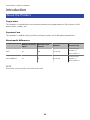 11
11
-
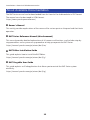 12
12
-
 13
13
-
 14
14
-
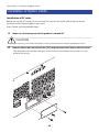 15
15
-
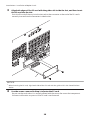 16
16
-
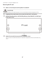 17
17
-
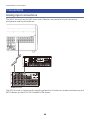 18
18
-
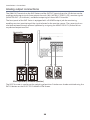 19
19
-
 20
20
-
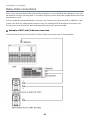 21
21
-
 22
22
-
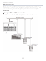 23
23
-
 24
24
-
 25
25
-
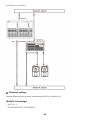 26
26
-
 27
27
-
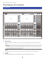 28
28
-
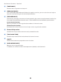 29
29
-
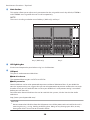 30
30
-
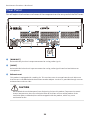 31
31
-
 32
32
-
 33
33
-
 34
34
-
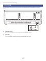 35
35
-
 36
36
-
 37
37
-
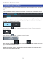 38
38
-
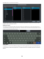 39
39
-
 40
40
-
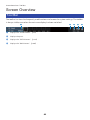 41
41
-
 42
42
-
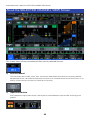 43
43
-
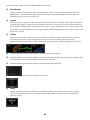 44
44
-
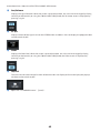 45
45
-
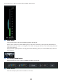 46
46
-
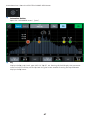 47
47
-
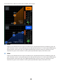 48
48
-
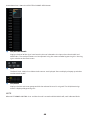 49
49
-
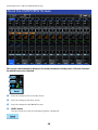 50
50
-
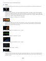 51
51
-
 52
52
-
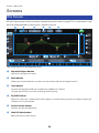 53
53
-
 54
54
-
 55
55
-
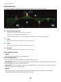 56
56
-
 57
57
-
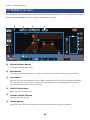 58
58
-
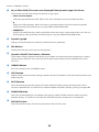 59
59
-
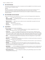 60
60
-
 61
61
-
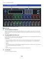 62
62
-
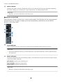 63
63
-
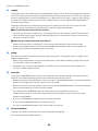 64
64
-
 65
65
-
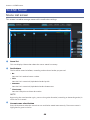 66
66
-
 67
67
-
 68
68
-
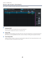 69
69
-
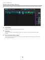 70
70
-
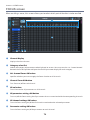 71
71
-
 72
72
-
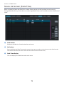 73
73
-
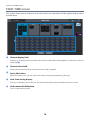 74
74
-
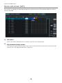 75
75
-
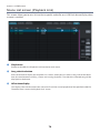 76
76
-
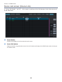 77
77
-
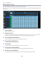 78
78
-
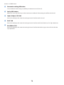 79
79
-
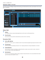 80
80
-
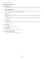 81
81
-
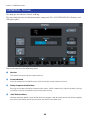 82
82
-
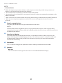 83
83
-
 84
84
-
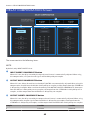 85
85
-
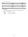 86
86
-
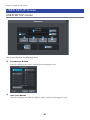 87
87
-
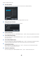 88
88
-
 89
89
-
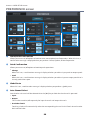 90
90
-
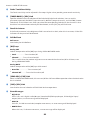 91
91
-
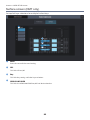 92
92
-
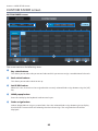 93
93
-
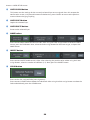 94
94
-
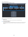 95
95
-
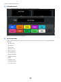 96
96
-
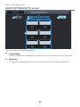 97
97
-
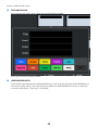 98
98
-
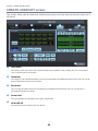 99
99
-
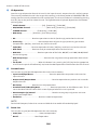 100
100
-
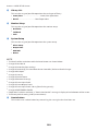 101
101
-
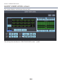 102
102
-
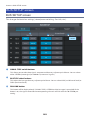 103
103
-
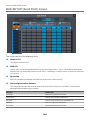 104
104
-
 105
105
-
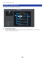 106
106
-
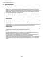 107
107
-
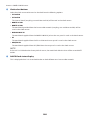 108
108
-
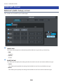 109
109
-
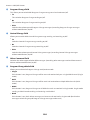 110
110
-
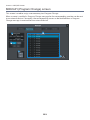 111
111
-
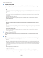 112
112
-
 113
113
-
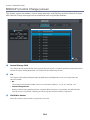 114
114
-
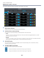 115
115
-
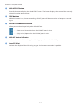 116
116
-
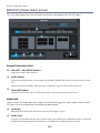 117
117
-
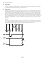 118
118
-
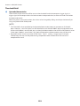 119
119
-
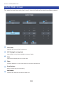 120
120
-
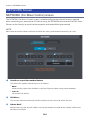 121
121
-
 122
122
-
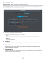 123
123
-
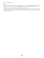 124
124
-
 125
125
-
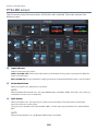 126
126
-
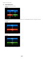 127
127
-
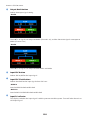 128
128
-
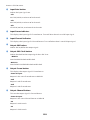 129
129
-
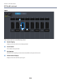 130
130
-
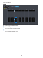 131
131
-
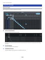 132
132
-
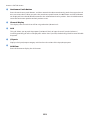 133
133
-
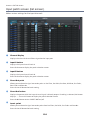 134
134
-
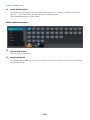 135
135
-
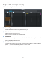 136
136
-
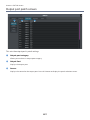 137
137
-
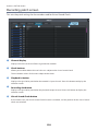 138
138
-
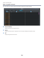 139
139
-
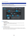 140
140
-
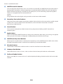 141
141
-
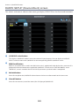 142
142
-
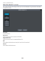 143
143
-
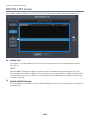 144
144
-
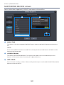 145
145
-
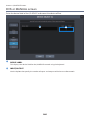 146
146
-
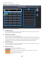 147
147
-
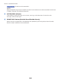 148
148
-
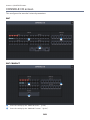 149
149
-
 150
150
-
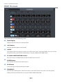 151
151
-
 152
152
-
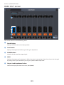 153
153
-
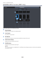 154
154
-
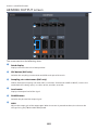 155
155
-
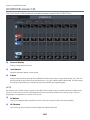 156
156
-
 157
157
-
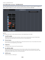 158
158
-
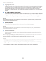 159
159
-
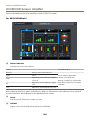 160
160
-
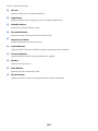 161
161
-
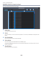 162
162
-
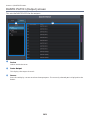 163
163
-
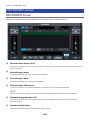 164
164
-
 165
165
-
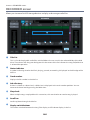 166
166
-
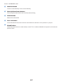 167
167
-
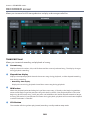 168
168
-
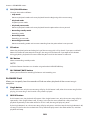 169
169
-
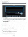 170
170
-
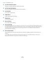 171
171
-
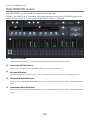 172
172
-
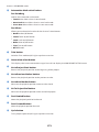 173
173
-
 174
174
-
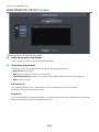 175
175
-
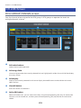 176
176
-
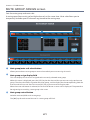 177
177
-
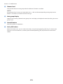 178
178
-
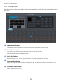 179
179
-
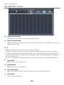 180
180
-
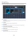 181
181
-
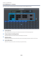 182
182
-
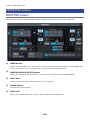 183
183
-
 184
184
-
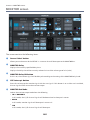 185
185
-
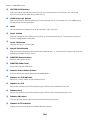 186
186
-
 187
187
-
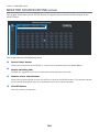 188
188
-
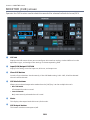 189
189
-
 190
190
-
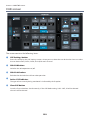 191
191
-
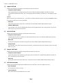 192
192
-
 193
193
-
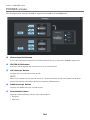 194
194
-
 195
195
-
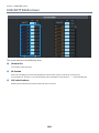 196
196
-
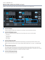 197
197
-
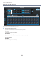 198
198
-
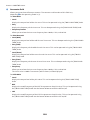 199
199
-
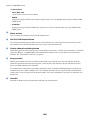 200
200
-
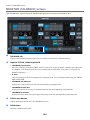 201
201
-
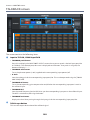 202
202
-
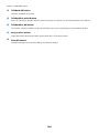 203
203
-
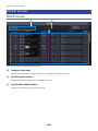 204
204
-
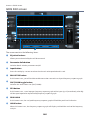 205
205
-
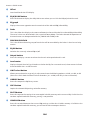 206
206
-
 207
207
-
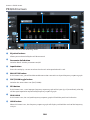 208
208
-
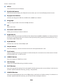 209
209
-
 210
210
-
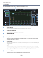 211
211
-
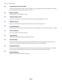 212
212
-
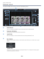 213
213
-
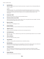 214
214
-
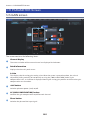 215
215
-
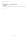 216
216
-
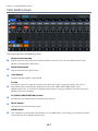 217
217
-
 218
218
-
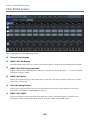 219
219
-
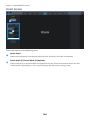 220
220
-
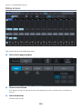 221
221
-
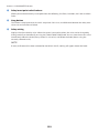 222
222
-
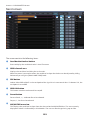 223
223
-
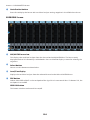 224
224
-
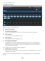 225
225
-
 226
226
-
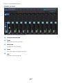 227
227
-
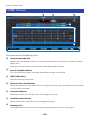 228
228
-
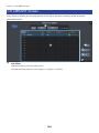 229
229
-
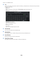 230
230
-
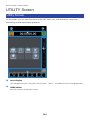 231
231
-
 232
232
-
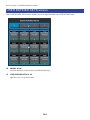 233
233
-
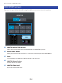 234
234
-
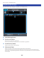 235
235
-
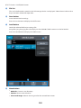 236
236
-
 237
237
-
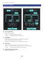 238
238
-
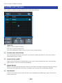 239
239
-
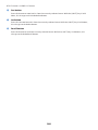 240
240
-
 241
241
-
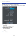 242
242
-
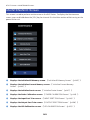 243
243
-
 244
244
-
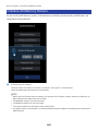 245
245
-
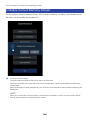 246
246
-
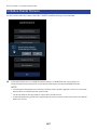 247
247
-
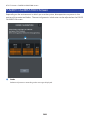 248
248
-
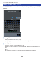 249
249
-
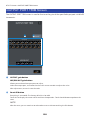 250
250
-
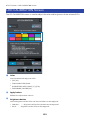 251
251
-
 252
252
-
 253
253
-
 254
254
-
 255
255
-
 256
256
-
 257
257
-
 258
258
-
 259
259
-
 260
260
-
 261
261
-
 262
262
-
 263
263
-
 264
264
-
 265
265
-
 266
266
-
 267
267
-
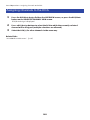 268
268
-
 269
269
-
 270
270
-
 271
271
-
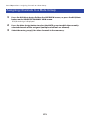 272
272
-
 273
273
-
 274
274
-
 275
275
-
 276
276
-
 277
277
-
 278
278
-
 279
279
-
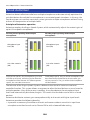 280
280
-
 281
281
-
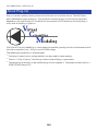 282
282
-
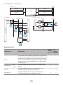 283
283
-
 284
284
-
 285
285
-
 286
286
-
 287
287
-
 288
288
-
 289
289
-
 290
290
-
 291
291
-
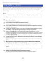 292
292
-
 293
293
-
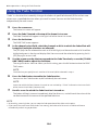 294
294
-
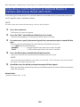 295
295
-
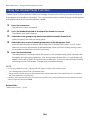 296
296
-
 297
297
-
 298
298
-
 299
299
-
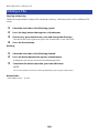 300
300
-
 301
301
-
 302
302
-
 303
303
-
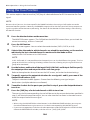 304
304
-
 305
305
-
 306
306
-
 307
307
-
 308
308
-
 309
309
-
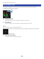 310
310
-
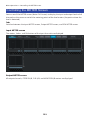 311
311
-
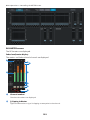 312
312
-
 313
313
-
 314
314
-
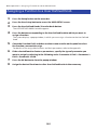 315
315
-
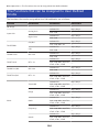 316
316
-
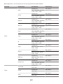 317
317
-
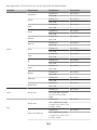 318
318
-
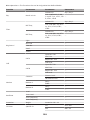 319
319
-
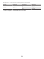 320
320
-
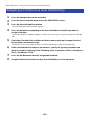 321
321
-
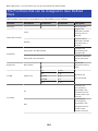 322
322
-
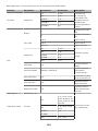 323
323
-
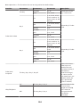 324
324
-
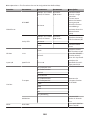 325
325
-
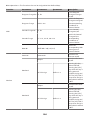 326
326
-
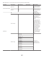 327
327
-
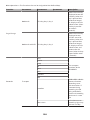 328
328
-
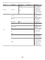 329
329
-
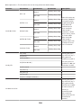 330
330
-
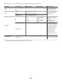 331
331
-
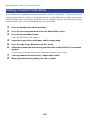 332
332
-
 333
333
-
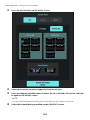 334
334
-
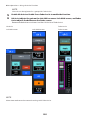 335
335
-
 336
336
-
 337
337
-
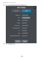 338
338
-
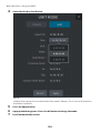 339
339
-
 340
340
-
 341
341
-
 342
342
-
 343
343
-
 344
344
-
 345
345
-
 346
346
-
 347
347
-
 348
348
-
 349
349
-
 350
350
-
 351
351
-
 352
352
-
 353
353
-
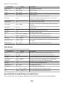 354
354
-
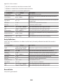 355
355
-
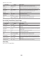 356
356
-
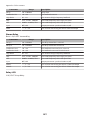 357
357
-
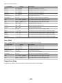 358
358
-
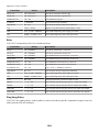 359
359
-
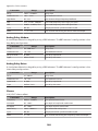 360
360
-
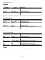 361
361
-
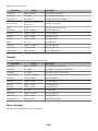 362
362
-
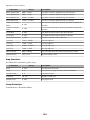 363
363
-
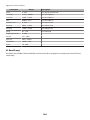 364
364
-
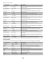 365
365
-
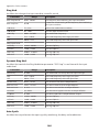 366
366
-
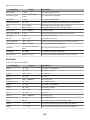 367
367
-
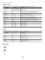 368
368
-
 369
369
-
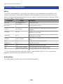 370
370
-
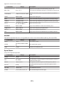 371
371
-
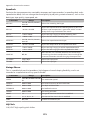 372
372
-
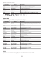 373
373
-
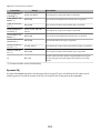 374
374
-
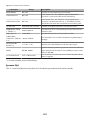 375
375
-
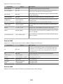 376
376
-
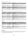 377
377
-
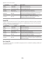 378
378
-
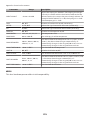 379
379
-
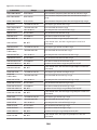 380
380
-
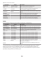 381
381
-
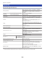 382
382
-
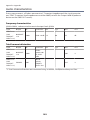 383
383
-
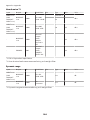 384
384
-
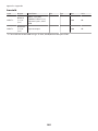 385
385
-
 386
386
-
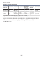 387
387
-
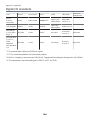 388
388
-
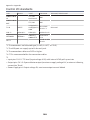 389
389
-
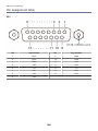 390
390
-
 391
391


in andere talen
- English: Yamaha DM7 Reference guide
- italiano: Yamaha DM7 Guida di riferimento
- русский: Yamaha DM7 Справочное руководство
- français: Yamaha DM7 Guide de référence
- español: Yamaha DM7 Guia de referencia
- Deutsch: Yamaha DM7 Referenzhandbuch
- português: Yamaha DM7 Guia de referência
- dansk: Yamaha DM7 henvisning guide
- suomi: Yamaha DM7 pikaopas
- čeština: Yamaha DM7 Referenční příručku
- 日本語: Yamaha DM7 リファレンスガイド
- svenska: Yamaha DM7 Referens guide
- polski: Yamaha DM7 instrukcja obsługi
- română: Yamaha DM7 Ghid de referință