Yamaha AW4416 de handleiding
- Categorie
- Toetsenborden
- Type
- de handleiding
Deze handleiding is ook geschikt voor

PROFESSIONAL AUDIO WORKSTATION
E
Operation Guide

FCC INFORMATION (U.S.A.)
1. IMPORTANT NOTICE: DO NOT MODIFY THIS UNIT! This product, when installed as indicated in the instructions contained in this manual, meets FCC
requirements. Modifications not expressly approved by Yamaha may void your authority, granted by the FCC, to use the product.
2. IMPORTANT: When connecting this product to accessories and/or another product use only high quality shielded cables. Cable/s supplied with this product MUST
be used. Follow all installation instructions. Failure to follow instructions could void your FCC authorization to use this product in the USA.
3. NOTE: This product has been tested and found to comply with the requirements listed in FCC Regulations, Part 15 for Class “B” digital devices. Compliance with
these requirements provides a reasonable level of assurance that your use of this product in a residential environment will not result in harmful interference with
other electronic devices. This equipment generates/uses radio frequencies and, if not installed and used according to the instructions found in the users manual, may
cause interference harmful to the operation of other electronic devices. Compliance with FCC regulations does not guarantee that interference will not occur in all
installations. If this product is found to be the source of interference, which can be determined by turning the unit “OFF” and “ON”, please try to eliminate the
problem by using one of the following measures: Relocate either this product or the device that is being affected by the interference. Utilize power outlets that are on
different branch (circuit breaker or fuse) circuits or install AC line filter/s. In the case of radio or TV interference, relocate/reorient the antenna. If the antenna lead-in
is 300 ohm ribbon lead, change the lead-in to coaxial type cable. If these corrective measures do not produce satisfactory results, please contact the local retailer
authorized to distribute this type of product. If you can not locate the appropriate retailer, please contact Yamaha Corporation of America, Electronic Service
Division, 6600 Orangethorpe Ave, Buena Park, CA 90620
The above statements apply ONLY to those products distributed by Yamaha Corporation of America or its subsidiaries.
WARNING: THIS APPARATUS MUST BE EARTHED
IMPORTANT
THE WIRES IN THIS MAINS LEAD ARE COLOURED IN
ACCORDANCE WITH THE FOLLOWING CODE:
GREEN-AND-YELLOW : EARTH
BLUE : NEUTRAL
BROWN : LIVE
As the colours of the wires in the mains lead of this apparatus may
not correspond with the coloured markings identifying the terminals in
your plug, proceed as follows:
The wire which is coloured GREEN and YELLOW must be
connected to the terminal in the plug which is marked by the letter E
or by the safety earth symbol or coloured GREEN and YELLOW.
The wire which is coloured BLUE must be connected to the terminal
which is marked with the letter N or coloured BLACK.
The wire which is coloured BROWN must be connected to the
terminal which is marked with the letter L or coloured RED.
* This applies only to products distributed by YAMAHA KEMBLE
MUSIC (U.K.) LTD.
ADVARSEL!
Lithiumbatteri—Eksplosionsfare ved fejlagtig
håndtering. Udskiftning må kun ske med batteri
af samme fabrikat og type. Levér det brugte
batteri tilbage til leverandoren.
VARNING
Explosionsfara vid felaktigt batteribyte. Använd
samma batterityp eller en ekvivalent typ som
rekommenderas av apparattillverkaren.
Kassera använt batteri enligt fabrikantens
instruktion.
VAROITUS
Paristo voi räjähtää, jos se on virheellisesti
asennettu. Vaihda paristo ainoastaan
laitevalmistajan suosittelemaan tyyppiin. Hävitä
käytetty paristo valmistajan ohjeiden
mukaisesti.
• Explanation of Graphical Symbols
The exclamation point within an equilat-
eral triangle is intended to alert the user to
the presence of important operating and
maintenance (servicing) instructions in the
literature accompanying the product.
The lightning flash with arrowhead symbol
within an equilateral triangle is intended to
alert the user to the presence of uninsulated
“dangerous voltage” within the product’s
enclosure that may be of sufficient magni-
tude to constitute a risk of electric shock to
persons.
CAUTION: TO REDUCE THE RISK OF
ELECTRIC SHOCK, DO NOT REMOVE
COVER (OR BACK). NO USER-SERVICEABLE
PARTS INSIDE. REFER SERVICING TO
QUALIFIED SERVICE PERSONNEL.
CAUTION
RISK OF ELECTRIC SHOCK
DO NOT OPEN
The above warning is located on the
rear of the unit

NEDERLAND THE NETHERLANDS
● Dit apparaat bevat een lithium batterij voor geheugen
back-up.
● Raadpleeg uw leverancier over de verwijdering van de
batterij op het moment dat u het apparaat ann het einde
van de levensduur afdankt of de volgende Yamaha Service
Afdeiing:
Yamaha Music Nederland Service Afdeiing
Kanaalweg 18-G, 3526 KL UTRECHT
Tel. 030-2828425
● Gooi de batterij niet weg, maar lever hem in als KCA.
● This apparatus contains a lithium battery for memory
back-up.
● For the removal of the battery at the moment of the
disposal at the end of the service life please consult your
retailer or Yamaha Service Center as follows:
Yamaha Music Nederland Service Center
Address: Kanaalweg 18-G, 3526 KL
UTRECHT
Tel: 030-2828425
● Do not throw away the battery. Instead, hand it in as small
chemical waste.

Important
iv
— Operation Guide
Important
Read the following before operating the
AW4416
❒
Warnings
• Do not allow water to enter this unit or allow the unit to become wet. Fire or
electrical shock may result.
• Connect this unit’s power cord only to an AC outlet of the type stated in this
Owner’s Manual or as marked on the unit. Failure to do so is a fire and electri-
cal shock hazard.
• Do not scratch, bend, twist, pull, or heat the power cord. A damaged power
cord is a fire and electrical shock hazard.
• Do not place heavy objects, including this unit, on top of the power cord. A
damaged power cord is a fire and electrical shock hazard. In particular, be
careful not to place heavy objects on a power cord covered by a carpet.
• If you notice any abnormality, such as smoke, odor, or noise, or if a foreign
object or liquid gets inside the unit, turn it off immediately. Remove the
power cord from the AC outlet. Consult your dealer for repair. Using the unit
in this condition is a fire and electrical shock hazard.
• Should this unit be dropped or the cabinet be damaged, turn the power
switch off, remove the power plug from the AC outlet, and contact your
dealer. If you continue using the unit without heeding this instruction, fire or
electrical shock may result.
• If the power cord is damaged (i.e., cut or a bare wire is exposed), ask your
dealer for a replacement. Using the unit with a damaged power cord is a fire
and electrical shock hazard.
• Do not modify the unit. Doing so is a fire and electrical shock hazard.
❒
Cautions
• When rack-mounting the unit, allow enough free space around the unit for
normal ventilation. This should be: 10 cm at the sides, 20 cm behind, and 30
cm above.
For normal ventilation during use, remove the rear of the rack or open a ven-
tilation hole.
If the airflow is not adequate, the unit will heat up inside and may cause a
fire.
• This unit has ventilation holes at the bottom to prevent the internal tempera-
ture rising too high. Do not block them. Blocked ventilation holes are a fire
hazard.
• Hold the power cord plug when disconnecting it from an AC outlet. Never
pull the cord. A damaged power cord is a potential fire and electrical shock
hazard.

Important
— Operation Guide
v
• Do not touch the power plug with wet hands. Doing so is a potential electri-
cal shock hazard.
• Use only the included power supply cable for this unit. Using other types may
be a fire hazard.
• Always touch a well-grounded metal surface or the like to fully discharge any
static electric charge on your body and clothing before handling an I/O card
or hard disk.
Neglecting this precaution can cause damage to the unit from static electric-
ity.
• Be careful not to touch the leads (metal feet) on the rear side when handling
an I/O card or hard disk. Touching the leads can cause contact defects.
❒
Operating Notes
• Using a mobile telephone near this unit may induce noise. If noise occurs,
use the telephone away from the unit.
• XLR-type connectors are wired as follows: pin 1: ground, pin 2: hot (+), and
pin 3: cold (–).
• Insert TRS phone jacks are wired as follows: sleeve: ground, tip: send, and
ring: return.
• If the message “LOW BATTERY” appears when you turn on this unit, contact
your dealer as soon as possible about replacing the internal data backup bat-
tery. The unit will still operate correctly, but data other than the presets will be
lost.
We recommend that you save the data on CD-RW drive or external SCSI
device before replacing the battery.
• The performance of components with moving contacts, such switches, rotary
controls, faders, and connectors, deteriorates over time. The rate of deteriora-
tion depends on the operating environment and is unavoidable. Consult your
dealer about replacing defective components.
Handling the CD-R/RW media
Please observe the following points when handling the disk.
Failure to do so may cause problems such as the recorded data being lost, the
drive to malfunction, or the printed label to become blurred.
• Do not place the disk in locations of direct sunlight, high temperature, or high
humidity.
• Do not touch either surface of the disk.
• Hold the disk at the edges. Gently wipe dust or dirt off of the recording sur-
face of the disk.
• Do not wipe the disk with chemicals or detergents.
• Do not bend or drop the disk.
• Use an air duster or cleaner to remove dust. Vigorously rubbing the surface of
the disk with a dry cloth may scratch the disk.
• Do not write on the disk or affix labels to it.

Important
vi
— Operation Guide
Storing produced data
Produced data can be lost due to breakdown or mistaken operation. We recom-
mend that you store all important data on CD-R or CD-RW disks or other external
storage medium.
Responsibility for loss of data, etc.
• Yamaha will accept no responsibility for any damages (including consequen-
tial or incidental) incurred by the customer or any third party as a result of
loss or impairment of the data stored on the CD-R media, regardless of
whether such loss could have been or actually was foreseen by Yamaha.
• Nor does Yamaha guarantee the media against any defect that may render it
unusable.
Cautions for handling optional equipment
• For inquiries concerning I/O card, hard disk, or CD-RW drive handling,
please consult your Yamaha dealer.
• Always switch off the power for the main unit and all peripherals, unplug the
power cord for the main unit from the outlet, then disconnect the cables con-
necting the main unit with the peripherals before starting installation work.
• Wear thick gloves when working on this equipment to avoid cutting your
hands on metal fittings or the like on the main unit, I/O card, hard disk, or
CD-RW drive.
• Always touch a well-grounded metal surface or the like to fully discharge any
static electric charge on your body and clothing before starting to work on
this equipment.
• Take extreme care to avoid touching any terminals or board surface parts.
• In order to protect the electronic circuits of the I/O card, hard disk, CD-RW
drive, etc. from damage due to static electricity, when handling any of this
equipment, take the most extreme care to avoid touching IC leads or other
electronic parts.
• Be careful not to drop any screws into the main unit. If you switch the power
on with a dropped screw still in the main unit, the main unit may malfunction
or break down. If a dropped screw can not be retrieved, consult your Yamaha
dealer.
• If the hard disk or CD-RW drive breaks down, contact the store where you
purchased that equipment.
Except for duplication for personal use or when there is no copyright problem,
the duplication or transfer of commercially sold music/sound data without the
permission of the copyright holder is prohibited. When using this equipment,
please consult with a copyright specialist.

Important
— Operation Guide
vii
❍
Warning
The Yamaha Professional Audio Workstation is designed to be used professionally
and responsibly by recording industry professionals. The reproduction, distribu-
tion, or, in some instances, the public performance, of all or a portion of a sound
recording or musical composition protected by copyright, without having
obtained a proper license from the relevant copyright holders, may constitute
copyright infringement and may otherwise violate copyright laws and other laws.
In addition, laws (such as the Audio Home Recording Act and the Digital Millen-
nium Copyright Act in USA) contain certain restrictions and requirements that
may apply to your use of works protected by copyright and related information
and data that may accompany such works. Violation of such laws may result in
civil remedies and, in some cases, criminal liability.
Because violations of copyright laws may be serious offenses, you should consult
a lawyer familiar with the law of copyright, including all laws that may be appli-
cable to your use of the Workstation (such as the Audio Home Recording Act and
the Digital Millennium Copyright Act in USA), if you have any questions regard-
ing your intended use of all or parts of sound recordings or musical compositions
protected by copyright.

Table of contents
viii
— Operation Guide
Thank you for purchasing the Yamaha AW4416 audio workstation. In order
to take full advantage of the AW4416’s functionality and enjoy trouble-free
operation, please carefully read the “Operation Guide” (this manual) and
the separate “Reference Manual” and “Tutorial.”
Table of contents
Before you begin . . . . . . . . . . . . . . . . . . . . . . . . . . . . . . 1
Checking the included items . . . . . . . . . . . . . . . . . . . . . . . . . . . . . . . 1
Installing an internal hard disk . . . . . . . . . . . . . . . . . . . . . . . . . . . . . 2
About the internal hard disk. . . . . . . . . . . . . . . . . . . . . . . . . . . . . . 2
Installation. . . . . . . . . . . . . . . . . . . . . . . . . . . . . . . . . . . . . . . . . . . 3
Installing a CD-RW drive. . . . . . . . . . . . . . . . . . . . . . . . . . . . . . . . . . 5
About the CD-RW drives . . . . . . . . . . . . . . . . . . . . . . . . . . . . . . . . 5
The SCSI ID of the CD-RW drive. . . . . . . . . . . . . . . . . . . . . . . . . . . . . 5
Installation procedure . . . . . . . . . . . . . . . . . . . . . . . . . . . . . . . . . . 6
Removing the transport protection pad. . . . . . . . . . . . . . . . . . . . . . . 9
How to remove the transport protection pad . . . . . . . . . . . . . . . . . 9
Manual eject (emergency disc removal). . . . . . . . . . . . . . . . . . . . 10
Attaching an external SCSI device. . . . . . . . . . . . . . . . . . . . . . . . . . 10
About external SCSI devices . . . . . . . . . . . . . . . . . . . . . . . . . . . . 10
Connection procedure. . . . . . . . . . . . . . . . . . . . . . . . . . . . . . . . . 11
About terminators . . . . . . . . . . . . . . . . . . . . . . . . . . . . . . . . . . . . . . . 12
About SCSI errors . . . . . . . . . . . . . . . . . . . . . . . . . . . . . . . . . . . . . . . 12
Installing I/O cards . . . . . . . . . . . . . . . . . . . . . . . . . . . . . . . . . . . . . 13
About I/O cards . . . . . . . . . . . . . . . . . . . . . . . . . . . . . . . . . . . . . . 13
Installation procedure . . . . . . . . . . . . . . . . . . . . . . . . . . . . . . . . . 14
Important points you must observe. . . . . . . . . . . . . . . 15
Turning the power on or off . . . . . . . . . . . . . . . . . . . . . . . . . . . . . . 15
Turning the power on . . . . . . . . . . . . . . . . . . . . . . . . . . . . . . . . . . . . 15
Setting the internal clock. . . . . . . . . . . . . . . . . . . . . . . . . . . . . . . . . 16
Turning the power off . . . . . . . . . . . . . . . . . . . . . . . . . . . . . . . . . . . . 17
Transporting the AW4416. . . . . . . . . . . . . . . . . . . . . . . . . . . . . . . . 18
Vibration during use . . . . . . . . . . . . . . . . . . . . . . . . . . . . . . . . . . . . 18
Chapter 1 Welcome to the world of the AW4416. . . . . . . . .19
Features of the AW4416 . . . . . . . . . . . . . . . . . . . . . . . . . . . . . . . . . 19
Mixer section . . . . . . . . . . . . . . . . . . . . . . . . . . . . . . . . . . . . . . . . . . 19
Recorder section. . . . . . . . . . . . . . . . . . . . . . . . . . . . . . . . . . . . . . . . 20
Sampling pad section . . . . . . . . . . . . . . . . . . . . . . . . . . . . . . . . . . . . 21

Table of contents
— Operation Guide
ix
CD-RW drive (option) . . . . . . . . . . . . . . . . . . . . . . . . . . . . . . . . . . . . 21
Other features . . . . . . . . . . . . . . . . . . . . . . . . . . . . . . . . . . . . . . . . . . 21
Signal flow within the AW4416 . . . . . . . . . . . . . . . . . . . . . . . . . . . 22
Input patch . . . . . . . . . . . . . . . . . . . . . . . . . . . . . . . . . . . . . . . . . 23
Input channels 1–24 . . . . . . . . . . . . . . . . . . . . . . . . . . . . . . . . . . 24
Return channels 1/2 . . . . . . . . . . . . . . . . . . . . . . . . . . . . . . . . . . 25
Recorder input patching . . . . . . . . . . . . . . . . . . . . . . . . . . . . . . . 26
Monitor channels 1–16. . . . . . . . . . . . . . . . . . . . . . . . . . . . . . . . 26
Digital cascade connections . . . . . . . . . . . . . . . . . . . . . . . . . . . . 27
Oscillator . . . . . . . . . . . . . . . . . . . . . . . . . . . . . . . . . . . . . . . . . . 27
Stereo output channel. . . . . . . . . . . . . . . . . . . . . . . . . . . . . . . . . 27
Buses 1–8 . . . . . . . . . . . . . . . . . . . . . . . . . . . . . . . . . . . . . . . . . . 28
AUX buses 1–8 . . . . . . . . . . . . . . . . . . . . . . . . . . . . . . . . . . . . . . 28
Output patch . . . . . . . . . . . . . . . . . . . . . . . . . . . . . . . . . . . . . . . 29
Internal effects 1/2 . . . . . . . . . . . . . . . . . . . . . . . . . . . . . . . . . . . 29
Monitor output/headphone output . . . . . . . . . . . . . . . . . . . . . . . 30
Chapter 2 Parts and their functions . . . . . . . . . . . . . . . . . . 31
Top panel . . . . . . . . . . . . . . . . . . . . . . . . . . . . . . . . . . . . . . . . . . . . 31
Analog input/output section . . . . . . . . . . . . . . . . . . . . . . . . . . . . 31
WORK NAVIGATE section . . . . . . . . . . . . . . . . . . . . . . . . . . . . . 32
UNIT section . . . . . . . . . . . . . . . . . . . . . . . . . . . . . . . . . . . . . . . 32
MIXER section. . . . . . . . . . . . . . . . . . . . . . . . . . . . . . . . . . . . . . . 33
FADER MODE section . . . . . . . . . . . . . . . . . . . . . . . . . . . . . . . . 34
MIXING LAYER section. . . . . . . . . . . . . . . . . . . . . . . . . . . . . . . . 35
[SEL] keys, [ON] keys, faders . . . . . . . . . . . . . . . . . . . . . . . . . . . 37
Display section . . . . . . . . . . . . . . . . . . . . . . . . . . . . . . . . . . . . . . 38
Level meter/counter section . . . . . . . . . . . . . . . . . . . . . . . . . . . . 39
RECORDER section. . . . . . . . . . . . . . . . . . . . . . . . . . . . . . . . . . . 40
AUTOMATION section . . . . . . . . . . . . . . . . . . . . . . . . . . . . . . . 41
SCENE MEMORY section . . . . . . . . . . . . . . . . . . . . . . . . . . . . . . 41
CURSOR/JOG & SHUTTLE section . . . . . . . . . . . . . . . . . . . . . . . 42
Locate section. . . . . . . . . . . . . . . . . . . . . . . . . . . . . . . . . . . . . . . 43
Transport section . . . . . . . . . . . . . . . . . . . . . . . . . . . . . . . . . . . . 44
SAMPLING PAD section. . . . . . . . . . . . . . . . . . . . . . . . . . . . . . . 45
Rear panel . . . . . . . . . . . . . . . . . . . . . . . . . . . . . . . . . . . . . . . . . . . 46
Front panel . . . . . . . . . . . . . . . . . . . . . . . . . . . . . . . . . . . . . . . . . . . 50
Chapter 3 The user interface of the AW4416 . . . . . . . . . . . 51
Display . . . . . . . . . . . . . . . . . . . . . . . . . . . . . . . . . . . . . . . . . . . . . . 51
Level meters/counter . . . . . . . . . . . . . . . . . . . . . . . . . . . . . . . . . . . 54
Basic operation of the AW4416 . . . . . . . . . . . . . . . . . . . . . . . . . . . 56
Accessing a screen/page . . . . . . . . . . . . . . . . . . . . . . . . . . . . . . . 56
Using the controls of the top panel . . . . . . . . . . . . . . . . . . . . . . . . . . 56

Table of contents
x
— Operation Guide
Using the mouse. . . . . . . . . . . . . . . . . . . . . . . . . . . . . . . . . . . . . . . . 56
Turning a button on/off . . . . . . . . . . . . . . . . . . . . . . . . . . . . . . . . 57
Using the controls of the top panel . . . . . . . . . . . . . . . . . . . . . . . . . . 57
Using the mouse. . . . . . . . . . . . . . . . . . . . . . . . . . . . . . . . . . . . . . . . 57
Editing the value of a fader/knob/numerical box . . . . . . . . . . . . . 58
Using the controls of the top panel . . . . . . . . . . . . . . . . . . . . . . . . . . 58
Using the mouse. . . . . . . . . . . . . . . . . . . . . . . . . . . . . . . . . . . . . . . . 58
Using the additional function buttons . . . . . . . . . . . . . . . . . . . . . 59
Using the controls of the top panel . . . . . . . . . . . . . . . . . . . . . . . . . . 59
Using the mouse. . . . . . . . . . . . . . . . . . . . . . . . . . . . . . . . . . . . . . . . 59
Inputting text . . . . . . . . . . . . . . . . . . . . . . . . . . . . . . . . . . . . . . . . 60
Using the controls of the tab page. . . . . . . . . . . . . . . . . . . . . . . . . . . 60
Using the mouse. . . . . . . . . . . . . . . . . . . . . . . . . . . . . . . . . . . . . . . . 62
Selecting channels. . . . . . . . . . . . . . . . . . . . . . . . . . . . . . . . . . . . 63
Chapter 4 Connections and setup . . . . . . . . . . . . . . . . . . . . .67
Connections . . . . . . . . . . . . . . . . . . . . . . . . . . . . . . . . . . . . . . . . . . 67
Word clock settings. . . . . . . . . . . . . . . . . . . . . . . . . . . . . . . . . . . . . 68
Chapter 5 Recording on the AW4416 . . . . . . . . . . . . . . . . . .73
Preparations for recording . . . . . . . . . . . . . . . . . . . . . . . . . . . . . . . 73
Connections and start-up. . . . . . . . . . . . . . . . . . . . . . . . . . . . . . . 73
Creating a new song . . . . . . . . . . . . . . . . . . . . . . . . . . . . . . . . . . 75
Recording the first tracks . . . . . . . . . . . . . . . . . . . . . . . . . . . . . . . . 78
Set the input level . . . . . . . . . . . . . . . . . . . . . . . . . . . . . . . . . . . . 78
Assign the signals to buses. . . . . . . . . . . . . . . . . . . . . . . . . . . . . . 81
Set the tracks to record-ready mode. . . . . . . . . . . . . . . . . . . . . . . 82
Make monitor settings . . . . . . . . . . . . . . . . . . . . . . . . . . . . . . . . . 83
Let’s record!. . . . . . . . . . . . . . . . . . . . . . . . . . . . . . . . . . . . . . . . . 85
Overdubbing . . . . . . . . . . . . . . . . . . . . . . . . . . . . . . . . . . . . . . . . . . 87
Set the input level . . . . . . . . . . . . . . . . . . . . . . . . . . . . . . . . . . . . 87
Assign the signal to a bus. . . . . . . . . . . . . . . . . . . . . . . . . . . . . . . 88
Put the track in record-ready mode . . . . . . . . . . . . . . . . . . . . . . . 89
Make monitor settings . . . . . . . . . . . . . . . . . . . . . . . . . . . . . . . . . 90
Using EQ and the dynamics processor. . . . . . . . . . . . . . . . . . . . . 91
Using the four-band EQ . . . . . . . . . . . . . . . . . . . . . . . . . . . . . . . . . . 91
Using the dynamics processor. . . . . . . . . . . . . . . . . . . . . . . . . . . . . . 92
Let’s overdub! . . . . . . . . . . . . . . . . . . . . . . . . . . . . . . . . . . . . . . . 94
Mixdown . . . . . . . . . . . . . . . . . . . . . . . . . . . . . . . . . . . . . . . . . . . . . 95
Creating the mix balance of the tracks . . . . . . . . . . . . . . . . . . . . . 95
Using the Solo function . . . . . . . . . . . . . . . . . . . . . . . . . . . . . . . . 96
Using the internal effects . . . . . . . . . . . . . . . . . . . . . . . . . . . . . . . 99
Other convenient functions. . . . . . . . . . . . . . . . . . . . . . . . . . . . . . 101
Fader groups. . . . . . . . . . . . . . . . . . . . . . . . . . . . . . . . . . . . . . . . . . 101
Mute groups . . . . . . . . . . . . . . . . . . . . . . . . . . . . . . . . . . . . . . . . . . 101
Automix . . . . . . . . . . . . . . . . . . . . . . . . . . . . . . . . . . . . . . . . . . . . . 102

Table of contents
— Operation Guide
xi
Recording the stereo track. . . . . . . . . . . . . . . . . . . . . . . . . . . . . 102
Saving a scene/song . . . . . . . . . . . . . . . . . . . . . . . . . . . . . . . . . . . 105
Saving a scene . . . . . . . . . . . . . . . . . . . . . . . . . . . . . . . . . . . . . . . . 105
Saving a song . . . . . . . . . . . . . . . . . . . . . . . . . . . . . . . . . . . . . . . . . 106
Chapter 6 Transport/locate operations. . . . . . . . . . . . . . . 109
Table of transport key operations . . . . . . . . . . . . . . . . . . . . . . . . . 109
Shuttle function (cue/review operation). . . . . . . . . . . . . . . . . . . . 110
Nudge function. . . . . . . . . . . . . . . . . . . . . . . . . . . . . . . . . . . . . . . 110
Using the Nudge function. . . . . . . . . . . . . . . . . . . . . . . . . . . . . . . . 110
Nudge function settings . . . . . . . . . . . . . . . . . . . . . . . . . . . . . . . . . 112
Rollback function . . . . . . . . . . . . . . . . . . . . . . . . . . . . . . . . . . . . . 113
Locating to a specific point. . . . . . . . . . . . . . . . . . . . . . . . . . . . . . 114
Locating to the zero location of the counter. . . . . . . . . . . . . . . . . 115
Setting the zero relative time location . . . . . . . . . . . . . . . . . . . . . . . 115
Locating to the start/end points . . . . . . . . . . . . . . . . . . . . . . . . . . 117
A-B repeat . . . . . . . . . . . . . . . . . . . . . . . . . . . . . . . . . . . . . . . . . . 118
Setting the A/B points . . . . . . . . . . . . . . . . . . . . . . . . . . . . . . . . . . . 118
Performing A-B repeat playback . . . . . . . . . . . . . . . . . . . . . . . . . . . 118
In/out points. . . . . . . . . . . . . . . . . . . . . . . . . . . . . . . . . . . . . . . . . 120
Setting the In point/Out point . . . . . . . . . . . . . . . . . . . . . . . . . . . . . 120
Markers . . . . . . . . . . . . . . . . . . . . . . . . . . . . . . . . . . . . . . . . . . . . 121
Setting a marker . . . . . . . . . . . . . . . . . . . . . . . . . . . . . . . . . . . . . . . 121
Locating to a marker . . . . . . . . . . . . . . . . . . . . . . . . . . . . . . . . . . . . 121
Adjusting the location of a locate point . . . . . . . . . . . . . . . . . . . . 123
Deleting a locate point . . . . . . . . . . . . . . . . . . . . . . . . . . . . . . . . . 125
Deleting a locate point using the panel keys. . . . . . . . . . . . . . . . . 126
Deleting an In/Out point or A/B point . . . . . . . . . . . . . . . . . . . . . . . 126
Deleting a marker . . . . . . . . . . . . . . . . . . . . . . . . . . . . . . . . . . . . . . 126
Chapter 7 Punch-in/out . . . . . . . . . . . . . . . . . . . . . . . . . . . 127
About punch-in/out . . . . . . . . . . . . . . . . . . . . . . . . . . . . . . . . . . . 127
Manual punch-in/out (
→
P.128) . . . . . . . . . . . . . . . . . . . . . . . . . . . 127
Auto punch-in/out (
→
P.130). . . . . . . . . . . . . . . . . . . . . . . . . . . . . . 127
Manual punch-in/out . . . . . . . . . . . . . . . . . . . . . . . . . . . . . . . . . . 128
Preparations . . . . . . . . . . . . . . . . . . . . . . . . . . . . . . . . . . . . . . . 128
Make input monitor settings . . . . . . . . . . . . . . . . . . . . . . . . . . . . . . 128
Connect a foot switch . . . . . . . . . . . . . . . . . . . . . . . . . . . . . . . . . . . 128
Manual punch-in/out recording . . . . . . . . . . . . . . . . . . . . . . . . 129
Auto punch-in/out . . . . . . . . . . . . . . . . . . . . . . . . . . . . . . . . . . . . 130
Preparations . . . . . . . . . . . . . . . . . . . . . . . . . . . . . . . . . . . . . . . 130
Make input monitor settings . . . . . . . . . . . . . . . . . . . . . . . . . . . . . . 130
Set the auto punch-in/out points . . . . . . . . . . . . . . . . . . . . . . . . . . . 130
Set the pre-roll/post-roll times . . . . . . . . . . . . . . . . . . . . . . . . . . . . . 130
Rehearsing and recording with auto punch-in/out. . . . . . . . . . . 131
Rehearsing with auto punch-in/out . . . . . . . . . . . . . . . . . . . . . . . . . 131
Recording with auto punch-in/out. . . . . . . . . . . . . . . . . . . . . . . . . . 132

Table of contents
xii
— Operation Guide
Chapter 8 Patching . . . . . . . . . . . . . . . . . . . . . . . . . . . . . . .133
Patching to the input channels . . . . . . . . . . . . . . . . . . . . . . . . . . . 133
Patching to the recorder inputs. . . . . . . . . . . . . . . . . . . . . . . . . . . 135
Patching to the outputs . . . . . . . . . . . . . . . . . . . . . . . . . . . . . . . . . 136
Patch library . . . . . . . . . . . . . . . . . . . . . . . . . . . . . . . . . . . . . . . . . 138
Storing to the patch library . . . . . . . . . . . . . . . . . . . . . . . . . . . . . . . 138
Recalling a patch program . . . . . . . . . . . . . . . . . . . . . . . . . . . . . . . 139
Patching input/output jacks to an insert I/O point . . . . . . . . . . . . 140
Using the Quick Rec function . . . . . . . . . . . . . . . . . . . . . . . . . . . . 143
Chapter 9 Track and virtual track operations. . . . . . . . . . .147
The track structure of the AW4416. . . . . . . . . . . . . . . . . . . . . . . . 147
Switching virtual tracks. . . . . . . . . . . . . . . . . . . . . . . . . . . . . . . . . 149
Pairing tracks. . . . . . . . . . . . . . . . . . . . . . . . . . . . . . . . . . . . . . . . . 151
Editing tracks and virtual tracks . . . . . . . . . . . . . . . . . . . . . . . . . . 152
Tracks, parts, and regions . . . . . . . . . . . . . . . . . . . . . . . . . . . . . 152
Naming a virtual track or region . . . . . . . . . . . . . . . . . . . . . . . . 153
Naming a virtual track . . . . . . . . . . . . . . . . . . . . . . . . . . . . . . . . . . 153
Naming a region. . . . . . . . . . . . . . . . . . . . . . . . . . . . . . . . . . . . . . . 155
Track editing procedure. . . . . . . . . . . . . . . . . . . . . . . . . . . . . . . 156
Virtual track editing procedure . . . . . . . . . . . . . . . . . . . . . . . . . 159
Editing command list. . . . . . . . . . . . . . . . . . . . . . . . . . . . . . . . . . . 161
TRACK menu. . . . . . . . . . . . . . . . . . . . . . . . . . . . . . . . . . . . . . . 161
PART menu . . . . . . . . . . . . . . . . . . . . . . . . . . . . . . . . . . . . . . . . 162
REGION menu . . . . . . . . . . . . . . . . . . . . . . . . . . . . . . . . . . . . . 163
Chapter 10 Internal effects . . . . . . . . . . . . . . . . . . . . . . . . . .165
About the internal effects . . . . . . . . . . . . . . . . . . . . . . . . . . . . . . . 165
Using AUX send/return . . . . . . . . . . . . . . . . . . . . . . . . . . . . . . . . . . 165
Inserting an effect into a channel . . . . . . . . . . . . . . . . . . . . . . . . . . 165
Using AUX send/return to apply an effect. . . . . . . . . . . . . . . . . . . 166
Patching . . . . . . . . . . . . . . . . . . . . . . . . . . . . . . . . . . . . . . . . . . . . . 166
Recalling an effect program from the library . . . . . . . . . . . . . . . . . . 167
Switching between pre-fader and post-fader . . . . . . . . . . . . . . . . . . 169
Adjusting the send level/return level . . . . . . . . . . . . . . . . . . . . . . . . 170
Adjusting the send level . . . . . . . . . . . . . . . . . . . . . . . . . . . . . . . . . 170
Inserting an effect into a desired channel . . . . . . . . . . . . . . . . . . . 171
Patching . . . . . . . . . . . . . . . . . . . . . . . . . . . . . . . . . . . . . . . . . . . . . 171
Inserting an effect into monitor channel 1. . . . . . . . . . . . . . . . . . . . 172
Recalling an effect program . . . . . . . . . . . . . . . . . . . . . . . . . . . . . . 174
Chapter 11 Song management . . . . . . . . . . . . . . . . . . . . . . .175
About songs. . . . . . . . . . . . . . . . . . . . . . . . . . . . . . . . . . . . . . . . . . 175
Song structure and size . . . . . . . . . . . . . . . . . . . . . . . . . . . . . . . . . 176
Song structure . . . . . . . . . . . . . . . . . . . . . . . . . . . . . . . . . . . . . . 176

Table of contents
— Operation Guide
xiii
Usable hard disks/song capacity . . . . . . . . . . . . . . . . . . . . . . . . 176
Work area for audio CD production . . . . . . . . . . . . . . . . . . . . . 176
Saving/loading a song. . . . . . . . . . . . . . . . . . . . . . . . . . . . . . . . . . 177
Saving the current song. . . . . . . . . . . . . . . . . . . . . . . . . . . . . . . . . . 177
Loading a song . . . . . . . . . . . . . . . . . . . . . . . . . . . . . . . . . . . . . . . . 178
Editing the song name/comment . . . . . . . . . . . . . . . . . . . . . . . . . 179
Deleting/copying a song. . . . . . . . . . . . . . . . . . . . . . . . . . . . . . . . 180
Deleting a song. . . . . . . . . . . . . . . . . . . . . . . . . . . . . . . . . . . . . . . . 180
Copying a song. . . . . . . . . . . . . . . . . . . . . . . . . . . . . . . . . . . . . . . . 181
Optimizing a song . . . . . . . . . . . . . . . . . . . . . . . . . . . . . . . . . . 182
Importing mixer data of an existing song . . . . . . . . . . . . . . . . . . . 183
Chapter 12 Sampling pads . . . . . . . . . . . . . . . . . . . . . . . . . . 185
About the sampling pads . . . . . . . . . . . . . . . . . . . . . . . . . . . . . . . 185
Assigning the pad outputs to channels . . . . . . . . . . . . . . . . . . . . . 186
Assigning a region to a sampling pad . . . . . . . . . . . . . . . . . . . . . . 187
Trimming a sample . . . . . . . . . . . . . . . . . . . . . . . . . . . . . . . . . . . . 190
Naming a pad . . . . . . . . . . . . . . . . . . . . . . . . . . . . . . . . . . . . . . . . 193
Erasing a pad sample and name . . . . . . . . . . . . . . . . . . . . . . . . . . 194
Recording your performance on the sampling pads . . . . . . . . . . . 196
Copying a pad performance . . . . . . . . . . . . . . . . . . . . . . . . . . . . . 198
Erasing a pad performance . . . . . . . . . . . . . . . . . . . . . . . . . . . . . . 201
Chapter 13 Scene memory . . . . . . . . . . . . . . . . . . . . . . . . . . 203
About scene memory . . . . . . . . . . . . . . . . . . . . . . . . . . . . . . . . . . 203
Parameters included in a scene. . . . . . . . . . . . . . . . . . . . . . . . . . . . 203
About scene numbers . . . . . . . . . . . . . . . . . . . . . . . . . . . . . . . . . . . 203
Storing a scene . . . . . . . . . . . . . . . . . . . . . . . . . . . . . . . . . . . . . . . 204
Recalling a scene . . . . . . . . . . . . . . . . . . . . . . . . . . . . . . . . . . . . . 206
Editing the name of a scene . . . . . . . . . . . . . . . . . . . . . . . . . . . . . 207
Protecting a scene . . . . . . . . . . . . . . . . . . . . . . . . . . . . . . . . . . . . 208
Changing the order of scenes . . . . . . . . . . . . . . . . . . . . . . . . . . . . 209
Using keys to store/recall a scene. . . . . . . . . . . . . . . . . . . . . . . . . 211
Storing a scene . . . . . . . . . . . . . . . . . . . . . . . . . . . . . . . . . . . . . 211
Recalling a scene . . . . . . . . . . . . . . . . . . . . . . . . . . . . . . . . . . . 212
Chapter 14 Automix. . . . . . . . . . . . . . . . . . . . . . . . . . . . . . . 213
What is automix? . . . . . . . . . . . . . . . . . . . . . . . . . . . . . . . . . . . . . 213
Creating a new automix . . . . . . . . . . . . . . . . . . . . . . . . . . . . . . . . 214
Recording the first section . . . . . . . . . . . . . . . . . . . . . . . . . . . . . . 216
Playing back automix . . . . . . . . . . . . . . . . . . . . . . . . . . . . . . . . . . 218
Overwriting events . . . . . . . . . . . . . . . . . . . . . . . . . . . . . . . . . . . . 219
Automix punch-in/out . . . . . . . . . . . . . . . . . . . . . . . . . . . . . . . . . 221

Table of contents
xiv — Operation Guide
Editing the fader movements . . . . . . . . . . . . . . . . . . . . . . . . . . . . . 223
Editing automix off-line . . . . . . . . . . . . . . . . . . . . . . . . . . . . . . . . . 225
Storing an automix . . . . . . . . . . . . . . . . . . . . . . . . . . . . . . . . . . . . 228
Recalling an automix. . . . . . . . . . . . . . . . . . . . . . . . . . . . . . . . . . . 230
Chapter 15 MIDI. . . . . . . . . . . . . . . . . . . . . . . . . . . . . . . . . . .231
What you can do using MIDI . . . . . . . . . . . . . . . . . . . . . . . . . . . . 231
MIDI connectors and the TO HOST connector. . . . . . . . . . . . . . . 232
Using the TO HOST connector for direct connection to your
computer. . . . . . . . . . . . . . . . . . . . . . . . . . . . . . . . . . . . . . . . . . . . 233
Connections . . . . . . . . . . . . . . . . . . . . . . . . . . . . . . . . . . . . . . . 233
Setting the PORT SELECT parameter . . . . . . . . . . . . . . . . . . . . . 234
Switching AW4416 scenes from an external device . . . . . . . . . . . 235
Using MTC to synchronize the AW4416 and a MIDI sequencer . . 238
Using MIDI Clock to synchronize the AW4416 and a MIDI
sequencer . . . . . . . . . . . . . . . . . . . . . . . . . . . . . . . . . . . . . . . . . . . 240
Using MMC to control the AW4416 . . . . . . . . . . . . . . . . . . . . . . . 243
Chapter 16 Backing up and restoring songs . . . . . . . . . . . . .245
Selecting the backup format . . . . . . . . . . . . . . . . . . . . . . . . . . . . . 245
Backing up a song . . . . . . . . . . . . . . . . . . . . . . . . . . . . . . . . . . . . . 246
Restoring a song . . . . . . . . . . . . . . . . . . . . . . . . . . . . . . . . . . . . . . 248
Disk utilities . . . . . . . . . . . . . . . . . . . . . . . . . . . . . . . . . . . . . . . . . 250
Formatting the internal hard disk/external SCSI device. . . . . . . . 250
Formatting the internal hard disk. . . . . . . . . . . . . . . . . . . . . . . . . . . 251
Formatting an external hard disk. . . . . . . . . . . . . . . . . . . . . . . . . . . 251
Formatting removable media such as an MO drive . . . . . . . . . . . . . 253
Erasing CD-RW media. . . . . . . . . . . . . . . . . . . . . . . . . . . . . . . . 254
Chapter 17 Mastering . . . . . . . . . . . . . . . . . . . . . . . . . . . . . .255
About mastering . . . . . . . . . . . . . . . . . . . . . . . . . . . . . . . . . . . . . . 255
Stereo tracks that can be mastered. . . . . . . . . . . . . . . . . . . . . . . 255
CD-R and CD-RW . . . . . . . . . . . . . . . . . . . . . . . . . . . . . . . . . . . 256
Track At Once and Disc At Once . . . . . . . . . . . . . . . . . . . . . . . 257
Preparations for mastering . . . . . . . . . . . . . . . . . . . . . . . . . . . . . 258
Mastering mode settings . . . . . . . . . . . . . . . . . . . . . . . . . . . . . . . . . 258
Writing the master . . . . . . . . . . . . . . . . . . . . . . . . . . . . . . . . . . . . 259
Finalizing. . . . . . . . . . . . . . . . . . . . . . . . . . . . . . . . . . . . . . . . . . . . 263
Playing CD-R/RW media (the CD Play function). . . . . . . . . . . . . . 264
Index . . . . . . . . . . . . . . . . . . . . . . . . . . . . . . . . . . . . . . 267

— Operation Guide 1
Before you begin
This chapter explains preparations you need to make before using the
AW4416, such as checking the included items and installing options.
Checking the included items
Please make sure that the package contains the following items. If any items are
missing, please contact your dealer.
• AW4416 mixer/recorder unit: 1
• Operation guide (this document): 1
• Reference guide: 1
• Tutorial: 1
• Power supply cable: 1
• CD-ROM: 1
• Red and white cable for CD-RW drive (four conductor): 1
• Screws for installing 2.5 inch hard disk/CD-RW drive: 8
• ADP25H 2.5 inch hard disk adapter: 1 (pre-installed in the 2.5" HARD DISK
DRIVE slot on the rear panel of the AW4416)
❍ Trademarks
ADAT MultiChannel Optical Digital Interface is a trademark and ADAT and Alesis
are registered trademarks of Alesis Corporation. Apple and Macintosh are regis-
tered trademarks of Apple Computer, Inc. Tascam Digital Interface is a trademark
and Tascam and Teac are registered trademarks of Teac Corporation. MS-DOS is a
registered trademark and Windows is a trademark of Microsoft Corporation.
Yamaha is a trademark of Yamaha Corporation. All other trademarks are the prop-
erty of their respective holders and are hereby acknowledged.
❍ Copyright
No part of the AW4416 software or the manuals may be reproduced or distrib-
uted in any form or by any means without the prior written authorization of
Yamaha Corporation.
© 2000 Yamaha Corporation. All rights reserved.
❍ Yamaha website
<http://www.yamaha.co.jp/product/proaudio/homeenglish/>

Before you begin
2 — Operation Guide
Installing an internal hard disk
You must install a hard disk in the AW4416 before using it. If you attempt to use
the AW4416 without installing a hard disk, the recorder section and mixer sec-
tion will fail to operate correctly, and the AW4416 will be damaged as well.
About the internal hard disk
On the AW4416, all data necessary for reproducing a composition (mixer set-
tings, recorder settings, audio data etc.) is stored on the hard disk as a “song.”
An internal hard disk is attached to the ADP25H 2.5 inch hard disk adapter and
installed in the 2.5" HARD DISK DRIVE slot located on the rear panel. Hard disks
with the following specifications can be used.
• Type: IDE 2.5 inch (attachment location conforms to SFF-8201)
• Thickness: no particular limitation
• Capacity: no particular limitation (however, the AW4416 can use a maximum
capacity of 64 GB)
• Models known to work: consult your local Yamaha distributor or refer to the
website at the following URL.
<http://www.aw4416.com/>
• By “models known to work,” we mean commercially available models that
Yamaha has obtained, installed in the AW4416, and successfully tested by
means of various operational tests. However, we cannot take into account
slight differences in performance that may occur due to the manufacturing tol-
erances of each manufacturer.
• Hard disks are precision devices. Strong physical shock, magnetism, static
electricity, or excessive current etc. can damage the data on a hard disk. You
must use media such as an external SCSI device or CD-RW to backup your
important musical data.
• Please be aware that Yamaha Corporation will accept no responsibility for any
damages, neither direct nor indirect, resulting from the use of any of the above
hard disks.

Before you begin
— Operation Guide 3
Installation
Please read and observe the cautions on installing optional equipment listed at
the beginning of this manual.
Here’s how to attach a 2.5 inch IDE hard disk to the ADP25H hard disk adapter
included with the AW4416, and install it into the appropriate slot of the
AW4416.
• Hard disks are precision devices. Do not subject them to physical shock or
static electricity, etc.
• Do not place a hard disk nearby devices that produce a strong magnetic field,
or in locations of extreme cold, heat, or moisture.
• Before you handle a hard disk, touch your hand to a grounded metallic object
to release any static charge that may be present in your body or clothing. If you
fail to do so, static electricity may damage the hard disk.
• Never attempt to disassemble a hard disk or apply excessive force to it.
• The AW4416 is shipped with four screws for attaching a 2.5 inch hard disk,
and four screws for attaching a CD-RW drive, making a total of eight included
screws of the same type.
1. You will need the following items.
• The AW4416 itself
• A 2.5 inch IDE hard disk (sold separately) for installation
• Four screws included with the AW4416 for attaching the 2.5 inch hard disk
• A philips (+) screwdriver
2. Make sure that the power of the AW4416 is turned off. For safety’s sake,
disconnect the power cable from the AC outlet.
3. On the rear panel of the AW4416, remove the two screws that hold the
ADP25H 2.5 inch hard disk adapter to the 2.5" HARD DISK DRIVE slot.
ADP25H
(2.5 inch hard disk adapter)

Before you begin
4 — Operation Guide
4. Place the hard disk on the ADP25H as shown in the diagram below,
align the screw holes of the hard disk and the ADP25H, and use your
screwdriver to fasten the screws at the four locations shown.
5. Plug the connector of the flat cable extending from the ADP25H into
the connector of the hard disk.
• Even if it is difficult to plug in the connector, do not use excessive pressure to
force it in. This may damage the hard disk, or you may injure yourself.
6. Aligning the ADP25H (with the hard disk attached) with the rails inside
the 2.5" HARD DISK DRIVE slot, push it in until it clicks into place.
7. Use the screws that you removed in step 3 to fasten the ADP25H into
the 2.5" HARD DISK DRIVE slot.
If you fail to tighten the screws all the way, the hard disk may vibrate and fail to
operate correctly.
• Do not turn on the power of the AW4416 until all options have been installed.
• When you turn on the power of the AW4416 after installing a new hard disk,
formatting of the hard disk will begin automatically (
→
P.15).
Flat cable
Flat cable connector

Before you begin
— Operation Guide 5
Installing a CD-RW drive
About the CD-RW drives
A CD-RW drive is an option that allows you to create music CD’s, to backup/
restore internal hard disk data, to play a music CD or to read a CD-ROM. An
internal-type CD-RW drive can be installed by removing the CD-RW drive cover
from the front panel. CD-RW drives with the following specifications can be
used.
• Interface: SCSI-2
• Models known to work: consult your local Yamaha distributor or refer to the
website at the following URL.
<http://www.aw4416.com/>
• By “models known to work,” we mean commercially available models that
Yamaha has obtained, installed in the AW4416, and successfully tested by
means of various operational tests. However, we cannot take into account
slight differences in performance that may occur due to the manufacturing tol-
erances of each manufacturer.
• Please be aware that Yamaha Corporation will accept no responsibility for any
damages, neither direct nor indirect, resulting from the use of any of the above
CD-RW drives.
* Note that the cover panel of the AW4416 cannot be attached to a CD-RW
drive with a lid-type tray. The AW4416’s cover panel can be attached to a CD-
RW drive with a tray of the following dimensions.
❒ The SCSI ID of the CD-RW drive
• The SCSI ID of the AW4416 itself is fixed at “6.” For this reason, you must set
the SCSI ID of the CD-RW drive to “6” before installing it.
Maximum 138 mm

Before you begin
6 — Operation Guide
• In the various screens of the AW4416, the SCSI ID of the internal CD-RW
drive has been set to “3” by default. For this reason, you will find it conve-
nient to set the ID of the CD-RW to “3.” (For details on setting the SCSI ID,
refer to the manual for your CD-RW drive.)
• If you are installing a CD-RW drive manufactured by Yamaha, the SCSI ID will
be set to “3” at the factory, and we recommend that you leave it at this setting.
Installation procedure
Please carefully read the cautions for installing optional equipment given at the
beginning of this manual.
1. You will need the following items.
• The AW4416 itself
• Internal CD-RW drive (option)
• Screws (included with the AW4416) for attaching the CD-RW drive
• Red and white cable for CD-RW drive (four conductor)
• Philips (+) screwdriver
• Work surface
• In order to install the CD-RW drive you will need to turn the AW4416 on its
back. Make sure that you have a sufficiently broad work surface.
• The AW4416 is shipped with four screws for attaching the 2.5 inch hard disk,
and four screws for attaching the CD-RW drive, making a total of eight screws
of the same type.
2. Make sure that the power of the AW4416 is turned off. For safety’s sake,
disconnect the power cable from the AC outlet.
3. Turn the AW4416 upside down on the work surface.
When turning the AW4416 upside down, we recommend that you use the pack-
ing foam from the AW4416’s shipping carton as shown in the diagram at above,
so that the controls of the top panel are not damaged. If the packing foam is not
available, please spread out a soft cloth, and support each of the four corners of
the AW4416 with a stack of magazines etc.

Before you begin
— Operation Guide 7
4. Remove the CD-RW drive cover from the front panel, and remove the
bottom panel.
5. Turn the CD-RW drive over, and insert it little by little, stopping when
the connector end of the CD-RW drive enters the opening in the bottom
of the AW4416.
6. Connect the red and white four-conductor cable included with the
AW4416 to the internal connector of the AW4416 as shown in the dia-
gram. Then connect the cable to the connector of the CD-RW drive.
Bottom panel
CD-R/RW drive
cover panel

Before you begin
8 — Operation Guide
7. Plug the connector of the flat cable (extending from inside the AW4416)
into the connector of the CD-RW drive.
8. Align the screw holes in the bottom of the CD-RW drive with the screw
holes of the AW4416, and use a screwdriver to fasten the drive with the
four included screws.
9. Re-attach the CD-RW drive cover and the bottom panel that you
removed in step 3. At this time, remove the inner cover from the CD-RW
drive cover.
CD-R/RW drive
cover panel
Inner cover
Bottom panel

Before you begin
— Operation Guide 9
Removing the transport protection
pad
When CD-RW drives are shipped, the disc tray contains a transport protection
pad that protects the internal mechanism from physical shock suffered during
shipment. Please remove this protective pad before use.
Be sure to save the transport protection pad for the next time you need to trans-
port the unit.
How to remove the transport protection pad
1. Install the CD-RW drive in the AW4416.
2. Turn on the power of the AW4416.
Set the SCSI ID number as necessary (→ P.259).
3. Press the [CD PLAY] key, and then press the [SHIFT] + [F2] keys to open
the disc tray.
4. Remove the transport protection pad.
Before transporting the unit, reverse this procedure to insert the pad.
P
a
d
f
o
r
t
r
a
n
s
p
o
r
t
a
t
i
o
n
R
e
m
o
v
e
i
t
b
e
f
o
r
e
u
s
e
.
P
r
o
t
e
c
t
i
o
n
p
o
u
r
l
e
t
r
a
n
s
p
o
r
t
A
e
n
le
v
e
r
a
v
a
n
t
u
s
a
g
e
.
T
r
a
n
s
p
o
r
t
p
o
l
s
t
e
r
V
o
r
d
e
r
I
n
b
e
t
r
i
e
b
n
a
h
m
e
e
n
t
f
e
r
n
e
n
.
P
a
d
f
o
r
t
r
a
n
s
p
o
r
t
a
t
io
n
R
e
m
o
v
e
i
t
b
e
f
o
r
e
u
s
e
.
P
r
o
t
e
c
t
i
o
n
p
o
u
r
l
e
t
r
a
n
s
p
o
r
t
A
e
n
l
e
v
e
r
a
v
a
n
t
u
s
a
g
e
.
T
r
a
n
s
p
o
r
t
p
o
l
s
t
e
r
V
o
r
d
e
r
In
b
e
t
r
ie
b
n
a
h
m
e
e
n
t
f
e
r
n
e
n
.
* This diagram shows a CD-RW
drive manufactured by Yamaha
Corporation.

Before you begin
10 — Operation Guide
Manual eject (emergency disc removal)
Manual eject allows you to remove the disc manually in the case of an emer-
gency such as a malfunction of the disc tray mechanism (usually temporary) or a
power failure. Please be aware that using this method frequently can cause the
CD-RW drive to malfunction. For the location of the eject hole and the proce-
dure, refer to the manual of your CD-RW drive.
In order to perform this operation, you will need a pin-like object 2 mm or less in
diameter, such as a straightened paper clip.
Attaching an external SCSI device
About external SCSI devices
The external SCSI devices referred to here are storage devices used to backup/
restore the internal data of the AW4416, and can be connected to the SCSI con-
nector on the rear panel of the AW4416. The following types of storage device
can be used.
• Type of drive: MO drives (128 MB, 230 MB, 540MB, 640 MB 1.3 GB), hard
disk drives, CD-RW drives
• Interface: SCSI-2
• Models known to work: consult your local Yamaha distributor or refer to the
website at the following URL.
<http://www.aw4416.com/>
• By “models known to work,” we mean commercially available models that
Yamaha has obtained, connected to the AW4416, and successfully tested by
means of various operational tests. However, we cannot take into account
slight differences in performance that may occur due to the manufacturing tol-
erances of each manufacturer.
• Please be aware that Yamaha Corporation will accept no responsibility for any
damages, neither direct nor indirect, resulting from the use of any of the above
storage devices.
It is not possible to directly record or play back audio signals in realtime on an
external storage device connected to the SCSI connector.
* This diagram shows a CD-RW drive
manufactured by Yamaha Corporation.
Eject Hall
Insert a pin-like object 2 mm
or less in diameter.

Before you begin
— Operation Guide 11
Connection procedure
1. Make sure that the power is turned off for the AW4416 and for the
external SCSI device(s), and use a SCSI cable to connect the SCSI con-
nectors of each device.
When connecting an external SCSI device, use only high impedance SCSI cables
of 100 ohms (±10 ohms) impedance that are 1 meter or shorter in length.
Use only good-quality SCSI cables.
Note
• A maximum of seven SCSI devices (SCSI ID= 0–5,7) can be connected in a
daisy-chain (including the internal CD-RW drive).
• When connecting multiple SCSI devices, you must make sure that the SCSI ID
of each device (including the internal CD-RW drive) does not conflict with any
other device. (For details on how to set the SCSI ID, refer to the manuals for
your SCSI devices.)
• The SCSI ID of the AW4416 itself is fixed at “6.”
• In the various screens of the AW4416, the SCSI ID of the internal CD-RW drive
has been set to “3” by default. For this reason, if you install a CD-RW drive,
you will find it convenient to set its ID to “3.” (For details on setting the SCSI
ID, refer to the manual for your CD-RW drive.)
• If you install a CD-RW drive manufactured by Yamaha, the SCSI ID will be set
to “3” at the factory, and we recommend that you leave it at this setting.
2. Attach a terminator to the last SCSI device in the chain.
A “terminator” is a device that terminates the SCSI signal at the end of the chain,
and is normally attached to the vacant SCSI connector of the last device in the
daisy chain. If the SCSI device has an active terminator (a circuit that terminates
the signal electrically), turn it on. (For details of how to turn on the active termi-
nator, refer to the manual of your SCSI device.)
Before using an external SCSI device, you will need to format it. For details on
this procedure, refer to page 250.
SCSI connector
SCSI
connector
PROFESSIONAL AUDIO WORKSTATION
SCSI connector
SCSI connectorSCSI connector
AW4416
ID=6 (fixed)
Internal CD-RW
ID-3 (default setting)
Terminator
External SCSI device 1
External SCSI device 2

Before you begin
12 — Operation Guide
❒ About terminators
“Termination” refers to the process of applying a resistor appropriate for the
impedance of the SCSI bus to terminate the end of the circuit. The resistor
required for this is called the “terminator.” Normally, a terminator must be
installed at the beginning and end of the SCSI bus (in the case of the example
shown above, this would be the AW4416 itself, and the SCSI device connected to
the end of the daisy chain).
However, this is only a general principle, and is not an absolute. Depending on
the combination of SCSI devices, the order of connection, or on the length of the
SCSI cables, there may be cases in which better results are obtained by terminat-
ing only one end of the chain. If problems occur such as the AW4416 failing to
start up when an external SCSI device is connected, try defeating one of the ter-
minators. (For details on how to defeat the internal terminator of the AW4416,
refer to “UTILITY screen → Prefer. 3 page” in the Reference Guide.)
❒ About SCSI errors
The SCSI bus is able to transfer data in a stable manner only if all connected SCSI
devices are operating correctly. If the SCSI bus of the AW4416 is connected to a
device whose operation is unstable or which produces noise, errors may occur in
other devices, or the AW4416 may fail to start up correctly. If such problems
occur, check the following points.
❍ Check the SCSI ID
Make sure that the SCSI ID of each SCSI device (including the AW4416 and the
internal CD-RW drive) does not conflict with the SCSI ID of any other device. The
SCSI ID of the AW4416 is fixed at “6.”
❍ Check the terminator
Check the location of the terminator. Under certain conditions, better results may
be obtained by terminating only one end of the SCSI chain.
❍ Check the SCSI cables
Since errors are often caused by low-quality SCSI cables or unnecessarily long
SCSI cables, you should avoid using such cables. Please use double-shielded
cables that are as short as possible. It is also important that the shield within the
cable is grounded to the connector.
❍ External SCSI devices with 25-pin connectors
Most SCSI cables with 25-pin connectors at both ends do not meet SCSI specifi-
cations. For this reason if the system includes a SCSI device that uses a 25-pin
connector, the problems may be due to this type of cable.

Before you begin
— Operation Guide 13
Installing I/O cards
About I/O cards
I/O cards compatible with the Yamaha mini-YGDAI format can be installed in the
OPTION I/O slots 1/2 located on the rear panel of the AW4416 in order to add
input/output ports. For example by installing an ADAT format compatible I/O
card into an OPTION I/O slot, you can transmit/receive eight channels of digital
audio to/from an ADAT format digital recorder.
At present, the following types of I/O cards can be used.
❍ MY8-AT
This card transmits and receives eight channels of Alesis ADAT format digital sig-
nals.
❍ MY8-TD
This card transmits and receives eight channels of TASCAM format digital signals.
❍ MY8-AE
This card transmits and receives eight channels of AES/EBU format digital signals.
❍ MY8-AD
This is an A/D card with eight channels of analog input jacks (balanced TRS
phone jacks).
❍ MY4-AD
This is an A/D card with four channels of analog input jacks (balanced XLR jacks).
❍ MY4-DA
This is a D/A card with four channels of analog output jacks (balanced XLR
jacks).
For up-to-date information on available MY cards, contact your local Yamaha dis-
tributor or check the following website.
<http://www.aw4416.com/>
Some types of MY card sold by other manufacturers may be usable only in SLOT
1 or 2.

Before you begin
14 — Operation Guide
Installation procedure
Please carefully read the cautions for installing optional devices, given at the
beginning of this manual.
1. Make sure that the power of the AW4416 is turned off. For safety’s sake,
disconnect the power cable from the AC outlet.
2. From the OPTION I/O slot located on the rear panel of the AW4416,
remove the two screws that hold the cover in place.
Please keep the cover and screws you removed in a safe place.
3. Slide the I/O card along the rails inside the slot until it clicks into place.
4. Tighten the two screws included with the I/O card to fasten the card
securely.
Please note that if the screws are loose, the card may not be grounded correctly.

— Operation Guide 15
Important points you
must observe
Turning the power on or off
You must use the following procedure to turn the power of the AW4416 on or off.
❒ Turning the power on
To turn on the power of a system that includes the AW4416, you must turn on the
power switches in the following order.
1 Storage devices connected to the AW4416’s SCSI connector, and external
sound sources connected to the input/output jacks
B The AW4416 itself
C The monitor system connected to the output jacks of the AW4416
If the SCSI device is turned on after the AW4416 is turned on, it will not function
correctly.
After the opening screen appears in the display of the AW4416, a TRACK screen
like the following will appear.
When the AW4416 is first turned on after a new internal hard disk has been
installed, the display will ask “Format OK? [Y (Enter)/N (Any)].” If you now press
the [ENTER] key, formatting of the hard disk will begin automatically. When for-
matting is completed, the screen shown above will appear.
Never turn off the power of the AW4416 while formatting is in progress. Doing
so may damage the hard disk itself.

Important points you must observe
16 — Operation Guide
Setting the internal clock
When the AW4416 is shipped from the factory, its internal clock is set to Japan
time. When you create a song on the AW4416, the song will store the date and
time using this internal time.
If it becomes necessary to reset the internal clock after replacing a run-down bat-
tery or for any other reason, use the following procedure.
1. Press the [UTILITY] key → [F4] key.
The UTILITY screen Prefer.3 page will appear.
Use the CURSOR [ ] key to move the cursor to the square frame of the Y (year)
field in the CLOCK area, and use the [DATA/JOG] dial to input the year. In the
same way, input M (month), D (date), h (hour), m (minute), and s (second). (W is
the day of the week, and will be set automatically.)
The time you specified will blink. Move the cursor to the SET button to confirm
the setting, or to the RESET button to cancel, and then press the [ENTER] key. The
internal clock of the AW4416 will be set to the specified time. If you select the
RESET button and press the [ENTER] key, the clock will return to the previous
state.

Important points you must observe
— Operation Guide 17
❒ Turning the power off
To turn off the power of a system that includes the AW4416, you must turn off the
power switches in the following order.
1 The monitor system connected to the output jacks of the AW4416
B The AW4416 itself
C Storage devices connected to the AW4416’s SCSI connector, and external
sound sources connected to the input/output jacks
Before turning off the power of the AW4416 itself, you must perform the follow-
ing shut-down procedure.
❍ Shut-down operation
1. In the WORK NAVIGATE section located in the upper left of the
AW4416’s top panel, press the [SONG] key.
2. Below the display, press the [F5] (Shut Down) key.
3. The CURRENT SONG STATUS screen will appear, allowing you to check
the content of the last-saved song.
The data for the current song (date, size, quantization bits, protect) shown here in
the song list is the data for when the song was last saved. When you perform the
following Save procedure and press the [ENTER] key, it will be overwritten by the
new data.
Move the cursor to the EXECUTE button and press the [ENTER] key.
A message will ask you whether you wish to save the current song.
4. Use the CURSOR [ ]/[ ]/[ ]/[ ] keys in the center right of the top
panel to move the cursor (the blinking rectangle) to the OK button, and
press the [ENTER] key located immediately below.
5. When the “Now safe to turn off” message appears, turn off the [POWER]
switch located on the rear panel.
• If you turn off the power of the AW4416 without performing the shut-down
procedure described at the above, the audio data on the hard disk may be lost.
• Never turn off the power while the access indicator in the level meter/counter
is lit, since this may damage the hard disk itself.
• If lightning is occurring nearby, disconnect the power cable from the AC out-
let. The AW4416 can be damaged by lightning.

Important points you must observe
18 — Operation Guide
Transporting the AW4416
When transporting the AW4416, you must disconnect all cables, and pack it in
the packing foam in which the unit was shipped (or the equivalent). If a CD-RW
drive (option) is installed, insert the protective pad that was included with it into
the drive.
• If you transport the AW4416 without packing it as described at the above, any
damage or malfunctions that occur during transport may not be covered under
warranty.
• Even if the AW4416 is packed as described at the above, any damage or mal-
functions that occur due to dropping the unit etc. may not be covered under
warranty. Please handle the AW4416 with care.
Vibration during use
The internal hard disk or CD-RW drive of the AW4416 are very sensitive to vibra-
tion. Do not allow them to be subject to vibration or shock during operation, and
do not move the AW4416 while its power is turned on.
In particular, you must never apply physical shock or vibration while the access
indicator of the level meter/counter is lit, since this may damage the hard disk
itself.

— Operation Guide 19
1
Welcome to the world
of the AW4416
This chapter explains the features and basic concepts of the AW4416, and
outlines the signal flow.
Features of the AW4416
The AW4416 is an audio workstation that combines a digital mixer, hard disk
recorder, multi-effects, and sampling pads. It is the only equipment you need to
perform the entire music production process, from multi-track recording, mixing,
audio editing, effect processing, and creating a final CD
(*1)
. In the following
pages of this manual, the functionality of each section is described separately.
*1. An optional internal/external CD-RW drive is required.
❒ Mixer section
❍ Professional-quality audio with 32 bit internal processing
The AW4416 carries on the technology made famous on the de-facto standard for
digital consoles — the Yamaha 02R. Internal processing is performed with 32 bit
precision (54 bit precision for EQ) to guarantee the highest possible audio quality.
❍ Up to 44 input channels and 20 buses, rivaling even large consoles
A total of 44 mixing inputs are provided, with 8 analog inputs, digital stereo
input, 16 (maximum) digital/analog inputs via the OPTION I/O slot, in addition
to 16 recorder monitor channels, and 2 return channels. Output buses total 20,
with 8 group buses, 8 AUX buses, stereo bus, and SOLO bus (stereo). With a bus
configuration that rivals large consoles, the AW4416 can handle a wide variety of
applications.
❍ Four-band EQ and dynamics processing on each channel
Every input as well as the stereo output channel provides the same powerful four-
band full-parametric EQ and dynamics processor as on the 02R. (The two return
channels are excepted.)
Each band of the EQ is fully adjustable in the range of ±18 dB/f= 20 Hz–20 kHz/
Q= 41 points. The dynamics processor provides compressor, gate, ducking,
expander, and compander functionality. Key-in and stereo link are also supported
for precise control of the input signals.
❍ Two high-quality multi-effect processors are built-in
Two multi-effect processors provide spatial effects such as reverb and delay, mod-
ulation effects such as chorus and flanger, and guitar effects such as distortion
and amp simulator.
In addition to using these via the AUX bus send/return, they can be inserted into a
channel or the stereo bus. A high-impedance jack for direct connection of an
electric guitar is also provided.

Chapter1—Welcome to the world of the AW4416
20 — Operation Guide
❍ Scenes and libraries
Faders locations and mix parameters for each channel, together with effect set-
tings, can be stored as a scene.
Up to 96 scenes can be used for each song. Scenes that you save can be recalled
instantly using the top panel keys, or by transmitting program change messages
from an external MIDI device. Libraries for storing EQ, dynamics processor, and
channel settings are also provided.
❍ Full mixing automation
The AW4416 features seventeen 60 mm motorized faders.
In addition to the ability to recall scene memories and libraries, the AW4416 pro-
vides fully automated mixing that records fader/pan/EQ movements in realtime.
❒ Recorder section
❍ High capacity hard disk up to 64 GB
(*2)
An internal hard disk (2.5 inch IDE type) of up to 64 GB (maximum 6.4 GB per
song) is supported.
A hard disk attached to the ADP25H cartridge (sold separately) can be inserted
into the hard disk slot of the AW4416, allowing you to exchange hard disks as
easily and conveniently as if you were using removable media.
*2. Hard disks are sold separately.
❍ Efficient data management
All of the audio data (multi-track and stereo track), scene memories, libraries, and
automix data used in a song are managed on the internal hard disk as a “Song.”
A desired song can be recalled from disk at any time. Songs can also be backed
up on an external hard disk, MO disk, or CD-R/RW disc.
❍ 16×8 virtual tracks + stereo track
A single song consists of 16 tracks × 8 virtual tracks + stereo track (total of 130
tracks).
The quantization (16 bit/24 bit) and sampling frequency (44.1 kHz/48 kHz) can
be selected for each song. 16 tracks can be recorded simultaneously, or 16 tracks
played back while recording 8 tracks simultaneously, making the AW4416 an
ideal choice for live recording or for re-recording or ping-ponging from an exter-
nal recorder. The 16 tracks can also be mixed down directly to the stereo track.
This has the advantage not only of making a master recorder unnecessary, but
also of allowing multi-track and two-track mix data to be managed together.
❍ Versatile editing functionality
Data can be edited freely at every level — song, track, part, and region.
Editing functions include “time compression” that allows you to compress or
expand time over a range of 50%–200%, and “pitch change” that can modify the
pitch as far as an octave upward or downward. Editing is non-destructive, allow-
ing up to fifteen levels of undo/redo.
❍ Locate functions, and auto punch-in/out
A total of eight locate keys are provided: start, end, RTZ, A, B, in, out, and roll-
back. In addition, you can set 99 markers for each song, making it fast and easy
to locate to any desired point. Auto punch-in/out at the specified punch-in and
punch-out points is also provided. The AW4416 also has a built-in click metro-
nome linked with the tempo map.

Chapter1—Welcome to the world of the AW4416
— Operation Guide 21
❒ Sampling pad section
❍ Assign 16 sounds to the sampling pads
Sixteen sounds can be assigned to the eight pads with switchable A/B banks.
Sounds can be sampled into these pads at the same 16 bit/24 bit and 44.1 kHz/
48 kHz audio quality as for recording. Sampling sources can be taken from a
sound file on hard disk, an audio CD inserted in the CD-RW drive, or from a
WAV file on a SCSI device. The playback timing can be recorded on a special
sequencer track, and edited later. Pad polyphony is eight notes, and a total of
approximately 90 seconds can be sampled in the pads (16 bit/44.1 kHz).
❒ CD-RW drive (option)
❍ CD-RW drive
(*3)
can be installed internally
You can produce an audio CD off-line, using stereo tracks from the hard disk. This
allows entire process from recording to CD production to be completed within a
single unit. The CD-RW drive can also be used to store recorded data, making
backups easy. Playback of audio CD’s and loading from CD-ROM is also sup-
ported, allowing these to be used as sources for the sampling pads.
*3. A CD-RW drive is optional.
❒ Other features
❍ Simple panel layout and efficient operation
The AW4416 features a large backlit LCD and a three-color FL display, providing
a graphic user interface that can be used intuitively and efficiently. A serial mouse
(9 pin D-sub connector) can also be connected.
❍ Two I/O card option slots
Two slots support a variety of formats including ADAT, TASCAM, AES/EBU, and
analog. The AW4416 is designed with an open architecture for superb expand-
ability.
❍ Sophisticated connectivity
TO HOST connector and SCSI connector (SCSI-2) are standard, ensuring easy
connection to computers, external SCSI devices
(*4)
, and MIDI devices. WORD
CLOCK IN/OUT connectors are also provided to allow the construction of digital
systems for a variety of applications. In addition, MTC/MIDI clock can be used
for synchronization, and MMC commands can control the AW4416 from an
external device.
*4. External SCSI devices can be used only to back up data. They cannot be used to
record audio data directly.

Chapter1—Welcome to the world of the AW4416
22 — Operation Guide
Signal flow within the AW4416
The following diagram shows the general signal flow of the AW4416. As you can
see from this diagram, the AW4416 consists of several sections: input patch, out-
put patch, mixer, sampling pads, recorder, and CD-RW drive (optional).
The signal flow within each section is explained in detail in the pages that follow.
Input channels 1–24
Effect returns 1/2
Monitor channels 1–16
Buses 1–8
STEREO bus
AUX buses 1–8
SOLO bus
Channel insert I/O
Stereo bus insert I/O
Output patch
Input patch
Mixer section
AW4416
Sampling pads section
Recorder section
×8
×8 ×16 ×16
×8
×4
×8
×2
×2 ×2
×2
×2
×2
×2
×2
×2
×8
×8
Trigger
CD Writing
Data Backup/
Restore
INPUT jacks 1–8
OMNI OUT jacks 1–4
MONITOR OUT jacks
PHONES jack
STEREO OUT jacks
DIGITAL STEREO OUT jack
Effect
1/2
Effect
1/2
D-RAM
1 2 3 4 5 6 7 8
1
A
B 2 3 4 5 6 7 8
Audio
File
Import
I/O
card
I/O
card
I/O
card
I/O
card
OPTION I/O
slot 1
OPTION I/O
slot 2
OPTION I/O
slot 1
OPTION I/O
slot 2
DIGITAL STEREO
IN connector
CD-RW
Drive

Chapter1—Welcome to the world of the AW4416
— Operation Guide 23
Input patch
The input patch section is where input signals are assigned to input channels 1–
24 and return channels 1/2. The following types of input signal can be selected.
❍ MIC/LINE INPUT
Input signals from analog INPUT jacks 1–8.
❍ OPTION IN
Input signals from an I/O card installed in rear panel OPTION I/O slots 1/2. Up to
8 channels of signal can be input simultaneously from a single I/O card.
❍ SAMPLING PAD
Output signals of pads 1–8 in the sampling pad section.
❍ EFFECT 1/2
Return signals from internal effects 1/2.
❍ DIGITAL STEREO IN
Input signals from the DIGITAL STEREO IN jack.
❍ METRONOME
The playback of the internal metronome.
The following input signals can be assigned to each channel.
Input channel 1–24
(mono)
Return channel
1 (stereo)
Return channel
2 (stereo)
MIC/LINE INPUT OOO
OPTION IN OOO
SAMPLING PAD O
EFFECT 1 O
EFFECT 2 O
DIGITAL STEREO IN OOO
METRONOME O

Chapter1—Welcome to the world of the AW4416
24 — Operation Guide
Input channels 1–24
There are monaural input channels used mainly for inputting mics or line level
instruments. The signals input to input channels 1–24 are routed through an
attenuator, phase switch, four-band EQ, dynamics processor, and delay, and are
sent to buses 1–8, the stereo bus, or AUX buses 1–8. Input channels 1–16 have a
direct output (DIRECT OUT) function that allows their signal to be output directly
to an output jack or to the recorder section.
MIC/LINE
INPUT
OPTION IN
INPUT PATCH
METRONOME
EFFECT 1
EFFECT 2
SAMPLING
PAD
DIGITAL
STEREO IN
48V
INPUT
1-2
INPUT
3-8
Hi-z
8 ch
ONLY
INSERT
I/O
SLOT1
SLOT2
AD
RETURN 1/2
INPUT 1-24
AD
PEAK
PEAK
8
8
8
2
2
2
De-
Emp
De-
Emp
De-
Emp
INPUT 1(...24)
Mono in X 24
INPUT PATCH
INSERT
METER
METER
METER METER
PREFADER LISTEN/
AFTER PAN
DIRECT OUT
(1~16 only)
4 BAND EQ
46
SELECTED INSERT RETURNS
ON LEVEL
PA N
PRE/POST ON AUX
INPUT
DELAY
DY-
NAMICS
AT T
BUS1
BUS2
BUS3
BUS4
BUS5
BUS6
BUS7
BUS8
STEREO L
STEREO R
SOLO L
SOLO R
AUX 1
AUX 6
AUX 7(EFF1)
AUX 8(EFF2)
SOLO
METER
(EQ) (Gain Reduction)
...

Chapter1—Welcome to the world of the AW4416
— Operation Guide 25
Return channels 1/2
These are stereo input channels used mainly to input the return signals from inter-
nal effects 1/2. However they can also be used as supplementary input channels
by changing the input signal assignments of the input patch section.
The structure of these channels is identical to that of the input channels, with the
exception of the following differences:
1 Stereo
B No dynamics processor
C No direct output
D No AUX 7 send level from return channel 1
E No AUX 8 send level from return channel 2
Tip!
Since return channels 1/2 are stereo, selecting MIC/LINE INPUT or OPTION IN as
input signals will cause two adjacent odd-numbered/even-numbered signals to be
assigned. Also if DIGITAL STEREO IN is selected, the signals of both L/R will be
assigned.
• The reason that return channel 1 (2) has no send level to AUX 7 (8) is to pre-
vent the feedback loop that would occur if the signal returned from internal
effect 1 (2) were sent back to the same internal effect.
• Be aware that the AUX 7 (8) send level is not available even if a different input
signal is assigned to return channel 1 (2).
RETURN 1(...2)
Stereo in X 2
INPUT PATCH
INSERT
INSERT
METER METER
METER METER
METER
METER
AT T
AT T
BUS1
BUS2
BUS3
BUS4
BUS5
BUS6
BUS7
BUS8
STEREO L
STEREO R
SOLO L
SOLO R
AUX 1
AUX 6
AUX 7(EFF1)
AUX 8(EFF2)
PREFADER LISTEN/
AFTER PAN
SOLO
SOLO
PA N
PA N
PRE/POST
RETURN1 can not be assigned to AUX7
(EFF1)
RETURN2 can not be assigned to AUX8
(EFF2)
ON AUX
ON LEVEL
INPUT
DELAY
INPUT
DELAY
METER
4 BAND EQ
(EQ)
METER
4 BAND EQ
(EQ)
...

Chapter1—Welcome to the world of the AW4416
26 — Operation Guide
Recorder input patching
This section assigns the signals that are input to tracks 1–16 of the recorder sec-
tion. The following types of signal can be selected.
❍ STEREO
The stereo bus output signal that has passed through the stereo output channel.
❍ BUS 1–8
The output signal of buses 1–8.
❍ DIRECT OUT 1–16
The direct output signal of input channels 1–16.
Monitor channels 1–16
These are monaural channels that are assigned to the track 1–16 outputs of the
recorder section. According to the input monitor settings or the state of the trans-
port, they will input either the signals being input to tracks 1–16, or the playback
signals of tracks 1–16.
As an exception, the stereo track will be patched to monitor channels 1/2 when
the stereo track of that song is being played back, and the remainder of the moni-
tor channels 3–16 will be muted.
The structure of these channels is the same as that of the input channels, with the
exception that the direct output is fixed at a point immediately before the attenu-
ator.
RECORDER
INPUT 1(...16)
INPUT PATCH
BUS 1~8
CH DIRECT OUT1~16
STEREO
RECORDER INPUT 1~16
DITHER
8
16 16
2
RECORDER
RECORDER MONI 1(...16)
Mono in X 16
INPUT PATCH
ON LEVEL
PA N
PRE/POST ON AUX
16
16
2
RECORDER INPUT 1-16
INPUT
MONITOR
RECORDER
DIRECT OUT
RECORDER
REPRO1-16
RECORDER
ST Trk L/R
INSERT
METER
METER
(FL Display)
AT T
BUS1
BUS2
BUS3
BUS4
BUS5
BUS6
BUS7
BUS8
STEREO L
STEREO R
SOLO L
SOLO R
AUX 1
AUX 6
AUX 7(EFF1)
AUX 8(EFF2)
METER METER
PREFADER LISTEN/
AFTER PAN
SOLO
METERMETER
4 BAND EQ
INPUT
DELAY
DY-
NAMICS
(EQ) (Gain Reduction)
...

Chapter1—Welcome to the world of the AW4416
— Operation Guide 27
Digital cascade connections
The input signal from the rear panel DIGITAL STEREO IN jack can be cascaded
directly into the stereo bus, instead of being sent via the input patch section and
patched to a pair of input channels. This is convenient when you wish to use an
external digital mixer without linking it to the mixer section of the AW4416. Set-
tings for cascade connection are made in the SET UP screen D.InSetup page.
* For the signal flow diagram, refer to Oscillator, below.
Oscillator
The AW4416 has a built-in oscillator section that allows you to select a sine wave
(100 Hz, 1 kHz, 10 kHz) or white noise. The signal of the oscillator can be output
from one of the following buses: buses 1–8, AUX buses 1–8, or the stereo bus.
Oscillator settings are made in the UTILITY screen Oscillator page.
Stereo output channel
This is the stereo output channel that processes the signals sent from each chan-
nel to the stereo bus. It provides the same four-band EQ and dynamics processor
as do the input channels. The output signal of the stereo output channel is sent
via the output patch section to the various output jacks, and is simultaneously
output from the MONITOR OUT jacks and the PHONES jack.
When an internal or external CD-RW drive is used to play back an audio CD, the
CD audio signal is patched to a point before the fader of the stereo output chan-
nel.
ON
OSC
BUS1
BUS2
BUS3
BUS4
BUS5
BUS6
BUS7
BUS8
STEREO L
STEREO R
SOLO L
SOLO R
AUX 1
AUX 6
AUX 7(EFF1)
AUX 8(EFF2)
AT T
AT T
ENABLE
DIGITAL STEREO L
DIGITAL STEREO R
(BUS CASCADE)
...

Chapter1—Welcome to the world of the AW4416
28 — Operation Guide
Buses 1–8
The signals sent from each channel to buses 1–8 pass through the master level,
and are sent to the output patch section. The master level is adjusted in the
HOME screen Bus page ([HOME] key → [F3] key).
* For the signal flow diagram, refer to AUX buses 1–8, below.
AUX buses 1–8
The signals sent to AUX buses 1–8 from each channel pass through the master
level, and are sent to the output patch section. The master level is adjusted in the
HOME screen Bus page ([HOME] key → [F3] key).
Tip!
When the AW4416 is in its default state, the output of AUX buses 7/8 is sent to the
output patch section, and simultaneously assigned to the inputs of internal effects 1/
2 as well.
STEREO
CD-RW
DRIVE
OUTPUT PATCH
LEVEL BALON
INSERT
METER
METER
METER
METER
METER
METER
METER
ATT 4BAND EQ
ATT 4BAND EQ
DY-
NAMICS
DY-
NAMICS
STEREO L
STEREO R
SOLO L
SOLO R
AUX 1
AUX 6
AUX 7(EFF1)
AUX 8(EFF2)
(EQ)
(EQ) (Gain Reduction)
CD PLAY mode
L
R
...
AUX1(...8)
BUS1(...8)
LEVEL
LEVEL
METER
METER
METER
METER
BUS1
BUS2
BUS3
BUS4
BUS5
BUS6
BUS7
BUS8
STEREO L
STEREO R
SOLO L
SOLO R
AUX 1
AUX 6
AUX 7(EFF1)
AUX 8(EFF2)
...
OUTPUT PATCH

Chapter1—Welcome to the world of the AW4416
— Operation Guide 29
Output patch
This section assigns the output signals to the STEREO OUT jacks, DIGITAL STE-
REO OUT jack, I/O cards installed in OPTION I/O slots 1/2, and OMNI OUT
jacks 1–4. The following types of signals can be selected.
❍ STEREO
The stereo bus output signal that has passed through the stereo output channel.
❍ BUS 1–8
The output signals of buses 1–8.
❍ AUX 1–8
The output signals of buses 1–8.
❍ CH DIRECT OUT 1–16
The direct output of input channels 1–16.
❍ INSERT SEND
An insertion output for inserting an external effect into each channel.
❍ RECORDER DIRECT OUT 1–16
The direct output of tracks 1–16 of the recorder section.
Internal effects 1/2
When the AW4416 is in its default state, the output of AUX bus 7/8 is sent to the
output patch section, and simultaneously assigned to the inputs of internal effects
1/2 as well. The outputs of effects 1/2 are respectively assigned to return channels
1/2.
DIGITAL
STEREO OUT
OPTION OUT
OMNI OUT
STEREO
OUT
DITHER
DA
DA
DA
DA
SLOT1 OUT
SLOT2 OUT
2
L
R
X 2
X 4
0dB
8
8
OUTPUT PATCH
STEREO
BUS1~8
AUX1~8
CH DIRECT OUT1~16
INSERT SEND
2
8
8
16
46
16
RECORDER DIRECT
OUT 1~16
10dBV
DITHER
DITHER
METER
METER
METER
METER

Chapter1—Welcome to the world of the AW4416
30 — Operation Guide
By defeating these assignments, you can insert internal effects 1/2 into any
desired channel, or use AUX bus 7/8 or return channels 1/2 for other purposes.
Monitor output/headphone output
As monitoring jacks, the AW4416 provides MONITOR OUT jacks and a
PHONES jack. The types of signal that are output from these jacks will change as
follows, depending on the state of the AW4416.
1 Initial state
The signal of the stereo output channel will be output without change from the
MONITOR OUT jacks/PHONES jack.
B When the [SOLO] key is on
The signal of the channel selected by the [ON] key will be sent to the SOLO bus,
and output from the MONITOR OUT jacks/PHONES jack. At this time, all other
signals will be muted.
C When the TRACK [CUE] key is on
The direct output signal of the track selected by the [REC TRACK SELECT] key will
be output from the MONITOR OUT jacks/PHONES jack.
D When the internal metronome function is on
The metronome signal will be mixed with the output signals of 1–3.
Tip!
• The same signal is always sent from the MONITOR OUT jacks and the
PHONES jack. However, the level adjustment is independent; the output level
of the MONITOR OUT jacks is adjusted by the [MONITOR OUT] control, and
the output level of the PHONES jack is adjusted by the [PHONES] control.
• Whenever the [SOLO] key and the TRACK [CUE] key are both on, only the
TRACK [CUE] key will be valid.
EFFECT
SELECT
46
2
EFFECT RETURN 1/2
X 2
AUX7 (EFF1),
AUX8 (EFF2)
INSERT SEND
METER
METER
PHONES
MONITOR
OUT
PHONES
MONITOR
L
R
+4dB
DA
RECORDER
TRACK CUE
Logic
MIXER SOLO
Logic
ON
AT T
RECORDER
DIRECT OUT 1
RECORDER
DIRECT OUT 16
STEREO L
STEREO R
METRONOME
SOLO L
SOLO R

— Operation Guide 31
2
Parts and their func-
tions
This chapter explains the names and functions of the various objects on
the top panel, rear panel, and front panel.
Note
Names of the controllers on the top panel are enclosed in square brackets [ ], in
order to distinguish them from the “software” knobs or buttons displayed in the
display.
Example: [SEL] key, EQ [Q] control
Top panel
Analog input/output section
1 [GAIN] controls
These controls adjust the input sensitivity of INPUT jacks 1–8. The supported
input level range is –46 dB– +4 dB.
B PEAK indicators
These LEDs will light red when the input signal of INPUT jacks 1–8 reaches a
level 3 dB below the clipping point.
C [PHONES] control
This control adjusts the output level of the signal that is sent from the rear panel
PHONES jack.
PEAK PEAK PEAK PEAK PEAK PEAK PEAK PEAK
MONITOR OUT
PHONES
12345678
MICLINE MICLINE MICLINE MICLINE MICLINE MICLINE MICLINE MICLINE MIN MAX
MIN
MAX
PROFESSIONAL AUDIO WORKSTATION
PEAK PEAK PEAK PEAK PEAK PEAK PEAK PEAK
MONITOR OUT
PHONES
12345678
MICLINE MICLINE MICLINE MICLINE MICLINE MICLINE MICLINE MICLINE MIN MAX
MIN
MAX
234
1

Chapter2—Parts and their functions
32 — Operation Guide
D [MONITOR OUT] control
This control adjusts the output level of the signal that is sent from the rear panel
MONITOR OUT jacks.
WORK NAVIGATE section
1 [SONG] key
This key is used for song settings and editing, and to access the SONG screen
where you can perform the shut-down operation.
B [QUICK REC] (quick record) key
At one touch, this key assigns the physical input jacks to the channels of the
mixer section and the tracks of the recorder section, and accesses the QUICK
REC screen in which you can record 16 tracks simultaneously.
C [MASTERING] key
This key accesses the MASTERING screen, where the audio data of the stereo
tracks can be recorded as CD-DA (CD audio) on a CD-R/RW disc inserted in the
CD-R/CD-RW drive (optional).
D [CD PLAY] key
This key accesses the CD PLAY screen, where you can play a music CD or the
audio tracks of a CD-ROM/CD-R inserted in the CD-R/CD-RW drive (optional).
UNIT section
1 [SETUP] key
This key accesses the SETUP screen, where you can make settings such as exter-
nal input/output patching, word clock, dither, and the solo function.
PROFESSIONAL AUDIO WORKSTATION
SHUT DOWN
WORK NAVIGATE
CD
PLAY
QUICK
REC
MASTER-
ING
SONG
SHUT DOWN
WORK NAVIGATE
CD
PLAY
QUICK
REC
MASTER-
ING
SONG
1 2 3 4
PROFESSIONAL AUDIO WORKSTATION
FILE
MIDI
SETUP
UNIT
UTILITY
FILE
MIDI
SETUP
UNIT
UTILITY
1 2 3 4

Chapter2—Parts and their functions
— Operation Guide 33
B [FILE] key
This key accesses the FILE screen, where you can backup/restore songs and for-
mat external storage devices connected to the SCSI connector.
C [UTILITY] key
This key accesses the UTILITY screen, where you can operate the built-in oscilla-
tor, and make various system settings.
D [MIDI] key
This key accesses the MIDI screen, where you can make MIDI-related settings.
MIXER section
1 [VIEW] key
This key accesses the VIEW screen, where you can view all the mix parameters of
the currently selected channel.
B [PAN] key
This key accesses the PAN screen, where you can set the pan and routing of each
channel.
C [EQ] (equalizer) key
This key accesses the EQ/ATT/GRP screen, where you can make equalizer/attenu-
ator settings for the currently selected channel, and make fader group and mute
group settings.
D [DYN] key
This key accesses the DYN/DLY screen, where you can make dynamics processor
and delay settings for the currently selected channel.
PROFESSIONAL AUDIO WORKSTATION
DYN/DLY/
EQ/ATT/GRP
CH VIEW
PAN/ROUTING
VIEW
PAN
EQ
DYN
MIXER
DYN/DLY/
EQ/ATT/GRP
CH VIEW
PAN/ROUTING
VIEW
PAN
EQ
DYN
MIXER
1 2 3 4

Chapter2—Parts and their functions
34 — Operation Guide
FADER MODE section
In this section you can select the items that will be controlled by faders 1–16 of
the top panel.
1 [HOME] key
When this key is on, faders 1–16 will adjust the input levels of the channels
selected in the MIXING LAYER section. The HOME page will appear in the dis-
play, showing meters to indicate the input/output levels of each channel.
B [AUX 1]–[AUX 6] keys
When these keys are on, faders 1–16 will adjust the send levels of the signals sent
to AUX 1–6 from the channels selected in the MIXING LAYER section. The AUX
1–AUX 6 pages will appear in the display, allowing you to switch the pre or post
setting for the signals sent from each channel to AUX 1–6.
C [AUX 7]/[AUX 8] keys
When these keys are on, faders 1–16 will adjust the send levels of the signals sent
to internal effects 1/2 from the channels selected in the MIXING LAYER section.
The AUX7/EFF1 screen or AUX8/EFF2 screen will appear in the display, allowing
you to switch the pre or post setting for the signals sent from each channel to
internal effects 1 and 2, and to set the effect parameters.
PROFESSIONAL AUDIO WORKSTATION
FADER MODE
EFF 1
EFF 2
AUX
1
AUX
2
AUX
3
AUX
4
AUX
5
AUX
6
AUX
7
AUX
8
HOME
FADER MODE
EFF 1
EFF 2
AUX
1
AUX
2
AUX
3
AUX
4
AUX
5
AUX
6
AUX
7
AUX
8
HOME
32
1

Chapter2—Parts and their functions
— Operation Guide 35
MIXING LAYER section
1 [1-16] key
B [17-24] key
C [MONI] key
In this section you can select the mixing layer that will be controlled by the top
panel [SEL] keys 1–16, [ON] keys 1–16 and faders 1–16.
These keys correspond to mixing layers as follows.
PROFESSIONAL AUDIO WORKSTATION
MIXING LAYER
INPUT INPUT RECORDER
17-24
RTN
MONI
1-16
MIXING LAYER
INPUT INPUT RECORDER
17-24
RTN
MONI
1-16
1 2 3
12
RTN
17 18 19 20 21 22 23 24
345678910111212 13 14 15 16
STEREO
34 56789101112
1
2 13 14 15 16
5
10
20
30
70
50
40
15
ON
SEL
ON
SEL
ON
SEL
ON
SEL
ON
SEL
ON
SEL
ON
SEL
ON
SEL
ON
SEL
ON
SEL
ON
SEL
ON
SEL
ON
SEL
ON
SEL
ON
SEL
ON
SEL
ON
SEL
0
0
5
40
60
10
20
+6
0
5
40
60
10
20
+6
0
5
40
60
10
20
+6
0
5
40
60
10
20
+6
0
5
40
60
10
20
+6
0
5
40
60
10
20
+6
0
5
40
60
10
20
+6
0
5
40
60
10
20
+6
0
5
40
60
10
20
+6
0
5
40
60
10
20
+6
0
5
40
60
10
20
+6
0
5
40
60
10
20
+6
0
5
40
60
10
20
+6
0
5
40
60
10
20
+6
0
5
40
60
10
20
+6
0
5
40
60
10
20
+6
Input channels 1–16 Stereo output channel
1-16

Chapter2—Parts and their functions
36 — Operation Guide
The parameters controlled by faders 1–16 will also change depending on the set-
tings of the FADER MODE section.
12
RTN
17 18 19 20 21 22 23 24
345678910111212 13 14 15 16
STEREO
34 56789101112
1
2 13 14 15 16
5
10
20
30
70
50
40
15
ON
SEL
ON
SEL
ON
SEL
ON
SEL
ON
SEL
ON
SEL
ON
SEL
ON
SEL
ON
SEL
ON
SEL
ON
SEL
ON
SEL
ON
SEL
ON
SEL
ON
SEL
ON
SEL
ON
SEL
0
0
5
40
60
10
20
+6
0
5
40
60
10
20
+6
0
5
40
60
10
20
+6
0
5
40
60
10
20
+6
0
5
40
60
10
20
+6
0
5
40
60
10
20
+6
0
5
40
60
10
20
+6
0
5
40
60
10
20
+6
0
5
40
60
10
20
+6
0
5
40
60
10
20
+6
0
5
40
60
10
20
+6
0
5
40
60
10
20
+6
0
5
40
60
10
20
+6
0
5
40
60
10
20
+6
0
5
40
60
10
20
+6
0
5
40
60
10
20
+6
Input channels 17–24 No function
Stereo output channel
Effect return channels 1/2
17-24
RTN
The faders will not be operable.
will cause malfunctions.
Attempting to move them by force
12
RTN
17 18 19 20 21 22 23 24
345678910111212 13 14 15 16
STEREO
34 56789101112
1
2 13 14 15 16
5
10
20
30
70
50
40
15
ON
SEL
ON
SEL
ON
SEL
ON
SEL
ON
SEL
ON
SEL
ON
SEL
ON
SEL
ON
SEL
ON
SEL
ON
SEL
ON
SEL
ON
SEL
ON
SEL
ON
SEL
ON
SEL
ON
SEL
0
0
5
40
60
10
20
+6
0
5
40
60
10
20
+6
0
5
40
60
10
20
+6
0
5
40
60
10
20
+6
0
5
40
60
10
20
+6
0
5
40
60
10
20
+6
0
5
40
60
10
20
+6
0
5
40
60
10
20
+6
0
5
40
60
10
20
+6
0
5
40
60
10
20
+6
0
5
40
60
10
20
+6
0
5
40
60
10
20
+6
0
5
40
60
10
20
+6
0
5
40
60
10
20
+6
0
5
40
60
10
20
+6
0
5
40
60
10
20
+6
Monitor channels 1–16 Stereo output channel
MONI

Chapter2—Parts and their functions
— Operation Guide 37
[SEL] keys, [ON] keys, faders
1 [SEL] (select) keys
These keys select the channel to be operated. The [SEL] key of the currently
selected channel will light. When using automix, the [SEL] keys are used to select
the channels that will be recorded.
B [ON] key
These keys turn each channel on/off. The [ON] key will be lit for channels that
are currently on; the [ON] key will be dark for channels that are off (muted).
When the solo function is on, the [ON] keys will function as solo keys.
C Faders
Depending on the settings of the FADER mode section, these moving faders
adjust the input level or send levels to AUX 1–8 for each channel.
• The channels that correspond to the [SEL] keys 1–16, [ON] keys 1–16, and
faders 1–16 will change depending on the setting of the MIXING LAYER sec-
tion.
• The STEREO [SEL] key, STEREO [ON] key, and STEREO fader always control
the stereo output channel. They are not affected by the MIXING LAYER sec-
tion.
D [SOLO] key
This key turns the Solo function on/off.
PROFESSIONAL AUDIO WORKSTATION
12
RTN
17 18 19 20 21 22 23 24
345678 910111212 13 14 15 16
STEREO
34567 89101112
1
2 13 14 15 16
5
10
20
30
70
50
40
15
ON
SEL
ON
SEL
ON
SEL
ON
SEL
ON
SEL
ON
SEL
ON
SEL
ON
SEL
ON
SEL
ON
SEL
ON
SEL
ON
SEL
ON
SEL
ON
SEL
ON
SEL
ON
SEL
ON
SEL
SOLO
0
0
5
40
60
10
20
+6
0
5
40
60
10
20
+6
0
5
40
60
10
20
+6
0
5
40
60
10
20
+6
0
5
40
60
10
20
+6
0
5
40
60
10
20
+6
0
5
40
60
10
20
+6
0
5
40
60
10
20
+6
0
5
40
60
10
20
+6
0
5
40
60
10
20
+6
0
5
40
60
10
20
+6
0
5
40
60
10
20
+6
0
5
40
60
10
20
+6
0
5
40
60
10
20
+6
0
5
40
60
10
20
+6
0
5
40
60
10
20
+6
17 18 19
312
1
2
ON
SEL
ON
SEL
ON
SEL
0
5
40
60
10
20
+6
0
5
40
60
10
20
+6
0
5
40
60
10
20
+6 +6
0
5
40
60
10
20
+6
0
5
40
60
10
20
+6
0
5
40
60
10
20
+6
+6
2
16
STEREO
15 16
5
10
20
30
70
50
40
15
ON
SEL
ON
SEL
SOLO
0
40
60
20
0
5
40
60
10
20
+6
20
0
5
40
60
10
20
+6
40
60
1
2
4
3

Chapter2—Parts and their functions
38 — Operation Guide
Display section
1 Display
This is a 320×240 pixel liquid crystal display with backlight, that displays the val-
ues of the mix parameters and the current operating status.
B [PAN] control
This controls the pan of the channel currently selected by the [SEL] key. If the ste-
reo output channel is selected, this controls the L/R channel balance.
C EQ [Q]/EQ [F] (EQ frequency)/EQ [G] (EG gain) controls
These are controls for manually operating the EQ of the channel currently
selected by the [SEL] key. From above, they adjust the Q (steepness), F (center fre-
quency), and G (gain) parameters. Use the 4 EQ [HIGH]–EQ [LOW] keys to
select the band that will be controlled.
D EQ [HIGH]/EQ [HI-MID]/EQ [LO-MID]/EQ [LOW] keys
These keys select the band that will be controlled by the 3 controls.
E [F1]–[F5] (function 1–5) keys
These keys are used to access pages or to execute specific functions, according to
the tabs or buttons shown at the bottom of the display.
PROFESSIONAL AUDIO WORKSTATION
LO
LO-MID
HI-MID
HI
EQ
F
PAN
G
Q
SHIFT
F1
SHIFT
F2 F3 F4 F5
SHIFT
F1
SHIFT
LOW
LO-MID
HI-MID
HIGH
F2 F3 F4 F5
EQ
F
PAN
G
Q
6
1
75
2
4
3

Chapter2—Parts and their functions
— Operation Guide 39
F [SHIFT] key
This key is used to switch the tabs or buttons shown at the bottom of the display.
You can use a variety of additional functions by holding down the [SHIFT] key
and pressing the [F1]–[F5] keys.
Note
symbol is displayed in the lower left of the screen to indicate a page that sup-
ports the [SHIFT] key.
G Contrast
This adjusts the contrast of the display.
Level meter/counter section
1 Access indicator
This indicator shows that the internal hard disk is being accessed. This indicator
will light red while the hard disk is being read or written.
Note
Turning off the power while the access indicator is lit may not only result in loss
of the data on disk, but may also destroy the disk itself. You must perform the
shut-down process (
→
P.17) before turning the power off.
B [ABS/REL] switch
This switches the counter display between absolute time (ABS) or relative time
(REL).
PROFESSIONAL AUDIO WORKSTATION
9
TRACK
REC TRACK SELECT
ST
CUE
ALL
SAFE
1
2
10
3
11
4
12
5
13
6
14
7
15
8
16
ABS/REL
PEAK HOLD
9
TRACK
REC TRACK SELECT
ST
CUE
ALL
SAFE
1
2
10
3
11
4
12
5
13
6
14
7
15
8
16
ABS/REL
PEAK HOLD
4
6
1
2
3
5
7

Chapter2—Parts and their functions
40 — Operation Guide
C [PEAK HOLD] switch
This switch sets/defeats the peak hold function of the level meters.
D Level meters/counter
This area displays various information necessary when operating the recorder
section of the AW4416, such as level meters for each track of the recorder sec-
tion, a time counter, and the number of the currently selected scene memory.
E TRACK [CUE] key
This key is used to output the signal of the desired track directly to the MONITOR
OUT jacks for monitoring. Use the [REC TRACK SELECT] keys to select the track.
F [REC TRACK SELECT] keys
Use these keys to select the track(s) to be recorded. When the TRACK [CUE] key
is on, these keys select the track to be monitored.
G [ALL SAFE] key
This key cancels all record-ready settings of the [REC TRACK SELECT] keys.
RECORDER section
1 [TRACK] key
This key accesses the TRACK screen, where you can view the recorded status of
each track and make virtual track assignments.
B [EDIT] key
This key accesses the EDIT page, where you can edit tracks and virtual tracks.
C [UNDO] key
This key cancels the recording or editing operation that was last executed in the
recorder section, restoring the data to its previous state. By repeatedly pressing
the [UNDO] key, you can return through as many as sixteen previous operations.
D [REDO] key
This key re-executes the recording or editing operation that was cancelled by the
[UNDO] key.
PROFESSIONAL AUDIO WORKSTATION
EDITTRACK
UNDO REDO
RECORDER
EDITTRACK
UNDO REDO
RECORDER
1 2
3 4

Chapter2—Parts and their functions
— Operation Guide 41
AUTOMATION section
The keys of this section access screen pages where you can operate the automix
and scene memory functions.
The following screens correspond to these keys.
1 [AUTOMIX] key
This key accesses the AUTOMIX screen, where you can operate and edit auto-
mix.
B [SCENE] key
This key accesses the SCENE screen, where you can perform scene memory oper-
ations.
SCENE MEMORY section
In this section you can directly store or recall scene memories.
1 [STORE] key
This key stores the state of the mixer section and input/output patching into the
scene number shown in the display or the level meter/counter.
B [ ]/[ ] keys
These keys select the scene number for storing or recalling.
C [RECALL] key
This key recalls the scene whose number is shown in the display or in the level
meter/counter.
PROFESSIONAL AUDIO WORKSTATION
SCENE
AUTOMATION
AUTO
MIX
SCENE
AUTOMATION
AUTO
MIX
1 2
PROFESSIONAL AUDIO WORKSTATION
SCENE MEMORY
STORE
RECALL
SCENE MEMORY
STORE
RECALL
213

Chapter2—Parts and their functions
42 — Operation Guide
CURSOR/JOG & SHUTTLE section
1 [JOG ON] key
This key turns the “nudge” function on/off for the [DATA/JOG] dial and [SHUT-
TLE] dial. (“Nudge” is a function that repeatedly plays back a fixed region starting
at the current location, either forward or backward.) When this is turned on, the
key will light.
B [DATA/JOG] dial
The function of this dial will depend on the on/off status of the [JOG ON] key,
and on the on/off status of the [NUM LOCATE] key in the locate section.
❍ When the [JOG ON] key is off
The dial will adjust the value of the parameter currently selected in the display, or
select an item from a list.
❍ When the [JOG ON] key is on
Depending on the direction in which you turn the dial, playback of a fixed region
will occur repeatedly in the forward or reverse direction, allowing you to search
for a desired location.
❍ When the [NUM LOCATE] key is on
The dial will advance the time counter in the display.
C [SHUTTLE] dial
The function of this dial will depend on the on/off status of the [JOG ON] key.
❍ When the [JOG ON] key is on
The current nudge playback region will be moved either forward or backward,
depending on the direction in which you turn the dial.
❍ When the [JOG ON] key is off
Depending on the direction and angle to which you turn the dial, reverse
(review) or fast-forward (cue) playback will occur at a variety of speeds.
D CURSOR [ ]/[ ]/[ ]/[ ] keys
These keys move the cursor (the blinking box) in the display.
PROFESSIONAL AUDIO WORKSTATION
JOG ON
CURSOR
SHUTTLE
DATA/
JOG
YES/LOCATE
ENTER
CURSOR
JOG ON
SHUTTLE
DATA /
JOG
LOCATE
ENTER
1
4
2
5
3

Chapter2—Parts and their functions
— Operation Guide 43
E [ENTER] key
This key is used to finalize a value, execute a function, or move to the specified
locate point.
Locate section
In this section you can perform locate operations for the recorder.
1 [NUM LOCATE] (number locate) key
This key is used to specify a locate point as a numerical value. When this key is
lit, you can use the numeric keys or the [DATA/JOG] dial to input a locate posi-
tion, and press the [ENTER] key to execute the Locate operation.
B MARK SEARCH [ ]/[ ] keys
These keys are used to move to the nearest pre-specified mark point.
C [MARK] key
When you press this key, the current location will be memorized as a mark point.
D [AUTO PUNCH] key
This key turns the auto punch-in/out function on/off.
E LAST REC[IN]/[OUT] (last record in/out) keys
These keys move to the point at which recording was last begun (the IN point) or
ended (the OUT point).
F [SET] key
This key is used in conjunction with the LAST REC[IN]/[OUT] keys and the [A]/
[B] keys to set the last record in/out points or the A/B points. It is also used in con-
junction with the [RTZ] key to set the zero point of relative time (REL).
LAST REC
MARK SEARCH
LAST REC
54
IN OUT
NO
A
B
REPEAT
RTZ
231
0
ROLL
BACK
CANCEL
SET
MARK
NUM
LOCATE
897
6
AUTO
PUNCH
PROFESSIONAL AUDIO WORKSTATION
LAST REC
LAST REC
54
IN OUT
A
B
REPEAT
RTZ
231
0
ROLL
BACK
CANCEL
SET
6
AUTO
PUNCH
MARK SEARCH
MARK
NUM
LOCATE
897
1 32
4
9
7
8
J
K L M
5
6

Chapter2—Parts and their functions
44 — Operation Guide
G [REPEAT] key
When this key is on, the area from the A point → B point will be played repeat-
edly. To cancel repeat playback, press the [REPEAT] key once again, or press the
[STOP] key in the transport section.
H [A]/[B] keys
These keys move to the pre-specified A or B points.
I [ROLL BACK] key
When this key is pressed, you will move backward from the current location by
the length of time specified in the UTILITY screen → Prefer.2 page.
J [ ] key
Pressing this key will move to the start point of the song.
K [RTZ] (return to zero) key
Pressing this key will move to the zero location of absolute time (if the counter
indicates ABS) or the zero location of relative time (if the counter indicates REL).
L [ ] key
Pressing this key will move to the end point of the song.
M [CANCEL] key
This key is used to discard a numerical value that you input, or to cancel opera-
tion of a function.
Transport section
In this section you can operate the transport of the recorder.
1 [REW] (rewind) key
This key rewinds the current location. By repeatedly pressing this key, you can
switch between 8x and 16x speeds. To stop rewind, press the [STOP] key or the
[PLAY] key.
B [FF] (fast-forward) key
This key fast-forwards the current location. By repeatedly pressing this key, you
can switch between 8x and 16x speeds. To stop fast-forward, press the [STOP]
key or the [PLAY] key.
PROFESSIONAL AUDIO WORKSTATION
REW FF
STOP PLAY REC
REW FF
STOP PLAY REC
1 2 3 4 5

Chapter2—Parts and their functions
— Operation Guide 45
C [STOP] key
This key interrupts playback, recording, rewind, or fast-forward, and stops the
recorder.
D [PLAY] key
If the recorder is stopped, pressing this key will begin playback (if the key is
pressed by itself) or record (if the key is pressed while holding down the [REC]
key). If this key is pressed during rewind or fast-forward, the respective operation
will be interrupted, and normal-speed playback will begin. If this key is pressed
during recording, recording will be interrupted and playback will continue
(punch-out).
E [REC] key
If the recorder is stopped, pressing this key holding down the [PLAY] key will
begin recording. Pressing this key holding down the [PLAY] key during playback
will begin recording from that point (punch-in).
SAMPLING PAD section
In this section you can operate the built-in sampler.
1 A/B bank indicators
These will light to indicate the currently selected bank (A or B) of sampling pads.
B [BANK] pad
This pad selects the pad bank (A or B).
C [EDIT] pad
This pad accesses the SAMP.PAD screen, where you can assign sampled sounds
or tracks to each pad.
D Pads 1–8
These pads play back the sampled sounds that have been assigned to each pad.
PROFESSIONAL AUDIO WORKSTATION
EDIT
8754321
AB
6
BANK
SAMPLING PAD
EDIT
8754321
AB
6
BANK
SAMPLING PAD
SHIFT
F1
SHIFT
F2 F3 F4 F5
1
4
2 3

Chapter2—Parts and their functions
46 — Operation Guide
Rear panel
1 [PHANTOM +48V ON/OFF] switch
This switch supplies +48 V phantom power to the INPUT (XLR) 1/2 jacks.
B INPUT 1/2 (XLR) jacks
These are balanced XLR-3-31 type input jacks. Nominal input level is –46 dB–
+4 dB. Pin connections are as follows.
C INPUT 1/2 (phone) jacks
These are balanced TRS phone type input jacks. Nominal input level is –46 dB–
+4 dB. Pin connections are as follows.
If plugs are inserted into both the XLR jack for INPUT 1/2 and the phone jack, the
phone jack will take priority.
BAL BAL
4321
MONITOR OUT
BAL (+4dB)UNBAL ( 0dB ) UNBAL (–10dBV)
STEREO OUT
OMNI OUT
876543 2 1
BAL
BALINSERT I/O
BAL
BALHI-Z
INSERT I/O
OUT INHOT COLD
INSERTBAL PHONEXLR
3:COLD
1:GND 2:HOT
PHANTOM +48V
ON OFF
RL LR
1
7
6
8 J9 K
5
4 3 2
Male XLR connector
1 (ground)
3 (cold)
2 (hot)
1/4" TRS phone plug
Tip (hot)
Ring (cold)
Sleeve (ground)

Chapter2—Parts and their functions
— Operation Guide 47
D INSERT I/O 1/2 jacks
These are TRS phone jacks that allow an external effect etc. to be inserted into the
input signal of INPUT jacks 1/2. Nominal input level is 0 dB. Pin connections are
as follows.
E INPUT 3–8 (phone) jacks
These are balanced TRS phone type input jacks. The specifications are the same
as for 3 INPUT 1/2 (phone) jacks.
F INPUT 8 (HI-Z) jack
This is a high impedance unbalanced phone type input jack. Instruments with a
high output impedance such as passive type electric guitars can be directly con-
nected here. Nominal input level is –46 dB– +4 dB.
If plugs are inserted into both the normal INPUT 8 (BAL) jack and the INPUT 8
(HI-Z) jack, the INPUT 8 (HI-Z) jack will take priority.
G 2.5" HARD DISK DRIVE slot
This slot allows an IDE 2.5 inch hard disk to be installed.
Note
• For the procedure of installing the hard disk, refer to page 2.
• For a list of manufacturers and models of hard disk that are known to work
when installed in the AW4416, please refer to the website
<http://www.aw4416.com>
H OMNI OUT 1–4 jacks
These are unbalanced phone jacks that output the analog signal assigned to
OMNI OUT 1–4 in the SETUP screen → Patch OUT page (→ P.136). Nominal
output level is 0 dB.
I MONITOR OUT jacks
These are balanced TRS phone jacks that output analog monitor signals such as
the stereo bus, internal metronome, solo signal, or direct output from recorder
tracks 1–16. Nominal output level is +4 dB.
J STEREO OUT jacks
These are unbalanced RCA phono jacks that output the analog signal assigned to
ST OUT in the SETUP screen → Patch OUT page (→ P.136). Nominal output level
is –10 dBV.
1/4" phone plug
1/4" phone plug
1/4" TRS phone plug
To the input jack of
the external processor
To the output jack of
the external processor
To the INSERT I/O jack of the AW4416
OUT
Tip (OUT)
IN
Sleeve (ground)
Sleeve (ground)
Tip (IN)
Sleeve (ground)

Chapter2—Parts and their functions
48 — Operation Guide
K OPTION I/O slots 1/2
These slots allow optional I/O cards to be installed. Assignments for the signals
input or output via the I/O cards are made in the SETUP screen → Patch IN page
(→ P.133), and in the SETUP screen → Patch OUT page (→ P.136).
Note
For details on installing an I/O card, refer to page 14.
L PHONES jack
This is a stereo headphone jack that allows a set of stereo headphones to be con-
nected. This jack will always output the same signal as the MONITOR OUT jacks.
M DIGITAL STEREO IN jack
This is a coaxial jack that digitally inputs a stereo signal. It is compatible with the
IEC958 consumer format. The channel to which this signal will be input is
assigned in the SETUP screen → Patch IN page (→ P.133).
N DIGITAL STEREO OUT jack
This is a coaxial jack that digitally outputs the stereo signal assigned to D.ST OUT
in the SETUP screen → Patch OUT page (→ P.136). It is compatible with the
IEC958 consumer format.
O WORD CLOCK IN jack
P WORD CLOCK OUT jack
These are BNC type jacks for input/output of a word clock signal. They are used
to synchronize the digital audio signal processing with an external device.
Q SCSI connector
This is a D-sub half-pitch 50 pin SCSI connector that is compatible with the SCSI-
2 standard. SCSI-2 compatible storage devices can be connected for data backup.
POWER
ON/ OFF
AC INLET
MTC OUT
OUT/ THRU
IN
MIDI
FOOT SW
SCSI
PHONES
TO HOST
MOUSE
WORD CLOCK
DIGITAL STEREO
OUT
OUTIN IN
R
S
TZ YXWVU
Q LMNOP

Chapter2—Parts and their functions
— Operation Guide 49
• To connect the AW4416 to an external device, use only high-impedance SCSI
cables shorter than 1 meter and with an impedance of 100 ohms (±10 ohms).
• Storage devices connected to the SCSI connector are used for data backup.
They cannot be used directly for recording or playback.
• The only types of SCSI-2 storage devices that can be connected are MO, HD,
and CD-R/W drives. For a list of manufacturers and models of storage device
that are known to work with the AW4416, please refer to the website
<http://www.aw4416.com>
R TO HOST connector
This is an 8-pin mini-DIN connector that can be connected directly to the serial
port of a PC or Macintosh, allowing MIDI applications programs to be used.
S POWER switch
This switch turns the power on/off.
T AC INLET connector
Connect the included power supply cable here to supply power to the unit.
Use only the included power supply cable.
U MTC OUT connector
These connectors are used to send and receive MIDI messages to and from exter-
nal MIDI devices. The MIDI IN connector receives messages. The MIDI OUT/
THRU jack can function either as a MIDI OUT or MIDI THRU connector,
depending on the setting of the MIDI screen → MIDI Setup page MIDI OUT
SELECT. parameter. The MTC OUT connector is an output connector dedicated to
MTC (MIDI Time Code) messages.
V MIDI OUT/THRU connector
W MIDI IN connector
X MOUSE connector
This is a D-sub 9-pin (male) connector for connecting a serial mouse. By using
this connector, you can use a mouse to select parameters within the display or to
change pages.
Y FOOT SW jack
An optional foot switch (Yamaha FC5) can be connected to this jack, and used to
play/stop the transport, or to manually punch-in/out.
If a foot switch of the wrong format is connected, the unit may not operate cor-
rectly.
Z Grounding connector
To reduce the risk of electrical shock, connect this to a grounding connection
(earth) before you connect the power cable. This unit comes with a three-conduc-
tor power cable. In this case, the same result will be obtained if the ground pin of
the electrical outlet is connected to ground. This will also reduce hum and noise.


— Operation Guide 51
3
The user interface of
the AW4416
This chapter explains the various parts of the AW4416’s user interface, and
basic operation of the AW4416.
Display
The display in the top panel shows the following information.
1 Screen name
This is the name of the currently selected screen.
B Page name/channel
The information shown here will depend on the screen. It will show either the
name of the page selected within the screen, or the channel that is selected for
operation.
C Song name
This is the name of the currently selected song.
D Current location
This shows the current time location of the song, and the remaining available
recording time. The units of the current location can be selected from the follow-
ing. (Refer to Reference Guide “SONG screen/Setting page.”)
• Time display (SECOND) ............... Hours:minutes:seconds:milliseconds
• Time code display (TIME CODE) .. Hours:minutes:seconds:frames:sub-frames
• Measure display (MEASURE) ........ Measures/beats/ticks (1/960th of a quarter
note)
3 5 6
1
7
2
4

Chapter3—The user interface of the AW4416
52 — Operation Guide
The remaining recording time will be displayed in the TRACK screen TR View
page when you press the [SHIFT] + [F1] key.
E Song/scene information
The information shown in this location will depend on the screen: the sampling
frequency, quantization, and tempo/meter of the currently selected song, or the
number and name of the currently selected scene.
F M (menu) button
This button selects the display access menu. The display access menu lets you
switch screens using the mouse instead of the keys of the top panel (→ P.56).
G Main screen
The information shown here will depend on the key that was pressed last. The fol-
lowing user interface components are used in the main screen.
❍ Cursor
The blinking rectangular frame in the display is
called the “cursor.” When the cursor surrounds an
on-screen item, that item is selected for opera-
tion.
❍ Pointer
If a serial mouse is connected to the MOUSE con-
nector on the rear panel, a black arrow will
appear in the display. This arrow is called the
“pointer.” The pointer is used to select the item
that will be manipulated by the mouse.
The action of moving the pointer to the desired item pressing the left button or
right button of the mouse is called “clicking.”
Tip!
When clicking the mouse to adjust a parameter value, the value will increase by
one each time you click the right button, and decrease by one each time you click
the left button.
Cursor
Pointer
Clicking

Chapter3—The user interface of the AW4416
— Operation Guide 53
The action of moving the pointer to the desired item, then pressing and holding
the left button or right button of the mouse and moving the mouse is called “drag-
ging.”
Tip!
When dragging the mouse to continuously adjust a parameter value, the value will
change more rapidly if you hold down the right button while dragging. The value
will change at the usual rate if you hold down the left button while dragging.
❍ Buttons
Buttons in the display are used to turn parameters on/off, or to select one of mul-
tiple possibilities. Buttons that are currently on are displayed as white text on a
black background, and buttons that are currently off are displayed as black text
on a white background.
< Buttons >
❍ Knobs/faders/numerical boxes
Knobs/faders/numerical boxes in the display are used to modify the value of the
corresponding parameter. The value of a knob or fader is displayed below or at
the right.
❍ Tab
If a screen includes multiple pages, the name of each page will be shown at the
bottom of the display. The areas where these names appear are called “tabs.” Tabs
are used to switch pages within a screen.
< Tabs >
In some screens, you can access additional items or buttons in this area. Such
screens are indicated by a symbol in the lower left of the display.
< symbol indicating that there are additional tabs or buttons >
Dragging
On
Off
< Knob > < Numerical box >< Fader >

Chapter3—The user interface of the AW4416
54 — Operation Guide
Level meters/counter
The level meters/counter in the upper right of the top panel show the following
information.
1 REMAIN indicator
This will light when the counter 3 shows the remaining recording time. In the
TRACK screen TR View page, this will appear when you press [SHIFT] + [F1].
B ABS/REL indicator
One of these indicators will light when the time/timecode shown in the counter
3 is either absolute time (ABS) or relative time (REL). To switch between absolute
time and relative time, use the ABS/REL switch located at the right of the level
meter/counter.
C Counter
This is the current time in the song. You can select from the following units for
display (Refer to Reference Guide “SONG screen/Setting page”).
• Time display (SECOND) ............... Hours:minutes:seconds:milliseconds
• Time code display (TIME CODE) .. Hours:minutes:seconds:frames:sub-frames
• Measure display (MEASURE)........ Measures/beats/ticks (1/960th of a quarter
note)
D Word clock
This shows the source (INT=internal clock or EXT=external clock) of the clock
according to which the AW4416 is operating, and the frequency (44.1 k or 48 k).
This will indicate “LOCK” if the AW4416 is locked to the clock source, and
“VARI” if the vari-pitch function (Refer to Reference Guide “SET UP screen/D.in
Setup page”) is enabled.
E MTC
This shows the status of MTC synchronization. If the AW4416 is following MTC
messages from an external device, this will indicate “SLAVE.” It the AW4416 is
transmitting MTC to an external device, this will indicate “MASTER”
F Scene
This is the number of the currently selected scene (the current scene). When the
mix parameters of the last stored or recalled scene are modified, an “E” (edited)
character will be displayed at the lower right.
1 2 3 4 5 6 7 8 9 13 14 15 1610 11 12
–dB
0
2
6
20
30
42
60
10
14
18
20
26
12
FINE
READY
INPUT
–dB
0
2
6
20
30
42
60
10
14
18
20
26
12
FINE
READY
INPUT
LR
REMAIN
ABS
REL
HMS Fms
EXT
VARI
44.1k 48k
LOCK
WORD CLOCK MTC SCENE
SLAVE
MASTER
INT
E
3 4 5 6
8K7
K
9
J
12

Chapter3—The user interface of the AW4416
— Operation Guide 55
G Level meters 1–16
These level meters show the input level and output level for each track 1–16 of
the recorder section.
H Level meter L/R
These level meters show the output level (the signal after passing through EQ and
dynamics processing) of the stereo output channel.
I REC READY indicator
This indicator will light red for tracks that are in record-ready mode.
J INPUT MONITOR indicator
This indicator will light white for tracks whose input is being monitored.
K Level display
The range of the display can be switched between two ranges: 0 to –60 dB (nor-
mal) and 0 to –26 dB (fine).

Chapter3—The user interface of the AW4416
56 — Operation Guide
Basic operation of the AW4416
This section explains basic operation of the AW4416.
Accessing a screen/page
To operate the mix parameters of the AW4416 or to edit the internal settings, you
must first access the desired screen in the display. If a screen contains two or
more pages, you must then select the desired page.
❒ Using the controls of the top panel
1. Press the key for the desired screen.
The keys of the WORK NAVIGATE, UNIT, MIXER, FADER MODE, RECORDER,
and AUTOMATION sections of the top panel, and the [EDIT] key of the sample
pad section each correspond to their own screens, which you can access by
pressing the appropriate key.
Tip!
If a screen contains multiple pages, the most recently operated page will appear.
2. To switch pages within a screen, press the function key ([F1]–[F5] keys)
that corresponds to the tab for the desired page.
Each tab corresponds to the following function key.
Tip!
By repeatedly pressing the same key you pressed in step 1, you can cycle through
the pages of the screen.
❒ Using the mouse
1. Click the M (menu) button in the upper right of the screen.
The display access menu will appear. From this menu you can use the mouse to
select screens.
[F1 key] [F2 key] [F3 key] [F4 key] [F5 key]

Chapter3—The user interface of the AW4416
— Operation Guide 57
2. In the display access menu, click the button that corresponds to the
desired screen.
3. To changes pages within the same screen, move the pointer to one of
the tabs in the bottom of the screen, and click the left or right mouse
button.
The corresponding page will appear.
< Click a tab >
Turning a button on/off
Here’s how a button displayed in the screen can be turned on/off.
❒ Using the controls of the top panel
1. Use the CURSOR [ ]/[ ]/[ ]/[ ] keys to move the cursor to the
desired button.
< Move the cursor >
2. Press the [ENTER] key.
The button will be turned on or off.
< Switch on/off >
❒ Using the mouse
1. Move the pointer to the desired button.
< Move the pointer >
2. Click the left or right button of the mouse.
< Switch on/off >

Chapter3—The user interface of the AW4416
58 — Operation Guide
Editing the value of a fader/knob/numerical
box
Here’s how to edit the value of an on-screen fader/knob/numerical box.
❒ Using the controls of the top panel
1. Use the CURSOR [ ]/[ ]/[ ]/[ ] keys to move the cursor to the
desired fader/knob numerical box.
< Move the cursor >
2. Rotate the [DATA/JOG] dial to edit the value.
< Edit the value >
❒ Using the mouse
1. Move the pointer to the desired fader/knob/numerical box, and click the
left or right mouse button.
The cursor will change to a shape.
< Click the fader/knob/numerical box >
Tip!
The amount by which the value changes will differ depending on whether you
clicked the left or right mouse button. If you wish to change the value in large steps,
click the right button. If you wish to change the value in fine steps, click the left
mouse button.
2. Continue to hold down the mouse button, and drag the mouse up or down.
The value will increase or decrease depending on the direction in which you drag
the mouse.
< Drag the fader/knob/numerical box up or down >

Chapter3—The user interface of the AW4416
— Operation Guide 59
Using the additional function buttons
In screens where the symbol is displayed in the lower left, you can access
additional buttons or tabs in the bottom of the display to use various additional
functions.
❒ Using the controls of the top panel
1. In a screen where the symbol is displayed in the lower left, press the
[SHIFT] key.
While you continue holding the [SHIFT] key, buttons for the additional functions
will appear in the tab area at the bottom of the display.
< Additional function buttons >
2. Continue to hold down the [SHIFT] key, and press the function key
([F1]–[F5]) that corresponds to the desired button.
The function assigned to the corresponding button will be executed.
❒ Using the mouse
1. In a screen where the symbol is displayed, click the symbol.
Buttons for the additional functions will appear in the tab area at the bottom of
the display.
< Additional function buttons >
Tip!
When using the mouse, the additional function buttons will continue to be dis-
played even after you take your finger off of the mouse button.
2. Directly click one of the additional function buttons.
The function assigned to the corresponding button will be executed.

Chapter3—The user interface of the AW4416
60 — Operation Guide
Inputting text
When you create a new song, or when you save the settings of a scene memory
or library, a popup window will appear, allowing you to assign a name to the
song or the settings. Here’s how to input text into the popup window.
❒ Using the controls of the tab page
1. Perform the scene or library Save operation, or create a new song.
If you perform the scene or library Save operation, a TITLE EDIT popup window
will appear, allowing you to assign a name to the scene or library.
If you create a new song, a NAME EDIT popup window will appear, allowing you
to assign a name to the song. Then a COMMENT EDIT popup window will
appear, allowing you to add a comment to the song.
< TITLE EDIT popup window >
< NAME EDIT popup window >
< COMMENT EDIT popup window >
2
3
1
4
2
3
1
4
2
3
1
4

Chapter3—The user interface of the AW4416
— Operation Guide 61
The items in each popup window and their function are as follows.
1 Text input box
Characters, numerals, and symbols can be input in this box. When you create a
new song or save for the first time, a default name will be input. The highlighted
text indicates that it is being changed.
Tip!
Scene and library names can be up to 16 characters long. Song names and song
comments can be up to 64 characters long.
B CANCEL button
If you move the cursor to this button and press the [ENTER] key, the procedure
will be cancelled and you will return to the previous screen.
C OK button
If you move the cursor to this button and press the [ENTER] key, the text you
entered will be finalized. (If you are creating a new song, you will proceed to the
next step of the procedure.)
D Text palette
Here you can select the character to input in the text input box. The following
characters, symbols, and numerals can be used.
2. Use the CURSOR [ ]/[ ]/[ ]/[ ] keys to move the cursor in the text
palette to the button for the desired character, and press the [ENTER]
key.
The corresponding character/symbol/numeral will be input into the text input
box, and the highlighted area will move to the right.
Tip!
If you wish to correct a character that was input by mistake, you can use the [DATA/
JOG] dial to move the highlighted area to left or right.
3. Input the remaining characters in the same way.
While inputting text, you can use the following buttons in the text palette.
button........... Insert a space (blank) at the highlighted area. Subsequent
characters will be moved backward.
button........... Delete the character at the highlighted area. Subsequent
characters will be moved forward.
/ buttons........ Move the highlighted area to left or right.
/ buttons
(NAME EDIT, COMMENT EDIT windows only)......Move the highlighted area
upward or downward.
button.. Switch between uppercase alphabet + numerals and lower-
case alphabet + symbols. When this button is on, you can
input uppercase alphabetical characters and numerals.
4. When you have finished inputting the desired text, move the cursor to
the OK button, and press the [ENTER] key.
A B C D E F G H I J K L M N O P Q R S T U V W X Y Z
a b c d e f g h i j k l m n o p q r s t u v w x y z
spc (space) 1 2 3 4 5 6 7 8 9 0 , . ! " # & / * - + < > : ;

Chapter3—The user interface of the AW4416
62 — Operation Guide
❒ Using the mouse
1. Perform the scene or library Save operation, or create a new song.
If you perform the scene or library Save operation, a TITLE EDIT popup window
will appear, allowing you to assign a name to the scene or library.
If you create a new song, a NAME EDIT popup window will appear, allowing you
to assign a name to the song. Then a COMMENT EDIT popup window will
appear, allowing you to add a comment to the song.
2. In the text palette, click the mouse on the button for the character that
you wish to input.
The corresponding character/symbol/numeral will be input into the text input
box, and the highlighted area will move to the right.
< Click a character button >
Tip!
If you wish to correct a character that you input by mistake, click the incorrect char-
acter to move the highlighted area to that location.
3. Input the remaining characters in the same way.
Tip!
When using the mouse, you can use the button, button,
/
buttons,
/
(NAME EDIT/COMMENT EDIT windows only), or button by
clicking the corresponding button in the text palette.
4. When you have finished inputting the desired text, move the cursor to
the OK button, and press the [ENTER] key.

Chapter3—The user interface of the AW4416
— Operation Guide 63
Selecting channels
When editing the channel mix parameters on the AW4416, you must first select
the channel that you wish to control. Here’s how to select channels.
1. Use the keys of the MIXING LAYER section to select the mixing layer that
you wish to control
According to the selected key of the MIXING LAYER section, the channels con-
trolled by the [SEL] keys, [ON] keys, and faders of the top panel will change as
follows.
2. Press the [SEL] key of the channel you wish to control.
The [SEL] key of the corresponding channel will light.
1–89–14 15/16 STEREO
[1-16] Input channels 1–16
Stereo output
channel
[17-24 RTN]
Input chan-
nels 17–24
—
Effect return
1/2
[MONI] Monitor channels 1–16
PROFESSIONAL AUDIO WORKSTATION
MIXING LAYER
INPUT INPUT RECORDER
17-24
RTN
MONI
1-16
MIXING LAYER
INPUT INPUT RECORDER
17-24
RTN
MONI
1-16
PROFESSIONAL AUDIO WORKSTATION
12
RTN
17 18 19 20 21 22 23 24
345678 910111212 13 14 15 16
STEREO
34567 89101112
1
2 13 14 15 16
5
10
20
30
70
50
40
15
ON
SEL
ON
SEL
ON
SEL
ON
SEL
ON
SEL
ON
SEL
ON
SEL
ON
SEL
ON
SEL
ON
SEL
ON
SEL
ON
SEL
ON
SEL
ON
SEL
ON
SEL
ON
SEL
ON
SEL
SOLO
0
0
5
40
60
10
20
+6
0
5
40
60
10
20
+6
0
5
40
60
10
20
+6
0
5
40
60
10
20
+6
0
5
40
60
10
20
+6
0
5
40
60
10
20
+6
0
5
40
60
10
20
+6
0
5
40
60
10
20
+6
0
5
40
60
10
20
+6
0
5
40
60
10
20
+6
0
5
40
60
10
20
+6
0
5
40
60
10
20
+6
0
5
40
60
10
20
+6
0
5
40
60
10
20
+6
0
5
40
60
10
20
+6
0
5
40
60
10
20
+6
17 18 19
312
1
2
ON
SEL
ON ON
SEL
0
5
40
60
10
20
+6
0
5
40
60
10
20
+6
0
5
40
60
10
20
+6 +6
0
5
40
60
10
20
+6
0
5
40
60
10
20
+6
0
5
40
60
10
20
+6 +6
2
16
STEREO
15 16
5
10
20
30
70
50
40
15
ON
SEL
ON
SEL
SOLO
0
40
60
20
0
5
40
60
10
20
+6
20
0
5
40
60
10
20
+6
40
60
SEL

Chapter3—The user interface of the AW4416
64 — Operation Guide
3. Use the [PAN] control, EQ [Q]/[F]/[G] controls, and EQ [HIGH]–
EQ[LOW] keys at the right of the display to adjust the pan and EQ of the
channel that you selected by pressing its [SEL] key.
The controls and keys at the right of the display apply only to the channel that
was last-selected by its [SEL] key.
Tip!
If the VIEW, PAN, EQ, or DYN screens are shown in the display, you can control the
parameters of the channel selected by its [SEL] key.
4. To operate the faders, use the [HOME] key or [AUX 1]–[AUX 8] keys of
the FADER MODE section to select the fader mode (the parameters that
will be controlled by the faders).
The table on the following page shows the parameters controlled by each fader
will change.
PROFESSIONAL AUDIO WORKSTATION
LO
LO-MID
HI-MID
HI
EQ
F
PAN
G
Q
LOW
LO-MID
HI-MID
HIGH
EQ
F
PAN
G
Q
PROFESSIONAL AUDIO WORKSTATION
FADER MODE
EFF 1
EFF 2
AUX
1
AUX
2
AUX
3
AUX
4
AUX
5
AUX
6
AUX
7
AUX
8
HOME
FADER MODE
EFF 1
EFF 2
AUX
1
AUX
2
AUX
3
AUX
4
AUX
5
AUX
6
AUX
7
AUX
8
HOME

Chapter3—The user interface of the AW4416
— Operation Guide 65
❍ If the mixing layer is [1-16]
❍ If the mixing layer is [17-24 RTN]
Fader mode
Fader
1–89–14 15 16 STEREO
HOME Input level of input channels 1–16
Output level of the
stereo output
channel
AUX1 Send level from input channels 1–16 to AUX 1
AUX2 Send level from input channels 1–16 to AUX 2
AUX3 Send level from input channels 1–16 to AUX 3
AUX4 Send level from input channels 1–16 to AUX 4
AUX5 Send level from input channels 1–16 to AUX 5
AUX6 Send level from input channels 1–16 to AUX 6
AUX7 Send level from input channels 1–16 to effect 1
AUX8 Send level from input channels 1–16 to effect 2
Fader mode
Fader
1–89–14 15 16 STEREO
HOME
Input level of
input channels
17–24
—
Input level of
effect return 1
Input level of
effect return 2
Output level of the
stereo output
channel
AUX1
Send level from
input channels
17–24 to AUX 1
Send level from
effect return 1 to
AUX 1
Send level from
effect return 2 to
AUX 1
AUX2
Send level from
input channels
17–24 to AUX 2
Send level from
effect return 1 to
AUX 2
Send level from
effect return 2 to
AUX 2
AUX3
Send level from
input channels
17–24 to AUX 3
Send level from
effect return 1 to
AUX 3
Send level from
effect return 2 to
AUX 3
AUX4
Send level from
input channels
17–24 to AUX 4
Send level from
effect return 1 to
AUX 4
Send level from
effect return 2 to
AUX 4
AUX5
Send level from
input channels
17–24 to AUX 5
Send level from
effect return 1 to
AUX 5
Send level from
effect return 2 to
AUX 5
AUX6
Send level from
input channels
17–24 to AUX 6
Send level from
effect return 1 to
AUX 6
Send level from
effect return 2 to
AUX 6
AUX7
Send level from
input channels
17–24 to effect 1
—
Send level from
effect return 2 to
effect 1
AUX8
Send level from
input channels
17–24 to effect 2
Send level from
effect return 1 to
effect 2
—

Chapter3—The user interface of the AW4416
66 — Operation Guide
❍ If the mixing layer is [MONI]
Fader mode
Fader
1–89–14 15 16 STEREO
HOME Input level of monitor channels 1–16
Output level of the
stereo output
channel
AUX1 Send level from monitor channels 1–16 to AUX 1
AUX2 Send level from monitor channels 1–16 to AUX 2
AUX3 Send level from monitor channels 1–16 to AUX 3
AUX4 Send level from monitor channels 1–16 to AUX 4
AUX5 Send level from monitor channels 1–16 to AUX 5
AUX6 Send level from monitor channels 1–16 to AUX 6
AUX7 Send level from monitor channels 1–16 to effect 1
AUX8 Send level from monitor channels 1–16 to effect 2

— Operation Guide 67
4
Connections and setup
This chapter explains how to connect external devices and set up your sys-
tem before you begin using the AW4416.
Connections
The following diagram shows typical audio connections for the AW4416.
Monitor system
Headphones
MONITOR OUT
OMNI OUT 1/2
INPUT 1–8
INPUT 1–8INSERT I/O INPUT 8
Hi-Z
PHONES
OPTION
SLOT 1
STEREO DIGITAL IN
STEREO DIGITAL OUT
DAT
00.00.00.00
Rhythm machine
Effect processor
Signal processor
Synthesizer
Electric guitar/
Electric bass
DAT recorder
Digital MTR
I/O card
OPTION
SLOT 2
88
PROFESSIONAL AUDIO WORKSTATION
AW4416
VOL VOL
GC2020C
COMP/LIMITER
COMP
GAIN
REDUCTION
0
–4
–8
–16
–24
EXP GATE THRESHOLD RATIO ATTACK RELEASE INPUT OUTPUT
CHANNEL A CHANNEL B
SIGNAL PEAK
GAIN
REDUCTION
0
–4
–8
–16
–24
EXP GATE THRESHOLD RATIO ATTACK RELEASE INPUT OUTPUT
SIGNAL PEAK
LINK COMP
ON OFF
POWER
0 10 0 10 0 10 0 10
1
2
48
20
00
0.2
1
35
10
20
0.05
0.1
0.3 0.5
1
2
0 10 0 10 0 10 0 10
1
2
48
20
00
0.2
1
35
10
20
0.05
0.1
0.3 0.5
1
2
secms
secms

Chapter4—Connections and setup
68 — Operation Guide
Word clock settings
If a device such as a digital MTR or DAT recorder is digitally connected to the
AW4416, the clock that controls the timing at which digital audio is processed
(referred to as the “word clock”) must be synchronized. To do so, you must select
one of the devices as the word clock master, and set the remaining devices so
that they will follow the word clock supplied from the master device. Here we
will explain how to select the clock source to which the AW4416 will synchro-
nize.
Be aware that if the system includes an unsynchronized device, drop-outs and
click noise will occur.
1. Turn on the power of the external digital device and of the AW4416.
If an external device is connected to the SCSI connector of the AW4416, you
must turn on the power in the order of external SCSI device
→
AW4416. If the
power of the external SCSI device is off when you turn on the AW4416, it may
not start up correctly.
If the D.in Setup tab is not assigned to the [F4] key when you press the [SETUP]
key, press the [SHIFT] key + [F1] key to switch the tab, and then press the [F4]
key.
2. 2. Press the [SETUP] key → [F4] key.
The SETUP UP screen D.in Setup page will appear, allowing you to make word
clock settings.
In the WORD CLOCK SOURCE area of this screen you can select one of the fol-
lowing as the clock source to which the AW4416 will synchronize.
❍ SLOT 1 1/2–7/8
❍ SLOT 2 1/2–7/8
An input signal from a digital I/O card installed in OPTION I/O slot 1/2 will be
the clock source. You can select one pair from input channels 1/2–7/8 of the digi-
tal I/O card, and the AW4416 will synchronize to the word clock data included
in the input signal of the corresponding channel.

Chapter4—Connections and setup
— Operation Guide 69
❍ D.ST IN
The word clock data included in the input signal from the DIGITAL STEREO IN
jack will be the clock source.
❍ WCLK IN
The word clock data included in the input signal from the WORD CLOCK IN jack
will be the clock source.
❍ INT
The internal clock of the AW4416 will be the clock source.
The currently highlighted button is selected as the word clock source.
Buttons marked with an × symbol indicate that no digital audio signal is
being input from the corresponding slot/jack.
Buttons marked with a / symbol indicate that either no digital audio sig-
nal is being input from the corresponding slot/jack, or that it is not syn-
chronized with the AW4416’s internal clock.
Buttons without an × or / symbol indicate that a digital audio signal is
being input from the corresponding slot/jack, and that it is synchronized
with the AW4416’s internal clock.
If the AW4416 is set to be an MTC slave, it is not possible for the AW4416 to
simultaneously be set as the word clock slave.
3. Select the desired clock source in the WORD CLOCK SOURCE area by
using the CURSOR [ ]/[ ]/[ ]/[ ] keys to move the cursor to the
corresponding button.
The clock source you should select will depend on the system in which you are
using the AW4416. Here we will explain some typical situations.
❍ Using the AW4416 as the word clock master
If no external digital device is connected to the AW4416, or if you wish to use the
AW4416 as the word clock master so that external devices such as a digital MTR
will follow it, turn on the INT button of the WORD CLOCK SOURCE area.
• Set the digital MTR so that it will synchronize to the word clock included in
the input signal from the AW4416.
• If you are using two digital MTR units, connect the Sync Out jack of the first
to the Sync In jack of the second as shown here, so that the second digital
MTR will follow the first.
OPTION
SLOT 1
Digital MTR
(word clock slave)
Digital MTR
(word clock slave)
Word clock
Word
clock
OPTION
SLOT 2
Sync Out
Sync In
PROFESSIONAL AUDIO WORKSTATION
AW4416
(word clock master)
WORD CLOCK SOURCE= INT

Chapter4—Connections and setup
70 — Operation Guide
❍ Using a digital MTR as the word clock master (1)
This method uses a digital MTR as the word clock master, and causes the
AW4416 to synchronize to the word clock included in the input signal from the
digital I/O card. For this method, turn on one of the 1/2–7/8 buttons for the slot to
which that digital MTR is connected.
• Set the digital MTR so that it will operate according to its own internal clock.
• If you are using two digital MTR units, connect the Sync Out jack of the first
to the Sync In jack of the second as shown here, so that the second digital
MTR will follow the first.
❍ Using a digital MTR as the word clock master (2)
This method uses a digital MTR as the word clock master, and causes the
AW4416 to synchronize to the word clock supplied from the word clock output
jack of the digital MTR to the WORD CLOCK IN jack of the AW4416. For this
method, turn on the WCLK IN button.
• Set the digital MTR so that it will operate according to its own internal clock.
• If you are using two digital MTR units, connect the Sync Out jack of the first
to the Sync In jack of the second as shown here, so that the second digital
MTR will follow the first.
OPTION
SLOT 1
Digital MTR
(word clock master)
OPTION
SLOT 2
Sync Out
Sync In
PROFESSIONAL AUDIO WORKSTATION
WORD CLOCK SOURCE= SLOT 1 1/2–7/8
Word
clock
AW4416
(word clock slave)
Digital MTR
(word clock slave)
Word clock
OPTION
SLOT 1
Word
clock
OPTION
SLOT 2
Sync OutWord Clock OutWord Clock In
Sync In
PROFESSIONAL AUDIO WORKSTATION
WORD CLOCK SOURCE= WCLK IN
AW4416
(word clock slave)
Digital MTR
(word clock master)
Digital MTR
(word clock slave)
Word clock

Chapter4—Connections and setup
— Operation Guide 71
❍ Using a DAT recorder as the word clock master
If you wish to input a digital signal from a DAT recorder or sampler etc. into the
AW4416 via the DIGITAL STEREO IN jack, turn on the D.ST IN button.
• Set the DAT recorder so that it will operate according to its own internal
clock.
Most consumer DAT recorders are designed to forcibly follow the word clock of
the input signal when recording. This type of DAT recorder can be used as the
word clock master only when it is playing back.
4. After selecting the desired button, press the [ENTER] key.
The AW4416 will switch to the specified clock source.
• A slight interval of time is required for the AW4416 to select clock sources,
and the sound may be muted during this time.
• After switching the clock source, verify that the button you selected in step 3 is
not marked with an X symbol or / symbol. If an X symbol or / symbol appears
on the button, or if an error message is displayed, check the connections or the
clock setting of the external device.
PROFESSIONAL AUDIO WORKSTATION
WORD CLOCK SOURCE= D.ST IN
DIGITAL STEREO OUT
DIGITAL STEREO IN
DAT
00.00.00.00
DAT recorder
(word clock master)
AW4416
(word clock slave)

— Operation Guide 73
5
Recording on the
AW4416
This chapter explains basic operation for performing multitrack recording
and mixdown on the AW4416, using the example of recording instruments
such as rhythm machine (drums), bass, guitar, and keyboard on their own
tracks.
Preparations for recording
Connections and start-up
Here’s how to connect your instruments and monitor system, and start up the
AW4416.
1. Connect your instruments, mics, and monitor system to the AW4416 as
shown in the following diagram.
Connect mics, synthesizers or rhythm machines, direct boxes, or guitar/bass
preamps to the INPUT 1/2 (XLR) jacks or INPUT 1–8 (phone) jacks, according to
the type of their output connector.
When directly connecting instruments with a high output impedance, such as
passive type electric guitars or electric basses, connect them to the INPUT 8 (HI-
Z) jack.
Headphones
MONITOR OUT
INPUT 1 2 3–8
INPUT 8
(HI-Z)
PHONES
Rhythm machine
Synthesizer
Mics for
recording drums
Electric guitar/
Electric bass
PROFESSIONAL AUDIO WORKSTATION
AW4416
VOL VOL
Monitor
system

Chapter5—Recording on the AW4416
74 — Operation Guide
2. Turn on the power in the following order: audio sources/SCSI devices
connected to the AW4416 → the AW4416 → monitor system.
The display of the AW4416 will show the opening screen, and will then change
to the TRACK screen TR View page.
When the power of the AW4416 is turned on, the song you were last operating
will be loaded automatically.
• If the internal hard disk of the AW4416 has not been formatted, a message of
“Format OK? [Y (Enter)/N (Any)]” will appear instead of the above screen when
the power is turned on.
• If a SCSI device is connected to the AW4416, and you turn on the power of the
AW4416 when the SCSI device is turned off, it may not start up correctly. If the
SCSI device is turned on after the AW4416 is turned on, it will not function
correctly.

Chapter5—Recording on the AW4416
— Operation Guide 75
Creating a new song
On the AW4416, all data (mixer settings, recorder settings, audio data etc.) nec-
essary for reproducing a musical work are stored on the hard disk as a unit called
a “song.” In order to record, you must begin by creating a new song.
Tip!
A new 44.1 kHz/16 bit song is created when the internal hard disk is formatted, and
will automatically be loaded the next time you turn on the power of the AW4416. If
you wish to use this song, the following procedure is not necessary.
1. Press the [SONG] key → [F1] key.
The SONG screen Song List page will appear. In this page you can create a new
song, and save/load existing songs.
2. Use the CURSOR [ ]/[ ]/[ ]/[ ] keys to move the cursor to the NEW
SONG button in the lower right of the screen, and press the [ENTER]
key.
A popup window will appear, asking you whether you wish to save the song you
are now working on (referred to as the “current song”).

Chapter5—Recording on the AW4416
76 — Operation Guide
3. Move the cursor to the YES button to save the current song, or to the
NO button if you do not wish to save it. Then press the [ENTER] key.
The NEW SONG SETTING popup window will appear. In this popup window
you can specify the basic settings for the new song.
❍ Fs
This is the sampling frequency at which the input signals are converted into digi-
tal form. Move the cursor to either the 44.1 kHz or 48 kHz button, and press the
[ENTER] key to make your selection.
❍ Recbit
This is the number of quantization bits for the audio data recorded on the hard
disk. Move the cursor to either 16 BIT or 24 BIT, and press the [ENTER] key to
make your selection.
• It is not possible to change the sampling frequency or quantization after creat-
ing a song.
• The number of tracks that can be simultaneously played or recorded will
depend on the specified quantization.
• If you intend to use a CD-RW drive to create an audio CD of your song when it
is completed, you must select 44.1 kHz as the sampling frequency. A song
with a sampling frequency of 48 kHz cannot be recorded on an audio CD.
4. After you have selected the sampling frequency and the quantization,
move the cursor to the OK button and press the [ENTER] key. The new
song will be created.
If you selected 48 kHz as the sampling frequency, the display will indicate “Not
for Audio CD -48 kHz- ARE YOU SURE?”, warning you that an audio CD cannot
be produced from this song. Move the cursor to either the OK button or the CAN-
CEL button, and press the [ENTER] key.
The MIXER DATA IMPORT popup window will appear. This popup window
allows you to import mixer data from an existing song. For this example, it is not
necessary to make any settings.

Chapter5—Recording on the AW4416
— Operation Guide 77
Tip!
Mixer data import, name edit, and comment edit operations can also be performed
later in the SONG screen Song Edit page or SONG screen Setting page, as an alter-
native to performing them here when you create a new song.
5. Make sure that the cursor is located at the OK button, and press the
[ENTER] key.
The NAME EDIT popup window will appear, allowing you to assign a name to
the song.
6. Use the character palette to assign a song name of up to 64 characters.
(For details on inputting characters, refer to page 60.) When you have
finished inputting the song name, move the cursor to the OK button
and press the [ENTER] key.
The COMMENT EDIT popup window will appear, allowing you to assign a com-
ment to the song.
7. As desired, input a comment in the same way as the song name. Then
move the cursor to the OK button and press the [ENTER] key.

Chapter5—Recording on the AW4416
78 — Operation Guide
Recording the first tracks
This section explains the procedure for recording a rhythm machine (or drum
mics) connected to INPUT jacks 1/2 onto tracks 1/2 of the recorder.
The explanation in this section assumes that the AW4416’s mixer and patching
settings are in their initial state. If you have already modified the mixer parame-
ters or the input/output patching, please recall the default scene (scene number
00) from the scene memory (
→
P.206).
Set the input level
1. While producing sound on your instrument, adjust [GAIN] controls 1/2
so that the PEAK indicators of INPUT jacks 1/2 light briefly when the
loudest sounds are played.
Tip!
The [GAIN] control adjusts the sensitivity of the analog input. In order to record the
sound cleanly and with the widest possible range, you should adjust the [GAIN] as
high as possible without allowing clipping to occur.
2. Press the [HOME] key → [F1] key
The HOME screen 1–24/Rtn page will appear. This page shows the input levels of
input channels 1–24 and return channels 1/2.
3. In the MIXING LAYER section, press the [1–16] key to select input chan-
nels 1–16 as the mixing layer.
PEAK PEAK
12
MICLINE MICLINE

Chapter5—Recording on the AW4416
— Operation Guide 79
When you switch mixing layers, the faders will move instantly to new positions.
Be careful not to place objects near the faders.
The “mixing layer” is the group of channels controlled by the top panel [ON]
keys 1–16, [SEL] keys 1–16, and faders 1–16. The AW4416 has the following
three mixing layers:
1 Input channels 1–16
B Input channels 17–24 + return channels
C Monitor channels
Even when you switch to a different mixing layer, the fader locations and [ON]
key settings of the previous mixing layer are remembered, and will return when
that mixing layer is selected once again.
4. Make sure that [ON] keys 1/2 are turned on, and raise faders 1/2 to the
0 dB position.
5. While playing your instrument, watch the level meters displayed in the
screen and adjust the input level of inputs 1/2.
When the AW4416 is in the initial state, the input jacks are patched to input
channels as follows. As you can see from this diagram, the rhythm machine (or
drum mics) connected to INPUT jacks 1/2 are patched to input channels 1/2.
Now raise the faders of input channels 1/2 and check that the signals are being
input. If the level meters reach the “CLIP” position, you should lower [GAIN]
controls 1/2.
Tip!
The patching of the input jacks and input channels can be changed freely. For
details refer to page 133.
PROFESSIONAL AUDIO WORKSTATION
MIXING LAYER
INPUT INPUT RECORDER
17-24
RTN
MONI
1-16
MIXING LAYER
INPUT INPUT RECORDER
17-24
RTN
MONI
1-16
Input channels 1–8
Input channels 9–16
Input channels 17–24
OPTION I/O
slot 1
OPTION I/O
slot 2
Mixer section
Input
patch
×8
×8
×8
INPUT jacks 1–8
I/O card
I/O card

Chapter5—Recording on the AW4416
80 — Operation Guide
6. If you wish to set the input signals of INPUT jacks 1/2 as a stereo pair,
hold down [SEL] key 1 and press [SEL] key 2.
Adjacent odd-numbered → even-numbered input channels can be specified as a
stereo pair. You will find it convenient to pair two channels that are inputting a
stereo source, so that all mix parameters except for phase and pan will be linked.
However, Effect Insert will not be linked.
When you simultaneously press the two [SEL] keys, a CHANNEL PAIRING popup
window will appear, allowing you to specify how pairing will occur.
7. Move the cursor to either the “INPUT 1→2,” “INPUT 2→1,” or “RESET
BOTH” button, and press the [ENTER] key.
One of the following can be selected as the pairing method.
❍ INPUT x→y (x=odd number, y=even number)
The parameters (except for phase and pan) of the odd-numbered channel will be
copied to the even-numbered channel.
❍ INPUT y→x (x=odd number, y=even number)
The parameters (except for phase and pan) of the even-numbered channel will be
copied to the odd-numbered channel.
❍ RESET BOTH
The parameters of both channels will be reset to their initial settings.

Chapter5—Recording on the AW4416
— Operation Guide 81
Assign the signals to buses
When the AW4416 is in the initial state, bus outputs 1–8 of the mixer section are
patched as follows to tracks 1–16 of the recorder. In our example here, we will
assign the signal from the rhythm machine (or drum mics) input via input chan-
nels 1/2 to buses 1/2 and send to them to tracks 1/2 of the recorder.
1. Press the [PAN] key → [F1] key.
The PAN/ROUTE screen Pan 1–16 page will appear. In this page you can assign
input channels 1–16 to buses (stereo bus, buses 1–8) and make pan settings.
2. Use the CURSOR [ ]/[ ]/[ ]/[ ] keys to move the cursor to the input
channel 1 area. Turn the ST button off, and turn the bus assign 1/2 but-
tons on.
With these settings, the signal of input channel 1 will not be sent to the stereo
bus, but will be sent instead to buses 1–2. The ST button and bus assign 1/2 but-
tons of input channel 2 (which is paired with input channel 1) will follow these
settings.
Tip!
To switch an on-screen button on/off, move the cursor to the button and press the
[ENTER] key.
3. Move the cursor to the PAN knob of input channel 1, and use the
[DATA/JOG] dial to set the pan to far left (L16).
The PAN knob sets the stereo position between the L/R channels of the stereo
bus, and pans between odd-numbered buses and even-numbered buses of bus
1–8. In this example, the signal will be sent only to bus 1 if you rotate the PAN
knob to the far left.
Buses 1–8
Mixer section Recorder section
Recorder
input patch
Tracks 1–8
Tracks 9–16
×8
×8
ST button
PAN knob
Bus assign
1–8 buttons

Chapter5—Recording on the AW4416
82 — Operation Guide
Note that the level when the PAN knob is positioned at full left or full right will
differ between paired and unpaired channels.
The level of a channel that is not paired will rise 3 dB when the PAN knob is
positioned at full left (L16) or full right (R16).
4. In the same way, move the cursor to the input channel 2 area, and set
the PAN knob to far right (R16).
Even for paired channels, the PAN knobs will not operate in tandem if the MODE
area Pan parameter is set to INDIVIDUAL (default setting). The PAN knobs will
move in tandem if this parameter is set to GANG or INVERTED GANG.
Set the tracks to record-ready mode
Next we will set tracks 1/2 of the recorder to record-ready mode, and adjust the
input level of each track.
1. In the level meters/counter section, press [REC TRACK SELECT] keys 1
and 2.
[REC TRACK SELECT] keys 1 and 2 will begin blinking. In the level meters/
counter section, REC READY indicators 1 and 2 will blink red. This indicates that
tracks 1/2 are in record-ready mode.
2. While producing sound on your instrument, watch level meters 1/2 in
the level meters/counter section.
The level of the signals being input to tracks 1/2 (which are in record-ready
mode) will be shown in level meters 1/2. If the red segment at the 0 dB position
lights for level meters 1/2, lower faders 1/2 (input channel 1/2 input levels).
In this example, tracks 1/2 are paired, so be sure to operate only one of the fad-
ers.
Tip!
When the AW4416 is in its initial state, the input monitor mode of each track is set
to “AUTO.” For tracks that are currently in record-ready mode, the level meters will
show the level of the input signal while the recorder is stopped, and the level of the
track playback signal when the recorder is playing back.
9
REC TRACK SELECT
ST
1
2
10
3
11
4
12
5
13
6
14
7
15
8
16
1 2 3 4 5 6 7 8 9 13 14 15 1610 11 12
–dB
0
2
6
20
30
42
60
10
14
18
20
26
12
FINE
READY
INPUT
REMAIN
ABS
REL
HMS Fms
EXT
VARI
44.1k 48k
LOCK
WORD CLOCK MTC
SLAVE
MASTER
INT
–dB
0
2
6
20
30
42
60
10
14
18
20
26
12
FINE
READY
INPUT
LR
SCENE
E
1 23
20
30
42
60
14
18
20
26
READY
NPUT

Chapter5—Recording on the AW4416
— Operation Guide 83
When tracks are paired, you must operate only one of the faders. Attempting to
move both faders simultaneously will place a strain on the motor, and may cause
malfunctions.
Make monitor settings
Now we will send the signal of monitor channels 1/2 to the stereo bus, so that it
can be monitored via the MONITOR OUT jacks or the PHONES jack.
1. Press the [PAN] key → [F3] key.
The PAN/ROUTE screen Pan MONI page will appear. In this page you can make
bus assignments and pan settings for monitor channels 1–16.
2. Press the [MONI] key.
Monitor channels 1–16 will be selected as the mixing layer.
3. Hold down [SEL] key 1, and press [SEL] key 2.
Just as we did for input channels 1/2, we will also pair monitor channels 1/2.
When you simultaneously hold down the monitor channel 1/2 [SEL] keys, the
CHANNEL PAIRING popup window will appear.
4. Move the cursor to one of the three buttons and press the [ENTER] key.
Monitor channels 1/2 will be paired.
5. In the monitor channel 1/2 area, make sure that the ST buttons are on
and the 1–8 buttons are off.
With these settings, the signal of the monitor channels will be sent to the stereo
bus.

Chapter5—Recording on the AW4416
84 — Operation Guide
6. In the same way as for the input channels, set the PAN knobs of monitor
channels 1/2 to far left (L16) for channel 1 and far right (R16) for chan-
nel 2.
7. Make sure that [ON] keys 1/2 and the STEREO [ON] key are on, and
raise faders 1/2 and the STEREO fader to the 0 dB position.
When tracks are paired, you must operate only one of the faders. Attempting to
move both faders simultaneously will place a strain on the motor, and may cause
malfunctions.
8. While producing sound on your instrument, watch the L/R level meters
of the level meter/counter.
The signal from the rhythm machine (or drum mics) will be sent via tracks 1/2 →
monitor channels 1/2 to the stereo bus. If the red 0 dB segment lights, lower fad-
ers 1/2 (input level of monitor channels 1/2).
9. Raise the MONITOR OUT control/PHONES control.
You can monitor the input signal via your monitor system or headphones.
Note that the signals being controlled here are not the signals recorded on the
recorder; rather, they are the signals passing through the recorder. Operating the
pan, fader, or [ON] key of a monitor channel will not affect the signal that is
recorded.
8 9 13 14 15 1610 11 12
–dB
0
2
6
20
30
42
60
10
14
18
20
26
12
FINE
READY
INPUT
LR
SFms
EXT
VARI
44.1k 48k
LOCK
WORD CLOCK MTC SCENE
SLAVE
MASTER
INT
E
1 2 3 4 5 67
–dB
0
2
6
20
30
42
60
10
14
18
20
26
12
FINE
READY
INPUT
REMAIN
ABS
REL
HM
–dB
0
2
6
20
30
42
60
10
14
18
20
26
12
FINE
READY
INPUT
LR
E
L/R level meter

Chapter5—Recording on the AW4416
— Operation Guide 85
Let’s record!
1. Press the Locate section [RTZ] key.
The level meter/counter and the display counter will rewind to zero
(00:00:00.000).
Tip!
With the default settings of the song, hours (hours/minutes/seconds/milliseconds)
are selected as the counter unit of the level meter/counter and display counter.
However you may switch this to time code display (hours/minutes/seconds/frames/
sub-frames) or measure display (measure/beat/tick) if desired.
2. To begin recording, hold down the Transport section [REC] (●) key and
press the [PLAY] (®) key.
The [REC] key and [PLAY] key will light, and the red REC READY indicators of the
[REC TRACK SELECT] keys 1/2 and the level meter/counter will change from
blinking to lit.
When you attempt to record the signal being input from the DIGITAL STEREO IN
jack, the display may sometimes indicate “DIGITAL-ST-IN-PROHIBIT,” and you
will be unable to perform step 2. In this case, go to UTILITY screen Prefer.2 page
([UTILITY] key
→
[F3] key), and set CD/DAT DIGITAL REC to ENABLE. (For
details refer to Reference Guide “UTILITY” screen.)
LAST REC
MARK SEARCH
LAST REC
54
IN OUT
NO
A
B
REPEAT
RTZ
231
0
ROLL
BACK
CANCEL
SET
MARK
NUM
LOCATE
897
6
AUTO
PUNCH
PROFESSIONAL AUDIO WORKSTATION
REW FF
STOP PLAY REC
REW FF
STOP PLAY REC

Chapter5—Recording on the AW4416
86 — Operation Guide
If the following keys are on, the keys of the Locate section and the Transport sec-
tion will have no effect. (Alternatively, the functions assigned to the keys will
change.) Select a different key before you continue with this procedure.
• WORK NAVIGATE section: [SONG] key, [MASTERING] key, [CD PLAY] key
• UNIT section: [FILE] key
• RECORDER section: [EDIT] key
• SAMPLING PAD section: [EDIT] pad (except for when the Trig.List page is dis-
played)
3. Start the rhythm machine (drum) performance.
4. When the performance is finished, press the [STOP] (■) key.
5. To listen to the recorded content, press the Locate section [RTZ] key,
and then press the Transport section [PLAY] (®) key.
6. When you are satisfied with the recorded content, press the [STOP] (■)
key to stop the transport. Then press [REC TRACK SELECT] keys 1/2 to
defeat record-ready mode for tracks 1/2.
Tip!
• By using the [ALL SAFE] key instead of step 6, you can cancel record-ready
mode in one operation.
• If you wish to re-do the recording, repeat steps 1–4.
• We recommend that you save the song whenever you take a break from your
work. (
→
P.106)

Chapter5—Recording on the AW4416
— Operation Guide 87
Overdubbing
In this section we will explain how to record an electric bass connected to
INPUT 8 (HI-Z) jack while monitoring the rhythm machine (or drums) recorded
on tracks 1/2.
Set the input level
1. While producing sound on your instrument, adjust [GAIN] control 8 so
that the PEAK indicator of INPUT 8 (HI-Z) lights briefly when you play
most loudly.
The INPUT 8 (HI-Z) jack is an input jack designed for high impedance instru-
ments. It cannot be used simultaneously with the conventional INPUT 8 (phone)
jack.
2. Press the [HOME] key → [F1] key.
The HOME screen 1–24/Rtn page will appear.
3. Press the MIXING LAYER section [1–16] key to select input channels 1–
16 as the mixing layer.
4. Make sure that [ON] key 8 is turned on, and raise fader 8 to the 0 dB
position.
To avoid confusion, turn off the [ON] keys for all input channels that you are not
using.
5. While producing sound on your instrument, watch the input level of
input channel 8 that is displayed in the on-screen level meter.
If the AW4416 is in the initial state, the electric bass connected to the INPUT 8
(HI-Z) jack will be sent to input channel 8. If the level meter reaches the “CLIP”
position, lower [GAIN] control 8.

Chapter5—Recording on the AW4416
88 — Operation Guide
Assign the signal to a bus
Here we will make settings so that the electric bass signal being input from input
channel 8 will be sent to recorder track 3 via bus 3.
1. Press the [VIEW] key → [F1] key.
The VIEW screen CH View page will appear. The CH View page shows all mix
parameters of the currently selected channel. (Major parameters can also be
operated here.) It is convenient to use this page when you wish to control all the
mix parameters of a specific channel.
In the preceding section “Recording the first track,” we used the PAN/ROUTE
screen to set bus assignments and pan for multiple channels at once. Here, how-
ever, we are going to use the VIEW screen CH View page to perform the same
operations.
2. In the MIXING LAYER section, press the [1–16] key → [SEL] key 8.
On the AW4416, you select the channel to be controlled by selecting a mixing
layer in the MIXING LAYER section, and then pressing a [SEL] key to select a
channel. When you are using the CH View page, the currently selected channel
will be shown in the upper left of the display. The corresponding [SEL] key will
also light.
3. Move the cursor to the PAN/ROUTE area. Turn the ST button off and the
bus assign 3 button on.
4. Make sure that the PAN/ROUTE area PAN knob is positioned in the cen-
ter (CENTER).
With these settings, the signal of input channel 8 will no longer be sent to the ste-
reo bus, but will be sent to bus 3 instead.
Note that the level of a channel that is not paired will rise 3 dB when the PAN
knob is positioned at full left (L16) or full right (R16).
ST button
Bus assign
1–8 buttons
PAN knob
Selected
channel

Chapter5—Recording on the AW4416
— Operation Guide 89
Put the track in record-ready mode
Next we will put track 3 of the recorder in record-ready mode, and adjust the
input level.
1. In the level meters/counter section, press [REC TRACK SELECT] key 3.
[REC TRACK SELECT] key 3 and REC READY indicator 3 in the level meter/
counter will blink, indicating that track 3 is in record-ready mode.
2. Make sure that [ON] key 8 is lit, and while producing sound on your
instrument, watch level meter 3 in the level meters/counter section.
Level meter 3 will show the level of the input signal of track 3. If the red 0 dB seg-
ment lights, lower fader 8 (input level of input channel 8).
9
REC TRACK SELECT
ST
1
2
10
3
11
4
12
5
13
6
14
7
15
8
16
1 2 3 4 5 6 7 8 9 13 14 15 1610 11 12
–dB
0
2
6
20
30
42
60
10
14
18
20
26
12
FINE
READY
INPUT
REMAIN
ABS
REL
HMS Fms
EXT
VARI
44.1k 48k
LOCK
WORD CLOCK MTC
SLAVE
MASTER
INT
–dB
0
2
6
20
30
42
60
10
14
18
20
26
12
FINE
READY
INPUT
LR
SCENE
E
234

Chapter5—Recording on the AW4416
90 — Operation Guide
Make monitor settings
We will make settings so that the signal of the rhythm machine (drums) that were
earlier recorded on tracks 1/2 and the bass signal being recorded on track 3 will
be sent to the stereo bus, and can be monitored via the MONITOR OUT jacks or
PHONES jack.
1. Press the [PAN] key → [F3] key.
The PAN/ROUTE screen PAN Moni page will appear, allowing you to make pan
and bus assignment settings for monitor channels 1–16.
2. For monitor channel 3, turn the ST button on and the bus assign 1–8
buttons off.
At this time, verify that the ST button is on and the bus assign 1–8 button is off for
monitor channels 1–2 as well.
3. Move the cursor to the PAN knob of monitor channel 3, and pan the
bass where you can monitor it most comfortably.
4. Make sure that [ON] key 3 is turned on. Then produce sound on your
bass, and raise fader 3 to a volume that is comfortable for monitoring.

Chapter5—Recording on the AW4416
— Operation Guide 91
Using EQ and the dynamics processor
By using the four-band EQ and dynamics processor that are provided for each
input channel, you can process the bass sound as you record it on a track.
❒ Using the four-band EQ
1. In the MIXING LAYER section, press the [1–16] key → [SEL] key 8.
[SEL] key 8 will light, and input channel 8 will be selected for control.
2. Press one of the EQ [HIGH]/[HI-MID]/[LO-MID]/[LOW] keys in the row
at the right of the display to select the band that you wish to control.
When you press a key, the settings of that band will appear for a time in the upper
right of the display.
Tip!
The keys/controls at the right of the display can be used as dedicated controls for
the channel that is currently selected by the [SEL] key. As with EQ, you can also use
the [PAN] control located at the right of the display to adjust the panning of the cur-
rently selected channel.
3. Use the EQ [Q]/[F]/[G] controls to adjust the band that you selected in
step 2. The function of each control is described below.
• [Q] .................Adjust the steepness of each band. The range is 10.0–0.10, and
higher settings will produce a steeper EQ curve.
The [Q] control of the HIGH band can also be used as a switch
to change the EQ type between shelving and LPF. The [Q] con-
trol of the LOW band can also be used as a switch to change
the EQ type between shelving and HPF.
PROFESSIONAL AUDIO WORKSTATION
LO
LO-MID
HI-MID
HI
EQ
LOW
LO-MID
HI-MID
HIGH
EQ
PROFESSIONAL AUDIO WORKSTATION
F
PAN
G
Q
F
PAN
G
Q

Chapter5—Recording on the AW4416
92 — Operation Guide
• [F] ..................Set the center frequency of each band. For each band, the
range is 21 Hz–20.1 kHz.
• [G] .................Set the amount of boost/cut for each band. For each band, the
range is ±18 dB.
When you operate the EQ [Q]/[F]/[G] controls, the parameter values of that band
will briefly appear in the upper right of the display.
Tip!
As an alternative way to make EQ settings, you can also use the EQ/ATT/GRP screen
EQ/Att page ([EQ] key
→
[F1] key). The EQ/Att page displays all EQ parameters of
the currently selected channel.
If the sound does not change when you operate the EQ, check whether the EQ
ON button is turned on in the EQ/ATT/GRP screen EQ/ATT page.
❒ Using the dynamics processor
1. In the MIXING LAYER section, press the [1–16] key → [SEL] key 8.
[SEL] key 8 will light, and input channel 8 will be selected for control.
2. Press the [DYN] key → [F2].
The DYN/DLY screen Library page will appear.
In this page you can load or save dynamics programs from or to the dynamics
library. From the library list in the center of the screen, you can select the dynam-
ics program that you wish to load or save.
3. Move the cursor to the library list, and rotate the [DATA/JOG] dial to
move the cursor location to “011.E.B.Finger.”
Dynamics library numbers 000–040 are read-only programs, and contains stan-
dard dynamics settings for frequently used instruments. For this example, we will
select a program named “E.B. Finger.”
4. Move the cursor to the RECALL button at the left of the library list, and
press the [ENTER] key.
Library list

Chapter5—Recording on the AW4416
— Operation Guide 93
5. A CONFIRMATION popup window will appear, asking you confirm the
recall operation.
6. Move the cursor to the OK button and press the [ENTER] key.
The “E.B.Finger” dynamics program will be loaded into input channel 8.
7. Press the [F1] key.
The DYN/DLY screen Dyn.Edit page will appear. In this page you can set the
parameters of the dynamics processor.
8. Press the [ENTER] key, and turn on the ON/OFF button located in the
lower left of the screen.
As the name suggests, the ON/OFF button turns the dynamics processor on/off.
9. While playing the bass, move the cursor to the PARAMETER area in the
lower right of the screen, and adjust the parameters of the dynamics
processor.
• Five types of dynamics processor are provided: CMP (compressor), EXP
(expander), GAT (gate), CPS (compander S), and CPH (compander H). Each
type has different parameters. (For details on the parameters of each type, see
the Reference Guide.)
• It is not possible to change the type of the dynamics processor in the Dyn.Edit
page. For this reason if you wish to use a specific type, you must first load a
program that uses that type from the dynamics library, and then modify its
parameters as necessary.

Chapter5—Recording on the AW4416
94 — Operation Guide
Let’s overdub!
1. Press the Locate section [RTZ] key.
2. To begin recording, hold down the Transport section [REC] (●) key and
press the [PLAY] (®) key.
The [REC] key and [PLAY] key will light, and the red REC READY indicator of
track 3 will change from blinking to lit.
3. Play the bass while listening to the rhythm machine (drum) performance
recorded on tracks 1/2.
Tip!
If you wish to adjust the volume at which you are monitoring the rhythm machine
(drums) and bass, press the MIXING LAYER section [MONI] key, and adjust faders
1–3.
4. When you are finished playing, press the [STOP] (■) key.
5. To listen to the recorded performance, press the Locate section [RTZ]
key, and then press the Transport section [PLAY] (®) key.
6. If you are satisfied with the recorded performance, press [REC TRACK
SELECT] key 3 to defeat record-ready mode for track 3.
If you wish to continue overdubbing more instrumental tracks, simply use the
same procedure. Go ahead and record the remaining instruments.
Tip!
If you wish to try the recording again, press the [UNDO] key and repeat steps 1–4.
It is also possible to re-record from the middle of the song. If you will be re-record-
ing repeatedly from the same location, it is convenient to assign a marker (
→
P.121)
to that location so that you can move rapidly to it, or to use the auto punch-in/out
function (
→
P.130).

Chapter5—Recording on the AW4416
— Operation Guide 95
Mixdown
In this section we will explain the procedure for creating a stereo mix of the sig-
nals recorded on tracks 1–16, applying internal effects, and recording the stereo
track on the hard disk.
Creating the mix balance of the tracks
1. Make sure that [REC TRACK SELECT] keys 1–16 are dark (record-ready
mode is defeated). Also make sure that the [ON] key is dark for all input
channels 1–24.
Tip!
If necessary, the input signals from input channels 1–24 can be mixed down
together with the signals of tracks 1–16. In this case, turn on the [ON] keys of the
input channels that you wish to use, so that they are lit.
2. Press the [MONI] key.
Monitor channels 1–16 will be selected as the mixing layer.
3. Press the [PAN] key → [F3] key.
The PAN/ROUTE screen Pan MONI page will appear, allowing you to make pan
settings and bus assignments for monitor channels 1–16.
4. For monitor channels 1–16, turn the ST button on and the bus assign 1–
8 buttons off.
With these settings, all monitor channels will be sent to the stereo bus.
5. Use the PAN knobs of monitor channels 1–16 to set the stereo position
of each track.
Tip!
You can also use the [SEL] keys to select a channel and use the [PAN] control at the
right of the display to set the pan of the corresponding monitor channel.

Chapter5—Recording on the AW4416
96 — Operation Guide
6. Raise the STEREO fader to the 0 dB position.
7. Make sure that [ON] keys 1–16 and the STEREO [ON] key are lit, play
back the song from the beginning, and use faders 1–16 to set the level
of each track.
At this time, watch the L/R level meter of the level meter/counter, and do not
allow the red 0 dB segment to light.
8. To adjust the EQ of a specific channel, use the [SEL] key to select the
channel and operate the EQ [HIGH]/[HI-MID]/[LO-MID]/[LOW] keys and
the EQ [Q]/[F]/[G] controls.
9. To use the dynamics processor of a specific channel, use the [SEL] key to
select the channel and press [DYN] key → [F2] key to load the desired
dynamics program.
For the procedure of loading a dynamics program, refer to page 92. To edit the
dynamics processor parameters, press the MIXER section [DYN] key → [F1] key
to access the DYN/DLY screen Dyn.Edit page.
Using the Solo function
The AW4416 provides a flexible Solo function. By pressing the top panel [SOLO]
during recording or playback and using one of the [ON] keys to select a desired
channel, you can monitor only the corresponding channel. Here we will explain
how you can use the Solo function to monitor only the desired track during mix-
down.
1. Press the [SETUP] key → [F3] key.
The SET UP screen Solo Setup page will appear. In this page you can make vari-
ous settings for the Solo function.
If the Solo Setup tab is not assigned to the [F3] key, press the [SHIFT] key + [F1]
key to switch the tab, and then press the [F3] key.

Chapter5—Recording on the AW4416
— Operation Guide 97
Tip!
As an alternative to using the Solo function, you can also monitor just a specific
track by pressing the TRACK [CUE] switch in the level meters/counter section, and
then using [REC TRACK SELECT] keys 1–16 to select a track. By using this method,
the direct output of the recorder (the signal that has not passed through the monitor
channel) can be sent directly to the MONITOR OUT jacks and the PHONES jack.
2. Move the cursor to the SOLO STATUS area, and select one of the follow-
ing two modes for the Solo function.
❍ RECORDING SOLO
In this mode, the solo signal is routed through the dedicated SOLO bus and out-
put from the MONITOR OUT jacks and PHONES jack. The stereo bus and buses
1–8 will not be affected. You can monitor even channels that are not assigned to
the stereo bus or to buses 1–8, or channels whose [ON] key is turned off.
Tip!
If you will be using the Solo function during multitrack recording, it is convenient to
select RECORDING SOLO so that specific channels can be monitored without
affecting the stereo bus or buses 1–8.
❍ MIXDOWN SOLO
In this mode, the solo signal is routed through the stereo bus and output from the
MONITOR OUT jacks and PHONES jack. When the Solo function is turned on,
only the soloed channels will be sent to the stereo bus, and the remaining chan-
nels will be muted. It will not be possible to monitor channels whose [ON] key is
turned off, nor channels that are not assigned to the stereo bus.
If MIXDOWN SOLO mode is selected, the Solo Setup page LISTEN settings and
LEVEL settings will be ignored (they will be grayed out).
In this example, we will use MIXDOWN SOLO mode. Move the cursor to the
MIXDOWN SOLO button, and press the [ENTER] key.
3. Move the cursor to the SEL MODE area, and choose one of the following
ways in which the channel(s) to be monitored in Solo mode will be
selected.
❍ LAST SOLO
When the [SOLO] key is on, only the channel whose [ON] key was pressed last
will be monitored.
❍ MIX SOLO
When the [SOLO] key is on, all channels selected by their [ON] key will be mon-
itored.
Move the cursor to one of these buttons, and press the [ENTER] key.
4. Move the cursor to the SOLO SAFE CHANNEL section, and select the
channel(s) that you wish to set to Solo Safe mode.
Solo Safe is a function that excludes specified channels from the Solo function
when MIXDOWN SOLO mode is selected. Move the cursor to the button(s) for
the channel(s) that you wish to set to Solo Safe, and press the [ENTER] key. (You
may select more than one channel.)

Chapter5—Recording on the AW4416
98 — Operation Guide
Tip!
For example if the SOLO SAFE CHANNEL section RTN1/RTN2 buttons are on, the
Solo function will not affect return channels 1/2. This allows you to monitor the
soloed channel with an effect such as reverb still applied.
5. To use the Solo function, play back the recorder and press the [SOLO]
key.
The [SOLO] key and [ON] keys 1–16 will blink.
6. Press the MIXING LAYER section [MONI] key, and press the [ON] key for
the monitor channel corresponding to the track you wish to monitor.
If you selected LAST SOLO in step 3, only the channel whose [ON] key was last
pressed will be monitored. If you selected MIX SOLO, all channels selected by
their [ON] key will be monitored.
At this time, all [ON] keys 1–16 other than the selected key(s) will go dark.
7. To defeat the Solo function, press the [SOLO] key once again.
Tip!
Solo operations using the [ON] keys are also linked for paired channels.
12
RTN
17 18 19 20
341 2 14 15 16
SEL SEL SEL SEL SEL SEL SEL SEL
ON ON ON ON ON ON ON ON
SOLO

Chapter5—Recording on the AW4416
— Operation Guide 99
Using the internal effects
The AW4416 provides two internal effects, which can be used either via AUX
send/return or by being inserted into a specific channel. Here we will explain
how to use the AUX bus to apply reverb to the signals of the tracks.
1. Press the [AUX 7] key → [F2] key.
The AUX7/EFF1 screen Library page will appear. In this page you can load or save
effect programs from or to the effect library. The list in the display shows the effect
programs that have been saved.
Tip!
When the AW4416 is in the initial state, the outputs of AUX buses 7/8 are patched
to the inputs of internal effects 1/2, and the outputs of internal effects 1/2 are
patched to return channels 1/2.
2. Move the cursor to the library list, and rotate the [DATA/JOG] dial to dis-
play “002.Reverb Room” at the cursor location.
In this example we will select a reverb room program.
Tip!
If desired, you can recall the effect program directly without having to reply to the
recall confirmation popup window. To make this setting, access the UTILITY screen
Prefer.1 page ([UTILITY] key
→
[F2] key), and turn RECALL CONFIRMATION off.
3. Move the cursor to the RECALL button and press the [ENTER] key.
A CONFIRMATION popup window will appear, asking you to confirm the recall
operation.
4. Move the cursor to the OK button and press the [ENTER] key.
The “Reverb Room” effect program will be loaded into internal effect 1.

Chapter5—Recording on the AW4416
100 — Operation Guide
5. Press [PAN] key → [F2] key.
The PAN/ROUTE screen Pan 17–24 page will appear, allowing you to make pan
settings and bus assignments for input channels 17–24 and return channels 1/2.
6. Make sure that the RTN1 (return channel 1) area ST button is on, and
that the two PAN knobs are turned to the far left and right.
With these settings, the return signal from effect 1 will be sent to the stereo bus
and mixed with the signals of the monitor channels.
7. Press the [MONO] key → [AUX 7] key.
Monitor channels 1–16 will be selected as the mixing layer. In this state, faders 1–
16 will adjust the send level of the signals sent from monitor channels 1–16 to
AUX 7 (effect 1).
8. Play back the song from the beginning, and use faders 1–16 to adjust
the send level of each monitor channel.
9. If necessary, press the [HOME] key → [17–24 RTN] key and use fader 15
to readjust the effect return level.
Tip!
When the AW4416 is in the initial state, the faders of return channels 1/2 are set to
nominal level (0 dB).

Chapter5—Recording on the AW4416
— Operation Guide 101
Other convenient functions
The mixer section of the AW4416 provides other convenient functions as
described below. You can use them as needed.
❒ Fader groups
This function groups fader operations for multiple channels. By moving a single
fader, you can adjust all faders in that group while preserving the current bal-
ance. To set or cancel fader groups, use the EQ/ATT/GRP screen FaderGrp page
([EQ] key → [F3] key). (Refer to Reference Guide “EQ/ATT/GRP screen/FaderGrp
page.”)
Faders in the same group must not be moved manually at the same time. Doing
so will strain the motors and cause malfunctions.
❒ Mute groups
This function groups [ON] key operations for multiple channels. (On and off sta-
tuses can be mixed.) By operating a single [ON] key, you can switch the on/off
status of each channel in the group. To set or cancel mute groups, use the EQ/
ATT/GRP screen MuteGrp page ([EQ] key → [F4] key). (Refer to Reference Guide
“EQ/ATT/GRP screen/MuteGrp page.”)

Chapter5—Recording on the AW4416
102 — Operation Guide
❒ Automix
By using this function, fader and [ON] key operations, changes in mix parameters
such as EQ and pan, and events such as scene memory or library selection can
be recorded and played back in realtime in synchronization with the song. You
can also record operations in multiple stages, or edit recorded events later. To
record or play back scene memories, you can use the AUTOMIX screen Main
page ([AUTOMIX] key → [F1] key), etc.
Recording the stereo track
The recorder section of the AW4416 provides a stereo track that is independent
of audio tracks 1–16, and which is used mainly as a master track for creating a
two-track mix.
Here we will explain the procedure of mixing the signals of tracks 1–16 and the
return signals from the internal effects into a stereo track to create a finished song.
1. Press the REC TRACK SELECT [ST] key.
The stereo track will be in record-ready mode.
Tip!
The input of the stereo track is internally connected to the stereo output channel of
the mixer. This means that the L/R level meter in the level meters/counter section
can be used as the input level meter for the stereo track.
9
REC TRACK SELECT
ST
1
2
10
3
11
4
12
5
13
6
14
7
15
8
16

Chapter5—Recording on the AW4416
— Operation Guide 103
2. Play back the song from the beginning, and watch the L/R level meter in
the level meters/counter section.
If the red 0 dB segment lights, lower faders 1–16 and/or the STEREO fader.
3. After you have set the level, rewind the song to the beginning. Then
hold down the Transport section [REC] (●) key and press the [PLAY] key
(®).
Recording on the stereo track will begin.
In order to create an audio CD (44.1 kHz), there must be at least four seconds of
data in the stereo track.
4. When you are finished recording, press the [STOP] (■) key.
5. To listen to the newly recorded stereo track, press the Recorder section
[TRACK] key → [F3] key.
The TRACK screen Stereo page will appear, allowing you to play back or erase
the stereo track. When the AW4416 is in the initial state, the M (mute) button in
the upper left of the screen will be turned on, muting the stereo track.
6. Move the cursor to the M (mute) button and press the [ENTER] key.
Muting of the stereo track will be defeated, allowing the stereo track to play back.
At this time, the stereo track will automatically be assigned to monitor channels
1/2, and the remaining monitor channels will be muted. If you play back the song
in this state, the stereo track can be monitored via monitor channels 1/2 → stereo
bus.
8 9 13 14 15 1610 11 12
–dB
0
2
6
20
30
42
60
10
14
18
20
26
12
FINE
READY
INPUT
LR
SFms
EXT
VARI
44.1k 48k
LOCK
WORD CLOCK MTC SCENE
SLAVE
MASTER
INT
E
1 2 3 4 5 67
–dB
0
2
6
20
30
42
60
10
14
18
20
26
12
FINE
READY
INPUT
REMAIN
ABS
REL
HM
–dB
0
2
6
20
30
42
60
10
14
18
20
26
12
FINE
READY
INPUT
LR
E
L/R level meter

Chapter5—Recording on the AW4416
104 — Operation Guide
However with this monitoring method, the signal will pass through the monitor
channel and the output channel, meaning that you will not necessarily be moni-
toring in a “flat” state. Here’s how you can output the stereo track directly from
the MONITOR OUT jacks.
7. In the level meters/counter section, turn the TRACK [CUE] key on.
The TRACK [CUE] key is used to output the signal of the desired track directly to
the MONITOR OUT jacks. If you press the TRACK [CUE] key when the stereo
track is not muted, the TRACK [CUE] key will blink and the REC TRACK SELECT
[ST] key will blink red. This indicates that only the stereo track can be selected as
the signal for monitoring.
8. Press the REC TRACK SELECT [ST] key.
The TRACK [CUE] key and REC TRACK SELECT [ST] key will change from blink-
ing to lit. This indicates that the stereo track is selected as the signal for monitor-
ing.
When you use the TRACK [CUE] key, the signal will be output directly to the
MONITOR OUT jacks, and therefore the fader cannot be used to adjust the level.
To avoid sudden loud sounds, lower the MONITOR OUT control beforehand.
9. Press the Locate section [RTZ] key, and then press the Transport section
[PLAY] (®) key.
The signal of the stereo track will be sent in monaural directly to the MONITOR
OUT jacks.
10. If you are satisfied with the recorded result, turn off the TRACK [CUE]
key.
The REC TRACK SELECT [ST] key will go dark simultaneously. To defeat muting
for audio tracks 1–16, access the TRACK screen Stereo page and turn the M
(mute) button on once again.
Tip!
Only one stereo track can be used for each song. If you wish to try the mixdown
again, perform the Undo operation. If Undo is not possible, access the TRACK
screen Stereo page, move the cursor to the ST TRACK ERASE button in the right side
of the screen, and press the [ENTER] key to erase the stereo track. Then record it
once again.
9
TRACK
REC TRACK SELECT
ALL
SAFE
1
2
10
3
11
4
12
5
13
6
14
7
15
8
16
ST
CUE

Chapter5—Recording on the AW4416
— Operation Guide 105
Saving a scene/song
❒ Saving a scene
If you wish to reproduce the mixer settings as well when you recall the current
song at a later time, you must store the current mix parameters as a Scene.
1. Use the [ ]/[ ] keys in the SCENE MEMORY section of the top panel
to select the store destination scene number (01–96).
The currently selected scene number will appear in the upper right of the level
meter/counter.
Scene number 00 contains a preset recall-only scene that returns all mix parame-
ters to their default state. For this reason, it is not possible to store a scene into
number 00.
2. Press the SCENE MEMORY section [STORE] key.
The TITLE EDIT popup window will appear, allowing you to assign a name to the
scene memory.
Tip!
If STORE CONFIRMATION is turned “OFF” in the UTILITY screen Prefer.1 page
([UTILITY] key
→
[F2] key), the scene will be stored directly to the specified scene
number without displaying this confirmation popup window. This is more conve-
nient if you will be repeatedly overwriting a scene onto the same scene number.
PROFESSIONAL AUDIO WORKSTATION
SCENE MEMORY
STORE
RECALL
SCENE MEMORY
STORE
RECALL
5 6 7 8 9 13 14 15 1610 11 12
–dB
0
2
6
20
30
42
60
10
14
18
20
26
12
FINE
READY
INPUT
LR
MSFms
EXT
VARI
44.1k 48k
LOCK
WORD CLOCK MTC SCENE
SLAVE
MASTER
INT
E
E
–dB
0
2
FINE
MTC SCENE
SLAVE
MASTER

Chapter5—Recording on the AW4416
106 — Operation Guide
3. As desired, assign a scene name of up to 16 characters. (For details on
inputting characters, refer to page 60.) When you are finished, move the
cursor to the OK button and press the [ENTER] key.
The scene will be stored.
❒ Saving a song
The current song will be saved automatically when you create a new song, load
an existing song, or perform the shut-down procedure. However as a precaution
against the power being accidentally turned off while you are working, it is a
good idea to save your song frequently, and not just after completing the mix-
down.
• When you save a song, the scene memory contents and only the scene num-
ber (i.e., not the settings) of the most recently stored/recalled scene will be
saved together with the song. Be aware that the current mix parameters are not
saved.
• When an existing song is loaded, the scene number that was most recently
stored/recalled for that song will be displayed in the upper right of the level
meter/counter. If you wish to reproduce both the song and the mix parameters,
you must press the SCENE MEMORY section [RECALL] key and recall that
scene immediately after loading the song.
1. Press the WORK NAVIGATE section [SONG] key → [F1] key.
The SONG screen Song List page will appear.
The data for the current song (date, size, quantization bits, sampling frequency,
protect) shown here in the song list is the data for when the song was last saved.
When you perform the following Save procedure and press the [ENTER] key, it
will be overwritten by the new data.
2. Move the cursor to the SAVE button at the bottom of the screen, and
press the [ENTER] key.

Chapter5—Recording on the AW4416
— Operation Guide 107
A CONFIRMATION popup window will appear, asking you to confirm the Save
operation.
Tip!
When you shut down the AW4416, the current song will be saved automatically.
However, we recommend that you save the song manually when you are finished
recording (
→
P.177). If you fail to do this, the song will revert to the last-saved state
if the power of the AW4416 is turned off accidentally.
3. Move the cursor to the OK button and press the [ENTER] key.
The song will be saved.

— Operation Guide 109
6
Transport/locate oper-
ations
This chapter explains transport and locate operations on the AW4416.
Table of transport key operations
The function of the keys in the transport section of the AW4416 will change
depending on the status (current operating mode) of the transport. The following
table shows how the transport keys change function according to the status of the
transport.
* : Recording will occur only if any of the [REC TRACK SELECT] keys are blinking.
— : Key has no function.
Status/
Transport keys
Stopped Playing Rewinding
Fast-
forwarding
Recording
A-B
repeating
— Stop Stop Stop Stop Stop
Play — Play Play
Play
(punch-out)
—
Rewind
(8X)
Rewind
(8X)
Switch rewind
speeds
(8X⇔16X)
Rewind (8X) —
Defeat
repeat, and
rewind (8X)
Fast-for-
ward (8X)
Fast-for-
ward (8X)
Fast-forward
(8X)
Switch fast-
forward
speeds
(8X⇔16X)
—
Defeat
repeat, and
fast-forward
(8X)
Record*
Record*
(punch-in)
Play Play ——
STOP
PLAY
REW
FF
PLAY
REC
+

Chapter6—Transport/locate operations
110 — Operation Guide
Shuttle function (cue/review opera-
tion)
While the transport is stopped or playing, you can operate the [SHUTTLE] dial to
play forward (cue) or play backward (review) at various speeds.
The cue or review speed will change according to the angle of the [SHUTTLE]
dial, as shown in the following diagram. When the [SHUTTLE] dial is returned to
the center, the shuttle function is defeated, and the transport will return to the
state in which it was before you operated the dial (i.e., stopped or playing).
Nudge function
“Nudge” is a function that repeatedly plays back a short region before and after
the current location, and lets you move the current location forward or backward
in small steps so that you can search for a desired point. This lets you accurately
specify a point in the song, such as when setting the auto punch-in/out points, or
setting the range for a track editing operation.
❒ Using the Nudge function
1. Use normal transport operations or the shuttle function to locate to the
general area of the desired point in the song.
2. Press [JOG ON].
The [JOG ON] key will light, and playback will repeat over a fixed region (the
default setting is 100 milliseconds) starting at the current location.
The result may sound different depending on the number of tracks that are being
played back simultaneously.
Cue (forward)
Stop
+8
+16
–8
+4
–4
+2
–2
+1(normal speed)
–1
+1/2–1/2
+1/4–1/4
Review (backward)
–16

Chapter6—Transport/locate operations
— Operation Guide 111
3. To move the current location forward, turn the [DATA/JOG] dial toward
the right. To move the current location backward, turn the [DATA/JOG]
dial toward the left.
If time display (SECOND) is selected as the counter display mode, the current
location will move in millisecond steps. If time code display (TIME CODE) is
selected as the counter display mode, the current location will move in sub-frame
steps.
If you use the Nudge function when the counter display is set to MEASURE, turn-
ing the [DATA/JOG] dial will move only in steps of one beat, meaning that you
will not be able to set the location precisely. Before using the Nudge function,
you should switch the counter display to either the Time display or the Time Code
display (Refer to Reference Guide “SONG screen/Setting page”).
Tip!
Normally, turning the Nudge function on will repeatedly play a 100 msec region
starting at the current location. However, you can change the play mode of the
Nudge function so that the repeated region ends at the current location, or adjust
the length (“nudge time”) of the repeated region. For details on play mode and
nudge time settings, refer to the section below, “Nudge function settings.”
4. To defeat the Nudge function, press the [JOG ON] key or the [STOP] key
of the transport section.
Nudge time
Current
location
Song tracks
Use [SHUTTLE] dial
to move to approxi-
mate location
Use [DATA/JOG]
dial to move in
small steps

Chapter6—Transport/locate operations
112 — Operation Guide
❒ Nudge function settings
Here’s how to adjust the nudge time and play mode of the Nudge function.
1. With the song stopped, press the [UTILITY] key → [F3] key.
2. To set the nudge time, move the cursor to the TIME field of the NUDGE
area, and rotate the [DATA/JOG] dial to set the nudge time (25–800
msec).
3. To change the play mode of the nudge function, move the cursor to the
PLAY MODE field of the NUDGE area, and press the [ENTER] key to
switch between the following two play modes.
• AFTER...................Repeatedly play back a range starting at the current location
and extending the length of the nudge time setting.
• BEFORE................Repeatedly play back a range corresponding to the length of
the nudge time setting and ending at the current location.
Nudge function
settings
Current
location
Current
location
PLAY MODE= BEFORE PLAY MODE= AFTER

Chapter6—Transport/locate operations
— Operation Guide 113
Rollback function
While the song is stopped or playing, you can press the [ROLL BACK] key of the
Locate section to move the current location back by a fixed length. This is conve-
nient when you are playing back, and come to a location that you wish to listen
to once again. The rollback time is set to 5 seconds by default, but can be
adjusted as desired.
1. With the song stopped, press the [UTILITY] key → [F3] key.
2. Move the cursor to the ROLLBACK TIME field, and use the [DATA/JOG]
dial to set the rollback time.
The rollback time can be adjusted in millisecond steps over a range of 0–5 sec-
onds (default setting is 5 seconds).
3. When the song is stopped or playing, press the [ROLL BACK] key.
If the [ROLL BACK] key is pressed while stopped, the current location will simply
move back by the length of the rollback time. If pressed while playing, playback
will resume immediately after the rollback occurs.
LAST REC
MARK SEARCH
LAST REC
54
IN OUT
NO
A
B
REPEAT
RTZ
2 31
0
ROLL
BACK
CANCEL
SET
MARK
NUM
LOCATE
897
6
AUTO
PUNCH
Rollback time
setting

Chapter6—Transport/locate operations
114 — Operation Guide
Locating to a specific point
You can directly specify a locate point as a numerical value, and locate to it.
Here’s how.
1. With the transport stopped, press the [NUM LOCATE] key of the Locate
section.
If you have selected a screen where normal transport operations cannot be per-
formed, such as the SONG screen or the MASTERING screen, the [NUM
LOCATE] key cannot be used even if the cursor is displayed at the counter in the
upper part of the display.
The cursor will move to the counter in the upper part of the display.
2. To specify the locate point using the [DATA/JOG] dial, use the CURSOR
[ ]/[ ] keys to move the cursor to the digit that you wish to change,
and rotate the [DATA/JOG] dial to specify the value.
3. To specify the locate point using the numeric keys (keys 0–9 of the
locate section), move the cursor to the lowest digit of the value you wish
to input, and use the numeric keys to directly input the value.
If the time display (SECOND) is selected as the counter display type, you can
specify the value as hours/minutes/seconds/milliseconds; if time code display
(TIME CODE) is selected, you can specify hours/minutes/seconds/frames/sub-
frames; if measure display (MEASURE) is selected, you can specify measures/
beats.
4. To execute the Locate operation, press the [ENTER] key.
LAST REC
MARK SEARCH
LAST REC
54
IN OUT
NO
A
B
REPEAT
RTZ
231
0
ROLL
BACK
CANCEL
SET
MARK
NUM
LOCATE
897
6
AUTO
PUNCH
Cursor

Chapter6—Transport/locate operations
— Operation Guide 115
Locating to the zero location of the
counter
When the song is stopped or playing, you can press the [RTZ] key of the Locate
section to locate to the zero location of the currently displayed counter. (If the
counter is displaying measures, you will locate to the beginning of the first mea-
sure.)
If the counter display type is set to Time (SECOND) or Time Code (TIME CODE),
the point to which the [RTZ] key will locate will depend on whether absolute
time or relative time is being displayed.
❍ If the counter shows absolute time (ABS)
Pressing the [RTZ] key will locate to the 00:00:00.00 position if the counter
shows the time code, or to the start point (zero absolute time) if the counter
shows the time.
❍ If the counter shows relative time (REL)
Pressing the [RTZ] key will locate to the point that the user specified as zero rela-
tive time. (For details on setting the zero relative time, refer to the section below.)
If Measure display (MEASURE) is selected for the counter, you cannot switch
between absolute time and relative time; pressing the [RTZ] key will always
locate to the start point of the song.
❒ Setting the zero relative time location
You can use the following procedure to set the relative (REL) zero point that is dis-
played by the counter.
1. Locate the song to the point that you wish to set as relative zero.
2. Hold down the Locate section [SET] key, and press the [RTZ] key.
If the counter had been displaying the relative time (REL), the counter display will
be reset to zero (00:00:00.000). If the counter had been displaying the absolute
time (ABS), it will automatically switch to relative time, and will be reset to zero
(00:00:00.000).
LAST REC
MARK SEARCH
LAST REC
54
IN OUT
NO
A
B
REPEAT
RTZ
231
0
ROLL
BACK
CANCEL
SET
MARK
NUM
LOCATE
897
6
AUTO
PUNCH

Chapter6—Transport/locate operations
116 — Operation Guide
3. If you wish to return the counter to the absolute time display, press the
[ABS/REL] key.
The specified relative zero location will be displayed as follows in the TRACK
screen → TR View page that appears when you press the [TRACK] key → [F1] key.
Tip!
The zero relative time location is saved on the hard disk as part of the currently
selected song.
LAST REC
MARK SEARCH
LAST REC
54
IN OUT
NO
A
B
REPEAT
RTZ
231
0
ROLL
BACK
CANCEL
SET
MARK
NUM
LOCATE
897
6
AUTO
PUNCH
Zero relative time location

Chapter6—Transport/locate operations
— Operation Guide 117
Locating to the start/end points
The start point and end point normally correspond to the beginning and end of
the song. When you create a new song, absolute time 00:00:00.000 will be set as
the default start point. When you record a song, the last point in the song will
automatically be set as the end point. (If you extend the length of the song, the
end point will move accordingly.) You can locate to the start point by pressing the
[ ] key of the Locate section, or to the end point by pressing the [ ] key.
The start point and end point will be displayed as follows in the TRACK screen TR
View page that appears when you press the [TRACK] key → [F1] key.
Tip!
The locations of the start point and end point can be adjusted as desired (
→
P.123).
LAST REC
MARK SEARCH
LAST REC
54
IN OUT
NO
A
B
REPEAT
RTZ
231
0
ROLL
BACK
CANCEL
SET
MARK
NUM
LOCATE
897
6
AUTO
PUNCH
Start point End point

Chapter6—Transport/locate operations
118 — Operation Guide
A-B repeat
A-B Repeat is a function that repeatedly plays back the region between the point
A and point B that you specify. The A/B points can be set when the song is either
stopped or playing.
❒ Setting the A/B points
1. Locate the song to the location where you wish to set point A (the
beginning of the repeated playback).
2. Hold down the Locate section [SET] key and press the [A] key.
The [A] key will light, indicating that point A has been set.
3. Locate the song to the location where you wish to set point B (the end
of the repeated playback).
4. Hold down the [SET] key and press the [B] key.
The [B] key will light, indicating that point B has been set.
Tip!
You can also use the [A]/[B] keys to locate directly to points A/B.
❒ Performing A-B repeat playback
5. To perform repeat playback, press the Locate section [REPEAT] key when
the transport is stopped. The transport will automatically locate to point
A.
Tip!
If you press the [REPEAT] key during playback, repeated playback between points A/
B will begin automatically. If you press the [REPEAT] key during repeat playback,
you will return to normal playback.
LAST REC
MARK SEARCH
LAST REC
54
IN OUT
NO
A
B
REPEAT
RTZ
231
0
ROLL
BACK
CANCEL
SET
MARK
NUM
LOCATE
897
6
AUTO
PUNCH
LAST REC
MARK SEARCH
LAST REC
54
IN OUT
NO
A
B
REPEAT
RTZ
2 31
0
ROLL
BACK
CANCEL
SET
MARK
NUM
LOCATE
897
6
AUTO
PUNCH

Chapter6—Transport/locate operations
— Operation Guide 119
6. Press the [PLAY] key. Repeated playback between points A/B will begin.
7. To defeat A-B repeat, press the [REPEAT] key.
The [REPEAT] key will go dark, indicating that A-B repeat has been defeated. If
you pressed the [REPEAT] key to defeat A-B repeat, normal playback will resume
from that point.
The A/B points that you specify will be displayed as follows in the TRACK screen
TR View page that appears when you press the [TRACK] key → [F1] key.
The A and B points must be at least one second apart.
Tip!
• If you set point B earlier than point A and press the [REPEAT] key, playback
will repeat from B
→
A.
• The A/B points you set can be deleted (
→
P.126) or moved (
→
P.123) as
desired.
• The A/B point settings are saved on the hard disk as part of the currently
selected song.
Point A Point B

Chapter6—Transport/locate operations
120 — Operation Guide
In/out points
The AW4416 remembers the locations at which recording was last begun and
ended as the In point and the Out point. When the In and Out points are memo-
rized, the [IN] and [OUT] keys will light. In this state, you can press the [IN] key
or the [OUT] key to locate to the In or Out points. You can also set the In or Out
points manually.
❒ Setting the In point/Out point
1. Locate the song to the location where you wish to set the In point.
2. Hold down the Locate section [SET] key and press the [IN] key.
3. Locate the song to the location where you wish to set the Out point.
4. Hold down the [SET] key and press the [OUT] key.
The In point and Out point that you specify will be displayed as follows in the
TRACK screen TR View page that appears when you press the [TRACK] key →
[F1] key.
Tip!
• The In/Out points are also used as the auto punch-in/out points used by auto
punch-in/out (
→
P.130).
• The In/Out point settings are saved on the hard disk as part of the currently
selected song.
You must set the In point ahead of the Out point.
LAST REC
MARK SEARCH
LAST REC
54
IN OUT
NO
A
B
REPEAT
RTZ
231
0
ROLL
BACK
CANCEL
SET
MARK
NUM
LOCATE
897
6
AUTO
PUNCH
LAST REC
MARK SEARCH
LAST REC
54
IN OUT
NO
A
B
REPEAT
RTZ
231
0
ROLL
BACK
CANCEL
SET
MARK
NUM
LOCATE
897
6
AUTO
PUNCH
In point Out point

Chapter6—Transport/locate operations
— Operation Guide 121
Markers
The AW4416 allows you to set up to 99 markers at any desired locations in the
song. You can use the [ ]/[ ] keys to search/locate these markers. Markers are
convenient when you wish to locate repeatedly to specific points in the song.
❒ Setting a marker
1. Locate the song to the point where you wish to set a marker.
2. Press the Locate section [MARK] key.
Marker settings can be made when the song is either playing or stopped. When
you press the [MARK] key, a message of “MARK SET” will be displayed briefly at
the bottom of the display, indicating that marker has been inserted at that point.
Each time you press the [MARK] key, a new marker will be inserted.
Marker settings cannot be made while recording.
❒ Locating to a marker
3. To locate to the marker immediately before the current location, press
the Locate section [ ] key. To locate to the marker immediately follow-
ing the current location, press the [ ] key.
The [ ] key will light if a marker exists before the current location, and the [ ]
key will light if a marker exists after the current location.
LAST REC
MARK SEARCH
LAST REC
54
IN OUT
NO
A
B
REPEAT
RTZ
231
0
ROLL
BACK
CANCEL
SET
MARK
NUM
LOCATE
8 97
6
AUTO
PUNCH
LAST REC
MARK SEARCH
LAST REC
54
IN OUT
NO
A
B
REPEAT
RTZ
231
0
ROLL
BACK
CANCEL
SET
MARK
NUM
LOCATE
8 97
6
AUTO
PUNCH

Chapter6—Transport/locate operations
122 — Operation Guide
A number in the range of 1–99 will be assigned to each marker you set, and these
will be displayed as follows in the TRACK screen TR View page that appears when
you press the [TRACK] key → [F1] key.
Please note that the numbers 1–99 do not indicate the order in which you speci-
fied the markers; they indicate the order from the beginning of the song. For
example if you insert a new marker between two existing markers, the subse-
quent markers will be renumbered.
Tip!
• Marker settings are saved on the hard disk as part of the currently selected
song.
• The markers you set can be deleted (
→
P.125) or moved (
→
P.123) as desired.
Markers

Chapter6—Transport/locate operations
— Operation Guide 123
Adjusting the location of a locate
point
The location of the Start/End points, A/B points, In/Out points, and Markers can
be adjusted as desired.
1. Press the [TRACK] key → [F4] key.
A screen will appear in which you can adjust the various locate points.
• Except for the Start/End points, the displayed location of the locate points will
differ depending on the currently selected counter display type (Time, Time
Code, Measure). The Start point and End point are always displayed as time
code, regardless of the currently selected display method.
• The automix of the AW4416 operates according to the absolute time of the
song. Be aware that if you change the start point after recording events in the
automix, the song will no longer be synchronized with the automix.
2. Use the CURSOR [ ]/[ ]/[ ]/[ ] keys to move the cursor, and use
the [DATA/JOG] dial to adjust the location of each locate point.
When you change the Start point, the absolute time zero of the song will change.
For example if you change the Start point to “00:00:05:00.00,” the location five
seconds after the beginning of the song will be specified as absolute time zero. (If
you press the [RTZ] key when absolute time is displayed, you will move to this
point.)
• The smallest unit of adjustment will be a “millisecond” if time (SECOND) is
selected as the counter display method, “sub-frame” if time code display (TIME
CODE) is selected, or “beats” if measure display (MEASURE) is selected.
• When adjusting the location of a marker, it is not possible to move the marker
beyond the preceding or following marker.
Marker number
Start Point
A point
In point
End point
B point
Out point

Chapter6—Transport/locate operations
124 — Operation Guide
However, please be aware that changing the Start point will not affect the time
code display of the counter. If you want the time code display to match the abso-
lute time display, set the time code top to the Start point (Refer to Reference
Guide “SONG screen/Setting page.”).
Absolute time (ABS) zero
Song
00:00:00.000 00:00:05.000 00:00:10.000
Start point= 00:00:00:00.00
Start point = 00:00:05:00.00
Absolute time (ABS) zero
Song
– 0:00:05
05
.000 00:00:00.000 00:00:05.000
Absolute time (ABS) zero
00:00:00.000
00:00:00:00.00
00:00:10.000
00:00:05
05
:00.00 00:00:10:00.00
Time
– 0:00:05
05
.000
Start point = 00:00:05:00.00
Song
Time code
display

Chapter6—Transport/locate operations
— Operation Guide 125
Deleting a locate point
A locate point (except for the Start/End points) can be deleted as follows.
Be aware that a locate point you delete cannot be recovered.
1. Press the [TRACK] key → [F4] key.
2. Move the cursor to the display area of the locate point you wish to
delete, and press the [ENTER] key.
The selected locate point will be deleted. When you delete the In/Out point or
the A/B point, the corresponding key ([IN]/[OUT] key or [A]/[B] key) will go dark.
Tip!
• If using the mouse, you can delete a locate point by clicking it in the locate
point display and then clicking the DELETE button in the lower right of the dis-
play.
• The DELETE button is used only when operating the mouse. When using the
top panel keys, you can delete simply by moving the cursor to the desired
locate point or marker and pressing the [ENTER] key.

Chapter6—Transport/locate operations
126 — Operation Guide
Deleting a locate point using the
panel keys
A locate point (except for the Start/End points) can be deleted as follows using
only the panel keys.
❒ Deleting an In/Out point or A/B point
Hold down the [CANCEL] key, and press the key for the locate point that you
wish to delete ([A]/[B] key or [IN]/[OUT] key). The locate point will be deleted,
and the corresponding key will go dark.
❒ Deleting a marker
Use the [ ]/[ ] keys to locate to the marker that you wish to delete. Then hold
down the [CANCEL] key and press the [MARK] key. A message of “MARK ERASE”
will briefly appear at the bottom of the display, indicating that the selected
marker has been erased.

— Operation Guide 127
7
Punch-in/out
This chapter explains how to use punch-in/out.
About punch-in/out
Punch-in/out is a method for re-recording a portion of a previously recorded
track. There are two types of punch-in/out.
❒ Manual punch-in/out (→ P.128)
In this method you can punch in or out manually, using the transport keys of the
AW4416 or a separately sold foot switch (Yamaha FC-5). If a foot switch is used,
the entire procedure of playback → punch-in → punch-out → stop can be per-
formed using your foot, which is convenient when you are playing an instrument
while operating the AW4416.
❒ Auto punch-in/out (→ P.130)
In this method, punch-in/out will occur automatically at the points that you spec-
ify ahead of time (the auto punch-in/out points). This method allows the location
to be specified with sub-frame or millisecond accuracy, and lets you punch-in/
out repeatedly. You can also practice (rehearse) the auto punch-in/out.

Chapter7—Punch-in/out
128 — Operation Guide
Manual punch-in/out
Here’s how to perform manual punch-in/out.
Preparations
❒ Make input monitor settings
For the track on which you wish to punch-in/out, you will need to monitor the
track playback up to the punch-in point, and then monitor the input signal of the
track (the recording source) after you punch-in. To do this, set the input monitor
setting to “auto input monitor,” as explained below.
1. Press the [TRACK] key → [F1] key.
2. In the INPUT MONITOR area, move the cursor to the AUTO button and
press the [ENTER] key.
The AUTO button will be turned on, and Auto Input Monitor will be selected as
the input monitor setting.
❒ Connect a foot switch
If you will be using a separately sold foot switch (Yamaha FC-5) to perform man-
ual punch-in/out, connect the foot switch to the FOOT SW jack on the rear panel.
If a foot switch other than the Yamaha FC-5 is connected, it may not operate cor-
rectly.
Input monitor setting

Chapter7—Punch-in/out
— Operation Guide 129
Manual punch-in/out recording
1. Locate the song to a location earlier than where you wish to punch-in.
Tip!
If you set a locate point such as a marker or the A/B point at this location, it will be
convenient when you later check the recorded result or perform punch-in/out again.
For details on setting a locate point, refer to page 114.
2. Press the [REC TRACK SELECT] key for the track that you wish to record.
The [REC TRACK SELECT] key will blink, and the track will be in record-
ready mode.
3. Press the [PLAY] key. (If you are using a foot switch, press the foot
switch.)
The song will begin playing.
4. At the location where you wish to punch-in, hold down the [REC] key
and press the [PLAY] key (or press the foot switch).
The [REC] key will light, and recording will begin on the track you selected in
step 2.
5. At the location where you wish to punch-out, press the [PLAY] key (or
press the foot switch).
The [REC] key will go dark, and you will return to normal playback mode.
6. To stop the song, press the [STOP] key (or press the foot switch).
The song will stop.
7. To check the recorded result, locate to the location of step 1, and press
the [PLAY] key.
Tip!
If you make a mistake during punch-in/out recording, stop the transport and press
the [UNDO] key to cancel the previous recording and return the data to the state
before recording.
The following diagram shows the manual punch-in/out procedure.
STOPPLAYPLAY PLAY
REC
REC TRACK SELECT
2
1
2
3
16
Record PlaybackPlayback
Punch-in Punch-out

Chapter7—Punch-in/out
130 — Operation Guide
Auto punch-in/out
Here’s how to use auto punch-in/out.
Preparations
❒ Make input monitor settings
To perform punch-in/out recording, you will need to select “auto input monitor”
as the input monitor setting. For details refer to page 128.
❒ Set the auto punch-in/out points
Specify the location at which punch-in/out will start (Auto Punch In point) and
end (Auto Punch Out Point). Auto punch-in/out uses the in/out point settings (→
P.120).
1. At the location where you wish to punch-in, hold down the [SET] key
and press the [IN] key.
The [IN] key will light, indicating that the In point has been set.
2. At the location where you wish to punch-out, hold down the [SET] key
and press the [OUT] key.
The [OUT] key will light, indicating that the Out point has been set.
Be aware that auto punch-in/out will not occur if the Out point is earlier than the
In point.
Tip!
The auto punch-in/out points (in/out points) can be precisely adjusted in millisec-
onds or in sub-frame units. For details refer to page 123.
❒ Set the pre-roll/post-roll times
When executing auto punch-in/out, you can specify intervals of playback before
the punch-in and after the punch-out. The playback before punch-in is called the
“pre-roll time,” and the playback after punch-out is called the “post-roll time.”
With the factory settings, these are set to five seconds, but you can change this as
desired. The beginning of the pre-roll is called the “pre-roll point,” and the end of
the post-roll is called the “post-roll point.”
Song
Pre-roll
point
Pre-roll time
Post-roll
point
Auto punch-out
point
Auto punch-in
point
Post-roll time

Chapter7—Punch-in/out
— Operation Guide 131
1. Press the [UTILITY] key → [F3] key.
2. Move the cursor to the pre-roll (PREROLL) or post-roll (POSTROLL) fields,
and use the [DATA/JOG] dial to set the pre-roll time and post-roll time.
Rehearsing and recording with auto punch-
in/out
❒ Rehearsing with auto punch-in/out
1. Press the [REC TRACK SELECT] key for the track that you wish to record
using auto punch-in/out.
The [REC TRACK SELECT] key will blink, and the track will be in record-ready
mode.
2. Make sure that the Locate section [IN]/[OUT] keys are lit, and press the
[AUTO PUNCH] key.
The [AUTO PUNCH] key will light, and you will locate to the pre-roll point.
While the [AUTO PUNCH] key is lit, transport/locate operations other than the
[STOP]/[PLAY]/[REC] keys cannot be used.
3. To begin rehearsing the auto punch-in/out, press the [PLAY] key.
1 The [PLAY] key will light, and playback will begin from the pre-roll point.
B When you reach the auto punch-in point, the [REC] key will begin blinking,
and the monitor signal of the track you selected in step 1 will change from the
track playback to the input signal (recording source). However, recording will
not actually occur.
C When you reach the auto punch-out point, the [REC] key will go dark, and
the monitor signal will return to the track playback. (During rehearsal, record-
ing will not actually occur.)
D When you reach the post-roll point, the transport will locate to the pre-roll
point and stop.
Pre-roll/post-roll time
settings

Chapter7—Punch-in/out
132 — Operation Guide
4. If you wish to rehearse once again, press the [PLAY] key once again while
the transport is stopped.
Tip!
If you press the [REHEARSAL] key before or during rehearsal, operations
1
–
4
of
step 3 will continue repeating. (In this case, the A-B Repeat function will be
defeated.) To stop repeating the rehearsal, press the [REPEAT] key once again, or
press the [STOP] key.
❒ Recording with auto punch-in/out
5. To actually record using auto punch-in/out, stop the transport, and hold
down the [REC] key and press the [PLAY] key.
1 The [PLAY] key will light and the [REC] key will blink, then playback will
begin from the pre-roll point.
B When you reach the auto punch-in point, the [REC] key will light, and
recording will begin on the track you selected in step 1 (punch-in).
C When you reach the auto punch-out point, the [REC] key will blink, recording
will end, and playback will resume (punch-out).
D When you reach the post-roll point, the transport will locate to the pre-roll
point and stop.
6. If you wish to listen to the recorded result, press the [AUTO PUNCH] key
to make it go dark, and then press the [PLAY] key.
Tip!
If you make a mistake during auto punch-in/out recording, stop the transport and
press the [UNDO] key to cancel the previous recording and return the data to the
state before recording.
The following diagram shows the operating procedure for auto punch-in/out.
PLAY
PLAY
REC
REC TRACK SELECT
2
AUTO
PUNCH
1
2
3
16
Rehearsal
Rehearsal
Actual recording
PlaybackPlayback
Recording PlaybackPlayback
Locate
Auto punch-in
point
Pre-roll
point
Post-roll
point
Auto punch-out
point

— Operation Guide 133
8
Patching
This chapter explains how to patch the inputs and outputs, and how to use
the Quick Rec function to simultaneously record sixteen channels of input
sources.
Patching to the input channels
When the AW4416 is in the default state, input signals are patched to input chan-
nels 1–24 as shown in the following diagram. However, you can change the
input signals assigned to each input channel as necessary.
Here’s how to patch input signals to input channels 1–24 and return channels 1/
2.
1. Press the [SETUP] key → [F1] (Patch IN) key.
The display will show the SETUP screen Patch IN page, where you can patch sig-
nals to the input channels and recorder inputs. In this page, the MIXER CHAN-
NEL INPUT ASSIGN column shows the patched status of input channels 1–24
and return channels 1/2.
Tip!
If the Patch IN tab is not assigned to the [F1] key, press the [SHIFT] key + [F1] key to
switch the tabs, and then press the [F1] key.
Input channels 1–8
Input channels 9–16
Input channels 17–14
Return channel 1
Return channel 2
Mixer section
Input
patch
Effect 1
Effect 2
INPUT jacks 1–8
I/O
card
I/O
card
OPTION I/O
slot 1
OPTION I/O
slot 2
×8
×8
×2
×2
×8

Chapter8—Patching
134 — Operation Guide
1 Input channels 1–24
B Return channels 1/2
2. Move the cursor to the channel that you wish to patch, and use the
[DATA/JOG] dial to select the signal that you wish to assign.
The following signals can be assigned to each channel.
❍ Input channels 1–24
❍ Return channels 1/2
Tip!
You can use the patch library to save the state of the patch settings you make. For
details refer to page 138.
Display Type of signal
AD 1 – AD 8 INPUT jacks 1–8
SL1-1 – SL1-8 INPUT 1–8 of an I/O card (slot 1)
SL2-1 – SL2-8 INPUT 1–8 of an I/O card (slot 2)
DIN L/DIN R L/R channels of the DIGITAL STEREO IN jack
SMP 1 – SMP 8 Sampling pads 1–8
MET Internal metronome
Display Type of signal
EFF 1 L/R Return from internal effect 1
*1
*1. Selectable only for return 1
EFF 2 L/R Return from internal effect 2
*2
*2. Selectable only for return 2
AD 1/2 – AD 7/8 INPUT jacks 1/2–7/8
SL1-1/2 – SL1-7/8 INPUT 1/2–7/8 of an I/O card (slot 1)
SL2-1/2 – SL2-7/8 INPUT 1/2–7/8 of an I/O card (slot 2)
DIN L/R DIGITAL STEREO IN jack (stereo)
1
2

Chapter8—Patching
— Operation Guide 135
Patching to the recorder inputs
When the AW4416 is in the default state, buses 1–8 are assigned respectively to
recorder inputs 1–8 and 9–16, but you can assign the direct signals from the
input channels as desired.
Here’s how to assign the desired signals to recorder inputs 1–16.
1. Press the [SETUP] key → [F1] (Patch IN) key to access the SETUP screen
Patch IN page.
The RECORDER TRACK INPUT ASSIGN column will indicate the patched status
of recorder inputs 1–16.
Tip!
If the Patch IN tab is not assigned to the [F1] key, press the [SHIFT] key + [F1] key to
switch the tabs, and then press the [F1] key.
2. Move the cursor to the recorder input whose patching you wish to
change, and use the [DATA/JOG] dial to select the signal that you wish
to assign.
The following types of signal can be assigned to each input.
❍ Recorder inputs 1–16
Display Type of signal
BUS 1 – BUS 8 Buses 1–8
DIR 1 – DIR16 Input channel direct out 1–16
Buses 1–8
Mixer section Recorder section
Recorder
input patch
Tracks 1–8
Tracks 9–16
×8
×8
RECORDER
TRACK INPUT
ASSIGN column

Chapter8—Patching
136 — Operation Guide
Patching to the outputs
When the AW4416 is in the default state, the following signals are assigned to the
OMNI OUT jacks, STEREO OUT jacks, and digital I/O card outputs. If necessary,
you can change the output signals that are assigned to these output jacks.
Here’s how to assign the desired signal to each output jack.
1. Press the [SETUP] key → [F2] (Patch OUT) key.
The display will show the SETUP screen Patch OUT page. The various fields of
the display will show the patched status of each output jack.
Tip!
If the Patch OUT tab is not assigned to the [F2] key, press the [SHIFT] key + [F1] key
to switch the tabs, and then press the [F2] key.
1 OMNI OUT jack 1–4
B DIGITAL STEREO OUT jack
C STEREO OUT jack
D OUTPUT 1–8 of an I/O card (slot 1)
E OUTPUT 1–8 of an I/O card (slot 2)
AUX buses 1–4
Stereo output channel
Buses 1–8
OMNI OUT jacks 1–4
DIGITAL STEREO OUT jack
STEREO OUT jacks
Mixer section
Output
patch
×8
×2
×2
×4
×8
OPTION I/O
slot 1
OPTION I/O
slot 2
I/O
card
I/O
card
1
23
4
5

Chapter8—Patching
— Operation Guide 137
2. Move the cursor to the output jack whose patching you wish to change,
and use the [DATA/JOG] dial to select the signal that you wish to assign.
The following types of signal can be assigned to each output jack.
❍ OMNI OUT jacks 1–4
❍ DIGITAL STEREO OUT jack
❍ STEREO OUT jacks
❍ Digital I/O card (slot 1) OUTPUT 1–8
❍ Digital I/O card (slot 2) OUTPUT 1–8
Tip!
When selecting a signal for assignment to an output jack, selections beginning with
“I-” such as “I-I8” or “I-M16” may be displayed in gray. Selections beginning with
“I-” indicate insert-out points of each channel. The gray display indicates that this
insert point is invalid. (For details on insert I/O patching, refer to page 140.)
Display Type of signal
AUX 1 – AUX 8 AUX buses 1–8
RDR 1 – RDR16 Recorder direct out 1–16
ST L/ST R L/R channels of the stereo output channel
BUS 1 – BUS 8 Buses 1–8
DIR 1 – DIR16 Input channel direct out 1–16
Display Type of signal
ST L/R Stereo output channel
BUS 1/2 – BUS 7/8 Buses 1/2–7/8
DIR 1/2 – DIR15/16 Input channel direct out 1/2–15/16
AUX 1/2 – AUX 7/8 AUX buses 1/2–7/8
RDR 1/2 – RDR15/16 Recorder direct out 1/2–15/16
Display Type of signal
BUS 1 – BUS 8 Buses 1–8
DIR 1 – DIR16 Input channel direct out 1–16
AUX 1 – AUX 8 AUX buses 1–8
RDR 1 – RDR16 Recorder direct out 1–16
ST L/ST R L/R channels of the stereo output channel

Chapter8—Patching
138 — Operation Guide
Patch library
Patch settings that you make in the SETUP screen Patch IN page and Patch OUT
page can be stored in the patch library as one of twenty patch programs. The con-
tents of the patch library are saved on the internal hard disk as part of the song.
Here’s how to use the patch library.
❒ Storing to the patch library
Here’s how to assign a name to your patch settings, and store them in the patch
library.
1. Press the [SETUP] key → [F3] (Patch Lib) key.
The display will show the PATCH screen Patch Lib page. The list in the lower part
of the display shows the contents of the patch library.
Tip!
• If the Patch Lib tab is not assigned to the [F3] key, press the [SHIFT] key + [F1]
key to switch the tabs, and then press the [F3] key.
• Patch library numbers in which no data has been stored will be displayed with
a title of “[No Data!]”.
2. Use the [DATA/JOG] dial to select the patch library number (01–20) in
which you will store the settings.
Tip!
Patch library number 00 contains a preset patch program (recall-only) that returns
all patch settings to the initial state. For this reason, your settings cannot be stored in
patch number 00.
3. Move the cursor to the STORE button, and press the [ENTER] key.
A TITLE EDIT popup window will appear, allowing you to assign a name to the
patch program.
4. Use the CURSOR [ ]/[ ]/[ ]/[ ] keys and the [ENTER] key to specify
the name for the patch program.
For details on inputting characters, refer to page 60.

Chapter8—Patching
— Operation Guide 139
Tip!
You can also write the patch program directly, without accessing the TITLE EDIT
popup window. To do so, turn off the STORE CONFIRMATION setting in the UTIL-
ITY screen Prefer.1 page ([UTILITY] key
→
[F2] key). In this case, your settings will
be saved in a library named “New Data” when you execute step 3.
5. To execute the Store operation, move the cursor to the OK button and
press the [ENTER] key.
Tip!
If you decide to cancel without storing, move the cursor to the CANCEL button and
press the [ENTER] key.
❒ Recalling a patch program
Here’s how to recall a patch program that you saved in the patch library.
1. Press the [SETUP] key → [F3] (Patch Lib) key to access the SETUP screen
Patch Lib page.
2. Use the [DATA/JOG] dial to select the patch program that you wish to
recall.
3. Move the cursor to the RECALL button and press the [ENTER] key.
A popup window will ask you to confirm the Recall operation.
Tip!
You can also recall the patch program directly, bypassing the confirmation popup
window. To do so, turn off the RECALL CONFIRMATION setting in the UTILITY
screen Prefer.1 page ([UTILITY] key
→
[F2] key).
4. To execute the Recall, move the cursor to the OK button and press the
[ENTER] key.
Tip!
If you decide to cancel without recalling, move the cursor to the CANCEL button
and press the [ENTER] key.

Chapter8—Patching
140 — Operation Guide
Patching input/output jacks to an
insert I/O point
You can patch various input/output jacks to the insert I/O point of a channel. This
patching method allows you to apply an external effect to a monitor channel dur-
ing mixdown.
1. Use the MIXING LAYER section keys and the [SEL] keys to select the
channel whose insert I/O point you wish to patch to input/output jacks.
2. Press the [VIEW] key → [F1] key.
The display will show the VIEW screen CH View page. In the example shown
here, monitor channel 1 is selected.
3. Move the cursor to the ASSIGN button of the EFFECT INSERT field, and
press the [ENTER] key.
The EFF.INSERT SETTING popup window will appear. The SEND and RTN. fields
of the popup window will respectively show the types of output jack and input
jack that are patched.
4. Move the cursor to the EXTERNAL button and press the [ENTER] key.
EFFECT INSERT
field

Chapter8—Patching
— Operation Guide 141
5. Move the cursor to the SEND field, and use the [DATA/JOG] dial to select
the insert send jack.
You can select from the following jacks.
❍ When selecting for an input channel 1–24 or a monitor channel 1–16
❍ When selecting for a return channel 1/2 or the stereo output channel
6. Move the cursor to the RTN. field, and use the [DATA/JOG] dial to select
the inert return jack.
You can select from the following jacks.
❍ When selecting for an input channel 1–24 or monitor channel 1–16
❍ When selecting for a return channel 1/2 or the stereo output channel
Display Jack
OMNI 1 – OMNI 4 OMNI OUT jacks 1–4
SL1-1 – SL1-8 OUTPUT 1–8 of an I/O card (slot 1)
SL2-1 – SL2-8 OUTPUT 1–8 of an I/O card (slot 2)
D STO L
*1
*1. Selectable only for odd-numbered channels
L channel of the DIGITAL STEREO OUT jack
D STO R
*2
*2. Selectable only for even-numbered channels
R channel of the DIGITAL STEREO OUT jack
STOUT L
*1
L channel of the STEREO OUT jack
STOUT R
*2
R channel of the STEREO OUT jack
Display Jack
OMNI 1/2 – OMNI 3/4 OMNI OUT jacks 1/2–3/4
SL1-1/2 – SL1-7/8 OUTPUT 1/2–7/8 of an I/O card (slot 1)
SL2-1/2 – SL2-7/8 OUTPUT 1/2–7/8 of an I/O card (slot 2)
D STOUT DIGITAL STEREO OUT jack (L/R)
STOUT STEREO OUT jack (L/R)
Display Jack
AD 1 – AD 8 INPUT jacks 1–8
SL1-1 – SL1-8 INPUT 1–8 of an I/O card (slot 1)
SL2-1 – SL2-8 INPUT 1–8 of an I/O card (slot 2)
D STIN L/D STIN R L/R channels of the DIGITAL STEREO IN jack
Display Jack
AD 1/2 – AD 7/8 INPUT jacks 1/2–7/8
SL1-1/2 – SL1-7/8 INPUT 1/2–7/8 of an I/O card (slot 1)
SL2-1/2 – SL2-7/8 INPUT 1/2–7/8 of an I/O card (slot 2)
D ST L/R DIGITAL STEREO IN jack (L/R)

Chapter8—Patching
142 — Operation Guide
7. When you have finished making patching settings, move the cursor to
the OK button and press the [ENTER] key.
The EFFECT INSERT field will indicate “ON [EXTERNAL] ,” indicating that the
selected input/output jacks have been patched to the insert I/O point.
Tip!
To defeat the patching of an insert I/O point, use the ASSIGN button of the EFFECT
INSERT field to access the EFF.INSERT SETTING popup window, turn on the OFF
button, and select the OK button.
The procedure described above can be made for multiple channels. However, it
is not possible for multiple insert sends to share the same output jack.
8. Press the [SETUP] key → [F2] (Patch OUT) key.
The display will show the SETUP screen Patch OUT page. Notice that OMNI
OUT ASSIGN field 4 shows “I-M 1”. This means that OMNI OUT jack 4 is being
used as an insert send jack for monitor channel 1.
• In this case, changing the patching of OMNI OUT jack 4 in the Patch OUT
page will defeat the insert I/O patching as well.
• If you wish to save the patching and insert I/O point settings that you made
here, you must store the current settings in a scene memory (not in the patch
library or channel library).
• The patch library cannot store insert I/O point settings. (When a patch program
is recalled from the patch library, the insert I/O points of all channels will be
reset to “OFF.”)
• Patching information cannot be stored in the channel library.

Chapter8—Patching
— Operation Guide 143
Using the Quick Rec function
Quick Rec is a function that rapidly makes the appropriate settings so that you
can simultaneously record sixteen input sources to audio tracks 1–16. When you
execute Quick Rec, groups of eight input sources will be assigned directly to
tracks 1–16, and input patch and mix parameter settings will also be reset. All
that remains for you to do is to press the [REC] key + [PLAY] key, and you will be
ready to record sixteen tracks simultaneously. This is convenient when you wish
to transfer multiple tracks from an external MTR to the AW4416.
Here we will explain the procedure by which the input signals from I/O cards
installed in slots 1 and 2 can be recorded simultaneously on tracks 1–16.
Tip!
When you execute Quick Rec, patching settings and mix parameters will be reset. If
you will need to reproduce the current patching or mix settings, we recommend
that you store the current scene into a scene memory before you execute Quick
Rec. (
→
P.211)
1. Press the [QUICK REC] key.
The display will show the QUICK REC screen.
1 Input jacks sent to track 1–8 inputs
B Input jacks sent to track 9–16 inputs
2. Move the cursor to fields 1/2 in the above screen, and use the [DATA/
JOG] dial to select the input jacks that will be sent to the inputs of tracks
1–8/9–16.
You can select from the following choices. For this example, we will select
“SLOT1 1–8” for tracks 1–8, and “SLOT2 1–8” for tracks 9–16.
• ANALOG 1–8 ..... INPUT jacks 1–8
• SLOT1 1–8 ......... INPUT 1–8 of an I/O card (slot 1)
• SLOT2 1–8 ......... INPUT 1–8 of an I/O card (slot 2)
1
2

Chapter8—Patching
144 — Operation Guide
3. Move the cursor to the EXECUTE button in the lower right of the display,
and press the [ENTER] key.
A popup window will appear, asking you to confirm execution of Quick Rec.
4. To execute the Quick Rec settings, move the cursor to the OK button
and press the [ENTER] key.
All [REC TRACK SELECT] keys will blink, and the input patch settings and mix
parameters of each channel will be reset. At this time, the signal flow will be as
follows.
Tip!
• If you decide to cancel without executing Quick Rec, move the cursor to the
CANCEL button and press the [ENTER] key.
• At this time, you can also turn off the blinking [REC TRACK SELECT] buttons to
limit the number of recording tracks, or re-adjust the mix parameters and input
patch settings of each channel.
5. Press the [TRACK] key → [F1] key.
The display will show the TRACK screen TR View page. As you can see from the
display shown below, executing Quick Rec will turn input monitor on (I field= ●)
for all tracks, and will mute (M field= ●) all tracks.
Input channels 1–8
Input channels 9–16
Recorder section
Tracks 1–8
Tracks 9–16
Mixer section
Input
patch
Recorder
Input
patch
×8
×8
OPTION I/O
slot 1
OPTION I/O
slot 2
I/O
card
I/O
card

Chapter8—Patching
— Operation Guide 145
6. Play back the audio source connected to the input jacks of the I/O cards
(slots 1/2).
The levels of the signals sent from the I/O card INPUT to tracks 1–16 (i.e., record-
ing levels) will be displayed in the level meter/counter.
7. As necessary, use the faders of input channels 1–16 to adjust the record-
ing level of tracks 1–16.
The faders of input channels 1–16 will be reset to nominal level (0 dB) when
Quick Rec is executed. Adjust the recording level if necessary.
If you wish to use the faders to adjust the recording level, the POST FADER but-
ton must be turned on in the DIRECT OUT EXTRACT POSITION field of the
UTILITY screen
→
Prefer.1 page.
8. When you finish recording on the AW4416, press the [ALL SAFE] key.
Record-ready and mute status will be canceled for all tracks.

— Operation Guide 147
9
Track and virtual track
operations
This chapter explains the track structure of the recorder section, and how
to perform editing and other operations.
The track structure of the AW4416
The recorder section of the AW4416 handles three types of tracks: audio tracks,
virtual tracks, and the stereo track.
❍ Audio tracks
These are physical tracks that are used for actual recording and playback, and are
also referred to simply as “tracks.” When the AW4416 is in its initial state, the
output of buses 1–8 is patched to the inputs of tracks 1–8/9–16, and the output of
tracks 1–16 is patched to monitor channels 1–16. This allows a maximum of 16
tracks to be recorded simultaneously.
However, the number of tracks that can be played back simultaneously is limited
by the number of tracks that are being recorded simultaneously. Be aware that
tracks will automatically be muted depending on the number of simultaneously
recorded tracks. The tables below show the numbers of tracks that can be
recorded simultaneously and played back simultaneously, and the number of
tracks that will be muted in each case.
For example if you simultaneously record nine or more tracks in a 16 bit song, no
tracks can be played back simultaneously, meaning that the moment you put the
ninth track in record-ready mode (the instant you turn on the ninth [REC TRACK
SELECT] key), tracks 1–16 will all be muted automatically.
• 16 bit song
Simultaneously
recordable tracks
Simultaneously
playable tracks
Automatically muted
tracks
0–816 0
9–16 0 16
• 24 bit song
Simultaneously
recordable tracks
Simultaneously
playable tracks
Automatically muted
tracks
0160
1–214 2
3–412 4
5–88 8
9–16 0 16

Chapter9—Track and virtual track operations
148 — Operation Guide
To defeat muting of tracks 1–16, you must first reduce the number of record-
ready tracks to eight tracks or fewer, and then use the TRACK screen TR View
page ([TRACK] key → [F1] key) to manually un-mute each track. (For details refer
to Reference Guide “TRACK screen.”)
By pressing the [ALL SAFE] button in the level meter/counter section, you can
cancel record-ready/mute status for all tracks at once. It is convenient to use this
method as a shortcut when you wish to quickly cancel the mute settings and re-
do the settings.
❍ Virtual tracks
These are “virtual” tracks from which you can select. On the AW4416, recording
and playback will occur on the virtual track 1–8 that you select for each audio
track 1–16.
The following diagram shows the concept of virtual tracks. The horizontal rows
represent audio tracks 1–16, and the vertical columns represent virtual tracks 1–
8. The shaded areas indicate the virtual tracks that are currently selected for
recording and playback.
For example if you are recording a solo part on a certain track, you can switch
virtual tracks to record multiple takes, and select the best take later.
Tip!
In the initial state of the AW4416, virtual track 1 is selected for all tracks.
❍ Stereo track
This is a stereo track that is independent of the audio tracks, and is used mainly as
a master track to create a two-track mix. The AW4416 provides one stereo track
for each song.
The input of the stereo track is internally connected to the stereo bus, so that you
can record the signal of the stereo bus at any time simply by putting the stereo
track in record mode. At this time, recording on the normal audio tracks 1–16
will not be possible. These tracks will only play back.
When you play back the stereo track, the output of the stereo track is automati-
cally assigned to monitor channels 1/2. At this time, all of the normal audio tracks
will be muted.
1
2
3
4
5
6
7
8
1
2 3 4 5 6 7 8 9 10 11 12 13 14 15 16
Virtual tracks
Audio tracks

Chapter9—Track and virtual track operations
— Operation Guide 149
Switching virtual tracks
Here’s how to switch the virtual track that a specific track will use.
1. Press the [TRACK] key → [F2] key.
The TRACK screen V.Track page will appear in the display.
This page shows the following information.
1 Track number
These are the track numbers 1–16.
B Track name
These are the names assigned to the virtual track currently selected for each track.
By default, virtual tracks that have already been recorded will be named “V.Tr x-
y” (“x” will be a track number 1–16, and “y” will be a virtual track number 1–8).
This name can be changed later as desired (→ P.153). Virtual tracks that have not
yet been recorded will be displayed as “-NO REC-”.
C Virtual track
The highlighted number is the virtual track number currently selected for track 1–
16. In the screen shown above, virtual track 1 is assigned to all tracks 1–16
(default setting).
Of the currently selected virtual tracks, the numbers of tracks that have already
been recorded will be enclosed by a square; e.g., .
2
13

Chapter9—Track and virtual track operations
150 — Operation Guide
2. Move the cursor to the virtual track number that you wish to assign to
track 1, and press the [ENTER] key.
The virtual track number you select will be highlighted. Now you can record and
play back the newly selected virtual track without affecting the previous virtual
track.

Chapter9—Track and virtual track operations
— Operation Guide 151
Pairing tracks
Adjacent odd-numbered → even-numbered tracks (tracks 1/2, tracks 3/4 ... tracks
15/16) can be set as a stereo pair. Paired tracks will always operate in tandem,
such as when tracks are selected for editing, or when you switch virtual tracks.
For example if you pair two tracks on which a stereo source was recorded, both
tracks can be processed by a single operation, for greater convenience.
Even if tracks are paired, this will not affect the pairing settings of the monitor
channels. If necessary, you can make separate settings to pair the monitor chan-
nels of these tracks as well.
1. Press the [TRACK] key → [F2] key.
The TRACK screen V.Track page will appear. The heart symbols in the left of the
display indicate the current pairing status. Paired tracks are connected by a heart
symbol.
2. To create a pair, move the cursor to the corresponding heart symbol
( ), and press the [ENTER] key.
The heart symbol will be connected, and the two tracks will be paired. To cancel
pairing, move the cursor to the heart symbol once again, and press the [ENTER]
key.

Chapter9—Track and virtual track operations
152 — Operation Guide
Editing tracks and virtual tracks
A variety of editing operations can be performed on the audio data recorded on
tracks 1–16 of the AW4416, such as copying data between tracks, moving data to
an earlier or later location within the same track, or changing the pitch. In the
same way, you can also copy or move data between the virtual tracks 1–8 that are
included in each track. The following pages explain how to edit tracks and virtual
tracks.
Tracks, parts, and regions
Track and virtual track editing can be performed in three editing units.
❍ Track
The entire currently selected track (1–16) or virtual track (1–8) will be affected by
the editing operation. When editing in units of a track, tracks that contain no
audio data cannot be selected.
❍ Part
Within the currently selected track (1–16) or virtual track (1–8), the currently
selected range is called the “part.” Unlike the case when editing tracks, portions
that contain no audio data can be selected as a part.
❍ Region
A continuous piece of audio that was recorded on a track in a single operation is
called a “region.” When editing in units of a region, portions that contain no
audio data cannot be selected.
Tip!
It is possible for a single track or a single part to include multiple regions.
Track 1
Track 2
Track 3
Region
Track
Part
= Continuous audio data

Chapter9—Track and virtual track operations
— Operation Guide 153
Naming a virtual track or region
When you record something on a track, the following default name will be
assigned to that virtual track.
• Default virtual track name .. V.Tr x-y (x=track number, y=virtual track number)
• Default region name ........... VTxy (x=track number, y=virtual track number)
If multiple regions exist in the same track (i.e., if you recorded the track in more
than one stage), all the default region names will be the same.
These track names and region names can be modified using the following proce-
dure.
❒ Naming a virtual track
1. In the RECORDER section, press the [EDIT] key → [F1] key.
The EDIT screen TR Edit page will appear.
2. Move the cursor to the TRACK menu and press the [ENTER] key.
The TRACK menu will show the available editing commands.
Editing
commands

Chapter9—Track and virtual track operations
154 — Operation Guide
3. Move the cursor to the NAME menu and press the [ENTER] key.
Buttons to specify NAME menu options will appear.
4. Move the cursor to the TRACK button and press the [ENTER] key.
The cursor will move to the area at the bottom of the screen.
5. Use the [DATA/JOG] dial to select the track that you wish to name, and
press the [ENTER] key.

Chapter9—Track and virtual track operations
— Operation Guide 155
6. Move the cursor to the NAME button and press the [ENTER] key.
A NAME EDIT popup window will appear, allowing you to assign a name to the
track/region.
7. When you have finished inputting the name, move the cursor to the OK
button and press the [ENTER] key. (For details on inputting characters,
refer to page 60.)
You will return to the screen of step 1.
Tip!
You can assign a track name of up to 16 characters. In the TRACK screen etc., the
first eight characters of the name will be displayed.
❒ Naming a region
1. In the RECORDER section, press the [EDIT] key → [F1] key.
The EDIT screen TR Edit page will appear.
2. Move the cursor to the REGION menu and press the [ENTER] key.
The REGION menu will show the available editing commands.
3. Move the cursor to the NAME menu and press the [ENTER] key.
Buttons to specify NAME menu options will appear.
4. Move the cursor to the REGION button and press the [ENTER] key.
The cursor will move to the area at the bottom of the screen.
Editing
commands

Chapter9—Track and virtual track operations
156 — Operation Guide
5. Use the CURSOR [ ]/[ ]/[ ]/[ ] keys to select the region that you
wish to name, and press the [ENTER] key.
6. Move the cursor to the NAME button and press the [ENTER] key.
A NAME EDIT popup window will appear, allowing you to assign a name to the
region.
7. When you have finished inputting the name, move the cursor to the OK
button and press the [ENTER] key. (For details on inputting characters,
refer to page 60.)
You will return to the screen of step 1.
Tip!
You can assign a region name of up to 8 characters.
Track editing procedure
Here’s the basic procedure for editing tracks, parts, or regions for audio tracks 1–
16.
1. In the RECORDER section, press the [EDIT] key → [F1] key.
The EDIT screen TR Edit page will appear.
This screen shows the following information.
1 Track number
This is the track number 1–16.
B Pair
This shows the pairing status for adjacent odd-numbered → even-numbered
tracks. Pairing can also be set or defeated in this screen.
C Track name
This is the name assigned to each virtual track.
D Bar graph
Bar graphs indicate the presence or absence of audio data for each track.
5
2
1 3 4
6

Chapter9—Track and virtual track operations
— Operation Guide 157
E TRACK/PART/REGION menus
These respectively access editing commands for editing entire tracks, parts, or
regions. Move the cursor to the desired menu, and press the [ENTER] key to view
the list of editing commands.
F Parameter setting area
In this area you can make the necessary parameter settings when executing the
editing command.
2. According to the smallest unit (track/part/region) that you wish to edit,
move the cursor to the TRACK, PART, or REGION menu and press the
[ENTER] key.
The selected menu of editing commands will appear. The following screen shows
the commands that appear when the TRACK menu is selected.
3. Move the cursor to the desired editing command and press the [ENTER]
key.
Buttons to set the parameters for the selected editing command will appear. The
screen shown below is an example of when the TRACK menu COPY command is
selected.
Tip!
Page 161 provides brief explanations of the editing commands of each menu. For
details of each command, refer to the Reference Guide.

Chapter9—Track and virtual track operations
158 — Operation Guide
4. To change the parameter settings, move the cursor to the correspond-
ing button.
The lower part of the display will show the settings of the parameter at which the
cursor is currently located.
5. Press the [ENTER] key.
The cursor will move to the setting area in the lower part of the display. The
screen shown below is an example of when the COPY command is selected.
6. Use the [DATA/JOG] dial to modify the parameter value, and press the
[ENTER] key.
The cursor will return to the button selected in step 4.
Tip!
If you decide to cancel without executing the editing command, move the cursor
from here to a button at a higher level, and press the [ENTER] key.
7. Repeat steps 4–6 to make settings for the remaining parameters.

Chapter9—Track and virtual track operations
— Operation Guide 159
8. To execute the editing command, move the cursor to the EXECUTE but-
ton, and press the [ENTER] key.
The editing command you selected in step 3 will be executed.
Tip!
• If you wish to halt the editing operation, move the cursor to a button in the top
level, and press the [ENTER] key.
• As exceptions, the TRACK menu NAME command and the REGION menu
NAME command do not require you to use the EXECUTE button.
• Even after executing an editing command, you can use the [UNDO] button to
cancel the results of the operation. (The TRACK menu NAME command and
the REGION menu NAME command are exceptions to this.)
Virtual track editing procedure
Here’s the basic procedure for editing entire tracks, parts, or regions for virtual
tracks 1–8 of the desired track.
1. In the RECORDER section, press the [EDIT] key → [F2] key.
The EDIT screen V.TR Edit page will appear, where you can edit virtual tracks.
This screen shows the following information.
1 Track number
This is the track number (1–16) currently selected for editing.
If this track is paired, a heart symbol and the other track of the pair will be dis-
played.
B Virtual track number
This is the virtual track number 1–8.
C Track name
This is the name assigned to the virtual track.
D Bar graph
Bar graphs indicate the presence or absence of audio data for each virtual track.
5
2
1 3 4
6

Chapter9—Track and virtual track operations
160 — Operation Guide
E TRACK/PART/REGION menus
These respectively access editing commands for editing entire tracks, parts, or
regions. Move the cursor to the desired menu, and press the [ENTER] key to view
the list of editing commands.
F Parameter setting area
In this area you can make the necessary parameter settings when executing the
editing command.
2. Move the cursor to the track number area and use the [DATA/JOG] dial
to select the track (1–16) that you wish to edit.
When you switch tracks, the track names and bar graph display of virtual tracks
1–8 will change accordingly.
3. According to the smallest unit (entire virtual track/part/region) that you
wish to edit, move the cursor to the TRACK, PART, or REGION menu and
press the [ENTER] key.
The selected menu of editing commands will appear.
Tip!
Page 161 provides brief explanations of the editing commands of each menu. For
details of each command, refer to the Reference Guide.
4. Move the cursor to the desired editing command and press the [ENTER]
key.
Buttons to set the parameters for the selected editing command will appear.
5. To change the parameter settings, move the cursor to the correspond-
ing button.
The lower part of the display will show the settings of the parameter at which the
cursor is currently located.
6. Press the [ENTER] key.
The cursor will move to the setting area in the lower part of the display.
Tip!
If you decide to cancel without executing the editing command, move the cursor
from here to a button at a higher level, and press the [ENTER] key.
7. Use the [DATA/JOG] dial to modify the parameter value, and press the
[ENTER] key.
The cursor will return to the button selected in step 4.
8. Repeat steps 5–7 to make settings for the remaining parameters.

Chapter9—Track and virtual track operations
— Operation Guide 161
9. To execute the editing command, move the cursor to the EXECUTE but-
ton, and press the [ENTER] key.
The editing command you selected in step 4 will be executed.
Tip!
• If you wish to halt the editing operation, move the cursor to a button in the top
level, and press the [ENTER] key.
• As exceptions, the TRACK menu NAME command and the REGION menu
NAME command do not require you to use the EXECUTE button.
• Even after executing an editing command, you can use the [UNDO] button to
cancel the results of the operation. (The TRACK menu NAME command and
the REGION menu NAME command are exceptions to this.)
Editing command list
This section provides brief explanations for the editing commands of the TRACK/
PART/REGION menus for tracks and virtual tracks. Details and parameters for
each command are given in the Reference Guide.
TRACK menu
These commands edit entire tracks or entire virtual tracks.
❍ NAME (Track Name)
Assign a name to an already-recorded virtual track.
❍ ERASE
Erase the audio data of the selected track.
❍ COPY
Copy the audio data of the selected track to another track. The Fr.Track (From
Track) parameter specifies the copy source track, and the To Track parameter
specifies the copy destination track.
❍ EXCHG (Exchange)
Exchange the audio data of two selected tracks. The Fr.Track (From Track) and To
Track parameters specify the tracks to be exchanged.
❍ SLIP
Move all audio data of the selected track forward or backward. The SLIP parame-
ter specifies the distance of the movement (maximum ±5 hours).
❍ T-COMP (Time Compression/Expansion)
Compress or expand the length of the audio data in the selected track without
affecting the pitch. The RATIO parameter specifies the amount of compression or
expansion (50%–200%).
❍ PITCH (Pitch Change)
Change only the pitch without affecting the length of the audio data. The PITCH
parameter specifies the change in semitones (maximum ±12 semitones) and the
FINE parameter specifies the change in one-cent steps (maximum ±50 cents).

Chapter9—Track and virtual track operations
162 — Operation Guide
PART menu
These commands edit data in units of parts. When using these commands, you
will need to specify not only the track for editing, but also the editing start loca-
tion (START) and end location (END).
❍ ERASE
Erase the audio data of the selected part. Audio data following that part will not
be affected.
❍ DELETE
Delete the audio data of the selected part. Audio data following that part will
move forward by the length of the deleted data.
❍ COPY
Copy the audio data of the selected part to the specified location of the specified
track. You can also specify the number of times the data will be copied, and the
interval between copies. If audio data exists at the destination, you can specify
whether the copied data will be inserted or overwritten.
❍ MOVE
Move the audio data of the selected part to the specified location of the specified
track. At this time, the audio data of the move source will be erased. If audio data
exists at the destination, you can specify whether the moved data will be inserted
or overwritten.
❍ INSERT
Insert silence into the selected part. Audio data following that part will move
backward by the length of the inserted data.
❍ T-COMP (Time Compression/Expansion)
Compress or expand the length of the audio data in the selected track without
affecting the pitch. The RATIO parameter specifies the amount of compression or
expansion (50%–200%).
❍ PITCH (Pitch Change)
Change only the pitch without affecting the length of the audio data of the
selected part. The PITCH parameter specifies the change in semitones (maximum
±12 semitones) and the FINE parameter specifies the change in one-cent steps
(maximum ±50 cents).

Chapter9—Track and virtual track operations
— Operation Guide 163
REGION menu
These commands edit data in units of regions.
❍ NAME
Assign a name to a region.
❍ ERASE
Erase the selected region. Audio data following that region will not be affected.
❍ DELETE
Delete the selected region. Audio data following that region will move forward
by the length of the deleted data.
❍ COPY
Copy the selected region to the specified location of the specified track. You can
also specify the number of times the data will be copied, and the interval
between copies. If audio data exists at the copy destination, you can specify
whether the copied data will be inserted or overwritten.
❍ MOVE
Move the selected region to the specified location of the specified track. At this
time, the move source region will be erased. If audio data exists at the move des-
tination, you can specify whether the moved data will be inserted or overwritten.
❍ DIVIDE
Divide the selected region into two at the location you specify.
❍ TRIM IN
Trim the starting location of the selected region toward the end in sample units.
❍ TRIM OUT
Trim the ending location of the selected region toward the beginning in sample
units.
❍ T-COMP (Time Compression/Expansion)
Compress or expand the length of the audio data in the selected track without
affecting the pitch. The RATIO parameter specifies the amount of compression or
expansion (50%–200%).
❍ PITCH (Pitch Change)
Change only the pitch without affecting the length of the audio data of the
selected region. The PITCH parameter specifies the change in semitones (maxi-
mum ±12 semitones) and the FINE parameter specifies the change in one-cent
steps (maximum ±50 cents).

— Operation Guide 165
10
Internal effects
This chapter explains the two built-in effects of the AW4416.
About the internal effects
The AW4416 contains two multi-effect units (respectively called “effect 1” and
“effect 2”). In general, the internal effects can be used in the following two ways.
❒ Using AUX send/return
In this method, the two AUX sends are used to send signals from each channel to
the inputs of effects 1/2, and the outputs of effects 1/2 are mixed with the signals
of the stereo bus or buses 1–8. When the AW4416 is in the default state, AUX
send 7/8 are patched to the inputs of effects 1/2, and the outputs of effects 1/2 are
patched to return channels 1/2.
The signals sent from input channels 1–24 and monitor channels 1–16 to AUX
buses 7/8 are input to effects 1/2 respectively. For each channel, you can adjust
the AUX 7/8 send levels and switch between pre- or post-fader.
The output signals from effects 1/2 are sent to return channels 1/2. By routing the
return channels to buses 1–8 or the stereo bus, they can be mixed with the origi-
nal sound of each channel.
❒ Inserting an effect into a channel
If you defeat the assignment of effect 1/2 to AUX send 7/8, you can insert an
effect into the desired channel (immediately before the attenuator). In this case,
the mixed effect and direct signals will be input to the corresponding channel. An
effect that is used for insertion cannot be inserted into another channel, or used
via send/return.
Effects can be inserted into the following channels.
• Input channels 1–24
• Monitor channels 1–16
• Return channels 1/2
• Stereo output channel

Chapter10—Internal effects
166 — Operation Guide
Using AUX send/return to apply an
effect
As an example of using an effect with AUX send/return, here’s how to apply effect
1 via AUX bus 7.
❒ Patching
Make sure that the AUX send/return patching for effect 1 is appropriate.
1. Press the [SETUP] key → [F1] (Patch IN) key.
The SETUP screen Patch IN page will appear.
If the Patch IN tab is not assigned to the [F1] key, press the [SHIFT] key + [F1] key
to switch the tab, and then press the [F1] key.
2. Make sure that the EFFECT PATCH parameter EFF1 is set to “AUX 7.”
The EFFECT PATCH parameters select whether effects 1/2 will be used via AUX or
inserted into a specific channel. By default, EFF1 (effect 1) is assigned to AUX 7
and EFF2 (effect 2) is assigned to AUX 8, as shown above.
Tip!
If EFF1 is set to “INSERT,” move the cursor to the “INSERT” field and use the [DATA/
JOG] dial to change it to “AUX 7.” Then move the cursor to the OK button and press
the [ENTER] key.
3. Make sure that the MIXER CHANNEL INPUT ASSIGN parameter RTN1 is
set to “EFF1 L/R.”
The MIXER CHANNEL INPUT ASSIGN area switches the signal that is assigned to
the input channel/return channel of the mixer. By default, “EFF1 L/R” (L/R output
of effect 1) is assigned to RTN1 (return channel 1).
Tip!
If RTN1 has been changed to another setting, move the cursor to the setting area,
and rotate the [DATA/JOG] dial to change the setting to “EFF 1 L/R.”

Chapter10—Internal effects
— Operation Guide 167
❒ Recalling an effect program from the library
The AW4416 provides 41 effect types such as Reverb Hall, Gate Reverb, and Ste-
reo Delay. The effect type library contains factory-set effect programs that use
these effect types. Here’s how to recall an effect program of the effect type you
wish to use.
1. Press the [AUX 7] key → [F2] key.
The AUX7/EFF1 screen Library page will appear. A list of effect programs will be
displayed.
Tip!
• In general, the effect library is common to both effects 1 and 2. However,
effect program no. 19 “HQ-Pitch” can be used only by effect 2.
• Effect library 001–041 contain read-only effect programs using the corre-
sponding effect type.
• It is not possible to change the effect type of the currently used effect program.
For this reason, you must load a program that uses the desired effect type from
the library even if you wish to create an effect program from scratch.
2. Move the cursor to the list, and rotate the [DATA/JOG] dial to select the
program that you wish to recall.
When you select a program, the effect type used by that program will be dis-
played at the right of the list. For this example, let’s select the room reverb pro-
gram “Reverb Room.”

Chapter10—Internal effects
168 — Operation Guide
3. Move the cursor to the RECALL button, and press the [ENTER] key.
A popup window will appear, asking you to confirm the recall operation.
Tip!
It is also possible to recall the effect program directly, without displaying the popup
window that asks you to confirm the recall operation. To do so, access the UTILITY
screen Pref. 1 page ([UTILITY] key
→
[F2] key), and turn RECALL CONFIRMATION
off.
4. To recall the program, move the cursor to the OK button and press the
[ENTER] key.
The effect program will be recalled. The name of the recalled program will
appear in the “CURRENT EFFECT NAME” area in the upper left of the display.
5. Press the [F1] key.
The Eff.Edit page will appear in the display.
6. Make sure that the MIX BAL knob located in the lower right of the dis-
play is set to 100%.
The Eff.Edit page allows you to edit the effect parameters. Regardless of the effect
type that is selected, the MIX BAL (a parameter that adjusts the balance between
the dry and effect sounds) knob will be located in the lower right of the Eff.Edit
page.
When using an effect via AUX send/return, you will need to set this parameter to
100% so that the effect will output only the “wet” (processed) sound. To adjust
this setting, move the cursor to the MIX BAL knob, and rotate the [DATA/JOG]
dial.
Tip!
• Other effect parameters can be edited in the same way by moving the cursor to
them and rotating the [DATA/JOG] dial.
• For the type and function of the effect parameters of each effect type, refer to
the Reference Guide.

Chapter10—Internal effects
— Operation Guide 169
❒ Switching between pre-fader and post-fader
For each monitor channel, you can select the location (pre-fader or post-fader)
from which the signal will be sent to AUX 7.
1. Press the [AUX 7] → [F4] key.
The Pre/PstMON page will appear, where you can make pre-/post-fader settings
for monitor channels 1–16.
Tip!
When the AW4416 is in the initial state, this will be set to post-fader.
2. To switch a specific channel between pre-fader (PRE) and post-fader
(POST), move the cursor to the button for that channel and press the
[ENTER] key.
Tip!
To switch all monitor channels between pre-fader/post-fader, move the cursor to the
PRE/POST button in the GBL (global) section at the right of the display, and press the
[ENTER] key.

Chapter10—Internal effects
170 — Operation Guide
❒ Adjusting the send level/return level
Here’s how to adjust the send level for each monitor channel, and the return level
of the return channel.
1. Press the [HOME] key → [17-24 RTN] key.
[SEL] keys 15/16, [ON] keys 15/16, and faders 15/16 will be assigned to return
channels 1/2. At this time, faders 15/16 will adjust the input level of the return
signals from effects 1/2.
Tip!
When the AW4416 is in the initial state, the faders of return channels 1/2 will be set
to nominal level (0 dB).
2. Press the [VIEW] key → [SEL] key 15.
The VIEW screen of return channel 1 will appear in the display.
3. Make sure that the ST button of the PAN/ROUT area is on.
In this state, the return signal from effect 1 will be sent to the stereo bus and
mixed with the signals of the monitor channels.
Tip!
If the ST button is off, move the cursor to the button and press the [ENTER] key.
❒ Adjusting the send level
1. Press the [AUX 7] key → [MONI] key.
[SEL] keys 1–16, [ON] keys 1–16, and faders 1–16 will be assigned to monitor
channels 1–16. At this time, faders 1–16 will adjust the send level of the signals
sent from monitor channels 1–16 to AUX 7 (effect 1).
2. While the song plays back, use faders 1–16 to adjust the send level of
each monitor channel.
3. As necessary, press the [HOME] key → [17-24] RTN key, and use fader 15
to readjust the return level.

Chapter10—Internal effects
— Operation Guide 171
Inserting an effect into a desired
channel
If you defeat their assignment to AUX 7/8, the AW4416’s internal effects can be
inserted into a desired channel. As an example, here’s how effect 2 can be
inserted into monitor channel 1.
❒ Patching
Here’s how to release effect 2 from its assignment to AUX send 8, and use it as an
insertion effect.
1. Press the [SETUP] key → [F1] (Patch IN) key.
The SETUP screen Patch IN page will appear in the display.
If the Patch IN tab is not assigned to the [F1] key, press the [SHIFT] key + [F1] key
to switch the tab, and then press the [F1] key.
2. Move the cursor to the EFF2 parameter of the EFFECT PATCH area, and
rotate the [DATA/JOG] dial.
A popup window will appear, asking you to confirm that you wish to disconnect
effect 2 from AUX bus 8 and use it for insertion.
3. Move the cursor to the OK button and press the [ENTER] key.
In the EFFECT PATCH area, EFF2 will change to “INSERT.” Now the effect can be
inserted into the desired channel.

Chapter10—Internal effects
172 — Operation Guide
An effect that has been specified for insertion cannot again be used via AUX
send/return until you reassign it to the AUX bus in the EFFECT PATCH area.
If RTN 2 is set to “EFF 2 L/R” in the Patch IN page, performing this step will auto-
matically cancel the assignment.
❒ Inserting an effect into monitor channel 1
1. Press [MONI] key → [SEL] key 1.
Monitor channel 1 will be selected.
2. Press the [VIEW] key → [F1] key.
The VIEW screen CH View page will appear in the display.
3. Move the cursor to the ASSIGN button in the EFFECT INSERT area, and
press the [ENTER] key.
The EFF.INSERT SETTING popup window will appear. In this popup window, you
can use the following four buttons to select the type of effect that will be inserted.
• OFF .....................Effect insertion will be cancelled.
• INT.EFF1 ..............Insert internal effect 1.
• INT.EFF2 ..............Insert internal effect 2.
• EXTERNAL ...........Insert an external effect.
The INT.EFF1 and INT.EFF2 buttons cannot be turned on if the respective internal
effect 1/2 has not been disconnected from AUX send.

Chapter10—Internal effects
— Operation Guide 173
4. To insert effect 2, move the cursor to the INT.EFF2 button and press the
[ENTER] key.
In the popup window, SEND will change to “EFF2,” and RTN. will change to “EFF
2L.” This indicates that the input of effect 2 has been patched to the insert send of
monitor channel 1, and the L output of effect 2 has been patched to the insert
return.
Tip!
• Regardless of the channel, the effect will be inserted at a position immediately
after the attenuator.
• If you move the cursor to the RTN. field and rotate the [DATA/JOG] dial, you
can switch between “EFF 2L” and “EFF 2R.”
• If an effect is inserted into a stereo channel (return channels 1/2, stereo output
channel), the L/R outputs of the effect will be returned to the L/R of that chan-
nel.
5. When you have finished making settings in the EFF.INSERT SETTING
popup window, move the cursor to the OK button and press the
[ENTER] key.
The EFFECT INSERT field of the CH View page will be displayed as “ON
[INT.EFF2].” This indicates that effect 2 has been inserted into the corresponding
channel (in this case, monitor channel 1).
An effect that has been inserted into a channel will be usable only for that chan-
nel until you insert the same effect into a different channel or turn on the OFF
button in the EFF.INSERT SETTING popup window.

Chapter10—Internal effects
174 — Operation Guide
❒ Recalling an effect program
Here’s how you can recall the desired program for effect 2 from the effect library.
1. Press the [AUX 8] key → [F2] key.
The AUX8/EFF2 screen Library page will appear in the display.
2. Move the cursor to the list at the bottom of the display, and use the
[DATA/JOG] dial to select the effect program that you wish to recall.
3. Move the cursor to the RECALL button, and press the [ENTER] key.
The selected program will be recalled to effect 2.
4. Press the [F1] key.
The Eff.Edit page will appear.
5. As necessary, move the cursor to the MIX BAL. knob and rotate the
[DATA/JOG] dial to adjust the balance between the “wet” (processed)
and “dry” (unprocessed) sound.
Tip!
Immediately after an effect program is recalled, MIX BAL. will be reset to 100%
(only “wet” sound).

— Operation Guide 175
11
Song management
This chapter explains song management operations such as saving, load-
ing, deleting, or copying songs.
About songs
On the AW4416, all the data necessary to reproduce a musical composition you
create (i.e., mixer settings, recorder settings, audio data, etc.) is saved in the inter-
nal hard disk as a “song.” By loading a song into internal memory, you can return
to the saved state at any time. A song includes the following data.
• Audio data for all virtual tracks
• TRACK screen settings (including locate point settings)
• Tempo map settings
• Scene memories
• Automix memory
• Patch library
• EQ library
• Dynamics library
• Channel library
• Data and settings for the Sampling Pad function
• Song name and comment
• Counter display method (SECOND/TIME CODE/MEASURE)
• Song Protect setting
• Time Code Top setting
• Region Fade Time setting
• Undo data
Tip!
• Multiple songs can be saved on the internal hard disk. However, only the sin-
gle song currently being controlled on the AW4416 (the “current song”) can
be handled at any given time.
• When the power of the AW4416 is turned on, the most-recently saved song
will be loaded automatically.
Be aware that if you turn off the power of the AW4416 without saving the current
song, any changes in the current song will be lost. When you wish to turn off the
power of the AW4416, you must perform the shut-down procedure (
→
P.17).

Chapter11—Song management
176 — Operation Guide
Song structure and size
Song structure
The following diagram shows the structure of songs saved on the hard disk.
As you can see from the diagram, each song consists of the following two areas.
❍ System area
This area contains data for various
settings, the song name, libraries,
scenes, and automix data. The size of
the system area is fixed at approxi-
mately 2 MB.
❍ Audio area
This area contains audio data for the
audio tracks and stereo track, sample
data, and undo data. The size of the
audio area will depend on the size of
the recorded tracks and virtual tracks.
You can increase the available free
area by deleting the audio data of
unneeded tracks and then executing
the Song Optimize operation.
Usable hard disks/song capacity
The AW4416 can use a hard disk of up to 64 GB, and allows you to create a max-
imum of 30,000 songs. However, the size of each song (system area + data area)
is limited to a maximum of 6.4 GB.
• If you have used up the available space of a song or of the hard disk, you can
delete the audio data of unwanted tracks or virtual tracks (
→
P.156), and exe-
cute the Song Optimize operation (
→
P.182) to create more free space. (It is not
possible to increase the free space by performing other operations.)
• The song size (SIZE) displayed in the song list shows only the size of the data
area. Be aware that in actuality, each song also uses a system area of approxi-
mately 2 MB. On the AW4416, data sizes are displayed as 1 KB= 1,024 bytes.
Work area for audio CD production
When using an internal/external CD-R/RW drive to create an audio CD, you will
need at least as much work area on the hard disk as occupied by the audio data
being written to the CD. For example in order to create a 74 minute audio CD,
the internal hard disk must have sufficient free area to record a 74 minute or
longer 16 bit/44.1 kHz stereo track (approximately 650 MB).
To check the amount of free area on the internal hard disk, select a 16 bit/
44.1 kHz song, and press the REC TRACK SELECT [ST] key to put the stereo track
■ System area
Various settings
Song name
Libraries
Scenes
Automix data
■
CD production work area
Required when producing
an audio CD
(not allocated beforehand)
■ Song
(maximum 6.4 GB per song)
■ Data area
16 tracks × 8
Stereo track
Samples
Undo data
Hard disk
(maximum 64 GB/
30,000 songs)

Chapter11—Song management
— Operation Guide 177
in record-ready mode. Then access the TRACK screen Stereo page ([TRACK] key
→ [F3] (Stereo) key), and hold down the [SHIFT] key and press the [F1] (REMAIN)
key. The counter will show the REMAIN TIME (remaining time). For example if
you wish to create a 74 minute CD, make sure that the remaining time is at least
74 minutes.
If there is not enough free area on the hard disk, you must delete audio data for
unneeded tracks or virtual tracks (
→
P.156), and then execute the Song Optimize
operation (
→
P.182) to increase the free area. (It is not possible to increase the
free area by performing any other operation.)
Saving/loading a song
Here’s how to save the current song on the internal hard disk, and how to load a
song from the internal hard disk into the current song.
❒ Saving the current song
1. Press the [SONG] key → [F1] key.
The SONG screen Song List page will appear in the display. A list of information
on the songs currently saved on the internal hard disk will appear in the upper
part of the display. The current song will be highlighted in the list.
1 Song name
B Date and time when the song was saved
C Song size
D Song quantization/sampling frequency
E Song protect
2. To save the current song, move the cursor to the SAVE button in the
lower right of the screen and press the [ENTER] key.
1 2 3 4 5

Chapter11—Song management
178 — Operation Guide
A popup window will appear, asking you to confirm that you wish to save the
current song.
3. To execute the Save operation, move the cursor to the OK button and
press the [ENTER] key.
Tip!
• If you decide to cancel without saving, move the cursor to the CANCEL button
and press the [ENTER] key.
• If the free space on the internal hard disk is running low, execute the Song
Optimize operation (
→
P.182). You can also back up desired songs on an exter-
nal device such as CD-RW or MO (
→
P.246).
❒ Loading a song
1. Press the [SONG] key → [F1] key.
The SONG screen Song List page will appear.
2. Use the [DATA/JOG] dial to select the song that you wish to load. Then
move the cursor to the LOAD button and press the [ENTER] key.
A popup window will appear, asking you whether you wish to save the current
song first.
3. If you wish to save the current song before loading another song, move
the cursor to the YES button. If you wish to load the song without saving
the current song, move the cursor to the NO button. Then press the
[ENTER] key.
If you selected the YES button, the current song will be saved and then the
selected song will be loaded immediately. If you selected the NO button, any
changes to the current song will be discarded, and the selected song will be
loaded.
Tip!
If you decide to cancel the Load operation, move the cursor to the CANCEL button
and press the [ENTER] key.

Chapter11—Song management
— Operation Guide 179
Editing the song name/comment
When you create a new song, a default song name “xxxx - NEW SONG -” (xxxxx
will be a serial number) will be assigned unless you specify otherwise, and the
comment will be “No Description”. You can edit the song name and comment
afterward.
1. Press the [SONG] key → [F2] key.
The SONG screen Setting page will appear.
The SONG NAME field in the upper part of the screen will show the song name
of the current song, and the COMMENT field will show the comment. (If no com-
ment has been assigned, this will be displayed as “No Description.”)
2. To edit the song name, move the cursor to the NAME EDIT button in the
upper left of the screen, and press the [ENTER] key.
The NAME EDIT window will appear, allowing you to assign a name to the song.
3. Use the character palette to modify the name. Then move the cursor to
the OK button and press the [ENTER] key. (For details on inputting char-
acters, refer to page 60.)
You will return to the SONG screen Setting page.
4. To edit the comment, move the cursor to the COMMENT EDIT button in
the upper left of the screen, and press the [ENTER] key.
The COMMENT EDIT window will appear, allowing you to assign a comment to
the song.
5. Use the character palette to modify the comment. Then move the cursor
to the OK button and press the [ENTER] key. (For details on inputting
characters, refer to page 60.)
You will return to the SONG screen Setting page.
Simply modifying the song name in this page will not change the song name
shown in the list of the SONG screen Song List page. The new name will be
reflected in the list when you save the current song.

Chapter11—Song management
180 — Operation Guide
Deleting/copying a song
Here’s how to delete a song saved on the internal hard disk, or copy (duplicate) a
song within the hard disk.
❒ Deleting a song
1. Press the [SONG] key → [F3] key.
The SONG screen Song Edit page will appear in the display. The upper part of the
display will show a list of the songs currently saved on the hard disk. The current
song will be highlighted in the list. The song currently selected for editing will be
indicated by an “E” symbol at the left of the list.
Songs you delete will be lost forever. Use this procedure with caution.
When you delete, copy, or optimize a song, the current song will be saved auto-
matically.
1 The song currently selected for editing
B Song name
C Date and time when the song was saved
D Song size
E Song quantization/sampling frequency
F Song protect
It is not possible to delete a protected song. You must load the song, and turn off
the PROTECT button in the SONG screen Setting page before performing the
Delete operation.
21 3 4 5 6

Chapter11—Song management
— Operation Guide 181
2. Move the cursor to the list in the upper part of the display, use the
[DATA/JOG] dial to select the song that you wish to delete, and press the
[ENTER] key.
An “E” symbol will appear at the left within the list, indicating that the corre-
sponding song is selected for deletion.
Tip!
• If you select a song that is already marked with an “E” and press the [ENTER]
key, the “E” symbol will disappear, and the song will be excluded from the
Delete operation.
• You can select multiple songs for deletion.
It is not possible to delete the current song. If you execute Song Delete with an
“E” symbol displayed for the current song, an error message will appear. Load a
different song to change the current song. Then execute the operation.
3. Move the cursor to the DELETE button and press the [ENTER] key.
A popup window will appear, asking you to confirm the Delete operation.
4. To execute the Delete operation, move the cursor to the OK button and
press the [ENTER] key.
The current song will automatically be saved, and the specified song(s) will be
deleted.
Tip!
If you wish to cancel without deleting, move the cursor to the CANCEL button and
press the [ENTER] key.
❒ Copying a song
1. Press the [SONG] key → [F3] key to access the SONG screen Song Edit
page.
2. Move the cursor to the list in the upper part of the display. Use the
[DATA/JOG] dial to select the song that you wish to copy, and press the
[ENTER] key.
An “E” symbol will appear in the left edge of the list, indicating that the corre-
sponding song is selected for the Copy operation.

Chapter11—Song management
182 — Operation Guide
Tip!
You may select multiple songs (including the current song) for copying.
3. Move the cursor to the COPY button, and press the [ENTER] key.
A popup window will ask you to confirm the Copy operation.
Tip!
• If you decide to cancel the Copy operation, move the cursor to the CANCEL
button and press the [ENTER] key.
• After the Copy operation is executed, the hard disk will contain two songs with
identical song name, date, and size. To avoid confusion, we recommend that
you change the song name immediately.
4. To execute the Copy operation, move the cursor to the OK button and
press the [ENTER] key.
The current song will be saved automatically, and then the Copy operation will
be executed.
Optimizing a song
By using the top panel [UNDO] key and [REDO] key, you can cancel or re-exe-
cute the last-performed recording or track editing operation. By repeatedly press-
ing the [UNDO] key, you can retrace as many as 15 previous operations. Undo/
redo can be a very convenient function, but when you record or perform a track
editing operation, data for the corresponding number of Undo operations must
be maintained, and this data will occupy space on the hard disk.
The “Optimize” command deletes any audio data that is not currently being used
by the song; i.e., it deletes the Undo data. In order to recover this space, we rec-
ommend that you execute the Song Optimize command when you are finished
recording and editing.
1. Press the [SONG] key → [F3] key.
The SONG screen Song Edit page will appear in the display. The upper part of the
display will show a list of the songs currently saved on the hard disk.
2. Move the cursor to the list in the upper part of the display, use the
[DATA/JOG] dial to select the song that you wish to optimize, and press
the [ENTER] key.

Chapter11—Song management
— Operation Guide 183
An “E” symbol will appear in the left edge of the list, and the corresponding song
will be selected optimization.
It is not possible to execute Optimize with more than one song selected. If Opti-
mize is executed when the “E” symbol is displayed for more than one song, an
error message will be displayed.
3. Move the cursor to the OPTIMIZE button, and press the [ENTER] key.
A popup window will ask you to confirm the Optimize command.
4. To execute the Optimize command, move the cursor to the OK button
and press the [ENTER] key.
The current song will be saved automatically, and then the Optimize command
will be executed.
Tip!
If you decide to cancel the Optimize command without executing, move the cursor
to the CANCEL button and press the [ENTER] key.
Importing mixer data of an existing song
You can extract the scene memory, automix, tempo map, and library data
(referred to as “mixer data”) of a previously-saved song, and import it into the
current song. For example, this function is convenient when an existing song has
a special effect library that you wish to use in a newly created song.
• Be aware that when you execute the mixer data import command, the corre-
sponding mixer data of the import destination song (the current song) will be
erased, and replaced by the imported mixer data.
• Library mixer data includes all libraries: channel, EQ, dynamics, and effect.
1. If necessary, load the import destination song as the current song.
2. Press the [SONG] key → [F3] key.
The SONG screen Song Edit page will appear in the display. The upper part of the
display will show a list of the songs currently saved in the hard disk. The current
song will be highlighted in the list.

Chapter11—Song management
184 — Operation Guide
3. Move the cursor to the list in the upper part of the display, and use the
[DATA/JOG] dial to select the import source song from which you wish
to import mixer data.
4. Press the [ENTER] key.
An “E” symbol will appear at the left edge of the list, and the corresponding song
will be selected as the import source for mixer data.
• The current song cannot be selected as the import source. If you execute
Import when the current song is marked with an “E” symbol, an error message
will be displayed.
• It is not possible to select two or more songs as the import source.
5. Move the cursor to the MIXER IMP button and press the [ENTER] key.
The MIXER DATA IMPORT popup window will appear.
6. Turn on the button(s) for the type(s) of mixer data that you wish to
import. (You may select more than one.)
• SCENE MEM. button ....Scene memories
• AUTOMIX button .........Automix
• TEMPO MAP button .....Tempo map
• LIBRARY button ...........Libraries (channel/EQ/dynamics/effect)
7. To execute the Import, move the cursor to the OK button and press the
[ENTER] key.
Tip!
If you decide to cancel the Import command without executing, move the cursor to
the CANCEL button and press the [ENTER] key.

— Operation Guide 185
12
Sampling pads
This chapter explains the sampling pads of the AW4416.
About the sampling pads
The AW4416 has a sampling pad function that allows you to play samples by
striking pads. By striking the eight pads in the SAMPLING PAD section you can
play up to sixteen samples held in RAM, and record your playing on a simple
sequencer that is linked with the recorder.
A sample can be assigned to a pad on one of three ways. You can directly assign
a region (a piece of continuous audio data that was recorded in a single opera-
tion) that was recorded earlier on a track, import CD-DA data from an audio CD,
or import a WAV file from a CD-ROM or MO disk.
Tip!
• The eight sampling pads can be used as sixteen pads by switching between
two banks A and B.
• Sampling pad settings and the samples in RAM are saved as part of the song.
The samples that can be assigned to the pads must be the same audio format as
that song. For example in the case of a song that was created as 24 bit/48 kHz,
CD-DA (16 bit/44.1 kHz) data cannot be imported. In the case of a 16 bit/44.1
kHz song, 16 bit/48 kHz WAV files cannot be imported.
CD-DA
WAV file
Sampling pads
Region recorded
on a track
Input channel
Bank A
Bank B
D-RAM
87543216
87543216

Chapter12—Sampling pads
186 — Operation Guide
Assigning the pad outputs to chan-
nels
In order to use the sampling pads, you must first assign each pad output to an
input channel 1–24. The output of a pad that is assigned to a channel can be con-
trolled by attenuation, phase, EQ, and dynamics in the same way as a conven-
tional input, and can be recorded on a track of the recorder.
1. Press the [SETUP] key → [F1] key.
The SETUP screen Patch In page will appear, allowing you to select the input sig-
nal for each input channel.
2. In the MIXER CHANNEL INPUT ASSIGN area, move the cursor to the
input channel to which you will assign the pad output.
3. Rotate the [DATA/JOG] dial to make a selection in the range of “SMP 1”–
”SMP 8.”
The output of the selected pad will be assigned to the input channel.
Tip!
• Pad assignments are common to banks A and B. If “SMP 1” is selected for a
channel, the output of pad 1 for both banks A and B will be assigned to it.
• All sounds assigned to pads will be monaural output.
4. Turn on the [ON] key of the input channel to which the pad is assigned,
and raise the fader.
Now the signal of the pad you selected in step 3 will be sent to the corresponding
input channel, and can be recorded or monitored.
MIXER CHANNEL
INPUT ASSIGN area

Chapter12—Sampling pads
— Operation Guide 187
Assigning a region to a sampling pad
In order to use the pads to play samples, you must first assign the desired samples
to those pads. There are three ways to assign samples to pads.
1 Assign a desired region from tracks 1–16 of the recorder section
B Import an audio CD track from an internal/external CD-RW drive
C Import a WAV file from a SCSI device
As an example, here’s how to assign a region that was previously recorded on a
track.
1. In the SAMPLING PAD section, press the [EDIT] pad → [F1] key.
The SAMP.PAD screen From Rgn. page will appear, allowing you to assign a
desired region to a pad. This page shows three buttons and the regions recorded
on each track.
The three buttons have the following functions.
1 PAD SEL button
Selects the pad to which the region will be assigned.
B RGN. SEL button
Selects the region.
C EXECUTE button
Executes the assignment of the region to the pad.
1
2
3

Chapter12—Sampling pads
188 — Operation Guide
2. Move the cursor to the PAD SEL button in the upper left of the display,
and press the [ENTER] key.
The cursor will move to the PAD No. area in the lower right of the display. Pads to
which nothing is assigned will be displayed as “-NO ASN-”.
3. Use the [CURSOR] keys and the [DATA/JOG] dial to select the pad bank
(A/B) and pad number (1–8) to which a region will be assigned.
4. Press the [ENTER] key.
The cursor will return to the PAD SEL button.
5. Move the cursor to the RGN. SEL button and press the [ENTER] key.
The currently selected region will blink.
If you perform this step when no region exists (i.e., when nothing has been
recorded on any track), an message of “ERROR SELECTED SONG HAS NO
REGION” will appear, and it will not be possible to make settings.
6. Use the [CURSOR] keys to move the cursor to select the region.
The currently selected region will be highlighted, and its size will be displayed at
the bottom of the screen.
Tip!
The sample size that can be assigned to the sampling pads are limited to a total of
approximately 8 MB (approximately 90 seconds at 16 bit/44.1 kHz). If you wish to
assign only a portion of a long region to a pad, you should first use the EDIT screen
TR Edit page to divide the region (
→
P.156).
7. Press the [ENTER] key.
The selected region will be highlighted, and the cursor will return to the RGN.
SEL button.
PAD No. area

Chapter12—Sampling pads
— Operation Guide 189
8. Move the cursor to the EXECUTE button, and press the [ENTER] key.
A popup window will appear, asking you to confirm the assignment to the pad.
9. To execute the assignment, move the cursor to the OK button and press
the [ENTER] key.
When the assignment is completed, the display will indicate “COMPLETE.”
Tip!
When you assign a region to a pad, a name of “Smpltr” will automatically be
assigned to that pad. If you wish to change this name, refer to page 193.
Tip!
For the procedure of importing CD-DA data or a WAV file to a pad, refer to the Ref-
erence Guide.
If you attempt to assign a sample that would exceed the memory capacity, an
error message of “Memory Full” will be displayed, and the assignment will not
be executed.
Tip!
You can check the approximate amount of sample pad memory in the SMPL. PAD
screen PAD Edit page ([EDIT] pad
→
[F4] key).

Chapter12—Sampling pads
190 — Operation Guide
Trimming a sample
You can make fine adjustments to the playback start location and playback end
location of a sample assigned to a pad in order to eliminate unwanted portions at
the beginning and end.
Use the TRIM IN command to adjust the playback start location, and use the
TRIM OUT command to adjust the playback end location.
Trimming a sample will not increase the sample size that can be assigned to the
sampling pads.
1. In the SAMPLING PAD section, press the [EDIT] pad → [F4].
The PAD Edit page will appear.
2. Move the cursor to the TRIM IN menu (if you wish to edit the playback
start location) or the TRIM OUT menu (if you wish to edit the playback
end location), and press the [ENTER] key.
Unwanted portions
Adjust the playback
end location
(TRIM OUT)
Adjust the playback
start location
(TRIM IN)

Chapter12—Sampling pads
— Operation Guide 191
Buttons for setting the TRIM IN/TRIM OUT command parameters will appear.
3. Move the cursor to the PAD button, and press the [ENTER] key.
The cursor will move to the PAD No. area in the lower right.
4. Use the [CURSOR] keys and the [DATA/JOG] dial to select the pad bank
and pad number that you wish to trim.
5. Press the [ENTER] key.
The cursor will return to the PAD button.
6. Move the cursor to the TRIM IN button (if editing the playback start
location) or the TRIM OUT button (if editing the playback end location),
and press the [ENTER] key.
The cursor will move to the trim value field.
1 TRIM IN/TRIM OUT
Here you can specify the amount of trimming in units of a sample.
B Bank/pad number
This displays the bank and pad number of the currently selected pad.
C PAD SIZE
This displays the length of the currently assigned sample, in units of one sample.
1 2 3

Chapter12—Sampling pads
192 — Operation Guide
7. Use the [DATA/JOG] dial to specify the amount of trimming in sample
units.
8. Press the [ENTER] key.
9. Move the cursor to the EXECUTE button, and press the [ENTER] key.
A popup window will appear, asking you to confirm the trimming operation.
10. To execute the trimming operation, move the cursor to the OK button
and press the [ENTER] key.
The beginning or end of the sample will be deleted as you specified. Strike the
pad to hear the results.
Once you execute the trimming operation, it cannot be reversed by pressing the
[UNDO] key. If you wish to make fine adjustments again, you must re-assign the
region.

Chapter12—Sampling pads
— Operation Guide 193
Naming a pad
You can name each pad to which a sample is assigned.
1. In the SAMPLING PAD section, press the [EDIT] pad → [F4] key.
The PAD Edit page will appear.
2. Move the cursor to the NAME menu and press the [ENTER] key.
The display will show the PAD button used to select a pad, and the NAME button
used to assign a name.
3. Move the cursor to the PAD button and press the [ENTER] key.
The cursor will move to the PAD No. area at the lower right.
4. Use the [CURSOR] keys and the [DATA/JOG] dial to select the bank and
number of the pad that you wish to name.
5. Press the [ENTER] key.
The cursor will return to the PAD button.
NAME button

Chapter12—Sampling pads
194 — Operation Guide
6. Move the cursor to the NAME button and press the [ENTER] key.
The NAME EDIT popup window will appear, allowing you to input the name.
Tip!
A name of up to eight characters can be input.
7. After assigning the desired name, move the cursor to the OK button and
press the [ENTER] key.
Tip!
For details on inputting characters, refer to page 60.
Erasing a pad sample and name
Here’s how to erase the sample and name assigned to a pad, returning that pad to
the initial state.
1. In the SAMPLING PAD section, press the [EDIT] pad → [F4] key.
The SAMP.PAD screen PAD Edit page will appear.
2. Move the cursor to the ERASE button and press the [ENTER] key.
The display will show the PAD button used to select the pad, and the EXECUTE
button used to execute the Erase command.
ERASE button

Chapter12—Sampling pads
— Operation Guide 195
3. Move the cursor to the PAD button and press the [ENTER] key.
The cursor will move to the PAD No. area at the lower right.
4. Use the [CURSOR] keys and the [DATA/JOG] dial to select the bank and
pad number of the pad that you wish to erase.
5. Press the [ENTER] key.
Press the [ENTER] key.
The pad will be selected, and the cursor will return to the PAD button.
6. Move the cursor to the EXECUTE button, and press the [ENTER] key.
A popup window will appear, asking you to confirm that you wish to erase the
pad settings.
7. To execute the Erase command, move the cursor to the OK button and
press the [ENTER] key.

Chapter12—Sampling pads
196 — Operation Guide
Recording your performance on the
sampling pads
The AW4416 provides a simple sequencer dedicated to the sampling pads which
operates in conjunction with the recorder. This simple sequencer records the tim-
ing of the trigger events that occur when you strike a pad, and can be used to
layer kick or snare sounds on the audio tracks, or to add sound effects. Events in a
specified area can also be copied repeatedly as a pattern, or erased.
Here’s how to record your pad performance on the simple sequencer.
1. In the SAMPLING PAD section, press the [EDIT] pad → [F5] key.
The Trig. List page will appear, allowing you to record your pad performance.
This screen shows the following information.
1 PAD
The bank and number of the pads that will be recorded/played.
B NAME (pad name)
This is the name assigned to each pad. Pads to which no sample has been
assigned will be displayed as “-NO ASN-”.
C R button
This is the recording switch for each pad. When you move the cursor and press
the [ENTER] key to change the button display from O to ●, that pad can now be
recorded.
D M button
This is the mute switch for each pad. When you move the cursor and press the
[ENTER] key to change the button display from O to ●, that pad will be muted.
It is not possible to play bank A and B pads simultaneously. The M buttons will
automatically switch to
●
for the bank that is not currently selected by the
[BANK] switch, and will be muted.
6
1
2 34 5
7

Chapter12—Sampling pads
— Operation Guide 197
E Pad tracks
These tracks record the timing of the trigger events for each pad. The time from
while you press the pad until you release it is shown as a bar graph.
F COPY/ERASE menu
This menu accesses commands for copying/erasing previously-recorded trigger
events. Move the cursor to the desired menu and press the [ENTER] key to access
the list of commands.
G Parameter value area
In this area you can set the parameters required to execute the command.
2. Use the [CURSOR] keys and the [ENTER] key to switch the R column of
the pad(s) you wish to record from O to ●.
3. Start the recorder, and strike the pads while listening to the playback of
the audio tracks.
Trigger events will be recorded on the corresponding pad track.
4. When you are finished performing, stop playback on the recorder.
Tip!
• You can also begin recording from the middle of the song.
• Immediately after recording, you can press the [UNDO] key to cancel trigger
event recording.

Chapter12—Sampling pads
198 — Operation Guide
5. Use the [CURSOR] keys and the [ENTER] key to change the R column
from ● back to O, and play back the recorder to hear the playback of
the trigger events.
Be aware that if you play back the recorder when the R column still displays
●
and strike the pads, your new performance will be recorded.
Tip!
If you switch the M column of a pad from O to
●
, that pad track will be muted even
if you play back the recorder.
Copying a pad performance
Here’s how to copy a recorded pad performance to another location.
1. In the SAMPLING PAD section, press the [EDIT] pad → [F5] key.
The Trig. List page will appear.
2. Move the cursor to the COPY menu and press the [ENTER] key.
The parameters for the copy command will appear. These parameters have the
following functions.
COPY button

Chapter12—Sampling pads
— Operation Guide 199
❍ FR. PAD (from pad)
Specify the copy source pad track.
❍ FR. START (from start)
❍ FR. END (from end)
Specify the beginning (FR. START) and end (FR. END) of the area that will be cop-
ied from the pad track specified by FR. PAD. The specified area will be selected
as a pattern.
❍ TO PAD
Select the copy destination pad track.
❍ TO START
Specify the location in the pad track selected by TO PAD at which the data will
be copied.
❍ TIMES (copy times)
Specify the number of times that the data will be copied. The pattern selected as
the copy source will be copied repeatedly.
Please note that the above operation does not copy the sample itself, but rather
the pad operation. This means that if the copy source and copy destination track
are different, a different sample will be played at the copy destination. Even if
you specify FR.START or FR.END during pad playback on the copy destination
track, the sample will always play back from the beginning for the specified
length on the copy destination track.
Copy source
pad track
(FR. PAD)
FR. START
TO START
COPY (TIMES= 3)
Copy destination
pad track
(TO PAD)
FR. END
Copy source
pad track
(FR. PAD)
Copy destination
pad track
(TO PAD)
FR. START
TO START
COPY
FR. END

Chapter12—Sampling pads
200 — Operation Guide
❍ INTERVAL
When copying multiple times, this parameter specifies the interval between copy
destination patterns.
❍ INSERT
Specify whether the pattern will be inserted (Insert) or overwritten (OverWrite) at
the copy destination.
❍ EXECUTE
This button executes the Copy operation.
Tip!
• If you set the counter to measure units, you can set the FR. START, FR. END,
and TO START parameters in measure/beat units.
• Instead of using the [DATA/JOG] dial to vary a location continuously, you can
use the keys of the locate section to move instantly to a desired locate point or
marker.
3. Move the cursor to the parameter whose setting you wish to change,
and press the [ENTER] key.
The cursor will move to the parameter setting, and the value of the selected
parameter will be displayed.
4. Use the [DATA/JOG] dial to set the parameter, and press the [ENTER]
key.
The setting will change, and the cursor will return to the parameter location of
step 3.
5. Repeat steps 3–4 to set the remaining parameters.
6. Move the cursor to the EXECUTE button and press the [ENTER] key.
A popup window will appear, asking you to confirm the Copy command.
FR. START
TO START INTERVAL
COPY (TIMES= 3)
FR. END
Copy source
pad track
(FR. PAD)
Copy destination
pad track
(TO PAD)

Chapter12—Sampling pads
— Operation Guide 201
7. To execute the Copy, move the cursor to the OK button and press the
[ENTER] key.
Tip!
You can undo the result of the copy by pressing the [UNDO] key immediately after
executing Copy.
Erasing a pad performance
Here’s how to erase a pad performance that you recorded.
1. In the SAMPLING PAD section, press the [EDIT] pad → [F5] key.
The Trig. List page will appear.
2. Move the cursor to the ERASE menu, and press the [ENTER] key.
The parameters for the Erase command will appear. Each parameter has the fol-
lowing function.
❍ PAD
Select the pad track that will be erased.
ERASE button

Chapter12—Sampling pads
202 — Operation Guide
❍ START
❍ END
Specify the beginning (START) and end (END) of the area that will be erased from
the pad track selected by PAD.
❍ EXECUTE
This button executes the Erase command.
Tip!
• If you set the counter to measure units, you can set the START and END
parameters in measure/beat units.
• Instead of using the [DATA/JOG] dial to vary a location continuously, you can
use the keys of the locate section to move instantly to a desired locate point or
marker.
3. Move the cursor to the parameter whose setting you wish to change,
and press the [ENTER] key.
The cursor will move to the parameter setting, and the value of the selected
parameter will be displayed.
4. Use the [DATA/JOG] dial to set the parameter, and press the [ENTER]
key.
The setting will change, and the cursor will return to the parameter location of
step 3.
5. Repeat steps 3–4 to set the remaining parameters.
6. Move the cursor to the EXECUTE button and press the [ENTER] key.
A popup window will appear, asking you to confirm the Erase command.
7. To execute the Erase command, move the cursor to the OK button and
press the [ENTER] key.
Tip!
You can undo the result of the erasure by pressing the [UNDO] key immediately
after executing Erase.

— Operation Guide 203
13
Scene memory
This chapter explains the scene memory function and how to use it.
About scene memory
On the AW4416, settings such as the mix parameters of each channel, external
input/output patching, and effect 1/2 parameters can be assigned a name and stored
in internal memory as a “scene.” The memory area in which these scenes are stored
is called “scene memory.” Up to 96 scenes can be stored for a single song, and can
be recalled by operations of the AW4416’s keys or by the automix function. All
scenes stored in scene memory are saved on the hard disk as part of the song.
❒ Parameters included in a scene
The following parameters are included in a scene.
❒ About scene numbers
There are 97 scene numbers, numbered 00–96. Of these, scenes can be stored in
scene numbers 01–96. Scene number 00 contains a scene that returns the param-
eters to the initial state of the AW4416, and is for recall only.
Mix parameters
Fader locations for all channels and buses (input channels
1–24, recorder monitor channels 1–16, AUX send levels 1–
8, effect returns 1/2, stereo)
ON key settings of all channels
Attenuation settings of all channels
Phrase settings of all channels
EQ settings of all channels
Pan settings of all channels
Routing settings of all channels
Fader group settings of all channels
Pair settings of all channels
Dynamics settings of all channels
Delay settings of all channels
Effect parameters Parameter settings of effects 1/2
Other
Scene name settings
Fader recall fade time settings
Internal input/output patching and insert settings

Chapter13—Scene memory
204 — Operation Guide
The currently recalled scene number is displayed at the upper right of the level
meter/counter. When a key of the MIXER section, FADER MODE section, AUTO-
MATION section, or UNIT section (except for the [FILE] key) is pressed, the upper
right of the display will show the number and name of the currently recalled
scene.
If an “E” character is displayed at the right of the scene number, this means that
the currently operated scene (the “current scene”) is different than the previously
recalled or saved contents.
When the read-only scene number 00 is recalled, a symbol will appear, indi-
cating that the scene is read-only.
Storing a scene
Here’s how to assign a name to the current scene and store it in a scene memory.
1. Press the [SCENE] key → [F1] key.
The Scene Mem page of the SCENE screen will appear. A list of the scenes (scene
numbers and scene names) stored in scene memory will be shown in the center
of the display. The last-recalled scene will be highlighted in the list. For scene
numbers in which no data has been stored, the scene number field will indicate
“[ No Data ! ].”
Scene number
Scene name
• Level meter/counter • Display
1 2 3 4 5 6 7 8 9 13 14 15 1610 11 12
–dB
0
2
6
20
30
42
60
10
14
18
20
26
12
FINE
READY
INPUT
0
2
6
0
0
2
0
2
Y
T
LR
A
IN
B
S
E
L
HMS Fms
EXT
VARI
44.1k 48k
LOCK
WORD CLOCK MTC SCENE
SLAVE
MASTER
INT
E
E
–dB
0
2
FINE
TC SCENE
VE
TER

Chapter13—Scene memory
— Operation Guide 205
2. Use the [DATA/JOG] dial to select the store destination scene number
(01–96).
• Scene number 00 is for recall only, and cannot be stored.
• Be aware that if you select a previously-stored scene number and execute the
Store operation, the previous scene will be lost.
3. Use the CURSOR [ ]/[ ]/[ ]/[ ] keys to move the cursor to the
STORE button in the screen, and press the [ENTER] key.
The TITLE EDIT popup window will appear, allowing you to specify the name of
the scene (scene name).
4. Use the CURSOR [ ]/[ ]/[ ]/[ ] keys and the [DATA/JOG] dial to
specify the name of the scene.
For details on inputting characters, refer to page 60.
5. To store the scene, move the cursor to the OK button in the screen and
press the [ENTER] key.
The scene will be stored, and the AW4416 will be in the same state as when the
store destination scene number of step 2 is recalled. To cancel without storing the
scene, move the cursor to the CANCEL button and press the [ENTER] key.
Tip!
• To prevent a stored scene from accidentally being overwritten, you can make
memory protect settings for each scene number. For details refer to page 208.
• You can use the keys of the SCENE MEMORY section to store a scene even
when you are in a screen other than the SCENE screen Scene Mem page. For
details refer to page 211.

Chapter13—Scene memory
206 — Operation Guide
Recalling a scene
Here’s how to recall the scene data stored in a scene memory.
1. Press the [SCENE] key → [F1] key.
The Scene Mem page of the SCENE screen will appear.
2. Use the [DATA/JOG] dial to select the scene that you wish to recall.
3. Use the CURSOR [ ]/[ ]/[ ]/[ ] keys to move the cursor to the
RECALL button and press the [ENTER] key.
A popup window will appear, asking you to confirm the recall.
4. To execute the recall, move the cursor to the OK button and press the
[ENTER] key.
To cancel without recalling, move the cursor to the CANCEL button and press the
[ENTER] key.
When you execute the recall, the data of the current scene will be discarded. If
you will need to reproduce the current scene, you must save it before recalling
another scene.
Tip!
• You can use the keys of the SCENE MEMORY section to recall a scene even
when you are in a screen other than the SCENE screen Scene Mem page. For
details refer to page 212.
• You can use program changes to recall AW4416 scenes from an external
device (
→
P.235), or use the automix function to recall scenes (
→
P.225).
• If desired, you can specify the time (fade time) over which the faders will move
to their new locations when a scene is recalled, or exclude specific faders from
the recall. For details on these settings, refer to the Reference Guide “SCENE
screen/Fade Time page”, “SCENE screen/RCL. Safe page”.

Chapter13—Scene memory
— Operation Guide 207
Editing the name of a scene
Here’s how you can edit just the name of a stored scene.
1. Press the [SCENE] key → [F1] key.
The Scene Mem page of the SCENE screen will appear.
2. Use the [DATA/JOG] dial to select the scene whose scene name you wish
to edit.
It is not possible to select a scene that has not been stored, a scene whose protect
setting is on, or scene number 00.
3. Use the CURSOR [ ]/[ ]/[ ]/[ ] keys to move the cursor to the TITLE
EDIT button in the upper left of the display, and press the [ENTER] key.
The TITLE EDIT popup window will appear, allowing you to edit the scene name.
4. Use the CURSOR [ ]/[ ]/[ ]/[ ] keys and the [ENTER] key to input
the new scene name.
5. To finalize the edited scene name, move the cursor to the OK button
and press the [ENTER] key.
The scene name will be updated. If you wish to cancel without changing the
scene name, move the cursor to the CANCEL button and press the [ENTER] key.

Chapter13—Scene memory
208 — Operation Guide
Protecting a scene
You can memory-protect each individual scene that has been stored. A scene
number for which protect is turned on can only be recalled.
1. Press the [SCENE] key → [F1] key.
The Scene Mem page of the SCENE screen will appear.
2. Use the [DATA/JOG] dial to select the scene number that you wish to
protect.
It is not possible to select a scene number that has not been stored or scene num-
ber 00.
3. Use the CURSOR [ ]/[ ]/[ ]/[ ] keys to move the cursor to the PRO-
TECTION field and press the [ENTER] key.
The button display will change from “OFF” to “ON,” indicating that the selected
scene is protected. Scenes that are protected will be indicated by a lock icon ( )
displayed in the PRT column of the list.
4. To turn protect off, use the [DATA/JOG] dial to select a protected scene
in the same page, move the cursor to the PROTECTION button, and
press the [ENTER] key.
The button display will change from “ON” to “OFF,” indicating that protect has
been turned off.

Chapter13—Scene memory
— Operation Guide 209
By using the PROTECTION ON/OFF GLOBAL buttons in the Scene Mem page,
you can turn protect on/off for entire groups of scene memories.
❍ SCENE 01–50 ON/OFF buttons
Turn protect on/off for scene numbers 01–50.
❍ SCENE 51–96 ON/OFF buttons
Turn protect on/off for scene numbers 51–96.
Changing the order of scenes
Any scene saved in scene numbers 01–96 can be moved to a different scene
number.
1. Press the [SCENE] key → [F4] key.
In this example, scene names “A,” “B,” “C,” and “D” have been saved in scene
numbers 01–04.
2. Press the CURSOR [ ] key to move the cursor to the list at left
(SOURCE), and use the [DATA/JOG] dial to select the move source scene.
In this example, we will select scene “D” which is stored in scene number 04.

Chapter13—Scene memory
210 — Operation Guide
3. Press the CURSOR [ ] key to move the cursor to the list at right (DESTI-
NATION), and use the [DATA/JOG] dial to select the move destination.
In this example, we will select a location between scene numbers 01 and 02.
4. To move the scene, press the CURSOR [ ] key to move the cursor to the
EXECUTE button and press the [ENTER] key.
Scene “D” will move to scene number 02, and the scene numbers of scenes “B”
and “C” will be incremented. In this example, scene numbers 01–04 will be rear-
ranged in the order of scenes “A,” “D,” “B,” and “C.”

Chapter13—Scene memory
— Operation Guide 211
Using keys to store/recall a scene
You can also store/recall a scene by using the keys of the SCENE MEMORY sec-
tion. By using this method, you can perform these operations even when you are
in a screen other than the Scene Mem page of the SCENE screen. For example,
this method is convenient when you are editing mix parameters, and wish to
overwrite the same scene repeatedly.
Storing a scene
1. Use the [ ]/[ ] keys to select the store destination scene number.
The scene number is displayed in the upper right of the level meter/counter.
2. Press the [STORE] key.
The TITLE EDIT popup window will appear in the display, allowing you to specify
the scene name.
3. As desired, use the CURSOR [ ]/[ ]/[ ]/[ ] keys and the [ENTER] key
to specify the scene name.
4. To execute the Store operation, move the cursor to the OK button and
press the [ENTER] key.
Tip!
If desired, you can cause the Store operation to be executed immediately when you
press the [STORE] key, instead of accessing the popup window. For details on this
setting, refer to the Reference Guide “UTILITY screen/Prefer.1 page.”
1 2 3 4 5 6 7 8 9 13 14 15 1610 11 12
–dB
0
2
6
20
30
42
60
10
14
18
20
26
12
FINE
READY
INPUT
–dB
0
2
6
20
30
42
60
10
14
18
20
26
12
FINE
READY
INPUT
LR
REMAIN
ABS
REL
HMS Fms
EXT
VARI
44.1k 48k
LOCK
WORD CLOCK MTC SCENE
SLAVE
MASTER
INT
E
–dB
0
2
FINE
TC SCENE
VE
TER
E

Chapter13—Scene memory
212 — Operation Guide
Recalling a scene
1. Use the [ ]/[ ] keys to select the scene number that you wish to
recall.
The scene number is displayed in the upper right of the level meter/counter.
2. Press the [RECALL] key.
A popup window will appear in the display, asking you to confirm the recall.
3. To execute the recall, move the cursor to the OK button and press the
[ENTER] key.
Tip!
If desired, you can cause the Recall operation to be executed immediately when
you press the [RECALL] key, instead of accessing the popup window. For details on
this setting, refer to the Reference Guide “UTILITY screen/Prefer.1 page.”

— Operation Guide 213
14
Automix
This chapter explains how to record and play back automix, and how to
edit a recorded automix.
What is automix?
The AW4416 provides an “automix function” that allows controller operations
and parameter changes to be recorded in realtime along with the song. Scene
recall operations or movements of the channel faders and [ON] keys can be
recorded into the automix to completely automate the mix. You will find this par-
ticularly valuable when performing ping-pong recording or during mixdown.
The following items can be recorded in the automix.
• Fader operations of each channel
• [ON] key operations of each channel
• Pan operations of each channel
• EQ operations of each channel
• AUX send operations of each channel
• Scene memory/library recall operations
You can record fader operations, pan operations, EQ operations, and scene mem-
ory recall operations etc. in separate passes, or use punch-in/out to re-record spe-
cific items. The timing and values of individual pieces of recorded data (referred
to as “events”) can be edited off-line (i.e., with automix stopped).
Up to sixteen different automixes can be stored in internal memory for a song,
and you can recall and use any one of these automixes as desired. (The currently
selected automix is called the “current automix.”) The sixteen automixes saved in
internal memory are saved on the hard disk as part of the currently selected song
(the current song).
The automix of the AW4416 is always linked to the absolute time of the song.
When you play back the song, automix will start playing or recording at the same
absolute time, and when you stop the song, automix will also stop. It is not pos-
sible to use the automix function by itself with the song stopped, or to change the
alignment between the starting location of the song and the starting location of
automix.

Chapter14—Automix
214 — Operation Guide
Creating a new automix
In order to record an automix, you must first create a new automix.
When you create a new automix, the contents of the current automix will be
erased. If you wish to save the contents of the current automix, refer to page 228
“Storing an automix.”
1. While playing back the beginning of the song, set the channel faders,
pan, EQ, and effect send/return etc., and save the settings in a scene
memory.
The scene you save here will be the starting point for recording the automix.
Alternatively, if you wish to use a previously-recorded scene as the starting point
for the automix, recall that scene.
2. Press the [AUTOMIX] key → [F2] key.
The following display will appear.
3. Move the cursor to the NEW MIX button in the upper right of the
screen, and press the [ENTER] key.
A message of “Will Make New Automix, ARE YOU SURE?” will appear.
4. Move the cursor to the OK button and press the [ENTER] key.
The current automix will be erased, and the automix will be initialized.
Note
If you decide to cancel without creating a new automix, move the cursor to the
CANCEL button after step 3, and press the [ENTER] key.
NEW MIX button

Chapter14—Automix
— Operation Guide 215
5. Press the [F4] key.
The Event List page will appear, where you can edit the events recorded in the
current automix.
Notice that data for the scene number you saved in step 1 is entered at the
“00:00:00.000” location in the TIME column. This event recalls a scene at abso-
lute time location “00:00:00.000” of the song. When you create a new automix,
data recalling the current scene (the last recalled or stored scene) will be written
into this location. This scene number or time can be modified later if desired.
Note
If an event recalling the scene memory is not displayed when you press the [F4] but-
ton, make sure that the SCENE/LIB button in the upper left of the screen is on (high-
lighted).
On

Chapter14—Automix
216 — Operation Guide
Recording the first section
Here we will explain the procedure for recording fader operations of the monitor
channels.
1. Press the [HOME] key of the FADER MODE section, and the [MONI] key
of the MIXING LAYER section.
Faders 1–16 will function as the channel faders for monitor channels 1–16.
2. Locate the song to a point slightly earlier than where you wish to begin
recording the automix.
3. Press the [AUTOMIX] key → [F1] key.
4. Move the cursor to the DISABLE button of the AUTOMIX field, and press
the [ENTER] key.
The button will be turned on (highlighted), and its title will change to ENABLE.
Now automix is on (i.e., can be recorded or played). Whenever automix is on,
the icon will always be displayed at the left of the on-screen counter.
5. Move the cursor to the OVERWRITE field. Turn the FADER button on,
and turn off the remaining buttons (CH ON, PAN, EQ).
The FADER/CH ON/PAN/EQ buttons in the OVERWRITE field are used to select
the events that will be recorded in the automix. If a button is on (highlighted), the
corresponding type of event can be recorded in the automix. The following
events correspond to each button.
• FADER..................Operations of the faders and AUX send 1–8 faders of each
channel
• CH ON.................Operations of the [ON] switches of each channel
• PAN......................Pan operations of each channel
• EQ........................EQ operations of each channel
AUTOMIX field
On

Chapter14—Automix
— Operation Guide 217
Scene and library recall operations can be recorded at any time, regardless of
these settings.
6. Move the cursor to the REC button in the screen, and press the [ENTER]
key.
The REC button will blink, indicating that the AW4416 is ready to record auto-
mix.
7. Use the [SEL] keys to select the channels whose fader operations you
wish to record.
When automix is in record-ready mode, you can use the [SEL] keys to select the
channel that will be recorded. At this time, the [SEL] keys will blink.
8. Press the [PLAY] key on the top panel to begin song playback.
When you press the [PLAY] key, the REC button in the screen will turn on (high-
lighted), and automix recording will begin. While automix is being recorded, the
symbol at the left of the on-screen counter will be highlighted ( ).
9. While listening to the song, operate the faders of each channel.
10. When you have finished your operations, press the [STOP] key on the
top panel to stop the song.
The on-screen REC button will turn off (normal display), and automix recording
will stop. A message will ask whether you wish to update the automix with the
newly recorded content.
on (highlighted)

Chapter14—Automix
218 — Operation Guide
11. If you wish to update the automix with the newly recorded content,
move the cursor to the OK button and press the [ENTER] key.
The automix will be updated. If you move the cursor to the CANCEL button and
press the [ENTER] key, the recorded content will be discarded, and the automix
will return to its previous state.
Note
• If in step 10 you move the cursor to the ABORT button and press the [ENTER]
key, the recorded content will be discarded in the same way, and the automix
will return to its previous state.
• Automix recording can also be stopped by using the on-screen STOP button
instead of the [STOP] key. In this case, automix recording will stop, but the
song will continue playing.
• Even after updating the automix content, you still move the cursor to the
UNDO button in the right side of the screen, and press the [ENTER] key to
return the automix to its state before recording (Undo). The front panel
[UNDO] key cannot be used to undo automix.
Playing back automix
Here’s how to play back the recorded automix.
1. Press the [AUTOMIX] key → [F1] key.
2. Make sure that the button in the AUTOMIX field is displayed as
“ENABLE.”
If the button is displayed as “DISABLE,” move the cursor to the button, and press
the [ENTER] key.
3. Make sure that the on-screen REC button and AUTO REC button are
turned off.
If they are on, move the cursor to the corresponding button, and press the
[ENTER] key.
4. Locate the song to a point slightly earlier than where you began record-
ing automix, and press the top panel [PLAY] key.
On
Off

Chapter14—Automix
— Operation Guide 219
The on-screen PLAY button will turn on (the STOP button will turn off), and auto-
mix will begin playing automatically.
Note
If you begin playback from the middle of the song, automix will also begin playing
from the same location. At this time if any automix events exist before the playback
start location, automix will begin playback from a state of having executed all of
these earlier events (i.e., the mix will be updated before playback begins).
5. To stop automix playback, move the cursor to the on-screen STOP but-
ton and press the [ENTER] key, or press the top panel [STOP] key.
Even if automix is not stopped manually in this way, it will stop automatically
after all of the recorded automix events have been played.
Overwriting events
New data can be overwritten (added or rewritten) onto a previously-recorded
automix, either on a different channel or different mix element on the same chan-
nel. For example after recording fader operations for monitor channel 1, you can
then record fader operations for monitor channel 2, or record pan operations on
the same channel. The following explanation shows pan or EQ operations can be
overwritten onto an automix that already contains previously-recorded opera-
tions of the monitor channel faders.
You can use the same procedure to overwrite (rewrite) the previously-recorded
events of a previously-recorded channel. In this case, the previously-recorded
content will be erased when you begin overwrite-recording.
1. Press the [HOME] key of the FADER MODE section, and the [MONI] key
of the MIXING LAYER section.
2. Locate the song to a point slightly before the location where you wish to
begin overwriting.
3. Press the [AUTOMIX] key → [F1] key.
On

Chapter14—Automix
220 — Operation Guide
4. Make sure that the button in the AUTOMIX field is displayed as
“ENABLE.”
5. Move the cursor to the OVERWRITE field. Turn the PAN button and EQ
button on, and the remaining buttons (FADER, CH ON) off.
6. Move the cursor to the on-screen REC button, and press the [ENTER]
key.
7. Press [SEL] key 1.
Monitor channel 1 will be selected for recording.
You can use the [SEL] keys to select multiple channels for overwriting. However,
operations of the [PAN]/[EQ] controls will be recorded only for the channel that
you selected last by pressing the [SEL] key.
8. Press the top panel [PLAY] key to begin song playback.
Simultaneously with the start of song playback, the previously-recorded automix
will also play back.
9. While listening to the song, operate the [PAN] control.
When recording pan or EQ operations in the automix, it is convenient to use the
[PAN]/[EQ] controls at the right of the display.
Note
When you operate the [PAN] control and [EQ] controls, the pan and EQ settings of
the corresponding channel will be displayed briefly in the upper part of the screen.
10. When you are finished, press the top panel [STOP] key.
Automix recording will stop, and a message will ask whether you wish to update
the automix with the newly recorded content.
11. To update the automix with the newly recorded content, move the cur-
sor to the OK button and press the [ENTER] key.

Chapter14—Automix
— Operation Guide 221
Automix punch-in/out
If you make a mistake while recording the automix, you can re-record just the
location of your error (punch-in/out). As an example here, we will explain how to
punch-in/out to re-record the pan operations of monitor channel 1 that you
already recorded. When punching-in/out on only a specific channel, it is conve-
nient to use the on-screen AUTO REC button instead of the on-screen REC but-
ton.
1. Press the [HOME] key in the FADER MODE section, and the [MONI] key
in the MIXING LAYER section.
2. Locate the song to a point slightly earlier than the location where you
wish to punch-in.
If you will be punching-in/out repeatedly on the automix, it is convenient to set a
locate point at a location earlier than the intended punch-in. For details on
locate points, refer to page 109.
3. Press the [AUTOMIX] key → [F1] key.
Make sure that the AUTOMIX button is displayed as “ENABLE.”
4. Move the cursor to the OVERWRITE field. Turn the PAN button on, and
the remaining buttons (FADER, CH ON, EQ) off.
5. Move the cursor to the AUTO REC button in the lower right of the
screen, and press the [ENTER] key.
The AUTO REC button will turn on.
Note
When you use the AUTO REC button instead of the REC button, you can select the
recording channel after placing automix in record-ready mode. It is not necessary to
use the [SEL] keys to select the channel beforehand.
On

Chapter14—Automix
222 — Operation Guide
6. Press the top panel [PLAY] key to play back the song.
When song playback is started with the AUTO REC button on, the REC button
will be turned on automatically, and automix will be in record mode. However,
recording will not actually occur since the recording channel has not yet been
selected.
7. When the song arrives at the punch-in location, press [SEL] key 1 (moni-
tor channel 1).
Recording of pan operations on the corresponding channel will begin at the
moment you press the [SEL] key (punch-in). At this time, the corresponding [SEL]
key will blink.
8. While listening to the song, operate the [PAN] control.
9. When you are finished, press the [SEL] key of the same channel once
again.
The [SEL] key of the corresponding channel will go dark, and recording will end
(punch-out). Automix will still be in a recordable state, but recording will not
actually occur since no recording channel is selected.
Note
If you did not operate the [PAN] control in step 8, the currently-recorded pan oper-
ation events between the punch-in and punch-out locations will be erased. This
method can be used to erase specific events from the corresponding section of the
song.
10. Press the top panel [STOP] key.
A message will ask whether you wish to update the automix with the newly
recorded content. If you wish to update the automix, move the cursor to the OK
button and press the [ENTER] key.
When you stop the song, the on-screen REC will return to the Off state. However,
since the AUTO REC button will remain on, you can punch-in on the automix
again by pressing the [PLAY] key. If you wish to turn off the AUTO REC button,
move the cursor to the AUTO REC button, and press the [ENTER] key.

Chapter14—Automix
— Operation Guide 223
Editing the fader movements
Fader operation events recorded in the automix can be precisely edited in real-
time while watching the fader movements in a special screen. As an example
here, we will explain how to edit the previously-recorded fader movements of
monitor channel 1.
1. Press the [HOME] key of the FADER MODE section, and the [MONI] key
of the MIXING LAYER section.
2. Locate the song to a point slightly earlier that where you wish to punch-
in.
3. Press the [AUTOMIX] key → [F1] key.
Make sure that the button in the AUTOMIX field is displayed as “ENABLE.”
4. Move the cursor to the OVERWRITE field. Turn the FADER button on,
and the other buttons (CH ON, PAN, EQ) off.
5. Press the [F3] key.
A page will appear in which the current locations for the faders of each channel
(monitor channels 1–16) are shown as a bar graph. When you wish to make
detailed edits to the fader movements recorded in the automix, it is convenient to
do so while viewing this screen.
On

Chapter14—Automix
224 — Operation Guide
6. Make sure that the ABSOLUTE button in the FADER EDIT MODE field is
turned on.
The two buttons of the FADER EDIT MODE field in the screen are used to select
the fader editing method. When the ABSOLUTE button is on, previously-
recorded events will be erased, and new events will be recorded.
Note
Use the RELATIVE button when you wish to make relative changes to the previ-
ously-recorded fader events. For details refer to the Reference Guide “AUTOMIX
screen/Main page.”
7. Move the cursor to the on-screen AUTO REC button, and press the
[ENTER] key.
8. Press the top panel [PLAY] key to play back the song.
When song playback is started with the AUTO REC button on, the REC button
will be turned on automatically, and automix will be in record mode. However,
recording will not actually occur, since a recording channel has not yet been
selected.
9. While listening to the song, press [SEL] key 1 (monitor channel 1) at the
point where you wish to punch-in, and begin operating the fader.
Punch-in will begin at the instant you press the [SEL] key. When you operate the
fader, the previously-recorded position of the fader and the position currently
being recorded will both be displayed in the bar graph. The upward or downward
arrow shown beside the bar graph indicates the direction in which you can move
the fader to return to the previously-recorded position.
10. When you are finished operating the fader, press the [SEL] key of the
same channel to punch-out.
Note
If you turn on the RET button in the FADER EDIT OUT field before you begin
punch-in, the faders will automatically return to the previously-recorded positions
as soon as you punch-out. This is convenient when you wish to change the level
only for the punch-in/out area. You can use the knob located at the right of the RET
button to adjust the time over which faders will return to the previously-recorded
positions. For details refer to the Reference Guide “AUTOMIX screen/Main page.”
Previously-recorded
fader/encoder position
Fader/encoder position
now being recorded
Fader/encoder position
now being recorded
Previously-recorded
fader/encoder position
(1) If the fader/encoder is lowered
below the previous value
(2) If the fader/encoder is raised
above the previous value

Chapter14—Automix
— Operation Guide 225
11. When you are finished with punch-in/out, press the top panel [STOP]
key.
A message will ask you whether you wish to update the automix with the newly
recorded content. If you wish to update the automix, move the cursor to the OK
button and press the [ENTER] key.
Editing automix off-line
While the AW4416 is off-line, you can adjust the timing or value of previously-
recorded events, or delete unwanted events. The following types of event can be
edited off-line.
• Fader operations for each channel
• [ON] key operations for each channel
• Pan operations for each channel
• Scene memory or library recall operations
Event times are always displayed as absolute song time. For this reason, we rec-
ommend that you display the absolute song time in the counter when editing
events off-line (
→
P.39).
As an example, we will explain how to edit a scene recall or library recall event.
1. Press the [AUTOMIX] key → [F4] key.
The EventList page will appear, displaying a list of the events recorded in auto-
mix.
Use the SCENE/LIB, CH ON, PAN, and FADER buttons in the upper part of the
screen to select the type of events that will be displayed. The following events
correspond to each button.
1 SCENE/LIB button.......Scene or library recall operations
B CH ON button ............[ON] key operations for each channel
C PAN button .................Pan operations for each channel
D FADER button .............Fader operations for each channel
1
5
7
3
4
2
6

Chapter14—Automix
226 — Operation Guide
2. Move the cursor to the SCENE/LIB button, and press the [ENTER] key.
The scene/library recall events recorded in the automix will be displayed in the
list. The event enclosed by the dashed line in the center of the list is the event cur-
rently selected for editing.
3. Move the cursor to the at the left of the list, and rotate the [DATA/
JOG] dial to scroll the list and select the event that you wish to edit.
4. Use the CURSOR [ ]/[ ] keys to move the cursor to the data item
within that event that you wish to edit.
E TIME
The timing at which the event will be executed is displayed as “hours:min-
utes:seconds:milliseconds.”
F EVENT
This area shows the type and value of the event. The type of events that can be
selected in this area will depend on which of the buttons above has been pressed.
When the SCENE/LIB button is on, the following events can be selected.
• SCENE .................Scene memories. The value at the right is the number of the
scene that will be recalled.
• EQ.Lib. ................EQ libraries. The value at the right is the number of the EQ
library that will be recalled.
• DY.Lib. ................Dynamics libraries. The value at the right is the number of
the dynamics library that will be recalled.
• EF.Lib. ..................Effect libraries. The value at the right is the number of the
effect library that will be recalled.
• CH.Lib. ................Channel libraries. The value at the right is the number of the
channel library that will be recalled.
G CHANNEL
This shows the channel (input channels 1–24, monitor channels 1–16, stereo out-
put channel, return channels 1/2) for which the event will be recalled. This will
be blank if scene memory has been selected in 6.
5. Rotate the [DATA/JOG] dial to modify the value of the item where the
cursor is located.

Chapter14—Automix
— Operation Guide 227
When you change the timing of an event, the cursor may jump one or more rows
of the list to another location. This is because events are sorted in order of time,
and is not a malfunction. The timing of events can be adjusted in fine steps of 25
msec.
Note
If the SELECTED CH ONLY button in the upper right of the screen is turned on, the
screen will display only events of the channel selected by the [SEL] key.
6. To add a new event, move the cursor to the DUPLICATE button in the
upper right of the screen, and press the [ENTER] key.
The event currently selected for editing will be duplicated. Modify its timing,
event type, and value as desired.
7. To delete an unwanted event, move the cursor to the DELETE button in
the upper right of the screen, and press the [ENTER] key.
The event currently selected for editing will be deleted.
Note
AUX 1–8 send level or EQ operations cannot be performed off-line. You must use
punch-in/out to overwrite or delete these operations in the specified range.

Chapter14—Automix
228 — Operation Guide
Storing an automix
When you have completed the current automix, you should assign a name and
store it in automix memory. Sixteen automixes can be stored in internal memory.
Note
Automix data that you store is saved on the hard disk as part of the current song.
This means that you can create up to sixteen different automix versions for one
song, and compare them at any time.
1. Press the [AUTOMIX] key → [F2] key.
2. Move the cursor to the list in the center of the screen, and rotate the
[DATA/JOG] dial to select the store destination automix number.
You can select automix numbers 01–16. Vacant automix numbers will be dis-
played in the list as “[ No Data! ].”
3. Move the cursor to the STORE button located at the left of the list, and
press the [ENTER] key.
A screen will appear where you can input the automix name. Assign a name of
up to sixteen characters. (For details on inputting characters, refer to page 60.)
4. After you have input the automix name, move the cursor to the OK but-
ton and press the [ENTER] key.
The current automix data will be stored in the selected automix number.

Chapter14—Automix
— Operation Guide 229
Tip!
If you turn STORE CONFIRMATION “OFF” in the Prefer.1 page of the UTILITY
screen ([UTILITY] key
→
[F2] key), the automix will be stored in the specified auto-
mix number without this screen appearing. This method is convenient when you
wish to repeatedly overwrite an automix into the same automix number.
The internal automix memory is shared between the current automix and a max-
imum of sixteen stored automixes. This means that if the current automix occu-
pies a large amount of automix memory, it may be impossible to store the
automix even if there are vacant automix numbers in the list. If this occurs, clear
previously-saved automix data that you no longer need (Refer to
the Reference
Guide “AUTOMIX screen/Memory page”
), and then execute the Store operation
once again.

Chapter14—Automix
230 — Operation Guide
Recalling an automix
Here’s how to recall an automix that was saved in memory.
1. Press the [AUTOMIX] key → [F2] key.
2. Move the cursor to the list in the center of the screen, and rotate the
[DATA/JOG] dial to select the automix number that you wish to recall.
3. Move the cursor to the RECALL button located at the left of the list, and
press the [ENTER] key.
A message will ask you to confirm that you wish to recall the automix number
selected in step 2.
4. Move the cursor to the OK button and press the [ENTER] key.
The recall will be executed, and the current automix will be replaced by the
automix data that you recalled.

— Operation Guide 231
15
MIDI
This chapter explains how you can use MIDI when operating the AW4416.
What you can do using MIDI
On the AW4416, MIDI can be used to perform the following operations.
❍ Change scenes by remote control
By transmitting program changes from an external device to the AW4416, you
can switch AW4416 scenes by remote control. You can also cause program
changes to be transmitted to an external device when you select scenes on the
AW4416.
❍ Synchronize with an external device via MTC/MIDI Clock
Synchronization messages such as MTC (MIDI Time Code) or MIDI Clock can be
transmitted from the AW4416 to an external device such as a MIDI sequencer, so
that it will operate in synchronization with the AW4416 song. (MTC can also be
received by the AW4416.)
❍ Remote control via MMC
MMC (MIDI Machine Control) messages from a computer or other external
device can be received to remotely control the operation of the AW4416’s trans-
port, or to select/defeat recording tracks.

Chapter15—MIDI
232 — Operation Guide
MIDI connectors and the TO HOST
connector
The AW4416 provides the following connectors used to convey MIDI messages.
❍ MIDI IN connector
MIDI messages such as program change, MMC, and MTC are received at this
connector.
❍ MIDI OUT/THRU connector
By changing the setting of an internal parameter, this connector can function
either as a MIDI OUT connector or a MIDI THRU connector. When used as a
MIDI OUT connector, it will transmit MIDI messages such as program change,
MMC, and MIDI Clock. When used as a MIDI THRU connector, it will re-transmit
the messages received at the MIDI IN connector without change.
❍ MTC OUT connector
This is a dedicated output connector for MTC.
❍ TO HOST connector
A separately sold cable can be used to connect this to the serial port of your com-
puter, allowing MIDI messages to be exchanged directly between the AW4416
and your computer. In order to use this connector, you will need to set the MIDI
port setting to “TO HOST PC1,” “TO HOST PC 2,” or “TO HOST MAC,” depend-
ing on the computer you are using (→ P.233).
• The TO HOST connector cannot be used simultaneously with the MIDI IN
connector and MIDI OUT/THRU connector.
• MTC cannot be transmitted via the TO HOST connector. If you need to trans-
mit MTC to your computer, use the MTC OUT connector.
• Regardless of the port setting, the OUT/THRU connector will function as
THRU if MIDI THRU is selected.
MTC OUT
OUT/ THRU
IN
MIDI
TO HOST

Chapter15—MIDI
— Operation Guide 233
Using the TO HOST connector for
direct connection to your computer
Connections
To exchange MIDI messages directly between the AW4416 and your computer,
use a separately sold cable to connect the TO HOST connector of the AW4416 to
the serial port of your computer.
❍ IBM/PC series: D-SUB9P → mini DIN8P cross cable
PROFESSIONAL AUDIO WORKSTATION
PROFESSIONAL AUDIO WORKSTATION
RS-232C
(DB-9)
TO HOST
connector
TO HOST
connector
Connection cable
(YAMAHA-CCJ-PC2)
MODEM
port
IBM/PC seriesAW4416
Apple Macintosh series
Connection to an IBM/PC series computer
Connection cable
(YAMAHA-CCJ-MAC)
AW4416
Connection to an Apple Macintosh series computer
PORT SELECT Setting=
TO HOST PC2
PORT SELECT Setting=
TO HOST MAC
mini DIN 8-pin
8 (CTS)
7 (RTS)
2 (RxD)
5 (GND)
3 (TxD)
1
2
3
4
8
5
D-SUB 9-pin
6
7
3
8
5
1
1
69
5
2
4
If your PC has a D-SUB 25-pin connector,
use a Yamaha CCJ-PC1 cable together with
a male/female conversion adapter.

Chapter15—MIDI
234 — Operation Guide
❍ Apple Macintosh series: 8-pin system peripheral cable
In the case of some Macintosh computers that have no modem/printer cable, it is
not possible to make direct connections to the AW4416’s TO HOST connector.
Setting the PORT SELECT parameter
In order to use the TO HOST connector, the AW4416’s PORT SELECT parameter
must be set appropriately for the type of computer that is selected.
1. Press [MIDI], and then press the [F1] key.
The MIDI Setup page will appear, allowing you to make MIDI-related settings for
the AW4416.
2. Move the cursor to the PORT SELECT knob, and use the [DATA/JOG] dial
to select the setting appropriate for your computer.
The following types of computer require the following PORT SELECT parameter
settings.
• IBM/PC series: TO HOST PC 2 (38.4 kbps)
• Apple Macintosh series (models with modem/printer port): TO HOST MAC
• Depending on your system, you may need separate driver software in order to
make serial port connections.
• When connecting to a Macintosh, you must set the MIDI interface clock set-
ting of your application to 1 MHz.
mini DIN 8-pin
6
7
3
8
5
12
4
mini DIN 8-pin
6
7
3
8
5
12
4
2 (HSK i)
1 (HSK O)
5 (RxD -)
4 (GND)
3 (TxD -)
8 (RxD +)
7 (GPI)
6 (TxD +)
1
2
3
4
5
6
7
8

Chapter15—MIDI
— Operation Guide 235
Switching AW4416 scenes from an
external device
By transmitting program changes from an external device to the AW4416, you
can recall AW4416 scene memories by remote control.
1. Connect the MIDI OUT connector of the external device to the MIDI IN
connector of the AW4416.
2. Press the [MIDI] key, and then press the [F1] key.
The MIDI Setup page will appear in the display. In this page you can select the
MIDI channel on which the AW4416 will transmit and receive, and specify
whether program changes and control changes will be transmitted and received.
3. Move the cursor to the RX (receive) button in the PROGRAM CHANGE
area, and press the [ENTER] key.
The button will change from “OFF” to “ON.” With this setting, program changes
can be received.
4. Move the cursor to the Rx CH knob in the MIDI CHANNEL area, and
rotate the [DATA/JOG] dial to select the MIDI receive channel of the
AW4416.
Tip!
If you turn on the OMNI button in the PROGRAM CHANGE area, program changes
of all channels will be received.
MIDI OUT connector
MIDI IN connector
PROFESSIONAL AUDIO WORKSTATION
AW4416
External device
(MIDI sequencer etc.)

Chapter15—MIDI
236 — Operation Guide
5. Press the [F3] key.
The PGM Asgn. page will appear, allowing you to assign AW4416 scene numbers
to each program number 1–128. The “PGM CHG.” column is the program
change number, and the “SCENE MEM.No./TITLE” column is the scene number
and title.
Tip!
If you move the cursor to the INITIALIZE button located in the right of the screen
and press the [ENTER] key, the scene number assignments will be initialized; scene
numbers 01–96 will be assigned to program numbers 1–96, and scene number 00
will be assigned to program change 100. (All other program change numbers will
be “-NO ASSIGN-.”)
6. Move the cursor to the PGM CHG. column, and use the [DATA/JOG] dial
to select a program change number (1–128).
7. Move the cursor to the right, and use the [DATA/JOG] dial to select the
scene number (00–96) that will be assigned to the program change
number you selected in step 6.

Chapter15—MIDI
— Operation Guide 237
If you select “–NO ASSIGN–,” no scene number will be assigned to that program
change number. If you select a scene number which has not been stored in the
AW4416’s internal memory, the title area will indicate “[ No Data! ].”
If the same scene number is assigned to multiple program change numbers,
recalling the corresponding scene will cause only the lowest of the assigned pro-
gram change numbers to be transmitted. When you recall a scene number to
which no program change is assigned, no program change will be transmitted.
8. Transmit a program change message from the external device.
The AW4416 will recall the scene corresponding to the program change that was
received.
Tip!
When you use the AW4416’s keys to recall a scene, you can cause a program
change corresponding to that scene to be transmitted. To do so, turn on the Tx but-
ton in the PROGRAM CHANGE area in the screen for step 2.

Chapter15—MIDI
238 — Operation Guide
Using MTC to synchronize the
AW4416 and a MIDI sequencer
MTC can be transmitted from the MTC OUT connector of the AW4416 to an
external device such as a MIDI sequencer or computer, causing the MIDI
sequencer (or computer-based sequencer program) to synchronize to the
AW4416 song.
1. Use a MIDI cable to connect the AW4416’s MTC OUT connector to the
MIDI IN connector of your MIDI sequencer.
2. Press the [MIDI] key, and then press the [F2] key.
The following screen will appear in the display.
3. Move the cursor to the MASTER button in the MTC SYNC area, and
press the [ENTER] key.
With this setting, the AW4416 will function as the MTC master (the device that
transmits MTC).
4. Move the cursor to the MTC button in the SYNC OUT area, and press
the [ENTER] key.
With this setting, MTC will be transmitted from the MTC OUT connector when
the AW4416 is running.
5. If you need to set the MTC frame rate, press the [SONG] key and then
press the [F2] key.
MIDI IN connector
MTC OUT connector
PROFESSIONAL AUDIO WORKSTATION
AW4416
MTC master MTC slave
MIDI sequencer

Chapter15—MIDI
— Operation Guide 239
The following screen will appear in the display.
6. Move the cursor to the TIME CODE area, and turn on one of the 24/25/
30/30D (drop) buttons to select the frame rate.
By default, a frame rate of 30 is selected. The frame rate you select here will also
affect the time code that is displayed in the counter.
7. If you wish to display time code in the counter, move the cursor to the
TIME CODE button in the DISPLAY area, and press the [ENTER] key.
8. Set your MIDI sequencer so that it will follow MTC messages that it
receives, and put it in playback mode. At this time, make sure that the
frame rate setting of the sequencer matches the setting that you
selected in step 6.
With these settings, the MIDI sequencer will be the MTC slave (the device that
receives MTC).
9. Record or play back the AW4416 song.
When the AW4416 begins running, MTC will be transmitted from the MTC OUT
connector to the external MIDI sequencer, causing it to begin synchronized oper-
ation from the same location.
• It is possible to use the AW4416 as the MTC slave. However in order to ensure
that the recorder section operates with maximum stability, we recommend that
you use the AW4416 as the MTC master whenever possible.
• For the MTC time that is transmitted by the AW4416, you can specify an offset
value that will be applied to the internal absolute time (ABS time). For details
refer to the Song screen/Setting page in the Reference Guide.

Chapter15—MIDI
240 — Operation Guide
Using MIDI Clock to synchronize the
AW4416 and a MIDI sequencer
Here we will explain how MIDI Clock (and Song Position Pointer) messages can
be transmitted from the AW4416 instead of MTC, and used to synchronize an
external MIDI sequencer. Use this method if the MIDI sequencer or rhythm
machine you wish to synchronize with the AW4416 does not support MTC, or if
you wish to specify the locate positions in terms of measures/beats.
1. Use a MIDI cable to connect the AW4416’s MIDI OUT connector to the
MIDI IN connector of your MIDI sequencer.
2. Press the [MIDI] key, and then press the [F1] key.
The MIDI Setup screen will appear in the display.
3. Move the cursor to the OUT button of the MIDI OUT SEL. area, and
press the [ENTER] key.
The MIDI OUT SEL. buttons select whether the MIDI OUT/THRU connector will
function as a MIDI OUT connector (when the OUT button is on) or as a MIDI
THRU connector (when the THRU button is on). In this example we will turn on
the OUT button, in order to output the MIDI clock that is generated inside the
AW4416.
MIDI IN connector
MIDI OUT/THRU connector
PROFESSIONAL AUDIO WORKSTATION
AW4416
MIDI clock master MIDI clock slave
MIDI sequencer

Chapter15—MIDI
— Operation Guide 241
4. Press the [F2] key.
The MIDI Sync page will appear in the display.
5. Move the cursor to the MIDI CLOCK button in the SYNC OUT area, and
press the [ENTER] key. Also make sure that the MASTER button in the
MTC SYNC area is on.
With these settings, MIDI Clock messages will be transmitted from the MIDI
OUT/THRU connector when the AW4416 is running.
6. Press the [SONG] key → [F2] key, and turn on the MEASURE button in
the DISPLAY area.
The counter display will be in measure/beat/tick (1/960th of a quarter note) units.
With this setting, you will be able to specify locate positions in measure/beat
units.
7. Press the [SONG] key, and then press the [F4] key.
The left side of the screen will show the beat map in which you can input time
signature data for the song, and the right side of the screen will show the tempo
map in which you can input tempo data. With the default settings for a song, a
time signature of 4/4 and a tempo of BPM=120.0 will be input at measure 1.
Note
In order for a MIDI sequencer to synchronize to the MIDI Clock messages send from
the AW4416, tempo settings and time signature settings must be made on the
AW4416. You can input this tempo data and time signature data in the Tempo Map
page described above.

Chapter15—MIDI
242 — Operation Guide
8. Move the cursor to the METER area of the beat map, and use the [DATA/
JOG] dial to specify the time signature for measure 1.
The time signature can be specified in a range of 1/2–8/8.
9. If you wish to change time signatures in the middle of the song, switch
the EDIT SELECT buttons at the bottom of the screen to METER. Then
move the cursor to the NEW button and press the [ENTER] key.
New time signature data will be added, allowing you to specify the new location
(measure) and time signature. (For details refer to the Song screen/Tempo Map
page in the Reference Guide.)
10. Move the cursor to the TEMPO column of the tempo map, and use the
[DATA/JOG] dial to specify the tempo for the first measure.
The tempo (BPM) can be set in 0.1 units over a range of 20.0–300.0.
11. If you wish to change tempo in the middle of the song, switch the EDIT
SELECT buttons at the bottom of the screen to TEMPO. Then move the
cursor to the NEW button and press the [ENTER] key.
New tempo data will be added, allowing you to specify the new location (mea-
sure/beat) and tempo. (For details refer to the Song screen/Tempo Map page in
the Reference Guide.)
12. Make settings on your MIDI sequencer so that it will synchronize to an
external MIDI clock, and put it in playback-ready mode.
13. Record/play back the AW4416 song.
When you specify a location on the AW4416 in measure/beat units, the external
MIDI sequencer will also move to the same location. When the AW4416 begins
running, the MIDI sequencer will begin running in synchronization according to
the MIDI clock that is being transmitted.
Tip!
The internal metronome of the AW4416 will sound according to the tempo data
and time signature data you specify here.

Chapter15—MIDI
— Operation Guide 243
Using MMC to control the AW4416
MMC (MIDI Machine Control) is a group of MIDI messages used to control the
transport of an audio recorder etc. from an external MIDI device. The AW4416
supports MMC transmission and reception. This means that an external MIDI
device can control AW4416 transport operations, locate operations, selection
and disabling of recording tracks, or conversely that the AW4416 can control
transport and other operations on another MMC-compatible device.
In this section we will explain how MMC can be used to control various opera-
tions of the AW4416 from an external MIDI sequencer while MTC is being used
to synchronize the AW4416 and MIDI sequencer.
1. Connect the AW4416’s MIDI IN connector to the MIDI OUT connector
of the MIDI sequencer, and connect the AW4416’s MTC OUT connector
to the MIDI IN connector of the MIDI sequencer.
In this case, the MIDI sequencer will be the MMC master (the device transmitting
MTC) and MTC slave, and the AW4416 will be the MMC slave (the device receiv-
ing MMC) and MTC master.
2. As described in “Using MTC to synchronize the AW4416 and a MIDI
sequencer” (→ P.238), make settings on both devices so that the
AW4416 and MIDI sequencer will run in synchronization.
3. Press the [MIDI] key, and then press the [F2] key.
MIDI OUT
connector
MIDI IN
connector
MIDI IN
connector
MTC OUT
connector
PROFESSIONAL AUDIO WORKSTATION
AW4416
MMC slave MMC master
MIDI sequencer

Chapter15—MIDI
244 — Operation Guide
4. Move the cursor to the SLAVE button in the MMC area, and press the
[ENTER] key.
With this setting the AW4416 will function as an MMC slave device.
5. Move the cursor to the MMC DEV. knob, and use the [DATA/JOG] dial to
set the MMC device ID.
The device ID is a number in the range of 1–127 that is used to distinguish the
device to be controlled when a single system contains multiple MMC-compatible
devices. By default, the AW4416 is set to device ID = 1.
6. On your MIDI sequencer, set the device ID of the MMC device to be
controlled to the same setting as in step 5.
Note
If necessary, you can specify the AW4416 recording track after step 6, and control
recording operations in step 7. For details on selecting the recording track and on
controlling record operations, refer to the manual for your MIDI sequencer.
7. Start playback on your MIDI sequencer.
When you start the MIDI sequencer, MMC commands will be transmitted to the
AW4416, and the AW4416 will begin running. At this time, MTC will be trans-
mitted from the AW4416’s MTC OUT connector to the MIDI sequencer, and the
sequencer will synchronize to the AW4416.

— Operation Guide 245
16
Backing up and
restoring songs
This chapter explains how part or all of the song data on the internal hard
disk can be backed up to a SCSI device (such as a CD-RW drive or MO
drive), and how backed-up data can be restored to the internal hard disk.
This chapter also explains how to re-format the internal hard disk, and
how to erase CD-RW media.
Selecting the backup format
When using removable media such as MO as the backup destination, you must
first select the backup format.
1. Press the [UTILITY] key → [F4] key.
The UTILITY screen Prefer.3 page will appear in the display.
2. Move the cursor to the button in the REMOVABLE BACKUP area, and
select either “TYPE1” or “TYPE2” as the backup format.
Each time you press the [ENTER] key, the button display will alternate between
“TYPE1” and “TYPE2.” The difference between these formats is described below.
Tip!
When you backup on CD-RW media, TYPE 1 will be selected as the backup format
regardless of this setting. If the song being backed up will not fit on a single piece of
CD-RW media, the backup can extend across multiple volumes of media.

Chapter16—Backing up and restoring songs
246 — Operation Guide
❍ TYPE1
This is the usual backup format, in which part or all of the songs are backed up
using the full capacity of the removable media. This format has the advantage that
even if the size of the song(s) being backed up exceeds the capacity of one vol-
ume of media, the backup can be performed using multiple volumes of media.
If this format is selected, the media will be formatted/erased automatically before
backup is performed.
❍ TYPE2
This backup format stores the specified song(s) or all songs as individual files on
removable media. This format has the advantage that new files can be stored on a
volume of media that already contains data backed up in the same format. How-
ever, it is not possible to backup data that extends across multiple volumes.
Before you can use this format to backup on newly purchased media, you must
first manually format the media.
Backing up a song
• If “TYPE1” is selected as the backup format, the media will automatically be
formatted before the backup is performed.
• If “TYPE2” is selected as the backup format, the media will not be formatted
automatically. If necessary, you must format the media manually.
• If you are backing up on removable media such as CD-RW or MO, insert the
CD-RW media or MO media into the drive before you begin this procedure.
1. Press the [FILE] key → [F1] key.
The FILE screen Backup page will appear in the display. The list in the upper part
of the display shows the songs that are currently saved on the internal hard disk.
The current song is highlighted in the list.

Chapter16—Backing up and restoring songs
— Operation Guide 247
2. Move the cursor to the DESTINATION area in the lower right of the dis-
play, and use the [DATA/JOG] dial to select the ID number of the backup
destination SCSI device (e.g., internal CD-RW drive or external hard disk
or MO drive).
It is also possible to backup on CD-R media using an internal or external CD-RW
drive. However, you should be aware that CD-R media on which a backup has
been created cannot be erased or added to.
3. Move the cursor to the list in the upper part of the display, and use the
[DATA/JOG] dial to select the sound that you wish to backup.
4. Move the cursor to the button in the BACKUP SONG area and press the
[ENTER] key.
The button display will change from “DISABLE” to “ENABLE,” and the song will
be selected for backup. The “O” symbol at the left edge of the list will change to
“●” for songs that are selected for backup.
Tip!
• You can repeat steps 3 and 4 to select multiple songs for backup.
• If you wish to backup all songs, move the cursor to the ALL ENABLE button
located in the center of the display, and press the [ENTER] key.
• Conversely if you wish to exclude all songs from backup, move the cursor to
the ALL DISABLE button and press the [ENTER] key.
5. Move the cursor to the EXECUTE button in the lower right of the display,
and press the [ENTER] key.
A popup window will appear, asking you to confirm the backup operation.

Chapter16—Backing up and restoring songs
248 — Operation Guide
6. To execute the backup, move the cursor to the OK button and press the
[ENTER] key.
If “TYPE2” was selected as the backup format, the backup will begin immedi-
ately.
If “TYPE1” was selected as the backup format, the media will be formatted auto-
matically (in the case of CD-RW media, all data will be erased). Then the backup
will begin. If the selected song(s) will not fit on a single volume of media, as mes-
sage will ask you to insert the next volume. Eject the media and insert a new vol-
ume of media.
When backing up on a hard disk or MO disk, the disk will be formatted before
the backup is performed.
When backing up on a CD-RW disc, a popup window will ask you to confirm
that it is OK to erase the media. Move the cursor to the OK button and press the
[ENTER] key, and the media will first be erased and then the backup will be per-
formed.
Tip!
If you decide to cancel the backup, move the cursor to the CANCEL button and
press the [ENTER] key.
• In the case of removable media such as MO, make sure that write protect is
defeated.
• If the backup extends across multiple volumes of media, be sure to note the
order of volumes on the label of the media.
• Once backup has begun, the operation cannot be cancelled.
Restoring a song
Here’s how data for the selected song(s) or all songs previously backed up to a
SCSI device (e.g., internal CD-RW drive, or external hard disk or MO drive) can
be restored to the AW4416’s internal hard disk.
• Before you begin, insert the disk (e.g., CD-RW or MO) containing the backed-
up data into the appropriate device. If the backup extended across multiple
volumes of media, make sure that the first volume of media is inserted.
• Once the restore operation has begun, it cannot be cancelled.
1. Press the [FILE] key → [F2] key.
The FILE screen Restore page will appear in the display.
2. Move the cursor to the SOURCE area in the lower left of the display, and
use the [DATA/JOG] dial to select the ID number of the SCSI device on
which the backup data is saved.
3. Press the [ENTER] key.
The FILE RESTORE in the upper part of the display will show the song data that
was backed up to the selected SCSI device.

Chapter16—Backing up and restoring songs
— Operation Guide 249
4. Move the cursor to the FILE RESTORE area in the upper part of the dis-
play, and use the [DATA/JOG] dial to select the song(s) that you wish to
restore, then press the [ENTER] key.
The button in the RESTORE SONG area will change from DISABLE to ENABLE,
indicating that the corresponding song has been selected for restore. The “O”
symbol at the left edge of the list will change to “●” for songs that are selected for
restore.
You can select multiple songs for restoring.
If you wish to restore all songs, move the cursor to the ALL ENABLE button in the
center of the display, and press the [ENTER] key.
Conversely, if you wish to exclude all songs from the restore operation, move the
cursor to the ALL DISABLE button and press the [ENTER] key.
5. Move the cursor to the EXECUTE button in the lower right of the display,
and press the [ENTER] key.
A popup window will appear, asking you to confirm the restore operation.

Chapter16—Backing up and restoring songs
250 — Operation Guide
6. To execute the restore operation, move the cursor to the OK button and
press the [ENTER] key.
To cancel the restore operation, move the cursor to the CANCEL button and press
the [ENTER] key.
• Even when you restore from a SCSI device to the internal hard disk, the songs
that were previously recorded on the internal hard disk will remain unaffected.
Be aware that if songs of identical song names exist both in the backup and on
the internal hard disk at this time, the internal hard disk will end up containing
two identically-named songs.
• If the internal hard disk does not have sufficient free space to load the backup
data, the restore operation will not be executed.
Disk utilities
This section explains the disk utility functions, such as formatting the internal
hard disk or external SCSI device, and erasing CD-RW media.
Formatting the internal hard disk/external
SCSI device
Here’s how to format the internal hard disk/external SCSI device (hard disk, MO
disk drive).
When you execute the format operation, all songs saved on the device will be
lost forever. In particular, be very careful about formatting the internal hard disk.
Be sure to create a backup of important song data before you proceed.
1. Press the [FILE] key → [F3] key.
The FILE screen Disk Util. page will appear in the display.

Chapter16—Backing up and restoring songs
— Operation Guide 251
2. Rotate the [DATA/JOG] dial to select the drive that you wish to format,
and press the [ENTER] key.
To format the internal hard disk, select “INT.IDE.” To format an external SCSI
device, select the SCSI ID of that device.
The rest of the procedure will differ depending on the type of drive you are for-
matting.
❒ Formatting the internal hard disk
3. Move the cursor to the EXECUTE button in the FORMAT area, and press
the [ENTER] key.
A popup window will appear, asking you to confirm the Format operation.
4. Move the cursor to the OK button and press the [ENTER] key.
A popup window will appear once again, asking you to confirm that you really
want to format the internal hard disk.
Tip!
If you decide to cancel the format operation, move the cursor to the CANCEL button
and press the [ENTER] key.
5. Once again, move the cursor to the OK button and press the [ENTER]
key.
Formatting will begin. When formatting of the internal disk is completed, an
empty song will be created automatically, and selected as the current song.
❒ Formatting an external hard disk
3. Select the SCSI ID of the external hard disk, and press the [ENTER] key.
A popup window will appear, allowing you to select the type of file system and
the formatting method.

Chapter16—Backing up and restoring songs
252 — Operation Guide
4. Move the cursor to either the QUICK or the NORMAL button, and press
the [ENTER] key.
The formatting method will depend on the button you select.
❍ QUICK (quick format)
Use this when you wish to quickly erase data from a previously-formatted hard
disk.
❍ NORMAL (normal format)
Use this when formatting a newly purchased hard disk. Depending on the capac-
ity of the hard disk, this may require several minutes or several-ten minutes.
After selecting one or the other button, press the [ENTER] key, and a popup win-
dow will appear, asking you to confirm the Format operation.
5. Move the cursor to the TYPE area, and rotate the [DATA/JOG] dial to
select one of the following two types of file system that will be created
during the formatting operation.
• ORIGINAL ...................This is the native file system of the AW4416. Select
this file system if you have selected TYPE2 as the
backup format.
• FAT 16 ..........................This is the file system used on PC-type computers
(e.g., Windows 95 or Windows 98 machines). Select
this file system if you wish to exchange files with a
PC.
The AW4416 does not support the “FAT32” file system used on Windows 95
OSR2 and subsequent operating systems.
A popup window will appear, asking you to confirm the Format operation.
6. Move the cursor to the OK button and press the [ENTER] key.
Formatting will be performed.

Chapter16—Backing up and restoring songs
— Operation Guide 253
❒ Formatting removable media such as an MO drive
A FORMAT window will appear, allowing you to select the type of file system
and the formatting method.
3. Move the cursor to the TYPE area, and rotate the [DATA/JOG] dial to
select one of the following two types of file system that will be created
during the formatting operation.
• ORIGINAL ...................This is the native file system of the AW4416. Select
this file system if you have selected TYPE2 as the
backup format.
• FAT 16 ..........................This is the file system used on PC-type computers
(e.g., Windows 95 or Windows 98 machines). Select
this file system if you wish to exchange files with a
PC.
4. Move the cursor to either the QUICK or the NORMAL button, and press
the [ENTER] key.
The formatting method will depend on the button you select.
❍ QUICK (quick format)
Use this when you wish to quickly erase data from a previously-formatted MO
disk.
❍ NORMAL (normal format)
Use this when formatting a newly purchased MO disk. Depending on the capac-
ity of the MO disk, this may require several minutes or several-ten minutes.
After selecting one or the other button, press the [ENTER] key, and a popup win-
dow will appear, asking you to confirm the Format operation.
5. Move the cursor to the OK button and press the [ENTER] key.
Formatting will begin.

Chapter16—Backing up and restoring songs
254 — Operation Guide
Erasing CD-RW media
Here’s how to erase CD-RW media inserted in the CD-RW drive.
1. Press the [FILE] key → [F3] key.
The FILE screen Disk Util. page will appear in the display.
2. Use the [DATA/JOG] dial to select the SCSI ID number of the CD-RW
drive, and press the [ENTER] key.
3. Use the two buttons (PERFECTLY/SIMPLY buttons) in the CD-RW MEDIA
ERASE area to select the method by which the CD-RW media will be
erased.
The CD-RW media can be erased in one of the following two ways.
• PERFECTLY ...................All data written on the CD-RW media will be erased.
This will take significantly longer than SIMPLE, but
can be selected when you want to be sure that the
data is completely erased.
• SIMPLY .........................Only the table of contents (TOC) of the data written
on the CD-RW will be erased. This method has the
advantage of being fast.
Move the cursor to one of these methods and press the [ENTER] key. A popup
window will ask you to confirm the erasure.
4. To execute the Erase operation, move the cursor to the OK button and
press the [ENTER] key.
When you execute the Erase operation, all data that was saved on the CD-RW
media will be lost forever. Please use caution.

— Operation Guide 255
17
Mastering
This chapter explains the “mastering function” which allows you to use the
internal CD-RW drive (option) of the AW4416 to create an audio CD.
About mastering
By installing a CD-RW drive in the AW4416 (or connecting an external CD-RW
drive to the SCSI connector), you can write the audio data of the stereo track
(included in each song) onto CD-R/RW media in CD-DA format. This function is
called “mastering.” The CD-R/RW media to which the data is written can be
played back on the internal CD-RW drive or on conventional CD players in the
same way as an audio CD.
Some CD players and CD-ROM drives which do not support CD-R/RW may be
unable to play back audio data that was written on CD-R/RW media.
Stereo tracks that can be mastered
To master a song, you will select the desired stereo track from the stereo track
included in each song on the internal hard disk, and write it to a track on the CD-
R/RW media. However, only stereo tracks (more than four seconds) from songs
recorded as 16 bit/24 bit and a 44.1 kHz sampling frequency can be mastered.
• Mastering cannot be performed from the stereo track of a song whose sam-
pling frequency is 48 kHz.
• When mastering is performed from a 24 bit/44.1 kHz stereo track, the lower
8 bits will be discarded when the data is written, converting it into 16 bit/
44.1 kHz format.

Chapter17—Mastering
256 — Operation Guide
CD-R and CD-RW
CD-RW drives support two types of media: “CD-R” and “CD-RW.” These two
types of media differ in the following ways.
❍ CD-R
CD-R media can only be recorded or added to. Previously-recorded data cannot
be erased and rewritten.
CD-R media to which audio data has been written by the AW4416’s mastering
function can be played back on a CD-RW drive or on most CD players if the
media has been “finalized.” Additional audio data can be recorded on CD-R
media only if the disc has not yet been finalized.
❍ CD-RW
CD-RW media allows previously-recorded data to be entirely erased and rewrit-
ten. (CD-RW does not allow data to be added as on a CD-R.) CD-RW media to
which audio data has been written by the AW4416’s mastering function can be
played back on a CD-RW drive or on some CD players. However caution is nec-
essary, since many CD players do not support CD-RW at the present time.
The following table shows compatibility between CD-R/CD-RW media on which
audio data has been recorded, and CD-RW drives and CD players.
● : playable
O : playable on most devices
q : playable on some devices
× : not playable
Recording/Playback CD-RW drives CD players
CD-R
Disc At Once
(finalized automatically)
●
No silence between
tracks
O
No silence between
tracks
Track At
Once
Finalized
●
Two seconds of silence
between tracks
O
Two seconds of silence
between tracks
Not finalized
×
(data can be added)
×
CD-RW
Disc At Once
(finalized automatically)
●
No silence between
tracks
q
No silence between
tracks
Track At Once CD-RW media does not support Track At Once

Chapter17—Mastering
— Operation Guide 257
Track At Once and Disc At Once
Data can be written to CD-R/RW media in one of the following two ways.
❍ Track At Once
In this method, data is written in units of tracks (individual regions of audio data).
This method can be used only for CD-R media.
When the Track At Once method is used to write data to a CD-R, approximately
two seconds of silence will be created between tracks each time a track is writ-
ten. Additional audio data can be recorded later on CD-R media that was written
using this method.
• In order for CD-R media written using Track At Once to be played on a CD-RW
drive or on a conventional CD player, you must perform the Finalize operation
to write track location data etc. on the disc after all tracks have been written.
• No further recording is possible on CD-R media that has been finalized.
❍ Disc At Once
This method writes the data for all tracks in one operation, and can be used for
either CD-R or CD-RW media. Unlike the Track At Once method, the operation
will not stop until all data has been written, meaning that there will be no silent
sections between tracks.
• CD-R/CD-RW media written using Disc At Once will automatically be final-
ized, and can therefore be played immediately on a CD player.
• No further data can be recorded on media written using Disc At Once. (How-
ever in the case of CD-RW media, you can erase all of the audio data and then
rewrite.)

Chapter17—Mastering
258 — Operation Guide
Preparations for mastering
Here we will explain the preparations that you will need to make before writing
audio data to CD-R/CD-RW media.
❒ Mastering mode settings
The AW4416 has a “writing test” function that checks before mastering to see
whether errors will occur during data transmission. By default, the AW4416 will
not perform this test before mastering, but you may perform the test if desired, or
execute only the test by itself. Here’s how to make these settings.
1. Press the [UTILITY] key → [F4] key.
The UTILITY screen Prefer.3 page will appear.
2. To perform the writing test, turn the TEST button on and the WRITE but-
ton on in the MASTERING MODE area.
3. To execute only the writing test, turn the TEST button on and the WRITE
button off in the MASTERING MODE area.
• It is not possible to turn off both the TEST and WRITE buttons.
• When writing for the first time, we recommend that you leave the TEST button
on.

Chapter17—Mastering
— Operation Guide 259
Writing the master
Here’s how to use the mastering function to write the stereo track data to CD-R/
RW media.
1. Press the [MASTERING] key.
The MASTERING screen will appear in the display.
2. Hold down the [SHIFT] key and press the [F2] key (CD UNLOAD).
The tray of the CD-RW drive will open.
3. Place a CD-R/RW disc on the tray. Then hold down [SHIFT] and press the
[F1] key (CD LOAD).
The tray will close.
4. Use the [DATA/JOG] dial to select the SCSI ID number of the AW4416’s
internal CD-RW drive, and press the [ENTER] key.
In the MASTERING screen, you can access all stereo tracks (44.1 kHz sampling
frequency) saved on the internal hard disk. Thus, it is not necessary that the ste-
reo track be part of the current song.

Chapter17—Mastering
260 — Operation Guide
5. Move the cursor to the TRACK AT ONCE button if you wish to master
using Track At Once, or to the DISC AT ONCE button if you wish to mas-
ter using Disc At Once. Then press the [ENTER] key.
If you are using CD-RW media, only DISC AT ONCE can be used. The following
screen is an example of when you have inserted CD-R media in the tray, moved
the cursor to TRACK AT ONCE, and pressed the [ENTER] key.
6. Move the cursor to the NEW button at the bottom of the display, and
press the [ENTER] key.
The list in the right of the display will show information (the name of the song
containing the stereo track, the size of the stereo track, and the copy protect set-
ting) for the stereo track that will be written to CD audio track 1.

Chapter17—Mastering
— Operation Guide 261
7. Move the cursor to the stereo track data area of the list, and use the
[DATA/JOG] dial to select the stereo track that you wish to write to track
1 of the CD.
Stereo tracks from 48 kHz songs cannot be selected in this list. Also in some
cases, it may not be possible to select stereo tracks from songs for which Opti-
mize has not been executed. To optimize a song, refer to page 182.
8. If you wish to allow digital copying of the track you selected in step 7,
move the cursor to the COPYRIGHT button at the bottom of the screen,
and press the [ENTER] key.
The COPYRIGHT button specifies whether copy prohibit data will be written into
the subcode channel of the CD. When the button is displayed as PROHIBIT, a
symbol will be displayed in the COPY column of the corresponding track, and
digital copying will be prohibited for that track. If you switch the COPYRIGHT
button to PERMIT, digital copying will be allowed for that track.
9. Repeat steps 5–7 to select the stereo tracks that will be written into track
numbers 2 and following of the CD.
Tip!
By using the DEL button at the bottom of the display, you can remove the currently
selected stereo track from the list. By using the INS button, you can insert data for a
new audio track into the track number that follows the currently selected track.

Chapter17—Mastering
262 — Operation Guide
10. As necessary, use the WRITE SPEED buttons located in the lower left of
the display to select the writing speed.
The x1/x2/x4/x6 buttons correspond to single-speed/double-speed/quad-speed/
6x speed writing. Normally you should select the fastest speed that your CD-RW
drive supports.
11. When you have finished selecting all of the stereo tracks that will be
written to the CD, move the cursor to the EXECUTE button in the lower
right of the display, and press the [ENTER] key.
A popup window will appear, asking you to confirm the operation.
12. To execute the writing operation, move the cursor to the OK button and
press the [ENTER] key.
If you decide to cancel the disc writing operation, move the cursor to CANCEL
and press the [ENTER] key.
After all data has been written, the media will be ejected automatically.
Tip!
• If Writing Test is turned on, the writing test will be executed before the actual
writing begins. If a problem occurs during the test, a message will appear.
• If you write using Disc At Once, the media can be played in a CD player as
soon as it is ejected.
• If you write to CD-R media using Track At Once, a popup window will ask you
whether you wish to finalize the disc.
13. If you wish to execute the Finalize operation, move the cursor to the OK
button and press the [ENTER] key. The CD-RW tray will close automati-
cally, and the disc will be finalized.
If you do not wish to finalize, move the cursor to the CANCEL button and press
the [ENTER] key. In this case, additional data can be recorded later on the ejected
CD-R media.

Chapter17—Mastering
— Operation Guide 263
Finalizing
As long as you have not executed the Finalize operation, other stereo track data
can be added to CD-R media that was recorded using Track At Once. However,
media that has not yet been finalized cannot be played back by a CD-RW drive
or a conventional CD player. In order to use a CD player to play CD-R media on
which you have written data, use the following procedure to execute the Finalize
operation.
1. Press the [MASTERING] key.
2. Place the CD-R media that you wish to finalize on the CD-RW drive tray.
3. Move the cursor to the TRACK AT ONCE button, and press the [ENTER]
key.
The FINALIZE button will appear at the left of the TRACK AT ONCE button. The
list in the right side of the display will show the tracks that have been written on
the CD-R media.

Chapter17—Mastering
264 — Operation Guide
4. Move the cursor to the FINALIZE button and press the [ENTER] key.
A popup window will appear, asking you to confirm the Finalize command.
5. To execute the Finalize command, move the cursor to the OK button
and press the [ENTER] key.
To cancel without executing, move the cursor to the CANCEL button and press
the [ENTER] key.
Playing CD-R/RW media (the CD Play
function)
By using the AW4416’s CD Play function, CD-R/RW media that contains audio
data can be played back from the internal CD-RW drive (or from an external CD-
RW drive connected to the SCSI connector).
1. Press the [CD PLAY] key.
The CD PLAY screen will appear in the display.
2. Use the [DATA/JOG] dial to select the SCSI ID of the CD-RW drive, and
press the [ENTER] key.
3. Hold down the [SHIFT] key and press the [F2] key (CD UNLOAD).
The tray of the CD-RW drive will open.
4. Place the CD-R/RW media on which data was written into the drive.
Then hold down the [SHIFT] key and press the [F1] key (CD LOAD).

Chapter17—Mastering
— Operation Guide 265
5. Move the cursor to the CD PLAY MODE button, and press the [ENTER]
key.
The CD PLAY MODE button will change from OFF to ON, and track information
for the CD-R/RW media in the drive will be displayed.
1 Currently selected track number (TRACK column) and elapsed time (TIME
column).
B Track numbers on the disc (TRACK column) and their track times (TIME col-
umn).
• CD-R media that has not been finalized cannot be played back.
• The counter in the level meters/counter section will not function while you are
using the CD Play function.
6. Use the Locate section [ ]/[ ] keys to select the track that you wish
to play.
7. To begin playback, press the Transport section [PLAY] key.
The audio output of the CD-RW drive will be sent directly to the stereo bus. Use
the STEREO fader to adjust the volume.
8. To stop playback, press the [STOP] key.
Tip!
While playback is stopped, you can press and hold the [REW]/[FF] keys to rewind or
fast-forward. (However, there will be no sound.)
9. To exit the CD PLAY function, move the cursor to the CD PLAY MODE
button and press the [ENTER] key.
• While the CD Play function is being used, all keys except for [ ]/[ ],
[PLAY], [STOP], [REW]/[FF], and [ENTER] will have no effect.
• If you wish to perform other operations, turn off the CD Play function.
1
2

— Operation Guide 267
Index
A
A/B point 118
Deleting 126
A-B repeat 118
Active terminator 11
Additional function 59
ADP25H 2
Analog input/output section 31
Audio tracks 147
Auto Punch In point 130
Auto Punch Out Point 130
Auto punch-in/out 130
Recording 132
Rehearsing 131
AUTOMATION section 41
Automix 213
Creating a new automix 214
Editing off-line 225
Editing the fader 223
first section 216
Overwriting events 219
Playing back 218
punch-in/out 221
Recalling 230
Storing 228
AUX buses 1–8 28
AW4416
Features 19
Signal flow 22
user interface 51
B
Backed-up 245
Backup format 245
Buses 1–8 28
Button 53, 57
C
CD Play function 264
CD-R 256
CD-R/RW
Playing 264
CD-RW 256
Erasing media 254
CD-RW drive 5, 21
Installation procedure 6
Manual eject 10
Removing the transport
protection pad 9
SCSI ID 5
Clicking 52
Connections 67
Counter 54, 54
Cue 110
Current song 75, 177
Cursor 52
CURSOR/JOG & SHUTTLE
section 42
D
Digital cascade connections 27
Disc At Once 257
Disk utilities 250
Display 38, 51
Contrast 39
Display section 38
Dragging 53
Dynamics processor 92
E
Effect type library 167
End point 117
EQ 91
External SCSI device 10
Connection procedure 11
Formatting 250
F
Fader 37, 53
fader 58
Fader groups 101
Fader mode 64
FADER MODE section 34
Finalizing 263
Foot switch 128
Formatting 250
Formatting removable media
253
Front panel 50
Fs 76
Function key 56
H
Headphone output 30
I
I/O cards 13
Installation procedure 14
IBM/PC series 233
Importing (mixer data) 183
Importing mixer data 183
In point 120
In/Out point
Deleting 126
Included items 1
Input channels 1–24 24
Input patch 23
Inputting text 60
Internal clock 16
Internal effects 29, 99, 165
AUX send/return 166
Inserting 171
library 167
Patching 166, 171
post-fader 169
pre-fader 169
return level 170
send level 170
Internal hard disk 2
Access indicator 39
Formatting 250
Installation 3
K
Knob 53, 58
L
LAST SOLO 97
Level meter/counter section 39

Index
268 — Operation Guide
Level meters 54
Level meters/counter 40
Locate point
Adjusting the location 123
Deleting 125, 126
Locate section 43
Locating 114
M
M button 52
Macintosh series 233
Make monitor settings 83, 90
Manual punch-in/out 128
recording 129
Marker 121
Deleting 126
Mastering 255
Stereo tracks that can be
mastered 255
Mastering mode 258
MIDI 231
MIDI Clock 240
MIDI connectors 232
MIX SOLO 97
Mixdown 95
MIXDOWN SOLO 97
MIXER section 19, 33
MIXING LAYER section 35
Mixing layers 35
MMC 243
Monitor channels 1–16 26
Monitor output 30
Mouse 52
MTC 54, 238
MTC OUT connector 232
Mute groups 101
MY4-AD 13
MY4-DA 13
MY8-AD 13
MY8-AE 13
MY8-AT 13
MY8-TD 13
N
Nudge function 110
nudge time 112
play mode 112
Numerical box 53, 58
O
Oscillator 27
Out point 120
Output patch 29
Overdubbing 87
P
Page 56
Pair 80
PART menu 162
Parts 152
Patch library 138
Storing 138
Patch program
Recalling 139
Patching 133
input channels 133
insert I/O point 140
outputs 136
recorder inputs 135
Pointer 52
PORT SELECT parameter 234
Post-roll time 130
Pre-roll time 130
Program changes 235
Punch-in/out 127
Q
Quantization 76
Quick Rec function 143
R
Rear panel 46
Recbit 76
Recorder input patching 26
RECORDER section 20, 40
RECORDING SOLO 97
Recording the first tracks 78
Region 152
Naming 155
REGION menu 163
Return channels 1/2 25
Review 110
Rollback function 113
S
Sampling frequency 76
Sampling pad 185
Assigning a region 187
Assigning to channels 186
Copying a performance 198
Erasing a performance 201
Erasing a sample 194
Erasing name 194
Naming 193
Recording your performance
196
SAMPLING PAD section 21, 45
Scene 203
Changing the order 209
name 207
Parameters included in a scene
203
Protecting 208
Recalling 206, 212
Saving 105
scene numbers 203
Storing 204, 211
Switching scenes from an
external device 235
SCENE MEMORY section 41
SCSI errors 12
Selecting channels 63
Set the input level 78, 87
Shut-down 17
Shuttle function 110
Simultaneously playable tracks
147
Simultaneously recordable tracks
147
Solo 96
Song 175
Backing up 246
comment 179
Copying 181
Creating songs 75
Deleting 180
Loading 178
name 179
Optimizing 182
Restoring 248
Saving 106, 177
Start point 117
Stereo output channel 27
Stereo track 102, 148
Synchronize a MIDI sequencer
238, 240

Index
— Operation Guide 269
T
Tab 53
Terminator 11
Text input box 61
Text palette 61
TO HOST connector 232
Top panel 31
Track 152
Editing 152
editing 156
Editing command 161
mix balance 95
Pairing 151
record-ready mode 82, 89
stereo track 102
track structure 147
Track At Once 257
TRACK menu 161
Transport key 109
Transport section 44
Trimming a sample 190
Turning the power off 17
Turning the power on 15
U
UNIT section 32
V
Virtual tracks 148
Editing 152
editing 159
Naming 153
Switching virtual tracks 149
W
Word clock 54, 68
WORK NAVIGATE section 32
Z
zero relative time 115

YAMAHA CORPORATION
V618350 R1 1 IP 284 Pro Audio & Digital Musical Instrument Division
P.O. Box 3, Hamamatsu, 430-8651, Japan
00 09 7000 AP Printed in Japan
Documenttranscriptie
PROFESSIONAL AUDIO WORKSTATION Operation Guide E FCC INFORMATION (U.S.A.) 1. IMPORTANT NOTICE: DO NOT MODIFY THIS UNIT! This product, when installed as indicated in the instructions contained in this manual, meets FCC requirements. Modifications not expressly approved by Yamaha may void your authority, granted by the FCC, to use the product. 2. IMPORTANT: When connecting this product to accessories and/or another product use only high quality shielded cables. Cable/s supplied with this product MUST be used. Follow all installation instructions. Failure to follow instructions could void your FCC authorization to use this product in the USA. 3. NOTE: This product has been tested and found to comply with the requirements listed in FCC Regulations, Part 15 for Class “B” digital devices. Compliance with these requirements provides a reasonable level of assurance that your use of this product in a residential environment will not result in harmful interference with other electronic devices. This equipment generates/uses radio frequencies and, if not installed and used according to the instructions found in the users manual, may cause interference harmful to the operation of other electronic devices. Compliance with FCC regulations does not guarantee that interference will not occur in all installations. If this product is found to be the source of interference, which can be determined by turning the unit “OFF” and “ON”, please try to eliminate the problem by using one of the following measures: Relocate either this product or the device that is being affected by the interference. Utilize power outlets that are on different branch (circuit breaker or fuse) circuits or install AC line filter/s. In the case of radio or TV interference, relocate/reorient the antenna. If the antenna lead-in is 300 ohm ribbon lead, change the lead-in to coaxial type cable. If these corrective measures do not produce satisfactory results, please contact the local retailer authorized to distribute this type of product. If you can not locate the appropriate retailer, please contact Yamaha Corporation of America, Electronic Service Division, 6600 Orangethorpe Ave, Buena Park, CA 90620 The above statements apply ONLY to those products distributed by Yamaha Corporation of America or its subsidiaries. ADVARSEL! Lithiumbatteri—Eksplosionsfare ved fejlagtig håndtering. Udskiftning må kun ske med batteri af samme fabrikat og type. Levér det brugte batteri tilbage til leverandoren. VARNING Explosionsfara vid felaktigt batteribyte. Använd samma batterityp eller en ekvivalent typ som rekommenderas av apparattillverkaren. Kassera använt batteri enligt fabrikantens instruktion. VAROITUS Paristo voi räjähtää, jos se on virheellisesti asennettu. Vaihda paristo ainoastaan laitevalmistajan suosittelemaan tyyppiin. Hävitä käytetty paristo valmistajan ohjeiden mukaisesti. WARNING: THIS APPARATUS MUST BE EARTHED IMPORTANT THE WIRES IN THIS MAINS LEAD ARE COLOURED IN ACCORDANCE WITH THE FOLLOWING CODE: GREEN-AND-YELLOW : EARTH BLUE : NEUTRAL BROWN : LIVE As the colours of the wires in the mains lead of this apparatus may not correspond with the coloured markings identifying the terminals in your plug, proceed as follows: The wire which is coloured GREEN and YELLOW must be connected to the terminal in the plug which is marked by the letter E or by the safety earth symbol or coloured GREEN and YELLOW. The wire which is coloured BLUE must be connected to the terminal which is marked with the letter N or coloured BLACK. The wire which is coloured BROWN must be connected to the terminal which is marked with the letter L or coloured RED. * This applies only to products distributed by YAMAHA KEMBLE MUSIC (U.K.) LTD. • Explanation of Graphical Symbols CAUTION RISK OF ELECTRIC SHOCK DO NOT OPEN CAUTION: TO REDUCE THE RISK OF ELECTRIC SHOCK, DO NOT REMOVE COVER (OR BACK). NO USER-SERVICEABLE PARTS INSIDE. REFER SERVICING TO QUALIFIED SERVICE PERSONNEL. The above warning is located on the rear of the unit The exclamation point within an equilateral triangle is intended to alert the user to the presence of important operating and maintenance (servicing) instructions in the literature accompanying the product. The lightning flash with arrowhead symbol within an equilateral triangle is intended to alert the user to the presence of uninsulated “dangerous voltage” within the product’s enclosure that may be of sufficient magnitude to constitute a risk of electric shock to persons. NEDERLAND THE NETHERLANDS ● Dit apparaat bevat een lithium batterij voor geheugen back-up. ● This apparatus contains a lithium battery for memory back-up. ● Raadpleeg uw leverancier over de verwijdering van de batterij op het moment dat u het apparaat ann het einde van de levensduur afdankt of de volgende Yamaha Service Afdeiing: Yamaha Music Nederland Service Afdeiing Kanaalweg 18-G, 3526 KL UTRECHT Tel. 030-2828425 ● For the removal of the battery at the moment of the disposal at the end of the service life please consult your retailer or Yamaha Service Center as follows: Yamaha Music Nederland Service Center Address: Kanaalweg 18-G, 3526 KL UTRECHT Tel: 030-2828425 ● Gooi de batterij niet weg, maar lever hem in als KCA. ● Do not throw away the battery. Instead, hand it in as small chemical waste. Important Important Read the following before operating the AW4416 ❒ Warnings • Do not allow water to enter this unit or allow the unit to become wet. Fire or electrical shock may result. • Connect this unit’s power cord only to an AC outlet of the type stated in this Owner’s Manual or as marked on the unit. Failure to do so is a fire and electrical shock hazard. • Do not scratch, bend, twist, pull, or heat the power cord. A damaged power cord is a fire and electrical shock hazard. • Do not place heavy objects, including this unit, on top of the power cord. A damaged power cord is a fire and electrical shock hazard. In particular, be careful not to place heavy objects on a power cord covered by a carpet. • If you notice any abnormality, such as smoke, odor, or noise, or if a foreign object or liquid gets inside the unit, turn it off immediately. Remove the power cord from the AC outlet. Consult your dealer for repair. Using the unit in this condition is a fire and electrical shock hazard. • Should this unit be dropped or the cabinet be damaged, turn the power switch off, remove the power plug from the AC outlet, and contact your dealer. If you continue using the unit without heeding this instruction, fire or electrical shock may result. • If the power cord is damaged (i.e., cut or a bare wire is exposed), ask your dealer for a replacement. Using the unit with a damaged power cord is a fire and electrical shock hazard. • Do not modify the unit. Doing so is a fire and electrical shock hazard. ❒ Cautions • When rack-mounting the unit, allow enough free space around the unit for normal ventilation. This should be: 10 cm at the sides, 20 cm behind, and 30 cm above. For normal ventilation during use, remove the rear of the rack or open a ventilation hole. If the airflow is not adequate, the unit will heat up inside and may cause a fire. • This unit has ventilation holes at the bottom to prevent the internal temperature rising too high. Do not block them. Blocked ventilation holes are a fire hazard. • Hold the power cord plug when disconnecting it from an AC outlet. Never pull the cord. A damaged power cord is a potential fire and electrical shock hazard. iv — Operation Guide Important • Do not touch the power plug with wet hands. Doing so is a potential electrical shock hazard. • Use only the included power supply cable for this unit. Using other types may be a fire hazard. • Always touch a well-grounded metal surface or the like to fully discharge any static electric charge on your body and clothing before handling an I/O card or hard disk. Neglecting this precaution can cause damage to the unit from static electricity. • Be careful not to touch the leads (metal feet) on the rear side when handling an I/O card or hard disk. Touching the leads can cause contact defects. ❒ Operating Notes • Using a mobile telephone near this unit may induce noise. If noise occurs, use the telephone away from the unit. • XLR-type connectors are wired as follows: pin 1: ground, pin 2: hot (+), and pin 3: cold (–). • Insert TRS phone jacks are wired as follows: sleeve: ground, tip: send, and ring: return. • If the message “LOW BATTERY” appears when you turn on this unit, contact your dealer as soon as possible about replacing the internal data backup battery. The unit will still operate correctly, but data other than the presets will be lost. We recommend that you save the data on CD-RW drive or external SCSI device before replacing the battery. • The performance of components with moving contacts, such switches, rotary controls, faders, and connectors, deteriorates over time. The rate of deterioration depends on the operating environment and is unavoidable. Consult your dealer about replacing defective components. Handling the CD-R/RW media Please observe the following points when handling the disk. Failure to do so may cause problems such as the recorded data being lost, the drive to malfunction, or the printed label to become blurred. • Do not place the disk in locations of direct sunlight, high temperature, or high humidity. • Do not touch either surface of the disk. • Hold the disk at the edges. Gently wipe dust or dirt off of the recording surface of the disk. • Do not wipe the disk with chemicals or detergents. • Do not bend or drop the disk. • Use an air duster or cleaner to remove dust. Vigorously rubbing the surface of the disk with a dry cloth may scratch the disk. • Do not write on the disk or affix labels to it. — Operation Guide v Important Storing produced data Produced data can be lost due to breakdown or mistaken operation. We recommend that you store all important data on CD-R or CD-RW disks or other external storage medium. Responsibility for loss of data, etc. • Yamaha will accept no responsibility for any damages (including consequential or incidental) incurred by the customer or any third party as a result of loss or impairment of the data stored on the CD-R media, regardless of whether such loss could have been or actually was foreseen by Yamaha. • Nor does Yamaha guarantee the media against any defect that may render it unusable. Cautions for handling optional equipment • For inquiries concerning I/O card, hard disk, or CD-RW drive handling, please consult your Yamaha dealer. • Always switch off the power for the main unit and all peripherals, unplug the power cord for the main unit from the outlet, then disconnect the cables connecting the main unit with the peripherals before starting installation work. • Wear thick gloves when working on this equipment to avoid cutting your hands on metal fittings or the like on the main unit, I/O card, hard disk, or CD-RW drive. • Always touch a well-grounded metal surface or the like to fully discharge any static electric charge on your body and clothing before starting to work on this equipment. • Take extreme care to avoid touching any terminals or board surface parts. • In order to protect the electronic circuits of the I/O card, hard disk, CD-RW drive, etc. from damage due to static electricity, when handling any of this equipment, take the most extreme care to avoid touching IC leads or other electronic parts. • Be careful not to drop any screws into the main unit. If you switch the power on with a dropped screw still in the main unit, the main unit may malfunction or break down. If a dropped screw can not be retrieved, consult your Yamaha dealer. • If the hard disk or CD-RW drive breaks down, contact the store where you purchased that equipment. Except for duplication for personal use or when there is no copyright problem, the duplication or transfer of commercially sold music/sound data without the permission of the copyright holder is prohibited. When using this equipment, please consult with a copyright specialist. vi — Operation Guide Important ❍ Warning The Yamaha Professional Audio Workstation is designed to be used professionally and responsibly by recording industry professionals. The reproduction, distribution, or, in some instances, the public performance, of all or a portion of a sound recording or musical composition protected by copyright, without having obtained a proper license from the relevant copyright holders, may constitute copyright infringement and may otherwise violate copyright laws and other laws. In addition, laws (such as the Audio Home Recording Act and the Digital Millennium Copyright Act in USA) contain certain restrictions and requirements that may apply to your use of works protected by copyright and related information and data that may accompany such works. Violation of such laws may result in civil remedies and, in some cases, criminal liability. Because violations of copyright laws may be serious offenses, you should consult a lawyer familiar with the law of copyright, including all laws that may be applicable to your use of the Workstation (such as the Audio Home Recording Act and the Digital Millennium Copyright Act in USA), if you have any questions regarding your intended use of all or parts of sound recordings or musical compositions protected by copyright. — Operation Guide vii Table of contents Thank you for purchasing the Yamaha AW4416 audio workstation. In order to take full advantage of the AW4416’s functionality and enjoy trouble-free operation, please carefully read the “Operation Guide” (this manual) and the separate “Reference Manual” and “Tutorial.” Table of contents Before you begin . . . . . . . . . . . . . . . . . . . . . . . . . . . . . . 1 Checking the included items . . . . . . . . . . . . . . . . . . . . . . . . . . . . . . . Installing an internal hard disk . . . . . . . . . . . . . . . . . . . . . . . . . . . . . About the internal hard disk. . . . . . . . . . . . . . . . . . . . . . . . . . . . . . Installation. . . . . . . . . . . . . . . . . . . . . . . . . . . . . . . . . . . . . . . . . . . Installing a CD-RW drive. . . . . . . . . . . . . . . . . . . . . . . . . . . . . . . . . . About the CD-RW drives . . . . . . . . . . . . . . . . . . . . . . . . . . . . . . . . 1 2 2 3 5 5 The SCSI ID of the CD-RW drive. . . . . . . . . . . . . . . . . . . . . . . . . . . . . 5 Installation procedure . . . . . . . . . . . . . . . . . . . . . . . . . . . . . . . . . . 6 Removing the transport protection pad. . . . . . . . . . . . . . . . . . . . . . . 9 How to remove the transport protection pad . . . . . . . . . . . . . . . . . 9 Manual eject (emergency disc removal). . . . . . . . . . . . . . . . . . . . 10 Attaching an external SCSI device. . . . . . . . . . . . . . . . . . . . . . . . . . 10 About external SCSI devices . . . . . . . . . . . . . . . . . . . . . . . . . . . . 10 Connection procedure . . . . . . . . . . . . . . . . . . . . . . . . . . . . . . . . . 11 About terminators . . . . . . . . . . . . . . . . . . . . . . . . . . . . . . . . . . . . . . . 12 About SCSI errors . . . . . . . . . . . . . . . . . . . . . . . . . . . . . . . . . . . . . . . 12 Installing I/O cards . . . . . . . . . . . . . . . . . . . . . . . . . . . . . . . . . . . . . 13 About I/O cards . . . . . . . . . . . . . . . . . . . . . . . . . . . . . . . . . . . . . . 13 Installation procedure . . . . . . . . . . . . . . . . . . . . . . . . . . . . . . . . . 14 Important points you must observe. . . . . . . . . . . . . . . 15 Turning the power on or off . . . . . . . . . . . . . . . . . . . . . . . . . . . . . . 15 Turning the power on . . . . . . . . . . . . . . . . . . . . . . . . . . . . . . . . . . . . 15 Setting the internal clock. . . . . . . . . . . . . . . . . . . . . . . . . . . . . . . . . 16 Turning the power off . . . . . . . . . . . . . . . . . . . . . . . . . . . . . . . . . . . . 17 Transporting the AW4416 . . . . . . . . . . . . . . . . . . . . . . . . . . . . . . . . 18 Vibration during use . . . . . . . . . . . . . . . . . . . . . . . . . . . . . . . . . . . . 18 Chapter 1 Welcome to the world of the AW4416. . . . . . . . .19 Features of the AW4416 . . . . . . . . . . . . . . . . . . . . . . . . . . . . . . . . . 19 Mixer section . . . . . . . . . . . . . . . . . . . . . . . . . . . . . . . . . . . . . . . . . . 19 Recorder section . . . . . . . . . . . . . . . . . . . . . . . . . . . . . . . . . . . . . . . . 20 Sampling pad section . . . . . . . . . . . . . . . . . . . . . . . . . . . . . . . . . . . . 21 viii — Operation Guide Table of contents CD-RW drive (option) . . . . . . . . . . . . . . . . . . . . . . . . . . . . . . . . . . . . 21 Other features . . . . . . . . . . . . . . . . . . . . . . . . . . . . . . . . . . . . . . . . . . 21 Signal flow within the AW4416 . . . . . . . . . . . . . . . . . . . . . . . . . . . Input patch . . . . . . . . . . . . . . . . . . . . . . . . . . . . . . . . . . . . . . . . . Input channels 1–24 . . . . . . . . . . . . . . . . . . . . . . . . . . . . . . . . . . Return channels 1/2 . . . . . . . . . . . . . . . . . . . . . . . . . . . . . . . . . . Recorder input patching . . . . . . . . . . . . . . . . . . . . . . . . . . . . . . . Monitor channels 1–16 . . . . . . . . . . . . . . . . . . . . . . . . . . . . . . . . Digital cascade connections . . . . . . . . . . . . . . . . . . . . . . . . . . . . Oscillator . . . . . . . . . . . . . . . . . . . . . . . . . . . . . . . . . . . . . . . . . . Stereo output channel . . . . . . . . . . . . . . . . . . . . . . . . . . . . . . . . . Buses 1–8 . . . . . . . . . . . . . . . . . . . . . . . . . . . . . . . . . . . . . . . . . . AUX buses 1–8 . . . . . . . . . . . . . . . . . . . . . . . . . . . . . . . . . . . . . . Output patch . . . . . . . . . . . . . . . . . . . . . . . . . . . . . . . . . . . . . . . Internal effects 1/2 . . . . . . . . . . . . . . . . . . . . . . . . . . . . . . . . . . . Monitor output/headphone output . . . . . . . . . . . . . . . . . . . . . . . Chapter 2 Parts and their functions . . . . . . . . . . . . . . . . . . 31 Top panel . . . . . . . . . . . . . . . . . . . . . . . . . . . . . . . . . . . . . . . . . . . . Analog input/output section . . . . . . . . . . . . . . . . . . . . . . . . . . . . WORK NAVIGATE section . . . . . . . . . . . . . . . . . . . . . . . . . . . . . UNIT section . . . . . . . . . . . . . . . . . . . . . . . . . . . . . . . . . . . . . . . MIXER section. . . . . . . . . . . . . . . . . . . . . . . . . . . . . . . . . . . . . . . FADER MODE section . . . . . . . . . . . . . . . . . . . . . . . . . . . . . . . . MIXING LAYER section. . . . . . . . . . . . . . . . . . . . . . . . . . . . . . . . [SEL] keys, [ON] keys, faders . . . . . . . . . . . . . . . . . . . . . . . . . . . Display section . . . . . . . . . . . . . . . . . . . . . . . . . . . . . . . . . . . . . . Level meter/counter section . . . . . . . . . . . . . . . . . . . . . . . . . . . . RECORDER section. . . . . . . . . . . . . . . . . . . . . . . . . . . . . . . . . . . AUTOMATION section . . . . . . . . . . . . . . . . . . . . . . . . . . . . . . . SCENE MEMORY section . . . . . . . . . . . . . . . . . . . . . . . . . . . . . . CURSOR/JOG & SHUTTLE section . . . . . . . . . . . . . . . . . . . . . . . Locate section. . . . . . . . . . . . . . . . . . . . . . . . . . . . . . . . . . . . . . . Transport section . . . . . . . . . . . . . . . . . . . . . . . . . . . . . . . . . . . . SAMPLING PAD section . . . . . . . . . . . . . . . . . . . . . . . . . . . . . . . Rear panel . . . . . . . . . . . . . . . . . . . . . . . . . . . . . . . . . . . . . . . . . . . Front panel . . . . . . . . . . . . . . . . . . . . . . . . . . . . . . . . . . . . . . . . . . . Chapter 3 22 23 24 25 26 26 27 27 27 28 28 29 29 30 31 31 32 32 33 34 35 37 38 39 40 41 41 42 43 44 45 46 50 The user interface of the AW4416 . . . . . . . . . . . 51 Display . . . . . . . . . . . . . . . . . . . . . . . . . . . . . . . . . . . . . . . . . . . . . . Level meters/counter . . . . . . . . . . . . . . . . . . . . . . . . . . . . . . . . . . . Basic operation of the AW4416 . . . . . . . . . . . . . . . . . . . . . . . . . . . Accessing a screen/page . . . . . . . . . . . . . . . . . . . . . . . . . . . . . . . 51 54 56 56 Using the controls of the top panel . . . . . . . . . . . . . . . . . . . . . . . . . . 56 — Operation Guide ix Table of contents Using the mouse . . . . . . . . . . . . . . . . . . . . . . . . . . . . . . . . . . . . . . . . 56 Turning a button on/off . . . . . . . . . . . . . . . . . . . . . . . . . . . . . . . . 57 Using the controls of the top panel . . . . . . . . . . . . . . . . . . . . . . . . . . 57 Using the mouse . . . . . . . . . . . . . . . . . . . . . . . . . . . . . . . . . . . . . . . . 57 Editing the value of a fader/knob/numerical box . . . . . . . . . . . . . 58 Using the controls of the top panel . . . . . . . . . . . . . . . . . . . . . . . . . . 58 Using the mouse . . . . . . . . . . . . . . . . . . . . . . . . . . . . . . . . . . . . . . . . 58 Using the additional function buttons . . . . . . . . . . . . . . . . . . . . . 59 Using the controls of the top panel . . . . . . . . . . . . . . . . . . . . . . . . . . 59 Using the mouse . . . . . . . . . . . . . . . . . . . . . . . . . . . . . . . . . . . . . . . . 59 Inputting text . . . . . . . . . . . . . . . . . . . . . . . . . . . . . . . . . . . . . . . . 60 Using the controls of the tab page. . . . . . . . . . . . . . . . . . . . . . . . . . . 60 Using the mouse . . . . . . . . . . . . . . . . . . . . . . . . . . . . . . . . . . . . . . . . 62 Selecting channels . . . . . . . . . . . . . . . . . . . . . . . . . . . . . . . . . . . . 63 Chapter 4 Connections and setup . . . . . . . . . . . . . . . . . . . . .67 Connections . . . . . . . . . . . . . . . . . . . . . . . . . . . . . . . . . . . . . . . . . . 67 Word clock settings. . . . . . . . . . . . . . . . . . . . . . . . . . . . . . . . . . . . . 68 Chapter 5 Recording on the AW4416 . . . . . . . . . . . . . . . . . .73 Preparations for recording . . . . . . . . . . . . . . . . . . . . . . . . . . . . . . . Connections and start-up . . . . . . . . . . . . . . . . . . . . . . . . . . . . . . . Creating a new song . . . . . . . . . . . . . . . . . . . . . . . . . . . . . . . . . . Recording the first tracks . . . . . . . . . . . . . . . . . . . . . . . . . . . . . . . . Set the input level . . . . . . . . . . . . . . . . . . . . . . . . . . . . . . . . . . . . Assign the signals to buses . . . . . . . . . . . . . . . . . . . . . . . . . . . . . . Set the tracks to record-ready mode. . . . . . . . . . . . . . . . . . . . . . . Make monitor settings . . . . . . . . . . . . . . . . . . . . . . . . . . . . . . . . . Let’s record!. . . . . . . . . . . . . . . . . . . . . . . . . . . . . . . . . . . . . . . . . Overdubbing . . . . . . . . . . . . . . . . . . . . . . . . . . . . . . . . . . . . . . . . . . Set the input level . . . . . . . . . . . . . . . . . . . . . . . . . . . . . . . . . . . . Assign the signal to a bus. . . . . . . . . . . . . . . . . . . . . . . . . . . . . . . Put the track in record-ready mode . . . . . . . . . . . . . . . . . . . . . . . Make monitor settings . . . . . . . . . . . . . . . . . . . . . . . . . . . . . . . . . Using EQ and the dynamics processor. . . . . . . . . . . . . . . . . . . . . 73 73 75 78 78 81 82 83 85 87 87 88 89 90 91 Using the four-band EQ . . . . . . . . . . . . . . . . . . . . . . . . . . . . . . . . . . 91 Using the dynamics processor. . . . . . . . . . . . . . . . . . . . . . . . . . . . . . 92 Let’s overdub! . . . . . . . . . . . . . . . . . . . . . . . . . . . . . . . . . . . . . . . 94 Mixdown . . . . . . . . . . . . . . . . . . . . . . . . . . . . . . . . . . . . . . . . . . . . . 95 Creating the mix balance of the tracks . . . . . . . . . . . . . . . . . . . . . 95 Using the Solo function . . . . . . . . . . . . . . . . . . . . . . . . . . . . . . . . 96 Using the internal effects . . . . . . . . . . . . . . . . . . . . . . . . . . . . . . . 99 Other convenient functions. . . . . . . . . . . . . . . . . . . . . . . . . . . . . . 101 Fader groups . . . . . . . . . . . . . . . . . . . . . . . . . . . . . . . . . . . . . . . . . . 101 Mute groups . . . . . . . . . . . . . . . . . . . . . . . . . . . . . . . . . . . . . . . . . . 101 Automix . . . . . . . . . . . . . . . . . . . . . . . . . . . . . . . . . . . . . . . . . . . . . 102 x — Operation Guide Table of contents Recording the stereo track. . . . . . . . . . . . . . . . . . . . . . . . . . . . . 102 Saving a scene/song . . . . . . . . . . . . . . . . . . . . . . . . . . . . . . . . . . . 105 Saving a scene . . . . . . . . . . . . . . . . . . . . . . . . . . . . . . . . . . . . . . . . 105 Saving a song . . . . . . . . . . . . . . . . . . . . . . . . . . . . . . . . . . . . . . . . . 106 Chapter 6 Transport/locate operations. . . . . . . . . . . . . . . 109 Table of transport key operations . . . . . . . . . . . . . . . . . . . . . . . . . 109 Shuttle function (cue/review operation) . . . . . . . . . . . . . . . . . . . . 110 Nudge function. . . . . . . . . . . . . . . . . . . . . . . . . . . . . . . . . . . . . . . 110 Using the Nudge function . . . . . . . . . . . . . . . . . . . . . . . . . . . . . . . . 110 Nudge function settings . . . . . . . . . . . . . . . . . . . . . . . . . . . . . . . . . 112 Rollback function . . . . . . . . . . . . . . . . . . . . . . . . . . . . . . . . . . . . . 113 Locating to a specific point. . . . . . . . . . . . . . . . . . . . . . . . . . . . . . 114 Locating to the zero location of the counter. . . . . . . . . . . . . . . . . 115 Setting the zero relative time location . . . . . . . . . . . . . . . . . . . . . . . 115 Locating to the start/end points . . . . . . . . . . . . . . . . . . . . . . . . . . 117 A-B repeat . . . . . . . . . . . . . . . . . . . . . . . . . . . . . . . . . . . . . . . . . . 118 Setting the A/B points . . . . . . . . . . . . . . . . . . . . . . . . . . . . . . . . . . . 118 Performing A-B repeat playback . . . . . . . . . . . . . . . . . . . . . . . . . . . 118 In/out points. . . . . . . . . . . . . . . . . . . . . . . . . . . . . . . . . . . . . . . . . 120 Setting the In point/Out point . . . . . . . . . . . . . . . . . . . . . . . . . . . . . 120 Markers . . . . . . . . . . . . . . . . . . . . . . . . . . . . . . . . . . . . . . . . . . . . 121 Setting a marker . . . . . . . . . . . . . . . . . . . . . . . . . . . . . . . . . . . . . . . 121 Locating to a marker . . . . . . . . . . . . . . . . . . . . . . . . . . . . . . . . . . . . 121 Adjusting the location of a locate point . . . . . . . . . . . . . . . . . . . . 123 Deleting a locate point . . . . . . . . . . . . . . . . . . . . . . . . . . . . . . . . . 125 Deleting a locate point using the panel keys. . . . . . . . . . . . . . . . . 126 Deleting an In/Out point or A/B point . . . . . . . . . . . . . . . . . . . . . . . 126 Deleting a marker . . . . . . . . . . . . . . . . . . . . . . . . . . . . . . . . . . . . . . 126 Chapter 7 Punch-in/out . . . . . . . . . . . . . . . . . . . . . . . . . . . 127 About punch-in/out . . . . . . . . . . . . . . . . . . . . . . . . . . . . . . . . . . . 127 Manual punch-in/out (→ P.128) . . . . . . . . . . . . . . . . . . . . . . . . . . . 127 Auto punch-in/out (→ P.130). . . . . . . . . . . . . . . . . . . . . . . . . . . . . . 127 Manual punch-in/out . . . . . . . . . . . . . . . . . . . . . . . . . . . . . . . . . . 128 Preparations . . . . . . . . . . . . . . . . . . . . . . . . . . . . . . . . . . . . . . . 128 Make input monitor settings . . . . . . . . . . . . . . . . . . . . . . . . . . . . . . 128 Connect a foot switch . . . . . . . . . . . . . . . . . . . . . . . . . . . . . . . . . . . 128 Manual punch-in/out recording . . . . . . . . . . . . . . . . . . . . . . . . 129 Auto punch-in/out . . . . . . . . . . . . . . . . . . . . . . . . . . . . . . . . . . . . 130 Preparations . . . . . . . . . . . . . . . . . . . . . . . . . . . . . . . . . . . . . . . 130 Make input monitor settings . . . . . . . . . . . . . . . . . . . . . . . . . . . . . . 130 Set the auto punch-in/out points . . . . . . . . . . . . . . . . . . . . . . . . . . . 130 Set the pre-roll/post-roll times . . . . . . . . . . . . . . . . . . . . . . . . . . . . . 130 Rehearsing and recording with auto punch-in/out. . . . . . . . . . . 131 Rehearsing with auto punch-in/out . . . . . . . . . . . . . . . . . . . . . . . . . 131 Recording with auto punch-in/out. . . . . . . . . . . . . . . . . . . . . . . . . . 132 — Operation Guide xi Table of contents Chapter 8 Patching . . . . . . . . . . . . . . . . . . . . . . . . . . . . . . .133 Patching to the input channels . . . . . . . . . . . . . . . . . . . . . . . . . . . Patching to the recorder inputs . . . . . . . . . . . . . . . . . . . . . . . . . . . Patching to the outputs . . . . . . . . . . . . . . . . . . . . . . . . . . . . . . . . . Patch library . . . . . . . . . . . . . . . . . . . . . . . . . . . . . . . . . . . . . . . . . 133 135 136 138 Storing to the patch library . . . . . . . . . . . . . . . . . . . . . . . . . . . . . . . 138 Recalling a patch program . . . . . . . . . . . . . . . . . . . . . . . . . . . . . . . 139 Patching input/output jacks to an insert I/O point . . . . . . . . . . . . 140 Using the Quick Rec function . . . . . . . . . . . . . . . . . . . . . . . . . . . . 143 Chapter 9 Track and virtual track operations. . . . . . . . . . .147 The track structure of the AW4416. . . . . . . . . . . . . . . . . . . . . . . . Switching virtual tracks . . . . . . . . . . . . . . . . . . . . . . . . . . . . . . . . . Pairing tracks. . . . . . . . . . . . . . . . . . . . . . . . . . . . . . . . . . . . . . . . . Editing tracks and virtual tracks . . . . . . . . . . . . . . . . . . . . . . . . . . Tracks, parts, and regions . . . . . . . . . . . . . . . . . . . . . . . . . . . . . Naming a virtual track or region . . . . . . . . . . . . . . . . . . . . . . . . 147 149 151 152 152 153 Naming a virtual track . . . . . . . . . . . . . . . . . . . . . . . . . . . . . . . . . . 153 Naming a region . . . . . . . . . . . . . . . . . . . . . . . . . . . . . . . . . . . . . . . 155 Track editing procedure. . . . . . . . . . . . . . . . . . . . . . . . . . . . . . . Virtual track editing procedure . . . . . . . . . . . . . . . . . . . . . . . . . Editing command list . . . . . . . . . . . . . . . . . . . . . . . . . . . . . . . . . . . TRACK menu. . . . . . . . . . . . . . . . . . . . . . . . . . . . . . . . . . . . . . . PART menu . . . . . . . . . . . . . . . . . . . . . . . . . . . . . . . . . . . . . . . . REGION menu . . . . . . . . . . . . . . . . . . . . . . . . . . . . . . . . . . . . . 156 159 161 161 162 163 Chapter 10 Internal effects . . . . . . . . . . . . . . . . . . . . . . . . . .165 About the internal effects . . . . . . . . . . . . . . . . . . . . . . . . . . . . . . . 165 Using AUX send/return . . . . . . . . . . . . . . . . . . . . . . . . . . . . . . . . . . 165 Inserting an effect into a channel . . . . . . . . . . . . . . . . . . . . . . . . . . 165 Using AUX send/return to apply an effect. . . . . . . . . . . . . . . . . . . 166 Patching . . . . . . . . . . . . . . . . . . . . . . . . . . . . . . . . . . . . . . . . . . . . . 166 Recalling an effect program from the library . . . . . . . . . . . . . . . . . . 167 Switching between pre-fader and post-fader . . . . . . . . . . . . . . . . . . 169 Adjusting the send level/return level . . . . . . . . . . . . . . . . . . . . . . . . 170 Adjusting the send level . . . . . . . . . . . . . . . . . . . . . . . . . . . . . . . . . 170 Inserting an effect into a desired channel . . . . . . . . . . . . . . . . . . . 171 Patching . . . . . . . . . . . . . . . . . . . . . . . . . . . . . . . . . . . . . . . . . . . . . 171 Inserting an effect into monitor channel 1 . . . . . . . . . . . . . . . . . . . . 172 Recalling an effect program . . . . . . . . . . . . . . . . . . . . . . . . . . . . . . 174 Chapter 11 Song management . . . . . . . . . . . . . . . . . . . . . . .175 About songs. . . . . . . . . . . . . . . . . . . . . . . . . . . . . . . . . . . . . . . . . . 175 Song structure and size . . . . . . . . . . . . . . . . . . . . . . . . . . . . . . . . . 176 Song structure . . . . . . . . . . . . . . . . . . . . . . . . . . . . . . . . . . . . . . 176 xii — Operation Guide Table of contents Usable hard disks/song capacity . . . . . . . . . . . . . . . . . . . . . . . . 176 Work area for audio CD production . . . . . . . . . . . . . . . . . . . . . 176 Saving/loading a song . . . . . . . . . . . . . . . . . . . . . . . . . . . . . . . . . . 177 Saving the current song. . . . . . . . . . . . . . . . . . . . . . . . . . . . . . . . . . 177 Loading a song . . . . . . . . . . . . . . . . . . . . . . . . . . . . . . . . . . . . . . . . 178 Editing the song name/comment . . . . . . . . . . . . . . . . . . . . . . . . . 179 Deleting/copying a song . . . . . . . . . . . . . . . . . . . . . . . . . . . . . . . . 180 Deleting a song. . . . . . . . . . . . . . . . . . . . . . . . . . . . . . . . . . . . . . . . 180 Copying a song . . . . . . . . . . . . . . . . . . . . . . . . . . . . . . . . . . . . . . . . 181 Optimizing a song . . . . . . . . . . . . . . . . . . . . . . . . . . . . . . . . . . 182 Importing mixer data of an existing song . . . . . . . . . . . . . . . . . . . 183 Chapter 12 Sampling pads . . . . . . . . . . . . . . . . . . . . . . . . . . 185 About the sampling pads . . . . . . . . . . . . . . . . . . . . . . . . . . . . . . . Assigning the pad outputs to channels . . . . . . . . . . . . . . . . . . . . . Assigning a region to a sampling pad . . . . . . . . . . . . . . . . . . . . . . Trimming a sample . . . . . . . . . . . . . . . . . . . . . . . . . . . . . . . . . . . . Naming a pad . . . . . . . . . . . . . . . . . . . . . . . . . . . . . . . . . . . . . . . . Erasing a pad sample and name . . . . . . . . . . . . . . . . . . . . . . . . . . Recording your performance on the sampling pads . . . . . . . . . . . Copying a pad performance . . . . . . . . . . . . . . . . . . . . . . . . . . . . . Erasing a pad performance . . . . . . . . . . . . . . . . . . . . . . . . . . . . . . 185 186 187 190 193 194 196 198 201 Chapter 13 Scene memory . . . . . . . . . . . . . . . . . . . . . . . . . . 203 About scene memory . . . . . . . . . . . . . . . . . . . . . . . . . . . . . . . . . . 203 Parameters included in a scene. . . . . . . . . . . . . . . . . . . . . . . . . . . . 203 About scene numbers . . . . . . . . . . . . . . . . . . . . . . . . . . . . . . . . . . . 203 Storing a scene . . . . . . . . . . . . . . . . . . . . . . . . . . . . . . . . . . . . . . . Recalling a scene . . . . . . . . . . . . . . . . . . . . . . . . . . . . . . . . . . . . . Editing the name of a scene . . . . . . . . . . . . . . . . . . . . . . . . . . . . . Protecting a scene . . . . . . . . . . . . . . . . . . . . . . . . . . . . . . . . . . . . Changing the order of scenes . . . . . . . . . . . . . . . . . . . . . . . . . . . . Using keys to store/recall a scene. . . . . . . . . . . . . . . . . . . . . . . . . Storing a scene . . . . . . . . . . . . . . . . . . . . . . . . . . . . . . . . . . . . . Recalling a scene . . . . . . . . . . . . . . . . . . . . . . . . . . . . . . . . . . . 204 206 207 208 209 211 211 212 Chapter 14 Automix. . . . . . . . . . . . . . . . . . . . . . . . . . . . . . . 213 What is automix? . . . . . . . . . . . . . . . . . . . . . . . . . . . . . . . . . . . . . Creating a new automix . . . . . . . . . . . . . . . . . . . . . . . . . . . . . . . . Recording the first section . . . . . . . . . . . . . . . . . . . . . . . . . . . . . . Playing back automix . . . . . . . . . . . . . . . . . . . . . . . . . . . . . . . . . . Overwriting events . . . . . . . . . . . . . . . . . . . . . . . . . . . . . . . . . . . . Automix punch-in/out . . . . . . . . . . . . . . . . . . . . . . . . . . . . . . . . . — Operation Guide 213 214 216 218 219 221 xiii Table of contents Editing the fader movements . . . . . . . . . . . . . . . . . . . . . . . . . . . . . Editing automix off-line . . . . . . . . . . . . . . . . . . . . . . . . . . . . . . . . . Storing an automix . . . . . . . . . . . . . . . . . . . . . . . . . . . . . . . . . . . . Recalling an automix . . . . . . . . . . . . . . . . . . . . . . . . . . . . . . . . . . . 223 225 228 230 Chapter 15 MIDI. . . . . . . . . . . . . . . . . . . . . . . . . . . . . . . . . . .231 What you can do using MIDI . . . . . . . . . . . . . . . . . . . . . . . . . . . . MIDI connectors and the TO HOST connector. . . . . . . . . . . . . . . Using the TO HOST connector for direct connection to your computer. . . . . . . . . . . . . . . . . . . . . . . . . . . . . . . . . . . . . . . . . . . . Connections . . . . . . . . . . . . . . . . . . . . . . . . . . . . . . . . . . . . . . . Setting the PORT SELECT parameter . . . . . . . . . . . . . . . . . . . . . Switching AW4416 scenes from an external device . . . . . . . . . . . Using MTC to synchronize the AW4416 and a MIDI sequencer . . Using MIDI Clock to synchronize the AW4416 and a MIDI sequencer . . . . . . . . . . . . . . . . . . . . . . . . . . . . . . . . . . . . . . . . . . . Using MMC to control the AW4416 . . . . . . . . . . . . . . . . . . . . . . . 231 232 233 233 234 235 238 240 243 Chapter 16 Backing up and restoring songs . . . . . . . . . . . . .245 Selecting the backup format . . . . . . . . . . . . . . . . . . . . . . . . . . . . . Backing up a song . . . . . . . . . . . . . . . . . . . . . . . . . . . . . . . . . . . . . Restoring a song . . . . . . . . . . . . . . . . . . . . . . . . . . . . . . . . . . . . . . Disk utilities . . . . . . . . . . . . . . . . . . . . . . . . . . . . . . . . . . . . . . . . . Formatting the internal hard disk/external SCSI device. . . . . . . . 245 246 248 250 250 Formatting the internal hard disk. . . . . . . . . . . . . . . . . . . . . . . . . . . 251 Formatting an external hard disk . . . . . . . . . . . . . . . . . . . . . . . . . . . 251 Formatting removable media such as an MO drive . . . . . . . . . . . . . 253 Erasing CD-RW media . . . . . . . . . . . . . . . . . . . . . . . . . . . . . . . . 254 Chapter 17 Mastering . . . . . . . . . . . . . . . . . . . . . . . . . . . . . .255 About mastering . . . . . . . . . . . . . . . . . . . . . . . . . . . . . . . . . . . . . . Stereo tracks that can be mastered . . . . . . . . . . . . . . . . . . . . . . . CD-R and CD-RW . . . . . . . . . . . . . . . . . . . . . . . . . . . . . . . . . . . Track At Once and Disc At Once . . . . . . . . . . . . . . . . . . . . . . . Preparations for mastering . . . . . . . . . . . . . . . . . . . . . . . . . . . . . 255 255 256 257 258 Mastering mode settings . . . . . . . . . . . . . . . . . . . . . . . . . . . . . . . . . 258 Writing the master . . . . . . . . . . . . . . . . . . . . . . . . . . . . . . . . . . . . 259 Finalizing. . . . . . . . . . . . . . . . . . . . . . . . . . . . . . . . . . . . . . . . . . . . 263 Playing CD-R/RW media (the CD Play function) . . . . . . . . . . . . . . 264 Index . . . . . . . . . . . . . . . . . . . . . . . . . . . . . . . . . . . . . . 267 xiv — Operation Guide Before you begin This chapter explains preparations you need to make before using the AW4416, such as checking the included items and installing options. Checking the included items Please make sure that the package contains the following items. If any items are missing, please contact your dealer. • AW4416 mixer/recorder unit: 1 • Operation guide (this document): 1 • Reference guide: 1 • Tutorial: 1 • Power supply cable: 1 • CD-ROM: 1 • Red and white cable for CD-RW drive (four conductor): 1 • Screws for installing 2.5 inch hard disk/CD-RW drive: 8 • ADP25H 2.5 inch hard disk adapter: 1 (pre-installed in the 2.5" HARD DISK DRIVE slot on the rear panel of the AW4416) ❍ Trademarks ADAT MultiChannel Optical Digital Interface is a trademark and ADAT and Alesis are registered trademarks of Alesis Corporation. Apple and Macintosh are registered trademarks of Apple Computer, Inc. Tascam Digital Interface is a trademark and Tascam and Teac are registered trademarks of Teac Corporation. MS-DOS is a registered trademark and Windows is a trademark of Microsoft Corporation. Yamaha is a trademark of Yamaha Corporation. All other trademarks are the property of their respective holders and are hereby acknowledged. ❍ Copyright No part of the AW4416 software or the manuals may be reproduced or distributed in any form or by any means without the prior written authorization of Yamaha Corporation. © 2000 Yamaha Corporation. All rights reserved. ❍ Yamaha website <http://www.yamaha.co.jp/product/proaudio/homeenglish/> — Operation Guide 1 Before you begin Installing an internal hard disk You must install a hard disk in the AW4416 before using it. If you attempt to use the AW4416 without installing a hard disk, the recorder section and mixer section will fail to operate correctly, and the AW4416 will be damaged as well. About the internal hard disk On the AW4416, all data necessary for reproducing a composition (mixer settings, recorder settings, audio data etc.) is stored on the hard disk as a “song.” An internal hard disk is attached to the ADP25H 2.5 inch hard disk adapter and installed in the 2.5" HARD DISK DRIVE slot located on the rear panel. Hard disks with the following specifications can be used. • Type: IDE 2.5 inch (attachment location conforms to SFF-8201) • Thickness: no particular limitation • Capacity: no particular limitation (however, the AW4416 can use a maximum capacity of 64 GB) • Models known to work: consult your local Yamaha distributor or refer to the website at the following URL. <http://www.aw4416.com/> • By “models known to work,” we mean commercially available models that Yamaha has obtained, installed in the AW4416, and successfully tested by means of various operational tests. However, we cannot take into account slight differences in performance that may occur due to the manufacturing tolerances of each manufacturer. • Hard disks are precision devices. Strong physical shock, magnetism, static electricity, or excessive current etc. can damage the data on a hard disk. You must use media such as an external SCSI device or CD-RW to backup your important musical data. • Please be aware that Yamaha Corporation will accept no responsibility for any damages, neither direct nor indirect, resulting from the use of any of the above hard disks. 2 — Operation Guide Before you begin Installation Please read and observe the cautions on installing optional equipment listed at the beginning of this manual. Here’s how to attach a 2.5 inch IDE hard disk to the ADP25H hard disk adapter included with the AW4416, and install it into the appropriate slot of the AW4416. • Hard disks are precision devices. Do not subject them to physical shock or static electricity, etc. • Do not place a hard disk nearby devices that produce a strong magnetic field, or in locations of extreme cold, heat, or moisture. • Before you handle a hard disk, touch your hand to a grounded metallic object to release any static charge that may be present in your body or clothing. If you fail to do so, static electricity may damage the hard disk. • Never attempt to disassemble a hard disk or apply excessive force to it. • The AW4416 is shipped with four screws for attaching a 2.5 inch hard disk, and four screws for attaching a CD-RW drive, making a total of eight included screws of the same type. 1. You will need the following items. • The AW4416 itself • A 2.5 inch IDE hard disk (sold separately) for installation • Four screws included with the AW4416 for attaching the 2.5 inch hard disk • A philips (+) screwdriver 2. Make sure that the power of the AW4416 is turned off. For safety’s sake, disconnect the power cable from the AC outlet. 3. On the rear panel of the AW4416, remove the two screws that hold the ADP25H 2.5 inch hard disk adapter to the 2.5" HARD DISK DRIVE slot. ADP25H (2.5 inch hard disk adapter) — Operation Guide 3 Before you begin 4. Place the hard disk on the ADP25H as shown in the diagram below, align the screw holes of the hard disk and the ADP25H, and use your screwdriver to fasten the screws at the four locations shown. Flat cable 5. Plug the connector of the flat cable extending from the ADP25H into the connector of the hard disk. Flat cable connector • Even if it is difficult to plug in the connector, do not use excessive pressure to force it in. This may damage the hard disk, or you may injure yourself. 6. Aligning the ADP25H (with the hard disk attached) with the rails inside the 2.5" HARD DISK DRIVE slot, push it in until it clicks into place. 7. Use the screws that you removed in step 3 to fasten the ADP25H into the 2.5" HARD DISK DRIVE slot. If you fail to tighten the screws all the way, the hard disk may vibrate and fail to operate correctly. • Do not turn on the power of the AW4416 until all options have been installed. • When you turn on the power of the AW4416 after installing a new hard disk, formatting of the hard disk will begin automatically (→ P.15). 4 — Operation Guide Before you begin Installing a CD-RW drive About the CD-RW drives A CD-RW drive is an option that allows you to create music CD’s, to backup/ restore internal hard disk data, to play a music CD or to read a CD-ROM. An internal-type CD-RW drive can be installed by removing the CD-RW drive cover from the front panel. CD-RW drives with the following specifications can be used. • Interface: SCSI-2 • Models known to work: consult your local Yamaha distributor or refer to the website at the following URL. <http://www.aw4416.com/> • By “models known to work,” we mean commercially available models that Yamaha has obtained, installed in the AW4416, and successfully tested by means of various operational tests. However, we cannot take into account slight differences in performance that may occur due to the manufacturing tolerances of each manufacturer. • Please be aware that Yamaha Corporation will accept no responsibility for any damages, neither direct nor indirect, resulting from the use of any of the above CD-RW drives. * Note that the cover panel of the AW4416 cannot be attached to a CD-RW drive with a lid-type tray. The AW4416’s cover panel can be attached to a CDRW drive with a tray of the following dimensions. Maximum 138 mm ❒ The SCSI ID of the CD-RW drive • The SCSI ID of the AW4416 itself is fixed at “6.” For this reason, you must set the SCSI ID of the CD-RW drive to “6” before installing it. — Operation Guide 5 Before you begin • In the various screens of the AW4416, the SCSI ID of the internal CD-RW drive has been set to “3” by default. For this reason, you will find it convenient to set the ID of the CD-RW to “3.” (For details on setting the SCSI ID, refer to the manual for your CD-RW drive.) • If you are installing a CD-RW drive manufactured by Yamaha, the SCSI ID will be set to “3” at the factory, and we recommend that you leave it at this setting. Installation procedure Please carefully read the cautions for installing optional equipment given at the beginning of this manual. 1. You will need the following items. • The AW4416 itself • Internal CD-RW drive (option) • Screws (included with the AW4416) for attaching the CD-RW drive • Red and white cable for CD-RW drive (four conductor) • Philips (+) screwdriver • Work surface • In order to install the CD-RW drive you will need to turn the AW4416 on its back. Make sure that you have a sufficiently broad work surface. • The AW4416 is shipped with four screws for attaching the 2.5 inch hard disk, and four screws for attaching the CD-RW drive, making a total of eight screws of the same type. 2. Make sure that the power of the AW4416 is turned off. For safety’s sake, disconnect the power cable from the AC outlet. 3. Turn the AW4416 upside down on the work surface. When turning the AW4416 upside down, we recommend that you use the packing foam from the AW4416’s shipping carton as shown in the diagram at above, so that the controls of the top panel are not damaged. If the packing foam is not available, please spread out a soft cloth, and support each of the four corners of the AW4416 with a stack of magazines etc. 6 — Operation Guide Before you begin 4. Remove the CD-RW drive cover from the front panel, and remove the bottom panel. Bottom panel CD-R/RW drive cover panel 5. Turn the CD-RW drive over, and insert it little by little, stopping when the connector end of the CD-RW drive enters the opening in the bottom of the AW4416. 6. Connect the red and white four-conductor cable included with the AW4416 to the internal connector of the AW4416 as shown in the diagram. Then connect the cable to the connector of the CD-RW drive. — Operation Guide 7 Before you begin 7. Plug the connector of the flat cable (extending from inside the AW4416) into the connector of the CD-RW drive. 8. Align the screw holes in the bottom of the CD-RW drive with the screw holes of the AW4416, and use a screwdriver to fasten the drive with the four included screws. 9. Re-attach the CD-RW drive cover and the bottom panel that you removed in step 3. At this time, remove the inner cover from the CD-RW drive cover. Bottom panel CD-R/RW drive cover panel Inner cover 8 — Operation Guide Before you begin Removing the transport protection pad When CD-RW drives are shipped, the disc tray contains a transport protection pad that protects the internal mechanism from physical shock suffered during shipment. Please remove this protective pad before use. い ずしてくださtion 輸送用パッド porta use. ご使用前には for trans it before le transport Pad Removection pour usage. rnen. er avant er Prote ahme entfe A enlevsport polst Inbetriebn Tran Vor der い ずしてくださtion 輸送用パッド porta use. ご使用前には for trans it before le transport Pad Removection pour usage. rnen. er avant er Prote ahme entfe A enlevsport polst Inbetriebn Tran Vor der * This diagram shows a CD-RW drive manufactured by Yamaha Corporation. Be sure to save the transport protection pad for the next time you need to transport the unit. How to remove the transport protection pad 1. Install the CD-RW drive in the AW4416. 2. Turn on the power of the AW4416. Set the SCSI ID number as necessary (→ P.259). 3. Press the [CD PLAY] key, and then press the [SHIFT] + [F2] keys to open the disc tray. 4. Remove the transport protection pad. Before transporting the unit, reverse this procedure to insert the pad. — Operation Guide 9 Before you begin Manual eject (emergency disc removal) Manual eject allows you to remove the disc manually in the case of an emergency such as a malfunction of the disc tray mechanism (usually temporary) or a power failure. Please be aware that using this method frequently can cause the CD-RW drive to malfunction. For the location of the eject hole and the procedure, refer to the manual of your CD-RW drive. In order to perform this operation, you will need a pin-like object 2 mm or less in diameter, such as a straightened paper clip. Insert a pin-like object 2 mm or less in diameter. Eject Hall * This diagram shows a CD-RW drive manufactured by Yamaha Corporation. Attaching an external SCSI device About external SCSI devices The external SCSI devices referred to here are storage devices used to backup/ restore the internal data of the AW4416, and can be connected to the SCSI connector on the rear panel of the AW4416. The following types of storage device can be used. • Type of drive: MO drives (128 MB, 230 MB, 540MB, 640 MB 1.3 GB), hard disk drives, CD-RW drives • Interface: SCSI-2 • Models known to work: consult your local Yamaha distributor or refer to the website at the following URL. <http://www.aw4416.com/> • By “models known to work,” we mean commercially available models that Yamaha has obtained, connected to the AW4416, and successfully tested by means of various operational tests. However, we cannot take into account slight differences in performance that may occur due to the manufacturing tolerances of each manufacturer. • Please be aware that Yamaha Corporation will accept no responsibility for any damages, neither direct nor indirect, resulting from the use of any of the above storage devices. It is not possible to directly record or play back audio signals in realtime on an external storage device connected to the SCSI connector. 10 — Operation Guide Before you begin Connection procedure 1. Make sure that the power is turned off for the AW4416 and for the external SCSI device(s), and use a SCSI cable to connect the SCSI connectors of each device. When connecting an external SCSI device, use only high impedance SCSI cables of 100 ohms (±10 ohms) impedance that are 1 meter or shorter in length. Use only good-quality SCSI cables. SCSI connector SCSI connector SCSI connector External SCSI device 1 PROFESSIONAL AUDIO WORKSTATION AW4416 ID=6 (fixed) Terminator SCSI connector SCSI connector External SCSI device 2 Internal CD-RW ID-3 (default setting) Note • A maximum of seven SCSI devices (SCSI ID= 0–5,7) can be connected in a daisy-chain (including the internal CD-RW drive). • When connecting multiple SCSI devices, you must make sure that the SCSI ID of each device (including the internal CD-RW drive) does not conflict with any other device. (For details on how to set the SCSI ID, refer to the manuals for your SCSI devices.) • The SCSI ID of the AW4416 itself is fixed at “6.” • In the various screens of the AW4416, the SCSI ID of the internal CD-RW drive has been set to “3” by default. For this reason, if you install a CD-RW drive, you will find it convenient to set its ID to “3.” (For details on setting the SCSI ID, refer to the manual for your CD-RW drive.) • If you install a CD-RW drive manufactured by Yamaha, the SCSI ID will be set to “3” at the factory, and we recommend that you leave it at this setting. 2. Attach a terminator to the last SCSI device in the chain. A “terminator” is a device that terminates the SCSI signal at the end of the chain, and is normally attached to the vacant SCSI connector of the last device in the daisy chain. If the SCSI device has an active terminator (a circuit that terminates the signal electrically), turn it on. (For details of how to turn on the active terminator, refer to the manual of your SCSI device.) Before using an external SCSI device, you will need to format it. For details on this procedure, refer to page 250. — Operation Guide 11 Before you begin ❒ About terminators “Termination” refers to the process of applying a resistor appropriate for the impedance of the SCSI bus to terminate the end of the circuit. The resistor required for this is called the “terminator.” Normally, a terminator must be installed at the beginning and end of the SCSI bus (in the case of the example shown above, this would be the AW4416 itself, and the SCSI device connected to the end of the daisy chain). However, this is only a general principle, and is not an absolute. Depending on the combination of SCSI devices, the order of connection, or on the length of the SCSI cables, there may be cases in which better results are obtained by terminating only one end of the chain. If problems occur such as the AW4416 failing to start up when an external SCSI device is connected, try defeating one of the terminators. (For details on how to defeat the internal terminator of the AW4416, refer to “UTILITY screen → Prefer. 3 page” in the Reference Guide.) ❒ About SCSI errors The SCSI bus is able to transfer data in a stable manner only if all connected SCSI devices are operating correctly. If the SCSI bus of the AW4416 is connected to a device whose operation is unstable or which produces noise, errors may occur in other devices, or the AW4416 may fail to start up correctly. If such problems occur, check the following points. ❍ Check the SCSI ID Make sure that the SCSI ID of each SCSI device (including the AW4416 and the internal CD-RW drive) does not conflict with the SCSI ID of any other device. The SCSI ID of the AW4416 is fixed at “6.” ❍ Check the terminator Check the location of the terminator. Under certain conditions, better results may be obtained by terminating only one end of the SCSI chain. ❍ Check the SCSI cables Since errors are often caused by low-quality SCSI cables or unnecessarily long SCSI cables, you should avoid using such cables. Please use double-shielded cables that are as short as possible. It is also important that the shield within the cable is grounded to the connector. ❍ External SCSI devices with 25-pin connectors Most SCSI cables with 25-pin connectors at both ends do not meet SCSI specifications. For this reason if the system includes a SCSI device that uses a 25-pin connector, the problems may be due to this type of cable. 12 — Operation Guide Before you begin Installing I/O cards About I/O cards I/O cards compatible with the Yamaha mini-YGDAI format can be installed in the OPTION I/O slots 1/2 located on the rear panel of the AW4416 in order to add input/output ports. For example by installing an ADAT format compatible I/O card into an OPTION I/O slot, you can transmit/receive eight channels of digital audio to/from an ADAT format digital recorder. At present, the following types of I/O cards can be used. ❍ MY8-AT This card transmits and receives eight channels of Alesis ADAT format digital signals. ❍ MY8-TD This card transmits and receives eight channels of TASCAM format digital signals. ❍ MY8-AE This card transmits and receives eight channels of AES/EBU format digital signals. ❍ MY8-AD This is an A/D card with eight channels of analog input jacks (balanced TRS phone jacks). ❍ MY4-AD This is an A/D card with four channels of analog input jacks (balanced XLR jacks). ❍ MY4-DA This is a D/A card with four channels of analog output jacks (balanced XLR jacks). For up-to-date information on available MY cards, contact your local Yamaha distributor or check the following website. <http://www.aw4416.com/> Some types of MY card sold by other manufacturers may be usable only in SLOT 1 or 2. — Operation Guide 13 Before you begin Installation procedure Please carefully read the cautions for installing optional devices, given at the beginning of this manual. 1. Make sure that the power of the AW4416 is turned off. For safety’s sake, disconnect the power cable from the AC outlet. 2. From the OPTION I/O slot located on the rear panel of the AW4416, remove the two screws that hold the cover in place. Please keep the cover and screws you removed in a safe place. 3. Slide the I/O card along the rails inside the slot until it clicks into place. 4. Tighten the two screws included with the I/O card to fasten the card securely. Please note that if the screws are loose, the card may not be grounded correctly. 14 — Operation Guide Important points you must observe Turning the power on or off You must use the following procedure to turn the power of the AW4416 on or off. ❒ Turning the power on To turn on the power of a system that includes the AW4416, you must turn on the power switches in the following order. 1 Storage devices connected to the AW4416’s SCSI connector, and external sound sources connected to the input/output jacks B The AW4416 itself C The monitor system connected to the output jacks of the AW4416 If the SCSI device is turned on after the AW4416 is turned on, it will not function correctly. After the opening screen appears in the display of the AW4416, a TRACK screen like the following will appear. When the AW4416 is first turned on after a new internal hard disk has been installed, the display will ask “Format OK? [Y (Enter)/N (Any)].” If you now press the [ENTER] key, formatting of the hard disk will begin automatically. When formatting is completed, the screen shown above will appear. Never turn off the power of the AW4416 while formatting is in progress. Doing so may damage the hard disk itself. — Operation Guide 15 Important points you must observe Setting the internal clock When the AW4416 is shipped from the factory, its internal clock is set to Japan time. When you create a song on the AW4416, the song will store the date and time using this internal time. If it becomes necessary to reset the internal clock after replacing a run-down battery or for any other reason, use the following procedure. 1. Press the [UTILITY] key → [F4] key. The UTILITY screen Prefer.3 page will appear. Use the CURSOR [ ] key to move the cursor to the square frame of the Y (year) field in the CLOCK area, and use the [DATA/JOG] dial to input the year. In the same way, input M (month), D (date), h (hour), m (minute), and s (second). (W is the day of the week, and will be set automatically.) The time you specified will blink. Move the cursor to the SET button to confirm the setting, or to the RESET button to cancel, and then press the [ENTER] key. The internal clock of the AW4416 will be set to the specified time. If you select the RESET button and press the [ENTER] key, the clock will return to the previous state. 16 — Operation Guide Important points you must observe ❒ Turning the power off To turn off the power of a system that includes the AW4416, you must turn off the power switches in the following order. 1 The monitor system connected to the output jacks of the AW4416 B The AW4416 itself C Storage devices connected to the AW4416’s SCSI connector, and external sound sources connected to the input/output jacks Before turning off the power of the AW4416 itself, you must perform the following shut-down procedure. ❍ Shut-down operation 1. In the WORK NAVIGATE section located in the upper left of the AW4416’s top panel, press the [SONG] key. 2. Below the display, press the [F5] (Shut Down) key. 3. The CURRENT SONG STATUS screen will appear, allowing you to check the content of the last-saved song. The data for the current song (date, size, quantization bits, protect) shown here in the song list is the data for when the song was last saved. When you perform the following Save procedure and press the [ENTER] key, it will be overwritten by the new data. Move the cursor to the EXECUTE button and press the [ENTER] key. A message will ask you whether you wish to save the current song. 4. Use the CURSOR [ ]/[ ]/[ ]/[ ] keys in the center right of the top panel to move the cursor (the blinking rectangle) to the OK button, and press the [ENTER] key located immediately below. 5. When the “Now safe to turn off” message appears, turn off the [POWER] switch located on the rear panel. • If you turn off the power of the AW4416 without performing the shut-down procedure described at the above, the audio data on the hard disk may be lost. • Never turn off the power while the access indicator in the level meter/counter is lit, since this may damage the hard disk itself. • If lightning is occurring nearby, disconnect the power cable from the AC outlet. The AW4416 can be damaged by lightning. — Operation Guide 17 Important points you must observe Transporting the AW4416 When transporting the AW4416, you must disconnect all cables, and pack it in the packing foam in which the unit was shipped (or the equivalent). If a CD-RW drive (option) is installed, insert the protective pad that was included with it into the drive. • If you transport the AW4416 without packing it as described at the above, any damage or malfunctions that occur during transport may not be covered under warranty. • Even if the AW4416 is packed as described at the above, any damage or malfunctions that occur due to dropping the unit etc. may not be covered under warranty. Please handle the AW4416 with care. Vibration during use The internal hard disk or CD-RW drive of the AW4416 are very sensitive to vibration. Do not allow them to be subject to vibration or shock during operation, and do not move the AW4416 while its power is turned on. In particular, you must never apply physical shock or vibration while the access indicator of the level meter/counter is lit, since this may damage the hard disk itself. 18 — Operation Guide 1 Welcome to the world of the AW4416 This chapter explains the features and basic concepts of the AW4416, and outlines the signal flow. Features of the AW4416 The AW4416 is an audio workstation that combines a digital mixer, hard disk recorder, multi-effects, and sampling pads. It is the only equipment you need to perform the entire music production process, from multi-track recording, mixing, audio editing, effect processing, and creating a final CD(*1). In the following pages of this manual, the functionality of each section is described separately. *1. An optional internal/external CD-RW drive is required. ❒ Mixer section ❍ Professional-quality audio with 32 bit internal processing The AW4416 carries on the technology made famous on the de-facto standard for digital consoles — the Yamaha 02R. Internal processing is performed with 32 bit precision (54 bit precision for EQ) to guarantee the highest possible audio quality. ❍ Up to 44 input channels and 20 buses, rivaling even large consoles A total of 44 mixing inputs are provided, with 8 analog inputs, digital stereo input, 16 (maximum) digital/analog inputs via the OPTION I/O slot, in addition to 16 recorder monitor channels, and 2 return channels. Output buses total 20, with 8 group buses, 8 AUX buses, stereo bus, and SOLO bus (stereo). With a bus configuration that rivals large consoles, the AW4416 can handle a wide variety of applications. ❍ Four-band EQ and dynamics processing on each channel Every input as well as the stereo output channel provides the same powerful fourband full-parametric EQ and dynamics processor as on the 02R. (The two return channels are excepted.) Each band of the EQ is fully adjustable in the range of ±18 dB/f= 20 Hz–20 kHz/ Q= 41 points. The dynamics processor provides compressor, gate, ducking, expander, and compander functionality. Key-in and stereo link are also supported for precise control of the input signals. ❍ Two high-quality multi-effect processors are built-in Two multi-effect processors provide spatial effects such as reverb and delay, modulation effects such as chorus and flanger, and guitar effects such as distortion and amp simulator. In addition to using these via the AUX bus send/return, they can be inserted into a channel or the stereo bus. A high-impedance jack for direct connection of an electric guitar is also provided. — Operation Guide 19 Chapter1—Welcome to the world of the AW4416 ❍ Scenes and libraries Faders locations and mix parameters for each channel, together with effect settings, can be stored as a scene. Up to 96 scenes can be used for each song. Scenes that you save can be recalled instantly using the top panel keys, or by transmitting program change messages from an external MIDI device. Libraries for storing EQ, dynamics processor, and channel settings are also provided. ❍ Full mixing automation The AW4416 features seventeen 60 mm motorized faders. In addition to the ability to recall scene memories and libraries, the AW4416 provides fully automated mixing that records fader/pan/EQ movements in realtime. ❒ Recorder section ❍ High capacity hard disk up to 64 GB(*2) An internal hard disk (2.5 inch IDE type) of up to 64 GB (maximum 6.4 GB per song) is supported. A hard disk attached to the ADP25H cartridge (sold separately) can be inserted into the hard disk slot of the AW4416, allowing you to exchange hard disks as easily and conveniently as if you were using removable media. *2. Hard disks are sold separately. ❍ Efficient data management All of the audio data (multi-track and stereo track), scene memories, libraries, and automix data used in a song are managed on the internal hard disk as a “Song.” A desired song can be recalled from disk at any time. Songs can also be backed up on an external hard disk, MO disk, or CD-R/RW disc. ❍ 16×8 virtual tracks + stereo track A single song consists of 16 tracks × 8 virtual tracks + stereo track (total of 130 tracks). The quantization (16 bit/24 bit) and sampling frequency (44.1 kHz/48 kHz) can be selected for each song. 16 tracks can be recorded simultaneously, or 16 tracks played back while recording 8 tracks simultaneously, making the AW4416 an ideal choice for live recording or for re-recording or ping-ponging from an external recorder. The 16 tracks can also be mixed down directly to the stereo track. This has the advantage not only of making a master recorder unnecessary, but also of allowing multi-track and two-track mix data to be managed together. ❍ Versatile editing functionality Data can be edited freely at every level — song, track, part, and region. Editing functions include “time compression” that allows you to compress or expand time over a range of 50%–200%, and “pitch change” that can modify the pitch as far as an octave upward or downward. Editing is non-destructive, allowing up to fifteen levels of undo/redo. ❍ Locate functions, and auto punch-in/out A total of eight locate keys are provided: start, end, RTZ, A, B, in, out, and rollback. In addition, you can set 99 markers for each song, making it fast and easy to locate to any desired point. Auto punch-in/out at the specified punch-in and punch-out points is also provided. The AW4416 also has a built-in click metronome linked with the tempo map. 20 — Operation Guide Chapter1—Welcome to the world of the AW4416 ❒ Sampling pad section ❍ Assign 16 sounds to the sampling pads Sixteen sounds can be assigned to the eight pads with switchable A/B banks. Sounds can be sampled into these pads at the same 16 bit/24 bit and 44.1 kHz/ 48 kHz audio quality as for recording. Sampling sources can be taken from a sound file on hard disk, an audio CD inserted in the CD-RW drive, or from a WAV file on a SCSI device. The playback timing can be recorded on a special sequencer track, and edited later. Pad polyphony is eight notes, and a total of approximately 90 seconds can be sampled in the pads (16 bit/44.1 kHz). ❒ CD-RW drive (option) ❍ CD-RW drive(*3) can be installed internally You can produce an audio CD off-line, using stereo tracks from the hard disk. This allows entire process from recording to CD production to be completed within a single unit. The CD-RW drive can also be used to store recorded data, making backups easy. Playback of audio CD’s and loading from CD-ROM is also supported, allowing these to be used as sources for the sampling pads. *3. A CD-RW drive is optional. ❒ Other features ❍ Simple panel layout and efficient operation The AW4416 features a large backlit LCD and a three-color FL display, providing a graphic user interface that can be used intuitively and efficiently. A serial mouse (9 pin D-sub connector) can also be connected. ❍ Two I/O card option slots Two slots support a variety of formats including ADAT, TASCAM, AES/EBU, and analog. The AW4416 is designed with an open architecture for superb expandability. ❍ Sophisticated connectivity TO HOST connector and SCSI connector (SCSI-2) are standard, ensuring easy connection to computers, external SCSI devices(*4), and MIDI devices. WORD CLOCK IN/OUT connectors are also provided to allow the construction of digital systems for a variety of applications. In addition, MTC/MIDI clock can be used for synchronization, and MMC commands can control the AW4416 from an external device. *4. External SCSI devices can be used only to back up data. They cannot be used to record audio data directly. — Operation Guide 21 Chapter1—Welcome to the world of the AW4416 Signal flow within the AW4416 The following diagram shows the general signal flow of the AW4416. As you can see from this diagram, the AW4416 consists of several sections: input patch, output patch, mixer, sampling pads, recorder, and CD-RW drive (optional). OPTION I/O slot 1 ×8 OPTION I/O slot 2 ×8 ×2 DIGITAL STEREO IN connector Buses 1–8 STEREO bus AUX buses 1–8 SOLO bus ×2 Effect 1/2 ×4 Output patch I/O card Input channels 1–24 Effect returns 1/2 Monitor channels 1–16 Input patch I/O card Mixer section ×8 INPUT jacks 1–8 ×8 ×8 OPTION I/O slot 2 ×2 ×2 ×2 Channel insert I/O Stereo bus insert I/O ×2 ×8 ×16 ×2 I/O card I/O card STEREO OUT jacks DIGITAL STEREO OUT jack MONITOR OUT jacks PHONES jack Effect 1/2 ×16 ×2 OMNI OUT jacks 1–4 OPTION I/O slot 1 ×2 D-RAM CD Writing Import Trigger A B Audio File Data Backup/ Restore 1 2 3 4 5 6 7 8 1 2 3 4 5 6 7 8 Sampling pads section Recorder section CD-RW Drive AW4416 The signal flow within each section is explained in detail in the pages that follow. 22 — Operation Guide Chapter1—Welcome to the world of the AW4416 Input patch The input patch section is where input signals are assigned to input channels 1– 24 and return channels 1/2. The following types of input signal can be selected. ❍ MIC/LINE INPUT Input signals from analog INPUT jacks 1–8. ❍ OPTION IN Input signals from an I/O card installed in rear panel OPTION I/O slots 1/2. Up to 8 channels of signal can be input simultaneously from a single I/O card. ❍ SAMPLING PAD Output signals of pads 1–8 in the sampling pad section. ❍ EFFECT 1/2 Return signals from internal effects 1/2. ❍ DIGITAL STEREO IN Input signals from the DIGITAL STEREO IN jack. ❍ METRONOME The playback of the internal metronome. The following input signals can be assigned to each channel. Input channel 1–24 (mono) Return channel 1 (stereo) Return channel 2 (stereo) MIC/LINE INPUT O O O OPTION IN O O O SAMPLING PAD O EFFECT 1 O EFFECT 2 O DIGITAL STEREO IN O METRONOME O O O — Operation Guide 23 Chapter1—Welcome to the world of the AW4416 MIC/LINE INPUT 48V PEAK INPUT 1-2 AD INSERT I/O INPUT 1-24 PEAK AD INPUT PATCH INPUT 3-8 Hi-z 8 ch ONLY OPTION IN 8 SLOT1 8 SLOT2 SAMPLING PAD EFFECT 1 EFFECT 2 8 DIGITAL STEREO IN 2 DeEmp RETURN 1/2 DeEmp 2 2 DeEmp METRONOME Input channels 1–24 METER INPUT PATCH METER METER PREFADER LISTEN/ AFTER PAN SOLO INSERT ON ATT DYNAMICS 4 BAND EQ METER (EQ) INPUT DELAY METER (Gain Reduction) LEVEL PAN PRE/POST ON AUX Mono in X 24 DIRECT OUT (1~16 only) 24 — Operation Guide AUX 6 AUX 7(EFF1) AUX 8(EFF2) INPUT 1(...24) ... AUX 1 BUS1 BUS2 BUS3 BUS4 BUS5 BUS6 BUS7 BUS8 SELECTED INSERT RETURNS SOLO L SOLO R 46 STEREO L STEREO R There are monaural input channels used mainly for inputting mics or line level instruments. The signals input to input channels 1–24 are routed through an attenuator, phase switch, four-band EQ, dynamics processor, and delay, and are sent to buses 1–8, the stereo bus, or AUX buses 1–8. Input channels 1–16 have a direct output (DIRECT OUT) function that allows their signal to be output directly to an output jack or to the recorder section. Chapter1—Welcome to the world of the AW4416 Return channels 1/2 These are stereo input channels used mainly to input the return signals from internal effects 1/2. However they can also be used as supplementary input channels by changing the input signal assignments of the input patch section. The structure of these channels is identical to that of the input channels, with the exception of the following differences: 1 Stereo B No dynamics processor C No direct output D No AUX 7 send level from return channel 1 E No AUX 8 send level from return channel 2 Tip! Since return channels 1/2 are stereo, selecting MIC/LINE INPUT or OPTION IN as input signals will cause two adjacent odd-numbered/even-numbered signals to be assigned. Also if DIGITAL STEREO IN is selected, the signals of both L/R will be assigned. RETURN 1(...2) METER METER AUX 6 AUX 7(EFF1) AUX 8(EFF2) ... AUX 1 SOLO L SOLO R STEREO L STEREO R BUS1 BUS2 BUS3 BUS4 BUS5 BUS6 BUS7 BUS8 • The reason that return channel 1 (2) has no send level to AUX 7 (8) is to prevent the feedback loop that would occur if the signal returned from internal effect 1 (2) were sent back to the same internal effect. • Be aware that the AUX 7 (8) send level is not available even if a different input signal is assigned to return channel 1 (2). PREFADER LISTEN/ AFTER PAN SOLO METER INPUT PATCH INSERT ATT METER 4 BAND EQ METER (EQ) PAN INPUT DELAY METER METER SOLO ON LEVEL INSERT ATT 4 BAND EQ INPUT DELAY PAN METER (EQ) Stereo in X 2 PRE/POST ON AUX RETURN1 can not be assigned to AUX7 (EFF1) RETURN2 can not be assigned to AUX8 (EFF2) — Operation Guide 25 Chapter1—Welcome to the world of the AW4416 Recorder input patching This section assigns the signals that are input to tracks 1–16 of the recorder section. The following types of signal can be selected. ❍ STEREO The stereo bus output signal that has passed through the stereo output channel. ❍ BUS 1–8 The output signal of buses 1–8. ❍ DIRECT OUT 1–16 The direct output signal of input channels 1–16. RECORDER INPUT 1~16 INPUT PATCH 8 BUS 1~8 CH DIRECT OUT1~16 16 2 STEREO 16 RECORDER INPUT 1(...16) DITHER Monitor channels 1–16 These are monaural channels that are assigned to the track 1–16 outputs of the recorder section. According to the input monitor settings or the state of the transport, they will input either the signals being input to tracks 1–16, or the playback signals of tracks 1–16. As an exception, the stereo track will be patched to monitor channels 1/2 when the stereo track of that song is being played back, and the remainder of the monitor channels 3–16 will be muted. 16 RECORDER INPUT 1-16 (FL Display) METER METER METER PREFADER LISTEN/ AFTER PAN SOLO METER INPUT MONITOR 26 RECORDER REPRO1-16 16 RECORDER ST Trk L/R 2 INSERT ON INPUT PATCH RECORDER ATT RECORDER DIRECT OUT — Operation Guide DYNAMICS 4 BAND EQ METER (EQ) INPUT DELAY METER (Gain Reduction) Mono in X 16 LEVEL PAN PRE/POST ON AUX AUX 6 AUX 7(EFF1) AUX 8(EFF2) ... AUX 1 SOLO L SOLO R BUS1 BUS2 BUS3 BUS4 BUS5 BUS6 BUS7 BUS8 RECORDER MONI 1(...16) STEREO L STEREO R The structure of these channels is the same as that of the input channels, with the exception that the direct output is fixed at a point immediately before the attenuator. Chapter1—Welcome to the world of the AW4416 Digital cascade connections The input signal from the rear panel DIGITAL STEREO IN jack can be cascaded directly into the stereo bus, instead of being sent via the input patch section and patched to a pair of input channels. This is convenient when you wish to use an external digital mixer without linking it to the mixer section of the AW4416. Settings for cascade connection are made in the SET UP screen D.InSetup page. * For the signal flow diagram, refer to Oscillator, below. Oscillator ENABLE ATT ON ATT AUX 6 AUX 7(EFF1) AUX 8(EFF2) ... AUX 1 SOLO L SOLO R STEREO L STEREO R BUS1 BUS2 BUS3 BUS4 BUS5 BUS6 BUS7 BUS8 The AW4416 has a built-in oscillator section that allows you to select a sine wave (100 Hz, 1 kHz, 10 kHz) or white noise. The signal of the oscillator can be output from one of the following buses: buses 1–8, AUX buses 1–8, or the stereo bus. Oscillator settings are made in the UTILITY screen Oscillator page. DIGITAL STEREO L DIGITAL STEREO R (BUS CASCADE) OSC Stereo output channel This is the stereo output channel that processes the signals sent from each channel to the stereo bus. It provides the same four-band EQ and dynamics processor as do the input channels. The output signal of the stereo output channel is sent via the output patch section to the various output jacks, and is simultaneously output from the MONITOR OUT jacks and the PHONES jack. When an internal or external CD-RW drive is used to play back an audio CD, the CD audio signal is patched to a point before the fader of the stereo output channel. — Operation Guide 27 AUX 6 AUX 7(EFF1) AUX 8(EFF2) STEREO METER INSERT METER ON LEVEL BAL DYNAMICS ATT 4BAND EQ METER METER (EQ) METER DYNAMICS ATT 4BAND EQ METER METER (EQ) (Gain Reduction) OUTPUT PATCH ... AUX 1 SOLO L SOLO R STEREO L STEREO R Chapter1—Welcome to the world of the AW4416 CD PLAY mode CD-RW DRIVE L R Buses 1–8 The signals sent from each channel to buses 1–8 pass through the master level, and are sent to the output patch section. The master level is adjusted in the HOME screen Bus page ([HOME] key → [F3] key). * For the signal flow diagram, refer to AUX buses 1–8, below. AUX buses 1–8 The signals sent to AUX buses 1–8 from each channel pass through the master level, and are sent to the output patch section. The master level is adjusted in the HOME screen Bus page ([HOME] key → [F3] key). Tip! METER METER BUS1(...8) LEVEL METER METER AUX1(...8) LEVEL 28 — Operation Guide OUTPUT PATCH AUX 6 AUX 7(EFF1) AUX 8(EFF2) ... AUX 1 SOLO L SOLO R STEREO L STEREO R BUS1 BUS2 BUS3 BUS4 BUS5 BUS6 BUS7 BUS8 When the AW4416 is in its default state, the output of AUX buses 7/8 is sent to the output patch section, and simultaneously assigned to the inputs of internal effects 1/ 2 as well. Chapter1—Welcome to the world of the AW4416 Output patch This section assigns the output signals to the STEREO OUT jacks, DIGITAL STEREO OUT jack, I/O cards installed in OPTION I/O slots 1/2, and OMNI OUT jacks 1–4. The following types of signals can be selected. ❍ STEREO The stereo bus output signal that has passed through the stereo output channel. ❍ BUS 1–8 The output signals of buses 1–8. ❍ AUX 1–8 The output signals of buses 1–8. ❍ CH DIRECT OUT 1–16 The direct output of input channels 1–16. ❍ INSERT SEND An insertion output for inserting an external effect into each channel. ❍ RECORDER DIRECT OUT 1–16 The direct output of tracks 1–16 of the recorder section. STEREO OUT DA L DA R 10dBV 2 2 STEREO 8 BUS1~8 8 AUX1~8 16 CH DIRECT OUT1~16 46 INSERT SEND RECORDER DIRECT 16 OUT 1~16 OUTPUT PATCH DITHER DIGITAL STEREO OUT METER OPTION OUT 8 DITHER SLOT1 OUT X2 METER 8 DITHER SLOT2 OUT METER OMNI OUT DA X4 METER DA 0dB Internal effects 1/2 When the AW4416 is in its default state, the output of AUX bus 7/8 is sent to the output patch section, and simultaneously assigned to the inputs of internal effects 1/2 as well. The outputs of effects 1/2 are respectively assigned to return channels 1/2. — Operation Guide 29 Chapter1—Welcome to the world of the AW4416 By defeating these assignments, you can insert internal effects 1/2 into any desired channel, or use AUX bus 7/8 or return channels 1/2 for other purposes. INSERT SEND EFFECT 2 46 SELECT AUX7 (EFF1), AUX8 (EFF2) EFFECT METER METER RETURN 1/2 X2 Monitor output/headphone output As monitoring jacks, the AW4416 provides MONITOR OUT jacks and a PHONES jack. The types of signal that are output from these jacks will change as follows, depending on the state of the AW4416. 1 Initial state The signal of the stereo output channel will be output without change from the MONITOR OUT jacks/PHONES jack. B When the [SOLO] key is on The signal of the channel selected by the [ON] key will be sent to the SOLO bus, and output from the MONITOR OUT jacks/PHONES jack. At this time, all other signals will be muted. C When the TRACK [CUE] key is on The direct output signal of the track selected by the [REC TRACK SELECT] key will be output from the MONITOR OUT jacks/PHONES jack. D When the internal metronome function is on The metronome signal will be mixed with the output signals of 1–3. Tip! • The same signal is always sent from the MONITOR OUT jacks and the PHONES jack. However, the level adjustment is independent; the output level of the MONITOR OUT jacks is adjusted by the [MONITOR OUT] control, and the output level of the PHONES jack is adjusted by the [PHONES] control. • Whenever the [SOLO] key and the TRACK [CUE] key are both on, only the TRACK [CUE] key will be valid. RECORDER DIRECT OUT 1 PHONES PHONES RECORDER DIRECT OUT 16 STEREO L MIXER SOLO Logic STEREO R SOLO L — Operation Guide MONITOR OUT L +4dB R ON 30 MONITOR DA SOLO R METRONOME RECORDER TRACK CUE Logic ATT 2 Parts and their functions This chapter explains the names and functions of the various objects on the top panel, rear panel, and front panel. Note Names of the controllers on the top panel are enclosed in square brackets [ ], in order to distinguish them from the “software” knobs or buttons displayed in the display. Example: [SEL] key, EQ [Q] control Top panel Analog input/output section 2 1 LINE 2 PEAK MIC LINE 3 PEAK MIC LINE 4 PEAK MIC LINE 5 PEAK MIC LINE 6 PEAK MIC LINE 7 PEAK MIC 8 PEAK LINE MIC LINE PEAK MIC MIN 3 4 PHONES MONITOR OUT MAX MIN MAX 1 1 LINE 2 PEAK MIC LINE 3 PEAK MIC LINE 4 PEAK MIC LINE 5 PEAK MIC LINE 6 PEAK MIC LINE 7 PEAK MIC LINE 8 PEAK MIC LINE PEAK MIC PHONES MIN MONITOR OUT MAX MIN MAX PROFESSIONAL AUDIO WORKSTATION 1 [GAIN] controls These controls adjust the input sensitivity of INPUT jacks 1–8. The supported input level range is –46 dB– +4 dB. B PEAK indicators These LEDs will light red when the input signal of INPUT jacks 1–8 reaches a level 3 dB below the clipping point. C [PHONES] control This control adjusts the output level of the signal that is sent from the rear panel PHONES jack. — Operation Guide 31 Chapter2—Parts and their functions D [MONITOR OUT] control This control adjusts the output level of the signal that is sent from the rear panel MONITOR OUT jacks. WORK NAVIGATE section PROFESSIONAL AUDIO WORKSTATION WORK NAVIGATE SONG MASTERING QUICK REC CD PLAY SHUT DOWN WORK NAVIGATE SONG QUICK REC MASTERING CD PLAY 2 3 4 SHUT DOWN 1 1 [SONG] key This key is used for song settings and editing, and to access the SONG screen where you can perform the shut-down operation. B [QUICK REC] (quick record) key At one touch, this key assigns the physical input jacks to the channels of the mixer section and the tracks of the recorder section, and accesses the QUICK REC screen in which you can record 16 tracks simultaneously. C [MASTERING] key This key accesses the MASTERING screen, where the audio data of the stereo tracks can be recorded as CD-DA (CD audio) on a CD-R/RW disc inserted in the CD-R/CD-RW drive (optional). D [CD PLAY] key This key accesses the CD PLAY screen, where you can play a music CD or the audio tracks of a CD-ROM/CD-R inserted in the CD-R/CD-RW drive (optional). UNIT section PROFESSIONAL AUDIO WORKSTATION UNIT SETUP FILE UTILITY MIDI UNIT SETUP FILE UTILITY MIDI 1 2 3 4 1 [SETUP] key This key accesses the SETUP screen, where you can make settings such as external input/output patching, word clock, dither, and the solo function. 32 — Operation Guide Chapter2—Parts and their functions B [FILE] key This key accesses the FILE screen, where you can backup/restore songs and format external storage devices connected to the SCSI connector. C [UTILITY] key This key accesses the UTILITY screen, where you can operate the built-in oscillator, and make various system settings. D [MIDI] key This key accesses the MIDI screen, where you can make MIDI-related settings. MIXER section PROFESSIONAL AUDIO WORKSTATION 1 2 3 4 DYN MIXER VIEW PAN EQ CH VIEW PAN/ROUTING EQ/ATT/GRP DYN DYN/DLY/ MIXER VIEW PAN EQ CH VIEW PAN / ROUTING EQ/ATT/GRP DYN/DLY/ 1 [VIEW] key This key accesses the VIEW screen, where you can view all the mix parameters of the currently selected channel. B [PAN] key This key accesses the PAN screen, where you can set the pan and routing of each channel. C [EQ] (equalizer) key This key accesses the EQ/ATT/GRP screen, where you can make equalizer/attenuator settings for the currently selected channel, and make fader group and mute group settings. D [DYN] key This key accesses the DYN/DLY screen, where you can make dynamics processor and delay settings for the currently selected channel. — Operation Guide 33 Chapter2—Parts and their functions FADER MODE section In this section you can select the items that will be controlled by faders 1–16 of the top panel. PROFESSIONAL AUDIO WORKSTATION FADER MODE FADER MODE AUX AUX AUX AUX AUX 1 2 3 4 AUX AUX AUX AUX 5 6 7 8 EFF 1 EFF 2 HOME 2 AUX 1 2 AUX AUX 5 6 AUX 3 AUX AUX 4 AUX 7 8 EFF 1 EFF 2 HOME 3 1 1 [HOME] key When this key is on, faders 1–16 will adjust the input levels of the channels selected in the MIXING LAYER section. The HOME page will appear in the display, showing meters to indicate the input/output levels of each channel. B [AUX 1]–[AUX 6] keys When these keys are on, faders 1–16 will adjust the send levels of the signals sent to AUX 1–6 from the channels selected in the MIXING LAYER section. The AUX 1–AUX 6 pages will appear in the display, allowing you to switch the pre or post setting for the signals sent from each channel to AUX 1–6. C [AUX 7]/[AUX 8] keys When these keys are on, faders 1–16 will adjust the send levels of the signals sent to internal effects 1/2 from the channels selected in the MIXING LAYER section. The AUX7/EFF1 screen or AUX8/EFF2 screen will appear in the display, allowing you to switch the pre or post setting for the signals sent from each channel to internal effects 1 and 2, and to set the effect parameters. 34 — Operation Guide Chapter2—Parts and their functions MIXING LAYER section PROFESSIONAL AUDIO WORKSTATION 1 2 3 MIXING LAYER 1-16 17-24 RTN MONI INPUT INPUT RECORDER MIXING LAYER 1-16 17-24 RTN MONI INPUT INPUT RECORDER 1 [1-16] key B [17-24] key C [MONI] key In this section you can select the mixing layer that will be controlled by the top panel [SEL] keys 1–16, [ON] keys 1–16 and faders 1–16. These keys correspond to mixing layers as follows. 1-16 SEL SEL SEL SEL SEL SEL SEL SEL SEL SEL SEL SEL SEL SEL SEL ON ON ON ON ON ON ON ON ON ON ON ON ON ON ON 17 18 19 20 21 22 23 24 1 2 3 4 5 6 7 8 1 9 10 11 12 13 14 RTN SEL SEL ON ON 2 15 16 +6 +6 +6 +6 +6 +6 +6 +6 +6 +6 +6 +6 +6 +6 +6 +6 0 0 0 0 0 0 0 0 0 0 0 0 0 0 0 0 0 10 5 15 5 5 5 5 5 5 5 5 5 5 5 5 5 5 5 5 10 10 10 10 10 10 10 10 10 10 10 10 10 10 10 10 20 20 20 20 20 20 20 20 20 20 20 20 20 20 20 20 40 60 40 60 40 60 40 60 40 60 40 60 40 60 40 60 40 60 40 60 40 60 40 60 40 60 40 60 40 60 40 60 20 30 40 50 1 2 3 4 5 6 Input channels 1–16 7 8 9 10 11 12 13 14 15 70 16 STEREO Stereo output channel — Operation Guide 35 Chapter2—Parts and their functions Stereo output channel 17-24 RTN Effect return channels 1/2 SEL SEL SEL SEL SEL SEL SEL SEL SEL SEL SEL SEL SEL SEL SEL ON ON ON ON ON ON ON ON ON ON ON ON ON ON ON 17 18 19 20 21 22 23 24 1 2 3 4 5 6 7 8 9 10 11 12 13 14 15 1 RTN SEL SEL ON ON 2 16 +6 +6 +6 +6 +6 +6 +6 +6 +6 +6 +6 +6 +6 +6 +6 +6 0 0 0 0 0 0 0 0 0 0 0 0 0 0 0 0 0 10 5 15 5 5 5 5 5 5 5 5 5 5 5 5 5 5 5 5 10 10 10 10 10 10 10 10 10 10 10 10 10 10 10 10 20 20 20 20 20 20 20 20 20 20 20 20 20 20 20 20 40 60 40 60 40 60 40 60 40 60 40 60 40 60 40 60 40 60 40 60 40 60 40 60 40 60 40 60 40 60 40 60 20 30 40 50 2 1 3 4 5 6 7 8 9 10 Input channels 17–24 11 12 13 14 15 70 16 STEREO No function The faders will not be operable. Attempting to move them by force will cause malfunctions. MONI SEL SEL SEL SEL SEL SEL SEL SEL SEL SEL SEL SEL SEL SEL SEL ON ON ON ON ON ON ON ON ON ON ON ON ON ON ON 17 18 19 20 21 22 23 24 1 2 3 4 5 6 7 8 9 10 11 12 13 14 15 1 RTN SEL SEL ON ON 2 16 +6 +6 +6 +6 +6 +6 +6 +6 +6 +6 +6 +6 +6 +6 +6 +6 0 0 0 0 0 0 0 0 0 0 0 0 0 0 0 0 0 10 5 15 5 5 5 5 5 5 5 5 5 5 5 5 5 5 5 5 10 10 10 10 10 10 10 10 10 10 10 10 10 10 10 10 20 20 20 20 20 20 20 20 20 20 20 20 20 20 20 20 40 60 40 60 40 60 40 60 40 60 40 60 40 60 40 60 40 60 40 60 40 60 40 60 40 60 40 60 40 60 40 60 20 30 40 50 1 2 3 4 5 6 7 Monitor channels 1–16 8 9 10 11 12 13 14 15 70 16 Stereo output channel The parameters controlled by faders 1–16 will also change depending on the settings of the FADER MODE section. 36 — Operation Guide STEREO Chapter2—Parts and their functions [SEL] keys, [ON] keys, faders PROFESSIONAL AUDIO WORKSTATION 1 SEL SEL SEL SEL SEL SEL SEL ON SEL ON 17 SEL ON SEL ON SEL ON SEL ON SEL ON SEL ON 1 8 +6 9 +6 10 +6 11 +6 12 +6 13 +6 14 +6 SEL ON 24 7 +6 SEL ON 23 6 +6 SEL ON 22 5 +6 SEL ON 21 4 +6 SEL ON 20 3 +6 SEL ON 19 2 +6 SEL ON 18 1 +6 SEL ON RTN ON SOLO 2 15 +6 16 0 +6 5 0 0 0 0 0 0 0 0 0 0 0 0 0 0 0 0 10 15 5 5 5 5 5 5 5 5 5 5 5 5 5 5 5 5 10 10 10 10 10 10 10 10 10 10 10 10 10 10 10 10 20 20 20 20 20 20 20 20 20 20 20 20 20 20 20 20 30 40 20 50 40 60 2 3 40 60 1 ON ON ON ON 17 18 19 2 1 2 3 16 ON +6 0 0 0 10 5 5 5 10 10 10 10 20 20 20 20 20 40 60 40 60 40 60 40 60 40 60 +6 +6 +6 0 0 5 +6 SOLO 40 60 2 40 60 3 40 60 4 40 60 5 40 60 6 40 60 7 40 60 8 40 60 9 40 60 10 40 60 11 40 60 12 40 60 13 40 60 14 40 60 15 70 16 STEREO 4 5 15 20 30 40 50 1 2 15 70 16 STEREO 1 [SEL] (select) keys These keys select the channel to be operated. The [SEL] key of the currently selected channel will light. When using automix, the [SEL] keys are used to select the channels that will be recorded. B [ON] key These keys turn each channel on/off. The [ON] key will be lit for channels that are currently on; the [ON] key will be dark for channels that are off (muted). When the solo function is on, the [ON] keys will function as solo keys. C Faders Depending on the settings of the FADER mode section, these moving faders adjust the input level or send levels to AUX 1–8 for each channel. • The channels that correspond to the [SEL] keys 1–16, [ON] keys 1–16, and faders 1–16 will change depending on the setting of the MIXING LAYER section. • The STEREO [SEL] key, STEREO [ON] key, and STEREO fader always control the stereo output channel. They are not affected by the MIXING LAYER section. D [SOLO] key This key turns the Solo function on/off. — Operation Guide 37 Chapter2—Parts and their functions Display section 2 PAN EQ HIGH Q 1 HI-MID F LO-MID LOW G SHIFT F1 F2 F3 F4 F5 4 3 SHIFT 5 6 7 PROFESSIONAL AUDIO WORKSTATION PAN EQ F HI HI-MID G LO-MID Q SHIFT F1 F2 F3 F4 F5 LO SHIFT 1 Display This is a 320×240 pixel liquid crystal display with backlight, that displays the values of the mix parameters and the current operating status. B [PAN] control This controls the pan of the channel currently selected by the [SEL] key. If the stereo output channel is selected, this controls the L/R channel balance. C EQ [Q]/EQ [F] (EQ frequency)/EQ [G] (EG gain) controls These are controls for manually operating the EQ of the channel currently selected by the [SEL] key. From above, they adjust the Q (steepness), F (center frequency), and G (gain) parameters. Use the 4 EQ [HIGH]–EQ [LOW] keys to select the band that will be controlled. D EQ [HIGH]/EQ [HI-MID]/EQ [LO-MID]/EQ [LOW] keys These keys select the band that will be controlled by the 3 controls. E [F1]–[F5] (function 1–5) keys These keys are used to access pages or to execute specific functions, according to the tabs or buttons shown at the bottom of the display. 38 — Operation Guide Chapter2—Parts and their functions F [SHIFT] key This key is used to switch the tabs or buttons shown at the bottom of the display. You can use a variety of additional functions by holding down the [SHIFT] key and pressing the [F1]–[F5] keys. Note symbol is displayed in the lower left of the screen to indicate a page that supports the [SHIFT] key. G Contrast This adjusts the contrast of the display. Level meter/counter section 1 2 4 ABS/REL 3 PEAK HOLD REC TRACK SELECT TRACK 5 CUE 1 2 3 4 5 6 7 8 ST 6 7 ALL SAFE 9 10 11 12 13 14 15 16 PROFESSIONAL AUDIO WORKSTATION ABS/REL PEAK HOLD REC TRACK SELECT TRACK CUE 1 2 3 4 5 6 7 8 ALL SAFE 9 10 11 12 13 14 15 16 ST 1 Access indicator This indicator shows that the internal hard disk is being accessed. This indicator will light red while the hard disk is being read or written. Note Turning off the power while the access indicator is lit may not only result in loss of the data on disk, but may also destroy the disk itself. You must perform the shut-down process (→ P.17) before turning the power off. B [ABS/REL] switch This switches the counter display between absolute time (ABS) or relative time (REL). — Operation Guide 39 Chapter2—Parts and their functions C [PEAK HOLD] switch This switch sets/defeats the peak hold function of the level meters. D Level meters/counter This area displays various information necessary when operating the recorder section of the AW4416, such as level meters for each track of the recorder section, a time counter, and the number of the currently selected scene memory. E TRACK [CUE] key This key is used to output the signal of the desired track directly to the MONITOR OUT jacks for monitoring. Use the [REC TRACK SELECT] keys to select the track. F [REC TRACK SELECT] keys Use these keys to select the track(s) to be recorded. When the TRACK [CUE] key is on, these keys select the track to be monitored. G [ALL SAFE] key This key cancels all record-ready settings of the [REC TRACK SELECT] keys. RECORDER section RECORDER TRACK EDIT 1 2 UNDO REDO 3 4 PROFESSIONAL AUDIO WORKSTATION RECORDER TRACK EDIT UNDO REDO 1 [TRACK] key This key accesses the TRACK screen, where you can view the recorded status of each track and make virtual track assignments. B [EDIT] key This key accesses the EDIT page, where you can edit tracks and virtual tracks. C [UNDO] key This key cancels the recording or editing operation that was last executed in the recorder section, restoring the data to its previous state. By repeatedly pressing the [UNDO] key, you can return through as many as sixteen previous operations. D [REDO] key This key re-executes the recording or editing operation that was cancelled by the [UNDO] key. 40 — Operation Guide Chapter2—Parts and their functions AUTOMATION section The keys of this section access screen pages where you can operate the automix and scene memory functions. PROFESSIONAL AUDIO WORKSTATION AUTOMATION AUTOMATION AUTO MIX SCENE AUTO MIX SCENE 1 2 The following screens correspond to these keys. 1 [AUTOMIX] key This key accesses the AUTOMIX screen, where you can operate and edit automix. B [SCENE] key This key accesses the SCENE screen, where you can perform scene memory operations. SCENE MEMORY section In this section you can directly store or recall scene memories. PROFESSIONAL AUDIO WORKSTATION SCENE MEMORY SCENE MEMORY STORE RECALL RECALL STORE 1 2 3 1 [STORE] key This key stores the state of the mixer section and input/output patching into the scene number shown in the display or the level meter/counter. B [ ]/[ ] keys These keys select the scene number for storing or recalling. C [RECALL] key This key recalls the scene whose number is shown in the display or in the level meter/counter. — Operation Guide 41 Chapter2—Parts and their functions CURSOR/JOG & SHUTTLE section PROFESSIONAL AUDIO WORKSTATION 1 JOG ON JOG ON 4 CURSOR ENTER YES/LOCATE DATA/ JOG SHUTTLE 2 3 5 CURSOR ENTER LOCATE DATA/ JOG SHUTTLE 1 [JOG ON] key This key turns the “nudge” function on/off for the [DATA/JOG] dial and [SHUTTLE] dial. (“Nudge” is a function that repeatedly plays back a fixed region starting at the current location, either forward or backward.) When this is turned on, the key will light. B [DATA/JOG] dial The function of this dial will depend on the on/off status of the [JOG ON] key, and on the on/off status of the [NUM LOCATE] key in the locate section. ❍ When the [JOG ON] key is off The dial will adjust the value of the parameter currently selected in the display, or select an item from a list. ❍ When the [JOG ON] key is on Depending on the direction in which you turn the dial, playback of a fixed region will occur repeatedly in the forward or reverse direction, allowing you to search for a desired location. ❍ When the [NUM LOCATE] key is on The dial will advance the time counter in the display. C [SHUTTLE] dial The function of this dial will depend on the on/off status of the [JOG ON] key. ❍ When the [JOG ON] key is on The current nudge playback region will be moved either forward or backward, depending on the direction in which you turn the dial. ❍ When the [JOG ON] key is off Depending on the direction and angle to which you turn the dial, reverse (review) or fast-forward (cue) playback will occur at a variety of speeds. D CURSOR [ ]/[ ]/[ ]/[ ] keys These keys move the cursor (the blinking box) in the display. 42 — Operation Guide Chapter2—Parts and their functions E [ENTER] key This key is used to finalize a value, execute a function, or move to the specified locate point. Locate section In this section you can perform locate operations for the recorder. PROFESSIONAL AUDIO WORKSTATION 1 2 MARK SEARCH MARK SEARCH NUM LOCATE 7 8 9 MARK LAST REC AUTO PUNCH REPEAT 4 1 IN A 5 OUT 2 B 3 6 SET 3 ROLL BACK 0 RTZ CANCEL NO NUM LOCATE 7 8 9 MARK 5 LAST REC 4 7 AUTO PUNCH REPEAT 4 1 IN A 5 OUT 2 B 6 SET 3 ROLL BACK 6 9 8 0 CANCEL RTZ J K L M 1 [NUM LOCATE] (number locate) key This key is used to specify a locate point as a numerical value. When this key is lit, you can use the numeric keys or the [DATA/JOG] dial to input a locate position, and press the [ENTER] key to execute the Locate operation. B MARK SEARCH [ ]/[ ] keys These keys are used to move to the nearest pre-specified mark point. C [MARK] key When you press this key, the current location will be memorized as a mark point. D [AUTO PUNCH] key This key turns the auto punch-in/out function on/off. E LAST REC[IN]/[OUT] (last record in/out) keys These keys move to the point at which recording was last begun (the IN point) or ended (the OUT point). F [SET] key This key is used in conjunction with the LAST REC[IN]/[OUT] keys and the [A]/ [B] keys to set the last record in/out points or the A/B points. It is also used in conjunction with the [RTZ] key to set the zero point of relative time (REL). — Operation Guide 43 Chapter2—Parts and their functions G [REPEAT] key When this key is on, the area from the A point → B point will be played repeatedly. To cancel repeat playback, press the [REPEAT] key once again, or press the [STOP] key in the transport section. H [A]/[B] keys These keys move to the pre-specified A or B points. I [ROLL BACK] key When this key is pressed, you will move backward from the current location by the length of time specified in the UTILITY screen → Prefer.2 page. J [ ] key Pressing this key will move to the start point of the song. K [RTZ] (return to zero) key Pressing this key will move to the zero location of absolute time (if the counter indicates ABS) or the zero location of relative time (if the counter indicates REL). L [ ] key Pressing this key will move to the end point of the song. M [CANCEL] key This key is used to discard a numerical value that you input, or to cancel operation of a function. Transport section In this section you can operate the transport of the recorder. PROFESSIONAL AUDIO WORKSTATION REW FF STOP PLAY REW FF STOP PLAY REC 1 2 3 4 5 REC 1 [REW] (rewind) key This key rewinds the current location. By repeatedly pressing this key, you can switch between 8x and 16x speeds. To stop rewind, press the [STOP] key or the [PLAY] key. B [FF] (fast-forward) key This key fast-forwards the current location. By repeatedly pressing this key, you can switch between 8x and 16x speeds. To stop fast-forward, press the [STOP] key or the [PLAY] key. 44 — Operation Guide Chapter2—Parts and their functions C [STOP] key This key interrupts playback, recording, rewind, or fast-forward, and stops the recorder. D [PLAY] key If the recorder is stopped, pressing this key will begin playback (if the key is pressed by itself) or record (if the key is pressed while holding down the [REC] key). If this key is pressed during rewind or fast-forward, the respective operation will be interrupted, and normal-speed playback will begin. If this key is pressed during recording, recording will be interrupted and playback will continue (punch-out). E [REC] key If the recorder is stopped, pressing this key holding down the [PLAY] key will begin recording. Pressing this key holding down the [PLAY] key during playback will begin recording from that point (punch-in). SAMPLING PAD section In this section you can operate the built-in sampler. 1 A B F1 SHIFT F2 F3 F4 F5 SHIFT SAMPLING PAD BANK 1 2 3 2 4 5 6 7 8 EDIT 3 4 PROFESSIONAL AUDIO WORKSTATION A B SAMPLING PAD BANK 1 2 3 4 5 6 7 8 EDIT 1 A/B bank indicators These will light to indicate the currently selected bank (A or B) of sampling pads. B [BANK] pad This pad selects the pad bank (A or B). C [EDIT] pad This pad accesses the SAMP.PAD screen, where you can assign sampled sounds or tracks to each pad. D Pads 1–8 These pads play back the sampled sounds that have been assigned to each pad. — Operation Guide 45 Chapter2—Parts and their functions Rear panel 5 6 8 HI-Z 7 6 BAL 5 4 3 OMNI OUT MONITOR OUT 3 INSERT I/O BAL 2 INSERT I/O BAL 4 BAL 2 1 1 PHANTOM +48V ON OFF STEREO OUT BAL BAL 3:COLD 4 3 2 1 UNBAL ( 0dB ) 7 8 R L R L BAL (+4dB) UNBAL (–10dBV) 9 J 1:GND 2:HOT HOT COLD XLR BAL PHONE OUT IN INSERT K 1 [PHANTOM +48V ON/OFF] switch This switch supplies +48 V phantom power to the INPUT (XLR) 1/2 jacks. B INPUT 1/2 (XLR) jacks These are balanced XLR-3-31 type input jacks. Nominal input level is –46 dB– +4 dB. Pin connections are as follows. Male XLR connector 1 (ground) 3 (cold) 2 (hot) C INPUT 1/2 (phone) jacks These are balanced TRS phone type input jacks. Nominal input level is –46 dB– +4 dB. Pin connections are as follows. Tip (hot) 1/4" TRS phone plug Ring (cold) Sleeve (ground) If plugs are inserted into both the XLR jack for INPUT 1/2 and the phone jack, the phone jack will take priority. 46 — Operation Guide Chapter2—Parts and their functions D INSERT I/O 1/2 jacks These are TRS phone jacks that allow an external effect etc. to be inserted into the input signal of INPUT jacks 1/2. Nominal input level is 0 dB. Pin connections are as follows. Tip (OUT) 1/4" phone plug OUT IN 1/4" TRS phone plug Sleeve (ground) To the INSERT I/O jack of the AW4416 To the input jack of the external processor Sleeve (ground) Tip (IN) 1/4" phone plug To the output jack of the external processor Sleeve (ground) E INPUT 3–8 (phone) jacks These are balanced TRS phone type input jacks. The specifications are the same as for 3 INPUT 1/2 (phone) jacks. F INPUT 8 (HI-Z) jack This is a high impedance unbalanced phone type input jack. Instruments with a high output impedance such as passive type electric guitars can be directly connected here. Nominal input level is –46 dB– +4 dB. If plugs are inserted into both the normal INPUT 8 (BAL) jack and the INPUT 8 (HI-Z) jack, the INPUT 8 (HI-Z) jack will take priority. G 2.5" HARD DISK DRIVE slot This slot allows an IDE 2.5 inch hard disk to be installed. Note • For the procedure of installing the hard disk, refer to page 2. • For a list of manufacturers and models of hard disk that are known to work when installed in the AW4416, please refer to the website <http://www.aw4416.com> H OMNI OUT 1–4 jacks These are unbalanced phone jacks that output the analog signal assigned to OMNI OUT 1–4 in the SETUP screen → Patch OUT page (→ P.136). Nominal output level is 0 dB. I MONITOR OUT jacks These are balanced TRS phone jacks that output analog monitor signals such as the stereo bus, internal metronome, solo signal, or direct output from recorder tracks 1–16. Nominal output level is +4 dB. J STEREO OUT jacks These are unbalanced RCA phono jacks that output the analog signal assigned to ST OUT in the SETUP screen → Patch OUT page (→ P.136). Nominal output level is –10 dBV. — Operation Guide 47 Chapter2—Parts and their functions K OPTION I/O slots 1/2 These slots allow optional I/O cards to be installed. Assignments for the signals input or output via the I/O cards are made in the SETUP screen → Patch IN page (→ P.133), and in the SETUP screen → Patch OUT page (→ P.136). Note For details on installing an I/O card, refer to page 14. R Q P TO HOST SCSI WORD CLOCK OUT IN MIDI MTC OUT POWER ON/ OFF Z S OUT/ THRU O N M DIGITAL STEREO OUT IN L PHONES MOUSE FOOT SW X Y IN AC INLET T U V W L PHONES jack This is a stereo headphone jack that allows a set of stereo headphones to be connected. This jack will always output the same signal as the MONITOR OUT jacks. M DIGITAL STEREO IN jack This is a coaxial jack that digitally inputs a stereo signal. It is compatible with the IEC958 consumer format. The channel to which this signal will be input is assigned in the SETUP screen → Patch IN page (→ P.133). N DIGITAL STEREO OUT jack This is a coaxial jack that digitally outputs the stereo signal assigned to D.ST OUT in the SETUP screen → Patch OUT page (→ P.136). It is compatible with the IEC958 consumer format. O WORD CLOCK IN jack P WORD CLOCK OUT jack These are BNC type jacks for input/output of a word clock signal. They are used to synchronize the digital audio signal processing with an external device. Q SCSI connector This is a D-sub half-pitch 50 pin SCSI connector that is compatible with the SCSI2 standard. SCSI-2 compatible storage devices can be connected for data backup. 48 — Operation Guide Chapter2—Parts and their functions • To connect the AW4416 to an external device, use only high-impedance SCSI cables shorter than 1 meter and with an impedance of 100 ohms (±10 ohms). • Storage devices connected to the SCSI connector are used for data backup. They cannot be used directly for recording or playback. • The only types of SCSI-2 storage devices that can be connected are MO, HD, and CD-R/W drives. For a list of manufacturers and models of storage device that are known to work with the AW4416, please refer to the website <http://www.aw4416.com> R TO HOST connector This is an 8-pin mini-DIN connector that can be connected directly to the serial port of a PC or Macintosh, allowing MIDI applications programs to be used. S POWER switch This switch turns the power on/off. T AC INLET connector Connect the included power supply cable here to supply power to the unit. Use only the included power supply cable. U MTC OUT connector These connectors are used to send and receive MIDI messages to and from external MIDI devices. The MIDI IN connector receives messages. The MIDI OUT/ THRU jack can function either as a MIDI OUT or MIDI THRU connector, depending on the setting of the MIDI screen → MIDI Setup page MIDI OUT SELECT. parameter. The MTC OUT connector is an output connector dedicated to MTC (MIDI Time Code) messages. V MIDI OUT/THRU connector W MIDI IN connector X MOUSE connector This is a D-sub 9-pin (male) connector for connecting a serial mouse. By using this connector, you can use a mouse to select parameters within the display or to change pages. Y FOOT SW jack An optional foot switch (Yamaha FC5) can be connected to this jack, and used to play/stop the transport, or to manually punch-in/out. If a foot switch of the wrong format is connected, the unit may not operate correctly. Z Grounding connector To reduce the risk of electrical shock, connect this to a grounding connection (earth) before you connect the power cable. This unit comes with a three-conductor power cable. In this case, the same result will be obtained if the ground pin of the electrical outlet is connected to ground. This will also reduce hum and noise. — Operation Guide 49 Chapter2—Parts and their functions Front panel 1 1 CD-RW drive cover This covers the CD-RW drive (option) installation bay. Note For details on installing a CD-RW drive, refer to page 5. 50 — Operation Guide 3 The user interface of the AW4416 This chapter explains the various parts of the AW4416’s user interface, and basic operation of the AW4416. Display The display in the top panel shows the following information. 3 4 5 6 1 2 7 1 Screen name This is the name of the currently selected screen. B Page name/channel The information shown here will depend on the screen. It will show either the name of the page selected within the screen, or the channel that is selected for operation. C Song name This is the name of the currently selected song. D Current location This shows the current time location of the song, and the remaining available recording time. The units of the current location can be selected from the following. (Refer to Reference Guide “SONG screen/Setting page.”) • Time display (SECOND) ............... Hours:minutes:seconds:milliseconds • Time code display (TIME CODE) .. Hours:minutes:seconds:frames:sub-frames • Measure display (MEASURE) ........ Measures/beats/ticks (1/960th of a quarter note) — Operation Guide 51 Chapter3—The user interface of the AW4416 The remaining recording time will be displayed in the TRACK screen TR View page when you press the [SHIFT] + [F1] key. E Song/scene information The information shown in this location will depend on the screen: the sampling frequency, quantization, and tempo/meter of the currently selected song, or the number and name of the currently selected scene. F M (menu) button This button selects the display access menu. The display access menu lets you switch screens using the mouse instead of the keys of the top panel (→ P.56). G Main screen The information shown here will depend on the key that was pressed last. The following user interface components are used in the main screen. ❍ Cursor The blinking rectangular frame in the display is called the “cursor.” When the cursor surrounds an on-screen item, that item is selected for operation. Cursor ❍ Pointer If a serial mouse is connected to the MOUSE connector on the rear panel, a black arrow will appear in the display. This arrow is called the “pointer.” The pointer is used to select the item that will be manipulated by the mouse. Pointer The action of moving the pointer to the desired item pressing the left button or right button of the mouse is called “clicking.” Clicking Tip! When clicking the mouse to adjust a parameter value, the value will increase by one each time you click the right button, and decrease by one each time you click the left button. 52 — Operation Guide Chapter3—The user interface of the AW4416 The action of moving the pointer to the desired item, then pressing and holding the left button or right button of the mouse and moving the mouse is called “dragging.” Dragging Tip! When dragging the mouse to continuously adjust a parameter value, the value will change more rapidly if you hold down the right button while dragging. The value will change at the usual rate if you hold down the left button while dragging. ❍ Buttons Buttons in the display are used to turn parameters on/off, or to select one of multiple possibilities. Buttons that are currently on are displayed as white text on a black background, and buttons that are currently off are displayed as black text on a white background. Off On < Buttons > ❍ Knobs/faders/numerical boxes Knobs/faders/numerical boxes in the display are used to modify the value of the corresponding parameter. The value of a knob or fader is displayed below or at the right. < Knob > < Fader > < Numerical box > ❍ Tab If a screen includes multiple pages, the name of each page will be shown at the bottom of the display. The areas where these names appear are called “tabs.” Tabs are used to switch pages within a screen. < Tabs > In some screens, you can access additional items or buttons in this area. Such screens are indicated by a symbol in the lower left of the display. < symbol indicating that there are additional tabs or buttons > — Operation Guide 53 Chapter3—The user interface of the AW4416 Level meters/counter The level meters/counter in the upper right of the top panel show the following information. 21 3 H 4 M S F ms REMAIN ABS REL K WORD CLOCK 44.1k 48k LOCK INT EXT VARI 5 6 MTC SCENE MASTER SLAVE E –dB 0 –dB 0 FINE 2 FINE 2 6 10 12 14 20 18 30 20 42 26 60 6 10 12 14 20 18 30 20 42 26 60 READY INPUT 1 2 9J 3 4 5 6 7 8 9 7 10 11 12 13 14 15 16 READY INPUT L R K 8 1 REMAIN indicator This will light when the counter 3 shows the remaining recording time. In the TRACK screen TR View page, this will appear when you press [SHIFT] + [F1]. B ABS/REL indicator One of these indicators will light when the time/timecode shown in the counter 3 is either absolute time (ABS) or relative time (REL). To switch between absolute time and relative time, use the ABS/REL switch located at the right of the level meter/counter. C Counter This is the current time in the song. You can select from the following units for display (Refer to Reference Guide “SONG screen/Setting page”). • Time display (SECOND) ............... Hours:minutes:seconds:milliseconds • Time code display (TIME CODE) .. Hours:minutes:seconds:frames:sub-frames • Measure display (MEASURE) ........ Measures/beats/ticks (1/960th of a quarter note) D Word clock This shows the source (INT=internal clock or EXT=external clock) of the clock according to which the AW4416 is operating, and the frequency (44.1 k or 48 k). This will indicate “LOCK” if the AW4416 is locked to the clock source, and “VARI” if the vari-pitch function (Refer to Reference Guide “SET UP screen/D.in Setup page”) is enabled. E MTC This shows the status of MTC synchronization. If the AW4416 is following MTC messages from an external device, this will indicate “SLAVE.” It the AW4416 is transmitting MTC to an external device, this will indicate “MASTER” F Scene This is the number of the currently selected scene (the current scene). When the mix parameters of the last stored or recalled scene are modified, an “E” (edited) character will be displayed at the lower right. 54 — Operation Guide Chapter3—The user interface of the AW4416 G Level meters 1–16 These level meters show the input level and output level for each track 1–16 of the recorder section. H Level meter L/R These level meters show the output level (the signal after passing through EQ and dynamics processing) of the stereo output channel. I REC READY indicator This indicator will light red for tracks that are in record-ready mode. J INPUT MONITOR indicator This indicator will light white for tracks whose input is being monitored. K Level display The range of the display can be switched between two ranges: 0 to –60 dB (normal) and 0 to –26 dB (fine). — Operation Guide 55 Chapter3—The user interface of the AW4416 Basic operation of the AW4416 This section explains basic operation of the AW4416. Accessing a screen/page To operate the mix parameters of the AW4416 or to edit the internal settings, you must first access the desired screen in the display. If a screen contains two or more pages, you must then select the desired page. ❒ Using the controls of the top panel 1. Press the key for the desired screen. The keys of the WORK NAVIGATE, UNIT, MIXER, FADER MODE, RECORDER, and AUTOMATION sections of the top panel, and the [EDIT] key of the sample pad section each correspond to their own screens, which you can access by pressing the appropriate key. Tip! If a screen contains multiple pages, the most recently operated page will appear. 2. To switch pages within a screen, press the function key ([F1]–[F5] keys) that corresponds to the tab for the desired page. Each tab corresponds to the following function key. [F1 key] [F2 key] [F3 key] [F4 key] [F5 key] Tip! By repeatedly pressing the same key you pressed in step 1, you can cycle through the pages of the screen. ❒ Using the mouse 1. Click the M (menu) button in the upper right of the screen. The display access menu will appear. From this menu you can use the mouse to select screens. 56 — Operation Guide Chapter3—The user interface of the AW4416 2. In the display access menu, click the button that corresponds to the desired screen. 3. To changes pages within the same screen, move the pointer to one of the tabs in the bottom of the screen, and click the left or right mouse button. The corresponding page will appear. < Click a tab > Turning a button on/off Here’s how a button displayed in the screen can be turned on/off. ❒ Using the controls of the top panel 1. Use the CURSOR [ desired button. ]/[ ]/[ ]/[ ] keys to move the cursor to the < Move the cursor > 2. Press the [ENTER] key. The button will be turned on or off. < Switch on/off > ❒ Using the mouse 1. Move the pointer to the desired button. < Move the pointer > 2. Click the left or right button of the mouse. < Switch on/off > — Operation Guide 57 Chapter3—The user interface of the AW4416 Editing the value of a fader/knob/numerical box Here’s how to edit the value of an on-screen fader/knob/numerical box. ❒ Using the controls of the top panel 1. Use the CURSOR [ ]/[ ]/[ ]/[ ] keys to move the cursor to the desired fader/knob numerical box. < Move the cursor > 2. Rotate the [DATA/JOG] dial to edit the value. < Edit the value > ❒ Using the mouse 1. Move the pointer to the desired fader/knob/numerical box, and click the left or right mouse button. The cursor will change to a shape. < Click the fader/knob/numerical box > Tip! The amount by which the value changes will differ depending on whether you clicked the left or right mouse button. If you wish to change the value in large steps, click the right button. If you wish to change the value in fine steps, click the left mouse button. 2. Continue to hold down the mouse button, and drag the mouse up or down. The value will increase or decrease depending on the direction in which you drag the mouse. < Drag the fader/knob/numerical box up or down > 58 — Operation Guide Chapter3—The user interface of the AW4416 Using the additional function buttons In screens where the symbol is displayed in the lower left, you can access additional buttons or tabs in the bottom of the display to use various additional functions. ❒ Using the controls of the top panel 1. In a screen where the [SHIFT] key. symbol is displayed in the lower left, press the While you continue holding the [SHIFT] key, buttons for the additional functions will appear in the tab area at the bottom of the display. < Additional function buttons > 2. Continue to hold down the [SHIFT] key, and press the function key ([F1]–[F5]) that corresponds to the desired button. The function assigned to the corresponding button will be executed. ❒ Using the mouse 1. In a screen where the symbol is displayed, click the symbol. Buttons for the additional functions will appear in the tab area at the bottom of the display. < Additional function buttons > Tip! When using the mouse, the additional function buttons will continue to be displayed even after you take your finger off of the mouse button. 2. Directly click one of the additional function buttons. The function assigned to the corresponding button will be executed. — Operation Guide 59 Chapter3—The user interface of the AW4416 Inputting text When you create a new song, or when you save the settings of a scene memory or library, a popup window will appear, allowing you to assign a name to the song or the settings. Here’s how to input text into the popup window. ❒ Using the controls of the tab page 1. Perform the scene or library Save operation, or create a new song. If you perform the scene or library Save operation, a TITLE EDIT popup window will appear, allowing you to assign a name to the scene or library. If you create a new song, a NAME EDIT popup window will appear, allowing you to assign a name to the song. Then a COMMENT EDIT popup window will appear, allowing you to add a comment to the song. 2 3 1 4 < TITLE EDIT popup window > 2 3 1 4 < NAME EDIT popup window > 2 3 1 4 < COMMENT EDIT popup window > 60 — Operation Guide Chapter3—The user interface of the AW4416 The items in each popup window and their function are as follows. 1 Text input box Characters, numerals, and symbols can be input in this box. When you create a new song or save for the first time, a default name will be input. The highlighted text indicates that it is being changed. Tip! Scene and library names can be up to 16 characters long. Song names and song comments can be up to 64 characters long. B CANCEL button If you move the cursor to this button and press the [ENTER] key, the procedure will be cancelled and you will return to the previous screen. C OK button If you move the cursor to this button and press the [ENTER] key, the text you entered will be finalized. (If you are creating a new song, you will proceed to the next step of the procedure.) D Text palette Here you can select the character to input in the text input box. The following characters, symbols, and numerals can be used. A B C D E F G H I J K L M N O P Q R ST UVW XY Z a b c d e f g h i j k l m n o p q r s t u v w x y z spc (space) 1 2 3 4 5 6 7 8 9 0 , . ! " # & / * - + < > : ; 2. Use the CURSOR [ ]/[ ]/[ ]/[ ] keys to move the cursor in the text palette to the button for the desired character, and press the [ENTER] key. The corresponding character/symbol/numeral will be input into the text input box, and the highlighted area will move to the right. Tip! If you wish to correct a character that was input by mistake, you can use the [DATA/ JOG] dial to move the highlighted area to left or right. 3. Input the remaining characters in the same way. While inputting text, you can use the following buttons in the text palette. button........... Insert a space (blank) at the highlighted area. Subsequent characters will be moved backward. button........... Delete the character at the highlighted area. Subsequent characters will be moved forward. / buttons ........ Move the highlighted area to left or right. / buttons (NAME EDIT, COMMENT EDIT windows only)......Move the highlighted area upward or downward. button .. Switch between uppercase alphabet + numerals and lowercase alphabet + symbols. When this button is on, you can input uppercase alphabetical characters and numerals. 4. When you have finished inputting the desired text, move the cursor to the OK button, and press the [ENTER] key. — Operation Guide 61 Chapter3—The user interface of the AW4416 ❒ Using the mouse 1. Perform the scene or library Save operation, or create a new song. If you perform the scene or library Save operation, a TITLE EDIT popup window will appear, allowing you to assign a name to the scene or library. If you create a new song, a NAME EDIT popup window will appear, allowing you to assign a name to the song. Then a COMMENT EDIT popup window will appear, allowing you to add a comment to the song. 2. In the text palette, click the mouse on the button for the character that you wish to input. The corresponding character/symbol/numeral will be input into the text input box, and the highlighted area will move to the right. < Click a character button > Tip! If you wish to correct a character that you input by mistake, click the incorrect character to move the highlighted area to that location. 3. Input the remaining characters in the same way. Tip! When using the mouse, you can use the button, / (NAME EDIT/COMMENT EDIT windows only), or clicking the corresponding button in the text palette. button, / buttons, button by 4. When you have finished inputting the desired text, move the cursor to the OK button, and press the [ENTER] key. 62 — Operation Guide Chapter3—The user interface of the AW4416 Selecting channels When editing the channel mix parameters on the AW4416, you must first select the channel that you wish to control. Here’s how to select channels. 1. Use the keys of the MIXING LAYER section to select the mixing layer that you wish to control PROFESSIONAL AUDIO WORKSTATION MIXING LAYER MIXING LAYER 1-16 17-24 RTN MONI INPUT INPUT RECORDER 1-16 17-24 RTN MONI INPUT INPUT RECORDER According to the selected key of the MIXING LAYER section, the channels controlled by the [SEL] keys, [ON] keys, and faders of the top panel will change as follows. 1–8 9–14 [1-16] 15/16 STEREO Effect return 1/2 Stereo output channel Input channels 1–16 Input channels 17–24 [17-24 RTN] [MONI] — Monitor channels 1–16 2. Press the [SEL] key of the channel you wish to control. The [SEL] key of the corresponding channel will light. PROFESSIONAL AUDIO WORKSTATION SEL SEL SEL SEL SEL SEL SEL ON SEL ON 17 SEL ON 18 1 SEL ON 19 2 SEL ON 20 3 SEL ON 21 4 SEL ON 22 5 SEL ON 23 6 SEL ON SEL ON SEL ON SEL ON SEL ON SEL ON 1 8 9 10 11 12 13 SEL ON 24 7 14 SEL ON RTN ON SOLO 2 15 16 +6 +6 +6 +6 +6 +6 +6 +6 +6 +6 +6 +6 +6 +6 +6 +6 0 0 0 0 0 0 0 0 0 0 0 0 0 0 0 0 0 5 10 15 5 5 5 5 5 5 5 5 5 5 5 5 5 5 5 5 10 10 10 10 10 10 10 10 10 10 10 10 10 10 10 10 20 20 20 20 20 20 20 20 20 20 20 20 20 20 20 20 20 30 40 50 40 60 40 60 1 ON ON ON ON 17 18 19 2 1 2 3 16 ON +6 0 0 0 10 5 5 5 10 10 10 10 20 20 20 20 20 40 60 40 60 40 60 40 60 40 60 +6 +6 +6 0 0 5 +6 40 60 2 40 60 3 40 60 4 40 60 5 40 60 6 40 60 7 40 60 8 40 60 9 40 60 10 40 60 11 40 60 12 40 60 13 40 60 14 40 60 15 70 16 STEREO SOLO 5 15 20 30 40 50 1 2 15 70 16 STEREO — Operation Guide 63 Chapter3—The user interface of the AW4416 3. Use the [PAN] control, EQ [Q]/[F]/[G] controls, and EQ [HIGH]– EQ[LOW] keys at the right of the display to adjust the pan and EQ of the channel that you selected by pressing its [SEL] key. PROFESSIONAL AUDIO WORKSTATION PAN EQ F HI HI-MID G LO-MID Q LO PAN EQ Q HIGH HI-MID F LO-MID G LOW The controls and keys at the right of the display apply only to the channel that was last-selected by its [SEL] key. Tip! If the VIEW, PAN, EQ, or DYN screens are shown in the display, you can control the parameters of the channel selected by its [SEL] key. 4. To operate the faders, use the [HOME] key or [AUX 1]–[AUX 8] keys of the FADER MODE section to select the fader mode (the parameters that will be controlled by the faders). PROFESSIONAL AUDIO WORKSTATION FADER MODE FADER MODE AUX AUX AUX AUX AUX 1 2 3 4 AUX AUX AUX AUX 5 6 7 8 EFF 1 EFF 2 AUX 1 2 AUX AUX 5 6 AUX 3 AUX AUX 4 AUX 7 8 EFF 1 EFF 2 HOME HOME The table on the following page shows the parameters controlled by each fader will change. 64 — Operation Guide Chapter3—The user interface of the AW4416 ❍ If the mixing layer is [1-16] Fader Fader mode 1–8 9–14 15 16 HOME Input level of input channels 1–16 AUX1 Send level from input channels 1–16 to AUX 1 AUX2 Send level from input channels 1–16 to AUX 2 AUX3 Send level from input channels 1–16 to AUX 3 AUX4 Send level from input channels 1–16 to AUX 4 AUX5 Send level from input channels 1–16 to AUX 5 AUX6 Send level from input channels 1–16 to AUX 6 AUX7 Send level from input channels 1–16 to effect 1 AUX8 Send level from input channels 1–16 to effect 2 STEREO Output level of the stereo output channel ❍ If the mixing layer is [17-24 RTN] Fader Fader mode 1–8 9–14 15 16 STEREO HOME Input level of input channels 17–24 Input level of effect return 1 Input level of effect return 2 AUX1 Send level from input channels 17–24 to AUX 1 Send level from effect return 1 to AUX 1 Send level from effect return 2 to AUX 1 AUX2 Send level from input channels 17–24 to AUX 2 Send level from effect return 1 to AUX 2 Send level from effect return 2 to AUX 2 AUX3 Send level from input channels 17–24 to AUX 3 Send level from effect return 1 to AUX 3 Send level from effect return 2 to AUX 3 AUX4 Send level from input channels 17–24 to AUX 4 Send level from effect return 1 to AUX 4 Send level from Output level of the stereo output effect return 2 to channel AUX 4 AUX5 Send level from input channels 17–24 to AUX 5 Send level from effect return 1 to AUX 5 Send level from effect return 2 to AUX 5 AUX6 Send level from input channels 17–24 to AUX 6 Send level from effect return 1 to AUX 6 Send level from effect return 2 to AUX 6 AUX7 Send level from input channels 17–24 to effect 1 — Send level from effect return 2 to effect 1 AUX8 Send level from input channels 17–24 to effect 2 Send level from effect return 1 to effect 2 — — — Operation Guide 65 Chapter3—The user interface of the AW4416 ❍ If the mixing layer is [MONI] Fader Fader mode 1–8 66 9–14 15 16 HOME Input level of monitor channels 1–16 AUX1 Send level from monitor channels 1–16 to AUX 1 AUX2 Send level from monitor channels 1–16 to AUX 2 AUX3 Send level from monitor channels 1–16 to AUX 3 AUX4 Send level from monitor channels 1–16 to AUX 4 AUX5 Send level from monitor channels 1–16 to AUX 5 AUX6 Send level from monitor channels 1–16 to AUX 6 AUX7 Send level from monitor channels 1–16 to effect 1 AUX8 Send level from monitor channels 1–16 to effect 2 — Operation Guide STEREO Output level of the stereo output channel 4 Connections and setup This chapter explains how to connect external devices and set up your system before you begin using the AW4416. Connections The following diagram shows typical audio connections for the AW4416. Monitor system VOL VOL Headphones MONITOR OUT PHONES OMNI OUT 1/2 I/O card Digital MTR PROFESSIONAL AUDIO WORKSTATION Effect processor OPTION SLOT 1 88 OPTION SLOT 2 INPUT 1–8 DAT recorder AW4416 STEREO DIGITAL IN 00.00.00.00 DAT STEREO DIGITAL OUT INSERT I/O GAIN REDUCTION 0 SIGNAL PEAK EXP GATE THRESHOLD RATIO 4 –4 ATTACK 3 0 10 0 10 0.3 10 1 1 00 RELEASE 5 20 –16 –24 COMP/LIMITER 8 2 –8 COMP GC2020C 0.2 0.1 ms 20 0.05 sec INPUT GAIN REDUCTION 0 –4 –8 OUTPUT 0.5 1 2 0 10 0 10 LINK CHANNEL A COMP SIGNAL PEAK EXP GATE THRESHOLD –24 RATIO 4 ATTACK 8 3 0 10 0 10 0.3 00 0.2 0.1 ms CHANNEL B 20 0.05 INPUT INPUT 8 Hi-Z POWER OUTPUT 0.5 1 10 1 1 RELEASE 5 20 2 –16 INPUT 1–8 sec 2 0 10 0 10 ON OFF Signal processor Electric guitar/ Electric bass Rhythm machine Synthesizer — Operation Guide 67 Chapter4—Connections and setup Word clock settings If a device such as a digital MTR or DAT recorder is digitally connected to the AW4416, the clock that controls the timing at which digital audio is processed (referred to as the “word clock”) must be synchronized. To do so, you must select one of the devices as the word clock master, and set the remaining devices so that they will follow the word clock supplied from the master device. Here we will explain how to select the clock source to which the AW4416 will synchronize. Be aware that if the system includes an unsynchronized device, drop-outs and click noise will occur. 1. Turn on the power of the external digital device and of the AW4416. If an external device is connected to the SCSI connector of the AW4416, you must turn on the power in the order of external SCSI device → AW4416. If the power of the external SCSI device is off when you turn on the AW4416, it may not start up correctly. If the D.in Setup tab is not assigned to the [F4] key when you press the [SETUP] key, press the [SHIFT] key + [F1] key to switch the tab, and then press the [F4] key. 2. 2. Press the [SETUP] key → [F4] key. The SETUP UP screen D.in Setup page will appear, allowing you to make word clock settings. In the WORD CLOCK SOURCE area of this screen you can select one of the following as the clock source to which the AW4416 will synchronize. ❍ SLOT 1 1/2–7/8 ❍ SLOT 2 1/2–7/8 An input signal from a digital I/O card installed in OPTION I/O slot 1/2 will be the clock source. You can select one pair from input channels 1/2–7/8 of the digital I/O card, and the AW4416 will synchronize to the word clock data included in the input signal of the corresponding channel. 68 — Operation Guide Chapter4—Connections and setup ❍ D.ST IN The word clock data included in the input signal from the DIGITAL STEREO IN jack will be the clock source. ❍ WCLK IN The word clock data included in the input signal from the WORD CLOCK IN jack will be the clock source. ❍ INT The internal clock of the AW4416 will be the clock source. The currently highlighted button is selected as the word clock source. Buttons marked with an × symbol indicate that no digital audio signal is being input from the corresponding slot/jack. Buttons marked with a / symbol indicate that either no digital audio signal is being input from the corresponding slot/jack, or that it is not synchronized with the AW4416’s internal clock. Buttons without an × or / symbol indicate that a digital audio signal is being input from the corresponding slot/jack, and that it is synchronized with the AW4416’s internal clock. If the AW4416 is set to be an MTC slave, it is not possible for the AW4416 to simultaneously be set as the word clock slave. 3. Select the desired clock source in the WORD CLOCK SOURCE area by using the CURSOR [ ]/[ ]/[ ]/[ ] keys to move the cursor to the corresponding button. The clock source you should select will depend on the system in which you are using the AW4416. Here we will explain some typical situations. ❍ Using the AW4416 as the word clock master If no external digital device is connected to the AW4416, or if you wish to use the AW4416 as the word clock master so that external devices such as a digital MTR will follow it, turn on the INT button of the WORD CLOCK SOURCE area. Word clock Sync Out PROFESSIONAL AUDIO WORKSTATION OPTION SLOT 1 Word clock Sync In AW4416 (word clock master) WORD CLOCK SOURCE= INT Digital MTR (word clock slave) OPTION SLOT 2 Digital MTR (word clock slave) • Set the digital MTR so that it will synchronize to the word clock included in the input signal from the AW4416. • If you are using two digital MTR units, connect the Sync Out jack of the first to the Sync In jack of the second as shown here, so that the second digital MTR will follow the first. — Operation Guide 69 Chapter4—Connections and setup ❍ Using a digital MTR as the word clock master (1) This method uses a digital MTR as the word clock master, and causes the AW4416 to synchronize to the word clock included in the input signal from the digital I/O card. For this method, turn on one of the 1/2–7/8 buttons for the slot to which that digital MTR is connected. Sync Out PROFESSIONAL AUDIO WORKSTATION OPTION SLOT 1 Word clock Digital MTR (word clock master) Sync In AW4416 (word clock slave) WORD CLOCK SOURCE= SLOT 1 1/2–7/8 Word clock OPTION SLOT 2 Digital MTR (word clock slave) • Set the digital MTR so that it will operate according to its own internal clock. • If you are using two digital MTR units, connect the Sync Out jack of the first to the Sync In jack of the second as shown here, so that the second digital MTR will follow the first. ❍ Using a digital MTR as the word clock master (2) This method uses a digital MTR as the word clock master, and causes the AW4416 to synchronize to the word clock supplied from the word clock output jack of the digital MTR to the WORD CLOCK IN jack of the AW4416. For this method, turn on the WCLK IN button. Word clock Word Clock In Word Clock Out Sync Out PROFESSIONAL AUDIO WORKSTATION OPTION SLOT 1 Word clock Sync In AW4416 (word clock slave) WORD CLOCK SOURCE= WCLK IN Digital MTR (word clock master) OPTION SLOT 2 Digital MTR (word clock slave) • Set the digital MTR so that it will operate according to its own internal clock. • If you are using two digital MTR units, connect the Sync Out jack of the first to the Sync In jack of the second as shown here, so that the second digital MTR will follow the first. 70 — Operation Guide Chapter4—Connections and setup ❍ Using a DAT recorder as the word clock master If you wish to input a digital signal from a DAT recorder or sampler etc. into the AW4416 via the DIGITAL STEREO IN jack, turn on the D.ST IN button. PROFESSIONAL AUDIO WORKSTATION DAT recorder (word clock master) AW4416 (word clock slave) DIGITAL STEREO OUT 00.00.00.00 DAT DIGITAL STEREO IN WORD CLOCK SOURCE= D.ST IN • Set the DAT recorder so that it will operate according to its own internal clock. Most consumer DAT recorders are designed to forcibly follow the word clock of the input signal when recording. This type of DAT recorder can be used as the word clock master only when it is playing back. 4. After selecting the desired button, press the [ENTER] key. The AW4416 will switch to the specified clock source. • A slight interval of time is required for the AW4416 to select clock sources, and the sound may be muted during this time. • After switching the clock source, verify that the button you selected in step 3 is not marked with an X symbol or / symbol. If an X symbol or / symbol appears on the button, or if an error message is displayed, check the connections or the clock setting of the external device. — Operation Guide 71 5 Recording on the AW4416 This chapter explains basic operation for performing multitrack recording and mixdown on the AW4416, using the example of recording instruments such as rhythm machine (drums), bass, guitar, and keyboard on their own tracks. Preparations for recording Connections and start-up Here’s how to connect your instruments and monitor system, and start up the AW4416. 1. Connect your instruments, mics, and monitor system to the AW4416 as shown in the following diagram. Synthesizer Mics for recording drums Electric guitar/ Electric bass Headphones INPUT 1 2 3–8 Rhythm machine INPUT 8 (HI-Z) PHONES PROFESSIONAL AUDIO WORKSTATION AW4416 VOL VOL Monitor system MONITOR OUT Connect mics, synthesizers or rhythm machines, direct boxes, or guitar/bass preamps to the INPUT 1/2 (XLR) jacks or INPUT 1–8 (phone) jacks, according to the type of their output connector. When directly connecting instruments with a high output impedance, such as passive type electric guitars or electric basses, connect them to the INPUT 8 (HIZ) jack. — Operation Guide 73 Chapter5—Recording on the AW4416 2. Turn on the power in the following order: audio sources/SCSI devices connected to the AW4416 → the AW4416 → monitor system. The display of the AW4416 will show the opening screen, and will then change to the TRACK screen TR View page. When the power of the AW4416 is turned on, the song you were last operating will be loaded automatically. • If the internal hard disk of the AW4416 has not been formatted, a message of “Format OK? [Y (Enter)/N (Any)]” will appear instead of the above screen when the power is turned on. • If a SCSI device is connected to the AW4416, and you turn on the power of the AW4416 when the SCSI device is turned off, it may not start up correctly. If the SCSI device is turned on after the AW4416 is turned on, it will not function correctly. 74 — Operation Guide Chapter5—Recording on the AW4416 Creating a new song On the AW4416, all data (mixer settings, recorder settings, audio data etc.) necessary for reproducing a musical work are stored on the hard disk as a unit called a “song.” In order to record, you must begin by creating a new song. Tip! A new 44.1 kHz/16 bit song is created when the internal hard disk is formatted, and will automatically be loaded the next time you turn on the power of the AW4416. If you wish to use this song, the following procedure is not necessary. 1. Press the [SONG] key → [F1] key. The SONG screen Song List page will appear. In this page you can create a new song, and save/load existing songs. 2. Use the CURSOR [ ]/[ ]/[ ]/[ ] keys to move the cursor to the NEW SONG button in the lower right of the screen, and press the [ENTER] key. A popup window will appear, asking you whether you wish to save the song you are now working on (referred to as the “current song”). — Operation Guide 75 Chapter5—Recording on the AW4416 3. Move the cursor to the YES button to save the current song, or to the NO button if you do not wish to save it. Then press the [ENTER] key. The NEW SONG SETTING popup window will appear. In this popup window you can specify the basic settings for the new song. ❍ Fs This is the sampling frequency at which the input signals are converted into digital form. Move the cursor to either the 44.1 kHz or 48 kHz button, and press the [ENTER] key to make your selection. ❍ Recbit This is the number of quantization bits for the audio data recorded on the hard disk. Move the cursor to either 16 BIT or 24 BIT, and press the [ENTER] key to make your selection. • It is not possible to change the sampling frequency or quantization after creating a song. • The number of tracks that can be simultaneously played or recorded will depend on the specified quantization. • If you intend to use a CD-RW drive to create an audio CD of your song when it is completed, you must select 44.1 kHz as the sampling frequency. A song with a sampling frequency of 48 kHz cannot be recorded on an audio CD. 4. After you have selected the sampling frequency and the quantization, move the cursor to the OK button and press the [ENTER] key. The new song will be created. If you selected 48 kHz as the sampling frequency, the display will indicate “Not for Audio CD -48 kHz- ARE YOU SURE?”, warning you that an audio CD cannot be produced from this song. Move the cursor to either the OK button or the CANCEL button, and press the [ENTER] key. The MIXER DATA IMPORT popup window will appear. This popup window allows you to import mixer data from an existing song. For this example, it is not necessary to make any settings. 76 — Operation Guide Chapter5—Recording on the AW4416 Tip! Mixer data import, name edit, and comment edit operations can also be performed later in the SONG screen Song Edit page or SONG screen Setting page, as an alternative to performing them here when you create a new song. 5. Make sure that the cursor is located at the OK button, and press the [ENTER] key. The NAME EDIT popup window will appear, allowing you to assign a name to the song. 6. Use the character palette to assign a song name of up to 64 characters. (For details on inputting characters, refer to page 60.) When you have finished inputting the song name, move the cursor to the OK button and press the [ENTER] key. The COMMENT EDIT popup window will appear, allowing you to assign a comment to the song. 7. As desired, input a comment in the same way as the song name. Then move the cursor to the OK button and press the [ENTER] key. — Operation Guide 77 Chapter5—Recording on the AW4416 Recording the first tracks This section explains the procedure for recording a rhythm machine (or drum mics) connected to INPUT jacks 1/2 onto tracks 1/2 of the recorder. The explanation in this section assumes that the AW4416’s mixer and patching settings are in their initial state. If you have already modified the mixer parameters or the input/output patching, please recall the default scene (scene number 00) from the scene memory (→ P.206). Set the input level 1. While producing sound on your instrument, adjust [GAIN] controls 1/2 so that the PEAK indicators of INPUT jacks 1/2 light briefly when the loudest sounds are played. 1 LINE 2 PEAK MIC LINE PEAK MIC Tip! The [GAIN] control adjusts the sensitivity of the analog input. In order to record the sound cleanly and with the widest possible range, you should adjust the [GAIN] as high as possible without allowing clipping to occur. 2. Press the [HOME] key → [F1] key The HOME screen 1–24/Rtn page will appear. This page shows the input levels of input channels 1–24 and return channels 1/2. 3. In the MIXING LAYER section, press the [1–16] key to select input channels 1–16 as the mixing layer. 78 — Operation Guide Chapter5—Recording on the AW4416 When you switch mixing layers, the faders will move instantly to new positions. Be careful not to place objects near the faders. PROFESSIONAL AUDIO WORKSTATION MIXING LAYER MIXING LAYER 1-16 17-24 RTN MONI INPUT INPUT RECORDER 1-16 17-24 RTN MONI INPUT INPUT RECORDER The “mixing layer” is the group of channels controlled by the top panel [ON] keys 1–16, [SEL] keys 1–16, and faders 1–16. The AW4416 has the following three mixing layers: 1 Input channels 1–16 B Input channels 17–24 + return channels C Monitor channels Even when you switch to a different mixing layer, the fader locations and [ON] key settings of the previous mixing layer are remembered, and will return when that mixing layer is selected once again. 4. Make sure that [ON] keys 1/2 are turned on, and raise faders 1/2 to the 0 dB position. 5. While playing your instrument, watch the level meters displayed in the screen and adjust the input level of inputs 1/2. When the AW4416 is in the initial state, the input jacks are patched to input channels as follows. As you can see from this diagram, the rhythm machine (or drum mics) connected to INPUT jacks 1/2 are patched to input channels 1/2. Input patch ×8 INPUT jacks 1–8 I/O card I/O card OPTION I/O slot 1 ×8 OPTION I/O slot 2 ×8 Mixer section Input channels 1–8 Input channels 9–16 Input channels 17–24 Now raise the faders of input channels 1/2 and check that the signals are being input. If the level meters reach the “CLIP” position, you should lower [GAIN] controls 1/2. Tip! The patching of the input jacks and input channels can be changed freely. For details refer to page 133. — Operation Guide 79 Chapter5—Recording on the AW4416 6. If you wish to set the input signals of INPUT jacks 1/2 as a stereo pair, hold down [SEL] key 1 and press [SEL] key 2. Adjacent odd-numbered → even-numbered input channels can be specified as a stereo pair. You will find it convenient to pair two channels that are inputting a stereo source, so that all mix parameters except for phase and pan will be linked. However, Effect Insert will not be linked. When you simultaneously press the two [SEL] keys, a CHANNEL PAIRING popup window will appear, allowing you to specify how pairing will occur. 7. Move the cursor to either the “INPUT 1→2,” “INPUT 2→1,” or “RESET BOTH” button, and press the [ENTER] key. One of the following can be selected as the pairing method. ❍ INPUT x→y (x=odd number, y=even number) The parameters (except for phase and pan) of the odd-numbered channel will be copied to the even-numbered channel. ❍ INPUT y→x (x=odd number, y=even number) The parameters (except for phase and pan) of the even-numbered channel will be copied to the odd-numbered channel. ❍ RESET BOTH The parameters of both channels will be reset to their initial settings. 80 — Operation Guide Chapter5—Recording on the AW4416 Assign the signals to buses When the AW4416 is in the initial state, bus outputs 1–8 of the mixer section are patched as follows to tracks 1–16 of the recorder. In our example here, we will assign the signal from the rhythm machine (or drum mics) input via input channels 1/2 to buses 1/2 and send to them to tracks 1/2 of the recorder. Mixer section Recorder input patch Buses 1–8 Recorder section ×8 ×8 Tracks 1–8 Tracks 9–16 1. Press the [PAN] key → [F1] key. The PAN/ROUTE screen Pan 1–16 page will appear. In this page you can assign input channels 1–16 to buses (stereo bus, buses 1–8) and make pan settings. Bus assign 1–8 buttons ST button PAN knob 2. Use the CURSOR [ ]/[ ]/[ ]/[ ] keys to move the cursor to the input channel 1 area. Turn the ST button off, and turn the bus assign 1/2 buttons on. With these settings, the signal of input channel 1 will not be sent to the stereo bus, but will be sent instead to buses 1–2. The ST button and bus assign 1/2 buttons of input channel 2 (which is paired with input channel 1) will follow these settings. Tip! To switch an on-screen button on/off, move the cursor to the button and press the [ENTER] key. 3. Move the cursor to the PAN knob of input channel 1, and use the [DATA/JOG] dial to set the pan to far left (L16). The PAN knob sets the stereo position between the L/R channels of the stereo bus, and pans between odd-numbered buses and even-numbered buses of bus 1–8. In this example, the signal will be sent only to bus 1 if you rotate the PAN knob to the far left. — Operation Guide 81 Chapter5—Recording on the AW4416 Note that the level when the PAN knob is positioned at full left or full right will differ between paired and unpaired channels. The level of a channel that is not paired will rise 3 dB when the PAN knob is positioned at full left (L16) or full right (R16). 4. In the same way, move the cursor to the input channel 2 area, and set the PAN knob to far right (R16). Even for paired channels, the PAN knobs will not operate in tandem if the MODE area Pan parameter is set to INDIVIDUAL (default setting). The PAN knobs will move in tandem if this parameter is set to GANG or INVERTED GANG. Set the tracks to record-ready mode Next we will set tracks 1/2 of the recorder to record-ready mode, and adjust the input level of each track. 1. In the level meters/counter section, press [REC TRACK SELECT] keys 1 and 2. REC TRACK SELECT 1 2 3 4 5 6 7 8 9 10 11 12 13 14 15 16 ST [REC TRACK SELECT] keys 1 and 2 will begin blinking. In the level meters/ counter section, REC READY indicators 1 and 2 will blink red. This indicates that tracks 1/2 are in record-ready mode. 14 20 18 30 20 42 26 60 READY NPUT H M S F ms REMAIN ABS REL 1 2 3 WORD CLOCK 44.1k 48k LOCK INT EXT VARI MTC SCENE MASTER SLAVE E –dB 0 –dB 0 FINE 2 FINE 2 6 10 12 14 20 18 30 20 42 26 60 6 10 12 14 20 18 30 20 42 26 60 READY INPUT 1 2 3 4 5 6 7 8 9 10 11 12 13 14 15 16 READY INPUT L R 2. While producing sound on your instrument, watch level meters 1/2 in the level meters/counter section. The level of the signals being input to tracks 1/2 (which are in record-ready mode) will be shown in level meters 1/2. If the red segment at the 0 dB position lights for level meters 1/2, lower faders 1/2 (input channel 1/2 input levels). In this example, tracks 1/2 are paired, so be sure to operate only one of the faders. Tip! When the AW4416 is in its initial state, the input monitor mode of each track is set to “AUTO.” For tracks that are currently in record-ready mode, the level meters will show the level of the input signal while the recorder is stopped, and the level of the track playback signal when the recorder is playing back. 82 — Operation Guide Chapter5—Recording on the AW4416 When tracks are paired, you must operate only one of the faders. Attempting to move both faders simultaneously will place a strain on the motor, and may cause malfunctions. Make monitor settings Now we will send the signal of monitor channels 1/2 to the stereo bus, so that it can be monitored via the MONITOR OUT jacks or the PHONES jack. 1. Press the [PAN] key → [F3] key. The PAN/ROUTE screen Pan MONI page will appear. In this page you can make bus assignments and pan settings for monitor channels 1–16. 2. Press the [MONI] key. Monitor channels 1–16 will be selected as the mixing layer. 3. Hold down [SEL] key 1, and press [SEL] key 2. Just as we did for input channels 1/2, we will also pair monitor channels 1/2. When you simultaneously hold down the monitor channel 1/2 [SEL] keys, the CHANNEL PAIRING popup window will appear. 4. Move the cursor to one of the three buttons and press the [ENTER] key. Monitor channels 1/2 will be paired. 5. In the monitor channel 1/2 area, make sure that the ST buttons are on and the 1–8 buttons are off. With these settings, the signal of the monitor channels will be sent to the stereo bus. — Operation Guide 83 Chapter5—Recording on the AW4416 6. In the same way as for the input channels, set the PAN knobs of monitor channels 1/2 to far left (L16) for channel 1 and far right (R16) for channel 2. 7. Make sure that [ON] keys 1/2 and the STEREO [ON] key are on, and raise faders 1/2 and the STEREO fader to the 0 dB position. When tracks are paired, you must operate only one of the faders. Attempting to move both faders simultaneously will place a strain on the motor, and may cause malfunctions. 8. While producing sound on your instrument, watch the L/R level meters of the level meter/counter. The signal from the rhythm machine (or drum mics) will be sent via tracks 1/2 → monitor channels 1/2 to the stereo bus. If the red 0 dB segment lights, lower faders 1/2 (input level of monitor channels 1/2). E –dB 0 H M S F ms REMAIN ABS REL WORD CLOCK 44.1k 48k LOCK INT EXT VARI MTC MASTER SLAVE E –dB 0 –dB 0 FINE 2 FINE 2 6 10 12 14 20 18 30 20 42 26 60 6 10 12 14 20 18 30 20 42 26 60 READY INPUT 1 2 3 4 5 6 7 8 9 10 11 12 13 14 15 FINE 2 SCENE 16 READY INPUT L R 6 10 12 14 20 18 30 20 42 26 60 READY INPUT L R L/R level meter 9. Raise the MONITOR OUT control/PHONES control. You can monitor the input signal via your monitor system or headphones. Note that the signals being controlled here are not the signals recorded on the recorder; rather, they are the signals passing through the recorder. Operating the pan, fader, or [ON] key of a monitor channel will not affect the signal that is recorded. 84 — Operation Guide Chapter5—Recording on the AW4416 Let’s record! 1. Press the Locate section [RTZ] key. MARK SEARCH NUM LOCATE 7 8 9 MARK LAST REC AUTO PUNCH REPEAT 4 1 IN A 6 5 OUT 2 SET 3 B ROLL BACK 0 CANCEL RTZ NO The level meter/counter and the display counter will rewind to zero (00:00:00.000). Tip! With the default settings of the song, hours (hours/minutes/seconds/milliseconds) are selected as the counter unit of the level meter/counter and display counter. However you may switch this to time code display (hours/minutes/seconds/frames/ sub-frames) or measure display (measure/beat/tick) if desired. 2. To begin recording, hold down the Transport section [REC] (●) key and press the [PLAY] (®) key. The [REC] key and [PLAY] key will light, and the red REC READY indicators of the [REC TRACK SELECT] keys 1/2 and the level meter/counter will change from blinking to lit. When you attempt to record the signal being input from the DIGITAL STEREO IN jack, the display may sometimes indicate “DIGITAL-ST-IN-PROHIBIT,” and you will be unable to perform step 2. In this case, go to UTILITY screen Prefer.2 page ([UTILITY] key → [F3] key), and set CD/DAT DIGITAL REC to ENABLE. (For details refer to Reference Guide “UTILITY” screen.) PROFESSIONAL AUDIO WORKSTATION REW REW FF STOP FF STOP PLAY REC PLAY REC — Operation Guide 85 Chapter5—Recording on the AW4416 If the following keys are on, the keys of the Locate section and the Transport section will have no effect. (Alternatively, the functions assigned to the keys will change.) Select a different key before you continue with this procedure. • WORK NAVIGATE section: [SONG] key, [MASTERING] key, [CD PLAY] key • UNIT section: [FILE] key • RECORDER section: [EDIT] key • SAMPLING PAD section: [EDIT] pad (except for when the Trig.List page is displayed) 3. Start the rhythm machine (drum) performance. 4. When the performance is finished, press the [STOP] (■) key. 5. To listen to the recorded content, press the Locate section [RTZ] key, and then press the Transport section [PLAY] (®) key. 6. When you are satisfied with the recorded content, press the [STOP] (■) key to stop the transport. Then press [REC TRACK SELECT] keys 1/2 to defeat record-ready mode for tracks 1/2. Tip! • By using the [ALL SAFE] key instead of step 6, you can cancel record-ready mode in one operation. • If you wish to re-do the recording, repeat steps 1–4. • We recommend that you save the song whenever you take a break from your work. (→ P.106) 86 — Operation Guide Chapter5—Recording on the AW4416 Overdubbing In this section we will explain how to record an electric bass connected to INPUT 8 (HI-Z) jack while monitoring the rhythm machine (or drums) recorded on tracks 1/2. Set the input level 1. While producing sound on your instrument, adjust [GAIN] control 8 so that the PEAK indicator of INPUT 8 (HI-Z) lights briefly when you play most loudly. The INPUT 8 (HI-Z) jack is an input jack designed for high impedance instruments. It cannot be used simultaneously with the conventional INPUT 8 (phone) jack. 2. Press the [HOME] key → [F1] key. The HOME screen 1–24/Rtn page will appear. 3. Press the MIXING LAYER section [1–16] key to select input channels 1– 16 as the mixing layer. 4. Make sure that [ON] key 8 is turned on, and raise fader 8 to the 0 dB position. To avoid confusion, turn off the [ON] keys for all input channels that you are not using. 5. While producing sound on your instrument, watch the input level of input channel 8 that is displayed in the on-screen level meter. If the AW4416 is in the initial state, the electric bass connected to the INPUT 8 (HI-Z) jack will be sent to input channel 8. If the level meter reaches the “CLIP” position, lower [GAIN] control 8. — Operation Guide 87 Chapter5—Recording on the AW4416 Assign the signal to a bus Here we will make settings so that the electric bass signal being input from input channel 8 will be sent to recorder track 3 via bus 3. 1. Press the [VIEW] key → [F1] key. The VIEW screen CH View page will appear. The CH View page shows all mix parameters of the currently selected channel. (Major parameters can also be operated here.) It is convenient to use this page when you wish to control all the mix parameters of a specific channel. In the preceding section “Recording the first track,” we used the PAN/ROUTE screen to set bus assignments and pan for multiple channels at once. Here, however, we are going to use the VIEW screen CH View page to perform the same operations. Bus assign 1–8 buttons ST button PAN knob 2. In the MIXING LAYER section, press the [1–16] key → [SEL] key 8. On the AW4416, you select the channel to be controlled by selecting a mixing layer in the MIXING LAYER section, and then pressing a [SEL] key to select a channel. When you are using the CH View page, the currently selected channel will be shown in the upper left of the display. The corresponding [SEL] key will also light. Selected channel 3. Move the cursor to the PAN/ROUTE area. Turn the ST button off and the bus assign 3 button on. 4. Make sure that the PAN/ROUTE area PAN knob is positioned in the center (CENTER). With these settings, the signal of input channel 8 will no longer be sent to the stereo bus, but will be sent to bus 3 instead. Note that the level of a channel that is not paired will rise 3 dB when the PAN knob is positioned at full left (L16) or full right (R16). 88 — Operation Guide Chapter5—Recording on the AW4416 Put the track in record-ready mode Next we will put track 3 of the recorder in record-ready mode, and adjust the input level. 1. In the level meters/counter section, press [REC TRACK SELECT] key 3. REC TRACK SELECT 1 2 3 4 5 6 7 8 9 10 11 12 13 14 15 16 ST [REC TRACK SELECT] key 3 and REC READY indicator 3 in the level meter/ counter will blink, indicating that track 3 is in record-ready mode. H M S F ms REMAIN ABS REL 2 3 4 WORD CLOCK 44.1k 48k LOCK INT EXT VARI MTC SCENE MASTER SLAVE E –dB 0 –dB 0 FINE 2 FINE 2 6 10 12 14 20 18 30 20 42 26 60 6 10 12 14 20 18 30 20 42 26 60 READY INPUT 1 2 3 4 5 6 7 8 9 10 11 12 13 14 15 16 READY INPUT L R 2. Make sure that [ON] key 8 is lit, and while producing sound on your instrument, watch level meter 3 in the level meters/counter section. Level meter 3 will show the level of the input signal of track 3. If the red 0 dB segment lights, lower fader 8 (input level of input channel 8). — Operation Guide 89 Chapter5—Recording on the AW4416 Make monitor settings We will make settings so that the signal of the rhythm machine (drums) that were earlier recorded on tracks 1/2 and the bass signal being recorded on track 3 will be sent to the stereo bus, and can be monitored via the MONITOR OUT jacks or PHONES jack. 1. Press the [PAN] key → [F3] key. The PAN/ROUTE screen PAN Moni page will appear, allowing you to make pan and bus assignment settings for monitor channels 1–16. 2. For monitor channel 3, turn the ST button on and the bus assign 1–8 buttons off. At this time, verify that the ST button is on and the bus assign 1–8 button is off for monitor channels 1–2 as well. 3. Move the cursor to the PAN knob of monitor channel 3, and pan the bass where you can monitor it most comfortably. 4. Make sure that [ON] key 3 is turned on. Then produce sound on your bass, and raise fader 3 to a volume that is comfortable for monitoring. 90 — Operation Guide Chapter5—Recording on the AW4416 Using EQ and the dynamics processor By using the four-band EQ and dynamics processor that are provided for each input channel, you can process the bass sound as you record it on a track. ❒ Using the four-band EQ 1. In the MIXING LAYER section, press the [1–16] key → [SEL] key 8. [SEL] key 8 will light, and input channel 8 will be selected for control. 2. Press one of the EQ [HIGH]/[HI-MID]/[LO-MID]/[LOW] keys in the row at the right of the display to select the band that you wish to control. When you press a key, the settings of that band will appear for a time in the upper right of the display. PROFESSIONAL AUDIO WORKSTATION EQ EQ HI HI-MID LO-MID HIGH LO HI-MID LO-MID LOW Tip! The keys/controls at the right of the display can be used as dedicated controls for the channel that is currently selected by the [SEL] key. As with EQ, you can also use the [PAN] control located at the right of the display to adjust the panning of the currently selected channel. 3. Use the EQ [Q]/[F]/[G] controls to adjust the band that you selected in step 2. The function of each control is described below. PROFESSIONAL AUDIO WORKSTATION PAN F G Q PAN Q F G • [Q] .................Adjust the steepness of each band. The range is 10.0–0.10, and higher settings will produce a steeper EQ curve. The [Q] control of the HIGH band can also be used as a switch to change the EQ type between shelving and LPF. The [Q] control of the LOW band can also be used as a switch to change the EQ type between shelving and HPF. — Operation Guide 91 Chapter5—Recording on the AW4416 • [F] .................. Set the center frequency of each band. For each band, the range is 21 Hz–20.1 kHz. • [G] ................. Set the amount of boost/cut for each band. For each band, the range is ±18 dB. When you operate the EQ [Q]/[F]/[G] controls, the parameter values of that band will briefly appear in the upper right of the display. Tip! As an alternative way to make EQ settings, you can also use the EQ/ATT/GRP screen EQ/Att page ([EQ] key → [F1] key). The EQ/Att page displays all EQ parameters of the currently selected channel. If the sound does not change when you operate the EQ, check whether the EQ ON button is turned on in the EQ/ATT/GRP screen EQ/ATT page. ❒ Using the dynamics processor 1. In the MIXING LAYER section, press the [1–16] key → [SEL] key 8. [SEL] key 8 will light, and input channel 8 will be selected for control. 2. Press the [DYN] key → [F2]. The DYN/DLY screen Library page will appear. Library list In this page you can load or save dynamics programs from or to the dynamics library. From the library list in the center of the screen, you can select the dynamics program that you wish to load or save. 3. Move the cursor to the library list, and rotate the [DATA/JOG] dial to move the cursor location to “011.E.B.Finger.” Dynamics library numbers 000–040 are read-only programs, and contains standard dynamics settings for frequently used instruments. For this example, we will select a program named “E.B. Finger.” 4. Move the cursor to the RECALL button at the left of the library list, and press the [ENTER] key. 92 — Operation Guide Chapter5—Recording on the AW4416 5. A CONFIRMATION popup window will appear, asking you confirm the recall operation. 6. Move the cursor to the OK button and press the [ENTER] key. The “E.B.Finger” dynamics program will be loaded into input channel 8. 7. Press the [F1] key. The DYN/DLY screen Dyn.Edit page will appear. In this page you can set the parameters of the dynamics processor. 8. Press the [ENTER] key, and turn on the ON/OFF button located in the lower left of the screen. As the name suggests, the ON/OFF button turns the dynamics processor on/off. 9. While playing the bass, move the cursor to the PARAMETER area in the lower right of the screen, and adjust the parameters of the dynamics processor. • Five types of dynamics processor are provided: CMP (compressor), EXP (expander), GAT (gate), CPS (compander S), and CPH (compander H). Each type has different parameters. (For details on the parameters of each type, see the Reference Guide.) • It is not possible to change the type of the dynamics processor in the Dyn.Edit page. For this reason if you wish to use a specific type, you must first load a program that uses that type from the dynamics library, and then modify its parameters as necessary. — Operation Guide 93 Chapter5—Recording on the AW4416 Let’s overdub! 1. Press the Locate section [RTZ] key. 2. To begin recording, hold down the Transport section [REC] (●) key and press the [PLAY] (®) key. The [REC] key and [PLAY] key will light, and the red REC READY indicator of track 3 will change from blinking to lit. 3. Play the bass while listening to the rhythm machine (drum) performance recorded on tracks 1/2. Tip! If you wish to adjust the volume at which you are monitoring the rhythm machine (drums) and bass, press the MIXING LAYER section [MONI] key, and adjust faders 1–3. 4. When you are finished playing, press the [STOP] (■) key. 5. To listen to the recorded performance, press the Locate section [RTZ] key, and then press the Transport section [PLAY] (®) key. 6. If you are satisfied with the recorded performance, press [REC TRACK SELECT] key 3 to defeat record-ready mode for track 3. If you wish to continue overdubbing more instrumental tracks, simply use the same procedure. Go ahead and record the remaining instruments. Tip! If you wish to try the recording again, press the [UNDO] key and repeat steps 1–4. It is also possible to re-record from the middle of the song. If you will be re-recording repeatedly from the same location, it is convenient to assign a marker (→ P.121) to that location so that you can move rapidly to it, or to use the auto punch-in/out function (→ P.130). 94 — Operation Guide Chapter5—Recording on the AW4416 Mixdown In this section we will explain the procedure for creating a stereo mix of the signals recorded on tracks 1–16, applying internal effects, and recording the stereo track on the hard disk. Creating the mix balance of the tracks 1. Make sure that [REC TRACK SELECT] keys 1–16 are dark (record-ready mode is defeated). Also make sure that the [ON] key is dark for all input channels 1–24. Tip! If necessary, the input signals from input channels 1–24 can be mixed down together with the signals of tracks 1–16. In this case, turn on the [ON] keys of the input channels that you wish to use, so that they are lit. 2. Press the [MONI] key. Monitor channels 1–16 will be selected as the mixing layer. 3. Press the [PAN] key → [F3] key. The PAN/ROUTE screen Pan MONI page will appear, allowing you to make pan settings and bus assignments for monitor channels 1–16. 4. For monitor channels 1–16, turn the ST button on and the bus assign 1– 8 buttons off. With these settings, all monitor channels will be sent to the stereo bus. 5. Use the PAN knobs of monitor channels 1–16 to set the stereo position of each track. Tip! You can also use the [SEL] keys to select a channel and use the [PAN] control at the right of the display to set the pan of the corresponding monitor channel. — Operation Guide 95 Chapter5—Recording on the AW4416 6. Raise the STEREO fader to the 0 dB position. 7. Make sure that [ON] keys 1–16 and the STEREO [ON] key are lit, play back the song from the beginning, and use faders 1–16 to set the level of each track. At this time, watch the L/R level meter of the level meter/counter, and do not allow the red 0 dB segment to light. 8. To adjust the EQ of a specific channel, use the [SEL] key to select the channel and operate the EQ [HIGH]/[HI-MID]/[LO-MID]/[LOW] keys and the EQ [Q]/[F]/[G] controls. 9. To use the dynamics processor of a specific channel, use the [SEL] key to select the channel and press [DYN] key → [F2] key to load the desired dynamics program. For the procedure of loading a dynamics program, refer to page 92. To edit the dynamics processor parameters, press the MIXER section [DYN] key → [F1] key to access the DYN/DLY screen Dyn.Edit page. Using the Solo function The AW4416 provides a flexible Solo function. By pressing the top panel [SOLO] during recording or playback and using one of the [ON] keys to select a desired channel, you can monitor only the corresponding channel. Here we will explain how you can use the Solo function to monitor only the desired track during mixdown. 1. Press the [SETUP] key → [F3] key. The SET UP screen Solo Setup page will appear. In this page you can make various settings for the Solo function. If the Solo Setup tab is not assigned to the [F3] key, press the [SHIFT] key + [F1] key to switch the tab, and then press the [F3] key. 96 — Operation Guide Chapter5—Recording on the AW4416 Tip! As an alternative to using the Solo function, you can also monitor just a specific track by pressing the TRACK [CUE] switch in the level meters/counter section, and then using [REC TRACK SELECT] keys 1–16 to select a track. By using this method, the direct output of the recorder (the signal that has not passed through the monitor channel) can be sent directly to the MONITOR OUT jacks and the PHONES jack. 2. Move the cursor to the SOLO STATUS area, and select one of the following two modes for the Solo function. ❍ RECORDING SOLO In this mode, the solo signal is routed through the dedicated SOLO bus and output from the MONITOR OUT jacks and PHONES jack. The stereo bus and buses 1–8 will not be affected. You can monitor even channels that are not assigned to the stereo bus or to buses 1–8, or channels whose [ON] key is turned off. Tip! If you will be using the Solo function during multitrack recording, it is convenient to select RECORDING SOLO so that specific channels can be monitored without affecting the stereo bus or buses 1–8. ❍ MIXDOWN SOLO In this mode, the solo signal is routed through the stereo bus and output from the MONITOR OUT jacks and PHONES jack. When the Solo function is turned on, only the soloed channels will be sent to the stereo bus, and the remaining channels will be muted. It will not be possible to monitor channels whose [ON] key is turned off, nor channels that are not assigned to the stereo bus. If MIXDOWN SOLO mode is selected, the Solo Setup page LISTEN settings and LEVEL settings will be ignored (they will be grayed out). In this example, we will use MIXDOWN SOLO mode. Move the cursor to the MIXDOWN SOLO button, and press the [ENTER] key. 3. Move the cursor to the SEL MODE area, and choose one of the following ways in which the channel(s) to be monitored in Solo mode will be selected. ❍ LAST SOLO When the [SOLO] key is on, only the channel whose [ON] key was pressed last will be monitored. ❍ MIX SOLO When the [SOLO] key is on, all channels selected by their [ON] key will be monitored. Move the cursor to one of these buttons, and press the [ENTER] key. 4. Move the cursor to the SOLO SAFE CHANNEL section, and select the channel(s) that you wish to set to Solo Safe mode. Solo Safe is a function that excludes specified channels from the Solo function when MIXDOWN SOLO mode is selected. Move the cursor to the button(s) for the channel(s) that you wish to set to Solo Safe, and press the [ENTER] key. (You may select more than one channel.) — Operation Guide 97 Chapter5—Recording on the AW4416 Tip! For example if the SOLO SAFE CHANNEL section RTN1/RTN2 buttons are on, the Solo function will not affect return channels 1/2. This allows you to monitor the soloed channel with an effect such as reverb still applied. 5. To use the Solo function, play back the recorder and press the [SOLO] key. The [SOLO] key and [ON] keys 1–16 will blink. SEL SEL SEL SEL SEL SEL ON ON ON ON ON ON 17 18 19 20 1 2 3 4 1 14 15 RTN SEL SEL ON ON SOLO 2 16 6. Press the MIXING LAYER section [MONI] key, and press the [ON] key for the monitor channel corresponding to the track you wish to monitor. If you selected LAST SOLO in step 3, only the channel whose [ON] key was last pressed will be monitored. If you selected MIX SOLO, all channels selected by their [ON] key will be monitored. At this time, all [ON] keys 1–16 other than the selected key(s) will go dark. 7. To defeat the Solo function, press the [SOLO] key once again. Tip! Solo operations using the [ON] keys are also linked for paired channels. 98 — Operation Guide Chapter5—Recording on the AW4416 Using the internal effects The AW4416 provides two internal effects, which can be used either via AUX send/return or by being inserted into a specific channel. Here we will explain how to use the AUX bus to apply reverb to the signals of the tracks. 1. Press the [AUX 7] key → [F2] key. The AUX7/EFF1 screen Library page will appear. In this page you can load or save effect programs from or to the effect library. The list in the display shows the effect programs that have been saved. Tip! When the AW4416 is in the initial state, the outputs of AUX buses 7/8 are patched to the inputs of internal effects 1/2, and the outputs of internal effects 1/2 are patched to return channels 1/2. 2. Move the cursor to the library list, and rotate the [DATA/JOG] dial to display “002.Reverb Room” at the cursor location. In this example we will select a reverb room program. Tip! If desired, you can recall the effect program directly without having to reply to the recall confirmation popup window. To make this setting, access the UTILITY screen Prefer.1 page ([UTILITY] key → [F2] key), and turn RECALL CONFIRMATION off. 3. Move the cursor to the RECALL button and press the [ENTER] key. A CONFIRMATION popup window will appear, asking you to confirm the recall operation. 4. Move the cursor to the OK button and press the [ENTER] key. The “Reverb Room” effect program will be loaded into internal effect 1. — Operation Guide 99 Chapter5—Recording on the AW4416 5. Press [PAN] key → [F2] key. The PAN/ROUTE screen Pan 17–24 page will appear, allowing you to make pan settings and bus assignments for input channels 17–24 and return channels 1/2. 6. Make sure that the RTN1 (return channel 1) area ST button is on, and that the two PAN knobs are turned to the far left and right. With these settings, the return signal from effect 1 will be sent to the stereo bus and mixed with the signals of the monitor channels. 7. Press the [MONO] key → [AUX 7] key. Monitor channels 1–16 will be selected as the mixing layer. In this state, faders 1– 16 will adjust the send level of the signals sent from monitor channels 1–16 to AUX 7 (effect 1). 8. Play back the song from the beginning, and use faders 1–16 to adjust the send level of each monitor channel. 9. If necessary, press the [HOME] key → [17–24 RTN] key and use fader 15 to readjust the effect return level. Tip! When the AW4416 is in the initial state, the faders of return channels 1/2 are set to nominal level (0 dB). 100 — Operation Guide Chapter5—Recording on the AW4416 Other convenient functions The mixer section of the AW4416 provides other convenient functions as described below. You can use them as needed. ❒ Fader groups This function groups fader operations for multiple channels. By moving a single fader, you can adjust all faders in that group while preserving the current balance. To set or cancel fader groups, use the EQ/ATT/GRP screen FaderGrp page ([EQ] key → [F3] key). (Refer to Reference Guide “EQ/ATT/GRP screen/FaderGrp page.”) Faders in the same group must not be moved manually at the same time. Doing so will strain the motors and cause malfunctions. ❒ Mute groups This function groups [ON] key operations for multiple channels. (On and off statuses can be mixed.) By operating a single [ON] key, you can switch the on/off status of each channel in the group. To set or cancel mute groups, use the EQ/ ATT/GRP screen MuteGrp page ([EQ] key → [F4] key). (Refer to Reference Guide “EQ/ATT/GRP screen/MuteGrp page.”) — Operation Guide 101 Chapter5—Recording on the AW4416 ❒ Automix By using this function, fader and [ON] key operations, changes in mix parameters such as EQ and pan, and events such as scene memory or library selection can be recorded and played back in realtime in synchronization with the song. You can also record operations in multiple stages, or edit recorded events later. To record or play back scene memories, you can use the AUTOMIX screen Main page ([AUTOMIX] key → [F1] key), etc. Recording the stereo track The recorder section of the AW4416 provides a stereo track that is independent of audio tracks 1–16, and which is used mainly as a master track for creating a two-track mix. Here we will explain the procedure of mixing the signals of tracks 1–16 and the return signals from the internal effects into a stereo track to create a finished song. 1. Press the REC TRACK SELECT [ST] key. The stereo track will be in record-ready mode. REC TRACK SELECT 1 2 3 4 5 6 7 8 9 10 11 12 13 14 15 16 ST Tip! The input of the stereo track is internally connected to the stereo output channel of the mixer. This means that the L/R level meter in the level meters/counter section can be used as the input level meter for the stereo track. 102 — Operation Guide Chapter5—Recording on the AW4416 2. Play back the song from the beginning, and watch the L/R level meter in the level meters/counter section. If the red 0 dB segment lights, lower faders 1–16 and/or the STEREO fader. E –dB 0 H M S F ms REMAIN ABS REL WORD CLOCK 44.1k 48k LOCK INT EXT VARI MTC MASTER SLAVE E –dB 0 –dB 0 FINE 2 FINE 2 6 10 12 14 20 18 30 20 42 26 60 6 10 12 14 20 18 30 20 42 26 60 READY INPUT 1 2 3 4 5 6 7 8 9 10 11 12 13 14 15 FINE 2 SCENE 16 READY INPUT L R 6 10 12 14 20 18 30 20 42 26 60 READY INPUT L R L/R level meter 3. After you have set the level, rewind the song to the beginning. Then hold down the Transport section [REC] (●) key and press the [PLAY] key (®). Recording on the stereo track will begin. In order to create an audio CD (44.1 kHz), there must be at least four seconds of data in the stereo track. 4. When you are finished recording, press the [STOP] (■) key. 5. To listen to the newly recorded stereo track, press the Recorder section [TRACK] key → [F3] key. The TRACK screen Stereo page will appear, allowing you to play back or erase the stereo track. When the AW4416 is in the initial state, the M (mute) button in the upper left of the screen will be turned on, muting the stereo track. 6. Move the cursor to the M (mute) button and press the [ENTER] key. Muting of the stereo track will be defeated, allowing the stereo track to play back. At this time, the stereo track will automatically be assigned to monitor channels 1/2, and the remaining monitor channels will be muted. If you play back the song in this state, the stereo track can be monitored via monitor channels 1/2 → stereo bus. — Operation Guide 103 Chapter5—Recording on the AW4416 However with this monitoring method, the signal will pass through the monitor channel and the output channel, meaning that you will not necessarily be monitoring in a “flat” state. Here’s how you can output the stereo track directly from the MONITOR OUT jacks. 7. In the level meters/counter section, turn the TRACK [CUE] key on. REC TRACK SELECT TRACK CUE 1 2 3 4 5 6 7 8 ALL SAFE 9 10 11 12 13 14 15 16 ST The TRACK [CUE] key is used to output the signal of the desired track directly to the MONITOR OUT jacks. If you press the TRACK [CUE] key when the stereo track is not muted, the TRACK [CUE] key will blink and the REC TRACK SELECT [ST] key will blink red. This indicates that only the stereo track can be selected as the signal for monitoring. 8. Press the REC TRACK SELECT [ST] key. The TRACK [CUE] key and REC TRACK SELECT [ST] key will change from blinking to lit. This indicates that the stereo track is selected as the signal for monitoring. When you use the TRACK [CUE] key, the signal will be output directly to the MONITOR OUT jacks, and therefore the fader cannot be used to adjust the level. To avoid sudden loud sounds, lower the MONITOR OUT control beforehand. 9. Press the Locate section [RTZ] key, and then press the Transport section [PLAY] (®) key. The signal of the stereo track will be sent in monaural directly to the MONITOR OUT jacks. 10. If you are satisfied with the recorded result, turn off the TRACK [CUE] key. The REC TRACK SELECT [ST] key will go dark simultaneously. To defeat muting for audio tracks 1–16, access the TRACK screen Stereo page and turn the M (mute) button on once again. Tip! Only one stereo track can be used for each song. If you wish to try the mixdown again, perform the Undo operation. If Undo is not possible, access the TRACK screen Stereo page, move the cursor to the ST TRACK ERASE button in the right side of the screen, and press the [ENTER] key to erase the stereo track. Then record it once again. 104 — Operation Guide Chapter5—Recording on the AW4416 Saving a scene/song ❒ Saving a scene If you wish to reproduce the mixer settings as well when you recall the current song at a later time, you must store the current mix parameters as a Scene. 1. Use the [ ]/[ ] keys in the SCENE MEMORY section of the top panel to select the store destination scene number (01–96). The currently selected scene number will appear in the upper right of the level meter/counter. PROFESSIONAL AUDIO WORKSTATION SCENE MEMORY SCENE MEMORY RECALL STORE RECALL STORE MTC M S F ms WORD CLOCK 44.1k 48k LOCK INT EXT VARI SCENE MASTER MTC SCENE MASTER SLAVE SLAVE E E –dB 0 FINE 2 5 6 7 8 9 10 11 12 13 14 15 16 6 10 12 14 20 18 30 20 42 26 60 READY INPUT –dB 0 FINE 2 L R Scene number 00 contains a preset recall-only scene that returns all mix parameters to their default state. For this reason, it is not possible to store a scene into number 00. 2. Press the SCENE MEMORY section [STORE] key. The TITLE EDIT popup window will appear, allowing you to assign a name to the scene memory. Tip! If STORE CONFIRMATION is turned “OFF” in the UTILITY screen Prefer.1 page ([UTILITY] key → [F2] key), the scene will be stored directly to the specified scene number without displaying this confirmation popup window. This is more convenient if you will be repeatedly overwriting a scene onto the same scene number. — Operation Guide 105 Chapter5—Recording on the AW4416 3. As desired, assign a scene name of up to 16 characters. (For details on inputting characters, refer to page 60.) When you are finished, move the cursor to the OK button and press the [ENTER] key. The scene will be stored. ❒ Saving a song The current song will be saved automatically when you create a new song, load an existing song, or perform the shut-down procedure. However as a precaution against the power being accidentally turned off while you are working, it is a good idea to save your song frequently, and not just after completing the mixdown. • When you save a song, the scene memory contents and only the scene number (i.e., not the settings) of the most recently stored/recalled scene will be saved together with the song. Be aware that the current mix parameters are not saved. • When an existing song is loaded, the scene number that was most recently stored/recalled for that song will be displayed in the upper right of the level meter/counter. If you wish to reproduce both the song and the mix parameters, you must press the SCENE MEMORY section [RECALL] key and recall that scene immediately after loading the song. 1. Press the WORK NAVIGATE section [SONG] key → [F1] key. The SONG screen Song List page will appear. The data for the current song (date, size, quantization bits, sampling frequency, protect) shown here in the song list is the data for when the song was last saved. When you perform the following Save procedure and press the [ENTER] key, it will be overwritten by the new data. 2. Move the cursor to the SAVE button at the bottom of the screen, and press the [ENTER] key. 106 — Operation Guide Chapter5—Recording on the AW4416 A CONFIRMATION popup window will appear, asking you to confirm the Save operation. Tip! When you shut down the AW4416, the current song will be saved automatically. However, we recommend that you save the song manually when you are finished recording (→ P.177). If you fail to do this, the song will revert to the last-saved state if the power of the AW4416 is turned off accidentally. 3. Move the cursor to the OK button and press the [ENTER] key. The song will be saved. — Operation Guide 107 6 Transport/locate operations This chapter explains transport and locate operations on the AW4416. Table of transport key operations The function of the keys in the transport section of the AW4416 will change depending on the status (current operating mode) of the transport. The following table shows how the transport keys change function according to the status of the transport. Status/ Transport keys Stopped Playing Rewinding Fastforwarding Recording A-B repeating — Stop Stop Stop Stop Stop Play — Play Play Play (punch-out) — Rewind (8X) Rewind (8X) Switch rewind speeds (8X⇔16X) Rewind (8X) — Defeat repeat, and rewind (8X) Fast-forward (8X) Fast-forward (8X) Fast-forward (8X) Switch fastforward speeds (8X⇔16X) — Defeat repeat, and fast-forward (8X) Record* Record* (punch-in) Play Play — — STOP PLAY REW FF REC PLAY + * : Recording will occur only if any of the [REC TRACK SELECT] keys are blinking. — : Key has no function. — Operation Guide 109 Chapter6—Transport/locate operations Shuttle function (cue/review operation) While the transport is stopped or playing, you can operate the [SHUTTLE] dial to play forward (cue) or play backward (review) at various speeds. The cue or review speed will change according to the angle of the [SHUTTLE] dial, as shown in the following diagram. When the [SHUTTLE] dial is returned to the center, the shuttle function is defeated, and the transport will return to the state in which it was before you operated the dial (i.e., stopped or playing). Review (backward) –1/4 –1/2 –1 Stop –2 –4 –8 –16 +1/4 Cue (forward) +1/2 +1(normal speed) +2 +4 +8 +16 Nudge function “Nudge” is a function that repeatedly plays back a short region before and after the current location, and lets you move the current location forward or backward in small steps so that you can search for a desired point. This lets you accurately specify a point in the song, such as when setting the auto punch-in/out points, or setting the range for a track editing operation. ❒ Using the Nudge function 1. Use normal transport operations or the shuttle function to locate to the general area of the desired point in the song. 2. Press [JOG ON]. The [JOG ON] key will light, and playback will repeat over a fixed region (the default setting is 100 milliseconds) starting at the current location. The result may sound different depending on the number of tracks that are being played back simultaneously. 110 — Operation Guide Chapter6—Transport/locate operations 3. To move the current location forward, turn the [DATA/JOG] dial toward the right. To move the current location backward, turn the [DATA/JOG] dial toward the left. If time display (SECOND) is selected as the counter display mode, the current location will move in millisecond steps. If time code display (TIME CODE) is selected as the counter display mode, the current location will move in sub-frame steps. Use [SHUTTLE] dial to move to approximate location Current location Use [DATA/JOG] dial to move in small steps Song tracks Nudge time If you use the Nudge function when the counter display is set to MEASURE, turning the [DATA/JOG] dial will move only in steps of one beat, meaning that you will not be able to set the location precisely. Before using the Nudge function, you should switch the counter display to either the Time display or the Time Code display (Refer to Reference Guide “SONG screen/Setting page”). Tip! Normally, turning the Nudge function on will repeatedly play a 100 msec region starting at the current location. However, you can change the play mode of the Nudge function so that the repeated region ends at the current location, or adjust the length (“nudge time”) of the repeated region. For details on play mode and nudge time settings, refer to the section below, “Nudge function settings.” 4. To defeat the Nudge function, press the [JOG ON] key or the [STOP] key of the transport section. — Operation Guide 111 Chapter6—Transport/locate operations ❒ Nudge function settings Here’s how to adjust the nudge time and play mode of the Nudge function. 1. With the song stopped, press the [UTILITY] key → [F3] key. Nudge function settings 2. To set the nudge time, move the cursor to the TIME field of the NUDGE area, and rotate the [DATA/JOG] dial to set the nudge time (25–800 msec). 3. To change the play mode of the nudge function, move the cursor to the PLAY MODE field of the NUDGE area, and press the [ENTER] key to switch between the following two play modes. • AFTER...................Repeatedly play back a range starting at the current location and extending the length of the nudge time setting. • BEFORE ................Repeatedly play back a range corresponding to the length of the nudge time setting and ending at the current location. 112 PLAY MODE= BEFORE PLAY MODE= AFTER Current location Current location — Operation Guide Chapter6—Transport/locate operations Rollback function While the song is stopped or playing, you can press the [ROLL BACK] key of the Locate section to move the current location back by a fixed length. This is convenient when you are playing back, and come to a location that you wish to listen to once again. The rollback time is set to 5 seconds by default, but can be adjusted as desired. MARK SEARCH NUM LOCATE 7 8 9 MARK LAST REC AUTO PUNCH REPEAT 4 1 IN A 5 OUT 2 B 6 SET 3 ROLL BACK 0 RTZ CANCEL NO 1. With the song stopped, press the [UTILITY] key → [F3] key. Rollback time setting 2. Move the cursor to the ROLLBACK TIME field, and use the [DATA/JOG] dial to set the rollback time. The rollback time can be adjusted in millisecond steps over a range of 0–5 seconds (default setting is 5 seconds). 3. When the song is stopped or playing, press the [ROLL BACK] key. If the [ROLL BACK] key is pressed while stopped, the current location will simply move back by the length of the rollback time. If pressed while playing, playback will resume immediately after the rollback occurs. — Operation Guide 113 Chapter6—Transport/locate operations Locating to a specific point You can directly specify a locate point as a numerical value, and locate to it. Here’s how. 1. With the transport stopped, press the [NUM LOCATE] key of the Locate section. MARK SEARCH NUM LOCATE 7 8 9 MARK LAST REC AUTO PUNCH REPEAT 4 1 IN A 5 OUT 2 B 6 SET 3 ROLL BACK 0 RTZ CANCEL NO If you have selected a screen where normal transport operations cannot be performed, such as the SONG screen or the MASTERING screen, the [NUM LOCATE] key cannot be used even if the cursor is displayed at the counter in the upper part of the display. The cursor will move to the counter in the upper part of the display. Cursor 2. To specify the locate point using the [DATA/JOG] dial, use the CURSOR [ ]/[ ] keys to move the cursor to the digit that you wish to change, and rotate the [DATA/JOG] dial to specify the value. 3. To specify the locate point using the numeric keys (keys 0–9 of the locate section), move the cursor to the lowest digit of the value you wish to input, and use the numeric keys to directly input the value. If the time display (SECOND) is selected as the counter display type, you can specify the value as hours/minutes/seconds/milliseconds; if time code display (TIME CODE) is selected, you can specify hours/minutes/seconds/frames/subframes; if measure display (MEASURE) is selected, you can specify measures/ beats. 4. To execute the Locate operation, press the [ENTER] key. 114 — Operation Guide Chapter6—Transport/locate operations Locating to the zero location of the counter When the song is stopped or playing, you can press the [RTZ] key of the Locate section to locate to the zero location of the currently displayed counter. (If the counter is displaying measures, you will locate to the beginning of the first measure.) MARK SEARCH NUM LOCATE 7 8 9 MARK LAST REC AUTO PUNCH REPEAT 4 1 IN A 5 OUT 2 B 6 SET 3 ROLL BACK 0 RTZ CANCEL NO If the counter display type is set to Time (SECOND) or Time Code (TIME CODE), the point to which the [RTZ] key will locate will depend on whether absolute time or relative time is being displayed. ❍ If the counter shows absolute time (ABS) Pressing the [RTZ] key will locate to the 00:00:00.00 position if the counter shows the time code, or to the start point (zero absolute time) if the counter shows the time. ❍ If the counter shows relative time (REL) Pressing the [RTZ] key will locate to the point that the user specified as zero relative time. (For details on setting the zero relative time, refer to the section below.) If Measure display (MEASURE) is selected for the counter, you cannot switch between absolute time and relative time; pressing the [RTZ] key will always locate to the start point of the song. ❒ Setting the zero relative time location You can use the following procedure to set the relative (REL) zero point that is displayed by the counter. 1. Locate the song to the point that you wish to set as relative zero. 2. Hold down the Locate section [SET] key, and press the [RTZ] key. If the counter had been displaying the relative time (REL), the counter display will be reset to zero (00:00:00.000). If the counter had been displaying the absolute time (ABS), it will automatically switch to relative time, and will be reset to zero (00:00:00.000). — Operation Guide 115 Chapter6—Transport/locate operations MARK SEARCH NUM LOCATE 7 8 9 MARK LAST REC AUTO PUNCH REPEAT 4 1 IN A 5 OUT 2 B 6 SET 3 ROLL BACK 0 RTZ CANCEL NO 3. If you wish to return the counter to the absolute time display, press the [ABS/REL] key. The specified relative zero location will be displayed as follows in the TRACK screen → TR View page that appears when you press the [TRACK] key → [F1] key. Zero relative time location Tip! The zero relative time location is saved on the hard disk as part of the currently selected song. 116 — Operation Guide Chapter6—Transport/locate operations Locating to the start/end points The start point and end point normally correspond to the beginning and end of the song. When you create a new song, absolute time 00:00:00.000 will be set as the default start point. When you record a song, the last point in the song will automatically be set as the end point. (If you extend the length of the song, the end point will move accordingly.) You can locate to the start point by pressing the [ ] key of the Locate section, or to the end point by pressing the [ ] key. MARK SEARCH NUM LOCATE 7 8 9 MARK LAST REC AUTO PUNCH REPEAT 4 1 IN A 5 OUT 2 B 6 SET 3 ROLL BACK 0 RTZ CANCEL NO The start point and end point will be displayed as follows in the TRACK screen TR View page that appears when you press the [TRACK] key → [F1] key. Start point End point Tip! The locations of the start point and end point can be adjusted as desired (→ P.123). — Operation Guide 117 Chapter6—Transport/locate operations A-B repeat A-B Repeat is a function that repeatedly plays back the region between the point A and point B that you specify. The A/B points can be set when the song is either stopped or playing. ❒ Setting the A/B points 1. Locate the song to the location where you wish to set point A (the beginning of the repeated playback). 2. Hold down the Locate section [SET] key and press the [A] key. MARK SEARCH NUM LOCATE 7 8 9 MARK LAST REC AUTO PUNCH REPEAT 4 1 5 IN OUT 2 A B 6 SET 3 ROLL BACK 0 CANCEL RTZ NO The [A] key will light, indicating that point A has been set. 3. Locate the song to the location where you wish to set point B (the end of the repeated playback). 4. Hold down the [SET] key and press the [B] key. MARK SEARCH NUM LOCATE 7 8 9 MARK LAST REC AUTO PUNCH REPEAT 4 1 IN A 5 OUT 2 B 6 SET 3 ROLL BACK 0 RTZ CANCEL NO The [B] key will light, indicating that point B has been set. Tip! You can also use the [A]/[B] keys to locate directly to points A/B. ❒ Performing A-B repeat playback 5. To perform repeat playback, press the Locate section [REPEAT] key when the transport is stopped. The transport will automatically locate to point A. Tip! If you press the [REPEAT] key during playback, repeated playback between points A/ B will begin automatically. If you press the [REPEAT] key during repeat playback, you will return to normal playback. 118 — Operation Guide Chapter6—Transport/locate operations 6. Press the [PLAY] key. Repeated playback between points A/B will begin. 7. To defeat A-B repeat, press the [REPEAT] key. The [REPEAT] key will go dark, indicating that A-B repeat has been defeated. If you pressed the [REPEAT] key to defeat A-B repeat, normal playback will resume from that point. The A/B points that you specify will be displayed as follows in the TRACK screen TR View page that appears when you press the [TRACK] key → [F1] key. Point A Point B The A and B points must be at least one second apart. Tip! • If you set point B earlier than point A and press the [REPEAT] key, playback will repeat from B → A. • The A/B points you set can be deleted (→ P.126) or moved (→ P.123) as desired. • The A/B point settings are saved on the hard disk as part of the currently selected song. — Operation Guide 119 Chapter6—Transport/locate operations In/out points The AW4416 remembers the locations at which recording was last begun and ended as the In point and the Out point. When the In and Out points are memorized, the [IN] and [OUT] keys will light. In this state, you can press the [IN] key or the [OUT] key to locate to the In or Out points. You can also set the In or Out points manually. ❒ Setting the In point/Out point 1. Locate the song to the location where you wish to set the In point. 2. Hold down the Locate section [SET] key and press the [IN] key. MARK SEARCH NUM LOCATE 7 8 9 MARK LAST REC AUTO PUNCH REPEAT 4 1 5 IN OUT 2 A B 6 SET 3 ROLL BACK 0 CANCEL RTZ NO 3. Locate the song to the location where you wish to set the Out point. 4. Hold down the [SET] key and press the [OUT] key. MARK SEARCH NUM LOCATE 7 8 9 MARK LAST REC AUTO PUNCH REPEAT 4 1 IN A 5 OUT 2 B 6 SET 3 ROLL BACK 0 RTZ CANCEL NO The In point and Out point that you specify will be displayed as follows in the TRACK screen TR View page that appears when you press the [TRACK] key → [F1] key. In point Out point Tip! • The In/Out points are also used as the auto punch-in/out points used by auto punch-in/out (→ P.130). • The In/Out point settings are saved on the hard disk as part of the currently selected song. You must set the In point ahead of the Out point. 120 — Operation Guide Chapter6—Transport/locate operations Markers The AW4416 allows you to set up to 99 markers at any desired locations in the song. You can use the [ ]/[ ] keys to search/locate these markers. Markers are convenient when you wish to locate repeatedly to specific points in the song. ❒ Setting a marker 1. Locate the song to the point where you wish to set a marker. 2. Press the Locate section [MARK] key. MARK SEARCH NUM LOCATE 7 8 9 MARK LAST REC AUTO PUNCH REPEAT 4 1 5 IN OUT 2 A B 6 SET 3 ROLL BACK 0 CANCEL RTZ NO Marker settings can be made when the song is either playing or stopped. When you press the [MARK] key, a message of “MARK SET” will be displayed briefly at the bottom of the display, indicating that marker has been inserted at that point. Each time you press the [MARK] key, a new marker will be inserted. Marker settings cannot be made while recording. ❒ Locating to a marker 3. To locate to the marker immediately before the current location, press the Locate section [ ] key. To locate to the marker immediately following the current location, press the [ ] key. MARK SEARCH NUM LOCATE 7 8 9 MARK LAST REC AUTO PUNCH REPEAT 4 1 IN A 5 OUT 2 B 6 SET 3 ROLL BACK 0 RTZ CANCEL NO The [ ] key will light if a marker exists before the current location, and the [ key will light if a marker exists after the current location. — Operation Guide ] 121 Chapter6—Transport/locate operations A number in the range of 1–99 will be assigned to each marker you set, and these will be displayed as follows in the TRACK screen TR View page that appears when you press the [TRACK] key → [F1] key. Markers Please note that the numbers 1–99 do not indicate the order in which you specified the markers; they indicate the order from the beginning of the song. For example if you insert a new marker between two existing markers, the subsequent markers will be renumbered. Tip! • Marker settings are saved on the hard disk as part of the currently selected song. • The markers you set can be deleted (→ P.125) or moved (→ P.123) as desired. 122 — Operation Guide Chapter6—Transport/locate operations Adjusting the location of a locate point The location of the Start/End points, A/B points, In/Out points, and Markers can be adjusted as desired. 1. Press the [TRACK] key → [F4] key. A screen will appear in which you can adjust the various locate points. A point B point In point Out point Start Point End point Marker number • Except for the Start/End points, the displayed location of the locate points will differ depending on the currently selected counter display type (Time, Time Code, Measure). The Start point and End point are always displayed as time code, regardless of the currently selected display method. • The automix of the AW4416 operates according to the absolute time of the song. Be aware that if you change the start point after recording events in the automix, the song will no longer be synchronized with the automix. 2. Use the CURSOR [ ]/[ ]/[ ]/[ ] keys to move the cursor, and use the [DATA/JOG] dial to adjust the location of each locate point. When you change the Start point, the absolute time zero of the song will change. For example if you change the Start point to “00:00:05:00.00,” the location five seconds after the beginning of the song will be specified as absolute time zero. (If you press the [RTZ] key when absolute time is displayed, you will move to this point.) • The smallest unit of adjustment will be a “millisecond” if time (SECOND) is selected as the counter display method, “sub-frame” if time code display (TIME CODE) is selected, or “beats” if measure display (MEASURE) is selected. • When adjusting the location of a marker, it is not possible to move the marker beyond the preceding or following marker. — Operation Guide 123 Chapter6—Transport/locate operations Start point= 00:00:00:00.00 Absolute time (ABS) zero 00:00:00.000 00:00:05.000 00:00:10.000 00:00:00.000 00:00:05.000 Song Start point = 00:00:05:00.00 Absolute time (ABS) zero – 0:00:05 05.000 Song However, please be aware that changing the Start point will not affect the time code display of the counter. If you want the time code display to match the absolute time display, set the time code top to the Start point (Refer to Reference Guide “SONG screen/Setting page.”). Start point = 00:00:05:00.00 Absolute time (ABS) zero Time – 0:00:05 05.000 00:00:00.000 00:00:10.000 00:00:00:00.00 00:00:05 05:00.00 00:00:10:00.00 Song Time code display 124 — Operation Guide Chapter6—Transport/locate operations Deleting a locate point A locate point (except for the Start/End points) can be deleted as follows. Be aware that a locate point you delete cannot be recovered. 1. Press the [TRACK] key → [F4] key. 2. Move the cursor to the display area of the locate point you wish to delete, and press the [ENTER] key. The selected locate point will be deleted. When you delete the In/Out point or the A/B point, the corresponding key ([IN]/[OUT] key or [A]/[B] key) will go dark. Tip! • If using the mouse, you can delete a locate point by clicking it in the locate point display and then clicking the DELETE button in the lower right of the display. • The DELETE button is used only when operating the mouse. When using the top panel keys, you can delete simply by moving the cursor to the desired locate point or marker and pressing the [ENTER] key. — Operation Guide 125 Chapter6—Transport/locate operations Deleting a locate point using the panel keys A locate point (except for the Start/End points) can be deleted as follows using only the panel keys. ❒ Deleting an In/Out point or A/B point Hold down the [CANCEL] key, and press the key for the locate point that you wish to delete ([A]/[B] key or [IN]/[OUT] key). The locate point will be deleted, and the corresponding key will go dark. ❒ Deleting a marker Use the [ ]/[ ] keys to locate to the marker that you wish to delete. Then hold down the [CANCEL] key and press the [MARK] key. A message of “MARK ERASE” will briefly appear at the bottom of the display, indicating that the selected marker has been erased. 126 — Operation Guide 7 Punch-in/out This chapter explains how to use punch-in/out. About punch-in/out Punch-in/out is a method for re-recording a portion of a previously recorded track. There are two types of punch-in/out. ❒ Manual punch-in/out (→ P.128) In this method you can punch in or out manually, using the transport keys of the AW4416 or a separately sold foot switch (Yamaha FC-5). If a foot switch is used, the entire procedure of playback → punch-in → punch-out → stop can be performed using your foot, which is convenient when you are playing an instrument while operating the AW4416. ❒ Auto punch-in/out (→ P.130) In this method, punch-in/out will occur automatically at the points that you specify ahead of time (the auto punch-in/out points). This method allows the location to be specified with sub-frame or millisecond accuracy, and lets you punch-in/ out repeatedly. You can also practice (rehearse) the auto punch-in/out. — Operation Guide 127 Chapter7—Punch-in/out Manual punch-in/out Here’s how to perform manual punch-in/out. Preparations ❒ Make input monitor settings For the track on which you wish to punch-in/out, you will need to monitor the track playback up to the punch-in point, and then monitor the input signal of the track (the recording source) after you punch-in. To do this, set the input monitor setting to “auto input monitor,” as explained below. 1. Press the [TRACK] key → [F1] key. Input monitor setting 2. In the INPUT MONITOR area, move the cursor to the AUTO button and press the [ENTER] key. The AUTO button will be turned on, and Auto Input Monitor will be selected as the input monitor setting. ❒ Connect a foot switch If you will be using a separately sold foot switch (Yamaha FC-5) to perform manual punch-in/out, connect the foot switch to the FOOT SW jack on the rear panel. If a foot switch other than the Yamaha FC-5 is connected, it may not operate correctly. 128 — Operation Guide Chapter7—Punch-in/out Manual punch-in/out recording 1. Locate the song to a location earlier than where you wish to punch-in. Tip! If you set a locate point such as a marker or the A/B point at this location, it will be convenient when you later check the recorded result or perform punch-in/out again. For details on setting a locate point, refer to page 114. 2. Press the [REC TRACK SELECT] key for the track that you wish to record. The [REC TRACK SELECT] key will blink, and the track will be in recordready mode. 3. Press the [PLAY] key. (If you are using a foot switch, press the foot switch.) The song will begin playing. 4. At the location where you wish to punch-in, hold down the [REC] key and press the [PLAY] key (or press the foot switch). The [REC] key will light, and recording will begin on the track you selected in step 2. 5. At the location where you wish to punch-out, press the [PLAY] key (or press the foot switch). The [REC] key will go dark, and you will return to normal playback mode. 6. To stop the song, press the [STOP] key (or press the foot switch). The song will stop. 7. To check the recorded result, locate to the location of step 1, and press the [PLAY] key. Tip! If you make a mistake during punch-in/out recording, stop the transport and press the [UNDO] key to cancel the previous recording and return the data to the state before recording. The following diagram shows the manual punch-in/out procedure. 1 2 3 16 Playback PLAY Record REC PLAY Playback PLAY STOP REC TRACK SELECT 2 Punch-in Punch-out — Operation Guide 129 Chapter7—Punch-in/out Auto punch-in/out Here’s how to use auto punch-in/out. Preparations ❒ Make input monitor settings To perform punch-in/out recording, you will need to select “auto input monitor” as the input monitor setting. For details refer to page 128. ❒ Set the auto punch-in/out points Specify the location at which punch-in/out will start (Auto Punch In point) and end (Auto Punch Out Point). Auto punch-in/out uses the in/out point settings (→ P.120). 1. At the location where you wish to punch-in, hold down the [SET] key and press the [IN] key. The [IN] key will light, indicating that the In point has been set. 2. At the location where you wish to punch-out, hold down the [SET] key and press the [OUT] key. The [OUT] key will light, indicating that the Out point has been set. Be aware that auto punch-in/out will not occur if the Out point is earlier than the In point. Tip! The auto punch-in/out points (in/out points) can be precisely adjusted in milliseconds or in sub-frame units. For details refer to page 123. ❒ Set the pre-roll/post-roll times When executing auto punch-in/out, you can specify intervals of playback before the punch-in and after the punch-out. The playback before punch-in is called the “pre-roll time,” and the playback after punch-out is called the “post-roll time.” With the factory settings, these are set to five seconds, but you can change this as desired. The beginning of the pre-roll is called the “pre-roll point,” and the end of the post-roll is called the “post-roll point.” Pre-roll point Auto punch-in point Pre-roll time Song 130 — Operation Guide Auto punch-out point Post-roll point Post-roll time Chapter7—Punch-in/out 1. Press the [UTILITY] key → [F3] key. Pre-roll/post-roll time settings 2. Move the cursor to the pre-roll (PREROLL) or post-roll (POSTROLL) fields, and use the [DATA/JOG] dial to set the pre-roll time and post-roll time. Rehearsing and recording with auto punchin/out ❒ Rehearsing with auto punch-in/out 1. Press the [REC TRACK SELECT] key for the track that you wish to record using auto punch-in/out. The [REC TRACK SELECT] key will blink, and the track will be in record-ready mode. 2. Make sure that the Locate section [IN]/[OUT] keys are lit, and press the [AUTO PUNCH] key. The [AUTO PUNCH] key will light, and you will locate to the pre-roll point. While the [AUTO PUNCH] key is lit, transport/locate operations other than the [STOP]/[PLAY]/[REC] keys cannot be used. 3. To begin rehearsing the auto punch-in/out, press the [PLAY] key. 1 The [PLAY] key will light, and playback will begin from the pre-roll point. B When you reach the auto punch-in point, the [REC] key will begin blinking, and the monitor signal of the track you selected in step 1 will change from the track playback to the input signal (recording source). However, recording will not actually occur. C When you reach the auto punch-out point, the [REC] key will go dark, and the monitor signal will return to the track playback. (During rehearsal, recording will not actually occur.) D When you reach the post-roll point, the transport will locate to the pre-roll point and stop. — Operation Guide 131 Chapter7—Punch-in/out 4. If you wish to rehearse once again, press the [PLAY] key once again while the transport is stopped. Tip! If you press the [REHEARSAL] key before or during rehearsal, operations 1–4 of step 3 will continue repeating. (In this case, the A-B Repeat function will be defeated.) To stop repeating the rehearsal, press the [REPEAT] key once again, or press the [STOP] key. ❒ Recording with auto punch-in/out 5. To actually record using auto punch-in/out, stop the transport, and hold down the [REC] key and press the [PLAY] key. 1 The [PLAY] key will light and the [REC] key will blink, then playback will begin from the pre-roll point. B When you reach the auto punch-in point, the [REC] key will light, and recording will begin on the track you selected in step 1 (punch-in). C When you reach the auto punch-out point, the [REC] key will blink, recording will end, and playback will resume (punch-out). D When you reach the post-roll point, the transport will locate to the pre-roll point and stop. 6. If you wish to listen to the recorded result, press the [AUTO PUNCH] key to make it go dark, and then press the [PLAY] key. Tip! If you make a mistake during auto punch-in/out recording, stop the transport and press the [UNDO] key to cancel the previous recording and return the data to the state before recording. The following diagram shows the operating procedure for auto punch-in/out. Pre-roll point Auto punch-in point Auto punch-out Post-roll point point 1 2 3 16 Locate Playback Rehearsal Playback Playback Recording Playback REC TRACK SELECT PLAY AUTO PUNCH 2 Rehearsal REC Actual recording 132 — Operation Guide PLAY 8 Patching This chapter explains how to patch the inputs and outputs, and how to use the Quick Rec function to simultaneously record sixteen channels of input sources. Patching to the input channels When the AW4416 is in the default state, input signals are patched to input channels 1–24 as shown in the following diagram. However, you can change the input signals assigned to each input channel as necessary. Input patch ×8 INPUT jacks 1–8 I/O card I/O card OPTION I/O slot 1 ×8 OPTION I/O slot 2 ×8 Effect 1 Effect 2 ×2 ×2 Mixer section Input channels 1–8 Input channels 9–16 Input channels 17–14 Return channel 1 Return channel 2 Here’s how to patch input signals to input channels 1–24 and return channels 1/ 2. 1. Press the [SETUP] key → [F1] (Patch IN) key. The display will show the SETUP screen Patch IN page, where you can patch signals to the input channels and recorder inputs. In this page, the MIXER CHANNEL INPUT ASSIGN column shows the patched status of input channels 1–24 and return channels 1/2. Tip! If the Patch IN tab is not assigned to the [F1] key, press the [SHIFT] key + [F1] key to switch the tabs, and then press the [F1] key. — Operation Guide 133 Chapter8—Patching 1 2 1 Input channels 1–24 B Return channels 1/2 2. Move the cursor to the channel that you wish to patch, and use the [DATA/JOG] dial to select the signal that you wish to assign. The following signals can be assigned to each channel. ❍ Input channels 1–24 Display Type of signal AD 1 – AD 8 INPUT jacks 1–8 SL1-1 – SL1-8 INPUT 1–8 of an I/O card (slot 1) SL2-1 – SL2-8 INPUT 1–8 of an I/O card (slot 2) DIN L/DIN R L/R channels of the DIGITAL STEREO IN jack SMP 1 – SMP 8 Sampling pads 1–8 MET Internal metronome ❍ Return channels 1/2 Display Type of signal EFF 1 L/R Return from internal effect 1*1 EFF 2 L/R Return from internal effect 2*2 AD 1/2 – AD 7/8 INPUT jacks 1/2–7/8 SL1-1/2 – SL1-7/8 INPUT 1/2–7/8 of an I/O card (slot 1) SL2-1/2 – SL2-7/8 INPUT 1/2–7/8 of an I/O card (slot 2) DIN L/R DIGITAL STEREO IN jack (stereo) *1. Selectable only for return 1 *2. Selectable only for return 2 Tip! You can use the patch library to save the state of the patch settings you make. For details refer to page 138. 134 — Operation Guide Chapter8—Patching Patching to the recorder inputs When the AW4416 is in the default state, buses 1–8 are assigned respectively to recorder inputs 1–8 and 9–16, but you can assign the direct signals from the input channels as desired. Mixer section Recorder input patch Recorder section ×8 Buses 1–8 ×8 Tracks 1–8 Tracks 9–16 Here’s how to assign the desired signals to recorder inputs 1–16. 1. Press the [SETUP] key → [F1] (Patch IN) key to access the SETUP screen Patch IN page. The RECORDER TRACK INPUT ASSIGN column will indicate the patched status of recorder inputs 1–16. Tip! If the Patch IN tab is not assigned to the [F1] key, press the [SHIFT] key + [F1] key to switch the tabs, and then press the [F1] key. RECORDER TRACK INPUT ASSIGN column 2. Move the cursor to the recorder input whose patching you wish to change, and use the [DATA/JOG] dial to select the signal that you wish to assign. The following types of signal can be assigned to each input. ❍ Recorder inputs 1–16 Display Type of signal BUS 1 – BUS 8 Buses 1–8 DIR 1 – DIR16 Input channel direct out 1–16 — Operation Guide 135 Chapter8—Patching Patching to the outputs When the AW4416 is in the default state, the following signals are assigned to the OMNI OUT jacks, STEREO OUT jacks, and digital I/O card outputs. If necessary, you can change the output signals that are assigned to these output jacks. Mixer section Output patch AUX buses 1–4 Stereo output channel ×4 OMNI OUT jacks 1–4 ×2 DIGITAL STEREO OUT jack ×2 Buses 1–8 STEREO OUT jacks ×8 OPTION I/O slot 1 ×8 OPTION I/O slot 2 I/O card I/O card Here’s how to assign the desired signal to each output jack. 1. Press the [SETUP] key → [F2] (Patch OUT) key. The display will show the SETUP screen Patch OUT page. The various fields of the display will show the patched status of each output jack. Tip! If the Patch OUT tab is not assigned to the [F2] key, press the [SHIFT] key + [F1] key to switch the tabs, and then press the [F2] key. 1 2 4 5 1 OMNI OUT jack 1–4 B DIGITAL STEREO OUT jack C STEREO OUT jack D OUTPUT 1–8 of an I/O card (slot 1) E OUTPUT 1–8 of an I/O card (slot 2) 136 — Operation Guide 3 Chapter8—Patching 2. Move the cursor to the output jack whose patching you wish to change, and use the [DATA/JOG] dial to select the signal that you wish to assign. The following types of signal can be assigned to each output jack. ❍ OMNI OUT jacks 1–4 Display Type of signal AUX 1 – AUX 8 AUX buses 1–8 RDR 1 – RDR16 Recorder direct out 1–16 ST L/ST R L/R channels of the stereo output channel BUS 1 – BUS 8 Buses 1–8 DIR 1 – DIR16 Input channel direct out 1–16 ❍ DIGITAL STEREO OUT jack ❍ STEREO OUT jacks Display Type of signal ST L/R Stereo output channel BUS 1/2 – BUS 7/8 Buses 1/2–7/8 DIR 1/2 – DIR15/16 Input channel direct out 1/2–15/16 AUX 1/2 – AUX 7/8 AUX buses 1/2–7/8 RDR 1/2 – RDR15/16 Recorder direct out 1/2–15/16 ❍ Digital I/O card (slot 1) OUTPUT 1–8 ❍ Digital I/O card (slot 2) OUTPUT 1–8 Display Type of signal BUS 1 – BUS 8 Buses 1–8 DIR 1 – DIR16 Input channel direct out 1–16 AUX 1 – AUX 8 AUX buses 1–8 RDR 1 – RDR16 Recorder direct out 1–16 ST L/ST R L/R channels of the stereo output channel Tip! When selecting a signal for assignment to an output jack, selections beginning with “I-” such as “I-I8” or “I-M16” may be displayed in gray. Selections beginning with “I-” indicate insert-out points of each channel. The gray display indicates that this insert point is invalid. (For details on insert I/O patching, refer to page 140.) — Operation Guide 137 Chapter8—Patching Patch library Patch settings that you make in the SETUP screen Patch IN page and Patch OUT page can be stored in the patch library as one of twenty patch programs. The contents of the patch library are saved on the internal hard disk as part of the song. Here’s how to use the patch library. ❒ Storing to the patch library Here’s how to assign a name to your patch settings, and store them in the patch library. 1. Press the [SETUP] key → [F3] (Patch Lib) key. The display will show the PATCH screen Patch Lib page. The list in the lower part of the display shows the contents of the patch library. Tip! • If the Patch Lib tab is not assigned to the [F3] key, press the [SHIFT] key + [F1] key to switch the tabs, and then press the [F3] key. • Patch library numbers in which no data has been stored will be displayed with a title of “[No Data!]”. 2. Use the [DATA/JOG] dial to select the patch library number (01–20) in which you will store the settings. Tip! Patch library number 00 contains a preset patch program (recall-only) that returns all patch settings to the initial state. For this reason, your settings cannot be stored in patch number 00. 3. Move the cursor to the STORE button, and press the [ENTER] key. A TITLE EDIT popup window will appear, allowing you to assign a name to the patch program. 4. Use the CURSOR [ ]/[ ]/[ ]/[ ] keys and the [ENTER] key to specify the name for the patch program. For details on inputting characters, refer to page 60. 138 — Operation Guide Chapter8—Patching Tip! You can also write the patch program directly, without accessing the TITLE EDIT popup window. To do so, turn off the STORE CONFIRMATION setting in the UTILITY screen Prefer.1 page ([UTILITY] key → [F2] key). In this case, your settings will be saved in a library named “New Data” when you execute step 3. 5. To execute the Store operation, move the cursor to the OK button and press the [ENTER] key. Tip! If you decide to cancel without storing, move the cursor to the CANCEL button and press the [ENTER] key. ❒ Recalling a patch program Here’s how to recall a patch program that you saved in the patch library. 1. Press the [SETUP] key → [F3] (Patch Lib) key to access the SETUP screen Patch Lib page. 2. Use the [DATA/JOG] dial to select the patch program that you wish to recall. 3. Move the cursor to the RECALL button and press the [ENTER] key. A popup window will ask you to confirm the Recall operation. Tip! You can also recall the patch program directly, bypassing the confirmation popup window. To do so, turn off the RECALL CONFIRMATION setting in the UTILITY screen Prefer.1 page ([UTILITY] key → [F2] key). 4. To execute the Recall, move the cursor to the OK button and press the [ENTER] key. Tip! If you decide to cancel without recalling, move the cursor to the CANCEL button and press the [ENTER] key. — Operation Guide 139 Chapter8—Patching Patching input/output jacks to an insert I/O point You can patch various input/output jacks to the insert I/O point of a channel. This patching method allows you to apply an external effect to a monitor channel during mixdown. 1. Use the MIXING LAYER section keys and the [SEL] keys to select the channel whose insert I/O point you wish to patch to input/output jacks. 2. Press the [VIEW] key → [F1] key. The display will show the VIEW screen CH View page. In the example shown here, monitor channel 1 is selected. EFFECT INSERT field 3. Move the cursor to the ASSIGN button of the EFFECT INSERT field, and press the [ENTER] key. The EFF.INSERT SETTING popup window will appear. The SEND and RTN. fields of the popup window will respectively show the types of output jack and input jack that are patched. 4. Move the cursor to the EXTERNAL button and press the [ENTER] key. 140 — Operation Guide Chapter8—Patching 5. Move the cursor to the SEND field, and use the [DATA/JOG] dial to select the insert send jack. You can select from the following jacks. ❍ When selecting for an input channel 1–24 or a monitor channel 1–16 Display Jack OMNI 1 – OMNI 4 OMNI OUT jacks 1–4 SL1-1 – SL1-8 OUTPUT 1–8 of an I/O card (slot 1) SL2-1 – SL2-8 OUTPUT 1–8 of an I/O card (slot 2) L*1 L channel of the DIGITAL STEREO OUT jack D STO R*2 R channel of the DIGITAL STEREO OUT jack D STO L*1 L channel of the STEREO OUT jack STOUT R*2 R channel of the STEREO OUT jack STOUT *1. Selectable only for odd-numbered channels *2. Selectable only for even-numbered channels ❍ When selecting for a return channel 1/2 or the stereo output channel Display Jack OMNI 1/2 – OMNI 3/4 OMNI OUT jacks 1/2–3/4 SL1-1/2 – SL1-7/8 OUTPUT 1/2–7/8 of an I/O card (slot 1) SL2-1/2 – SL2-7/8 OUTPUT 1/2–7/8 of an I/O card (slot 2) D STOUT DIGITAL STEREO OUT jack (L/R) STOUT STEREO OUT jack (L/R) 6. Move the cursor to the RTN. field, and use the [DATA/JOG] dial to select the inert return jack. You can select from the following jacks. ❍ When selecting for an input channel 1–24 or monitor channel 1–16 Display Jack AD 1 – AD 8 INPUT jacks 1–8 SL1-1 – SL1-8 INPUT 1–8 of an I/O card (slot 1) SL2-1 – SL2-8 INPUT 1–8 of an I/O card (slot 2) D STIN L/D STIN R L/R channels of the DIGITAL STEREO IN jack ❍ When selecting for a return channel 1/2 or the stereo output channel Display Jack AD 1/2 – AD 7/8 INPUT jacks 1/2–7/8 SL1-1/2 – SL1-7/8 INPUT 1/2–7/8 of an I/O card (slot 1) SL2-1/2 – SL2-7/8 INPUT 1/2–7/8 of an I/O card (slot 2) D ST L/R DIGITAL STEREO IN jack (L/R) — Operation Guide 141 Chapter8—Patching 7. When you have finished making patching settings, move the cursor to the OK button and press the [ENTER] key. The EFFECT INSERT field will indicate “ON [EXTERNAL] ,” indicating that the selected input/output jacks have been patched to the insert I/O point. Tip! To defeat the patching of an insert I/O point, use the ASSIGN button of the EFFECT INSERT field to access the EFF.INSERT SETTING popup window, turn on the OFF button, and select the OK button. The procedure described above can be made for multiple channels. However, it is not possible for multiple insert sends to share the same output jack. 8. Press the [SETUP] key → [F2] (Patch OUT) key. The display will show the SETUP screen Patch OUT page. Notice that OMNI OUT ASSIGN field 4 shows “I-M 1”. This means that OMNI OUT jack 4 is being used as an insert send jack for monitor channel 1. • In this case, changing the patching of OMNI OUT jack 4 in the Patch OUT page will defeat the insert I/O patching as well. • If you wish to save the patching and insert I/O point settings that you made here, you must store the current settings in a scene memory (not in the patch library or channel library). • The patch library cannot store insert I/O point settings. (When a patch program is recalled from the patch library, the insert I/O points of all channels will be reset to “OFF.”) • Patching information cannot be stored in the channel library. 142 — Operation Guide Chapter8—Patching Using the Quick Rec function Quick Rec is a function that rapidly makes the appropriate settings so that you can simultaneously record sixteen input sources to audio tracks 1–16. When you execute Quick Rec, groups of eight input sources will be assigned directly to tracks 1–16, and input patch and mix parameter settings will also be reset. All that remains for you to do is to press the [REC] key + [PLAY] key, and you will be ready to record sixteen tracks simultaneously. This is convenient when you wish to transfer multiple tracks from an external MTR to the AW4416. Here we will explain the procedure by which the input signals from I/O cards installed in slots 1 and 2 can be recorded simultaneously on tracks 1–16. Tip! When you execute Quick Rec, patching settings and mix parameters will be reset. If you will need to reproduce the current patching or mix settings, we recommend that you store the current scene into a scene memory before you execute Quick Rec. (→ P.211) 1. Press the [QUICK REC] key. The display will show the QUICK REC screen. 1 2 1 Input jacks sent to track 1–8 inputs B Input jacks sent to track 9–16 inputs 2. Move the cursor to fields 1/2 in the above screen, and use the [DATA/ JOG] dial to select the input jacks that will be sent to the inputs of tracks 1–8/9–16. You can select from the following choices. For this example, we will select “SLOT1 1–8” for tracks 1–8, and “SLOT2 1–8” for tracks 9–16. • ANALOG 1–8 ..... INPUT jacks 1–8 • SLOT1 1–8 ......... INPUT 1–8 of an I/O card (slot 1) • SLOT2 1–8 ......... INPUT 1–8 of an I/O card (slot 2) — Operation Guide 143 Chapter8—Patching 3. Move the cursor to the EXECUTE button in the lower right of the display, and press the [ENTER] key. A popup window will appear, asking you to confirm execution of Quick Rec. 4. To execute the Quick Rec settings, move the cursor to the OK button and press the [ENTER] key. All [REC TRACK SELECT] keys will blink, and the input patch settings and mix parameters of each channel will be reset. At this time, the signal flow will be as follows. I/O card I/O card OPTION I/O slot 1 ×8 Input patch OPTION I/O slot 2 ×8 Mixer section Recorder Input patch Recorder section Input channels 1–8 Tracks 1–8 Input channels 9–16 Tracks 9–16 Tip! • If you decide to cancel without executing Quick Rec, move the cursor to the CANCEL button and press the [ENTER] key. • At this time, you can also turn off the blinking [REC TRACK SELECT] buttons to limit the number of recording tracks, or re-adjust the mix parameters and input patch settings of each channel. 5. Press the [TRACK] key → [F1] key. The display will show the TRACK screen TR View page. As you can see from the display shown below, executing Quick Rec will turn input monitor on (I field= ●) for all tracks, and will mute (M field= ●) all tracks. 144 — Operation Guide Chapter8—Patching 6. Play back the audio source connected to the input jacks of the I/O cards (slots 1/2). The levels of the signals sent from the I/O card INPUT to tracks 1–16 (i.e., recording levels) will be displayed in the level meter/counter. 7. As necessary, use the faders of input channels 1–16 to adjust the recording level of tracks 1–16. The faders of input channels 1–16 will be reset to nominal level (0 dB) when Quick Rec is executed. Adjust the recording level if necessary. If you wish to use the faders to adjust the recording level, the POST FADER button must be turned on in the DIRECT OUT EXTRACT POSITION field of the UTILITY screen → Prefer.1 page. 8. When you finish recording on the AW4416, press the [ALL SAFE] key. Record-ready and mute status will be canceled for all tracks. — Operation Guide 145 9 Track and virtual track operations This chapter explains the track structure of the recorder section, and how to perform editing and other operations. The track structure of the AW4416 The recorder section of the AW4416 handles three types of tracks: audio tracks, virtual tracks, and the stereo track. ❍ Audio tracks These are physical tracks that are used for actual recording and playback, and are also referred to simply as “tracks.” When the AW4416 is in its initial state, the output of buses 1–8 is patched to the inputs of tracks 1–8/9–16, and the output of tracks 1–16 is patched to monitor channels 1–16. This allows a maximum of 16 tracks to be recorded simultaneously. However, the number of tracks that can be played back simultaneously is limited by the number of tracks that are being recorded simultaneously. Be aware that tracks will automatically be muted depending on the number of simultaneously recorded tracks. The tables below show the numbers of tracks that can be recorded simultaneously and played back simultaneously, and the number of tracks that will be muted in each case. • 16 bit song Simultaneously recordable tracks Simultaneously playable tracks Automatically muted tracks 0–8 16 0 9–16 0 16 Simultaneously recordable tracks Simultaneously playable tracks Automatically muted tracks 0 16 0 1–2 14 2 3–4 12 4 5–8 8 8 9–16 0 16 • 24 bit song For example if you simultaneously record nine or more tracks in a 16 bit song, no tracks can be played back simultaneously, meaning that the moment you put the ninth track in record-ready mode (the instant you turn on the ninth [REC TRACK SELECT] key), tracks 1–16 will all be muted automatically. — Operation Guide 147 Chapter9—Track and virtual track operations To defeat muting of tracks 1–16, you must first reduce the number of recordready tracks to eight tracks or fewer, and then use the TRACK screen TR View page ([TRACK] key → [F1] key) to manually un-mute each track. (For details refer to Reference Guide “TRACK screen.”) By pressing the [ALL SAFE] button in the level meter/counter section, you can cancel record-ready/mute status for all tracks at once. It is convenient to use this method as a shortcut when you wish to quickly cancel the mute settings and redo the settings. ❍ Virtual tracks These are “virtual” tracks from which you can select. On the AW4416, recording and playback will occur on the virtual track 1–8 that you select for each audio track 1–16. The following diagram shows the concept of virtual tracks. The horizontal rows represent audio tracks 1–16, and the vertical columns represent virtual tracks 1– 8. The shaded areas indicate the virtual tracks that are currently selected for recording and playback. Audio tracks 1 Virtual tracks 2 3 4 5 6 7 8 9 10 11 12 13 14 15 16 1 2 3 4 5 6 7 8 For example if you are recording a solo part on a certain track, you can switch virtual tracks to record multiple takes, and select the best take later. Tip! In the initial state of the AW4416, virtual track 1 is selected for all tracks. ❍ Stereo track This is a stereo track that is independent of the audio tracks, and is used mainly as a master track to create a two-track mix. The AW4416 provides one stereo track for each song. The input of the stereo track is internally connected to the stereo bus, so that you can record the signal of the stereo bus at any time simply by putting the stereo track in record mode. At this time, recording on the normal audio tracks 1–16 will not be possible. These tracks will only play back. When you play back the stereo track, the output of the stereo track is automatically assigned to monitor channels 1/2. At this time, all of the normal audio tracks will be muted. 148 — Operation Guide Chapter9—Track and virtual track operations Switching virtual tracks Here’s how to switch the virtual track that a specific track will use. 1. Press the [TRACK] key → [F2] key. The TRACK screen V.Track page will appear in the display. 2 1 3 This page shows the following information. 1 Track number These are the track numbers 1–16. B Track name These are the names assigned to the virtual track currently selected for each track. By default, virtual tracks that have already been recorded will be named “V.Tr xy” (“x” will be a track number 1–16, and “y” will be a virtual track number 1–8). This name can be changed later as desired (→ P.153). Virtual tracks that have not yet been recorded will be displayed as “-NO REC-”. C Virtual track The highlighted number is the virtual track number currently selected for track 1– 16. In the screen shown above, virtual track 1 is assigned to all tracks 1–16 (default setting). Of the currently selected virtual tracks, the numbers of tracks that have already been recorded will be enclosed by a square; e.g., . — Operation Guide 149 Chapter9—Track and virtual track operations 2. Move the cursor to the virtual track number that you wish to assign to track 1, and press the [ENTER] key. The virtual track number you select will be highlighted. Now you can record and play back the newly selected virtual track without affecting the previous virtual track. 150 — Operation Guide Chapter9—Track and virtual track operations Pairing tracks Adjacent odd-numbered → even-numbered tracks (tracks 1/2, tracks 3/4 ... tracks 15/16) can be set as a stereo pair. Paired tracks will always operate in tandem, such as when tracks are selected for editing, or when you switch virtual tracks. For example if you pair two tracks on which a stereo source was recorded, both tracks can be processed by a single operation, for greater convenience. Even if tracks are paired, this will not affect the pairing settings of the monitor channels. If necessary, you can make separate settings to pair the monitor channels of these tracks as well. 1. Press the [TRACK] key → [F2] key. The TRACK screen V.Track page will appear. The heart symbols in the left of the display indicate the current pairing status. Paired tracks are connected by a heart symbol. 2. To create a pair, move the cursor to the corresponding heart symbol ( ), and press the [ENTER] key. The heart symbol will be connected, and the two tracks will be paired. To cancel pairing, move the cursor to the heart symbol once again, and press the [ENTER] key. — Operation Guide 151 Chapter9—Track and virtual track operations Editing tracks and virtual tracks A variety of editing operations can be performed on the audio data recorded on tracks 1–16 of the AW4416, such as copying data between tracks, moving data to an earlier or later location within the same track, or changing the pitch. In the same way, you can also copy or move data between the virtual tracks 1–8 that are included in each track. The following pages explain how to edit tracks and virtual tracks. Tracks, parts, and regions Track and virtual track editing can be performed in three editing units. ❍ Track The entire currently selected track (1–16) or virtual track (1–8) will be affected by the editing operation. When editing in units of a track, tracks that contain no audio data cannot be selected. ❍ Part Within the currently selected track (1–16) or virtual track (1–8), the currently selected range is called the “part.” Unlike the case when editing tracks, portions that contain no audio data can be selected as a part. ❍ Region A continuous piece of audio that was recorded on a track in a single operation is called a “region.” When editing in units of a region, portions that contain no audio data cannot be selected. Region Track 1 Track Track 2 Track 3 Part = Continuous audio data Tip! It is possible for a single track or a single part to include multiple regions. 152 — Operation Guide Chapter9—Track and virtual track operations Naming a virtual track or region When you record something on a track, the following default name will be assigned to that virtual track. • Default virtual track name .. V.Tr x-y (x=track number, y=virtual track number) • Default region name ........... VTxy (x=track number, y=virtual track number) If multiple regions exist in the same track (i.e., if you recorded the track in more than one stage), all the default region names will be the same. These track names and region names can be modified using the following procedure. ❒ Naming a virtual track 1. In the RECORDER section, press the [EDIT] key → [F1] key. The EDIT screen TR Edit page will appear. 2. Move the cursor to the TRACK menu and press the [ENTER] key. The TRACK menu will show the available editing commands. Editing commands — Operation Guide 153 Chapter9—Track and virtual track operations 3. Move the cursor to the NAME menu and press the [ENTER] key. Buttons to specify NAME menu options will appear. 4. Move the cursor to the TRACK button and press the [ENTER] key. The cursor will move to the area at the bottom of the screen. 5. Use the [DATA/JOG] dial to select the track that you wish to name, and press the [ENTER] key. 154 — Operation Guide Chapter9—Track and virtual track operations 6. Move the cursor to the NAME button and press the [ENTER] key. A NAME EDIT popup window will appear, allowing you to assign a name to the track/region. 7. When you have finished inputting the name, move the cursor to the OK button and press the [ENTER] key. (For details on inputting characters, refer to page 60.) You will return to the screen of step 1. Tip! You can assign a track name of up to 16 characters. In the TRACK screen etc., the first eight characters of the name will be displayed. ❒ Naming a region 1. In the RECORDER section, press the [EDIT] key → [F1] key. The EDIT screen TR Edit page will appear. 2. Move the cursor to the REGION menu and press the [ENTER] key. The REGION menu will show the available editing commands. Editing commands 3. Move the cursor to the NAME menu and press the [ENTER] key. Buttons to specify NAME menu options will appear. 4. Move the cursor to the REGION button and press the [ENTER] key. The cursor will move to the area at the bottom of the screen. — Operation Guide 155 Chapter9—Track and virtual track operations 5. Use the CURSOR [ ]/[ ]/[ ]/[ ] keys to select the region that you wish to name, and press the [ENTER] key. 6. Move the cursor to the NAME button and press the [ENTER] key. A NAME EDIT popup window will appear, allowing you to assign a name to the region. 7. When you have finished inputting the name, move the cursor to the OK button and press the [ENTER] key. (For details on inputting characters, refer to page 60.) You will return to the screen of step 1. Tip! You can assign a region name of up to 8 characters. Track editing procedure Here’s the basic procedure for editing tracks, parts, or regions for audio tracks 1– 16. 1. In the RECORDER section, press the [EDIT] key → [F1] key. The EDIT screen TR Edit page will appear. 21 3 4 5 6 This screen shows the following information. 1 Track number This is the track number 1–16. B Pair This shows the pairing status for adjacent odd-numbered → even-numbered tracks. Pairing can also be set or defeated in this screen. C Track name This is the name assigned to each virtual track. D Bar graph Bar graphs indicate the presence or absence of audio data for each track. 156 — Operation Guide Chapter9—Track and virtual track operations E TRACK/PART/REGION menus These respectively access editing commands for editing entire tracks, parts, or regions. Move the cursor to the desired menu, and press the [ENTER] key to view the list of editing commands. F Parameter setting area In this area you can make the necessary parameter settings when executing the editing command. 2. According to the smallest unit (track/part/region) that you wish to edit, move the cursor to the TRACK, PART, or REGION menu and press the [ENTER] key. The selected menu of editing commands will appear. The following screen shows the commands that appear when the TRACK menu is selected. 3. Move the cursor to the desired editing command and press the [ENTER] key. Buttons to set the parameters for the selected editing command will appear. The screen shown below is an example of when the TRACK menu COPY command is selected. Tip! Page 161 provides brief explanations of the editing commands of each menu. For details of each command, refer to the Reference Guide. — Operation Guide 157 Chapter9—Track and virtual track operations 4. To change the parameter settings, move the cursor to the corresponding button. The lower part of the display will show the settings of the parameter at which the cursor is currently located. 5. Press the [ENTER] key. The cursor will move to the setting area in the lower part of the display. The screen shown below is an example of when the COPY command is selected. 6. Use the [DATA/JOG] dial to modify the parameter value, and press the [ENTER] key. The cursor will return to the button selected in step 4. Tip! If you decide to cancel without executing the editing command, move the cursor from here to a button at a higher level, and press the [ENTER] key. 7. Repeat steps 4–6 to make settings for the remaining parameters. 158 — Operation Guide Chapter9—Track and virtual track operations 8. To execute the editing command, move the cursor to the EXECUTE button, and press the [ENTER] key. The editing command you selected in step 3 will be executed. Tip! • If you wish to halt the editing operation, move the cursor to a button in the top level, and press the [ENTER] key. • As exceptions, the TRACK menu NAME command and the REGION menu NAME command do not require you to use the EXECUTE button. • Even after executing an editing command, you can use the [UNDO] button to cancel the results of the operation. (The TRACK menu NAME command and the REGION menu NAME command are exceptions to this.) Virtual track editing procedure Here’s the basic procedure for editing entire tracks, parts, or regions for virtual tracks 1–8 of the desired track. 1. In the RECORDER section, press the [EDIT] key → [F2] key. The EDIT screen V.TR Edit page will appear, where you can edit virtual tracks. 2 1 3 4 5 6 This screen shows the following information. 1 Track number This is the track number (1–16) currently selected for editing. If this track is paired, a heart symbol and the other track of the pair will be displayed. B Virtual track number This is the virtual track number 1–8. C Track name This is the name assigned to the virtual track. D Bar graph Bar graphs indicate the presence or absence of audio data for each virtual track. — Operation Guide 159 Chapter9—Track and virtual track operations E TRACK/PART/REGION menus These respectively access editing commands for editing entire tracks, parts, or regions. Move the cursor to the desired menu, and press the [ENTER] key to view the list of editing commands. F Parameter setting area In this area you can make the necessary parameter settings when executing the editing command. 2. Move the cursor to the track number area and use the [DATA/JOG] dial to select the track (1–16) that you wish to edit. When you switch tracks, the track names and bar graph display of virtual tracks 1–8 will change accordingly. 3. According to the smallest unit (entire virtual track/part/region) that you wish to edit, move the cursor to the TRACK, PART, or REGION menu and press the [ENTER] key. The selected menu of editing commands will appear. Tip! Page 161 provides brief explanations of the editing commands of each menu. For details of each command, refer to the Reference Guide. 4. Move the cursor to the desired editing command and press the [ENTER] key. Buttons to set the parameters for the selected editing command will appear. 5. To change the parameter settings, move the cursor to the corresponding button. The lower part of the display will show the settings of the parameter at which the cursor is currently located. 6. Press the [ENTER] key. The cursor will move to the setting area in the lower part of the display. Tip! If you decide to cancel without executing the editing command, move the cursor from here to a button at a higher level, and press the [ENTER] key. 7. Use the [DATA/JOG] dial to modify the parameter value, and press the [ENTER] key. The cursor will return to the button selected in step 4. 8. Repeat steps 5–7 to make settings for the remaining parameters. 160 — Operation Guide Chapter9—Track and virtual track operations 9. To execute the editing command, move the cursor to the EXECUTE button, and press the [ENTER] key. The editing command you selected in step 4 will be executed. Tip! • If you wish to halt the editing operation, move the cursor to a button in the top level, and press the [ENTER] key. • As exceptions, the TRACK menu NAME command and the REGION menu NAME command do not require you to use the EXECUTE button. • Even after executing an editing command, you can use the [UNDO] button to cancel the results of the operation. (The TRACK menu NAME command and the REGION menu NAME command are exceptions to this.) Editing command list This section provides brief explanations for the editing commands of the TRACK/ PART/REGION menus for tracks and virtual tracks. Details and parameters for each command are given in the Reference Guide. TRACK menu These commands edit entire tracks or entire virtual tracks. ❍ NAME (Track Name) Assign a name to an already-recorded virtual track. ❍ ERASE Erase the audio data of the selected track. ❍ COPY Copy the audio data of the selected track to another track. The Fr.Track (From Track) parameter specifies the copy source track, and the To Track parameter specifies the copy destination track. ❍ EXCHG (Exchange) Exchange the audio data of two selected tracks. The Fr.Track (From Track) and To Track parameters specify the tracks to be exchanged. ❍ SLIP Move all audio data of the selected track forward or backward. The SLIP parameter specifies the distance of the movement (maximum ±5 hours). ❍ T-COMP (Time Compression/Expansion) Compress or expand the length of the audio data in the selected track without affecting the pitch. The RATIO parameter specifies the amount of compression or expansion (50%–200%). ❍ PITCH (Pitch Change) Change only the pitch without affecting the length of the audio data. The PITCH parameter specifies the change in semitones (maximum ±12 semitones) and the FINE parameter specifies the change in one-cent steps (maximum ±50 cents). — Operation Guide 161 Chapter9—Track and virtual track operations PART menu These commands edit data in units of parts. When using these commands, you will need to specify not only the track for editing, but also the editing start location (START) and end location (END). ❍ ERASE Erase the audio data of the selected part. Audio data following that part will not be affected. ❍ DELETE Delete the audio data of the selected part. Audio data following that part will move forward by the length of the deleted data. ❍ COPY Copy the audio data of the selected part to the specified location of the specified track. You can also specify the number of times the data will be copied, and the interval between copies. If audio data exists at the destination, you can specify whether the copied data will be inserted or overwritten. ❍ MOVE Move the audio data of the selected part to the specified location of the specified track. At this time, the audio data of the move source will be erased. If audio data exists at the destination, you can specify whether the moved data will be inserted or overwritten. ❍ INSERT Insert silence into the selected part. Audio data following that part will move backward by the length of the inserted data. ❍ T-COMP (Time Compression/Expansion) Compress or expand the length of the audio data in the selected track without affecting the pitch. The RATIO parameter specifies the amount of compression or expansion (50%–200%). ❍ PITCH (Pitch Change) Change only the pitch without affecting the length of the audio data of the selected part. The PITCH parameter specifies the change in semitones (maximum ±12 semitones) and the FINE parameter specifies the change in one-cent steps (maximum ±50 cents). 162 — Operation Guide Chapter9—Track and virtual track operations REGION menu These commands edit data in units of regions. ❍ NAME Assign a name to a region. ❍ ERASE Erase the selected region. Audio data following that region will not be affected. ❍ DELETE Delete the selected region. Audio data following that region will move forward by the length of the deleted data. ❍ COPY Copy the selected region to the specified location of the specified track. You can also specify the number of times the data will be copied, and the interval between copies. If audio data exists at the copy destination, you can specify whether the copied data will be inserted or overwritten. ❍ MOVE Move the selected region to the specified location of the specified track. At this time, the move source region will be erased. If audio data exists at the move destination, you can specify whether the moved data will be inserted or overwritten. ❍ DIVIDE Divide the selected region into two at the location you specify. ❍ TRIM IN Trim the starting location of the selected region toward the end in sample units. ❍ TRIM OUT Trim the ending location of the selected region toward the beginning in sample units. ❍ T-COMP (Time Compression/Expansion) Compress or expand the length of the audio data in the selected track without affecting the pitch. The RATIO parameter specifies the amount of compression or expansion (50%–200%). ❍ PITCH (Pitch Change) Change only the pitch without affecting the length of the audio data of the selected region. The PITCH parameter specifies the change in semitones (maximum ±12 semitones) and the FINE parameter specifies the change in one-cent steps (maximum ±50 cents). — Operation Guide 163 10 Internal effects This chapter explains the two built-in effects of the AW4416. About the internal effects The AW4416 contains two multi-effect units (respectively called “effect 1” and “effect 2”). In general, the internal effects can be used in the following two ways. ❒ Using AUX send/return In this method, the two AUX sends are used to send signals from each channel to the inputs of effects 1/2, and the outputs of effects 1/2 are mixed with the signals of the stereo bus or buses 1–8. When the AW4416 is in the default state, AUX send 7/8 are patched to the inputs of effects 1/2, and the outputs of effects 1/2 are patched to return channels 1/2. The signals sent from input channels 1–24 and monitor channels 1–16 to AUX buses 7/8 are input to effects 1/2 respectively. For each channel, you can adjust the AUX 7/8 send levels and switch between pre- or post-fader. The output signals from effects 1/2 are sent to return channels 1/2. By routing the return channels to buses 1–8 or the stereo bus, they can be mixed with the original sound of each channel. ❒ Inserting an effect into a channel If you defeat the assignment of effect 1/2 to AUX send 7/8, you can insert an effect into the desired channel (immediately before the attenuator). In this case, the mixed effect and direct signals will be input to the corresponding channel. An effect that is used for insertion cannot be inserted into another channel, or used via send/return. Effects can be inserted into the following channels. • Input channels 1–24 • Monitor channels 1–16 • Return channels 1/2 • Stereo output channel — Operation Guide 165 Chapter10—Internal effects Using AUX send/return to apply an effect As an example of using an effect with AUX send/return, here’s how to apply effect 1 via AUX bus 7. ❒ Patching Make sure that the AUX send/return patching for effect 1 is appropriate. 1. Press the [SETUP] key → [F1] (Patch IN) key. The SETUP screen Patch IN page will appear. If the Patch IN tab is not assigned to the [F1] key, press the [SHIFT] key + [F1] key to switch the tab, and then press the [F1] key. 2. Make sure that the EFFECT PATCH parameter EFF1 is set to “AUX 7.” The EFFECT PATCH parameters select whether effects 1/2 will be used via AUX or inserted into a specific channel. By default, EFF1 (effect 1) is assigned to AUX 7 and EFF2 (effect 2) is assigned to AUX 8, as shown above. Tip! If EFF1 is set to “INSERT,” move the cursor to the “INSERT” field and use the [DATA/ JOG] dial to change it to “AUX 7.” Then move the cursor to the OK button and press the [ENTER] key. 3. Make sure that the MIXER CHANNEL INPUT ASSIGN parameter RTN1 is set to “EFF1 L/R.” The MIXER CHANNEL INPUT ASSIGN area switches the signal that is assigned to the input channel/return channel of the mixer. By default, “EFF1 L/R” (L/R output of effect 1) is assigned to RTN1 (return channel 1). Tip! If RTN1 has been changed to another setting, move the cursor to the setting area, and rotate the [DATA/JOG] dial to change the setting to “EFF 1 L/R.” 166 — Operation Guide Chapter10—Internal effects ❒ Recalling an effect program from the library The AW4416 provides 41 effect types such as Reverb Hall, Gate Reverb, and Stereo Delay. The effect type library contains factory-set effect programs that use these effect types. Here’s how to recall an effect program of the effect type you wish to use. 1. Press the [AUX 7] key → [F2] key. The AUX7/EFF1 screen Library page will appear. A list of effect programs will be displayed. Tip! • In general, the effect library is common to both effects 1 and 2. However, effect program no. 19 “HQ-Pitch” can be used only by effect 2. • Effect library 001–041 contain read-only effect programs using the corresponding effect type. • It is not possible to change the effect type of the currently used effect program. For this reason, you must load a program that uses the desired effect type from the library even if you wish to create an effect program from scratch. 2. Move the cursor to the list, and rotate the [DATA/JOG] dial to select the program that you wish to recall. When you select a program, the effect type used by that program will be displayed at the right of the list. For this example, let’s select the room reverb program “Reverb Room.” — Operation Guide 167 Chapter10—Internal effects 3. Move the cursor to the RECALL button, and press the [ENTER] key. A popup window will appear, asking you to confirm the recall operation. Tip! It is also possible to recall the effect program directly, without displaying the popup window that asks you to confirm the recall operation. To do so, access the UTILITY screen Pref. 1 page ([UTILITY] key → [F2] key), and turn RECALL CONFIRMATION off. 4. To recall the program, move the cursor to the OK button and press the [ENTER] key. The effect program will be recalled. The name of the recalled program will appear in the “CURRENT EFFECT NAME” area in the upper left of the display. 5. Press the [F1] key. The Eff.Edit page will appear in the display. 6. Make sure that the MIX BAL knob located in the lower right of the display is set to 100%. The Eff.Edit page allows you to edit the effect parameters. Regardless of the effect type that is selected, the MIX BAL (a parameter that adjusts the balance between the dry and effect sounds) knob will be located in the lower right of the Eff.Edit page. When using an effect via AUX send/return, you will need to set this parameter to 100% so that the effect will output only the “wet” (processed) sound. To adjust this setting, move the cursor to the MIX BAL knob, and rotate the [DATA/JOG] dial. Tip! • Other effect parameters can be edited in the same way by moving the cursor to them and rotating the [DATA/JOG] dial. • For the type and function of the effect parameters of each effect type, refer to the Reference Guide. 168 — Operation Guide Chapter10—Internal effects ❒ Switching between pre-fader and post-fader For each monitor channel, you can select the location (pre-fader or post-fader) from which the signal will be sent to AUX 7. 1. Press the [AUX 7] → [F4] key. The Pre/PstMON page will appear, where you can make pre-/post-fader settings for monitor channels 1–16. Tip! When the AW4416 is in the initial state, this will be set to post-fader. 2. To switch a specific channel between pre-fader (PRE) and post-fader (POST), move the cursor to the button for that channel and press the [ENTER] key. Tip! To switch all monitor channels between pre-fader/post-fader, move the cursor to the PRE/POST button in the GBL (global) section at the right of the display, and press the [ENTER] key. — Operation Guide 169 Chapter10—Internal effects ❒ Adjusting the send level/return level Here’s how to adjust the send level for each monitor channel, and the return level of the return channel. 1. Press the [HOME] key → [17-24 RTN] key. [SEL] keys 15/16, [ON] keys 15/16, and faders 15/16 will be assigned to return channels 1/2. At this time, faders 15/16 will adjust the input level of the return signals from effects 1/2. Tip! When the AW4416 is in the initial state, the faders of return channels 1/2 will be set to nominal level (0 dB). 2. Press the [VIEW] key → [SEL] key 15. The VIEW screen of return channel 1 will appear in the display. 3. Make sure that the ST button of the PAN/ROUT area is on. In this state, the return signal from effect 1 will be sent to the stereo bus and mixed with the signals of the monitor channels. Tip! If the ST button is off, move the cursor to the button and press the [ENTER] key. ❒ Adjusting the send level 1. Press the [AUX 7] key → [MONI] key. [SEL] keys 1–16, [ON] keys 1–16, and faders 1–16 will be assigned to monitor channels 1–16. At this time, faders 1–16 will adjust the send level of the signals sent from monitor channels 1–16 to AUX 7 (effect 1). 2. While the song plays back, use faders 1–16 to adjust the send level of each monitor channel. 3. As necessary, press the [HOME] key → [17-24] RTN key, and use fader 15 to readjust the return level. 170 — Operation Guide Chapter10—Internal effects Inserting an effect into a desired channel If you defeat their assignment to AUX 7/8, the AW4416’s internal effects can be inserted into a desired channel. As an example, here’s how effect 2 can be inserted into monitor channel 1. ❒ Patching Here’s how to release effect 2 from its assignment to AUX send 8, and use it as an insertion effect. 1. Press the [SETUP] key → [F1] (Patch IN) key. The SETUP screen Patch IN page will appear in the display. If the Patch IN tab is not assigned to the [F1] key, press the [SHIFT] key + [F1] key to switch the tab, and then press the [F1] key. 2. Move the cursor to the EFF2 parameter of the EFFECT PATCH area, and rotate the [DATA/JOG] dial. A popup window will appear, asking you to confirm that you wish to disconnect effect 2 from AUX bus 8 and use it for insertion. 3. Move the cursor to the OK button and press the [ENTER] key. In the EFFECT PATCH area, EFF2 will change to “INSERT.” Now the effect can be inserted into the desired channel. — Operation Guide 171 Chapter10—Internal effects An effect that has been specified for insertion cannot again be used via AUX send/return until you reassign it to the AUX bus in the EFFECT PATCH area. If RTN 2 is set to “EFF 2 L/R” in the Patch IN page, performing this step will automatically cancel the assignment. ❒ Inserting an effect into monitor channel 1 1. Press [MONI] key → [SEL] key 1. Monitor channel 1 will be selected. 2. Press the [VIEW] key → [F1] key. The VIEW screen CH View page will appear in the display. 3. Move the cursor to the ASSIGN button in the EFFECT INSERT area, and press the [ENTER] key. The EFF.INSERT SETTING popup window will appear. In this popup window, you can use the following four buttons to select the type of effect that will be inserted. • OFF .....................Effect insertion will be cancelled. • INT.EFF1 ..............Insert internal effect 1. • INT.EFF2 ..............Insert internal effect 2. • EXTERNAL ...........Insert an external effect. The INT.EFF1 and INT.EFF2 buttons cannot be turned on if the respective internal effect 1/2 has not been disconnected from AUX send. 172 — Operation Guide Chapter10—Internal effects 4. To insert effect 2, move the cursor to the INT.EFF2 button and press the [ENTER] key. In the popup window, SEND will change to “EFF2,” and RTN. will change to “EFF 2L.” This indicates that the input of effect 2 has been patched to the insert send of monitor channel 1, and the L output of effect 2 has been patched to the insert return. Tip! • Regardless of the channel, the effect will be inserted at a position immediately after the attenuator. • If you move the cursor to the RTN. field and rotate the [DATA/JOG] dial, you can switch between “EFF 2L” and “EFF 2R.” • If an effect is inserted into a stereo channel (return channels 1/2, stereo output channel), the L/R outputs of the effect will be returned to the L/R of that channel. 5. When you have finished making settings in the EFF.INSERT SETTING popup window, move the cursor to the OK button and press the [ENTER] key. The EFFECT INSERT field of the CH View page will be displayed as “ON [INT.EFF2].” This indicates that effect 2 has been inserted into the corresponding channel (in this case, monitor channel 1). An effect that has been inserted into a channel will be usable only for that channel until you insert the same effect into a different channel or turn on the OFF button in the EFF.INSERT SETTING popup window. — Operation Guide 173 Chapter10—Internal effects ❒ Recalling an effect program Here’s how you can recall the desired program for effect 2 from the effect library. 1. Press the [AUX 8] key → [F2] key. The AUX8/EFF2 screen Library page will appear in the display. 2. Move the cursor to the list at the bottom of the display, and use the [DATA/JOG] dial to select the effect program that you wish to recall. 3. Move the cursor to the RECALL button, and press the [ENTER] key. The selected program will be recalled to effect 2. 4. Press the [F1] key. The Eff.Edit page will appear. 5. As necessary, move the cursor to the MIX BAL. knob and rotate the [DATA/JOG] dial to adjust the balance between the “wet” (processed) and “dry” (unprocessed) sound. Tip! Immediately after an effect program is recalled, MIX BAL. will be reset to 100% (only “wet” sound). 174 — Operation Guide 11 Song management This chapter explains song management operations such as saving, loading, deleting, or copying songs. About songs On the AW4416, all the data necessary to reproduce a musical composition you create (i.e., mixer settings, recorder settings, audio data, etc.) is saved in the internal hard disk as a “song.” By loading a song into internal memory, you can return to the saved state at any time. A song includes the following data. • Audio data for all virtual tracks • TRACK screen settings (including locate point settings) • Tempo map settings • Scene memories • Automix memory • Patch library • EQ library • Dynamics library • Channel library • Data and settings for the Sampling Pad function • Song name and comment • Counter display method (SECOND/TIME CODE/MEASURE) • Song Protect setting • Time Code Top setting • Region Fade Time setting • Undo data Tip! • Multiple songs can be saved on the internal hard disk. However, only the single song currently being controlled on the AW4416 (the “current song”) can be handled at any given time. • When the power of the AW4416 is turned on, the most-recently saved song will be loaded automatically. Be aware that if you turn off the power of the AW4416 without saving the current song, any changes in the current song will be lost. When you wish to turn off the power of the AW4416, you must perform the shut-down procedure (→ P.17). — Operation Guide 175 Chapter11—Song management Song structure and size Song structure The following diagram shows the structure of songs saved on the hard disk. As you can see from the diagram, each song consists of the following two areas. ■ Song (maximum 6.4 GB per song) ■ System area Various settings Song name Libraries Scenes Automix data ■ Data area 16 tracks × 8 Stereo track Samples Undo data Hard disk (maximum 64 GB/ 30,000 songs) ■ CD production work area Required when producing an audio CD (not allocated beforehand) ❍ System area This area contains data for various settings, the song name, libraries, scenes, and automix data. The size of the system area is fixed at approximately 2 MB. ❍ Audio area This area contains audio data for the audio tracks and stereo track, sample data, and undo data. The size of the audio area will depend on the size of the recorded tracks and virtual tracks. You can increase the available free area by deleting the audio data of unneeded tracks and then executing the Song Optimize operation. Usable hard disks/song capacity The AW4416 can use a hard disk of up to 64 GB, and allows you to create a maximum of 30,000 songs. However, the size of each song (system area + data area) is limited to a maximum of 6.4 GB. • If you have used up the available space of a song or of the hard disk, you can delete the audio data of unwanted tracks or virtual tracks (→ P.156), and execute the Song Optimize operation (→ P.182) to create more free space. (It is not possible to increase the free space by performing other operations.) • The song size (SIZE) displayed in the song list shows only the size of the data area. Be aware that in actuality, each song also uses a system area of approximately 2 MB. On the AW4416, data sizes are displayed as 1 KB= 1,024 bytes. Work area for audio CD production When using an internal/external CD-R/RW drive to create an audio CD, you will need at least as much work area on the hard disk as occupied by the audio data being written to the CD. For example in order to create a 74 minute audio CD, the internal hard disk must have sufficient free area to record a 74 minute or longer 16 bit/44.1 kHz stereo track (approximately 650 MB). To check the amount of free area on the internal hard disk, select a 16 bit/ 44.1 kHz song, and press the REC TRACK SELECT [ST] key to put the stereo track 176 — Operation Guide Chapter11—Song management in record-ready mode. Then access the TRACK screen Stereo page ([TRACK] key → [F3] (Stereo) key), and hold down the [SHIFT] key and press the [F1] (REMAIN) key. The counter will show the REMAIN TIME (remaining time). For example if you wish to create a 74 minute CD, make sure that the remaining time is at least 74 minutes. If there is not enough free area on the hard disk, you must delete audio data for unneeded tracks or virtual tracks (→ P.156), and then execute the Song Optimize operation (→ P.182) to increase the free area. (It is not possible to increase the free area by performing any other operation.) Saving/loading a song Here’s how to save the current song on the internal hard disk, and how to load a song from the internal hard disk into the current song. ❒ Saving the current song 1. Press the [SONG] key → [F1] key. The SONG screen Song List page will appear in the display. A list of information on the songs currently saved on the internal hard disk will appear in the upper part of the display. The current song will be highlighted in the list. 1 2 3 4 5 1 Song name B Date and time when the song was saved C Song size D Song quantization/sampling frequency E Song protect 2. To save the current song, move the cursor to the SAVE button in the lower right of the screen and press the [ENTER] key. — Operation Guide 177 Chapter11—Song management A popup window will appear, asking you to confirm that you wish to save the current song. 3. To execute the Save operation, move the cursor to the OK button and press the [ENTER] key. Tip! • If you decide to cancel without saving, move the cursor to the CANCEL button and press the [ENTER] key. • If the free space on the internal hard disk is running low, execute the Song Optimize operation (→ P.182). You can also back up desired songs on an external device such as CD-RW or MO (→ P.246). ❒ Loading a song 1. Press the [SONG] key → [F1] key. The SONG screen Song List page will appear. 2. Use the [DATA/JOG] dial to select the song that you wish to load. Then move the cursor to the LOAD button and press the [ENTER] key. A popup window will appear, asking you whether you wish to save the current song first. 3. If you wish to save the current song before loading another song, move the cursor to the YES button. If you wish to load the song without saving the current song, move the cursor to the NO button. Then press the [ENTER] key. If you selected the YES button, the current song will be saved and then the selected song will be loaded immediately. If you selected the NO button, any changes to the current song will be discarded, and the selected song will be loaded. Tip! If you decide to cancel the Load operation, move the cursor to the CANCEL button and press the [ENTER] key. 178 — Operation Guide Chapter11—Song management Editing the song name/comment When you create a new song, a default song name “xxxx - NEW SONG -” (xxxxx will be a serial number) will be assigned unless you specify otherwise, and the comment will be “No Description”. You can edit the song name and comment afterward. 1. Press the [SONG] key → [F2] key. The SONG screen Setting page will appear. The SONG NAME field in the upper part of the screen will show the song name of the current song, and the COMMENT field will show the comment. (If no comment has been assigned, this will be displayed as “No Description.”) 2. To edit the song name, move the cursor to the NAME EDIT button in the upper left of the screen, and press the [ENTER] key. The NAME EDIT window will appear, allowing you to assign a name to the song. 3. Use the character palette to modify the name. Then move the cursor to the OK button and press the [ENTER] key. (For details on inputting characters, refer to page 60.) You will return to the SONG screen Setting page. 4. To edit the comment, move the cursor to the COMMENT EDIT button in the upper left of the screen, and press the [ENTER] key. The COMMENT EDIT window will appear, allowing you to assign a comment to the song. 5. Use the character palette to modify the comment. Then move the cursor to the OK button and press the [ENTER] key. (For details on inputting characters, refer to page 60.) You will return to the SONG screen Setting page. Simply modifying the song name in this page will not change the song name shown in the list of the SONG screen Song List page. The new name will be reflected in the list when you save the current song. — Operation Guide 179 Chapter11—Song management Deleting/copying a song Here’s how to delete a song saved on the internal hard disk, or copy (duplicate) a song within the hard disk. ❒ Deleting a song 1. Press the [SONG] key → [F3] key. The SONG screen Song Edit page will appear in the display. The upper part of the display will show a list of the songs currently saved on the hard disk. The current song will be highlighted in the list. The song currently selected for editing will be indicated by an “E” symbol at the left of the list. Songs you delete will be lost forever. Use this procedure with caution. When you delete, copy, or optimize a song, the current song will be saved automatically. 1 2 3 4 5 6 1 The song currently selected for editing B Song name C Date and time when the song was saved D Song size E Song quantization/sampling frequency F Song protect It is not possible to delete a protected song. You must load the song, and turn off the PROTECT button in the SONG screen Setting page before performing the Delete operation. 180 — Operation Guide Chapter11—Song management 2. Move the cursor to the list in the upper part of the display, use the [DATA/JOG] dial to select the song that you wish to delete, and press the [ENTER] key. An “E” symbol will appear at the left within the list, indicating that the corresponding song is selected for deletion. Tip! • If you select a song that is already marked with an “E” and press the [ENTER] key, the “E” symbol will disappear, and the song will be excluded from the Delete operation. • You can select multiple songs for deletion. It is not possible to delete the current song. If you execute Song Delete with an “E” symbol displayed for the current song, an error message will appear. Load a different song to change the current song. Then execute the operation. 3. Move the cursor to the DELETE button and press the [ENTER] key. A popup window will appear, asking you to confirm the Delete operation. 4. To execute the Delete operation, move the cursor to the OK button and press the [ENTER] key. The current song will automatically be saved, and the specified song(s) will be deleted. Tip! If you wish to cancel without deleting, move the cursor to the CANCEL button and press the [ENTER] key. ❒ Copying a song 1. Press the [SONG] key → [F3] key to access the SONG screen Song Edit page. 2. Move the cursor to the list in the upper part of the display. Use the [DATA/JOG] dial to select the song that you wish to copy, and press the [ENTER] key. An “E” symbol will appear in the left edge of the list, indicating that the corresponding song is selected for the Copy operation. — Operation Guide 181 Chapter11—Song management Tip! You may select multiple songs (including the current song) for copying. 3. Move the cursor to the COPY button, and press the [ENTER] key. A popup window will ask you to confirm the Copy operation. Tip! • If you decide to cancel the Copy operation, move the cursor to the CANCEL button and press the [ENTER] key. • After the Copy operation is executed, the hard disk will contain two songs with identical song name, date, and size. To avoid confusion, we recommend that you change the song name immediately. 4. To execute the Copy operation, move the cursor to the OK button and press the [ENTER] key. The current song will be saved automatically, and then the Copy operation will be executed. Optimizing a song By using the top panel [UNDO] key and [REDO] key, you can cancel or re-execute the last-performed recording or track editing operation. By repeatedly pressing the [UNDO] key, you can retrace as many as 15 previous operations. Undo/ redo can be a very convenient function, but when you record or perform a track editing operation, data for the corresponding number of Undo operations must be maintained, and this data will occupy space on the hard disk. The “Optimize” command deletes any audio data that is not currently being used by the song; i.e., it deletes the Undo data. In order to recover this space, we recommend that you execute the Song Optimize command when you are finished recording and editing. 1. Press the [SONG] key → [F3] key. The SONG screen Song Edit page will appear in the display. The upper part of the display will show a list of the songs currently saved on the hard disk. 2. Move the cursor to the list in the upper part of the display, use the [DATA/JOG] dial to select the song that you wish to optimize, and press the [ENTER] key. 182 — Operation Guide Chapter11—Song management An “E” symbol will appear in the left edge of the list, and the corresponding song will be selected optimization. It is not possible to execute Optimize with more than one song selected. If Optimize is executed when the “E” symbol is displayed for more than one song, an error message will be displayed. 3. Move the cursor to the OPTIMIZE button, and press the [ENTER] key. A popup window will ask you to confirm the Optimize command. 4. To execute the Optimize command, move the cursor to the OK button and press the [ENTER] key. The current song will be saved automatically, and then the Optimize command will be executed. Tip! If you decide to cancel the Optimize command without executing, move the cursor to the CANCEL button and press the [ENTER] key. Importing mixer data of an existing song You can extract the scene memory, automix, tempo map, and library data (referred to as “mixer data”) of a previously-saved song, and import it into the current song. For example, this function is convenient when an existing song has a special effect library that you wish to use in a newly created song. • Be aware that when you execute the mixer data import command, the corresponding mixer data of the import destination song (the current song) will be erased, and replaced by the imported mixer data. • Library mixer data includes all libraries: channel, EQ, dynamics, and effect. 1. If necessary, load the import destination song as the current song. 2. Press the [SONG] key → [F3] key. The SONG screen Song Edit page will appear in the display. The upper part of the display will show a list of the songs currently saved in the hard disk. The current song will be highlighted in the list. — Operation Guide 183 Chapter11—Song management 3. Move the cursor to the list in the upper part of the display, and use the [DATA/JOG] dial to select the import source song from which you wish to import mixer data. 4. Press the [ENTER] key. An “E” symbol will appear at the left edge of the list, and the corresponding song will be selected as the import source for mixer data. • The current song cannot be selected as the import source. If you execute Import when the current song is marked with an “E” symbol, an error message will be displayed. • It is not possible to select two or more songs as the import source. 5. Move the cursor to the MIXER IMP button and press the [ENTER] key. The MIXER DATA IMPORT popup window will appear. 6. Turn on the button(s) for the type(s) of mixer data that you wish to import. (You may select more than one.) • SCENE MEM. button ....Scene memories • AUTOMIX button .........Automix • TEMPO MAP button .....Tempo map • LIBRARY button ...........Libraries (channel/EQ/dynamics/effect) 7. To execute the Import, move the cursor to the OK button and press the [ENTER] key. Tip! If you decide to cancel the Import command without executing, move the cursor to the CANCEL button and press the [ENTER] key. 184 — Operation Guide 12 Sampling pads This chapter explains the sampling pads of the AW4416. About the sampling pads The AW4416 has a sampling pad function that allows you to play samples by striking pads. By striking the eight pads in the SAMPLING PAD section you can play up to sixteen samples held in RAM, and record your playing on a simple sequencer that is linked with the recorder. A sample can be assigned to a pad on one of three ways. You can directly assign a region (a piece of continuous audio data that was recorded in a single operation) that was recorded earlier on a track, import CD-DA data from an audio CD, or import a WAV file from a CD-ROM or MO disk. Region recorded on a track Input channel D-RAM CD-DA Bank A Bank B 1 2 3 4 5 6 7 8 1 2 3 4 5 6 7 8 Sampling pads WAV file Tip! • The eight sampling pads can be used as sixteen pads by switching between two banks A and B. • Sampling pad settings and the samples in RAM are saved as part of the song. The samples that can be assigned to the pads must be the same audio format as that song. For example in the case of a song that was created as 24 bit/48 kHz, CD-DA (16 bit/44.1 kHz) data cannot be imported. In the case of a 16 bit/44.1 kHz song, 16 bit/48 kHz WAV files cannot be imported. — Operation Guide 185 Chapter12—Sampling pads Assigning the pad outputs to channels In order to use the sampling pads, you must first assign each pad output to an input channel 1–24. The output of a pad that is assigned to a channel can be controlled by attenuation, phase, EQ, and dynamics in the same way as a conventional input, and can be recorded on a track of the recorder. 1. Press the [SETUP] key → [F1] key. The SETUP screen Patch In page will appear, allowing you to select the input signal for each input channel. MIXER CHANNEL INPUT ASSIGN area 2. In the MIXER CHANNEL INPUT ASSIGN area, move the cursor to the input channel to which you will assign the pad output. 3. Rotate the [DATA/JOG] dial to make a selection in the range of “SMP 1”– ”SMP 8.” The output of the selected pad will be assigned to the input channel. Tip! • Pad assignments are common to banks A and B. If “SMP 1” is selected for a channel, the output of pad 1 for both banks A and B will be assigned to it. • All sounds assigned to pads will be monaural output. 4. Turn on the [ON] key of the input channel to which the pad is assigned, and raise the fader. Now the signal of the pad you selected in step 3 will be sent to the corresponding input channel, and can be recorded or monitored. 186 — Operation Guide Chapter12—Sampling pads Assigning a region to a sampling pad In order to use the pads to play samples, you must first assign the desired samples to those pads. There are three ways to assign samples to pads. 1 Assign a desired region from tracks 1–16 of the recorder section B Import an audio CD track from an internal/external CD-RW drive C Import a WAV file from a SCSI device As an example, here’s how to assign a region that was previously recorded on a track. 1. In the SAMPLING PAD section, press the [EDIT] pad → [F1] key. The SAMP.PAD screen From Rgn. page will appear, allowing you to assign a desired region to a pad. This page shows three buttons and the regions recorded on each track. 1 2 3 The three buttons have the following functions. 1 PAD SEL button Selects the pad to which the region will be assigned. B RGN. SEL button Selects the region. C EXECUTE button Executes the assignment of the region to the pad. — Operation Guide 187 Chapter12—Sampling pads 2. Move the cursor to the PAD SEL button in the upper left of the display, and press the [ENTER] key. The cursor will move to the PAD No. area in the lower right of the display. Pads to which nothing is assigned will be displayed as “-NO ASN-”. PAD No. area 3. Use the [CURSOR] keys and the [DATA/JOG] dial to select the pad bank (A/B) and pad number (1–8) to which a region will be assigned. 4. Press the [ENTER] key. The cursor will return to the PAD SEL button. 5. Move the cursor to the RGN. SEL button and press the [ENTER] key. The currently selected region will blink. If you perform this step when no region exists (i.e., when nothing has been recorded on any track), an message of “ERROR SELECTED SONG HAS NO REGION” will appear, and it will not be possible to make settings. 6. Use the [CURSOR] keys to move the cursor to select the region. The currently selected region will be highlighted, and its size will be displayed at the bottom of the screen. Tip! The sample size that can be assigned to the sampling pads are limited to a total of approximately 8 MB (approximately 90 seconds at 16 bit/44.1 kHz). If you wish to assign only a portion of a long region to a pad, you should first use the EDIT screen TR Edit page to divide the region (→ P.156). 7. Press the [ENTER] key. The selected region will be highlighted, and the cursor will return to the RGN. SEL button. 188 — Operation Guide Chapter12—Sampling pads 8. Move the cursor to the EXECUTE button, and press the [ENTER] key. A popup window will appear, asking you to confirm the assignment to the pad. 9. To execute the assignment, move the cursor to the OK button and press the [ENTER] key. When the assignment is completed, the display will indicate “COMPLETE.” Tip! When you assign a region to a pad, a name of “Smpltr” will automatically be assigned to that pad. If you wish to change this name, refer to page 193. Tip! For the procedure of importing CD-DA data or a WAV file to a pad, refer to the Reference Guide. If you attempt to assign a sample that would exceed the memory capacity, an error message of “Memory Full” will be displayed, and the assignment will not be executed. Tip! You can check the approximate amount of sample pad memory in the SMPL. PAD screen PAD Edit page ([EDIT] pad → [F4] key). — Operation Guide 189 Chapter12—Sampling pads Trimming a sample You can make fine adjustments to the playback start location and playback end location of a sample assigned to a pad in order to eliminate unwanted portions at the beginning and end. Use the TRIM IN command to adjust the playback start location, and use the TRIM OUT command to adjust the playback end location. Trimming a sample will not increase the sample size that can be assigned to the sampling pads. Unwanted portions Adjust the playback start location (TRIM IN) Adjust the playback end location (TRIM OUT) 1. In the SAMPLING PAD section, press the [EDIT] pad → [F4]. The PAD Edit page will appear. 2. Move the cursor to the TRIM IN menu (if you wish to edit the playback start location) or the TRIM OUT menu (if you wish to edit the playback end location), and press the [ENTER] key. 190 — Operation Guide Chapter12—Sampling pads Buttons for setting the TRIM IN/TRIM OUT command parameters will appear. 3. Move the cursor to the PAD button, and press the [ENTER] key. The cursor will move to the PAD No. area in the lower right. 4. Use the [CURSOR] keys and the [DATA/JOG] dial to select the pad bank and pad number that you wish to trim. 5. Press the [ENTER] key. The cursor will return to the PAD button. 6. Move the cursor to the TRIM IN button (if editing the playback start location) or the TRIM OUT button (if editing the playback end location), and press the [ENTER] key. The cursor will move to the trim value field. 1 2 3 1 TRIM IN/TRIM OUT Here you can specify the amount of trimming in units of a sample. B Bank/pad number This displays the bank and pad number of the currently selected pad. C PAD SIZE This displays the length of the currently assigned sample, in units of one sample. — Operation Guide 191 Chapter12—Sampling pads 7. Use the [DATA/JOG] dial to specify the amount of trimming in sample units. 8. Press the [ENTER] key. 9. Move the cursor to the EXECUTE button, and press the [ENTER] key. A popup window will appear, asking you to confirm the trimming operation. 10. To execute the trimming operation, move the cursor to the OK button and press the [ENTER] key. The beginning or end of the sample will be deleted as you specified. Strike the pad to hear the results. Once you execute the trimming operation, it cannot be reversed by pressing the [UNDO] key. If you wish to make fine adjustments again, you must re-assign the region. 192 — Operation Guide Chapter12—Sampling pads Naming a pad You can name each pad to which a sample is assigned. 1. In the SAMPLING PAD section, press the [EDIT] pad → [F4] key. The PAD Edit page will appear. 2. Move the cursor to the NAME menu and press the [ENTER] key. The display will show the PAD button used to select a pad, and the NAME button used to assign a name. NAME button 3. Move the cursor to the PAD button and press the [ENTER] key. The cursor will move to the PAD No. area at the lower right. 4. Use the [CURSOR] keys and the [DATA/JOG] dial to select the bank and number of the pad that you wish to name. 5. Press the [ENTER] key. The cursor will return to the PAD button. — Operation Guide 193 Chapter12—Sampling pads 6. Move the cursor to the NAME button and press the [ENTER] key. The NAME EDIT popup window will appear, allowing you to input the name. Tip! A name of up to eight characters can be input. 7. After assigning the desired name, move the cursor to the OK button and press the [ENTER] key. Tip! For details on inputting characters, refer to page 60. Erasing a pad sample and name Here’s how to erase the sample and name assigned to a pad, returning that pad to the initial state. 1. In the SAMPLING PAD section, press the [EDIT] pad → [F4] key. The SAMP.PAD screen PAD Edit page will appear. ERASE button 2. Move the cursor to the ERASE button and press the [ENTER] key. The display will show the PAD button used to select the pad, and the EXECUTE button used to execute the Erase command. 194 — Operation Guide Chapter12—Sampling pads 3. Move the cursor to the PAD button and press the [ENTER] key. The cursor will move to the PAD No. area at the lower right. 4. Use the [CURSOR] keys and the [DATA/JOG] dial to select the bank and pad number of the pad that you wish to erase. 5. Press the [ENTER] key. Press the [ENTER] key. The pad will be selected, and the cursor will return to the PAD button. 6. Move the cursor to the EXECUTE button, and press the [ENTER] key. A popup window will appear, asking you to confirm that you wish to erase the pad settings. 7. To execute the Erase command, move the cursor to the OK button and press the [ENTER] key. — Operation Guide 195 Chapter12—Sampling pads Recording your performance on the sampling pads The AW4416 provides a simple sequencer dedicated to the sampling pads which operates in conjunction with the recorder. This simple sequencer records the timing of the trigger events that occur when you strike a pad, and can be used to layer kick or snare sounds on the audio tracks, or to add sound effects. Events in a specified area can also be copied repeatedly as a pattern, or erased. Here’s how to record your pad performance on the simple sequencer. 1. In the SAMPLING PAD section, press the [EDIT] pad → [F5] key. The Trig. List page will appear, allowing you to record your pad performance. 1 2 34 5 6 7 This screen shows the following information. 1 PAD The bank and number of the pads that will be recorded/played. B NAME (pad name) This is the name assigned to each pad. Pads to which no sample has been assigned will be displayed as “-NO ASN-”. C R button This is the recording switch for each pad. When you move the cursor and press the [ENTER] key to change the button display from O to ●, that pad can now be recorded. D M button This is the mute switch for each pad. When you move the cursor and press the [ENTER] key to change the button display from O to ●, that pad will be muted. It is not possible to play bank A and B pads simultaneously. The M buttons will automatically switch to ● for the bank that is not currently selected by the [BANK] switch, and will be muted. 196 — Operation Guide Chapter12—Sampling pads E Pad tracks These tracks record the timing of the trigger events for each pad. The time from while you press the pad until you release it is shown as a bar graph. F COPY/ERASE menu This menu accesses commands for copying/erasing previously-recorded trigger events. Move the cursor to the desired menu and press the [ENTER] key to access the list of commands. G Parameter value area In this area you can set the parameters required to execute the command. 2. Use the [CURSOR] keys and the [ENTER] key to switch the R column of the pad(s) you wish to record from O to ●. 3. Start the recorder, and strike the pads while listening to the playback of the audio tracks. Trigger events will be recorded on the corresponding pad track. 4. When you are finished performing, stop playback on the recorder. Tip! • You can also begin recording from the middle of the song. • Immediately after recording, you can press the [UNDO] key to cancel trigger event recording. — Operation Guide 197 Chapter12—Sampling pads 5. Use the [CURSOR] keys and the [ENTER] key to change the R column from ● back to O, and play back the recorder to hear the playback of the trigger events. Be aware that if you play back the recorder when the R column still displays ● and strike the pads, your new performance will be recorded. Tip! If you switch the M column of a pad from O to ●, that pad track will be muted even if you play back the recorder. Copying a pad performance Here’s how to copy a recorded pad performance to another location. 1. In the SAMPLING PAD section, press the [EDIT] pad → [F5] key. The Trig. List page will appear. COPY button 2. Move the cursor to the COPY menu and press the [ENTER] key. The parameters for the copy command will appear. These parameters have the following functions. 198 — Operation Guide Chapter12—Sampling pads ❍ FR. PAD (from pad) Specify the copy source pad track. ❍ FR. START (from start) ❍ FR. END (from end) Specify the beginning (FR. START) and end (FR. END) of the area that will be copied from the pad track specified by FR. PAD. The specified area will be selected as a pattern. ❍ TO PAD Select the copy destination pad track. ❍ TO START Specify the location in the pad track selected by TO PAD at which the data will be copied. ❍ TIMES (copy times) Specify the number of times that the data will be copied. The pattern selected as the copy source will be copied repeatedly. FR. START FR. END Copy source pad track (FR. PAD) COPY (TIMES= 3) Copy destination pad track (TO PAD) TO START Please note that the above operation does not copy the sample itself, but rather the pad operation. This means that if the copy source and copy destination track are different, a different sample will be played at the copy destination. Even if you specify FR.START or FR.END during pad playback on the copy destination track, the sample will always play back from the beginning for the specified length on the copy destination track. FR. START FR. END Copy source pad track (FR. PAD) COPY Copy destination pad track (TO PAD) TO START — Operation Guide 199 Chapter12—Sampling pads ❍ INTERVAL When copying multiple times, this parameter specifies the interval between copy destination patterns. FR. START FR. END Copy source pad track (FR. PAD) COPY (TIMES= 3) Copy destination pad track (TO PAD) TO START INTERVAL ❍ INSERT Specify whether the pattern will be inserted (Insert) or overwritten (OverWrite) at the copy destination. ❍ EXECUTE This button executes the Copy operation. Tip! • If you set the counter to measure units, you can set the FR. START, FR. END, and TO START parameters in measure/beat units. • Instead of using the [DATA/JOG] dial to vary a location continuously, you can use the keys of the locate section to move instantly to a desired locate point or marker. 3. Move the cursor to the parameter whose setting you wish to change, and press the [ENTER] key. The cursor will move to the parameter setting, and the value of the selected parameter will be displayed. 4. Use the [DATA/JOG] dial to set the parameter, and press the [ENTER] key. The setting will change, and the cursor will return to the parameter location of step 3. 5. Repeat steps 3–4 to set the remaining parameters. 6. Move the cursor to the EXECUTE button and press the [ENTER] key. A popup window will appear, asking you to confirm the Copy command. 200 — Operation Guide Chapter12—Sampling pads 7. To execute the Copy, move the cursor to the OK button and press the [ENTER] key. Tip! You can undo the result of the copy by pressing the [UNDO] key immediately after executing Copy. Erasing a pad performance Here’s how to erase a pad performance that you recorded. 1. In the SAMPLING PAD section, press the [EDIT] pad → [F5] key. The Trig. List page will appear. ERASE button 2. Move the cursor to the ERASE menu, and press the [ENTER] key. The parameters for the Erase command will appear. Each parameter has the following function. ❍ PAD Select the pad track that will be erased. — Operation Guide 201 Chapter12—Sampling pads ❍ START ❍ END Specify the beginning (START) and end (END) of the area that will be erased from the pad track selected by PAD. ❍ EXECUTE This button executes the Erase command. Tip! • If you set the counter to measure units, you can set the START and END parameters in measure/beat units. • Instead of using the [DATA/JOG] dial to vary a location continuously, you can use the keys of the locate section to move instantly to a desired locate point or marker. 3. Move the cursor to the parameter whose setting you wish to change, and press the [ENTER] key. The cursor will move to the parameter setting, and the value of the selected parameter will be displayed. 4. Use the [DATA/JOG] dial to set the parameter, and press the [ENTER] key. The setting will change, and the cursor will return to the parameter location of step 3. 5. Repeat steps 3–4 to set the remaining parameters. 6. Move the cursor to the EXECUTE button and press the [ENTER] key. A popup window will appear, asking you to confirm the Erase command. 7. To execute the Erase command, move the cursor to the OK button and press the [ENTER] key. Tip! You can undo the result of the erasure by pressing the [UNDO] key immediately after executing Erase. 202 — Operation Guide 13 Scene memory This chapter explains the scene memory function and how to use it. About scene memory On the AW4416, settings such as the mix parameters of each channel, external input/output patching, and effect 1/2 parameters can be assigned a name and stored in internal memory as a “scene.” The memory area in which these scenes are stored is called “scene memory.” Up to 96 scenes can be stored for a single song, and can be recalled by operations of the AW4416’s keys or by the automix function. All scenes stored in scene memory are saved on the hard disk as part of the song. ❒ Parameters included in a scene The following parameters are included in a scene. Fader locations for all channels and buses (input channels 1–24, recorder monitor channels 1–16, AUX send levels 1– 8, effect returns 1/2, stereo) ON key settings of all channels Attenuation settings of all channels Phrase settings of all channels Mix parameters EQ settings of all channels Pan settings of all channels Routing settings of all channels Fader group settings of all channels Pair settings of all channels Dynamics settings of all channels Delay settings of all channels Effect parameters Parameter settings of effects 1/2 Scene name settings Other Fader recall fade time settings Internal input/output patching and insert settings ❒ About scene numbers There are 97 scene numbers, numbered 00–96. Of these, scenes can be stored in scene numbers 01–96. Scene number 00 contains a scene that returns the parameters to the initial state of the AW4416, and is for recall only. — Operation Guide 203 Chapter13—Scene memory The currently recalled scene number is displayed at the upper right of the level meter/counter. When a key of the MIXER section, FADER MODE section, AUTOMATION section, or UNIT section (except for the [FILE] key) is pressed, the upper right of the display will show the number and name of the currently recalled scene. TC SCENE TER VE E Scene number –dB 0 FINE 2 H M S F ms AIN BS EL 0 2 6 2 0 0 2 0 Y T WORD CLOCK 44.1k 48k LOCK INT EXT VARI MTC SCENE MASTER SLAVE E –dB 0 FINE 2 1 2 3 4 5 6 7 8 9 10 11 12 13 14 15 16 6 10 12 14 20 18 30 20 42 26 60 READY INPUT L R • Level meter/counter Scene name • Display If an “E” character is displayed at the right of the scene number, this means that the currently operated scene (the “current scene”) is different than the previously recalled or saved contents. When the read-only scene number 00 is recalled, a cating that the scene is read-only. symbol will appear, indi- Storing a scene Here’s how to assign a name to the current scene and store it in a scene memory. 1. Press the [SCENE] key → [F1] key. The Scene Mem page of the SCENE screen will appear. A list of the scenes (scene numbers and scene names) stored in scene memory will be shown in the center of the display. The last-recalled scene will be highlighted in the list. For scene numbers in which no data has been stored, the scene number field will indicate “[ No Data ! ].” 204 — Operation Guide Chapter13—Scene memory 2. Use the [DATA/JOG] dial to select the store destination scene number (01–96). • Scene number 00 is for recall only, and cannot be stored. • Be aware that if you select a previously-stored scene number and execute the Store operation, the previous scene will be lost. 3. Use the CURSOR [ ]/[ ]/[ ]/[ ] keys to move the cursor to the STORE button in the screen, and press the [ENTER] key. The TITLE EDIT popup window will appear, allowing you to specify the name of the scene (scene name). 4. Use the CURSOR [ ]/[ ]/[ ]/[ ] keys and the [DATA/JOG] dial to specify the name of the scene. For details on inputting characters, refer to page 60. 5. To store the scene, move the cursor to the OK button in the screen and press the [ENTER] key. The scene will be stored, and the AW4416 will be in the same state as when the store destination scene number of step 2 is recalled. To cancel without storing the scene, move the cursor to the CANCEL button and press the [ENTER] key. Tip! • To prevent a stored scene from accidentally being overwritten, you can make memory protect settings for each scene number. For details refer to page 208. • You can use the keys of the SCENE MEMORY section to store a scene even when you are in a screen other than the SCENE screen Scene Mem page. For details refer to page 211. — Operation Guide 205 Chapter13—Scene memory Recalling a scene Here’s how to recall the scene data stored in a scene memory. 1. Press the [SCENE] key → [F1] key. The Scene Mem page of the SCENE screen will appear. 2. Use the [DATA/JOG] dial to select the scene that you wish to recall. 3. Use the CURSOR [ ]/[ ]/[ ]/[ ] keys to move the cursor to the RECALL button and press the [ENTER] key. A popup window will appear, asking you to confirm the recall. 4. To execute the recall, move the cursor to the OK button and press the [ENTER] key. To cancel without recalling, move the cursor to the CANCEL button and press the [ENTER] key. When you execute the recall, the data of the current scene will be discarded. If you will need to reproduce the current scene, you must save it before recalling another scene. Tip! • You can use the keys of the SCENE MEMORY section to recall a scene even when you are in a screen other than the SCENE screen Scene Mem page. For details refer to page 212. • You can use program changes to recall AW4416 scenes from an external device (→ P.235), or use the automix function to recall scenes (→ P.225). • If desired, you can specify the time (fade time) over which the faders will move to their new locations when a scene is recalled, or exclude specific faders from the recall. For details on these settings, refer to the Reference Guide “SCENE screen/Fade Time page”, “SCENE screen/RCL. Safe page”. 206 — Operation Guide Chapter13—Scene memory Editing the name of a scene Here’s how you can edit just the name of a stored scene. 1. Press the [SCENE] key → [F1] key. The Scene Mem page of the SCENE screen will appear. 2. Use the [DATA/JOG] dial to select the scene whose scene name you wish to edit. It is not possible to select a scene that has not been stored, a scene whose protect setting is on, or scene number 00. 3. Use the CURSOR [ ]/[ ]/[ ]/[ ] keys to move the cursor to the TITLE EDIT button in the upper left of the display, and press the [ENTER] key. The TITLE EDIT popup window will appear, allowing you to edit the scene name. 4. Use the CURSOR [ ]/[ the new scene name. ]/[ ]/[ ] keys and the [ENTER] key to input 5. To finalize the edited scene name, move the cursor to the OK button and press the [ENTER] key. The scene name will be updated. If you wish to cancel without changing the scene name, move the cursor to the CANCEL button and press the [ENTER] key. — Operation Guide 207 Chapter13—Scene memory Protecting a scene You can memory-protect each individual scene that has been stored. A scene number for which protect is turned on can only be recalled. 1. Press the [SCENE] key → [F1] key. The Scene Mem page of the SCENE screen will appear. 2. Use the [DATA/JOG] dial to select the scene number that you wish to protect. It is not possible to select a scene number that has not been stored or scene number 00. 3. Use the CURSOR [ ]/[ ]/[ ]/[ ] keys to move the cursor to the PROTECTION field and press the [ENTER] key. The button display will change from “OFF” to “ON,” indicating that the selected scene is protected. Scenes that are protected will be indicated by a lock icon ( ) displayed in the PRT column of the list. 4. To turn protect off, use the [DATA/JOG] dial to select a protected scene in the same page, move the cursor to the PROTECTION button, and press the [ENTER] key. The button display will change from “ON” to “OFF,” indicating that protect has been turned off. 208 — Operation Guide Chapter13—Scene memory By using the PROTECTION ON/OFF GLOBAL buttons in the Scene Mem page, you can turn protect on/off for entire groups of scene memories. ❍ SCENE 01–50 ON/OFF buttons Turn protect on/off for scene numbers 01–50. ❍ SCENE 51–96 ON/OFF buttons Turn protect on/off for scene numbers 51–96. Changing the order of scenes Any scene saved in scene numbers 01–96 can be moved to a different scene number. 1. Press the [SCENE] key → [F4] key. In this example, scene names “A,” “B,” “C,” and “D” have been saved in scene numbers 01–04. 2. Press the CURSOR [ ] key to move the cursor to the list at left (SOURCE), and use the [DATA/JOG] dial to select the move source scene. In this example, we will select scene “D” which is stored in scene number 04. — Operation Guide 209 Chapter13—Scene memory 3. Press the CURSOR [ ] key to move the cursor to the list at right (DESTINATION), and use the [DATA/JOG] dial to select the move destination. In this example, we will select a location between scene numbers 01 and 02. 4. To move the scene, press the CURSOR [ ] key to move the cursor to the EXECUTE button and press the [ENTER] key. Scene “D” will move to scene number 02, and the scene numbers of scenes “B” and “C” will be incremented. In this example, scene numbers 01–04 will be rearranged in the order of scenes “A,” “D,” “B,” and “C.” 210 — Operation Guide Chapter13—Scene memory Using keys to store/recall a scene You can also store/recall a scene by using the keys of the SCENE MEMORY section. By using this method, you can perform these operations even when you are in a screen other than the Scene Mem page of the SCENE screen. For example, this method is convenient when you are editing mix parameters, and wish to overwrite the same scene repeatedly. Storing a scene 1. Use the [ ]/[ ] keys to select the store destination scene number. The scene number is displayed in the upper right of the level meter/counter. TC SCENE TER VE E –dB 0 FINE 2 H M S F ms REMAIN ABS REL WORD CLOCK 44.1k 48k LOCK INT EXT VARI MTC SCENE MASTER SLAVE E –dB 0 –dB 0 FINE 2 FINE 2 6 10 12 14 20 18 30 20 42 26 60 6 10 12 14 20 18 30 20 42 26 60 READY INPUT 1 2 3 4 5 6 7 8 9 10 11 12 13 14 15 16 READY INPUT L R 2. Press the [STORE] key. The TITLE EDIT popup window will appear in the display, allowing you to specify the scene name. 3. As desired, use the CURSOR [ to specify the scene name. ]/[ ]/[ ]/[ ] keys and the [ENTER] key 4. To execute the Store operation, move the cursor to the OK button and press the [ENTER] key. Tip! If desired, you can cause the Store operation to be executed immediately when you press the [STORE] key, instead of accessing the popup window. For details on this setting, refer to the Reference Guide “UTILITY screen/Prefer.1 page.” — Operation Guide 211 Chapter13—Scene memory Recalling a scene 1. Use the [ recall. ]/[ ] keys to select the scene number that you wish to The scene number is displayed in the upper right of the level meter/counter. 2. Press the [RECALL] key. A popup window will appear in the display, asking you to confirm the recall. 3. To execute the recall, move the cursor to the OK button and press the [ENTER] key. Tip! If desired, you can cause the Recall operation to be executed immediately when you press the [RECALL] key, instead of accessing the popup window. For details on this setting, refer to the Reference Guide “UTILITY screen/Prefer.1 page.” 212 — Operation Guide 14 Automix This chapter explains how to record and play back automix, and how to edit a recorded automix. What is automix? The AW4416 provides an “automix function” that allows controller operations and parameter changes to be recorded in realtime along with the song. Scene recall operations or movements of the channel faders and [ON] keys can be recorded into the automix to completely automate the mix. You will find this particularly valuable when performing ping-pong recording or during mixdown. The following items can be recorded in the automix. • Fader operations of each channel • [ON] key operations of each channel • Pan operations of each channel • EQ operations of each channel • AUX send operations of each channel • Scene memory/library recall operations You can record fader operations, pan operations, EQ operations, and scene memory recall operations etc. in separate passes, or use punch-in/out to re-record specific items. The timing and values of individual pieces of recorded data (referred to as “events”) can be edited off-line (i.e., with automix stopped). Up to sixteen different automixes can be stored in internal memory for a song, and you can recall and use any one of these automixes as desired. (The currently selected automix is called the “current automix.”) The sixteen automixes saved in internal memory are saved on the hard disk as part of the currently selected song (the current song). The automix of the AW4416 is always linked to the absolute time of the song. When you play back the song, automix will start playing or recording at the same absolute time, and when you stop the song, automix will also stop. It is not possible to use the automix function by itself with the song stopped, or to change the alignment between the starting location of the song and the starting location of automix. — Operation Guide 213 Chapter14—Automix Creating a new automix In order to record an automix, you must first create a new automix. When you create a new automix, the contents of the current automix will be erased. If you wish to save the contents of the current automix, refer to page 228 “Storing an automix.” 1. While playing back the beginning of the song, set the channel faders, pan, EQ, and effect send/return etc., and save the settings in a scene memory. The scene you save here will be the starting point for recording the automix. Alternatively, if you wish to use a previously-recorded scene as the starting point for the automix, recall that scene. 2. Press the [AUTOMIX] key → [F2] key. The following display will appear. NEW MIX button 3. Move the cursor to the NEW MIX button in the upper right of the screen, and press the [ENTER] key. A message of “Will Make New Automix, ARE YOU SURE?” will appear. 4. Move the cursor to the OK button and press the [ENTER] key. The current automix will be erased, and the automix will be initialized. Note If you decide to cancel without creating a new automix, move the cursor to the CANCEL button after step 3, and press the [ENTER] key. 214 — Operation Guide Chapter14—Automix 5. Press the [F4] key. The Event List page will appear, where you can edit the events recorded in the current automix. On Notice that data for the scene number you saved in step 1 is entered at the “00:00:00.000” location in the TIME column. This event recalls a scene at absolute time location “00:00:00.000” of the song. When you create a new automix, data recalling the current scene (the last recalled or stored scene) will be written into this location. This scene number or time can be modified later if desired. Note If an event recalling the scene memory is not displayed when you press the [F4] button, make sure that the SCENE/LIB button in the upper left of the screen is on (highlighted). — Operation Guide 215 Chapter14—Automix Recording the first section Here we will explain the procedure for recording fader operations of the monitor channels. 1. Press the [HOME] key of the FADER MODE section, and the [MONI] key of the MIXING LAYER section. Faders 1–16 will function as the channel faders for monitor channels 1–16. 2. Locate the song to a point slightly earlier than where you wish to begin recording the automix. 3. Press the [AUTOMIX] key → [F1] key. AUTOMIX field 4. Move the cursor to the DISABLE button of the AUTOMIX field, and press the [ENTER] key. The button will be turned on (highlighted), and its title will change to ENABLE. Now automix is on (i.e., can be recorded or played). Whenever automix is on, the icon will always be displayed at the left of the on-screen counter. On 5. Move the cursor to the OVERWRITE field. Turn the FADER button on, and turn off the remaining buttons (CH ON, PAN, EQ). The FADER/CH ON/PAN/EQ buttons in the OVERWRITE field are used to select the events that will be recorded in the automix. If a button is on (highlighted), the corresponding type of event can be recorded in the automix. The following events correspond to each button. • FADER..................Operations of the faders and AUX send 1–8 faders of each channel • CH ON.................Operations of the [ON] switches of each channel • PAN......................Pan operations of each channel • EQ........................EQ operations of each channel 216 — Operation Guide Chapter14—Automix Scene and library recall operations can be recorded at any time, regardless of these settings. 6. Move the cursor to the REC button in the screen, and press the [ENTER] key. The REC button will blink, indicating that the AW4416 is ready to record automix. 7. Use the [SEL] keys to select the channels whose fader operations you wish to record. When automix is in record-ready mode, you can use the [SEL] keys to select the channel that will be recorded. At this time, the [SEL] keys will blink. 8. Press the [PLAY] key on the top panel to begin song playback. When you press the [PLAY] key, the REC button in the screen will turn on (highlighted), and automix recording will begin. While automix is being recorded, the symbol at the left of the on-screen counter will be highlighted ( ). on (highlighted) 9. While listening to the song, operate the faders of each channel. 10. When you have finished your operations, press the [STOP] key on the top panel to stop the song. The on-screen REC button will turn off (normal display), and automix recording will stop. A message will ask whether you wish to update the automix with the newly recorded content. — Operation Guide 217 Chapter14—Automix 11. If you wish to update the automix with the newly recorded content, move the cursor to the OK button and press the [ENTER] key. The automix will be updated. If you move the cursor to the CANCEL button and press the [ENTER] key, the recorded content will be discarded, and the automix will return to its previous state. Note • If in step 10 you move the cursor to the ABORT button and press the [ENTER] key, the recorded content will be discarded in the same way, and the automix will return to its previous state. • Automix recording can also be stopped by using the on-screen STOP button instead of the [STOP] key. In this case, automix recording will stop, but the song will continue playing. • Even after updating the automix content, you still move the cursor to the UNDO button in the right side of the screen, and press the [ENTER] key to return the automix to its state before recording (Undo). The front panel [UNDO] key cannot be used to undo automix. Playing back automix Here’s how to play back the recorded automix. 1. Press the [AUTOMIX] key → [F1] key. On Off 2. Make sure that the button in the AUTOMIX field is displayed as “ENABLE.” If the button is displayed as “DISABLE,” move the cursor to the button, and press the [ENTER] key. 3. Make sure that the on-screen REC button and AUTO REC button are turned off. If they are on, move the cursor to the corresponding button, and press the [ENTER] key. 4. Locate the song to a point slightly earlier than where you began recording automix, and press the top panel [PLAY] key. 218 — Operation Guide Chapter14—Automix The on-screen PLAY button will turn on (the STOP button will turn off), and automix will begin playing automatically. Note If you begin playback from the middle of the song, automix will also begin playing from the same location. At this time if any automix events exist before the playback start location, automix will begin playback from a state of having executed all of these earlier events (i.e., the mix will be updated before playback begins). 5. To stop automix playback, move the cursor to the on-screen STOP button and press the [ENTER] key, or press the top panel [STOP] key. Even if automix is not stopped manually in this way, it will stop automatically after all of the recorded automix events have been played. Overwriting events New data can be overwritten (added or rewritten) onto a previously-recorded automix, either on a different channel or different mix element on the same channel. For example after recording fader operations for monitor channel 1, you can then record fader operations for monitor channel 2, or record pan operations on the same channel. The following explanation shows pan or EQ operations can be overwritten onto an automix that already contains previously-recorded operations of the monitor channel faders. You can use the same procedure to overwrite (rewrite) the previously-recorded events of a previously-recorded channel. In this case, the previously-recorded content will be erased when you begin overwrite-recording. 1. Press the [HOME] key of the FADER MODE section, and the [MONI] key of the MIXING LAYER section. 2. Locate the song to a point slightly before the location where you wish to begin overwriting. 3. Press the [AUTOMIX] key → [F1] key. On — Operation Guide 219 Chapter14—Automix 4. Make sure that the button in the AUTOMIX field is displayed as “ENABLE.” 5. Move the cursor to the OVERWRITE field. Turn the PAN button and EQ button on, and the remaining buttons (FADER, CH ON) off. 6. Move the cursor to the on-screen REC button, and press the [ENTER] key. 7. Press [SEL] key 1. Monitor channel 1 will be selected for recording. You can use the [SEL] keys to select multiple channels for overwriting. However, operations of the [PAN]/[EQ] controls will be recorded only for the channel that you selected last by pressing the [SEL] key. 8. Press the top panel [PLAY] key to begin song playback. Simultaneously with the start of song playback, the previously-recorded automix will also play back. 9. While listening to the song, operate the [PAN] control. When recording pan or EQ operations in the automix, it is convenient to use the [PAN]/[EQ] controls at the right of the display. Note When you operate the [PAN] control and [EQ] controls, the pan and EQ settings of the corresponding channel will be displayed briefly in the upper part of the screen. 10. When you are finished, press the top panel [STOP] key. Automix recording will stop, and a message will ask whether you wish to update the automix with the newly recorded content. 11. To update the automix with the newly recorded content, move the cursor to the OK button and press the [ENTER] key. 220 — Operation Guide Chapter14—Automix Automix punch-in/out If you make a mistake while recording the automix, you can re-record just the location of your error (punch-in/out). As an example here, we will explain how to punch-in/out to re-record the pan operations of monitor channel 1 that you already recorded. When punching-in/out on only a specific channel, it is convenient to use the on-screen AUTO REC button instead of the on-screen REC button. 1. Press the [HOME] key in the FADER MODE section, and the [MONI] key in the MIXING LAYER section. 2. Locate the song to a point slightly earlier than the location where you wish to punch-in. If you will be punching-in/out repeatedly on the automix, it is convenient to set a locate point at a location earlier than the intended punch-in. For details on locate points, refer to page 109. 3. Press the [AUTOMIX] key → [F1] key. Make sure that the AUTOMIX button is displayed as “ENABLE.” On 4. Move the cursor to the OVERWRITE field. Turn the PAN button on, and the remaining buttons (FADER, CH ON, EQ) off. 5. Move the cursor to the AUTO REC button in the lower right of the screen, and press the [ENTER] key. The AUTO REC button will turn on. Note When you use the AUTO REC button instead of the REC button, you can select the recording channel after placing automix in record-ready mode. It is not necessary to use the [SEL] keys to select the channel beforehand. — Operation Guide 221 Chapter14—Automix 6. Press the top panel [PLAY] key to play back the song. When song playback is started with the AUTO REC button on, the REC button will be turned on automatically, and automix will be in record mode. However, recording will not actually occur since the recording channel has not yet been selected. 7. When the song arrives at the punch-in location, press [SEL] key 1 (monitor channel 1). Recording of pan operations on the corresponding channel will begin at the moment you press the [SEL] key (punch-in). At this time, the corresponding [SEL] key will blink. 8. While listening to the song, operate the [PAN] control. 9. When you are finished, press the [SEL] key of the same channel once again. The [SEL] key of the corresponding channel will go dark, and recording will end (punch-out). Automix will still be in a recordable state, but recording will not actually occur since no recording channel is selected. Note If you did not operate the [PAN] control in step 8, the currently-recorded pan operation events between the punch-in and punch-out locations will be erased. This method can be used to erase specific events from the corresponding section of the song. 10. Press the top panel [STOP] key. A message will ask whether you wish to update the automix with the newly recorded content. If you wish to update the automix, move the cursor to the OK button and press the [ENTER] key. When you stop the song, the on-screen REC will return to the Off state. However, since the AUTO REC button will remain on, you can punch-in on the automix again by pressing the [PLAY] key. If you wish to turn off the AUTO REC button, move the cursor to the AUTO REC button, and press the [ENTER] key. 222 — Operation Guide Chapter14—Automix Editing the fader movements Fader operation events recorded in the automix can be precisely edited in realtime while watching the fader movements in a special screen. As an example here, we will explain how to edit the previously-recorded fader movements of monitor channel 1. 1. Press the [HOME] key of the FADER MODE section, and the [MONI] key of the MIXING LAYER section. 2. Locate the song to a point slightly earlier that where you wish to punchin. 3. Press the [AUTOMIX] key → [F1] key. Make sure that the button in the AUTOMIX field is displayed as “ENABLE.” On 4. Move the cursor to the OVERWRITE field. Turn the FADER button on, and the other buttons (CH ON, PAN, EQ) off. 5. Press the [F3] key. A page will appear in which the current locations for the faders of each channel (monitor channels 1–16) are shown as a bar graph. When you wish to make detailed edits to the fader movements recorded in the automix, it is convenient to do so while viewing this screen. — Operation Guide 223 Chapter14—Automix 6. Make sure that the ABSOLUTE button in the FADER EDIT MODE field is turned on. The two buttons of the FADER EDIT MODE field in the screen are used to select the fader editing method. When the ABSOLUTE button is on, previouslyrecorded events will be erased, and new events will be recorded. Note Use the RELATIVE button when you wish to make relative changes to the previously-recorded fader events. For details refer to the Reference Guide “AUTOMIX screen/Main page.” 7. Move the cursor to the on-screen AUTO REC button, and press the [ENTER] key. 8. Press the top panel [PLAY] key to play back the song. When song playback is started with the AUTO REC button on, the REC button will be turned on automatically, and automix will be in record mode. However, recording will not actually occur, since a recording channel has not yet been selected. 9. While listening to the song, press [SEL] key 1 (monitor channel 1) at the point where you wish to punch-in, and begin operating the fader. Punch-in will begin at the instant you press the [SEL] key. When you operate the fader, the previously-recorded position of the fader and the position currently being recorded will both be displayed in the bar graph. The upward or downward arrow shown beside the bar graph indicates the direction in which you can move the fader to return to the previously-recorded position. Previously-recorded fader/encoder position Fader/encoder position now being recorded Fader/encoder position now being recorded Previously-recorded fader/encoder position (1) If the fader/encoder is lowered below the previous value (2) If the fader/encoder is raised above the previous value 10. When you are finished operating the fader, press the [SEL] key of the same channel to punch-out. Note If you turn on the RET button in the FADER EDIT OUT field before you begin punch-in, the faders will automatically return to the previously-recorded positions as soon as you punch-out. This is convenient when you wish to change the level only for the punch-in/out area. You can use the knob located at the right of the RET button to adjust the time over which faders will return to the previously-recorded positions. For details refer to the Reference Guide “AUTOMIX screen/Main page.” 224 — Operation Guide Chapter14—Automix 11. When you are finished with punch-in/out, press the top panel [STOP] key. A message will ask you whether you wish to update the automix with the newly recorded content. If you wish to update the automix, move the cursor to the OK button and press the [ENTER] key. Editing automix off-line While the AW4416 is off-line, you can adjust the timing or value of previouslyrecorded events, or delete unwanted events. The following types of event can be edited off-line. • Fader operations for each channel • [ON] key operations for each channel • Pan operations for each channel • Scene memory or library recall operations Event times are always displayed as absolute song time. For this reason, we recommend that you display the absolute song time in the counter when editing events off-line (→ P.39). As an example, we will explain how to edit a scene recall or library recall event. 1. Press the [AUTOMIX] key → [F4] key. The EventList page will appear, displaying a list of the events recorded in automix. 2 1 5 6 3 4 7 Use the SCENE/LIB, CH ON, PAN, and FADER buttons in the upper part of the screen to select the type of events that will be displayed. The following events correspond to each button. 1 SCENE/LIB button.......Scene or library recall operations B CH ON button ............[ON] key operations for each channel C PAN button .................Pan operations for each channel D FADER button .............Fader operations for each channel — Operation Guide 225 Chapter14—Automix 2. Move the cursor to the SCENE/LIB button, and press the [ENTER] key. The scene/library recall events recorded in the automix will be displayed in the list. The event enclosed by the dashed line in the center of the list is the event currently selected for editing. 3. Move the cursor to the at the left of the list, and rotate the [DATA/ JOG] dial to scroll the list and select the event that you wish to edit. 4. Use the CURSOR [ ]/[ ] keys to move the cursor to the data item within that event that you wish to edit. E TIME The timing at which the event will be executed is displayed as “hours:minutes:seconds:milliseconds.” F EVENT This area shows the type and value of the event. The type of events that can be selected in this area will depend on which of the buttons above has been pressed. When the SCENE/LIB button is on, the following events can be selected. • SCENE .................Scene memories. The value at the right is the number of the scene that will be recalled. • EQ.Lib. ................EQ libraries. The value at the right is the number of the EQ library that will be recalled. • DY.Lib. ................Dynamics libraries. The value at the right is the number of the dynamics library that will be recalled. • EF.Lib. ..................Effect libraries. The value at the right is the number of the effect library that will be recalled. • CH.Lib. ................Channel libraries. The value at the right is the number of the channel library that will be recalled. G CHANNEL This shows the channel (input channels 1–24, monitor channels 1–16, stereo output channel, return channels 1/2) for which the event will be recalled. This will be blank if scene memory has been selected in 6. 5. Rotate the [DATA/JOG] dial to modify the value of the item where the cursor is located. 226 — Operation Guide Chapter14—Automix When you change the timing of an event, the cursor may jump one or more rows of the list to another location. This is because events are sorted in order of time, and is not a malfunction. The timing of events can be adjusted in fine steps of 25 msec. Note If the SELECTED CH ONLY button in the upper right of the screen is turned on, the screen will display only events of the channel selected by the [SEL] key. 6. To add a new event, move the cursor to the DUPLICATE button in the upper right of the screen, and press the [ENTER] key. The event currently selected for editing will be duplicated. Modify its timing, event type, and value as desired. 7. To delete an unwanted event, move the cursor to the DELETE button in the upper right of the screen, and press the [ENTER] key. The event currently selected for editing will be deleted. Note AUX 1–8 send level or EQ operations cannot be performed off-line. You must use punch-in/out to overwrite or delete these operations in the specified range. — Operation Guide 227 Chapter14—Automix Storing an automix When you have completed the current automix, you should assign a name and store it in automix memory. Sixteen automixes can be stored in internal memory. Note Automix data that you store is saved on the hard disk as part of the current song. This means that you can create up to sixteen different automix versions for one song, and compare them at any time. 1. Press the [AUTOMIX] key → [F2] key. 2. Move the cursor to the list in the center of the screen, and rotate the [DATA/JOG] dial to select the store destination automix number. You can select automix numbers 01–16. Vacant automix numbers will be displayed in the list as “[ No Data! ].” 3. Move the cursor to the STORE button located at the left of the list, and press the [ENTER] key. A screen will appear where you can input the automix name. Assign a name of up to sixteen characters. (For details on inputting characters, refer to page 60.) 4. After you have input the automix name, move the cursor to the OK button and press the [ENTER] key. The current automix data will be stored in the selected automix number. 228 — Operation Guide Chapter14—Automix Tip! If you turn STORE CONFIRMATION “OFF” in the Prefer.1 page of the UTILITY screen ([UTILITY] key → [F2] key), the automix will be stored in the specified automix number without this screen appearing. This method is convenient when you wish to repeatedly overwrite an automix into the same automix number. The internal automix memory is shared between the current automix and a maximum of sixteen stored automixes. This means that if the current automix occupies a large amount of automix memory, it may be impossible to store the automix even if there are vacant automix numbers in the list. If this occurs, clear previously-saved automix data that you no longer need (Refer to the Reference Guide “AUTOMIX screen/Memory page”), and then execute the Store operation once again. — Operation Guide 229 Chapter14—Automix Recalling an automix Here’s how to recall an automix that was saved in memory. 1. Press the [AUTOMIX] key → [F2] key. 2. Move the cursor to the list in the center of the screen, and rotate the [DATA/JOG] dial to select the automix number that you wish to recall. 3. Move the cursor to the RECALL button located at the left of the list, and press the [ENTER] key. A message will ask you to confirm that you wish to recall the automix number selected in step 2. 4. Move the cursor to the OK button and press the [ENTER] key. The recall will be executed, and the current automix will be replaced by the automix data that you recalled. 230 — Operation Guide 15 MIDI This chapter explains how you can use MIDI when operating the AW4416. What you can do using MIDI On the AW4416, MIDI can be used to perform the following operations. ❍ Change scenes by remote control By transmitting program changes from an external device to the AW4416, you can switch AW4416 scenes by remote control. You can also cause program changes to be transmitted to an external device when you select scenes on the AW4416. ❍ Synchronize with an external device via MTC/MIDI Clock Synchronization messages such as MTC (MIDI Time Code) or MIDI Clock can be transmitted from the AW4416 to an external device such as a MIDI sequencer, so that it will operate in synchronization with the AW4416 song. (MTC can also be received by the AW4416.) ❍ Remote control via MMC MMC (MIDI Machine Control) messages from a computer or other external device can be received to remotely control the operation of the AW4416’s transport, or to select/defeat recording tracks. — Operation Guide 231 Chapter15—MIDI MIDI connectors and the TO HOST connector The AW4416 provides the following connectors used to convey MIDI messages. MIDI MTC OUT OUT/ THRU IN ❍ MIDI IN connector MIDI messages such as program change, MMC, and MTC are received at this connector. ❍ MIDI OUT/THRU connector By changing the setting of an internal parameter, this connector can function either as a MIDI OUT connector or a MIDI THRU connector. When used as a MIDI OUT connector, it will transmit MIDI messages such as program change, MMC, and MIDI Clock. When used as a MIDI THRU connector, it will re-transmit the messages received at the MIDI IN connector without change. ❍ MTC OUT connector This is a dedicated output connector for MTC. TO HOST ❍ TO HOST connector A separately sold cable can be used to connect this to the serial port of your computer, allowing MIDI messages to be exchanged directly between the AW4416 and your computer. In order to use this connector, you will need to set the MIDI port setting to “TO HOST PC1,” “TO HOST PC 2,” or “TO HOST MAC,” depending on the computer you are using (→ P.233). • The TO HOST connector cannot be used simultaneously with the MIDI IN connector and MIDI OUT/THRU connector. • MTC cannot be transmitted via the TO HOST connector. If you need to transmit MTC to your computer, use the MTC OUT connector. • Regardless of the port setting, the OUT/THRU connector will function as THRU if MIDI THRU is selected. 232 — Operation Guide Chapter15—MIDI Using the TO HOST connector for direct connection to your computer Connections To exchange MIDI messages directly between the AW4416 and your computer, use a separately sold cable to connect the TO HOST connector of the AW4416 to the serial port of your computer. Connection to an IBM/PC series computer PROFESSIONAL AUDIO WORKSTATION Connection cable (YAMAHA-CCJ-PC2) PORT SELECT Setting= TO HOST PC2 TO HOST connector RS-232C (DB-9) AW4416 IBM/PC series Connection to an Apple Macintosh series computer PROFESSIONAL AUDIO WORKSTATION Connection cable (YAMAHA-CCJ-MAC) PORT SELECT Setting= TO HOST MAC MODEM port TO HOST connector Apple Macintosh series AW4416 ❍ IBM/PC series: D-SUB9P → mini DIN8P cross cable mini DIN 8-pin 7 6 8 3 4 5 1 2 1 2 3 4 8 5 8 (CTS) 7 (RTS) 2 (RxD) 5 (GND) 3 (TxD) D-SUB 9-pin 1 6 5 9 If your PC has a D-SUB 25-pin connector, use a Yamaha CCJ-PC1 cable together with a male/female conversion adapter. — Operation Guide 233 Chapter15—MIDI ❍ Apple Macintosh series: 8-pin system peripheral cable mini DIN 8-pin 7 6 8 3 4 5 1 2 mini DIN 8-pin 1 2 3 4 5 6 7 8 2 (HSK i) 1 (HSK O) 5 (RxD -) 4 (GND) 3 (TxD -) 8 (RxD +) 7 (GPI) 6 (TxD +) 7 6 8 3 4 5 1 2 In the case of some Macintosh computers that have no modem/printer cable, it is not possible to make direct connections to the AW4416’s TO HOST connector. Setting the PORT SELECT parameter In order to use the TO HOST connector, the AW4416’s PORT SELECT parameter must be set appropriately for the type of computer that is selected. 1. Press [MIDI], and then press the [F1] key. The MIDI Setup page will appear, allowing you to make MIDI-related settings for the AW4416. 2. Move the cursor to the PORT SELECT knob, and use the [DATA/JOG] dial to select the setting appropriate for your computer. The following types of computer require the following PORT SELECT parameter settings. • IBM/PC series: TO HOST PC 2 (38.4 kbps) • Apple Macintosh series (models with modem/printer port): TO HOST MAC • Depending on your system, you may need separate driver software in order to make serial port connections. • When connecting to a Macintosh, you must set the MIDI interface clock setting of your application to 1 MHz. 234 — Operation Guide Chapter15—MIDI Switching AW4416 scenes from an external device By transmitting program changes from an external device to the AW4416, you can recall AW4416 scene memories by remote control. 1. Connect the MIDI OUT connector of the external device to the MIDI IN connector of the AW4416. MIDI IN connector MIDI OUT connector PROFESSIONAL AUDIO WORKSTATION External device (MIDI sequencer etc.) AW4416 2. Press the [MIDI] key, and then press the [F1] key. The MIDI Setup page will appear in the display. In this page you can select the MIDI channel on which the AW4416 will transmit and receive, and specify whether program changes and control changes will be transmitted and received. 3. Move the cursor to the RX (receive) button in the PROGRAM CHANGE area, and press the [ENTER] key. The button will change from “OFF” to “ON.” With this setting, program changes can be received. 4. Move the cursor to the Rx CH knob in the MIDI CHANNEL area, and rotate the [DATA/JOG] dial to select the MIDI receive channel of the AW4416. Tip! If you turn on the OMNI button in the PROGRAM CHANGE area, program changes of all channels will be received. — Operation Guide 235 Chapter15—MIDI 5. Press the [F3] key. The PGM Asgn. page will appear, allowing you to assign AW4416 scene numbers to each program number 1–128. The “PGM CHG.” column is the program change number, and the “SCENE MEM.No./TITLE” column is the scene number and title. Tip! If you move the cursor to the INITIALIZE button located in the right of the screen and press the [ENTER] key, the scene number assignments will be initialized; scene numbers 01–96 will be assigned to program numbers 1–96, and scene number 00 will be assigned to program change 100. (All other program change numbers will be “-NO ASSIGN-.”) 6. Move the cursor to the PGM CHG. column, and use the [DATA/JOG] dial to select a program change number (1–128). 7. Move the cursor to the right, and use the [DATA/JOG] dial to select the scene number (00–96) that will be assigned to the program change number you selected in step 6. 236 — Operation Guide Chapter15—MIDI If you select “–NO ASSIGN–,” no scene number will be assigned to that program change number. If you select a scene number which has not been stored in the AW4416’s internal memory, the title area will indicate “[ No Data! ].” If the same scene number is assigned to multiple program change numbers, recalling the corresponding scene will cause only the lowest of the assigned program change numbers to be transmitted. When you recall a scene number to which no program change is assigned, no program change will be transmitted. 8. Transmit a program change message from the external device. The AW4416 will recall the scene corresponding to the program change that was received. Tip! When you use the AW4416’s keys to recall a scene, you can cause a program change corresponding to that scene to be transmitted. To do so, turn on the Tx button in the PROGRAM CHANGE area in the screen for step 2. — Operation Guide 237 Chapter15—MIDI Using MTC to synchronize the AW4416 and a MIDI sequencer MTC can be transmitted from the MTC OUT connector of the AW4416 to an external device such as a MIDI sequencer or computer, causing the MIDI sequencer (or computer-based sequencer program) to synchronize to the AW4416 song. 1. Use a MIDI cable to connect the AW4416’s MTC OUT connector to the MIDI IN connector of your MIDI sequencer. MTC OUT connector MIDI IN connector PROFESSIONAL AUDIO WORKSTATION MIDI sequencer AW4416 MTC master MTC slave 2. Press the [MIDI] key, and then press the [F2] key. The following screen will appear in the display. 3. Move the cursor to the MASTER button in the MTC SYNC area, and press the [ENTER] key. With this setting, the AW4416 will function as the MTC master (the device that transmits MTC). 4. Move the cursor to the MTC button in the SYNC OUT area, and press the [ENTER] key. With this setting, MTC will be transmitted from the MTC OUT connector when the AW4416 is running. 5. If you need to set the MTC frame rate, press the [SONG] key and then press the [F2] key. 238 — Operation Guide Chapter15—MIDI The following screen will appear in the display. 6. Move the cursor to the TIME CODE area, and turn on one of the 24/25/ 30/30D (drop) buttons to select the frame rate. By default, a frame rate of 30 is selected. The frame rate you select here will also affect the time code that is displayed in the counter. 7. If you wish to display time code in the counter, move the cursor to the TIME CODE button in the DISPLAY area, and press the [ENTER] key. 8. Set your MIDI sequencer so that it will follow MTC messages that it receives, and put it in playback mode. At this time, make sure that the frame rate setting of the sequencer matches the setting that you selected in step 6. With these settings, the MIDI sequencer will be the MTC slave (the device that receives MTC). 9. Record or play back the AW4416 song. When the AW4416 begins running, MTC will be transmitted from the MTC OUT connector to the external MIDI sequencer, causing it to begin synchronized operation from the same location. • It is possible to use the AW4416 as the MTC slave. However in order to ensure that the recorder section operates with maximum stability, we recommend that you use the AW4416 as the MTC master whenever possible. • For the MTC time that is transmitted by the AW4416, you can specify an offset value that will be applied to the internal absolute time (ABS time). For details refer to the Song screen/Setting page in the Reference Guide. — Operation Guide 239 Chapter15—MIDI Using MIDI Clock to synchronize the AW4416 and a MIDI sequencer Here we will explain how MIDI Clock (and Song Position Pointer) messages can be transmitted from the AW4416 instead of MTC, and used to synchronize an external MIDI sequencer. Use this method if the MIDI sequencer or rhythm machine you wish to synchronize with the AW4416 does not support MTC, or if you wish to specify the locate positions in terms of measures/beats. 1. Use a MIDI cable to connect the AW4416’s MIDI OUT connector to the MIDI IN connector of your MIDI sequencer. MIDI OUT/THRU connector MIDI IN connector PROFESSIONAL AUDIO WORKSTATION MIDI sequencer AW4416 MIDI clock master MIDI clock slave 2. Press the [MIDI] key, and then press the [F1] key. The MIDI Setup screen will appear in the display. 3. Move the cursor to the OUT button of the MIDI OUT SEL. area, and press the [ENTER] key. The MIDI OUT SEL. buttons select whether the MIDI OUT/THRU connector will function as a MIDI OUT connector (when the OUT button is on) or as a MIDI THRU connector (when the THRU button is on). In this example we will turn on the OUT button, in order to output the MIDI clock that is generated inside the AW4416. 240 — Operation Guide Chapter15—MIDI 4. Press the [F2] key. The MIDI Sync page will appear in the display. 5. Move the cursor to the MIDI CLOCK button in the SYNC OUT area, and press the [ENTER] key. Also make sure that the MASTER button in the MTC SYNC area is on. With these settings, MIDI Clock messages will be transmitted from the MIDI OUT/THRU connector when the AW4416 is running. 6. Press the [SONG] key → [F2] key, and turn on the MEASURE button in the DISPLAY area. The counter display will be in measure/beat/tick (1/960th of a quarter note) units. With this setting, you will be able to specify locate positions in measure/beat units. 7. Press the [SONG] key, and then press the [F4] key. The left side of the screen will show the beat map in which you can input time signature data for the song, and the right side of the screen will show the tempo map in which you can input tempo data. With the default settings for a song, a time signature of 4/4 and a tempo of BPM=120.0 will be input at measure 1. Note In order for a MIDI sequencer to synchronize to the MIDI Clock messages send from the AW4416, tempo settings and time signature settings must be made on the AW4416. You can input this tempo data and time signature data in the Tempo Map page described above. — Operation Guide 241 Chapter15—MIDI 8. Move the cursor to the METER area of the beat map, and use the [DATA/ JOG] dial to specify the time signature for measure 1. The time signature can be specified in a range of 1/2–8/8. 9. If you wish to change time signatures in the middle of the song, switch the EDIT SELECT buttons at the bottom of the screen to METER. Then move the cursor to the NEW button and press the [ENTER] key. New time signature data will be added, allowing you to specify the new location (measure) and time signature. (For details refer to the Song screen/Tempo Map page in the Reference Guide.) 10. Move the cursor to the TEMPO column of the tempo map, and use the [DATA/JOG] dial to specify the tempo for the first measure. The tempo (BPM) can be set in 0.1 units over a range of 20.0–300.0. 11. If you wish to change tempo in the middle of the song, switch the EDIT SELECT buttons at the bottom of the screen to TEMPO. Then move the cursor to the NEW button and press the [ENTER] key. New tempo data will be added, allowing you to specify the new location (measure/beat) and tempo. (For details refer to the Song screen/Tempo Map page in the Reference Guide.) 12. Make settings on your MIDI sequencer so that it will synchronize to an external MIDI clock, and put it in playback-ready mode. 13. Record/play back the AW4416 song. When you specify a location on the AW4416 in measure/beat units, the external MIDI sequencer will also move to the same location. When the AW4416 begins running, the MIDI sequencer will begin running in synchronization according to the MIDI clock that is being transmitted. Tip! The internal metronome of the AW4416 will sound according to the tempo data and time signature data you specify here. 242 — Operation Guide Chapter15—MIDI Using MMC to control the AW4416 MMC (MIDI Machine Control) is a group of MIDI messages used to control the transport of an audio recorder etc. from an external MIDI device. The AW4416 supports MMC transmission and reception. This means that an external MIDI device can control AW4416 transport operations, locate operations, selection and disabling of recording tracks, or conversely that the AW4416 can control transport and other operations on another MMC-compatible device. In this section we will explain how MMC can be used to control various operations of the AW4416 from an external MIDI sequencer while MTC is being used to synchronize the AW4416 and MIDI sequencer. 1. Connect the AW4416’s MIDI IN connector to the MIDI OUT connector of the MIDI sequencer, and connect the AW4416’s MTC OUT connector to the MIDI IN connector of the MIDI sequencer. In this case, the MIDI sequencer will be the MMC master (the device transmitting MTC) and MTC slave, and the AW4416 will be the MMC slave (the device receiving MMC) and MTC master. MTC OUT connector MIDI IN connector MIDI IN connector MIDI OUT connector PROFESSIONAL AUDIO WORKSTATION MIDI sequencer AW4416 MMC slave MMC master 2. As described in “Using MTC to synchronize the AW4416 and a MIDI sequencer” (→ P.238), make settings on both devices so that the AW4416 and MIDI sequencer will run in synchronization. 3. Press the [MIDI] key, and then press the [F2] key. — Operation Guide 243 Chapter15—MIDI 4. Move the cursor to the SLAVE button in the MMC area, and press the [ENTER] key. With this setting the AW4416 will function as an MMC slave device. 5. Move the cursor to the MMC DEV. knob, and use the [DATA/JOG] dial to set the MMC device ID. The device ID is a number in the range of 1–127 that is used to distinguish the device to be controlled when a single system contains multiple MMC-compatible devices. By default, the AW4416 is set to device ID = 1. 6. On your MIDI sequencer, set the device ID of the MMC device to be controlled to the same setting as in step 5. Note If necessary, you can specify the AW4416 recording track after step 6, and control recording operations in step 7. For details on selecting the recording track and on controlling record operations, refer to the manual for your MIDI sequencer. 7. Start playback on your MIDI sequencer. When you start the MIDI sequencer, MMC commands will be transmitted to the AW4416, and the AW4416 will begin running. At this time, MTC will be transmitted from the AW4416’s MTC OUT connector to the MIDI sequencer, and the sequencer will synchronize to the AW4416. 244 — Operation Guide 16 Backing up and restoring songs This chapter explains how part or all of the song data on the internal hard disk can be backed up to a SCSI device (such as a CD-RW drive or MO drive), and how backed-up data can be restored to the internal hard disk. This chapter also explains how to re-format the internal hard disk, and how to erase CD-RW media. Selecting the backup format When using removable media such as MO as the backup destination, you must first select the backup format. 1. Press the [UTILITY] key → [F4] key. The UTILITY screen Prefer.3 page will appear in the display. 2. Move the cursor to the button in the REMOVABLE BACKUP area, and select either “TYPE1” or “TYPE2” as the backup format. Each time you press the [ENTER] key, the button display will alternate between “TYPE1” and “TYPE2.” The difference between these formats is described below. Tip! When you backup on CD-RW media, TYPE 1 will be selected as the backup format regardless of this setting. If the song being backed up will not fit on a single piece of CD-RW media, the backup can extend across multiple volumes of media. — Operation Guide 245 Chapter16—Backing up and restoring songs ❍ TYPE1 This is the usual backup format, in which part or all of the songs are backed up using the full capacity of the removable media. This format has the advantage that even if the size of the song(s) being backed up exceeds the capacity of one volume of media, the backup can be performed using multiple volumes of media. If this format is selected, the media will be formatted/erased automatically before backup is performed. ❍ TYPE2 This backup format stores the specified song(s) or all songs as individual files on removable media. This format has the advantage that new files can be stored on a volume of media that already contains data backed up in the same format. However, it is not possible to backup data that extends across multiple volumes. Before you can use this format to backup on newly purchased media, you must first manually format the media. Backing up a song • If “TYPE1” is selected as the backup format, the media will automatically be formatted before the backup is performed. • If “TYPE2” is selected as the backup format, the media will not be formatted automatically. If necessary, you must format the media manually. • If you are backing up on removable media such as CD-RW or MO, insert the CD-RW media or MO media into the drive before you begin this procedure. 1. Press the [FILE] key → [F1] key. The FILE screen Backup page will appear in the display. The list in the upper part of the display shows the songs that are currently saved on the internal hard disk. The current song is highlighted in the list. 246 — Operation Guide Chapter16—Backing up and restoring songs 2. Move the cursor to the DESTINATION area in the lower right of the display, and use the [DATA/JOG] dial to select the ID number of the backup destination SCSI device (e.g., internal CD-RW drive or external hard disk or MO drive). It is also possible to backup on CD-R media using an internal or external CD-RW drive. However, you should be aware that CD-R media on which a backup has been created cannot be erased or added to. 3. Move the cursor to the list in the upper part of the display, and use the [DATA/JOG] dial to select the sound that you wish to backup. 4. Move the cursor to the button in the BACKUP SONG area and press the [ENTER] key. The button display will change from “DISABLE” to “ENABLE,” and the song will be selected for backup. The “O” symbol at the left edge of the list will change to “●” for songs that are selected for backup. Tip! • You can repeat steps 3 and 4 to select multiple songs for backup. • If you wish to backup all songs, move the cursor to the ALL ENABLE button located in the center of the display, and press the [ENTER] key. • Conversely if you wish to exclude all songs from backup, move the cursor to the ALL DISABLE button and press the [ENTER] key. 5. Move the cursor to the EXECUTE button in the lower right of the display, and press the [ENTER] key. A popup window will appear, asking you to confirm the backup operation. — Operation Guide 247 Chapter16—Backing up and restoring songs 6. To execute the backup, move the cursor to the OK button and press the [ENTER] key. If “TYPE2” was selected as the backup format, the backup will begin immediately. If “TYPE1” was selected as the backup format, the media will be formatted automatically (in the case of CD-RW media, all data will be erased). Then the backup will begin. If the selected song(s) will not fit on a single volume of media, as message will ask you to insert the next volume. Eject the media and insert a new volume of media. When backing up on a hard disk or MO disk, the disk will be formatted before the backup is performed. When backing up on a CD-RW disc, a popup window will ask you to confirm that it is OK to erase the media. Move the cursor to the OK button and press the [ENTER] key, and the media will first be erased and then the backup will be performed. Tip! If you decide to cancel the backup, move the cursor to the CANCEL button and press the [ENTER] key. • In the case of removable media such as MO, make sure that write protect is defeated. • If the backup extends across multiple volumes of media, be sure to note the order of volumes on the label of the media. • Once backup has begun, the operation cannot be cancelled. Restoring a song Here’s how data for the selected song(s) or all songs previously backed up to a SCSI device (e.g., internal CD-RW drive, or external hard disk or MO drive) can be restored to the AW4416’s internal hard disk. • Before you begin, insert the disk (e.g., CD-RW or MO) containing the backedup data into the appropriate device. If the backup extended across multiple volumes of media, make sure that the first volume of media is inserted. • Once the restore operation has begun, it cannot be cancelled. 1. Press the [FILE] key → [F2] key. The FILE screen Restore page will appear in the display. 2. Move the cursor to the SOURCE area in the lower left of the display, and use the [DATA/JOG] dial to select the ID number of the SCSI device on which the backup data is saved. 3. Press the [ENTER] key. The FILE RESTORE in the upper part of the display will show the song data that was backed up to the selected SCSI device. 248 — Operation Guide Chapter16—Backing up and restoring songs 4. Move the cursor to the FILE RESTORE area in the upper part of the display, and use the [DATA/JOG] dial to select the song(s) that you wish to restore, then press the [ENTER] key. The button in the RESTORE SONG area will change from DISABLE to ENABLE, indicating that the corresponding song has been selected for restore. The “O” symbol at the left edge of the list will change to “●” for songs that are selected for restore. You can select multiple songs for restoring. If you wish to restore all songs, move the cursor to the ALL ENABLE button in the center of the display, and press the [ENTER] key. Conversely, if you wish to exclude all songs from the restore operation, move the cursor to the ALL DISABLE button and press the [ENTER] key. 5. Move the cursor to the EXECUTE button in the lower right of the display, and press the [ENTER] key. A popup window will appear, asking you to confirm the restore operation. — Operation Guide 249 Chapter16—Backing up and restoring songs 6. To execute the restore operation, move the cursor to the OK button and press the [ENTER] key. To cancel the restore operation, move the cursor to the CANCEL button and press the [ENTER] key. • Even when you restore from a SCSI device to the internal hard disk, the songs that were previously recorded on the internal hard disk will remain unaffected. Be aware that if songs of identical song names exist both in the backup and on the internal hard disk at this time, the internal hard disk will end up containing two identically-named songs. • If the internal hard disk does not have sufficient free space to load the backup data, the restore operation will not be executed. Disk utilities This section explains the disk utility functions, such as formatting the internal hard disk or external SCSI device, and erasing CD-RW media. Formatting the internal hard disk/external SCSI device Here’s how to format the internal hard disk/external SCSI device (hard disk, MO disk drive). When you execute the format operation, all songs saved on the device will be lost forever. In particular, be very careful about formatting the internal hard disk. Be sure to create a backup of important song data before you proceed. 1. Press the [FILE] key → [F3] key. The FILE screen Disk Util. page will appear in the display. 250 — Operation Guide Chapter16—Backing up and restoring songs 2. Rotate the [DATA/JOG] dial to select the drive that you wish to format, and press the [ENTER] key. To format the internal hard disk, select “INT.IDE.” To format an external SCSI device, select the SCSI ID of that device. The rest of the procedure will differ depending on the type of drive you are formatting. ❒ Formatting the internal hard disk 3. Move the cursor to the EXECUTE button in the FORMAT area, and press the [ENTER] key. A popup window will appear, asking you to confirm the Format operation. 4. Move the cursor to the OK button and press the [ENTER] key. A popup window will appear once again, asking you to confirm that you really want to format the internal hard disk. Tip! If you decide to cancel the format operation, move the cursor to the CANCEL button and press the [ENTER] key. 5. Once again, move the cursor to the OK button and press the [ENTER] key. Formatting will begin. When formatting of the internal disk is completed, an empty song will be created automatically, and selected as the current song. ❒ Formatting an external hard disk 3. Select the SCSI ID of the external hard disk, and press the [ENTER] key. A popup window will appear, allowing you to select the type of file system and the formatting method. — Operation Guide 251 Chapter16—Backing up and restoring songs 4. Move the cursor to either the QUICK or the NORMAL button, and press the [ENTER] key. The formatting method will depend on the button you select. ❍ QUICK (quick format) Use this when you wish to quickly erase data from a previously-formatted hard disk. ❍ NORMAL (normal format) Use this when formatting a newly purchased hard disk. Depending on the capacity of the hard disk, this may require several minutes or several-ten minutes. After selecting one or the other button, press the [ENTER] key, and a popup window will appear, asking you to confirm the Format operation. 5. Move the cursor to the TYPE area, and rotate the [DATA/JOG] dial to select one of the following two types of file system that will be created during the formatting operation. • ORIGINAL ...................This is the native file system of the AW4416. Select this file system if you have selected TYPE2 as the backup format. • FAT 16 ..........................This is the file system used on PC-type computers (e.g., Windows 95 or Windows 98 machines). Select this file system if you wish to exchange files with a PC. The AW4416 does not support the “FAT32” file system used on Windows 95 OSR2 and subsequent operating systems. A popup window will appear, asking you to confirm the Format operation. 6. Move the cursor to the OK button and press the [ENTER] key. Formatting will be performed. 252 — Operation Guide Chapter16—Backing up and restoring songs ❒ Formatting removable media such as an MO drive A FORMAT window will appear, allowing you to select the type of file system and the formatting method. 3. Move the cursor to the TYPE area, and rotate the [DATA/JOG] dial to select one of the following two types of file system that will be created during the formatting operation. • ORIGINAL ...................This is the native file system of the AW4416. Select this file system if you have selected TYPE2 as the backup format. • FAT 16 ..........................This is the file system used on PC-type computers (e.g., Windows 95 or Windows 98 machines). Select this file system if you wish to exchange files with a PC. 4. Move the cursor to either the QUICK or the NORMAL button, and press the [ENTER] key. The formatting method will depend on the button you select. ❍ QUICK (quick format) Use this when you wish to quickly erase data from a previously-formatted MO disk. ❍ NORMAL (normal format) Use this when formatting a newly purchased MO disk. Depending on the capacity of the MO disk, this may require several minutes or several-ten minutes. After selecting one or the other button, press the [ENTER] key, and a popup window will appear, asking you to confirm the Format operation. 5. Move the cursor to the OK button and press the [ENTER] key. Formatting will begin. — Operation Guide 253 Chapter16—Backing up and restoring songs Erasing CD-RW media Here’s how to erase CD-RW media inserted in the CD-RW drive. 1. Press the [FILE] key → [F3] key. The FILE screen Disk Util. page will appear in the display. 2. Use the [DATA/JOG] dial to select the SCSI ID number of the CD-RW drive, and press the [ENTER] key. 3. Use the two buttons (PERFECTLY/SIMPLY buttons) in the CD-RW MEDIA ERASE area to select the method by which the CD-RW media will be erased. The CD-RW media can be erased in one of the following two ways. • PERFECTLY ...................All data written on the CD-RW media will be erased. This will take significantly longer than SIMPLE, but can be selected when you want to be sure that the data is completely erased. • SIMPLY .........................Only the table of contents (TOC) of the data written on the CD-RW will be erased. This method has the advantage of being fast. Move the cursor to one of these methods and press the [ENTER] key. A popup window will ask you to confirm the erasure. 4. To execute the Erase operation, move the cursor to the OK button and press the [ENTER] key. When you execute the Erase operation, all data that was saved on the CD-RW media will be lost forever. Please use caution. 254 — Operation Guide 17 Mastering This chapter explains the “mastering function” which allows you to use the internal CD-RW drive (option) of the AW4416 to create an audio CD. About mastering By installing a CD-RW drive in the AW4416 (or connecting an external CD-RW drive to the SCSI connector), you can write the audio data of the stereo track (included in each song) onto CD-R/RW media in CD-DA format. This function is called “mastering.” The CD-R/RW media to which the data is written can be played back on the internal CD-RW drive or on conventional CD players in the same way as an audio CD. Some CD players and CD-ROM drives which do not support CD-R/RW may be unable to play back audio data that was written on CD-R/RW media. Stereo tracks that can be mastered To master a song, you will select the desired stereo track from the stereo track included in each song on the internal hard disk, and write it to a track on the CDR/RW media. However, only stereo tracks (more than four seconds) from songs recorded as 16 bit/24 bit and a 44.1 kHz sampling frequency can be mastered. • Mastering cannot be performed from the stereo track of a song whose sampling frequency is 48 kHz. • When mastering is performed from a 24 bit/44.1 kHz stereo track, the lower 8 bits will be discarded when the data is written, converting it into 16 bit/ 44.1 kHz format. — Operation Guide 255 Chapter17—Mastering CD-R and CD-RW CD-RW drives support two types of media: “CD-R” and “CD-RW.” These two types of media differ in the following ways. ❍ CD-R CD-R media can only be recorded or added to. Previously-recorded data cannot be erased and rewritten. CD-R media to which audio data has been written by the AW4416’s mastering function can be played back on a CD-RW drive or on most CD players if the media has been “finalized.” Additional audio data can be recorded on CD-R media only if the disc has not yet been finalized. ❍ CD-RW CD-RW media allows previously-recorded data to be entirely erased and rewritten. (CD-RW does not allow data to be added as on a CD-R.) CD-RW media to which audio data has been written by the AW4416’s mastering function can be played back on a CD-RW drive or on some CD players. However caution is necessary, since many CD players do not support CD-RW at the present time. The following table shows compatibility between CD-R/CD-RW media on which audio data has been recorded, and CD-RW drives and CD players. Recording/Playback CD-RW drives CD players ● No silence between tracks O No silence between tracks Finalized ● Two seconds of silence between tracks O Two seconds of silence between tracks Not finalized × (data can be added) × ● No silence between tracks q No silence between tracks Disc At Once (finalized automatically) CD-R Track At Once Disc At Once (finalized automatically) CD-RW Track At Once ● : playable O : playable on most devices q : playable on some devices × : not playable 256 — Operation Guide CD-RW media does not support Track At Once Chapter17—Mastering Track At Once and Disc At Once Data can be written to CD-R/RW media in one of the following two ways. ❍ Track At Once In this method, data is written in units of tracks (individual regions of audio data). This method can be used only for CD-R media. When the Track At Once method is used to write data to a CD-R, approximately two seconds of silence will be created between tracks each time a track is written. Additional audio data can be recorded later on CD-R media that was written using this method. • In order for CD-R media written using Track At Once to be played on a CD-RW drive or on a conventional CD player, you must perform the Finalize operation to write track location data etc. on the disc after all tracks have been written. • No further recording is possible on CD-R media that has been finalized. ❍ Disc At Once This method writes the data for all tracks in one operation, and can be used for either CD-R or CD-RW media. Unlike the Track At Once method, the operation will not stop until all data has been written, meaning that there will be no silent sections between tracks. • CD-R/CD-RW media written using Disc At Once will automatically be finalized, and can therefore be played immediately on a CD player. • No further data can be recorded on media written using Disc At Once. (However in the case of CD-RW media, you can erase all of the audio data and then rewrite.) — Operation Guide 257 Chapter17—Mastering Preparations for mastering Here we will explain the preparations that you will need to make before writing audio data to CD-R/CD-RW media. ❒ Mastering mode settings The AW4416 has a “writing test” function that checks before mastering to see whether errors will occur during data transmission. By default, the AW4416 will not perform this test before mastering, but you may perform the test if desired, or execute only the test by itself. Here’s how to make these settings. 1. Press the [UTILITY] key → [F4] key. The UTILITY screen Prefer.3 page will appear. 2. To perform the writing test, turn the TEST button on and the WRITE button on in the MASTERING MODE area. 3. To execute only the writing test, turn the TEST button on and the WRITE button off in the MASTERING MODE area. • It is not possible to turn off both the TEST and WRITE buttons. • When writing for the first time, we recommend that you leave the TEST button on. 258 — Operation Guide Chapter17—Mastering Writing the master Here’s how to use the mastering function to write the stereo track data to CD-R/ RW media. 1. Press the [MASTERING] key. The MASTERING screen will appear in the display. 2. Hold down the [SHIFT] key and press the [F2] key (CD UNLOAD). The tray of the CD-RW drive will open. 3. Place a CD-R/RW disc on the tray. Then hold down [SHIFT] and press the [F1] key (CD LOAD). The tray will close. 4. Use the [DATA/JOG] dial to select the SCSI ID number of the AW4416’s internal CD-RW drive, and press the [ENTER] key. In the MASTERING screen, you can access all stereo tracks (44.1 kHz sampling frequency) saved on the internal hard disk. Thus, it is not necessary that the stereo track be part of the current song. — Operation Guide 259 Chapter17—Mastering 5. Move the cursor to the TRACK AT ONCE button if you wish to master using Track At Once, or to the DISC AT ONCE button if you wish to master using Disc At Once. Then press the [ENTER] key. If you are using CD-RW media, only DISC AT ONCE can be used. The following screen is an example of when you have inserted CD-R media in the tray, moved the cursor to TRACK AT ONCE, and pressed the [ENTER] key. 6. Move the cursor to the NEW button at the bottom of the display, and press the [ENTER] key. The list in the right of the display will show information (the name of the song containing the stereo track, the size of the stereo track, and the copy protect setting) for the stereo track that will be written to CD audio track 1. 260 — Operation Guide Chapter17—Mastering 7. Move the cursor to the stereo track data area of the list, and use the [DATA/JOG] dial to select the stereo track that you wish to write to track 1 of the CD. Stereo tracks from 48 kHz songs cannot be selected in this list. Also in some cases, it may not be possible to select stereo tracks from songs for which Optimize has not been executed. To optimize a song, refer to page 182. 8. If you wish to allow digital copying of the track you selected in step 7, move the cursor to the COPYRIGHT button at the bottom of the screen, and press the [ENTER] key. The COPYRIGHT button specifies whether copy prohibit data will be written into the subcode channel of the CD. When the button is displayed as PROHIBIT, a symbol will be displayed in the COPY column of the corresponding track, and digital copying will be prohibited for that track. If you switch the COPYRIGHT button to PERMIT, digital copying will be allowed for that track. 9. Repeat steps 5–7 to select the stereo tracks that will be written into track numbers 2 and following of the CD. Tip! By using the DEL button at the bottom of the display, you can remove the currently selected stereo track from the list. By using the INS button, you can insert data for a new audio track into the track number that follows the currently selected track. — Operation Guide 261 Chapter17—Mastering 10. As necessary, use the WRITE SPEED buttons located in the lower left of the display to select the writing speed. The x1/x2/x4/x6 buttons correspond to single-speed/double-speed/quad-speed/ 6x speed writing. Normally you should select the fastest speed that your CD-RW drive supports. 11. When you have finished selecting all of the stereo tracks that will be written to the CD, move the cursor to the EXECUTE button in the lower right of the display, and press the [ENTER] key. A popup window will appear, asking you to confirm the operation. 12. To execute the writing operation, move the cursor to the OK button and press the [ENTER] key. If you decide to cancel the disc writing operation, move the cursor to CANCEL and press the [ENTER] key. After all data has been written, the media will be ejected automatically. Tip! • If Writing Test is turned on, the writing test will be executed before the actual writing begins. If a problem occurs during the test, a message will appear. • If you write using Disc At Once, the media can be played in a CD player as soon as it is ejected. • If you write to CD-R media using Track At Once, a popup window will ask you whether you wish to finalize the disc. 13. If you wish to execute the Finalize operation, move the cursor to the OK button and press the [ENTER] key. The CD-RW tray will close automatically, and the disc will be finalized. If you do not wish to finalize, move the cursor to the CANCEL button and press the [ENTER] key. In this case, additional data can be recorded later on the ejected CD-R media. 262 — Operation Guide Chapter17—Mastering Finalizing As long as you have not executed the Finalize operation, other stereo track data can be added to CD-R media that was recorded using Track At Once. However, media that has not yet been finalized cannot be played back by a CD-RW drive or a conventional CD player. In order to use a CD player to play CD-R media on which you have written data, use the following procedure to execute the Finalize operation. 1. Press the [MASTERING] key. 2. Place the CD-R media that you wish to finalize on the CD-RW drive tray. 3. Move the cursor to the TRACK AT ONCE button, and press the [ENTER] key. The FINALIZE button will appear at the left of the TRACK AT ONCE button. The list in the right side of the display will show the tracks that have been written on the CD-R media. — Operation Guide 263 Chapter17—Mastering 4. Move the cursor to the FINALIZE button and press the [ENTER] key. A popup window will appear, asking you to confirm the Finalize command. 5. To execute the Finalize command, move the cursor to the OK button and press the [ENTER] key. To cancel without executing, move the cursor to the CANCEL button and press the [ENTER] key. Playing CD-R/RW media (the CD Play function) By using the AW4416’s CD Play function, CD-R/RW media that contains audio data can be played back from the internal CD-RW drive (or from an external CDRW drive connected to the SCSI connector). 1. Press the [CD PLAY] key. The CD PLAY screen will appear in the display. 2. Use the [DATA/JOG] dial to select the SCSI ID of the CD-RW drive, and press the [ENTER] key. 3. Hold down the [SHIFT] key and press the [F2] key (CD UNLOAD). The tray of the CD-RW drive will open. 4. Place the CD-R/RW media on which data was written into the drive. Then hold down the [SHIFT] key and press the [F1] key (CD LOAD). 264 — Operation Guide Chapter17—Mastering 5. Move the cursor to the CD PLAY MODE button, and press the [ENTER] key. The CD PLAY MODE button will change from OFF to ON, and track information for the CD-R/RW media in the drive will be displayed. 1 2 1 Currently selected track number (TRACK column) and elapsed time (TIME column). B Track numbers on the disc (TRACK column) and their track times (TIME column). • CD-R media that has not been finalized cannot be played back. • The counter in the level meters/counter section will not function while you are using the CD Play function. 6. Use the Locate section [ to play. ]/[ ] keys to select the track that you wish 7. To begin playback, press the Transport section [PLAY] key. The audio output of the CD-RW drive will be sent directly to the stereo bus. Use the STEREO fader to adjust the volume. 8. To stop playback, press the [STOP] key. Tip! While playback is stopped, you can press and hold the [REW]/[FF] keys to rewind or fast-forward. (However, there will be no sound.) 9. To exit the CD PLAY function, move the cursor to the CD PLAY MODE button and press the [ENTER] key. • While the CD Play function is being used, all keys except for [ ]/[ [PLAY], [STOP], [REW]/[FF], and [ENTER] will have no effect. • If you wish to perform other operations, turn off the CD Play function. ], — Operation Guide 265 Index A A/B point 118 Deleting 126 A-B repeat 118 Active terminator 11 Additional function 59 ADP25H 2 Analog input/output section 31 Audio tracks 147 Auto Punch In point 130 Auto Punch Out Point 130 Auto punch-in/out 130 Recording 132 Rehearsing 131 AUTOMATION section 41 Automix 213 Creating a new automix 214 Editing off-line 225 Editing the fader 223 first section 216 Overwriting events 219 Playing back 218 punch-in/out 221 Recalling 230 Storing 228 AUX buses 1–8 28 AW4416 Features 19 Signal flow 22 user interface 51 B Backed-up 245 Backup format 245 Buses 1–8 28 Button 53, 57 C CD Play function 264 CD-R 256 CD-R/RW Playing 264 CD-RW 256 Erasing media 254 CD-RW drive 5, 21 Installation procedure 6 Manual eject 10 Removing the transport protection pad 9 SCSI ID 5 Clicking 52 Connections 67 Counter 54, 54 Cue 110 Current song 75, 177 Cursor 52 CURSOR/JOG & SHUTTLE section 42 D Digital cascade connections 27 Disc At Once 257 Disk utilities 250 Display 38, 51 Contrast 39 Display section 38 Dragging 53 Dynamics processor 92 E Effect type library 167 End point 117 EQ 91 External SCSI device 10 Connection procedure 11 Formatting 250 F Fader 37, 53 fader 58 Fader groups 101 Fader mode 64 FADER MODE section 34 Finalizing 263 Foot switch 128 Formatting 250 Formatting removable media 253 Front panel 50 Fs 76 Function key 56 H Headphone output 30 I I/O cards 13 Installation procedure 14 IBM/PC series 233 Importing (mixer data) 183 Importing mixer data 183 In point 120 In/Out point Deleting 126 Included items 1 Input channels 1–24 24 Input patch 23 Inputting text 60 Internal clock 16 Internal effects 29, 99, 165 AUX send/return 166 Inserting 171 library 167 Patching 166, 171 post-fader 169 pre-fader 169 return level 170 send level 170 Internal hard disk 2 Access indicator 39 Formatting 250 Installation 3 K Knob 53, 58 L LAST SOLO 97 Level meter/counter section 39 — Operation Guide 267 Index Level meters 54 Level meters/counter 40 Locate point Adjusting the location 123 Deleting 125, 126 Locate section 43 Locating 114 S Oscillator 27 Out point 120 Output patch 29 Overdubbing 87 Sampling frequency 76 Sampling pad 185 Assigning a region 187 Assigning to channels 186 Copying a performance 198 Erasing a performance 201 Erasing a sample 194 Erasing name 194 Naming 193 Recording your performance 196 SAMPLING PAD section 21, 45 Scene 203 Changing the order 209 name 207 Parameters included in a scene 203 Protecting 208 Recalling 206, 212 Saving 105 scene numbers 203 Storing 204, 211 Switching scenes from an external device 235 SCENE MEMORY section 41 SCSI errors 12 Selecting channels 63 Set the input level 78, 87 Shut-down 17 Shuttle function 110 Simultaneously playable tracks 147 Simultaneously recordable tracks 147 Solo 96 Song 175 Backing up 246 comment 179 Copying 181 Creating songs 75 Deleting 180 Loading 178 name 179 Optimizing 182 Restoring 248 Saving 106, 177 Start point 117 Stereo output channel 27 Stereo track 102, 148 Synchronize a MIDI sequencer 238, 240 P M M button 52 Macintosh series 233 Make monitor settings 83, 90 Manual punch-in/out 128 recording 129 Marker 121 Deleting 126 Mastering 255 Stereo tracks that can be mastered 255 Mastering mode 258 MIDI 231 MIDI Clock 240 MIDI connectors 232 MIX SOLO 97 Mixdown 95 MIXDOWN SOLO 97 MIXER section 19, 33 MIXING LAYER section 35 Mixing layers 35 MMC 243 Monitor channels 1–16 26 Monitor output 30 Mouse 52 MTC 54, 238 MTC OUT connector 232 Mute groups 101 MY4-AD 13 MY4-DA 13 MY8-AD 13 MY8-AE 13 MY8-AT 13 MY8-TD 13 N Nudge function 110 nudge time 112 play mode 112 Numerical box 53, 58 268 O Page 56 Pair 80 PART menu 162 Parts 152 Patch library 138 Storing 138 Patch program Recalling 139 Patching 133 input channels 133 insert I/O point 140 outputs 136 recorder inputs 135 Pointer 52 PORT SELECT parameter 234 Post-roll time 130 Pre-roll time 130 Program changes 235 Punch-in/out 127 Q Quantization 76 Quick Rec function 143 R Rear panel 46 Recbit 76 Recorder input patching 26 RECORDER section 20, 40 RECORDING SOLO 97 Recording the first tracks 78 Region 152 Naming 155 REGION menu 163 Return channels 1/2 25 Review 110 Rollback function 113 — Operation Guide Index T Tab 53 Terminator 11 Text input box 61 Text palette 61 TO HOST connector 232 Top panel 31 Track 152 Editing 152 editing 156 Editing command 161 mix balance 95 Pairing 151 record-ready mode 82, 89 stereo track 102 track structure 147 Track At Once 257 TRACK menu 161 Transport key 109 Transport section 44 Trimming a sample 190 Turning the power off 17 Turning the power on 15 U UNIT section 32 V Virtual tracks 148 Editing 152 editing 159 Naming 153 Switching virtual tracks 149 W Word clock 54, 68 WORK NAVIGATE section 32 Z zero relative time 115 — Operation Guide 269 YAMAHA CORPORATION V618350 R1 1 IP 284 00 09 7000 AP Printed in Japan Pro Audio & Digital Musical Instrument Division P.O. Box 3, Hamamatsu, 430-8651, Japan-
 1
1
-
 2
2
-
 3
3
-
 4
4
-
 5
5
-
 6
6
-
 7
7
-
 8
8
-
 9
9
-
 10
10
-
 11
11
-
 12
12
-
 13
13
-
 14
14
-
 15
15
-
 16
16
-
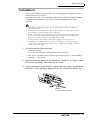 17
17
-
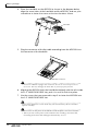 18
18
-
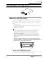 19
19
-
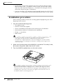 20
20
-
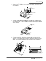 21
21
-
 22
22
-
 23
23
-
 24
24
-
 25
25
-
 26
26
-
 27
27
-
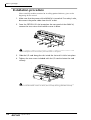 28
28
-
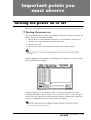 29
29
-
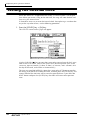 30
30
-
 31
31
-
 32
32
-
 33
33
-
 34
34
-
 35
35
-
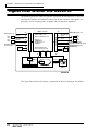 36
36
-
 37
37
-
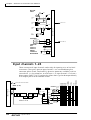 38
38
-
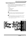 39
39
-
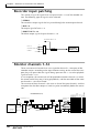 40
40
-
 41
41
-
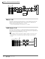 42
42
-
 43
43
-
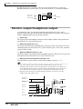 44
44
-
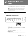 45
45
-
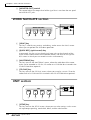 46
46
-
 47
47
-
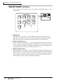 48
48
-
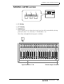 49
49
-
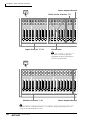 50
50
-
 51
51
-
 52
52
-
 53
53
-
 54
54
-
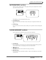 55
55
-
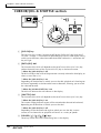 56
56
-
 57
57
-
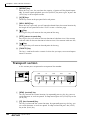 58
58
-
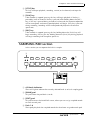 59
59
-
 60
60
-
 61
61
-
 62
62
-
 63
63
-
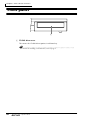 64
64
-
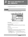 65
65
-
 66
66
-
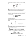 67
67
-
 68
68
-
 69
69
-
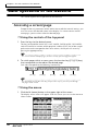 70
70
-
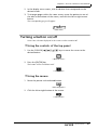 71
71
-
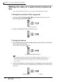 72
72
-
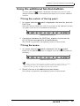 73
73
-
 74
74
-
 75
75
-
 76
76
-
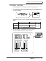 77
77
-
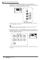 78
78
-
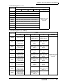 79
79
-
 80
80
-
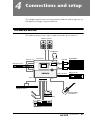 81
81
-
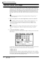 82
82
-
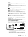 83
83
-
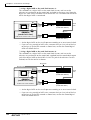 84
84
-
 85
85
-
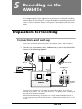 86
86
-
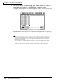 87
87
-
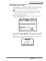 88
88
-
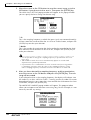 89
89
-
 90
90
-
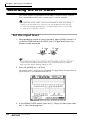 91
91
-
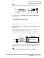 92
92
-
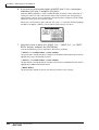 93
93
-
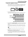 94
94
-
 95
95
-
 96
96
-
 97
97
-
 98
98
-
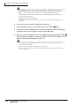 99
99
-
 100
100
-
 101
101
-
 102
102
-
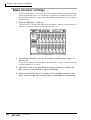 103
103
-
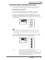 104
104
-
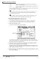 105
105
-
 106
106
-
 107
107
-
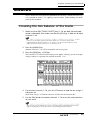 108
108
-
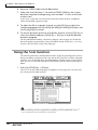 109
109
-
 110
110
-
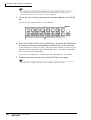 111
111
-
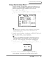 112
112
-
 113
113
-
 114
114
-
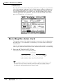 115
115
-
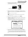 116
116
-
 117
117
-
 118
118
-
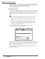 119
119
-
 120
120
-
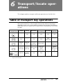 121
121
-
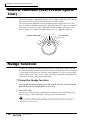 122
122
-
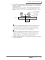 123
123
-
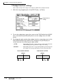 124
124
-
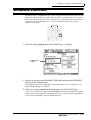 125
125
-
 126
126
-
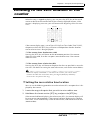 127
127
-
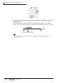 128
128
-
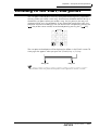 129
129
-
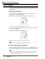 130
130
-
 131
131
-
 132
132
-
 133
133
-
 134
134
-
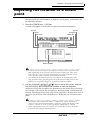 135
135
-
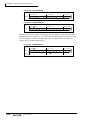 136
136
-
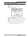 137
137
-
 138
138
-
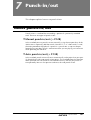 139
139
-
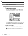 140
140
-
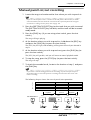 141
141
-
 142
142
-
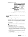 143
143
-
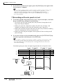 144
144
-
 145
145
-
 146
146
-
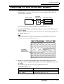 147
147
-
 148
148
-
 149
149
-
 150
150
-
 151
151
-
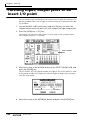 152
152
-
 153
153
-
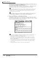 154
154
-
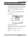 155
155
-
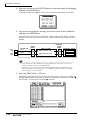 156
156
-
 157
157
-
 158
158
-
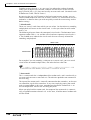 159
159
-
 160
160
-
 161
161
-
 162
162
-
 163
163
-
 164
164
-
 165
165
-
 166
166
-
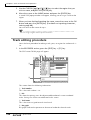 167
167
-
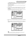 168
168
-
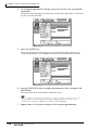 169
169
-
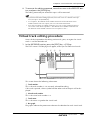 170
170
-
 171
171
-
 172
172
-
 173
173
-
 174
174
-
 175
175
-
 176
176
-
 177
177
-
 178
178
-
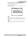 179
179
-
 180
180
-
 181
181
-
 182
182
-
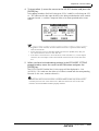 183
183
-
 184
184
-
 185
185
-
 186
186
-
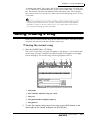 187
187
-
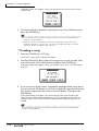 188
188
-
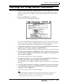 189
189
-
 190
190
-
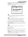 191
191
-
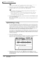 192
192
-
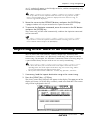 193
193
-
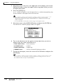 194
194
-
 195
195
-
 196
196
-
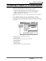 197
197
-
 198
198
-
 199
199
-
 200
200
-
 201
201
-
 202
202
-
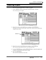 203
203
-
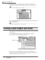 204
204
-
 205
205
-
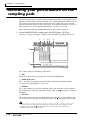 206
206
-
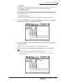 207
207
-
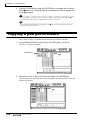 208
208
-
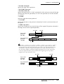 209
209
-
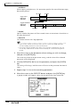 210
210
-
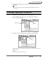 211
211
-
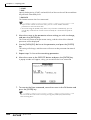 212
212
-
 213
213
-
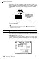 214
214
-
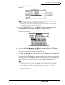 215
215
-
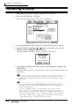 216
216
-
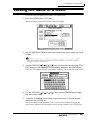 217
217
-
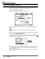 218
218
-
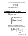 219
219
-
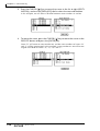 220
220
-
 221
221
-
 222
222
-
 223
223
-
 224
224
-
 225
225
-
 226
226
-
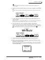 227
227
-
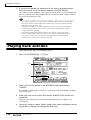 228
228
-
 229
229
-
 230
230
-
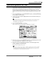 231
231
-
 232
232
-
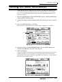 233
233
-
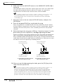 234
234
-
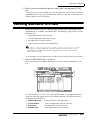 235
235
-
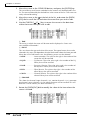 236
236
-
 237
237
-
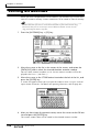 238
238
-
 239
239
-
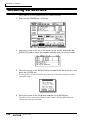 240
240
-
 241
241
-
 242
242
-
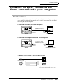 243
243
-
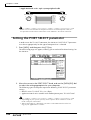 244
244
-
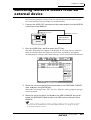 245
245
-
 246
246
-
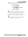 247
247
-
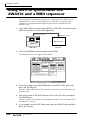 248
248
-
 249
249
-
 250
250
-
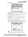 251
251
-
 252
252
-
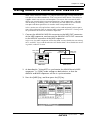 253
253
-
 254
254
-
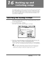 255
255
-
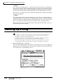 256
256
-
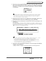 257
257
-
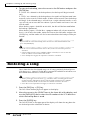 258
258
-
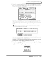 259
259
-
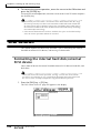 260
260
-
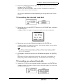 261
261
-
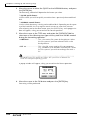 262
262
-
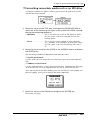 263
263
-
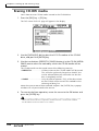 264
264
-
 265
265
-
 266
266
-
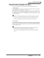 267
267
-
 268
268
-
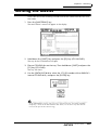 269
269
-
 270
270
-
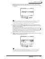 271
271
-
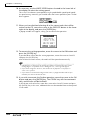 272
272
-
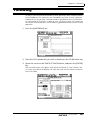 273
273
-
 274
274
-
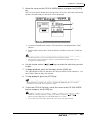 275
275
-
 276
276
-
 277
277
-
 278
278
-
 279
279


Yamaha AW4416 de handleiding
- Categorie
- Toetsenborden
- Type
- de handleiding
- Deze handleiding is ook geschikt voor
in andere talen
- English: Yamaha AW4416 Owner's manual
- italiano: Yamaha AW4416 Manuale del proprietario
- русский: Yamaha AW4416 Инструкция по применению
- français: Yamaha AW4416 Le manuel du propriétaire
- español: Yamaha AW4416 El manual del propietario
- Deutsch: Yamaha AW4416 Bedienungsanleitung
- português: Yamaha AW4416 Manual do proprietário
- dansk: Yamaha AW4416 Brugervejledning
- čeština: Yamaha AW4416 Návod k obsluze
- svenska: Yamaha AW4416 Bruksanvisning
- Türkçe: Yamaha AW4416 El kitabı
- polski: Yamaha AW4416 Instrukcja obsługi
- română: Yamaha AW4416 Manualul proprietarului