
Owner’s Manual
Mode d’emploi
Bedienungsanleitung
M
MIXING CONSOLE

2
Introduction
Thank you for purchasing the Yamaha M3000 mixing console. The M3000
is based on Yamaha’s experience with the PM series, and features superb
sound quality with a full range of functionality such as VCA faders, scene
memory, and GA diversity. In order to take full advantage of the M3000’s
performance and enjoy long and trouble-free use, please read this manual
carefully.
Note:
This manual assumes that you are thoroughly familiar with basic
operation of mixing consoles and their terminology.
FCC INFORMATION (U.S.A.)
1. IMPORTANT NOTICE: DO NOT MODIFY THIS UNIT! This product, when installed as indicated in the instructions contained in this manual, meets FCC
requirements. Modifications not expressly approved by Yamaha may void your authority, granted by the FCC, to use the product.
2. IMPORTANT: When connecting this product to accessories and/or another product use only high quality shielded cables. Cable/s supplied with this product MUST
be used. Follow all installation instructions. Failure to follow instructions could void your FCC authorization to use this product in the USA.
3. NOTE: This product has been tested and found to comply with the requirements listed in FCC Regulations, Part 15 for Class “B” digital devices. Compliance with
these requirements provides a reasonable level of assurance that your use of this product in a residential environment will not result in harmful interference with
other electronic devices. This equipment generates/uses radio frequencies and, if not installed and used according to the instructions found in the users manual, may
cause interference harmful to the operation of other electronic devices. Compliance with FCC regulations does not guarantee that interference will not occur in all
installations. If this product is found to be the source of interference, which can be determined by turning the unit “OFF” and “ON”, please try to eliminate the
problem by using one of the following measures: Relocate either this product or the device that is being affected by the interference. Utilize power outlets that are on
different branch (circuit breaker or fuse) circuits or install AC line filter/s. In the case of radio or TV interference, relocate/reorient the antenna. If the antenna lead-in
is 300 ohm ribbon lead, change the lead-in to coaxial type cable. If these corrective measures do not produce satisfactory results, please contact the local retailer
authorized to distribute this type of product. If you can not locate the appropriate retailer, please contact Yamaha Corporation of America, Electronic Service
Division, 6600 Orangethorpe Ave, Buena Park, CA 90620
The above statements apply ONLY to those products distributed by Yamaha Corporation of America or its subsidiaries.
NEDERLAND
●Dit apparaat bevat een lithium batterij voor geheugen
back-up.
●Raadpleeg uw leverancier over de verwijdering van de
batterij op het moment dat u het apparaat ann het einde
van de levensduur afdankt of de volgende Yamaha
Service Afdeiing:
Yamaha Music Nederland Service Afdeiing
Kanaalweg 18-G, 3526 KL UTRECHT
Tel. 030-2828425
● Gooi de batterij niet weg, maar lever hem in als KCA.
THE NETHERLANDS
●This apparatus contains a lithium battery for memory
back-up.
●For the removal of the battery at the moment of the
disposal at the end of the service life please consult your
retailer or Yamaha Service Center as follows:
Yamaha Music Nederland Service Center
Address: Kanaalweg 18-G, 3526 KL
UTRECHT
Tel: 030-2828425
●Do not throw away the battery. Instead, hand it in as
ADVARSEL!
Lithiumbatteri—Eksplosionsfare ved
fejlagtig håndtering. Udskiftning må
kun ske med batteri af samme fabrikat
og type. Levér det brugte batteri
tilbage til leverandoren.
VARNING
Explosionsfara vid felaktigt
batteribyte. Använd samma batterityp
eller en ekvivalent typ som
rekommenderas av
apparattillverkaren. Kassera använt
batteri enligt fabrikantens instruktion.
VAROITUS
Paristo voi räjähtää, jos se on
virheellisesti asennettu. Vaihda paristo
ainoastaan laitevalmistajan
suosittelemaan tyyppiin. Hävitä
käytetty paristo valmistajan ohjeiden
mukaisesti.

3
Contents
Features of the system...............................5
Control panel............................................6
Input channel section................................................6
Variable/fixed select section....................................13
Mix section..............................................................14
VCA master fader section.......................................16
STEREO A section...................................................16
STEREO B section...................................................18
Monitor section.......................................................19
Talkback section......................................................21
Meter select section.................................................22
Scene memory section ............................................22
Matrix section..........................................................24
Meter bridge............................................................25
Rear panel .............................................26
Mono input channel input/output jacks ...............26
Stereo input channel input/output jacks...............26
Master section input/output jacks..........................27
Output connector for illumination power
supply.......................................................................29
About the GA Diversity functionality........30
Using MIX buses 1–8 as group buses.....................30
Using MIX buses 1–8 as AUX buses ......................30
About the Scene Memory function...........31
What is scene memory?...........................................31
About the modes of the Scene Memory function..31
Operations in normal mode....................................32
Operations in check mode......................................33
Operations in utility mode......................................34
Utility items..............................................................34
Control change table ...............................................35
Using mute groups..................................................36
About the local control circuit................................37
About the VCA functionality....................38
Error messages ......................................41
Specifications.........................................42
General specifications..............................................42
Input/output characteristics....................................43
Other ........................................................................44
Dimensions ............................................45
MIDI data format....................................46
MIDI Implementation Chart .....................47

4
Precautions
• Connect the mixer power cord only to the power supply
unit, and connect the power supply unit to an AC outlet
of the type stated in this
Owner’s Manual
or as marked
on the power supply unit. Failure to do so is a fire and
electrical shock hazard.
• Do not locate the mixer in a place subject to excessive
heat or in direct sunlight. This could be a fire hazard.
• Do not place the mixer in a place subject to excessive
humidity or dust. This could be a fire and electrical
shock hazard.
• Do not plug several devices into the same AC outlet. This
may overload the AC outlet, and could be a fire and elec-
trical shock hazard. It may also affect the performance of
some equipment.
• Do not place heavy objects on the power cord. A dam-
aged power cord is a potential fire and electrical shock
hazard.
• If the power cord is damaged (i.e., cut or a bare wire is
exposed), ask your dealer for a replacement. Using the
mixer in this condition is a fire and shock hazard.
• Hold the power cord plug when disconnecting from an
AC outlet. Never pull the cord. Damaging the power cord
in this way is a potential fire and electrical shock hazard.
• Do not place small metal objects on top of the mixer.
Metal objects inside the mixer are a fire and electrical
shock hazard.
• Do not try to modify the mixer. This could be a fire and
electrical shock hazard.
• The mixer operating temperature is between 5˚C and
35˚C (41˚F and 95˚F).
• Turn off all audio devices and speakers when connecting
to the mixer. Refer to the owner’s manual for each device.
Use the correct cables and connect as specified.
• If you notice any abnormality—such as smoke, odor, or
noise—turn off the mixer immediately. Remove the
power cord from the AC outlet. Confirm that the abnor-
mality is no longer present. Consult your dealer for
repair. Using the mixer in this condition is a fire and
shock hazard.
• If a foreign object or water gets inside the mixer, turn it
off immediately. Remove the power cord from the AC
outlet. Consult your dealer for repair. Using the mixer in
this condition is a fire and electrical shock hazard.
• If you plan not to use the mixer for a long period of time,
remove the power cord from the AC outlet. Leaving the
mixer connected is a fire hazard.
• Do not use benzene, thinner, cleaning detergent, or a
chemical cloth to clean the mixer. Use only a soft, dry
cloth.
• The mixer is a heavy piece of equipment. Always grip the
underneath, not the side panels, when lifting.
• The mixer uses high-frequency digital circuits that may
cause interference on radios and televisions placed close
to it. If interference does occur, relocate the affected
equipment.

5
Features of the system
• The M3000-40C provides a generous number of input
modules; 40 monaural and 4 stereo (the M3000-24
provides 24 monaural and 4 stereo). Stereo output, 16
mix outputs, and 8 matrix outputs are provided in
addition. The M3000 is suitable for use in a wide
range of applications, such as the main mixer for
sound reinforcement, as a monitor mixer, or in build-
ing installations.
• The GA Diversity function allows each pair of MIX
buses 1/2–7/8 to be switched between group bus
(fixed output level from the input channels) and AUX
bus (variable output level from the input channels).
Bus configuration can be set up as needed.
• The Scene Memory function allows the on/off status
of the mono/stereo input channels, MIX OUT 1–16,
and STEREO A OUT to be saved as one of 128
“scenes.” Scenes can be selected from the front panel,
or by MIDI program change messages from an exter-
nal device. In addition, MIDI control change mes-
sages transmitted from an external device can be used
to switch the individual on/off status of input chan-
nels or bus outputs channels.
• By modifying internal settings, Scene Memory num-
bers 1–8 can be used as mute groups. In this case, up
to eight mute (on/off) settings can be added/defeated
individually.
• Eight VCA master faders allow the gain of multiple
input channels to be controlled as a group. By group-
ing the desired input channels and assigning them to a
VCA master fader, you can adjust the mix as appropri-
ate for the on-state action using the VCA master fad-
ers alone.
• The mono input channels provide a 26 dB pad, HPF,
phase switch, four-band parametric EQ, and 100 mm
full stroke faders as well as DIRECT OUT jacks. Phan-
tom power is also provided, and can be switched on/
off individually.
• The M3000-40C features a center master design that
places the master section in the middle of the mixer
for superior operability.
• All input channels provide a PFL switch, and an AFL
switch is provided for MATRIX OUT 1–8/MIX OUT
1–16/STEREO A OUT/STEREO B OUT. This makes it
easy to check your input/output sources.
• Eight independent matrices are provided. The signals
from MIX OUT 1–16/STEREO A OUT and dedicated
input jacks can be mixed at the desired levels, and out-
put from MATRIX OUT jacks 1–8. This capability can
be used for foldback or as a mix for individual speak-
ers/amps.
• All mono input channels, stereo buses, and MIX buses
provide an INSERT I/O jack. External effect proces-
sors can be inserted as necessary.
• The talkback signal and test tone oscillators can be
sent to any of the MIX buses 1-2–13/16 or the stereo
buses.
• As monitor sources for the monitor output, you can
select (in addition to STEREO A OUT), PFL from the
input channels, AFL/PFL from MATRIX OUT 1–8/
MIX OUT 1–16/STEREO A OUT/STEREO B OUT, or
2TR IN 1/2.

6
Control panel
Input channel section
Mono input channels
The M3000-24 provides 24 input channels, and the
M3000-40C provides 40 input channels. All input
channels have the same specifications.
A
Phantom power switch/
+48 V
indicator
This switch turns the +48 V phantom power on/off
for each channel. When phantom power is on, the +48
V indicator located above the switch will light. If you
wish to use phantom power, first make sure that the
PHANTOM MASTER switch (page 28) located on the
rear panel is turned on.
B
GAIN
control
This control adjusts the input sensitivity. Levels sup-
ported are –16dB ~ –60 dB when the Pad switch (
3
)
is off, and +10dB ~ –34dB when the switch is on.
C
26 dB
pad switch
This switch attenuates the input signal by 26 dB.
When the switch is pressed ( ), the pad is on.
D
ø
(phase) switch
This switch reverses the phase of the input signal.
When the switch is pressed ( ), the phase is
reversed.
E
HPF
(high pass filter) control
This controls the cutoff frequency of the high pass fil-
ter. The range is 20Hz–400Hz.
F
HPF
switch
This switch turns the high pass filter on/off. When the
switch is pressed ( ), the high pass filter is on, and
the signal component below the frequency specified
by the HPF control (
5
) will be attenuated by 12 dB/
oct.
G
EQ
control
This is a four-band equalizer which can boost/cut
each band over range of
±
15 dB. HI-MID and LOW-
MID provide switches that let you change between
two settings of Q (filter steepness). The center fre-
quency, Q value, and gain range of each band are as
follows.
H
EQ
switch
This switches the equalizer on/off. When the switch is
pressed ( ), the equalizer is on.
GAIN
HI
HI-
MID
LO-
MID
LO
600
20090
30
+15–15
EQ
HPF
+48V
Ø
1.6k
600240
80
+15–15
8k
3k1.2k
0.4k
+15–15
20k
8k3k
1k
400
15050
20
–60–16
+15–15
100
PRE
PRE
M9
100
M10
100
M11
100
M14
PAN
M13
M12
M13/
M14
100
M16
PAN
M15
M15/
M16
100
100
100
100
100
100
PRE
PRE
M1
M2
M3
M4
M5
100
M6
100
M7
100
M8
26dB
–34
+10
1
2
3
4
5
6
8
P
P
P
O
P
J
I
7
J
L
K
M
N
Band
Center
frequency
Q Gain
HI 1 kHz–20 kHz 0.667
±
15 dB
HI-MID 0.4 kHz–8 kHz 1.41/2.88
LO-MID 80 Hz–1.6 kHz 1.41/2.88
LO 30 Hz–600 Hz 0.667

Control panel
7
I
M1–M8
switches
These switch on/off the signal which is sent from the
input channel to MIX buses 1–8.
J
M1–M8
mix level controls
These controls send the signal from the input channel
to MIX buses 1–8. When the control is in the “
▲
”
position, the level is nominal (0 dB). Use the PRE
switch (
P
) to switch between pre/post fader.
K
M9–M12
switches
These are on/off switches for the signals that are sent
from the input channel to MIX buses 9–12.
L
M9–M12
mix level controls
These controls send the signal from the input channel
to MIX buses 9–12. When the control is in the “
▲
”
position, the level is nominal (0 dB). Use the PRE
switch (
P
) to switch between pre/post fader.
M
M13/M14
,
M15/M16
switches
These are on/off switches for the signals that are sent
from the input channel to MIX buses 13–16. M13 and
14, and M15 and M16 are stereo pairs, and each pair is
turned on/off by one switch. Use the PRE switch (
P
)
to switch between pre/post fader.
N
M13/M14
,
M15/M16
mix level controls
These controls send the signal from the input channel
to MIX buses 13–16. When the control is in the “
▲
”
position, the level is nominal (0 dB). M13 and M14,
and M15 and M16 are stereo pairs, and the output
level of each pair is controlled by one knob. Use the
PRE switch (
P
) to switch between pre/post fader.
O
M13/M14
,
M15/M16
pan controls
These controls set the panning of the signals that are
sent from the input channel to MIX buses 13/14 or
MIX buses 15/16. When the control is in the center
position, an equal amount of signal will be sent to
both buses.
P
PRE
switches
These are pre-fader/post-fader switches for the signals
that are sent from the input channel to MIX buses 1–
16. Pre/post can be switched independently for each
group of MIX buses: 1–4, 5–8, 9–12, and 13–16. When
the switch is pressed ( ), the post-EG/pre-fader sig-
nal will be sent to the corresponding group of MIX
buses.
Note:
If these switches are off, no signal will be sent
to the corresponding MIX bus from this input
channel, regardless of the switch setting of the vari-
able/fixed select section (page 13).
Note:
For MIX bus pairs for which the variable/fix
select section (page 13) switch is set to FIX, the out-
put level which is sent from each input channel to
the bus will be fixed, and therefore the mix level
control setting will have no effect.
from Ctrl Master
from VCA Master
ON/EDIT
CHECK ON
CONTROL
ST
L R
PFL
L R ON
MIX
(FIX)
MIX
(VARIABLE)
M8
M7
M6
M5
PRE
M4
M3
M2
8
7
2
1
PFL
DIRECT OUT
Internal Jumper
PRE
M15/
M16
M13/
M14
PAN
PAN
M12
M11
M10
M9
PRE
PRE
M1
PEAK
NOM
SIGNAL
ST
VCA
INSERT I/O
4 Stage EQ
EQHPF
HPF
PHANTOM
MASTER
+48V
Input
1-24/1-40
+48V
26dB
PAD
PAN
HA
GAIN
1 2 3 4 5 6 7 81 3 5 7 9
2 4 6 8
11 13 15
10 12 14 16
f
g
f
g
f
g
Q
f
g
Q
LO
LO-MID
HI-MID
HI

Control panel
8
Q
ST
(stereo) switch
When this switch is on, the signal of the input channel
will be sent to the (ST) stereo bus.
R
PAN
control
This sets the panning of the signal that is sent from the
input channel to the ST bus.
S
ON/EDIT
switch/
ON
,
CHECK
indicators
The function of this switch and these indicators will
depend on the mode of the M3000.
●
In normal mode
The ON/EDIT switch will turn on the input channel.
When on, the ON indicator will light. Channels which
are turned off will send no signal to the ST bus or the
MIX buses. However even in this case, you can use the
PFL switch (
W
) to monitor the channel from the
MONITOR OUT jacks or the PHONE jack.
●
In check mode
In check mode (page 33), you can use the CHECK
indicators to view the on/off status of each channel
stored in a scene before you actually recall the scene.
This is convenient when you wish to verify the status
of each channel before you recall a scene.
In check mode, you can also use the ON/EDIT
switches to change only the lit/dark status of the
CHECK indicators. (The actual on/off setting will not
be affected.) Use this when you wish to maintain the
current mix settings, and store partially modified set-
tings as a scene.
T
PEAK/NOM/SIGNAL
indicators
Three indicators show the level of the input channel
signal after it passes through the EQ.
• PEAK indicator
This will light when the signal exceeds the nominal
level by 18 dB.
• NOM (nominal) indicator
This will light when the signal reaches nominal level
(0 dB).
• SIGNAL indicator
This will light when the signal reaches 10 dB below the
nominal level.
ON/
EDIT
CHECK
ON
PEAK
NOM
SIGNAL
PFL
1
2
3
4
5
6
7
8
VCA
GROUP
10
5
0
5
10
20
30
40
50
60
ST
PAN
RL
R
V
Q
S
U
W
T

Control panel
9
U VCA GROUP select switches
These switches select the VCA master fader(s) which
will control the signal output level of this channel.
When you select a VCA group 1–8, the indicator
located at the left of each switch will light, and the
corresponding VCA master fader (VCA master section
3) will control the channel. It is possible to select two
or more VCA groups for one input channel, or to con-
trol two or more input channels by the same VCA
group.
●Channels for which a VCA group is selected
The signal output level of the channel can be con-
trolled both by the corresponding VCA master
fader(s) and by the channel fader (V). The settings of
all corresponding VCA master faders are summed
with the setting of the channel fader to specify the sig-
nal output level of that channel.
●Channels for which a VCA group is not selected
The signal output level of the channel can be con-
trolled only by the channel fader (V).
V Channel fader
This fader adjusts the signal output level of the input
channel. This fader will affect the level of the signal
that is sent to the ST bus and to the MIX buses (if the
PRE switch is off). If one or more VCA groups are
selected by the VCA GROUP select switches (U), the
signal output level of that channel will also be affected
by the corresponding VCA master fader(s).
W PFL (pre-fader listen) switch
When this switch is on ( ), the pre-fader/post-EQ
signal of this input channel will be sent to the PFL
bus, allowing it to be monitored from the MONITOR
OUT jacks or the PHONES jack.
Note: For details on VCA functions, refer to
page 38.
from Ctrl Master
from VCA Master
ON/EDIT
CHECK ON
CONTROL
ST
L R
PFL
L R ON
MIX
(FIX)
MIX
(VARIABLE)
M8
M7
M6
M5
PRE
M4
M3
M2
8
7
2
1
PFL
DIRECT OUT
Internal Jumper
PRE
M15/
M16
M13/
M14
PAN
PAN
M12
M11
M10
M9
PRE
PRE
M1
PEAK
NOM
SIGNAL
ST
VCA
INSERT I/O
4 Stage EQ
EQHPF
HPF
PHANTOM
MASTER
+48V
Input
1-24/1-40
+48V
26dB
PAD
PAN
HA
GAIN
1 2 3 4 5 6 7 81 3 5 7 9
2 4 6 8
11 13 15
10 12 14 16
f
g
f
g
f
g
Q
f
g
Q
LO
LO-MID
HI-MID
HI

Control panel
10
Stereo input channels
The M3000 provides four stereo input channels. Ste-
reo sound sources such as sub-mixers, effect proces-
sor, or CD players can be input to the INPUT A jacks
(XLR connectors) or INPUT B jacks (RCA phono
connectors) located on the rear panel.
A GAIN A control
This control adjusts the input sensitivity of the signal
that is input from the XLR connector INPUT A jack
(rear panel 4). The level range is +10~ –30 dB. When
the A/B select switch (3) is in the B position ( ),
this control will have no effect.
B GAIN B control
This control adjusts the input sensitivity of the signal
that is input from the RCA phono connector INPUT
B jack (rear panel 5). The level range is +10~ –20 dB.
When the A/B select switch (3) is in the A position
( ), this control will have no effect.
C A/B select switch
This switch selects the input jacks that the stereo input
channel will use. When the switch is in the upward
position ( ) the INPUT A jack can be used. When
the switch is in the downward position ( ) the
INPUT B jacks can be used.
D EQ controls
This is a four-band equalizer which allows ±15 dB of
boost/cut for each band. The HI-MID and LOW-MID
bands allow you to switch between two settings of Q
(steepness). The center frequency, Q values, and gain
range for each band is as follows.
E EQ switch
This switches the equalizer on/off. The equalizer is on
when the switch is pressed down ( ).
F M1–M8 switches
These switch on/off the signal which is sent from the
stereo input channel to MIX buses 1–8.
–30+10
+15–15
A
–20+10
B
GAIN
HI
A
B
+15–15
HI-
MID
+15–15
LO-
MID
+15–15
100
100
100
100
100
LO
EQ
PRE
PRE
M1
M2
M3
M4
M5
100
M6
100
M7
100
M8
100
PRE
PRE
M9
100
M10
100
M11
100
M14
BAL
M13
M12
M13/
M14
100
M16
BAL
M15
M15/
M16
100
A
B
C
E
M
M
M
I
L
M
G
F
D
G
H
J
K
Band
Center
frequency
Q Gain
HI 20 kHz 0.667
±15 dB
HI-MID 3 kHz 1.41/2.88
LO-MID 800 Hz 1.41/2.88
LO 50 Hz 0.667
Note: If these switches are off, no signal will be sent
to the corresponding MIX bus from this input
channel, regardless of the switch setting of the vari-
able/fixed select section (page 13).

Control panel
11
G M1–M8 mix level controls
These controls combine the stereo signal from the ste-
reo input channel into a mono signal, and send it to
MIX buses 1–8. When the control is in the “▲” posi-
tion, the level is nominal (0 dB). Use the PRE switch
(M) to switch between pre/post fader.
H M9–M12 switches
These are on/off switches for the signals that are sent
from the stereo input channel to MIX buses 9–12.
I M9–M12 mix level controls
These controls combine the stereo signal from the ste-
reo input channel into a mono signal, and send it to
MIX buses 9–12. When the control is in the “▲” posi-
tion, the level is nominal (0 dB). Use the PRE switch
(M) to switch between pre/post fader.
J M13/M14, M15/M16 switches
These are on/off switches for the signals that are sent
from the stereo input channel to MIX buses 13–16.
M13 and 14, and M15 and M16 are stereo pairs, and
each pair is turned on/off by one switch.
K M13/M14, M15/M16 mix level controls
These controls send the stereo signal from the stereo
input channel to MIX buses 13/14, 15/16. When the
control is in the “▲” position, the level is nominal (0
dB). M13 and M14, and M15 and M16 are stereo
pairs, and the output level of each pair is controlled by
one knob. Use the PRE switch (P) to switch between
pre/post fader.
L M13/M14, M15/M16 BAL (balance) controls
These controls set the left/right balance of the signals
that are sent from the stereo input channel to MIX
buses 13/14 or MIX buses 15/16.
M PRE switches
These are pre-fader/post-fader switches for the signals
that are sent from the stereo input channel to the MIX
buses. Pre/post can be switched independently for
each group of MIX buses: 1–4, 5–8, 9–12, and 13–16.
When the switch is pressed ( ), the pre-fader/post-
EQ signal will be sent to the corresponding group of
MIX buses.
Note: For MIX bus pairs for which the variable/fix
select section (page 13) switch is set to FIX, the out-
put level which is sent from each input channel to
the bus will be fixed, and therefore the mix level
control setting will have no effect.
ST
L R
PFL
L R ON
MIX
(FIX)
MIX
(VARIABLE)
1 2 3 4 5 6 7 81 3 5 7 9
2 4 6 8
11 13 15
10 12 14 16
1
2
7
8
from VCA Master
CONTROL
ONCHECK
ON/EDIT
from Ctrl Master
B
A
M15
M16
HA
HA
GAIN A GAIN A
BAL
M13
M14
BAL
PRE
M1
PRE
PRE
M9
M10
M11
M12
PFL
M2
M3
M4
PRE
M5
M6
M7
M8
BAL
VCA
ST CH
1-4
INPUT A
INPUT B
R
L
R
L
4 Stage EQ
HA
HA
EQ
4 Stage EQ
VCA
ST
PEAK
NOM
SIGNAL
LO
LO-MID
HI-MID
HI
g
Q
g
g
g
Q

Control panel
12
N ST (stereo) switch
When this switch is on, the signal of the input channel
will be sent to the (ST) stereo bus.
O BAL (balance) control
This sets the left/right balance of the signal that is sent
from the input channel to the ST bus.
P ON/EDIT switch/ON, CHECK indicators
The function of this switch and these indicators will
depend on the mode of the M3000.
●In normal mode
The ON/EDIT switch will turn on the stereo input
channel. When on, the ON indicator will light. Chan-
nels which are turned off will send no signal to the ST
bus or the MIX buses. However even in this case, you
can use the PFL switch (T) to monitor the channel
from the MONITOR OUT jacks or the PHONE jack.
●In check mode
You can use the CHECK indicators to view the on/off
status of each channel stored in a scene before you
actually recall the scene. This is convenient when you
wish to verify the status of each channel before you
recall a scene.
In check mode, you can also use the ON/EDIT
switches to change only the lit/dark status of the
CHECK indicators. (The actual on/off setting will not
be affected.)
For details on Check mode, refer to page 33.
Q PEAK/NOM/SIGNAL indicators
Three indicators show the level of the stereo input
channel signal after it passes through the EQ.
• PEAK indicator
This will light when the sum of the L and R signals
exceeds the nominal level by 18 dB.
• NOM (nominal) indicator
This will light when the sum of the L and R signals
reaches nominal level (0 dB).
• SIGNAL indicator
This will light when the sum of the L and R signals
reaches 10 dB below the nominal level.
R VCA GROUP select switches
These switches select the VCA master fader(s) which
will control the signal output level of this stereo input
channel. When you select a VCA group 1–8, the indi-
cator located at the left of each switch will light, and
the corresponding VCA master fader (VCA master
section 3) will control the channel. It is possible to
select two or more VCA groups for one stereo input
channel, or to control two or more channels by the
same VCA group.
●Stereo input channels for which a VCA group is
selected
The signal output level of the channel can be con-
trolled both by the corresponding VCA master
fader(s) and by the channel fader (S).
●Stereo input channels for which a VCA group is
not selected
The signal output level of the stereo input channel can
be controlled only by the channel fader (S).
S Channel fader
This fader adjusts the signal output level of the stereo
input channel. This fader will affect the level of the
signal that is sent to the ST bus and to the MIX buses
(if the PRE switch is off). If one or more VCA groups
are selected by the VCA GROUP select switches (R),
the signal output level of that channel will also be
affected by the corresponding VCA master fader(s).
T PFL (pre-fader listen) switch
When this switch is on ( ), the pre-fader/post-EQ
signal of this stereo input channel will be sent to the
PFL bus, allowing it to be monitored from the MONI-
TOR OUT jacks or the PHONES jack.
ST
ON/
EDIT
PFL
CHECK
ON
PEAK
NOM
SIGNAL
BAL
RL
1
2
3
4
5
6
7
8
VCA
GROUP
10
5
0
5
10
20
30
40
50
60
O
S
N
P
R
T
Q
Note: For details on VCA functions, refer to
page 38.

Control panel
13
Variable/fixed select section
The M3000’s GA (Group/Aux) diversity function
allows MIX buses 1–8 to function either as group
buses or as AUX buses. In this section, you can switch
each pair of MIX buses (1/2, 3/4, 5/6, 7/8) between
functioning as group buses or as AUX buses.
A Variable/fixed select switches
These switches select whether the level of the signals
sent from the input channels to MIX buses 1–8 will be
fixed (FIX) or variable (VARIABLE). From top to bot-
tom, these switch MIX buses 1/2, 3/4, 5/6 and 7/8.
●When FIX ( ) is selected
The corresponding pair of MIX buses (1/2, 3/4, 5/6, 7/
8) will function as a group bus, and the signal of the
MIX (FIX) bus will be output to the corresponding
mix channel. In this case, the settings of the mix level
controls M1–M8 (mono input channels J, stereo
input channels 7) will have no effect.
●When VARIABLE ( ) is selected
The corresponding pair of MIX buses (1/2, 3/4, 5/6, 7/
8) will function as an AUX bus, and the signal of the
MIX (VARIABLE) bus will be output to the corre-
sponding mix channel. In this case, the mix level con-
trols M1–M8 (mono input channels J, stereo input
channels 7) will take effect just as they are set.
+15–15
100
100
100
100
100
EQ
PRE
PRE
M1
M2
M3
M4
M5
100
M6
100
M7
100
M8
VARIABLE
FIX
+15–15
100
100
100
100
100
EQ
PRE
PRE
M1
M2
M3
M4
M5
100
M6
100
M7
100
M8
+15–15
100
100
100
100
100
EQ
PRE
PRE
M1
M2
M3
M4
M5
100
M6
100
M7
100
M8
+15–15
100
100
100
100
100
EQ
PRE
PRE
M1
M2
M3
M4
M5
100
M6
100
M7
100
M8
1
(SUB)(ST)
from INPUT
MIX 3-4, 5-6, 7-8: Same as MIX 1-2
MIX 2: Same as MIX 1
to Meter
VARIABLE
FIX
AFL
PFL
LRON
MAS
AFL
MAS
(MIX)
TO MATRIX
CONTROL
ONCHECK
ON/EDIT
MIX OUT 1
AFL
TO STEREO
PAN
TO MATRIX
MIX
INSERT
I/O
ST
RL
LR
MIX
(FIX)
MIX
(VARIABLE)
1 3 5 7 12345678
2468
9 111315
10 12 14 16
from Ctrl
Master
1357
2468
9 111315
10 12 14 16
LR
LR

Control panel
14
Mix section
These output channels control the signals of MIX
buses 1–16. MIX buses 13/14 and 15/16 are controlled
as stereo pairs respectively. The signal that passes
through these output channels is output individually
from the MIX OUT 1–16 jacks (page 27), and can also
be sent to the MAS AFL bus, MAS PFL bus, ST bus,
and the matrix.
A TO MATRIX switches
When these switches are on ( ), the signal of the
corresponding MIX OUT will be sent to the matrix.
B PAN controls/BAL controls
These controls specify the pan (MIX OUT 1–12) or
left/right balance (MIX OUT 13–16) when the MIX
OUT signal is sent to the ST bus.
C TO STEREO switches
When these switches are on ( ), the signal of the
corresponding MIX OUT will be sent to the ST bus.
D ON/EDIT switches
The function of these switches and indicators will
depend on the mode of the M3000.
●In normal mode
The ON/EDIT switches will turn each MIX OUT on/
off. When on, the ON indicator will light. MIX OUTs
which are turned off will send no signal to the MIX
OUT 1–16 jacks, the MAS AFL bus, the ST bus or the
matrix. However even in this case, you can turn on the
AFL switch (6) to monitor the pre-fader signal from
the MONITOR OUT jacks or the PHONE jack.
●In check mode
You can use the CHECK indicators to view the on/off
status of each MIX OUT stored in a scene before you
actually recall the scene.
In check mode, you can also use the ON/EDIT
switches to change only the lit/dark status of the
CHECK indicators. (The actual on/off setting will not
be affected.)
For details on check mode, refer to page 33.
E Mix master faders
These faders adjust the output level of MIX OUT 1–
16. These faders affect the signal which is sent to the
MIX OUT 1–16 jacks, the MAS AFL bus, the ST bus,
and the matrix.
F AFL (after fader listen) switches
These switches allow the signals from MIX OUT to be
monitored from the MONITOR OUT jacks or
PHONES jack. When these switches are on ( ), the
pre-fader signal of the corresponding MIX bus will be
sent to the MAS PFL bus, and the post-fader signal
will be sent to the MAS AFL bus, allowing you to
monitor from the MONITOR OUT jacks or the
PHONES jacks. The signal of the MAS AFL bus can be
monitored when the MASTER PFL switch (page 19)
of the monitor section is off, and the signal of the
MAS PFL bus can be monitored when this switch is
on. However while even one of the PFL switches of the
input channels is on, the signal of the PFL bus will
take precedence, meaning that it will not be possible
to monitor MIX OUT.
MIX 13/14MIX 11/12 MIX 15/16
MIX 13/14MIX 11/12 MIX 15/16
BAL
TO STEREO
TO MATRIXTO MATRIX
TO STEREO
L
R
PAN
L
R
PAN
L
R
AFLAFL
ON/EDITON/EDIT
CHECK
ON
CHECK
ON
10
5
0
5
10
20
40
BAL
TO STEREO
TO MATRIX
L
R
AFL
ON/EDIT
CHECK
ON
10
5
0
5
10
20
40
10
5
0
5
10
20
40
MIX 9/10
MIX 9/10
TO MATRIX
TO STEREO
PAN
L
R
PAN
L
R
AFL
ON/EDIT
CHECK
ON
10
5
0
5
10
20
40
MIX 7/8
MIX 7/8
TO MATRIX
TO STEREO
PAN
L
R
PAN
L
R
AFL
ON/EDIT
CHECK
ON
10
5
0
5
10
20
40
MIX 5/6
MIX 5/6
TO MATRIX
TO STEREO
PAN
L
R
PAN
L
R
AFL
ON/EDIT
CHECK
ON
10
5
0
5
10
20
40
MIX 3/4
MIX 3/4
TO MATRIX
TO STEREO
PAN
L
R
PAN
L
R
AFL
ON/EDIT
CHECK
ON
10
5
0
5
10
20
40
MIX 1/2
MIX 1/2
TO MATRIX
TO STEREO
PAN
L
R
PAN
L
R
AFL
ON/EDIT
CHECK
ON
10
5
0
5
10
20
40
A
D
E
F
C
B

Control panel
15
MIX buses 1–8
MIX buses 9–12
MIX buses 13–16
(SUB)(ST)
from INPUT
MIX 3-4, 5-6, 7-8: Same as MIX 1-2
MIX 2: Same as MIX 1
to Meter
VARIABLE
FIX
AFL
PFL
LRON
MAS
AFL
MAS
(MIX)
TO MATRIX
CONTROL
ONCHECK
ON/EDIT
MIX OUT 1
AFL
TO STEREO
PAN
TO MATRIX
MIX
INSERT
I/O
ST
RL
LR
MIX
(FIX)
MIX
(VARIABLE)
1 3 5 7 12345678
2468
9 111315
10 12 14 16
from Ctrl
Master
1357
2468
9 111315
10 12 14 16
LR
LR
(SUB)(ST)
AFL
PFL
LRON
MAS
AFL
MAS
(MIX)
TO MATRIX
ST
RL
LR
MIX
(FIX)
MIX
(VARIABLE)
1 3 5 7 12345678
2468
9 111315
10 12 14 16
1357
2468
9111315
10 12 14 16
LR
LR
from ST CH
from Ctrl Master
ON/EDIT
CHECK ON
CONTROL
MIX 10, 11, 12: Same as MIX 9
to Meter
TO MATRIX
PAN
TO STEREO
AFL
MIX OUT 9
MIX
INSERT
I/O
(SUB)(ST)
AFL
PFL
LRON
MAS
AFL
MAS
(MIX)
TO MATRIX
ST
RL
LR
MIX
(FIX)
MIX
(VARIABLE)
1 3 5 7 12345678
2468
9 111315
10 12 14 16
1357
2468
9111315
10 12 14 16
LR
LR
from Ctrl Master
CONTROL
ONCHECK
ON/EDIT
MIX 15-16: Same as MIX 13-14
to Meter
AFL
TO MATRIX
BAL
TO STEREO
MIX OUT 14
MIX
INSERT
I/O
MIX
INSERT
I/O
MIX OUT 13

Control panel
16
VCA master fader section
The VCA master fader section allows the gain of input channels assigned to a VCA group to
be controlled as a whole by the corresponding VCA fader. The VCA group(s) to which each
input channel is assigned is specified by the VCA GROUP select switches (mono input
channels (U), stereo input channels R).
A VCA MUTE switches
When these switches are turned on (the indicator at
left will light), the VCA master fader (3) will be shut
down completely. At this time, the post-fader signal of
all input channels assigned to the corresponding VCA
group will be muted.
B NOMINAL indicators
These indicators will light when the corresponding
VCA master fader is in the nominal (0 dB) position.
In this position, the VCA master fader will not affect
the gain.
C VCA master faders
These faders control the gain of the input channels
assigned to the corresponding VCA group. If you wish
to use the VCA master faders, make sure that the rear
panel VCA MASTER/SLAVE select switch (page 28) is
set to the MASTER position.
STEREO A section
This section controls the signal that is output from the
rear panel ST OUT jacks (page 28). The signal level
which is sent from ST OUT A to the matrix is also
controlled by this section.
MIX 13/14MIX 11/12 MIX 15/16
NOMINALNOMINAL
VCA
MUTE
VCA
MUTE
5
0
5
10
20
30
40
50
60
10
5
0
5
10
20
30
40
50
60
10
NOMINAL
VCA
MUTE
5
0
5
10
20
30
40
50
60
10
MIX 9/10
NOMINAL
VCA
MUTE
5
0
5
10
20
30
40
50
60
10
MIX 7/8
NOMINAL
VCA
MUTE
5
0
5
10
20
30
40
50
60
10
MIX 5/6
NOMINAL
VCA
MUTE
5
0
5
10
20
30
40
50
60
10
MIX 3/4
NOMINAL
VCA
MUTE
5
0
5
10
20
30
40
50
60
10
MIX 1/2
NOMINAL
VCA
MUTE
5
0
5
10
20
30
40
50
60
10
A
B
C
(SUB)(ST)
ON
ON/EDIT
CHECK ON
CONTROL
to Meter
to Meter
ON
AFL
AFL
TO MATRIX
AFL
PFL
LRON
MAS
AFL
MAS
LR
PFL
(MIX)
TO MATRIX
LEVEL
ST OUT B
L
R
ST
INSERT
I/O L
ST
INSERT
I/O R
R
L
ST OUT A
ST
RL
LR
1357
2468
9 111315
10 12 14 16
LR
LR
to MONITOR OUT
to PHONES

Control panel
17
A TO MATRIX switch
When this switch is on ( ), the ST OUT A post-
fader signal is sent to the matrix.
B ON/EDIT switch
The function of this switch and indicator will depend
on the mode of the M3000.
●In normal mode
The ON/EDIT switch will turn ST OUT A on/off.
When on, the ON indicator will light. When off, no
signal will be sent to the ST OUT A jacks, MONITOR
OUT jacks, PHONES jack, MAS AFL bus, or the
matrix. However even in this case, you can turn on the
AFL switch (3) to monitor the pre-fader signal from
the MONITOR OUT jacks or the PHONE jack.
●In check mode
You can use the CHECK indicator to view the on/off
status of ST OUT A stored in a scene before you actu-
ally recall the scene.
In check mode, you can also use the ON/EDIT switch
to change only the lit/dark status of the CHECK indi-
cator. (The actual on/off setting will not be affected.)
C AFL switch
This switch allows the ST OUT A signal which is sent
to the ST OUT A jacks or to the matrix to be moni-
tored from the MONITOR OUT jacks or from the
PHONES jack. When this switch is on ( ), the pre-
fader signal will be sent to the MAS PFL bus and the
post-fader signal will be sent to the MAS AFL bus,
allowing you to monitor them from the MONITOR
OUT jacks or the PHONES jack.
When the master section MASTER PFL switch
(page 19) is off you can monitor the signal of the MAS
AFL bus, and when it is on you can monitor the signal
of the MAS PFL bus. However if even one of the PFL
switches of the input channels is turned on, the signal
of the PFL bus will take priority for monitoring, and it
will not be possible to monitor ST OUT A.
D ST (stereo) fader
This fader adjusts the final output level of ST OUT A.
This fader affects the level of the signal which is sent
to the ST OUT A jacks, the MONITOR OUT jacks,
the PHONES jack, the MAS AFL bus, and the matrix.
10
5
0
5
10
20
30
40
50
60
STEREO A
TO MATRIX
ON/EDIT
AFL
CHECK
ON
STEREO A
A
D
C
B

Control panel
18
STEREO B section
This section controls the signal which is output from
the rear panel ST OUT B jacks (page 28)
A LEVEL control
This controls the output level of the signal which is
sent from the ST OUT B jacks. It does not affect the
signal which is output from the ST OUT A jacks.
When the control is in the “▲” position the level is
nominal (0 dB).
B ON switch
This is an on/off switch for the signal which is output
from the ST OUT B jacks. It does not affect the signal
which is output from the ST OUT A jacks. When this
switch is turned off, the indicator will go dark, and no
signal will be output from the ST OUT B jacks. How-
ever even in this case, the signal sourced before pass-
ing through the LEVEL control can be monitored
from the MONITOR OUT jacks or the PHONES jack
by turning on the AFL switch (3).
C AFL switch
This switch allows the signal which is sent from the ST
OUT B jacks to be monitored from the MONITOR
OUT jacks or PHONES jack. When this switch is on
( ) the signal before passing through the LEVEL
control will be sent to the MAS PFL bus and the signal
after passing through the LEVEL control will be sent
to the MAS AFL bus, and can be monitored from the
MONITOR OUT jacks or the PHONES jack.
If the master section MASTER PFL switch (page 19) is
off, the MAS AFL bus signal can be monitored. If this
switch is on, the MAS PFL bus signal will be moni-
tored. However if even one of the input channel PFL
switches are on, the PFL bus signal will take priority
for monitoring, and ST OUT B cannot be monitored.
Note: This section is not affected by the on/off
switching of scene memory.
STEREO B
ON
AFL
LEVEL
100
A
C
B
(SUB)(ST)
to Meter
ON
ON/EDIT
CHECK ON
CONTROL
ON
from
STEREO B R
CUE R
STEREO B L
CUE L
from
to Meter
to Meter
INPUT
MASTER
ON
L+R
ON
BA
BA
BA
BA
Phon
e
PHONES
2TR IN
2
1
1/2
BA
BA
BA
BA
L
R
L
R
MASTER PFL
LEVEL
L
R
MON
I
OUT
AFL
AFL
TO MATRIX
AFL
PFL
LRON
MAS
AFL
MAS
LR
PFL
(MIX)
TO MATRIX
LEVEL
ST OUT B
L
R
ST
INSERT
I/O L
ST
INSERT
I/O R
R
L
ST OUT A
ST
RL
LR
STEREO B/CUE L
STEREO B/CUE R
1357
2468
9 111315
10 12 14 16
LR
LR

Control panel
19
Monitor section
In this section you can select the signal which will be
monitored from the MONITOR OUT jacks and the
PHONES jack. The following signals can be selected
as monitor sources. Signal sources in priority group 1
can be selected at any time, and signal sources in pri-
ority group 2 can be selected only when no signal in
group 1 is selected.
Signals which can be selected as monitor
sources
A INPUT indicator
This indicator will light if even one of the input chan-
nel PFL switches are turned on.
B MASTER indicator
This indicator will light if even one of the AFL
switches of the mix section, STEREO A section, STE-
REO B section, or matrix section (page 24) are turned
on.
C MASTER PFL switch
This switch selects the master signal (the signal of
either the MAS AFL bus or the MAS PFL bus) which
will be monitored by the MONITOR jacks or
PHONES jack. When the MASTER PFL switch is on
( ) the signal of the MAS PFL bus will be moni-
tored. When this switch is off ( ), the signal of the
MAS AFL bus will be monitored.
D L+R switch
When this switch is on ( ), the monitor signal which
is output from the MONITOR OUT jacks and the
PHONES jack will be mixed to a monaural signal.
E 1/ 2 select switch
This switches between the two sets of 2TR IN jacks
located on the rear panel. When the switch is in the
upward position ( ) the 2TR IN 1 jacks are selected,
and when the switch is in the downward position
( ) the 2TR IN 2 jacks are selected.
F ON switch
This switch sends the input signal from the set of 2TR
IN jacks selected by the 1/2 select switch to the MON-
ITOR jacks and PHONES jack. When this switch is
pressed ( ), the input signal from the selected pair
of 2TR IN jacks will be sent to the MONITOR jacks
and PHONES jack.
Priority group 1
(can be selected at any time)
Priority group 2
(can be selected only when no
source of group 1 is selected)
• Mono input PFL
• Stereo input PFL
• MIX AFL
• ST bus (ST OUT A/B) AFL
• MATRIX AFL
• St OUT a
• 2TR IN
L+R
MASTER
PFL
2
1/
ON
INPUT
MASTER
2TR IN
C
D
E
F
A
B

Control panel
20
G LEVEL control
This control adjusts the level of the signal which is
output from the MONITOR OUT jacks. It does not
affect the PHONES jack.
H ON switch
This is an on/off switch for the signal which is output
from the MONITOR OUT jacks. When this is on, the
indicator located above the switch will light. This
switch does not affect the PHONES jack.
I PHONES (headphone) control
This control adjusts the level of the signal which is
output from the PHONES jack. It does not affect the
MONITOR OUT jacks.
J PHONES jack
A set of headphones can be connected to this jack for
monitoring.
PHONES
MONITOR
ON
100
LEVEL
100
G
I
J
H
to Meter
ON
ON/EDIT
CHECK ON
CONTROL
ON
from
STEREO B R
CUE R
STEREO B L
CUE L
from
to Meter
INPUT
MASTER
L+R
ON
BA
BA
BA
BA
Phones
PHONES
2TR IN
2
1
1/2
BA
BA
BA
BA
L
R
L
R
MASTER PFL
LEVEL
L
R
MONITOR
OUT
AFL
PFL
LRON
MAS
AFL
MAS
LR
PFL
ST
INSERT
I/O L
ST
INSERT
I/O R
R
L
ST OUT A
ST
RL
LR
STEREO B/CUE L
STEREO B/CUE R

Control panel
21
Talkback section
A M1–M2 switch
B M3–M4 switch
C M5–M6 switch
D M7–M8 switch
E M9–M12 switch
F M13–M16 switch
G ST switch
These switches send the talkback or test tone oscillator
signal to MIX buses 1–2, MIX buses 3–4, MIX buses
5–6, MIX buses 7–8, MIX buses 9–12, MIX buses 13–
16, or the ST bus. The switches can be turned on/off
individually.
H OSCILLATOR select switch
These switches select the type of test oscillator, and
begin oscillation. Only one can be selected at a time.
The corresponding indicator will light to indicate the
switch which is currently on.
●PINK switch
Pink noise will be produced.
●10 kHz/1 kHz/100 Hz switches
A sine wave of the corresponding frequency will be
produced.
I OSCILLATOR OFF/ ON switch
This is an off/on switch for the oscillation of the oscil-
lator.
J MIC jack
This is an XLR-3-31 input jack (unbalanced) for con-
necting a talkback mic. It can be used with mics of 50–
600 ohms impedance.
K LEVEL control
This control adjusts the level of talkback or the oscilla-
tor.
L ON switch
This switch turns talkback on/off. When this is on, the
indicator located above the switch will light. If you
wish to use the oscillator, turn this switch off.
TALKBACK
MIC
OSCILLATOR
100Hz
1kHz
10kHz
PINK
ST
M13-M16
M1-M2
M3-M4
M9-M12
M7-M8
M5-M6
ON
LEVEL
100
A
B
C
D
E
F
G
I
J
K
L
H
ON
OFF/
Note: The oscillator cannot be used in conjunction
with talkback. In order to use the oscillator, you
must turn off the talkback ON switch (L).
ST
LEVEL
BA
OFF/.ON
MIC HA
ST
LR
MIX
(FIX)
MIX
(VARIABLE)
1 3 5 7 12345678
2468
9 111315
10 12 14 16
M1-M2
M3-M4
M5-M6
M7-M8
M9-M12
M13-M16
from Osillator

Control panel
22
Meter select section
In this section you can select the source whose level
will be shown in the meter bridge section. Only one of
the sources 1–3 can be selected.
A M1–M8 switch
When this switch is turned on, the M1/M9/
MATRIX1–M8/M16/MATRIX8 meters (page 25) will
show the output levels of MIX OUT 1–8. At this time,
the indicator located at the left of the switch will light.
B M9–M16 switch
When this switch is turned on, the M1/M9/
MATRIX1–M8/M16/MATRIX8 meters (page 25) will
show the output levels of MIX OUT 9–16. At this
time, the indicator located at the left of the switch will
light.
C MATRIX switch
When this switch is turned on, the M1/M9/
MATRIX1–M8/M16/MATRIX8 meters (page 25) will
show the output levels of MATRIX OUT 1–8. At this
time, the indicator located at the left of the switch will
light.
Scene memory section
On the M3000, on/off settings for the mono/stereo
input channels, the output channels of the mix sec-
tions, and STEREO A OUT can be stored as a “scene”
(memory numbers 1–128 can be rewritten, and 129–
130 are read-only). In this section you can save and
read scene memories. (For details on using scene
memories, refer to page 31.)
METER SEL
M9-M16
M1-M8
MATRIX
A
B
C
DIRECT
RECALL
8
7
6
5
4
3
2
1
SCENE
MEMORY
ENTER
90
87
5
6
4
3
21
CHECK
STORE
MEMORY
RECALL
UTILITY
A
B
C
D
8
E
G
6

Control panel
23
A UTILITY switch
Press this switch to enter Utility mode, where you can
make settings for scene memories and MIDI, etc.
When you are in Utility mode, the indicator located
above the switch will light.
B RECALL switch
Use this switch to recall scenes from scene memory. If
you select a scene which has not been stored and
attempt to recall it, the MEMORY display (3) will
indicate “ ” (No data) for approximately two sec-
onds.
C MEMORY display
This is a three-digit LED display.
In normal mode and in check mode, it displays a
scene memory number 1–130.
In utility mode, utility-related parameters are dis-
played here (for details refer to page 34).
D STORE key
Use this key to store a scene into scene memory. When
you press this switch once, the display will indicate
“ ,” notifying you that the scene may now be
stored. At this time press the button once again to exe-
cute the Store operation. If you decide not to store the
scene, simply press any other button. Before storing a
scene memory, make sure that the Memory Protect
setting (page 34) is turned OFF.
E CHECK switch
Use this to switch from normal mode to check mode.
In check mode, the indicator located above the switch
will light.
F 0–9/ENTER buttons
Use these to numerically specify a scene memory
number. Use the 0–9 switches to enter a value, and
press the ENTER button to finalize that value.
G ▲/▼ switches
Use these to step through scene memory numbers
consecutively. However, the read-only scenes in mem-
ory numbers 129/130 cannot be selected by these
switches, and must be selected using the 0–9/ENTER
buttons (6).
These switches are also used to select parameters in
Utility mode. However in Utility mode when the oP
(recall operation) parameter is set to “ ,” scenes in
memory numbers 1–8 cannot be selected by these
switches, and must be selected using the 0–9/ENTER
buttons.
If either switch is held for longer than one second, the
value will change rapidly. (For details on parameter
content, refer to page 34.)
H DIRECT RECALL 1–8 switches
The DIRECT RECALL 1–8 switches can be used in
one of two ways, depending on the Utility mode set-
ting. With the factory settings, they will function as
“direct recall” switches that will select the scenes of
memory numbers 1–8 at a single touch. By modifying
the Utility mode settings, you can also use these as
“mute group” switches that will simultaneously select
or defeat the mute (off) settings saved in memory
numbers 1–8. (For details on direct recall and mute
groups, refer to page 36.)
This will light if the
display number
contains no data. If
all memories contain
no data, this dot will
light when the M3000
is powered-on.
This will light when
bulk data is being
received from the
MIDI IN connector.
In normal mode, this
will light when you have
modified the settings of
the last-recalled scene.
In check mode, this will
light when you have
modified the settings of
the selected scene.
Concerning the decimal point display
Note: Even if you press a DIRECT RECALL switch,
the scene will not change if no data has been saved
in the corresponding memory number. If this
occurs, the MEMORY display will indicate “ ”
(No Data) for several seconds.
Note: Be aware that if you press a DIRECT RECALL
switch in check mode, check mode will be forced
off, and the scene will recalled.

Control panel
24
Matrix section
The M3000 provides eight matrices which allow output signals from the MIX buses 1–16
or the ST bus, or input signals from MATRIX SUB IN to be mixed at the desired level.
Matrix 1–8 are output in mono from MATRIX OUT jacks 1-8 respectively (page 27), and
can be used as foldback or for an individual monitor system.
A M1–M16 controls
When the TO MATRIX switch of the mix section is
on, these controls adjust the level of the signal which
is input from the corresponding MIX OUT to the
matrix. The “▼” position is nominal level (0 dB).
B STEREO A L/R controls
When the TO MATRIX switch of the STEREO A sec-
tion is on, these controls adjust the level of the signal
which is input to the matrix from ST OUT A. The “▼”
position is nominal level (0 dB).
C SUB IN L/R controls
These controls adjust the level of the signal which is
input to the matrix from the rear panel MATRIX SUB
IN jacks (page 27). The “▼” position is nominal level
(0 dB).
D ON switch
This is an on/off switch for the output of the matrix.
When this is turned off, no signal will be transmitted
from the corresponding MATRIX OUT jack or to the
MAS AFL bus. However even in this case, if the AFL
switch (6) is turned on, the signal before passing
through the LEVEL control can be monitored from
the MONITOR OUT jacks or the PHONES jack.
E LEVEL control
This adjusts the final output level of the correspond-
ing matrix 1–8. The “▼” position is nominal level (0
dB).
F AFL switch
This switch allows the output signal of the corre-
sponding matrix 1–8 to be monitored from the
MONITOR OUT jacks or the PHONES jack. When
this switch is on ( ), the signal before passing
through the level control will be sent to the MAS PFL
bus, and the signal after passing through the LEVEL
control will be sent to the MAS AFL bus, allowing you
to monitor them from the MONITOR OUT jacks or
the PHONES jack.
When the monitor section MASTER PFL switch
(page 19) is off, you can monitor the signal of the
MAS AFL bus. When the MASTER PFL switch is on,
you can monitor the signal of the MAS PFL bus. How-
ever if even one of the input channel PFL switches is
on, the PFL bus will be given priority for monitoring,
meaning that it will not be possible to monitor the
matrix.
MATRIX 1
AFL
LEVEL
ON
STEREO A SUB IN
M1
0
M3
0
M6
0
M9
0
M13
0
L
0
R
0
L
0
R
0
M16
0
M15
0
M14
0
M12
0
M11
0
M10
0
M8
0
M7
0
M5
0
M4
0
M2
0
100
F
E
D
C
B
1
(SUB)(ST)
ON
MATRIX
SUB IN
R
L
BA
BA
AFL
PFL
LRON
MAS
AFL
MAS
LR
PFL
STEREO A
L
SUB IN
L
SUB IN
R
STEREO A
R
LEVEL ON
MATRIX
OUT 1-8
to
Meter
AFL
(MIX)
TO MATRIX
RL
M1
M2
M3
M4
M5
M6
M7
M8
M9
M10
M11
M12
M13
M14
M15
M16
1357
2468
9 111315
10 12 14 16
LR
LR

Control panel
25
Meter bridge
A M1/M9/MATRIX1–M8/M16/MATRIX8 level
meters
As selected by the switch settings of the METER SEL
section (page 22), these meters indicate the output
levels of MIX OUT 1–8/MIX OUT 9–16/MATRIX
OUT 1–8. Each meter has a PEAK indicator which
lights 3 dB before peak level.
B STEREO A level meters
These meters indicate the output levels of the signal
which is output from the STEREO OUT A jacks. Each
meter has a PEAK indicator which lights 3 dB before
peak level.
C STEREO B/CUE level meters
Normally, these meters indicate the output levels of
the signal which is output from the STEREO OUT B
jacks. However if the PFL switch of an input channel
or an AFL switch in the mix section or matrix section
etc. has been pressed and you are monitoring the PFL
bus, the MAS PFL bus, or the MAS AFL bus, these
meters will indicate the level of the signal which is
being monitored. Each meter has a PEAK indicator
which lights 3 dB before peak level.
VU
+
3
2
1
0
1
2
3
5
7
10
20
–
PEAK
VU
STEREO B/CUE RLSTEREO A RLM8/M16/MATRIX 8IX 7
+
3
2
1
0
1
2
3
5
7
10
20
–
PEAK
VU
+
3
2
1
0
1
2
3
5
7
10
20
–
PEAK
VU
+
3
2
1
0
1
2
3
5
7
10
20
–
PEAK
VU
+
3
2
1
0
1
2
3
5
7
10
20
–
PEAK
+
3
2
PEAK
M2/M1/M9/MATRIX 1
7
10
20
–
VU
+
3
2
1
0
1
2
3
5
7
10
20
–
PEAK
B C
A

26
Rear panel
Mono input channel input/out-
put jacks
A INPUT jacks
These are XLR-3-31 type input jacks (balanced).
Nominal input level is –16 dB ~ –60 dB when the 26
dB pad switch (page 6) is off, or +10 dB ~ –34 dB
when the pad switch is on. When the rear panel
PHANTOM MASTER switch and the phantom power
switches for the corresponding input channel are on,
+48 V phantom power is supplied. Pin wiring is as fol-
lows.
B DIRECT OUT jacks
These are 1/4" phone jack direct outputs (unbal-
anced). Nominal output level is 0 dB. Pin wiring is as
follows.
With the factory settings, the post-fader signal is out-
put. However by changing internal jumpers, you can
switch this so that the pre-EQ or pre-fader/post EQ
signal is output. If you wish to change internal jumper
settings, please contact your dealer.
C INSERT I/O jacks
These are TRS phone jacks which allow an external
effect processor to be inserted into each mono input
channel. Nominal level is 0 dB. Pin wiring is as fol-
lows.
Stereo input channel input/out-
put jacks
D INPUT A jacks
These are XLR-3-31 type input jacks (balanced).
Nominal input level is +10 dB ~ –30 dB. To use these
jacks, you must set the A/B select switch of the corre-
sponding stereo input channel to the A position. Pin
wiring is as follows.
E INPUT B jacks
These are RCA phono input jacks (unbalanced).
Nominal input level is +10 dB ~ –20 dB. To use these
jacks, you must set the A/B select switch of the corre-
sponding stereo input channel to the B position. Pin
wiring is as follows.
4
NPUT
ECT OUT
ERT I/O
3
INPUT
DIRECT OUT
0 dB
INSERT I/O
0 dB
2
INPUT
DIRECT OUT
0 dB
INSERT I/O
0 dB
1
INPUT
DIRECT OUT
0 dB
INSERT I/O
0 dB
INSERT
OUT IN
24
INPUT
DIRECT OUT
0 dB
INSERT I/O
0 dB
23
INPUT
DIRECT OUT
0 dB
INSERT I/O
0 dB
22
INPUT
DIRECT OUT
0 dB
INSERT I/O
0 dB
21
INPU
DIRECT
0 dB
INSERT
0 dB
H
3
T A
T
B
ST CH 2
INPUT A
INPUT B
L
R
R
L
ST CH 1
INPUT A
INPUT B
L
R
R
L
A
B
C
Male XLR plug
1 (ground)
3 (cold)
2 (hot)
1/4" phone plug
Tip (send)
Sleeve (ground)
1/4" phone plug
1/4" phone plug
1/4" TRS phone plug
To processor’s input
From processor’s output
Connect to INSERT I/O jack
Tip (send)
Tip (send)
Ring (return)
Sleeve (ground)
Sleeve (ground)
Tip (return)
Sleeve (ground)
INSERT
OUT IN
ST CH 4
INPUT A
INPUT B
L
R
R
L
ST CH 3
INPUT A
INPUT B
L
R
R
L
ST CH 2
INPUT A
INPUT B
L
R
R
L
ST CH 1
INPUT A
INPUT B
L
R
R
L
4
5
Male XLR plug
1 (ground)
3 (cold)
2 (hot)
Phono plug
Tip
Sleeve

Rear panel
27
Master section input/output jacks
F MIX INSERT I/O jacks
These are TRS phone jacks for inserting external sig-
nal processors into MIX buses 1–16. Nominal input/
output level is 0 dB. Pin wiring is as follows.
G STEREO INSERT I/O jacks
These are TRS phone jacks for inserting external sig-
nal processors into the ST bus. Nominal input/output
level is 0 dB. Pin wiring is as follows.
H MATRIX SUB IN jacks
These are 1/4" phone jacks (unbalanced) for mixing
the signals of external devices into matrix 1–8. Nomi-
nal input level is +4 dB. Pin wiring is as follows.
I MIX OUT jacks
These are XLR-3-32 output jacks (balanced) for indi-
vidually outputting the signals of MIX buses 1–16.
Nominal output level is +4 dB. Pin wiring is as fol-
lows.
J MATRIX OUT jacks
These are XLR-3-32 output jacks (balanced) for indi-
vidually outputting the signals of matrix 1–8. Nomi-
nal output level is +4 dB. Pin wiring is as follows.
K MIX SUB IN jacks
These are 1/4" phone jacks (unbalanced) for individu-
ally mixing signals from external devices into MIX
buses 1–16. Nominal output level is +4 dB. Pin wiring
is as follows.
2–10dBV
1+4dB
MASTER SLAVE
VCA
MASTER/SLAVE
VCA
EXTERNAL I/O
CUE CONTROL
IN
OUT
THRU
MIDI 2TR IN MONITOR
OUT
+4dB
MATRIX
OUT
+4dB
MIX OUT +4dB ST
INSERT
I/O
0dB
MATRIX
SUB IN
+4dB
MIX INSERT
I/O
0dB
ST OUT+4dBCONTROL
CUE SUB IN ST SUB IN MIX SUB IN
+4dB
+4dB +4dB
R L R L 16 15 14 13 12 11 10 9 8 7 6 5 4 3 2 1
PHANTOM
MASTER
ON
OFF
L
R
L
R
L
R
L
R
5
6
7
8
1
2
3
4
5
6
7
8
1
2
3
4
13
14
15
16
9
10
11
12
A
B
DC POWER INPUT
FGJ
K HOPTV
R
ILMNQ
S
U
1/4" phone plug
1/4" phone plug
1/4" TRS phone plug
To processor’s input
From processor’s output
Connect to INSERT I/O jack
Tip (send)
Tip (send)
Ring (return)
Sleeve (ground)
Sleeve (ground)
Tip (return)
Sleeve (ground)
1/4" phone plug
1/4" phone plug
1/4" TRS phone plug
To processor’s input
From processor’s output
Connect to INSERT I/O jack
Tip (send)
Tip (send)
Ring (return)
Sleeve (ground)
Sleeve (ground)
Tip (return)
Sleeve (ground)
1/4" phone plug
Tip (send)
Sleeve (ground)
Female XLR plug
1 (ground)
3 (cold)
2 (hot)
Female XLR plug
1 (ground)
3 (cold)
2 (hot)
1/4" phone plug
Tip (send)
Sleeve (ground)

Rear panel
28
L ST OUT A/B jacks
These are XLR output jacks (balanced) for outputting
the signals from the STEREO A/B sections. Nominal
output level is +4 dB for both sections. Pin wiring is as
follows.
M MONITOR OUT jacks
These are XLR output jacks (balanced) for monitor-
ing the monitor source selected on the control panel.
Nominal output level is +4 dB. Pin wiring is as fol-
lows.
N 2TR IN jacks
These jacks are for connecting line-level external
devices.
●2TR IN 1 jacks
These are XLR balanced input jacks. Nominal input
level is +4 dB. Pin wiring is as follows.
●TR IN 2 jacks
These are 1/4" phone unbalanced input jacks. Nomi-
nal input level is –10 dBV. Pin wiring is as follows.
O ST SUB IN jacks
These are 1/4" phone jacks (unbalanced) for mixing
the signal from an external device into the ST bus.
Nominal input level is +4 dB. Pin wiring is as follows.
P CUE SUB IN jacks
These are 1/4" phone jacks (unbalanced) for mixing
the signal from an external device into the PFL bus.
Nominal input level is +4 dB. Pin wiring is as follows.
Q PHANTOM MASTER switch
This is the master switch for the +48V phantom
power supply.
R VCA EXTERNAL I/O connector
This connector can be connected to an external device
which has a VCA control function. This allows the
VCA control functionality of the other device to
which this connector is connected to be controlled
from a single console. If the M3000 is to be the master
for the VCA control, set the VCA MASTER/SLAVE
switch (N) to the MASTER position. If the M3000 is
to be the slave, set the VCA MASTER/SLAVE switch to
the SLAVE position. Pin wiring is as follows.
S VCA MASTER/SLAVE switch
When an external device with VCA control function-
ality is connected to the VCA EXTERNAL I/O connec-
tor, this switch determines whether or not the M3000
will be the master for the VCA control. If the M3000 is
to be the VCA control master, set this switch to the
MASTER position. If the M3000 is to be the slave, set
this switch to the SLAVE position.
T CUE CONTROL jack
When using two M3000 consoles, connect their
respective CUE CONTROL jacks with a standard
unbalanced shielded cable. If this is done, turning on
the PFL switch of one M3000 to select the PFL bus as
the monitor source will allow you to monitor the PFL
bus of the other console as well.
Female XLR plug
1 (ground)
3 (cold)
2 (hot)
Female XLR plug
1 (ground)
3 (cold)
2 (hot)
Male XLR plug
1 (ground)
3 (cold)
2 (hot)
1/4" phone plug
Tip (send)
Sleeve (ground)
1/4" phone plug
Tip (send)
Sleeve (ground)
Pin# Assignment
1 VCA control 1
2 VCA control 2
3 VCA control 3
4 VCA control 4
5 VCA control 5
6 VCA control 6
7 VCA control 7
8 VCA control 8
9 Ground
1/4" phone plug
Tip (send)
Sleeve (ground)

Rear panel
29
U MIDI IN/OUT/THRU connectors
These are standard five-pin MIDI connectors. By con-
necting a sequencer or personal computer to these con-
nectors, you can select scenes remotely, or backup scene
memories. If two or more M3000 consoles are con-
nected via MIDI, a scene selection on one M3000 can
simultaneously switch the scene on the other M3000(s).
●MIDI IN connector
MIDI messages are received at this connector. Use a
MIDI cable to connect the MIDI OUT connector of
the external MIDI device to this connector.
●MIDI OUT connector
MIDI messages are transmitted from this connector.
Use a MIDI cable to connect the MIDI IN connector
of the external MIDI device to this connector.
●MIDI THRU connector
Messages received at the MIDI IN connector are re-
transmitted without change from this connector. For
example if three or more M3000 consoles are con-
nected via MIDI, you would connect the MIDI OUT
connector of the first unit (the master) to the MIDI
IN connector of the second unit (slave), and connect
the THRU connector of the second unit to the MIDI
IN connector of the third unit. With these connec-
tions, selecting a scene on the first M3000 will cause
the scene to change on the second and third units in
the same way.
V DC POWER INPUT connector
Connect the included PW3000M power supply to this
connector to supply power to the M3000.
It is also possible to connect two PW3000M units in
parallel as shown in the following diagram. In this
case, the two PW3000M units will each supply 50% of
the power in normal operation. Even in the unlikely
event that one of the PW3000M units failed, the other
PW3000M will supply 100% of the power, ensuring
an uninterrupted power supply.
Output connector for illumina-
tion power supply
W LAMP connector
This is a four-pin female XLR type output connector.
It supplies power to the optional lamp.
Note: Make sure that the PW3000M is powered-off
before connecting or disconnecting the power sup-
ply cable.
DC OUTPUT
CONNECT
DISCONNECT
PIN 2 +15V 4.2A
PIN 5 –15V 4.2A
PIN 6 +12V 4.1A
PIN 9 +48V 0.2A
DC PARALLEL INPUT
CONNECT
DISCONNECT
DC OUTPUT
CONNECT
DISCONNECT
PIN 2 +15V 4.2A
PIN 5 –15V 4.2A
PIN 6 +12V 4.1A
PIN 9 +48V 0.2A
DC PARALLEL INPUT
CONNECT
DISCONNECT
M3000
PW3000M
PW3000M
DC POWER
INPUT
DC OUTPUT
DC OUTPUT
DC PARALLEL
INPUT
LAMP
W

30
About the GA Diversity functionality
The GA Diversity functionality of the M3000 allows
you to switch the MIX buses 1–8 between acting as
group buses (output level from the input channels
will be fixed) or acting as AUX buses (output level
from the input channels will be variable).
This functionality lets you use MIX bus pairs 1/2, 3/4,
5/6, or 7/8 either as group buses or as AUX buses, and
gives you the flexibility to configure the console as 8
group buses/8 AUX sends, 4 group/12 AUX send, or
16 AUX send, etc.
Using MIX buses 1–8 as group
buses
1. Of the four switches in the variable/fix select sec-
tion (page 13), set the switches to the FIX posi-
tion ( ) for the MIX buses that you wish to use
as group buses.
From top to bottom, the switches of the variable/fix
select section correspond to MIX buses 1/2, 3/4, 5/6,
and 7/8. For MIX buses whose switch is in the FIX
position, the output level from the input channels will
be fixed. At this time, M1–M8 controls of the input
channels will have no effect.
2. To send the signal from an input channel to that
MIX bus, turn on the M1–M8 ON switch for the
corresponding MIX bus.
The post-fader signal of the input channel will be sent
to the corresponding MIX bus (FIX).
Using MIX buses 1–8 as AUX buses
1. In the variable/fix select section
(page 13), set the desired switch(es)
M1–M4 to the VARIABLE position ( )
for the MIX buses that you wish to use
as AUX buses.
With this setting, the output level from the
input channels to the corresponding MIX
bus can be adjusted.
2. To send the signal from the input chan-
nel to the desired MIX bus, turn on the
M1–M8 ON switch for the correspond-
ing MIX bus. Then adjust the M1–M8
control(s) for the desired mix bus(es)
to the appropriate level.
The post-fader signal from the input chan-
nel will pass through the M1–M8 controls,
and will be sent to the corresponding MIX
bus (VARIABLE).
Note: MIX buses 9–16 always function as AUX
buses.
+15–15
100
100
100
100
100
EQ
PRE
PRE
M1
M2
M3
M4
M5
100
M6
100
M7
100
M8
VARIABLE
FIX
+15–15
100
100
100
100
100
EQ
PRE
PRE
M1
M2
M3
M4
M5
100
M6
100
M7
100
M8
+15–15
100
100
100
100
100
EQ
PRE
PRE
M1
M2
M3
M4
M5
100
M6
100
M7
100
M8
+15–15
100
100
100
100
100
EQ
PRE
PRE
M1
M2
M3
M4
M5
100
M6
100
M7
100
M8
from INPUT
ON/EDIT
to Meter
to Meter
VARIABLE
FIX
M1–2
TO MATRIX
PAN
TO STEREO
AFL
to MAS AFL L
to MAS AFL R
to MAS PFL L
to MAS PFL R
to AFL ON
to AFL ON
to MAS PFL L
to MAS PFL R
to MAS AFL L
to MAS AFL R
ON/EDIT
MIX OUT 9
MIX OUT 1
AFL
TO STEREO
PAN
TO MATRIX
MIX
INSERT
I/O
ST
LR
MIX
(FIX)
MIX
(VARIABLE)
MIX
INSERT
I/O
1 3 5 7 12345678
2468
9 111315
10 12 14 16

31
About the Scene Memory function
What is scene memory?
Scene memory is a function which stores the on/off
status of the mono/stereo input channels and of MIX
buses 1–12, 13/14, 15/16 and ST A as one of 128
“scenes.” A scene that has been stored can be recalled
instantly at a touch of a switch.
It is also possible to select scenes remotely from an
external device connected to the M3000’s MIDI IN, or
conversely to transmit a scene recall operation from
the MIDI OUT connector as a MIDI program change
message.
With the factory settings, the M3000’s scene memo-
ries are set as follows. However, the scenes of memory
numbers 1–128 can be rewritten as desired.
Scene memory operations are performed in the Scene
Memory section.
About the modes of the Scene
Memory function
The Scene Memory function has the following three
modes.
●Normal mode
In this mode you can recall and store scenes normally.
When the M3000 is in Normal mode, the CHECK
switch and UTILITY switch indicators of the scene
memory section will be dark.
●Check mode
In this mode you can confirm the settings of a scene
before you actually recall it, or edit the on/off settings
of each input channel or mix bus before storing a
scene. When the M3000 is in Check mode, the indica-
tor of the CHECK switch in the scene memory section
will light.
●Utility mode
In this mode you can make various settings related to
scene memory and MIDI. When the M3000 is in Util-
ity mode, the indicator of the UTILITY switch in the
scene memory section will light.
Memory number 1 all on
Memory number 2 all off
Memory number 3 all on
Memory number 4 all off
Memory number 5 all on
Memory number 6 all off
Memory number 7 all on
Memory number 8 all off
Memory numbers 9–128 no data
Memory number 129 all on
Memory number 130 all off
Note: With the factory settings, memory 1 will be
selected when the power is first turned on.
DIRECT
RECALL
8
7
6
5
4
3
2
1
SCENE
MEMORY
ENTER
ENTER
90
87
5
6
4
3
21
CHECK
STORE
MEMORY
RECALL
UTILITY
CHECK
STORE
MEMORY
RECALL
UTILITY
CHECK
STORE
MEMORY
RECALL
UTILITY

About the Scene Memory function
32
Operations in normal mode
Storing a scene (normal mode)
1. Make sure that the M3000 is in normal mode,
and use the ON/EDIT switches of the mono/ste-
reo input channels, the mix section and the STE-
REO A section to make the desired on/off
settings.
2. Use the scene memory section ▲/▼ switches or
the 0–9/ENTER buttons of the scene memory
section to make the MEMORY display indicate
the memory number (1–128) into which you wish
to store the scene. (Memory numbers 129/130
are read-only, and cannot be selected.)
The selected memory number will blink in the MEM-
ORY display. Scenes which are stored in memory
numbers 1–8 can be selected at one touch using the
DIRECT RECALL 1–8 switches. If you need one-
touch access to a scene memory, it is convenient to
store it in one of these memory numbers.
3. Press the STORE switch.
The MEMORY display will blink “ ,” indicating
that the M3000 is ready to store the scene.
4. To execute the Store operation, press the
STORE switch once again.
If you decide not to store, you can cancel the opera-
tion by pressing any switch other than STORE.
Recalling a scene (normal mode)
1. Use the scene memory section ▲/▼ switches or
the 0–9/ENTER buttons of the scene memory
section to make the MEMORY display indicate
the memory number (1–130) that you wish to
recall.
The selected memory number will blink. Read-only
memory numbers 129/130 can be selected only by the
0–9/ENTER buttons.
2. Press the RECALL switch.
The selected scene memory will be recalled.
3. To instantly recall a memory number 1–8, press
the desired DIRECT RECALL 1–8 switch.
With the factory settings, the scenes of memory num-
bers 1–8 can be recalled directly by the DIRECT
RECALL 1–8 switches. (This is referred to as “direct
recall.”) In this case, it is not necessary to press the
RECALL switch, and the scene will change instantly.
If you press the ▲/▼ switches following a direct recall
operation, the scene memory number which had been
selected before you pressed the DIRECT RECALL 1–8
switch will blink in the display. This allows you to
quickly return to the previous scene number even if
you used direct recall while selecting consecutive
scene memories.
Note: In normal mode, operation of all ON/EDIT
switches will affect the signal which is actually out-
put. If you are conducting a rehearsal or actual per-
formance and wish to make on/off settings without
affecting the signals that are being output, use
Check mode.
Note: When you perform the Store operation, the
contents that were previously in that memory num-
ber will be erased, and cannot be recovered. Be
aware of this as you select of a store destination.
Note: If memory protect is on, the MEMORY dis-
play will indicate “ ,” and it will not be possible
to execute the Store operation. Disable memory
protect, and execute the Store operation once again.
(For details on disabling memory protect, refer to
page 34.)
Note: STEREO B OUT is not affected by scene
memories.
Note: If no data has been stored in the selected
scene, the MEMORY display will indicate “ ,”
and the scene will not be recalled.
Note: The DIRECT RECALL 1–8 switches can also
be used as mute group switches to add/defeat mute
groups. For details refer to page 36.

About the Scene Memory function
33
Operations in check mode
In check mode you can verify the settings of a scene
before recalling it, or edit the on/off status of the ON/
EDIT keys without affecting the internal audio sig-
nals. To move from normal mode to check mode,
press the CHECK switch in the scene memory section.
Verifying a scene before you recall
(Check mode)
1. If the M3000 is in normal mode, press the scene
memory section CHECK switch.
The CHECK switch LED will light, and the M3000
will enter check mode.
2. Use the scene memory section ▲/▼ switches or
the 0–9/ENTER buttons to make the MEMORY
display indicate the scene number that you wish
to check. (If you use the 0–9 buttons to change
the number, your selection will not be finalized
until you press the ENTER button.)
The CHECK indicators of the input channels, mix
section, and STEREO A section will indicate the on
(lit)/off (dark) status of that scene. This allows you to
verify the settings of each channel before actually
recalling that scene.
3. To recall the selected scene, press the RECALL
switch.
The scene will be recalled, and you will simulta-
neously exit check mode and return to normal mode.
(In this case, the operation of step 4 is not necessary.)
4. To exit check mode without changing the scene,
press the CHECK switch once again.
The M3000 will return to normal mode, and the
CHECK indicator will go dark.
Storing after editing a scene (Check
mode)
In check mode, you can edit the on/off state of the
ON/EDIT switches without affecting the actual on/off
settings. This is convenient when you wish to store a
scene for later use while maintaining the current on/
off settings.
1. When the M3000 is in normal mode, press the
scene memory section CHECK switch.
The CHECK switch LED will light, and the M3000
will enter check mode.
2. Use the ▲/▼ switches of the scene memory sec-
tion to make the MEMORY display indicate the
scene number for the desired storing destination.
The CHECK indicators of the input channels, mix
section, and STEREO A section will be lit or dark to
indicate the on/off status of that scene.
3. Use the CHECK indicator ON/EDIT switches of
the input channels, mix sections, and STEREO A
section to edit the on/off state.
In check mode, the ON/EDIT switches will edit the
on/off state of the scene, but will not affect the actual
on/off state. If even one point of the on/off state of the
scene is modified, a decimal point will light in the
lower right of the MEMORY display.
4. To store the edited on/off settings in the scene,
press the STORE switch twice.
In check mode, the STORE switch functions in the
same way as in normal mode. You can cancel the Store
operation by pressing a different switch before press-
ing the STORE switch the second time.
5. To exit check mode, press the CHECK switch
once again. Alternatively, you can recall the
scene that you stored.
The M3000 will return to normal mode, and the
CHECK indicator will go dark.
Note: Check mode cannot be used together with
the DIRECT RECALL 1–8 switches. When the
M3000 is in check mode, pressing a DIRECT
RECALL 1–8 switch will cause the corresponding
scene to be recalled immediately, and the M3000
will forcibly return to normal mode.

About the Scene Memory function
34
Operations in utility mode
In utility mode you can modify various settings
related to scene memory operations. Operations such
as Bulk Out and Bulk Dump Request are also per-
formed in this mode.
Basic operation in utility mode
1. When the M3000 is in normal mode, press and
immediately release the scene memory section
UTILITY switch.
The UTILITY switch indicator will light, and the
M3000 will enter utility mode. At this time, the MEM-
ORY display will alternately show the currently
selected utility item and the current parameter value.
2. Press the UTILITY switch repeatedly until the
desired item appears in the MEMORY display.
For the available items, refer to the section “Utility
items” below.
3. Use the scene memory section ▲/▼ switches to
modify the setting of the currently selected item.
For the available values of each item, refer to the sec-
tion “Utility items” below.
• If you select Bulk Out or Bulk Dump Request parame-
ters, or if you select the Memory Initialize parameter,
the function will be executed when you press the
STORE switch.
4. To exit utility mode, press and hold the UTILITY
switch for one second or longer.
The M3000 will return to normal mode. If the display
shows “ ” (bulk request), you can also return to
normal mode by pressing the UTILITY switch once
again.
Utility items
Utility mode includes the following items and param-
eter settings.
(battery check)...........*.* (*.* is voltage value)
This indicates the voltage of the internal battery. If the
voltage drops to 2.5V or less, the indicator will show
“ ” and the voltage alternately. If an abnormal volt-
age occurs, the indicator will show “ ” and “ ”
alternately. If either of these displays appears, immedi-
ately contact your dealer or a Yamaha service center to
have the battery replaced.
(memory protect) ............................... on/oFF
This is a memory protect function to prevent impor-
tant data from being overwritten. When this is turned
on, it will not be possible to modify or save scene data.
Also, even if a bulk dump is received from an external
MIDI device, the contents of memory will not be
rewritten.
(recall operation) .............................. dir/GrP
This changes the operation of the DIRECT RECALL
1–8 switches. When this is set to “ ,” the DIRECT
RECALL 1–8 switches will function as direct recall
switches which directly recall memory numbers 1–8.
When this is set to “ ,” the DIRECT RECALL 1–8
switches will function as mute group switches to add/
defeat mute groups 1–8. (For details on mute groups,
refer to page 36.)
(memory initialize)....................... ALL/1–128
This erases all scene memories (ALL) or an individual
scene memory (1–128). After selecting “” or “”
~ “
,” press the STORE switch to erase the speci-
fied scene memory(s). Be aware that once a scene
memory is erased, it cannot be recovered.
(MIDI channel) ...................................... 1–16
This specifies the MIDI channel on which MIDI mes-
sages will be transmitted and received via the MIDI
IN/OUT connectors.
(program change transmission/reception)
........................................................oFF/on/LoC
This specifies whether or not program changes will be
transmitted and received via the MIDI IN/OUT con-
nectors. If this is set to “ ,” program changes will
not be transmitted or received. If this is set to “ ,”
program changes 0–127 received from an external
device will select scenes 1–128 that were saved in the
M3000’s scene memory. (However if the oP parameter
is set to “ ,” incoming program changes 0–7 will be
ignored.) Also, when a scene for which data has been
saved is recalled by an operation on the M3000, the cor-
Note: If you continue holding the UTILITY switch
for approximately one second or longer, you will
exit utility mode and return to normal mode.
Utility item Parameter values

About the Scene Memory function
35
responding program change message will be transmit-
ted. If this is set to “ ” (local), the corresponding
program change will be transmitted even when you
select a scene for which data has not been saved, thus
allowing you to select programs on an external device.
(control change transmission/reception)
....................................................... oFF/GrP/on
This specifies whether or not control change messages
will be transmitted and received via MIDI IN/OUT. If
this is set to “ ,” control change messages will not
be transmitted or received. If this is set to “ ,” con-
trol changes 1–104 received from an external device
will switch the corresponding channel on/off. (If mute
groups can be used, control changes 105–112 can also
be used to switch mute groups 1–8 on/off.) Also,
when the ON/EDIT switches of the M3000 are oper-
ated, the corresponding control change will be trans-
mitted. If this is set to “ ,” only control change
numbers (105–112) which correspond to mute groups
will be transmitted.
(program change reception omni on/off)
...............................................................on/oFF
This specifies whether or not the MIDI channel speci-
fied by the CH (MIDI channel) parameter will be
valid. When this setting is “ ,” program changes will
be received on all MIDI channels. When this setting is
“ ,” program changes will be received only on the
MIDI channel specified by the CH (MIDI channel)
parameter.
(echo back) ........................................on/oFF
When this parameter is “ ,” messages received at the
MIDI IN connector will be retransmitted from the
MIDI OUT connector.
However if a bulk dump request is received, bulk
dump data will be output, and the bulk dump request
message itself will not be retransmitted (echoed).
(bulk out) .....................................ALL/1–128
This operation transmits all scene memories (ALL) or
a specified scene memory (1–128) as MIDI bulk
dump data from the MIDI OUT connector. Select
“ ” or “ ” ~ “ ” and then press the STORE
switch to begin transmission. During transmission,
the display will indicate “ .”
(bulk dump request) .....................ALL/1–128
This operation transmits a request for a bulk dump
from the MIDI OUT connector. If the respective
MIDI IN/OUT connectors of two M3000 units are
connected, such a request will cause all scene memo-
ries (ALL) or the specified scene memory (1–128) of
the other M3000 to overwrite the scene memory (or
memories) of this M3000. After selecting “ ” or
“ ” ~ “
,” press the STORE switch to transmit the
bulk dump request MIDI message.
Control change table
The following table shows the M3000 channel/bus to
which each control number is assigned. If the CC
(control change) item is turned ON in utility mode, a
control change message with a value of 127 received
from an external device will turn on the correspond-
ing channel/bus, and a control change message with a
value of 0 will turn it off. In the same way, operating
the ON/EDIT switches of the M3000 will transmit the
corresponding control change message from the
MIDI OUT connector.
Also, if mute groups can be used (refer to page 36),
control change numbers 105–112 can be used to
switch mute groups 1–8 on/off.
Control No. ON/EDIT Switch Control No. ON/EDIT Switch
0 30 CH INPUT 30
1 CH INPUT 1 31 CH INPUT 31
2 CH INPUT 2 32 CH INPUT 32
3 CH INPUT 3 33 CH INPUT 33
4 CH INPUT 4 34 CH INPUT 34
5 CH INPUT 5 35 CH INPUT 35
6 CH INPUT 6 36 CH INPUT 36
7 CH INPUT 7 37 CH INPUT 37
8 CH INPUT 8 38 CH INPUT 38
9 CH INPUT 9 39 CH INPUT 39
10 CH INPUT 10 40 CH INPUT 40
11 CH INPUT 11 41
12 CH INPUT 12 42
13 CH INPUT 13 43
14 CH INPUT 14 44
15 CH INPUT 15 45
16 CH INPUT 16 46
17 CH INPUT 17 47
18 CH INPUT 18 48
19 CH INPUT 19 49 ST INPUT 1
20 CH INPUT 20 50 ST INPUT 2
21 CH INPUT 21 51 ST INPUT 3
22 CH INPUT 22 52 ST INPUT 4
23 CH INPUT 23 53
24 CH INPUT 24 54
25 CH INPUT 25 55
26 CH INPUT 26 56
27 CH INPUT 27 57
28 CH INPUT 28 58
29 CH INPUT 29 59

About the Scene Memory function
36
• If the CC (control change) parameter of utility
mode is set to “ ” (mute group), only control
change numbers (105–112) which correspond to
mute groups will be transmitted or received.
Using mute groups
When the utility mode oP (recall operation) parame-
ter is set to “ ” (refer to page 34), the DIRECT
RECALL 1–8 switches will function as “mute group”
switches, and the scenes of memory numbers 1–8 can
be used as mute groups. If two or more DIRECT
RECALL switches are turned on, channels or buses
which are off (muted) in the corresponding scenes
will be turned off (while the ON status stored in these
scenes is ignored).
The following diagram shows the difference in opera-
tion between when the oP parameter is set to “ ”
(direct recall) and “ ” (Mute group). If the oP
parameter is set to “ ,” recalling a new scene will
cause the channels or buses to be switched on/off
according to the settings saved in that scene. In con-
trast if this parameter is set to “ ,” two or more
DIRECT RECALL 1–8 switches can be turned on, and
all channels or buses which are muted (off) in any of
the mute groups will be muted.
Control No. ON/EDIT Switch Control No. ON/EDIT Switch
60 90
61 MIX 1 OUT 91
62 MIX 2 OUT 92
63 MIX 3 OUT 93
64 MIX 4 OUT 94
65 MIX 5 OUT 95
66 MIX 6 OUT 96
67 MIX 7 OUT 97
68 MIX 8 OUT 98
69 STEREO A OUT 99
70 100
71 101
72 102
73 MIX 9 OUT 103
74 MIX 10 OUT 104
75 MIX 11 OUT 105 MUTE GROUP 1
76 MIX 12 OUT 106 MUTE GROUP 2
77 MIX 13/14 OUT 107 MUTE GROUP 3
78 MIX 15/16 OUT 108 MUTE GROUP 4
79 109 MUTE GROUP 5
80 110 MUTE GROUP 6
81 111 MUTE GROUP 7
82 112 MUTE GROUP 8
83 113
84 114
85 115
86 116
87 117
88 118
89 119
8
7
6
5
4
3
2
1
Mute group 1 (scene memory number 1)
MUTE
(OFF)
ON ON MUTE
(OFF)
ON
Mute group 3 (scene memory number 3)
ON ON ON MUTE
(OFF)
MUTE
(OFF)
ON/
EDIT
CHECK
ON
ON/
EDIT
CHECK
ON
ON/
EDIT
CHECK
ON
ON/
EDIT
CHECK
ON
ON/
EDIT
CHECK
ON
The on/off settings of memory number 1
are recalled
When Direct Recall is used
OFF ON ON OFF ON
ON/
EDIT
CHECK
ON
ON/
EDIT
CHECK
ON
ON/
EDIT
CHECK
ON
ON/
EDIT
CHECK
ON
ON/
EDIT
CHECK
ON
8
7
6
5
4
3
2
1
Switch to the on/off settings of memory
number 3
ON/
EDIT
CHECK
ON
ON/
EDIT
CHECK
ON
ON/
EDIT
CHECK
ON
ON/
EDIT
CHECK
ON
ON/
EDIT
CHECK
ON
ON ON ON OFF
OFF
ON/
EDIT
CHECK
ON
ON/
EDIT
CHECK
ON
ON/
EDIT
CHECK
ON
ON/
EDIT
CHECK
ON
ON/
EDIT
CHECK
ON

About the Scene Memory function
37
Adding/defeating mute groups
1. Store the channel or bus mute settings that you
wish to use as a mute group in a memory num-
ber 1–8.
2. In utility mode, select the oP (recall operation)
item, and switch the display to “ .” (For
details refer to page 34.)
3. Either press and hold the UTILITY switch for one
second or more, or press the UTILITY switch
repeatedly to return to normal mode.
Even if the Utility mode item oP is set to “ ,” you
can edit scenes 1–8 either by using the 0–9/ENTER
buttons to specify the scene number or by entering
check mode.
4. Press a DIRECT RECALL 1–8 switch.
The corresponding mute group will become active,
and the channels or buses which are turned off
(muted) in that scene will be muted.
5. As desired, press other DIRECT RECALL 1–8
switches.
Mute groups will be added, and channels or buses
which are turned off (muted) on those scenes will be
muted.
6. If you wish to defeat a mute group, press the cor-
responding DIRECT RECALL 1–8 switch.
The mute group will be canceled.
About the local control circuit
If an error occurs in the system of the M3000, the on/
off control of each input channel and bus will auto-
matically switch from the scene memory circuit to the
local control circuit, allowing you to operate the
M3000 like a conventional analog mixer. In this case,
the ON/EDIT switch of each input channel or mix
channel will function like a conventional ON/OFF
(mute) switch. However, the MEMORY display will
go dark, and the switches for the Scene Memory func-
tionality cannot be operated.
Mute group 1 (scene memory number 1)
MUTE
(OFF)
ON ON MUTE
(OFF)
ON
Mute group 3 (scene memory number 3)
ON ON ON MUTE
(OFF)
MUTE
(OFF)
ON/
EDIT
CHECK
ON
ON/
EDIT
CHECK
ON
ON/
EDIT
CHECK
ON
ON/
EDIT
CHECK
ON
ON/
EDIT
CHECK
ON
ON/
EDIT
CHECK
ON
ON/
EDIT
CHECK
ON
ON/
EDIT
CHECK
ON
ON/
EDIT
CHECK
ON
ON/
EDIT
CHECK
ON
8
7
6
5
4
3
2
1
The mute settings of memory number 1
are recalled
When Mute Group is used
MUTE ON ON MUTE ON
ON/
EDIT
CHECK
ON
ON/
EDIT
CHECK
ON
ON/
EDIT
CHECK
ON
ON/
EDIT
CHECK
ON
ON/
EDIT
CHECK
ON
8
7
6
5
4
3
2
1
The mute settings of memory number 3
are added
MUTE ON ON MUTE
MUTE
ON/
EDIT
CHECK
ON
ON/
EDIT
CHECK
ON
ON/
EDIT
CHECK
ON
ON/
EDIT
CHECK
ON
ON/
EDIT
CHECK
ON
Note:
• The mute settings used in a mute group are the
same as the on/off settings of the scenes stored
in memory numbers 1–8.
• Even while using mute groups, you can use the
▲/▼ switches or 0–9/ENTER buttons to recall
memory numbers 9–128. However in this case,
the currently-muted channels or buses will not
change until you defeat the applicable mute
groups.
• If you use the 0–9/ENTER buttons to recall
memory number 129 (all on) or 130 (all off),
the mute group settings of the DIRECT
RECALL 1–8 switches will be defeated.
Note: If the cause of the system error lies in the
power supply, it may not be possible to use the local
control circuit either.

38
About the VCA functionality
The VCA master section of the M3000 contains eight
VCA master faders. These VCA master faders 1–8 can
be used to control the overall input level of input
channels assigned to the corresponding VCA groups
1–8.
If you wish to use the VCA functionality, set the rear
panel VCA MASTER/SLAVE switch to the MASTER
position.
Basic function of the VCA master fad-
ers
The VCA master faders control the gain of the pre-
fader signal of input channels which are assigned to
the corresponding VCA group. The following diagram
shows the flow of audio signals and control signals
(CV) when input channel 1 is assigned to VCA group
1.
• The gain of an input channel which is assigned to a
VCA group can be controlled both by the channel
fader and by the VCA master fader. For example if the
channel fader is set to 0 dB and the VCA master fader
is set to –10 dB, the gain will be 0 dB + (–10 dB) = –10
dB.
• When you operate a VCA master fader, it will affect all
MIX buses (except for MIX buses set to pre-fader),
matrix, and STEREO bus to which a signal is being
sent from the corresponding channel.
• When a VCA master fader is in the 0 dB position (the
NOMINAL indicator of that fader will be lit) it is in
unity gain, and that VCA will produce no boost or cut.
• When the VCA MUTE switch of a VCA master fader is
turned on (the indicator beside the switch will be lit),
no control signal will be sent from that VCA master
fader, and the post-fader signal of input channels
assigned to that VCA group will be muted.
Using a single VCA master fader to
control multiple channels
If two or more channels are assigned to the same VCA
group, you can use a single VCA master fader to con-
trol them. The following diagram shows an example
of the signal flow when VCA GROUP select switch 1 is
turned on for input channels 1, 5, and 16.
• If two or more input channels are assigned to a VCA
group, the gain of each channel can be controlled both
by the channel fader and by the VCA master fader.
• When you operate a VCA master fader, it will affect all
MIX buses (except for MIX buses set to pre-fader),
matrix, and STEREO buses to which the input chan-
nel assigned to that VCA group is being sent.
• When a VCA master fader is in the 0 dB position (the
NOMINAL indicator of that fader will be lit) it is in
unity gain, and that VCA will produce no boost or cut.
• When the VCA MUTE switch of a VCA master fader is
turned on (the indicator beside the switch will be lit),
the post-fader signal of all input channels assigned to
that VCA group will be muted.
S
MIX 13/14MIX 11/12 MIX 15/16
NOMINALNOMINAL
VCA
MUTE
VCA
MUTE
5
0
5
10
20
30
40
50
60
10
5
0
5
10
20
30
40
50
60
10
NOMINAL
VCA
MUTE
5
0
5
10
20
30
40
50
60
10
MIX 9/10
NOMINAL
VCA
MUTE
5
0
5
10
20
30
40
50
60
10
MIX 7/8
NOMINAL
VCA
MUTE
5
0
5
10
20
30
40
50
60
10
MIX 5/6
NOMINAL
VCA
MUTE
5
0
5
10
20
30
40
50
60
10
MIX 3/4
NOMINAL
VCA
MUTE
5
0
5
10
20
30
40
50
60
10
MIX 1/2
NOMINAL
VCA
MUTE
5
0
5
10
20
30
40
50
60
10
INPUT 1
VCA
VCA MASTER
FADER 1
CH 1
VCA GROUP SW 1
CH1
FADER
OUT
OUT
OUT
MIX
MATRIX
STEREO
Audio signals
Control signals
INPUT 1
VCA MASTER
FADER 1
CH 1
VCA GROUP SW 1
INPUT 5
CH 5
VCA GROUP SW 1
INPUT 16
CH 16
VCA GROUP SW 1
CH1
FADER
OUT
OUT
OUT
CH5
FADER
CH16
FADER
VCA
Audio signals
Control signals
VCA
VCA

About the VCA functionality
39
Using two or more VCA master faders
to control a single channel
As the opposite of the example on the previous page,
it is also possible to assign a channel to two or more
VCA groups. The following diagram shows an exam-
ple of signal flow when channel 1 is assigned to VCA
groups 1, 5, and 8.
• If an input channel is assigned to two or more VCA
groups, the gain of that channel can be controlled
both by the channel fader and by the corresponding
VCA master faders. For example if the channel fader is
set to 0 dB and VCA master faders 1, 5, and 8 are
respectively set to -10 dB, the gain will be 0 dB + (–10
dB) + (–10 dB) + (–10 dB) = –30 dB. However the
control signal from the VCA is limited so that the gain
will not exceed +20 dB at maximum.
• Operating any of the VCA master faders to which the
input channel is assigned will affect the MIX buses
(except for MIX buses set to pre-fader), matrix, and
STEREO buses to which the signal of that channel is
being sent.
• If the VCA MUTE switch of the VCA master fader is
turned on (the indicator beside the switch will be lit),
the post-fader signal of all input channels assigned to
that VCA group will be muted. This is convenient
when you wish to mute/un-mute multiple channels
without operating the fader.
• The VCA of the input channel is supplied with a signal
which sums the control signals from all corresponding
VCA master faders. If a VCA master fader is in the 0
dB position (the NOMINAL indicator of that fader
will be lit), the gain will be unity, and that VCA will
produce no boost or cut.
Using multiple VCA master faders to
control multiple channels (overlapping
VCA)
In sound reinforcement mixing it is often necessary to
mix the same inputs at different levels as the on-stage
performance progresses. In such situations, you can
assign multiple input channels to multiple VCA
groups (this is referred to as “overlapping VCA”), and
control most levels using only the eight VCA master
faders.
The following diagram is an example of multiple
input channels being controlled by multiple VCA
master faders; VCA master fader 1 controls the drums
and bass of inputs 1–3, VCA master fader 2 controls
the piano and synth of inputs 4–7, and so on.
Even in this case, you will use the mix section or
matrix section to specify the output mix and the out-
put destination speakers, but you can perform most of
the actual level changes using only the VCA master
faders; for example when you wish to raise or lower
only the vocals you can use VCA master fader 5, and
when you wish to control both vocals and chorus you
can use VCA master fader 6.
• The gain of each channel can be controlled both by
the channel fader and by the corresponding VCA mas-
ter faders. For example in the above example if you set
the channel faders for vocal 1/2 (inputs 10/11) to 0
dB, and set VCA master faders 5 and 6 to –5 dB
respectively, the gain would be 0 dB + (–5 dB) + (–5
dB) = –10 dB.
• The faders of VCA groups which do not need to be
adjusted must be set to unity gain (the 0 dB position).
(The NOMINAL indicator of these faders will light.)
INPUT 1
VCA MASTER
FADER 1
VCA MASTER
FADER 5
VCA MASTER
FADER 8
CH1
FADER
OUT
VCA
Adder
Audio signals
Control signals
1
2
3
4
5
6
7
8
9
10
11
12
1
2
3
4
5
6
7
8
13
14
15
16
Channel faders
VCA MASTER
faders
MIX master faders
M1–M16 controls
Drums
Bass
Piano
Guitar1
Vocal 1
Chorus1
Chorus2
Chorus3
Vocal 2
Guitar2
Synth
VCA GROUP switches
Control
drums and bass
Control
piano and synth
Control
all instruments
Control
chorus 1–3
Control
vocal 1 and 2
Control
vocal and chorus
Control
guitar 1 and 2
Control
other than vocal

About the VCA functionality
40
• If the VCA MUTE switch of a VCA master fader is
turned on (the indicator beside the switch will light),
the post-fader signal of all input channels assigned to
that VCA group will be muted. This is convenient
when you wish to simultaneously mute or un-mute
multiple channels without operating the faders.
• By using this in conjunction with the Scene Memory
function, you can also mute only specific inputs
within a VCA group. In the above example, if you
recall a scene in which chorus 1–3 (inputs 12–14) are
turned off, chorus 1–3 will be muted from VCA
groups 4, 6, and 8.

41
Error messages
One of the following error messages may appear in
the MEMORY display while operating the M3000 or
when the power is turned on. If this occurs, refer to
the following explanations and take the appropriate
action.
(* is an error number)
An error occurred while receiving MIDI data.
If an error occurs while received MIDI data, this
error message will be displayed for several sec-
onds.
While transmitting or receiving MIDI data, the
memory buffer became full.
If the memory buffer becomes full while MIDI data
is being transmitted or received, this error mes-
sage will be displayed for several seconds. If this
error is displayed while transmitting or receiving
MIDI data, turn the (MIDI echo back) param-
eter in Utility mode off (oFF).
Since memory protect is turned on, it is not possi-
ble to store data or receive a bulk dump.
This error message will be displayed for several
seconds if you attempt to store into memory or
receive a bulk dump when the memory is pro-
tected.
A check sum error has occurred during a bulk
dump.
This error message will be displayed for several
seconds if a check sum error occurs while receiv-
ing bulk dump MIDI data. Check the MIDI connec-
tions and whether the transmitting device is set
appropriately.
The internal battery voltage has fallen below 2.5V
or is an abnormal value (in this case the display
will indicate “ ”).
This error message will be displayed when the
power is turned on or when the Utility mode
(battery check) parameter is selected. If this mes-
sage appears, contact your dealer or a Yamaha
service center to have the battery replaced as
soon as possible. If this error message appears
when the power is turned on, press any switch to
return to the normal display.
You attempted to recall a scene memory which
contained no data.
This error message will be displayed for several
seconds if the scene memory you attempted to
recall contains no data.
There is no data in any scene memory.
This will be displayed if all scene memories have
been erased in utility mode, or if the power was
turned on in that condition and you attempted to
store without specifying a number.
*
A system error has occurred.
If this error message appears, the M3000 will not
function correctly. Contact a nearby Yamaha ser-
vice center to have the unit repaired.

42
Specifications
General specifications
0 dB is referenced to 0.775 Vrms.
Total Harmonic Distortion Less than 0.1% (THD+N)
(Master output) 20 Hz–20 kHz @ +14 dB 600 Ω
Less than 0.05%(2nd-10th)
20 Hz–20 kHz @ +14 dB 600 Ω
Frequency Response 0+1, –3 dB
(Master Output) 20 Hz–20 kHz @ +4 dB 600 Ω
Hum & Noise (20 Hz–20 kHz)*1
–128 dB Equivalent Input Noise.
Rs = 150 Ω
Input Gain = Max. –99 dB Residual Output Noise.
Input Pad = OFF
||
Input sensitivity=–60 dB
–64 dB(68 dB S/N) MIX OUT Master Level control and one Ch
fader at nominal level.
–81 dB(85 dB S/N) STEREO OUT Master fader at nominal level
and all Ch assign SW’s off and all MIX to ST
SW’s off.
–77 dB(81 dB S/N) MIX OUT(VARIABLE) Master Level control at
nominal level and all Ch assign SW’s off.
–83 dB(87 dB S/N) MIX OUT(FIX) Master Level control at nomi-
nal level and all Ch assign SW’s off.
–90 dB(94 dB S/N) MATRIX OUT Master level control at nominal
level and all Matrix Mix controls at minimum
level.
Crosstalk –80 dB @ 1 kHz adjacent inputs.
–70 dB @ 1 kH input to output.(CH INPUT)
–50 dB @ 1 kHz input to output.(ST CH INPUT)
Maximum Voltage Gain
70 dB CH INPUT to DIRECT OUT
60 dB CH INPUT to CH INSERT OUT
80 dB CH INPUT to MIX OUT(VARIABLE, Pre
Fader)
90 dB CH INPUT to MIX OUT(VARIABLE, Post
Fader)
84 dB CH INPUT to MIX OUT(FIX;1–8, Post Fader)
84 dB CH INPUT to STEREO A OUT(CH to ST)
80 dB CH INPUT to STEREO B OUT(CH to ST)
100 dB CH INPUT to STEREO A OUT(VARIABLE,
MIX;Post Fader) (via MIX to ST)
96 dB CH INPUT to MATRIX OUT(VARIABLE,
MIX;Post Fader)(via MIX to MATRIX)
70 dB CH INPUT to MONITOR OUT(PFL)
47 dB ST CH A INPUT to MIX OUT(VARIABLE;1–
12, Pre Fader)
54 dB ST CH A INPUT to MIX OUT(FIX;1–8)
44 dB ST CH B INPUT to MIX OUT(FIX;1–8)
70 dB TALKBACK IN to MIX OUT
6 dB SUB IN to STEREO B OUT, MONITOR OUT,
MATRIX OUT
10 dB SUB IN to STEREO A OUT, MIX OUT
6 dB 2TR IN 1 to MONITOR OUT
17.8 dB 2TR IN 2 to MONITOR OUT
CH INPUT PAD SW 26 dB
CH INPUT GAIN control 44 dB variable
ST CH INPUT GAIN control
40 dB variable (ST CH A INPUT)
30 dB variable (ST CH B INPUT)
CH INPUT High Pass Filter 12 dB/octave
roll-off below 20–400 Hz at –3 dB point.
CH INPUT Equalization
+15,–15 dB maximum
HIGH 1k– 20 kHz (peaking, Q=0.667)
HIGH-MID 400– 8 kHz (peaking, Q=1.41/2.88)
LOW-MID 80–1.6 kHz (peaking, Q=1.41/2.88)
LOW 30– 600 Hz (peaking, Q=0.667)
ST CH INPUT Equalization
+15, –15 dB maximum
HIGH 20 kHz (peaking, Q=0.667)
HIGH-MID 3 kHz (peaking, Q=1.41/2.88)
LOW-MID 800 Hz (peaking, Q=1.41/2.88)
LOW 50 Hz (peaking, Q=0.667)
Phantom Power +48V DC is applied to balanced inputs (via 6.8 kΩ
current-limiting/isolation resistors) for power-
ing condenser microphones ; may be turned
ON or OFF via rear-panel phantom Master
switch.
When Master is ON, individual channels may
be turned ON or OFF via +48V switches(with
red LED) on each input channel.
CH LED Indicators
PEAK LED(red) built into each CH INPUT turns on
when pre-Fader level reaches +18 dB.
NOM LED(yellow) built into each CH INPUT turns
on when pre-Fader level reaches 0 dB.
SIGNAL LED(green) built into each CH INPUT turns
on when pre-Fader level reaches –10 dB.
ST CH LED Indicators
PEAK LED(red) built into each ST CH INPUT turns
on when pre-Fader [L+R] level reaches +18
dB.
NOM LED(yellow) built into each ST CH INPUT
turns on when pre-Fader [L+R] level reaches
0 dB.
SIGNAL LED(green) built into each ST CH INPUT
turns on when pre-Fader [L+R] level reaches
–10 dB.
Oscillator/Noise Switchable sine wave @ 100 Hz, 1 kHz or 10
kHz(1% T.H.D. @ +4 dB output), or pink
noise.
Scene Memory Direct Scene Memory recall switches (1–8)
Switchable Scene Memory recall (1–128)
VU Meters 12 illuminated meters
(0VU=+4 dB output @ 600 Ω load)
#1 ; MIX1 / MIX9 / MATRIX1
#2 ; MIX2 / MIX10 / MATRIX2
#3 ; MIX3 / MIX11 / MATRIX3
#4 ; MIX4 / MIX12 / MATRIX4
#5 ; MIX5 / MIX13 / MATRIX5
#6 ; MIX6 / MIX14 / MATRIX6
#7 ; MIX7 / MIX15 / MATRIX7
#8 ; MIX8 / MIX16 / MATRIX8
#9 ; STEREO A L
#10; STEREO A R
#11; STEREO B L / CUE L
#12; STEREO B R / CUR R
VU Meter Peak Indicators LED(red) built into each VU meter turns on
when output signal is above the level 3 dB
lower than clipping level.
Dimension Heigt 265 mm
Depth 874 mm
Width 2043 mm(40C), 1515mm(24)
Weight 99 kg(40C), 85 kg(24)
*1 Hum & Noise are measured with a 6 dB/octave filter @ 12.7 kHz;equiv-
alent to a 20 kHz filter with infinite dB/octave attenuation.

Specifications
43
Input/output characteristics
Input specifications
• 0 dB=0.775 Vrms.
*1 XLR connectors are balanced.
*2 XLR connector is unbalanced.
*3 Phono Jacks are unbalanced.
*4 SUB IN Phone Jacks(TRS) are unbalanced(T=SIGNAL, R=GND, S=GND).
*5 INSERT Phone Jacks(TRS) are unbalanced(T=OUTPUT, R=INPUT, S=GND).
*6 Sensitivity is the lowest level that will produce an output of +4 dB(1.23 V), or the nominal output level when the unit is set to maximum level.
Output specifications
• 0 dB=0.775 Vrms.
*1 All XLR connectors are balanced.
*2 CH DIRECT OUT Phone Jacks(TRS) are unbalanced(T=SIGNAL, R=GND, S=GND).
*3 INSERT Phone Jacks(TRS) are unbalanced(T=OUTPUT, R=INPUT, S=GND).
*4 Stereo Phone Jack is unbalanced.
Connection PAD
Gain
Trim
Actual Load
Impedance
For Use With
Nominal
Input Level
Connector In Mixer
Sensitivity
*6
Nominal Max before Clip
CH INPUT
(1~24)
(1~40)
0
–60
3 kΩ
50-600 Ω Mics
&
600 Ω Lines
–86 dB(0.039 mV) –60 dB(0.775 mV) –40 dB(0.775 mV)
XLR-3-31 type
*1
26 –60 dB(0.775 mV) –34 dB(15.5 mV) –14 dB(155 mV)
0
–16
–42 dB(6.16 mV) –16 dB(123 mV) +4 dB(1.23 V)
26 –16 dB(123 mV) +10 dB(2.45 V) +30 dB(24.5 V)
ST CH A INPUT
[L, R] (1~4)
–30
5 kΩ 600 Ω Lines
–56 dB(1.23 mV) –30 dB(24.5 mV) –10 dB(245 mV)
XLR-3-31 type
*1
+10 –16 dB(123 mV) +10 dB(2.45 V) +30 dB(24.5 V)
ST CH B INPUT
[L, R] (1~4)
–20
10 kΩ 600 Ω Lines
–46 dB(3.88 mV) –20 dB(77.5 mV) 0 dB(0.775 V)
Phono Jack
*3
+10 –16 dB(123 mV) +10 dB(2.45 V) +30 dB(24.5 V)
TALKBACK IN 10 kΩ 50-600 Ω Mics –66 dB(0.388 mV) –50 dB(2.45 mV) –20 dB(77.5 mV) XLR-3-31 type
*2
2TR IN 1 [L, R]
2TR IN 2 [L, R]
10 kΩ 600 Ω Lines
–2 dB(0.616 V) +4 dB(1.23 V) +24 dB(12.3 V) XLR-3-31 type
*1
–13.8 dB(158 mV) –7.8 dB(316 mV) +12.2 dB(3.15 V) Phono Jack
*3
CUE SUB IN [L, R]
MATRIX SUB IN [L, R]
10 kΩ 600 Ω Lines
–2 dB(0.616 V)
+4 dB(1.23 V) +24 dB(12.3 V) Phone Jack(TRS)
*4
STEREO SUB IN [L, R]
MIX SUB IN (1~16)
–6 dB(388 mV)
CH INSERT IN (1~24, 40)
10 kΩ 600 Ω Lines
–26 dB(38.8 mV)
0 dB(0.775 V) +20 dB(7.75 V) Phone Jack(TRS)
*5
STEREO INSERT IN [L, R]
MIX INSERT IN (1~16)
–10 dB(245 mV)
Connection
Actual Source
Impedance
For Use With
Nominal
Output Level
Connector In Mixer
Nominal Max before Clip
STEREO A OUT [L, R]
STEREO B OUT [L, R]
MIX OUT (1~16)
MONITOR OUT [L, R]
MATRIX OUT (1~8)
150 Ω 600 Ω Lines +4 dB(1.23 V) +24 dB(12.3 V) XLR-3-32 type
*1
CH DIRECT OUT (1~24, 40)
CH INSERT OUT (1~24, 40)
600 Ω 10 kΩ Lines 0 dB(0.775 V) +20 dB(7.75 V) Phone Jack(TRS)
*2
STEREO INSERT OUT [L, R]
MIX INSERT OUT (1~16)
600 Ω 10 kΩ Lines 0 dB(0.775 V) +20 dB(7.75 V) Phone Jack(TRS)
*3
PHONES OUT [L, R] 100 Ω
8 Ω Phones 1 mW 20 mW
Stereo Phone Jack
*4
40 Ω Phones 3 mW 75 mW

Specifications
44
Other
Connector wiring
DC POWER INPUT
VCA EXTERNAL I/O
Included items
Power supply connection cable (3 m, 10 pin)
Pin No. Signal name
1 Power supply remote
2 +15 V
3 ±15 V GND
4 +48 V GND
5 –15 V
6 +12 V
7 +12V GND/ power supply remote
8 Power supply remote
9 +48 V
10 FRAME GND
Pin No. Signal name
1 VCA GROUP 1
2 VCA GROUP 2
3 VCA GROUP 3
4 VCA GROUP 4
5 VCA GROUP 5
6 VCA GROUP 6
7 VCA GROUP 7
8 VCA GROUP 8
9 GND
3 2 1
1
2
6
7
8
9
3
4
5
10 9 8
7 6 5 4

45
D: 874
H: 265
W: 2043/40ch
W: 1515/24ch
Units: mm
Dimensions

46
MIDI data format
1. MIDI Channel
The same channel is used for transmission and recep-
tion. Select from channel numbers 1–16.
2. MIDI Program Change
Program change numbers 0–127 correspond to Scene
Memory numbers 1–128. This correspondence can-
not be changed. However when Mute Group is
selected, program change numbers 0–7 cannot be
transmitted or received. (Since memory numbers 1–8
will not correspond to program change numbers 0–
7.)
In the case of OMNI [on], program changes of all
MIDI channels are received.
Transmission/reception can be switched [LoC/on/
oFF]. When [LoC] is selected, program changes will
be transmitted to control an external MIDI device
even when a scene memory with no data is recalled.
3. MIDI Control Change
Control change messages correspond to the various
ON/EDIT switches and to the DIRECT RECALL
switches. This correspondence cannot be changed.
However, control change numbers 105–112 corre-
spond to the DIRECT RECALL 1–8 switches only
when MUTE GROUP is selected.
Transmission/reception can be switched [on/GrP/
oFF]. When [GrP] is selected, only control change
messages corresponding to mute groups will be trans-
mitted or received.
4. MIDI Echo Back
The Echo Back function can be switched [on/oFF].
However if the internal transmission buffer overflows
because a long exclusive message is being echoed back
etc., echo back will be halted, and internal data will be
transmitted. Bulk Dump Request messages will not be
echoed back – bulk data will be transmitted instead.
5. Bulk Out, Bulk Dump Request
The following bulk messages can be transmitted and
received.
(1) SCENE MEMORY No. BULK OUT FORMAT
(2) SCENE MEMORY No. BULK REQUEST FORMAT
MIDI Control
Change No.
ON/EDIT switch Assign
1–40 CH INPUT(1–40)
49–52 ST CH INPUT(1–4)
61–68 MIX(1–8) OUT
69 STEREO A OUT
73–76 MIX(9–12) OUT
77, 78 MIX(13/14, 15/16) OUT
105–112 DIRECT RECALL(1–8)
=MUTE GROUP(1–8)
STATUS 11110000 F0h System Exclusive Message
ID No. 01000011 43h Manufacturer's ID No.(YAMAHA)
SUB STATUS 0000xxxx 0nh n=0~15(MIDI Channel)
FORMAT No. 01111110 7Eh Universal Bulk Dump
BYTE COUNT(HIGH) 00000000 00h 39(29+10)bytes
BYTE COUNT(LOW) 00100111 27h
01001100 4Ch 'L'
01001101 4Dh 'M'
00100000 20h ' '
00100000 20h ' '
00111000 38h '8'
01000010 42h 'B'
00110011 33h '3'
00110001 31h '1'
DATA NAME 01001101 4Dh 'M'
0xxxxxxx mmh mm=0~127(MEMORY No.)
DATA STATUS 0000xxxx 0nh n=0:no data, n=f:valid data.
DATA 0000xxxx d01 ON/OFF DATA assigned Control
Change 4~1
: :
0000xxxx d28 ON/OFF DATA assigned Control
Change 112~109
CHECK SUM 0xxxxxxx eeh
ee=(INVERT('L'+'M'+...+d01+...+d28)+1)
AND 7Fh
EOX 11110111 F7h End Of Exclusive
STATUS 11110000 F0h System Exclusive Message
ID No. 01000011 43h Manufacturer's ID No.(YAMAHA)
SUB STATUS 0010xxxx 2nh n=0~15(MIDI Channel)
FORMAT No. 01111110 7Eh Universal Bulk Dump
01001100 4Ch 'L'
01001101 4Dh 'M'
00100000 20h ' '
00100000 20h ' '
00111000 38h '8'
01000010 42h 'B'
00110011 33h '3'
00110001 31h '1'
DATA NAME 01001101 4Dh 'M'
0xxxxxxx mmh mm=0~127(MEMORY No.)
EOX 11110111 F7h End Of Exclusive

47
IDI Implementation
Chart
M
Function... Transmitted Recognized Remarks

V302330 R2 1 AP 148
NP Printed in Taiwan
YAMAHA CORPORATION
Pro Audio Division, #18/3
P.O. Box 3, Hamamatsu, 430-8651, Japan
Documenttranscriptie
MIXING CONSOLE Owner’s Manual Mode d’emploi Bedienungsanleitung M FCC INFORMATION (U.S.A.) 1. IMPORTANT NOTICE: DO NOT MODIFY THIS UNIT! This product, when installed as indicated in the instructions contained in this manual, meets FCC requirements. Modifications not expressly approved by Yamaha may void your authority, granted by the FCC, to use the product. 2. IMPORTANT: When connecting this product to accessories and/or another product use only high quality shielded cables. Cable/s supplied with this product MUST be used. Follow all installation instructions. Failure to follow instructions could void your FCC authorization to use this product in the USA. 3. NOTE: This product has been tested and found to comply with the requirements listed in FCC Regulations, Part 15 for Class “B” digital devices. Compliance with these requirements provides a reasonable level of assurance that your use of this product in a residential environment will not result in harmful interference with other electronic devices. This equipment generates/uses radio frequencies and, if not installed and used according to the instructions found in the users manual, may cause interference harmful to the operation of other electronic devices. Compliance with FCC regulations does not guarantee that interference will not occur in all installations. If this product is found to be the source of interference, which can be determined by turning the unit “OFF” and “ON”, please try to eliminate the problem by using one of the following measures: Relocate either this product or the device that is being affected by the interference. Utilize power outlets that are on different branch (circuit breaker or fuse) circuits or install AC line filter/s. In the case of radio or TV interference, relocate/reorient the antenna. If the antenna lead-in is 300 ohm ribbon lead, change the lead-in to coaxial type cable. If these corrective measures do not produce satisfactory results, please contact the local retailer authorized to distribute this type of product. If you can not locate the appropriate retailer, please contact Yamaha Corporation of America, Electronic Service Division, 6600 Orangethorpe Ave, Buena Park, CA 90620 The above statements apply ONLY to those products distributed by Yamaha Corporation of America or its subsidiaries. ADVARSEL! Lithiumbatteri—Eksplosionsfare ved fejlagtig håndtering. Udskiftning må kun ske med batteri af samme fabrikat og type. Levér det brugte batteri tilbage til leverandoren. VARNING Explosionsfara vid felaktigt batteribyte. Använd samma batterityp eller en ekvivalent typ som rekommenderas av apparattillverkaren. Kassera använt batteri enligt fabrikantens instruktion. NEDERLAND VAROITUS Paristo voi räjähtää, jos se on virheellisesti asennettu. Vaihda paristo ainoastaan laitevalmistajan suosittelemaan tyyppiin. Hävitä käytetty paristo valmistajan ohjeiden mukaisesti. THE NETHERLANDS ● Dit apparaat bevat een lithium batterij voor geheugen back-up. ● This apparatus contains a lithium battery for memory back-up. ● Raadpleeg uw leverancier over de verwijdering van de batterij op het moment dat u het apparaat ann het einde van de levensduur afdankt of de volgende Yamaha Service Afdeiing: Yamaha Music Nederland Service Afdeiing Kanaalweg 18-G, 3526 KL UTRECHT Tel. 030-2828425 ● For the removal of the battery at the moment of the disposal at the end of the service life please consult your retailer or Yamaha Service Center as follows: Yamaha Music Nederland Service Center Address: Kanaalweg 18-G, 3526 KL UTRECHT Tel: 030-2828425 ● Gooi de batterij niet weg, maar lever hem in als KCA. ● Do not throw away the battery. Instead, hand it in as Introduction Thank you for purchasing the Yamaha M3000 mixing console. The M3000 is based on Yamaha’s experience with the PM series, and features superb sound quality with a full range of functionality such as VCA faders, scene memory, and GA diversity. In order to take full advantage of the M3000’s performance and enjoy long and trouble-free use, please read this manual carefully. Note: This manual assumes that you are thoroughly familiar with basic operation of mixing consoles and their terminology. 2 Contents Features of the system...............................5 About the Scene Memory function ........... 31 Control panel............................................6 What is scene memory? ...........................................31 About the modes of the Scene Memory function..31 Operations in normal mode....................................32 Operations in check mode ......................................33 Operations in utility mode......................................34 Utility items..............................................................34 Control change table ...............................................35 Using mute groups ..................................................36 About the local control circuit................................37 Input channel section................................................ 6 Variable/fixed select section.................................... 13 Mix section .............................................................. 14 VCA master fader section ....................................... 16 STEREO A section................................................... 16 STEREO B section................................................... 18 Monitor section....................................................... 19 Talkback section ...................................................... 21 Meter select section ................................................. 22 Scene memory section ............................................ 22 Matrix section.......................................................... 24 Meter bridge ............................................................ 25 Rear panel .............................................26 Mono input channel input/output jacks ............... 26 Stereo input channel input/output jacks ............... 26 Master section input/output jacks.......................... 27 Output connector for illumination power supply....................................................................... 29 About the GA Diversity functionality ........30 About the VCA functionality .................... 38 Error messages ...................................... 41 Specifications ......................................... 42 General specifications..............................................42 Input/output characteristics....................................43 Other ........................................................................44 Dimensions ............................................ 45 MIDI data format.................................... 46 MIDI Implementation Chart ..................... 47 Using MIX buses 1–8 as group buses..................... 30 Using MIX buses 1–8 as AUX buses ...................... 30 3 Precautions • Connect the mixer power cord only to the power supply unit, and connect the power supply unit to an AC outlet of the type stated in this Owner’s Manual or as marked on the power supply unit. Failure to do so is a fire and electrical shock hazard. • Do not locate the mixer in a place subject to excessive heat or in direct sunlight. This could be a fire hazard. • Do not place the mixer in a place subject to excessive humidity or dust. This could be a fire and electrical shock hazard. • Do not plug several devices into the same AC outlet. This may overload the AC outlet, and could be a fire and electrical shock hazard. It may also affect the performance of some equipment. • Do not place heavy objects on the power cord. A damaged power cord is a potential fire and electrical shock hazard. • If the power cord is damaged (i.e., cut or a bare wire is exposed), ask your dealer for a replacement. Using the mixer in this condition is a fire and shock hazard. • Hold the power cord plug when disconnecting from an AC outlet. Never pull the cord. Damaging the power cord in this way is a potential fire and electrical shock hazard. • Do not place small metal objects on top of the mixer. Metal objects inside the mixer are a fire and electrical shock hazard. • Do not try to modify the mixer. This could be a fire and electrical shock hazard. • The mixer operating temperature is between 5˚C and 35˚C (41˚F and 95˚F). 4 • Turn off all audio devices and speakers when connecting to the mixer. Refer to the owner’s manual for each device. Use the correct cables and connect as specified. • If you notice any abnormality—such as smoke, odor, or noise—turn off the mixer immediately. Remove the power cord from the AC outlet. Confirm that the abnormality is no longer present. Consult your dealer for repair. Using the mixer in this condition is a fire and shock hazard. • If a foreign object or water gets inside the mixer, turn it off immediately. Remove the power cord from the AC outlet. Consult your dealer for repair. Using the mixer in this condition is a fire and electrical shock hazard. • If you plan not to use the mixer for a long period of time, remove the power cord from the AC outlet. Leaving the mixer connected is a fire hazard. • Do not use benzene, thinner, cleaning detergent, or a chemical cloth to clean the mixer. Use only a soft, dry cloth. • The mixer is a heavy piece of equipment. Always grip the underneath, not the side panels, when lifting. • The mixer uses high-frequency digital circuits that may cause interference on radios and televisions placed close to it. If interference does occur, relocate the affected equipment. Features of the system • The M3000-40C provides a generous number of input modules; 40 monaural and 4 stereo (the M3000-24 provides 24 monaural and 4 stereo). Stereo output, 16 mix outputs, and 8 matrix outputs are provided in addition. The M3000 is suitable for use in a wide range of applications, such as the main mixer for sound reinforcement, as a monitor mixer, or in building installations. • The GA Diversity function allows each pair of MIX buses 1/2–7/8 to be switched between group bus (fixed output level from the input channels) and AUX bus (variable output level from the input channels). Bus configuration can be set up as needed. • The Scene Memory function allows the on/off status of the mono/stereo input channels, MIX OUT 1–16, and STEREO A OUT to be saved as one of 128 “scenes.” Scenes can be selected from the front panel, or by MIDI program change messages from an external device. In addition, MIDI control change messages transmitted from an external device can be used to switch the individual on/off status of input channels or bus outputs channels. • By modifying internal settings, Scene Memory numbers 1–8 can be used as mute groups. In this case, up to eight mute (on/off) settings can be added/defeated individually. • The M3000-40C features a center master design that places the master section in the middle of the mixer for superior operability. • All input channels provide a PFL switch, and an AFL switch is provided for MATRIX OUT 1–8/MIX OUT 1–16/STEREO A OUT/STEREO B OUT. This makes it easy to check your input/output sources. • Eight independent matrices are provided. The signals from MIX OUT 1–16/STEREO A OUT and dedicated input jacks can be mixed at the desired levels, and output from MATRIX OUT jacks 1–8. This capability can be used for foldback or as a mix for individual speakers/amps. • All mono input channels, stereo buses, and MIX buses provide an INSERT I/O jack. External effect processors can be inserted as necessary. • The talkback signal and test tone oscillators can be sent to any of the MIX buses 1-2–13/16 or the stereo buses. • As monitor sources for the monitor output, you can select (in addition to STEREO A OUT), PFL from the input channels, AFL/PFL from MATRIX OUT 1–8/ MIX OUT 1–16/STEREO A OUT/STEREO B OUT, or 2TR IN 1/2. • Eight VCA master faders allow the gain of multiple input channels to be controlled as a group. By grouping the desired input channels and assigning them to a VCA master fader, you can adjust the mix as appropriate for the on-state action using the VCA master faders alone. • The mono input channels provide a 26 dB pad, HPF, phase switch, four-band parametric EQ, and 100 mm full stroke faders as well as DIRECT OUT jacks. Phantom power is also provided, and can be switched on/ off individually. 5 Control panel Input channel section Mono input channels The M3000-24 provides 24 input channels, and the M3000-40C provides 40 input channels. All input channels have the same specifications. +48V 1 2 3 4 5 6 A Phantom power switch/+48 V indicator GAIN –16 –60 26dB Ø 50 150 20 400 HPF HI 3k 8k 1k –15 8k –15 +15 240 1.6k –15 +15 90 P J P L P D ø(phase) switch This switch reverses the phase of the input signal. When the switch is pressed ( ), the phase is reversed. 600 –15 J This switch attenuates the input signal by 26 dB. When the switch is pressed ( ), the pad is on. 200 30 8 C 26 dB pad switch 600 80 LO This control adjusts the input sensitivity. Levels supported are –16dB ~ –60 dB when the Pad switch (3) is off, and +10dB ~ –34dB when the switch is on. +15 3k 0.4k LOMID B GAIN control 20k HI- 1.2k MID 7 This switch turns the +48 V phantom power on/off for each channel. When phantom power is on, the +48 V indicator located above the switch will light. If you wish to use phantom power, first make sure that the PHANTOM MASTER switch (page 28) located on the rear panel is turned on. –34 +10 +15 E HPF (high pass filter) control EQ 0 10 M1 0 10 M2 0 10 M3 0 10 M4 PRE 0 10 M5 0 10 M6 0 10 M7 0 10 M8 This controls the cutoff frequency of the high pass filter. The range is 20Hz–400Hz. F HPF switch I G EQ control This is a four-band equalizer which can boost/cut each band over range of ± 15 dB. HI-MID and LOWMID provide switches that let you change between two settings of Q (filter steepness). The center frequency, Q value, and gain range of each band are as follows. PRE 0 10 M9 0 10 M10 0 10 M11 0 10 M12 This switch turns the high pass filter on/off. When the switch is pressed ( ), the high pass filter is on, and the signal component below the frequency specified by the HPF control (5) will be attenuated by 12 dB/ oct. K Band HI Center frequency 1 kHz–20 kHz Q Gain 0.667 HI-MID 0.4 kHz–8 kHz 1.41/2.88 LO-MID 80 Hz–1.6 kHz 1.41/2.88 LO 30 Hz–600 Hz 0.667 PRE ±15 dB PAN M13 O N P 6 0 M14 10 M13/ M14 PAN M15 0 M16 10 M15/ M16 PRE H EQ switch M This switches the equalizer on/off. When the switch is pressed ( ), the equalizer is on. Control panel I M1–M8 switches M M13/M14, M15/M16 switches These switch on/off the signal which is sent from the input channel to MIX buses 1–8. These are on/off switches for the signals that are sent from the input channel to MIX buses 13–16. M13 and 14, and M15 and M16 are stereo pairs, and each pair is turned on/off by one switch. Use the PRE switch (P) to switch between pre/post fader. Note: If these switches are off, no signal will be sent to the corresponding MIX bus from this input channel, regardless of the switch setting of the variable/fixed select section (page 13). N M13/M14, M15/M16 mix level controls These controls send the signal from the input channel to MIX buses 13–16. When the control is in the “▲” position, the level is nominal (0 dB). M13 and M14, and M15 and M16 are stereo pairs, and the output level of each pair is controlled by one knob. Use the PRE switch (P) to switch between pre/post fader. J M1–M8 mix level controls These controls send the signal from the input channel to MIX buses 1–8. When the control is in the “▲” position, the level is nominal (0 dB). Use the PRE switch (P) to switch between pre/post fader. O M13/M14, M15/M16 pan controls Note: For MIX bus pairs for which the variable/fix select section (page 13) switch is set to FIX, the output level which is sent from each input channel to the bus will be fixed, and therefore the mix level control setting will have no effect. These controls set the panning of the signals that are sent from the input channel to MIX buses 13/14 or MIX buses 15/16. When the control is in the center position, an equal amount of signal will be sent to both buses. K M9–M12 switches P PRE switches These are on/off switches for the signals that are sent from the input channel to MIX buses 9–12. These are pre-fader/post-fader switches for the signals that are sent from the input channel to MIX buses 1– 16. Pre/post can be switched independently for each group of MIX buses: 1–4, 5–8, 9–12, and 13–16. When the switch is pressed ( ), the post-EG/pre-fader signal will be sent to the corresponding group of MIX buses. L M9–M12 mix level controls These controls send the signal from the input channel to MIX buses 9–12. When the control is in the “▲” position, the level is nominal (0 dB). Use the PRE switch (P) to switch between pre/post fader. Internal Jumper +48V +48V PAD INSERT I/O PHANTOM MASTER HA HPF 4 Stage EQ 1 3 2 MIX MIX (VARIABLE) (FIX) PFL ST 5 7 9 11 13 15 1 2 3 4 5 6 7 8 L R ON L R 4 6 8 10 12 14 16 PAN PRE M1 M2 M3 M4 PRE M5 M6 M7 M8 f g Q ST HI f g HI-MID f LO-MID g Q EQ f g 26dB DIRECT OUT VCA HPF GAIN LO Input 1-24/1-40 PEAK NOM SIGNAL 1 2 from VCA Master M9 7 M10 8 PRE M12 CHECK ON M13/ PAN M14 PRE from Ctrl Master CONTROL ON/EDIT M11 M15/ PAN M16 PFL 7 Control panel Q ST (stereo) switch R L PAN ST Q ON/ EDIT S R When this switch is on, the signal of the input channel will be sent to the (ST) stereo bus. CHECK ON PEAK T NOM SIGNAL R PAN control This sets the panning of the signal that is sent from the input channel to the ST bus. S ON/EDIT switch/ON, CHECK indicators The function of this switch and these indicators will depend on the mode of the M3000. 10 1 5 2 0 5 4 10 5 20 6 30 7 40 V 3 50 U 8 VCA GROUP 60 PFL W ●In normal mode The ON/EDIT switch will turn on the input channel. When on, the ON indicator will light. Channels which are turned off will send no signal to the ST bus or the MIX buses. However even in this case, you can use the PFL switch (W) to monitor the channel from the MONITOR OUT jacks or the PHONE jack. ●In check mode In check mode (page 33), you can use the CHECK indicators to view the on/off status of each channel stored in a scene before you actually recall the scene. This is convenient when you wish to verify the status of each channel before you recall a scene. In check mode, you can also use the ON/EDIT switches to change only the lit/dark status of the CHECK indicators. (The actual on/off setting will not be affected.) Use this when you wish to maintain the current mix settings, and store partially modified settings as a scene. T PEAK/NOM/SIGNAL indicators Three indicators show the level of the input channel signal after it passes through the EQ. • PEAK indicator This will light when the signal exceeds the nominal level by 18 dB. • NOM (nominal) indicator This will light when the signal reaches nominal level (0 dB). • SIGNAL indicator This will light when the signal reaches 10 dB below the nominal level. 8 Control panel U VCA GROUP select switches V Channel fader These switches select the VCA master fader(s) which will control the signal output level of this channel. When you select a VCA group 1–8, the indicator located at the left of each switch will light, and the corresponding VCA master fader (VCA master section 3) will control the channel. It is possible to select two or more VCA groups for one input channel, or to control two or more input channels by the same VCA group. This fader adjusts the signal output level of the input channel. This fader will affect the level of the signal that is sent to the ST bus and to the MIX buses (if the PRE switch is off). If one or more VCA groups are selected by the VCA GROUP select switches (U), the signal output level of that channel will also be affected by the corresponding VCA master fader(s). W PFL (pre-fader listen) switch When this switch is on ( ), the pre-fader/post-EQ signal of this input channel will be sent to the PFL bus, allowing it to be monitored from the MONITOR OUT jacks or the PHONES jack. ●Channels for which a VCA group is selected The signal output level of the channel can be controlled both by the corresponding VCA master fader(s) and by the channel fader (V). The settings of all corresponding VCA master faders are summed with the setting of the channel fader to specify the signal output level of that channel. ●Channels for which a VCA group is not selected The signal output level of the channel can be controlled only by the channel fader (V). Note: For details on VCA functions, refer to page 38. Internal Jumper +48V +48V PAD INSERT I/O PHANTOM MASTER HA HPF 4 Stage EQ 1 3 2 MIX MIX (VARIABLE) (FIX) PFL ST 5 7 9 11 13 15 1 2 3 4 5 6 7 8 L R ON L R 4 6 8 10 12 14 16 PAN PRE M1 M2 M3 M4 PRE M5 M6 M7 M8 f g Q ST HI f g HI-MID f LO-MID g Q EQ f g 26dB DIRECT OUT VCA HPF GAIN LO Input 1-24/1-40 PEAK NOM SIGNAL 1 2 from VCA Master M9 7 M10 8 PRE M12 CHECK ON M13/ PAN M14 PRE from Ctrl Master CONTROL ON/EDIT M11 M15/ PAN M16 PFL 9 Control panel Stereo input channels A The M3000 provides four stereo input channels. Stereo sound sources such as sub-mixers, effect processor, or CD players can be input to the INPUT A jacks (XLR connectors) or INPUT B jacks (RCA phono connectors) located on the rear panel. GAIN A +10 B C –30 B +10 –20 A B A GAIN A control This control adjusts the input sensitivity of the signal that is input from the XLR connector INPUT A jack (rear panel 4). The level range is +10~ –30 dB. When the A/B select switch (3) is in the B position ( ), this control will have no effect. HI –15 +15 –15 +15 HIMID D B GAIN B control This control adjusts the input sensitivity of the signal that is input from the RCA phono connector INPUT B jack (rear panel 5). The level range is +10~ –20 dB. When the A/B select switch (3) is in the A position ( ), this control will have no effect. LOMID –15 +15 –15 +15 LO C A/B select switch E G M G M I M This switch selects the input jacks that the stereo input channel will use. When the switch is in the upward position ( ) the INPUT A jack can be used. When the switch is in the downward position ( ) the INPUT B jacks can be used. EQ 0 10 M1 0 10 M2 0 10 M3 0 10 M4 PRE 0 10 M5 0 10 M6 0 10 M7 0 10 M8 D EQ controls F Band PRE 0 10 M9 0 10 M10 0 10 M11 0 10 M12 H 0 K M15 10 M13/ M14 BAL 0 M16 10 M15/ M16 PRE HI 20 kHz 0.667 HI-MID 3 kHz 1.41/2.88 LO-MID 800 Hz 1.41/2.88 LO 50 Hz 0.667 Gain ±15 dB E EQ switch These switch on/off the signal which is sent from the stereo input channel to MIX buses 1–8. M14 10 Q F M1–M8 switches BAL L Center frequency This switches the equalizer on/off. The equalizer is on when the switch is pressed down ( ). PRE M13 M This is a four-band equalizer which allows ±15 dB of boost/cut for each band. The HI-MID and LOW-MID bands allow you to switch between two settings of Q (steepness). The center frequency, Q values, and gain range for each band is as follows. J Note: If these switches are off, no signal will be sent to the corresponding MIX bus from this input channel, regardless of the switch setting of the variable/fixed select section (page 13). Control panel G M1–M8 mix level controls J M13/M14, M15/M16 switches These controls combine the stereo signal from the stereo input channel into a mono signal, and send it to MIX buses 1–8. When the control is in the “▲” position, the level is nominal (0 dB). Use the PRE switch (M) to switch between pre/post fader. Note: For MIX bus pairs for which the variable/fix select section (page 13) switch is set to FIX, the output level which is sent from each input channel to the bus will be fixed, and therefore the mix level control setting will have no effect. H M9–M12 switches These are on/off switches for the signals that are sent from the stereo input channel to MIX buses 9–12. I M9–M12 mix level controls These controls combine the stereo signal from the stereo input channel into a mono signal, and send it to MIX buses 9–12. When the control is in the “▲” position, the level is nominal (0 dB). Use the PRE switch (M) to switch between pre/post fader. These are on/off switches for the signals that are sent from the stereo input channel to MIX buses 13–16. M13 and 14, and M15 and M16 are stereo pairs, and each pair is turned on/off by one switch. K M13/M14, M15/M16 mix level controls These controls send the stereo signal from the stereo input channel to MIX buses 13/14, 15/16. When the control is in the “▲” position, the level is nominal (0 dB). M13 and M14, and M15 and M16 are stereo pairs, and the output level of each pair is controlled by one knob. Use the PRE switch (P) to switch between pre/post fader. L M13/M14, M15/M16 BAL (balance) controls These controls set the left/right balance of the signals that are sent from the stereo input channel to MIX buses 13/14 or MIX buses 15/16. M PRE switches These are pre-fader/post-fader switches for the signals that are sent from the stereo input channel to the MIX buses. Pre/post can be switched independently for each group of MIX buses: 1–4, 5–8, 9–12, and 13–16. When the switch is pressed ( ), the pre-fader/postEQ signal will be sent to the corresponding group of MIX buses. PEAK NOM SIGNAL R R HI ST HA GAIN A L EQ BAL VCA 4 Stage EQ INPUT B MIX MIX (VARIABLE) (FIX) PFL ST 5 7 9 11 13 15 1 2 3 4 5 6 7 8 L R ON L R 6 8 10 12 14 16 g g HI-MID Q LO g LO-MID Q HA ST CH 1-4 4 VCA 4 Stage EQ B g INPUT A 3 2 A HA GAIN A L 1 PRE M1 M2 M3 M4 PRE M5 M6 M7 M8 HA 1 2 from VCA Master M9 7 M10 M11 PRE 8 M12 CHECK ON PRE from Ctrl Master CONTROL M13 M14 BAL M15 M16 BAL ON/EDIT PFL 11 Control panel O L BAL ST R N CHECK ON ON/ EDIT PEAK P Q NOM SIGNAL Q PEAK/NOM/SIGNAL indicators Three indicators show the level of the stereo input channel signal after it passes through the EQ. • PEAK indicator This will light when the sum of the L and R signals exceeds the nominal level by 18 dB. • NOM (nominal) indicator This will light when the sum of the L and R signals reaches nominal level (0 dB). 10 1 5 2 0 5 4 10 5 20 6 30 7 40 S 3 50 R R VCA GROUP select switches 8 VCA GROUP 60 PFL T N ST (stereo) switch When this switch is on, the signal of the input channel will be sent to the (ST) stereo bus. O BAL (balance) control This sets the left/right balance of the signal that is sent from the input channel to the ST bus. P ON/EDIT switch/ON, CHECK indicators The function of this switch and these indicators will depend on the mode of the M3000. ●In normal mode The ON/EDIT switch will turn on the stereo input channel. When on, the ON indicator will light. Channels which are turned off will send no signal to the ST bus or the MIX buses. However even in this case, you can use the PFL switch (T) to monitor the channel from the MONITOR OUT jacks or the PHONE jack. ●In check mode You can use the CHECK indicators to view the on/off status of each channel stored in a scene before you actually recall the scene. This is convenient when you wish to verify the status of each channel before you recall a scene. In check mode, you can also use the ON/EDIT switches to change only the lit/dark status of the CHECK indicators. (The actual on/off setting will not be affected.) For details on Check mode, refer to page 33. 12 • SIGNAL indicator This will light when the sum of the L and R signals reaches 10 dB below the nominal level. These switches select the VCA master fader(s) which will control the signal output level of this stereo input channel. When you select a VCA group 1–8, the indicator located at the left of each switch will light, and the corresponding VCA master fader (VCA master section 3) will control the channel. It is possible to select two or more VCA groups for one stereo input channel, or to control two or more channels by the same VCA group. ●Stereo input channels for which a VCA group is selected The signal output level of the channel can be controlled both by the corresponding VCA master fader(s) and by the channel fader (S). ●Stereo input channels for which a VCA group is not selected The signal output level of the stereo input channel can be controlled only by the channel fader (S). Note: For details on VCA functions, refer to page 38. S Channel fader This fader adjusts the signal output level of the stereo input channel. This fader will affect the level of the signal that is sent to the ST bus and to the MIX buses (if the PRE switch is off). If one or more VCA groups are selected by the VCA GROUP select switches (R), the signal output level of that channel will also be affected by the corresponding VCA master fader(s). T PFL (pre-fader listen) switch When this switch is on ( ), the pre-fader/post-EQ signal of this stereo input channel will be sent to the PFL bus, allowing it to be monitored from the MONITOR OUT jacks or the PHONES jack. Control panel A Variable/fixed select switches Variable/fixed select section These switches select whether the level of the signals sent from the input channels to MIX buses 1–8 will be fixed (FIX) or variable (VARIABLE). From top to bottom, these switch MIX buses 1/2, 3/4, 5/6 and 7/8. The M3000’s GA (Group/Aux) diversity function allows MIX buses 1–8 to function either as group buses or as AUX buses. In this section, you can switch each pair of MIX buses (1/2, 3/4, 5/6, 7/8) between functioning as group buses or as AUX buses. –15 +15 –15 EQ +15 –15 EQ +15 –15 +15 EQ VARIABLE FIX EQ 0 10 M1 0 10 M1 0 10 M1 0 10 M1 0 10 M2 0 10 M2 0 10 M2 0 10 M2 0 10 M3 0 10 M3 0 10 M3 0 10 M3 0 10 M4 0 10 M4 0 10 M4 0 10 M4 PRE PRE PRE 10 M5 0 10 M5 0 10 M5 0 10 M5 0 10 M6 0 10 M6 0 10 M6 0 10 M6 0 10 M7 0 10 M7 0 10 M7 0 10 M7 0 10 M8 0 10 M8 0 10 M8 0 10 M8 1 3 2 5 4 PRE PRE ●When VARIABLE ( ) is selected The corresponding pair of MIX buses (1/2, 3/4, 5/6, 7/ 8) will function as an AUX bus, and the signal of the MIX (VARIABLE) bus will be output to the corresponding mix channel. In this case, the mix level controls M1–M8 (mono input channels J, stereo input channels 7) will take effect just as they are set. 1 PRE 0 PRE ●When FIX ( ) is selected The corresponding pair of MIX buses (1/2, 3/4, 5/6, 7/ 8) will function as a group bus, and the signal of the MIX (FIX) bus will be output to the corresponding mix channel. In this case, the settings of the mix level controls M1–M8 (mono input channels J, stereo input channels 7) will have no effect. PRE MIX MIX (VARIABLE) (FIX) 7 9 11 13 15 1 2 3 4 5 6 7 8 6 8 10 12 14 16 ST LR from INPUT MIX INSERT I/O to Meter 1 3 2 5 4 6 TO MATRIX (SUB)(ST) (MIX) LR LR 7 9 11 13 15 8 10 12 14 16 MAS MAS AFL AFL PFL L R L R ON MIX OUT 1 CHECK ON TO MATRIX from Ctrl Master CONTROL PAN TO STEREO ON/EDIT VARIABLE FIX AFL MIX 2: Same as MIX 1 MIX 3-4, 5-6, 7-8: Same as MIX 1-2 13 Control panel D ON/EDIT switches Mix section The function of these switches and indicators will depend on the mode of the M3000. These output channels control the signals of MIX buses 1–16. MIX buses 13/14 and 15/16 are controlled as stereo pairs respectively. The signal that passes through these output channels is output individually from the MIX OUT 1–16 jacks (page 27), and can also be sent to the MAS AFL bus, MAS PFL bus, ST bus, and the matrix. TO MATRIX L L PAN PAN L R R TO STEREO MIX 1/2 TO MATRIX TO MATRIX L PAN PAN R TO STEREO MIX 3/4 L R L PAN PAN TO MATRIX R TO STEREO MIX 5/6 L R L PAN PAN TO MATRIX L R R L TO STEREO MIX 7/8 PAN PAN TO MATRIX L R R TO STEREO MIX 9/10 L PAN PAN TO MATRIX R A B R TO STEREO MIX 11/12 TO MATRIX L BAL R TO STEREO MIX 13/14 L BAL R TO STEREO C ●In normal mode The ON/EDIT switches will turn each MIX OUT on/ off. When on, the ON indicator will light. MIX OUTs which are turned off will send no signal to the MIX OUT 1–16 jacks, the MAS AFL bus, the ST bus or the matrix. However even in this case, you can turn on the AFL switch (6) to monitor the pre-fader signal from the MONITOR OUT jacks or the PHONE jack. ●In check mode You can use the CHECK indicators to view the on/off status of each MIX OUT stored in a scene before you actually recall the scene. In check mode, you can also use the ON/EDIT switches to change only the lit/dark status of the CHECK indicators. (The actual on/off setting will not be affected.) For details on check mode, refer to page 33. MIX 15/16 E Mix master faders CHECK CHECK CHECK CHECK CHECK CHECK ON ON ON ON ON ON ON/EDIT ON/EDIT ON/EDIT ON/EDIT ON/EDIT ON/EDIT 10 10 10 10 10 10 10 10 5 5 5 5 5 5 5 5 0 0 0 0 0 0 0 0 5 5 5 5 5 5 5 5 10 10 10 10 10 10 10 10 20 20 20 20 20 20 20 20 40 40 40 40 40 40 40 40 AFL AFL AFL AFL AFL AFL AFL AFL MIX 11/12 MIX 13/14 MIX 15/16 MIX 1/2 MIX 3/4 MIX 5/6 MIX 7/8 MIX 9/10 CHECK CHECK ON ON ON/EDIT D ON/EDIT A TO MATRIX switches When these switches are on ( ), the signal of the corresponding MIX OUT will be sent to the matrix. B PAN controls/BAL controls These controls specify the pan (MIX OUT 1–12) or left/right balance (MIX OUT 13–16) when the MIX OUT signal is sent to the ST bus. C TO STEREO switches When these switches are on ( ), the signal of the corresponding MIX OUT will be sent to the ST bus. 14 These faders adjust the output level of MIX OUT 1– 16. These faders affect the signal which is sent to the MIX OUT 1–16 jacks, the MAS AFL bus, the ST bus, and the matrix. E F AFL (after fader listen) switches F These switches allow the signals from MIX OUT to be monitored from the MONITOR OUT jacks or PHONES jack. When these switches are on ( ), the pre-fader signal of the corresponding MIX bus will be sent to the MAS PFL bus, and the post-fader signal will be sent to the MAS AFL bus, allowing you to monitor from the MONITOR OUT jacks or the PHONES jacks. The signal of the MAS AFL bus can be monitored when the MASTER PFL switch (page 19) of the monitor section is off, and the signal of the MAS PFL bus can be monitored when this switch is on. However while even one of the PFL switches of the input channels is on, the signal of the PFL bus will take precedence, meaning that it will not be possible to monitor MIX OUT. Control panel MIX buses 1–8 1 3 2 5 4 MIX MIX (VARIABLE) (FIX) 7 9 11 13 15 1 2 3 4 5 6 7 8 6 8 10 12 14 16 ST LR TO MATRIX (MIX) (SUB)(ST) LR LR 7 9 11 13 15 8 10 12 14 16 MAS MAS AFL AFL PFL L R L R ON 6 TO MATRIX (MIX) (SUB)(ST) LR LR 7 9 11 13 15 8 10 12 14 16 MAS MAS AFL AFL PFL L R L R ON 6 TO MATRIX (MIX) (SUB)(ST) LR LR 7 9 11 13 15 6 8 10 12 14 16 MAS MAS AFL AFL PFL L R L R ON from INPUT MIX INSERT I/O to Meter 1 3 2 5 4 MIX OUT 1 CHECK ON TO MATRIX from Ctrl Master CONTROL PAN TO STEREO ON/EDIT VARIABLE FIX AFL MIX 2: Same as MIX 1 MIX 3-4, 5-6, 7-8: Same as MIX 1-2 MIX buses 9–12 1 3 2 5 4 MIX MIX (VARIABLE) (FIX) 7 9 11 13 15 1 2 3 4 5 6 7 8 6 8 10 12 14 16 ST LR from ST CH MIX INSERT I/O to Meter 1 3 2 5 4 MIX OUT 9 CHECK ON TO MATRIX PAN from Ctrl Master CONTROL TO STEREO ON/EDIT AFL MIX 10, 11, 12: Same as MIX 9 MIX buses 13–16 1 3 2 5 4 MIX MIX (VARIABLE) (FIX) 7 9 11 13 15 1 2 3 4 5 6 7 8 6 8 10 12 14 16 ST LR to Meter MIX INSERT I/O 1 MIX OUT 13 3 2 5 4 MIX INSERT I/O MIX OUT 14 CHECK ON TO MATRIX from Ctrl Master CONTROL BAL TO STEREO ON/EDIT AFL MIX 15-16: Same as MIX 13-14 15 Control panel VCA master fader section The VCA master fader section allows the gain of input channels assigned to a VCA group to be controlled as a whole by the corresponding VCA fader. The VCA group(s) to which each input channel is assigned is specified by the VCA GROUP select switches (mono input channels (U), stereo input channels R). MIX 1/2 MIX 3/4 10 MIX 5/6 10 VCA MUTE 5 0 5 10 VCA MUTE 0 NOMINAL MIX 7/8 5 10 VCA MUTE 0 NOMINAL MIX 9/10 10 VCA MUTE 5 MIX 13/14 10 VCA MUTE 5 0 NOMINAL MIX 11/12 0 10 VCA MUTE 5 5 0 NOMINAL MIX 15/16 10 VCA MUTE 5 0 NOMINAL NOMINAL VCA MUTE 0 NOMINAL NOMINAL 5 5 5 5 5 5 5 5 10 10 10 10 10 10 10 10 20 20 20 20 20 20 20 20 30 30 30 30 30 30 30 30 40 40 40 40 40 40 40 40 50 50 50 50 50 50 50 50 60 60 60 60 60 60 60 60 A B C A VCA MUTE switches When these switches are turned on (the indicator at left will light), the VCA master fader (3) will be shut down completely. At this time, the post-fader signal of all input channels assigned to the corresponding VCA group will be muted. STEREO A section This section controls the signal that is output from the rear panel ST OUT jacks (page 28). The signal level which is sent from ST OUT A to the matrix is also controlled by this section. B NOMINAL indicators These indicators will light when the corresponding VCA master fader is in the nominal (0 dB) position. In this position, the VCA master fader will not affect the gain. 1 3 2 5 4 6 TO MATRIX (SUB)(ST) (MIX) LR LR 7 9 11 13 15 8 10 12 14 16 C VCA master faders These faders control the gain of the input channels assigned to the corresponding VCA group. If you wish to use the VCA master faders, make sure that the rear panel VCA MASTER/SLAVE select switch (page 28) is set to the MASTER position. ST LR ST INSERT I/O L to Meter L ST INSERT I/O R ST OUT A MAS MAS PFL AFL AFL PFL L R ON L R L R ON R CHECK ON TO MATRIX to MONITOR OUT to PHONES CONTROL ON/EDIT AFL to Meter L LEVEL ON ST OUT B R AFL 16 Control panel A TO MATRIX switch A TO MATRIX When this switch is on ( ), the ST OUT A postfader signal is sent to the matrix. B ON/EDIT switch The function of this switch and indicator will depend on the mode of the M3000. ●In normal mode The ON/EDIT switch will turn ST OUT A on/off. When on, the ON indicator will light. When off, no signal will be sent to the ST OUT A jacks, MONITOR OUT jacks, PHONES jack, MAS AFL bus, or the matrix. However even in this case, you can turn on the AFL switch (3) to monitor the pre-fader signal from the MONITOR OUT jacks or the PHONE jack. STEREO A ●In check mode You can use the CHECK indicator to view the on/off status of ST OUT A stored in a scene before you actually recall the scene. In check mode, you can also use the ON/EDIT switch to change only the lit/dark status of the CHECK indicator. (The actual on/off setting will not be affected.) C AFL switch CHECK B ON ON/EDIT C AFL STEREO A 10 5 0 This switch allows the ST OUT A signal which is sent to the ST OUT A jacks or to the matrix to be monitored from the MONITOR OUT jacks or from the PHONES jack. When this switch is on ( ), the prefader signal will be sent to the MAS PFL bus and the post-fader signal will be sent to the MAS AFL bus, allowing you to monitor them from the MONITOR OUT jacks or the PHONES jack. When the master section MASTER PFL switch (page 19) is off you can monitor the signal of the MAS AFL bus, and when it is on you can monitor the signal of the MAS PFL bus. However if even one of the PFL switches of the input channels is turned on, the signal of the PFL bus will take priority for monitoring, and it will not be possible to monitor ST OUT A. 5 10 20 30 40 D D ST (stereo) fader This fader adjusts the final output level of ST OUT A. This fader affects the level of the signal which is sent to the ST OUT A jacks, the MONITOR OUT jacks, the PHONES jack, the MAS AFL bus, and the matrix. 50 60 17 Control panel B ON switch STEREO B section This is an on/off switch for the signal which is output from the ST OUT B jacks. It does not affect the signal which is output from the ST OUT A jacks. When this switch is turned off, the indicator will go dark, and no signal will be output from the ST OUT B jacks. However even in this case, the signal sourced before passing through the LEVEL control can be monitored from the MONITOR OUT jacks or the PHONES jack by turning on the AFL switch (3). This section controls the signal which is output from the rear panel ST OUT B jacks (page 28) Note: This section is not affected by the on/off switching of scene memory. A 0 C AFL switch 10 LEVEL This switch allows the signal which is sent from the ST OUT B jacks to be monitored from the MONITOR OUT jacks or PHONES jack. When this switch is on ( ) the signal before passing through the LEVEL control will be sent to the MAS PFL bus and the signal after passing through the LEVEL control will be sent to the MAS AFL bus, and can be monitored from the MONITOR OUT jacks or the PHONES jack. If the master section MASTER PFL switch (page 19) is off, the MAS AFL bus signal can be monitored. If this switch is on, the MAS PFL bus signal will be monitored. However if even one of the input channel PFL switches are on, the PFL bus signal will take priority for monitoring, and ST OUT B cannot be monitored. B ON C AFL STEREO B A LEVEL control This controls the output level of the signal which is sent from the ST OUT B jacks. It does not affect the signal which is output from the ST OUT A jacks. When the control is in the “▲” position the level is nominal (0 dB). 1 3 2 5 4 STEREO B/CUE L TO MATRIX (MIX) (SUB)(ST) LR LR 7 9 11 13 15 6 8 10 12 14 16 from STEREO B L CUE L STEREO B/CUE R from MAS MAS AFL AFL PFL L R ON L R L R ON PFL STEREO B R CUE R MASTER ST LR INPUT ST INSERT I/O L to Meter L ST INSERT I/O R ST OUT A MASTER PFL R to Meter CHECK ON TO MATRIX BA CONTROL ON L+R BA ON/EDIT AFL to Meter ON BA R BA ST OUT B 1/2 AFL 18 PHONES Phone BA L BA R BA 2 R MONI OUT R BA 1 2TR IN L LEVEL L L ON LEVEL Control panel A INPUT indicator Monitor section A C D This indicator will light if even one of the input channel PFL switches are turned on. INPUT B MASTER B MASTER indicator This indicator will light if even one of the AFL switches of the mix section, STEREO A section, STEREO B section, or matrix section (page 24) are turned on. MASTER PFL L+R C MASTER PFL switch E F 1/ This switch selects the master signal (the signal of either the MAS AFL bus or the MAS PFL bus) which will be monitored by the MONITOR jacks or PHONES jack. When the MASTER PFL switch is on ( ) the signal of the MAS PFL bus will be monitored. When this switch is off ( ), the signal of the MAS AFL bus will be monitored. 2 ON 2TR IN D L+R switch When this switch is on ( ), the monitor signal which is output from the MONITOR OUT jacks and the PHONES jack will be mixed to a monaural signal. In this section you can select the signal which will be monitored from the MONITOR OUT jacks and the PHONES jack. The following signals can be selected as monitor sources. Signal sources in priority group 1 can be selected at any time, and signal sources in priority group 2 can be selected only when no signal in group 1 is selected. Signals which can be selected as monitor sources Priority group 1 (can be selected at any time) • Mono input PFL • Stereo input PFL • MIX AFL • ST bus (ST OUT A/B) AFL • MATRIX AFL Priority group 2 (can be selected only when no source of group 1 is selected) • St OUT a • 2TR IN E 1/ 2 select switch This switches between the two sets of 2TR IN jacks located on the rear panel. When the switch is in the upward position ( ) the 2TR IN 1 jacks are selected, and when the switch is in the downward position ( ) the 2TR IN 2 jacks are selected. F ON switch This switch sends the input signal from the set of 2TR IN jacks selected by the 1/2 select switch to the MONITOR jacks and PHONES jack. When this switch is pressed ( ), the input signal from the selected pair of 2TR IN jacks will be sent to the MONITOR jacks and PHONES jack. 19 Control panel G LEVEL control G This control adjusts the level of the signal which is output from the MONITOR OUT jacks. It does not affect the PHONES jack. 0 H ON switch 10 LEVEL This is an on/off switch for the signal which is output from the MONITOR OUT jacks. When this is on, the indicator located above the switch will light. This switch does not affect the PHONES jack. H ON MONITOR I 0 I PHONES (headphone) control This control adjusts the level of the signal which is output from the PHONES jack. It does not affect the MONITOR OUT jacks. 10 PHONES J PHONES jack A set of headphones can be connected to this jack for monitoring. J MAS MAS PFL AFL AFL PFL L R ON L R L R ON STEREO B/CUE L from STEREO B L CUE L STEREO B/CUE R from ST LR STEREO B R CUE R MASTER INPUT ST INSERT I/O L to Meter L ST INSERT I/O R ST OUT A MASTER PFL R to Meter CHECK ON BA CONTROL ON L+R BA ON/EDIT L BA R BA MONITOR OUT R BA 1 1/2 PHONES Phones BA 2TR IN L BA R BA 2 20 L ON LEVEL Control panel H OSCILLATOR select switch Talkback section A B C D E F G These switches select the type of test oscillator, and begin oscillation. Only one can be selected at a time. The corresponding indicator will light to indicate the switch which is currently on. ●PINK switch Pink noise will be produced. M1-M2 M3-M4 ●10 kHz/1 kHz/100 Hz switches A sine wave of the corresponding frequency will be produced. M5-M6 M7-M8 M9-M12 Note: The oscillator cannot be used in conjunction with talkback. In order to use the oscillator, you must turn off the talkback ON switch (L). M13-M16 ST I OSCILLATOR PINK H 10kHz 1kHz ON switch J MIC jack 100Hz I OFF/ This is an off/on switch for the oscillation of the oscillator. This is an XLR-3-31 input jack (unbalanced) for connecting a talkback mic. It can be used with mics of 50– 600 ohms impedance. OFF/ ON OSCILLATOR K LEVEL control This control adjusts the level of talkback or the oscillator. J MIC K L ON switch 0 This switch turns talkback on/off. When this is on, the indicator located above the switch will light. If you wish to use the oscillator, turn this switch off. 10 LEVEL L ON TALKBACK A M1–M2 switch B M3–M4 switch C M5–M6 switch D M7–M8 switch E M9–M12 switch F M13–M16 switch G ST switch These switches send the talkback or test tone oscillator signal to MIX buses 1–2, MIX buses 3–4, MIX buses 5–6, MIX buses 7–8, MIX buses 9–12, MIX buses 13– 16, or the ST bus. The switches can be turned on/off individually. 1 3 2 5 4 MIX MIX (VARIABLE) (FIX) 7 9 11 13 15 1 2 3 4 5 6 7 8 6 8 10 12 14 16 ST LR M1-M2 M3-M4 from Osillator M5-M6 MIC BA HA OFF/.ON LEVEL M7-M8 M9-M12 M13-M16 ST 21 Control panel Meter select section In this section you can select the source whose level will be shown in the meter bridge section. Only one of the sources 1–3 can be selected. A B C M1-M8 Scene memory section On the M3000, on/off settings for the mono/stereo input channels, the output channels of the mix sections, and STEREO A OUT can be stored as a “scene” (memory numbers 1–128 can be rewritten, and 129– 130 are read-only). In this section you can save and read scene memories. (For details on using scene memories, refer to page 31.) M9-M16 MATRIX METER SEL A UTILITY B RECALL C MEMORY D STORE A M1–M8 switch When this switch is turned on, the M1/M9/ MATRIX1–M8/M16/MATRIX8 meters (page 25) will show the output levels of MIX OUT 1–8. At this time, the indicator located at the left of the switch will light. E B M9–M16 switch When this switch is turned on, the M1/M9/ MATRIX1–M8/M16/MATRIX8 meters (page 25) will show the output levels of MIX OUT 9–16. At this time, the indicator located at the left of the switch will light. 6 CHECK 1 2 3 4 5 6 7 8 9 0 ENTER C MATRIX switch When this switch is turned on, the M1/M9/ MATRIX1–M8/M16/MATRIX8 meters (page 25) will show the output levels of MATRIX OUT 1–8. At this time, the indicator located at the left of the switch will light. G SCENE MEMORY 1 2 3 4 8 5 6 7 8 DIRECT RECALL 22 Control panel G ▲/▼ switches A UTILITY switch Press this switch to enter Utility mode, where you can make settings for scene memories and MIDI, etc. When you are in Utility mode, the indicator located above the switch will light. B RECALL switch Use this switch to recall scenes from scene memory. If you select a scene which has not been stored and attempt to recall it, the MEMORY display (3) will indicate “ ” (No data) for approximately two seconds. C MEMORY display This is a three-digit LED display. In normal mode and in check mode, it displays a scene memory number 1–130. Concerning the decimal point display This will light if the display number contains no data. If all memories contain no data, this dot will light when the M3000 is powered-on. This will light when bulk data is being received from the MIDI IN connector. In normal mode, this will light when you have modified the settings of the last-recalled scene. In check mode, this will light when you have modified the settings of the selected scene. In utility mode, utility-related parameters are displayed here (for details refer to page 34). D STORE key Use this key to store a scene into scene memory. When you press this switch once, the display will indicate “ ,” notifying you that the scene may now be stored. At this time press the button once again to execute the Store operation. If you decide not to store the scene, simply press any other button. Before storing a scene memory, make sure that the Memory Protect setting (page 34) is turned OFF. Use these to step through scene memory numbers consecutively. However, the read-only scenes in memory numbers 129/130 cannot be selected by these switches, and must be selected using the 0–9/ENTER buttons (6). These switches are also used to select parameters in Utility mode. However in Utility mode when the oP (recall operation) parameter is set to “ ,” scenes in memory numbers 1–8 cannot be selected by these switches, and must be selected using the 0–9/ENTER buttons. If either switch is held for longer than one second, the value will change rapidly. (For details on parameter content, refer to page 34.) H DIRECT RECALL 1–8 switches The DIRECT RECALL 1–8 switches can be used in one of two ways, depending on the Utility mode setting. With the factory settings, they will function as “direct recall” switches that will select the scenes of memory numbers 1–8 at a single touch. By modifying the Utility mode settings, you can also use these as “mute group” switches that will simultaneously select or defeat the mute (off) settings saved in memory numbers 1–8. (For details on direct recall and mute groups, refer to page 36.) Note: Even if you press a DIRECT RECALL switch, the scene will not change if no data has been saved in the corresponding memory number. If this occurs, the MEMORY display will indicate “ ” (No Data) for several seconds. Note: Be aware that if you press a DIRECT RECALL switch in check mode, check mode will be forced off, and the scene will recalled. E CHECK switch Use this to switch from normal mode to check mode. In check mode, the indicator located above the switch will light. F 0–9/ENTER buttons Use these to numerically specify a scene memory number. Use the 0–9 switches to enter a value, and press the ENTER button to finalize that value. 23 Control panel Matrix section The M3000 provides eight matrices which allow output signals from the MIX buses 1–16 or the ST bus, or input signals from MATRIX SUB IN to be mixed at the desired level. Matrix 1–8 are output in mono from MATRIX OUT jacks 1-8 respectively (page 27), and can be used as foldback or for an individual monitor system. D E F C B 1 MATRIX 1 0 M1 0 M2 0 M3 0 M4 0 M5 0 M6 0 M7 0 M8 0 M9 0 M10 0 M11 0 M12 0 M13 0 A M1–M16 controls M14 0 0 M15 M16 0 L 0 R STEREO A 0 L 0 ON R SUB IN 0 10 AFL LEVEL F AFL switch When the TO MATRIX switch of the mix section is on, these controls adjust the level of the signal which is input from the corresponding MIX OUT to the matrix. The “▼” position is nominal level (0 dB). This switch allows the output signal of the corresponding matrix 1–8 to be monitored from the MONITOR OUT jacks or the PHONES jack. When this switch is on ( ), the signal before passing through the level control will be sent to the MAS PFL bus, and the signal after passing through the LEVEL control will be sent to the MAS AFL bus, allowing you to monitor them from the MONITOR OUT jacks or the PHONES jack. When the monitor section MASTER PFL switch (page 19) is off, you can monitor the signal of the MAS AFL bus. When the MASTER PFL switch is on, you can monitor the signal of the MAS PFL bus. However if even one of the input channel PFL switches is on, the PFL bus will be given priority for monitoring, meaning that it will not be possible to monitor the matrix. B STEREO A L/R controls When the TO MATRIX switch of the STEREO A section is on, these controls adjust the level of the signal which is input to the matrix from ST OUT A. The “▼” position is nominal level (0 dB). C SUB IN L/R controls These controls adjust the level of the signal which is input to the matrix from the rear panel MATRIX SUB IN jacks (page 27). The “▼” position is nominal level (0 dB). D ON switch This is an on/off switch for the output of the matrix. When this is turned off, no signal will be transmitted from the corresponding MATRIX OUT jack or to the MAS AFL bus. However even in this case, if the AFL switch (6) is turned on, the signal before passing through the LEVEL control can be monitored from the MONITOR OUT jacks or the PHONES jack. 1 3 2 5 4 TO MATRIX (MIX) (SUB)(ST) LR LR 7 9 11 13 15 6 8 10 12 14 16 M1 M2 M3 M4 E LEVEL control M5 This adjusts the final output level of the corresponding matrix 1–8. The “▼” position is nominal level (0 dB). M6 M7 M8 to Meter M9 M10 M11 LEVEL MATRIX OUT 1-8 ON M12 MAS MAS PFL AFL AFL PFL L R ON L R L R ON M13 M14 M15 M16 STEREO A L STEREO A R SUB IN L SUB IN R L BA MATRIX SUB IN R 24 BA AFL Control panel Meter bridge B A 20 – 10 PEAK 2 7 5 3 1 0 1 2 VU M1/M9/MATRIX 1 PEAK 3 20 + – 10 7 M2/ 2 3 20 + – IX 7 10 PEAK 2 7 5 3 1 0 1 2 VU 3 20 + – M8/M16/MATRIX 8 10 PEAK 2 7 5 3 1 0 1 2 VU L C 3 20 + – STEREO A 10 PEAK 2 7 5 3 1 0 1 2 VU R 3 20 + – 10 PEAK 2 7 5 3 1 0 1 2 VU L 3 20 + – STEREO B/CUE 10 PEAK 2 7 5 3 1 0 1 2 3 VU + R A M1/M9/MATRIX1–M8/M16/MATRIX8 level meters As selected by the switch settings of the METER SEL section (page 22), these meters indicate the output levels of MIX OUT 1–8/MIX OUT 9–16/MATRIX OUT 1–8. Each meter has a PEAK indicator which lights 3 dB before peak level. B STEREO A level meters These meters indicate the output levels of the signal which is output from the STEREO OUT A jacks. Each meter has a PEAK indicator which lights 3 dB before peak level. C STEREO B/CUE level meters Normally, these meters indicate the output levels of the signal which is output from the STEREO OUT B jacks. However if the PFL switch of an input channel or an AFL switch in the mix section or matrix section etc. has been pressed and you are monitoring the PFL bus, the MAS PFL bus, or the MAS AFL bus, these meters will indicate the level of the signal which is being monitored. Each meter has a PEAK indicator which lights 3 dB before peak level. 25 Rear panel Mono input channel input/output jacks Stereo input channel input/output jacks INSERT INSERT OUT IN OUT IN H3 ST CH 2 ST CH 1 TA INPUT A INPUT A L 24 INPUT L 23 22 INPUT INPUT 21 INPU 4 3 NPUT 2 INPUT 1 INPUT ST CH 2 ST CH 1 INPUT A INPUT A INPUT A L L L L R R R R 4 R DIRECT OUT DIRECT OUT DIRECT OUT DIRECT 0 dB TB ST CH 3 INPUT A INPUT A R ST CH 4 L L R R INPUT B INPUT B 0 dB 0 dB ECT OUT DIRECT OUT DIRECT OUT DIRECT OUT 0 dB INSERT I/O INSERT I/O INSERT I/O INSERT 0 dB 0 dB 0 dB 0 dB 0 dB 0 dB ERT I/O 0 dB INSERT I/O INSERT I/O INSERT I/O 0 dB 0 dB 0 dB B C L L L L R R R R INPUT B INPUT B INPUT B 5 INPUT B D INPUT A jacks A INPUT jacks These are XLR-3-31 type input jacks (balanced). Nominal input level is –16 dB ~ –60 dB when the 26 dB pad switch (page 6) is off, or +10 dB ~ –34 dB when the pad switch is on. When the rear panel PHANTOM MASTER switch and the phantom power switches for the corresponding input channel are on, +48 V phantom power is supplied. Pin wiring is as follows. Male XLR plug These are XLR-3-31 type input jacks (balanced). Nominal input level is +10 dB ~ –30 dB. To use these jacks, you must set the A/B select switch of the corresponding stereo input channel to the A position. Pin wiring is as follows. 1 (ground) 3 (cold) Male XLR plug 1 (ground) 3 (cold) 2 (hot) E INPUT B jacks 2 (hot) B DIRECT OUT jacks These are 1/4" phone jack direct outputs (unbalanced). Nominal output level is 0 dB. Pin wiring is as follows. Tip (send) Sleeve (ground) With the factory settings, the post-fader signal is output. However by changing internal jumpers, you can switch this so that the pre-EQ or pre-fader/post EQ signal is output. If you wish to change internal jumper settings, please contact your dealer. C INSERT I/O jacks These are TRS phone jacks which allow an external effect processor to be inserted into each mono input channel. Nominal level is 0 dB. Pin wiring is as follows. Tip (send) 1/4" phone plug Tip (send) To processor’s input 1/4" TRS phone plug Sleeve (ground) Connect to INSERT I/O jack 26 Sleeve (ground) Tip (return) 1/4" phone plug From processor’s output Phono plug Tip Sleeve 1/4" phone plug Ring (return) These are RCA phono input jacks (unbalanced). Nominal input level is +10 dB ~ –20 dB. To use these jacks, you must set the A/B select switch of the corresponding stereo input channel to the B position. Pin wiring is as follows. Sleeve (ground) Rear panel Master section input/output jacks Q N M L R MIDI CONTROL MONITOR ST OUT+4dB OUT+4dB L L I MATRIX OUT+4dB MIX OUT +4dB L 5 1 13 9 5 1 R 6 2 14 10 6 2 L 7 3 15 11 7 3 1+4dB ST INSERT I/O 0dB MIX INSERT I/O 0dB A R OUT R VCA EXTERNAL I/O MASTER SLAVE VCA MASTER/SLAVE MATRIX SUB IN 2–10dBV L R +4dB L 16 15 14 13 12 16 4 8 R R DC POWER INPUT +4dB B CUE CONTROL 12 11 10 9 4 8 8 7 6 5 4 3 2 1 +4dB CUE SUB IN ST SUB IN MIX SUB IN +4dB P O K VT F MIX INSERT I/O jacks H I MIX OUT jacks These are TRS phone jacks for inserting external signal processors into MIX buses 1–16. Nominal input/ output level is 0 dB. Pin wiring is as follows. Tip (send) 1/4" phone plug Tip (send) Ring (return) F ON OFF THRU S G PHANTOM MASTER IN U 2TR IN J To processor’s input 1/4" TRS phone plug Sleeve (ground) These are XLR-3-32 output jacks (balanced) for individually outputting the signals of MIX buses 1–16. Nominal output level is +4 dB. Pin wiring is as follows. Female XLR plug 2 (hot) 3 (cold) Tip (return) Sleeve (ground) 1/4" phone plug Connect to INSERT I/O jack 1 (ground) From processor’s output Sleeve (ground) J MATRIX OUT jacks G STEREO INSERT I/O jacks These are TRS phone jacks for inserting external signal processors into the ST bus. Nominal input/output level is 0 dB. Pin wiring is as follows. Tip (send) 1/4" phone plug These are XLR-3-32 output jacks (balanced) for individually outputting the signals of matrix 1–8. Nominal output level is +4 dB. Pin wiring is as follows. Female XLR plug 2 (hot) 3 (cold) Tip (send) Ring (return) To processor’s input 1/4" TRS phone plug Sleeve (ground) 1 (ground) Tip (return) Sleeve (ground) Connect to INSERT I/O jack 1/4" phone plug From processor’s output Sleeve (ground) H MATRIX SUB IN jacks These are 1/4" phone jacks (unbalanced) for mixing the signals of external devices into matrix 1–8. Nominal input level is +4 dB. Pin wiring is as follows. Tip (send) K MIX SUB IN jacks These are 1/4" phone jacks (unbalanced) for individually mixing signals from external devices into MIX buses 1–16. Nominal output level is +4 dB. Pin wiring is as follows. Tip (send) 1/4" phone plug 1/4" phone plug Sleeve (ground) Sleeve (ground) 27 Rear panel L ST OUT A/B jacks P CUE SUB IN jacks These are XLR output jacks (balanced) for outputting the signals from the STEREO A/B sections. Nominal output level is +4 dB for both sections. Pin wiring is as follows. Female XLR plug These are 1/4" phone jacks (unbalanced) for mixing the signal from an external device into the PFL bus. Nominal input level is +4 dB. Pin wiring is as follows. Tip (send) 1/4" phone plug 2 (hot) 3 (cold) Sleeve (ground) 1 (ground) Q PHANTOM MASTER switch M MONITOR OUT jacks These are XLR output jacks (balanced) for monitoring the monitor source selected on the control panel. Nominal output level is +4 dB. Pin wiring is as follows. Female XLR plug 2 (hot) 3 (cold) 1 (ground) N 2TR IN jacks These jacks are for connecting line-level external devices. ●2TR IN 1 jacks These are XLR balanced input jacks. Nominal input level is +4 dB. Pin wiring is as follows. Male XLR plug 1 (ground) 3 (cold) 2 (hot) ●TR IN 2 jacks These are 1/4" phone unbalanced input jacks. Nominal input level is –10 dBV. Pin wiring is as follows. Tip (send) 1/4" phone plug Sleeve (ground) O ST SUB IN jacks These are 1/4" phone jacks (unbalanced) for mixing the signal from an external device into the ST bus. Nominal input level is +4 dB. Pin wiring is as follows. Tip (send) 1/4" phone plug Sleeve (ground) 28 This is the master switch for the +48V phantom power supply. R VCA EXTERNAL I/O connector This connector can be connected to an external device which has a VCA control function. This allows the VCA control functionality of the other device to which this connector is connected to be controlled from a single console. If the M3000 is to be the master for the VCA control, set the VCA MASTER/SLAVE switch (N) to the MASTER position. If the M3000 is to be the slave, set the VCA MASTER/SLAVE switch to the SLAVE position. Pin wiring is as follows. Pin# Assignment 1 VCA control 1 2 VCA control 2 3 VCA control 3 4 VCA control 4 5 VCA control 5 6 VCA control 6 7 VCA control 7 8 VCA control 8 9 Ground S VCA MASTER/SLAVE switch When an external device with VCA control functionality is connected to the VCA EXTERNAL I/O connector, this switch determines whether or not the M3000 will be the master for the VCA control. If the M3000 is to be the VCA control master, set this switch to the MASTER position. If the M3000 is to be the slave, set this switch to the SLAVE position. T CUE CONTROL jack When using two M3000 consoles, connect their respective CUE CONTROL jacks with a standard unbalanced shielded cable. If this is done, turning on the PFL switch of one M3000 to select the PFL bus as the monitor source will allow you to monitor the PFL bus of the other console as well. Rear panel U MIDI IN/OUT/THRU connectors These are standard five-pin MIDI connectors. By connecting a sequencer or personal computer to these connectors, you can select scenes remotely, or backup scene memories. If two or more M3000 consoles are connected via MIDI, a scene selection on one M3000 can simultaneously switch the scene on the other M3000(s). Output connector for illumination power supply ●MIDI IN connector MIDI messages are received at this connector. Use a MIDI cable to connect the MIDI OUT connector of the external MIDI device to this connector. ●MIDI OUT connector MIDI messages are transmitted from this connector. Use a MIDI cable to connect the MIDI IN connector of the external MIDI device to this connector. LAMP W W LAMP connector This is a four-pin female XLR type output connector. It supplies power to the optional lamp. ●MIDI THRU connector Messages received at the MIDI IN connector are retransmitted without change from this connector. For example if three or more M3000 consoles are connected via MIDI, you would connect the MIDI OUT connector of the first unit (the master) to the MIDI IN connector of the second unit (slave), and connect the THRU connector of the second unit to the MIDI IN connector of the third unit. With these connections, selecting a scene on the first M3000 will cause the scene to change on the second and third units in the same way. V DC POWER INPUT connector Connect the included PW3000M power supply to this connector to supply power to the M3000. Note: Make sure that the PW3000M is powered-off before connecting or disconnecting the power supply cable. It is also possible to connect two PW3000M units in parallel as shown in the following diagram. In this case, the two PW3000M units will each supply 50% of the power in normal operation. Even in the unlikely event that one of the PW3000M units failed, the other PW3000M will supply 100% of the power, ensuring an uninterrupted power supply. DC POWER INPUT M3000 PW3000M DC PARALLEL INPUT CONNECT DC OUTPUT DC OUTPUT CONNECT PIN 2 +15V 4.2A PIN 5 –15V 4.2A PIN 6 +12V 4.1A PIN 9 +48V 0.2A DISCONNECT DISCONNECT DC PARALLEL INPUT PW3000M DC PARALLEL INPUT CONNECT DC OUTPUT DC OUTPUT CONNECT PIN 2 +15V 4.2A PIN 5 –15V 4.2A PIN 6 +12V 4.1A PIN 9 +48V 0.2A DISCONNECT DISCONNECT 29 About the GA Diversity functionality The GA Diversity functionality of the M3000 allows you to switch the MIX buses 1–8 between acting as group buses (output level from the input channels will be fixed) or acting as AUX buses (output level from the input channels will be variable). This functionality lets you use MIX bus pairs 1/2, 3/4, 5/6, or 7/8 either as group buses or as AUX buses, and gives you the flexibility to configure the console as 8 group buses/8 AUX sends, 4 group/12 AUX send, or 16 AUX send, etc. be fixed. At this time, M1–M8 controls of the input channels will have no effect. –15 +15 –15 EQ Note: MIX buses 9–16 always function as AUX buses. +15 –15 +15 EQ VARIABLE FIX EQ 10 M1 0 10 M1 0 10 M1 0 10 M1 0 10 M2 0 10 M2 0 10 M2 0 10 M2 0 10 M3 0 10 M3 0 10 M3 0 10 M3 0 10 M4 0 10 M4 0 10 M4 0 10 M4 PRE PRE PRE 0 10 M5 0 10 M5 0 10 M5 0 10 M5 0 10 M6 0 10 M6 0 10 M6 0 10 M6 0 10 M7 0 10 M7 0 10 M7 0 10 M7 0 10 M8 0 10 M8 0 10 M8 0 10 M8 PRE 1. Of the four switches in the variable/fix select section (page 13), set the switches to the FIX position ( ) for the MIX buses that you wish to use as group buses. From top to bottom, the switches of the variable/fix select section correspond to MIX buses 1/2, 3/4, 5/6, and 7/8. For MIX buses whose switch is in the FIX position, the output level from the input channels will –15 0 PRE Using MIX buses 1–8 as group buses +15 EQ PRE PRE PRE 2. To send the signal from an input channel to that MIX bus, turn on the M1–M8 ON switch for the corresponding MIX bus. The post-fader signal of the input channel will be sent to the corresponding MIX bus (FIX). Using MIX buses 1–8 as AUX buses 1. In the variable/fix select section (page 13), set the desired switch(es) M1–M4 to the VARIABLE position ( ) for the MIX buses that you wish to use as AUX buses. With this setting, the output level from the input channels to the corresponding MIX bus can be adjusted. 1 3 2 5 4 MIX MIX (VARIABLE) (FIX) 7 9 11 13 15 1 2 3 4 5 6 7 8 6 8 10 12 14 16 ST LR from INPUT MIX INSERT I/O to Meter MIX OUT 1 ON/EDIT TO MATRIX PAN TO STEREO to MAS AFL L to MAS AFL R to MAS PFL L to MAS PFL R VARIABLE M1–2 2. To send the signal from the input channel to the desired MIX bus, turn on the M1–M8 ON switch for the corresponding MIX bus. Then adjust the M1–M8 control(s) for the desired mix bus(es) to the appropriate level. The post-fader signal from the input channel will pass through the M1–M8 controls, and will be sent to the corresponding MIX bus (VARIABLE). 30 to AFL ON FIX AFL MIX INSERT I/O to Meter MIX OUT 9 ON/EDIT TO MATRIX PAN TO STEREO to MAS AFL L to MAS AFL R to MAS PFL L to MAS PFL R to AFL ON AFL About the Scene Memory function What is scene memory? Scene memory is a function which stores the on/off status of the mono/stereo input channels and of MIX buses 1–12, 13/14, 15/16 and ST A as one of 128 “scenes.” A scene that has been stored can be recalled instantly at a touch of a switch. It is also possible to select scenes remotely from an external device connected to the M3000’s MIDI IN, or conversely to transmit a scene recall operation from the MIDI OUT connector as a MIDI program change message. With the factory settings, the M3000’s scene memories are set as follows. However, the scenes of memory numbers 1–128 can be rewritten as desired. Memory number 1 all on Memory number 2 all off Memory number 3 all on Memory number 4 all off Memory number 5 all on Memory number 6 all off Memory number 7 all on Memory number 8 all off About the modes of the Scene Memory function The Scene Memory function has the following three modes. ●Normal mode In this mode you can recall and store scenes normally. When the M3000 is in Normal mode, the CHECK switch and UTILITY switch indicators of the scene memory section will be dark. ●Check mode In this mode you can confirm the settings of a scene before you actually recall it, or edit the on/off settings of each input channel or mix bus before storing a scene. When the M3000 is in Check mode, the indicator of the CHECK switch in the scene memory section will light. UTILITY RECALL Memory numbers 9–128 no data Memory number 129 all on Memory number 130 all off MEMORY STORE Note: With the factory settings, memory 1 will be selected when the power is first turned on. Scene memory operations are performed in the Scene Memory section. ENTER CHECK ●Utility mode In this mode you can make various settings related to scene memory and MIDI. When the M3000 is in Utility mode, the indicator of the UTILITY switch in the scene memory section will light. UTILITY RECALL MEMORY SCENE MEMORY UTILITY STORE 1 RECALL 2 CHECK 3 MEMORY 4 1 2 3 4 5 6 7 8 9 0 5 STORE 6 7 8 CHECK DIRECT RECALL ENTER 31 About the Scene Memory function Operations in normal mode Storing a scene (normal mode) 1. Make sure that the M3000 is in normal mode, and use the ON/EDIT switches of the mono/stereo input channels, the mix section and the STEREO A section to make the desired on/off settings. Note: In normal mode, operation of all ON/EDIT switches will affect the signal which is actually output. If you are conducting a rehearsal or actual performance and wish to make on/off settings without affecting the signals that are being output, use Check mode. 2. Use the scene memory section ▲/▼ switches or the 0–9/ENTER buttons of the scene memory section to make the MEMORY display indicate the memory number (1–128) into which you wish to store the scene. (Memory numbers 129/130 are read-only, and cannot be selected.) The selected memory number will blink in the MEMORY display. Scenes which are stored in memory numbers 1–8 can be selected at one touch using the DIRECT RECALL 1–8 switches. If you need onetouch access to a scene memory, it is convenient to store it in one of these memory numbers. Note: When you perform the Store operation, the contents that were previously in that memory number will be erased, and cannot be recovered. Be aware of this as you select of a store destination. 3. Press the STORE switch. The MEMORY display will blink “ ,” indicating that the M3000 is ready to store the scene. 4. To execute the Store operation, press the STORE switch once again. If you decide not to store, you can cancel the operation by pressing any switch other than STORE. Note: If memory protect is on, the MEMORY display will indicate “ ,” and it will not be possible to execute the Store operation. Disable memory protect, and execute the Store operation once again. (For details on disabling memory protect, refer to page 34.) Note: STEREO B OUT is not affected by scene memories. 32 Recalling a scene (normal mode) 1. Use the scene memory section ▲/▼ switches or the 0–9/ENTER buttons of the scene memory section to make the MEMORY display indicate the memory number (1–130) that you wish to recall. The selected memory number will blink. Read-only memory numbers 129/130 can be selected only by the 0–9/ENTER buttons. 2. Press the RECALL switch. The selected scene memory will be recalled. Note: If no data has been stored in the selected scene, the MEMORY display will indicate “ ,” and the scene will not be recalled. 3. To instantly recall a memory number 1–8, press the desired DIRECT RECALL 1–8 switch. With the factory settings, the scenes of memory numbers 1–8 can be recalled directly by the DIRECT RECALL 1–8 switches. (This is referred to as “direct recall.”) In this case, it is not necessary to press the RECALL switch, and the scene will change instantly. If you press the ▲/▼ switches following a direct recall operation, the scene memory number which had been selected before you pressed the DIRECT RECALL 1–8 switch will blink in the display. This allows you to quickly return to the previous scene number even if you used direct recall while selecting consecutive scene memories. Note: The DIRECT RECALL 1–8 switches can also be used as mute group switches to add/defeat mute groups. For details refer to page 36. About the Scene Memory function Operations in check mode In check mode you can verify the settings of a scene before recalling it, or edit the on/off status of the ON/ EDIT keys without affecting the internal audio signals. To move from normal mode to check mode, press the CHECK switch in the scene memory section. Verifying a scene before you recall (Check mode) 1. If the M3000 is in normal mode, press the scene memory section CHECK switch. The CHECK switch LED will light, and the M3000 will enter check mode. 2. Use the scene memory section ▲/▼ switches or the 0–9/ENTER buttons to make the MEMORY display indicate the scene number that you wish to check. (If you use the 0–9 buttons to change the number, your selection will not be finalized until you press the ENTER button.) The CHECK indicators of the input channels, mix section, and STEREO A section will indicate the on (lit)/off (dark) status of that scene. This allows you to verify the settings of each channel before actually recalling that scene. 3. To recall the selected scene, press the RECALL switch. The scene will be recalled, and you will simultaneously exit check mode and return to normal mode. (In this case, the operation of step 4 is not necessary.) 4. To exit check mode without changing the scene, press the CHECK switch once again. The M3000 will return to normal mode, and the CHECK indicator will go dark. Note: Check mode cannot be used together with the DIRECT RECALL 1–8 switches. When the M3000 is in check mode, pressing a DIRECT RECALL 1–8 switch will cause the corresponding scene to be recalled immediately, and the M3000 will forcibly return to normal mode. Storing after editing a scene (Check mode) In check mode, you can edit the on/off state of the ON/EDIT switches without affecting the actual on/off settings. This is convenient when you wish to store a scene for later use while maintaining the current on/ off settings. 1. When the M3000 is in normal mode, press the scene memory section CHECK switch. The CHECK switch LED will light, and the M3000 will enter check mode. 2. Use the ▲/▼ switches of the scene memory section to make the MEMORY display indicate the scene number for the desired storing destination. The CHECK indicators of the input channels, mix section, and STEREO A section will be lit or dark to indicate the on/off status of that scene. 3. Use the CHECK indicator ON/EDIT switches of the input channels, mix sections, and STEREO A section to edit the on/off state. In check mode, the ON/EDIT switches will edit the on/off state of the scene, but will not affect the actual on/off state. If even one point of the on/off state of the scene is modified, a decimal point will light in the lower right of the MEMORY display. 4. To store the edited on/off settings in the scene, press the STORE switch twice. In check mode, the STORE switch functions in the same way as in normal mode. You can cancel the Store operation by pressing a different switch before pressing the STORE switch the second time. 5. To exit check mode, press the CHECK switch once again. Alternatively, you can recall the scene that you stored. The M3000 will return to normal mode, and the CHECK indicator will go dark. 33 About the Scene Memory function Operations in utility mode In utility mode you can modify various settings related to scene memory operations. Operations such as Bulk Out and Bulk Dump Request are also performed in this mode. Basic operation in utility mode 1. When the M3000 is in normal mode, press and immediately release the scene memory section UTILITY switch. The UTILITY switch indicator will light, and the M3000 will enter utility mode. At this time, the MEMORY display will alternately show the currently selected utility item and the current parameter value. Note: If you continue holding the UTILITY switch for approximately one second or longer, you will exit utility mode and return to normal mode. 2. Press the UTILITY switch repeatedly until the desired item appears in the MEMORY display. For the available items, refer to the section “Utility items” below. 3. Use the scene memory section ▲/▼ switches to modify the setting of the currently selected item. For the available values of each item, refer to the section “Utility items” below. • If you select Bulk Out or Bulk Dump Request parameters, or if you select the Memory Initialize parameter, the function will be executed when you press the STORE switch. 4. To exit utility mode, press and hold the UTILITY switch for one second or longer. The M3000 will return to normal mode. If the display shows “ ” (bulk request), you can also return to normal mode by pressing the UTILITY switch once again. Utility items Utility mode includes the following items and parameter settings. Utility item Parameter values (battery check)........... *.* (*.* is voltage value) This indicates the voltage of the internal battery. If the voltage drops to 2.5V or less, the indicator will show “ ” and the voltage alternately. If an abnormal voltage occurs, the indicator will show “ ” and “ ” alternately. If either of these displays appears, immediately contact your dealer or a Yamaha service center to have the battery replaced. (memory protect) ............................... on/oFF This is a memory protect function to prevent important data from being overwritten. When this is turned on, it will not be possible to modify or save scene data. Also, even if a bulk dump is received from an external MIDI device, the contents of memory will not be rewritten. (recall operation) .............................. dir/GrP This changes the operation of the DIRECT RECALL 1–8 switches. When this is set to “ ,” the DIRECT RECALL 1–8 switches will function as direct recall switches which directly recall memory numbers 1–8. When this is set to “ ,” the DIRECT RECALL 1–8 switches will function as mute group switches to add/ defeat mute groups 1–8. (For details on mute groups, refer to page 36.) (memory initialize) ....................... ALL/1–128 This erases all scene memories (ALL) or an individual scene memory (1–128). After selecting “ ” or “ ” ,” press the STORE switch to erase the speci~“ fied scene memory(s). Be aware that once a scene memory is erased, it cannot be recovered. (MIDI channel) ...................................... 1–16 This specifies the MIDI channel on which MIDI messages will be transmitted and received via the MIDI IN/OUT connectors. (program change transmission/reception) ........................................................ oFF/on/LoC This specifies whether or not program changes will be transmitted and received via the MIDI IN/OUT connectors. If this is set to “ ,” program changes will not be transmitted or received. If this is set to “ ,” program changes 0–127 received from an external device will select scenes 1–128 that were saved in the M3000’s scene memory. (However if the oP parameter is set to “ ,” incoming program changes 0–7 will be ignored.) Also, when a scene for which data has been saved is recalled by an operation on the M3000, the cor- 34 About the Scene Memory function responding program change message will be transmitted. If this is set to “ ” (local), the corresponding program change will be transmitted even when you select a scene for which data has not been saved, thus allowing you to select programs on an external device. (control change transmission/reception) ....................................................... oFF/GrP/on This specifies whether or not control change messages will be transmitted and received via MIDI IN/OUT. If this is set to “ ,” control change messages will not be transmitted or received. If this is set to “ ,” control changes 1–104 received from an external device will switch the corresponding channel on/off. (If mute groups can be used, control changes 105–112 can also be used to switch mute groups 1–8 on/off.) Also, when the ON/EDIT switches of the M3000 are operated, the corresponding control change will be transmitted. If this is set to “ ,” only control change numbers (105–112) which correspond to mute groups will be transmitted. (program change reception omni on/off) ...............................................................on/oFF This specifies whether or not the MIDI channel specified by the CH (MIDI channel) parameter will be valid. When this setting is “ ,” program changes will be received on all MIDI channels. When this setting is “ ,” program changes will be received only on the MIDI channel specified by the CH (MIDI channel) parameter. (echo back) ........................................on/oFF When this parameter is “ ,” messages received at the MIDI IN connector will be retransmitted from the MIDI OUT connector. However if a bulk dump request is received, bulk dump data will be output, and the bulk dump request message itself will not be retransmitted (echoed). (bulk out) ..................................... ALL/1–128 This operation transmits all scene memories (ALL) or a specified scene memory (1–128) as MIDI bulk dump data from the MIDI OUT connector. Select “ ” or “ ” ~ “ ” and then press the STORE switch to begin transmission. During transmission, the display will indicate “ .” (bulk dump request) ..................... ALL/1–128 This operation transmits a request for a bulk dump from the MIDI OUT connector. If the respective MIDI IN/OUT connectors of two M3000 units are connected, such a request will cause all scene memories (ALL) or the specified scene memory (1–128) of the other M3000 to overwrite the scene memory (or memories) of this M3000. After selecting “ ” or ,” press the STORE switch to transmit the “ ”~“ bulk dump request MIDI message. Control change table The following table shows the M3000 channel/bus to which each control number is assigned. If the CC (control change) item is turned ON in utility mode, a control change message with a value of 127 received from an external device will turn on the corresponding channel/bus, and a control change message with a value of 0 will turn it off. In the same way, operating the ON/EDIT switches of the M3000 will transmit the corresponding control change message from the MIDI OUT connector. Also, if mute groups can be used (refer to page 36), control change numbers 105–112 can be used to switch mute groups 1–8 on/off. Control No. ON/EDIT Switch 0 Control No. ON/EDIT Switch 30 CH INPUT 30 1 CH INPUT 1 31 CH INPUT 31 2 CH INPUT 2 32 CH INPUT 32 3 CH INPUT 3 33 CH INPUT 33 4 CH INPUT 4 34 CH INPUT 34 5 CH INPUT 5 35 CH INPUT 35 6 CH INPUT 6 36 CH INPUT 36 7 CH INPUT 7 37 CH INPUT 37 8 CH INPUT 8 38 CH INPUT 38 9 CH INPUT 9 39 CH INPUT 39 10 CH INPUT 10 40 CH INPUT 40 11 CH INPUT 11 41 12 CH INPUT 12 42 13 CH INPUT 13 43 14 CH INPUT 14 44 15 CH INPUT 15 45 16 CH INPUT 16 46 17 CH INPUT 17 47 18 CH INPUT 18 48 19 CH INPUT 19 49 ST INPUT 1 20 CH INPUT 20 50 ST INPUT 2 21 CH INPUT 21 51 ST INPUT 3 22 CH INPUT 22 52 ST INPUT 4 23 CH INPUT 23 53 24 CH INPUT 24 54 25 CH INPUT 25 55 26 CH INPUT 26 56 27 CH INPUT 27 57 28 CH INPUT 28 58 29 CH INPUT 29 59 35 About the Scene Memory function Control No. ON/EDIT Switch 60 Control No. ON/EDIT Switch 90 61 MIX 1 OUT 91 62 MIX 2 OUT 92 63 MIX 3 OUT 93 64 MIX 4 OUT 94 65 MIX 5 OUT 95 66 MIX 6 OUT 96 67 MIX 7 OUT 97 68 MIX 8 OUT 98 69 STEREO A OUT 99 70 100 71 101 72 102 73 MIX 9 OUT 103 74 MIX 10 OUT 104 75 MIX 11 OUT 105 MUTE GROUP 1 76 MIX 12 OUT 106 MUTE GROUP 2 77 MIX 13/14 OUT 107 MUTE GROUP 3 78 MIX 15/16 OUT 108 MUTE GROUP 4 79 109 MUTE GROUP 5 80 110 MUTE GROUP 6 81 111 MUTE GROUP 7 82 112 MUTE GROUP 8 83 113 84 114 85 115 86 116 87 117 88 118 89 119 • If the CC (control change) parameter of utility mode is set to “ ” (mute group), only control change numbers (105–112) which correspond to mute groups will be transmitted or received. Using mute groups When the utility mode oP (recall operation) parameter is set to “ ” (refer to page 34), the DIRECT RECALL 1–8 switches will function as “mute group” switches, and the scenes of memory numbers 1–8 can be used as mute groups. If two or more DIRECT RECALL switches are turned on, channels or buses which are off (muted) in the corresponding scenes will be turned off (while the ON status stored in these scenes is ignored). The following diagram shows the difference in operation between when the oP parameter is set to “ ” (direct recall) and “ ” (Mute group). If the oP parameter is set to “ ,” recalling a new scene will cause the channels or buses to be switched on/off according to the settings saved in that scene. In contrast if this parameter is set to “ ,” two or more DIRECT RECALL 1–8 switches can be turned on, and all channels or buses which are muted (off) in any of the mute groups will be muted. Mute group 1 (scene memory number 1) CHECK CHECK CHECK CHECK CHECK ON ON ON ON ON ON/ EDIT ON/ EDIT MUTE (OFF) ON/ EDIT ON ON ON/ EDIT ON/ EDIT MUTE (OFF) ON Mute group 3 (scene memory number 3) CHECK CHECK CHECK CHECK CHECK ON ON ON ON ON ON/ EDIT ON/ EDIT ON ON/ EDIT ON ON ON/ EDIT ON/ EDIT MUTE (OFF) MUTE (OFF) When Direct Recall is used 1 2 3 4 The on/off settings of memory number 1 are recalled CHECK CHECK CHECK CHECK CHECK ON ON ON ON ON ON/ EDIT 5 6 OFF ON/ EDIT ON ON/ EDIT ON ON/ EDIT OFF ON/ EDIT ON 7 8 1 2 3 4 5 6 7 8 36 Switch to the on/off settings of memory number 3 CHECK CHECK CHECK CHECK CHECK ON ON ON ON ON ON/ EDIT ON ON/ EDIT ON ON/ EDIT ON ON/ EDIT OFF ON/ EDIT OFF About the Scene Memory function 6. If you wish to defeat a mute group, press the corresponding DIRECT RECALL 1–8 switch. The mute group will be canceled. Mute group 1 (scene memory number 1) CHECK CHECK CHECK CHECK CHECK ON ON ON ON ON ON/ EDIT ON/ EDIT MUTE (OFF) ON/ EDIT ON ON ON/ EDIT ON/ EDIT MUTE (OFF) Note: ON • The mute settings used in a mute group are the same as the on/off settings of the scenes stored in memory numbers 1–8. Mute group 3 (scene memory number 3) CHECK CHECK CHECK CHECK CHECK ON ON ON ON ON ON/ EDIT ON/ EDIT ON ON/ EDIT ON ON ON/ EDIT ON/ EDIT MUTE (OFF) MUTE (OFF) When Mute Group is used 1 2 3 4 The mute settings of memory number 1 are recalled CHECK CHECK CHECK CHECK CHECK ON ON ON ON ON ON/ EDIT 5 6 MUTE ON/ EDIT ON ON/ EDIT ON ON/ EDIT MUTE ON/ EDIT ON • Even while using mute groups, you can use the ▲/▼ switches or 0–9/ENTER buttons to recall memory numbers 9–128. However in this case, the currently-muted channels or buses will not change until you defeat the applicable mute groups. • If you use the 0–9/ENTER buttons to recall memory number 129 (all on) or 130 (all off), the mute group settings of the DIRECT RECALL 1–8 switches will be defeated. 7 8 About the local control circuit 1 2 3 4 5 6 The mute settings of memory number 3 are added CHECK CHECK CHECK CHECK CHECK ON ON ON ON ON ON/ EDIT MUTE ON/ EDIT ON ON/ EDIT ON ON/ EDIT MUTE ON/ EDIT MUTE 7 8 Adding/defeating mute groups 1. Store the channel or bus mute settings that you wish to use as a mute group in a memory number 1–8. If an error occurs in the system of the M3000, the on/ off control of each input channel and bus will automatically switch from the scene memory circuit to the local control circuit, allowing you to operate the M3000 like a conventional analog mixer. In this case, the ON/EDIT switch of each input channel or mix channel will function like a conventional ON/OFF (mute) switch. However, the MEMORY display will go dark, and the switches for the Scene Memory functionality cannot be operated. Note: If the cause of the system error lies in the power supply, it may not be possible to use the local control circuit either. 2. In utility mode, select the oP (recall operation) item, and switch the display to “ .” (For details refer to page 34.) 3. Either press and hold the UTILITY switch for one second or more, or press the UTILITY switch repeatedly to return to normal mode. Even if the Utility mode item oP is set to “ ,” you can edit scenes 1–8 either by using the 0–9/ENTER buttons to specify the scene number or by entering check mode. 4. Press a DIRECT RECALL 1–8 switch. The corresponding mute group will become active, and the channels or buses which are turned off (muted) in that scene will be muted. 5. As desired, press other DIRECT RECALL 1–8 switches. Mute groups will be added, and channels or buses which are turned off (muted) on those scenes will be muted. 37 About the VCA functionality The VCA master section of the M3000 contains eight VCA master faders. These VCA master faders 1–8 can be used to control the overall input level of input channels assigned to the corresponding VCA groups 1–8. MIX 1/2 MIX 3/4 10 5 MIX 5/6 10 VCA MUTE 0 5 10 VCA MUTE 0 NOMINAL MIX 7/8 5 10 VCA MUTE 0 NOMINAL MIX 9/10 5 10 VCA MUTE 0 NOMINAL MIX 11/12 5 10 VCA MUTE 0 NOMINAL 5 10 VCA MUTE 0 NOMINAL MIX 13/14 5 S 10 VCA MUTE 0 NOMINAL MIX 15/16 • When the VCA MUTE switch of a VCA master fader is turned on (the indicator beside the switch will be lit), no control signal will be sent from that VCA master fader, and the post-fader signal of input channels assigned to that VCA group will be muted. VCA MUTE 5 Using a single VCA master fader to control multiple channels 0 NOMINAL NOMINAL 5 5 5 5 5 5 5 5 10 10 10 10 10 10 10 10 20 20 20 20 20 20 20 20 30 30 30 30 30 30 30 30 40 40 40 40 40 40 40 40 50 50 50 50 50 50 50 50 60 60 60 60 60 60 60 60 If two or more channels are assigned to the same VCA group, you can use a single VCA master fader to control them. The following diagram shows an example of the signal flow when VCA GROUP select switch 1 is turned on for input channels 1, 5, and 16. Audio signals Control signals If you wish to use the VCA functionality, set the rear panel VCA MASTER/SLAVE switch to the MASTER position. Basic function of the VCA master faders The VCA master faders control the gain of the prefader signal of input channels which are assigned to the corresponding VCA group. The following diagram shows the flow of audio signals and control signals (CV) when input channel 1 is assigned to VCA group 1. CH1 FADER INPUT 1 CH 1 VCA GROUP SW 1 CH5 FADER INPUT 5 OUT VCA CH 5 VCA GROUP SW 1 CH16 FADER INPUT 16 Audio signals Control signals OUT VCA VCA OUT CH 16 VCA GROUP SW 1 CH1 FADER INPUT 1 VCA MIX OUT MATRIX OUT STEREO OUT CH 1 VCA GROUP SW 1 VCA MASTER FADER 1 • The gain of an input channel which is assigned to a VCA group can be controlled both by the channel fader and by the VCA master fader. For example if the channel fader is set to 0 dB and the VCA master fader is set to –10 dB, the gain will be 0 dB + (–10 dB) = –10 dB. • When you operate a VCA master fader, it will affect all MIX buses (except for MIX buses set to pre-fader), matrix, and STEREO bus to which a signal is being sent from the corresponding channel. • When a VCA master fader is in the 0 dB position (the NOMINAL indicator of that fader will be lit) it is in unity gain, and that VCA will produce no boost or cut. 38 VCA MASTER FADER 1 • If two or more input channels are assigned to a VCA group, the gain of each channel can be controlled both by the channel fader and by the VCA master fader. • When you operate a VCA master fader, it will affect all MIX buses (except for MIX buses set to pre-fader), matrix, and STEREO buses to which the input channel assigned to that VCA group is being sent. • When a VCA master fader is in the 0 dB position (the NOMINAL indicator of that fader will be lit) it is in unity gain, and that VCA will produce no boost or cut. • When the VCA MUTE switch of a VCA master fader is turned on (the indicator beside the switch will be lit), the post-fader signal of all input channels assigned to that VCA group will be muted. About the VCA functionality Using two or more VCA master faders to control a single channel As the opposite of the example on the previous page, it is also possible to assign a channel to two or more VCA groups. The following diagram shows an example of signal flow when channel 1 is assigned to VCA groups 1, 5, and 8. Audio signals Control signals CH1 FADER INPUT 1 OUT VCA Adder Using multiple VCA master faders to control multiple channels (overlapping VCA) In sound reinforcement mixing it is often necessary to mix the same inputs at different levels as the on-stage performance progresses. In such situations, you can assign multiple input channels to multiple VCA groups (this is referred to as “overlapping VCA”), and control most levels using only the eight VCA master faders. The following diagram is an example of multiple input channels being controlled by multiple VCA master faders; VCA master fader 1 controls the drums and bass of inputs 1–3, VCA master fader 2 controls the piano and synth of inputs 4–7, and so on. Channel faders Drums VCA GROUP switches M1–M16 controls MIX master faders 1 2 Bass 3 4 5 6 Synth 7 8 Guitar1 Guitar2 9 Vocal 1 10 Vocal 2 11 Chorus1 12 Chorus2 13 Chorus3 14 15 16 Piano VCA MASTER FADER 1 VCA MASTER FADER 5 VCA MASTER FADER 8 • If an input channel is assigned to two or more VCA groups, the gain of that channel can be controlled both by the channel fader and by the corresponding VCA master faders. For example if the channel fader is set to 0 dB and VCA master faders 1, 5, and 8 are respectively set to -10 dB, the gain will be 0 dB + (–10 dB) + (–10 dB) + (–10 dB) = –30 dB. However the control signal from the VCA is limited so that the gain will not exceed +20 dB at maximum. • Operating any of the VCA master faders to which the input channel is assigned will affect the MIX buses (except for MIX buses set to pre-fader), matrix, and STEREO buses to which the signal of that channel is being sent. • If the VCA MUTE switch of the VCA master fader is turned on (the indicator beside the switch will be lit), the post-fader signal of all input channels assigned to that VCA group will be muted. This is convenient when you wish to mute/un-mute multiple channels without operating the fader. • The VCA of the input channel is supplied with a signal which sums the control signals from all corresponding VCA master faders. If a VCA master fader is in the 0 dB position (the NOMINAL indicator of that fader will be lit), the gain will be unity, and that VCA will produce no boost or cut. VCA MASTER faders Control drums and bass 1 Control piano and synth 2 Control all instruments Control chorus 1–3 Control vocal 1 and 2 Control vocal and chorus Control guitar 1 and 2 Control other than vocal 3 4 5 6 7 8 Even in this case, you will use the mix section or matrix section to specify the output mix and the output destination speakers, but you can perform most of the actual level changes using only the VCA master faders; for example when you wish to raise or lower only the vocals you can use VCA master fader 5, and when you wish to control both vocals and chorus you can use VCA master fader 6. • The gain of each channel can be controlled both by the channel fader and by the corresponding VCA master faders. For example in the above example if you set the channel faders for vocal 1/2 (inputs 10/11) to 0 dB, and set VCA master faders 5 and 6 to –5 dB respectively, the gain would be 0 dB + (–5 dB) + (–5 dB) = –10 dB. • The faders of VCA groups which do not need to be adjusted must be set to unity gain (the 0 dB position). (The NOMINAL indicator of these faders will light.) 39 About the VCA functionality • If the VCA MUTE switch of a VCA master fader is turned on (the indicator beside the switch will light), the post-fader signal of all input channels assigned to that VCA group will be muted. This is convenient when you wish to simultaneously mute or un-mute multiple channels without operating the faders. • By using this in conjunction with the Scene Memory function, you can also mute only specific inputs within a VCA group. In the above example, if you recall a scene in which chorus 1–3 (inputs 12–14) are turned off, chorus 1–3 will be muted from VCA groups 4, 6, and 8. 40 Error messages One of the following error messages may appear in the MEMORY display while operating the M3000 or when the power is turned on. If this occurs, refer to the following explanations and take the appropriate action. An error occurred while receiving MIDI data. If an error occurs while received MIDI data, this error message will be displayed for several seconds. The internal battery voltage has fallen below 2.5V or is an abnormal value (in this case the display will indicate “ ”). This error message will be displayed when the power is turned on or when the Utility mode (battery check) parameter is selected. If this message appears, contact your dealer or a Yamaha service center to have the battery replaced as soon as possible. If this error message appears when the power is turned on, press any switch to return to the normal display. While transmitting or receiving MIDI data, the memory buffer became full. If the memory buffer becomes full while MIDI data is being transmitted or received, this error message will be displayed for several seconds. If this error is displayed while transmitting or receiving MIDI data, turn the (MIDI echo back) parameter in Utility mode off (oFF). You attempted to recall a scene memory which contained no data. This error message will be displayed for several seconds if the scene memory you attempted to recall contains no data. Since memory protect is turned on, it is not possible to store data or receive a bulk dump. This error message will be displayed for several seconds if you attempt to store into memory or receive a bulk dump when the memory is protected. A check sum error has occurred during a bulk dump. This error message will be displayed for several seconds if a check sum error occurs while receiving bulk dump MIDI data. Check the MIDI connections and whether the transmitting device is set appropriately. There is no data in any scene memory. This will be displayed if all scene memories have been erased in utility mode, or if the power was turned on in that condition and you attempted to store without specifying a number. * A system error has occurred. If this error message appears, the M3000 will not function correctly. Contact a nearby Yamaha service center to have the unit repaired. (* is an error number) 41 Specifications General specifications 0 dB is referenced to 0.775 Vrms. Total Harmonic Distortion (Master output) Less than 0.1% (THD+N) 20 Hz–20 kHz @ +14 dB 600 Ω Less than 0.05%(2nd-10th) 20 Hz–20 kHz @ +14 dB 600 Ω Frequency Response (Master Output) 0+1, –3 dB 20 Hz–20 kHz @ +4 dB 600 Ω Hum & Noise (20 Hz–20 kHz)*1 –128 dB Equivalent Input Noise. Rs = 150 Ω Input Gain = Max. –99 dB Residual Output Noise. Input Pad = OFF || Input sensitivity=–60 dB –64 dB(68 dB S/N) MIX OUT Master Level control and one Ch fader at nominal level. –81 dB(85 dB S/N) STEREO OUT Master fader at nominal level and all Ch assign SW’s off and all MIX to ST SW’s off. –77 dB(81 dB S/N) MIX OUT(VARIABLE) Master Level control at nominal level and all Ch assign SW’s off. –83 dB(87 dB S/N) MIX OUT(FIX) Master Level control at nominal level and all Ch assign SW’s off. –90 dB(94 dB S/N) MATRIX OUT Master level control at nominal level and all Matrix Mix controls at minimum level. ST CH INPUT Equalization +15, –15 dB maximum HIGH 20 kHz (peaking, Q=0.667) HIGH-MID 3 kHz (peaking, Q=1.41/2.88) LOW-MID 800 Hz (peaking, Q=1.41/2.88) LOW 50 Hz (peaking, Q=0.667) Phantom Power +48V CH LED Indicators PEAK NOM SIGNAL ST CH LED Indicators PEAK NOM Crosstalk –80 dB @ 1 kHz –70 dB @ 1 kH –50 dB @ 1 kHz Maximum Voltage Gain 70 dB 60 dB 80 dB 90 dB 84 dB 84 dB 80 dB 100 dB 96 dB 70 dB 47 dB 54 dB 44 dB 70 dB 6 dB 10 dB 6 dB 17.8 dB adjacent inputs. input to output.(CH INPUT) input to output.(ST CH INPUT) CH INPUT to DIRECT OUT CH INPUT to CH INSERT OUT CH INPUT to MIX OUT(VARIABLE, Pre Fader) CH INPUT to MIX OUT(VARIABLE, Post Fader) CH INPUT to MIX OUT(FIX;1–8, Post Fader) CH INPUT to STEREO A OUT(CH to ST) CH INPUT to STEREO B OUT(CH to ST) CH INPUT to STEREO A OUT(VARIABLE, MIX;Post Fader) (via MIX to ST) CH INPUT to MATRIX OUT(VARIABLE, MIX;Post Fader)(via MIX to MATRIX) CH INPUT to MONITOR OUT(PFL) ST CH A INPUT to MIX OUT(VARIABLE;1– 12, Pre Fader) ST CH A INPUT to MIX OUT(FIX;1–8) ST CH B INPUT to MIX OUT(FIX;1–8) TALKBACK IN to MIX OUT SUB IN to STEREO B OUT, MONITOR OUT, MATRIX OUT SUB IN to STEREO A OUT, MIX OUT 2TR IN 1 to MONITOR OUT 2TR IN 2 to MONITOR OUT SIGNAL Scene Memory Direct Scene Memory recall switches (1–8) Switchable Scene Memory recall (1–128) VU Meters 12 illuminated meters (0VU=+4 dB output @ 600 Ω load) #1 ; MIX1 / MIX9 / MATRIX1 #2 ; MIX2 / MIX10 / MATRIX2 #3 ; MIX3 / MIX11 / MATRIX3 #4 ; MIX4 / MIX12 / MATRIX4 #5 ; MIX5 / MIX13 / MATRIX5 #6 ; MIX6 / MIX14 / MATRIX6 #7 ; MIX7 / MIX15 / MATRIX7 #8 ; MIX8 / MIX16 / MATRIX8 #9 ; STEREO A L #10; STEREO A R #11; STEREO B L / CUE L #12; STEREO B R / CUR R VU Meter Peak Indicators LED(red) built into each VU meter turns on when output signal is above the level 3 dB lower than clipping level. 265 mm 874 mm 2043 mm(40C), 1515mm(24) CH INPUT GAIN control 44 dB variable Dimension 40 dB 30 dB variable (ST CH A INPUT) variable (ST CH B INPUT) Weight ST CH INPUT GAIN control 42 LED(red) built into each ST CH INPUT turns on when pre-Fader [L+R] level reaches +18 dB. LED(yellow) built into each ST CH INPUT turns on when pre-Fader [L+R] level reaches 0 dB. LED(green) built into each ST CH INPUT turns on when pre-Fader [L+R] level reaches –10 dB. Switchable sine wave @ 100 Hz, 1 kHz or 10 kHz(1% T.H.D. @ +4 dB output), or pink noise. 26 dB CH INPUT Equalization +15,–15 dB maximum HIGH 1k– 20 kHz (peaking, Q=0.667) HIGH-MID 400– 8 kHz (peaking, Q=1.41/2.88) LOW-MID 80–1.6 kHz (peaking, Q=1.41/2.88) LOW 30– 600 Hz (peaking, Q=0.667) LED(red) built into each CH INPUT turns on when pre-Fader level reaches +18 dB. LED(yellow) built into each CH INPUT turns on when pre-Fader level reaches 0 dB. LED(green) built into each CH INPUT turns on when pre-Fader level reaches –10 dB. Oscillator/Noise CH INPUT PAD SW CH INPUT High Pass Filter 12 dB/octave roll-off below 20–400 Hz at –3 dB point. DC is applied to balanced inputs (via 6.8 kΩ current-limiting/isolation resistors) for powering condenser microphones ; may be turned ON or OFF via rear-panel phantom Master switch. When Master is ON, individual channels may be turned ON or OFF via +48V switches(with red LED) on each input channel. Heigt Depth Width 99 kg(40C), 85 kg(24) *1 Hum & Noise are measured with a 6 dB/octave filter @ 12.7 kHz;equivalent to a 20 kHz filter with infinite dB/octave attenuation. Specifications Input/output characteristics Input specifications Connection PAD Gain Trim Actual Load Impedance For Use With Nominal 3 kΩ 50-600 Ω Mics & 600 Ω Lines 0 CH INPUT (1~24) (1~40) –60 26 0 –16 26 –30 ST CH A INPUT [L, R] (1~4) +10 ST CH B INPUT [L, R] (1~4) +10 600 Ω Lines 5 kΩ –20 600 Ω Lines 10 kΩ TALKBACK IN 10 kΩ 50-600 Ω Mics 2TR IN 1 [L, R] 2TR IN 2 [L, R] 10 kΩ 600 Ω Lines CUE SUB IN [L, R] MATRIX SUB IN [L, R] Connector In Mixer Sensitivity *6 Nominal Max before Clip –86 dB(0.039 mV) –60 dB(0.775 mV) –40 dB(0.775 mV) –60 dB(0.775 mV) –34 dB(15.5 mV) –14 dB(155 mV) –42 dB(6.16 mV) –16 dB(123 mV) +4 dB(1.23 V) –16 dB(123 mV) +10 dB(2.45 V) +30 dB(24.5 V) XLR-3-31 type *1 –56 dB(1.23 mV) –30 dB(24.5 mV) –10 dB(245 mV) –16 dB(123 mV) +10 dB(2.45 V) +30 dB(24.5 V) XLR-3-31 type *1 –46 dB(3.88 mV) –20 dB(77.5 mV) 0 dB(0.775 V) –16 dB(123 mV) +10 dB(2.45 V) +30 dB(24.5 V) –66 dB(0.388 mV) –50 dB(2.45 mV) –20 dB(77.5 mV) XLR-3-31 type *2 –2 dB(0.616 V) +4 dB(1.23 V) +24 dB(12.3 V) XLR-3-31 type *1 –13.8 dB(158 mV) –7.8 dB(316 mV) +12.2 dB(3.15 V) Phono Jack *3 +4 dB(1.23 V) +24 dB(12.3 V) Phone Jack(TRS) *4 0 dB(0.775 V) +20 dB(7.75 V) Phone Jack(TRS) *5 Phono Jack *3 –2 dB(0.616 V) 10 kΩ STEREO SUB IN [L, R] MIX SUB IN (1~16) 600 Ω Lines –6 dB(388 mV) CH INSERT IN (1~24, 40) STEREO INSERT IN [L, R] MIX INSERT IN (1~16) Input Level –26 dB(38.8 mV) 10 kΩ 600 Ω Lines –10 dB(245 mV) • 0 dB=0.775 Vrms. *1 XLR connectors are balanced. *2 XLR connector is unbalanced. *3 Phono Jacks are unbalanced. *4 SUB IN Phone Jacks(TRS) are unbalanced(T=SIGNAL, R=GND, S=GND). *5 INSERT Phone Jacks(TRS) are unbalanced(T=OUTPUT, R=INPUT, S=GND). *6 Sensitivity is the lowest level that will produce an output of +4 dB(1.23 V), or the nominal output level when the unit is set to maximum level. Output specifications Output Level Actual Source Impedance For Use With Nominal STEREO A OUT [L, R] STEREO B OUT [L, R] MIX OUT (1~16) MONITOR OUT [L, R] MATRIX OUT (1~8) 150 Ω 600 Ω Lines +4 dB(1.23 V) +24 dB(12.3 V) XLR-3-32 type *1 CH DIRECT OUT (1~24, 40) CH INSERT OUT (1~24, 40) 600 Ω 10 kΩ Lines 0 dB(0.775 V) +20 dB(7.75 V) Phone Jack(TRS) *2 STEREO INSERT OUT [L, R] MIX INSERT OUT (1~16) 600 Ω 10 kΩ Lines 0 dB(0.775 V) +20 dB(7.75 V) Phone Jack(TRS) *3 100 Ω 8 Ω Phones 1 mW 20 mW PHONES OUT [L, R] 40 Ω Phones 3 mW 75 mW Connection Connector In Mixer Nominal Max before Clip Stereo Phone Jack *4 • 0 dB=0.775 Vrms. *1 All XLR connectors are balanced. *2 CH DIRECT OUT Phone Jacks(TRS) are unbalanced(T=SIGNAL, R=GND, S=GND). *3 INSERT Phone Jacks(TRS) are unbalanced(T=OUTPUT, R=INPUT, S=GND). *4 Stereo Phone Jack is unbalanced. 43 Specifications Other Connector wiring DC POWER INPUT Pin No. Signal name 1 Power supply remote 2 +15 V 3 ±15 V GND 4 +48 V GND 5 –15 V 6 +12 V 7 +12V GND/ power supply remote 8 Power supply remote 9 +48 V 10 FRAME GND 3 7 2 1 6 5 10 9 8 VCA EXTERNAL I/O Pin No. Signal name 1 VCA GROUP 1 2 VCA GROUP 2 3 VCA GROUP 3 4 VCA GROUP 4 5 VCA GROUP 5 6 VCA GROUP 6 7 VCA GROUP 7 8 VCA GROUP 8 9 GND Included items Power supply connection cable (3 m, 10 pin) 44 1 2 3 4 5 4 6 7 8 9 Dimensions W: 2043/40ch D: 874 H: 265 W: 1515/24ch Units: mm 45 MIDI data format 1. MIDI Channel The same channel is used for transmission and reception. Select from channel numbers 1–16. 2. MIDI Program Change Program change numbers 0–127 correspond to Scene Memory numbers 1–128. This correspondence cannot be changed. However when Mute Group is selected, program change numbers 0–7 cannot be transmitted or received. (Since memory numbers 1–8 will not correspond to program change numbers 0– 7.) In the case of OMNI [on], program changes of all MIDI channels are received. Transmission/reception can be switched [LoC/on/ oFF]. When [LoC] is selected, program changes will be transmitted to control an external MIDI device even when a scene memory with no data is recalled. 3. MIDI Control Change Control change messages correspond to the various ON/EDIT switches and to the DIRECT RECALL switches. This correspondence cannot be changed. However, control change numbers 105–112 correspond to the DIRECT RECALL 1–8 switches only when MUTE GROUP is selected. Transmission/reception can be switched [on/GrP/ oFF]. When [GrP] is selected, only control change messages corresponding to mute groups will be transmitted or received. MIDI Control Change No. 5. Bulk Out, Bulk Dump Request The following bulk messages can be transmitted and received. (1) SCENE MEMORY No. BULK OUT FORMAT STATUS ID No. SUB STATUS FORMAT No. BYTE COUNT(HIGH) BYTE COUNT(LOW) DATA NAME DATA STATUS DATA CHECK SUM EOX CH INPUT(1–40) 49–52 ST CH INPUT(1–4) 61–68 MIX(1–8) OUT STATUS ID No. SUB STATUS FORMAT No. DATA NAME EOX 69 STEREO A OUT 73–76 MIX(9–12) OUT 77, 78 MIX(13/14, 15/16) OUT 105–112 DIRECT RECALL(1–8) =MUTE GROUP(1–8) 4. MIDI Echo Back The Echo Back function can be switched [on/oFF]. However if the internal transmission buffer overflows because a long exclusive message is being echoed back etc., echo back will be halted, and internal data will be transmitted. Bulk Dump Request messages will not be echoed back – bulk data will be transmitted instead. 46 F0h 43h 0nh 7Eh 00h 27h 4Ch 4Dh 20h 20h 38h 42h 33h 31h 4Dh mmh 0nh d01 System Exclusive Message Manufacturer's ID No.(YAMAHA) n=0~15(MIDI Channel) Universal Bulk Dump 39(29+10)bytes 'L' 'M' ' ' ' ' '8' 'B' '3' '1' 'M' mm=0~127(MEMORY No.) n=0:no data, n=f:valid data. ON/OFF DATA assigned Control Change 4~1 : : 0000xxxx d28 ON/OFF DATA assigned Control Change 112~109 0xxxxxxx eeh ee=(INVERT('L'+'M'+...+d01+...+d28)+1) AND 7Fh 11110111 F7h End Of Exclusive (2) SCENE MEMORY No. BULK REQUEST FORMAT ON/EDIT switch Assign 1–40 11110000 01000011 0000xxxx 01111110 00000000 00100111 01001100 01001101 00100000 00100000 00111000 01000010 00110011 00110001 01001101 0xxxxxxx 0000xxxx 0000xxxx 11110000 01000011 0010xxxx 01111110 01001100 01001101 00100000 00100000 00111000 01000010 00110011 00110001 01001101 0xxxxxxx 11110111 F0h 43h 2nh 7Eh 4Ch 4Dh 20h 20h 38h 42h 33h 31h 4Dh mmh F7h System Exclusive Message Manufacturer's ID No.(YAMAHA) n=0~15(MIDI Channel) Universal Bulk Dump 'L' 'M' ' ' ' ' '8' 'B' '3' '1' 'M' mm=0~127(MEMORY No.) End Of Exclusive M YAMAHA [MIXING CONSOLE] Model : M3000 MIDI Implementation Chart Function... IDI Implementation Basic Default Chart Changed Channel Date:Apl/08, 1998 Version : 1.0 Transmitted Recognized Remarks 1 - 16 1 - 16 1 - 16 1 - 16 Memorized Memorized Mode Default Messages Altered x x ************** OMNI off/OMNI on x x Note Number : True voice x ************** x x Velocity Note ON Note OFF x x x x After Touch Key's Ch's x x x x x x 1-40, 49-52 o o 61-68, 69 o o 73-78 o o 105-112 o o o 0 - 127 ************** o 0 - 127 1 - 128 System Exclusive o o System : Common : : Song Pos Song Sel Tune x x x x x x System : Real Time : Clock Commands x x x x : Aux : Messages : : Local ON/OFF All Notes OFF Active Sense Reset x x x x x x x x Pitch Bend Control Change Prog Change : True # Notes *1 : See Control Change chart. *2 : Bulk Dump/Request Mode 1 : OMNI ON, POLY Mode 3 : OMNI OFF, POLY Mode 2 : OMNI ON, MONO Mode 4 : OMNI OFF, MONO *1 *2 o : Yes x : No 47 YAMAHA CORPORATION V302330 R2 1 AP 148 NP Printed in Taiwan Pro Audio Division, #18/3 P.O. Box 3, Hamamatsu, 430-8651, Japan-
 1
1
-
 2
2
-
 3
3
-
 4
4
-
 5
5
-
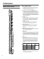 6
6
-
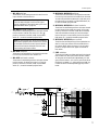 7
7
-
 8
8
-
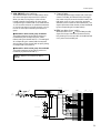 9
9
-
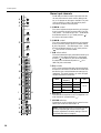 10
10
-
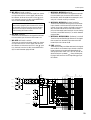 11
11
-
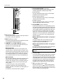 12
12
-
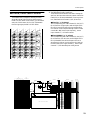 13
13
-
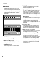 14
14
-
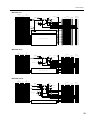 15
15
-
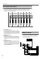 16
16
-
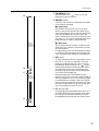 17
17
-
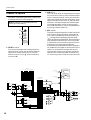 18
18
-
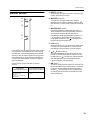 19
19
-
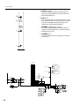 20
20
-
 21
21
-
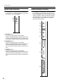 22
22
-
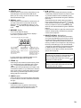 23
23
-
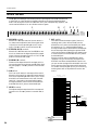 24
24
-
 25
25
-
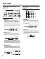 26
26
-
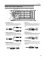 27
27
-
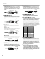 28
28
-
 29
29
-
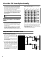 30
30
-
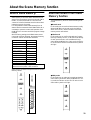 31
31
-
 32
32
-
 33
33
-
 34
34
-
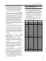 35
35
-
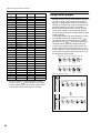 36
36
-
 37
37
-
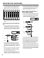 38
38
-
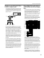 39
39
-
 40
40
-
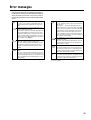 41
41
-
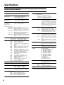 42
42
-
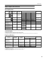 43
43
-
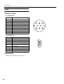 44
44
-
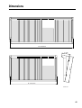 45
45
-
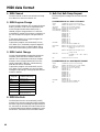 46
46
-
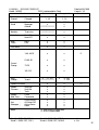 47
47
-
 48
48


Yamaha 40C Handleiding
- Categorie
- Audiomixers
- Type
- Handleiding