Yamaha CLP-555 Handleiding
- Categorie
- Muziekinstrumenten
- Type
- Handleiding
Deze handleiding is ook geschikt voor

FCC INFORMATION (U.S.A.)
1. IMPORTANT NOTICE: DO NOT MODIFY THIS UNIT!
This product, when installed as indicated in the instructions contained in this
manual, meets FCC requirements. Modifications not expressly approved by
Yamaha may void your authority, granted by the FCC, to use the product.
2. IMPORTANT: When connecting this product to accessories and/or another
product use only high quality shielded cables. Cable/s supplied with this product
MUST be used. Follow all installation instructions. Failure to follow instructions
could void your FCC authorization to use this product in the USA.
3. NOTE: This product has been tested and found to comply with the requirements
listed in FCC Regulations, Part 15 for Class “B” digital devices. Compliance with
these requirements provides a reasonable level of assurance that your use of
this product in a residential environment will not result in harmful interference
with other electronic devices. This equipment generates/uses radio frequencies
and, if not installed and used according to the instructions found in the users
manual, may cause interference harmful to the operation of other electronic
devices. Compliance with FCC regulations does not guarantee that interference
will not occur in all installations. If this product is found to be the source of inter-
ference, which can be determined by turning the unit “OFF” and “ON”, please try
to eliminate the problem by using one of the following measures:
Relocate either this product or the device that is being affected by the
interference.
Utilize power outlets that are on different branch (circuit breaker or fuse) circuits
or install AC line filter/s.
In the case of radio or TV interference, relocate/reorient the antenna. If the
antenna lead-in is 300 ohm ribbon lead, change the lead-in to co-axial type
cable.
If these corrective measures do not produce satisfactory results, please contact
the local retailer authorized to distribute this type of product. If you can not
locate the appropriate retailer, please contact Yamaha Corporation of America,
Electronic Service Division, 6600 Orangethorpe Ave, Buena Park, CA90620
The above statements apply ONLY to those products distributed by Yamaha
Corporation of America or its subsidiaries.
* This applies only to products distributed by YAMAHA CORPORATION OF AMERICA.
• This applies only to products distributed by Yamaha-Kemble Music (U.K.) Ltd.
IMPORTANT NOTICE FOR THE UNITED KINGDOM
Connecting the Plug and Cord
IMPORTANT. The wires in this mains lead are coloured in accordance with the
following code:
BLUE : NEUTRAL
BROWN : LIVE
As the colours of the wires in the mains lead of this apparatus may not correspond
with the coloured makings identifying the terminals in your plug proceed as follows:
The wire which is coloured BLUE must be connected to the terminal which is
marked with the letter N or coloured BLACK.
The wire which is coloured BROWN must be connected to the terminal which is
marked with the letter L or coloured RED.
Making sure that neither core is connected to the earth terminal of the three pin
plug.
CAUTION: TO PREVENT ELECTRIC SHOCK, MATCH WIDE BLADE OF PLUG
TO WIDE SLOT, FULLY INSERT.
ATTENTION: POUR ÉVITER LES CHOCS ÉLECTRIQUES, INTRODUIRE LA
LAME LA PLUS LARGE DE LA FICHE DANS LA BORNE CORRESPONDANTE DE
LA PRISE ET POUSSER JUSQU’AU FOND.
• This applies only to products distributed by Yamaha Canada Music Ltd.
• Ceci ne s’applique qu’aux produits distribués par Yamaha Canada Musique Ltée.
ENGLISH
DEUTSCHFRANÇAISESPAÑOL
Owner’s Manual
Bedienungsanleitung
Mode d’emploi
Manual de instrucciones
IMPORTANT
Check Your Power Supply
Make sure that your local AC mains vol-
tage matches the voltage specified on
the name plate on the bottom panel. In
some areas a voltage selector may be
provided on the bottom panel of the
main keyboard unit near the power
cord. Make sure that the voltage selec-
tor is set for the voltage in your area.
The voltage selector is set at 240V
when the unit is initially shipped. To
change the setting use a “minus” screw-
driver to rotate the selector dial so that
the correct voltage appears next to the
pointer on the panel.
WICHTIG
Überprüfung der Stromversorgung
Vergewissern Sie sich vor dem Ansch-
ließen an das Stromnetz, daß die ör-
tliche Netzspannung den Betriebsspan-
nungswerten auf dem Typenschild an
der Unterseite des Instruments ents-
pricht. In bestimmten Verkaufsgebieten
ist das Instrument mit einem Span-
nungswähler an der Unterseite neben
der Netzkabeldurchführung ausgestat-
tet. Falls vorhanden, muß der Span-
nungswähler auf die örtliche Netzspan-
nung eingestellt werden. Der Span-
nungswähler wurde werkseitig auf 240
V voreingestellt. Zum Verstellen drehen
Sie den Spannungsregler mit einem
Schlitzschraubendreher, bis der Zeiger
auf den korrekten Spannungswert weist.
IMPORTANTE
Verifique la alimentación de corriente
Asegúrese de que tensión de alimenta-
ción de CA de su área corresponde con
la tensión especificada en la placa de
características del panel inferior de la
unidad del teclado principal, cerca del
cable de alimentación. Asegúrese de
que el selector de tensión esté ajustado
a la tensión de su área. El selector de
tensión se ajusta a 240V cuando la uni-
dad sale de fábrica. Para cambiar el
ajuste, emplee un destornillador de ca-
beza “recta” para girar el selector de
modo que aparezca la tensión correcta
al lado del indicador del panel.
IMPORTANT
Contrôler la source d’alimentation
Vérifiez que la tension spécifiée sur le
panneau arrière correspond à la tension
du secteur. Dans certaines régions, l’in-
strument peut être équipé d’un sélec-
teur de tension situé sur le panneau in-
férieur du clavier à proximité du cordon
d’alimentation. Vérifiez que ce sélec-
teur est bien réglé en fonction de la ten-
sion secteur de votre région. Le sélec-
teur de tension est réglé sur 240 V au
départ d’usine. Pour modifier ce ré-
glage, utilisez un tournevis à lame plate
pour tourner le sélecteur afin de mettre
l’indication correspondant à la tension
de votre région vis à vis du repère trian-
gulaire situé sur le panneau.
M.D.G., EMI Division © Yamaha Corporation 1997
VV62120 706POCP1.2-0310 Printed in Japan

Die Einzelheiten zu Produkten sind bei Ihrer unten aufgeführten Nie-
derlassung und bei Yamaha Vertragshändlern in den jeweiligen
Bestimmungsländern erhältlich.
Para detalles sobre productos, contacte su tienda Yamaha más cercana
o el distribuidor autorizado que se lista debajo.
For details of products, please contact your nearest Yamaha or the
authorized distributor listed below.
Pour plus de détails sur les produits, veuillez-vous adresser à Yamaha
ou au distributeur le plus proche de vous figurant dans la liste suivante.
ITALY
Yamaha Musica Italia S.P.A.,
Home Keyboard Division
Viale Italia 88, 20020 Lainate (Milano), Italy
Tel: 02-935-771
SPAIN
Yamaha-Hazen Electronica Musical, S.A.
Jorge Juan 30, 28001, Madrid, Spain
Tel: 91-577-7270
PORTUGAL
Valentim de Carvalho CI SA
Estrada de Porto Salvo, Paço de Arcos 2780 Oeiras,
Portugal
Tel: 01-443-3398/4030/1823
GREECE
Philippe Nakas S.A.
Navarinou Street 13, P.Code 10680, Athens, Greece
Tel: 01-364-7111
SWEDEN
Yamaha Scandinavia AB
J. A. Wettergrens Gata 1
Box 30053
S-400 43 Göteborg, Sweden
Tel: 031 89 34 00
DENMARK
YS Copenhagen Liaison Office
Generatorvej 8B
DK-2730 Herlev, Denmark
Tel: 44 92 49 00
FINLAND
Warner Music Finland OY/Fazer Music
Aleksanterinkatu 11, P.O. Box 260
SF-00101 Helsinki, Finland
Tel: 0435 011
NORWAY
Narud Yamaha AS
Grini Næringspark 17
N-1345 Østerås, Norway
Tel: 67 14 47 90
ICELAND
Skifan HF
Skeifan 17 P.O. Box 8120
IS-128 Reykjavik, Iceland
Tel: 525 5000
OTHER EUROPEAN COUNTRIES
Yamaha Europa GmbH.
Siemensstraße 22-34, 25462 Rellingen, F.R. of
Germany
Tel: 04101-3030
ASIA
HONG KONG
Tom Lee Music Co., Ltd.
11/F., Silvercord Tower 1, 30 Canton Road,
Tsimshatsui, Kowloon, Hong Kong
Tel: 730-1098
INDONESIA
PT. Yamaha Music Indonesia (Distributor)
PT. Nusantik
Gedung Yamaha Music Center, Jalan Jend. Gatot
Subroto Kav. 4, Jakarta 12930, Indonesia
Tel: 21-520-2577
MALAYSIA
Yamaha Music Malaysia, Sdn., Bhd.
16-28, Jalan SS 2/72, Petaling Jaya, Selangor,
Malaysia
Tel: 3-717-8977
PHILIPPINES
Yupangco Music Corporation
339 Gil J. Puyat Avenue, P.O. Box 885 MCPO,
Makati, Metro Manila, Philippines
Tel: 819-7551
SINGAPORE
Yamaha Music Asia Pte., Ltd.
Blk 17A Toa Payoh #01-190 Lorong 7
Singapore 1231
Tel: 354-0133
TAIWAN
Kung Hsue She Trading Co., Ltd.
No. 322, Section 1, FuHsing S. Road,
Taipei 106, Taiwan. R.O.C.
Tel: 02-709-1266
THAILAND
Siam Music Yamaha Co., Ltd.
865 Phornprapha Building, Rama I Road,
Patumwan, Bangkok 10330, Thailand
Tel: 2-215-3443
THE PEOPLE’S REPUBLIC OF CHINA
AND OTHER ASIAN COUNTRIES
Yamaha Corporation,
International Marketing Division
Nakazawa-cho 10-1, Hamamatsu, Japan 430
Tel: 053-460-2317
NORTH AMERICA
CANADA
Yamaha Canada Music Ltd.
135 Milner Avenue, Scarborough, Ontario,
M1S 3R1, Canada
Tel: 416-298-1311
U.S.A.
Yamaha Corporation of America,
Keyboard Division
6600 Orangethorpe Ave., Buena Park, Calif. 90620,
U.S.A.
Tel: 714-522-9011
MIDDLE & SOUTH AMERICA
MEXICO
Yamaha De Mexico S.A. De C.V.,
Departamento de ventas
Javier Rojo Gomez No.1149, Col. Gpe Del
Moral, Deleg. Iztapalapa, 09300 Mexico, D.F.
Tel: 686-00-33
BRASIL
Yamaha Musical Do Brasil LTDA.
Ave. Reboucas 2636, São Paulo, Brasil
Tel: 011-853-1377
PANAMA
Yamaha De Panama S.A.
Edificio Interseco, Calle Elvira Mendez no.10,
Piso 3, Oficina #105, Ciudad de Panama, Panama
Tel: 507-69-5311
OTHER LATIN AMERICAN COUNTRIES
AND CARIBBEAN COUNTRIES
Yamaha Music Latin America Corp.
6101 Blue Lagoon Drive, Miami, Florida 33126,
U.S.A.
Tel: 305-261-4111
MIDDLE EAST
TURKEY/CYPRUS
Yamaha Europa GmbH.
Siemensstraße 22-34, 25462 Rellingen,
F.R. of Germany
Tel: 04101-3030
OTHER COUNTRIES
Yamaha Corporation,
International Marketing Division
Nakazawa-cho 10-1, Hamamatsu, Japan 430
Tel: 053-460-2312
EUROPE
THE UNITED KINGDOM
Yamaha-Kemble Music (U.K.) Ltd.
Sherbourne Drive, Tilbrook, Milton Keynes,
MK7 8BL, England
Tel: 01908-366700
IRELAND
Danfay Ltd.
61D, Sallynoggin Road, Dun Laoghaire, Co. Dublin
Tel: 01-2859177
GERMANY/SWITZERLAND
Yamaha Europa GmbH.
Siemensstraße 22-34, 25462 Rellingen,
F.R. of Germany
Tel: 04101-3030
AUSTRIA
Yamaha Music Austria
Schleiergasse 20, A-1100 Wien Austria
Tel: 0222-60203900
THE NETHERLANDS
Yamaha Music Nederland
Kanaalweg 18G, 3526KL, Utrecht, The Netherlands
Tel: 030-2828411
BELGIUM
Yamaha Music Belgium
Keiberg Imperiastraat 8, 1930 Zaventem, Belgium
Tel: 02-7258220
FRANCE
Yamaha Musique France,
Division Claviers
BP 70-77312 Marne-la-Valée Cedex 2, France
Tel: 01-64-61-4000
HEAD OFFICE Yamaha Corporation, Electronic Musical Instrument Division
Nakazawa-cho 10-1, Hamamatsu, Japan 430
Tel: 053-460-3255
AFRICA
Yamaha Corporation,
International Marketing Division
Nakazawa-cho 10-1, Hamamatsu, Japan 430
Tel: 053-460-2312
OCEANIA
AUSTRALIA
Yamaha Music Australia Pty. Ltd.
17-33 Market Street, South Melbourne, Vic. 3205,
Australia
Tel: 3-699-2388
NEW ZEALAND
Music Houses of N.Z. Ltd.
146/148 Captain Springs Road, Te Papapa,
Auckland, New Zealand
Tel: 9-634-0099
COUNTRIES AND TRUST
TERRITORIES IN PACIFIC OCEAN
Yamaha Corporation,
International Marketing Division
Nakazawa-cho 10-1, Hamamatsu, Japan 430
Tel: 053-460-2317
[CL] 9
92-469 1
ENVIRONMENTAL ISSUES: Yamaha strives to pro-
duce products that are both user safe and environmentally
friendly. We sincerely believe that our products and the
production methods used to produce them, meet these
goals. In keeping with both the letter and the spirit of the
law, we want you to be aware of the following:
Battery Notice: This product MAY contain a small non-
rechargable battery which (if applicable) is soldered in
place. The average life span of this type of battery is ap-
proximately five years. When replacement becomes nec-
essary, contact a qualified service representative to per-
form the replacement.
Warning: Do not attempt to recharge, disassemble, or
incinerate this type of battery. Keep all batteries away
from children. Dispose of used batteries promptly and as
regulated by applicable laws. Note: In some areas, the
servicer is required by law to return the defective parts.
However, you do have the option of having the servicer
dispose of these parts for you.
Disposal Notice: Should this product become damaged
beyond repair, or for some reason its useful life is consid-
ered to be at an end, please observe all local, state, and
federal regulations that relate to the disposal of products
that contain lead, batteries, plastics, etc.
NOTICE: Service charges incurred due to lack of knowl-
edge relating to how a function or effect works (when the
unit is operating as designed) are not covered by the
manufacturer’s warranty, and are therefore the owners
responsibility. Please study this manual carefully and con-
sult your dealer before requesting service.
NAME PLATE LOCATION: The graphic below indi-
cates the location of the name plate. The model number,
serial number, power requirements, etc., are located on
this plate. You should record the model number, serial
number, and the date of purchase in the spaces provided
below and retain this manual as a permanent record of
your purchase.
CAUTION
RISK OF ELECTRIC SHOCK
DO NOT OPEN
CAUTION: TO REDUCE THE RISK OF ELECTRIC SHOCK.
DO NOT REMOVE COVER (OR BACK).
NO USER-SERVICEABLE PARTS INSIDE.
REFER SERVICING TO QUALIFIED SERVICE PERSONNEL.
PRODUCT SAFETY MARKINGS: Yamaha electronic
products may have either labels similar to the graphics
shown below or molded/stamped facsimiles of these
graphics on the enclosure. The explanation of these graph-
ics appears on this page. Please observe all cautions indi-
cated on this page and those indicated in the safety in-
struction section.
See bottom of Keyboard enclosure for graphic symbol markings
The exclamation point within the equi-
lateral triangle is intended to alert the
user to the presence of important oper-
ating and maintenance (servicing) in-
structions in the literature accompany-
ing the product.
The lightning flash with arrowhead
symbol, within the equilateral triangle,
is intended to alert the user to the pres-
ence of uninsulated “dangerous volt-
age” within the product’s enclosure that
may be of sufficient magnitude to con-
stitute a risk of electrical shock.
IMPORTANT NOTICE: All Yamaha electronic prod-
ucts are tested and approved by an independent safety
testing laboratory in order that you may be sure that when
it is properly installed and used in its normal and custom-
ary manner, all foreseeable risks have been eliminated.
DO NOT modify this unit or commission others to do so
unless specifically authorized by Yamaha. Product per-
formance and/or safety standards may be diminished.
Claims filed under the expressed warranty may be denied
if the unit is/has been modified. Implied warranties may
also be affected.
SPECIFICATIONS SUBJECT TO CHANGE: The
information contained in this manual is believed to be
correct at the time of printing. However, Yamaha reserves
the right to change or modify any of the specifications
without notice or obligation to update existing units.
SPECIAL MESSAGE SECTION
Model _____________________________________
Serial No. __________________________________
Purchase Date ______________________________

1
• Take care that the key cover does not pinch your fingers, and do not
insert a finger or hand in the key cover gap.
• Never insert or drop paper or metallic or other objects between the slits of
the key cover and the keyboard. If this happens, immediately turn off the
power and remove the electric plug from the outlet and have the instru-
ment inspected by qualified Yamaha service personnel.
• Do not place the instrument against a wall (allow at least 3 cm/one-inch
from the wall), since this can cause inadequate air circulation, and possi-
bly result in the instrument overheating.
• Read carefully the attached documentation explaining the assembly pro-
cess. Failure to assemble the instrument in the proper sequence might
result in damage to the instrument or even injury.
• Do not operate the instrument for a long period of time at a high or un-
comfortable volume level, since this can cause permanent hearing loss. If
you experience any hearing loss or ringing in the ears, consult a physi-
cian.
■USING THE BENCH (if included)
• Do not play carelessly with or stand on the bench. Using it as a tool or
step-ladder or for any other purpose might result in accident or injury.
• Only one person should sit on the bench at a time, in order to prevent the
possibility of accident or injury.
• Do not attempt to adjust the bench height while sitting on the bench,
since this can cause excessive force to be imposed on the adjustment
mechanism, possibly resulting in damage to the mechanism or even in-
jury.
• If the bench screws become loose due to extensive long-term use, tighten
them periodically using the included tool.
■SAVING USER DATA
• Save all data to an external device such as the Yamaha DOU-10 Disk
Orchestra Unit in order to help prevent the loss of important data due to a
malfunction or user operating error.
Yamaha cannot be held responsible for damage caused by improper use or modi-
fications to the instrument, or data that is lost or destroyed.
Always turn the power off when the instrument is not in use.
PRECAUTIONS
PLEASE READ CAREFULLY BEFORE PROCEEDING
* Please keep these precautions in a safe place for future reference.
WARNING
Always follow the basic precautions listed below to avoid the possibility of serious injury or even death from electrical shock,
short-circuiting, damages, fire or other hazards. These precautions include, but are not limited to, the following:
• Do not open the instrument or attempt to disassemble the internal parts
or modify them in any way. The instrument contains no user-serviceable
parts. If it should appear to be malfunctioning, discontinue use immedi-
ately and have it inspected by qualified Yamaha service personnel.
• Do not expose the instrument to rain, use it near water or in damp or wet
conditions, or place containers on it containing liquids which might spill
into any openings.
• If the power cord or plug becomes frayed or damaged, or if there is a
sudden loss of sound during use of the instrument, or if any unusual smells
or smoke should appear to be caused by it, immediately turn off the power
switch, disconnect the electric plug from the outlet, and have the instru-
ment inspected by qualified Yamaha service personnel.
• Only use the voltage specified as correct for the instrument. The required
voltage is printed on the name plate of the instrument.
• Before cleaning the instrument, always remove the electric plug from the
outlet. Never insert or remove an electric plug with wet hands.
• Check the electric plug periodically and remove any dirt or dust which
may have accumulated on it.
CAUTION
Always follow the basic precautions listed below to avoid the possibility of physical injury to you or others, or damage to the
instrument or other property. These precautions include, but are not limited to, the following:
• Do not place the power cord near heat sources such as heaters or radia-
tors, and do not excessively bend or otherwise damage the cord, place
heavy objects on it, or place it in a position where anyone could walk on,
trip over, or roll anything over it.
• When removing the electric plug from an outlet, always hold the plug
itself and not the cord. Pulling by the cord can damage it.
• Do not connect the instrument to an electrical outlet using a multiple-
connector. Doing so can result in lower sound quality, or possibly cause
overheating in the outlet.
• Remove the electric plug from the outlet when the instrument is not to be
used for extended periods of time, or during electrical storms.
• Before connecting the instrument to other electronic components, turn off
the power for all components. Before turning the power on or off for all
components, set all volume levels to minimum.
• Do not expose the instrument to excessive dust or vibrations, or extreme
cold or heat (such as in direct sunlight, near a heater, or in a car during the
day) to prevent the possibility of panel disfiguration or damage to the
internal components.
• Do not use the instrument near other electrical products such as televi-
sions, radios, or speakers, since this might cause interference which can
affect proper operation of the other products.
• Do not place the instrument in an unstable position where it might acci-
dentally fall over.
• Before moving the instrument, remove all connected cables.
• When cleaning the instrument, use a soft, dry cloth. Do not use paint
thinners, solvents, cleaning fluids, or chemical-impregnated wiping cloths.
Also, do not place vinyl or plastic objects on the instrument, since this
might discolor the panel or keyboard.
• Gently remove dust and dirt with a soft cloth. Do not wipe too hard since
small particles of dirt can scratch the instrument’s finish.
• Bumping the surface of the instrument with metal, porcelain, or other hard
objects can cause the finish to crack or peel. Use caution.
• Do not rest your weight on, or place heavy objects on the instrument, and
do not use excessive force on the buttons, switches or connectors.

2
The Control Panel ...................................................4
Preparation ..............................................................6
■
The Music Stand.............................................6
■
The Key Cover ................................................6
■
Opening and Closing the Lid........................6
Connections .............................................................. 7
Selecting & Playing Voices....................................8
Playing the Demonstration Tunes........................9
■
Piano Song A-B Repeat...............................10
■
Piano Song Part Cancel ..............................11
●
Synchro Start ..........................................11
●
Left Pedal Start/Stop ...............................11
The Dual Mode ......................................................12
●
Other Dual Mode Functions ....................12
The Split Mode ......................................................13
●
Selecting the Left-hand Voice.................. 13
●
Setting the Split Point .............................. 13
●
Other Split Mode Functions.....................13
Reverb .................................................................... 14
●
Adjusting Reverb Depth .......................... 14
The Chorus Effect ..................................................15
●
Adjusting Effect Depth.............................15
The Pedals..............................................................15
●
Soft (Left) Pedal ...................................... 15
●
Sostenuto (Center) Pedal........................ 15
●
Damper (Right) Pedal..............................15
Touch Sensitivity ...................................................16
Transposition .........................................................16
Introduction
Thank you for choosing a Yamaha CLP-555
Clavinova. Your Clavinova is a fine musical
instrument that employs advanced Yamaha music
technology. With the proper care, your Clavinova
will give you many years of musical pleasure.
● Yamaha’s AWM (Advanced Wave Memory) tone
generator system offers rich, realistic voices. Both
models feature stereo sampling of the piano voices
for unmatched realism and expressive power.
● Piano-like touch response — adjustable in 4 stages
— provides extensive expressive control and
outstanding playability.
● Dual mode allows 2 voices to be played simulta-
neously.
● Split mode allows different voices to be played by
the left and right hands.
● Unique Clavinova Tone voice provides a fresh
sound for new musical expression.
● Metronome feature with variable tempo facilitates
practice.
● Digital recorder lets you record and play back
anything you play on the keyboard (up to approxi-
mately 4,200 notes).
● MIDI compatibility and a range of MIDI functions
make the Clavinova useful in a range of advanced
MIDI music systems.
● Built-in computer interface for direct connection to
personal computers running advanced music
software.
In order to make the most of your Clavinova’s
performance potential and features, we urge you
to read this Owner’s Manual thoroughly, and keep
it in a safe place for later reference.

3
■
F5: Metronome Functions ...........................27
F5.1: Beat ..................................................27
F5.2: Volume ..............................................27
■
F6: Left Pedal Mode .....................................27
■
F7: Piano Song Part Cancel Volume........... 27
■
F8: MIDI Functions....................................... 28
●
A Brief Introduction to MIDI ..................... 28
F8.1: MIDI Transmit Channel Selection...... 28
F8.2: MIDI Receive Channel Selection ......28
F8.3: Local Control ON/OFF ......................29
F8.4: Program Change ON/OFF................ 29
F8.5: Control Change ON/OFF ..................30
F8.6: MIDI Transmit Transpose................... 30
F8.7: Panel/Status Transmit ....................... 30
F8.8: Bulk Data Dump................................30
■
F9: Backup Functions .................................31
F9.1: Voice ................................................. 31
F9.2: MIDI .................................................. 31
F9.3: Tuning ...............................................31
F9.4: Pedal................................................. 31
Connecting to a Personal Computer .................. 32
●
Connecting to an Apple Macintosh Series
Computer.................................................32
●
Connecting to an IBM-PC/AT Series
Computer.................................................33
●
Connecting to an NEC PC-9801/9821
Series Computer .....................................33
Troubleshooting .....................................................34
Factory Preset Recall............................................. 34
Options & Expander Modules ............................... 34
MIDI Data Format.................................................... 35
MIDI Implementation Chart ...................................39
Keyboard Stand Assembly....................................40
Demo Song List......................................................48
Default Setting List ................................................ 48
Specifications.........................................................49
Tuning......................................................................17
●
Tuning Up ................................................17
●
Tuning Down............................................17
●
To Restore Standard Pitch ...................... 17
The Metronome & Tempo Control ...................... 18
■
The Metronome ............................................18
●
Metronome Volume ................................. 18
●
Other Metronome Functions ................... 18
■
Tempo Control.............................................. 18
Using the Recorder ...............................................19
■
Recording .....................................................19
●
Changing the Initial Settings ................... 20
●
Erasing a Single Track............................. 20
■
Playback .......................................................21
●
Synchro Start .......................................... 21
●
Left Pedal Start/Stop ...............................21
The Function Mode ............................................... 22
●
To Select a Function … ...........................22
■
F1: Tuning ..................................................... 23
■
F2: Scale ....................................................... 23
■
F3: Dual Mode Functions ............................ 24
F3.1: Dual Balance ....................................24
F3.2: Dual Detune......................................24
F3.3: 1st Voice Octave Shift .......................24
F3.4: 2nd Voice Octave Shift ...................... 24
F3.5: 1st Voice Effect Depth.......................25
F3.6: 2nd Voice Effect Depth......................25
F3.7: Slow-attack Strings ...........................25
F3.8: Reset ................................................25
■
F4: Split Mode Functions ............................ 25
F4.1: Split Point.......................................... 25
F4.2: Split Balance..................................... 26
F4.3: Right Voice Octave Shift ...................26
F4.4: Left Voice Octave Shift ...................... 26
F4.5: Right Voice Effect Depth ................... 26
F4.6: Left Voice Effect Depth...................... 26
F4.7: Damper Mode ................................... 26
F4.8: Reset ................................................26
Contents

4
1 [POWER] Switch
Press the [POWER] switch once to turn the power
ON, a second time to turn the power OFF. When the
power is initially turned ON, a voice selector LED
will light, and the power indicator located below the
left end of the keyboard will light.
2 [MASTER VOLUME] Control
The [MASTER VOLUME] control adjusts the
volume (level) of sound produced by the Clavinova’s
internal stereo sound system. The [MASTER VOL-
UME] control also adjusts headphone volume when a
pair of headphones is plugged into the PHONES jack
(page 7).
The Control Panel
3 [FUNCTION] Button
This button accesses a range of utility functions
— including the MIDI functions — that significantly
enhance versatility and playability. See page 22 for
details.
4 [TRANSPOSE] Button
The [TRANSPOSE] button allows access to the
Clavinova’s TRANSPOSE function (to shift the pitch
of the entire keyboard up or down in semitone
intervals).
5 [SPLIT] Button
Engages the split mode, in which different voices
can be played on the left- and right-hand sections of
the keyboard. See page 13 for details.
–
/
NO
CLP-
555
STEREO SAMPLING
POWER
B0A0G0F0E0D0C0B-1A-1
C1 D1 E1 F1 G1 A1 B1 C2 D2 E2 F2 G2 A2 B2 C3 D3 E3 F3 G3 A3 B3 C4 D4 E4 F4 G4 A4 B4 C5 D5 E5 F5 G5 A5 B5 C6
D
1
278456
3
9@0 !
MASTER VOLUME
FUNCTION
TRANSPOSE SPLIT
VARIATION
PIANO 1
PIANO 2 CLAVI.TONE E.PIANO 1 E.PIANO 2 STRINGS
HARPSI-
CHORD
PIPE
ORGAN 1
PIPE
ORGAN 2
REVERB
ROOM
HALL 1
HALL 2
STAGE
HARD
MEDIUM
SOFT
FIXED
EFFECT TOUCH
MAX
MIN
METRONOME
TEMPO/
SONG
–
/
N O
+
/
Y ES
DEMO
/
PIANO SONG
PHONES Jacks
(Bottom Panel)
Tuning keys
(See page 17)
MASTER VOLUME
FUNCTION
TRANSPOSE SPLIT
VARIATION
PIANO 1
PIANO 2 CLAVI.TONE E.PIANO 1 E.PIANO 2 STRINGS
HARPSI-
CHORD
PIPE
ORGAN 1
PIPE
ORGAN 2
REVERB
ROOM
HALL 1
HALL 2
STAGE
HARD
MEDIUM
SOFT
FIXED
EFFECT TOUCH
MAX
MIN
METRONOME
TEMPO/
SONG
+
/
YES
START
/
STOP
REC
12
DEMO
/
PIANO SONG
RECORDER

5
The Control Panel
6 [REVERB] Button
The [REVERB] button selects a number of digital
reverb effects that you can use for extra depth and
expressive power. See page 14 for details.
7 [EFFECT] Button
This button engages a chorus effect which can
give your sound greater depth and animation.
8 [TOUCH] Button
The [TOUCH] button makes it easy to adjust the
touch response of the Clavinova to match your
playing style. See page 16 for details.
9 Voice Selectors & [VARIATION] Button
The CLP-555 has nine voice selectors and a
[VARIATION] button. Simply press any of the voice
selectors to select the corresponding voice. The voice
selector LED will light to indicate which voice is
currently selected. Press the [VARIATION] button
so that its indicator lights to select a variation of the
currently selected voice.
There is also a dual mode in which two voices can
be played simultaneously across the full range of the
keyboard (see page 12 for details), and a split mode
which allows different voices to be played by the left
and right hands (see page 13 for details).
0 [METRONOME] Button
Turns the metronome sound on and off. The
[TEMPO/SONG] buttons, below, are used to set the
tempo of the metronome sound, and the volume of
the metronome sound if used while the [METRO-
NOME] button is held — page 18.
! [TEMPO/SONG] (–/NO, +/YES) Buttons
These buttons adjust the tempo of the metronome
function as well as the playback tempo of the re-
corder function. The tempo range is from 32 to 280
beats per minute — page 18. These same buttons are
also used to select a piano song number for playback
— page 9. The [TEMPO/SONG] buttons are also
used to adjust a range of other parameters (i.e. their
“–/NO” and “+/YES” functions).
@ [DEMO/PIANO SONG] Button
Activates the demo playback mode in which you
can select playback of different demonstration
sequences for each of the Clavinova’s voices, and a
range of 30 piano songs. See page 9 for details.
# RECORDER [START/STOP] and [REC] But-
tons
These buttons control the Clavinova’s recorder,
letting you record and play back just about anything
you play on the keyboard — up to a maximum of
about 4,200 notes. See page 19 for details.
$ RECORDER [1] and [2] Buttons
The CLP-555 has a 2-track recorder, and these
buttons are used to select the track(s) to be recorded
or played back. See page 19 for details.
% Pedals
The soft (left), sostenuto (center) and damper
(right) pedals provide a range of expressive control
capabilities similar to the pedal functions on an
acoustic piano. See page 15 for details.
%
Soft pedal
Damper pedal
Sostenuto pedal
D6 E6 F6 G6 A6 B6 C7
$ #
START
/
STOP
REC
12
RECORDER

6
Preparation
If you will be using sheet music with your
Clavinova, raise the music stand built into its top
panel by lifting the rear edge of the music stand,
then flip down the music stand braces and engage
them with the corresponding recesses.
The music stand can be lowered after slightly
lifting it and folding the two brackets which sup-
port it against the back of the stand.
To open the CLP-555 key cover lift it just
enough to clear the keys (do not lift excessively)
then slide the cover back into the main unit. To
close the cover slide it forward all the way and then
lower it gently until it closes completely.
The Music Stand.............................................................................................................................................................................
The Key Cover...................................................................................................................................................................................
Opening and Closing the Lid...........................................................................................................................................
• Hold the cover with both hands when moving it, and
do not release it until it is fully opened or closed. Be
careful to avoid catching fingers (yours or others)
between the cover and main unit.
• Do not place objects on top of the key cover. Small
objects placed on the key cover may fall inside the
main unit when the cover is opened.
Z Raise the music stand as described in “The
Music Stand”, above.
X Raise and hold the right side of the lid (viewed
from the keyboard end of the instrument).
C Raise the lid stay and carefully lower the lid so
that the end of the stay fits into the recess in
the lid.
• Make sure that the end of the stay fits securely in
the lid recess. If the stay is not properly seated in
the recess the lid may fall causing damage or injury.
• Be careful that you or others do not bump the stay
while the lid is raised. The stay may be bumped out
of the lid recess causing the lid to fall.
• Be careful not to catch your fingers when raising or
lowering the lid.
Be careful of fingers when opening or closing.
Z
C
X

7
Connections
1 AUX IN L/L+R and R Jacks
These jacks are intended for use with an external tone generator mod-
ule such as the Yamaha DOU-10 Disk Orchestra Unit. The stereo outputs
from the external tone generator module are connected to the AUX IN L/
L+R and R jacks, allowing the sound of the tone generator to be repro-
duced via the Clavinova’s internal sound system and speakers. A line-level
mono source can be connected to the L/L+R jack.
• The input signal from the AUX IN jacks is delivered to the AUX OUT jacks,
but is not affected by the Clavinova’s volume control or reverb effect.
2 AUX OUT L/L+R and R Jacks
The AUX OUT L/L+R and R jacks deliver the output of the Clavinova for
connection to an instrument amplifier, mixing console, PA system, or record-
ing equipment. If you will be connecting the Clavinova to a monaural sound
system, use only the L/L+R jack. When a plug is inserted into the L/L+R jack
only, the left- and right-channel signals are combined and delivered via the L/
L+R jack so you don’t lose any of the Clavinova’s sound.
• The AUX OUT jack signal must never be returned to the AUX IN jacks, either
directly or through external equipment.
3 MIDI IN, THRU and OUT Connectors
The MIDI IN connector receives MIDI data from an external MIDI
device (such as the DOU-10 Disk Orchestra Unit) which can be used to
control the Clavinova. The MIDI THRU connector re-transmits any data
received at the MIDI IN connector, allowing “chaining” of several MIDI
instruments or other devices. The MIDI OUT connector transmits MIDI
data generated by the Clavinova (e.g. note and velocity data produced by
playing the Clavinova keyboard).
More details on MIDI are given in “MIDI FUNCTIONS” on page 28.
4 TO HOST Connector & HOST SELECT Switch
This jack and selector switch allow direct connection to a personal
computer for sequencing and other music applications — without the need
for a separate MIDI interface. See page 32 for details.
● PHONES Jacks
(Bottom Panel)
Two pairs of standard pair of stereo headphones can be plugged in here
for private practice or late-night playing. The internal speaker system is
automatically shut off when a pair of headphones is plugged into either of
the PHONES jacks.
Tone Generator
AUX OUT
RL
/
L+R
DOU-10
MIDI
IN OUT THRU
Personal Computer
HOST SELECT TO HOST
PC-2 PC-1
Mac
MIDI
Stereo System
DOU-10
AUX IN
RL
/
L+R
1
2
3
4
Bottom Panel
MIDI
AUX IN
HOST SELECT TO HOST
IN OUT
RL
/
L+R
THRU
PC-2 PC-1
Mac
MIDI
AUX OUT
RL
/
L+R

8
Selecting & Playing Voices
Turn Power On...................................................................................................
After making sure that the Clavinova’s AC cord is properly plugged
into the Clavinova itself and plugged into a convenient AC wall outlet,
press the [POWER] switch located to the left of the keyboard to turn
the power ON.
When the power is turned ON, one of the voice selector LEDs will
light.
Set the Volume ..................................................................................................
Initially set the [MASTER VOLUME] control about half way
between the “MIN” and “MAX” settings. Then, when you start playing,
re-adjust the [MASTER VOLUME] control for the most comfortable
listening level.
Select a Voice .....................................................................................................
Select the desired voice by pressing one of the voice selectors. Use
the [VARIATION] button to select a variation of the current voice, as
required.
POWER
MASTER VOLUME
MAX
MIN
VARIATION
PIANO 1
PIANO 2 CLAVI.TONE E.PIANO 1 E.PIANO 2
STRINGS
HARPSI-
CHORD
PIPE
ORGAN 1
PIPE
ORGAN 2
Play................................................................................................................................
The Clavinova also offers keyboard touch response, so the volume
and timbre of notes played can be controlled according to how “hard”
you play the keys. The amount of variation available depends on the
selected voice.
Add Effects As Required.......................................................................
You can also change add reverb and/or a chorus effect as desired by
using the [REVERB] and [EFFECT] buttons (see page 14 for [RE-
VERB] button operation, and page 15 for [EFFECT] button opera-
tion).
REVERB
ROOM
HALL 1
HALL 2
STAGE
EFFECT

9
Demonstration tunes are provided that effectively demonstrate each of the
Clavinova’s voices. There are also 30 piano songs that you can play individually,
all in sequence, or in random order. Here’s how you can select and play the
demo tunes.
Playing the Demonstration Tunes
Engage the Demo Mode .........................................................................
Play a Voice Demo or Piano Song ...............................................
● Voice Demo Playback
Press one of the voice selectors to start playback of the corresponding voice
demo tune — featuring the voice normally selected by that voice selector
button. The indicator of the selected voice selector button will flash during
playback, and “---” (relative tempo) will appear on the LED display. You can
start playback of any other voice demo tune during playback by simply
pressing the corresponding voice selector. You can stop playback at any time
by pressing the [START/STOP] button, the voice selector of the currently
playing demo.
● Piano Song Playback
To play any of the 30 piano songs provided, use the [TEMPO/SONG] buttons to
select the number of the tune you want to play (the number will appear on the
LED display), then press the [START/STOP] button. Playback will stop automati-
cally when playback of the selected piano song has finished. To randomly select
and play one of the piano songs press the [VARIATION] button while playback is
stopped.
Select “ALL” instead of a number to play all piano songs and voice demo
tunes in sequence, or select “rnd” to continuously play all piano songs and
voice demo tunes in random order. The [VARIATION] button indicator will
flash during playback. Press the [START/STOP] button to stop playback. If a
voice selector is pressed while “ALL” is showing on the display, playback will
begin from the corresponding song.
• While a voice demo or piano song is playing, you can use the [TEMPO/
SONG] buttons to adjust the playback tempo as required. This produces a
relative tempo variation, with a range from “-99” through “---” to “99”.
• Use the [MASTER VOLUME] control to adjust the volume.
• The demo mode cannot be engaged while the recorder (page 19) is in
use.
• The default tempo is automatically selected whenever a new song is
selected, or playback of a new song begins during “
ALL
” or “
rnd
”
playback.
• No MIDI reception occurs in the demo mode.
• The demo/piano song data is not transmitted via the MIDI connectors.
* See page 48 for a complete listing of the demo tunes.
Press the [DEMO/PIANO SONG] button to engage the demo mode
— the voice selector indicators will flash in sequence.
VARIATION
PIANO 1
PIANO 2 CLAVI.TONE E.PIANO 1 E.PIANO 2
STRINGS
HARPSI-
CHORD
PIPE
ORGAN 1
PIPE
ORGAN 2
Exit From the Demo Mode....................................................................
After stopping demo playback, press the [DEMO/PIANO SONG]
button to exit from the demo mode and return to the normal play mode.
DEMO
/
PIANO SONG
DEMO
/
PIANO SONG
TEMPO/
SONG
–
/
NO
+
/
YES
START
/
STOP

10
Piano Song A-B Repeat
The A-B Repeat function can be used to continuously repeat a
specified phrase within a piano song. Combined with the Part Cancel
function described below, this provides an excellent way to practice
difficult phrases.
Specify the Beginning (A) of the Phrase..............................
Select and play a piano song, then press the [FUNCTION] button at
the beginning of the phrase you want to repeat. This sets the “A” point
(“A-” will appear on the display).
To set the “A” point at the very beginning of the song, press the
[FUNCTION] button before starting playback.
Specify the End (B) of the Phrase ...............................................
Press the [FUNCTION] button a second time at the end of the
phrase. This sets the “B” point (“A-b” will appear on the display). At
this point repeat playback will begin between the specified A and B
points.
Stop Playback....................................................................................................
Press the [START/STOP] button to stop playback while retaining
the specified A and B points. A-B repeat playback will resume if the
[START/STOP] button is then pressed again.
To cancel the A and B points press the [FUNCTION] button once.
• The A and B points are automatically canceled when a new song is
selected.
• The A-B Repeat function cannot be used during “
ALL
” or “
rnd
” playback.
Playing the Demonstration Tunes
FUNCTION
FUNCTION
START
/
STOP
REC
12
RECORDER

11
Piano Song Part Cancel
The 30 piano songs have separate left- and right-hand parts that can
be turned on and off as required so you can practice the corresponding
part on the keyboard. The right-hand part is played by the recorder’s [1]
track, and the left-hand part is played by recorder’s [2] track.
Turn the Desired Part Off.......................................................................
Press the RECORDER [1] or [2] button to turn the corresponding
part off — the corresponding indicator will go out (these buttons
alternately toggle the corresponding part on and off).
• The parts can be turned on or off even during playback.
• The Piano Song Part Cancel function cannot be used during “
ALL
” or
“
rnd
” playback.
• The “Piano Song Part Cancel Volume” function described on page 27 can
be used to set the canceled part so that it plays at a volume from “0” (no
sound) to “20”. The default setting is “5”.
• Both parts are automatically turned ON whenever a new song is selected.
Playing the Demonstration Tunes
START
/
STOP
REC
12
RECORDER
Start/Stop Playback.....................................................................................
Press the [START/STOP] button to start and stop playback as
required.
START
/
STOP
REC
12
RECORDER
Synchro Start .....................................................................................................
When the Synchro Start function is engaged, playback of the se-
lected piano song will begin automatically as soon as you start playing
on the keyboard.
To engage the Synchro Start function press the [START/STOP]
button while holding the part button corresponding to the part which is
ON. The rightmost dot on the display will light. Playback will then start
as soon as you begin playing on the keyboard.
• If you hold a track button which is OFF while pressing the [START/STOP]
button, that track will be turned ON and the Synchro Start mode will be
engaged.
START
/
STOP
REC
12
RECORDER
Left Pedal Start/Stop..................................................................................
The left pedal can be assigned to start and stop piano song playback
via the “Left Pedal Mode” function described on page 27.

12
The Dual Mode
The dual mode makes it possible to play two voices simultaneously across
the entire range of the keyboard.
To activate the dual mode simply press two voice selectors at the
same time (or press one voice selector while holding another). The
voice indicators of both selected voices will light when the dual mode is
active. To return to the normal single-voice play mode, press any single
voice selector.
• The dual and split modes cannot be engaged at the same time.
• The [VARIATION] button indicator will light if the variation is engaged for
either or both of the dual-mode voices. While the dual mode is engaged
the [VARIATION] button can be used to turn the variation for both voices
on or off. To use the variation for only one of the voices the setting must
be made prior to engaging the dual mode.
• The chorus effect will apply to both the dual mode voices as specified
after engaging the dual mode (the default effect on/off and depth settings
are different for each voice combination). The effect depth for the dual
mode voices can be individually set via the Dual Mode “1st Voice Effect
Depth” and “2nd Voice Effect Depth” functions described on page 25.
IANO 1 E.PIANO 2
HARPSI-
CHORD
Other Dual Mode Functions...............................................................
The CLP-555 Function mode provides access to a number of other
dual-mode functions, listed below. See the corresponding pages for
details.
• Dual Balance..........................................24
• Dual Detune ...........................................24
• 1st Voice Octave Shift............................. 24
• 2nd Voice Octave Shift ........................... 24
• 1st Voice Effect Depth ............................ 25
• 2nd Voice Effect Depth ...........................25
• Slow-attack Strings.................................25
• Reset......................................................25

13
The Split Mode
The split mode makes it possible to play two different voices on the keyboard
— one with the left hand and another with the right hand. The left-hand voice is
played on all keys to the left of (and including) a specified “split point” key, while
the right-hand voice is played on all keys to the right of the split point key.
To activate the split mode simply press the [SPLIT] button so thats
indicator lights. The split mode can be turned off at any time by press-
ing the [SPLIT] button again so that its indicator goes out.
• The dual and split modes cannot be engaged at the same time.
Selecting the Left-hand Voice...........................................................
The voice that was selected before the split mode was engaged
becomes the right-hand voice in the split mode. To select a left-hand
voice press the corresponding voice selector while holding the [SPLIT]
button. The indicator of the left-hand voice selector will light while it is
pressed, then only the right-hand voice selector and [SPLIT] button
indicators will remain lit.
• The variation can be individually turned on and off for the split mode
voices. Normally the voice indicator of the right-hand voice lights in the
split mode. The [VARIATION] can be used to turn the variation for the
right-hand voice on or off as required. While the [SPLIT] button is held,
however, the voice indicator of the left-hand voice lights, and in this state
the [VARIATION] button can be used to turn the variation for the left-hand
voice on or off as required.
• The chorus effect will apply to both the split mode voices as specified
after engaging the split mode (the default effect on/off and depth settings
are different for each voice combination). The effect depth for the split
mode voices can be individually set via the Split Mode “Left Voice Effect
Depth” and “Right Voice Effect Depth” functions described on page 26.
SPLIT
N
O 2
STRINGS
HARPSI-
CHORD
SPLIT
Setting the Split Point...............................................................................
The split point is initially set at the F#2 key by default. You can reset
the split point to any other key by pressing the key while holding the
[SPLIT] button (the name of the current split-point key appears on the
LED display while the [SPLIT] button is held). The split point can also
be set via the Function mode (see below).
Other Split Mode Functions...............................................................
The CLP-555 Function mode provides access to a number of other
split-mode functions, listed below. See the corresponding pages for
details.
• Split Point ...............................................25
• Split Balance ..........................................26
• Right Voice Octave Shift ......................... 26
• Left Voice Octave Shift ........................... 26
• Right Voice Effect Depth.........................26
• Left Voice Effect Depth ...........................26
• Damper Mode ........................................26
• Reset......................................................26
SPLIT
A-1 b=1 C 2 F~2
A-1 Bb-1 C2 F#2
Example:

14
Reverb
The [REVERB] button selects a number of digital reverb effects that you can
use for extra depth and expressive power.
To select a reverb type press the [REVERB] button a few times until
the indicator corresponding to the desired type lights (the indicators
light in sequence each time the [REVERB] button is pressed). No
reverb is produced when all indicators are off.
OFF
No reverb effect is selected when no REVERB indicator is lit.
ROOM
This setting add a continuous reverb effect to the sound that is similar
to the type of acoustic reverberation you would hear in a medium-size
room. This is the default reverb setting.
HALL 1
For a “bigger” reverb sound, use the HALL 1 setting. This effect
simulates the natural reverberation of a medium-size concert hall.
HALL 2
For a really spacious reverb sound, use the HALL 2 setting. This effect
simulates the natural reverberation of a large concert hall.
STAGE
A simulation of the type of reverb produced in a stage environment.
Adjusting Reverb Depth.........................................................................
The depth of the selected reverb effect can be adjusted for the
current voice by using the [–/NO] and [+/YES] buttons while holding
the [REVERB] button. The depth range is from 0 through 20 (the
current depth setting appears on the LED display while the [REVERB]
button is held). A setting of “0” produces no effect, while a setting of
“20” produces maximum reverb depth. Press the [–/NO] and [+/YES]
buttons simultaneously while holding the [REVERB] button to recall
the default setting: “10”.
• The reverb type and depth settings affect all voices.
REVERB
ROOM
HALL 1
HALL 2
STAGE
REVERB
ROOM
HALL 1
HALL 2
STAGE
TEMPO/
SONG
–
/
NO
+
/
YES

15
The Chorus Effect
The [EFFECT] button engages a chorus effect that can give your sound
greater depth and animation.
The [EFFECT] button turns the chorus effect on (indicator lit) and
off (indicator off).
• The default effect on/off settings are different for each voice.
Adjusting Effect Depth.............................................................................
While the chorus effect is on the effect depth can be individually
adjusted for the selected voice by using the [–/NO] and [+/YES]
buttons while holding the [EFFECT] button. The depth range is from 0
through 20 (the current depth setting appears on the LED display while
the [EFFECT] button is held). A setting of “0” produces no effect,
while a setting of “20” produces maximum effect depth. Press the
[–/NO] and [+/YES] buttons simultaneously while holding the [EF-
FECT] button to recall the default setting for the current voice (the
default depth settings are different for each voice).
The Pedals
Soft (Left) Pedal...............................................................................................
The soft pedal reduces the volume and slightly changes the timbre of
notes played while the pedal is pressed. The soft pedal will not affect
notes which are already playing when it is pressed.
The left pedal can also be assigned to song start/stop operation via
the “Left Pedal Mode” described on page 27.
The CLP-555 has three foot pedals that produce a range of expressive ef-
fects similar to those produced by the pedals on an acoustic piano.
Damper (Right) Pedal ................................................................................
The damper pedal functions in the same way as a damper pedal on
an acoustic piano. When the damper pedal is pressed notes played have
a long sustain. Releasing the pedal immediately stops (damps) any
sustained notes.
TEMPO/
SONG
–
/
NO
+
/
YES
EFFECT
EFFECT
Sostenuto (Center) Pedal......................................................................
If you play a note or chord on the keyboard and press the sostenuto
pedal while the note(s) are held, those notes will be sustained as long as
the pedal is held (as if the damper pedal had been pressed) but all
subsequently played notes will not be sustained. This makes it possible
to sustain a chord, for example, while other notes are played “staccato.”
Soft pedal
Damper pedal
Sostenuto pedal

16
Touch Sensitivity
Four different types of keyboard touch sensitivity — HARD, MEDIUM, SOFT
or FIXED — can be selected to match different playing styles and preferences.
To select a touch sensitivity type press the [TOUCH] button a few
times until the indicator corresponding to the desired type lights (the
indicators light in sequence each time the [TOUCH] button is pressed).
HARD
The HARD setting requires the keys to be played quite hard to
produce maximum loudness.
MEDIUM
The MEDIUM setting produces a fairly “standard” keyboard response.
This is the initial factory default setting.
SOFT
The SOFT setting allows maximum loudness to be produced with
relatively light key pressure.
FIXED
All notes are produced at the same volume no matter how hard the
keyboard is played. This is an ideal setting for voices which normally
have no keyboard sensitivity (i.e. harpsichord and organ).
The volume of notes played in the FIXED mode can be set by using
the [–/NO] and [+/YES] buttons while the [TOUCH] button is held (the
current volume level appears on the display). The volume range is
from 1 through 127. The default setting is 64.
Transposition
Use the [–/NO] or [+/YES] button while holding the [TRANS-
POSE] button to transpose down or up as required. The transposition
range is from “–12” (down one octave) through “0” (normal pitch) to
“12” (up one octave). The amount of transposition appears on the LED
display while the [TRANSPOSE] button is held. The default transpose
setting is “0”.
• The [TRANSPOSE] button indicator remains lit when a transpose setting
other than “0” is selected.
• Notes below and above the A-1 … C7 range of the Clavinova sound one
octave higher and lower, respectively.
The Clavinova’s TRANSPOSE function makes it possible to shift the pitch of
the entire keyboard up or down in semitone intervals up to a maximum of 12
semitones (i.e. a maximum of one octave up or down). “Transposing” the pitch of
the Clavinova keyboard facilitates playing in difficult key signatures, and you can
easily match the pitch of the keyboard to the range of a singer or other instru-
mentalist.
HARD
MEDIUM
SOFT
FIXED
TOUCH
TEMPO/
SONG
–
/
NO
+
/
YES
TRANSPOSE

17
Tuning
Tuning makes it possible to adjust the pitch of the Clavinova over a 427.0 Hz
… 453.0 Hz (corresponding to the A3 note’s Hz) range in approximately 0.2
Hertz intervals. Pitch control is useful for tuning the Clavinova to match other
instruments or recorded music.
Tuning Up ...............................................................................................................
ZTo tune up (raise pitch), hold the A-1 and B-1 keys simultaneously.
XPress any key between C3 and B3. Each time a key in this range is
pressed the pitch is increased by approximately 0.2 Hz.
The [–/NO] and [+/YES] buttons can also be used to tune down or up,
respectively, in 1 Hz increments. Press the [–/NO] and [+/YES] buttons
simultaneously to recall standard tuning (A3 = 440 Hz).
CRelease the A-1 and B-1 keys.
Tuning Down.......................................................................................................
ZTo tune down (lower pitch), hold the A-1 and A#-1 keys simulta-
neously.
XPress any key between C3 and B3. Each time a key in this range is
pressed the pitch is decreased by approximately 0.2 Hz.
The [–/NO] and [+/YES] buttons can also be used to tune down or up,
respectively, in 1 Hz increments. Press the [–/NO] and [+/YES] buttons
simultaneously to recall standard tuning (A3 = 440 Hz).
CRelease the A-1 and A#-1 keys.
To Restore Standard Pitch...................................................................
ZTo restore the default pitch (A3 = 440 Hz), hold the A-1, A#-1 and
B-1 keys simultaneously.
XPress any key between C3 and B3.
CRelease the A-1, A#-1 and B-1 keys.
A
-1
B
-1
A#
-1
C
3
B
3
C
3
B
3
A
-1
B
-1
TEMPO/
SONG
–
/
NO
+
/
YES
A
-1
A#
-1
C
3
B
3
TEMPO/
SONG
–
/
NO
+
/
YES
In terms of “Hertz”, the overall tuning range is from 427.0 Hz to 453.0
Hz. The current tuning setting is shown on the LED display while the tuning
is being adjusted. Tenths of a Hertz are indicated on the LED display by the
appearance and position of one or two dots, as in the following example:
• An alternative tuning method is available in the Function mode — page 23.
• The keyboard method of pitch control, described above, has no effect when
LOCAL OFF is active (see “MIDI FUNCTIONS,” page 28).
Display Value
440 440.0
4.40 440.2
44.0 440.4
440. 440.6
4.40. 440.8

18
The Metronome & Tempo Control
The CLP-555 built-in metronome is a convenient feature for practice, and it
can also provide a solid rhythmic guide when recording using the Recorder
feature, described below.
The Metronome
The metronome sound is alternately turned on and off by pressing
the [METRONOME] button. When on, the beat indicator flashes at the
current tempo.
Metronome Volume ......................................................................................
The volume of the metronome sound can be adjusted by using the
[–/NO] and [+/YES] buttons while holding the [METRONOME]
button. The volume range is from 1 through 20 (the current volume
setting appears on the LED display while the [METRONOME] button
is held). A setting of “1” produces minimum sound, while a setting of
“20” produces maximum metronome volume. Press the [–/NO] and [+/
YES] buttons simultaneously while holding the [METRONOME]
button to recall the default setting: “10”.
Other Metronome Functions .............................................................
The time signature (“beat”) of the metronome can be changed via
the metronome “Beat” function in the Function mode — page 27. The
Function mode also has an alternative method for adjusting the metro-
nome volume — page 27.
Tempo Control
The tempo of the metronome and recorder playback (the recorder is
described in the next section) can be set from 32 to 280 beats per
minute by using the [TEMPO/SONG t/s] buttons. The [t] button
decreases the tempo and the [s] button increases the tempo. The
selected tempo appears on the LED display in the normal play mode
and while the [TEMPO/SONG t/s] buttons are being used to adjust
the tempo. The default tempo (120 or the recorded song tempo when
the recorder contains data and the playback track lamp is lit) can be
recalled by simultaneously pressing the [t] and [s] buttons.
TEMPO/
SONG
–
/
NO
+
/
YES
METRONOME
TEMPO/
SONG
–
/
NO
+
/
YES
METRONOME
Beat indicator

19
Using the Recorder
The CLP-555 features a two-track recorder that let you record what you play
on the keyboard and then play it back. Two tracks mean that you can “overdub”
one part on top of another, using a different voice if you like. The recorder fea-
ture is a useful adjunct to any keyboard study program, since it lets you hear
exactly how you sound from the listener’s perspective. It can also be just plain
fun.
The recorder actually records the following data:
■ Entire Song
● Tempo ● Reverb type & depth ● Effect type
■ Individual Tracks
● Notes played ● Voice selection ● Voice variation
● Dual mode voices ● Split mode voices
● Damper pedal ● Soft pedal
● Sostenuto pedal (not recorded as an initial setting)
● Effect depth ● Dual mode functions (F3)
● Split mode functions (F4)
Recording
Make All Necessary Initial Settings ...........................................
Before actually beginning to record, select the voice you want to
record with (or voices if you will be using the dual or split mode). You
might also want to set the volume and tempo controls.
V
I.TONE E.PIANO 1 E.PIANO 2
HARPSI-
CHORD
Engage the Record Ready Mode ..................................................
Press the RECORDER [REC] button to engage the record ready
mode (recording does not actually start yet). The record ready mode can
be disengaged before recording by pressing the [REC] button a second
time.
• The record ready mode cannot be engaged while the demo/piano song
mode is engaged.
Select the Record Track..........................................................................
When the record mode is engaged in the previous step, the last-
recorded track will automatically be selected for recording and its
indicator — i.e. the [1] or [2] button indicator — will glow red. If you
want to record on a different track, press the appropriate track button so
that its indicator glows red.
• The track button indicators of tracks which contain previously recorded
data will glow green (unless the track is turned off as described below).
The previously-recorded data on the non-record track will normally be
played back as you record, so you can play along with a previously-
recorded track. If you don’t want to hear the previously recorded track as
you record, press the playback track button before pressing the [REC]
button (step 1, above) so that its indicator goes out.
• Recording on a track which already contains data will erase all previous
data on that track.
• When the record mode is engaged the amount of memory available for
recording will be shown on the LED display in approximate kilobytes
(starting at “21”), and the rightmost dot on the LED display will flash at the
current METRONOME tempo setting.
START
/
STOP
REC
12
RECORDER
START
/
STOP
REC
12
RECORDER

20
Using the Recorder
Start Recording................................................................................................
Recording will begin automatically as soon as you play a note on the
keyboard or press the [START/STOP] button. The current measure
number will appear on the display while recording.
• The left pedal can be assigned to start and stop recording via the “Left
Pedal Mode” function described on page 27.
• If the metronome was on when you started recording, you’ll be able to
keep time with the metronome while recording, but the metronome sound
will not be recorded.
• You can record up to a maximum of about 4,200 notes, depending on
pedal usage and other factors. The record track indicators will begin to
flash when recorder memory is almost full. If the memory becomes full
during recording, “FUL” will appear on the display and recording will stop
automatically.
START
/
STOP
REC
12
RECORDER
Stop Recording ................................................................................................
Press either the RECORDER [REC] or [START/STOP] button to
stop recording.
The indicator of the recorded track will glow green to indicate that it
now contains data.
Erasing a Single Track..............................................................................
All data can be erased from either of the recorder’s tracks by engag-
ing the record mode, selecting the track you want to erase, and then
pressing the [START/STOP] button twice without recording any data.
Changing the Initial Settings.............................................................
The initial voice (including dual mode), damper pedal, soft pedal,
tempo, reverb type, reverb depth, and effect settings made in step 1 of the
recording procedure are actually recorded by the CLP-555. These initial
settings can be changed after the recording is finished by pressing the
[REC] button to engage the record ready mode, pressing the appropriate
track button, making the required changes, and then pressing the [REC]
button again to exit from the record ready mode and register the changes.
If you do this, be careful not to press the [START/STOP] button or a key
on the keyboard, either of which will start recording and erase all previ-
ous recorded data on the selected track. It is possible to cancel the
operation even after changes have been made: change tracks and then
press the [REC] button to exit from the record mode (this also cancels
data for the entire song).
•
The initial data of the “Dual mode functions (F3)” or “Split mode functions
(F4)” cannot be changed.
START
/
STOP
REC
12
RECORDER
Press twice.
START
/
STOP
REC
12
RECORDER
START
/
STOP
REC
12
RECORDER

21
Using the Recorder
Playback
To play back what you’ve recorded, first make sure that the green track
indicators of the tracks you want to play are lit. If not, press the corresponding
track button(s) so that they are lit. Then press the RECORDER [START/
STOP] button. Playback starts from the beginning of the recorded data, and
will stop automatically at the end of the recorded data. You can also stop
playback at any time by pressing the [START/STOP] button. To mute a track
so that it doesn’t play back, press the corresponding track button so that its
indicator goes out (press again to turn the track back on).
The current measure number appears on the display during playback.
• It is possible to play along on the keyboard during playback.
• The playback volume and tempo can be adjusted by using the [MASTER VOLUME]
control and [TEMPO/SONG] buttons (press both [TEMPO/SONG] buttons simulta-
neously to recall the default tempo).
• All recorder data will be retained in memory for about one week after the power is
turned off. If you want to keep your recorded data for longer periods, turn the power
on for a few minutes at least once a week. It is also possible to store it to an
external MIDI storage device such as the Yamaha DOU-10 Disk Orchestra Unit by
using the Bulk Dump function described on page 30.
• The track indicators will not light automatically when the power is turned on even if
the recorder contains data. It is therefore necessary to press the track buttons so
that the corresponding green indicators light before starting RECORDER playback.
It is also a good idea to press the track buttons to check if the tracks contain data
before recording. If the green indicator lights when the corresponding track button
is pressed, that track contains data which will be erased and replaced by the newly-
recorded data.
• If the metronome is being used during playback, the metronome will stop when
playback is stopped.
• During recorder playback, the volume of a track which is turned off will always be
“0” (i.e. the “Piano Song Part Cancel Volume” function — page 27 — only affects
piano song playback.
• The playback data is not transmitted via the MIDI OUT connector.
• Playback cannot be started when the demo/piano song mode or function mode is
engaged. Playback can be started from the function mode, however, after one of
the track buttons — [1] or [2] — is pressed.
• Playback cannot be started when the recorder contains no data, or when both track
buttons are off.
START
/
STOP
REC
12
RECORDER
Synchro Start ....................................................................................................................
When the Synchro Start function is engaged, recorder playback will begin
automatically as soon as you start playing on the keyboard.
To engage the Synchro Start function press the [START/STOP] button
while holding a track button which is ON. The rightmost dot on the display will
flash at the current tempo. Playback will then start as soon as you begin playing
on the keyboard.
If you hold a track button which is OFF while pressing the [START/STOP]
button, that track will be turned ON and the Synchro Start mode will be engaged.
START
/
STOP
REC
12
RECORDER
Left Pedal Start/Stop.................................................................................................
The left pedal can be assigned to start and stop recorder playback via the
“Left Pedal Mode” function described on page 27.

22
The Function Mode
The [FUNCTION] button provides access to a range of functions that give the
CLP-555 extraordinary versatility. The functions are categorized in groups as
follows:
F1 Tuning ............................................................. 23
F2 Scale ............................................................... 23
F3 Dual Mode Functions .................................... 24
F4 Split Mode Functions .................................... 24
F5 Metronome Functions ................................... 27
F6 Left Pedal Mode ............................................. 27
F7 Piano Song Part Cancel Volume................... 27
F8 MIDI Functions ............................................... 28
F9 Backup Functions.......................................... 31
To Select a Function … ...........................................................................
ZPress the [FUNCTION] button so that its indicator lights.
• Functions cannot be selected during demo/piano song playback or when
the recorder is in operation.
TRANSPOSE SPLIT
XUse the [<] and [>] buttons (i.e. the [TRANSPOSE] and [SPLIT]
buttons) to select the desired function: F1 through F9.
CIn the case of the Dual Mode (F3), Split Mode (F4), Metronome
(F5), MIDI (F8), and Backup (F9) functions, you will have to press
the [+/YES] button once to enter the respective sub-mode after the
function has been selected, and then use the [<] and [>] buttons
again to select the desired sub-function.
• The Dual or Split mode must be engaged before the F3 and F4 functions
can be selected, respectively. If the corresponding mode is not engaged,
“
F3.-
” or “
F4.-
” will appear on the display and the corresponding sub-
mode will not be available.
• The Dual mode can be engaged while in the Function mode, but the
Function mode must be exited before the Split mode can be engaged.
VSet the function as required by using the [–/NO] and [+/YES]
buttons (see the individual function descriptions, below).
BPress the [FUNCTION] button so that its indicator goes out to exit
from the function mode.
FUNCTION
● Operation Example
(sub-mode)
Press [+/YES]
Use [<], [>]
Use [–/NO], [+/YES]
Press [–/NO] or [+/YES]
once

23
The Function Mode
F1
Tuning
F2
Scale
In addition to the tuning method described on page 17, overall tuning can also be accom-
plished via the F1 function.
After selecting “F1”, use the [–/NO] and [+/YES] buttons to lower or raise the pitch in 0.2
Hz increments (the first time the [–/NO] or [+/YES] button is pressed simply switches to the
tuning value display without actually changing the tuning). The overall tuning range is from
427.0 Hz to 453.0 Hz (corresponding to the A3 note’s Hz). Press the [–/NO] and [+/YES]
buttons simultaneously to recall the default value: 440 Hz.
Tenths of a Hertz are indicated on the LED display by the appearance and position of one
or two dots, as in the following example:
In addition to the standard Equal Temperament tuning, the CLP-555 includes 6 classic
tunings that you can select and use to play music of the corresponding period, or experiment
with in a more modern context. The tunings are:
1: Equal Temperament
2: Pure Major
3: Pure Minor
4: Pythagorean
5: Mean Tone
6: Werckmeister
7: Kirnberger
After selecting “F2”, use the [–/NO] and [+/YES] buttons to select the number of the
desired tuning, then press the key corresponding to the key on which you want the selected
tuning to be based (unlike the Equal Temperament tuning, the classic tunings must be tuned to
a specific key). The selected key will appear on the display, followed by a low bar if flat (e.g.
“2d_”) or a high bar if sharp (e.g. “2F~”).
Press the [–/NO] and [+/YES] buttons simultaneously to recall the default settings (Equal
Temperament tuning).
• No base key can be set for the 1: Equal Temperament tuning.
Display Value
440 440.0
4.40 440.2
44.0 440.4
440. 440.6
4.40. 440.8

24
The Function Mode
F3
Dual Mode Functions
After selecting “F3.Y”, press the [+/YES] button to engage the dual-mode function sub-
mode, then use the [<] and [>] buttons to select the desired dual mode function, as listed
below.
If the Dual mode is not engaged “F3.-” will appear instead of “F3.Y” and the Dual mode
functions cannot be selected. If this happens engage the Dual mode and proceed.
■ SHORTCUT: You can jump directly to the dual-mode functions (F3) by pressing the
[FUNCTION] button while holding the two dual-mode voice selectors
corresponding to the voices you want to combine in the dual mode.
F3.1: Dual Balance.....................................................................................................................................
The volume levels of the two voices combined in the dual mode can be adjusted as re-
quired by using this function. Use the [–/NO] and [+/YES] buttons to adjust the balance as
required. The balance range is from 0 through 20. A setting of “10” produces equal balance
between the two dual-mode voices. Settings below “10” increase the volume of the 2nd voice
in relation to the 1st voice, and settings above “10” increase the volume of the 1st voice in
relation to the 2nd voice (“1st” and “2nd” refer to the left and right voice selectors, respec-
tively). Press the [–/NO] and [+/YES] buttons simultaneously to recall the default setting
(different for each voice combination).
F3.2: Dual Detune .......................................................................................................................................
This function makes it possible to detune the 1st and 2nd dual-mode voices to create a
thicker sound. Use the [–/NO] and [+/YES] buttons to set the amount of detuning as required.
The detune range is from –10 through 10. A setting of “0” sets both voices to the same pitch.
Settings below “0” increase the pitch of the 2nd voice in relation to the 1st voice, and settings
above “0” increase the pitch of the 1st voice in relation to the 2nd voice (“1st” and “2nd” refer
to the left and right voice selectors, respectively). Press the [–/NO] and [+/YES] buttons
simultaneously to recall the default setting (different for each voice combination).
F3.3: 1st Voice Octave Shift.............................................................................................................
F3.4: 2nd Voice Octave Shift...........................................................................................................
Depending on which voices you combine using the dual mode, the combination may sound
better if one of the voices is shifted up or down an octave. Use the [–/NO] and [+/YES]
buttons to set the octave of the 1st or 2nd voice as required (“1st” and “2nd” refer to the left
and right voice selectors, respectively). The available settings are “0” for normal pitch, “–1” to
shift the pitch down one octave, and “1” to shift the pitch up one octave. Press the [–/NO] and
[+/YES] buttons simultaneously to recall the default setting (different for each voice combina-
tion).

25
The Function Mode
F3.5: 1st Voice Effect Depth.............................................................................................................
F3.6: 2nd Voice Effect Depth...........................................................................................................
These functions make it possible to individually set the depth of the chorus effect for the
1st and 2nd dual-mode voices (“1st” and “2nd” refer to the left and right voice selectors,
respectively). Use the [–/NO] and [+/YES] buttons to set the effect depth for the correspond-
ing voice as required. The depth range is from 0 through 20. A setting of “0” produces no
effect, while a setting of “20” produces maximum effect depth. Press the [–/NO] and [+/YES]
buttons simultaneously to recall the default setting (the default effect depth setting is different
for each voice).
• The effect depth settings cannot be changed unless the EFFECT is ON. The Function mode must be
exited before EFFECT can be turned ON.
F3.7: Slow-attack Strings ...................................................................................................................
In a dual mode voice combination using a strings voice and any other voice, a better
“blend” can sometimes be produced by switching the strings voice to a slow-attack variation.
Use the [–/NO] and [+/YES] buttons to turn the slow-attack variation “On” or “OFF”, as
required. Press the [–/NO] and [+/YES] buttons simultaneously to recall the default setting:
“OFF”.
F3.8: Reset..........................................................................................................................................................
This function resets all dual-mode functions to their default values. Press the [+/YES]
button to reset the values. “End” will appear on the display when all functions have been
reset.
F4
Split Mode Functions
After selecting “F4.Y”, press the [+/YES] button to engage the split-mode function sub-
mode, then use the [<] and [>] buttons to select the desired split mode function, as listed
below.
If the Split mode is not engaged “F4.-” will appear instead of “F4.Y” and the Split mode
functions cannot be selected. Also note that you must exit from the Function mode before the
Split mode can be engaged.
■ SHORTCUT: You can jump directly to the split-mode functions (F4) by pressing the
[FUNCTION] button while holding the [SPLIT] button.
F4.1: Split Point.............................................................................................................................................
In addition to the split point setting method described on page 13, the split point can be set
via this function. Use the [–/NO] and [+/YES] buttons to set the split point as required, or
simply press the appropriate key on the keyboard: from “A-1” to “C7”. Press the [–/NO] and
[+/YES] buttons simultaneously to recall the default setting: “F#2”.

26
The Function Mode
F4.2: Split Balance.....................................................................................................................................
The volume levels of the two voices combined in the split mode can be adjusted as re-
quired by using this function. Use the [–/NO] and [+/YES] buttons to adjust the balance as
required. The balance range is from 0 through 20. A setting of “10” produces equal balance
between the two split-mode voices. Settings below “10” increase the volume of the left-hand
voice in relation to the right-hand voice, and settings above “10” increase the volume of the
right-hand voice in relation to the left-hand voice. Press the [–/NO] and [+/YES] buttons
simultaneously to recall the default setting (different for each voice combination).
F4.3: Right Voice Octave Shift.......................................................................................................
F4.4: Left Voice Octave Shift...........................................................................................................
Depending on which voices you combine using the split mode, the combination may sound
better if one of the voices is shifted up or down an octave. Use the [–/NO] and [+/YES]
buttons to set the octave of the left-hand or right-hand voice as required. The available settings
are “0” for normal pitch, “–1” to shift the pitch down one octave, and “1” to shift the pitch up
one octave. Press the [–/NO] and [+/YES] buttons simultaneously to recall the default setting
(different for each voice combination).
F4.5: Right Voice Effect Depth ......................................................................................................
F4.6: Left Voice Effect Depth...........................................................................................................
These functions make it possible to individually set the depth of the chorus effect for the
left-hand and right-hand split-mode voices. Use the [–/NO] and [+/YES] buttons to set the
effect depth for the corresponding voice as required. The depth range is from 0 through 20. A
setting of “0” produces no effect, while a setting of “20” produces maximum effect depth.
Press the [–/NO] and [+/YES] buttons simultaneously to recall the default setting (the default
effect depth setting is different for each voice).
• The effect depth settings cannot be changed unless the EFFECT is ON. The Function mode must be
exited before EFFECT can be turned ON.
F4.7: Damper Mode...................................................................................................................................
The Damper Mode function determines whether the damper pedal affects the right voice,
the left voice, or both the left and right voices in the split mode. Use the [–/NO] and [+/YES]
buttons to select “2” for the left voice, “1” for the right voice, or “ALL” for both voices. Press
the [–/NO] and [+/YES] buttons simultaneously to recall the default setting: “ALL”.
F4.8: Reset..........................................................................................................................................................
This function resets all dual-mode functions to their default values. Press the [+/YES]
button to reset the values. “End” will appear on the display when all functions have been
reset.

27
The Function Mode
F5
Metronome Functions
After selecting “F5.Y”, press the [+/YES] button to engage the metronome function sub-
mode, then use the [<] and [>] buttons to select the desired metronome function, as listed
below.
■ SHORTCUT: You can jump directly to the metronome functions by pressing the [FUNC-
TION] button while holding the [METRONOME] button.
F5.1: Beat.............................................................................................................................................................
Use this function to set the time signature of the metronome as required (i.e. the number of
unaccented beats that occur between each accented beat). Use the [–/NO] and [+/YES]
buttons to set the time signature to “0” (no accent), or a value between “2” and “6”, as re-
quired. Press the [–/NO] and [+/YES] buttons simultaneously to recall the default setting: “0”.
F5.2: Volume .....................................................................................................................................................
Use the [–/NO] and [+/YES] buttons to set the metronome volume as required. The vol-
ume range is from 1 through 20. A setting of “1” produces minimum sound, while a setting of
“20” produces maximum metronome volume. Press the [–/NO] and [+/YES] buttons simulta-
neously to recall the default setting: “10”.
F6
Left Pedal Mode
This function sets the left pedal for normal soft-pedal operation, or for song start/stop
operation. Use the [–/NO] and [+/YES] buttons to select the desired left-pedal mode. “1” is
the normal soft-pedal mode, and “2” is the start/stop mode. When the start/stop mode is
selected, the left-pedal functions in the same way as the panel [START/STOP] button.
F7
Piano Song Part Cancel Volume
This functions sets the volume at which a “canceled” part is played during piano song
playback (see page 11 for information on the “part-cancel” function). Use the [–/NO] and [+/
YES] buttons to set the volume as required. The volume range is from 0 through 20. A setting
of “0” produces no sound, while a setting of “20” produces maximum volume. Press the [–/
NO] and [+/YES] buttons simultaneously to recall the default setting: “5”.

28
The Function Mode
F8
MIDI Functions
● A Brief Introduction to MIDI
MIDI, the Musical Instrument Digital Interface, is a world-
standard communication interface that allows MIDI-compatible
musical instruments and equipment to share musical information and
control one another. This makes it possible to create “systems” of
MIDI instruments and equipment that offer far greater versatility and
control than is available with isolated instruments. For example, most
MIDI keyboards (including the Clavinova, of course) transmit note
and velocity (touch response) information via the MIDI OUT connector whenever a note is played on the
keyboard. If the MIDI OUT connector is connected to the MIDI IN connector of a second keyboard (synthesizer,
etc.) or a tone generator (essentially a synthesizer with no keyboard), the second keyboard or tone generator will
respond precisely to notes played on the original transmitting keyboard. The result is that you can effectively
play two instruments at once, providing thick multi-instrument sounds.
This same type of musical information transfer is used for MIDI
sequence recording. A sequence recorder can be used to “record”
MIDI data received from a Clavinova, for example. When the
recorded data is played back, the Clavinova automatically “plays”
the recorded performance in precise detail.
The examples given above really only scratch the surface. MIDI
can do much, much more. The CLP-555 MIDI functions allow it to
be used in fairly sophisticated MIDI systems.
After selecting “F8.Y”, press the [+/YES] button to engage the MIDI function sub-mode, then
use the [<] and [>] buttons to select the desired MIDI function, as listed below.
• The rear-panel HOST SELECT switch must be set to “MIDI” in order to use the MIDI connectors.
• Always use a high-quality MIDI cable to connect MIDI OUT to MIDI IN terminals. Never use MIDI cables
longer than about 15 meters, since cables longer than this can pick up noise which can cause data errors.
F8.1: MIDI Transmit Channel Selection............................................................................................
F8.2: MIDI Receive Channel Selection .............................................................................................
The MIDI system allows transmission
and reception of MIDI data on 16 differ-
ent channels. Multiple channels have
been implemented to allow selective
control of certain instruments or devices
connected in series. For example, a single
MIDI sequence recorder could be used to
“play” two different instruments or tone
generators. One of the instruments or tone generators could be set to receive only on channel 1,
while the other is set to receive on channel 2. In this situation the first instrument or tone generator
will respond only to channel-1 information transmitted by the sequence recorder, while the second
instrument or tone generator will respond only to channel-2 information. This allows the sequence
recorder to “play” two completely different parts on the receiving instruments or tone generators.
Tone Generator
MIDI IN
MIDI IN MIDI THRU
DOU-10
MIDI OUT
Clavinova
(Set to receive on MIDI channel 1)
(Set to receive on MIDI
channel 2)
DOU-10
Clavinova
Data Being Recorded
Playback Data
MIDI IN
MIDI IN
MIDI OUT
MIDI OUT
DOU-10
MIDI Cable
MIDI IN
MIDI OUT
Clavinova

29
The Function Mode
In any MIDI control setup, the MIDI channels of the transmitting and receiving equipment must
be matched for proper data transfer. A “Multi-timbre” receive mode is also available, which allows
simultaneous reception of different parts on all 16 MIDI channels, allowing the Clavinova to play
multi-channel song data received from a music computer or sequencer. There’s also a “1-2” mode
which allows simultaneous reception on channels 1 and 2.
Use the [–/NO] and [+/YES] buttons to select the desired transmit or receive channel. The trans-
mit channel parameter can also be turned “OFF” if you don’t want the Clavinova to transmit any
MIDI data. To select the multi-timbre receive mode, set the receive channel to “ALL”. Select “1-2”
for multi-timbre reception on channels 1 and 2 only.
Press the [–/NO] and [+/YES] buttons simultaneously to recall the default setting: transmit = “1”;
receive = “ALL”.
• In the dual mode the second voice data is transmitted on channel 2, and in the split mode the left-voice data
is transmitted on channel 2. In either mode, no data is transmitted if the transmit channel parameter is set to
“OFF”.
• Demo/piano song data and recorder playback data are not transmitted via MIDI.
• No MIDI reception occurs when the demo/piano song mode is engaged.
• Received MIDI data will not affect the Clavinova’s panel settings or what is being played on the keyboard —
except for reverb type, reverb depth, and effect on/off data which will affect the Clavinova settings.
F8.3: Local Control ON/OFF........................................................................................................................
“Local Control” refers to the fact that, normally, the
Clavinova keyboard controls its internal tone generator,
allowing the internal voices to be played directly from
the keyboard. This situation is “Local Control On”
since the internal tone generator is controlled locally by
its own keyboard.
Local control can be turned OFF, however, so that
the Clavinova keyboard does not play the internal
voices, but the appropriate MIDI information is still
transmitted via the MIDI OUT connector when notes are played on the keyboard. At the same time,
the internal tone generator responds to MIDI information received via the MIDI IN connector.
When using the DOU-10 Disk Orchestra Unit with the Clavinova, for example, Local Control
should be turned OFF when recording using the DOU-10 voices only, and ON when recording the
Clavinova voices while listening to playback of the DOU-10 voices.
Use the [–/NO] and [+/YES] buttons to turn local control “On” or “OFF”.
Press the [–/NO] and [+/YES] buttons simultaneously to recall the default setting: “On”.
F8.4: Program Change ON/OFF...............................................................................................................
Normally the Clavinova will respond to MIDI program change numbers received from an exter-
nal keyboard or other MIDI device, causing the correspondingly numbered voice to be selected on
the corresponding channel (the keyboard voice does not change). The Clavinova will normally also
send a MIDI program change number whenever one of its voices is selected, causing the correspond-
ingly numbered voice or program to be selected on the external MIDI device if the device is set up to
receive and respond to MIDI program change numbers.
This function makes it possible to cancel program change number reception and transmission so
that voices can be selected on the Clavinova without affecting the external MIDI device.
Use the [–/NO] and [+/YES] buttons to turn program change transmission and reception “On” or
“OFF”.
Press the [–/NO] and [+/YES] buttons simultaneously to recall the default setting: “On”.
DOU-10
OUT PUT
R
L
AUX IN
L
R
MIDI OUT
MIDI
IN
Clavinova

30
The Function Mode
F8.5: Control Change ON/OFF......................................................................................................
Normally the Clavinova will respond to MIDI control change data received from an exter-
nal MIDI device or keyboard, causing the voice on the corresponding channel to be affected
by pedal and other “control” settings received from the controlling device (the keyboard voice
is not affected, but reverb depth data will affect the Clavinova settings). The Clavinova also
transmits MIDI control change information when one of its pedals or other appropriate con-
trols are operated.
This function makes it possible to cancel control change data reception and transmission so
that, for example, the Clavinova pedals and other controls can be operated without affecting an
external MIDI device.
Use the [–/NO] and [+/YES] buttons to turn control change transmission and reception
“On” or “OFF”.
Press the [–/NO] and [+/YES] buttons simultaneously to recall the default setting: “On”.
F8.6: MIDI Transmit Transpose......................................................................................................
This function allows the MIDI note data transmitted by the Clavinova to be transposed up
or down in semitone increments by up to plus or minus 12 semitones. The pitch of th-
Clavinova itself is not affected
Use the [–/NO] and [+/YES] buttons to set the desired amount of MIDI transmit transposi-
tion. The range is from “–12” (down one octave) through “0” (no transposition) to “12” (u
one octave)
Press the [–/NO] and [+/YES] buttons simultaneously to recall the default setting: “0”
F8.7: Panel/Status Transmit .............................................................................................................
This function causes all the current Clavinova control settings (selected voice, etc.) to be
transmitted via the MIDI OUT terminal. This is particularly useful if you will be recording
performances to a MIDI sequence recorder such as the Yamaha DOU-10 Disk Orchestra Unit
which will be used to control the Clavinova on playback. By transmitting the Clavinova panel
settings and recording them on the MIDI sequence recorder prior to the actual performance
data, the Clavinova will be automatically restored to the same settings when the performance
is played back.
Press the [+/YES] button to transmit the panel/status data. “End” will appear on the LED
display when the data has been successfully transmitted.
• See page 36 for list of the “Panel Data Contents” transmitted by this function.
• Panel setting data can only be transferred between the same models (data cannot, for example, be
transferred between a CLP-555 and CLP-411).
F8.8: Bulk Data Dump ............................................................................................................................
This function is used to transmit all data stored in the Recorder memory to a MIDI data
storage device such as the Yamaha DOU-10 Disk Orchestra Unit, other sequence recorders, or
MIDI compatible computers.
Press the [+/YES] button to begin bulk transmission. “End” will appear on the LED
display when the data has been successfully transmitted.
• Bulk dump will not function when the recorder is in operation.
• Recorder data can only be transferred between the same models (data cannot, for example, be
transferred between a CLP-555 and CLP-411).
• No MIDI note/panel data transmission or data reception occurs during a bulk dump transmit operation.

31
The Function Mode
F9
Backup Functions
After selecting “F9.Y”, press the [+/YES] button to engage the backup function sub-mode,
then use the [<] and [>] buttons to select the desired backup function, as listed below.
• The backup settings themselves, and the contents of the recorder memory, are always backed up.
Even if backup is turned on via one of the functions described below, the data will only be
retained in memory for about 1 week if the power is not turned on during this time. If the
backup period is exceeded, all settings will be reset to their default values. If you want to
retain the backup settings for longer periods, be sure to turn the power switch on for a few
minutes at least once a week.
F9.2: MIDI.............................................................................................................................................................
Turns backup of the MIDI functions listed below on or off. Use the [–/NO] and [+/YES]
buttons to turn backup “On” or “OFF”.
The default backup mode is “OFF”.
• Channel (Transmit, Receive)
• Local ON/OFF
• Program Change ON/OFF
• Control Change ON/OFF
• MIDI Transmit Transpose
F9.3: Tuning.......................................................................................................................................................
Turns backup of the tuning functions listed below on or off. Use the [–/NO] and [+/YES]
buttons to turn backup “On” or “OFF”.
The default backup mode is “OFF”.
• Transpose
• Tuning
• Scale
F9.4: Pedal..........................................................................................................................................................
Turns backup of the left pedal function on or off. Use the [–/NO] and [+/YES] buttons to
turn backup “On” or “OFF”.
The default backup mode is “OFF”.
F9.1: Voice...........................................................................................................................................................
Turns backup of the voice functions listed below on or off. Use the [–/NO] and [+/YES]
buttons to turn backup “On” or “OFF”.
The default backup mode is “OFF”.
• Voice (Keyboard, Dual, Split)
• Dual (Voice, Dual Functions)
• Split (Voice, Split Functions)
• Reverb (Type, Depth)
• Effect (ON/OFF, Depth)
• Variation
• Touch Sensitivity
• Metronome (Beat, Volume)

32
• When using the [TO HOST] terminal of the CLP-555, first turn the power off on both the CLP-555 and the
computer before connecting the cable. After connecting the cable, turn the power of the computer on first,
then the CLP-555.
• When not using the [TO HOST] terminal of the CLP-555, make sure the cable is disconnected from the [TO
HOST] terminal. If the cable is left connected, the CLP-555 may not function properly.
• When the HOST SELECT switch is set to “Mac”, “PC-1”, or “PC-2, no data transfer occurs via the MIDI
connectors. To use the MIDI connectors for connection via a standard MIDI interface, set the HOST SELECT
switch to “MIDI”.
Connecting to a Personal Computer
Although the CLP-555 can be connected to a personal computer via the MIDI
IN/OUT connectors and a MIDI interface, the TO HOST connector and HOST
SELECT switch allow direct connection to Apple Macintosh or IBM-PC/AT per-
sonal computers for sequencing and other music applications without the need
for a separate MIDI interface.
Connect the TO HOST connector of the Clavinova to the modem or
printer port on your Macintosh, depending on which port your MIDI
software is using for MIDI data communication, using a standard
Macintosh 8-pin system peripheral cable. Set the HOST SELECT
switch to the “Mac” position.
You may also have to make other MIDI interface settings on the
computer side, depending on the type of software you use (refer to your
software owner’s manual). In any case the clock speed should be set to
1 MHz.
Connecting to an Apple Macintosh Series
Computer................................................................................................................
HOST SELECT TO HOST
PC-2 PC-1
Mac
MIDI
Apple Macintosh
Series Computer
Set to the “Mac”
position.
● “Mac” Cable Connections
2 (HSK i)1
1 (HSK 0)2
5 (RxD-)3
MINI DIN
8-PIN
4 GND4
3 (TxD-)5
8 (RxD+)6
7 (GP i)7
6 (TxD+)8
MINI DIN
8-PIN
• 8-pin system peripheral cable.
• Data transfer rate: 31,250 bps.

33
Connecting to an IBM-PC/AT Series Computer............
Connect the TO HOST connector of the Clavinova to the RS-232C port
on your IBM computer, using a standard 8-pin MINI DIN → 9-pin D-SUB
cross cable. Set the HOST SELECT switch to the “PC-2” position.
Refer to your software owner’s manual for information on any
settings you might have to make on the computer side.
Connecting to a Personal Computer
HOST SELECT TO HOST
PC-2 PC-1
Mac
MIDI
IBM-PC/AT
Series Computer
Set to the “PC-2”
position.
● “PC-2” Cable Connections
8 (CTS)1
7 (RST)2
2 (RxD)3
4 5 (GND)
8
3 (TxD) 5
MINI DIN
8-PIN
D-SUB
9-PIN
• 8-pin mini DIN
→
9-pin D-SUB cable.
• Data transfer rate: 38,400 bps.
● Connector Pin Numbers
1
5
9
4
8
3
7
2
6
1
34
678
5
2
MINI DIN 8-PIN
D-SUB 9-PIN
■ Trademarks
• Apple and Macintosh are trademarks of Apple Computer, Inc.
• IBM-PC/AT is a trademark of International Business Machines Corporation.
• Windows is the registered trademark of Microsoft® Corporation.
All other trademarks are the property of their respective holders.
• If your system doesn’t work properly with the connections and settings listed above, your software may require
different settings. Check your software operation manual and if it requires a 31,250 bps. data transfer rate, set the
HOST SELECT switch to “PC-1”.
• When using the TO HOST terminal to connect to a personal computer using Windows, a Yamaha MIDI driver must
be installed in the personal computer. The Yamaha MIDI driver can be obtained at Yamaha’s home page on the
World Wide Web, <http://www.yamaha.co.jp/english/xg/>.

34
Factory Preset Recall
Options & Expander Modules
● Options
HPE-160 Stereo Headphones
High-performance lightweight dynamic head-
phones with extra-soft ear pads.
All dual mode, split mode, reverb, effect, touch sensitivity, tuning
settings, and the settings affected by the Backup Functions can be
restored to their original factory preset values by holding the C7 key
while turning the [POWER] switch ON. This also erases all recorder
data, and sets all Backup on/off settings (F9) to “OFF”.
POWER
Troubleshooting
If you encounter what appears to be a malfunction, please check the following points before assuming
that your Clavinova is faulty.
1. No Sound When the Power is Turned ON
Is the AC plug properly connected to the Clavinova
and an AC wall outlet? Check the AC connection
carefully. Is the MASTER VOLUME control turned
up to a reasonable listening level?
Also make sure that a pair of headphones is not
plugged into the PHONES jack, and that the Local
Control (page 29) is ON.
2. The Damper Pedal Doesn’t Work
If the damper pedal doesn’t work, or notes are
sustained even when the pedal is not pressed, make
sure that the pedal cord is properly plugged into the
main unit (page 46).
3. The Clavinova Reproduces Radio or TV Sound
This can occur if there is a high-power transmitter
in your vicinity. Contact your Yamaha dealer.
4. Intermittent Static Noise
This is usually due to turning ON or OFF a house-
hold appliance or other electronic equipment which is
fed by the same AC mains line as your Clavinova.
5. Interference Appears On Radio or TV Sets
Located Near the Clavinova
The Clavinova contains digital circuitry which can
generate radio-frequency noise. The solution is to
move the Clavinova further away from the affected
equipment, or vice versa.
6. Distorted Sound When the Clavinova is Con-
nected to An External Amplifier/Speaker
System
If the Clavinova is connected to a stereo system or
instrument amplifier and the sound is distorted, reduce
the setting of the Clavinova volume control to a level
at which the distortion ceases.
● If “Scn” appears on the display an internal malfunction has occurred. In this case, contact your Yamaha
dealer.
● Expander Modules
DOU-10 Disk Orchestra Unit
A range of MIDI recording and playback
functions, plus Yamaha Disk Orchestra Collection,
Disklavier PianoSoft™, General MIDI, and
Standard MIDI File disk playback capability.

35
2.1.(9) Effect4 Depth ( Variation Effect Send Level )
Cntrl# Parameter Data Range
94 Effect4 Depth 0...127
2.2 Mode Messages
The following Channel Mode messages are supported. (But the
actual mode is fixed to Poly and can not be changed.)
Cntrl# Parameter Data Range
120 All Sound Off 0
121 Reset All Controllers 0
123 All Notes Off 0
124 Omni Off 0
125 Omni On 0
126 Mono 0 ~ 16
127 Poly 0
2.2.(1) All Sound Off
Switches off all sound from the channel. Does not reset Note On
and Hold On conditions established by Channel Messages.
2.2.(2) Reset All Controllers
Resets controllers as follows.
Controller Value
Expression 127 (max)
Damper Pedal 0 (off)
Sostenuto 0 (off)
Soft Pedal 0 (off)
2.2.(3) All Notes Off
Switches off all of the channel’s “on” notes. Any notes being held
by DAMPER or SOSTENUTO continue to sound until DAMPER/
SOSTENUTO goes off.
2.2.(4) Omni Off (reception only)
Same processing as for All Notes Off.
2.2.(5) Omni On (reception only)
Same processing as for All Notes Off.
2.2.(6) Mono (reception only)
Same processing as for All Sound Off.
2.2.(7) Poly (reception only)
Same processing as for All Sound Off.
* When control change reception is turned OFF in the Function
mode, no control change data is transmitted or received.
* Local on/off, OMNI on/off are not transmitted. (The appropriate
note off number is supplied with “All Note Off” transmission).
* When a voice bank MSB/LSB is received, the number is stored
in the internal buffer regardless of the received order, then the
stored value is used to select the appropriate voice when a
program change message is received.
* The Multi-timbre and Poly modes are always active. No change
occurs when OMNI ON, OMNI OFF, MONO, or POLY mode
messages are received.
Si vous êtes très familier avec l’interface MIDI ou si vous
utilisez un ordinateur pour commander votre matériel de
musique au moyen de messages MIDI générés par
ordinateur, les données suivantes vous seront utiles et vous
aideront à commander le Clavinova.
SI usted está ya familiarizado con MIDI, o si emplea una
computadora para controlar sus aparatos musicales con
mensajes MIDI generados por computadora, los datos
proporcionados en esta sección le ayudarán a controlar la
Clavinova.
If you’re already very familiar with MIDI, or are using a
computer to control your music hardware with computer-
generated MIDI messages, the data provided in this section
can help you to control the Clavinova.
Falls Sie bereits mit MIDI vertraut sind oder einen Compu-
ter zur Erzeugung von MIDI-Steuermeldungen für die
Instrumente verwenden, können Sie sich zur Steuerung des
Clavinovas nach den im folgenden Abschnitt aufgeführten
Spezifikationen richten.
1. NOTE ON/OFF
Data format: [9nH] -> [kk] -> [vv]
9nH = Note ON/OFF event (n = channel number)
kk = Note number (Transmit: 09H ~ 78H = A-2 ~ C8 /
Receive: 00H ~ 7FH = C-2 ~ G8)
vv = Velocity (Key ON = 1 ~ 127. Key OFF = 0)
Data format: [8nH] -> [kk] -> [vv]
8nH = Note OFF event (n = channel number)
kk = Note number: 00H ~ 7FH = C-2 ~ G8
vv = Velocity (Key OFF = 0 ~ 127)
* 8nH (note off) is receive only.
9nH (vvH=00H) used for transmission.
2. CONTROL CHANGE & MODE MESSAGES
Data format: [BnH] -> [cc] -> [vv]
BnH = Control event (n = channel number)
cc = Control number
vv = Data Range
2.1 Control Change
2.1.(1) Bank Select
Cntrl# Parameter Data Range
0 Bank Select MSB 0:Normal
32 Bank Select LSB 0...127
112 Variation Off
113 Variation On
A new bank selection does not become effective until receipt of the
next Program Change message.
2.1.(2) Main Volume (reception only)
Cntrl# Parameter Data Range
7 Volume MSB 0...127
2.1.(3) Expression
Cntrl# Parameter Data Range
11 Expression MSB 0...127
2.1.(4) Damper
Cntrl# Parameter Data Range
64 Damper MSB 0...127
Half pedal continuous data is received and accepted.
2.1.(5) Sostenuto
Cntrl# Parameter Data Range
66 Sostenuto 0...127
(0-63:off, 64-127:on)
2.1.(6) Soft Pedal
Cntrl# Parameter Data Range
67 Soft Pedal 0...127
(0-63:off, 64-127:on)
2.1.(7) Attack Time
Cntrl# Parameter Data Range
73 Attack Time 0...127
2.1.(8) Effect1 Depth ( Reverb Send Level )
Cntrl# Parameter Data Range
91 Effect1 Depth 0...127
Adjusts the reverb send level.
MIDI Data Format/MIDI-Datenformat/Format des données MIDI/
Formato de datos MIDI

36
MIDI Data Format/MIDI-Datenformat/Format des données MIDI/Formato de datos MIDI
3. PROGRAM CHANGE
Data format: [CnH] -> [pp]
CnH = program event (n = channel number)
pp = Program number
pp VOICE NAME
00 PIANO 1
01 PIANO 2
88 CLAVINOVA TONE
05 E. PIANO 1
04 E. PIANO 2
06 HARPSICHORD
48 STRINGS
19 PIPE ORGAN 1
16 PIPE ORGAN 2
4. SYSTEM REALTIME MESSAGES
[rrH]
F8H: Timing clock
FAH: Start
FCH: Stop
FEH: Active sensing
Data Transmission Reception
F8H Transmitted every Received as 96-clock tempo timing
96 clocks when MIDI clock is set to External
FAH Recorder start Recorder start
FCH Recorder stop Recorder stop
FEH Transmitted every All notes are turned off if no data is
200 milliseconds received for more than 400
milliseconds
* Caution: If an error occurs during MIDI reception, the Damper, Sostenuto,
and Soft effects for all channels are turned off and an All Note Off occurs.
5. SYSTEM EXCLUSIVE MESSAGES
(1) Panel Data Transmit
Data format: [F0H] -> [43H] -> [0nH] -> [7CH] -> ... ->
[F7H]
F0H, 43H, 0nH, 7CH (n: channel number)
00H, 2EH (
data length
)
43H, 4CH, 20H, 20H (CL)
43H, 4CH, 50H, 27H, 39H, 36H (CLP ’96)
30H, 30H (version x, y)
[PANEL DATA]
[CHECK SUM (1byte)] = 0-(43H+4CH+20H+......+Data end)
F7H
• Panel Data Contents
(1) Voice
(2) Dual On/Off
(3) Dual Voice
(4) Dual Balance
(5) Dual Detune
(6) Dual Voice1 Octave
(7) Dual Voice2 Octave
(8) Dual Voice1 Effect Depth
(9) Dual Voice2 Effect Depth
(10) Dual Slow-attack Strings On/Off
(11) Split On/Off
(12) Split Voice
(13) Split Point
(14) Split Balance
(15) Split Voice1 Octave
(16) Split Voice2 Octave
(17) Split Voice1 Effect Depth
(18) Split Voice2 Effect Depth
(19) Split Damper Mode
(20) Reverb Type 1
(21) Reverb Depth 1
(22) Effect Type 1
(23) Effect Type 2
(24) Effect Depth
(25) - - -
(26) Variation 1 On/Off
(27) Variation 2 On/Off
(28) Touch Sensitivity
(29) Touch Volume in the FIXED Mode
(30) Left Pedal (Soft/Start)
(31) - - -
(32) Absolute tempo low byte
(33) Absolute tempo high byte
(34) - - -
(2) Universal Realtime Message
Master Volume
Data format: [F0H] -> [7FH] -> [XnH] -> [04H] -> [01H] ->
[ll] -> [mm] -> [F7H]
F0 = Exclusive status
7F = Universal Realtime
7F = ID of target device
04 = Sub-ID #1=Device Control Message
01 = Sub-ID #2=Master Volume
ll = Volume LSB
mm = Volume MSB
F7 = End of Exclusive
or
F0 = Exclusive status
7F = Universal Realtime
XN = When N is received N=0~F, whichever is received.
x = don’t care
04 = Sub-ID #1=Device Control Message
01 = Sub-ID #2=Master Volume
ll = Volume LSB
mm = Volume MSB
F7 = End of Exclusive
(3) Universal Non-Realtime Message
General MIDI Mode On
Data format: [F0H] -> [7EH] -> [XnH] -> [09H] -> [01H] ->
[F7H]
F0 = Exclusive status
7E = Universal Non-Realtime
7F = ID of target device
09 = Sub-ID #1=General MIDI Message
01 = Sub-ID #2=General MIDI On
F7 = End of Exclusive
or
F0 = Exclusive status
7E = Universal Non-Realtime
XN = When N is received N=0~F, whichever is received.
X = don’t care
09 = Sub-ID #1=General MIDI Message
01 = Sub-ID #2=General MIDI On
F7 = End of Exclusive
When the General MIDI mode ON message is received, the MIDI
system will be reset to its default settings.
This message requires approximately 50ms to execute, so suffi-
cient time should be allowed before the next message is sent.
(4) XG Native Parameter Change
Data format: [F0H] -> [43H] -> [1nH] -> [4CH] -> [hh] ->
[mm] -> [ll] -> [dd] -> [F7H]
F0 = Exclusive status
43 = YAMAHA ID
1n = When n is received n=0~F, whichever is received.
When n is transmitted n always=0.
4C = Model ID of XG
hh = Address High
mm = Address Mid
ll = Address Low
dd = Data
|
F7 = End of Exclusive
Data size must match parameter size (2 or 4 bytes).
When the XG System On message is received, the MIDI system
will be reset to its default settings.
The message requires approximately 50ms to execute, so suffi-
cient time should be allowed before the next message is sent.
* When program change reception is turned OFF in the Function
mode, no program change data is transmitted or received.

37
(5) XG Native Bulk Data (reception only)
Data format: [F0H] -> [43H] -> [0nH] -> [4CH] -> [aa] ->
[bb] -> [hh] -> [mm] -> [ll] -> [dd] ->...-> [cc]
-> [F7H]
F0 Exclusive status
43 YAMAHA ID
0n When n is received n=0~F, whichever is received.
When n is transmitted n always=0.
4C Model ID of XG
aa ByteCount
bb ByteCount
hh Address High
mm Address Mid
ll Address Low
dd Data
| |
| |
cc Check sum
F7 End of Exclusive
For information about “Address” and “Byte Count” fields, refer to
attached tables.
In the attached tables “TOTAL SIZE” partitions a data series into
single bulk dumps. The “address” is the first byte of the bulk data.
The checksum value is set such that the sum of Byte Count, Ad-
dress, Data, and Checksum has value zero in its seven least
significant bits.
If too much bulk data is received at a time there is a chance of
error. The total data for a bulk dump should not exceed 512 bytes,
it is recommended that data be kept under 512 bytes with an
interval time of 120msec or more between 512 byte bulk.
(6) Clavinova MIDI Format
Data format: [F0H] -> [43H] -> [73H] -> [3BH] -> [yy] ->
[F7H]
F0 = Exclusive status
43H = Yamaha ID
73H = Clavinova ID
3BH = CLP-555 ID
yy = Substatus
yy Information
02H Internal MIDI clock
03H External MIDI clock
06H Bulk Data
* The bulk data follows 06H.
* When yy=2, 3 or Clavinova common ID (01H) is recog-
nized
as well as 3BH.
BULK DUMP FORMAT
F0H, 43H, 73H
nnH (Product ID: CLP-555=4F)
06H (Bulk ID)
05H (Sequence data, Bulk Dump Format)
0xH, 0xH, 0xH, 0xH (Data length= xxxx bytes)
[BULK DATA] (low, high........low, high)
[CHECK SUM (1byte)] = 0-sum (BULK DATA)
F7H
(7) Special Control
Data format: [F0H] -> [43H] -> [73H] -> [3BH] -> [11H] ->
[0nH] -> [cc] -> [vv] -> [F7H]
43H = Yamaha ID
73H = Clavinova ID
3BH = CLP-555 ID
11H = Clavinova special control
0nH = Control MIDI change + channel number
cc = Control number
vv = Value
Control 0nH ccH dd
Split Point Always 00 14H 14H : Split Key Number
Metronome Always 00 1BH 00H : off
01H : –
02H : 2/4
03H : 3/4
04H : 4/4
05H : 5/4
06H : 6/4
07H : No accent
Channel Detune ch: 00-0F 43H 00H-7FH
Voice Reserve ch: 00-0F 45H 00H : Reserve off
7FH : on *1
*1 When Volume, Expression is received for Reserve On, they will
be effective from the next Key On. Reserve Off is normal.
(8) Others
Data format: [F0H] -> [43H] -> [1nH] -> [27H] -> [30H] ->
[00H] -> [00H] -> [mmH] -> [llH] -> [ccH] ->
[F7H]
Master Tuning (XG and last message priority) simultaneously
changes the pitch of all channels.
F0H = Exclusive Status
43H = Yamaha ID
1nH = Transmission from n=CLP is always 0. 0-F is received.
27H = Model ID of TG100
30H = Sub ID
00H =
00H =
mmH = Master Tune MSB
llH = Master Tune LSB
ccH = don’t care (under 7FH)
F7H = End of Exclusive

38
REVERB TYPE
TYPE MSB TYPE LSB
DEC HEX 00 01 02 03~
000 0 Effect Off <—— <—— <——
001 1 Hall1 Hall2 Hall1 <——
002 2 Room1 <—— <—— <——
003 3 Stage1 <—— <—— <——
004 4 No Effect <—— <—— <——
: : :
<—— .......... Same as Basic Effect (LSB=0)
● Effect MIDI Map
VARIATION TYPE
TYPE MSB TYPE LSB
DEC HEX 00 01 02 03~
000 0 Effect Off <—— <—— <——
: : No Effect <—— <—— <——
065 41 Chorus1 <—— <—— <——
: : No Effect <—— <—— <——
<—— .......... Same as Basic Effect (LSB=0)
<Table 1-1>
MIDI Parameter Change table ( SYSTEM )
Address (H) Size (H) Data (H) Parameter Description Default value (H)
00 00 00 4
020C - 05F4(*1)
MASTER TUNE -50 - +50[cent] 00 04 00 00
01 1st bit 3 - 0 → bit 15 - 12 400
02 2nd bit 3 - 0 → bit 11 - 8
03 3rd bit 3 - 0 → bit 7 - 4
4th bit 3 - 0 → bit 3 - 0
04 1 00 - 7F MASTER VOLUME 0 - 127 7F
05 1 — —
06 1 34 - 4C(*2) TRANSPOSE -12 - +12[semitones] 40
7E 00 XG SYSTEM ON 00=XG sytem ON
7F 00 RESET ALL PARAMETERS 00=ON (receive only)
TOTAL SIZE 07
*1: Values lower than 020CH select -50 cents. Values higher than 05F4H select +50 cents.
*2: Values from 28 through 33 are interpreted as -12 through -1. Values from 4D through 58 are interpreted as +1 through +12.
<Table 1-2>
MIDI Parameter Change table ( EFFECT 1)
Refer to the “Effect MIDI Map” for a complete list of Reverb, Chorus and Variation type numbers.
Address (H) Size (H) Data (H) Parameter Description Default value (H)
02 01 00 2 00-7F REVERB TYPE MSB Refer to Effect MIDI Map 01(=HALL1)
00-7F REVERB TYPE LSB 00 : basic type 00
0C 1 00-7F REVERB RETURN -∞dB...0dB...+6dB(0...64...127) 40
TOTAL SIZE 0E
02 01 40 2 00-7F VARIATION TYPE MSB Refer to Effect MIDI Map 00(=Effect off)
00-7F VARIATION TYPE LSB 00 : basic type 00
TOTAL SIZE 21
* “VARIATION” refers to the EFFECT on the panel.
<Table 1-3>
MIDI Parameter Change table ( MULTI PART )
Address (H) Size (H) Data (H) Parameter Description Default value (H)
08 nn 11 1 00 - 7F DRY LEVEL 0 - 127 7F
nn = PartNumber
MIDI Data Format/MIDI-Datenformat/Format des données MIDI/Formato de datos MIDI

39
YAMAHA [Clavinova] Date: 11/20, 1996
Model: CLP-555 MIDI Implementation Chart Version: 1.0
Function Transmitted Recognized Remarks
Basic Default 1 1
Channel Changed 1~16 1~16
Default 3 1 *1 Poly Mode only
Mode Messages XX
***************** X
Note 9~120 0~127
Number : True voice ***************** 21~108
Velocity Note on O 9nH, v=1~127 O v=1~127
Note off X 9nH, v=0 X
After key’s XX
Touch Ch’s XX
Pitch Bender XX
Control Change
0, 32 OOBank Select
07 XOVolume
11 XOExpression
64 OODamper
66 OOSostenuto
67 OOSoft pedal
91 OOReverb Depth
94 OOEffect Depth
120 XOAll sounds off
121 XOReset All Controllers
Program OO
Change : True # *****************
System Exclusive OO
System : Song Position XX
: Song Select XX
Common : Tune XX
System : Clock OO
Real Time: Commands OO
Aux : Local ON/OFF XX
: All Notes Off OO (123~127)
Messages: Active Sense OO
: Reset XX
Notes : *1 = Recieve Mode is always multi timbre and Poly mode.
Mode 1: OMNI ON, POLY Mode 2: OMNI ON, MONO O: Yes
Mode 3: OMNI OFF, POLY Mode 4: OMNI OFF, MONO X: No

40
1
• Be careful not to confuse parts, and be sure to install
all parts in the correct direction. Please assemble in
accordance with the sequence given below.
• Assembly should be carried out by at least two
persons.
• Be sure to use the correct screw size, as indicated
above. Use of incorrect screws can cause damage.
• Be sure to tighten up all screws upon completing
assembly of each unit.
• The entire package must be turned over during
assembly, so select an area that is large enough for
the unpacking and assembly operation.
Z
Open the carton and remove the parts from
the upper level.
Referring to the illustration, make sure that you have all the
required parts.
Zusammenbau und AufstellungKeyboard Stand Assembly
● Cord holders
● Kabelhalter
● Serre-câble
● Soportes de cable
● AC power cord
● Netzkabel
● Cordon d’alimentation
● Cable de alimentación de CA
• A bench may be supplied or optional, depending on
the location in which the instrument was purchased.
X
Attach the three legs (A, B, C).
Use scissors or a cutter to remove the packing material in
which the main unit is wrapped. Then attach the legs to the
bottom of the main unit using four 5 x 20 mm long screws per
leg. Please refer to the illustration carefully when attaching the
legs, to ensure that the positions of the (A) and (B) legs are not
reversed. Also make sure that there is minimum space between
the (A) and (B) leg flanges and the metal frame on the bottom of
the main unit (the screws which attach the legs to this frame will
be installed later, in step
NN
NN
N
).
A
D
CB
● Front leg A
● Vorderes Standbein A
● Pied avant A
● Pata frontal A
● Front leg B
● Vorderes Standbein B
● Pied avant B
● Pata frontal B
● Rear leg C
● Hinteres Standbein C
● Pied arrière C
● Pata trasera C
● Pedal box D
● Pedalkasten D
● Pédalier D
● Caja de pedales D
x 20
5 x 20 mm long screws
Lange Schrauben
(5 x 20 mm)
Vis longue 5 x 20 mm
Tornillos largos de 5 x 20 mm
x 2
• Achten Sie darauf, die Teile nicht zu verwechseln, und
installieren Sie alle Teile in der richtigen Ausrichtung.
Gehen Sie beim Zusammenbau bitte in der angegebe-
nen Reihenfolge vor.
• Die Montage sollte von mindestens zwei Personen
vorgenommen werden.
• Achten Sie darauf, die richtige Schraubengröße zu
verwenden, wie es oben gezeigt ist. Die Verwendung
der falschen Schrauben kann zu Schäden führen.
• Achten Sie während der Montage darauf, bei jedem
Arbeitsgang alle Schrauben festzuziehen.
• Das Instrument wird im Karton zusammengebaut und
muß abschließend zum Aufstellen umgedreht werden.
Achten Sie darauf, daß ausreichend Platz zum Aus-
packen und Aufstellen vorhanden ist.
Z
Den Karton öffnen und die Teile der ober-
sten Lage herausnehmen.
Prüfen Sie anhand der Abbildung, ob die Teile vollzählig
vorhanden sind.
• Je nach Vertriebsland wird eine Sitzbank entweder
standardmäßig mitgeliefert oder ist als Sonderzubehör
erhältlich.
X
Die drei Standbeine (A, B und C) montieren.
Entfernen Sie das Verpackungsmaterial an der Unterseite des
Instruments mit einer Schere oder einem anderen
Schneidwerkzeug. Schrauben Sie dann die drei Standbeine mit
jeweils vier langen Schrauben (5 x 20 mm) an das Instrument.
Richten Sie sich bei der Montage der Standbeine bitte nach der
Abbildung — die vorderen Standbeine (A und B) dürfen nicht
vertauscht werden. Achten Sie auch darauf, daß zwischen den
Ansätzen an den vorderen Standbeinen (A und B) und dem
Metallrahmen an der Unterseite des Instruments ein möglichst
kleiner Zwischenraum verbleibt (die Standbeine werden an späte-
rer Stelle, in Schritt
NN
NN
N
, mit diesem Rahmen verschraubt ).

41
2
Assemblage du support de clavier Conjunto del soporte del teclado
A
B
C
5 x 20 mm long screws
Lange Schrauben (5 x 20 mm)
Vis longue 5 x 20 mm
Tornillos largos de 5 x 20 mm
Minimum space between the leg flanges and
the metal frame.
Minimaler Zwischenraum zwischen Ansatz
und Metallrahmen.
Espace minimum entre les collerettes de
pieds et le châssis métallique.
Espacio mínimo entre las bridas de las
patas y el bastidor metálico.
• Veiller à ne pas mélanger les pièces et à les installer
dans le sens correct. Veuillez assembler l’instrument
dans l’ordre indiqué ci-dessous.
• La présence de deux personnes minimum est néces-
saire pour procéder au montage.
• Toujours utiliser des vis aux dimensions correctes,
comme indiqué cidessus. I’utilisation de vis aux dimen-
sions incorrectes pourrait en effet endommager l’instru-
ment.
• Resserrer convenablement toutes les vis après le
montage de chaque élément.
• L’ensemble du carton d’emballage doit être retourné
pendant le montage aussi, choisir un endroit suffisam-
ment spacieux pour les opérations de déballage et de
montage.
Z
Ouvrir le carton et retirer les pièces du ni-
veau supérieur.
Vérifier que toutes les pièces figurant sur l’illustration se
trouvent bien dans le carton.
X
Monter les trois pieds (A, B, C).
Utiliser une paire de ciseaux ou un cutter pour retirer les ma-
tériaux dans lesquels l’instrument est emballé. Puis, monter les
pieds au-dessous de l’instrument avec quatre vis longues 5 x 20
mm par pied. Pour le montage des pieds,se référer soigneusement
à l’illustration afin de garantir que la position des pieds (A) et
(B) n’est pas inversée. S’assurer aussi qu’il y a un espace mini-
mum entre les collerettes de pieds (A) et (B) et le châssis
metallique sous l’instrument (les vis qui fixent les pieds sur ce
châssis seront installées ultérieurement, à l’étape
NN
NN
N
).
• Un banc peut être fourni ou en option, selon l’endroit
où l’instrument a été acheté.
• Observe cuidado para no confundir las piezas, y ase-
gúrese de montar todas ellas en el sentido correcto.
Proceda al montaje en el orden indicado a continua-
ción.
• El montaje deberá realizarse al menos por dos perso-
nas.
• Procure utilizar los tornillos del tamaño adecuado,
según se indica arriba. El empleo de tornillos inade-
cuados puede ocasionar daños en el instrumento.
• Asegúrese de apretar bien todos los tornillos después
de montar cada unidad.
• Deberá dar la vuelta a todo el paquete durante el
montaje, por lo que es mejor que seleccione un lugar
espacioso para efectuar el desembalaje y el montaje.
Z
Abra el cartón y extraiga las partes del nivel
superior.
Consultando la ilustración, asegúrese de que dispone de todas
las partes necesarias.
• Es posible que se suministre un banco o que sea
opcional, dependiendo del lugar de venta del instru-
mento.
X
Coloque las tres patas (A, B, C).
Emplee unas tijeras o un cortador para sacar el material de
embalaje en el que está envuelta la unidad principal. Luego,
mote las patas en la parte inferior de la unidad principal emplean-
do cuatro tornillos largos de 5 x 20 mm por pata. Consulte con
cuidado la ilustración para asegurarse de que las posiciones de las
patas (A) y (B) no se invierten. Asegúrese también que existe un
espacio mínimo entre las bridas de las patas (A) y (B) y el basti-
dor metálico en la parte inferior de la unidad principal (los torni-
llos que se unen las patas a este bastidor se instalarán después, en
el paso
NN
NN
N
).
5 x 20 mm long screws
Lange Schrauben (5 x 20 mm)
Vis longue 5 x 20 mm
Tornillos largos de 5 x 20 mm

42
3
C
Attach the pedal box (D).
Before attaching the pedal box, connect the pedal cord. Pull
the pedal plug out from the hole in the base plate and plug it into
the socket in the bottom of the main unit with the lug on the plug
facing the rear of the main unit (refer to the illustration). If the
plug won’t go in properly, don’t force it … check the plug
orientation and try again.
Making sure that the pedal cord doesn’t get caught between
the base plate and main unit, carefully lower the pedal box
assembly onto the bottom of the main unit and line up the screw
holes. Finally, attach the pedal box with four 5 x 20 mm long
screws.
V
Turn over the instrument and packing.
Make sure that the three legs are firmly attached, then using
the front legs (A) and (B) for support, turn over the instrument
and packing so that the carton is on top of the instrument.
D
C
Den Pedalkasten (D) montieren.
Schließen Sie vor der Montage des Pedalkastens zunächst das
Pedalkabel an. Führen Sie den Kabelstecker durch das Loch in
der Grundplatte, um ihn dann, mit der Führungsnase zur Rücksei-
te des Instruments weisend, an die Buchse an der Unterseite an-
zuschließen (siehe Abbildung). Wenn der Stecker nicht in die
Buchse paßt, bitte nicht mit Gewalt hineinstecken ... prüfen Sie
seine Ausrichtung, und versuchen Sie es dann noch einmal.
Setzen Sie den Pedalkasten nun so auf der Unterseite des
Instruments an, daß das Pedalkabel nicht zwischen Grundplatte
und Instrument eingeklemmt wird und die Schraubenbohrungen
zur Deckung kommen. Schrauben Sie den Pedalkasten dann mit
vier langen Schrauben (5 x 20 mm) fest.
V
Das Instrument mit dem Karton aufstellen.
Prüfen Sie noch einmal, ob die drei Standbeine fest montiert
sind, und stellen Sie das Instrument dann über die vorderen
Standbeine (A und B) so aufrecht, daß der Karton oben ist.
5 x 20 mm long screws
Lange Schrauben (5 x 20 mm)
Vis longue 5 x 20 mm
Tornillos largos de 5 x 20 mm
Rear Side
Rückseite
Côté arrière
Lado posterior
Keyboard Side
Tastaturseite
Côté clavier
Lado del teclado

43
4
C
Monter le pédalier (D).
Avant de monter le pédalier, raccordez son cordon. Sortir le
connecteur de pédalier de l’orifice de l’embase et le brancher
dans la prise sous de l’instrument, la cosse du connecteur orienté
vers l’arrière de l’instrument (comme indiqué sur l’illustration).
Si la prise est difficile à enclencher, ne pas forcer... vérifier
l’orientation de la prise et essayer à nouveau.
En vérifiant que le cordon du pédalier n’est pas pincé entre
l’embase et l’instrument, abaisser soigneusement l’ensemble de
pédalier en place au bas de l’instrument et l’aligner sur les trous
de vis. Pour finir, monter le pédalier avec quatre vis longues 5 x
20 mm.
V
Retourner l’instrument et l’emballage.
Vérifier que les trois pieds sont fermement fixés, puis, en
utilisant les pieds avant (A) et (B) comme support, retourner
l’instrument et l’emballage, de manière à ce que le carton se
trouve sur l’instrument.
C
Coloque la caja de pedales (D).
Antes de montar la caja de pedales, conecte el cable de los
pedales. Tire de la clavija de pedales desde el orificio de la placa
de la base y enchúfelo a la toma de la parte inferior de la unidad
principal con el apéndice de la clavija encarado a la parte poste-
rior de la unidad principal (consulte la ilustración). Si la clavija
no entra correctamente, no la fuerza ... compruebe la orientación
de la clavija e inténtelo de nuevo.
Teniendo cuidado de que el cable de los pedales no queda
pillado entre la placa de la base y la unidad principal, baje con
cuidado el conjunto de la caja de pedales a la parte inferior de la
unidad principal y alinee los orificios de los tornillos. Finalmen-
te, monte la caja de pedales con cuatro tornillos largos de 5 x 20
mm.
V
Dé la vuelta al instrumentos y al embalaje.
Asegúrese de que las tres patas estén firmemente unidas, y
empleando las patas frontales (A) y (B) como soporte, dé la vuel-
ta al instrumento y al embalaje de modo que el cartón quede en la
parte superior del instrumento.
B
A

44
B
Remove the carton and packing material.
Lift and remove the carton, then remove the remaining
packing material from the main unit.
N
Attach the front leg/frame screws.
Firmly attach the front legs (A) and (B) to the frame on the
bottom of the main unit using two 5 x 20 mm long screws for
each leg.
M
Voltage Selector
Check the setting of the voltage selector which is provided in
some areas. To set the selector for 110V, 127V, 220V or 240V
main voltages, use a “minus” screwdriver to rotate the selector
dial so that the correct voltage for your region appears next to the
pointer on the panel. The voltage selector is set at 240V when the
unit is initially shipped.
5
B
Den Karton und das Verpackungsmaterial
entfernen.
Heben Sie zunächst den Karton weg, und entfernen Sie dann
die beiden Formstücke und das übrige Verpackungsmaterial.
N
Die vorderen Standbeine mit dem Rahmen
verschrauben.
Schrauben Sie die vorderen Standbeine (A und B) mit jeweils
zwei langen Schrauben (5 x 20 mm) gut am Rahmen an der
Unterseite des Instruments fest.
M
Den Spannungswähler einstellen.
Stellen Sie den Spannungswähler (falls vorhanden) auf die
örtliche Netzspannung ein. Zum Verstellen drehen Sie den
Spannungswähler mit einem Schlitzschraubendreher, bis der
richtige Spannungswert (110, 127, 220 oder 240) an der
Pfeilmarkierung steht. Bei der Auslieferung werden alle
Instrumente mit Spannungswähler auf “240” voreingestellt.

45
6
B
A
B
Retirer le carton et les matériaux de garni-
ture.
Soulever le carton et le retirer, puis retirer les matériaux d’em-
ballage qui restaient sur l’instrument.
N
Fixer les vis pieds avant/châssis.
Fixer fermement, sous l’instrument, les pieds avant (A) et (B)
au châssis avec deux vis longues 5 x 20 mm par pied.
M
Sélecteur de tension.
Vérifiez le réglage du sélecteur de tension qui est prévu pour
certaines régions. Pour régler le sélecteur sur 110 V, 127 V, 220
V ou 240 V, utilisez un tournevis à lame plate pour tourner le
cadran du sélecteur afin de mettre l’indication correspondant à la
tension de votre région vis à vis du repère triangulaire situé sur le
panneau. Le sélecteur de tension est réglé sur 240 V au départ
d’usine.
B
Extraiga el cartón y el material de embalaje.
Levante y extraiga el cartón, y saque entonces el material de
embalaje restante de la unidad principal.
N
Monte los tornillos de las patas frontales/
bastidor.
Coloque firmemente las patas frontales (A) y (B) en el basti-
dor en la parte inferior de la unidad principal empleando dos
tornillos largos de 5 x 20 mm para cada pata.
M
Selector de tensión.
Compruebe el ajuste del selector de tensión que se incorpora
para ciertos destinos. Para ajustar el selector a 110V, 127V,
220V ó 240V de la red de alimentación, emplee un destornillador
de cabeza recta “-” para girar el selector de modo que la tensión
correcta de su zona aparezca al lado del indicador del panel. El
selector de tensión se ajusta a 240V cuando la unidad sale de
fábrica.
5 x 20 mm long screws
Lange Schrauben (5 x 20 mm)
Vis longue 5 x 20 mm
Tornillos largos de 5 x 20 mm
5 x 20 mm long screws
Lange Schrauben (5 x 20 mm)
Vis longue 5 x 20 mm
Tornillos largos de 5 x 20 mm
7
● A voltage selector is provided in some
areas.
● Spannungswähler
(nur in bestimmten Verkaufsgebieten)
● Un sélecteur de tension est prévu pour
certaines régions
● El selector de tensión está provisto para
ciertos destinos.
240
127
110
220

46
9
<
Attach the cord holders and plug in the AC
cord.
Remove the protective backing from the adhesive surface of
the cord holders, and attach at approximately the locations shown
in the illustration. Plug the main-unit end of the AC cord into the
corresponding socket on the bottom of the main unit, then secure
the cord with the cord holders.
A plug adaptor may be also provided in some areas to match
the pin configuration of the AC wall outlets in your area.
>
Set the adjuster.
For stability, an adjuster is provided on the bottom of the
pedal box (D). Rotate the adjuster until it comes in firm contact
with the floor surface. The adjuster ensures stable pedal operation
and facilitates pedal effect control. If the adjuster is not in firm
contact with the floor surface, distorted sound may result.
■ After completing the assembly, please
check the following.
● Are there any parts left over?
m Review the assembly procedure and correct any errors.
● Is the Clavinova clear of doors and other movable fixtures?
m Move the Clavinova to an appropriate location.
● Does the Clavinova make a rattling noise when you shake it?
m Tighten all screws.
● Does the pedal box rattle or give way when you step on the
pedals?
m Turn the adjuster so that it is set firmly against the floor.
● Are the pedal and power cords inserted securely into the
sockets?
m Check the connection.
● If the main unit creaks or is otherwise unsteady when you play
on the keyboard, refer to the assembly diagrams and retighten
all screws.
D
<
Die Kabelhalter anbringen und das Netz-
kabel anschließen.
Ziehen Sie das Schutzpapier von der Klebefläche der
Kabelhalter ab, und bringen Sie die Halter ungefähr an den in der
Abbildung gezeigten Stellen an. Stecken Sie den kleineren Stek-
ker des Netzkabels in die entsprechende Buchse an der Unterseite
des Instruments, um das Kabel dann in die Kabelhalter zu legen.
In manchen Gebieten wird ein Steckerdapter mitgeliefert, um
den Anschluß an die evtl. unterschiedlich geformte Steckdose zu
ermöglichen.
>
Den Pedalfuß einstellen.
Um dem Pedalkasten (D) mehr Standfestigkeit zu geben, ist er
mit einem verstellbaren Pedalfuß ausgestattet. Drehen Sie diesen
Fuß heraus, bis er fest auf der Bodenfläche steht. Der Pedalfuß
stabilisiert den Pedalkasten und ermöglicht eine präzise Pedal-
betätigung. Wenn der Pedalfuß nicht fest auf dem Boden steht,
können Klangverzerrungen auftreten.
■ Wenn der Zusammenbau beendet ist, prü-
fen Sie bitte folgende Dinge:
● Sind Teile übrig geblieben?
m Gehen Sie den Vorgang des Zusammenbaus noch einmal durch und
korrigieren Sie eventuelle Fehler.
● Befindet sich das Clavinova weit genug von Türen und anderen
beweglichen Vorrichtungen entfernt?
m
Bewegen Sie das Clavinova an einen entsprechend sicheren Ort.
● Macht das Clavinova Klappergeräusche, wenn Sie es schütteln?
m Ziehen Sie alle Schrauben fest.
● Klappert der Pedalkasten oder gibt er nach, wenn Sie das Pedal
treten?
m Drehen Sie den Höhenversteller, bis er fest auf dem Fußboden steht.
● Sind Pedal-und Netzkabel richtig an den Buchsen angeschlos-
sen?
m Prüfen Sie die Verbindung.
● Wenn die Haupteinheit knarrt oder beim Spielen wackelt, be-
trachten Sie die Abbildungen und ziehen Sie alle Schrauben
noch einmal nach.
8
● Cord holders
● Kabelhalter
● Serre-câble
● Soportes de cable
D

47
• When moving the instrument after assembly,
always hold the lower surface of the main unit,
NEVER the lid or keyboard cover. Improper
handling can result in damage to the instrument or
personal injury.
• Fassen Sie zum Umstellen des Instruments nach
dem Zusammenbau stets unter das Gehäuse;
heben Sie es niemals am Gehäuse- oder
Tastaturdeckel. Bei Nichtbeachtung dieses Punkts
kann das Instrument beschädigt und im Extremfall
eine Verletzung hervorgerufen werden.
• Pour déplacer l’instrument après le montage,
toujours tenir l’instrument par la surface inférieure,
JAMAIS par le couvercle ou le protège-clavier.
Une mauvaise manipulation peut provoquer des
dommages ou des blessures.
• Cuando mueva el instrumento después del
montaje, sostenga siempre la superficie inferior
de la unidad principal. NUNCA por la tapa ni
cubierta del teclado. La manipulación indebida
puede causar daños en el instrumento o
personales.
<
Fixer les serre-fils et brancher le cordon de
l’alimentation secteur.
Retirer le film protecteur des surfaces adhésives aux serre-fils
et les fixer approximativement aux emplacements indiqués sur
l’illustration. Brancher l’extrémité instrument du cordon secteur
dans la prise correspondante au bas de l’instrument et fixer le
cordon avec les serre-fils.
Un adaptateur de prise peut également être fourni dans certai-
nes régions pour pouvoir brancher le cordon à la prise secteur
murale.
>
Régler la hauteur du pédalier
Pour assurer la stabilité, un dispositif de réglage du pédalier
(D) est équipé. Tourner ce dispositif jusqu’à ce qu’il soit en con-
tact ferme avec le sol. Ce dispositif assure la stabilité du pédalier
pendant son utilisation et facilite la commande au pied des effets.
Si ce dispositif n’est pas fermement en contact avec le sol, le son
pourra être déformé.
■ Lorsque le montage est terminé, veuillez
mener à bien les vérifications suivantes.
● Reste-t-il des pièces non utilisées?
m Passer en revue la procédure de montage et corriger toute erreur
éventuelle.
● Le Clavinova est-il placé à l’écart des portes et de toute autre
structure mobile?
m Déplacer le Clavinova vers un emplacement approprié.
● Lorsque vous secouez quelque peu le Clavinova, entendez-
vous un cliquetis?
m Serrer convenablement toutes les vis.
● Le pédalier fait-il du bruit ou s’écarte-t-il lorsque vous appuyez
sur les pédales?
m Tourner le stabilisateur de sorte qu’il repose fermement sur le sol.
● Les cordons des pédales et d’alimentation sont-ils bien
enfoncés dans les prises?
m Vérifier toutes les connexions.
● Si la partie principale de l’appareil craque ou est instable
lorsque vous jouez sur le clavier, consulter les diagrammes de
montage et resserrer toutes les vis.
<
Monte los soportes de cable y enchufe el
cable de CA
Extraiga el dorso protector de la superficie adhesiva de los
soportes de cable, y colóquelos aproximadamente en los lugares
mostrados en la ilustración. Enchufe e extremo de la unidad
principal del cable de CA en la toma correspondiente de la parte
inferior de la unidad principal, y fije el cable con los soportes de
cables.
En algunas zonas puede suministrarse también un adaptador
para adaptar la configuración de las patillas de los tomacorrientes
de CA de su localidad.
>
Ajuste el ajustador.
Para mayor estabilidad, se proporciona un ajustador en la parte
inferior de la caja de pedales (D). Gire el ajustador hasta que se
ponga firmemente en contacto con la superficie del suelo. El
ajustador asegura la operación estable de lo pedales y facilita el
control de efectos de los pedales. Si el ajustador no está firme-
mente en contacto con la superficie del suelo, puede producirse
sonido distorsionado.
■ Cuando haya concluido el montaje,
compruebe los siguientes puntos:
● ¿Ha quedado alguna pieza sin instalar?
m Revise el procedimiento de montaje y corrija cualquier error que se
haya podido cometer.
● ¿Está el Clavinova alejado del recorrido de puertas y muebles?
m Traslade el Clavinova a una posición adecuada.
● ¿Suena algún ruido de holgura cuando se mueve el Clavinova?
m Apriete con firmeza todos los tornillos.
● ¿Vibra o cede la caja de pedales cuando se pisan los pedales?
m Gire el ajustador hasta que se apoye firmemente sobre el suelo.
● ¿Están perfectamente insertados los cables de pedal y alimen-
tación en los conectores?
m Revise las conexiones.
● Si la unidad principal cruje o presenta algún signo de inestabili-
dad cuando se toca el teclado, consulte los esquemas de
montajee y vuelva a apretar todos los tornillos.

48
Default
Voice PIANO 1
Dual Mode OFF
Split Mode OFF
Split Mode Left-hand Voice
STRINGS
Reverb Type ROOM
Reverb Depth 10
Effect OFF
Effect Depth
Preset for each voice
Transpose 0
Touch Sensitivity MEDIUM
Touch Volume in the FIXED Mode
64
Metronome OFF
Metronome Volume 10
Tempo 120
Function
Function Default
F1 : Tuning A3=440Hz
F2 : Scale 1 (Equal Temperament)
F3.1 : Dual Balance
Preset for each voice combination
F3.2 : Dual Detune
Preset for each voice combination
F3.3/F3.4 : Dual Octave Shift
Preset for each voice combination
F3.5/F3.6 : Dual Effect Depth
Preset for each voice combination
F3.7 : Slow-attack Strings OFF
F4.1 : Split Point F#2
F4.2 : Split Balance
Preset for each voice combination
F4.3/F4.4 : Split Octave Shift
Preset for each voice combination
F4.5/F4.6 : Split Effect Depth
Preset for each voice combination
F4.7 : Damper Mode ALL
F5.1 : Metronome Beat 0 (no accent)
F5.2 : Metronome Volume 10
F6 : Left Pedal Mode 1 (soft pedal)
F7 :
Piano Song Part Cancel Volume
5
F8.1 : MIDI Transmit Channel 1
F8.2 : MIDI Receive Channel ALL
F8.3 : Local Control ON
F8.4 :
Program Change Send & Receive
ON
F8.5 :
Control Change Send & Receive
ON
F8.6 : MIDI Transmit Transpose 0
F9 : Backup All OFF
Voice Demo Tune Titles
Voice Name Title Composer
PIANO 1 Ballad No. 1 G minor op. 23 F. F. Chopin
PIANO 2 Lake Louise Y. Kuramoto
CLAVINOVA TONE Consolation No. 3 F. Liszt
HARPSICHORD “Allemande” from French Suite No. 5 BWV816 J. S. Bach
STRINGS Salut d’amour op.12 E. Elgar
PIPE OPRGAN 1 “Prelude No.1 C major” from 8 Short Prelude and Fugues BWV553 — 560 J. S. Bach
PIPE ORGAN 2 Hymn “Allein Gott in der Höh’ sei Ehr’ ” F. W. Zachow
* The demonstration pieces listed above are short excerpts from the original
compositions. All other demo tunes are original (© 1997 by YAMAHA CORPO-
RATION).
* Bei den oben aufgeführten Demo-Stücken handelt es sich um kurze Auszüge
aus den Originalkompositionen. Die anderen Demo-Stücke sind geschützt (©
1997 by YAMAHA CORPORATION).
* Les morceaux de démonstration énumérés ci-dessus sont de courts extraits
des compositions originales. Les autres morceaux de démonstration sont des
morceaux originaux (© 1997 par YAMAHA CORPORATION).
* Las piezas de demostración arriba mencionadas son pasajes cortos de las
composiciones originales. Todas las demás canciones son originales (© 1997
por YAMAHA CORPORATION).
Piano Song Titles
Demo Song List/Verzeichnis der Demo-Songs/
Liste des morceaux de démonstration/Lista de canciones de demostración
Default Setting List/Liste der Vorgabeeinstellungen/
Liste des réglages par défaut/Lista de ajustes de fábrica
No. Title Composer
16 The Harvest Time G. Lange
17 Impromptu op.90-2 F. P. Schubert
18 Waltz op.64-2 F. F. Chopin
19 Nocturne op.9-2 F. F. Chopin
20 Sonata C major K.545 1st Mov. W. A. Mozart
21 1ère Arabesque C. A. Debussy
22 La Prière d’une Vierge T. Badarzewska
23 Frühlingslied J. L. F. Mendelssohn
24 La Viollette L. Streabbog
25 Ecossaise G major L. v. Beethoven
26 Arabesque J. F. F. Burgmüller
27 The Entertainer S. Joplin
28 Gavotte G. P. Telemann
29 Little Serenade J. Haydn
30 Allegro B major K.3 W. A. Mozart
No. Title Composer
1 Für Elise L. v. Beethoven
2 Dolly’s Dreaming and Awakening T. Oesten
3 Blumenlied G. Lange
4
“Marche Turke” from Sonata A major K.331”
W. A. Mozart
5 Waltz “Petit Chien” op.64-1 F. F. Chopin
6 Türkischer Marsch L. v. Beethoven
7 SpinnerLied A. Ellmenreich
8 Alpenabendröte T. Oesten
9 Sonatine Anh.6 L. v. Beethoven
10 Melodie op.68-1 R. A. Schumann
11 Heidenröslein G. Lange
12 La chevaleresque J. F. F. Burgmüller
13 Minuet G major BWV Anh.114 J. S. Bach
14 Ronde alla Turca J. F. F. Burgmüller
15 Minuet G minor K.1e W. A. Mozart

49
KEYBOARD
POLYPHONY
VOICE SELECTORS
REVERB
TOUCH SENSITIVITY
RECORDER
PEDAL CONTROLS
OTHER CONTROLS
JACKS/CONNECTORS
INPUT & OUTPUT
LEVEL/IMPEDANCE
MAIN AMPLIFIERS
SPEAKERS
DIMENTIONS
Lid down
(W x D x H)
Lid up
WEIGHT
CLP-555
88 KEYS (A-1 ~ C7)
32 NOTES MAX.
PIANO 1, PIANO 2, CLAVINOVA TONE, E. PIANO 1, E. PIANO 2, HARPSICHORD,
STRINGS, PIPE ORGAN 1, PIPE ORGAN 2, VARIATION
ROOM, HALL 1, HALL 2, STAGE
HARD, MEDIUM, SOFT, FIXED
1, 2, START/STOP, REC
SOFT, SOSTENUTO, DAMPER
MASTER VOLUME, FUNCTION, TRANSPOSE, SPLIT, EFFECT,
METRONOME, TEMPO/SONG [s]/[t], LED Display, DEMO/PIANO SONG
PHONES x 2, AUX OUT L/L+R & R, AUX IN L/L+R & R,
MIDI IN/OUT/THRU, HOST SELECT, TO HOST
AUX OUT: Output impedance 600 Ω
AUX IN: Input impedance 10 kΩ / Input sensitivity -10 dBm
30W x 2
14 cm x 2 , 5 cm x 2
1417 x 870 x 884.4 mm
(55-3/4" x 34-1/4" x 34-13/16")
1417 x 870 x 1228.9 mm
(55-3/4" x 34-1/4" x 48-3/8")
72 kg (158.7 lbs.)
* Specifications subject to change without notice.
* Änderungen ohne Vorankündigung vorbehalten.
* Sous toute réserve de modification des caractéristiques sans préavis.
* Especificaciones sujetas a cambios sin previo aviso.
Specifications/Technische Daten/Caractéristiques techniques/Especificaciones

WARNING- When using any electrical or electronic prod-
uct, basic precautions should always be followed. These pre-
cautions include, but are not limited to, the following:
1. Read all Safety Instructions, Installation Instructions,
Special Message Section items, and any Assembly Instructions
found in this manual BEFORE marking any connections, in-
cluding connection to the main supply.
2. Main Power Supply Verification: Yamaha products are
manufactured specifically for the supply voltage in the area
where they are to be sold. If you should move, or if any doubt
exists about the supply voltage in your area, please contact
your dealer for supply voltage verification and (if applicable)
instructions. The required supply voltage is printed on the
name plate. For name plate location, please refer to the graphic
found in the Special Message Section of this manual.
3. This product may be equipped with a polarized plug
(one blade wider than the other). If you are unable to insert the
plug into the outlet, turn the plug over and try again. If the
problem persists, contact an electrician to have the obsolete
outlet replaced. Do NOT defeat the safety purpose of the plug.
4. Some electronic products utilize external power sup-
plies or adapters. Do NOT connect this type of product to any
power supply or adapter other than one described in the owners
manual, on the name plate, or specifically recommended by
Yamaha.
5. WARNING: Do not place this product or any other
objects on the power cord or place it in a position where any-
one could walk on, trip over, or roll anything over power or
connecting cords of any kind. The use of an extension cord is
not recommended! If you must use an extension cord, the
minimum wire size for a 25' cord (or less) is 18 AWG. NOTE:
The smaller the AWG number, the larger the current handling
capacity. For longer extension cords, consult a local electri-
cian.
6. Ventilation: Electronic products, unless specifically
designed for enclosed installations, should be placed in loca-
tions that do not interfere with proper ventilation. If instruc-
tions for enclosed installations are not provided, it must be
assumed that unobstructed ventilation is required.
7. Temperature considerations: Electronic products
should be installed in locations that do not significantly con-
tribute to their operating temperature. Placement of this prod-
uct close to heat sources such as; radiators, heat registers and
other devices that produce heat should be avoided.
8. This product was NOT designed for use in wet/damp loca-
tions and should not be used near water or exposed to rain. Exam-
ples of wet/damp locations are; near a swimming pool, spa, tub,
sink, or wet basement.
9. This product should be used only with the components
supplied or; a cart, rack, or stand that is recommended by the
manufacturer. If a cart, rack, or stand is used, please observe all
safety markings and instructions that accompany the accessory
product.
10. The power supply cord (plug) should be disconnected from
the outlet when electronic products are to be left unused for ex-
tended periods of time. Cords should also be disconnected when
there is a high probability of lightening and/or electrical storm
activity.
11. Care should be taken that objects do not fall and liquids are
not spilled into the enclosure through any openings that may exist.
12. Electrical/electronic products should be serviced by a
qualified service person when:
a. The power supply cord has been damaged; or
b. Objects have fallen, been inserted, or liquids have been
spilled into the enclosure through openings; or
c. The product has been exposed to rain: or
d. The product dose not operate, exhibits a marked change
in performance; or
e. The product has been dropped, or the enclosure of the
product has been damaged.
13. Do not attempt to service this product beyond that de-
scribed in the user-maintenance instructions. All other servicing
should be referred to qualified service personnel.
14. This product, either alone or in combination with an ampli-
fier and headphones or speaker/s, may be capable of producing
sound levels that could cause permanent hearing loss. DO NOT
operate for a long period of time at a high volume level or at a
level that is uncomfortable. If you experience any hearing loss or
ringing in the ears, you should consult an audiologist.
IMPORTANT: The louder the sound, the shorter the time period
before damage occurs.
15. Some Yamaha products may have benches and/or acces-
sory mounting fixtures that are either supplied as a part of the
product or as optional accessories. Some of these items are de-
signed to be dealer assembled or installed Please make sure that
benches are stable and any optional fixtures (where applicable) are
well secured BEFORE using. Benches supplied by Yamaha are
designed for seating only. No other uses are recommended.
INFORMATION RELATING TO PERSONAL INJURY, ELECTRICAL SHOCK,
AND FIRE HAZARD POSSIBILITIES HAS BEEN INCLUDED IN THIS LIST.
IMPORTANT SAFETY INSTRUCTIONS
PLEASE KEEP THIS MANUAL
92-469-2

Die Einzelheiten zu Produkten sind bei Ihrer unten aufgeführten Nie-
derlassung und bei Yamaha Vertragshändlern in den jeweiligen
Bestimmungsländern erhältlich.
Para detalles sobre productos, contacte su tienda Yamaha más cercana
o el distribuidor autorizado que se lista debajo.
For details of products, please contact your nearest Yamaha or the
authorized distributor listed below.
Pour plus de détails sur les produits, veuillez-vous adresser à Yamaha
ou au distributeur le plus proche de vous figurant dans la liste suivante.
ITALY
Yamaha Musica Italia S.P.A.,
Home Keyboard Division
Viale Italia 88, 20020 Lainate (Milano), Italy
Tel: 02-935-771
SPAIN
Yamaha-Hazen Electronica Musical, S.A.
Jorge Juan 30, 28001, Madrid, Spain
Tel: 91-577-7270
PORTUGAL
Valentim de Carvalho CI SA
Estrada de Porto Salvo, Paço de Arcos 2780 Oeiras,
Portugal
Tel: 01-443-3398/4030/1823
GREECE
Philippe Nakas S.A.
Navarinou Street 13, P.Code 10680, Athens, Greece
Tel: 01-364-7111
SWEDEN
Yamaha Scandinavia AB
J. A. Wettergrens Gata 1
Box 30053
S-400 43 Göteborg, Sweden
Tel: 031 89 34 00
DENMARK
YS Copenhagen Liaison Office
Generatorvej 8B
DK-2730 Herlev, Denmark
Tel: 44 92 49 00
FINLAND
Warner Music Finland OY/Fazer Music
Aleksanterinkatu 11, P.O. Box 260
SF-00101 Helsinki, Finland
Tel: 0435 011
NORWAY
Narud Yamaha AS
Grini Næringspark 17
N-1345 Østerås, Norway
Tel: 67 14 47 90
ICELAND
Skifan HF
Skeifan 17 P.O. Box 8120
IS-128 Reykjavik, Iceland
Tel: 525 5000
OTHER EUROPEAN COUNTRIES
Yamaha Europa GmbH.
Siemensstraße 22-34, 25462 Rellingen, F.R. of
Germany
Tel: 04101-3030
ASIA
HONG KONG
Tom Lee Music Co., Ltd.
11/F., Silvercord Tower 1, 30 Canton Road,
Tsimshatsui, Kowloon, Hong Kong
Tel: 730-1098
INDONESIA
PT. Yamaha Music Indonesia (Distributor)
PT. Nusantik
Gedung Yamaha Music Center, Jalan Jend. Gatot
Subroto Kav. 4, Jakarta 12930, Indonesia
Tel: 21-520-2577
MALAYSIA
Yamaha Music Malaysia, Sdn., Bhd.
16-28, Jalan SS 2/72, Petaling Jaya, Selangor,
Malaysia
Tel: 3-717-8977
PHILIPPINES
Yupangco Music Corporation
339 Gil J. Puyat Avenue, P.O. Box 885 MCPO,
Makati, Metro Manila, Philippines
Tel: 819-7551
SINGAPORE
Yamaha Music Asia Pte., Ltd.
Blk 17A Toa Payoh #01-190 Lorong 7
Singapore 1231
Tel: 354-0133
TAIWAN
Kung Hsue She Trading Co., Ltd.
No. 322, Section 1, FuHsing S. Road,
Taipei 106, Taiwan. R.O.C.
Tel: 02-709-1266
THAILAND
Siam Music Yamaha Co., Ltd.
865 Phornprapha Building, Rama I Road,
Patumwan, Bangkok 10330, Thailand
Tel: 2-215-3443
THE PEOPLE’S REPUBLIC OF CHINA
AND OTHER ASIAN COUNTRIES
Yamaha Corporation,
International Marketing Division
Nakazawa-cho 10-1, Hamamatsu, Japan 430
Tel: 053-460-2317
NORTH AMERICA
CANADA
Yamaha Canada Music Ltd.
135 Milner Avenue, Scarborough, Ontario,
M1S 3R1, Canada
Tel: 416-298-1311
U.S.A.
Yamaha Corporation of America,
Keyboard Division
6600 Orangethorpe Ave., Buena Park, Calif. 90620,
U.S.A.
Tel: 714-522-9011
MIDDLE & SOUTH AMERICA
MEXICO
Yamaha De Mexico S.A. De C.V.,
Departamento de ventas
Javier Rojo Gomez No.1149, Col. Gpe Del
Moral, Deleg. Iztapalapa, 09300 Mexico, D.F.
Tel: 686-00-33
BRASIL
Yamaha Musical Do Brasil LTDA.
Ave. Reboucas 2636, São Paulo, Brasil
Tel: 011-853-1377
PANAMA
Yamaha De Panama S.A.
Edificio Interseco, Calle Elvira Mendez no.10,
Piso 3, Oficina #105, Ciudad de Panama, Panama
Tel: 507-69-5311
OTHER LATIN AMERICAN COUNTRIES
AND CARIBBEAN COUNTRIES
Yamaha Music Latin America Corp.
6101 Blue Lagoon Drive, Miami, Florida 33126,
U.S.A.
Tel: 305-261-4111
MIDDLE EAST
TURKEY/CYPRUS
Yamaha Europa GmbH.
Siemensstraße 22-34, 25462 Rellingen,
F.R. of Germany
Tel: 04101-3030
OTHER COUNTRIES
Yamaha Corporation,
International Marketing Division
Nakazawa-cho 10-1, Hamamatsu, Japan 430
Tel: 053-460-2312
EUROPE
THE UNITED KINGDOM
Yamaha-Kemble Music (U.K.) Ltd.
Sherbourne Drive, Tilbrook, Milton Keynes,
MK7 8BL, England
Tel: 01908-366700
IRELAND
Danfay Ltd.
61D, Sallynoggin Road, Dun Laoghaire, Co. Dublin
Tel: 01-2859177
GERMANY/SWITZERLAND
Yamaha Europa GmbH.
Siemensstraße 22-34, 25462 Rellingen,
F.R. of Germany
Tel: 04101-3030
AUSTRIA
Yamaha Music Austria
Schleiergasse 20, A-1100 Wien Austria
Tel: 0222-60203900
THE NETHERLANDS
Yamaha Music Nederland
Kanaalweg 18G, 3526KL, Utrecht, The Netherlands
Tel: 030-2828411
BELGIUM
Yamaha Music Belgium
Keiberg Imperiastraat 8, 1930 Zaventem, Belgium
Tel: 02-7258220
FRANCE
Yamaha Musique France,
Division Claviers
BP 70-77312 Marne-la-Valée Cedex 2, France
Tel: 01-64-61-4000
HEAD OFFICE Yamaha Corporation, Electronic Musical Instrument Division
Nakazawa-cho 10-1, Hamamatsu, Japan 430
Tel: 053-460-3255
AFRICA
Yamaha Corporation,
International Marketing Division
Nakazawa-cho 10-1, Hamamatsu, Japan 430
Tel: 053-460-2312
OCEANIA
AUSTRALIA
Yamaha Music Australia Pty. Ltd.
17-33 Market Street, South Melbourne, Vic. 3205,
Australia
Tel: 3-699-2388
NEW ZEALAND
Music Houses of N.Z. Ltd.
146/148 Captain Springs Road, Te Papapa,
Auckland, New Zealand
Tel: 9-634-0099
COUNTRIES AND TRUST
TERRITORIES IN PACIFIC OCEAN
Yamaha Corporation,
International Marketing Division
Nakazawa-cho 10-1, Hamamatsu, Japan 430
Tel: 053-460-2317
[CL] 9
92-469 1
ENVIRONMENTAL ISSUES: Yamaha strives to pro-
duce products that are both user safe and environmentally
friendly. We sincerely believe that our products and the
production methods used to produce them, meet these
goals. In keeping with both the letter and the spirit of the
law, we want you to be aware of the following:
Battery Notice: This product MAY contain a small non-
rechargable battery which (if applicable) is soldered in
place. The average life span of this type of battery is ap-
proximately five years. When replacement becomes nec-
essary, contact a qualified service representative to per-
form the replacement.
Warning: Do not attempt to recharge, disassemble, or
incinerate this type of battery. Keep all batteries away
from children. Dispose of used batteries promptly and as
regulated by applicable laws. Note: In some areas, the
servicer is required by law to return the defective parts.
However, you do have the option of having the servicer
dispose of these parts for you.
Disposal Notice: Should this product become damaged
beyond repair, or for some reason its useful life is consid-
ered to be at an end, please observe all local, state, and
federal regulations that relate to the disposal of products
that contain lead, batteries, plastics, etc.
NOTICE: Service charges incurred due to lack of knowl-
edge relating to how a function or effect works (when the
unit is operating as designed) are not covered by the
manufacturer’s warranty, and are therefore the owners
responsibility. Please study this manual carefully and con-
sult your dealer before requesting service.
NAME PLATE LOCATION: The graphic below indi-
cates the location of the name plate. The model number,
serial number, power requirements, etc., are located on
this plate. You should record the model number, serial
number, and the date of purchase in the spaces provided
below and retain this manual as a permanent record of
your purchase.
CAUTION
RISK OF ELECTRIC SHOCK
DO NOT OPEN
CAUTION: TO REDUCE THE RISK OF ELECTRIC SHOCK.
DO NOT REMOVE COVER (OR BACK).
NO USER-SERVICEABLE PARTS INSIDE.
REFER SERVICING TO QUALIFIED SERVICE PERSONNEL.
PRODUCT SAFETY MARKINGS: Yamaha electronic
products may have either labels similar to the graphics
shown below or molded/stamped facsimiles of these
graphics on the enclosure. The explanation of these graph-
ics appears on this page. Please observe all cautions indi-
cated on this page and those indicated in the safety in-
struction section.
See bottom of Keyboard enclosure for graphic symbol markings
The exclamation point within the equi-
lateral triangle is intended to alert the
user to the presence of important oper-
ating and maintenance (servicing) in-
structions in the literature accompany-
ing the product.
The lightning flash with arrowhead
symbol, within the equilateral triangle,
is intended to alert the user to the pres-
ence of uninsulated “dangerous volt-
age” within the product’s enclosure that
may be of sufficient magnitude to con-
stitute a risk of electrical shock.
IMPORTANT NOTICE: All Yamaha electronic prod-
ucts are tested and approved by an independent safety
testing laboratory in order that you may be sure that when
it is properly installed and used in its normal and custom-
ary manner, all foreseeable risks have been eliminated.
DO NOT modify this unit or commission others to do so
unless specifically authorized by Yamaha. Product per-
formance and/or safety standards may be diminished.
Claims filed under the expressed warranty may be denied
if the unit is/has been modified. Implied warranties may
also be affected.
SPECIFICATIONS SUBJECT TO CHANGE: The
information contained in this manual is believed to be
correct at the time of printing. However, Yamaha reserves
the right to change or modify any of the specifications
without notice or obligation to update existing units.
SPECIAL MESSAGE SECTION
Model _____________________________________
Serial No. __________________________________
Purchase Date ______________________________

FCC INFORMATION (U.S.A.)
1. IMPORTANT NOTICE: DO NOT MODIFY THIS UNIT!
This product, when installed as indicated in the instructions contained in this
manual, meets FCC requirements. Modifications not expressly approved by
Yamaha may void your authority, granted by the FCC, to use the product.
2. IMPORTANT: When connecting this product to accessories and/or another
product use only high quality shielded cables. Cable/s supplied with this product
MUST be used. Follow all installation instructions. Failure to follow instructions
could void your FCC authorization to use this product in the USA.
3. NOTE: This product has been tested and found to comply with the requirements
listed in FCC Regulations, Part 15 for Class “B” digital devices. Compliance with
these requirements provides a reasonable level of assurance that your use of
this product in a residential environment will not result in harmful interference
with other electronic devices. This equipment generates/uses radio frequencies
and, if not installed and used according to the instructions found in the users
manual, may cause interference harmful to the operation of other electronic
devices. Compliance with FCC regulations does not guarantee that interference
will not occur in all installations. If this product is found to be the source of inter-
ference, which can be determined by turning the unit “OFF” and “ON”, please try
to eliminate the problem by using one of the following measures:
Relocate either this product or the device that is being affected by the
interference.
Utilize power outlets that are on different branch (circuit breaker or fuse) circuits
or install AC line filter/s.
In the case of radio or TV interference, relocate/reorient the antenna. If the
antenna lead-in is 300 ohm ribbon lead, change the lead-in to co-axial type
cable.
If these corrective measures do not produce satisfactory results, please contact
the local retailer authorized to distribute this type of product. If you can not
locate the appropriate retailer, please contact Yamaha Corporation of America,
Electronic Service Division, 6600 Orangethorpe Ave, Buena Park, CA90620
The above statements apply ONLY to those products distributed by Yamaha
Corporation of America or its subsidiaries.
* This applies only to products distributed by YAMAHA CORPORATION OF AMERICA.
• This applies only to products distributed by Yamaha-Kemble Music (U.K.) Ltd.
IMPORTANT NOTICE FOR THE UNITED KINGDOM
Connecting the Plug and Cord
IMPORTANT. The wires in this mains lead are coloured in accordance with the
following code:
BLUE : NEUTRAL
BROWN : LIVE
As the colours of the wires in the mains lead of this apparatus may not correspond
with the coloured makings identifying the terminals in your plug proceed as follows:
The wire which is coloured BLUE must be connected to the terminal which is
marked with the letter N or coloured BLACK.
The wire which is coloured BROWN must be connected to the terminal which is
marked with the letter L or coloured RED.
Making sure that neither core is connected to the earth terminal of the three pin
plug.
CAUTION: TO PREVENT ELECTRIC SHOCK, MATCH WIDE BLADE OF PLUG
TO WIDE SLOT, FULLY INSERT.
ATTENTION: POUR ÉVITER LES CHOCS ÉLECTRIQUES, INTRODUIRE LA
LAME LA PLUS LARGE DE LA FICHE DANS LA BORNE CORRESPONDANTE DE
LA PRISE ET POUSSER JUSQU’AU FOND.
• This applies only to products distributed by Yamaha Canada Music Ltd.
• Ceci ne s’applique qu’aux produits distribués par Yamaha Canada Musique Ltée.
ENGLISH
DEUTSCHFRANÇAISESPAÑOL
Owner’s Manual
Bedienungsanleitung
Mode d’emploi
Manual de instrucciones
IMPORTANT
Check Your Power Supply
Make sure that your local AC mains vol-
tage matches the voltage specified on
the name plate on the bottom panel. In
some areas a voltage selector may be
provided on the bottom panel of the
main keyboard unit near the power
cord. Make sure that the voltage selec-
tor is set for the voltage in your area.
The voltage selector is set at 240V
when the unit is initially shipped. To
change the setting use a “minus” screw-
driver to rotate the selector dial so that
the correct voltage appears next to the
pointer on the panel.
WICHTIG
Überprüfung der Stromversorgung
Vergewissern Sie sich vor dem Ansch-
ließen an das Stromnetz, daß die ör-
tliche Netzspannung den Betriebsspan-
nungswerten auf dem Typenschild an
der Unterseite des Instruments ents-
pricht. In bestimmten Verkaufsgebieten
ist das Instrument mit einem Span-
nungswähler an der Unterseite neben
der Netzkabeldurchführung ausgestat-
tet. Falls vorhanden, muß der Span-
nungswähler auf die örtliche Netzspan-
nung eingestellt werden. Der Span-
nungswähler wurde werkseitig auf 240
V voreingestellt. Zum Verstellen drehen
Sie den Spannungsregler mit einem
Schlitzschraubendreher, bis der Zeiger
auf den korrekten Spannungswert weist.
IMPORTANTE
Verifique la alimentación de corriente
Asegúrese de que tensión de alimenta-
ción de CA de su área corresponde con
la tensión especificada en la placa de
características del panel inferior de la
unidad del teclado principal, cerca del
cable de alimentación. Asegúrese de
que el selector de tensión esté ajustado
a la tensión de su área. El selector de
tensión se ajusta a 240V cuando la uni-
dad sale de fábrica. Para cambiar el
ajuste, emplee un destornillador de ca-
beza “recta” para girar el selector de
modo que aparezca la tensión correcta
al lado del indicador del panel.
IMPORTANT
Contrôler la source d’alimentation
Vérifiez que la tension spécifiée sur le
panneau arrière correspond à la tension
du secteur. Dans certaines régions, l’in-
strument peut être équipé d’un sélec-
teur de tension situé sur le panneau in-
férieur du clavier à proximité du cordon
d’alimentation. Vérifiez que ce sélec-
teur est bien réglé en fonction de la ten-
sion secteur de votre région. Le sélec-
teur de tension est réglé sur 240 V au
départ d’usine. Pour modifier ce ré-
glage, utilisez un tournevis à lame plate
pour tourner le sélecteur afin de mettre
l’indication correspondant à la tension
de votre région vis à vis du repère trian-
gulaire situé sur le panneau.
M.D.G., EMI Division © Yamaha Corporation 1997
VV62120 706POCP1.2-0310 Printed in Japan
Documenttranscriptie
FCC INFORMATION (U.S.A.) 1. IMPORTANT NOTICE: DO NOT MODIFY THIS UNIT! This product, when installed as indicated in the instructions contained in this manual, meets FCC requirements. Modifications not expressly approved by Yamaha may void your authority, granted by the FCC, to use the product. 2. IMPORTANT: When connecting this product to accessories and/or another product use only high quality shielded cables. Cable/s supplied with this product MUST be used. Follow all installation instructions. Failure to follow instructions could void your FCC authorization to use this product in the USA. 3. NOTE: This product has been tested and found to comply with the requirements listed in FCC Regulations, Part 15 for Class “B” digital devices. Compliance with these requirements provides a reasonable level of assurance that your use of this product in a residential environment will not result in harmful interference with other electronic devices. This equipment generates/uses radio frequencies and, if not installed and used according to the instructions found in the users manual, may cause interference harmful to the operation of other electronic devices. Compliance with FCC regulations does not guarantee that interference will not occur in all installations. If this product is found to be the source of interference, which can be determined by turning the unit “OFF” and “ON”, please try to eliminate the problem by using one of the following measures: Relocate either this product or the device that is being affected by the interference. Utilize power outlets that are on different branch (circuit breaker or fuse) circuits or install AC line filter/s. In the case of radio or TV interference, relocate/reorient the antenna. If the antenna lead-in is 300 ohm ribbon lead, change the lead-in to co-axial type cable. If these corrective measures do not produce satisfactory results, please contact the local retailer authorized to distribute this type of product. If you can not locate the appropriate retailer, please contact Yamaha Corporation of America, Electronic Service Division, 6600 Orangethorpe Ave, Buena Park, CA90620 The above statements apply ONLY to those products distributed by Yamaha Corporation of America or its subsidiaries. Owner’s Manual Bedienungsanleitung Mode d’emploi Manual de instrucciones • This applies only to products distributed by Yamaha-Kemble Music (U.K.) Ltd. CAUTION: TO PREVENT ELECTRIC SHOCK, MATCH WIDE BLADE OF PLUG TO WIDE SLOT, FULLY INSERT. ATTENTION: POUR ÉVITER LES CHOCS ÉLECTRIQUES, INTRODUIRE LA LAME LA PLUS LARGE DE LA FICHE DANS LA BORNE CORRESPONDANTE DE LA PRISE ET POUSSER JUSQU’AU FOND. • This applies only to products distributed by Yamaha Canada Music Ltd. • Ceci ne s’applique qu’aux produits distribués par Yamaha Canada Musique Ltée. M.D.G., EMI Division © Yamaha Corporation 1997 VV62120 706POCP1.2-0310 Printed in Japan Check Your Power Supply Überprüfung der Stromversorgung Make sure that your local AC mains voltage matches the voltage specified on the name plate on the bottom panel. In some areas a voltage selector may be provided on the bottom panel of the main keyboard unit near the power cord. Make sure that the voltage selector is set for the voltage in your area. The voltage selector is set at 240V when the unit is initially shipped. To change the setting use a “minus” screwdriver to rotate the selector dial so that the correct voltage appears next to the pointer on the panel. Vergewissern Sie sich vor dem Anschließen an das Stromnetz, daß die örtliche Netzspannung den Betriebsspannungswerten auf dem Typenschild an der Unterseite des Instruments entspricht. In bestimmten Verkaufsgebieten ist das Instrument mit einem Spannungswähler an der Unterseite neben der Netzkabeldurchführung ausgestattet. Falls vorhanden, muß der Spannungswähler auf die örtliche Netzspannung eingestellt werden. Der Spannungswähler wurde werkseitig auf 240 V voreingestellt. Zum Verstellen drehen Sie den Spannungsregler mit einem Schlitzschraubendreher, bis der Zeiger auf den korrekten Spannungswert weist. IMPORTANT IMPORTANTE Contrôler la source d’alimentation Verifique la alimentación de corriente Vérifiez que la tension spécifiée sur le panneau arrière correspond à la tension du secteur. Dans certaines régions, l’instrument peut être équipé d’un sélecteur de tension situé sur le panneau inférieur du clavier à proximité du cordon d’alimentation. Vérifiez que ce sélecteur est bien réglé en fonction de la tension secteur de votre région. Le sélecteur de tension est réglé sur 240 V au départ d’usine. Pour modifier ce réglage, utilisez un tournevis à lame plate pour tourner le sélecteur afin de mettre l’indication correspondant à la tension de votre région vis à vis du repère triangulaire situé sur le panneau. Asegúrese de que tensión de alimentación de CA de su área corresponde con la tensión especificada en la placa de características del panel inferior de la unidad del teclado principal, cerca del cable de alimentación. Asegúrese de que el selector de tensión esté ajustado a la tensión de su área. El selector de tensión se ajusta a 240V cuando la unidad sale de fábrica. Para cambiar el ajuste, emplee un destornillador de cabeza “recta” para girar el selector de modo que aparezca la tensión correcta al lado del indicador del panel. DEUTSCH WICHTIG FRANÇAIS IMPORTANT. The wires in this mains lead are coloured in accordance with the following code: BLUE : NEUTRAL BROWN : LIVE As the colours of the wires in the mains lead of this apparatus may not correspond with the coloured makings identifying the terminals in your plug proceed as follows: The wire which is coloured BLUE must be connected to the terminal which is marked with the letter N or coloured BLACK. The wire which is coloured BROWN must be connected to the terminal which is marked with the letter L or coloured RED. Making sure that neither core is connected to the earth terminal of the three pin plug. IMPORTANT ESPAÑOL IMPORTANT NOTICE FOR THE UNITED KINGDOM Connecting the Plug and Cord ENGLISH * This applies only to products distributed by YAMAHA CORPORATION OF AMERICA. SPECIAL MESSAGE SECTION PRODUCT SAFETY MARKINGS: Yamaha electronic products may have either labels similar to the graphics shown below or molded/stamped facsimiles of these graphics on the enclosure. The explanation of these graphics appears on this page. Please observe all cautions indicated on this page and those indicated in the safety instruction section. CAUTION RISK OF ELECTRIC SHOCK DO NOT OPEN CAUTION: TO REDUCE THE RISK OF ELECTRIC SHOCK. DO NOT REMOVE COVER (OR BACK). NO USER-SERVICEABLE PARTS INSIDE. REFER SERVICING TO QUALIFIED SERVICE PERSONNEL. See bottom of Keyboard enclosure for graphic symbol markings The exclamation point within the equilateral triangle is intended to alert the user to the presence of important operating and maintenance (servicing) instructions in the literature accompanying the product. The lightning flash with arrowhead symbol, within the equilateral triangle, is intended to alert the user to the presence of uninsulated “dangerous voltage” within the product’s enclosure that may be of sufficient magnitude to constitute a risk of electrical shock. IMPORTANT NOTICE: All Yamaha electronic products are tested and approved by an independent safety testing laboratory in order that you may be sure that when it is properly installed and used in its normal and customary manner, all foreseeable risks have been eliminated. DO NOT modify this unit or commission others to do so unless specifically authorized by Yamaha. Product performance and/or safety standards may be diminished. Claims filed under the expressed warranty may be denied if the unit is/has been modified. Implied warranties may also be affected. ENVIRONMENTAL ISSUES: Yamaha strives to produce products that are both user safe and environmentally friendly. We sincerely believe that our products and the production methods used to produce them, meet these goals. In keeping with both the letter and the spirit of the law, we want you to be aware of the following: Battery Notice: This product MAY contain a small nonrechargable battery which (if applicable) is soldered in place. The average life span of this type of battery is approximately five years. When replacement becomes necessary, contact a qualified service representative to perform the replacement. Warning: Do not attempt to recharge, disassemble, or incinerate this type of battery. Keep all batteries away from children. Dispose of used batteries promptly and as regulated by applicable laws. Note: In some areas, the servicer is required by law to return the defective parts. However, you do have the option of having the servicer dispose of these parts for you. Disposal Notice: Should this product become damaged beyond repair, or for some reason its useful life is considered to be at an end, please observe all local, state, and federal regulations that relate to the disposal of products that contain lead, batteries, plastics, etc. NOTICE: Service charges incurred due to lack of knowledge relating to how a function or effect works (when the unit is operating as designed) are not covered by the manufacturer’s warranty, and are therefore the owners responsibility. Please study this manual carefully and consult your dealer before requesting service. NAME PLATE LOCATION: The graphic below indicates the location of the name plate. The model number, serial number, power requirements, etc., are located on this plate. You should record the model number, serial number, and the date of purchase in the spaces provided below and retain this manual as a permanent record of your purchase. For details of products, please contact your nearest Yamaha or the authorized distributor listed below. Pour plus de détails sur les produits, veuillez-vous adresser à Yamaha ou au distributeur le plus proche de vous figurant dans la liste suivante. NORTH AMERICA CANADA Yamaha Canada Music Ltd. 135 Milner Avenue, Scarborough, Ontario, M1S 3R1, Canada Tel: 416-298-1311 U.S.A. Yamaha Corporation of America, Keyboard Division 6600 Orangethorpe Ave., Buena Park, Calif. 90620, U.S.A. Tel: 714-522-9011 MIDDLE & SOUTH AMERICA MEXICO Yamaha De Mexico S.A. De C.V., Departamento de ventas Javier Rojo Gomez No.1149, Col. Gpe Del Moral, Deleg. Iztapalapa, 09300 Mexico, D.F. Tel: 686-00-33 BRASIL Yamaha Musical Do Brasil LTDA. Ave. Reboucas 2636, São Paulo, Brasil Tel: 011-853-1377 PANAMA Yamaha De Panama S.A. Edificio Interseco, Calle Elvira Mendez no.10, Piso 3, Oficina #105, Ciudad de Panama, Panama Tel: 507-69-5311 OTHER LATIN AMERICAN COUNTRIES AND CARIBBEAN COUNTRIES Yamaha Music Latin America Corp. 6101 Blue Lagoon Drive, Miami, Florida 33126, U.S.A. Tel: 305-261-4111 EUROPE THE UNITED KINGDOM Yamaha-Kemble Music (U.K.) Ltd. Sherbourne Drive, Tilbrook, Milton Keynes, MK7 8BL, England Tel: 01908-366700 IRELAND Danfay Ltd. 61D, Sallynoggin Road, Dun Laoghaire, Co. Dublin Tel: 01-2859177 GERMANY/SWITZERLAND Yamaha Europa GmbH. Siemensstraße 22-34, 25462 Rellingen, F.R. of Germany Tel: 04101-3030 AUSTRIA Yamaha Music Austria Schleiergasse 20, A-1100 Wien Austria Tel: 0222-60203900 Para detalles sobre productos, contacte su tienda Yamaha más cercana o el distribuidor autorizado que se lista debajo. ASIA ITALY Yamaha Musica Italia S.P.A., Home Keyboard Division Viale Italia 88, 20020 Lainate (Milano), Italy Tel: 02-935-771 SPAIN Yamaha-Hazen Electronica Musical, S.A. Jorge Juan 30, 28001, Madrid, Spain Tel: 91-577-7270 PORTUGAL Valentim de Carvalho CI SA Estrada de Porto Salvo, Paço de Arcos 2780 Oeiras, Portugal Tel: 01-443-3398/4030/1823 GREECE Philippe Nakas S.A. Navarinou Street 13, P.Code 10680, Athens, Greece Tel: 01-364-7111 SWEDEN Yamaha Music Nederland Kanaalweg 18G, 3526KL, Utrecht, The Netherlands Tel: 030-2828411 BELGIUM Yamaha Music Belgium Keiberg Imperiastraat 8, 1930 Zaventem, Belgium Tel: 02-7258220 FRANCE Model _____________________________________ Yamaha Musique France, Division Claviers BP 70-77312 Marne-la-Valée Cedex 2, France Tel: 01-64-61-4000 Serial No. __________________________________ Purchase Date ______________________________ Tom Lee Music Co., Ltd. 11/F., Silvercord Tower 1, 30 Canton Road, Tsimshatsui, Kowloon, Hong Kong Tel: 730-1098 INDONESIA PT. Yamaha Music Indonesia (Distributor) PT. Nusantik Gedung Yamaha Music Center, Jalan Jend. Gatot Subroto Kav. 4, Jakarta 12930, Indonesia Tel: 21-520-2577 MALAYSIA Yamaha Music Malaysia, Sdn., Bhd. 16-28, Jalan SS 2/72, Petaling Jaya, Selangor, Malaysia Tel: 3-717-8977 PHILIPPINES SINGAPORE Yamaha Music Asia Pte., Ltd. Blk 17A Toa Payoh #01-190 Lorong 7 Singapore 1231 Tel: 354-0133 DENMARK YS Copenhagen Liaison Office Generatorvej 8B DK-2730 Herlev, Denmark Tel: 44 92 49 00 TAIWAN FINLAND Warner Music Finland OY/Fazer Music Aleksanterinkatu 11, P.O. Box 260 SF-00101 Helsinki, Finland Tel: 0435 011 Kung Hsue She Trading Co., Ltd. No. 322, Section 1, Fu Hsing S. Road, Taipei 106, Taiwan. R.O.C. Tel: 02-709-1266 THAILAND Siam Music Yamaha Co., Ltd. 865 Phornprapha Building, Rama I Road, Patumwan, Bangkok 10330, Thailand Tel: 2-215-3443 NORWAY Narud Yamaha AS Grini Næringspark 17 N-1345 Østerås, Norway Tel: 67 14 47 90 THE PEOPLE’S REPUBLIC OF CHINA AND OTHER ASIAN COUNTRIES ICELAND Yamaha Corporation, International Marketing Division Nakazawa-cho 10-1, Hamamatsu, Japan 430 Tel: 053-460-2317 Skifan HF Skeifan 17 P.O. Box 8120 IS-128 Reykjavik, Iceland Tel: 525 5000 OTHER EUROPEAN COUNTRIES Yamaha Europa GmbH. Siemensstraße 22-34, 25462 Rellingen, F.R. of Germany Tel: 04101-3030 AFRICA Yamaha Corporation, International Marketing Division Nakazawa-cho 10-1, Hamamatsu, Japan 430 Tel: 053-460-2312 OCEANIA AUSTRALIA Yamaha Music Australia Pty. Ltd. 17-33 Market Street, South Melbourne, Vic. 3205, Australia Tel: 3-699-2388 NEW ZEALAND Music Houses of N.Z. Ltd. 146/148 Captain Springs Road, Te Papapa, Auckland, New Zealand Tel: 9-634-0099 COUNTRIES AND TRUST TERRITORIES IN PACIFIC OCEAN MIDDLE EAST Yamaha Corporation, International Marketing Division Nakazawa-cho 10-1, Hamamatsu, Japan 430 Tel: 053-460-2317 TURKEY/CYPRUS Yamaha Europa GmbH. Siemensstraße 22-34, 25462 Rellingen, F.R. of Germany Tel: 04101-3030 OTHER COUNTRIES Yamaha Corporation, International Marketing Division Nakazawa-cho 10-1, Hamamatsu, Japan 430 Tel: 053-460-2312 HEAD OFFICE [CL] 9 HONG KONG Yupangco Music Corporation 339 Gil J. Puyat Avenue, P.O. Box 885 MCPO, Makati, Metro Manila, Philippines Tel: 819-7551 Yamaha Scandinavia AB J. A. Wettergrens Gata 1 Box 30053 S-400 43 Göteborg, Sweden Tel: 031 89 34 00 THE NETHERLANDS SPECIFICATIONS SUBJECT TO CHANGE: The information contained in this manual is believed to be correct at the time of printing. However, Yamaha reserves the right to change or modify any of the specifications without notice or obligation to update existing units. 92-469 1 Die Einzelheiten zu Produkten sind bei Ihrer unten aufgeführten Niederlassung und bei Yamaha Vertragshändlern in den jeweiligen Bestimmungsländern erhältlich. Yamaha Corporation, Electronic Musical Instrument Division Nakazawa-cho 10-1, Hamamatsu, Japan 430 Tel: 053-460-3255 PRECAUTIONS PLEASE READ CAREFULLY BEFORE PROCEEDING * Please keep these precautions in a safe place for future reference. WARNING Always follow the basic precautions listed below to avoid the possibility of serious injury or even death from electrical shock, short-circuiting, damages, fire or other hazards. These precautions include, but are not limited to, the following: • Donotopentheinstrumentorattempttodisassembletheinternalparts ormodifytheminanyway.Theinstrumentcontainsnouser-serviceable parts.Ifitshouldappeartobemalfunctioning,discontinueuseimmediatelyandhaveitinspectedbyqualifiedYamahaservicepersonnel. • Donotexposetheinstrumenttorain,useitnearwaterorindamporwet conditions, or place containers on it containing liquids which might spill intoanyopenings. • If the power cord or plug becomes frayed or damaged, or if there is a suddenlossofsoundduringuseoftheinstrument,orifanyunusualsmells orsmokeshouldappeartobecausedbyit,immediatelyturnoffthepower switch,disconnecttheelectricplugfromtheoutlet,andhavetheinstrumentinspectedbyqualifiedYamahaservicepersonnel. • Onlyusethevoltagespecifiedascorrectfortheinstrument.Therequired voltageisprintedonthenameplateoftheinstrument. • Beforecleaningtheinstrument,alwaysremovetheelectricplugfromthe outlet.Neverinsertorremoveanelectricplugwithwethands. • Check the electric plug periodically and remove any dirt or dust which mayhaveaccumulatedonit. CAUTION Always follow the basic precautions listed below to avoid the possibility of physical injury to you or others, or damage to the instrument or other property. These precautions include, but are not limited to, the following: • Donotplacethepowercordnearheatsourcessuchasheatersorradiators,anddonotexcessivelybendorotherwisedamagethecord,place heavyobjectsonit,orplaceitinapositionwhereanyonecouldwalkon, trip over, or roll anything over it. • Take care that the key cover does not pinch your fingers, and do not insert a finger or hand in the key cover gap. • When removing the electric plug from an outlet, always hold the plug itselfandnotthecord.Pullingbythecordcandamageit. • Neverinsertordroppaperormetallicorotherobjectsbetweentheslitsof thekeycoverandthekeyboard.Ifthishappens,immediatelyturnoffthe power and remove the electric plug from the outlet and have the instrumentinspectedbyqualifiedYamahaservicepersonnel. • Do not connect the instrument to an electrical outlet using a multipleconnector.Doingsocanresultinlowersoundquality,orpossiblycause overheatingintheoutlet. • Do not place the instrument against a wall (allow at least 3 cm/one-inch fromthewall),sincethiscancauseinadequateaircirculation,andpossiblyresultintheinstrumentoverheating. • Removetheelectricplugfromtheoutletwhentheinstrumentisnottobe usedforextendedperiodsoftime,orduringelectricalstorms. • Readcarefullytheattacheddocumentationexplainingtheassemblyprocess. Failure to assemble the instrument in the proper sequence might result in damage to the instrument or even injury. • Beforeconnectingtheinstrumenttootherelectroniccomponents,turnoff the power for all components. Before turning the power on or off for all components,setallvolumelevelstominimum. • Donotexposetheinstrumenttoexcessivedustorvibrations,orextreme coldorheat(suchasindirectsunlight,nearaheater,orinacarduringthe day) to prevent the possibility of panel disfiguration or damage to the internalcomponents. • Do not use the instrument near other electrical products such as televisions,radios,orspeakers,sincethismightcauseinterferencewhichcan affectproperoperationoftheotherproducts. • Do not place the instrument in an unstable position where it might accidentallyfallover. • Beforemovingtheinstrument,removeallconnectedcables. • When cleaning the instrument, use a soft, dry cloth. Do not use paint thinners,solvents,cleaningfluids,orchemical-impregnatedwipingcloths. Also, do not place vinyl or plastic objects on the instrument, since this mightdiscolorthepanelorkeyboard. • Gentlyremovedustanddirtwithasoftcloth.Donotwipetoohardsince smallparticlesofdirtcanscratchtheinstrument’sfinish. • Bumpingthesurfaceoftheinstrumentwithmetal,porcelain,orotherhard objectscancausethefinishtocrackorpeel.Usecaution. • Donotrestyourweighton,orplaceheavyobjectsontheinstrument,and donotuseexcessiveforceonthebuttons,switchesorconnectors. • Do not operate the instrument for a long period of time at a high or uncomfortablevolumelevel,sincethiscancausepermanenthearingloss.If you experience any hearing loss or ringing in the ears, consult a physician. ■USING THE BENCH (if included) • Do not play carelessly with or stand on the bench. Using it as a tool or step-ladderorforanyotherpurposemightresultinaccidentorinjury. • Onlyonepersonshouldsitonthebenchatatime,inordertopreventthe possibilityofaccidentorinjury. • Do not attempt to adjust the bench height while sitting on the bench, since this can cause excessive force to be imposed on the adjustment mechanism,possiblyresultingindamagetothemechanismoreveninjury. • Ifthebenchscrewsbecomelooseduetoextensivelong-termuse,tighten themperiodicallyusingtheincludedtool. ■SAVING USER DATA • Save all data to an external device such as the Yamaha DOU-10 Disk OrchestraUnitinordertohelppreventthelossofimportantdataduetoa malfunctionoruseroperatingerror. Yamahacannotbeheldresponsiblefordamagecausedbyimproperuseormodificationstotheinstrument,ordatathatislostordestroyed. Always turn the power off when the instrument is not in use. ○○○○○○○○○○○○○○○○○○○○○○○○○○○○○○○○○○○○○○○○○○○○○○○○○○○○○○○○○○○○ 1 Introduction Thank you for choosing a Yamaha CLP-555 Clavinova. Your Clavinova is a fine musical instrument that employs advanced Yamaha music technology. With the proper care, your Clavinova will give you many years of musical pleasure. The Control Panel ................................................... 4 Preparation .............................................................. 6 ■ The Music Stand ............................................. 6 ■ The Key Cover ................................................ 6 ■ ● Yamaha’s AWM (Advanced Wave Memory) tone generator system offers rich, realistic voices. Both models feature stereo sampling of the piano voices for unmatched realism and expressive power. ● Piano-like touch response — adjustable in 4 stages — provides extensive expressive control and outstanding playability. ● Dual mode allows 2 voices to be played simultaneously. ● Split mode allows different voices to be played by Opening and Closing the Lid ........................ 6 Connections .............................................................. 7 Selecting & Playing Voices .................................... 8 Playing the Demonstration Tunes ........................ 9 ■ Piano Song A-B Repeat ............................... 10 ■ Piano Song Part Cancel .............................. 11 ● Synchro Start .......................................... 11 ● Left Pedal Start/Stop ............................... 11 The Dual Mode ...................................................... 12 ● the left and right hands. ● Unique Clavinova Tone voice provides a fresh sound for new musical expression. ● Metronome feature with variable tempo facilitates practice. ● Digital recorder lets you record and play back anything you play on the keyboard (up to approxi- The Split Mode ...................................................... 13 ● Selecting the Left-hand Voice .................. 13 ● Setting the Split Point .............................. 13 ● Other Split Mode Functions ..................... 13 Reverb .................................................................... 14 ● mately 4,200 notes). ● MIDI compatibility and a range of MIDI functions make the Clavinova useful in a range of advanced Other Dual Mode Functions .................... 12 Adjusting Reverb Depth .......................... 14 The Chorus Effect .................................................. 15 ● Adjusting Effect Depth ............................. 15 MIDI music systems. ● Built-in computer interface for direct connection to The Pedals .............................................................. 15 personal computers running advanced music ● Soft (Left) Pedal ...................................... 15 software. ● Sostenuto (Center) Pedal ........................ 15 ● Damper (Right) Pedal .............................. 15 Touch Sensitivity ................................................... 16 In order to make the most of your Clavinova’s performance potential and features, we urge you to read this Owner’s Manual thoroughly, and keep it in a safe place for later reference. 2 Transposition ......................................................... 16 ○ ○ ○ ○ ○ ○ ○○○○○○○○○○○○○○○○○○○○○○○○○○○○○○○○○○○○○○○○○○○○○○○○○○○○○ Contents Tuning ...................................................................... 17 ● Tuning Up ................................................ 17 ● Tuning Down ............................................ 17 ● To Restore Standard Pitch ...................... 17 The Metronome & Tempo Control ...................... 18 ■ The Metronome ............................................ 18 ● Metronome Volume ................................. 18 ● Other Metronome Functions ................... 18 ■ Tempo ■ F5.1: Beat .................................................. 27 F5.2: Volume .............................................. 27 ■ F6: Left Pedal Mode ..................................... 27 ■ F7: Piano Song Part Cancel Volume ........... 27 ■ F8: MIDI Functions ....................................... 28 ● F8.2: MIDI Receive Channel Selection ...... 28 Control .............................................. 18 F8.3: Local Control ON/OFF ...................... 29 ■ F8.4: Program Change ON/OFF ................ 29 F8.5: Control Change ON/OFF .................. 30 Recording ..................................................... 19 ● Changing the Initial Settings ................... 20 ● Erasing a Single Track ............................. 20 F8.6: MIDI Transmit Transpose ................... 30 F8.7: Panel/Status Transmit ....................... 30 F8.8: Bulk Data Dump ................................ 30 Playback ....................................................... 21 ● Synchro Start .......................................... 21 ● Left Pedal Start/Stop ............................... 21 A Brief Introduction to MIDI ..................... 28 F8.1: MIDI Transmit Channel Selection ...... 28 Using the Recorder ............................................... 19 ■ F5: Metronome Functions ........................... 27 ■ F9: Backup Functions ................................. 31 F9.1: Voice ................................................. 31 F9.2: MIDI .................................................. 31 The Function Mode ............................................... 22 F9.3: Tuning ............................................... 31 To Select a Function … ........................... 22 F9.4: Pedal ................................................. 31 ● ■ F1: Tuning ..................................................... 23 ■ F2: Scale ....................................................... 23 ■ F3: Dual Mode Functions ............................ 24 Connecting to a Personal Computer .................. 32 ● Connecting to an Apple Macintosh Series Computer ................................................. 32 ● Connecting to an IBM-PC/AT Series Computer ................................................. 33 ● Connecting to an NEC PC-9801/9821 Series Computer ..................................... 33 F3.1: Dual Balance .................................... 24 F3.2: Dual Detune ...................................... 24 F3.3: 1st Voice Octave Shift ....................... 24 F3.4: 2nd Voice Octave Shift ...................... 24 F3.5: 1st Voice Effect Depth ....................... 25 F3.6: 2nd Voice Effect Depth ...................... 25 F3.7: Slow-attack Strings ........................... 25 F3.8: Reset ................................................ 25 ■ F4: Split Mode Functions ............................ 25 Troubleshooting ..................................................... 34 F4.1: Split Point .......................................... 25 Factory Preset Recall ............................................. 34 F4.2: Split Balance ..................................... 26 Options & Expander Modules ............................... 34 F4.3: Right Voice Octave Shift ................... 26 MIDI Data Format .................................................... 35 F4.4: Left Voice Octave Shift ...................... 26 MIDI Implementation Chart ................................... 39 F4.5: Right Voice Effect Depth ................... 26 Keyboard Stand Assembly .................................... 40 F4.6: Left Voice Effect Depth ...................... 26 Demo Song List ...................................................... 48 F4.7: Damper Mode ................................... 26 Default Setting List ................................................ 48 F4.8: Reset ................................................ 26 Specifications ......................................................... 49 ○○○○○○○○○○○○○○○○○○○○○○○○○○○○○○○○○○○○○○○○○○○○○○○○○○○○○○○○○○○○ 3 The Control Panel 3 FUNCTION MASTER VOLUME MIN MAX TRANSPOSE SPLIT ROOM HALL 1 HALL 2 STAGE REVERB EFFECT HARD MEDIUM SOFT FIXED TOUCH PIANO 1 PIANO 2 CLAVI.TONE E.PIANO 1 E.PIANO 2 HARPSICHORD STRINGS PIPE ORGAN 1 PIPE ORGAN 2 METRONOME VARIATION TEMPO/ SONG – / NO 2 4 5 6 7 8 9 0 DEMO/ PIANO SONG +/ YES ! @ 1 FUNCTION MASTER VOLUME MIN MAX TRANSPOSE SPLIT ROOM HALL 1 HALL 2 STAGE REVERB EFFECT HARD MEDIUM SOFT FIXED TOUCH RECORDER PIANO 1 PIANO 2 CLAVI.TONE E.PIANO 1 E.PIANO 2 HARPSICHORD STRINGS PIPE ORGAN 1 PIPE ORGAN 2 VARIATION METRONOME TEMPO/ SONG – / NO +/ YES DEMO/ PIANO SONG 1 2 START/ STOP REC STEREO SAMPLING CLP-555 POWER A-1 B-1 C0 D0 E0 F0 G0 A0 B0 C1 D1 E1 F1 G1 A1 B1 C2 D2 E2 F2 G2 A2 B2 C3 D3 E3 F3 G3 A3 B3 C4 D4 E4 F4 G4 A4 B4 C5 D5 E5 F5 G5 A5 B5 C6 D Tuning keys (See page 17) PHONES Jacks (Bottom Panel) 1 [POWER] Switch Press the [POWER] switch once to turn the power ON, a second time to turn the power OFF. When the power is initially turned ON, a voice selector LED will light, and the power indicator located below the left end of the keyboard will light. 2 [MASTER VOLUME] Control The [MASTER VOLUME] control adjusts the volume (level) of sound produced by the Clavinova’s internal stereo sound system. The [MASTER VOLUME] control also adjusts headphone volume when a pair of headphones is plugged into the PHONES jack (page 7). 4 3 [FUNCTION] Button This button accesses a range of utility functions — including the MIDI functions — that significantly enhance versatility and playability. See page 22 for details. 4 [TRANSPOSE] Button The [TRANSPOSE] button allows access to the Clavinova’s TRANSPOSE function (to shift the pitch of the entire keyboard up or down in semitone intervals). 5 [SPLIT] Button Engages the split mode, in which different voices can be played on the left- and right-hand sections of the keyboard. See page 13 for details. ○ ○ ○ ○ ○ ○ ○○○○○○○○○○○○○○○○○○○○○○○○○○○○○○○○○○○○○○○○○○○○○○○○○○○○○ The Control Panel selectors to select the corresponding voice. The voice selector LED will light to indicate which voice is currently selected. Press the [VARIATION] button so that its indicator lights to select a variation of the currently selected voice. There is also a dual mode in which two voices can be played simultaneously across the full range of the keyboard (see page 12 for details), and a split mode which allows different voices to be played by the left and right hands (see page 13 for details). 0 [METRONOME] Button Turns the metronome sound on and off. The [TEMPO/SONG] buttons, below, are used to set the tempo of the metronome sound, and the volume of the metronome sound if used while the [METRONOME] button is held — page 18. RECORDER 1 2 $ START/ STOP REC # ! [TEMPO/SONG] (–/NO, +/YES) Buttons These buttons adjust the tempo of the metronome function as well as the playback tempo of the recorder function. The tempo range is from 32 to 280 beats per minute — page 18. These same buttons are also used to select a piano song number for playback — page 9. The [TEMPO/SONG] buttons are also used to adjust a range of other parameters (i.e. their “–/NO” and “+/YES” functions). % D6 E6 F6 G6 A6 B6 C7 Soft pedal Damper pedal Sostenuto pedal 6 [REVERB] Button The [REVERB] button selects a number of digital reverb effects that you can use for extra depth and expressive power. See page 14 for details. 7 [EFFECT] Button This button engages a chorus effect which can give your sound greater depth and animation. 8 [TOUCH] Button The [TOUCH] button makes it easy to adjust the touch response of the Clavinova to match your playing style. See page 16 for details. 9 Voice Selectors & [VARIATION] Button The CLP-555 has nine voice selectors and a [VARIATION] button. Simply press any of the voice @ [DEMO/PIANO SONG] Button Activates the demo playback mode in which you can select playback of different demonstration sequences for each of the Clavinova’s voices, and a range of 30 piano songs. See page 9 for details. # RECORDER [START/STOP] and [REC] Buttons These buttons control the Clavinova’s recorder, letting you record and play back just about anything you play on the keyboard — up to a maximum of about 4,200 notes. See page 19 for details. $ RECORDER [1] and [2] Buttons The CLP-555 has a 2-track recorder, and these buttons are used to select the track(s) to be recorded or played back. See page 19 for details. % Pedals The soft (left), sostenuto (center) and damper (right) pedals provide a range of expressive control capabilities similar to the pedal functions on an acoustic piano. See page 15 for details. ○○○○○○○○○○○○○○○○○○○○○○○○○○○○○○○○○○○○○○○○○○○○○○○○○○○○○○○○○○○○ 5 Preparation The Music Stand ............................................................................................................................................................................. If you will be using sheet music with your Clavinova, raise the music stand built into its top panel by lifting the rear edge of the music stand, then flip down the music stand braces and engage them with the corresponding recesses. The music stand can be lowered after slightly lifting it and folding the two brackets which support it against the back of the stand. The Key Cover ................................................................................................................................................................................... To open the CLP-555 key cover lift it just enough to clear the keys (do not lift excessively) then slide the cover back into the main unit. To close the cover slide it forward all the way and then lower it gently until it closes completely. • Hold the cover with both hands when moving it, and do not release it until it is fully opened or closed. Be careful to avoid catching fingers (yours or others) between the cover and main unit. • Do not place objects on top of the key cover. Small objects placed on the key cover may fall inside the main unit when the cover is opened. Be careful of fingers when opening or closing. Opening and Closing the Lid ........................................................................................................................................... X Z C Z Raise the music stand as described in “The Music Stand”, above. X Raise and hold the right side of the lid (viewed from the keyboard end of the instrument). C Raise the lid stay and carefully lower the lid so that the end of the stay fits into the recess in the lid. • Make sure that the end of the stay fits securely in the lid recess. If the stay is not properly seated in the recess the lid may fall causing damage or injury. • Be careful that you or others do not bump the stay while the lid is raised. The stay may be bumped out of the lid recess causing the lid to fall. • Be careful not to catch your fingers when raising or lowering the lid. 6 ○ ○ ○ ○ ○ ○ ○○○○○○○○○○○○○○○○○○○○○○○○○○○○○○○○○○○○○○○○○○○○○○○○○○○○○ Connections 3 4 MIDI IN THRU OUT HOST SELECT PC-2 MIDI AUX IN R L/L+R TO HOST PC-1 Mac AUX OUT R L/L+R Bottom Panel 1 AUX IN R L/L+R DOU-10 2 1 AUX IN L/L+R and R Jacks These jacks are intended for use with an external tone generator module such as the Yamaha DOU-10 Disk Orchestra Unit. The stereo outputs from the external tone generator module are connected to the AUX IN L/ L+R and R jacks, allowing the sound of the tone generator to be reproduced via the Clavinova’s internal sound system and speakers. A line-level mono source can be connected to the L/L+R jack. • The input signal from the AUX IN jacks is delivered to the AUX OUT jacks, but is not affected by the Clavinova’s volume control or reverb effect. AUX OUT R L/L+R Stereo System 2 AUX OUT L/L+R and R Jacks The AUX OUT L/L+R and R jacks deliver the output of the Clavinova for connection to an instrument amplifier, mixing console, PA system, or recording equipment. If you will be connecting the Clavinova to a monaural sound system, use only the L/L+R jack. When a plug is inserted into the L/L+R jack only, the left- and right-channel signals are combined and delivered via the L/ L+R jack so you don’t lose any of the Clavinova’s sound. • The AUX OUT jack signal must never be returned to the AUX IN jacks, either directly or through external equipment. MIDI IN OUT THRU Tone Generator DOU-10 HOST SELECT PC-2 MIDI 3 MIDI IN, THRU and OUT Connectors The MIDI IN connector receives MIDI data from an external MIDI device (such as the DOU-10 Disk Orchestra Unit) which can be used to control the Clavinova. The MIDI THRU connector re-transmits any data received at the MIDI IN connector, allowing “chaining” of several MIDI instruments or other devices. The MIDI OUT connector transmits MIDI data generated by the Clavinova (e.g. note and velocity data produced by playing the Clavinova keyboard). More details on MIDI are given in “MIDI FUNCTIONS” on page 28. TO HOST PC-1 Mac 4 TO HOST Connector & HOST SELECT Switch This jack and selector switch allow direct connection to a personal computer for sequencing and other music applications — without the need for a separate MIDI interface. See page 32 for details. Personal Computer ● PHONES Jacks (Bottom Panel) Two pairs of standard pair of stereo headphones can be plugged in here for private practice or late-night playing. The internal speaker system is automatically shut off when a pair of headphones is plugged into either of the PHONES jacks. ○○○○○○○○○○○○○○○○○○○○○○○○○○○○○○○○○○○○○○○○○○○○○○○○○○○○○○○○○○○○ 7 Selecting & Playing Voices Turn Power On ................................................................................................... After making sure that the Clavinova’s AC cord is properly plugged into the Clavinova itself and plugged into a convenient AC wall outlet, press the [POWER] switch located to the left of the keyboard to turn the power ON. When the power is turned ON, one of the voice selector LEDs will light. POWER Set the Volume .................................................................................................. Initially set the [MASTER VOLUME] control about half way between the “MIN” and “MAX” settings. Then, when you start playing, re-adjust the [MASTER VOLUME] control for the most comfortable listening level. MASTER VOLUME MIN MAX Select a Voice ..................................................................................................... Select the desired voice by pressing one of the voice selectors. Use the [VARIATION] button to select a variation of the current voice, as required. PIANO 1 PIANO 2 CLAVI.TONE E.PIANO 1 E.PIANO 2 HARPSICHORD STRINGS PIPE ORGAN 1 PIPE ORGAN 2 VARIATION Play ................................................................................................................................ The Clavinova also offers keyboard touch response, so the volume and timbre of notes played can be controlled according to how “hard” you play the keys. The amount of variation available depends on the selected voice. Add Effects As Required ....................................................................... ROOM HALL 1 HALL 2 STAGE REVERB 8 EFFECT You can also change add reverb and/or a chorus effect as desired by using the [REVERB] and [EFFECT] buttons (see page 14 for [REVERB] button operation, and page 15 for [EFFECT] button operation). ○ ○ ○ ○ ○ ○ ○○○○○○○○○○○○○○○○○○○○○○○○○○○○○○○○○○○○○○○○○○○○○○○○○○○○○ Playing the Demonstration Tunes Demonstration tunes are provided that effectively demonstrate each of the Clavinova’s voices. There are also 30 piano songs that you can play individually, all in sequence, or in random order. Here’s how you can select and play the demo tunes. Engage the Demo Mode ......................................................................... DEMO/ PIANO SONG Press the [DEMO/PIANO SONG] button to engage the demo mode — the voice selector indicators will flash in sequence. Play a Voice Demo or Piano Song ............................................... ● Voice Demo Playback PIANO 1 PIANO 2 CLAVI.TONE E.PIANO 1 E.PIANO 2 HARPSICHORD STRINGS PIPE ORGAN 1 PIPE ORGAN 2 VARIATION Press one of the voice selectors to start playback of the corresponding voice demo tune — featuring the voice normally selected by that voice selector button. The indicator of the selected voice selector button will flash during playback, and “---” (relative tempo) will appear on the LED display. You can start playback of any other voice demo tune during playback by simply pressing the corresponding voice selector. You can stop playback at any time by pressing the [START/STOP] button, the voice selector of the currently playing demo. ● Piano Song Playback TEMPO/ SONG – / NO START/ STOP +/ YES To play any of the 30 piano songs provided, use the [TEMPO/SONG] buttons to select the number of the tune you want to play (the number will appear on the LED display), then press the [START/STOP] button. Playback will stop automatically when playback of the selected piano song has finished. To randomly select and play one of the piano songs press the [VARIATION] button while playback is stopped. Select “ALL” instead of a number to play all piano songs and voice demo tunes in sequence, or select “rnd” to continuously play all piano songs and voice demo tunes in random order. The [VARIATION] button indicator will flash during playback. Press the [START/STOP] button to stop playback. If a voice selector is pressed while “ALL” is showing on the display, playback will begin from the corresponding song. • While a voice demo or piano song is playing, you can use the [TEMPO/ SONG] buttons to adjust the playback tempo as required. This produces a relative tempo variation, with a range from “-99” through “---” to “99”. • Use the [MASTER VOLUME] control to adjust the volume. • The demo mode cannot be engaged while the recorder (page 19) is in use. • The default tempo is automatically selected whenever a new song is selected, or playback of a new song begins during “ALL” or “rnd” playback. • No MIDI reception occurs in the demo mode. • The demo/piano song data is not transmitted via the MIDI connectors. * See page 48 for a complete listing of the demo tunes. DEMO/ PIANO SONG Exit From the Demo Mode .................................................................... After stopping demo playback, press the [DEMO/PIANO SONG] button to exit from the demo mode and return to the normal play mode. ○○○○○○○○○○○○○○○○○○○○○○○○○○○○○○○○○○○○○○○○○○○○○○○○○○○○○○○○○○○○ 9 Playing the Demonstration Tunes Piano Song A-B Repeat The A-B Repeat function can be used to continuously repeat a specified phrase within a piano song. Combined with the Part Cancel function described below, this provides an excellent way to practice difficult phrases. Specify the Beginning (A) of the Phrase .............................. FUNCTION Select and play a piano song, then press the [FUNCTION] button at the beginning of the phrase you want to repeat. This sets the “A” point (“A-” will appear on the display). To set the “A” point at the very beginning of the song, press the [FUNCTION] button before starting playback. Specify the End (B) of the Phrase ............................................... FUNCTION Press the [FUNCTION] button a second time at the end of the phrase. This sets the “B” point (“A-b” will appear on the display). At this point repeat playback will begin between the specified A and B points. Stop Playback .................................................................................................... RECORDER 1 2 START/ STOP REC Press the [START/STOP] button to stop playback while retaining the specified A and B points. A-B repeat playback will resume if the [START/STOP] button is then pressed again. To cancel the A and B points press the [FUNCTION] button once. • The A and B points are automatically canceled when a new song is selected. • The A-B Repeat function cannot be used during “ALL” or “rnd” playback. 10 ○ ○ ○ ○ ○ ○ ○○○○○○○○○○○○○○○○○○○○○○○○○○○○○○○○○○○○○○○○○○○○○○○○○○○○○ Playing the Demonstration Tunes Piano Song Part Cancel The 30 piano songs have separate left- and right-hand parts that can be turned on and off as required so you can practice the corresponding part on the keyboard. The right-hand part is played by the recorder’s [1] track, and the left-hand part is played by recorder’s [2] track. Turn the Desired Part Off ....................................................................... RECORDER 1 2 START/ STOP REC Press the RECORDER [1] or [2] button to turn the corresponding part off — the corresponding indicator will go out (these buttons alternately toggle the corresponding part on and off). • The parts can be turned on or off even during playback. • The Piano Song Part Cancel function cannot be used during “ALL” or “rnd” playback. • The “Piano Song Part Cancel Volume” function described on page 27 can be used to set the canceled part so that it plays at a volume from “0” (no sound) to “20”. The default setting is “5”. • Both parts are automatically turned ON whenever a new song is selected. Start/Stop Playback ..................................................................................... RECORDER 1 2 START/ STOP REC Press the [START/STOP] button to start and stop playback as required. Synchro Start ..................................................................................................... RECORDER 1 2 START/ STOP REC When the Synchro Start function is engaged, playback of the selected piano song will begin automatically as soon as you start playing on the keyboard. To engage the Synchro Start function press the [START/STOP] button while holding the part button corresponding to the part which is ON. The rightmost dot on the display will light. Playback will then start as soon as you begin playing on the keyboard. • If you hold a track button which is OFF while pressing the [START/STOP] button, that track will be turned ON and the Synchro Start mode will be engaged. Left Pedal Start/Stop .................................................................................. The left pedal can be assigned to start and stop piano song playback via the “Left Pedal Mode” function described on page 27. ○○○○○○○○○○○○○○○○○○○○○○○○○○○○○○○○○○○○○○○○○○○○○○○○○○○○○○○○○○○○ 11 The Dual Mode The dual mode makes it possible to play two voices simultaneously across the entire range of the keyboard. IANO 1 E.PIANO 2 HARPSICHORD To activate the dual mode simply press two voice selectors at the same time (or press one voice selector while holding another). The voice indicators of both selected voices will light when the dual mode is active. To return to the normal single-voice play mode, press any single voice selector. • The dual and split modes cannot be engaged at the same time. • The [VARIATION] button indicator will light if the variation is engaged for either or both of the dual-mode voices. While the dual mode is engaged the [VARIATION] button can be used to turn the variation for both voices on or off. To use the variation for only one of the voices the setting must be made prior to engaging the dual mode. • The chorus effect will apply to both the dual mode voices as specified after engaging the dual mode (the default effect on/off and depth settings are different for each voice combination). The effect depth for the dual mode voices can be individually set via the Dual Mode “1st Voice Effect Depth” and “2nd Voice Effect Depth” functions described on page 25. Other Dual Mode Functions ............................................................... The CLP-555 Function mode provides access to a number of other dual-mode functions, listed below. See the corresponding pages for details. • • • • • • • • 12 Dual Balance .......................................... 24 Dual Detune ........................................... 24 1st Voice Octave Shift ............................. 24 2nd Voice Octave Shift ........................... 24 1st Voice Effect Depth ............................ 25 2nd Voice Effect Depth ........................... 25 Slow-attack Strings ................................. 25 Reset ...................................................... 25 ○ ○ ○ ○ ○ ○ ○○○○○○○○○○○○○○○○○○○○○○○○○○○○○○○○○○○○○○○○○○○○○○○○○○○○○ The Split Mode The split mode makes it possible to play two different voices on the keyboard — one with the left hand and another with the right hand. The left-hand voice is played on all keys to the left of (and including) a specified “split point” key, while the right-hand voice is played on all keys to the right of the split point key. To activate the split mode simply press the [SPLIT] button so thats indicator lights. The split mode can be turned off at any time by pressing the [SPLIT] button again so that its indicator goes out. SPLIT • The dual and split modes cannot be engaged at the same time. Selecting the Left-hand Voice ........................................................... NO 2 SPLIT HARPSICHORD STRINGS The voice that was selected before the split mode was engaged becomes the right-hand voice in the split mode. To select a left-hand voice press the corresponding voice selector while holding the [SPLIT] button. The indicator of the left-hand voice selector will light while it is pressed, then only the right-hand voice selector and [SPLIT] button indicators will remain lit. • The variation can be individually turned on and off for the split mode voices. Normally the voice indicator of the right-hand voice lights in the split mode. The [VARIATION] can be used to turn the variation for the right-hand voice on or off as required. While the [SPLIT] button is held, however, the voice indicator of the left-hand voice lights, and in this state the [VARIATION] button can be used to turn the variation for the left-hand voice on or off as required. • The chorus effect will apply to both the split mode voices as specified after engaging the split mode (the default effect on/off and depth settings are different for each voice combination). The effect depth for the split mode voices can be individually set via the Split Mode “Left Voice Effect Depth” and “Right Voice Effect Depth” functions described on page 26. SPLIT Setting the Split Point ............................................................................... Example: A-1 b=1 C 2 A-1 Bb-1 C2 F~2 The split point is initially set at the F#2 key by default. You can reset the split point to any other key by pressing the key while holding the [SPLIT] button (the name of the current split-point key appears on the LED display while the [SPLIT] button is held). The split point can also be set via the Function mode (see below). F#2 Other Split Mode Functions ............................................................... The CLP-555 Function mode provides access to a number of other split-mode functions, listed below. See the corresponding pages for details. • • • • • • • • Split Point ............................................... 25 Split Balance .......................................... 26 Right Voice Octave Shift ......................... 26 Left Voice Octave Shift ........................... 26 Right Voice Effect Depth ......................... 26 Left Voice Effect Depth ........................... 26 Damper Mode ........................................ 26 Reset ...................................................... 26 ○○○○○○○○○○○○○○○○○○○○○○○○○○○○○○○○○○○○○○○○○○○○○○○○○○○○○○○○○○○○ 13 Reverb The [REVERB] button selects a number of digital reverb effects that you can use for extra depth and expressive power. To select a reverb type press the [REVERB] button a few times until the indicator corresponding to the desired type lights (the indicators light in sequence each time the [REVERB] button is pressed). No reverb is produced when all indicators are off. ROOM HALL 1 HALL 2 STAGE REVERB OFF No reverb effect is selected when no REVERB indicator is lit. ROOM This setting add a continuous reverb effect to the sound that is similar to the type of acoustic reverberation you would hear in a medium-size room. This is the default reverb setting. HALL 1 For a “bigger” reverb sound, use the HALL 1 setting. This effect simulates the natural reverberation of a medium-size concert hall. HALL 2 For a really spacious reverb sound, use the HALL 2 setting. This effect simulates the natural reverberation of a large concert hall. STAGE A simulation of the type of reverb produced in a stage environment. Adjusting Reverb Depth ......................................................................... ROOM HALL 1 HALL 2 STAGE REVERB TEMPO/ SONG – / NO +/ YES The depth of the selected reverb effect can be adjusted for the current voice by using the [–/NO] and [+/YES] buttons while holding the [REVERB] button. The depth range is from 0 through 20 (the current depth setting appears on the LED display while the [REVERB] button is held). A setting of “0” produces no effect, while a setting of “20” produces maximum reverb depth. Press the [–/NO] and [+/YES] buttons simultaneously while holding the [REVERB] button to recall the default setting: “10”. • The reverb type and depth settings affect all voices. 14 ○ ○ ○ ○ ○ ○ ○○○○○○○○○○○○○○○○○○○○○○○○○○○○○○○○○○○○○○○○○○○○○○○○○○○○○ The Chorus Effect The [EFFECT] button engages a chorus effect that can give your sound greater depth and animation. The [EFFECT] button turns the chorus effect on (indicator lit) and off (indicator off). EFFECT • The default effect on/off settings are different for each voice. Adjusting Effect Depth ............................................................................. EFFECT TEMPO/ SONG – / NO +/ YES While the chorus effect is on the effect depth can be individually adjusted for the selected voice by using the [–/NO] and [+/YES] buttons while holding the [EFFECT] button. The depth range is from 0 through 20 (the current depth setting appears on the LED display while the [EFFECT] button is held). A setting of “0” produces no effect, while a setting of “20” produces maximum effect depth. Press the [–/NO] and [+/YES] buttons simultaneously while holding the [EFFECT] button to recall the default setting for the current voice (the default depth settings are different for each voice). The Pedals The CLP-555 has three foot pedals that produce a range of expressive effects similar to those produced by the pedals on an acoustic piano. Soft (Left) Pedal ............................................................................................... The soft pedal reduces the volume and slightly changes the timbre of notes played while the pedal is pressed. The soft pedal will not affect notes which are already playing when it is pressed. The left pedal can also be assigned to song start/stop operation via the “Left Pedal Mode” described on page 27. Sostenuto (Center) Pedal ...................................................................... Soft pedal Damper pedal Sostenuto pedal If you play a note or chord on the keyboard and press the sostenuto pedal while the note(s) are held, those notes will be sustained as long as the pedal is held (as if the damper pedal had been pressed) but all subsequently played notes will not be sustained. This makes it possible to sustain a chord, for example, while other notes are played “staccato.” Damper (Right) Pedal ................................................................................ The damper pedal functions in the same way as a damper pedal on an acoustic piano. When the damper pedal is pressed notes played have a long sustain. Releasing the pedal immediately stops (damps) any sustained notes. ○○○○○○○○○○○○○○○○○○○○○○○○○○○○○○○○○○○○○○○○○○○○○○○○○○○○○○○○○○○○ 15 Touch Sensitivity Four different types of keyboard touch sensitivity — HARD, MEDIUM, SOFT or FIXED — can be selected to match different playing styles and preferences. To select a touch sensitivity type press the [TOUCH] button a few times until the indicator corresponding to the desired type lights (the indicators light in sequence each time the [TOUCH] button is pressed). HARD MEDIUM SOFT FIXED TOUCH HARD The HARD setting requires the keys to be played quite hard to produce maximum loudness. MEDIUM The MEDIUM setting produces a fairly “standard” keyboard response. This is the initial factory default setting. SOFT The SOFT setting allows maximum loudness to be produced with relatively light key pressure. FIXED All notes are produced at the same volume no matter how hard the keyboard is played. This is an ideal setting for voices which normally have no keyboard sensitivity (i.e. harpsichord and organ). The volume of notes played in the FIXED mode can be set by using the [–/NO] and [+/YES] buttons while the [TOUCH] button is held (the current volume level appears on the display). The volume range is from 1 through 127. The default setting is 64. Transposition The Clavinova’s TRANSPOSE function makes it possible to shift the pitch of the entire keyboard up or down in semitone intervals up to a maximum of 12 semitones (i.e. a maximum of one octave up or down). “Transposing” the pitch of the Clavinova keyboard facilitates playing in difficult key signatures, and you can easily match the pitch of the keyboard to the range of a singer or other instrumentalist. TRANSPOSE TEMPO/ SONG – / NO +/ YES Use the [–/NO] or [+/YES] button while holding the [TRANSPOSE] button to transpose down or up as required. The transposition range is from “–12” (down one octave) through “0” (normal pitch) to “12” (up one octave). The amount of transposition appears on the LED display while the [TRANSPOSE] button is held. The default transpose setting is “0”. • The [TRANSPOSE] button indicator remains lit when a transpose setting other than “0” is selected. • Notes below and above the A-1 … C7 range of the Clavinova sound one octave higher and lower, respectively. 16 ○ ○ ○ ○ ○ ○ ○○○○○○○○○○○○○○○○○○○○○○○○○○○○○○○○○○○○○○○○○○○○○○○○○○○○○ Tuning Tuning makes it possible to adjust the pitch of the Clavinova over a 427.0 Hz … 453.0 Hz (corresponding to the A3 note’s Hz) range in approximately 0.2 Hertz intervals. Pitch control is useful for tuning the Clavinova to match other instruments or recorded music. Tuning Up ............................................................................................................... A -1 B -1 C3 B3 pressed the pitch is increased by approximately 0.2 Hz. The [–/NO] and [+/YES] buttons can also be used to tune down or up, respectively, in 1 Hz increments. Press the [–/NO] and [+/YES] buttons simultaneously to recall standard tuning (A3 = 440 Hz). TEMPO/ SONG – / NO Z To tune up (raise pitch), hold the A-1 and B-1 keys simultaneously. X Press any key between C3 and B3. Each time a key in this range is C Release the A-1 and B-1 keys. +/ YES Tuning Down ....................................................................................................... A# -1 C3 A -1 B3 Z To tune down (lower pitch), hold the A-1 and A#-1 keys simultaneously. X Press any key between C3 and B3. Each time a key in this range is pressed the pitch is decreased by approximately 0.2 Hz. The [–/NO] and [+/YES] buttons can also be used to tune down or up, respectively, in 1 Hz increments. Press the [–/NO] and [+/YES] buttons simultaneously to recall standard tuning (A3 = 440 Hz). TEMPO/ SONG – / NO C Release the A-1 and A#-1 keys. +/ YES To Restore Standard Pitch ................................................................... A# -1 A -1 B -1 C3 B3 Z To restore the default pitch (A3 = 440 Hz), hold the A-1, A#-1 and B-1 keys simultaneously. X Press any key between C3 and B3. C Release the A-1, A#-1 and B-1 keys. In terms of “Hertz”, the overall tuning range is from 427.0 Hz to 453.0 Hz. The current tuning setting is shown on the LED display while the tuning is being adjusted. Tenths of a Hertz are indicated on the LED display by the appearance and position of one or two dots, as in the following example: Display 440 4.40 44.0 440. 4.40. Value 440.0 440.2 440.4 440.6 440.8 • An alternative tuning method is available in the Function mode — page 23. • The keyboard method of pitch control, described above, has no effect when LOCAL OFF is active (see “MIDI FUNCTIONS,” page 28). ○○○○○○○○○○○○○○○○○○○○○○○○○○○○○○○○○○○○○○○○○○○○○○○○○○○○○○○○○○○○ 17 The Metronome & Tempo Control The CLP-555 built-in metronome is a convenient feature for practice, and it can also provide a solid rhythmic guide when recording using the Recorder feature, described below. The Metronome METRONOME The metronome sound is alternately turned on and off by pressing the [METRONOME] button. When on, the beat indicator flashes at the current tempo. Beat indicator Metronome Volume ...................................................................................... TEMPO/ SONG METRONOME – / NO +/ YES The volume of the metronome sound can be adjusted by using the [–/NO] and [+/YES] buttons while holding the [METRONOME] button. The volume range is from 1 through 20 (the current volume setting appears on the LED display while the [METRONOME] button is held). A setting of “1” produces minimum sound, while a setting of “20” produces maximum metronome volume. Press the [–/NO] and [+/ YES] buttons simultaneously while holding the [METRONOME] button to recall the default setting: “10”. Other Metronome Functions ............................................................. The time signature (“beat”) of the metronome can be changed via the metronome “Beat” function in the Function mode — page 27. The Function mode also has an alternative method for adjusting the metronome volume — page 27. Tempo Control TEMPO/ SONG – / NO 18 +/ YES The tempo of the metronome and recorder playback (the recorder is described in the next section) can be set from 32 to 280 beats per minute by using the [TEMPO/SONG t/s] buttons. The [t] button decreases the tempo and the [s] button increases the tempo. The selected tempo appears on the LED display in the normal play mode and while the [TEMPO/SONG t/s] buttons are being used to adjust the tempo. The default tempo (120 or the recorded song tempo when the recorder contains data and the playback track lamp is lit) can be recalled by simultaneously pressing the [t] and [s] buttons. ○ ○ ○ ○ ○ ○ ○○○○○○○○○○○○○○○○○○○○○○○○○○○○○○○○○○○○○○○○○○○○○○○○○○○○○ Using the Recorder The CLP-555 features a two-track recorder that let you record what you play on the keyboard and then play it back. Two tracks mean that you can “overdub” one part on top of another, using a different voice if you like. The recorder feature is a useful adjunct to any keyboard study program, since it lets you hear exactly how you sound from the listener’s perspective. It can also be just plain fun. The recorder actually records the following data: ■ Entire Song ● Tempo ● Reverb type & depth ■ Individual Tracks ● Notes played ● Voice selection ● Dual mode voices ● Split mode voices ● Damper pedal ● Soft pedal ● Sostenuto pedal (not recorded as an initial setting) ● Effect depth ● Dual mode functions (F3) ● Split mode functions (F4) ● Effect type ● Voice variation Recording Make All Necessary Initial Settings ........................................... VI.TONE E.PIANO 1 E.PIANO 2 HARPSICHORD Before actually beginning to record, select the voice you want to record with (or voices if you will be using the dual or split mode). You might also want to set the volume and tempo controls. Engage the Record Ready Mode .................................................. RECORDER 1 2 START/ STOP REC Press the RECORDER [REC] button to engage the record ready mode (recording does not actually start yet). The record ready mode can be disengaged before recording by pressing the [REC] button a second time. • The record ready mode cannot be engaged while the demo/piano song mode is engaged. Select the Record Track .......................................................................... RECORDER 1 2 START/ STOP REC When the record mode is engaged in the previous step, the lastrecorded track will automatically be selected for recording and its indicator — i.e. the [1] or [2] button indicator — will glow red. If you want to record on a different track, press the appropriate track button so that its indicator glows red. • The track button indicators of tracks which contain previously recorded data will glow green (unless the track is turned off as described below). The previously-recorded data on the non-record track will normally be played back as you record, so you can play along with a previouslyrecorded track. If you don’t want to hear the previously recorded track as you record, press the playback track button before pressing the [REC] button (step 1, above) so that its indicator goes out. • Recording on a track which already contains data will erase all previous data on that track. • When the record mode is engaged the amount of memory available for recording will be shown on the LED display in approximate kilobytes (starting at “21”), and the rightmost dot on the LED display will flash at the current METRONOME tempo setting. ○○○○○○○○○○○○○○○○○○○○○○○○○○○○○○○○○○○○○○○○○○○○○○○○○○○○○○○○○○○○ 19 Using the Recorder Start Recording ................................................................................................ Recording will begin automatically as soon as you play a note on the keyboard or press the [START/STOP] button. The current measure number will appear on the display while recording. RECORDER 1 2 START/ STOP REC Stop Recording ................................................................................................ RECORDER 1 2 START/ STOP • The left pedal can be assigned to start and stop recording via the “Left Pedal Mode” function described on page 27. • If the metronome was on when you started recording, you’ll be able to keep time with the metronome while recording, but the metronome sound will not be recorded. • You can record up to a maximum of about 4,200 notes, depending on pedal usage and other factors. The record track indicators will begin to flash when recorder memory is almost full. If the memory becomes full during recording, “FUL” will appear on the display and recording will stop automatically. REC Press either the RECORDER [REC] or [START/STOP] button to stop recording. The indicator of the recorded track will glow green to indicate that it now contains data. Changing the Initial Settings ............................................................. RECORDER 1 2 START/ STOP REC The initial voice (including dual mode), damper pedal, soft pedal, tempo, reverb type, reverb depth, and effect settings made in step 1 of the recording procedure are actually recorded by the CLP-555. These initial settings can be changed after the recording is finished by pressing the [REC] button to engage the record ready mode, pressing the appropriate track button, making the required changes, and then pressing the [REC] button again to exit from the record ready mode and register the changes. If you do this, be careful not to press the [START/STOP] button or a key on the keyboard, either of which will start recording and erase all previous recorded data on the selected track. It is possible to cancel the operation even after changes have been made: change tracks and then press the [REC] button to exit from the record mode (this also cancels data for the entire song). • The initial data of the “Dual mode functions (F3)” or “Split mode functions (F4)” cannot be changed. RECORDER 1 2 START/ STOP Erasing a Single Track .............................................................................. REC All data can be erased from either of the recorder’s tracks by engaging the record mode, selecting the track you want to erase, and then pressing the [START/STOP] button twice without recording any data. Press twice. 20 ○ ○ ○ ○ ○ ○ ○○○○○○○○○○○○○○○○○○○○○○○○○○○○○○○○○○○○○○○○○○○○○○○○○○○○○ Using the Recorder Playback RECORDER 1 2 START/ STOP REC To play back what you’ve recorded, first make sure that the green track indicators of the tracks you want to play are lit. If not, press the corresponding track button(s) so that they are lit. Then press the RECORDER [START/ STOP] button. Playback starts from the beginning of the recorded data, and will stop automatically at the end of the recorded data. You can also stop playback at any time by pressing the [START/STOP] button. To mute a track so that it doesn’t play back, press the corresponding track button so that its indicator goes out (press again to turn the track back on). The current measure number appears on the display during playback. • It is possible to play along on the keyboard during playback. • The playback volume and tempo can be adjusted by using the [MASTER VOLUME] control and [TEMPO/SONG] buttons (press both [TEMPO/SONG] buttons simultaneously to recall the default tempo). • All recorder data will be retained in memory for about one week after the power is turned off. If you want to keep your recorded data for longer periods, turn the power on for a few minutes at least once a week. It is also possible to store it to an external MIDI storage device such as the Yamaha DOU-10 Disk Orchestra Unit by using the Bulk Dump function described on page 30. • The track indicators will not light automatically when the power is turned on even if the recorder contains data. It is therefore necessary to press the track buttons so that the corresponding green indicators light before starting RECORDER playback. It is also a good idea to press the track buttons to check if the tracks contain data before recording. If the green indicator lights when the corresponding track button is pressed, that track contains data which will be erased and replaced by the newlyrecorded data. • If the metronome is being used during playback, the metronome will stop when playback is stopped. • During recorder playback, the volume of a track which is turned off will always be “0” (i.e. the “Piano Song Part Cancel Volume” function — page 27 — only affects piano song playback. • The playback data is not transmitted via the MIDI OUT connector. • Playback cannot be started when the demo/piano song mode or function mode is engaged. Playback can be started from the function mode, however, after one of the track buttons — [1] or [2] — is pressed. • Playback cannot be started when the recorder contains no data, or when both track buttons are off. Synchro Start .................................................................................................................... RECORDER 1 2 START/ STOP REC When the Synchro Start function is engaged, recorder playback will begin automatically as soon as you start playing on the keyboard. To engage the Synchro Start function press the [START/STOP] button while holding a track button which is ON. The rightmost dot on the display will flash at the current tempo. Playback will then start as soon as you begin playing on the keyboard. If you hold a track button which is OFF while pressing the [START/STOP] button, that track will be turned ON and the Synchro Start mode will be engaged. Left Pedal Start/Stop ................................................................................................. The left pedal can be assigned to start and stop recorder playback via the “Left Pedal Mode” function described on page 27. ○○○○○○○○○○○○○○○○○○○○○○○○○○○○○○○○○○○○○○○○○○○○○○○○○○○○○○○○○○○○ 21 The Function Mode The [FUNCTION] button provides access to a range of functions that give the CLP-555 extraordinary versatility. The functions are categorized in groups as follows: F1 F2 F3 F4 F5 F6 F7 F8 F9 Tuning ............................................................. Scale ............................................................... Dual Mode Functions .................................... Split Mode Functions .................................... Metronome Functions ................................... Left Pedal Mode ............................................. Piano Song Part Cancel Volume ................... MIDI Functions ............................................... Backup Functions .......................................... 23 23 24 24 27 27 27 28 31 To Select a Function … ........................................................................... FUNCTION Z Press the [FUNCTION] button so that its indicator lights. • Functions cannot be selected during demo/piano song playback or when the recorder is in operation. X Use the [<] and [>] buttons (i.e. the [TRANSPOSE] and [SPLIT] TRANSPOSE SPLIT buttons) to select the desired function: F1 through F9. C In the case of the Dual Mode (F3), Split Mode (F4), Metronome ● Operation Example Press [+/YES] (sub-mode) Use [<], [>] Press [–/NO] or [+/YES] once Use [–/NO], [+/YES] (F5), MIDI (F8), and Backup (F9) functions, you will have to press the [+/YES] button once to enter the respective sub-mode after the function has been selected, and then use the [<] and [>] buttons again to select the desired sub-function. • The Dual or Split mode must be engaged before the F3 and F4 functions can be selected, respectively. If the corresponding mode is not engaged, “F3.-” or “F4.-” will appear on the display and the corresponding submode will not be available. • The Dual mode can be engaged while in the Function mode, but the Function mode must be exited before the Split mode can be engaged. V Set the function as required by using the [–/NO] and [+/YES] buttons (see the individual function descriptions, below). B Press the [FUNCTION] button so that its indicator goes out to exit from the function mode. 22 ○ ○ ○ ○ ○ ○ ○○○○○○○○○○○○○○○○○○○○○○○○○○○○○○○○○○○○○○○○○○○○○○○○○○○○○ The Function Mode F1 Tuning In addition to the tuning method described on page 17, overall tuning can also be accomplished via the F1 function. After selecting “F1”, use the [–/NO] and [+/YES] buttons to lower or raise the pitch in 0.2 Hz increments (the first time the [–/NO] or [+/YES] button is pressed simply switches to the tuning value display without actually changing the tuning). The overall tuning range is from 427.0 Hz to 453.0 Hz (corresponding to the A3 note’s Hz). Press the [–/NO] and [+/YES] buttons simultaneously to recall the default value: 440 Hz. Tenths of a Hertz are indicated on the LED display by the appearance and position of one or two dots, as in the following example: Display 440 4.40 44.0 440. 4.40. Value 440.0 440.2 440.4 440.6 440.8 F2 Scale In addition to the standard Equal Temperament tuning, the CLP-555 includes 6 classic tunings that you can select and use to play music of the corresponding period, or experiment with in a more modern context. The tunings are: 1: Equal Temperament 2: Pure Major 3: Pure Minor 4: Pythagorean 5: Mean Tone 6: Werckmeister 7: Kirnberger After selecting “F2”, use the [–/NO] and [+/YES] buttons to select the number of the desired tuning, then press the key corresponding to the key on which you want the selected tuning to be based (unlike the Equal Temperament tuning, the classic tunings must be tuned to a specific key). The selected key will appear on the display, followed by a low bar if flat (e.g. “2d_”) or a high bar if sharp (e.g. “2F~”). Press the [–/NO] and [+/YES] buttons simultaneously to recall the default settings (Equal Temperament tuning). • No base key can be set for the 1: Equal Temperament tuning. ○○○○○○○○○○○○○○○○○○○○○○○○○○○○○○○○○○○○○○○○○○○○○○○○○○○○○○○○○○○○ 23 The Function Mode F3 Dual Mode Functions After selecting “F3.Y”, press the [+/YES] button to engage the dual-mode function submode, then use the [<] and [>] buttons to select the desired dual mode function, as listed below. If the Dual mode is not engaged “F3.-” will appear instead of “F3.Y” and the Dual mode functions cannot be selected. If this happens engage the Dual mode and proceed. ■ SHORTCUT: You can jump directly to the dual-mode functions (F3) by pressing the [FUNCTION] button while holding the two dual-mode voice selectors corresponding to the voices you want to combine in the dual mode. F3.1: Dual Balance ..................................................................................................................................... The volume levels of the two voices combined in the dual mode can be adjusted as required by using this function. Use the [–/NO] and [+/YES] buttons to adjust the balance as required. The balance range is from 0 through 20. A setting of “10” produces equal balance between the two dual-mode voices. Settings below “10” increase the volume of the 2nd voice in relation to the 1st voice, and settings above “10” increase the volume of the 1st voice in relation to the 2nd voice (“1st” and “2nd” refer to the left and right voice selectors, respectively). Press the [–/NO] and [+/YES] buttons simultaneously to recall the default setting (different for each voice combination). F3.2: Dual Detune ....................................................................................................................................... This function makes it possible to detune the 1st and 2nd dual-mode voices to create a thicker sound. Use the [–/NO] and [+/YES] buttons to set the amount of detuning as required. The detune range is from –10 through 10. A setting of “0” sets both voices to the same pitch. Settings below “0” increase the pitch of the 2nd voice in relation to the 1st voice, and settings above “0” increase the pitch of the 1st voice in relation to the 2nd voice (“1st” and “2nd” refer to the left and right voice selectors, respectively). Press the [–/NO] and [+/YES] buttons simultaneously to recall the default setting (different for each voice combination). F3.3: 1st Voice Octave Shift ............................................................................................................. F3.4: 2nd Voice Octave Shift ........................................................................................................... Depending on which voices you combine using the dual mode, the combination may sound better if one of the voices is shifted up or down an octave. Use the [–/NO] and [+/YES] buttons to set the octave of the 1st or 2nd voice as required (“1st” and “2nd” refer to the left and right voice selectors, respectively). The available settings are “0” for normal pitch, “–1” to shift the pitch down one octave, and “1” to shift the pitch up one octave. Press the [–/NO] and [+/YES] buttons simultaneously to recall the default setting (different for each voice combination). 24 ○ ○ ○ ○ ○ ○ ○○○○○○○○○○○○○○○○○○○○○○○○○○○○○○○○○○○○○○○○○○○○○○○○○○○○○ The Function Mode F3.5: 1st Voice Effect Depth ............................................................................................................. F3.6: 2nd Voice Effect Depth ........................................................................................................... These functions make it possible to individually set the depth of the chorus effect for the 1st and 2nd dual-mode voices (“1st” and “2nd” refer to the left and right voice selectors, respectively). Use the [–/NO] and [+/YES] buttons to set the effect depth for the corresponding voice as required. The depth range is from 0 through 20. A setting of “0” produces no effect, while a setting of “20” produces maximum effect depth. Press the [–/NO] and [+/YES] buttons simultaneously to recall the default setting (the default effect depth setting is different for each voice). • The effect depth settings cannot be changed unless the EFFECT is ON. The Function mode must be exited before EFFECT can be turned ON. F3.7: Slow-attack Strings ................................................................................................................... In a dual mode voice combination using a strings voice and any other voice, a better “blend” can sometimes be produced by switching the strings voice to a slow-attack variation. Use the [–/NO] and [+/YES] buttons to turn the slow-attack variation “On” or “OFF”, as required. Press the [–/NO] and [+/YES] buttons simultaneously to recall the default setting: “OFF”. F3.8: Reset .......................................................................................................................................................... This function resets all dual-mode functions to their default values. Press the [+/YES] button to reset the values. “End” will appear on the display when all functions have been reset. F4 Split Mode Functions After selecting “F4.Y”, press the [+/YES] button to engage the split-mode function submode, then use the [<] and [>] buttons to select the desired split mode function, as listed below. If the Split mode is not engaged “F4.-” will appear instead of “F4.Y” and the Split mode functions cannot be selected. Also note that you must exit from the Function mode before the Split mode can be engaged. ■ SHORTCUT: You can jump directly to the split-mode functions (F4) by pressing the [FUNCTION] button while holding the [SPLIT] button. F4.1: Split Point ............................................................................................................................................. In addition to the split point setting method described on page 13, the split point can be set via this function. Use the [–/NO] and [+/YES] buttons to set the split point as required, or simply press the appropriate key on the keyboard: from “A-1” to “C7”. Press the [–/NO] and [+/YES] buttons simultaneously to recall the default setting: “F#2”. ○○○○○○○○○○○○○○○○○○○○○○○○○○○○○○○○○○○○○○○○○○○○○○○○○○○○○○○○○○○○ 25 The Function Mode F4.2: Split Balance ..................................................................................................................................... The volume levels of the two voices combined in the split mode can be adjusted as required by using this function. Use the [–/NO] and [+/YES] buttons to adjust the balance as required. The balance range is from 0 through 20. A setting of “10” produces equal balance between the two split-mode voices. Settings below “10” increase the volume of the left-hand voice in relation to the right-hand voice, and settings above “10” increase the volume of the right-hand voice in relation to the left-hand voice. Press the [–/NO] and [+/YES] buttons simultaneously to recall the default setting (different for each voice combination). F4.3: Right Voice Octave Shift ....................................................................................................... F4.4: Left Voice Octave Shift ........................................................................................................... Depending on which voices you combine using the split mode, the combination may sound better if one of the voices is shifted up or down an octave. Use the [–/NO] and [+/YES] buttons to set the octave of the left-hand or right-hand voice as required. The available settings are “0” for normal pitch, “–1” to shift the pitch down one octave, and “1” to shift the pitch up one octave. Press the [–/NO] and [+/YES] buttons simultaneously to recall the default setting (different for each voice combination). F4.5: Right Voice Effect Depth ...................................................................................................... F4.6: Left Voice Effect Depth ........................................................................................................... These functions make it possible to individually set the depth of the chorus effect for the left-hand and right-hand split-mode voices. Use the [–/NO] and [+/YES] buttons to set the effect depth for the corresponding voice as required. The depth range is from 0 through 20. A setting of “0” produces no effect, while a setting of “20” produces maximum effect depth. Press the [–/NO] and [+/YES] buttons simultaneously to recall the default setting (the default effect depth setting is different for each voice). • The effect depth settings cannot be changed unless the EFFECT is ON. The Function mode must be exited before EFFECT can be turned ON. F4.7: Damper Mode ................................................................................................................................... The Damper Mode function determines whether the damper pedal affects the right voice, the left voice, or both the left and right voices in the split mode. Use the [–/NO] and [+/YES] buttons to select “2” for the left voice, “1” for the right voice, or “ALL” for both voices. Press the [–/NO] and [+/YES] buttons simultaneously to recall the default setting: “ALL”. F4.8: Reset .......................................................................................................................................................... This function resets all dual-mode functions to their default values. Press the [+/YES] button to reset the values. “End” will appear on the display when all functions have been reset. 26 ○ ○ ○ ○ ○ ○ ○○○○○○○○○○○○○○○○○○○○○○○○○○○○○○○○○○○○○○○○○○○○○○○○○○○○○ The Function Mode F5 Metronome Functions After selecting “F5.Y”, press the [+/YES] button to engage the metronome function submode, then use the [<] and [>] buttons to select the desired metronome function, as listed below. ■ SHORTCUT: You can jump directly to the metronome functions by pressing the [FUNCTION] button while holding the [METRONOME] button. F5.1: Beat ............................................................................................................................................................. Use this function to set the time signature of the metronome as required (i.e. the number of unaccented beats that occur between each accented beat). Use the [–/NO] and [+/YES] buttons to set the time signature to “0” (no accent), or a value between “2” and “6”, as required. Press the [–/NO] and [+/YES] buttons simultaneously to recall the default setting: “0”. F5.2: Volume ..................................................................................................................................................... Use the [–/NO] and [+/YES] buttons to set the metronome volume as required. The volume range is from 1 through 20. A setting of “1” produces minimum sound, while a setting of “20” produces maximum metronome volume. Press the [–/NO] and [+/YES] buttons simultaneously to recall the default setting: “10”. F6 Left Pedal Mode This function sets the left pedal for normal soft-pedal operation, or for song start/stop operation. Use the [–/NO] and [+/YES] buttons to select the desired left-pedal mode. “1” is the normal soft-pedal mode, and “2” is the start/stop mode. When the start/stop mode is selected, the left-pedal functions in the same way as the panel [START/STOP] button. F7 Piano Song Part Cancel Volume This functions sets the volume at which a “canceled” part is played during piano song playback (see page 11 for information on the “part-cancel” function). Use the [–/NO] and [+/ YES] buttons to set the volume as required. The volume range is from 0 through 20. A setting of “0” produces no sound, while a setting of “20” produces maximum volume. Press the [–/ NO] and [+/YES] buttons simultaneously to recall the default setting: “5”. ○○○○○○○○○○○○○○○○○○○○○○○○○○○○○○○○○○○○○○○○○○○○○○○○○○○○○○○○○○○○ 27 The Function Mode F8 MIDI Functions ● A Brief Introduction to MIDI MIDI, the Musical Instrument Digital Interface, is a worldstandard communication interface that allows MIDI-compatible MIDI IN musical instruments and equipment to share musical information and control one another. This makes it possible to create “systems” of DOU-10 MIDI instruments and equipment that offer far greater versatility and control than is available with isolated instruments. For example, most Clavinova MIDI keyboards (including the Clavinova, of course) transmit note and velocity (touch response) information via the MIDI OUT connector whenever a note is played on the keyboard. If the MIDI OUT connector is connected to the MIDI IN connector of a second keyboard (synthesizer, etc.) or a tone generator (essentially a synthesizer with no keyboard), the second keyboard or tone generator will respond precisely to notes played on the original transmitting keyboard. The result is that you can effectively play two instruments at once, providing thick multi-instrument sounds. This same type of musical information transfer is used for MIDI Data Being Recorded sequence recording. A sequence recorder can be used to “record” MIDI OUT Playback Data MIDI data received from a Clavinova, for example. When the MIDI IN MIDI IN recorded data is played back, the Clavinova automatically “plays” MIDI OUT the recorded performance in precise detail. The examples given above really only scratch the surface. MIDI DOU-10 can do much, much more. The CLP-555 MIDI functions allow it to be used in fairly sophisticated MIDI systems. MIDI Cable MIDI OUT Clavinova After selecting “F8.Y”, press the [+/YES] button to engage the MIDI function sub-mode, then use the [<] and [>] buttons to select the desired MIDI function, as listed below. • The rear-panel HOST SELECT switch must be set to “MIDI” in order to use the MIDI connectors. • Always use a high-quality MIDI cable to connect MIDI OUT to MIDI IN terminals. Never use MIDI cables longer than about 15 meters, since cables longer than this can pick up noise which can cause data errors. F8.1: MIDI Transmit Channel Selection ............................................................................................ F8.2: MIDI Receive Channel Selection ............................................................................................. The MIDI system allows transmission and reception of MIDI data on 16 differMIDI IN MIDI OUT MIDI IN MIDI THRU ent channels. Multiple channels have Tone Generator DOU-10 been implemented to allow selective (Set to receive on MIDI control of certain instruments or devices channel 2) connected in series. For example, a single MIDI sequence recorder could be used to Clavinova (Set to receive on MIDI channel 1) “play” two different instruments or tone generators. One of the instruments or tone generators could be set to receive only on channel 1, while the other is set to receive on channel 2. In this situation the first instrument or tone generator will respond only to channel-1 information transmitted by the sequence recorder, while the second instrument or tone generator will respond only to channel-2 information. This allows the sequence recorder to “play” two completely different parts on the receiving instruments or tone generators. 28 ○ ○ ○ ○ ○ ○ ○○○○○○○○○○○○○○○○○○○○○○○○○○○○○○○○○○○○○○○○○○○○○○○○○○○○○ The Function Mode In any MIDI control setup, the MIDI channels of the transmitting and receiving equipment must be matched for proper data transfer. A “Multi-timbre” receive mode is also available, which allows simultaneous reception of different parts on all 16 MIDI channels, allowing the Clavinova to play multi-channel song data received from a music computer or sequencer. There’s also a “1-2” mode which allows simultaneous reception on channels 1 and 2. Use the [–/NO] and [+/YES] buttons to select the desired transmit or receive channel. The transmit channel parameter can also be turned “OFF” if you don’t want the Clavinova to transmit any MIDI data. To select the multi-timbre receive mode, set the receive channel to “ALL”. Select “1-2” for multi-timbre reception on channels 1 and 2 only. Press the [–/NO] and [+/YES] buttons simultaneously to recall the default setting: transmit = “1”; receive = “ALL”. • In the dual mode the second voice data is transmitted on channel 2, and in the split mode the left-voice data is transmitted on channel 2. In either mode, no data is transmitted if the transmit channel parameter is set to “OFF”. • Demo/piano song data and recorder playback data are not transmitted via MIDI. • No MIDI reception occurs when the demo/piano song mode is engaged. • Received MIDI data will not affect the Clavinova’s panel settings or what is being played on the keyboard — except for reverb type, reverb depth, and effect on/off data which will affect the Clavinova settings. F8.3: Local Control ON/OFF ........................................................................................................................ “Local Control” refers to the fact that, normally, the Clavinova keyboard controls its internal tone generator, MIDI OUT R allowing the internal voices to be played directly from OUT PUT MIDI the keyboard. This situation is “Local Control On” L R IN since the internal tone generator is controlled locally by its own keyboard. DOU-10 Local control can be turned OFF, however, so that the Clavinova keyboard does not play the internal Clavinova voices, but the appropriate MIDI information is still transmitted via the MIDI OUT connector when notes are played on the keyboard. At the same time, the internal tone generator responds to MIDI information received via the MIDI IN connector. When using the DOU-10 Disk Orchestra Unit with the Clavinova, for example, Local Control should be turned OFF when recording using the DOU-10 voices only, and ON when recording the Clavinova voices while listening to playback of the DOU-10 voices. AUX IN L Use the [–/NO] and [+/YES] buttons to turn local control “On” or “OFF”. Press the [–/NO] and [+/YES] buttons simultaneously to recall the default setting: “On”. F8.4: Program Change ON/OFF ............................................................................................................... Normally the Clavinova will respond to MIDI program change numbers received from an external keyboard or other MIDI device, causing the correspondingly numbered voice to be selected on the corresponding channel (the keyboard voice does not change). The Clavinova will normally also send a MIDI program change number whenever one of its voices is selected, causing the correspondingly numbered voice or program to be selected on the external MIDI device if the device is set up to receive and respond to MIDI program change numbers. This function makes it possible to cancel program change number reception and transmission so that voices can be selected on the Clavinova without affecting the external MIDI device. Use the [–/NO] and [+/YES] buttons to turn program change transmission and reception “On” or “OFF”. Press the [–/NO] and [+/YES] buttons simultaneously to recall the default setting: “On”. ○○○○○○○○○○○○○○○○○○○○○○○○○○○○○○○○○○○○○○○○○○○○○○○○○○○○○○○○○○○○ 29 The Function Mode F8.5: Control Change ON/OFF ...................................................................................................... Normally the Clavinova will respond to MIDI control change data received from an external MIDI device or keyboard, causing the voice on the corresponding channel to be affected by pedal and other “control” settings received from the controlling device (the keyboard voice is not affected, but reverb depth data will affect the Clavinova settings). The Clavinova also transmits MIDI control change information when one of its pedals or other appropriate controls are operated. This function makes it possible to cancel control change data reception and transmission so that, for example, the Clavinova pedals and other controls can be operated without affecting an external MIDI device. Use the [–/NO] and [+/YES] buttons to turn control change transmission and reception “On” or “OFF”. Press the [–/NO] and [+/YES] buttons simultaneously to recall the default setting: “On”. F8.6: MIDI Transmit Transpose ...................................................................................................... This function allows the MIDI note data transmitted by the Clavinova to be transposed up or down in semitone increments by up to plus or minus 12 semitones. The pitch of thClavinova itself is not affected Use the [–/NO] and [+/YES] buttons to set the desired amount of MIDI transmit transposition. The range is from “–12” (down one octave) through “0” (no transposition) to “12” (u one octave) Press the [–/NO] and [+/YES] buttons simultaneously to recall the default setting: “0” F8.7: Panel/Status Transmit ............................................................................................................. This function causes all the current Clavinova control settings (selected voice, etc.) to be transmitted via the MIDI OUT terminal. This is particularly useful if you will be recording performances to a MIDI sequence recorder such as the Yamaha DOU-10 Disk Orchestra Unit which will be used to control the Clavinova on playback. By transmitting the Clavinova panel settings and recording them on the MIDI sequence recorder prior to the actual performance data, the Clavinova will be automatically restored to the same settings when the performance is played back. Press the [+/YES] button to transmit the panel/status data. “End” will appear on the LED display when the data has been successfully transmitted. • See page 36 for list of the “Panel Data Contents” transmitted by this function. • Panel setting data can only be transferred between the same models (data cannot, for example, be transferred between a CLP-555 and CLP-411). F8.8: Bulk Data Dump ............................................................................................................................ This function is used to transmit all data stored in the Recorder memory to a MIDI data storage device such as the Yamaha DOU-10 Disk Orchestra Unit, other sequence recorders, or MIDI compatible computers. Press the [+/YES] button to begin bulk transmission. “End” will appear on the LED display when the data has been successfully transmitted. • Bulk dump will not function when the recorder is in operation. • Recorder data can only be transferred between the same models (data cannot, for example, be transferred between a CLP-555 and CLP-411). • No MIDI note/panel data transmission or data reception occurs during a bulk dump transmit operation. 30 ○ ○ ○ ○ ○ ○ ○○○○○○○○○○○○○○○○○○○○○○○○○○○○○○○○○○○○○○○○○○○○○○○○○○○○○ The Function Mode F9 Backup Functions After selecting “F9.Y”, press the [+/YES] button to engage the backup function sub-mode, then use the [<] and [>] buttons to select the desired backup function, as listed below. • The backup settings themselves, and the contents of the recorder memory, are always backed up. Even if backup is turned on via one of the functions described below, the data will only be retained in memory for about 1 week if the power is not turned on during this time. If the backup period is exceeded, all settings will be reset to their default values. If you want to retain the backup settings for longer periods, be sure to turn the power switch on for a few minutes at least once a week. F9.1: Voice ........................................................................................................................................................... Turns backup of the voice functions listed below on or off. Use the [–/NO] and [+/YES] buttons to turn backup “On” or “OFF”. The default backup mode is “OFF”. • • • • • • • • Voice (Keyboard, Dual, Split) Dual (Voice, Dual Functions) Split (Voice, Split Functions) Reverb (Type, Depth) Effect (ON/OFF, Depth) Variation Touch Sensitivity Metronome (Beat, Volume) F9.2: MIDI ............................................................................................................................................................. Turns backup of the MIDI functions listed below on or off. Use the [–/NO] and [+/YES] buttons to turn backup “On” or “OFF”. The default backup mode is “OFF”. • • • • • Channel (Transmit, Receive) Local ON/OFF Program Change ON/OFF Control Change ON/OFF MIDI Transmit Transpose F9.3: Tuning ....................................................................................................................................................... Turns backup of the tuning functions listed below on or off. Use the [–/NO] and [+/YES] buttons to turn backup “On” or “OFF”. The default backup mode is “OFF”. • Transpose • Tuning • Scale F9.4: Pedal .......................................................................................................................................................... Turns backup of the left pedal function on or off. Use the [–/NO] and [+/YES] buttons to turn backup “On” or “OFF”. The default backup mode is “OFF”. ○○○○○○○○○○○○○○○○○○○○○○○○○○○○○○○○○○○○○○○○○○○○○○○○○○○○○○○○○○○○ 31 Connecting to a Personal Computer Although the CLP-555 can be connected to a personal computer via the MIDI IN/OUT connectors and a MIDI interface, the TO HOST connector and HOST SELECT switch allow direct connection to Apple Macintosh or IBM-PC/AT personal computers for sequencing and other music applications without the need for a separate MIDI interface. Connecting to an Apple Macintosh Series Computer ................................................................................................................ HOST SELECT PC-2 MIDI TO HOST PC-1 Mac Set to the “Mac” position. Apple Macintosh Series Computer Connect the TO HOST connector of the Clavinova to the modem or printer port on your Macintosh, depending on which port your MIDI software is using for MIDI data communication, using a standard Macintosh 8-pin system peripheral cable. Set the HOST SELECT switch to the “Mac” position. You may also have to make other MIDI interface settings on the computer side, depending on the type of software you use (refer to your software owner’s manual). In any case the clock speed should be set to 1 MHz. ● “Mac” Cable Connections MINI DIN 8-PIN 1 2 3 4 5 6 7 8 2 (HSK i) 1 (HSK 0) 5 (RxD-) 4 GND 3 (TxD-) 8 (RxD+) 7 (GP i) 6 (TxD+) MINI DIN 8-PIN • 8-pin system peripheral cable. • Data transfer rate: 31,250 bps. • When using the [TO HOST] terminal of the CLP-555, first turn the power off on both the CLP-555 and the computer before connecting the cable. After connecting the cable, turn the power of the computer on first, then the CLP-555. • When not using the [TO HOST] terminal of the CLP-555, make sure the cable is disconnected from the [TO HOST] terminal. If the cable is left connected, the CLP-555 may not function properly. • When the HOST SELECT switch is set to “Mac”, “PC-1”, or “PC-2, no data transfer occurs via the MIDI connectors. To use the MIDI connectors for connection via a standard MIDI interface, set the HOST SELECT switch to “MIDI”. 32 ○ ○ ○ ○ ○ ○ ○○○○○○○○○○○○○○○○○○○○○○○○○○○○○○○○○○○○○○○○○○○○○○○○○○○○○ Connecting to a Personal Computer Connecting to an IBM-PC/AT Series Computer ............ HOST SELECT PC-2 MIDI TO HOST PC-1 Mac Set to the “PC-2” position. IBM-PC/AT Series Computer Connect the TO HOST connector of the Clavinova to the RS-232C port on your IBM computer, using a standard 8-pin MINI DIN → 9-pin D-SUB cross cable. Set the HOST SELECT switch to the “PC-2” position. Refer to your software owner’s manual for information on any settings you might have to make on the computer side. ● “PC-2” Cable Connections MINI DIN 8-PIN 1 2 3 4 8 5 8 (CTS) 7 (RST) 2 (RxD) 5 (GND) D-SUB 9-PIN 3 (TxD) • 8-pin mini DIN → 9-pin D-SUB cable. • Data transfer rate: 38,400 bps. • If your system doesn’t work properly with the connections and settings listed above, your software may require different settings. Check your software operation manual and if it requires a 31,250 bps. data transfer rate, set the HOST SELECT switch to “PC-1”. • When using the TO HOST terminal to connect to a personal computer using Windows, a Yamaha MIDI driver must be installed in the personal computer. The Yamaha MIDI driver can be obtained at Yamaha’s home page on the World Wide Web, <http://www.yamaha.co.jp/english/xg/>. ● Connector Pin Numbers MINI DIN 8-PIN 6 7 8 3 4 5 1 2 D-SUB 9-PIN 5 4 3 2 1 9 8 7 6 ■ Trademarks • Apple and Macintosh are trademarks of Apple Computer, Inc. • IBM-PC/AT is a trademark of International Business Machines Corporation. • Windows is the registered trademark of Microsoft® Corporation. All other trademarks are the property of their respective holders. ○○○○○○○○○○○○○○○○○○○○○○○○○○○○○○○○○○○○○○○○○○○○○○○○○○○○○○○○○○○○ 33 Troubleshooting If you encounter what appears to be a malfunction, please check the following points before assuming that your Clavinova is faulty. 1. No Sound When the Power is Turned ON Is the AC plug properly connected to the Clavinova and an AC wall outlet? Check the AC connection carefully. Is the MASTER VOLUME control turned up to a reasonable listening level? Also make sure that a pair of headphones is not plugged into the PHONES jack, and that the Local Control (page 29) is ON. 2. The Damper Pedal Doesn’t Work If the damper pedal doesn’t work, or notes are sustained even when the pedal is not pressed, make sure that the pedal cord is properly plugged into the main unit (page 46). 3. The Clavinova Reproduces Radio or TV Sound This can occur if there is a high-power transmitter in your vicinity. Contact your Yamaha dealer. 4. Intermittent Static Noise This is usually due to turning ON or OFF a household appliance or other electronic equipment which is fed by the same AC mains line as your Clavinova. 5. Interference Appears On Radio or TV Sets Located Near the Clavinova The Clavinova contains digital circuitry which can generate radio-frequency noise. The solution is to move the Clavinova further away from the affected equipment, or vice versa. 6. Distorted Sound When the Clavinova is Connected to An External Amplifier/Speaker System If the Clavinova is connected to a stereo system or instrument amplifier and the sound is distorted, reduce the setting of the Clavinova volume control to a level at which the distortion ceases. ● If “Scn” appears on the display an internal malfunction has occurred. In this case, contact your Yamaha dealer. Factory Preset Recall POWER All dual mode, split mode, reverb, effect, touch sensitivity, tuning settings, and the settings affected by the Backup Functions can be restored to their original factory preset values by holding the C7 key while turning the [POWER] switch ON. This also erases all recorder data, and sets all Backup on/off settings (F9) to “OFF”. Options & Expander Modules ● Options HPE-160 Stereo Headphones High-performance lightweight dynamic headphones with extra-soft ear pads. 34 ● Expander Modules DOU-10 Disk Orchestra Unit A range of MIDI recording and playback functions, plus Yamaha Disk Orchestra Collection, Disklavier PianoSoft™, General MIDI, and Standard MIDI File disk playback capability. ○ ○ ○ ○ ○ ○ ○○○○○○○○○○○○○○○○○○○○○○○○○○○○○○○○○○○○○○○○○○○○○○○○○○○○○ MIDI Data Format/MIDI-Datenformat/Format des données MIDI/ Formato de datos MIDI If you’re already very familiar with MIDI, or are using a computer to control your music hardware with computergenerated MIDI messages, the data provided in this section can help you to control the Clavinova. Falls Sie bereits mit MIDI vertraut sind oder einen Computer zur Erzeugung von MIDI-Steuermeldungen für die Instrumente verwenden, können Sie sich zur Steuerung des Clavinovas nach den im folgenden Abschnitt aufgeführten Spezifikationen richten. 1. NOTE ON/OFF Data format: [9nH] -> [kk] -> [vv] 9nH = Note ON/OFF event (n = channel number) kk = Note number (Transmit: 09H ~ 78H = A-2 ~ C8 / Receive: 00H ~ 7FH = C-2 ~ G8) vv = Velocity (Key ON = 1 ~ 127. Key OFF = 0) Data format: [8nH] -> [kk] -> [vv] 8nH = Note OFF event (n = channel number) kk = Note number: 00H ~ 7FH = C-2 ~ G8 vv = Velocity (Key OFF = 0 ~ 127) * 8nH (note off) is receive only. 9nH (vvH=00H) used for transmission. 2. CONTROL CHANGE & MODE MESSAGES Data format: [BnH] -> [cc] -> [vv] BnH = Control event (n = channel number) cc = Control number vv = Data Range 2.1 Control Change 2.1.(1) Bank Select Cntrl# 0 32 Cntrl# 7 Parameter Data Range Bank Select MSB 0:Normal Bank Select LSB 0...127 112 Variation Off 113 Variation On 2.1.(3) Cntrl# 11 2.1.(4) Cntrl# 64 Main Volume (reception only) Parameter Volume MSB Data Range 0...127 Expression Parameter Expression MSB Data Range 0...127 2.1.(9) Cntrl# 94 Effect4 Depth ( Variation Effect Send Level ) Parameter Effect4 Depth Data Range 0...127 2.2 Mode Messages The following Channel Mode messages are supported. (But the actual mode is fixed to Poly and can not be changed.) Cntrl# 120 121 123 124 125 126 127 2.2.(1) Parameter All Sound Off Reset All Controllers All Notes Off Omni Off Omni On Mono Poly Data Range 0 0 0 0 0 0 ~ 16 0 All Sound Off Switches off all sound from the channel. Does not reset Note On and Hold On conditions established by Channel Messages. 2.2.(2) Reset All Controllers Controller Expression Damper Pedal Sostenuto Soft Pedal 2.2.(3) Data Range 0...127 Half pedal continuous data is received and accepted. Value 127 (max) 0 (off) 0 (off) 0 (off) All Notes Off Switches off all of the channel’s “on” notes. Any notes being held by DAMPER or SOSTENUTO continue to sound until DAMPER/ SOSTENUTO goes off. 2.2.(4) Omni Off (reception only) Same processing as for All Notes Off. 2.2.(5) Omni On (reception only) Same processing as for All Notes Off. 2.2.(6) Damper Parameter Damper MSB SI usted está ya familiarizado con MIDI, o si emplea una computadora para controlar sus aparatos musicales con mensajes MIDI generados por computadora, los datos proporcionados en esta sección le ayudarán a controlar la Clavinova. Resets controllers as follows. A new bank selection does not become effective until receipt of the next Program Change message. 2.1.(2) Si vous êtes très familier avec l’interface MIDI ou si vous utilisez un ordinateur pour commander votre matériel de musique au moyen de messages MIDI générés par ordinateur, les données suivantes vous seront utiles et vous aideront à commander le Clavinova. Mono (reception only) Same processing as for All Sound Off. 2.2.(7) Poly (reception only) Same processing as for All Sound Off. 2.1.(5) Cntrl# 66 2.1.(6) Cntrl# 67 2.1.(7) Cntrl# 73 2.1.(8) Cntrl# 91 Sostenuto Parameter Sostenuto Data Range 0...127 (0-63:off, 64-127:on) Soft Pedal Parameter Soft Pedal Data Range 0...127 (0-63:off, 64-127:on) Attack Time Parameter Attack Time * When control change reception is turned OFF in the Function mode, no control change data is transmitted or received. * Local on/off, OMNI on/off are not transmitted. (The appropriate note off number is supplied with “All Note Off” transmission). * When a voice bank MSB/LSB is received, the number is stored in the internal buffer regardless of the received order, then the stored value is used to select the appropriate voice when a program change message is received. * The Multi-timbre and Poly modes are always active. No change occurs when OMNI ON, OMNI OFF, MONO, or POLY mode messages are received. Data Range 0...127 Effect1 Depth ( Reverb Send Level ) Parameter Effect1 Depth Data Range 0...127 Adjusts the reverb send level. 35 MIDI Data Format/MIDI-Datenformat/Format des données MIDI/Formato de datos MIDI 3. PROGRAM CHANGE Data format: [CnH] -> [pp] (23) (24) (25) (26) (27) (28) (29) (30) (31) (32) (33) (34) CnH = program event (n = channel number) pp = Program number pp 00 01 88 05 04 06 48 19 16 VOICE NAME PIANO 1 PIANO 2 CLAVINOVA TONE E. PIANO 1 E. PIANO 2 HARPSICHORD STRINGS PIPE ORGAN 1 PIPE ORGAN 2 Effect Type 2 Effect Depth --Variation 1 On/Off Variation 2 On/Off Touch Sensitivity Touch Volume in the FIXED Mode Left Pedal (Soft/Start) --Absolute tempo low byte Absolute tempo high byte --- (2) Universal Realtime Message Master Volume Data format: [F0H] -> [7FH] -> [XnH] -> [04H] -> [01H] -> [ll] -> [mm] -> [F7H] F0 7F 7F 04 01 ll mm F7 * When program change reception is turned OFF in the Function mode, no program change data is transmitted or received. 4. SYSTEM REALTIME MESSAGES [rrH] F8H: Timing clock FAH: Start FCH: Stop FEH: Active sensing = Exclusive status = Universal Realtime = ID of target device = Sub-ID #1=Device Control Message = Sub-ID #2=Master Volume = Volume LSB = Volume MSB = End of Exclusive or F0 7F XN Data Transmission Reception F8H Transmitted every 96 clocks Received as 96-clock tempo timing when MIDI clock is set to External FAH Recorder start Recorder start FCH Recorder stop Recorder stop FEH Transmitted every 200 milliseconds All notes are turned off if no data is received for more than 400 milliseconds * Caution: If an error occurs during MIDI reception, the Damper, Sostenuto, and Soft effects for all channels are turned off and an All Note Off occurs. = Exclusive status = Universal Realtime = When N is received N=0~F, whichever is received. x = don’t care = Sub-ID #1=Device Control Message = Sub-ID #2=Master Volume = Volume LSB = Volume MSB = End of Exclusive 04 01 ll mm F7 (3) Universal Non-Realtime Message General MIDI Mode On Data format: [F0H] -> [7EH] -> [XnH] -> [09H] -> [01H] -> [F7H] F0 7E 7F 09 01 F7 5. SYSTEM EXCLUSIVE MESSAGES (1) Panel Data Transmit Data format: [F0H] -> [43H] -> [0nH] -> [7CH] -> ... -> [F7H] = Exclusive status = Universal Non-Realtime = ID of target device = Sub-ID #1=General MIDI Message = Sub-ID #2=General MIDI On = End of Exclusive or F0 7E XN F0H, 43H, 0nH, 7CH (n: channel number) 00H, 2EH (data length) 43H, 4CH, 20H, 20H (CL) 43H, 4CH, 50H, 27H, 39H, 36H (CLP ’96) 30H, 30H (version x, y) [PANEL DATA] [CHECK SUM (1byte)] = 0-(43H+4CH+20H+......+Data end) F7H 09 01 F7 = Exclusive status = Universal Non-Realtime = When N is received N=0~F, whichever is received. X = don’t care = Sub-ID #1=General MIDI Message = Sub-ID #2=General MIDI On = End of Exclusive When the General MIDI mode ON message is received, the MIDI system will be reset to its default settings. This message requires approximately 50ms to execute, so sufficient time should be allowed before the next message is sent. • Panel Data Contents (1) Voice (2) Dual On/Off (3) Dual Voice (4) Dual Balance (5) Dual Detune (6) Dual Voice1 Octave (7) Dual Voice2 Octave (8) Dual Voice1 Effect Depth (9) Dual Voice2 Effect Depth (10) Dual Slow-attack Strings On/Off (11) Split On/Off (12) Split Voice (13) Split Point (14) Split Balance (15) Split Voice1 Octave (16) Split Voice2 Octave (17) Split Voice1 Effect Depth (18) Split Voice2 Effect Depth (19) Split Damper Mode (20) Reverb Type 1 (21) Reverb Depth 1 (22) Effect Type 1 36 (4) XG Native Parameter Change Data format: [F0H] -> [43H] -> [1nH] -> [4CH] -> [hh] -> [mm] -> [ll] -> [dd] -> [F7H] F0 43 1n 4C hh mm ll dd | F7 = Exclusive status = YAMAHA ID = When n is received n=0~F, whichever is received. When n is transmitted n always=0. = Model ID of XG = Address High = Address Mid = Address Low = Data = End of Exclusive Data size must match parameter size (2 or 4 bytes). When the XG System On message is received, the MIDI system will be reset to its default settings. The message requires approximately 50ms to execute, so sufficient time should be allowed before the next message is sent. (5) XG Native Bulk Data (reception only) Data format: [F0H] -> [43H] -> [0nH] -> [4CH] -> [aa] -> [bb] -> [hh] -> [mm] -> [ll] -> [dd] ->...-> [cc] -> [F7H] F0 43 0n 4C aa bb hh mm ll dd | | cc F7 Exclusive status YAMAHA ID When n is received n=0~F, whichever is received. When n is transmitted n always=0. Model ID of XG ByteCount ByteCount Address High Address Mid Address Low Data | | Check sum End of Exclusive For information about “Address” and “Byte Count” fields, refer to attached tables. In the attached tables “TOTAL SIZE” partitions a data series into single bulk dumps. The “address” is the first byte of the bulk data. The checksum value is set such that the sum of Byte Count, Address, Data, and Checksum has value zero in its seven least significant bits. If too much bulk data is received at a time there is a chance of error. The total data for a bulk dump should not exceed 512 bytes, it is recommended that data be kept under 512 bytes with an interval time of 120msec or more between 512 byte bulk. (7) Special Control Data format: [F0H] -> [43H] -> [73H] -> [3BH] -> [11H] -> [0nH] -> [cc] -> [vv] -> [F7H] 43H 73H 3BH 11H 0nH cc vv = Yamaha ID = Clavinova ID = CLP-555 ID = Clavinova special control = Control MIDI change + channel number = Control number = Value Control Split Point Metronome 0nH Always 00 Always 00 Channel Detune Voice Reserve ch: 00-0F ch: 00-0F ccH 14H 1BH 43H 45H dd 14H : Split Key Number 00H : off 01H : – 02H : 2/4 03H : 3/4 04H : 4/4 05H : 5/4 06H : 6/4 07H : No accent 00H-7FH 00H : Reserve off 7FH : on *1 *1 When Volume, Expression is received for Reserve On, they will be effective from the next Key On. Reserve Off is normal. (8) Others (6) Clavinova MIDI Format Data format: [F0H] -> [43H] -> [73H] -> [3BH] -> [yy] -> [F7H] F0 43H 73H 3BH yy = Exclusive status = Yamaha ID = Clavinova ID = CLP-555 ID = Substatus yy 02H 03H 06H Information Internal MIDI clock External MIDI clock Bulk Data * The bulk data follows 06H. * When yy=2, 3 or Clavinova common ID (01H) is recognized as well as 3BH. Data format: [F0H] -> [43H] -> [1nH] -> [27H] -> [30H] -> [00H] -> [00H] -> [mmH] -> [llH] -> [ccH] -> [F7H] Master Tuning (XG and last message priority) simultaneously changes the pitch of all channels. F0H 43H 1nH 27H 30H 00H 00H mmH llH ccH F7H = Exclusive Status = Yamaha ID = Transmission from n=CLP is always 0. 0-F is received. = Model ID of TG100 = Sub ID = = = Master Tune MSB = Master Tune LSB = don’t care (under 7FH) = End of Exclusive BULK DUMP FORMAT F0H, 43H, 73H nnH (Product ID: CLP-555=4F) 06H (Bulk ID) 05H (Sequence data, Bulk Dump Format) 0xH, 0xH, 0xH, 0xH (Data length= xxxx bytes) [BULK DATA] (low, high........low, high) [CHECK SUM (1byte)] = 0-sum (BULK DATA) F7H 37 MIDI Data Format/MIDI-Datenformat/Format des données MIDI/Formato de datos MIDI <Table 1-1> MIDI Parameter Change table ( SYSTEM ) Address (H) 00 00 00 01 02 03 Size (H) 4 Data (H) Parameter 020C - 05F4(*1) MASTER TUNE 04 05 06 7E 7F TOTAL SIZE 1 1 1 00 - 7F — 34 - 4C(*2) 00 00 MASTER VOLUME — TRANSPOSE XG SYSTEM ON RESET ALL PARAMETERS Description -50 - +50[cent] 1st bit 3 - 0 → bit 15 - 12 2nd bit 3 - 0 → bit 11 - 8 3rd bit 3 - 0 → bit 7 - 4 4th bit 3 - 0 → bit 3 - 0 0 - 127 Default value (H) 00 04 00 00 400 -12 - +12[semitones] 00=XG sytem ON 00=ON (receive only) 40 7F 07 *1: Values lower than 020CH select -50 cents. Values higher than 05F4H select +50 cents. *2: Values from 28 through 33 are interpreted as -12 through -1. Values from 4D through 58 are interpreted as +1 through +12. <Table 1-2> MIDI Parameter Change table ( EFFECT 1) Refer to the “Effect MIDI Map” for a complete list of Reverb, Chorus and Variation type numbers. Address (H) 02 01 00 Size (H) 2 0C TOTAL SIZE 1 0E 02 01 40 2 TOTAL SIZE 21 Data (H) 00-7F 00-7F 00-7F Parameter REVERB TYPE MSB REVERB TYPE LSB REVERB RETURN Description Refer to Effect MIDI Map 00 : basic type -∞dB...0dB...+6dB(0...64...127) Default value (H) 01(=HALL1) 00 40 00-7F 00-7F VARIATION TYPE MSB VARIATION TYPE LSB Refer to Effect MIDI Map 00 : basic type 00(=Effect off) 00 Description 0 - 127 Default value (H) 7F * “VARIATION” refers to the EFFECT on the panel. <Table 1-3> MIDI Parameter Change table ( MULTI PART ) Address (H) 08 nn 11 Size (H) 1 Data (H) 00 - 7F Parameter DRY LEVEL nn = PartNumber ● Effect MIDI Map REVERB TYPE TYPE MSB DEC HEX 000 0 001 1 002 2 003 3 004 4 : : TYPE LSB 00 Effect Off Hall1 Room1 Stage1 No Effect : VARIATION TYPE 01 <—— Hall2 <—— <—— <—— 02 <—— Hall1 <—— <—— <—— <—— .......... Same as Basic Effect (LSB=0) 38 03~ <—— <—— <—— <—— <—— TYPE MSB DEC HEX 000 0 : : 065 41 : : TYPE LSB 00 Effect Off No Effect Chorus1 No Effect 01 <—— <—— <—— <—— <—— .......... Same as Basic Effect (LSB=0) 02 <—— <—— <—— <—— 03~ <—— <—— <—— <—— YAMAHA [Clavinova] Date: 11/20, 1996 MIDI Implementation Chart Model: CLP-555 Function Transmitted Basic Default Channel Changed Version: 1.0 Recognized 1 1~16 1 1~16 3 X ***************** 1 X X Remarks Mode Default Messages Note Number : True voice 9~120 ***************** 0~127 21~108 Velocity Note on Note off O 9nH, v=1~127 X 9nH, v=0 O v=1~127 X After Touch key’s Ch’s X X X X X X 0, 32 07 11 64 66 67 91 94 O X X O O O O O O O O O O O O O Bank Select Volume Expression Damper Sostenuto Soft pedal Reverb Depth Effect Depth 120 121 X X O O All sounds off Reset All Controllers Program Change : True # O ***************** O System Exclusive O O System : Song Position : Song Select Common : Tune X X X X X X System : Clock Real Time : Commands O O O O Aux X O O X X O (123~127) O X Pitch Bender *1 Poly Mode only Control Change : Local ON/OFF : All Notes Off Messages : Active Sense : Reset Notes : *1 = Recieve Mode is always multi timbre and Poly mode. Mode 1: OMNI ON, POLY Mode 3: OMNI OFF, POLY Mode 2: OMNI ON, MONO Mode 4: OMNI OFF, MONO O: Yes X: No 39 1 ● Front leg A ● Vorderes Standbein A ● Pied avant A ● Pata frontal A A D C B ● Front leg B ● Vorderes Standbein B ● Pied avant B ● Pata frontal B 5 x 20 mm long screws Lange Schrauben (5 x 20 mm) Vis longue 5 x 20 mm Tornillos largos de 5 x 20 mm x 20 ● Cord holders ● Kabelhalter ● Serre-câble ● Soportes de cable x2 ● AC power cord ● Netzkabel ● Cordon d’alimentation ● Cable de alimentación de CA ● Rear leg C ● Hinteres Standbein C ● Pied arrière C ● Pata trasera C ● Pedal box D ● Pedalkasten D ● Pédalier D ● Caja de pedales D Keyboard Stand Assembly • Be careful not to confuse parts, and be sure to install all parts in the correct direction. Please assemble in accordance with the sequence given below. • Assembly should be carried out by at least two persons. • Be sure to use the correct screw size, as indicated above. Use of incorrect screws can cause damage. • Be sure to tighten up all screws upon completing assembly of each unit. • The entire package must be turned over during assembly, so select an area that is large enough for the unpacking and assembly operation. Z Open the carton and remove the parts from the upper level. Referring to the illustration, make sure that you have all the required parts. • A bench may be supplied or optional, depending on the location in which the instrument was purchased. X Attach the three legs (A, B, C). Use scissors or a cutter to remove the packing material in which the main unit is wrapped. Then attach the legs to the bottom of the main unit using four 5 x 20 mm long screws per leg. Please refer to the illustration carefully when attaching the legs, to ensure that the positions of the (A) and (B) legs are not reversed. Also make sure that there is minimum space between the (A) and (B) leg flanges and the metal frame on the bottom of the main unit (the screws which attach the legs to this frame will be installed later, in step N ). 40 Zusammenbau und Aufstellung • Achten Sie darauf, die Teile nicht zu verwechseln, und installieren Sie alle Teile in der richtigen Ausrichtung. Gehen Sie beim Zusammenbau bitte in der angegebenen Reihenfolge vor. • Die Montage sollte von mindestens zwei Personen vorgenommen werden. • Achten Sie darauf, die richtige Schraubengröße zu verwenden, wie es oben gezeigt ist. Die Verwendung der falschen Schrauben kann zu Schäden führen. • Achten Sie während der Montage darauf, bei jedem Arbeitsgang alle Schrauben festzuziehen. • Das Instrument wird im Karton zusammengebaut und muß abschließend zum Aufstellen umgedreht werden. Achten Sie darauf, daß ausreichend Platz zum Auspacken und Aufstellen vorhanden ist. Z Den Karton öffnen und die Teile der obersten Lage herausnehmen. Prüfen Sie anhand der Abbildung, ob die Teile vollzählig vorhanden sind. • Je nach Vertriebsland wird eine Sitzbank entweder standardmäßig mitgeliefert oder ist als Sonderzubehör erhältlich. X Die drei Standbeine (A, B und C) montieren. Entfernen Sie das Verpackungsmaterial an der Unterseite des Instruments mit einer Schere oder einem anderen Schneidwerkzeug. Schrauben Sie dann die drei Standbeine mit jeweils vier langen Schrauben (5 x 20 mm) an das Instrument. Richten Sie sich bei der Montage der Standbeine bitte nach der Abbildung — die vorderen Standbeine (A und B) dürfen nicht vertauscht werden. Achten Sie auch darauf, daß zwischen den Ansätzen an den vorderen Standbeinen (A und B) und dem Metallrahmen an der Unterseite des Instruments ein möglichst kleiner Zwischenraum verbleibt (die Standbeine werden an späterer Stelle, in Schritt N , mit diesem Rahmen verschraubt ). 2 C 5 x 20 mm long screws Lange Schrauben (5 x 20 mm) Vis longue 5 x 20 mm Tornillos largos de 5 x 20 mm B A 5 x 20 mm long screws Lange Schrauben (5 x 20 mm) Vis longue 5 x 20 mm Tornillos largos de 5 x 20 mm Minimum space between the leg flanges and the metal frame. Minimaler Zwischenraum zwischen Ansatz und Metallrahmen. Espace minimum entre les collerettes de pieds et le châssis métallique. Espacio mínimo entre las bridas de las patas y el bastidor metálico. Assemblage du support de clavier • Veiller à ne pas mélanger les pièces et à les installer dans le sens correct. Veuillez assembler l’instrument dans l’ordre indiqué ci-dessous. • La présence de deux personnes minimum est nécessaire pour procéder au montage. • Toujours utiliser des vis aux dimensions correctes, comme indiqué cidessus. I’utilisation de vis aux dimensions incorrectes pourrait en effet endommager l’instrument. Conjunto del soporte del teclado • Observe cuidado para no confundir las piezas, y asegúrese de montar todas ellas en el sentido correcto. Proceda al montaje en el orden indicado a continuación. • El montaje deberá realizarse al menos por dos personas. • Procure utilizar los tornillos del tamaño adecuado, según se indica arriba. El empleo de tornillos inadecuados puede ocasionar daños en el instrumento. • Resserrer convenablement toutes les vis après le montage de chaque élément. • Asegúrese de apretar bien todos los tornillos después de montar cada unidad. • L’ensemble du carton d’emballage doit être retourné pendant le montage aussi, choisir un endroit suffisamment spacieux pour les opérations de déballage et de montage. • Deberá dar la vuelta a todo el paquete durante el montaje, por lo que es mejor que seleccione un lugar espacioso para efectuar el desembalaje y el montaje. Z Ouvrir le carton et retirer les pièces du ni- Z Abra el cartón y extraiga las partes del nivel Vérifier que toutes les pièces figurant sur l’illustration se trouvent bien dans le carton. Consultando la ilustración, asegúrese de que dispone de todas las partes necesarias. veau supérieur. • Un banc peut être fourni ou en option, selon l’endroit où l’instrument a été acheté. X Monter les trois pieds (A, B, C). Utiliser une paire de ciseaux ou un cutter pour retirer les matériaux dans lesquels l’instrument est emballé. Puis, monter les pieds au-dessous de l’instrument avec quatre vis longues 5 x 20 mm par pied. Pour le montage des pieds,se référer soigneusement à l’illustration afin de garantir que la position des pieds (A) et (B) n’est pas inversée. S’assurer aussi qu’il y a un espace minimum entre les collerettes de pieds (A) et (B) et le châssis metallique sous l’instrument (les vis qui fixent les pieds sur ce châssis seront installées ultérieurement, à l’étape N ). superior. • Es posible que se suministre un banco o que sea opcional, dependiendo del lugar de venta del instrumento. X Coloque las tres patas (A, B, C). Emplee unas tijeras o un cortador para sacar el material de embalaje en el que está envuelta la unidad principal. Luego, mote las patas en la parte inferior de la unidad principal empleando cuatro tornillos largos de 5 x 20 mm por pata. Consulte con cuidado la ilustración para asegurarse de que las posiciones de las patas (A) y (B) no se invierten. Asegúrese también que existe un espacio mínimo entre las bridas de las patas (A) y (B) y el bastidor metálico en la parte inferior de la unidad principal (los tornillos que se unen las patas a este bastidor se instalarán después, en el paso N ). 41 3 5 x 20 mm long screws Lange Schrauben (5 x 20 mm) Vis longue 5 x 20 mm Tornillos largos de 5 x 20 mm D Keyboard Side Tastaturseite Côté clavier Lado del teclado Rear Side Rückseite Côté arrière Lado posterior CAttach the pedal box (D). CDen Pedalkasten (D) montieren. Before attaching the pedal box, connect the pedal cord. Pull the pedal plug out from the hole in the base plate and plug it into the socket in the bottom of the main unit with the lug on the plug facing the rear of the main unit (refer to the illustration). If the plug won’t go in properly, don’t force it … check the plug orientation and try again. Making sure that the pedal cord doesn’t get caught between the base plate and main unit, carefully lower the pedal box assembly onto the bottom of the main unit and line up the screw holes. Finally, attach the pedal box with four 5 x 20 mm long screws. Schließen Sie vor der Montage des Pedalkastens zunächst das Pedalkabel an. Führen Sie den Kabelstecker durch das Loch in der Grundplatte, um ihn dann, mit der Führungsnase zur Rückseite des Instruments weisend, an die Buchse an der Unterseite anzuschließen (siehe Abbildung). Wenn der Stecker nicht in die Buchse paßt, bitte nicht mit Gewalt hineinstecken ... prüfen Sie seine Ausrichtung, und versuchen Sie es dann noch einmal. Setzen Sie den Pedalkasten nun so auf der Unterseite des Instruments an, daß das Pedalkabel nicht zwischen Grundplatte und Instrument eingeklemmt wird und die Schraubenbohrungen zur Deckung kommen. Schrauben Sie den Pedalkasten dann mit vier langen Schrauben (5 x 20 mm) fest. V Turn over the instrument and packing. Make sure that the three legs are firmly attached, then using the front legs (A) and (B) for support, turn over the instrument and packing so that the carton is on top of the instrument. 42 V Das Instrument mit dem Karton aufstellen. Prüfen Sie noch einmal, ob die drei Standbeine fest montiert sind, und stellen Sie das Instrument dann über die vorderen Standbeine (A und B) so aufrecht, daß der Karton oben ist. 4 B A CMonter le pédalier (D). CColoque la caja de pedales (D). Avant de monter le pédalier, raccordez son cordon. Sortir le connecteur de pédalier de l’orifice de l’embase et le brancher dans la prise sous de l’instrument, la cosse du connecteur orienté vers l’arrière de l’instrument (comme indiqué sur l’illustration). Si la prise est difficile à enclencher, ne pas forcer... vérifier l’orientation de la prise et essayer à nouveau. En vérifiant que le cordon du pédalier n’est pas pincé entre l’embase et l’instrument, abaisser soigneusement l’ensemble de pédalier en place au bas de l’instrument et l’aligner sur les trous de vis. Pour finir, monter le pédalier avec quatre vis longues 5 x 20 mm. Antes de montar la caja de pedales, conecte el cable de los pedales. Tire de la clavija de pedales desde el orificio de la placa de la base y enchúfelo a la toma de la parte inferior de la unidad principal con el apéndice de la clavija encarado a la parte posterior de la unidad principal (consulte la ilustración). Si la clavija no entra correctamente, no la fuerza ... compruebe la orientación de la clavija e inténtelo de nuevo. Teniendo cuidado de que el cable de los pedales no queda pillado entre la placa de la base y la unidad principal, baje con cuidado el conjunto de la caja de pedales a la parte inferior de la unidad principal y alinee los orificios de los tornillos. Finalmente, monte la caja de pedales con cuatro tornillos largos de 5 x 20 mm. V Retourner l’instrument et l’emballage. Vérifier que les trois pieds sont fermement fixés, puis, en utilisant les pieds avant (A) et (B) comme support, retourner l’instrument et l’emballage, de manière à ce que le carton se trouve sur l’instrument. V Dé la vuelta al instrumentos y al embalaje. Asegúrese de que las tres patas estén firmemente unidas, y empleando las patas frontales (A) y (B) como soporte, dé la vuelta al instrumento y al embalaje de modo que el cartón quede en la parte superior del instrumento. 43 5 B Remove the carton and packing material. Lift and remove the carton, then remove the remaining packing material from the main unit. N Attach the front leg/frame screws. Firmly attach the front legs (A) and (B) to the frame on the bottom of the main unit using two 5 x 20 mm long screws for each leg. MVoltage Selector Check the setting of the voltage selector which is provided in some areas. To set the selector for 110V, 127V, 220V or 240V main voltages, use a “minus” screwdriver to rotate the selector dial so that the correct voltage for your region appears next to the pointer on the panel. The voltage selector is set at 240V when the unit is initially shipped. 44 B Den Karton und das Verpackungsmaterial entfernen. Heben Sie zunächst den Karton weg, und entfernen Sie dann die beiden Formstücke und das übrige Verpackungsmaterial. N Die vorderen Standbeine mit dem Rahmen verschrauben. Schrauben Sie die vorderen Standbeine (A und B) mit jeweils zwei langen Schrauben (5 x 20 mm) gut am Rahmen an der Unterseite des Instruments fest. MDen Spannungswähler einstellen. Stellen Sie den Spannungswähler (falls vorhanden) auf die örtliche Netzspannung ein. Zum Verstellen drehen Sie den Spannungswähler mit einem Schlitzschraubendreher, bis der richtige Spannungswert (110, 127, 220 oder 240) an der Pfeilmarkierung steht. Bei der Auslieferung werden alle Instrumente mit Spannungswähler auf “240” voreingestellt. 6 7 5 x 20 mm long screws Lange Schrauben (5 x 20 mm) Vis longue 5 x 20 mm Tornillos largos de 5 x 20 mm ● A voltage selector is provided in some areas. ● Spannungswähler (nur in bestimmten Verkaufsgebieten) 5 x 20 mm long screws Lange Schrauben (5 x 20 mm) Vis longue 5 x 20 mm Tornillos largos de 5 x 20 mm ● Un sélecteur de tension est prévu pour certaines régions ● El selector de tensión está provisto para ciertos destinos. A B 220 240 110 127 B Retirer le carton et les matériaux de garniture. Soulever le carton et le retirer, puis retirer les matériaux d’emballage qui restaient sur l’instrument. NFixer les vis pieds avant/châssis. Fixer fermement, sous l’instrument, les pieds avant (A) et (B) au châssis avec deux vis longues 5 x 20 mm par pied. MSélecteur de tension. Vérifiez le réglage du sélecteur de tension qui est prévu pour certaines régions. Pour régler le sélecteur sur 110 V, 127 V, 220 V ou 240 V, utilisez un tournevis à lame plate pour tourner le cadran du sélecteur afin de mettre l’indication correspondant à la tension de votre région vis à vis du repère triangulaire situé sur le panneau. Le sélecteur de tension est réglé sur 240 V au départ d’usine. B Extraiga el cartón y el material de embalaje. Levante y extraiga el cartón, y saque entonces el material de embalaje restante de la unidad principal. N Monte los tornillos de las patas frontales/ bastidor. Coloque firmemente las patas frontales (A) y (B) en el bastidor en la parte inferior de la unidad principal empleando dos tornillos largos de 5 x 20 mm para cada pata. MSelector de tensión. Compruebe el ajuste del selector de tensión que se incorpora para ciertos destinos. Para ajustar el selector a 110V, 127V, 220V ó 240V de la red de alimentación, emplee un destornillador de cabeza recta “-” para girar el selector de modo que la tensión correcta de su zona aparezca al lado del indicador del panel. El selector de tensión se ajusta a 240V cuando la unidad sale de fábrica. 45 9 8 ● Cord holders ● Kabelhalter ● Serre-câble ● Soportes de cable D D < Attach the cord holders and plug in the AC < Die Kabelhalter anbringen und das Netz- Remove the protective backing from the adhesive surface of the cord holders, and attach at approximately the locations shown in the illustration. Plug the main-unit end of the AC cord into the corresponding socket on the bottom of the main unit, then secure the cord with the cord holders. A plug adaptor may be also provided in some areas to match the pin configuration of the AC wall outlets in your area. Ziehen Sie das Schutzpapier von der Klebefläche der Kabelhalter ab, und bringen Sie die Halter ungefähr an den in der Abbildung gezeigten Stellen an. Stecken Sie den kleineren Stekker des Netzkabels in die entsprechende Buchse an der Unterseite des Instruments, um das Kabel dann in die Kabelhalter zu legen. In manchen Gebieten wird ein Steckerdapter mitgeliefert, um den Anschluß an die evtl. unterschiedlich geformte Steckdose zu ermöglichen. cord. >Set the adjuster. For stability, an adjuster is provided on the bottom of the pedal box (D). Rotate the adjuster until it comes in firm contact with the floor surface. The adjuster ensures stable pedal operation and facilitates pedal effect control. If the adjuster is not in firm contact with the floor surface, distorted sound may result. ■ After completing the assembly, please check the following. ● Are there any parts left over? m Review the assembly procedure and correct any errors. ● Is the Clavinova clear of doors and other movable fixtures? m Move the Clavinova to an appropriate location. ● Does the Clavinova make a rattling noise when you shake it? m Tighten all screws. ● Does the pedal box rattle or give way when you step on the pedals? m Turn the adjuster so that it is set firmly against the floor. ● Are the pedal and power cords inserted securely into the sockets? m Check the connection. ● If the main unit creaks or is otherwise unsteady when you play on the keyboard, refer to the assembly diagrams and retighten all screws. 46 kabel anschließen. >Den Pedalfuß einstellen. Um dem Pedalkasten (D) mehr Standfestigkeit zu geben, ist er mit einem verstellbaren Pedalfuß ausgestattet. Drehen Sie diesen Fuß heraus, bis er fest auf der Bodenfläche steht. Der Pedalfuß stabilisiert den Pedalkasten und ermöglicht eine präzise Pedalbetätigung. Wenn der Pedalfuß nicht fest auf dem Boden steht, können Klangverzerrungen auftreten. ■ Wenn der Zusammenbau beendet ist, prüfen Sie bitte folgende Dinge: ● Sind Teile übrig geblieben? m Gehen Sie den Vorgang des Zusammenbaus noch einmal durch und korrigieren Sie eventuelle Fehler. ● Befindet sich das Clavinova weit genug von Türen und anderen beweglichen Vorrichtungen entfernt? m Bewegen Sie das Clavinova an einen entsprechend sicheren Ort. ● Macht das Clavinova Klappergeräusche, wenn Sie es schütteln? m Ziehen Sie alle Schrauben fest. ● Klappert der Pedalkasten oder gibt er nach, wenn Sie das Pedal treten? m Drehen Sie den Höhenversteller, bis er fest auf dem Fußboden steht. ● Sind Pedal-und Netzkabel richtig an den Buchsen angeschlossen? m Prüfen Sie die Verbindung. ● Wenn die Haupteinheit knarrt oder beim Spielen wackelt, betrachten Sie die Abbildungen und ziehen Sie alle Schrauben noch einmal nach. • When moving the instrument after assembly, always hold the lower surface of the main unit, NEVER the lid or keyboard cover. Improper handling can result in damage to the instrument or personal injury. • Fassen Sie zum Umstellen des Instruments nach dem Zusammenbau stets unter das Gehäuse; heben Sie es niemals am Gehäuse- oder Tastaturdeckel. Bei Nichtbeachtung dieses Punkts kann das Instrument beschädigt und im Extremfall eine Verletzung hervorgerufen werden. • Pour déplacer l’instrument après le montage, toujours tenir l’instrument par la surface inférieure, JAMAIS par le couvercle ou le protège-clavier. Une mauvaise manipulation peut provoquer des dommages ou des blessures. • Cuando mueva el instrumento después del montaje, sostenga siempre la superficie inferior de la unidad principal. NUNCA por la tapa ni cubierta del teclado. La manipulación indebida puede causar daños en el instrumento o personales. < Fixer les serre-fils et brancher le cordon de < Monte los soportes de cable y enchufe el Retirer le film protecteur des surfaces adhésives aux serre-fils et les fixer approximativement aux emplacements indiqués sur l’illustration. Brancher l’extrémité instrument du cordon secteur dans la prise correspondante au bas de l’instrument et fixer le cordon avec les serre-fils. Un adaptateur de prise peut également être fourni dans certaines régions pour pouvoir brancher le cordon à la prise secteur murale. Extraiga el dorso protector de la superficie adhesiva de los soportes de cable, y colóquelos aproximadamente en los lugares mostrados en la ilustración. Enchufe e extremo de la unidad principal del cable de CA en la toma correspondiente de la parte inferior de la unidad principal, y fije el cable con los soportes de cables. En algunas zonas puede suministrarse también un adaptador para adaptar la configuración de las patillas de los tomacorrientes de CA de su localidad. cable de CA l’alimentation secteur. >Régler la hauteur du pédalier Pour assurer la stabilité, un dispositif de réglage du pédalier (D) est équipé. Tourner ce dispositif jusqu’à ce qu’il soit en contact ferme avec le sol. Ce dispositif assure la stabilité du pédalier pendant son utilisation et facilite la commande au pied des effets. Si ce dispositif n’est pas fermement en contact avec le sol, le son pourra être déformé. ■ Lorsque le montage est terminé, veuillez mener à bien les vérifications suivantes. ● Reste-t-il des pièces non utilisées? m Passer en revue la procédure de montage et corriger toute erreur éventuelle. ● Le Clavinova est-il placé à l’écart des portes et de toute autre structure mobile? m Déplacer le Clavinova vers un emplacement approprié. ● Lorsque vous secouez quelque peu le Clavinova, entendezvous un cliquetis? m Serrer convenablement toutes les vis. ● Le pédalier fait-il du bruit ou s’écarte-t-il lorsque vous appuyez sur les pédales? m Tourner le stabilisateur de sorte qu’il repose fermement sur le sol. ● Les cordons des pédales et d’alimentation sont-ils bien enfoncés dans les prises? m Vérifier toutes les connexions. ● Si la partie principale de l’appareil craque ou est instable lorsque vous jouez sur le clavier, consulter les diagrammes de montage et resserrer toutes les vis. >Ajuste el ajustador. Para mayor estabilidad, se proporciona un ajustador en la parte inferior de la caja de pedales (D). Gire el ajustador hasta que se ponga firmemente en contacto con la superficie del suelo. El ajustador asegura la operación estable de lo pedales y facilita el control de efectos de los pedales. Si el ajustador no está firmemente en contacto con la superficie del suelo, puede producirse sonido distorsionado. ■ Cuando haya concluido el montaje, compruebe los siguientes puntos: ● ¿Ha quedado alguna pieza sin instalar? m Revise el procedimiento de montaje y corrija cualquier error que se haya podido cometer. ● ¿Está el Clavinova alejado del recorrido de puertas y muebles? m Traslade el Clavinova a una posición adecuada. ● ¿Suena algún ruido de holgura cuando se mueve el Clavinova? m Apriete con firmeza todos los tornillos. ● ¿Vibra o cede la caja de pedales cuando se pisan los pedales? m Gire el ajustador hasta que se apoye firmemente sobre el suelo. ● ¿Están perfectamente insertados los cables de pedal y alimentación en los conectores? m Revise las conexiones. ● Si la unidad principal cruje o presenta algún signo de inestabilidad cuando se toca el teclado, consulte los esquemas de montajee y vuelva a apretar todos los tornillos. 47 Demo Song List/Verzeichnis der Demo-Songs/ Liste des morceaux de démonstration/Lista de canciones de demostración Voice Demo Tune Titles Voice Name PIANO 1 PIANO 2 CLAVINOVA TONE HARPSICHORD STRINGS PIPE OPRGAN 1 PIPE ORGAN 2 Title Ballad No. 1 G minor op. 23 Lake Louise Consolation No. 3 “Allemande” from French Suite No. 5 BWV816 Salut d’amour op.12 “Prelude No.1 C major” from 8 Short Prelude and Fugues BWV553 — 560 Hymn “Allein Gott in der Höh’ sei Ehr’ ” Composer F. F. Chopin Y. Kuramoto F. Liszt J. S. Bach E. Elgar J. S. Bach F. W. Zachow * The demonstration pieces listed above are short excerpts from the original compositions. All other demo tunes are original (© 1997 by YAMAHA CORPORATION). * Les morceaux de démonstration énumérés ci-dessus sont de courts extraits des compositions originales. Les autres morceaux de démonstration sont des morceaux originaux (© 1997 par YAMAHA CORPORATION). * Bei den oben aufgeführten Demo-Stücken handelt es sich um kurze Auszüge aus den Originalkompositionen. Die anderen Demo-Stücke sind geschützt (© 1997 by YAMAHA CORPORATION). * Las piezas de demostración arriba mencionadas son pasajes cortos de las composiciones originales. Todas las demás canciones son originales (© 1997 por YAMAHA CORPORATION). Piano Song Titles No. 1 2 3 4 5 6 7 8 9 10 11 12 13 14 15 Title Für Elise Dolly’s Dreaming and Awakening Blumenlied “Marche Turke” from Sonata A major K.331” Waltz “Petit Chien” op.64-1 Türkischer Marsch SpinnerLied Alpenabendröte Sonatine Anh.6 Melodie op.68-1 Heidenröslein La chevaleresque Minuet G major BWV Anh.114 Ronde alla Turca Minuet G minor K.1e Composer L. v. Beethoven T. Oesten G. Lange W. A. Mozart F. F. Chopin L. v. Beethoven A. Ellmenreich T. Oesten L. v. Beethoven R. A. Schumann G. Lange J. F. F. Burgmüller J. S. Bach J. F. F. Burgmüller W. A. Mozart No. 16 17 18 19 20 21 22 23 24 25 26 27 28 29 30 Title The Harvest Time Impromptu op.90-2 Waltz op.64-2 Nocturne op.9-2 Sonata C major K.545 1st Mov. 1ère Arabesque La Prière d’une Vierge Frühlingslied La Viollette Ecossaise G major Arabesque The Entertainer Gavotte Little Serenade Allegro B major K.3 Composer G. Lange F. P. Schubert F. F. Chopin F. F. Chopin W. A. Mozart C. A. Debussy T. Badarzewska J. L. F. Mendelssohn L. Streabbog L. v. Beethoven J. F. F. Burgmüller S. Joplin G. P. Telemann J. Haydn W. A. Mozart Default Setting List/Liste der Vorgabeeinstellungen/ Liste des réglages par défaut/Lista de ajustes de fábrica Function Voice Dual Mode Split Mode Split Mode Left-hand Voice Reverb Type Reverb Depth Effect Effect Depth Transpose Touch Sensitivity Touch Volume in the FIXED Mode Metronome Metronome Volume Tempo 48 Default PIANO 1 OFF OFF STRINGS ROOM 10 OFF Preset for each voice 0 MEDIUM 64 OFF 10 120 Function F1 F2 F3.1 F3.2 F3.3/F3.4 F3.5/F3.6 F3.7 F4.1 F4.2 F4.3/F4.4 F4.5/F4.6 F4.7 F5.1 F5.2 F6 F7 F8.1 F8.2 F8.3 F8.4 F8.5 F8.6 F9 : : : : : : : : : : : : : : : : : : : : : : : Tuning Scale Dual Balance Dual Detune Dual Octave Shift Dual Effect Depth Slow-attack Strings Split Point Split Balance Split Octave Shift Split Effect Depth Damper Mode Metronome Beat Metronome Volume Left Pedal Mode Piano Song Part Cancel Volume MIDI Transmit Channel MIDI Receive Channel Local Control Program Change Send & Receive Control Change Send & Receive MIDI Transmit Transpose Backup Default A3=440Hz 1 (Equal Temperament) Preset for each voice combination Preset for each voice combination Preset for each voice combination Preset for each voice combination OFF F#2 Preset for each voice combination Preset for each voice combination Preset for each voice combination ALL 0 (no accent) 10 1 (soft pedal) 5 1 ALL ON ON ON 0 All OFF Specifications/Technische Daten/Caractéristiques techniques/Especificaciones CLP-555 88 KEYS (A-1 ~ C7) KEYBOARD 32 NOTES MAX. POLYPHONY VOICE SELECTORS PIANO 1, PIANO 2, CLAVINOVA TONE, E. PIANO 1, E. PIANO 2, HARPSICHORD, STRINGS, PIPE ORGAN 1, PIPE ORGAN 2, VARIATION ROOM, HALL 1, HALL 2, STAGE REVERB HARD, MEDIUM, SOFT, FIXED TOUCH SENSITIVITY 1, 2, START/STOP, REC RECORDER PEDAL CONTROLS SOFT, SOSTENUTO, DAMPER OTHER CONTROLS MASTER VOLUME, FUNCTION, TRANSPOSE, SPLIT, EFFECT, METRONOME, TEMPO/SONG [s]/[t], LED Display, DEMO/PIANO SONG JACKS/CONNECTORS PHONES x 2, AUX OUT L/L+R & R, AUX IN L/L+R & R, MIDI IN/OUT/THRU, HOST SELECT, TO HOST INPUT & OUTPUT LEVEL/IMPEDANCE AUX OUT: Output impedance 600 Ω AUX IN: Input impedance 10 kΩ / Input sensitivity -10 dBm MAIN AMPLIFIERS 30W x 2 14 cm x 2 , 5 cm x 2 SPEAKERS Lid down DIMENTIONS (W x D x H) Lid up WEIGHT 1417 x 870 x 884.4 mm (55-3/4" x 34-1/4" x 34-13/16") 1417 x 870 x 1228.9 mm (55-3/4" x 34-1/4" x 48-3/8") 72 kg (158.7 lbs.) * Specifications subject to change without notice. * Änderungen ohne Vorankündigung vorbehalten. * Sous toute réserve de modification des caractéristiques sans préavis. * Especificaciones sujetas a cambios sin previo aviso. 49 IMPORTANT SAFETY INSTRUCTIONS INFORMATION RELATING TO PERSONAL INJURY, ELECTRICAL SHOCK, AND FIRE HAZARD POSSIBILITIES HAS BEEN INCLUDED IN THIS LIST. WARNING- When using any electrical or electronic product, basic precautions should always be followed. These precautions include, but are not limited to, the following: 1. Read all Safety Instructions, Installation Instructions, Special Message Section items, and any Assembly Instructions found in this manual BEFORE marking any connections, including connection to the main supply. 2. Main Power Supply Verification: Yamaha products are manufactured specifically for the supply voltage in the area where they are to be sold. If you should move, or if any doubt exists about the supply voltage in your area, please contact your dealer for supply voltage verification and (if applicable) instructions. The required supply voltage is printed on the name plate. For name plate location, please refer to the graphic found in the Special Message Section of this manual. 3. This product may be equipped with a polarized plug (one blade wider than the other). If you are unable to insert the plug into the outlet, turn the plug over and try again. If the problem persists, contact an electrician to have the obsolete outlet replaced. Do NOT defeat the safety purpose of the plug. 4. Some electronic products utilize external power supplies or adapters. Do NOT connect this type of product to any power supply or adapter other than one described in the owners manual, on the name plate, or specifically recommended by Yamaha. 5. WARNING: Do not place this product or any other objects on the power cord or place it in a position where anyone could walk on, trip over, or roll anything over power or connecting cords of any kind. The use of an extension cord is not recommended! If you must use an extension cord, the minimum wire size for a 25' cord (or less) is 18 AWG. NOTE: The smaller the AWG number, the larger the current handling capacity. For longer extension cords, consult a local electrician. 6. Ventilation: Electronic products, unless specifically designed for enclosed installations, should be placed in locations that do not interfere with proper ventilation. If instructions for enclosed installations are not provided, it must be assumed that unobstructed ventilation is required. 7. Temperature considerations: Electronic products should be installed in locations that do not significantly contribute to their operating temperature. Placement of this product close to heat sources such as; radiators, heat registers and other devices that produce heat should be avoided. 8. This product was NOT designed for use in wet/damp locations and should not be used near water or exposed to rain. Examples of wet/damp locations are; near a swimming pool, spa, tub, sink, or wet basement. 9. This product should be used only with the components supplied or; a cart, rack, or stand that is recommended by the manufacturer. If a cart, rack, or stand is used, please observe all safety markings and instructions that accompany the accessory product. 10. The power supply cord (plug) should be disconnected from the outlet when electronic products are to be left unused for extended periods of time. Cords should also be disconnected when there is a high probability of lightening and/or electrical storm activity. 11. Care should be taken that objects do not fall and liquids are not spilled into the enclosure through any openings that may exist. 12. Electrical/electronic products should be serviced by a qualified service person when: a. The power supply cord has been damaged; or b. Objects have fallen, been inserted, or liquids have been spilled into the enclosure through openings; or c. The product has been exposed to rain: or d. The product dose not operate, exhibits a marked change in performance; or e. The product has been dropped, or the enclosure of the product has been damaged. 13. Do not attempt to service this product beyond that described in the user-maintenance instructions. All other servicing should be referred to qualified service personnel. 14. This product, either alone or in combination with an amplifier and headphones or speaker/s, may be capable of producing sound levels that could cause permanent hearing loss. DO NOT operate for a long period of time at a high volume level or at a level that is uncomfortable. If you experience any hearing loss or ringing in the ears, you should consult an audiologist. IMPORTANT: The louder the sound, the shorter the time period before damage occurs. 15. Some Yamaha products may have benches and/or accessory mounting fixtures that are either supplied as a part of the product or as optional accessories. Some of these items are designed to be dealer assembled or installed Please make sure that benches are stable and any optional fixtures (where applicable) are well secured BEFORE using. Benches supplied by Yamaha are designed for seating only. No other uses are recommended. PLEASE KEEP THIS MANUAL 92-469-2 SPECIAL MESSAGE SECTION PRODUCT SAFETY MARKINGS: Yamaha electronic products may have either labels similar to the graphics shown below or molded/stamped facsimiles of these graphics on the enclosure. The explanation of these graphics appears on this page. Please observe all cautions indicated on this page and those indicated in the safety instruction section. CAUTION RISK OF ELECTRIC SHOCK DO NOT OPEN CAUTION: TO REDUCE THE RISK OF ELECTRIC SHOCK. DO NOT REMOVE COVER (OR BACK). NO USER-SERVICEABLE PARTS INSIDE. REFER SERVICING TO QUALIFIED SERVICE PERSONNEL. See bottom of Keyboard enclosure for graphic symbol markings The exclamation point within the equilateral triangle is intended to alert the user to the presence of important operating and maintenance (servicing) instructions in the literature accompanying the product. The lightning flash with arrowhead symbol, within the equilateral triangle, is intended to alert the user to the presence of uninsulated “dangerous voltage” within the product’s enclosure that may be of sufficient magnitude to constitute a risk of electrical shock. IMPORTANT NOTICE: All Yamaha electronic products are tested and approved by an independent safety testing laboratory in order that you may be sure that when it is properly installed and used in its normal and customary manner, all foreseeable risks have been eliminated. DO NOT modify this unit or commission others to do so unless specifically authorized by Yamaha. Product performance and/or safety standards may be diminished. Claims filed under the expressed warranty may be denied if the unit is/has been modified. Implied warranties may also be affected. ENVIRONMENTAL ISSUES: Yamaha strives to produce products that are both user safe and environmentally friendly. We sincerely believe that our products and the production methods used to produce them, meet these goals. In keeping with both the letter and the spirit of the law, we want you to be aware of the following: Battery Notice: This product MAY contain a small nonrechargable battery which (if applicable) is soldered in place. The average life span of this type of battery is approximately five years. When replacement becomes necessary, contact a qualified service representative to perform the replacement. Warning: Do not attempt to recharge, disassemble, or incinerate this type of battery. Keep all batteries away from children. Dispose of used batteries promptly and as regulated by applicable laws. Note: In some areas, the servicer is required by law to return the defective parts. However, you do have the option of having the servicer dispose of these parts for you. Disposal Notice: Should this product become damaged beyond repair, or for some reason its useful life is considered to be at an end, please observe all local, state, and federal regulations that relate to the disposal of products that contain lead, batteries, plastics, etc. NOTICE: Service charges incurred due to lack of knowledge relating to how a function or effect works (when the unit is operating as designed) are not covered by the manufacturer’s warranty, and are therefore the owners responsibility. Please study this manual carefully and consult your dealer before requesting service. NAME PLATE LOCATION: The graphic below indicates the location of the name plate. The model number, serial number, power requirements, etc., are located on this plate. You should record the model number, serial number, and the date of purchase in the spaces provided below and retain this manual as a permanent record of your purchase. For details of products, please contact your nearest Yamaha or the authorized distributor listed below. Pour plus de détails sur les produits, veuillez-vous adresser à Yamaha ou au distributeur le plus proche de vous figurant dans la liste suivante. NORTH AMERICA CANADA Yamaha Canada Music Ltd. 135 Milner Avenue, Scarborough, Ontario, M1S 3R1, Canada Tel: 416-298-1311 U.S.A. Yamaha Corporation of America, Keyboard Division 6600 Orangethorpe Ave., Buena Park, Calif. 90620, U.S.A. Tel: 714-522-9011 MIDDLE & SOUTH AMERICA MEXICO Yamaha De Mexico S.A. De C.V., Departamento de ventas Javier Rojo Gomez No.1149, Col. Gpe Del Moral, Deleg. Iztapalapa, 09300 Mexico, D.F. Tel: 686-00-33 BRASIL Yamaha Musical Do Brasil LTDA. Ave. Reboucas 2636, São Paulo, Brasil Tel: 011-853-1377 PANAMA Yamaha De Panama S.A. Edificio Interseco, Calle Elvira Mendez no.10, Piso 3, Oficina #105, Ciudad de Panama, Panama Tel: 507-69-5311 OTHER LATIN AMERICAN COUNTRIES AND CARIBBEAN COUNTRIES Yamaha Music Latin America Corp. 6101 Blue Lagoon Drive, Miami, Florida 33126, U.S.A. Tel: 305-261-4111 EUROPE THE UNITED KINGDOM Yamaha-Kemble Music (U.K.) Ltd. Sherbourne Drive, Tilbrook, Milton Keynes, MK7 8BL, England Tel: 01908-366700 IRELAND Danfay Ltd. 61D, Sallynoggin Road, Dun Laoghaire, Co. Dublin Tel: 01-2859177 GERMANY/SWITZERLAND Yamaha Europa GmbH. Siemensstraße 22-34, 25462 Rellingen, F.R. of Germany Tel: 04101-3030 AUSTRIA Yamaha Music Austria Schleiergasse 20, A-1100 Wien Austria Tel: 0222-60203900 Para detalles sobre productos, contacte su tienda Yamaha más cercana o el distribuidor autorizado que se lista debajo. ASIA ITALY Yamaha Musica Italia S.P.A., Home Keyboard Division Viale Italia 88, 20020 Lainate (Milano), Italy Tel: 02-935-771 SPAIN Yamaha-Hazen Electronica Musical, S.A. Jorge Juan 30, 28001, Madrid, Spain Tel: 91-577-7270 PORTUGAL Valentim de Carvalho CI SA Estrada de Porto Salvo, Paço de Arcos 2780 Oeiras, Portugal Tel: 01-443-3398/4030/1823 GREECE Philippe Nakas S.A. Navarinou Street 13, P.Code 10680, Athens, Greece Tel: 01-364-7111 SWEDEN Yamaha Music Nederland Kanaalweg 18G, 3526KL, Utrecht, The Netherlands Tel: 030-2828411 BELGIUM Yamaha Music Belgium Keiberg Imperiastraat 8, 1930 Zaventem, Belgium Tel: 02-7258220 FRANCE Model _____________________________________ Yamaha Musique France, Division Claviers BP 70-77312 Marne-la-Valée Cedex 2, France Tel: 01-64-61-4000 Serial No. __________________________________ Purchase Date ______________________________ Tom Lee Music Co., Ltd. 11/F., Silvercord Tower 1, 30 Canton Road, Tsimshatsui, Kowloon, Hong Kong Tel: 730-1098 INDONESIA PT. Yamaha Music Indonesia (Distributor) PT. Nusantik Gedung Yamaha Music Center, Jalan Jend. Gatot Subroto Kav. 4, Jakarta 12930, Indonesia Tel: 21-520-2577 MALAYSIA Yamaha Music Malaysia, Sdn., Bhd. 16-28, Jalan SS 2/72, Petaling Jaya, Selangor, Malaysia Tel: 3-717-8977 PHILIPPINES SINGAPORE Yamaha Music Asia Pte., Ltd. Blk 17A Toa Payoh #01-190 Lorong 7 Singapore 1231 Tel: 354-0133 DENMARK YS Copenhagen Liaison Office Generatorvej 8B DK-2730 Herlev, Denmark Tel: 44 92 49 00 TAIWAN FINLAND Warner Music Finland OY/Fazer Music Aleksanterinkatu 11, P.O. Box 260 SF-00101 Helsinki, Finland Tel: 0435 011 Kung Hsue She Trading Co., Ltd. No. 322, Section 1, Fu Hsing S. Road, Taipei 106, Taiwan. R.O.C. Tel: 02-709-1266 THAILAND Siam Music Yamaha Co., Ltd. 865 Phornprapha Building, Rama I Road, Patumwan, Bangkok 10330, Thailand Tel: 2-215-3443 NORWAY Narud Yamaha AS Grini Næringspark 17 N-1345 Østerås, Norway Tel: 67 14 47 90 THE PEOPLE’S REPUBLIC OF CHINA AND OTHER ASIAN COUNTRIES ICELAND Yamaha Corporation, International Marketing Division Nakazawa-cho 10-1, Hamamatsu, Japan 430 Tel: 053-460-2317 Skifan HF Skeifan 17 P.O. Box 8120 IS-128 Reykjavik, Iceland Tel: 525 5000 OTHER EUROPEAN COUNTRIES Yamaha Europa GmbH. Siemensstraße 22-34, 25462 Rellingen, F.R. of Germany Tel: 04101-3030 AFRICA Yamaha Corporation, International Marketing Division Nakazawa-cho 10-1, Hamamatsu, Japan 430 Tel: 053-460-2312 OCEANIA AUSTRALIA Yamaha Music Australia Pty. Ltd. 17-33 Market Street, South Melbourne, Vic. 3205, Australia Tel: 3-699-2388 NEW ZEALAND Music Houses of N.Z. Ltd. 146/148 Captain Springs Road, Te Papapa, Auckland, New Zealand Tel: 9-634-0099 COUNTRIES AND TRUST TERRITORIES IN PACIFIC OCEAN MIDDLE EAST Yamaha Corporation, International Marketing Division Nakazawa-cho 10-1, Hamamatsu, Japan 430 Tel: 053-460-2317 TURKEY/CYPRUS Yamaha Europa GmbH. Siemensstraße 22-34, 25462 Rellingen, F.R. of Germany Tel: 04101-3030 OTHER COUNTRIES Yamaha Corporation, International Marketing Division Nakazawa-cho 10-1, Hamamatsu, Japan 430 Tel: 053-460-2312 HEAD OFFICE [CL] 9 HONG KONG Yupangco Music Corporation 339 Gil J. Puyat Avenue, P.O. Box 885 MCPO, Makati, Metro Manila, Philippines Tel: 819-7551 Yamaha Scandinavia AB J. A. Wettergrens Gata 1 Box 30053 S-400 43 Göteborg, Sweden Tel: 031 89 34 00 THE NETHERLANDS SPECIFICATIONS SUBJECT TO CHANGE: The information contained in this manual is believed to be correct at the time of printing. However, Yamaha reserves the right to change or modify any of the specifications without notice or obligation to update existing units. 92-469 1 Die Einzelheiten zu Produkten sind bei Ihrer unten aufgeführten Niederlassung und bei Yamaha Vertragshändlern in den jeweiligen Bestimmungsländern erhältlich. Yamaha Corporation, Electronic Musical Instrument Division Nakazawa-cho 10-1, Hamamatsu, Japan 430 Tel: 053-460-3255 FCC INFORMATION (U.S.A.) 1. IMPORTANT NOTICE: DO NOT MODIFY THIS UNIT! This product, when installed as indicated in the instructions contained in this manual, meets FCC requirements. Modifications not expressly approved by Yamaha may void your authority, granted by the FCC, to use the product. 2. IMPORTANT: When connecting this product to accessories and/or another product use only high quality shielded cables. Cable/s supplied with this product MUST be used. Follow all installation instructions. Failure to follow instructions could void your FCC authorization to use this product in the USA. 3. NOTE: This product has been tested and found to comply with the requirements listed in FCC Regulations, Part 15 for Class “B” digital devices. Compliance with these requirements provides a reasonable level of assurance that your use of this product in a residential environment will not result in harmful interference with other electronic devices. This equipment generates/uses radio frequencies and, if not installed and used according to the instructions found in the users manual, may cause interference harmful to the operation of other electronic devices. Compliance with FCC regulations does not guarantee that interference will not occur in all installations. If this product is found to be the source of interference, which can be determined by turning the unit “OFF” and “ON”, please try to eliminate the problem by using one of the following measures: Relocate either this product or the device that is being affected by the interference. Utilize power outlets that are on different branch (circuit breaker or fuse) circuits or install AC line filter/s. In the case of radio or TV interference, relocate/reorient the antenna. If the antenna lead-in is 300 ohm ribbon lead, change the lead-in to co-axial type cable. If these corrective measures do not produce satisfactory results, please contact the local retailer authorized to distribute this type of product. If you can not locate the appropriate retailer, please contact Yamaha Corporation of America, Electronic Service Division, 6600 Orangethorpe Ave, Buena Park, CA90620 The above statements apply ONLY to those products distributed by Yamaha Corporation of America or its subsidiaries. Owner’s Manual Bedienungsanleitung Mode d’emploi Manual de instrucciones • This applies only to products distributed by Yamaha-Kemble Music (U.K.) Ltd. CAUTION: TO PREVENT ELECTRIC SHOCK, MATCH WIDE BLADE OF PLUG TO WIDE SLOT, FULLY INSERT. ATTENTION: POUR ÉVITER LES CHOCS ÉLECTRIQUES, INTRODUIRE LA LAME LA PLUS LARGE DE LA FICHE DANS LA BORNE CORRESPONDANTE DE LA PRISE ET POUSSER JUSQU’AU FOND. • This applies only to products distributed by Yamaha Canada Music Ltd. • Ceci ne s’applique qu’aux produits distribués par Yamaha Canada Musique Ltée. M.D.G., EMI Division © Yamaha Corporation 1997 VV62120 706POCP1.2-0310 Printed in Japan Check Your Power Supply Überprüfung der Stromversorgung Make sure that your local AC mains voltage matches the voltage specified on the name plate on the bottom panel. In some areas a voltage selector may be provided on the bottom panel of the main keyboard unit near the power cord. Make sure that the voltage selector is set for the voltage in your area. The voltage selector is set at 240V when the unit is initially shipped. To change the setting use a “minus” screwdriver to rotate the selector dial so that the correct voltage appears next to the pointer on the panel. Vergewissern Sie sich vor dem Anschließen an das Stromnetz, daß die örtliche Netzspannung den Betriebsspannungswerten auf dem Typenschild an der Unterseite des Instruments entspricht. In bestimmten Verkaufsgebieten ist das Instrument mit einem Spannungswähler an der Unterseite neben der Netzkabeldurchführung ausgestattet. Falls vorhanden, muß der Spannungswähler auf die örtliche Netzspannung eingestellt werden. Der Spannungswähler wurde werkseitig auf 240 V voreingestellt. Zum Verstellen drehen Sie den Spannungsregler mit einem Schlitzschraubendreher, bis der Zeiger auf den korrekten Spannungswert weist. IMPORTANT IMPORTANTE Contrôler la source d’alimentation Verifique la alimentación de corriente Vérifiez que la tension spécifiée sur le panneau arrière correspond à la tension du secteur. Dans certaines régions, l’instrument peut être équipé d’un sélecteur de tension situé sur le panneau inférieur du clavier à proximité du cordon d’alimentation. Vérifiez que ce sélecteur est bien réglé en fonction de la tension secteur de votre région. Le sélecteur de tension est réglé sur 240 V au départ d’usine. Pour modifier ce réglage, utilisez un tournevis à lame plate pour tourner le sélecteur afin de mettre l’indication correspondant à la tension de votre région vis à vis du repère triangulaire situé sur le panneau. Asegúrese de que tensión de alimentación de CA de su área corresponde con la tensión especificada en la placa de características del panel inferior de la unidad del teclado principal, cerca del cable de alimentación. Asegúrese de que el selector de tensión esté ajustado a la tensión de su área. El selector de tensión se ajusta a 240V cuando la unidad sale de fábrica. Para cambiar el ajuste, emplee un destornillador de cabeza “recta” para girar el selector de modo que aparezca la tensión correcta al lado del indicador del panel. DEUTSCH WICHTIG FRANÇAIS IMPORTANT. The wires in this mains lead are coloured in accordance with the following code: BLUE : NEUTRAL BROWN : LIVE As the colours of the wires in the mains lead of this apparatus may not correspond with the coloured makings identifying the terminals in your plug proceed as follows: The wire which is coloured BLUE must be connected to the terminal which is marked with the letter N or coloured BLACK. The wire which is coloured BROWN must be connected to the terminal which is marked with the letter L or coloured RED. Making sure that neither core is connected to the earth terminal of the three pin plug. IMPORTANT ESPAÑOL IMPORTANT NOTICE FOR THE UNITED KINGDOM Connecting the Plug and Cord ENGLISH * This applies only to products distributed by YAMAHA CORPORATION OF AMERICA.-
 1
1
-
 2
2
-
 3
3
-
 4
4
-
 5
5
-
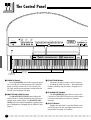 6
6
-
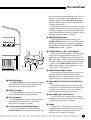 7
7
-
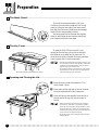 8
8
-
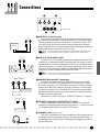 9
9
-
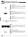 10
10
-
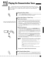 11
11
-
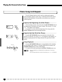 12
12
-
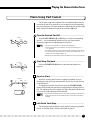 13
13
-
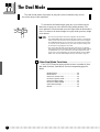 14
14
-
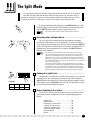 15
15
-
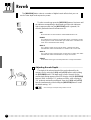 16
16
-
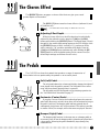 17
17
-
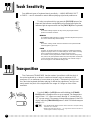 18
18
-
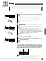 19
19
-
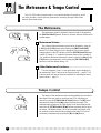 20
20
-
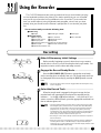 21
21
-
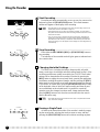 22
22
-
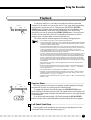 23
23
-
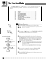 24
24
-
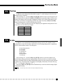 25
25
-
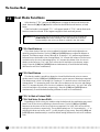 26
26
-
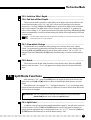 27
27
-
 28
28
-
 29
29
-
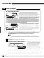 30
30
-
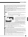 31
31
-
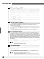 32
32
-
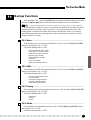 33
33
-
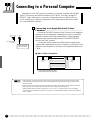 34
34
-
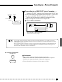 35
35
-
 36
36
-
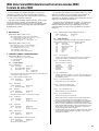 37
37
-
 38
38
-
 39
39
-
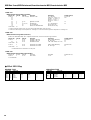 40
40
-
 41
41
-
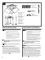 42
42
-
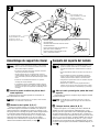 43
43
-
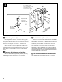 44
44
-
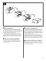 45
45
-
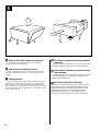 46
46
-
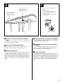 47
47
-
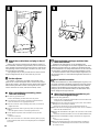 48
48
-
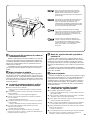 49
49
-
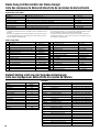 50
50
-
 51
51
-
 52
52
-
 53
53
-
 54
54


Yamaha CLP-555 Handleiding
- Categorie
- Muziekinstrumenten
- Type
- Handleiding
- Deze handleiding is ook geschikt voor
in andere talen
- English: Yamaha CLP-555 User manual
- italiano: Yamaha CLP-555 Manuale utente
- русский: Yamaha CLP-555 Руководство пользователя
- français: Yamaha CLP-555 Manuel utilisateur
- español: Yamaha CLP-555 Manual de usuario
- Deutsch: Yamaha CLP-555 Benutzerhandbuch
- português: Yamaha CLP-555 Manual do usuário
- dansk: Yamaha CLP-555 Brugermanual
- suomi: Yamaha CLP-555 Ohjekirja
- čeština: Yamaha CLP-555 Uživatelský manuál
- svenska: Yamaha CLP-555 Användarmanual
- Türkçe: Yamaha CLP-555 Kullanım kılavuzu
- polski: Yamaha CLP-555 Instrukcja obsługi
- română: Yamaha CLP-555 Manual de utilizare