
EN
SIGNAL PROCESSOR
DME7
V1.1 Reference Manual

Table of contents
Introduction. . . . . . . . . . . . . . . . . . . . . . . . . . . . . . . . . . . . . . . . . . . . . . . . . . . . . . . . . . . . . . . . . . . . . . . . . . . . . . . . . . . . . . Ê3
About the symbols . . . . . . . . . . . . . . . . . . . . . . . . . . . . . . . . . . . . . . . . . . . . . . . . . . . . . . . . . . . . . . . . . . . . . . . . . . . . . Ê3
About this manual . . . . . . . . . . . . . . . . . . . . . . . . . . . . . . . . . . . . . . . . . . . . . . . . . . . . . . . . . . . . . . . . . . . . . . . . . . . . . Ê3
Features. . . . . . . . . . . . . . . . . . . . . . . . . . . . . . . . . . . . . . . . . . . . . . . . . . . . . . . . . . . . . . . . . . . . . . . . . . . . . . . . . . . . . . Ê4
Included items . . . . . . . . . . . . . . . . . . . . . . . . . . . . . . . . . . . . . . . . . . . . . . . . . . . . . . . . . . . . . . . . . . . . . . . . . . . . . . . . Ê4
Available documentation. . . . . . . . . . . . . . . . . . . . . . . . . . . . . . . . . . . . . . . . . . . . . . . . . . . . . . . . . . . . . . . . . . . . . . . . Ê4
About ProVisionaire Design . . . . . . . . . . . . . . . . . . . . . . . . . . . . . . . . . . . . . . . . . . . . . . . . . . . . . . . . . . . . . . . . . . . . . Ê5
About Provisionaire Edge . . . . . . . . . . . . . . . . . . . . . . . . . . . . . . . . . . . . . . . . . . . . . . . . . . . . . . . . . . . . . . . . . . . . . . . Ê5
About Yamaha Steinberg USB Driver . . . . . . . . . . . . . . . . . . . . . . . . . . . . . . . . . . . . . . . . . . . . . . . . . . . . . . . . . . . . . . Ê5
Updating the firmware . . . . . . . . . . . . . . . . . . . . . . . . . . . . . . . . . . . . . . . . . . . . . . . . . . . . . . . . . . . . . . . . . . . . . . . . . . Ê5
Precautions for rack mounting . . . . . . . . . . . . . . . . . . . . . . . . . . . . . . . . . . . . . . . . . . . . . . . . . . . . . . . . . . . . . . . . . . . Ê6
Part names and functions. . . . . . . . . . . . . . . . . . . . . . . . . . . . . . . . . . . . . . . . . . . . . . . . . . . . . . . . . . . . . . . . . . . . . . . . . . Ê7
Front panel . . . . . . . . . . . . . . . . . . . . . . . . . . . . . . . . . . . . . . . . . . . . . . . . . . . . . . . . . . . . . . . . . . . . . . . . . . . . . . . . . . . Ê7
Rear panel . . . . . . . . . . . . . . . . . . . . . . . . . . . . . . . . . . . . . . . . . . . . . . . . . . . . . . . . . . . . . . . . . . . . . . . . . . . . . . . . . . . . Ê9
Making connections . . . . . . . . . . . . . . . . . . . . . . . . . . . . . . . . . . . . . . . . . . . . . . . . . . . . . . . . . . . . . . . . . . . . . . . . . . . . . Ê12
Connecting to the [GPI] ports . . . . . . . . . . . . . . . . . . . . . . . . . . . . . . . . . . . . . . . . . . . . . . . . . . . . . . . . . . . . . . . . . . . Ê12
Connecting a Euroblock plug . . . . . . . . . . . . . . . . . . . . . . . . . . . . . . . . . . . . . . . . . . . . . . . . . . . . . . . . . . . . . . . . . . . Ê12
Installing the cable hook . . . . . . . . . . . . . . . . . . . . . . . . . . . . . . . . . . . . . . . . . . . . . . . . . . . . . . . . . . . . . . . . . . . . . . . Ê14
About Dante . . . . . . . . . . . . . . . . . . . . . . . . . . . . . . . . . . . . . . . . . . . . . . . . . . . . . . . . . . . . . . . . . . . . . . . . . . . . . . . . . . . . Ê15
About connection. . . . . . . . . . . . . . . . . . . . . . . . . . . . . . . . . . . . . . . . . . . . . . . . . . . . . . . . . . . . . . . . . . . . . . . . . . . . . Ê16
Power supply . . . . . . . . . . . . . . . . . . . . . . . . . . . . . . . . . . . . . . . . . . . . . . . . . . . . . . . . . . . . . . . . . . . . . . . . . . . . . . . . . . . Ê19
Connecting the power supply . . . . . . . . . . . . . . . . . . . . . . . . . . . . . . . . . . . . . . . . . . . . . . . . . . . . . . . . . . . . . . . . . . . Ê19
Switching on/off this device . . . . . . . . . . . . . . . . . . . . . . . . . . . . . . . . . . . . . . . . . . . . . . . . . . . . . . . . . . . . . . . . . . . . Ê19
Panel operation . . . . . . . . . . . . . . . . . . . . . . . . . . . . . . . . . . . . . . . . . . . . . . . . . . . . . . . . . . . . . . . . . . . . . . . . . . . . . . . . . Ê20
Basic operations . . . . . . . . . . . . . . . . . . . . . . . . . . . . . . . . . . . . . . . . . . . . . . . . . . . . . . . . . . . . . . . . . . . . . . . . . . . . . Ê20
Muting/Unmuting (Device Mute screen) . . . . . . . . . . . . . . . . . . . . . . . . . . . . . . . . . . . . . . . . . . . . . . . . . . . . . . . . . . Ê21
Enabling/disabling the control function (Control Function screen) . . . . . . . . . . . . . . . . . . . . . . . . . . . . . . . . . . . . Ê22
Alert screen. . . . . . . . . . . . . . . . . . . . . . . . . . . . . . . . . . . . . . . . . . . . . . . . . . . . . . . . . . . . . . . . . . . . . . . . . . . . . . . . . . Ê22
Panel lock . . . . . . . . . . . . . . . . . . . . . . . . . . . . . . . . . . . . . . . . . . . . . . . . . . . . . . . . . . . . . . . . . . . . . . . . . . . . . . . . . . . Ê22
Screens . . . . . . . . . . . . . . . . . . . . . . . . . . . . . . . . . . . . . . . . . . . . . . . . . . . . . . . . . . . . . . . . . . . . . . . . . . . . . . . . . . . . . . . . Ê24
Home screen . . . . . . . . . . . . . . . . . . . . . . . . . . . . . . . . . . . . . . . . . . . . . . . . . . . . . . . . . . . . . . . . . . . . . . . . . . . . . . . . Ê24
[Menu] screen . . . . . . . . . . . . . . . . . . . . . . . . . . . . . . . . . . . . . . . . . . . . . . . . . . . . . . . . . . . . . . . . . . . . . . . . . . . . . . . . Ê25
Screen flowchart . . . . . . . . . . . . . . . . . . . . . . . . . . . . . . . . . . . . . . . . . . . . . . . . . . . . . . . . . . . . . . . . . . . . . . . . . . . . . Ê26
Input Meter/Output Meter. . . . . . . . . . . . . . . . . . . . . . . . . . . . . . . . . . . . . . . . . . . . . . . . . . . . . . . . . . . . . . . . . . . . . . . . . Ê27
Reading the meter . . . . . . . . . . . . . . . . . . . . . . . . . . . . . . . . . . . . . . . . . . . . . . . . . . . . . . . . . . . . . . . . . . . . . . . . . . . . Ê27
Device Information. . . . . . . . . . . . . . . . . . . . . . . . . . . . . . . . . . . . . . . . . . . . . . . . . . . . . . . . . . . . . . . . . . . . . . . . . . . . . . . Ê28
Capacity . . . . . . . . . . . . . . . . . . . . . . . . . . . . . . . . . . . . . . . . . . . . . . . . . . . . . . . . . . . . . . . . . . . . . . . . . . . . . . . . . . . . Ê28
Sampling Frequency . . . . . . . . . . . . . . . . . . . . . . . . . . . . . . . . . . . . . . . . . . . . . . . . . . . . . . . . . . . . . . . . . . . . . . . . . . Ê28
License . . . . . . . . . . . . . . . . . . . . . . . . . . . . . . . . . . . . . . . . . . . . . . . . . . . . . . . . . . . . . . . . . . . . . . . . . . . . . . . . . . . . . Ê28
System Date . . . . . . . . . . . . . . . . . . . . . . . . . . . . . . . . . . . . . . . . . . . . . . . . . . . . . . . . . . . . . . . . . . . . . . . . . . . . . . . . . Ê28
QR Code . . . . . . . . . . . . . . . . . . . . . . . . . . . . . . . . . . . . . . . . . . . . . . . . . . . . . . . . . . . . . . . . . . . . . . . . . . . . . . . . . . . . Ê29
MAC Address . . . . . . . . . . . . . . . . . . . . . . . . . . . . . . . . . . . . . . . . . . . . . . . . . . . . . . . . . . . . . . . . . . . . . . . . . . . . . . . . Ê29
Serial No.. . . . . . . . . . . . . . . . . . . . . . . . . . . . . . . . . . . . . . . . . . . . . . . . . . . . . . . . . . . . . . . . . . . . . . . . . . . . . . . . . . . . Ê29
Dante Version . . . . . . . . . . . . . . . . . . . . . . . . . . . . . . . . . . . . . . . . . . . . . . . . . . . . . . . . . . . . . . . . . . . . . . . . . . . . . . . . Ê29
Firmware Version . . . . . . . . . . . . . . . . . . . . . . . . . . . . . . . . . . . . . . . . . . . . . . . . . . . . . . . . . . . . . . . . . . . . . . . . . . . . . Ê29
Alert Log . . . . . . . . . . . . . . . . . . . . . . . . . . . . . . . . . . . . . . . . . . . . . . . . . . . . . . . . . . . . . . . . . . . . . . . . . . . . . . . . . . . . . . . Ê30
Clearing the log . . . . . . . . . . . . . . . . . . . . . . . . . . . . . . . . . . . . . . . . . . . . . . . . . . . . . . . . . . . . . . . . . . . . . . . . . . . . . . Ê30
Utility . . . . . . . . . . . . . . . . . . . . . . . . . . . . . . . . . . . . . . . . . . . . . . . . . . . . . . . . . . . . . . . . . . . . . . . . . . . . . . . . . . . . . . . . . . Ê31
Panel Setup. . . . . . . . . . . . . . . . . . . . . . . . . . . . . . . . . . . . . . . . . . . . . . . . . . . . . . . . . . . . . . . . . . . . . . . . . . . . . . . . . . Ê31
Exporting/saving (Export File) . . . . . . . . . . . . . . . . . . . . . . . . . . . . . . . . . . . . . . . . . . . . . . . . . . . . . . . . . . . . . . . . . . Ê33
Table of contents
DME7 V1.1 Reference Manual | 1

Selecting the language (Language) . . . . . . . . . . . . . . . . . . . . . . . . . . . . . . . . . . . . . . . . . . . . . . . . . . . . . . . . . . . . . . Ê34
Dante Settings . . . . . . . . . . . . . . . . . . . . . . . . . . . . . . . . . . . . . . . . . . . . . . . . . . . . . . . . . . . . . . . . . . . . . . . . . . . . . . . . . . Ê35
Specifying the sampling frequency (Sample Rate) . . . . . . . . . . . . . . . . . . . . . . . . . . . . . . . . . . . . . . . . . . . . . . . . . Ê35
Specifying the preferred leader (Preferred Leader) . . . . . . . . . . . . . . . . . . . . . . . . . . . . . . . . . . . . . . . . . . . . . . . . . Ê35
Specifying the encoding (Encoding) . . . . . . . . . . . . . . . . . . . . . . . . . . . . . . . . . . . . . . . . . . . . . . . . . . . . . . . . . . . . . Ê35
Specifying the latency (Latency) . . . . . . . . . . . . . . . . . . . . . . . . . . . . . . . . . . . . . . . . . . . . . . . . . . . . . . . . . . . . . . . . Ê35
Specifying the secondary port (Secondary Port) . . . . . . . . . . . . . . . . . . . . . . . . . . . . . . . . . . . . . . . . . . . . . . . . . . . Ê36
Settings . . . . . . . . . . . . . . . . . . . . . . . . . . . . . . . . . . . . . . . . . . . . . . . . . . . . . . . . . . . . . . . . . . . . . . . . . . . . . . . . . . . . . . . . Ê37
Specifying the unit ID (Unit ID) . . . . . . . . . . . . . . . . . . . . . . . . . . . . . . . . . . . . . . . . . . . . . . . . . . . . . . . . . . . . . . . . . . Ê37
Specifying the IP address (IP Settings) . . . . . . . . . . . . . . . . . . . . . . . . . . . . . . . . . . . . . . . . . . . . . . . . . . . . . . . . . . . Ê37
Restoring factory default settings (Initialize Settings) . . . . . . . . . . . . . . . . . . . . . . . . . . . . . . . . . . . . . . . . . . . . . . Ê38
Restarting (Reboot) . . . . . . . . . . . . . . . . . . . . . . . . . . . . . . . . . . . . . . . . . . . . . . . . . . . . . . . . . . . . . . . . . . . . . . . . . . . Ê39
Snapshot Recall . . . . . . . . . . . . . . . . . . . . . . . . . . . . . . . . . . . . . . . . . . . . . . . . . . . . . . . . . . . . . . . . . . . . . . . . . . . . . . . . . Ê40
Restoring factory default settings (initializing) . . . . . . . . . . . . . . . . . . . . . . . . . . . . . . . . . . . . . . . . . . . . . . . . . . . . . . . Ê41
Method of selecting [Settings] > [Initialize Settings] . . . . . . . . . . . . . . . . . . . . . . . . . . . . . . . . . . . . . . . . . . . . . . . . Ê41
If you have forgotten your administrator PIN . . . . . . . . . . . . . . . . . . . . . . . . . . . . . . . . . . . . . . . . . . . . . . . . . . . . . . Ê42
Appendix . . . . . . . . . . . . . . . . . . . . . . . . . . . . . . . . . . . . . . . . . . . . . . . . . . . . . . . . . . . . . . . . . . . . . . . . . . . . . . . . . . . . . . . Ê43
Precautions for the USB port . . . . . . . . . . . . . . . . . . . . . . . . . . . . . . . . . . . . . . . . . . . . . . . . . . . . . . . . . . . . . . . . . . . Ê43
Using USB flash drives . . . . . . . . . . . . . . . . . . . . . . . . . . . . . . . . . . . . . . . . . . . . . . . . . . . . . . . . . . . . . . . . . . . . . . . . Ê43
Precautions for using SD memory cards. . . . . . . . . . . . . . . . . . . . . . . . . . . . . . . . . . . . . . . . . . . . . . . . . . . . . . . . . . Ê44
Using SD memory cards . . . . . . . . . . . . . . . . . . . . . . . . . . . . . . . . . . . . . . . . . . . . . . . . . . . . . . . . . . . . . . . . . . . . . . . Ê44
Distance to furthest DCP control panel . . . . . . . . . . . . . . . . . . . . . . . . . . . . . . . . . . . . . . . . . . . . . . . . . . . . . . . . . . . Ê45
Message List . . . . . . . . . . . . . . . . . . . . . . . . . . . . . . . . . . . . . . . . . . . . . . . . . . . . . . . . . . . . . . . . . . . . . . . . . . . . . . . . Ê46
General specifications. . . . . . . . . . . . . . . . . . . . . . . . . . . . . . . . . . . . . . . . . . . . . . . . . . . . . . . . . . . . . . . . . . . . . . . . . Ê52
Dimensions . . . . . . . . . . . . . . . . . . . . . . . . . . . . . . . . . . . . . . . . . . . . . . . . . . . . . . . . . . . . . . . . . . . . . . . . . . . . . . . . . . Ê54
Block diagram. . . . . . . . . . . . . . . . . . . . . . . . . . . . . . . . . . . . . . . . . . . . . . . . . . . . . . . . . . . . . . . . . . . . . . . . . . . . . . . . Ê55
Table of contents
2 | DME7 V1.1 Reference Manual

Introduction
Thank you for purchasing a Yamaha DME7 signal processor. This device can process a wide range of audio
signals for facility acoustics. This Reference Manual provides explanations for everything necessary to configure
settings and operate the system. In order to take full advantage of the various functions of this device, consult
this Reference Manual whenever necessary.
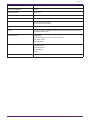
About the symbols
The symbols on this device and in this manual have the following meanings.
Symbol Meaning
Warning This indicates a risk of serious injury or death.
Caution This indicates a risk of injury.
Notice This indicates a risk of product failure, damage or malfunction as well as data loss.
NOTE This indicates content regarding operation and use. Read this for your information.
About this manual
•The illustrations and screens in this manual are for instructional purposes only.
•Windows is a registered trademark of Microsoft Corporation in the United States and other countries.
•“QR Code” is a registered trademark of DENSO WAVE INCORPORATED.
•The company names and product names in this document are the trademarks and registered trademarks
of their respective companies.
•Updates to the software may become available without prior notice.
Introduction
DME7 V1.1 Reference Manual | 3

Features
•Programmable signal processor for audio processing required by sound systems for a wide variety of
applications
The DME7 is a freely configurable processor with sophisticated functionality and high audio quality,
providing the audio processing required by sound systems for a wide variety of applications. In addition to
basic matrix mixer, equalizer, delay, compressor and gate functionality, it includes many components
supporting a variety of applications, such as Automixer and Room Combiner. It even supports large-scale
sound systems with up to 256 × 256 Dante input/output channels*.
(* Increasing the number of channels requires additional licenses.)
•ProVisionaire Design application software can be used to design the overall sound system
The application software ProVisionaire Design enables you to not only freely program DME7 audio
processing but also design an integrated sound system that includes inputs/outputs and amplifiers.
•Supports external control
Various DCP (wall-recessed control panel) models are supported. It also supports ProVisionaire Control
and the tablet software ProVisionaire Touch Kiosk, which allow you to customize their design as well as
the operating environment based on the given equipment application.
Included items
•One Setup Guide
•Two Euroblock plugs (16-pin, 3.50 mm pitch)
•Two power cords
•One cable hook
Available documentation
•DME7 Setup Guide (included with this device)
Describes the setup procedure from connecting the power supply to setting up the system.
•DME7 Reference Manual (this document)
Explains everything necessary for configuring settings and operating the system.
•ProVisionaire Design User Guide (HTML)
Describes how to operate the ProVisionaire Design software used to control this device from a computer.
Introduction
4 | DME7 V1.1 Reference Manual

About ProVisionaire Design
This Windows application software integrates settings for devices such as signal processors, power amplifiers,
and audio interfaces.
Download ProVisionaire Design from the following website.
https://www.yamahaproaudio.com/
For details, refer to the ProVisionaire Design User Guide (HTML).
https://manual.yamaha.com/pa/pv/pvd/
About Provisionaire Edge
This software is for monitoring local network devices. ProVisionaire Edge must be installed to monitor the
DME7. Download the software from the website below.
https://www.yamahaproaudio.com/
About Yamaha Steinberg USB Driver
This driver software is for connecting the DME7 to a computer via USB.
Up to 8 input/8 output audio signals can be exchanged with DAW software.
The driver software can be downloaded from the following website.
https://www.yamahaproaudio.com/
Updating the firmware
This device is designed to allow its firmware to be updated for the purpose of improving operability, adding
functionality, and fixing bugs.
When a firmware update is available, relevant information will be posted on the following website.
https://www.yamahaproaudio.com/
For details on the updating procedure and device settings, refer to the ProVisionaire Design User Guide (HTML).
NOTE
•The Dante firmware is updated with Dante Updater. Dante Updater can be opened from Dante
Controller.
•Other devices may need to be updated, depending on the version of each device in the Dante
network. For details, check the firmware compatibility chart provided on the Yamaha website
mentioned above.
Introduction
DME7 V1.1 Reference Manual | 5

Precautions for rack mounting
The guaranteed operating temperature range for this device is 0 to 40 °C. When multiple DME7 devices are
mounted and operated on a standard EIA rack, it is not necessary to leave space between them. When this
device is mounted on a standard EIA rack together with other devices, heat generated from those devices may
impair performance due to the elevated temperature in the rack. In order to prevent heat from building up inside
this device, be sure to mount it in a manner that satisfies the following conditions.
•When mounted together with a power amplifier or other devices that tend to generate heat, leave at least
1U of space between this device and other devices. In addition, in order to ensure adequate ventilation,
install vented panels at those spaces or leave the spaces open.
•This device is designed to intake air at the front and exhaust it at the rear, so do not install it together with
other devices that intake air at the rear and exhaust it at the front.
•Leave the rear of the rack open and the rack positioned at least 10 cm away from the wall and ceiling. If
the rear of the rack cannot be left open, use a commercially available fan kit or other forced air ventilation
system. If a fan kit is installed, note that closing off the rear of the rack can improve heat dissipation in
some cases. For details, refer to the instruction manuals for the rack and fan kit.
Introduction
6 | DME7 V1.1 Reference Manual

Part names and functions
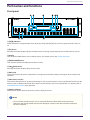
Front panel
① [A]/[B] indicators
These indicate the energized state of AC IN (power inlet) jacks [A]/[B]. They are lit in green when this device is
on.
② [Fn] button
Pressing this button displays the Device Mute screen. Pressing it again displays the Control Function screen.
③ Display
This shows the DME7 status or the settings menus. For details, refer to the “screen flowchart”.
④ [MENU/HOME] button
This switches between the [Menu] and Home screens.
⑤ (back) button
Pressing this button displays the previous screen.
⑥ Main knob
Turning the main knob selects a parameter or changes the parameter setting. Pressing the knob confirms the
selection.
⑦ SD memory card slot
Project files transferred from ProVisionaire Design or the log for this device can be exported and saved to an SD
memory card. In addition, MP3/WAV files saved to an SD memory card can be played back. For details, refer to
“Using SD memory cards” in the Appendix.
⑧ SD/ACT indicator
This indicator flashes while an SD memory card is being accessed.
Notice
•Do not remove the SD memory card or switch off this device while data is being accessed.
Otherwise, the storage media may become damaged, or data on this device and the media may
become corrupted.
Part names and functions
DME7 V1.1 Reference Manual | 7

⑨ Intake vent
Since air is taken in through here, be sure not to obstruct the intake vent.
Part names and functions
8 | DME7 V1.1 Reference Manual

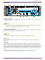
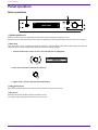
Rear panel
① / (power switch)
This switches this device on ( )/off ( ). Before extended periods of disuse, be sure to disconnect the power
cords from the AC outlets.
Caution
•Flipping the power switch on and off in rapid succession may cause a malfunction. Before switching
this device on again after switching it off, wait at least six seconds.
② AC IN (power inlet) jacks [A]/[B]
Connect the included power cords here. Connect the power cord to this device, and then plug it into an AC outlet.
Press the power plug latch when disconnecting the power cord.
Caution
•Be sure to switch off this device before connecting or disconnecting a power cord.
③ Exhaust vent
The DME7 is equipped with a cooling fan. Since air is exhausted through here, be sure not to obstruct the
exhaust vent.
④ [GPI] ports
These are Euroblock connectors for GPI (General Purpose Interface), which input and output control signals.
With GPI inputs and outputs, the DME7 can be remotely controlled from custom-made controllers and external
devices. The DME7 has 15 analog/digital input terminals, 1 digital input terminal, and 8 output terminals. At [IN]
terminals 1 to 15, voltages between 0 and 5 V are detected. Only at [IN] terminal 16, +24 V input is supported, and
voltages between 2.5 V and 24 V are identified as high and voltages below 2.5 V as low. [OUT] terminals 1 to 8
are open collector outputs, which switch between open and ground. The output voltage of the +5 V DC terminal
is 5 V.
Use the included Euroblock plug for making connections (refer to “Connecting a Euroblock plug”).
For detailed connection methods and usage examples, refer to “Connecting to the [GPI] ports”.
Part names and functions
DME7 V1.1 Reference Manual | 9

Caution
•Do not input voltages exceeding 5 V to [IN] terminals 1 to 15. Otherwise, failure of this device may
occur.
⑤ [USB TO HOST] port
This is a USB Type C (USB 2.0) port.
When connected to a computer with a USB cable, this device functions as an audio interface with up to 8
inputs/8 outputs and a maximum sampling frequency of 96 kHz.
Notice
•Use a USB cable of 3 m or less.
•Before connecting the USB cable again after disconnecting it, wait at least six seconds.
⑥ [USB TO DEVICE] port
This port is for connecting a USB flash drive. For details, refer to “Using USB flash drives”.
Notice
•Do not remove the USB flash drive or switch off this device while data is being accessed. Otherwise,
the storage media may become damaged, or data on this device and the media may become
corrupted.
⑦ Network port
This port is for control communication with external devices. The secure copy protocol (SCP) allows
communication with a computer (ProVisionaire Design, ProVisionaire Control, or ProVisionaire Touch Kiosk) or
other external controllers (AMX, Crestron, etc.).
10/100BASE-TX and Auto MDI (no mode switching) functionality is supported.
NOTE
•Only when using a standalone DME7 can you connect it directly to a computer with a LAN cable.
⑧ [MIDI] ports
These ports are for sending and receiving MIDI messages to and from an external MIDI device.
⑨ [DCP] port
This port is for controlling the DME7 by daisy-chaining separately sold control panels such as the DCP1V4S. Use
a straight-through CAT5e or higher Ethernet cable with all 8 contacts used.
Up to eight control panels can be connected to one DME7. Also, the distance from the DME7 to the furthest DCP
control panel varies depending on the number of connected DCP units. For details, refer to “Distance to furthest
DCP control panel”.
Part names and functions
10 | DME7 V1.1 Reference Manual

Warning
•Do not connect a control panel to any port other than the [DCP] port of the DME7. Otherwise, a fire or
malfunction may occur due to electrical incompatibility.
Notice
•Never connect a device other than a separately sold control panel such as a DCP to the [DCP] port.
Otherwise, failure of this device or other devices may occur.
⑩ [PRIMARY]/[SECONDARY] Dante ports
These ports are for connecting I/O devices such as the Rio3224-D2 to the Dante audio network. Use cables with
RJ-45 plugs that comply with Neutrik’s etherCON CAT5e.
Part names and functions
DME7 V1.1 Reference Manual | 11

Making connections
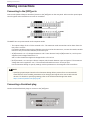
Connecting to the [GPI] ports
Connect GPI (General Purpose Interface) devices to the [GPI] ports on the rear panel. GPI is used to input/output
control signals with external devices such as controllers.
The DME7 has 16 input terminals and 8 output terminals.
•The output voltage of the +5 V DC terminal is 5 V. The maximum total current that can be drawn from the
two ports is 100 mA.
If a switch/variable resistor and an LED/relay are to be used at the same time, connect the switch/variable
resistor to one port and the LED/relay to the other port.
•At [IN] terminals 1 to 15, voltages between 0 and 5 V are detected. Only at [IN] terminal 16, +24 V input is
supported, and voltages between 2.5 V
and 24 V are identified as high and voltages below 2.5 V as low.
•[OUT] terminals 1 to 8 are open collector outputs, which switch between open and ground. The maximum
voltage that can be applied is +12 V. The maximum allowable current is 75 mA per port.
Use ProVisionaire Design to specify settings such as parameters to be assigned to GPI controllers.
NOTE
•Specifying input/output channels in ProVisionaire Design allows presets from a connected GPI
external device to be recalled, parameters to be changed, and signals to be sent to GPI external
devices. For details on specifying settings, refer to the ProVisionaire Design User Guide.
https://manual.yamaha.com/pa/pv/pvd/
Connecting a Euroblock plug
Use the included Euroblock plugs to connect to the [GPI] ports.
Making connections
12 | DME7 V1.1 Reference Manual

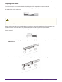
Preparing cable wires
The cable wires to be connected to the Euroblock plug should be stripped as shown and twisted.
Note that the cable wire strands connected to Euroblock plugs may easily break due to metal fatigue caused by
the weight of the cable or vibration.
Caution
•Do not apply solder to stranded wires.
If wires will be frequently disconnected and reconnected as in a portable setup, the use of pin terminals with
insulation sleeves is recommended. Use pin terminals with a conductor portion as shown below.
With an outer diameter of 1.3 mm or less and a length of about 5 mm (such as AI0, 5-6WH manufactured by
Phoenix Contact)
1. Push in the Euroblock plug until it is firmly seated in the [GPI] port on this device, and then raise the left
and right locks.
2. To remove a Euroblock plug, lower the left and right locks, and then pull out the plug.
Making connections
DME7 V1.1 Reference Manual | 13

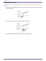
Installing the cable hook
To prevent the USB cable from being accidentally disconnected, follow the steps below to install the included
cable hook.
1. Hook one end of the included cable hook into the lower end of the security slot, located in the lower-left
area of the rear panel.
2. Insert the other end of the hook into the upper end of the security slot.
3. Pass the USB cable through the hook, and then connect it to the USB port.
Making connections
14 | DME7 V1.1 Reference Manual

About Dante
■ Overview of Dante
The DME7 transmits digital audio signals by using the Dante protocol. Dante is a network audio protocol
developed by Audinate. In a network environment compatible with Gigabit Ethernet, Dante has the advantage of
being able to transmit multiple audio signals with different sampling frequencies/bit rates as well as device
control signals within the same network.
For details on Dante, refer to the Audinate website.
http://www.audinate.com/
In addition, a variety of information about Dante can be found on the Yamaha Pro Audio website.
https://www.yamahaproaudio.com/
NOTE
•With a Dante network, do not use the EEE function* of the network switch.
The EEE function may deteriorate the clock synchronization performance and interrupting audio.
Therefore, please note the following.
◦When using managed switches, turn off the EEE function on all ports used for Dante. Do not
use a switch that does not allow the EEE function to be turned off.
◦When using unmanaged switches, do not use switches that support the EEE function. In such
switches, the EEE function cannot be turned off.
Ê*EEE (Energy-Efficient Ethernet) function: Technology that reduces the power consumption of Ethernet
devices during periods of low network traffic; also known as Green Ethernet or IEEE802.3az
About Dante
DME7 V1.1 Reference Manual | 15

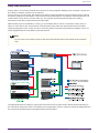
About connection
There are two methods of connecting this model to a Dante network, and they can be used in combination.
Redundant connection
A redundant connection allows you to build a system that is more resistant to network failures than a daisy-
chained network. A redundant connection consists of two circuits, a primary (main) circuit and a secondary (sub)
circuit. Communication normally occurs on the primary circuit, but automatically switches to the secondary
circuit if a problem occurs, such as the primary circuit being disconnected.
NOTE
•If you wish to run Dante audio network and ProVisionaire Design’s network on the same computer,
connect them using separate network interface cards.
About Dante
16 | DME7 V1.1 Reference Manual

Daisy-chain connection
A daisy chain is a connection method where devices are strung together. Building such a network is simple and
the number of network switches can be reduced.
As more devices are connected, the transmission delay increases between the devices furthest apart, requiring
the latency setting to be increased in order to prevent sound interruptions on the Dante network. Moreover, if a
system failure occurs due to a broken cable, etc., the network will be interrupted at that point, making
transmission with devices beyond that point impossible.
With the latency set to the default (1.0 msec), up to ten Dante devices can be connected in a daisy chain. If
eleven or more devices are connected, the communication delay within the network will increase, possibly
causing interruptions in the sound. In order to avoid this, either increase the Dante latency setting or use an L2
switch (Gigabit Ethernet compatible) to split the network.
NOTE
•Do not connect more than one port to the same external switch since this would create a network
loop.
The appropriate latency setting for signals sent and received over a Dante audio network differs depending on
the connection method and scale. The following is an explanation of how to select the [Latency] setting based on
the connections between Dante-compatible devices and the DME7.
About Dante
DME7 V1.1 Reference Manual | 17

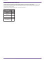
■ Relationship between latency and hop count
The [Latency] setting for the Dante audio network depends on the hop count in that network.
The hop count is the number of switches between the farthest connections of Dante devices. A switch is built
into not only each switching hub but also each DME7 and I/O device. The hop count provides a guideline for
specifying the [Latency] setting.
Typical [Latency] settings for various hop counts are shown below.
Hop count Latency
(ms)
Up to 3 0.25
Up to 5 0.5
Up to 10 1.0
Up to 20 2.0
21 or more
(or if problems occur) 5.0
About Dante
18 | DME7 V1.1 Reference Manual

Power supply
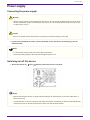
Connecting the power supply
Warning
•Always use the power cords included with this device. Do not use the included power cords for other
devices. Otherwise, failure, overheating or fire may occur. The included power cords are only for use
in Japan (up to 125 V).
Caution
•Be sure to switch off this device before connecting or disconnecting a power cord.
1. Connect the included power cords. Connect the power cord to this device, and then plug it into an
electrical outlet.
NOTE
•To disconnect a power cord, reverse the above procedure.
•Press the power plug latch when disconnecting the power cord.
Switching on/off this device
1. Switch this device on ( )/off ( )with the power switch on its rear panel.
Notice
•Before switching this device on again after switching it off, wait at least six seconds. Otherwise, a
failure may occur.
•A small amount of current is flowing, even when this device is switched off. Before extended periods
of disuse, be sure to disconnect the power cords from the electrical outlets.
Power supply
DME7 V1.1 Reference Manual | 19

Panel operation
Basic operations
① [MENU/HOME] button
When the Home screen is displayed, pressing this button displays the [Menu] screen.
When any screen other than the Home screen is displayed, pressing this button returns to the Home screen.
② Main knob
This moves the cursor or changes parameter settings. For parameters with a wide setting range, the speed at
which the knob is turned affects the speed at which the setting changes.
1. Turn the main knob to select an item. The selected item is highlighted.
2. Press the main knob to confirm the selection.
3. Repeat steps 1 and 2 to edit the desired parameter.
③ (back) button
Each press of this button moves up one level or back to the previous screen.
④ [Fn] button
Pressing this button displays the Device Mute screen.
Pressing it again displays the Control Function screen.
Panel operation
20 | DME7 V1.1 Reference Manual

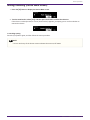
Muting/Unmuting (Device Mute screen)
1. Press the [Fn] button to display the Device Mute screen.
2. Turn the main knob to select [Yes], and then press the knob to confirm the selection.
If this device is already muted, a screen (shown below) appears, prompting you to confirm whether to
unmute this device.
● Canceling muting
Press the [Fn] button again, and then follow the same procedure.
NOTE
•An icon at the top of the Home screen indicates the mute on/off status.
Panel operation
DME7 V1.1 Reference Manual | 21

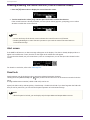
Enabling/disabling the control function (Control Function screen)
1. Press the [Fn] button twice to display the Control Function screen.
2. Turn the main knob to select [Yes], and then press the knob to confirm the selection.
If the control function is already disabled, a screen (shown below) appears, prompting you to confirm
whether to enable the control function.
NOTE
•An icon at the top of the Home screen indicates the control function on/off status.
•Enabling/disabling the control function operates in sync with the Control Function button in
ProVisionaire Design.
Alert screen
If the DME7 malfunctions, an alert message will appear on the display. If an alert is already displayed when a
higher level malfunction occurs, the alert for the higher level malfunction will appear.
To view the alert details, use your smart device, such as a smartphone, to scan the QR code indicated on the
screen.
For details on each alert, refer to the “Message list”.
Panel lock
Panel operation can be locked in order to prevent accidental parameter changes.
Holding down the [MENU/HOME] and (back) buttons at the same time for at least two seconds locks the
panel.
A 4-digit authentication number (called a PIN code) can be set.
Specify the PIN code by selecting Utility > Panel Setup > Enable Unlock PIN. If you have forgotten the PIN code
that you set for panel lock, you can unlock the panel operation in ProVisionaire Design.
NOTE
•While the panel is locked, you can display only the Input Meter and Output Meter screens.
Panel operation
22 | DME7 V1.1 Reference Manual

● Unlocking the panel
If the panel is operated while it is locked, the following message will appear on the display.
While the panel is locked, again holding down the [MENU/HOME] and (back) buttons at the same time for
at least two seconds unlocks the panel.
If Enable Unlock PIN is set to [On], the PIN code input screen will appear.
Panel operation
DME7 V1.1 Reference Manual | 23

Screens
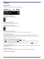
Home screen
The Home screen appears after this device is switched on.
① Device Mute status indicator
This indicates the mute on/off status.
Off
On
② Panel lock status indicator
A key icon appears when the panel is locked.
③ Control function status indicator
This indicates the control function on/off status.
On
Off
④ SD memory card status indicator
An icon appears when an SD memory card is inserted into the SD memory card slot.
⑤ Word clock status indicator
When the word clock is locked, the sampling frequency (44.1 kHz, 48 kHz, 88.2 kHz or 96 kHz) appears.
If the word clock is unlocked or if the configuration data has not been transferred from ProVisionaire Design,
“Unlocked” will appear on the screen.
⑥ DDM (Dante Domain Manager) status indicators
When the device belongs to the DDM domain, the icon appears.
The icon (Read Write: editable) or the icon (Read Only: not editable) appears depending on the LOCAL
CONTROLLER ACCESS setting on the DDM server.
If the device belongs to the DDM domain but is not connected to the DDM server, the icon also appears.
⑦ Scheduler status indicator
If the Scheduler has been configured, the clock icon will appear. The icon starts flashing one minute prior to the
scheduled event.
⑧ Unit ID and device name
The unit ID and device name are displayed. This name can be changed in ProVisionaire Design.
⑨ Name of last recalled snapshot
Screens
24 | DME7 V1.1 Reference Manual

[Menu] screen
The following screens can be accessed from the [Menu] screen.
•[Input Meter] screen
•[Output Meter] screen
•[Device Information] screen
•[Alert Log] screen
•[Utility] screen
•[Dante Settings] screen
•[Settings] screen
•[Snapshot Recall] screen
With the [Menu] screen displayed, turn the main knob to select the desired screen, and then press the main knob
to display the respective setting or parameter.
● Moving up one level in the [Menu] screen
Press the back button.
NOTE
•The path of the displayed screen appears at the top of the screen.
● Displaying the Home screen
With the [Menu] screen displayed, press the [HOME/MENU] button.
Screens
DME7 V1.1 Reference Manual | 25

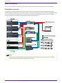
Screen flowchart
Screens
26 | DME7 V1.1 Reference Manual

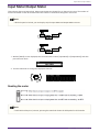
Input Meter/Output Meter
This indicates the input/output level. Dante input/output is indicated for 16 channels at a time. The number of
licenses activated on this device determines the number of channels that appear in this meter.
NOTE
•While the panel is locked, you can display only the Input Meter and Output Meter screens.
1. With the [Menu] screen displayed, turn the main knob to select [Input Meter] or [Output Meter], and then
press the main knob.
2. Turn the main knob to change the displayed channels.
Reading the meter
NOTE
•Peak Hold is always on; however, pressing the main knob clears the held peaks for all channels.
Input Meter/Output Meter
DME7 V1.1 Reference Manual | 27

Device Information
This displays the status of and information specific to this device.
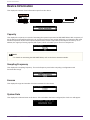
Capacity
This displays the capacity as a result of activating the optional expansion kit DEK-DME7-DX64. With a capacity of
64, the Dante inputs/outputs will be 64 × 64, and the maximum matrix output will be 64 × 64 channels. With each
activated expansion kit, the Dante inputs/outputs and the matrix component inputs/outputs increase by 64. In
addition, the signal processing capacity will expand, which will enable you to use more components.
NOTE
•For details on activating the DEK-DME7-DX64, refer to the Device Activation Guide.
Sampling Frequency
This displays the sampling frequency. This is the frequency used when compiling a configuration with
ProVisionaire Design.
License
This displays the type and number of licenses activated on this device.
System Date
This displays the date and time on the device. If the Scheduler has been configured, the clock icon will appear.
Device Information
28 | DME7 V1.1 Reference Manual

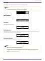
QR Code
This displays a QR code that can be scanned when activating a license.
NOTE
•For details on activating, refer to the Device Activation Guide.
MAC Address
This displays the MAC address.
Serial No.
This displays the serial number.
Dante Version
This displays the version of the Dante firmware. From the left, the Dante firmware version, Dante hardware
version and Yamaha software version are displayed.
Firmware Version
This displays the version of the DME7 device firmware.
NOTE
•Update the firmware with ProVisionaire Design.
For details, refer to the ProVisionaire Design User Guide (HTML).
The latest firmware can also be downloaded from the download page of the Yamaha Pro Audio
website.
https://www.yamahaproaudio.com/
Device Information
DME7 V1.1 Reference Manual | 29

Alert Log
This allows you to check the alert log recorded in the DME7. The log displays the alerts in the order that they
occurred.
Up to 3000 alerts are saved.
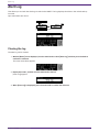
Clearing the log
The alert log can be cleared.
1. With the [Menu] screen displayed, turn the main knob to select [Alert Log], and then press the knob to
confirm the selection.
The most recent alert appears.
2. Display alert 0001, and then turn the main knob to the left.
[Clear Log] appears.
3. When [Clear Log] is displayed, press the main knob to confirm the selection.
Alert Log
30 | DME7 V1.1 Reference Manual

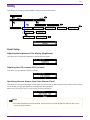
Utility
This allows you to specify general DME7 settings and check information.
Panel Setup
Adjusting the brightness of the display (Brightness)
This allows you to adjust the brightness of the display backlight.
Adjusting the LCD contrast (LCD Contrast)
This allows you to adjust the display contrast.
Specifying the auto dimmer time (Auto Dimmer Time)
This allows you to specify the length of time (after this device has not been operated for a certain period of time)
for the display to reach the brightness specified with [Dimmer Ratio].
Select from [10 sec], [30 sec], [1 min], [3 min], [30 min], and [Never].
NOTE
•Even after the display has been dimmed, it will return to its normal brightness when an alert occurs
or during synchronization.
Utility
DME7 V1.1 Reference Manual | 31

Specifying the dimmer ratio (Dimmer Ratio)
This allows you to specify the brightness of displays after this device has not been operated for a certain period
of time.
Select a value between 0% (off) and 75%.
Specifying the auto lock time (Auto Lock Time)
This allows you to specify the length of time after this device has not been operated until the panel is
automatically locked.
Select from [10 sec], [30 sec], [1 min], [3 min], [30 min], [1 hour], and [Never].
Specifying a PIN code for unlocking the panel (Enable Unlock PIN)
When this is set to [On], PIN code authentication is required in order to unlock the panel.
When this is changed from [Off] to [On], the PIN code input screen appears.
Utility
32 | DME7 V1.1 Reference Manual

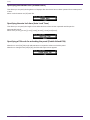
Exporting/saving (Export File)
Alert logs and project files can be saved to an SD memory card or USB flash drive. Project files can be
transferred from ProVisionaire Design to the DME7 device.
1. Turn the main knob to select [Export File], and then press the knob to confirm the selection.
2. Turn the main knob to select the item to be saved, and then press the knob to confirm the selection.
If an administrator PIN has been specified, type the PIN code into the PIN input screen that appears.
NOTE
•Administrator PIN is a code used to prevent the device settings from being modified via
ProVisionaire Design.
For details, refer to the ProVisionaire Design User Guide.
A screen to confirm the save destination appears. If you select a USB flash drive as the save destination, “To
USB Memory” will appear instead.
NOTE
•At this time, “Not Inserted” appears at the bottom of the display if no media has been inserted,
“Unsupported Format” if the media is not formatted or mounted, or “Write Protected” if the media is
write-protected.
3. Turn the main knob to select the save destination, and then press the knob to confirm the selection.
Follow the on-screen instructions to save the data.
NOTE
•Pressing the main knob during the export process stops the operation.
Utility
DME7 V1.1 Reference Manual | 33

Selecting the language (Language)
You can select one of two language types.
Type1: Japanese kanji, hiragana, katakana, English, all European languages
Type2: Chinese characters, Japanese hiragana, katakana, English, all European languages
Utility
34 | DME7 V1.1 Reference Manual

Dante Settings
This specifies settings related to the Dante network.
NOTE
•Settings in Dante Controller are changed in sync with the parameters in this [Dante Settings] screen.
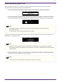
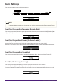
Specifying the sampling frequency (Sample Rate)
This allows you to specify the Dante input/output sampling frequency. Select from [44.1 kHz], [48 kHz], [88.2
kHz], and [96 kHz].
Specifying the preferred leader (Preferred Leader)
Selecting [On] sets this device to be “Preferred Leader” (device supplying the master clock).
If more than one device is set to be “Preferred Leader”, the device with the lowest MAC address will be used.
Specifying the encoding (Encoding)
This allows you to specify the Encording (number of quantization bits). Select from [24 bit] or [32 bit].
Specifying the latency (Latency)
This allows you to specify the latency for signals sent and received over a Dante network.
Select from [0.25 ms], [0.5 ms], [1 ms], [2 ms], and [5 ms].
The appropriate latency setting for signals sent and received over a Dante network differs depending on the
connection method and scale.
Dante Settings
DME7 V1.1 Reference Manual | 35

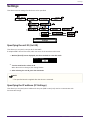
Specifying the secondary port (Secondary Port)
Select [Redundant] or [Daisy Chain] for the connection method for the two Dante ports.
After the setting is changed, a message appears, prompting you to restart this device.
NOTE
•The setting is applied after this device is restarted.
Dante Settings
36 | DME7 V1.1 Reference Manual

Settings
This allows various settings for this device to be specified.
Specifying the unit ID (Unit ID)
This allows you to specify a unique ID for the DME7.
If multiple DME7 devices are used, make sure none of the unit IDs are the same.
1. With the [Unit ID] screen displayed, turn the main knob to enter edit mode.
2. Turn the main knob to select an ID.
When the unit ID is changed, the setting flashes.
3. After selecting the unit ID, press the main knob.
NOTE
•The specified unit ID is applied after this device is restarted.
Specifying the IP address (IP Settings)
This allows you to specify the IP address for the port (DME control port) used to communicate with
ProVisionaire Design.
Settings
DME7 V1.1 Reference Manual | 37

Specifying the network mode (Network Mode)
This allows you to select the mode for setting the IP address of the DME7 manually or automatically (for
example, by using a DHCP server).
NOTE
•For details on the modes, refer to the ProVisionaire Design User Guide.
•The IP address and network mode settings will take effect after you restart this device.
•If this is set to [DHCP], the IP address will be automatically specified by the DHCP server. If there is no
DHCP server, no IP address will be specified.
•If this is set to [Static IP], select [IP Settings] > [DME Control Port] > [IP Address]. Manually specify the IP
address and subnet mask. Set the DME Control Port and Device Control Port addresses to different
subnets.
•If this is set to [Unit ID], the IP address is specified based on the unit ID.
This sets the IP address to 192.168.0.x (where “x” is the unit ID) and the subnet mask to 255.255.255.0.
Displaying/specifying the subnet mask (Subnet Mask)
This displays the subnet mask. If [Static IP] was selected as the mode for specifying the IP address, this allows
you to specify the subnet mask.
Displaying/specifying the default gateway (Default Gateway)
You can view and specify the default gateway.
Restoring factory default settings (Initialize Settings)
This allows you to initialize all internal data.
NOTE
•For details on initializing, refer to “Restoring factory default settings (initializing)”.
Settings
38 | DME7 V1.1 Reference Manual

Restarting (Reboot)
This allows you to change multiple parameter settings that require a restart, then to reboot to apply all settings
at once.
Settings
DME7 V1.1 Reference Manual | 39

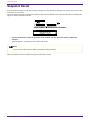
Snapshot Recall
In ProVisionaire Design, you can store (save) a snapshot of the parameter settings at a certain point in time, then
recall them as necessary.
Use ProVisionaire Design to select the snapshots that will be available to be recalled to this device. Nothing will
appear if nothing has been selected.
1. Turn the main knob to select the snapshot to be recalled, and then press the knob to confirm the
selection.
A screen appears, prompting you to confirm the recall.
NOTE
•Do not switch off this device while a snapshot is being recalled.
After a snapshot has been recalled, it appears in the Home screen.
Snapshot Recall
40 | DME7 V1.1 Reference Manual

Restoring factory default settings (initializing)
There are two methods to initialize this device.
Method of selecting [Settings] > [Initialize Settings]
Do not switch off this device while it is being initialized.
1. With the [Menu] screen displayed, turn the main knob to select [Initialize Settings], and then press the
knob to confirm the selection.
2. Turn the main knob to select an item to be initialized, and then set it to [On].
In addition to signal processing settings, the following items that have been set to [On] will be initialized.
•IP Settings
•Unit ID/ Device Name
•Dante Settings
•Stored Files
NOTE
•This regular initialization process does not initialize the administrator PIN or license activation
information.
3. After selecting the desired settings, turn the main knob to select [Initialize], and then press the knob.
This device automatically restarts when initialization is finished.
Restoring factory default settings (initializing)
DME7 V1.1 Reference Manual | 41

If you have forgotten your administrator PIN
If you cannot initialize the unit in the Settings screen because you have forgotten your administrator PIN or due
to some other reason, follow the steps below to perform a forced initialization:
Notice
•This forced initialization process does not initialize license activation information, but returns all
other parameters to their factory default settings.
1. While holding down the [Fn], [MENU/HOME] and [ ] (back) buttons, switch on this device.
2. Keep holding down the three buttons until the Yamaha logo and the initialization screen appear in the
display.
This device automatically restarts when initialization is finished.
Restoring factory default settings (initializing)
42 | DME7 V1.1 Reference Manual

Appendix
Precautions for the USB port
● USB devices that can be used
•Use a USB flash drive. Other USB devices (USB hubs, mice, computer keyboards, etc.) cannot be used
even if they can be connected.
•USB 1.1 to 2.0 USB flash drives can be used with this device (however, operation of all USB flash drives is
not guaranteed).
The rating of the USB port is a maximum of 5 V/500 mA. Connecting a device that requires more than 500 mA of
current will stop the power supply to this device.
● Connecting a USB flash drive
•Do not remove or install the USB flash drive while data is being written to it. Otherwise, this device may
stop functioning, or the USB flash drive or its data may become corrupted.
•Before installing the USB flash drive again after removing it, wait a few seconds.
Notice
•When using a USB extension cable, be sure that it is 1 m or less.
Using USB flash drives
● Formatting a USB flash drive
Use a USB flash drive formatted to FAT32 or FAT16. Use a computer to format. USB flash drives formatted with
other devices may not work properly with this device.
● Preventing accidental data loss
Some USB flash drives have a write-protect function to prevent accidental deletion of data. If the USB flash drive
contains important data, write-protect it to prevent overwriting. Likewise, before adding data to the USB flash
drive, for example, be sure to remove write protection.
● Switching off this device with a USB flash drive installed
Do not switch off this device while data is being written. Otherwise, the USB flash drive or its data may become
corrupted.
Appendix
DME7 V1.1 Reference Manual | 43

Precautions for using SD memory cards
● SD memory cards that can be used
•Use memory cards with the SD or SDHC format. (The SDXC format is not supported).
● Supported file specifications
WAV files
File extension .wav only.
Sampling rates of 44.1 kHz, 48 kHz, 88.2 kHz and 96 kHz are supported.
16-bit, 24-bit and 32-bit PCM monaural and stereo are supported.
MP3 files
Only one MPEG audio is supported.
Layer III is supported (only extension .mp3); free format is excluded.
Sampling rates of 32 kHz, 44.1 kHz and 48 kHz are supported.
Bit rates of 32 to 320 kbps and VBR (variable bit rate) are supported.
● Inserting an SD memory card
•Do not insert or remove the SD memory card while the SD/ACT indicator is lit. Otherwise, this device may
stop functioning, or the SD memory card or its data may become corrupted.
•Before inserting the SD memory card again after removing it, wait a few seconds.
Using SD memory cards
● Formatting an SD memory card
•Use an SD memory card formatted to FAT16 for SD or formatted to FAT32 for SDHC. Use a computer to
format. SD memory cards formatted with other devices may not work properly with this device.
● Preventing accidental data loss
•SD memory cards have a locking switch to prevent accidental deletion of data. If the SD memory card
contains important data, lock it to prevent overwriting. Likewise, before adding data to the SD memory
card, for example, be sure to unlock it.
● Switching off this device with an SD memory card inserted
•Before switching off this device, make sure that the SD/ACT indicator is not lit. Otherwise, the SD memory
card or its data may become corrupted.
Appendix
44 | DME7 V1.1 Reference Manual

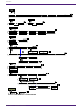
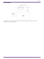
Distance to furthest DCP control panel
The distance from the DME7 to the furthest DCP control panel depends on the number of connected DCPs.
Example 1. When there are 8 DCP devices
DME7 DCP DCP DCP DCP DCP DCP DCP
DCP
200m
Example 2. When there are 2 DCP devices
For the relationship between the number of connected devices and the distance, refer to the following table.
No. of
connected
DCPs
Distance from
DME7 to furthest
DCPs
1 1000 m
2 850 m
3 550 m
4 400 m
5 350 m
6 250 m
7 250 m
8 200 m
NOTE
•Use a DCH8, a digital controller hub, to make a star connection.
Appendix
DME7 V1.1 Reference Manual | 45

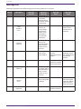
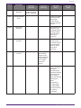
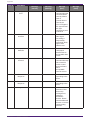
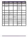
Message List
Messages displayed on the DME7 display and countermeasures are as follows.
Data ID Data Name Message
[Normal]
Message
[Warning]
Message
[Error]
Message
[Fault]
30002 EXT TEMP Limit - Environmental
temperature
exceeded device
upper limit. Please
check air flow.
- -
30009 FAN
Rotation
Error
- FAN rotation
speed out of
control. Please
check that fan
rotation is not
obstructed by
some external
impediment.
- FAN stopped.
Please contact
Yamaha service
personnel.
30010 Fan
Lifespan
Warning
- FAN will soon
reach end of
expected lifespan.
Please contact
Yamaha service
personnel.
- -
30011 Low Battery - Remaining battery
charge is low.
Please replace.
Battery charge will
soon be
exhausted. Please
replace.
No battery charge
remaining. Some
part of data cannot
be preserved
correctly.
30022 Leader W/C Unlock - - Wrong word clock
detected on leader
word clock source.
-
30024 Storage Lifespan
Warning
- Storage device will
soon reach end of
expected lifespan.
Please contact
Yamaha service
personnel.
- -
30025 Storage
Access
Error
- Error occurred
whilst writing data
to storage.
- Error occurred
while writing data
to storage. Please
contact Yamaha
service personnel.
30026 IP Address
Duplicate
- - IP Address
collision detected.
-
Appendix
46 | DME7 V1.1 Reference Manual

Data ID Data Name Message
[Normal]
Message
[Warning]
Message
[Error]
Message
[Fault]
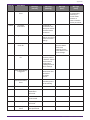
30033 Dante Module
Error
- - - Dante module is
not responding.
Please try to
recover Dante
firmware or
contact Yamaha
service personnel.
30034 No Dante
Connection
- No network is
connected to the
Dante port. Please
check the Dante
connection.
- -
30037 Wrong Dante Clock - Dante word clock
settings are wrong.
Please check the
settings.
- -
30038 Muted - Dante
Clock Err.
- - Muted due to
incorrect Dante
word clock
settings. Please
check Dante word
clock settings.
-
30039 Dante Clock Offset
Err.
- Dante Clock
Frequency Offset
is unstable. Please
check network
configuration
including Ethernet
switch settings.
- -
30040 Dante Redundancy
Triiggered
- Dante Audio
transmission has
switched to
Secondary
network.
- -
30041 Dante Secondary
Error
- The Dante
secondary port is
not functioning.
- -
30047 Power ON Power ON - - -
30049 Device Initialized Memory
initialization
performed.
---
30050 Time Synchronized Date and time is
synchronized.
---
30051 Firmware Updated Firmware update
performed.
---
30052 Scene/Snapshot
Store
Scene/Snapshot
store performed.
---
Appendix
DME7 V1.1 Reference Manual | 47

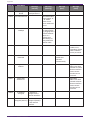
Data ID Data Name Message
[Normal]
Message
[Warning]
Message
[Error]
Message
[Fault]
30053 Scene/Snapshot
Recall
Scene/Snapshot
recall performed.
---
30056 PSU Switched Over - Either Redundant
Power Supply "A"
or "B" failed.
Please check
power cables and
source.
- -
30057 Dante Link
100Mbps
- Dante link speed is
less than Gigabit.
Try plugging into a
different network
switch or a
different port.
Alternatively, try
using a different
network cable.
- -
30058 Sub Module Error - - - Internal sub
module is not
responding. Please
contact Yamaha
service personnel.
30059 Sub Module
Rebooted
- - Internal sub
module has
rebooted
unintentionally.
-
30060 Illegal MAC
address
- - - Illegal MAC
address has been
detected at control
ethernet interface.
Please contact
Yamaha service
personnel.
30061 Dante MAC
Address Err.
- - - Illegal MAC
address has been
detected at Dante
ethernet interface.
Please contact
Yamaha service
personnel.
30062 IP Address
Assigned
IP address is
assigned to the
network interface.
---
30063 IP Address
Assigned (Auto IP)
IP address is
assigned (AutoIP)
to the network
interface.
---
Appendix
48 | DME7 V1.1 Reference Manual

Data ID Data Name Message
[Normal]
Message
[Warning]
Message
[Error]
Message
[Fault]
30064 IP Address
Released
IP address
assigned by DHCP
server is released.
---
30065 Internal Network
Error
- - Unable to establish
connection with
internal sub
module due to
incorrect network
address.
-
30066 Dante (TX)
Overflow
- - Dante Audio Flow
Resource (TX)
exceeded. Please
re-design Dante
patch to match
Dante Flow
resources.
-
30067 Dante (RX)
Overflow
- - Dante Audio Flow
Resource (RX)
exceeded. Please
re-design Dante
patch to match
Dante Flow
resources.
-
30068 Dante Settings
Locked
- Unable to apply
Dante setting
changes to the
Dante module due
to Dante Device
Lock or DDM
permission
settings.
- -
30069 DCP Comms Error - - Communication
error is detected
during the
communication
sequence between
host device and
DCPs. Please
make sure that the
following are
within
specification:
1) cable length,
2) cable quality,
3) the final DCP in
the chain is
terminated.
-
Appendix
DME7 V1.1 Reference Manual | 49

Data ID Data Name Message
[Normal]
Message
[Warning]
Message
[Error]
Message
[Fault]
30070 DCP Configuration
Error
- - Unable to
communicate with
connected DCPs
correctly. Please
check if
1) Panel ID’s are
correctly set
2) Pre-configured
DCP type and real
DCP type
connected by wire
is identical.
-
30071 DSP Resource
Overflow
- - The resource for
audio signal
processing is
unexpectedly
overflowed, which
might cause
audible noise.
-
30072 Incompatible
Data/File
- - Unable to
Load/Import
Data/File due to
incompatible data
format.
-
30073 Incompatible RC
Protocol
- - Unable to
communicate/resp
ond to external
remote control
device/software
due to
incompatible
protocol version.
-
30074 DHCP Server No
Response
- - DHCP server is not
responding to the
device.
-
30075 NTP Server No
Response
- - NTP server is not
responding to the
device.
-
30076 Missing License - - Some or entire
functions of this
device stop
working due to
missing or
insufficient
licenses. Please
activate additional
licenses or remove
corresponding
functions.
-
Appendix
50 | DME7 V1.1 Reference Manual

Data ID Data Name Message
[Normal]
Message
[Warning]
Message
[Error]
Message
[Fault]
30077 Setting Data
Corrupted/Lost
- - Corrupted data/file
is detected.
-
30078 Storage Full - - Storage Full. -
30079 Unsupported
File System
- - The storage drive
is formatted with
unsupported file
system type.
Please re-format
the storage to a
supported format.
-
30080 Removable Drive
Mounted
Removal drive has
been mounted to
device.
---
30081 Removable Drive
Unmounted
Removal drive has
been unmounted
from device.
---
30082 File Not Found The file cannot be
found.
---
30083 Authentication
Failed
- Wrong PIN
code/Password
was entered.
- -
30084 Panel Locked The operation
panel is locked.
---
30085 Panel Unlocked The operation
panel is unlocked.
---
30086 Scene/Snapshot
Recall Failed
- - Failed to recall the
Scene/Snapshot
data.
-
30087 Data Sync Failed - - Synchronization
sequence has been
stopped
unexpectedly.
-
Appendix
DME7 V1.1 Reference Manual | 51

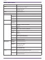
General specifications
Internal processing 44.1/48/88.2/96 kHz
Latency 2.7 msec (at Rio-D2 analog input/output with Dante latency at 0.25 msec,
Dante through output on DME7)
Memory Parameter sets: 1,000
Snapshots: 10,000
Cooling Constant-speed fan × 1
Fan noise NC20 (1 m from front panel)
Dante interface Channel count 64IN, 64OUT, redundant (expandable to 256IN, 256OUT)
Sampling
frequency
44.1/48/88.2/96 kHz
Bit depth 24/32 bits
USB audio Channel count 8 inputs, 8 outputs with SRC
Sampling
frequency
44.1/48/88.2/96 kHz
Connectors Dante etherCON × 2 (PRIMARY/SECONDARY)
1000Base-T
DCP RJ45 × 1
USB TO HOST USB 2.0 Type-C connector for USB audio
USB TO
DEVICE
USB 2.0 Standard-A Connector for Save/Load, Firmware update with USB
memory
Network RJ45 × 1
100Base-TX
GPI Euroblock 16 terminals (mini) × 2
(GPI x16, GPO x8, +5V power x4)
MIDI DIN 5 pin x2 (IN, OUT)
AC IN AC inlet (IEC, V-Lock) x2
Memory device
specifications
Compatible
formats
File format: FAT32, FAT16
Supported
capacity Maximum media capacity:
SDHC: Maximum 32 GB
SD: Maximum 2 GB
Maximum file
size FAT16: Maximum 2 GB
FAT32: Maximum 4 GB
Controls Front panel Rotary encoder and buttons for GUI control
Operation lock feature (Full lock or Lock except volume and mute)
Display 224 × 48 pixels, mono color with brightness adjustment
Auto display off feature
Appendix
52 | DME7 V1.1 Reference Manual

AC power requirement 100 V-240 V 50 Hz/60 Hz
Power consumption 100 W
Heat dissipation 86.3 kcal/h
Operating temperature 0 °C to +40 °C
Storage temperature -20 °C to +60 °C
Dimensions (W × H × D) 480 x 132 x 363 mm (3U)
(18.90 x 5.20 x 14.29 inch)
Weight 9.5 kg
Finish Front panel: Metal (black paint) Munsell approximate value N2.5 Handle:
Aluminum (black paint)
Included items Setup Guide
Two Euroblock plugs (16-pin, 3.50 mm pitch)
Two power cords
One cable hook
Separately sold items DCP4V4S-US/EU
DCP1V4S-US/EU
DCP4S-US/EU
DCH8
Expansion license DEK-DME7-DX64
Appendix
DME7 V1.1 Reference Manual | 53

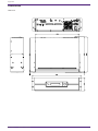
Dimensions
Units: mm
Appendix
54 | DME7 V1.1 Reference Manual

Block diagram
This document is based on the latest specifications at the time of publication. The latest version can be
downloaded from the Yamaha website.
Appendix
DME7 V1.1 Reference Manual | 55

© 2023 Yamaha Corporation
Published 01/2024
YJMA-B0
-
 1
1
-
 2
2
-
 3
3
-
 4
4
-
 5
5
-
 6
6
-
 7
7
-
 8
8
-
 9
9
-
 10
10
-
 11
11
-
 12
12
-
 13
13
-
 14
14
-
 15
15
-
 16
16
-
 17
17
-
 18
18
-
 19
19
-
 20
20
-
 21
21
-
 22
22
-
 23
23
-
 24
24
-
 25
25
-
 26
26
-
 27
27
-
 28
28
-
 29
29
-
 30
30
-
 31
31
-
 32
32
-
 33
33
-
 34
34
-
 35
35
-
 36
36
-
 37
37
-
 38
38
-
 39
39
-
 40
40
-
 41
41
-
 42
42
-
 43
43
-
 44
44
-
 45
45
-
 46
46
-
 47
47
-
 48
48
-
 49
49
-
 50
50
-
 51
51
-
 52
52
-
 53
53
-
 54
54
-
 55
55
-
 56
56
-
 57
57


in andere talen
- English: Yamaha DME7 Reference guide
- italiano: Yamaha DME7 Guida di riferimento
- русский: Yamaha DME7 Справочное руководство
- français: Yamaha DME7 Guide de référence
- español: Yamaha DME7 Guia de referencia
- Deutsch: Yamaha DME7 Referenzhandbuch
- português: Yamaha DME7 Guia de referência
- dansk: Yamaha DME7 henvisning guide
- suomi: Yamaha DME7 pikaopas
- čeština: Yamaha DME7 Referenční příručku
- 日本語: Yamaha DME7 リファレンスガイド
- svenska: Yamaha DME7 Referens guide
- polski: Yamaha DME7 instrukcja obsługi
- română: Yamaha DME7 Ghid de referință