Owner’s Manual
LS9-16/LS9-32
EN

2
LS9-16/32 Owner’s Manual
* This applies only to products distributed by YAMAHA CORPORATION OF AMERICA. (Perchlorate)
This product contains a battery that contains perchlorate material.
Perchlorate Material—special handling may apply,
See www.dtsc.ca.gov/hazardouswaste/perchlorate.
* This applies only to products distributed by YAMAHA CORPORATION OF AMERICA. (class B)
FCC INFORMATION (U.S.A.)
1. IMPORTANT NOTICE: DO NOT MODIFY THIS
UNIT!
This product, when installed as indicated in the instructions
contained in this manual, meets FCC requirements. Modifi-
cations not expressly approved by Yamaha may void your
authority, granted by the FCC, to use the product.
2. IMPORTANT: When connecting this product to accesso-
ries and/or another product use only high quality shielded
cables. Cable/s supplied with this product MUST be used.
Follow all installation instructions. Failure to follow instruc-
tions could void your FCC authorization to use this product
in the USA.
3. NOTE: This product has been tested and found to comply
with the requirements listed in FCC Regulations, Part 15 for
Class “B” digital devices. Compliance with these require-
ments provides a reasonable level of assurance that your
use of this product in a residential environment will not
result in harmful interference with other electronic devices.
This equipment generates/uses radio frequencies and, if
not installed and used according to the instructions found in
the users manual, may cause interference harmful to the
operation of other electronic devices. Compliance with FCC
regulations does not guarantee that interference will not
occur in all installations. If this product is found to be the
source of interference, which can be determined by turning
the unit “OFF” and “ON”, please try to eliminate the problem
by using one of the following measures:
Relocate either this product or the device that is being
affected by the interference.
Utilize power outlets that are on different branch (circuit
breaker or fuse) circuits or install AC line filter/s.
In the case of radio or TV interference, relocate/reorient the
antenna. If the antenna lead-in is 300 ohm ribbon lead,
change the lead-in to co-axial type cable.
If these corrective measures do not produce satisfactory
results, please contact the local retailer authorized to dis-
tribute this type of product. If you can not locate the appro-
priate retailer, please contact Yamaha Corporation of
America, Electronic Service Division, 6600 Orangethorpe
Ave, Buena Park, CA90620
The above statements apply ONLY to those products dis-
tributed by Yamaha Corporation of America or its subsidiar-
ies.
* This applies only to products distributed by
YAMAHA CORPORATION OF AMERICA.
COMPLIANCE INFORMATION STATEMENT
(DECLARATION OF CONFORMITY PROCEDURE)
Responsible Party : Yamaha Corporation of America
Address : 6600 Orangethorpe Ave., Buena Park,
Calif. 90620
Telephone : 714-522-9011
Type of Equipment : DIGITAL MIXING CONSOLE
Model Name : LS9-16, LS9-32
This device complies with Part 15 of the FCC Rules.
Operation is subject to the following two conditions:
1) this device may not cause harmful interference, and
2) this device must accept any interference received including
interference that may cause undesired operation.
See user manual instructions if interference to radio recep-
tion is suspected.
(FCC DoC)
IMPORTANT NOTICE FOR THE UNITED KINGDOM
Connecting the Plug and Cord
WARNING: THIS APPARATUS MUST BE EARTHED
IMPORTANT. The wires in this mains lead are coloured in
accordance with the following code:
GREEN-AND-YELLOW : EARTH
BLUE : NEUTRAL
BROWN : LIVE
As the colours of the wires in the mains lead of this apparatus
may not correspond with the coloured markings identifying the
terminals in your plug proceed as follows:
The wire which is coloured GREEN-and-YELLOW must be
connected to the terminal in the plug which is marked by the
letter E or by the safety earth symbol or colored GREEN or
GREEN-and-YELLOW.
The wire which is coloured BLUE must be connected to the
terminal which is marked with the letter N or coloured BLACK.
The wire which is coloured BROWN must be connected to the
terminal which is marked with the letter L or coloured RED.
(3 wires)
This product contains a high intensity lamp that contains
a small amount of mercury. Disposal of this material
may be regulated due to environmental considerations.
For disposal information in the United States, refer to
the Electronic Industries Alliance web site:
www.eiae.org
(mercury)* This applies only to products distributed by
YAMAHA CORPORATION OF AMERICA.

3
LS9-16/32 Owner’s Manual
The above warning is located on the rear or side of the unit.
Explanation of Graphical Symbols
The lightning flash with arrowhead symbol
within an equilateral triangle is intended to
alert the user to the presence of uninsulated
“dangerous voltage” within the product’s
enclosure that may be of sufficient magnitude
to constitute a risk of electric shock to
persons.
The exclamation point within an equilateral
triangle is intended to alert the user to the
presence of important operating and
maintenance (servicing) instructions in the
literature accompanying the product.
IMPORTANT SAFETY INSTRUCTIONS
1 Read these instructions.
2Keep these instructions.
3 Heed all warnings.
4 Follow all instructions.
5 Do not use this apparatus near water.
6 Clean only with dry cloth.
7 Do not block any ventilation openings. Install in
accordance with the manufacturer’s instructions.
8 Do not install near any heat sources such as radiators,
heat registers, stoves, or other apparatus (including
amplifiers) that produce heat.
9 Do not defeat the safety purpose of the polarized or
grounding-type plug. A polarized plug has two blades
with one wider than the other. A grounding type plug
has two blades and a third grounding prong. The wide
blade or the third prong are provided for your safety. If
the provided plug does not fit into your outlet, consult
an electrician for replacement of the obsolete outlet.
10 Protect the power cord from being walked on or
pinched particularly at plugs, convenience receptacles,
and the point where they exit from the apparatus.
11 Only use attachments/accessories specified by the
manufacturer.
12 Use only with the cart, stand,
tripod, bracket, or table
specified by the manufacturer,
or sold with the apparatus. When
a cart is used, use caution when
moving the cart/apparatus
combination to avoid injury from
tip-over.
13 Unplug this apparatus during lightning storms or when
unused for long periods of time.
14 Refer all servicing to qualified service personnel.
Servicing is required when the apparatus has been
damaged in any way, such as power-supply cord or
plug is damaged, liquid has been spilled or objects
have fallen into the apparatus, the apparatus has been
exposed to rain or moisture, does not operate
normally, or has been dropped.
(98-6500)
CAUTION: TO REDUCE THE RISK OF
ELECTRIC SHOCK, DO NOT REMOVE
COVER (OR BACK). NO USER-SERVICEABLE
PARTS INSIDE. REFER SERVICING TO
QUALIFIED SERVICE PERSONNEL.
CAUTION
RISK OF ELECTRIC SHOCK
DO NOT OPEN
WARNING
TO REDUCE THE RISK OF FIRE OR ELECTRIC SHOCK, DO NOT EXPOSE THIS APPARATUS TO RAIN OR MOISTURE.
ADVARSEL!
Lithiumbatteri—Eksplosionsfare ved fejlagtig
håndtering. Udskiftning må kun ske med batteri af
samme fabrikat og type. Levér det brugte batteri
tilbage til leverandoren.
VARNING
Explosionsfara vid felaktigt batteribyte. Använd
samma batterityp eller en ekvivalent typ som reko-
mmenderas av apparattillverkaren. Kassera
använt batteri enligt fabrikantens instruktion.
VAROITUS
Paristo voi räjähtää, jos se on virheellisesti asen-
nettu. Vaihda paristo ainoastaan laitevalmistajan
suosittelemaan tyyppiin. Hävitä käytetty paristo
valmistajan ohjeiden mukaisesti.
(lithium caution)
NEDERLAND / THE NETHERLANDS
• Dit apparaat bevat een lithium batterij voor geheugen back-up.
• This apparatus contains a lithium battery for memory back-up.
• Raadpleeg uw leverancier over de verwijdering van de batterij op het
moment dat u het apparaat ann het einde van de levensduur of gelieve
dan contact op te nemen met de vertegenwoordiging van Yamaha in
uw land.
•For the removal of the battery at the moment of the disposal at the end
of life please consult your retailer or Yamaha representative office in
your country.
• Gooi de batterij niet weg, maar lever hem in als KCA.
• Do not throw away the battery. Instead, hand it in as small chemical
waste.
(lithium disposal)

4
LS9-16/32 Owner’s Manual
PRECAUTIONS
PLEASE READ CAREFULLY BEFORE PROCEEDING
* Please keep this manual in a safe place for future reference.
WARNING
Always follow the basic precautions listed below to avoid the possibility of serious injury or even death from
electrical shock, short-circuiting, damages, fire or other hazards. These precautions include, but are not limited
to, the following:
• Only use the voltage specified as correct for the device. The required
voltage is printed on the name plate of the device.
• Use only the included power cord.
If you intend to use the device in an area other than in the one you
purchased, the included power cord may not be compatible. Please check
with your Yamaha dealer.
• Do not place the power cord near heat sources such as heaters or radiators,
and do not excessively bend or otherwise damage the cord, place heavy
objects on it, or place it in a position where anyone could walk on, trip over,
or roll anything over it.
• Be sure to connect to an appropriate outlet with a protective grounding
connection. Improper grounding can result in electrical shock.
• Do not open the device or attempt to disassemble the internal parts or
modify them in any way. The device contains no user-serviceable parts. If it
should appear to be malfunctioning, discontinue use immediately and have
it inspected by qualified Yamaha service personnel.
• Do not expose the device to rain, use it near water or in damp or wet
conditions, or place containers on it containing liquids which might spill
into any openings.
• Never insert or remove an electric plug with wet hands.
• Do not put burning items, such as candles, on the unit. A burning item may
fall over and cause a fire.
• When one of the following problems occur, immediately turn off the power
switch and disconnect the electric plug from the outlet. Then have the
device inspected by Yamaha service personnel.
- The power cord or plug becomes frayed or damaged.
- It emits unusual smells or smoke.
- Some object has been dropped into the instrument.
- There is a sudden loss of sound during use of the device.
• If this device should be dropped or damaged, immediately turn off the
power switch, disconnect the electric plug from the outlet, and have the
device inspected by qualified Yamaha service personnel.
CAUTION
Always follow the basic precautions listed below to avoid the possibility of physical injury to you or others, or
damage to the device or other property. These precautions include, but are not limited to, the following:
• Remove the electric plug from the outlet when the device is not to be used
for extended periods of time, or during electrical storms.
• When removing the electric plug from the device or an outlet, always hold
the plug itself and not the cord. Pulling by the cord can damage it.
• When transporting or moving the device, do not hold the display.
Improper transportation can result in injury or damage to the device itself.
• Before moving the device, remove all connected cables.
• When setting up the product, make sure that the AC outlet you are using is
easily accessible. If some trouble or malfunction occurs, immediately turn
off the power switch and disconnect the plug from the outlet. Even when the
power switch is turned off, electricity is still flowing to the product at the
minimum level. When you are not using the product for a long time, make
sure to unplug the power cord from the wall AC outlet.
Power supply/Power cord
Do not open
Water warning
Fire warning
If you notice any abnormality
Power supply/Power cord Location
PA_en_1 1/2

5
LS9-16/32 Owner’s Manual
• Do not place the device in a location where it may come into contact with
corrosive gases or salt air. Doing so may result in malfunction.
•Avoid setting all equalizer controls and faders to their maximum.
Depending on the condition of the connected devices, doing so may cause
feedback and may damage the speakers.
• Do not expose the device to excessive dust or vibrations, or extreme cold
or heat (such as in direct sunlight, near a heater, or in a car during the day)
to prevent the possibility of panel disfiguration or damage to the internal
components.
• Do not place the device in an unstable position where it might accidentally
fall over.
• Do not block the vents. This device has ventilation holes at the top and rear
to prevent the internal temperature from becoming too high. In particular,
do not place the device on its side or upside down. Inadequate ventilation
can result in overheating, possibly causing damage to the device(s), or
even fire.
• Do not use the device in the vicinity of a TV, radio, stereo equipment,
mobile phone, or other electric devices. Doing so may result in noise, both
in the device itself and in the TV or radio next to it.
• Before connecting the device to other devices, turn off the power for all
devices. Before turning the power on or off for all devices, set all volume
levels to minimum.
• Be sure to connect to a properly grounded power source. A ground screw is
provided on the rear panel of this device for maximum safety and shock
prevention. If the mains outlet is not grounded, be sure to connect the
ground screw to a confirmed ground point before plugging the device into
the mains. Improper grounding can result in electrical shock.
• When turning on the AC power in your audio system, always turn on the
power amplifier LAST, to avoid speaker damage. When turning the power
off, the power amplifier should be turned off FIRST for the same reason.
• Do not insert your fingers or hands in any gaps or openings on the device
(vents, etc.).
•Avoid inserting or dropping foreign objects (paper, plastic, metal, etc.) into
any gaps or openings on the device (vents, etc.) If this happens, turn off the
power immediately and unplug the power cord from the AC outlet. Then
have the device inspected by qualified Yamaha service personnel.
• Do not apply oil, grease, or contact cleaner to the faders. Doing so may
cause problems with electrical contact or fader motion.
• Do not use the device or headphones for a long period of time at a high or
uncomfortable volume level, since this can cause permanent hearing loss.
If you experience any hearing loss or ringing in the ears, consult a
physician.
• Do not rest your weight on the device or place heavy objects on it, and
avoid use excessive force on the buttons, switches or connectors.
• This device has a built-in backup battery. When you unplug the power cord
from the AC outlet, the current scene data and library data is retained.
However, if the backup battery fully discharges, this data will be lost. When
the backup battery is running low, the LCD display indicates “Low Battery!”
when you starting up the system (the Battery field also indicates “LOW” or
“NO” in the MISC SETUP screen.) In this case, immediately save the data
to a USB memory, then have qualified Yamaha service personnel replace
the backup battery.
Always turn the power off when the device is not in use.
The performance of components with moving contacts, such as switches, volume controls, and connectors, deteriorates over time. Consult qualified Yamaha service
personnel about replacing defective components.
Connections
Handling caution
Backup battery
XLR-type connectors are wired as follows (IEC60268 standard): pin 1: ground, pin 2: hot (+), and pin 3: cold (-).
Yamaha cannot be held responsible for damage caused by improper use or modifications to the device, or data that is lost or destroyed.
PA_en_1 2/2

6
LS9-16/32 Owner’s Manual
1. Introduction 9
Thank you ...................................................................9
An overview of the LS9.............................................. 9
Differences between the LS9-16 and LS9-32 ......... 11
Number of INPUT channels................................. 11
Rear panel ........................................................... 11
Top panel............................................................. 12
Other.................................................................... 13
The LS9’s channel structure ...................................13
About the MIX bus types (VARI / FIXED)................ 14
About word clock .....................................................14
Conventions in this manual.....................................14
About the firmware version..................................... 14
2. Parts and their function 15
Top panel...................................................................15
Rear panel ................................................................. 23
Front panel................................................................ 26
3. Basic operations on the LS9 27
Basic operations in the top panel........................... 27
About the [HOME] key......................................... 27
Selecting the fader layer...................................... 27
Using the SELECTED CHANNEL section........... 29
Selecting functions ..............................................29
Viewing the display .................................................. 30
Constant display area.......................................... 30
Main area............................................................. 31
The on-screen user interface............................... 32
Assigning a name..................................................... 34
Using the tool buttons ............................................. 35
About the tool buttons.......................................... 35
Using libraries...................................................... 35
Initializing settings ...............................................38
Copying and pasting settings ..............................39
Comparing two sets of settings ...........................39
4. Connections and setup 41
Connections.............................................................. 41
Installing an option card.......................................... 44
Setup required when starting up ............................ 45
Returning the current scene to the initial state ....45
Word clock connection and settings .................... 46
HA (head amp) settings....................................... 47
Sending an input channel signal
to the STEREO bus.......................................... 50
5. Input channel operations 53
Signal flow for input channels.................................53
Specifying the channel name / icon........................55
HA (head amp) settings............................................57
Sending the signal from
an input channel to the STEREO/MONO bus......58
Sending the signal from
an input channel to a MIX bus..............................62
Using the SELECTED CHANNEL section ...........62
Using a popup window.........................................64
Using the faders (SENDS ON FADER mode) .....65
6. Output channel operations 67
Signal flow for output channels ..............................67
Specifying the channel name / icon........................69
Sending signals from MIX channels
to the STEREO/MONO bus ...................................71
Sending signals from MIX channels
and STEREO/MONO channels
to MATRIX buses...................................................75
Using the SELECTED CHANNEL section ...........75
Using a popup window.........................................77
Using the faders (SENDS ON FADER mode) .....78
7. Operations in
the SELECTED CHANNEL section 81
About the SELECTED CHANNEL section...............81
About the SELECTED CH VIEW screen..................82
Operations in the SELECTED CHANNEL section..83
8. Custom fader layer 91
About the custom fader layer ..................................91
Assigning channels to the custom fader layer ......92
9. Input/output patching 95
Changing the output patching.................................95
Changing the input patching ...................................99
Inserting an external device into a channel .........101
Directly outputting an INPUT channel ..................103
10. USB memory recorder 105
About the USB memory recorder..........................105
Assigning channels to
the input/output of the recorder.........................106
Recording to USB memory ....................................108
Playing back audio files from USB memory ........110
Editing the title list..................................................112
Linking scene recall with audio file playback ......113
Contents

7
LS9-16/32 Owner’s Manual
Contents
11. EQ and Dynamics 115
About EQ and dynamics........................................ 115
Using EQ .................................................................115
Using dynamics...................................................... 117
Using the EQ/Dynamics libraries.......................... 120
EQ library........................................................... 120
Dynamics library ................................................ 120
12. Grouping and linking 121
About mute groups ................................................ 121
Using mute groups................................................. 121
Using the MUTE GROUP screen
to operate mute groups .................................. 121
Using the SELECTED CH VIEW screen
to specify mute groups ................................... 122
Using the Mute Safe function ............................123
The Channel Link function .................................... 124
Linking the desired input channels ....................124
Copying, moving, or initializing a channel...........126
Copying the parameters of a channel................ 126
Moving the parameters of a channel .................127
Initializing the parameters of a channel ............. 128
13. Scene memory 129
About scene memories.......................................... 129
Using scene memories ..........................................129
Storing a scene.................................................. 129
Recalling a scene ..............................................131
Using user-defined keys to recall ......................132
Editing scene memories ........................................ 134
Sorting and renaming scene memories............. 134
Scene memory editing....................................... 136
Copying/pasting a scene ...................................136
Clearing a scene................................................ 137
Cutting a scene.................................................. 138
Inserting a scene ...............................................138
Using the Focus function ...................................... 139
Using the Recall Safe function..............................140
Using the Fade function.........................................143
14. Monitor/Cue 145
About the monitor/cue functions.......................... 145
Using the Monitor function....................................146
Using the Cue function .......................................... 148
About cue groups ..............................................148
Operating the Cue function................................ 149
15. Talkback / Oscillator 151
About talkback and oscillator................................151
Using talkback ........................................................151
Using the oscillator ................................................153
16. Meters 155
Using the METER screen .......................................155
17. Graphic EQ and effects 157
About the virtual rack.............................................157
Mounting a GEQ or effect in the virtual rack ......158
Graphic EQ operations...........................................161
About the graphic EQ.........................................161
Inserting a GEQ in a channel.............................161
Using the 31 Band GEQ ....................................163
Using the Flex15GEQ ........................................164
About the internal effects ......................................166
Using an internal effect via send/return .............167
Inserting an internal effect into a channel ..........168
Editing the internal effect parameters ................170
Using the Tap Tempo function...........................172
Using the Freeze effect......................................173
Using the graphic EQ and effect libraries ............174
GEQ library ........................................................174
Effect library .......................................................174
Using an external head amp ..................................175
Remotely controlling an external head amp.......175
18. MIDI 177
MIDI functionality on the LS9 ................................177
Basic MIDI settings.................................................178
Using program changes
to recall scenes and library items......................180
Using control changes to control parameters .....183
Using parameter changes
to control parameters .........................................185
Using MMC (MIDI Machine Control)
to operate the USB memory recorder ...............186
19. User settings (Security) 187
User Level settings.................................................187
User types and user authentication keys ...........187
Setting the Administrator password ...................188
Creating a user authentication key ....................188
Logging-in ..........................................................189
Changing the password .....................................191
Editing a user authentication key .......................192
Changing the user level .....................................192

8
LS9-16/32 Owner’s Manual
Contents
Preferences............................................................. 194
User-defined keys .................................................. 196
Console lock ........................................................... 197
Locking the console........................................... 197
Unlocking the console .......................................198
Specifying the CONSOLE LOCK
screen image.................................................. 198
Using USB memory to save/load data.................. 199
Saving the LS9’s internal data
on USB memory............................................. 199
Loading a file from USB memory....................... 200
Editing the files saved on USB memory ............201
Formatting USB memory media ........................204
20. Other functions 205
About the SETUP screen ....................................... 205
Word clock settings ............................................... 206
Switching a digital I/O card’s SRC on/off............. 208
Using cascade connections .................................. 209
Operations on the cascade slave LS9............... 210
Operations on the cascade master LS9 ............212
Basic settings for MIX buses and
MATRIX buses..................................................... 213
Setting the date and time of the internal clock.... 215
Setting the network address ................................. 216
Specifying the brightness or
contrast of the display, LEDs, and lamps......... 217
Using the Help function ......................................... 218
Loading a Help file from a USB memory ...........218
Loading a text file from a USB memory............. 219
Assigning the Help function to
a user-defined key.......................................... 219
Viewing Help...................................................... 220
Initializing the LS9’s internal memory.................. 222
Adjusting the faders (Calibration function) ......... 223
Adjusting the input/output gain
(Calibration function).......................................... 224
Appendices 225
EQ Library List........................................................ 225
DYNAMICS Library List.......................................... 227
Dynamics Parameters ............................................229
Effect Type List....................................................... 232
Effects Parameters .................................................233
Effects and tempo synchronization...................... 244
Scene Memory/Effect Library
to Program Change Table ..................................245
Parameters that can be assigned
to control changes ..............................................249
Control change parameter assignments.............. 251
NRPN parameter assignments ..............................253
Mixing parameter operation applicability............. 256
Functions that can be assigned
to user-defined keys ........................................... 257
MIDI Data Format ....................................................260
Warning/Error Messages .......................................268
Troubleshooting .....................................................270
General Specifications........................................... 272
Input/output characteristics ..................................273
Electrical characteristics ....................................... 275
Mixer Basic Parameters .........................................277
Pin Assignment ......................................................278
Dimensions .............................................................279
Attaching the RK1 rackmount kit
(sold separately).................................................. 280
MIDI Implementation Chart .................................... 281
Index ........................................................................ 282
Block Diagram ..................................... End of Manual
Level Diagram ...................................... End of Manual
• The illustrations and screen displays as shown in this Owner’s manual are for instructional purposes
only, and may be different from the ones on your device.
• The bitmap fonts used in this device have been provided by and are the property of Ricoh Co., Ltd.
• The company names and product names in this Owner’s Manual are the trademarks or registered
trademarks of their respective companies.
• MPEG Layer-3 audio coding technology licensed from Fraunhofer IIS and Thomson.

9
1
Introduction
LS9-16/32 Owner’s Manual
Chapter 1
Introduction
Thank you for purchasing the Yamaha LS9 digital mixing console. In order to take full advantage
of the LS9’s superior functionality and enjoy years of trouble-free use, please read this manual
before you begin using the product. After you have read the manual, keep it in a safe place.
The LS9 is a digital mixing console with the following features.
■
Mixing system that packs top-class
functionality into a compact size
• • • • •
The LS9 is a full-digital mixing console designed for
installed systems or SR applications, and in spite of its
compact size, provides functionality and a channel count
comparable to large-format consoles. 24-bit linear AD/DA
converters are used to deliver up to 108 dB of dynamic
range and amazing sound quality.
As input channels, it provides 32 (LS9-16 model) or 64
(LS9-32 model) monaural INPUT channels, and four ste-
reo ST IN channels.
As output channels, it provides 16 MIX channels, eight
MATRIX channels, a STEREO channel, and a MONO
channel. L/C/R three-channel output using the STEREO/
MONO channels is also supported.
■
Analog-feeling operability
• • • • • • • • • •
Simply by pressing a key, you can select the combination
of channels (“fader layer”) to be operated from the top
panel faders. You can operate the console while quickly
switching between input channels and output channels. In
addition, you can also use a custom fader layer that lets
you specify any desired combination of channels. Since
fader/cue operations and on/off switching for all channels
can be performed from the panel, even customers using
digital consoles for the first time will find operation famil-
iar and comfortable.
The SELECTED CHANNEL section located at the right
of the display lets you use the knobs to control the main
parameters (gain, EQ, dynamics threshold, bus send lev-
els, etc.) for the particular channel on which you’re focus-
ing. This section can be operated just like a module on an
analog mixer.
Mix parameter settings, including head amp gain and
phantom power for input channels, can be stored and
recalled as “scenes.”
All faders on the panel are motorized moving faders, so
that when you recall a scene, the previous fader locations
are reproduced immediately.
Thank you
An overview of the LS9

10
An overview of the LS9
LS9-16/32 Owner’s Manual
■
Effects and graphic EQ that can be
patched into a desired signal path
• • • •
There are eight virtual racks, in which you can mount
effects or graphic EQ and then patch them into the desired
signal route. Graphic EQ can be mounted in racks 1–4,
and effects or graphic EQ can be mounted in racks 5–8.
You can simultaneously use up to four high-quality multi-
effects, which include reverb, delay, multi-band compres-
sor, and various modulation-type effects. These can be
used via an internal bus, or inserted into a desired channel.
For the graphic EQ you can select either 31-band graphic
EQ or Flex 15 GEQ. These can be inserted into the desired
channel or output. The Flex 15 GEQ allows you to adjust
the gain for any fifteen of the thirty-one bands. Since two
Flex 15 GEQ units can be mounted in a single virtual rack,
a total of up to sixteen graphic EQ units can be used
simultaneously.
■
A recorder function that’s useful for
sound checks or recording mixes
• • • •
A recorder function is provided, allowing you to use USB
memory to record the output of the STEREO bus or a
MIX bus, or assign an audio file in USB memory to a
desired input channel or monitor output and play it back.
Supported file formats are MP3 (MPEG-1 Audio Layer-3)
for recording, and MP3, WMA (Windows Media Audio),
and MPEG-4 AAC (Advanced Audio Coding) for play-
back. However, DRM (Digital Rights Management) is not
supported. This function is convenient when you want to
record the mix output of a specific bus, or if you want to
play back a song from the speakers during the sound
check.
■
Cascade connections in the digital
domain
• • • • • • • • • • • • • • • • • • • • • • •
A second LS9 console or a digital mixer such as the
Yamaha M7CL or PM5D connected via a digital I/O card
installed in a slot can be cascade-connected in the digital
domain.
Of the MIX buses, MATRIX buses, STEREO (L/R) bus,
MONO buses, and CUE (L/R) bus, the desired buses can
be merged, and all mixed bus signals can be cascaded
individually.
■
Security functions that can be specified
at user-level or system-level
• • • • • • •
User levels can be distinguished into three levels (admin-
istrator, guest, user), and the functionality available to
each non-administrator user can be restricted. Passwords
can be specified for the administrator and users, prevent-
ing important settings from being changed accidentally.
Information specific to each user (user level, system set-
tings, and user-defined key settings) can be stored on USB
memory as a “user authentication key.” By loading your
own user authentication key from USB memory, you can
instantly set up the ideal operating environment for your-
self.
■
I/O card expansion
• • • • • • • • • • • • • •
The rear panel provides one slot (LS9-16) or two slots
(LS9-32) in which separately sold mini-YGDAI cards can
be installed. AD cards, DA cards, or digital I/O cards can
be installed in these slots to add inputs and outputs port.

11
Differences between the LS9-16 and LS9-32
1
Introduction
LS9-16/32 Owner’s Manual
The LS9 is available in two models; the LS9-16 and the LS9-32. These models differ as follows.
The LS9-16 has up to 32 operable INPUT channels, while the LS9-32 has up to 64. The number and structure of other chan-
nels (ST IN channels, MIX channels, MATRIX channels, STEREO/MONO channels) are identical.
The LS9-16 and LS9-32 differ in the number of rear panel INPUT jacks, OMNI OUT jacks, and slots they provide.
The rear panel of the LS9-16 provides sixteen INPUT jacks, eight OMNI OUT jacks, and one slot.
In contrast, the rear panel of the LS9-32 provides thirty-two INPUT jacks, sixteen OMNI OUT jacks, two slots, and one
LAMP connector.
Differences between the LS9-16 and LS9-32
Number of INPUT channels
Rear panel
INPUT jacksOMNI OUT jacks Slot
OMNI OUT jacks INPUT jacks
Slots
LAMP connector

12
Differences between the LS9-16 and LS9-32
LS9-16/32 Owner’s Manual
The LS9-16 and LS9-32 differ in the number of top panel channel modules and ST IN channels they provide.
The LS9-16 provides sixteen channel modules and two ST IN channels, and by switching fader layers you can operate up to
32 INPUT channels (monaural) and four ST IN channels (stereo).
The LS9-16 provides thirty-two channel modules and four ST IN channels. By switching fader layers you can operate up to
sixty-four INPUT channels (monaural).
The four ST IN channels (stereo) can be operated from either layer (1-32 or 33-64).
Top panel
Channel modules ST IN channels
Channel modules ST IN channels

13
1
Introduction
LS9-16/32 Owner’s Manual
The names of the LAYER section keys differ between the LS9-16 and LS9-32.
● LS9-16 ● LS9-32
In conjunction with this difference, there are also differences in the numbering of the channel modules on the panel and the
channels that are assigned to each fader layer.
The LS9 provides the following input channels and output channels.
■ Input channels • • • • • • • • • • • • • • • • •
This section processes input signals and sends them to
various buses (STEREO, MONO, MIX). The LS9 has the
following two types of input channel.
● INPUT channels 1–32 {1–64}
These channels process monaural signals. In the initial
state, the input signals from the rear panel INPUT jacks
and the input channels of the slot(s) are assigned to these
channels.
● ST IN channels 1–4
These channels process stereo signals. In the initial state,
the outputs of virtual racks 5–8 are assigned to these chan-
nels.
Signal assignments to the input channels (input patching)
can be changed as desired.
■ Output channels • • • • • • • • • • • • • • • •
This section mixes the signals sent from input channels
etc., and sends them to the corresponding output ports or
output buses.
There are three types of output channel, as follows.
● MIX channels 1–16
These channels process the signals sent from input chan-
nels to the MIX buses, and send them from the output
ports. These are used mainly to send signals to the monitor
system or to external effects.
The signals of MIX channels 1–16 can also be sent to the
STEREO bus, MONO bus, or MATRIX buses.
When the LS9 is in the initial state, these are assigned to
the OMNI OUT jacks or the output channels of the slot(s).
● MATRIX channels 1–8
These channels process the signals that are sent from MIX
channels, STEREO channels, and MONO channel to the
MATRIX buses, and send them from the output ports.
Using the STEREO and MONO buses, different combina-
tions of signals and mix balances can be sent out from the
console.
● STEREO channel / MONO channel
These channels process the signals that are sent from the
input channels or MIX channels, and send them to the cor-
responding output port. These channels are used as the
main stereo output and monaural output.
The STEREO channel and MONO channel can be used
either to output independent signals, or for three-channel L/
C/R playback.
When the
LS9
is in the initial state, the STEREO channel is
assigned to OMNI OUT jacks 15/16 {31/32} and to the
2TR OUT DIGITAL jack.
Signal assignments to the output channels (output patch-
ing) can be changed as desired.
Other
LAYER [1-16] key LAYER [17-32] key
LAYER [MASTER] key LAYER [CUSTOM
FADER] key
LAYER [1-32] key LAYER [33-64] key
LAYER [MASTER] key LAYER [CUSTOM
FADER] key
• In this owner’s manual, whenever there is a difference between the LS9-16 model and the LS9-32 model, specifica-
tions that apply only to the LS9-32 model are enclosed in curly brackets { } (e.g., INPUT jacks 1–16 {1–32}).
• When the specifications are common to both models, the manual refers simply to the LS9.
HINT
The LS9’s channel structure
Differences between the LS9-16 and LS9-32 • The LS9’s channel structure

14
LS9-16/32 Owner’s Manual
The sixteen MIX buses provided on the LS9 can be assigned either as VARI or FIXED types in
pairs of adjacent odd-numbered/even-numbered buses (→ p. 213). They can also be switched
between monaural/stereo for the same pairs of buses. VARI type and FIXED type buses differ as
follows.
● VARI
This type allows the send level of the signal sent from the
input channels to the MIX bus to be varied. The point at
which the signal is sent from the input channel to a VARI
type MIX bus can be chosen from before the EQ
(attenuator), before the fader, or after the channel on/off.
This type is used mainly for sending the signal to a moni-
tor system or external effect.
● FIXED
With this type, the send level of the signal sent from the
input channels to the MIX bus is fixed. The signal from an
input channel is sent to a FIXED type MIX bus from
before Pan (if the MIX bus is monaural) or after Pan (if
the MIX bus is stereo). This type is used mainly when you
want to distribute signals to an external device with the
same mix as the STEREO/MONO buses.
“Word clock” refers to the clock that provides the basis of timing for digital audio signal process-
ing.
Normally, one device transmits a reference word clock signal, and the other devices receive this
word clock signal and synchronize to it.
In order to transmit or receive digital audio signals to or from an external device via the LS9’s
2TR IN DIGITAL/2TR OUT DIGITAL jacks or via a digital I/O card installed in a slot, the word
clock must be synchronized between the devices. Be aware that if the word clock is not synchro-
nized, the signal will not be sent correctly, or there may be unpleasant noise. (For details on syn-
chronizing the LS9’s word clock with an external device → p. 46)
In this manual, switch-type controllers on the panel are called “keys.” Of the control knobs on the
panel, those that turn from a minimum value to a maximum value are called “controls,” while
those that turn endlessly are called “encoders.”
Controllers located on the panel are enclosed in square
brackets [ ] (e.g., [CUE] key) in order to distinguish them
from the virtual buttons and knobs displayed in the screen.
For some controllers, the name of the section is given
before the [ ] (e.g., LAYER [MASTER] key).
Whenever there is a difference between the LS9-16 model
and the LS9-32 model, specifications that apply only to
the LS9-32 model are enclosed in curly brackets { } (e.g.,
INPUT jacks 1–16 {1–32}).
You can view the firmware version number in the MISC SETUP screen (→ p. 206).
You can also download the most recent firmware version from the website.
http://www.yamahaproaudio.com/
About the MIX bus types (VARI / FIXED)
About word clock
Conventions in this manual
About the firmware version
About the MIX bus types (VARI / FIXED) • About word clock • Conventions in this manual • About the firmware version

15
LS9-16/32 Owner’s Manual
2
Parts and their function
Chapter 2
Parts and their function
This chapter explains the LS9’s parts and their functions.
The LS9’s top panel is organized into the following sections.
Top panel
LS9-16
z Channel module section (p. 17) c STEREO MASTER section (p. 18)
v USER DEFINED KEYS section (p. 18)
b DISPLAY ACCESS section (p. 19)
n LAYER section (p. 19)
m MIX/MATRIX SELECT section (p. 20)
, Display (p. 20)
. Stereo meter / Cue section (p. 20)
⁄0 SELECTED CHANNEL section (p. 21)
⁄1 Data entry section
(p. 22)
x ST IN (stereo input)
section (p. 17)
⁄2 USB connector (side
panel, to the right of the
display) (p. 22)

Top panel
16
LS9-16/32 Owner’s Manual
LS9-32
z Channel module section (p. 17) c STEREO MASTER section (p. 18)
v USER DEFINED KEYS section (p. 18)
b DISPLAY ACCESS section (p. 19)
n LAYER section (p. 19)
m MIX/MATRIX SELECT section (p. 20)
, Display (p. 20)
. Stereo meter / Cue section (p. 20)
⁄0 SELECTED CHANNEL section (p. 21)
⁄1 Data entry section
(p. 22)
⁄2 USB connector
(side panel, to the
right of the display)
(p. 22)
x ST IN (stereo input) section (p. 17)

Top panel
LS9-16/32 Owner’s Manual
17
2
Parts and their function
z Channel module section • • • • • • • • • • •
In this section you can operate the main parameters of the
input channels and output channels, as well as the monitor
output. Use the LAYER section (→ p. 19) to select the
channels that are mapped to this section.
x ST IN (stereo input) section • • • • • • • •
In this section you can operate the main parameters of the
stereo ST IN channels 1–4. The function of each control-
ler is the same as in the Channel Module section, with the
exception that the L-channel or R-channel will be alter-
nately selected as the target of operations each time you
press the [SEL] key, and the fact that the encoder rather
than the fader is used to adjust the level.
1 [SEL] key
This key selects the channel to be operated. When you
press this key to make the LED light, the corresponding
channel will be selected for operations in the SELECTED
CHANNEL section or in the display. In the ST IN section,
the L-channel and R-channel will be alternately selected
as the target of operations each time you press the [SEL]
key.
B [CUE] key
This key selects the channel to be cue-monitored. When
cue is on, the LED will be lit.
C Meter LEDs
These LEDs indicate the audio signal level of the input
channel or output channel.
D [ON] key
This switches the channel on/off. The key LED will light
for channels that are on. In SENDS ON FADER mode,
this key is an on/off switch for the signal that is sent from
that channel to the currently selected MIX bus (or from a
MIX channel, to the MATRIX bus).
E Fader/Encoder
This adjusts the signal level or monitor level of the input
channel or output channel. In SENDS ON FADER mode,
this adjusts the send level from that channel to the cur-
rently selected MIX bus (or from a MIX channel, to the
MATRIX bus).
1
2
4
5
3
1
2
4
5
3
1
2
4
5
3
LS9-32LS9-16

Top panel
18
LS9-16/32 Owner’s Manual
c STEREO MASTER section • • • • • • • • • • •
In this section you can operate the main parameters of the
STEREO channel.
1 [SEL] key
This key selects the STEREO channel as the target of
operations. The L-channel and R-channel will be alter-
nately selected as the target of operations each time you
press the [SEL] key.
B [CUE] key
This key cue-monitors the STEREO channel. When cue is
on, the LED will be lit.
C [ON] key
This switches the STEREO channel on/off. When on, the
key LED will light. In SENDS ON FADER mode, you can
use this as an on/off switch for MIX/MATRIX channels or
as an on/off switch for the signal sent from the STEREO
channel to the MATRIX buses, depending on the LAYER.
D Fader
This adjusts the output level of the STEREO channel. In
SENDS ON FADER mode, this adjusts the level of the
MIX/MATRIX channels or the send level from the STE-
REO channel to the MATRIX buses, depending on the
LAYER.
v USER DEFINED KEYS section• • • • • • • • •
Here you can execute the functions that are programmed
for the user-defined keys.
1 User-defined keys [1]–[12]
These keys execute the functions that have been pro-
grammed for each key (e.g., switching scenes, turning
talkback or the internal oscillator on/off).
1
2
3
4
• If you turn on MONITOR ON MASTER FADER in the USER
DEFINED KEY SETUP screen, the [ON] key and fader will respec-
tively turn MONITOR on/off and control its level.
HINT
1

Top panel
LS9-16/32 Owner’s Manual
19
2
Parts and their function
b DISPLAY ACCESS section • • • • • • • • • • • • • • • • • • • • • • • • • • • • • • • • • • • • • • • • • • • •
1 [SCENE MEMORY] key
This key accesses a screen where you can store, recall, and
edit scene memories, and make settings for the Focus
function and Fade Time function.
B [MONITOR] key
This key accesses a screen where you can make settings
for cue, monitor, oscillator, and talkback.
C [SETUP] key
This key accesses a screen where you can set and verify
the user level, and make basic system settings.
D [CHANNEL JOB] key
This key accesses a screen where you can make settings
for Channel Link, Mute Group, and Recall Safe functions,
and copy or move settings between channels.
E [RECORDER] key
This key accesses a screen where you can operate and
make settings for the Recorder function which records and
plays audio files.
F [METER] key
This key accesses a meter screen where you can view the
input/output levels of all channels in a single view.
G [RACK 1-4] key
This key accesses a screen where you can edit the graphic
EQ assigned to virtual racks 1–4. By pressing the [RACK
1-4] key and [RACK 5-8] key simultaneously you can
access the VIRTUAL RACK screen, where you can assign
a graphic EQ (31 Band GEQ or Flex 15 GEQ) to each vir-
tual rack.
H [RACK 5-8] key
This key accesses a screen where you can edit the graphic
EQ or internal effect that is assigned to virtual racks 5–8,
and make settings for external head amps. By pressing the
[RACK 1-4] key and [RACK 5-8] key simultaneously you
can access the VIRTUAL RACK screen, where you can
assign a graphic EQ (31 Band GEQ or Flex 15 GEQ) or
internal effect to each virtual rack.
n LAYER section • • • • • • • • • • • • • • • • • • • • • • • • • • • • • • • • • • • • • • • • • • • • • • • • • • •
Here you can select the type of channels that will be operated from the channel module section (→ p. 17) and ST IN section
(→ p. 17).
1 LAYER [1-16] {LAYER [1-32]} key
B LAYER [17-32] {LAYER [33-64]} key
C LAYER [MASTER] key
These keys assign fixed preset combinations of channels to the channel module section and the ST IN
section. The combination of channels corresponding to each key is as follows.
D LAYER [CUSTOM FADER] key
This key assigns the channels selected by you (the user) to the channel module section and the ST IN
section. (For the channel assignment procedure → p. 91)
2
4
6
87
5
3
1
2
43
1 2
43
1
LS9-16 LS9-32
For the LS9-16
LAYER key / module 1–16 ST IN 1–2
LAYER [1-16] key CH 1–16 ST IN 1–2
LAYER [17-32] key CH 17–32 ST IN 3–4
LAYER [MASTER] key MIX 1–16 —
For the LS9-32
LAYER key / module 1–16 17–24 25–31 32 ST IN 1–4
LAYER [1-32] key CH 1–16 CH 17–24 CH 25–31 CH 32 ST IN 1–4
LAYER [33-64] key CH 33–48 CH 49–56 CH 57–63 CH 64 ST IN 1–4
LAYER [MASTER] key MIX 1–16 MATRIX 1–8 — MONO —

Top panel
20
LS9-16/32 Owner’s Manual
m MIX/MATRIX SELECT section • • • • • • • • •
In this section you can select the MIX channel or
MATRIX channel that will be the object of operations.
1 MIX/MATRIX [1]–[16] keys
These keys select the MIX channel (or if the selected
channel is a MIX/STEREO/MONO channel, the
MATRIX channel) whose send level will be adjusted by
the SELECTED CHANNEL section. The LED of the key
corresponding to the currently selected channel will light
(or blink, in the case of a MATRIX channel).
In SENDS ON FADER mode, these keys select a MIX bus
or MATRIX button as the send-destination. In this case,
the LED of the key corresponding to the currently selected
bus will blink, and the LED of keys corresponding to
selectable buses will light. For MATRIX buses, the [9]–
[16] keys will be dark and cannot be selected.
, Display • • • • • • • • • • • • • • • • • • • • • •
In this display you can view and edit all mix parameters,
as well as various settings.
Use the DISPLAY ACCESS section (→ p. 19) to select the
screen that you want to view. Then use the cursor keys of
the data entry section (→ p. 22) to move the cursor to the
desired parameter, and use the dial or the [INC][DEC]
keys to edit the value.
. Stereo meter / Cue section • • • • • • • •
In this section you can view the level of the STEREO
channel or cue monitor.
1 Stereo meter
This is a 32-segment LED meter that indicates the L/R
channel levels of the STEREO channel.
While the [CUE] key of any channel is on, this meter will
indicate the cue monitor level.
B CUE LED
This LED will blink while the [CUE] key of any channel
is on.
C [CUE CLEAR] key
This key clears all cue monitoring that is currently active.
1
1
2
3

Top panel
LS9-16/32 Owner’s Manual
21
2
Parts and their function
⁄0 SELECTED CHANNEL section• • • • • • • • •
In this section you can operate the most important mix
parameters for the currently selected input channel or out-
put channel.
The function of the controllers in this section will depend
on the type of channel that is selected.
1 [HA GAIN] encoder
● When an INPUT/ST IN channel is selected
The encoder will adjust the gain of the internal head
amp or an external head amp device (AD8HR) con-
nected to a rear panel slot.
● When any other channel is selected
The encoder will not do anything.
B [PAN] encoder
● When an INPUT/ST IN channel is selected
● When a MIX channel is selected
The encoder will adjust the panning of the signal sent
to the L/R channels (or the L/C/R channels in the case
of LCR mode) of the STEREO bus. If a MIX channel
set to stereo is selected, the encoder will adjust the
output balance of the left and right channels.
● When a MATRIX channel is selected
If a monaural MATRIX channel is selected, the
encoder will not do anything. If a stereo MATRIX
channel is selected, the encoder will adjust the output
balance of the left and right channels.
● When a STEREO/MONO (C) channel is
selected
The encoder will not do anything for MONO (C)
channel. For a STEREO channel, the encoder will
adjust the output balance of the left and right channels.
C [SELECTED SEND] encoder
● When an INPUT/ST IN channel is selected
The encoder will adjust the send level from that chan-
nel to the currently selected bus. (For a FIXED type
bus, the encoder will switch the send on/off.)
If the send-destination bus is stereo, this encoder will
specify the panning of the signal sent to the two buses
if an odd-numbered bus is selected, or will specify the
send level if an even-numbered bus is selected.
● When a MIX channel is selected
The encoder will adjust the send level from that MIX
channel to the currently selected MATRIX bus.
● When a MATRIX channel is selected
The encoder will adjust the send level from the MIX
channels to the currently selected MATRIX bus.
D [DYNAMICS 1] encoder
● When an INPUT/ST IN channel is selected
The encoder will adjust the threshold of Dynamics 1
(e.g., gate).
● When any other channel is selected
The encoder will adjust the threshold of the compres-
sor, etc.
E [DYNAMICS 2] encoder
● When an INPUT/ST IN channel is selected
The encoder will adjust the threshold of Dynamics 2
(e.g., compressor).
● When any other channel is selected
The encoder will not do anything.
F EQ [Q] encoder
G EQ [FREQUENCY] encoder
H EQ [GAIN] encoder
These encoders adjust the Q, frequency, and gain of the
band selected by keys 9–L.
1
2
4
5
9
J
K
L
3
7
M
8
6
• The PAD will be internally switched on or off when the HA
gain is adjusted between -14 dB and -13 dB. Keep in mind
that noise may be generated if there is a difference between
the Hot and Cold output impedance of the external device
connected to the INPUT connector when using phantom
power.
NOTE
• In SENDS ON FADER mode, this encoder will not do any-
thing regardless of which channel is selected.
NOTE
• By simultaneously pressing the EQ [Q] encoder and the EQ
[GAIN] encoder, you can reset the gain to 0 dB for the band
selected by the keys below (
9
–
L
).
• If you have selected a LOW band or HIGH band whose type can
be changed, you can switch the type by turning the EQ [Q]
encoder while pressing it when Q is set to the maximum or mini-
mum value.
LOW band :
• Switches to LOW shelving if you turn the encoder toward the
right while pressing it when Q is at the minimum value
• Switches to high pass filter if you turn the encoder toward the
left while pressing it when Q is at the maximum value (MIX,
MATRIX, STEREO, and MONO channels only)
HIGH band :
• Switches to HIGH shelving if you turn the encoder toward the
right while pressing it when Q is at the minimum value
• Switches to low pass filter if you turn the encoder toward the
left while pressing it when Q is at the maximum value
For shelving, high pass filter, and low pass filter as well, you can
switch the type by turning the encoder while pressing it.
HINT

Top panel
22
LS9-16/32 Owner’s Manual
I EQ [HIGH] key
J EQ [HIGH MID] key
K EQ [LOW MID] key
L EQ [LOW] key
These keys select the band controlled by encoders 6–8.
By simultaneously pressing the EQ [HIGH] key and EQ
[LOW] key, you can reset the gain of all four bands to 0
dB.
M [HOME] key
This key returns the state of the LS9’s panel to home posi-
tion. When you press this key, the panel will change as fol-
lows.
• The display will show the SELECTED CH VIEW
screen for the currently selected channel.
• The channel level function will be assigned to the fad-
ers (SENDS ON FADER mode will be defeated).
⁄1 Data entry section • • • • • • • • • • • • • • •
This section lets you edit specific parameters in the screen.
1 [DEC]/[INC] keys
These keys increment or decrement the value of the
parameter at which the cursor is located in the screen, in
steps of -1/+1.
B Cursor keys
These keys move the cursor up/down/left/right in the
screen.
C Dial
This dial continuously increments or decrements the value
of the parameter at which the cursor is located in the
screen.
D [ENTER] key
This key is used to switch a button in the screen on/off, or
to confirm a change you make.
⁄2 USB connector (side panel, to the right
of the display)
• • • • • • • • • • • • • • • • •
This connector lets you connect USB memory.
1 USB connector
USB memory can be connected here, and used to save or
load internal data. User authentication key data to define
the user level can also be saved on USB memory and used
to restrict the functionality that is available to each user.
1
4
2
3
■ USB memory format
Only USB memory that is 2 GB or less in capacity
and is formatted in FAT12, FAT16, or FAT32 is sup-
ported. If the USB memory is formatted in any
other way, you must reformat it in the USER SETUP
screen.
■ Write protection
Some USB memory has write protection that prevents
data from being erased inadvertently. If your USB memory
contains important data, we suggest that you use its write
protect feature to prevent accidental erasure.
Conversely, you must make sure that your USB memory’s
write protect feature is disabled before you attempt to
save data to it.
1
• Operation is guaranteed only for USB flash memory.
NOTE
• The ACCESS indicator will appear in the upper part of the
screen while data is being accessed, such as during saving,
loading, or deleting. During this time, you must not discon-
nect the USB memory from the USB connector or power-off
the LS9. Doing so may damage your USB memory, or damage
the data in the LS9 or in the USB memory.
CAUTION

Rear panel
LS9-16/32 Owner’s Manual
23
2
Parts and their function
Rear panel
LS9-16
1 32
4 5 6 7 8
K JL M
LS9-32
14JK 5 6 7 8 9
2L M 3

Rear panel
24
LS9-16/32 Owner’s Manual
1 INPUT jacks 1–16 {1–32}
These are balanced XLR-3-31 female input jacks for inputting analog
audio signals from line level devices or microphones. The nominal
input level is -62 dBu – +10 dBu. Resettable head amps are provided
on all jacks, and head amp settings can be stored in scene memory.
B OMNI OUT jacks 1–8 {1–16}
These are XLR-3-32 male output jacks for outputting ana-
log audio signals. These are used mainly to output MIX/
MATRIX channel signals. The nominal output level is +4
dBu.
C Slots {1–2}
Separately sold mini-YGDAI I/O cards can be installed in
these slots to provide additional input/output ports. The
LS9-16 has one slot, and the LS9-32 has two slots. Each
slot can input/output a maximum of 16 channels of sig-
nals.
LS9-16
LS9-32
Male XLR plug
1 (ground)
3 (cold)
2 (hot)
LS9-16
LS9-32
Female XLR plug
1 (ground)
3 (cold)
2 (hot)
• The nominal output level of OMNI OUT jacks 1–8 {1–16} is +4 dBu
(maximum level is +24 dBu), but if necessary this can be changed
by an internal switch to -2 dBu (maximum level is +18 dBu). (A fee
will be charged for this change.) For details, contact to your
Yamaha dealer listed at the end of this manual.
NOTE
LS9-16
LS9-32

Rear panel
LS9-16/32 Owner’s Manual
25
2
Parts and their function
D NETWORK connector
This connector allows the LS9 to be connected to a Win-
dows computer via a CAT3 (transfer rate: maximum 10
Mbps) or CAT5 (transfer rate: maximum 100 Mbps) com-
patible Ethernet cable. This is used mainly for controlling
mix parameters or editing scene memories and libraries
from the dedicated “LS9 Editor” application program.
E WORD CLOCK IN/OUT connectors
These are BNC connectors used to transmit and receive
word clock signals to and from an external device. The
WORD CLOCK IN connector is internally terminated by
a 75 ohm resistor.
F 2TR OUT DIGITAL jack
This is a coaxial jack that outputs the digital audio signal
of a specified channel in consumer format (IEC-60958).
This is used mainly to output STEREO/MONO channel
signals.
G 2TR IN DIGITAL jack
This is a coaxial jack that inputs a stereo digital audio sig-
nal in consumer format (IEC-60958). The signal input
from this jack can be patched to any input channel.
H MIDI IN/OUT connectors
These connectors are used to transmit and receive MIDI
messages to and from external MIDI devices. The MIDI
IN connector receives messages from an external device,
and the MIDI OUT connector transmits messages from
the LS9. These are used mainly for recording LS9 param-
eter operations or scene/library changes on an external
device, or for remotely operating LS9 parameters.
I LAMP connector (LS9-32 only)
This is an XLR-4-31 connector that supplies power to a
separately sold gooseneck lamp (e.g., Yamaha LA1L). The
brightness of the lamp can be adjusted in the screen.
J AC IN connector
Connect the included power cable to this connector to sup-
ply power to the unit.
K POWER switch
This switch turns the power on/off.
L Grounding screw
To ensure safe operation, be sure to ground the LS9
securely. The included power cable has a three-conductor
plug, so if the AC outlet is grounded the LS9 will be
grounded appropriately. If the AC outlet is not grounded,
establish a secure ground connection from this screw. Cor-
rectly grounding the unit is an effective way to eliminate
hum and interference noise.
M Cooling fan vent
This is the vent for the cooling fan inside the console.
When placing the console, be careful not to block this
vent.
4 5 6 7 8
4 5 6 7 8 9
LS9-16
LS9-32
• The DME-N Network Driver required for connection to the NET-
WORK connector, the Studio Manager required for running LS9
Editor, and the LS9 Editor itself can downloaded from the Yamaha
website listed below.
http://www.yamahaproaudio.com/
NOTE
JKML
L
M
K
J
LS9-16
LS9-32

Front panel
26
LS9-16/32 Owner’s Manual
1 PHONES LEVEL control
This adjusts the level of the signal that is output from the
PHONES OUT jack 2.
B PHONES OUT (headphone output) jack
This is a headphone jack for monitoring the MONITOR
OUT or CUE signal.
Front panel
1 2

27
LS9-16/32 Owner’s Manual
3
Basic operations on the LS9
Chapter 3
Basic operations on the LS9
This chapter explains the various user interfaces you’ll use to operate the
LS9, and basic operations.
Here we explain basic operations you’ll perform in the LS9’s top panel.
The [HOME] key in the SELECTED CHANNEL section
restores the LS9’s panel to its basic state (home position).
When you press the [HOME] key, the panel will change as
follows.
• The display will show the SELECTED CH VIEW
screen, where you can view all parameters of the
selected channel.
• The channel level function will be assigned to the fad-
ers (SENDS ON FADER mode will be defeated).
The [HOME] key will blink if the display is showing any
screen other than the SELECTED CH VIEW screen, or if
SENDS ON FADER mode is active. In such cases, you
will find it convenient to press the [HOME] key to restore
the panel to home position (the [HOME] key will change
to steadily lit), and then proceed with operations.
The channel module section of the top panel lets you
switch between combinations of channels to be controlled
(“fader layers”) so that you can control input channels,
output channels, or monitor levels.
Press the keys of the LAYER section to switch the combi-
nation of channels you want to control.
Basic operations in the top panel
About the [HOME] key Selecting the fader layer
LS9-16 LS9-32

28
LS9-16/32 Owner’s Manual
Basic operations in the top panel
The combination of channels corresponding to each key is as follows.
LAYER section key
LAYER [1-16]
LAYER [17-32]
LAYER [MASTER]
LAYER [CUSTOM FADER]
INPUT CH 1–16
INPUT CH 17–32
MIX 1–16
Any desired channels
STEREO ST IN 1–2
ST IN 3–4STEREO
STEREO
STEREO Any desired channels
—
LS9-16
LAYER section key
LAYER [1-32]
LAYER [33-64]
LAYER [MASTER]
LAYER [CUSTOM FADER]
INPUT CH 1–16
INPUT CH 33–48
MIX 1–16
INPUT CH 17–32 STEREO ST IN 1–4
ST IN 1–4STEREO
STEREO
STEREO Any desired channels
INPUT CH 49–64
MATRIX 1–8
——
MONO
Any desired channels
LS9-32
• On the LS9-16, MATRIX channels and MONO channels are not assigned to the fader layers that are preset.
If you want to use the top panel faders and [ON] keys to control the MATRIX channels or MONO channel,
you can assign them to the custom fader layer (
→
p. 91).
HINT

29
3
Basic operations on the LS9
LS9-16/32 Owner’s Manual
Basic operations in the top panel
You can use the encoders and keys of the SELECTED
CHANNEL section to directly operate the mix parameters
(EQ, pan, dynamics, etc.) of the currently selected channel
from the top panel.
1
Make sure that the desired fader layer is
selected in the LAYER section.
2
Use the [SEL] keys of the channel module
section, STEREO section, and ST IN section
to select the channel that you want to oper-
ate.
The currently selected channel is indicated in the
upper left of the screen.
For stereo channels (STEREO channels, ST IN chan-
nels), you will alternate between the L-channel and R-
channel each time you press the [SEL] key.
3
Turn the encoders of the SELECTED CHAN-
NEL section to edit the desired parameters.
The parameter assigned to each encoder will change.
Before operating the EQ encoders, you’ll need to use
the EQ [HIGH], EQ [HIGH MID], EQ [LOW MID],
and EQ [LOW] keys to select the band you want to
control.
Use the keys of the DISPLAY ACCESS section when you
want to use functions other than mix parameters, or when
you want to change various settings.
When you press one of the keys in the DISPLAY
ACCESS section, the corresponding screen will appear in
the display. If the screen consists of more than one page,
you can switch between pages by pressing the same key
repeatedly. For example if you press the [SCENE MEM-
ORY] key, the SCENE MEMORY screen will appear,
where you can store or recall scene memories.
Using the SELECTED CHANNEL sec-
tion
• If AUTO CHANNEL SELECT is turned on in the PREFER-
ENCE popup window (
→
p. 194), you can select a channel
simply by operating its [ON] key or fader, without having to
press its [SEL] key.
HINT
• By pressing one of the SELECTED CHANNEL section’s
encoders inward, you can also access a popup window where
you can edit detailed settings for the parameter (
→
p. 194).
HINT
Selecting functions
• If you press the lit DISPLAY ACCESS key while a popup
screen is displayed, the popup screen will close.
• If you press and hold down the DISPLAY ACCESS section
key, the previously displayed screen will appear.
HINT

30
LS9-16/32 Owner’s Manual
Viewing the display
Here we explain the various types of information shown in the display.
1 Selected channel
This shows the number, name, and icon of the channel
currently selected by its [SEL] key for operations. (For
details on assigning a name → p. 34, For details on select-
ing an icon → p. 55, 69) You can also move the cursor to
this area and use the dial or the [DEC]/[INC] keys to
change the selected channel.
B Scene memory
This shows the number and name of the scene that is cur-
rently selected for store/recall operations.
An “R” (Read Only) indication is shown for read-only
scenes or write-protected scenes. If you have modified the
parameters from their most recently stored or recalled
state, an “E” (Edited) indication is shown. Move the cur-
sor to the scene number, use the dial or the [DEC]/[INC]
keys to change the scene number, and press the [ENTER]
key to recall the scene.
C MIDI
The MIDI indicator will appear when MIDI messages are
received.
D User name / status
This shows the name of the user who is currently logged-
in (authenticated and permitted to operate the console).
Other indicators are shown here if oscillator or talkback is
on, or if internal memory or USB memory is being
accessed.
E ST IN level
This indicates the on/off status and input level of ST IN
channels 1–4. This shows a gray knob and black index
when on, or a dark gray knob and black index when off.
In SENDS ON FADER mode, this shows the on/off status
and send level of the signal sent from ST IN channels 1–4
to the MIX bus. When on, the knob will be a color corre-
sponding to the send-destination (the same type of color
as the keys of the MIX/MATRIX SELECT section), and
the indices will be white. When off, the knob will be gray
and the indices will be black.
Viewing the display
Constant display area
12 5
4
3
• Simply changing the scene that is shown here will not execute a
store/recall operation.
•To execute a store or recall operation, access the SCENE MEM-
ORY screen and use the STORE/RECALL buttons in the screen
(
→
p. 129), or press a user-defined key to which you’ve assigned
the scene store/recall operation (
→
p. 132).
•You can also move the cursor to the scene number in the constant
display area and use the dial or the [DEC]/[INC] keys to change
the scene number. This scene number will blink if the most
recently stored or recalled scene is different than the currently
selected scene.
NOTE
When oscillator is on
When talkback is on
While recording to USB memory
While playing from USB memory
While accessing internal memory when storing
USB memory or a scene
• In SENDS ON FADER mode, the send-destination bus is shown
blinking at the right of the scene number.
HINT

31
3
Basic operations on the LS9
LS9-16/32 Owner’s Manual
Viewing the display
The contents of the main area will depend on the currently
selected function.
■ SELECTED CH VIEW screen
This screen shows all mix parameters of the currently
selected channel. To access this screen, press the [HOME]
key of the SELECTED CHANNEL section.
■ Various function screens
These screens allow you to access functions and settings
other than channel mix parameters. To access each of
these screens, press the appropriate key of the DISPLAY
ACCESS section.
■ Popup windows
Some windows show lists or details of specific parameters
in the screen. These are called “popup windows.”
By operating the knobs and buttons in a popup window,
you can edit more detailed parameters. In some popup
windows, there are several buttons called “tool buttons” in
the upper part of the window. You can use these tool but-
tons to recall or copy/paste library data.
To close the popup window and return to the previous
screen, move the cursor to the “×” symbol or the CLOSE
button, and press the [ENTER] key. (You can also close
the popup window and return to the SELECTED CHAN-
NEL VIEW screen by pressing the [HOME] key.)
Main area
Popup window

32
LS9-16/32 Owner’s Manual
Viewing the display
The interface shown in the screen of the LS9 includes the
following items.
■ Cursor
The blinking red and yellow frame displayed in the screen
is called the “cursor.”
The cursor is used to specify the object of your operations.
Use the cursor keys of the data entry section to move the
cursor up/down/left/right.
■ Buttons
Buttons in the screen are used to execute specific func-
tions, to switch parameters on/off, or to select one of sev-
eral choices.
To execute a button’s function, to switch it on/off, or to
select a desired item, move the cursor to the desired button
and press the [ENTER] key of the data entry section.
By moving the cursor to a button that shows the ▼ symbol
and then pressing the [Enter] key, you can open another
popup window where you can specify details.
■ Knobs and faders
Knobs in the screen are used to view or edit the values of
the corresponding parameters. Normally, you will move
the cursor to a knob and use the dial or [DEC]/[INC] keys
of the data entry section to edit the value. The current
value is shown in numerical form immediately below the
knob. Some knobs will move in tandem with the encoders
of the SELECTED CHANNEL section.
Faders in the screen are mainly used to view or edit the
level of the corresponding channels. They will move in
tandem with the faders of the top panel. You can also
move the cursor to a fader and use the dial or [DEC]/
[INC] keys of the data entry section to edit the value. The
current value is shown in numerical form immediately
below the fader.
■ List window
A window like the following will appear when you are
selecting an item from a list, such as when selecting a
function for a user-defined key.
Within the list, the constantly-highlighted item in the cen-
ter is the selected item. To scroll the list up or down, use
the dial or the [DEC]/[INC] keys.
The on-screen user interface
Cursor
Buttons
Knob
Fader
List window

33
3
Basic operations on the LS9
LS9-16/32 Owner’s Manual
Viewing the display
■ Keyboard window
The keyboard window shown below will appear when you
assign a name or comment to a scene or library, or when
you assign a name to a channel. To enter characters, move
the cursor to the desired character in the window and press
the [ENTER] key. (For the procedure → p. 34)
■ Dialog box
When you need to confirm the operation you just per-
formed or when a problem has occurred, a dialog box will
appear, asking you to confirm the operation or displaying
a warning.
● CONFIRMATION dialog box
This dialog box will appear when confirmation is
required. Move the cursor to the OK button to execute
the operation (or to the CANCEL button to cancel it),
and press the [ENTER] key.
● ATTENTION dialog box
This dialog box will display a warning when a prob-
lem has occurred with the operation you are attempt-
ing to execute.
If you move the cursor to the OK button and press the
[ENTER] key, the operation will be executed in a way
that circumvents the problem. If you move the cursor
to the CANCEL button and press the [ENTER] key,
the operation will be cancelled.
● CAUTION dialog box
This dialog box will display a warning if a fatal error
has occurred in the operation you attempted to exe-
cute. When you move the cursor to the CLOSE button
and press the [ENTER] key, the operation will be forc-
ibly cancelled, and the dialog box will disappear.
Keyboard window

34
LS9-16/32 Owner’s Manual
Assigning a name
On the LS9, you can assign a name to each input channel and output channel, and assign a title
to each scene or library data item when you save it.
To assign a name, you will use the keyboard window that is shown in the main area.
1
Access the window where you can assign a
name.
The illustration below shows the SCENE STORE
popup window that is used when assigning a name to a
scene.
A yellow vertical line called the “text cursor” is shown
to indicate the current location in the box that displays
the characters that have been input.
2
Use the on-screen keyboard to enter text.
Move the cursor (the red frame) to the desired charac-
ter in the keyboard window and press the [ENTER]
key; the character will be entered in the text input box,
and the text cursor (yellow vertical line) in the box will
move to the right.
3
Enter the subsequent characters in the
same way.
While entering characters, you can use the following
buttons in the keyboard window.
● COPY button
Copies the entire text string from the text box into
buffer memory.
● PASTE button
Inserts the text string copied using the COPY button at
the location of the text cursor.
● CLEAR button
Erases all characters that were entered in the text input
box.
● ←←
←←
/ →→
→→
buttons
Moves the text cursor forward or backward in the text
input box.
● INS button
Inserts a space (blank) at the text cursor.
● DEL button
Deletes the character to the right of the text cursor.
● BS button
Deletes the character to the left of the text cursor.
● SHIFT LOCK button
Switches between uppercase and lowercase alphabeti-
cal characters. You’ll be able to enter uppercase char-
acters and symbols if this button is on, and lowercase
characters and numerals if this button is off.
● ENTER button
Finalizes the name you entered. In the SCENE
STORE popup window, you can obtain the same result
by moving the cursor to the STORE button and press-
ing the [ENTER] key.
4
When you’ve entered the name, move the
cursor to the STORE button or the ENTER
button and press the [ENTER] key.
The name you entered will be applied.
Assigning a name
Text input box
• The basic procedure is the same in the windows that let you
assign names to channels or other types of library data. If
you’re entering a channel name, the name will be updated
immediately, without your having to use the ENTER button.
HINT

35
3
Basic operations on the LS9
LS9-16/32 Owner’s Manual
Using the tool buttons
The title bar at the top of some popup windows and screens contains tool buttons that provide
additional functions. You can use these buttons to recall related libraries, or to copy the parame-
ters of a channel to a different channel. Here we will explain how to use the tool buttons.
Tool buttons like the following are shown in the ATT/
HPF/EQ, DYNAMICS 1/2, GEQ, and EFFECT popup
windows and screens.
1 LIB (library) button
This button recalls the library that is related to the current
popup window or screen (EQ, dynamics, GEQ, or effect
library).
B DEF (default) button
This button restores the currently selected channel (EQ/
dynamics) or rack (effect) to the default state.
C COPY button
This button copies the settings of the currently selected
channel (EQ/dynamics) or rack (GEQ/effect). The copied
settings are held in buffer memory (a memory area for
temporary storage).
D PASTE button
This button pastes the settings held in buffer memory into
the currently selected channel (EQ/dynamics) or rack
(GEQ/effect).
E COMPARE button
This button exchanges the settings held in buffer memory
with the settings of the currently selected channel (EQ/
dynamics) or rack (GEQ/effect).
In addition, some screens have the following tool buttons.
• SET ALL ...............Turns on all of the parameters in the
screen.
• CLEAR ALL..........Turns off all of the parameters in the
screen.
Here we will explain the basic procedure for using librar-
ies. You can use libraries to store (save) or recall (load)
the settings of the currently selected channel (EQ/dynam-
ics) or rack (GEQ/effect).
The following libraries are provided.
• Input EQ library
• Output EQ library
• Dynamics library
• GEQ library
•Effect library
The operating procedure is essentially the same for all
libraries.
● Recalling data from a library
1
Access a popup window or screen that con-
tains tool buttons.
To access each popup window or screen, proceed as
follows.
[ ATT/HPF/EQ popup window ]
[ DYNAMICS 1/2 popup window ]
Using the tool buttons
About the tool buttons
12 345
•You cannot press the PASTE button or COMPARE button if no set-
tings have been copied into buffer memory.
NOTE
Using libraries

36
LS9-16/32 Owner’s Manual
Using the tool buttons
In the SELECTED CH VIEW screen, move the cursor
to the knob corresponding to EQ or dynamics 1/2, or
to a button that has a ▼ symbol, and press the
[ENTER] key.
[ RACK screen ]
In the DISPLAY ACCESS section, press the [RACK
1-4] or [RACK 5-8] key.
2
Select the channel (EQ/dynamics) or rack
(GEQ/effect) whose settings you want to
recall.
The method of selecting a channel/rack will depend on
the type of popup window or screen that is currently
displayed.
[ ATT/HPF/EQ popup window ]
[ DYNAMICS 1/2 popup window ]
Press a [SEL] key on the panel, or move the cursor to
the selected channel in the constant display area of the
screen, and use the dial or the [DEC]/[INC] keys.
[ RACK screen ]
In the DISPLAY ACCESS section, repeatedly press
the [RACK 1-4] or [RACK 5-8] key.
3
Move the cursor to the LIB button in the
toolbar and press the [ENTER] key to
access the popup window of the corre-
sponding library.
1
List
This shows the settings that are saved in the library.
The highlighted line indicates the data that is selected
for operations. Read-only data is indicated by an “R”
symbol.
B RECALL button
This button recalls the settings selected in the list into
the currently selected channel (EQ/dynamics) or rack
(GEQ/effect).
4
Move the cursor to the list, and select the
recall-source library number by using the
dial or the [DEC]/[INC] keys to move the
highlighted line in the list.
In some cases, the data selected as the recall-source
cannot be recalled into the currently selected channel/
rack. Each library has the following limitations.
● Dynamics library
The dynamics library holds three types of data;
Dynamics 1 and Dynamics 2 for input channels, and
Dynamics 1 for output channels. Recall is not possible
if you’ve selected a type that is not supported by the
corresponding dynamics processor.
• If POPUP APPEARS WHEN PRESSING KNOBS is turned
on in the PREFERENCE popup window (
→
p. 194), you can
access the popup window by pressing the SELECTED
CHANNEL section encoder that corresponds to EQ or
dynamics 1/2.
HINT
Selected channel
• If you want to change the assignment (31BandGEQ,
Flex15GEQ, or effect) to each rack, simultaneously press the
[RACK 1-4] key and [RACK 5-8] to access the VIRTUAL
RACK screen (
→
p. 158).
HINT
1
2
• The right side of the list shows information about the corre-
sponding data (the dynamics type or effect type used, etc.).
For the dynamics library, a symbol is shown to indicate
whether the data can be recalled by dynamics 1 or 2.
HINT

37
3
Basic operations on the LS9
LS9-16/32 Owner’s Manual
Using the tool buttons
● GEQ library
The GEQ library holds two types of data; 31BandGEQ
or Flex15GEQ. Recall is not possible if you’ve
selected a type that is different than the recall-destina-
tion GEQ.
● Effect library
Effect settings whose effect type is “HQ.Pitch” or
“Freeze” can be recalled only to racks 5 or 7. They
cannot be recalled if any other rack is selected.
If you select a library item number that cannot be
recalled, the RECALL button will be disabled.
5
Move the cursor to the RECALL button and
press the [ENTER] key.
The selected data will be loaded into the channel (EQ/
dynamics) or rack (GEQ/effect) you selected in step 2.
● Storing data in a library
1
Access a popup window or screen that con-
tains tool buttons.
2
Select the channel (EQ/dynamics) whose
settings you want to store, or the rack in
which the GEQ/effect whose settings you
want to store is already mounted.
3
Move the cursor to the LIB button in the
toolbar and press the [ENTER] key to
access the popup window or screen of the
corresponding library.
4
Move the cursor to the list, and use the dial
or the [DEC]/[INC] keys to select the store-
destination library number.
5
After you’ve selected the store-destination,
move the cursor to the STORE button and
press the [ENTER] key.
The LIBRARY STORE popup window will appear,
allowing you to assign a name to the data. For details
on entering text, refer to “Assigning a name” (→
p. 34).
6
When you’ve assigned a name to the data,
move the cursor to the STORE button in the
LIBRARY STORE popup window and press
the [ENTER] key.
A dialog box will ask you to confirm the Store opera-
tion.
7
To execute the Store operation, move the
cursor to the OK button and press the
[ENTER] key.
The current settings will be stored in the library num-
ber you selected in step 4. If you decide to cancel the
Store operation, move the cursor to the CANCEL but-
ton instead of the OK button, and press the [ENTER]
key.
•You also have the option of displaying a dialog box that asks
you to confirm the recall operation (
→
p. 194).
HINT
STORE button
•Even after you’ve stored the settings, you can edit the title of
the data by moving the cursor to the data name in the list and
pressing the [ENTER] key to access the LIBRARY TITLE
EDIT popup window. However, you can’t rename read-only
data (indicated by the “R” symbol).
HINT
• Please be aware that if you store to a location that already
contains data, the existing data will be overwritten. (However,
you can’t overwrite read-only data.)
• Don’t turn off the power while the Store operation is in
progress. The data will not be stored correctly if you do so.
NOTE

38
LS9-16/32 Owner’s Manual
Using the tool buttons
● Erasing data from a library
1
Access a popup window or screen that con-
tains tool buttons.
2
Move the cursor to the LIB button in the
toolbar and press the [ENTER] key to
access the popup window of the corre-
sponding library.
1 CLEAR button
Clears (erases) the data that is selected in the list.
3
Move the cursor to the list, and use the dial
or the [DEC]/[INC] keys to select the library
item number that you want to clear.
4
Move the cursor to the CLEAR button and
press the [ENTER] key.
A dialog box will ask you to confirm the Clear opera-
tion.
5
To execute the Clear operation, move the
cursor to the OK button and press the
[ENTER] key.
The data you selected in step 3 will be cleared. If you
decide to cancel the Clear operation, move the cursor
to the CANCEL button instead of the OK button, and
press the [ENTER] key.
Here’s how you can return the EQ/dynamics settings of
the currently selected channel or the effect settings of a
rack to their initial state.
1
Access a popup window or screen that con-
tains tool buttons.
2
Select the channel (EQ/dynamics) or rack
(effect) whose settings you want to initial-
ize.
3
Move the cursor to the DEF button and
press the [ENTER] key.
A dialog box will ask you to confirm the Initialize
operation.
4
To execute the Initialize operation, move the
cursor to the OK button and press the
[ENTER] key.
The EQ/dynamics settings of the channel you selected
in step 2 or the effect settings of the rack will be ini-
tialized. If you decide to cancel the Initialize opera-
tion, move the cursor to the CANCEL button instead
of the OK button, and press the [ENTER] key.
1
•You can’t clear read-only data (data indicated by an “R” sym-
bol).
NOTE
Initializing settings
• GEQ settings can be initialized using the FLAT button in the
screen.
HINT

39
3
Basic operations on the LS9
LS9-16/32 Owner’s Manual
Using the tool buttons
Here’s how you can copy the EQ/dynamics settings of the
currently selected channel or the GEQ/effect settings of
the currently selected rack to buffer memory, and then
paste them to a different channel or rack.
Copy/paste is limited to the following combinations.
• Between EQ of input channels
• Between EQ of output channels
• Between dynamics for which the same type (GATE,
DUCKING, COMPRESSOR, EXPANDER, COM-
PANDER-H, COMPANDER-S, DE-ESSER) is
selected
• Between effects mounted in a rack
1
Access a popup window or screen that con-
tains tool buttons.
2
Select the channel (EQ/dynamics) or rack
(GEQ/effect) whose settings you want to
copy.
3
Move the cursor to the COPY button and
press the [ENTER] key.
The current settings will be held in buffer memory.
4
Select the paste-destination channel or
rack.
5
Move the cursor to the PASTE button and
press the [ENTER] key.
The settings of the channel (EQ/dynamics) or the rack
(GEQ/effect) you selected in step 2 will be pasted.
By using the compare button in the toolbar, you can
exchange the settings held in the buffer memory with the
settings of the currently selected channel (EQ/dynamics)
or rack (GEQ/effect). This is convenient when you want to
temporarily save an interim result of your editing, and
then compare it with subsequent edits.
1
Access a popup window or screen that con-
tains tool buttons.
2
Select a channel (EQ/dynamics) or rack
(GEQ/effect).
3
Move the cursor to the COPY button and
press the [ENTER] key to save the current
settings in the buffer memory.
This will be the first version of your settings.
4
Edit the settings of the currently selected
channel (EQ/dynamics) or rack (GEQ/
effect).
This will be the second version of your settings.
Copying and pasting settings Comparing two sets of settings
• Please note that if you copy other settings before you execute
the Compare operation, the buffer memory will be overwritten.
• After saving the first version of your settings in buffer memory,
you can also initialize the channel/rack and create the second
version of your settings from scratch.
NOTE

40
LS9-16/32 Owner’s Manual
Using the tool buttons
5
When you want to compare the first and
second versions of your settings, move the
cursor to the COMPARE button and press
the [ENTER] key.
You will return to the first version of your settings. At
this time, the second version of your settings will be
saved in buffer memory.
6
With the cursor left at the COMPARE but-
ton, repeatedly press the [ENTER] key to
compare the first and second versions of
settings.
Each time you press the [ENTER] key, the current set-
tings will be exchanged with the settings saved in
buffer memory. Unlike the Paste operation, this opera-
tion lets you return to the previous settings at any time
as long as the buffer memory has not been overwritten.
The first set
Edit the settings
(The second set)
The first set
Buffer memory
The first set
Buffer memory
The first set
Buffer memory
The second set
COPY
COMPARE
• The settings held in buffer memory can also be used by the
Paste operation.
• If you operate the tool buttons for a rack in which Flex15GEQ
(of the two types of GEQ) is selected, A and B will be individ-
ually exchanged with the buffer memory.
HINT

41
LS9-16/32 Owner’s Manual
4
Connections and setup
Chapter 4
Connections and setup
This chapter explains how to connect the audio inputs and outputs, how to
perform the setup necessary when starting the LS9 for the first time, and
how to check the operation.
■ Analog input connections • • • • • • • • • • • • • • • • • • • • • • • • • • • • • • • • • • • • • • • • • • • •
Connect microphones or line level devices to INPUT jacks 1–16 {1–32}. When the LS9 is in its initial state,
the signal from each INPUT jack is patched to the following channels.
Connections
LS9-16
LS9-32
For the LS9-16
Analog input jacks Input channels
INPUT jacks 1–16 INPUT channels 1–16
For the LS9-32
Analog input jacks Input channels
INPUT jacks 1–32 INPUT channels 1–32
• This patching can be changed as necessary (
→
p. 99). For example if you want to connect a stereo line-level device, you can assign
two INPUT jacks to a ST IN channel so that the left and right channels can be operated in tandem for convenience.
NOTE

42
Connections
LS9-16/32 Owner’s Manual
■ Analog output connections• • • • • • • • • • • • • • • • • • • • • • • • • • • • • • • • • • • • • • • • • • •
OMNI OUT jacks 1–8 {1–16} can be connected to your main speakers, monitor speakers (foldback), or mon-
itor speakers for the engineer.
When the LS9 is in its initial state, the signal from the following channels is patched to each OMNI OUT jack.
This patching can be changed as necessary (→ p. 95).
Monitor speakers
Power amp
Power amp
Power amp
Monitor speakers (foldback)
Main speakers
LS9-16
For the LS9-16
Analog output jacks Output channels
OMNI OUT jacks 1–6 MIX channels 1–6
OMNI OUT jacks 7–8 STEREO L/R channel
For the LS9-32
Analog output jacks Output channels
OMNI OUT jacks 1–14 MIX channels 1–14
OMNI OUT jacks 15–16 STEREO L/R channel

43
Connections
LS9-16/32 Owner’s Manual
4
Connections and setup
■ Digital input/output connections • • • • • • • • • • • • • • • • • • • • • • • • • • • • • • • • • • • • • • •
Use the 2TR IN DIGITAL/2TR OUT DIGITAL jacks or the mini-YGDAI slot to send or receive digital audio
signals between the LS9 and external equipment. When the LS9 is in the default state, the signals of the fol-
lowing channels are patched to the 2TR IN DIGITAL/2TR OUT DIGITAL jacks and slots. This patching can
be changed as necessary (→ p. 95, 99).
The LS9’s 2TR IN DIGITAL/2TR OUT DIGITAL jacks are used to transfer two-channel digital audio signals
to or from an external device (e.g., CD player or CD/MD recorder).
By installing a separately sold digital I/O card in a slot, you can add more input/output jacks to the LS9, or
connect a DAW system or speaker processor.
For details on the types of I/O cards that can be used, refer to the appendix at the end of this manual (→
p. 274). Check the Yamaha website for the most recent information on I/O cards.
http://www.yamahaproaudio.com/
e.g., CD recorder
Digital I/O card
Speaker processor
(e.g., Yamaha DME64N)
Main speakers
Power amp
LS9-16
For the LS9-16
Digital input/output jacks Input/output channels
2TR IN DIGITAL jack (L/R) No assignment
2TR OUT DIGITAL jack (L/R) STEREO L/R channel
Slot input channels 1–8 INPUT channels 17–24
Slot input channels 9–16 INPUT channels 25–32
Slot output channels 1–8 MIX channels 1–8
Slot output channels 9–16 MIX channels 9–16
For the LS9-32
Digital input/output jacks Input/output channels
2TR IN DIGITAL jack (L/R) No assignment
2TR OUT DIGITAL jack (L/R) STEREO L/R channel
Slot 1 input channels 1–8 INPUT channels 33–40
Slot 1 input channels 9–16 INPUT channels 41–48
Slot 2 input channels 1–8 INPUT channels 49–56
Slot 2 input channels 9–16 INPUT channels 57–64
Slot 1 output channels 1–8 MIX channels 1–8
Slot 1 output channels 9–16 MIX channels 9–16
Slot 2 output channels 1–8 MIX channels 1–8
Slot 2 output channels 9–16 MIX channels 9–16
• In order for digital audio signal to be transmitted or received via the 2TR IN DIGITAL/2TR OUT DIGITAL jacks
or slots, the word clock of both devices must be synchronized (
→
p. 46).
NOTE

44
Installing an option card
LS9-16/32 Owner’s Manual
Before you install an I/O card in a slot, you must check the Yamaha website to verify whether the
LS9 supports that card and to verify the number of other Yamaha cards or third-party cards that
can be used in conjunction with it.
http://www.yamahaproaudio.com/
To install an option I/O card, proceed as follows.
1
Make sure that the power is turned off.
2
Loosen the screws that fasten the slot, and
remove the slot cover.
Keep the removed slot cover in a safe place.
3
Align both edges of the card with the guide
rails inside the slot, and insert the card into
the slot.
Push the card all the way into the slot to ensure that the
contacts of the card are correctly inserted into the con-
nector inside the slot.
4
Fasten the card using the screws attached
to the card.
Be aware that damage or malfunctions may occur if
the card is not fastened.
Installing an option card
Slot cover
LS9-16
Card
LS9-16
• Before installing separately sold I/O cards into the console,
you must make sure that the console’s power switch is
turned off. Otherwise, malfunctions or electrical shock may
occur.
CAUTION

45
Setup required when starting up
LS9-16/32 Owner’s Manual
4
Connections and setup
Here we explain the setup that is required when starting the LS9 for the first time. So that you
can check whether the connections are correct, we also describe the basic procedure for getting
the input signal from an INPUT channel to be output from the STEREO bus.
We will power-on the LS9 and recall (load) the initial set-
ting scene (scene number 000).
1
Power-on the LS9.
When you power-on the LS9, you must turn on your
equipment in the order of the LS9 → power amp or
monitor system. (Use the opposite order when power-
ing-off.)
2
In the DISPLAY ACCESS section, press the
[SCENE MEMORY] key to access the
SCENE LIST screen.
In this screen you can recall or store scene memories.
1 Scene list
B RECALL button
3
Move the cursor to the scene list, and use
the dial or the [DEC]/[INC] keys to make
“000 Initial Data” appear in the highlighted
line in the center of the list.
4
Move the cursor to the RECALL button and
press the [ENTER] key.
Scene number “000” will be loaded, and the mix
parameters will return to their initial state.
Setup required when starting up
Returning the current scene to the
initial state
•We are recalling the default setting scene here so that the remain-
ing operations in this chapter can be performed appropriately. In
actual operation, there’s no need to recall the default setting scene
each time you start up.
NOTE
2
1
• Be aware that when scene number “000” is loaded, the input
patch, output patch, internal effect/GEQ, and HA (head amp)
settings will also return to their initial state. (However, the
word clock source selection will not be affected.)
NOTE

46
Setup required when starting up
LS9-16/32 Owner’s Manual
“Word clock” is the clock data that provides the timing
basis for audio signals to be processed digitally.
If a digital I/O card installed in a slot is digitally con-
nected to an external device such as a DAW system, CD
player, or HDR (hard disk recorder), and you want digital
audio signals to be transmitted or received between the
LS9 and the external device, you must synchronize the
word clock of the respective devices.
In order for this to occur, one device must be the word
clock master (transmitting device) and the other device
must be the slave (receiving device), and the slave device
must synchronize to the master device.
If you want to set the LS9 as the word clock slave so that it
will synchronize to the word clock supplied from an exter-
nal device, you can either use the clock data included in
the digital audio signal received from a digital I/O card, or
provide dedicated word clock to the WORD CLOCK IN
jack located on the rear panel.
In either case, you must use the following procedure to
specify the word clock source that the LS9 will use for
operation.
1
In the DISPLAY ACCESS section, press the
[SETUP] key repeatedly to access the SYS-
TEM SETUP screen.
In this screen you can make various settings that affect
the entire LS9.
1 WORD CLOCK button
2
Move the cursor to the WORD CLOCK but-
ton in the MIXER SETUP field, and press the
[ENTER] key.
The WORD CLOCK popup window will appear,
allowing you to select the clock source on which the
LS9 will operate.
Word clock connection and set-
tings
Digital audio device
+
Clock data
LS9 (word clock slave)
HDR or other digital
audio device (word
clock master)
Slot
Clock data
LS9 (word clock slave)
Digital MTR or other
digital audio device
(word clock master)
Digital audio signal
WORDCLOCK
IN jack
Slot
• The following procedure is not necessary if you are using the LS9
as the word clock master, or if no external devices are digitally
connected to the LS9.
HINT
LS9-32
1
LS9-32

47
Setup required when starting up
LS9-16/32 Owner’s Manual
4
Connections and setup
3
Use the buttons in the window to select the
clock source to which the LS9 will synchro-
nize.
● If you want the clock source to be the clock
data included in a digital audio signal from a
slot
Turn on a valid 2-channel button for the corresponding
slot.
● If you want the clock source to be the clock
data included in the digital audio signal from
the 2TR IN DIGITAL jack
Turn on the 2TR IN button.
● If you want the word clock data from the
WORD CLOCK IN jack to be the clock source
Turn on the WC IN button.
● If you want the LS9’s internal clock to be the
clock source
Turn on the INT48k (sampling frequency: 48 kHz) or
INT44.1k (sampling frequency: 44.1 kHz) button.
If the LS9 is correctly operating with the new clock,
the symbol located immediately above the correspond-
ing button will turn light blue. Also, the frequency of
the selected clock source is shown in the upper left of
the window.
4
To close the WORD CLOCK popup window,
move the cursor to the CLOSE button (or
the × symbol in the upper right of the win-
dow) and press the [ENTER] key.
Here we explain how to adjust the HA (head amp) gain,
switch phantom power on/off, and switch the phase for
each input channel to which you’ve connected a mic or
instrument.
When setting HA-related parameters on the LS9, you can
either use the SELECTED CHANNEL section or the
SELECTED CH VIEW screen in the display to make set-
tings for a single channel at a time, or use the popup win-
dow to make settings for eight channels at a time.
● Making HA settings for one channel at a
time
Select the channel that you want to set, and use the
SELECTED CHANNEL section or the SELECTED CH
VIEW screen of the display to make HA settings.
1
Make sure that a mic or instrument is con-
nected to the INPUT jack (→ p. 41).
2
Make sure that the fader layer that contains
the desired channel is selected in the
LAYER section.
If necessary, use the keys of the LAYER section to
switch fader layers.
3
Press the [SEL] key of the channel for the
INPUT jack you want to operate, so that the
LED is lit.
That channel is now selected for operations in the
SELECTED CHANNEL section.
1 [SEL] key
B Meter LEDs
• If a conventional CD player or similar device is connected to
the 2TR IN DIGITAL jack, use that device as the clock master.
In some cases, noise may occur when synchronization is lost.
NOTE
• The word clock setting is maintained even if you turn off the
power. If you’ve set the LS9 to synchronize to the word clock
of an external device, be aware that an error message will
appear and the system will not operate correctly if the exter-
nal device is powered-off when you power-cycle the LS9 or if
the connection is disconnected.
NOTE
HA (head amp) settings
LS9-16 LS9-32
1
2

48
Setup required when starting up
LS9-16/32 Owner’s Manual
4
Press the SELECTED CHANNEL section
[HOME] key.
The [HOME] key restores the LS9’s panel to its basic
state (home position). When you press this key, the
SELECTED CH VIEW screen will appear in the dis-
play, showing all the parameters of the channel that is
selected by its [SEL] key. Also, SENDS ON FADER
mode will be defeated, and the channel level function
will be assigned to the faders.
1 GAIN knob
5
Use either of the following methods to
adjust the HA gain of the selected channel.
● Using the SELECTED CHANNEL section
Operate the SELECTED CHANNEL section [HA
GAIN] encoder. When you do so, the GAIN knob in
the SELECTED CH VIEW screen will move in tan-
dem. (If any other screen is displayed, a small popup
window will show the value.)
● Using the SELECTED CH VIEW screen
Use the cursor keys of the DATA ENTRY section to
move the cursor to the GAIN knob in the screen, and
use the dial or the [DEC]/[INC] keys to adjust the HA
gain.
In either case, the level of that channel is shown by the
meter LEDs in the channel module section.
If the meter does not move even though a signal is
being input, check whether the INPUT jack is con-
nected appropriately, and whether the meter detection
point might have been set to POST ON (immediately
after the channel on/off) (→ p. 155).
6
To make HA settings for another channel,
use the [SEL] keys to select another chan-
nel and make settings in the same way.
1
• The PAD will be internally switched on or off when the HA
gain is adjusted between -14 dB and -13 dB. Keep in mind
that noise may be generated if there is a difference between
the Hot and Cold output impedance of the external device
connected to the INPUT connector when using phantom
power.
NOTE

49
Setup required when starting up
LS9-16/32 Owner’s Manual
4
Connections and setup
● Making HA settings for a group of eight
channels
Here’s how to access a popup window where you can
make HA settings for a group of eight channels.
1
Make sure that a mic or instrument is con-
nected to the INPUT jack (→ p. 41).
2
Press the SELECTED CHANNEL section
[HOME] key.
The SELECTED CH VIEW screen will appear in the
display.
1 HA popup button
B GAIN knob
3
Use the keys of the LAYER section and the
[SEL] keys of the channel module section
to select the channel for the INPUT jack you
want to control.
4
Move the cursor to the HA popup button or
GAIN knob in the SELECTED CH VIEW
screen, and press the [ENTER] key.
The HA/PATCH popup window will appear, allowing
you to adjust the HA gain, switch phantom power on/
off, and switch the phase in groups of eight channels.
This popup window shows the parameters for the eight
channels that include the channel you selected in step
2.
1 +48V button
B GAIN knob
C ø (phase) button
5
To adjust the HA gain, move the cursor to
the GAIN knob of the desired channel in the
window, and use the dial or the [DEC]/[INC]
keys.
The input level of the channel is shown by the level
meter located immediately to the right of the GAIN
knob in the screen.
6
To turn on phantom power for each chan-
nel, move the cursor to the +48V button in
the HA field of the screen, and press the
[ENTER] key.
The +48V button will turn on (red), and phantom
power will be supplied to the corresponding INPUT
jack.
7
To switch the phase of each channel
between normal and reverse phase, move
the cursor to the ø button in the HA field
and press the [ENTER] key.
The ø button will change from black to red, and the
phase of the corresponding channel will be reversed.
8
If you want to operate the HA of a channel
that is not currently shown in the popup
window, use the [SEL] key to select that
channel, and then make settings for it.
For example if INPUT channels 1–8 are shown in the
popup window, pressing the INPUT channel 9 [SEL]
key will change the popup window to INPUT channels
9–16.
1 2
1
2
3
• If you’ve turned on POPUP APPEARS WHEN PRESSING
KNOBS in the PREFERENCE popup window (
→
p. 194), you
can also access this popup window by pressing the
SELECTED CHANNEL section [HA GAIN] encoder.
HINT
• The PAD will be internally switched on or off when the HA
gain is adjusted between -14 dB and -13 dB. Keep in mind
that noise may be generated if there is a difference between
the Hot and Cold output impedance of the external device
connected to the INPUT connector when using phantom
power.
NOTE
• If you want to use phantom power, you must first turn ON the
+48V MASTER ON/OFF button located in the SYSTEM
SETUP screen.
NOTE

50
Setup required when starting up
LS9-16/32 Owner’s Manual
Here we explain how to adjust the level of a signal sent
from a gain-adjusted input channel to the STEREO bus,
adjust its pan (INPUT channel) or balance (ST IN chan-
nel), and monitor it from external speakers connected to
the STEREO channel. The following procedure will let
you check whether the mic, instrument, and main speakers
are connected appropriately.
When setting the level or pan/balance of a signal being
sent to the STEREO bus, you can either use the
SELECTED CHANNEL section or the SELECTED CH
VIEW screen in the display to make settings for a single
channel at a time, or use the popup window to make set-
tings for eight channels at a time.
● Controlling the signal sent to the STE-
REO bus, one channel at a time
Here’s how to select the input channel that you want to
control, and use the top panel faders/encoders, the
SELECTED CHANNEL section, and the SELECTED CH
VIEW screen of the display to control the level and pan/
balance.
1
Press the SELECTED CHANNEL section
[HOME] key.
The SELECTED CH VIEW screen will appear in the
display.
1 ST button
B PAN/BAL knob
2
Use the keys of the LAYER section and the
[SEL] keys of the channel module section
to select the channel for the INPUT jack you
want to control.
3
Make sure that the ST button in the screen
is on (white characters on a pink back-
ground).
The ST button is an on/off switch for the signal sent
from that channel to the STEREO bus. If this is off
(gray characters on a black background), move the
cursor to ST button and press the [ENTER] key.
4
In the STEREO MASTER section of the top
panel, make sure that the STEREO channel
[ON] key is on, and raise the STEREO chan-
nel fader to 0 dB.
1 STEREO channel [ON] key
B STEREO channel fader
5
In the channel module section or the ST IN
section, make sure that the [ON] key of the
currently selected channel is turned on.
Sending an input channel signal to
the STEREO bus
21
1
2

51
Setup required when starting up
LS9-16/32 Owner’s Manual
4
Connections and setup
6
Raise the fader of the currently selected
channel (or the encoder for a ST IN chan-
nel) to obtain an appropriate volume.
In this state, you should hear sound from the speaker
system patched to the STEREO channel. If you don’t
hear sound, watch the stereo meter located at the right
of the display to see whether the LR meter is moving.
● If the LR meter is moving
It is possible that the output jack connected to your
speaker system is not correctly patched to the STE-
REO channel. Check the output port patching (→
p. 95).
● If the LR meter is not moving
It is possible that the channel’s [ON] key is off, or that
the ST button is turned off in the SELECTED CH
VIEW screen. Check the setting of the [ON] key or ST
button.
7
To adjust the pan/balance of the signal that
is sent from the input channel to the STE-
REO bus, turn the SELECTED CHANNEL
section [PAN] encoder.
When you turn the [PAN] encoder, the PAN/BAL
knob in the SELECTED CH VIEW screen will also
move in tandem with it. You can obtain the same result
by moving the cursor to the PAN/BAL knob and oper-
ating the dial or the [DEC]/[INC] keys.
8
To control another channel, use the [SEL]
keys to select another channel and make
settings in the same way.
● Controlling the signal sent to the STE-
REO bus, eight channels at a time
Here’s how to access a popup window in which the level
and pan/balance of the signal sent to the STEREO bus can
be adjusted for eight channels at a time.
1
Press the SELECTED CHANNEL section
[HOME] key.
The SELECTED CH VIEW screen will appear in the
display.
1 PAN popup button
B PAN/BAL knob
2
Use the keys of the LAYER section and the
[SEL] keys of the channel module section
to select the channel for the INPUT jack you
want to control.
3
Move the cursor to the PAN popup button
or PAN/BAL knob in the SELECTED CH
VIEW screen, and press the [ENTER] key.
The TO STEREO/MONO popup window will appear,
allowing you to adjust the level and pan/balance of the
signal sent to the STEREO bus, eight channels at a
time. This popup window shows the parameters for the
eight channels that include the channel you selected in
step 2.
1 ST button
B PAN/BAL knob
•You can also use headphones connected to the front panel
PHONES OUT jack to monitor the signal that is being output
from the STEREO channel (
→
p. 146).
HINT
21
1
2

52
Setup required when starting up
LS9-16/32 Owner’s Manual
4
In the STEREO MASTER section of the top
panel, make sure that the STEREO channel
[ON] key is on, and raise the STEREO chan-
nel fader to 0 dB.
5
Make sure that the ST button for each chan-
nel in the window is on (white characters on
a pink background).
The ST button is an on/off switch for the signal sent
from each channel to the STEREO bus. This is the
same function as the ST button in the SELECTED CH
VIEW screen.
6
To adjust the pan (INPUT channel) or bal-
ance (ST IN channel) of the signal sent from
the input channel to the STEREO bus, move
the cursor to the PAN/BAL knob of the
desired channel in the window, and operate
the dial or the [DEC]/[INC] keys.
7
In the channel module section or the ST IN
section, make sure that the [ON] key of the
channel you want to operate is turned on.
8
Raise the fader/encoder of each channel to
obtain an appropriate volume.
9
If you want to operate a channel that is not
currently shown in the popup window, use
the [SEL] key to select that channel, and
then make settings for it.
For example if INPUT channels 1–8 are shown in the
popup window, pressing the INPUT channel 9 [SEL]
key will change the popup window to INPUT channels
9–16. If you press a [SEL] key of the ST IN section,
the L/R channels of ST IN channels 1–4 will be dis-
played together.
• If you’ve turned on POPUP APPEARS WHEN PRESSING
KNOBS in the PREFERENCE popup window (
→
p. 194), you
can also access this popup window by pressing the
SELECTED CHANNEL section [PAN] encoder.
HINT

53
5
Input channel operations
LS9-16/32 Owner’s Manual
Chapter 5
Input channel operations
This chapter explains operations for input channels (INPUT channels and ST
IN channels).
The input channel are the section that processes the signals received from the rear panel input
jacks or slot, and sends them to the STEREO bus, MONO bus, and MIX buses. There are two
types of input channel, as follows.
■ INPUT channels 1–32 {1–64} • • • • • • • • • • • • • • • • • • • • • • • • • • • • • • • • • • • • • • • • •
These channels are used to process monaural signals. When the LS9 is in the default state, the input signals from the
rear panel INPUT jacks and the input channels of the slot(s) are assigned to these channels. For details, refer to p.99.
■ ST IN channels 1–4• • • • • • • • • • • • • • • • • • • • • • • • • • • • • • • • • • • • • • • • • • • • • • • •
These channels are used to process stereo signals. When the LS9 is in the default state, the outputs of virtual racks 5–
8 are assigned to these channels.
Signal flow for input channels
32
{64}
To OUTPUT PATCH
CH 1-32{64}
To RACKIN PATCH
CH
INSERT OUT 1-32
CH
INSERT IN 1-32
PRE HPF
METER
KEYIN CUE
PAN LINK
INSERT
PAN
To MIX
LCR
ON LEVEL
ON
ON
INSERT POINT
PRE EQ
PRE FADER
PRE EQ
INSERT OUT
POST ON INSERT OUT
INSERT OUT
PRE EQ
INSERT OUT
PRE EQ
EQ OUT
POST EQ
DYNA1OUT DYNA2OUT
Keyin
Self PRE EQ
Self POST EQ
MIX13-16 OUT
CH[1-8,9-16,17-24,25-32]POST EQ{16}
CH[1-8,9-16,17-24,25-32,33-40,41-48,49-56,57-64]POST EQ{32}
PRE HPF
GR METER
Keyin Filter
PRE HPF / PRE EQ / PRE FADER
PRE FADER
INSERT
PRE FADER
INSERT OUT
PRE FADER
LEVEL
FIXED
To MIX
FIXED
STEREO
To MIX
VARI
To MIX
VARI
STEREO
POST ON
POST PAN L
POST PAN R
PRE EQ / PRE FADER / POST ON
PRE EQ / PRE FADER / POST ON
(PRE FADER)PFL / (POST ON)AFL / POST PAN L
(PRE FADER)PFL / (POST ON)AFL / POST PAN R
POST ON
POST ON
POST ON
INSERT OUT
LEVEL
LEVEL
LEVEL
PAN
DIRECT OUT 1-32{64}
LR MONO
POST PAN L
POST PAN R
TO MONO TO ST
TO LCR
PAN MODE
To OUTPUT PATCH
To RECORDER IN PATCH
ST L
MONO(C)
ST R
MIX1,3...15
MIX2,4...16
CUE L
CUE R
HPF
METER
ATT
4BAND
EQ
GR METER
GATE
DUCK
EXPAND
COMP
METER METER METER
COMP
COMPAND
DE-ESSER
METER METER
CSR
INSERT
INPUT PATCH
12
... ...
15 16
ST
LR
MATRIX CUE
MIX
M
O
N
O
(C)
12 78 LR
ON
ON
ON
ON
ON
ON
ON
ON
ON
ON
ON
ON
ON
ON
ON
BAL
LCR
ON
ON
8
INPUT PATCH
ST IN 1L-4R
PRE HPF
PRE HPF
PRE EQ
ATT
EQ OUT
GR METER
COMP
COMPAND
DE-ESSER
KEYIN CUE
Keyin Filter
Keyin
Self PRE EQ
Self POST EQ
MIX13-16 OUT
ST IN 1L-4R POST EQ
PRE FADER
LEVEL
PRE FADER
POST ON
ON
POST ON
LR MONO
POST PAN L
POST PAN R
TO MONO TO ST
TO LCR
PAN MODE
ST L
ST R
MIX1,3...15
MIX2,4...16
CUE L
CUE R
POST ON
To MIX
FIXED
POST PAN L
POST PAN R
To MIX
FIXED
STEREO
To MIX
VARI
To MIX
VARI
STEREO
PRE EQ / PRE FADER / POST ON
PRE EQ / PRE FADER / POST ON
LEVEL
LEVEL
LEVEL
BAL
PAN LINK
(PRE FADER)PFL / (POST ON)AFL / POST PAN L
(PRE FADER)PFL / (POST ON)AFL / POST PAN R
MONO(C)
METER
HPF
METER
4BAND
EQ
PRE EQ POST EQ
METER
DYNA1OUT
METER
GATE
DUCK
EXPAND
COMP
GR METER
DYNA2OUT
METER
METER
METER
CSR
12
... ...
15 16
ST
LR
MATRIX CUE
MIX
M
O
N
O
(C)
12 78 LR

54
Signal flow for input channels
LS9-16/32 Owner’s Manual
● INPUT PATCH
This assigns input signals to the input channels.
● ø (phase)
Switches the phase of the input signal.
● HPF (High Pass Filter)
This is a high pass filter that cuts the region below the
specified frequency.
● ATT (attenuator)
Attenuates/boosts the level of the input signal.
● 4 BAND EQ (4 band equalizer)
A parametric EQ with four bands; HIGH, HIGH MID,
LOW MID, and LOW.
● DYNAMICS 1
This is a dynamics processor that can be used as a gating,
ducking, expander, or compressor.
● DYNAMICS 2
This is a dynamics processor that can be used as a com-
pressor, compander, or de-esser.
● LEVEL
Adjusts the input level of the input channel.
● ON (on/off)
Turns the input channel on/off. If this is off, the corre-
sponding channel is muted.
● PAN
This adjusts the panning of the signal sent from the
INPUT channel to the STEREO bus. If necessary, this pan
setting can also be applied to signals sent to two MIX
buses that are assigned as stereo.
● BALANCE
On ST IN channels, the BALANCE is used instead of
PAN. The BALANCE adjusts the volume balance of the
left/right signals sent from the ST IN channel to the STE-
REO bus. If necessary, you can also apply this balance set-
ting to the signal sent to two MIX buses that are assigned
as stereo.
● LCR (Left/Center/Right)
This sends the signal of the input channel to the STEREO
bus / MONO bus as a three-channel signal that adds a C
(Center) channel to the L/R channels.
● TO MIX ON/OFF MIX (MIX send on/off)
This is an on/off switch for the signal sent from the input
channel to MIX buses 1–16.
There are two types of MIX buses; FIXED types whose
send level is fixed, and VARI types whose send level can
be adjusted. You can switch between FIXED type and
VARI type in sets of two adjacent odd-numbered/even-
numbered MIX buses. (For details, refer to → p. 213)
● TO MIX LEVEL 1-16 (MIX send level 1–16)
This adjusts the send level of the signal sent from the input
channel to VARI type MIX buses 1–16. The signal sent to
VARI type MIX buses can be taken from pre-EQ, pre-
fader, or post-channel on/off as desired. The signal sent to
FIXED type MIX buses is taken pre-pan if the MIX bus is
monaural, or post-pan if the MIX bus is stereo.
● INSERT (INPUT channels 1–32 only)
This lets you patch the desired output/input ports in order
to insert an effect processor or other external device (→
p. 101). The insert-out/insert-in position can be switched
pre-EQ, pre-fader, or post-channel on/off.
● DIRECT OUT (INPUT channels only)
This lets you patch the desired output port in order to out-
put the input signal directly (→ p. 103). The direct out sig-
nal can be taken from pre-HPF, pre-EQ, or pre-fader.
● METER
This meters the level of the input channel. You can switch
the position at which the level is detected.

55
Specifying the channel name / icon
5
Input channel operations
LS9-16/32 Owner’s Manual
On the LS9, the name and icon shown in the screen can be specified for each input channel.
Here we will explain how to specify the channel name and icon.
1
Press the SELECTED CHANNEL section
[HOME] key.
The SELECTED CH VIEW screen will appear in the
display.
2
Use the LAYER section to select the desired
fader layer.
3
Press a [SEL] key in the channel module
section or ST IN section to select the input
channel that you want to operate.
1 Input port select popup button
4
Move the cursor to the input port select
popup button in the HA field of the screen,
and press the [ENTER] key.
The PATCH/NAME popup window will appear,
allowing you to select an input port and icon for the
input channel, and to assign a name.
This popup window contains the following items.
1 Input port button
This indicates the currently selected input port. When
you’re selecting the icon or editing the channel name,
moving the cursor to this button and pressing the
[ENTER] key will take you back to the input port
selection screen.
B Icon button
This indicates the icon selected for that channel.
When you move the cursor to this button and press the
[ENTER] key, a screen where you can select an icon
and a sample name will appear.
C Channel name input box
This indicates the name assigned to that channel.
When you move the cursor to this field and press the
[ENTER] key, a keyboard window will appear, allow-
ing you to enter a name.
D Tabs
These tabs switch the items that are shown in the win-
dow.
Specifying the channel name / icon
1
LS9-32
14 2 3

56
Specifying the channel name / icon
LS9-16/32 Owner’s Manual
5
To select an icon for this channel, move the
cursor to the icon button and press the
[ENTER] key.
The window display will change as follows.
1 Icon select buttons
These buttons select the icon that is used for this chan-
nel.
B Sample name select buttons
These buttons select sample names that are related to
the currently selected icon. When you press a button,
its sample name will be entered in the channel name
field.
C Icon background color select buttons
These buttons let you choose one of eight colors as the
background color for the icon.
6
Use the icon select buttons and the icon
background color select buttons to select
the icon and icon color you want to use for
that channel.
The selected icon is shown in the icon button in the
upper part of the window.
7
If desired, use the sample name select but-
tons to select a sample name. The selected
sample name will be entered in the channel
name field in the upper part of the window.
8
If you want to enter a channel name directly
(or edit the previously-entered sample
name), move the cursor to the channel
name field in the upper part of the window
and press the [ENTER] key.
The keyboard window will appear in the lower part of
the window, allowing you to enter or edit the text. For
details on using the keyboard window, refer to p.34.
9
Use the [SEL] keys to select another input
channel, and specify its icon and channel
name in the same way.
While the PATCH/NAME popup window is displayed,
you can use the [SEL] keys to switch the channel that
you’re operating.
10
When you’ve finished entering information,
move the cursor to the CLOSE button (or
the × symbol in the upper right of the win-
dow) and press the [ENTER] key.
You will return to the SELECTED CH VIEW screen.
2
1
3
•You can add or edit the text after entering the sample name in
the channel name field. If you want to assign channel names
that consist of a common name plus a number, such as “Vocal
1” and “Vocal 2,” you can simply enter a sample name and
then add a number.
HINT

57
HA (head amp) settings
5
Input channel operations
LS9-16/32 Owner’s Manual
Here’s how to make HA (Head Amp) settings such as phantom power on/off, gain, and phase for
each input channel.
1
Press the SELECTED CHANNEL section
[HOME] key.
The SELECTED CH VIEW screen will appear in the
display.
1 HA popup button
B GAIN knob
2
Use the LAYER section to select the desired
fader layer.
3
Press a [SEL] key in the channel module
section or ST IN section to select the input
channel that you want to operate.
4
If you only want to adjust the HA gain for
that channel, operate the SELECTED
CHANNEL section [HA GAIN] encoder.
You can obtain the same result by moving the cursor to
the GAIN knob in the SELECTED CH VIEW screen
and operating the dial or the [DEC]/[INC] keys.
5
If you want to edit detailed parameters such
as phantom power on/off and phase, move
the cursor to the HA popup button or GAIN
knob in the HA field of the SELECTED CH
VIEW screen, and press the [ENTER] key to
access the HA/PATCH popup window.
In the HA/PATCH popup window you can adjust the
HA gain, switch phantom power on/off, and switch the
phase for sets of eight channels. This popup window
shows the parameters for the eight channels that
include the channel you selected in step 3.
1 +48V button
B GAIN knob
C ø (phase) button
6
To adjust the HA gain, move the cursor to
the GAIN knob of the desired channel in the
window, and use the dial or the [DEC]/[INC]
keys.
The input level of the channel is shown by the level
meter located immediately to the right of the GAIN
knob in the screen.
7
To turn on phantom power, move the cursor
to the +48V button of the desired channel in
the window, and press the [ENTER] key.
The +48V button will turn on (red), and phantom
power will be supplied to the corresponding INPUT
jack.
HA (head amp) settings
1 2
1
2
3
• If you’ve turned on POPUP APPEARS WHEN PRESSING
KNOBS in the PREFERENCE popup window (
→
p. 194), you
can also access the above popup window by pressing the
SELECTED CHANNEL section [HA GAIN] encoder.
HINT
• If you don’t need phantom power, be sure to turn this but-
ton off.
• Before you turn phantom power on, make sure that no
devices other than phantom-powered devices, such as a
condenser microphone, are connected. Otherwise, you
risk damaging the devices.
• Do not connect or disconnect a device while phantom
power is applied. Doing so can damage the connected
device and/or the unit itself.
•To protect your speaker system, leave the power amps
(powered speakers) turned off when switching the phan-
tom power on/off. We also recommend that you set all
output level faders to the minimum position. Otherwise,
high-volume output may damage your hearing or equip-
ment.
CAUTION
• The PAD will be internally switched on or off when the HA
gain is adjusted between -14 dB and -13 dB. Keep in mind
that noise may be generated if there is a difference between
the Hot and Cold output impedance of the external device
connected to the INPUT connector when using phantom
power.
NOTE
• If you want to use phantom power, you must first turn ON the
+48V MASTER ON/OFF button located in the SYSTEM
SETUP screen.
NOTE

58
LS9-16/32 Owner’s Manual
8
To switch the phase of each channel
between normal and reverse phase, move
the cursor to the ø button of the desired
channel in the window, and press the
[ENTER] key.
The ø button will change from black to red, and the
phase of the corresponding channel will be reversed.
9
If you want to operate the HA of a channel
that is not currently shown in the popup
window, use the [SEL] key to select that
channel, and then make settings for it.
For example if INPUT channels 1–8 are shown in the
popup window, pressing the INPUT channel 9 [SEL]
key will change the popup window to INPUT channels
9–16.
10
When you’ve finished making settings,
move the cursor to the CLOSE button (or
the × symbol in the upper right of the win-
dow) and press the [ENTER] key.
Here we will explain how to send the signal of an input channel to the STEREO bus or MONO
bus.
The STEREO bus / MONO bus are used to output signals to the main speakers. Signals can be
sent to the STEREO bus or MONO bus in either ST/MONO mode or LCR mode, and you can
choose either of these two modes for each channel. These two modes differ as follows.
■ ST/MONO mode • • • • • • • • • • • • • • • • • • • • • • • • • • • • • • • • • • • • • • • • • • • • • • • • • •
In this mode, signals are sent independently from the input channel to the STEREO bus and to the MONO bus.
• The signals sent from the same input channel to the STEREO bus and to the MONO bus can be switched on/
off independently.
• The panning of the signal sent from an INPUT channel to the STEREO bus L/R can be operated by the
SELECTED CHANNEL section [PAN] encoder, or by the TO ST PAN knob in the screen. (The signal sent to
the MONO bus is not affected by this encoder or knob.)
• The volume balance of the signal sent from a ST IN channel to the STEREO bus left and right can be operated
by the SELECTED CHANNEL section [PAN] encoder, or by the TO ST BALANCE knob in the screen. (The
signal sent to the MONO bus is not affected by this knob.)
■ LCR mode • • • • • • • • • • • • • • • • • • • • • • • • • • • • • • • • • • • • • • • • • • • • • • • • • • • • • •
In this mode, the signal from the input channel is sent to three buses at once; STEREO (L/R) and MONO (C).
• The signals sent from the same input channel to the STEREO bus and to the MONO bus can be switched on/
off together.
• The CSR (Center Side Ratio) knob in the screen adjusts the proportion of the signal level sent from the input
channel to the STEREO (L/R) bus and the level sent to the MONO (C) bus.
• The level of the signal sent from the input channel to the STEREO (L/R) bus and the MONO (C) bus will
change according to the settings of the SELECTED CHANNEL section [PAN] encoder or the TO ST PAN
knob / TO ST BALANCE knob in the screen.
Sending the signal from an input channel to the STEREO/MONO bus
• If you want to use headphones etc. to monitor the signal of the STEREO bus or MONO bus, you should
press the DISPLAY ACCESS section [MONITOR] key several times to access the MONITOR screen, and
select “LCR” as the monitor source (
→
p. 146).
HINT
HA (head amp) settings • Sending the signal from an input channel to the STEREO/MONO bus

59
Sending the signal from an input channel to the STEREO/MONO bus
5
Input channel operations
LS9-16/32 Owner’s Manual
1
Make sure that an input source is con-
nected to the input channel you’re operat-
ing, and make head amp settings for
phantom power, gain, and phase to obtain
the optimal input signal (→ p. 57).
2
Press the SELECTED CHANNEL section
[HOME] key.
The SELECTED CH VIEW screen will appear in the
display.
1 TO ST field
B TO ST PAN knob (for a ST IN channel, the
TO ST BAL knob)
3
Use the LAYER section to select the desired
fader layer.
4
Press a [SEL] key in the channel module
section or ST IN section to select the input
channel for the desired source.
5
If you only want to adjust the pan or bal-
ance for that channel, operate the
SELECTED CHANNEL section [PAN]
encoder (→ p. 86).
You can obtain the same result by moving the cursor to
the PAN/BAL knob in the SELECTED CH VIEW
screen and operating the dial or the [DEC]/[INC] keys.
6
If you want to switch the on/off setting of
the signal sent from the input channel to
the STEREO/MONO bus, or if you want to
switch between ST/MONO mode and LCR
mode, move the cursor to the TO ST PAN
knob or the PAN popup button located in
the TO ST field of the SELECTED CH VIEW
screen, and press the [ENTER] key to
access the TO STEREO/MONO popup win-
dow.
In the TO STEREO/MONO popup window you can
switch between ST/MONO mode and LCR mode in
sets of eight channels, and change the on/off status and
pan/balance settings of the signals sent from those
channels to the STEREO/MONO bus. This popup
window shows the parameters for the eight channels
that include the channel you selected in step 4.
This popup window contains the following items.
1 Channel number / Channel name
This indicates the number and name of the channel
you’re operating.
B MODE button
This button selects either ST/MONO mode or LCR
mode to as the way in which the signal will be sent to
the STEREO bus and MONO bus. This mode can be
specified individually for each channel. The setting
will alternate between the two modes each time you
press the button.
The currently selected mode is shown by the position
of the indicator (the green ◆ symbol) located immedi-
ately above the button.
C ST button
D MONO button
When the MODE button is set to ST/MONO mode,
these buttons act as individual on/off switches for the
signal sent from that channel to the STEREO bus and
MONO bus.
E TO ST PAN/TO ST BALANCE knob
For an INPUT channel, this acts as a PAN knob that
adjusts the left/right panning of the signal sent to the
STEREO bus.
For a ST IN channel, this acts as a BALANCE knob
that adjusts the volume balance of the left/right signals
sent to the STEREO bus.
Move the cursor to the knob and use the dial or the
[DEC]/[INC] keys to adjust the setting.
1 2
3
5
4
2
1
• If you’ve turned on POPUP APPEARS WHEN PRESSING
KNOBS in the PREFERENCE popup window (
→
p. 194), you
can also access the above popup window by pressing the
SELECTED CHANNEL section [PAN] encoder.
HINT

60
Sending the signal from an input channel to the STEREO/MONO bus
LS9-16/32 Owner’s Manual
For channels whose MODE button is set to LCR
mode, the following button and knob are shown
instead of the ST button
3 and MONO button 4.
F LCR button
This button is an on/off switch for all signals sent from
that channel to the STEREO bus and MONO bus. If
you turn off the button, no signals will be sent from
that input channel to the STEREO bus or MONO bus.
G CSR knob
This knob adjusts the relative level of the signals sent
from that channel to the STEREO (L/R) bus and to the
MONO (C) bus, in a range of 0–100%. Move the cur-
sor to the knob and use the dial or the [DEC]/[INC]
keys to adjust the setting.
7
Use the MODE button to select either ST/
MONO mode or LCR mode for each chan-
nel.
8
The ST button and MONO button are on/off
switches for the signal sent from each
channel to the STEREO bus and MONO
bus.
9
If you want to use the STEREO bus, make
sure that the [ON] key of the STEREO chan-
nel is turned on in the top panel STEREO
MASTER section, and raise the fader of the
STEREO channel to an appropriate posi-
tion.
10
If you want to use the MONO bus, make
sure that the [ON] key of the MONO channel
is turned on, and raise the fader of the
MONO channel to an appropriate position.
This operation will differ between the LS9-16 and
LS9-32.
● For the LS9-16
Assign the MONO channel to the custom fader layer,
press the LAYER [CUSTOM FADER] key to access
the custom fader layer, and then operate the [ON] key
and fader of the corresponding channel module.
● For the LS9-32
Press the LAYER [MASTER] key to access the master
fader layer, and operate the [ON] key and fader of
channel module 32.
11
In the top panel channel module section or
ST IN section, make sure that the [ON] key
is turned on for the input channel you want
to operate, and raise the fader/encoder to
an appropriate position.
● For a channel set to ST/MONO mode
12
Use the ST button and MONO button in the
TO STEREO/MONO popup window as on/off
switches for the signal sent from the input
channel to the STEREO bus and MONO
bus.
13
Use the SELECTED CHANNEL section
[PAN] encoder to adjust the pan/balance of
the signal sent from the input channel to
the STEREO bus.
You can obtain the same result by using the TO ST
PAN/TO ST BAL knob in the TO STEREO/MONO
popup window.
● For a channel set to LCR mode
12
Use the LCR button in the TO STEREO/
MONO popup window as an on/off switch
for the signal sent from the input channel to
the STEREO bus and MONO bus.
For a channel that is set to LCR mode, the signal sent
to the STEREO bus and MONO bus can be switched
on/off in a single operation.
13
Use the CSR knob in the TO STEREO/MONO
popup window to adjust the proportion
between the signal level sent from that
channel to the STEREO (L/R) bus and the
signal level sent to the MONO (C) bus.
14
Use the TO ST PAN knob in the TO STEREO/
MONO popup window to set the panning of
the signal sent from the input channel to
the STEREO (L/R) bus and the MONO (C)
bus.
If the CSR knob is set to 0%, operating the TO ST
PAN knob of an INPUT channel will change the signal
levels sent to the STEREO (L/R) bus and MONO (C)
bus as shown in the following illustration. In this case,
the TO ST PAN knob will operate as a conventional
PAN knob, and no signal is sent to the MONO (C) bus.
6
7
The following steps will differ depending on whether
you selected a ST/MONO mode channel or an LCR
mode channel in step 7.

61
Sending the signal from an input channel to the STEREO/MONO bus
5
Input channel operations
LS9-16/32 Owner’s Manual
If a ST IN channel is selected, operating the TO ST
BALANCE knob will change the signal levels sent
from the ST IN L/R channels to the STEREO (L/R)
bus and MONO (C) bus as shown in the following
illustration. In this case, the [PAN] encoder will oper-
ate as a conventional BALANCE knob, and no signal
is sent to the MONO (C) bus.
If the CSR knob is set to 100%, operating the TO ST
PAN knob will change the signal levels sent to the
STEREO (L/R) bus and MONO (C) bus as shown in
the following illustration.
If a ST IN channel is selected, operating the TO ST
BALANCE knob will change the signal levels sent
from the ST IN L/R channels to the STEREO (L/R)
bus and MONO (C) bus as shown in the following
illustration.
15
If you want to operate a channel that is not
currently shown in the popup window, use
the [SEL] key to select that channel, and
then make settings for it.
For example if INPUT channels 1–8 are shown in the
popup window, pressing the INPUT channel 9 [SEL]
key will change the popup window to INPUT channels
9–16.
16
When you’ve finished making settings,
move the cursor to the CLOSE button (or
the × symbol in the upper right of the win-
dow) and press the [ENTER] key.
CLR
TO ST PAN knob
Signal sent to the
STEREO (L) bus
Signal sent to the
STEREO (R) bus
Signal level
CLR
TO ST BALANCE knob
Signal sent from the
ST IN (L) channel to
the STEREO (L) bus
CLR
TO ST BALANCE knob
Signal sent from the
ST IN (R) channel to
the STEREO (R) bus
Signal levelSignal level
CLR
PAN knob
Signal sent to the
MONO (C) bus
Signal sent to the
STEREO (L) bus
Signal sent to the
STEREO (R) bus
Signal level
CLR
TO ST BALANCE knob
Signal sent from the
ST IN (L) channel to
the STEREO (L) bus
Signal sent from the
ST IN (L) channel to
the MONO (C) bus
CLR
TO ST BALANCE knob
Signal sent from the
ST IN (R) channel to
the STEREO (R) bus
Signal sent from the
ST IN (R) channel to
the MONO (C) bus
Signal levelSignal level

62
Sending the signal from an input channel to a MIX bus
LS9-16/32 Owner’s Manual
Here we will explain how to send the signal of an input channel to MIX buses 1–16.
MIX buses are used mainly to send signals to on-stage foldback speakers or to external effect
processors. Signals can be sent from an input channel to a MIX bus in the following three ways.
■ Using the SELECTED CHANNEL section• • • • • • • • • • • • • • • • • • • • • • • • • • • • • • • • • • • •
In this method, you use the SELECTED CHANNEL section [SELECTED SEND] encoder to adjust the level of
the signal sent to the MIX bus.
This method lets you control the signals sent from a specific input channel to all MIX buses.
■ Using a popup window • • • • • • • • • • • • • • • • • • • • • • • • • • • • • • • • • • • • • • • • • • • • •
In this method, you use the MIX SEND popup window to adjust the send levels from eight channels to a MIX bus.
This method lets you control the send level, on/off setting, and send point for the signals sent from a set of eight
channels to a specific MIX bus.
■ Using the top panel faders• • • • • • • • • • • • • • • • • • • • • • • • • • • • • • • • • • • • • • • • • • •
In this method, you switch the LS9 to SENDS ON FADER mode and use the top panel faders to adjust the send
levels to the MIX bus. This method lets you simultaneously control the send levels and on/off switching for the sig-
nals sent from all input channels to a specific MIX bus.
Here’s how to use the SELECTED CHANNEL section
[SELECTED SEND] encoder to adjust the level of the
signals sent from a specific input channel to each MIX
bus.
1
Make sure that an output port is assigned
to the MIX bus to which you’re sending the
signal, and that a monitor system or exter-
nal effect processor etc. is connected to the
corresponding output port.
Refer to p.95 for details on assigning an output port to
a MIX bus, or to p.42 for details on connecting exter-
nal equipment.
2
Press the SELECTED CHANNEL section
[HOME] key.
The SELECTED CH VIEW screen will appear in the
display.
1 TO MIX field
In this field you can switch the on/off status and adjust
the send level of the signal sent from the input channel
to the MIX bus.
B TO MIX LEVEL knob
This adjusts the send level of the signal sent from the
input channel to a VARI type MIX bus. To adjust the
send level in this field, move the cursor to the knob
and use the dial or the [DEC]/[INC] keys.
C TO MIX ON/OFF button
If the send-destination MIX bus is a FIXED type, this
button is displayed instead of the knob
2. This button
is an on/off switch for the signal sent from the input
channel to a FIXED type MIX bus. To turn the signal
on/off, move the cursor to the button and press the
[ENTER] key.
Sending the signal from an input channel to a MIX bus
Using the SELECTED CHANNEL sec-
tion
1
4
23

63
Sending the signal from an input channel to a MIX bus
5
Input channel operations
LS9-16/32 Owner’s Manual
D PRE/POST indicator
This indicates the send position of the signal sent from
the input channel to a VARI type MIX bus. The signal
is being sent from the pre-EQ or pre-fader position if
this indicates PRE, or from immediately after the
channel on/off if the PRE indication is not shown. This
indicator is only for display. You cannot use this field
to change the send position of the signal.
3
Use the LAYER section keys and the [SEL]
keys of the channel module section or ST
IN section to select the input channel that
you want to operate.
4
Use the MIX/MATRIX SELECT section keys
to select the send-destination MIX bus.
The LED of the corresponding key will light, indicat-
ing that it is selected as the send-destination.
● If the send-destination MIX bus is the VARI
type
The TO MIX field in the screen shows the knob in the
same color as the corresponding key of the MIX/
MATRIX SEND section.
● If the send-destination MIX bus is the FIXED
type
The TO MIX field will show the TO MIX ON/OFF
button instead of the TO MIX LEVEL knob. In this
case, you can’t adjust the send level.
5
If you selected a VARI type MIX bus in step
4, use the SELECTED CHANNEL section
[SELECTED SEND] encoder to adjust the
send level from that channel to the MIX bus
you selected in step 4.
If the send-destination MIX bus is set to stereo, the
function of the [SELECTED SEND] encoder will
change depending on which of the two adjacent keys
of the MIX/MATRIX SELECT section are lit.
● If the left key is lit
Use the [SELECTED SEND] encoder to adjust the
pan (or balance, for a ST IN channel) of the signal that
is sent from the INPUT channel to the two MIX buses.
● If the right key is lit
Use the [SELECTED SEND] encoder to adjust the
send level shared by the two MIX buses.
6
To switch the on/off status of a signal sent
to a VARI type MIX bus, move the cursor to
the TO MIX LEVEL knob in the screen and
press the [ENTER] key to accsess the MIX
SEND popup window.
If you switch this off, the knob will turn grey.
7
To switch the on/off status of a signal sent
to a FIXED type MIX bus, move the cursor to
the TO MIX ON/OFF button in the screen
and press the [ENTER] key.
If you switch this off, the knob will change to black
characters on a blue background. To turn it back on,
press the [ENTER] key once again.
8
Use the top panel [SEL] keys to select
another input channel, and adjust the send
level to the selected MIX bus in the same
way.
9
Use the keys of the MIX/MATRIX SELECT
section to select another MIX bus as the
send-destination, and adjust the send level
from the input channel in the same way.
• If the LED of only a specific key in the MIX/MATRIX SELECT
section is blinking and the LEDs of the remaining keys are lit,
the LS9 is in SENDS ON FADER mode (the mode in which
you can use the faders to control the send levels to the MIX
buses or MATRIX buses). Press the desired key in the MIX/
MATRIX SELECT section so that only the LED of that key is
lit.
NOTE
• If PRE is selected as the send position to the MIX bus, then
you will also be able to select either PRE EQ (immediately
before the attenuator) or PRE FADER (immediately before the
fader) for each MIX bus (
→
p. 213).
• If desired, the pan/balance setting of the signal sent to a ste-
reo MIX bus can be linked with the TO ST PAN/TO ST BAL
knob of the SELECTED CH VIEW screen (
→
p. 213).
• If you want to monitor the signal that is being sent to a specific
MIX bus, select the master fader layer and press the [CUE]
key for that MIX channel.
HINT

64
Sending the signal from an input channel to a MIX bus
LS9-16/32 Owner’s Manual
In this method, you use the MIX SEND popup window to
adjust the send levels from eight channels to a MIX bus.
1
Make sure that an output port is assigned
to the MIX bus to which you’re sending the
signal, and that a monitor system or exter-
nal effect processor etc. is connected to the
corresponding output port.
2
Press the SELECTED CHANNEL section
[HOME] key.
The SELECTED CH VIEW screen will appear in the
display.
1 SEND popup button
3
Use the LAYER section keys and the [SEL]
keys of the channel module section or ST
IN section to select the send-source input
channel.
4
Use the MIX/MATRIX SELECT section keys
to select the send-destination MIX bus.
5
Move the cursor to the SEND popup button
in the screen, and press the [ENTER] key to
access the MIX SEND popup window.
In the MIX SEND popup window you can control the
send level, on/off setting, and send point for the sig-
nals sent from a set of eight input channels to the cur-
rently selected MIX bus.
The MIX SEND popup window shows the parameters
for the eight channels that include the channel you
selected in step 3. The contents of the window will dif-
fer depending on whether the send-destination MIX
bus is VARI type or FIXED type.
[ For a VARI type MIX bus ]
1 Channel number / Channel name
This indicates the number and name of the send-
source channel.
B PRE button
This switches the position from which the signal is
sent from the send-source channel to the currently
selected MIX bus. If this button is on, the pre-EQ or
pre-fader signal will be sent; if this button is off, the
signal from immediately after the channel on/off will
be sent.
C TO MIX ON/OFF button
This is an on/off switch for the signal that is sent from
the send-source channel to the currently selected MIX
bus.
D TO MIX LEVEL knob
This adjusts the level of the signal that is sent from the
send-source channel to the currently selected MIX
bus.
E ALL PRE button
This button selects PRE as the position from which the
signals are sent from all input channels to the VARI
type MIX bus.
F ALL POST button
This button selects POST as the position from which
the signals are sent from all input channels to the
VARI type MIX bus.
If the send-destination MIX bus is set to stereo, the
screen will change as follows.
Using a popup window
1
• If you’ve turned on POPUP APPEARS WHEN PRESSING
KNOBS in the PREFERENCE popup window (
→
p. 194), you
can also access the above popup window by pressing the
SELECTED CHANNEL section [SELECTED SEND] encoder.
• If you want to switch the on/off status of the signal sent to a
VARI type MIX bus, you can move the cursor to the TO MIX
LEVEL knob in the screen and press the [ENTER] key to
access the above popup window.
HINT
3
4
2
1
5 6
7

65
Sending the signal from an input channel to a MIX bus
5
Input channel operations
LS9-16/32 Owner’s Manual
G TO MIX PAN/TO MIX BALANCE knob
This knob adjusts the pan (or balance, for a ST IN
channel) of the signal that is sent from the INPUT
channel to the two MIX buses.
[ For a FIXED type MIX bus ]
1 Channel number / Channel name
This indicates the number and name of the send-
source channel.
B TO MIX ON/OFF button
This is an on/off switch for the signal that is sent from
the send-source channel to the currently selected MIX
bus.
If the send-destination MIX bus is set to stereo, on/off
operations are linked for adjacent odd-numbered/even-
numbered MIX buses.
6
If you selected a VARI type MIX bus in step
4, move the cursor to the TO MIX LEVEL
knob in the screen, and use the dial or the
[DEC]/[INC] keys to adjust the send level
from each channel to the selected MIX bus.
If the send-destination MIX bus is set to stereo, move
the cursor to the TO MIX PAN (TO MIX BALANCE)
knob and adjust the pan (or balance, for a ST IN chan-
nel) of the signal sent from each channel to the two
MIX buses.
7
To switch the send position of a signal sent
to a VARI type MIX bus, move the cursor to
the PRE button in the screen and press the
[ENTER] key.
If the PRE button is on, the pre-EQ or pre-fader signal
will be sent; if this button is off, the signal from imme-
diately after the channel on/off will be sent.
8
To switch the on/off status of a signal sent
to a VARI/FIXED type MIX bus, move the
cursor to the TO MIX ON/OFF button in the
screen and press the [ENTER] key.
If the send-destination MIX bus is set to stereo, opera-
tion of the adjacent left/right pair of buttons is linked.
9
If you want to operate a channel that is not
currently shown in the popup window, use
the [SEL] key to select that channel, and
then make settings for it.
10
If you want to adjust the send level to
another MIX bus, use the keys of the MIX/
MATRIX SELECT section to select another
MIX bus, and make settings in the same
way.
11
When you’ve finished making settings,
move the cursor to the CLOSE button (or
the × symbol in the upper right of the win-
dow) and press the [ENTER] key.
Here’s how to use the top panel faders/encoders to adjust
the send level and turn the signal on/off for the signals sent
from all input channels to a specific MIX bus.
1
Make sure that an output port is assigned
to the MIX bus to which you’re sending the
signal, and that a monitor system or exter-
nal effect processor etc. is connected to the
corresponding output port.
2
Press the SELECTED CHANNEL section
[HOME] key.
The SELECTED CH VIEW screen will appear in the
display.
1 SEND popup button
• If PRE is selected as the send position to the MIX bus, then
you will also be able to select either PRE EQ (immediately
before the attenuator) or PRE FADER (immediately before the
fader) for each MIX bus (
→
p. 213).
• If desired, the pan/balance setting of the signal sent to a ste-
reo MIX bus can be linked with the TO ST PAN/TO ST BAL
knob of the SELECTED CH VIEW screen (
→
p. 213).
HINT
2
1
• If the PRE button is on, then you will be able to select either
PRE EQ (immediately before the attenuator) or PRE FADER
(immediately before the fader) for each MIX bus (
→
p. 213).
HINT
Using the faders (SENDS ON FADER
mode)
1

66
Sending the signal from an input channel to a MIX bus
LS9-16/32 Owner’s Manual
3
Use the MIX/MATRIX SELECT section keys
to select the send-destination MIX bus.
The LED of the corresponding key will light, indicat-
ing that it is selected as the send-destination.
4
Press the same key of the MIX/MATRIX
SELECT section once again.
The key will change from lit to blinking, and the LEDs
of the remaining keys in the MIX/MATRIX SELECT
section will light. This indicates that the LS9 is now in
SENDS ON FADER mode (in which you can use the
faders to control the send levels to the MIX bus /
MATRIX bus).
In SENDS ON FADER mode, the function of the
channel module section’s faders and [ON] keys (the
ST IN section’s encoders and [ON] keys) will change
as follows.
● Faders/Encoders
These will adjust the send level of the signal sent from
the input channels to the currently selected MIX bus.
When you switch from normal mode to SENDS ON
FADER mode, the fader positions will move to the
value of the send levels to the currently selected MIX
bus.
● [ON] keys
These will operate as on/off switches for the signal
sent from the input channels to the currently selected
MIX bus. When you switch from normal mode to
SENDS ON FADER mode, the [ON] keys will light or
go dark according to the on/off status of the signals
being sent to the currently selected MIX bus.
● [SEL] keys
The [SEL] key of the selected channel will blink, and
the [SEL] keys of channels that are not selected will
light. However, the [SEL] keys of unassigned modules
will go dark.
5
If you selected a VARI type MIX bus in step
3, use the faders of the channel module
section and the encoders of the ST IN sec-
tion to adjust the send level from the chan-
nels to the MIX bus you selected in step 3.
As necessary, switch fader layers to the layer that con-
tains the desired send-source input channels.
6
To switch the on/off status of a signal sent
to a VARI/FIXED type MIX bus, press the top
panel [ON] key.
If the send-destination MIX bus is set to stereo, on/off
operations will be linked for the signal sent to the two
adjacent odd-numbered/even-numbered MIX buses.
7
Repeat steps 3–6 to adjust the send level
and switch the on/off status for other MIX
buses in the same way.
8
When you’ve finished setting the MIX send
levels, press the key that is currently blink-
ing in the MIX/MATRIX SELECT section.
The LS9 will return to normal mode.
In SENDS ON FADER mode (when the send-destina-
tion is a MIX bus), the STEREO MASTER module
will operate differently depending on the selected
fader layer.
Fader layer Function
1-16 {1-32}/17-32
{33-64}
Send-destination MIX channel module
MASTER/CUS-
TOM FADER
STEREO channel (however, the fader
and [ON] key will do nothing)
•You can assign the SENDS ON FADER function to a user-
defined key. This allows you quickly switch to SENDS ON
FADER mode for a specific MIX bus, or quickly return to the
previous state.
•You can also use the [HOME] key to cancel SENDS ON
FADER mode.
HINT
• If you switch the fader layer from 1-16 {1-32}, 17-32 {33-64},
or CUSTOM FADER to MASTER while in SENDS ON FADER
mode (when the send-destination is a MIX bus), SENDS ON
FADER mode will be cancelled.
•You cannot operate the fader or [ON] key of a channel that is
not a send-source (a channel that does not have a MIX SEND
parameter) or of a channel that is not a send-destination bus
master.
NOTE

67
6
Output channel operations
LS9-16/32 Owner’s Manual
Chapter 6
Output channel operations
This chapter explains operations for output channels (MIX channels, MATRIX
channels, STEREO channels, MONO channels).
The output channel section takes the signals sent from the input channels to the various buses,
processes them with EQ and dynamics, and sends them to output ports or other buses. The fol-
lowing types of output channel are provided.
■ MIX channels 1–16• • • • • • • • • • • • • • • • • • • • • • • • • • • • • • • • • • • • • • • • • • • • • • • •
These channels process the signals sent from input channels to MIX buses, and output them to the corresponding
output port, MATRIX bus, STEREO bus, or MONO (C) bus. When the LS9 is in the initial state, these are assigned
to the OMNI OUT jacks or the output channels of the slot(s).
Signal flow for output channels
12
... ...
15 16
ST
LR
MATRIX CUE
MIX
M
O
N
O
(C)
12 78 LR
ON
ON
ON
PAN
ON
MIX 1-16
To RACKIN PATCH
To OUTPUT PATCH
INSERT OUT 1-16
MIX
INSERT IN 1-16
MIX
INSERT POINT
PRE EQ
METER
INSERT
PRE EQ
INSERT OUT
PRE EQ POST EQ
EQ OUT
METER
DYNA OUT
METER
PRE FADER
METER
INSERT
PRE FADER
INSERT OUT
LEVEL
PRE FADER
Keyin
Self PRE EQ/Self POST EQ/MIX13-16 OUT/
MIX(1-8,9-16) POST EQ
LEVEL
LEVEL
LEVEL
CUE ON
MATRIX1,3...7
MATRIX2,4...8
(PRE FADER)PFL / (POST ON)AFL
PRE FADER / POST ON
PRE FADER / POST ON
To MATRIX
VARI
To MATRIX
VARI
STEREO
ST L
POST ON
METER
POST ON
MIX OUT1-16
(13-16)To KEYIN
To RACKIN PATCH
To OUTPUT PATCH
To MONITOR SELECT
To RECORDER IN PATCH
MONO(C)
ST R
PAN MODE
TO ST TO MONO
TO LCR
PAN
LR MONO
LCR
POST ON
CSR
GR METER
ATT
4BAND
EQ
COMP
COMPAND
EXPAND
PRE FADER
PRE EQ
INSERT OUT
POST ON INSERT OUT
INSERT OUT
POST ON
INSERT OUT
INSERT

68
Signal flow for output channels
LS9-16/32 Owner’s Manual
■ STEREO channel / MONO (C) channel • • • • • • • • • • • • • • • • • • • • • • • • • • • • • • • • • • • •
Each of these channels process the signal sent from the input channels to the STEREO bus or MONO (C) bus, and
send it to an output port or MATRIX bus. If input channels are set to LCR mode, the STEREO (L/R) channels and
the MONO (C) channel can be used together as a set of three output channels.
When the LS9 is in the initial state, the STEREO channel is assigned to the 2TR OUT DIGITAL jack.
■ MATRIX channels 1–8 • • • • • • • • • • • • • • • • • • • • • • • • • • • • • • • • • • • • • • • • • • • • • •
These channels process the signals sent from MIX channels and STEREO/MONO channels to MATRIX buses,
and send them to the corresponding output ports.
● ATT (attenuator)
Attenuates/boosts the level of the signal.
● 4 BAND EQ (4 band equalizer)
This is a parametric EQ with four bands; HIGH, HIGH
MID, LOW MID, and LOW.
● COMP/COMPANDER/EXPAND (compressor/com-
pander/expander)
This is a dynamics processor that can be used as a com-
pressor, compander, or expander.
● LEVEL
This adjusts the output level of the channel.
● BALANCE (STEREO channel only)
Adjusts the left/right volume balance of the STEREO (L/
R) channel.
● ON (on/off)
Turns the output channel on/off. If this is off, the corre-
sponding channel is muted.
● TO MATRIX ON/OFF (MATRIX send on/off)
This is an on/off switch for the signal sent from the MIX
channels, STEREO (L/R) channel, or MONO (C) channel
to each MATRIX bus 1–8.
● TO MATRIX LEVEL 1-8 (MATRIX send levels 1–8)
This adjusts the send level of the signal sent from the MIX
channels, STEREO (L/R) channel, or MONO (C) channel
to each MATRIX bus 1–8. As the position from which the
signal is sent to the MATRIX bus, you can choose either
pre-fader or after the channel on/off.
12
... ...
15 16
ST
LR
MATRIX CUE
MIX
M
O
N
O
(C)
12 78 LR
PRE FADER
PRE EQ
INSERT OUT
POST ON INSERT OUT
INSERT OUT
ON
ON
ON
To OUTPUT PATCH
To MONITOR SELECT
To RECORDER IN PATCH
ON
To OUTPUT PATCH
To RECORDER IN PATCH
STEREO L,R,MONO(C)
To RACKIN PATCH
To OUTPUT PATCH
STEREO
INSERT OUT L,R,MONO(C)
STEREO
INSERT IN L,R,MONO(C)
INSERT POINT
PRE EQ
METER
INSERT
PRE EQ
ATT
POST EQ
4BAND
EQ
EQ OUT
METER
DYNA OUT
METER
GR METER
Keyin
Self PRE EQ/Self POST EQ/MIX13-16 OUT/
ST(L,R,MONO(C)) POST EQ
PRE EQ
INSERT OUT
PRE FADER
METER
INSERT
PRE FADER
INSERT OUT
PRE FADER
LEVEL BAL
(PRE FADER)PFL / (POST ON)AFL
MATRIX1,3...7
MATRIX2,4...8
CUE ON
PAN
LEVEL
LEVEL
LEVEL
PRE FADER / POST ON
To MATRIX
VARI
PRE FADER / POST ON
To MATRIX
VARI
STEREO
POST ON
METER
To STEREO OUT L+C,R+C
POST ON
STEREO OUT
L,R,MONO(C)
STEREO OUT L
STEREO OUT MONO(C)
STEREO OUT R
STEREO OUT L+C
STEREO OUT R+C
To OUTPUT PATCH
To RECORDER IN PATCH
COMP
COMPAND
EXPAND
POST ON
INSERT OUT
INSERT
12
... ...
15 16
ST
LR
MATRIX CUE
MIX
M
O
N
O
(C)
12 78 LR
PRE FADER
PRE EQ
INSERT OUT
POST ON INSERT OUT
INSERT OUT
ON
MATRIX1-8
To RACKIN PATCH
To OUTPUT PATCH
MATRIX
INSERT OUT 1-8
MATRIX
INSERTIN1-8
CUE ON
INSERT POINT
PRE EQ
METER
EQ OUT
METER
INSERT
PRE EQ
ATT
POST EQ
4BAND
EQ
DYNA OUT
METER
COMP
COMPAND
EXPAND
PRE FADER
METER
INSERT
LEVEL
PRE FADER
INSERT OUT
PRE FADER
PRE EQ
INSERT OUT
Keyin
Self PRE EQ/Self POST EQ/MIX13-16 OUT/
MATRIX1-8 POST EQ
(PRE FADER)PFL / (POST ON)AFL
POST ON
METER
MATRIX OUT 1-8
To OUTPUT PATCH
To MONITOR SELECT
To RECORDER IN PATCH
GR METER
POST ON
INSERT OUT
INSERT
POST ON

69
6
Output channel operations
LS9-16/32 Owner’s Manual
If the send-destination MATRIX bus is set to stereo, you
can use the TO MATRIX PAN knob in the screen to adjust
the panning between the two MATRIX buses. If the send-
source is the STEREO channel or a stereo MIX channel,
use the TO MATRIX BALANCE knob to adjust the vol-
ume balance of the left and right channels sent to the two
MATRIX buses.
● INSERT
You can patch the desired output/input ports to insert an
external device such as an effect processor. You can switch
the insert-out and insert-in locations.
● METER
This meters the level of the output channel. You can
switch the position at which the level is detected.
● KEY IN (MIX channels 13–16 only)
You can send the output signals of MIX channels 13–16 to
the dynamics processors of each channel, and use them as
key-in signals to control the dynamics.
● RACK IN PATCH
This patches the output signal of a MIX channel to an
input of the rack.
● OUTPUT PATCH
This assigns an output port to an output channel.
● MONITOR SELECT
This selects the output signal of an output channel as a
monitor source.
Here’s how to specify the channel name and icon for each output channel.
1
Press the SELECTED CHANNEL section
[HOME] key.
The SELECTED CH VIEW screen will appear in the
display.
2
Use the LAYER section to select the fader
layer that contains the desired output chan-
nel.
3
Press a [SEL] key in the channel module
section or ST IN section to select the output
channel that you want to operate.
1 PATCH field
B Output port select popup button
4
Move the cursor to the output port select
popup button in the PATCH field of the
screen, and press the [ENTER] key.
The PATCH/NAME popup window will appear,
allowing you to select an output port and icon for the
output channel, and to assign a name.
This popup window contains the following items.
1 Output port button
This indicates the output port that is assigned to the
corresponding channel. If more than one output port is
assigned, one port will be displayed to represent them.
When you’re selecting the icon or editing the channel
name, moving the cursor to this button and pressing
the [ENTER] key will take you back to the output port
selection screen.
Specifying the channel name / icon
• In order to select a MATRIX channel or MONO channel on the
LS9-16, you must assign the channel to the custom fader
layer, and then select this layer.
HINT
12
4 2 3 1
Signal flow for output channels • Specifying the channel name / icon

70
Specifying the channel name / icon
LS9-16/32 Owner’s Manual
B Icon button
This shows the icon that is selected for the correspond-
ing channel.
When you move the cursor to this button and press the
[ENTER] key, a screen where you can select an icon
and a sample name will appear.
C Channel name input box
This indicates the name that is assigned to the corre-
sponding channel. When you move the cursor to this
field and press the [ENTER] key, a keyboard window
will appear, allowing you to enter a name.
D Tabs
These tabs switch the items that are shown in the win-
dow.
5
To select an icon for this channel, move the
cursor to the icon button and press the
[ENTER] key.
The window display will change as follows.
1 Icon select buttons
These buttons select the icon that is used for this chan-
nel.
B Sample name select buttons
These buttons select sample names that are related to
the currently selected icon. When you press a button,
its sample name will be entered in the channel name
field.
C Icon background color select buttons
These buttons let you choose one of eight colors as the
background color for the icon.
6
Use the icon select buttons and the icon
background color select buttons to select
the icon you want to use for that channel.
The selected icon is shown in the icon button in the
upper part of the window.
7
If desired, use the sample name select but-
tons to select a sample name. The selected
sample name will be entered in the channel
name field in the upper part of the window.
8
If you want to enter a channel name directly
(or edit the previously-entered sample
name), move the cursor to the channel
name field in the upper part of the window
and press the [ENTER] key.
The keyboard window will appear in the lower part of
the window, allowing you to enter or edit the text. For
details on using the keyboard window, refer to p.34.
9
Use the [SEL] keys to select another output
channel, and specify its icon and channel
name in the same way.
While the PATCH/NAME popup window is displayed,
you can use the [SEL] keys to switch the channel that
you’re operating.
10
When you’ve finished entering information,
move the cursor to the CLOSE button (or
the × symbol in the upper right of the win-
dow) and press the [ENTER] key.
You will return to the SELECTED CH VIEW screen.
1
2
3
•You can add or edit the text after entering the sample name in
the channel name field. If you want to assign channel names
that consist of a common name plus a number, such as “Vocal
1” and “Vocal 2,” you can simply enter a sample name and
then add a number.
HINT

71
Sending signals from MIX channels to the STEREO/MONO bus
6
Output channel operations
LS9-16/32 Owner’s Manual
This section explains how to send the signal of a MIX channel to the STEREO bus or MONO
bus.
Signals can be sent to the STEREO bus or MONO bus in either ST/MONO mode or LCR mode,
and you can choose either of these two modes for each MIX channel. These two modes differ as
follows.
■ ST/MONO mode• • • • • • • • • • • • • • • • • • • • • • • • • • • • • • • • • • • • • • • • • • • • • • • • • • •
This mode sends the signal from the MIX channel to the STEREO bus and to the MONO bus independently.
• The signals sent from the same MIX channel to the STEREO bus and to the MONO bus can be switched on/off
individually.
• The panning of the signal sent from a monaural MIX channel to the STEREO bus L/R can be operated by the
SELECTED CHANNEL section [PAN] encoder, or by the TO ST PAN knob in the screen. (The signal sent to
the MONO bus is not affected by this encoder or knob.)
• The volume balance of the signals sent from two stereo-assigned MIX channels to the STEREO bus left and
right can be operated by the SELECTED CHANNEL section [PAN] encoder, or by the TO ST BAL knob in
the screen. (The signal sent to the MONO bus is not affected by this knob.)
■ LCR mode • • • • • • • • • • • • • • • • • • • • • • • • • • • • • • • • • • • • • • • • • • • • • • • • • • • • • •
This mode sends the signal of the MIX channel to a total of three buses (STEREO (L/R) and MONO (C)) together.
• The signals sent from the same MIX channel to the STEREO bus and to the MONO bus can be switched on/off
together.
• The CSR (Center Side Ratio) knob in the screen adjusts the proportion of the signal level sent from the MIX
channel to the STEREO (L/R) bus and the level sent to the MONO (C) bus.
• The level of the signal sent from the MIX channel to the STEREO (L/R) bus and the MONO (C) bus will
change according to the settings of the SELECTED CHANNEL section [PAN] encoder or the TO ST PAN
knob / TO ST BAL knob in the screen.
1
Press the SELECTED CHANNEL section
[HOME] key.
The SELECTED CH VIEW screen will appear in the
display.
1 TO ST field
B TO ST PAN knob (for a stereo MIX channel,
the TO ST BAL knob)
2
In the LAYER section, press the LAYER
[MASTER] key to select the master fader
layer.
3
Press a [SEL] key in the channel module
section to select the send-source MIX chan-
nel.
4
If you only want to adjust the pan or bal-
ance of the MIX channel, operate the
SELECTED CHANNEL section [PAN]
encoder (→ p. 86).
You can obtain the same result by moving the cursor to
the PAN/BAL knob in the SELECTED CH VIEW
screen and operating the dial or the [DEC]/[INC] keys.
Sending signals from MIX channels to the STEREO/MONO bus
• If you want to use headphones etc. to monitor the signal of the STEREO bus or MONO bus, you should
press the DISPLAY ACCESS section [MONITOR] key several times to access the MONITOR (2/4) screen,
and select “LCR” as the monitor source (
→
p. 146) before you continue with the following procedure.
HINT
1 2

72
Sending signals from MIX channels to the STEREO/MONO bus
LS9-16/32 Owner’s Manual
5
If you want to switch the on/off status of the
signal sent from the MIX channel to the
STEREO/MONO bus, or switch it between
ST/MONO mode and LCR mode, use either
of the following methods to access the TO
STEREO/MONO popup window.
•Move the cursor to the PAN popup button located in
the TO ST field of the SELECTED CH VIEW
screen, and press the [ENTER] key.
•Move the cursor to the TO ST PAN knob located in
the TO ST field of the SELECTED CH VIEW
screen, and press the [ENTER] key.
In the TO STEREO/MONO popup window you can
switch between ST/MONO mode and LCR mode in
sets of eight MIX channels, and change the on/off sta-
tus and pan/balance settings of the signals sent from
those channels to the STEREO/MONO bus. This
popup window shows the parameters for the eight
channels that include the MIX channel you selected in
step 3.
This popup window contains the following items.
1 Channel number / Channel name
This indicates the number and name of the channel
you’re operating.
B MODE button
This button selects either ST/MONO mode or LCR
mode to specify how the signal is sent to the STEREO
bus and MONO bus. You can specify this mode indi-
vidually for each MIX channel. The setting will alter-
nate between the two modes each time you press the
button.
The currently selected mode is shown by the position
of the indicator (the green ◆ symbol) located immedi-
ately above the button.
C ST button
D MONO button
When the MODE button is set to ST/MONO mode,
these buttons act as individual on/off switches for the
signal sent from that MIX channel to the STEREO bus
and MONO bus.
E TO ST PAN/TO ST BALANCE knob
For monaural MIX channels, this acts as the PAN
knob that adjusts the left/right panning of the signal
sent to the STEREO bus.
For stereo MIX channels, this acts as the BALANCE
knob that adjusts the volume of the left and right sig-
nals sent to the STEREO bus.
Move the cursor to the knob and use the dial or the
[DEC]/[INC] keys to adjust the setting.
For channels whose MODE button is set to LCR
mode, the following button and knob are shown
instead of the ST button (
3) and MONO button (4).
F LCR button
This button is an on/off switch for all signals sent from
that MIX channel to the STEREO bus and MONO
bus. If you turn off the button, no signals will be sent
from that output channel to the STEREO bus or
MONO bus.
G CSR knob
This knob adjusts the proportion between the signal
level sent from that MIX channel to the STEREO (L/
R) bus and the level sent to the MONO (C) bus, over a
range of 0–100%. To adjust the setting, move the cur-
sor to the knob, press the [ENTER] key, and use the
dial or the [DEC]/[INC] keys.
6
Use the MODE button to select either ST/
MONO mode or LCR mode for each MIX
channel.
7
The ST button and MONO button are on/off
switches for the signal sent from the MIX
channel to the STEREO bus and MONO
bus.
8
If you want to use the STEREO bus, make
sure that the [ON] key of the STEREO chan-
nel is turned on in the top panel STEREO
MASTER section, and raise the fader of the
STEREO channel to an appropriate posi-
tion.
3
5
4
2
1
• If you’ve turned on POPUP APPEARS WHEN PRESSING
KNOBS in the PREFERENCE popup window (
→
p. 194), you
can also access the above popup window by pressing the
SELECTED CHANNEL section [PAN] encoder.
HINT
6
7

73
Sending signals from MIX channels to the STEREO/MONO bus
6
Output channel operations
LS9-16/32 Owner’s Manual
9
If you want to use the MONO bus, make
sure that the [ON] key of the MONO channel
is turned on, and raise the fader of the
MONO channel to an appropriate position.
This operation will differ between the LS9-16 and
LS9-32.
● For the LS9-16
Assign the MONO channel to the custom fader layer,
press the LAYER [CUSTOM] key to access the cus-
tom fader layer, and then operate the [ON] key and
fader of the corresponding channel module.
● For the LS9-32
Press the LAYER [MASTER] key to access the master
fader layer, and operate the [ON] key and fader of
channel module 32.
10
Select the master fader layer, make sure
that the [ON] key of the desired MIX channel
is turned on, and raise the fader to an
appropriate position.
● For a MIX channel set to ST/MONO
mode
11
Use the ST button and MONO button in the
TO STEREO/MONO popup window as on/off
switches for the signal sent from the MIX
channel to the STEREO bus and MONO
bus.
12
Use the SELECTED CHANNEL section
[PAN] encoder to adjust the pan/balance of
the signal sent from the MIX channel to the
STEREO bus.
You can obtain the same result by using the TO ST
PAN/TO ST BALANCE knob in the TO STEREO/
MONO popup window.
● For a MIX channel set to LCR mode
11
Use the LCR button in the TO STEREO/
MONO popup window as an on/off switch
for the signal sent from the MIX channel to
the STEREO bus and MONO bus.
For a MIX channel that is set to LCR mode, the signal
sent to the STEREO bus and MONO bus can be
switched on/off in a single operation.
12
Use the CSR knob in the TO STEREO/MONO
popup window to adjust the proportion
between the signal level sent from that MIX
channel to the STEREO (L/R) bus and the
signal level sent to the MONO (C) bus.
13
Use the TO ST PAN knob in the TO STEREO/
MONO popup window to set the panning of
the signal sent from the MIX channel to the
STEREO (L/R) bus and the MONO (C) bus.
If the CSR knob is set to 0%, operating the TO ST
PAN knob of a MIX channel will change the signal
levels sent to the STEREO (L/R) bus and MONO (C)
bus as shown in the following illustration. In this case,
the TO ST PAN knob will operate as a conventional
PAN knob, and no signal is sent to the MONO (C) bus.
If a MIX channel set to stereo is selected, operating
the TO ST BALANCE knob will change the signal
levels sent from the MIX channel to the STEREO (L/
R) bus and MONO (C) bus as shown in the following
illustration. In this case, the [PAN] encoder will oper-
ate as a conventional BALANCE knob, and no signal
is sent to the MONO (C) bus.
The following steps will differ depending on whether
you selected a ST/MONO mode MIX channel or an
LCR mode MIX channel in step 6.
CLR
TO ST PAN knob
Signal sent to the
STEREO (L) bus
Signal sent to the
STEREO (R) bus
Signal level
CLR
TO ST BALANCE knob
Signal sent from the
odd-numbered MIX
channel to the STE-
REO (L) bus
CLR
TO ST BALANCE knob
Signal sent from the
even-numbered MIX
channel to the STE-
REO (R) bus
Signal levelSignal level

74
Sending signals from MIX channels to the STEREO/MONO bus
LS9-16/32 Owner’s Manual
If the CSR knob is set to 100%, operating the TO ST
PAN knob will change the signal levels sent to the
STEREO (L/R) bus and MONO (C) bus as shown in
the following illustration.
If a stereo MIX channel is selected, operating the TO
ST BALANCE knob will change the signal levels sent
from the MIX channel to the STEREO (L/R) bus and
MONO (C) bus as shown in the following illustration.
14
If you want to operate a channel that is not
currently shown in the popup window, use
the [SEL] key to select that channel, and
then make settings for it.
For example if MIX channels 1–8 are shown in the
popup window, pressing the MIX channel 9 [SEL] key
will change the popup window to MIX channels 9–16.
15
When you’ve finished making settings,
move the cursor to the CLOSE button (or
the × symbol in the upper right of the win-
dow) and press the [ENTER] key.
CLR
PAN knob
Signal sent to the
MONO (C) bus
Signal sent to the
STEREO (L) bus
Signal sent to the
STEREO (R) bus
Signal level
CLR
TO ST BALANCE knob
Signal sent from the
odd-numbered MIX
channel to the STE-
REO (L) bus
Signal sent from the
odd-numbered MIX
channel to the
MONO (C) bus
CLR
TO ST BALANCE knob
Signal sent from the
even-numbered MIX
channel to the
MONO (C) bus
Signal sent from the
even-numbered MIX
channel to the STE-
REO (R) bus
Signal levelSignal level

75
Sending signals from MIX channels and STEREO/MONO channels to MATRIX buses
6
Output channel operations
LS9-16/32 Owner’s Manual
This section explains how to send the signal from a MIX channel or STEREO/MONO channel to
MATRIX buses 1–8. You can do this in any of the following three ways.
■ Using the SELECTED CHANNEL section • • • • • • • • • • • • • • • • • • • • • • • • • • • • • • • • • • • •
In this method, you use the SELECTED CHANNEL section [SELECTED SEND] encoder to adjust the level of
the signal sent to the MATRIX bus.
■ Using a popup window • • • • • • • • • • • • • • • • • • • • • • • • • • • • • • • • • • • • • • • • • • • • •
In this method, you use the MATRIX SEND popup window to adjust the send levels from eight channels to a
MATRIX bus.
This method lets you control the send level, on/off setting, and send point for the signals sent from a set of eight
channels to a specific MATRIX bus.
■ Using the top panel faders • • • • • • • • • • • • • • • • • • • • • • • • • • • • • • • • • • • • • • • • • • •
In this method, you switch the LS9 to SENDS ON FADER mode and use the top panel faders to adjust the send
levels to the MATRIX bus. This method lets you simultaneously control the send levels and on/off switching for
the signals sent from MIX, STEREO (L/R), and MONO channels to a specific MATRIX bus.
In this method, you use the SELECTED CHANNEL sec-
tion [SELECTED SEND] encoder to adjust the level of
the signal sent to the MATRIX bus.
You can either control the signals sent from a desired
MIX, STEREO (L/R), or MONO channel to all MATRIX
buses, or control the signals sent from all MIX channels to
a specific MATRIX bus.
■ Controlling the signals sent from a MIX,
STEREO (L/R), or MONO channel to all
MATRIX buses
1
Press the SELECTED CHANNEL section
[HOME] key.
The SELECTED CH VIEW screen will appear in the
display.
1 TO MATRIX field
If a MIX, STEREO (L/R), or MONO channel is
selected, this area of the SELECTED CH VIEW
screen will show the TO MATRIX field, allowing you
to switch the on/off status and adjust the send level of
the signals sent to the MATRIX buses.
B TO MATRIX LEVEL knobs
These adjust the send level of the signals sent from the
MIX, STEREO (L/R), or MONO channel to the
MATRIX buses. These knobs are the same color as the
corresponding keys of the MIX/MATRIX SEND sec-
tion.
To adjust the send level in this field, move the cursor to
the knob and use the dial or the [DEC]/[INC] keys. To
switch the on/off status of a signal sent to a MATRIX
bus, move the cursor to the corresponding knob and
press the [ENTER] key.
2
Use the LAYER section keys and the chan-
nel module section [SEL] keys to select the
send-source MIX, STEREO (L/R), or MONO
channel.
Sending signals from MIX channels and STEREO/MONO channels
to MATRIX buses
Using the SELECTED CHANNEL sec-
tion
1
2
• In order to select a MONO channel on the LS9-16, you must
first select the custom fader layer to which you’ve assigned
that MONO channel, and then press the corresponding [SEL]
key.
HINT

76
Sending signals from MIX channels and STEREO/MONO channels to MATRIX buses
LS9-16/32 Owner’s Manual
3
Use the MIX/MATRIX SELECT section keys
to select the send-destination MATRIX bus.
When a MIX, STEREO (L/R), or MONO channel is
selected, the keys of the MIX/MATRIX SELECT sec-
tion are used to select the send-destination MATRIX
bus.
When you press a key to select the send-destination
MATRIX bus, only the LED of the corresponding key
will blink, indicating that it is selected as the send-des-
tination. The cursor will move to the corresponding
TO MATRIX LEVEL knob in the TO MATRIX field
of the screen.
4
Use the SELECTED CHANNEL section
[SELECTED SEND] encoder to adjust the
send level from that channel to the MATRIX
bus you selected in step 3.
If the send-destination MATRIX bus is set to stereo,
the function of the [SELECTED SEND] encoder will
change depending on which of the two adjacent keys
of the MIX/MATRIX SELECT section are lit.
● If the left key is lit
Use the [SELECTED SEND] encoder to adjust the
pan (or balance, for a STEREO channel) of the signal
that is sent from that channel to the two MATRIX
buses.
● If the right key is lit
Use the [SELECTED SEND] encoder to adjust the
send level shared by the two MATRIX buses.
5
To switch the on/off status of a signal sent
to a MATRIX bus, move the cursor to the TO
MATRIX LEVEL knob in the screen and
press the [ENTER] key.
If you switch this off, the knob will turn grey. To turn
it back on, press the [ENTER] key once again.
6
Use the top panel [SEL] keys to select
another channel, and adjust the send level
to the selected MATRIX bus in the same
way.
7
Use the keys of the MIX/MATRIX SELECT
section to select another MATRIX bus as
the send-destination, and adjust the send
level in the same way.
■ Controlling the signals sent from MIX, STE-
REO (L/R), or MONO channels to a specific
MATRIX bus
1
Press the SELECTED CHANNEL section
[HOME] key.
The SELECTED CH VIEW screen will appear in the
display.
2
Use the LAYER section keys and the [SEL]
keys of the channel module section to
select the send-destination MATRIX chan-
nel.
The SELECTED CH VIEW screen will change as fol-
lows.
1 FROM MIX field
If a MATRIX channel is selected, this area of the
SELECTED CH VIEW screen will show the FROM
MIX field, allowing you to switch the on/off status and
adjust the send level of the signals sent from each MIX
channel to the MATRIX bus.
B FROM MIX LEVEL knobs
These knobs indicate and control the send level of the
signals sent from MIX channels 1–16 to the currently
selected MATRIX bus.
• If a MIX, STEREO (L/R), or MONO channel is selected, MIX/
MATRIX SELECT section keys 9–16 are inactive.
• If the LED of only the specified key is blinking in the MIX/
MATRIX SELECT section and the LEDs of the remaining keys
are lit, the LS9 is in SENDS ON FADER mode. Press the
desired key of the MIX/MATRIX SELECT section so that only
the LED of that key is blinking.
NOTE
• If PRE is selected as the send position to the MATRIX bus,
then you will also be able to select either PRE EQ (immedi-
ately before the attenuator) or PRE FADER (immediately
before the fader) for each two adjacent odd-numbered/even-
numbered MATRIX buses (
→
p. 213).
• If desired, the pan/balance setting of the signal sent to a ste-
reo MATRIX bus can be linked with the TO ST PAN/TO ST
BAL knob of the SELECTED CH VIEW screen (
→
p. 213).
• If you want to monitor the signal that is being sent to a specific
MATRIX bus, select the fader layer that includes that MATRIX
channel, and press the corresponding [CUE] key.
HINT
1
2
• In order to select a MATRIX channel on the LS9-16, you must
first select the custom fader layer to which you’ve assigned
that MATRIX channel, and then press the corresponding
[SEL] key.
HINT

77
Sending signals from MIX channels and STEREO/MONO channels to MATRIX buses
6
Output channel operations
LS9-16/32 Owner’s Manual
3
To adjust the send level from a MIX channel
to the selected MATRIX bus, move the cur-
sor to the corresponding knob of the FROM
MIX field, and operate the [SELECTED
SEND] encoder.
You can obtain the same result by operating the dial or
the [DEC]/[INC] keys.
If the send-destination MATRIX bus is set to stereo,
the send level to the two adjacent odd-numbered/even-
numbered MATRIX buses will be linked.
4
To switch the on/off status of a signal sent
from a MIX channel to the selected MATRIX
bus, move the cursor to the corresponding
knob of the FROM MIX field and press the
[ENTER] key.
If you switch this off, the knob will turn grey. To turn
it back on, press the [ENTER] key once again.
5
Use the top panel [SEL] keys to switch the
send-destination MATRIX channel and con-
trol the send level to a specific MATRIX bus
in the same way.
Here’s how you can use the MATRIX SEND popup win-
dow to adjust the send levels from up to eight channels to
a MATRIX bus.
1
Press the SELECTED CHANNEL section
[HOME] key.
The SELECTED CH VIEW screen will appear in the
display.
1 SEND popup button
2
Use the LAYER section keys and the chan-
nel module section [SEL] keys to select the
send-source MIX, STEREO (L/R), or MONO
channel.
3
Use the MIX/MATRIX SELECT section keys
to select the send-destination MATRIX bus.
Only the LED of the corresponding key will blink,
indicating that it is selected as the send-destination.
4
Move the cursor to the SEND popup button
in the screen, and press the [ENTER] key to
access the MATRIX SEND popup window.
In the MATRIX SEND popup window you can view
eight MIX channels or the STEREO (L/R) and MONO
channels at once, and control the send level, on/off sta-
tus, and send point for the signals sent to the MATRIX
bus.
The MATRIX SEND popup window shows the param-
eters for a maximum of eight channels that include the
channel you selected in step 3.
1 Channel number / Channel name
This indicates the number and name of the send-
source channel.
B PRE button
This switches the position from which the signal is
sent from the send-source channel to the currently
selected MATRIX bus. If this button is on, the pre-EQ
or pre-fader signal will be sent; if this button is off, the
signal from immediately after the channel on/off will
be sent.
C TO MATRIX ON/OFF button
This is an on/off switch for the signal that is sent from
the send-source channel to the currently selected
MATRIX bus.
D TO MATRIX LEVEL knob
This adjusts the level of the signal that is sent from the
send-source channel to the currently selected
MATRIX bus.
Using a popup window
• When the SELECTED CH VIEW screen for MATRIX channels
is displayed, the keys of the MIX/MATRIX section will operate
as keys that select the send-destination MIX bus for the input
channels.
NOTE
1
3
4
2
1

78
Sending signals from MIX channels and STEREO/MONO channels to MATRIX buses
LS9-16/32 Owner’s Manual
If the send-destination MATRIX bus is set to stereo,
the screen will change as follows.
E TO MATRIX PAN/TO MATRIX BALANCE
knob
This knob adjusts the panning (or the balance, if the
send-source is a STEREO channel or a MIX channel
set to stereo) of the signal sent from this channel to the
two MATRIX buses.
5
To adjust the send level from each channel
to the selected MATRIX bus, move the cur-
sor to a TO MATRIX LEVEL knob in the
screen, and operate the dial or the [DEC]/
[INC] keys.
If the send-destination MATRIX bus is set to stereo,
move the cursor to the TO MATRIX PAN (TO
MATRIX BAL) knob and adjust the pan (or balance,
for a STEREO channel or MIX channels set to stereo)
of the signal sent from each channel to the two
MATRIX buses.
6
To switch the send position of a signal sent
to the MATRIX bus, move the cursor to the
PRE button in the screen and press the
[ENTER] key.
If the PRE button is on, the pre-EQ or pre-fader signal
will be sent; if this button is off, the signal from imme-
diately after the channel on/off will be sent.
7
To switch the on/off status of a signal sent
to the MATRIX bus, move the cursor to the
TO MATRIX ON/OFF button in the screen
and press the [ENTER] key.
If the send-destination MATRIX bus is set to stereo,
operation of the adjacent left/right pair of buttons is
linked.
8
If you want to operate a channel that is not
currently shown in the popup window, use
the [SEL] key to select that channel, and
then make settings for it.
9
If you want to adjust the send level to
another MATRIX bus, use the keys of the
MIX/MATRIX SELECT section to select
another MATRIX bus, and make settings in
the same way.
10
When you’ve finished making settings,
move the cursor to the CLOSE button (or
the × symbol in the upper right of the win-
dow) and press the [ENTER] key.
Here’s how to use the top panel faders and [ON] keys to
adjust the send level and turn the signal on/off for the sig-
nals sent from the MIX, STEREO (L/R), and MONO
channels to a specific MATRIX bus.
1
Press the SELECTED CHANNEL section
[HOME] key.
The SELECTED CH VIEW screen will appear in the
display.
1 SEND popup button
2
Use the LAYER section keys and the chan-
nel module section [SEL] keys to select a
MIX, STEREO (L/R), or MONO channel.
5
• If you’ve turned on POPUP APPEARS WHEN PRESSING
KNOBS in the PREFERENCE popup window (
→
p. 194), you
can also access the above popup window by pressing the
SELECTED CHANNEL section [SELECTED SEND] encoder.
• If PRE is selected as the send position to the MATRIX bus,
then you will also be able to select either PRE EQ (immedi-
ately before the attenuator) or PRE FADER (immediately
before the fader) for each two adjacent odd-numbered/even-
numbered MATRIX buses (
→
p. 213).
• If desired, the pan/balance setting of the signal sent to a ste-
reo MATRIX bus can be linked with the TO ST PAN/TO ST
BAL knob of the SELECTED CH VIEW screen (
→
p. 213).
HINT
• If the PRE button is on, then you will be able to select either
PRE EQ (immediately before the attenuator) or PRE FADER
(immediately before the fader) for each two adjacent odd-
numbered/even-numbered MATRIX buses (
→
p. 213).
HINT
Using the faders (SENDS ON FADER
mode)
1

79
Sending signals from MIX channels and STEREO/MONO channels to MATRIX buses
6
Output channel operations
LS9-16/32 Owner’s Manual
3
Use the MIX/MATRIX SELECT section keys
to select the send-destination MATRIX bus.
Only the LED of the corresponding key will blink,
indicating that it is selected as the send-destination.
4
Press the same key of the MIX/MATRIX
SELECT section once again.
The key will change from lit to blinking, and the LEDs
of the remaining keys in the MIX/MATRIX SELECT
section will light. This indicates that the LS9 is now in
SENDS ON FADER mode, allowing you to use the
faders to control the send levels to the MIX bus /
MATRIX bus.
In SENDS ON FADER mode, the faders and [ON]
keys of the channel module section will change their
operation as follows.
● Faders
The faders will adjust the send level of the signal sent
from each channel to the currently selected MATRIX
bus. When you switch from normal mode to SENDS
ON FADER mode, the fader positions will move to the
value of the send levels to the currently selected
MATRIX bus.
● [ON] keys
These keys will function as on/off switches for the sig-
nal sent from each channel to the currently selected
MATRIX bus. When you switch from normal mode to
SENDS ON FADER mode, the [ON] keys will light or
go dark according to the on/off status of the signals
being sent to the currently selected MATRIX bus.
● [SEL] keys
The [SEL] key of the selected channel will blink, and
the [SEL] keys of channels that are not selected will
light. However, the [SEL] keys of unassigned modules
will go dark.
5
Use the channel module faders to adjust
the send levels from the channels to the
MATRIX bus you selected in step 3.
As necessary, switch fader layers to access the layer
that contains the desired send-source channel.
6
To switch the on/off status of a signal sent
to the MATRIX bus, press the top panel [ON]
key.
If the send-destination MATRIX bus is set to stereo,
on/off operations will be linked for the signal sent to
the two adjacent odd-numbered/even-numbered
MATRIX buses.
7
Repeat steps 3–6 to adjust the send level
and switch the on/off status for other
MATRIX buses in the same way.
8
When you’ve finished setting the MATRIX
send levels, press the key that is currently
blinking in the MIX/MATRIX SELECT sec-
tion.
The LS9 will return to normal mode.
In SENDS ON FADER mode (when the send-destina-
tion is a MATRIX bus), the STEREO MASTER mod-
ule will operate differently depending on the selected
fader layer.
• While SENDS ON FADER mode is active with a MATRIX bus
as the send-destination, the faders/encoders and [ON] keys
of input channels will be disabled. If you want to operate an
input channel, you must first disable the above SENDS ON
FADER mode.
NOTE
Fader layer Function
1-16 {1-32}/17-32 {33-64}
Send-destination MATRIX channel
module
MASTER/
CUSTOM FADER
[SEL] key, [CUE] key:
STEREO channel
[ON] key, fader:
Adjust the on/off status and
send level of signals sent to
MATRIX buses
•You can assign the SENDS ON FADER function to a user-
defined key. This allows you quickly switch to SENDS ON
FADER mode for a specific MATRIX bus, or quickly return to
the previous state.
•You can also use the [HOME] key to cancel SENDS ON
FADER mode.
HINT
• If you switch the fader layer from 1-16 {1-32}, 17-32 {33-64},
or CUSTOM FADER to MASTER while in SENDS ON FADER
mode (when the send-destination is a MATRIX bus), SENDS
ON FADER mode will be cancelled.
•You cannot operate the fader or [ON] key of a channel that is
not a send-source (a channel that does not have a MATRIX
SEND parameter) or of a channel that is not a send-destina-
tion bus master.
NOTE

80
LS9-16/32 Owner’s Manual

81
7
Operations in the SELECTED CHANNEL section
LS9-16/32 Owner’s Manual
Chapter 7
Operations in the SELECTED CHANNEL
section
This chapter explains how you can use the SELECTED CHANNEL section
and the SELECTED CH VIEW screen to control the parameters of a selected
channel.
The SELECTED CHANNEL section located at the right of the display corresponds to a channel
module of a conventional analog mixer, and allows you to manually adjust all the major parame-
ters of the currently selected channel.
Operations in this section will affect the channel that is currently selected by its [SEL] key. You
can use the encoders and keys on the panel to control mix parameters such as head amp gain,
EQ settings, the threshold setting of the dynamics processors, pan/balance settings, and send
levels to the MIX/MATRIX buses.
For a ST IN channel or STEREO channel, either the L or the R channel is selected, and the
major parameters are linked.
About the SELECTED CHANNEL section
SELECTED CHANNEL section
LS9-16
• If you want to use the SELECTED CHANNEL section to set the send levels to the MIX/MATRIX buses,
use the keys of the MIX/MATRIX SELECT section located at the left of the display.
HINT

82
About the SELECTED CH VIEW screen
LS9-16/32 Owner’s Manual
When you press the [HOME] key, the SELECTED CH VIEW screen will appear in the display.
This screen shows most of the parameters of the channel currently selected by its [SEL] key. You
can use the SELECTED CH VIEW screen to check the values when operating the encoders of
the SELECTED CHANNEL section, or when you need to edit more detailed parameters.
The SELECTED CH VIEW screen contains the following
items.
1 SEND field
● When an input channel is selected
Here you can switch the on/off status of the signals
sent from that channel to each MIX bus (if the MIX
bus is set to the FIXED type), and view or edit the
send levels.
● When a MIX, STEREO, or MONO channel is
selected
Here you can switch the on/off status of the signals
sent from that channel to each MATRIX bus, and view
or edit the send levels.
● When a MATRIX channel is selected
Here you can switch the on/off status of the signals
sent from each MIX channel to that MATRIX bus, and
view or edit the send levels.
B HA field (input channels only)
In this field you can view or edit the input port patched to
the input channel, the head amp gain, the phantom power
on/off status, and the phase setting. The input level OVER
indicator is also shown here.
C PATCH field (output channels only)
For output channels, the PATCH field is shown in the
2
area. In this field you can view and edit the output port
that is patched to the output channel. For channels to
which two or more output ports are patched, only one will
be shown as a representative.
D PAN field
● When an INPUT channel or monaural MIX
channel is selected
This functions as an on/off switch for the signal sent
from that channel to the STEREO/MONO bus. Here
you can also view or edit the panning of the signal sent
to the STEREO bus.
● When a ST IN channel or a stereo MIX channel
is selected
This functions as an on/off switch for the signal sent
from that channel to the STEREO/MONO bus. This
also lets you view or edit the balance of the left/right
signals sent from that channel to the STEREO bus.
● When a stereo MATRIX channel is selected
This shows the balance of the signals sent from the
two MATRIX channels.
● When a STEREO channel is selected
This shows the balance of the left/right signals sent
from the STEREO channel.
E DYNA1 field
F DYNA2 field (input channels only)
Here you can view or edit the Dynamics 1/2 parameters.
This also accesses the DYNAMICS 1 / DYNAMICS 2
popup windows where you can edit detailed dynamics
parameters that cannot be edited in the SELECTED
CHANNEL section.
G EQ field
Here you can switch the four-band EQ on/off, and view or
edit its parameters. For input channels, you can also
switch the HPF (high-pass filter) on/off, and view or
adjust its cutoff frequency.
H EQ graph field
This shows the response of the EQ/HPF.
I INSERT field (INPUT channels 1–32 and MIX/
MATRIX/STEREO/MONO channels only)
The signal route for insertion in the channel can be
switched on/off here.
J DIRECT field (INPUT channels only)
This is an on/off switch for the signal that is directly out-
put from the channel. You can also view and edit the out-
put level here.
K SAFE field
Switches the Recall Safe status on/off for that channel. If
only some of the channel parameters are set to Recall
Safe, the PARTIAL indicator will light.
L FADER field
Here you can view and edit the input/output level of the
channel, and switch the channel on/off.
M MUTE field
Here you can select the mute group to which that channel
is assigned. SAFE indicator will light if the corresponding
channel is set to Mute Safe.
About the SELECTED CH VIEW screen
7LMJ8
1234
5
6
9
K
3

83
Operations in the SELECTED CHANNEL section
7
Operations in the SELECTED CHANNEL section
LS9-16/32 Owner’s Manual
This section explains how you can use the SELECTED CHANNEL section to control all of the
parameters for a specific channel.
1
Press the SELECTED CHANNEL section
[HOME] key.
The SELECTED CH VIEW screen will appear in the
display. If you leave this screen displayed, you will
always be able to view the settings in the screen while
operating an encoder of the SELECTED CHANNEL
section.
2
Use the LAYER section to select the desired
fader layer.
3
Press a [SEL] key in the channel module
section, ST IN section, or STEREO MASTER
section to select a channel.
Operations in the SELECTED CHANNEL section
will affect the channel that is currently selected by its
[SEL] key. The number and name of the currently
selected channel is shown in the upper left of the dis-
play.
1 Channel number
B Channel name
Even if a screen other than the SELECTED CH VIEW
screen is selected, the encoders of the SELECTED
CHANNEL section always affect the currently
selected channel. When you operate an encoder, a
small popup window indicating the value of that
parameter will appear in the screen.
4
Use the encoders of the SELECTED CHAN-
NEL section and the buttons and knobs in
the SELECTED CH VIEW screen to edit the
parameters of the selected channel.
Operations in the SELECTED CHANNEL section
•You can also access the SELECTED CH VIEW screen by
pressing any one of the encoders in the SELECTED CHAN-
NEL section.
HINT
1
2
• In the case of ST IN channels or STEREO channels, you can
switch between L and R by repeatedly pressing the same
[SEL] key.
• In order to select a MATRIX/MONO channel on the LS9-16,
you must first select the custom fader layer to which you’ve
assigned that channel, and then press the corresponding
[SEL] key.
•You can also move the cursor to the selected channel in the
upper left of the display, and use the dial or the [DEC]/[INC]
keys to change the selected channel.
HINT

84
Operations in the SELECTED CHANNEL section
LS9-16/32 Owner’s Manual
● Adjusting the send levels from a spe-
cific channel to the MIX buses / MATRIX
buses
Use the SEND field when you want to send the signal
from an INPUT/ST IN channel to a MIX bus, or from a
MIX, STEREO, or MONO channel to a MATRIX bus.
1 SEND popup button
This accesses a popup window where you can make send
level settings for eight channels at a time.
B TO MIX LEVEL (TO MATRIX LEVEL) knobs
These knobs indicate the send level of the signal sent from
that input channel to each MIX bus or MATRIX bus. If the
send-destination MIX bus / MATRIX bus is set to stereo,
the left knob of the two adjacent knobs will operate as a
PAN knob. (For a ST IN channel, a stereo MIX channel, or
STEREO channel, it will operate as the BALANCE knob.)
C TO MIX ON/OFF button
If the send-destination MIX bus is a FIXED type, the TO
MIX LEVEL knob will not appear; instead, the TO MIX
ON/OFF button will be shown. By moving the cursor to
the TO MIX ON/OFF button and pressing the [ENTER]
key, you can turn the signal sent from that channel to the
MIX button on/off.
To adjust the send level to a MIX bus / MATRIX bus, use
the keys of the MIX/MATRIX SELECT section to select
the send-destination bus, and use the SELECTED CHAN-
NEL section [SELECTED SEND] encoder. (Alternatively,
move the cursor to the TO MIX LEVEL/TO MATRIX
LEVEL knob in the screen, and operate the dial or the
[DEC]/[INC] keys.)
If desired, you can use the TO MIX ON/OFF buttons to
switch the signal sent to each bus on/off (if the MIX bus is
the FIXED type).
At the left side of these buttons is shown the position from
which the signal is sent from the current channel. (For
details on changing the send position → p. 213)
Subsequent operations will differ depending on the
parameters you want to adjust.
1
2
3
• If you want to make send level settings for eight channels at a
time, use the SEND popup button in the screen to access the
popup window (
→
p. 64).
• If you’ve turned on POPUP APPEARS WHEN PRESSING
KNOBS in the PREFERENCE popup window (
→
p. 194), you can
also access the above popup window by pressing the SELECTED
CHANNEL section [SELECTED SEND] encoder.
•You can access the SEND popup window by moving the cursor to
the To MIX SEND knob of a VARI type, and pressing the [ENTER]
key.
•For MIX buses that are set to STEREO, the left knob indicates the
PAN of the MIX SEND, and the right knob indicates the SEND
LEVEL.
HINT

85
Operations in the SELECTED CHANNEL section
7
Operations in the SELECTED CHANNEL section
LS9-16/32 Owner’s Manual
● Adjusting the send level from the MIX
channels to a specific MATRIX bus
To adjust the send level from the MIX channels to a spe-
cific MATRIX bus, access the send-destination MATRIX
channel in the SELECTED CH VIEW screen.
1 SEND popup button
This button displays a popup window where you can make
send level settings for eight channels at a time.
B TO MATRIX LEVEL knobs
These adjust the send level of the signal sent from each
MIX channel to the currently selected MATRIX bus.
To adjust the send level to a MATRIX bus, use the keys of
the MIX/MATRIX SELECT section to select the MIX
channel you want to operate, and then operate the
SELECTED CHANNEL section [SELECTED SEND]
encoder. (Alternatively, move the cursor to the TO
MATRIX LEVEL knob in the screen, and operate the dial
or the [DEC]/[INC] keys.)
At the left side of each of these knobs is shown the posi-
tion from which the signal is sent from the MIX channel.
(For details on changing the send position → p. 213)
● Making HA settings (input channels
only)
To control the head amp (HA) assigned to an INPUT/ST
IN channel, you will use the [HA GAIN] encoder of the
SELECTED CHANNEL section and the HA field of the
SELECTED CHANNEL VIEW screen. The HA field
includes the following items.
1 HA popup button
This button displays the HA/PATCH popup window
where you can make head amp settings for eight channels
at a time (→ p. 57).
B Input port select popup button
This accesses the PATCH/NAME popup window, where
you can select the input port and specify the channel name
and icon. The input port assigned to that channel is shown
inside this button.
C +48V button
This button switches the phantom power on/off for the
head amp assigned to that channel.
D ø (phase) button
This button switches the input assigned to that channel
between normal phase and reverse phase. The phase is
reversed when the button is on, and normal when the but-
ton is off.
E OVER indicator
This will light when the input signal from the HA reaches
the overload point.
F GAIN knob
This indicates the amount of gain for the head amp
assigned to that channel.
To adjust the gain value, use the SELECTED CHANNEL
section [HA GAIN] encoder. (Alternatively, move the cur-
sor to the GAIN knob and operate the dial or the [DEC]/
[INC] keys.) The indicator above the GAIN knob in the
screen shows whether the signal of the patched input port
has overloaded.
When you move the cursor to the input port select popup
button and press the [ENTER] key, the PATCH/NAME
popup window will appear, allowing you to select the
input port and specify the channel name and icon. (For
details on the popup window → p. 55)
1
2
• If you want to make send level settings for eight channels at a
time, use the SEND popup button in the screen to access the
popup window (
→
p. 77).
• If you’ve turned on POPUP APPEARS WHEN PRESSING
KNOBS in the PREFERENCE popup window (
→
p. 194), you can
also access the above popup window by pressing the SELECTED
CHANNEL section [SELECTED SEND] encoder.
•You can access the SEND popup window by moving the cursor to
the To MATRIX SEND knob and pressing the [ENTER] key.
•For MATRIX buses that are set to STEREO, the left knob indicates
the PAN of the MATRIX SEND, and the right knob indicates the
SEND LEVEL.
HINT
2
1
6
3
5
4
• If you want to make head amp settings for eight channels at a
time, use the HA popup button in the screen to access the HA/
PATCH popup window (
→
p. 57).
• If you’ve turned on POPUP APPEARS WHEN PRESSING
KNOBS in the PREFERENCE popup window (
→
p. 194), you can
also access the above popup window by pressing the SELECTED
CHANNEL section [HA GAIN] encoder.
HINT
• The PAD will be internally switched on or off when the HA gain is
adjusted between -14 dB and -13 dB. Keep in mind that noise may
be generated if there is a difference between the Hot and Cold
output impedance of the external device connected to the INPUT
connector when using phantom power.
NOTE

86
Operations in the SELECTED CHANNEL section
LS9-16/32 Owner’s Manual
● Changing the output patching (Output
channels only)
To change the output patching of an output channel in the
SELECTED CH VIEW screen, use the PATCH popup but-
ton.
1 PATCH popup button
This button displays the HA/PATCH popup window
where you can make output port settings for eight chan-
nels at a time (→ p. 95).
B Output port select popup button
This accesses the PATCH/NAME popup window, where
you can select the output port and specify the channel
name and icon. The output port assigned to that channel is
shown inside the button. For channels to which two or
more output ports are patched, only one will be shown as a
representative.
To select the output port and specify the channel name or
icon, move the cursor to the output port select popup but-
ton and press the [ENTER] key to access the PATCH/
NAME popup window (→ p. 69).
● Setting the pan/balance
To adjust the pan/balance of the signal sent from that
channel to the STEREO bus, use the [PAN] encoder of the
SELECTED CHANNEL section and the PAN field of the
SELECTED CH VIEW screen. The PAN field includes
the following items.
1 PAN popup button
This button displays the TO STEREO/MONO popup win-
dow where you can make pan/balance settings for eight
channels at a time.
B PAN/BAL knob
The following parameter will change, according to the
channel that is selected.
C ST/MONO button (INPUT, ST IN, MIX channels
only)
This switches the on/off status of the signal sent from that
channel to the STEREO (L/R) bus and MONO (C) bus.
D LCR button
If an INPUT, ST IN, or MIX channel is set to LCR mode,
the LCR button is displayed in location
3. The LCR but-
ton is an overall on/off switch for the signals sent from the
channel to the STEREO bus and MONO bus.
To adjust the pan/balance of each channel, use the ST/
MONO button or the LCR button to select the send-desti-
nation bus, and operate the SELECTED CHANNEL sec-
tion [PAN] encoder. (Alternatively, move the cursor to the
PAN/BAL knob in the screen, and operate the dial or the
[DEC]/[INC] keys.)
12
• If you want to make output port settings for eight channels at a
time, use the PATCH popup button in the screen to access the HA/
PATCH popup window (
→
p. 95).
• If you’ve turned on POPUP APPEARS WHEN PRESSING
KNOBS in the PREFERENCE popup window (
→
p. 194), you can
also access the above popup window by pressing the SELECTED
CHANNEL section [HA GAIN] encoder.
HINT
1
2
3
INPUT channel TO STEREO PAN
ST IN channel TO STEREO BALANCE
MIX (MONO x 2) channel TO STEREO PAN
MIX (STEREO) channel MIX BALANCE
MATRIX (MONO x 2) channel Not displayed
MATRIX (STEREO) channel MATRIX BALANCE
STEREO channel STEREO BALANCE
MONO channel Not displayed
•You can also access the TO STEREO/MONO popup window by
moving the cursor to the PAN/BAL knob and pressing the [ENTER]
key.
HINT
4
• If you want to make pan/balance settings for eight channels at a
time, use the PAN popup button in the screen to access the TO
STEREO/MONO popup window (
→
p. 72). Alternatively, you can
move the cursor to the PAN/BAL knob and press the [ENTER] key
to access it.
• If you’ve turned on POPUP APPEARS WHEN PRESSING
KNOBS in the PREFERENCE popup window (
→
p. 194), you can
also access the above popup window by pressing the SELECTED
CHANNEL section [PAN] encoder.
HINT

87
Operations in the SELECTED CHANNEL section
7
Operations in the SELECTED CHANNEL section
LS9-16/32 Owner’s Manual
● Making dynamics settings
To operate the dynamics of the currently selected channel,
use the SELECTED CHANNEL section [DYNAMICS 1]/
[DYNAMICS 2] encoder, and the DYNA1/DYNA2 field
of the SELECTED CH VIEW screen.
The DYNA1/DYNA2 field of the SELECTED CH VIEW
screen contains the following items.
1 DYNA1/DYNA2 popup buttons
These buttons access the DYNAMICS 1/DYNAMICS 2
popup window, where you can make detailed settings for
dynamics.
B THRESH knob
This indicates the setting of the threshold parameter of a
gate or compressor. To adjust the value, use the
SELECTED CHANNEL section [DYNAMICS 1]/
[DYNAMICS 2] encoder. (Alternatively, move the cursor
to the knob and operate the dial or the [DEC]/[INC] keys.)
C DYNAMICS ON/OFF button
These buttons turn dynamics processors 1/2 on/off.
D OVER indicator
This will light if the output level of the dynamics reaches
the overload point.
E Level meter
This displays a bar graph indication of the signal level
being input to the dynamics (on=green, off=gray) and the
amount of gain reduction (orange). The threshold setting
is shown as a vertical line.
F Parameter knobs
These knobs indicate the values of parameters other than
threshold.
To operate the dynamics, turn the DYNAMICS ON/OFF
button on, and use the SELECTED CHANNEL section
[DYNAMICS 1]/[DYNAMICS 2] encoders to adjust the
threshold parameters. (Alternatively, move the cursor to
the DYNA1/DYNA2 field, and operate the dial or the
[DEC]/[INC] keys.)
To make detailed dynamics settings, move the cursor to
the DYNA1/DYNA2 popup button or the DYNA1/
DYNA2 field, and press the [ENTER] key to access the
DYNAMICS 1/DYNAMICS 2 popup window. (For
details on the popup window → p. 117)
● Making HPF/EQ settings
To operate the HPF/EQ of the currently selected channel,
use the SELECTED CHANNEL section EQ encoders,
and the EQ field of the SELECTED CH VIEW screen.
The EQ field of the SELECTED CH VIEW screen con-
tains the following items.
1 EQ popup button
This button accesses the ATT/HPF/EQ popup window,
where you can make detailed HPF/EQ settings.
B EQ ON/OFF button
Switches the EQ on/off.
C HPF ON/OFF button
Switches the HPF on/off.
D HPF FREQ knob
Indicates the cutoff frequency of the HPF.
E OVER indicator
This will light when the post-EQ signal reaches the over-
load point.
F Q/F/G knobs
These knobs indicate the Q, F (center frequency), and G
(amount of boost/cut) settings for each band (LOW, L-
MID, H-MID, and HIGH).
To operate the EQ, switch the EQ ON/OFF button on, and
use the EQ [Q], EQ [FREQUENCY], and EQ [GAIN]
knobs of the SELECTED CHANNEL section to adjust the
Q, center frequency, and the amount of boost/cut. (Use the
EQ [HIGH], EQ [HIGH MID], EQ [LOW MID], and EQ
[LOW] keys to select the band you want to operate.)
Alternatively, move the cursor to the knobs of the EQ field
in the screen, and use the dial or the [DEC]/[INC] keys.
To make detailed EQ settings, move the cursor to the EQ
popup button or the knobs of the EQ field, and press the
[ENTER] key to access the ATT/HPF/EQ popup window.
(For details on the popup window → p. 115)
• The DYNA 2 field of the SELECTED CH VIEW screen and the
[DYNAMICS 2] encoder of the SELECTED CHANNEL section are
valid only if an input channel is selected.
NOTE
2
1
34
6
5
• If you’ve turned on POPUP APPEARS WHEN PRESSING
KNOBS in the PREFERENCE popup window (
→
p. 194), you can
also access the above popup window by pressing the SELECTED
CHANNEL section [DYNAMICS 1]/[DYNAMICS 2] encoder.
HINT
6
2
5
1
4
3

88
Operations in the SELECTED CHANNEL section
LS9-16/32 Owner’s Manual
● Making insert settings (INPUT channels
1–32 and MIX/MATRIX/STEREO/MONO
channels only)
Use the INSERT field to make insert-related settings in the
SELECTED CH VIEW screen. This field includes the fol-
lowing items.
1 INSERT popup button
This accesses the INSERT popup window, where you can
assign input/output ports to insert-in/insert-out and specify
the signal insertion points for eight channels at a time.
B IN indicator
This indicates the signal level of the input port that is
patched to insert-in.
C INSERT ON/OFF button
Switches the insert on/off.
To make insert settings, move the cursor to the INSERT
popup button, and press the [ENTER] key to access the
INSERT popup window. (For details on the popup win-
dow → p. 101)
When you’ve assigned input/output ports to insert-in/out
in the popup window, turn on the INSERT ON/OFF but-
ton.
●
Making direct output settings (INPUT
channels only)
Use the DIRECT field to make direct-output related set-
tings for an INPUT channel in the SELECTED CH VIEW
screen. This field includes the following items.
1 DIRECT popup button
This button accesses the DIRECT OUT popup window,
where you can assign an output port to the direct output
and adjust the output level for eight channels at a time.
B DIRECT OUT ON/OFF button
Turns the direct output on/off.
To make direct output settings, move the cursor to the
DIRECT popup button, and press the [ENTER] key to
access the DIRECT OUT popup window. (For details on
the popup window → p. 103)
When you’ve assigned an output port to direct output in
the popup window, turn on the DIRECT OUT ON/OFF
button.
● Setting a channel to Recall Safe
In the SELECTED CH VIEW screen, use the SAFE field
to set the currently selected channel to the Recall Safe sta-
tus (in which that channel will not be affected by Recall
operations). This field includes the following items.
1 SAFE popup button
This opens the RECALL SAFE screen, where you can
make settings related to Recall Safe.
B PARTIAL indicator
This indicator will light if only some of the parameters of
that channel are set to Recall Safe.
C RECALL SAFE ON/OFF button
Switches the Recall Safe status on/off for the channel.
To set all parameters of the channel to Recall Safe mode,
press the RECALL SAFE ON/OFF button to turn it on.
If you want to set only specific parameters of the channel
to Recall Safe mode, use the SAFE popup button to access
the RECALL SAFE screen, and select the parameters that
you want to be in Recall Safe mode. (For details on the
RECALL SAFE screen → p. 140)
•You can also use the cursor keys to switch bands.
• If you’ve turned on POPUP APPEARS WHEN PRESSING
KNOBS in the PREFERENCE popup window (
→
p. 194), you can
also access the above popup window by pressing an EQ encoder
in the SELECTED CHANNEL section.
HINT
• The type of the LOW band EQ or HIGH band EQ cannot be
switched in the SELECTED CH VIEW screen. If necessary, you
can access the ATT/HPF/EQ popup window and switch the EQ
type.
• If the HIGH band EQ type is set to Low Pass Filter, the HIGH band
Q knob will not be displayed, and the GAIN knob will function as
an on/off switch for the Low Pass Filter.
NOTE
2
1
3
2
1
1
3
2

89
Operations in the SELECTED CHANNEL section
7
Operations in the SELECTED CHANNEL section
LS9-16/32 Owner’s Manual
● Turning a channel on/off
Use the FADER field to switch the channel on/off in the
SELECTED CH VIEW screen. This field includes the fol-
lowing items.
1 ∑ CLIP indicator
This indicator will light if an overload occurs at even one
of the level detection points in that channel.
B Fader
This indicates and adjusts the input/output level of the
channel. This is linked with the fader on the top panel.
C Input/output level
This indicates the current setting of the fader.
D CH ON/OFF button
This button switches the channel on/off. This is linked
with the [ON] button of the top panel.
When you press the CH ON/OFF button in the FADER
field, that channel will be switched on/off. If you move the
cursor to the fader and operate the dial or the [DEC]/[INC]
keys, the level of that channel will change.
If a fader layer that includes the corresponding channel is
recalled to the top panel, the corresponding [ON] key and
fader will be linked with these operations.
● Assigning a channel to a mute group
In the SELECTED CH VIEW screen, use the MUTE field
to assign a channel to a mute group (a group that allows
multiple channels to be muted/unmuted simultaneously).
This field includes the following items.
1 MUTE popup button
This accesses the MUTE GROUP screen, where you can
select the channels to be assigned to each mute group.
B MUTE buttons 1–8
These buttons select the mute group(s) to which this chan-
nel is assigned.
C MUTE SAFE indicator
This will light if the corresponding channel is set to Mute
Safe (the state in which it will not be affected by Mute
operations). Mute Safe settings can be made in the MUTE
GROUP screen.
To assign the channel to a mute group, turn on the desired
mute button 1–8 (multiple selections are allowed).
To check the channels that are assigned to each mute
group, move the cursor to the MUTE popup button and
press the [ENTER] key to access the MUTE GROUP
screen. (For details on the MUTE GROUP screen →
p. 121)
4
1
2
3
3
1
2

90
LS9-16/32 Owner’s Manual

91
LS9-16/32 Owner’s Manual
8
Custom fader layer
Chapter 8
Custom fader layer
This chapter explains how to assign the desired channels to the custom
fader layer.
The channel module section and ST IN channel section on the top panel of the LS9 consists of
four layers called “fader layers.”
When you switch between these fader layers, you are changing the channels that will be controlled by the faders, encoders,
[ON] keys, and [SEL] keys of the channel module section and ST IN channel section.
Use the keys of the LAYER section to switch fader layers.
About the custom fader layer
Fader layer 1-16 {1-32}
Fader layer 17-32 {33-64}
Master fader layer
Custom fader layer
LS9-16 LS9-32
Fader layer 1-16 Fader layer 17-32
Master fader layer Custom fader layer
Fader layer 1-32 Fader layer 33-64
Master fader layer Custom fader layer

92
LS9-16/32 Owner’s Manual
Of the above fader layers, channels are pre-assigned to
fader layer 1-16 {1-32}, fader layer 17-32 {33-64}, and
the master fader layer (→ p. 28).
However, you are free to assign desired channels to the
custom fader layer that is recalled when you press the
LAYER [CUSTOM FADER] key.
For example, INPUT channels belonging to different fader
layers could be assigned to consecutive modules so that
they can be operated together. Alternatively, input chan-
nels and output channels can both be assigned, so that you
could simultaneously operate the send level from an
INPUT channel to a specific MIX bus at the same time
that you adjust the master level of that MIX bus itself.
To assign the desired channels to the custom fader layer, proceed as follows.
1
In the DISPLAY ACCESS section, press the
[SETUP] key repeatedly to access the USER
SETUP screen.
1
CUSTOM FADER LAYER popup button
2
Move the cursor to the CUSTOM FADER
LAYER popup button in the screen, and
press the [ENTER] key.
The CUSTOM FADER LAYER popup window will
appear, allowing you to select the channel that will be
assigned to each channel module or ST channel.
CH1 CH5 CH10 CH13 CH17 CH19 MIX1 MIX2
Assigning channels to the custom fader layer
1
1
2
LS9-32
About the custom fader layer • Assigning channels to the custom fader layer

93
Assigning channels to the custom fader layer
LS9-16/32 Owner’s Manual
8
Custom fader layer
1 Channel module select field
Select the channels that will be assigned to the top
panel channel modules 1–16 {1–32}.
B ST IN channel select field
Select the channels that will be assigned to the top
panel ST IN channels 1–2 {1–4}.
3
Move the cursor to the channel module
select field or the ST IN channel select field,
use the dial or the [DEC]/[INC] keys to
select the channel that you want to assign
to that field, and press the [ENTER] key.
The field will show the name of the selected channel.
The following channels can be selected for each field.
● Channels that can be selected in the chan-
nel module select field
• INPUT channels 1–32 {1–64}
• ST IN channels 1–4
• STEREO channel
• MONO channels
• MIX channels 1–16
•MATRIX channels 1–8
• MONITOR LEVEL
If you select a ST IN channel 1–4 or the STEREO
channel in the channel module select field, the L/R
channels will be assigned together. In this case, the
channel module will operate as follows.
• The fader and [ON] key will operate the L and R
channels together.
• The L and R channels will be selected alter-
nately each time you press the [SEL] key.
• The meter LEDs will indicate the signal level of
the L or R channel, whichever level is greater.
If you select one of a pair of MIX/MATRIX channels
set to stereo in the channel module select field, the
channel module will operate as follows.
• The fader and [ON] key will operate the two
MIX/MATRIX channels together.
• Pressing the [SEL] key will select only the MIX/
MATRIX channel that you assigned.
• The meter LEDs will indicate the signal level of
the L or R channel, whichever level is greater.
● Channels that can be selected in the ST IN
channel select field
• ST IN channels 1–4
4
Assign channels to other fields in the same
way.
5
To recall the custom fader layer you’ve cre-
ated, press the LAYER [CUSTOM FADER]
key in the LAYER section.
The channels you selected in step 3 will be assigned to
the channel module section and ST IN channel section
of the panel.
• As an alternative to using the dial or the [DEC]/[INC] keys,
you can move the cursor to the field you want to edit and
press a [SEL] key to select a channel.
HINT
• Custom fader layer settings are remembered for each user.
When a user logs-in, their previous settings will be repro-
duced.
HINT

94
LS9-16/32 Owner’s Manual

95
LS9-16/32 Owner’s Manual
9
Input/output patching
Chapter 9
Input/output patching
This chapter explains how to edit the input patching and output patching,
how to connect inserts, and how to use direct outputs.
When the LS9 is in the initial state, the output ports (jacks and internal ports) are patched to the
following output channels.
However, the above patching can be modified as needed.
If you want to change the output patching, you can either
select the output port that will be the output destination for
each channel, or you can select the channel that will be the
output source for each output port.
● Selecting the output port for each out-
put channel
Here’s how to select the output port that will be the output
destination for each output channel.
1
Press the [HOME] key to access the
SELECTED CH VIEW screen, and use the
[SEL] keys to select an output channel.
1 Channel number / Channel name
B PATCH popup button
C Port select popup button
Changing the output patching
For the LS9-16
Output port (jack / internal port) Output channels
OMNI OUT jacks 1–6 MIX channels 1–6
OMNI OUT jacks 7–8 STEREO L/R channel
Slot output channels 1–8 MIX channels 1–8
Slot output channels 9–16 MIX channels 9–16
Rack inputs 5A (L), 6A (L), 7A (L), 8A (L) MIX channels 13–16
2TR OUT DIGITAL jack (L/R) STEREO L/R channel
USB memory recorder input (L/R) STEREO L/R channel
For the LS9-32
Output port (jack / internal port) Output channels
OMNI OUT jacks 1–12 MIX channels 1–12
OMNI OUT jacks 13–14 MATRIX channels 1–2
OMNI OUT jacks 15–16 STEREO L/R channel
Slot 1 output channels 1–8 MIX channels 1–8
Slot 1 output channels 9–16 MIX channels 9–16
Slot 2 output channels 1–8 MIX channels 1–8
Slot 2 output channels 9–16 MIX channels 9–16
Rack inputs 5A (L), 6A (L), 7A (L), 8A (L) MIX channels 13–16
2TR OUT DIGITAL jack (L/R) STEREO L/R channel
USB memory recorder input (L/R) STEREO L/R channel
1 2 3
• As an alternative to using the PATCH popup button, you can
also select the output port in the PATCH/NAME popup win-
dow that appears when you move the cursor to the port select
popup button and press the [ENTER] key (
→
p. 69).
HINT

96
Changing the output patching
LS9-16/32 Owner’s Manual
2
Move the cursor to the PATCH popup button
in the screen, and press the [ENTER] key.
The HA/PATCH popup window will appear. This
popup window shows the output port assigned to the
output channels, in groups of eight channels.
1 Channel number
This is the number of the output channel.
B Channel name
These are the names of each channel.
C Port select popup button
This button selects the output port assigned to the
channel. The currently selected output port is shown.
3
Make sure that the cursor is located at the
output port for the desired channel, and
press the [ENTER] key.
The OUTPUT PORT SELECT popup window will
appear, allowing you to select the output port for the
output channel.
This popup window contains the following items.
1 Category tab
This selects the type of output ports that are shown in
the lower part of the popup window. Each tab corre-
sponds to the following output ports.
● OMNI/2TR OUT
Shows the OMNI OUT jacks 1–8 {1–16} and 2TR
OUT DIGITAL jack.
● SLOT {1/2}
Shows output channels 1–16 of the slot(s) {1/2}.
● RACK
Shows the inputs of racks 1–8. Use this when you
want to send the signal of an output channel to the
input of a GEQ or effect.
● REC IN
Shows the input of the USB memory recorder. Use
this when you want to send the signal of an output
channel to the input of the USB memory recorder.
B Port select button
This selects the output port that is assigned to the cor-
responding channel.
C Level indicator
This indicates the state of the port’s signal using the
following colors.
• -60 dB or below ........... black
• -60 dB to -18 dB .......... green
• -18 dB to 0 dB.............. yellow
•OVER............................ red‘
4
Move the cursor to the desired tab in the
upper part of the window, and press the
[ENTER] key.
The type of ports shown in the lower part of the win-
dow will change according to the tab you selected.
5
Move the cursor to the desired port select
button, and press the [ENTER] key.
That port will be selected as the output destination.
You can select more than one output port.
6
Move the cursor to the CLOSE button and
press the [ENTER] key to return to the pre-
vious screen.
7
If necessary, perform the same steps for
other output channels.
1
2
3
•Even if multiple output ports are assigned, only one output
port is shown.
HINT
1
2
3
LS9-16
•For details on GEQ and effects, refer to p.157.
HINT
• As an alternative to using the CLOSE button, you can return
to the previous screen by pressing the SELECTED CHAN-
NEL section [HOME] key once.
HINT

97
9
Input/output patching
Changing the output patching
LS9-16/32 Owner’s Manual
● Selecting the output channel for each
output port
Here’s how to select the output channel that will be the
output source for each output port.
1
In the DISPLAY ACCESS section, press the
[SETUP] key repeatedly to access the SYS-
TEM SETUP screen.
In the OUTPUT PORT SETUP field in the center of
the screen, you can select the output port assigned to
the output channel from the following choices.
● OMNI 1-8 {1-8/9-16}
Select the output channels assigned to OMNI OUT
jacks 1–8 {1–16}.
● SLOT {1/2} 1-8/9-16
Select the output channels assigned to output chan-
nels 1–16 of the slot(s) {1/2}.
● 2TR OUT
Select the output channel assigned to the 2TR
OUT DIGITAL jack.
2
In the OUTPUT PORT SETUP field, move
the cursor to the button for the output ports
that you want to set, and press the [ENTER]
key.
The OUTPUT PORT popup window will appear,
allowing you to make output port settings.
1 INITIALIZE button
This initializes the settings for the displayed output
ports. When you move the cursor to this button and
press the [ENTER] key, a dialog box will ask you to
confirm the Initialize operation.
B I/O card type
If the output channel of a slot is selected for opera-
tions, this area indicates the type of I/O card installed
in that slot.
C DELAY SCALE field
Use the following buttons to select the units for the
delay time displayed below the delay time setting
knob (
6).
● METER
The delay time is displayed as a distance in meters,
calculated as the speed of sound at an air tempera-
ture of 20°C (68°F) (343.59 m/s) × delay time
(seconds).
● FEET
The delay time is displayed as a distance in feet,
calculated as the speed of sound at an air tempera-
ture of 20°C (68°F) (1127.26 feet/s) × delay time
(seconds).
● SAMPLE
The delay time is displayed in units of samples. If
you change the sampling frequency on which the
LS9 operates, the number of samples will change
accordingly.
● msec
The delay time is displayed in units of millisec-
onds.
D Output port
This is the type and number of the output port to
which the channel is assigned.
E Channel select button
This button selects the channel assigned to the output
port. The number of the currently selected channel is
shown.
LS9-16
LS9-32
32 1
5
6
7
9
J
4
8

98
Changing the output patching
LS9-16/32 Owner’s Manual
F Delay time setting knob
This knob sets the delay time of the output port. Move
the cursor to this knob and use the dial or the [DEC]/
[INC] keys to adjust the setting. The delay time value
is shown below the knob, using the units selected in
the DELAY SCALE field (
3).
G DELAY button
Switches the delay on/off for the output port.
H ø (phase) button
Switches the phase of the signal assigned to the output
port between normal phase (black) and reverse phase
(orange).
I ATT knob
Adjusts the amount of attenuation/boost for the signal
assigned to the output port. To change the setting,
move the cursor to this knob in the screen, and use the
dial or the [DEC]/[INC] keys. You can adjust the value
in 1.0 dB steps in a range of -96 – +24 dB. The current
value is shown immediately below the knob.
J Level meter
This meter shows the signal level of the channel
assigned to the output port.
3
To assign a channel to an output port, move
the cursor to the channel number field of
that port, and press the [ENTER] key.
The OUTPUT CH SELECT popup window will
appear. This popup window contains the following
items.
1 Category tab
This selects the type of channel that will be shown in
the lower part of the window. Each tab corresponds to
the following channels.
● OUT CH
Output channels (MIX channels 1–16, MATRIX
channels 1–8, STEREO L/R channel, and MONO
(C) channel) will be shown.
● MONITOR OUT
The MONITOR OUT L/R/C channels will be
shown.
● CH 1-32 {1-32/33-64}
INPUT channels 1–32 {1–64} will be shown.
B Channel select button
This selects the channel that is assigned to the output
port.
4
Use the category tabs and the channel
select buttons to select the send-source
channel.
5
Move the cursor to the CLOSE button and
press the [ENTER] key to return to the pre-
vious screen.
If PATCH is turned on in the CONFIRMATION field
of the PREFERENCE popup window, a confirmation
dialog box will appear when you attempt to modify the
patching.
If STEAL PATCH is turned on, a confirmation dialog
box will appear if you attempt to change a location
that is already patched to another location. (For
details, refer to → p. 194)
6
Make settings for delay, phase, and
attenuator as necessary.
7
Repeat steps 3–6 to assign channels to
other output ports.
8
When you’ve finished making settings,
move the cursor to the CLOSE button (or to
the × symbol in the upper right of the win-
dow), and press the [ENTER] key to return
to the previous screen.
1
2
LS9-32
• If you assign CH 1-32 {1-32/33-64} to an output port, the
selected INPUT channel will be output directly from the corre-
sponding output port. In this case, the channel select button
in the OUTPUT PORT popup window will indicate “DIR CH
xx” (xx = channel number). (For details on direct output
→
p. 103)
HINT

99
9
Input/output patching
Changing the input patching
LS9-16/32 Owner’s Manual
When the LS9 is in the initial state, the following input ports (jacks / internal ports) are patched to
each input channel.
However, the above patching can be modified as needed.
Here’s how to change the patching of each input channel.
1
Press the [HOME] key to access the
SELECTED CH VIEW screen, and use the
[SEL] keys to select an input channel.
1 Channel number / Channel name
B HA popup button
C Port select popup button
2
Move the cursor to the HA popup button in
the screen, and press the [ENTER] key.
The HA/PATCH popup window will appear. In this
popup window, you can view the input port and name
selected for each input channel, turn the phantom
power on/off, adjust the gain, and switch between nor-
mal/reversed phase, in groups of eight channels.
1 Channel number
This is the number of the input channel.
B Channel name
This is the name of the input channel.
C Port select popup button
This button selects the input port assigned to the chan-
nel. The currently selected input port is shown.
D +48V button
This button switches the phantom power on (red) or
off (black) for the head amp assigned to that channel.
E GAIN knob
This indicates the amount of gain for the head amp
assigned to that channel. Move the cursor to the knob
and use the dial or the [DEC]/[INC] keys to adjust the
setting. The level meter located immediately to the
right of the knob shows the input level of the corre-
sponding port.
F ø (phase) button
This button switches the head amp assigned to that
channel between normal phase (black) and reverse
phase (orange).
Changing the input patching
For the LS9-16
Input channels Input port (jack / internal port)
INPUT channels 1–16 INPUT jacks 1–16
INPUT channels 17–32 Slot input channels 1–16
ST IN channels 1–4 (L/R) Rack outputs 5–8 (L/R)
For the LS9-32
Input channels Input port (jack / internal port)
INPUT channels 1–32 INPUT jacks 1–32
INPUT channels 33–48 Slot 1 input channels 1–16
INPUT channels 49–64 Slot 2 input channels 1–16
ST IN channels 1–4 (L/R) Rack outputs 5–8 (L/R)
1 2 3
• As an alternative to using the HA popup button, you can also
select the input port in the PATCH/NAME popup window that
appears when you move the cursor to the port select popup
button and press the [ENTER] key (
→
p. 55).
HINT
1
2
3
4
5
6
• The PAD will be internally switched on or off when the HA
gain is adjusted between -14 dB and -13 dB. Keep in mind
that noise may be generated if there is a difference between
the Hot and Cold output impedance of the external device
connected to the INPUT connector when using phantom
power.
NOTE

100
Changing the input patching
LS9-16/32 Owner’s Manual
3
Move the cursor to the port select popup
button for the desired channel, and press
the [ENTER] key.
The INPUT PORT SELECT popup window will
appear, allowing you to select the input port for the
input channel.
This popup window contains the following items.
1 Category tab
These tabs select the input ports that are shown in the
popup window. Each tab corresponds to the following
input ports.
● IN 1-16 {1-32}
Shows INPUT jacks 1–16 {1–32}.
● SLOT {1/2}
Shows input channels 1–16 of the slot(s) {1/2}.
● RACK
Shows the outputs of racks 1–8. Use this when you
want to send the output of a GEQ or effect to an
input channel.
● 2TR IN/PB OUT
Shows the 2TR IN DIGITAL jack and the USB
memory recorder’s output. Use this when you
want to send the input signal from the 2TR IN
DIGITAL jack or the output signal of the USB
memory recorder to an input channel.
B Port select button
This selects the input port that is assigned to the chan-
nel.
4
Use the category tabs and the port select
buttons to select the input-source port.
5
Move the cursor to the CLOSE button and
press the [ENTER] key to return to the pre-
vious screen.
6
If necessary, perform the same steps for
other input channels.
LS9-16
1
2
•For details on GEQ and effects, refer to p.157.
HINT
• As an alternative to using the CLOSE button, you can return
to the previous screen by pressing the SELECTED CHAN-
NEL section [HOME] key once.
HINT

101
9
Input/output patching
Inserting an external device into a channel
LS9-16/32 Owner’s Manual
If necessary, you can insert an internal effect/GEQ or an external device such as an effect pro-
cessor into the signal path of INPUT channels 1–32 or any output channel (MIX, MATRIX, STE-
REO, MONO). When doing so, the type of input/output port used for the insertion and the signal
patch location of the insertion can be specified individually for each channel.
Here we will explain how an external device connected to an I/O card in a slot can be inserted
into the desired channel.
1
Connect your external device to the I/O card
installed in a slot {1/2}.
2
Press the [HOME] key to access the
SELECTED CH VIEW screen, and use the
[SEL] keys to select the channel into which
you want to insert an external device.
1 INSERT popup button
3
Move the cursor to the INSERT popup but-
ton in the screen, and press the [ENTER]
key.
The INSERT popup window will appear. In this popup
window, you can view the insert input/output port,
change the insert position and switches the insert on/
off, in groups of eight channels.
1 Channel block diagram
This shows the direct output position (only for INPUT
channels) and the position of the insert connection for
the selected channel.
B Channel number
This is the channel number.
C Channel name
This is the channel name.
D Insert point select box
This selects the insert point for the signal. Move the
cursor to this box and use the dial or the [DEC]/[INC]
keys to switch between PRE EQ (immediately before
the EQ), PRE FADER (immediately before the fader),
or POST ON (immediately after the channel on/off).
Inserting an external device into a channel
DIGITAL OUT
LS9
DIGITAL IN
DIGITAL OUT DIGITAL IN
Effect processor
Digital I/O
card
• If you install a digital I/O card in a slot and digitally connect an
external device, you must synchronize the word clock of the
LS9 and the external device (
→
p. 46).
NOTE
1
•For the INPUT channels, insert connections can be made
only for channels 1–32. If an INPUT channel 33–64 is
selected on the LS9-32, the INSERT popup button is not
shown.
NOTE
1
2
3
4
5
7
6

102
Inserting an external device into a channel
LS9-16/32 Owner’s Manual
E Output port select popup button
F Input port select popup button
These buttons select the output port and input port that
are patched to insert-out and insert-in. The currently
selected output port and input port are shown.
G INSERT ON/OFF button
This button turns the insert on/off. To switch this on/
off, move the cursor to this button and use the [DEC]/
[INC] keys or the [ENTER] key.
4
Move the cursor to the output port select
popup button, and press the [ENTER] key.
The OUTPUT PORT SELECT popup window will
appear, allowing you to select the output port that will
be patched to insert-out.
1 Category tab
These tabs select the output ports that are shown in the
popup window. Each tab corresponds to the following
output ports.
● SLOT {1/2}
Shows output channels 1–16 of the slot(s) {1/2}.
● RACK
Shows the inputs of racks 1–8. Use these when you
want to insert a GEQ or effect into that channel.
B Port select button
This selects the output port that is assigned to insert-
out.
5
Use the category tabs and the port select
buttons to select the insert-out port.
6
Move the cursor to the CLOSE button and
press the [ENTER] key to return to the pre-
vious screen.
7
Move the cursor to the input port select
popup button, and press the [ENTER] key.
The INPUT PORT SELECT popup window will
appear, allowing you to select the input port that will
be patched to insert-in.
1 Category tab
These tabs select the input ports that are shown in the
popup window. Each tab corresponds to the following
input ports.
● SLOT {1/2}
Shows input channels 1–16 of the slot(s) {1/2}.
● RACK
Shows the outputs of racks 1–8. Use these when
you want to insert a GEQ or effect into the chan-
nel.
B Port select button
This selects the input port that is assigned to insert-in.
8
Use the category tabs and the port select
buttons to select the insert-in port.
9
Move the cursor to the CLOSE button and
press the [ENTER] key to return to the pre-
vious screen.
10
Move the cursor to the insert point select
box, and use the dial or the [DEC]/[INC]
keys to select the insert point.
You can select PRE EQ (immediately before the EQ),
PRE FADER (immediately before the fader), or POST
ON (immediately after the channel on/off).
11
Move the cursor to the INSERT ON/OFF but-
ton, and press the [DEC]/[INC] keys or the
[ENTER] key to turn it ON.
This enables the insertion you specified.
LS9-16
1
2
• After moving the cursor to the insert-out patch select box in
step 4, you can also select the output port by using the dial or
the [DEC]/[INC] keys instead of pressing the [ENTER] key.
HINT
LS9-16
1
2

103
9
Input/output patching
Directly outputting an INPUT channel
LS9-16/32 Owner’s Manual
The signal of an INPUT channel can be output directly from the desired OMNI OUT jack or from
the output channel of a desired slot. For example by sending signals to an external digital
recorder via a digital I/O card installed in a slot, you can make a live recording without affecting
the LS9’s internal mixing.
1
Connect your external device to an OMNI
OUT jack or to an I/O card installed in a slot
{1/2}.
2
Press the [HOME] key to access the
SELECTED CH VIEW screen, and use the
[SEL] keys to select the INPUT channel
from which you want to take a direct output.
1 DIRECT popup button
3
Move the cursor to the DIRECT popup but-
ton in the screen, and press the [ENTER]
key.
The DIRECT OUT popup window will appear. In this
popup window you can view the name of each chan-
nel, switch the direct output point, and adjust the out-
put level, in groups of eight channels.
1 Channel block diagram
This shows the direct output point for the selected
channel.
B Channel number
This is the channel number.
C Channel name
This is the channel name.
D Direct out point select box
This selects the point from which the signal will be
directly output. Move the cursor to this box and use
the dial or the [DEC]/[INC] keys to switch between
PRE HPF (immediately before the high pass filter),
PRE EQ (immediately before the EQ), or PRE
FADER (immediately before the fader).
E DIRECT ON/OFF button
This button turns direct output on/off. To switch this
on/off, move the cursor to this button and use the
[DEC]/[INC] keys or the [ENTER] key.
F Port select popup button
This button selects the output port that will be patched
to direct output. The currently selected output port is
shown.
G DIRECT OUT LEVEL knob
This knob adjusts the level of the direct output.
Directly outputting an INPUT channel
DIGITAL OUT
LS9
DIGITAL IN
Digital recorder
Digital I/O
card
• If you install a digital I/O card in a slot and digitally connect an
external device, you must synchronize the word clock of the
LS9 and the external device (
→
p. 46).
NOTE
1
1
2
3
4
5
6
7

104
Directly outputting an INPUT channel
LS9-16/32 Owner’s Manual
4
Move the cursor to the port select popup
button, and press the [ENTER] key.
The OUTPUT PORT SELECT popup window will
appear, allowing you to select the output port that will
be patched to direct output.
1 Category tab
These tabs select the output ports that are shown in the
popup window. Each tab corresponds to the following
output ports.
● OMNI / 2TR OUT
Shows OMNI OUT jacks 1–8 {1–16} and 2TR
OUT DIGITAL jack.
● SLOT {1/2}
Shows output channels 1–16 of the slot(s) {1/2}.
● REC IN
Shows USB memory recorder input channels.
B Port select button
This selects the output port that is assigned to direct
output.
5
Use the category tabs and the port select
buttons to select the port that will be the
direct output.
6
Move the cursor to the CLOSE button and
press the [ENTER] key to return to the pre-
vious screen.
7
Move the cursor to the direct out point
select box, and use the dial or the [DEC]/
[INC] keys to select the direct out point.
You can choose PRE HPF (immediately before the
high-pass filter), PRE EQ (immediately before the
EQ), or PRE FADER (immediately before the fader).
8
Move the cursor to the DIRECT OUT ON/
OFF button, and press the [DEC]/[INC] keys
or the [ENTER] key to turn it ON.
This enables the direct output you specified.
9
As necessary, move the cursor to the
DIRECT OUT LEVEL knob and use the dial
or the [DEC]/[INC] keys to adjust the level of
the direct output.
LS9-16
1
2
• As an alternate method of specifying a direct output, you can
select an INPUT channel as the output source of an output
port (
→
p. 98).
HINT

105
LS9-16/32 Owner’s Manual
10
USB memory recorder
Chapter 10
USB memory recorder
This chapter explains how to use the USB memory recorder.
The LS9 provides a USB memory recorder function that lets you easily record internal signals to
USB memory, or play back audio files recorded on USB memory.
As the file format for recording, it uses MP3 (MPEG-1 Audio Layer-3). For playback, it supports
MP3 as well as WMA (Windows Media Audio) and AAC (MPEG-4 AAC) files. However, DRM
(Digital Rights Management) is not supported.
By using the USB memory recorder, the output from the STEREO bus or a MIX bus can be
recorded to USB memory, or background music or sound effects saved in USB memory can be
played back via an assigned input channel.
■ Signal flow for the USB memory recorder
About the USB memory recorder
MIX 1–16
MATRIX 1–8
STEREO L/R
MONO
INPUT 1–32 {1–64}
DIRECT OUT
RECORDER
INPUT
L
R
USB memory
recorder
PLAYBACK
OUT
L
R
INPUT 1–32 {1–64}
ST IN 1L/1R–
ST IN 4L/4R
• Recording and playback cannot be done simultaneously.
• The signal being recorded cannot be input to an INPUT channel.
NOTE

106
Assigning channels to the input/output of the recorder
LS9-16/32 Owner’s Manual
Here’s how to patch the desired channels to the input and output of the USB memory recorder.
You can patch any desired output channel or the direct output of an INPUT channel to the
recorder input, and you can patch the recorder output to any desired input channel.
1
In the DISPLAY ACCESS section, press the
[RECORDER] key repeatedly to access the
RECORDER screen.
In this screen you can assign signals to the input and
output of the USB memory recorder, and perform
recording and playback operations.
1 RECORDER INPUT field
Here you can make settings for the recorder inputs.
B RECORDER INPUT popup buttons L/R
These buttons access the OUTPUT CH SELECT
popup window, where you can patch channels to the L/
R inputs of the recorder.
C ATT (attenuator) knob
This knob adjusts the amount of attenuation/boost for
the signal that is input to the recorder. You can adjust
the value in 0.1 dB steps in a range of -96 to +24 dB.
The current value is shown immediately below the
knob.
D Input level meter
This level meter indicates the level of the signal being
input to the recorder.
E INPUT CUE button
This button cue-monitors the signal that is being input
to the recorder. Move the cursor to the button and
press the [ENTER] key to turn cue on/off.
F PLAYBACK OUT field
Here you can make settings for the recorder outputs.
G PLAYBACK OUT popup buttons L/R
These buttons access the INPUT CH SELECT popup
window, where you can patch channels to the L/R out-
puts of the recorder.
H Output level meter
This level meter indicates the level of the signal being
output from the recorder.
I OUTPUT CUE button
This button cue-monitors the signal that is being out-
put from the recorder. Move the cursor to the button
and press the [ENTER] key to turn cue on/off.
2
To assign channels to the recorder inputs,
move the cursor to the RECORDER INPUT
popup button L or R, and press the
[ENTER] key.
The OUTPUT CH SELECT popup window will
appear.
1 Category tabs
These tabs select the type of channels shown in the
lower part of the window.
● OUT CH
Output channels will be shown.
● CH 1-32 {1-32/33-64}
Direct outputs of INPUT channels 1–32 {1–32/
33–64} will be shown.
Assigning channels to the input/output of the recorder
12 3 4 6
5
8
9
7
1
2
LS9-32

107
Assigning channels to the input/output of the recorder
LS9-16/32 Owner’s Manual
10
USB memory recorder
B Channel select buttons
Select the channels that will be assigned to the USB
memory recorder’s inputs, from the following choices.
● MIX 1–16
MIX channels 1–16
● MTRX 1–8
MATRIX channels 1–8
● ST L/R
STEREO channel L/R
● ST L+C
STEREO channel L mixed with the MONO (C)
channel
● ST R+C
STEREO channel R mixed with the MONO (C)
channel
● MONO
MONO channel
● CH1–32 {1–64}
Direct output of an INPUT channel 1–32 {1–64}
3
Use the category tabs and the port select
buttons to select the channel that you want
to patch to the USB memory recorder input.
If you select a channel to which another port is already
patched, a dialog box will ask you to confirm the patch
change. Move the cursor to the OK button of the
dialog box and press the [ENTER] key.
4
When you’ve finished making the assign-
ment, move the cursor to the CLOSE button
and press the [ENTER] key.
You will return to the RECORDER screen.
5
Assign a channel to the other input in the
same way.
6
To assign channels to the recorder outputs,
move the cursor to the PLAYBACK OUT
popup button L or R, and press the
[ENTER] key.
The OUTPUT CH SELECT popup window will
appear.
1 Category tabs
These tabs select the type of channels shown in the
lower part of the window.
● CH 1-32 {1-32/33-64}
INPUT channels 1–32 {1–32/33–64} will be
shown
● ST IN
L/R channels of ST IN channels 1–4 will be
shown.
B Channel select buttons
Select the channels that will be patched to the USB
memory recorder’s outputs, from the following
choices.
● CH 1–32 {1–64}
INPUT channels 1–32 {1–64}
● STIN 1L/1R–STIN 4L/4R
L/R channels of ST IN channels 1–4
7
Use the category tabs and the channel
select buttons to select the channel that
you want to patch to the USB memory
recorder input.
If you select a channel to which another signal is
already patched, a dialog box will ask you to confirm
the patch change. Move the cursor to the OK button of
the dialog box and press the [ENTER] key.
8
When you’ve finished making the assign-
ment, move the cursor to the CLOSE button
and press the [ENTER] key.
You will return to the RECORDER screen.
9
Assign a channel to the other output in the
same way.
•You cannot assign multiple channels to a single input.
NOTE
• The USB memory recorder always records and plays back in
stereo. If you want to record in monaural, with the same signal
for left and right, you must assign both of the recorder inputs
to the same channel.
HINT
LS9-32
1
2
•You can patch multiple channels to the recorder output.
HINT

108
Recording to USB memory
LS9-16/32 Owner’s Manual
Here’s how to record the signal of the desired output channels as an audio file (MP3) onto the
USB memory inserted in the USB connector located at the right of the display.
1
In the DISPLAY ACCESS section, press the
[RECORDER] key repeatedly to access the
RECORDER screen.
1 Audio file display field
The track number, title, artist, format (MP3/WMA/
AAC), and bit rate of during playback or the most
recently played audio file are displayed.
B REMAIN/ELAPSE button
This button selects the content that is shown in the
TIME FIELD (
3). When you move the cursor to this
button and press the [ENTER] key, the field will alter-
nate between showing REMAIN (remaining time dis-
play) and ELAPSE (elapsed time display).
C TIME (remaining time / elapsed time) field
According to the setting in (
2), this shows either the
remaining time that can be recorded to USB memory,
or the elapsed time.
D Transport
These buttons perform record/play/stop operations for
the USB memory recorder.
E REC RATE (bit depth) button
This selects the bit depth for recording.
F FREE SIZE field
This indicates the amount of free capacity in USB
memory, in terms of MB and as a percentage.
2
Connect USB memory with sufficient free
capacity to the USB connector.
The FREE SIZE field indicates the amount of free
capacity.
When you connect USB memory to the USB connec-
tor, a YPE folder and a SONGS folder within that YPE
folder will be created automatically in the root direc-
tory of the USB memory.
The files created by recording operations will be saved
in the above SONGS folder, or in the currently
selected folder below that level.
For playback as well, you will only be able to play
back audio files that are saved in the SONGS folder or
in the currently selected folder below that level.
■ USB memory folder structure
3
Assign the desired channels to the input
and output of the USB memory recorder (→
p. 106).
4
So that you can monitor the signal being
recorded on the recorder, raise the fader of
the channel(s) that are patched to the input/
output of the recorder.
The level meter in the RECORDER screen shows the
signal level before and after the recorder. If necessary,
use the ATT knob in the RECORDER INPUT field to
adjust the input level to the recorder.
5
Move the cursor to the REC RATE field in
the lower right of the screen, and use the
dial or the [DEC]/[INC] keys to select the bit
depth of the audio file that will be recorded.
You can choose 96 kbps, 128 kbps, or 192 kbps.
Higher bit rates will improve the audio quality, but
will increase the size of the data.
Recording to USB memory
2
5 643
1
Songs
(Audio files)
SONGS folder
YPE folder
Root directory
• The signal being recorded will not be output from the recorder
output jacks (PLAYBACK OUT).
NOTE
• Operating the ATT knob will not affect the level of the signal
being output to other ports from the corresponding output
channel.
HINT
• The word clock rate at which the LS9 is currently operating
(44.1 kHz or 48 kHz) will automatically be selected as the
sampling rate of the audio file.
HINT

109
Recording to USB memory
LS9-16/32 Owner’s Manual
10
USB memory recorder
6
Move the cursor to the REC button (●) at
the bottom of the screen, and press the
[ENTER] key.
You will use the transport at the bottom of the screen
to perform record/play/stop operations for the
recorder.
Each button has the following function.
1 REW ( ) button
● When you move the cursor to this button,
and press and immediately release the
[ENTER] key
You will return to the beginning of the song. If you
were already at the beginning, you will return to
the beginning of the preceding song in the title list
(→ p. 110).
● When you move the cursor to this button,
and press and hold the [ENTER] key for
two seconds or longer
The song will rewind.
In either of the above cases, operating this button dur-
ing playback will cause playback to resume from the
current location when you release the [ENTER] key.
B STOP (■) button
●
When you move the cursor to this button
and press the [ENTER] key during playback
Playback will stop.
●
When you move the cursor to this button
and press the [ENTER] key during recording
Recording will stop, and the recorded content will
be saved in a file (the file name and title will be
assigned a default name).
● When you move the cursor to this button
and press the [ENTER] key in record-ready
mode
Record-ready mode will be defeated.
C PLAY/PAUSE ( ) button
● When you move the cursor to this button
and press the [ENTER] key while stopped
Playback will start.
●
When you move the cursor to this button
and press the [ENTER] key during playback
Playback will pause.
● When you move the cursor to this button
and press the [ENTER] key in record-ready
mode
Recording will start.
●
When you move the cursor to this button
and press the [ENTER] key during recording
Recording will pause.
D FF ( ) button
● When you move the cursor to this button,
and press and immediately release the
[ENTER] key
You will move to the beginning of the next song in
the title list.
● When you move the cursor to this button,
and press and hold the [ENTER] key for
two seconds or longer
The song will be fast-forwarded.
In either of the above cases, operating this button dur-
ing playback will cause playback to resume from the
current location when you release the [ENTER] key.
E REC (●) button
● When you move the cursor to this button
and press the [ENTER] key while stopped
The recorder will be in record-ready mode, and the
PLAY/PAUSE ( ) button will blink.
While stopped, move the cursor to the REC (●) button
and press the [ENTER] key; the PLAY/PAUSE ( )
button will blink, and the recorder will be in record-
ready mode.
7
To begin recording, move the cursor to the
PLAY/PAUSE ( ) button in the lower part
of the screen, and press the [ENTER] key.
During recording, the REC (●) button and the PLAY/
PAUSE ( ) button will light. The TIME field will
indicate the elapsed time.
8
To stop recording, move the cursor to the
STOP (■) button and press the [ENTER]
key.
The audio file will be saved to USB memory.
9
To audition the recorded content, proceed
as follows.
1 Move the cursor to the PLAY/PAUSE ( )
button and press the [ENTER] key.
The recorded content will be played back via the input
channel you specified in step 3.
B To stop playback, move the cursor to the
STOP (■) button and press the [ENTER]
key.
1 2 3 4 5
•You can also assign the function of each button to a user-
defined key (
→
p. 196).
HINT
• In the default state, the recorded audio file will be saved in the
SONGS folder within the YPE folder. However, you may also
specify a folder of a level below the SONGS folder.
• The recorded file will be given a default title and file name.
You can change this later.
HINT

110
Playing back audio files from USB memory
LS9-16/32 Owner’s Manual
Here’s how to play back audio files that have been saved on USB memory. In addition to files that
were recorded on the LS9 console, you can also play files that were copied from your computer
to USB memory.
Three types of audio file format can be played: MP3 (MPEG-1 Audio Layer-3), WMA (Windows
Media Audio), and AAC (MPEG-4 AAC). The sampling rate can be either 44.1 kHz or 48 kHz,
and the bit rate can be between 64 kbps and 320 kbps.
1
Connect the USB memory containing the
audio files to the USB connector.
2
In the DISPLAY ACCESS section, press the
[RECORDER] key repeatedly to access the
TITLE LIST screen.
1
Title list
This list shows the playable audio files and the folders
that are saved in the selected folder of USB memory.
The row with the blue background in the center of the
list indicates the file/folder that is selected for opera-
tions.
B No. (track number)
This number indicates the order of each file for con-
secutive playback. If there is a lower-level folder, a
folder icon ( ) is shown here. If an icon ( ) is
shown here, it indicates that an upper level exists.
Move the cursor to a displayed number and press the
[ENTER] key to play back that audio file.
C Playback selection check field
This field lets you select the files that will be played
back during consecutive playback. When you move
the cursor to this field and press the [ENTER] key, the
check mark will alternately appear or disappear.
D Status
This field shows a symbol to indicate whether the cur-
rently selected file is playing ( ) or paused ( ).
E SONG TITLE/FILE NAME
This field shows the title or file name of the song. If
the title is too long to be displayed, a “~” character is
shown at the end.
F ARTIST
This field shows the artist of the song. If the artist
name is too long to be displayed, a “~” character is
shown at the end.
G TIME
This field shows the length of the song in hours : min-
utes : seconds.
H MODE button
This button switches the playback mode. You can play
back one song or all songs, and play them only once or
repeatedly.
I Change directory button
When you move the cursor to this button and press the
[ENTER] key, the list will show the contents of the
directory at the next higher level.
J PATH (current path) field
This shows the full pathname of the folder (directory)
that is currently selected as the recording destination
and playback source.
K JPN button
If this button is on, the titles or artist names in the list
or of the currently-playing song will be displayed in
Japanese characters compatible with Shift-JIS charac-
ter encoding (double-byte code).
This setting will also be reflected in the RECORDER
screen and in the TITLE/ARTIST EDIT popup win-
dow.
Playing back audio files from USB memory
• If you want to play back an audio file, you must save it in the
SONGS folder within the YPE folder, or in a folder you’ve cre-
ated below the SONGS folder. Files located in other folders
and files of unsupported formats will not be recognized.
NOTE
1
532678
4
J9 K

111
Playing back audio files from USB memory
LS9-16/32 Owner’s Manual
10
USB memory recorder
3
You can use the change directory button in
the screen and the folder icon in the No.
field to view a content list of the folder that
includes the desired file.
● To move to a folder below
Move the cursor to a folder icon shown in the No. field
of the list, and press the [ENTER] key.
● To move to the folder above
Move the cursor to the change directory button and
press the [ENTER] key.
4
Operate the dial or the [DEC]/[INC] keys so
that the desired file is shown in the center
of the list.
5
Move the cursor to the MODE button and
press the [ENTER] key to select the play-
back mode.
The setting will alternate between the following four
modes each time you press the [ENTER] key.
●
Starting with the currently selected song in the title
list, songs will play back consecutively, and playback
will stop at the last song in the list.
●
Starting with the currently selected song in the title
list, songs will play back consecutively until the last
song; then playback will return to the first song and
will continue until you stop playback.
●
The currently selected song will play repeatedly until
you stop playback.
●
The currently selected song will play once and then
stop.
6
If you selected a consecutive playback
mode in step 5, move the cursor to the play-
back selection check field for each song
you want to play, and press the [ENTER]
key.
When performing consecutive playback, the files with
a check mark will be played.
7
Move the cursor to the PLAY/PAUSE ( )
button and press the [ENTER] key.
The song you selected in step 4 will begin playing.
8
To stop playback, move the cursor to the
STOP (■) button and press the [ENTER]
key.
• When you move to a different folder in this way, that folder will
automatically be selected as the recording-destination.
HINT
• The folders that can be selected are restricted to the SONGS
folder inside the YPE folder, and folders located below the
SONGS folder.
• The LS9 can recognize a file name that is a maximum of 64
characters. If the file name is longer than this, the desired file
may not play correctly.
•A maximum of 300 songs can be managed in a single direc-
tory. A maximum of 64 songs can be managed in a subdirec-
tory.
NOTE
• The USB memory recorder can play back audio files whose
sampling rate is 44.1 kHz or 48 kHz.
•Even if the sampling rate at which the LS9 is operating differs
from the sampling rate of the audio file being played, the
SRC (Sampling Rate Converter) function will automatically
convert the rate so that the playback will be correct.
HINT
• If or is selected as the playback mode,
playback will continue until you stop playback.
NOTE

112
Editing the title list
LS9-16/32 Owner’s Manual
Here’s how you can change the order of the audio files shown in the title list, and edit the titles or
artist names.
1
Connect USB memory containing audio
files to the USB connector.
2
In the DISPLAY ACCESS section, press the
[RECORDER] key repeatedly to access the
TITLE LIST screen.
1 ↑↑
↑↑
/ ↓↓
↓↓
buttons
These buttons move the track number of the song
selected in the list earlier ( ↑ ) or later ( ↓ ) in the
list.
B SONG TITLE/FILE NAME EDIT button
This button lets you edit the title or file name of the
song selected in the list.
C ARTIST EDIT button
This button lets you edit the artist name of the song
selected in the list.
D TITLE SORT button
This button sorts the list in alphabetical order of the
title.
E ARTIST SORT button
This button sorts the list in alphabetical order of the
artist name.
F SAVE LIST button
This button saves the list sorting data to USB memory.
G SONG TITLE/FILE NAME buttons
These buttons switch the items (title or file name) that
are shown in the SONG TITLE/FILE NAME field.
3
Use the No. button and the change direc-
tory button in the screen to view a list of the
contents of the folder that includes the
desired file.
4
If you want to edit a title or file name in the
title list, move the cursor to the SONG
TITLE/FILE NAME EDIT button; if you want
to edit the artist name, move the cursor to
the ARTIST EDIT button; then press the
[ENTER] key.
A popup window will appear, allowing you to edit the
text.
5
Edit the title or artist name.
A maximum of 128 single-byte characters (64 double-
byte characters) can be input for both the title and for
the artist name. (For details on entering characters →
p. 34) If the text cannot be shown completely in the
input field, the text will scroll horizontally.
6
Move the cursor to the OK button and press
the [ENTER] key to close the popup window.
7
If necessary, use the SONG TITLE/FILE
NAME SORT button, ARTIST SORT button,
and ↑↑
↑↑
/ ↓↓
↓↓
buttons in the screen to change
the order of the title list.
Use the following buttons to change the order of the
title list.
● SONG TITLE/FILE NAME SORT button
When you move the cursor to this button and press the
[ENTER] key, the title list will be sorted in numerical
→ alphabetical order by title. Each time you press the
[ENTER] key, the list will alternate between ascend-
ing and descending order.
● ARTIST SORT button
When you move the cursor to this button and press the
[ENTER] key, the title list will be sorted in numerical
→ alphabetical order by artist name. Each time you
press the [ENTER] key, the list will alternate between
ascending and descending order.
Editing the title list
4 5 6
2
3
1 7
• If the title or artist name contains characters that cannot be
displayed, these characters will be converted into for
display.
• The title and the artist name can be edited only for MP3
format audio files.
NOTE

113
LS9-16/32 Owner’s Manual
10
USB memory recorder
● ↑↑
↑↑
/ ↓↓
↓↓
buttons
When you move the cursor to these buttons and press
the [ENTER] key, the track number of the file cur-
rently selected in the title list will be moved upward or
downward by one.
● SAVE LIST button
When you move the cursor to this button and press the
[ENTER] key, the title list order and playback selec-
tions will be saved in USB memory. You should per-
form this operation if you want the title list to be
preserved even after you disconnect the USB memory
or turn off the power.
Since these settings are stored for each folder, a confir-
mation dialog box will ask you whether you want to
save them if you move to a different folder.
You can make link settings so that a specific audio file from USB memory is played back when
you recall a certain scene. This is a convenient way to automatically play back a sound effect or
background music at a certain point in the performance.
To link scene recall with audio file playback, proceed as follows.
1
Connect the USB memory containing the
audio file to the USB connector.
2
In the DISPLAY ACCESS section, press the
[SCENE MEMORY] key repeatedly to
access the SCENE PLAYBACK LINK
screen.
1 Scene list
This is the list of scenes to which you can assign a
song (audio file). The line with the blue background in
the middle of the list is the scene that’s selected for
operation.
B No. (scene number)
C TITLE (scene title)
D Protect
These respectively indicate the scene number, title,
and protect status.
E Song list
This is the list of songs (audio files) that can be linked.
The line with the blue background in the middle of the
list is the file that’s selected for operation.
F LINK
This indicates whether linking from the scene to an
audio file is enabled. The PLAY indicator is shown if
linking is enabled. If the PLAY indicator is off even
though a file is selected, the audio file will not play
when scene recall occurs.
G SONG TITLE/FILE NAME field
This shows the title or file name of the audio file.
H OFFSET (Offset time)
This shows the time from the recall operation until the
corresponding audio file will begin playing.
I SONG TITLE/FILE NAME buttons
These buttons select the item that is shown in the
SONG TITLE/FILE NAME field.
J JPN button
If this button is on, the song title will be displayed
using Shift-JIS code (double-byte character code) to
support Japanese.
3
Operate the dial or the [DEC]/[INC] keys so
that the scene to which you want to assign
a song is displayed in the middle.
•Two-byte code or Latin-1 (ISO-8859-1) code characters will
not be sorted correctly.
NOTE
Linking scene recall with audio file playback
2 3 4 7 81 5
9
6
J
• The audio file to be played must be saved in the SONGS
folder within the YPE folder. Please note that you won’t be
able to specify a file that is in the root directory or another
folder. When you execute playback, the path in the TITLE
LIST screen will change to \YPE\SONGS\.
• The file name is shown in black if the specified file no longer
exists, and the song title or file name is shown in yellow if the
file can no longer be recognized.
• The file specified for linking is distinguished by its eight-char-
acter file name + three-character extension. If you change the
file name after specifying it for linking, or if you repeatedly
delete and copy the file, there may be rare cases in which the
linked file can no longer be recognized.
NOTE
• Other items in the SCENE PLAYBACK LINK screen are the
same as in the SCENE LIST screen (
→
p. 134).
NOTE
Editing the title list • Linking scene recall with audio file playback

114
Linking scene recall with audio file playback
LS9-16/32 Owner’s Manual
4
Move the cursor to the blue background
area in the middle of the list SONG TITLE/
FILE NAME field, and press the [ENTER]
key.
The SONG SELECT popup window will appear,
allowing you to select an audio file.
1 SONG TITLE/FILE NAME buttons
These buttons select the item (song title or file name)
that is shown in the song list.
B JPN button
If this button is on, the song title will be displayed
using Shift-JIS code (double-byte character code) to
support Japanese.
C PATH field
This indicates the path of the folder (\YPE\SONGS\)
in which the audio files are saved. This cannot be
changed.
D Song list
This shows the playable audio files in the SONGS
folder.
E SONG TITLE/FILE NAME button
When you move the cursor to this button and press the
[ENTER] key, the song list will be sorted in alphanu-
meric order by song tile or file name. Each time you
press the [ENTER] key, the list will alternate between
ascending and descending order.
F TYPE
This indicates the type of the audio file. The signifi-
cance of this indication is as follows.
• MP3 .............MPEG-1 Audio Layer-3
• WMA ...........Windows Media Audio
•AAC.............MPEG4 AAC
G OFFSET (Offset time)
This specifies the time from the recall operation until
the corresponding audio file begins to play.
5
Operate the dial or the [DEC]/[INC] keys to
scroll the song list so that the file you want
to link to the scene is shown in the center
with a blue background.
6
If necessary, move the cursor to the OFF-
SET knob and use the dial or the [DEC]/
[INC] keys to specify an offset time before
the audio file will play back.
You can specify the offset time in a range of 0–99 sec-
onds in 0.5 second units.
7
Move the cursor to the OK button and press
the [ENTER] key.
The popup window will close, and you will return to
the SCENE PLAYBACK LINK screen. The title or file
name of the file you selected will be displayed in the
center of the song list.
Alternatively, if you select the CANCEL button
instead of the OK button, the settings will be discarded
and you will return to the SCENE PLAYBACK LINK
screen.
8
Move the cursor to the LINK field and press
the [ENTER] key to turn on the link to the
audio file.
The PLAY indicator will appear in the LINK field.
The PLAY indicator will also appear in the STATUS
field of the SCENE LIST screen.
9
Repeat steps 3–8 to assign audio files to
other scenes in the same way.
10
Recall a scene to which you’ve linked an
audio file.
After the offset time has elapsed, the audio file will
play only once.
1 2 5 6 7
3
4
•A maximum of 300 audio files can be displayed.
• Files other than playable audio files will not be displayed.
HINT
• As other ways to control audio file playback, you can use MIDI
MMC commands for remote control from an external device
(
→
p. 186), or assign the DIRECT PLAY function to a user-
defined key and play back the audio file directly (
→
p. 196).
HINT
• When you recall the scene, the constant display area will
show a count-down until the offset time has elapsed.
•You cannot play back during recording or in record-ready
mode.
• If another song is playing when scene recall occurs, the cur-
rently-playing song will stop when recall occurs, regardless of
the offset time setting.
• The linked audio file will be played only once, regardless of
the playback mode setting.
NOTE

115
11
EQ and Dynamics
LS9-16/32 Owner’s Manual
Chapter 11
EQ and Dynamics
This chapter explains the EQ (equalizer) and dynamics that are provided on
each channel of the LS9.
Each input channel and output channel of the LS9 provides a four-band EQ and dynamics.
EQ can be used on all input channels and all output channels. An attenuator is provided immedi-
ately before the EQ, allowing you to adjust the level of the input signal. In addition, input channels
provide a high-pass filter that is independent of the EQ.
Input channels provide two dynamics processors. Dynamics 1 can be used as gate, ducking,
compressor, or expander. Dynamics 2 can be used as compressor, compander hard, compander
soft, or de-esser. Output channels provide one dynamics processor, which can be used as com-
pressor, expander, compander hard, or compander soft.
This section explains the four-band EQ that is provided on input channels and output channels.
1
Press the SELECTED CHANNEL section
[HOME] key.
The SELECTED CH VIEW screen will appear in the
display.
1 EQ popup button
2
Use the LAYER section to select the desired
fader layer.
3
Press a [SEL] key in the channel module
section, STEREO MASTER section, or ST IN
section to select the channel that you want
to operate.
4
In the screen, move the cursor to the EQ
popup button or any knob in the EQ field,
and press the [ENTER] key.
The ATT/HPF/EQ popup window will appear.
In the ATT/HPF/EQ popup window you can view and
edit all EQ parameters of the currently selected chan-
nel.
About EQ and dynamics
Using EQ
1
• If you’ve turned on POPUP APPEARS WHEN PRESSING
KNOBS in the PREFERENCE popup window (
→
p. 194), you
can access the above popup window by pressing either of the
EQ [Q], EQ [FREQUENCY], or EQ [GAIN] encoders while the
SELECTED CH VIEW screen is shown.
HINT

116
Using EQ
LS9-16/32 Owner’s Manual
The window contains the following items.
1 TYPE I, II buttons
These buttons select the EQ type. If the TYPE I button
is on, the EQ will use the same algorithm as previous
Yamaha digital mixers; if the TYPE II button is on, a
newly-developed algorithm will be used. Using TYPE
II will reduce interference between bands.
B FLAT button
This button resets the GAIN parameter of all bands to
the initial value (0.0 dB). When you move the cursor
to this button and press the [ENTER] key, a dialog box
will ask you to confirm the operation.
C EQ graph
This graph shows the approximate response of the EQ
parameters. A pointer is shown at the peak of each
band. Operating the Q, FREQ, or GAIN knobs of each
band will change the response curve accordingly. If
EQ or high-pass filter is on, the response curve will be
highlighted.
D Level meter
This meter indicates the peak level before the EQ and
after the EQ. If the signal has overloaded before or
after the EQ, the OVER segment will light. If the cor-
responding channel is stereo (a ST IN channel, a MIX
channel / MATRIX channel that is set to stereo, or the
STEREO channel), level meters for two channels will
be displayed.
E ATT knob
This knob specifies the amount of attenuation/gain
before entering the EQ, in a range of -96 dB–+24 dB.
Use this to compensate for level changes caused by the
EQ.
F HPF FREQ knob, HPF ON/OFF button
(input channels only)
This knob and button let you adjust the cutoff fre-
quency of the high-pass filter placed immediately after
the attenuation and before the EQ, and switch it on/off.
The cutoff frequency can be adjusted in a range of 20–
600 Hz.
G EQ ON/OFF button
This switches the EQ on/off.
H LOW shelving button
If this button is on, the LOW band EQ will switch to a
shelving type. In this case, the LOW band Q knob will
not be shown.
I Q/FREQ/GAIN knobs
For each of the LOW, LOW MID, HIGH MID, and
HIGH bands, these knobs adjust the Q (steepness),
FREQ (center frequency), and GAIN (amount of
boost/cut).
J HIGH shelving button
If this button is on, the HIGH band EQ will switch to a
shelving type. In this case, the HIGH band Q knob will
not be shown.
K Low pass filter button
If this button is on, the HIGH band EQ will operate as
a low-pass filter. In this case, the HIGH band Q knob
will not be shown, and the GAIN knob will operate as
a switch that turns the low-pass filter on/off.
L High-pass filter button (output channels
only)
If this button is on, the LOW band EQ will operate as a
high-pass filter. In this case, the LOW band Q knob
will not be shown, and the GAIN knob will operate as
a switch that turns the high-pass filter on/off.
5
To turn the EQ on/off, move the cursor to
the EQ ON/OFF button and press the
[ENTER] key.
If you want to make settings in the ATT/HPF/EQ
popup window, move the cursor to the desired button/
knob and use the [ENTER] key, the dial, or the [DEC]/
[INC] keys.
21 3 4
5
6
7
K
8
J
9
•You can move the cursor to one of the knobs in
9
and press
the [ENTER] key to switch the EQ on/off.
HINT
L
•You can also adjust the Q, center frequency, and boost/cut
amount using the EQ [Q], EQ [FREQUENCY], and EQ [GAIN]
encoders of the SELECTED CHANNEL section. In this case,
use the EQ [HIGH], EQ [HIGH MID], EQ [LOW MID], and EQ
[LOW] keys to select the band that you want to adjust. You
can also switch EQ bands for editing by moving the cursor
onto a parameter of the desired band.
HINT

117
11
EQ and Dynamics
LS9-16/32 Owner’s Manual
6
If you want to use the high-pass filter on an
input channel, operate the HPF FREQ knob
or HPF ON/OFF button in the ATT/HPF/EQ
popup window.
Input channels provide a high-pass filter that is inde-
pendent of the four-band EQ. Use the HPF ON/OFF
button to switch the high-pass filter on/off, and use the
HPF FREQ knob to specify the cutoff frequency.
7
If you want to initialize EQ settings or copy
them to another channel, use the tool but-
tons in the ATT/HPF/EQ popup window.
For details on how to use these buttons, refer to “Using
the tool buttons” (→ p. 35).
Input channels provide two dynamics processors, and output channels provide one dynamics
processor.
1
Press the SELECTED CHANNEL section
[HOME] key.
The SELECTED CH VIEW screen will appear in the
display.
1 DYNA1 popup button
B DYNA2 popup button (input channels only)
2
Use the LAYER section to select the desired
fader layer.
3
Press a [SEL] key in the channel module
section, STEREO MASTER section, or ST IN
section to select the channel that you want
to operate.
4
In the screen, move the cursor to the
DYNA1/DYNA2 popup button or any knob in
the DYNA1/DYNA2 field, and press the
[ENTER] key.
The DYNAMICS 1/DYNAMICS 2 popup window
will appear. In this popup window you can view and
edit all dynamics parameters of the currently selected
channel.
• Output channels do not provide a high-pass filter that is inde-
pendent of the EQ. However by turning on the high-pass filter
button in the popup window, you can use the LOW band EQ
as a high-pass filter.
•For both input channels and output channels, you can turn on
the low-pass filter button and use the HIGH band EQ as a
low-pass filter.
HINT
•You can also use a dedicated library to save or load EQ set-
tings at any time (
→
p. 120). You can also take advantage of a
wide variety of presets suitable for various instruments or situ-
ations.
•You can also use the encoders of the SELECTED CHANNEL
section to adjust the EQ or high-pass filter (
→
p. 87).
HINT
Using dynamics
12
• If you’ve turned on POPUP APPEARS WHEN PRESSING
KNOBS in the PREFERENCE popup window (
→
p. 194), you
can also access the above popup window by pressing any of
the [DYNAMICS 1]/[DYNAMICS 2] encoders while the
SELECTED CH VIEW screen is shown.
HINT
Using EQ • Using dynamics

118
Using dynamics
LS9-16/32 Owner’s Manual
The window contains the following items.
1 Dynamics type buttons
Use these buttons to select one of the following four
types of dynamics.
B Dynamics graph
This graph shows the approximate response of dynam-
ics processing.
C Level meters
These meters show the amount of gain reduction (GR),
and the peak levels before the gate (IN) and after the
gate (OUT). If the signal has overloaded, the OVER
segment will light. If the corresponding channel is ste-
reo (a ST IN channel, a MIX channel / MATRIX chan-
nel that is set to stereo, or the STEREO channel), level
meters for two channels will be displayed.
D DYNAMICS ON/OFF button
This switches dynamics on/off.
E THRESHOLD knob
This specifies the threshold level at which dynamics
will operate.
F KEY IN SOURCE box
You can select a key-in signal in this box. For details
on the procedure, refer to step 6.
G Other parameters
This area shows other dynamics parameters. The
parameters shown will depend on the currently
selected dynamics type.
H KEY IN FILTER field (GATE and DUCKING
only)
This field lets you apply a filter to the key-in signal.
This field provides a FILTER box that lets you select
the filter type, a Q knob (which adjusts the Q of the fil-
ter), and a FREQ knob (which adjusts the cutoff fre-
quency or center frequency).
To change the filter type, move the cursor to the FIL-
TER BOX and use the dial or the [DEC]/[INC] keys to
select either HPF (high-pass filter), BPF (band-pass
filter), or LPF (low-pass filter); then press the
[ENTER] key. If you select “----” in the FILTER box,
no filter will be applied.
I KEY IN CUE (GATE and DUCKING only)
This button lets you cue-monitor the currently selected
key-in signal.
5
To turn dynamics on/off, move the cursor to
the DYNAMICS ON/OFF button and press
the [ENTER] key.
If you want to make settings in the DYNAMICS 1/
DYNAMICS 2 popup window, move the cursor to the
desired button/knob and use the [ENTER] key, the
dial, or the [DEC]/[INC] keys.
Input channels
DYNAMICS 1
GATE
DUCKING
COMPRESSOR
EXPANDER
DYNAMICS 2
COMPRESSOR
COMPANDER-H
COMPANDER-S
DE-ESSER
Output channels
DYNAMICS 1
COMPRESSOR
EXPANDER
COMPANDER-H
COMPANDER-S
2 3
9
8
1
5
6
4
7
•For details on dynamics types, refer to the appendix at the
end of this manual (
→
p. 229).
HINT
•For details on parameters, refer to the appendix at the end of
this manual (
→
p. 229).
•You can switch dynamics on/off by moving the cursor to one
of the knobs in
5
or
7
and pressing the [ENTER] key.
HINT
• After changing the type of filter in the FILTER box, be sure to
press the [ENTER] key to apply the change.
NOTE
•Even if you’ve selected MIX CUE mode (when all channels
whose [CUE] key is on will be mixed for monitoring) as the
cue mode, turning on the KEY IN CUE button will give priority
to monitoring only the corresponding signal. All [CUE] keys
that had been turned on at that time will be forcibly defeated.
• KEY IN CUE will automatically be cancelled when you exit the
corresponding screen.
HINT
•You can also adjust the dynamics threshold by using the
[DYNAMICS 1]/[DYNAMICS 2] encoders of the SELECTED
CHANNEL section.
HINT

119
Using dynamics
11
EQ and Dynamics
LS9-16/32 Owner’s Manual
6
Select the key-in signal as necessary.
You can select one of the following as the key-in sig-
nal.
*1: The signals that you can select are limited to the group to which
that channel belongs, from the following five {nine} groups: CH
1–8, CH 9–16, CH17–24, CH25–32, {CH33–40, CH41–48,
CH49–56, CH57–64}, and STIN1L1R–4L4R.
*1: The signals that you can select are limited to the group to which
that channel belongs, from the following four groups: MIX 1–8,
MIX 9–16, MATRIX 1–8, and ST/MONO.
To select the key-in signal, make your selection in the
DYNAMICS 1/DYNAMICS 2 popup window.
1 Move the cursor to the KEY IN SOURCE box,
and use the dial or the [DEC]/[INC] keys to
select the desired key-in signal.
The newly selected key-in signal will blink.
B Press the [ENTER] key to confirm your selec-
tion of key-in signal.
7
If you want to initialize dynamics settings or
copy them to another channel, use the tool
buttons in the DYNAMICS 1/DYNAMICS 2
popup window.
For details on how to use these buttons, refer to “Using
the tool buttons” (→ p. 35).
For an input channel
SELF PRE EQ
The signal immediately before the
EQ (attenuator) of the currently
selected input channel
SELF POST EQ
The signal immediately after the EQ
of the currently selected input chan-
nel
CH 1–32 {64} POST
EQ, STIN1L/1R–4L/4R
POST EQ
The signal immediately after the EQ
of the corresponding input channel
(*1)
MIX OUT 13–16
The signal immediately after the ON
of the corresponding MIX channel
For an output channel
SELF PRE EQ
The signal immediately before the
EQ (attenuator) of the currently
selected output channel
SELF POST EQ
The signal immediately after the EQ
of the currently selected output chan-
nel
MIX 1–16 POST EQ,
MTRX1–8 POST EQ,
ST L/R, MONO, POST
EQ
The signal immediately after the EQ
of the corresponding output channel
(*1)
MIX OUT 13–16
The signal immediately after the ON
of the corresponding MIX channel
• If the dynamics type of DE-ESSER, the key-in signal is fixed
at SELF POST EQ and cannot be changed.
HINT
• If you move the cursor out of the KEY IN SOURCE box while
the key-in signal is blinking in the box, your change will be dis-
carded, and the key-in signal setting will revert to the previous
choice. To confirm your new choice of key-in signal, press the
[ENTER] key without moving the cursor.
NOTE
•You can also use a dedicated library to save or load dynamics
settings at any time (
→
p. 120). You can also take advantage
of a wide variety of presets suitable for various instruments or
situations.
HINT

120
Using the EQ/Dynamics libraries
LS9-16/32 Owner’s Manual
EQ or dynamics settings can be stored in or recalled from dedicated libraries.
The EQ library consists of an input EQ library that lets
you store and recall EQ settings for input channels, and an
output EQ library that lets you store and recall EQ settings
for output channels.
To access each library, move the cursor to the LIB tool
button in the ATT/HPF/EQ popup window and press the
[ENTER] key.
For details on library operations, refer to “Using libraries”
(→ p. 35).
You can use the dynamics library to store and recall
dynamics settings.
All of the LS9’s dynamics processors use this library.
However, the types that can be selected will differ
between dynamics 1 and dynamics 2 for input channels,
and dynamics 1 for output channels. You can’t recall a
type that cannot be used.
To access the dynamics library, move the cursor to the LIB
tool button in the DYNAMICS 1/DYNAMICS 2 popup
window, and press the [ENTER] key.
For details on library operations, refer to “Using libraries”
(→ p. 35).
Using the EQ/Dynamics libraries
EQ library
LIB button
•For both the input EQ library and the output EQ library, you can
recall 199 settings from each library. Input EQ provides 40 read-
only presets, and output EQ provides 3 read-only presets.
•For details on how to access the ATT/HPF/EQ popup window,
refer to “Using EQ” (
→
p. 115).
HINT
Dynamics library
LIB button
•You can recall 199 settings from this library. The library contains
41 read-only presets.
•For details on how to access the DYNAMICS 1/DYNAMICS 2
popup window, refer to “Using dynamics” (
→
p. 117).
HINT

121
LS9-16/32 Owner’s Manual
12
Grouping and linking
Chapter 12
Grouping and linking
This chapter explains the Mute Group function that lets you simultaneously
control the muting of multiple channels, the Channel Link function that links
the parameters of multiple channels, and the operations that let you copy or
move parameters between channels.
Mute groups allow you to switch muting on/off for multiple channels together. For example, you
can use mute groups to cut out multiple non-adjacent channels simultaneously.
The LS9 has eight mute groups, and they can be used with both input channels and output chan-
nels. Both types of channel can exist in the same group.
Here we will explain how to use mute groups. You will use the MUTE GROUP screen of the
CHANNEL JOB screens to assign channels to each mute group or switch muting on/off. You can
also use the SELECTED CH VIEW screen to specify the mute group(s) to which the currently
selected channel belongs.
In the MUTE GROUP screen of the CHANNEL JOB
screens, you can select a specific mute group and specify
the channels that belong to that mute group. You can also
switch each mute group on/off.
1
In the DISPLAY ACCESS section, press the
[CHANNEL JOB] key repeatedly to access
the MUTE GROUP screen of the CHANNEL
JOB screens.
The [CHANNEL JOB] key accesses various CHAN-
NEL JOB screens that allow you to perform opera-
tions on channels. The screen will change each time
you press the key.
About mute groups
Using mute groups
• Mute group 1–8 on/off functions can also be assigned to user-defined keys. For more about
user-defined keys, refer to ““User-defined keys” (
→
p. 196).
HINT
Using the MUTE GROUP screen to
operate mute groups
[CHANNEL JOB] key

122
Using mute groups
LS9-16/32 Owner’s Manual
The MUTE GROUP screen of the CHANNEL JOB
screen contains the following items.
1 Channel display field
Channels assigned to the mute group selected by the
1–8 buttons are highlighted in red. If the SAFE button
is selected, channels that are temporarily excluded
from all mute groups are highlighted in green.
B CLEAR ALL button
When you move the cursor to this button and press the
[ENTER] key, all channels that are currently high-
lighted in the channel display field will be cleared.
C 1–8 buttons
These buttons select the mute group that is shown in
the channel display field.
D SAFE button
Use this button when you want to temporarily exclude
a specific channel from all mute groups. The channel
display field shows the channels that are temporarily
excluded from the mute groups. For more about mute
safe, refer to “Using the Mute Safe function” (→
p. 123).
E MUTE GROUP MASTER buttons 1–8
These buttons switch muting on/off for mute groups
1–8.
2
To select the mute group to which you want
to assign channels, move the cursor to one
of the 1–8 buttons and press the [ENTER]
key.
3
Press the [SEL] key of the input channels /
output channels (you may select more than
one) that you want to assign.
The [SEL] keys of the assigned channels will light. In
the channel display field in the screen, the correspond-
ing channels will also be highlighted in red. To cancel
an assignment, press a lit [SEL] key once again to
make it go dark.
4
Assign channels to other mute groups in
the same way.
5
To mute the channels assigned to a mute
group, move the cursor to the MUTE
GROUP MASTER 1–8 button for the desired
mute group, and press the [ENTER] key
(multiple selections are allowed).
The selected MUTE GROUP MASTER button will
light, and all channels belonging to that mute group
will be muted. At this time, the [ON] key of the muted
channels will blink.
6
To defeat muting for a mute group, move
the cursor to the MUTE GROUP MASTER
button that you turned on in step 5, and
press the [ENTER] key to make the button
go dark.
In the SELECTED CH VIEW screen you can select a spe-
cific channel and assign the mute group(s) to which that
channel belongs (multiple assignments are allowed).
1
Press the SELECTED CHANNEL section
[HOME] key to access the SELECTED CH
VIEW screen.
2
3
5
41
Using the SELECTED CH VIEW screen
to specify mute groups
•You are free to assign the same channel to more than one
mute group.
HINT
• Mute group assignments are saved as part of the scene.
However, the mute on/off settings are not saved.
NOTE
• If you assigned a mute group on/off function to a user-defined
key, you can switch mute on/off by pressing the correspond-
ing user-defined key to make it light or go dark.
•Even if a channel is assigned to a mute group, it will not be
affected by mute on/off operations if its [ON] key was off to
begin with.
HINT
• In the SELECTED CH VIEW screen you can only assign mute
groups. To switch muting on/off, you must either use the MUTE
GROUP screen of the CHANNEL JOB screens (
→
p. 121), or
assign the mute on/off function to a user-defined key and operate
that key (
→
p. 196).
HINT

123
Using mute groups
LS9-16/32 Owner’s Manual
12
Grouping and linking
2
Use the LAYER section keys and the [SEL]
keys to select the channel whose mute
group(s) you want to specify.
In the SELECTED CH VIEW screen you can use the
MUTE field to specify the mute group(s) to which the
currently selected channel belongs.
1 MUTE field
This shows the mute groups to which the currently
selected channel is assigned.
B MUTE popup button
When you move the cursor to this popup button and
press the [ENTER] key, the MUTE GROUP screen of
the CHANNEL JOB screen will appear. For details,
refer to “Using the MUTE GROUP screen to operate
mute groups” (→ p. 121).
C Mute group select buttons 1–8
These select the mute group(s) to which the currently
selected channel will be assigned.
D SAFE indicator
This will light if the currently selected channel is set to
Mute Safe. For more about mute safe, refer to “Using
the Mute Safe function”.
3
To select the mute group(s) to which this
channel will be assigned, move the cursor
to a mute group select button and press the
[ENTER] key (multiple selections are
allowed).
4
Select the mute group(s) for other channels
in the same way.
If necessary, specific channels registered to a mute group
can be temporarily excluded from mute group operations
(Mute Safe).
1
In the DISPLAY ACCESS section, press the
[CHANNEL JOB] key repeatedly to access
the MUTE GROUP screen of the CHANNEL
JOB screens.
1 Channel display field
When the SAFE button is on, channels that are tempo-
rarily excluded from the mute group are highlighted in
this field.
B SAFE button
This lets you select the channels that will be set to
Mute Safe status.
2
Move the cursor to the SAFE button and
press the [ENTER] key.
3
Use the LAYER section keys and the chan-
nel module section [SEL] keys to select the
channels you want to exclude from mute
group operations (multiple selections are
allowed).
The [SEL] key will light, and the corresponding chan-
nel in the channel display field of the screen will be
highlighted in green. You can cancel the Mute Safe
status by pressing a lit [SEL] key once again to make it
go dark.
Channels that are set to Mute Safe will not be affected
when you mute a mute group to which that channel
belongs.
1
2
3
4
Using the Mute Safe function
21
• Mute Safe settings are not saved in the scene. They will
remain valid until you cancel the settings.
HINT

124
The Channel Link function
LS9-16/32 Owner’s Manual
Channel Link is a function that links the operation of parameters such as fader and EQ between
input channels.
The parameters to be linked can be selected from the following choices.
• HA GAIN settings (linked while preserving the difference in level.)
• EQ settings
• Dynamics 1 and 2 settings
• On/off status of signals sent to MIX buses
• Send levels of signals sent to MIX buses
•Fader operations (linked while preserving the difference in level.)
• [ON] key operations
Two or more input channels that are linked are called a “link group.” The maximum number of link
groups you can create, and the maximum number of input channels that can be included in each
group, is 18 {34}. However, the selection of parameters for which operations of a channel are
linked for multiple link groups is shared by all link groups.
Here’s how to link specific parameters of input channels.
1
In the DISPLAY ACCESS section, press the
[CHANNEL JOB] key repeatedly to access
the CH LINK screen of the CHANNEL JOB
screens.
1 Channel display field
When you create a link group, the corresponding
channels will be highlighted. If there are two or more
link groups, each group is shown in a different color.
B LINK PARAMETER field
Use the buttons in this field to select the parameters
that you want to be linked. These settings are shared
by all link groups.
C SEND PARAMETER field
If you have turned on the MIX ON or MIX SEND but-
tons in the LINK PARAMETER field, use the buttons
of this field to specify the send-destination bus(es).
2
Use the buttons of the LINK PARAMETER
field to select the parameter(s) that will be
linked (multiple selections are allowed).
The table below lists the parameters you can select in
the LINK PARAMETER field.
The Channel Link function
Linking the desired input channels
• Channel link settings are saved as part of the scene.
• Recall Safe does not affect channel link. When you recall a scene,
the link status saved in that scene will always be reproduced.
HINT
3
2
1
HA button Head amp settings
EQ button EQ settings (including ATT/HPF)
DYNA 1, 2 buttons Dynamics 1 and 2 settings
MIX ON button
On/off status of signals sent to MIX
buses
MIX SEND button Send levels of signals sent to MIX buses
FADER button Fader operations
CH ON button [ON] key operations
•For ST IN channels, all parameters of L and R are always
linked.
HINT
• If you link Dynamics 1 or 2 for two or more input channels, the
parameter values will be linked, but the key-in signals are not
linked. For more about dynamics, refer to “EQ and Dynamics”
(
→
p. 115).
• If you turn on the EQ button or DYNA 1/2 buttons, library
recall operations will also be linked.
HINT

125
The Channel Link function
LS9-16/32 Owner’s Manual
12
Grouping and linking
3
If you turned on the MIX ON or MIX SEND
buttons in step 2, use the buttons of the
SEND PARAMETER field to specify the
bus(es) for which you want operations to be
linked (multiple selections are allowed).
The table below lists the parameters you can select in
the SEND PARAMETER field.
4
To link channels, proceed as follows.
1 Select the fader layer that contains the link-desti-
nation channel.
B Use one of the following methods to select the
link-source channel.
● If the link-source and link-destination
channels are in the same fader layer
Hold down the link-source [SEL] key and select
the [SEL] key of the link-destination channel.
● If the link-source and link-destination
channels are in different fader layers
Use the cursor keys to move the white frame of the
channel display field to the link-source channel,
then hold down the [ENTER] key and select the
[SEL] key of the link-destination channel.
At this time, the values of the parameters you selected
in steps 2 and 3 will be copied from the link-source to
the link-destination channel. Subsequent operations of
the parameters you selected in steps 2 and 3 will be
linked between channels belonging to the same link
group. The current link status is shown in the channel
display field of the window.
5
If you want to add a new channel to an
existing link group, do so as described in
step 4.
6
To cancel a link, proceed as follows.
1 Select the fader layer that contains the channel you
want to un-link.
B Use one of the following methods to select any
channel assigned to the link group.
● If the channel that you want to un-link is in
the same fader layer as another channel in
that link group
Hold down any [SEL] key registered in the link
group, and select the [SEL] key of the channel that
you want to un-link.
● If no other channel in that link group is in
the same fader layer as the channel you
want to un-link
Use the cursor keys to move the white frame of the
channel display field to any channel registered in
the link group, then hold down the [ENTER] key
and select the [SEL] key of the channel you want
to un-link.
TO MIX 1–16 buttons MIX buses 1–16
• If nothing is selected in the SEND PARAMETER field, send
on/off and send level will not be linked.
NOTE
• HA GAIN and fader values, which are linked while preserving
their level difference, will not be copied.
NOTE
Link-source channel
• When you press the [SEL] key of a channel belonging to a link
group to make it light, the [SEL] keys of all channels belong-
ing to the same link group will blink.
• If you link an INPUT channel to a ST IN channel, parameters
that do not exist for a ST IN channel will be ignored.
HINT
• If the link-destination channel is already assigned to another
link group, its assignment to the previous group will be can-
celled, and it will be added to the newly assigned group.
HINT
•You can temporarily exclude a channel from link groups in
order to adjust parameters that maintain their level balance
while linked, such as when you want to adjust the level bal-
ance between channels in a link group. Hold down the [SEL]
key of the channel whose balance you want to adjust, and edit
the desired parameter. HA GAIN and fader will not be linked
while you are holding down the [SEL] key. (However, this func-
tion will not work during the fade of a scene memory recall
operation.)
HINT

126
Copying, moving, or initializing a channel
LS9-16/32 Owner’s Manual
This section explains how you can copy or move mix parameters between channels, or restore
the parameters of a specific channel to their default settings.
You can copy the mix parameter settings of a channel to
another channel. When you execute the copy operation,
the settings will overwrite the parameters of the copy-des-
tination.
You can copy between the following combinations of
channels.
• Between input channels
• Between the STEREO L/R channel and MONO chan-
nel
• Between MIX channels
• Between MATRIX channels
1
In the DISPLAY ACCESS section, press the
[CHANNEL JOB] key repeatedly to access
the CH COPY screen of the CHANNEL JOB
screens.
1 SOURCE CH field
Indicates the channel that is selected as the copy-
source.
B CLEAR SOURCE button
This button clears the channels shown in the SOURCE
CH field and DESTINATION CHs field.
C DESTINATION CHs field
Indicates the channels selected as the copy-destina-
tion.
D CLEAR DEST button
This button clears the channels shown in the DESTI-
NATION CHs field.
E COPY TARGET field
If you’ve selected a MIX channel, MATRIX channel,
or STEREO/MONO channel as the copy-source, use
the buttons of this field to select the parameters that
will be copied. You may turn both buttons on if
desired.
If both buttons are on, the following parameters will
be copied.
● MODULE PARAM button
All parameters of the copy-source channel
●
WITH MIX SEND/WITH MATRIX SEND button
On/off status and send level settings of the send
signals sent to the copy-source channel
F COPY button
Executes the copy.
2
To select the copy-source channel, press the
corresponding [SEL] key to make it light.
The corresponding channel is highlighted in the
SOURCE CH field of the window.
When you choose the copy-source channel, the DES-
TINATION CHs field is automatically emboldened,
allowing you to select the copy-destination.
If you want to re-select the copy-source channel, move
the cursor to the CLEAR SOURCE button and press
the [ENTER] key.
3
To select the copy-destination channel(s),
press the corresponding [SEL] key to make
it light (multiple selections are allowed).
The corresponding channel(s) is/are highlighted in the
DESTINATION CHs field of the window. The chan-
nels that can be selected as the copy-destination will
depend on the channel you selected in step 2.
If you want to re-select all of the copy-destination
channels, move the cursor to the CLEAR DEST button
and press the [ENTER] key.
4
If you selected a MIX/MATRIX/STEREO/
MONO channel as the copy-source, use the
buttons of the COPY TARGET field to select
the parameters you want to copy.
5
To execute the Copy operation, move the
cursor to the COPY button and press the
[ENTER] key.
The copy will be executed, and the settings will over-
write the parameters of the copy-destination chan-
nel(s). After the copy has been executed, the SOURCE
CH field and DESTINATION CHs field will return to
an unset state.
Copying, moving, or initializing a channel
Copying the parameters of a chan-
nel
2 5
64
3
1
• Copy settings can be made only in the order of “copy-source”
→
“copy-destination.”
NOTE

127
Copying, moving, or initializing a channel
LS9-16/32 Owner’s Manual
12
Grouping and linking
The settings of a specific input channel can be moved to a
different input channel. When you execute a Move opera-
tion, the numbering of the channels between the move-
source and move-destination will move forward or back-
ward by one.
You can move settings between the following combina-
tions of channels.
• Between INPUT channels
• Between ST IN channels
1
In the DISPLAY ACCESS section, press the
[CHANNEL JOB] key repeatedly to access
the CH MOVE screen of the CHANNEL JOB
screens.
1 SOURCE CH field
This indicates the move-source channel.
B CLEAR SOURCE button
This button clears the channels shown in the SOURCE
CH field and DESTINATION CH field.
C DESTINATION CH field
This indicates the move-destination channel.
D CLEAR DEST button
This button clears all channels shown in the DESTI-
NATION CH field.
E MOVE button
Executes the move.
2
To select the move-source channel, press
the corresponding [SEL] key to make it light.
The corresponding channel is highlighted in the
SOURCE CH field of the window.
When you select the move-source channel, the DES-
TINATION CH field will automatically be embold-
ened, allowing you to select the move-destination.
If you want to re-select the move-source channel,
move the cursor to the CLEAR SOURCE button and
press the [ENTER] key.
3
To select the move-destination channel,
press the corresponding [SEL] key to make
it light.
The corresponding channel is highlighted in the DES-
TINATION CH field of the window. The channels that
can be selected will depend on the channel you
selected in step 2.
If you want to re-select the move-destination channel,
move the cursor to the CLEAR DEST button and press
the [ENTER] key.
4
To execute the Move operation, move the
cursor to the MOVE button and press the
[ENTER] key.
The settings of the move-source channel will be
moved to the move-destination. The settings of all
channels between the move-source and move-destina-
tion will be moved by one channel in the direction of
the move-source. When the Move has been executed,
the SOURCE CH field and DESTINATION CH field
will return to an un-set state.
Moving the parameters of a chan-
nel
1 2 3 4 5
1 5 2 3 4
Move
Move by one
2
54
3
1
• Settings for the Move operation can be made only in the order
of “move-source”
→
“move-destination.”
NOTE

128
Copying, moving, or initializing a channel
LS9-16/32 Owner’s Manual
If desired, you can restore the parameters of any channel
to an initialized state. This operation can be performed on
any channel(s).
1
In the DISPLAY ACCESS section, press the
[CHANNEL JOB] key repeatedly to access
the CH CLEAR screen of the CHANNEL
JOB screens.
1 TARGET CHs field
In this field, select the channel(s) that you want to ini-
tialize.
B CLEAR TARGET button
This button clears the channels shown in the TARGET
CHs field.
C CLEAR button
Executes the initialization.
2
To select the channel(s) to be initialized,
press the corresponding [SEL] key to make
it light (multiple selections are allowed).
The corresponding channel(s) is/are highlighted in the
TARGET CHs field of the window.
If you want to de-select all channels, move the cursor
to the CLEAR TARGET button and press the
[ENTER] key.
3
To execute the Initialize operation, move the
cursor to the CLEAR button and press the
[ENTER] key.
The parameters of the selected channel(s) will be ini-
tialized. After initialization, the TARGET CHs field
will return to a state in which nothing is selected.
Initializing the parameters of a
channel
2
1
3

129
LS9-16/32 Owner’s Manual
13
Scene memory
Chapter 13
Scene memory
This chapter explains how to perform scene memory operations.
On the LS9, settings such as the mix parameters and input/output port patching can be assigned
a name and stored into memory (and later recalled from memory) as a “scene.”
Scenes are numbered with a scene number in the range of 000–300. Of these scenes, scene
000 is a read-only scene that restores the mix parameters to their default state, and scenes 001–
300 are rewritable.
Each scene contains the position of the top panel faders and [ON] keys, as well as the following
parameters.
This section explains how to store and recall the LS9’s mix parameters as “scenes.”
To store the current mix settings as a scene memory, use
the SCENE MEMORY screen.
1
Use the various controllers of the top panel
or the buttons in the display to set the mix
parameters as desired.
The number and title of the currently selected scene
are shown in the center of the constant display area.
About scene memories
• Input/output port patching
• Bus settings
• Head amp settings
• EQ settings
• Dynamics 1 and 2 settings
• Rack (GEQ/effect) settings
•Pan/balance settings
• Insert/direct out settings
• On/off status and send level of signals sent to MIX buses
• On/off status and send level of signals sent to MATRIX buses
•Mute group settings
• Channel link settings
Using scene memories
Storing a scene
Scene number and title
•You can also move the cursor to the scene number in the con-
stant display area and use the dial or the [DEC]/[INC] keys to
change the scene number. This scene number will blink if the
most recently stored or recalled scene is different than the
currently selected scene.
HINT

130
Using scene memories
LS9-16/32 Owner’s Manual
2
In the DISPLAY ACCESS section, press the
[SCENE MEMORY] key repeatedly to
access the SCENE LIST screen.
In this screen you can perform operations such as stor-
ing or recalling a scene.
1 Scene list
This list shows the scenes that are stored in scene
memory. The row highlighted in blue indicates that
this scene number is selected for operations. A read-
only scene is indicated by the R symbol, and a write-
protected scene is indicated by the protect (lock) sym-
bol.
B STORE button
This stores the current mix settings into the location
currently selected in the scene list.
C STORE UNDO button
This button cancels (Undo) or re-executes (Redo) the
most recently performed scene Store operation. This
button is available from immediately after you over-
write (save) until the next time you store.
3
Make sure that the cursor is located some-
where other than the constant display area,
and use the dial or the [DEC]/[INC] keys to
select the store-destination scene number.
4
Move the cursor to the STORE button and
press the [ENTER] key.
The SCENE STORE popup window will appear,
allowing you to assign a title to the scene.
1 SCENE TITLE field
This field lets you enter a title for the scene (a maxi-
mum of sixteen characters).
5
Assign a title to the scene as desired.
For details on entering text, refer to “Assigning a
name” (→ p. 34)
6
Move the cursor to the STORE button
located at the bottom of the SCENE STORE
popup window, and press the [ENTER] key.
The SCENE STORE popup window will close, and a
dialog box will ask you to confirm the Store operation.
• Simply changing the scene number does not actually execute
the store or recall operation. To execute the store or recall
operation, you must use the STORE/RECALL buttons in the
SCENE MEMORY screen as explained in step 2 and follow-
ing or in “Recalling a scene” (
→
p. 131), or use a user-defined
key (
→
p. 132) to which you’ve assigned the scene store/
recall function.
NOTE
[SCENE MEMORY]
key
1
2
3
• Note that the scene number, channel number, or ST IN chan-
nel input level will change if you operate the dial or the [DEC]/
[INC] keys when the cursor is located in the constant display
area.
NOTE
1

131
Using scene memories
LS9-16/32 Owner’s Manual
13
Scene memory
7
To execute the Store operation, move the
cursor to the OK button and press the
[ENTER] key.
The current mix settings will be stored to the scene
number you selected in step 3.
If you decide to cancel the Store operation, move the
cursor to the CANCEL button instead of the OK but-
ton, and press the [ENTER] key.
8
If you want to cancel the scene overwrite-
store operation, move the cursor to the
STORE UNDO button and press the
[ENTER] key.
Immediately after overwrite-storing a scene, you can
use the STORE UNDO button to undo (cancel) the
most recently executed scene store operation. When
you execute the STORE UNDO button, a dialog box
will ask you to confirm the Undo operation. If you
want to execute the Undo, move the cursor to the OK
button and press the [ENTER] key. After executing the
Undo, you can use the STORE UNDO button once
again to Redo (re-execute) the store operation.
To recall a scene that was stored in scene memory, use the
SCENE MEMORY screen.
1
In the DISPLAY ACCESS section, press the
[SCENE MEMORY] key repeatedly to
access the SCENE LIST screen.
1 Scene list
This list shows the scenes that are stored in scene
memory. The row highlighted in blue indicates that
this scene number is selected for operations.
B RECALL button
This recalls the scene that is currently selected in the
scene list.
C RECALL UNDO button
This button cancels (Undo) or re-executes (Redo) the
most recently performed scene Recall operation.
2
Make sure that the cursor is located some-
where other than the constant display area,
and use the dial or the [DEC]/[INC] keys to
select the recall-source scene number.
3
Move the cursor to the RECALL button and
press the [ENTER] key.
A dialog box will ask you to confirm the Recall opera-
tion.
• If you store to a scene number in which a scene is already
stored, the previous data will be overwritten.
NOTE
•You have the option of making settings so that the Store Con-
firmation dialog box does not appear (
→
p. 194).
HINT
• The STORE UNDO button is available only immediately after
overwrite-storing. Undo will no longer be possible if you sub-
sequently perform a scene store/recall operation.
NOTE
•You can use the same procedure to store a scene in other
SCENE MEMORY screens as well.
• The same function as the STORE button or STORE UNDO
button can also be assigned to a user-defined key (
→
p. 132).
HINT
Recalling a scene
23
1

132
Using scene memories
LS9-16/32 Owner’s Manual
4
To execute the Recall operation, move the
cursor to the OK button and press the
[ENTER] key.
The scene you selected in step 2 will be recalled. If
you decide not to execute the Recall operation, move
the cursor to the CANCEL button instead of the OK
button, and press the [ENTER] key.
5
If you decide to cancel the scene recall
operation, move the cursor to the RECALL
UNDO button and press the [ENTER] key.
A dialog box will ask you to confirm the Undo opera-
tion. To execute the operation, move the cursor to the
OK button and press the [ENTER] key. After execut-
ing the Undo, you can use the RECALL UNDO button
once again to Redo (re-execute) the recall operation.
You can use the user-defined keys to directly recall a
selected scene with a single keystroke, or to step through
the scenes. To do this, you must first assign a scene recall
operation to a user-defined key.
The following recall operations can be assigned to a user-
defined key.
● INC RECALL
Recalls the scene of the number that follows the cur-
rently loaded scene.
● DEC RECALL
Recalls the scene of the number that precedes the cur-
rently loaded scene.
● DIRECT RECALL
Allows you to directly specify a certain scene number
and recall that scene.
To assign one of these functions to a user-defined key so
that a scene can be recalled in a single keystroke, proceed
as follows.
1
In the DISPLAY ACCESS section, press the
[SETUP] key repeatedly to access the USER
SETUP screen.
•You have the option of making settings so that the Recall
Confirmation dialog box does not appear (
→
p. 194).
HINT
•You can use the same procedure to recall a scene in other
SCENE MEMORY screens as well.
• Alternatively, you can recall a scene by moving the cursor to
the scene number in the constant display area, using the dial
or the [DEC]/[INC] keys to select a scene number, and press-
ing the [ENTER] key. A confirmation dialog box will appear if
RECALL CONFIRMATION is turned ON in the PREFER-
ENCE popup window.
• The same function as the RECALL button or RECALL UNDO
button can also be assigned to a user-defined key.
• In addition, you can recall a scene by using MIDI messages
(program changes) (
→
p. 180).
HINT
Using user-defined keys to recall
• If no scene is stored in the number that precedes or follows
the currently loaded scene, the closest scene number in
which a scene is stored will be recalled.
HINT
USER DEFINED KEYS button

133
Using scene memories
LS9-16/32 Owner’s Manual
13
Scene memory
2
Move the cursor to the USER DEFINED
KEYS button and press the [ENTER] key to
access the USER DEFINED KEYS popup
window.
The USER DEFINED KEYS popup window lets you
assign functions to user defined keys [1]–[12].
3
Move the cursor to the popup button for the
user-defined key to which you want to
assign a function, and press the [ENTER]
key.
The USER DEFINED KEY SETUP popup window
will appear.
4
Move the cursor to the FUNCTION column,
and use the dial or the [DEC]/[INC] keys to
select “SCENE.”
In this popup window, you will proceed as follows
depending on the function you want to assign.
● To assign INC RECALL or DEC RECALL
Move the cursor to the PARAMETER 1 column, and
use the dial or the [DEC]/[INC] keys to select “INC
RECALL” or “DEC RECALL.”
● To assign DIRECT RECALL
Move the cursor to the PARAMETER 1 column, use
the dial or the [DEC]/[INC] keys to choose “DIRECT
RECALL,” and then choose “SCENE #xxx” (xxx is
the scene number) in the PARAMETER 2 column.
5
When you’ve finished making settings,
move the cursor to the OK button and press
the [ENTER] key to close the popup win-
dow.
If desired, assign scene-recall functions to other user-
defined keys in the same way.
6
Press the user-defined key to which you
assigned a recall function.
The corresponding scene will be recalled.
User defined keys popup buttons

134
Editing scene memories
LS9-16/32 Owner’s Manual
This section explains how to sort the scenes stored in scene memory, edit their titles, and copy/
paste them.
You can use a dedicated window to sort the saved scene
memories in alphabetical order of their titles or in order of
the date on which they were created. You can also edit
their titles.
1
In the DISPLAY ACCESS section, press the
[SCENE MEMORY] key repeatedly to
access the SCENE LIST screen.
1 Scene list
This lists the scenes that are stored in scene memory.
The line highlighted in blue indicates the scene cur-
rently selected for operations.
B Scene number
This is the scene number 000–300.
C TITLE
This is the name assigned to each scene (maximum 16
characters). You can move the cursor to this area and
press the [ENTER] key to access the SCENE TITLE
EDIT popup window, where you can assign a title or
comment to the scene.
D R symbol (READ ONLY) / Protect symbol
A read-only scene is indicated by the R symbol, and a
write-protected scene is indicated by the protect (lock)
symbol. For scenes 001–300, you can move the cursor
to this area and press the [ENTER] key to switch
between protected and un-protected settings.
E Store/Recall buttons
These buttons are used to store/recall scenes. You can
also undo (cancel) or redo (re-execute) store/recall
operations. For details, refer to “Using scene memo-
ries” (→ p. 129).
F Tool buttons
Use these buttons to perform operations such as Copy
and Paste on the scenes stored in scene memory. For
details, refer to “Scene memory editing” (→ p. 136).
G STATUS field
This field indicates the status of each scene. For scenes
for which something other than the ALL button is
selected in the Focus function (→ p. 139), for scenes in
which the Fade function is enabled (→ p. 143), and
for scenes for which the link with an audio file is
enabled (→ p. 113), the “FOCUS”, “FADING”, and
“PLAY” indications will respectively be lit.
H COMMENT/TIME STAMP field
This indicates the comment, or the date and time at
which the scene was last stored, as the year/month/
date and hours/minutes/seconds.
I COMMENT/TIME STAMP tabs
These tabs switch the items (comment or time stamp)
that are shown in the COOMENT/TIME STAMP
field.
2
To select a scene number, make sure that
the cursor is located somewhere other than
the constant display area, and use the dial
or the [DEC]/[INC] keys.
The line highlighted in blue in the scene list indicates
the scene currently selected for operations.
Editing scene memories
Sorting and renaming scene memo-
ries
• The SCENE MEMORY screen consists of four screens, but
the left half (scene list, store/recall buttons) and the tool but-
tons are the same in all screens.
HINT
5
1
2 3 4 6
8 79
•You can also change the default order in which the list is
sorted (ascending or descending scene number) (
→
p. 194).
HINT
•You can also assign user-defined keys to execute functions
such as incrementing or decrementing the scene number or
scrolling the scene list up or down (
→
p. 196).
HINT

135
Editing scene memories
LS9-16/32 Owner’s Manual
13
Scene memory
3
If you want the scenes to be listed in a dif-
ferent order, move the cursor to the “NO.” or
“TITLE” buttons located above the scene
list, or to “TIME STAMP” located above the
STATUS/TIME STAMP field, and press the
[ENTER] key.
1 NO.
Sorted in order of scene number.
B TITLE
Sorted in numeric/alphabetical order of title.
C COMMENT/TIME STAMP
Sorted in order of comment or date of creation.
4
If you want to edit the title of a scene, move
the cursor to the TITLE field of the selected
scene, and press the [ENTER] key to
access the SCENE TITLE EDIT popup win-
dow.
For details on entering text, refer to “Assigning a
name” (→ p. 34).
1 TITLE field
This field lets you enter a title for the scene. (The max-
imum is 16 characters.)
5
To turn the protect setting on/off for a
scene, move the cursor to the R symbol /
protect symbol of the selected scene, and
press the [ENTER] key.
Each time you press the [ENTER] key, the indication
will alternate between the protect (lock) symbol, R
(read only) symbol, and no symbol.
● Protect (lock) symbol
The scene cannot be overwritten.
● R (read only) symbol
In addition to the protection described above, it will
also be impossible to overwrite the scene by loading a
file from USB memory, etc.
This setting can be selected only for consecutive scene
numbers from scene number 000.
● No symbol
The scene is not protected.
6
Use the tool buttons to edit the scene mem-
ory.
For details, refer to the section “Scene memory edit-
ing” that follows.
1 2 3
• By leaving the cursor at the same button and pressing the
[ENTER] key again, you can change the direction (ascending
or descending) in which the list is sorted.
HINT
1
•You cannot edit the title of a read-only scene or a write-pro-
tected scene.
• If you want to edit the comment of a scene, use the COM-
MENT/TIME STAMP tabs to display the comments in the
scene list, move the cursor to the SCENE COMMENT field of
the selected scene, and press the [ENTER] key to access the
COMMENT EDIT popup window.
HINT
• The R symbol for scene number 000 cannot be disabled.
NOTE

136
Editing scene memories
LS9-16/32 Owner’s Manual
The scenes stored in scene memory can be copied/pasted
to other scene numbers, or cleared (erased).
1
In the DISPLAY ACCESS section, press the
[SCENE MEMORY] key to access any one of
the SCENE MEMORY screens.
Scene memories are edited using the buttons shown in
the upper part of the SCENE MEMORY screen.
Each button has the following function.
1 COPY button
Copies a scene into a memory buffer (a temporary
storage area). For details on how to use this, refer to
“Copying/pasting a scene” below.
B PASTE button
This button pastes a scene (previously copied into the
memory buffer) into another scene number. For details
on how to use this, refer to “Copying/pasting a scene”
below.
C CLEAR button
This button clears (erases) the selected scene. For
details on how to use this, refer to “Clearing a scene”
(→ p. 137).
D CUT button
Cuts a scene and places it in the memory buffer.
Scenes following the scene number you cut will be
moved forward. For details on how to use this, refer to
“Cutting a scene” (→ p. 138).
E INSERT button
Inserts a scene from the memory buffer at the location
of a different scene number. Scene numbers following
the inserted position will be moved backward. For
details on how to use this, refer to “Inserting a scene”
(→ p. 138).
F UNDO button
This button cancels the most recently-executed scene
editing operation. If you’ve accidentally cleared an
important scene, you can press this key to return to the
state prior to editing the scene.
2
Perform the desired editing operations.
For details on the procedure, refer to the explanations
that follow.
Here’s how to copy a scene into buffer memory, and then
paste it to a different scene number.
1
In the DISPLAY ACCESS section, press the
[SCENE MEMORY] key to access any one of
the SCENE MEMORY screens.
2
Make sure that the cursor is located some-
where other than the constant display area,
and use the dial or the [DEC]/[INC] keys to
select the copy-source scene number.
3
Move the cursor to the COPY button and
press the [ENTER] key.
A dialog box will ask you to confirm the Copy opera-
tion.
4
To execute the Copy operation, move the
cursor to the OK button and press the
[ENTER] key.
The scene you selected in step 2 will be saved in the
buffer memory.
5
Make sure that the cursor is located some-
where other than the constant display area,
and use the dial or the [DEC]/[INC] keys to
select the paste-destination scene number.
6
Move the cursor to the PASTE button and
press the [ENTER] key.
A dialog box will ask you to confirm the Paste opera-
tion.
Scene memory editing
1 2 3 4 5 6
Copying/pasting a scene
• Be aware that if you copy/cut another scene before you paste,
the other scene will be overwritten to the buffer memory.
HINT
•A copied scene can also be inserted (
→
p. 138).
HINT
• If nothing has been stored in the buffer memory, the PASTE
button is not available.
NOTE

137
Editing scene memories
LS9-16/32 Owner’s Manual
13
Scene memory
7
To execute the Paste operation, move the
cursor to the OK button and press the
[ENTER] key.
The scene stored in the buffer memory will be pasted
to the scene number you selected in step 5. If you
decide to cancel the Paste operation, use the CANCEL
button instead of the OK button.
Here’s how to clear a specified scene.
1
In the DISPLAY ACCESS section, press the
[SCENE MEMORY] key to access any one of
the SCENE MEMORY screens.
2
Make sure that the cursor is located some-
where other than the constant display area,
and use the dial or the [DEC]/[INC] keys to
select the scene number that you want to
clear.
3
Move the cursor to the CLEAR button and
press the [ENTER] key.
A dialog box will ask you to confirm the Clear opera-
tion.
4
To execute the Clear operation, move the
cursor to the OK button and press the
[ENTER] key.
The scene number you selected in step 2 will be
cleared. If you decide to cancel the Clear operation,
use the CANCEL button instead of the OK button.
• Be aware that when you paste to a scene number in which a
scene has already been stored, the existing scene will be
overwritten.
• Read-only scenes or write-protected scenes cannot be
pasted.
NOTE
Clearing a scene
• Read-only scenes or write-protected scenes cannot be
cleared.
NOTE

138
Editing scene memories
LS9-16/32 Owner’s Manual
Here’s how to cut a scene. When you cut a scene, the
scenes of subsequent numbers will move forward. After
you cut a scene, you’ll be able to paste or insert it at the
desired location.
1
In the DISPLAY ACCESS section, press the
[SCENE MEMORY] key to access any one of
the SCENE MEMORY screens.
2
Make sure that the cursor is located some-
where other than the constant display area,
and use the dial or the [DEC]/[INC] keys to
select the scene number that you want to
cut.
3
Move the cursor to the CUT button and
press the [ENTER] key.
A dialog box will ask you to confirm the Cut opera-
tion.
4
To execute the Cut operation, move the cur-
sor to the OK button and press the [ENTER]
key.
The scene you selected in step 2 will be cut, and the
scenes of subsequent numbers will be moved forward.
At this time, the scene that was cut will be stored in
buffer memory.
5
If desired, you can paste (→ p. 136) or insert
the cut scene (that was held in the buffer
memory).
Here’s how a scene held in the buffer memory can be
inserted at the desired scene number location.
1
In the DISPLAY ACCESS section, press the
[SCENE MEMORY] key to access any one of
the SCENE MEMORY screens.
2
Perform the Copy operation (→ p. 136) or
Cut operation so that the scene you want to
insert is placed in the buffer memory.
3
Make sure that the cursor is located some-
where other than the constant display area,
and use the dial or the [DEC]/[INC] keys to
select the insert-destination scene number.
4
Move the cursor to the INSERT button and
press the [ENTER] key.
A dialog box will ask you to confirm the Insert opera-
tion.
5
To execute the Insert operation, move the
cursor to the OK button and press the
[ENTER] key.
The scene stored in the buffer memory will be insert at
the scene number you selected in step 3. The numbers
of scenes stored in locations preceding that scene will
be moved back by one.
Cutting a scene
• The CUT button cannot be used if the scene list is sorted in
any other way than by the “NO.” column.
NOTE
• Read-only scenes or write-protected scenes cannot be cut.
NOTE
• Be aware that if you copy or cut a different scene before you
paste or insert, the newly copied or cut scene will overwrite
the scene in the buffer memory.
NOTE
Inserting a scene
• The INSERT button cannot be used if the scene list is sorted
in any other way than by the “NO.” column.
• If nothing has been stored in the buffer memory, the INSERT
button is not available.
• The INSERT button cannot be used if the Insert operation
would cause the number of stored scenes to exceed 300.
•You can’t insert in front of a scene for which the R symbol
(read only) is specified.
NOTE

139
Using the Focus function
LS9-16/32 Owner’s Manual
13
Scene memory
“Focus” is a function that lets you select the parameters that will be updated when you recall each
scene, so that only specific parameters will be updated when you recall that scene. For example, it
is convenient to use this if you want to recall only the input channel settings of a certain scene.
1
In the DISPLAY ACCESS section, press the
[SCENE MEMORY] key repeatedly to
access the SCENE FOCUS screen.
In this screen you can make various settings for the
Focus function. The screen contains the following
items.
1 FOCUS field
This field lets you make Focus function settings for a
scene saved in scene memory. Using the buttons
arrayed in the center, select the parameters that will be
updated when you recall the scene selected in the list
in the left side of the screen. For other scenes, you can
only check the on/off status of each parameter.
B CURRENT field
This field lets you make Focus function settings for the
scene you’re currently operating. If you select a
parameter in this field and then store the scene, your
selections will be used the next time you recall that
scene. When you recall a scene, the Focus function
settings of that scene are shown in this field.
2
Make sure that the cursor is located some-
where other than the constant display area,
and use the dial or the [DEC]/[INC] keys to
select the scene for which you want to
make Focus function settings.
3
Use the buttons other than “ALL” to select
the parameters that will be subject to recall.
These buttons correspond to the following parameters
(multiple selections are allowed).
4
If you want to cancel the restrictions you
specified in step 3, so that all parameters
will be subject to recall, turn the ALL button
on.
When you turn on the ALL button, all other buttons for
that scene will be turned off. Turning on any other but-
ton will turn off the ALL button.
5
Make Focus function settings for other
scenes as described in steps 2–4.
6
Recall a scene for which you’ve made
Focus settings.
If buttons other than ALL are turned on for the scene,
only the parameters whose buttons are on will be
recalled. If the ALL button is turned on for the scene,
all parameters will be updated.
Using the Focus function
• As a function that is the converse of Focus, there is also a “Recall Safe” function that lets you select
channels and parameters to be excluded from recall operations (
→
p. 140). However while the Focus
function is specified for each scene, Recall Safe settings are common to all scenes.
HINT
12
Button name Corresponding parameters
RACK Rack settings
HA Head amp settings
IN (PATCH) Input port patching
OUT (PATCH) Output port patching
IN Input channel parameters
OUT Output channel parameters
SEND
On/off status and send level settings for sig-
nals sent from input channels to MIX buses
(shown only if the OUT button is on)
• The SEND button is shown only if the OUT button is on. How-
ever if both the IN button and OUT button are on, the parame-
ters corresponding to SEND will automatically be subject to
recall.
HINT
•For scenes other than the scene number currently selected in
the scene list, check marks show the state of the Focus func-
tion settings.
• Scenes for which Focus settings are made are indicated by a
“FOCUS” indication in the STATUS field of the SCENE LIST
screen.
• The Focus function can be used in conjunction with the Recall
Safe function (
→
p. 140). Channels or parameters that are
excluded from Recall operations by either Focus or Recall
Safe will not be recalled.
HINT

140
Using the Recall Safe function
LS9-16/32 Owner’s Manual
“Recall Safe” is a function that excludes only specific parameters/channels from Recall opera-
tions. This differs from the Focus settings (→ p. 139) made for individual scenes in that Recall
Safe settings are common to all scenes.
1
In the DISPLAY ACCESS section, press the
[CHANNEL JOB] key repeatedly to access
the RECALL SAFE screen.
In this screen you can make settings for the Recall
Safe function. The window contains the following
items.
1 CH RECALL SAFE field
The channels for which Recall Safe is turned on are
highlighted in this field. If you turn on the SET BY
SEL button, you can turn on Recall Safe for a channel
simply by pressing the [SEL] key of that channel.
B CLEAR ALL button
This clears all Recall Safe settings for the channels
that are highlighted in the CH RECALL SAFE field.
C GLOBAL field
In this field, global parameters (parameters that affect
the entire mix, and are not specific to individual chan-
nels) can be excluded from Recall operations.
D SAFE PARAMETER field
Here you can switch Recall Safe on/off for each chan-
nel, and choose the parameters that will be excluded
from Recall operations. If you select a channel by
pressing its [SEL] key, the Recall Safe settings of that
channel will be shown in this field.
E APPLY TO ALL INPUT button / APPLY TO
ALL OUTPUT button
If these buttons are on when you operate the SAFE
PARAMETER buttons, the changes will apply to all
input (or output) channels. This is convenient when
you want to make settings for all channels in a single
action.
2
To select the channel whose Recall Safe
settings you want to edit, press the corre-
sponding [SEL] key.
The corresponding channel in the CH RECALL SAFE
field will be enclosed by a white border. (However,
Recall Safe is not yet enabled at this point.) At this
time, the SAFE PARAMETER field will show the
Recall Safe settings of the selected channel.
Using the Recall Safe function
[CHANNEL JOB] key
LS9-16
LS9-32
1
2
4
5
3
1
2
4
5
3
•You can also access this screen from the SAFE field of the
SELECTED CH VIEW screen (
→
p. 88).
HINT
• If the CH RECALL SAFE field’s SET BY SEL button is on,
Recall Safe will be enabled when you press the [SEL] key,
and the corresponding channel will be highlighted in the CH
RECALL SAFE field. You can select parameters as described
in step 3 even after turning Recall Safe on.
HINT

141
Using the Recall Safe function
LS9-16/32 Owner’s Manual
13
Scene memory
3
If you want to enable Recall Safe for spe-
cific parameters of the selected channel,
make the following settings in the SAFE
PARAMETER field.
● For an input channel
Use the buttons in the lower part of the SAFE
PARAMETER field (except for the “ALL” button) to
select the parameters that will be subject to Recall
Safe (multiple selections are allowed). If you want all
parameters to be subject to Recall Safe, turn on the
ALL button (this is the default setting).
These buttons correspond to the following parameters.
● If a STEREO/MONO channel is selected
With the exception of the types of button that are dis-
played, this is the same as for an input channel.
These buttons correspond to the following parameters.
● If a MIX channel is selected
Use the buttons in the lower part of the SAFE
PARAMETER field (except for the “ALL” button) to
select the parameters that will be subject to Recall
Safe (multiple selections are allowed).
In addition, you can use the WITH MIX SEND button
to enable Recall Safe for the on/off status and send
level of the signals sent from input channels to MIX
buses.
If you want all parameters shown in the lower part of
the field to be subject to Recall Safe, turn on the ALL
button (this is the default setting).
Button name Corresponding parameters
ALL All parameters
HA Head amp settings (including external HA)
EQ EQ settings (including ATT/HPF)
DYNA 1 Dynamics 1 settings
DYNA 2 Dynamics 2 settings
MIX ON On/off status of signals sent to MIX buses
MIX SEND Send levels of signals sent to MIX buses
FADER Fader positions
CH ON On/off status of [ON] keys
LS9-16
LS9-32
• If you turn on the ALL button, all other buttons of the SAFE
PARAMETER field will be turned off.
NOTE
Button name Corresponding parameters
ALL All parameters
EQ EQ settings (including ATT)
DYNA 1 Dynamics 1 settings
MTRX ON On/off status of signals sent to MATRIX buses
MTRX SEND Send levels of signals sent to MATRIX buses
FADER Fader positions
CH ON On/off status of [ON] keys

142
Using the Recall Safe function
LS9-16/32 Owner’s Manual
These buttons correspond to the following parameters.
● If a MATRIX channel is selected
With the exception of the types of button that are dis-
played, this is the same as for a MIX channel.
In addition, you can use the WITH MATRIX SEND
button to enable Recall Safe for the on/off status and
send level of the signals sent from output channels to
MATRIX buses.
These buttons correspond to the following parameters.
4
To enable Recall Safe for the selected chan-
nel, turn on the SAFE button in the SAFE
PARAMETER field.
Channels for which Recall Safe is enabled will be
highlighted in the CH RECALL SAFE field.
Button name Corresponding parameters
ALL All parameters (except for WITH MIX SEND)
EQ EQ settings (including ATT)
DYNA 1 Dynamics 1 settings
MTRX ON On/off status of signals sent to MATRIX buses
MTRX SEND Send levels of signals sent to MATRIX buses
FADER Fader positions
CH ON On/off status of [ON] keys
WITH MIX
SEND
On/off status and send level of signals sent
from input channels to MIX buses
Button name Corresponding parameters
ALL
All parameters (except for WITH MATRIX
SEND)
EQ EQ settings (including ATT)
DYNA 1 Dynamics 1 settings
FADER Fader positions
CH ON On/off status of [ON] keys
WITH MATRIX
SEND
On/off status and send level of signals sent
from MIX channels / STEREO/MONO chan-
nels to MATRIX buses
• If the ALL button is on, all buttons will be turned off except for
the WITH MIX SEND button located in the lower part of the
SAFE PARAMETER field.
•You can switch the WITH MIX SEND button on/off while the
ALL button is left on.
NOTE
• If you turn on the ALL button, all buttons will be turned off
except for the WITH MATRIX SEND button located in the
SAFE PARAMETER field.
•You can switch the WITH MATRIX SEND button on/off while
the ALL button is left on.
NOTE
LS9-16
SAFE button
LS9-32
SAFE button
• Simply selecting a parameter in step 3 does not enable Recall
Safe. To turn Recall Safe on/off, you must also perform the
operation of step 4.
NOTE
• In the CH RECALL SAFE field, the color of the highlight will
be green if the ALL button was selected in step 3, or blue if
buttons other than ALL were selected.
• If you press the CLEAR ALL button, Recall Safe will be
defeated for all channels for which it is enabled (i.e., the high-
lighted channels).
•You can also switch Recall Safe on/off in the SELECTED CH
VIEW screen’s SAFE field (
→
p. 88).
HINT

143
LS9-16/32 Owner’s Manual
13
Scene memory
5
If you want to enable Recall Safe for global
parameters, turn on the desired buttons in
the GLOBAL field.
These buttons correspond to the following parameters.
6
When you’ve finished making settings, exe-
cute a Recall operation.
Only the selected channel(s) and parameter(s) will be
excluded from Recall operations.
Channel Link (→ p. 124) and the MIX/MATRIX bus
settings in the SYSTEM SETUP screen (→ p. 213) are
not subject to Recall Safe; the settings of the recalled
scene will always be reproduced.
This means that if Recall Safe is enabled for one of
several channels included in a link group or one of two
MIX/MATRIX channels set to stereo, the parameter
settings of that channel may differ from those of the
other channel(s) when you recall a scene. In such
cases, the applicable parameter will be automatically
re-linked the next time it is operated.
“Fade” is a function that smoothly changes the faders of specified channels to their new values
over a specified duration when you recall a scene. This is convenient when you want to obtain a
fade-in/out effect, or when you want the levels to transition smoothly between two scenes.
The settings of the Fade function are made independently for each scene.
1
In the DISPLAY ACCESS section, press the
[SCENE MEMORY] key repeatedly to
access the SCENE FADE screen.
In this screen you can make various settings for the
Fade function. The screen contains the following
items.
1 FADE TIME field
This field lets you make Fade function settings for a
scene saved in scene memory. Use the buttons located
in the center to make Fade function settings for the
scene selected in the list shown in the left side of the
screen. For other scenes, you can only view the set-
tings.
B CURRENT field
This field lets you make Fade function settings for the
scene you’re currently operating.
When you recall a scene, the Fade function settings of
that scene are shown in this field.
C SETUP popup button
This button displays the FADE TIME popup window.
D FADING button
This button switches the Fade function on/off for each
scene.
E Fade time
This indicates the fade time (the time over which the
fader will reach the new value).
Button name Corresponding parameters
INPUT PATCH Input port patching
INPUT NAME Input channel name
OUTPUT
PATCH
Output port patching
OUTPUT NAME Output channel name
1–8 Rack 1–8 settings
• The Recall Safe function can be used in conjunction with the
Focus function (
→
p. 139). Channels or parameters that are
excluded from Recall operations by either Focus or Recall
Safe will not be recalled.
• By performing the Recall operation while holding down the
[SEL] key of a channel for which Recall Safe is disabled, you
can temporarily enable the Recall Safe settings for that chan-
nel.
HINT
Using the Fade function
12
3 4 5
Using the Recall Safe function • Using the Fade function

144
Using the Fade function
LS9-16/32 Owner’s Manual
2
Make sure that the cursor is located some-
where other than the constant display area,
and use the dial or the [DEC]/[INC] keys to
select the scene for which you want to
make Fade function settings.
3
Move the cursor to the SET popup button,
and press the [ENTER] key to access the
FADE TIME popup window.
In this popup window you can select the channels to
which Fade will be applied, and adjust the fade time.
1 Channel display field
The channels to which Fade is applied are highlighted.
B FADE TIME knob
This knob sets the fade time. Move the cursor to this
knob and use the dial or the [DEC]/[INC] keys to
adjust the setting.
C SET ALL button
If you press this button, the Fade effect will be enabled
for all faders/encoders of that scene.
D CLEAR ALL button
If you press this button, the Fade effect will be dis-
abled for all faders/encoders of that scene.
4
Press the [SEL] keys of the desired chan-
nels to select the channels to which the
Fade effect will be applied (multiple selec-
tions are allowed).
The [SEL] keys of the selected channels will light, and
those channels will be highlighted in the channel dis-
play field of the popup window. You can cancel a
selection by pressing a lit [SEL] key once again to
make it go dark.
5
Move the cursor to the FADE TIME knob,
and use the dial or the [DEC]/[INC] keys to
adjust the fade time.
The range is 0.0 sec–60.0 sec.
When you’ve finished making settings, move the cur-
sor to the OK button and press the [ENTER] key to
close the FADE TIME popup window.
6
To turn on the Fade function, move the cur-
sor to the FADING button and press the
[ENTER] key.
The Fade on/off setting is made individually for each
scene. Save the scene if necessary.
7
Make Fade function settings for other
scenes as described in steps 2–6.
8
Recall a scene for which the Fade function
is turned on.
The faders will begin to move immediately after
Recall occurs, and will reach the values of the recalled
scene over the course of the specified fade time.
123
4
• The fade time you specify here is used for all channels
selected in step 4.
HINT
• Scenes for which Fade settings are made are shown by a
“FADING” indication in the STATUS field of the SCENE LIST
screen.
HINT
• The Fade function settings can be applied individually even if
faders are linked by Channel Link.
NOTE
• If you stop a moving fader while you hold down the corre-
sponding [SEL] key, the fade effect will stop at that point.
• If you recall the same scene while faders are moving, all
channel faders will move immediately to their target positions.
HINT

145
LS9-16/32 Owner’s Manual
14
Monitor/Cue
Chapter 14
Monitor/Cue
This chapter explains the LS9’s monitor/cue functions.
The Monitor function lets you audition various signals through your nearfield monitors or head-
phones. The LS9’s front panel has a PHONES OUT jack for monitoring, and this jack always lets
you monitor the signal that is selected as the monitoring source. By assigning the MONITOR
OUT L/R/C channels to the desired output jacks, you can also monitor the same signal through
external speakers. You can select the following signals as the monitor source.
The Cue function lets you check an individual selected channel by temporarily sending it from the
output jacks assigned to the MONITOR OUT channel or from the PHONES OUT jack. When you
press the top panel [CUE] key, the cue signal of the corresponding channel is sent as the monitor
output from the selected output port.
The following diagram shows the monitor/cue signal flow.
● MONITOR SELECT
Selects the monitor source.
● METER
Detects and indicates the level of the monitor signal or cue
signal.
● DIMMER
Attenuates the monitor/cue signal by a fixed amount.
● MONITOR LEVEL
Adjusts the level of the monitor/cue signal. This affects
the output jacks that are assigned to the MONITOR OUT
L/R/C channels, and also the PHONES OUT jack.
● ON (On/off)
Turns the monitor output on/off.
● PHONES LEVEL (Headphone level)
Adjusts the output level of only the PHONES OUT jack.
About the monitor/cue functions
• STEREO channel output signal
•MONO channel output signal
• STEREO + MONO channel output signal
• 2TR IN DIGITAL jack input signal
• INPUT channels 15/16 {31/32} input signal
• USB memory recorder output signal
•Any combination of up to eight signals from the STE-
REO, MONO, MIX, and MATRIX channels, the USB
memory recorder output signal, INPUT channel 15/
16 {31/32}, and the 2TR IN DIGITAL jack input signal
• The cue signal is sent to the same output destination as the monitor signal. Be aware that for this reason,
the cue signal will no longer be sent to the connected monitor speakers if you turn off the Monitor output.
However, the cue signal will always be sent to the PHONES OUT jack.
NOTE
ON
To PHONES OUT
LR
CUE TRIM
(INPUT/OUTPUT/DCA)
CUE L
CUE R
MONO
METER
CUE L
METER
CUE R
METER
MONITOR L
METER
MONITOR R
METER
MONITOR MONO(C)
MONO
MONITOR L
MONITOR R
MONITOR MONO(C)
2TRD L,R
INPUT 15,16{31,32}
PLAYBACK OUT
STEREO OUT L,R
STEREO OUT MONO(C)
STEREO OUT L,C,R
2TRD L,R
INPUT 15,16{31,32}
PLAYBACK OUT
STEREO OUT
L,R
STEREO OUT
MONO(C)
MIX OUT1-16
MATRIX OUT1-8
DEFINE
MIX
(MAX:8ch)
MONITOR SELECT
CUE LOGIC
TALKBACK ON
MONITOR DIMM ON MONITOR LEVEL
PHONES
LEVEL LINK
+MONO(C)
PHONES L
PHONES R
MONITOR OUT L
MONITOR OUT R
MONITOR OUT MONO(C)
To PHONES OUT
To OUTPUT PATCH
To OUTPUT PATCH
To OUTPUT PATCH
DIMMER
PHONES OUT LR
DA
2
PHONES LEVEL
[PHONES]
Tip
Ring
Sleeve
CUE

146
Using the Monitor function
LS9-16/32 Owner’s Manual
This section explains how to select the desired monitor source, and monitor it from the PHONES
OUT jack or external monitor speakers.
1
Connect your monitor system to the rear
panel OMNI OUT jacks, 2TR OUT DIGITAL
jack, or an I/O card installed in a slot.
The monitor signal can be sent to any desired output
jack or output channel. If you’re monitoring through
headphones, make sure that your headphones are con-
nected to the front panel PHONES OUT jack.
2
In the DISPLAY ACCESS section, press the
[MONITOR] key repeatedly to access the
MONITOR screen.
In the MONITOR screen you can check the current
monitor settings, and turn monitoring on/off.
The screen contains the following items.
1 OUTPUT button
Turns the monitor output on/off.
B SOURCE SELECT field
Use the buttons in this field to select the monitor
source.
C ASSIGN field
If you selected DEFINE in the SOURCE SELECT
field, use this field to specify the monitor source. You
can select up to eight monitor sources simultaneously.
If you want to clear all selections, move the cursor to
the CLEAR ALL button and press the [ENTER] key.
D PHONES LEVEL LINK button
If this is on, the MONITOR LEVEL knob will adjust
the level of the signal sent to the PHONES OUT jack.
E MONITOR LEVEL knob
Adjusts the output level of the monitor signal.
F DIMMER field
The Dimmer function which temporarily attenuates
the monitor signal can be switched on/off here. Use
the knob in this field to adjust the amount of attenua-
tion.
G TALKBACK DIMMER field
If Talkback is enabled, this will indicate the on/off sta-
tus of the Talkback Dimmer function which automati-
cally attenuates the monitor signal. Here you can also
specify the amount of attenuation applied by the talk-
back dimmer.
H Meter field
This indicates the level of the monitor signal. This
meter shows the level immediately before the dimmer.
If you move the cursor to the port select box located
below the level meter and press the [ENTER] key, a
popup window will appear, allowing you to select the
port that will output the monitor signal.
I MONO MONITOR button
This button allows monaural monitoring. If this button
is on, the signal sent from the PHONES OUT jack and
the MONITOR OUT L/R channels will be monaural.
3
Use the buttons of the SOURCE SELECT
field to select a monitor source.
In the SOURCE SELECT field you can select only
one monitor source. However if you’ve selected
DEFINE, you can use the ASSIGN field to specify
multiple monitor sources.
The following table shows the monitor sources you
can select in the SOURCE SELECT field.
Using the Monitor function
56 7 4
8
9
3
12
ST L/R button STEREO L/R channel output signal
MONO button MONO channel output signal
2TR L/R button 2TR IN DIGITAL jack input signal
LCR button
STEREO L/R + MONO channel (LCR)
output signal
IN 15/16 {31/32}
button
INPUT channels 15/16 {31/32} input
signal
PLAYBACK OUT
button
USB memory recorder playback signal
DEFINE button
The signal(s) selected in the ASSIGN
field
• If the normal dimmer and the talkback dimmer are both
switched on simultaneously, the setting with the greatest
amount of attenuation will be applied.
HINT

147
Using the Monitor function
LS9-16/32 Owner’s Manual
14
Monitor/Cue
If you’ve selected DEFINE in the SOURCE SELECT
field, you can use the ASSIGN field to select multiple
sources. The following table shows the monitor
sources you can select in the ASSIGN field.
4
Move the cursor to one of the port select
boxes (L/R/C) located below the level meter,
and press the [ENTER] key.
The OUT PORT SELECT popup window will appear,
allowing you to specify the port from which the L, R,
and C monitor signals will be output.
5
Move the cursor to the output destination
port and press the [ENTER] key to select it;
then move the cursor to the CLOSE button
and press the [ENTER] key to close the
popup window.
The following table lists the output ports you can
select.
6
To output the monitor signal, move the cur-
sor to the OUTPUT button of the MONITOR
screen and press the [ENTER] key to turn it
on.
The monitor source you selected in step 3 will be sent
to the output destination you specified in step 5.
7
Move the cursor to the MONITOR LEVEL
knob in the MONITOR screen, and use the
dial or the [DEC]/[INC] keys to adjust the
monitor level.
If PHONES LEVEL LINK is ON, you can use both
the MONITOR LEVEL knob and the front panel
PHONES LEVEL control to adjust the monitor level
when monitoring through headphones.
8
Make settings for Dimmer and Monaural as
desired.
MIX 1–16 buttons MIX channels 1–16 output signals
MATRIX 1–8 but-
tons
MATRIX buses 1–8 output signals
STEREO L/R button STEREO L/R channel output signal
MONO button MONO channel output signal
2TR L/R button 2TR IN DIGITAL jack input signal
INPUT 15/16 {31/32}
button
INPUT channels 15/16 {31/32} input
signal
PLAYBACK OUT
button
USB memory recorder playback signal
OMNI 1–8 {1–16} OMNI OUT jacks 1–8 {1–16}
2TR OUT L/R 2TR OUT DIGITAL jack L, R
SLOT {1/2} 1–16
Output channels 1–16 of an I/O card
installed in a slot {1/2}
•You can select a maximum of eight monitor sources in the
ASSIGN field. If you select eight monitor sources, no further
selections will be possible. Please turn off the buttons for
unneeded sources.
NOTE
LS9-16
• If desired, you can specify output ports only for MONITOR
OUT L and R, and monitor through two speakers. If you have
not specified an output port for MONITOR OUT C, selecting
the MONO button or LCR button as the monitor source will
automatically cause the MONO channel signal to be distrib-
uted to MONITOR OUT L/R.
HINT
• The PHONES OUT jack will always output the monitor signal,
regardless of whether the OUTPUT button is on or off.
HINT
• If PHONES LEVEL LINK is on, the MONITOR LEVEL knob
will also affect the PHONES OUT jack.
• If you turn on MONITOR ON MASTER FADER that you’ve
assigned to a user-defined key, you’ll be able to use the mas-
ter fader to control the monitor.
HINT
• Monitor on/off operations, selection of the monitor source,
and dimmer on/off operations can also be assigned to user-
defined keys (
→
p. 196).
HINT

148
Using the Cue function
LS9-16/32 Owner’s Manual
This section explains how to use the LS9’s Cue function.
The LS9’s cue signals can be categorized into the follow-
ing three groups.
1 INPUT CUE group
The cue signals of input channels make up this group. To
enable Cue for this group, press to turn on the [CUE] key
of a channel module to which an INPUT channel is
assigned or the [CUE] key of a ST IN channel.
B OUTPUT CUE group
The cue signals of output channels make up this group. To
switch to Cue for this group, press to turn on the [CUE]
key of the STEREO MASTER section or the [CUE] key
of a channel module to which a MIX/MATRIX/MONO
channel is assigned.
C Other CUE group
These are the Cue signals operated using buttons dis-
played in the screen. This group is enabled if you turn on a
CUE button in a RACK screen to which you’ve assigned
an effect, the CUE button of the RECORDER screen, or
the KEY IN CUE button of the DYNAMICS 1/2 popup
window. This group will automatically be disabled when
you exit the corresponding screen.
It is not possible to simultaneously turn on Cue between
different groups. Normally, the group to which the most
recently pressed [CUE] key (or a CUE/KEY IN CUE but-
ton in the screen) belongs will take priority, and the [CUE]
keys of the previously selected group will be defeated.
However if you switch the Cue signal group in a specific
order, the state of the [CUE] keys of the previously-
selected group will be restored when the current Cue sig-
nal is defeated.
The following illustration shows the priority order of the
[CUE] keys. After you have switched groups from lower
to upper levels, if you then defeat Cue for the upper group,
the previous [CUE] key status of the group immediately
below will be restored.
For example if you switch groups in the order of OUT-
PUT CUE group → INPUT CUE group → Other CUE
group, you can then successively defeat the [CUE] keys
(CUE/KEY IN CUE buttons) to successively restore the
[CUE] key status of the previously selected group. How-
ever, if the CUE MODE is LAST CUE, the state of the
[CUE] key is not reproduced.
Using the Cue function
About cue groups
[CUE] key of a channel module to
which an INPUT channel is assigned
[CUE] key of a ST IN channel
[CUE] key of the STEREO channel
[CUE] key of a channel module to which a
MIX/MATRIX/MONO channel is assigned
CUE button in the screen
Other CUE group
INPUT CUE group
OUTPUT CUE group

149
Using the Cue function
LS9-16/32 Owner’s Manual
14
Monitor/Cue
This section explains how you can use the [CUE] key of a
desired channel to monitor the Cue signal.
1
In the DISPLAY ACCESS section, press the
[MONITOR] button repeatedly to access the
CUE screen.
In the CUE screen you can check the Cue status, and
turn Cue on/off.
1 CUE MODE field
This specifies the mode of operation when multiple
[CUE] keys within the same group are turned on.
B INPUT field
Here you can select one of the following positions
from which input channels will be cued.
● PFL (Pre-Fader Listen) button
The pre-fader signal will be output
● AFL (After-Fader Listen) button
The signal immediately after the [ON] key will be
output
● POST PAN button
The post-pan signal will be output
● PFL TRIM knob
If PFL is selected, you can adjust the output level
of the cue signal in a range of -20 dB to +10 dB.
C OUTPUT field
Here you can select one of the following choices as the
position from which output channels will be cued.
● PFL (Pre-Fader Listen) button
The pre-fader signal will be output
● AFL (After-Fader Listen) button
The signal immediately after the [ON] key will be
output
● PFL TRIM knob
If PFL is selected, you can adjust the output level
of the cue signal in a range of -20 dB to +10 dB.
D Meter field
● CUE meter
This indicates the level of the cue signal.
● ACTIVE CUE indicator
This indicates the currently-active CUE group.
● CLEAR CUE button
Clears all Cue selections.
2
Use the buttons of the CUE MODE section
to specify what will happen when multiple
[CUE] keys within the same CUE group are
turned on.
Use the following two buttons to choose the Cue
mode.
● MIX CUE button
All channels within the same CUE group whose
[CUE] key is on will be mixed for monitoring
(MIX CUE mode).
● LAST CUE button
Only the channel whose [CUE] key was last turned
on will be monitored (LAST CUE mode).
3
Use the buttons and knobs of the INPUT
field and OUTPUT field to specify the out-
put position and output level for each CUE
group.
Operating the Cue function
• The cue signal is sent to the same output destination as the moni-
tor signal. Be aware that for this reason, the cue signal will not be
sent to the connected monitor speakers if you turn off the Monitor
output. However, the front panel PHONES OUT jack will always
output the cue signal regardless of the Monitor on/off setting. For
details on Monitor function settings, refer to “Using the Monitor
function” (
→
p. 146).
NOTE
1 2 3 4
• Be aware that if you turn the POST PAN button on, you can
no longer use input CUE to monitor the signal sent to the
MONO bus from an input channel that is set to LCR mode.
NOTE
• [CUE] keys belonging to different CUE groups cannot be
turned on simultaneously. The CUE group to which the last-
pressed [CUE] key belongs will be turned on, allowing only
the signals of that group to be monitored.
HINT

150
Using the Cue function
LS9-16/32 Owner’s Manual
4
Press the [CUE] key of a desired channel to
turn it on.
The Cue signal of the corresponding channel will be
sent to the monitor signal output destination.
You can also watch the Cue meter of the meter field to
check the output level of the cue signal. The ACTIVE
CUE indicator located below the Cue meter indicates
the CUE group (INPUT or OUTPUT) that is currently
turned on.
5
Press the DISPLAY ACCESS section [MONI-
TOR] button to access the MONITOR
screen, and use the MONITOR LEVEL knob
in the screen to adjust the level of the cue
signal.
If PHONES LEVEL LINK is ON, you can use both
the MONITOR LEVEL knob and the front panel
PHONES LEVEL control to adjust the monitor level
when monitoring through headphones.
6
To defeat Cue, press the [CUE CLEAR] key
or the currently-on [CUE] key once again.
If you want to clear all Cue selections, move the cursor
to the CUE CLEAR button in the CUE screen, and
press the [ENTER] key.
ACTIVE CUE indicator
CUE meter
• If you want Cue operations and channel select operations to
be linked, open the PREFERENCE popup window of the
USER SETUP screen, and turn “[CUE]>[SEL] LINK” on (
→
p. 194).
HINT
• All Cue selections will be cleared if you switch between MIX
CUE mode and LAST CUE mode in the CUE MODE section.
•You can also assign the same function as the CLEAR CUE
button to a user-defined key (
→
p. 196).
HINT

151
LS9-16/32 Owner’s Manual
15
Talkback / Oscillator
Chapter 15
Talkback / Oscillator
This chapter explains how to use the talkback and oscillator functions.
Talkback is a function that sends the signal of the selected INPUT jack to the desired bus. This is
used mainly to convey directions from the operator to the performers and staff. The LS9 also con-
tains an oscillator that allows a sine wave or pink noise to the desired bus, and this can be used
to check external equipment or to test the response of the room.
The diagram below shows the signal flow of the talkback and oscillator.
Here’s how a signal received at an INPUT jack 1–16 {1–32} can be output to the desired bus.
1
In the DISPLAY ACCESS section, press the
[MONITOR] button repeatedly to access the
TALKBACK screen.
In the TALKBACK screen you can check the status of
the talkback and turn it on/off.
1 TALKBACK ON button
This switches talkback on/off.
B INPUT TO TALKBACK field
Of the INPUT jacks 1–16 {1–32}, the input sensitiv-
ity, input level, and phantom power on/off status of the
jack used for talkback is shown here. You can adjust
the input sensitivity by selecting the GAIN knob in
this field.
● Input select popup button
This displays the INPUT PORT SELECT popup
window, where you can select the INPUT jack
used for talkback.
● +48V button
This is an on/off switch for the phantom power
(+48V) supplied to the INPUT jack used for talk-
back.
● GAIN knob
This adjusts the input sensitivity of the INPUT
jack used for talkback.
● Input level meter
This indicates the input level of the mic connected
to the INPUT jack used for talkback.
C ASSIGN field
This selects the buses to which the talkback signal will
be sent. If you want to clear all selections, move the
cursor to the CLEAR ALL button and press the
[ENTER] key.
About talkback and oscillator
TALKBACK
ON
INPUT 1-16{32}
12
... ...
15 16
ST
LR
MATRIX CUE
ON
+48V
AD
[INPUT]
+
-
1
2
3
METER
HA
ON
METER
GAIN/TRIM
[1-16{32}]
INPUT
+48V
+48V MASTER
INPUT
SELEECT
OSCILLATOR
Sine Wave
Pink Noise
Burst Noise
HPF
LPF
LEVEL
OSC
MIX
M
O
N
O
(C)
12 78 LR
Using talkback
1
3
2

152
Using talkback
LS9-16/32 Owner’s Manual
2
To assign the input from the INPUT jack to
talkback, move the cursor to the input
select popup window in the INPUT TO
TALKBACK field, and press the [ENTER]
key.
The INPUT PORT SELECT popup window will
appear.
3
Of the IN1–16 {1–32} buttons, move the cur-
sor to the port you want to use for talkback,
and press the [ENTER] key. To cancel the
selection, press the [ENTER] key once
again on the selected port.
You can select only one port at a time.
4
When you’ve selected the port, move the
cursor to the CLOSE button and press the
[ENTER] key to close the popup window.
5
Connect your mic to the rear panel INPUT
jack, move the cursor to the TALKBACK
GAIN knob, and use the dial or the [DEC]/
[INC] keys to adjust the input sensitivity of
the mic.
The input level meter in the INPUT TO TALKBACK
field shows the input level of the mic connected to the
INPUT jack. If you want phantom power (+48V) to be
supplied to the INPUT jack, turn on the +48V button
in the INPUT TO TALKBACK field.
6
Using the buttons in the ASSIGN field,
select the bus(es) to which you want to
send the talkback signal. (You may select
more than one.)
The buttons correspond to the following buses.
7
To enable talkback, move the cursor to the
TALKBACK ON button and press the
[ENTER] key to turn it on.
The TALKBACK ON button will alternate between on
and off each time you press the [ENTER] key (latched
operation).
While talkback is on, the signal from the INPUT jack
selected as the TALKBACK jack will be output to the
send-destination bus.
LS9-32
• If you want to use phantom power, you must first turn ON the
+48V MASTER ON/OFF button located in the SYSTEM
SETUP screen.
• The PAD will be internally switched on or off when the HA
gain is adjusted between -14 dB and -13 dB. Keep in mind
that noise may be generated if there is a difference between
the Hot and Cold output impedance of the external device
connected to the INPUT connector when using phantom
power.
NOTE
MIX 1–16 buttons MIX buses 1–16
MATRIX 1–8 buttons MATRIX buses 1–8
ST L, ST R, MONO
buttons
STEREO bus L/R, MONO bus
• If you want to clear all selections, move the cursor to the
CLEAR ALL button and press the [ENTER] key.
HINT
•You can also assign the talkback on/off function to a user-
defined key. In this case, you can choose either latched oper-
ation or unlatched operation (i.e., talkback will be On only
while you hold down the key) (
→
p. 196).
•You can also use Talkback Dimmer to lower the monitor level
of the non-talkback signals when talkback is on (
→
p. 146).
HINT

153
Using the oscillator
LS9-16/32 Owner’s Manual
15
Talkback / Oscillator
Here’s how you can send a sine wave or pink noise from the internal oscillator to the desired bus.
1
In the DISPLAY ACCESS section, press the
[MONITOR] button repeatedly to access the
OSCILLATOR screen.
In the OSCILLATOR screen you can check the set-
tings of the oscillator and turn it on/off.
1 OUTPUT button
This switches the oscillator on/off.
B MODE field
Move the cursor to a button in this field to select the
desired type of oscillator.
C Parameter field
Here you can adjust the parameters of the oscillator
you selected in the MODE field. Use the dial or the
[DEC]/[INC] keys to operate the knobs shown in the
field.
D Oscillator level
This indicates the output level of the oscillator.
E ASSIGN field
This selects the buses to which the oscillator signal
will be sent. If you want to clear all selections, move
the cursor to the CLEAR ALL button and press the
[ENTER] key.
2
Use the buttons in the MODE field to select
the type of signal you want to output.
You can choose from the following signals.
3
If you want to adjust the oscillator parame-
ters, use the dial or the [DEC]/[INC] keys to
operate the knobs shown in the field.
The parameters shown in the parameter field will
depend on the type of oscillator selected in the MODE
field.
The following table lists the oscillator types and the
parameters displayed for each type.
The following table describes each parameter in detail.
4
Using the buttons in the ASSIGN field,
select the bus(es) to which you want to
send the oscillator signal. (You may select
more than one.)
The buttons correspond to the following buses.
Using the oscillator
SINE WAVE 1CH Sine wave, one channel
PINK NOISE Pink noise
BURST NOISE
Burst noise (intermittently output pink
noise)
3
1
5
2
4
Oscillator type Parameters
SINE WAVE 1CH LEVEL, FREQ
PINK NOISE LEVEL, HPF, LPF
BURST NOISE LEVEL, HPF, LPF, WIDTH, INTERVAL
Parameter Details
LEVEL Oscillator output level
FREQ
Frequency of the sine wave produced
by the oscillator
HPF
High-pass filter (on/off switch, cutoff
frequency)
LPF
Low-pass filter (on/off switch, cutoff fre-
quency)
WIDTH Duration of the noise
INTERVAL Length of silence between noise bursts
MIX 1–16 buttons MIX buses 1–16
MATRIX 1–8 but-
tons
MATRIX buses 1–8
ST L, ST R, MONO
buttons
STEREO bus L/R, MONO bus
Level
The BURST NOISE button is on
WIDTH
INTERVAL
Pink noise output
Time
• If you want to clear all selections, move the cursor to the
CLEAR ALL button and press the [ENTER] key.
HINT

154
Using the oscillator
LS9-16/32 Owner’s Manual
5
To enable the oscillator, move the cursor to
the OUTPUT button and press the [ENTER]
key to turn it on.
The oscillator signal will be sent to the bus(es) you
selected in step 4. When you select the button and
press the [ENTER] key once again, the oscillator will
be turned off.
•You can also assign the oscillator on/off function to a user-
defined key (
→
p. 196).
HINT

155
LS9-16/32 Owner’s Manual
16
Meters
Chapter 16
Meters
This chapter describes the meter screen which displays input/output level
meters for all channels.
By accessing the Meter screen you can view the input/output levels of all channels in the screen,
and switch the metering point (the location at which the level is detected) of the level meters.
1
In the DISPLAY ACCESS section, press the
[METER] key to access the Meter screen.
The Meter screen is divided into the METER CH1-32
screen, {METER CH 33-64 screen}, OUTPUT
METER screen, and CUSTOM FADER screen.
[ METER CH1-32 screen ]
[ OUTPUT METER screen ]
[ CUSTOM FADER screen ]
1 Metering point select buttons
Use these three buttons to select the metering point for
the input/output channels.
B Level meters
These show the input/output levels or fader values.
The current fader value is shown in a range of -
∞–10.
When you operate the corresponding fader, the value
will change in realtime.
The ∑ segment will light if even one of the level detec-
tion points within each channel is overloaded.
The ∑ segment level detection points are as follows.
• Input channels
........... PRE HPF, PRE FADER, POST ON
• Output channels
........... PRE EQ, PRE FADER, POST ON
C PEAK HOLD button
If you turn this button on, the peak levels of the meters
will be held. When you turn this button off, the peak
level indications that had been held will be cleared.
Using the METER screen
1
2
3
1
3
2
4
2
LS9-16
5

156
Using the METER screen
LS9-16/32 Owner’s Manual
D Metering point select box
Use the dial or the [DEC]/[INC] keys to select the
metering point for the input/output channels.
E Channel name
This shows the first four characters of the channel
name for the channels assigned to the [CUSTOM
FADER] layer. Channels that are not assigned are
shown as “----”.
2
If desired, you can move the cursor to the
metering point select buttons and press the
[ENTER] key to switch the metering point.
In the CUSTOM FADER screen, move the
cursor to the metering point select box, use
the dial or the [DEC]/[INC] keys to make
your selection, and then press the [ENTER]
key.
The metering point for the level meters can be set
independently for input channels and output channels.
You can choose from the following metering points.
● Input channels
• PRE HPF ............Immediately before the high-
pass filter
• PRE FADER .......Immediately before the fader
• POST ON ...........Immediately after the channel
on/off.
● Output channels
• PRE EQ ..............Immediately before the
attenuator
• PRE FADER .......Immediately before the fader
• POST ON ...........Immediately after the channel
on/off.
For details on the metering points, refer to the block
diagram at the end of this manual.
3
If you want to hold the peak levels of the
level meters, move the cursor to the PEAK
HOLD button and press the [ENTER] key to
turn it on.
On/off operations of the PEAK HOLD button will
apply to both input channels and output channels.
When you turn this button off, the peak level indica-
tions that had been held will be cleared.
•You can also assign the PEAK HOLD button on/off function to
a user-defined key (
→
p. 196).
• If you turn on METER FOLLOW LAYER in the PREFERENCE
screen, the same meter screen as the selected layer will be
displayed when you press a LAYER key.
HINT

157
LS9-16/32 Owner’s Manual
17
Graphic EQ and effects
Chapter 17
Graphic EQ and effects
This chapter explains how to use the built-in graphic EQ and effects, and how
to perform remote control operations via the dedicated protocol to control an
external head amp (Yamaha AD8HR) from the LS9.
The LS9 lets you insert the built-in graphic EQ (subsequently abbreviated as “GEQ”) and effects
into the desired signal route to process the signals.
You can use two types of GEQ; 31 Band GEQ which lets you freely adjust thirty-one bands (fre-
quency regions), and Flex15GEQ which lets you adjust any fifteen of thirty-one bands. You can
also use 48 different effect types.
In order to use a GEQ or effect, you must mount the GEQ or effect in one of the eight virtual racks provided in the screen,
and patch the input and output of that rack to the desired signal route. In other words, the operation is just as though you had
installed a signal processor or effect device in an actual rack, and used patch cords to connect it. Only GEQ can be mounted
in racks 1–4, and either GEQ or effects can be mounted in racks 5–8. [Figure 1]
Up to two channels of input and output can be used for each rack. (However if the “31 Band GEQ” is mounted in a rack,
there will be only one channel each for input and output.) [Figure 2] shows the signal flow for the virtual racks.
About the virtual rack
RACK5
EFFECT CUE
RACK
METER
16
3
8
To MATRIX INSERT IN
32
MIX OUT
1-16
MATRIX OUT
1-8
STEREO OUT
L,R,MONO(C)
CH
INSERT OUT
1-32
MIX
INSERT OUT
1-16
STEREO
INSERT OUT
L,R,MONO(C)
MATRIX
INSERT OUT
1-8
RACK
IN
PATCH
RACK1 IN
A(L)/B(R)
RACK2 IN
A(L)/B(R)
RACK3 IN
A(L)/B(R)
RACK4 IN
A(L)/B(R)
RACK5 IN
A(L)/B(R)
RACK6 IN
A(L)/B(R)
RACK7 IN
A(L)/B(R)
RACK8 IN
A(L)/B(R)
INSERT
IN
PATCH
RACK1
METER
METER
RACK IN
31BandGEQ
Flex15GEQ
RACK IN A
RACK IN B
RACK OUT
RACK OUT A
RACK OUT B
METER
RACK IN
31BandGEQ
RACK OUT
Flex15GEQ
RACK IN A
RACK IN B
RACK OUT A
RACK OUT B
RACK IN L
RACK IN R
METER
METER
RACK OUT L
RACK OUT R
EFFECT
RACK6 (same as RACK5)
RACK7 (same as RACK5)
RACK8 (same as RACK5)
RACK1 OUT
A(L)/B(R)
RACK2 OUT
A(L)/B(R)
RACK3 OUT
A(L)/B(R)
RACK4 OUT
A(L)/B(R)
RACK5 OUT
A(L)/B(R)
RACK6 OUT
A(L)/B(R)
RACK7 OUT
A(L)/B(R)
RACK8 OUT
A(L)/B(R)
CH INSERT IN 1-32
MIX INSERT IN 1-16
STEREO INSERT IN L,R,MONO(C)
MATRIX INSERT IN 1-8
To CH INSERT IN
To MIX INSERT IN
To STEREO INSERT IN
METER
METER
METER
RACK2 (same as RACK1)
RACK3 (same as RACK1)
RACK4 (same as RACK1)
METER
METER
METER
METER
METER
METER
METER
RACK 1
RACK 2
RACK 3
RACK 4
RACK 5
RACK 6
RACK 7
RACK 8
[Figure 1]
[Figure 2]
Only for GEQGEQ or effects
• In addition to the virtual rack for GEQ and effects, there is also a rack for mounting external head amps
(Yamaha AD8HR). For details, refer to “Using an external head amp” (
→
p. 175).
HINT

158
About the virtual rack
LS9-16/32 Owner’s Manual
This section explains how to mount a GEQ or effect in the
virtual rack, and patch the input/output of the rack.
1
In the DISPLAY ACCESS section, press the
[RACK 1-4] key and [RACK 5-8] key simulta-
neously to access the VIRTUAL RACK
screen.
In the VIRTUAL RACK screen you can mount GEQ
or effects, and make input/output settings.
The screen contains the following items.
1 GEQ/EFFECT field
In this field you can mount GEQ or effects in racks 1–
8, and edit the input/output patching for each rack.
B RACK button
This displays the RACK MOUNT popup window,
where you can select an item to mount in the rack.
Each of these buttons corresponds to the rack shown at
the immediate right.
C SAFE button
This button switches Recall Safe on/off for the rack.
Each of these buttons corresponds to the rack shown at
the immediate right.
D INPUT button
This button displays the OUTPUT CH SELECT
popup window, where you can select the input source
for the rack.
E Virtual rack
This area shows eight virtual racks in which GEQ or
effects can be mounted. Racks 1–4 are only for GEQ,
and either GEQ or effects can be mounted in racks 5–
8. (However depending on the type of internal effect,
some can be mounted only in rack 5 or 7.)
When you move the cursor to a virtual rack and press
the [ENTER] key, the result will depend on whether a
GEQ or effect is already mounted.
● If a GEQ/effect is already mounted in that
rack
The RACK 1–RACK 8 screen will appear, allow-
ing you to edit the parameters of the GEQ or
effect.
● If the rack is vacant
The RACK MOUNTER popup window will
appear, allowing you to select the GEQ or effect
that will be mounted in the rack.
F OUTPUT button
This button displays the INPUT CH SELECT popup
window, where you can select the output destination of
the rack.
2
To mount a GEQ or effect in the rack, move
the cursor to the RACK button for that rack
and press the [ENTER] key.
The RACK MOUNTER popup window will appear.
1 Rack number
This indicates the number of the selected rack.
B Virtual rack
This is the virtual rack in which you can mount a GEQ
or effect.
Mounting a GEQ or effect in the vir-
tual rack
• If you press only the [RACK 1-4] key or the [RACK 5-8] key,
the setting screen (RACK 1–RACK 8 screens) for the rack you
operated most recently will appear. To ensure that you access
the desired screen, hold down one of the keys and then press
the other key.
HINT
2
3
645
1
213
4 5

159
About the virtual rack
LS9-16/32 Owner’s Manual
17
Graphic EQ and effects
C MODULE SELECT buttons
Use these buttons to select the GEQ or effect that will
be mounted in the rack. Each button has the following
function.
● BLANK button
Removes the GEQ or effect currently mounted in
the rack; the rack will be empty.
● 31 Band GEQ button
Mounts a 31 Band GEQ in the rack.
● Flex15GEQ button
Mounts a Flex15GEQ in the rack.
● EFFECT button
Mounts an effect in the rack. This button will not
operate for racks 1–4.
D CANCEL button
Cancels the changes you made in the RACK
MOUNTER popup window, and closes the window.
E OK button
Applies the changes you made in the RACK
MOUNTER popup window, and closes the window.
3
Use the MODULE SELECT buttons to select
the item you want to mount, move the cur-
sor to the OK button, and press the
[ENTER] key.
4
To select the input source for a rack, move
the cursor to the INPUT button for that rack
and press the [ENTER] key.
The OUTPUT CH SELECT popup window will
appear, allowing you to select the input source for the
rack.
1 Channel select tabs
These tabs switch the type of channels that are shown
in the lower part of the window.
B Channel select buttons
Use these buttons to select the input source. Use the
three tabs to switch between groups of input sources
shown in the window.
C CLOSE button
Closes the popup window.
The following input sources can be selected in this
popup window.
*1: This cannot be selected for 31 Band GEQ or Flex15GEQ.
• Input/output patching will be cleared if you change the item
that is mounted or remove the mounted item.
HINT
• Be aware that if you remove a GEQ or effect that was
mounted in a rack and close the window, all parameter set-
tings for that GEQ or effect will be discarded. If you have not
yet closed the window, you can recover the settings by mount-
ing the same GEQ or effect once again.
NOTE
•You can also display the RACK MOUNTER popup window by
moving the cursor to a vacant rack in the GEQ/EFFECT field
and pressing the [ENTER] key.
HINT
Tab name Button name Input source
OUT CH
(*1)
MIX 1–16 MIX channel 1–16 outputs
MTRX 1–8
MATRIX channel 1–8 out-
puts
ST L, ST R,
MONO
STEREO (L/R) channel
output, MONO (C) channel
output
CH 1-32
(INSERT OUT)
CH 1–32
INPUT channel 1–32
Insert Outs
OUT CH
(INSERT OUT)
MIX 1–16
MIX channel 1–16 Insert
Outs
MTRX 1–8
MATRIX channel 1–8
Insert Outs
ST L, ST R,
MONO
STEREO (L/R) channel
Insert Out, MONO (C)
channel Insert Out
1
2
3
• If you select Insert Out of a channel as the input source for 31
Band GEQ or Flex15GEQ, the Insert In of that same channel
will automatically be selected as the output destination for
that rack. When you defeat an Insert Out, the Insert In will
also be defeated automatically. For details on Insert Out/In,
refer to “Inserting an external device into a channel” (
→
p. 101).
HINT

160
About the virtual rack
LS9-16/32 Owner’s Manual
5
Switch the tabs as necessary, and select
the input source that you want to use.
When you select an input source in the OUTPUT CH
SELECT popup window, a dialog box will ask you to
confirm the change in patching. To confirm the opera-
tion, move the cursor to the OK button and press the
[ENTER] key.
6
Move the cursor to the OUTPUT button for
that rack, and press the [ENTER] key.
The INPUT CH SELECT popup window will appear,
allowing you to select the output destination for the
rack.
1 Channel select tabs
These tabs switch the type of channels that are shown
in the lower part of the window.
B Channel select buttons
Use these buttons to select the output destination.
C CLOSE button
Closes the popup window.
The following output destinations can be selected in
this popup window (multiple selections are allowed).
*1: This cannot be selected for 31 Band GEQ or Flex15GEQ.
7
Switch the tabs as necessary, and select
the output destination that you want to use.
When you select an output destination in the INPUT
CH SELECT popup window, a dialog box will ask you
to confirm the patching change. To confirm the opera-
tion, move the cursor to the OK button and press the
[ENTER] key.
8
To turn Recall Safe on/off, move the cursor
to the SAFE button for that rack and press
the [ENTER] key.
If Recall Safe is turned on for a rack, the contents and
parameters of that rack will not change when a scene
is recalled. For more about Recall Safe, refer to
“Using the Recall Safe function” (→ p. 140).
•You have the option of making settings so that the patch
change confirmation dialog box does not appear (
→
p. 194).
• If you selected 31 Band GEQ, you’ll be able to select one
channel of input; otherwise you’ll be able to select two chan-
nels of input.
HINT
1
2
3
Tab name Button name Output destination
CH 1-32
(*1) CH 1–32
INPUT channel 1–32
inputs
CH33-64
(*1)
(LS9-32 only)
CH 33–64
INPUT channel 33–64
inputs
STIN
(*1)
STIN1L/1R–
4L/4R
ST IN channel 1–4 inputs
CH 1-32
(INSERT OUT)
CH 1–32
INPUT channel 1–32
Insert In
OUT CH
(INSERT OUT)
MIX 1–16 MIX channel 1–16 Insert In
MTRX 1–8
MATRIX channel 1–8
Insert In
ST L, ST R,
MONO
STEREO (L/R) channel
Insert In, MONO (C) chan-
nel Insert In
• If you selected the Insert In of a certain channel as the output
destination for 31 Band GEQ or Flex15GEQ, the Insert Out of
the same channel will automatically be selected as the input
source of that rack. When you defeat an Insert In, the Insert
Out will also be defeated automatically.
HINT
•You have the option of making settings so that the patch
change confirmation dialog box does not appear (
→
p. 194).
•You can specify multiple output destinations for a rack.
• If you selected 31 Band GEQ, you’ll be able to select one
channel of output; otherwise you’ll be able to select two chan-
nels of output.
HINT
• The type of GEQ or effect mounted in each rack, its parame-
ter settings, and the input-source/output-destination settings
are saved as part of the scene.
HINT

161
Graphic EQ operations
LS9-16/32 Owner’s Manual
17
Graphic EQ and effects
The LS9 lets you mount a GEQ in racks 1–8 and patch it
to the insert-out/in of a channel. You can use the top panel
faders and [ON] keys to operate the amount of boost/cut
for each band.
The following two types of GEQ are provided.
● 31 Band GEQ
This is a monaural 31-band GEQ. Each band is 1/3 octave
wide, the adjustable boost/cut range is ±15 dB, and the
amount of boost/cut for each of the thirty-one bands can
be adjusted. If a 31 Band GEQ is mounted in a rack, one
channel of input and output can be used for that rack.
● Flex15GEQ
This is a monaural 15-band GEQ. Each band is 1/3 octave
wide, and the adjustable boost/cut range is ±15 dB. The
Flex 15GEQ lets you adjust the boost/cut amount for any
fifteen of the same bands as the thirty-one bands of the 31
Band GEQ. (Once you’ve used up fifteen bands of adjust-
ment, you won’t be able to adjust the boost/cut amount of
another band until you reset a previously-adjusted band to
the flat setting.)
A rack for which the Flex15GEQ is selected will have two
Flex15GEQ units (shown as “A” and “B” respectively)
mounted in that rack, and will allow two channels of input
and output. If you mount a Flex15GEQ in each rack,
you’ll be able to use up to sixteen GEQ units simulta-
neously.
The LS9’s GEQ units can be patched to the insert-in/out
of any channel except the ST IN channels. Here’s how to
insert a GEQ into the selected channel for use.
1
As described in steps 1–3 of “Mounting a
GEQ or effect in the virtual rack” (→ p. 158),
mount a GEQ in a rack.
The GEQ/EFFECT field shows the approximate set-
tings and input/output levels of the GEQ. A rack in
which a Flex15GEQ is mounted will show informa-
tion for two GEQ units (A and B).
1 Racks
B INPUT buttons
C OUTPUT buttons
2
Use the INPUT button to open the OUTPUT
CH SELECT popup window where you can
select the input-source for the rack, and
choose the insert-out of the desired chan-
nel.
The insert-out will be assigned to the input of the
GEQ. (For details on the OUTPUT CH SELECT
popup window → p. 159)
Graphic EQ operations
About the graphic EQ
INPUT
Rack
OUTPUT
31 Band GEQ
INPUT
Rack
OUTPUT
Flex15GEQ (A)
Flex15GEQ (B)
Inserting a GEQ in a channel
213
• If you’re using a stereo source, you can mount a Flex15GEQ
in one rack, or mount two 31 Band GEQ units in adjacent odd-
numbered/even-numbered racks. This will let you link the two
GEQ units later.
HINT
• If you select the Insert Out of a certain channel as the input
source, the Insert In of that same channel will automatically
be selected as the output destination for that rack. For details
on Insert Out/In, refer to “Inserting an external device into a
channel” (
→
p. 101).
HINT

162
Graphic EQ operations
LS9-16/32 Owner’s Manual
3
Use the OUTPUT button to open the INPUT
CH SELECT popup window where you can
select the output-destination for the rack,
and choose the insert-in to which you want
to assign the output of the GEQ (multiple
selections are allowed).
The insert-in will be assigned to the output of the
GEQ. (For details on the INPUT CH SELECT popup
window → p. 160)
4
In the GEQ/EFFECT field, move the cursor
to the rack in which you mounted the GEQ
and press the [ENTER] key.
The RACK screen will appear, allowing you to edit the
parameters of the GEQ or effect.
1 GEQ ON/OFF button
Switches the currently selected GEQ on/off.
B FLAT button
This returns all bands of the currently selected GEQ to
0 dB.
C INPUT button
This button displays the OUTPUT CH SELECT
popup window, where you can select the input source
of the rack. The operating procedure is the same as for
the INPUT button in the GEQ/EFFECT field.
D OUTPUT button
This button displays the INPUT CH SELECT popup
window, where you can select the output destination of
the rack. The operating procedure is the same as for
the OUTPUT button in the GEQ/EFFECT field.
E GEQ LINK button
This button links adjacent GEQ units. In the case of a
31 band GEQ, the GEQ units in adjacent odd-num-
bered/even-numbered racks will be linked. In the case
of a Flex15GEQ, the GEQ(A) and GEQ(B) within the
same rack will be linked.
5
If you want to link two GEQ units, turn on
the GEQ LINK button.
If you’ve selected 31 Band GEQ for two adjacent odd-
numbered/even-numbered racks, or if you’ve selected
a Flex15GEQ, you can use the GEQ LINK button to
link the two GEQ units. This is convenient when you
want to process a stereo source through GEQ units
with identical settings.
When you turn the GEQ LINK button on, a popup
window like the following will appear. The popup
window contains the following items.
1 RACK x→y button (“x” and “y” are the rack
number, or the rack number and the alpha-
betical characters A or B)
The parameters of “x” will be copied to “y,” and then
linked.
B RACK y→x button
The parameters of “y” will be copied to “x,” and then
linked.
C RESET BOTH button
The parameters of both will be initialized, and then
linked.
D CANCEL button
Cancels the link and closes the popup window.
To confirm the link, move the cursor to a button other
than CANCEL, and press the [ENTER] key. When
you link GEQ units, a symbol will appear in the GEQ/
EFFECT field to indicate the linked status.
• If you select the Insert In of a certain channel as the output
source, the Insert Out of that same channel will automatically
be selected as the input source for that rack.
HINT
•You can also access the RACK screen by pressing the [RACK
1-4] key or [RACK 5-8] key. By repeatedly pressing the [RACK
1-4] key you can access the RACK 1–4 screens, and by
repeatedly pressing the [RACK 5-8] key you can access the
RACK 5–8 screens and EXTERNAL HA screen.
• The RACK screens for the 31 Band GEQ and the Flex15GEQ
are nearly identical. However, the Flex15GEQ individually dis-
plays two GEQ units (A and B) mounted in a single rack.
HINT
1 2 3 4 5
• The GEQ LINK button is shown only if linking is possible.
NOTE
1
2
3
4
Symbol indicating
linked status

163
Graphic EQ operations
LS9-16/32 Owner’s Manual
17
Graphic EQ and effects
6
To turn on the GEQ, move the cursor to the
GEQ ON/OFF button and press the [ENTER]
key.
After you’ve turned the GEQ on, adjust the bands of
the GEQ. For details on operating the GEQ, refer to
“Using the 31 Band GEQ” (below) or “Using the
Flex15GEQ” (→ p. 164).
7
Check whether INSERT is turned on for the
patched channel.
For details, refer to “Inserting an external device into
a channel” (→ p. 101).
Here we will explain how to use the 31 Band GEQ.
1
As described in steps 1–3 of “Mounting a
GEQ or effect in the virtual rack” (→ p. 158),
mount a GEQ in a rack.
A rack in which a 31 Band GEQ is mounted will show
the approximate settings.
2
In the GEQ/EFFECT field, move the cursor
to the rack in which you mounted the GEQ
and press the [ENTER] key.
The RACK screen will appear, allowing you to edit the
parameters of the GEQ.
You can also access the RACK screen by pressing the
[RACK 1-4] key or [RACK 5-8] key. By repeatedly
pressing the [RACK 1-4] key you can access the
RACK 1–4 screens, and by repeatedly pressing the
[RACK 5-8] key you can access the RACK 5–8
screens and EXTERNAL HA screen.
1 EQ graph
This indicates the approximate response of the current
31 Band GEQ settings.
B Faders
These faders indicate the amount of boost/cut for each
band of the 31 Band GEQ. The frequency and value
for the fader currently selected by the cursor are
shown below the fader.
C FADER ASSIGN field
Use this field when you want to operate the boost/cut
amount for each band using the top panel faders.
D GEQ ON/OFF button
Switches the currently selected GEQ on/off.
E FLAT button
This returns all bands of the currently selected GEQ to
0 dB.
F INPUT button
This button displays the OUTPUT CH SELECT
popup window, where you can select the input source
of the rack.
G OUTPUT button
This button displays the INPUT CH SELECT popup
window, where you can select the output destination of
the rack.
H GEQ LINK button
This button links adjacent GEQ units.
3
After you’ve set the input-source and out-
put-destination correctly, use the GEQ ON/
OFF button to turn on the 31-band GEQ.
4
To adjust the boost/cut of each band, move
the cursor to the desired fader and operate
the dial or the [DEC]/[INC] keys.
5
If you want to use the top panel faders to
adjust the boost/cut of each band, proceed
as follows.
1 Move the cursor to the button in the
FADER ASSIGN field and press the
[ENTER] key.
When this button is turned on, the faders in the screen
will turn white, and you will be able to use the top
panel faders to adjust the GEQ bands.
Using the 31 Band GEQ
Rack image display
1
2
3
4 5 6 7 8
LS9-32
• The GEQ LINK button is shown only if linking is possible. For
a 31 Band GEQ, this button is displayed if a 31 Band GEQ is
mounted in two adjacent odd-numbered/even-numbered
racks.
NOTE

164
Graphic EQ operations
LS9-16/32 Owner’s Manual
● For the LS9-16
On the LS9-16, the bands that can be controlled
will depend on the button you selected. In order to
adjust all of the bands, you’ll need to switch these
buttons as you work.
● For the LS9-32
Only the [20-20k] button can be selected. When
this button is on, you can use the top panel faders
1–31 to operate all 31 bands.
B Operate the faders.
The corresponding frequency region will be boosted
or cut.
C When you’ve finished making settings,
turn off the button(s) of the FADER
ASSIGN field.
The top panel faders and [ON] keys will return to their
previous function.
6
If you want to copy the currently-displayed
31 Band GEQ settings to the GEQ of
another rack, or to initialize the settings,
you can do so using the tool buttons at the
top of the screen.
For details on how to use these buttons, refer to “Using
the tool buttons” (→ p. 35).
Here we will explain how to use the Flex15GEQ.
1
As described in “Mounting a GEQ or effect
in the virtual rack” (→ p. 158) steps 1–3,
mount a GEQ in a rack.
A rack in which a Flex15GEQ is mounted will show
information for two GEQ units (A and B).
1 GEQ (A)
B GEQ (B)
C Rack graphic display area
2
Move the cursor to a rack in which a
Flex15GEQ is mounted, and press the
[ENTER] key.
The RACK screen will appear, allowing you to edit the
parameters of GEQ (A) or GEQ (B).
To switch the RACK screen, repeatedly press the
[RACK 1-4] keys (RACK 1–4 screens) or [RACK 5-8]
key (RACK 5–8 screens / EXTERNAL HA screens).
For a rack in which a Flex15GEQ is mounted, the
RACK screen is shown separately as xA and xB (x is
the rack number).
Button name Bands
[20-630] button 16 bands from 20 Hz–630 Hz
[125-4k] button 16 bands from 125 Hz–4 KHz
[630-20k] button 16 bands from 630 Hz–20 KHz
• When a top panel fader is in the center (flat) position, the cor-
responding [ON] key will go dark. This indicates that the cor-
responding band is not being modified. If you raise or lower
the fader even lightly, the [ON] key will light, indicating that this
band is being modified. If you press a lit [ON] key to make it
go dark, the corresponding band will immediately return to the
flat state.
HINT
• If a button in the FADER ASSIGN field is on, switching the
display to another screen or rack will forcibly defeat the top
panel fader assignments.
•However if you once again display the same rack, the group of
bands you had previously been controlling will automatically
be assigned to the faders.
•FADER ASSIGN on/off settings apply to all GEQ units
together.
HINT
Using the Flex15GEQ
• If a 31 Band GEQ is using 15 or fewer bands, its settings can
also be copied to a Flex15GEQ.
NOTE
• GEQ settings can be saved/loaded at any time using the ded-
icated library (
→
p. 174).
HINT
3
1
2
• When you mount a Flex15GEQ, two monaural 31 Band GEQ
units (A and B) are placed in a single rack. However, only up
to fifteen bands can be adjusted for each unit.
HINT

165
Graphic EQ operations
LS9-16/32 Owner’s Manual
17
Graphic EQ and effects
1 EQ graph
This indicates the approximate response of the current
Flex15GEQ settings.
B Faders
These faders indicate the amount of boost/cut for each
band of the Flex15GEQ. The frequency and value for
the fader currently selected by the cursor are shown
below the fader.
C FADER ASSIGN field
Use this field when you want to operate the boost/cut
amount for each band using the faders. At the right
side of “AVAILABLE BANDS,” there is always an
indication of the remaining number of bands (maxi-
mum 15) that can be controlled for the current
Flex15GEQ.
D GEQ ON/OFF button
Switches the currently selected GEQ on/off.
E FLAT button
This returns all bands of the currently selected GEQ to
0 dB.
3
Use the [RACK 1-4] key (for RACK 1–4
screens) or the [RACK 5-8] key (for RACK
5–8 screens) to select either GEQ unit A or
B, make the correct input-source and out-
put-destination settings, and then turn on
the Flex15GEQ.
4
To adjust the boost/cut of each band, move
the cursor to the desired fader and operate
the dial or the [DEC]/[INC] keys.
For each of a Flex15GEQ’s two GEQ units (A and B),
a maximum of fifteen bands can be controlled.
The remaining number of bands that can be controlled
is shown at the right of “AVAILABLE BANDS” in the
FADER ASSIGN field. If you have used all fifteen
bands, you will have to return one of the used bands
(i.e., a band for which a fader was raised or lowered)
to the flat position before you can operate any other
band.
5
If you want to use the top panel faders to
adjust the boost/cut of each band, proceed
as follows.
1 Move the cursor to the button in the
FADER ASSIGN field and press the
[ENTER] key.
For details on how operation and the buttons differ
between models, refer to step 5 of “Using the 31 Band
GEQ” (→ p. 163).
When this button is turned on, the faders in the screen
will turn white, and you will be able to use the top
panel faders to adjust the GEQ bands.
B Operate the faders.
The corresponding frequency region will be boosted
or cut. A maximum of 15 bands can be controlled.
C When you’ve finished making settings,
turn off the button(s) of the FADER
ASSIGN field.
The top panel faders and [ON] keys will return to their
previous function.
6
If you want to copy the currently-displayed
Flex15GEQ settings to the GEQ of another
rack, or to initialize the settings, you can do
so using the tool buttons at the top of the
screen.
For details on how to use these buttons, refer to “Using
the tool buttons” (→ p. 35).
1
2
3
4 5
Remaining number
of bands
• The [ON] key will light if you raise or lower a fader even the
slightest amount. This indicates that the corresponding band
is being modified.
•To quickly return a boosted or cut band to the flat position,
press the corresponding [ON] key to make it go dark.
HINT
• If a button in the FADER ASSIGN field is on, switching the
display to another screen or rack will forcibly defeat the top
panel fader assignments. However if you once again display
the same rack, the group of bands you had previously been
controlling will automatically be assigned to the faders.
HINT
• GEQ settings can be saved/loaded at any time using the ded-
icated library (
→
p. 174).
HINT

166
About the internal effects
LS9-16/32 Owner’s Manual
The internal effects of the LS9 can be mounted in racks 5–8. For each mounted effect you can
choose one of 48 effect types, and patch the effect to the output of an output channel or the input
of an input channel, or insert it into a channel.
With the default settings, the signals from MIX channels 13–16 are input to racks 5–8, and output
to ST IN 1–4 (L/R).
To use an internal effect via send/return, assign the output
of a MIX channel etc. to the input of the effect, and assign
the output of the effect to an input channel.
In this case, the corresponding MIX bus is used as a mas-
ter channel for the effect send, and the input channel is
used as an effect return channel.
Alternatively, you can assign the input and output of the
internal effect to the insert-out/in of a desired channel
(except for a ST IN channel), so that the effect is inserted
into that channel.
The internal effects fall into two categories; “STEREO
type” (2-in/2-out) effects that process the L/R channel
input signals independently, and “MIX type” (1-in/2-out)
effects that mix the two channels to monaural before pro-
cessing them.
If signals are assigned to both the L and R inputs of an
effect, the way in which the L/R channels are processed
will depend on whether a Stereo effect type or a Mix
effect type is selected, as follows.
● STEREO type effects
● MIX type effects
If a signal is assigned to only one input of a two-input
effect, it will be processed as mono-in/stereo-out regard-
less of whether a Stereo effect type or Mix effect type is
selected.
About the internal effects
• The internal effects cannot be mounted in racks 1–4.
• Some effect types can be mounted only in rack 5 or 7.
NOTE
Rack 5
Output of the
output channel
Input of the
input channel
EFFECT
Rack 6
EFFECT
Rack 7
EFFECT
Rack 8
EFFECT
OUTPUT PATCH
INPUT PATCH
Insert-out of a
desired channel*
Insert-in of a
desired channel*
EFFECT
* Except for a ST IN channel
INPUT L
INPUT R
L RETURN
R RETURN
EFFECT L
EFFECT R
INPUT L
INPUT R
L RETURN
R RETURN
EFFECT
INPUT L
or R
L RETURN
R RETURN
EFFECT

167
About the internal effects
LS9-16/32 Owner’s Manual
17
Graphic EQ and effects
Here we will explain how to use a MIX bus as an effect
send bus and a ST IN channel as an effect return channel,
so that the effect can be used in a send/return configura-
tion.
1
As described in “Mounting a GEQ or effect
in the virtual rack” (→ p. 158) steps 1–3,
mount an effect in a rack.
A rack in which an effect is mounted will indicate the
effect type used by that effect, and the bypass on/off
status.
1 Racks
B INPUT buttons
C OUTPUT buttons
2
Use the INPUT L button to open the OUT-
PUT CH SELECT popup window, and select
a MIX channel as the input source for the
rack.
The output of the MIX channel you’re using as the
effect send will be assigned to the L input of the effect.
For details on the OUTPUT CH SELECT popup win-
dow, refer to step 4 of “Mounting a GEQ or effect in
the virtual rack” (→ p. 158).
If you’re using a stereo source, assign the L/R signals
of the stereo MIX channels to the L/R inputs of the
rack.
3
Use the OUTPUT L button to open the
INPUT CH SELECT popup window, and
select the L input of the desired ST IN chan-
nel as the output-destination for the rack.
The L input of the ST IN channel used as the effect
return channel will be assigned to the L output of the
effect. For details on the INPUT CH SELECT popup
window, refer to step 6 of “Mounting a GEQ or effect
in the virtual rack” (→ p. 158).
If you’re using the output of the effect in stereo, assign
the R input of the same ST IN channel to the R output
of the rack in the same way.
4
Move the cursor to a rack in which an effect
is mounted in the GEQ/EFFECT field, and
press the [ENTER] key.
The RACK screen will appear, allowing you to edit the
parameters of the effect.
You can also access the RACK 5–8 screens by repeat-
edly pressing the [RACK 5-8] key.
1 MIX BAL. knob
This knob adjusts the balance between the original
sound and effect sound included in the output signal
from the effect.
B Input/output meters
These indicate the level of the signals before and after
the effect.
C INPUT L/R buttons
These buttons display the OUTPUT CH SELECT
popup window. The operating procedure is the same as
for the INPUT button in the GEQ/EFFECT field.
D OUTPUT L/R buttons
These buttons display the INPUT CH SELECT popup
window. The operating procedure is the same as for
the OUTPUT button in the GEQ/EFFECT field.
Using an internal effect via send/
return
• If you want to use a MIX bus as an effect send bus, select “VARI”
as the bus type (
→
p. 213). This will allow you to adjust the send
level separately for each input channel.
• If you want to use the input to an effect in stereo, it is convenient to
assign the send-source MIX bus to stereo (
→
p. 213).
HINT
213
•You can select more than one output destination for the effect.
HINT
• The EXTERNAL HA screen that appears when you operate
the [RACK 5-8] key is used when you’re using an external
head amp (
→
p. 175).
HINT
3 2 41

168
About the internal effects
LS9-16/32 Owner’s Manual
5
To change the mix balance of the original
sound and effect sound, move the cursor to
the MIX BAL. knob and use the dial or the
[DEC]/[INC] keys.
The MIX BAL. knob adjusts the balance between the
original sound and effect sound included in the output
signal from the effect. This parameter is provided for
all effect types.
If you’re using the effect via send/return, set this to
100% (effect sound only).
6
To adjust the effect send level of an input
channel, press the [HOME] key to access
the SELECTED CH VIEW screen, and
access the input channel that you want to
control.
1 SEND field
B TO MIX SEND LEVEL knob
7
Move the cursor to the TO MIX SEND LEVEL
knob for the desired MIX bus, and use the
dial or the [DEC]/[INC] keys to adjust the
send level.
With these settings, the signal will be sent from the
input channel to the internal effect. Adjust the send
level of other input channels in the same way.
By moving the cursor to the knob and pressing the
[ENTER] key, you can switch the signal sent from
each channel to the corresponding bus on/off, and
access a popup window where you can choose the
send point (PRE/POST) (→ p. 64).
8
To adjust the master level of the effect
send, call up the fader layer that includes
the MIX channel you specified as the input-
source of the rack in step 2, and adjust the
corresponding fader.
Set the level as high as possible without allowing the
post-effect signal to reach the overload point.
9
To adjust the effect return level, operate the
encoder of the ST IN channel you selected
as the output-destination of the rack in step
3.
Here we will explain how to insert an effect into a channel
by assigning the input/output of the internal effect to the
input/output of the desired channel (except for a ST IN
channel).
1
As described in “Mounting a GEQ or effect
in the virtual rack” (→ p. 158) steps 1–3,
mount an effect in a rack.
A rack in which an effect is mounted will indicate the
effect type used by that effect, and the bypass on/off
status.
1 Racks
B INPUT buttons
C OUTPUT buttons
2
Use the INPUT L button to open the OUT-
PUT CH SELECT popup window, and select
the insert-out of a channel as the input-
source.
Insert-out will be assigned to the L input of the effect.
For details on the OUTPUT CH SELECT popup win-
dow, refer to step 4 of “Mounting a GEQ or effect in
the virtual rack” (→ p. 158).
•For details on editing the effect parameters, refer to “Editing
the internal effect parameters” (
→
p. 170).
HINT
1
2
• Make sure that the send level from the ST IN channel you
selected in step 3 to the corresponding MIX bus is set to 0. If
you raise this send level, the output of the effect will be
returned to the input of the same effect, possibly causing
oscillation.
NOTE
Inserting an internal effect into a
channel
213

169
About the internal effects
LS9-16/32 Owner’s Manual
17
Graphic EQ and effects
3
Use the INPUT L button to open the INPUT
CH SELECT popup window, and select the
insert-in of the same channel as the output-
destination.
Insert-in will be assigned to the L output of the effect.
If you are inserting in a channel that handles a stereo
source, use the same procedure to assign the insert-
out/insert-in of the other channel to the R input and R
output of the effect.
4
Press the [HOME] key to access the
SELECTED CH VIEW screen, and access
the channel into which you want to insert
the effect.
5
Move the cursor to the INSERT popup but-
ton, and press the [ENTER] key to access
the INSERT popup window.
Make sure that the desired rack is selected for the
input/output ports you’re using for the insertion. For
details on Insert Out/In, refer to “Inserting an external
device into a channel” (→ p. 101).
1 INSERT ON/OFF button
6
Make sure that the INSERT ON/OFF button
is turned on for the channel into which you
inserted the effect.
If this is off, turn it on. In this state, effect insertion is
enabled for the corresponding channel.
7
Repeatedly press the [RACK 5-8] key to
access the RACK screen for the rack you
inserted into the channel.
In this screen you can edit the parameters of the effect.
The screen contains the following items.
1 Input/output meters
These indicate the level of the signals before and after
the effect.
B INPUT L/R buttons
These buttons display the OUTPUT CH SELECT
popup window. The operating procedure is the same as
for the INPUT button in the GEQ/EFFECT field.
C OUTPUT L/R buttons
These buttons display the INPUT CH SELECT popup
window. The operating procedure is the same as for
the OUTPUT button in the GEQ/EFFECT field.
8
Select the effect type and edit the effect
parameters.
For details on editing the effect parameters, refer to
“Editing the internal effect parameters.”
9
Select the fader layer that includes the
channel you selected in step 3 as the out-
put destination of the rack, and operate the
corresponding fader to adjust the level
appropriately.
1
• The INSERT popup window also lets you change the insert-
out/in position within the channel.
HINT
2 1 3
• The levels before and after the effect are shown by the input/
output meters at the upper right of the RACK screen.
HINT
• Adjust the insert out signal level and the effect parameters so
that the signal does not reach the overload point at the input
or output stage of the effect.
NOTE

170
About the internal effects
LS9-16/32 Owner’s Manual
This section explains how to change the effect type and
edit the parameters.
1
As described in “Mounting a GEQ or effect
in the virtual rack” (→ p. 158) steps 1–3,
mount an effect in a rack.
A rack in which an effect is mounted will indicate the
effect type used by that effect, and the bypass on/off
status.
1 Effect title/type
B Bypass on/off status
2
Move the cursor to the rack in which the
effect you want to edit is mounted, and
press the [ENTER] key.
The RACK screen will appear, allowing you to edit the
parameters of the effect.
You can also access the RACK 5–8 screens by repeat-
edly pressing the [RACK 5-8] key.
1 Effect type field
This shows the effect title, the name of the type that is
used, and a graphic. The number of input/output chan-
nels (1 IN/2 OUT or 2 IN/2 OUT) of this effect is also
shown. If you move the cursor to the effect type
graphic and press the [ENTER] key, the EFFECT
TYPE popup window will appear, allowing you to
select the effect type.
B BYPASS button
This button temporarily bypasses the effect.
C EFFECT CUE button
This button cue-monitors the output of the currently
displayed effect. This cue function is valid only while
this screen is displayed. The cue will be cancelled
automatically when you switch to a different screen.
D Special parameter field
This shows special parameters that are specific to
some effect types.
E Input/output meters
These indicate the level of the signals before and after
the effect.
F INPUT L/R buttons
These buttons display the OUTPUT CH SELECT
popup window.
G OUTPUT L/R buttons
These buttons display the INPUT CH SELECT popup
window.
H Effect parameter field
This area shows parameters for the currently selected
effect type.
3
If you want to change the effect type, pro-
ceed as follows.
1 Move the cursor to the effect type graphic,
and press the [ENTER] key.
The EFFECT TYPE popup window will appear.
Editing the internal effect parame-
ters
1 2
• The EXTERNAL HA screen that appears when you operate
the [RACK 5-8] key is used when you’re using an external
head amp (
→
p. 175).
HINT
5 7
8
1 462
3
CLOSE button

171
About the internal effects
LS9-16/32 Owner’s Manual
17
Graphic EQ and effects
B Use the dial or the cursor keys to move the
cursor, and select the new effect type.
You can move the cursor up or down to select a new
type in steps of twelve.
If you decide not to change the effect type, use the cur-
sor keys to move the cursor to the CLOSE button, and
press the [ENTER] key.
C When you’ve selected a new effect type,
press the [ENTER] key.
The EFFECT TYPE popup window will close auto-
matically, and the new effect is now available for use.
4
To edit the effect parameters, move the cur-
sor to the knobs in the effect parameter
field, and use the dial or the [DEC]/[INC]
keys.
5
Edit the settings in the special parameter
field as necessary.
For some effect types, parameters such as the follow-
ing will appear in the special parameter field.
● TEMPO
This is shown if a tempo-type or modulation-type
effect is selected.
1 MIDI CLK button
If you turn this button on, the BPM parameter of
that effect will be set to match the tempo of the
MIDI timing clock being input from the currently-
enabled MIDI port.
B BPM knob
This knob sets the BPM parameter manually. You
can also assign the Tap Tempo function to a user-
defined key, and set the BPM using it (→ p. 172).
● PLAY/REC
This is shown if FREEZE is selected as the effect type.
1 PLAY button / REC button
These buttons are used to record (sample) and play
back when using the freeze effect. For details on
how to use this, refer to “Using the Freeze effect”
(→ p. 173).
● SOLO
This is shown if M.BAND DYNA. or M.BAND
COMP. is selected as the effect type.
1 HIGH/MID/LOW buttons
These buttons pass only the selected frequency
band (multiple selections are allowed).
B Gain reduction meters
These show the amount of gain reduction for each
band.
6
If you want to monitor only the output sig-
nal of the currently displayed effect, press
the EFFECT CUE button to turn it on.
7
If you want to bypass the currently dis-
played effect, turn the BYPASS button on.
8
If you want to copy the currently-displayed
effect settings to the effect of another rack,
or to initialize the settings, you can do so
using the tool buttons at the top of the
screen.
For details on how to use these buttons, refer to “Using
the tool buttons” (→ p. 35).
•You can also switch the effect type by recalling a library set-
ting.
HINT
• Effect types “HQ.PITCH” and FREEZE” can be used only in
rack 5 or 7. Also, even if you copy these two effect types, you
will not be able to paste them to rack 6 or 8.
NOTE
•For details on the parameters of each effect type, refer to the
supplementary material at the end of this manual (
→
p. 233).
HINT
1
2
1
1
2
• If the Cue mode is set to MIX CUE mode (in which all chan-
nels whose [CUE] keys are on will be mixed for monitoring),
only the output signal of the effect will be monitored when you
turn on the EFFECT CUE button. (The [CUE] keys that had
been turned on until then will be temporarily defeated.)
HINT
• Effect settings can be stored and recalled at any time using
the effect library (
→
p. 174).
HINT

172
About the internal effects
LS9-16/32 Owner’s Manual
“Tap tempo” is a function that lets you specify the delay
time of a delay effect or the modulation speed of a modu-
lation effect by striking a key at the desired interval. To
use the Tap function, you must first assign Tap Tempo to a
user-defined key, and then operate that user-defined key.
1
In the DISPLAY ACCESS section, press the
[SETUP] key repeatedly to access the USER
SETUP screen within the SETUP screens.
1 USER DEFINED KEYS popup button
2
Move the cursor to the USER DEFINED
KEYS popup button and press the [ENTER]
key to access the USER DEFINED KEYS
popup window.
The USER DEFINED KEYS popup window lets you
assign functions to user defined keys [1]–[12].
1 User defined keys popup buttons
3
Move the cursor to the popup button for the
user-defined key to which you want to
assign the Tap Tempo function, and press
the [ENTER] key.
The USER DEFINED KEY SETUP popup window
will appear.
4
Select “TAP TEMPO” in the FUNCTION col-
umn, select “CURRENT PAGE” in the
PARAMETER 1 column, move the cursor to
the OK button, and press the [ENTER] key.
To select an item in each column, move the cursor to
the desired column and use the dial or the [DEC]/
[INC] keys. Move the cursor to the OK button and
press the [ENTER] key; the Tap Tempo function will
be assigned to the user-defined key you selected in
step 3, and you will return to the USER DEFINED
KEY SETUP page.
5
Repeatedly press the [RACK 5-8] key to
access the RACK screen for the rack in
which the effect you want to control is
mounted.
6
Select an effect type that includes a BPM
parameter.
For details on selecting the effect type, refer to step 3
of “Editing the internal effect parameters” (→ p. 170).
The BPM parameter is shown in the special parameter
field. It is included in delay-type and modulation-type
effects, and can be used to specify the delay time or
modulation speed.
1 BPM parameter
Using the Tap Tempo function
1
1
• If you specify “CURRENT PAGE” in the PARAMETER 1 col-
umn, the Tap Tempo function can be used for the currently-
shown effect (rack).
• If you specify “RACK x” (x=5–8) in the PARAMETER 1 col-
umn, the Tap Tempo function can be used only for a specific
effect (rack).
•For more about user-defined keys, refer to “User-defined
keys” (
→
p. 196).
HINT
1

173
About the internal effects
LS9-16/32 Owner’s Manual
17
Graphic EQ and effects
7
At the desired tempo, repeatedly press the
user-defined key to which you assigned the
Tap Tempo function.
The average interval (BPM) at which you press the
key will be calculated, and that value will be reflected
by the BPM parameter.
Here’s how to use the “FREEZE” effect type, which pro-
vides the functionality of a simple sampler. When this
effect type is selected, you can perform operations in the
screen to record (sample) and play back a sound.
1
In the DISPLAY ACCESS section, press the
[RACK 1-4] key and [RACK 5-8] key simulta-
neously to access the VIRTUAL RACK
screen.
2
Mount an effect in rack 5 or rack 7.
3
Move the cursor to the rack in which the
effect you want to edit is mounted, and
press the [ENTER] key.
The RACK screen will appear, allowing you to edit the
parameters of the effect.
You can also access the RACK 5–8 screens by repeat-
edly pressing the [RACK 5-8] key.
4
Select “FREEZE” as the effect type.
For details on selecting the effect type, refer to step 3
of “Editing the internal effect parameters” (→ p. 170).
If the “FREEZE” effect type is selected, a PLAY but-
ton, REC button, and progress bar are shown in the
special parameter field.
1 PLAY button
B REC button
C Progress bar
5
To begin recording (sampling), turn on the
REC button to make it light, and then turn
on the PLAY button.
The signal being input to the effect will be recorded.
The progress bar shows the current recording location.
When a fixed time has elapsed, the buttons will auto-
matically turn off.
6
To play back the recorded sample, move the
cursor to the PLAY button and press the
[ENTER] key.
Using the Freeze effect
•For details on the parameters of each effect type, refer to the
supplementary material at the end of this manual (
→
p. 233).
HINT
The average interval will be input
(the average of a, b, and c)
First tap Second tap Third tap Fourth tap
ab c
• If the average value is outside the range of 20–300 BPM, it
will be ignored.
• If you turn on the MIDI CLK button in the special parameter
field, the BPM parameter value will change according to the
tempo of the MIDI timing clock received from the currently-
enabled MIDI port.
HINT
• Effect types “FREEZE” and “HQ.PITCH” can be used only in
rack 5 or 7.
NOTE
123
• As an alternative to switching the effect type, you can also
recall settings that use the “FREEZE” effect type from the
effect library.
HINT
•You can adjust the parameters in the window to make detailed
settings for recording time, the way in which recording will
begin, and the way in which the sample will play back. For
details on the parameters, refer to the supplementary material
at the end of this manual (
→
p. 233).
HINT
•If, after recording, you turn on the REC button again to enter
record-ready mode, the sampled content will be erased.
NOTE

174
Using the graphic EQ and effect libraries
LS9-16/32 Owner’s Manual
You can use dedicated libraries to store and recall graphic EQ and effect settings.
Use the “GEQ library” to store and recall GEQ settings.
This GEQ library can be referenced by all GEQ units used
in the LS9. (However, the 31 Band GEQ and Flex15GEQ
are different types. You cannot recall a GEQ library item
of a different type.)
200 items can be recalled from the library. Number 000 is
read-only, and the remaining library numbers can be
freely read or written.
To access the GEQ library, move the cursor to the LIB
toolbutton in the upper part of the screen when a GEQ is
shown in the RACK screen, and press the [ENTER] key.
1 LIB button
For details on using the library, refer to “Using libraries”
(→ p. 35).
Use the “Effect library” to store and recall effect settings.
199 items can be recalled from the effect library. Library
items 1–48 are read-only presets, and correspond to effect
types 1–48 respectively. Library items 49–57 are reserved
for use by the system. Other library item numbers can be
freely read and written.
To access the effect library, move the cursor to the LIB
toolbutton in the upper part of the screen when an effect is
shown in a RACK 5–8 screen, and press the [ENTER]
key.
1 LIB button
For details on using the library, refer to “Using libraries”
(→ p. 35).
Using the graphic EQ and effect libraries
GEQ library
1
• Store/recall operations are performed on individual racks. You
can’t individually store/recall two Flex15GEQ units that are
mounted in the same rack.
NOTE
Effect library
1
• Library items using the “HQ.PITCH” or “FREEZE” effect types can
be recalled only into rack 5 or 7. They cannot be recalled into rack
6 or 8.
NOTE
•You can also use MIDI messages (program changes) to recall
effect settings from the library (
→
p. 180).
HINT

175
Using an external head amp
LS9-16/32 Owner’s Manual
17
Graphic EQ and effects
If an I/O card (expected to go on sale in the future) that supports the external head amp (Yamaha
AD8HR) remote protocol is installed in an LS9 slot, you’ll be able to remotely control parameters
such as the external head amp’s phantom power (+48V) on/off, gain, and HPF from the LS9.
For an example of actual connections, refer to the owner’s manual of the I/O card.
Here’s how to control the external head amp (subse-
quently called “external HA”) from the LS9 via an I/O
card installed in a slot.
1
Connect the LS9 and external HA.
Refer to the owner’s manual for the I/O card and for
the external head amp.
2
Repeatedly press the [RACK 5-8] key to
access the EXTERNAL HA screen.
The EXTERNAL HA screen includes the following
items.
1 COMM PORT box
This box lets you select the communication port for
the currently-installed I/O card(s).
● SLOT {SLOT1}
Select the communication port for the I/O card
installed in the slot {slot 1}.
● SLOT2 (LS9-32 only)
Select the communication port for the I/O card
installed in slot 2.
B ID / Model name / +48V master
This displays information for the external HA
mounted in the rack. The ID number is assigned auto-
matically as 1 to 2 {1 to 4} in the order in which
devices are connected to the I/O card. This area also
shows the on/off status of the master phantom power.
C Virtual racks
These are two {four} racks in which remotely control-
lable external HA units can be mounted. If an external
HA is mounted, its settings (gain setting, phantom
power on/off, HPF on/off) are shown. When you move
the cursor to a rack and press the [ENTER] key, the
EXTERNAL HA popup window for that rack will
appear.
D EXTERNAL HA PORT SELECT popup but-
ton
This button accesses the EXTERNAL HA PORT
SELECT popup window, where you can specify the
input ports to which the external HA mounted in the
rack will be connected.
3
To select the communication port for the I/O
card, move the cursor to the COMM PORT
box, use the dial or the [DEC]/[INC] keys to
select a port, and press the [ENTER] key.
4
To specify the input ports for an external
HA, move the cursor to the EXTERNAL HA
PORT SELECT popup button for that rack,
and press the [ENTER] key.
The EXTERNAL HA PORT SELECT popup window
will appear. The popup window includes the following
items.
1 PORT SELECT buttons
These buttons specify the input ports to which the
external HA is connected.
B NO ASSIGN button
This button defeats the port selection.
Using an external head amp
Remotely controlling an external
head amp
1
234
• When installing an MY16-ES64 or similar EtherSound inter-
face card in an LS9-32, be sure to install it in SLOT 1.
NOTE
1 2

176
Using an external head amp
LS9-16/32 Owner’s Manual
5
Use the PORT SELECT buttons to specify
the input ports to which the audio output of
the external HA is connected.
When you’ve finished making settings, move the cur-
sor to the CLOSE button and press the [ENTER] key
to close the popup window.
6
To remotely control an external HA, move
the cursor to the rack in which the external
HA you want to control is mounted, and
press the [ENTER] key.
The EXTERNAL HA popup window will appear.
Here you can remotely control the external HA by
using the knobs and buttons in the LS9’s display or the
dial etc. of the top panel.
1 Rack select buttons
These switch the rack that is displayed in the EXTER-
NAL HA popup window.
B +48V MASTER
If an external HA is connected to the REMOTE con-
nector, the on/off status of the master phantom power
is shown here. (Switching this on/off is performed on
the external HA itself.)
C +48V buttons
These switch phantom power on/off for each channel.
D GAIN knobs
These indicate the gain of the external HA. Move the
cursor to the knob and use the dial or the [DEC]/[INC]
keys to adjust the setting.
E HPF knobs / ON buttons
These controls switch the external HA’s built-in high-
pass filter on/off, and adjust its cutoff frequency.
7
To remotely control the external HA in an
LS9 input channel, press the [HOME] key to
access the SELECTED CH VIEW screen,
and access the channel that you want to
control.
1 HA popup button
8
Move the cursor to the HA popup button,
and press the [ENTER] key to access the
HA/PATCH popup window.
1 Input port popup button
9
Press the input port popup button, and
select the input port assigned to the exter-
nal HA.
With these settings, the external HA can be used in the
same way as the LS9’s own HA. For details on the
HA/PATCH popup window, refer to “HA (head amp)
settings” (→ p. 57).
• If an external HA is connected to one of the LS9’s slots, you
must specify the appropriate input port manually. If this is set
incorrectly, the external HA will not be detected correctly
when you patch input ports to input channels.
NOTE
2
3
4
5
1
• When you newly connect an AD8HR, the above screen will
reflect the state of the AD8HR’s settings.
• Since the above knobs and buttons will be shown even if an
AD8HR is not connected, you can use them to make settings
even without the AD8HR, and store these settings in a scene.
HINT
1
1
• Settings for the external HA are saved as part of the scene
(However, master phantom on/off, HPF on/off, and cutoff fre-
quency settings are excepted).
• When you adjust the brightness of the LS9’s panel LEDs, this
will also affect the LEDs of the external HA.
HINT

177
LS9-16/32 Owner’s Manual
18
MIDI
Chapter 18
MIDI
This chapter explains how MIDI messages can be transmitted from an exter-
nal device to control the LS9’s parameters, and conversely how operations
on the LS9 can be transmitted as MIDI messages.
The LS9 can use MIDI to perform the following operations.
● Program Change transmission and reception
When you execute a specific event (scene/effect library recall) on the LS9, a program change message of the cor-
responding number can be transmitted to an external device. Conversely, the corresponding event can be exe-
cuted when a program change message is received from an external device.
● Control Change transmission and reception
When you execute a specific event (fader/encoder or key operation) on the LS9, the corresponding control
change message can be transmitted to an external device. Conversely, events can be executed when control
change messages are received from an external device. This allows you to record fader and key operations on a
MIDI sequencer or other external device, and play them back later.
● Parameter change (SysEx) transmission and reception
When specific events (fader/encoder or key operations, changes in system settings or user settings) are executed
on the LS9, “parameter change” system exclusive messages can be transmitted to an external device. Conversely,
events can be executed when parameter changes are received from an external device.
Using this capability, LS9 operations can be recorded and played back on a MIDI sequencer or other external
device, or changes in system settings and user settings can be reflected on another LS9 console.
MIDI functionality on the LS9
• As the MIDI port used for transmitting and receiving MIDI messages, you can select either the rear panel MIDI IN/OUT
connectors or an I/O card installed in the slot {1, 2}. (If you select an I/O card, you can also select a port number.) All of
the above functionality will be common to the selected port.
• MMC (MIDI Machine Control) messages can be received to control the transport of the USB memory recorder.
NOTE

178
Basic MIDI settings
LS9-16/32 Owner’s Manual
Here’s how to select the type of MIDI messages the LS9 will transmit and receive, the MIDI port
that will be used, and the MIDI channel.
1
In the DISPLAY ACCESS section, press the
[SETUP] key repeatedly to access the MISC
SETUP screen within the SETUP screens.
2
Move the cursor to the MIDI SETUP popup
button, and press the [ENTER] key to
access the MIDI SETUP popup window.
In the MIDI SETUP page you can select the type of
MIDI messages that will be transmitted and received,
and choose the port that will be used. This page
includes the following items.
1 PORT/CH field
Here you can select the port and MIDI channel that
will be used to transmit and receive MIDI messages. If
MIDI messages are being transmitted or received, the
SIGNAL indicators at the top of this field will light.
B Port select box
Use the dial or the [DEC]/[INC] keys to select the
MIDI message transmit (Tx) port and receive (Rx)
port. If you select the same port as used by another
function such as cascade link or HA remote, a confir-
mation dialog box will appear. If you select OK, the
port setting for the other function will be disabled.
C Channel select box
Use the dial or the [DEC]/[INC] keys to select the
MIDI message transmit (Tx) channel and receive (Rx)
channel.
D PROGRAM CHANGE field
Here you can make settings for program change trans-
mission and reception.
● Tx button
Switches program change transmission on/off.
● Rx button
Switches program change reception on/off.
● ECHO button
This selects whether incoming program changes
are echoed-out from the transmission port.
E PROGRAM CHANGE MODE field
Here you can select the program change transmit/
receive mode.
● SINGLE button
If this button is on, program changes will be trans-
mitted and received on a single MIDI channel.
● OMNI button
If this button is on, program changes of all MIDI
channels will be received in Single mode. (Multi
mode transmission/reception and Single mode
transmission are disabled.)
● BANK button
If this button is on, bank select messages can be
transmitted and received in Single mode. (This is
disabled for Multi mode transmission/reception.)
● MULTI button
If this button is on, program changes will be trans-
mitted/received on multiple MIDI channels (Multi
mode).
F CONTROL CHANGE field
Here you can make settings for control change trans-
mission/reception.
● Tx button
Switches control change transmission on/off.
● Rx button
Switches control change reception on/off.
● ECHO button
This selects whether incoming control changes are
echoed-out from the transmission port.
Basic MIDI settings
MIDI SETUP popup button
1
4
6
8
9
53 72
•For details on how to assign the scene or effect for each pro-
gram number, refer to “Using program changes to recall
scenes and library items” (
→
p. 180).
HINT

179
Basic MIDI settings
LS9-16/32 Owner’s Manual
18
MIDI
G CONTROL CHANGE MODE field
Here you can select the control change transmission/
reception mode.
● NRPN button
If this button is on, the LS9’s mix parameters will
be transmitted/received as NRPN messages on one
MIDI channel (NRPN mode).
● TABLE button
If this button is on, the LS9’s mix parameters will
be transmitted/received as control change mes-
sages on one MIDI channel (TABLE mode).
H PARAMETER CHANGE field
Here you can make settings for transmission/reception
of “parameter change” system exclusive messages.
● Tx button
Switches parameter change transmission on/off.
● Rx button
Switches parameter change reception on/off.
● ECHO button
This selects whether incoming parameter changes
are echoed-out from the transmission port.
I OTHER COMMAND field
Here you can specify how MIDI messages other than
program changes, control changes, and parameter
changes (i.e., messages such as note-on/off and MIDI
timing clock) will be received.
● ECHO button
Selects whether other MIDI messages that are
received will be echoed out from the transmit port.
3
To specify the port that will transmit or
receive each type of MIDI message, move
the cursor to the transmit (Tx) or receive
(Rx) port selection box, use the dial or the
[DEC]/[INC] keys to specify the setting, and
then press the [ENTER] key.
You can choose from the following items.
4
To specify the channel (CH1–CH16) on
which MIDI messages will be transmitted or
received, move the cursor to the channel
selection box, use the dial or the [DEC]/
[INC] keys to specify the setting, and press
the [ENTER] key.
5
Turn transmission/reception on or off for
each MIDI message.
Item Description
---- No port will be used.
MIDI
Rear panel MIDI IN (Rx) / OUT (Tx)
connector
SLOT {1/2} -1–8
(The number of available
ports will depend on the
card that is installed.)
A card that supports serial trans-
mission, installed in a rear panel
slot {1/2} (MY16-CII is valid in
SLOT {1–2})
• When transmitting or receiving parameter changes, the chan-
nel number you specify here is used as the device number (a
number that identifies the transmitting or receiving unit).
HINT
•For details on using program changes, refer to “Using pro-
gram changes to recall scenes and library items,” below.
•For details on using control changes, refer to “Using control
changes to control parameters” (
→
p. 183).
HINT

180
Using program changes to recall scenes and library items
LS9-16/32 Owner’s Manual
The LS9 lets you assign a specific event (scene recall or effect library recall) to each program
change number, so that when this event is executed on the LS9, a program change message of
the corresponding number will be transmitted to an external device. Conversely, the correspond-
ing event can be executed when a program change message is received from an external device.
1
Connect the LS9 to your external device.
The following illustration shows an example of using
the MIDI IN/OUT connectors to transmit and receive
MIDI messages.
2
In the DISPLAY ACCESS section, press the
[SETUP] key repeatedly to access the MISC
SETUP screen.
3
Move the cursor to the MIDI SETUP popup
button, and press the [ENTER] key to
access the MIDI SETUP popup window.
4
As described in “Basic MIDI settings” (→
p. 178), select the ports and MIDI channels
that will be used to transmit/receive pro-
gram changes.
5
When you’ve finished making settings,
move the cursor to the CLOSE button and
press the [ENTER] key to close the popup
window.
You will return to the MISC SETUP screen.
6
Move the cursor to the PROGRAM CHANGE
popup button, and press the [ENTER] key
to access the PROGRAM CHANGE popup
window.
In the PROGRAM CHANGE popup window you can
specify how program changes will be transmitted and
received, and choose the event (scene recall or effect
library recall) that will be assigned to each program
number.
This page includes the following items.
1 PROGRAM CHANGE field
Here you can switch program change transmission/
reception on/off, and specify whether program
changes will be echoed out. This setting is linked with
the PROGRAM CHANGE field of the MIDI SETUP
popup window.
B PROGRAM CHANGE MODE field
Here you can select the program change transmit/
receive mode. This setting is linked with the PRO-
GRAM CHANGE MODE field of the MIDI SETUP
page popup window.
C List
This list shows the event (scene recall / effect library
recall) assigned to each program number. The list
shows the following items.
● CH/BANK
Indicates the MIDI channel 1–16 on which pro-
gram changes are transmitted/received. In Single
mode if the BANK button is on, this will be
labeled BANK, and the numerical value in this
column will correspond to the bank number.
● NO.
Indicates the program number 1–128.
Using program changes to recall scenes and library items
MIDI IN
LS9
MIDI OUT
external device
MIDI IN MIDI OUT
1
4
5
3
2

181
Using program changes to recall scenes and library items
LS9-16/32 Owner’s Manual
18
MIDI
● PROGRAM CHANGE EVENT
Indicates the type/number/title of the event
assigned to the program number for each MIDI
channel (bank number). By pressing the popup
button for an individual event, you can access the
PROGRAM CHANGE EVENT popup window,
where you can change the assignment for each
program number.
D CLEAR ALL button
Pressing this button will clear all event assignments in
the list.
E INITIALIZE ALL button
Pressing this button will restore all event assignments
in the list to their default state.
7
Use the buttons of the PROGRAM CHANGE
MODE field to select the program change
transmission/reception mode.
You can select one of the following two program
change transmission/reception modes.
● Multi mode (when the MULTI button is on)
Program changes of all MIDI channels will be trans-
mitted and received. (The transmit/receive channel
specified in the MIDI SETUP popup window will be
ignored.)
When a program change is received, the event
assigned to the corresponding MIDI channel and pro-
gram number in the list will be executed.
When you execute the specified event on the LS9, the
program change of the corresponding MIDI channel
and program number in the list will be transmitted.
● Single mode (when the SINGLE button is on)
Only program changes of the transmit (Tx) and
receive (Rx) channels specified in the MIDI SETUP
popup window will be transmitted and received.
When a program change on the Rx channel is
received, the event assigned to that program number of
the corresponding channel in the list will be executed.
When you execute a specific event on the LS9, the
program change of the corresponding program number
will be transmitted on the Tx channel shown in the list.
(If an event is assigned to more than one program
number on the same channel, the lowest-numbered
program number will be transmitted.)
If you turn on the OMNI button / BANK button in Sin-
gle mode, operation will change as follows.
● When the OMNI button is on
Program changes of all MIDI channels will be
received. However, regardless of the MIDI channel
that is received, the event assigned to the corre-
sponding program number of the Rx channel will
be executed.
Turning on the OMNI button will not change the
operation for program change transmission.
● When the BANK button is on
The CH indication in the list will change to BANK
(bank number), and bank select (control change
#0, #32) + program change messages can be trans-
mitted and received. This is convenient when you
want to control more than 128 events on a single
MIDI channel.
When bank select and then program change messages
(in that order) are received on the Rx channel, the
event assigned to that bank number and program num-
ber in the list will be executed.
When you execute a specific event on the LS9, bank
select + program change messages for the bank num-
ber and program number assigned to that event will be
transmitted on the Tx channel. (If the same event is
assigned more than once in the list, the lowest-num-
bered bank number and program number will be trans-
mitted.)
8
Use the buttons of the PROGRAM CHANGE
field to turn transmission and reception on/
off, and make settings for echo output.
This field includes the following items.
● Tx button
Switches program change transmission on/off.
● Rx button
Switches program change reception on/off.
● ECHO button
This selects whether incoming program changes are
echoed-out from the transmission port.
• The settings of the OMNI and BANK buttons are ignored in
Multi mode.
• If the BANK button is on and only a program change on an
applicable MIDI channel is received, the last-selected bank
number will be used.
NOTE
• If the BANK button is on, the OMNI button can also be turned
on at the same time. In this case, bank select + program
change messages of all MIDI channels will be received.
HINT

182
Using program changes to recall scenes and library items
LS9-16/32 Owner’s Manual
9
To change the event assignment for each
program number, move the cursor to the
popup button for the corresponding event
in the list, and press the [ENTER] key.
The PROGRAM CHANGE EVENT popup window
will appear. In this window you can specify the event
assigned to each program number. This popup window
contains the following items.
1 TYPE field
Select the type of event.
The following table lists the events you can select.
B LIBRARY NAME field
Select the number and title of the scene or library item
to recall. If you selected SCENE in the TYPE field,
this shows the scene number and its title. If you
selected RACK 5–8, this shows the library number
and its title.
10
Use the TYPE field to select the type of
event you want to assign, and use the
LIBRARY NAME field to select the scene/
library number that will be recalled.
To select an item, use the dial or the [DEC]/[INC]
keys. Move the cursor to the OK button and press the
[ENTER] key to finalize the changes and close the
PROGRAM CHANGE EVENT popup window.
11
Assign events to other program numbers in
the same way.
With these settings, executing the specified event on
the LS9 will cause the corresponding program change
(or bank select + program change) message to be
transmitted to the external device.
When an external device transmits a program change
(or bank select + program change) message on the
appropriate channel, the event assigned to that pro-
gram number of the corresponding MIDI channel (or
bank number) will be executed.
Item Content
NO ASSIGN No assignment
SCENE Scene memory recall operations
RACK 5–8
Effect library recall operations for racks 5–8
(only if an effect is mounted)
21
•You can use the CLEAR ALL button to erase all assignments
to program numbers. The INITIALIZE ALL button will return all
program number assignments to their default state.
• Assignments to program numbers are maintained as settings
for the entire system, rather than for individual scenes.
HINT
• In Single mode, if the same event is assigned to more than
one program number on a Tx channel, only the lowest pro-
gram number will be transmitted. (If the BANK button is on,
only the program number of the lowest bank number will be
transmitted.)
• In Multi mode, if the same event is assigned to more than one
MIDI channel and more than one program number, only the
lowest program number on each MIDI channel will be trans-
mitted.
NOTE

183
Using control changes to control parameters
LS9-16/32 Owner’s Manual
18
MIDI
You can use MIDI control change messages to control specified events (fader/encoder opera-
tions, [ON] key on/off operations etc.) on the LS9. This capability can be used to record fader and
key operations on a MIDI sequencer or other external device, and play back this data later.
You can use control changes to control events in either of the following two ways.
● Using control changes
This method uses typical control changes (control numbers 1–31, 33–95, 102–119). You can freely assign an
event to each control number.
● Using NRPN (Non Registered Parameter Number)
This method uses a special type of control change messages called NRPN.
NRPN uses control change numbers 62 and 63 to specify the MSB (Most Significant Byte) and LSB (Least Sig-
nificant Byte) of the parameter number, and subsequently-transmitted control change messages of control
change number 6 (or 6 and 26) to specify the value of that parameter.
The event assigned to each combination of MSB and LSB is pre-defined, and cannot be changed.
1
Connect the LS9 to your external device.
2
In the DISPLAY ACCESS section, press the
[SETUP] key repeatedly to access the MISC
SETUP screen.
3
Move the cursor to the MIDI SETUP popup
button, and press the [ENTER] key to
access the MIDI SETUP popup window.
4
As described in “Basic MIDI settings” (→
p. 178), select the ports and MIDI channels
that will be used to transmit/receive control
changes.
5
When you’ve finished making settings,
move the cursor to the CLOSE button and
press the [ENTER] key to close the popup
window.
You will return to the MISC SETUP screen.
6
Move the cursor to the CONTROL CHANGE
popup button, and press the [ENTER] key
to access the CONTROL CHANGE popup
window.
In the CONTROL CHANGE popup window you can
specify how control changes will be transmitted and
received, and assign the event (fader/encoder opera-
tion, [ON] key on/off operation, etc.) assigned to each
control number. This page includes the following
items.
1 CONTROL CHANGE field
Here you can switch control change transmission/
reception on/off, and specify whether control changes
will be echoed out. This setting is linked with the
CONTROL CHANGE field of the MIDI SETUP
popup window.
Using control changes to control parameters
•For details on the events assigned to NRPN messages, refer to the appendix (
→
p. 253).
HINT
1
4
5
3
2

184
Using control changes to control parameters
LS9-16/32 Owner’s Manual
B CONTROL CHANGE MODE field
Here you can select the control change transmission/
reception mode. This setting is linked with the CON-
TROL CHANGE MODE field of the MIDI SETUP
popup window.
C List
This list shows the event (fader/encoder pattern, [ON]
key on/off operation, etc.) assigned to each control
number.
● NO.
This indicates the control number. You can use
control numbers 1–31, 33–95, and 102–119.
● CONTROL CHANGE EVENT
Indicates/selects the type of event assigned to each
control number. When you press the popup button
for an event, the CONTROL CHANGE EVENT
popup window will appear, allowing you to change
the control number assignment.
D CLEAR ALL button
Pressing this button will clear all event assignments in
the list.
E INITIALIZE ALL button
Pressing this button will restore all event assignments
in the list to their default state.
7
Use the buttons of the CONTROL CHANGE
MODE field to select the control change
transmission/reception mode.
You can choose one of the following two modes for
control change transmission/reception.
● NRPN mode (when the NRPN button is on)
The LS9’s various mix parameters will be transmitted
and received on a single MIDI channel as NRPN mes-
sages. If you select this mode, the assignments in the
list will be ignored.
● TABLE mode (when the TABLE button is on)
The LS9’s various mix parameters will be transmitted
and received on a single MIDI channel as control
change messages.
8
Use the buttons of the CONTROL CHANGE
field to turn transmission and reception on/
off, and make settings for echo output.
Each button has the following function.
● Tx button
Switches control change transmission on/off.
● Rx button
Switches control change reception on/off.
● ECHO button
This selects whether incoming control changes are
echoed-out from the transmission port.
9
To change the event assignment for each
control number, move the cursor to the
popup button for the corresponding event
in the list, and press the [ENTER] key.
The CONTROL CHANGE EVENT popup window
will appear. In this window you can specify the event
assigned to each control number. The window contains
the following items.
1 MODE field
Select the type of event.
B PARAMETER 1/2 field
In conjunction with the MODE field, this specifies the
type of event.
10
In the order of the MODE field → PARAME-
TER 1 field → PARAMETER 2 field, specify
the type of event you want to assign.
To select an item, use the dial or the [DEC]/[INC]
keys. Move the cursor to the OK button and press the
[ENTER] key to finalize the changes and close the
CONTROL CHANGE EVENT popup window.
11
Assign events to other control numbers in
the same way.
When you operate the parameters you assigned on the
LS9, control change messages will be transmitted to
external devices. Similarly, if the corresponding con-
trol change messages are sent from an external device
on the appropriate channel, the parameters assigned to
those control numbers will change.
• The channel on which control changes are transmitted and
received is specified by the MIDI SETUP popup window
PORT/CH field (
→
p. 178).
HINT
1 2
• If NRPN mode is selected as the control change transmis-
sion/reception mode, the settings in this window are ignored.
NOTE
•For details on the events that can be assigned to control
changes, refer to the appendix (
→
p. 249).
HINT
•You can use the CLEAR ALL button to erase all assignments
to control numbers. The INITIALIZE ALL button will return all
control number assignments to their default state.
• Assignments to control numbers are maintained as settings
for the entire system, rather than for individual scenes.
HINT

185
Using parameter changes to control parameters
LS9-16/32 Owner’s Manual
18
MIDI
On the LS9, you can use a type of system exclusive messages called “parameter changes” to
control specific events (fader/encoder operations, [ON] key on/off operations, etc.) as an alterna-
tive to using control changes or NRPN messages.
For details on the parameter changes that can be transmitted and received, refer to “MIDI Data
Format” in the appendix.
1
Connect the LS9 to your external device.
2
In the DISPLAY ACCESS section, press the
[SETUP] key repeatedly to access the MISC
SETUP screen.
3
Move the cursor to the MIDI SETUP popup
button, and press the [ENTER] key to
access the MIDI SETUP popup window.
4
As described in “Basic MIDI settings” (→
p. 178), select the ports and MIDI channels
(device numbers) that will be used to trans-
mit/receive parameter changes.
5
Use the Tx button and Rx button of the
PARAMETER CHANGE field to turn on
parameter change transmission/reception.
In this state when you operate specific parameters on
the LS9, the corresponding parameter change mes-
sages will be transmitted. If valid parameter change
messages are transmitted from an external device, the
parameters assigned to those parameter changes will
be controlled.
Using parameter changes to control parameters
•Parameter changes include a “device number” that specifies
the transmitting or receiving device. The transmit (Tx) channel
and receive (Rx) channel specified in the MIDI SETUP page
are used as the device number.
• Please be aware that if the device number included in the
transmitted parameter change does not match the device
number of the receiving LS9 console, the message will be
ignored.
• If parameter change and control change transmission/recep-
tion are turned on at the same time, a large amount of data
will flood the MIDI port and cause overflows or other prob-
lems, so you should avoid this.
NOTE

186
Using MMC (MIDI Machine Control) to operate the USB memory recorder
LS9-16/32 Owner’s Manual
You can use MMC (MIDI Machine Control) messages to operate the LS9’s USB memory
recorder from an external device.
MMC is only received (not transmitted). For details on the MMC messages that can be received,
refer to “MIDI Data Format” in the appendix.
1
Connect the LS9 to your external device.
2
In the DISPLAY ACCESS section, press the
[SETUP] key repeatedly to access the MISC
SETUP screen within the SETUP screens.
3
Move the cursor to the MIDI SETUP popup
button, and press the [ENTER] key to
access the MIDI SETUP popup window.
4
As described in “Basic MIDI settings” (→
p. 178), select the port and MIDI channel
(device number) that will be used to receive
MMC messages.
5
Prepare the USB memory recorder for use.
For details on using the USB memory
recorder, see p.105.
In this state, an external device will be able to control
operations such as play, record, stop, and pause on the
LS9’s USB memory recorder.
The following MMC commands are supported.
Using MMC (MIDI Machine Control) to operate the USB
memory recorder
Command MMC# Content
Stop 01 Stop playback or recording.
Play 02
Begins playback of the selected file.
The file to be played can be selected
beforehand in the TITLE LIST
screen, or the desired track number
can be selected using a MIDI Song
Select message (F3).
Play 03
Begins playback of the selected file.
The file to be played can be selected
beforehand in the TITLE LIST
screen, or the desired track number
can be selected using a MIDI Song
Select message (F3).
Record 06 Begins recording.
Pause 09 Pauses playback or recording.
• MMC messages include a “device number” that specifies the
receiving device. The receive (Rx) channel specified in the
MIDI SETUP page is used as the device number.
• Please be aware that if the device number included in the
transmitted MMC message does not match the device num-
ber of the receiving LS9 console, the message will be
ignored.
NOTE

187
19
User settings (Security)
LS9-16/32 Owner’s Manual
Chapter 19
User settings (Security)
This chapter explains the User Level settings that allow restrictions on the
parameters that can be operated by each user, the Console Lock function
that temporarily disables operation of the console, the Preferences settings
that allow the operating environment to be customized, and Save/Load oper-
ations using USB memory.
User Level settings allow you to restrict the parameters that be operated by each user, or to
change the settings of the custom fader layer, user-defined keys, and preference settings for
each user. Settings for each user can be stored as a “user authentication key” on USB memory,
allowing users to be switched easily, simply by connecting the memory device to a USB connec-
tor. This is convenient in the following situations.
•Unintended or mistaken operation can be prevented.
• The range of functionality operable by an outside engineer (guest engineer) can be limited.
• In situations in which multiple operators alternate with each other, output settings etc. can
be locked to prevent unintended operations.
•Preferences of each operator can easily be switched.
There are three types of user, as follows. In order to operate the LS9, you must log-in as some type of user.
● Administrator
This is the administrator of the LS9, and can use all of its functionality. Only one set of Administrator
settings is internally maintained in the console. The Administrator can create user authentication keys
for other users.
● Guest
A User can use only the range of functionality permitted by the Administrator. Only one set of Guest
settings is internally maintained in the console.
● User
A User can use only the range of functionality permitted by the Administrator. User settings are saved
on USB memory as a user authentication key. Multiple sets of User settings can be saved with different
user names. Custom fader layer, user-defined key, and preference settings can be edited, and these set-
tings stored in the user authentication key.
In addition, a User who has Power User privileges can create or edit user authentication keys with a
specified user level.
When a user logs on, the user settings for that user are applied. User settings include the following informa-
tion.
•Password (except for Guest)
• User level (except for Administrator)
• Preferences
• User-defined keys
User Level settings
User types and user authentication keys

188
User Level settings
LS9-16/32 Owner’s Manual
Privileges for each user are as follows.
With the factory settings, the Administrator password is
not set, meaning that anyone can log in with Administrator
privileges and perform all operations. If you want to
restrict the operations of other users, you must specify an
Administrator password.
1
In the DISPLAY ACCESS section, press the
[SETUP] key repeatedly to access the USER
SETUP screen.
2
Move the cursor to the PASSWORD
CHANGE popup button, and press the
[ENTER] key.
A keyboard window will appear, allowing you to enter
a password.
3
Enter the password in the NEW PASSWORD
field; then move the cursor to the OK button
and press the [ENTER] key.
The password can be up to eight characters. For details
on entering a password, refer to “Assigning a name”
(→ p. 34)
Here’s how to create a user authentication key and save it
on USB memory. A user authentication key can be created
only by an Administrator or Power User. The user level
can be specified when the authentication key is created,
but the custom fader layer, user-defined key settings, and
preference settings will be carried over from the user who
is currently logged-in.
1
Connect USB memory to the USB connec-
tor.
2
In the DISPLAY ACCESS section, press the
[SETUP] key repeatedly to access the USER
SETUP screen.
Logged-in user
Custom fader layer / user-
defined keys / preference
setting editing
User Level setting
Password
setting
Comment
editing
User authentication key
(USB memory)
Create new Overwrite-save
Administrator
Available
(Can edit the settings for
Administrator and for
Guest.)
Available
(Cannot edit the user level, since
the administrator can always
perform all operations. Can edit
the user level for Guest.)
Available — Available —
User
Power user Available Available Available Available Available Available
Normal user (a
user without
Power User
privileges)
Available
N/A
(View only)
Available Available —
Available
(Only settings
other than User
Level)
Guest Available
N/A
(View only)
—Available — —
Setting the Administrator pass-
word
PASSWORD CHANGE popup button
Creating a user authentication key
CREATE USER KEY button

189
User Level settings
19
User settings (Security)
LS9-16/32 Owner’s Manual
3
Move the cursor to the CREATE USER KEY
button and press the [ENTER] key.
The CREATE USER KEY popup window will appear.
1 USER NAME
The user name of up to eight characters is shown (and
can be edited) here. When you move the cursor to this
field and press the [ENTER] key, a keyboard window
will appear, allowing you to enter a user name (→
p. 34).
B PASSWORD
Specify a password of up to eight characters. Press this
to access a keyboard window where you can enter the
password (→ p. 34).
C POWER USER
Specifies whether Power User privileges will be
granted to this user.
D Access permission settings
These settings specify the range of operations that the
user can perform. For details on each item, refer to
p.193.
4
When you have specified the user name,
password, power user privileges on/off, and
user rights, move the cursor to the CREATE
button and press the [ENTER] key.
If you are logged-in as the Administrator, the user
authentication key will be saved on USB memory.
If you are logged-in as a Power User, a dialog box will
ask you to confirm the store-destination USB memory.
If you want to save the user authentication key on dif-
ferent USB memory, connect the desired USB mem-
ory and then press [OK].
In order to operate the LS9, you must log in as the Admin-
istrator, Guest, or a User.
User settings for the Administrator and Guest are saved in
the console itself, but in order to log in as a User you must
connect USB memory on which a user authentication key
has been saved. If you disconnect the USB memory after
logging-in, your access privileges will forcibly revert to
Guest.
● Logging-in as Administrator
1
In the DISPLAY ACCESS section, press the
[SETUP] key repeatedly to access the USER
SETUP screen.
2
Move the cursor to the log-in popup button
and press the [ENTER] key.
The LOGIN popup window will appear.
1 2 3
4
Logging-in
• If the power is turned off and then on again, the console will gener-
ally start up in the log-in state in which the power was turned off. If
a user password has been assigned, you will need to enter the
password. However if you cancel the input, you will be forcibly
logged-in as Guest. Similarly, you will also be forcibly logged-in as
Guest if you had been logged-in as a user requiring a user authen-
tication key, but USB memory is no longer connected.
NOTE
Log-in popup button

190
User Level settings
LS9-16/32 Owner’s Manual
3
Move the cursor to the ADMINISTRATOR
LOGIN button and press the [ENTER] key.
If no Administrator password has been set, you will
simply be logged-in. If a password has been set, a key-
board window will appear, allowing you to enter the
password.
4
Enter the password, move the cursor to the
OK button, and press the [ENTER] key.
For details on entering a password, refer to “Assigning
a name” (→ p. 34).
If the password was incorrect, a message of “WRONG
PASSWORD” will appear in the bottom of the screen.
● Logging-in as Guest
1
In the DISPLAY ACCESS section, press the
[SETUP] key repeatedly to access the USER
SETUP screen.
2
Move the cursor to the log-in popup button
and press the [ENTER] key.
The LOGIN popup window will appear.
3
Move the cursor to the GUEST LOGIN but-
ton and press the [ENTER] key.
● Logging-in as a User
To log-in as a User, you will use a user authentication key
saved on USB memory. You may also log-in using a user
authentication key that was created on a different LS9
console.
1
Connect the USB memory to the USB con-
nector.
2
In the DISPLAY ACCESS section, press the
[SETUP] key repeatedly to access the USER
SETUP screen.
3
Move the cursor to the log-in popup button
and press the [ENTER] key.
The LOGIN popup window will appear.
4
Move the cursor to the LOAD USER KEY
button and press the [ENTER] key.
The SAVE/LOAD popup window will appear, and the
files and folders saved on the USB memory will be
displayed. User authentication keys have a file name
of “User name.L9U”.
5
Move the cursor to the file list, and turn the
dial to select the user authentication key of
the user as whom you want to log-in.
The highlighted line in the file list indicates the file
that is selected for operations.
For details on loading from USB memory, refer to
“Loading a file from USB memory” (→ p. 200).
LOAD buttonFile list

191
User Level settings
19
User settings (Security)
LS9-16/32 Owner’s Manual
6
Move the cursor to the LOAD button and
press the [ENTER] key.
If no password has been set, you will simply be
logged-in. If a password has been set, a keyboard win-
dow will appear, allowing you to enter the password.
7
Enter the password, move the cursor to the
OK button, and press the [ENTER] key.
For details on entering a password, refer to “Assigning
a name” (→ p. 34).
If the password was incorrect, a message of “WRONG
PASSWORD” will appear in the bottom of the screen.
Here’s how to change the password of the logged-in user.
A change in the Administrator password is updated imme-
diately. A change in a User password will be discarded if
the user simply logs-out; it must be applied to the user
authentication key before the user logs-out. The Guest
account does not have a password.
1
In the DISPLAY ACCESS section, press the
[SETUP] key repeatedly to access the USER
SETUP screen.
2
Move the cursor to the PASSWORD
CHANGE popup button, and press the
[ENTER] key.
A keyboard window will appear, allowing you to enter
the password.
• If you select a user authentication key that was created on a
different LS9 console, a keyboard window will appear, allow-
ing you to enter the Administrator password of the LS9 con-
sole that you will be using. (If the Administrator passwords are
identical, this window will not appear.) When you enter the
correct Administrator password, another keyboard window will
appear, allowing you to enter the password for the selected
user.
• If you re-save the user authentication key, you will not be
asked for the Administrator password the next time. (
→
p. 192
Editing a user authentication key)
NOTE
Changing the password
PASSWORD CHANGE popup button

192
User Level settings
LS9-16/32 Owner’s Manual
3
Enter the current password, move the cur-
sor to the OK button, and press the
[ENTER] key.
For details on entering a password, refer to “Assigning
a name” (→ p. 34).
When you enter the correct password, a keyboard win-
dow will appear, allowing you to enter the new pass-
word.
4
Enter the password in the NEW PASSWORD
field; then move the cursor to the OK button
and press the [ENTER] key.
If you are logged-in as a user, you can edit your custom
fader layer, user-defined keys, and preference settings, and
overwrite (save) them onto your user authentication key. If
you are logged-in as a Power User, you can also change
the user level.
1
Log-in as a user, and edit the custom fader
layer (→ p. 91), user-defined keys (→ p. 196)
and preference settings (→ p. 194).
If you are logged-in as a Power User, you can also
change the user level.
2
In the DISPLAY ACCESS section, press the
[SETUP] key repeatedly to access the USER
SETUP screen.
3
Move the cursor to the SAVE KEY popup
button, and press the [ENTER] key.
A dialog box will ask whether you really want to over-
write (save) the user authentication key.
4
To overwrite (save), move the cursor to the
OK button and press the [ENTER] key.
Here’s how to view/change the user level of the logged-in
user.
• For the Administrator
...............There is no such setting for the
Administrator himself, but the set-
ting for the Guest account can be
changed.
• For the Guest ..........The setting of the Guest account
can be viewed. It cannot be
changed.
• For a normal User...The setting of that User account
can be viewed. It cannot be
changed.
• For a Power User....The setting of that User account
can be changed.
1
In the DISPLAY ACCESS section, press the
[SETUP] key repeatedly to access the USER
SETUP screen.
2
Move the cursor to the USER LEVEL popup
button and press the [ENTER] key to
access the USER LEVEL popup window.
Editing a user authentication key
SAVE KEY popup button
Changing the user level
• If you attempt to log-in as a different user after changing the
settings but not saving them, a message will ask you whether
you want to save the user authentication key. In this case, you
can also save the user authentication key by moving the cur-
sor to the OK button and pressing the [ENTER] key.
HINT
USER LEVEL popup button
• If you are logged in as Administrator, you can move the cursor
to the “for Guest” USER LEVEL popup button and press the
[ENTER] key to access the USER LEVEL popup window,
where you can view or change the guest’s user level.
NOTE

193
User Level settings
19
User settings (Security)
LS9-16/32 Owner’s Manual
This page includes the following items.
1 CH OPERATION field
Here you can specify (for each channel) the operations
that will be permitted for input channels and output
channels. The settings will apply to the currently
selected channel. Use the panel [SEL] keys to select
the channel for which you want to make settings.
Channels that have the same settings are shown with
the same color in the channel display field. The
selected channel is shown with a frame around it.
● HA
Restricts operation of the HA (Head Amp) patched
to that channel.
● PROCESSING
Restricts operation of all signal processing param-
eters for that channel (except for fader and [ON]
key).
● FADER / ON
Restricts operation of that channel’s fader and
[ON] key.
● SET BY SEL
If this button is on, you can use the [SEL] keys of
the panel to turn all settings of the corresponding
channel on or off.
B CURRENT SCENE field
This specifies the operations that can be performed on
the current scene memory.
● INPUT PATCH / NAME
Restricts operations for input channel patching and
names.
● OUTPUT PATCH / NAME
Restricts operations for output channel patching
and names.
● BUS SETUP
Restricts operations for bus setup.
● RACK 1–8
Restricts operations for the racks (1–8).
● MUTE GROUP ASSIGN / MASTER
Restricts operations for mute group assignment
and mute group master.
C SCENE LIST field
This specifies the operations that can be performed on
scene memories.
● STORE / SORT operations
● RECALL operations
D LIBRARY LIST field
This specifies the operations that can be performed on
libraries.
● STORE / CLEAR operations
● RECALL operations
E FILE LOAD field
This specifies the types of file that can be loaded from
USB memory.
● USER SETUP (user-defined keys and pref-
erence settings)
● SYSTEM SETUP / MONITOR SETUP
● CURRENT SCENE
● SCENE LIST
● LIBRARY LIST
F MONITOR field
This specifies the monitor setup operations that can be
performed.
● OSCILLATOR
● TALKBACK
G SYSTEM SETUP field
This specifies the system setup operations that can be
performed.
● MIXER SETUP
● OUTPUT SETUP
● MIDI
H SET ALL/CLEAR ALL buttons
These buttons set or clear all items in the window.
3
Specify the user level by turning-on the but-
ton for each item that will be permitted.
4
When you’ve finished making settings,
move the cursor to the CLOSE button and
press the [ENTER] key to close the popup
window.
1 2
54 73 6
8
•For the channel parameters included in PROCESSING,
refer to the appendix (
→
p. 256).
HINT

194
Preferences
LS9-16/32 Owner’s Manual
Settings related to the operating environment (such as whether or not certain messages are dis-
played, or whether key operations are linked) can be made according to the preferences of each
user. These settings are changed for the user who is logged-in, but if you are logged-in as the
Administrator, you will also be able to change the Guest settings.
1
In the DISPLAY ACCESS section, press the
[SETUP] key repeatedly to access the USER
SETUP screen.
2
Move the cursor to the PREFERENCE
popup button, and press the [ENTER] key
to access the PREFERENCE popup win-
dow.
This page includes the following items.
1 CONFIRMATION field
Here you can select whether confirmation messages
will appear when you perform scene or patch opera-
tions.
● STORE
● RECALL
If these buttons are on, a confirmation message
will appear when you perform a scene Store or
Recall operation respectively.
● PATCH
If this button is on, a confirmation message will
appear when you edit an input patch or output
patch.
● STEAL PATCH
If this button is on, a confirmation message will
appear when you edit an input patch or output
patch item that is already patched.
B ERROR MESSAGE field
Here you can select whether an error message will be
displayed when the following problems occur.
● DIGITAL I/O
When an error is detected in the digital input/out-
put.
● MIDI I/O
When an error is detected in MIDI transmission/
reception.
C PANEL OPERATION field
Here you can make settings for options related to
panel operation.
● AUTO CHANNEL SELECT—INPUT
● AUTO CHANNEL SELECT—OUTPUT
These specify whether the corresponding channel
will be selected when you operate a channel’s
[ON] key or fader. This can be turned on/off sep-
arately for INPUT (input channels) and OUT-
PUT (output channels).
● [CUE] → [SEL] LINK
Specifies whether channel selection will be linked
with cue operations. If this button is on, pressing
the [CUE] key of a channel will simultaneously
select that channel and light its [SEL] key.
● [LAYER] → [SEL] LINK
Specifies whether channel selection will be linked
with fader layer selection. If this button is on, and
you press a panel LAYER key to switch the fader
layer, the last-selected channel of that fader layer
will be selected, and its [SEL] key will light.
Preferences
PREFERENCE popup button
• If you are logged in as Administrator, you can move the cursor
to the “for Guest” PREFERENCE popup button and press the
[ENTER] key to access the PREFERENCE popup window,
where you can view or change the guest’s preference set-
tings.
NOTE
1 32

195
Preferences
19
User settings (Security)
LS9-16/32 Owner’s Manual
● POPUP APPEARS WHEN PRESSING
KNOBS
Specifies whether pressing a knob of the
SELECTED CHANNEL section when the
SELECTED CHANNEL VIEW screen is shown
will cause the popup window for that parameter to
appear.
If this button is on, a popup window will appear
(or close) whenever you press a knob.
● LIST ORDER
This specifies the order in which scene memories
and library items will appear in the screen.
• NORMAL.............. Show the list in ascending
numerical order.
• REVERSE ............ Show the list in ascending
numerical order.
● STEREO / MONO LINK
This specifies whether STEREO channel and
MONO channel on/off and fader operations will
be linked.
If you turn this button on, the STEREO channel
on/off setting will be copied to the MONO chan-
nel, and subsequently on/off operations will be
linked. Faders will be linked while preserving the
difference in level.
● METER FOLLOW LAYER
Specifies whether the meter screen will be linked
with fader layer selection. If this button is on,
switching the fader layer will cause the meter
screen to switch to the corresponding fader layer,
regardless of which screen had been displayed.
3
Turn each button on or off to make the
desired preference settings.
4
When you’ve finished making settings,
move the cursor to the CLOSE button and
press the [ENTER] key to close the popup
window.

196
User-defined keys
LS9-16/32 Owner’s Manual
Here’s how you can assign the desired functions to the user defined keys in the USER DEFINED
section of the top panel, and press these keys to execute the defined function.
This assignment procedure will define the user-defined keys for the user who is currently logged-
in, but if you are logged-in as the Administrator, you can also make user-defined key settings for
the Guest account.
1
In the DISPLAY ACCESS section, press the
[SETUP] key repeatedly to access the USER
SETUP screen.
2
Move the cursor to the USER DEFINED
KEYS popup button, and press the [ENTER]
key.
The USER DEFINED KEYS popup window will
appear.
The twelve buttons in the screen correspond to user-
defined keys [1]–[12] on the panel, and the function or
parameter assigned to each one is shown at the right of
the corresponding button. If nothing is assigned to the
button, an indication of “----” is shown.
3
Move the cursor to the button for the user-
defined key whose function you want to
assign, and press the [ENTER] key.
The USER DEFINED KEY SETUP popup window
will appear. In this window you can select a function
to assign to the user defined key, and select option
parameters.
4
Make sure that the FUNCTION field is
enclosed by a yellow frame, and then use
the dial or the [DEC]/[INC] keys of the panel
to select the function you want to assign.
If the selected function has additional parameters, the
parameters are shown in the PARAMETER 1/2 fields.
For details on the assignable functions and their
parameters, refer to “Functions that can be assigned to
user-defined keys” (→ p. 257).
5
If the selected function has parameters,
move the cursor to the PARAMETER 1 or 2
field and select parameters 1 and 2 in the
same way.
6
Move the cursor to the OK button and press
the [ENTER] key to close the USER
DEFINED KEY SETUP popup window.
7
Assign the desired functions to other user-
defined keys in the same way.
8
To execute an assigned function, press the
corresponding USER DEFINED [1]–[12] key
on the panel.
User-defined keys
USER DEFINED KEYS popup button

197
Console lock
19
User settings (Security)
LS9-16/32 Owner’s Manual
You can temporarily prohibit console operations in order to prevent unwanted operation. This set-
ting completely disables operations of the panel and touch screen, so that controls cannot be
operated by an accidental touch or by an unauthorized third party while the operator is taking a
break.
If a password is set for the currently logged-in user, that password will be used for the Console
Lock function. If you power-cycle the console while it is locked, you will be asked to enter the
password if you had been logged-in as a user for whom a password is assigned. If you had been
logged-in as the Guest, the console will start up normally.
1
In the DISPLAY ACCESS section, press the
[SETUP] key repeatedly to access the MISC
SETUP screen.
2
Move the cursor to the CONSOLE LOCK
button and press the [ENTER] key.
If you are logged-in as a user for whom a password is
set, a keyboard window will appear, allowing you to
enter the password. For details on entering a password,
refer to “Assigning a name” (→ p. 34).
3
Enter the password of the logged-in user,
move the cursor to the OK button, and
press the [ENTER] key.
The CONSOLE LOCK screen will appear, the Con-
sole Lock function will be enabled, and all controls
will become inoperable.
Console lock
• If you have forgotten the password, refer to “Initializing the LS9’s internal memory” (
→
p. 222).
• The Guest cannot set a password.
•Even while the console is locked, control from an external device via MIDI or LS9 Editor will still operate as usual.
NOTE
Locking the console
CONSOLE LOCK button
• If an image file is loaded from USB memory, the CONSOLE
LOCK screen will show that image.
HINT

198
Console lock
LS9-16/32 Owner’s Manual
1
When the CONSOLE LOCK screen is dis-
played, press the [ENTER] key.
If you are logged-in as a user for whom no password is
set, the console will be unlocked. If you are logged-in
as a user for whom a password is set, a keyboard win-
dow will appear, allowing you to enter the password.
2
Enter the password of the logged-in user,
move the cursor to the OK button, and
press the [ENTER] key.
The console will be unlocked, you will return to the
MISC SETUP screen, and the controls will be opera-
ble once again.
If an image file is saved in USB memory, the CONSOLE
LOCK screen can display that image.
In the SAVE/LOAD popup window, specify the image file
that you want to display and load it from USB memory.
For the procedure of loading from USB memory, refer to
“Loading a file from USB memory” (→ p. 200).
Unlocking the console
•You may disconnect the USB memory device while the con-
sole is locked. Insert the USB memory device before you
defeat Console Lock.
HINT
Specifying the CONSOLE LOCK
screen image
• The image file is not backed-up in internal memory. Each time you
turn on the power, you will need to reload it from USB memory.
• The image file will be converted into 320 x 240 pixels, 216 colors
for display.
• The image file is limited to 8/16/24/32-bit color, un-compressed,
and a maximum of 307,256 bytes.
NOTE

199
Using USB memory to save/load data
19
User settings (Security)
LS9-16/32 Owner’s Manual
This section explains how you can connect commercially-available USB memory to the USB con-
nector located at the right side of the display, and use it to save or load data such as internal set-
tings for the LS9.
Here’s how all of the LS9’s internal data (except for the
data included in a user authentication key) can be saved on
USB memory as a file. The saved file will have an exten-
sion of “.L9A”.
1
In the DISPLAY ACCESS section, press the
[SETUP] key repeatedly to access the USER
SETUP screen.
2
Move the cursor to the SAVE/LOAD button
and press the [ENTER] key.
The SAVE/LOAD popup window will appear.
3
If you want to move to a different directory,
move the cursor to the icon of the column
of the desired directory, and press the
[ENTER] key.
To move to the next higher level, move the cursor to
the arrow button in the PATH field and press the
[ENTER] key.
4
Move the cursor to the SAVE button and
press the [ENTER] key.
A keyboard window will appear, allowing you to enter
a file name and comment.
5
Enter a file name of up to eight characters
and a comment of up to 32 characters; then
move the cursor to the SAVE button and
press the [ENTER] key.
When the file has finished being saved, the popup win-
dow showing the save progress indication and the type
of data will close.
Using USB memory to save/load data
• Operation is guaranteed only with USB flash memory.
• The operation of storage media with capacities of up to 16GB has been verified. (However, this does not necessarily
guarantee the operation of all USB storage media.) The FAT12, FAT16 and FAT32 formats are supported. On the LS9
V1.10 or higher, storage media with a capacity of 4GB or larger will be formatted in FAT32 and storage media with a
capacity of 2GB or smaller will be formatted in FAT16. Long file names are not supported.
NOTE
• The ACCESS indicator will appear in the constant display area of the screen while data is being accessed,
such as during saving, loading, or deleting. Do not disconnect the USB memory or power-off the LS9 while this
indicator is shown. Doing so may damage the data in USB memory.
CAUTION
Saving the LS9’s internal data on
USB memory
SAVE/LOAD button
SAVE button

200
Using USB memory to save/load data
LS9-16/32 Owner’s Manual
Here’s how to load an LS9 settings file (extension .L9A)
from USB memory into the LS9.
You can use the same procedure to load the following files
other than the settings files.
1
In the DISPLAY ACCESS section, press the
[SETUP] key repeatedly to access the USER
SETUP screen.
2
Move the cursor to the SAVE/LOAD button
and press the [ENTER] key.
The SAVE/LOAD popup window will appear.
If an image file is saved in USB memory, the CON-
SOLE LOCK screen can display that image (→
p. 198).
3
Move the cursor to the file list, and use the
dial on the panel to select the file you want
to load.
The highlighted line in the file list indicates the file
that is selected for operations.
4
When you move the cursor to the LOAD
button and press the [ENTER] key, a dialog
box will ask you to confirm the operation.
5
Move the cursor to the OK button and press
the [ENTER] key; loading will begin.
When the file has finished being loaded, the popup
window showing the progress indication and the type
of data will close.
Even if you cancel while the settings file is still being
loaded, the data up to that point will have been loaded.
The type of file that can be loaded will depend on the
User Level setting at the time you load the file.
Loading a file from USB memory
Extension Type Contents of file
.L9A ALL LS9 internal settings file
.L9U KEY LS9 user authentication key
.XML XML XML file for displaying help
.TXT TXT Text file for displaying help
.BMP BMP
Image file for display in the CONSOLE
LOCK screen
• Press the [HOME] key to access the SELECTED CH VIEW
screen, and use the [SEL] keys to select the INPUT channel
from which you want to take a direct output. Before you load,
turn off the power of the equipment connected to the LS9
and/or lower the volume so that there will not be a problem
even if a signal is output from the LS9.
CAUTION
SAVE/LOAD button
LOAD buttonFile list

201
Using USB memory to save/load data
19
User settings (Security)
LS9-16/32 Owner’s Manual
Here’s how you can perform editing operations such as
sorting the files and directories on USB memory, editing
the file names or comments, copying, or pasting.
● File editing
1
In the DISPLAY ACCESS section, press the
[SETUP] key repeatedly to access the USER
SETUP screen.
2
Move the cursor to the SAVE/LOAD button
and press the [ENTER] key.
The SAVE/LOAD popup window will appear, and the
saved files and sub-directories will be shown in a list.
1 COPY button
This button copies a file into buffer memory (a tempo-
rary holding area) (→ p. 203).
B PASTE button
This button pastes the file from buffer memory (→
p. 203).
C DELETE button
This button deletes the selected file (→ p. 203).
D MAKE DIR button
This button creates a new directory (→ p. 203).
E VOLUME NAME
This indicates the volume name of the USB memory.
If the USB memory is write-protected, a protect sym-
bol is shown in the VOLUME NAME field.
F FREE SIZE
This indicates the amount of free space in the USB
memory.
G PATH
This shows the name of the current directory. You can
move the cursor to the arrow button and press the
[ENTER] key to move to the next upper level. If the
current directory is the top level, the arrow button is
dimmed.
H File list
This area lists the files that are saved on USB memory.
The highlighted line indicates the file selected for
operations.
The file list contains the following items. If you move
the cursor to the name of an item and press the
[ENTER] key, that item name will turn orange, and the
list will be sorted according to the character strings for
those items. Each time you press the [ENTER] key,
the sorting order will alternate between ascending and
descending order.
● FILE NAME
Indicates the file name or directory name, and
shows an icon indicating its type.
● READ ONLY
A lock symbol is shown to indicate protected files.
You can press this area to enable or disable the
protect setting.
● FILE TYPE
ALL indicates a file containing LS9 internal set-
tings, KEY indicates a user authentication key,
XML indicates a help file, BMP indicates a bitmap
image file, MP3 indicates an MP3 file, and [DIR]
indicates a directory.
● COMMENT
For LS9 files, the comment is displayed here.
When you move the cursor to this area and press
the [ENTER] key, a keyboard window will appear,
allowing you to enter a comment for the file.
● TIME STAMP
This shows the date and time at which the file was
last modified.
Editing the files saved on USB mem-
ory
1 2 3 4 78 5 6
9JK L M
•You cannot save if the directory name would exceed 237
characters.
NOTE
•You can use the COMMENT/TIME STAMP button located at
the lower right of the file list to toggle the display between
COMMENT and TIME STAMP.
NOTE

202
Using USB memory to save/load data
LS9-16/32 Owner’s Manual
I SAVE button
Saves all of the LS9’s internal settings together (→
p. 199).
J LOAD button
Loads the selected LS9 settings file (→ p. 200).
K CREATE USER KEY button
Creates a user authentication key (→ p. 192).
L FORMAT button
Formats the USB memory media (→ p. 204).
M COMMENT/TIME STAMP button
Toggles the item shown at the far right of the file list
between COMMENT and TIME STAMP.
3
Perform the desired editing operation.
For details on the procedure, refer to the explanations
that follow.
● Sorting files and editing file names/
comments
1
In the DISPLAY ACCESS section, press the
[SETUP] key repeatedly to access the USER
SETUP screen.
2
Move the cursor to the SAVE/LOAD button,
and press the [ENTER] key to access the
SAVE/LOAD popup window.
3
To sort the files, move the cursor to the
“FILE NAME,” lock symbol, “FILE TYPE,”
“COMMENT,” or “TIME STAMP” field at the
top of the file list, and press the [ENTER]
key.
The list will be sorted as follows, according to the col-
umn title you selected.
1 FILE NAME
Sort the list in alphanumerical order of file name.
B Lock symbol
Sort the list according to Write Protect on/off status.
C FILE TYPE
Sort the list according to file type.
D COMMENT
Sort the list in alphanumeric order of the comment.
E TIME STAMP
Sort the list in order of date of creation.
4
If you want to edit the file name or com-
ment, move the cursor to the FILE NAME
field or COMMENT field of each file and
press the [ENTER] key to access the key-
board window.
For details on entering text, refer to “Assigning a
name” (→ p. 34).
5
Enter a file name / comment, move the cur-
sor to the RENAME button or the SET but-
ton, and press the [ENTER] key.
6
To turn the Protect setting on/off, move the
cursor to the lock symbol for that file and
press the [ENTER] key.
A lock symbol is displayed for protected files; these
files cannot be overwritten.
1 2 3 4 5
• By pressing the [ENTER] key again, you can change the
direction (ascending or descending) in which the list is sorted.
HINT
• If the COMMENT field is not displayed, use the COMMENT/
TIME STAMP button located at the lower right of the file list to
turn COMMENT on.
NOTE
•You cannot edit the file name or comment of a protected file.
NOTE

203
Using USB memory to save/load data
19
User settings (Security)
LS9-16/32 Owner’s Manual
● Copying/pasting a file
Here’s how to copy a desired file into buffer memory, and
then paste it with a different file name.
1
In the DISPLAY ACCESS section, press the
[SETUP] key repeatedly to access the USER
SETUP screen.
2
Move the cursor to the SAVE/LOAD button,
and press the [ENTER] key to access the
SAVE/LOAD popup window.
3
Move the cursor to the file list, use the
panel dial to select the file that you want to
copy, move the cursor to the COPY button,
and press the [ENTER] key.
The highlighted line in the file list indicates the file
that is selected for operations.
4
If you want to move to a different directory,
move the cursor to the icon of the column
of the desired directory, and press the
[ENTER] key.
To move to the next higher level, move the cursor to
the arrow button in the PATH field and press the
[ENTER] key.
5
Move the cursor to the PASTE button and
press the [ENTER] key.
A keyboard window will appear, allowing you to enter
the paste-destination file name.
For details on entering text, refer to “Assigning a
name” (→ p. 34).
6
Enter the paste-destination file name, move
the cursor to the PASTE button, and press
the [ENTER] key.
If you specified an existing file name, a confirmation
message will appear.
● Deleting a file
1
In the DISPLAY ACCESS section, press the
[SETUP] key repeatedly to access the USER
SETUP screen.
2
Move the cursor to the SAVE/LOAD button,
and press the [ENTER] key to access the
SAVE/LOAD popup window.
3
Move the cursor to the file list, use the
panel dial to select the file that you want to
delete, move the cursor to the DELETE but-
ton, and press the [ENTER] key.
A dialog box will ask you to confirm the Delete opera-
tion.
4
To execute the Delete operation, move the
cursor to the OK button and press the
[ENTER] key.
● Creating a directory
1
In the DISPLAY ACCESS section, press the
[SETUP] key repeatedly to access the USER
SETUP screen.
2
Move the cursor to the SAVE/LOAD button,
and press the [ENTER] key to access the
SAVE/LOAD popup window.
3
If you want to move to a different directory,
move the cursor to the icon of the column
of the desired directory, and press the
[ENTER] key.
To move to the next higher level, move the cursor to
the arrow button in the PATH field and press the
[ENTER] key.
• If you attempt to paste using the file name of an existing copy-
protected file, the Paste operation will not be executed.
NOTE
•You can’t delete a protected file.
NOTE

204
Using USB memory to save/load data
LS9-16/32 Owner’s Manual
4
Move the cursor to the MAKE DIR button
and press the [ENTER] key.
A keyboard window will appear, allowing you to enter
a directory name.
For details on entering text, refer to “Assigning a
name” (→ p. 34).
5
Enter a name for the directory you want to
create, move the cursor to the MAKE but-
ton, and press the [ENTER] key.
If you specified an existing file name, a confirmation
message will appear.
Here’s how to format USB memory media using the
FAT16 file system. USB memory up to 2 Gbytes in capac-
ity is supported.
1
In the DISPLAY ACCESS section, press the
[SETUP] key repeatedly to access the USER
SETUP screen.
2
Move the cursor to the SAVE/LOAD button,
and press the [ENTER] key to access the
SAVE/LOAD popup window.
3
Move the cursor to the FORMAT button and
press the [ENTER] key.
A keyboard window will appear, allowing you to enter
the volume name that will be applied after formatting.
For details on entering text, refer to “Assigning a
name” (→ p. 34).
4
Enter the volume name, move the cursor to
the FORMAT button, and press the [ENTER]
key.
A dialog box will ask you to confirm the Format oper-
ation.
5
To execute the Format operation, move the
cursor to the OK button and press the
[ENTER] key.
Formatting will require several tens of seconds.
Formatting USB memory media
FORMAT button

205
LS9-16/32 Owner’s Manual
20
Other functions
Chapter 20
Other functions
This chapter explains other functionality of the LS9 not covered elsewhere.
In the SETUP screen you can make various settings that apply to the entire LS9. The SETUP
screen includes the following three screens. Repeatedly press the DISPLAY ACCESS section
[SETUP] key to access the desired screen.
● USER SETUP screen
In this screen you can restrict the functionality that is
available to each user, and make settings that affect the
operating environment. Here you can also save or load
user settings to or from USB memory, and create user
authentication keys.
● SYSTEM SETUP screen
In this screen you can make settings related to buses and
output ports, and settings related to word clock and cas-
cade connections.
1 BUS SETUP field
Here you can make basic settings for MIX/MATRIX
buses (→ p. 213).
B OUTPUT PORT field
In this field you can assign an output channel to each out-
put port. For details, refer to chapter 9 “Selecting the out-
put channel for each output port” (→ p. 97).
C MIXER SETUP field
Here you can make word clock settings (→ p. 206), slot
settings (→ p. 208), and cascade settings (→ p. 209).
About the SETUP screen
•For details on functions and operation in the USER SETUP
screen, refer to chapter 19 (
→
p. 187).
HINT
1
3
2
LS9-32

206
LS9-16/32 Owner’s Manual
● MISC SETUP screen
In this screen you can make various other settings.
1 MIDI field
Here you can make various MIDI-related settings. For
details, refer to chapter 18 (→ p. 177).
B DATE/TIME field
Here you can specify the date and time (→ p. 215).
C NETWORK field
Here you can make various network-related settings (→
p. 216).
D CONSOLE LOCK field
This enables or disables Console Lock. For details, refer
to chapter 19 “Console lock” (→ p. 197).
E CPU/BATTERY field
The firmware version and the state of the internal memory
backup battery are shown here. This will indicate OK if
operation is normal, or LOW or NO if the voltage is low.
F CONTRAST/BRIGHTNESS field
Here you can adjust the contrast and brightness of the dis-
play, the brightness of the top panel LEDs, and the bright-
ness of the lamp connected to the LAMP connector (→
p. 217).
For details on the function and operations for each screen,
refer to the second half of this chapter or to the corre-
sponding other chapter.
“Word clock” refers to the clock that provides the basis of timing for digital audio signal processing.
If you connect external equipment such as a DAW system or HDR (Hard Disk Recorder) to a dig-
ital I/O card installed in a rear panel slot, this equipment must be synchronized to the same word
clock in order for digital audio signals to be sent and received. If digital audio signals are trans-
ferred in an unsynchronized state, the data will not be transmitted or received correctly, and noise
may be present in the signal, even if the sampling rates are the same.
Specifically, you must first decide which device will transmit the reference word clock for the
entire system (the word clock master), and then set the remaining devices (the word clock
slaves) so that they synchronize to the word clock master. If you wish to use the LS9 as a word
clock slave that is synchronized to the word clock supplied from an external device, you must
specify the appropriate clock source (the port through which the word clock is obtained).
The following steps show how to select the clock source that the LS9 will use.
1
In the DISPLAY ACCESS section, press the
[SETUP] key repeatedly to access the SYS-
TEM SETUP screen.
1 MIXER SETUP field
B WORD CLOCK button
2
Move the cursor to the WORD CLOCK but-
ton of the MIXER SETUP field in the lower
part of the screen, and press the [ENTER]
key.
The WORD CLOCK popup window will appear,
allowing you to make word clock settings.
This popup window contains the following items.
LS9-32
1
4
2
5 6
3
• The LOW or NO indication will appear if the battery runs down. If
this occurs, immediately save your data on a USB memory and
contact your Yamaha dealer.
NOTE
Word clock settings
1
2
LS9-32
About the SETUP screen • Word clock settings

207
Word clock settings
LS9-16/32 Owner’s Manual
20
Other functions
1 Clock frequency
This indicates the frequency of the currently selected
clock source. This field will indicate “UNLOCKED”
while synchronization is lost, such as immediately
after switching the master clock.
B Clock select buttons
These buttons select the master clock source. You can
choose from the internal clock, the word clock signal
supplied from the WORD CLOCK IN connector, or
the word clock data included in the input signal from
an I/O card in a slot.
C Card type {Card type / Slot number}
This area shows the type of I/O card installed in the
slot. {On the LS9-32, this area shows the slot number
and the type of I/O card.}
3
Use the clock select buttons to select a
clock source.
You can choose one of the following clock sources.
● INT 48 k
● INT 44.1 k
The LS9’s internal clock (sampling rate 48 kHz or
44.1 kHz, respectively) will be the clock source.
Choose one of these if you want to use the LS9 as the
word clock master.
● WORD CLOCK IN
The word clock signal supplied from the rear panel
WORD CLOCK IN jack will be used as the clock
source. In this case, the LS9 will operate as a word
clock slave.
● SLOT {SLOT 1/2}
The clock data included in the digital audio input sig-
nal from a digital I/O card in the slot {slots 1/2} will
be used as the clock source. (Select this in two-chan-
nel units.) In this case, the LS9 will operate as a word
clock slave.
The status (operating state) of the clock data being
received from each port is indicated by the color of the
symbol displayed immediately above. Each color has
the following significance.
● LOCK (light blue)
This indicates that a clock synchronized with the
selected source is being input. If an external device is
connected to the corresponding connector or slot,
input/output is occurring normally between that device
and the LS9. If the sampling frequency is close, this
status may be displayed even if not synchronized.
● LOCK, BUT NOT SYNC’ED (yellow)
A valid clock is being input, but is not synchronized
with the selected clock source. If an external device is
connected to the corresponding connector, input/out-
put cannot occur correctly between that device and the
LS9.
● SRC ON (green)
This is a special status that is unique to a digital I/O
card with SRC (Sampling Rate Converter) functional-
ity installed in the slot {slots 1/2}; it indicates that
SRC is enabled for the corresponding channel. If this
status is displayed, normal input/output with the LS9
is occurring even if the signal is not synchronized.
● UNLOCK (red)
A valid clock is not being input. If an external device
is connected to the corresponding connector, input/
output cannot occur correctly between that device and
the LS9.
● UNKNOWN (black)
This indicates that the clock status cannot be detected
because no external device is connected or because
there is no valid clock input. You will be able to select
this connector/slot, but successful synchronization
cannot occur until a valid connection is established.
If the symbol for the port selected in step 3 has turned
light blue, and the clock frequency is shown in the
upper left of the window, this indicates that the LS9 is
operating correctly with the new clock.
4
To close the WORD CLOCK popup window,
move the cursor to the CLOSE button (or
the × symbol in the upper right) and press
the [ENTER] key.
You will return to the SYSTEM SETUP screen.
LS9-32
1
2
3
• If you use a digital I/O card that contains a sampling rate con-
verter (e.g., MY8-AE96S), input and output can occur nor-
mally with the LS9 even when unsynchronized. In this case,
turn on the SRC button for the slot/channel that is receiving
the signal (
→
p. 208).
HINT
• If the symbol for the selected clock does not turn light blue,
make sure that the external device is correctly connected,
and that the external device is set to transmit clock data.
• Noise may occur at the output jacks when the word clock set-
ting is changed. In order to protect your speaker system, be
sure to turn down the power amp volume before changing the
word clock setting.
• If you attempt to select a channel whose SRC is on as the
word clock source, a message will appear, warning you that
the sampling rate converter will be disabled.
NOTE

208
Switching a digital I/O card’s SRC on/off
LS9-16/32 Owner’s Manual
If a digital I/O card with SRC (Sampling Rate Converter) functionality (such as the MY8-AE96S)
is installed in the slot {slot 1/2}, you can use the SLOT SETUP popup window to turn the card’s
SRC on/off. In this window you can also check the operating status of the I/O card(s) installed in
the slot(s).
1
In the DISPLAY ACCESS section, press the
[SETUP] key repeatedly to access the SYS-
TEM SETUP screen.
1 SLOT SETUP button
2
Move the cursor to the SLOT SETUP button
of the MIXER SETUP field in the lower part
of the screen, and press the [ENTER] key.
The SLOT SETUP popup window will appear, allow-
ing you to make slot-related settings. This popup win-
dow contains the following items.
1 Card type {Card type / Slot number}
This area shows the type of I/O card installed in the
slot. {On the LS9-32, this area shows the slot number
and the type of I/O card in each slot.}
B FREQ (Frequency)
This indicates the sampling frequency of the signal
being input to each channel of an MY8-AE96 or
MY8-AE96S digital I/O card, in sets of two channels.
C SRC buttons
For digital I/O cards that contain a built-in SRC (Sam-
pling Rate Converter), the SCR can be switched on/off
in groups of two channels.
D EMPHASIS
This area indicates whether emphasis processing is
applied to the input signals of a slot in which an AES/
EBU format digital I/O card is installed, in units of
two channels.
This indication is displayed as follows.
3
To turn on the SRC that is built-into the dig-
ital I/O card, move the cursor to the corre-
sponding SRC button and press the
[ENTER] key.
The SRC can be turned on/off in units of two channels.
For channels whose SRC is turned on, input/output
can occur correctly even if the input signal is not syn-
chronized with the LS9’s clock source.
4
To close the WORD CLOCK popup window,
move the cursor to the CLOSE button (or
the × symbol in the upper right) and press
the [ENTER] key.
You will return to the SYSTEM SETUP screen.
Switching a digital I/O card’s SRC on/off
LS9-32
1
2
1
3
4
LS9-32
Item Description
----
No signal, or a signal without emphasis is being
input
ON
A valid digital audio signal is being input, and
emphasis is turned On for that signal
OFF
A valid digital audio signal is being input, and
emphasis is turned Off for that signal

209
Using cascade connections
LS9-16/32 Owner’s Manual
20
Other functions
By cascade-connecting two or more LS9 consoles or an LS9 with an external mixer (such as the
Ya maha M7CL) you can share the buses. For example this is convenient when you want to use
an external mixer to increase the number of inputs.
If you are cascading two LS9 consoles, you can use the “Cascade Link” function to link cue oper-
ations, scene recall/store operations, and fader layer selections. In this case, you can operate the
two LS9 consoles as if they were a single mixer.
Here we will explain cascade connections and operation, using an example in which two LS9
consoles are cascade-connected.
To cascade two LS9 consoles, you will install digital I/O
cards in their respective slots, and connect the output ports
of the sending unit (the cascade slave) to the input ports of
the receiving unit (the cascade master).
The following illustration shows an example in which one
sixteen-channel digital I/O card for each console are
installed in the cascade slave LS9 and in the cascade mas-
ter LS9, and the DIGITAL OUT jacks of the sending unit
connected to the DIGITAL IN jacks of the receiving unit.
In this example, up to sixteen buses chosen from MIX
buses 1–16, MATRIX buses 1–8, STEREO bus (L/R),
MONO (C) bus, and CUE bus (L/R) can be shared, and
the mixed signals transmitted from the cascade master
LS9. {If you’re cascade-connecting two LS9-32 consoles,
you will be able to share all buses if you install two 16-
channel digital I/O cards in each LS9-32 console.}
Control signals for the Cascade Link function are trans-
mitted and received via the MIDI IN/OUT connectors. In
this type of setup, performing a cue operation, scene
recall/store operation, or fader layer selection on either
console will cause the same to occur on the other console.
When using a cascade connection, you must specify the
slot(s)/channels on each LS9 console that will send and
receive audio signals. Similarly, in order to use the Cas-
cade Link function, you must specify the port that will
transmit and receive control signals, and specify the
parameters and events that will be linked. The following
pages explain the required settings for cascade connection
and the method of operation, separately for the cascade
slave and the cascade master.
Using cascade connections
Audio signals of
unit A
Audio signals of
A + B
Digital I/O
card
Digital I/O
card
Digital audio signal
LS9 A
(Cascade slave)
LS9 B
(Cascade master)
MIDI
IN
MIDI
OUT
MIDI
IN
MIDI
OUT
Control signals for cascade link
•You can also cascade-connect the LS9 with digital mixers that
have a Mini-YGDAI slot, such as the Yamaha M7CL or PM5D.
However, this only allows you to cascade the audio signals; linking
via control signals is not possible.
•You can also use an AD/DA card to make cascade connections
with an analog mixer.
• There is no limit to the number of units that can be cascade-con-
nected, but the signal delay from each cascade-slave will increase
according to the number of units between it and the cascade-mas-
ter.
HINT

210
Using cascade connections
LS9-16/32 Owner’s Manual
1
In the DISPLAY ACCESS section, press the
[SETUP] key repeatedly to access the SYS-
TEM SETUP screen.
1 CASCADE OUT button
2
In the MIXER SETUP field located at the
lower part of the SYSTEM SETUP screen,
move the cursor to the CASCADE OUT but-
ton and press the [ENTER] key.
The CASCADE OUT PATCH popup window will
appear. This window contains the following items.
1 Port select popup buttons
These buttons access an OUTPUT PORT SELECT
popup window where you can select the output port
for each bus.
B CASCADE LINK PORT field
When using the Cascade Link function, this specifies
the port by which control signals will be transmitted
and received between the two LS9 consoles.
C CASCADE COMM LINK field
Here you can select the parameters and events that will
be linked by the Cascade Link function.
3
Move the cursor to the port select popup
button for the bus whose port you want to
assign, and press the [ENTER] key.
The OUTPUT PORT SELECT popup window will
appear.
[ OUTPUT PORT SELECT popup window for
the LS9-32 ]
[ OUTPUT PORT SELECT popup window for
the LS9-16 ]
This popup window contains the following items.
1 Port select buttons
These buttons select the output port for the selected
bus.
B Slot select tabs (LS9-32 only)
These tabs select slots 1/2.
4
Use the port select buttons {slot select tabs
and port select buttons} to select an output
port, move the cursor to the CLOSE button
and press the [ENTER] key.
The port will be assigned to the bus you selected in
step 3.
5
Repeat steps 3 and 4 to assign output ports
to other buses.
Operations on the cascade slave
LS9
LS9-32
1
1
2
3
2
1
1
•You can’t assign two or more buses to the same output port. If
you select a bus to which a signal route has already been
assigned, the previous assignment will be cancelled.
NOTE

211
Using cascade connections
LS9-16/32 Owner’s Manual
20
Other functions
6
If you want to use the Cascade Link func-
tion to link parameters and events between
two LS9 consoles, proceed as follows.
1 Move the cursor to the CASCADE LINK PORT
field, and use the dial or the [DEC]/[INC] keys to
select the port that will transmit/receive control
signals for cascade link.
You can choose from the following items.
B Move the cursor to the CASCADE COMM LINK
field, and use the dial or the [DEC]/[INC] keys to
select the item you want to link.
You can choose from the following items.
● OFF
Linking will not occur.
● CUE
The following cue-related parameters and events
will be linked.
• Cue enable/disable
• Cue mode (MIX CUE or LAST CUE)
• Cue point settings for input channels and out-
put channels
● ALL
All linkable parameters and events (including cue-
related parameters) will be linked.
• Cue-related parameters and events (see above)
• Scene recall operations
• Scene store operations
• DIMMER (MONITOR screen) operations
• Switching the fader layer
•Panel LED and display brightness (MISC
SETUP screen) operations
• Master mute group operations
7
To close the OUTPUT PORT SELECT popup
window, move the cursor to the CLOSE but-
ton (or the × symbol in the upper right) and
press the [ENTER] key.
LS9-16
Item Description
---- No port will be used.
MIDI Rear panel MIDI IN/OUT connectors
SLOT-1–
SLOT-8
Input/output channels 1–8 of a card supporting
serial communication, installed in the rear panel
slot
LS9-32
Item Description
---- No port will be used.
MIDI Rear panel MIDI IN/OUT connectors
SLOT1-1–
SLOT1-8
Input/output channels 1–8 of a card supporting
serial communication, installed in rear panel slot
1
SLOT2-1–
SLOT2-8
Input/output channels 1–8 of a card supporting
serial communication, installed in rear panel slot
2
• Control signals for cascade link and MIDI messages cannot
share the same port. If you select a port that is already speci-
fied for transmission/reception of MIDI messages, a dialog
box will ask whether it is OK to cancel the existing settings.
NOTE

212
Using cascade connections
LS9-16/32 Owner’s Manual
1
In the DISPLAY ACCESS section, press the
[SETUP] key repeatedly to access the SYS-
TEM SETUP screen.
2
In the MIXER SETUP field located at the
lower part of the SYSTEM SETUP screen,
move the cursor to the CASCADE IN button
and press the [ENTER] key to access the
CASCADE IN PATCH popup window.
The CASCADE IN PATCH popup window contains
the following items.
1 Port select popup buttons
These buttons access the INPUT PORT SELECT
popup window, where you can select the input port
whose signal will be added to the bus.
B CASCADE LINK PORT field
Here you can select the port that will transmit and
receive control signals when using the Cascade Link
function to link specific operations and parameter
changes between two LS9 consoles.
C CASCADE COMM LINK field
Here you can select the parameters and events that will
be linked by the Cascade Link function.
3
Move the cursor to the port select popup
button for the bus whose port you want to
assign, and press the [ENTER] key.
The INPUT PORT SELECT popup window will
appear.
This popup window contains the following items.
[ INPUT PORT SELECT popup window for
the LS9-32 ]
[ INPUT PORT SELECT popup window for
the LS9-16 ]
This popup window contains the following items.
1 Port select buttons
Here you can select the input port whose signal will be
added to the selected bus.
B Slot select tabs (LS9-32 only)
These tabs select slots 1/2.
4
Use the port select buttons {slot select tabs
and port select buttons} to select an input
port, move the cursor to the CLOSE button
and press the [ENTER] key.
The input port will be assigned to the bus you selected
in step 3. The signal input from this port will be mixed
with the signal of the corresponding bus inside the cas-
cade master.
5
Repeat steps 3 and 4 to assign input ports
to other buses.
Operations on the cascade master
LS9
1
2
3
2
1
1
•You can’t assign the same input port to two or more buses. If
you select a bus to which a signal route has already been
assigned, the previous assignment will be cancelled.
NOTE

213
LS9-16/32 Owner’s Manual
20
Other functions
6
If you want to link specific parameters or
events between two LS9 consoles, proceed
as follows.
1 Move the cursor to the CASCADE LINK PORT
field, and use the dial or the [DEC]/[INC] keys to
specify the port that will transmit/receive control
signals for cascade link.
The items you can select are the same as in the
CASCADE OUT PATCH popup window (→
p. 211).
B Move the cursor to the CASCADE COMM LINK
field, and use the dial or the [DEC]/[INC] keys to
specify the item(s) you want to link, so that they
match the settings of the cascade slave. The items
you can select are the same as in the CASCADE
OUT PATCH popup window (→ p. 211).
7
To close the INPUT PORT SELECT popup
window, move the cursor to the CLOSE but-
ton (or the × symbol in the upper right) and
press the [ENTER] key.
In this state, the bus signals of the cascade slave will
be sent via the slot to the buses of the cascade master,
and the combined signals of both buses will be output
from the cascade master. If the Cascade Link function
is enabled, the specified operations or parameter
changes performed on either LS9 console will be fol-
lowed by the other LS9 console.
This section explains how to change the basic settings for MIX buses and MATRIX buses, such
as switching between stereo and monaural, and selecting the position from which the signal is
sent from an input channel.
The settings you make in the following procedure are saved as part of the scene.
1
In the DISPLAY ACCESS section, press the
[SETUP] key repeatedly to access the SYS-
TEM SETUP screen.
1 BUS SETUP field
B MIX button
C MATRIX button
2
To make MIX bus settings, move the cursor
to the MIX button of the BUS SETUP field
and press the [ENTER] key.
The MIX BUS SETUP popup window will appear.
1 SIGNAL TYPE (Signal processing method)
This selects whether two adjacent odd-numbered/
even-numbered MIX buses will be used as stereo
channels whose main parameters are linked (STE-
REO) or as two monaural channels (MONO × 2).
• Control signals for cascade link and MIDI messages cannot
share the same port. If you select a port that is already speci-
fied for transmission/reception of MIDI messages, a dialog
box will ask whether it is OK to cancel the existing settings.
NOTE
Basic settings for MIX buses and MATRIX buses
2
1
3
LS9-32
1 2 3
Using cascade connections • Basic settings for MIX buses and MATRIX buses

214
Basic settings for MIX buses and MATRIX buses
LS9-16/32 Owner’s Manual
B BUS TYPE / PRE FADER SEND POINT
For two adjacent odd-numbered/even-numbered
buses, this selects the position from which the signal
will be sent from the input channel. You can also
switch the MIX bus type (VARI or FIXED) here.
C PAN LINK
This specifies whether the panning at which the signal
is sent from an input channel to the stereo bus will be
linked with the TO ST PAN setting.
3
Use the buttons in the SIGNAL TYPE field to
specify for each two adjacent odd-num-
bered/even-numbered MIX buses whether
they will function as STEREO (main param-
eters linked for the two MIX channels) or
MONO × 2 (used as two monaural chan-
nels).
4
Use the buttons of the BUS TYPE / SEND
POINT field to select the position from
which the signal of the input channel will be
sent.
In this field you can switch the MIX bus type (VARI or
FIXED). The following items can be selected for each
bus.
● VARI PRE EQ
The MIX bus will be a VARI type (adjustable send
level). Choose this if you want to use the MIX bus as
an external effect send or as a foldback output. If the
MIX send point of the input channel is set to PRE, the
signal will be sent from immediately before the EQ
(attenuator).
● VARI PRE FADER
The MIX bus will be a VARI type. Choose this if you
want to use the MIX bus as an external effect send or
as a foldback output. If the MIX send point of the
input channel is set to PRE, the signal will be sent
from immediately before the fader.
● FIXED
The MIX bus will be a FIXED type (send level is fixed
at nominal level = 0.0 dB).
Choose this if you want to use the MIX bus as a group
output or as a bus output for recording on a multitrack
recorder. If the bus is set to MONO, the signal will be
sent from immediately before the pan/balance of the
input channel; if the bus is set to STEREO, the signal
will be sent from immediately after the pan/balance.
5
As desired, turn the buttons of the PAN
LINK field on/off.
For two MIX buses whose SIGNAL TYPE = STE-
REO and BUS TYPE = VARI, the PAN LINK button
is displayed in this position.
This button specifies whether the panning at which the
signal is sent from an input channel to the stereo MIX
bus will be linked with the TO ST PAN setting.
● If the PAN LINK button is on
The PAN knob that appears in the location of the TO
MIX SEND LEVEL knob of the input channel’s
SELECTED CH VIEW screen when the send-destina-
tion MIX bus is stereo will be linked with the TO ST
PAN (BAL) knob.
● If the PAN LINK button is off
The PAN (BALANCE) knob displayed in the position
of the TO MIX SEND LEVEL knob in the input chan-
nel SELECTED CH VIEW screen can be operated
independently of the TO ST PAN (BAL) knob.
6
To close the popup window and return to
the SYSTEM SETUP screen, move the cur-
sor to the CLOSE button (or the × symbol in
the upper right) and press the [ENTER] key.
7
To make basic settings for MATRIX buses,
move the cursor to the MATRIX button of
the BUS SETUP field and press the
[ENTER] key.
The MATRIX BUS SETUP popup window will
appear.
1 SIGNAL TYPE (Signal processing method)
This selects whether two adjacent odd-numbered/
even-numbered MATRIX buses will be used as stereo
channels whose main parameters are linked (STE-
REO) or as two monaural channels (MONO × 2).
8
Use the buttons in the SIGNAL TYPE field to
specify for each two adjacent odd-num-
bered/even-numbered MATRIX buses
whether they will function as STEREO
(main parameters linked for the two MATRIX
channels) or MONO × 2 (used as two mon-
aural channels).
9
To close the popup window and return to
the SYSTEM SETUP screen, move the cur-
sor to the CLOSE button (or the × symbol in
the upper right) and press the [ENTER] key.
•Even if you select VARI PRE EQ or VARI PRE FADER, input
channels whose MIX send position is set to POST will send
the post-fader signal to the MIX bus.
NOTE
• The PAN LINK button is not displayed for MIX buses whose
SIGNAL TYPE is set to MONO × 2, or MIX buses whose BUS
TYPE is set to FIXED.
NOTE
1

215
Setting the date and time of the internal clock
LS9-16/32 Owner’s Manual
20
Other functions
This section explains how to set the date and time of the clock built into the LS9, and how to view
the date and time. The date and time you specify here will affect the time stamp used when sav-
ing a scene.
1
In the DISPLAY ACCESS section, press the
[SETUP] key to access the MISC SETUP
screen.
1 DATE/TIME field
This indicates the currently specified date and time.
B DATE/TIME SET popup button
This button accesses the DATE/TIME popup window,
where you can set the date and time.
2
Move the cursor to the DATE/TIME SET
popup button in the DATE/TIME field, and
press the [ENTER] key.
The DATE/TIME popup window will appear.
1 DATE field
Specifies the date of the internal clock.
B DATE MODE button
Specifies the format in which the date will be dis-
played.
C TIME field
Specifies the time of the internal clock.
D TIME MODE button
Specifies the format in which the time will be dis-
played.
3
Move the cursor to the DATE MODE button
and press the [ENTER] key to select the
date format.
You can select from the following formats.
• MM/DD/YYYY (Month/Day/Year)
• DD/MM/YYYY (Day/Month/Year)
• YYYY/MM/DD (Year/Month/Day)
4
Move the cursor to each field of the DATE
field, and use the dial or the [DEC]/[INC]
keys to specify the date.
5
Move the cursor to the TIME MODE button
and press the [ENTER] key to select the
time format.
You can select from the following formats.
• 24Hours (hours shown in a range of 0–23)
• 12Hours (hours shown from AM 0–AM 11 and
PM 0–PM 11)
6
Move the cursor to each field of the TIME
field, and use the dial or the [DEC]/[INC]
keys to specify the time.
7
When you have finished making settings,
move the cursor to the OK button and press
the [ENTER] key.
The date, time, and display format you specified will
be finalized, and the popup window will close. If you
select the CANCEL button or the × symbol instead of
the OK button, your changes will be discarded and the
popup window will close.
Setting the date and time of the internal clock
1 2
LS9-32
1 3
2 4

216
Setting the network address
LS9-16/32 Owner’s Manual
Here’s how to set the network address that will be required when you use the LS9’s NETWORK
connector to connect it to a Windows computer.
1
In the DISPLAY ACCESS section, press the
[SETUP] key repeatedly to access the MISC
SETUP screen.
1 NETWORK field
This shows the values of network-related parameters.
B NETWORK SET button
This accesses the NETWORK popup window, where
you can make network-related settings.
C MAC ADDRESS field
This is the MAC (Machine Access Control) address
specified for identifying a host within a network. This
field is only for display, and cannot be edited.
2
Move the cursor to the NETWORK SET but-
ton in the NETWORK field, and press the
[ENTER] key to access the NETWORK
popup window.
1 IP ADDRESS field
This is a number (IP address) assigned to identify each
device on the Internet or within an LAN (Local Area
Network).
B GATEWAY ADDRESS field
This specifies the number (gateway address) that iden-
tifies a device (gateway) that allows data of differing
media or protocol to be exchanged within a network to
allow communication.
C SUBNET MASK field
This defines the number of bits (of the IP address used
within the network) that will be used as the network
address that distinguishes the network.
D LINK MODE field
Select either 100BASE-TX (transmission speed: max-
imum 100 Mbps) or 10BASE-T (transmission speed:
max 10 Mbps) as the specification used for communi-
cation via the NETWORK connector.
3
Move the cursor to the LINK MODE field,
and use the dial or the [DEC]/[INC] keys to
select a communication protocol for the
NETWORK connector as appropriate for the
network to which the LS9 is connected.
4
Move the cursor to each remaining field in
the screen, and use the dial or the [DEC]/
[INC] keys to specify each address.
If you are connecting the LS9 to your computer in a
one-to-one connection, we recommend that you make
the following initial settings.
● IP address
192.168.0.128 or similar (it must not conflict with the
IP address of any other device on the network)
● Gateway address
192.168.0.1 or similar (it must not conflict with the IP
address of any other device on the network)
● Subnet mask
255.255.255.0 or similar
Setting the network address
• The network address can be changed only by users who have administrative privileges.
•For details on network settings, refer to the LS9 Editor installation guide which can be downloaded from the following Yamaha website.
http://www.yamahaproaudio.com/
NOTE
1
LS9-32
2
3
1 3
2 4
• Be aware that if the specification does not match, communi-
cation will not occur correctly.
NOTE

217
LS9-16/32 Owner’s Manual
20
Other functions
5
When you have finished making settings,
move the cursor to the OK button and press
the [ENTER] key.
The changes will be finalized, and the popup window
will close.
If you select the CANCEL button or the × symbol
instead of the OK button, your changes will be dis-
carded and the popup window will close.
Here you can specify the contrast and brightness of the display, the brightness of the top panel
LEDs, and the brightness of the lamp connected to the rear panel LAMP connector.
1
In the DISPLAY ACCESS section, press the
[SETUP] key to access the MISC SETUP
screen.
1 CONTRAST field
B BRIGHTNESS field
2
Move the cursor to a knob of the CON-
TRAST/BRIGHTNESS field, and use the dial
or the [DEC]/[INC] keys to set the following
parameters.
● CONTRAST field
• SCREEN knob
........ Specifies the contrast of the display
backlight.
● BRIGHTNESS field
• SCREEN knob
........ Specifies the brightness of the display
backlight.
•PANEL knob
........ Adjusts the brightness of the top panel
LEDs. If a Yamaha AD8HR is connected
to an I/O card that provides a REMOTE
connector, the brightness of the
AD8HR’s LEDs will also change.
• LAMP knob (LS9-32 only)
........ Adjusts the brightness of the lamp con-
nected to the rear panel LAMP jack.
Specifying the brightness or contrast of the display, LEDs,
and lamps
LS9-32
1 2
•You can also adjust the contrast by holding down the [HOME]
key and turning the dial.
HINT
Setting the network address • Specifying the brightness or contrast of the display, LEDs, and lamps

218
Using the Help function
LS9-16/32 Owner’s Manual
You can view Help files provided by Yamaha, or display any desired text file created by the user.
*We accept no responsibility for any damages that may result from the use of Help files created by a third
party other than Yamaha.
The help file is not backed up in internal memory. Each
time you turn on the power, you must reload it from your
USB memory. It is convenient to save your help file on the
USB memory that contains your user authentication key.
1
Before you proceed, save the Help file
(extension .xml) provided by Yamaha on
your USB memory. You can download the
most recent version of the Help file from the
Yamaha website.
http://www.yamahaproaudio.com/
2
In the DISPLAY ACCESS section, press the
[SETUP] key repeatedly to access the USER
SETUP screen.
3
Move the cursor to the SAVE/LOAD button
and press the [ENTER] key.
The SAVE/LOAD popup window will appear.
4
Move the cursor to the file list, and use the
dial on the panel to select the help file you
want to load.
5
Move the cursor to the LOAD button and
press the [ENTER] key, and a confirmation
dialog box will appear.
6
Move the cursor to the OK button and press
the [ENTER] key to begin loading the file.
Using the Help function
Loading a Help file from a USB mem-
ory
SAVE/LOAD button

219
Using the Help function
LS9-16/32 Owner’s Manual
20
Other functions
1
Using a commercially available text editor
or the “Notepad” included with the
Microsoft Windows series, create a text file
(extension .txt) and save it on your USB
memory.
By default, the character code set of the text file will
be detected as UTF-8. However by adding a line con-
sisting of [ISO-8859-1] or [Shift_JIS] at the beginning
of the file, you can force recognition of the file using
that character code set. You can specify the desired
character code set when using your text editor to save
the text file. The Help function is able to display the
following text files (character code sets / languages).
•Text files written in the ISO-8859-1 character code
set (English, German, French, Spanish, etc.)
•Text files written in the Shift_JIS character code set
(Japanese)
•Text files of the above languages written in the
UTF-8 character code set.
2
In the DISPLAY ACCESS section, press the
[SETUP] key repeatedly to access the USER
SETUP screen.
3
Move the cursor to the SAVE/LOAD button
and press the [ENTER] key.
The SAVE/LOAD popup window will appear.
4
Move the cursor to the file list, and use the
dial on the panel to select the text file you
want to load.
5
Move the cursor to the LOAD button and
press the [ENTER] key, and a confirmation
dialog box will appear.
6
Move the cursor to the OK button and press
the [ENTER] key to begin loading the file.
1
Before you proceed, load the Help file from
your USB memory.
2
In the DISPLAY ACCESS section, press the
[SETUP] key repeatedly to access the USER
SETUP screen.
3
Move the cursor to the USER DEFINED
KEYS popup button, and press the [ENTER]
key.
The USER DEFINED KEYS popup window will
appear.
4
Move the cursor to the button for the user-
defined key whose function you want to
assign, and press the [ENTER] key.
Loading a text file from a USB mem-
ory
Assigning the Help function to a
user-defined key
USER DEFINED KEYS popup button

220
Using the Help function
LS9-16/32 Owner’s Manual
5
Use the panel dial or the [DEC]/[INC] keys
to select “HELP.” Move the cursor to the OK
button and press the [ENTER] key to close
the USER DEFINED KEY SETUP popup win-
dow.
6
Move the cursor to the CLOSE button and
press the [ENTER] key to close the USER
DEFINED KEY popup window.
1
Before you proceed, load the help file or
text file from your USB memory.
2
Press the user-defined key to which the
Help function is assigned; the HELP popup
window will appear.
3
Move the cursor to the desired section, and
use the panel dial to scroll the contents.
Links in the selected text will be high-
lighted.
4
Select a link (underlined portion) in the doc-
ument, and press the [ENTER] key to jump
to the link destination. By selecting a text
link in INDEX mode and pressing the
“ENTER” key, you can switch to CON-
TENTS mode and scroll to the correspond-
ing section.
Move the cursor a window link and press the
[ENTER] key (a location with an symbol and
underlined text), you can close the HELP window and
open the corresponding window.
5
To return from CONTENTS mode to INDEX
mode, move the cursor to the INDEX button
and press the [ENTER] key.
6
As necessary, you can also scroll by using
the buttons in the tool bar.
● < INDEX button
Jumps to the table of contents.
If the cursor is at the table of contents, you can use the
panel cursor key as an alternative.
● CONTENTS > button
Jumps to the content (article).
If the cursor is at the table of contents, you can use the
panel cursor key as an alternative.
● button
Scrolls to the chapter that precedes the currently-dis-
played location.
● button
Returns to the previous link in the link history.
If the cursor is at the table of contents or within an
article, you can use the panel [DEC] key as an alterna-
tive.
● button
Proceeds to the next link in the link history.
If the cursor is at the table of contents or within an
article, you can use the panel [INC] key as an alterna-
tive.
7
To close the window, once again press the
user-defined key to which the Help function
is assigned.
Viewing Help
INDEX mode
CONTENTS mode

221
Using the Help function
LS9-16/32 Owner’s Manual
20
Other functions
■ Directly recalling the Help for a specific
panel controller • • • • • • • • • • •
1
While holding down the user-defined key to
which you’ve assigned the Help function,
press (or turn) the panel controller whose
function you want to learn about.
Panel controllers (other than the faders) will not func-
tion as long as you continue holding down the user-
defined key to which the Help function is assigned.
2
If the corresponding controller has an
explanation associated with it, the HELP
popup window will appear, and you will
automatically scroll to the corresponding
item.
If there are multiple explanations for the same control-
ler, you can repeat step 1 to successively display these
explanations.
3
To close the window, once again press the
user-defined key to which the Help function
is assigned.
■ Directly recalling the Help for a specific
controller in the LCD screen • • • • •
1
While holding down the user-defined key to
which you’ve assigned the Help function,
move the cursor to the on-screen controller
whose function you want to read and press
the [ENTER] key.
The on-screen buttons and tabs will not function as
long as you continue holding down the user-defined
key to which the Help function is assigned.
2
If there is a corresponding Help item, the
HELP popup window will appear and you
will automatically scroll to the correspond-
ing item.
If there are multiple explanations for the same control-
ler, close the HELP popup window and then repeat
step 1 to successively view these explanations.
3
To close the window, once again press the
user-defined key to which the Help function
is assigned.

222
Initializing the LS9’s internal memory
LS9-16/32 Owner’s Manual
If an error occurs in the LS9’s internal memory, or if you have forgotten the password, you can
use the following procedure to initialize the internal memory.
1
While holding down the [SCENE MEMORY]
key of the DISPLAY ACCESS section, turn
on the power.
After the opening screen, the following startup menu
screen will appear.
1 MODE SELECT field
B INITIALIZE ALL MEMORIES button
C INITIALIZE CURRENT MEMORIES button
2
According to the desired type of initializa-
tion, move the cursor to one of the buttons
in the MODE SELECT field, and press the
[ENTER] key.
● INITIALIZE ALL MEMORIES button
The entire memory including scene memories and
libraries will be returned to their factory-set condition.
● INITIALIZE CURRENT MEMORIES button
The contents of memory except for scene memories
and libraries will be returned to its factory-set condi-
tion.
3
To execute the Initialize operation, move the
cursor to the INITIALIZE button located in
the dialog box at the left side of the screen,
and press the [ENTER] key.
A dialog box will ask you to confirm the operation.
4
Move the cursor to the OK button of the
dialog box and press the [ENTER] key.
Initialization will begin.
5
When initialization has been completed,
move the cursor to the EXIT button and
press the [ENTER] key.
The console will start up in normal operating mode.
Initializing the LS9’s internal memory
• The entire contents of memory will be lost if you initialize the internal memory. Proceed with the following
operation only if you are very sure you want to do this.
CAUTION
1
3
2
• Do not press any key until initialization has been completed.
NOTE
• If the backup battery voltage is low, or if an error occurs in the
internal memory, a warning dialog box will appear, and then
the initialization menu will appear. If the warning dialog box
appears, and you select the EXIT button to start up in normal
operating mode, Yamaha cannot guarantee that the unit will
operate correctly.
NOTE
• Instead of using the EXIT button, you can also select a differ-
ent button of the MODE SELECT field.
HINT

223
Adjusting the faders (Calibration function)
LS9-16/32 Owner’s Manual
20
Other functions
Depending on the environment in which you use the console, discrepancies may occur in the
motion of the motor faders. You can use the Calibration function to correct these discrepancies.
1
While holding down the [SCENE MEMORY]
key of the DISPLAY ACCESS section, turn
on the power.
After the opening screen, the following startup menu
screen will appear.
1 FADER CALIBRATION button
2
Move the cursor to the FADER CALIBRA-
TION button and press the [ENTER] key.
The FADER CALIBRATION MODE popup window
will appear, where you can adjust the faders.
3
Use the top panel [SEL] keys to select the
fader for which you want to perform calibra-
tion.
Fader calibration is performed semi-automatically for
the faders you specify using their [SEL] keys. Each
fader selected by its [SEL] key is shown in red in the
popup window.
4
Move the cursor to the START button and
press the [ENTER] key.
A dialog box will ask you to confirm the operation.
5
Move the cursor to the OK button of the
dialog box and press the [ENTER] key.
Each of the specified faders will move to the target
positions in the following sequence.
1 -∞ (push down to the minimum value)
B -20 dB
C 0 dB
D +10 dB (push up to the maximum value)
6
If there are any faders that are not in the
positions shown in the screen, manually
move them to the appropriate position.
7
When you have set all faders to the target
location, move the cursor to the OK button
and press the [ENTER] key.
The process will proceed to the next fader position.
8
Repeat steps 6–7 to adjust the faders for
positions 1 through 4.
9
When you have finished the calibration pro-
cess and the APPLY button has appeared,
move the cursor to the APPLY button and
press the [ENTER] key.
The calibration settings will be saved in internal mem-
ory.
10
Move the cursor to the EXIT button and
press the [ENTER] key.
The console will start up in normal operating mode.
Adjusting the faders (Calibration function)
1
• This window will also appear if a problem is detected in the
fader settings while the LS9 is started up.
HINT
• If the RESTART button appears when calibration ends, cali-
bration has failed. Move the cursor to the RESTART button
and press the [ENTER] key to execute calibration once again.
NOTE
• Alternatively, you can continue by selecting a different menu
instead of using the EXIT button.
HINT

224
Adjusting the input/output gain (Calibration function)
LS9-16/32 Owner’s Manual
If necessary, you can make fine adjustments to the input/output gain.
1
While holding down the [SCENE MEMORY]
key of the DISPLAY ACCESS section, turn
on the power.
After the opening screen, the following startup menu
screen will appear.
1 INPUT PORT TRIM button
B OUTPUT PORT TRIM button
C SLOT OUTPUT TRIM button
2
In the MODE SELECT field, move the cursor
to one of the following buttons to select the
target you want to adjust, and press the
[ENTER] key.
● INPUT PORT TRIM (fine adjustment of the ana-
log input gain) button
This makes fine adjustments in 0.1 dB steps to the gain
of the specified analog input port. When you press this
button, the screen will change as follows.
● OUTPUT PORT TRIM (fine adjustment of the
output ports) button
This makes fine adjustments in 0.01 dB steps to the
gain of the specified output port. When you press this
button, the screen will change as follows.
● SLOT OUTPUT TRIM (fine adjustment of the
output ports) button
This makes fine adjustments in 0.01 dB steps to the
output port gain of the specified slot. When you press
this button, the screen will change as follows.
3
Move the cursor to the desired knob in the
screen, and use the dial or the [DEC]/[INC]
keys to adjust the value.
If you move the cursor to the RESET ALL button in
the screen, and press the [ENTER] key, all knobs in
that screen will be reset to 0 dB (the factory-set default
value).
4
When you have finished making adjust-
ments, move the cursor to the EXIT button
and press the [ENTER] key.
The console will start up in normal operating mode.
Adjusting the input/output gain (Calibration function)
1
2
3
LS9-32
LS9-32
LS9-32
• Alternatively, you can continue by selecting a different menu
instead of using the EXIT button.
HINT

Appendices
225
LS9-16/32 Owner’s Manual
Appendices
EQ Library List
# Title
Parameter
LOW L-MID H-MID HIGH
01 Bass Drum 1
PEAKING PEAKING PEAKING H.SHELF
G +3.5 dB –3.5 dB 0.0 dB +4.0 dB
F 100 Hz 265 Hz 1.06 kHz 5.30 kHz
Q 1.25 10.0 0.90 —
02 Bass Drum 2
PEAKING PEAKING PEAKING LPF
G +8.0 dB –7.0 dB +6.0 dB ON
F 80.0 Hz 400 Hz 2.50 kHz 12.5 kHz
Q 1.4 4.5 2.2 —
03 Snare Drum 1
PEAKING PEAKING PEAKING H.SHELF
G –0.5 dB 0.0 dB +3.0 dB +4.5 dB
F 132 Hz 1.00 kHz 3.15 kHz 5.00 kHz
Q 1.25 4.5 0.11 —
04 Snare Drum 2
L.SHELF PEAKING PEAKING PEAKING
G +1.5 dB –8.5 dB +2.5 dB +4.0 dB
F 180 Hz 335 Hz 2.36 kHz 4.00 kHz
Q — 10.0 0.70 0.10
05 Tom-tom 1
PEAKING PEAKING PEAKING PEAKING
G +2.0 dB –7.5 dB +2.0 dB +1.0 dB
F 212 Hz 670 Hz 4.50 kHz 6.30 kHz
Q 1.4 10.0 1.25 0.28
06 Cymbal
L.SHELF PEAKING PEAKING H.SHELF
G –2.0 dB 0.0 dB 0.0 dB +3.0 dB
F 106 Hz 425 Hz 1.06 kHz 13.2 kHz
Q — 8.0 0.90 —
07 High Hat
L.SHELF PEAKING PEAKING H.SHELF
G –4.0 dB –2.5 dB +1.0 dB +0.5 dB
F 95.0 Hz 425 Hz 2.80 kHz 7.50 kHz
Q — 0.50 1.0 —
08 Percussion
L.SHELF PEAKING PEAKING H.SHELF
G –4.5 dB 0.0 dB +2.0 dB 0.0 dB
F 100 Hz 400 Hz 2.80 kHz 17.0 kHz
Q — 4.5 0.56 —
09 E. Bass 1
L.SHELF PEAKING PEAKING H.SHELF
G –7.5 dB +4.5 dB +2.5 dB 0.0 dB
F 35.5 Hz 112 Hz 2.00 kHz 4.00 kHz
Q — 5.0 4.5 —
10 E. Bass 2
PEAKING PEAKING PEAKING H.SHELF
G +3.0 dB 0.0 dB +2.5 dB +0.5 dB
F 112 Hz 112 Hz 2.24 kHz 4.00 kHz
Q 0.10 5.0 6.3 —
11 Syn. Bass 1
PEAKING PEAKING PEAKING H.SHELF
G +3.5 dB +8.5 dB 0.0 dB 0.0 dB
F 85.0 Hz 950 Hz 4.00 kHz 12.5 kHz
Q 0.10 8.0 4.5 —
12 Syn. Bass 2
PEAKING PEAKING PEAKING H.SHELF
G +2.5 dB 0.0 dB +1.5 dB 0.0 dB
F 125 Hz 180 Hz 1.12 kHz 12.5 kHz
Q 1.6 8.0 2.2 —
13 Piano 1
L.SHELF PEAKING PEAKING H.SHELF
G –6.0 dB 0.0 dB +2.0 dB +4.0 dB
F 95.0 Hz 950 Hz 3.15 kHz 7.50 kHz
Q — 8.0 0.90 —
14 Piano 2
PEAKING PEAKING PEAKING H.SHELF
G +3.5 dB –8.5 dB +1.5 dB +3.0 dB
F 224 Hz 600 Hz 3.15 kHz 5.30 kHz
Q 5.6 10.0 0.70 —
15 E. G. Clean
PEAKING PEAKING PEAKING H.SHELF
G +2.0 dB –5.5 dB +0.5 dB +2.5 dB
F 265 Hz 400 Hz 1.32 kHz 4.50 kHz
Q 0.18 10.0 6.3 —
16 E. G. Crunch 1
PEAKING PEAKING PEAKING PEAKING
G +4.5 dB 0.0 dB +4.0 dB +2.0 dB
F 140 Hz 1.00 kHz 1.90 kHz 5.60 kHz
Q 8.0 4.5 0.63 9.0
17 E. G. Crunch 2
PEAKING PEAKING PEAKING H.SHELF
G +2.5 dB +1.5 dB +2.5 dB 0.0 dB
F 125 Hz 450 Hz 3.35 kHz 19.0 kHz
Q 8.0 0.40 0.16 —
18 E. G. Dist. 1
L.SHELF PEAKING PEAKING H.SHELF
G +5.0 dB 0.0 dB +3.5 dB 0.0 dB
F 355 Hz 950 Hz 3.35 kHz 12.5 kHz
Q — 9.0 10.0 —
19 E. G. Dist. 2
L.SHELF PEAKING PEAKING H.SHELF
G +6.0 dB –8.5 dB +4.5 dB +4.0 dB
F 315 Hz 1.06 kHz 4.25 kHz 12.5 kHz
Q — 10.0 4.0 —
20 A. G. Stroke 1
PEAKING PEAKING PEAKING H.SHELF
G –2.0 dB 0.0 dB +1.0 dB +4.0 dB
F 106 Hz 1.00 kHz 1.90 kHz 5.30 kHz
Q 0.90 4.5 3.5 —
21 A. G. Stroke 2
L.SHELF PEAKING PEAKING H.SHELF
G –3.5 dB –2.0 dB 0.0 dB +2.0 dB
F 300 Hz 750 Hz 2.00 kHz 3.55 kHz
Q — 9.0 4.5 —
22 A. G. Arpeg. 1
L.SHELF PEAKING PEAKING PEAKING
G –0.5 dB 0.0 dB 0.0 dB +2.0 dB
F 224 Hz 1.00 kHz 4.00 kHz 6.70 kHz
Q — 4.5 4.5 0.125
23 A. G. Arpeg. 2
L.SHELF PEAKING PEAKING H.SHELF
G 0.0 dB –5.5 dB 0.0 dB +4.0 dB
F 180 Hz 355 Hz 4.00 kHz 4.25 kHz
Q — 7.0 4.5 —
24 Brass Sec.
PEAKING PEAKING PEAKING PEAKING
G –2.0 dB –1.0 dB +1.5 dB +3.0 dB
F 90.0 Hz 850 Hz 2.12 kHz 4.50 kHz
Q 2.8 2.0 0.70 7.0
25 Male Vocal 1
PEAKING PEAKING PEAKING PEAKING
G –0.5 dB 0.0 dB +2.0 dB +3.5 dB
F 190 Hz 1.00 kHz 2.00 kHz 6.70 kHz
Q 0.11 4.5 0.56 0.11
26 Male Vocal 2
PEAKING PEAKING PEAKING H.SHELF
G +2.0 dB –5.0 dB –2.5 dB +4.0 dB
F 170 Hz 236 Hz 2.65 kHz 6.70 kHz
Q 0.11 10.0 5.6 —
# Title
Parameter
LOW L-MID H-MID HIGH

EQ Library List
226
LS9-16/32 Owner’s Manual
27 Female Vo. 1
PEAKING PEAKING PEAKING PEAKING
G –1.0 dB +1.0 dB +1.5 dB +2.0 dB
F 118 Hz 400 Hz 2.65 kHz 6.00 kHz
Q 0.18 0.45 0.56 0.14
28 Female Vo. 2
L.SHELF PEAKING PEAKING H.SHELF
G –7.0 dB +1.5 dB +1.5 dB +2.5 dB
F 112 Hz 335 Hz 2.00 kHz 6.70 kHz
Q — 0.16 0.20 —
29
Chorus &
Harmo
PEAKING PEAKING PEAKING PEAKING
G –2.0 dB –1.0 dB +1.5 dB +3.0 dB
F 90.0 Hz 850 Hz 2.12 kHz 4.50 kHz
Q 2.8 2.0 0.70 7.0
30 Total EQ 1
PEAKING PEAKING PEAKING H.SHELF
G –0.5 dB 0.0 dB +3.0 dB +6.5 dB
F 95.0 Hz 950 Hz 2.12 kHz 16.0 kHz
Q 7.0 2.2 5.6 —
31 Total EQ 2
PEAKING PEAKING PEAKING H.SHELF
G +4.0 dB +1.5 dB +2.0 dB +6.0 dB
F 95.0 Hz 750 Hz 1.80 kHz 18.0 kHz
Q 7.0 2.8 5.6 —
32 Total EQ 3
L.SHELF PEAKING PEAKING H.SHELF
G +1.5 dB +0.5 dB +2.0 dB +4.0 dB
F 67.0 Hz 850 Hz 1.90 kHz 15.0 kHz
Q — 0.28 0.70 —
33 Bass Drum 3
PEAKING PEAKING PEAKING PEAKING
G +3.5 dB –10.0 dB +3.5 dB 0.0 dB
F 118 Hz 315 Hz 4.25 kHz 20.0 kHz
Q 2.0 10.0 0.40 0.40
34 Snare Drum 3
L.SHELF PEAKING PEAKING PEAKING
G 0.0 dB +2.0 dB +3.5 dB 0.0 dB
F 224 Hz 560 Hz 4.25 kHz 4.00 kHz
Q — 4.5 2.8 0.10
35 Tom-tom 2
L.SHELF PEAKING PEAKING H.SHELF
G –9.0 dB +1.5 dB +2.0 dB 0.0 dB
F 90.0 Hz 212 Hz 5.30 kHz 17.0 kHz
Q — 4.5 1.25 —
36 Piano 3
PEAKING PEAKING PEAKING H.SHELF
G +4.5 dB –13.0 dB +4.5 dB +2.5 dB
F 100 Hz 475 Hz 2.36 kHz 10.0 kHz
Q 8.0 10.0 9.0 —
37 Piano Low
PEAKING PEAKING PEAKING H.SHELF
G –5.5 dB +1.5 dB +6.0 dB 0.0 dB
F 190 Hz 400 Hz 6.70 kHz 12.5 kHz
Q 10.0 6.3 2.2 —
38 Piano High
PEAKING PEAKING PEAKING PEAKING
G –5.5 dB +1.5 dB +5.0 dB +3.0 dB
F 190 Hz 400 Hz 6.70 kHz 5.60 kHz
Q 10.0 6.3 2.2 0.10
39 Fine-EQ Cass
L.SHELF PEAKING PEAKING H.SHELF
G –1.5 dB 0.0 dB +1.0 dB +3.0 dB
F 75.0 Hz 1.00 kHz 4.00 kHz 12.5 kHz
Q — 4.5 1.8 —
40 Narrator
PEAKING PEAKING PEAKING H.SHELF
G –4.0 dB –1.0 dB +2.0 dB 0.0 dB
F 106 Hz 710 Hz 2.50 kHz 10.0 kHz
Q 4.0 7.0 0.63 —
# Title
Parameter
LOW L-MID H-MID HIGH

DYNAMICS Library List
227
LS9-16/32 Owner’s Manual
Appendices
DYNAMICS Library List
# Title Type Parameter Value
1 Gate GATE
Threshold (dB) –26
Range (dB) –56
Attack (ms) 0
Hold (ms) 2.56
Decay (ms) 331
2 Ducking DUCKING
Threshold (dB) –19
Range (dB) –22
Attack (ms) 93
Hold (ms) 1.20 S
Decay (ms) 6.32 S
3 A. Dr. BD GATE
Threshold (dB) –11
Range (dB) –53
Attack (ms) 0
Hold (ms) 1.93
Decay (ms) 400
4 A. Dr. SN GATE
Threshold (dB) –8
Range (dB) –23
Attack (ms) 1
Hold (ms) 0.63
Decay (ms) 238
5 De-Esser DE-ESSER
Threshold (dB) –8
Frequency (kHz) 2.00
6 Comp COMPRESSOR
Threshold (dB) –8
Ratio ( :1) 2.5
Attack (ms) 30
Out gain (dB) 0.0
Knee 2
Release (ms) 250
7 Expand EXPANDER
Threshold (dB) –23
Ratio ( :1) 1.7
Attack (ms) 1
Out gain (dB) 3.5
Knee 2
Release (ms) 70
8 Compander (H) COMPANDER-H
Threshold (dB) –10
Ratio ( :1) 3.5
Attack (ms) 1
Out gain (dB) 0.0
Width (dB) 6
Release (ms) 250
9 Compander (S) COMPANDER-S
Threshold (dB) –8
Ratio ( :1) 4
Attack (ms) 25
Out gain (dB) 0.0
Width (dB) 24
Release (ms) 180
10 A. Dr. BD COMPRESSOR
Threshold (dB) –24
Ratio ( :1) 3
Attack (ms) 9
Out gain (dB) 5.5
Knee 2
Release (ms) 58
11 A. Dr. BD COMPANDER-H
Threshold (dB) –11
Ratio ( :1) 3.5
Attack (ms) 1
Out gain (dB) –1.5
Width (dB) 7
Release (ms) 192
12 A. Dr. SN COMPRESSOR
Threshold (dB) –17
Ratio ( :1) 2.5
Attack (ms) 8
Out gain (dB) 3.5
Knee 2
Release (ms) 12
13 A. Dr. SN EXPANDER
Threshold (dB) –23
Ratio ( :1) 2
Attack (ms) 0
Out gain (dB) 0.5
Knee 2
Release (ms) 151
14 A. Dr. SN COMPANDER-S
Threshold (dB) –8
Ratio ( :1) 1.7
Attack (ms) 11
Out gain (dB) 0.0
Width (dB) 10
Release (ms) 128
15 A. Dr. Tom EXPANDER
Threshold (dB) –20
Ratio ( :1) 2
Attack (ms) 2
Out gain (dB) 5.0
Knee 2
Release (ms) 749
16 A. Dr. OverTop COMPANDER-S
Threshold (dB) –24
Ratio ( :1) 2
Attack (ms) 38
Out gain (dB) –3.5
Width (dB) 54
Release (ms) 842
17 E. B. Finger COMPRESSOR
Threshold (dB) –12
Ratio ( :1) 2
Attack (ms) 15
Out gain (dB) 4.5
Knee 2
Release (ms) 470
18 E. B. Slap COMPRESSOR
Threshold (dB) –12
Ratio ( :1) 1.7
Attack (ms) 6
Out gain (dB) 4.0
Knee hard
Release (ms) 133
19 Syn. Bass COMPRESSOR
Threshold (dB) –10
Ratio ( :1) 3.5
Attack (ms) 9
Out gain (dB) 3.0
Knee hard
Release (ms) 250
20 Piano1 COMPRESSOR
Threshold (dB) –9
Ratio ( :1) 2.5
Attack (ms) 17
Out gain (dB) 1.0
Knee hard
Release (ms) 238
21 Piano2 COMPRESSOR
Threshold (dB) –18
Ratio ( :1) 3.5
Attack (ms) 7
Out gain (dB) 6.0
Knee 2
Release (ms) 174
# Title Type Parameter Value

DYNAMICS Library List
228
LS9-16/32 Owner’s Manual
* At fs=44.1 kHz
22 E. Guitar COMPRESSOR
Threshold (dB) –8
Ratio ( :1) 3.5
Attack (ms) 7
Out gain (dB) 2.5
Knee 4
Release (ms) 261
23 A. Guitar COMPRESSOR
Threshold (dB) –10
Ratio ( :1) 2.5
Attack (ms) 5
Out gain (dB) 1.5
Knee 2
Release (ms) 238
24 Strings1 COMPRESSOR
Threshold (dB) –11
Ratio ( :1) 2
Attack (ms) 33
Out gain (dB) 1.5
Knee 2
Release (ms) 749
25 Strings2 COMPRESSOR
Threshold (dB) –12
Ratio ( :1) 1.5
Attack (ms) 93
Out gain (dB) 1.5
Knee 4
Release (ms) 1.35 S
26 Strings3 COMPRESSOR
Threshold (dB) –17
Ratio ( :1) 1.5
Attack (ms) 76
Out gain (dB) 2.5
Knee 2
Release (ms) 186
27 BrassSection COMPRESSOR
Threshold (dB) –18
Ratio ( :1) 1.7
Attack (ms) 18
Out gain (dB) 4.0
Knee 1
Release (ms) 226
28 Syn. Pad COMPRESSOR
Threshold (dB) –13
Ratio ( :1) 2
Attack (ms) 58
Out gain (dB) 2.0
Knee 1
Release (ms) 238
29 SamplingPerc COMPANDER-S
Threshold (dB) –18
Ratio ( :1) 1.7
Attack (ms) 8
Out gain (dB) –2.5
Width (dB) 18
Release (ms) 238
30 Sampling BD COMPRESSOR
Threshold (dB) –14
Ratio ( :1) 2
Attack (ms) 2
Out gain (dB) 3.5
Knee 4
Release (ms) 35
31 Sampling SN COMPRESSOR
Threshold (dB) –18
Ratio ( :1) 4
Attack (ms) 8
Out gain (dB) 8.0
Knee hard
Release (ms) 354
# Title Type Parameter Value
32 Hip Comp COMPANDER-S
Threshold (dB) –23
Ratio ( :1) 20
Attack (ms) 15
Out gain (dB) 0.0
Width (dB) 15
Release (ms) 163
33 Solo Vocal1 COMPRESSOR
Threshold (dB) –20
Ratio ( :1) 2.5
Attack (ms) 31
Out gain (dB) 2.0
Knee 1
Release (ms) 342
34 Solo Vocal2 COMPRESSOR
Threshold (dB) –8
Ratio ( :1) 2.5
Attack (ms) 26
Out gain (dB) 1.5
Knee 3
Release (ms) 331
35 Chorus COMPRESSOR
Threshold (dB) –9
Ratio ( :1) 1.7
Attack (ms) 39
Out gain (dB) 2.5
Knee 2
Release (ms) 226
36 Click Erase EXPANDER
Threshold (dB) –33
Ratio ( :1) 2
Attack (ms) 1
Out gain (dB) 2.0
Knee 2
Release (ms) 284
37 Announcer COMPANDER-H
Threshold (dB) –14
Ratio ( :1) 2.5
Attack (ms) 1
Out gain (dB) –2.5
Width (dB) 18
Release (ms) 180
38 Limiter1 COMPANDER-S
Threshold (dB) –9
Ratio ( :1) 3
Attack (ms) 20
Out gain (dB) –3.0
Width (dB) 90
Release (ms) 3.91 s
39 Limiter2 COMPRESSOR
Threshold (dB) 0
Ratio ( :1) ∞
Attack (ms) 0
Out gain (dB) 0.0
Knee hard
Release (ms) 319
40 Total Comp1 COMPRESSOR
Threshold (dB) –18
Ratio ( :1) 3.5
Attack (ms) 94
Out gain (dB) 2.5
Knee hard
Release (ms) 447
41 Total Comp2 COMPRESSOR
Threshold (dB) –16
Ratio ( :1) 6
Attack (ms) 11
Out gain (dB) 6.0
Knee 1
Release (ms) 180
# Title Type Parameter Value

Dynamics Parameters
229
LS9-16/32 Owner’s Manual
Appendices
Input channels provide DYNAMICS section 1 and DYNAMICS section 2. Output channels provide
DYNAMICS section 1. An input channel’s DYNAMICS section 1 provides the following four types: GATE,
DUCKING, COMPRESSOR, and EXPANDER. An input channel’s DYNAMICS section 2 provides the fol-
lowing four types: COMPRESSOR, COMPANDER-H (Compander Hard), COMPANDER-S (Compander
Soft), and DE-ESSER. An output channel’s DYNAMICS section 1 provides the following four types:
COMPRESSOR, EXPANDER, COMPANDER-H (Compander Hard), and COMPANDER-S (Compander
Soft).
■ GATE • • • • • • • • • • • • • • • • • • • • • • • • • • • • • • • • • • • • • • • • • • • • • • • • • • • • • • • • • • • • • • • • •
A gate attenuates signals below a set THRESHOLD level by a specified amount (RANGE).
■ DUCKING • • • • • • • • • • • • • • • • • • • • • • • • • • • • • • • • • • • • • • • • • • • • • • • • • • • • • • • • • • • • • •
Ducking is commonly used for voice-over applications in which the background music level is reduced automatically when an
announcer speaks. When the KEY IN source signal level exceeds the specified THRESHOLD, the output level is attenuated by a
specified amount (RANGE).
Dynamics Parameters
Parameter Range Description
THRESHOLD (dB) –54 to 0 (55 points) This determines the level at which the gate effect is applied.
RANGE (dB) –∞, –69 to 0 (71 points) This determines the amount of attenuation when the gate closes.
ATTACK (ms) 0–120 (121 points)
This determines how fast the gate opens when the signal exceeds the threshold
level.
HOLD (ms)
44.1kHz: 0.02 ms – 2.13 sec
48kHz: 0.02 ms – 1.96 sec (160 points)
This determines how long the gate stays open once the trigger signal has fallen
below the threshold.
DECAY (ms)
44.1kHz: 6 ms – 46.0 sec
48kHz: 5 ms – 42.3 sec (160 points)
This determines how fast the gate closes once the hold time has expired. The value
is expressed as the duration required for the level to change by 6 dB.
Parameter Range Description
THRESHOLD (dB) –54 to 0 (55 points) This determines the level of trigger signal (KEY IN) required to activate ducking.
RANGE (dB) –70 to 0 (71 points) This determines the amount of attenuation when ducking is activated.
ATTACK (ms) 0–120 (121 points) This determines how soon the signal is ducked once the ducker has been triggered.
HOLD (ms)
44.1kHz: 0.02 ms – 2.13 sec
48kHz: 0.02 ms – 1.96 sec (160 points)
This determines how long ducking remains active once the trigger signal has fallen
below the THRESHOLD level.
DECAY (ms)
44.1kHz: 6 ms – 46.0 sec
48kHz: 5 ms – 42.3 sec (160 points)
This determines how soon the ducker returns to its normal gain once the trigger sig-
nal level drops below the threshold. The value is expressed as the duration required
for the level to change by 6 dB.
Input Level Time Time
Output Level
Input Level
Output Level
• I/O Characteristics • Time Series Analysis
RANGE
THRESHOLD
THRESHOLD
RANGE
Input Signal Output Signal
ATTACK DECAY
HOLD
Input Level Time Time
Output Level
Input Level
Output Level
• I/O Characteristics • Time Series Analysis
RANGE
THRESHOLD
THRESHOLD
RANGE
Input Signal Output Signal
ATTACK DECAY
HOLD

Dynamics Parameters
230
LS9-16/32 Owner’s Manual
■ COMPRESSOR• • • • • • • • • • • • • • • • • • • • • • • • • • • • • • • • • • • • • • • • • • • • • • • • • • • • • • • • • • •
The COMP processor attenuates signals above a specified THRESHOLD by a specified RATIO. The COMP processor can also
be used as a limiter, which, with a RATIO of ∞:1, reduces the level to the threshold. This means that the limiter’s output level
never actually exceeds the threshold.
■ EXPANDER • • • • • • • • • • • • • • • • • • • • • • • • • • • • • • • • • • • • • • • • • • • • • • • • • • • • • • • • • • • • •
An expander attenuates signals below a specified THRESHOLD by a specified RATIO.
Parameter Range Description
THRESHOLD (dB) –54 to 0 (55 points) This determines the level of input signal required to trigger the compressor.
RATIO
1.0:1, 1.1:1, 1.3:1, 1.5:1, 1.7:1, 2.0:1,
2.5:1, 3.0:1, 3.5:1, 4.0:1, 5.0:1, 6.0:1,
8.0:1, 10:1, 20:1, ∞:1 (16 points)
This determines the amount of compression, that is, the change in output signal
level relative to change in input signal level.
ATTACK (ms) 0–120 (121 points)
This determines how soon the signal will be compressed once the compressor has
been triggered.
RELEASE (ms)
44.1kHz: 6 ms – 46.0 sec
48kHz: 5 ms – 42.3 sec (160 points)
This determines how soon the compressor returns to its normal gain once the trigger
signal level drops below the threshold. The value is expressed as the duration
required for the level to change by 6 dB.
OUT GAIN (dB) 0.0 to +18.0 (181 points) This sets the compressor’s output signal level.
KNEE Hard, 1–5 (6 points)
This determines how compression is applied at the threshold. For higher knee set-
tings, compression is applied gradually as the signal exceeds the specified threshold,
creating a more natural sound.
Parameter Range Description
THRESHOLD (dB) –54 to 0 (55 points) This determines the level of input signal required to trigger the expander.
RATIO
1.0:1, 1.1:1, 1.3:1, 1.5:1, 1.7:1, 2.0:1,
2.5:1, 3.0:1, 3.5:1, 4.0:1, 5.0:1, 6.0:1,
8.0:1, 10:1, 20:1, ∞:1 (16 points)
This determines the amount of expansion.
ATTACK (ms) 0–120 (121 points)
This determines how soon the expander returns to its normal gain once the trigger
signal level exceeds the threshold.
RELEASE (ms)
44.1kHz: 6 ms – 46.0 sec
48kHz: 5 ms – 42.3 sec (160 points)
This determines how soon the signal is expanded once the signal level drops below
the threshold. The value is expressed as the duration required for the level to change
by 6 dB.
OUT GAIN (dB) 0.0 to +18.0 (181 points) This sets the expander’s output signal level.
KNEE Hard, 1–5 (6 points)
This determines how expansion is applied at the threshold. For higher knee settings,
expansion is applied gradually as the signal falls below the specified threshold, creat-
ing a more natural sound.
Input Level Time Time
Output Level
Input Level
Output Level
• Time Series Analysis (RATIO= ∞:1)
RATIO
THRESHOLD
THRESHOLD
Input signal Output Signal
ATTACK RELEASE
• I/O Characteristics
(KNEE= hard, OUT GAIN=0.0dB)
Input Level Time Time
Output Level
Input Level
Output Level
• I/O Characteristics
(KNEE= hard, OUT GAIN= 0.0dB)
• Time Series Analysis (RATIO= ∞:1)
RATIO
THRESHOLD
THRESHOLD
Input Signal Output Signal
ATTACK RELEASE

Dynamics Parameters
231
LS9-16/32 Owner’s Manual
Appendices
■ COMPANDER HARD (COMPANDER-H), COMPANDER SOFT (COMPANDER-S) • • • • • • • • • • • • • • • • • • • •
The hard and soft companders combine the effects of the compressor, expander and limiter.
The companders function differently at the following levels:
1 0 dB and higher . . . . . . . . . . . . . . . . . . Functions as a limiter.
2 Exceeding the threshold . . . . . . . . . . Functions as a compressor.
3 Below the threshold and width . . . . Functions as an expander.
The hard compander has an expansion ratio of 5:1, while the soft compander has an expansion ratio of 1.5:1. The expander is
essentially turned off when the width is set to maximum. The compressor has a fixed knee setting of 2.
* The gain is automatically adjusted according to the ratio and threshold values, and can be increased by up to 18 dB.
* The OUT GAIN parameter enables you to compensate for the overall level change caused by the compression and expan-
sion processes.
■ DE-ESSER • • • • • • • • • • • • • • • • • • • • • • • • • • • • • • • • • • • • • • • • • • • • • • • • • • • • • • • • • • • • • •
This detects and compresses only the sibilants and other high-frequency consonants of the vocal.
Parameter Range Description
THRESHOLD (dB) –54 to 0 (55 points) This determines the level at which compression is applied.
RATIO
1.0:1, 1.1:1, 1.3:1, 1.5:1, 1.7:1, 2.0:1,
2.5:1, 3.0:1, 3.5:1, 4.0:1, 5.0:1, 6.0:1,
8.0:1, 10:1, 20:1 (15 points)
This determines the amount of compression.
ATTACK (ms) 0–120 (121 points)
This determines how soon the signal is compressed or expanded once the com-
pander has been triggered.
RELEASE (ms)
44.1kHz: 6 ms – 46.0 sec
48kHz: 5 ms – 42.3 sec (160 points)
This determines how soon the compressor or expander returns to the normal gain
once the trigger signal level drops below or exceeds the threshold respectively. The
value is expressed as the duration required for the level to change by 6 dB.
OUT GAIN (dB) –18.0 to 0.0 (181 points) This sets the compander’s output signal level.
WIDTH (dB) 1–90 (90 points)
This determines how far below the threshold expansion will be applied. The
expander is activated when the level drops below the threshold and width.
Parameter Range Description
THRESHOLD –54 to 0 (55 points) Threshold level at which the de-esser effect applies.
FREQUENCY 1kHz – 12.5kHz (45 points) Cutoff frequency of the HPF used to detect the high frequencies.
0dB
Input Level
Output Level
THRESHOLD
WIDTH

Effect Type List
232
LS9-16/32 Owner’s Manual
Effect Type List
Title Type Description
Reverb Hall REVERB HALL
Concert hall reverberation simula-
tion with gate
Reverb Room REVERB ROOM
Room reverberation simulation
with gate
Reverb Stage REVERB STAGE
Reverb designed for vocals, with
gate
Reverb Plate REVERB PLATE Plate reverb simulation with gate
Early Ref. EARLY REF.
Early reflections without the sub-
sequent reverb
Gate Reverb GATE REVERB Gated early reflections
Reverse Gate REVERSE GATE Gated reverse early reflections
Mono Delay MONO DELAY Simple mono delay
Stereo Delay STEREO DELAY Simple stereo delay
Mod.Delay MOD.DELAY
Simple repeat delay with modula-
tion
Delay LCR DELAY LCR 3-tap (left, center, right) delay
Echo ECHO
Stereo delay with crossed left/
right feedback
Chorus CHORUS Chorus
Flange FLANGE Flanger
Symphonic SYMPHONIC
Proprietary Yamaha effect that
produces a richer and more com-
plex modulation than normal
chorus
Phaser PHASER 16-stage stereo phase shifter
Auto Pan AUTO PAN Auto-panner
Tremolo TREMOLO Tremolo
HQ. Pitch HQ.PITCH
Mono pitch shifter, producing
stable results
Dual Pitch DUAL PITCH Stereo pitch shifter
Rotary ROTARY Rotary speaker simulation
Ring Mod. RING MOD. Ring modulator
Mod.Filter MOD.FILTER Modulated filter
Distortion DISTORTION Distortion
Amp Simulate AMP SIMULATE Guitar amp simulation
Dyna.Filter DYNA.FILTER Dynamically controlled filter
Dyna.Flange DYNA.FLANGE Dynamically controlled flanger
Dyna.Phaser DYNA.PHASER
Dynamically controlled phase
shifter
Rev+Chorus REV+CHORUS Reverb and chorus in parallel
Rev→Chorus REV→CHORUS Reverb and chorus in series
Rev+Flange REV+FLANGE Reverb and flanger in parallel
Rev→Flange REV→FLANGE Reverb and flanger in series
Rev+Sympho. REV+SYMPHO. Reverb and symphonic in parallel
Rev→Sympho. REV→SYMPHO. Reverb and symphonic in series
Rev→Pan REV→PAN Reverb and auto-pan in series
Delay+Er. DELAY+ER.
Delay and early reflections in par-
allel
Delay→Er. DELAY→ER.
Delay and early reflections in
series
Delay+Rev DELAY+REV Delay and reverb in parallel
Delay→Rev DELAY→REV Delay and reverb in series
Dist→Delay DIST→DELAY Distortion and delay in series
Multi Filter MULTI FILTER
3-band parallel filter (24 dB/
octave)
Freeze FREEZE Simple sampler
Stereo Reverb ST REVERB Stereo reverb
M.Band Dyna. M.BAND DYNA. Multi-band dynamics processor
M.Band Comp M.BAND COMP Multi-band compressor
REV-X Hall REV-X HALL
New reverb algorithm that deliv-
ers dense and rich reverberation,
smooth decay, and provides a
spaciousness and depth that
enhances the original sound.
Choose from three types depend-
ing on your location and needs;
REV-X HALL, REV-X ROOM, and
REV-X PLATE.
REV-X Room REV-X ROOM
REV-X Plate REV-X PLATE
Title Type Description

Effects Parameters
233
LS9-16/32 Owner’s Manual
Appendices
■ REVERB HALL, REVERB ROOM, REVERB STAGE,
REVERB PLATE
One input, two output hall, room, stage, and plate reverb
simulations, all with gates.
■ EARLY REF.
One input, two output early reflections.
■ GATE REVERB, REVERSE GATE
One input, two output early reflections with gate, and early
reflections with reverse gate.
■ MONO DELAY
One input, one output basic repeat delay.
■ STEREO DELAY
Two input, two output basic stereo delay.
Effects Parameters
Parameter Range Description
REV TIME 0.3–99.0 s Reverb time
INI. DLY 0.0–500.0 ms
Initial delay before reverb
begins
HI. RATIO 0.1–1.0
High-frequency reverb time
ratio
LO. RATIO 0.1–2.4
Low-frequency reverb time
ratio
DIFF. 0–10
Reverb diffusion (left–right
reverb spread)
DENSITY 0–100% Reverb density
E/R DLY 0.0–100.0 ms
Delay between early reflec-
tions and reverb
E/R BAL. 0–100%
Balance of early reflections
and reverb
(0% = all reverb, 100% = all
early reflections)
HPF THRU, 21.2 Hz–8.00 kHz
High-pass filter cutoff fre-
quency
LPF 50.0 Hz–16.0 kHz, THRU
Low-pass filter cutoff fre-
quency
GATE LVL OFF, –60 to 0 dB Level at which gate kicks in
ATTACK 0–120 ms Gate opening speed
HOLD
*1
*1. 0.02 ms–2.13 s (fs=44.1 kHz), 0.02 ms–1.96 s (fs=48 kHz)
Gate open time
DECAY
*2
*2. 6.0 ms–46.0 s (fs=44.1 kHz), 5.0 ms–42.3 s (fs=48 kHz)
Gate closing speed
Parameter Range Description
TYPE
S-Hall, L-Hall, Random,
Revers, Plate, Spring
Type of early reflection sim-
ulation
ROOMSIZE 0.1–20.0 Reflection spacing
LIVENESS 0–10
Early reflections decay char-
acteristics (0 = dead, 10 =
live)
INI. DLY 0.0–500.0 ms
Initial delay before reverb
begins
DIFF. 0–10
Reflection diffusion (left–
right reflection spread)
DENSITY 0–100% Reflection density
ER NUM. 1–19 Number of early reflections
FB GAIN –99 to +99% Feedback gain
HI. RATIO 0.1–1.0
High-frequency feedback
ratio
HPF THRU, 21.2 Hz–8.00 kHz
High-pass filter cutoff fre-
quency
LPF 50.0 Hz–16.0 kHz, THRU
Low-pass filter cutoff fre-
quency
Parameter Range Description
TYPE Type-A, Type-B Type of early reflection simulation
ROOMSIZE 0.1–20.0 Reflection spacing
LIVENESS 0–10
Early reflections decay characteris-
tics (0 = dead, 10 = live)
INI. DLY 0.0–500.0 ms Initial delay before reverb begins
DIFF. 0–10
Reflection diffusion (left–right
reflection spread)
DENSITY 0–100% Reflection density
HI. RATIO 0.1–1.0 High-frequency feedback ratio
ER NUM. 1–19 Number of early reflections
FB GAIN –99 to +99% Feedback gain
HPF
THRU, 21.2 Hz–
8.00 kHz
High-pass filter cutoff frequency
LPF
50.0 Hz–16.0 kHz,
THRU
Low-pass filter cutoff frequency
Parameter Range Description
DELAY 0.0–2730.0 ms Delay time
FB. GAIN –99 to +99%
Feedback gain (plus values for
normal-phase feedback, minus
values for reverse-phase feedback)
HI. RATIO 0.1–1.0 High-frequency feedback ratio
HPF
THRU, 21.2 Hz–
8.00 kHz
High-pass filter cutoff frequency
LPF
50.0 Hz–16.0 kHz,
THRU
Low-pass filter cutoff frequency
SYNC OFF/ON Tempo parameter sync on/off
NOTE
*1
*1.
(Max. value depends on tempo setting)
Used in conjunction with TEMPO
to determine DELAY
Parameter Range Description
DELAY L 0.0–1350.0 ms Left channel delay time
DELAY R 0.0–1350.0 ms Right channel delay time
FB. G L –99 to +99%
Left channel feedback (plus values
for normal-phase feedback, minus
values for reverse-phase feedback)
FB. G R –99 to +99%
Right channel feedback (plus val-
ues for normal-phase feedback,
minus values for reverse-phase
feedback)
HI. RATIO 0.1–1.0 High-frequency feedback ratio
HPF
THRU, 21.2 Hz–
8.00 kHz
High-pass filter cutoff frequency
LPF
50.0 Hz–16.0 kHz,
THRU
Low-pass filter cutoff frequency
SYNC OFF/ON Tempo parameter sync on/off
NOTE L
*1
*1.
(Maximum value depends on the tempo setting)
Used in conjunction with TEMPO
to determine left channel DELAY
NOTE R
*1
Used in conjunction with TEMPO
to determine right channel DELAY

Effects Parameters
234
LS9-16/32 Owner’s Manual
■ MOD. DELAY
One input, two output basic repeat delay with modulation.
■ DELAY LCR
One input, two output 3-tap delay (left, center, right).
■ ECHO
Two input, two output stereo delay with crossed feedback
loop.
■ CHORUS
Two input, two output chorus effect.
Parameter Range Description
DELAY 0.0–2725.0 ms Delay time
FB. GAIN –99 to +99%
Feedback gain (plus values for
normal-phase feedback, minus
values for reverse-phase feedback)
HI. RATIO 0.1–1.0 High-frequency feedback ratio
FREQ. 0.05–40.00 Hz Modulation speed
DEPTH 0–100% Modulation depth
WAVE Sine/Tri Modulation waveform
HPF
THRU, 21.2 Hz–
8.00 kHz
High-pass filter cutoff frequency
LPF
50.0 Hz–16.0 kHz,
THRU
Low-pass filter cutoff frequency
SYNC OFF/ON Tempo parameter sync on/off
DLY.NOTE
*1
*1.
(Maximum value depends on the tempo setting)
Used in conjunction with TEMPO
to determine DELAY
MOD.NOTE
*2
*2.
Used in conjunction with TEMPO
to determine FREQ
Parameter Range Description
DELAY L 0.0–2730.0 ms Left channel delay time
DELAY C 0.0–2730.0 ms Center channel delay time
DELAY R 0.0–2730.0 ms Right channel delay time
FB. DLY 0.0–2730.0 ms Feedback delay time
LEVEL L –100 to +100% Left channel delay level
LEVEL C –100 to +100% Center channel delay level
LEVEL R –100 to +100% Right channel delay level
FB. GAIN –99 to +99%
Feedback gain (plus values for
normal-phase feedback, minus
values for reverse-phase feedback)
HI. RATIO 0.1–1.0 High-frequency feedback ratio
HPF
THRU, 21.2 Hz–
8.00 kHz
High-pass filter cutoff frequency
LPF
50.0 Hz–16.0 kHz,
THRU
Low-pass filter cutoff frequency
SYNC OFF/ON Tempo parameter sync on/off
NOTE L
*1
*1.
(Maximum value depends on the tempo setting)
Used in conjunction with TEMPO
to determine DELAY L
NOTE C
*1
Used in conjunction with TEMPO
to determine DELAY C
NOTE R
*1
Used in conjunction with TEMPO
to determine DELAY R
NOTE FB
*1
Used in conjunction with TEMPO
to determine FB. DLY
Parameter Range Description
DELAY L 0.0–1350.0 ms Left channel delay time
DELAY R 0.0–1350.0 ms Right channel delay time
FB.DLY L 0.0–1350.0 ms Left channel feedback delay time
FB.DLY R 0.0–1350.0 ms Right channel feedback delay time
FB. G L –99 to +99%
Left channel feedback gain (plus
values for normal-phase feedback,
minus values for reverse-phase
feedback)
FB. G R –99 to +99%
Right channel feedback gain (plus
values for normal-phase feedback,
minus values for reverse-phase
feedback)
L→R FBG –99 to +99%
Left to right channel feedback
gain (plus values for normal-phase
feedback, minus values for
reverse-phase feedback)
R→L FBG –99 to +99%
Right to left channel feedback
gain (plus values for normal-phase
feedback, minus values for
reverse-phase feedback)
HI. RATIO 0.1–1.0 High-frequency feedback ratio
HPF
THRU, 21.2 Hz–
8.00 kHz
High-pass filter cutoff frequency
LPF
50.0 Hz–16.0 kHz,
THRU
Low-pass filter cutoff frequency
SYNC OFF/ON Tempo parameter sync on/off
NOTE L
*1
*1.
(Maximum value depends on the tempo setting)
Used in conjunction with TEMPO
to determine DELAY L
NOTE R
*1
Used in conjunction with TEMPO
to determine DELAY R
NOTE FBL
*1
Used in conjunction with TEMPO
to determine FB. D L
NOTE FBR
*1
Used in conjunction with TEMPO
to determine FB. D R
Parameter Range Description
FREQ. 0.05–40.00 Hz Modulation speed
AM DEPTH 0–100% Amplitude modulation depth
PM DEPTH 0–100% Pitch modulation depth
MOD. DLY 0.0–500.0 ms Modulation delay time
WAVE Sine, Tri Modulation waveform
SYNC OFF/ON Tempo parameter sync on/off
NOTE
*1
*1.
Used in conjunction with TEMPO
to determine FREQ.
LSH F 21.2 Hz–8.00 kHz Low shelving filter frequency
LSH G –12.0 to +12.0 dB Low shelving filter gain
EQ F 100 Hz–8.00 kHz EQ (peaking type) frequency
EQ G –12.0 to +12.0 dB EQ (peaking type) gain
EQ Q 10.0–0.10 EQ (peaking type) bandwidth
HSH F 50.0 Hz–16.0 kHz High shelving filter frequency
HSH G –12.0 to +12.0 dB High shelving filter gain

Effects Parameters
235
LS9-16/32 Owner’s Manual
Appendices
■ FLANGE
Two input, two output flange effect.
■ SYMPHONIC
Two input, two output symphonic effect.
■ PHASER
Two input, two output 16-stage phaser.
■ AUTOPAN
Two input, two output autopanner.
Parameter Range Description
FREQ. 0.05–40.00 Hz Modulation speed
DEPTH 0–100% Modulation depth
MOD. DLY 0.0–500.0 ms Modulation delay time
FB. GAIN –99 to +99%
Feedback gain (plus values for
normal-phase feedback, minus
values for reverse-phase feedback)
WAVE Sine, Tri Modulation waveform
SYNC OFF/ON Tempo parameter sync on/off
NOTE
*1
*1.
Used in conjunction with TEMPO
to determine FREQ.
LSH F 21.2 Hz–8.00 kHz Low shelving filter frequency
LSH G –12.0 to +12.0 dB Low shelving filter gain
EQ F 100 Hz–8.00 kHz EQ (peaking type) frequency
EQ G –12.0 to +12.0 dB EQ (peaking type) gain
EQ Q 10.0–0.10 EQ (peaking type) bandwidth
HSH F 50.0 Hz–16.0 kHz High shelving filter frequency
HSH G –12.0 to +12.0 dB High shelving filter gain
Parameter Range Description
FREQ. 0.05–40.00 Hz Modulation speed
DEPTH 0–100% Modulation depth
MOD. DLY 0.0–500.0 ms Modulation delay time
WAVE Sine, Tri Modulation waveform
SYNC OFF/ON Tempo parameter sync on/off
NOTE
*1
*1.
Used in conjunction with TEMPO
to determine FREQ.
LSH F 21.2 Hz–8.00 kHz Low shelving filter frequency
LSH G –12.0 to +12.0 dB Low shelving filter gain
EQ F 100 Hz–8.00 kHz EQ (peaking type) frequency
EQ G –12.0 to +12.0 dB EQ (peaking type) gain
EQ Q 10.0–0.10 EQ (peaking type) bandwidth
HSH F 50.0 Hz–16.0 kHz High shelving filter frequency
HSH G –12.0 to +12.0 dB High shelving filter gain
Parameter Range Description
FREQ. 0.05–40.00 Hz Modulation speed
DEPTH 0–100% Modulation depth
FB. GAIN –99 to +99%
Feedback gain (plus values for
normal-phase feedback, minus
values for reverse-phase feedback)
OFFSET 0–100
Lowest phase-shifted frequency
offset
PHASE
0.00–354.38
degrees
Left and right modulation phase
balance
STAGE
2, 4, 6, 8, 10, 12,
14, 16
Number of phase shift stages
SYNC OFF/ON Tempo parameter sync on/off
NOTE
*1
*1.
Used in conjunction with TEMPO
to determine FREQ.
LSH F 21.2 Hz–8.00 kHz Low shelving filter frequency
LSH G –12.0 to +12.0 dB Low shelving filter gain
HSH F 50.0 Hz–16.0 kHz High shelving filter frequency
HSH G –12.0 to +12.0 dB High shelving filter gain
Parameter Range Description
FREQ. 0.05–40.00 Hz Modulation speed
DEPTH 0–100% Modulation depth
DIR.
*1
*1. L↔R, L→R, L←R, Turn L, Turn R
Panning direction
WAVE Sine, Tri, Square Modulation waveform
SYNC OFF/ON Tempo parameter sync on/off
NOTE
*2
*2.
Used in conjunction with TEMPO
to determine FREQ.
LSH F 21.2 Hz–8.00 kHz Low shelving filter frequency
LSH G –12.0 to +12.0 dB Low shelving filter gain
EQ F 100 Hz–8.00 kHz EQ (peaking type) frequency
EQ G –12.0 to +12.0 dB EQ (peaking type) gain
EQ Q 10.0–0.10 EQ (peaking type) bandwidth
HSH F 50.0 Hz–16.0 kHz High shelving filter frequency
HSH G –12.0 to +12.0 dB High shelving filter gain

Effects Parameters
236
LS9-16/32 Owner’s Manual
■ TREMOLO
Two input, two output tremolo effect.
■ HQ. PITCH
One input, two output high-quality pitch shifter.
■ DUAL PITCH
Two input, two output pitch shifter.
■ ROTARY
One input, two output rotary speaker simulator.
■ RING MOD.
Two input, two output ring modulator.
Parameter Range Description
FREQ. 0.05–40.00 Hz Modulation speed
DEPTH 0–100% Modulation depth
WAVE Sine, Tri, Square Modulation waveform
SYNC OFF/ON Tempo parameter sync on/off
NOTE
*1
*1.
Used in conjunction with TEMPO
to determine FREQ.
LSH F 21.2 Hz–8.00 kHz Low shelving filter frequency
LSH G –12.0 to +12.0 dB Low shelving filter gain
EQ F 100 Hz–8.00 kHz EQ (peaking type) frequency
EQ G –12.0 to +12.0 dB EQ (peaking type) gain
EQ Q 10.0–0.10 EQ (peaking type) bandwidth
HSH F 50.0 Hz–16.0 kHz High shelving filter frequency
HSH G –12.0 to +12.0 dB High shelving filter gain
Parameter Range Description
PITCH –12 to +12 semitones Pitch shift
FINE –50 to +50 cents Pitch shift fine
DELAY 0.0–1000.0 ms Delay time
FB. GAIN –99 to +99%
Feedback gain (plus values for
normal-phase feedback, minus
values for reverse-phase feed-
back)
MODE 1–10 Pitch shift precision
SYNC OFF/ON Tempo parameter sync on/off
NOTE
*1
*1.
(Maximum value depends on the tempo setting)
Used in conjunction with
TEMPO to determine DELAY
Parameter Range Description
PITCH 1 –24 to +24 semitones Channel #1 pitch shift
FINE 1 –50 to +50 cents Channel #1 pitch shift fine
LEVEL 1 –100 to +100%
Channel #1 level (plus values
for normal phase, minus values
for reverse phase)
PAN 1 L63 to R63 Channel #1 pan
DELAY 1 0.0–1000.0 ms Channel #1 delay time
FB. G 1 –99 to +99%
Channel #1 feedback gain (plus
values for normal-phase feed-
back, minus values for
reverse-phase feedback)
MODE 1–10 Pitch shift precision
PITCH 2 –24 to +24 semitones Channel #2 pitch shift
FINE 2 –50 to +50 cents Channel #2 pitch shift fine
LEVEL 2 –100 to +100%
Channel #2 level (plus values
for normal phase, minus values
for reverse phase)
PAN 2 L63 to R63 Channel #2 pan
DELAY 2 0.0–1000.0 ms Channel #2 delay time
FB. G 2 –99 to +99%
Channel #2 feedback gain (plus
values for normal-phase feed-
back, minus values for
reverse-phase feedback)
SYNC OFF/ON Tempo parameter sync on/off
NOTE 1
*1
*1.
(Maximum value depends on the tempo setting)
Used in conjunction with
TEMPO to determine Channel
#1 delay
NOTE 2
*1
Used in conjunction with
TEMPO to determine Channel
#2 delay
Parameter Range Description
ROTATE STOP, START Rotation stop, start
SPEED SLOW, FAST
Rotation speed (see SLOW and
FAST parameters)
SLOW 0.05–10.00 Hz SLOW rotation speed
FAST 0.05–10.00 Hz FAST rotation speed
DRIVE 0–100 Overdrive level
ACCEL 0–10 Acceleration at speed changes
LOW 0–100 Low-frequency filter
HIGH 0–100 High-frequency filter
Parameter Range Description
SOURCE OSC, SELF
Modulation source: oscillator or
input signal
OSC FREQ 0.0–5000.0 Hz Oscillator frequency
FM FREQ. 0.05–40.00 Hz
Oscillator frequency modulation
speed
FM DEPTH 0–100%
Oscillator frequency modulation
depth
SYNC OFF/ON Tempo parameter sync on/off
FM NOTE
*1
*1.
Used in conjunction with TEMPO
to determine FM FREQ

Effects Parameters
237
LS9-16/32 Owner’s Manual
Appendices
■ MOD. FILTER
Two input, two output modulation filter.
■ DISTORTION
One input, two output distortion effect.
■ AMP SIMULATE
One input, two output guitar amp simulator.
■ DYNA. FILTER
Two input, two output dynamically controlled filter.
■ DYNA. FLANGE
Two input, two output dynamically controlled flanger.
Parameter Range Description
FREQ. 0.05–40.00 Hz Modulation speed
DEPTH 0–100% Modulation depth
PHASE 0.00–354.38 degrees
Left-channel modulation and
right-channel modulation
phase difference
TYPE LPF, HPF, BPF
Filter type: low pass, high pass,
band pass
OFFSET 0–100 Filter frequency offset
RESO. 0–20 Filter resonance
LEVEL 0–100 Output level
SYNC OFF/ON Tempo parameter sync on/off
NOTE
*1
*1.
Used in conjunction with
TEMPO to determine FREQ
Parameter Range Description
DST TYPE
DST1, DST2, OVD1,
OVD2, CRUNCH
Distortion type (DST = distortion,
OVD = overdrive)
DRIVE 0–100 Distortion drive
MASTER 0–100 Master volume
TONE –10 to +10 Tone
N. GATE 0–20 Noise reduction
Parameter Range Description
AMP TYPE
*1
*1. STK-M1, STK-M2, THRASH, MIDBST, CMB-PG, CMB-VR, CMB-
DX, CMB-TW, MINI, FLAT
Guitar amp simulation type
DST TYPE
DST1, DST2, OVD1,
OVD2, CRUNCH
Distortion type (DST = distortion,
OVD = overdrive)
DRIVE 0–100 Distortion drive
MASTER 0–100 Master volume
BASS 0–100 Bass tone control
MIDDLE 0–100 Middle tone control
TREBLE 0–100 High tone control
N. GATE 0–20 Noise reduction
CAB DEP 0–100% Speaker cabinet simulation depth
EQ F 100 Hz–8.00 kHz EQ (peaking type) frequency
EQ G –12.0 to +12.0 dB EQ (peaking type) gain
EQ Q 10.0–0.10 EQ (peaking type) bandwidth
Parameter Range Description
SOURCE INPUT, MIDI
Control source: input signal or
MIDI Note On velocity
SENSE 0–100 Sensitivity
DIR. UP, DOWN
Upward or downward frequency
change
DECAY
*1
*1. 6.0 ms–46.0 s (fs=44.1 kHz), 5.0 ms–42.3 s (fs=48 kHz)
Filter frequency change decay
speed
TYPE LPF, HPF, BPF Filter type
OFFSET 0–100 Filter frequency offset
RESO. 0–20 Filter resonance
LEVEL 0–100 Output Level
Parameter Range Description
SOURCE INPUT, MIDI
Control source: input signal or
MIDI Note On velocity
SENSE 0–100 Sensitivity
DIR. UP, DOWN
Upward or downward frequency
change
DECAY
*1
*1. 6.0 ms–46.0 s (fs=44.1 kHz), 5.0 ms–42.3 s (fs=48 kHz)
Decay speed
OFFSET 0–100 Delay time offset
FB.GAIN –99 to +99%
Feedback gain (plus values for
normal-phase feedback, minus
values for reverse-phase feedback)
LSH F 21.2 Hz–8.00 kHz Low shelving filter frequency
LSH G –12.0 to +12.0 dB Low shelving filter gain
EQ F 100 Hz–8.00 kHz EQ (peaking type) frequency
EQ G –12.0 to +12.0 dB EQ (peaking type) gain
EQ Q 10.0–0.10 EQ (peaking type) bandwidth
HSH F 50.0 Hz–16.0 kHz High shelving filter frequency
HSH G –12.0 to +12.0 dB High shelving filter gain

Effects Parameters
238
LS9-16/32 Owner’s Manual
■ DYNA. PHASER
Two input, two output dynamically controlled phaser.
■ REV+CHORUS
One input, two output reverb and chorus effects in parallel.
■ REV→CHORUS
One input, two output reverb and chorus effects in series.
■ REV+FLANGE
One input, two output reverb and flanger effects in parallel.
Parameter Range Description
SOURCE INPUT, MIDI
Control source: input signal or
MIDI Note On velocity
SENSE 0–100 Sensitivity
DIR. UP, DOWN
Upward or downward frequency
change
DECAY
*1
*1. 6.0 ms–46.0 s (fs=44.1 kHz), 5.0 ms–42.3 s (fs=48 kHz)
Decay speed
OFFSET 0–100
Lowest phase-shifted frequency
offset
FB.GAIN –99 to +99%
Feedback gain (plus values for
normal-phase feedback, minus
values for reverse-phase feedback)
STAGE
2, 4, 6, 8, 10, 12,
14, 16
Number of phase shift stages
LSH F 21.2 Hz–8.00 kHz Low shelving filter frequency
LSH G –12.0 to +12.0 dB Low shelving filter gain
HSH F 50.0 Hz–16.0 kHz High shelving filter frequency
HSH G –12.0 to +12.0 dB High shelving filter gain
Parameter Range Description
REV TIME 0.3–99.0 s Reverb time
INI. DLY 0.0–500.0 ms Initial delay before reverb begins
HI. RATIO 0.1–1.0 High-frequency reverb time ratio
DIFF. 0–10 Spread
DENSITY 0–100% Reverb density
REV/CHO 0–100%
Reverb and chorus balance (0% =
all reverb, 100% = all chorus)
HPF
THRU, 21.2 Hz–
8.00 kHz
High-pass filter cutoff frequency
LPF
50.0 Hz–16.0 kHz,
THRU
Low-pass filter cutoff frequency
FREQ. 0.05–40.00 Hz Modulation speed
AM DEPTH 0–100% Amplitude modulation depth
PM DEPTH 0–100% Pitch modulation depth
MOD. DLY 0.0–500.0 ms Modulation delay time
WAVE Sine, Tri Modulation waveform
SYNC OFF/ON Tempo parameter sync on/off
NOTE
*1
*1.
Used in conjunction with TEMPO
to determine FREQ.
Parameter Range Description
REV TIME 0.3–99.0 s Reverb time
INI. DLY 0.0–500.0 ms Initial delay before reverb begins
HI. RATIO 0.1–1.0 High-frequency reverb time ratio
DIFF. 0–10 Spread
DENSITY 0–100% Reverb density
REV.BAL 0–100%
Reverb and chorused reverb bal-
ance (0% = all chorused reverb,
100% = all reverb)
HPF
THRU, 21.2 Hz–
8.00 kHz
High-pass filter cutoff frequency
LPF
50.0 Hz–16.0 kHz,
THRU
Low-pass filter cutoff frequency
FREQ. 0.05–40.00 Hz Modulation speed
AM DEPTH 0–100% Amplitude modulation depth
PM DEPTH 0–100% Pitch modulation depth
MOD. DLY 0.0–500.0 ms Modulation delay time
WAVE Sine, Tri Modulation waveform
SYNC OFF/ON Tempo parameter sync on/off
NOTE
*1
*1.
Used in conjunction with TEMPO
to determine FREQ.
Parameter Range Description
REV TIME 0.3–99.0 s Reverb time
INI. DLY 0.0–500.0 ms Initial delay before reverb begins
HI. RATIO 0.1–1.0 High-frequency reverb time ratio
DIFF. 0–10 Spread
DENSITY 0–100% Reverb density
REV/FLG 0–100%
Reverb and flange balance (0% =
all reverb, 100% = all flange)
HPF
THRU, 21.2 Hz–
8.00 kHz
High-pass filter cutoff frequency
LPF
50.0 Hz–16.0 kHz,
THRU
Low-pass filter cutoff frequency
FREQ. 0.05–40.00 Hz Modulation speed
DEPTH 0–100% Modulation depth
MOD. DLY 0.0–500.0 ms Modulation delay time
FB. GAIN –99 to +99%
Feedback gain (plus values for
normal-phase feedback, minus
values for reverse-phase feedback)
WAVE Sine, Tri Modulation waveform
SYNC OFF/ON Tempo parameter sync on/off
NOTE
*1
*1.
Used in conjunction with TEMPO
to determine FREQ.

Effects Parameters
239
LS9-16/32 Owner’s Manual
Appendices
■ REV→FLANGE
One input, two output reverb and flanger effects in series.
■ REV+SYMPHO.
One input, two output reverb and symphonic effects in
parallel.
■ REV→SYMPHO.
One input, two output reverb and symphonic effects in
series.
■ REV→PAN
This is a 1-in/2-out series-connected reverb and auto-pan
effect.
Parameter Range Description
REV TIME 0.3–99.0 s Reverb time
INI. DLY 0.0–500.0 ms Initial delay before reverb begins
HI. RATIO 0.1–1.0 High-frequency reverb time ratio
DIFF. 0–10 Spread
DENSITY 0–100% Reverb density
REV.BAL 0–100%
Reverb and flanged reverb bal-
ance (0% = all flanged reverb,
100% = all reverb)
HPF
THRU, 21.2 Hz–
8.00 kHz
High-pass filter cutoff frequency
LPF
50.0 Hz–16.0 kHz,
THRU
Low-pass filter cutoff frequency
FREQ. 0.05–40.00 Hz Modulation speed
DEPTH 0–100% Modulation depth
MOD. DLY 0.0–500.0 ms Modulation delay time
FB. GAIN –99 to +99%
Feedback gain (plus values for
normal-phase feedback, minus
values for reverse-phase feedback)
WAVE Sine, Tri Modulation waveform
SYNC OFF/ON Tempo parameter sync on/off
NOTE
*1
*1.
Used in conjunction with TEMPO
to determine FREQ.
Parameter Range Description
REV TIME 0.3–99.0 s Reverb time
INI. DLY 0.0–500.0 ms Initial delay before reverb begins
HI. RATIO 0.1–1.0 High-frequency reverb time ratio
DIFF. 0–10 Spread
DENSITY 0–100% Reverb density
REV/SYM 0–100%
Reverb and symphonic balance
(0% = all reverb, 100% = all sym-
phonic)
HPF
THRU, 21.2 Hz–
8.00 kHz
High-pass filter cutoff frequency
LPF
50.0 Hz–16.0 kHz,
THRU
Low-pass filter cutoff frequency
FREQ. 0.05–40.00 Hz Modulation speed
DEPTH 0–100% Modulation depth
MOD. DLY 0.0–500.0 ms Modulation delay time
WAVE Sine, Tri Modulation waveform
SYNC OFF/ON Tempo parameter sync on/off
NOTE
*1
*1.
Used in conjunction with TEMPO
to determine FREQ.
Parameter Range Description
REV TIME 0.3–99.0 s Reverb time
INI. DLY 0.0–500.0 ms Initial delay before reverb begins
HI. RATIO 0.1–1.0 High-frequency reverb time ratio
DIFF. 0–10 Spread
DENSITY 0–100% Reverb density
REV.BAL 0–100%
Reverb and symphonic reverb bal-
ance (0% = all symphonic reverb,
100% = all reverb)
HPF
THRU, 21.2 Hz–
8.00 kHz
High-pass filter cutoff frequency
LPF
50.0 Hz–16.0 kHz,
THRU
Low-pass filter cutoff frequency
FREQ. 0.05–40.00 Hz Modulation speed
DEPTH 0–100% Modulation depth
MOD. DLY 0.0–500.0 ms Modulation delay time
WAVE Sine, Tri Modulation waveform
SYNC OFF/ON Tempo parameter sync on/off
NOTE
*1
*1.
Used in conjunction with TEMPO
to determine FREQ.
Parameter Range Description
REV TIME 0.3–99.0 s Reverb time
INI. DLY 0.0–500.0 ms Initial delay before reverb begins
HI. RATIO 0.1–1.0 High-frequency reverb time ratio
DIFF. 0–10 Spread
DENSITY 0–100% Reverb density
REV.BAL 0–100%
Reverb and panned reverb bal-
ance (0% = all panned reverb,
100% = all reverb)
HPF
THRU, 21.2 Hz–
8.00 kHz
High-pass filter cutoff frequency
LPF
50.0 Hz–16.0 kHz,
THRU
Low-pass filter cutoff frequency
FREQ. 0.05–40.00 Hz Modulation speed
DEPTH 0–100% Modulation depth
DIR.
*1
*1. L↔R, L→R, L←R, Turn L, Turn R
Panning direction
WAVE Sine, Tri, Square Modulation waveform
SYNC OFF/ON Tempo parameter sync on/off
NOTE
*2
*2.
Used in conjunction with TEMPO
to determine FREQ.

Effects Parameters
240
LS9-16/32 Owner’s Manual
■ DELAY+ER.
One input, two output delay and early reflections effects in
parallel.
■ DELAY→ER.
One input, two output delay and early reflections effects in
series.
Parameter Range Description
DELAY L 0.0–1000.0 ms Left channel delay time
DELAY R 0.0–1000.0 ms Right channel delay time
FB. DLY 0.0–1000.0 ms Feedback delay time
FB. GAIN –99 to +99%
Feedback gain (plus values for
normal-phase feedback, minus
values for reverse-phase feedback)
HI. RATIO 0.1–1.0 High-frequency feedback ratio
DLY/ER 0–100%
Delay and early reflections bal-
ance (0% = all delay, 100% = all
early reflections)
HPF
THRU, 21.2 Hz–
8.00 kHz
High-pass filter cutoff frequency
LPF
50.0 Hz–16.0 kHz,
THRU
Low-pass filter cutoff frequency
TYPE
S-Hall, L-Hall, Ran-
dom, Revers, Plate,
Spring
Type of early reflection simulation
ROOMSIZE 0.1–20.0 Reflection spacing
LIVENESS 0–10
Early reflections decay characteris-
tics (0 = dead, 10 = live)
INI. DLY 0.0–500.0 ms Initial delay before reverb begins
DIFF. 0–10 Spread
DENSITY 0–100% Reverb density
ER NUM. 1–19 Number of early reflections
SYNC OFF/ON Tempo parameter sync on/off
NOTE L
*1
*1.
(Maximum value depends on the tempo setting)
Used in conjunction with TEMPO
to determine left channel DELAY L
NOTE R
*1
Used in conjunction with TEMPO
to determine right channel DELAY
R
NOTE FB
*1
Used in conjunction with TEMPO
to determine FB. DLY
Parameter Range Description
DELAY L 0.0–1000.0 ms Left channel delay time
DELAY R 0.0–1000.0 ms Right channel delay time
FB. DLY 0.0–1000.0 ms Feedback delay time
FB. GAIN –99 to +99%
Feedback gain (plus values for
normal-phase feedback, minus
values for reverse-phase feedback)
HI. RATIO 0.1–1.0 High-frequency feedback ratio
DLY.BAL 0–100%
Delay and early reflected delay
balance (0% = all early reflected
delay, 100% = all delay)
HPF
THRU, 21.2 Hz–
8.00 kHz
High-pass filter cutoff frequency
LPF
50.0 Hz–16.0 kHz,
THRU
Low-pass filter cutoff frequency
TYPE
S-Hall, L-Hall, Ran-
dom, Revers, Plate,
Spring
Type of early reflection simulation
ROOMSIZE 0.1–20.0 Reflection spacing
LIVENESS 0–10
Early reflections decay characteris-
tics (0 = dead, 10 = live)
INI. DLY 0.0–500.0 ms Initial delay before reverb begins
DIFF. 0–10 Spread
DENSITY 0–100% Reverb density
ER NUM. 1–19 Number of early reflections
SYNC OFF/ON Tempo parameter sync on/off
NOTE L
*1
*1.
(Maximum value depends on the tempo setting)
Used in conjunction with TEMPO
to determine left channel DELAY L
NOTE R
*1
Used in conjunction with TEMPO
to determine right channel DELAY
R
NOTE FB
*1
Used in conjunction with TEMPO
to determine FB. DLY

Effects Parameters
241
LS9-16/32 Owner’s Manual
Appendices
■ DELAY+REV
One input, two output delay and reverb effects in parallel.
■ DELAY→REV
One input, two output delay and reverb effects in series.
■ DIST→DELAY
One input, two output distortion and delay effects in series.
Parameter Range Description
DELAY L 0.0–1000.0 ms Left channel delay time
DELAY R 0.0–1000.0 ms Right channel delay time
FB. DLY 0.0–1000.0 ms Feedback delay time
FB. GAIN –99 to +99%
Feedback gain (plus values for
normal-phase feedback, minus
values for reverse-phase feedback)
DELAY HI 0.1–1.0
Delay high-frequency feedback
ratio
DLY/REV 0–100%
Delay and reverb balance (0% =
all delay, 100% = all reverb)
HPF
THRU, 21.2 Hz–
8.00 kHz
High-pass filter cutoff frequency
LPF
50.0 Hz–16.0 kHz,
THRU
Low-pass filter cutoff frequency
REV TIME 0.3–99.0 s Reverb time
INI. DLY 0.0–500.0 ms Initial delay before reverb begins
REV HI 0.1–1.0 High-frequency reverb time ratio
DIFF. 0–10 Spread
DENSITY 0–100% Reverb density
SYNC OFF/ON Tempo parameter sync on/off
NOTE L
*1
*1.
(Maximum value depends on the tempo setting)
Used in conjunction with TEMPO
to determine left channel DELAY L
NOTE R
*1
Used in conjunction with TEMPO
to determine right channel DELAY
R
NOTE FB
*1
Used in conjunction with TEMPO
to determine FB. DLY
Parameter Range Description
DELAY L 0.0–1000.0 ms Left channel delay time
DELAY R 0.0–1000.0 ms Right channel delay time
FB. DLY 0.0–1000.0 ms Feedback delay time
FB. GAIN –99 to +99%
Feedback gain (plus values for
normal-phase feedback, minus
values for reverse-phase feedback)
DELAY HI 0.1–1.0
Delay high-frequency feedback
ratio
DLY.BAL 0–100%
Delay and delayed reverb balance
(0% = all delayed reverb, 100% =
all delay)
HPF
THRU, 21.2 Hz–
8.00 kHz
High-pass filter cutoff frequency
LPF
50.0 Hz–16.0 kHz,
THRU
Low-pass filter cutoff frequency
REV TIME 0.3–99.0 s Reverb time
INI. DLY 0.0–500.0 ms Initial delay before reverb begins
REV HI 0.1–1.0 High-frequency reverb time ratio
DIFF. 0–10 Spread
DENSITY 0–100% Reverb density
SYNC OFF/ON Tempo parameter sync on/off
NOTE L
*1
*1.
(Maximum value depends on the tempo setting)
Used in conjunction with TEMPO
to determine left channel DELAY L
NOTE R
*1
Used in conjunction with TEMPO
to determine right channel DELAY
R
NOTE FB
*1
Used in conjunction with TEMPO
to determine FB. DLY
Parameter Range Description
DST TYPE
DST1, DST2, OVD1,
OVD2, CRUNCH
Distortion type (DST = distortion,
OVD = overdrive)
DRIVE 0–100 Distortion drive
MASTER 0–100 Master volume
TONE –10 to +10 Tone control
N. GATE 0–20 Noise reduction
SYNC OFF/ON Tempo parameter sync on/off
DLY.NOTE
*1
*1.
(Maximum value depends on the tempo setting)
Used in conjunction with TEMPO
to determine DELAY
MOD.NOT
E
*2
*2.
Used in conjunction with TEMPO
to determine FREQ.
DELAY 0.0–2725.0 ms Delay time
FB. GAIN –99 to +99%
Feedback gain (plus values for
normal-phase feedback, minus
values for reverse-phase feed-
back)
HI. RATIO 0.1–1.0 High-frequency feedback ratio
FREQ. 0.05–40.00 Hz Modulation speed
DEPTH 0–100% Modulation depth
DLY.BAL 0–100%
Distortion and delay balance (0%
= all distortion, 100% = all
delayed distortion)

Effects Parameters
242
LS9-16/32 Owner’s Manual
■ MULTI FILTER
Two input, two output 3-band multi-filter (24 dB/octave).
■ FREEZE
One input, two output basic sampler.
■ STEREO REVERB
Two input, two output stereo reverb.
■ M. BAND DYNA.
Two input, two output 3-band dynamics processor, with
individual solo and gain reduction metering for each band.
Parameter Range Description
TYPE 1 LPF, HPF, BPF
Filter 1 type: high pass, low pass,
band pass
FREQ. 1 28.0 Hz–16.0 kHz Filter 1 frequency
LEVEL 1 0–100 Filter 1 level
RESO. 1 0–20 Filter 1 resonance
TYPE 2 LPF, HPF, BPF
Filter 2 type: high pass, low pass,
band pass
FREQ. 2 28.0 Hz–16.0 kHz Filter 2 frequency
LEVEL 2 0–100 Filter 2 level
RESO. 2 0–20 Filter 2 resonance
TYPE 3 LPF, HPF, BPF
Filter 3 type: high pass, low pass,
band pass
FREQ. 3 28.0 Hz–16.0 kHz Filter 3 frequency
LEVEL 3 0–100 Filter 3 level
RESO. 3 0–20 Filter 3 resonance
Parameter Range Description
REC MODE MANUAL, INPUT
In MANUAL mode, recording is
started by pressing the REC and
PLAY buttons. In INPUT mode,
Record-Ready mode is engaged by
pressing the REC button, and
actual recording is triggered by the
input signal.
REC DLY
–1000 to +1000
ms
Recording delay. For plus values,
recording starts after the trigger is
received. For minus values, record-
ing starts before the trigger is
received.
PLY MODE
MOMENT,
CONTI., INPUT
In MOMENT mode, the sample
plays only while the that the PLAY
button is pressed. In CONT mode,
playback continues once the PLAY
button has been pressed. The
number of times the sample plays
is set using the LOOP NUM param-
eter. In INPUT mode, playback is
triggered by the input signal.
TRG LVL –60 to 0 dB
Input trigger level (i.e., the signal
level required to trigger recording
or playback)
TRG MASK 0–1000 ms
Once playback has been triggered,
subsequent triggers are ignored for
the duration of the TRG MASK
time.
START
*1
*1. 0.0–5941.0 ms (fs=44.1 kHz), 0.0 ms–5458.3 ms (fs=48 kHz)
Playback start point in milliseconds
END
*1
Playback end point in milliseconds
LOOP
*1
Loop start point in milliseconds
LOOP
NUM
0–100 Number of times the sample plays
PITCH
–12 to +12 semi-
tones
Playback pitch shift
FINE –50 to +50 cents Playback pitch shift fine
MIDI TRG OFF, C1–C6, ALL
PLAY button can be triggered by
using MIDI Note on/off messages.
START
[SAMPLE]
0–131000 Playback start point in samples
END
[SAMPLE]
0–131000 Playback end point in samples
LOOP
[SAMPLE]
0–131000 Loop start point in samples
Parameter Range Description
REV TIME 0.3–99.0 s Reverb time
REV TYPE
Hall, Room, Stage,
Plate
Reverb type
INI. DLY 0.0–100.0 ms Initial delay before reverb begins
HI. RATIO 0.1–1.0 High-frequency reverb time ratio
LO. RATIO 0.1–2.4 Low-frequency reverb time ratio
DIFF. 0–10
Reverb diffusion (left–right reverb
spread)
DENSITY 0–100% Reverb density
E/R BAL. 0–100%
Balance of early reflections and
reverb (0% = all reverb, 100% =
all early reflections)
HPF
THRU, 21.2 Hz–
8.00 kHz
High-pass filter cutoff frequency
LPF
50.0 Hz–16.0 kHz,
THRU
Low-pass filter cutoff frequency
Parameter Range Description
LOW GAIN –96.0 to +12.0 dB Low band level
MID GAIN –96.0 to +12.0 dB Mid band level
HI. GAIN –96.0 to +12.0 dB High band level
PRESENCE –10 to +10
For positive values, the thresh-
old of the high band is low-
ered and the threshold of the
low band is increased. For
negative values, the opposite
will occur. When set to 0, all
three bands are affected the
same.
L–M XOVR 21.2 Hz–8.00 kHz Low/mid crossover frequency
M–H XOVR 21.2 Hz–8.00 kHz Mid/high crossover frequency
SLOPE –6 dB, –12 dB Filter slope
CEILING –6.0 dB to 0.0 dB, OFF
Specifies the maximum output
level
CMP. THRE –24.0 dB to 0.0 dB Compressor threshold
CMP. RAT 1:1 to 20:1 Compressor ratio
CMP. ATK 0–120 ms Compressor attack
CMP. REL
*1
Compressor release time
CMP. KNEE 0–5 Compressor knee
CMP. BYP OFF/ON Compressor bypass
LOOKUP 0.0–100.0 ms Lookup delay
EXP. THRE –54.0 dB to –24.0 dB Expander threshold
EXP. RAT 1:1 to ∞:1 Expander ratio
EXP. REL
*1
*1. 6.0 ms–46.0 s (fs=44.1 kHz), 5.0 ms–42.3 s (fs=48 kHz)
Expander release time
EXP. BYP OFF/ON Expander bypass
LIM. THRE –12.0 dB to 0.0 dB Limiter threshold
LIM. ATK 0–120 ms Limiter attack
LIM. REL
*1
Limiter release time
LIM. KNEE 0–5 Limiter knee
LIM. BYP OFF/ON Limiter bypass

Effects Parameters
243
LS9-16/32 Owner’s Manual
Appendices
■ M.BAND COMP
Two input, two output 3-band compressor, with individ-
ual solo and gain reduction metering for each band.
■ REV-X HALL, REV-X ROOM, REV-X PLATE
Newly-developed two input, two output reverb algorithm.
Delivers dense and rich reverberation, smooth decay, and
provides a spaciousness and depth that enhances the origi-
nal sound. Choose from three types depending on your
location and needs; REV-X HALL, REV-X ROOM, and
REV-X PLATE.
Parameter Range Description
LOW GAIN –96.0 to +12.0 dB Low band level
MID GAIN –96.0 to +12.0 dB Mid band level
HI. GAIN –96.0 to +12.0 dB High band level
L-M XOVR 21.2 Hz–8.00 kHz Low/mid crossover frequency
M-H XOVR 21.2 Hz–8.00 kHz Mid/high crossover frequency
SLOPE –6 dB, –12 dB Filter slope
CEILING –6.0 dB to 0.0 dB, OFF
Specifies the maximum output
level
LOOKUP 0.0–100.0 ms Lookup delay
LOW THRE –54.0 dB to 0.0 dB Low band threshold level
MID THRE –54.0 dB to 0.0 dB Mid band threshold level
HI. THRE –54.0 dB to 0.0 dB High band threshold level
RATIO 1:1 to 20:1 Compression ratio
ATTACK 0–120 ms Compressor attack time
RELEASE
*1
*1. 6.0 ms–46.0 s (fs=44.1 kHz), 5.0 ms–42.3 s (fs=48 kHz)
Compressor release time
KNEE 0–5 Compressor knee
BYPASS OFF/ON Bypasses the compressor
Parameter Range Description
REV TIME
0.28–27.94 s
*1
*1. These values are for when the effect type is REV-X HALL and the
ROOM SIZE=28. The range will differ depending on the effect type
and ROOM SIZE setting.
Reverb time
INI. DLY 0.0–120.0 ms Initial delay before reverb begins
HI. RATIO 0.1–1.0 High-frequency reverb time ratio
LO. RATIO 0.1–2.4 Low-frequency reverb time ratio
LO.FREQ 22.0 Hz–18.0 kHz
Frequency point for LO.RATIO set-
ting
DIFF. 0–10
Reverb diffusion (left–right reverb
spread)
ROOM
SIZE
0–28 Size of room
DECAY 0–53 Gate closing speed
HPF
THRU, 22.0 Hz–
8.00 kHz
High-pass filter cutoff frequency
LPF
1.00 kHz–
18.0 kHz, THRU
Low-pass filter cutoff frequency

Effects and tempo synchronization
244
LS9-16/32 Owner’s Manual
Some of the LS9’s effects allow you to synchronize the effect with the tempo. There are two such types
of effect; delay-type effects and modulation-type effects. For delay-type effects, the delay time will
change according to the tempo. For modulation-type effects, the frequency of the modulation signal will
change according to the tempo.
• Parameters related to tempo synchronization
The following five parameters are related to tempo synchronization.
1) SYNC 2) NOTE 3) TEMPO 4) DELAY 5) FREQ.
SYNC:.............................This is the on/off switch for tempo synchronization.
NOTE and TEMPO: .....These are the basic parameters for tempo synchronization.
DELAY and FREQ.:.......DELAY is the delay time, and FREQ. is the frequency of the modulation signal. These directly affect the
way in which the effect sound will change. DELAY is relevant only for delay-type effects, and FREQ. is
relevant only for modulation-type effects.
• How the parameters are related
Te mpo synchronization uses TEMPO and NOTE to calculate a value that will be the basis for the tempo, and continues making
adjustments so that this tempo basis stays essentially the same as the DELAY (or FREQ.). This means that when TEMPO, NOTE, and
DELAY (or FREQ.) are synchronized, and you change any of these values, the other parameters will be re-set in order to maintain the
correct relationship. The parameters that are re-set and the calculation method(*a) used are as follows.
If you turn SYNC on → NOTE will be set
If you edit NOTE → DELAY (or FREQ.) will be set
In this case, the DELAY (or FREQ.) value is calculated as follows.
DELAY (or FREQ.) = NOTE x 4 x (60/TEMPO)
If you edit TEMPO → DELAY (or FREQ.) will be set
In this case, the DELAY (or FREQ.) value is calculated as follows.
DELAY (or FREQ.) = original DELAY (or FREQ.) x (previous TEMPO/new TEMPO)
Example 1: When SYNC=ON, DELAY=250 ms, TEMPO=120, you change NOTE from 8th note to quarter note
DELAY= new NOTE x 4 x (60/TEMPO)
= (1/4) x 4 x (60/120)
= 0.5 (sec)
= 500 ms
Thus, the DELAY will change from 250 ms to 500 ms.
Example 2: When SYNC=ON, DELAY=250 ms, NOTE=8th note, you change TEMPO from 120 to 121
DELAY= original DELAY x (previous TEMPO/new TEMPO)
= 250 x (120/121)
= 247.9 (ms)
Thus, the TEMPO will change from 250 ms to 247.9 ms.
*a Rounded values are used for the calculation results.
• Ranges of the NOTE and TEMPO values
The ranges of the NOTE and TEMPO values are limited by the ranges of the DELAY or FREQ. values. You cannot set NOTE or
TEMPO values that would cause DELAY or FREQ. to exceed their maximum possible values when synchronized to tempo. This lim-
itation also applies even when SYNC is OFF.
• Special characteristics of the TEMPO parameter
The TEMPO parameter has the following characteristics that are unlike other parameters.
•It is a common value shared by all effects
•You cannot stored it to or recall it from the Effects Library. (You can store it to and recall it from a Scene.)
This means that the TEMPO value may not necessarily be the same when an effect is recalled as when that effect was stored. Here is
an example.
Store the effect: TEMPO=120 → Change TEMPO to 60 → Recall the effect: TEMPO=60
Normally when you change the TEMPO, the DELAY (or FREQ.) will be re-set accordingly. However if the DELAY (or FREQ.) were
changed, the effect would sound differently when recalled than when it was stored. To prevent the effect from changing in this way
between store and recall, the LS9 does not update the DELAY (or FREQ.) value when an effect is recalled, even if the TEMPO is no
longer the same as when that effect was stored.
* The NOTE parameter is calculated based on the following values.
Effects and tempo synchronization
= 1/48
= 2/1
= 1/16= 1/24 = 1/12
= 3/4= 3/16 = 1/2
= 3/32 = 1/6
= 1/4
= 1/8
= 1/1= 3/8

Scene Memory/Effect Library to Program Change Table
245
LS9-16/32 Owner’s Manual
Appendices
■ Preset Bank/Ch# 1 ■ Preset Bank/Ch# 2
Scene Memory/Effect Library to Program Change Table
Program
Change#
Scene/
Effect
Preset#
Program
Change#
Scene/
Effect
Preset#
001
Scene
001 065
Scene
065
002 002 066 066
003 003 067 067
004 004 068 068
005 005 069 069
006 006 070 070
007 007 071 071
008 008 072 072
009 009 073 073
010 010 074 074
011 011 075 075
012 012 076 076
013 013 077 077
014 014 078 078
015 015 079 079
016 016 080 080
017 017 081 081
018 018 082 082
019 019 083 083
020 020 084 084
021 021 085 085
022 022 086 086
023 023 087 087
024 024 088 088
025 025 089 089
026 026 090 090
027 027 091 091
028 028 092 092
029 029 093 093
030 030 094 094
031 031 095 095
032 032 096 096
033 033 097 097
034 034 098 098
035 035 099 099
036 036 100 100
037 037 101 101
038 038 102 102
039 039 103 103
040 040 104 104
041 041 105 105
042 042 106 106
043 043 107 107
044 044 108 108
045 045 109 109
046 046 110 110
047 047 111 111
048 048 112 112
049 049 113 113
050 050 114 114
051 051 115 115
052 052 116 116
053 053 117 117
054 054 118 118
055 055 119 119
056 056 120 120
057 057 121 121
058 058 122 122
059 059 123 123
060 060 124 124
061 061 125 125
062 062 126 126
063 063 127 127
064 064 128 128
Program
Change#
Scene/
Effect
Preset#
Program
Change#
Scene/
Effect
Preset#
001
Scene
129 065
Scene
193
002 130 066 194
003 131 067 195
004 132 068 196
005 133 069 197
006 134 070 198
007 135 071 199
008 136 072 200
009 137 073 201
010 138 074 202
011 139 075 203
012 140 076 204
013 141 077 205
014 142 078 206
015 143 079 207
016 144 080 208
017 145 081 209
018 146 082 210
019 147 083 211
020 148 084 212
021 149 085 213
022 150 086 214
023 151 087 215
024 152 088 216
025 153 089 217
026 154 090 218
027 155 091 219
028 156 092 220
029 157 093 221
030 158 094 222
031 159 095 223
032 160 096 224
033 161 097 225
034 162 098 226
035 163 099 227
036 164 100 228
037 165 101 229
038 166 102 230
039 167 103 231
040 168 104 232
041 169 105 233
042 170 106 234
043 171 107 235
044 172 108 236
045 173 109 237
046 174 110 238
047 175 111 239
048 176 112 240
049 177 113 241
050 178 114 242
051 179 115 243
052 180 116 244
053 181 117 245
054 182 118 246
055 183 119 247
056 184 120 248
057 185 121 249
058 186 122 250
059 187 123 251
060 188 124 252
061 189 125 253
062 190 126 254
063 191 127 255
064 192 128 256

Scene Memory/Effect Library to Program Change Table
246
LS9-16/32 Owner’s Manual
■ Preset Bank/Ch# 3 ■ Preset Bank/Ch# 4
Program
Change#
Scene/
Effect
Preset#
Program
Change#
Scene/
Effect
Preset#
001
Scene
257 065
No Assign
002 258 066
003 259 067
004 260 068
005 261 069
006 262 070
007 263 071
008 264 072
009 265 073
010 266 074
011 267 075
012 268 076
013 269 077
014 270 078
015 271 079
016 272 080
017 273 081
018 274 082
019 275 083
020 276 084
021 277 085
022 278 086
023 279 087
024 280 088
025 281 089
026 282 090
027 283 091
028 284 092
029 285 093
030 286 094
031 287 095
032 288 096
033 289 097
034 290 098
035 291 099
036 292 100
037 293 101
038 294 102
039 295 103
040 296 104
041 297 105
042 298 106
043 299 107
044 300 108
045 000 109
046
No Assign
110
047 111
048 112
049 113
050 114
051 115
052 116
053 117
054 118
055 119
056 120
057 121
058 122
059 123
060 124
061 125
062 126
063 127
064 128
Program
Change#
Scene/
Effect
Preset#
Program
Change#
Scene/
Effect
Preset#
001
No Assign
065
No Assign
002 066
003 067
004 068
005 069
006 070
007 071
008 072
009 073
010 074
011 075
012 076
013 077
014 078
015 079
016 080
017 081
018 082
019 083
020 084
021 085
022 086
023 087
024 088
025 089
026 090
027 091
028 092
029 093
030 094
031 095
032 096
033 097
034 098
035 099
036 100
037 101
038 102
039 103
040 104
041 105
042 106
043 107
044 108
045 109
046 110
047 111
048 112
049 113
050 114
051 115
052 116
053 117
054 118
055 119
056 120
057 121
058 122
059 123
060 124
061 125
062 126
063 127
064 128

Scene Memory/Effect Library to Program Change Table
247
LS9-16/32 Owner’s Manual
Appendices
■ Preset Bank/Ch# 5
■ Preset Bank/Ch# 6
■ Preset Bank/Ch# 7
■ Preset Bank/Ch# 8
■ Preset Bank/Ch# 9
■ Preset Bank/Ch# 10
■ Preset Bank/Ch# 11
■ Preset Bank/Ch# 12
■ Preset Bank/Ch# 13
■ Preset Bank/Ch# 14
■ Preset Bank/Ch# 15
■ Preset Bank/Ch# 16
Program Change# Scene/Effect Preset#
001
No Assign
002
003
:
128
Program Change# Scene/Effect Preset#
001
No Assign
002
003
:
128
Program Change# Scene/Effect Preset#
001
No Assign
002
003
:
128
Program Change# Scene/Effect Preset#
001
No Assign
002
003
:
128
Program Change# Scene/Effect Preset#
001
RACK5
001
002 002
003 003
::
128 128
Program Change# Scene/Effect Preset#
001
RACK6
001
002 002
003 003
::
128 128
Program Change# Scene/Effect Preset#
001
RACK7
001
002 002
003 003
::
128 128
Program Change# Scene/Effect Preset#
001
RACK8
001
002 002
003 003
::
128 128
Program Change# Scene/Effect Preset#
001
No Assign
002
003
:
128
Program Change# Scene/Effect Preset#
001
No Assign
002
003
:
128
Program Change# Scene/Effect Preset#
001
No Assign
002
003
:
128
Program Change# Scene/Effect Preset#
001
No Assign
002
003
:
128

Scene Memory/Effect Library to Program Change Table
248
LS9-16/32 Owner’s Manual
■ Bank/Ch#
Program
Change#
Scene/
Effect
User#
Program
Change#
Scene/
Effect
User#
Program
Change#
Scene/
Effect
User#
001 044 087
002 045 088
003 046 089
004 047 090
005 048 091
006 049 092
007 050 093
008 051 094
009 052 095
010 053 096
011 054 097
012 055 098
013 056 099
014 057 100
015 058 101
016 059 102
017 060 103
018 061 104
019 062 105
020 063 106
021 064 107
022 065 108
023 066 109
024 067 110
025 068 111
026 069 112
027 070 113
028 071 114
029 072 115
030 073 116
031 074 117
032 075 118
033 076 119
034 077 120
035 078 121
036 079 122
037 080 123
038 081 124
039 082 125
040 083 126
041 084 127
042 085 128
043 086

Parameters that can be assigned to control changes
249
LS9-16/32 Owner’s Manual
Appendices
Parameters that can be assigned to control changes
Mode Parameter 1 Parameter 2
NO ASSIGN — 0
FADER H
INPUT
CH 1–CH 32{64}
STIN1L–STIN4R
OUTPUT
MIX 1–MIX 16
MATRIX 1–MATRIX 8 STE-
REO L–MONO(C)
FADER L
INPUT
CH 1–CH 32{64}
STIN1L–STIN4R
OUTPUT
MIX 1–MIX 16
MATRIX 1–MATRIX 8
STEREO L–MONO(C)
CH ON
INPUT
CH 1–CH 32{64}
STIN1L–STIN4R
OUTPUT
MIX 1–MIX 16
MATRIX 1–MATRIX 8
STEREO L–MONO(C)
PHASE INPUT
CH 1–CH 32{64}
STIN1L–STIN4R
INSERT
INPUT CH 1–CH 32
OUTPUT
MIX 1–MIX 16
MATRIX 1–MATRIX 8
STEREO L–MONO(C)
DIRECT OUT ON CH 1–CH 32{64}
PAN/BALANCE INPUT
CH 1–CH 32{64}
STIN1L–STIN4R
BALANCE OUTPUT
MIX 1–MIX 16
MATRIX 1–MATRIX 8
STEREO L–STEREO R
TO STEREO ON
CH 1–CH 32{64}
STIN1L–STIN4R
TO MONO ON
CH 1–CH 32{64}
STIN1L–STIN4R
LCR
ON CH 1–CH 32{64}
STIN1L–STIN4R
MIX 1–MIX 16
CSR
MIX SEND
MIX 1 ON – MIX16
ON
CH 1–CH 32{64}
STIN1L–STIN4R
MIX 1 PRE – MIX 16
POINT
MIX 1 LVL H –
MIX 16 LVL H
MIX 1 LVL L –
MIX 16 LVL L
MIX 1/ 2 PAN –
MIX 15/16 PAN
MIX TO ST
TO ST ON
MIX 1–MIX 16TO MONO ON
PAN
MIX TO MTRX
MTRX1 POINT –
MTRX8 POINT
MIX 1–MIX 16
MTRX1 ON – MTRX8
ON
MTRX1 LVL H –
MTRX8 LVL H
MTRX1 LVL L – MTRX8
LVL L
MTRX1/2 PAN –
MTRX7/8 PAN
ST TO MTRX
MTRX1 POINT –
MTRX8 POINT
STEREO L–MONO(C)
MTRX1 ON – MTRX8
ON
MTRX1 LVL H –
MTRX8 LVL H
MTRX1 LVL L – MTRX8
LVL L
MTRX1/2 PAN –
MTRX7/8 PAN
INPUT EQ
ON
CH 1–CH 32{64}
STIN1L–STIN4R
LOW Q
LOW F
LOW G
LOW MID Q
LOW MID F
LOW MID G
HIGH MID Q
HIGH MID F
HIGH MID G
HIGH Q
HIGH F
HIGH G
LPF ON
LOW TYPE
HIGH TYPE
INPUT ATT INPUT
CH 1–CH 32{64}
STIN1L–STIN4R
INPUT HPF
ON
CH 1–CH 32{64}
STIN1L–STIN4R
FREQ
OUTPUT EQ
ON
MIX 1–MIX 16
MATRIX 1–MATRIX 8
STEREO L–MONO(C)
LOW Q
LOW F
LOW G
LOW MID Q
LOW MID F
LOW MID G
HIGH MID Q
HIGH MID F
HIGH MID G
HIGH Q
HIGH F
HIGH G
LOW TYPE
HIGH TYPE
LOW HPF ON
HIGH LPF ON
OUTPUT ATT OUTPUT
MIX 1–MIX 16
MATRIX 1–MATRIX 16
STEREO L–MONO(C)
INPUT DYNA1
ON
CH 1–CH 32{64}
STIN1L–STIN4R
ATTACK
THRESHOLD
RANGE
HOLD H
HOLD L
DECAY/REL H
DECAY/REL L
RATIO
GAIN H
GAIN L
KNEE/WIDTH
Mode Parameter 1 Parameter 2

Parameters that can be assigned to control changes
250
LS9-16/32 Owner’s Manual
INPUT DYNA2
ON
CH 1–CH 32{64}
STIN1L–STIN4R
ATTACK
THRESHOLD
RELEASE H
RELEASE L
RATIO
GAIN H
GAIN L
KNEE/WIDTH
FILTER FREQ
OUTPUT
DYNA1
ON
MIX 1–MIX 16
MATRIX 1–MATRIX 8
STEREO L–MONO(C)
ATTACK
THRESHOLD
RELEASE H
RELEASE L
RATIO
GAIN H
GAIN L
KNEE/WIDTH
EFFECT
BYPASS
RACK5–8
MIX BAL
PARAM 1 H –
PARAM 32 L
GEQ
ON A
RACK1–8
ON B
GAIN A 1 – GAIN A 31
GAIN B 1 – GAIN B 31
MUTE MASTER ON MASTER 1–MASTER 8
RECALL SAFE ON
CH 1–CH 32{64}
STIN1L–STIN4R
MIX 1–MIX 16
MATRIX 1–MATRIX 8
STEREO L–MONO(C)
RACK1–8
Mode Parameter 1 Parameter 2

Control change parameter assignments
251
LS9-16/32 Owner’s Manual
Appendices
■ PRESET
Control change parameter assignments
Control
Change#
Mode Parameter 1 Parameter 2
1
FADER H INPUT
CH 1
2 CH 2
3 CH 3
4 CH 4
5 CH 5
6 CH 6
7 CH 7
8 CH 8
9 CH 9
10 CH10
11 CH11
12 CH12
13 CH13
14 CH14
15 CH15
16 CH16
17 CH17
18 CH18
19 CH19
20 CH20
21 CH21
22 CH22
23 CH23
24 CH24
25
NO ASSIGN
26
27
28
29
30
31
33
FADER L INPUT
CH 1
34 CH 2
35 CH 3
36 CH 4
37 CH 5
38 CH 6
39 CH 7
40 CH 8
41 CH 9
42 CH10
43 CH11
44 CH12
45 CH13
46 CH14
47 CH15
48 CH16
49 CH17
50 CH18
51 CH19
52 CH20
53 CH21
54 CH22
55 CH23
56 CH24
57
NO ASSIGN
58
59
60
61
62
63
64
CH ON INPUT
CH 1
65 CH 2
66 CH 3
67 CH 4
68 CH 5
69 CH 6
70 CH 7
71 CH 8
72 CH 9
73 CH10
74 CH11
75 CH12
76 CH13
77 CH14
78 CH15
79 CH16
80 CH17
81 CH18
82 CH19
83 CH20
84 CH21
85 CH22
86 CH23
87 CH24
88 NO ASSIGN
89
PAN/BALANCE INPUT
CH 1
90 CH 2
91 CH 3
92 CH 4
93 CH 5
94 CH 6
95 CH 7
102 CH 8
103 CH 9
104 CH10
105 CH11
106 CH12
107 CH13
108 CH14
109 CH15
110 CH16
111 CH17
112 CH18
113 CH19
114 CH20
115 CH21
116 CH22
117 CH23
118 CH24
119 NO ASSIGN
Control
Change#
Mode Parameter 1 Parameter 2

Control change parameter assignments
252
LS9-16/32 Owner’s Manual
Control
Change#
Mode Parameter 1 Parameter 2
1
2
3
4
5
6
7
8
9
10
11
12
13
14
15
16
17
18
19
20
21
22
23
24
25
26
27
28
29
30
31
33
34
35
36
37
38
39
40
41
42
43
44
45
46
47
48
49
50
51
52
53
54
55
56
57
58
59
60
61
62
63
64
65
66
67
68
69
70
71
72
73
74
75
76
77
78
79
80
81
82
83
84
85
86
87
88
89
90
91
92
93
94
95
102
103
104
105
106
107
108
109
110
111
112
113
114
115
116
117
118
119
Control
Change#
Mode Parameter 1 Parameter 2

NRPN parameter assignments
253
LS9-16/32 Owner’s Manual
Appendices
NRPN parameter assignments
Parameter
From
(HEX)
To
(HEX)
FADER
INPUT 0000 0047
MIX, MATRIX, STEREO LR 0060 007D
INPUT to Mix9–16
LEVEL
MIX9 SEND 007E 00C5
MIX10 SEND 00DE 0125
MIX11 SEND 013E 0185
MIX12 SEND 019E 01E5
MIX13 SEND 01FE 0245
MIX14 SEND 025E 02A5
MIX15 SEND 02BE 0305
MIX16 SEND 031E 0365
MIX1–16, STEREO
LR to MATRIX LEVEL
MATRIX1 SEND 04FE 0513
MATRIX2 SEND 0514 0529
MATRIX3 SEND 052A 053F
MATRIX4 SEND 0540 0555
MATRIX5 SEND 0556 056B
MATRIX6 SEND 056C 0581
MATRIX7 SEND 0582 0597
MATRIX8 SEND 0598 05AD
ON
INPUT 05B6 05FD
MIX, MATRIX, STEREO LR 0616 0633
INPUT to Mix9–16
ON
MIX9 SEND 0634 067B
MIX10 SEND 0694 06DB
MIX11 SEND 06F4 073B
MIX12 SEND 0754 079B
MIX13 SEND 07B4 07FB
MIX14 SEND 0814 085B
MIX15 SEND 0874 08BB
MIX16 SEND 08D4 091B
MIX1–16, STEREO
LR to MATRIX ON
MATRIX1 SEND 0AB4 0AC9
MATRIX2 SEND 0ACA 0ADF
MATRIX3 SEND 0AE0 0AF5
MATRIX4 SEND 0AF6 0B0B
MATRIX5 SEND 0B0C 0B21
MATRIX6 SEND 0B22 0B37
MATRIX7 SEND 0B38 0B4D
MATRIX8 SEND 0B4E 0B63
MIX1–8 to STEREO
ON
MIX TO ST 0B64 0B6B
PHASE INPUT 0B6C 0BB3
INSERT ON
INPUT 0BCC 0BEB
MIX, MATRIX, STEREO LR 0C2C 0C49
INPUT to Mix9–16
PRE/POST
MIX9 SEND 0C4A 0C91
MIX10 SEND 0CAA 0CF1
MIX11 SEND 0D0A 0D51
MIX12 SEND 0D6A 0DB1
MIX13 SEND 0DCA 0E11
MIX14 SEND 0E2A 0E71
MIX15 SEND 0E8A 0ED1
MIX16 SEND 0EEA 0F31
INPUT57–64 to
Mix1–8 LEVEL
MIX1 SEND 10CA 10D1
MIX2 SEND 10D2 10D9
MIX3 SEND 10DA 10E1
MIX4 SEND 10E2 10E9
MIX5 SEND 10EA 10F1
MIX6 SEND 10F2 10F9
MIX7 SEND 10FA 1101
MIX8 SEND 1102 1109
INPUT57–64 to
Mix1–8 ON
MIX1 SEND 112A 1131
MIX2 SEND 1132 1139
MIX3 SEND 113A 1141
MIX4 SEND 1142 1149
MIX5 SEND 114A 1151
MIX6 SEND 1152 1159
MIX7 SEND 115A 1161
MIX8 SEND 1162 1169
INPUT57–64 to
MIX1–8 PRE/POST
MIX1 SEND 118A 1191
MIX2 SEND 1192 1199
MIX3 SEND 119A 11A1
MIX4 SEND 11A2 11A9
MIX5 SEND 11AA 11B1
MIX6 SEND 11B2 11B9
MIX7 SEND 11BA 11C1
MIX8 SEND 11C2 11C9
INPUT57–64 EQ
LOW TYPE 11EA 11F1
HIGH TYPE 11F2 11F9
INPUT57–64 HPF FREQ 11FA 1201
INPUT57–64 to
MIX1–8 PAN
MIX1–2 1202 1209
MIX3–4 120A 1211
MIX5–6 1212 1219
MIX7–8 121A 1221
INPUT57–64 to
STEREO
ON 1232 1239
INPUT57–64
RECALL SAFE
ON 123A 1241
INPUT57–64 to
MONO
ON 1242 1249
INPUT49–64
DYNAMICS1
RATIO 124A 1259
KNEE/WIDTH 125A 1269
GAIN 126A 1279
INPUT49–64
DYNAMICS2
HIGH ONLY/FULL 127A 1289
FILTER FREQ 128A 1299
EQ INPUT, MIX,
MATRIX, STEREO LR
ON 1304 1381
LOW Q 1382 13FF
LOW FREQ 1400 147D
LOW GAIN 147E 14FB
LOW MID Q 14FC 1579
LOW MID FREQ 157A 15F7
LOW MID GAIN 15F8 1675
HIGH MID Q 1676 16F3
HIGH MID FREQ 16F4 1771
HIGH MID GAIN 1772 17EF
HIGH Q 17F0 186D
HIGH FREQ 186E 18EB
HIGH GAIN 18EC 1969
ATT 196A 19B1
HPF ON 19E8 1A65
LPF ON 1A66 1AE3
INPUT DYNAMICS1
ON 1AE4 1B2B
ATTACK 1B44 1B8B
THRESHOLD 1BA4 1BEB
RANGE 1C04 1C4B
HOLD 1C64 1CAB
DECAY/RELEASE 1CC4 1D0B
INPUT DYNAMICS2
MIX, MATRIX, STE-
REO LR DYNAMICS1
ON 1D24 1DA1
ATTACK 1DA2 1E1F
THRESHOLD 1E20 1E9D
RELEASE 1E9E 1F1B
RATIO 1F1C 1F99
GAIN 1F9A 2017
KNEE/WIDTH 2018 2095
PAN/BALANCE INPUT 2096 20DD
INPUT to Mix9/10–
15/16 PAN
MIX9–10 20F6 213D
MIX11–12 2156 219D
MIX13–14 21B6 21FD
MIX15–16 2216 225D
MIX1–16, STEREO
LR to MATRIX PAN
MATRIX1, 2 2336 234B
MATRIX3, 4 234C 2361
MATRIX5, 6 2362 2377
MATRIX7, 8 2378 238D
MIX1–8 to STEREO
PAN
MIX TO ST 238E 2395
BALANCE MIX, MATRIX, STEREO LR 2396 23B3
Parameter
From
(HEX)
To
(HEX)

NRPN parameter assignments
254
LS9-16/32 Owner’s Manual
RACK5–8(EFFECT)
BYPASS 26B4 26B7
MIX BALANCE 26BC 26BF
PARAM1 26C4 26C7
PARAM2 26CC 26CF
PARAM3 26D4 26D7
PARAM4 26DC 26DF
PARAM5 26E4 26E7
PARAM6 26EC 26EF
PARAM7 26F4 26F7
PARAM8 26FC 26FF
PARAM9 2704 2707
PARAM10 270C 270F
PARAM11 2714 2717
PARAM12 271C 271F
PARAM13 2724 2727
PARAM14 272C 272F
PARAM15 2734 2737
PARAM16 273C 273F
PARAM17 2744 2747
PARAM18 274C 274F
PARAM19 2754 2757
PARAM20 275C 275F
PARAM21 2764 2767
PARAM22 276C 276F
PARAM23 2774 2777
PARAM24 277C 277F
PARAM25 2784 2787
PARAM26 278C 278F
PARAM27 2794 2797
PARAM28 279C 279F
PARAM29 27A4 27A7
PARAM30 27AC 27AF
PARAM31 27B4 27B7
PARAM32 27BC 27BF
RACK1–3(GEQ)
ON 27C4 27C9
GAIN1 27CA 27CF
GAIN2 27D0 27D5
GAIN3 27D6 27DB
GAIN4 27DC 27E1
GAIN5 27E2 27E7
GAIN6 27E8 27ED
GAIN7 27EE 27F3
GAIN8 27F4 27F9
GAIN9 27FA 27FF
GAIN10 2800 2805
GAIN11 2806 280B
GAIN12 280C 2811
GAIN13 2812 2817
GAIN14 2818 281D
GAIN15 281E 2823
GAIN16 2824 2829
GAIN17 282A 282F
GAIN18 2830 2835
GAIN19 2836 283B
GAIN20 283C 2841
GAIN21 2842 2847
GAIN22 2848 284D
GAIN23 284E 2853
GAIN24 2854 2859
GAIN25 285A 285F
GAIN26 2860 2865
GAIN27 2866 286B
GAIN28 286C 2871
GAIN29 2872 2877
GAIN30 2878 287D
GAIN31 287E 2883
FADER MONO(C) 28E4 28E8
Parameter
From
(HEX)
To
(HEX)
INPUT1–56, STIN
1L–4R to Mix1–8
LEVEL
MIX1 SEND 28EA 2929
MIX2 SEND 292A 2969
MIX3 SEND 296A 29A9
MIX4 SEND 29AA 29E9
MIX5 SEND 29EA 2A29
MIX6 SEND 2A2A 2A69
MIX7 SEND 2A6A 2AA9
MIX8 SEND 2AAA 2AE9
MONO(C) to Matrix
LEVEL
MATRIX1 SEND 2BEA 2BEE
MATRIX2 SEND 2BF0 2BF4
MATRIX3 SEND 2BF6 2BFA
MATRIX4 SEND 2BFC 2C00
MATRIX5 SEND 2C02 2C06
MATRIX6 SEND 2C08 2C0C
MATRIX7 SEND 2C0E 2C12
MATRIX8 SEND 2C14 2C18
ON MONO(C) 2C2A 2C2E
INPUT1–56, STIN
1L–4R to Mix1–8
ON
MIX1 SEND 2C30 2C6F
MIX2 SEND 2C70 2CAF
MIX3 SEND 2CB0 2CEF
MIX4 SEND 2CF0 2D2F
MIX5 SEND 2D30 2D6F
MIX6 SEND 2D70 2DAF
MIX7 SEND 2DB0 2DEF
MIX8 SEND 2DF0 2E2F
MONO(C) to Matrix
ON
MATRIX SEND 2F30 2F34
MIX9–16 to STE-
REO ON
MIX TO ST 2F36 2F3D
INSERT MONO(C) 2F46 2F4A
INPUT1–56, STIN
1L–4R to MIX1–8
PRE/POST
MIX1 SEND 2F4C 2F8B
MIX2 SEND 2F8C 2FCB
MIX3 SEND 2FCC 300B
MIX4 SEND 300C 304B
MIX5 SEND 304C 308B
MIX6 SEND 308C 30CB
MIX7 SEND 30CC 310B
MIX8 SEND 310C 314B
MONO(C) EQ
ON 325E 3262
LOW Q 3264 3268
LOW FREQ 326A 326E
LOW GAIN 3270 3274
LOW MID Q 3276 327A
LOW MID FREQ 327C 3280
LOW MID GAIN 3282 3286
HIGH MID Q 3288 328C
HIGH MID FREQ 328E 3292
HIGH MID GAIN 3294 3298
HIGH Q 329A 329E
HIGH FREQ 32A0 32A4
HIGH GAIN 32A6 32AA
HPF ON 32AC 32B0
LPF ON 32B2 32B6
INPUT1–56, STIN
1L–4R EQ
LOW TYPE 3440 347F
HIGH TYPE 3480 34BF
MIX, MATRIX, STE-
REO LRC EQ
LOW TYPE 34C0 34E2
HIGH TYPE 34E4 3506
INPUT1–56, STIN
1L–4R HPF
FREQ 3640 367F
MONO(C)
DYNAMICS1
ON 3680 3684
ATTACK 3686 368A
THRESHOLD 368C 3690
RELEASE 3692 3696
RATIO 3698 369C
GAIN 369E 36A2
KNEE/WIDTH 36A4 36A8
Parameter
From
(HEX)
To
(HEX)

NRPN parameter assignments
255
LS9-16/32 Owner’s Manual
Appendices
INPUT1–56, STIN
1L–4R to MIX1–8
PAN
MIX1–2 36AA 36E9
MIX3–4 36EA 3729
MIX5–6 372A 3769
MIX7–8 376A 37A9
MONO(C) to
Matrix1–8 PAN
MATRIX1,2 382A 382E
MATRIX3, 4 3830 3834
MATRIX5, 6 3836 383A
MATRIX7, 8 383C 3840
MIX9–16 to STE-
REO ON
MIX TO ST 3842 3849
RACK4–6(GEQ)
ON 3852 3857
GAIN1 3858 385D
GAIN2 385E 3863
GAIN3 3864 3869
GAIN4 386A 386F
GAIN5 3870 3875
GAIN6 3876 387B
GAIN7 387C 3881
GAIN8 3882 3887
GAIN9 3888 388D
GAIN10 388E 3893
GAIN11 3894 3899
GAIN12 389A 389F
GAIN13 38A0 38A5
GAIN14 38A6 38AB
GAIN15 38AC 38B1
GAIN16 38B2 38B7
GAIN17 38B8 38BD
GAIN18 38BE 38C3
GAIN19 38C4 38C9
GAIN20 38CA 38CF
GAIN21 38D0 38D5
GAIN22 38D6 38DB
GAIN23 38DC 38E1
GAIN24 38E2 38E7
GAIN25 38E8 38ED
GAIN26 38EE 38F3
GAIN27 38F4 38F9
GAIN28 38FA 38FF
GAIN29 3900 3905
GAIN30 3906 390B
GAIN31 390C 3911
LCR IN, MIX
ON 3912 3969
CSR 396A 39C1
DIRECT OUT ON 39C2 3A01
INPUT1–56, STIN
1L–4R to STEREO
ON 3A02 3A41
MUTE MASTER ON 3A5A 3A61
RECALL SAFE ON 3A66 3AEA
HA
INPUT GAIN 1,9,17,25 3B0F 3B12
INPUT GAIN 2,10,18,26 3B1F 3B22
INPUT GAIN 3,11,19,27 3B2F 3B32
INPUT GAIN 4,12,20,28 3B3F 3B42
INPUT GAIN 5,13,21,29 3B4F 3B52
INPUT GAIN 6,14,22,30 3B5F 3B62
INPUT GAIN 7,15,23,31 3B6F 3B72
INPUT GAIN 8,16,24,32 3B7F 3B82
INPUT +48v 1,9,17,25 3B8F 3B92
INPUT +48v 2,10,18,26 3B9F 3BA2
INPUT +48v 3,11,19,27 3BAF 3BB2
INPUT +48v 4,12,20,28 3BBF 3BC2
INPUT +48v 5,13,21,29 3BCF 3BD2
INPUT +48v 6,14,22,30 3BDF 3BE2
INPUT +48v 7,15,23,31 3BEF 3BF2
INPUT +48v 8,16,24,32 3BFF 3C02
EXTERNAL GAIN1 3B06 3B09
EXTERNAL GAIN2 3B16 3B19
EXTERNAL GAIN3 3B26 3B29
EXTERNAL GAIN4 3B36 3B39
EXTERNAL GAIN5 3B46 3B49
Parameter
From
(HEX)
To
(HEX)
HA
EXTERNAL GAIN6 3B56 3B59
EXTERNAL GAIN7 3B66 3B69
EXTERNAL GAIN8 3B76 3B79
EXTERNAL +48v 1 3B86 3B89
EXTERNAL +48v 2 3B96 3B99
EXTERNAL +48v 3 3BA6 3BA9
EXTERNAL +48v 4 3BB6 3BB9
EXTERNAL +48v 5 3BC6 3BC9
EXTERNAL +48v 6 3BD6 3BD9
EXTERNAL +48v 7 3BE6 3BE9
EXTERNAL +48v 8 3BF6 3BF9
EXTERNAL HPF1 3C06 3C09
EXTERNAL HPF2 3C16 3C19
EXTERNAL HPF3 3C26 3C29
EXTERNAL HPF4 3C36 3C39
EXTERNAL HPF5 3C46 3C49
EXTERNAL HPF6 3C56 3C59
EXTERNAL HPF7 3C66 3C69
EXTERNAL HPF8 3C76 3C79
INPUT1–56, STIN
1L–4R to MONO
ON 3C86 3CC5
MIX to MONO ON 3CC6 3CD5
SLOT OUT DELAY
ON 3CD6 3CF5
TIME HIGH 3D06 3D25
TIME LOW 3D36 3D55
OMNI OUT DELAY
ON 3D66 3D75
TIME HIGH 3D76 3D85
TIME LOW 3D86 3D95
DIGITAL OUT DELAY
ON 3D96 3D97
TIME HIGH 3D98 3D99
TIME LOW 3D9A 3D9B
INPUT1–48, STIN
1L–4R DYNAMICS1
RATIO 3D9C 3DD3
KNEE/WIDTH 3DD4 3E0B
GAIN 3E0C 3E43
INPUT1–48, STIN
1L–4R DYNAMICS2
HIGH ONLY/FULL 3E44 3E7B
FILTER FREQ 3E7C 3EB3
RACK7–8(GEQ)
ON 3EB4 3EB7
GAIN1 3EB8 3EBB
GAIN2 3EBC 3EBF
GAIN3 3EC0 3EC3
GAIN4 3EC4 3EC7
GAIN5 3EC8 3ECB
GAIN6 3ECC 3ECF
GAIN7 3ED0 3ED3
GAIN8 3ED4 3ED7
GAIN9 3ED8 3EDB
GAIN10 3EDC 3EDF
GAIN11 3EE0 3EE3
GAIN12 3EE4 3EE7
GAIN13 3EE8 3EEB
GAIN14 3EEC 3EEF
GAIN15 3EF0 3EF3
GAIN16 3EF4 3EF7
GAIN17 3EF8 3EFB
GAIN18 3EFC 3EFF
GAIN19 3F00 3F03
GAIN20 3F04 3F07
GAIN21 3F08 3F0B
GAIN22 3F0C 3F0F
GAIN23 3F10 3F13
GAIN24 3F14 3F17
GAIN25 3F18 3F1B
GAIN26 3F1C 3F1F
GAIN27 3F20 3F23
GAIN28 3F24 3F27
GAIN29 3F28 3F2B
GAIN30 3F2C 3F2F
GAIN31 3F30 3F33
EQ ATT 3F34 3F4E
Parameter
From
(HEX)
To
(HEX)

Mixing parameter operation applicability
256
LS9-16/32 Owner’s Manual
This table indicates how the behaviors of each of the input channel and output channel parameters are
affected by Stereo, Link, Recall Safe, and User Level settings.
■ Input Channels
*1 Except for Key In Source
*2 Applies to parameters for which the MIX channel 1–16 individual Send
Parameter setting and the item in the table are both enabled.
*3 ST IN 1–4 only.
■ MIX Channels
*1 Except for Key In Source
■ MATRIX Channels
*1 Except for Key In Source
■ STEREO, MONO Channels
*1 Except for Key In Source
*2 STEREO channel only.
Mixing parameter operation applicability
Parameter
Stereo
*3
LINK RECALL SAFE USER LEVEL
HA O INPUT HA INPUT HA INPUT HA
NAME,
ICON
INPUT NAME INPUT NAME
LCR O
INPUT ALL
INPUT
PROCESSING
Insert On O
INPUT ALL
INPUT
PROCESSING
Direct Out
On/Level
O
INPUT ALL
INPUT
PROCESSING
On O INPUT ON INPUT ON
INPUT
FADER/ON
Fader O INPUT FADER INPUT FADER
INPUT
FADER/ON
Pan/
Balance
O
INPUT ALL
INPUT
FADER/ON
Att O INPUT EQ INPUT EQ
INPUT
PROCESSING
HPF O INPUT EQ INPUT EQ
INPUT
PROCESSING
EQ O INPUT EQ INPUT EQ
INPUT
PROCESSING
Dynamics1 O
*1
INPUT
DYNAMICS1
*1
INPUT
DYNA1
INPUT
PROCESSING
Dynamics2 O
*1
INPUT
DYNAMICS2
*1
INPUT
DYNA2
INPUT
PROCESSING
Mute
Assign
O
INPUT ALL
MUTE GROUP
ASSIGN
To Mix
ON
O
INPUT
MIX ON
*2
INPUT MIX
ON
INPUT
FADER/ON
To Mix
LEVEL
O
INPUT
MIX SEND
*2
INPUT MIX
SEND
INPUT
FADER/ON
To Mix
PRE/POST
O
INPUT ALL
INPUT
PROCESSING
To Stereo/
Mono
O
INPUT ALL
INPUT
PROCESSING
Cue O
Key In Cue O
Mute Safe O
Recall Safe O
Fade Time O STORE
Parameter
Stereo
RECALL SAFE USER LEVEL
NAME, ICON
MIX NAME OUTPUT NAME
LCR O MIX ALL MIX PROCESSING
Insert On O MIX ALL MIX PROCESSING
On O MIX ON MIX FADER/ON
Fader O MIX FADER MIX FADER/ON
Pan/Balance O MIX ALL MIX FADER/ON
Att O MIX EQ MIX PROCESSING
EQ O MIX EQ MIX PROCESSING
Dynamics1 O
*1 MIX DYNA1 MIX PROCESSING
Mute Assign O MIX ALL MUTE ASSIGN
To Mix ON
WITH MIX SEND WITH MIX SEND
To Mix LEVEL
WITH MIX SEND WITH MIX SEND
To Matrix On O MIX to MATRIX ON MIX FADER/ON
To Matrix LEVEL O MIX to MATRIX SEND MIX FADER/ON
To Matrix POINT O MIX ALL MIX PROCESSING
To Stereo/Mono O MIX ALL MIX PROCESSING
Cue O
Mute Safe O
Recall Safe O
Fade Time O STORE
Parameter
Stereo
RECALL SAFE USER LEVEL
NAME, ICON
MATRIX NAME OUTPUT NAME
Insert On O MATRIX ALL
MATRIX
PROCESSING
On O MATRIX ON
MATRIX
FADER/ON
Fader O MATRIX FADER
MATRIX
FADER/ON
Pan/Balance O MATRIX ALL
MATRIX
FADER/ON
Att O MATRIX EQ
MATRIX
PROCESSING
Dynamics1 O
*1 MATRIX DYNA1
MATRIX
PROCESSING
EQ O MATRIX EQ
MATRIX
PROCESSING
Mute Assign O MATRIX ALL MUTE ASSIGN
To Matrix On
WITH MATRIX SEND
WITH MATRIX
SEND
To Matrix LEVEL
WITH MATRIX SEND
WITH MATRIX
SEND
Cue O
Mute Safe O
Recall Safe O
Fade Time O STORE
Parameter
Stereo
*2
RECALL SAFE USER LEVEL
NAME, ICON
STEREO, MONO
NAME
OUTPUT NAME
Insert On O STEREO, MONO ALL
STEREO, MONO
PROCESSING
On O STEREO, MONO ON
STEREO, MONO
FADER/ON
Fader O
STEREO, MONO
FADER
STEREO, MONO
FADER/ON
Pan/Balance O STEREO, MONO ALL
STEREO, MONO
FADER/ON
Att O STEREO, MONO EQ
STEREO, MONO
PROCESSING
Dynamics1 O
STEREO, MONO
DYNA1
STEREO, MONO
PROCESSING
EQ O STEREO, MONO EQ
STEREO, MONO
PROCESSING
Mute Assign O STEREO, MONO ALL MUTE ASSIGN
To Matrix On O
STEREO, MONO to
MATRIX ON
STEREO, MONO
FADER/ON
To Matrix LEVEL O
STEREO, MONO to
MATRIX SEND
STEREO, MONO
FADER/ON
To Matrix POINT O STEREO, MONO ALL
STEREO, MONO
PROCESSING
Cue O
Mute Safe O
Recall Safe O
Fade Time O STORE

Functions that can be assigned to user-defined keys
257
LS9-16/32 Owner’s Manual
Appendices
Functions that can be assigned to user-defined keys
Function PARAMETER 1 PARAMETER 2 LED Explanation
NO ASSIGN — — Dark No assignment
SCENE
RECALL —
Flash
Recall the currently selected scene
STORE — Store to the currently selected scene
▲ SCENE +1, LIST UP
SCENE +1 selects the next scene number. LIST UP scrolls
the scene list upward by one. Simultaneously pressing
[SCENE ▲] and [SCENE ▼] keys will return to the current
scene number. After scene 300, wrap around to scene
000.
▼ SCENE -1, LIST DOWN
SCENE -1 selects the previous scene number. LIST UP
scrolls the scene list upward by one. Simultaneously press-
ing [SCENE ▲] and [SCENE ▼] keys will return to the cur-
rent scene number. After scene 000, wrap around to scene
300.
INC RECALL — Recall the scene of the next existing number
DEC RECALL — Recall the scene of the previous existing number
DIRECT RECALL SCENE #000–#300 Directly recall the scene of the specified number
RECALL UNDO —
Lit if UNDO is possi-
ble
Execute RECALL UNDO
STORE UNDO —
Lit if UNDO is possi-
ble
Execute STORE UNDO
TALKBACK
TALKBACK ON
LATCH ON: lit, OFF: dark Switch TALKBACK on/off
UNLATCH ON: lit, OFF: dark Turn TALKBACK on while pressed
SELECTED CH
ASSIGN
—
Lit if assignment is
the same
When you press this key, the previously-stored assignment
state will be applied. While holding down this key, press a
SEL key of an output channel to switch the assignment on/
off, and its state will be remembered. During this time, the
[SEL] LED will be lit if assign is ON, or dark if OFF.
OSCILLATOR
OSCILLATOR ON — ON: lit, OFF: dark
Switch the OSC on/off
When this turns on, the OSC popup window will appear
SELECTED CH
ASSIGN
—
Lit if assignment is
the same
When you press this key, the previously-stored assignment
state will be applied. While holding down this key, press a
SEL key of an output channel to switch the assignment on/
off, and its state will be remembered. During this time, the
[SEL] LED will be lit if assign is ON, or dark if OFF.
CUE CLEAR — — Flash Clear all CUE settings together
MONITOR
MONITOR ON — ON: lit, OFF: dark Switch MONITOR on/off
SELECTED CH
ASSIGN
—
Lit if assignment is
the same
When you press this key, the previously-stored assignment
state will be applied. While holding down this key, press a
SEL key of a MIX or MATRIX channel to switch the assign-
ment on/off, and its state will be remembered. During this
time, the [SEL] LED will be lit if assign is ON, or dark if OFF.
SOURCE SELECT
STEREO L/R,
MONO(C), LCR, 2TR
IN L/R, INPUT 15/16
{31/32}, PLAYBACK
OUT, DEFINE
Lit if the selected
monitor source is on
Recall the selected signal to the monitor
DIMMER ON — ON: lit, OFF: dark Switch the monitor dimmer function on/off
MONO MONITOR — ON: lit, OFF: dark Switch MONO MONITOR on/off
MONITOR ON MAS-
TER FADER
— ON: lit, OFF: dark
If this is on, you can use the master fader to control the
monitor level, and the ON key to switch the monitor out-
put on/off
EFFECT BYPASS RACK 5–8 — ON: lit, OFF: dark Bypass the specified effect
TAP TEMPO
CURRENT PAGE —
Blink in synchroniza-
tion to the tempo
Use the tap tempo function in the displayed screen
RACK 5–8 — Use the tap tempo function for the specified effect
MUTE MASTER MUTE GROUP 1–8 — ON: lit, OFF: dark Switch MUTE GROUP MASTER on/off
METER
PEAK HOLD ON — ON: lit, OFF: dark Turn the meter PEAK HOLD function on/off
STEREO/MONO(C)
SEL
—
MONO (C): lit, STE-
REO: dark
Switch the top panel STEREO L/R METER function

Functions that can be assigned to user-defined keys
258
LS9-16/32 Owner’s Manual
PAGE CHANGE
PAGE BOOKMARK —
When storing a page:
Flash
When showing a
memorized page:
Blink
When not showing a
memorized page: Lit
Not memorized:
Dark
Memorize the currently selected screen (hold down the
key for two seconds or longer), or display the last-memo-
rized screen (press and release the key within two sec-
onds). Popup windows can also be memorized. In the case
of a rack, the number of that rack is also memorized.
CLOSE POPUP — Flash Close the displayed popup window
CH SELECT INC, DEC — Flash Increment/Decrement the channel selection
SET BY SEL
SET [+48V] —
While pressing: Lit
Hold down this key and press SEL to switch it on/off. Dur-
ing this time, the [SEL] LED will be lit if on or dark if off.
SET [Ø] —
SET [PRE SEND] —
SET [TO STEREO] —
SET [TO MONO] —
SET [TO LCR] —
SET [INSERT ON] —
SET [DIRECT OUT] —
SET DEFAULT
VALUE
—— While pressing: Lit
Hold down this key and press the SELECTED CH encoder
to return to the default value. You can also return to the
default value by moving the cursor to the knob or fader in
the LCD screen, then holding down this key and pressing
the [ENTER] key.
SET NOMINAL
LEVEL
—— While pressing: Lit
While holding down this key, press a [SEL] key to set the
fader of that channel to nominal level. You can also push a
SELECTED SEND encoder to set the send level to nominal
level. You can also return to nominal level by moving the
cursor to the knob or fader in the LCD screen, then hold-
ing down this key and pressing the [ENTER] key.
SENDS ON FADER
MIX1–16, MATRIX1–
8
—
Blinks in SENDS ON
FADER mode
Recall the Sends On Fader function to the selected MIX or
MATRIX
GEQ FADER ASSIGN — ON: lit, OFF: dark Turn the GEQ Fader Assign function on/off.
RECORDER
TRANSPORT
PLAY/PAUSE, STOP, FF/
Next, REW/Previous,
REC
Same as the indica-
tion for the corre-
sponding LCD
button
Recorder transport functions
AUTOREC While pressing: Lit
Shortcut function for STOP → REC → PLAY.
Recording will be initiated in a single action. If this is exe-
cuted during recording, the file being recorded will first be
closed, and then recording will continue with a new file.
DIRECT PLAY
Song title or file name
of audio files
While pressing: Lit
Start playback of a specified audio file from the begining
only once.
The audio file to be played must be saved in the SONGS
folder within the YPE folder. Please note that you won’t be
able to specify a file that is in the root directory or another
folder. When you execute playback, the path in the TITLE
LIST screen will change to \YPE\SONGS\.
HELP — — ON: lit, OFF: dark Switch the Help function on/off
Function PARAMETER 1 PARAMETER 2 LED Explanation

Functions that can be assigned to user-defined keys
259
LS9-16/32 Owner’s Manual
Appendices
LS9 EDITOR
MASTER —
Flash Access the LS9 EDITOR screen
OVERVIEW
CH1–16, CH17–32,
{CH33–48, CH49–64 ,}
STIN, MIX, MATRIX,
ST/MONO, CUSTOM
FADER LAYER CH1–16,
{CUSTOM FADER
LAYER CH17–32}, CUS-
TOM FADER LAYER
STIN
SELECTED CHANNEL —
LIBRARY
DYNAMICS LIBRARY,
INPUT EQ LIBRARY,
OUTPUT EQ LIBRARY,
EFFECT LIBRARY, GEQ
LIBRARY
PATCH EDITOR
INPUT PATCH, OUT-
PUT PATCH, INPUT
INSERT PATCH, OUT-
PUT INSERT PATCH,
DIRECT OUT PATCH,
PATCH LIST
RACK EDITOR RACK, RACK1–8
METER
INPUT METER, OUT-
PUT METER, CUSTOM
FADER LAYER
GROUP/LINK
MUTE GROUP, CHAN-
NEL LINK
SCENE
SCENE MEMORY,
RECALL SAFE, FADE
TIME
Function PARAMETER 1 PARAMETER 2 LED Explanation

MIDI Data Format
260
LS9-16/32 Owner’s Manual
This section explains the format of the data that the LS9 is able to understand, send, and receive.
1 CHANNEL MESSAGE
1.1 NOTE OFF (8n)
Reception
These messages are echoed to MIDI OUT if [OTHER COMMAND ECHO] is
ON.
They are received if [Rx CH] matches, and used to control effects.
1.2 NOTE ON (9n)
Reception
These messages are echoed to MIDI OUT if [OTHER COMMAND ECHO] is
ON.
They are received if [Rx CH] matches, and used to control effects.
1.3 CONTROL CHANGE (Bn)
Tw o types of CONTROL CHANGE can be transmitted and received; [NRPN]
(Non-Registered Parameter Numbers) and freely-assigned [TABLE] (1CH x
110) messages. Select either [TABLE] or [NRPN].
Reception
These messages are echoed to MIDI OUT if [CONTROL CHANGE ECHO] is
ON.
If [TABLE] is selected, these messages are received when [CONTROL CHANGE
Rx] is ON and [Rx CH] matches, and will control parameters according to the
settings of the [CONTROL CHANGE EVENT LIST]. For the parameters that
can be assigned, refer to “Parameters that can be assigned to control changes” on
page 249.
If [NRPN] is selected, these messages are received when [CONTROL CHANGE
Rx] is ON and the [Rx CH] matches; the four messages NRPN control number
(62h, 63h) and DATA ENTRY control number (06h, 26h) are used to control the
specified parameter.
Transmission
If [TABLE] is selected, and if [CONTROL CHANGE Tx] is ON when you
operate a parameter that is assigned in the [CONTROL CHANGE EVENT
LIST], these messages will be transmitted on the [Tx CH] channel. For the
parameters that can be assigned, refer to “Parameters that can be assigned to
control changes” on page 249.
If [NRPN] is selected, and if [CONTROL CHANGE Tx] is ON when you
operate a specified parameter, the four messages NRPN control number (62h,
63h) and DATA ENTRY control number (06h, 26h) are transmitted on the [Tx
CH] channel. For the parameters that can be assigned, refer to “Parameters that
can be assigned to control changes” on page 249.
CONTROL CHANGE messages are not used for transmission to LS9 Editor
because there is no guarantee that the contents of the assignment tables will
match. (PARAMETER CHANGE messages are always used.)
CONTROL CHANGE numbers 0 and 32 are for selecting banks.
If [TABLE] is selected
Equation for converting a Control Value to parameter data
paramSteps = paramMax–paramMin + 1;
add = paramWidth / paramSteps;
mod = paramWidth–add * paramSteps;
curValue = paramSteps * add + mod / 2;
(1) If the assigned parameter has fewer than 128 steps
paramWidth = 128; rxValue = Control value;
(2) If the assigned parameter has 128 or more but less than
16,384 steps
paramWidth = 16384;
(2-1) When High and Low data is received
rxValue = Control value(High) * 128 + Control value(Low);
(2-2) When only Low data is received
rxValue = (curValue & 16256) + Control value(Low);
(2-3) When only High data is received
rxValue = Control value(High) * 128 + (curValue & 127);
(3) If the assigned parameter has 16,384 or more but less than
2,097,152 steps
paramWidth = 2097152;
(3-1) When High, Middle, and Low data is received
rxValue = Control value(High) * 16384 + Control value(Middle) * 128 + Control
value(Low);
(3-2) When only Low data is received
rxValue = (curValue & 2097024) + Control value(Low);
(3-3) When only Middle data is received
rxValue = (curValue & 2080895) + Control value(Middle) * 128;
(3-4) When only High data is received
rxValue = (curValue & 16383) + Control value(High) * 16384;
(3-5) When only Middle and Low data is received
rxValue = (curValue & 2080768) + Control value(Middle) * 128 + Control
value(Low);
(3-6) When only High and Low data is received
rxValue = (curValue & 16256) + Control value(High) * 16384 + Control value(Low);
(3-7) When only High and Middle data is received
rxValue = (curValue & 127) + Control value(High) * 16384 + Control value(Middle)
* 128;
if ( rxValue > paramWidth)
rxValue = paramWidth;
param = ( rxValue–mod / 2) / add;
If [NRPN] is selected
MIDI Data Format
STATUS 1000nnnn 8n
Note off message
DATA 0nnnnnnn nn
Note number
0vvvvvvv vv
Velocity(ignored)
STATUS 1001nnnn 9n
Note on message
DATA 0nnnnnnn nn
Note number
0vvvvvvv vv
Velocity (1-127:on, 0:off)
STATUS 1011nnnn Bn
Control change
DATA 00
Control number (00)
0vvvvvvv vv
Control Value (0-127)
STATUS 1011nnnn Bn
Control change
DATA 20
Control number (32)
0vvvvvvv vv
Control Value (0-127)
STATUS 1011nnnn Bn
Control change
DATA 0nnnnnnn nn
Control number (1-5, 7-31, 33-37, 38-95,
102-119) *
0vvvvvvv vv
Control Value (0-127)
* Numbers 0, 32, and 96–101 cannot be used.
* Control number 6, 38 can be used.
STATUS 1011nnnn Bn
Control change
DATA 01100010 62
NRPN LSB
0vvvvvvv vv
Parameter number LSB
STATUS 1011nnnn Bn
Control change *
DATA 01100011 63
NRPN MSB
0vvvvvvv vv
Parameter number MSB
STATUS 1011nnnn Bn
Control change *
DATA 00000110 06
Data entry MSB
0vvvvvvv vv
Parameter data MSB
STATUS 1011nnnn Bn
Control change *
DATA 00100110 26
Data entry LSB
0vvvvvvv vv
Parameter data LSB
* The STATUS byte of the second and subsequent messages need not
be added during transmission. Reception must occur correctly
whether or not the status byte is omitted.

MIDI Data Format
261
LS9-16/32 Owner’s Manual
Appendices
1.4 PROGRAM CHANGE (Cn)
Reception
If [PROGRAM CHANGE ECHO] is ON, bank select messages will also be
echoed from MIDI OUT.
If SINGLE CH is selected, these messages are received if [PROGRAM CHANGE
Rx] is ON and the [Rx CH] matches. However if [OMNI] is ON, these messages
are received regardless of the channel. When these messages are received, scene
memory and effect library are recalled according to the settings of the
[PROGRAM CHANGE EVENT LIST].
Transmission
If [PROGRAM CHANGE Tx] is ON, these messages are transmitted according
to the [PROGRAM CHANGE Table] settings when scene memory and effect
library are recalled.
If SINGLE CH is selected, these messages are transmitted on the [Tx CH]
channel.
If the recalled scene memory and effect library has been assigned to more than
one PROGRAM NUMBER, the lowest-numbered PROGRAM NUMBER for
each MIDI channel will be transmitted.
PROGRAM CHANGE messages are not used for transmission to LS9 Editor
because there is no guarantee that the contents of the assignment tables will
match. (PARAMETER CHANGE messages are always used.)
You can choose either MULTI MIDI CH or SINGLE CH.
If SINGLE is selected
You can choose the Rx CH, OMNI CH, and Tx CH.
You can choose whether a bank select message will be added.
A bank of up to 16 can be specified.
If MULTI is selected
The Rx and Tx channels will be the same.
The assignment table will use the settings for each MIDI channel. Bank select
messages will not be added.
You can make settings for up to sixteen MIDI channels.
2 SYSTEM REALTIME MESSAGE
2.1 SONG SELECT (F3)
Select the track number shown in the TITLE LIST screen of the USB memory
recorder.
2.2 TIMING CLOCK (F8)
Reception
This message is used to control effects. This message is transmitted twenty-four
times per quarter note.
Echoing of this message depends on the OTHER item in the ECHO settings.
2.3 ACTIVE SENSING (FE)
Reception
Once this message has been received, MIDI communication will be initialized
(e.g., Running Status will be cleared) if no message is received for an interval of
400 ms.
This message is not subject to echoing.
2.4 SYSTEM RESET (FF)
Reception
When this message is received, MIDI communication will be initialized (e.g.,
Running Status will be cleared).
This message is not subject to echoing.
3 SYSTEM EXCLUSIVE MESSAGE
3.1 MMC
< MMC STOP >
Reception
If the [DEVICE NO.] matches or is 7F, receives this message and stops.
< MMC PLAY >
Reception
If the [DEVICE NO.] matches or is 7F, receives this message and starts playback.
< MMC DEFERED PLAY >
Reception
If the [DEVICE NO.] matches or is 7F, receives this message and starts playback.
< MMC RECORD STROBE >
Reception
If the [DEVICE NO.] matches or is 7F, receives this message, and if stopped,
starts recording.
< MMC PAUSE >
Reception
If the [DEVICE NO.] matches or is 7F, receives this message, and if playing,
pauses.
STATUS 1100nnnn Cn
Program change
DATA 0nnnnnnn nn
Program number (0-127)
STATUS 11110011 F3
Song select
Song number 0sssssss ss
Song number (0-127)
STATUS 11111000 F8
Timing clock
STATUS 11111110 FE
Active sensing
STATUS 11111111 FF
System reset
STATUS 11110000 F0
System exclusive message
ID No. 01111111 7F
Real time System exclusive
Device ID 0ddddddd dd
Destination (00-7E, 7F:all call)
COMMAND 00000110 06
Machine Control Command(MCC) sub-id
00000001 01
Stop(MCS)
EOX 11110111 F7
End of exclusive
STATUS 11110000 F0
System exclusive message
ID No. 01111111 7F
Real time System exclusive
Device ID 0ddddddd dd
Destination (00-7E, 7F:all call)
COMMAND 00000110 06
Machine Control Command(MCC) sub-id
00000010 02
Play(MCS)
EOX 11110111 F7
End of exclusive
STATUS 11110000 F0
System exclusive message
ID No. 01111111 7F
Real time System exclusive
Device ID 0ddddddd dd
Destination (00-7E, 7F:all call)
COMMAND 00000110 06
Machine Control Command(MCC) sub-id
00000011 03
Deferred Play(MCS)
EOX 11110111 F7
End of exclusive
STATUS 11110000 F0
System exclusive message
ID No. 01111111 7F
Real time System exclusive
Device ID 0ddddddd dd
Destination (00-7E, 7F:all call)
COMMAND 00000110 06
Machine Control Command(MCC) sub-id
00000110 06
Record strobe
EOX 11110111 F7
End of exclusive
STATUS 11110000 F0
System exclusive message
ID No. 01111111 7F
Real time System exclusive
Device ID 0ddddddd dd
Destination (00-7E, 7F:all call)
COMMAND 00000110 06
Machine Control Command(MCC) sub-id
00001001 09
Pause(MCS)
EOX 11110111 F7
End of exclusive

MIDI Data Format
262
LS9-16/32 Owner’s Manual
3.2 BULK DUMP
The LS9 uses the following data types for a bulk dump.
*1) 0–300 Scene Number (0 Request Only),
*2) 1–199 Input EQ Library Number (1–40 Request Only)
*3) 1–199 Output EQ Library Number (1–3 Request Only)
*4) 1–199 Dynamics Library Number (1–41 Request Only)
*5) 0–199 GEQ Library Number (0 Request Only)
*6) 1–199 Effect Library Number (1–57 Request Only)
*7) 512–575 Input 1–64,
*8) 576–583 STIN 1L–4R,
*9) 768–783 MIX 1–16,
*10) 1024–1031 MATRIX 1-8 (LS9-32 only),
*11) 1280–1282 STEREO L–C,
*12) 512–519 GEQ 1–8,
*13) 512–515 EFFECT 1–4,
*14) 512 Current Data,
*15) 768 Current Data with Recall Safe,
Data is lost when you write to the preset library.
The unique header (Model ID) identifies whether the device is a LS9.
To calculate the check sum, add the bytes starting with the byte after BYTE
COUNT (LOW) and ending with the byte before CHECK SUM, take the binary
complement, and set bit 7 to 0.
CHECK SUM = (-sum)&0x7F
Bulk Dumps can be received at any time, and can be transmitted at any time
when a Bulk Dump Request is received.
A Bulk Dump is transmitted on the [Rx CH] channel in response to a Bulk
Dump Request.
In the data portion, seven words of 8-bit data are converted into eight words of
7-bit data.
[Conversion from actual data to bulk data]
d[0-6]: actual data
b[0-7]: bulk data
b[0] = 0;
for( I=0; I<7; I++){
if( d[I]&0x80){
b[0] |= 1<<(6-I);
}
b[I+1] = d[I]&0x7F;
}
[Recovery from bulk data to actual data]
d[0-6]: actual data
b[0-7]: bulk data
for( I=0; I<7; I++){
b[0] <<= 1;
d[I] = b[I+1]+(0x80&b[0]);
}
3.3 PARAMETER CHANGE
Reception
This message is echoed if [PARAMETER CHANGE ECHO] is ON.
This message is received if [PARAMETER CHANGE Rx] is ON and [Rx CH]
matches the Device number included in the SUB STATUS. When a
PARAMETER CHANGE is received, the specified parameter will be controlled.
When a PARAMETER REQUEST is received, the current value of the specified
parameter will be transmitted as a PARAMETER CHANGE with its Device
Number as the [Rx CH].
Transmission
If [PARAMETER CHANGE Tx] is ON, and you edit a parameter for which
CONTROL CHANGE transmission has not been enabled, a PARAMETER
CHANGE will be transmitted with the [Tx CH] as its device number.
In response to a PARAMETER REQUEST, a PARAMETER CHANGE will be
transmitted with [Rx CH] as its device number.
4PARAMETER CHANGE details
4.1 CURRENT SCENE, SETUP, BACKUP, USER SETUP
4.1.1 Format (PARAMETER CHANGE)
Receive
Data will be received when [PARAMETER CHANGE Rx] is on and the Device
number of both [Rx CH] and SUB STATUS are matched. The data will be
echoed when [PARAMETER CHANGE ECHO] is on. The corresponding
parameter will be changed immediately the data is received.
Transmission
Data will be transmitted with the [Device Number] in [Tx CH] when
[PARAMETER CHANGE Tx] is on and the parameter is not registered on the
[CONTROL CHANGE EVENT LIST].
Command rx/tx Function
F0 43 0n 3E cc cc 12 mm … mm dd
dd … ee F7
rx/tx
BULK DUMP
DATA
F0 43 2n 3E 12 mm … mm dd dd F7 rx
BULK DUMP
REQUEST
Module Name(mm) Data Number(dd)
SCENE LIB “SCENE___” *1) *14) *15)
INPUT EQ LIB “INEQ____” *2) *7) *8)
OUTPUT EQ LIB “OUTEQ___” *3) *9) *10) *11)
Dynamics LIB “DYNA____” *4) *7) *8) *9) *10) *11)
GEQ LIB “GEQ_____” *5) *12)
EFFECT LIB “EFFECT__” *6) *13)
Mixer Setup “MIXERSET” Fix (512)
Outport Setup “OUT_PORT” Fix (512)
Monitor Setup “MONITOR_” Fix (512)
MIDI Setup “MIDI_SET” Fix (512)
Lib Number “LIB_NUM_” Fix (512)
Program Change Table “PRGMCHG_” Fix (512)
Control Change Table “CTRLCHG_” Fix (512)
Preference (Current) “PREF_CUR” Fix (512)
Preference (Admin) “PREF_ADM” Fix (512)
Preference (Guest) “PREF_GST” Fix (512)
User Defined Keys (Current) “UDEF_CUR” Fix (512)
User Defined Keys (Admin) “UDEF_ADM” Fix (512)
User Defined Keys (Guest) “UDEF_GST” Fix (512)
Custom Fader Layer (Current) “CFAD_CUR” Fix (512)
Custom Fader Layer (Admin) “CFAD_ADM” Fix (512)
Custom Fader Layer (Guest) “CFAD_GST” Fix (512)
User Level (Current) “UKEY_CUR” Fix (512)
User Level (Guest) “UKEY_GST” Fix (512)
Command rx/tx function
F0 43 1n 3E 12 … F7
RARAMETER CHANGE
rx/tx
LS9 native parameter change
F0 43 3n 3E 12 … F7
PARAMETER REQUEST
rx/tx
LS9 native parameter request
STATUS 11110000 F0
System exclusive message
ID No. 01000011 43
Manufacture’s ID number (YAMAHA)
SUB STATUS 0001nnnn 1n
n=0-15 (Device number=MIDI Channel)
GROUP ID 00111110 3E
Digital mixer
MODEL ID 00010010 12
LS9
DATA
Category
0ccccccc cc
DATA 0eeeeeee eh
Element no High.
0eeeeeee el
Element no Low.
0iiiiiii ih
Index no High.
0iiiiiii il
Index no Low.
0ccccccc ch
Channel no High.
0ccccccc cl
Channel no Low.
0ddddddd dd
Data
::
EOX 11110111 F7
End of exclusive

MIDI Data Format
263
LS9-16/32 Owner’s Manual
Appendices
4.1.2 Format (PARAMETER REQUEST)
Receive
Data will be received when [PARAMETER CHANGE Rx] is on and the Device
number of both [Rx CH] and SUB STATUS are matched. The data will be
echoed when [PARAMETER CHANGE ECHO] is on. The corresponding
parameter will be changed via PARAMETER CHANGE immediately the data is
received.
4.1.3 Data category
4.2 FUNCTION CALL – LIBRARY STORE, RECALL –
4.2.1 Format (PARAMETER CHANGE)
Receive
Data will be received when [PARAMETER CHANGE Rx] is on and the Device
number of both [Rx CH] and SUB STATUS are matched. The data will be
echoed when [PARAMETER CHANGE ECHO] is on. The corresponding
parameter will be changed immediately the data is received.
Transmission
Data will be transmitted with the [Device Number] (MIDI CH) in [Tx CH]
when [PARAMETER CHANGE Tx] is on.
4.2.2 Function Name
4.2.3 Module Name
STATUS 11110000 F0
System exclusive message
ID No. 01000011 43
Manufacture’s ID number (YAMAHA)
SUB STATUS 0001nnnn 3n
n=0-15 (Device number=MIDI Channel)
GROUP ID 00111110 3E
Digital mixer
MODEL ID 00010010 12
LS9
DATA Category 0ccccccc cc
DATA 0eeeeeee eh
Element no High.
0eeeeeee el
Element no Low.
0iiiiiii ih
Index no High.
0iiiiiii il
Index no Low.
0ccccccc ch
Channel no High.
0ccccccc cl
Channel no Low.
EOX 11110111 F7
End of exclusive
DATA CATEGORY NAME
0x01 00000001
Current Scene/Setup/Backup/
User Setup Data
STATUS 11110000 F0
System exclusive message
ID No. 01000011 43
Manufacture’s ID number (YAMAHA)
SUB STATUS 0001nnnn 1n
n=0-15 (Device number=MIDI Channel)
GROUP ID 00111110 3E
Digital mixer
MODEL ID 00010010 12
LS9
DATA CATEGORY 00000000 00
OTHER DATA
FUNCTION NAME 01001100 "L"
(ASCII CODE)
01101001 "i"
(ASCII CODE)
01100010 "b"
(ASCII CODE)
0fffffff ff
(ASCII CODE)
0fffffff ff
(ASCII CODE)
0fffffff ff
(ASCII CODE)
0fffffff ff
(ASCII CODE)
0fffffff ff
(ASCII CODE)
MODULE NAME 0mmmmmmm mm
(ASCII CODE)
0mmmmmmm mm
(ASCII CODE)
0mmmmmmm mm
(ASCII CODE)
0mmmmmmm mm
(ASCII CODE)
0mmmmmmm mm
(ASCII CODE)
0mmmmmmm mm
(ASCII CODE)
0mmmmmmm mm
(ASCII CODE)
0mmmmmmm mm
(ASCII CODE)
DATA 0nnnnnnn nh
Number High
0nnnnnnn nl
Number Low
0ccccccc ch
Channel High
0ccccccc cl
Channel Low
EOX 11110111 F7
End of exclusive
FUNCTION NAME
Store “LibStr__”
Recall “LibRcl__”
Unknown Factor Store “LibUnStr”
Unknown Factor Recall “LibUnRcl”
Store Undo (only Scene) “LibStrUd”
Recall Undo (only Scene) “LibRclUd”
MODULE NAME
Scene “SCENE___”
Input EQ “INEQ____”
Output EQ “OUTEQ___”
Dynamics “DYNA____”
GEQ “GEQ_____”
Effect “EFFECT__”
Function Number channel*1) tx/rx
“LibStr__“ SCENE 1- 300 *5)
tx/rx
INPUT EQ LIB 41- 199 *1)
tx/rx
OUTPUT EQ LIB 4- 199 *2) *3) *4)
tx/rx
Dynamics LIB 42- 199 *1) *2) *3) *4) *8)
tx/rx
GEQ LIB 1- 199 *6)
tx/rx
EFFECT LIB 58- 199 *7)
tx/rx
“LibUnStr“ SCENE 1- 300 0
tx
INPUT EQ LIB 41- 199 0
tx
OUTPUT EQ LIB 4- 199 0
tx
Dynamics LIB 42- 199 0
tx
GEQ LIB 1- 199 0
tx
EFFECT LIB 58- 199 0
tx
“LibRcl__“ SCENE 0- 300 *5)
tx/rx
INPUT EQ LIB 1- 199 *1)
tx/rx
OUTPUT EQ LIB 1- 199 *2) *3) *4)
tx/rx
Dynamics LIB 1- 199 *1) *2) *3) *4) *8)
tx/rx
GEQ LIB 0- 199 *6)
tx/rx
EFFECT LIB 1- 199 *7)
tx/rx
“LibUnRcl“ SCENE 0 *5)
tx
INPUT EQ LIB 0 *1)
tx
OUTPUT EQ LIB 0 *2) *3) *4)
tx
Dynamics LIB 0 *1) *2) *3) *4) *8)
tx
GEQ LIB 0 *6)
tx
EFFECT LIB 0 *7)
tx
“LibStrUd“ SCENE 0 0
“LibRclUd“ SCENE 0 0
*1) 0:CH1–63:CH64
64:ST IN 1L–71:ST IN 4R
*2) 256:MIX1–271:MIX16
*3) 512:MATRIX1–519:MATRIX8
*4) 1024:STEREO L–1026:MONO(C)
*5) 512:will be used if the recalling or storing data is only one.
*6) 0:RACK1–7:RACK8 If a GEQ is mounted in RACK 1–8.
*7) 0:RACK5–3:RACK8 If an effect is mounted in RACK 5–8.
*8) 1280:CH 1–1343:CH 64
1344:STIN 1L–1351:STIN 4R
(Dynamics2)

MIDI Data Format
264
LS9-16/32 Owner’s Manual
4.3 FUNCTION CALL – LIBRARY EDIT –
4.3.1 Format (PARAMETER CHANGE)
Receive
Data will be received when [PARAMETER CHANGE Rx] is on and the Device
number of both [Rx CH] and SUB STATUS are matched. The data will be
echoed when [PARAMETER CHANGE ECHO] is on. The corresponding
memory/library will be changed immediately the data is received.
Transmission
PARAMETER CHANGE will be sent in reply to Request. If [PARAMETER
CHANGE ECHO] is on, the message will be sent as it is.
4.3.2 Function Name
4.3.3 Module Name
4.4 FUNCTION CALL – LIBRARY ATTRIBUTE –
4.4.1 Format (PARAMETER CHANGE)
Receive
Data will be received when [PARAMETER CHANGE Rx] is on and the Device
number of both [Rx CH] and SUB STATUS are matched. The data will be
echoed when [PARAMETER CHANGE ECHO] is on. The corresponding
memory/library title will be changed immediately the data is received.
Transmission
PARAMETER CHANGE will be sent in reply to Request. If [PARAMETER
CHANGE ECHO] is on, the message will be sent as it is.
STATUS 11110000 F0
System exclusive message
ID No. 01000011 43
Manufacture’s ID number (YAMAHA)
SUB STATUS 0001nnnn 1n
n=0-15 (Device number=MIDI Channel)
GROUP ID 00111110 3E
Digital mixer
MODEL ID 00010010 12
LS9
DATA
CATEGORY
00000000 00
OTHER DATA
FUNCTION
NAME
01001100 "L"
(ASCII CODE)
01101001 "i"
(ASCII CODE)
01100010 "b"
(ASCII CODE)
0fffffff ff
(ASCII CODE)
0fffffff ff
(ASCII CODE)
0fffffff ff
(ASCII CODE)
0fffffff ff
(ASCII CODE)
0fffffff ff
(ASCII CODE)
MODULE NAME 0mmmmmmm mm
(ASCII CODE)
0mmmmmmm mm
(ASCII CODE)
0mmmmmmm mm
(ASCII CODE)
0mmmmmmm mm
(ASCII CODE)
0mmmmmmm mm
(ASCII CODE)
0mmmmmmm mm
(ASCII CODE)
0mmmmmmm mm
(ASCII CODE)
0mmmmmmm mm
(ASCII CODE)
DATA 0sssssss sh
number -source start High
0sssssss sl
number -source start Low
0eeeeeee eh
number -source end High
0eeeeeee el
number -source end Low
0ddddddd dh
number -destination start High
0ddddddd dl
number -destination to start Low
EOX 11110111 F7
End of exclusive
FUNCTION NAME Source
start
Source
end
Destination
start
Copy ”LibCpy__” Valid – –
Paste ”LibPst__” – – Valid
Clear ”LibClr__” Valid – –
Cut ”LibCut__” Valid – –
Insert ”LibIns__” – – Valid
Edit Undo ”LibEdtUd” – – –
MODULE NAME function
SCENE LIB “SCENE___“ Copy, Paste, Clear, Cut, Insert,
EditUndo
INPUT EQ LIB “INEQ____“ Only Copy
OUTPUT EQ LIB “OUTEQ___“ Only Copy
Dynamics LIB “DYNA____“ Only Copy
GEQ LIB “GEQ_____“ Only Copy
EFFECT LIB “EFFECT__“ Only Copy
STATUS 11110000 F0
System exclusive message
ID No. 01000011 43
Manufacture’s ID number (YAMAHA)
SUB STATUS 0001nnnn 1n
n=0-15 (Device number=MIDI Channel)
GROUP ID 00111110 3E
Digital mixer
MODEL ID 00010010 12
LS9
DATA
CATEGORY
00000000 00
OTHER DATA
FUNCTION
NAME
01001100 "L"
(ASCII CODE)
01101001 "i"
(ASCII CODE)
01100010 "b"
(ASCII CODE)
01000001 "A"
(ASCII CODE)
01110100 "t"
(ASCII CODE)
01110010 "r"
(ASCII CODE)
01100010 "b"
(ASCII CODE)
01110100 "t"
(ASCII CODE)
MODULE NAME 0mmmmmmm mm
(ASCII CODE)
0mmmmmmm mm
(ASCII CODE)
0mmmmmmm mm
(ASCII CODE)
0mmmmmmm mm
(ASCII CODE)
0mmmmmmm mm
(ASCII CODE)
0mmmmmmm mm
(ASCII CODE)
0mmmmmmm mm
(ASCII CODE)
0mmmmmmm mm
(ASCII CODE)
DATA 0nnnnnnn nh
Scene/Library number High
0nnnnnnn nl
Scene/Library number Low
0eeeeeee eh
Element High
0eeeeeee el
Element Low
0iiiiiii ih
Index High
0iiiiiii il
Index Low
0ccccccc ch
Channel High
0ccccccc cl
Channel Low
0000dddd dd
Data28–31bit
0ddddddd dd
Data21–27bit
0ddddddd dd
Data14–20bit
0ddddddd dd
Data7–13bit
0ddddddd dd
Data0–6bit
EOX 11110111 F7
End of exclusive

MIDI Data Format
265
LS9-16/32 Owner’s Manual
Appendices
4.4.2 Format (PARAMETER REQUEST)
Receive
The PARAMETER CHANGE will be sent with Device number [Rx CH]
immediately the data is received.
4.4.3 Module Name
4.5 EXIST LIBRARY RANGE
4.5.1 Format (PARAMETER CHANGE)
Transmission
When LS9 receives Library Exist request command from outside, the answer will
be sent back with the following Parameter change.
This packet shows smallest library number range that exists and not read only.
To p number is requested number or more.
-Example-
SCENE is stored 5,6,7,10,100 and 101
Request Number:0
Data : Valid, Top Number : 5, End Number 7
Request Number: 8
Data : Valid, Top Number : 10, End Number 10
Request Number: 11
Data : Valid, Top Number : 100, End Number 101
Request Number: 102
Data : Invalid, Top Number : 0, End Number 0
STATUS 11110000 F0
System exclusive message
ID No. 01000011 43
Manufacture’s ID number (YAMAHA)
SUB STATUS 0011nnnn 3n
n=0-15 (Device number=MIDI Channel)
GROUP ID 00111110 3E
Digital mixer
MODEL ID 00010010 12
LS9
DATA
CATEGORY
00000000 00
OTHER DATA
FUNCTION
NAME
01001100 "L"
(ASCII CODE)
01101001 "i"
(ASCII CODE)
01100010 "b"
(ASCII CODE)
01000001 "A"
(ASCII CODE)
01110100 "t"
(ASCII CODE)
01110010 "r"
(ASCII CODE)
01100010 "b"
(ASCII CODE)
01110100 "t"
(ASCII CODE)
MODULE NAME 0mmmmmmm mm
(ASCII CODE)
0mmmmmmm mm
(ASCII CODE)
0mmmmmmm mm
(ASCII CODE)
0mmmmmmm mm
(ASCII CODE)
0mmmmmmm mm
(ASCII CODE)
0mmmmmmm mm
(ASCII CODE)
0mmmmmmm mm
(ASCII CODE)
0mmmmmmm mm
(ASCII CODE)
DATA 0nnnnnnn nh
Scene/Library number High
0nnnnnnn nl
Scene/Library number Low
0eeeeeee eh
Element High
0eeeeeee el
Element Low
0iiiiiii ih
Index High
0iiiiiii il
Index Low
0ccccccc ch
Channel High
0ccccccc cl
Channel Low
EOX 11110111 F7
End of exclusive
MODULE NAME number size
SCENE LIB “SCENE___” 0-300 (0:response only) 16
INPUT EQ LIB “INEQ____” 1-199 (1-40:response only) 16
OUTPUT EQ LIB “OUTEQ___” 1-199 (1-3:response only) 16
Dynamics LIB “DYNA____” 1-199 (1-41:response only) 16
GEQ LIB “GEQ_____” 0-199 (0:response only) 16
EFFECT LIB “EFFECT__” 1-199 (1–57:response only) 16
STATUS 11110000 F0
System exclusive message
ID No. 01000011 43
Manufacture’s ID number (YAMAHA)
SUB STATUS 0001nnnn 1n
n=0-15 (Device number=MIDI Channel)
GROUP ID 00111110 3E
Digital mixer
MODEL ID 00010010 12
LS9
DATA
CATEGORY
00000000 00
OTHER DATA
FUNCTION
NAME
01001100 "L"
(ASCII CODE)
01101001 "i"
(ASCII CODE)
01100010 "b"
(ASCII CODE)
01000101 "E"
(ASCII CODE)
01111000 "x"
(ASCII CODE)
01101001 "i"
(ASCII CODE)
01110011 "s"
(ASCII CODE)
01110100 "t"
(ASCII CODE)
MODULE NAME 0mmmmmmm mm
(ASCII CODE)
0mmmmmmm mm
(ASCII CODE)
0mmmmmmm mm
(ASCII CODE)
0mmmmmmm mm
(ASCII CODE)
0mmmmmmm mm
(ASCII CODE)
0mmmmmmm mm
(ASCII CODE)
0mmmmmmm mm
(ASCII CODE)
0mmmmmmm mm
(ASCII CODE)
DATA 0sssssss nn
Data Status (0:Invalid data,1:Valid Data)
0nnnnnnn nh
Request Number High
0nnnnnnn nl
Request Number Low
0ttttttt nh
Top Number High
0ttttttt nl
Top Number Low
0eeeeeee nh
End Number High
0eeeeeee nl
End Number Low
EOX 11110111 F7
End of exclusive

MIDI Data Format
266
LS9-16/32 Owner’s Manual
4.5.2 Format (PARAMETER REQUEST)
Receive
The PARAMETER CHANGE will be sent with Device number [Rx CH]
immediately the data is received.
4.5.3 Module Name
4.6 FUNCTION CALL – COLLECTION STORE –
4.6.1 Format (PARAMETER CHANGE)
Transmission
Data will be transmitted with the [Device Number] in [Tx CH] when
[PARAMETER CHANGE Tx] is on.
4.6.2 Function Name
4.6.3 Module Name
4.7 FUNCTION CALL – MODULE –
4.7.1 Format (PARAMETER CHANGE)
Receive
Data will be received when [PARAMETER CHANGE Rx] is on and the Device
number of both [Rx CH] and SUB STATUS are matched. The data will be
echoed when [PARAMETER CHANGE ECHO] is on. The corresponding effect
will function immediately the data is received (depending on the effect type).
4.7.2 Module Name
This will not work when the Effect Type is different.
STATUS 11110000 F0
System exclusive message
ID No. 01000011 43
Manufacture’s ID number (YAMAHA)
SUB STATUS 0011nnnn 3n
n=0-15 (Device number=MIDI Channel)
GROUP ID 00111110 3E
Digital mixer
MODEL ID 00010010 12
LS9
DATA
CATEGORY
00000000 00
OTHER DATA
FUNCTION
NAME
01001100 "L"
(ASCII CODE)
01101001 "i"
(ASCII CODE)
01100010 "b"
(ASCII CODE)
01000101 "E"
(ASCII CODE)
01111000 "x"
(ASCII CODE)
01101001 "i"
(ASCII CODE)
01110011 "s"
(ASCII CODE)
01110100 "t"
(ASCII CODE)
MODULE NAME 0mmmmmmm mm
(ASCII CODE)
0mmmmmmm mm
(ASCII CODE)
0mmmmmmm mm
(ASCII CODE)
0mmmmmmm mm
(ASCII CODE)
0mmmmmmm mm
(ASCII CODE)
0mmmmmmm mm
(ASCII CODE)
0mmmmmmm mm
(ASCII CODE)
0mmmmmmm mm
(ASCII CODE)
DATA 0nnnnnnn nh
Request Number High
0nnnnnnn nl
Request Number Low
EOX 11110111 F7
End of exclusive
MODULE NAME number
SCENE LIB “SCENE___“ 1-300
INPUT EQ LIB “INEQ____“ 41-199
OUTPUT EQ LIB “OUTEQ___“ 4-199
Dynamics LIB “DYNA____“ 42-199
GEQ LIB “GEQ_____“ 1-199
EFFECT LIB “EFFECT__“ 58-199
STATUS 11110000 F0
System exclusive message
ID No. 01000011 43
Manufacture’s ID number (YAMAHA)
SUB STATUS 0001nnnn 1n
n=0-15 (Device number=MIDI Channel)
GROUP ID 00111110 3E
Digital mixer
MODEL ID 00010010 12
LS9
DATA
CATEGORY
00000000 00
OTHER DATA
FUNCTION
NAME
01001100 "C"
(ASCII CODE)
01101001 "o"
(ASCII CODE)
01100010 "l"
(ASCII CODE)
01010101 "U"
(ASCII CODE)
01101110 "n"
(ASCII CODE)
01010011 "S"
(ASCII CODE)
01110100 "t"
(ASCII CODE)
01110010 "r"
(ASCII CODE)
MODULE NAME 0mmmmmmm mm
(ASCII CODE)
0mmmmmmm mm
(ASCII CODE)
0mmmmmmm mm
(ASCII CODE)
0mmmmmmm mm
(ASCII CODE)
0mmmmmmm mm
(ASCII CODE)
0mmmmmmm mm
(ASCII CODE)
0mmmmmmm mm
(ASCII CODE)
0mmmmmmm mm
(ASCII CODE)
DATA 0nnnnnnn nh
Number High
0nnnnnnn nl
Number Low
0ccccccc ch
Channel High
0ccccccc cl
Channel Low
EOX 11110111 F7
End of exclusive
Function Number tx/rx
“ColUnStr“ Setup 0
tx
User Defined Key 0
tx
Program Change 0
tx
Control Change 0
tx
Module Name
Mixer Setting “MIXERSET”
Outport Setting “OUT_PORT”
Monitor Setting “MONITOR_”
MIDI Setting “MIDI_SET”
Lib Number “LIB_NUM_”
Program Change Table “PRGMCHG_”
Control Change Table “CTRLCHG_”
Preference(Current) “PREF_CUR”
Preference(Admin) “PREF_ADM”
Preference(Guest) “PREF_GST”
User Defined Keys(Current) “UDEF_CUR”
User Defined Keys(Admin) “UDEF_ADM”
User Defined Keys(Guest) “UDEF_GST”
Custom Fader Layer(Current) “CFAD_CUR”
Custom Fader Layer(Admin) “CFAD_ADM”
Custom Fader Layer(Guest) “CFAD_GST”
User Level(Current) “UKEY_CUR”
User Level(Guest) “UKEY_GST”
STATUS 11110000 F0
System exclusive message
ID No. 01000011 43
Manufacture’s ID number (YAMAHA)
SUB STATUS 0001nnnn 1n
n=0-15 (Device number=MIDI Channel)
GROUP ID 00111110 3E
Digital mixer
MODEL ID 00010010 12
LS9
DATA
CATEGORY
00000000 00
OTHER DATA
FUNCTION
NAME
01001101 "M"
01101111 "o"
01100100 "d"
01000110 "F"
01111000 "x"
01010100 "T"
01110010 "r"
01100111 "g"
MODULE NAME 0mmmmmmm mm
(ASCII CODE)
0mmmmmmm mm
(ASCII CODE)
0mmmmmmm mm
(ASCII CODE)
0mmmmmmm mm
(ASCII CODE)
0mmmmmmm mm
(ASCII CODE)
0mmmmmmm mm
(ASCII CODE)
0mmmmmmm mm
(ASCII CODE)
0mmmmmmm mm
(ASCII CODE)
DATA 0eeeeeee ee
Effect number (0:RACK5–3:RACK8)
0ppppppp pp
Release:0, Press:1
EOX 11110111 F7
End of exclusive
MODULE NAME channel
Freeze Play button ”FRZPLAY_” 0:RACK5, 2:RACK7
Freeze Record button ”FRZREC__” 0:RACK5, 2:RACK7

MIDI Data Format
267
LS9-16/32 Owner’s Manual
Appendices
4.8 FUNCTION CALL – CHANNEL –
4.8.1 Pair ON/OFF Trigger Format (PARAMETER CHANGE)
Receive
Data will be received when [PARAMETER CHANGE Rx] is on and the Device
number of both [Rx CH] and SUB STATUS are matched. The data will be
echoed when [PARAMETER CHANGE ECHO] is on.
4.8.2 Module Name
4.9 LEVEL METER DATA
4.9.1 Format (PARAMETER CHANGE)
When transmission is enabled by receiving Request for Level Meter, the
corresponding metering data will be sent in every 50 millisecond for 10 seconds.
If metering information is expected to be continuously sent, Request is needed
to be sent in at least every 10 seconds.
Receive
The data will be echoed when [PARAMETER CHANGE ECHO] is ON.
Transmission
When transmission is enabled by receiving Request, the corresponding metering
data will be sent in constant interval for a given period of time (The interval and
time will vary depending on devices). When rebooted or port setting is changed,
the transmission will be disabled.
When [PARAMETER CHANGE ECHO] is on, the message will be sent as it is.
4.9.2 Format (PARAMETER REQUEST)
Receive
Data will be received when [PARAMETER CHANGE Rx] is on and the Device
number of both [Rx CH] and SUB STATUS are matched. The data will be
echoed when [PARAMETER CHANGE ECHO] is on. the corresponding
metering data will be sent via [Rx CH] in constant interval for a given period of
time (The interval and time will vary depending on devices).
When Address UL = 0x7F is received, all metering data transmission will be
immediately stopped [disabled].
Transmission
When [PARAMETER CHANGE ECHO] is on, the message will be sent as it is.
STATUS 11110000 F0
System exclusive message
ID No. 01000011 43
Manufacture’s ID number (YAMAHA)
SUB STATUS 0001nnnn 1n
n=0-15 (Device number=MIDI Channel)
GROUP ID 00111110 3E
Digital mixer
MODEL ID 00010010 12
LS9
DATA
CATEGORY
00000000 00
OTHER DATA
FUNCTION
NAME
01000011 "C"
01101000 "h"
01101100 "l"
01010000 "P"
01101001 "i"
01110010 "r"
01000011 "C"
01110000 "p"
MODULE NAME 0mmmmmmm mm
(ASCII CODE)
0mmmmmmm mm
(ASCII CODE)
0mmmmmmm mm
(ASCII CODE)
0mmmmmmm mm
(ASCII CODE)
0mmmmmmm mm
(ASCII CODE)
0mmmmmmm mm
(ASCII CODE)
0mmmmmmm mm
(ASCII CODE)
0mmmmmmm mm
(ASCII CODE)
DATA 0sssssss sh
Source Channel Number H *1)
0sssssss sl
Source Channel Number L *1)
0ddddddd dh
Destination Channel Number H *1)
0ddddddd dl
Destination Channel Number L *1)
EOX 11110111 F7
End of exclusive
MODULE NAME
Pair On (with Copy) ”PAIRONCP”
Pair On (with Reset Both) ”PAIRONRS”
Pair Off ”PAIROFF_”
*1) 0:CH1–63:CH64
256:MIX 1– 271:MIX 16
512:MATRIX 1–519:MATRIX 8
STATUS 11110000 F0
System exclusive message
ID No. 01000011 43
Manufacture’s ID number (YAMAHA)
SUB STATUS 0001nnnn 1n
n=0-15 (Device number=MIDI Channel)
GROUP ID 00111110 3E
Digital mixer
MODEL ID 00010010 12
LS9
DATA
CATEGORY
00100001 21
REMOTE LEVEL METER
DATA 0mmmmmmm mm
ADDRESS UL
0mmmmmmm mm
ADDRESS LU
0mmmmmmm mm
ADDRESS LL
0ddddddd dd
Data1
::
EOX 11110111 F7
End of exclusive
STATUS 11110000 F0
System exclusive message
ID No. 01000011 43
Manufacture’s ID number (YAMAHA)
SUB STATUS 0011nnnn 3n
n=0-15 (Device number=MIDI Channel)
GROUP ID 00111110 3E
Digital mixer
MODEL ID 00010010 12
LS9
DATA
CATEGORY
00100001 21
REMOTE LEVEL METER
DATA 0mmmmmmm mm
ADDRESS UL
0mmmmmmm mm
ADDRESS LU
0mmmmmmm mm
ADDRESS LL
0ccccccc ch
Count H
0ccccccc cl
Count L
EOX 11110111 F7
End of exclusive

Warning/Error Messages
268
LS9-16/32 Owner’s Manual
Warning/Error Messages
Message Meaning
xxx Parameters Copied. Parameter xxx was copied to the copy buffer.
xxx Parameters Initialized. Parameter xxx was initialized.
xxx Parameters Pasted. Parameter xxx was pasted from the copy buffer.
xxx Parameters Swapped with Copy Buffer. Parameter xxx was exchanged with the contents of the copy buffer.
Assignment is Restricted to Max. 8 Sources!
The Monitor Define function allows a maximum of eight sources to be selected, but you attempted to
assign more than this.
Cannot Bookmark This Popup. This popup window cannot be bookmarked.
Cannot Recall to Different Parameter Type! You attempted to recall a library of a different type.
Cannot Recall! Failed to recall a scene memory or library.
Cannot Select This Channel.
You attempted to select a channel that cannot be operated due to your user level or some other reason.
Cannot Store! Failed to store a scene memory or library.
Cannot Undo! You pressed the [UNDO] button when Undo was not available.
Couldn’t Access File. File on the USB memory could not be accessed for some reason.
Couldn’t Write File. File could not be saved from the USB memory.
Current User Changed. [xxx] Current user was changed to [xxx].
Directory Not Empty! You attempted to delete a directory, but failed because there were files remaining in the directory.
EFFECT CUE: Turned Off. CUE was defeated because you switched from the RACK screen to a different screen.
External HA Connection Conflict!
External HA data could not be recalled, because the state of connections to the external HA differs
from when the scene was stored.
File Access is Busy! The following operation has not been performed yet because the USB memory is being accessed.
File Already Exists!
The USB memory already contains a file/directory with the same name as the one you are attempting
to save, rename, or create.
File Error [xx]! Internal file access error
File Protected! Overwriting was not possible because the file on the USB memory is write-protected.
Help File Not Found! Can’t find HELP file.
Illegal Address! The IP address or Gateway address setting is invalid.
Illegal MAC Address! Cannot Use Network.
Communication via the Network connector is not possible because the MAC address setting has been
damaged for some reason. Please contact your Yamaha dealer.
Illegal Storage Format! The USB memory could not be accessed because its format is invalid or unsupported.
KEY IN CUE: Turned Off.
KEY IN CUE was defeated because you switched from the DYNAMICS 1/2 popup window to a differ-
ent screen.
Loading Aborted. Loading from USB memory was aborted.
Low Battery! The backup battery voltage is low.
Maximum Number of Audio Files
Exceeded!
The number of songs that can be managed by the USB memory recorder has been exceeded.
Memory Error! All Memories were
Initialized.
All data has been initialized because the data in internal backup memory has been lost, due to failure
of the backup battery or some other reason. Please contact your Yamaha dealer.
MIDI: Data Framing Error! An inappropriate signal is being input to the MIDI input port.
MIDI: Data Overrun! An inappropriate signal is being input to the MIDI input port.
MIDI: Rx Buffer Full! Too much data is being received at the MIDI input port.
MIDI: Tx Buffer Full! To much data is being transmitted from the MIDI output port.
No Access From Recorder! In the RECORDER screen, it is not possible to move to a level higher than YPE/SONGS/.
No Controllable Knob.
Your operation has been ignored because there is no parameter that corresponds to the knob you
operated.
No Corresponding Help Items. A section in the HELP data cannot be found.
No Response from External HA. No response from an external AD8HR.
Page Bookmarked. The current screen or popup has been bookmarked.
Password Changed. The password has been changed.
PlayBack Failed: Recorder is Busy! Audio file link playback is not possible because recording is in progress.
Power Supply Fan has Malfunctioned!
The cooling fan of the internal power supply has stopped. If a malfunction has occurred, please con-
tact your Yamaha dealer.
Processing Aborted. Processing was interrupted.
Recorder Busy: Operation Aborted! Operation of the JPN button was cancelled because time is required for recorder processing.
Saving Aborted. Saving to the USB memory has been interrupted.
Scene #xxx is Empty!
No data has been stored in the scene you attempted to recall, or the data has been damaged so that
it cannot be recalled.
Scene #xxx is Protected! You attempted to overwrite (store) a protected scene.
Scene #xxx is Read Only! You attempted to overwrite (store) a read-only scene.

Warning/Error Messages
269
LS9-16/32 Owner’s Manual
Appendices
SLOT x: Data Framing Error! Invalid signals are being input from the SLOT x input port.
SLOT x: Data Overrun! Invalid signals are being input from the SLOT x input port.
SLOT x: Rx Buffer Full! Too much data is being received at the SLOT x input port.
SLOT x: Tx Buffer Full! Too much data is being sent from the SLOT x output port.
Some Song Files Are Unidentified.
There was a song file that could not be identified. It is possible that the song being used for DIRECT
PLAY or SCENE PLAY BACK LINK is different than the song that was specified.
Song File Not Found! The file assigned to SCENE LINK or to the DIRECT PLAY user defined key does not exist.
Storage Full! The file could not be saved because there is not enough space on the USB memory.
Storage Not Found! The USB memory could not be recognized.
Storage Not Ready! Access is not possible because the USB memory is not ready.
Sync Error! [xxx] The LS9 is not synchronized with the [xxx] signal.
Tap Operation Ignored. Tap operation was ignored because the TAP TEMPO button is not displayed in the screen.
This Operation is Not Allowed. This operation has been ignored because the current user does not have permission.
Too Large Files! Loading Failed.
Loading is not possible because the bitmap file is too large. The maximum supported file size is
307,256 bytes.
Too Many Bands Used! Cannot Compare. More than 15 bands are used, when trying to copy 31band GEQ and then compare with Flex15GEQ.
Too Many EQ Bands Used! Cannot Paste! More than 15 bands are used, when trying to copy 31band GEQ and then paste to Flex15GEQ.
Total Slot Power Capability Exceeded! The I/O cards installed in the slots exceed the rated power capacity.
Unsupported File Format! The file you attempted to load from the USB memory is of an unsupported format.
USB: Data Framing Error! Invalid signals are being input from the USB connector input port.
USB: Data Overrun! Invalid signals are being input from the USB connector input port.
USB: Rx Buffer Full! Too much data is being received at the USB connector input port.
USB: Tx Buffer Full! Too much data is being transmitted from the USB connector output port.
USB Currently Active for Recorder
function!
Since the USB memory recorder is recording or playing back, functions such as Save/Load cannot be
used.
USB Currently Active for SAVE or LOAD!
The recorder cannot oparate, since mixer scene memory/library data is being saved or loaded in USB
memory.
USB Memory Busy: Recorder Stopped! Recording/playback stopped because time is required for USB memory processing.
USB Memory Full! Recorder Stopped.
Recorder processing was halted because the USB memory capacity ran out while the USB memory
recorder was operating.
USB Memory Unmounted! Recorder
Stopped.
Recorder processing was halted because the USB memory was disconnected while the USB memory
recorder was operating.
USB over current Error! Disconnect USB
device.
Excessive current has occurred at the USB connector.
Disconnect the USB memory that is connected to the USB connector.
Word Clock Error! Recorder Stopped! Recorder was halted because synchronization with the word clock was lost.
Wrong Audio File Format! The format of the audio file is invalid.
Wrong Password! The password you input was incorrect.
Wrong Word Clock!
The LS9 cannot synchronize because the source selected by MASTER CLOCK SELECT in the WORD
CLOCK screen is not appropriate.
You Cannot Create User Key. The current user does not have permission to create a user key.
Message Meaning

Troubleshooting
270
LS9-16/32 Owner’s Manual
Troubleshooting
Power does not turn on, panel LEDs
and the LCD display do not light
❍ Are the LCD contrast and panel brightness adjusted appropriately? You can adjust the LCD contrast by
holding down the [HOME] key and turning the dial.
❍ Is the LS9’s POWER switch turned on?
❍ If the power still does not turn on, contact your Yamaha dealer.
Sound is not input
❍ Is the optional I/O card installed correctly? (→ p. 44)
❍ Is a signal being input from the external device?
❍ Is the input port patched to an input channel? (→ p. 99)
❍ Is the GAIN of the internal head amp or external head amp set to an appropriate level? (→ p. 47, 57)
❍ Is the EQ attenuator raised? (→ p. 115)
❍ Could insert be turned on even though it has not been specified correctly? (→ p. 101)
❍ Is the [ON] key indicator of the input channel lit?
❍ Is the fader of the input channel raised?
Sound is not output
❍ Is the optional I/O card installed correctly? (→ p. 44)
❍ Is the [ON] key indicator of the STEREO channel lit?
❍ Is an output port patched to the output channel? (→ p. 95)
❍ Could LCR be on, and the CSR value be set to 1.0? (→ p. 58)
Sound is not output from headphones
or the MONITOR OUT jacks
❍ Is the [PHONES] knob or [LEVEL] knob set to an appropriate volume?
Sound is not loud enough
❍ Is the GAIN of the internal head amp or external head amp set to an appropriate level? (→ p. 47, 57)
❍ Is the fader of the input channel raised?
❍ Could the EQ gain be set to an extremely low setting? (→ p. 115)
❍ Could the GATE/COMP threshold or ratio be set to an extreme setting? (→ p. 117)
❍ Is the EQ attenuator raised? (→ p. 115)
❍ Is the fader of the output channel raised?
❍ Try using the various screens of the METER function to check the levels. (→ p. 155)
Sound is distorted
❍ Is the word clock set correctly? (→ p. 206)
❍ Is the GAIN of the internal head amp or external head amp set to an appropriate level? (→ p. 47, 57)
❍ Could the fader of the input channel be raised too high?
❍ Could the fader of the STEREO channel be raised too high?
❍ Could the EQ gain be set to an extremely high setting? (→ p. 115)
Sound is output even though it is not
patched to an output channel
❍ Could you have assigned an input channel to direct out? (→ p. 103)
❍ Could you have assigned an output channel as the insert out? (→ p. 101)
The volume of a specific channel rises
and falls
❍ Could GATE/COMP be set to ducking? (→ p. 117)
Operating a fader does not control the
level as you expect
❍ Is SENDS ON FADER selected and INPUT TO MIX FADER and so on active in the panel?
Only the sound of a specific channel is
heard from the MONITOR OUT or
PHONES jack
❍ Could a [CUE] key be on?
Noise occurs from an externally
connected recorder or other device
❍ Is the word clock set correctly? (→ p. 206)
❍ Could the input signal be unsynchronized?
❍ Could oscillator or talkback be turned on? (→ p. 151, 153)
High frequency range is attenuated
❍ Could emphasis be applied? This problem will occur if the input signal status does not match the
emphasis data. (→ p. 206)
❍ Could EQ be applied? (→ p. 115)
An input signal is being input, but
there’s no monitor output
❍ Is the dimmer applied?
❍ Is the MONITOR C assigned even though its output port has not been connected to external device.
Not enough headroom, especially
when EQ boost is applied
❍ Use the EQ attenuator function to lower the level. (→ p. 115)
Signal is delayed ❍ Check whether the delay setting for each channel is set correctly. (→ p. 95)
Turning a SELECTED SEND encoder
does not change the send level to the
MIX/MATRIX bus
❍ Is the MIX/MATRIX turned on?
❍ Is the MIX/MATRIX [ON] turned on?
❍ Is the MIX bus set to VARI type? (→ p. 213)
❍ If the send point is set to POST, could the fader have been lowered?
Can’t save scene memory or library
data
❍ Are you attempting to save the data to a read-only scene/library or a protected scene? (→ p. 129)
Can’t save to USB memory
❍ Is the USB memory protected?
❍ Does the USB memory have enough free capacity to save the data?
❍ When formatting the USB memory, format it in FAT32 or FAT16 format.
❍ Could the recorder be playing back?
Can’t transmit/receive MIDI data
❍ Is the MIDI PORT selected correctly? (→ p. 178)
❍ Are the mode and channel selected correctly on the transmitting and receiving devices? (→ p. 178)
❍ Has an event been assigned for the program change? (→ p. 180)
When you recall a scene, some
channels/parameters are not updated
❍ Could that channel or parameter be set to Recall Safe? Could Focus be turned off in the scene you
recalled? Could user level restrictions have been specified? (→ p. 139, 140, 192)

Troubleshooting
271
LS9-16/32 Owner’s Manual
Appendices
You turn on a CUE button in the EFFECT
PARAM screen, but it is automatically
defeated
❍ This is defeated automatically when you switch screens in the display. (→ p. 170)
When you recall a scene, it takes a
certain amount of time for the faders to
stop
❍ Could you have specified a fade time? (→ p. 143)
The panel LEDs or LCD display are too
dark / too bright
❍ This can be adjusted in the MISC SETUP screen. (→ p. 217)
Signal level of a specific frequency is
low
❍ Could the EQ gain be turned down excessively?
❍ Routing a signal through a GEQ or effect will delay it relative to other signals. If this signal is mixed with
the signal via a different signal path, a comb filtering effect will cause the level of a specific frequency
to be decreased.
Can’t control an external head amp
(AD8HR)
❍ Is the external head amp connected to the specified port?
❍ Is the audio output signal of the external head amp being input via an I/O card to SLOT 1–3?
❍ Is the input port of the external head amp set correctly?
❍ Could there be a problem with the cable that connects the LS9 and external head amp? Are you using
a D-sub 9-pin cross cable?
Can’t control the LS9 by LS9 Editor.
❍ Refer to LS9 Editor installation guide on our web site.
http://www.yamahaproaudio.com/
In the LCD display, there are some
black points (unlit) or white points
(always lit).
❍ Unfortunately, this is a common characteristic of TFT-LCDs and not a malfunction.

General Specifications
272
LS9-16/32 Owner’s Manual
General Specifications
Signal Delay Less than 2.5 ms (INPUT to OMNI OUT @Fs=48kHz)
Dimensions (WxHxD)
LS9-16: 480 x 220 x 500 mm
LS9-32: 884 x 220 x 500 mm
Net Weight
LS9-16: 12.0 kg
LS9-32: 19.4 kg
Power Requirements
LS9-16: 95 W, 110–240 V, 50/60 Hz
LS9-32: 170 W, 110–240 V, 50/60 Hz
Temperature Range
Operating: +10˚C to +35˚C
Storage: -20˚C to +60˚C
Included Accessories Owner’s Manual, AC Power Cord, Dust Cover (only LS9-32)
Optional Accessories mini-YGDAI cards, Gooseneck Light LA1L (for LS9-32), Rack Mount Kit RK1
AC Power Cord Length 250 cm
Conditions Min. Typ. Max. Unit
Sampling Frequency
External Clock
Frequency Range 39.69 50.88 kHz
Jitter of PLL *
* The jitter of input
clock is less than 1ns.
Digital Input Fs = 44.1 kHz or 48 kHz 10
ns
Digital Input Fs = 39.69–50.88 kHz 20
Sampling Frequency
Internal Clock
Frequency
Word Clock: INT 44.1 kHz 44.1
kHz
Word Clock: INT 48 kHz 48
Accuracy Word Clock: INT 44.1 kHz or 48 kHz 50 ppm
Jitter Word Clock: INT 44.1 kHz or 48 kHz 5 ns
Fader
Travel (Stroke) Resolution: 1,024 steps, +10 to -138, -∞ dB for all faders 100
mm
Position Error ±1.5
Moving Time From end to the other end, Under normal software control 0.3 sec

Input/output characteristics
273
LS9-16/32 Owner’s Manual
Appendices
❏ Analog Input Characteristics
*1. Sensitivity is the lowest level that will produce an output of +4 dBu (1.23 V) or the nominal output level when the unit is set to maximum gain. (all fad-
ers and level controls are maximum position.)
*2. XLR-3-31 type connectors are balanced. (1=GND, 2=HOT, 3=COLD)
* In these specifications, 0 dBu = 0.775 Vrms.
* All input AD converters are 24-bit linear, 128-times oversampling.
* +48V DC (phantom power) is supplied to INPUT XLR type connectors via each individual software controlled switch.
❏ Analog Output Characteristics
*1. XLR-3-32 type connectors are balanced. (1=GND, 2=HOT, 3=COLD)
*2. PHONES OUT stereo phone jack is unbalanced. (Tip=LEFT, Ring=RIGHT, Sleeve=GND)
*3. There are switches inside the body to preset the maximum output level.
*4. The position of the level control is 10dB lowered from Max.
* In these specifications, 0 dBu = 0.775 Vrms.
* All output DA converters are 24-bit, 128-times oversampling.
❏ Digital Input Characteristics
❏ Digital Output Characteristics
Input/output characteristics
Input Terminals GAIN
Actual Load
Impedance
For Use With
Nominal
Input Level
Connector
Sensitivity
*1
Nominal
Max. before
clip
INPUT 1-16 <LS9-16>
INPUT 1-32 <LS9-32>
-62 dB
3 kΩ
50-600Ω Mics &
600Ω Lines
-82 dBu
(61.6 µV)
-62 dBu
(0.616 mV)
-42 dBu
(6.16 mV)
XLR-3-31 type
(Balanced)
*2
+10 dB
-10 dBu
(245 mV)
+10 dBu
(2.45 V)
+30 dBu
(24.5 V)
Output Terminals
Actual Source
Impedance
For Use With
Nominal
Gain Switch
*3
Output Level
Connector
Nominal
Max. before
clip
OMNI OUT 1-8 <LS9-16>
OMNI OUT 1-16 <LS9-32>
75 Ω 600 Ω Lines
+24 dB
(default)
+4 dBu
(1.23 V)
+24 dBu
(12.3 V)
XLR-3-32 type
(Balanced)
*1
+18 dB
-2 dBu
(616 mV)
+18 dBu
(6.16 V)
PHONES OUT 15 Ω
8 Ω Phones —
75 mW
*4
150 mW
Stereo Phone
Jack (TRS)
(Unbalanced)
*2
40 Ω Phones —
65 mW
*4
150 mW
Terminal Format Data Length Level Connector
2TR IN DIGITAL Coaxial IEC-60958 24 bit 0.5 Vpp/75 Ω RCA Pin Jack
Terminal Format Data Length Level Connector
2TR OUT DIGITAL Coaxial
IEC-60958
Consumer Use
24 bit 0.5 Vpp/75 Ω RCA Pin Jack

Input/output characteristics
274
LS9-16/32 Owner’s Manual
❏ I/O Slot Characteristics
The rear panel provides one slot (LS9-16) or two slots (LS9-32) in which separately sold mini-YGDAI cards can be installed.
The following types of card can be used.
Only Slot 1 has a serial interface (LS9-32).
Refer to the Yamaha Pro Audio global website for the most recent information on mini-YGDAI cards.
http://www.yamahaproaudio.com/
❏ Control I/O Characteristics
*1. Bus-powered hubs are not supported.
*2. 4pin=+12V, 3pin=GND, Supported lamp: max. 5W
Card Name Function Input Output
The number of available cards
LS9-16 LS9-32
MY8-AD24 Analog In 8In — 1 2
MY8-AD96 Analog In 8In — 1 2
MY8-ADDA96 Analog In/Out 8In 8Out 1 2
MY8-AE AES/EBU 8In 8Out 1 2
MY8-AE96 AES/EBU 8In 8Out 1 2
MY8-AE96S AES/EBU 8In 8Out 1 2
MY8-AEB AES/EBU 8In 8Out 1 2
MY8-AT ADAT 8In 8Out 1 2
MY8-DA96 Analog Out — 8Out 1 2
MY8-TD TASCAM 8In 8Out 1 2
MY4-DA Analog Out — 4Out 1 2
MY4-AD Analog In 4In — 1 2
MY16-AE AES/EBU 16In 16Out 1 2
MY16-AT ADAT 16In 16Out 1 2
MY16-TD TASCAM 16In 16Out 1 2
MY16-CII CobraNet 16In 16Out 1 2
Terminal Format Level Connector
MIDI
IN MIDI — DIN Connector 5P
OUT MIDI — DIN Connector 5P
WORD CLOCK
IN — TTL/75Ω terminated BNC Connector
OUT — TTL/75Ω BNC Connector
NETWORK (Ethernet) 100Base-T 100Base-T RJ-45
USB USB 1.1 Host
USB
*1
USB A Connector (Female)
LAMP (LS9-32 only) — 0V–12V
XLR-4-31 type
*2

Electrical characteristics
275
LS9-16/32 Owner’s Manual
Appendices
All faders are nominal when measured. Output impedance of signal generator: 150 ohms
❏ Frequency Response Fs = 44.1kHz or 48kHz@20Hz–20kHz, referenced to the nominal output level @1kHz
❏ Gain Error Fs = 44.1kHz or 48kHz@1kHz
❏ Total Harmonic Distortion Fs = 44.1kHz or 48kHz
*Total Harmonic Distortion is measured with a 18dB/octave filter @80kHz
❏ Hum & Noise Fs = 44.1kHz or 48kHz, EIN = Equivalent Input Noise
* Hum & Noise are measured with a 6dB/octave filter @12.7kHz; equivalent to a 20kHz filter with infinite dB/octave attenuation.
❏ Dynamic Range Fs = 44.1kHz or 48kHz
* Dynamic range is measured with a 6dB/octave filter @12.7kHz; equivalent to a 20kHz filter with infinite dB/octave attenuation.
Electrical characteristics
Input Output RL Conditions Min. Typ. Max. Unit
INPUT 1-16 <LS9-16>
INPUT 1-32 <LS9-32>
OMNI OUT 1-8 <LS9-16>
OMNI OUT 1-16 <LS9-32>
600 Ω GAIN: max. -1.5 0.0 0.5
dB
PHONES OUT 8 Ω GAIN: max. -3.0 0.0 0.5
Input Output RL Conditions Min. Typ. Max. Unit
INPUT 1-16 <LS9-16>
INPUT 1-32 <LS9-32>
OMNI OUT 1-8 <LS9-16>
OMNI OUT 1-16 <LS9-32>
600 Ω
Input level: -62dBu, GAIN: max. → Output level:
+4.0dBu (Typ.)
-2.0 0.0 2.0
dB
Input level: +10dBu, GAIN: min. → Output level:
+4.0dBu (Typ.)
-2.0 0.0 2.0
Internal Oscillator
OMNI OUT 1-8 <LS9-16>
OMNI OUT 1-16 <LS9-32>
600 Ω Full scale output, Output level: +24.0dBu -0.5 0.0 0.5
PHONES OUT 8 Ω
-30dBFs, Phones level control: max. → Output
level: 0dBu (Typ.)
-0.5 0.0 0.5
Input Output RL Conditions Min. Typ. Max. Unit
INPUT 1-16 <LS9-16>
INPUT 1-32 <LS9-32>
OMNI OUT 1-8 <LS9-16>
OMNI OUT 1-16 <LS9-32>
600 Ω
+4dBu@20Hz-20kHz, GAIN: max. 0.1
%
+4dBu@20Hz-20kHz, GAIN: min. 0.05
Internal Oscillator
OMNI OUT 1-8 <LS9-16>
OMNI OUT 1-16 <LS9-32>
600 Ω Full scale output @1kHz 0.02
PHONES OUT 8 Ω
Full scale output @1kHz, Phones level control:
max.
0.2
Input Output RL Conditions Min. Typ. Max. Unit
INPUT 1-16 <LS9-16>
INPUT 1-32 <LS9-32>
OMNI OUT 1-8 <LS9-16>
OMNI OUT 1-16 <LS9-32>
600 Ω
Rs=150Ω, GAIN: max.
Master fader: nominal, One channel fader: nom-
inal
-128
EIN
dBu
-62
Rs=150Ω, GAIN: min.
Master fader: nominal, One channel fader: nom-
inal
-84 -79
All Inputs <LS9-16> OMNI OUT 1-8 <LS9-16> 600 Ω
Rs=150Ω, GAINs: min.
Master fader: nominal, All channel faders: nomi-
nal
-67
All Inputs <LS9-32> OMNI OUT 1-16 <LS9-32> 600 Ω
Rs=150Ω, GAINs: min
Master fader: nominal, All channel faders: nomi-
nal
-64
—
OMNI OUT 1-8 <LS9-16>
OMNI OUT 1-16 <LS9-32>
600 Ω Residual output noise, Stereo Master: off -86
— PHONES OUT 8 Ω Residual output noise, Phones level control: min. -86
Input Output RL Conditions Min. Typ. Max. Unit
INPUT 1-16 <LS9-16>
INPUT 1-32 <LS9-32>
OMNI OUT 1-8 <LS9-16>
OMNI OUT 1-16 <LS9-32>
600 Ω AD + DA, GAIN: min. 108
dB
—
OMNI OUT 1-8 <LS9-16>
OMNI OUT 1-16 <LS9-32>
600 Ω DA Converter 110

Electrical characteristics
276
LS9-16/32 Owner’s Manual
❏ Crosstalk@1kHz
❏ Maximum Voltage Gain@1kHz
❏ Phantom Voltage
From To Conditions Min. Typ. Max. Unit
INPUT n INPUT (n-1) or (n+1) CH 1-16 {1-32}, Adjacent inputs, GAIN: min. -80
dB
OMNI OUT n OMNI OUT (n-1) or (n+1) OMNI OUT 1-8 {1-16}, Input to output -80
Input Output RL Conditions Min. Typ. Max. Unit
INPUT 1-16 <LS9-16>
INPUT 1-32 <LS9-32>
OMNI OUT 1-8 <LS9-16>
OMNI OUT 1-16 <LS9-32>
600 Ω Rs=150Ω, Input GAIN: max. 86 dB
Output Conditions Min. Typ. Max. Unit
INPUT 1-16 <LS9-16>
INPUT 1-32 <LS9-32>
hot & cold: No load 46 48 50 V

Mixer Basic Parameters
277
LS9-16/32 Owner’s Manual
Appendices
❏ Libraries
❏ Input Function
❏ Output Function
❏ Output Port
❏ Processor
Mixer Basic Parameters
Name Number Total
Scene Memory Preset 1 + User 300 301
Input EQ Library Preset 40 + User 159 199
Output EQ Library Preset 3 + User 196 199
Dynamics Library Preset 41 + User 158 199
Effect Library Preset 57 + User 142 199
GEQ Library Preset 1 + User 199 200
Function Parameter
Phase Normal/Reverse
Attenuator –96 to +24 dB
HPF
Slope= 12 dB/Oct
Frequency= 20 Hz to 600 Hz
4 Band Equal-
izer
Frequency= 20 Hz to 20 kHz
Gain= –18 dB to +18 dB
Q= 0.10 to 10.0
Low Shelving (Low Band)
High Shelving, LPF (High Band)
Type I/Type II
Insert
(only ch1-32)
Insert Point: Pre EQ/Pre Fader/Post On
Direct Out Direct Out Point: Pre HPF/Pre EQ
Dynamics 1
Type: Gate/Ducking/Comp/Expander
Threshold= –54 dB to 0 dB
Ratio= 1:1 to ∞:1
Attack= 0 msec to 120 msec
Hold= 0.02 msec to 1.96 sec
Decay= 5 msec to 42.3 sec (Release)
Releace= 5msec to 42.3 sec
Range= –70 dB to 0 dB
Gain= –18 dB to 0 dB, 0 dB to +18 dB
Knee= Hard to 5 (soft)
Key In: Self Pre EQ/Self Post EQ/Mix Out13-16
Ch1-STIN4R (8ch block)
Key In Filter: HPF/LPF/BPF
Dynamics2
Type: Comp/De-Esser/Compander H/Com-
pander S
Threshold= –54 dB to 0 dB
Ratio= 1:1 to ∞:1
Attack= 0 msec to 120 msec
Release= 5 msec to 42.3 sec
Gain= –18 dB to 0 dB, 0 dB to +18 dB
Knee= Hard to 5 (soft)
Key In: Self Pre EQ/Self Post EQ/Mix Out13-16
Ch1-STIN4R (8ch block)
Fader Level: 1024 steps, ∞, –138 dB to +10 dB
On On/Off
Mute Group 8 Groups
Mix Send
16 sends
Fix/Variable can be set each two mixes
Mix Send Point: Pre EQ/Pre Fader/Post On
Level: 1024 steps, ∞, –138 dB to +10 dB
LCR Pan CSR= 0% to 100%
Function Parameter
Attenuator –96 to +24 dB
4Band Equalizer
Frequency= 20 Hz to 20 kHz
Gain= –18 dB to +18 dB
Q= 0.10 to 10.0
Low Shelving (Low Band)
High Shelving, LPF (High Band)
Type I/Type II
Insert Insert Point: Pre EQ/Post EQ/Pre Fader/Post On
Dynamics 1
Type: Comp/Expander/Compander H/Com-
pander S
Threshold= –54 dB to 0 dB
Ratio= 1:1 to ∞:1
Attack= 0 msec to 120 msec
Release= 5 msec to 42.3 sec
Gain= –18 dB to 0 dB, 0 dB to + 18 dB
Knee= Hard to 5 (soft)
Key In: Self Pre EQ/Self Post EQ/Mix Out13-16
MIX1-16/MTRX1-8/STIN LR/MONO(C)
(8ch block)
Fader Level: 1024 steps, ∞, –138 dB to +10 dB
On On/Off
Mute Group 8 Groups
Mix to Matrix
Stereo to Matrix
Matrix Send Point: Pre Fader/Post On
Level: 1024 steps, ∞, –138 dB to +10 dB
Oscillator
Level= 0 to –96dB (1 dB step)
On/Off= Software control
Function Parameter
Out Port Delay 0 msec to 600 msec
Out Port Phase Normal/Reverse
Attenuator –96 to +24 dB
Function Parameter
GEQ 31 bands x 4(8) systems
Effects Stereo In/Stereo Out multi effector x 4 systems

Pin Assignment
278
LS9-16/32 Owner’s Manual
❏ LAMP (LS9-32 only)
Pin Assignment
1
4
23
Pin Signal Name
1NC
2NC
3 GND
4 +12V

Dimensions
279
LS9-16/32 Owner’s Manual
Appendices
* Specifications and descriptions in this owner’s manual are for information purposes only. Yamaha Corp. reserves
the right to change or modify products or specifications at any time without prior notice. Since specifications,
equipment or options may not be the same in every locale, please check with your Yamaha dealer.
European models
Purchaser/User Information specified in EN55103-1 and EN55103-2.
Inrush Current: 16A
Conforms to Environments: E1, E2, E3 and E4
Dimensions
25 430
480
25
220
500
220
500
884
834 25
25
Unit : mm
LS9-16
LS9-32

Attaching the RK1 rackmount kit (sold separately)
280
LS9-16/32 Owner’s Manual
You can attach the optional RK-1 rackmount kit to the LS9-16 or LS9-32 and mount it in a rack or an
installed system.
1
Make sure that the power is turned off.
2
Remove screws “A” and detach the side pads.
3
At the locations indicated by the arrows, tighten the screws to attach the rackmount hard-
ware.
The mixer can be attached at either of two angles, as shown in the following illustration.
4
Attach the hardware to the other side in the same way.
Attaching the RK1 rackmount kit (sold separately)
•Keep the side pad screws together with the pads you removed.
NOTE
Side pad
AA
A
A
• When attaching the RK1 rackmount kit, make sure that the power is turned off. You must use the screws
that are included with the RK1.
CAUTION

MIDI Implementation Chart
281
LS9-16/32 Owner’s Manual
Appendices
MIDI Implementation Chart
YAMAHA [ Digital Mixing Console ] Date :8-Aug-2006
Model LS9-16/32 MIDI Implementation Chart Version : 1.0
Transmitted Recognized Remarks
Function...
Basic Default 1 - 16 1 - 16 Memorized
Channel Changed 1 - 16 1 - 16
Default x 1, 3 Memorized
Mode Messages x x
Altered ************** x
Note x 0 - 127
Number : True voice ************** x
Velocity Note ON x o 9nH, v=1-127 Effect Control
Note OFF x x
After Key's x x
Touch Ch's x x
Pitch Bend x x
0,32 o o Bank Select
6,38 o o Data Entry
98,99 o o NRPN LSB,MSB
1-31,33-98, o o Assignable Cntrl
Control 102-119
Change
Prog o 0 - 127 o 0 - 127 Assignable
Change : True # ************** 0 - 300
System Exclusive o *1 o *1,*2
: Song Pos. x x
Common : Song Sel. x o Recorder Control
: Tune x x
System : Clock x o Effect Control
Real Time: Commands x x
:All Sound Off x x
Aux :Reset All Cntrls x x
:Local ON/OFF x x
Mes- :All Notes OFF x x
sages:Active Sense x o
:Reset x o
Mode 1 : OMNI ON , POLY Mode 2 : OMNI ON ,MONO o : Yes
Mode 3 : OMNI OFF, POLY Mode 4 : OMNI OFF,MONO x : No
Notes: *1 :Bulk Dump/Request and Parameter Change/Request.
*2 :MMC

282
Index
LS9-16/32 Owner’s Manual
Numerics
2TR IN DIGITAL jack .........................................25
2TR OUT DIGITAL jack .....................................25
A
AC IN connector.................................................25
Adjusting faders ...............................................223
Adjusting input/output gain...............................224
Administrator ....................................................187
Analog input connections ...................................41
Analog output connections.................................42
Assigning a name...............................................34
B
Block Diagram................................ End of Manual
BRIGHTNESS field ..........................................217
Buttons ...............................................................32
C
Calibration function ..................................223, 224
Cascade connections.......................................209
CH CLEAR screen ...........................................128
CH COPY screen .............................................126
CH LINK screen ...............................................124
CH MOVE screen.............................................127
[CHANNEL JOB] key .........................................19
Channel link .....................................................124
Channel module section.....................................17
Channel parameters
Copying.....................................................126
Initializing ..................................................128
Moving ......................................................127
COMPANDER HARD (COMPANDER-H) ........231
COMPANDER SOFT (COMPANDER-S).........231
COMPARE button ..............................................39
COMPRESSOR ...............................................230
Connections .......................................................41
Console lock.....................................................197
Constant display area ........................................30
CONTRAST field..............................................217
Control changes ...............................................183
Cooling fan vent .................................................25
COPY button ......................................................39
Cue function .............................................145, 148
[CUE] key .........................................................149
CUE screen..................................................... 149
Cursor ............................................................... 32
[CUSTOM FADER] key..................................... 91
Custom fader layer............................................ 91
D
Data entry section ............................................. 22
DE-ESSER...................................................... 231
DEF button ........................................................ 38
Digital input/output connections ........................ 43
Dimensions ..................................................... 279
DIRECT field ..................................................... 82
Direct output.................................................... 103
Display ........................................................ 20, 30
DISPLAY ACCESS section......................... 19, 29
DUCKING........................................................ 229
DYNA field......................................................... 82
Dynamics ........................................................ 117
[DYNAMICS 1] encoder .................................... 21
[DYNAMICS 2] encoder .................................... 21
DYNAMICS Library List................................... 227
Dynamics parameter ....................................... 229
E
Effect Type List ............................................... 232
Effects ............................................................. 166
Editing parameters................................... 170
Freeze...................................................... 173
Inserting ................................................... 168
Mounting .................................................. 158
Send/return .............................................. 167
Tap tempo................................................ 172
Effects and tempo synchronization ................. 244
Effects Parameters.......................................... 233
Electrical characteristics.................................. 275
EQ ................................................................... 115
EQ field ............................................................. 82
EQ [HIGH]/[HIGH MID]/
[LOW MID]/[LOW] keys.................................. 22
EQ Library List ................................................ 225
EQ [Q]/[FREQUENCY]/[GAIN] encoders .......... 21
Equalizer ......................................................... 115
Error Messages............................................... 268
EXPANDER .................................................... 230
External head amp .......................................... 175
Index

283
Index
LS9-16/32 Owner’s Manual
Appendices
F
Fade function ...................................................143
FADER field .......................................................82
Fader layer.........................................................27
Firmware versionn .............................................14
Focus function .................................................139
Front panel.........................................................26
Functions that can be
assigned to user-defined keys ......................257
G
GATE ...............................................................229
General Specifications.....................................272
GEQ.................................................................161
Graphic EQ ......................................................161
31BandGEQ .....................................161, 163
Flex15GEQ.......................................161, 164
Inserting....................................................161
Mounting...................................................158
Grounding screw................................................25
Guest ...............................................................187
H
HA field ..............................................................82
[HA GAIN] encoder ............................................21
HA settings ........................................................47
Head amp settings.............................................47
Headphone output jack......................................26
Help function....................................................218
[HOME] key ...........................................22, 27, 82
I
Initializing internal memory ..............................222
INPUT channels...........................................13, 53
Input channels .............................................13, 53
Head amp settings......................................57
Sending to MIX bus ....................................62
Sending to STEREO bus............................50
Sending to STEREO/MONO bus................58
INPUT jacks.......................................................24
Input patching ....................................................99
Input/output characteristics..............................273
Insert connections............................................101
INSERT field ......................................................82
Internal clock....................................................215
IP address........................................................216
K
Keyboard window...............................................34
Knobs.................................................................32
L
LAMP connector (LS9-32 only)..........................25
LAYER section.............................................19, 27
LCR mode....................................................58, 71
Level Diagram.................................End of Manual
LIB button...........................................................35
Libraries .............................................35, 120, 174
List window ........................................................32
Login ................................................................189
LS9 Editor ........................................................216
LS9-16 ...............................................................11
LS9-32 ...............................................................11
M
MAC address ...................................................216
MATRIX buses.................................................213
MATRIX channels ........................................13, 67
[METER] key......................................................19
METER screen.................................................155
Meters ..............................................................155
MIDI .................................................................177
MIDI Data Format ............................................260
MIDI Implementation Chart ..............................281
MIDI IN/OUT connectors....................................25
MISC SETUP screen .......................................206
MIX bus types (VARI/FIXED).............................14
MIX buses ........................................................213
MIX channels ...............................................13, 67
Sending to MATRIX buses .........................75
Sending to STEREO/MONO bus................71
MIX/MATRIX SELECT section...........................20
MMC ................................................................186
Monitor function .......................................145, 146
[MONITOR] key .................................................19
MONITOR screen ............................................146
MONO channels ..........................................13, 67
MUTE field .........................................................82
Mute group.......................................................121
MUTE GROUP screen.....................................121
Mute safe .........................................................123

284
Index
LS9-16/32 Owner’s Manual
N
Network address ..............................................216
NETWORK connector ................................25, 216
O
OMNI OUT jacks ................................................24
Oscillator ..........................................................153
OSCILLATOR screen.......................................153
Output channels ...........................................13, 67
Output patching..................................................95
Overview ..............................................................9
P
[PAN] encoder....................................................21
PAN field ............................................................82
Parameter changes..........................................185
Password .................................................188, 191
PASTE button ....................................................39
PATCH field .......................................................82
PHONES LEVEL control ....................................26
PHONES OUT jack ............................................26
Pin Assignment ................................................278
Playback...........................................................110
Popup windows ..................................................31
POWER switch...................................................25
Power user .......................................................187
Preferences......................................................194
Program changes.............................................180
R
[RACK 1-4] key ..................................................19
[RACK 5-8] key ..................................................19
RACK screen ...........................................161, 167
Rear panel....................................................11, 23
Recall Safe function .........................................140
RECALL SAFE screen .....................................140
Recorder ..........................................................105
[RECORDER] key ..............................................19
RECORDER screen.........................................106
Recording.........................................................108
S
SAVE/LOAD popup window.............................199
SCENE FADE screen ......................................143
SCENE FOCUS screen ...................................139
SCENE LIST screen ........................................129
Scene memory ................................................ 129
Clearing.................................................... 137
Constant display area ................................ 30
Copying/pasting ....................................... 136
Cutting...................................................... 138
Initializing current scene............................. 45
Inserting ................................................... 138
Recalling .................................................. 131
Sorting and renaming............................... 134
Storing...................................................... 129
[SCENE MEMORY] key .................................... 19
SCENE PLAYBACK LINK screen ................... 113
SELECTED CH VIEW screen ..................... 31, 82
Selected channel............................................... 30
SELECTED CHANNEL section................... 21, 81
Adjusting send levels ................................. 84
Assigning to mute group ............................ 89
Basic operations......................................... 29
Direct output settings ................................. 88
Dynamics settings...................................... 87
HA settings................................................. 85
HPF/EQ settings ........................................ 87
Insert settings............................................. 88
Output patching.......................................... 86
Pan/balance ............................................... 86
Recall Safe settings ................................... 88
Sending signal to MIX bus ......................... 62
Turning a channel on/off ............................ 89
[SELECTED SEND] encoder ............................ 21
SEND field......................................................... 82
SENDS ON FADER mode .......................... 65, 78
[SETUP] key...................................................... 19
Slots ............................................................ 24, 44
ST IN channels............................................ 13, 53
ST IN section..................................................... 17
ST/MONO mode ......................................... 58, 71
STEREO channels ...................................... 13, 67
STEREO MASTER section ............................... 18
Stereo meter / Cue section ............................... 20
STEREO/MONO channels
Sending to MATRIX buses......................... 75
SYSTEM SETUP screen................................. 205

285
Index
LS9-16/32 Owner’s Manual
Appendices
T
Talkback ..........................................................151
TALKBACK screen ..........................................151
TITLE LIST screen...........................................110
Tool buttons .......................................................35
Top panel...............................................12, 15, 27
Troubleshooting ...............................................270
U
USB connector...................................................22
USB memory
Editing files ...............................................201
Formatting ................................................204
Loading.....................................................200
Saving.......................................................199
USB memory recorder .....................................105
User .................................................................187
User authentication keys .................187, 188, 192
User defined keys ............................132, 196, 257
USER DEFINED KEYS section .........18, 132, 196
User level.................................................187, 192
USER SETUP screen ..............................187, 205
V
Virtual rack.......................................................157
VIRTUAL RACK screen...................................158
W
Warning ...........................................................268
Word clock ...........................................14, 46, 206
WORD CLOCK IN/OUT connectors ..................25
WORD CLOCK popup window ..................46, 206

286
LS9-16/32 Owner’s Manual

■ LS9-16/LS9-32 Block Diagram
ON
+48V
AD
[INPUT]
+
-
1
2
3
[2TR IN DIGITAL]
COAXIAL
2
2TR IN DIGITAL
[1-16{32}]
INPUT
+48V
+48V MASTER
16
16
[SLOT
{SLOT1,SLOT2}]
SLOT {SLOT1}
{SLOT2}
SLOT IN
METER
SLOT IN
METER
To CASCADE IN
SELECT
METER
HA
GAIN/TRIM
INPUT 15,16{31,32}
2TR IN
To MONITOR SELECT
To MONITOR SELECT
PLAYBACK OUT
METER
TALKBACK
INPUT 1-16{32}
INPUT
SELECT
INPUT
1-16{32}
INPUT
PATCH
ON
32
{64}
2TR IN L,R
PLAYBACK
OUT L,R
To OUTPUT PATCH
CH 1-32{64}
To RACKIN PATCH
CH
INSERT OUT 1-32
CH
INSERT IN 1-32
PRE HPF
METER
8
INSERT
IN
PATCH
SLOT 1-16
{SLOT1 1-16}
{SLOT2 1-16}
SLOT 1-16
{SLOT1 1-16}
{SLOT2 1-16}
RACK1 OUT
A(L)/B(R)
RACK2 OUT
A(L)/B(R)
RACK3 OUT
A(L)/B(R)
RACK4 OUT
A(L)/B(R)
RACK5 OUT
A(L)/B(R)
RACK6 OUT
A(L)/B(R)
RACK7 OUT
A(L)/B(R)
RACK8 OUT
A(L)/B(R)
RACK5
EFFECT CUE
RACK
METER
MIX OUT
1-16
MATRIX OUT
1-8
STEREO OUT
L,R,MONO(C)
CH
INSERT OUT
1-32
MIX
INSERT OUT
1-16
STEREO
INSERT OUT
L,R,MONO(C)
MATRIX
INSERT OUT
1-8
RACK
IN
PATCH
RACK1 IN
A(L)/B(R)
RACK2 IN
A(L)/B(R)
RACK3 IN
A(L)/B(R)
RACK4 IN
A(L)/B(R)
RACK5 IN
A(L)/B(R)
RACK6 IN
A(L)/B(R)
RACK7 IN
A(L)/B(R)
RACK8 IN
A(L)/B(R)
RACK1
METER
METER
RACK IN
31BandGEQ
Flex15GEQ
RACK IN A
RACK IN B
RACK OUT
RACK OUT A
RACK OUT B
METER
RACK IN
31BandGEQ
RACK OUT
Flex15GEQ
RACK IN A
RACK IN B
RACK OUT A
RACK OUT B
RACK IN L
RACK IN R
METER
METER
RACK OUT L
RACK OUT R
EFFECT
RACK6 (same as RACK5)
RACK7 (same as RACK5)
RACK8 (same as RACK5)
METER
METER
METER
RACK2 (same as RACK1)
RACK3 (same as RACK1)
RACK4 (same as RACK1)
METER
METER
METER
METER
METER
METER
METER
16
3
8
32
RACK1 OUT
A(L)/B(R)
RACK2 OUT
A(L)/B(R)
RACK3 OUT
A(L)/B(R)
RACK4 OUT
A(L)/B(R)
RACK5 OUT
A(L)/B(R)
RACK6 OUT
A(L)/B(R)
RACK7 OUT
A(L)/B(R)
RACK8 OUT
A(L)/B(R)
OUTPUTS
MIX CASCADE OUT 1-16
STEREO CASCADE OUT L,R,MONO(C)
MATRIX CASCADE OUT 1-8
CUE CASCADE OUT L,R
DIRECT OUT 1-32{64}
MIX OUT 1-16
STEREO OUT L,R,MONO(C)
MATRIX OUT 1-8
MONITOR OUT L,R,MONO(C)
CH INSERT OUT 1-32
MIX INSERT OUT 1-16
STEREO INSERT OUT L,R,MONO(C)
MATRIX INSERT OUT 1-8
DIRECT OUT 1-32{64}
MIX OUT 1-16
STEREO OUT L,R,MONO(C)
MATRIX OUT 1-8
MONITOR OUT L,R,MONO(C)
DIRECT OUT 1-32{64}
MIX OUT 1-16
STEREO OUT L,R,MONO(C),L+C,R+C
MATRIX OUT 1-8
MONITOR OUT L,R,MONO(C)
USB MEMORY RECORDER
DIRECT OUT 1-32{64}
MIX OUT 1-16
STEREO OUT L,R,MONO(C),L+C,R+C
MATRIX OUT 1-8
MONITOR OUT L,R,MONO(C)
PHONES OUT LR
DA
2
16
16
DA
+
-
1
2
3
ATT
ATT
2
ATT
2
RECORDER CUE
or
To INPUT PATCH
To MONITOR SELECT
OUTPUT
PATCH
OUTPUT
PATCH
DELAY
(MAX:600ms)
DELAY
(MAX:600ms)
DELAY
(MAX:600ms)
DELAY
(MAX:600ms)
METER
SLOT OUT
SLOT OUT
OMNI OUT
2TR OUT
TRIM
TRIM
TRIM
8{16}
DIT
PHONES LEVEL
SLOT{SLOT1}
{SLOT2}
COAXIAL
[PHONES]
[SLOT
{SLOT1,SLOT2}]
[OMNI OUT](1-8{16})
[2TR OUT DIGITAL]
Tip
Ring
Sleeve
RECORDER
IN
PATCH
ATT
RECORDER IN
METER
RECORDER CUE
PLAYBACK OUT
DECODER
ENCODER
PLAYBACK OUT
USB
OUTPUT
PATCH
METER
METER
METER
METER
To MATRIX INSERT IN
CH INSERT IN 1-32
MIX INSERT IN 1-16
STEREO INSERT IN L,R,MONO(C)
MATRIX INSERT IN 1-8
To CH INSERT IN
To MIX INSERT IN
To STEREO INSERT IN
ON
ON
ON
CUE L
CUE R
KEYIN CUE
EFFECT CUE
RECORDER CUE
KEYIN CH1-32{64}
KEYIN ST IN1L-4R
RACK 5-8 OUT L/R
RECORDER IN L/R
PLAYBACK OUT L/R
KEYIN CUE
SELECT
EFFECT CUE
SELECT
RECORDER CUE
SELECT
ON
ON
ON
ON
ON
ON
ON
BAL
LCR
ON
ON
ST IN 1L-4R
PRE HPF
PRE HPF
PRE EQ
ATT
EQ OUT
GR METER
COMP
COMPAND
DE-ESSER
KEYIN CUE
Keyin Filter
Keyin
Self PRE EQ
Self POST EQ
MIX13-16 OUT
ST IN 1L-4R POST EQ
PRE FADER
LEVEL
PRE FADER
POST ON
ON
POST ON
LR MONO
POST PAN L
POST PAN R
TO MONO TO ST
TO LCR
PAN MODE
ST L
ST R
MIX1,3...15
MIX2,4...16
POST ON
To MIX
FIXED
POST PAN L
POST PAN R
To MIX
FIXED
STEREO
To MIX
VARI
To MIX
VARI
STEREO
PRE EQ / PRE FADER / POST ON
PRE EQ / PRE FADER / POST ON
LEVEL
LEVEL
LEVEL
BAL
PAN LINK
(PRE FADER)PFL / (POST ON)AFL / POST PAN L
(PRE FADER)PFL / (POST ON)AFL / POST PAN R
MONO(C)
METER
HPF
METER
4BAND
EQ
PRE EQ POST EQ
METER
DYNA1OUT
METER
GATE
DUCK
EXPAND
COMP
GR METER
DYNA2OUT
METER METER METER
CSR
METER
MONITOR L
METER
MONITOR R
METER
MONITOR MONO(C)
MONO
MONITOR L
MONITOR R
MONITOR MONO(C)
2TRD L,R
INPUT 15,16{31,32}
PLAYBACK OUT
STEREO OUT L,R
STEREO OUT MONO(C)
STEREO OUT L,C,R
2TRD L,R
INPUT 15,16{31,32}
PLAYBACK OUT
STEREO OUT
L,R
STEREO OUT
MONO(C)
MIX OUT1-16
MATRIX OUT1-8
DEFINE
MIX
(MAX:8ch)
MONITOR SELECT
ON
To PHONES OUT
CUE LOGIC
TALKBACK ON
MONITOR DIMM ON MONITOR LEVEL
PHONES
LEVEL LINK
+MONO(C)
PHONES L
PHONES R
MONITOR OUT L
MONITOR OUT R
MONITOR OUT MONO(C)
To PHONES OUT
To OUTPUT PATCH
To OUTPUT PATCH
To OUTPUT PATCH
DIMMER
CUE TRIM
(INPUT/OUTPUT/DCA)
CUE L
CUE R
MONO
METER
CUE L
METER
CUE R
12
... ...
15 16
ST
LR
MATRIX CUE
CASCADE IN
SLOT 1-16
{SLOT1 1-16}
{SLOT2 1-16}
CASCADE
IN
SELECT
MIX
M
O
N
O
(C)
12 78 LR
CASCADE OUT
MIX CASCADE OUT1-16
STEREO CASCADE OUT L,R,MONO(C)
MATRIX CASCADE OUT1-8
CUE CASCADE OUT LR
To OUTPUT PATCH
To OUTPUT PATCH
To OUTPUT PATCH
To OUTPUT PATCH
To OUTPUT PATCH
To OUTPUT PATCH
To OUTPUT PATCH
To OUTPUT PATCH
To OUTPUT PATCH
To OUTPUT PATCH
To OUTPUT PATCH
To OUTPUT PATCH
To OUTPUT PATCH
ON
METER
OSCILLATOR
Sine Wave
Pink Noise
Burst Noise
HPF LPF
LEVEL
OSC
KEYIN CUE
PAN LINK
INSERT
PAN
To MIX
LCR
ON LEVEL
ON
ON
INSERT POINT
PRE EQ
PRE FADER
PRE EQ
INSERT OUT
POST ON INSERT OUT
INSERT OUT
PRE EQ
INSERT OUT
PRE EQ
EQ OUT
POST EQ
DYNA1OUT DYNA2OUT
Keyin
Self PRE EQ
Self POST EQ
MIX13-16 OUT
CH[1-8,9-16,17-24,25-32]POST EQ{16}
CH[1-8,9-16,17-24,25-32,33-40,41-48,49-56,57-64]POST EQ{32}
PRE HPF
GR METER
Keyin Filter
PRE HPF / PRE EQ / PRE FADER
PRE FADER
INSERT
PRE FADER
INSERT OUT
PRE FADER
LEVEL
FIXED
To MIX
FIXED
STEREO
To MIX
VARI
To MIX
VARI
STEREO
POST ON
POST PAN L
POST PAN R
PRE EQ / PRE FADER / POST ON
PRE EQ / PRE FADER / POST ON
(PRE FADER)PFL / (POST ON)AFL / POST PAN L
(PRE FADER)PFL / (POST ON)AFL / POST PAN R
POST ON
POST ON
POST ON
INSERT OUT
LEVEL
LEVEL
LEVEL
PAN
DIRECT OUT 1-32{64}
LR MONO
POST PAN L
POST PAN R
TO MONO TO ST
TO LCR
PAN MODE
To OUTPUT PATCH
To RECORDER IN PATCH
ST L
MONO(C)
ST R
MIX1,3...15
MIX2,4...16
CUE L
CUE R
HPF
METER
ATT
4BAND
EQ
GR METER
GATE
DUCK
EXPAND
COMP
METER METER METER
COMP
COMPAND
DE-ESSER
METER METER
CSR
INSERT
ON
ON
ON
PAN
ON
MIX 1-16
To RACKIN PATCH
To OUTPUT PATCH
INSERT OUT 1-16
MIX
INSERT IN 1-16
MIX
INSERT POINT
PRE EQ
METER
INSERT
PRE EQ
INSERT OUT
PRE EQ POST EQ
EQ OUT
METER
DYNA OUT
METER
PRE FADER
METER
INSERT
PRE FADER
INSERT OUT
LEVEL
PRE FADER
Keyin
Self PRE EQ/Self POST EQ/MIX13-16 OUT/
MIX(1-8,9-16) POST EQ
LEVEL
LEVEL
LEVEL
CUE ON
MATRIX1,3...7
MATRIX2,4...8
(PRE FADER)PFL / (POST ON)AFL
PRE FADER / POST ON
PRE FADER / POST ON
To MATRIX
VARI
To MATRIX
VARI
STEREO
ST L
POST ON
METER
POST ON
MIX OUT1-16
(13-16)To KEYIN
To RACKIN PATCH
To OUTPUT PATCH
To MONITOR SELECT
To RECORDER IN PATCH
MONO(C)
ST R
PAN MODE
TO ST TO MONO
TO LCR
PAN
LR MONO
LCR
POST ON
CSR
GR METER
ATT
4BAND
EQ
COMP
COMPAND
EXPAND
PRE FADER
PRE EQ
INSERT OUT
POST ON INSERT OUT
INSERT OUT
PRE FADER
PRE EQ
INSERT OUT
POST ON INSERT OUT
INSERT OUT
PRE FADER
PRE EQ
INSERT OUT
POST ON INSERT OUT
INSERT OUT
POST ON
INSERT OUT
INSERT
ON
ON
ON
To OUTPUT PATCH
To MONITOR SELECT
To RECORDER IN PATCH
ON
To OUTPUT PATCH
To RECORDER IN PATCH
STEREO L,R,MONO(C)
To RACKIN PATCH
To OUTPUT PATCH
STEREO
INSERT OUT L,R,MONO(C)
STEREO
INSERT IN L,R,MONO(C)
INSERT POINT
PRE EQ
METER
INSERT
PRE EQ
ATT
POST EQ
4BAND
EQ
EQ OUT
METER
DYNA OUT
METER
GR METER
Keyin
Self PRE EQ/Self POST EQ/MIX13-16 OUT/
ST(L,R,MONO(C)) POST EQ
PRE EQ
INSERT OUT
PRE FADER
METER
INSERT
PRE FADER
INSERT OUT
PRE FADER
LEVEL BAL
(PRE FADER)PFL / (POST ON)AFL
MATRIX1,3...7
MATRIX2,4...8
CUE ON
PAN
LEVEL
LEVEL
LEVEL
PRE FADER / POST ON
To MATRIX
VARI
PRE FADER / POST ON
To MATRIX
VARI
STEREO
POST ON
METER
To STEREO OUT L+C,R+C
POST ON
STEREO OUT
L,R,MONO(C)
STEREO OUT L
STEREO OUT MONO(C)
STEREO OUT R
STEREO OUT L+C
STEREO OUT R+C
To OUTPUT PATCH
To RECORDER IN PATCH
COMP
COMPAND
EXPAND
POST ON
INSERT OUT
INSERT
ON
MATRIX1-8
To RACKIN PATCH
To OUTPUT PATCH
MATRIX
INSERT OUT 1-8
MATRIX
INSERTIN1-8
CUE ON
INSERT POINT
PRE EQ
METER
EQ OUT
METER
INSERT
PRE EQ
ATT
POST EQ
4BAND
EQ
DYNA OUT
METER
COMP
COMPAND
EXPAND
PRE FADER
METER
INSERT
LEVEL
PRE FADER
INSERT OUT
PRE FADER
PRE EQ
INSERT OUT
Keyin
Self PRE EQ/Self POST EQ/MIX13-16 OUT/
MATRIX1-8 POST EQ
(PRE FADER)PFL / (POST ON)AFL
POST ON
METER
MATRIX OUT 1-8
To OUTPUT PATCH
To MONITOR SELECT
To RECORDER IN PATCH
GR METER
POST ON
INSERT OUT
INSERT
POST ON
ON
ON
ON
ON
ON
ON
ON
ON

■ LS9-16/LS9-32 Level Diagram
0
1
2
3
4
5
6
7
8
9
10
11
12
13
14
15
16
17
18
19
20
21
22
23
24
25
26
27
28
29
30
31
32
33
Digital
Bit
34
35
36
0
-10
-20
-30
-40
-50
-60
-70
-80
-90
-100
-110
-120
-130
-140
-150
-160
-170
-190
-200
-210
dBu
Analog
dBFS
-180
+20
+10
0
-10
-20
-30
-40
-50
-60
-70
-80
-90
-100
-110
-120
-130
-140
-150
-160
+24
+4
-170
-180
-190
+30
[0dBu = 0.775Vrms]
[0dBFS = Full Scale]
INPUT 1-32/16 (GAIN MIN.)
1
2
INPUT 1-32/16 (GAIN MAX.)
Nominal Input [-62dBu]
Max. Input [-42dBu]
Nominal Input [+10dBu]
Max. Input [+30dBu]
1
1
2
2
AD
GAIN
DigitalAnalog
INPUT
PATCH HPF
ATT.
ON PAN
BUS Adder
LEVEL
EQ
(x4)
ø
DYN
1
DYN
2
INSERT
INSERT
IN
OUT
IN IN
OUT OUT
CASCADE OUT
CASCADE IN
Max. DSP Noise Floor
Max. Output
Digital Analog
dBu
Analog
+20
+10
0
-10
-20
-30
-40
-50
-60
-70
-80
-90
-100
-110
-120
-130
-140
-150
-160
+24
+4
-170
-180
-190
Nominal Output
[+24dBu]
[+4dBu]
+30
OMNI OUT1-16/8
[Default setting]
Nominal Output
(75mW@8Ω)
(150mW@8Ω)
Max Output
[The position of the level
control is 10dB lowered
from Max]
PHONES
DELAY
OUTPUT
PATCH
ATT.
EQ
(x4) DYN
ø,ATT,
TRIM
DA
INSERTINSERT
MASTER
LEVEL
/ BAL
MASTER
ON
Digital Clipping Level
IN IN
OUT OUT
INSERT

For details of products, please contact your nearest Yamaha
representative or the authorized distributor listed below.
Pour plus de détails sur les produits, veuillez-vous adresser à Yamaha ou
au distributeur le plus proche de vous figurant dans la liste suivante.
Die Einzelheiten zu Produkten sind bei Ihrer unten aufgeführten
Niederlassung und bei Yamaha Vertragshändlern in den jeweiligen
Bestimmungsländern erhältlich.
Para detalles sobre productos, contacte su tienda Yamaha más cercana
o el distribuidor autorizado que se lista debajo.
CANADA
Yamaha Canada Music Ltd.
135 Milner Avenue, Scarborough, Ontario,
M1S 3R1, Canada
Tel: 416-298-1311
U.S.A.
Yamaha Corporation of America
6600 Orangethorpe Ave., Buena Park, Calif. 90620,
U.S.A.
Tel: 714-522-9011
MEXICO
Yamaha de México S.A. de C.V.
Calz. Javier Rojo Gómez #1149,
Col. Guadalupe del Moral
C.P. 09300, México, D.F., México
Tel: 55-5804-0600
BRAZIL
Yamaha Musical do Brasil Ltda.
Rua Joaquim Floriano, 913 - 4' andar, Itaim Bibi,
CEP 04534-013 Sao Paulo, SP. BRAZIL
Tel: 011-3704-1377
ARGENTINA
Yamaha Music Latin America, S.A.
Sucursal de Argentina
Olga Cossettini 1553, Piso 4 Norte
Madero Este-C1107CEK
Buenos Aires, Argentina
Tel: 011-4119-7000
PANAMA AND OTHER LATIN
AMERICAN COUNTRIES/
CARIBBEAN COUNTRIES
Yamaha Music Latin America, S.A.
Torre Banco General, Piso 7, Urbanización Marbella,
Calle 47 y Aquilino de la Guardia,
Ciudad de Panamá, Panamá
Tel: +507-269-5311
THE UNITED KINGDAM/IRELAND
Yamaha Music Europe GmbH (UK)
Sherbourne Drive, Tilbrook, Milton Keynes,
MK7 8BL, England
Tel: 01908-366700
GERMANY
Yamaha Music Europe GmbH
Siemensstraße 22-34, 25462 Rellingen, Germany
Tel: 04101-3030
SWITZERLAND/LIECHTENSTEIN
Yamaha Music Europe GmbH
Branch Switzerland in Zürich
Seefeldstrasse 94, 8008 Zürich, Switzerland
Tel: 044-387-8080
AUSTRIA/BULGARIA
Yamaha Music Europe GmbH Branch Austria
Schleiergasse 20, A-1100 Wien, Austria
Tel: 01-60203900
CZECH REPUBLIC/HUNGARY/
ROMANIA/SLOVAKIA/SLOVENIA
Yamaha Music Europe GmbH
Branch Austria (Central Eastern Europe Office)
Schleiergasse 20, A-1100 Wien, Austria
Tel: 01-602039025
POLAND/LITHUANIA/LATVIA/ESTONIA
Yamaha Music Europe GmbH
Branch Sp.z o.o. Oddzial w Polsce
ul. 17 Stycznia 56, PL-02-146 Warszawa, Poland
Tel: 022-500-2925
MARTA
Olimpus Music Ltd.
The Emporium, Level 3, St. Louis Street Msida
MSD06
Tel: 02133-2144
THE NETHERLANDS/
BELGIUM/LUXEMBOURG
Yamaha Music Europe Branch Benelux
Clarissenhof 5-b, 4133 AB Vianen, The Netherlands
Tel: 0347-358 040
FRANCE
Yamaha Music Europe
BP 70-77312 Marne-la-Vallée Cedex 2, France
Tel: 01-64-61-4000
ITALY
Yamaha Music Europe GmbH, Branch Italy
Viale Italia 88, 20020 Lainate (Milano), Italy
Tel: 02-935-771
SPAIN/PORTUGAL
Yamaha Music Europe GmbH Ibérica, Sucursal
en España
Ctra. de la Coruna km. 17, 200, 28230
Las Rozas (Madrid), Spain
Tel: +34-902-39-8888
GREECE
Philippos Nakas S.A. The Music House
147 Skiathou Street, 112-55 Athens, Greece
Tel: 01-228 2160
SWEDEN/FINLAND/ICELAND
Yamaha Music Europe GmbH Germany filial
Scandinavia
J. A. Wettergrens Gata 1, Box 30053
S-400 43 Göteborg, Sweden
Tel: 031 89 34 00
DENMARK
Yamaha Music Europe GmbH, Tyskland – filial
Denmark
Generatorvej 6A, DK-2730 Herlev, Denmark
Tel: 44 92 49 00
NORWAY
Yamaha Music Europe GmbH Germany -
Norwegian Branch
Grini Næringspark 1, N-1345 Østerås, Norway
Tel: 67 16 77 70
RUSSIA
Yamaha Music (Russia)
Room 37, bld. 7, Kievskaya street, Moscow,
121059, Russia
Tel: 495 626 5005
OTHER EUROPEAN COUNTRIES
Yamaha Music Europe GmbH
Siemensstraße 22-34, 25462 Rellingen, Germany
Tel: +49-4101-3030
Yamaha Corporation,
Asia-Pacific Sales & Marketing Group
Nakazawa-cho 10-1, Naka-ku, Hamamatsu,
Japan 430-8650
Tel: +81-53-460-2303
TURKEY/CYPRUS
Yamaha Music Europe GmbH
Siemensstraße 22-34, 25462 Rellingen, Germany
Tel: 04101-3030
OTHER COUNTRIES
Yamaha Music Gulf FZE
LOB 16-513, P.O.Box 17328, Jubel Ali,
Dubai, United Arab Emirates
Tel: +971-4-881-5868
THE PEOPLE’S REPUBLIC OF CHINA
Yamaha Music & Electronics (China) Co.,Ltd.
2F, Yunhedasha, 1818 Xinzha-lu, Jingan-qu,
Shanghai, China
Tel: 021-6247-2211
INDIA
Yamaha Music India Pvt. Ltd.
5F Ambience Corporate Tower Ambience Mall Complex
Ambience Island, NH-8, Gurgaon-122001, Haryana, India
Tel: 0124-466-5551
INDONESIA
PT. Yamaha Musik Indonesia (Distributor)
PT. Nusantik
Gedung Yamaha Music Center, Jalan Jend. Gatot
Subroto Kav. 4, Jakarta 12930, Indonesia
Tel: 021-520-2577
KOREA
Yamaha Music Korea Ltd.
8F, 9F, Dongsung Bldg. 158-9 Samsung-Dong,
Kangnam-Gu, Seoul, Korea
Tel: 02-3467-3300
MALAYSIA
Yamaha Music (Malaysia) Sdn., Bhd.
Lot 8, Jalan Perbandaran, 47301 Kelana Jaya,
Petaling Jaya, Selangor, Malaysia
Tel: 03-78030900
SINGAPORE
Yamaha Music (Asia) Pte., Ltd.
#03-11 A-Z Building
140 Paya Lebor Road, Singapore 409015
Tel: 6747-4374
TAIWAN
Yamaha KHS Music Co., Ltd.
3F, #6, Sec.2, Nan Jing E. Rd. Taipei.
Taiwan 104, R.O.C.
Tel: 02-2511-8688
THAILAND
Siam Music Yamaha Co., Ltd.
4, 6, 15 and 16th floor, Siam Motors Building,
891/1 Rama 1 Road, Wangmai,
Pathumwan, Bangkok 10330, Thailand
Tel: 02-215-2622
OTHER ASIAN COUNTRIES
Yamaha Corporation,
Asia-Pacific Sales & Marketing Group
Nakazawa-cho 10-1, Naka-ku, Hamamatsu,
Japan 430-8650
Tel: +81-53-460-2303
AUSTRALIA
Yamaha Music Australia Pty. Ltd.
Level 1, 99 Queensbridge Street, Southbank,
Victoria 3006, Australia
Tel: 3-9693-5111
COUNTRIES AND TRUST
TERRITORIES IN PACIFIC OCEAN
Yamaha Corporation,
Asia-Pacific Sales & Marketing Group
Nakazawa-cho 10-1, Naka-ku, Hamamatsu,
Japan 430-8650
Tel: +81-53-460-2303
NORTH AMERICA
CENTRAL & SOUTH AMERICA
EUROPE
AFRICA
MIDDLE EAST
ASIA
OCEANIA
HEAD OFFICE Yamaha Corporation, Pro Audio Division
Nakazawa-cho 10-1, Naka-ku, Hamamatsu, Japan 430-8650
Tel: +81-53-460-2441
PA29

C.S.G., Pro Audio Division
© 2006-2011 Yamaha Corporation
110POTO-J0
Printed in Japan
WH39070
Yamaha Pro Audio global web site:
http://www.yamahaproaudio.com/
Yamaha Manual Library
http://www.yamaha.co.jp/manual/
Documenttranscriptie
LS9-16/LS9-32 Owner’s Manual EN FCC INFORMATION (U.S.A.) 1. IMPORTANT NOTICE: DO NOT MODIFY THIS UNIT! regulations does not guarantee that interference will not occur in all installations. If this product is found to be the source of interference, which can be determined by turning the unit “OFF” and “ON”, please try to eliminate the problem by using one of the following measures: Relocate either this product or the device that is being affected by the interference. Utilize power outlets that are on different branch (circuit breaker or fuse) circuits or install AC line filter/s. In the case of radio or TV interference, relocate/reorient the antenna. If the antenna lead-in is 300 ohm ribbon lead, change the lead-in to co-axial type cable. If these corrective measures do not produce satisfactory results, please contact the local retailer authorized to distribute this type of product. If you can not locate the appropriate retailer, please contact Yamaha Corporation of America, Electronic Service Division, 6600 Orangethorpe Ave, Buena Park, CA90620 The above statements apply ONLY to those products distributed by Yamaha Corporation of America or its subsidiaries. This product, when installed as indicated in the instructions contained in this manual, meets FCC requirements. Modifications not expressly approved by Yamaha may void your authority, granted by the FCC, to use the product. 2. IMPORTANT: When connecting this product to accessories and/or another product use only high quality shielded cables. Cable/s supplied with this product MUST be used. Follow all installation instructions. Failure to follow instructions could void your FCC authorization to use this product in the USA. 3. NOTE: This product has been tested and found to comply with the requirements listed in FCC Regulations, Part 15 for Class “B” digital devices. Compliance with these requirements provides a reasonable level of assurance that your use of this product in a residential environment will not result in harmful interference with other electronic devices. This equipment generates/uses radio frequencies and, if not installed and used according to the instructions found in the users manual, may cause interference harmful to the operation of other electronic devices. Compliance with FCC * This applies only to products distributed by YAMAHA CORPORATION OF AMERICA. (class B) COMPLIANCE INFORMATION STATEMENT (DECLARATION OF CONFORMITY PROCEDURE) IMPORTANT NOTICE FOR THE UNITED KINGDOM Connecting the Plug and Cord Responsible Party : Yamaha Corporation of America Address : 6600 Orangethorpe Ave., Buena Park, Calif. 90620 Telephone : 714-522-9011 Type of Equipment : DIGITAL MIXING CONSOLE Model Name : LS9-16, LS9-32 WARNING: THIS APPARATUS MUST BE EARTHED IMPORTANT. The wires in this mains lead are coloured in accordance with the following code: GREEN-AND-YELLOW : EARTH BLUE : NEUTRAL BROWN : LIVE As the colours of the wires in the mains lead of this apparatus may not correspond with the coloured markings identifying the terminals in your plug proceed as follows: The wire which is coloured GREEN-and-YELLOW must be connected to the terminal in the plug which is marked by the letter E or by the safety earth symbol or colored GREEN or GREEN-and-YELLOW. The wire which is coloured BLUE must be connected to the terminal which is marked with the letter N or coloured BLACK. The wire which is coloured BROWN must be connected to the terminal which is marked with the letter L or coloured RED. This device complies with Part 15 of the FCC Rules. Operation is subject to the following two conditions: 1) this device may not cause harmful interference, and 2) this device must accept any interference received including interference that may cause undesired operation. See user manual instructions if interference to radio reception is suspected. * This applies only to products distributed by YAMAHA CORPORATION OF AMERICA. (FCC DoC) (3 wires) This product contains a battery that contains perchlorate material. Perchlorate Material—special handling may apply, See www.dtsc.ca.gov/hazardouswaste/perchlorate. * This applies only to products distributed by YAMAHA CORPORATION OF AMERICA. (Perchlorate) This product contains a high intensity lamp that contains a small amount of mercury. Disposal of this material may be regulated due to environmental considerations. For disposal information in the United States, refer to the Electronic Industries Alliance web site: www.eiae.org * This applies only to products distributed by YAMAHA CORPORATION OF AMERICA. 2 LS9-16/32 Owner’s Manual (mercury) Explanation of Graphical Symbols The lightning flash with arrowhead symbol within an equilateral triangle is intended to alert the user to the presence of uninsulated “dangerous voltage” within the product’s enclosure that may be of sufficient magnitude to constitute a risk of electric shock to persons. CAUTION RISK OF ELECTRIC SHOCK DO NOT OPEN CAUTION: TO REDUCE THE RISK OF ELECTRIC SHOCK, DO NOT REMOVE COVER (OR BACK). NO USER-SERVICEABLE PARTS INSIDE. REFER SERVICING TO QUALIFIED SERVICE PERSONNEL. The exclamation point within an equilateral triangle is intended to alert the user to the presence of important operating and maintenance (servicing) instructions in the literature accompanying the product. The above warning is located on the rear or side of the unit. IMPORTANT SAFETY INSTRUCTIONS 1 2 3 4 5 6 7 8 9 10 Read these instructions. Keep these instructions. Heed all warnings. Follow all instructions. Do not use this apparatus near water. Clean only with dry cloth. Do not block any ventilation openings. Install in accordance with the manufacturer’s instructions. Do not install near any heat sources such as radiators, heat registers, stoves, or other apparatus (including amplifiers) that produce heat. Do not defeat the safety purpose of the polarized or grounding-type plug. A polarized plug has two blades with one wider than the other. A grounding type plug has two blades and a third grounding prong. The wide blade or the third prong are provided for your safety. If the provided plug does not fit into your outlet, consult an electrician for replacement of the obsolete outlet. Protect the power cord from being walked on or pinched particularly at plugs, convenience receptacles, and the point where they exit from the apparatus. 11 12 13 14 Only use attachments/accessories specified by the manufacturer. Use only with the cart, stand, tripod, bracket, or table specified by the manufacturer, or sold with the apparatus. When a cart is used, use caution when moving the cart/apparatus combination to avoid injury from tip-over. Unplug this apparatus during lightning storms or when unused for long periods of time. Refer all servicing to qualified service personnel. Servicing is required when the apparatus has been damaged in any way, such as power-supply cord or plug is damaged, liquid has been spilled or objects have fallen into the apparatus, the apparatus has been exposed to rain or moisture, does not operate normally, or has been dropped. WARNING TO REDUCE THE RISK OF FIRE OR ELECTRIC SHOCK, DO NOT EXPOSE THIS APPARATUS TO RAIN OR MOISTURE. (98-6500) ADVARSEL! Lithiumbatteri—Eksplosionsfare ved fejlagtig håndtering. Udskiftning må kun ske med batteri af samme fabrikat og type. Levér det brugte batteri tilbage til leverandoren. VARNING Explosionsfara vid felaktigt batteribyte. Använd samma batterityp eller en ekvivalent typ som rekommenderas av apparattillverkaren. Kassera använt batteri enligt fabrikantens instruktion. VAROITUS Paristo voi räjähtää, jos se on virheellisesti asennettu. Vaihda paristo ainoastaan laitevalmistajan suosittelemaan tyyppiin. Hävitä käytetty paristo valmistajan ohjeiden mukaisesti. (lithium caution) NEDERLAND / THE NETHERLANDS • Dit apparaat bevat een lithium batterij voor geheugen back-up. • This apparatus contains a lithium battery for memory back-up. • Raadpleeg uw leverancier over de verwijdering van de batterij op het moment dat u het apparaat ann het einde van de levensduur of gelieve dan contact op te nemen met de vertegenwoordiging van Yamaha in uw land. • For the removal of the battery at the moment of the disposal at the end of life please consult your retailer or Yamaha representative office in your country. • Gooi de batterij niet weg, maar lever hem in als KCA. • Do not throw away the battery. Instead, hand it in as small chemical waste. (lithium disposal) LS9-16/32 Owner’s Manual 3 PRECAUTIONS PLEASE READ CAREFULLY BEFORE PROCEEDING * Please keep this manual in a safe place for future reference. WARNING Always follow the basic precautions listed below to avoid the possibility of serious injury or even death from electrical shock, short-circuiting, damages, fire or other hazards. These precautions include, but are not limited to, the following: Power supply/Power cord Water warning • Only use the voltage specified as correct for the device. The required voltage is printed on the name plate of the device. • Use only the included power cord. If you intend to use the device in an area other than in the one you purchased, the included power cord may not be compatible. Please check with your Yamaha dealer. • Do not place the power cord near heat sources such as heaters or radiators, and do not excessively bend or otherwise damage the cord, place heavy objects on it, or place it in a position where anyone could walk on, trip over, or roll anything over it. • Be sure to connect to an appropriate outlet with a protective grounding connection. Improper grounding can result in electrical shock. • Do not expose the device to rain, use it near water or in damp or wet conditions, or place containers on it containing liquids which might spill into any openings. • Never insert or remove an electric plug with wet hands. Fire warning • Do not put burning items, such as candles, on the unit. A burning item may fall over and cause a fire. If you notice any abnormality • When one of the following problems occur, immediately turn off the power switch and disconnect the electric plug from the outlet. Then have the device inspected by Yamaha service personnel. Do not open • Do not open the device or attempt to disassemble the internal parts or modify them in any way. The device contains no user-serviceable parts. If it should appear to be malfunctioning, discontinue use immediately and have it inspected by qualified Yamaha service personnel. - The power cord or plug becomes frayed or damaged. It emits unusual smells or smoke. Some object has been dropped into the instrument. There is a sudden loss of sound during use of the device. • If this device should be dropped or damaged, immediately turn off the power switch, disconnect the electric plug from the outlet, and have the device inspected by qualified Yamaha service personnel. CAUTION Always follow the basic precautions listed below to avoid the possibility of physical injury to you or others, or damage to the device or other property. These precautions include, but are not limited to, the following: Power supply/Power cord Location • Remove the electric plug from the outlet when the device is not to be used for extended periods of time, or during electrical storms. • When transporting or moving the device, do not hold the display. Improper transportation can result in injury or damage to the device itself. • When removing the electric plug from the device or an outlet, always hold the plug itself and not the cord. Pulling by the cord can damage it. • Before moving the device, remove all connected cables. PA_en_1 4 LS9-16/32 Owner’s Manual • When setting up the product, make sure that the AC outlet you are using is easily accessible. If some trouble or malfunction occurs, immediately turn off the power switch and disconnect the plug from the outlet. Even when the power switch is turned off, electricity is still flowing to the product at the minimum level. When you are not using the product for a long time, make sure to unplug the power cord from the wall AC outlet. 1/2 • Do not place the device in a location where it may come into contact with corrosive gases or salt air. Doing so may result in malfunction. • Avoid setting all equalizer controls and faders to their maximum. Depending on the condition of the connected devices, doing so may cause feedback and may damage the speakers. • Do not expose the device to excessive dust or vibrations, or extreme cold or heat (such as in direct sunlight, near a heater, or in a car during the day) to prevent the possibility of panel disfiguration or damage to the internal components. • Do not place the device in an unstable position where it might accidentally fall over. • Do not block the vents. This device has ventilation holes at the top and rear to prevent the internal temperature from becoming too high. In particular, do not place the device on its side or upside down. Inadequate ventilation can result in overheating, possibly causing damage to the device(s), or even fire. • Do not use the device in the vicinity of a TV, radio, stereo equipment, mobile phone, or other electric devices. Doing so may result in noise, both in the device itself and in the TV or radio next to it. Handling caution • When turning on the AC power in your audio system, always turn on the power amplifier LAST, to avoid speaker damage. When turning the power off, the power amplifier should be turned off FIRST for the same reason. • Do not insert your fingers or hands in any gaps or openings on the device (vents, etc.). • Avoid inserting or dropping foreign objects (paper, plastic, metal, etc.) into any gaps or openings on the device (vents, etc.) If this happens, turn off the power immediately and unplug the power cord from the AC outlet. Then have the device inspected by qualified Yamaha service personnel. • Do not apply oil, grease, or contact cleaner to the faders. Doing so may cause problems with electrical contact or fader motion. • Do not use the device or headphones for a long period of time at a high or uncomfortable volume level, since this can cause permanent hearing loss. If you experience any hearing loss or ringing in the ears, consult a physician. • Do not rest your weight on the device or place heavy objects on it, and avoid use excessive force on the buttons, switches or connectors. Backup battery Connections • Before connecting the device to other devices, turn off the power for all devices. Before turning the power on or off for all devices, set all volume levels to minimum. • Be sure to connect to a properly grounded power source. A ground screw is provided on the rear panel of this device for maximum safety and shock prevention. If the mains outlet is not grounded, be sure to connect the ground screw to a confirmed ground point before plugging the device into the mains. Improper grounding can result in electrical shock. • This device has a built-in backup battery. When you unplug the power cord from the AC outlet, the current scene data and library data is retained. However, if the backup battery fully discharges, this data will be lost. When the backup battery is running low, the LCD display indicates “Low Battery!” when you starting up the system (the Battery field also indicates “LOW” or “NO” in the MISC SETUP screen.) In this case, immediately save the data to a USB memory, then have qualified Yamaha service personnel replace the backup battery. XLR-type connectors are wired as follows (IEC60268 standard): pin 1: ground, pin 2: hot (+), and pin 3: cold (-). Yamaha cannot be held responsible for damage caused by improper use or modifications to the device, or data that is lost or destroyed. Always turn the power off when the device is not in use. The performance of components with moving contacts, such as switches, volume controls, and connectors, deteriorates over time. Consult qualifi ed Yamaha service personnel about replacing defective components. PA_en_1 2/2 LS9-16/32 Owner’s Manual 5 Contents 1. Introduction 9 5. Input channel operations 53 Thank you ................................................................... 9 Signal flow for input channels.................................53 An overview of the LS9 .............................................. 9 Specifying the channel name / icon ........................55 Differences between the LS9-16 and LS9-32 ......... 11 HA (head amp) settings............................................57 Number of INPUT channels................................. 11 Rear panel ........................................................... 11 Top panel............................................................. 12 Other.................................................................... 13 Sending the signal from an input channel to the STEREO/MONO bus......58 The LS9’s channel structure ................................... 13 Using the SELECTED CHANNEL section ...........62 Using a popup window .........................................64 Using the faders (SENDS ON FADER mode) .....65 About the MIX bus types (VARI / FIXED) ................ 14 About word clock ..................................................... 14 Sending the signal from an input channel to a MIX bus..............................62 Conventions in this manual..................................... 14 About the firmware version ..................................... 14 6. Output channel operations 67 Signal flow for output channels ..............................67 15 Specifying the channel name / icon ........................69 Top panel................................................................... 15 Sending signals from MIX channels to the STEREO/MONO bus ...................................71 2. Parts and their function Rear panel ................................................................. 23 Front panel ................................................................ 26 3. Basic operations on the LS9 27 Basic operations in the top panel ........................... 27 About the [HOME] key ......................................... 27 Selecting the fader layer ...................................... 27 Using the SELECTED CHANNEL section ........... 29 Selecting functions .............................................. 29 Sending signals from MIX channels and STEREO/MONO channels to MATRIX buses ...................................................75 Using the SELECTED CHANNEL section ...........75 Using a popup window .........................................77 Using the faders (SENDS ON FADER mode) .....78 7. Operations in the SELECTED CHANNEL section 81 Viewing the display .................................................. 30 About the SELECTED CHANNEL section...............81 Constant display area .......................................... 30 Main area............................................................. 31 The on-screen user interface............................... 32 About the SELECTED CH VIEW screen ..................82 Assigning a name..................................................... 34 Operations in the SELECTED CHANNEL section ..83 8. Custom fader layer 91 Using the tool buttons ............................................. 35 About the tool buttons.......................................... 35 Using libraries ...................................................... 35 Initializing settings ............................................... 38 Copying and pasting settings .............................. 39 Comparing two sets of settings ........................... 39 About the custom fader layer ..................................91 Assigning channels to the custom fader layer ......92 9. Input/output patching 95 Changing the output patching.................................95 Changing the input patching ...................................99 4. Connections and setup 41 Inserting an external device into a channel .........101 Connections.............................................................. 41 Directly outputting an INPUT channel ..................103 Installing an option card .......................................... 44 Setup required when starting up ............................ 45 Returning the current scene to the initial state .... 45 Word clock connection and settings .................... 46 HA (head amp) settings ....................................... 47 Sending an input channel signal to the STEREO bus.......................................... 50 10. USB memory recorder 105 About the USB memory recorder ..........................105 Assigning channels to the input/output of the recorder.........................106 Recording to USB memory ....................................108 Playing back audio files from USB memory ........110 Editing the title list..................................................112 Linking scene recall with audio file playback ......113 6 LS9-16/32 Owner’s Manual Contents 11. EQ and Dynamics 115 15. Talkback / Oscillator 151 About EQ and dynamics ........................................ 115 About talkback and oscillator................................151 Using EQ ................................................................. 115 Using talkback ........................................................151 Using dynamics ...................................................... 117 Using the oscillator ................................................153 Using the EQ/Dynamics libraries .......................... 120 EQ library........................................................... 120 Dynamics library ................................................ 120 12. Grouping and linking 121 About mute groups ................................................ 121 Using mute groups................................................. 121 Using the MUTE GROUP screen to operate mute groups .................................. 121 Using the SELECTED CH VIEW screen to specify mute groups ................................... 122 Using the Mute Safe function ............................ 123 16. Meters 155 Using the METER screen .......................................155 17. Graphic EQ and effects 157 About the virtual rack .............................................157 Mounting a GEQ or effect in the virtual rack ......158 Graphic EQ operations...........................................161 The Channel Link function .................................... 124 About the graphic EQ.........................................161 Inserting a GEQ in a channel.............................161 Using the 31 Band GEQ ....................................163 Using the Flex15GEQ ........................................164 Linking the desired input channels .................... 124 About the internal effects ......................................166 Copying, moving, or initializing a channel........... 126 Using an internal effect via send/return .............167 Inserting an internal effect into a channel ..........168 Editing the internal effect parameters ................170 Using the Tap Tempo function...........................172 Using the Freeze effect ......................................173 Copying the parameters of a channel................ 126 Moving the parameters of a channel ................. 127 Initializing the parameters of a channel ............. 128 13. Scene memory 129 Using the graphic EQ and effect libraries ............174 About scene memories .......................................... 129 GEQ library ........................................................174 Effect library .......................................................174 Using scene memories .......................................... 129 Using an external head amp ..................................175 Storing a scene.................................................. 129 Recalling a scene .............................................. 131 Using user-defined keys to recall ...................... 132 Remotely controlling an external head amp.......175 Editing scene memories ........................................ 134 Sorting and renaming scene memories ............. 134 Scene memory editing ....................................... 136 Copying/pasting a scene ................................... 136 Clearing a scene................................................ 137 Cutting a scene.................................................. 138 Inserting a scene ............................................... 138 Using the Focus function ...................................... 139 Using the Recall Safe function.............................. 140 Using the Fade function......................................... 143 14. Monitor/Cue 145 About the monitor/cue functions .......................... 145 Using the Monitor function.................................... 146 Using the Cue function .......................................... 148 About cue groups .............................................. 148 Operating the Cue function................................ 149 18. MIDI 177 MIDI functionality on the LS9 ................................177 Basic MIDI settings .................................................178 Using program changes to recall scenes and library items......................180 Using control changes to control parameters .....183 Using parameter changes to control parameters .........................................185 Using MMC (MIDI Machine Control) to operate the USB memory recorder ...............186 19. User settings (Security) 187 User Level settings .................................................187 User types and user authentication keys ...........187 Setting the Administrator password ...................188 Creating a user authentication key ....................188 Logging-in ..........................................................189 Changing the password .....................................191 Editing a user authentication key .......................192 Changing the user level .....................................192 LS9-16/32 Owner’s Manual 7 Contents Preferences ............................................................. 194 User-defined keys .................................................. 196 Console lock ........................................................... 197 Locking the console ........................................... 197 Unlocking the console ....................................... 198 Specifying the CONSOLE LOCK screen image.................................................. 198 Appendices 225 EQ Library List ........................................................ 225 DYNAMICS Library List .......................................... 227 Dynamics Parameters ............................................ 229 Effect Type List ....................................................... 232 Effects Parameters ................................................. 233 Using USB memory to save/load data.................. 199 Effects and tempo synchronization ...................... 244 Saving the LS9’s internal data on USB memory ............................................. 199 Loading a file from USB memory....................... 200 Editing the files saved on USB memory ............ 201 Formatting USB memory media ........................ 204 Scene Memory/Effect Library to Program Change Table .................................. 245 Parameters that can be assigned to control changes .............................................. 249 Control change parameter assignments .............. 251 NRPN parameter assignments .............................. 253 20. Other functions 205 Mixing parameter operation applicability............. 256 About the SETUP screen ....................................... 205 Functions that can be assigned to user-defined keys ........................................... 257 Word clock settings ............................................... 206 MIDI Data Format .................................................... 260 Switching a digital I/O card’s SRC on/off ............. 208 Warning/Error Messages ....................................... 268 Using cascade connections .................................. 209 Troubleshooting ..................................................... 270 Operations on the cascade slave LS9 ............... 210 Operations on the cascade master LS9 ............ 212 General Specifications ........................................... 272 Basic settings for MIX buses and MATRIX buses ..................................................... 213 Electrical characteristics ....................................... 275 Setting the date and time of the internal clock.... 215 Setting the network address ................................. 216 Specifying the brightness or contrast of the display, LEDs, and lamps......... 217 Using the Help function ......................................... 218 Loading a Help file from a USB memory ........... 218 Loading a text file from a USB memory ............. 219 Assigning the Help function to a user-defined key.......................................... 219 Viewing Help...................................................... 220 Input/output characteristics .................................. 273 Mixer Basic Parameters ......................................... 277 Pin Assignment ...................................................... 278 Dimensions ............................................................. 279 Attaching the RK1 rackmount kit (sold separately).................................................. 280 MIDI Implementation Chart .................................... 281 Index ........................................................................ 282 Block Diagram ..................................... End of Manual Level Diagram ...................................... End of Manual Initializing the LS9’s internal memory .................. 222 Adjusting the faders (Calibration function) ......... 223 Adjusting the input/output gain (Calibration function).......................................... 224 • The illustrations and screen displays as shown in this Owner’s manual are for instructional purposes only, and may be different from the ones on your device. • The bitmap fonts used in this device have been provided by and are the property of Ricoh Co., Ltd. • The company names and product names in this Owner’s Manual are the trademarks or registered trademarks of their respective companies. • MPEG Layer-3 audio coding technology licensed from Fraunhofer IIS and Thomson. 8 LS9-16/32 Owner’s Manual Chapter 1 Introduction Introduction 1 Thank you Thank you for purchasing the Yamaha LS9 digital mixing console. In order to take full advantage of the LS9’s superior functionality and enjoy years of trouble-free use, please read this manual before you begin using the product. After you have read the manual, keep it in a safe place. An overview of the LS9 The LS9 is a digital mixing console with the following features. ■ Mixing system that packs top-class functionality into a compact size • • • • • The LS9 is a full-digital mixing console designed for installed systems or SR applications, and in spite of its compact size, provides functionality and a channel count comparable to large-format consoles. 24-bit linear AD/DA converters are used to deliver up to 108 dB of dynamic range and amazing sound quality. As input channels, it provides 32 (LS9-16 model) or 64 (LS9-32 model) monaural INPUT channels, and four stereo ST IN channels. As output channels, it provides 16 MIX channels, eight MATRIX channels, a STEREO channel, and a MONO channel. L/C/R three-channel output using the STEREO/ MONO channels is also supported. ■ Analog-feeling operability • • • • • • • • • • Simply by pressing a key, you can select the combination of channels (“fader layer”) to be operated from the top panel faders. You can operate the console while quickly switching between input channels and output channels. In addition, you can also use a custom fader layer that lets you specify any desired combination of channels. Since fader/cue operations and on/off switching for all channels can be performed from the panel, even customers using digital consoles for the first time will find operation familiar and comfortable. The SELECTED CHANNEL section located at the right of the display lets you use the knobs to control the main parameters (gain, EQ, dynamics threshold, bus send levels, etc.) for the particular channel on which you’re focusing. This section can be operated just like a module on an analog mixer. Mix parameter settings, including head amp gain and phantom power for input channels, can be stored and recalled as “scenes.” All faders on the panel are motorized moving faders, so that when you recall a scene, the previous fader locations are reproduced immediately. LS9-16/32 Owner’s Manual 9 An overview of the LS9 ■ Effects and graphic EQ that can be patched into a desired signal path •••• There are eight virtual racks, in which you can mount effects or graphic EQ and then patch them into the desired signal route. Graphic EQ can be mounted in racks 1–4, and effects or graphic EQ can be mounted in racks 5–8. You can simultaneously use up to four high-quality multieffects, which include reverb, delay, multi-band compressor, and various modulation-type effects. These can be used via an internal bus, or inserted into a desired channel. For the graphic EQ you can select either 31-band graphic EQ or Flex 15 GEQ. These can be inserted into the desired channel or output. The Flex 15 GEQ allows you to adjust the gain for any fifteen of the thirty-one bands. Since two Flex 15 GEQ units can be mounted in a single virtual rack, a total of up to sixteen graphic EQ units can be used simultaneously. ■ A recorder function that’s useful for sound checks or recording mixes • • • • A recorder function is provided, allowing you to use USB memory to record the output of the STEREO bus or a MIX bus, or assign an audio file in USB memory to a desired input channel or monitor output and play it back. Supported file formats are MP3 (MPEG-1 Audio Layer-3) for recording, and MP3, WMA (Windows Media Audio), and MPEG-4 AAC (Advanced Audio Coding) for playback. However, DRM (Digital Rights Management) is not supported. This function is convenient when you want to record the mix output of a specific bus, or if you want to play back a song from the speakers during the sound check. ■ Cascade connections in the digital domain • • • • • • • • • • • • • • • • • • • • • • • A second LS9 console or a digital mixer such as the Yamaha M7CL or PM5D connected via a digital I/O card installed in a slot can be cascade-connected in the digital domain. Of the MIX buses, MATRIX buses, STEREO (L/R) bus, MONO buses, and CUE (L/R) bus, the desired buses can be merged, and all mixed bus signals can be cascaded individually. 10 LS9-16/32 Owner’s Manual ■ Security functions that can be specified at user-level or system-level • • • • • • • User levels can be distinguished into three levels (administrator, guest, user), and the functionality available to each non-administrator user can be restricted. Passwords can be specified for the administrator and users, preventing important settings from being changed accidentally. Information specific to each user (user level, system settings, and user-defined key settings) can be stored on USB memory as a “user authentication key.” By loading your own user authentication key from USB memory, you can instantly set up the ideal operating environment for yourself. ■ I/O card expansion •••••••••••••• The rear panel provides one slot (LS9-16) or two slots (LS9-32) in which separately sold mini-YGDAI cards can be installed. AD cards, DA cards, or digital I/O cards can be installed in these slots to add inputs and outputs port. Differences between the LS9-16 and LS9-32 Differences between the LS9-16 and LS9-32 1 Introduction The LS9 is available in two models; the LS9-16 and the LS9-32. These models differ as follows. Number of INPUT channels The LS9-16 has up to 32 operable INPUT channels, while the LS9-32 has up to 64. The number and structure of other channels (ST IN channels, MIX channels, MATRIX channels, STEREO/MONO channels) are identical. Rear panel The LS9-16 and LS9-32 differ in the number of rear panel INPUT jacks, OMNI OUT jacks, and slots they provide. The rear panel of the LS9-16 provides sixteen INPUT jacks, eight OMNI OUT jacks, and one slot. OMNI OUT jacks INPUT jacks Slot In contrast, the rear panel of the LS9-32 provides thirty-two INPUT jacks, sixteen OMNI OUT jacks, two slots, and one LAMP connector. OMNI OUT jacks LAMP connector INPUT jacks Slots LS9-16/32 Owner’s Manual 11 Differences between the LS9-16 and LS9-32 Top panel The LS9-16 and LS9-32 differ in the number of top panel channel modules and ST IN channels they provide. The LS9-16 provides sixteen channel modules and two ST IN channels, and by switching fader layers you can operate up to 32 INPUT channels (monaural) and four ST IN channels (stereo). Channel modules ST IN channels The LS9-16 provides thirty-two channel modules and four ST IN channels. By switching fader layers you can operate up to sixty-four INPUT channels (monaural). The four ST IN channels (stereo) can be operated from either layer (1-32 or 33-64). Channel modules 12 LS9-16/32 Owner’s Manual ST IN channels Differences between the LS9-16 and LS9-32 • The LS9’s channel structure Other ● LS9-16 ● LS9-32 LAYER [1-16] key LAYER [17-32] key LAYER [MASTER] key LAYER [CUSTOM FADER] key LAYER [1-32] key LAYER [33-64] key LAYER [MASTER] key Introduction 1 The names of the LAYER section keys differ between the LS9-16 and LS9-32. LAYER [CUSTOM FADER] key In conjunction with this difference, there are also differences in the numbering of the channel modules on the panel and the channels that are assigned to each fader layer. HINT • In this owner’s manual, whenever there is a difference between the LS9-16 model and the LS9-32 model, specifications that apply only to the LS9-32 model are enclosed in curly brackets { } (e.g., INPUT jacks 1–16 {1–32}). • When the specifications are common to both models, the manual refers simply to the LS9. The LS9’s channel structure The LS9 provides the following input channels and output channels. ■ Input channels • • • • • • • • • • • • • • • • • This section processes input signals and sends them to various buses (STEREO, MONO, MIX). The LS9 has the following two types of input channel. ● INPUT channels 1–32 {1–64} These channels process monaural signals. In the initial state, the input signals from the rear panel INPUT jacks and the input channels of the slot(s) are assigned to these channels. ● ST IN channels 1–4 These channels process stereo signals. In the initial state, the outputs of virtual racks 5–8 are assigned to these channels. Signal assignments to the input channels (input patching) can be changed as desired. ■ Output channels • • • • • • • • • • • • • • • • This section mixes the signals sent from input channels etc., and sends them to the corresponding output ports or output buses. There are three types of output channel, as follows. ● MIX channels 1–16 These channels process the signals sent from input channels to the MIX buses, and send them from the output ports. These are used mainly to send signals to the monitor system or to external effects. The signals of MIX channels 1–16 can also be sent to the STEREO bus, MONO bus, or MATRIX buses. When the LS9 is in the initial state, these are assigned to the OMNI OUT jacks or the output channels of the slot(s). ● MATRIX channels 1–8 These channels process the signals that are sent from MIX channels, STEREO channels, and MONO channel to the MATRIX buses, and send them from the output ports. Using the STEREO and MONO buses, different combinations of signals and mix balances can be sent out from the console. ● STEREO channel / MONO channel These channels process the signals that are sent from the input channels or MIX channels, and send them to the corresponding output port. These channels are used as the main stereo output and monaural output. The STEREO channel and MONO channel can be used either to output independent signals, or for three-channel L/ C/R playback. When the LS9 is in the initial state, the STEREO channel is assigned to OMNI OUT jacks 15/16 {31/32} and to the 2TR OUT DIGITAL jack. Signal assignments to the output channels (output patching) can be changed as desired. LS9-16/32 Owner’s Manual 13 About the MIX bus types (VARI / FIXED) • About word clock • Conventions in this manual • About the firmware version About the MIX bus types (VARI / FIXED) The sixteen MIX buses provided on the LS9 can be assigned either as VARI or FIXED types in pairs of adjacent odd-numbered/even-numbered buses (→ p. 213). They can also be switched between monaural/stereo for the same pairs of buses. VARI type and FIXED type buses differ as follows. ● VARI ● FIXED This type allows the send level of the signal sent from the input channels to the MIX bus to be varied. The point at which the signal is sent from the input channel to a VARI type MIX bus can be chosen from before the EQ (attenuator), before the fader, or after the channel on/off. This type is used mainly for sending the signal to a monitor system or external effect. With this type, the send level of the signal sent from the input channels to the MIX bus is fixed. The signal from an input channel is sent to a FIXED type MIX bus from before Pan (if the MIX bus is monaural) or after Pan (if the MIX bus is stereo). This type is used mainly when you want to distribute signals to an external device with the same mix as the STEREO/MONO buses. About word clock “Word clock” refers to the clock that provides the basis of timing for digital audio signal processing. Normally, one device transmits a reference word clock signal, and the other devices receive this word clock signal and synchronize to it. In order to transmit or receive digital audio signals to or from an external device via the LS9’s 2TR IN DIGITAL/2TR OUT DIGITAL jacks or via a digital I/O card installed in a slot, the word clock must be synchronized between the devices. Be aware that if the word clock is not synchronized, the signal will not be sent correctly, or there may be unpleasant noise. (For details on synchronizing the LS9’s word clock with an external device → p. 46) Conventions in this manual In this manual, switch-type controllers on the panel are called “keys.” Of the control knobs on the panel, those that turn from a minimum value to a maximum value are called “controls,” while those that turn endlessly are called “encoders.” Controllers located on the panel are enclosed in square brackets [ ] (e.g., [CUE] key) in order to distinguish them from the virtual buttons and knobs displayed in the screen. For some controllers, the name of the section is given before the [ ] (e.g., LAYER [MASTER] key). Whenever there is a difference between the LS9-16 model and the LS9-32 model, specifications that apply only to the LS9-32 model are enclosed in curly brackets { } (e.g., INPUT jacks 1–16 {1–32}). About the firmware version You can view the firmware version number in the MISC SETUP screen (→ p. 206). You can also download the most recent firmware version from the website. http://www.yamahaproaudio.com/ 14 LS9-16/32 Owner’s Manual Chapter 2 Parts and their function 2 Parts and their function This chapter explains the LS9’s parts and their functions. Top panel The LS9’s top panel is organized into the following sections. LS9-16 m MIX/MATRIX SELECT section (p. 20) b DISPLAY ACCESS section (p. 19) n LAYER section (p. 19) . Stereo meter / Cue section (p. 20) , Display (p. 20) ⁄0 SELECTED CHANNEL section (p. 21) ⁄2 USB connector (side panel, to the right of the display) (p. 22) ⁄1 Data entry section (p. 22) x ST IN (stereo input) section (p. 17) z Channel module section (p. 17) c STEREO MASTER section (p. 18) v USER DEFINED KEYS section (p. 18) LS9-16/32 Owner’s Manual 15 Top panel LS9-32 m MIX/MATRIX SELECT section (p. 20) ⁄0 SELECTED CHANNEL section (p. 21) ⁄1 Data entry section . Stereo meter / Cue section (p. 20) (p. 22) b DISPLAY ACCESS section (p. 19) ⁄2 USB connector n LAYER section (p. 19) z Channel module section (p. 17) , Display (p. 20) (side panel, to the right of the display) (p. 22) c STEREO MASTER section (p. 18) v USER DEFINED KEYS section (p. 18) x ST IN (stereo input) section (p. 17) 16 LS9-16/32 Owner’s Manual Top panel z Channel module section • • • • • • • • • • • x ST IN (stereo input) section In this section you can operate the main parameters of the input channels and output channels, as well as the monitor output. Use the LAYER section (→ p. 19) to select the channels that are mapped to this section. In this section you can operate the main parameters of the stereo ST IN channels 1–4. The function of each controller is the same as in the Channel Module section, with the exception that the L-channel or R-channel will be alternately selected as the target of operations each time you press the [SEL] key, and the fact that the encoder rather than the fader is used to adjust the level. •••••••• 2 1 1 2 2 3 3 4 4 5 5 3 Parts and their function 1 2 4 5 LS9-16 1 [SEL] key This key selects the channel to be operated. When you press this key to make the LED light, the corresponding channel will be selected for operations in the SELECTED CHANNEL section or in the display. In the ST IN section, the L-channel and R-channel will be alternately selected as the target of operations each time you press the [SEL] key. B [CUE] key This key selects the channel to be cue-monitored. When cue is on, the LED will be lit. C Meter LEDs These LEDs indicate the audio signal level of the input channel or output channel. LS9-32 D [ON] key This switches the channel on/off. The key LED will light for channels that are on. In SENDS ON FADER mode, this key is an on/off switch for the signal that is sent from that channel to the currently selected MIX bus (or from a MIX channel, to the MATRIX bus). E Fader/Encoder This adjusts the signal level or monitor level of the input channel or output channel. In SENDS ON FADER mode, this adjusts the send level from that channel to the currently selected MIX bus (or from a MIX channel, to the MATRIX bus). LS9-16/32 Owner’s Manual 17 Top panel c STEREO MASTER section ••••••••••• v USER DEFINED KEYS section• • • • • • • • • In this section you can operate the main parameters of the STEREO channel. Here you can execute the functions that are programmed for the user-defined keys. 1 2 1 3 4 1 [SEL] key This key selects the STEREO channel as the target of operations. The L-channel and R-channel will be alternately selected as the target of operations each time you press the [SEL] key. B [CUE] key This key cue-monitors the STEREO channel. When cue is on, the LED will be lit. C [ON] key This switches the STEREO channel on/off. When on, the key LED will light. In SENDS ON FADER mode, you can use this as an on/off switch for MIX/MATRIX channels or as an on/off switch for the signal sent from the STEREO channel to the MATRIX buses, depending on the LAYER. D Fader This adjusts the output level of the STEREO channel. In SENDS ON FADER mode, this adjusts the level of the MIX/MATRIX channels or the send level from the STEREO channel to the MATRIX buses, depending on the LAYER. HINT • If you turn on MONITOR ON MASTER FADER in the USER DEFINED KEY SETUP screen, the [ON] key and fader will respectively turn MONITOR on/off and control its level. 18 LS9-16/32 Owner’s Manual 1 User-defined keys [1]–[12] These keys execute the functions that have been programmed for each key (e.g., switching scenes, turning talkback or the internal oscillator on/off). Top panel •••••••••••••••••••••••••••••••••••••••••••• 1 2 3 4 5 6 7 8 D [CHANNEL JOB] key This key accesses a screen where you can make settings for Channel Link, Mute Group, and Recall Safe functions, and copy or move settings between channels. E [RECORDER] key This key accesses a screen where you can operate and make settings for the Recorder function which records and plays audio files. F [METER] key This key accesses a meter screen where you can view the input/output levels of all channels in a single view. G [RACK 1-4] key This key accesses a screen where you can edit the graphic EQ assigned to virtual racks 1–4. By pressing the [RACK 1-4] key and [RACK 5-8] key simultaneously you can access the VIRTUAL RACK screen, where you can assign a graphic EQ (31 Band GEQ or Flex 15 GEQ) to each virtual rack. 1 [SCENE MEMORY] key This key accesses a screen where you can store, recall, and edit scene memories, and make settings for the Focus function and Fade Time function. B [MONITOR] key This key accesses a screen where you can make settings for cue, monitor, oscillator, and talkback. H [RACK 5-8] key This key accesses a screen where you can edit the graphic EQ or internal effect that is assigned to virtual racks 5–8, and make settings for external head amps. By pressing the [RACK 1-4] key and [RACK 5-8] key simultaneously you can access the VIRTUAL RACK screen, where you can assign a graphic EQ (31 Band GEQ or Flex 15 GEQ) or internal effect to each virtual rack. C [SETUP] key This key accesses a screen where you can set and verify the user level, and make basic system settings. n LAYER section 2 Parts and their function b DISPLAY ACCESS section ••••••••••••••••••••••••••••••••••••••••••••••••••• Here you can select the type of channels that will be operated from the channel module section (→ p. 17) and ST IN section (→ p. 17). 1 2 1 2 3 4 3 4 LS9-16 LS9-32 1 LAYER [1-16] {LAYER [1-32]} key B LAYER [17-32] {LAYER [33-64]} key C LAYER [MASTER] key These keys assign fixed preset combinations of channels to the channel module section and the ST IN section. The combination of channels corresponding to each key is as follows. For the LS9-16 LAYER key / module 1–16 ST IN 1–2 LAYER [1-16] key CH 1–16 ST IN 1–2 LAYER [17-32] key CH 17–32 ST IN 3–4 LAYER [MASTER] key MIX 1–16 — For the LS9-32 LAYER key / module 1–16 17–24 25–31 32 ST IN 1–4 LAYER [1-32] key CH 1–16 CH 17–24 CH 25–31 CH 32 ST IN 1–4 LAYER [33-64] key CH 33–48 CH 49–56 CH 57–63 CH 64 ST IN 1–4 LAYER [MASTER] key MIX 1–16 MATRIX 1–8 — MONO — D LAYER [CUSTOM FADER] key This key assigns the channels selected by you (the user) to the channel module section and the ST IN section. (For the channel assignment procedure → p. 91) LS9-16/32 Owner’s Manual 19 Top panel m MIX/MATRIX SELECT section • • • • • • • • • , Display • • • • • • • • • • • • • • • • • • • • • • In this section you can select the MIX channel or MATRIX channel that will be the object of operations. In this display you can view and edit all mix parameters, as well as various settings. 1 Use the DISPLAY ACCESS section (→ p. 19) to select the screen that you want to view. Then use the cursor keys of the data entry section (→ p. 22) to move the cursor to the desired parameter, and use the dial or the [INC][DEC] keys to edit the value. 1 MIX/MATRIX [1]–[16] keys These keys select the MIX channel (or if the selected channel is a MIX/STEREO/MONO channel, the MATRIX channel) whose send level will be adjusted by the SELECTED CHANNEL section. The LED of the key corresponding to the currently selected channel will light (or blink, in the case of a MATRIX channel). In SENDS ON FADER mode, these keys select a MIX bus or MATRIX button as the send-destination. In this case, the LED of the key corresponding to the currently selected bus will blink, and the LED of keys corresponding to selectable buses will light. For MATRIX buses, the [9]– [16] keys will be dark and cannot be selected. . Stereo meter / Cue section •••••••• In this section you can view the level of the STEREO channel or cue monitor. 1 2 3 1 Stereo meter This is a 32-segment LED meter that indicates the L/R channel levels of the STEREO channel. While the [CUE] key of any channel is on, this meter will indicate the cue monitor level. B CUE LED This LED will blink while the [CUE] key of any channel is on. C [CUE CLEAR] key This key clears all cue monitoring that is currently active. 20 LS9-16/32 Owner’s Manual Top panel In this section you can operate the most important mix parameters for the currently selected input channel or output channel. The function of the controllers in this section will depend on the type of channel that is selected. ● When an INPUT/ST IN channel is selected The encoder will adjust the send level from that channel to the currently selected bus. (For a FIXED type bus, the encoder will switch the send on/off.) If the send-destination bus is stereo, this encoder will specify the panning of the signal sent to the two buses if an odd-numbered bus is selected, or will specify the send level if an even-numbered bus is selected. ● When a MIX channel is selected 1 4 2 3 C [SELECTED SEND] encoder The encoder will adjust the send level from that MIX channel to the currently selected MATRIX bus. ● When a MATRIX channel is selected 5 The encoder will adjust the send level from the MIX channels to the currently selected MATRIX bus. 2 Parts and their function ⁄0 SELECTED CHANNEL section • • • • • • • • • NOTE 6 J 7 8 M • In SENDS ON FADER mode, this encoder will not do anything regardless of which channel is selected. 9 D [DYNAMICS 1] encoder K ● When an INPUT/ST IN channel is selected L The encoder will adjust the threshold of Dynamics 1 (e.g., gate). ● When any other channel is selected The encoder will adjust the threshold of the compressor, etc. 1 [HA GAIN] encoder ● When an INPUT/ST IN channel is selected The encoder will adjust the gain of the internal head amp or an external head amp device (AD8HR) connected to a rear panel slot. NOTE • The PAD will be internally switched on or off when the HA gain is adjusted between -14 dB and -13 dB. Keep in mind that noise may be generated if there is a difference between the Hot and Cold output impedance of the external device connected to the INPUT connector when using phantom power. ● When any other channel is selected The encoder will not do anything. B [PAN] encoder ● When an INPUT/ST IN channel is selected ● When a MIX channel is selected The encoder will adjust the panning of the signal sent to the L/R channels (or the L/C/R channels in the case of LCR mode) of the STEREO bus. If a MIX channel set to stereo is selected, the encoder will adjust the output balance of the left and right channels. ● When a MATRIX channel is selected If a monaural MATRIX channel is selected, the encoder will not do anything. If a stereo MATRIX channel is selected, the encoder will adjust the output balance of the left and right channels. ● When a STEREO/MONO (C) channel is selected The encoder will not do anything for MONO (C) channel. For a STEREO channel, the encoder will adjust the output balance of the left and right channels. E [DYNAMICS 2] encoder ● When an INPUT/ST IN channel is selected The encoder will adjust the threshold of Dynamics 2 (e.g., compressor). ● When any other channel is selected The encoder will not do anything. F EQ [Q] encoder G EQ [FREQUENCY] encoder H EQ [GAIN] encoder These encoders adjust the Q, frequency, and gain of the band selected by keys 9–L. HINT • By simultaneously pressing the EQ [Q] encoder and the EQ [GAIN] encoder, you can reset the gain to 0 dB for the band selected by the keys below (9–L). • If you have selected a LOW band or HIGH band whose type can be changed, you can switch the type by turning the EQ [Q] encoder while pressing it when Q is set to the maximum or minimum value. LOW band : • Switches to LOW shelving if you turn the encoder toward the right while pressing it when Q is at the minimum value • Switches to high pass filter if you turn the encoder toward the left while pressing it when Q is at the maximum value (MIX, MATRIX, STEREO, and MONO channels only) HIGH band : • Switches to HIGH shelving if you turn the encoder toward the right while pressing it when Q is at the minimum value • Switches to low pass filter if you turn the encoder toward the left while pressing it when Q is at the maximum value For shelving, high pass filter, and low pass filter as well, you can switch the type by turning the encoder while pressing it. LS9-16/32 Owner’s Manual 21 Top panel I J K L EQ [HIGH] key EQ [HIGH MID] key EQ [LOW MID] key EQ [LOW] key These keys select the band controlled by encoders 6–8. By simultaneously pressing the EQ [HIGH] key and EQ [LOW] key, you can reset the gain of all four bands to 0 dB. ⁄2 USB connector (side panel, to the right of the display) ••••••••••••••••• This connector lets you connect USB memory. M [HOME] key This key returns the state of the LS9’s panel to home position. When you press this key, the panel will change as follows. 1 • The display will show the SELECTED CH VIEW screen for the currently selected channel. • The channel level function will be assigned to the faders (SENDS ON FADER mode will be defeated). ⁄1 Data entry section • • • • • • • • • • • • • • • This section lets you edit specific parameters in the screen. 1 1 USB connector USB memory can be connected here, and used to save or load internal data. User authentication key data to define the user level can also be saved on USB memory and used to restrict the functionality that is available to each user. NOTE • Operation is guaranteed only for USB flash memory. ■ USB memory format 2 3 4 1 [DEC]/[INC] keys These keys increment or decrement the value of the parameter at which the cursor is located in the screen, in steps of -1/+1. B Cursor keys These keys move the cursor up/down/left/right in the screen. C Dial This dial continuously increments or decrements the value of the parameter at which the cursor is located in the screen. D [ENTER] key This key is used to switch a button in the screen on/off, or to confirm a change you make. 22 LS9-16/32 Owner’s Manual Only USB memory that is 2 GB or less in capacity and is formatted in FAT12, FAT16, or FAT32 is supported. If the USB memory is formatted in any other way, you must reformat it in the USER SETUP screen. ■ Write protection Some USB memory has write protection that prevents data from being erased inadvertently. If your USB memory contains important data, we suggest that you use its write protect feature to prevent accidental erasure. Conversely, you must make sure that your USB memory’s write protect feature is disabled before you attempt to save data to it. CAUTION • The ACCESS indicator will appear in the upper part of the screen while data is being accessed, such as during saving, loading, or deleting. During this time, you must not disconnect the USB memory from the USB connector or power-off the LS9. Doing so may damage your USB memory, or damage the data in the LS9 or in the USB memory. Rear panel Rear panel LS9-16 4 2 5 L M 5 67 67 K 8 1 3 Parts and their function 2 J LS9-32 K L M J 4 2 8 9 1 3 LS9-16/32 Owner’s Manual 23 Rear panel 1 INPUT jacks 1–16 {1–32} LS9-16 LS9-32 These are balanced XLR-3-31 female input jacks for inputting analog audio signals from line level devices or microphones. The nominal input level is -62 dBu – +10 dBu. Resettable head amps are provided on all jacks, and head amp settings can be stored in scene memory. Male XLR plug 1 (ground) 3 (cold) 2 (hot) B OMNI OUT jacks 1–8 {1–16} C Slots {1–2} LS9-16 LS9-16 LS9-32 LS9-32 These are XLR-3-32 male output jacks for outputting analog audio signals. These are used mainly to output MIX/ MATRIX channel signals. The nominal output level is +4 dBu. Female XLR plug 2 (hot) 3 (cold) 1 (ground) NOTE • The nominal output level of OMNI OUT jacks 1–8 {1–16} is +4 dBu (maximum level is +24 dBu), but if necessary this can be changed by an internal switch to -2 dBu (maximum level is +18 dBu). (A fee will be charged for this change.) For details, contact to your Yamaha dealer listed at the end of this manual. 24 LS9-16/32 Owner’s Manual Separately sold mini-YGDAI I/O cards can be installed in these slots to provide additional input/output ports. The LS9-16 has one slot, and the LS9-32 has two slots. Each slot can input/output a maximum of 16 channels of signals. Rear panel 5 6 7 L 8 M K J 2 LS9-16 4 5 6 7 8 9 LS9-16 J LS9-32 D NETWORK connector This connector allows the LS9 to be connected to a Windows computer via a CAT3 (transfer rate: maximum 10 Mbps) or CAT5 (transfer rate: maximum 100 Mbps) compatible Ethernet cable. This is used mainly for controlling mix parameters or editing scene memories and libraries from the dedicated “LS9 Editor” application program. K Parts and their function 4 M L LS9-32 NOTE • The DME-N Network Driver required for connection to the NETWORK connector, the Studio Manager required for running LS9 Editor, and the LS9 Editor itself can downloaded from the Yamaha website listed below. http://www.yamahaproaudio.com/ E WORD CLOCK IN/OUT connectors These are BNC connectors used to transmit and receive word clock signals to and from an external device. The WORD CLOCK IN connector is internally terminated by a 75 ohm resistor. F 2TR OUT DIGITAL jack This is a coaxial jack that outputs the digital audio signal of a specified channel in consumer format (IEC-60958). This is used mainly to output STEREO/MONO channel signals. G 2TR IN DIGITAL jack This is a coaxial jack that inputs a stereo digital audio signal in consumer format (IEC-60958). The signal input from this jack can be patched to any input channel. J AC IN connector Connect the included power cable to this connector to supply power to the unit. K POWER switch This switch turns the power on/off. L Grounding screw To ensure safe operation, be sure to ground the LS9 securely. The included power cable has a three-conductor plug, so if the AC outlet is grounded the LS9 will be grounded appropriately. If the AC outlet is not grounded, establish a secure ground connection from this screw. Correctly grounding the unit is an effective way to eliminate hum and interference noise. M Cooling fan vent This is the vent for the cooling fan inside the console. When placing the console, be careful not to block this vent. H MIDI IN/OUT connectors These connectors are used to transmit and receive MIDI messages to and from external MIDI devices. The MIDI IN connector receives messages from an external device, and the MIDI OUT connector transmits messages from the LS9. These are used mainly for recording LS9 parameter operations or scene/library changes on an external device, or for remotely operating LS9 parameters. I LAMP connector (LS9-32 only) This is an XLR-4-31 connector that supplies power to a separately sold gooseneck lamp (e.g., Yamaha LA1L). The brightness of the lamp can be adjusted in the screen. LS9-16/32 Owner’s Manual 25 Front panel Front panel 1 2 1 PHONES LEVEL control This adjusts the level of the signal that is output from the PHONES OUT jack 2. B PHONES OUT (headphone output) jack This is a headphone jack for monitoring the MONITOR OUT or CUE signal. 26 LS9-16/32 Owner’s Manual Chapter 3 Basic operations on the LS9 Basic operations in the top panel Here we explain basic operations you’ll perform in the LS9’s top panel. About the [HOME] key The [HOME] key in the SELECTED CHANNEL section restores the LS9’s panel to its basic state (home position). Selecting the fader layer 3 Basic operations on the LS9 This chapter explains the various user interfaces you’ll use to operate the LS9, and basic operations. The channel module section of the top panel lets you switch between combinations of channels to be controlled (“fader layers”) so that you can control input channels, output channels, or monitor levels. Press the keys of the LAYER section to switch the combination of channels you want to control. When you press the [HOME] key, the panel will change as follows. • The display will show the SELECTED CH VIEW screen, where you can view all parameters of the selected channel. LS9-16 LS9-32 • The channel level function will be assigned to the faders (SENDS ON FADER mode will be defeated). The [HOME] key will blink if the display is showing any screen other than the SELECTED CH VIEW screen, or if SENDS ON FADER mode is active. In such cases, you will find it convenient to press the [HOME] key to restore the panel to home position (the [HOME] key will change to steadily lit), and then proceed with operations. LS9-16/32 Owner’s Manual 27 Basic operations in the top panel The combination of channels corresponding to each key is as follows. LS9-16 LAYER section key LAYER [1-16] INPUT CH 1–16 STEREO ST IN 1–2 LAYER [17-32] INPUT CH 17–32 STEREO ST IN 3–4 MIX 1–16 STEREO — Any desired channels STEREO Any desired channels LAYER [MASTER] LAYER [CUSTOM FADER] LS9-32 LAYER section key LAYER [1-32] INPUT CH 1–16 INPUT CH 17–32 STEREO ST IN 1–4 LAYER [33-64] INPUT CH 33–48 INPUT CH 49–64 STEREO ST IN 1–4 LAYER [MASTER] LAYER [CUSTOM FADER] MIX 1–16 MATRIX 1–8 — MONO Any desired channels HINT • On the LS9-16, MATRIX channels and MONO channels are not assigned to the fader layers that are preset. If you want to use the top panel faders and [ON] keys to control the MATRIX channels or MONO channel, you can assign them to the custom fader layer (→ p. 91). 28 LS9-16/32 Owner’s Manual STEREO — STEREO Any desired channels Basic operations in the top panel Using the SELECTED CHANNEL section Use the keys of the DISPLAY ACCESS section when you want to use functions other than mix parameters, or when you want to change various settings. 3 Basic operations on the LS9 You can use the encoders and keys of the SELECTED CHANNEL section to directly operate the mix parameters (EQ, pan, dynamics, etc.) of the currently selected channel from the top panel. Selecting functions When you press one of the keys in the DISPLAY ACCESS section, the corresponding screen will appear in the display. If the screen consists of more than one page, you can switch between pages by pressing the same key repeatedly. For example if you press the [SCENE MEMORY] key, the SCENE MEMORY screen will appear, where you can store or recall scene memories. 1 Make sure that the desired fader layer is selected in the LAYER section. 2 Use the [SEL] keys of the channel module section, STEREO section, and ST IN section to select the channel that you want to operate. The currently selected channel is indicated in the upper left of the screen. For stereo channels (STEREO channels, ST IN channels), you will alternate between the L-channel and Rchannel each time you press the [SEL] key. HINT • If AUTO CHANNEL SELECT is turned on in the PREFERENCE popup window (→ p. 194), you can select a channel simply by operating its [ON] key or fader, without having to press its [SEL] key. HINT • If you press the lit DISPLAY ACCESS key while a popup screen is displayed, the popup screen will close. • If you press and hold down the DISPLAY ACCESS section key, the previously displayed screen will appear. 3 Turn the encoders of the SELECTED CHANNEL section to edit the desired parameters. The parameter assigned to each encoder will change. Before operating the EQ encoders, you’ll need to use the EQ [HIGH], EQ [HIGH MID], EQ [LOW MID], and EQ [LOW] keys to select the band you want to control. HINT • By pressing one of the SELECTED CHANNEL section’s encoders inward, you can also access a popup window where you can edit detailed settings for the parameter (→ p. 194). LS9-16/32 Owner’s Manual 29 Viewing the display Viewing the display Here we explain the various types of information shown in the display. Constant display area 1 2 5 D User name / status This shows the name of the user who is currently loggedin (authenticated and permitted to operate the console). Other indicators are shown here if oscillator or talkback is on, or if internal memory or USB memory is being accessed. When oscillator is on 3 4 When talkback is on While recording to USB memory While playing from USB memory 1 Selected channel This shows the number, name, and icon of the channel currently selected by its [SEL] key for operations. (For details on assigning a name → p. 34, For details on selecting an icon → p. 55, 69) You can also move the cursor to this area and use the dial or the [DEC]/[INC] keys to change the selected channel. B Scene memory This shows the number and name of the scene that is currently selected for store/recall operations. An “R” (Read Only) indication is shown for read-only scenes or write-protected scenes. If you have modified the parameters from their most recently stored or recalled state, an “E” (Edited) indication is shown. Move the cursor to the scene number, use the dial or the [DEC]/[INC] keys to change the scene number, and press the [ENTER] key to recall the scene. NOTE • Simply changing the scene that is shown here will not execute a store/recall operation. While accessing internal memory when storing USB memory or a scene E ST IN level This indicates the on/off status and input level of ST IN channels 1–4. This shows a gray knob and black index when on, or a dark gray knob and black index when off. In SENDS ON FADER mode, this shows the on/off status and send level of the signal sent from ST IN channels 1–4 to the MIX bus. When on, the knob will be a color corresponding to the send-destination (the same type of color as the keys of the MIX/MATRIX SELECT section), and the indices will be white. When off, the knob will be gray and the indices will be black. • To execute a store or recall operation, access the SCENE MEMORY screen and use the STORE/RECALL buttons in the screen (→ p. 129), or press a user-defined key to which you’ve assigned the scene store/recall operation (→ p. 132). • You can also move the cursor to the scene number in the constant display area and use the dial or the [DEC]/[INC] keys to change the scene number. This scene number will blink if the most recently stored or recalled scene is different than the currently selected scene. C MIDI The MIDI indicator will appear when MIDI messages are received. 30 LS9-16/32 Owner’s Manual HINT • In SENDS ON FADER mode, the send-destination bus is shown blinking at the right of the scene number. Viewing the display Main area The contents of the main area will depend on the currently selected function. ■ Popup windows Some windows show lists or details of specific parameters in the screen. These are called “popup windows.” Popup window ■ SELECTED CH VIEW screen This screen shows all mix parameters of the currently selected channel. To access this screen, press the [HOME] key of the SELECTED CHANNEL section. By operating the knobs and buttons in a popup window, you can edit more detailed parameters. In some popup windows, there are several buttons called “tool buttons” in the upper part of the window. You can use these tool buttons to recall or copy/paste library data. ■ Various function screens These screens allow you to access functions and settings other than channel mix parameters. To access each of these screens, press the appropriate key of the DISPLAY ACCESS section. Basic operations on the LS9 3 To close the popup window and return to the previous screen, move the cursor to the “×” symbol or the CLOSE button, and press the [ENTER] key. (You can also close the popup window and return to the SELECTED CHANNEL VIEW screen by pressing the [HOME] key.) LS9-16/32 Owner’s Manual 31 Viewing the display The on-screen user interface The interface shown in the screen of the LS9 includes the following items. ■ Cursor The blinking red and yellow frame displayed in the screen is called the “cursor.” The cursor is used to specify the object of your operations. Use the cursor keys of the data entry section to move the cursor up/down/left/right. Cursor ■ Knobs and faders Knobs in the screen are used to view or edit the values of the corresponding parameters. Normally, you will move the cursor to a knob and use the dial or [DEC]/[INC] keys of the data entry section to edit the value. The current value is shown in numerical form immediately below the knob. Some knobs will move in tandem with the encoders of the SELECTED CHANNEL section. Knob Faders in the screen are mainly used to view or edit the level of the corresponding channels. They will move in tandem with the faders of the top panel. You can also move the cursor to a fader and use the dial or [DEC]/ [INC] keys of the data entry section to edit the value. The current value is shown in numerical form immediately below the fader. ■ Buttons Buttons in the screen are used to execute specific functions, to switch parameters on/off, or to select one of several choices. To execute a button’s function, to switch it on/off, or to select a desired item, move the cursor to the desired button and press the [ENTER] key of the data entry section. By moving the cursor to a button that shows the ▼ symbol and then pressing the [Enter] key, you can open another popup window where you can specify details. Buttons Fader ■ List window A window like the following will appear when you are selecting an item from a list, such as when selecting a function for a user-defined key. Within the list, the constantly-highlighted item in the center is the selected item. To scroll the list up or down, use the dial or the [DEC]/[INC] keys. List window 32 LS9-16/32 Owner’s Manual Viewing the display ■ Keyboard window ● CAUTION dialog box The keyboard window shown below will appear when you assign a name or comment to a scene or library, or when you assign a name to a channel. To enter characters, move the cursor to the desired character in the window and press the [ENTER] key. (For the procedure → p. 34) This dialog box will display a warning if a fatal error has occurred in the operation you attempted to execute. When you move the cursor to the CLOSE button and press the [ENTER] key, the operation will be forcibly cancelled, and the dialog box will disappear. Keyboard window Basic operations on the LS9 3 ■ Dialog box When you need to confirm the operation you just performed or when a problem has occurred, a dialog box will appear, asking you to confirm the operation or displaying a warning. ● CONFIRMATION dialog box This dialog box will appear when confirmation is required. Move the cursor to the OK button to execute the operation (or to the CANCEL button to cancel it), and press the [ENTER] key. ● ATTENTION dialog box This dialog box will display a warning when a problem has occurred with the operation you are attempting to execute. If you move the cursor to the OK button and press the [ENTER] key, the operation will be executed in a way that circumvents the problem. If you move the cursor to the CANCEL button and press the [ENTER] key, the operation will be cancelled. LS9-16/32 Owner’s Manual 33 Assigning a name Assigning a name On the LS9, you can assign a name to each input channel and output channel, and assign a title to each scene or library data item when you save it. To assign a name, you will use the keyboard window that is shown in the main area. 1 Access the window where you can assign a ● DEL button name. Deletes the character to the right of the text cursor. The illustration below shows the SCENE STORE popup window that is used when assigning a name to a scene. ● BS button Text input box Deletes the character to the left of the text cursor. ● SHIFT LOCK button Switches between uppercase and lowercase alphabetical characters. You’ll be able to enter uppercase characters and symbols if this button is on, and lowercase characters and numerals if this button is off. ● ENTER button Finalizes the name you entered. In the SCENE STORE popup window, you can obtain the same result by moving the cursor to the STORE button and pressing the [ENTER] key. 4 When you’ve entered the name, move the cursor to the STORE button or the ENTER button and press the [ENTER] key. A yellow vertical line called the “text cursor” is shown to indicate the current location in the box that displays the characters that have been input. 2 Use the on-screen keyboard to enter text. Move the cursor (the red frame) to the desired character in the keyboard window and press the [ENTER] key; the character will be entered in the text input box, and the text cursor (yellow vertical line) in the box will move to the right. 3 Enter the subsequent characters in the same way. While entering characters, you can use the following buttons in the keyboard window. ● COPY button Copies the entire text string from the text box into buffer memory. ● PASTE button Inserts the text string copied using the COPY button at the location of the text cursor. ● CLEAR button Erases all characters that were entered in the text input box. ● ← / → buttons Moves the text cursor forward or backward in the text input box. ● INS button Inserts a space (blank) at the text cursor. 34 LS9-16/32 Owner’s Manual The name you entered will be applied. HINT • The basic procedure is the same in the windows that let you assign names to channels or other types of library data. If you’re entering a channel name, the name will be updated immediately, without your having to use the ENTER button. Using the tool buttons Using the tool buttons The title bar at the top of some popup windows and screens contains tool buttons that provide additional functions. You can use these buttons to recall related libraries, or to copy the parameters of a channel to a different channel. Here we will explain how to use the tool buttons. Tool buttons like the following are shown in the ATT/ HPF/EQ, DYNAMICS 1/2, GEQ, and EFFECT popup windows and screens. 1 2 3 3 Using libraries 4 5 1 LIB (library) button This button recalls the library that is related to the current popup window or screen (EQ, dynamics, GEQ, or effect library). B DEF (default) button This button restores the currently selected channel (EQ/ dynamics) or rack (effect) to the default state. C COPY button This button copies the settings of the currently selected channel (EQ/dynamics) or rack (GEQ/effect). The copied settings are held in buffer memory (a memory area for temporary storage). D PASTE button This button pastes the settings held in buffer memory into the currently selected channel (EQ/dynamics) or rack (GEQ/effect). Here we will explain the basic procedure for using libraries. You can use libraries to store (save) or recall (load) the settings of the currently selected channel (EQ/dynamics) or rack (GEQ/effect). The following libraries are provided. • • • • • Input EQ library Output EQ library Dynamics library GEQ library Effect library Basic operations on the LS9 About the tool buttons The operating procedure is essentially the same for all libraries. ● Recalling data from a library 1 Access a popup window or screen that contains tool buttons. To access each popup window or screen, proceed as follows. [ ATT/HPF/EQ popup window ] [ DYNAMICS 1/2 popup window ] E COMPARE button This button exchanges the settings held in buffer memory with the settings of the currently selected channel (EQ/ dynamics) or rack (GEQ/effect). NOTE • You cannot press the PASTE button or COMPARE button if no settings have been copied into buffer memory. In addition, some screens have the following tool buttons. • SET ALL ...............Turns on all of the parameters in the screen. • CLEAR ALL..........Turns off all of the parameters in the screen. LS9-16/32 Owner’s Manual 35 Using the tool buttons In the SELECTED CH VIEW screen, move the cursor to the knob corresponding to EQ or dynamics 1/2, or to a button that has a ▼ symbol, and press the [ENTER] key. [ RACK screen ] In the DISPLAY ACCESS section, repeatedly press the [RACK 1-4] or [RACK 5-8] key. HINT HINT • If POPUP APPEARS WHEN PRESSING KNOBS is turned on in the PREFERENCE popup window (→ p. 194), you can access the popup window by pressing the SELECTED CHANNEL section encoder that corresponds to EQ or dynamics 1/2. • If you want to change the assignment (31BandGEQ, Flex15GEQ, or effect) to each rack, simultaneously press the [RACK 1-4] key and [RACK 5-8] to access the VIRTUAL RACK screen (→ p. 158). 3 Move the cursor to the LIB button in the [ RACK screen ] In the DISPLAY ACCESS section, press the [RACK 1-4] or [RACK 5-8] key. toolbar and press the [ENTER] key to access the popup window of the corresponding library. 1 2 Select the channel (EQ/dynamics) or rack (GEQ/effect) whose settings you want to recall. The method of selecting a channel/rack will depend on the type of popup window or screen that is currently displayed. [ ATT/HPF/EQ popup window ] [ DYNAMICS 1/2 popup window ] Press a [SEL] key on the panel, or move the cursor to the selected channel in the constant display area of the screen, and use the dial or the [DEC]/[INC] keys. 2 1 List This shows the settings that are saved in the library. The highlighted line indicates the data that is selected for operations. Read-only data is indicated by an “R” symbol. B RECALL button This button recalls the settings selected in the list into the currently selected channel (EQ/dynamics) or rack (GEQ/effect). HINT • The right side of the list shows information about the corresponding data (the dynamics type or effect type used, etc.). For the dynamics library, a symbol is shown to indicate whether the data can be recalled by dynamics 1 or 2. Selected channel 4 Move the cursor to the list, and select the recall-source library number by using the dial or the [DEC]/[INC] keys to move the highlighted line in the list. In some cases, the data selected as the recall-source cannot be recalled into the currently selected channel/ rack. Each library has the following limitations. ● Dynamics library The dynamics library holds three types of data; Dynamics 1 and Dynamics 2 for input channels, and Dynamics 1 for output channels. Recall is not possible if you’ve selected a type that is not supported by the corresponding dynamics processor. 36 LS9-16/32 Owner’s Manual Using the tool buttons The GEQ library holds two types of data; 31BandGEQ or Flex15GEQ. Recall is not possible if you’ve selected a type that is different than the recall-destination GEQ. ● Effect library Effect settings whose effect type is “HQ.Pitch” or “Freeze” can be recalled only to racks 5 or 7. They cannot be recalled if any other rack is selected. If you select a library item number that cannot be recalled, the RECALL button will be disabled. 5 Move the cursor to the RECALL button and press the [ENTER] key. The selected data will be loaded into the channel (EQ/ dynamics) or rack (GEQ/effect) you selected in step 2. 4 Move the cursor to the list, and use the dial or the [DEC]/[INC] keys to select the storedestination library number. 5 After you’ve selected the store-destination, move the cursor to the STORE button and press the [ENTER] key. The LIBRARY STORE popup window will appear, allowing you to assign a name to the data. For details on entering text, refer to “Assigning a name” (→ p. 34). 6 When you’ve assigned a name to the data, move the cursor to the STORE button in the LIBRARY STORE popup window and press the [ENTER] key. A dialog box will ask you to confirm the Store operation. HINT • You also have the option of displaying a dialog box that asks you to confirm the recall operation (→ p. 194). 3 Basic operations on the LS9 ● GEQ library ● Storing data in a library 1 Access a popup window or screen that contains tool buttons. 2 Select the channel (EQ/dynamics) whose settings you want to store, or the rack in which the GEQ/effect whose settings you want to store is already mounted. 3 Move the cursor to the LIB button in the toolbar and press the [ENTER] key to access the popup window or screen of the corresponding library. 7 To execute the Store operation, move the cursor to the OK button and press the [ENTER] key. The current settings will be stored in the library number you selected in step 4. If you decide to cancel the Store operation, move the cursor to the CANCEL button instead of the OK button, and press the [ENTER] key. HINT • Even after you’ve stored the settings, you can edit the title of the data by moving the cursor to the data name in the list and pressing the [ENTER] key to access the LIBRARY TITLE EDIT popup window. However, you can’t rename read-only data (indicated by the “R” symbol). NOTE • Please be aware that if you store to a location that already contains data, the existing data will be overwritten. (However, you can’t overwrite read-only data.) • Don’t turn off the power while the Store operation is in progress. The data will not be stored correctly if you do so. STORE button LS9-16/32 Owner’s Manual 37 Using the tool buttons ● Erasing data from a library 1 Access a popup window or screen that contains tool buttons. 2 Move the cursor to the LIB button in the toolbar and press the [ENTER] key to access the popup window of the corresponding library. Initializing settings Here’s how you can return the EQ/dynamics settings of the currently selected channel or the effect settings of a rack to their initial state. HINT • GEQ settings can be initialized using the FLAT button in the screen. 1 Access a popup window or screen that contains tool buttons. 2 Select the channel (EQ/dynamics) or rack (effect) whose settings you want to initialize. 3 Move the cursor to the DEF button and press the [ENTER] key. 1 A dialog box will ask you to confirm the Initialize operation. 1 CLEAR button Clears (erases) the data that is selected in the list. 3 Move the cursor to the list, and use the dial or the [DEC]/[INC] keys to select the library item number that you want to clear. 4 Move the cursor to the CLEAR button and press the [ENTER] key. A dialog box will ask you to confirm the Clear operation. 5 To execute the Clear operation, move the cursor to the OK button and press the [ENTER] key. The data you selected in step 3 will be cleared. If you decide to cancel the Clear operation, move the cursor to the CANCEL button instead of the OK button, and press the [ENTER] key. NOTE • You can’t clear read-only data (data indicated by an “R” symbol). 38 LS9-16/32 Owner’s Manual 4 To execute the Initialize operation, move the cursor to the OK button and press the [ENTER] key. The EQ/dynamics settings of the channel you selected in step 2 or the effect settings of the rack will be initialized. If you decide to cancel the Initialize operation, move the cursor to the CANCEL button instead of the OK button, and press the [ENTER] key. Using the tool buttons Here’s how you can copy the EQ/dynamics settings of the currently selected channel or the GEQ/effect settings of the currently selected rack to buffer memory, and then paste them to a different channel or rack. Copy/paste is limited to the following combinations. • Between EQ of input channels • Between EQ of output channels • Between dynamics for which the same type (GATE, DUCKING, COMPRESSOR, EXPANDER, COMPANDER-H, COMPANDER-S, DE-ESSER) is selected • Between effects mounted in a rack 1 Access a popup window or screen that contains tool buttons. 2 Select the channel (EQ/dynamics) or rack (GEQ/effect) whose settings you want to copy. 3 Move the cursor to the COPY button and press the [ENTER] key. The current settings will be held in buffer memory. 4 Select the paste-destination channel or rack. 5 Move the cursor to the PASTE button and Comparing two sets of settings By using the compare button in the toolbar, you can exchange the settings held in the buffer memory with the settings of the currently selected channel (EQ/dynamics) or rack (GEQ/effect). This is convenient when you want to temporarily save an interim result of your editing, and then compare it with subsequent edits. 1 Access a popup window or screen that contains tool buttons. 2 Select a channel (EQ/dynamics) or rack (GEQ/effect). 3 Move the cursor to the COPY button and press the [ENTER] key to save the current settings in the buffer memory. This will be the first version of your settings. 3 Basic operations on the LS9 Copying and pasting settings 4 Edit the settings of the currently selected channel (EQ/dynamics) or rack (GEQ/ effect). This will be the second version of your settings. NOTE • Please note that if you copy other settings before you execute the Compare operation, the buffer memory will be overwritten. • After saving the first version of your settings in buffer memory, you can also initialize the channel/rack and create the second version of your settings from scratch. press the [ENTER] key. The settings of the channel (EQ/dynamics) or the rack (GEQ/effect) you selected in step 2 will be pasted. LS9-16/32 Owner’s Manual 39 Using the tool buttons 5 When you want to compare the first and second versions of your settings, move the cursor to the COMPARE button and press the [ENTER] key. You will return to the first version of your settings. At this time, the second version of your settings will be saved in buffer memory. COPY The first set The first set Buffer memory Edit the settings (The second set) The first set Buffer memory COMPARE The first set The second set Buffer memory 6 With the cursor left at the COMPARE but- ton, repeatedly press the [ENTER] key to compare the first and second versions of settings. Each time you press the [ENTER] key, the current settings will be exchanged with the settings saved in buffer memory. Unlike the Paste operation, this operation lets you return to the previous settings at any time as long as the buffer memory has not been overwritten. HINT • The settings held in buffer memory can also be used by the Paste operation. • If you operate the tool buttons for a rack in which Flex15GEQ (of the two types of GEQ) is selected, A and B will be individually exchanged with the buffer memory. 40 LS9-16/32 Owner’s Manual Chapter 4 Connections and setup This chapter explains how to connect the audio inputs and outputs, how to perform the setup necessary when starting the LS9 for the first time, and how to check the operation. Connections ■ Analog input connections • • • • • • • • • • • • • • • • • • • • • • • • • • • • • • • • • • • • • • • • • • • • Connections and setup 4 LS9-16 LS9-32 Connect microphones or line level devices to INPUT jacks 1–16 {1–32}. When the LS9 is in its initial state, the signal from each INPUT jack is patched to the following channels. For the LS9-16 Analog input jacks INPUT jacks 1–16 For the LS9-32 Input channels INPUT channels 1–16 Analog input jacks INPUT jacks 1–32 Input channels INPUT channels 1–32 NOTE • This patching can be changed as necessary (→ p. 99). For example if you want to connect a stereo line-level device, you can assign two INPUT jacks to a ST IN channel so that the left and right channels can be operated in tandem for convenience. LS9-16/32 Owner’s Manual 41 Connections ■ Analog output connections• • • • • • • • • • • • • • • • • • • • • • • • • • • • • • • • • • • • • • • • • • • Monitor speakers Power amp LS9-16 Power amp Power amp Monitor speakers (foldback) Main speakers OMNI OUT jacks 1–8 {1–16} can be connected to your main speakers, monitor speakers (foldback), or monitor speakers for the engineer. When the LS9 is in its initial state, the signal from the following channels is patched to each OMNI OUT jack. This patching can be changed as necessary (→ p. 95). For the LS9-16 For the LS9-32 Analog output jacks 42 Output channels Analog output jacks Output channels OMNI OUT jacks 1–6 MIX channels 1–6 OMNI OUT jacks 1–14 MIX channels 1–14 OMNI OUT jacks 7–8 STEREO L/R channel OMNI OUT jacks 15–16 STEREO L/R channel LS9-16/32 Owner’s Manual Connections ■ Digital input/output connections ••••••••••••••••••••••••••••••••••••••• e.g., CD recorder LS9-16 Power amp Digital I/O card Speaker processor (e.g., Yamaha DME64N) Connections and setup 4 Main speakers Use the 2TR IN DIGITAL/2TR OUT DIGITAL jacks or the mini-YGDAI slot to send or receive digital audio signals between the LS9 and external equipment. When the LS9 is in the default state, the signals of the following channels are patched to the 2TR IN DIGITAL/2TR OUT DIGITAL jacks and slots. This patching can be changed as necessary (→ p. 95, 99). For the LS9-16 Digital input/output jacks 2TR IN DIGITAL jack (L/R) For the LS9-32 Input/output channels Digital input/output jacks Input/output channels No assignment 2TR IN DIGITAL jack (L/R) No assignment 2TR OUT DIGITAL jack (L/R) STEREO L/R channel 2TR OUT DIGITAL jack (L/R) STEREO L/R channel Slot input channels 1–8 INPUT channels 17–24 Slot 1 input channels 1–8 INPUT channels 33–40 Slot input channels 9–16 INPUT channels 25–32 Slot 1 input channels 9–16 INPUT channels 41–48 Slot output channels 1–8 MIX channels 1–8 Slot 2 input channels 1–8 INPUT channels 49–56 Slot output channels 9–16 MIX channels 9–16 Slot 2 input channels 9–16 INPUT channels 57–64 Slot 1 output channels 1–8 MIX channels 1–8 Slot 1 output channels 9–16 MIX channels 9–16 Slot 2 output channels 1–8 MIX channels 1–8 Slot 2 output channels 9–16 MIX channels 9–16 The LS9’s 2TR IN DIGITAL/2TR OUT DIGITAL jacks are used to transfer two-channel digital audio signals to or from an external device (e.g., CD player or CD/MD recorder). By installing a separately sold digital I/O card in a slot, you can add more input/output jacks to the LS9, or connect a DAW system or speaker processor. For details on the types of I/O cards that can be used, refer to the appendix at the end of this manual (→ p. 274). Check the Yamaha website for the most recent information on I/O cards. http://www.yamahaproaudio.com/ NOTE • In order for digital audio signal to be transmitted or received via the 2TR IN DIGITAL/2TR OUT DIGITAL jacks or slots, the word clock of both devices must be synchronized (→ p. 46). LS9-16/32 Owner’s Manual 43 Installing an option card Installing an option card Before you install an I/O card in a slot, you must check the Yamaha website to verify whether the LS9 supports that card and to verify the number of other Yamaha cards or third-party cards that can be used in conjunction with it. http://www.yamahaproaudio.com/ 4 Fasten the card using the screws attached To install an option I/O card, proceed as follows. 1 Make sure that the power is turned off. 2 Loosen the screws that fasten the slot, and to the card. Be aware that damage or malfunctions may occur if the card is not fastened. remove the slot cover. Keep the removed slot cover in a safe place. CAUTION • Before installing separately sold I/O cards into the console, you must make sure that the console’s power switch is turned off. Otherwise, malfunctions or electrical shock may occur. LS9-16 Slot cover 3 Align both edges of the card with the guide rails inside the slot, and insert the card into the slot. Push the card all the way into the slot to ensure that the contacts of the card are correctly inserted into the connector inside the slot. LS9-16 Card 44 LS9-16/32 Owner’s Manual Setup required when starting up Setup required when starting up Here we explain the setup that is required when starting the LS9 for the first time. So that you can check whether the connections are correct, we also describe the basic procedure for getting the input signal from an INPUT channel to be output from the STEREO bus. 3 Move the cursor to the scene list, and use the dial or the [DEC]/[INC] keys to make “000 Initial Data” appear in the highlighted line in the center of the list. We will power-on the LS9 and recall (load) the initial setting scene (scene number 000). NOTE • We are recalling the default setting scene here so that the remaining operations in this chapter can be performed appropriately. In actual operation, there’s no need to recall the default setting scene each time you start up. 1 Power-on the LS9. When you power-on the LS9, you must turn on your equipment in the order of the LS9 → power amp or monitor system. (Use the opposite order when powering-off.) 4 Move the cursor to the RECALL button and press the [ENTER] key. Scene number “000” will be loaded, and the mix parameters will return to their initial state. 4 Connections and setup Returning the current scene to the initial state NOTE • Be aware that when scene number “000” is loaded, the input patch, output patch, internal effect/GEQ, and HA (head amp) settings will also return to their initial state. (However, the word clock source selection will not be affected.) 2 In the DISPLAY ACCESS section, press the [SCENE MEMORY] key to access the SCENE LIST screen. In this screen you can recall or store scene memories. 1 2 1 Scene list B RECALL button LS9-16/32 Owner’s Manual 45 Setup required when starting up Word clock connection and settings “Word clock” is the clock data that provides the timing basis for audio signals to be processed digitally. If a digital I/O card installed in a slot is digitally connected to an external device such as a DAW system, CD player, or HDR (hard disk recorder), and you want digital audio signals to be transmitted or received between the LS9 and the external device, you must synchronize the word clock of the respective devices. In order for this to occur, one device must be the word clock master (transmitting device) and the other device must be the slave (receiving device), and the slave device must synchronize to the master device. If you want to set the LS9 as the word clock slave so that it will synchronize to the word clock supplied from an external device, you can either use the clock data included in the digital audio signal received from a digital I/O card, or provide dedicated word clock to the WORD CLOCK IN jack located on the rear panel. 1 In the DISPLAY ACCESS section, press the [SETUP] key repeatedly to access the SYSTEM SETUP screen. In this screen you can make various settings that affect the entire LS9. 1 LS9-32 1 WORD CLOCK button 2 Move the cursor to the WORD CLOCK but- Digital audio device + Clock data ton in the MIXER SETUP field, and press the [ENTER] key. The WORD CLOCK popup window will appear, allowing you to select the clock source on which the LS9 will operate. Slot HDR or other digital audio device (word clock master) LS9 (word clock slave) Digital audio signal Clock data Slot WORDCLOCK IN jack Digital MTR or other digital audio device (word clock master) LS9 (word clock slave) In either case, you must use the following procedure to specify the word clock source that the LS9 will use for operation. HINT • The following procedure is not necessary if you are using the LS9 as the word clock master, or if no external devices are digitally connected to the LS9. 46 LS9-16/32 Owner’s Manual LS9-32 Setup required when starting up clock source to which the LS9 will synchronize. ● If you want the clock source to be the clock data included in a digital audio signal from a slot Turn on a valid 2-channel button for the corresponding slot. ● If you want the clock source to be the clock data included in the digital audio signal from the 2TR IN DIGITAL jack Turn on the 2TR IN button. NOTE • If a conventional CD player or similar device is connected to the 2TR IN DIGITAL jack, use that device as the clock master. In some cases, noise may occur when synchronization is lost. ● If you want the word clock data from the WORD CLOCK IN jack to be the clock source Turn on the WC IN button. ● If you want the LS9’s internal clock to be the clock source Turn on the INT48k (sampling frequency: 48 kHz) or INT44.1k (sampling frequency: 44.1 kHz) button. If the LS9 is correctly operating with the new clock, the symbol located immediately above the corresponding button will turn light blue. Also, the frequency of the selected clock source is shown in the upper left of the window. HA (head amp) settings Here we explain how to adjust the HA (head amp) gain, switch phantom power on/off, and switch the phase for each input channel to which you’ve connected a mic or instrument. When setting HA-related parameters on the LS9, you can either use the SELECTED CHANNEL section or the SELECTED CH VIEW screen in the display to make settings for a single channel at a time, or use the popup window to make settings for eight channels at a time. ● Making HA settings for one channel at a time Select the channel that you want to set, and use the SELECTED CHANNEL section or the SELECTED CH VIEW screen of the display to make HA settings. 1 Make sure that a mic or instrument is con- 4 Connections and setup 3 Use the buttons in the window to select the nected to the INPUT jack (→ p. 41). 2 Make sure that the fader layer that contains the desired channel is selected in the LAYER section. If necessary, use the keys of the LAYER section to switch fader layers. 4 To close the WORD CLOCK popup window, move the cursor to the CLOSE button (or the × symbol in the upper right of the window) and press the [ENTER] key. LS9-16 LS9-32 NOTE • The word clock setting is maintained even if you turn off the power. If you’ve set the LS9 to synchronize to the word clock of an external device, be aware that an error message will appear and the system will not operate correctly if the external device is powered-off when you power-cycle the LS9 or if the connection is disconnected. 3 Press the [SEL] key of the channel for the INPUT jack you want to operate, so that the LED is lit. That channel is now selected for operations in the SELECTED CHANNEL section. 1 2 1 [SEL] key B Meter LEDs LS9-16/32 Owner’s Manual 47 Setup required when starting up 4 Press the SELECTED CHANNEL section [HOME] key. The [HOME] key restores the LS9’s panel to its basic state (home position). When you press this key, the SELECTED CH VIEW screen will appear in the display, showing all the parameters of the channel that is selected by its [SEL] key. Also, SENDS ON FADER mode will be defeated, and the channel level function will be assigned to the faders. 5 Use either of the following methods to adjust the HA gain of the selected channel. ● Using the SELECTED CHANNEL section Operate the SELECTED CHANNEL section [HA GAIN] encoder. When you do so, the GAIN knob in the SELECTED CH VIEW screen will move in tandem. (If any other screen is displayed, a small popup window will show the value.) ● Using the SELECTED CH VIEW screen Use the cursor keys of the DATA ENTRY section to move the cursor to the GAIN knob in the screen, and use the dial or the [DEC]/[INC] keys to adjust the HA gain. In either case, the level of that channel is shown by the meter LEDs in the channel module section. If the meter does not move even though a signal is being input, check whether the INPUT jack is connected appropriately, and whether the meter detection point might have been set to POST ON (immediately after the channel on/off) (→ p. 155). NOTE • The PAD will be internally switched on or off when the HA gain is adjusted between -14 dB and -13 dB. Keep in mind that noise may be generated if there is a difference between the Hot and Cold output impedance of the external device connected to the INPUT connector when using phantom power. 6 To make HA settings for another channel, use the [SEL] keys to select another channel and make settings in the same way. 1 1 GAIN knob 48 LS9-16/32 Owner’s Manual Setup required when starting up Here’s how to access a popup window where you can make HA settings for a group of eight channels. 1 Make sure that a mic or instrument is connected to the INPUT jack (→ p. 41). 2 Press the SELECTED CHANNEL section [HOME] key. The SELECTED CH VIEW screen will appear in the display. 1 2 1 +48V button B GAIN knob C ø (phase) button HINT • If you’ve turned on POPUP APPEARS WHEN PRESSING KNOBS in the PREFERENCE popup window (→ p. 194), you can also access this popup window by pressing the SELECTED CHANNEL section [HA GAIN] encoder. 5 To adjust the HA gain, move the cursor to the GAIN knob of the desired channel in the window, and use the dial or the [DEC]/[INC] keys. The input level of the channel is shown by the level meter located immediately to the right of the GAIN knob in the screen. NOTE • The PAD will be internally switched on or off when the HA gain is adjusted between -14 dB and -13 dB. Keep in mind that noise may be generated if there is a difference between the Hot and Cold output impedance of the external device connected to the INPUT connector when using phantom power. 4 Connections and setup ● Making HA settings for a group of eight channels 6 To turn on phantom power for each chan- nel, move the cursor to the +48V button in the HA field of the screen, and press the [ENTER] key. 1 HA popup button B GAIN knob 3 Use the keys of the LAYER section and the [SEL] keys of the channel module section to select the channel for the INPUT jack you want to control. 4 Move the cursor to the HA popup button or GAIN knob in the SELECTED CH VIEW screen, and press the [ENTER] key. The HA/PATCH popup window will appear, allowing you to adjust the HA gain, switch phantom power on/ off, and switch the phase in groups of eight channels. This popup window shows the parameters for the eight channels that include the channel you selected in step 2. The +48V button will turn on (red), and phantom power will be supplied to the corresponding INPUT jack. NOTE • If you want to use phantom power, you must first turn ON the +48V MASTER ON/OFF button located in the SYSTEM SETUP screen. 7 To switch the phase of each channel between normal and reverse phase, move the cursor to the ø button in the HA field and press the [ENTER] key. The ø button will change from black to red, and the phase of the corresponding channel will be reversed. 8 If you want to operate the HA of a channel that is not currently shown in the popup window, use the [SEL] key to select that channel, and then make settings for it. 1 2 For example if INPUT channels 1–8 are shown in the popup window, pressing the INPUT channel 9 [SEL] key will change the popup window to INPUT channels 9–16. 3 LS9-16/32 Owner’s Manual 49 Setup required when starting up Sending an input channel signal to the STEREO bus Here we explain how to adjust the level of a signal sent from a gain-adjusted input channel to the STEREO bus, adjust its pan (INPUT channel) or balance (ST IN channel), and monitor it from external speakers connected to the STEREO channel. The following procedure will let you check whether the mic, instrument, and main speakers are connected appropriately. When setting the level or pan/balance of a signal being sent to the STEREO bus, you can either use the SELECTED CHANNEL section or the SELECTED CH VIEW screen in the display to make settings for a single channel at a time, or use the popup window to make settings for eight channels at a time. 3 Make sure that the ST button in the screen is on (white characters on a pink background). The ST button is an on/off switch for the signal sent from that channel to the STEREO bus. If this is off (gray characters on a black background), move the cursor to ST button and press the [ENTER] key. 4 In the STEREO MASTER section of the top panel, make sure that the STEREO channel [ON] key is on, and raise the STEREO channel fader to 0 dB. ● Controlling the signal sent to the STEREO bus, one channel at a time Here’s how to select the input channel that you want to control, and use the top panel faders/encoders, the SELECTED CHANNEL section, and the SELECTED CH VIEW screen of the display to control the level and pan/ balance. 1 Press the SELECTED CHANNEL section [HOME] key. 1 2 The SELECTED CH VIEW screen will appear in the display. 1 2 1 STEREO channel [ON] key B STEREO channel fader 5 In the channel module section or the ST IN section, make sure that the [ON] key of the currently selected channel is turned on. 1 ST button B PAN/BAL knob 2 Use the keys of the LAYER section and the [SEL] keys of the channel module section to select the channel for the INPUT jack you want to control. 50 LS9-16/32 Owner’s Manual Setup required when starting up 6 Raise the fader of the currently selected channel (or the encoder for a ST IN channel) to obtain an appropriate volume. In this state, you should hear sound from the speaker system patched to the STEREO channel. If you don’t hear sound, watch the stereo meter located at the right of the display to see whether the LR meter is moving. ● Controlling the signal sent to the STEREO bus, eight channels at a time Here’s how to access a popup window in which the level and pan/balance of the signal sent to the STEREO bus can be adjusted for eight channels at a time. 1 Press the SELECTED CHANNEL section [HOME] key. 1 2 4 Connections and setup The SELECTED CH VIEW screen will appear in the display. ● If the LR meter is moving It is possible that the output jack connected to your speaker system is not correctly patched to the STEREO channel. Check the output port patching (→ p. 95). ● If the LR meter is not moving It is possible that the channel’s [ON] key is off, or that the ST button is turned off in the SELECTED CH VIEW screen. Check the setting of the [ON] key or ST button. HINT • You can also use headphones connected to the front panel PHONES OUT jack to monitor the signal that is being output from the STEREO channel (→ p. 146). 7 To adjust the pan/balance of the signal that is sent from the input channel to the STEREO bus, turn the SELECTED CHANNEL section [PAN] encoder. When you turn the [PAN] encoder, the PAN/BAL knob in the SELECTED CH VIEW screen will also move in tandem with it. You can obtain the same result by moving the cursor to the PAN/BAL knob and operating the dial or the [DEC]/[INC] keys. 8 To control another channel, use the [SEL] keys to select another channel and make settings in the same way. 1 PAN popup button B PAN/BAL knob 2 Use the keys of the LAYER section and the [SEL] keys of the channel module section to select the channel for the INPUT jack you want to control. 3 Move the cursor to the PAN popup button or PAN/BAL knob in the SELECTED CH VIEW screen, and press the [ENTER] key. The TO STEREO/MONO popup window will appear, allowing you to adjust the level and pan/balance of the signal sent to the STEREO bus, eight channels at a time. This popup window shows the parameters for the eight channels that include the channel you selected in step 2. 1 2 1 ST button B PAN/BAL knob LS9-16/32 Owner’s Manual 51 Setup required when starting up HINT • If you’ve turned on POPUP APPEARS WHEN PRESSING KNOBS in the PREFERENCE popup window (→ p. 194), you can also access this popup window by pressing the SELECTED CHANNEL section [PAN] encoder. 4 In the STEREO MASTER section of the top panel, make sure that the STEREO channel [ON] key is on, and raise the STEREO channel fader to 0 dB. 5 Make sure that the ST button for each channel in the window is on (white characters on a pink background). The ST button is an on/off switch for the signal sent from each channel to the STEREO bus. This is the same function as the ST button in the SELECTED CH VIEW screen. 6 To adjust the pan (INPUT channel) or bal- ance (ST IN channel) of the signal sent from the input channel to the STEREO bus, move the cursor to the PAN/BAL knob of the desired channel in the window, and operate the dial or the [DEC]/[INC] keys. 7 In the channel module section or the ST IN section, make sure that the [ON] key of the channel you want to operate is turned on. 8 Raise the fader/encoder of each channel to obtain an appropriate volume. 9 If you want to operate a channel that is not currently shown in the popup window, use the [SEL] key to select that channel, and then make settings for it. For example if INPUT channels 1–8 are shown in the popup window, pressing the INPUT channel 9 [SEL] key will change the popup window to INPUT channels 9–16. If you press a [SEL] key of the ST IN section, the L/R channels of ST IN channels 1–4 will be displayed together. 52 LS9-16/32 Owner’s Manual Chapter 5 Input channel operations This chapter explains operations for input channels (INPUT channels and ST IN channels). The input channel are the section that processes the signals received from the rear panel input jacks or slot, and sends them to the STEREO bus, MONO bus, and MIX buses. There are two types of input channel, as follows. ■ INPUT channels 1–32 {1–64} • • • • • • • • • • • • • • • • • • • • • • • • • • • • • • • • • • • • • • • • • These channels are used to process monaural signals. When the LS9 is in the default state, the input signals from the rear panel INPUT jacks and the input channels of the slot(s) are assigned to these channels. For details, refer to p.99. MIX 1 2 ...15 16 CH 1-32{64} To RACKIN PATCH To OUTPUT PATCH CH INSERT OUT 1-32 CH INSERT IN 1-32 INSERT POINT PRE EQ METER HPF INSERT ATT PRE HPF LEVEL 4BAND EQ PRE EQ POST EQ Keyin Self PRE EQ Self POST EQ MIX13-16 OUT CH[1-8,9-16,17-24,25-32]POST EQ{16} CH[1-8,9-16,17-24,25-32,33-40,41-48,49-56,57-64]POST EQ{32} To MIX FIXED STEREO To MIX INSERT INSERT ST L MONO(C) TO LCR LCR LR ST R CSR PRE FADER PRE FADER INSERT OUT POST ON FIXED To MIX PAN MODE LEVEL ON GATE COMP DUCK COMPAND EXPAND DE-ESSER COMP KEYIN CUE Keyin Filter POST PAN L POST PAN R TO MONO TO ST CUE To OUTPUT PATCH To RECORDER IN PATCH DIRECT OUT 1-32{64} POST ON METER LR MONO PRE FADER METER EQ OUT DYNA1OUT DYNA2OUT METER METER METER GR METER GR METER PRE EQ INSERT OUT INPUT PATCH ON PRE HPF / PRE EQ / PRE FADER PAN PRE HPF METER 32 {64} PRE FADER INSERT OUT PRE EQ INSERT OUT POST ON INSERT OUT M O N O MATRIX L R (C) 1 2 ... 7 8 ST Input channel operations 5 Signal flow for input channels POST ON POST ON INSERT OUT MIX1,3...15 ON MIX2,4...16 POST PAN L ON POST PAN R ON PRE EQ / PRE FADER / POST ON VARI (PRE FADER)PFL / (POST ON)AFL / POST PAN L To MIX PRE EQ / PRE FADER / POST ON VARI STEREO ON (PRE FADER)PFL / (POST ON)AFL / POST PAN R ON PAN LINK ON ON LEVEL ON LEVEL ON LEVEL PAN CUE L CUE R ■ ST IN channels 1–4 • • • • • • • • • • • • • • • • • • • • • • • • • • • • • • • • • • • • • • • • • • • • • • • • These channels are used to process stereo signals. When the LS9 is in the default state, the outputs of virtual racks 5– 8 are assigned to these channels. MIX 1 2 ...15 16 BAL ST IN 1L-4R PRE EQ METER EQ OUT DYNA1OUT DYNA2OUT METER METER METER GR METER GR METER PRE HPF METER HPF 8 INPUT PATCH PRE HPF ATT 4BAND EQ PRE EQ POST EQ Keyin Self PRE EQ Self POST EQ MIX13-16 OUT ST IN 1L-4R POST EQ PRE FADER METER FIXED STEREO To MIX LCR LR ST L MONO(C) TO LCR ST R CSR PAN LINK POST ON ON MIX1,3...15 ON MIX2,4...16 POST PAN L ON POST PAN R ON PRE EQ / PRE FADER / POST ON VARI To MIX VARI STEREO PAN MODE CUE POST ON PRE FADER FIXED To MIX LR MONO LEVEL ON GATE COMP DUCK COMPAND EXPAND DE-ESSER COMP KEYIN CUE Keyin Filter To MIX POST ON METER POST PAN L POST PAN R TO MONO TO ST M O N O MATRIX L R (C) 1 2 ... 7 8 ST PRE EQ / PRE FADER / POST ON ON LEVEL ON LEVEL ON LEVEL BAL (PRE FADER)PFL / (POST ON)AFL / POST PAN L ON CUE L (PRE FADER)PFL / (POST ON)AFL / POST PAN R ON CUE R LS9-16/32 Owner’s Manual 53 Signal flow for input channels ● INPUT PATCH ● LCR (Left/Center/Right) This assigns input signals to the input channels. This sends the signal of the input channel to the STEREO bus / MONO bus as a three-channel signal that adds a C (Center) channel to the L/R channels. ● ø (phase) Switches the phase of the input signal. ● HPF (High Pass Filter) This is a high pass filter that cuts the region below the specified frequency. ● ATT (attenuator) Attenuates/boosts the level of the input signal. ● 4 BAND EQ (4 band equalizer) A parametric EQ with four bands; HIGH, HIGH MID, LOW MID, and LOW. ● DYNAMICS 1 This is a dynamics processor that can be used as a gating, ducking, expander, or compressor. ● DYNAMICS 2 This is a dynamics processor that can be used as a compressor, compander, or de-esser. ● LEVEL Adjusts the input level of the input channel. ● ON (on/off) Turns the input channel on/off. If this is off, the corresponding channel is muted. ● PAN This adjusts the panning of the signal sent from the INPUT channel to the STEREO bus. If necessary, this pan setting can also be applied to signals sent to two MIX buses that are assigned as stereo. ● BALANCE On ST IN channels, the BALANCE is used instead of PAN. The BALANCE adjusts the volume balance of the left/right signals sent from the ST IN channel to the STEREO bus. If necessary, you can also apply this balance setting to the signal sent to two MIX buses that are assigned as stereo. 54 LS9-16/32 Owner’s Manual ● TO MIX ON/OFF MIX (MIX send on/off) This is an on/off switch for the signal sent from the input channel to MIX buses 1–16. There are two types of MIX buses; FIXED types whose send level is fixed, and VARI types whose send level can be adjusted. You can switch between FIXED type and VARI type in sets of two adjacent odd-numbered/evennumbered MIX buses. (For details, refer to → p. 213) ● TO MIX LEVEL 1-16 (MIX send level 1–16) This adjusts the send level of the signal sent from the input channel to VARI type MIX buses 1–16. The signal sent to VARI type MIX buses can be taken from pre-EQ, prefader, or post-channel on/off as desired. The signal sent to FIXED type MIX buses is taken pre-pan if the MIX bus is monaural, or post-pan if the MIX bus is stereo. ● INSERT (INPUT channels 1–32 only) This lets you patch the desired output/input ports in order to insert an effect processor or other external device (→ p. 101). The insert-out/insert-in position can be switched pre-EQ, pre-fader, or post-channel on/off. ● DIRECT OUT (INPUT channels only) This lets you patch the desired output port in order to output the input signal directly (→ p. 103). The direct out signal can be taken from pre-HPF, pre-EQ, or pre-fader. ● METER This meters the level of the input channel. You can switch the position at which the level is detected. Specifying the channel name / icon Specifying the channel name / icon On the LS9, the name and icon shown in the screen can be specified for each input channel. Here we will explain how to specify the channel name and icon. 1 Press the SELECTED CHANNEL section [HOME] key. The SELECTED CH VIEW screen will appear in the display. 2 Use the LAYER section to select the desired 4 Move the cursor to the input port select popup button in the HA field of the screen, and press the [ENTER] key. The PATCH/NAME popup window will appear, allowing you to select an input port and icon for the input channel, and to assign a name. fader layer. 2 3 5 Input channel operations 3 Press a [SEL] key in the channel module 4 1 section or ST IN section to select the input channel that you want to operate. 1 LS9-32 This popup window contains the following items. 1 Input port select popup button 1 Input port button This indicates the currently selected input port. When you’re selecting the icon or editing the channel name, moving the cursor to this button and pressing the [ENTER] key will take you back to the input port selection screen. B Icon button This indicates the icon selected for that channel. When you move the cursor to this button and press the [ENTER] key, a screen where you can select an icon and a sample name will appear. C Channel name input box This indicates the name assigned to that channel. When you move the cursor to this field and press the [ENTER] key, a keyboard window will appear, allowing you to enter a name. D Tabs These tabs switch the items that are shown in the window. LS9-16/32 Owner’s Manual 55 Specifying the channel name / icon 5 To select an icon for this channel, move the cursor to the icon button and press the [ENTER] key. The window display will change as follows. channel, and specify its icon and channel name in the same way. While the PATCH/NAME popup window is displayed, you can use the [SEL] keys to switch the channel that you’re operating. 3 10 When you’ve finished entering information, 1 You will return to the SELECTED CH VIEW screen. move the cursor to the CLOSE button (or the × symbol in the upper right of the window) and press the [ENTER] key. 2 1 Icon select buttons These buttons select the icon that is used for this channel. B Sample name select buttons These buttons select sample names that are related to the currently selected icon. When you press a button, its sample name will be entered in the channel name field. C Icon background color select buttons These buttons let you choose one of eight colors as the background color for the icon. 6 Use the icon select buttons and the icon background color select buttons to select the icon and icon color you want to use for that channel. The selected icon is shown in the icon button in the upper part of the window. 7 If desired, use the sample name select but- tons to select a sample name. The selected sample name will be entered in the channel name field in the upper part of the window. HINT • You can add or edit the text after entering the sample name in the channel name field. If you want to assign channel names that consist of a common name plus a number, such as “Vocal 1” and “Vocal 2,” you can simply enter a sample name and then add a number. 8 If you want to enter a channel name directly (or edit the previously-entered sample name), move the cursor to the channel name field in the upper part of the window and press the [ENTER] key. The keyboard window will appear in the lower part of the window, allowing you to enter or edit the text. For details on using the keyboard window, refer to p.34. 56 9 Use the [SEL] keys to select another input LS9-16/32 Owner’s Manual HA (head amp) settings HA (head amp) settings Here’s how to make HA (Head Amp) settings such as phantom power on/off, gain, and phase for each input channel. [HOME] key. The SELECTED CH VIEW screen will appear in the display. 1 2 1 +48V button B GAIN knob C ø (phase) button HINT • If you’ve turned on POPUP APPEARS WHEN PRESSING KNOBS in the PREFERENCE popup window (→ p. 194), you can also access the above popup window by pressing the SELECTED CHANNEL section [HA GAIN] encoder. CAUTION • If you don’t need phantom power, be sure to turn this button off. • Before you turn phantom power on, make sure that no devices other than phantom-powered devices, such as a condenser microphone, are connected. Otherwise, you risk damaging the devices. • Do not connect or disconnect a device while phantom power is applied. Doing so can damage the connected device and/or the unit itself. 1 HA popup button B GAIN knob 2 Use the LAYER section to select the desired 5 Input channel operations 1 Press the SELECTED CHANNEL section • To protect your speaker system, leave the power amps (powered speakers) turned off when switching the phantom power on/off. We also recommend that you set all output level faders to the minimum position. Otherwise, high-volume output may damage your hearing or equipment. fader layer. 3 Press a [SEL] key in the channel module section or ST IN section to select the input channel that you want to operate. 4 If you only want to adjust the HA gain for that channel, operate the SELECTED CHANNEL section [HA GAIN] encoder. You can obtain the same result by moving the cursor to the GAIN knob in the SELECTED CH VIEW screen and operating the dial or the [DEC]/[INC] keys. 5 If you want to edit detailed parameters such as phantom power on/off and phase, move the cursor to the HA popup button or GAIN knob in the HA field of the SELECTED CH VIEW screen, and press the [ENTER] key to access the HA/PATCH popup window. In the HA/PATCH popup window you can adjust the HA gain, switch phantom power on/off, and switch the phase for sets of eight channels. This popup window shows the parameters for the eight channels that include the channel you selected in step 3. 6 To adjust the HA gain, move the cursor to the GAIN knob of the desired channel in the window, and use the dial or the [DEC]/[INC] keys. The input level of the channel is shown by the level meter located immediately to the right of the GAIN knob in the screen. NOTE • The PAD will be internally switched on or off when the HA gain is adjusted between -14 dB and -13 dB. Keep in mind that noise may be generated if there is a difference between the Hot and Cold output impedance of the external device connected to the INPUT connector when using phantom power. 7 To turn on phantom power, move the cursor to the +48V button of the desired channel in the window, and press the [ENTER] key. The +48V button will turn on (red), and phantom power will be supplied to the corresponding INPUT jack. NOTE • If you want to use phantom power, you must first turn ON the +48V MASTER ON/OFF button located in the SYSTEM SETUP screen. 1 2 3 LS9-16/32 Owner’s Manual 57 HA (head amp) settings • Sending the signal from an input channel to the STEREO/MONO bus 8 To switch the phase of each channel between normal and reverse phase, move the cursor to the ø button of the desired channel in the window, and press the [ENTER] key. 10 When you’ve finished making settings, move the cursor to the CLOSE button (or the × symbol in the upper right of the window) and press the [ENTER] key. The ø button will change from black to red, and the phase of the corresponding channel will be reversed. 9 If you want to operate the HA of a channel that is not currently shown in the popup window, use the [SEL] key to select that channel, and then make settings for it. For example if INPUT channels 1–8 are shown in the popup window, pressing the INPUT channel 9 [SEL] key will change the popup window to INPUT channels 9–16. Sending the signal from an input channel to the STEREO/MONO bus Here we will explain how to send the signal of an input channel to the STEREO bus or MONO bus. The STEREO bus / MONO bus are used to output signals to the main speakers. Signals can be sent to the STEREO bus or MONO bus in either ST/MONO mode or LCR mode, and you can choose either of these two modes for each channel. These two modes differ as follows. ■ ST/MONO mode •••••••••••••••••••••••••••••••••••••••••••••••••• In this mode, signals are sent independently from the input channel to the STEREO bus and to the MONO bus. • The signals sent from the same input channel to the STEREO bus and to the MONO bus can be switched on/ off independently. • The panning of the signal sent from an INPUT channel to the STEREO bus L/R can be operated by the SELECTED CHANNEL section [PAN] encoder, or by the TO ST PAN knob in the screen. (The signal sent to the MONO bus is not affected by this encoder or knob.) • The volume balance of the signal sent from a ST IN channel to the STEREO bus left and right can be operated by the SELECTED CHANNEL section [PAN] encoder, or by the TO ST BALANCE knob in the screen. (The signal sent to the MONO bus is not affected by this knob.) ■ LCR mode •••••••••••••••••••••••••••••••••••••••••••••••••••••• In this mode, the signal from the input channel is sent to three buses at once; STEREO (L/R) and MONO (C). • The signals sent from the same input channel to the STEREO bus and to the MONO bus can be switched on/ off together. • The CSR (Center Side Ratio) knob in the screen adjusts the proportion of the signal level sent from the input channel to the STEREO (L/R) bus and the level sent to the MONO (C) bus. • The level of the signal sent from the input channel to the STEREO (L/R) bus and the MONO (C) bus will change according to the settings of the SELECTED CHANNEL section [PAN] encoder or the TO ST PAN knob / TO ST BALANCE knob in the screen. HINT • If you want to use headphones etc. to monitor the signal of the STEREO bus or MONO bus, you should press the DISPLAY ACCESS section [MONITOR] key several times to access the MONITOR screen, and select “LCR” as the monitor source (→ p. 146). 58 LS9-16/32 Owner’s Manual Sending the signal from an input channel to the STEREO/MONO bus 1 Make sure that an input source is con- nected to the input channel you’re operating, and make head amp settings for phantom power, gain, and phase to obtain the optimal input signal (→ p. 57). 2 Press the SELECTED CHANNEL section In the TO STEREO/MONO popup window you can switch between ST/MONO mode and LCR mode in sets of eight channels, and change the on/off status and pan/balance settings of the signals sent from those channels to the STEREO/MONO bus. This popup window shows the parameters for the eight channels that include the channel you selected in step 4. [HOME] key. 1 2 1 2 3 4 5 5 HINT • If you’ve turned on POPUP APPEARS WHEN PRESSING KNOBS in the PREFERENCE popup window (→ p. 194), you can also access the above popup window by pressing the SELECTED CHANNEL section [PAN] encoder. Input channel operations The SELECTED CH VIEW screen will appear in the display. This popup window contains the following items. 1 TO ST field B TO ST PAN knob (for a ST IN channel, the TO ST BAL knob) 3 Use the LAYER section to select the desired fader layer. 4 Press a [SEL] key in the channel module section or ST IN section to select the input channel for the desired source. 5 If you only want to adjust the pan or balance for that channel, operate the SELECTED CHANNEL section [PAN] encoder (→ p. 86). You can obtain the same result by moving the cursor to the PAN/BAL knob in the SELECTED CH VIEW screen and operating the dial or the [DEC]/[INC] keys. 6 If you want to switch the on/off setting of the signal sent from the input channel to the STEREO/MONO bus, or if you want to switch between ST/MONO mode and LCR mode, move the cursor to the TO ST PAN knob or the PAN popup button located in the TO ST field of the SELECTED CH VIEW screen, and press the [ENTER] key to access the TO STEREO/MONO popup window. 1 Channel number / Channel name This indicates the number and name of the channel you’re operating. B MODE button This button selects either ST/MONO mode or LCR mode to as the way in which the signal will be sent to the STEREO bus and MONO bus. This mode can be specified individually for each channel. The setting will alternate between the two modes each time you press the button. The currently selected mode is shown by the position of the indicator (the green ◆ symbol) located immediately above the button. C ST button D MONO button When the MODE button is set to ST/MONO mode, these buttons act as individual on/off switches for the signal sent from that channel to the STEREO bus and MONO bus. E TO ST PAN/TO ST BALANCE knob For an INPUT channel, this acts as a PAN knob that adjusts the left/right panning of the signal sent to the STEREO bus. For a ST IN channel, this acts as a BALANCE knob that adjusts the volume balance of the left/right signals sent to the STEREO bus. Move the cursor to the knob and use the dial or the [DEC]/[INC] keys to adjust the setting. LS9-16/32 Owner’s Manual 59 Sending the signal from an input channel to the STEREO/MONO bus For channels whose MODE button is set to LCR mode, the following button and knob are shown instead of the ST button 3 and MONO button 4. 6 7 11 In the top panel channel module section or ST IN section, make sure that the [ON] key is turned on for the input channel you want to operate, and raise the fader/encoder to an appropriate position. The following steps will differ depending on whether you selected a ST/MONO mode channel or an LCR mode channel in step 7. ● For a channel set to ST/MONO mode F LCR button This button is an on/off switch for all signals sent from that channel to the STEREO bus and MONO bus. If you turn off the button, no signals will be sent from that input channel to the STEREO bus or MONO bus. G CSR knob This knob adjusts the relative level of the signals sent from that channel to the STEREO (L/R) bus and to the MONO (C) bus, in a range of 0–100%. Move the cursor to the knob and use the dial or the [DEC]/[INC] keys to adjust the setting. 7 Use the MODE button to select either ST/ MONO mode or LCR mode for each channel. 8 The ST button and MONO button are on/off switches for the signal sent from each channel to the STEREO bus and MONO bus. 9 If you want to use the STEREO bus, make sure that the [ON] key of the STEREO channel is turned on in the top panel STEREO MASTER section, and raise the fader of the STEREO channel to an appropriate position. 10 If you want to use the MONO bus, make sure that the [ON] key of the MONO channel is turned on, and raise the fader of the MONO channel to an appropriate position. This operation will differ between the LS9-16 and LS9-32. ● For the LS9-16 Assign the MONO channel to the custom fader layer, press the LAYER [CUSTOM FADER] key to access the custom fader layer, and then operate the [ON] key and fader of the corresponding channel module. ● For the LS9-32 Press the LAYER [MASTER] key to access the master fader layer, and operate the [ON] key and fader of channel module 32. 60 LS9-16/32 Owner’s Manual 12 Use the ST button and MONO button in the TO STEREO/MONO popup window as on/off switches for the signal sent from the input channel to the STEREO bus and MONO bus. 13 Use the SELECTED CHANNEL section [PAN] encoder to adjust the pan/balance of the signal sent from the input channel to the STEREO bus. You can obtain the same result by using the TO ST PAN/TO ST BAL knob in the TO STEREO/MONO popup window. ● For a channel set to LCR mode 12 Use the LCR button in the TO STEREO/ MONO popup window as an on/off switch for the signal sent from the input channel to the STEREO bus and MONO bus. For a channel that is set to LCR mode, the signal sent to the STEREO bus and MONO bus can be switched on/off in a single operation. 13 Use the CSR knob in the TO STEREO/MONO popup window to adjust the proportion between the signal level sent from that channel to the STEREO (L/R) bus and the signal level sent to the MONO (C) bus. 14 Use the TO ST PAN knob in the TO STEREO/ MONO popup window to set the panning of the signal sent from the input channel to the STEREO (L/R) bus and the MONO (C) bus. If the CSR knob is set to 0%, operating the TO ST PAN knob of an INPUT channel will change the signal levels sent to the STEREO (L/R) bus and MONO (C) bus as shown in the following illustration. In this case, the TO ST PAN knob will operate as a conventional PAN knob, and no signal is sent to the MONO (C) bus. Signal level Sending the signal from an input channel to the STEREO/MONO bus If a ST IN channel is selected, operating the TO ST BALANCE knob will change the signal levels sent from the ST IN L/R channels to the STEREO (L/R) bus and MONO (C) bus as shown in the following illustration. Signal sent to the STEREO (L) bus Signal sent to the STEREO (R) bus R TO ST PAN knob Signal sent from the ST IN (L) channel to the STEREO (L) bus L C R Signal sent from the ST IN (R) channel to the STEREO (R) bus 5 Signal sent from the ST IN (R) channel to the MONO (C) bus L L C TO ST BALANCE knob Signal level Signal level If a ST IN channel is selected, operating the TO ST BALANCE knob will change the signal levels sent from the ST IN L/R channels to the STEREO (L/R) bus and MONO (C) bus as shown in the following illustration. In this case, the [PAN] encoder will operate as a conventional BALANCE knob, and no signal is sent to the MONO (C) bus. Signal sent from the ST IN (L) channel to the MONO (C) bus Input channel operations C Signal level L Signal sent from the ST IN (L) channel to the STEREO (L) bus C TO ST BALANCE knob R R TO ST BALANCE knob 15 If you want to operate a channel that is not Signal level currently shown in the popup window, use the [SEL] key to select that channel, and then make settings for it. Signal sent from the ST IN (R) channel to the STEREO (R) bus L C For example if INPUT channels 1–8 are shown in the popup window, pressing the INPUT channel 9 [SEL] key will change the popup window to INPUT channels 9–16. 16 When you’ve finished making settings, R move the cursor to the CLOSE button (or the × symbol in the upper right of the window) and press the [ENTER] key. TO ST BALANCE knob If the CSR knob is set to 100%, operating the TO ST PAN knob will change the signal levels sent to the STEREO (L/R) bus and MONO (C) bus as shown in the following illustration. Signal level Signal sent to the MONO (C) bus Signal sent to the STEREO (L) bus Signal sent to the STEREO (R) bus L C PAN knob R LS9-16/32 Owner’s Manual 61 Sending the signal from an input channel to a MIX bus Sending the signal from an input channel to a MIX bus Here we will explain how to send the signal of an input channel to MIX buses 1–16. MIX buses are used mainly to send signals to on-stage foldback speakers or to external effect processors. Signals can be sent from an input channel to a MIX bus in the following three ways. ■ Using the SELECTED CHANNEL section • • • • • • • • • • • • • • • • • • • • • • • • • • • • • • • • • • • • In this method, you use the SELECTED CHANNEL section [SELECTED SEND] encoder to adjust the level of the signal sent to the MIX bus. This method lets you control the signals sent from a specific input channel to all MIX buses. ■ Using a popup window ••••••••••••••••••••••••••••••••••••••••••••• In this method, you use the MIX SEND popup window to adjust the send levels from eight channels to a MIX bus. This method lets you control the send level, on/off setting, and send point for the signals sent from a set of eight channels to a specific MIX bus. ■ Using the top panel faders• • • • • • • • • • • • • • • • • • • • • • • • • • • • • • • • • • • • • • • • • • • In this method, you switch the LS9 to SENDS ON FADER mode and use the top panel faders to adjust the send levels to the MIX bus. This method lets you simultaneously control the send levels and on/off switching for the signals sent from all input channels to a specific MIX bus. 1 Using the SELECTED CHANNEL section Here’s how to use the SELECTED CHANNEL section [SELECTED SEND] encoder to adjust the level of the signals sent from a specific input channel to each MIX bus. 23 4 1 Make sure that an output port is assigned to the MIX bus to which you’re sending the signal, and that a monitor system or external effect processor etc. is connected to the corresponding output port. Refer to p.95 for details on assigning an output port to a MIX bus, or to p.42 for details on connecting external equipment. 2 Press the SELECTED CHANNEL section [HOME] key. The SELECTED CH VIEW screen will appear in the display. 1 TO MIX field In this field you can switch the on/off status and adjust the send level of the signal sent from the input channel to the MIX bus. B TO MIX LEVEL knob This adjusts the send level of the signal sent from the input channel to a VARI type MIX bus. To adjust the send level in this field, move the cursor to the knob and use the dial or the [DEC]/[INC] keys. C TO MIX ON/OFF button If the send-destination MIX bus is a FIXED type, this button is displayed instead of the knob 2. This button is an on/off switch for the signal sent from the input channel to a FIXED type MIX bus. To turn the signal on/off, move the cursor to the button and press the [ENTER] key. 62 LS9-16/32 Owner’s Manual Sending the signal from an input channel to a MIX bus 3 Use the LAYER section keys and the [SEL] keys of the channel module section or ST IN section to select the input channel that you want to operate. 4 Use the MIX/MATRIX SELECT section keys to select the send-destination MIX bus. The LED of the corresponding key will light, indicating that it is selected as the send-destination. 5 If you selected a VARI type MIX bus in step 4, use the SELECTED CHANNEL section [SELECTED SEND] encoder to adjust the send level from that channel to the MIX bus you selected in step 4. If the send-destination MIX bus is set to stereo, the function of the [SELECTED SEND] encoder will change depending on which of the two adjacent keys of the MIX/MATRIX SELECT section are lit. ● If the left key is lit Use the [SELECTED SEND] encoder to adjust the pan (or balance, for a ST IN channel) of the signal that is sent from the INPUT channel to the two MIX buses. ● If the right key is lit Use the [SELECTED SEND] encoder to adjust the send level shared by the two MIX buses. 6 To switch the on/off status of a signal sent to a VARI type MIX bus, move the cursor to the TO MIX LEVEL knob in the screen and press the [ENTER] key to accsess the MIX SEND popup window. 5 Input channel operations D PRE/POST indicator This indicates the send position of the signal sent from the input channel to a VARI type MIX bus. The signal is being sent from the pre-EQ or pre-fader position if this indicates PRE, or from immediately after the channel on/off if the PRE indication is not shown. This indicator is only for display. You cannot use this field to change the send position of the signal. If you switch this off, the knob will turn grey. 7 To switch the on/off status of a signal sent to a FIXED type MIX bus, move the cursor to the TO MIX ON/OFF button in the screen and press the [ENTER] key. If you switch this off, the knob will change to black characters on a blue background. To turn it back on, press the [ENTER] key once again. 8 Use the top panel [SEL] keys to select another input channel, and adjust the send level to the selected MIX bus in the same way. 9 Use the keys of the MIX/MATRIX SELECT ● If the send-destination MIX bus is the VARI type The TO MIX field in the screen shows the knob in the same color as the corresponding key of the MIX/ MATRIX SEND section. ● If the send-destination MIX bus is the FIXED type The TO MIX field will show the TO MIX ON/OFF button instead of the TO MIX LEVEL knob. In this case, you can’t adjust the send level. section to select another MIX bus as the send-destination, and adjust the send level from the input channel in the same way. HINT • If PRE is selected as the send position to the MIX bus, then you will also be able to select either PRE EQ (immediately before the attenuator) or PRE FADER (immediately before the fader) for each MIX bus (→ p. 213). • If desired, the pan/balance setting of the signal sent to a stereo MIX bus can be linked with the TO ST PAN/TO ST BAL knob of the SELECTED CH VIEW screen (→ p. 213). • If you want to monitor the signal that is being sent to a specific MIX bus, select the master fader layer and press the [CUE] key for that MIX channel. NOTE • If the LED of only a specific key in the MIX/MATRIX SELECT section is blinking and the LEDs of the remaining keys are lit, the LS9 is in SENDS ON FADER mode (the mode in which you can use the faders to control the send levels to the MIX buses or MATRIX buses). Press the desired key in the MIX/ MATRIX SELECT section so that only the LED of that key is lit. LS9-16/32 Owner’s Manual 63 Sending the signal from an input channel to a MIX bus In this method, you use the MIX SEND popup window to adjust the send levels from eight channels to a MIX bus. The MIX SEND popup window shows the parameters for the eight channels that include the channel you selected in step 3. The contents of the window will differ depending on whether the send-destination MIX bus is VARI type or FIXED type. 1 Make sure that an output port is assigned [ For a VARI type MIX bus ] Using a popup window to the MIX bus to which you’re sending the signal, and that a monitor system or external effect processor etc. is connected to the corresponding output port. 2 Press the SELECTED CHANNEL section [HOME] key. The SELECTED CH VIEW screen will appear in the display. 1 5 6 1 2 3 4 1 Channel number / Channel name This indicates the number and name of the sendsource channel. B PRE button This switches the position from which the signal is sent from the send-source channel to the currently selected MIX bus. If this button is on, the pre-EQ or pre-fader signal will be sent; if this button is off, the signal from immediately after the channel on/off will be sent. C TO MIX ON/OFF button 1 SEND popup button 3 Use the LAYER section keys and the [SEL] keys of the channel module section or ST IN section to select the send-source input channel. 4 Use the MIX/MATRIX SELECT section keys to select the send-destination MIX bus. 5 Move the cursor to the SEND popup button in the screen, and press the [ENTER] key to access the MIX SEND popup window. In the MIX SEND popup window you can control the send level, on/off setting, and send point for the signals sent from a set of eight input channels to the currently selected MIX bus. HINT This is an on/off switch for the signal that is sent from the send-source channel to the currently selected MIX bus. D TO MIX LEVEL knob This adjusts the level of the signal that is sent from the send-source channel to the currently selected MIX bus. E ALL PRE button This button selects PRE as the position from which the signals are sent from all input channels to the VARI type MIX bus. F ALL POST button This button selects POST as the position from which the signals are sent from all input channels to the VARI type MIX bus. If the send-destination MIX bus is set to stereo, the screen will change as follows. • If you’ve turned on POPUP APPEARS WHEN PRESSING KNOBS in the PREFERENCE popup window (→ p. 194), you can also access the above popup window by pressing the SELECTED CHANNEL section [SELECTED SEND] encoder. • If you want to switch the on/off status of the signal sent to a VARI type MIX bus, you can move the cursor to the TO MIX LEVEL knob in the screen and press the [ENTER] key to access the above popup window. 64 LS9-16/32 Owner’s Manual 7 Sending the signal from an input channel to a MIX bus This knob adjusts the pan (or balance, for a ST IN channel) of the signal that is sent from the INPUT channel to the two MIX buses. HINT • If PRE is selected as the send position to the MIX bus, then you will also be able to select either PRE EQ (immediately before the attenuator) or PRE FADER (immediately before the fader) for each MIX bus (→ p. 213). • If desired, the pan/balance setting of the signal sent to a stereo MIX bus can be linked with the TO ST PAN/TO ST BAL knob of the SELECTED CH VIEW screen (→ p. 213). 8 To switch the on/off status of a signal sent to a VARI/FIXED type MIX bus, move the cursor to the TO MIX ON/OFF button in the screen and press the [ENTER] key. If the send-destination MIX bus is set to stereo, operation of the adjacent left/right pair of buttons is linked. 9 If you want to operate a channel that is not currently shown in the popup window, use the [SEL] key to select that channel, and then make settings for it. 10 If you want to adjust the send level to [ For a FIXED type MIX bus ] 1 another MIX bus, use the keys of the MIX/ MATRIX SELECT section to select another MIX bus, and make settings in the same way. 11 When you’ve finished making settings, move the cursor to the CLOSE button (or the × symbol in the upper right of the window) and press the [ENTER] key. 2 1 Channel number / Channel name This indicates the number and name of the sendsource channel. B TO MIX ON/OFF button This is an on/off switch for the signal that is sent from the send-source channel to the currently selected MIX bus. If the send-destination MIX bus is set to stereo, on/off operations are linked for adjacent odd-numbered/evennumbered MIX buses. 6 If you selected a VARI type MIX bus in step 4, move the cursor to the TO MIX LEVEL knob in the screen, and use the dial or the [DEC]/[INC] keys to adjust the send level from each channel to the selected MIX bus. If the send-destination MIX bus is set to stereo, move the cursor to the TO MIX PAN (TO MIX BALANCE) knob and adjust the pan (or balance, for a ST IN channel) of the signal sent from each channel to the two MIX buses. 5 Input channel operations G TO MIX PAN/TO MIX BALANCE knob Using the faders (SENDS ON FADER mode) Here’s how to use the top panel faders/encoders to adjust the send level and turn the signal on/off for the signals sent from all input channels to a specific MIX bus. 1 Make sure that an output port is assigned to the MIX bus to which you’re sending the signal, and that a monitor system or external effect processor etc. is connected to the corresponding output port. 2 Press the SELECTED CHANNEL section [HOME] key. The SELECTED CH VIEW screen will appear in the display. 1 7 To switch the send position of a signal sent to a VARI type MIX bus, move the cursor to the PRE button in the screen and press the [ENTER] key. If the PRE button is on, the pre-EQ or pre-fader signal will be sent; if this button is off, the signal from immediately after the channel on/off will be sent. HINT • If the PRE button is on, then you will be able to select either PRE EQ (immediately before the attenuator) or PRE FADER (immediately before the fader) for each MIX bus (→ p. 213). 1 SEND popup button LS9-16/32 Owner’s Manual 65 Sending the signal from an input channel to a MIX bus 3 Use the MIX/MATRIX SELECT section keys to select the send-destination MIX bus. The LED of the corresponding key will light, indicating that it is selected as the send-destination. 4 Press the same key of the MIX/MATRIX SELECT section once again. The key will change from lit to blinking, and the LEDs of the remaining keys in the MIX/MATRIX SELECT section will light. This indicates that the LS9 is now in SENDS ON FADER mode (in which you can use the faders to control the send levels to the MIX bus / MATRIX bus). In SENDS ON FADER mode, the function of the channel module section’s faders and [ON] keys (the ST IN section’s encoders and [ON] keys) will change as follows. ● Faders/Encoders These will adjust the send level of the signal sent from the input channels to the currently selected MIX bus. When you switch from normal mode to SENDS ON FADER mode, the fader positions will move to the value of the send levels to the currently selected MIX bus. ● [ON] keys These will operate as on/off switches for the signal sent from the input channels to the currently selected MIX bus. When you switch from normal mode to SENDS ON FADER mode, the [ON] keys will light or go dark according to the on/off status of the signals being sent to the currently selected MIX bus. ● [SEL] keys The [SEL] key of the selected channel will blink, and the [SEL] keys of channels that are not selected will light. However, the [SEL] keys of unassigned modules will go dark. 5 If you selected a VARI type MIX bus in step 3, use the faders of the channel module section and the encoders of the ST IN section to adjust the send level from the channels to the MIX bus you selected in step 3. As necessary, switch fader layers to the layer that contains the desired send-source input channels. 6 To switch the on/off status of a signal sent to a VARI/FIXED type MIX bus, press the top panel [ON] key. If the send-destination MIX bus is set to stereo, on/off operations will be linked for the signal sent to the two adjacent odd-numbered/even-numbered MIX buses. 7 Repeat steps 3–6 to adjust the send level and switch the on/off status for other MIX buses in the same way. 66 LS9-16/32 Owner’s Manual 8 When you’ve finished setting the MIX send levels, press the key that is currently blinking in the MIX/MATRIX SELECT section. The LS9 will return to normal mode. HINT • You can assign the SENDS ON FADER function to a userdefined key. This allows you quickly switch to SENDS ON FADER mode for a specific MIX bus, or quickly return to the previous state. • You can also use the [HOME] key to cancel SENDS ON FADER mode. In SENDS ON FADER mode (when the send-destination is a MIX bus), the STEREO MASTER module will operate differently depending on the selected fader layer. Fader layer Function 1-16 {1-32}/17-32 {33-64} Send-destination MIX channel module MASTER/CUSTOM FADER STEREO channel (however, the fader and [ON] key will do nothing) NOTE • If you switch the fader layer from 1-16 {1-32}, 17-32 {33-64}, or CUSTOM FADER to MASTER while in SENDS ON FADER mode (when the send-destination is a MIX bus), SENDS ON FADER mode will be cancelled. • You cannot operate the fader or [ON] key of a channel that is not a send-source (a channel that does not have a MIX SEND parameter) or of a channel that is not a send-destination bus master. Chapter 6 Output channel operations This chapter explains operations for output channels (MIX channels, MATRIX channels, STEREO channels, MONO channels). The output channel section takes the signals sent from the input channels to the various buses, processes them with EQ and dynamics, and sends them to output ports or other buses. The following types of output channel are provided. ■ MIX channels 1–16 • • • • • • • • • • • • • • • • • • • • • • • • • • • • • • • • • • • • • • • • • • • • • • • • These channels process the signals sent from input channels to MIX buses, and output them to the corresponding output port, MATRIX bus, STEREO bus, or MONO (C) bus. When the LS9 is in the initial state, these are assigned to the OMNI OUT jacks or the output channels of the slot(s). MIX 1 2 ...15 16 M O N ST O MATRIX L R (C) 1 2 ... 7 8 Output channel operations 6 Signal flow for output channels CUE LR MIX 1-16 To RACKIN PATCH To OUTPUT PATCH MIX INSERT OUT 1-16 MIX INSERT IN 1-16 INSERT POINT PRE FADER INSERT OUT PRE EQ INSERT OUT POST ON INSERT OUT PRE EQ METER INSERT EQ OUT DYNA OUT METER METER GR METER ATT 4BAND EQ PRE EQ POST EQ PRE EQ INSERT OUT CUE ON LEVEL ON MATRIX2,4...8 LEVEL ON LEVEL PAN ON MONO(C) POST ON METER LEVEL ON INSERT PRE FADER PRE FADER INSERT OUT Keyin Self PRE EQ/Self POST EQ/MIX13-16 OUT/ MIX(1-8,9-16) POST EQ INSERT POST ON INSERT OUT MIX OUT1-16 POST ON (13-16)To KEYIN To RACKIN PATCH To OUTPUT PATCH To MONITOR SELECT To RECORDER IN PATCH (PRE FADER)PFL / (POST ON)AFL MATRIX1,3...7 ST L COMP COMPAND EXPAND PRE FADER METER PRE FADER / POST ON To MATRIX VARI To MATRIX PRE FADER / POST ON VARI STEREO PAN MODE TO ST TO MONO TO LCR PAN LR MONO LCR ST R POST ON CSR LS9-16/32 Owner’s Manual 67 Signal flow for output channels ■ STEREO channel / MONO (C) channel •••••••••••••••••••••••••••••••••••• Each of these channels process the signal sent from the input channels to the STEREO bus or MONO (C) bus, and send it to an output port or MATRIX bus. If input channels are set to LCR mode, the STEREO (L/R) channels and the MONO (C) channel can be used together as a set of three output channels. When the LS9 is in the initial state, the STEREO channel is assigned to the 2TR OUT DIGITAL jack. MIX 1 2 ...15 16 M O N O MATRIX L R (C) 1 2 ... 7 8 ST CUE LR STEREO L,R,MONO(C) To RACKIN PATCH To OUTPUT PATCH STEREO INSERT OUT L,R,MONO(C) STEREO INSERT IN L,R,MONO(C) INSERT POINT PRE FADER INSERT OUT PRE EQ INSERT OUT POST ON INSERT OUT PRE EQ METER INSERT EQ OUT DYNA OUT METER METER GR METER ATT COMP COMPAND EXPAND 4BAND EQ PRE EQ POST EQ PRE EQ INSERT OUT PRE FADER METER POST ON METER LEVEL BAL ON INSERT PRE FADER PRE FADER INSERT OUT Keyin Self PRE EQ/Self POST EQ/MIX13-16 OUT/ ST(L,R,MONO(C)) POST EQ STEREO OUT L,R,MONO(C) INSERT POST ON INSERT OUT To OUTPUT PATCH To MONITOR SELECT To RECORDER IN PATCH POST ON To STEREO OUT L+C,R+C CUE ON (PRE FADER)PFL / (POST ON)AFL MATRIX1,3...7 LEVEL ON MATRIX2,4...8 LEVEL ON LEVEL PAN ON VARI PRE FADER / POST ON STEREO OUT L+C STEREO OUT L To MATRIX PRE FADER / POST ON To OUTPUT PATCH To RECORDER IN PATCH STEREO OUT MONO(C) To MATRIX VARI STEREO STEREO OUT R+C STEREO OUT R To OUTPUT PATCH To RECORDER IN PATCH ■ MATRIX channels 1–8 • • • • • • • • • • • • • • • • • • • • • • • • • • • • • • • • • • • • • • • • • • • • • • These channels process the signals sent from MIX channels and STEREO/MONO channels to MATRIX buses, and send them to the corresponding output ports. MIX 1 2 ...15 16 M O N ST O MATRIX L R (C) 1 2 ... 7 8 CUE LR MATRIX1-8 To RACKIN PATCH To OUTPUT PATCH MATRIX INSERT OUT 1-8 MATRIX INSERTIN1-8 INSERT POINT PRE FADER INSERT OUT PRE EQ INSERT OUT POST ON INSERT OUT PRE EQ METER INSERT ATT EQ OUT DYNA OUT METER METER GR METER 4BAND EQ PRE EQ POST EQ PRE EQ INSERT OUT CUE ON COMP COMPAND EXPAND PRE FADER METER LEVEL INSERT PRE FADER PRE FADER INSERT OUT Keyin Self PRE EQ/Self POST EQ/MIX13-16 OUT/ MATRIX1-8 POST EQ POST ON METER ON INSERT POST ON INSERT OUT MATRIX OUT 1-8 To OUTPUT PATCH To MONITOR SELECT To RECORDER IN PATCH POST ON (PRE FADER)PFL / (POST ON)AFL ● ATT (attenuator) ● ON (on/off) Attenuates/boosts the level of the signal. Turns the output channel on/off. If this is off, the corresponding channel is muted. ● 4 BAND EQ (4 band equalizer) This is a parametric EQ with four bands; HIGH, HIGH MID, LOW MID, and LOW. ● COMP/COMPANDER/EXPAND (compressor/compander/expander) This is a dynamics processor that can be used as a compressor, compander, or expander. ● LEVEL This adjusts the output level of the channel. ● BALANCE (STEREO channel only) Adjusts the left/right volume balance of the STEREO (L/ R) channel. 68 LS9-16/32 Owner’s Manual ● TO MATRIX ON/OFF (MATRIX send on/off) This is an on/off switch for the signal sent from the MIX channels, STEREO (L/R) channel, or MONO (C) channel to each MATRIX bus 1–8. ● TO MATRIX LEVEL 1-8 (MATRIX send levels 1–8) This adjusts the send level of the signal sent from the MIX channels, STEREO (L/R) channel, or MONO (C) channel to each MATRIX bus 1–8. As the position from which the signal is sent to the MATRIX bus, you can choose either pre-fader or after the channel on/off. Signal flow for output channels • Specifying the channel name / icon If the send-destination MATRIX bus is set to stereo, you can use the TO MATRIX PAN knob in the screen to adjust the panning between the two MATRIX buses. If the sendsource is the STEREO channel or a stereo MIX channel, use the TO MATRIX BALANCE knob to adjust the volume balance of the left and right channels sent to the two MATRIX buses. ● INSERT You can patch the desired output/input ports to insert an external device such as an effect processor. You can switch the insert-out and insert-in locations. ● METER This meters the level of the output channel. You can switch the position at which the level is detected. ● KEY IN (MIX channels 13–16 only) You can send the output signals of MIX channels 13–16 to the dynamics processors of each channel, and use them as key-in signals to control the dynamics. ● RACK IN PATCH This patches the output signal of a MIX channel to an input of the rack. ● OUTPUT PATCH This assigns an output port to an output channel. ● MONITOR SELECT This selects the output signal of an output channel as a monitor source. Specifying the channel name / icon Here’s how to specify the channel name and icon for each output channel. 1 Press the SELECTED CHANNEL section [HOME] key. The SELECTED CH VIEW screen will appear in the display. 2 Use the LAYER section to select the fader layer that contains the desired output channel. 4 Move the cursor to the output port select popup button in the PATCH field of the screen, and press the [ENTER] key. Output channel operations 6 The PATCH/NAME popup window will appear, allowing you to select an output port and icon for the output channel, and to assign a name. 4 2 3 1 HINT • In order to select a MATRIX channel or MONO channel on the LS9-16, you must assign the channel to the custom fader layer, and then select this layer. 3 Press a [SEL] key in the channel module section or ST IN section to select the output channel that you want to operate. 2 1 This popup window contains the following items. 1 Output port button This indicates the output port that is assigned to the corresponding channel. If more than one output port is assigned, one port will be displayed to represent them. When you’re selecting the icon or editing the channel name, moving the cursor to this button and pressing the [ENTER] key will take you back to the output port selection screen. 1 PATCH field B Output port select popup button LS9-16/32 Owner’s Manual 69 Specifying the channel name / icon B Icon button This shows the icon that is selected for the corresponding channel. When you move the cursor to this button and press the [ENTER] key, a screen where you can select an icon and a sample name will appear. C Channel name input box This indicates the name that is assigned to the corresponding channel. When you move the cursor to this field and press the [ENTER] key, a keyboard window will appear, allowing you to enter a name. D Tabs These tabs switch the items that are shown in the window. 5 To select an icon for this channel, move the cursor to the icon button and press the [ENTER] key. The window display will change as follows. 7 If desired, use the sample name select but- tons to select a sample name. The selected sample name will be entered in the channel name field in the upper part of the window. HINT • You can add or edit the text after entering the sample name in the channel name field. If you want to assign channel names that consist of a common name plus a number, such as “Vocal 1” and “Vocal 2,” you can simply enter a sample name and then add a number. 8 If you want to enter a channel name directly (or edit the previously-entered sample name), move the cursor to the channel name field in the upper part of the window and press the [ENTER] key. The keyboard window will appear in the lower part of the window, allowing you to enter or edit the text. For details on using the keyboard window, refer to p.34. 9 Use the [SEL] keys to select another output 3 1 2 channel, and specify its icon and channel name in the same way. While the PATCH/NAME popup window is displayed, you can use the [SEL] keys to switch the channel that you’re operating. 10 When you’ve finished entering information, move the cursor to the CLOSE button (or the × symbol in the upper right of the window) and press the [ENTER] key. You will return to the SELECTED CH VIEW screen. 1 Icon select buttons These buttons select the icon that is used for this channel. B Sample name select buttons These buttons select sample names that are related to the currently selected icon. When you press a button, its sample name will be entered in the channel name field. C Icon background color select buttons These buttons let you choose one of eight colors as the background color for the icon. 6 Use the icon select buttons and the icon background color select buttons to select the icon you want to use for that channel. The selected icon is shown in the icon button in the upper part of the window. 70 LS9-16/32 Owner’s Manual Sending signals from MIX channels to the STEREO/MONO bus Sending signals from MIX channels to the STEREO/MONO bus This section explains how to send the signal of a MIX channel to the STEREO bus or MONO bus. Signals can be sent to the STEREO bus or MONO bus in either ST/MONO mode or LCR mode, and you can choose either of these two modes for each MIX channel. These two modes differ as follows. ■ ST/MONO mode• • • • • • • • • • • • • • • • • • • • • • • • • • • • • • • • • • • • • • • • • • • • • • • • • • • This mode sends the signal from the MIX channel to the STEREO bus and to the MONO bus independently. • The panning of the signal sent from a monaural MIX channel to the STEREO bus L/R can be operated by the SELECTED CHANNEL section [PAN] encoder, or by the TO ST PAN knob in the screen. (The signal sent to the MONO bus is not affected by this encoder or knob.) • The volume balance of the signals sent from two stereo-assigned MIX channels to the STEREO bus left and right can be operated by the SELECTED CHANNEL section [PAN] encoder, or by the TO ST BAL knob in the screen. (The signal sent to the MONO bus is not affected by this knob.) ■ LCR mode •••••••••••••••••••••••••••••••••••••••••••••••••••••• This mode sends the signal of the MIX channel to a total of three buses (STEREO (L/R) and MONO (C)) together. • The signals sent from the same MIX channel to the STEREO bus and to the MONO bus can be switched on/off together. 6 Output channel operations • The signals sent from the same MIX channel to the STEREO bus and to the MONO bus can be switched on/off individually. • The CSR (Center Side Ratio) knob in the screen adjusts the proportion of the signal level sent from the MIX channel to the STEREO (L/R) bus and the level sent to the MONO (C) bus. • The level of the signal sent from the MIX channel to the STEREO (L/R) bus and the MONO (C) bus will change according to the settings of the SELECTED CHANNEL section [PAN] encoder or the TO ST PAN knob / TO ST BAL knob in the screen. HINT • If you want to use headphones etc. to monitor the signal of the STEREO bus or MONO bus, you should press the DISPLAY ACCESS section [MONITOR] key several times to access the MONITOR (2/4) screen, and select “LCR” as the monitor source (→ p. 146) before you continue with the following procedure. 1 Press the SELECTED CHANNEL section [HOME] key. The SELECTED CH VIEW screen will appear in the display. 1 2 1 TO ST field B TO ST PAN knob (for a stereo MIX channel, the TO ST BAL knob) 2 In the LAYER section, press the LAYER [MASTER] key to select the master fader layer. 3 Press a [SEL] key in the channel module section to select the send-source MIX channel. 4 If you only want to adjust the pan or balance of the MIX channel, operate the SELECTED CHANNEL section [PAN] encoder (→ p. 86). You can obtain the same result by moving the cursor to the PAN/BAL knob in the SELECTED CH VIEW screen and operating the dial or the [DEC]/[INC] keys. LS9-16/32 Owner’s Manual 71 Sending signals from MIX channels to the STEREO/MONO bus 5 If you want to switch the on/off status of the signal sent from the MIX channel to the STEREO/MONO bus, or switch it between ST/MONO mode and LCR mode, use either of the following methods to access the TO STEREO/MONO popup window. • Move the cursor to the PAN popup button located in the TO ST field of the SELECTED CH VIEW screen, and press the [ENTER] key. • Move the cursor to the TO ST PAN knob located in the TO ST field of the SELECTED CH VIEW screen, and press the [ENTER] key. In the TO STEREO/MONO popup window you can switch between ST/MONO mode and LCR mode in sets of eight MIX channels, and change the on/off status and pan/balance settings of the signals sent from those channels to the STEREO/MONO bus. This popup window shows the parameters for the eight channels that include the MIX channel you selected in step 3. C ST button D MONO button When the MODE button is set to ST/MONO mode, these buttons act as individual on/off switches for the signal sent from that MIX channel to the STEREO bus and MONO bus. E TO ST PAN/TO ST BALANCE knob For monaural MIX channels, this acts as the PAN knob that adjusts the left/right panning of the signal sent to the STEREO bus. For stereo MIX channels, this acts as the BALANCE knob that adjusts the volume of the left and right signals sent to the STEREO bus. Move the cursor to the knob and use the dial or the [DEC]/[INC] keys to adjust the setting. For channels whose MODE button is set to LCR mode, the following button and knob are shown instead of the ST button (3) and MONO button (4). 6 7 1 2 3 4 5 HINT • If you’ve turned on POPUP APPEARS WHEN PRESSING KNOBS in the PREFERENCE popup window (→ p. 194), you can also access the above popup window by pressing the SELECTED CHANNEL section [PAN] encoder. This popup window contains the following items. 1 Channel number / Channel name This indicates the number and name of the channel you’re operating. B MODE button This button selects either ST/MONO mode or LCR mode to specify how the signal is sent to the STEREO bus and MONO bus. You can specify this mode individually for each MIX channel. The setting will alternate between the two modes each time you press the button. The currently selected mode is shown by the position of the indicator (the green ◆ symbol) located immediately above the button. 72 LS9-16/32 Owner’s Manual F LCR button This button is an on/off switch for all signals sent from that MIX channel to the STEREO bus and MONO bus. If you turn off the button, no signals will be sent from that output channel to the STEREO bus or MONO bus. G CSR knob This knob adjusts the proportion between the signal level sent from that MIX channel to the STEREO (L/ R) bus and the level sent to the MONO (C) bus, over a range of 0–100%. To adjust the setting, move the cursor to the knob, press the [ENTER] key, and use the dial or the [DEC]/[INC] keys. 6 Use the MODE button to select either ST/ MONO mode or LCR mode for each MIX channel. 7 The ST button and MONO button are on/off switches for the signal sent from the MIX channel to the STEREO bus and MONO bus. 8 If you want to use the STEREO bus, make sure that the [ON] key of the STEREO channel is turned on in the top panel STEREO MASTER section, and raise the fader of the STEREO channel to an appropriate position. Sending signals from MIX channels to the STEREO/MONO bus 9 If you want to use the MONO bus, make sure that the [ON] key of the MONO channel is turned on, and raise the fader of the MONO channel to an appropriate position. 13 Use the TO ST PAN knob in the TO STEREO/ MONO popup window to set the panning of the signal sent from the MIX channel to the STEREO (L/R) bus and the MONO (C) bus. This operation will differ between the LS9-16 and LS9-32. If the CSR knob is set to 0%, operating the TO ST PAN knob of a MIX channel will change the signal levels sent to the STEREO (L/R) bus and MONO (C) bus as shown in the following illustration. In this case, the TO ST PAN knob will operate as a conventional PAN knob, and no signal is sent to the MONO (C) bus. ● For the LS9-16 Assign the MONO channel to the custom fader layer, press the LAYER [CUSTOM] key to access the custom fader layer, and then operate the [ON] key and fader of the corresponding channel module. 10 Select the master fader layer, make sure that the [ON] key of the desired MIX channel is turned on, and raise the fader to an appropriate position. Signal sent to the STEREO (L) bus Signal sent to the STEREO (R) bus L C R TO ST PAN knob If a MIX channel set to stereo is selected, operating the TO ST BALANCE knob will change the signal levels sent from the MIX channel to the STEREO (L/ R) bus and MONO (C) bus as shown in the following illustration. In this case, the [PAN] encoder will operate as a conventional BALANCE knob, and no signal is sent to the MONO (C) bus. The following steps will differ depending on whether you selected a ST/MONO mode MIX channel or an LCR mode MIX channel in step 6. ● For a MIX channel set to ST/MONO mode 6 Output channel operations Press the LAYER [MASTER] key to access the master fader layer, and operate the [ON] key and fader of channel module 32. Signal level ● For the LS9-32 TO STEREO/MONO popup window as on/off switches for the signal sent from the MIX channel to the STEREO bus and MONO bus. 12 Use the SELECTED CHANNEL section Signal level 11 Use the ST button and MONO button in the [PAN] encoder to adjust the pan/balance of the signal sent from the MIX channel to the STEREO bus. Signal sent from the odd-numbered MIX channel to the STEREO (L) bus L 11 Use the LCR button in the TO STEREO/ MONO popup window as an on/off switch for the signal sent from the MIX channel to the STEREO bus and MONO bus. For a MIX channel that is set to LCR mode, the signal sent to the STEREO bus and MONO bus can be switched on/off in a single operation. R Signal level You can obtain the same result by using the TO ST PAN/TO ST BALANCE knob in the TO STEREO/ MONO popup window. ● For a MIX channel set to LCR mode C TO ST BALANCE knob Signal sent from the even-numbered MIX channel to the STEREO (R) bus L C R TO ST BALANCE knob 12 Use the CSR knob in the TO STEREO/MONO popup window to adjust the proportion between the signal level sent from that MIX channel to the STEREO (L/R) bus and the signal level sent to the MONO (C) bus. LS9-16/32 Owner’s Manual 73 Sending signals from MIX channels to the STEREO/MONO bus If the CSR knob is set to 100%, operating the TO ST PAN knob will change the signal levels sent to the STEREO (L/R) bus and MONO (C) bus as shown in the following illustration. Signal level Signal sent to the MONO (C) bus Signal sent to the STEREO (L) bus Signal sent to the STEREO (R) bus L C PAN knob R If a stereo MIX channel is selected, operating the TO ST BALANCE knob will change the signal levels sent from the MIX channel to the STEREO (L/R) bus and MONO (C) bus as shown in the following illustration. Signal level Signal sent from the odd-numbered MIX channel to the STEREO (L) bus Signal sent from the odd-numbered MIX channel to the MONO (C) bus L C TO ST BALANCE knob R Signal level Signal sent from the even-numbered MIX channel to the MONO (C) bus Signal sent from the even-numbered MIX channel to the STEREO (R) bus L 74 C TO ST BALANCE knob LS9-16/32 Owner’s Manual R 14 If you want to operate a channel that is not currently shown in the popup window, use the [SEL] key to select that channel, and then make settings for it. For example if MIX channels 1–8 are shown in the popup window, pressing the MIX channel 9 [SEL] key will change the popup window to MIX channels 9–16. 15 When you’ve finished making settings, move the cursor to the CLOSE button (or the × symbol in the upper right of the window) and press the [ENTER] key. Sending signals from MIX channels and STEREO/MONO channels to MATRIX buses Sending signals from MIX channels and STEREO/MONO channels to MATRIX buses This section explains how to send the signal from a MIX channel or STEREO/MONO channel to MATRIX buses 1–8. You can do this in any of the following three ways. ■ Using the SELECTED CHANNEL section • • • • • • • • • • • • • • • • • • • • • • • • • • • • • • • • • • • • In this method, you use the SELECTED CHANNEL section [SELECTED SEND] encoder to adjust the level of the signal sent to the MATRIX bus. ••••••••••••••••••••••••••••••••••••••••••••• In this method, you use the MATRIX SEND popup window to adjust the send levels from eight channels to a MATRIX bus. This method lets you control the send level, on/off setting, and send point for the signals sent from a set of eight channels to a specific MATRIX bus. ■ Using the top panel faders • • • • • • • • • • • • • • • • • • • • • • • • • • • • • • • • • • • • • • • • • • • In this method, you switch the LS9 to SENDS ON FADER mode and use the top panel faders to adjust the send levels to the MATRIX bus. This method lets you simultaneously control the send levels and on/off switching for the signals sent from MIX, STEREO (L/R), and MONO channels to a specific MATRIX bus. Using the SELECTED CHANNEL section In this method, you use the SELECTED CHANNEL section [SELECTED SEND] encoder to adjust the level of the signal sent to the MATRIX bus. You can either control the signals sent from a desired MIX, STEREO (L/R), or MONO channel to all MATRIX buses, or control the signals sent from all MIX channels to a specific MATRIX bus. ■ Controlling the signals sent from a MIX, STEREO (L/R), or MONO channel to all MATRIX buses 1 Press the SELECTED CHANNEL section [HOME] key. The SELECTED CH VIEW screen will appear in the display. 1 6 Output channel operations ■ Using a popup window 1 TO MATRIX field If a MIX, STEREO (L/R), or MONO channel is selected, this area of the SELECTED CH VIEW screen will show the TO MATRIX field, allowing you to switch the on/off status and adjust the send level of the signals sent to the MATRIX buses. B TO MATRIX LEVEL knobs These adjust the send level of the signals sent from the MIX, STEREO (L/R), or MONO channel to the MATRIX buses. These knobs are the same color as the corresponding keys of the MIX/MATRIX SEND section. To adjust the send level in this field, move the cursor to the knob and use the dial or the [DEC]/[INC] keys. To switch the on/off status of a signal sent to a MATRIX bus, move the cursor to the corresponding knob and press the [ENTER] key. 2 Use the LAYER section keys and the chan- nel module section [SEL] keys to select the send-source MIX, STEREO (L/R), or MONO channel. HINT 2 • In order to select a MONO channel on the LS9-16, you must first select the custom fader layer to which you’ve assigned that MONO channel, and then press the corresponding [SEL] key. LS9-16/32 Owner’s Manual 75 Sending signals from MIX channels and STEREO/MONO channels to MATRIX buses 3 Use the MIX/MATRIX SELECT section keys HINT to select the send-destination MATRIX bus. • If PRE is selected as the send position to the MATRIX bus, then you will also be able to select either PRE EQ (immediately before the attenuator) or PRE FADER (immediately before the fader) for each two adjacent odd-numbered/evennumbered MATRIX buses (→ p. 213). When a MIX, STEREO (L/R), or MONO channel is selected, the keys of the MIX/MATRIX SELECT section are used to select the send-destination MATRIX bus. When you press a key to select the send-destination MATRIX bus, only the LED of the corresponding key will blink, indicating that it is selected as the send-destination. The cursor will move to the corresponding TO MATRIX LEVEL knob in the TO MATRIX field of the screen. • If desired, the pan/balance setting of the signal sent to a stereo MATRIX bus can be linked with the TO ST PAN/TO ST BAL knob of the SELECTED CH VIEW screen (→ p. 213). • If you want to monitor the signal that is being sent to a specific MATRIX bus, select the fader layer that includes that MATRIX channel, and press the corresponding [CUE] key. NOTE • If a MIX, STEREO (L/R), or MONO channel is selected, MIX/ MATRIX SELECT section keys 9–16 are inactive. • If the LED of only the specified key is blinking in the MIX/ MATRIX SELECT section and the LEDs of the remaining keys are lit, the LS9 is in SENDS ON FADER mode. Press the desired key of the MIX/MATRIX SELECT section so that only the LED of that key is blinking. 4 Use the SELECTED CHANNEL section [SELECTED SEND] encoder to adjust the send level from that channel to the MATRIX bus you selected in step 3. If the send-destination MATRIX bus is set to stereo, the function of the [SELECTED SEND] encoder will change depending on which of the two adjacent keys of the MIX/MATRIX SELECT section are lit. ■ Controlling the signals sent from MIX, STEREO (L/R), or MONO channels to a specific MATRIX bus 1 Press the SELECTED CHANNEL section [HOME] key. The SELECTED CH VIEW screen will appear in the display. 2 Use the LAYER section keys and the [SEL] keys of the channel module section to select the send-destination MATRIX channel. The SELECTED CH VIEW screen will change as follows. ● If the left key is lit Use the [SELECTED SEND] encoder to adjust the pan (or balance, for a STEREO channel) of the signal that is sent from that channel to the two MATRIX buses. 1 2 ● If the right key is lit Use the [SELECTED SEND] encoder to adjust the send level shared by the two MATRIX buses. 5 To switch the on/off status of a signal sent to a MATRIX bus, move the cursor to the TO MATRIX LEVEL knob in the screen and press the [ENTER] key. If you switch this off, the knob will turn grey. To turn it back on, press the [ENTER] key once again. 6 Use the top panel [SEL] keys to select another channel, and adjust the send level to the selected MATRIX bus in the same way. 7 Use the keys of the MIX/MATRIX SELECT section to select another MATRIX bus as the send-destination, and adjust the send level in the same way. 1 FROM MIX field If a MATRIX channel is selected, this area of the SELECTED CH VIEW screen will show the FROM MIX field, allowing you to switch the on/off status and adjust the send level of the signals sent from each MIX channel to the MATRIX bus. B FROM MIX LEVEL knobs These knobs indicate and control the send level of the signals sent from MIX channels 1–16 to the currently selected MATRIX bus. HINT • In order to select a MATRIX channel on the LS9-16, you must first select the custom fader layer to which you’ve assigned that MATRIX channel, and then press the corresponding [SEL] key. 76 LS9-16/32 Owner’s Manual Sending signals from MIX channels and STEREO/MONO channels to MATRIX buses to the selected MATRIX bus, move the cursor to the corresponding knob of the FROM MIX field, and operate the [SELECTED SEND] encoder. You can obtain the same result by operating the dial or the [DEC]/[INC] keys. If the send-destination MATRIX bus is set to stereo, the send level to the two adjacent odd-numbered/evennumbered MATRIX buses will be linked. 4 To switch the on/off status of a signal sent from a MIX channel to the selected MATRIX bus, move the cursor to the corresponding knob of the FROM MIX field and press the [ENTER] key. If you switch this off, the knob will turn grey. To turn it back on, press the [ENTER] key once again. NOTE • When the SELECTED CH VIEW screen for MATRIX channels is displayed, the keys of the MIX/MATRIX section will operate as keys that select the send-destination MIX bus for the input channels. 5 Use the top panel [SEL] keys to switch the send-destination MATRIX channel and control the send level to a specific MATRIX bus in the same way. 2 Use the LAYER section keys and the chan- nel module section [SEL] keys to select the send-source MIX, STEREO (L/R), or MONO channel. 3 Use the MIX/MATRIX SELECT section keys to select the send-destination MATRIX bus. Only the LED of the corresponding key will blink, indicating that it is selected as the send-destination. 4 Move the cursor to the SEND popup button in the screen, and press the [ENTER] key to access the MATRIX SEND popup window. In the MATRIX SEND popup window you can view eight MIX channels or the STEREO (L/R) and MONO channels at once, and control the send level, on/off status, and send point for the signals sent to the MATRIX bus. The MATRIX SEND popup window shows the parameters for a maximum of eight channels that include the channel you selected in step 3. 1 2 3 6 Output channel operations 3 To adjust the send level from a MIX channel 4 Using a popup window Here’s how you can use the MATRIX SEND popup window to adjust the send levels from up to eight channels to a MATRIX bus. 1 Channel number / Channel name This indicates the number and name of the sendsource channel. 1 Press the SELECTED CHANNEL section B PRE button This switches the position from which the signal is sent from the send-source channel to the currently selected MATRIX bus. If this button is on, the pre-EQ or pre-fader signal will be sent; if this button is off, the signal from immediately after the channel on/off will be sent. [HOME] key. The SELECTED CH VIEW screen will appear in the display. 1 C TO MATRIX ON/OFF button This is an on/off switch for the signal that is sent from the send-source channel to the currently selected MATRIX bus. D TO MATRIX LEVEL knob This adjusts the level of the signal that is sent from the send-source channel to the currently selected MATRIX bus. 1 SEND popup button LS9-16/32 Owner’s Manual 77 Sending signals from MIX channels and STEREO/MONO channels to MATRIX buses If the send-destination MATRIX bus is set to stereo, the screen will change as follows. 5 7 To switch the on/off status of a signal sent to the MATRIX bus, move the cursor to the TO MATRIX ON/OFF button in the screen and press the [ENTER] key. If the send-destination MATRIX bus is set to stereo, operation of the adjacent left/right pair of buttons is linked. 8 If you want to operate a channel that is not currently shown in the popup window, use the [SEL] key to select that channel, and then make settings for it. E TO MATRIX PAN/TO MATRIX BALANCE knob This knob adjusts the panning (or the balance, if the send-source is a STEREO channel or a MIX channel set to stereo) of the signal sent from this channel to the two MATRIX buses. HINT • If you’ve turned on POPUP APPEARS WHEN PRESSING KNOBS in the PREFERENCE popup window (→ p. 194), you can also access the above popup window by pressing the SELECTED CHANNEL section [SELECTED SEND] encoder. • If PRE is selected as the send position to the MATRIX bus, then you will also be able to select either PRE EQ (immediately before the attenuator) or PRE FADER (immediately before the fader) for each two adjacent odd-numbered/evennumbered MATRIX buses (→ p. 213). • If desired, the pan/balance setting of the signal sent to a stereo MATRIX bus can be linked with the TO ST PAN/TO ST BAL knob of the SELECTED CH VIEW screen (→ p. 213). 5 To adjust the send level from each channel to the selected MATRIX bus, move the cursor to a TO MATRIX LEVEL knob in the screen, and operate the dial or the [DEC]/ [INC] keys. If the send-destination MATRIX bus is set to stereo, move the cursor to the TO MATRIX PAN (TO MATRIX BAL) knob and adjust the pan (or balance, for a STEREO channel or MIX channels set to stereo) of the signal sent from each channel to the two MATRIX buses. 9 If you want to adjust the send level to another MATRIX bus, use the keys of the MIX/MATRIX SELECT section to select another MATRIX bus, and make settings in the same way. 10 When you’ve finished making settings, move the cursor to the CLOSE button (or the × symbol in the upper right of the window) and press the [ENTER] key. Using the faders (SENDS ON FADER mode) Here’s how to use the top panel faders and [ON] keys to adjust the send level and turn the signal on/off for the signals sent from the MIX, STEREO (L/R), and MONO channels to a specific MATRIX bus. 1 Press the SELECTED CHANNEL section [HOME] key. The SELECTED CH VIEW screen will appear in the display. 1 6 To switch the send position of a signal sent to the MATRIX bus, move the cursor to the PRE button in the screen and press the [ENTER] key. If the PRE button is on, the pre-EQ or pre-fader signal will be sent; if this button is off, the signal from immediately after the channel on/off will be sent. HINT • If the PRE button is on, then you will be able to select either PRE EQ (immediately before the attenuator) or PRE FADER (immediately before the fader) for each two adjacent oddnumbered/even-numbered MATRIX buses (→ p. 213). 1 SEND popup button 2 Use the LAYER section keys and the channel module section [SEL] keys to select a MIX, STEREO (L/R), or MONO channel. 78 LS9-16/32 Owner’s Manual Sending signals from MIX channels and STEREO/MONO channels to MATRIX buses to select the send-destination MATRIX bus. Only the LED of the corresponding key will blink, indicating that it is selected as the send-destination. 4 Press the same key of the MIX/MATRIX SELECT section once again. The key will change from lit to blinking, and the LEDs of the remaining keys in the MIX/MATRIX SELECT section will light. This indicates that the LS9 is now in SENDS ON FADER mode, allowing you to use the faders to control the send levels to the MIX bus / MATRIX bus. In SENDS ON FADER mode, the faders and [ON] keys of the channel module section will change their operation as follows. ● Faders The faders will adjust the send level of the signal sent from each channel to the currently selected MATRIX bus. When you switch from normal mode to SENDS ON FADER mode, the fader positions will move to the value of the send levels to the currently selected MATRIX bus. 7 Repeat steps 3–6 to adjust the send level and switch the on/off status for other MATRIX buses in the same way. 8 When you’ve finished setting the MATRIX send levels, press the key that is currently blinking in the MIX/MATRIX SELECT section. The LS9 will return to normal mode. HINT • You can assign the SENDS ON FADER function to a userdefined key. This allows you quickly switch to SENDS ON FADER mode for a specific MATRIX bus, or quickly return to the previous state. • You can also use the [HOME] key to cancel SENDS ON FADER mode. In SENDS ON FADER mode (when the send-destination is a MATRIX bus), the STEREO MASTER module will operate differently depending on the selected fader layer. Fader layer Function 1-16 {1-32}/17-32 {33-64} Send-destination MATRIX channel module ● [ON] keys These keys will function as on/off switches for the signal sent from each channel to the currently selected MATRIX bus. When you switch from normal mode to SENDS ON FADER mode, the [ON] keys will light or go dark according to the on/off status of the signals being sent to the currently selected MATRIX bus. ● [SEL] keys The [SEL] key of the selected channel will blink, and the [SEL] keys of channels that are not selected will light. However, the [SEL] keys of unassigned modules will go dark. 5 Use the channel module faders to adjust [SEL] key, [CUE] key: STEREO channel MASTER/ CUSTOM FADER 6 Output channel operations 3 Use the MIX/MATRIX SELECT section keys [ON] key, fader: Adjust the on/off status and send level of signals sent to MATRIX buses NOTE • If you switch the fader layer from 1-16 {1-32}, 17-32 {33-64}, or CUSTOM FADER to MASTER while in SENDS ON FADER mode (when the send-destination is a MATRIX bus), SENDS ON FADER mode will be cancelled. • You cannot operate the fader or [ON] key of a channel that is not a send-source (a channel that does not have a MATRIX SEND parameter) or of a channel that is not a send-destination bus master. the send levels from the channels to the MATRIX bus you selected in step 3. As necessary, switch fader layers to access the layer that contains the desired send-source channel. 6 To switch the on/off status of a signal sent to the MATRIX bus, press the top panel [ON] key. If the send-destination MATRIX bus is set to stereo, on/off operations will be linked for the signal sent to the two adjacent odd-numbered/even-numbered MATRIX buses. NOTE • While SENDS ON FADER mode is active with a MATRIX bus as the send-destination, the faders/encoders and [ON] keys of input channels will be disabled. If you want to operate an input channel, you must first disable the above SENDS ON FADER mode. LS9-16/32 Owner’s Manual 79 80 LS9-16/32 Owner’s Manual Chapter 7 Operations in the SELECTED CHANNEL section This chapter explains how you can use the SELECTED CHANNEL section and the SELECTED CH VIEW screen to control the parameters of a selected channel. About the SELECTED CHANNEL section 7 Operations in the SELECTED CHANNEL section The SELECTED CHANNEL section located at the right of the display corresponds to a channel module of a conventional analog mixer, and allows you to manually adjust all the major parameters of the currently selected channel. Operations in this section will affect the channel that is currently selected by its [SEL] key. You can use the encoders and keys on the panel to control mix parameters such as head amp gain, EQ settings, the threshold setting of the dynamics processors, pan/balance settings, and send levels to the MIX/MATRIX buses. For a ST IN channel or STEREO channel, either the L or the R channel is selected, and the major parameters are linked. LS9-16 SELECTED CHANNEL section HINT • If you want to use the SELECTED CHANNEL section to set the send levels to the MIX/MATRIX buses, use the keys of the MIX/MATRIX SELECT section located at the left of the display. LS9-16/32 Owner’s Manual 81 About the SELECTED CH VIEW screen About the SELECTED CH VIEW screen When you press the [HOME] key, the SELECTED CH VIEW screen will appear in the display. This screen shows most of the parameters of the channel currently selected by its [SEL] key. You can use the SELECTED CH VIEW screen to check the values when operating the encoders of the SELECTED CHANNEL section, or when you need to edit more detailed parameters. The SELECTED CH VIEW screen contains the following items. D PAN field ● When an INPUT channel or monaural MIX channel is selected 1 4 23 This functions as an on/off switch for the signal sent from that channel to the STEREO/MONO bus. Here you can also view or edit the panning of the signal sent to the STEREO bus. 5 ● When a ST IN channel or a stereo MIX channel 6 This functions as an on/off switch for the signal sent from that channel to the STEREO/MONO bus. This also lets you view or edit the balance of the left/right signals sent from that channel to the STEREO bus. is selected 9 K ● When a stereo MATRIX channel is selected This shows the balance of the signals sent from the two MATRIX channels. ● When a STEREO channel is selected 7 8 J L M 1 SEND field ● When an input channel is selected Here you can switch the on/off status of the signals sent from that channel to each MIX bus (if the MIX bus is set to the FIXED type), and view or edit the send levels. ● When a MIX, STEREO, or MONO channel is selected Here you can switch the on/off status of the signals sent from that channel to each MATRIX bus, and view or edit the send levels. ● When a MATRIX channel is selected Here you can switch the on/off status of the signals sent from each MIX channel to that MATRIX bus, and view or edit the send levels. B HA field (input channels only) In this field you can view or edit the input port patched to the input channel, the head amp gain, the phantom power on/off status, and the phase setting. The input level OVER indicator is also shown here. 3 C PATCH field (output channels only) For output channels, the PATCH field is shown in the 2 area. In this field you can view and edit the output port that is patched to the output channel. For channels to which two or more output ports are patched, only one will be shown as a representative. 82 LS9-16/32 Owner’s Manual This shows the balance of the left/right signals sent from the STEREO channel. E DYNA1 field F DYNA2 field (input channels only) Here you can view or edit the Dynamics 1/2 parameters. This also accesses the DYNAMICS 1 / DYNAMICS 2 popup windows where you can edit detailed dynamics parameters that cannot be edited in the SELECTED CHANNEL section. G EQ field Here you can switch the four-band EQ on/off, and view or edit its parameters. For input channels, you can also switch the HPF (high-pass filter) on/off, and view or adjust its cutoff frequency. H EQ graph field This shows the response of the EQ/HPF. I INSERT field (INPUT channels 1–32 and MIX/ MATRIX/STEREO/MONO channels only) The signal route for insertion in the channel can be switched on/off here. J DIRECT field (INPUT channels only) This is an on/off switch for the signal that is directly output from the channel. You can also view and edit the output level here. K SAFE field Switches the Recall Safe status on/off for that channel. If only some of the channel parameters are set to Recall Safe, the PARTIAL indicator will light. L FADER field Here you can view and edit the input/output level of the channel, and switch the channel on/off. M MUTE field Here you can select the mute group to which that channel is assigned. SAFE indicator will light if the corresponding channel is set to Mute Safe. Operations in the SELECTED CHANNEL section Operations in the SELECTED CHANNEL section This section explains how you can use the SELECTED CHANNEL section to control all of the parameters for a specific channel. 1 Press the SELECTED CHANNEL section [HOME] key. The SELECTED CH VIEW screen will appear in the display. If you leave this screen displayed, you will always be able to view the settings in the screen while operating an encoder of the SELECTED CHANNEL section. Even if a screen other than the SELECTED CH VIEW screen is selected, the encoders of the SELECTED CHANNEL section always affect the currently selected channel. When you operate an encoder, a small popup window indicating the value of that parameter will appear in the screen. HINT • You can also access the SELECTED CH VIEW screen by pressing any one of the encoders in the SELECTED CHANNEL section. 2 Use the LAYER section to select the desired fader layer. 3 Press a [SEL] key in the channel module section, ST IN section, or STEREO MASTER section to select a channel. Operations in the SELECTED CHANNEL section will affect the channel that is currently selected by its [SEL] key. The number and name of the currently selected channel is shown in the upper left of the display. 4 Use the encoders of the SELECTED CHANNEL section and the buttons and knobs in the SELECTED CH VIEW screen to edit the parameters of the selected channel. 1 2 Operations in the SELECTED CHANNEL section 7 1 Channel number B Channel name HINT • In the case of ST IN channels or STEREO channels, you can switch between L and R by repeatedly pressing the same [SEL] key. • In order to select a MATRIX/MONO channel on the LS9-16, you must first select the custom fader layer to which you’ve assigned that channel, and then press the corresponding [SEL] key. • You can also move the cursor to the selected channel in the upper left of the display, and use the dial or the [DEC]/[INC] keys to change the selected channel. LS9-16/32 Owner’s Manual 83 Operations in the SELECTED CHANNEL section Subsequent operations will differ depending on the parameters you want to adjust. ● Adjusting the send levels from a specific channel to the MIX buses / MATRIX buses Use the SEND field when you want to send the signal from an INPUT/ST IN channel to a MIX bus, or from a MIX, STEREO, or MONO channel to a MATRIX bus. 1 To adjust the send level to a MIX bus / MATRIX bus, use the keys of the MIX/MATRIX SELECT section to select the send-destination bus, and use the SELECTED CHANNEL section [SELECTED SEND] encoder. (Alternatively, move the cursor to the TO MIX LEVEL/TO MATRIX LEVEL knob in the screen, and operate the dial or the [DEC]/[INC] keys.) If desired, you can use the TO MIX ON/OFF buttons to switch the signal sent to each bus on/off (if the MIX bus is the FIXED type). At the left side of these buttons is shown the position from which the signal is sent from the current channel. (For details on changing the send position → p. 213) 2 HINT • If you want to make send level settings for eight channels at a time, use the SEND popup button in the screen to access the popup window (→ p. 64). • If you’ve turned on POPUP APPEARS WHEN PRESSING KNOBS in the PREFERENCE popup window (→ p. 194), you can also access the above popup window by pressing the SELECTED CHANNEL section [SELECTED SEND] encoder. • You can access the SEND popup window by moving the cursor to the To MIX SEND knob of a VARI type, and pressing the [ENTER] key. • For MIX buses that are set to STEREO, the left knob indicates the PAN of the MIX SEND, and the right knob indicates the SEND LEVEL. 1 SEND popup button This accesses a popup window where you can make send level settings for eight channels at a time. B TO MIX LEVEL (TO MATRIX LEVEL) knobs These knobs indicate the send level of the signal sent from that input channel to each MIX bus or MATRIX bus. If the send-destination MIX bus / MATRIX bus is set to stereo, the left knob of the two adjacent knobs will operate as a PAN knob. (For a ST IN channel, a stereo MIX channel, or STEREO channel, it will operate as the BALANCE knob.) 3 C TO MIX ON/OFF button If the send-destination MIX bus is a FIXED type, the TO MIX LEVEL knob will not appear; instead, the TO MIX ON/OFF button will be shown. By moving the cursor to the TO MIX ON/OFF button and pressing the [ENTER] key, you can turn the signal sent from that channel to the MIX button on/off. 84 LS9-16/32 Owner’s Manual Operations in the SELECTED CHANNEL section ● Adjusting the send level from the MIX channels to a specific MATRIX bus 1 To adjust the send level from the MIX channels to a specific MATRIX bus, access the send-destination MATRIX channel in the SELECTED CH VIEW screen. 2 6 3 4 1 1 HA popup button This button displays the HA/PATCH popup window where you can make head amp settings for eight channels at a time (→ p. 57). B Input port select popup button This accesses the PATCH/NAME popup window, where you can select the input port and specify the channel name and icon. The input port assigned to that channel is shown inside this button. C +48V button 1 SEND popup button This button displays a popup window where you can make send level settings for eight channels at a time. B TO MATRIX LEVEL knobs These adjust the send level of the signal sent from each MIX channel to the currently selected MATRIX bus. To adjust the send level to a MATRIX bus, use the keys of the MIX/MATRIX SELECT section to select the MIX channel you want to operate, and then operate the SELECTED CHANNEL section [SELECTED SEND] encoder. (Alternatively, move the cursor to the TO MATRIX LEVEL knob in the screen, and operate the dial or the [DEC]/[INC] keys.) At the left side of each of these knobs is shown the position from which the signal is sent from the MIX channel. (For details on changing the send position → p. 213) HINT • If you want to make send level settings for eight channels at a time, use the SEND popup button in the screen to access the popup window (→ p. 77). • If you’ve turned on POPUP APPEARS WHEN PRESSING KNOBS in the PREFERENCE popup window (→ p. 194), you can also access the above popup window by pressing the SELECTED CHANNEL section [SELECTED SEND] encoder. • You can access the SEND popup window by moving the cursor to the To MATRIX SEND knob and pressing the [ENTER] key. • For MATRIX buses that are set to STEREO, the left knob indicates the PAN of the MATRIX SEND, and the right knob indicates the SEND LEVEL. ● Making HA settings (input channels only) To control the head amp (HA) assigned to an INPUT/ST IN channel, you will use the [HA GAIN] encoder of the SELECTED CHANNEL section and the HA field of the SELECTED CHANNEL VIEW screen. The HA field includes the following items. This button switches the phantom power on/off for the head amp assigned to that channel. D ø (phase) button This button switches the input assigned to that channel between normal phase and reverse phase. The phase is reversed when the button is on, and normal when the button is off. E OVER indicator This will light when the input signal from the HA reaches the overload point. F GAIN knob This indicates the amount of gain for the head amp assigned to that channel. To adjust the gain value, use the SELECTED CHANNEL section [HA GAIN] encoder. (Alternatively, move the cursor to the GAIN knob and operate the dial or the [DEC]/ [INC] keys.) The indicator above the GAIN knob in the screen shows whether the signal of the patched input port has overloaded. When you move the cursor to the input port select popup button and press the [ENTER] key, the PATCH/NAME popup window will appear, allowing you to select the input port and specify the channel name and icon. (For details on the popup window → p. 55) 7 Operations in the SELECTED CHANNEL section 2 5 HINT • If you want to make head amp settings for eight channels at a time, use the HA popup button in the screen to access the HA/ PATCH popup window (→ p. 57). • If you’ve turned on POPUP APPEARS WHEN PRESSING KNOBS in the PREFERENCE popup window (→ p. 194), you can also access the above popup window by pressing the SELECTED CHANNEL section [HA GAIN] encoder. NOTE • The PAD will be internally switched on or off when the HA gain is adjusted between -14 dB and -13 dB. Keep in mind that noise may be generated if there is a difference between the Hot and Cold output impedance of the external device connected to the INPUT connector when using phantom power. LS9-16/32 Owner’s Manual 85 Operations in the SELECTED CHANNEL section ● Changing the output patching (Output channels only) To change the output patching of an output channel in the SELECTED CH VIEW screen, use the PATCH popup button. 1 2 B PAN/BAL knob The following parameter will change, according to the channel that is selected. INPUT channel TO STEREO PAN ST IN channel TO STEREO BALANCE MIX (MONO x 2) channel TO STEREO PAN MIX (STEREO) channel MIX BALANCE MATRIX (MONO x 2) channel Not displayed MATRIX (STEREO) channel MATRIX BALANCE STEREO channel STEREO BALANCE MONO channel Not displayed HINT 1 PATCH popup button This button displays the HA/PATCH popup window where you can make output port settings for eight channels at a time (→ p. 95). B Output port select popup button This accesses the PATCH/NAME popup window, where you can select the output port and specify the channel name and icon. The output port assigned to that channel is shown inside the button. For channels to which two or more output ports are patched, only one will be shown as a representative. To select the output port and specify the channel name or icon, move the cursor to the output port select popup button and press the [ENTER] key to access the PATCH/ NAME popup window (→ p. 69). HINT • If you want to make output port settings for eight channels at a time, use the PATCH popup button in the screen to access the HA/ PATCH popup window (→ p. 95). • If you’ve turned on POPUP APPEARS WHEN PRESSING KNOBS in the PREFERENCE popup window (→ p. 194), you can also access the above popup window by pressing the SELECTED CHANNEL section [HA GAIN] encoder. ● Setting the pan/balance To adjust the pan/balance of the signal sent from that channel to the STEREO bus, use the [PAN] encoder of the SELECTED CHANNEL section and the PAN field of the SELECTED CH VIEW screen. The PAN field includes the following items. 1 3 2 1 PAN popup button This button displays the TO STEREO/MONO popup window where you can make pan/balance settings for eight channels at a time. 86 LS9-16/32 Owner’s Manual • You can also access the TO STEREO/MONO popup window by moving the cursor to the PAN/BAL knob and pressing the [ENTER] key. C ST/MONO button (INPUT, ST IN, MIX channels only) This switches the on/off status of the signal sent from that channel to the STEREO (L/R) bus and MONO (C) bus. 4 D LCR button If an INPUT, ST IN, or MIX channel is set to LCR mode, the LCR button is displayed in location 3. The LCR button is an overall on/off switch for the signals sent from the channel to the STEREO bus and MONO bus. To adjust the pan/balance of each channel, use the ST/ MONO button or the LCR button to select the send-destination bus, and operate the SELECTED CHANNEL section [PAN] encoder. (Alternatively, move the cursor to the PAN/BAL knob in the screen, and operate the dial or the [DEC]/[INC] keys.) HINT • If you want to make pan/balance settings for eight channels at a time, use the PAN popup button in the screen to access the TO STEREO/MONO popup window (→ p. 72). Alternatively, you can move the cursor to the PAN/BAL knob and press the [ENTER] key to access it. • If you’ve turned on POPUP APPEARS WHEN PRESSING KNOBS in the PREFERENCE popup window (→ p. 194), you can also access the above popup window by pressing the SELECTED CHANNEL section [PAN] encoder. Operations in the SELECTED CHANNEL section ● Making dynamics settings HINT To operate the dynamics of the currently selected channel, use the SELECTED CHANNEL section [DYNAMICS 1]/ [DYNAMICS 2] encoder, and the DYNA1/DYNA2 field of the SELECTED CH VIEW screen. • If you’ve turned on POPUP APPEARS WHEN PRESSING KNOBS in the PREFERENCE popup window (→ p. 194), you can also access the above popup window by pressing the SELECTED CHANNEL section [DYNAMICS 1]/[DYNAMICS 2] encoder. NOTE The DYNA1/DYNA2 field of the SELECTED CH VIEW screen contains the following items. 3 4 5 ● Making HPF/EQ settings To operate the HPF/EQ of the currently selected channel, use the SELECTED CHANNEL section EQ encoders, and the EQ field of the SELECTED CH VIEW screen. The EQ field of the SELECTED CH VIEW screen contains the following items. 1 1 5 7 6 2 2 4 1 DYNA1/DYNA2 popup buttons These buttons access the DYNAMICS 1/DYNAMICS 2 popup window, where you can make detailed settings for dynamics. B THRESH knob This indicates the setting of the threshold parameter of a gate or compressor. To adjust the value, use the SELECTED CHANNEL section [DYNAMICS 1]/ [DYNAMICS 2] encoder. (Alternatively, move the cursor to the knob and operate the dial or the [DEC]/[INC] keys.) C DYNAMICS ON/OFF button These buttons turn dynamics processors 1/2 on/off. D OVER indicator This will light if the output level of the dynamics reaches the overload point. E Level meter This displays a bar graph indication of the signal level being input to the dynamics (on=green, off=gray) and the amount of gain reduction (orange). The threshold setting is shown as a vertical line. F Parameter knobs These knobs indicate the values of parameters other than threshold. To operate the dynamics, turn the DYNAMICS ON/OFF button on, and use the SELECTED CHANNEL section [DYNAMICS 1]/[DYNAMICS 2] encoders to adjust the threshold parameters. (Alternatively, move the cursor to the DYNA1/DYNA2 field, and operate the dial or the [DEC]/[INC] keys.) To make detailed dynamics settings, move the cursor to the DYNA1/DYNA2 popup button or the DYNA1/ DYNA2 field, and press the [ENTER] key to access the DYNAMICS 1/DYNAMICS 2 popup window. (For details on the popup window → p. 117) 6 3 1 EQ popup button This button accesses the ATT/HPF/EQ popup window, where you can make detailed HPF/EQ settings. B EQ ON/OFF button Switches the EQ on/off. C HPF ON/OFF button Switches the HPF on/off. Operations in the SELECTED CHANNEL section • The DYNA 2 field of the SELECTED CH VIEW screen and the [DYNAMICS 2] encoder of the SELECTED CHANNEL section are valid only if an input channel is selected. D HPF FREQ knob Indicates the cutoff frequency of the HPF. E OVER indicator This will light when the post-EQ signal reaches the overload point. F Q/F/G knobs These knobs indicate the Q, F (center frequency), and G (amount of boost/cut) settings for each band (LOW, LMID, H-MID, and HIGH). To operate the EQ, switch the EQ ON/OFF button on, and use the EQ [Q], EQ [FREQUENCY], and EQ [GAIN] knobs of the SELECTED CHANNEL section to adjust the Q, center frequency, and the amount of boost/cut. (Use the EQ [HIGH], EQ [HIGH MID], EQ [LOW MID], and EQ [LOW] keys to select the band you want to operate.) Alternatively, move the cursor to the knobs of the EQ field in the screen, and use the dial or the [DEC]/[INC] keys. To make detailed EQ settings, move the cursor to the EQ popup button or the knobs of the EQ field, and press the [ENTER] key to access the ATT/HPF/EQ popup window. (For details on the popup window → p. 115) LS9-16/32 Owner’s Manual 87 Operations in the SELECTED CHANNEL section ● Making direct output settings (INPUT channels only) HINT • You can also use the cursor keys to switch bands. • If you’ve turned on POPUP APPEARS WHEN PRESSING KNOBS in the PREFERENCE popup window (→ p. 194), you can also access the above popup window by pressing an EQ encoder in the SELECTED CHANNEL section. Use the DIRECT field to make direct-output related settings for an INPUT channel in the SELECTED CH VIEW screen. This field includes the following items. 1 NOTE • The type of the LOW band EQ or HIGH band EQ cannot be switched in the SELECTED CH VIEW screen. If necessary, you can access the ATT/HPF/EQ popup window and switch the EQ type. • If the HIGH band EQ type is set to Low Pass Filter, the HIGH band Q knob will not be displayed, and the GAIN knob will function as an on/off switch for the Low Pass Filter. ● Making insert settings (INPUT channels 1–32 and MIX/MATRIX/STEREO/MONO channels only) Use the INSERT field to make insert-related settings in the SELECTED CH VIEW screen. This field includes the following items. 1 2 2 1 DIRECT popup button This button accesses the DIRECT OUT popup window, where you can assign an output port to the direct output and adjust the output level for eight channels at a time. B DIRECT OUT ON/OFF button Turns the direct output on/off. To make direct output settings, move the cursor to the DIRECT popup button, and press the [ENTER] key to access the DIRECT OUT popup window. (For details on the popup window → p. 103) When you’ve assigned an output port to direct output in the popup window, turn on the DIRECT OUT ON/OFF button. 3 ● Setting a channel to Recall Safe 1 INSERT popup button This accesses the INSERT popup window, where you can assign input/output ports to insert-in/insert-out and specify the signal insertion points for eight channels at a time. In the SELECTED CH VIEW screen, use the SAFE field to set the currently selected channel to the Recall Safe status (in which that channel will not be affected by Recall operations). This field includes the following items. B IN indicator This indicates the signal level of the input port that is patched to insert-in. C INSERT ON/OFF button 1 3 2 Switches the insert on/off. To make insert settings, move the cursor to the INSERT popup button, and press the [ENTER] key to access the INSERT popup window. (For details on the popup window → p. 101) When you’ve assigned input/output ports to insert-in/out in the popup window, turn on the INSERT ON/OFF button. 1 SAFE popup button This opens the RECALL SAFE screen, where you can make settings related to Recall Safe. B PARTIAL indicator This indicator will light if only some of the parameters of that channel are set to Recall Safe. C RECALL SAFE ON/OFF button Switches the Recall Safe status on/off for the channel. To set all parameters of the channel to Recall Safe mode, press the RECALL SAFE ON/OFF button to turn it on. If you want to set only specific parameters of the channel to Recall Safe mode, use the SAFE popup button to access the RECALL SAFE screen, and select the parameters that you want to be in Recall Safe mode. (For details on the RECALL SAFE screen → p. 140) 88 LS9-16/32 Owner’s Manual Operations in the SELECTED CHANNEL section ● Turning a channel on/off ● Assigning a channel to a mute group Use the FADER field to switch the channel on/off in the SELECTED CH VIEW screen. This field includes the following items. In the SELECTED CH VIEW screen, use the MUTE field to assign a channel to a mute group (a group that allows multiple channels to be muted/unmuted simultaneously). This field includes the following items. 1 2 1 4 3 3 2 1 ∑ CLIP indicator This indicator will light if an overload occurs at even one of the level detection points in that channel. 1 MUTE popup button This accesses the MUTE GROUP screen, where you can select the channels to be assigned to each mute group. C Input/output level This indicates the current setting of the fader. B MUTE buttons 1–8 These buttons select the mute group(s) to which this channel is assigned. D CH ON/OFF button This button switches the channel on/off. This is linked with the [ON] button of the top panel. When you press the CH ON/OFF button in the FADER field, that channel will be switched on/off. If you move the cursor to the fader and operate the dial or the [DEC]/[INC] keys, the level of that channel will change. If a fader layer that includes the corresponding channel is recalled to the top panel, the corresponding [ON] key and fader will be linked with these operations. C MUTE SAFE indicator This will light if the corresponding channel is set to Mute Safe (the state in which it will not be affected by Mute operations). Mute Safe settings can be made in the MUTE GROUP screen. To assign the channel to a mute group, turn on the desired mute button 1–8 (multiple selections are allowed). To check the channels that are assigned to each mute group, move the cursor to the MUTE popup button and press the [ENTER] key to access the MUTE GROUP screen. (For details on the MUTE GROUP screen → p. 121) LS9-16/32 Owner’s Manual 7 Operations in the SELECTED CHANNEL section B Fader This indicates and adjusts the input/output level of the channel. This is linked with the fader on the top panel. 89 90 LS9-16/32 Owner’s Manual Chapter 8 Custom fader layer This chapter explains how to assign the desired channels to the custom fader layer. About the custom fader layer The channel module section and ST IN channel section on the top panel of the LS9 consists of four layers called “fader layers.” Custom fader layer 8 Fader layer 1-16 {1-32} Fader layer 17-32 {33-64} Master fader layer Custom fader layer When you switch between these fader layers, you are changing the channels that will be controlled by the faders, encoders, [ON] keys, and [SEL] keys of the channel module section and ST IN channel section. Use the keys of the LAYER section to switch fader layers. Fader layer 1-16 Fader layer 17-32 Master fader layer Custom fader layer LS9-16 Fader layer 1-32 Fader layer 33-64 Master fader layer Custom fader layer LS9-32 LS9-16/32 Owner’s Manual 91 About the custom fader layer • Assigning channels to the custom fader layer Of the above fader layers, channels are pre-assigned to fader layer 1-16 {1-32}, fader layer 17-32 {33-64}, and the master fader layer (→ p. 28). However, you are free to assign desired channels to the custom fader layer that is recalled when you press the LAYER [CUSTOM FADER] key. For example, INPUT channels belonging to different fader layers could be assigned to consecutive modules so that they can be operated together. Alternatively, input channels and output channels can both be assigned, so that you could simultaneously operate the send level from an INPUT channel to a specific MIX bus at the same time that you adjust the master level of that MIX bus itself. CH1 CH5 CH10 CH13 CH17 CH19 MIX1 MIX2 Assigning channels to the custom fader layer To assign the desired channels to the custom fader layer, proceed as follows. 1 In the DISPLAY ACCESS section, press the [SETUP] key repeatedly to access the USER SETUP screen. 2 Move the cursor to the CUSTOM FADER LAYER popup button in the screen, and press the [ENTER] key. The CUSTOM FADER LAYER popup window will appear, allowing you to select the channel that will be assigned to each channel module or ST channel. 1 1 2 1 CUSTOM FADER LAYER popup button 92 LS9-16/32 Owner’s Manual LS9-32 Assigning channels to the custom fader layer 1 Channel module select field Select the channels that will be assigned to the top panel channel modules 1–16 {1–32}. B ST IN channel select field Select the channels that will be assigned to the top panel ST IN channels 1–2 {1–4}. 3 Move the cursor to the channel module ● Channels that can be selected in the ST IN channel select field • ST IN channels 1–4 HINT • As an alternative to using the dial or the [DEC]/[INC] keys, you can move the cursor to the field you want to edit and press a [SEL] key to select a channel. select field or the ST IN channel select field, use the dial or the [DEC]/[INC] keys to select the channel that you want to assign to that field, and press the [ENTER] key. 4 Assign channels to other fields in the same The field will show the name of the selected channel. ated, press the LAYER [CUSTOM FADER] key in the LAYER section. way. 5 To recall the custom fader layer you’ve creThe channels you selected in step 3 will be assigned to the channel module section and ST IN channel section of the panel. The following channels can be selected for each field. ● Channels that can be selected in the chan- • Custom fader layer settings are remembered for each user. When a user logs-in, their previous settings will be reproduced. nel module select field • • • • • • • INPUT channels 1–32 {1–64} ST IN channels 1–4 STEREO channel MONO channels MIX channels 1–16 MATRIX channels 1–8 MONITOR LEVEL 8 Custom fader layer HINT If you select a ST IN channel 1–4 or the STEREO channel in the channel module select field, the L/R channels will be assigned together. In this case, the channel module will operate as follows. • The fader and [ON] key will operate the L and R channels together. • The L and R channels will be selected alternately each time you press the [SEL] key. • The meter LEDs will indicate the signal level of the L or R channel, whichever level is greater. If you select one of a pair of MIX/MATRIX channels set to stereo in the channel module select field, the channel module will operate as follows. • The fader and [ON] key will operate the two MIX/MATRIX channels together. • Pressing the [SEL] key will select only the MIX/ MATRIX channel that you assigned. • The meter LEDs will indicate the signal level of the L or R channel, whichever level is greater. LS9-16/32 Owner’s Manual 93 94 LS9-16/32 Owner’s Manual Chapter 9 Input/output patching This chapter explains how to edit the input patching and output patching, how to connect inserts, and how to use direct outputs. Changing the output patching When the LS9 is in the initial state, the output ports (jacks and internal ports) are patched to the following output channels. Output port (jack / internal port) Output channels OMNI OUT jacks 1–6 MIX channels 1–6 OMNI OUT jacks 7–8 STEREO L/R channel Slot output channels 1–8 MIX channels 1–8 Slot output channels 9–16 MIX channels 9–16 Rack inputs 5A (L), 6A (L), 7A (L), 8A (L) MIX channels 13–16 2TR OUT DIGITAL jack (L/R) STEREO L/R channel USB memory recorder input (L/R) STEREO L/R channel ● Selecting the output port for each output channel Here’s how to select the output port that will be the output destination for each output channel. 1 Press the [HOME] key to access the SELECTED CH VIEW screen, and use the [SEL] keys to select an output channel. 1 For the LS9-32 Output port (jack / internal port) 2 3 Output channels OMNI OUT jacks 1–12 MIX channels 1–12 OMNI OUT jacks 13–14 MATRIX channels 1–2 OMNI OUT jacks 15–16 STEREO L/R channel Slot 1 output channels 1–8 MIX channels 1–8 Slot 1 output channels 9–16 MIX channels 9–16 Slot 2 output channels 1–8 MIX channels 1–8 Slot 2 output channels 9–16 MIX channels 9–16 Rack inputs 5A (L), 6A (L), 7A (L), 8A (L) MIX channels 13–16 2TR OUT DIGITAL jack (L/R) STEREO L/R channel USB memory recorder input (L/R) STEREO L/R channel However, the above patching can be modified as needed. If you want to change the output patching, you can either select the output port that will be the output destination for each channel, or you can select the channel that will be the output source for each output port. 9 Input/output patching For the LS9-16 1 Channel number / Channel name B PATCH popup button C Port select popup button HINT • As an alternative to using the PATCH popup button, you can also select the output port in the PATCH/NAME popup window that appears when you move the cursor to the port select popup button and press the [ENTER] key (→ p. 69). LS9-16/32 Owner’s Manual 95 Changing the output patching 2 Move the cursor to the PATCH popup button in the screen, and press the [ENTER] key. The HA/PATCH popup window will appear. This popup window shows the output port assigned to the output channels, in groups of eight channels. 1 Category tab This selects the type of output ports that are shown in the lower part of the popup window. Each tab corresponds to the following output ports. ● OMNI/2TR OUT Shows the OMNI OUT jacks 1–8 {1–16} and 2TR OUT DIGITAL jack. 1 2 3 ● SLOT {1/2} Shows output channels 1–16 of the slot(s) {1/2}. ● RACK Shows the inputs of racks 1–8. Use this when you want to send the signal of an output channel to the input of a GEQ or effect. HINT 1 Channel number • For details on GEQ and effects, refer to p.157. This is the number of the output channel. B Channel name These are the names of each channel. ● REC IN C Port select popup button This button selects the output port assigned to the channel. The currently selected output port is shown. Shows the input of the USB memory recorder. Use this when you want to send the signal of an output channel to the input of the USB memory recorder. B Port select button HINT • Even if multiple output ports are assigned, only one output port is shown. 3 Make sure that the cursor is located at the output port for the desired channel, and press the [ENTER] key. The OUTPUT PORT SELECT popup window will appear, allowing you to select the output port for the output channel. This popup window contains the following items. This selects the output port that is assigned to the corresponding channel. C Level indicator This indicates the state of the port’s signal using the following colors. • -60 dB or below ........... black • -60 dB to -18 dB .......... green • -18 dB to 0 dB.............. yellow • OVER............................ red‘ 4 Move the cursor to the desired tab in the upper part of the window, and press the [ENTER] key. The type of ports shown in the lower part of the window will change according to the tab you selected. 1 3 2 5 Move the cursor to the desired port select button, and press the [ENTER] key. That port will be selected as the output destination. You can select more than one output port. 6 Move the cursor to the CLOSE button and LS9-16 press the [ENTER] key to return to the previous screen. HINT • As an alternative to using the CLOSE button, you can return to the previous screen by pressing the SELECTED CHANNEL section [HOME] key once. 7 If necessary, perform the same steps for other output channels. 96 LS9-16/32 Owner’s Manual Changing the output patching ● Selecting the output channel for each output port Here’s how to select the output channel that will be the output source for each output port. 1 In the DISPLAY ACCESS section, press the [SETUP] key repeatedly to access the SYSTEM SETUP screen. 2 3 1 4 5 6 7 8 9 J 1 INITIALIZE button This initializes the settings for the displayed output ports. When you move the cursor to this button and press the [ENTER] key, a dialog box will ask you to confirm the Initialize operation. C DELAY SCALE field Use the following buttons to select the units for the delay time displayed below the delay time setting knob (6). ● METER The delay time is displayed as a distance in meters, calculated as the speed of sound at an air temperature of 20°C (68°F) (343.59 m/s) × delay time (seconds). 9 Input/output patching LS9-16 B I/O card type If the output channel of a slot is selected for operations, this area indicates the type of I/O card installed in that slot. ● FEET LS9-32 In the OUTPUT PORT SETUP field in the center of the screen, you can select the output port assigned to the output channel from the following choices. ● OMNI 1-8 {1-8/9-16} Select the output channels assigned to OMNI OUT jacks 1–8 {1–16}. ● SLOT {1/2} 1-8/9-16 Select the output channels assigned to output channels 1–16 of the slot(s) {1/2}. ● 2TR OUT Select the output channel assigned to the 2TR OUT DIGITAL jack. 2 In the OUTPUT PORT SETUP field, move the cursor to the button for the output ports that you want to set, and press the [ENTER] key. The delay time is displayed as a distance in feet, calculated as the speed of sound at an air temperature of 20°C (68°F) (1127.26 feet/s) × delay time (seconds). ● SAMPLE The delay time is displayed in units of samples. If you change the sampling frequency on which the LS9 operates, the number of samples will change accordingly. ● msec The delay time is displayed in units of milliseconds. D Output port This is the type and number of the output port to which the channel is assigned. E Channel select button This button selects the channel assigned to the output port. The number of the currently selected channel is shown. The OUTPUT PORT popup window will appear, allowing you to make output port settings. LS9-16/32 Owner’s Manual 97 Changing the output patching F Delay time setting knob This knob sets the delay time of the output port. Move the cursor to this knob and use the dial or the [DEC]/ [INC] keys to adjust the setting. The delay time value is shown below the knob, using the units selected in the DELAY SCALE field (3). G DELAY button Switches the delay on/off for the output port. H ø (phase) button Switches the phase of the signal assigned to the output port between normal phase (black) and reverse phase (orange). I ATT knob Adjusts the amount of attenuation/boost for the signal assigned to the output port. To change the setting, move the cursor to this knob in the screen, and use the dial or the [DEC]/[INC] keys. You can adjust the value in 1.0 dB steps in a range of -96 – +24 dB. The current value is shown immediately below the knob. J Level meter This meter shows the signal level of the channel assigned to the output port. 3 To assign a channel to an output port, move the cursor to the channel number field of that port, and press the [ENTER] key. The OUTPUT CH SELECT popup window will appear. This popup window contains the following items. select buttons to select the send-source channel. 5 Move the cursor to the CLOSE button and press the [ENTER] key to return to the previous screen. If PATCH is turned on in the CONFIRMATION field of the PREFERENCE popup window, a confirmation dialog box will appear when you attempt to modify the patching. If STEAL PATCH is turned on, a confirmation dialog box will appear if you attempt to change a location that is already patched to another location. (For details, refer to → p. 194) HINT • If you assign CH 1-32 {1-32/33-64} to an output port, the selected INPUT channel will be output directly from the corresponding output port. In this case, the channel select button in the OUTPUT PORT popup window will indicate “DIR CH xx” (xx = channel number). (For details on direct output → p. 103) 6 Make settings for delay, phase, and attenuator as necessary. 7 Repeat steps 3–6 to assign channels to other output ports. 8 When you’ve finished making settings, move the cursor to the CLOSE button (or to the × symbol in the upper right of the window), and press the [ENTER] key to return to the previous screen. 1 2 LS9-32 1 Category tab This selects the type of channel that will be shown in the lower part of the window. Each tab corresponds to the following channels. ● OUT CH Output channels (MIX channels 1–16, MATRIX channels 1–8, STEREO L/R channel, and MONO (C) channel) will be shown. ● MONITOR OUT The MONITOR OUT L/R/C channels will be shown. ● CH 1-32 {1-32/33-64} INPUT channels 1–32 {1–64} will be shown. B Channel select button This selects the channel that is assigned to the output port. 98 4 Use the category tabs and the channel LS9-16/32 Owner’s Manual Changing the input patching Changing the input patching When the LS9 is in the initial state, the following input ports (jacks / internal ports) are patched to each input channel. 2 Move the cursor to the HA popup button in For the LS9-16 Input port (jack / internal port) INPUT jacks 1–16 INPUT channels 17–32 Slot input channels 1–16 ST IN channels 1–4 (L/R) Rack outputs 5–8 (L/R) For the LS9-32 Input channels the screen, and press the [ENTER] key. The HA/PATCH popup window will appear. In this popup window, you can view the input port and name selected for each input channel, turn the phantom power on/off, adjust the gain, and switch between normal/reversed phase, in groups of eight channels. Input port (jack / internal port) INPUT channels 1–32 INPUT jacks 1–32 INPUT channels 33–48 Slot 1 input channels 1–16 INPUT channels 49–64 Slot 2 input channels 1–16 ST IN channels 1–4 (L/R) Rack outputs 5–8 (L/R) However, the above patching can be modified as needed. Here’s how to change the patching of each input channel. 1 2 3 4 5 6 9 1 Press the [HOME] key to access the SELECTED CH VIEW screen, and use the [SEL] keys to select an input channel. 1 2 3 1 Channel number This is the number of the input channel. B Channel name This is the name of the input channel. C Port select popup button This button selects the input port assigned to the channel. The currently selected input port is shown. Input/output patching Input channels INPUT channels 1–16 D +48V button This button switches the phantom power on (red) or off (black) for the head amp assigned to that channel. 1 Channel number / Channel name B HA popup button C Port select popup button HINT • As an alternative to using the HA popup button, you can also select the input port in the PATCH/NAME popup window that appears when you move the cursor to the port select popup button and press the [ENTER] key (→ p. 55). E GAIN knob This indicates the amount of gain for the head amp assigned to that channel. Move the cursor to the knob and use the dial or the [DEC]/[INC] keys to adjust the setting. The level meter located immediately to the right of the knob shows the input level of the corresponding port. NOTE • The PAD will be internally switched on or off when the HA gain is adjusted between -14 dB and -13 dB. Keep in mind that noise may be generated if there is a difference between the Hot and Cold output impedance of the external device connected to the INPUT connector when using phantom power. F ø (phase) button This button switches the head amp assigned to that channel between normal phase (black) and reverse phase (orange). LS9-16/32 Owner’s Manual 99 Changing the input patching 3 Move the cursor to the port select popup button for the desired channel, and press the [ENTER] key. The INPUT PORT SELECT popup window will appear, allowing you to select the input port for the input channel. This popup window contains the following items. 4 Use the category tabs and the port select buttons to select the input-source port. 5 Move the cursor to the CLOSE button and press the [ENTER] key to return to the previous screen. HINT • As an alternative to using the CLOSE button, you can return to the previous screen by pressing the SELECTED CHANNEL section [HOME] key once. 1 6 If necessary, perform the same steps for 2 other input channels. LS9-16 1 Category tab These tabs select the input ports that are shown in the popup window. Each tab corresponds to the following input ports. ● IN 1-16 {1-32} Shows INPUT jacks 1–16 {1–32}. ● SLOT {1/2} Shows input channels 1–16 of the slot(s) {1/2}. ● RACK Shows the outputs of racks 1–8. Use this when you want to send the output of a GEQ or effect to an input channel. HINT • For details on GEQ and effects, refer to p.157. ● 2TR IN/PB OUT Shows the 2TR IN DIGITAL jack and the USB memory recorder’s output. Use this when you want to send the input signal from the 2TR IN DIGITAL jack or the output signal of the USB memory recorder to an input channel. B Port select button This selects the input port that is assigned to the channel. 100 LS9-16/32 Owner’s Manual Inserting an external device into a channel Inserting an external device into a channel If necessary, you can insert an internal effect/GEQ or an external device such as an effect processor into the signal path of INPUT channels 1–32 or any output channel (MIX, MATRIX, STEREO, MONO). When doing so, the type of input/output port used for the insertion and the signal patch location of the insertion can be specified individually for each channel. Here we will explain how an external device connected to an I/O card in a slot can be inserted into the desired channel. 1 Connect your external device to the I/O card installed in a slot {1/2}. 3 Move the cursor to the INSERT popup button in the screen, and press the [ENTER] key. NOTE DIGITAL IN DIGITAL OUT • For the INPUT channels, insert connections can be made only for channels 1–32. If an INPUT channel 33–64 is selected on the LS9-32, the INSERT popup button is not shown. DIGITAL IN Digital I/O card Effect processor The INSERT popup window will appear. In this popup window, you can view the insert input/output port, change the insert position and switches the insert on/ off, in groups of eight channels. LS9 1 2 3 4 NOTE • If you install a digital I/O card in a slot and digitally connect an external device, you must synchronize the word clock of the LS9 and the external device (→ p. 46). 9 Input/output patching DIGITAL OUT 5 7 6 2 Press the [HOME] key to access the SELECTED CH VIEW screen, and use the [SEL] keys to select the channel into which you want to insert an external device. 1 Channel block diagram This shows the direct output position (only for INPUT channels) and the position of the insert connection for the selected channel. B Channel number This is the channel number. 1 C Channel name This is the channel name. D Insert point select box This selects the insert point for the signal. Move the cursor to this box and use the dial or the [DEC]/[INC] keys to switch between PRE EQ (immediately before the EQ), PRE FADER (immediately before the fader), or POST ON (immediately after the channel on/off). 1 INSERT popup button LS9-16/32 Owner’s Manual 101 Inserting an external device into a channel 7 Move the cursor to the input port select E Output port select popup button F Input port select popup button popup button, and press the [ENTER] key. These buttons select the output port and input port that are patched to insert-out and insert-in. The currently selected output port and input port are shown. G INSERT ON/OFF button This button turns the insert on/off. To switch this on/ off, move the cursor to this button and use the [DEC]/ [INC] keys or the [ENTER] key. 4 Move the cursor to the output port select The INPUT PORT SELECT popup window will appear, allowing you to select the input port that will be patched to insert-in. 1 2 popup button, and press the [ENTER] key. The OUTPUT PORT SELECT popup window will appear, allowing you to select the output port that will be patched to insert-out. LS9-16 1 1 Category tab These tabs select the input ports that are shown in the popup window. Each tab corresponds to the following input ports. 2 ● SLOT {1/2} Shows input channels 1–16 of the slot(s) {1/2}. ● RACK LS9-16 1 Category tab These tabs select the output ports that are shown in the popup window. Each tab corresponds to the following output ports. ● SLOT {1/2} Shows output channels 1–16 of the slot(s) {1/2}. ● RACK Shows the inputs of racks 1–8. Use these when you want to insert a GEQ or effect into that channel. B Port select button This selects the output port that is assigned to insertout. 5 Use the category tabs and the port select buttons to select the insert-out port. 6 Move the cursor to the CLOSE button and press the [ENTER] key to return to the previous screen. HINT • After moving the cursor to the insert-out patch select box in step 4, you can also select the output port by using the dial or the [DEC]/[INC] keys instead of pressing the [ENTER] key. 102 LS9-16/32 Owner’s Manual Shows the outputs of racks 1–8. Use these when you want to insert a GEQ or effect into the channel. B Port select button This selects the input port that is assigned to insert-in. 8 Use the category tabs and the port select buttons to select the insert-in port. 9 Move the cursor to the CLOSE button and press the [ENTER] key to return to the previous screen. 10 Move the cursor to the insert point select box, and use the dial or the [DEC]/[INC] keys to select the insert point. You can select PRE EQ (immediately before the EQ), PRE FADER (immediately before the fader), or POST ON (immediately after the channel on/off). 11 Move the cursor to the INSERT ON/OFF button, and press the [DEC]/[INC] keys or the [ENTER] key to turn it ON. This enables the insertion you specified. Directly outputting an INPUT channel Directly outputting an INPUT channel The signal of an INPUT channel can be output directly from the desired OMNI OUT jack or from the output channel of a desired slot. For example by sending signals to an external digital recorder via a digital I/O card installed in a slot, you can make a live recording without affecting the LS9’s internal mixing. 1 Connect your external device to an OMNI OUT jack or to an I/O card installed in a slot {1/2}. DIGITAL OUT DIGITAL IN 3 Move the cursor to the DIRECT popup button in the screen, and press the [ENTER] key. The DIRECT OUT popup window will appear. In this popup window you can view the name of each channel, switch the direct output point, and adjust the output level, in groups of eight channels. Digital I/O card Digital recorder 1 2 3 4 5 LS9 NOTE • If you install a digital I/O card in a slot and digitally connect an external device, you must synchronize the word clock of the LS9 and the external device (→ p. 46). 1 Channel block diagram This shows the direct output point for the selected channel. Input/output patching 9 6 7 B Channel number This is the channel number. 2 Press the [HOME] key to access the SELECTED CH VIEW screen, and use the [SEL] keys to select the INPUT channel from which you want to take a direct output. 1 C Channel name This is the channel name. D Direct out point select box This selects the point from which the signal will be directly output. Move the cursor to this box and use the dial or the [DEC]/[INC] keys to switch between PRE HPF (immediately before the high pass filter), PRE EQ (immediately before the EQ), or PRE FADER (immediately before the fader). E DIRECT ON/OFF button This button turns direct output on/off. To switch this on/off, move the cursor to this button and use the [DEC]/[INC] keys or the [ENTER] key. F Port select popup button This button selects the output port that will be patched to direct output. The currently selected output port is shown. 1 DIRECT popup button G DIRECT OUT LEVEL knob This knob adjusts the level of the direct output. LS9-16/32 Owner’s Manual 103 Directly outputting an INPUT channel 4 Move the cursor to the port select popup button, and press the [ENTER] key. The OUTPUT PORT SELECT popup window will appear, allowing you to select the output port that will be patched to direct output. 8 Move the cursor to the DIRECT OUT ON/ OFF button, and press the [DEC]/[INC] keys or the [ENTER] key to turn it ON. This enables the direct output you specified. 9 As necessary, move the cursor to the DIRECT OUT LEVEL knob and use the dial or the [DEC]/[INC] keys to adjust the level of the direct output. 1 2 HINT • As an alternate method of specifying a direct output, you can select an INPUT channel as the output source of an output port (→ p. 98). LS9-16 1 Category tab These tabs select the output ports that are shown in the popup window. Each tab corresponds to the following output ports. ● OMNI / 2TR OUT Shows OMNI OUT jacks 1–8 {1–16} and 2TR OUT DIGITAL jack. ● SLOT {1/2} Shows output channels 1–16 of the slot(s) {1/2}. ● REC IN Shows USB memory recorder input channels. B Port select button This selects the output port that is assigned to direct output. 5 Use the category tabs and the port select buttons to select the port that will be the direct output. 6 Move the cursor to the CLOSE button and press the [ENTER] key to return to the previous screen. 7 Move the cursor to the direct out point select box, and use the dial or the [DEC]/ [INC] keys to select the direct out point. You can choose PRE HPF (immediately before the high-pass filter), PRE EQ (immediately before the EQ), or PRE FADER (immediately before the fader). 104 LS9-16/32 Owner’s Manual Chapter 10 USB memory recorder This chapter explains how to use the USB memory recorder. About the USB memory recorder ■ Signal flow for the USB memory recorder MIX 1–16 MATRIX 1–8 RECORDER INPUT L STEREO L/R USB memory recorder MONO INPUT 1–32 {1–64} DIRECT OUT R L R PLAYBACK OUT INPUT 1–32 {1–64} 10 USB memory recorder The LS9 provides a USB memory recorder function that lets you easily record internal signals to USB memory, or play back audio files recorded on USB memory. As the file format for recording, it uses MP3 (MPEG-1 Audio Layer-3). For playback, it supports MP3 as well as WMA (Windows Media Audio) and AAC (MPEG-4 AAC) files. However, DRM (Digital Rights Management) is not supported. By using the USB memory recorder, the output from the STEREO bus or a MIX bus can be recorded to USB memory, or background music or sound effects saved in USB memory can be played back via an assigned input channel. ST IN 1L/1R– ST IN 4L/4R NOTE • Recording and playback cannot be done simultaneously. • The signal being recorded cannot be input to an INPUT channel. LS9-16/32 Owner’s Manual 105 Assigning channels to the input/output of the recorder Assigning channels to the input/output of the recorder Here’s how to patch the desired channels to the input and output of the USB memory recorder. You can patch any desired output channel or the direct output of an INPUT channel to the recorder input, and you can patch the recorder output to any desired input channel. 1 In the DISPLAY ACCESS section, press the [RECORDER] key repeatedly to access the RECORDER screen. In this screen you can assign signals to the input and output of the USB memory recorder, and perform recording and playback operations. 2 1 3 4 8 6 7 F PLAYBACK OUT field Here you can make settings for the recorder outputs. G PLAYBACK OUT popup buttons L/R These buttons access the INPUT CH SELECT popup window, where you can patch channels to the L/R outputs of the recorder. H Output level meter This level meter indicates the level of the signal being output from the recorder. I OUTPUT CUE button This button cue-monitors the signal that is being output from the recorder. Move the cursor to the button and press the [ENTER] key to turn cue on/off. 2 To assign channels to the recorder inputs, move the cursor to the RECORDER INPUT popup button L or R, and press the [ENTER] key. The OUTPUT CH SELECT popup window will appear. 5 9 1 RECORDER INPUT field 1 Here you can make settings for the recorder inputs. B RECORDER INPUT popup buttons L/R These buttons access the OUTPUT CH SELECT popup window, where you can patch channels to the L/ R inputs of the recorder. 2 C ATT (attenuator) knob This knob adjusts the amount of attenuation/boost for the signal that is input to the recorder. You can adjust the value in 0.1 dB steps in a range of -96 to +24 dB. The current value is shown immediately below the knob. D Input level meter This level meter indicates the level of the signal being input to the recorder. E INPUT CUE button This button cue-monitors the signal that is being input to the recorder. Move the cursor to the button and press the [ENTER] key to turn cue on/off. 106 LS9-16/32 Owner’s Manual LS9-32 1 Category tabs These tabs select the type of channels shown in the lower part of the window. ● OUT CH Output channels will be shown. ● CH 1-32 {1-32/33-64} Direct outputs of INPUT channels 1–32 {1–32/ 33–64} will be shown. Assigning channels to the input/output of the recorder B Channel select buttons Select the channels that will be assigned to the USB memory recorder’s inputs, from the following choices. ● MIX 1–16 MIX channels 1–16 ● MTRX 1–8 6 To assign channels to the recorder outputs, move the cursor to the PLAYBACK OUT popup button L or R, and press the [ENTER] key. The OUTPUT CH SELECT popup window will appear. MATRIX channels 1–8 ● ST L/R STEREO channel L/R 1 ● ST L+C STEREO channel L mixed with the MONO (C) channel 2 ● ST R+C STEREO channel R mixed with the MONO (C) channel ● MONO LS9-32 MONO channel ● CH1–32 {1–64} 3 Use the category tabs and the port select 1 Category tabs These tabs select the type of channels shown in the lower part of the window. buttons to select the channel that you want to patch to the USB memory recorder input. ● CH 1-32 {1-32/33-64} If you select a channel to which another port is already patched, a dialog box will ask you to confirm the patch change. Move the cursor to the OK button of the dialog box and press the [ENTER] key. ● ST IN NOTE • You cannot assign multiple channels to a single input. 4 When you’ve finished making the assign- ment, move the cursor to the CLOSE button and press the [ENTER] key. You will return to the RECORDER screen. 5 Assign a channel to the other input in the same way. HINT • The USB memory recorder always records and plays back in stereo. If you want to record in monaural, with the same signal for left and right, you must assign both of the recorder inputs to the same channel. INPUT channels 1–32 {1–32/33–64} will be shown L/R channels of ST IN channels 1–4 will be shown. B Channel select buttons Select the channels that will be patched to the USB memory recorder’s outputs, from the following choices. 10 USB memory recorder Direct output of an INPUT channel 1–32 {1–64} ● CH 1–32 {1–64} INPUT channels 1–32 {1–64} ● STIN 1L/1R–STIN 4L/4R L/R channels of ST IN channels 1–4 7 Use the category tabs and the channel select buttons to select the channel that you want to patch to the USB memory recorder input. If you select a channel to which another signal is already patched, a dialog box will ask you to confirm the patch change. Move the cursor to the OK button of the dialog box and press the [ENTER] key. HINT • You can patch multiple channels to the recorder output. 8 When you’ve finished making the assign- ment, move the cursor to the CLOSE button and press the [ENTER] key. You will return to the RECORDER screen. 9 Assign a channel to the other output in the same way. LS9-16/32 Owner’s Manual 107 Recording to USB memory Recording to USB memory Here’s how to record the signal of the desired output channels as an audio file (MP3) onto the USB memory inserted in the USB connector located at the right of the display. 1 In the DISPLAY ACCESS section, press the [RECORDER] key repeatedly to access the RECORDER screen. For playback as well, you will only be able to play back audio files that are saved in the SONGS folder or in the currently selected folder below that level. ■ USB memory folder structure YPE folder Root directory SONGS folder Songs (Audio files) 1 2 3 4 5 6 1 Audio file display field The track number, title, artist, format (MP3/WMA/ AAC), and bit rate of during playback or the most recently played audio file are displayed. B REMAIN/ELAPSE button This button selects the content that is shown in the TIME FIELD (3). When you move the cursor to this button and press the [ENTER] key, the field will alternate between showing REMAIN (remaining time display) and ELAPSE (elapsed time display). C TIME (remaining time / elapsed time) field According to the setting in (2), this shows either the remaining time that can be recorded to USB memory, or the elapsed time. D Transport These buttons perform record/play/stop operations for the USB memory recorder. E REC RATE (bit depth) button 3 Assign the desired channels to the input and output of the USB memory recorder (→ p. 106). 4 So that you can monitor the signal being recorded on the recorder, raise the fader of the channel(s) that are patched to the input/ output of the recorder. The level meter in the RECORDER screen shows the signal level before and after the recorder. If necessary, use the ATT knob in the RECORDER INPUT field to adjust the input level to the recorder. NOTE • The signal being recorded will not be output from the recorder output jacks (PLAYBACK OUT). This selects the bit depth for recording. F FREE SIZE field This indicates the amount of free capacity in USB memory, in terms of MB and as a percentage. 2 Connect USB memory with sufficient free capacity to the USB connector. The FREE SIZE field indicates the amount of free capacity. When you connect USB memory to the USB connector, a YPE folder and a SONGS folder within that YPE folder will be created automatically in the root directory of the USB memory. The files created by recording operations will be saved in the above SONGS folder, or in the currently selected folder below that level. 108 LS9-16/32 Owner’s Manual HINT • Operating the ATT knob will not affect the level of the signal being output to other ports from the corresponding output channel. 5 Move the cursor to the REC RATE field in the lower right of the screen, and use the dial or the [DEC]/[INC] keys to select the bit depth of the audio file that will be recorded. You can choose 96 kbps, 128 kbps, or 192 kbps. Higher bit rates will improve the audio quality, but will increase the size of the data. HINT • The word clock rate at which the LS9 is currently operating (44.1 kHz or 48 kHz) will automatically be selected as the sampling rate of the audio file. Recording to USB memory 6 Move the cursor to the REC button (●) at the bottom of the screen, and press the [ENTER] key. You will use the transport at the bottom of the screen to perform record/play/stop operations for the recorder. 1 2 3 4 5 D FF ( ) button ● When you move the cursor to this button, and press and immediately release the [ENTER] key You will move to the beginning of the next song in the title list. ● When you move the cursor to this button, and press and hold the [ENTER] key for two seconds or longer The song will be fast-forwarded. 1 REW ( ) button ● When you move the cursor to this button, and press and immediately release the [ENTER] key You will return to the beginning of the song. If you were already at the beginning, you will return to the beginning of the preceding song in the title list (→ p. 110). ● When you move the cursor to this button, and press and hold the [ENTER] key for two seconds or longer The song will rewind. In either of the above cases, operating this button during playback will cause playback to resume from the current location when you release the [ENTER] key. B STOP (■) button ● When you move the cursor to this button and press the [ENTER] key during playback Playback will stop. ● When you move the cursor to this button and press the [ENTER] key during recording Recording will stop, and the recorded content will be saved in a file (the file name and title will be assigned a default name). ● When you move the cursor to this button and press the [ENTER] key in record-ready mode Record-ready mode will be defeated. C PLAY/PAUSE ( ) button ● When you move the cursor to this button and press the [ENTER] key while stopped In either of the above cases, operating this button during playback will cause playback to resume from the current location when you release the [ENTER] key. E REC (●) button ● When you move the cursor to this button and press the [ENTER] key while stopped The recorder will be in record-ready mode, and the PLAY/PAUSE ( ) button will blink. HINT • You can also assign the function of each button to a userdefined key (→ p. 196). While stopped, move the cursor to the REC (●) button and press the [ENTER] key; the PLAY/PAUSE ( ) button will blink, and the recorder will be in recordready mode. 7 To begin recording, move the cursor to the PLAY/PAUSE ( ) button in the lower part of the screen, and press the [ENTER] key. During recording, the REC (●) button and the PLAY/ PAUSE ( ) button will light. The TIME field will indicate the elapsed time. 10 USB memory recorder Each button has the following function. 8 To stop recording, move the cursor to the STOP (■) button and press the [ENTER] key. The audio file will be saved to USB memory. HINT • In the default state, the recorded audio file will be saved in the SONGS folder within the YPE folder. However, you may also specify a folder of a level below the SONGS folder. • The recorded file will be given a default title and file name. You can change this later. Playback will start. ● When you move the cursor to this button and press the [ENTER] key during playback Playback will pause. ● When you move the cursor to this button and press the [ENTER] key in record-ready mode Recording will start. ● When you move the cursor to this button and press the [ENTER] key during recording Recording will pause. 9 To audition the recorded content, proceed as follows. 1 Move the cursor to the PLAY/PAUSE ( ) button and press the [ENTER] key. The recorded content will be played back via the input channel you specified in step 3. B To stop playback, move the cursor to the STOP (■) button and press the [ENTER] key. LS9-16/32 Owner’s Manual 109 Playing back audio files from USB memory Playing back audio files from USB memory Here’s how to play back audio files that have been saved on USB memory. In addition to files that were recorded on the LS9 console, you can also play files that were copied from your computer to USB memory. Three types of audio file format can be played: MP3 (MPEG-1 Audio Layer-3), WMA (Windows Media Audio), and AAC (MPEG-4 AAC). The sampling rate can be either 44.1 kHz or 48 kHz, and the bit rate can be between 64 kbps and 320 kbps. 1 Connect the USB memory containing the audio files to the USB connector. NOTE • If you want to play back an audio file, you must save it in the SONGS folder within the YPE folder, or in a folder you’ve created below the SONGS folder. Files located in other folders and files of unsupported formats will not be recognized. 2 In the DISPLAY ACCESS section, press the [RECORDER] key repeatedly to access the TITLE LIST screen. 9 J C Playback selection check field This field lets you select the files that will be played back during consecutive playback. When you move the cursor to this field and press the [ENTER] key, the check mark will alternately appear or disappear. D Status This field shows a symbol to indicate whether the currently selected file is playing ( ) or paused ( ). E SONG TITLE/FILE NAME This field shows the title or file name of the song. If the title is too long to be displayed, a “~” character is shown at the end. F ARTIST This field shows the artist of the song. If the artist name is too long to be displayed, a “~” character is shown at the end. K G TIME This field shows the length of the song in hours : minutes : seconds. 1 4 H MODE button This button switches the playback mode. You can play back one song or all songs, and play them only once or repeatedly. 23 5 6 7 8 I Change directory button When you move the cursor to this button and press the [ENTER] key, the list will show the contents of the directory at the next higher level. J PATH (current path) field 1 Title list This list shows the playable audio files and the folders that are saved in the selected folder of USB memory. The row with the blue background in the center of the list indicates the file/folder that is selected for operations. B No. (track number) This number indicates the order of each file for consecutive playback. If there is a lower-level folder, a folder icon ( ) is shown here. If an icon ( ) is shown here, it indicates that an upper level exists. Move the cursor to a displayed number and press the [ENTER] key to play back that audio file. 110 LS9-16/32 Owner’s Manual This shows the full pathname of the folder (directory) that is currently selected as the recording destination and playback source. K JPN button If this button is on, the titles or artist names in the list or of the currently-playing song will be displayed in Japanese characters compatible with Shift-JIS character encoding (double-byte code). This setting will also be reflected in the RECORDER screen and in the TITLE/ARTIST EDIT popup window. Playing back audio files from USB memory 3 You can use the change directory button in the screen and the folder icon in the No. field to view a content list of the folder that includes the desired file. ● To move to a folder below Move the cursor to a folder icon shown in the No. field of the list, and press the [ENTER] key. 4 Operate the dial or the [DEC]/[INC] keys so that the desired file is shown in the center of the list. 5 Move the cursor to the MODE button and press the [ENTER] key to select the playback mode. The setting will alternate between the following four modes each time you press the [ENTER] key. ● Starting with the currently selected song in the title list, songs will play back consecutively, and playback will stop at the last song in the list. ● Starting with the currently selected song in the title list, songs will play back consecutively until the last song; then playback will return to the first song and will continue until you stop playback. ● ● To move to the folder above The currently selected song will play repeatedly until you stop playback. Move the cursor to the change directory button and press the [ENTER] key. ● 6 If you selected a consecutive playback mode in step 5, move the cursor to the playback selection check field for each song you want to play, and press the [ENTER] key. When performing consecutive playback, the files with a check mark will be played. 7 Move the cursor to the PLAY/PAUSE ( USB memory recorder 10 The currently selected song will play once and then stop. ) button and press the [ENTER] key. The song you selected in step 4 will begin playing. HINT • When you move to a different folder in this way, that folder will automatically be selected as the recording-destination. NOTE • The folders that can be selected are restricted to the SONGS folder inside the YPE folder, and folders located below the SONGS folder. HINT • The USB memory recorder can play back audio files whose sampling rate is 44.1 kHz or 48 kHz. • Even if the sampling rate at which the LS9 is operating differs from the sampling rate of the audio file being played, the SRC (Sampling Rate Converter) function will automatically convert the rate so that the playback will be correct. NOTE • The LS9 can recognize a file name that is a maximum of 64 characters. If the file name is longer than this, the desired file may not play correctly. • A maximum of 300 songs can be managed in a single directory. A maximum of 64 songs can be managed in a subdirectory. • If or is selected as the playback mode, playback will continue until you stop playback. 8 To stop playback, move the cursor to the STOP (■) button and press the [ENTER] key. LS9-16/32 Owner’s Manual 111 Editing the title list Editing the title list Here’s how you can change the order of the audio files shown in the title list, and edit the titles or artist names. 1 Connect USB memory containing audio 4 If you want to edit a title or file name in the files to the USB connector. [RECORDER] key repeatedly to access the TITLE LIST screen. title list, move the cursor to the SONG TITLE/FILE NAME EDIT button; if you want to edit the artist name, move the cursor to the ARTIST EDIT button; then press the [ENTER] key. 1 A popup window will appear, allowing you to edit the text. 2 In the DISPLAY ACCESS section, press the 4 7 5 6 2 3 NOTE 1 ↑ / ↓ buttons These buttons move the track number of the song selected in the list earlier ( ↑ ) or later ( ↓ ) in the list. B SONG TITLE/FILE NAME EDIT button This button lets you edit the title or file name of the song selected in the list. C ARTIST EDIT button This button lets you edit the artist name of the song selected in the list. D TITLE SORT button This button sorts the list in alphabetical order of the title. E ARTIST SORT button • The title and the artist name can be edited only for MP3 format audio files. 5 Edit the title or artist name. A maximum of 128 single-byte characters (64 doublebyte characters) can be input for both the title and for the artist name. (For details on entering characters → p. 34) If the text cannot be shown completely in the input field, the text will scroll horizontally. 6 Move the cursor to the OK button and press the [ENTER] key to close the popup window. 7 If necessary, use the SONG TITLE/FILE This button sorts the list in alphabetical order of the artist name. NAME SORT button, ARTIST SORT button, and ↑ / ↓ buttons in the screen to change the order of the title list. F SAVE LIST button This button saves the list sorting data to USB memory. Use the following buttons to change the order of the title list. G SONG TITLE/FILE NAME buttons These buttons switch the items (title or file name) that are shown in the SONG TITLE/FILE NAME field. ● SONG TITLE/FILE NAME SORT button 3 Use the No. button and the change direc- tory button in the screen to view a list of the contents of the folder that includes the desired file. 112 • If the title or artist name contains characters that cannot be displayed, these characters will be converted into for display. LS9-16/32 Owner’s Manual When you move the cursor to this button and press the [ENTER] key, the title list will be sorted in numerical → alphabetical order by title. Each time you press the [ENTER] key, the list will alternate between ascending and descending order. ● ARTIST SORT button When you move the cursor to this button and press the [ENTER] key, the title list will be sorted in numerical → alphabetical order by artist name. Each time you press the [ENTER] key, the list will alternate between ascending and descending order. Editing the title list • Linking scene recall with audio file playback ● SAVE LIST button NOTE • Two-byte code or Latin-1 (ISO-8859-1) code characters will not be sorted correctly. ● ↑ / ↓ buttons When you move the cursor to these buttons and press the [ENTER] key, the track number of the file currently selected in the title list will be moved upward or downward by one. When you move the cursor to this button and press the [ENTER] key, the title list order and playback selections will be saved in USB memory. You should perform this operation if you want the title list to be preserved even after you disconnect the USB memory or turn off the power. Since these settings are stored for each folder, a confirmation dialog box will ask you whether you want to save them if you move to a different folder. Linking scene recall with audio file playback You can make link settings so that a specific audio file from USB memory is played back when you recall a certain scene. This is a convenient way to automatically play back a sound effect or background music at a certain point in the performance. To link scene recall with audio file playback, proceed as follows. audio file to the USB connector. 2 In the DISPLAY ACCESS section, press the [SCENE MEMORY] key repeatedly to access the SCENE PLAYBACK LINK screen. 1 2 3 4 6 7 F LINK This indicates whether linking from the scene to an audio file is enabled. The PLAY indicator is shown if linking is enabled. If the PLAY indicator is off even though a file is selected, the audio file will not play when scene recall occurs. G SONG TITLE/FILE NAME field This shows the title or file name of the audio file. 8 5 NOTE • The audio file to be played must be saved in the SONGS folder within the YPE folder. Please note that you won’t be able to specify a file that is in the root directory or another folder. When you execute playback, the path in the TITLE LIST screen will change to \YPE\SONGS\. 10 USB memory recorder 1 Connect the USB memory containing the • The file name is shown in black if the specified file no longer exists, and the song title or file name is shown in yellow if the file can no longer be recognized. • The file specified for linking is distinguished by its eight-character file name + three-character extension. If you change the file name after specifying it for linking, or if you repeatedly delete and copy the file, there may be rare cases in which the linked file can no longer be recognized. 9 J 1 Scene list This is the list of scenes to which you can assign a song (audio file). The line with the blue background in the middle of the list is the scene that’s selected for operation. B No. (scene number) C TITLE (scene title) D Protect These respectively indicate the scene number, title, and protect status. E Song list This is the list of songs (audio files) that can be linked. The line with the blue background in the middle of the list is the file that’s selected for operation. H OFFSET (Offset time) This shows the time from the recall operation until the corresponding audio file will begin playing. I SONG TITLE/FILE NAME buttons These buttons select the item that is shown in the SONG TITLE/FILE NAME field. J JPN button If this button is on, the song title will be displayed using Shift-JIS code (double-byte character code) to support Japanese. NOTE • Other items in the SCENE PLAYBACK LINK screen are the same as in the SCENE LIST screen (→ p. 134). 3 Operate the dial or the [DEC]/[INC] keys so that the scene to which you want to assign a song is displayed in the middle. LS9-16/32 Owner’s Manual 113 Linking scene recall with audio file playback 4 Move the cursor to the blue background area in the middle of the list SONG TITLE/ FILE NAME field, and press the [ENTER] key. The SONG SELECT popup window will appear, allowing you to select an audio file. 1 2 5 6 6 If necessary, move the cursor to the OFF- SET knob and use the dial or the [DEC]/ [INC] keys to specify an offset time before the audio file will play back. You can specify the offset time in a range of 0–99 seconds in 0.5 second units. 7 7 Move the cursor to the OK button and press the [ENTER] key. The popup window will close, and you will return to the SCENE PLAYBACK LINK screen. The title or file name of the file you selected will be displayed in the center of the song list. Alternatively, if you select the CANCEL button instead of the OK button, the settings will be discarded and you will return to the SCENE PLAYBACK LINK screen. 3 4 8 Move the cursor to the LINK field and press 1 SONG TITLE/FILE NAME buttons These buttons select the item (song title or file name) that is shown in the song list. B JPN button If this button is on, the song title will be displayed using Shift-JIS code (double-byte character code) to support Japanese. the [ENTER] key to turn on the link to the audio file. The PLAY indicator will appear in the LINK field. The PLAY indicator will also appear in the STATUS field of the SCENE LIST screen. C PATH field This indicates the path of the folder (\YPE\SONGS\) in which the audio files are saved. This cannot be changed. D Song list This shows the playable audio files in the SONGS folder. HINT • A maximum of 300 audio files can be displayed. • Files other than playable audio files will not be displayed. E SONG TITLE/FILE NAME button When you move the cursor to this button and press the [ENTER] key, the song list will be sorted in alphanumeric order by song tile or file name. Each time you press the [ENTER] key, the list will alternate between ascending and descending order. F TYPE This indicates the type of the audio file. The significance of this indication is as follows. • MP3 .............MPEG-1 Audio Layer-3 • WMA ...........Windows Media Audio • AAC.............MPEG4 AAC G OFFSET (Offset time) This specifies the time from the recall operation until the corresponding audio file begins to play. 5 114 Operate the dial or the [DEC]/[INC] keys to scroll the song list so that the file you want to link to the scene is shown in the center with a blue background. LS9-16/32 Owner’s Manual 9 Repeat steps 3–8 to assign audio files to other scenes in the same way. HINT • As other ways to control audio file playback, you can use MIDI MMC commands for remote control from an external device (→ p. 186), or assign the DIRECT PLAY function to a userdefined key and play back the audio file directly (→ p. 196). 10 Recall a scene to which you’ve linked an audio file. After the offset time has elapsed, the audio file will play only once. NOTE • When you recall the scene, the constant display area will show a count-down until the offset time has elapsed. • You cannot play back during recording or in record-ready mode. • If another song is playing when scene recall occurs, the currently-playing song will stop when recall occurs, regardless of the offset time setting. • The linked audio file will be played only once, regardless of the playback mode setting. Chapter 11 EQ and Dynamics This chapter explains the EQ (equalizer) and dynamics that are provided on each channel of the LS9. About EQ and dynamics Each input channel and output channel of the LS9 provides a four-band EQ and dynamics. EQ can be used on all input channels and all output channels. An attenuator is provided immediately before the EQ, allowing you to adjust the level of the input signal. In addition, input channels provide a high-pass filter that is independent of the EQ. Input channels provide two dynamics processors. Dynamics 1 can be used as gate, ducking, compressor, or expander. Dynamics 2 can be used as compressor, compander hard, compander soft, or de-esser. Output channels provide one dynamics processor, which can be used as compressor, expander, compander hard, or compander soft. This section explains the four-band EQ that is provided on input channels and output channels. 1 Press the SELECTED CHANNEL section [HOME] key. The SELECTED CH VIEW screen will appear in the display. 1 2 Use the LAYER section to select the desired fader layer. 3 Press a [SEL] key in the channel module EQ and Dynamics 11 Using EQ section, STEREO MASTER section, or ST IN section to select the channel that you want to operate. 4 In the screen, move the cursor to the EQ popup button or any knob in the EQ field, and press the [ENTER] key. The ATT/HPF/EQ popup window will appear. In the ATT/HPF/EQ popup window you can view and edit all EQ parameters of the currently selected channel. HINT • If you’ve turned on POPUP APPEARS WHEN PRESSING KNOBS in the PREFERENCE popup window (→ p. 194), you can access the above popup window by pressing either of the EQ [Q], EQ [FREQUENCY], or EQ [GAIN] encoders while the SELECTED CH VIEW screen is shown. 1 EQ popup button LS9-16/32 Owner’s Manual 115 Using EQ H LOW shelving button If this button is on, the LOW band EQ will switch to a shelving type. In this case, the LOW band Q knob will not be shown. The window contains the following items. 1 3 2 4 8 J K 5 6 I Q/FREQ/GAIN knobs For each of the LOW, LOW MID, HIGH MID, and HIGH bands, these knobs adjust the Q (steepness), FREQ (center frequency), and GAIN (amount of boost/cut). HINT • You can move the cursor to one of the knobs in 9 and press the [ENTER] key to switch the EQ on/off. 7 9 1 TYPE I, II buttons These buttons select the EQ type. If the TYPE I button is on, the EQ will use the same algorithm as previous Yamaha digital mixers; if the TYPE II button is on, a newly-developed algorithm will be used. Using TYPE II will reduce interference between bands. J HIGH shelving button If this button is on, the HIGH band EQ will switch to a shelving type. In this case, the HIGH band Q knob will not be shown. K Low pass filter button If this button is on, the HIGH band EQ will operate as a low-pass filter. In this case, the HIGH band Q knob will not be shown, and the GAIN knob will operate as a switch that turns the low-pass filter on/off. B FLAT button This button resets the GAIN parameter of all bands to the initial value (0.0 dB). When you move the cursor to this button and press the [ENTER] key, a dialog box will ask you to confirm the operation. L C EQ graph This graph shows the approximate response of the EQ parameters. A pointer is shown at the peak of each band. Operating the Q, FREQ, or GAIN knobs of each band will change the response curve accordingly. If EQ or high-pass filter is on, the response curve will be highlighted. D Level meter This meter indicates the peak level before the EQ and after the EQ. If the signal has overloaded before or after the EQ, the OVER segment will light. If the corresponding channel is stereo (a ST IN channel, a MIX channel / MATRIX channel that is set to stereo, or the STEREO channel), level meters for two channels will be displayed. E ATT knob This knob specifies the amount of attenuation/gain before entering the EQ, in a range of -96 dB–+24 dB. Use this to compensate for level changes caused by the EQ. F HPF FREQ knob, HPF ON/OFF button (input channels only) This knob and button let you adjust the cutoff frequency of the high-pass filter placed immediately after the attenuation and before the EQ, and switch it on/off. The cutoff frequency can be adjusted in a range of 20– 600 Hz. G EQ ON/OFF button This switches the EQ on/off. 116 LS9-16/32 Owner’s Manual L High-pass filter button (output channels only) If this button is on, the LOW band EQ will operate as a high-pass filter. In this case, the LOW band Q knob will not be shown, and the GAIN knob will operate as a switch that turns the high-pass filter on/off. 5 To turn the EQ on/off, move the cursor to the EQ ON/OFF button and press the [ENTER] key. If you want to make settings in the ATT/HPF/EQ popup window, move the cursor to the desired button/ knob and use the [ENTER] key, the dial, or the [DEC]/ [INC] keys. HINT • You can also adjust the Q, center frequency, and boost/cut amount using the EQ [Q], EQ [FREQUENCY], and EQ [GAIN] encoders of the SELECTED CHANNEL section. In this case, use the EQ [HIGH], EQ [HIGH MID], EQ [LOW MID], and EQ [LOW] keys to select the band that you want to adjust. You can also switch EQ bands for editing by moving the cursor onto a parameter of the desired band. Using EQ • Using dynamics 6 If you want to use the high-pass filter on an input channel, operate the HPF FREQ knob or HPF ON/OFF button in the ATT/HPF/EQ popup window. Input channels provide a high-pass filter that is independent of the four-band EQ. Use the HPF ON/OFF button to switch the high-pass filter on/off, and use the HPF FREQ knob to specify the cutoff frequency. HINT • Output channels do not provide a high-pass filter that is independent of the EQ. However by turning on the high-pass filter button in the popup window, you can use the LOW band EQ as a high-pass filter. 7 If you want to initialize EQ settings or copy them to another channel, use the tool buttons in the ATT/HPF/EQ popup window. For details on how to use these buttons, refer to “Using the tool buttons” (→ p. 35). HINT • You can also use a dedicated library to save or load EQ settings at any time (→ p. 120). You can also take advantage of a wide variety of presets suitable for various instruments or situations. • You can also use the encoders of the SELECTED CHANNEL section to adjust the EQ or high-pass filter (→ p. 87). • For both input channels and output channels, you can turn on the low-pass filter button and use the HIGH band EQ as a low-pass filter. Using dynamics 1 Press the SELECTED CHANNEL section [HOME] key. The SELECTED CH VIEW screen will appear in the display. 2 1 3 Press a [SEL] key in the channel module section, STEREO MASTER section, or ST IN section to select the channel that you want to operate. 4 In the screen, move the cursor to the 11 EQ and Dynamics Input channels provide two dynamics processors, and output channels provide one dynamics processor. DYNA1/DYNA2 popup button or any knob in the DYNA1/DYNA2 field, and press the [ENTER] key. The DYNAMICS 1/DYNAMICS 2 popup window will appear. In this popup window you can view and edit all dynamics parameters of the currently selected channel. HINT • If you’ve turned on POPUP APPEARS WHEN PRESSING KNOBS in the PREFERENCE popup window (→ p. 194), you can also access the above popup window by pressing any of the [DYNAMICS 1]/[DYNAMICS 2] encoders while the SELECTED CH VIEW screen is shown. 1 DYNA1 popup button B DYNA2 popup button (input channels only) 2 Use the LAYER section to select the desired fader layer. LS9-16/32 Owner’s Manual 117 Using dynamics F KEY IN SOURCE box You can select a key-in signal in this box. For details on the procedure, refer to step 6. The window contains the following items. 1 2 3 G Other parameters This area shows other dynamics parameters. The parameters shown will depend on the currently selected dynamics type. HINT 6 4 8 9 • For details on parameters, refer to the appendix at the end of this manual (→ p. 229). • You can switch dynamics on/off by moving the cursor to one of the knobs in 5 or 7 and pressing the [ENTER] key. 5 H KEY IN FILTER field (GATE and DUCKING 7 1 Dynamics type buttons Use these buttons to select one of the following four types of dynamics. Input channels GATE DYNAMICS 1 DUCKING COMPRESSOR EXPANDER COMPRESSOR DYNAMICS 2 COMPANDER-H COMPANDER-S DE-ESSER Output channels COMPRESSOR DYNAMICS 1 EXPANDER COMPANDER-H COMPANDER-S HINT • For details on dynamics types, refer to the appendix at the end of this manual (→ p. 229). B Dynamics graph This graph shows the approximate response of dynamics processing. C Level meters These meters show the amount of gain reduction (GR), and the peak levels before the gate (IN) and after the gate (OUT). If the signal has overloaded, the OVER segment will light. If the corresponding channel is stereo (a ST IN channel, a MIX channel / MATRIX channel that is set to stereo, or the STEREO channel), level meters for two channels will be displayed. only) This field lets you apply a filter to the key-in signal. This field provides a FILTER box that lets you select the filter type, a Q knob (which adjusts the Q of the filter), and a FREQ knob (which adjusts the cutoff frequency or center frequency). To change the filter type, move the cursor to the FILTER BOX and use the dial or the [DEC]/[INC] keys to select either HPF (high-pass filter), BPF (band-pass filter), or LPF (low-pass filter); then press the [ENTER] key. If you select “----” in the FILTER box, no filter will be applied. NOTE • After changing the type of filter in the FILTER box, be sure to press the [ENTER] key to apply the change. I KEY IN CUE (GATE and DUCKING only) This button lets you cue-monitor the currently selected key-in signal. HINT • Even if you’ve selected MIX CUE mode (when all channels whose [CUE] key is on will be mixed for monitoring) as the cue mode, turning on the KEY IN CUE button will give priority to monitoring only the corresponding signal. All [CUE] keys that had been turned on at that time will be forcibly defeated. • KEY IN CUE will automatically be cancelled when you exit the corresponding screen. 5 To turn dynamics on/off, move the cursor to the DYNAMICS ON/OFF button and press the [ENTER] key. If you want to make settings in the DYNAMICS 1/ DYNAMICS 2 popup window, move the cursor to the desired button/knob and use the [ENTER] key, the dial, or the [DEC]/[INC] keys. HINT D DYNAMICS ON/OFF button This switches dynamics on/off. E THRESHOLD knob This specifies the threshold level at which dynamics will operate. 118 LS9-16/32 Owner’s Manual • You can also adjust the dynamics threshold by using the [DYNAMICS 1]/[DYNAMICS 2] encoders of the SELECTED CHANNEL section. Using dynamics 6 Select the key-in signal as necessary. 7 If you want to initialize dynamics settings or You can select one of the following as the key-in signal. copy them to another channel, use the tool buttons in the DYNAMICS 1/DYNAMICS 2 popup window. For an input channel For details on how to use these buttons, refer to “Using the tool buttons” (→ p. 35). SELF PRE EQ The signal immediately before the EQ (attenuator) of the currently selected input channel SELF POST EQ The signal immediately after the EQ of the currently selected input channel CH 1–32 {64} POST EQ, STIN1L/1R–4L/4R POST EQ MIX OUT 13–16 The signal immediately after the EQ of the corresponding input channel HINT • You can also use a dedicated library to save or load dynamics settings at any time (→ p. 120). You can also take advantage of a wide variety of presets suitable for various instruments or situations. (*1) The signal immediately after the ON of the corresponding MIX channel *1: The signals that you can select are limited to the group to which that channel belongs, from the following five {nine} groups: CH 1–8, CH 9–16, CH17–24, CH25–32, {CH33–40, CH41–48, CH49–56, CH57–64}, and STIN1L1R–4L4R. For an output channel SELF PRE EQ The signal immediately before the EQ (attenuator) of the currently selected output channel SELF POST EQ The signal immediately after the EQ of the currently selected output channel MIX OUT 13–16 The signal immediately after the EQ of the corresponding output channel (*1) 11 The signal immediately after the ON of the corresponding MIX channel EQ and Dynamics MIX 1–16 POST EQ, MTRX1–8 POST EQ, ST L/R, MONO, POST EQ *1: The signals that you can select are limited to the group to which that channel belongs, from the following four groups: MIX 1–8, MIX 9–16, MATRIX 1–8, and ST/MONO. HINT • If the dynamics type of DE-ESSER, the key-in signal is fixed at SELF POST EQ and cannot be changed. To select the key-in signal, make your selection in the DYNAMICS 1/DYNAMICS 2 popup window. 1 Move the cursor to the KEY IN SOURCE box, and use the dial or the [DEC]/[INC] keys to select the desired key-in signal. The newly selected key-in signal will blink. B Press the [ENTER] key to confirm your selection of key-in signal. NOTE • If you move the cursor out of the KEY IN SOURCE box while the key-in signal is blinking in the box, your change will be discarded, and the key-in signal setting will revert to the previous choice. To confirm your new choice of key-in signal, press the [ENTER] key without moving the cursor. LS9-16/32 Owner’s Manual 119 Using the EQ/Dynamics libraries Using the EQ/Dynamics libraries EQ or dynamics settings can be stored in or recalled from dedicated libraries. EQ library Dynamics library The EQ library consists of an input EQ library that lets you store and recall EQ settings for input channels, and an output EQ library that lets you store and recall EQ settings for output channels. To access each library, move the cursor to the LIB tool button in the ATT/HPF/EQ popup window and press the [ENTER] key. LIB button You can use the dynamics library to store and recall dynamics settings. All of the LS9’s dynamics processors use this library. However, the types that can be selected will differ between dynamics 1 and dynamics 2 for input channels, and dynamics 1 for output channels. You can’t recall a type that cannot be used. To access the dynamics library, move the cursor to the LIB tool button in the DYNAMICS 1/DYNAMICS 2 popup window, and press the [ENTER] key. LIB button For details on library operations, refer to “Using libraries” (→ p. 35). HINT • For both the input EQ library and the output EQ library, you can recall 199 settings from each library. Input EQ provides 40 readonly presets, and output EQ provides 3 read-only presets. • For details on how to access the ATT/HPF/EQ popup window, refer to “Using EQ” (→ p. 115). For details on library operations, refer to “Using libraries” (→ p. 35). HINT • You can recall 199 settings from this library. The library contains 41 read-only presets. • For details on how to access the DYNAMICS 1/DYNAMICS 2 popup window, refer to “Using dynamics” (→ p. 117). 120 LS9-16/32 Owner’s Manual Chapter 12 Grouping and linking This chapter explains the Mute Group function that lets you simultaneously control the muting of multiple channels, the Channel Link function that links the parameters of multiple channels, and the operations that let you copy or move parameters between channels. About mute groups Mute groups allow you to switch muting on/off for multiple channels together. For example, you can use mute groups to cut out multiple non-adjacent channels simultaneously. The LS9 has eight mute groups, and they can be used with both input channels and output channels. Both types of channel can exist in the same group. Using mute groups HINT • Mute group 1–8 on/off functions can also be assigned to user-defined keys. For more about user-defined keys, refer to ““User-defined keys” (→ p. 196). 12 Grouping and linking Here we will explain how to use mute groups. You will use the MUTE GROUP screen of the CHANNEL JOB screens to assign channels to each mute group or switch muting on/off. You can also use the SELECTED CH VIEW screen to specify the mute group(s) to which the currently selected channel belongs. Using the MUTE GROUP screen to operate mute groups In the MUTE GROUP screen of the CHANNEL JOB screens, you can select a specific mute group and specify the channels that belong to that mute group. You can also switch each mute group on/off. [CHANNEL JOB] key 1 In the DISPLAY ACCESS section, press the [CHANNEL JOB] key repeatedly to access the MUTE GROUP screen of the CHANNEL JOB screens. The [CHANNEL JOB] key accesses various CHANNEL JOB screens that allow you to perform operations on channels. The screen will change each time you press the key. LS9-16/32 Owner’s Manual 121 Using mute groups The MUTE GROUP screen of the CHANNEL JOB screen contains the following items. 1 4 Assign channels to other mute groups in the same way. 2 4 HINT • You are free to assign the same channel to more than one mute group. 5 To mute the channels assigned to a mute group, move the cursor to the MUTE GROUP MASTER 1–8 button for the desired mute group, and press the [ENTER] key (multiple selections are allowed). 3 5 The selected MUTE GROUP MASTER button will light, and all channels belonging to that mute group will be muted. At this time, the [ON] key of the muted channels will blink. 6 To defeat muting for a mute group, move 1 Channel display field Channels assigned to the mute group selected by the 1–8 buttons are highlighted in red. If the SAFE button is selected, channels that are temporarily excluded from all mute groups are highlighted in green. the cursor to the MUTE GROUP MASTER button that you turned on in step 5, and press the [ENTER] key to make the button go dark. NOTE B CLEAR ALL button • Mute group assignments are saved as part of the scene. However, the mute on/off settings are not saved. When you move the cursor to this button and press the [ENTER] key, all channels that are currently highlighted in the channel display field will be cleared. HINT • If you assigned a mute group on/off function to a user-defined key, you can switch mute on/off by pressing the corresponding user-defined key to make it light or go dark. C 1–8 buttons These buttons select the mute group that is shown in the channel display field. D SAFE button Use this button when you want to temporarily exclude a specific channel from all mute groups. The channel display field shows the channels that are temporarily excluded from the mute groups. For more about mute safe, refer to “Using the Mute Safe function” (→ p. 123). E MUTE GROUP MASTER buttons 1–8 These buttons switch muting on/off for mute groups 1–8. 2 To select the mute group to which you want to assign channels, move the cursor to one of the 1–8 buttons and press the [ENTER] key. 3 Press the [SEL] key of the input channels / output channels (you may select more than one) that you want to assign. The [SEL] keys of the assigned channels will light. In the channel display field in the screen, the corresponding channels will also be highlighted in red. To cancel an assignment, press a lit [SEL] key once again to make it go dark. 122 LS9-16/32 Owner’s Manual • Even if a channel is assigned to a mute group, it will not be affected by mute on/off operations if its [ON] key was off to begin with. Using the SELECTED CH VIEW screen to specify mute groups In the SELECTED CH VIEW screen you can select a specific channel and assign the mute group(s) to which that channel belongs (multiple assignments are allowed). HINT • In the SELECTED CH VIEW screen you can only assign mute groups. To switch muting on/off, you must either use the MUTE GROUP screen of the CHANNEL JOB screens (→ p. 121), or assign the mute on/off function to a user-defined key and operate that key (→ p. 196). 1 Press the SELECTED CHANNEL section [HOME] key to access the SELECTED CH VIEW screen. Using mute groups 2 Use the LAYER section keys and the [SEL] keys to select the channel whose mute group(s) you want to specify. In the SELECTED CH VIEW screen you can use the MUTE field to specify the mute group(s) to which the currently selected channel belongs. Using the Mute Safe function If necessary, specific channels registered to a mute group can be temporarily excluded from mute group operations (Mute Safe). 1 In the DISPLAY ACCESS section, press the [CHANNEL JOB] key repeatedly to access the MUTE GROUP screen of the CHANNEL JOB screens. 1 2 1 2 4 3 1 MUTE field This shows the mute groups to which the currently selected channel is assigned. 1 Channel display field When the SAFE button is on, channels that are temporarily excluded from the mute group are highlighted in this field. C Mute group select buttons 1–8 These select the mute group(s) to which the currently selected channel will be assigned. B SAFE button This lets you select the channels that will be set to Mute Safe status. D SAFE indicator This will light if the currently selected channel is set to Mute Safe. For more about mute safe, refer to “Using the Mute Safe function”. 2 Move the cursor to the SAFE button and 3 To select the mute group(s) to which this channel will be assigned, move the cursor to a mute group select button and press the [ENTER] key (multiple selections are allowed). 4 Select the mute group(s) for other channels in the same way. press the [ENTER] key. 3 Use the LAYER section keys and the chan- 12 Grouping and linking B MUTE popup button When you move the cursor to this popup button and press the [ENTER] key, the MUTE GROUP screen of the CHANNEL JOB screen will appear. For details, refer to “Using the MUTE GROUP screen to operate mute groups” (→ p. 121). nel module section [SEL] keys to select the channels you want to exclude from mute group operations (multiple selections are allowed). The [SEL] key will light, and the corresponding channel in the channel display field of the screen will be highlighted in green. You can cancel the Mute Safe status by pressing a lit [SEL] key once again to make it go dark. Channels that are set to Mute Safe will not be affected when you mute a mute group to which that channel belongs. HINT • Mute Safe settings are not saved in the scene. They will remain valid until you cancel the settings. LS9-16/32 Owner’s Manual 123 The Channel Link function The Channel Link function Channel Link is a function that links the operation of parameters such as fader and EQ between input channels. The parameters to be linked can be selected from the following choices. • • • • • • • HA GAIN settings (linked while preserving the difference in level.) EQ settings Dynamics 1 and 2 settings On/off status of signals sent to MIX buses Send levels of signals sent to MIX buses Fader operations (linked while preserving the difference in level.) [ON] key operations Two or more input channels that are linked are called a “link group.” The maximum number of link groups you can create, and the maximum number of input channels that can be included in each group, is 18 {34}. However, the selection of parameters for which operations of a channel are linked for multiple link groups is shared by all link groups. Linking the desired input channels Here’s how to link specific parameters of input channels. HINT • Channel link settings are saved as part of the scene. • Recall Safe does not affect channel link. When you recall a scene, the link status saved in that scene will always be reproduced. 1 In the DISPLAY ACCESS section, press the [CHANNEL JOB] key repeatedly to access the CH LINK screen of the CHANNEL JOB screens. 1 Channel display field When you create a link group, the corresponding channels will be highlighted. If there are two or more link groups, each group is shown in a different color. HINT • For ST IN channels, all parameters of L and R are always linked. B LINK PARAMETER field Use the buttons in this field to select the parameters that you want to be linked. These settings are shared by all link groups. C SEND PARAMETER field If you have turned on the MIX ON or MIX SEND buttons in the LINK PARAMETER field, use the buttons of this field to specify the send-destination bus(es). 2 Use the buttons of the LINK PARAMETER field to select the parameter(s) that will be linked (multiple selections are allowed). 1 2 3 The table below lists the parameters you can select in the LINK PARAMETER field. HA button Head amp settings EQ button EQ settings (including ATT/HPF) DYNA 1, 2 buttons Dynamics 1 and 2 settings MIX ON button On/off status of signals sent to MIX buses MIX SEND button Send levels of signals sent to MIX buses FADER button Fader operations CH ON button [ON] key operations HINT • If you link Dynamics 1 or 2 for two or more input channels, the parameter values will be linked, but the key-in signals are not linked. For more about dynamics, refer to “EQ and Dynamics” (→ p. 115). • If you turn on the EQ button or DYNA 1/2 buttons, library recall operations will also be linked. 124 LS9-16/32 Owner’s Manual The Channel Link function 3 If you turned on the MIX ON or MIX SEND buttons in step 2, use the buttons of the SEND PARAMETER field to specify the bus(es) for which you want operations to be linked (multiple selections are allowed). The table below lists the parameters you can select in the SEND PARAMETER field. TO MIX 1–16 buttons MIX buses 1–16 HINT • When you press the [SEL] key of a channel belonging to a link group to make it light, the [SEL] keys of all channels belonging to the same link group will blink. • If you link an INPUT channel to a ST IN channel, parameters that do not exist for a ST IN channel will be ignored. 5 If you want to add a new channel to an existing link group, do so as described in step 4. • If nothing is selected in the SEND PARAMETER field, send on/off and send level will not be linked. 4 To link channels, proceed as follows. 1 Select the fader layer that contains the link-destination channel. B Use one of the following methods to select the link-source channel. ● If the link-source and link-destination channels are in the same fader layer Hold down the link-source [SEL] key and select the [SEL] key of the link-destination channel. HINT • If the link-destination channel is already assigned to another link group, its assignment to the previous group will be cancelled, and it will be added to the newly assigned group. 6 To cancel a link, proceed as follows. 1 Select the fader layer that contains the channel you want to un-link. B Use one of the following methods to select any channel assigned to the link group. ● If the channel that you want to un-link is in the same fader layer as another channel in that link group ● If the link-source and link-destination channels are in different fader layers Use the cursor keys to move the white frame of the channel display field to the link-source channel, then hold down the [ENTER] key and select the [SEL] key of the link-destination channel. At this time, the values of the parameters you selected in steps 2 and 3 will be copied from the link-source to the link-destination channel. Subsequent operations of the parameters you selected in steps 2 and 3 will be linked between channels belonging to the same link group. The current link status is shown in the channel display field of the window. NOTE • HA GAIN and fader values, which are linked while preserving their level difference, will not be copied. Link-source channel Hold down any [SEL] key registered in the link group, and select the [SEL] key of the channel that you want to un-link. ● If no other channel in that link group is in the same fader layer as the channel you want to un-link Use the cursor keys to move the white frame of the channel display field to any channel registered in the link group, then hold down the [ENTER] key and select the [SEL] key of the channel you want to un-link. HINT 12 Grouping and linking NOTE • You can temporarily exclude a channel from link groups in order to adjust parameters that maintain their level balance while linked, such as when you want to adjust the level balance between channels in a link group. Hold down the [SEL] key of the channel whose balance you want to adjust, and edit the desired parameter. HA GAIN and fader will not be linked while you are holding down the [SEL] key. (However, this function will not work during the fade of a scene memory recall operation.) LS9-16/32 Owner’s Manual 125 Copying, moving, or initializing a channel Copying, moving, or initializing a channel This section explains how you can copy or move mix parameters between channels, or restore the parameters of a specific channel to their default settings. Copying the parameters of a channel You can copy the mix parameter settings of a channel to another channel. When you execute the copy operation, the settings will overwrite the parameters of the copy-destination. You can copy between the following combinations of channels. • Between input channels • Between the STEREO L/R channel and MONO channel • Between MIX channels • Between MATRIX channels 1 In the DISPLAY ACCESS section, press the [CHANNEL JOB] key repeatedly to access the CH COPY screen of the CHANNEL JOB screens. 2 5 E COPY TARGET field If you’ve selected a MIX channel, MATRIX channel, or STEREO/MONO channel as the copy-source, use the buttons of this field to select the parameters that will be copied. You may turn both buttons on if desired. If both buttons are on, the following parameters will be copied. ● MODULE PARAM button All parameters of the copy-source channel ● WITH MIX SEND/WITH MATRIX SEND button On/off status and send level settings of the send signals sent to the copy-source channel F COPY button Executes the copy. 2 To select the copy-source channel, press the corresponding [SEL] key to make it light. The corresponding channel is highlighted in the SOURCE CH field of the window. When you choose the copy-source channel, the DESTINATION CHs field is automatically emboldened, allowing you to select the copy-destination. If you want to re-select the copy-source channel, move the cursor to the CLEAR SOURCE button and press the [ENTER] key. NOTE • Copy settings can be made only in the order of “copy-source” → “copy-destination.” 1 3 To select the copy-destination channel(s), press the corresponding [SEL] key to make it light (multiple selections are allowed). 3 4 6 1 SOURCE CH field Indicates the channel that is selected as the copysource. B CLEAR SOURCE button This button clears the channels shown in the SOURCE CH field and DESTINATION CHs field. C DESTINATION CHs field Indicates the channels selected as the copy-destination. D CLEAR DEST button This button clears the channels shown in the DESTINATION CHs field. 126 LS9-16/32 Owner’s Manual The corresponding channel(s) is/are highlighted in the DESTINATION CHs field of the window. The channels that can be selected as the copy-destination will depend on the channel you selected in step 2. If you want to re-select all of the copy-destination channels, move the cursor to the CLEAR DEST button and press the [ENTER] key. 4 If you selected a MIX/MATRIX/STEREO/ MONO channel as the copy-source, use the buttons of the COPY TARGET field to select the parameters you want to copy. 5 To execute the Copy operation, move the cursor to the COPY button and press the [ENTER] key. The copy will be executed, and the settings will overwrite the parameters of the copy-destination channel(s). After the copy has been executed, the SOURCE CH field and DESTINATION CHs field will return to an unset state. Copying, moving, or initializing a channel Moving the parameters of a channel The settings of a specific input channel can be moved to a different input channel. When you execute a Move operation, the numbering of the channels between the movesource and move-destination will move forward or backward by one. Move 2 To select the move-source channel, press the corresponding [SEL] key to make it light. The corresponding channel is highlighted in the SOURCE CH field of the window. When you select the move-source channel, the DESTINATION CH field will automatically be emboldened, allowing you to select the move-destination. If you want to re-select the move-source channel, move the cursor to the CLEAR SOURCE button and press the [ENTER] key. NOTE 2 3 4 5 1 5 2 3 4 • Settings for the Move operation can be made only in the order of “move-source” → “move-destination.” 3 To select the move-destination channel, press the corresponding [SEL] key to make it light. Move by one You can move settings between the following combinations of channels. • Between INPUT channels • Between ST IN channels 1 In the DISPLAY ACCESS section, press the [CHANNEL JOB] key repeatedly to access the CH MOVE screen of the CHANNEL JOB screens. The corresponding channel is highlighted in the DESTINATION CH field of the window. The channels that can be selected will depend on the channel you selected in step 2. If you want to re-select the move-destination channel, move the cursor to the CLEAR DEST button and press the [ENTER] key. 4 To execute the Move operation, move the cursor to the MOVE button and press the [ENTER] key. The settings of the move-source channel will be moved to the move-destination. The settings of all channels between the move-source and move-destination will be moved by one channel in the direction of the move-source. When the Move has been executed, the SOURCE CH field and DESTINATION CH field will return to an un-set state. 2 1 12 Grouping and linking 1 3 4 5 1 SOURCE CH field This indicates the move-source channel. B CLEAR SOURCE button This button clears the channels shown in the SOURCE CH field and DESTINATION CH field. C DESTINATION CH field This indicates the move-destination channel. D CLEAR DEST button This button clears all channels shown in the DESTINATION CH field. E MOVE button Executes the move. LS9-16/32 Owner’s Manual 127 Copying, moving, or initializing a channel Initializing the parameters of a channel If desired, you can restore the parameters of any channel to an initialized state. This operation can be performed on any channel(s). 1 In the DISPLAY ACCESS section, press the [CHANNEL JOB] key repeatedly to access the CH CLEAR screen of the CHANNEL JOB screens. 2 3 1 1 TARGET CHs field In this field, select the channel(s) that you want to initialize. B CLEAR TARGET button This button clears the channels shown in the TARGET CHs field. C CLEAR button Executes the initialization. 2 To select the channel(s) to be initialized, press the corresponding [SEL] key to make it light (multiple selections are allowed). The corresponding channel(s) is/are highlighted in the TARGET CHs field of the window. If you want to de-select all channels, move the cursor to the CLEAR TARGET button and press the [ENTER] key. 3 To execute the Initialize operation, move the cursor to the CLEAR button and press the [ENTER] key. The parameters of the selected channel(s) will be initialized. After initialization, the TARGET CHs field will return to a state in which nothing is selected. 128 LS9-16/32 Owner’s Manual Chapter 13 Scene memory This chapter explains how to perform scene memory operations. About scene memories On the LS9, settings such as the mix parameters and input/output port patching can be assigned a name and stored into memory (and later recalled from memory) as a “scene.” Scenes are numbered with a scene number in the range of 000–300. Of these scenes, scene 000 is a read-only scene that restores the mix parameters to their default state, and scenes 001– 300 are rewritable. Each scene contains the position of the top panel faders and [ON] keys, as well as the following parameters. Input/output port patching Bus settings Head amp settings EQ settings Dynamics 1 and 2 settings Rack (GEQ/effect) settings • • • • • • Pan/balance settings Insert/direct out settings On/off status and send level of signals sent to MIX buses On/off status and send level of signals sent to MATRIX buses Mute group settings Channel link settings 13 Using scene memories This section explains how to store and recall the LS9’s mix parameters as “scenes.” Scene number and title Storing a scene Scene memory • • • • • • To store the current mix settings as a scene memory, use the SCENE MEMORY screen. 1 Use the various controllers of the top panel or the buttons in the display to set the mix parameters as desired. The number and title of the currently selected scene are shown in the center of the constant display area. HINT • You can also move the cursor to the scene number in the constant display area and use the dial or the [DEC]/[INC] keys to change the scene number. This scene number will blink if the most recently stored or recalled scene is different than the currently selected scene. LS9-16/32 Owner’s Manual 129 Using scene memories NOTE • Simply changing the scene number does not actually execute the store or recall operation. To execute the store or recall operation, you must use the STORE/RECALL buttons in the SCENE MEMORY screen as explained in step 2 and following or in “Recalling a scene” (→ p. 131), or use a user-defined key (→ p. 132) to which you’ve assigned the scene store/ recall function. 2 In the DISPLAY ACCESS section, press the [SCENE MEMORY] key repeatedly to access the SCENE LIST screen. In this screen you can perform operations such as storing or recalling a scene. 3 Make sure that the cursor is located some- where other than the constant display area, and use the dial or the [DEC]/[INC] keys to select the store-destination scene number. NOTE • Note that the scene number, channel number, or ST IN channel input level will change if you operate the dial or the [DEC]/ [INC] keys when the cursor is located in the constant display area. 4 Move the cursor to the STORE button and press the [ENTER] key. The SCENE STORE popup window will appear, allowing you to assign a title to the scene. 1 [SCENE MEMORY] key 1 SCENE TITLE field This field lets you enter a title for the scene (a maximum of sixteen characters). 5 Assign a title to the scene as desired. 1 For details on entering text, refer to “Assigning a name” (→ p. 34) 6 Move the cursor to the STORE button 2 3 1 Scene list This list shows the scenes that are stored in scene memory. The row highlighted in blue indicates that this scene number is selected for operations. A readonly scene is indicated by the R symbol, and a writeprotected scene is indicated by the protect (lock) symbol. B STORE button This stores the current mix settings into the location currently selected in the scene list. C STORE UNDO button This button cancels (Undo) or re-executes (Redo) the most recently performed scene Store operation. This button is available from immediately after you overwrite (save) until the next time you store. 130 LS9-16/32 Owner’s Manual located at the bottom of the SCENE STORE popup window, and press the [ENTER] key. The SCENE STORE popup window will close, and a dialog box will ask you to confirm the Store operation. Using scene memories 7 To execute the Store operation, move the cursor to the OK button and press the [ENTER] key. The current mix settings will be stored to the scene number you selected in step 3. If you decide to cancel the Store operation, move the cursor to the CANCEL button instead of the OK button, and press the [ENTER] key. Recalling a scene To recall a scene that was stored in scene memory, use the SCENE MEMORY screen. 1 In the DISPLAY ACCESS section, press the [SCENE MEMORY] key repeatedly to access the SCENE LIST screen. NOTE • If you store to a scene number in which a scene is already stored, the previous data will be overwritten. HINT • You have the option of making settings so that the Store Confirmation dialog box does not appear (→ p. 194). 8 If you want to cancel the scene overwrite- 1 store operation, move the cursor to the STORE UNDO button and press the [ENTER] key. NOTE • The STORE UNDO button is available only immediately after overwrite-storing. Undo will no longer be possible if you subsequently perform a scene store/recall operation. HINT • You can use the same procedure to store a scene in other SCENE MEMORY screens as well. • The same function as the STORE button or STORE UNDO button can also be assigned to a user-defined key (→ p. 132). 2 3 1 Scene list This list shows the scenes that are stored in scene memory. The row highlighted in blue indicates that this scene number is selected for operations. B RECALL button This recalls the scene that is currently selected in the scene list. C RECALL UNDO button This button cancels (Undo) or re-executes (Redo) the most recently performed scene Recall operation. 2 Make sure that the cursor is located some- where other than the constant display area, and use the dial or the [DEC]/[INC] keys to select the recall-source scene number. 13 Scene memory Immediately after overwrite-storing a scene, you can use the STORE UNDO button to undo (cancel) the most recently executed scene store operation. When you execute the STORE UNDO button, a dialog box will ask you to confirm the Undo operation. If you want to execute the Undo, move the cursor to the OK button and press the [ENTER] key. After executing the Undo, you can use the STORE UNDO button once again to Redo (re-execute) the store operation. 3 Move the cursor to the RECALL button and press the [ENTER] key. A dialog box will ask you to confirm the Recall operation. LS9-16/32 Owner’s Manual 131 Using scene memories 4 To execute the Recall operation, move the cursor to the OK button and press the [ENTER] key. The scene you selected in step 2 will be recalled. If you decide not to execute the Recall operation, move the cursor to the CANCEL button instead of the OK button, and press the [ENTER] key. HINT • You have the option of making settings so that the Recall Confirmation dialog box does not appear (→ p. 194). 5 If you decide to cancel the scene recall operation, move the cursor to the RECALL UNDO button and press the [ENTER] key. A dialog box will ask you to confirm the Undo operation. To execute the operation, move the cursor to the OK button and press the [ENTER] key. After executing the Undo, you can use the RECALL UNDO button once again to Redo (re-execute) the recall operation. HINT • You can use the same procedure to recall a scene in other SCENE MEMORY screens as well. • Alternatively, you can recall a scene by moving the cursor to the scene number in the constant display area, using the dial or the [DEC]/[INC] keys to select a scene number, and pressing the [ENTER] key. A confirmation dialog box will appear if RECALL CONFIRMATION is turned ON in the PREFERENCE popup window. • The same function as the RECALL button or RECALL UNDO button can also be assigned to a user-defined key. • In addition, you can recall a scene by using MIDI messages (program changes) (→ p. 180). Using user-defined keys to recall You can use the user-defined keys to directly recall a selected scene with a single keystroke, or to step through the scenes. To do this, you must first assign a scene recall operation to a user-defined key. The following recall operations can be assigned to a userdefined key. ● INC RECALL Recalls the scene of the number that follows the currently loaded scene. ● DEC RECALL Recalls the scene of the number that precedes the currently loaded scene. HINT • If no scene is stored in the number that precedes or follows the currently loaded scene, the closest scene number in which a scene is stored will be recalled. ● DIRECT RECALL Allows you to directly specify a certain scene number and recall that scene. To assign one of these functions to a user-defined key so that a scene can be recalled in a single keystroke, proceed as follows. 1 In the DISPLAY ACCESS section, press the [SETUP] key repeatedly to access the USER SETUP screen. USER DEFINED KEYS button 132 LS9-16/32 Owner’s Manual Using scene memories 2 Move the cursor to the USER DEFINED KEYS button and press the [ENTER] key to access the USER DEFINED KEYS popup window. The USER DEFINED KEYS popup window lets you assign functions to user defined keys [1]–[12]. 5 When you’ve finished making settings, move the cursor to the OK button and press the [ENTER] key to close the popup window. If desired, assign scene-recall functions to other userdefined keys in the same way. 6 Press the user-defined key to which you assigned a recall function. The corresponding scene will be recalled. User defined keys popup buttons 3 Move the cursor to the popup button for the user-defined key to which you want to assign a function, and press the [ENTER] key. The USER DEFINED KEY SETUP popup window will appear. Scene memory 13 4 Move the cursor to the FUNCTION column, and use the dial or the [DEC]/[INC] keys to select “SCENE.” In this popup window, you will proceed as follows depending on the function you want to assign. ● To assign INC RECALL or DEC RECALL Move the cursor to the PARAMETER 1 column, and use the dial or the [DEC]/[INC] keys to select “INC RECALL” or “DEC RECALL.” ● To assign DIRECT RECALL Move the cursor to the PARAMETER 1 column, use the dial or the [DEC]/[INC] keys to choose “DIRECT RECALL,” and then choose “SCENE #xxx” (xxx is the scene number) in the PARAMETER 2 column. LS9-16/32 Owner’s Manual 133 Editing scene memories Editing scene memories This section explains how to sort the scenes stored in scene memory, edit their titles, and copy/ paste them. Sorting and renaming scene memories You can use a dedicated window to sort the saved scene memories in alphabetical order of their titles or in order of the date on which they were created. You can also edit their titles. 1 In the DISPLAY ACCESS section, press the [SCENE MEMORY] key repeatedly to access the SCENE LIST screen. HINT • The SCENE MEMORY screen consists of four screens, but the left half (scene list, store/recall buttons) and the tool buttons are the same in all screens. 2 3 4 6 B Scene number This is the scene number 000–300. C TITLE This is the name assigned to each scene (maximum 16 characters). You can move the cursor to this area and press the [ENTER] key to access the SCENE TITLE EDIT popup window, where you can assign a title or comment to the scene. D R symbol (READ ONLY) / Protect symbol A read-only scene is indicated by the R symbol, and a write-protected scene is indicated by the protect (lock) symbol. For scenes 001–300, you can move the cursor to this area and press the [ENTER] key to switch between protected and un-protected settings. E Store/Recall buttons These buttons are used to store/recall scenes. You can also undo (cancel) or redo (re-execute) store/recall operations. For details, refer to “Using scene memories” (→ p. 129). F Tool buttons Use these buttons to perform operations such as Copy and Paste on the scenes stored in scene memory. For details, refer to “Scene memory editing” (→ p. 136). G STATUS field This field indicates the status of each scene. For scenes for which something other than the ALL button is selected in the Focus function (→ p. 139), for scenes in which the Fade function is enabled (→ p. 143), and for scenes for which the link with an audio file is enabled (→ p. 113), the “FOCUS”, “FADING”, and “PLAY” indications will respectively be lit. 1 5 8 9 7 1 Scene list This lists the scenes that are stored in scene memory. The line highlighted in blue indicates the scene currently selected for operations. HINT • You can also change the default order in which the list is sorted (ascending or descending scene number) (→ p. 194). H COMMENT/TIME STAMP field This indicates the comment, or the date and time at which the scene was last stored, as the year/month/ date and hours/minutes/seconds. I COMMENT/TIME STAMP tabs These tabs switch the items (comment or time stamp) that are shown in the COOMENT/TIME STAMP field. 2 To select a scene number, make sure that the cursor is located somewhere other than the constant display area, and use the dial or the [DEC]/[INC] keys. The line highlighted in blue in the scene list indicates the scene currently selected for operations. HINT • You can also assign user-defined keys to execute functions such as incrementing or decrementing the scene number or scrolling the scene list up or down (→ p. 196). 134 LS9-16/32 Owner’s Manual Editing scene memories 3 If you want the scenes to be listed in a dif- ferent order, move the cursor to the “NO.” or “TITLE” buttons located above the scene list, or to “TIME STAMP” located above the STATUS/TIME STAMP field, and press the [ENTER] key. 1 2 3 5 To turn the protect setting on/off for a scene, move the cursor to the R symbol / protect symbol of the selected scene, and press the [ENTER] key. Each time you press the [ENTER] key, the indication will alternate between the protect (lock) symbol, R (read only) symbol, and no symbol. ● Protect (lock) symbol The scene cannot be overwritten. ● R (read only) symbol 1 NO. Sorted in order of scene number. B TITLE Sorted in numeric/alphabetical order of title. C COMMENT/TIME STAMP In addition to the protection described above, it will also be impossible to overwrite the scene by loading a file from USB memory, etc. This setting can be selected only for consecutive scene numbers from scene number 000. ● No symbol The scene is not protected. Sorted in order of comment or date of creation. NOTE HINT • The R symbol for scene number 000 cannot be disabled. • By leaving the cursor at the same button and pressing the [ENTER] key again, you can change the direction (ascending or descending) in which the list is sorted. 6 Use the tool buttons to edit the scene memory. 4 If you want to edit the title of a scene, move the cursor to the TITLE field of the selected scene, and press the [ENTER] key to access the SCENE TITLE EDIT popup window. For details, refer to the section “Scene memory editing” that follows. For details on entering text, refer to “Assigning a name” (→ p. 34). 13 Scene memory 1 1 TITLE field This field lets you enter a title for the scene. (The maximum is 16 characters.) HINT • You cannot edit the title of a read-only scene or a write-protected scene. • If you want to edit the comment of a scene, use the COMMENT/TIME STAMP tabs to display the comments in the scene list, move the cursor to the SCENE COMMENT field of the selected scene, and press the [ENTER] key to access the COMMENT EDIT popup window. LS9-16/32 Owner’s Manual 135 Editing scene memories Scene memory editing Copying/pasting a scene The scenes stored in scene memory can be copied/pasted to other scene numbers, or cleared (erased). Here’s how to copy a scene into buffer memory, and then paste it to a different scene number. 1 In the DISPLAY ACCESS section, press the 1 In the DISPLAY ACCESS section, press the Scene memories are edited using the buttons shown in the upper part of the SCENE MEMORY screen. Each button has the following function. 2 Make sure that the cursor is located some- [SCENE MEMORY] key to access any one of the SCENE MEMORY screens. 1 2 3 4 5 6 [SCENE MEMORY] key to access any one of the SCENE MEMORY screens. where other than the constant display area, and use the dial or the [DEC]/[INC] keys to select the copy-source scene number. 3 Move the cursor to the COPY button and press the [ENTER] key. 1 COPY button Copies a scene into a memory buffer (a temporary storage area). For details on how to use this, refer to “Copying/pasting a scene” below. B PASTE button This button pastes a scene (previously copied into the memory buffer) into another scene number. For details on how to use this, refer to “Copying/pasting a scene” below. C CLEAR button This button clears (erases) the selected scene. For details on how to use this, refer to “Clearing a scene” (→ p. 137). D CUT button Cuts a scene and places it in the memory buffer. Scenes following the scene number you cut will be moved forward. For details on how to use this, refer to “Cutting a scene” (→ p. 138). A dialog box will ask you to confirm the Copy operation. 4 To execute the Copy operation, move the cursor to the OK button and press the [ENTER] key. The scene you selected in step 2 will be saved in the buffer memory. HINT • Be aware that if you copy/cut another scene before you paste, the other scene will be overwritten to the buffer memory. E INSERT button 5 Make sure that the cursor is located some- Inserts a scene from the memory buffer at the location of a different scene number. Scene numbers following the inserted position will be moved backward. For details on how to use this, refer to “Inserting a scene” (→ p. 138). 6 Move the cursor to the PASTE button and F UNDO button This button cancels the most recently-executed scene editing operation. If you’ve accidentally cleared an important scene, you can press this key to return to the state prior to editing the scene. where other than the constant display area, and use the dial or the [DEC]/[INC] keys to select the paste-destination scene number. press the [ENTER] key. A dialog box will ask you to confirm the Paste operation. 2 Perform the desired editing operations. For details on the procedure, refer to the explanations that follow. HINT • A copied scene can also be inserted (→ p. 138). NOTE • If nothing has been stored in the buffer memory, the PASTE button is not available. 136 LS9-16/32 Owner’s Manual Editing scene memories cursor to the OK button and press the [ENTER] key. The scene stored in the buffer memory will be pasted to the scene number you selected in step 5. If you decide to cancel the Paste operation, use the CANCEL button instead of the OK button. NOTE • Be aware that when you paste to a scene number in which a scene has already been stored, the existing scene will be overwritten. • Read-only scenes or write-protected scenes cannot be pasted. Clearing a scene Here’s how to clear a specified scene. 1 In the DISPLAY ACCESS section, press the [SCENE MEMORY] key to access any one of the SCENE MEMORY screens. 2 Make sure that the cursor is located some- where other than the constant display area, and use the dial or the [DEC]/[INC] keys to select the scene number that you want to clear. 3 Move the cursor to the CLEAR button and press the [ENTER] key. A dialog box will ask you to confirm the Clear operation. 4 To execute the Clear operation, move the cursor to the OK button and press the [ENTER] key. The scene number you selected in step 2 will be cleared. If you decide to cancel the Clear operation, use the CANCEL button instead of the OK button. NOTE • Read-only scenes or write-protected scenes cannot be cleared. LS9-16/32 Owner’s Manual 13 Scene memory 7 To execute the Paste operation, move the 137 Editing scene memories Cutting a scene Here’s how to cut a scene. When you cut a scene, the scenes of subsequent numbers will move forward. After you cut a scene, you’ll be able to paste or insert it at the desired location. 1 In the DISPLAY ACCESS section, press the [SCENE MEMORY] key to access any one of the SCENE MEMORY screens. 2 Make sure that the cursor is located some- where other than the constant display area, and use the dial or the [DEC]/[INC] keys to select the scene number that you want to cut. 3 Move the cursor to the CUT button and press the [ENTER] key. A dialog box will ask you to confirm the Cut operation. Inserting a scene Here’s how a scene held in the buffer memory can be inserted at the desired scene number location. 1 In the DISPLAY ACCESS section, press the [SCENE MEMORY] key to access any one of the SCENE MEMORY screens. 2 Perform the Copy operation (→ p. 136) or Cut operation so that the scene you want to insert is placed in the buffer memory. 3 Make sure that the cursor is located some- where other than the constant display area, and use the dial or the [DEC]/[INC] keys to select the insert-destination scene number. 4 Move the cursor to the INSERT button and press the [ENTER] key. A dialog box will ask you to confirm the Insert operation. NOTE • The CUT button cannot be used if the scene list is sorted in any other way than by the “NO.” column. 4 To execute the Cut operation, move the cursor to the OK button and press the [ENTER] key. The scene you selected in step 2 will be cut, and the scenes of subsequent numbers will be moved forward. At this time, the scene that was cut will be stored in buffer memory. NOTE • Read-only scenes or write-protected scenes cannot be cut. 5 If desired, you can paste (→ p. 136) or insert the cut scene (that was held in the buffer memory). NOTE • Be aware that if you copy or cut a different scene before you paste or insert, the newly copied or cut scene will overwrite the scene in the buffer memory. 138 LS9-16/32 Owner’s Manual NOTE • The INSERT button cannot be used if the scene list is sorted in any other way than by the “NO.” column. • If nothing has been stored in the buffer memory, the INSERT button is not available. • The INSERT button cannot be used if the Insert operation would cause the number of stored scenes to exceed 300. • You can’t insert in front of a scene for which the R symbol (read only) is specified. 5 To execute the Insert operation, move the cursor to the OK button and press the [ENTER] key. The scene stored in the buffer memory will be insert at the scene number you selected in step 3. The numbers of scenes stored in locations preceding that scene will be moved back by one. Using the Focus function Using the Focus function “Focus” is a function that lets you select the parameters that will be updated when you recall each scene, so that only specific parameters will be updated when you recall that scene. For example, it is convenient to use this if you want to recall only the input channel settings of a certain scene. HINT • As a function that is the converse of Focus, there is also a “Recall Safe” function that lets you select channels and parameters to be excluded from recall operations (→ p. 140). However while the Focus function is specified for each scene, Recall Safe settings are common to all scenes. 1 In the DISPLAY ACCESS section, press the [SCENE MEMORY] key repeatedly to access the SCENE FOCUS screen. the parameters that will be subject to recall. These buttons correspond to the following parameters (multiple selections are allowed). In this screen you can make various settings for the Focus function. The screen contains the following items. 1 3 Use the buttons other than “ALL” to select Button name 2 Corresponding parameters RACK Rack settings HA Head amp settings IN (PATCH) Input port patching OUT (PATCH) Output port patching IN Input channel parameters OUT Output channel parameters SEND On/off status and send level settings for signals sent from input channels to MIX buses (shown only if the OUT button is on) HINT 4 If you want to cancel the restrictions you 1 FOCUS field This field lets you make Focus function settings for a scene saved in scene memory. Using the buttons arrayed in the center, select the parameters that will be updated when you recall the scene selected in the list in the left side of the screen. For other scenes, you can only check the on/off status of each parameter. B CURRENT field This field lets you make Focus function settings for the scene you’re currently operating. If you select a parameter in this field and then store the scene, your selections will be used the next time you recall that scene. When you recall a scene, the Focus function settings of that scene are shown in this field. 2 Make sure that the cursor is located some- where other than the constant display area, and use the dial or the [DEC]/[INC] keys to select the scene for which you want to make Focus function settings. specified in step 3, so that all parameters will be subject to recall, turn the ALL button on. When you turn on the ALL button, all other buttons for that scene will be turned off. Turning on any other button will turn off the ALL button. 13 Scene memory • The SEND button is shown only if the OUT button is on. However if both the IN button and OUT button are on, the parameters corresponding to SEND will automatically be subject to recall. 5 Make Focus function settings for other scenes as described in steps 2–4. 6 Recall a scene for which you’ve made Focus settings. If buttons other than ALL are turned on for the scene, only the parameters whose buttons are on will be recalled. If the ALL button is turned on for the scene, all parameters will be updated. HINT • For scenes other than the scene number currently selected in the scene list, check marks show the state of the Focus function settings. • Scenes for which Focus settings are made are indicated by a “FOCUS” indication in the STATUS field of the SCENE LIST screen. • The Focus function can be used in conjunction with the Recall Safe function (→ p. 140). Channels or parameters that are excluded from Recall operations by either Focus or Recall Safe will not be recalled. LS9-16/32 Owner’s Manual 139 Using the Recall Safe function Using the Recall Safe function “Recall Safe” is a function that excludes only specific parameters/channels from Recall operations. This differs from the Focus settings (→ p. 139) made for individual scenes in that Recall Safe settings are common to all scenes. 1 In the DISPLAY ACCESS section, press the [CHANNEL JOB] key repeatedly to access the RECALL SAFE screen. In this screen you can make settings for the Recall Safe function. The window contains the following items. 1 CH RECALL SAFE field The channels for which Recall Safe is turned on are highlighted in this field. If you turn on the SET BY SEL button, you can turn on Recall Safe for a channel simply by pressing the [SEL] key of that channel. B CLEAR ALL button This clears all Recall Safe settings for the channels that are highlighted in the CH RECALL SAFE field. [CHANNEL JOB] key C GLOBAL field In this field, global parameters (parameters that affect the entire mix, and are not specific to individual channels) can be excluded from Recall operations. D SAFE PARAMETER field Here you can switch Recall Safe on/off for each channel, and choose the parameters that will be excluded from Recall operations. If you select a channel by pressing its [SEL] key, the Recall Safe settings of that channel will be shown in this field. E APPLY TO ALL INPUT button / APPLY TO 2 3 ALL OUTPUT button If these buttons are on when you operate the SAFE PARAMETER buttons, the changes will apply to all input (or output) channels. This is convenient when you want to make settings for all channels in a single action. HINT 1 • You can also access this screen from the SAFE field of the SELECTED CH VIEW screen (→ p. 88). 5 2 To select the channel whose Recall Safe settings you want to edit, press the corresponding [SEL] key. 4 LS9-16 2 3 The corresponding channel in the CH RECALL SAFE field will be enclosed by a white border. (However, Recall Safe is not yet enabled at this point.) At this time, the SAFE PARAMETER field will show the Recall Safe settings of the selected channel. HINT • If the CH RECALL SAFE field’s SET BY SEL button is on, Recall Safe will be enabled when you press the [SEL] key, and the corresponding channel will be highlighted in the CH RECALL SAFE field. You can select parameters as described in step 3 even after turning Recall Safe on. 1 5 4 LS9-32 140 LS9-16/32 Owner’s Manual Using the Recall Safe function 3 If you want to enable Recall Safe for specific parameters of the selected channel, make the following settings in the SAFE PARAMETER field. ● If a STEREO/MONO channel is selected With the exception of the types of button that are displayed, this is the same as for an input channel. ● For an input channel Use the buttons in the lower part of the SAFE PARAMETER field (except for the “ALL” button) to select the parameters that will be subject to Recall Safe (multiple selections are allowed). If you want all parameters to be subject to Recall Safe, turn on the ALL button (this is the default setting). These buttons correspond to the following parameters. Button name LS9-16 Corresponding parameters ALL All parameters EQ EQ settings (including ATT) DYNA 1 Dynamics 1 settings MTRX ON On/off status of signals sent to MATRIX buses MTRX SEND Send levels of signals sent to MATRIX buses FADER Fader positions CH ON On/off status of [ON] keys ● If a MIX channel is selected 13 Scene memory Use the buttons in the lower part of the SAFE PARAMETER field (except for the “ALL” button) to select the parameters that will be subject to Recall Safe (multiple selections are allowed). In addition, you can use the WITH MIX SEND button to enable Recall Safe for the on/off status and send level of the signals sent from input channels to MIX buses. If you want all parameters shown in the lower part of the field to be subject to Recall Safe, turn on the ALL button (this is the default setting). LS9-32 These buttons correspond to the following parameters. Button name Corresponding parameters ALL All parameters HA Head amp settings (including external HA) EQ EQ settings (including ATT/HPF) DYNA 1 Dynamics 1 settings DYNA 2 Dynamics 2 settings MIX ON On/off status of signals sent to MIX buses MIX SEND Send levels of signals sent to MIX buses FADER Fader positions CH ON On/off status of [ON] keys NOTE • If you turn on the ALL button, all other buttons of the SAFE PARAMETER field will be turned off. LS9-16/32 Owner’s Manual 141 Using the Recall Safe function These buttons correspond to the following parameters. Button name Corresponding parameters ALL All parameters (except for WITH MIX SEND) EQ EQ settings (including ATT) DYNA 1 Dynamics 1 settings MTRX ON On/off status of signals sent to MATRIX buses MTRX SEND Send levels of signals sent to MATRIX buses FADER Fader positions CH ON On/off status of [ON] keys WITH MIX SEND On/off status and send level of signals sent from input channels to MIX buses 4 To enable Recall Safe for the selected channel, turn on the SAFE button in the SAFE PARAMETER field. Channels for which Recall Safe is enabled will be highlighted in the CH RECALL SAFE field. SAFE button NOTE • If the ALL button is on, all buttons will be turned off except for the WITH MIX SEND button located in the lower part of the SAFE PARAMETER field. • You can switch the WITH MIX SEND button on/off while the ALL button is left on. ● If a MATRIX channel is selected LS9-16 With the exception of the types of button that are displayed, this is the same as for a MIX channel. In addition, you can use the WITH MATRIX SEND button to enable Recall Safe for the on/off status and send level of the signals sent from output channels to MATRIX buses. SAFE button LS9-32 NOTE These buttons correspond to the following parameters. Button name Corresponding parameters ALL All parameters (except for WITH MATRIX SEND) EQ EQ settings (including ATT) DYNA 1 Dynamics 1 settings FADER Fader positions CH ON On/off status of [ON] keys WITH MATRIX SEND On/off status and send level of signals sent from MIX channels / STEREO/MONO channels to MATRIX buses NOTE • If you turn on the ALL button, all buttons will be turned off except for the WITH MATRIX SEND button located in the SAFE PARAMETER field. • You can switch the WITH MATRIX SEND button on/off while the ALL button is left on. 142 • Simply selecting a parameter in step 3 does not enable Recall Safe. To turn Recall Safe on/off, you must also perform the operation of step 4. LS9-16/32 Owner’s Manual HINT • In the CH RECALL SAFE field, the color of the highlight will be green if the ALL button was selected in step 3, or blue if buttons other than ALL were selected. • If you press the CLEAR ALL button, Recall Safe will be defeated for all channels for which it is enabled (i.e., the highlighted channels). • You can also switch Recall Safe on/off in the SELECTED CH VIEW screen’s SAFE field (→ p. 88). Using the Recall Safe function • Using the Fade function 5 If you want to enable Recall Safe for global parameters, turn on the desired buttons in the GLOBAL field. These buttons correspond to the following parameters. Button name Corresponding parameters INPUT PATCH Input port patching INPUT NAME Input channel name OUTPUT PATCH Output port patching OUTPUT NAME Output channel name 1–8 Rack 1–8 settings 6 When you’ve finished making settings, execute a Recall operation. Only the selected channel(s) and parameter(s) will be excluded from Recall operations. Channel Link (→ p. 124) and the MIX/MATRIX bus settings in the SYSTEM SETUP screen (→ p. 213) are not subject to Recall Safe; the settings of the recalled scene will always be reproduced. This means that if Recall Safe is enabled for one of several channels included in a link group or one of two MIX/MATRIX channels set to stereo, the parameter settings of that channel may differ from those of the other channel(s) when you recall a scene. In such cases, the applicable parameter will be automatically re-linked the next time it is operated. HINT • The Recall Safe function can be used in conjunction with the Focus function (→ p. 139). Channels or parameters that are excluded from Recall operations by either Focus or Recall Safe will not be recalled. • By performing the Recall operation while holding down the [SEL] key of a channel for which Recall Safe is disabled, you can temporarily enable the Recall Safe settings for that channel. Using the Fade function 1 In the DISPLAY ACCESS section, press the [SCENE MEMORY] key repeatedly to access the SCENE FADE screen. In this screen you can make various settings for the Fade function. The screen contains the following items. 1 2 1 FADE TIME field This field lets you make Fade function settings for a scene saved in scene memory. Use the buttons located in the center to make Fade function settings for the scene selected in the list shown in the left side of the screen. For other scenes, you can only view the settings. 13 Scene memory “Fade” is a function that smoothly changes the faders of specified channels to their new values over a specified duration when you recall a scene. This is convenient when you want to obtain a fade-in/out effect, or when you want the levels to transition smoothly between two scenes. The settings of the Fade function are made independently for each scene. B CURRENT field This field lets you make Fade function settings for the scene you’re currently operating. When you recall a scene, the Fade function settings of that scene are shown in this field. C SETUP popup button This button displays the FADE TIME popup window. D FADING button This button switches the Fade function on/off for each scene. E Fade time This indicates the fade time (the time over which the fader will reach the new value). 3 4 5 LS9-16/32 Owner’s Manual 143 Using the Fade function 2 Make sure that the cursor is located some- where other than the constant display area, and use the dial or the [DEC]/[INC] keys to select the scene for which you want to make Fade function settings. 3 Move the cursor to the SET popup button, and press the [ENTER] key to access the FADE TIME popup window. In this popup window you can select the channels to which Fade will be applied, and adjust the fade time. 1 3 6 To turn on the Fade function, move the cursor to the FADING button and press the [ENTER] key. The Fade on/off setting is made individually for each scene. Save the scene if necessary. HINT • Scenes for which Fade settings are made are shown by a “FADING” indication in the STATUS field of the SCENE LIST screen. 7 Make Fade function settings for other scenes as described in steps 2–6. 2 8 Recall a scene for which the Fade function is turned on. The faders will begin to move immediately after Recall occurs, and will reach the values of the recalled scene over the course of the specified fade time. 4 NOTE • The Fade function settings can be applied individually even if faders are linked by Channel Link. HINT 1 Channel display field The channels to which Fade is applied are highlighted. B FADE TIME knob This knob sets the fade time. Move the cursor to this knob and use the dial or the [DEC]/[INC] keys to adjust the setting. C SET ALL button If you press this button, the Fade effect will be enabled for all faders/encoders of that scene. D CLEAR ALL button If you press this button, the Fade effect will be disabled for all faders/encoders of that scene. 4 Press the [SEL] keys of the desired chan- nels to select the channels to which the Fade effect will be applied (multiple selections are allowed). The [SEL] keys of the selected channels will light, and those channels will be highlighted in the channel display field of the popup window. You can cancel a selection by pressing a lit [SEL] key once again to make it go dark. 5 Move the cursor to the FADE TIME knob, and use the dial or the [DEC]/[INC] keys to adjust the fade time. The range is 0.0 sec–60.0 sec. When you’ve finished making settings, move the cursor to the OK button and press the [ENTER] key to close the FADE TIME popup window. HINT • The fade time you specify here is used for all channels selected in step 4. 144 LS9-16/32 Owner’s Manual • If you stop a moving fader while you hold down the corresponding [SEL] key, the fade effect will stop at that point. • If you recall the same scene while faders are moving, all channel faders will move immediately to their target positions. Chapter 14 Monitor/Cue This chapter explains the LS9’s monitor/cue functions. About the monitor/cue functions The Monitor function lets you audition various signals through your nearfield monitors or headphones. The LS9’s front panel has a PHONES OUT jack for monitoring, and this jack always lets you monitor the signal that is selected as the monitoring source. By assigning the MONITOR OUT L/R/C channels to the desired output jacks, you can also monitor the same signal through external speakers. You can select the following signals as the monitor source. • • • • • STEREO channel output signal MONO channel output signal STEREO + MONO channel output signal 2TR IN DIGITAL jack input signal INPUT channels 15/16 {31/32} input signal • USB memory recorder output signal • Any combination of up to eight signals from the STEREO, MONO, MIX, and MATRIX channels, the USB memory recorder output signal, INPUT channel 15/ 16 {31/32}, and the 2TR IN DIGITAL jack input signal The Cue function lets you check an individual selected channel by temporarily sending it from the output jacks assigned to the MONITOR OUT channel or from the PHONES OUT jack. When you press the top panel [CUE] key, the cue signal of the corresponding channel is sent as the monitor output from the selected output port. NOTE • The cue signal is sent to the same output destination as the monitor signal. Be aware that for this reason, the cue signal will no longer be sent to the connected monitor speakers if you turn off the Monitor output. However, the cue signal will always be sent to the PHONES OUT jack. CUE LR PHONES OUT LR CUE TRIM (INPUT/OUTPUT/DCA) CUE L MONO METER CUE L CUE LOGIC PHONES LEVEL LINK PLAYBACK OUT STEREO OUT L,R STEREO OUT MONO(C) MIX OUT1-16 MATRIX OUT1-8 DEFINE MIX (MAX:8ch) MONO METER MONITOR L MONITOR R METER MONITOR R MONITOR MONO(C) METER MONITOR MONO(C) PHONES L To PHONES OUT PHONES R To PHONES OUT MONITOR OUT L DIMMER 2TRD L,R INPUT 15,16{31,32} MONITOR SELECT 2TRD L,R INPUT 15,16{31,32} PLAYBACK OUT MONITOR L [PHONES] PHONES LEVEL METER CUE R CUE R STEREO OUT L,R STEREO OUT MONO(C) STEREO OUT L,C,R Tip Ring Sleeve DA 2 Monitor/Cue 14 The following diagram shows the monitor/cue signal flow. To OUTPUT PATCH MONITOR OUT MONO(C) ON TALKBACK ON MONITOR DIMM ON To OUTPUT PATCH MONITOR OUT R To OUTPUT PATCH +MONO(C) MONITOR LEVEL ● MONITOR SELECT ● MONITOR LEVEL Selects the monitor source. Adjusts the level of the monitor/cue signal. This affects the output jacks that are assigned to the MONITOR OUT L/R/C channels, and also the PHONES OUT jack. ● METER Detects and indicates the level of the monitor signal or cue signal. ● DIMMER Attenuates the monitor/cue signal by a fixed amount. ● ON (On/off) Turns the monitor output on/off. ● PHONES LEVEL (Headphone level) Adjusts the output level of only the PHONES OUT jack. LS9-16/32 Owner’s Manual 145 Using the Monitor function Using the Monitor function This section explains how to select the desired monitor source, and monitor it from the PHONES OUT jack or external monitor speakers. 1 Connect your monitor system to the rear E MONITOR LEVEL knob Adjusts the output level of the monitor signal. panel OMNI OUT jacks, 2TR OUT DIGITAL jack, or an I/O card installed in a slot. The monitor signal can be sent to any desired output jack or output channel. If you’re monitoring through headphones, make sure that your headphones are connected to the front panel PHONES OUT jack. 2 In the DISPLAY ACCESS section, press the [MONITOR] key repeatedly to access the MONITOR screen. In the MONITOR screen you can check the current monitor settings, and turn monitoring on/off. The screen contains the following items. 2 9 6 1 57 F DIMMER field The Dimmer function which temporarily attenuates the monitor signal can be switched on/off here. Use the knob in this field to adjust the amount of attenuation. G TALKBACK DIMMER field If Talkback is enabled, this will indicate the on/off status of the Talkback Dimmer function which automatically attenuates the monitor signal. Here you can also specify the amount of attenuation applied by the talkback dimmer. H Meter field This indicates the level of the monitor signal. This meter shows the level immediately before the dimmer. If you move the cursor to the port select box located below the level meter and press the [ENTER] key, a popup window will appear, allowing you to select the port that will output the monitor signal. 4 8 3 I MONO MONITOR button This button allows monaural monitoring. If this button is on, the signal sent from the PHONES OUT jack and the MONITOR OUT L/R channels will be monaural. HINT • If the normal dimmer and the talkback dimmer are both switched on simultaneously, the setting with the greatest amount of attenuation will be applied. 1 OUTPUT button Turns the monitor output on/off. B SOURCE SELECT field Use the buttons in this field to select the monitor source. C ASSIGN field If you selected DEFINE in the SOURCE SELECT field, use this field to specify the monitor source. You can select up to eight monitor sources simultaneously. If you want to clear all selections, move the cursor to the CLEAR ALL button and press the [ENTER] key. 146 3 Use the buttons of the SOURCE SELECT field to select a monitor source. In the SOURCE SELECT field you can select only one monitor source. However if you’ve selected DEFINE, you can use the ASSIGN field to specify multiple monitor sources. The following table shows the monitor sources you can select in the SOURCE SELECT field. ST L/R button STEREO L/R channel output signal MONO button MONO channel output signal 2TR L/R button 2TR IN DIGITAL jack input signal D PHONES LEVEL LINK button LCR button STEREO L/R + MONO channel (LCR) output signal If this is on, the MONITOR LEVEL knob will adjust the level of the signal sent to the PHONES OUT jack. IN 15/16 {31/32} button INPUT channels 15/16 {31/32} input signal PLAYBACK OUT button USB memory recorder playback signal DEFINE button The signal(s) selected in the ASSIGN field LS9-16/32 Owner’s Manual Using the Monitor function If you’ve selected DEFINE in the SOURCE SELECT field, you can use the ASSIGN field to select multiple sources. The following table shows the monitor sources you can select in the ASSIGN field. MIX 1–16 buttons MIX channels 1–16 output signals MATRIX 1–8 buttons MATRIX buses 1–8 output signals STEREO L/R button STEREO L/R channel output signal MONO button MONO channel output signal 2TR L/R button 2TR IN DIGITAL jack input signal INPUT 15/16 {31/32} button INPUT channels 15/16 {31/32} input signal PLAYBACK OUT button USB memory recorder playback signal 6 To output the monitor signal, move the cursor to the OUTPUT button of the MONITOR screen and press the [ENTER] key to turn it on. The monitor source you selected in step 3 will be sent to the output destination you specified in step 5. HINT • The PHONES OUT jack will always output the monitor signal, regardless of whether the OUTPUT button is on or off. 7 Move the cursor to the MONITOR LEVEL knob in the MONITOR screen, and use the dial or the [DEC]/[INC] keys to adjust the monitor level. NOTE • You can select a maximum of eight monitor sources in the ASSIGN field. If you select eight monitor sources, no further selections will be possible. Please turn off the buttons for unneeded sources. 4 Move the cursor to one of the port select boxes (L/R/C) located below the level meter, and press the [ENTER] key. The OUT PORT SELECT popup window will appear, allowing you to specify the port from which the L, R, and C monitor signals will be output. If PHONES LEVEL LINK is ON, you can use both the MONITOR LEVEL knob and the front panel PHONES LEVEL control to adjust the monitor level when monitoring through headphones. HINT • If PHONES LEVEL LINK is on, the MONITOR LEVEL knob will also affect the PHONES OUT jack. • If you turn on MONITOR ON MASTER FADER that you’ve assigned to a user-defined key, you’ll be able to use the master fader to control the monitor. 8 Make settings for Dimmer and Monaural as desired. HINT 14 Monitor/Cue • Monitor on/off operations, selection of the monitor source, and dimmer on/off operations can also be assigned to userdefined keys (→ p. 196). LS9-16 5 Move the cursor to the output destination port and press the [ENTER] key to select it; then move the cursor to the CLOSE button and press the [ENTER] key to close the popup window. The following table lists the output ports you can select. OMNI 1–8 {1–16} OMNI OUT jacks 1–8 {1–16} 2TR OUT L/R 2TR OUT DIGITAL jack L, R SLOT {1/2} 1–16 Output channels 1–16 of an I/O card installed in a slot {1/2} HINT • If desired, you can specify output ports only for MONITOR OUT L and R, and monitor through two speakers. If you have not specified an output port for MONITOR OUT C, selecting the MONO button or LCR button as the monitor source will automatically cause the MONO channel signal to be distributed to MONITOR OUT L/R. LS9-16/32 Owner’s Manual 147 Using the Cue function Using the Cue function This section explains how to use the LS9’s Cue function. About cue groups The LS9’s cue signals can be categorized into the following three groups. 1 INPUT CUE group The cue signals of input channels make up this group. To enable Cue for this group, press to turn on the [CUE] key of a channel module to which an INPUT channel is assigned or the [CUE] key of a ST IN channel. [CUE] key of a channel module to which an INPUT channel is assigned [CUE] key of a ST IN channel B OUTPUT CUE group The cue signals of output channels make up this group. To switch to Cue for this group, press to turn on the [CUE] key of the STEREO MASTER section or the [CUE] key of a channel module to which a MIX/MATRIX/MONO channel is assigned. C Other CUE group These are the Cue signals operated using buttons displayed in the screen. This group is enabled if you turn on a CUE button in a RACK screen to which you’ve assigned an effect, the CUE button of the RECORDER screen, or the KEY IN CUE button of the DYNAMICS 1/2 popup window. This group will automatically be disabled when you exit the corresponding screen. CUE button in the screen It is not possible to simultaneously turn on Cue between different groups. Normally, the group to which the most recently pressed [CUE] key (or a CUE/KEY IN CUE button in the screen) belongs will take priority, and the [CUE] keys of the previously selected group will be defeated. However if you switch the Cue signal group in a specific order, the state of the [CUE] keys of the previouslyselected group will be restored when the current Cue signal is defeated. The following illustration shows the priority order of the [CUE] keys. After you have switched groups from lower to upper levels, if you then defeat Cue for the upper group, the previous [CUE] key status of the group immediately below will be restored. Other CUE group INPUT CUE group OUTPUT CUE group [CUE] key of the STEREO channel [CUE] key of a channel module to which a MIX/MATRIX/MONO channel is assigned 148 LS9-16/32 Owner’s Manual For example if you switch groups in the order of OUTPUT CUE group → INPUT CUE group → Other CUE group, you can then successively defeat the [CUE] keys (CUE/KEY IN CUE buttons) to successively restore the [CUE] key status of the previously selected group. However, if the CUE MODE is LAST CUE, the state of the [CUE] key is not reproduced. Using the Cue function C OUTPUT field Here you can select one of the following choices as the position from which output channels will be cued. Operating the Cue function This section explains how you can use the [CUE] key of a desired channel to monitor the Cue signal. NOTE ● PFL (Pre-Fader Listen) button The pre-fader signal will be output ● AFL (After-Fader Listen) button • The cue signal is sent to the same output destination as the monitor signal. Be aware that for this reason, the cue signal will not be sent to the connected monitor speakers if you turn off the Monitor output. However, the front panel PHONES OUT jack will always output the cue signal regardless of the Monitor on/off setting. For details on Monitor function settings, refer to “Using the Monitor function” (→ p. 146). 1 In the DISPLAY ACCESS section, press the The signal immediately after the [ON] key will be output ● PFL TRIM knob If PFL is selected, you can adjust the output level of the cue signal in a range of -20 dB to +10 dB. D Meter field [MONITOR] button repeatedly to access the CUE screen. ● CUE meter In the CUE screen you can check the Cue status, and turn Cue on/off. ● ACTIVE CUE indicator 1 2 3 4 This indicates the level of the cue signal. This indicates the currently-active CUE group. ● CLEAR CUE button Clears all Cue selections. 2 Use the buttons of the CUE MODE section to specify what will happen when multiple [CUE] keys within the same CUE group are turned on. Use the following two buttons to choose the Cue mode. ● MIX CUE button All channels within the same CUE group whose [CUE] key is on will be mixed for monitoring (MIX CUE mode). Only the channel whose [CUE] key was last turned on will be monitored (LAST CUE mode). 1 CUE MODE field This specifies the mode of operation when multiple [CUE] keys within the same group are turned on. B INPUT field Here you can select one of the following positions from which input channels will be cued. ● PFL (Pre-Fader Listen) button The pre-fader signal will be output ● AFL (After-Fader Listen) button The signal immediately after the [ON] key will be output HINT • [CUE] keys belonging to different CUE groups cannot be turned on simultaneously. The CUE group to which the lastpressed [CUE] key belongs will be turned on, allowing only the signals of that group to be monitored. 14 Monitor/Cue ● LAST CUE button 3 Use the buttons and knobs of the INPUT field and OUTPUT field to specify the output position and output level for each CUE group. ● POST PAN button The post-pan signal will be output ● PFL TRIM knob If PFL is selected, you can adjust the output level of the cue signal in a range of -20 dB to +10 dB. NOTE • Be aware that if you turn the POST PAN button on, you can no longer use input CUE to monitor the signal sent to the MONO bus from an input channel that is set to LCR mode. LS9-16/32 Owner’s Manual 149 Using the Cue function 4 Press the [CUE] key of a desired channel to turn it on. The Cue signal of the corresponding channel will be sent to the monitor signal output destination. You can also watch the Cue meter of the meter field to check the output level of the cue signal. The ACTIVE CUE indicator located below the Cue meter indicates the CUE group (INPUT or OUTPUT) that is currently turned on. CUE meter ACTIVE CUE indicator HINT • If you want Cue operations and channel select operations to be linked, open the PREFERENCE popup window of the USER SETUP screen, and turn “[CUE]>[SEL] LINK” on (→ p. 194). 5 Press the DISPLAY ACCESS section [MONITOR] button to access the MONITOR screen, and use the MONITOR LEVEL knob in the screen to adjust the level of the cue signal. If PHONES LEVEL LINK is ON, you can use both the MONITOR LEVEL knob and the front panel PHONES LEVEL control to adjust the monitor level when monitoring through headphones. 6 To defeat Cue, press the [CUE CLEAR] key or the currently-on [CUE] key once again. If you want to clear all Cue selections, move the cursor to the CUE CLEAR button in the CUE screen, and press the [ENTER] key. HINT • All Cue selections will be cleared if you switch between MIX CUE mode and LAST CUE mode in the CUE MODE section. • You can also assign the same function as the CLEAR CUE button to a user-defined key (→ p. 196). 150 LS9-16/32 Owner’s Manual Chapter 15 Talkback / Oscillator This chapter explains how to use the talkback and oscillator functions. About talkback and oscillator Talkback is a function that sends the signal of the selected INPUT jack to the desired bus. This is used mainly to convey directions from the operator to the performers and staff. The LS9 also contains an oscillator that allows a sine wave or pink noise to the desired bus, and this can be used to check external equipment or to test the response of the room. The diagram below shows the signal flow of the talkback and oscillator. MIX 1 2 ...15 16 M O N O MATRIX L R (C) 1 2 ... 7 8 ST CUE LR TALKBACK INPUT 1-16{32} +48V MASTER +48V INPUT SELEECT ON OSCILLATOR LEVEL HA +48V [INPUT] [1-16{32}] INPUT 1 2 3 ON Sine Wave Pink Noise Burst Noise METER + - AD GAIN/TRIM OSC METER ON HPF LPF Using talkback Here’s how a signal received at an INPUT jack 1–16 {1–32} can be output to the desired bus. [MONITOR] button repeatedly to access the TALKBACK screen. In the TALKBACK screen you can check the status of the talkback and turn it on/off. 2 B INPUT TO TALKBACK field Of the INPUT jacks 1–16 {1–32}, the input sensitivity, input level, and phantom power on/off status of the jack used for talkback is shown here. You can adjust the input sensitivity by selecting the GAIN knob in this field. ● Input select popup button This displays the INPUT PORT SELECT popup window, where you can select the INPUT jack used for talkback. 15 Talkback / Oscillator 1 In the DISPLAY ACCESS section, press the ● +48V button 1 This is an on/off switch for the phantom power (+48V) supplied to the INPUT jack used for talkback. ● GAIN knob 3 This adjusts the input sensitivity of the INPUT jack used for talkback. ● Input level meter This indicates the input level of the mic connected to the INPUT jack used for talkback. 1 TALKBACK ON button This switches talkback on/off. C ASSIGN field This selects the buses to which the talkback signal will be sent. If you want to clear all selections, move the cursor to the CLEAR ALL button and press the [ENTER] key. LS9-16/32 Owner’s Manual 151 Using talkback 2 To assign the input from the INPUT jack to talkback, move the cursor to the input select popup window in the INPUT TO TALKBACK field, and press the [ENTER] key. The INPUT PORT SELECT popup window will appear. 6 Using the buttons in the ASSIGN field, select the bus(es) to which you want to send the talkback signal. (You may select more than one.) The buttons correspond to the following buses. MIX 1–16 buttons MIX buses 1–16 MATRIX 1–8 buttons MATRIX buses 1–8 ST L, ST R, MONO buttons STEREO bus L/R, MONO bus HINT • If you want to clear all selections, move the cursor to the CLEAR ALL button and press the [ENTER] key. 7 To enable talkback, move the cursor to the TALKBACK ON button and press the [ENTER] key to turn it on. LS9-32 3 Of the IN1–16 {1–32} buttons, move the cursor to the port you want to use for talkback, and press the [ENTER] key. To cancel the selection, press the [ENTER] key once again on the selected port. You can select only one port at a time. 4 When you’ve selected the port, move the cursor to the CLOSE button and press the [ENTER] key to close the popup window. 5 Connect your mic to the rear panel INPUT jack, move the cursor to the TALKBACK GAIN knob, and use the dial or the [DEC]/ [INC] keys to adjust the input sensitivity of the mic. The input level meter in the INPUT TO TALKBACK field shows the input level of the mic connected to the INPUT jack. If you want phantom power (+48V) to be supplied to the INPUT jack, turn on the +48V button in the INPUT TO TALKBACK field. NOTE • If you want to use phantom power, you must first turn ON the +48V MASTER ON/OFF button located in the SYSTEM SETUP screen. • The PAD will be internally switched on or off when the HA gain is adjusted between -14 dB and -13 dB. Keep in mind that noise may be generated if there is a difference between the Hot and Cold output impedance of the external device connected to the INPUT connector when using phantom power. 152 LS9-16/32 Owner’s Manual The TALKBACK ON button will alternate between on and off each time you press the [ENTER] key (latched operation). While talkback is on, the signal from the INPUT jack selected as the TALKBACK jack will be output to the send-destination bus. HINT • You can also assign the talkback on/off function to a userdefined key. In this case, you can choose either latched operation or unlatched operation (i.e., talkback will be On only while you hold down the key) (→ p. 196). • You can also use Talkback Dimmer to lower the monitor level of the non-talkback signals when talkback is on (→ p. 146). Using the oscillator Using the oscillator Here’s how you can send a sine wave or pink noise from the internal oscillator to the desired bus. 1 In the DISPLAY ACCESS section, press the [MONITOR] button repeatedly to access the OSCILLATOR screen. In the OSCILLATOR screen you can check the settings of the oscillator and turn it on/off. 3 4 3 If you want to adjust the oscillator parame- ters, use the dial or the [DEC]/[INC] keys to operate the knobs shown in the field. The parameters shown in the parameter field will depend on the type of oscillator selected in the MODE field. The following table lists the oscillator types and the parameters displayed for each type. Oscillator type 1 2 Parameters SINE WAVE 1CH LEVEL, FREQ PINK NOISE LEVEL, HPF, LPF BURST NOISE LEVEL, HPF, LPF, WIDTH, INTERVAL The following table describes each parameter in detail. Parameter Details LEVEL Oscillator output level FREQ Frequency of the sine wave produced by the oscillator HPF High-pass filter (on/off switch, cutoff frequency) LPF Low-pass filter (on/off switch, cutoff frequency) 1 OUTPUT button WIDTH Duration of the noise This switches the oscillator on/off. INTERVAL Length of silence between noise bursts B MODE field Move the cursor to a button in this field to select the desired type of oscillator. Level INTERVAL C Parameter field Pink noise output WIDTH Here you can adjust the parameters of the oscillator you selected in the MODE field. Use the dial or the [DEC]/[INC] keys to operate the knobs shown in the field. 15 D Oscillator level This indicates the output level of the oscillator. E ASSIGN field This selects the buses to which the oscillator signal will be sent. If you want to clear all selections, move the cursor to the CLEAR ALL button and press the [ENTER] key. 2 Use the buttons in the MODE field to select the type of signal you want to output. You can choose from the following signals. SINE WAVE 1CH Sine wave, one channel PINK NOISE Pink noise BURST NOISE Burst noise (intermittently output pink noise) Time The BURST NOISE button is on 4 Using the buttons in the ASSIGN field, select the bus(es) to which you want to send the oscillator signal. (You may select more than one.) Talkback / Oscillator 5 The buttons correspond to the following buses. MIX 1–16 buttons MIX buses 1–16 MATRIX 1–8 buttons MATRIX buses 1–8 ST L, ST R, MONO buttons STEREO bus L/R, MONO bus HINT • If you want to clear all selections, move the cursor to the CLEAR ALL button and press the [ENTER] key. LS9-16/32 Owner’s Manual 153 Using the oscillator 5 To enable the oscillator, move the cursor to the OUTPUT button and press the [ENTER] key to turn it on. The oscillator signal will be sent to the bus(es) you selected in step 4. When you select the button and press the [ENTER] key once again, the oscillator will be turned off. HINT • You can also assign the oscillator on/off function to a userdefined key (→ p. 196). 154 LS9-16/32 Owner’s Manual Chapter 16 Meters This chapter describes the meter screen which displays input/output level meters for all channels. Using the METER screen By accessing the Meter screen you can view the input/output levels of all channels in the screen, and switch the metering point (the location at which the level is detected) of the level meters. 1 In the DISPLAY ACCESS section, press the [ CUSTOM FADER screen ] [METER] key to access the Meter screen. The Meter screen is divided into the METER CH1-32 screen, {METER CH 33-64 screen}, OUTPUT METER screen, and CUSTOM FADER screen. 4 2 [ METER CH1-32 screen ] 5 1 2 LS9-16 B Level meters These show the input/output levels or fader values. The current fader value is shown in a range of -∞–10. When you operate the corresponding fader, the value will change in realtime. [ OUTPUT METER screen ] 1 2 16 Meters 3 1 Metering point select buttons Use these three buttons to select the metering point for the input/output channels. The ∑ segment will light if even one of the level detection points within each channel is overloaded. The ∑ segment level detection points are as follows. • Input channels ........... PRE HPF, PRE FADER, POST ON • Output channels ........... PRE EQ, PRE FADER, POST ON 3 C PEAK HOLD button If you turn this button on, the peak levels of the meters will be held. When you turn this button off, the peak level indications that had been held will be cleared. LS9-16/32 Owner’s Manual 155 Using the METER screen D Metering point select box Use the dial or the [DEC]/[INC] keys to select the metering point for the input/output channels. E Channel name This shows the first four characters of the channel name for the channels assigned to the [CUSTOM FADER] layer. Channels that are not assigned are shown as “----”. 2 If desired, you can move the cursor to the metering point select buttons and press the [ENTER] key to switch the metering point. In the CUSTOM FADER screen, move the cursor to the metering point select box, use the dial or the [DEC]/[INC] keys to make your selection, and then press the [ENTER] key. The metering point for the level meters can be set independently for input channels and output channels. You can choose from the following metering points. ● Input channels • PRE HPF ............Immediately before the highpass filter • PRE FADER .......Immediately before the fader • POST ON ...........Immediately after the channel on/off. ● Output channels • PRE EQ ..............Immediately before the attenuator • PRE FADER .......Immediately before the fader • POST ON ...........Immediately after the channel on/off. For details on the metering points, refer to the block diagram at the end of this manual. 3 If you want to hold the peak levels of the level meters, move the cursor to the PEAK HOLD button and press the [ENTER] key to turn it on. On/off operations of the PEAK HOLD button will apply to both input channels and output channels. When you turn this button off, the peak level indications that had been held will be cleared. HINT • You can also assign the PEAK HOLD button on/off function to a user-defined key (→ p. 196). • If you turn on METER FOLLOW LAYER in the PREFERENCE screen, the same meter screen as the selected layer will be displayed when you press a LAYER key. 156 LS9-16/32 Owner’s Manual Chapter 17 Graphic EQ and effects This chapter explains how to use the built-in graphic EQ and effects, and how to perform remote control operations via the dedicated protocol to control an external head amp (Yamaha AD8HR) from the LS9. About the virtual rack The LS9 lets you insert the built-in graphic EQ (subsequently abbreviated as “GEQ”) and effects into the desired signal route to process the signals. You can use two types of GEQ; 31 Band GEQ which lets you freely adjust thirty-one bands (frequency regions), and Flex15GEQ which lets you adjust any fifteen of thirty-one bands. You can also use 48 different effect types. In order to use a GEQ or effect, you must mount the GEQ or effect in one of the eight virtual racks provided in the screen, and patch the input and output of that rack to the desired signal route. In other words, the operation is just as though you had installed a signal processor or effect device in an actual rack, and used patch cords to connect it. Only GEQ can be mounted in racks 1–4, and either GEQ or effects can be mounted in racks 5–8. [Figure 1] Up to two channels of input and output can be used for each rack. (However if the “31 Band GEQ” is mounted in a rack, there will be only one channel each for input and output.) [Figure 2] shows the signal flow for the virtual racks. INSERT IN PATCH RACK RACK 2 RACK 3 Only for GEQ RACK 1 METER RACK OUT 31BandGEQ METER RACK IN A METER RACK IN B MIX OUT 1-16 MATRIX OUT 1-8 STEREO OUT L,R,MONO(C) RACK 4 RACK1 METER RACK IN RACK1 IN A(L)/B(R) METER RACK OUT A METER RACK OUT B Flex15GEQ RACK1 OUT A(L)/B(R) RACK2 IN A(L)/B(R) RACK2 (same as RACK1) RACK2 OUT A(L)/B(R) RACK3 IN A(L)/B(R) RACK3 (same as RACK1) RACK3 OUT A(L)/B(R) RACK4 IN A(L)/B(R) RACK4 (same as RACK1) RACK4 OUT A(L)/B(R) RACK5 CH INSERT OUT 1-32 RACK 6 RACK 7 RACK 8 [Figure 1] GEQ or effects RACK 5 METER RACK IN METER RACK IN A METER RACK IN B 16 To MIX INSERT IN STEREO INSERT IN L,R,MONO(C) 3 To STEREO INSERT IN MATRIX INSERT IN 1-8 To MATRIX INSERT IN 8 METER RACK OUT METER RACK OUT A METER RACK OUT B Flex15GEQ METER RACK IN L METER RACK IN R MATRIX INSERT OUT 1-8 To CH INSERT IN MIX INSERT IN 1-16 31BandGEQ MIX INSERT OUT 1-16 STEREO INSERT OUT L,R,MONO(C) CH INSERT IN 1-32 32 METER RACK OUT L METER RACK OUT R EFFECT EFFECT CUE RACK5 IN A(L)/B(R) RACK5 OUT A(L)/B(R) RACK6 IN A(L)/B(R) RACK6 (same as RACK5) RACK6 OUT A(L)/B(R) RACK7 IN A(L)/B(R) RACK7 (same as RACK5) RACK7 OUT A(L)/B(R) RACK8 IN A(L)/B(R) RACK8 (same as RACK5) RACK8 OUT A(L)/B(R) 17 Graphic EQ and effects RACK IN PATCH [Figure 2] HINT • In addition to the virtual rack for GEQ and effects, there is also a rack for mounting external head amps (Yamaha AD8HR). For details, refer to “Using an external head amp” (→ p. 175). LS9-16/32 Owner’s Manual 157 About the virtual rack Mounting a GEQ or effect in the virtual rack This section explains how to mount a GEQ or effect in the virtual rack, and patch the input/output of the rack. 1 In the DISPLAY ACCESS section, press the [RACK 1-4] key and [RACK 5-8] key simultaneously to access the VIRTUAL RACK screen. In the VIRTUAL RACK screen you can mount GEQ or effects, and make input/output settings. D INPUT button This button displays the OUTPUT CH SELECT popup window, where you can select the input source for the rack. E Virtual rack This area shows eight virtual racks in which GEQ or effects can be mounted. Racks 1–4 are only for GEQ, and either GEQ or effects can be mounted in racks 5– 8. (However depending on the type of internal effect, some can be mounted only in rack 5 or 7.) When you move the cursor to a virtual rack and press the [ENTER] key, the result will depend on whether a GEQ or effect is already mounted. ● If a GEQ/effect is already mounted in that HINT rack • If you press only the [RACK 1-4] key or the [RACK 5-8] key, the setting screen (RACK 1–RACK 8 screens) for the rack you operated most recently will appear. To ensure that you access the desired screen, hold down one of the keys and then press the other key. The RACK 1–RACK 8 screen will appear, allowing you to edit the parameters of the GEQ or effect. ● If the rack is vacant The RACK MOUNTER popup window will appear, allowing you to select the GEQ or effect that will be mounted in the rack. The screen contains the following items. 1 F OUTPUT button This button displays the INPUT CH SELECT popup window, where you can select the output destination of the rack. 2 2 To mount a GEQ or effect in the rack, move 3 the cursor to the RACK button for that rack and press the [ENTER] key. The RACK MOUNTER popup window will appear. 3 4 5 1 2 6 1 GEQ/EFFECT field In this field you can mount GEQ or effects in racks 1– 8, and edit the input/output patching for each rack. 4 5 B RACK button This displays the RACK MOUNT popup window, where you can select an item to mount in the rack. Each of these buttons corresponds to the rack shown at the immediate right. 1 Rack number This indicates the number of the selected rack. C SAFE button B Virtual rack This is the virtual rack in which you can mount a GEQ or effect. This button switches Recall Safe on/off for the rack. Each of these buttons corresponds to the rack shown at the immediate right. 158 LS9-16/32 Owner’s Manual About the virtual rack C MODULE SELECT buttons Use these buttons to select the GEQ or effect that will be mounted in the rack. Each button has the following function. ● BLANK button Removes the GEQ or effect currently mounted in the rack; the rack will be empty. 4 To select the input source for a rack, move the cursor to the INPUT button for that rack and press the [ENTER] key. The OUTPUT CH SELECT popup window will appear, allowing you to select the input source for the rack. ● 31 Band GEQ button Mounts a 31 Band GEQ in the rack. ● Flex15GEQ button 1 Mounts a Flex15GEQ in the rack. ● EFFECT button Mounts an effect in the rack. This button will not operate for racks 1–4. 2 HINT • Input/output patching will be cleared if you change the item that is mounted or remove the mounted item. E OK button Applies the changes you made in the RACK MOUNTER popup window, and closes the window. NOTE • Be aware that if you remove a GEQ or effect that was mounted in a rack and close the window, all parameter settings for that GEQ or effect will be discarded. If you have not yet closed the window, you can recover the settings by mounting the same GEQ or effect once again. HINT • You can also display the RACK MOUNTER popup window by moving the cursor to a vacant rack in the GEQ/EFFECT field and pressing the [ENTER] key. 1 Channel select tabs These tabs switch the type of channels that are shown in the lower part of the window. B Channel select buttons Use these buttons to select the input source. Use the three tabs to switch between groups of input sources shown in the window. C CLOSE button Closes the popup window. The following input sources can be selected in this popup window. Tab name Button name MIX channel 1–16 outputs MTRX 1–8 MATRIX channel 1–8 outputs ST L, ST R, MONO STEREO (L/R) channel output, MONO (C) channel output CH 1–32 INPUT channel 1–32 Insert Outs MIX 1–16 MIX channel 1–16 Insert Outs MTRX 1–8 MATRIX channel 1–8 Insert Outs ST L, ST R, MONO STEREO (L/R) channel Insert Out, MONO (C) channel Insert Out OUT CH (*1) 3 Use the MODULE SELECT buttons to select the item you want to mount, move the cursor to the OK button, and press the [ENTER] key. CH 1-32 (INSERT OUT) OUT CH (INSERT OUT) Input source MIX 1–16 *1: This cannot be selected for 31 Band GEQ or Flex15GEQ. HINT 17 Graphic EQ and effects D CANCEL button Cancels the changes you made in the RACK MOUNTER popup window, and closes the window. 3 • If you select Insert Out of a channel as the input source for 31 Band GEQ or Flex15GEQ, the Insert In of that same channel will automatically be selected as the output destination for that rack. When you defeat an Insert Out, the Insert In will also be defeated automatically. For details on Insert Out/In, refer to “Inserting an external device into a channel” (→ p. 101). LS9-16/32 Owner’s Manual 159 About the virtual rack 5 Switch the tabs as necessary, and select the input source that you want to use. When you select an input source in the OUTPUT CH SELECT popup window, a dialog box will ask you to confirm the change in patching. To confirm the operation, move the cursor to the OK button and press the [ENTER] key. The following output destinations can be selected in this popup window (multiple selections are allowed). Tab name • If you selected 31 Band GEQ, you’ll be able to select one channel of input; otherwise you’ll be able to select two channels of input. 6 Move the cursor to the OUTPUT button for Output destination CH 1–32 INPUT channel 1–32 inputs CH33-64 (*1) (LS9-32 only) CH 33–64 INPUT channel 33–64 inputs STIN (*1) STIN1L/1R– 4L/4R ST IN channel 1–4 inputs CH 1-32 (INSERT OUT) CH 1–32 INPUT channel 1–32 Insert In HINT • You have the option of making settings so that the patch change confirmation dialog box does not appear (→ p. 194). Button name CH 1-32 (*1) OUT CH (INSERT OUT) MIX 1–16 MIX channel 1–16 Insert In MTRX 1–8 MATRIX channel 1–8 Insert In ST L, ST R, MONO STEREO (L/R) channel Insert In, MONO (C) channel Insert In *1: This cannot be selected for 31 Band GEQ or Flex15GEQ. that rack, and press the [ENTER] key. The INPUT CH SELECT popup window will appear, allowing you to select the output destination for the rack. HINT • If you selected the Insert In of a certain channel as the output destination for 31 Band GEQ or Flex15GEQ, the Insert Out of the same channel will automatically be selected as the input source of that rack. When you defeat an Insert In, the Insert Out will also be defeated automatically. 7 Switch the tabs as necessary, and select 1 the output destination that you want to use. When you select an output destination in the INPUT CH SELECT popup window, a dialog box will ask you to confirm the patching change. To confirm the operation, move the cursor to the OK button and press the [ENTER] key. 2 HINT 3 1 Channel select tabs These tabs switch the type of channels that are shown in the lower part of the window. B Channel select buttons Use these buttons to select the output destination. C CLOSE button Closes the popup window. • You have the option of making settings so that the patch change confirmation dialog box does not appear (→ p. 194). • You can specify multiple output destinations for a rack. • If you selected 31 Band GEQ, you’ll be able to select one channel of output; otherwise you’ll be able to select two channels of output. 8 To turn Recall Safe on/off, move the cursor to the SAFE button for that rack and press the [ENTER] key. If Recall Safe is turned on for a rack, the contents and parameters of that rack will not change when a scene is recalled. For more about Recall Safe, refer to “Using the Recall Safe function” (→ p. 140). HINT • The type of GEQ or effect mounted in each rack, its parameter settings, and the input-source/output-destination settings are saved as part of the scene. 160 LS9-16/32 Owner’s Manual Graphic EQ operations Graphic EQ operations About the graphic EQ Inserting a GEQ in a channel The LS9 lets you mount a GEQ in racks 1–8 and patch it to the insert-out/in of a channel. You can use the top panel faders and [ON] keys to operate the amount of boost/cut for each band. The following two types of GEQ are provided. The LS9’s GEQ units can be patched to the insert-in/out of any channel except the ST IN channels. Here’s how to insert a GEQ into the selected channel for use. 1 As described in steps 1–3 of “Mounting a GEQ or effect in the virtual rack” (→ p. 158), mount a GEQ in a rack. ● 31 Band GEQ This is a monaural 31-band GEQ. Each band is 1/3 octave wide, the adjustable boost/cut range is ±15 dB, and the amount of boost/cut for each of the thirty-one bands can be adjusted. If a 31 Band GEQ is mounted in a rack, one channel of input and output can be used for that rack. INPUT The GEQ/EFFECT field shows the approximate settings and input/output levels of the GEQ. A rack in which a Flex15GEQ is mounted will show information for two GEQ units (A and B). OUTPUT Rack 31 Band GEQ ● Flex15GEQ INPUT OUTPUT 2 1 3 1 Racks B INPUT buttons C OUTPUT buttons HINT • If you’re using a stereo source, you can mount a Flex15GEQ in one rack, or mount two 31 Band GEQ units in adjacent oddnumbered/even-numbered racks. This will let you link the two GEQ units later. Rack Flex15GEQ (A) Flex15GEQ (B) 2 Use the INPUT button to open the OUTPUT CH SELECT popup window where you can select the input-source for the rack, and choose the insert-out of the desired channel. The insert-out will be assigned to the input of the GEQ. (For details on the OUTPUT CH SELECT popup window → p. 159) 17 Graphic EQ and effects This is a monaural 15-band GEQ. Each band is 1/3 octave wide, and the adjustable boost/cut range is ±15 dB. The Flex 15GEQ lets you adjust the boost/cut amount for any fifteen of the same bands as the thirty-one bands of the 31 Band GEQ. (Once you’ve used up fifteen bands of adjustment, you won’t be able to adjust the boost/cut amount of another band until you reset a previously-adjusted band to the flat setting.) A rack for which the Flex15GEQ is selected will have two Flex15GEQ units (shown as “A” and “B” respectively) mounted in that rack, and will allow two channels of input and output. If you mount a Flex15GEQ in each rack, you’ll be able to use up to sixteen GEQ units simultaneously. HINT • If you select the Insert Out of a certain channel as the input source, the Insert In of that same channel will automatically be selected as the output destination for that rack. For details on Insert Out/In, refer to “Inserting an external device into a channel” (→ p. 101). LS9-16/32 Owner’s Manual 161 Graphic EQ operations 3 Use the OUTPUT button to open the INPUT CH SELECT popup window where you can select the output-destination for the rack, and choose the insert-in to which you want to assign the output of the GEQ (multiple selections are allowed). The insert-in will be assigned to the output of the GEQ. (For details on the INPUT CH SELECT popup window → p. 160) HINT • If you select the Insert In of a certain channel as the output source, the Insert Out of that same channel will automatically be selected as the input source for that rack. 4 In the GEQ/EFFECT field, move the cursor to the rack in which you mounted the GEQ and press the [ENTER] key. The RACK screen will appear, allowing you to edit the parameters of the GEQ or effect. E GEQ LINK button This button links adjacent GEQ units. In the case of a 31 band GEQ, the GEQ units in adjacent odd-numbered/even-numbered racks will be linked. In the case of a Flex15GEQ, the GEQ(A) and GEQ(B) within the same rack will be linked. NOTE • The GEQ LINK button is shown only if linking is possible. 5 If you want to link two GEQ units, turn on the GEQ LINK button. If you’ve selected 31 Band GEQ for two adjacent oddnumbered/even-numbered racks, or if you’ve selected a Flex15GEQ, you can use the GEQ LINK button to link the two GEQ units. This is convenient when you want to process a stereo source through GEQ units with identical settings. When you turn the GEQ LINK button on, a popup window like the following will appear. The popup window contains the following items. HINT • You can also access the RACK screen by pressing the [RACK 1-4] key or [RACK 5-8] key. By repeatedly pressing the [RACK 1-4] key you can access the RACK 1–4 screens, and by repeatedly pressing the [RACK 5-8] key you can access the RACK 5–8 screens and EXTERNAL HA screen. • The RACK screens for the 31 Band GEQ and the Flex15GEQ are nearly identical. However, the Flex15GEQ individually displays two GEQ units (A and B) mounted in a single rack. 1 2 3 4 1 2 3 4 5 1 RACK x→y button (“x” and “y” are the rack number, or the rack number and the alphabetical characters A or B) The parameters of “x” will be copied to “y,” and then linked. B RACK y→x button The parameters of “y” will be copied to “x,” and then linked. C RESET BOTH button The parameters of both will be initialized, and then linked. D CANCEL button Cancels the link and closes the popup window. 1 GEQ ON/OFF button Switches the currently selected GEQ on/off. B FLAT button This returns all bands of the currently selected GEQ to 0 dB. To confirm the link, move the cursor to a button other than CANCEL, and press the [ENTER] key. When you link GEQ units, a symbol will appear in the GEQ/ EFFECT field to indicate the linked status. C INPUT button This button displays the OUTPUT CH SELECT popup window, where you can select the input source of the rack. The operating procedure is the same as for the INPUT button in the GEQ/EFFECT field. D OUTPUT button This button displays the INPUT CH SELECT popup window, where you can select the output destination of the rack. The operating procedure is the same as for the OUTPUT button in the GEQ/EFFECT field. 162 LS9-16/32 Owner’s Manual Symbol indicating linked status Graphic EQ operations 6 To turn on the GEQ, move the cursor to the GEQ ON/OFF button and press the [ENTER] key. After you’ve turned the GEQ on, adjust the bands of the GEQ. For details on operating the GEQ, refer to “Using the 31 Band GEQ” (below) or “Using the Flex15GEQ” (→ p. 164). 7 Check whether INSERT is turned on for the patched channel. For details, refer to “Inserting an external device into a channel” (→ p. 101). 1 EQ graph This indicates the approximate response of the current 31 Band GEQ settings. B Faders These faders indicate the amount of boost/cut for each band of the 31 Band GEQ. The frequency and value for the fader currently selected by the cursor are shown below the fader. C FADER ASSIGN field Use this field when you want to operate the boost/cut amount for each band using the top panel faders. D GEQ ON/OFF button Switches the currently selected GEQ on/off. E FLAT button This returns all bands of the currently selected GEQ to 0 dB. Using the 31 Band GEQ Here we will explain how to use the 31 Band GEQ. 1 As described in steps 1–3 of “Mounting a GEQ or effect in the virtual rack” (→ p. 158), mount a GEQ in a rack. A rack in which a 31 Band GEQ is mounted will show the approximate settings. F INPUT button This button displays the OUTPUT CH SELECT popup window, where you can select the input source of the rack. G OUTPUT button This button displays the INPUT CH SELECT popup window, where you can select the output destination of the rack. H GEQ LINK button This button links adjacent GEQ units. NOTE 2 In the GEQ/EFFECT field, move the cursor to the rack in which you mounted the GEQ and press the [ENTER] key. The RACK screen will appear, allowing you to edit the parameters of the GEQ. You can also access the RACK screen by pressing the [RACK 1-4] key or [RACK 5-8] key. By repeatedly pressing the [RACK 1-4] key you can access the RACK 1–4 screens, and by repeatedly pressing the [RACK 5-8] key you can access the RACK 5–8 screens and EXTERNAL HA screen. 4 5 6 7 8 • The GEQ LINK button is shown only if linking is possible. For a 31 Band GEQ, this button is displayed if a 31 Band GEQ is mounted in two adjacent odd-numbered/even-numbered racks. 3 After you’ve set the input-source and out- put-destination correctly, use the GEQ ON/ OFF button to turn on the 31-band GEQ. 4 To adjust the boost/cut of each band, move the cursor to the desired fader and operate the dial or the [DEC]/[INC] keys. 5 If you want to use the top panel faders to adjust the boost/cut of each band, proceed as follows. 1 Move the cursor to the button in the FADER ASSIGN field and press the [ENTER] key. When this button is turned on, the faders in the screen will turn white, and you will be able to use the top panel faders to adjust the GEQ bands. 1 17 Graphic EQ and effects Rack image display 2 3 LS9-32 LS9-16/32 Owner’s Manual 163 Graphic EQ operations ● For the LS9-16 On the LS9-16, the bands that can be controlled will depend on the button you selected. In order to adjust all of the bands, you’ll need to switch these buttons as you work. Button name Bands [20-630] button 16 bands from 20 Hz–630 Hz [125-4k] button 16 bands from 125 Hz–4 KHz [630-20k] button 16 bands from 630 Hz–20 KHz 6 If you want to copy the currently-displayed 31 Band GEQ settings to the GEQ of another rack, or to initialize the settings, you can do so using the tool buttons at the top of the screen. For details on how to use these buttons, refer to “Using the tool buttons” (→ p. 35). NOTE • If a 31 Band GEQ is using 15 or fewer bands, its settings can also be copied to a Flex15GEQ. HINT • GEQ settings can be saved/loaded at any time using the dedicated library (→ p. 174). Using the Flex15GEQ Here we will explain how to use the Flex15GEQ. 1 As described in “Mounting a GEQ or effect ● For the LS9-32 Only the [20-20k] button can be selected. When this button is on, you can use the top panel faders 1–31 to operate all 31 bands. in the virtual rack” (→ p. 158) steps 1–3, mount a GEQ in a rack. A rack in which a Flex15GEQ is mounted will show information for two GEQ units (A and B). B Operate the faders. The corresponding frequency region will be boosted or cut. 1 2 3 HINT • When a top panel fader is in the center (flat) position, the corresponding [ON] key will go dark. This indicates that the corresponding band is not being modified. If you raise or lower the fader even lightly, the [ON] key will light, indicating that this band is being modified. If you press a lit [ON] key to make it go dark, the corresponding band will immediately return to the flat state. C When you’ve finished making settings, turn off the button(s) of the FADER ASSIGN field. The top panel faders and [ON] keys will return to their previous function. HINT • If a button in the FADER ASSIGN field is on, switching the display to another screen or rack will forcibly defeat the top panel fader assignments. • However if you once again display the same rack, the group of bands you had previously been controlling will automatically be assigned to the faders. • FADER ASSIGN on/off settings apply to all GEQ units together. 164 LS9-16/32 Owner’s Manual 1 GEQ (A) B GEQ (B) C Rack graphic display area HINT • When you mount a Flex15GEQ, two monaural 31 Band GEQ units (A and B) are placed in a single rack. However, only up to fifteen bands can be adjusted for each unit. 2 Move the cursor to a rack in which a Flex15GEQ is mounted, and press the [ENTER] key. The RACK screen will appear, allowing you to edit the parameters of GEQ (A) or GEQ (B). To switch the RACK screen, repeatedly press the [RACK 1-4] keys (RACK 1–4 screens) or [RACK 5-8] key (RACK 5–8 screens / EXTERNAL HA screens). For a rack in which a Flex15GEQ is mounted, the RACK screen is shown separately as xA and xB (x is the rack number). Graphic EQ operations 4 5 Remaining number of bands 1 2 5 If you want to use the top panel faders to adjust the boost/cut of each band, proceed as follows. 1 Move the cursor to the button in the 1 EQ graph This indicates the approximate response of the current Flex15GEQ settings. B Faders These faders indicate the amount of boost/cut for each band of the Flex15GEQ. The frequency and value for the fader currently selected by the cursor are shown below the fader. C FADER ASSIGN field Use this field when you want to operate the boost/cut amount for each band using the faders. At the right side of “AVAILABLE BANDS,” there is always an indication of the remaining number of bands (maximum 15) that can be controlled for the current Flex15GEQ. D GEQ ON/OFF button Switches the currently selected GEQ on/off. E FLAT button This returns all bands of the currently selected GEQ to 0 dB. 3 Use the [RACK 1-4] key (for RACK 1–4 screens) or the [RACK 5-8] key (for RACK 5–8 screens) to select either GEQ unit A or B, make the correct input-source and output-destination settings, and then turn on the Flex15GEQ. 4 To adjust the boost/cut of each band, move the cursor to the desired fader and operate the dial or the [DEC]/[INC] keys. For each of a Flex15GEQ’s two GEQ units (A and B), a maximum of fifteen bands can be controlled. The remaining number of bands that can be controlled is shown at the right of “AVAILABLE BANDS” in the FADER ASSIGN field. If you have used all fifteen bands, you will have to return one of the used bands (i.e., a band for which a fader was raised or lowered) to the flat position before you can operate any other band. FADER ASSIGN field and press the [ENTER] key. For details on how operation and the buttons differ between models, refer to step 5 of “Using the 31 Band GEQ” (→ p. 163). When this button is turned on, the faders in the screen will turn white, and you will be able to use the top panel faders to adjust the GEQ bands. B Operate the faders. The corresponding frequency region will be boosted or cut. A maximum of 15 bands can be controlled. HINT • The [ON] key will light if you raise or lower a fader even the slightest amount. This indicates that the corresponding band is being modified. • To quickly return a boosted or cut band to the flat position, press the corresponding [ON] key to make it go dark. C When you’ve finished making settings, turn off the button(s) of the FADER ASSIGN field. The top panel faders and [ON] keys will return to their previous function. HINT • If a button in the FADER ASSIGN field is on, switching the display to another screen or rack will forcibly defeat the top panel fader assignments. However if you once again display the same rack, the group of bands you had previously been controlling will automatically be assigned to the faders. 6 If you want to copy the currently-displayed Flex15GEQ settings to the GEQ of another rack, or to initialize the settings, you can do so using the tool buttons at the top of the screen. For details on how to use these buttons, refer to “Using the tool buttons” (→ p. 35). 17 Graphic EQ and effects 3 HINT • GEQ settings can be saved/loaded at any time using the dedicated library (→ p. 174). LS9-16/32 Owner’s Manual 165 About the internal effects About the internal effects The internal effects of the LS9 can be mounted in racks 5–8. For each mounted effect you can choose one of 48 effect types, and patch the effect to the output of an output channel or the input of an input channel, or insert it into a channel. With the default settings, the signals from MIX channels 13–16 are input to racks 5–8, and output to ST IN 1–4 (L/R). NOTE • The internal effects cannot be mounted in racks 1–4. • Some effect types can be mounted only in rack 5 or 7. To use an internal effect via send/return, assign the output of a MIX channel etc. to the input of the effect, and assign the output of the effect to an input channel. In this case, the corresponding MIX bus is used as a master channel for the effect send, and the input channel is used as an effect return channel. ● STEREO type effects INPUT L EFFECT L L RETURN INPUT R EFFECT R R RETURN ● MIX type effects Rack 5 INPUT L Rack 6 EFFECT Rack 7 EFFECT INPUT PATCH Output of the output channel OUTPUT PATCH EFFECT INPUT R If a signal is assigned to only one input of a two-input effect, it will be processed as mono-in/stereo-out regardless of whether a Stereo effect type or Mix effect type is selected. Rack 8 Alternatively, you can assign the input and output of the internal effect to the insert-out/in of a desired channel (except for a ST IN channel), so that the effect is inserted into that channel. EFFECT Insert-in of a desired channel* * Except for a ST IN channel The internal effects fall into two categories; “STEREO type” (2-in/2-out) effects that process the L/R channel input signals independently, and “MIX type” (1-in/2-out) effects that mix the two channels to monaural before processing them. If signals are assigned to both the L and R inputs of an effect, the way in which the L/R channels are processed will depend on whether a Stereo effect type or a Mix effect type is selected, as follows. 166 LS9-16/32 Owner’s Manual R RETURN Input of the input channel EFFECT Insert-out of a desired channel* L RETURN EFFECT INPUT L or R L RETURN EFFECT R RETURN About the internal effects Using an internal effect via send/ return Here we will explain how to use a MIX bus as an effect send bus and a ST IN channel as an effect return channel, so that the effect can be used in a send/return configuration. HINT • If you want to use a MIX bus as an effect send bus, select “VARI” as the bus type (→ p. 213). This will allow you to adjust the send level separately for each input channel. • If you want to use the input to an effect in stereo, it is convenient to assign the send-source MIX bus to stereo (→ p. 213). 3 Use the OUTPUT L button to open the INPUT CH SELECT popup window, and select the L input of the desired ST IN channel as the output-destination for the rack. The L input of the ST IN channel used as the effect return channel will be assigned to the L output of the effect. For details on the INPUT CH SELECT popup window, refer to step 6 of “Mounting a GEQ or effect in the virtual rack” (→ p. 158). If you’re using the output of the effect in stereo, assign the R input of the same ST IN channel to the R output of the rack in the same way. HINT • You can select more than one output destination for the effect. 1 As described in “Mounting a GEQ or effect 4 Move the cursor to a rack in which an effect in the virtual rack” (→ p. 158) steps 1–3, mount an effect in a rack. is mounted in the GEQ/EFFECT field, and press the [ENTER] key. A rack in which an effect is mounted will indicate the effect type used by that effect, and the bypass on/off status. The RACK screen will appear, allowing you to edit the parameters of the effect. You can also access the RACK 5–8 screens by repeatedly pressing the [RACK 5-8] key. HINT • The EXTERNAL HA screen that appears when you operate the [RACK 5-8] key is used when you’re using an external head amp (→ p. 175). 1 1 2 4 3 1 Racks B INPUT buttons C OUTPUT buttons 2 Use the INPUT L button to open the OUT- PUT CH SELECT popup window, and select a MIX channel as the input source for the rack. The output of the MIX channel you’re using as the effect send will be assigned to the L input of the effect. For details on the OUTPUT CH SELECT popup window, refer to step 4 of “Mounting a GEQ or effect in the virtual rack” (→ p. 158). If you’re using a stereo source, assign the L/R signals of the stereo MIX channels to the L/R inputs of the rack. 17 1 MIX BAL. knob This knob adjusts the balance between the original sound and effect sound included in the output signal from the effect. B Input/output meters These indicate the level of the signals before and after the effect. Graphic EQ and effects 2 3 C INPUT L/R buttons These buttons display the OUTPUT CH SELECT popup window. The operating procedure is the same as for the INPUT button in the GEQ/EFFECT field. D OUTPUT L/R buttons These buttons display the INPUT CH SELECT popup window. The operating procedure is the same as for the OUTPUT button in the GEQ/EFFECT field. LS9-16/32 Owner’s Manual 167 About the internal effects 5 To change the mix balance of the original sound and effect sound, move the cursor to the MIX BAL. knob and use the dial or the [DEC]/[INC] keys. The MIX BAL. knob adjusts the balance between the original sound and effect sound included in the output signal from the effect. This parameter is provided for all effect types. If you’re using the effect via send/return, set this to 100% (effect sound only). HINT 8 To adjust the master level of the effect send, call up the fader layer that includes the MIX channel you specified as the inputsource of the rack in step 2, and adjust the corresponding fader. Set the level as high as possible without allowing the post-effect signal to reach the overload point. 9 To adjust the effect return level, operate the encoder of the ST IN channel you selected as the output-destination of the rack in step 3. • For details on editing the effect parameters, refer to “Editing the internal effect parameters” (→ p. 170). 6 To adjust the effect send level of an input channel, press the [HOME] key to access the SELECTED CH VIEW screen, and access the input channel that you want to control. 1 Inserting an internal effect into a channel Here we will explain how to insert an effect into a channel by assigning the input/output of the internal effect to the input/output of the desired channel (except for a ST IN channel). 1 As described in “Mounting a GEQ or effect 2 in the virtual rack” (→ p. 158) steps 1–3, mount an effect in a rack. A rack in which an effect is mounted will indicate the effect type used by that effect, and the bypass on/off status. 1 SEND field B TO MIX SEND LEVEL knob 7 Move the cursor to the TO MIX SEND LEVEL knob for the desired MIX bus, and use the dial or the [DEC]/[INC] keys to adjust the send level. With these settings, the signal will be sent from the input channel to the internal effect. Adjust the send level of other input channels in the same way. By moving the cursor to the knob and pressing the [ENTER] key, you can switch the signal sent from each channel to the corresponding bus on/off, and access a popup window where you can choose the send point (PRE/POST) (→ p. 64). NOTE • Make sure that the send level from the ST IN channel you selected in step 3 to the corresponding MIX bus is set to 0. If you raise this send level, the output of the effect will be returned to the input of the same effect, possibly causing oscillation. 168 LS9-16/32 Owner’s Manual 2 1 3 1 Racks B INPUT buttons C OUTPUT buttons 2 Use the INPUT L button to open the OUT- PUT CH SELECT popup window, and select the insert-out of a channel as the inputsource. Insert-out will be assigned to the L input of the effect. For details on the OUTPUT CH SELECT popup window, refer to step 4 of “Mounting a GEQ or effect in the virtual rack” (→ p. 158). About the internal effects 3 Use the INPUT L button to open the INPUT CH SELECT popup window, and select the insert-in of the same channel as the outputdestination. Insert-in will be assigned to the L output of the effect. If you are inserting in a channel that handles a stereo source, use the same procedure to assign the insertout/insert-in of the other channel to the R input and R output of the effect. 7 Repeatedly press the [RACK 5-8] key to access the RACK screen for the rack you inserted into the channel. In this screen you can edit the parameters of the effect. The screen contains the following items. 2 1 3 4 Press the [HOME] key to access the SELECTED CH VIEW screen, and access the channel into which you want to insert the effect. 5 Move the cursor to the INSERT popup button, and press the [ENTER] key to access the INSERT popup window. Make sure that the desired rack is selected for the input/output ports you’re using for the insertion. For details on Insert Out/In, refer to “Inserting an external device into a channel” (→ p. 101). 1 Input/output meters These indicate the level of the signals before and after the effect. B INPUT L/R buttons These buttons display the OUTPUT CH SELECT popup window. The operating procedure is the same as for the INPUT button in the GEQ/EFFECT field. 1 C OUTPUT L/R buttons These buttons display the INPUT CH SELECT popup window. The operating procedure is the same as for the OUTPUT button in the GEQ/EFFECT field. 1 INSERT ON/OFF button HINT • The INSERT popup window also lets you change the insertout/in position within the channel. parameters. For details on editing the effect parameters, refer to “Editing the internal effect parameters.” HINT Make sure that the INSERT ON/OFF button is turned on for the channel into which you inserted the effect. If this is off, turn it on. In this state, effect insertion is enabled for the corresponding channel. • The levels before and after the effect are shown by the input/ output meters at the upper right of the RACK screen. NOTE • Adjust the insert out signal level and the effect parameters so that the signal does not reach the overload point at the input or output stage of the effect. 9 Select the fader layer that includes the channel you selected in step 3 as the output destination of the rack, and operate the corresponding fader to adjust the level appropriately. LS9-16/32 Owner’s Manual 17 Graphic EQ and effects 6 8 Select the effect type and edit the effect 169 About the internal effects Editing the internal effect parameters This section explains how to change the effect type and edit the parameters. 1 As described in “Mounting a GEQ or effect 1 Effect type field This shows the effect title, the name of the type that is used, and a graphic. The number of input/output channels (1 IN/2 OUT or 2 IN/2 OUT) of this effect is also shown. If you move the cursor to the effect type graphic and press the [ENTER] key, the EFFECT TYPE popup window will appear, allowing you to select the effect type. in the virtual rack” (→ p. 158) steps 1–3, mount an effect in a rack. B BYPASS button This button temporarily bypasses the effect. A rack in which an effect is mounted will indicate the effect type used by that effect, and the bypass on/off status. C EFFECT CUE button This button cue-monitors the output of the currently displayed effect. This cue function is valid only while this screen is displayed. The cue will be cancelled automatically when you switch to a different screen. D Special parameter field This shows special parameters that are specific to some effect types. E Input/output meters These indicate the level of the signals before and after the effect. F INPUT L/R buttons These buttons display the OUTPUT CH SELECT popup window. 1 G OUTPUT L/R buttons These buttons display the INPUT CH SELECT popup window. 2 H Effect parameter field This area shows parameters for the currently selected effect type. 1 Effect title/type B Bypass on/off status 2 Move the cursor to the rack in which the 3 If you want to change the effect type, pro- effect you want to edit is mounted, and press the [ENTER] key. ceed as follows. The RACK screen will appear, allowing you to edit the parameters of the effect. You can also access the RACK 5–8 screens by repeatedly pressing the [RACK 5-8] key. 1 Move the cursor to the effect type graphic, and press the [ENTER] key. The EFFECT TYPE popup window will appear. HINT • The EXTERNAL HA screen that appears when you operate the [RACK 5-8] key is used when you’re using an external head amp (→ p. 175). 1 2 6 4 5 7 CLOSE button 3 8 170 LS9-16/32 Owner’s Manual About the internal effects B Use the dial or the cursor keys to move the ● PLAY/REC cursor, and select the new effect type. You can move the cursor up or down to select a new type in steps of twelve. If you decide not to change the effect type, use the cursor keys to move the cursor to the CLOSE button, and press the [ENTER] key. This is shown if FREEZE is selected as the effect type. 1 C When you’ve selected a new effect type, press the [ENTER] key. The EFFECT TYPE popup window will close automatically, and the new effect is now available for use. HINT • You can also switch the effect type by recalling a library setting. 1 PLAY button / REC button These buttons are used to record (sample) and play back when using the freeze effect. For details on how to use this, refer to “Using the Freeze effect” (→ p. 173). ● SOLO • Effect types “HQ.PITCH” and FREEZE” can be used only in rack 5 or 7. Also, even if you copy these two effect types, you will not be able to paste them to rack 6 or 8. This is shown if M.BAND DYNA. or M.BAND COMP. is selected as the effect type. 4 To edit the effect parameters, move the cur- 1 sor to the knobs in the effect parameter field, and use the dial or the [DEC]/[INC] keys. HINT • For details on the parameters of each effect type, refer to the supplementary material at the end of this manual (→ p. 233). 5 Edit the settings in the special parameter field as necessary. For some effect types, parameters such as the following will appear in the special parameter field. ● TEMPO This is shown if a tempo-type or modulation-type effect is selected. 1 2 2 1 HIGH/MID/LOW buttons These buttons pass only the selected frequency band (multiple selections are allowed). B Gain reduction meters These show the amount of gain reduction for each band. 6 If you want to monitor only the output sig- nal of the currently displayed effect, press the EFFECT CUE button to turn it on. HINT • If the Cue mode is set to MIX CUE mode (in which all channels whose [CUE] keys are on will be mixed for monitoring), only the output signal of the effect will be monitored when you turn on the EFFECT CUE button. (The [CUE] keys that had been turned on until then will be temporarily defeated.) 7 If you want to bypass the currently dis- played effect, turn the BYPASS button on. 1 MIDI CLK button If you turn this button on, the BPM parameter of that effect will be set to match the tempo of the MIDI timing clock being input from the currentlyenabled MIDI port. B BPM knob This knob sets the BPM parameter manually. You can also assign the Tap Tempo function to a userdefined key, and set the BPM using it (→ p. 172). 8 If you want to copy the currently-displayed effect settings to the effect of another rack, or to initialize the settings, you can do so using the tool buttons at the top of the screen. 17 Graphic EQ and effects NOTE For details on how to use these buttons, refer to “Using the tool buttons” (→ p. 35). HINT • Effect settings can be stored and recalled at any time using the effect library (→ p. 174). LS9-16/32 Owner’s Manual 171 About the internal effects Using the Tap Tempo function “Tap tempo” is a function that lets you specify the delay time of a delay effect or the modulation speed of a modulation effect by striking a key at the desired interval. To use the Tap function, you must first assign Tap Tempo to a user-defined key, and then operate that user-defined key. 1 In the DISPLAY ACCESS section, press the [SETUP] key repeatedly to access the USER SETUP screen within the SETUP screens. 4 Select “TAP TEMPO” in the FUNCTION col- umn, select “CURRENT PAGE” in the PARAMETER 1 column, move the cursor to the OK button, and press the [ENTER] key. To select an item in each column, move the cursor to the desired column and use the dial or the [DEC]/ [INC] keys. Move the cursor to the OK button and press the [ENTER] key; the Tap Tempo function will be assigned to the user-defined key you selected in step 3, and you will return to the USER DEFINED KEY SETUP page. 1 HINT • If you specify “CURRENT PAGE” in the PARAMETER 1 column, the Tap Tempo function can be used for the currentlyshown effect (rack). 1 USER DEFINED KEYS popup button 2 Move the cursor to the USER DEFINED KEYS popup button and press the [ENTER] key to access the USER DEFINED KEYS popup window. The USER DEFINED KEYS popup window lets you assign functions to user defined keys [1]–[12]. • If you specify “RACK x” (x=5–8) in the PARAMETER 1 column, the Tap Tempo function can be used only for a specific effect (rack). • For more about user-defined keys, refer to “User-defined keys” (→ p. 196). 5 Repeatedly press the [RACK 5-8] key to access the RACK screen for the rack in which the effect you want to control is mounted. 6 Select an effect type that includes a BPM parameter. For details on selecting the effect type, refer to step 3 of “Editing the internal effect parameters” (→ p. 170). The BPM parameter is shown in the special parameter field. It is included in delay-type and modulation-type effects, and can be used to specify the delay time or modulation speed. 1 1 User defined keys popup buttons 1 3 Move the cursor to the popup button for the user-defined key to which you want to assign the Tap Tempo function, and press the [ENTER] key. The USER DEFINED KEY SETUP popup window will appear. 1 BPM parameter 172 LS9-16/32 Owner’s Manual About the internal effects 4 Select “FREEZE” as the effect type. HINT • For details on the parameters of each effect type, refer to the supplementary material at the end of this manual (→ p. 233). 7 At the desired tempo, repeatedly press the For details on selecting the effect type, refer to step 3 of “Editing the internal effect parameters” (→ p. 170). If the “FREEZE” effect type is selected, a PLAY button, REC button, and progress bar are shown in the special parameter field. user-defined key to which you assigned the Tap Tempo function. 1 2 3 The average interval (BPM) at which you press the key will be calculated, and that value will be reflected by the BPM parameter. The average interval will be input (the average of a, b, and c) a First tap b Second tap c Third tap Fourth tap HINT • If the average value is outside the range of 20–300 BPM, it will be ignored. • If you turn on the MIDI CLK button in the special parameter field, the BPM parameter value will change according to the tempo of the MIDI timing clock received from the currentlyenabled MIDI port. 1 PLAY button B REC button C Progress bar HINT • As an alternative to switching the effect type, you can also recall settings that use the “FREEZE” effect type from the effect library. 5 To begin recording (sampling), turn on the REC button to make it light, and then turn on the PLAY button. Here’s how to use the “FREEZE” effect type, which provides the functionality of a simple sampler. When this effect type is selected, you can perform operations in the screen to record (sample) and play back a sound. 1 In the DISPLAY ACCESS section, press the [RACK 1-4] key and [RACK 5-8] key simultaneously to access the VIRTUAL RACK screen. 2 Mount an effect in rack 5 or rack 7. The signal being input to the effect will be recorded. The progress bar shows the current recording location. When a fixed time has elapsed, the buttons will automatically turn off. HINT • You can adjust the parameters in the window to make detailed settings for recording time, the way in which recording will begin, and the way in which the sample will play back. For details on the parameters, refer to the supplementary material at the end of this manual (→ p. 233). 6 To play back the recorded sample, move the cursor to the PLAY button and press the [ENTER] key. NOTE • Effect types “FREEZE” and “HQ.PITCH” can be used only in rack 5 or 7. NOTE 17 Graphic EQ and effects Using the Freeze effect • If, after recording, you turn on the REC button again to enter record-ready mode, the sampled content will be erased. 3 Move the cursor to the rack in which the effect you want to edit is mounted, and press the [ENTER] key. The RACK screen will appear, allowing you to edit the parameters of the effect. You can also access the RACK 5–8 screens by repeatedly pressing the [RACK 5-8] key. LS9-16/32 Owner’s Manual 173 Using the graphic EQ and effect libraries Using the graphic EQ and effect libraries You can use dedicated libraries to store and recall graphic EQ and effect settings. GEQ library Effect library Use the “GEQ library” to store and recall GEQ settings. This GEQ library can be referenced by all GEQ units used in the LS9. (However, the 31 Band GEQ and Flex15GEQ are different types. You cannot recall a GEQ library item of a different type.) 200 items can be recalled from the library. Number 000 is read-only, and the remaining library numbers can be freely read or written. To access the GEQ library, move the cursor to the LIB toolbutton in the upper part of the screen when a GEQ is shown in the RACK screen, and press the [ENTER] key. Use the “Effect library” to store and recall effect settings. 199 items can be recalled from the effect library. Library items 1–48 are read-only presets, and correspond to effect types 1–48 respectively. Library items 49–57 are reserved for use by the system. Other library item numbers can be freely read and written. To access the effect library, move the cursor to the LIB toolbutton in the upper part of the screen when an effect is shown in a RACK 5–8 screen, and press the [ENTER] key. 1 1 1 LIB button 1 LIB button For details on using the library, refer to “Using libraries” (→ p. 35). NOTE • Store/recall operations are performed on individual racks. You can’t individually store/recall two Flex15GEQ units that are mounted in the same rack. For details on using the library, refer to “Using libraries” (→ p. 35). NOTE • Library items using the “HQ.PITCH” or “FREEZE” effect types can be recalled only into rack 5 or 7. They cannot be recalled into rack 6 or 8. HINT • You can also use MIDI messages (program changes) to recall effect settings from the library (→ p. 180). 174 LS9-16/32 Owner’s Manual Using an external head amp Using an external head amp If an I/O card (expected to go on sale in the future) that supports the external head amp (Yamaha AD8HR) remote protocol is installed in an LS9 slot, you’ll be able to remotely control parameters such as the external head amp’s phantom power (+48V) on/off, gain, and HPF from the LS9. For an example of actual connections, refer to the owner’s manual of the I/O card. Remotely controlling an external head amp Here’s how to control the external head amp (subsequently called “external HA”) from the LS9 via an I/O card installed in a slot. 1 Connect the LS9 and external HA. Refer to the owner’s manual for the I/O card and for the external head amp. 2 Repeatedly press the [RACK 5-8] key to access the EXTERNAL HA screen. The EXTERNAL HA screen includes the following items. 1 B ID / Model name / +48V master This displays information for the external HA mounted in the rack. The ID number is assigned automatically as 1 to 2 {1 to 4} in the order in which devices are connected to the I/O card. This area also shows the on/off status of the master phantom power. C Virtual racks These are two {four} racks in which remotely controllable external HA units can be mounted. If an external HA is mounted, its settings (gain setting, phantom power on/off, HPF on/off) are shown. When you move the cursor to a rack and press the [ENTER] key, the EXTERNAL HA popup window for that rack will appear. D EXTERNAL HA PORT SELECT popup button This button accesses the EXTERNAL HA PORT SELECT popup window, where you can specify the input ports to which the external HA mounted in the rack will be connected. 3 To select the communication port for the I/O card, move the cursor to the COMM PORT box, use the dial or the [DEC]/[INC] keys to select a port, and press the [ENTER] key. 4 To specify the input ports for an external HA, move the cursor to the EXTERNAL HA PORT SELECT popup button for that rack, and press the [ENTER] key. 3 4 1 COMM PORT box This box lets you select the communication port for the currently-installed I/O card(s). 1 2 NOTE • When installing an MY16-ES64 or similar EtherSound interface card in an LS9-32, be sure to install it in SLOT 1. ● SLOT {SLOT1} Select the communication port for the I/O card installed in the slot {slot 1}. ● SLOT2 (LS9-32 only) Select the communication port for the I/O card installed in slot 2. 17 Graphic EQ and effects 2 The EXTERNAL HA PORT SELECT popup window will appear. The popup window includes the following items. 1 PORT SELECT buttons These buttons specify the input ports to which the external HA is connected. B NO ASSIGN button This button defeats the port selection. LS9-16/32 Owner’s Manual 175 Using an external head amp 5 Use the PORT SELECT buttons to specify the input ports to which the audio output of the external HA is connected. 7 To remotely control the external HA in an LS9 input channel, press the [HOME] key to access the SELECTED CH VIEW screen, and access the channel that you want to control. When you’ve finished making settings, move the cursor to the CLOSE button and press the [ENTER] key to close the popup window. 1 NOTE • If an external HA is connected to one of the LS9’s slots, you must specify the appropriate input port manually. If this is set incorrectly, the external HA will not be detected correctly when you patch input ports to input channels. 6 To remotely control an external HA, move the cursor to the rack in which the external HA you want to control is mounted, and press the [ENTER] key. The EXTERNAL HA popup window will appear. Here you can remotely control the external HA by using the knobs and buttons in the LS9’s display or the dial etc. of the top panel. 1 HA popup button 2 8 Move the cursor to the HA popup button, and press the [ENTER] key to access the HA/PATCH popup window. 1 3 4 1 5 1 Rack select buttons These switch the rack that is displayed in the EXTERNAL HA popup window. B +48V MASTER If an external HA is connected to the REMOTE connector, the on/off status of the master phantom power is shown here. (Switching this on/off is performed on the external HA itself.) C +48V buttons These switch phantom power on/off for each channel. D GAIN knobs These indicate the gain of the external HA. Move the cursor to the knob and use the dial or the [DEC]/[INC] keys to adjust the setting. E HPF knobs / ON buttons These controls switch the external HA’s built-in highpass filter on/off, and adjust its cutoff frequency. HINT • When you newly connect an AD8HR, the above screen will reflect the state of the AD8HR’s settings. • Since the above knobs and buttons will be shown even if an AD8HR is not connected, you can use them to make settings even without the AD8HR, and store these settings in a scene. 176 LS9-16/32 Owner’s Manual 1 Input port popup button 9 Press the input port popup button, and select the input port assigned to the external HA. With these settings, the external HA can be used in the same way as the LS9’s own HA. For details on the HA/PATCH popup window, refer to “HA (head amp) settings” (→ p. 57). HINT • Settings for the external HA are saved as part of the scene (However, master phantom on/off, HPF on/off, and cutoff frequency settings are excepted). • When you adjust the brightness of the LS9’s panel LEDs, this will also affect the LEDs of the external HA. Chapter 18 MIDI This chapter explains how MIDI messages can be transmitted from an external device to control the LS9’s parameters, and conversely how operations on the LS9 can be transmitted as MIDI messages. MIDI functionality on the LS9 The LS9 can use MIDI to perform the following operations. ● Program Change transmission and reception When you execute a specific event (scene/effect library recall) on the LS9, a program change message of the corresponding number can be transmitted to an external device. Conversely, the corresponding event can be executed when a program change message is received from an external device. ● Control Change transmission and reception When you execute a specific event (fader/encoder or key operation) on the LS9, the corresponding control change message can be transmitted to an external device. Conversely, events can be executed when control change messages are received from an external device. This allows you to record fader and key operations on a MIDI sequencer or other external device, and play them back later. ● Parameter change (SysEx) transmission and reception When specific events (fader/encoder or key operations, changes in system settings or user settings) are executed on the LS9, “parameter change” system exclusive messages can be transmitted to an external device. Conversely, events can be executed when parameter changes are received from an external device. Using this capability, LS9 operations can be recorded and played back on a MIDI sequencer or other external device, or changes in system settings and user settings can be reflected on another LS9 console. NOTE • As the MIDI port used for transmitting and receiving MIDI messages, you can select either the rear panel MIDI IN/OUT connectors or an I/O card installed in the slot {1, 2}. (If you select an I/O card, you can also select a port number.) All of the above functionality will be common to the selected port. • MMC (MIDI Machine Control) messages can be received to control the transport of the USB memory recorder. MIDI 18 LS9-16/32 Owner’s Manual 177 Basic MIDI settings Basic MIDI settings Here’s how to select the type of MIDI messages the LS9 will transmit and receive, the MIDI port that will be used, and the MIDI channel. 1 In the DISPLAY ACCESS section, press the [SETUP] key repeatedly to access the MISC SETUP screen within the SETUP screens. MIDI SETUP popup button C Channel select box Use the dial or the [DEC]/[INC] keys to select the MIDI message transmit (Tx) channel and receive (Rx) channel. D PROGRAM CHANGE field Here you can make settings for program change transmission and reception. ● Tx button Switches program change transmission on/off. ● Rx button Switches program change reception on/off. ● ECHO button This selects whether incoming program changes are echoed-out from the transmission port. HINT 2 Move the cursor to the MIDI SETUP popup button, and press the [ENTER] key to access the MIDI SETUP popup window. 2 3 5 7 • For details on how to assign the scene or effect for each program number, refer to “Using program changes to recall scenes and library items” (→ p. 180). E PROGRAM CHANGE MODE field Here you can select the program change transmit/ receive mode. ● SINGLE button If this button is on, program changes will be transmitted and received on a single MIDI channel. 1 ● OMNI button If this button is on, program changes of all MIDI channels will be received in Single mode. (Multi mode transmission/reception and Single mode transmission are disabled.) 4 6 8 ● BANK button 9 If this button is on, bank select messages can be transmitted and received in Single mode. (This is disabled for Multi mode transmission/reception.) In the MIDI SETUP page you can select the type of MIDI messages that will be transmitted and received, and choose the port that will be used. This page includes the following items. 1 PORT/CH field Here you can select the port and MIDI channel that will be used to transmit and receive MIDI messages. If MIDI messages are being transmitted or received, the SIGNAL indicators at the top of this field will light. B Port select box Use the dial or the [DEC]/[INC] keys to select the MIDI message transmit (Tx) port and receive (Rx) port. If you select the same port as used by another function such as cascade link or HA remote, a confirmation dialog box will appear. If you select OK, the port setting for the other function will be disabled. 178 LS9-16/32 Owner’s Manual ● MULTI button If this button is on, program changes will be transmitted/received on multiple MIDI channels (Multi mode). F CONTROL CHANGE field Here you can make settings for control change transmission/reception. ● Tx button Switches control change transmission on/off. ● Rx button Switches control change reception on/off. ● ECHO button This selects whether incoming control changes are echoed-out from the transmission port. Basic MIDI settings G CONTROL CHANGE MODE field Here you can select the control change transmission/ reception mode. ● NRPN button If this button is on, the LS9’s mix parameters will be transmitted/received as NRPN messages on one MIDI channel (NRPN mode). 4 To specify the channel (CH1–CH16) on which MIDI messages will be transmitted or received, move the cursor to the channel selection box, use the dial or the [DEC]/ [INC] keys to specify the setting, and press the [ENTER] key. ● TABLE button If this button is on, the LS9’s mix parameters will be transmitted/received as control change messages on one MIDI channel (TABLE mode). H PARAMETER CHANGE field Here you can make settings for transmission/reception of “parameter change” system exclusive messages. ● Tx button Switches parameter change transmission on/off. HINT • When transmitting or receiving parameter changes, the channel number you specify here is used as the device number (a number that identifies the transmitting or receiving unit). 5 Turn transmission/reception on or off for each MIDI message. ● Rx button Switches parameter change reception on/off. ● ECHO button This selects whether incoming parameter changes are echoed-out from the transmission port. HINT • For details on using program changes, refer to “Using program changes to recall scenes and library items,” below. • For details on using control changes, refer to “Using control changes to control parameters” (→ p. 183). I OTHER COMMAND field Here you can specify how MIDI messages other than program changes, control changes, and parameter changes (i.e., messages such as note-on/off and MIDI timing clock) will be received. ● ECHO button Selects whether other MIDI messages that are received will be echoed out from the transmit port. 3 To specify the port that will transmit or receive each type of MIDI message, move the cursor to the transmit (Tx) or receive (Rx) port selection box, use the dial or the [DEC]/[INC] keys to specify the setting, and then press the [ENTER] key. 18 Item MIDI You can choose from the following items. Description ---- No port will be used. MIDI Rear panel MIDI IN (Rx) / OUT (Tx) connector SLOT {1/2} -1–8 (The number of available ports will depend on the card that is installed.) A card that supports serial transmission, installed in a rear panel slot {1/2} (MY16-CII is valid in SLOT {1–2}) LS9-16/32 Owner’s Manual 179 Using program changes to recall scenes and library items Using program changes to recall scenes and library items The LS9 lets you assign a specific event (scene recall or effect library recall) to each program change number, so that when this event is executed on the LS9, a program change message of the corresponding number will be transmitted to an external device. Conversely, the corresponding event can be executed when a program change message is received from an external device. 1 Connect the LS9 to your external device. The following illustration shows an example of using the MIDI IN/OUT connectors to transmit and receive MIDI messages. MIDI IN MIDI OUT MIDI IN MIDI OUT external device 6 Move the cursor to the PROGRAM CHANGE popup button, and press the [ENTER] key to access the PROGRAM CHANGE popup window. In the PROGRAM CHANGE popup window you can specify how program changes will be transmitted and received, and choose the event (scene recall or effect library recall) that will be assigned to each program number. This page includes the following items. 1 2 LS9 2 In the DISPLAY ACCESS section, press the 3 [SETUP] key repeatedly to access the MISC SETUP screen. 4 5 1 PROGRAM CHANGE field Here you can switch program change transmission/ reception on/off, and specify whether program changes will be echoed out. This setting is linked with the PROGRAM CHANGE field of the MIDI SETUP popup window. 3 Move the cursor to the MIDI SETUP popup button, and press the [ENTER] key to access the MIDI SETUP popup window. 4 As described in “Basic MIDI settings” (→ p. 178), select the ports and MIDI channels that will be used to transmit/receive program changes. 5 When you’ve finished making settings, move the cursor to the CLOSE button and press the [ENTER] key to close the popup window. You will return to the MISC SETUP screen. 180 LS9-16/32 Owner’s Manual B PROGRAM CHANGE MODE field Here you can select the program change transmit/ receive mode. This setting is linked with the PROGRAM CHANGE MODE field of the MIDI SETUP page popup window. C List This list shows the event (scene recall / effect library recall) assigned to each program number. The list shows the following items. ● CH/BANK Indicates the MIDI channel 1–16 on which program changes are transmitted/received. In Single mode if the BANK button is on, this will be labeled BANK, and the numerical value in this column will correspond to the bank number. ● NO. Indicates the program number 1–128. Using program changes to recall scenes and library items Indicates the type/number/title of the event assigned to the program number for each MIDI channel (bank number). By pressing the popup button for an individual event, you can access the PROGRAM CHANGE EVENT popup window, where you can change the assignment for each program number. D CLEAR ALL button Pressing this button will clear all event assignments in the list. E INITIALIZE ALL button Pressing this button will restore all event assignments in the list to their default state. 7 Use the buttons of the PROGRAM CHANGE MODE field to select the program change transmission/reception mode. You can select one of the following two program change transmission/reception modes. ● Multi mode (when the MULTI button is on) Program changes of all MIDI channels will be transmitted and received. (The transmit/receive channel specified in the MIDI SETUP popup window will be ignored.) When a program change is received, the event assigned to the corresponding MIDI channel and program number in the list will be executed. When you execute the specified event on the LS9, the program change of the corresponding MIDI channel and program number in the list will be transmitted. ● Single mode (when the SINGLE button is on) Only program changes of the transmit (Tx) and receive (Rx) channels specified in the MIDI SETUP popup window will be transmitted and received. When a program change on the Rx channel is received, the event assigned to that program number of the corresponding channel in the list will be executed. When you execute a specific event on the LS9, the program change of the corresponding program number will be transmitted on the Tx channel shown in the list. (If an event is assigned to more than one program number on the same channel, the lowest-numbered program number will be transmitted.) If you turn on the OMNI button / BANK button in Single mode, operation will change as follows. ● When the OMNI button is on Program changes of all MIDI channels will be received. However, regardless of the MIDI channel that is received, the event assigned to the corresponding program number of the Rx channel will be executed. Turning on the OMNI button will not change the operation for program change transmission. ● When the BANK button is on The CH indication in the list will change to BANK (bank number), and bank select (control change #0, #32) + program change messages can be transmitted and received. This is convenient when you want to control more than 128 events on a single MIDI channel. When bank select and then program change messages (in that order) are received on the Rx channel, the event assigned to that bank number and program number in the list will be executed. When you execute a specific event on the LS9, bank select + program change messages for the bank number and program number assigned to that event will be transmitted on the Tx channel. (If the same event is assigned more than once in the list, the lowest-numbered bank number and program number will be transmitted.) NOTE • The settings of the OMNI and BANK buttons are ignored in Multi mode. • If the BANK button is on and only a program change on an applicable MIDI channel is received, the last-selected bank number will be used. HINT • If the BANK button is on, the OMNI button can also be turned on at the same time. In this case, bank select + program change messages of all MIDI channels will be received. 8 Use the buttons of the PROGRAM CHANGE field to turn transmission and reception on/ off, and make settings for echo output. This field includes the following items. ● Tx button 18 MIDI ● PROGRAM CHANGE EVENT Switches program change transmission on/off. ● Rx button Switches program change reception on/off. ● ECHO button This selects whether incoming program changes are echoed-out from the transmission port. LS9-16/32 Owner’s Manual 181 Using program changes to recall scenes and library items 9 To change the event assignment for each program number, move the cursor to the popup button for the corresponding event in the list, and press the [ENTER] key. The PROGRAM CHANGE EVENT popup window will appear. In this window you can specify the event assigned to each program number. This popup window contains the following items. 1 2 11 Assign events to other program numbers in the same way. With these settings, executing the specified event on the LS9 will cause the corresponding program change (or bank select + program change) message to be transmitted to the external device. When an external device transmits a program change (or bank select + program change) message on the appropriate channel, the event assigned to that program number of the corresponding MIDI channel (or bank number) will be executed. HINT • You can use the CLEAR ALL button to erase all assignments to program numbers. The INITIALIZE ALL button will return all program number assignments to their default state. • Assignments to program numbers are maintained as settings for the entire system, rather than for individual scenes. NOTE 1 TYPE field Select the type of event. The following table lists the events you can select. Item NO ASSIGN Content No assignment SCENE Scene memory recall operations RACK 5–8 Effect library recall operations for racks 5–8 (only if an effect is mounted) B LIBRARY NAME field Select the number and title of the scene or library item to recall. If you selected SCENE in the TYPE field, this shows the scene number and its title. If you selected RACK 5–8, this shows the library number and its title. 10 Use the TYPE field to select the type of event you want to assign, and use the LIBRARY NAME field to select the scene/ library number that will be recalled. To select an item, use the dial or the [DEC]/[INC] keys. Move the cursor to the OK button and press the [ENTER] key to finalize the changes and close the PROGRAM CHANGE EVENT popup window. 182 LS9-16/32 Owner’s Manual • In Single mode, if the same event is assigned to more than one program number on a Tx channel, only the lowest program number will be transmitted. (If the BANK button is on, only the program number of the lowest bank number will be transmitted.) • In Multi mode, if the same event is assigned to more than one MIDI channel and more than one program number, only the lowest program number on each MIDI channel will be transmitted. Using control changes to control parameters Using control changes to control parameters You can use MIDI control change messages to control specified events (fader/encoder operations, [ON] key on/off operations etc.) on the LS9. This capability can be used to record fader and key operations on a MIDI sequencer or other external device, and play back this data later. You can use control changes to control events in either of the following two ways. ● Using control changes This method uses typical control changes (control numbers 1–31, 33–95, 102–119). You can freely assign an event to each control number. ● Using NRPN (Non Registered Parameter Number) This method uses a special type of control change messages called NRPN. NRPN uses control change numbers 62 and 63 to specify the MSB (Most Significant Byte) and LSB (Least Significant Byte) of the parameter number, and subsequently-transmitted control change messages of control change number 6 (or 6 and 26) to specify the value of that parameter. The event assigned to each combination of MSB and LSB is pre-defined, and cannot be changed. HINT • For details on the events assigned to NRPN messages, refer to the appendix (→ p. 253). 1 Connect the LS9 to your external device. 2 In the DISPLAY ACCESS section, press the [SETUP] key repeatedly to access the MISC SETUP screen. 3 Move the cursor to the MIDI SETUP popup button, and press the [ENTER] key to access the MIDI SETUP popup window. 4 As described in “Basic MIDI settings” (→ p. 178), select the ports and MIDI channels that will be used to transmit/receive control changes. 6 Move the cursor to the CONTROL CHANGE popup button, and press the [ENTER] key to access the CONTROL CHANGE popup window. In the CONTROL CHANGE popup window you can specify how control changes will be transmitted and received, and assign the event (fader/encoder operation, [ON] key on/off operation, etc.) assigned to each control number. This page includes the following items. 1 2 5 When you’ve finished making settings, 3 You will return to the MISC SETUP screen. 4 5 18 MIDI move the cursor to the CLOSE button and press the [ENTER] key to close the popup window. 1 CONTROL CHANGE field Here you can switch control change transmission/ reception on/off, and specify whether control changes will be echoed out. This setting is linked with the CONTROL CHANGE field of the MIDI SETUP popup window. LS9-16/32 Owner’s Manual 183 Using control changes to control parameters B CONTROL CHANGE MODE field Here you can select the control change transmission/ reception mode. This setting is linked with the CONTROL CHANGE MODE field of the MIDI SETUP popup window. C List This list shows the event (fader/encoder pattern, [ON] key on/off operation, etc.) assigned to each control number. 9 To change the event assignment for each control number, move the cursor to the popup button for the corresponding event in the list, and press the [ENTER] key. The CONTROL CHANGE EVENT popup window will appear. In this window you can specify the event assigned to each control number. The window contains the following items. 1 ● NO. 2 This indicates the control number. You can use control numbers 1–31, 33–95, and 102–119. ● CONTROL CHANGE EVENT Indicates/selects the type of event assigned to each control number. When you press the popup button for an event, the CONTROL CHANGE EVENT popup window will appear, allowing you to change the control number assignment. D CLEAR ALL button Pressing this button will clear all event assignments in the list. E INITIALIZE ALL button Pressing this button will restore all event assignments in the list to their default state. 7 Use the buttons of the CONTROL CHANGE MODE field to select the control change transmission/reception mode. You can choose one of the following two modes for control change transmission/reception. ● NRPN mode (when the NRPN button is on) The LS9’s various mix parameters will be transmitted and received on a single MIDI channel as NRPN messages. If you select this mode, the assignments in the list will be ignored. ● TABLE mode (when the TABLE button is on) The LS9’s various mix parameters will be transmitted and received on a single MIDI channel as control change messages. HINT • The channel on which control changes are transmitted and received is specified by the MIDI SETUP popup window PORT/CH field (→ p. 178). 8 Use the buttons of the CONTROL CHANGE field to turn transmission and reception on/ off, and make settings for echo output. Each button has the following function. ● Tx button Switches control change transmission on/off. ● Rx button Switches control change reception on/off. ● ECHO button This selects whether incoming control changes are echoed-out from the transmission port. 184 LS9-16/32 Owner’s Manual 1 MODE field Select the type of event. B PARAMETER 1/2 field In conjunction with the MODE field, this specifies the type of event. NOTE • If NRPN mode is selected as the control change transmission/reception mode, the settings in this window are ignored. HINT • For details on the events that can be assigned to control changes, refer to the appendix (→ p. 249). 10 In the order of the MODE field → PARAMETER 1 field → PARAMETER 2 field, specify the type of event you want to assign. To select an item, use the dial or the [DEC]/[INC] keys. Move the cursor to the OK button and press the [ENTER] key to finalize the changes and close the CONTROL CHANGE EVENT popup window. 11 Assign events to other control numbers in the same way. When you operate the parameters you assigned on the LS9, control change messages will be transmitted to external devices. Similarly, if the corresponding control change messages are sent from an external device on the appropriate channel, the parameters assigned to those control numbers will change. HINT • You can use the CLEAR ALL button to erase all assignments to control numbers. The INITIALIZE ALL button will return all control number assignments to their default state. • Assignments to control numbers are maintained as settings for the entire system, rather than for individual scenes. Using parameter changes to control parameters Using parameter changes to control parameters On the LS9, you can use a type of system exclusive messages called “parameter changes” to control specific events (fader/encoder operations, [ON] key on/off operations, etc.) as an alternative to using control changes or NRPN messages. For details on the parameter changes that can be transmitted and received, refer to “MIDI Data Format” in the appendix. 1 Connect the LS9 to your external device. 2 In the DISPLAY ACCESS section, press the [SETUP] key repeatedly to access the MISC SETUP screen. 3 Move the cursor to the MIDI SETUP popup button, and press the [ENTER] key to access the MIDI SETUP popup window. 4 As described in “Basic MIDI settings” (→ p. 178), select the ports and MIDI channels (device numbers) that will be used to transmit/receive parameter changes. NOTE • Parameter changes include a “device number” that specifies the transmitting or receiving device. The transmit (Tx) channel and receive (Rx) channel specified in the MIDI SETUP page are used as the device number. • Please be aware that if the device number included in the transmitted parameter change does not match the device number of the receiving LS9 console, the message will be ignored. • If parameter change and control change transmission/reception are turned on at the same time, a large amount of data will flood the MIDI port and cause overflows or other problems, so you should avoid this. 5 Use the Tx button and Rx button of the PARAMETER CHANGE field to turn on parameter change transmission/reception. In this state when you operate specific parameters on the LS9, the corresponding parameter change messages will be transmitted. If valid parameter change messages are transmitted from an external device, the parameters assigned to those parameter changes will be controlled. MIDI 18 LS9-16/32 Owner’s Manual 185 Using MMC (MIDI Machine Control) to operate the USB memory recorder Using MMC (MIDI Machine Control) to operate the USB memory recorder You can use MMC (MIDI Machine Control) messages to operate the LS9’s USB memory recorder from an external device. MMC is only received (not transmitted). For details on the MMC messages that can be received, refer to “MIDI Data Format” in the appendix. 1 Connect the LS9 to your external device. 2 In the DISPLAY ACCESS section, press the [SETUP] key repeatedly to access the MISC SETUP screen within the SETUP screens. 3 Move the cursor to the MIDI SETUP popup button, and press the [ENTER] key to access the MIDI SETUP popup window. 4 As described in “Basic MIDI settings” (→ p. 178), select the port and MIDI channel (device number) that will be used to receive MMC messages. NOTE • MMC messages include a “device number” that specifies the receiving device. The receive (Rx) channel specified in the MIDI SETUP page is used as the device number. • Please be aware that if the device number included in the transmitted MMC message does not match the device number of the receiving LS9 console, the message will be ignored. 5 Prepare the USB memory recorder for use. For details on using the USB memory recorder, see p.105. In this state, an external device will be able to control operations such as play, record, stop, and pause on the LS9’s USB memory recorder. The following MMC commands are supported. Command MMC# Stop 01 Stop playback or recording. 02 Begins playback of the selected file. The file to be played can be selected beforehand in the TITLE LIST screen, or the desired track number can be selected using a MIDI Song Select message (F3). 03 Begins playback of the selected file. The file to be played can be selected beforehand in the TITLE LIST screen, or the desired track number can be selected using a MIDI Song Select message (F3). Play Play 186 Content Record 06 Begins recording. Pause 09 Pauses playback or recording. LS9-16/32 Owner’s Manual Chapter 19 User settings (Security) This chapter explains the User Level settings that allow restrictions on the parameters that can be operated by each user, the Console Lock function that temporarily disables operation of the console, the Preferences settings that allow the operating environment to be customized, and Save/Load operations using USB memory. User Level settings User Level settings allow you to restrict the parameters that be operated by each user, or to change the settings of the custom fader layer, user-defined keys, and preference settings for each user. Settings for each user can be stored as a “user authentication key” on USB memory, allowing users to be switched easily, simply by connecting the memory device to a USB connector. This is convenient in the following situations. • Unintended or mistaken operation can be prevented. • The range of functionality operable by an outside engineer (guest engineer) can be limited. • In situations in which multiple operators alternate with each other, output settings etc. can be locked to prevent unintended operations. • Preferences of each operator can easily be switched. User types and user authentication keys There are three types of user, as follows. In order to operate the LS9, you must log-in as some type of user. ● Administrator This is the administrator of the LS9, and can use all of its functionality. Only one set of Administrator settings is internally maintained in the console. The Administrator can create user authentication keys for other users. ● Guest ● User A User can use only the range of functionality permitted by the Administrator. User settings are saved on USB memory as a user authentication key. Multiple sets of User settings can be saved with different user names. Custom fader layer, user-defined key, and preference settings can be edited, and these settings stored in the user authentication key. In addition, a User who has Power User privileges can create or edit user authentication keys with a specified user level. When a user logs on, the user settings for that user are applied. User settings include the following information. • • • • 19 User settings (Security) A User can use only the range of functionality permitted by the Administrator. Only one set of Guest settings is internally maintained in the console. Password (except for Guest) User level (except for Administrator) Preferences User-defined keys LS9-16/32 Owner’s Manual 187 User Level settings Privileges for each user are as follows. Logged-in user Administrator Custom fader layer / userdefined keys / preference setting editing User Level setting Comment editing Available (Can edit the settings for Administrator and for Guest.) Available (Cannot edit the user level, since the administrator can always perform all operations. Can edit the user level for Guest.) Available — Available Available Available Available Available Available Available Power user User User authentication key (USB memory) Password setting Create new Overwrite-save — Normal user (a user without Power User privileges) Available N/A (View only) Available Available — Available (Only settings other than User Level) Guest Available N/A (View only) — Available — — Setting the Administrator password With the factory settings, the Administrator password is not set, meaning that anyone can log in with Administrator privileges and perform all operations. If you want to restrict the operations of other users, you must specify an Administrator password. 1 In the DISPLAY ACCESS section, press the [SETUP] key repeatedly to access the USER SETUP screen. PASSWORD CHANGE popup button 3 Enter the password in the NEW PASSWORD field; then move the cursor to the OK button and press the [ENTER] key. The password can be up to eight characters. For details on entering a password, refer to “Assigning a name” (→ p. 34) Creating a user authentication key Here’s how to create a user authentication key and save it on USB memory. A user authentication key can be created only by an Administrator or Power User. The user level can be specified when the authentication key is created, but the custom fader layer, user-defined key settings, and preference settings will be carried over from the user who is currently logged-in. 1 Connect USB memory to the USB connector. 2 In the DISPLAY ACCESS section, press the [SETUP] key repeatedly to access the USER SETUP screen. CREATE USER KEY button 2 Move the cursor to the PASSWORD CHANGE popup button, and press the [ENTER] key. A keyboard window will appear, allowing you to enter a password. 188 LS9-16/32 Owner’s Manual User Level settings 3 Move the cursor to the CREATE USER KEY button and press the [ENTER] key. The CREATE USER KEY popup window will appear. 1 2 3 Logging-in In order to operate the LS9, you must log in as the Administrator, Guest, or a User. User settings for the Administrator and Guest are saved in the console itself, but in order to log in as a User you must connect USB memory on which a user authentication key has been saved. If you disconnect the USB memory after logging-in, your access privileges will forcibly revert to Guest. NOTE 4 1 USER NAME The user name of up to eight characters is shown (and can be edited) here. When you move the cursor to this field and press the [ENTER] key, a keyboard window will appear, allowing you to enter a user name (→ p. 34). B PASSWORD Specify a password of up to eight characters. Press this to access a keyboard window where you can enter the password (→ p. 34). • If the power is turned off and then on again, the console will generally start up in the log-in state in which the power was turned off. If a user password has been assigned, you will need to enter the password. However if you cancel the input, you will be forcibly logged-in as Guest. Similarly, you will also be forcibly logged-in as Guest if you had been logged-in as a user requiring a user authentication key, but USB memory is no longer connected. ● Logging-in as Administrator 1 In the DISPLAY ACCESS section, press the [SETUP] key repeatedly to access the USER SETUP screen. Log-in popup button C POWER USER Specifies whether Power User privileges will be granted to this user. D Access permission settings These settings specify the range of operations that the user can perform. For details on each item, refer to p.193. 4 When you have specified the user name, If you are logged-in as the Administrator, the user authentication key will be saved on USB memory. If you are logged-in as a Power User, a dialog box will ask you to confirm the store-destination USB memory. If you want to save the user authentication key on different USB memory, connect the desired USB memory and then press [OK]. 2 Move the cursor to the log-in popup button and press the [ENTER] key. The LOGIN popup window will appear. 19 User settings (Security) password, power user privileges on/off, and user rights, move the cursor to the CREATE button and press the [ENTER] key. LS9-16/32 Owner’s Manual 189 User Level settings 3 Move the cursor to the ADMINISTRATOR LOGIN button and press the [ENTER] key. If no Administrator password has been set, you will simply be logged-in. If a password has been set, a keyboard window will appear, allowing you to enter the password. ● Logging-in as a User To log-in as a User, you will use a user authentication key saved on USB memory. You may also log-in using a user authentication key that was created on a different LS9 console. 1 Connect the USB memory to the USB connector. 2 In the DISPLAY ACCESS section, press the [SETUP] key repeatedly to access the USER SETUP screen. 3 Move the cursor to the log-in popup button and press the [ENTER] key. The LOGIN popup window will appear. 4 Enter the password, move the cursor to the OK button, and press the [ENTER] key. For details on entering a password, refer to “Assigning a name” (→ p. 34). If the password was incorrect, a message of “WRONG PASSWORD” will appear in the bottom of the screen. ● Logging-in as Guest 1 In the DISPLAY ACCESS section, press the [SETUP] key repeatedly to access the USER SETUP screen. 2 Move the cursor to the log-in popup button 4 Move the cursor to the LOAD USER KEY button and press the [ENTER] key. The SAVE/LOAD popup window will appear, and the files and folders saved on the USB memory will be displayed. User authentication keys have a file name of “User name.L9U”. and press the [ENTER] key. The LOGIN popup window will appear. 3 Move the cursor to the GUEST LOGIN button and press the [ENTER] key. File list LOAD button 5 Move the cursor to the file list, and turn the dial to select the user authentication key of the user as whom you want to log-in. The highlighted line in the file list indicates the file that is selected for operations. For details on loading from USB memory, refer to “Loading a file from USB memory” (→ p. 200). 190 LS9-16/32 Owner’s Manual User Level settings press the [ENTER] key. If no password has been set, you will simply be logged-in. If a password has been set, a keyboard window will appear, allowing you to enter the password. NOTE • If you select a user authentication key that was created on a different LS9 console, a keyboard window will appear, allowing you to enter the Administrator password of the LS9 console that you will be using. (If the Administrator passwords are identical, this window will not appear.) When you enter the correct Administrator password, another keyboard window will appear, allowing you to enter the password for the selected user. • If you re-save the user authentication key, you will not be asked for the Administrator password the next time. (→ p. 192 Editing a user authentication key) 7 Enter the password, move the cursor to the OK button, and press the [ENTER] key. For details on entering a password, refer to “Assigning a name” (→ p. 34). If the password was incorrect, a message of “WRONG PASSWORD” will appear in the bottom of the screen. Changing the password Here’s how to change the password of the logged-in user. A change in the Administrator password is updated immediately. A change in a User password will be discarded if the user simply logs-out; it must be applied to the user authentication key before the user logs-out. The Guest account does not have a password. 1 In the DISPLAY ACCESS section, press the [SETUP] key repeatedly to access the USER SETUP screen. PASSWORD CHANGE popup button 2 Move the cursor to the PASSWORD CHANGE popup button, and press the [ENTER] key. A keyboard window will appear, allowing you to enter the password. 19 User settings (Security) 6 Move the cursor to the LOAD button and LS9-16/32 Owner’s Manual 191 User Level settings 3 Enter the current password, move the cursor to the OK button, and press the [ENTER] key. For details on entering a password, refer to “Assigning a name” (→ p. 34). When you enter the correct password, a keyboard window will appear, allowing you to enter the new password. 3 Move the cursor to the SAVE KEY popup button, and press the [ENTER] key. A dialog box will ask whether you really want to overwrite (save) the user authentication key. 4 To overwrite (save), move the cursor to the OK button and press the [ENTER] key. HINT • If you attempt to log-in as a different user after changing the settings but not saving them, a message will ask you whether you want to save the user authentication key. In this case, you can also save the user authentication key by moving the cursor to the OK button and pressing the [ENTER] key. Changing the user level Here’s how to view/change the user level of the logged-in user. 4 Enter the password in the NEW PASSWORD field; then move the cursor to the OK button and press the [ENTER] key. Editing a user authentication key If you are logged-in as a user, you can edit your custom fader layer, user-defined keys, and preference settings, and overwrite (save) them onto your user authentication key. If you are logged-in as a Power User, you can also change the user level. 1 Log-in as a user, and edit the custom fader layer (→ p. 91), user-defined keys (→ p. 196) and preference settings (→ p. 194). • For the Administrator ...............There is no such setting for the Administrator himself, but the setting for the Guest account can be changed. • For the Guest ..........The setting of the Guest account can be viewed. It cannot be changed. • For a normal User...The setting of that User account can be viewed. It cannot be changed. • For a Power User ....The setting of that User account can be changed. 1 In the DISPLAY ACCESS section, press the [SETUP] key repeatedly to access the USER SETUP screen. If you are logged-in as a Power User, you can also change the user level. 2 In the DISPLAY ACCESS section, press the [SETUP] key repeatedly to access the USER SETUP screen. SAVE KEY popup button USER LEVEL popup button 2 Move the cursor to the USER LEVEL popup button and press the [ENTER] key to access the USER LEVEL popup window. NOTE • If you are logged in as Administrator, you can move the cursor to the “for Guest” USER LEVEL popup button and press the [ENTER] key to access the USER LEVEL popup window, where you can view or change the guest’s user level. 192 LS9-16/32 Owner’s Manual User Level settings 1 8 2 ● BUS SETUP Restricts operations for bus setup. ● RACK 1–8 Restricts operations for the racks (1–8). ● MUTE GROUP ASSIGN / MASTER Restricts operations for mute group assignment and mute group master. C SCENE LIST field This specifies the operations that can be performed on scene memories. ● STORE / SORT operations 4 5 7 6 This page includes the following items. 1 CH OPERATION field Here you can specify (for each channel) the operations that will be permitted for input channels and output channels. The settings will apply to the currently selected channel. Use the panel [SEL] keys to select the channel for which you want to make settings. Channels that have the same settings are shown with the same color in the channel display field. The selected channel is shown with a frame around it. ● RECALL operations D LIBRARY LIST field This specifies the operations that can be performed on libraries. ● STORE / CLEAR operations ● RECALL operations E FILE LOAD field This specifies the types of file that can be loaded from USB memory. ● USER SETUP (user-defined keys and pref- erence settings) ● HA ● SYSTEM SETUP / MONITOR SETUP Restricts operation of the HA (Head Amp) patched to that channel. ● CURRENT SCENE ● PROCESSING ● LIBRARY LIST Restricts operation of all signal processing parameters for that channel (except for fader and [ON] key). HINT • For the channel parameters included in PROCESSING, refer to the appendix (→ p. 256). ● FADER / ON Restricts operation of that channel’s fader and [ON] key. ● SET BY SEL If this button is on, you can use the [SEL] keys of the panel to turn all settings of the corresponding channel on or off. B CURRENT SCENE field This specifies the operations that can be performed on the current scene memory. ● INPUT PATCH / NAME Restricts operations for input channel patching and names. ● OUTPUT PATCH / NAME ● SCENE LIST F MONITOR field This specifies the monitor setup operations that can be performed. ● OSCILLATOR ● TALKBACK G SYSTEM SETUP field This specifies the system setup operations that can be performed. ● MIXER SETUP ● OUTPUT SETUP ● MIDI H SET ALL/CLEAR ALL buttons These buttons set or clear all items in the window. 3 Specify the user level by turning-on the button for each item that will be permitted. 4 When you’ve finished making settings, move the cursor to the CLOSE button and press the [ENTER] key to close the popup window. Restricts operations for output channel patching and names. LS9-16/32 Owner’s Manual 19 User settings (Security) 3 193 Preferences Preferences Settings related to the operating environment (such as whether or not certain messages are displayed, or whether key operations are linked) can be made according to the preferences of each user. These settings are changed for the user who is logged-in, but if you are logged-in as the Administrator, you will also be able to change the Guest settings. 1 In the DISPLAY ACCESS section, press the [SETUP] key repeatedly to access the USER SETUP screen. PREFERENCE popup button This page includes the following items. 1 CONFIRMATION field Here you can select whether confirmation messages will appear when you perform scene or patch operations. ● STORE ● RECALL If these buttons are on, a confirmation message will appear when you perform a scene Store or Recall operation respectively. ● PATCH If this button is on, a confirmation message will appear when you edit an input patch or output patch. ● STEAL PATCH 2 Move the cursor to the PREFERENCE popup button, and press the [ENTER] key to access the PREFERENCE popup window. NOTE • If you are logged in as Administrator, you can move the cursor to the “for Guest” PREFERENCE popup button and press the [ENTER] key to access the PREFERENCE popup window, where you can view or change the guest’s preference settings. 2 1 3 If this button is on, a confirmation message will appear when you edit an input patch or output patch item that is already patched. B ERROR MESSAGE field Here you can select whether an error message will be displayed when the following problems occur. ● DIGITAL I/O When an error is detected in the digital input/output. ● MIDI I/O When an error is detected in MIDI transmission/ reception. C PANEL OPERATION field Here you can make settings for options related to panel operation. ● AUTO CHANNEL SELECT—INPUT ● AUTO CHANNEL SELECT—OUTPUT These specify whether the corresponding channel will be selected when you operate a channel’s [ON] key or fader. This can be turned on/off separately for INPUT (input channels) and OUTPUT (output channels). ● [CUE] → [SEL] LINK Specifies whether channel selection will be linked with cue operations. If this button is on, pressing the [CUE] key of a channel will simultaneously select that channel and light its [SEL] key. ● [LAYER] → [SEL] LINK Specifies whether channel selection will be linked with fader layer selection. If this button is on, and you press a panel LAYER key to switch the fader layer, the last-selected channel of that fader layer will be selected, and its [SEL] key will light. 194 LS9-16/32 Owner’s Manual Preferences ● POPUP APPEARS WHEN PRESSING KNOBS Specifies whether pressing a knob of the SELECTED CHANNEL section when the SELECTED CHANNEL VIEW screen is shown will cause the popup window for that parameter to appear. If this button is on, a popup window will appear (or close) whenever you press a knob. ● LIST ORDER This specifies the order in which scene memories and library items will appear in the screen. • NORMAL.............. Show the list in ascending numerical order. • REVERSE ............ Show the list in ascending numerical order. ● STEREO / MONO LINK This specifies whether STEREO channel and MONO channel on/off and fader operations will be linked. If you turn this button on, the STEREO channel on/off setting will be copied to the MONO channel, and subsequently on/off operations will be linked. Faders will be linked while preserving the difference in level. ● METER FOLLOW LAYER Specifies whether the meter screen will be linked with fader layer selection. If this button is on, switching the fader layer will cause the meter screen to switch to the corresponding fader layer, regardless of which screen had been displayed. 3 Turn each button on or off to make the desired preference settings. 4 When you’ve finished making settings, move the cursor to the CLOSE button and press the [ENTER] key to close the popup window. User settings (Security) 19 LS9-16/32 Owner’s Manual 195 User-defined keys User-defined keys Here’s how you can assign the desired functions to the user defined keys in the USER DEFINED section of the top panel, and press these keys to execute the defined function. This assignment procedure will define the user-defined keys for the user who is currently loggedin, but if you are logged-in as the Administrator, you can also make user-defined key settings for the Guest account. 1 In the DISPLAY ACCESS section, press the [SETUP] key repeatedly to access the USER SETUP screen. USER DEFINED KEYS popup button 2 Move the cursor to the USER DEFINED KEYS popup button, and press the [ENTER] key. The USER DEFINED KEYS popup window will appear. 3 Move the cursor to the button for the userdefined key whose function you want to assign, and press the [ENTER] key. The USER DEFINED KEY SETUP popup window will appear. In this window you can select a function to assign to the user defined key, and select option parameters. 4 Make sure that the FUNCTION field is enclosed by a yellow frame, and then use the dial or the [DEC]/[INC] keys of the panel to select the function you want to assign. If the selected function has additional parameters, the parameters are shown in the PARAMETER 1/2 fields. For details on the assignable functions and their parameters, refer to “Functions that can be assigned to user-defined keys” (→ p. 257). 5 If the selected function has parameters, move the cursor to the PARAMETER 1 or 2 field and select parameters 1 and 2 in the same way. 6 Move the cursor to the OK button and press the [ENTER] key to close the USER DEFINED KEY SETUP popup window. The twelve buttons in the screen correspond to userdefined keys [1]–[12] on the panel, and the function or parameter assigned to each one is shown at the right of the corresponding button. If nothing is assigned to the button, an indication of “----” is shown. 196 LS9-16/32 Owner’s Manual 7 Assign the desired functions to other userdefined keys in the same way. 8 To execute an assigned function, press the corresponding USER DEFINED [1]–[12] key on the panel. Console lock Console lock You can temporarily prohibit console operations in order to prevent unwanted operation. This setting completely disables operations of the panel and touch screen, so that controls cannot be operated by an accidental touch or by an unauthorized third party while the operator is taking a break. If a password is set for the currently logged-in user, that password will be used for the Console Lock function. If you power-cycle the console while it is locked, you will be asked to enter the password if you had been logged-in as a user for whom a password is assigned. If you had been logged-in as the Guest, the console will start up normally. NOTE • If you have forgotten the password, refer to “Initializing the LS9’s internal memory” (→ p. 222). • The Guest cannot set a password. • Even while the console is locked, control from an external device via MIDI or LS9 Editor will still operate as usual. Locking the console 1 In the DISPLAY ACCESS section, press the [SETUP] key repeatedly to access the MISC SETUP screen. 3 Enter the password of the logged-in user, move the cursor to the OK button, and press the [ENTER] key. The CONSOLE LOCK screen will appear, the Console Lock function will be enabled, and all controls will become inoperable. HINT • If an image file is loaded from USB memory, the CONSOLE LOCK screen will show that image. CONSOLE LOCK button 2 Move the cursor to the CONSOLE LOCK button and press the [ENTER] key. If you are logged-in as a user for whom a password is set, a keyboard window will appear, allowing you to enter the password. For details on entering a password, refer to “Assigning a name” (→ p. 34). User settings (Security) 19 LS9-16/32 Owner’s Manual 197 Console lock Unlocking the console 1 When the CONSOLE LOCK screen is displayed, press the [ENTER] key. If you are logged-in as a user for whom no password is set, the console will be unlocked. If you are logged-in as a user for whom a password is set, a keyboard window will appear, allowing you to enter the password. Specifying the CONSOLE LOCK screen image If an image file is saved in USB memory, the CONSOLE LOCK screen can display that image. In the SAVE/LOAD popup window, specify the image file that you want to display and load it from USB memory. For the procedure of loading from USB memory, refer to “Loading a file from USB memory” (→ p. 200). NOTE • The image file is not backed-up in internal memory. Each time you turn on the power, you will need to reload it from USB memory. • The image file will be converted into 320 x 240 pixels, 216 colors for display. • The image file is limited to 8/16/24/32-bit color, un-compressed, and a maximum of 307,256 bytes. 2 Enter the password of the logged-in user, move the cursor to the OK button, and press the [ENTER] key. The console will be unlocked, you will return to the MISC SETUP screen, and the controls will be operable once again. HINT • You may disconnect the USB memory device while the console is locked. Insert the USB memory device before you defeat Console Lock. 198 LS9-16/32 Owner’s Manual Using USB memory to save/load data Using USB memory to save/load data This section explains how you can connect commercially-available USB memory to the USB connector located at the right side of the display, and use it to save or load data such as internal settings for the LS9. NOTE • Operation is guaranteed only with USB flash memory. • The operation of storage media with capacities of up to 16GB has been verified. (However, this does not necessarily guarantee the operation of all USB storage media.) The FAT12, FAT16 and FAT32 formats are supported. On the LS9 V1.10 or higher, storage media with a capacity of 4GB or larger will be formatted in FAT32 and storage media with a capacity of 2GB or smaller will be formatted in FAT16. Long file names are not supported. CAUTION • The ACCESS indicator will appear in the constant display area of the screen while data is being accessed, such as during saving, loading, or deleting. Do not disconnect the USB memory or power-off the LS9 while this indicator is shown. Doing so may damage the data in USB memory. Saving the LS9’s internal data on USB memory Here’s how all of the LS9’s internal data (except for the data included in a user authentication key) can be saved on USB memory as a file. The saved file will have an extension of “.L9A”. 1 In the DISPLAY ACCESS section, press the [SETUP] key repeatedly to access the USER SETUP screen. 3 If you want to move to a different directory, move the cursor to the icon of the column of the desired directory, and press the [ENTER] key. To move to the next higher level, move the cursor to the arrow button in the PATH field and press the [ENTER] key. 4 Move the cursor to the SAVE button and press the [ENTER] key. A keyboard window will appear, allowing you to enter a file name and comment. SAVE/LOAD button 2 Move the cursor to the SAVE/LOAD button and press the [ENTER] key. The SAVE/LOAD popup window will appear. and a comment of up to 32 characters; then move the cursor to the SAVE button and press the [ENTER] key. When the file has finished being saved, the popup window showing the save progress indication and the type of data will close. 19 User settings (Security) 5 Enter a file name of up to eight characters SAVE button LS9-16/32 Owner’s Manual 199 Using USB memory to save/load data Loading a file from USB memory Here’s how to load an LS9 settings file (extension .L9A) from USB memory into the LS9. You can use the same procedure to load the following files other than the settings files. Extension Type .L9A ALL LS9 internal settings file LS9 user authentication key 2 Move the cursor to the SAVE/LOAD button and press the [ENTER] key. The SAVE/LOAD popup window will appear. If an image file is saved in USB memory, the CONSOLE LOCK screen can display that image (→ p. 198). Contents of file .L9U KEY .XML XML XML file for displaying help .TXT TXT Text file for displaying help .BMP BMP Image file for display in the CONSOLE LOCK screen CAUTION • Press the [HOME] key to access the SELECTED CH VIEW screen, and use the [SEL] keys to select the INPUT channel from which you want to take a direct output. Before you load, turn off the power of the equipment connected to the LS9 and/or lower the volume so that there will not be a problem even if a signal is output from the LS9. 1 In the DISPLAY ACCESS section, press the [SETUP] key repeatedly to access the USER SETUP screen. SAVE/LOAD button File list LOAD button 3 Move the cursor to the file list, and use the dial on the panel to select the file you want to load. The highlighted line in the file list indicates the file that is selected for operations. 4 When you move the cursor to the LOAD button and press the [ENTER] key, a dialog box will ask you to confirm the operation. 5 Move the cursor to the OK button and press the [ENTER] key; loading will begin. When the file has finished being loaded, the popup window showing the progress indication and the type of data will close. Even if you cancel while the settings file is still being loaded, the data up to that point will have been loaded. The type of file that can be loaded will depend on the User Level setting at the time you load the file. 200 LS9-16/32 Owner’s Manual Using USB memory to save/load data Editing the files saved on USB memory Here’s how you can perform editing operations such as sorting the files and directories on USB memory, editing the file names or comments, copying, or pasting. ● File editing 1 In the DISPLAY ACCESS section, press the [SETUP] key repeatedly to access the USER SETUP screen. D MAKE DIR button This button creates a new directory (→ p. 203). E VOLUME NAME This indicates the volume name of the USB memory. If the USB memory is write-protected, a protect symbol is shown in the VOLUME NAME field. F FREE SIZE This indicates the amount of free space in the USB memory. G PATH This shows the name of the current directory. You can move the cursor to the arrow button and press the [ENTER] key to move to the next upper level. If the current directory is the top level, the arrow button is dimmed. NOTE • You cannot save if the directory name would exceed 237 characters. 2 Move the cursor to the SAVE/LOAD button and press the [ENTER] key. The SAVE/LOAD popup window will appear, and the saved files and sub-directories will be shown in a list. 8 5 1 2 3 4 6 7 H File list This area lists the files that are saved on USB memory. The highlighted line indicates the file selected for operations. The file list contains the following items. If you move the cursor to the name of an item and press the [ENTER] key, that item name will turn orange, and the list will be sorted according to the character strings for those items. Each time you press the [ENTER] key, the sorting order will alternate between ascending and descending order. ● FILE NAME Indicates the file name or directory name, and shows an icon indicating its type. ● READ ONLY A lock symbol is shown to indicate protected files. You can press this area to enable or disable the protect setting. ● FILE TYPE ● COMMENT 9 J K L M 1 COPY button This button copies a file into buffer memory (a temporary holding area) (→ p. 203). B PASTE button This button pastes the file from buffer memory (→ p. 203). C DELETE button This button deletes the selected file (→ p. 203). For LS9 files, the comment is displayed here. When you move the cursor to this area and press the [ENTER] key, a keyboard window will appear, allowing you to enter a comment for the file. ● TIME STAMP This shows the date and time at which the file was last modified. 19 User settings (Security) ALL indicates a file containing LS9 internal settings, KEY indicates a user authentication key, XML indicates a help file, BMP indicates a bitmap image file, MP3 indicates an MP3 file, and [DIR] indicates a directory. NOTE • You can use the COMMENT/TIME STAMP button located at the lower right of the file list to toggle the display between COMMENT and TIME STAMP. LS9-16/32 Owner’s Manual 201 Using USB memory to save/load data I SAVE button Saves all of the LS9’s internal settings together (→ p. 199). 4 If you want to edit the file name or com- J LOAD button Loads the selected LS9 settings file (→ p. 200). ment, move the cursor to the FILE NAME field or COMMENT field of each file and press the [ENTER] key to access the keyboard window. K CREATE USER KEY button For details on entering text, refer to “Assigning a name” (→ p. 34). Creates a user authentication key (→ p. 192). NOTE L FORMAT button Formats the USB memory media (→ p. 204). M COMMENT/TIME STAMP button Toggles the item shown at the far right of the file list between COMMENT and TIME STAMP. • If the COMMENT field is not displayed, use the COMMENT/ TIME STAMP button located at the lower right of the file list to turn COMMENT on. 3 Perform the desired editing operation. For details on the procedure, refer to the explanations that follow. ● Sorting files and editing file names/ comments 1 In the DISPLAY ACCESS section, press the [SETUP] key repeatedly to access the USER SETUP screen. 2 Move the cursor to the SAVE/LOAD button, and press the [ENTER] key to access the SAVE/LOAD popup window. 3 To sort the files, move the cursor to the “FILE NAME,” lock symbol, “FILE TYPE,” “COMMENT,” or “TIME STAMP” field at the top of the file list, and press the [ENTER] key. The list will be sorted as follows, according to the column title you selected. 1 2 3 45 5 Enter a file name / comment, move the cursor to the RENAME button or the SET button, and press the [ENTER] key. 6 To turn the Protect setting on/off, move the 1 FILE NAME Sort the list in alphanumerical order of file name. B Lock symbol Sort the list according to Write Protect on/off status. C FILE TYPE Sort the list according to file type. D COMMENT Sort the list in alphanumeric order of the comment. E TIME STAMP Sort the list in order of date of creation. HINT • By pressing the [ENTER] key again, you can change the direction (ascending or descending) in which the list is sorted. 202 LS9-16/32 Owner’s Manual cursor to the lock symbol for that file and press the [ENTER] key. A lock symbol is displayed for protected files; these files cannot be overwritten. NOTE • You cannot edit the file name or comment of a protected file. Using USB memory to save/load data ● Copying/pasting a file ● Deleting a file Here’s how to copy a desired file into buffer memory, and then paste it with a different file name. 1 In the DISPLAY ACCESS section, press the 1 In the DISPLAY ACCESS section, press the [SETUP] key repeatedly to access the USER SETUP screen. 2 Move the cursor to the SAVE/LOAD button, and press the [ENTER] key to access the SAVE/LOAD popup window. 3 Move the cursor to the file list, use the panel dial to select the file that you want to copy, move the cursor to the COPY button, and press the [ENTER] key. [SETUP] key repeatedly to access the USER SETUP screen. 2 Move the cursor to the SAVE/LOAD button, and press the [ENTER] key to access the SAVE/LOAD popup window. 3 Move the cursor to the file list, use the panel dial to select the file that you want to delete, move the cursor to the DELETE button, and press the [ENTER] key. A dialog box will ask you to confirm the Delete operation. The highlighted line in the file list indicates the file that is selected for operations. 4 If you want to move to a different directory, move the cursor to the icon of the column of the desired directory, and press the [ENTER] key. To move to the next higher level, move the cursor to the arrow button in the PATH field and press the [ENTER] key. 5 Move the cursor to the PASTE button and press the [ENTER] key. A keyboard window will appear, allowing you to enter the paste-destination file name. For details on entering text, refer to “Assigning a name” (→ p. 34). 4 To execute the Delete operation, move the cursor to the OK button and press the [ENTER] key. NOTE • You can’t delete a protected file. ● Creating a directory 1 In the DISPLAY ACCESS section, press the [SETUP] key repeatedly to access the USER SETUP screen. 2 Move the cursor to the SAVE/LOAD button, and press the [ENTER] key to access the SAVE/LOAD popup window. 3 If you want to move to a different directory, 6 Enter the paste-destination file name, move the cursor to the PASTE button, and press the [ENTER] key. To move to the next higher level, move the cursor to the arrow button in the PATH field and press the [ENTER] key. If you specified an existing file name, a confirmation message will appear. NOTE • If you attempt to paste using the file name of an existing copyprotected file, the Paste operation will not be executed. LS9-16/32 Owner’s Manual 19 User settings (Security) move the cursor to the icon of the column of the desired directory, and press the [ENTER] key. 203 Using USB memory to save/load data 4 Move the cursor to the MAKE DIR button and press the [ENTER] key. A keyboard window will appear, allowing you to enter a directory name. For details on entering text, refer to “Assigning a name” (→ p. 34). 2 Move the cursor to the SAVE/LOAD button, and press the [ENTER] key to access the SAVE/LOAD popup window. FORMAT button 3 Move the cursor to the FORMAT button and 5 Enter a name for the directory you want to create, move the cursor to the MAKE button, and press the [ENTER] key. If you specified an existing file name, a confirmation message will appear. press the [ENTER] key. A keyboard window will appear, allowing you to enter the volume name that will be applied after formatting. For details on entering text, refer to “Assigning a name” (→ p. 34). Formatting USB memory media Here’s how to format USB memory media using the FAT16 file system. USB memory up to 2 Gbytes in capacity is supported. 1 In the DISPLAY ACCESS section, press the [SETUP] key repeatedly to access the USER SETUP screen. 4 Enter the volume name, move the cursor to the FORMAT button, and press the [ENTER] key. A dialog box will ask you to confirm the Format operation. 5 To execute the Format operation, move the cursor to the OK button and press the [ENTER] key. Formatting will require several tens of seconds. 204 LS9-16/32 Owner’s Manual Chapter 20 Other functions This chapter explains other functionality of the LS9 not covered elsewhere. About the SETUP screen In the SETUP screen you can make various settings that apply to the entire LS9. The SETUP screen includes the following three screens. Repeatedly press the DISPLAY ACCESS section [SETUP] key to access the desired screen. ● USER SETUP screen ● SYSTEM SETUP screen In this screen you can restrict the functionality that is available to each user, and make settings that affect the operating environment. Here you can also save or load user settings to or from USB memory, and create user authentication keys. In this screen you can make settings related to buses and output ports, and settings related to word clock and cascade connections. 2 1 3 LS9-32 HINT 1 BUS SETUP field Here you can make basic settings for MIX/MATRIX buses (→ p. 213). B OUTPUT PORT field In this field you can assign an output channel to each output port. For details, refer to chapter 9 “Selecting the output channel for each output port” (→ p. 97). C MIXER SETUP field Here you can make word clock settings (→ p. 206), slot settings (→ p. 208), and cascade settings (→ p. 209). LS9-16/32 Owner’s Manual 20 Other functions • For details on functions and operation in the USER SETUP screen, refer to chapter 19 (→ p. 187). 205 About the SETUP screen • Word clock settings ● MISC SETUP screen C NETWORK field Here you can make various network-related settings (→ p. 216). In this screen you can make various other settings. 2 3 D CONSOLE LOCK field This enables or disables Console Lock. For details, refer to chapter 19 “Console lock” (→ p. 197). E CPU/BATTERY field The firmware version and the state of the internal memory backup battery are shown here. This will indicate OK if operation is normal, or LOW or NO if the voltage is low. 1 NOTE • The LOW or NO indication will appear if the battery runs down. If this occurs, immediately save your data on a USB memory and contact your Yamaha dealer. 4 5 6 LS9-32 1 MIDI field Here you can make various MIDI-related settings. For details, refer to chapter 18 (→ p. 177). B DATE/TIME field Here you can specify the date and time (→ p. 215). F CONTRAST/BRIGHTNESS field Here you can adjust the contrast and brightness of the display, the brightness of the top panel LEDs, and the brightness of the lamp connected to the LAMP connector (→ p. 217). For details on the function and operations for each screen, refer to the second half of this chapter or to the corresponding other chapter. Word clock settings “Word clock” refers to the clock that provides the basis of timing for digital audio signal processing. If you connect external equipment such as a DAW system or HDR (Hard Disk Recorder) to a digital I/O card installed in a rear panel slot, this equipment must be synchronized to the same word clock in order for digital audio signals to be sent and received. If digital audio signals are transferred in an unsynchronized state, the data will not be transmitted or received correctly, and noise may be present in the signal, even if the sampling rates are the same. Specifically, you must first decide which device will transmit the reference word clock for the entire system (the word clock master), and then set the remaining devices (the word clock slaves) so that they synchronize to the word clock master. If you wish to use the LS9 as a word clock slave that is synchronized to the word clock supplied from an external device, you must specify the appropriate clock source (the port through which the word clock is obtained). The following steps show how to select the clock source that the LS9 will use. 1 In the DISPLAY ACCESS section, press the [SETUP] key repeatedly to access the SYSTEM SETUP screen. 1 MIXER SETUP field B WORD CLOCK button 2 Move the cursor to the WORD CLOCK button of the MIXER SETUP field in the lower part of the screen, and press the [ENTER] key. The WORD CLOCK popup window will appear, allowing you to make word clock settings. This popup window contains the following items. 1 2 LS9-32 206 LS9-16/32 Owner’s Manual Word clock settings ● LOCK, BUT NOT SYNC’ED (yellow) A valid clock is being input, but is not synchronized with the selected clock source. If an external device is connected to the corresponding connector, input/output cannot occur correctly between that device and the LS9. 1 2 3 ● SRC ON (green) LS9-32 1 Clock frequency This indicates the frequency of the currently selected clock source. This field will indicate “UNLOCKED” while synchronization is lost, such as immediately after switching the master clock. B Clock select buttons These buttons select the master clock source. You can choose from the internal clock, the word clock signal supplied from the WORD CLOCK IN connector, or the word clock data included in the input signal from an I/O card in a slot. C Card type {Card type / Slot number} This area shows the type of I/O card installed in the slot. {On the LS9-32, this area shows the slot number and the type of I/O card.} 3 Use the clock select buttons to select a clock source. This is a special status that is unique to a digital I/O card with SRC (Sampling Rate Converter) functionality installed in the slot {slots 1/2}; it indicates that SRC is enabled for the corresponding channel. If this status is displayed, normal input/output with the LS9 is occurring even if the signal is not synchronized. ● UNLOCK (red) A valid clock is not being input. If an external device is connected to the corresponding connector, input/ output cannot occur correctly between that device and the LS9. ● UNKNOWN (black) This indicates that the clock status cannot be detected because no external device is connected or because there is no valid clock input. You will be able to select this connector/slot, but successful synchronization cannot occur until a valid connection is established. If the symbol for the port selected in step 3 has turned light blue, and the clock frequency is shown in the upper left of the window, this indicates that the LS9 is operating correctly with the new clock. You can choose one of the following clock sources. The LS9’s internal clock (sampling rate 48 kHz or 44.1 kHz, respectively) will be the clock source. Choose one of these if you want to use the LS9 as the word clock master. ● WORD CLOCK IN The word clock signal supplied from the rear panel WORD CLOCK IN jack will be used as the clock source. In this case, the LS9 will operate as a word clock slave. ● SLOT {SLOT 1/2} The clock data included in the digital audio input signal from a digital I/O card in the slot {slots 1/2} will be used as the clock source. (Select this in two-channel units.) In this case, the LS9 will operate as a word clock slave. The status (operating state) of the clock data being received from each port is indicated by the color of the symbol displayed immediately above. Each color has the following significance. HINT • If you use a digital I/O card that contains a sampling rate converter (e.g., MY8-AE96S), input and output can occur normally with the LS9 even when unsynchronized. In this case, turn on the SRC button for the slot/channel that is receiving the signal (→ p. 208). NOTE • If the symbol for the selected clock does not turn light blue, make sure that the external device is correctly connected, and that the external device is set to transmit clock data. • Noise may occur at the output jacks when the word clock setting is changed. In order to protect your speaker system, be sure to turn down the power amp volume before changing the word clock setting. • If you attempt to select a channel whose SRC is on as the word clock source, a message will appear, warning you that the sampling rate converter will be disabled. 4 To close the WORD CLOCK popup window, move the cursor to the CLOSE button (or the × symbol in the upper right) and press the [ENTER] key. You will return to the SYSTEM SETUP screen. ● LOCK (light blue) This indicates that a clock synchronized with the selected source is being input. If an external device is connected to the corresponding connector or slot, input/output is occurring normally between that device and the LS9. If the sampling frequency is close, this status may be displayed even if not synchronized. LS9-16/32 Owner’s Manual 20 Other functions ● INT 48 k ● INT 44.1 k 207 Switching a digital I/O card’s SRC on/off Switching a digital I/O card’s SRC on/off If a digital I/O card with SRC (Sampling Rate Converter) functionality (such as the MY8-AE96S) is installed in the slot {slot 1/2}, you can use the SLOT SETUP popup window to turn the card’s SRC on/off. In this window you can also check the operating status of the I/O card(s) installed in the slot(s). 1 In the DISPLAY ACCESS section, press the [SETUP] key repeatedly to access the SYSTEM SETUP screen. C SRC buttons For digital I/O cards that contain a built-in SRC (Sampling Rate Converter), the SCR can be switched on/off in groups of two channels. D EMPHASIS This area indicates whether emphasis processing is applied to the input signals of a slot in which an AES/ EBU format digital I/O card is installed, in units of two channels. This indication is displayed as follows. 1 LS9-32 Description ---- No signal, or a signal without emphasis is being input ON A valid digital audio signal is being input, and emphasis is turned On for that signal OFF A valid digital audio signal is being input, and emphasis is turned Off for that signal 3 To turn on the SRC that is built-into the digital I/O card, move the cursor to the corresponding SRC button and press the [ENTER] key. 1 SLOT SETUP button 2 Move the cursor to the SLOT SETUP button of the MIXER SETUP field in the lower part of the screen, and press the [ENTER] key. The SLOT SETUP popup window will appear, allowing you to make slot-related settings. This popup window contains the following items. 1 2 3 4 The SRC can be turned on/off in units of two channels. For channels whose SRC is turned on, input/output can occur correctly even if the input signal is not synchronized with the LS9’s clock source. 4 To close the WORD CLOCK popup window, move the cursor to the CLOSE button (or the × symbol in the upper right) and press the [ENTER] key. You will return to the SYSTEM SETUP screen. LS9-32 1 Card type {Card type / Slot number} This area shows the type of I/O card installed in the slot. {On the LS9-32, this area shows the slot number and the type of I/O card in each slot.} B FREQ (Frequency) This indicates the sampling frequency of the signal being input to each channel of an MY8-AE96 or MY8-AE96S digital I/O card, in sets of two channels. 208 Item LS9-16/32 Owner’s Manual Using cascade connections Using cascade connections By cascade-connecting two or more LS9 consoles or an LS9 with an external mixer (such as the Yamaha M7CL) you can share the buses. For example this is convenient when you want to use an external mixer to increase the number of inputs. If you are cascading two LS9 consoles, you can use the “Cascade Link” function to link cue operations, scene recall/store operations, and fader layer selections. In this case, you can operate the two LS9 consoles as if they were a single mixer. Here we will explain cascade connections and operation, using an example in which two LS9 consoles are cascade-connected. To cascade two LS9 consoles, you will install digital I/O cards in their respective slots, and connect the output ports of the sending unit (the cascade slave) to the input ports of the receiving unit (the cascade master). The following illustration shows an example in which one sixteen-channel digital I/O card for each console are installed in the cascade slave LS9 and in the cascade master LS9, and the DIGITAL OUT jacks of the sending unit connected to the DIGITAL IN jacks of the receiving unit. HINT • You can also cascade-connect the LS9 with digital mixers that have a Mini-YGDAI slot, such as the Yamaha M7CL or PM5D. However, this only allows you to cascade the audio signals; linking via control signals is not possible. • You can also use an AD/DA card to make cascade connections with an analog mixer. • There is no limit to the number of units that can be cascade-connected, but the signal delay from each cascade-slave will increase according to the number of units between it and the cascade-master. Digital audio signal Audio signals of unit A Digital I/O card Audio signals of A+B Digital I/O card LS9 A (Cascade slave) LS9 B (Cascade master) MIDI OUT MIDI OUT MIDI IN MIDI IN Control signals for cascade link In this example, up to sixteen buses chosen from MIX buses 1–16, MATRIX buses 1–8, STEREO bus (L/R), MONO (C) bus, and CUE bus (L/R) can be shared, and the mixed signals transmitted from the cascade master LS9. {If you’re cascade-connecting two LS9-32 consoles, you will be able to share all buses if you install two 16channel digital I/O cards in each LS9-32 console.} Control signals for the Cascade Link function are transmitted and received via the MIDI IN/OUT connectors. In this type of setup, performing a cue operation, scene recall/store operation, or fader layer selection on either console will cause the same to occur on the other console. Other functions 20 When using a cascade connection, you must specify the slot(s)/channels on each LS9 console that will send and receive audio signals. Similarly, in order to use the Cascade Link function, you must specify the port that will transmit and receive control signals, and specify the parameters and events that will be linked. The following pages explain the required settings for cascade connection and the method of operation, separately for the cascade slave and the cascade master. LS9-16/32 Owner’s Manual 209 Using cascade connections 3 Move the cursor to the port select popup Operations on the cascade slave LS9 button for the bus whose port you want to assign, and press the [ENTER] key. 1 In the DISPLAY ACCESS section, press the [SETUP] key repeatedly to access the SYSTEM SETUP screen. The OUTPUT PORT SELECT popup window will appear. [ OUTPUT PORT SELECT popup window for the LS9-32 ] 2 1 1 [ OUTPUT PORT SELECT popup window for the LS9-16 ] LS9-32 1 CASCADE OUT button 2 In the MIXER SETUP field located at the lower part of the SYSTEM SETUP screen, move the cursor to the CASCADE OUT button and press the [ENTER] key. 1 The CASCADE OUT PATCH popup window will appear. This window contains the following items. 1 This popup window contains the following items. 1 Port select buttons These buttons select the output port for the selected bus. B Slot select tabs (LS9-32 only) These tabs select slots 1/2. 2 3 1 Port select popup buttons These buttons access an OUTPUT PORT SELECT popup window where you can select the output port for each bus. B CASCADE LINK PORT field When using the Cascade Link function, this specifies the port by which control signals will be transmitted and received between the two LS9 consoles. C CASCADE COMM LINK field Here you can select the parameters and events that will be linked by the Cascade Link function. 210 LS9-16/32 Owner’s Manual 4 Use the port select buttons {slot select tabs and port select buttons} to select an output port, move the cursor to the CLOSE button and press the [ENTER] key. The port will be assigned to the bus you selected in step 3. 5 Repeat steps 3 and 4 to assign output ports to other buses. NOTE • You can’t assign two or more buses to the same output port. If you select a bus to which a signal route has already been assigned, the previous assignment will be cancelled. Using cascade connections 6 If you want to use the Cascade Link func- tion to link parameters and events between two LS9 consoles, proceed as follows. 1 Move the cursor to the CASCADE LINK PORT field, and use the dial or the [DEC]/[INC] keys to select the port that will transmit/receive control signals for cascade link. You can choose from the following items. LS9-16 Item ---MIDI SLOT-1– SLOT-8 Description No port will be used. Rear panel MIDI IN/OUT connectors Input/output channels 1–8 of a card supporting serial communication, installed in the rear panel slot ● ALL All linkable parameters and events (including cuerelated parameters) will be linked. • • • • • • Cue-related parameters and events (see above) Scene recall operations Scene store operations DIMMER (MONITOR screen) operations Switching the fader layer Panel LED and display brightness (MISC SETUP screen) operations • Master mute group operations 7 To close the OUTPUT PORT SELECT popup window, move the cursor to the CLOSE button (or the × symbol in the upper right) and press the [ENTER] key. LS9-32 Item ---MIDI Description No port will be used. Rear panel MIDI IN/OUT connectors SLOT1-1– SLOT1-8 Input/output channels 1–8 of a card supporting serial communication, installed in rear panel slot 1 SLOT2-1– SLOT2-8 Input/output channels 1–8 of a card supporting serial communication, installed in rear panel slot 2 NOTE • Control signals for cascade link and MIDI messages cannot share the same port. If you select a port that is already specified for transmission/reception of MIDI messages, a dialog box will ask whether it is OK to cancel the existing settings. B Move the cursor to the CASCADE COMM LINK field, and use the dial or the [DEC]/[INC] keys to select the item you want to link. You can choose from the following items. ● OFF Linking will not occur. ● CUE The following cue-related parameters and events will be linked. • Cue enable/disable • Cue mode (MIX CUE or LAST CUE) • Cue point settings for input channels and output channels Other functions 20 LS9-16/32 Owner’s Manual 211 Using cascade connections Operations on the cascade master LS9 1 In the DISPLAY ACCESS section, press the [SETUP] key repeatedly to access the SYSTEM SETUP screen. [ INPUT PORT SELECT popup window for the LS9-32 ] 2 1 2 In the MIXER SETUP field located at the lower part of the SYSTEM SETUP screen, move the cursor to the CASCADE IN button and press the [ENTER] key to access the CASCADE IN PATCH popup window. The CASCADE IN PATCH popup window contains the following items. 1 [ INPUT PORT SELECT popup window for the LS9-16 ] 1 2 3 This popup window contains the following items. 1 Port select popup buttons These buttons access the INPUT PORT SELECT popup window, where you can select the input port whose signal will be added to the bus. B CASCADE LINK PORT field Here you can select the port that will transmit and receive control signals when using the Cascade Link function to link specific operations and parameter changes between two LS9 consoles. C CASCADE COMM LINK field Here you can select the parameters and events that will be linked by the Cascade Link function. 3 Move the cursor to the port select popup button for the bus whose port you want to assign, and press the [ENTER] key. The INPUT PORT SELECT popup window will appear. This popup window contains the following items. 1 Port select buttons Here you can select the input port whose signal will be added to the selected bus. B Slot select tabs (LS9-32 only) These tabs select slots 1/2. 4 Use the port select buttons {slot select tabs and port select buttons} to select an input port, move the cursor to the CLOSE button and press the [ENTER] key. The input port will be assigned to the bus you selected in step 3. The signal input from this port will be mixed with the signal of the corresponding bus inside the cascade master. 5 Repeat steps 3 and 4 to assign input ports to other buses. NOTE • You can’t assign the same input port to two or more buses. If you select a bus to which a signal route has already been assigned, the previous assignment will be cancelled. 212 LS9-16/32 Owner’s Manual Using cascade connections • Basic settings for MIX buses and MATRIX buses 6 If you want to link specific parameters or events between two LS9 consoles, proceed as follows. 1 Move the cursor to the CASCADE LINK PORT field, and use the dial or the [DEC]/[INC] keys to specify the port that will transmit/receive control signals for cascade link. The items you can select are the same as in the CASCADE OUT PATCH popup window (→ p. 211). 7 To close the INPUT PORT SELECT popup window, move the cursor to the CLOSE button (or the × symbol in the upper right) and press the [ENTER] key. In this state, the bus signals of the cascade slave will be sent via the slot to the buses of the cascade master, and the combined signals of both buses will be output from the cascade master. If the Cascade Link function is enabled, the specified operations or parameter changes performed on either LS9 console will be followed by the other LS9 console. NOTE • Control signals for cascade link and MIDI messages cannot share the same port. If you select a port that is already specified for transmission/reception of MIDI messages, a dialog box will ask whether it is OK to cancel the existing settings. B Move the cursor to the CASCADE COMM LINK field, and use the dial or the [DEC]/[INC] keys to specify the item(s) you want to link, so that they match the settings of the cascade slave. The items you can select are the same as in the CASCADE OUT PATCH popup window (→ p. 211). Basic settings for MIX buses and MATRIX buses This section explains how to change the basic settings for MIX buses and MATRIX buses, such as switching between stereo and monaural, and selecting the position from which the signal is sent from an input channel. The settings you make in the following procedure are saved as part of the scene. 1 In the DISPLAY ACCESS section, press the [SETUP] key repeatedly to access the SYSTEM SETUP screen. 2 To make MIX bus settings, move the cursor to the MIX button of the BUS SETUP field and press the [ENTER] key. The MIX BUS SETUP popup window will appear. 1 2 3 1 2 3 LS9-32 1 BUS SETUP field B MIX button C MATRIX button 1 SIGNAL TYPE (Signal processing method) This selects whether two adjacent odd-numbered/ even-numbered MIX buses will be used as stereo channels whose main parameters are linked (STEREO) or as two monaural channels (MONO × 2). LS9-16/32 Owner’s Manual Other functions 20 213 Basic settings for MIX buses and MATRIX buses B BUS TYPE / PRE FADER SEND POINT For two adjacent odd-numbered/even-numbered buses, this selects the position from which the signal will be sent from the input channel. You can also switch the MIX bus type (VARI or FIXED) here. C PAN LINK This specifies whether the panning at which the signal is sent from an input channel to the stereo bus will be linked with the TO ST PAN setting. 3 Use the buttons in the SIGNAL TYPE field to specify for each two adjacent odd-numbered/even-numbered MIX buses whether they will function as STEREO (main parameters linked for the two MIX channels) or MONO × 2 (used as two monaural channels). 4 Use the buttons of the BUS TYPE / SEND POINT field to select the position from which the signal of the input channel will be sent. In this field you can switch the MIX bus type (VARI or FIXED). The following items can be selected for each bus. ● VARI PRE EQ The MIX bus will be a VARI type (adjustable send level). Choose this if you want to use the MIX bus as an external effect send or as a foldback output. If the MIX send point of the input channel is set to PRE, the signal will be sent from immediately before the EQ (attenuator). ● If the PAN LINK button is on The PAN knob that appears in the location of the TO MIX SEND LEVEL knob of the input channel’s SELECTED CH VIEW screen when the send-destination MIX bus is stereo will be linked with the TO ST PAN (BAL) knob. ● If the PAN LINK button is off The PAN (BALANCE) knob displayed in the position of the TO MIX SEND LEVEL knob in the input channel SELECTED CH VIEW screen can be operated independently of the TO ST PAN (BAL) knob. NOTE • The PAN LINK button is not displayed for MIX buses whose SIGNAL TYPE is set to MONO × 2, or MIX buses whose BUS TYPE is set to FIXED. 6 To close the popup window and return to the SYSTEM SETUP screen, move the cursor to the CLOSE button (or the × symbol in the upper right) and press the [ENTER] key. 7 To make basic settings for MATRIX buses, move the cursor to the MATRIX button of the BUS SETUP field and press the [ENTER] key. The MATRIX BUS SETUP popup window will appear. 1 ● VARI PRE FADER The MIX bus will be a VARI type. Choose this if you want to use the MIX bus as an external effect send or as a foldback output. If the MIX send point of the input channel is set to PRE, the signal will be sent from immediately before the fader. NOTE • Even if you select VARI PRE EQ or VARI PRE FADER, input channels whose MIX send position is set to POST will send the post-fader signal to the MIX bus. ● FIXED The MIX bus will be a FIXED type (send level is fixed at nominal level = 0.0 dB). Choose this if you want to use the MIX bus as a group output or as a bus output for recording on a multitrack recorder. If the bus is set to MONO, the signal will be sent from immediately before the pan/balance of the input channel; if the bus is set to STEREO, the signal will be sent from immediately after the pan/balance. 5 As desired, turn the buttons of the PAN LINK field on/off. For two MIX buses whose SIGNAL TYPE = STEREO and BUS TYPE = VARI, the PAN LINK button is displayed in this position. This button specifies whether the panning at which the signal is sent from an input channel to the stereo MIX bus will be linked with the TO ST PAN setting. 214 LS9-16/32 Owner’s Manual 1 SIGNAL TYPE (Signal processing method) This selects whether two adjacent odd-numbered/ even-numbered MATRIX buses will be used as stereo channels whose main parameters are linked (STEREO) or as two monaural channels (MONO × 2). 8 Use the buttons in the SIGNAL TYPE field to specify for each two adjacent odd-numbered/even-numbered MATRIX buses whether they will function as STEREO (main parameters linked for the two MATRIX channels) or MONO × 2 (used as two monaural channels). 9 To close the popup window and return to the SYSTEM SETUP screen, move the cursor to the CLOSE button (or the × symbol in the upper right) and press the [ENTER] key. Setting the date and time of the internal clock Setting the date and time of the internal clock This section explains how to set the date and time of the clock built into the LS9, and how to view the date and time. The date and time you specify here will affect the time stamp used when saving a scene. 1 In the DISPLAY ACCESS section, press the [SETUP] key to access the MISC SETUP screen. 3 Move the cursor to the DATE MODE button and press the [ENTER] key to select the date format. You can select from the following formats. 1 2 • MM/DD/YYYY (Month/Day/Year) • DD/MM/YYYY (Day/Month/Year) • YYYY/MM/DD (Year/Month/Day) 4 Move the cursor to each field of the DATE field, and use the dial or the [DEC]/[INC] keys to specify the date. 5 Move the cursor to the TIME MODE button and press the [ENTER] key to select the time format. You can select from the following formats. LS9-32 1 DATE/TIME field This indicates the currently specified date and time. B DATE/TIME SET popup button This button accesses the DATE/TIME popup window, where you can set the date and time. 2 Move the cursor to the DATE/TIME SET popup button in the DATE/TIME field, and press the [ENTER] key. The DATE/TIME popup window will appear. 1 6 Move the cursor to each field of the TIME field, and use the dial or the [DEC]/[INC] keys to specify the time. 7 When you have finished making settings, move the cursor to the OK button and press the [ENTER] key. The date, time, and display format you specified will be finalized, and the popup window will close. If you select the CANCEL button or the × symbol instead of the OK button, your changes will be discarded and the popup window will close. 20 4 Other functions 2 3 • 24Hours (hours shown in a range of 0–23) • 12Hours (hours shown from AM 0–AM 11 and PM 0–PM 11) 1 DATE field Specifies the date of the internal clock. B DATE MODE button Specifies the format in which the date will be displayed. C TIME field Specifies the time of the internal clock. D TIME MODE button Specifies the format in which the time will be displayed. LS9-16/32 Owner’s Manual 215 Setting the network address Setting the network address Here’s how to set the network address that will be required when you use the LS9’s NETWORK connector to connect it to a Windows computer. NOTE • The network address can be changed only by users who have administrative privileges. • For details on network settings, refer to the LS9 Editor installation guide which can be downloaded from the following Yamaha website. http://www.yamahaproaudio.com/ 1 In the DISPLAY ACCESS section, press the [SETUP] key repeatedly to access the MISC SETUP screen. 1 2 1 IP ADDRESS field This is a number (IP address) assigned to identify each device on the Internet or within an LAN (Local Area Network). B GATEWAY ADDRESS field This specifies the number (gateway address) that identifies a device (gateway) that allows data of differing media or protocol to be exchanged within a network to allow communication. C SUBNET MASK field This defines the number of bits (of the IP address used within the network) that will be used as the network address that distinguishes the network. 3 LS9-32 1 NETWORK field This shows the values of network-related parameters. B NETWORK SET button This accesses the NETWORK popup window, where you can make network-related settings. C MAC ADDRESS field This is the MAC (Machine Access Control) address specified for identifying a host within a network. This field is only for display, and cannot be edited. 2 Move the cursor to the NETWORK SET button in the NETWORK field, and press the [ENTER] key to access the NETWORK popup window. 1 3 D LINK MODE field Select either 100BASE-TX (transmission speed: maximum 100 Mbps) or 10BASE-T (transmission speed: max 10 Mbps) as the specification used for communication via the NETWORK connector. 3 Move the cursor to the LINK MODE field, and use the dial or the [DEC]/[INC] keys to select a communication protocol for the NETWORK connector as appropriate for the network to which the LS9 is connected. NOTE • Be aware that if the specification does not match, communication will not occur correctly. 4 Move the cursor to each remaining field in the screen, and use the dial or the [DEC]/ [INC] keys to specify each address. If you are connecting the LS9 to your computer in a one-to-one connection, we recommend that you make the following initial settings. ● IP address 192.168.0.128 or similar (it must not conflict with the IP address of any other device on the network) ● Gateway address 192.168.0.1 or similar (it must not conflict with the IP address of any other device on the network) 2 216 LS9-16/32 Owner’s Manual 4 ● Subnet mask 255.255.255.0 or similar Setting the network address • Specifying the brightness or contrast of the display, LEDs, and lamps 5 When you have finished making settings, move the cursor to the OK button and press the [ENTER] key. The changes will be finalized, and the popup window will close. If you select the CANCEL button or the × symbol instead of the OK button, your changes will be discarded and the popup window will close. Specifying the brightness or contrast of the display, LEDs, and lamps Here you can specify the contrast and brightness of the display, the brightness of the top panel LEDs, and the brightness of the lamp connected to the rear panel LAMP connector. 1 In the DISPLAY ACCESS section, press the [SETUP] key to access the MISC SETUP screen. 2 Move the cursor to a knob of the CON- TRAST/BRIGHTNESS field, and use the dial or the [DEC]/[INC] keys to set the following parameters. ● CONTRAST field • SCREEN knob ........ Specifies the contrast of the display backlight. HINT • You can also adjust the contrast by holding down the [HOME] key and turning the dial. ● BRIGHTNESS field 1 CONTRAST field B BRIGHTNESS field 2 LS9-32 • PANEL knob ........ Adjusts the brightness of the top panel LEDs. If a Yamaha AD8HR is connected to an I/O card that provides a REMOTE connector, the brightness of the AD8HR’s LEDs will also change. • LAMP knob (LS9-32 only) ........ Adjusts the brightness of the lamp connected to the rear panel LAMP jack. 20 Other functions 1 • SCREEN knob ........ Specifies the brightness of the display backlight. LS9-16/32 Owner’s Manual 217 Using the Help function Using the Help function You can view Help files provided by Yamaha, or display any desired text file created by the user. * We accept no responsibility for any damages that may result from the use of Help files created by a third party other than Yamaha. Loading a Help file from a USB memory 3 Move the cursor to the SAVE/LOAD button and press the [ENTER] key. The SAVE/LOAD popup window will appear. The help file is not backed up in internal memory. Each time you turn on the power, you must reload it from your USB memory. It is convenient to save your help file on the USB memory that contains your user authentication key. 1 Before you proceed, save the Help file (extension .xml) provided by Yamaha on your USB memory. You can download the most recent version of the Help file from the Yamaha website. http://www.yamahaproaudio.com/ 2 In the DISPLAY ACCESS section, press the [SETUP] key repeatedly to access the USER SETUP screen. SAVE/LOAD button 4 Move the cursor to the file list, and use the dial on the panel to select the help file you want to load. 5 Move the cursor to the LOAD button and press the [ENTER] key, and a confirmation dialog box will appear. 6 Move the cursor to the OK button and press the [ENTER] key to begin loading the file. 218 LS9-16/32 Owner’s Manual Using the Help function Loading a text file from a USB memory 1 Using a commercially available text editor or the “Notepad” included with the Microsoft Windows series, create a text file (extension .txt) and save it on your USB memory. By default, the character code set of the text file will be detected as UTF-8. However by adding a line consisting of [ISO-8859-1] or [Shift_JIS] at the beginning of the file, you can force recognition of the file using that character code set. You can specify the desired character code set when using your text editor to save the text file. The Help function is able to display the following text files (character code sets / languages). Assigning the Help function to a user-defined key 1 Before you proceed, load the Help file from your USB memory. 2 In the DISPLAY ACCESS section, press the [SETUP] key repeatedly to access the USER SETUP screen. • Text files written in the ISO-8859-1 character code set (English, German, French, Spanish, etc.) • Text files written in the Shift_JIS character code set (Japanese) • Text files of the above languages written in the UTF-8 character code set. 2 In the DISPLAY ACCESS section, press the [SETUP] key repeatedly to access the USER SETUP screen. 3 Move the cursor to the SAVE/LOAD button and press the [ENTER] key. The SAVE/LOAD popup window will appear. USER DEFINED KEYS popup button 3 Move the cursor to the USER DEFINED KEYS popup button, and press the [ENTER] key. The USER DEFINED KEYS popup window will appear. 4 Move the cursor to the file list, and use the dial on the panel to select the text file you want to load. 5 Move the cursor to the LOAD button and press the [ENTER] key, and a confirmation dialog box will appear. 6 Move the cursor to the OK button and press the [ENTER] key to begin loading the file. 4 Move the cursor to the button for the user- 20 Other functions defined key whose function you want to assign, and press the [ENTER] key. LS9-16/32 Owner’s Manual 219 Using the Help function 5 Use the panel dial or the [DEC]/[INC] keys to select “HELP.” Move the cursor to the OK button and press the [ENTER] key to close the USER DEFINED KEY SETUP popup window. 6 Move the cursor to the CLOSE button and press the [ENTER] key to close the USER DEFINED KEY popup window. Viewing Help 1 Before you proceed, load the help file or text file from your USB memory. 2 Press the user-defined key to which the Help function is assigned; the HELP popup window will appear. 3 Move the cursor to the desired section, and use the panel dial to scroll the contents. Links in the selected text will be highlighted. 4 Select a link (underlined portion) in the document, and press the [ENTER] key to jump to the link destination. By selecting a text link in INDEX mode and pressing the “ENTER” key, you can switch to CONTENTS mode and scroll to the corresponding section. Move the cursor a window link and press the [ENTER] key (a location with an symbol and underlined text), you can close the HELP window and open the corresponding window. 5 To return from CONTENTS mode to INDEX mode, move the cursor to the INDEX button and press the [ENTER] key. 6 As necessary, you can also scroll by using the buttons in the tool bar. ● < INDEX button Jumps to the table of contents. If the cursor is at the table of contents, you can use the panel cursor key as an alternative. ● CONTENTS > button Jumps to the content (article). If the cursor is at the table of contents, you can use the panel cursor key as an alternative. ● INDEX mode button Scrolls to the chapter that precedes the currently-displayed location. ● button Returns to the previous link in the link history. If the cursor is at the table of contents or within an article, you can use the panel [DEC] key as an alternative. ● button Proceeds to the next link in the link history. If the cursor is at the table of contents or within an article, you can use the panel [INC] key as an alternative. 7 To close the window, once again press the CONTENTS mode 220 LS9-16/32 Owner’s Manual user-defined key to which the Help function is assigned. Using the Help function ■ Directly recalling the Help for a specific panel controller • • • • • • • • • • • ■ Directly recalling the Help for a specific controller in the LCD screen • • • • • 1 While holding down the user-defined key to 1 While holding down the user-defined key to Panel controllers (other than the faders) will not function as long as you continue holding down the userdefined key to which the Help function is assigned. 2 If the corresponding controller has an explanation associated with it, the HELP popup window will appear, and you will automatically scroll to the corresponding item. If there are multiple explanations for the same controller, you can repeat step 1 to successively display these explanations. 3 To close the window, once again press the user-defined key to which the Help function is assigned. which you’ve assigned the Help function, move the cursor to the on-screen controller whose function you want to read and press the [ENTER] key. The on-screen buttons and tabs will not function as long as you continue holding down the user-defined key to which the Help function is assigned. 2 If there is a corresponding Help item, the HELP popup window will appear and you will automatically scroll to the corresponding item. If there are multiple explanations for the same controller, close the HELP popup window and then repeat step 1 to successively view these explanations. 3 To close the window, once again press the user-defined key to which the Help function is assigned. 20 Other functions which you’ve assigned the Help function, press (or turn) the panel controller whose function you want to learn about. LS9-16/32 Owner’s Manual 221 Initializing the LS9’s internal memory Initializing the LS9’s internal memory If an error occurs in the LS9’s internal memory, or if you have forgotten the password, you can use the following procedure to initialize the internal memory. CAUTION • The entire contents of memory will be lost if you initialize the internal memory. Proceed with the following operation only if you are very sure you want to do this. 1 While holding down the [SCENE MEMORY] key of the DISPLAY ACCESS section, turn on the power. 4 Move the cursor to the OK button of the dialog box and press the [ENTER] key. Initialization will begin. After the opening screen, the following startup menu screen will appear. NOTE • Do not press any key until initialization has been completed. 1 5 When initialization has been completed, 2 move the cursor to the EXIT button and press the [ENTER] key. 3 The console will start up in normal operating mode. NOTE • If the backup battery voltage is low, or if an error occurs in the internal memory, a warning dialog box will appear, and then the initialization menu will appear. If the warning dialog box appears, and you select the EXIT button to start up in normal operating mode, Yamaha cannot guarantee that the unit will operate correctly. HINT • Instead of using the EXIT button, you can also select a different button of the MODE SELECT field. 1 MODE SELECT field B INITIALIZE ALL MEMORIES button C INITIALIZE CURRENT MEMORIES button 2 According to the desired type of initializa- tion, move the cursor to one of the buttons in the MODE SELECT field, and press the [ENTER] key. ● INITIALIZE ALL MEMORIES button The entire memory including scene memories and libraries will be returned to their factory-set condition. ● INITIALIZE CURRENT MEMORIES button The contents of memory except for scene memories and libraries will be returned to its factory-set condition. 3 To execute the Initialize operation, move the cursor to the INITIALIZE button located in the dialog box at the left side of the screen, and press the [ENTER] key. A dialog box will ask you to confirm the operation. 222 LS9-16/32 Owner’s Manual Adjusting the faders (Calibration function) Adjusting the faders (Calibration function) Depending on the environment in which you use the console, discrepancies may occur in the motion of the motor faders. You can use the Calibration function to correct these discrepancies. 1 While holding down the [SCENE MEMORY] key of the DISPLAY ACCESS section, turn on the power. 4 Move the cursor to the START button and press the [ENTER] key. A dialog box will ask you to confirm the operation. After the opening screen, the following startup menu screen will appear. 5 Move the cursor to the OK button of the dialog box and press the [ENTER] key. Each of the specified faders will move to the target positions in the following sequence. 1 B C D -∞ (push down to the minimum value) -20 dB 0 dB +10 dB (push up to the maximum value) 6 If there are any faders that are not in the 1 positions shown in the screen, manually move them to the appropriate position. 7 When you have set all faders to the target 1 FADER CALIBRATION button 2 Move the cursor to the FADER CALIBRATION button and press the [ENTER] key. The FADER CALIBRATION MODE popup window will appear, where you can adjust the faders. location, move the cursor to the OK button and press the [ENTER] key. The process will proceed to the next fader position. 8 Repeat steps 6–7 to adjust the faders for positions 1 through 4. 9 When you have finished the calibration process and the APPLY button has appeared, move the cursor to the APPLY button and press the [ENTER] key. The calibration settings will be saved in internal memory. NOTE • If the RESTART button appears when calibration ends, calibration has failed. Move the cursor to the RESTART button and press the [ENTER] key to execute calibration once again. 10 Move the cursor to the EXIT button and press the [ENTER] key. The console will start up in normal operating mode. HINT HINT • Alternatively, you can continue by selecting a different menu instead of using the EXIT button. 3 Use the top panel [SEL] keys to select the fader for which you want to perform calibration. Fader calibration is performed semi-automatically for the faders you specify using their [SEL] keys. Each fader selected by its [SEL] key is shown in red in the popup window. LS9-16/32 Owner’s Manual 20 Other functions • This window will also appear if a problem is detected in the fader settings while the LS9 is started up. 223 Adjusting the input/output gain (Calibration function) Adjusting the input/output gain (Calibration function) If necessary, you can make fine adjustments to the input/output gain. 1 While holding down the [SCENE MEMORY] key of the DISPLAY ACCESS section, turn on the power. After the opening screen, the following startup menu screen will appear. ● OUTPUT PORT TRIM (fine adjustment of the output ports) button This makes fine adjustments in 0.01 dB steps to the gain of the specified output port. When you press this button, the screen will change as follows. 1 2 3 LS9-32 ● SLOT OUTPUT TRIM (fine adjustment of the 1 INPUT PORT TRIM button B OUTPUT PORT TRIM button C SLOT OUTPUT TRIM button output ports) button 2 In the MODE SELECT field, move the cursor This makes fine adjustments in 0.01 dB steps to the output port gain of the specified slot. When you press this button, the screen will change as follows. to one of the following buttons to select the target you want to adjust, and press the [ENTER] key. ● INPUT PORT TRIM (fine adjustment of the ana- log input gain) button This makes fine adjustments in 0.1 dB steps to the gain of the specified analog input port. When you press this button, the screen will change as follows. LS9-32 3 Move the cursor to the desired knob in the screen, and use the dial or the [DEC]/[INC] keys to adjust the value. LS9-32 If you move the cursor to the RESET ALL button in the screen, and press the [ENTER] key, all knobs in that screen will be reset to 0 dB (the factory-set default value). 4 When you have finished making adjust- ments, move the cursor to the EXIT button and press the [ENTER] key. The console will start up in normal operating mode. HINT • Alternatively, you can continue by selecting a different menu instead of using the EXIT button. 224 LS9-16/32 Owner’s Manual Appendices EQ Library List Parameter Title 01 Bass Drum 1 LOW L-MID H-MID HIGH PEAKING PEAKING PEAKING H.SHELF G +3.5 dB –3.5 dB 0.0 dB +4.0 dB F 100 Hz 265 Hz 1.06 kHz 5.30 kHz Q 02 Bass Drum 2 1.25 10.0 0.90 — PEAKING PEAKING PEAKING LPF G +8.0 dB –7.0 dB +6.0 dB ON F 80.0 Hz 400 Hz 2.50 kHz 12.5 kHz Q 03 Snare Drum 1 0.0 dB +3.0 dB +4.5 dB 132 Hz 1.00 kHz 3.15 kHz 5.00 kHz 1.25 4.5 0.11 — L.SHELF PEAKING PEAKING PEAKING G +1.5 dB –8.5 dB +2.5 dB +4.0 dB F 180 Hz 335 Hz 2.36 kHz 4.00 kHz — 10.0 0.70 0.10 PEAKING PEAKING PEAKING PEAKING G +2.0 dB –7.5 dB +2.0 dB +1.0 dB F 212 Hz 670 Hz 4.50 kHz 6.30 kHz 0.0 dB 0.0 dB +3.0 dB 425 Hz 1.06 kHz 13.2 kHz — 8.0 0.90 — L.SHELF PEAKING PEAKING H.SHELF G –4.0 dB –2.5 dB +1.0 dB +0.5 dB F 95.0 Hz 425 Hz 2.80 kHz 7.50 kHz 1.0 — PEAKING H.SHELF –4.5 dB 0.0 dB +2.0 dB 0.0 dB 100 Hz 400 Hz 2.80 kHz 17.0 kHz — 4.5 0.56 — L.SHELF PEAKING PEAKING H.SHELF G –7.5 dB +4.5 dB +2.5 dB 0.0 dB F 35.5 Hz 112 Hz 2.00 kHz 4.00 kHz — 5.0 4.5 — PEAKING PEAKING PEAKING H.SHELF G +3.0 dB 0.0 dB +2.5 dB +0.5 dB F 112 Hz 112 Hz 2.24 kHz 4.00 kHz 0.10 5.0 6.3 — PEAKING PEAKING PEAKING H.SHELF G +3.5 dB +8.5 dB 0.0 dB 0.0 dB F 85.0 Hz 950 Hz 4.00 kHz 12.5 kHz 0.10 8.0 4.5 — PEAKING PEAKING PEAKING H.SHELF G +2.5 dB 0.0 dB +1.5 dB 0.0 dB F 125 Hz 180 Hz 1.12 kHz 12.5 kHz Q 13 Piano 1 0.50 PEAKING F Q 12 Syn. Bass 2 — L.SHELF G Q 11 Syn. Bass 1 0.28 H.SHELF 106 Hz Q 10 E. Bass 2 1.25 PEAKING –2.0 dB Q 09 E. Bass 1 10.0 PEAKING F Q 08 Percussion 1.4 L.SHELF G Q 07 High Hat — H.SHELF –0.5 dB Q 06 Cymbal 2.2 PEAKING F Q 05 Tom-tom 1 4.5 PEAKING G Q 04 Snare Drum 2 1.4 PEAKING 1.6 8.0 2.2 — L.SHELF PEAKING PEAKING H.SHELF G –6.0 dB 0.0 dB +2.0 dB +4.0 dB F 95.0 Hz 950 Hz 3.15 kHz 7.50 kHz Q — 8.0 0.90 — # Parameter Title 14 Piano 2 LOW L-MID H-MID HIGH PEAKING PEAKING PEAKING H.SHELF G +3.5 dB –8.5 dB +1.5 dB +3.0 dB F 224 Hz 600 Hz 3.15 kHz 5.30 kHz Q 15 E. G. Clean 5.6 10.0 0.70 — PEAKING PEAKING PEAKING H.SHELF G +2.0 dB –5.5 dB +0.5 dB +2.5 dB F 265 Hz 400 Hz 1.32 kHz 4.50 kHz Q 16 E. G. Crunch 1 0.0 dB +4.0 dB +2.0 dB 140 Hz 1.00 kHz 1.90 kHz 5.60 kHz 8.0 4.5 0.63 9.0 PEAKING PEAKING PEAKING H.SHELF G +2.5 dB +1.5 dB +2.5 dB 0.0 dB F 125 Hz 450 Hz 3.35 kHz 19.0 kHz 0.0 dB +3.5 dB 0.0 dB 950 Hz 3.35 kHz 12.5 kHz 10.0 — PEAKING H.SHELF +6.0 dB –8.5 dB +4.5 dB +4.0 dB 315 Hz 1.06 kHz 4.25 kHz 12.5 kHz — 10.0 4.0 — PEAKING PEAKING PEAKING H.SHELF G –2.0 dB 0.0 dB +1.0 dB +4.0 dB F 106 Hz 1.00 kHz 1.90 kHz 5.30 kHz 0.90 4.5 3.5 — L.SHELF PEAKING PEAKING H.SHELF G –3.5 dB –2.0 dB 0.0 dB +2.0 dB F 300 Hz 750 Hz 2.00 kHz 3.55 kHz — 9.0 4.5 — L.SHELF PEAKING PEAKING PEAKING G –0.5 dB 0.0 dB 0.0 dB +2.0 dB F 224 Hz 1.00 kHz 4.00 kHz 6.70 kHz — 4.5 4.5 0.125 L.SHELF PEAKING PEAKING H.SHELF G 0.0 dB –5.5 dB 0.0 dB +4.0 dB F 180 Hz 355 Hz 4.00 kHz 4.25 kHz — 7.0 4.5 — PEAKING PEAKING PEAKING PEAKING G –2.0 dB –1.0 dB +1.5 dB +3.0 dB F 90.0 Hz 850 Hz 2.12 kHz 4.50 kHz 2.8 2.0 0.70 7.0 PEAKING PEAKING PEAKING PEAKING G –0.5 dB 0.0 dB +2.0 dB +3.5 dB F 190 Hz 1.00 kHz 2.00 kHz 6.70 kHz Q 26 Male Vocal 2 9.0 PEAKING F Q 25 Male Vocal 1 — L.SHELF G Q 24 Brass Sec. — H.SHELF 355 Hz Q 23 A. G. Arpeg. 2 0.16 PEAKING +5.0 dB Q 22 A. G. Arpeg. 1 0.40 PEAKING F Q 21 A. G. Stroke 2 8.0 L.SHELF G Q 20 A. G. Stroke 1 — PEAKING +4.5 dB Q 19 E. G. Dist. 2 6.3 PEAKING F Q 18 E. G. Dist. 1 10.0 PEAKING G Q 17 E. G. Crunch 2 0.18 PEAKING 0.11 4.5 0.56 0.11 PEAKING PEAKING PEAKING H.SHELF G +2.0 dB –5.0 dB –2.5 dB +4.0 dB F 170 Hz 236 Hz 2.65 kHz 6.70 kHz Q 0.11 10.0 5.6 — LS9-16/32 Owner’s Manual Appendices # 225 EQ Library List # Parameter Title 27 Female Vo. 1 LOW L-MID H-MID HIGH PEAKING PEAKING PEAKING PEAKING G –1.0 dB +1.0 dB +1.5 dB +2.0 dB F 118 Hz 400 Hz 2.65 kHz 6.00 kHz Q 28 Female Vo. 2 0.18 0.45 0.56 0.14 L.SHELF PEAKING PEAKING H.SHELF G –7.0 dB +1.5 dB +1.5 dB +2.5 dB F 112 Hz 335 Hz 2.00 kHz 6.70 kHz Q 29 Chorus & Harmo — 0.16 0.20 — PEAKING PEAKING PEAKING PEAKING G –2.0 dB –1.0 dB +1.5 dB +3.0 dB F 90.0 Hz 850 Hz 2.12 kHz 4.50 kHz Q 30 Total EQ 1 –0.5 dB 0.0 dB +3.0 dB +6.5 dB 950 Hz 2.12 kHz 16.0 kHz 7.0 2.2 5.6 — PEAKING PEAKING PEAKING H.SHELF G +4.0 dB +1.5 dB +2.0 dB +6.0 dB F 95.0 Hz 750 Hz 1.80 kHz 18.0 kHz 7.0 2.8 5.6 — L.SHELF PEAKING PEAKING H.SHELF G +1.5 dB +0.5 dB +2.0 dB +4.0 dB F 67.0 Hz 850 Hz 1.90 kHz 15.0 kHz — 0.28 0.70 — PEAKING PEAKING PEAKING PEAKING G +3.5 dB –10.0 dB +3.5 dB 0.0 dB F 118 Hz 315 Hz 4.25 kHz 20.0 kHz Q 34 Snare Drum 3 2.0 10.0 0.40 0.40 L.SHELF PEAKING PEAKING PEAKING G 0.0 dB +2.0 dB +3.5 dB 0.0 dB F 224 Hz 560 Hz 4.25 kHz 4.00 kHz Q 35 Tom-tom 2 — 4.5 2.8 0.10 L.SHELF PEAKING PEAKING H.SHELF G –9.0 dB +1.5 dB +2.0 dB 0.0 dB F 90.0 Hz 212 Hz 5.30 kHz 17.0 kHz Q 36 Piano 3 — 4.5 1.25 — PEAKING PEAKING PEAKING H.SHELF G +4.5 dB –13.0 dB +4.5 dB +2.5 dB F 100 Hz 475 Hz 2.36 kHz 10.0 kHz Q 37 Piano Low 8.0 10.0 9.0 — PEAKING PEAKING PEAKING H.SHELF G –5.5 dB +1.5 dB +6.0 dB 0.0 dB F 190 Hz 400 Hz 6.70 kHz 12.5 kHz Q 38 Piano High 10.0 6.3 2.2 — PEAKING PEAKING PEAKING PEAKING G –5.5 dB +1.5 dB +5.0 dB +3.0 dB F 190 Hz 400 Hz 6.70 kHz 5.60 kHz Q 39 Fine-EQ Cass 226 10.0 6.3 2.2 0.10 L.SHELF PEAKING PEAKING H.SHELF G –1.5 dB 0.0 dB +1.0 dB +3.0 dB F 75.0 Hz 1.00 kHz 4.00 kHz 12.5 kHz Q 40 Narrator 7.0 H.SHELF 95.0 Hz Q 33 Bass Drum 3 0.70 PEAKING F Q 32 Total EQ 3 2.0 PEAKING G Q 31 Total EQ 2 2.8 PEAKING — 4.5 1.8 — PEAKING PEAKING PEAKING H.SHELF G –4.0 dB –1.0 dB +2.0 dB 0.0 dB F 106 Hz 710 Hz 2.50 kHz 10.0 kHz Q 4.0 7.0 0.63 — LS9-16/32 Owner’s Manual DYNAMICS Library List DYNAMICS Library List 1 2 3 4 5 6 Title Gate Ducking A. Dr. BD A. Dr. SN De-Esser Comp Type GATE DUCKING GATE GATE DE-ESSER COMPRESSOR Parameter 8 Expand Compander (H) EXPANDER COMPANDER-H 10 11 A. Dr. BD A. Dr. BD COMPANDER-S COMPRESSOR COMPANDER-H Type Parameter Value –17 Range (dB) –56 Ratio ( :1) 2.5 Attack (ms) 0 Attack (ms) Hold (ms) 2.56 12 A. Dr. SN COMPRESSOR Out gain (dB) 8 3.5 Decay (ms) 331 Knee 2 Threshold (dB) –19 Release (ms) 12 Range (dB) –22 Threshold (dB) –23 Attack (ms) 93 Ratio ( :1) 2 Hold (ms) 1.20 S Attack (ms) 0 Decay (ms) 6.32 S 13 A. Dr. SN EXPANDER Out gain (dB) Threshold (dB) –11 Knee Range (dB) –53 Release (ms) Attack (ms) 0 Hold (ms) 1.93 Decay (ms) 400 Threshold (dB) –8 Range (dB) –23 Attack (ms) 1 14 A. Dr. SN COMPANDER-S 0.5 2 151 Threshold (dB) –8 Ratio ( :1) 1.7 Attack (ms) 11 Out gain (dB) 0.0 Width (dB) 10 Release (ms) 128 –20 Hold (ms) 0.63 Threshold (dB) Decay (ms) 238 Ratio ( :1) 2 –8 Attack (ms) 2 Threshold (dB) Frequency (kHz) 2.00 15 A. Dr. Tom EXPANDER Out gain (dB) 5.0 Threshold (dB) –8 Knee Ratio ( :1) 2.5 Release (ms) 749 Attack (ms) 30 Threshold (dB) –24 Out gain (dB) 0.0 Ratio ( :1) 2 2 Attack (ms) 38 16 A. Dr. OverTop COMPANDER-S Out gain (dB) 2 –3.5 Release (ms) 250 Threshold (dB) –23 Width (dB) 54 Ratio ( :1) 1.7 Release (ms) 842 Threshold (dB) –12 Attack (ms) 1 3.5 Ratio ( :1) 2 Knee 2 Attack (ms) 15 Release (ms) 70 Out gain (dB) 4.5 Threshold (dB) –10 Knee Ratio ( :1) 3.5 Release (ms) 470 Out gain (dB) Attack (ms) Out gain (dB) Release (ms) Compander (S) Title Threshold (dB) Width (dB) 9 # –26 Knee 7 Value Threshold (dB) 17 E. B. Finger COMPRESSOR 2 Threshold (dB) –12 0.0 Ratio ( :1) 1.7 6 Attack (ms) 1 250 18 E. B. Slap COMPRESSOR 6 Out gain (dB) 4.0 Threshold (dB) –8 Knee hard Ratio ( :1) 4 Release (ms) 133 Attack (ms) 25 Threshold (dB) –10 Out gain (dB) 0.0 Ratio ( :1) 3.5 Width (dB) 24 Attack (ms) Release (ms) 180 Threshold (dB) –24 19 Syn. Bass COMPRESSOR 9 Out gain (dB) 3.0 Knee hard Ratio ( :1) 3 Release (ms) 250 Attack (ms) 9 Threshold (dB) –9 Ratio ( :1) 2.5 Out gain (dB) 5.5 Attack (ms) 17 Out gain (dB) 1.0 –11 Knee hard 3.5 Release (ms) 238 Threshold (dB) –18 –1.5 Ratio ( :1) 3.5 7 Attack (ms) Knee 2 Release (ms) 58 Threshold (dB) Ratio ( :1) Attack (ms) 1 Out gain (dB) Width (dB) Release (ms) 192 20 21 Piano1 Piano2 COMPRESSOR COMPRESSOR Out gain (dB) Knee Release (ms) Appendices # 7 6.0 2 174 LS9-16/32 Owner’s Manual 227 DYNAMICS Library List # 22 Title E. Guitar Type COMPRESSOR Parameter A. Guitar COMPRESSOR COMPRESSOR Strings2 COMPRESSOR 20 Attack (ms) 7 Attack (ms) 15 Out gain (dB) 0.0 Out gain (dB) COMPRESSOR BrassSection COMPRESSOR Syn. Pad COMPRESSOR 30 31 SamplingPerc Sampling BD Sampling SN COMPANDER-S COMPRESSOR COMPRESSOR 4 LS9-16/32 Owner’s Manual Width (dB) 15 Threshold (dB) –10 Threshold (dB) –20 Ratio ( :1) 2.5 Ratio ( :1) 2.5 Attack (ms) 5 Attack (ms) 31 Out gain (dB) 2.0 Out gain (dB) 1.5 33 Solo Vocal1 COMPRESSOR Knee 2 1 Release (ms) 238 Release (ms) Threshold (dB) –11 Threshold (dB) –8 Ratio ( :1) 2.5 2 Attack (ms) 33 Out gain (dB) 1.5 34 Solo Vocal2 COMPRESSOR Attack (ms) 26 Out gain (dB) 1.5 Knee 2 342 3 Release (ms) 749 Release (ms) Threshold (dB) –12 Threshold (dB) –9 Ratio ( :1) 1.5 Ratio ( :1) 1.7 Attack (ms) 93 Out gain (dB) 1.5 35 Chorus COMPRESSOR 39 Out gain (dB) 2.5 226 –33 –17 Threshold (dB) Ratio ( :1) 1.5 Ratio ( :1) Attack (ms) 76 Attack (ms) Out gain (dB) 2.5 Click Erase EXPANDER Out gain (dB) Knee 2 2 Release (ms) Threshold (dB) 36 331 Attack (ms) Knee 4 1.35 S 2 1 2.0 2 Release (ms) 186 Release (ms) 284 Threshold (dB) –18 Threshold (dB) –14 Ratio ( :1) 1.7 Ratio ( :1) 2.5 Attack (ms) 18 Attack (ms) Out gain (dB) 4.0 37 Announcer COMPANDER-H Out gain (dB) 1 –2.5 Width (dB) 18 Release (ms) 226 Release (ms) 180 Threshold (dB) –13 Threshold (dB) 1 –9 Ratio ( :1) 2 Ratio ( :1) 3 Attack (ms) 58 Attack (ms) 20 Out gain (dB) 2.0 38 Limiter1 COMPANDER-S Out gain (dB) Width (dB) 1 –3.0 90 Release (ms) 238 Release (ms) Threshold (dB) –18 Threshold (dB) 0 Ratio ( :1) 1.7 Ratio ( :1) ∞ Attack (ms) Out gain (dB) 8 –2.5 39 Limiter2 COMPRESSOR Attack (ms) 3.91 s 0 Out gain (dB) 0.0 Width (dB) 18 Knee hard Release (ms) 238 Release (ms) 319 Threshold (dB) –14 Threshold (dB) –18 3.5 Ratio ( :1) 2 Ratio ( :1) Attack (ms) 2 Attack (ms) 94 Out gain (dB) 2.5 Out gain (dB) 3.5 40 Total Comp1 COMPRESSOR Knee 4 Knee hard Release (ms) 35 Release (ms) 447 Threshold (dB) –18 Threshold (dB) –16 Ratio ( :1) 4 Ratio ( :1) 6 Attack (ms) 8 Attack (ms) 11 Out gain (dB) 6.0 41 Total Comp2 COMPRESSOR Out gain (dB) 8.0 Knee hard Knee Release (ms) 354 Release (ms) * At fs=44.1 kHz 228 COMPANDER-S 163 Knee 29 Hip Comp Release (ms) Knee 28 32 261 Knee 27 2.5 –23 Release (ms) Release (ms) Strings3 Value Ratio ( :1) Knee 26 Parameter 3.5 Knee 25 Type Ratio ( :1) Ratio ( :1) Strings1 Title Threshold (dB) Knee 24 # –8 Knee 23 Value Threshold (dB) 1 180 Dynamics Parameters Dynamics Parameters Input channels provide DYNAMICS section 1 and DYNAMICS section 2. Output channels provide DYNAMICS section 1. An input channel’s DYNAMICS section 1 provides the following four types: GATE, DUCKING, COMPRESSOR, and EXPANDER. An input channel’s DYNAMICS section 2 provides the following four types: COMPRESSOR, COMPANDER-H (Compander Hard), COMPANDER-S (Compander Soft), and DE-ESSER. An output channel’s DYNAMICS section 1 provides the following four types: COMPRESSOR, EXPANDER, COMPANDER-H (Compander Hard), and COMPANDER-S (Compander Soft). ■ GATE ••••••••••••••••••••••••••••••••••••••••••••••••••••••••••••••••• A gate attenuates signals below a set THRESHOLD level by a specified amount (RANGE). Parameter Range Description THRESHOLD (dB) –54 to 0 (55 points) RANGE (dB) –∞, –69 to 0 (71 points) This determines the amount of attenuation when the gate closes. ATTACK (ms) 0–120 (121 points) This determines how fast the gate opens when the signal exceeds the threshold level. HOLD (ms) 44.1kHz: 0.02 ms – 2.13 sec 48kHz: 0.02 ms – 1.96 sec (160 points) This determines how long the gate stays open once the trigger signal has fallen below the threshold. DECAY (ms) 44.1kHz: 6 ms – 46.0 sec 48kHz: 5 ms – 42.3 sec (160 points) This determines how fast the gate closes once the hold time has expired. The value is expressed as the duration required for the level to change by 6 dB. • Time Series Analysis THRESHOLD Output Signal HOLD ATTACK DECAY Output Level Input Signal Input Level Output Level • I/O Characteristics This determines the level at which the gate effect is applied. THRESHOLD RANGE RANGE Input Level ■ DUCKING Time Time •••••••••••••••••••••••••••••••••••••••••••••••••••••••••••••• Ducking is commonly used for voice-over applications in which the background music level is reduced automatically when an announcer speaks. When the KEY IN source signal level exceeds the specified THRESHOLD, the output level is attenuated by a specified amount (RANGE). Parameter Range Description THRESHOLD (dB) –54 to 0 (55 points) This determines the level of trigger signal (KEY IN) required to activate ducking. RANGE (dB) –70 to 0 (71 points) This determines the amount of attenuation when ducking is activated. ATTACK (ms) 0–120 (121 points) This determines how soon the signal is ducked once the ducker has been triggered. HOLD (ms) 44.1kHz: 0.02 ms – 2.13 sec 48kHz: 0.02 ms – 1.96 sec (160 points) This determines how long ducking remains active once the trigger signal has fallen below the THRESHOLD level. DECAY (ms) 44.1kHz: 6 ms – 46.0 sec 48kHz: 5 ms – 42.3 sec (160 points) This determines how soon the ducker returns to its normal gain once the trigger signal level drops below the threshold. The value is expressed as the duration required for the level to change by 6 dB. • Time Series Analysis THRESHOLD Output Signal HOLD ATTACK DECAY Appendices Output Level Input Signal Input Level Output Level • I/O Characteristics THRESHOLD RANGE RANGE Input Level Time Time LS9-16/32 Owner’s Manual 229 Dynamics Parameters ■ COMPRESSOR• • • • • • • • • • • • • • • • • • • • • • • • • • • • • • • • • • • • • • • • • • • • • • • • • • • • • • • • • • • The COMP processor attenuates signals above a specified THRESHOLD by a specified RATIO. The COMP processor can also be used as a limiter, which, with a RATIO of ∞:1, reduces the level to the threshold. This means that the limiter’s output level never actually exceeds the threshold. Parameter Range Description THRESHOLD (dB) –54 to 0 (55 points) This determines the level of input signal required to trigger the compressor. RATIO 1.0:1, 1.1:1, 1.3:1, 1.5:1, 1.7:1, 2.0:1, 2.5:1, 3.0:1, 3.5:1, 4.0:1, 5.0:1, 6.0:1, 8.0:1, 10:1, 20:1, ∞:1 (16 points) This determines the amount of compression, that is, the change in output signal level relative to change in input signal level. ATTACK (ms) 0–120 (121 points) This determines how soon the signal will be compressed once the compressor has been triggered. RELEASE (ms) 44.1kHz: 6 ms – 46.0 sec 48kHz: 5 ms – 42.3 sec (160 points) This determines how soon the compressor returns to its normal gain once the trigger signal level drops below the threshold. The value is expressed as the duration required for the level to change by 6 dB. OUT GAIN (dB) 0.0 to +18.0 (181 points) This sets the compressor’s output signal level. Hard, 1–5 (6 points) This determines how compression is applied at the threshold. For higher knee settings, compression is applied gradually as the signal exceeds the specified threshold, creating a more natural sound. • Time Series Analysis (RATIO= ∞:1) Input Level Output Level • I/O Characteristics (KNEE= hard, OUT GAIN=0.0dB) THRESHOLD RATIO Input signal Output Level KNEE Output Signal ATTACK RELEASE THRESHOLD Input Level Time Time ■ EXPANDER • • • • • • • • • • • • • • • • • • • • • • • • • • • • • • • • • • • • • • • • • • • • • • • • • • • • • • • • • • • • • An expander attenuates signals below a specified THRESHOLD by a specified RATIO. Parameter Range Description THRESHOLD (dB) –54 to 0 (55 points) This determines the level of input signal required to trigger the expander. RATIO 1.0:1, 1.1:1, 1.3:1, 1.5:1, 1.7:1, 2.0:1, 2.5:1, 3.0:1, 3.5:1, 4.0:1, 5.0:1, 6.0:1, 8.0:1, 10:1, 20:1, ∞:1 (16 points) This determines the amount of expansion. ATTACK (ms) 0–120 (121 points) This determines how soon the expander returns to its normal gain once the trigger signal level exceeds the threshold. RELEASE (ms) 44.1kHz: 6 ms – 46.0 sec 48kHz: 5 ms – 42.3 sec (160 points) This determines how soon the signal is expanded once the signal level drops below the threshold. The value is expressed as the duration required for the level to change by 6 dB. OUT GAIN (dB) 0.0 to +18.0 (181 points) This sets the expander’s output signal level. Hard, 1–5 (6 points) This determines how expansion is applied at the threshold. For higher knee settings, expansion is applied gradually as the signal falls below the specified threshold, creating a more natural sound. • Time Series Analysis (RATIO= ∞:1) THRESHOLD Input Level Output Level • I/O Characteristics (KNEE= hard, OUT GAIN= 0.0dB) Input Signal Output Level KNEE Output Signal ATTACK RELEASE THRESHOLD RATIO 230 Input Level LS9-16/32 Owner’s Manual Time Time Dynamics Parameters ■ COMPANDER HARD (COMPANDER-H), COMPANDER SOFT (COMPANDER-S) • • • • • • • • • • • • • • • • • • • • Output Level The hard and soft companders combine the effects of the compressor, expander and limiter. THRESHOLD WIDTH 0dB Input Level The companders function differently at the following levels: 1 0 dB and higher . . . . . . . . . . . . . . . . . . Functions as a limiter. 2 Exceeding the threshold . . . . . . . . . . Functions as a compressor. 3 Below the threshold and width . . . . Functions as an expander. The hard compander has an expansion ratio of 5:1, while the soft compander has an expansion ratio of 1.5:1. The expander is essentially turned off when the width is set to maximum. The compressor has a fixed knee setting of 2. * The gain is automatically adjusted according to the ratio and threshold values, and can be increased by up to 18 dB. * The OUT GAIN parameter enables you to compensate for the overall level change caused by the compression and expansion processes. Parameter Range Description THRESHOLD (dB) –54 to 0 (55 points) This determines the level at which compression is applied. RATIO 1.0:1, 1.1:1, 1.3:1, 1.5:1, 1.7:1, 2.0:1, 2.5:1, 3.0:1, 3.5:1, 4.0:1, 5.0:1, 6.0:1, 8.0:1, 10:1, 20:1 (15 points) This determines the amount of compression. ATTACK (ms) 0–120 (121 points) This determines how soon the signal is compressed or expanded once the compander has been triggered. RELEASE (ms) 44.1kHz: 6 ms – 46.0 sec 48kHz: 5 ms – 42.3 sec (160 points) This determines how soon the compressor or expander returns to the normal gain once the trigger signal level drops below or exceeds the threshold respectively. The value is expressed as the duration required for the level to change by 6 dB. OUT GAIN (dB) –18.0 to 0.0 (181 points) This sets the compander’s output signal level. 1–90 (90 points) This determines how far below the threshold expansion will be applied. The expander is activated when the level drops below the threshold and width. WIDTH (dB) ■ DE-ESSER • • • • • • • • • • • • • • • • • • • • • • • • • • • • • • • • • • • • • • • • • • • • • • • • • • • • • • • • • • • • • • This detects and compresses only the sibilants and other high-frequency consonants of the vocal. Parameter Range Description –54 to 0 (55 points) Threshold level at which the de-esser effect applies. FREQUENCY 1kHz – 12.5kHz (45 points) Cutoff frequency of the HPF used to detect the high frequencies. Appendices THRESHOLD LS9-16/32 Owner’s Manual 231 Effect Type List Effect Type List Title Description Reverb Hall REVERB HALL Concert hall reverberation simulation with gate Reverb Room REVERB ROOM Room reverberation simulation with gate Title Type Description Rev→Chorus REV→CHORUS Reverb and chorus in series Rev+Flange REV+FLANGE Reverb and flanger in parallel Rev→Flange REV→FLANGE Reverb and flanger in series Rev+Sympho. REV+SYMPHO. Reverb and symphonic in parallel Reverb Stage REVERB STAGE Reverb designed for vocals, with gate Rev→Sympho. REV→SYMPHO. Reverb and symphonic in series Reverb Plate REVERB PLATE Plate reverb simulation with gate Rev→Pan REV→PAN Reverb and auto-pan in series Early Ref. EARLY REF. Early reflections without the subsequent reverb Delay+Er. DELAY+ER. Delay and early reflections in parallel Gate Reverb GATE REVERB Gated early reflections Delay→Er. DELAY→ER. Reverse Gate REVERSE GATE Gated reverse early reflections Delay and early reflections in series Mono Delay MONO DELAY Simple mono delay Delay+Rev DELAY+REV Delay and reverb in parallel Delay→Rev DELAY→REV Delay and reverb in series Dist→Delay DIST→DELAY Distortion and delay in series Multi Filter MULTI FILTER 3-band parallel filter (24 dB/ octave) Freeze FREEZE Simple sampler Stereo Reverb ST REVERB Stereo reverb M.BAND DYNA. Multi-band dynamics processor Stereo Delay STEREO DELAY Simple stereo delay Mod.Delay MOD.DELAY Simple repeat delay with modulation Delay LCR DELAY LCR 3-tap (left, center, right) delay Echo ECHO Stereo delay with crossed left/ right feedback Chorus CHORUS Chorus M.Band Dyna. FLANGE Flanger M.Band Comp M.BAND COMP Multi-band compressor Symphonic SYMPHONIC Proprietary Yamaha effect that produces a richer and more complex modulation than normal chorus Phaser PHASER 16-stage stereo phase shifter Auto Pan AUTO PAN Auto-panner Tremolo TREMOLO Tremolo HQ. Pitch HQ.PITCH Mono pitch shifter, producing stable results Dual Pitch DUAL PITCH Stereo pitch shifter Rotary ROTARY Rotary speaker simulation Ring Mod. RING MOD. Ring modulator Mod.Filter MOD.FILTER Modulated filter Distortion DISTORTION Distortion Amp Simulate AMP SIMULATE Guitar amp simulation Dyna.Filter DYNA.FILTER Dynamically controlled filter Dyna.Flange DYNA.FLANGE Dynamically controlled flanger Dyna.Phaser DYNA.PHASER Dynamically controlled phase shifter Rev+Chorus REV+CHORUS Reverb and chorus in parallel Flange 232 Type LS9-16/32 Owner’s Manual REV-X Hall REV-X HALL REV-X Room REV-X ROOM REV-X Plate REV-X PLATE New reverb algorithm that delivers dense and rich reverberation, smooth decay, and provides a spaciousness and depth that enhances the original sound. Choose from three types depending on your location and needs; REV-X HALL, REV-X ROOM, and REV-X PLATE. Effects Parameters Effects Parameters One input, two output hall, room, stage, and plate reverb simulations, all with gates. Parameter REV TIME Range 0.3–99.0 s Description Reverb time INI. DLY 0.0–500.0 ms Initial delay before reverb begins HI. RATIO 0.1–1.0 High-frequency reverb time ratio ■ GATE REVERB, REVERSE GATE One input, two output early reflections with gate, and early reflections with reverse gate. Parameter TYPE Range Type-A, Type-B Description Type of early reflection simulation ROOMSIZE 0.1–20.0 Reflection spacing LIVENESS 0–10 Early reflections decay characteristics (0 = dead, 10 = live) INI. DLY 0.0–500.0 ms Initial delay before reverb begins DIFF. 0–10 Reflection diffusion (left–right reflection spread) Reflection density 0.1–2.4 Low-frequency reverb time ratio DENSITY 0–100% DIFF. 0–10 Reverb diffusion (left–right reverb spread) HI. RATIO 0.1–1.0 High-frequency feedback ratio ER NUM. 1–19 Number of early reflections DENSITY 0–100% Reverb density FB GAIN –99 to +99% Feedback gain 0.0–100.0 ms Delay between early reflections and reverb HPF THRU, 21.2 Hz– 8.00 kHz High-pass filter cutoff frequency E/R BAL. 0–100% Balance of early reflections and reverb (0% = all reverb, 100% = all early reflections) LPF 50.0 Hz–16.0 kHz, THRU Low-pass filter cutoff frequency HPF THRU, 21.2 Hz–8.00 kHz High-pass filter cutoff frequency LPF 50.0 Hz–16.0 kHz, THRU Low-pass filter cutoff frequency GATE LVL OFF, –60 to 0 dB Level at which gate kicks in ATTACK 0–120 ms Gate opening speed HOLD *1 Gate open time DECAY *2 Gate closing speed LO. RATIO E/R DLY *1. 0.02 ms–2.13 s (fs=44.1 kHz), 0.02 ms–1.96 s (fs=48 kHz) *2. 6.0 ms–46.0 s (fs=44.1 kHz), 5.0 ms–42.3 s (fs=48 kHz) ■ EARLY REF. One input, two output early reflections. Parameter TYPE Range S-Hall, L-Hall, Random, Revers, Plate, Spring Reflection spacing LIVENESS 0–10 Early reflections decay characteristics (0 = dead, 10 = live) 0.0–500.0 ms Initial delay before reverb begins DIFF. 0–10 Reflection diffusion (left– right reflection spread) DENSITY 0–100% Reflection density ER NUM. 1–19 Number of early reflections FB GAIN –99 to +99% Feedback gain HI. RATIO 0.1–1.0 HPF LPF One input, one output basic repeat delay. Parameter Range Description DELAY 0.0–2730.0 ms Delay time FB. GAIN –99 to +99% Feedback gain (plus values for normal-phase feedback, minus values for reverse-phase feedback) HI. RATIO 0.1–1.0 High-frequency feedback ratio HPF THRU, 21.2 Hz– 8.00 kHz High-pass filter cutoff frequency LPF 50.0 Hz–16.0 kHz, THRU Low-pass filter cutoff frequency SYNC OFF/ON Tempo parameter sync on/off NOTE *1 Used in conjunction with TEMPO to determine DELAY Description Type of early reflection simulation ROOMSIZE 0.1–20.0 INI. DLY ■ MONO DELAY *1. (Max. value depends on tempo setting) ■ STEREO DELAY Two input, two output basic stereo delay. Parameter Range Description DELAY L 0.0–1350.0 ms Left channel delay time DELAY R 0.0–1350.0 ms Right channel delay time FB. G L –99 to +99% Left channel feedback (plus values for normal-phase feedback, minus values for reverse-phase feedback) High-frequency feedback ratio FB. G R –99 to +99% THRU, 21.2 Hz–8.00 kHz High-pass filter cutoff frequency Right channel feedback (plus values for normal-phase feedback, minus values for reverse-phase feedback) HI. RATIO 0.1–1.0 High-frequency feedback ratio 50.0 Hz–16.0 kHz, THRU Low-pass filter cutoff frequency HPF THRU, 21.2 Hz– 8.00 kHz High-pass filter cutoff frequency LPF 50.0 Hz–16.0 kHz, THRU Low-pass filter cutoff frequency SYNC OFF/ON Tempo parameter sync on/off NOTE L *1 Used in conjunction with TEMPO to determine left channel DELAY NOTE R *1 Used in conjunction with TEMPO to determine right channel DELAY Appendices ■ REVERB HALL, REVERB ROOM, REVERB STAGE, REVERB PLATE *1. (Maximum value depends on the tempo setting) LS9-16/32 Owner’s Manual 233 Effects Parameters ■ MOD. DELAY ■ ECHO One input, two output basic repeat delay with modulation. Two input, two output stereo delay with crossed feedback loop. Parameter DELAY Range Description 0.0–2725.0 ms Delay time Parameter DELAY L 0.0–1350.0 ms Left channel delay time –99 to +99% Feedback gain (plus values for normal-phase feedback, minus values for reverse-phase feedback) DELAY R 0.0–1350.0 ms Right channel delay time FB.DLY L 0.0–1350.0 ms Left channel feedback delay time FB.DLY R 0.0–1350.0 ms Right channel feedback delay time FB. G L –99 to +99% Left channel feedback gain (plus values for normal-phase feedback, minus values for reverse-phase feedback) FB. G R –99 to +99% Right channel feedback gain (plus values for normal-phase feedback, minus values for reverse-phase feedback) L→R FBG –99 to +99% Left to right channel feedback gain (plus values for normal-phase feedback, minus values for reverse-phase feedback) R→L FBG –99 to +99% Right to left channel feedback gain (plus values for normal-phase feedback, minus values for reverse-phase feedback) HI. RATIO 0.1–1.0 High-frequency feedback ratio ■ DELAY LCR HPF THRU, 21.2 Hz– 8.00 kHz High-pass filter cutoff frequency One input, two output 3-tap delay (left, center, right). LPF 50.0 Hz–16.0 kHz, THRU Low-pass filter cutoff frequency FB. GAIN HI. RATIO 0.1–1.0 High-frequency feedback ratio FREQ. 0.05–40.00 Hz Modulation speed DEPTH 0–100% Modulation depth WAVE Sine/Tri Modulation waveform HPF THRU, 21.2 Hz– 8.00 kHz High-pass filter cutoff frequency LPF 50.0 Hz–16.0 kHz, THRU SYNC OFF/ON Tempo parameter sync on/off DLY.NOTE *1 Used in conjunction with TEMPO to determine DELAY MOD.NOTE *2 Used in conjunction with TEMPO to determine FREQ Low-pass filter cutoff frequency *1. Range (Maximum value depends on the tempo setting) *2. Parameter Range Description SYNC OFF/ON Tempo parameter sync on/off NOTE L *1 Used in conjunction with TEMPO to determine DELAY L NOTE R *1 Used in conjunction with TEMPO to determine DELAY R NOTE FBL *1 Used in conjunction with TEMPO to determine FB. D L NOTE FBR *1 Used in conjunction with TEMPO to determine FB. D R DELAY L 0.0–2730.0 ms Left channel delay time DELAY C 0.0–2730.0 ms Center channel delay time DELAY R 0.0–2730.0 ms Right channel delay time FB. DLY 0.0–2730.0 ms Feedback delay time LEVEL L –100 to +100% Left channel delay level LEVEL C –100 to +100% Center channel delay level LEVEL R –100 to +100% Right channel delay level FB. GAIN –99 to +99% Feedback gain (plus values for normal-phase feedback, minus values for reverse-phase feedback) *1. HI. RATIO 0.1–1.0 High-frequency feedback ratio HPF THRU, 21.2 Hz– 8.00 kHz High-pass filter cutoff frequency ■ CHORUS LPF 50.0 Hz–16.0 kHz, THRU Low-pass filter cutoff frequency SYNC OFF/ON Tempo parameter sync on/off FREQ. NOTE L *1 Used in conjunction with TEMPO to determine DELAY L AM DEPTH 0–100% Amplitude modulation depth PM DEPTH 0–100% Pitch modulation depth Used in conjunction with TEMPO to determine DELAY C MOD. DLY 0.0–500.0 ms Modulation delay time Used in conjunction with TEMPO to determine DELAY R WAVE Sine, Tri Modulation waveform SYNC OFF/ON Tempo parameter sync on/off NOTE *1 Used in conjunction with TEMPO to determine FREQ. LSH F 21.2 Hz–8.00 kHz Low shelving filter frequency LSH G –12.0 to +12.0 dB Low shelving filter gain EQ F 100 Hz–8.00 kHz EQ (peaking type) frequency EQ G –12.0 to +12.0 dB EQ (peaking type) gain EQ Q 10.0–0.10 EQ (peaking type) bandwidth HSH F 50.0 Hz–16.0 kHz High shelving filter frequency HSH G –12.0 to +12.0 dB High shelving filter gain NOTE C NOTE R NOTE FB *1 *1 *1 Used in conjunction with TEMPO to determine FB. DLY *1. (Maximum value depends on the tempo setting) (Maximum value depends on the tempo setting) Two input, two output chorus effect. Parameter *1. 234 Description LS9-16/32 Owner’s Manual Range 0.05–40.00 Hz Description Modulation speed Effects Parameters ■ FLANGE ■ PHASER Two input, two output flange effect. Two input, two output 16-stage phaser. Parameter Range Description Parameter Range Description FREQ. 0.05–40.00 Hz Modulation speed FREQ. 0.05–40.00 Hz DEPTH 0–100% Modulation depth DEPTH 0–100% Modulation depth MOD. DLY 0.0–500.0 ms Modulation delay time –99 to +99% –99 to +99% Feedback gain (plus values for normal-phase feedback, minus values for reverse-phase feedback) FB. GAIN FB. GAIN Feedback gain (plus values for normal-phase feedback, minus values for reverse-phase feedback) OFFSET 0–100 WAVE Sine, Tri Modulation waveform Lowest phase-shifted frequency offset SYNC OFF/ON Tempo parameter sync on/off PHASE 0.00–354.38 degrees Left and right modulation phase balance NOTE *1 Used in conjunction with TEMPO to determine FREQ. STAGE 21.2 Hz–8.00 kHz Low shelving filter frequency 2, 4, 6, 8, 10, 12, 14, 16 Number of phase shift stages LSH F LSH G –12.0 to +12.0 dB Low shelving filter gain SYNC OFF/ON Tempo parameter sync on/off EQ F 100 Hz–8.00 kHz EQ (peaking type) frequency NOTE *1 Used in conjunction with TEMPO to determine FREQ. EQ G –12.0 to +12.0 dB EQ (peaking type) gain LSH F 21.2 Hz–8.00 kHz Low shelving filter frequency EQ Q 10.0–0.10 EQ (peaking type) bandwidth LSH G –12.0 to +12.0 dB Low shelving filter gain HSH F 50.0 Hz–16.0 kHz High shelving filter frequency HSH F 50.0 Hz–16.0 kHz High shelving filter frequency HSH G –12.0 to +12.0 dB High shelving filter gain HSH G –12.0 to +12.0 dB High shelving filter gain *1. *1. ■ SYMPHONIC ■ AUTOPAN Two input, two output symphonic effect. Parameter Range Description Modulation speed Two input, two output autopanner. Parameter Range Description FREQ. 0.05–40.00 Hz Modulation speed FREQ. 0.05–40.00 Hz DEPTH 0–100% Modulation depth DEPTH 0–100% Modulation depth MOD. DLY 0.0–500.0 ms Modulation delay time DIR. *1 Panning direction WAVE Sine, Tri Modulation waveform WAVE Sine, Tri, Square Modulation waveform SYNC OFF/ON Tempo parameter sync on/off SYNC OFF/ON Tempo parameter sync on/off NOTE *1 Used in conjunction with TEMPO to determine FREQ. NOTE *2 Used in conjunction with TEMPO to determine FREQ. LSH F 21.2 Hz–8.00 kHz Low shelving filter frequency LSH F 21.2 Hz–8.00 kHz Low shelving filter frequency LSH G –12.0 to +12.0 dB Low shelving filter gain LSH G –12.0 to +12.0 dB Low shelving filter gain EQ F 100 Hz–8.00 kHz EQ (peaking type) frequency EQ F 100 Hz–8.00 kHz EQ (peaking type) frequency EQ G –12.0 to +12.0 dB EQ (peaking type) gain EQ G –12.0 to +12.0 dB EQ (peaking type) gain EQ Q 10.0–0.10 EQ (peaking type) bandwidth EQ Q 10.0–0.10 EQ (peaking type) bandwidth HSH F 50.0 Hz–16.0 kHz High shelving filter frequency HSH F 50.0 Hz–16.0 kHz High shelving filter frequency HSH G –12.0 to +12.0 dB High shelving filter gain HSH G –12.0 to +12.0 dB High shelving filter gain *1. L↔R, L→R, L←R, Turn L, Turn R *2. Appendices *1. Modulation speed LS9-16/32 Owner’s Manual 235 Effects Parameters ■ TREMOLO ■ DUAL PITCH Two input, two output tremolo effect. Two input, two output pitch shifter. Parameter Range Description Parameter Range Description FREQ. 0.05–40.00 Hz Modulation speed PITCH 1 –24 to +24 semitones Channel #1 pitch shift DEPTH 0–100% Modulation depth FINE 1 –50 to +50 cents Channel #1 pitch shift fine WAVE Sine, Tri, Square Modulation waveform SYNC OFF/ON Tempo parameter sync on/off LEVEL 1 –100 to +100% NOTE *1 Used in conjunction with TEMPO to determine FREQ. Channel #1 level (plus values for normal phase, minus values for reverse phase) PAN 1 L63 to R63 Channel #1 pan DELAY 1 0.0–1000.0 ms Channel #1 delay time FB. G 1 –99 to +99% Channel #1 feedback gain (plus values for normal-phase feedback, minus values for reverse-phase feedback) Pitch shift precision LSH F 21.2 Hz–8.00 kHz Low shelving filter frequency LSH G –12.0 to +12.0 dB Low shelving filter gain EQ F 100 Hz–8.00 kHz EQ (peaking type) frequency EQ G –12.0 to +12.0 dB EQ (peaking type) gain EQ Q 10.0–0.10 EQ (peaking type) bandwidth MODE 1–10 HSH F 50.0 Hz–16.0 kHz High shelving filter frequency PITCH 2 –24 to +24 semitones Channel #2 pitch shift HSH G –12.0 to +12.0 dB High shelving filter gain FINE 2 –50 to +50 cents Channel #2 pitch shift fine LEVEL 2 –100 to +100% Channel #2 level (plus values for normal phase, minus values for reverse phase) PAN 2 L63 to R63 Channel #2 pan DELAY 2 0.0–1000.0 ms Channel #2 delay time FB. G 2 –99 to +99% Channel #2 feedback gain (plus values for normal-phase feedback, minus values for reverse-phase feedback) SYNC OFF/ON Tempo parameter sync on/off NOTE 1 *1 Used in conjunction with TEMPO to determine Channel #1 delay NOTE 2 *1 Used in conjunction with TEMPO to determine Channel #2 delay *1. ■ HQ. PITCH One input, two output high-quality pitch shifter. Parameter Range Description PITCH –12 to +12 semitones Pitch shift FINE –50 to +50 cents Pitch shift fine DELAY 0.0–1000.0 ms Delay time FB. GAIN –99 to +99% Feedback gain (plus values for normal-phase feedback, minus values for reverse-phase feedback) MODE 1–10 SYNC OFF/ON Tempo parameter sync on/off *1 Used in conjunction with TEMPO to determine DELAY NOTE Pitch shift precision *1. (Maximum value depends on the tempo setting) *1. (Maximum value depends on the tempo setting) ■ ROTARY One input, two output rotary speaker simulator. Parameter Range Description ROTATE STOP, START Rotation stop, start SPEED SLOW, FAST Rotation speed (see SLOW and FAST parameters) SLOW 0.05–10.00 Hz SLOW rotation speed FAST 0.05–10.00 Hz FAST rotation speed DRIVE 0–100 Overdrive level ACCEL 0–10 Acceleration at speed changes LOW 0–100 Low-frequency filter HIGH 0–100 High-frequency filter ■ RING MOD. Two input, two output ring modulator. Parameter OSC, SELF OSC FREQ 0.0–5000.0 Hz Oscillator frequency FM FREQ. 0.05–40.00 Hz Oscillator frequency modulation speed FM DEPTH 0–100% Oscillator frequency modulation depth SYNC OFF/ON Tempo parameter sync on/off *1 Used in conjunction with TEMPO to determine FM FREQ *1. LS9-16/32 Owner’s Manual Description Modulation source: oscillator or input signal SOURCE FM NOTE 236 Range Effects Parameters ■ MOD. FILTER ■ DYNA. FILTER Two input, two output modulation filter. Two input, two output dynamically controlled filter. Parameter Range Description FREQ. 0.05–40.00 Hz Modulation speed DEPTH 0–100% Modulation depth PHASE 0.00–354.38 degrees Left-channel modulation and right-channel modulation phase difference TYPE LPF, HPF, BPF OFFSET RESO. Parameter Range Description Control source: input signal or MIDI Note On velocity SOURCE INPUT, MIDI SENSE 0–100 Sensitivity DIR. UP, DOWN Upward or downward frequency change Filter type: low pass, high pass, band pass DECAY *1 Filter frequency change decay speed 0–100 Filter frequency offset TYPE LPF, HPF, BPF Filter type 0–20 Filter resonance OFFSET 0–100 Filter frequency offset LEVEL 0–100 Output level RESO. 0–20 Filter resonance SYNC OFF/ON Tempo parameter sync on/off LEVEL 0–100 Output Level NOTE *1 Used in conjunction with TEMPO to determine FREQ *1. 6.0 ms–46.0 s (fs=44.1 kHz), 5.0 ms–42.3 s (fs=48 kHz) *1. ■ DYNA. FLANGE ■ DISTORTION Two input, two output dynamically controlled flanger. One input, two output distortion effect. Parameter Range Description DST1, DST2, OVD1, OVD2, CRUNCH Distortion type (DST = distortion, OVD = overdrive) DRIVE 0–100 Distortion drive MASTER 0–100 Master volume TONE –10 to +10 Tone N. GATE 0–20 Noise reduction DST TYPE Parameter Range Description Control source: input signal or MIDI Note On velocity SOURCE INPUT, MIDI SENSE 0–100 Sensitivity UP, DOWN Upward or downward frequency change DECAY *1 Decay speed OFFSET 0–100 Delay time offset DIR. FB.GAIN –99 to +99% ■ AMP SIMULATE Feedback gain (plus values for normal-phase feedback, minus values for reverse-phase feedback) LSH F 21.2 Hz–8.00 kHz Low shelving filter frequency One input, two output guitar amp simulator. LSH G –12.0 to +12.0 dB Low shelving filter gain EQ F 100 Hz–8.00 kHz EQ (peaking type) frequency EQ G –12.0 to +12.0 dB EQ (peaking type) gain EQ Q 10.0–0.10 EQ (peaking type) bandwidth HSH F 50.0 Hz–16.0 kHz High shelving filter frequency HSH G –12.0 to +12.0 dB High shelving filter gain Parameter AMP TYPE Range *1 Description Guitar amp simulation type DST TYPE DST1, DST2, OVD1, OVD2, CRUNCH Distortion type (DST = distortion, OVD = overdrive) DRIVE 0–100 Distortion drive MASTER 0–100 Master volume BASS 0–100 Bass tone control MIDDLE 0–100 Middle tone control TREBLE 0–100 High tone control N. GATE 0–20 Noise reduction CAB DEP 0–100% Speaker cabinet simulation depth EQ F 100 Hz–8.00 kHz EQ (peaking type) frequency EQ G –12.0 to +12.0 dB EQ (peaking type) gain EQ Q 10.0–0.10 EQ (peaking type) bandwidth *1. 6.0 ms–46.0 s (fs=44.1 kHz), 5.0 ms–42.3 s (fs=48 kHz) Appendices *1. STK-M1, STK-M2, THRASH, MIDBST, CMB-PG, CMB-VR, CMBDX, CMB-TW, MINI, FLAT LS9-16/32 Owner’s Manual 237 Effects Parameters ■ DYNA. PHASER ■ REV→CHORUS Two input, two output dynamically controlled phaser. One input, two output reverb and chorus effects in series. Parameter Range Description Parameter Range REV TIME 0.3–99.0 s SOURCE INPUT, MIDI INI. DLY 0.0–500.0 ms Initial delay before reverb begins SENSE 0–100 Sensitivity HI. RATIO 0.1–1.0 High-frequency reverb time ratio DIR. UP, DOWN Upward or downward frequency change DIFF. 0–10 Spread DENSITY 0–100% Reverb density DECAY *1 OFFSET 0–100 Lowest phase-shifted frequency offset REV.BAL 0–100% Reverb and chorused reverb balance (0% = all chorused reverb, 100% = all reverb) FB.GAIN –99 to +99% Feedback gain (plus values for normal-phase feedback, minus values for reverse-phase feedback) HPF THRU, 21.2 Hz– 8.00 kHz High-pass filter cutoff frequency STAGE 2, 4, 6, 8, 10, 12, 14, 16 Number of phase shift stages LPF 50.0 Hz–16.0 kHz, THRU Low-pass filter cutoff frequency LSH F 21.2 Hz–8.00 kHz Low shelving filter frequency FREQ. 0.05–40.00 Hz LSH G –12.0 to +12.0 dB Low shelving filter gain HSH F 50.0 Hz–16.0 kHz High shelving filter frequency HSH G –12.0 to +12.0 dB High shelving filter gain Decay speed Modulation speed AM DEPTH 0–100% Amplitude modulation depth PM DEPTH 0–100% Pitch modulation depth MOD. DLY 0.0–500.0 ms Modulation delay time WAVE Sine, Tri Modulation waveform *1. 6.0 ms–46.0 s (fs=44.1 kHz), 5.0 ms–42.3 s (fs=48 kHz) SYNC OFF/ON Tempo parameter sync on/off ■ REV+CHORUS NOTE *1 Used in conjunction with TEMPO to determine FREQ. One input, two output reverb and chorus effects in parallel. *1. Reverb time ■ REV+FLANGE 0.0–500.0 ms Initial delay before reverb begins One input, two output reverb and flanger effects in parallel. 0.1–1.0 High-frequency reverb time ratio Parameter DIFF. 0–10 Spread REV TIME 0.3–99.0 s DENSITY 0–100% Reverb density INI. DLY 0.0–500.0 ms Initial delay before reverb begins REV/CHO 0–100% Reverb and chorus balance (0% = all reverb, 100% = all chorus) HI. RATIO 0.1–1.0 High-frequency reverb time ratio THRU, 21.2 Hz– 8.00 kHz DIFF. 0–10 Spread HPF High-pass filter cutoff frequency DENSITY 0–100% Reverb density Parameter Range REV TIME 0.3–99.0 s INI. DLY HI. RATIO Description Range Description Reverb time LPF 50.0 Hz–16.0 kHz, THRU Low-pass filter cutoff frequency REV/FLG 0–100% Reverb and flange balance (0% = all reverb, 100% = all flange) FREQ. 0.05–40.00 Hz Modulation speed HPF THRU, 21.2 Hz– 8.00 kHz High-pass filter cutoff frequency Low-pass filter cutoff frequency AM DEPTH 0–100% Amplitude modulation depth PM DEPTH 0–100% Pitch modulation depth LPF 50.0 Hz–16.0 kHz, THRU MOD. DLY 0.0–500.0 ms Modulation delay time FREQ. 0.05–40.00 Hz Modulation speed WAVE Sine, Tri Modulation waveform DEPTH 0–100% Modulation depth SYNC OFF/ON Tempo parameter sync on/off MOD. DLY 0.0–500.0 ms Modulation delay time NOTE *1 Used in conjunction with TEMPO to determine FREQ. FB. GAIN –99 to +99% Feedback gain (plus values for normal-phase feedback, minus values for reverse-phase feedback) WAVE Sine, Tri Modulation waveform SYNC OFF/ON Tempo parameter sync on/off NOTE *1 Used in conjunction with TEMPO to determine FREQ. *1. *1. 238 Description Reverb time Control source: input signal or MIDI Note On velocity LS9-16/32 Owner’s Manual Effects Parameters ■ REV→FLANGE ■ REV→SYMPHO. One input, two output reverb and flanger effects in series. One input, two output reverb and symphonic effects in series. Parameter Range Description REV TIME 0.3–99.0 s Reverb time Parameter INI. DLY 0.0–500.0 ms Initial delay before reverb begins REV TIME 0.3–99.0 s HI. RATIO 0.1–1.0 High-frequency reverb time ratio INI. DLY 0.0–500.0 ms Initial delay before reverb begins DIFF. 0–10 Spread HI. RATIO 0.1–1.0 High-frequency reverb time ratio DENSITY 0–100% Reverb density DIFF. 0–10 Spread DENSITY 0–100% Reverb density REV.BAL 0–100% Reverb and flanged reverb balance (0% = all flanged reverb, 100% = all reverb) REV.BAL 0–100% HPF THRU, 21.2 Hz– 8.00 kHz High-pass filter cutoff frequency Reverb and symphonic reverb balance (0% = all symphonic reverb, 100% = all reverb) 50.0 Hz–16.0 kHz, THRU HPF Low-pass filter cutoff frequency THRU, 21.2 Hz– 8.00 kHz High-pass filter cutoff frequency LPF FREQ. 0.05–40.00 Hz Modulation speed LPF 50.0 Hz–16.0 kHz, THRU Low-pass filter cutoff frequency DEPTH 0–100% Modulation depth FREQ. 0.05–40.00 Hz Modulation speed MOD. DLY 0.0–500.0 ms Modulation delay time DEPTH 0–100% Modulation depth 0.0–500.0 ms Modulation delay time –99 to +99% Feedback gain (plus values for normal-phase feedback, minus values for reverse-phase feedback) MOD. DLY FB. GAIN WAVE Sine, Tri Modulation waveform WAVE Sine, Tri Modulation waveform SYNC OFF/ON Tempo parameter sync on/off NOTE *1 Used in conjunction with TEMPO to determine FREQ. SYNC OFF/ON Tempo parameter sync on/off NOTE *1 Used in conjunction with TEMPO to determine FREQ. *1. Description Reverb time *1. ■ REV→PAN ■ REV+SYMPHO. One input, two output reverb and symphonic effects in parallel. Parameter Range Range Description Parameter Range Description REV TIME 0.3–99.0 s Reverb time INI. DLY 0.0–500.0 ms Initial delay before reverb begins HI. RATIO 0.1–1.0 High-frequency reverb time ratio DIFF. 0–10 Spread DENSITY 0–100% Reverb density REV TIME 0.3–99.0 s INI. DLY 0.0–500.0 ms Initial delay before reverb begins HI. RATIO 0.1–1.0 High-frequency reverb time ratio DIFF. 0–10 Spread DENSITY 0–100% Reverb density REV.BAL 0–100% 0–100% Reverb and symphonic balance (0% = all reverb, 100% = all symphonic) Reverb and panned reverb balance (0% = all panned reverb, 100% = all reverb) HPF THRU, 21.2 Hz– 8.00 kHz High-pass filter cutoff frequency HPF THRU, 21.2 Hz– 8.00 kHz High-pass filter cutoff frequency LPF 50.0 Hz–16.0 kHz, THRU Low-pass filter cutoff frequency LPF 50.0 Hz–16.0 kHz, THRU Low-pass filter cutoff frequency FREQ. 0.05–40.00 Hz Modulation speed DEPTH 0–100% Modulation depth Panning direction FREQ. 0.05–40.00 Hz Modulation speed DEPTH 0–100% Modulation depth MOD. DLY 0.0–500.0 ms Modulation delay time WAVE Sine, Tri Modulation waveform SYNC OFF/ON Tempo parameter sync on/off *1 Used in conjunction with TEMPO to determine FREQ. NOTE *1. DIR. *1 WAVE Sine, Tri, Square Modulation waveform SYNC OFF/ON Tempo parameter sync on/off NOTE *2 Used in conjunction with TEMPO to determine FREQ. *1. L↔R, L→R, L←R, Turn L, Turn R *2. Appendices REV/SYM Reverb time This is a 1-in/2-out series-connected reverb and auto-pan effect. LS9-16/32 Owner’s Manual 239 Effects Parameters ■ DELAY+ER. ■ DELAY→ER. One input, two output delay and early reflections effects in parallel. One input, two output delay and early reflections effects in series. Parameter Range Description Range Description 0.0–1000.0 ms Left channel delay time DELAY L 0.0–1000.0 ms Left channel delay time DELAY R 0.0–1000.0 ms Right channel delay time DELAY R 0.0–1000.0 ms Right channel delay time FB. DLY 0.0–1000.0 ms Feedback delay time FB. DLY 0.0–1000.0 ms Feedback delay time FB. GAIN –99 to +99% Feedback gain (plus values for normal-phase feedback, minus values for reverse-phase feedback) FB. GAIN –99 to +99% Feedback gain (plus values for normal-phase feedback, minus values for reverse-phase feedback) HI. RATIO 0.1–1.0 High-frequency feedback ratio HI. RATIO 0.1–1.0 High-frequency feedback ratio DLY/ER 0–100% Delay and early reflections balance (0% = all delay, 100% = all early reflections) DLY.BAL 0–100% Delay and early reflected delay balance (0% = all early reflected delay, 100% = all delay) HPF THRU, 21.2 Hz– 8.00 kHz High-pass filter cutoff frequency HPF THRU, 21.2 Hz– 8.00 kHz High-pass filter cutoff frequency LPF 50.0 Hz–16.0 kHz, THRU Low-pass filter cutoff frequency LPF 50.0 Hz–16.0 kHz, THRU Low-pass filter cutoff frequency TYPE S-Hall, L-Hall, Random, Revers, Plate, Spring Type of early reflection simulation TYPE S-Hall, L-Hall, Random, Revers, Plate, Spring Type of early reflection simulation ROOMSIZE 0.1–20.0 Reflection spacing ROOMSIZE 0.1–20.0 Reflection spacing LIVENESS 0–10 Early reflections decay characteristics (0 = dead, 10 = live) LIVENESS 0–10 Early reflections decay characteristics (0 = dead, 10 = live) INI. DLY 0.0–500.0 ms Initial delay before reverb begins INI. DLY 0.0–500.0 ms Initial delay before reverb begins DIFF. 0–10 Spread DIFF. 0–10 Spread DENSITY 0–100% Reverb density DENSITY 0–100% Reverb density ER NUM. 1–19 Number of early reflections ER NUM. 1–19 Number of early reflections SYNC OFF/ON Tempo parameter sync on/off SYNC OFF/ON Tempo parameter sync on/off NOTE L *1 Used in conjunction with TEMPO to determine left channel DELAY L NOTE L *1 Used in conjunction with TEMPO to determine left channel DELAY L NOTE R *1 Used in conjunction with TEMPO to determine right channel DELAY R NOTE R *1 Used in conjunction with TEMPO to determine right channel DELAY R NOTE FB *1 Used in conjunction with TEMPO to determine FB. DLY NOTE FB *1 Used in conjunction with TEMPO to determine FB. DLY *1. *1. (Maximum value depends on the tempo setting) 240 Parameter DELAY L LS9-16/32 Owner’s Manual (Maximum value depends on the tempo setting) Effects Parameters ■ DELAY+REV ■ DELAY→REV One input, two output delay and reverb effects in parallel. One input, two output delay and reverb effects in series. Range Description Parameter Range Description 0.0–1000.0 ms Left channel delay time DELAY L 0.0–1000.0 ms Left channel delay time DELAY R 0.0–1000.0 ms Right channel delay time DELAY R 0.0–1000.0 ms Right channel delay time FB. DLY 0.0–1000.0 ms Feedback delay time FB. DLY 0.0–1000.0 ms Feedback delay time FB. GAIN –99 to +99% Feedback gain (plus values for normal-phase feedback, minus values for reverse-phase feedback) FB. GAIN –99 to +99% Feedback gain (plus values for normal-phase feedback, minus values for reverse-phase feedback) DELAY HI 0.1–1.0 Delay high-frequency feedback ratio DELAY HI 0.1–1.0 Delay high-frequency feedback ratio DLY/REV 0–100% Delay and reverb balance (0% = all delay, 100% = all reverb) DLY.BAL 0–100% HPF THRU, 21.2 Hz– 8.00 kHz Delay and delayed reverb balance (0% = all delayed reverb, 100% = all delay) High-pass filter cutoff frequency HPF THRU, 21.2 Hz– 8.00 kHz High-pass filter cutoff frequency LPF 50.0 Hz–16.0 kHz, THRU Low-pass filter cutoff frequency LPF 0.3–99.0 s Reverb time 50.0 Hz–16.0 kHz, THRU Low-pass filter cutoff frequency REV TIME INI. DLY 0.0–500.0 ms Initial delay before reverb begins REV TIME 0.3–99.0 s Reverb time REV HI 0.1–1.0 High-frequency reverb time ratio INI. DLY 0.0–500.0 ms Initial delay before reverb begins DIFF. 0–10 Spread REV HI 0.1–1.0 High-frequency reverb time ratio DENSITY 0–100% Reverb density DIFF. 0–10 Spread OFF/ON Tempo parameter sync on/off DENSITY 0–100% Reverb density *1 Used in conjunction with TEMPO to determine left channel DELAY L SYNC OFF/ON Tempo parameter sync on/off NOTE L *1 Used in conjunction with TEMPO to determine left channel DELAY L *1 Used in conjunction with TEMPO to determine right channel DELAY R NOTE R *1 Used in conjunction with TEMPO to determine right channel DELAY R NOTE FB *1 Used in conjunction with TEMPO to determine FB. DLY SYNC NOTE L NOTE R NOTE FB *1 Used in conjunction with TEMPO to determine FB. DLY *1. (Maximum value depends on the tempo setting) *1. (Maximum value depends on the tempo setting) ■ DIST→DELAY One input, two output distortion and delay effects in series. Parameter Range Description DST TYPE DST1, DST2, OVD1, OVD2, CRUNCH Distortion type (DST = distortion, OVD = overdrive) DRIVE 0–100 Distortion drive MASTER 0–100 Master volume TONE –10 to +10 Tone control N. GATE 0–20 Noise reduction SYNC OFF/ON Tempo parameter sync on/off DLY.NOTE *1 Used in conjunction with TEMPO to determine DELAY MOD.NOT E *2 Used in conjunction with TEMPO to determine FREQ. DELAY 0.0–2725.0 ms Delay time FB. GAIN –99 to +99% Feedback gain (plus values for normal-phase feedback, minus values for reverse-phase feedback) HI. RATIO 0.1–1.0 High-frequency feedback ratio FREQ. 0.05–40.00 Hz Modulation speed DEPTH 0–100% Modulation depth DLY.BAL 0–100% Distortion and delay balance (0% = all distortion, 100% = all delayed distortion) *1. (Maximum value depends on the tempo setting) *2. LS9-16/32 Owner’s Manual Appendices Parameter DELAY L 241 Effects Parameters ■ MULTI FILTER ■ STEREO REVERB Two input, two output 3-band multi-filter (24 dB/octave). Two input, two output stereo reverb. Parameter Range Description Range Description 0.3–99.0 s Reverb time REV TYPE Hall, Room, Stage, Plate Reverb type TYPE 1 LPF, HPF, BPF FREQ. 1 28.0 Hz–16.0 kHz Filter 1 frequency LEVEL 1 0–100 Filter 1 level INI. DLY 0.0–100.0 ms Initial delay before reverb begins RESO. 1 0–20 Filter 1 resonance HI. RATIO 0.1–1.0 High-frequency reverb time ratio TYPE 2 LPF, HPF, BPF Filter 2 type: high pass, low pass, band pass LO. RATIO 0.1–2.4 Low-frequency reverb time ratio DIFF. 0–10 Reverb diffusion (left–right reverb spread) DENSITY 0–100% Reverb density FREQ. 2 28.0 Hz–16.0 kHz Filter 2 frequency LEVEL 2 0–100 Filter 2 level RESO. 2 0–20 Filter 2 resonance 0–100% LPF, HPF, BPF Filter 3 type: high pass, low pass, band pass E/R BAL. TYPE 3 Balance of early reflections and reverb (0% = all reverb, 100% = all early reflections) FREQ. 3 28.0 Hz–16.0 kHz Filter 3 frequency HPF 0–100 Filter 3 level THRU, 21.2 Hz– 8.00 kHz High-pass filter cutoff frequency LEVEL 3 RESO. 3 0–20 Filter 3 resonance LPF 50.0 Hz–16.0 kHz, THRU Low-pass filter cutoff frequency ■ FREEZE ■ M. BAND DYNA. One input, two output basic sampler. Parameter Range REC MODE MANUAL, INPUT REC DLY PLY MODE TRG LVL Description In MANUAL mode, recording is started by pressing the REC and PLAY buttons. In INPUT mode, Record-Ready mode is engaged by pressing the REC button, and actual recording is triggered by the input signal. –1000 to +1000 ms Recording delay. For plus values, recording starts after the trigger is received. For minus values, recording starts before the trigger is received. MOMENT, CONTI., INPUT In MOMENT mode, the sample plays only while the that the PLAY button is pressed. In CONT mode, playback continues once the PLAY button has been pressed. The number of times the sample plays is set using the LOOP NUM parameter. In INPUT mode, playback is triggered by the input signal. –60 to 0 dB TRG MASK 0–1000 ms Input trigger level (i.e., the signal level required to trigger recording or playback) Once playback has been triggered, subsequent triggers are ignored for the duration of the TRG MASK time. Two input, two output 3-band dynamics processor, with individual solo and gain reduction metering for each band. Parameter Range Description LOW GAIN –96.0 to +12.0 dB Low band level MID GAIN –96.0 to +12.0 dB Mid band level HI. GAIN –96.0 to +12.0 dB High band level PRESENCE –10 to +10 For positive values, the threshold of the high band is lowered and the threshold of the low band is increased. For negative values, the opposite will occur. When set to 0, all three bands are affected the same. L–M XOVR 21.2 Hz–8.00 kHz Low/mid crossover frequency M–H XOVR 21.2 Hz–8.00 kHz Mid/high crossover frequency SLOPE –6 dB, –12 dB Filter slope CEILING –6.0 dB to 0.0 dB, OFF Specifies the maximum output level CMP. THRE –24.0 dB to 0.0 dB Compressor threshold CMP. RAT Compressor ratio 1:1 to 20:1 CMP. ATK 0–120 ms Compressor attack CMP. REL *1 Compressor release time CMP. KNEE 0–5 Compressor knee CMP. BYP OFF/ON Compressor bypass LOOKUP 0.0–100.0 ms Lookup delay START *1 Playback start point in milliseconds EXP. THRE –54.0 dB to –24.0 dB Expander threshold END *1 Playback end point in milliseconds EXP. RAT 1:1 to ∞:1 Expander ratio LOOP *1 Loop start point in milliseconds EXP. REL *1 Expander release time LOOP NUM 0–100 Number of times the sample plays EXP. BYP OFF/ON Expander bypass –12.0 dB to 0.0 dB Limiter threshold PITCH –12 to +12 semitones LIM. THRE Playback pitch shift LIM. ATK 0–120 ms Limiter attack FINE –50 to +50 cents Playback pitch shift fine LIM. REL *1 Limiter release time LIM. KNEE 0–5 Limiter knee LIM. BYP OFF/ON Limiter bypass MIDI TRG OFF, C1–C6, ALL PLAY button can be triggered by using MIDI Note on/off messages. START [SAMPLE] 0–131000 Playback start point in samples END [SAMPLE] 0–131000 Playback end point in samples LOOP [SAMPLE] 0–131000 Loop start point in samples *1. 0.0–5941.0 ms (fs=44.1 kHz), 0.0 ms–5458.3 ms (fs=48 kHz) 242 Parameter REV TIME Filter 1 type: high pass, low pass, band pass LS9-16/32 Owner’s Manual *1. 6.0 ms–46.0 s (fs=44.1 kHz), 5.0 ms–42.3 s (fs=48 kHz) Effects Parameters ■ M.BAND COMP Two input, two output 3-band compressor, with individual solo and gain reduction metering for each band. Parameter Range Description LOW GAIN –96.0 to +12.0 dB Low band level MID GAIN –96.0 to +12.0 dB Mid band level HI. GAIN –96.0 to +12.0 dB High band level L-M XOVR 21.2 Hz–8.00 kHz Low/mid crossover frequency M-H XOVR 21.2 Hz–8.00 kHz Mid/high crossover frequency SLOPE –6 dB, –12 dB Filter slope CEILING –6.0 dB to 0.0 dB, OFF Specifies the maximum output level LOOKUP 0.0–100.0 ms Lookup delay LOW THRE –54.0 dB to 0.0 dB Low band threshold level MID THRE –54.0 dB to 0.0 dB Mid band threshold level HI. THRE –54.0 dB to 0.0 dB High band threshold level RATIO 1:1 to 20:1 Compression ratio ATTACK 0–120 ms Compressor attack time RELEASE *1 Compressor release time KNEE 0–5 Compressor knee BYPASS OFF/ON Bypasses the compressor *1. 6.0 ms–46.0 s (fs=44.1 kHz), 5.0 ms–42.3 s (fs=48 kHz) ■ REV-X HALL, REV-X ROOM, REV-X PLATE Newly-developed two input, two output reverb algorithm. Delivers dense and rich reverberation, smooth decay, and provides a spaciousness and depth that enhances the original sound. Choose from three types depending on your location and needs; REV-X HALL, REV-X ROOM, and REV-X PLATE. Parameter Range Description REV TIME 0.28–27.94 s*1 INI. DLY 0.0–120.0 ms Initial delay before reverb begins HI. RATIO 0.1–1.0 High-frequency reverb time ratio LO. RATIO 0.1–2.4 Low-frequency reverb time ratio LO.FREQ 22.0 Hz–18.0 kHz Frequency point for LO.RATIO setting DIFF. 0–10 Reverb diffusion (left–right reverb spread) ROOM SIZE 0–28 Size of room DECAY 0–53 Gate closing speed HPF THRU, 22.0 Hz– 8.00 kHz High-pass filter cutoff frequency LPF 1.00 kHz– 18.0 kHz, THRU Low-pass filter cutoff frequency Reverb time Appendices *1. These values are for when the effect type is REV-X HALL and the ROOM SIZE=28. The range will differ depending on the effect type and ROOM SIZE setting. LS9-16/32 Owner’s Manual 243 Effects and tempo synchronization Effects and tempo synchronization Some of the LS9’s effects allow you to synchronize the effect with the tempo. There are two such types of effect; delay-type effects and modulation-type effects. For delay-type effects, the delay time will change according to the tempo. For modulation-type effects, the frequency of the modulation signal will change according to the tempo. • Parameters related to tempo synchronization The following five parameters are related to tempo synchronization. 1) SYNC 2) NOTE 3) TEMPO 4) DELAY 5) FREQ. SYNC:.............................This is the on/off switch for tempo synchronization. NOTE and TEMPO: .....These are the basic parameters for tempo synchronization. DELAY and FREQ.:.......DELAY is the delay time, and FREQ. is the frequency of the modulation signal. These directly affect the way in which the effect sound will change. DELAY is relevant only for delay-type effects, and FREQ. is relevant only for modulation-type effects. • How the parameters are related Tempo synchronization uses TEMPO and NOTE to calculate a value that will be the basis for the tempo, and continues making adjustments so that this tempo basis stays essentially the same as the DELAY (or FREQ.). This means that when TEMPO, NOTE, and DELAY (or FREQ.) are synchronized, and you change any of these values, the other parameters will be re-set in order to maintain the correct relationship. The parameters that are re-set and the calculation method(*a) used are as follows. If you turn SYNC on → NOTE will be set If you edit NOTE → DELAY (or FREQ.) will be set In this case, the DELAY (or FREQ.) value is calculated as follows. DELAY (or FREQ.) = NOTE x 4 x (60/TEMPO) If you edit TEMPO → DELAY (or FREQ.) will be set In this case, the DELAY (or FREQ.) value is calculated as follows. DELAY (or FREQ.) = original DELAY (or FREQ.) x (previous TEMPO/new TEMPO) Example 1: When SYNC=ON, DELAY=250 ms, TEMPO=120, you change NOTE from 8th note to quarter note DELAY= new NOTE x 4 x (60/TEMPO) = (1/4) x 4 x (60/120) = 0.5 (sec) = 500 ms Thus, the DELAY will change from 250 ms to 500 ms. Example 2: When SYNC=ON, DELAY=250 ms, NOTE=8th note, you change TEMPO from 120 to 121 DELAY= original DELAY x (previous TEMPO/new TEMPO) = 250 x (120/121) = 247.9 (ms) Thus, the TEMPO will change from 250 ms to 247.9 ms. *a Rounded values are used for the calculation results. • Ranges of the NOTE and TEMPO values The ranges of the NOTE and TEMPO values are limited by the ranges of the DELAY or FREQ. values. You cannot set NOTE or TEMPO values that would cause DELAY or FREQ. to exceed their maximum possible values when synchronized to tempo. This limitation also applies even when SYNC is OFF. • Special characteristics of the TEMPO parameter The TEMPO parameter has the following characteristics that are unlike other parameters. • It is a common value shared by all effects • You cannot stored it to or recall it from the Effects Library. (You can store it to and recall it from a Scene.) This means that the TEMPO value may not necessarily be the same when an effect is recalled as when that effect was stored. Here is an example. Store the effect: TEMPO=120 → Change TEMPO to 60 → Recall the effect: TEMPO=60 Normally when you change the TEMPO, the DELAY (or FREQ.) will be re-set accordingly. However if the DELAY (or FREQ.) were changed, the effect would sound differently when recalled than when it was stored. To prevent the effect from changing in this way between store and recall, the LS9 does not update the DELAY (or FREQ.) value when an effect is recalled, even if the TEMPO is no longer the same as when that effect was stored. * The NOTE parameter is calculated based on the following values. 244 = 1/48 = 1/24 = 1/16 = 1/12 = 3/32 = 1/8 = 1/6 = 3/16 = 1/4 = 3/8 = 1/2 = 3/4 = 1/1 = 2/1 LS9-16/32 Owner’s Manual Scene Memory/Effect Library to Program Change Table Scene Memory/Effect Library to Program Change Table Program Change# 001 002 003 004 005 006 007 008 009 010 011 012 013 014 015 016 017 018 019 020 021 022 023 024 025 026 027 028 029 030 031 032 033 034 035 036 037 038 039 040 041 042 043 044 045 046 047 048 049 050 051 052 053 054 055 056 057 058 059 060 061 062 063 064 Scene/ Effect Scene ■ Preset Bank/Ch# 2 001 002 003 004 005 006 007 008 009 010 011 012 013 014 015 016 017 018 Program Change# 065 066 067 068 069 070 071 072 073 074 075 076 077 078 079 080 081 082 019 020 021 022 023 024 025 026 027 028 029 030 031 032 033 034 035 036 037 038 039 040 041 042 043 044 045 046 047 048 083 084 085 086 087 088 089 090 091 092 093 094 095 096 097 098 099 100 101 102 103 104 105 106 107 108 109 110 111 112 049 050 051 052 053 054 055 056 057 058 059 060 061 062 063 064 113 114 115 116 117 118 119 120 121 122 123 124 125 126 127 128 Preset# Scene/ Effect Scene 065 066 067 068 069 070 071 072 073 074 075 076 077 078 079 080 081 082 Program Change# 001 002 003 004 005 006 007 008 009 010 011 012 013 014 015 016 017 018 083 084 085 086 087 088 089 090 091 092 093 094 095 096 097 098 099 100 101 102 103 104 105 106 107 108 109 110 111 112 019 020 021 022 023 024 025 026 027 028 029 030 031 032 033 034 035 036 037 038 039 040 041 042 043 044 045 046 047 048 113 114 115 116 117 118 119 120 121 122 123 124 125 126 127 128 049 050 051 052 053 054 055 056 057 058 059 060 061 062 063 064 Preset# Scene/ Effect Scene 129 130 131 132 133 134 135 136 137 138 139 140 141 142 143 144 145 146 Program Change# 065 066 067 068 069 070 071 072 073 074 075 076 077 078 079 080 081 082 147 148 149 150 151 152 153 154 155 156 157 158 159 160 161 162 163 164 165 166 167 168 169 170 171 172 173 174 175 176 083 084 085 086 087 088 089 090 091 092 093 094 095 096 097 098 099 100 101 102 103 104 105 106 107 108 109 110 111 112 177 178 179 180 181 182 183 184 185 186 187 188 189 190 191 192 113 114 115 116 117 118 119 120 121 122 123 124 125 126 127 128 Preset# Scene/ Effect Preset# 193 194 195 196 197 198 199 200 201 202 203 204 205 206 207 208 209 210 Scene 211 212 213 214 215 216 217 218 219 220 221 222 223 224 225 226 227 228 229 230 231 232 233 234 235 236 237 238 239 240 241 242 243 244 245 246 247 248 249 250 251 252 253 254 255 256 LS9-16/32 Owner’s Manual Appendices ■ Preset Bank/Ch# 1 245 Scene Memory/Effect Library to Program Change Table ■ Preset Bank/Ch# 3 246 Program Change# 001 002 003 004 005 006 007 008 009 010 011 012 013 014 015 016 017 018 019 020 021 022 Scene/ Effect 023 024 025 026 027 028 029 030 031 032 033 034 035 036 037 038 039 040 041 042 043 044 045 046 047 048 049 050 051 052 053 054 055 056 057 058 059 060 061 062 063 064 Scene Preset# 257 258 259 260 261 262 263 264 265 266 267 268 269 270 271 272 273 274 275 276 277 278 279 280 281 282 283 284 285 286 287 288 289 290 291 292 293 294 295 296 297 298 299 300 000 No Assign LS9-16/32 Owner’s Manual ■ Preset Bank/Ch# 4 Program Change# 065 066 067 068 069 070 071 072 073 074 075 076 077 078 079 080 081 082 083 084 085 086 087 088 089 090 091 092 093 094 095 096 097 098 099 100 101 102 103 104 105 106 107 108 109 110 111 112 113 114 115 116 117 118 119 120 121 122 123 124 125 126 127 128 Scene/ Effect Preset# No Assign Program Change# 001 002 003 004 005 006 007 008 009 010 011 012 013 014 015 016 017 018 019 020 021 022 023 024 025 026 027 028 029 030 031 032 033 034 035 036 037 038 039 040 041 042 043 044 045 046 047 048 049 050 051 052 053 054 055 056 057 058 059 060 061 062 063 064 Scene/ Effect Preset# No Assign Program Change# 065 066 067 068 069 070 071 072 073 074 075 076 077 078 079 080 081 082 083 084 085 086 087 088 089 090 091 092 093 094 095 096 097 098 099 100 101 102 103 104 105 106 107 108 109 110 111 112 113 114 115 116 117 118 119 120 121 122 123 124 125 126 127 128 Scene/ Effect Preset# No Assign Scene Memory/Effect Library to Program Change Table ■ Preset Bank/Ch# 5 Program Change# 001 002 003 : 128 ■ Preset Bank/Ch# 13 Scene/Effect Preset# No Assign ■ Preset Bank/Ch# 6 Program Change# 001 002 003 : 128 Scene/Effect Preset# No Assign Preset# No Assign Program Change# 001 002 003 : 128 Scene/Effect Preset# No Assign ■ Preset Bank/Ch# 15 Scene/Effect Preset# No Assign ■ Preset Bank/Ch# 8 Program Change# 001 002 003 : 128 Scene/Effect ■ Preset Bank/Ch# 14 ■ Preset Bank/Ch# 7 Program Change# 001 002 003 : 128 Program Change# 001 002 003 : 128 Program Change# 001 002 003 : 128 Scene/Effect Preset# No Assign ■ Preset Bank/Ch# 16 Scene/Effect Preset# No Assign Program Change# 001 002 003 : 128 Scene/Effect Preset# No Assign ■ Preset Bank/Ch# 9 Program Change# 001 002 003 : 128 Scene/Effect RACK5 Preset# 001 002 003 : 128 ■ Preset Bank/Ch# 10 Program Change# 001 002 003 : 128 Scene/Effect RACK6 Preset# 001 002 003 : 128 ■ Preset Bank/Ch# 11 Scene/Effect RACK7 Preset# 001 002 003 : 128 Appendices Program Change# 001 002 003 : 128 ■ Preset Bank/Ch# 12 Program Change# 001 002 003 : 128 Scene/Effect RACK8 Preset# 001 002 003 : 128 LS9-16/32 Owner’s Manual 247 Scene Memory/Effect Library to Program Change Table ■ Bank/Ch# Program Change# 248 Scene/ Effect User# Program Change# Scene/ Effect User# Program Change# 001 044 087 002 045 088 003 046 089 004 047 090 005 048 091 006 049 092 007 050 093 008 051 094 009 052 095 010 053 096 011 054 097 012 055 098 013 056 099 014 057 100 015 058 101 016 059 102 017 060 103 018 061 104 019 062 105 020 063 106 021 064 107 022 065 108 023 066 109 024 067 110 025 068 111 026 069 112 027 070 113 028 071 114 029 072 115 030 073 116 031 074 117 032 075 118 033 076 119 034 077 120 035 078 121 036 079 122 037 080 123 038 081 124 039 082 125 040 083 126 041 084 127 042 085 128 043 086 LS9-16/32 Owner’s Manual Scene/ Effect User# Parameters that can be assigned to control changes Parameters that can be assigned to control changes NO ASSIGN Parameter 1 0 ON INPUT LOW Q OUTPUT MIX 1–MIX 16 MATRIX 1–MATRIX 8 STEREO L–MONO(C) INPUT CH 1–CH 32{64} STIN1L–STIN4R OUTPUT MIX 1–MIX 16 MATRIX 1–MATRIX 8 STEREO L–MONO(C) LOW G LOW MID Q LOW MID F LOW MID G INPUT EQ HIGH MID Q HIGH MID F CH 1–CH 32{64} STIN1L–STIN4R OUTPUT MIX 1–MIX 16 MATRIX 1–MATRIX 8 STEREO L–MONO(C) HIGH F INPUT CH 1–CH 32{64} STIN1L–STIN4R LPF ON INPUT CH 1–CH 32 OUTPUT MIX 1–MIX 16 MATRIX 1–MATRIX 8 STEREO L–MONO(C) INPUT ATT ON CH 1–CH 32{64} INPUT HPF HIGH Q HIGH G LOW TYPE HIGH TYPE INPUT ON INPUT CH 1–CH 32{64} STIN1L–STIN4R LOW Q BALANCE OUTPUT MIX 1–MIX 16 MATRIX 1–MATRIX 8 STEREO L–STEREO R ON CH 1–CH 32{64} STIN1L–STIN4R LOW G TO STEREO ON CH 1–CH 32{64} STIN1L–STIN4R LOW MID F TO MONO ON LCR MIX SEND CSR CH 1–CH 32{64} STIN1L–STIN4R MIX 1–MIX 16 MIX TO MTRX LOW MID G HIGH MID Q OUTPUT EQ HIGH MID F HIGH F HIGH G CH 1–CH 32{64} STIN1L–STIN4R LOW TYPE MIX 1 LVL L – MIX 16 LVL L HIGH TYPE MIX 1/ 2 PAN – MIX 15/16 PAN HIGH LPF ON LOW HPF ON MIX 1–MIX 16 OUTPUT ATT OUTPUT PAN ON MTRX1 POINT – MTRX8 POINT ATTACK MTRX1 ON – MTRX8 ON RANGE MTRX1 LVL H – MTRX8 LVL H MIX 1–MIX 16 MATRIX 1–MATRIX 16 STEREO L–MONO(C) THRESHOLD HOLD H MIX 1–MIX 16 INPUT DYNA1 HOLD L DECAY/REL H CH 1–CH 32{64} STIN1L–STIN4R DECAY/REL L MTRX1/2 PAN – MTRX7/8 PAN RATIO MTRX1 POINT – MTRX8 POINT GAIN H MTRX1 ON – MTRX8 ON KNEE/WIDTH MTRX1 LVL H – MTRX8 LVL H MIX 1–MIX 16 MATRIX 1–MATRIX 8 STEREO L–MONO(C) HIGH Q MTRX1 LVL L – MTRX8 LVL L ST TO MTRX LOW MID Q MIX 1 PRE – MIX 16 POINT TO MONO ON CH 1–CH 32{64} STIN1L–STIN4R LOW F HIGH MID G TO ST ON MIX TO ST CH 1–CH 32{64} STIN1L–STIN4R ON MIX 1 ON – MIX16 ON MIX 1 LVL H – MIX 16 LVL H CH 1–CH 32{64} STIN1L–STIN4R HIGH MID G FREQ PAN/BALANCE Parameter 2 LOW F INPUT CH ON DIRECT OUT Parameter 1 CH 1–CH 32{64} STIN1L–STIN4R FADER L INSERT Mode — FADER H PHASE Parameter 2 Appendices Mode GAIN L STEREO L–MONO(C) MTRX1 LVL L – MTRX8 LVL L MTRX1/2 PAN – MTRX7/8 PAN LS9-16/32 Owner’s Manual 249 Parameters that can be assigned to control changes Mode Parameter 1 Parameter 2 ON ATTACK THRESHOLD RELEASE H INPUT DYNA2 RELEASE L RATIO CH 1–CH 32{64} STIN1L–STIN4R GAIN H GAIN L KNEE/WIDTH FILTER FREQ ON ATTACK THRESHOLD RELEASE H OUTPUT DYNA1 RELEASE L RATIO MIX 1–MIX 16 MATRIX 1–MATRIX 8 STEREO L–MONO(C) GAIN H GAIN L KNEE/WIDTH BYPASS EFFECT MIX BAL RACK5–8 PARAM 1 H – PARAM 32 L ON A GEQ ON B GAIN A 1 – GAIN A 31 RACK1–8 GAIN B 1 – GAIN B 31 MUTE MASTER RECALL SAFE 250 ON MASTER 1–MASTER 8 ON CH 1–CH 32{64} STIN1L–STIN4R MIX 1–MIX 16 MATRIX 1–MATRIX 8 STEREO L–MONO(C) RACK1–8 LS9-16/32 Owner’s Manual Control change parameter assignments Control change parameter assignments ■ PRESET Control Change# Parameter 2 Control Change# 1 CH 1 64 CH 1 2 CH 2 65 CH 2 3 CH 3 66 CH 3 4 CH 4 67 CH 4 5 CH 5 68 CH 5 6 CH 6 69 CH 6 7 CH 7 70 CH 7 8 CH 8 71 CH 8 9 CH 9 72 CH 9 10 CH10 73 CH10 11 CH11 74 CH11 12 CH12 75 CH13 76 14 CH14 77 CH14 15 CH15 78 CH15 16 CH16 79 CH16 17 CH17 80 CH17 18 CH18 81 CH18 19 CH19 82 CH19 20 CH20 83 CH20 21 CH21 84 CH21 22 CH22 85 CH22 23 CH23 86 CH23 24 CH24 87 13 Mode FADER H Parameter 1 INPUT Mode CH ON Parameter 1 INPUT Parameter 2 CH12 CH13 CH24 25 88 26 89 CH 1 27 90 CH 2 91 CH 3 29 92 CH 4 30 93 CH 5 31 94 CH 6 28 NO ASSIGN NO ASSIGN 33 CH 1 95 CH 7 34 CH 2 102 CH 8 35 CH 3 103 CH 9 36 CH 4 104 CH10 37 CH 5 105 CH11 38 CH 6 106 39 CH 7 107 40 CH 8 108 CH14 41 CH 9 109 CH15 42 CH10 110 CH16 43 CH11 111 CH17 44 CH12 112 CH18 CH13 113 CH19 46 CH14 114 CH20 47 CH15 115 CH21 48 CH16 116 CH22 49 CH17 117 CH23 50 CH18 118 51 CH19 119 52 CH20 53 CH21 54 CH22 55 CH23 56 CH24 FADER L INPUT INPUT CH12 CH13 CH24 NO ASSIGN Appendices 45 PAN/BALANCE 57 58 59 60 NO ASSIGN 61 62 63 LS9-16/32 Owner’s Manual 251 Control change parameter assignments Control Change# Mode Parameter 2 Control Change# 1 66 2 67 3 68 4 69 5 70 6 71 7 72 8 73 9 74 10 75 11 76 12 77 13 78 14 79 15 80 16 81 17 82 18 83 19 84 20 85 21 86 22 87 23 88 24 89 25 90 26 91 27 92 28 93 29 94 30 95 31 102 33 103 34 104 35 105 36 106 37 107 38 108 39 109 40 110 41 111 42 112 43 113 44 114 45 115 46 116 47 117 48 118 49 119 50 51 52 53 54 55 56 57 58 59 60 61 62 63 64 65 252 Parameter 1 LS9-16/32 Owner’s Manual Mode Parameter 1 Parameter 2 NRPN parameter assignments INPUT MIX, MATRIX, STEREO LR MIX9 SEND MIX10 SEND MIX11 SEND MIX12 SEND MIX13 SEND MIX14 SEND MIX15 SEND MIX16 SEND MATRIX1 SEND MATRIX2 SEND MATRIX3 SEND MATRIX4 SEND MATRIX5 SEND MATRIX6 SEND MATRIX7 SEND MATRIX8 SEND INPUT MIX, MATRIX, STEREO LR MIX9 SEND MIX10 SEND MIX11 SEND MIX12 SEND MIX13 SEND MIX14 SEND MIX15 SEND MIX16 SEND MATRIX1 SEND MATRIX2 SEND MATRIX3 SEND MATRIX4 SEND MATRIX5 SEND MATRIX6 SEND MATRIX7 SEND MATRIX8 SEND From (HEX) 0000 0060 007E 00DE 013E 019E 01FE 025E 02BE 031E 04FE 0514 052A 0540 0556 056C 0582 0598 05B6 0616 0634 0694 06F4 0754 07B4 0814 0874 08D4 0AB4 0ACA 0AE0 0AF6 0B0C 0B22 0B38 0B4E To (HEX) 0047 007D 00C5 0125 0185 01E5 0245 02A5 0305 0365 0513 0529 053F 0555 056B 0581 0597 05AD 05FD 0633 067B 06DB 073B 079B 07FB 085B 08BB 091B 0AC9 0ADF 0AF5 0B0B 0B21 0B37 0B4D 0B63 MIX TO ST 0B64 0B6B INPUT INPUT MIX, MATRIX, STEREO LR MIX9 SEND MIX10 SEND MIX11 SEND MIX12 SEND MIX13 SEND MIX14 SEND MIX15 SEND MIX16 SEND MIX1 SEND MIX2 SEND MIX3 SEND MIX4 SEND MIX5 SEND MIX6 SEND MIX7 SEND MIX8 SEND MIX1 SEND MIX2 SEND MIX3 SEND MIX4 SEND MIX5 SEND MIX6 SEND MIX7 SEND MIX8 SEND 0B6C 0BCC 0C2C 0C4A 0CAA 0D0A 0D6A 0DCA 0E2A 0E8A 0EEA 10CA 10D2 10DA 10E2 10EA 10F2 10FA 1102 112A 1132 113A 1142 114A 1152 115A 1162 0BB3 0BEB 0C49 0C91 0CF1 0D51 0DB1 0E11 0E71 0ED1 0F31 10D1 10D9 10E1 10E9 10F1 10F9 1101 1109 1131 1139 1141 1149 1151 1159 1161 1169 Parameter FADER INPUT to Mix9–16 LEVEL MIX1–16, STEREO LR to MATRIX LEVEL ON INPUT to Mix9–16 ON MIX1–16, STEREO LR to MATRIX ON MIX1–8 to STEREO ON PHASE INSERT ON INPUT to Mix9–16 PRE/POST INPUT57–64 to Mix1–8 LEVEL INPUT57–64 to Mix1–8 ON MIX1 SEND MIX2 SEND MIX3 SEND MIX4 SEND MIX5 SEND MIX6 SEND MIX7 SEND MIX8 SEND LOW TYPE HIGH TYPE FREQ MIX1–2 MIX3–4 MIX5–6 MIX7–8 From (HEX) 118A 1192 119A 11A2 11AA 11B2 11BA 11C2 11EA 11F2 11FA 1202 120A 1212 121A To (HEX) 1191 1199 11A1 11A9 11B1 11B9 11C1 11C9 11F1 11F9 1201 1209 1211 1219 1221 ON 1232 1239 ON 123A 1241 ON 1242 1249 RATIO KNEE/WIDTH GAIN HIGH ONLY/FULL INPUT49–64 DYNAMICS2 FILTER FREQ ON LOW Q LOW FREQ LOW GAIN LOW MID Q LOW MID FREQ LOW MID GAIN HIGH MID Q EQ INPUT, MIX, MATRIX, STEREO LR HIGH MID FREQ HIGH MID GAIN HIGH Q HIGH FREQ HIGH GAIN ATT HPF ON LPF ON ON ATTACK THRESHOLD INPUT DYNAMICS1 RANGE HOLD DECAY/RELEASE ON ATTACK INPUT DYNAMICS2 THRESHOLD RELEASE MIX, MATRIX, STEREO LR DYNAMICS1 RATIO GAIN KNEE/WIDTH PAN/BALANCE INPUT MIX9–10 INPUT to Mix9/10– MIX11–12 15/16 PAN MIX13–14 MIX15–16 MATRIX1, 2 MATRIX3, 4 MIX1–16, STEREO LR to MATRIX PAN MATRIX5, 6 MATRIX7, 8 MIX1–8 to STEREO MIX TO ST PAN BALANCE MIX, MATRIX, STEREO LR 124A 125A 126A 127A 128A 1304 1382 1400 147E 14FC 157A 15F8 1676 16F4 1772 17F0 186E 18EC 196A 19E8 1A66 1AE4 1B44 1BA4 1C04 1C64 1CC4 1D24 1DA2 1E20 1E9E 1F1C 1F9A 2018 2096 20F6 2156 21B6 2216 2336 234C 2362 2378 1259 1269 1279 1289 1299 1381 13FF 147D 14FB 1579 15F7 1675 16F3 1771 17EF 186D 18EB 1969 19B1 1A65 1AE3 1B2B 1B8B 1BEB 1C4B 1CAB 1D0B 1DA1 1E1F 1E9D 1F1B 1F99 2017 2095 20DD 213D 219D 21FD 225D 234B 2361 2377 238D 238E 2395 2396 23B3 Parameter INPUT57–64 to MIX1–8 PRE/POST INPUT57–64 EQ INPUT57–64 HPF INPUT57–64 to MIX1–8 PAN INPUT57–64 to STEREO INPUT57–64 RECALL SAFE INPUT57–64 to MONO INPUT49–64 DYNAMICS1 LS9-16/32 Owner’s Manual Appendices NRPN parameter assignments 253 NRPN parameter assignments Parameter RACK5–8(EFFECT) RACK1–3(GEQ) FADER 254 BYPASS MIX BALANCE PARAM1 PARAM2 PARAM3 PARAM4 PARAM5 PARAM6 PARAM7 PARAM8 PARAM9 PARAM10 PARAM11 PARAM12 PARAM13 PARAM14 PARAM15 PARAM16 PARAM17 PARAM18 PARAM19 PARAM20 PARAM21 PARAM22 PARAM23 PARAM24 PARAM25 PARAM26 PARAM27 PARAM28 PARAM29 PARAM30 PARAM31 PARAM32 ON GAIN1 GAIN2 GAIN3 GAIN4 GAIN5 GAIN6 GAIN7 GAIN8 GAIN9 GAIN10 GAIN11 GAIN12 GAIN13 GAIN14 GAIN15 GAIN16 GAIN17 GAIN18 GAIN19 GAIN20 GAIN21 GAIN22 GAIN23 GAIN24 GAIN25 GAIN26 GAIN27 GAIN28 GAIN29 GAIN30 GAIN31 MONO(C) LS9-16/32 Owner’s Manual From (HEX) 26B4 26BC 26C4 26CC 26D4 26DC 26E4 26EC 26F4 26FC 2704 270C 2714 271C 2724 272C 2734 273C 2744 274C 2754 275C 2764 276C 2774 277C 2784 278C 2794 279C 27A4 27AC 27B4 27BC 27C4 27CA 27D0 27D6 27DC 27E2 27E8 27EE 27F4 27FA 2800 2806 280C 2812 2818 281E 2824 282A 2830 2836 283C 2842 2848 284E 2854 285A 2860 2866 286C 2872 2878 287E 28E4 To (HEX) 26B7 26BF 26C7 26CF 26D7 26DF 26E7 26EF 26F7 26FF 2707 270F 2717 271F 2727 272F 2737 273F 2747 274F 2757 275F 2767 276F 2777 277F 2787 278F 2797 279F 27A7 27AF 27B7 27BF 27C9 27CF 27D5 27DB 27E1 27E7 27ED 27F3 27F9 27FF 2805 280B 2811 2817 281D 2823 2829 282F 2835 283B 2841 2847 284D 2853 2859 285F 2865 286B 2871 2877 287D 2883 28E8 MIX1 SEND MIX2 SEND MIX3 SEND MIX4 SEND MIX5 SEND MIX6 SEND MIX7 SEND MIX8 SEND MATRIX1 SEND MATRIX2 SEND MATRIX3 SEND MATRIX4 SEND MATRIX5 SEND MATRIX6 SEND MATRIX7 SEND MATRIX8 SEND MONO(C) MIX1 SEND MIX2 SEND MIX3 SEND MIX4 SEND MIX5 SEND MIX6 SEND MIX7 SEND MIX8 SEND From (HEX) 28EA 292A 296A 29AA 29EA 2A2A 2A6A 2AAA 2BEA 2BF0 2BF6 2BFC 2C02 2C08 2C0E 2C14 2C2A 2C30 2C70 2CB0 2CF0 2D30 2D70 2DB0 2DF0 To (HEX) 2929 2969 29A9 29E9 2A29 2A69 2AA9 2AE9 2BEE 2BF4 2BFA 2C00 2C06 2C0C 2C12 2C18 2C2E 2C6F 2CAF 2CEF 2D2F 2D6F 2DAF 2DEF 2E2F MATRIX SEND 2F30 2F34 MIX TO ST 2F36 2F3D MONO(C) MIX1 SEND MIX2 SEND MIX3 SEND MIX4 SEND MIX5 SEND MIX6 SEND MIX7 SEND MIX8 SEND ON LOW Q LOW FREQ LOW GAIN LOW MID Q LOW MID FREQ LOW MID GAIN HIGH MID Q HIGH MID FREQ HIGH MID GAIN HIGH Q HIGH FREQ HIGH GAIN HPF ON LPF ON LOW TYPE HIGH TYPE LOW TYPE HIGH TYPE 2F46 2F4C 2F8C 2FCC 300C 304C 308C 30CC 310C 325E 3264 326A 3270 3276 327C 3282 3288 328E 3294 329A 32A0 32A6 32AC 32B2 3440 3480 34C0 34E4 2F4A 2F8B 2FCB 300B 304B 308B 30CB 310B 314B 3262 3268 326E 3274 327A 3280 3286 328C 3292 3298 329E 32A4 32AA 32B0 32B6 347F 34BF 34E2 3506 INPUT1–56, STIN 1L–4R HPF FREQ 3640 367F MONO(C) DYNAMICS1 ON ATTACK THRESHOLD RELEASE RATIO GAIN KNEE/WIDTH 3680 3686 368C 3692 3698 369E 36A4 3684 368A 3690 3696 369C 36A2 36A8 Parameter INPUT1–56, STIN 1L–4R to Mix1–8 LEVEL MONO(C) to Matrix LEVEL ON INPUT1–56, STIN 1L–4R to Mix1–8 ON MONO(C) to Matrix ON MIX9–16 to STEREO ON INSERT INPUT1–56, STIN 1L–4R to MIX1–8 PRE/POST MONO(C) EQ INPUT1–56, STIN 1L–4R EQ MIX, MATRIX, STEREO LRC EQ MIX1–2 MIX3–4 MIX5–6 MIX7–8 MATRIX1,2 MATRIX3, 4 MATRIX5, 6 MATRIX7, 8 From (HEX) 36AA 36EA 372A 376A 382A 3830 3836 383C To (HEX) 36E9 3729 3769 37A9 382E 3834 383A 3840 MIX TO ST 3842 3849 ON GAIN1 GAIN2 GAIN3 GAIN4 GAIN5 GAIN6 GAIN7 GAIN8 GAIN9 GAIN10 GAIN11 GAIN12 GAIN13 GAIN14 GAIN15 GAIN16 GAIN17 GAIN18 GAIN19 GAIN20 GAIN21 GAIN22 GAIN23 GAIN24 GAIN25 GAIN26 GAIN27 GAIN28 GAIN29 GAIN30 GAIN31 ON CSR ON 3852 3858 385E 3864 386A 3870 3876 387C 3882 3888 388E 3894 389A 38A0 38A6 38AC 38B2 38B8 38BE 38C4 38CA 38D0 38D6 38DC 38E2 38E8 38EE 38F4 38FA 3900 3906 390C 3912 396A 39C2 3857 385D 3863 3869 386F 3875 387B 3881 3887 388D 3893 3899 389F 38A5 38AB 38B1 38B7 38BD 38C3 38C9 38CF 38D5 38DB 38E1 38E7 38ED 38F3 38F9 38FF 3905 390B 3911 3969 39C1 3A01 ON 3A02 3A41 ON ON INPUT GAIN 1,9,17,25 INPUT GAIN 2,10,18,26 INPUT GAIN 3,11,19,27 INPUT GAIN 4,12,20,28 INPUT GAIN 5,13,21,29 INPUT GAIN 6,14,22,30 INPUT GAIN 7,15,23,31 INPUT GAIN 8,16,24,32 INPUT +48v 1,9,17,25 INPUT +48v 2,10,18,26 INPUT +48v 3,11,19,27 INPUT +48v 4,12,20,28 INPUT +48v 5,13,21,29 INPUT +48v 6,14,22,30 INPUT +48v 7,15,23,31 INPUT +48v 8,16,24,32 EXTERNAL GAIN1 EXTERNAL GAIN2 EXTERNAL GAIN3 EXTERNAL GAIN4 EXTERNAL GAIN5 3A5A 3A66 3B0F 3B1F 3B2F 3B3F 3B4F 3B5F 3B6F 3B7F 3B8F 3B9F 3BAF 3BBF 3BCF 3BDF 3BEF 3BFF 3B06 3B16 3B26 3B36 3B46 3A61 3AEA 3B12 3B22 3B32 3B42 3B52 3B62 3B72 3B82 3B92 3BA2 3BB2 3BC2 3BD2 3BE2 3BF2 3C02 3B09 3B19 3B29 3B39 3B49 Parameter INPUT1–56, STIN 1L–4R to MIX1–8 PAN MONO(C) to Matrix1–8 PAN MIX9–16 to STEREO ON RACK4–6(GEQ) LCR IN, MIX DIRECT OUT INPUT1–56, STIN 1L–4R to STEREO MUTE MASTER RECALL SAFE HA EXTERNAL GAIN6 EXTERNAL GAIN7 EXTERNAL GAIN8 EXTERNAL +48v 1 EXTERNAL +48v 2 EXTERNAL +48v 3 EXTERNAL +48v 4 EXTERNAL +48v 5 EXTERNAL +48v 6 EXTERNAL +48v 7 EXTERNAL +48v 8 EXTERNAL HPF1 EXTERNAL HPF2 EXTERNAL HPF3 EXTERNAL HPF4 EXTERNAL HPF5 EXTERNAL HPF6 EXTERNAL HPF7 EXTERNAL HPF8 From (HEX) 3B56 3B66 3B76 3B86 3B96 3BA6 3BB6 3BC6 3BD6 3BE6 3BF6 3C06 3C16 3C26 3C36 3C46 3C56 3C66 3C76 To (HEX) 3B59 3B69 3B79 3B89 3B99 3BA9 3BB9 3BC9 3BD9 3BE9 3BF9 3C09 3C19 3C29 3C39 3C49 3C59 3C69 3C79 ON 3C86 3CC5 3CC6 3CD6 3D06 3D36 3D66 3D76 3D86 3D96 3D98 3D9A 3D9C 3DD4 3E0C 3E44 3E7C 3EB4 3EB8 3EBC 3EC0 3EC4 3EC8 3ECC 3ED0 3ED4 3ED8 3EDC 3EE0 3EE4 3EE8 3EEC 3EF0 3EF4 3EF8 3EFC 3F00 3F04 3F08 3F0C 3F10 3F14 3F18 3F1C 3F20 3F24 3F28 3F2C 3F30 3F34 3CD5 3CF5 3D25 3D55 3D75 3D85 3D95 3D97 3D99 3D9B 3DD3 3E0B 3E43 3E7B 3EB3 3EB7 3EBB 3EBF 3EC3 3EC7 3ECB 3ECF 3ED3 3ED7 3EDB 3EDF 3EE3 3EE7 3EEB 3EEF 3EF3 3EF7 3EFB 3EFF 3F03 3F07 3F0B 3F0F 3F13 3F17 3F1B 3F1F 3F23 3F27 3F2B 3F2F 3F33 3F4E Parameter HA INPUT1–56, STIN 1L–4R to MONO MIX to MONO ON ON SLOT OUT DELAY TIME HIGH TIME LOW ON OMNI OUT DELAY TIME HIGH TIME LOW ON DIGITAL OUT DELAY TIME HIGH TIME LOW RATIO INPUT1–48, STIN KNEE/WIDTH 1L–4R DYNAMICS1 GAIN HIGH ONLY/FULL INPUT1–48, STIN 1L–4R DYNAMICS2 FILTER FREQ ON GAIN1 GAIN2 GAIN3 GAIN4 GAIN5 GAIN6 GAIN7 GAIN8 GAIN9 GAIN10 GAIN11 GAIN12 GAIN13 GAIN14 GAIN15 RACK7–8(GEQ) GAIN16 GAIN17 GAIN18 GAIN19 GAIN20 GAIN21 GAIN22 GAIN23 GAIN24 GAIN25 GAIN26 GAIN27 GAIN28 GAIN29 GAIN30 GAIN31 EQ ATT LS9-16/32 Owner’s Manual Appendices NRPN parameter assignments 255 Mixing parameter operation applicability Mixing parameter operation applicability This table indicates how the behaviors of each of the input channel and output channel parameters are affected by Stereo, Link, Recall Safe, and User Level settings. ■ Input Channels Parameter HA NAME, ICON Stereo *3 O LINK RECALL SAFE USER LEVEL INPUT HA INPUT HA INPUT HA INPUT NAME INPUT NAME LCR O INPUT ALL Insert On O INPUT ALL Direct Out On/Level O INPUT ALL On O INPUT ON INPUT ON Fader O INPUT FADER INPUT FADER Pan/ Balance O Att O INPUT EQ INPUT EQ HPF O INPUT EQ INPUT EQ EQ O INPUT EQ INPUT EQ INPUT DYNAMICS1*1 INPUT DYNAMICS2*1 INPUT DYNA1 INPUT DYNA2 Dynamics1 O*1 Dynamics2 O*1 Mute Assign To Mix ON To Mix LEVEL To Mix PRE/POST To Stereo/ Mono Cue Key In Cue Mute Safe Recall Safe Fade Time INPUT ALL INPUT ALL O O O INPUT MIX ON*2 INPUT MIX SEND*2 INPUT MIX ON INPUT MIX SEND O INPUT ALL O INPUT ALL O O O O O INPUT PROCESSING INPUT PROCESSING INPUT PROCESSING INPUT FADER/ON INPUT FADER/ON INPUT FADER/ON INPUT PROCESSING INPUT PROCESSING INPUT PROCESSING INPUT PROCESSING INPUT PROCESSING MUTE GROUP ASSIGN INPUT FADER/ON INPUT FADER/ON INPUT PROCESSING INPUT PROCESSING STORE *1 Except for Key In Source *2 Applies to parameters for which the MIX channel 1–16 individual Send Parameter setting and the item in the table are both enabled. *3 ST IN 1–4 only. ■ MIX Channels Parameter NAME, ICON LCR Insert On On Fader Pan/Balance Att EQ Dynamics1 Mute Assign To Mix ON To Mix LEVEL To Matrix On To Matrix LEVEL To Matrix POINT To Stereo/Mono Cue Mute Safe Recall Safe Fade Time Stereo O O O O O O O O*1 O O O O O O O O O RECALL SAFE MIX NAME MIX ALL MIX ALL MIX ON MIX FADER MIX ALL MIX EQ MIX EQ MIX DYNA1 MIX ALL WITH MIX SEND WITH MIX SEND MIX to MATRIX ON MIX to MATRIX SEND MIX ALL MIX ALL *1 Except for Key In Source 256 LS9-16/32 Owner’s Manual USER LEVEL OUTPUT NAME MIX PROCESSING MIX PROCESSING MIX FADER/ON MIX FADER/ON MIX FADER/ON MIX PROCESSING MIX PROCESSING MIX PROCESSING MUTE ASSIGN WITH MIX SEND WITH MIX SEND MIX FADER/ON MIX FADER/ON MIX PROCESSING MIX PROCESSING STORE ■ MATRIX Channels Parameter NAME, ICON Stereo RECALL SAFE MATRIX NAME Insert On O MATRIX ALL On O MATRIX ON Fader O MATRIX FADER Pan/Balance O MATRIX ALL Att O MATRIX EQ Dynamics1 O*1 EQ O Mute Assign O MATRIX DYNA1 MATRIX EQ MATRIX ALL To Matrix On WITH MATRIX SEND To Matrix LEVEL WITH MATRIX SEND Cue Mute Safe Recall Safe Fade Time O O O O USER LEVEL OUTPUT NAME MATRIX PROCESSING MATRIX FADER/ON MATRIX FADER/ON MATRIX FADER/ON MATRIX PROCESSING MATRIX PROCESSING MATRIX PROCESSING MUTE ASSIGN WITH MATRIX SEND WITH MATRIX SEND STORE *1 Except for Key In Source ■ STEREO, MONO Channels Parameter Stereo *2 RECALL SAFE STEREO, MONO NAME NAME, ICON Insert On O STEREO, MONO ALL On O STEREO, MONO ON Fader O STEREO, MONO FADER Pan/Balance O STEREO, MONO ALL Att O STEREO, MONO EQ Dynamics1 O STEREO, MONO DYNA1 EQ O STEREO, MONO EQ STEREO, MONO ALL STEREO, MONO to MATRIX ON STEREO, MONO to MATRIX SEND Mute Assign O To Matrix On O To Matrix LEVEL O To Matrix POINT O Cue Mute Safe Recall Safe Fade Time O O O O *1 Except for Key In Source *2 STEREO channel only. STEREO, MONO ALL USER LEVEL OUTPUT NAME STEREO, MONO PROCESSING STEREO, MONO FADER/ON STEREO, MONO FADER/ON STEREO, MONO FADER/ON STEREO, MONO PROCESSING STEREO, MONO PROCESSING STEREO, MONO PROCESSING MUTE ASSIGN STEREO, MONO FADER/ON STEREO, MONO FADER/ON STEREO, MONO PROCESSING STORE Functions that can be assigned to user-defined keys Functions that can be assigned to user-defined keys Function NO ASSIGN PARAMETER 1 PARAMETER 2 LED — — RECALL — Recall the currently selected scene STORE — Store to the currently selected scene SCENE +1, LIST UP SCENE +1 selects the next scene number. LIST UP scrolls the scene list upward by one. Simultaneously pressing [SCENE ▲] and [SCENE ▼] keys will return to the current scene number. After scene 300, wrap around to scene 000. ▲ Dark Flash SCENE Explanation No assignment ▼ SCENE -1, LIST DOWN SCENE -1 selects the previous scene number. LIST UP scrolls the scene list upward by one. Simultaneously pressing [SCENE ▲] and [SCENE ▼] keys will return to the current scene number. After scene 000, wrap around to scene 300. INC RECALL — Recall the scene of the next existing number DEC RECALL — Recall the scene of the previous existing number DIRECT RECALL SCENE #000–#300 Directly recall the scene of the specified number RECALL UNDO — Lit if UNDO is possible STORE UNDO — Lit if UNDO is possible Execute STORE UNDO LATCH ON: lit, OFF: dark Switch TALKBACK on/off UNLATCH ON: lit, OFF: dark Turn TALKBACK on while pressed SELECTED CH ASSIGN — Lit if assignment is the same When you press this key, the previously-stored assignment state will be applied. While holding down this key, press a SEL key of an output channel to switch the assignment on/ off, and its state will be remembered. During this time, the [SEL] LED will be lit if assign is ON, or dark if OFF. OSCILLATOR ON — ON: lit, OFF: dark Switch the OSC on/off When this turns on, the OSC popup window will appear SELECTED CH ASSIGN — Lit if assignment is the same When you press this key, the previously-stored assignment state will be applied. While holding down this key, press a SEL key of an output channel to switch the assignment on/ off, and its state will be remembered. During this time, the [SEL] LED will be lit if assign is ON, or dark if OFF. — — Flash Clear all CUE settings together MONITOR ON — ON: lit, OFF: dark Switch MONITOR on/off Execute RECALL UNDO TALKBACK OSCILLATOR CUE CLEAR MONITOR EFFECT BYPASS SELECTED CH ASSIGN — Lit if assignment is the same When you press this key, the previously-stored assignment state will be applied. While holding down this key, press a SEL key of a MIX or MATRIX channel to switch the assignment on/off, and its state will be remembered. During this time, the [SEL] LED will be lit if assign is ON, or dark if OFF. SOURCE SELECT STEREO L/R, MONO(C), LCR, 2TR IN L/R, INPUT 15/16 {31/32}, PLAYBACK OUT, DEFINE Lit if the selected monitor source is on Recall the selected signal to the monitor DIMMER ON — ON: lit, OFF: dark Switch the monitor dimmer function on/off MONO MONITOR — ON: lit, OFF: dark Switch MONO MONITOR on/off MONITOR ON MAS— TER FADER ON: lit, OFF: dark If this is on, you can use the master fader to control the monitor level, and the ON key to switch the monitor output on/off ON: lit, OFF: dark Bypass the specified effect Blink in synchronization to the tempo Use the tap tempo function in the displayed screen RACK 5–8 — CURRENT PAGE — RACK 5–8 — TAP TEMPO MUTE MASTER METER Use the tap tempo function for the specified effect MUTE GROUP 1–8 — ON: lit, OFF: dark Switch MUTE GROUP MASTER on/off PEAK HOLD ON — ON: lit, OFF: dark Turn the meter PEAK HOLD function on/off STEREO/MONO(C) SEL — MONO (C): lit, STEREO: dark Switch the top panel STEREO L/R METER function LS9-16/32 Owner’s Manual Appendices TALKBACK ON 257 Functions that can be assigned to user-defined keys Function PARAMETER 1 PARAMETER 2 LED Explanation When storing a page: Flash PAGE BOOKMARK — PAGE CHANGE When showing a memorized page: Blink Memorize the currently selected screen (hold down the key for two seconds or longer), or display the last-memorized screen (press and release the key within two secWhen not showing a onds). Popup windows can also be memorized. In the case memorized page: Lit of a rack, the number of that rack is also memorized. Not memorized: Dark CH SELECT CLOSE POPUP — Flash Close the displayed popup window INC, DEC — Flash Increment/Decrement the channel selection SET [+48V] — SET [Ø] — SET [PRE SEND] — SET [TO STEREO] — While pressing: Lit SET [TO MONO] — Hold down this key and press SEL to switch it on/off. During this time, the [SEL] LED will be lit if on or dark if off. SET [TO LCR] — SET [INSERT ON] — SET [DIRECT OUT] — While pressing: Lit Hold down this key and press the SELECTED CH encoder to return to the default value. You can also return to the default value by moving the cursor to the knob or fader in the LCD screen, then holding down this key and pressing the [ENTER] key. While pressing: Lit While holding down this key, press a [SEL] key to set the fader of that channel to nominal level. You can also push a SELECTED SEND encoder to set the send level to nominal level. You can also return to nominal level by moving the cursor to the knob or fader in the LCD screen, then holding down this key and pressing the [ENTER] key. SET BY SEL SET DEFAULT VALUE — — SET NOMINAL LEVEL — SENDS ON FADER MIX1–16, MATRIX1– — 8 Blinks in SENDS ON FADER mode Recall the Sends On Fader function to the selected MIX or MATRIX GEQ FADER ASSIGN ON: lit, OFF: dark Turn the GEQ Fader Assign function on/off. — — Same as the indicaPLAY/PAUSE, STOP, FF/ tion for the correNext, REW/Previous, sponding LCD REC button Recorder transport functions AUTOREC While pressing: Lit Shortcut function for STOP → REC → PLAY. Recording will be initiated in a single action. If this is executed during recording, the file being recorded will first be closed, and then recording will continue with a new file. TRANSPORT RECORDER HELP 258 DIRECT PLAY Song title or file name of audio files While pressing: Lit Start playback of a specified audio file from the begining only once. The audio file to be played must be saved in the SONGS folder within the YPE folder. Please note that you won’t be able to specify a file that is in the root directory or another folder. When you execute playback, the path in the TITLE LIST screen will change to \YPE\SONGS\. — — ON: lit, OFF: dark Switch the Help function on/off LS9-16/32 Owner’s Manual Functions that can be assigned to user-defined keys Function PARAMETER 1 PARAMETER 2 MASTER — OVERVIEW CH1–16, CH17–32, {CH33–48, CH49–64 ,} STIN, MIX, MATRIX, ST/MONO, CUSTOM FADER LAYER CH1–16, {CUSTOM FADER LAYER CH17–32}, CUSTOM FADER LAYER STIN LED Explanation SELECTED CHANNEL — PATCH EDITOR INPUT PATCH, OUTPUT PATCH, INPUT INSERT PATCH, OUTPUT INSERT PATCH, DIRECT OUT PATCH, PATCH LIST RACK EDITOR RACK, RACK1–8 METER INPUT METER, OUTPUT METER, CUSTOM FADER LAYER GROUP/LINK MUTE GROUP, CHANNEL LINK SCENE SCENE MEMORY, RECALL SAFE, FADE TIME LS9 EDITOR Flash Access the LS9 EDITOR screen Appendices LIBRARY DYNAMICS LIBRARY, INPUT EQ LIBRARY, OUTPUT EQ LIBRARY, EFFECT LIBRARY, GEQ LIBRARY LS9-16/32 Owner’s Manual 259 MIDI Data Format MIDI Data Format This section explains the format of the data that the LS9 is able to understand, send, and receive. 1 CHANNEL MESSAGE 1.1 NOTE OFF Equation for converting a Control Value to parameter data (8n) Reception These messages are echoed to MIDI OUT if [OTHER COMMAND ECHO] is ON. They are received if [Rx CH] matches, and used to control effects. STATUS DATA 1000nnnn 8n Note off message 0nnnnnnn nn Note number 0vvvvvvv vv Velocity(ignored) 1.2 NOTE ON (9n) Reception These messages are echoed to MIDI OUT if [OTHER COMMAND ECHO] is ON. They are received if [Rx CH] matches, and used to control effects. STATUS DATA 1001nnnn 9n Note on message 0nnnnnnn nn Note number 0vvvvvvv vv Velocity (1-127:on, 0:off) 1.3 CONTROL CHANGE (Bn) Two types of CONTROL CHANGE can be transmitted and received; [NRPN] (Non-Registered Parameter Numbers) and freely-assigned [TABLE] (1CH x 110) messages. Select either [TABLE] or [NRPN]. Reception These messages are echoed to MIDI OUT if [CONTROL CHANGE ECHO] is ON. If [TABLE] is selected, these messages are received when [CONTROL CHANGE Rx] is ON and [Rx CH] matches, and will control parameters according to the settings of the [CONTROL CHANGE EVENT LIST]. For the parameters that can be assigned, refer to “Parameters that can be assigned to control changes” on page 249. If [NRPN] is selected, these messages are received when [CONTROL CHANGE Rx] is ON and the [Rx CH] matches; the four messages NRPN control number (62h, 63h) and DATA ENTRY control number (06h, 26h) are used to control the specified parameter. Transmission If [TABLE] is selected, and if [CONTROL CHANGE Tx] is ON when you operate a parameter that is assigned in the [CONTROL CHANGE EVENT LIST], these messages will be transmitted on the [Tx CH] channel. For the parameters that can be assigned, refer to “Parameters that can be assigned to control changes” on page 249. If [NRPN] is selected, and if [CONTROL CHANGE Tx] is ON when you operate a specified parameter, the four messages NRPN control number (62h, 63h) and DATA ENTRY control number (06h, 26h) are transmitted on the [Tx CH] channel. For the parameters that can be assigned, refer to “Parameters that can be assigned to control changes” on page 249. CONTROL CHANGE messages are not used for transmission to LS9 Editor because there is no guarantee that the contents of the assignment tables will match. (PARAMETER CHANGE messages are always used.) CONTROL CHANGE numbers 0 and 32 are for selecting banks. STATUS DATA STATUS DATA 1011nnnn Bn 00 0vvvvvvv vv 1011nnnn Bn 20 0vvvvvvv vv Control change Control number (00) Control Value (0-127) Control change Control number (32) Control Value (0-127) If [TABLE] is selected STATUS DATA 1011nnnn Bn Control change 0nnnnnnn nn Control number (1-5, 7-31, 33-37, 38-95, 102-119) * 0vvvvvvv vv Control Value (0-127) * Numbers 0, 32, and 96–101 cannot be used. * Control number 6, 38 can be used. 260 LS9-16/32 Owner’s Manual paramSteps add mod curValue = paramMax–paramMin + 1; = paramWidth / paramSteps; = paramWidth–add * paramSteps; = paramSteps * add + mod / 2; (1) If the assigned parameter has fewer than 128 steps paramWidth = 128; rxValue = Control value; (2) If the assigned parameter has 128 or more but less than 16,384 steps paramWidth = 16384; (2-1) When High and Low data is received rxValue = Control value(High) * 128 + Control value(Low); (2-2) When only Low data is received rxValue = (curValue & 16256) + Control value(Low); (2-3) When only High data is received rxValue = Control value(High) * 128 + (curValue & 127); (3) If the assigned parameter has 16,384 or more but less than 2,097,152 steps paramWidth = 2097152; (3-1) When High, Middle, and Low data is received rxValue = Control value(High) * 16384 + Control value(Middle) * 128 + Control value(Low); (3-2) When only Low data is received rxValue = (curValue & 2097024) + Control value(Low); (3-3) When only Middle data is received rxValue = (curValue & 2080895) + Control value(Middle) * 128; (3-4) When only High data is received rxValue = (curValue & 16383) + Control value(High) * 16384; (3-5) When only Middle and Low data is received rxValue = (curValue & 2080768) + Control value(Middle) * 128 + Control value(Low); (3-6) When only High and Low data is received rxValue = (curValue & 16256) + Control value(High) * 16384 + Control value(Low); (3-7) When only High and Middle data is received rxValue = (curValue & 127) + Control value(High) * 16384 + Control value(Middle) * 128; if ( rxValue > paramWidth) rxValue = paramWidth; param = ( rxValue–mod / 2) / add; If [NRPN] is selected 1011nnnn Bn Control change 01100010 62 NRPN LSB 0vvvvvvv vv Parameter number LSB STATUS 1011nnnn Bn Control change * DATA 01100011 63 NRPN MSB 0vvvvvvv vv Parameter number MSB STATUS 1011nnnn Bn Control change * DATA 00000110 06 Data entry MSB 0vvvvvvv vv Parameter data MSB STATUS 1011nnnn Bn Control change * DATA 00100110 26 Data entry LSB 0vvvvvvv vv Parameter data LSB * The STATUS byte of the second and subsequent messages need not be added during transmission. Reception must occur correctly whether or not the status byte is omitted. STATUS DATA MIDI Data Format 1.4 PROGRAM CHANGE (Cn) Reception If [PROGRAM CHANGE ECHO] is ON, bank select messages will also be echoed from MIDI OUT. If SINGLE CH is selected, these messages are received if [PROGRAM CHANGE Rx] is ON and the [Rx CH] matches. However if [OMNI] is ON, these messages are received regardless of the channel. When these messages are received, scene memory and effect library are recalled according to the settings of the [PROGRAM CHANGE EVENT LIST]. Transmission If [PROGRAM CHANGE Tx] is ON, these messages are transmitted according to the [PROGRAM CHANGE Table] settings when scene memory and effect library are recalled. If SINGLE CH is selected, these messages are transmitted on the [Tx CH] channel. If the recalled scene memory and effect library has been assigned to more than one PROGRAM NUMBER, the lowest-numbered PROGRAM NUMBER for each MIDI channel will be transmitted. PROGRAM CHANGE messages are not used for transmission to LS9 Editor because there is no guarantee that the contents of the assignment tables will match. (PARAMETER CHANGE messages are always used.) You can choose either MULTI MIDI CH or SINGLE CH. If SINGLE is selected You can choose the Rx CH, OMNI CH, and Tx CH. You can choose whether a bank select message will be added. A bank of up to 16 can be specified. If MULTI is selected The Rx and Tx channels will be the same. The assignment table will use the settings for each MIDI channel. Bank select messages will not be added. You can make settings for up to sixteen MIDI channels. STATUS DATA 1100nnnn Cn Program change 0nnnnnnn nn Program number (0-127) 3 SYSTEM EXCLUSIVE MESSAGE 3.1 MMC < MMC STOP > Reception If the [DEVICE NO.] matches or is 7F, receives this message and stops. STATUS ID No. Device ID COMMAND EOX 11110000 01111111 0ddddddd 00000110 00000001 11110111 F0 7F dd 06 01 F7 STATUS ID No. Device ID COMMAND EOX 11110000 01111111 0ddddddd 00000110 00000010 11110111 F0 7F dd 06 02 F7 (F8) Reception This message is used to control effects. This message is transmitted twenty-four times per quarter note. Echoing of this message depends on the OTHER item in the ECHO settings. STATUS (FE) Reception Once this message has been received, MIDI communication will be initialized (e.g., Running Status will be cleared) if no message is received for an interval of 400 ms. This message is not subject to echoing. STATUS STATUS ID No. Device ID COMMAND System exclusive message Real time System exclusive Destination (00-7E, 7F:all call) Machine Control Command(MCC) sub-id Play(MCS) End of exclusive 11110000 01111111 0ddddddd 00000110 00000011 11110111 F0 7F dd 06 03 F7 System exclusive message Real time System exclusive Destination (00-7E, 7F:all call) Machine Control Command(MCC) sub-id Deferred Play(MCS) End of exclusive Reception If the [DEVICE NO.] matches or is 7F, receives this message, and if stopped, starts recording. STATUS ID No. Device ID COMMAND EOX 11110000 01111111 0ddddddd 00000110 00000110 11110111 F0 7F dd 06 06 F7 System exclusive message Real time System exclusive Destination (00-7E, 7F:all call) Machine Control Command(MCC) sub-id Record strobe End of exclusive Reception If the [DEVICE NO.] matches or is 7F, receives this message, and if playing, pauses. STATUS ID No. Device ID COMMAND 11111110 FE Active sensing EOX 2.4 SYSTEM RESET End of exclusive < MMC PAUSE > 11111000 F8 Timing clock 2.3 ACTIVE SENSING Stop(MCS) Reception If the [DEVICE NO.] matches or is 7F, receives this message and starts playback. < MMC RECORD STROBE > 2.2 TIMING CLOCK Machine Control Command(MCC) sub-id < MMC DEFERED PLAY > 2.1 SONG SELECT STATUS 11110011 F3 Song select Song number 0sssssss ss Song number (0-127) Destination (00-7E, 7F:all call) Reception If the [DEVICE NO.] matches or is 7F, receives this message and starts playback. EOX (F3) Real time System exclusive < MMC PLAY > 2 SYSTEM REALTIME MESSAGE Select the track number shown in the TITLE LIST screen of the USB memory recorder. System exclusive message 11110000 01111111 0ddddddd 00000110 00001001 11110111 F0 7F dd 06 09 F7 System exclusive message Real time System exclusive Destination (00-7E, 7F:all call) Machine Control Command(MCC) sub-id Pause(MCS) End of exclusive (FF) Reception When this message is received, MIDI communication will be initialized (e.g., Running Status will be cleared). This message is not subject to echoing. 11111111 FF System reset Appendices STATUS LS9-16/32 Owner’s Manual 261 MIDI Data Format 3.3 PARAMETER CHANGE 3.2 BULK DUMP Command rx/tx F0 43 0n 3E cc cc 12 mm … mm dd dd … ee F7 F0 43 2n 3E 12 mm … mm dd dd F7 rx/tx rx Function BULK DUMP DATA BULK DUMP REQUEST The LS9 uses the following data types for a bulk dump. Module Name(mm) SCENE LIB INPUT EQ LIB OUTPUT EQ LIB Dynamics LIB GEQ LIB EFFECT LIB Mixer Setup Outport Setup Monitor Setup MIDI Setup Lib Number Program Change Table Control Change Table Preference (Current) Preference (Admin) Preference (Guest) User Defined Keys (Current) User Defined Keys (Admin) User Defined Keys (Guest) Custom Fader Layer (Current) Custom Fader Layer (Admin) Custom Fader Layer (Guest) User Level (Current) User Level (Guest) “SCENE___” “INEQ____” “OUTEQ___” “DYNA____” “GEQ_____” “EFFECT__” “MIXERSET” “OUT_PORT” “MONITOR_” “MIDI_SET” “LIB_NUM_” “PRGMCHG_” “CTRLCHG_” “PREF_CUR” “PREF_ADM” “PREF_GST” “UDEF_CUR” “UDEF_ADM” “UDEF_GST” “CFAD_CUR” “CFAD_ADM” “CFAD_GST” “UKEY_CUR” “UKEY_GST” Data Number(dd) *1) *14) *15) *2) *7) *8) *3) *9) *10) *11) *4) *7) *8) *9) *10) *11) *5) *12) *6) *13) Fix (512) Fix (512) Fix (512) Fix (512) Fix (512) Fix (512) Fix (512) Fix (512) Fix (512) Fix (512) Fix (512) Fix (512) Fix (512) Fix (512) Fix (512) Fix (512) Fix (512) Fix (512) *1) 0–300 Scene Number (0 Request Only), *2) 1–199 Input EQ Library Number (1–40 Request Only) *3) 1–199 Output EQ Library Number (1–3 Request Only) *4) 1–199 Dynamics Library Number (1–41 Request Only) *5) 0–199 GEQ Library Number (0 Request Only) *6) 1–199 Effect Library Number (1–57 Request Only) *7) 512–575 Input 1–64, *8) 576–583 STIN 1L–4R, *9) 768–783 MIX 1–16, *10) 1024–1031 MATRIX 1-8 (LS9-32 only), *11) 1280–1282 STEREO L–C, *12) 512–519 GEQ 1–8, *13) 512–515 EFFECT 1–4, *14) 512 Current Data, *15) 768 Current Data with Recall Safe, Reception This message is echoed if [PARAMETER CHANGE ECHO] is ON. This message is received if [PARAMETER CHANGE Rx] is ON and [Rx CH] matches the Device number included in the SUB STATUS. When a PARAMETER CHANGE is received, the specified parameter will be controlled. When a PARAMETER REQUEST is received, the current value of the specified parameter will be transmitted as a PARAMETER CHANGE with its Device Number as the [Rx CH]. Transmission If [PARAMETER CHANGE Tx] is ON, and you edit a parameter for which CONTROL CHANGE transmission has not been enabled, a PARAMETER CHANGE will be transmitted with the [Tx CH] as its device number. In response to a PARAMETER REQUEST, a PARAMETER CHANGE will be transmitted with [Rx CH] as its device number. Command F0 43 1n 3E 12 … F7 RARAMETER CHANGE F0 43 3n 3E 12 … F7 PARAMETER REQUEST [Recovery from bulk data to actual data] d[0-6]: actual data b[0-7]: bulk data for( I=0; I<7; I++){ b[0] <<= 1; d[I] = b[I+1]+(0x80&b[0]); } 262 LS9-16/32 Owner’s Manual function LS9 native parameter change rx/tx LS9 native parameter request 4.1 CURRENT SCENE, SETUP, BACKUP, USER SETUP 4.1.1 Format (PARAMETER CHANGE) Receive Data will be received when [PARAMETER CHANGE Rx] is on and the Device number of both [Rx CH] and SUB STATUS are matched. The data will be echoed when [PARAMETER CHANGE ECHO] is on. The corresponding parameter will be changed immediately the data is received. Transmission Data will be transmitted with the [Device Number] in [Tx CH] when [PARAMETER CHANGE Tx] is on and the parameter is not registered on the [CONTROL CHANGE EVENT LIST]. STATUS ID No. SUB STATUS GROUP ID MODEL ID DATA Category DATA CHECK SUM = (-sum)&0x7F [Conversion from actual data to bulk data] d[0-6]: actual data b[0-7]: bulk data b[0] = 0; for( I=0; I<7; I++){ if( d[I]&0x80){ b[0] |= 1<<(6-I); } b[I+1] = d[I]&0x7F; } rx/tx 4 PARAMETER CHANGE details Data is lost when you write to the preset library. The unique header (Model ID) identifies whether the device is a LS9. To calculate the check sum, add the bytes starting with the byte after BYTE COUNT (LOW) and ending with the byte before CHECK SUM, take the binary complement, and set bit 7 to 0. Bulk Dumps can be received at any time, and can be transmitted at any time when a Bulk Dump Request is received. A Bulk Dump is transmitted on the [Rx CH] channel in response to a Bulk Dump Request. In the data portion, seven words of 8-bit data are converted into eight words of 7-bit data. rx/tx EOX 11110000 01000011 0001nnnn 00111110 00010010 0ccccccc F0 43 1n 3E 12 cc System exclusive message 0eeeeeee 0eeeeeee 0iiiiiii 0iiiiiii 0ccccccc 0ccccccc 0ddddddd : 11110111 eh el ih il ch cl dd : F7 Element no High. Manufacture’s ID number (YAMAHA) n=0-15 (Device number=MIDI Channel) Digital mixer LS9 Element no Low. Index no High. Index no Low. Channel no High. Channel no Low. Data End of exclusive MIDI Data Format Format (PARAMETER REQUEST) Receive Data will be received when [PARAMETER CHANGE Rx] is on and the Device number of both [Rx CH] and SUB STATUS are matched. The data will be echoed when [PARAMETER CHANGE ECHO] is on. The corresponding parameter will be changed via PARAMETER CHANGE immediately the data is received. STATUS ID No. SUB STATUS GROUP ID MODEL ID DATA Category DATA EOX 4.1.3 11110000 01000011 0001nnnn 00111110 00010010 0ccccccc 0eeeeeee 0eeeeeee 0iiiiiii 0iiiiiii 0ccccccc 0ccccccc 11110111 F0 43 3n 3E 12 cc eh el ih il ch cl F7 System exclusive message 4.2.2 Function Name FUNCTION NAME Store Recall Unknown Factor Store Unknown Factor Recall Store Undo (only Scene) Recall Undo (only Scene) Manufacture’s ID number (YAMAHA) n=0-15 (Device number=MIDI Channel) Digital mixer LS9 Element no High. Element no Low. Index no High. Index no Low. 4.2.3 Module Name MODULE NAME Scene Input EQ Output EQ Dynamics GEQ Effect 0x01 00000001 Channel no Low. End of exclusive Function “LibStr__“ NAME Current Scene/Setup/Backup/ User Setup Data “LibUnStr“ 4.2 FUNCTION CALL – LIBRARY STORE, RECALL – 4.2.1 Format (PARAMETER CHANGE) Receive Data will be received when [PARAMETER CHANGE Rx] is on and the Device number of both [Rx CH] and SUB STATUS are matched. The data will be echoed when [PARAMETER CHANGE ECHO] is on. The corresponding parameter will be changed immediately the data is received. Transmission Data will be transmitted with the [Device Number] (MIDI CH) in [Tx CH] when [PARAMETER CHANGE Tx] is on. STATUS ID No. SUB STATUS GROUP ID MODEL ID DATA CATEGORY FUNCTION NAME MODULE NAME DATA EOX 11110000 01000011 0001nnnn 00111110 00010010 00000000 01001100 01101001 01100010 0fffffff 0fffffff 0fffffff 0fffffff 0fffffff 0mmmmmmm 0mmmmmmm 0mmmmmmm 0mmmmmmm 0mmmmmmm 0mmmmmmm 0mmmmmmm 0mmmmmmm 0nnnnnnn 0nnnnnnn 0ccccccc 0ccccccc 11110111 “SCENE___” “INEQ____” “OUTEQ___” “DYNA____” “GEQ_____” “EFFECT__” Channel no High. Data category DATA CATEGORY “LibStr__” “LibRcl__” “LibUnStr” “LibUnRcl” “LibStrUd” “LibRclUd” F0 System exclusive message 43 Manufacture’s ID number (YAMAHA) 1n n=0-15 (Device number=MIDI Channel) 3E Digital mixer 12 LS9 00 OTHER DATA "L" (ASCII CODE) "i" (ASCII CODE) "b" (ASCII CODE) ff (ASCII CODE) ff (ASCII CODE) ff (ASCII CODE) ff (ASCII CODE) ff (ASCII CODE) mm (ASCII CODE) mm (ASCII CODE) mm (ASCII CODE) mm (ASCII CODE) mm (ASCII CODE) mm (ASCII CODE) mm (ASCII CODE) mm (ASCII CODE) nh Number High nl Number Low ch Channel High cl Channel Low F7 End of exclusive “LibRcl__“ “LibUnRcl“ SCENE Number 1- 300 *5) channel*1) INPUT EQ LIB 41- 199 *1) OUTPUT EQ LIB 4- 199 *2) *3) *4) Dynamics LIB 42- 199 *1) *2) *3) *4) *8) GEQ LIB 1- 199 *6) EFFECT LIB 58- 199 *7) SCENE 1- 300 0 INPUT EQ LIB 41- 199 0 OUTPUT EQ LIB 4- 199 0 Dynamics LIB 42- 199 0 GEQ LIB 1- 199 0 EFFECT LIB 58- 199 0 SCENE 0- 300 *5) INPUT EQ LIB 1- 199 *1) OUTPUT EQ LIB 1- 199 *2) *3) *4) Dynamics LIB 1- 199 *1) *2) *3) *4) *8) GEQ LIB 0- 199 *6) EFFECT LIB 1- 199 *7) SCENE 0 *5) INPUT EQ LIB 0 *1) OUTPUT EQ LIB 0 *2) *3) *4) Dynamics LIB 0 *1) *2) *3) *4) *8) GEQ LIB 0 *6) EFFECT LIB 0 *7) “LibStrUd“ SCENE 0 0 “LibRclUd“ SCENE 0 0 tx/rx tx/rx tx/rx tx/rx tx/rx tx/rx tx/rx tx tx tx tx tx tx tx/rx tx/rx tx/rx tx/rx tx/rx tx/rx tx tx tx tx tx tx *1) 0:CH1–63:CH64 64:ST IN 1L–71:ST IN 4R *2) 256:MIX1–271:MIX16 *3) 512:MATRIX1–519:MATRIX8 *4) 1024:STEREO L–1026:MONO(C) *5) 512:will be used if the recalling or storing data is only one. *6) 0:RACK1–7:RACK8 If a GEQ is mounted in RACK 1–8. *7) 0:RACK5–3:RACK8 If an effect is mounted in RACK 5–8. *8) 1280:CH 1–1343:CH 64 1344:STIN 1L–1351:STIN 4R (Dynamics2) Appendices 4.1.2 LS9-16/32 Owner’s Manual 263 MIDI Data Format 4.3 FUNCTION CALL – LIBRARY EDIT – 4.4 FUNCTION CALL – LIBRARY ATTRIBUTE – 4.3.1 4.4.1 Format (PARAMETER CHANGE) Receive Data will be received when [PARAMETER CHANGE Rx] is on and the Device number of both [Rx CH] and SUB STATUS are matched. The data will be echoed when [PARAMETER CHANGE ECHO] is on. The corresponding memory/library title will be changed immediately the data is received. Transmission PARAMETER CHANGE will be sent in reply to Request. If [PARAMETER CHANGE ECHO] is on, the message will be sent as it is. Transmission PARAMETER CHANGE will be sent in reply to Request. If [PARAMETER CHANGE ECHO] is on, the message will be sent as it is. STATUS ID No. SUB STATUS GROUP ID MODEL ID DATA CATEGORY FUNCTION NAME 11110000 01000011 0001nnnn 00111110 00010010 00000000 4.3.2 F0 43 1n 3E 12 00 Manufacture’s ID number (YAMAHA) n=0-15 (Device number=MIDI Channel) Digital mixer LS9 OTHER DATA "i" (ASCII CODE) "b" (ASCII CODE) ff (ASCII CODE) ff (ASCII CODE) ff (ASCII CODE) ff (ASCII CODE) ff (ASCII CODE) mm (ASCII CODE) mm (ASCII CODE) mm (ASCII CODE) mm (ASCII CODE) mm (ASCII CODE) mm (ASCII CODE) mm (ASCII CODE) mm (ASCII CODE) sh number -source start High sl number -source start Low eh number -source end High el number -source end Low dh number -destination start High dl number -destination to start Low F7 End of exclusive Function Name FUNCTION NAME Copy Paste Clear Cut Insert Edit Undo 4.3.3 System exclusive message 01001100 "L" (ASCII CODE) 01101001 01100010 0fffffff 0fffffff 0fffffff 0fffffff 0fffffff MODULE NAME 0mmmmmmm 0mmmmmmm 0mmmmmmm 0mmmmmmm 0mmmmmmm 0mmmmmmm 0mmmmmmm 0mmmmmmm DATA 0sssssss 0sssssss 0eeeeeee 0eeeeeee 0ddddddd 0ddddddd EOX 11110111 264 Format (PARAMETER CHANGE) Receive Data will be received when [PARAMETER CHANGE Rx] is on and the Device number of both [Rx CH] and SUB STATUS are matched. The data will be echoed when [PARAMETER CHANGE ECHO] is on. The corresponding memory/library will be changed immediately the data is received. ”LibCpy__” ”LibPst__” ”LibClr__” ”LibCut__” ”LibIns__” ”LibEdtUd” Source start Valid – Valid Valid – – Source end – – – – – – Destination start – Valid – – Valid – Module Name MODULE NAME SCENE LIB “SCENE___“ INPUT EQ LIB OUTPUT EQ LIB Dynamics LIB GEQ LIB EFFECT LIB “INEQ____“ “OUTEQ___“ “DYNA____“ “GEQ_____“ “EFFECT__“ LS9-16/32 Owner’s Manual function Copy, Paste, Clear, Cut, Insert, EditUndo Only Copy Only Copy Only Copy Only Copy Only Copy STATUS ID No. SUB STATUS GROUP ID MODEL ID DATA CATEGORY FUNCTION NAME 11110000 01000011 0001nnnn 00111110 00010010 00000000 F0 43 1n 3E 12 00 System exclusive message Manufacture’s ID number (YAMAHA) n=0-15 (Device number=MIDI Channel) Digital mixer LS9 OTHER DATA 01001100 "L" (ASCII CODE) 01101001 01100010 01000001 01110100 01110010 01100010 01110100 MODULE NAME 0mmmmmmm 0mmmmmmm 0mmmmmmm 0mmmmmmm 0mmmmmmm 0mmmmmmm 0mmmmmmm 0mmmmmmm DATA 0nnnnnnn 0nnnnnnn 0eeeeeee 0eeeeeee 0iiiiiii 0iiiiiii 0ccccccc 0ccccccc 0000dddd 0ddddddd 0ddddddd 0ddddddd 0ddddddd EOX 11110111 "i" (ASCII CODE) "b" (ASCII CODE) "A" (ASCII CODE) "t" (ASCII CODE) "r" (ASCII CODE) "b" (ASCII CODE) "t" (ASCII CODE) mm (ASCII CODE) mm (ASCII CODE) mm (ASCII CODE) mm (ASCII CODE) mm (ASCII CODE) mm (ASCII CODE) mm (ASCII CODE) mm (ASCII CODE) nh Scene/Library number High nl Scene/Library number Low eh Element High el Element Low ih Index High il Index Low ch Channel High cl Channel Low dd Data28–31bit dd Data21–27bit dd Data14–20bit dd Data7–13bit dd Data0–6bit F7 End of exclusive MIDI Data Format 4.5 EXIST LIBRARY RANGE Format (PARAMETER REQUEST) Receive The PARAMETER CHANGE will be sent with Device number [Rx CH] immediately the data is received. STATUS ID No. SUB STATUS GROUP ID MODEL ID DATA CATEGORY FUNCTION NAME 11110000 01000011 0011nnnn 00111110 00010010 00000000 System exclusive message Manufacture’s ID number (YAMAHA) n=0-15 (Device number=MIDI Channel) Digital mixer OTHER DATA "i" (ASCII CODE) "b" (ASCII CODE) "A" (ASCII CODE) "t" (ASCII CODE) "r" (ASCII CODE) "b" (ASCII CODE) "t" (ASCII CODE) mm (ASCII CODE) mm (ASCII CODE) mm (ASCII CODE) mm (ASCII CODE) mm (ASCII CODE) mm (ASCII CODE) mm (ASCII CODE) mm (ASCII CODE) nh Scene/Library number High nl Scene/Library number Low eh Element High el Element Low ih Index High il Index Low ch Channel High cl Channel Low F7 End of exclusive STATUS ID No. SUB STATUS GROUP ID MODEL ID DATA CATEGORY FUNCTION NAME Module Name MODULE NAME SCENE LIB INPUT EQ LIB OUTPUT EQ LIB Dynamics LIB GEQ LIB EFFECT LIB “SCENE___” “INEQ____” “OUTEQ___” “DYNA____” “GEQ_____” “EFFECT__” number 0-300 (0:response only) 1-199 (1-40:response only) 1-199 (1-3:response only) 1-199 (1-41:response only) 0-199 (0:response only) 1-199 (1–57:response only) Format (PARAMETER CHANGE) Transmission When LS9 receives Library Exist request command from outside, the answer will be sent back with the following Parameter change. This packet shows smallest library number range that exists and not read only. Top number is requested number or more. -ExampleSCENE is stored 5,6,7,10,100 and 101 Request Number:0 Data : Valid, Top Number : 5, End Number 7 Request Number: 8 Data : Valid, Top Number : 10, End Number 10 Request Number: 11 Data : Valid, Top Number : 100, End Number 101 Request Number: 102 Data : Invalid, Top Number : 0, End Number 0 LS9 01001100 "L" (ASCII CODE) 01101001 01100010 01000001 01110100 01110010 01100010 01110100 MODULE NAME 0mmmmmmm 0mmmmmmm 0mmmmmmm 0mmmmmmm 0mmmmmmm 0mmmmmmm 0mmmmmmm 0mmmmmmm DATA 0nnnnnnn 0nnnnnnn 0eeeeeee 0eeeeeee 0iiiiiii 0iiiiiii 0ccccccc 0ccccccc EOX 11110111 4.4.3 F0 43 3n 3E 12 00 4.5.1 size 16 16 16 16 16 16 11110000 01000011 0001nnnn 00111110 00010010 00000000 F0 43 1n 3E 12 00 System exclusive message Manufacture’s ID number (YAMAHA) n=0-15 (Device number=MIDI Channel) Digital mixer LS9 OTHER DATA 01001100 "L" (ASCII CODE) 01101001 01100010 01000101 01111000 01101001 01110011 01110100 MODULE NAME 0mmmmmmm 0mmmmmmm 0mmmmmmm 0mmmmmmm 0mmmmmmm 0mmmmmmm 0mmmmmmm 0mmmmmmm DATA 0sssssss 0nnnnnnn 0nnnnnnn 0ttttttt 0ttttttt 0eeeeeee 0eeeeeee EOX 11110111 "i" (ASCII CODE) "b" (ASCII CODE) "E" (ASCII CODE) "x" (ASCII CODE) "i" (ASCII CODE) "s" (ASCII CODE) "t" (ASCII CODE) mm (ASCII CODE) mm (ASCII CODE) mm (ASCII CODE) mm (ASCII CODE) mm (ASCII CODE) mm (ASCII CODE) mm (ASCII CODE) mm (ASCII CODE) nn Data Status (0:Invalid data,1:Valid Data) nh Request Number High nl Request Number Low nh Top Number High nl Top Number Low nh End Number High nl End Number Low F7 End of exclusive Appendices 4.4.2 LS9-16/32 Owner’s Manual 265 MIDI Data Format 4.5.2 Format (PARAMETER REQUEST) DATA 0nnnnnnn 0nnnnnnn 0ccccccc 0ccccccc 11110111 Receive The PARAMETER CHANGE will be sent with Device number [Rx CH] immediately the data is received. STATUS ID No. SUB STATUS GROUP ID MODEL ID DATA CATEGORY FUNCTION NAME 11110000 01000011 0011nnnn 00111110 00010010 00000000 System exclusive message Number High Number Low Channel High Channel Low End of exclusive Manufacture’s ID number (YAMAHA) n=0-15 (Device number=MIDI Channel) 4.6.2 Function Name Digital mixer Function “ColUnStr“ LS9 OTHER DATA "i" (ASCII CODE) "b" (ASCII CODE) "E" (ASCII CODE) "x" (ASCII CODE) "i" (ASCII CODE) "s" (ASCII CODE) "t" (ASCII CODE) mm (ASCII CODE) mm (ASCII CODE) mm (ASCII CODE) mm (ASCII CODE) mm (ASCII CODE) mm (ASCII CODE) mm (ASCII CODE) mm (ASCII CODE) nh Request Number High nl Request Number Low F7 End of exclusive 4.6.3 Number Setup 0 User Defined Key 0 Program Change 0 Control Change 0 number “SCENE___“ “INEQ____“ “OUTEQ___“ “DYNA____“ “GEQ_____“ “EFFECT__“ 1-300 41-199 4-199 42-199 1-199 58-199 4.6 FUNCTION CALL – COLLECTION STORE – Format (PARAMETER CHANGE) Transmission Data will be transmitted with the [Device Number] in [Tx CH] when [PARAMETER CHANGE Tx] is on. STATUS ID No. SUB STATUS GROUP ID MODEL ID DATA CATEGORY FUNCTION NAME 11110000 01000011 0001nnnn 00111110 00010010 00000000 F0 43 1n 3E 12 00 System exclusive message Manufacture’s ID number (YAMAHA) n=0-15 (Device number=MIDI Channel) Digital mixer LS9 OTHER DATA 01001100 "C" (ASCII CODE) 01101001 01100010 01010101 01101110 01010011 01110100 01110010 MODULE NAME 0mmmmmmm 0mmmmmmm 0mmmmmmm 0mmmmmmm 0mmmmmmm 0mmmmmmm 0mmmmmmm 0mmmmmmm Module Name Module Name Mixer Setting Outport Setting Monitor Setting MIDI Setting Lib Number Program Change Table Control Change Table Preference(Current) Preference(Admin) Preference(Guest) User Defined Keys(Current) User Defined Keys(Admin) User Defined Keys(Guest) Custom Fader Layer(Current) Custom Fader Layer(Admin) Custom Fader Layer(Guest) User Level(Current) User Level(Guest) “MIXERSET” “OUT_PORT” “MONITOR_” “MIDI_SET” “LIB_NUM_” “PRGMCHG_” “CTRLCHG_” “PREF_CUR” “PREF_ADM” “PREF_GST” “UDEF_CUR” “UDEF_ADM” “UDEF_GST” “CFAD_CUR” “CFAD_ADM” “CFAD_GST” “UKEY_CUR” “UKEY_GST” "o" (ASCII CODE) "l" (ASCII CODE) "U" (ASCII CODE) "n" (ASCII CODE) "S" (ASCII CODE) "t" (ASCII CODE) "r" (ASCII CODE) mm (ASCII CODE) mm (ASCII CODE) mm (ASCII CODE) mm (ASCII CODE) mm (ASCII CODE) mm (ASCII CODE) mm (ASCII CODE) mm (ASCII CODE) 4.7 FUNCTION CALL – MODULE – 4.7.1 Format (PARAMETER CHANGE) Receive Data will be received when [PARAMETER CHANGE Rx] is on and the Device number of both [Rx CH] and SUB STATUS are matched. The data will be echoed when [PARAMETER CHANGE ECHO] is on. The corresponding effect will function immediately the data is received (depending on the effect type). STATUS ID No. SUB STATUS GROUP ID MODEL ID DATA CATEGORY FUNCTION NAME 11110000 01000011 0001nnnn 00111110 00010010 00000000 System exclusive message Manufacture’s ID number (YAMAHA) n=0-15 (Device number=MIDI Channel) Digital mixer LS9 OTHER DATA 01001101 "M" 01101111 01100100 01000110 01111000 01010100 01110010 01100111 MODULE NAME 0mmmmmmm 0mmmmmmm 0mmmmmmm 0mmmmmmm 0mmmmmmm 0mmmmmmm 0mmmmmmm 0mmmmmmm DATA 0eeeeeee 0ppppppp EOX 11110111 4.7.2 F0 43 1n 3E 12 00 "o" "d" "F" "x" "T" "r" "g" mm (ASCII CODE) mm (ASCII CODE) mm (ASCII CODE) mm (ASCII CODE) mm (ASCII CODE) mm (ASCII CODE) mm (ASCII CODE) mm (ASCII CODE) ee Effect number (0:RACK5–3:RACK8) pp Release:0, Press:1 F7 End of exclusive Module Name MODULE NAME Freeze Play button ”FRZPLAY_” Freeze Record button ”FRZREC__” channel 0:RACK5, 2:RACK7 0:RACK5, 2:RACK7 This will not work when the Effect Type is different. 266 tx/rx tx tx tx tx Module Name MODULE NAME SCENE LIB INPUT EQ LIB OUTPUT EQ LIB Dynamics LIB GEQ LIB EFFECT LIB 4.6.1 EOX 01001100 "L" (ASCII CODE) 01101001 01100010 01000101 01111000 01101001 01110011 01110100 MODULE NAME 0mmmmmmm 0mmmmmmm 0mmmmmmm 0mmmmmmm 0mmmmmmm 0mmmmmmm 0mmmmmmm 0mmmmmmm DATA 0nnnnnnn 0nnnnnnn EOX 11110111 4.5.3 F0 43 3n 3E 12 00 nh nl ch cl F7 LS9-16/32 Owner’s Manual MIDI Data Format 4.8 FUNCTION CALL – CHANNEL – 4.9 4.8.1 4.9.1 Format (PARAMETER CHANGE) When transmission is enabled by receiving Request for Level Meter, the corresponding metering data will be sent in every 50 millisecond for 10 seconds. If metering information is expected to be continuously sent, Request is needed to be sent in at least every 10 seconds. Pair ON/OFF Trigger Format (PARAMETER CHANGE) Receive Data will be received when [PARAMETER CHANGE Rx] is on and the Device number of both [Rx CH] and SUB STATUS are matched. The data will be echoed when [PARAMETER CHANGE ECHO] is on. 11110000 01000011 0001nnnn 00111110 00010010 00000000 System exclusive message Manufacture’s ID number (YAMAHA) n=0-15 (Device number=MIDI Channel) Digital mixer LS9 OTHER DATA 01000011 "C" 01101000 01101100 01010000 01101001 01110010 01000011 01110000 MODULE NAME 0mmmmmmm 0mmmmmmm 0mmmmmmm 0mmmmmmm 0mmmmmmm 0mmmmmmm 0mmmmmmm 0mmmmmmm DATA 0sssssss 0sssssss 0ddddddd 0ddddddd EOX 11110111 4.8.2 F0 43 1n 3E 12 00 "h" "l" "P" "i" "r" "C" "p" mm (ASCII CODE) mm (ASCII CODE) mm (ASCII CODE) mm (ASCII CODE) mm (ASCII CODE) mm (ASCII CODE) mm (ASCII CODE) mm (ASCII CODE) sh Source Channel Number H *1) sl Source Channel Number L *1) dh Destination Channel Number H *1) dl Destination Channel Number L *1) F7 End of exclusive Transmission When transmission is enabled by receiving Request, the corresponding metering data will be sent in constant interval for a given period of time (The interval and time will vary depending on devices). When rebooted or port setting is changed, the transmission will be disabled. When [PARAMETER CHANGE ECHO] is on, the message will be sent as it is. STATUS ID No. SUB STATUS GROUP ID MODEL ID DATA CATEGORY DATA EOX 4.9.2 11110000 01000011 0001nnnn 00111110 00010010 00100001 F0 43 1n 3E 12 21 System exclusive message 0mmmmmmm 0mmmmmmm 0mmmmmmm 0ddddddd : 11110111 mm mm mm dd : F7 ADDRESS UL Manufacture’s ID number (YAMAHA) n=0-15 (Device number=MIDI Channel) Digital mixer LS9 REMOTE LEVEL METER ADDRESS LU ADDRESS LL Data1 End of exclusive Format (PARAMETER REQUEST) Receive Data will be received when [PARAMETER CHANGE Rx] is on and the Device number of both [Rx CH] and SUB STATUS are matched. The data will be echoed when [PARAMETER CHANGE ECHO] is on. the corresponding metering data will be sent via [Rx CH] in constant interval for a given period of time (The interval and time will vary depending on devices). When Address UL = 0x7F is received, all metering data transmission will be immediately stopped [disabled]. Transmission When [PARAMETER CHANGE ECHO] is on, the message will be sent as it is. Module Name MODULE NAME Pair On (with Copy) Pair On (with Reset Both) Pair Off Receive The data will be echoed when [PARAMETER CHANGE ECHO] is ON. ”PAIRONCP” ”PAIRONRS” ”PAIROFF_” *1) 0:CH1–63:CH64 256:MIX 1– 271:MIX 16 512:MATRIX 1–519:MATRIX 8 STATUS ID No. SUB STATUS GROUP ID MODEL ID DATA CATEGORY DATA EOX 11110000 01000011 0011nnnn 00111110 00010010 00100001 F0 43 3n 3E 12 21 System exclusive message 0mmmmmmm 0mmmmmmm 0mmmmmmm 0ccccccc 0ccccccc 11110111 mm mm mm ch cl F7 ADDRESS UL Manufacture’s ID number (YAMAHA) n=0-15 (Device number=MIDI Channel) Digital mixer LS9 REMOTE LEVEL METER ADDRESS LU ADDRESS LL Count H Count L End of exclusive Appendices STATUS ID No. SUB STATUS GROUP ID MODEL ID DATA CATEGORY FUNCTION NAME LEVEL METER DATA LS9-16/32 Owner’s Manual 267 Warning/Error Messages Warning/Error Messages Message Meaning xxx Parameters Copied. Parameter xxx was copied to the copy buffer. xxx Parameters Initialized. Parameter xxx was initialized. xxx Parameters Pasted. Parameter xxx was pasted from the copy buffer. xxx Parameters Swapped with Copy Buffer. Parameter xxx was exchanged with the contents of the copy buffer. Assignment is Restricted to Max. 8 Sources! The Monitor Define function allows a maximum of eight sources to be selected, but you attempted to assign more than this. Cannot Bookmark This Popup. This popup window cannot be bookmarked. Cannot Recall to Different Parameter Type! You attempted to recall a library of a different type. 268 Cannot Recall! Failed to recall a scene memory or library. Cannot Select This Channel. You attempted to select a channel that cannot be operated due to your user level or some other reason. Cannot Store! Failed to store a scene memory or library. Cannot Undo! You pressed the [UNDO] button when Undo was not available. Couldn’t Access File. File on the USB memory could not be accessed for some reason. Couldn’t Write File. File could not be saved from the USB memory. Current User Changed. [xxx] Current user was changed to [xxx]. Directory Not Empty! You attempted to delete a directory, but failed because there were files remaining in the directory. EFFECT CUE: Turned Off. CUE was defeated because you switched from the RACK screen to a different screen. External HA Connection Conflict! External HA data could not be recalled, because the state of connections to the external HA differs from when the scene was stored. File Access is Busy! The following operation has not been performed yet because the USB memory is being accessed. File Already Exists! The USB memory already contains a file/directory with the same name as the one you are attempting to save, rename, or create. File Error [xx]! Internal file access error File Protected! Overwriting was not possible because the file on the USB memory is write-protected. Help File Not Found! Can’t find HELP file. Illegal Address! The IP address or Gateway address setting is invalid. Illegal MAC Address! Cannot Use Network. Communication via the Network connector is not possible because the MAC address setting has been damaged for some reason. Please contact your Yamaha dealer. Illegal Storage Format! The USB memory could not be accessed because its format is invalid or unsupported. KEY IN CUE: Turned Off. KEY IN CUE was defeated because you switched from the DYNAMICS 1/2 popup window to a different screen. Loading Aborted. Loading from USB memory was aborted. Low Battery! The backup battery voltage is low. Maximum Number of Audio Files Exceeded! The number of songs that can be managed by the USB memory recorder has been exceeded. Memory Error! All Memories were Initialized. All data has been initialized because the data in internal backup memory has been lost, due to failure of the backup battery or some other reason. Please contact your Yamaha dealer. MIDI: Data Framing Error! An inappropriate signal is being input to the MIDI input port. MIDI: Data Overrun! An inappropriate signal is being input to the MIDI input port. MIDI: Rx Buffer Full! Too much data is being received at the MIDI input port. MIDI: Tx Buffer Full! To much data is being transmitted from the MIDI output port. No Access From Recorder! In the RECORDER screen, it is not possible to move to a level higher than YPE/SONGS/. No Controllable Knob. Your operation has been ignored because there is no parameter that corresponds to the knob you operated. No Corresponding Help Items. A section in the HELP data cannot be found. No Response from External HA. No response from an external AD8HR. Page Bookmarked. The current screen or popup has been bookmarked. Password Changed. The password has been changed. PlayBack Failed: Recorder is Busy! Audio file link playback is not possible because recording is in progress. Power Supply Fan has Malfunctioned! The cooling fan of the internal power supply has stopped. If a malfunction has occurred, please contact your Yamaha dealer. Processing Aborted. Processing was interrupted. Recorder Busy: Operation Aborted! Operation of the JPN button was cancelled because time is required for recorder processing. Saving Aborted. Saving to the USB memory has been interrupted. Scene #xxx is Empty! No data has been stored in the scene you attempted to recall, or the data has been damaged so that it cannot be recalled. Scene #xxx is Protected! You attempted to overwrite (store) a protected scene. Scene #xxx is Read Only! You attempted to overwrite (store) a read-only scene. LS9-16/32 Owner’s Manual Warning/Error Messages Message Meaning SLOT x: Data Framing Error! Invalid signals are being input from the SLOT x input port. SLOT x: Data Overrun! Invalid signals are being input from the SLOT x input port. SLOT x: Rx Buffer Full! Too much data is being received at the SLOT x input port. SLOT x: Tx Buffer Full! Too much data is being sent from the SLOT x output port. Some Song Files Are Unidentified. There was a song file that could not be identified. It is possible that the song being used for DIRECT PLAY or SCENE PLAY BACK LINK is different than the song that was specified. Song File Not Found! The file assigned to SCENE LINK or to the DIRECT PLAY user defined key does not exist. Storage Full! The file could not be saved because there is not enough space on the USB memory. Storage Not Found! The USB memory could not be recognized. Storage Not Ready! Access is not possible because the USB memory is not ready. Sync Error! [xxx] The LS9 is not synchronized with the [xxx] signal. Tap Operation Ignored. Tap operation was ignored because the TAP TEMPO button is not displayed in the screen. This Operation is Not Allowed. This operation has been ignored because the current user does not have permission. Too Large Files! Loading Failed. Loading is not possible because the bitmap file is too large. The maximum supported file size is 307,256 bytes. Too Many Bands Used! Cannot Compare. More than 15 bands are used, when trying to copy 31band GEQ and then compare with Flex15GEQ. Too Many EQ Bands Used! Cannot Paste! More than 15 bands are used, when trying to copy 31band GEQ and then paste to Flex15GEQ. Total Slot Power Capability Exceeded! The I/O cards installed in the slots exceed the rated power capacity. Unsupported File Format! The file you attempted to load from the USB memory is of an unsupported format. USB: Data Framing Error! Invalid signals are being input from the USB connector input port. USB: Data Overrun! Invalid signals are being input from the USB connector input port. USB: Rx Buffer Full! Too much data is being received at the USB connector input port. USB: Tx Buffer Full! Too much data is being transmitted from the USB connector output port. USB Currently Active for Recorder function! Since the USB memory recorder is recording or playing back, functions such as Save/Load cannot be used. USB Currently Active for SAVE or LOAD! The recorder cannot oparate, since mixer scene memory/library data is being saved or loaded in USB memory. USB Memory Busy: Recorder Stopped! Recording/playback stopped because time is required for USB memory processing. USB Memory Full! Recorder Stopped. Recorder processing was halted because the USB memory capacity ran out while the USB memory recorder was operating. USB Memory Unmounted! Recorder Stopped. Recorder processing was halted because the USB memory was disconnected while the USB memory recorder was operating. USB over current Error! Disconnect USB device. Excessive current has occurred at the USB connector. Disconnect the USB memory that is connected to the USB connector. Recorder was halted because synchronization with the word clock was lost. Wrong Audio File Format! The format of the audio file is invalid. Wrong Password! The password you input was incorrect. Wrong Word Clock! The LS9 cannot synchronize because the source selected by MASTER CLOCK SELECT in the WORD CLOCK screen is not appropriate. You Cannot Create User Key. The current user does not have permission to create a user key. Appendices Word Clock Error! Recorder Stopped! LS9-16/32 Owner’s Manual 269 Troubleshooting Troubleshooting 270 Power does not turn on, panel LEDs and the LCD display do not light ❍ Are the LCD contrast and panel brightness adjusted appropriately? You can adjust the LCD contrast by holding down the [HOME] key and turning the dial. ❍ Is the LS9’s POWER switch turned on? ❍ If the power still does not turn on, contact your Yamaha dealer. Sound is not input ❍ ❍ ❍ ❍ ❍ ❍ ❍ ❍ Is the optional I/O card installed correctly? (→ p. 44) Is a signal being input from the external device? Is the input port patched to an input channel? (→ p. 99) Is the GAIN of the internal head amp or external head amp set to an appropriate level? (→ p. 47, 57) Is the EQ attenuator raised? (→ p. 115) Could insert be turned on even though it has not been specified correctly? (→ p. 101) Is the [ON] key indicator of the input channel lit? Is the fader of the input channel raised? Sound is not output ❍ ❍ ❍ ❍ Is the optional I/O card installed correctly? (→ p. 44) Is the [ON] key indicator of the STEREO channel lit? Is an output port patched to the output channel? (→ p. 95) Could LCR be on, and the CSR value be set to 1.0? (→ p. 58) Sound is not output from headphones or the MONITOR OUT jacks ❍ Is the [PHONES] knob or [LEVEL] knob set to an appropriate volume? Sound is not loud enough ❍ ❍ ❍ ❍ ❍ ❍ ❍ Is the GAIN of the internal head amp or external head amp set to an appropriate level? (→ p. 47, 57) Is the fader of the input channel raised? Could the EQ gain be set to an extremely low setting? (→ p. 115) Could the GATE/COMP threshold or ratio be set to an extreme setting? (→ p. 117) Is the EQ attenuator raised? (→ p. 115) Is the fader of the output channel raised? Try using the various screens of the METER function to check the levels. (→ p. 155) Sound is distorted ❍ ❍ ❍ ❍ ❍ Is the word clock set correctly? (→ p. 206) Is the GAIN of the internal head amp or external head amp set to an appropriate level? (→ p. 47, 57) Could the fader of the input channel be raised too high? Could the fader of the STEREO channel be raised too high? Could the EQ gain be set to an extremely high setting? (→ p. 115) Sound is output even though it is not patched to an output channel ❍ Could you have assigned an input channel to direct out? (→ p. 103) ❍ Could you have assigned an output channel as the insert out? (→ p. 101) The volume of a specific channel rises and falls ❍ Could GATE/COMP be set to ducking? (→ p. 117) Operating a fader does not control the level as you expect ❍ Is SENDS ON FADER selected and INPUT TO MIX FADER and so on active in the panel? Only the sound of a specific channel is heard from the MONITOR OUT or PHONES jack ❍ Could a [CUE] key be on? Noise occurs from an externally connected recorder or other device ❍ Is the word clock set correctly? (→ p. 206) ❍ Could the input signal be unsynchronized? ❍ Could oscillator or talkback be turned on? (→ p. 151, 153) High frequency range is attenuated ❍ Could emphasis be applied? This problem will occur if the input signal status does not match the emphasis data. (→ p. 206) ❍ Could EQ be applied? (→ p. 115) An input signal is being input, but there’s no monitor output ❍ Is the dimmer applied? ❍ Is the MONITOR C assigned even though its output port has not been connected to external device. Not enough headroom, especially when EQ boost is applied ❍ Use the EQ attenuator function to lower the level. (→ p. 115) Signal is delayed ❍ Check whether the delay setting for each channel is set correctly. (→ p. 95) Turning a SELECTED SEND encoder does not change the send level to the MIX/MATRIX bus ❍ ❍ ❍ ❍ Can’t save scene memory or library data ❍ Are you attempting to save the data to a read-only scene/library or a protected scene? (→ p. 129) Can’t save to USB memory ❍ ❍ ❍ ❍ Can’t transmit/receive MIDI data ❍ Is the MIDI PORT selected correctly? (→ p. 178) ❍ Are the mode and channel selected correctly on the transmitting and receiving devices? (→ p. 178) ❍ Has an event been assigned for the program change? (→ p. 180) When you recall a scene, some channels/parameters are not updated ❍ Could that channel or parameter be set to Recall Safe? Could Focus be turned off in the scene you recalled? Could user level restrictions have been specified? (→ p. 139, 140, 192) LS9-16/32 Owner’s Manual Is the MIX/MATRIX turned on? Is the MIX/MATRIX [ON] turned on? Is the MIX bus set to VARI type? (→ p. 213) If the send point is set to POST, could the fader have been lowered? Is the USB memory protected? Does the USB memory have enough free capacity to save the data? When formatting the USB memory, format it in FAT32 or FAT16 format. Could the recorder be playing back? Troubleshooting You turn on a CUE button in the EFFECT PARAM screen, but it is automatically defeated ❍ This is defeated automatically when you switch screens in the display. (→ p. 170) When you recall a scene, it takes a certain amount of time for the faders to stop ❍ Could you have specified a fade time? (→ p. 143) The panel LEDs or LCD display are too dark / too bright ❍ This can be adjusted in the MISC SETUP screen. (→ p. 217) Signal level of a specific frequency is low ❍ Could the EQ gain be turned down excessively? ❍ Routing a signal through a GEQ or effect will delay it relative to other signals. If this signal is mixed with the signal via a different signal path, a comb filtering effect will cause the level of a specific frequency to be decreased. Can’t control an external head amp (AD8HR) ❍ ❍ ❍ ❍ Is the external head amp connected to the specified port? Is the audio output signal of the external head amp being input via an I/O card to SLOT 1–3? Is the input port of the external head amp set correctly? Could there be a problem with the cable that connects the LS9 and external head amp? Are you using a D-sub 9-pin cross cable? ❍ Refer to LS9 Editor installation guide on our web site. http://www.yamahaproaudio.com/ In the LCD display, there are some black points (unlit) or white points (always lit). ❍ Unfortunately, this is a common characteristic of TFT-LCDs and not a malfunction. Appendices Can’t control the LS9 by LS9 Editor. LS9-16/32 Owner’s Manual 271 General Specifications General Specifications Signal Delay Less than 2.5 ms (INPUT to OMNI OUT @Fs=48kHz) Dimensions (WxHxD) LS9-16: LS9-32: 480 x 220 x 500 mm 884 x 220 x 500 mm Net Weight LS9-16: LS9-32: 12.0 kg 19.4 kg Power Requirements LS9-16: LS9-32: 95 W, 110–240 V, 50/60 Hz 170 W, 110–240 V, 50/60 Hz Temperature Range Operating: Storage: +10˚C to +35˚C -20˚C to +60˚C Included Accessories Owner’s Manual, AC Power Cord, Dust Cover (only LS9-32) Optional Accessories mini-YGDAI cards, Gooseneck Light LA1L (for LS9-32), Rack Mount Kit RK1 AC Power Cord Length 250 cm Conditions Frequency Range Sampling Frequency External Clock Fader Max. Unit 50.88 kHz Digital Input Fs = 44.1 kHz or 48 kHz 10 * The jitter of input clock is less than 1ns. Digital Input Fs = 39.69–50.88 kHz 20 Word Clock: INT 44.1 kHz Word Clock: INT 48 kHz 44.1 ns kHz 48 Accuracy Word Clock: INT 44.1 kHz or 48 kHz 50 ppm Jitter Word Clock: INT 44.1 kHz or 48 kHz 5 ns Travel (Stroke) Resolution: 1,024 steps, +10 to -138, -∞ dB for all faders Position Error Moving Time 272 Typ. Jitter of PLL * Frequency Sampling Frequency Internal Clock Min. 39.69 LS9-16/32 Owner’s Manual 100 ±1.5 From end to the other end, Under normal software control 0.3 mm sec Input/output characteristics Input/output characteristics ❏ Analog Input Characteristics Input Terminals GAIN Actual Load Impedance For Use With Nominal 3 kΩ 50-600Ω Mics & 600Ω Lines -62 dB INPUT 1-16 <LS9-16> INPUT 1-32 <LS9-32> +10 dB Input Level Nominal Max. before clip -82 dBu (61.6 µV) -62 dBu (0.616 mV) -42 dBu (6.16 mV) -10 dBu (245 mV) +10 dBu (2.45 V) +30 dBu (24.5 V) Sensitivity *1 Connector XLR-3-31 type (Balanced) *2 *1. Sensitivity is the lowest level that will produce an output of +4 dBu (1.23 V) or the nominal output level when the unit is set to maximum gain. (all faders and level controls are maximum position.) *2. XLR-3-31 type connectors are balanced. (1=GND, 2=HOT, 3=COLD) * In these specifications, 0 dBu = 0.775 Vrms. * All input AD converters are 24-bit linear, 128-times oversampling. * +48V DC (phantom power) is supplied to INPUT XLR type connectors via each individual software controlled switch. ❏ Analog Output Characteristics Actual Source Impedance For Use With Nominal OMNI OUT 1-8 <LS9-16> OMNI OUT 1-16 <LS9-32> 75 Ω 600 Ω Lines PHONES OUT 15 Ω Output Terminals *1. *2. *3. *4. Gain Switch Output Level *3 Nominal Max. before clip +24 dB (default) +4 dBu (1.23 V) +24 dBu (12.3 V) +18 dB -2 dBu (616 mV) +18 dBu (6.16 V) 8 Ω Phones — 75 mW *4 150 mW 40 Ω Phones — *4 150 mW 65 mW Connector XLR-3-32 type (Balanced) *1 Stereo Phone Jack (TRS) (Unbalanced) *2 XLR-3-32 type connectors are balanced. (1=GND, 2=HOT, 3=COLD) PHONES OUT stereo phone jack is unbalanced. (Tip=LEFT, Ring=RIGHT, Sleeve=GND) There are switches inside the body to preset the maximum output level. The position of the level control is 10dB lowered from Max. * In these specifications, 0 dBu = 0.775 Vrms. * All output DA converters are 24-bit, 128-times oversampling. ❏ Digital Input Characteristics Terminal 2TR IN DIGITAL Coaxial Format Data Length Level IEC-60958 24 bit 0.5 Vpp/75 Ω Format Data Length Level IEC-60958 Consumer Use 24 bit 0.5 Vpp/75 Ω Connector RCA Pin Jack ❏ Digital Output Characteristics 2TR OUT DIGITAL Coaxial Connector RCA Pin Jack Appendices Terminal LS9-16/32 Owner’s Manual 273 Input/output characteristics ❏ I/O Slot Characteristics The rear panel provides one slot (LS9-16) or two slots (LS9-32) in which separately sold mini-YGDAI cards can be installed. The following types of card can be used. Card Name Function Input Output The number of available cards LS9-16 LS9-32 MY8-AD24 Analog In 8In — 1 2 MY8-AD96 Analog In 8In — 1 2 MY8-ADDA96 Analog In/Out 8In 8Out 1 2 MY8-AE AES/EBU 8In 8Out 1 2 MY8-AE96 AES/EBU 8In 8Out 1 2 MY8-AE96S AES/EBU 8In 8Out 1 2 MY8-AEB AES/EBU 8In 8Out 1 2 MY8-AT ADAT 8In 8Out 1 2 MY8-DA96 Analog Out MY8-TD TASCAM MY4-DA Analog Out MY4-AD Analog In MY16-AE AES/EBU 16In 16Out 1 2 MY16-AT ADAT 16In 16Out 1 2 MY16-TD TASCAM 16In 16Out 1 2 MY16-CII CobraNet 16In 16Out 1 2 — 8Out 1 2 8In 8Out 1 2 — 4Out 1 2 4In — 1 2 Only Slot 1 has a serial interface (LS9-32). Refer to the Yamaha Pro Audio global website for the most recent information on mini-YGDAI cards. http://www.yamahaproaudio.com/ ❏ Control I/O Characteristics Terminal MIDI WORD CLOCK Format Level IN MIDI — OUT MIDI — — TTL/75Ω terminated BNC Connector BNC Connector IN OUT NETWORK (Ethernet) USB LAMP (LS9-32 only) LS9-16/32 Owner’s Manual DIN Connector 5P — TTL/75Ω 100Base-T 100Base-T USB 1.1 Host USB *1 USB A Connector (Female) — 0V–12V XLR-4-31 type *2 *1. Bus-powered hubs are not supported. *2. 4pin=+12V, 3pin=GND, Supported lamp: max. 5W 274 Connector DIN Connector 5P RJ-45 Electrical characteristics Electrical characteristics All faders are nominal when measured. Output impedance of signal generator: 150 ohms ❏ Frequency Response Input INPUT 1-16 <LS9-16> INPUT 1-32 <LS9-32> Fs = 44.1kHz or 48kHz@20Hz–20kHz, referenced to the nominal output level @1kHz Output RL OMNI OUT 1-8 <LS9-16> OMNI OUT 1-16 <LS9-32> 600 Ω 8Ω PHONES OUT ❏ Gain Error Input INPUT 1-16 <LS9-16> INPUT 1-32 <LS9-32> Internal Oscillator Internal Oscillator Typ. Max. GAIN: max. -1.5 0.0 0.5 GAIN: max. -3.0 0.0 0.5 RL OMNI OUT 1-8 <LS9-16> OMNI OUT 1-16 <LS9-32> 600 Ω OMNI OUT 1-8 <LS9-16> OMNI OUT 1-16 <LS9-32> 600 Ω ❏ Total Harmonic Distortion INPUT 1-16 <LS9-16> INPUT 1-32 <LS9-32> Min. Unit dB Fs = 44.1kHz or 48kHz@1kHz Output 8Ω PHONES OUT Input Conditions Conditions Min. Typ. Max. Input level: -62dBu, GAIN: max. → Output level: +4.0dBu (Typ.) -2.0 0.0 2.0 Input level: +10dBu, GAIN: min. → Output level: +4.0dBu (Typ.) -2.0 0.0 2.0 Full scale output, Output level: +24.0dBu -0.5 0.0 0.5 -30dBFs, Phones level control: max. → Output level: 0dBu (Typ.) -0.5 0.0 0.5 Min. Typ. Max. Unit dB Fs = 44.1kHz or 48kHz Output RL OMNI OUT 1-8 <LS9-16> OMNI OUT 1-16 <LS9-32> 600 Ω OMNI OUT 1-8 <LS9-16> OMNI OUT 1-16 <LS9-32> 600 Ω 8Ω PHONES OUT Conditions +4dBu@20Hz-20kHz, GAIN: max. 0.1 +4dBu@20Hz-20kHz, GAIN: min. 0.05 Full scale output @1kHz 0.02 Full scale output @1kHz, Phones level control: max. 0.2 Unit % * Total Harmonic Distortion is measured with a 18dB/octave filter @80kHz ❏ Hum & Noise Input INPUT 1-16 <LS9-16> INPUT 1-32 <LS9-32> Fs = 44.1kHz or 48kHz, EIN = Equivalent Input Noise Output RL OMNI OUT 1-8 <LS9-16> OMNI OUT 1-16 <LS9-32> 600 Ω Conditions Min. Typ. Max. -62 Rs=150Ω, GAIN: min. Master fader: nominal, One channel fader: nominal -84 -79 All Inputs <LS9-16> OMNI OUT 1-8 <LS9-16> 600 Ω Rs=150Ω, GAINs: min. Master fader: nominal, All channel faders: nominal -67 All Inputs <LS9-32> OMNI OUT 1-16 <LS9-32> 600 Ω Rs=150Ω, GAINs: min Master fader: nominal, All channel faders: nominal -64 — OMNI OUT 1-8 <LS9-16> OMNI OUT 1-16 <LS9-32> 600 Ω Residual output noise, Stereo Master: off -86 — PHONES OUT Residual output noise, Phones level control: min. -86 8Ω Unit -128 EIN Rs=150Ω, GAIN: max. Master fader: nominal, One channel fader: nominal dBu ❏ Dynamic Range Input INPUT 1-16 <LS9-16> INPUT 1-32 <LS9-32> — Fs = 44.1kHz or 48kHz Output RL OMNI OUT 1-8 <LS9-16> OMNI OUT 1-16 <LS9-32> 600 Ω AD + DA, GAIN: min. Conditions Min. Typ. 108 OMNI OUT 1-8 <LS9-16> OMNI OUT 1-16 <LS9-32> 600 Ω DA Converter 110 Max. Unit dB Appendices * Hum & Noise are measured with a 6dB/octave filter @12.7kHz; equivalent to a 20kHz filter with infinite dB/octave attenuation. * Dynamic range is measured with a 6dB/octave filter @12.7kHz; equivalent to a 20kHz filter with infinite dB/octave attenuation. LS9-16/32 Owner’s Manual 275 Electrical characteristics ❏ Crosstalk@1kHz From To Conditions Min. Typ. Max. INPUT n INPUT (n-1) or (n+1) CH 1-16 {1-32}, Adjacent inputs, GAIN: min. -80 OMNI OUT n OMNI OUT (n-1) or (n+1) OMNI OUT 1-8 {1-16}, Input to output -80 Unit dB ❏ Maximum Voltage Gain@1kHz Input INPUT 1-16 <LS9-16> INPUT 1-32 <LS9-32> Output RL OMNI OUT 1-8 <LS9-16> OMNI OUT 1-16 <LS9-32> 600 Ω Conditions Min. Rs=150Ω, Input GAIN: max. Typ. Max. 86 Unit dB ❏ Phantom Voltage Output INPUT 1-16 <LS9-16> INPUT 1-32 <LS9-32> 276 LS9-16/32 Owner’s Manual Conditions hot & cold: No load Min. Typ. Max. Unit 46 48 50 V Mixer Basic Parameters Mixer Basic Parameters ❏ Libraries ❏ Output Function Name Number Scene Memory Preset 1 + User 300 Total 301 Function Attenuator Parameter –96 to +24 dB Input EQ Library Preset 40 + User 159 199 Frequency= 20 Hz to 20 kHz Output EQ Library Preset 3 + User 196 199 Gain= –18 dB to +18 dB Dynamics Library Preset 41 + User 158 199 Effect Library Preset 57 + User 142 199 GEQ Library Preset 1 + User 199 200 4Band Equalizer Q= 0.10 to 10.0 Low Shelving (Low Band) High Shelving, LPF (High Band) Type I/Type II ❏ Input Function Insert Function Insert Point: Pre EQ/Post EQ/Pre Fader/Post On Type: Comp/Expander/Compander H/Compander S Parameter Phase Normal/Reverse Threshold= –54 dB to 0 dB Attenuator –96 to +24 dB Ratio= 1:1 to ∞:1 HPF 4 Band Equalizer Slope= 12 dB/Oct Attack= 0 msec to 120 msec Frequency= 20 Hz to 600 Hz Gain= –18 dB to 0 dB, 0 dB to + 18 dB Gain= –18 dB to +18 dB Knee= Hard to 5 (soft) Q= 0.10 to 10.0 Key In: Low Shelving (Low Band) Type I/Type II Direct Out Insert Point: Pre EQ/Pre Fader/Post On Self Pre EQ/Self Post EQ/Mix Out13-16 MIX1-16/MTRX1-8/STIN LR/MONO(C) (8ch block) Fader Level: 1024 steps, ∞, –138 dB to +10 dB On On/Off Mute Group 8 Groups Matrix Send Point: Pre Fader/Post On Type: Gate/Ducking/Comp/Expander Mix to Matrix Stereo to Matrix Level: 1024 steps, ∞, –138 dB to +10 dB Threshold= –54 dB to 0 dB Oscillator Direct Out Point: Pre HPF/Pre EQ Ratio= 1:1 to ∞:1 Attack= 0 msec to 120 msec Hold= 0.02 msec to 1.96 sec Decay= 5 msec to 42.3 sec (Release) Dynamics 1 Release= 5 msec to 42.3 sec Frequency= 20 Hz to 20 kHz High Shelving, LPF (High Band) Insert (only ch1-32) Dynamics 1 Level= 0 to –96dB (1 dB step) On/Off= Software control ❏ Output Port Function Parameter Releace= 5msec to 42.3 sec Out Port Delay Range= –70 dB to 0 dB Out Port Phase Normal/Reverse Gain= –18 dB to 0 dB, 0 dB to +18 dB Attenuator –96 to +24 dB 0 msec to 600 msec Knee= Hard to 5 (soft) Key In: Self Pre EQ/Self Post EQ/Mix Out13-16 Ch1-STIN4R (8ch block) Key In Filter: HPF/LPF/BPF Type: Comp/De-Esser/Compander H/Compander S ❏ Processor Function Parameter GEQ 31 bands x 4(8) systems Effects Stereo In/Stereo Out multi effector x 4 systems Threshold= –54 dB to 0 dB Ratio= 1:1 to ∞:1 Dynamics2 Attack= 0 msec to 120 msec Release= 5 msec to 42.3 sec Gain= –18 dB to 0 dB, 0 dB to +18 dB Knee= Hard to 5 (soft) Key In: Self Pre EQ/Self Post EQ/Mix Out13-16 Ch1-STIN4R (8ch block) Fader Level: 1024 steps, ∞, –138 dB to +10 dB On On/Off Mute Group 8 Groups 16 sends Fix/Variable can be set each two mixes Mix Send Point: Appendices Mix Send Pre EQ/Pre Fader/Post On Level: 1024 steps, ∞, –138 dB to +10 dB LCR Pan CSR= 0% to 100% LS9-16/32 Owner’s Manual 277 Pin Assignment Pin Assignment 2 3 1 278 LS9-16/32 Owner’s Manual ❏ LAMP (LS9-32 only) 4 Pin Signal Name 1 NC 2 NC 3 GND 4 +12V Dimensions Dimensions 220 500 LS9-16 25 430 25 480 220 500 LS9-32 834 25 884 Unit : mm * Specifications and descriptions in this owner’s manual are for information purposes only. Yamaha Corp. reserves the right to change or modify products or specifications at any time without prior notice. Since specifications, equipment or options may not be the same in every locale, please check with your Yamaha dealer. Appendices 25 European models Purchaser/User Information specified in EN55103-1 and EN55103-2. Inrush Current: 16A Conforms to Environments: E1, E2, E3 and E4 LS9-16/32 Owner’s Manual 279 Attaching the RK1 rackmount kit (sold separately) Attaching the RK1 rackmount kit (sold separately) You can attach the optional RK-1 rackmount kit to the LS9-16 or LS9-32 and mount it in a rack or an installed system. 1 2 Make sure that the power is turned off. Remove screws “A” and detach the side pads. NOTE • Keep the side pad screws together with the pads you removed. A Side pad A 3 A A At the locations indicated by the arrows, tighten the screws to attach the rackmount hardware. The mixer can be attached at either of two angles, as shown in the following illustration. 4 Attach the hardware to the other side in the same way. CAUTION • When attaching the RK1 rackmount kit, make sure that the power is turned off. You must use the screws that are included with the RK1. 280 LS9-16/32 Owner’s Manual MIDI Implementation Chart MIDI Implementation Chart YAMAHA [ Digital Mixing Console ] Model LS9-16/32 MIDI Implementation Chart Transmitted Recognized Date :8-Aug-2006 Version : 1.0 Remarks Function... Basic Channel Default Changed 1 - 16 1 - 16 1 - 16 1 - 16 Memorized x x ************** 1, 3 x x Memorized Mode Default Messages Altered Note Number x : True voice ************** 0 - 127 x Velocity Note ON Note OFF x x o 9nH, v=1-127 x After Touch Key's Ch's x x x x x x o o o o o o o o Bank Select Data Entry NRPN LSB,MSB Assignable Cntrl o 0 - 127 ************** o 0 - 127 0 - 300 Assignable o *1 o *1,*2 x x x x o x System : Clock Real Time: Commands x x o x :All Sound Off :Reset All Cntrls :Local ON/OFF Mes- :All Notes OFF sages:Active Sense :Reset x x x x x x x x x x o o Pitch Bend Control 0,32 6,38 98,99 1-31,33-98, 102-119 Effect Control Change : True # System Exclusive Common Aux Notes: : Song Pos. : Song Sel. : Tune Recorder Control Effect Control Appendices Prog Change *1 :Bulk Dump/Request and Parameter Change/Request. *2 :MMC Mode 1 : OMNI ON , POLY Mode 3 : OMNI OFF, POLY Mode 2 : OMNI ON ,MONO Mode 4 : OMNI OFF,MONO o : Yes x : No LS9-16/32 Owner’s Manual 281 Index Index Numerics 2TR IN DIGITAL jack .........................................25 2TR OUT DIGITAL jack .....................................25 A AC IN connector.................................................25 Adjusting faders ...............................................223 Adjusting input/output gain...............................224 Administrator ....................................................187 Analog input connections ...................................41 Analog output connections.................................42 Assigning a name...............................................34 B Block Diagram................................ End of Manual BRIGHTNESS field ..........................................217 Buttons ...............................................................32 C Calibration function ..................................223, 224 Cascade connections.......................................209 CH CLEAR screen ...........................................128 CH COPY screen .............................................126 CH LINK screen ...............................................124 CH MOVE screen.............................................127 [CHANNEL JOB] key .........................................19 Channel link .....................................................124 Channel module section.....................................17 Channel parameters Copying.....................................................126 Initializing ..................................................128 Moving ......................................................127 COMPANDER HARD (COMPANDER-H) ........231 COMPANDER SOFT (COMPANDER-S).........231 COMPARE button ..............................................39 COMPRESSOR ...............................................230 Connections .......................................................41 Console lock.....................................................197 Constant display area ........................................30 CONTRAST field..............................................217 Control changes ...............................................183 Cooling fan vent .................................................25 COPY button ......................................................39 Cue function .............................................145, 148 [CUE] key .........................................................149 282 LS9-16/32 Owner’s Manual CUE screen ..................................................... 149 Cursor ............................................................... 32 [CUSTOM FADER] key ..................................... 91 Custom fader layer ............................................ 91 D Data entry section ............................................. 22 DE-ESSER ...................................................... 231 DEF button ........................................................ 38 Digital input/output connections ........................ 43 Dimensions ..................................................... 279 DIRECT field ..................................................... 82 Direct output .................................................... 103 Display ........................................................ 20, 30 DISPLAY ACCESS section ......................... 19, 29 DUCKING........................................................ 229 DYNA field......................................................... 82 Dynamics ........................................................ 117 [DYNAMICS 1] encoder .................................... 21 [DYNAMICS 2] encoder .................................... 21 DYNAMICS Library List................................... 227 Dynamics parameter ....................................... 229 E Effect Type List ............................................... 232 Effects ............................................................. 166 Editing parameters ................................... 170 Freeze ...................................................... 173 Inserting ................................................... 168 Mounting .................................................. 158 Send/return .............................................. 167 Tap tempo ................................................ 172 Effects and tempo synchronization ................. 244 Effects Parameters.......................................... 233 Electrical characteristics.................................. 275 EQ ................................................................... 115 EQ field ............................................................. 82 EQ [HIGH]/[HIGH MID]/ [LOW MID]/[LOW] keys.................................. 22 EQ Library List ................................................ 225 EQ [Q]/[FREQUENCY]/[GAIN] encoders .......... 21 Equalizer ......................................................... 115 Error Messages ............................................... 268 EXPANDER .................................................... 230 External head amp .......................................... 175 Index F K Fade function ...................................................143 FADER field .......................................................82 Fader layer.........................................................27 Firmware versionn .............................................14 Focus function .................................................139 Front panel.........................................................26 Functions that can be assigned to user-defined keys ......................257 Keyboard window...............................................34 Knobs.................................................................32 GATE ...............................................................229 General Specifications.....................................272 GEQ.................................................................161 Graphic EQ ......................................................161 31BandGEQ .....................................161, 163 Flex15GEQ .......................................161, 164 Inserting ....................................................161 Mounting ...................................................158 Grounding screw................................................25 Guest ...............................................................187 H HA field ..............................................................82 [HA GAIN] encoder ............................................21 HA settings ........................................................47 Head amp settings.............................................47 Headphone output jack......................................26 Help function....................................................218 [HOME] key ...........................................22, 27, 82 I Initializing internal memory ..............................222 INPUT channels...........................................13, 53 Input channels .............................................13, 53 Head amp settings......................................57 Sending to MIX bus ....................................62 Sending to STEREO bus ............................50 Sending to STEREO/MONO bus................58 INPUT jacks.......................................................24 Input patching ....................................................99 Input/output characteristics..............................273 Insert connections............................................101 INSERT field ......................................................82 Internal clock....................................................215 IP address........................................................216 LAMP connector (LS9-32 only)..........................25 LAYER section.............................................19, 27 LCR mode....................................................58, 71 Level Diagram.................................End of Manual LIB button...........................................................35 Libraries .............................................35, 120, 174 List window ........................................................32 Login ................................................................189 LS9 Editor ........................................................216 LS9-16 ...............................................................11 LS9-32 ...............................................................11 M MAC address ...................................................216 MATRIX buses.................................................213 MATRIX channels ........................................13, 67 [METER] key......................................................19 METER screen.................................................155 Meters ..............................................................155 MIDI .................................................................177 MIDI Data Format ............................................260 MIDI Implementation Chart ..............................281 MIDI IN/OUT connectors....................................25 MISC SETUP screen .......................................206 MIX bus types (VARI/FIXED).............................14 MIX buses ........................................................213 MIX channels ...............................................13, 67 Sending to MATRIX buses .........................75 Sending to STEREO/MONO bus................71 MIX/MATRIX SELECT section...........................20 MMC ................................................................186 Monitor function .......................................145, 146 [MONITOR] key .................................................19 MONITOR screen ............................................146 MONO channels ..........................................13, 67 MUTE field .........................................................82 Mute group.......................................................121 MUTE GROUP screen.....................................121 Mute safe .........................................................123 LS9-16/32 Owner’s Manual Appendices G L 283 Index N Network address ..............................................216 NETWORK connector ................................25, 216 O OMNI OUT jacks ................................................24 Oscillator ..........................................................153 OSCILLATOR screen.......................................153 Output channels ...........................................13, 67 Output patching..................................................95 Overview ..............................................................9 P [PAN] encoder....................................................21 PAN field ............................................................82 Parameter changes..........................................185 Password .................................................188, 191 PASTE button ....................................................39 PATCH field .......................................................82 PHONES LEVEL control ....................................26 PHONES OUT jack ............................................26 Pin Assignment ................................................278 Playback...........................................................110 Popup windows ..................................................31 POWER switch...................................................25 Power user .......................................................187 Preferences......................................................194 Program changes.............................................180 R [RACK 1-4] key ..................................................19 [RACK 5-8] key ..................................................19 RACK screen ...........................................161, 167 Rear panel....................................................11, 23 Recall Safe function .........................................140 RECALL SAFE screen .....................................140 Recorder ..........................................................105 [RECORDER] key ..............................................19 RECORDER screen.........................................106 Recording.........................................................108 S SAVE/LOAD popup window.............................199 SCENE FADE screen ......................................143 SCENE FOCUS screen ...................................139 SCENE LIST screen ........................................129 284 LS9-16/32 Owner’s Manual Scene memory ................................................ 129 Clearing.................................................... 137 Constant display area ................................ 30 Copying/pasting ....................................... 136 Cutting...................................................... 138 Initializing current scene............................. 45 Inserting ................................................... 138 Recalling .................................................. 131 Sorting and renaming............................... 134 Storing...................................................... 129 [SCENE MEMORY] key .................................... 19 SCENE PLAYBACK LINK screen ................... 113 SELECTED CH VIEW screen ..................... 31, 82 Selected channel............................................... 30 SELECTED CHANNEL section................... 21, 81 Adjusting send levels ................................. 84 Assigning to mute group ............................ 89 Basic operations......................................... 29 Direct output settings ................................. 88 Dynamics settings ...................................... 87 HA settings................................................. 85 HPF/EQ settings ........................................ 87 Insert settings............................................. 88 Output patching.......................................... 86 Pan/balance ............................................... 86 Recall Safe settings ................................... 88 Sending signal to MIX bus ......................... 62 Turning a channel on/off ............................ 89 [SELECTED SEND] encoder ............................ 21 SEND field......................................................... 82 SENDS ON FADER mode .......................... 65, 78 [SETUP] key...................................................... 19 Slots ............................................................ 24, 44 ST IN channels............................................ 13, 53 ST IN section..................................................... 17 ST/MONO mode ......................................... 58, 71 STEREO channels ...................................... 13, 67 STEREO MASTER section ............................... 18 Stereo meter / Cue section ............................... 20 STEREO/MONO channels Sending to MATRIX buses......................... 75 SYSTEM SETUP screen................................. 205 Index T Talkback ..........................................................151 TALKBACK screen ..........................................151 TITLE LIST screen...........................................110 Tool buttons .......................................................35 Top panel...............................................12, 15, 27 Troubleshooting ...............................................270 U USB connector...................................................22 USB memory Editing files ...............................................201 Formatting ................................................204 Loading .....................................................200 Saving.......................................................199 USB memory recorder .....................................105 User .................................................................187 User authentication keys .................187, 188, 192 User defined keys ............................132, 196, 257 USER DEFINED KEYS section .........18, 132, 196 User level.................................................187, 192 USER SETUP screen ..............................187, 205 V Virtual rack.......................................................157 VIRTUAL RACK screen...................................158 W Appendices Warning ...........................................................268 Word clock ...........................................14, 46, 206 WORD CLOCK IN/OUT connectors ..................25 WORD CLOCK popup window ..................46, 206 LS9-16/32 Owner’s Manual 285 286 LS9-16/32 Owner’s Manual ■ LS9-16/LS9-32 Block Diagram MIX 1 2 ...15 16 M O N O MATRIX L R (C) 1 2 ... 7 8 ST CUE CASCADE OUT LR MIX CASCADE OUT1-16 To OUTPUT PATCH To OUTPUT PATCH CASCADE IN To OUTPUT PATCH To OUTPUT PATCH STEREO CASCADE OUT L,R,MONO(C) SLOT 1-16 {SLOT1 1-16} {SLOT2 1-16} CASCADE IN SELECT To OUTPUT PATCH To OUTPUT PATCH To OUTPUT PATCH MATRIX CASCADE OUT1-8 To OUTPUT PATCH To OUTPUT PATCH To OUTPUT PATCH To OUTPUT PATCH CUE CASCADE OUT LR To OUTPUT PATCH To OUTPUT PATCH TALKBACK INPUT SELECT ON MIX 1-16 OSCILLATOR ON OSC METER LEVEL HA +48V [INPUT] [1-16{32}] INPUT 1 2 + - 3 AD INPUT 15,16{31,32} GAIN/TRIM 2TR IN INSERT POINT To RACKIN PATCH To OUTPUT PATCH CH INSERT OUT 1-32 CH INSERT IN 1-32 2TR IN L,R 2 To MONITOR SELECT PRE FADER INSERT OUT PRE EQ INSERT OUT POST ON INSERT OUT PRE EQ METER PRE HPF METER INSERT HPF ATT PRE HPF PRE EQ POST EQ Keyin Self PRE EQ Self POST EQ MIX13-16 OUT CH[1-8,9-16,17-24,25-32]POST EQ{16} CH[1-8,9-16,17-24,25-32,33-40,41-48,49-56,57-64]POST EQ{32} To MIX To MIX [SLOT {SLOT1,SLOT2}] SLOT {SLOT1} {SLOT2} (PRE FADER)PFL / (POST ON)AFL / POST PAN L RACK1 OUT A(L)/B(R) (PRE FADER)PFL / (POST ON)AFL / POST PAN R ON RACK2 OUT A(L)/B(R) RACK3 OUT A(L)/B(R) RACK4 OUT A(L)/B(R) RACK5 OUT A(L)/B(R) RACK6 OUT A(L)/B(R) RACK7 OUT A(L)/B(R) RACK8 OUT A(L)/B(R) PRE HPF METER HPF 8 PRE HPF ATT PRE EQ POST EQ Keyin Self PRE EQ Self POST EQ MIX13-16 OUT ST IN 1L-4R POST EQ To MIX FIXED STEREO To MIX To MIX VARI STEREO RACK1 ON LEVEL ON LEVEL ON LEVEL PAN POST ON METER Flex15GEQ 16 RACK1 OUT A(L)/B(R) RACK2 OUT A(L)/B(R) RACK2 (same as RACK1) RACK3 (same as RACK1) RACK3 OUT A(L)/B(R) RACK4 IN A(L)/B(R) RACK4 (same as RACK1) RACK4 OUT A(L)/B(R) METER RACK IN METER RACK IN A METER RACK IN B METER RACK OUT A METER RACK OUT B Flex15GEQ METER RACK IN L METER RACK IN R MATRIX INSERT OUT 1-8 METER RACK OUT 31BandGEQ METER RACK OUT L METER RACK OUT R EFFECT EFFECT CUE RACK5 IN A(L)/B(R) RACK6 IN A(L)/B(R) POST PAN L POST PAN R TO MONO TO ST PRE EQ METER EQ OUT DYNA OUT METER METER GR METER ON MIX1,3...15 ON MIX2,4...16 CH INSERT IN 1-32 To CH INSERT IN MIX INSERT IN 1-16 To MIX INSERT IN RACK5 OUT A(L)/B(R) RACK6 (same as RACK5) RACK6 OUT A(L)/B(R) RACK7 IN A(L)/B(R) RACK7 (same as RACK5) RACK7 OUT A(L)/B(R) RACK8 IN A(L)/B(R) RACK8 (same as RACK5) RACK8 OUT A(L)/B(R) 3 STEREO INSERT IN L,R,MONO(C) To STEREO INSERT IN MATRIX INSERT IN 1-8 To MATRIX INSERT IN LEVEL ON LEVEL ON LEVEL BAL LEVEL ON MATRIX2,4...8 LEVEL ON LEVEL PAN ON To RACKIN PATCH To OUTPUT PATCH MATRIX INSERT OUT 1-8 MATRIX INSERTIN1-8 POST ON METER LEVEL BAL PRE FADER PRE FADER INSERT OUT Keyin Self PRE EQ/Self POST EQ/MIX13-16 OUT/ ST(L,R,MONO(C)) POST EQ STEREO OUT L,R,MONO(C) INSERT INSERT POST ON INSERT OUT POST ON To STEREO OUT L+C,R+C VARI PRE FADER / POST ON STEREO OUT L+C STEREO OUT L To MATRIX PRE FADER / POST ON PRE EQ METER ATT PRE EQ INSERT OUT KEYIN CH1-32{64} KEYIN ST IN1L-4R KEYIN CUE SELECT ON KEYIN CUE EFFECT CUE EFFECT CUE SELECT ON RACK 5-8 OUT L/R RECORDER CUE SELECT ON RECORDER IN L/R RECORDER CUE PLAYBACK OUT L/R STEREO OUT R+C STEREO OUT R 4BAND EQ COMP COMPAND EXPAND PRE FADER METER ON INSERT INSERT POST ON INSERT OUT PRE FADER PRE FADER INSERT OUT Keyin Self PRE EQ/Self POST EQ/MIX13-16 OUT/ MATRIX1-8 POST EQ MATRIX OUT 1-8 To OUTPUT PATCH To MONITOR SELECT To RECORDER IN PATCH POST ON CUE TRIM (INPUT/OUTPUT/DCA) CUE L MONO METER CUE L METER CUE R OUTPUTS DIRECT OUT 1-32{64} MIX OUT 1-16 STEREO OUT L,R,MONO(C) MATRIX OUT 1-8 MONITOR OUT L,R,MONO(C) CH INSERT OUT 1-32 MIX INSERT OUT 1-16 STEREO INSERT OUT L,R,MONO(C) MATRIX INSERT OUT 1-8 DIRECT OUT 1-32{64} MIX OUT 1-16 STEREO OUT L,R,MONO(C) MATRIX OUT 1-8 MONITOR OUT L,R,MONO(C) DIRECT OUT 1-32{64} MIX OUT 1-16 STEREO OUT L,R,MONO(C),L+C,R+C MATRIX OUT 1-8 MONITOR OUT L,R,MONO(C) [PHONES] CUE LOGIC PHONES LEVEL OUTPUT PATCH DELAY (MAX:600ms) METER DELAY (MAX:600ms) METER SLOT OUT ATT TRIM SLOT{SLOT1} 16 SLOT OUT {SLOT2} 16 [SLOT {SLOT1,SLOT2}] OUTPUT PATCH DELAY (MAX:600ms) METER OMNI OUT ATT TRIM DA 8{16} DELAY (MAX:600ms) METER 2TR OUT 2 PLAYBACK OUT METER RECORDER IN RECORDER IN PATCH METER 2 1 3 DECODER or ENCODER [OMNI OUT](1-8{16}) COAXIAL ATT TRIM OUTPUT PATCH 2 + - DIT PLAYBACK OUT [2TR OUT DIGITAL] To INPUT PATCH To MONITOR SELECT ATT RECORDER CUE RECORDER CUE USB PHONES LEVEL LINK 2TRD L,R INPUT 15,16{31,32} PLAYBACK OUT STEREO OUT L,R STEREO OUT MONO(C) STEREO OUT L,C,R USB MEMORY RECORDER DIRECT OUT 1-32{64} MIX OUT 1-16 STEREO OUT L,R,MONO(C),L+C,R+C MATRIX OUT 1-8 MONITOR OUT L,R,MONO(C) Tip Ring Sleeve DA 2 To OUTPUT PATCH To RECORDER IN PATCH POST ON METER LEVEL (PRE FADER)PFL / (POST ON)AFL CUE R PHONES OUT LR To OUTPUT PATCH To RECORDER IN PATCH STEREO OUT MONO(C) To MATRIX VARI STEREO EQ OUT DYNA OUT METER METER GR METER PRE EQ POST EQ CUE R ON MIX CASCADE OUT 1-16 STEREO CASCADE OUT L,R,MONO(C) MATRIX CASCADE OUT 1-8 CUE CASCADE OUT L,R To OUTPUT PATCH To MONITOR SELECT To RECORDER IN PATCH INSERT POINT PRE FADER INSERT OUT PRE EQ INSERT OUT POST ON INSERT OUT CUE L 8 PRE FADER METER MATRIX1-8 ON PRE EQ / PRE FADER / POST ON LCR (PRE FADER)PFL / (POST ON)AFL MATRIX1,3...7 PAN LINK PRE EQ / PRE FADER / POST ON PAN LR MONO PAN MODE TO ST TO MONO CUE ON MONO(C) TO LCR POST ON ON To MATRIX VARI STEREO ON COMP COMPAND EXPAND 4BAND EQ PRE EQ INSERT OUT ST L CSR POST PAN R ATT PRE EQ POST EQ PAN MODE ST R 32 METER RACK OUT A METER RACK OUT B VARI PRE FADER / POST ON INSERT POINT PRE FADER INSERT OUT PRE EQ INSERT OUT POST ON INSERT OUT CUE ON 31BandGEQ RACK5 STEREO INSERT OUT L,R,MONO(C) LR MONO METER RACK OUT METER RACK IN RACK3 IN A(L)/B(R) MIX INSERT OUT 1-16 STEREO INSERT OUT L,R,MONO(C) STEREO INSERT IN L,R,MONO(C) LCR ON To MATRIX STEREO L,R,MONO(C) ON POST PAN L POST ON POST ON To RACKIN PATCH To OUTPUT PATCH LEVEL PRE FADER (13-16)To KEYIN To RACKIN PATCH To OUTPUT PATCH To MONITOR SELECT To RECORDER IN PATCH MIX OUT1-16 CSR ON (PRE FADER)PFL / (POST ON)AFL / POST PAN R PRE FADER / POST ON TO LCR INSERT METER RACK IN A METER RACK IN B CH INSERT OUT 1-32 ON ST R POST ON To MIX (PRE FADER)PFL / (POST ON)AFL / POST PAN L STEREO OUT L,R,MONO(C) LEVEL PAN MONO(C) FIXED RACK RACK2 IN A(L)/B(R) ON MIX2,4...16 VARI MATRIX OUT 1-8 LEVEL CUE L PRE FADER METER GATE COMP DUCK COMPAND EXPAND DE-ESSER COMP KEYIN CUE Keyin Filter 4BAND EQ {SLOT2 1-16} RACK1 IN A(L)/B(R) MATRIX2,4...8 CUE R DYNA2OUT DYNA1OUT EQ OUT METER METER METER GR METER GR METER PRE EQ METER INSERT POST ON INSERT OUT PRE FADER PRE FADER INSERT OUT Keyin Self PRE EQ/Self POST EQ/MIX13-16 OUT/ MIX(1-8,9-16) POST EQ ST L PAN LINK BAL ST IN 1L-4R SLOT 1-16 {SLOT1 1-16} MIX OUT 1-16 ON INSERT INSERT IN PATCH RACK IN PATCH LEVEL MIX1,3...15 ON ON INSERT (PRE FADER)PFL / (POST ON)AFL MATRIX1,3...7 ON POST PAN R PRE EQ / PRE FADER / POST ON {SLOT2 1-16} 16 CUE ON ST L MONO(C) LEVEL COMP COMPAND EXPAND 4BAND EQ PRE EQ POST EQ ON ON ATT POST ON METER PRE FADER METER ST R POST ON POST ON INSERT OUT POST PAN L To MIX PRE EQ / PRE FADER / POST ON VARI STEREO ON SLOT 1-16 {SLOT1 1-16} 16 PRE FADER PRE FADER INSERT OUT EQ OUT DYNA OUT METER METER GR METER PRE EQ INSERT OUT CSR VARI METER METER PAN MODE TO LCR LCR INSERT INSERT POST ON FIXED STEREO POST PAN L POST PAN R TO MONO TO ST LEVEL FIXED To MIX To OUTPUT PATCH To RECORDER IN PATCH DIRECT OUT 1-32{64} LEVEL POST ON METER LR MONO PRE FADER METER ON GATE COMP DUCK COMPAND EXPAND DE-ESSER COMP KEYIN CUE Keyin Filter 4BAND EQ PRE EQ INSERT OUT PLAYBACK OUT L,R ON PRE HPF / PRE EQ / PRE FADER EQ OUT DYNA1OUT DYNA2OUT METER METER METER GR METER GR METER To CASCADE IN SELECT SLOT IN SLOT IN PRE EQ METER HPF LPF PAN 32 {64} PLAYBACK OUT ON INSERT POINT PRE FADER INSERT OUT INSERT OUT PRE EQ POST ON INSERT OUT INSERT CH 1-32{64} To MONITOR SELECT 2TR IN DIGITAL MIX INSERT OUT 1-16 MIX INSERT IN 1-16 INPUT 1-16{32} METER COAXIAL [2TR IN DIGITAL] Sine Wave Pink Noise Burst Noise INPUT PATCH METER To RACKIN PATCH To OUTPUT PATCH 2TRD L,R INPUT 15,16{31,32} PLAYBACK OUT STEREO OUT L,R STEREO OUT MONO(C) MIX OUT1-16 MATRIX OUT1-8 DEFINE MIX (MAX:8ch) MONITOR SELECT +48V MONITOR L MONO METER MONITOR L MONITOR R METER MONITOR R MONITOR MONO(C) METER MONITOR MONO(C) PHONES L To PHONES OUT PHONES R To PHONES OUT MONITOR OUT L DIMMER INPUT 1-16{32} +48V MASTER MONITOR OUT R MONITOR OUT MONO(C) ON TALKBACK ON MONITOR DIMM ON +MONO(C) MONITOR LEVEL To OUTPUT PATCH To OUTPUT PATCH To OUTPUT PATCH ■ LS9-16/LS9-32 Level Diagram Analog Analog Digital GAIN dBu +30 +24 +20 dBFS 0 1 -10 2 3 4 5 6 -20 -10 -40 -20 -50 -30 -60 -40 -70 -30 -50 -80 -60 -90 -70 -100 -80 -110 -90 -120 -100 -130 -110 -140 -120 -150 -130 -160 -140 -170 -150 -180 -160 -190 -170 -180 -190 -200 -210 AD INPUT PATCH ø HPF INSERT ATT. EQ (x4) DYN 1 DYN 2 INSERT LEVEL ON INSERT PAN BUS Adder INSERT ATT. EQ (x4) DYN MASTER LEVEL / BAL MASTER ON INSERT OUTPUT PATCH DELAY ø,ATT, TRIM Analog Analog DA Bit 0 +10 +4 0 Digital Digital 7 8 9 10 11 12 13 14 15 16 17 18 19 20 21 22 23 dBu 1 Max. Input [+30dBu] IN IN IN OUT OUT OUT IN CASCADE IN 1 Nominal Input [+10dBu] CASCADE OUT OUT IN Digital Clipping Level [0dBu = 0.775Vrms] [0dBFS = Full Scale] +10 +4 0 Nominal Output (75mW@8Ω) [The position of the level control is 10dB lowered from Max] -10 -20 -30 -40 2 Max. Input [-42dBu] OMNI OUT1-16/8 [Default setting] -50 -60 2 Nominal Input [-62dBu] -70 1 INPUT 1-32/16 (GAIN MIN.) -80 2 INPUT 1-32/16 (GAIN MAX.) -90 -100 -110 -120 -130 -140 -150 30 31 36 Nominal Output [+4dBu] PHONES Max Output (150mW@8Ω) 27 28 29 34 35 +30 +24 +20 OUT 24 25 26 32 33 Max. Output [+24dBu] -160 Max. DSP Noise Floor -170 -180 -190 For details of products, please contact your nearest Yamaha representative or the authorized distributor listed below. Pour plus de détails sur les produits, veuillez-vous adresser à Yamaha ou au distributeur le plus proche de vous figurant dans la liste suivante. NORTH AMERICA CANADA Yamaha Canada Music Ltd. 135 Milner Avenue, Scarborough, Ontario, M1S 3R1, Canada Tel: 416-298-1311 U.S.A. Yamaha Corporation of America 6600 Orangethorpe Ave., Buena Park, Calif. 90620, U.S.A. Tel: 714-522-9011 CENTRAL & SOUTH AMERICA MEXICO Yamaha de México S.A. de C.V. Calz. Javier Rojo Gómez #1149, Col. Guadalupe del Moral C.P. 09300, México, D.F., México Tel: 55-5804-0600 BRAZIL Yamaha Musical do Brasil Ltda. Rua Joaquim Floriano, 913 - 4' andar, Itaim Bibi, CEP 04534-013 Sao Paulo, SP. BRAZIL Tel: 011-3704-1377 Die Einzelheiten zu Produkten sind bei Ihrer unten aufgeführten Niederlassung und bei Yamaha Vertragshändlern in den jeweiligen Bestimmungsländern erhältlich. Para detalles sobre productos, contacte su tienda Yamaha más cercana o el distribuidor autorizado que se lista debajo. ASIA MARTA Olimpus Music Ltd. The Emporium, Level 3, St. Louis Street Msida MSD06 Tel: 02133-2144 THE PEOPLE’S REPUBLIC OF CHINA Yamaha Music & Electronics (China) Co.,Ltd. 2F, Yunhedasha, 1818 Xinzha-lu, Jingan-qu, Shanghai, China Tel: 021-6247-2211 THE NETHERLANDS/ BELGIUM/LUXEMBOURG Yamaha Music Europe Branch Benelux Clarissenhof 5-b, 4133 AB Vianen, The Netherlands Tel: 0347-358 040 FRANCE Yamaha Music Europe BP 70-77312 Marne-la-Vallée Cedex 2, France Tel: 01-64-61-4000 Yamaha Music Latin America, S.A. Sucursal de Argentina Olga Cossettini 1553, Piso 4 Norte Madero Este-C1107CEK Buenos Aires, Argentina Tel: 011-4119-7000 PANAMA AND OTHER LATIN AMERICAN COUNTRIES/ CARIBBEAN COUNTRIES Yamaha Music Latin America, S.A. Torre Banco General, Piso 7, Urbanización Marbella, Calle 47 y Aquilino de la Guardia, Ciudad de Panamá, Panamá Tel: +507-269-5311 PT. Yamaha Musik Indonesia (Distributor) PT. Nusantik Gedung Yamaha Music Center, Jalan Jend. Gatot Subroto Kav. 4, Jakarta 12930, Indonesia Tel: 021-520-2577 ITALY Yamaha Music Europe GmbH, Branch Italy Viale Italia 88, 20020 Lainate (Milano), Italy Tel: 02-935-771 KOREA SPAIN/PORTUGAL Yamaha Music Europe GmbH Ibérica, Sucursal en España Ctra. de la Coruna km. 17, 200, 28230 Las Rozas (Madrid), Spain Tel: +34-902-39-8888 Philippos Nakas S.A. The Music House 147 Skiathou Street, 112-55 Athens, Greece Tel: 01-228 2160 EUROPE THE UNITED KINGDAM/IRELAND Yamaha Music Europe GmbH (UK) Sherbourne Drive, Tilbrook, Milton Keynes, MK7 8BL, England Tel: 01908-366700 Yamaha Music Europe GmbH, Tyskland – filial Denmark Generatorvej 6A, DK-2730 Herlev, Denmark Tel: 44 92 49 00 GERMANY Yamaha Music Europe GmbH Siemensstraße 22-34, 25462 Rellingen, Germany Tel: 04101-3030 SWITZERLAND/LIECHTENSTEIN Yamaha Music Europe GmbH Branch Switzerland in Zürich Seefeldstrasse 94, 8008 Zürich, Switzerland Tel: 044-387-8080 AUSTRIA/BULGARIA Yamaha Music Europe GmbH Branch Austria Schleiergasse 20, A-1100 Wien, Austria Tel: 01-60203900 CZECH REPUBLIC/HUNGARY/ ROMANIA/SLOVAKIA/SLOVENIA Yamaha Music Europe GmbH Branch Austria (Central Eastern Europe Office) Schleiergasse 20, A-1100 Wien, Austria Tel: 01-602039025 POLAND/LITHUANIA/LATVIA/ESTONIA Yamaha Music Europe GmbH Branch Sp.z o.o. Oddzial w Polsce ul. 17 Stycznia 56, PL-02-146 Warszawa, Poland Tel: 022-500-2925 Yamaha Music (Russia) Room 37, bld. 7, Kievskaya street, Moscow, 121059, Russia Tel: 495 626 5005 Yamaha Music (Malaysia) Sdn., Bhd. Lot 8, Jalan Perbandaran, 47301 Kelana Jaya, Petaling Jaya, Selangor, Malaysia Tel: 03-78030900 TAIWAN DENMARK RUSSIA MALAYSIA Yamaha Music (Asia) Pte., Ltd. #03-11 A-Z Building 140 Paya Lebor Road, Singapore 409015 Tel: 6747-4374 Yamaha Music Europe GmbH Germany filial Scandinavia J. A. Wettergrens Gata 1, Box 30053 S-400 43 Göteborg, Sweden Tel: 031 89 34 00 Yamaha Music Europe GmbH Germany Norwegian Branch Grini Næringspark 1, N-1345 Østerås, Norway Tel: 67 16 77 70 Yamaha Music Korea Ltd. 8F, 9F, Dongsung Bldg. 158-9 Samsung-Dong, Kangnam-Gu, Seoul, Korea Tel: 02-3467-3300 SINGAPORE SWEDEN/FINLAND/ICELAND NORWAY Yamaha Music India Pvt. Ltd. 5F Ambience Corporate Tower Ambience Mall Complex Ambience Island, NH-8, Gurgaon-122001, Haryana, India Tel: 0124-466-5551 INDONESIA GREECE ARGENTINA INDIA Yamaha KHS Music Co., Ltd. 3F, #6, Sec.2, Nan Jing E. Rd. Taipei. Taiwan 104, R.O.C. Tel: 02-2511-8688 THAILAND Siam Music Yamaha Co., Ltd. 4, 6, 15 and 16th floor, Siam Motors Building, 891/1 Rama 1 Road, Wangmai, Pathumwan, Bangkok 10330, Thailand Tel: 02-215-2622 OTHER ASIAN COUNTRIES Yamaha Corporation, Asia-Pacific Sales & Marketing Group Nakazawa-cho 10-1, Naka-ku, Hamamatsu, Japan 430-8650 Tel: +81-53-460-2303 OTHER EUROPEAN COUNTRIES Yamaha Music Europe GmbH Siemensstraße 22-34, 25462 Rellingen, Germany Tel: +49-4101-3030 AFRICA Yamaha Corporation, Asia-Pacific Sales & Marketing Group Nakazawa-cho 10-1, Naka-ku, Hamamatsu, Japan 430-8650 Tel: +81-53-460-2303 MIDDLE EAST OCEANIA AUSTRALIA Yamaha Music Australia Pty. Ltd. Level 1, 99 Queensbridge Street, Southbank, Victoria 3006, Australia Tel: 3-9693-5111 COUNTRIES AND TRUST TERRITORIES IN PACIFIC OCEAN Yamaha Corporation, Asia-Pacific Sales & Marketing Group Nakazawa-cho 10-1, Naka-ku, Hamamatsu, Japan 430-8650 Tel: +81-53-460-2303 TURKEY/CYPRUS Yamaha Music Europe GmbH Siemensstraße 22-34, 25462 Rellingen, Germany Tel: 04101-3030 OTHER COUNTRIES Yamaha Music Gulf FZE LOB 16-513, P.O.Box 17328, Jubel Ali, Dubai, United Arab Emirates Tel: +971-4-881-5868 HEAD OFFICE Yamaha Corporation, Pro Audio Division Nakazawa-cho 10-1, Naka-ku, Hamamatsu, Japan 430-8650 Tel: +81-53-460-2441 PA29 Yamaha Pro Audio global web site: http://www.yamahaproaudio.com/ Yamaha Manual Library http://www.yamaha.co.jp/manual/ C.S.G., Pro Audio Division © 2006-2011 Yamaha Corporation 110POTO-J0 Printed in Japan WH39070-
 1
1
-
 2
2
-
 3
3
-
 4
4
-
 5
5
-
 6
6
-
 7
7
-
 8
8
-
 9
9
-
 10
10
-
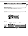 11
11
-
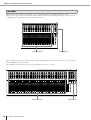 12
12
-
 13
13
-
 14
14
-
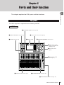 15
15
-
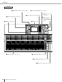 16
16
-
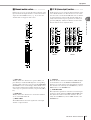 17
17
-
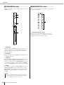 18
18
-
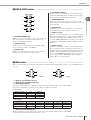 19
19
-
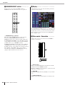 20
20
-
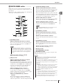 21
21
-
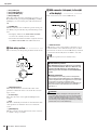 22
22
-
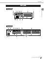 23
23
-
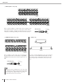 24
24
-
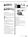 25
25
-
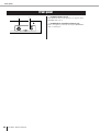 26
26
-
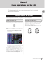 27
27
-
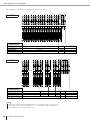 28
28
-
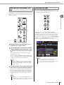 29
29
-
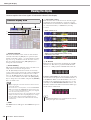 30
30
-
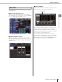 31
31
-
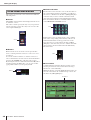 32
32
-
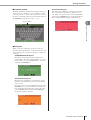 33
33
-
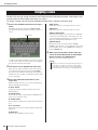 34
34
-
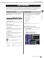 35
35
-
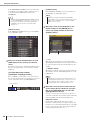 36
36
-
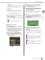 37
37
-
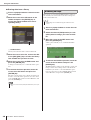 38
38
-
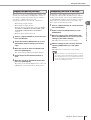 39
39
-
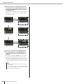 40
40
-
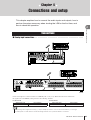 41
41
-
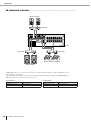 42
42
-
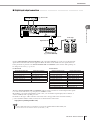 43
43
-
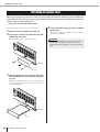 44
44
-
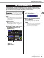 45
45
-
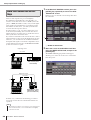 46
46
-
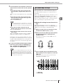 47
47
-
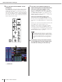 48
48
-
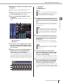 49
49
-
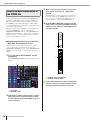 50
50
-
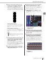 51
51
-
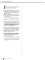 52
52
-
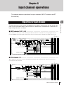 53
53
-
 54
54
-
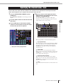 55
55
-
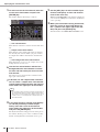 56
56
-
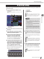 57
57
-
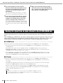 58
58
-
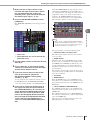 59
59
-
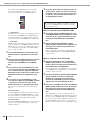 60
60
-
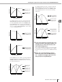 61
61
-
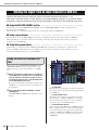 62
62
-
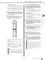 63
63
-
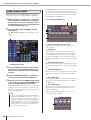 64
64
-
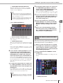 65
65
-
 66
66
-
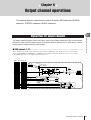 67
67
-
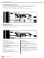 68
68
-
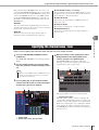 69
69
-
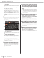 70
70
-
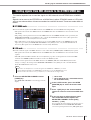 71
71
-
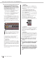 72
72
-
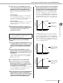 73
73
-
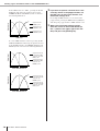 74
74
-
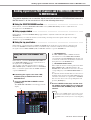 75
75
-
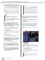 76
76
-
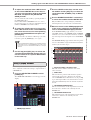 77
77
-
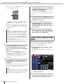 78
78
-
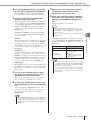 79
79
-
 80
80
-
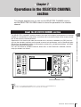 81
81
-
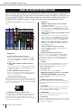 82
82
-
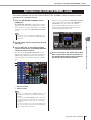 83
83
-
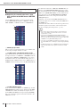 84
84
-
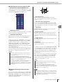 85
85
-
 86
86
-
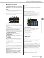 87
87
-
 88
88
-
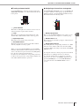 89
89
-
 90
90
-
 91
91
-
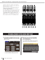 92
92
-
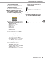 93
93
-
 94
94
-
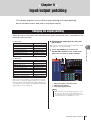 95
95
-
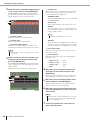 96
96
-
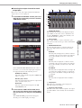 97
97
-
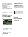 98
98
-
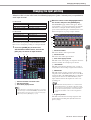 99
99
-
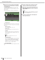 100
100
-
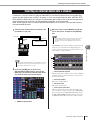 101
101
-
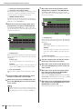 102
102
-
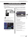 103
103
-
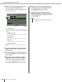 104
104
-
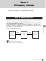 105
105
-
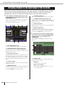 106
106
-
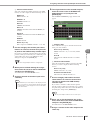 107
107
-
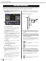 108
108
-
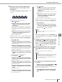 109
109
-
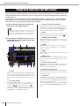 110
110
-
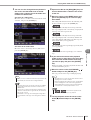 111
111
-
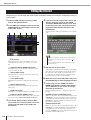 112
112
-
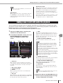 113
113
-
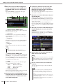 114
114
-
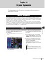 115
115
-
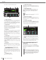 116
116
-
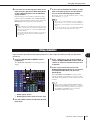 117
117
-
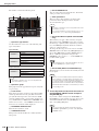 118
118
-
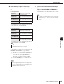 119
119
-
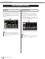 120
120
-
 121
121
-
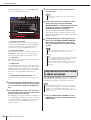 122
122
-
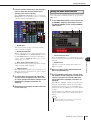 123
123
-
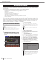 124
124
-
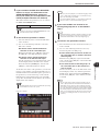 125
125
-
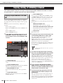 126
126
-
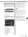 127
127
-
 128
128
-
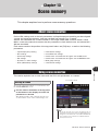 129
129
-
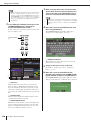 130
130
-
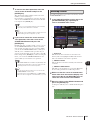 131
131
-
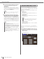 132
132
-
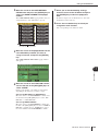 133
133
-
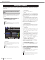 134
134
-
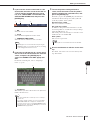 135
135
-
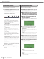 136
136
-
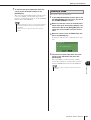 137
137
-
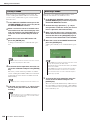 138
138
-
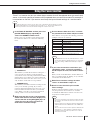 139
139
-
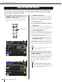 140
140
-
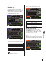 141
141
-
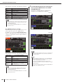 142
142
-
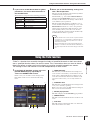 143
143
-
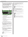 144
144
-
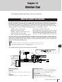 145
145
-
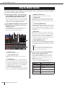 146
146
-
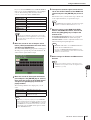 147
147
-
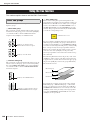 148
148
-
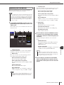 149
149
-
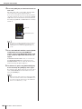 150
150
-
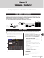 151
151
-
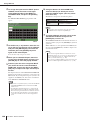 152
152
-
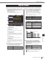 153
153
-
 154
154
-
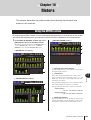 155
155
-
 156
156
-
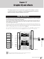 157
157
-
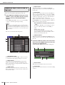 158
158
-
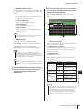 159
159
-
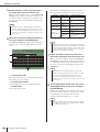 160
160
-
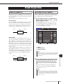 161
161
-
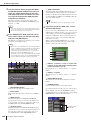 162
162
-
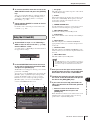 163
163
-
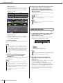 164
164
-
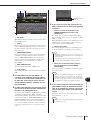 165
165
-
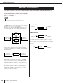 166
166
-
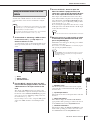 167
167
-
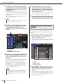 168
168
-
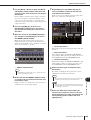 169
169
-
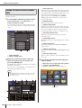 170
170
-
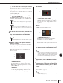 171
171
-
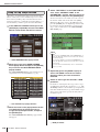 172
172
-
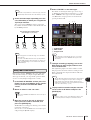 173
173
-
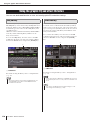 174
174
-
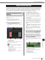 175
175
-
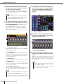 176
176
-
 177
177
-
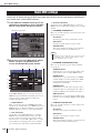 178
178
-
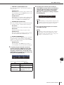 179
179
-
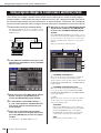 180
180
-
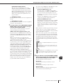 181
181
-
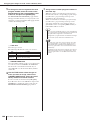 182
182
-
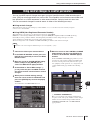 183
183
-
 184
184
-
 185
185
-
 186
186
-
 187
187
-
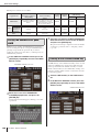 188
188
-
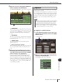 189
189
-
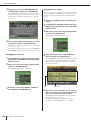 190
190
-
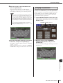 191
191
-
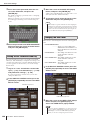 192
192
-
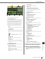 193
193
-
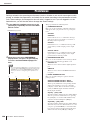 194
194
-
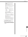 195
195
-
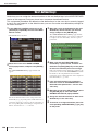 196
196
-
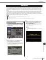 197
197
-
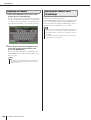 198
198
-
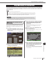 199
199
-
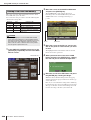 200
200
-
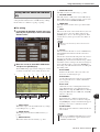 201
201
-
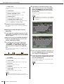 202
202
-
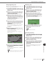 203
203
-
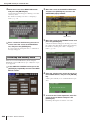 204
204
-
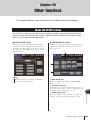 205
205
-
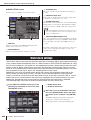 206
206
-
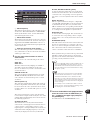 207
207
-
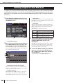 208
208
-
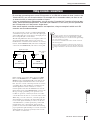 209
209
-
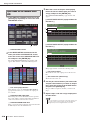 210
210
-
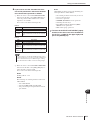 211
211
-
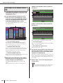 212
212
-
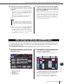 213
213
-
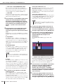 214
214
-
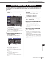 215
215
-
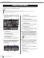 216
216
-
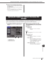 217
217
-
 218
218
-
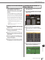 219
219
-
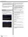 220
220
-
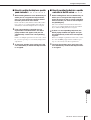 221
221
-
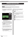 222
222
-
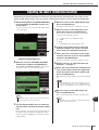 223
223
-
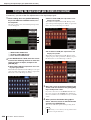 224
224
-
 225
225
-
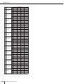 226
226
-
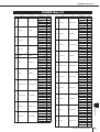 227
227
-
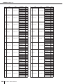 228
228
-
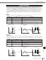 229
229
-
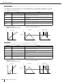 230
230
-
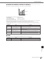 231
231
-
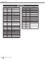 232
232
-
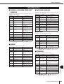 233
233
-
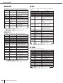 234
234
-
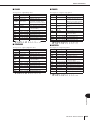 235
235
-
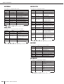 236
236
-
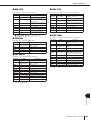 237
237
-
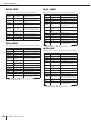 238
238
-
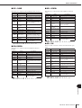 239
239
-
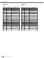 240
240
-
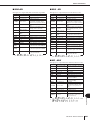 241
241
-
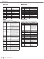 242
242
-
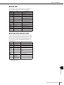 243
243
-
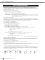 244
244
-
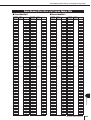 245
245
-
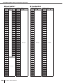 246
246
-
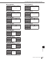 247
247
-
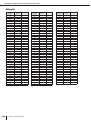 248
248
-
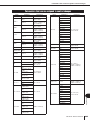 249
249
-
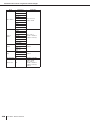 250
250
-
 251
251
-
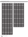 252
252
-
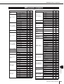 253
253
-
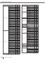 254
254
-
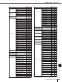 255
255
-
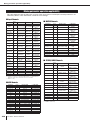 256
256
-
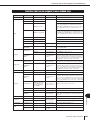 257
257
-
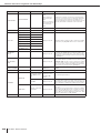 258
258
-
 259
259
-
 260
260
-
 261
261
-
 262
262
-
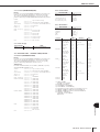 263
263
-
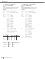 264
264
-
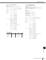 265
265
-
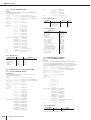 266
266
-
 267
267
-
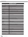 268
268
-
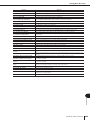 269
269
-
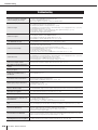 270
270
-
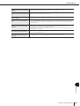 271
271
-
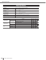 272
272
-
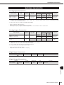 273
273
-
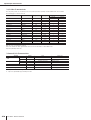 274
274
-
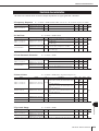 275
275
-
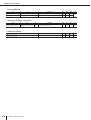 276
276
-
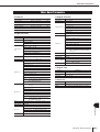 277
277
-
 278
278
-
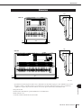 279
279
-
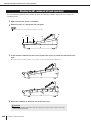 280
280
-
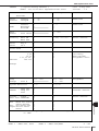 281
281
-
 282
282
-
 283
283
-
 284
284
-
 285
285
-
 286
286
-
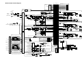 287
287
-
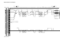 288
288
-
 289
289
-
 290
290


in andere talen
- English: Yamaha LS9 Owner's manual
- italiano: Yamaha LS9 Manuale del proprietario
- русский: Yamaha LS9 Инструкция по применению
- français: Yamaha LS9 Le manuel du propriétaire
- español: Yamaha LS9 El manual del propietario
- Deutsch: Yamaha LS9 Bedienungsanleitung
- português: Yamaha LS9 Manual do proprietário
- dansk: Yamaha LS9 Brugervejledning
- suomi: Yamaha LS9 Omistajan opas
- čeština: Yamaha LS9 Návod k obsluze
- svenska: Yamaha LS9 Bruksanvisning
- Türkçe: Yamaha LS9 El kitabı
- polski: Yamaha LS9 Instrukcja obsługi
- română: Yamaha LS9 Manualul proprietarului