

COMPLIANCE INFORMATION STATEMENT
(DECLARATION OF CONFORMITY PROCEDURE)
Responsible Party: YAMAHA CORPORATION OF AMERICA
Address: 6600 Orangethorpe Avenue, Buena Park, Calif. 90620 U.S.A.
Telephone: 1-714-522-9011
FAX: 1-714-739-2680
Type of Equipment: DIGITAL MIXING CARD
Model Name: DS2416
This device complies with Part 15 of the FCC Rules.
Operation is subject to the following conditions:
1) this device may not cause harmful interference, and
2) this device must accept any interference received including interference that may cause undesired operation.
FCC INFORMATION (U.S.A.)
1. IMPORTANT NOTICE: DO NOT MODIFY THIS UNIT! This product, when installed as indicated in the instructions contained in this manual, meets FCC
requirements. Modifications not expressly approved by Yamaha may void your authority, granted by the FCC, to use the product.
2. IMPORTANT: When connecting this product to accessories and/or another product use only high quality shielded cables. Cable/s supplied with this product MUST
be used. Follow all installation instructions. Failure to follow instructions could void your FCC authorization to use this product in the USA.
3. NOTE: This product has been tested and found to comply with the requirements listed in FCC Regulations, Part 15 for Class “B” digital devices. Compliance with
these requirements provides a reasonable level of assurance that your use of this product in a residential environment will not result in harmful interference with
other electronic devices. This equipment generates/uses radio frequencies and, if not installed and used according to the instructions found in the users manual, may
cause interference harmful to the operation of other electronic devices. Compliance with FCC regulations does not guarantee that interference will not occur in all
installations. If this product is found to be the source of interference, which can be determined by turning the unit “OFF” and “ON”, please try to eliminate the
problem by using one of the following measures: Relocate either this product or the device that is being affected by the interference. Utilize power outlets that are on
different branch (circuit breaker or fuse) circuits or install AC line filter/s. In the case of radio or TV interference, relocate/reorient the antenna. If the antenna lead-in
is 300 ohm ribbon lead, change the lead-in to coaxial type cable. If these corrective measures do not produce satisfactory results, please contact the local retailer
authorized to distribute this type of product. If you can not locate the appropriate retailer, please contact Yamaha Corporation of America, Electronic Service
Division, 6600 Orangethorpe Ave, Buena Park, CA 90620
The above statements apply ONLY to those products distributed by Yamaha Corporation of America or its subsidiaries.

1
DS2416—Owner’s Manual
Contents
Introduction . . . . . . . . . . . . . . . . . . . . . . . . . . . . . . . . . 3
Yamaha DSP Factory . . . . . . . . . . . . . . . . . . . . . . . . . . . . . . 3
Important Note . . . . . . . . . . . . . . . . . . . . . . . . . . . . . . . . . . . 3
System Requirements . . . . . . . . . . . . . . . . . . . . . . . . . . . . . . 4
System Notes . . . . . . . . . . . . . . . . . . . . . . . . . . . . . . . . . . . . . 4
Compatible Software . . . . . . . . . . . . . . . . . . . . . . . . . . . . . . 4
Features . . . . . . . . . . . . . . . . . . . . . . . . . . . . . . . . . . . . . 5
General . . . . . . . . . . . . . . . . . . . . . . . . . . . . . . . . . . . . . . . . . . 5
Mixer . . . . . . . . . . . . . . . . . . . . . . . . . . . . . . . . . . . . . . . . . . . 5
Recorder . . . . . . . . . . . . . . . . . . . . . . . . . . . . . . . . . . . . . . . . . 5
Connections . . . . . . . . . . . . . . . . . . . . . . . . . . . . . . . . . 6
Rear . . . . . . . . . . . . . . . . . . . . . . . . . . . . . . . . . . . . . . . . . . . . 6
Internal . . . . . . . . . . . . . . . . . . . . . . . . . . . . . . . . . . . . . . . . . . 7
Installing the DS2416 . . . . . . . . . . . . . . . . . . . . . . . . . . 8
Testing the DS2416 . . . . . . . . . . . . . . . . . . . . . . . . . . . 9
Installing the Test Program . . . . . . . . . . . . . . . . . . . . . . . . . 9
Using the Test Program . . . . . . . . . . . . . . . . . . . . . . . . . . . . 9
Wordclocks . . . . . . . . . . . . . . . . . . . . . . . . . . . . . . . . . . 10
Recording Digitally to the DS2416 . . . . . . . . . . . . . . . . . . . 11
Recording Digitally to DAT . . . . . . . . . . . . . . . . . . . . . . . . . 11
Digitally Cascading DS2416 Cards . . . . . . . . . . . . . . . . 12
DS2416 Q&A (Questions & Answers) . . . . . . . . . . . . . . 13
Troubleshooting . . . . . . . . . . . . . . . . . . . . . . . . . . . . . . 14
Effects Programs . . . . . . . . . . . . . . . . . . . . . . . . . . . . . . 15
Block Diagram . . . . . . . . . . . . . . . . . . . . . . . . . . . . . . . . 18
Specifications . . . . . . . . . . . . . . . . . . . . . . . . . . . . . . . . 20
Effects Parameters . . . . . . . . . . . . . . . . . . . . . . . . . . . 149

2
DS2416—Owner’s Manual
Important Notices
• Do not place the DS2416 in an area subject to excessive heat, direct sun-
light, excessive humidity, or dust.
• Keep the DS2416 inside its antistatic bag until you are ready to install it.
• To prevent handling damage, hold the DS2416 by the edges or bracket.
• If you accidentally touch the card edge connections, remove any finger-
prints using a dry tissue.
• Do not place objects on top of the DS2416, and do not put it down in a
place where other objects are likely to be placed on top of it.
• Before removing your computer’s cover, turn it off and remove the power
cord.
• To prevent static electricity damage, touch a grounded metal part of your
computer, such as the power supply case, before handling the DS2416.
Packing List
• DS2416 Digital Mixing Card
• Driver and Test program floppy disk
• 14-pin to 16-pin cable
• This manual
Trademarks
IBM PC is a registered trademark of International Business Machines. Korg is
a trademark of Korg, Inc. Pentium is a registered trademark of Intel. Sound
Blaster is a registered trademark of Advanced WavEffects. Windows 95 is a
trademark of Microsoft. Yamaha is a trademark of Yamaha Corporation. All
other trademarks are the property of their respective holders and are hereby
acknowledged.
Copyright
No part of the DS2416
Owner’s Manual
may be reproduced or distributed in
any form or by any means without the prior written authorization of Yamaha
Corporation, Inc.
© 1998 Yamaha Corporation. All rights reserved.
Keep this manual for future reference!

Introduction
3
DS2416—Owner’s Manual
Introduction
Thank you for purchasing the Yamaha DS2416 Digital Mixing Card. With
8-track simultaneous recording, 16-track simultaneous playback, 24-channel
mixing, 4-band parametric EQ, effects, and dynamics, the DS2416 provides a
complete digital recording studio inside a regular personal computer. Unlike
other audio cards, the DS2416’s five DSPs take the load off the computer’s
main processor leaving it free to concentrate on timing and other tasks while
the DS2416 takes care of high-quality effects, EQ, and dynamics processing.
In some cases, the DS2416’s onboard processing powerhouse may allow audio
software to record and playback a greater number of tracks.
For ease of installation and high data throughput, the DS2416 uses the indus-
try-standard PCI (Peripheral Component Interconnect) bus. Sound cards can
be connected digitally, or two DS2416 cards can be digitally cascaded for
48-channel mixing, each providing 2-channel analog inputs and outputs,
with 20-bit 128-times oversampling A/D converters and 20-bit 8-times over-
sampling D/A converters, and stereo coaxial digital input and output. Inputs
and outputs can be expanded using the optional AX44 Audio Expansion Unit,
which offers four 1/4-inch analog inputs—two of which can be used with
microphones—four 1/4-inch analog outputs and a stereo headphone jack.
Two AX44s can be used with each DS2416 card for eight analog inputs and
outputs.
Yamaha DSP Factory
The DS2416 Digital Mixing Card forms the heart of the Yamaha DSP Factory
system, a range of products designed to bring professional digital multitrack
recording and mixing to personal computers. Other DSP Factory products
include the AX44 Audio Expansion Unit, and several analog and digital
multi-channel input and output options are currently under development.
Check out the Yamaha Professional Audio Web site for the latest information
<http://www.yamaha.co.jp/product/proaudio/homeenglish/>.
Important Note
Whether you can actually use all the DS2416 functions that appear in the
manual will depend on your audio software.

4
Introduction
DS2416—Owner’s Manual
System Requirements
• IBM PC compatible PCI bus Windows 95 computer
• DS2416-compatible audio software
System Notes
The DS2416 can be used in any IBM PC-compatible PCI bus personal com-
puter running Windows 95. The DS2416 requires a single 5 V PCI expansion
bus slot, and cannot be used in 3.3 V PCI slots. It’s compliant with PCI ver-
sion 2.1, requires one IRQ (interrupt request), but no DMA (Direct Memory
Access). Since it’s a PCI card, IRQ settings are made automatically. PCI bus
speeds greater than 33 MHz are not supported.
Processor type, memory, and hard disk requirements are dependent on the
controlling software, not the DS2416. The supplied device driver requires a
few hundred kilobytes of disk space. Although the DS2416 supports 8-track
simultaneous recording and 16-track simultaneous playback, actual perfor-
mance will depend on the capabilities of your computer and audio software.
Compatible Software
Any software that supports Windows MME (Multimedia Extensions), includ-
ing the Windows 95 Media Player accessory, can be used with the DS2416 for
recording and playback. To use the mixing functions, however, requires soft-
ware that supports the DS2416 mixer. As of April 1998, the following software
companies are developing, or have already released software for the DS2416.
Please visit the following Web sites for more information.
•
C-Mexx
<http://www.c-mexx.com/>
•
Cakewalk
<http://www.cakewalk.com/>
•
Canam Computers
<http://www.canam-comp.fr/>
•
Emagic
<http://www.emagic.de/>
•
IQS (Innovative Quality Software)
<http://www.iqsoft.com/>
•
Musicator
<http://www.musicator.com/>
•
SEK’D
<http://www.sekd.com/CConsole/StudCcons.htm>
•
Sonic Foundry
<http://www.sfoundry.com/>
•
Steinberg
<http://www.steinberg.de/>
Audio software that doesn’t support all the features of the DS2416 can still use
a basic feature set. However, input and output patching is fixed, as shown in
the “Fixed Patchbay Diagram” on page 25. The Windows 95 Volume Control
can be used to set the stereo master fader and mute, and the level meters dis-
play the recording levels.

Features
5
DS2416—Owner’s Manual
Features
General
• PCI bus card (compliant with version 2.1)
• Support for Windows 95 MME (Multimedia Extensions)
• Plug and Play installation
• 5 onboard DSPs take the load off the computer’s main processor
• 2 analog inputs with 20-bit 128-times oversampling A/D converters
• 2 analog outputs with 20-bit 8-times oversampling D/A converters
• Stereo coaxial digital input and output (20- or 24-bit)
• Optional multi-channel analog and digital input and output options
Mixer
• 24 input channels, 8 bus outs, 6 aux sends (two feeding the onboard
effects processors), and a stereo output
• Input channels 21–24 function as effects returns for the onboard effects
• 4-band parametric EQ on all inputs channels and the stereo output
• Dynamics processors with reduction meters on all inputs channels and
the stereo output
• Two onboard effects processors with Yamaha ProR3/REV500 quality
• Input delay on input channels 1–20
• Signal level metering for all inputs and outputs
• Digital cascading of two DS2416 cards for 48-channel mixing
• 32-bit digital audio processing
Recorder
• 8-track simultaneous recording
• 16-track simultaneous playback
• Up to 32-bit recording and playback (software dependent)
• Sample-accurate synchronization between tracks
• External synchronization via controlling software

6
Connections
DS2416—Owner’s Manual
Connections
Rear
A
IN L, IN R
Analog IN L and IN R inputs feature phono jacks with a
nominal input level of –10 dBV. Analog to digital conversion
features 20-bit 128-times oversampling techniques. For best
performance use only shielded cables.
B
OUT L, OUT R
Analog OUT L and OUT R outputs feature phono jacks with
a nominal output level of –10 dBV. Digital to analog conver-
sion features 20-bit 8-times oversampling. For best perfor-
mance use only shielded cables.
C
D IN
This two-channel coaxial-type phono connection accepts
digital audio with a 24-bit maximum wordlength. Use con-
necting cables with a nominal impedance of 75 ohms.
D
D OUT
This two-channel coaxial-type phono connection outputs
digital audio with a 24-bit maximum wordlength. Use con-
necting cables with a nominal impedance of 75 ohms.
IN L
IN R
OUT L
OUT R
D IN
D OUT
1
2
3
4

Connections
7
DS2416—Owner’s Manual
Internal
A
SI (Serial In) connector
When two DS2416 cards are installed, this connector is connected to the “SO”
connector on the other card using the supplied 14-pin to 16-pin cable. Sound
cards that support the DS2416 can be connected directly to the mixer’s sub
inputs via this connector.
B
SO (Serial Out) connector
When two DS2416 cards are installed, this connector is connected to the “SI”
connector on the other card using the supplied 14-pin to 16-pin cable.
C
IO-A connector
This connector connects to the first optional AX44 Audio Expansion Unit.
D
IO-B connector
This connector connects to the second optional AX44 Audio Expansion Unit.
IO
A
B
1 2 3 4
SI
SO
IO-A
IO-B

8
Installing the DS2416
DS2416—Owner’s Manual
Installing the DS2416
The DS2416 installs into a PCI expansion slot and requires no special jumper
settings or interrupt settings.
See your computer’s manual for full details on installing PCI cards.
1
Turn off the computer and disconnect the power cord.
2
Remove the computer’s cover.
3
Choose an empty PCI slot for the DS2416, and remove the screw
from its expansion-slot cover.
To prevent static electricity from damaging the DS2416, touch a grounded
metal part of your computer, such as the power supply case, before handling
it.
4
Carefully align and insert the DS2416 into the PCI slot.
5
Secure the DS2416 using the screw removed previously.
6
Replace the computer’s cover.
7
Turn on your computer.
8
When the New Hardware Found dialog box appears, select “Driver
from disk provided by hardware manufacturer”, and then click OK.
9
When the Install From Disk dialog box appears, insert the driver
floppy disk into the floppy disk drive, and then click OK.
10
When the restart dialog box appears, restart your computer.
Important: The DS2416 is grounded via the expansion-card fixing screw, so
be sure to tighten it securely.

Testing the DS2416
9
DS2416—Owner’s Manual
Testing the DS2416
A test program is included with the DS2416 to make sure that the card, driver,
and DSPs are functioning correctly.
Installing the Test Program
1
Insert the supplied floppy disk into the floppy disk drive.
2
Double-click Setup.exe and follow the on-screen prompts.
The Test program and its associated files are installed.
Using the Test Program
1
From the Start menu, select Programs, DSP Factory, ds2416ck.exe.
2
When the Test program window appears, click the CHECK START
button to run the tests.
The Test program checks:
1. How many DS2416 cards are installed.
2. Whether the DS2416 drivers are installed
3. Whether the DSP chips are functioning correctly.
The test results appear as each test is completed. If all tests are successful, a
sine wave test tone can be produced through the OUT L, OUT R, D OUT, and
outputs 1 through 4 of any connected AX44s by clicking the test tone button.
If a test fails, follow the advice provided.
If the driver test fails again after restarting, try reinstalling the driver.
If the DSP test produces a “DSP ERROR” or “DSP NG” message, the DS2416
has a hardware problem and you should contact your Yamaha dealer.
3
Click the EXIT button to quit the Test program.

10
Wordclocks
DS2416—Owner’s Manual
Wordclocks
Unlike analog audio equipment, digital audio equipment must be synchro-
nized when digital audio is transferred from one device to another, otherwise,
the digital audio might not be read correctly and audible noise, glitches, or
clicks may occur. Synchronization is achieved using what’s called a wordclock,
which is a clock signal for synchronizing all the digital audio words in an
audio system. Note that wordclocks are not the same as SMPTE or MIDI
timecode, which are used to synchronize audio recorders, MIDI sequencers,
and so on. Wordclock synchronization refers to the synchronization of the
digital audio processing circuits inside each digital audio device.
In a typical digital audio system, one device acts as the wordclock master and
the other devices act as wordclock slaves, synchronizing to the wordclock
master. If the DS2416 is the only digital audio device in your system, no spe-
cial wordclock settings are required, as the DS2416 synchronizes to its own
internal wordclock. Add a DAT recorder or digital multitrack recorder, how-
ever, and you must decide which device to use as wordclock master and which
devices to use as slaves. Even when you’ve done this and configured your sys-
tem, it may sometimes be necessary to change the wordclock settings, such as
when recording from a DAT or CD player.
Wordclocks run at the same frequency as the sampling rate. The DS2416 gen-
erates its own wordclock at 44.1 kHz (the industry-standard sampling rate for
music CDs) or 48 kHz and can be used as wordclock master. Alternatively, it
can be used as a wordclock slave synchronized to an external wordclock of
between 30.08 kHz and 50.88 kHz (32 kHz –6% to 48 kHz +6%). Converting
the sampling rate of digital audio is a complicated process, so it’s best to use
the 44.1 kHz sampling rate, especially if your work is destined for CD distri-
bution.
Wordclock signals can be distributed via dedicated cables or derived from
standard digital audio connections, such as the D IN and D OUT connections
on the DS2416. With Coaxial digital audio connections, a wordclock signal is
transmitted even when no audio signal is present. The DS2416 can also trans-
mit and receive wordclock signals via its SI, SO, IO-A, and IO-B connectors.
In a system where all devices share a common wordclock, it’s important that
all devices be turned on even when they’re not being used. Turn on the word-
clock master first, and then the slaves. When shutting down the system, turn
off the slaves first, and then the master. Before commencing with a recording
session, make sure that all wordclock slaves are synchronized to the master.
Some devices have front panel indicators to show when they are wordclock
synchronized. Refer to the instructions for each device.

Wordclocks 11
DS2416—Owner’s Manual
Recording Digitally to the DS2416
In this example, a DAT deck is connected to the DS2416 D IN connector for
digital recording. The DS2416 works as wordclock slave, deriving its word-
clock from the D IN connection, and the DAT works as wordclock master.
Recording Digitally to DAT
In this example, the D OUT connector on the DS2416 is connected to the dig-
ital input of a DAT recorder for digital mixdown recording. The DS2416
works as wordclock master and the DAT works as wordclock slave. When the
digital input on the DAT recorder is selected as the recording source, the DAT
should automatically synchronize to the wordclock signal coming from the
DS2416. On some DAT recorders, the wordclock source may have to be set
separately. Refer to the instructions supplied with your DAT recorder.
IN L
IN R
OUT L
OUT R
D IN
D OUT
DAT
00.00.00.00
Digital Out
DAT recorder
(wordclock master)
DS2416
(wordclock slave
Source = D IN)
IN L
IN R
OUT L
OUT R
D IN
D OUT
DAT
00.00.00.00
Digital In
DAT recorder
(wordclock slave)
DS2416
(wordclock master)

12 Digitally Cascading DS2416 Cards
DS2416—Owner’s Manual
Digitally Cascading DS2416 Cards
Using the digital “SI” and “SO” connectors, two DS2416 cards can be digitally
cascaded for common busing and 48-channel mixing.
1 Install the second DS2416 into a PCI slot adjacent to the first
DS2416, as explained previously.
2 Using the supplied 14-pin to 16-pin cables, connect the “SI” and
“SO” connectors as shown below.
3 Replace the computer’s cover.
DS2416 (A) DS2416 (B)
I
O
I
O
DS2416 (A) DS2416 (B)
I
O
In this example, the buses of DS2416
(A) and (B) are linked together for 48-
channel mixing. Individual buses from
DS2416 (B) can alternatively be fed to
the sub inputs of DS2416 (A).
In this example, the buses of DS2416
(A) and (B) are linked together for 48-
channel mixing. Individual buses from
either DS2416 can be fed to the other
DS2416.

DS2416 Q&A (Questions & Answers) 13
DS2416—Owner’s Manual
DS2416 Q&A (Questions & Answers)
Q What’s a DSP?
A A DSP, or Digital Signal Processor is a processor optimized for
real-time digital data processing. The DS2416 features the same
DSP as the Yamaha 02R and 03D digital mixing consoles and
ProR3 and REV500 effects processors.
Q At what wordlength is digital audio processed?
A The EQ features a 44-bit data path, 32-bit coefficient, and 54-bit
accumulator. All other mixer sections feature a 32-bit data path,
24-bit coefficient, and 42-bit accumulator.
Q Does the DS2416 have any onboard memory?
A Yes, 3 megabytes, which is used for input, and effects delays.
Q What is the available recording time?
A This depends on the software, selected wordlength, and hard disk
space. In general, two channels of 16-bit digital audio use 10.6
MB/min.
Q How do I synchronize the DS2416 to MIDI Clock, MTC, or SMPTE
timecode?
A If the software and timecode interface support external timecode,
so does the DS2416.
Q Can DS2416 mixer functions be controlled via MIDI?
A If the controlling software supports this, yes.
Q How good are the onboard effects processors?
A As good as those used in the Yamaha ProR3 and REV500 effects
processors.
Q Can the DS2416 be used simultaneously with a Sound Blaster or
Korg 1212 I/O card?
A Yes.

14 Troubleshooting
DS2416—Owner’s Manual
Troubleshooting
Trouble Advice
The DS2416 does not work?
Make sure that the DS2416 is inserted in the
PCI bus slot correctly.
Make sure that the DS2416 input and outputs
are correctly assigned using the controlling
software.
In older computers, some PCI slots may not
function as the bus master, and the DS2416 will
not work in such slots. See your computer’s
manual for more details.
Some PCI cards may conflict with the DS2416.
Try removing cards, or swapping slots with the
DS2416.
A low-level hum can be heard?
The DS2416 is grounded via the expan-
sion-card fixing screw, so be sure to tighten it
securely.

Effects Programs 15
DS2416—Owner’s Manual
Effects Programs
The DS2416 provides the following effects programs. Detailed effects param-
eters are shown on page 149.
Reverb-type Effects
Delays
Type Description
REVERB HALL Reverb simulating a large space such as a concert hall.
REVERB ROOM Reverb simulating the acoustics of a smaller space than REVERB HALL.
REVERB STAGE Reverb designed with vocals in mind.
REVERB PLATE
Simulation of a metal-plate reverb unit, producing a feeling of
hard-edged reverberation.
EARLY REF.
An effect which isolates only the early reflection (ER) component from
reverberation. A flashier effect than reverb is produced.
GATE REVERB A type of ER designed for use as gated reverb.
REVERSE GATE A reverse-playback type ER.
Type Description
MONO DELAY
Mono delay with simple operation. Use when you don't need to use
complex parameter settings.
STEREO DELAY Stereo delay with independent left and right.
MOD.DELAY Mono delay with modulation.
DELAY LCR Three-tap delay (L, C, R).
ECHO
Stereo delay with additional parameters for more detailed control. The
signal can be fed back from left to right, and right to left.

16 Effects Programs
DS2416—Owner’s Manual
Modulation-type Effects
Guitar Effects
Dynamic Effects
Type Description
CHORUS Three-phase stereo chorus.
FLANGE The well-known flanging effect.
SYMPHONIC
A Yamaha proprietary effect that produces a richer and more complex
modulation than chorus.
PHASER Stereo phaser with 2–16 stages of phase shift.
AUTO PAN An effect which cyclically moves the sound between left and right.
TREMOLO Tremolo
HQ.PITCH
(Effect 2 only)
Only one note is pitch-shifted, but a stable effect is produced.
DUAL PITCH Stereo pitch shift with left and right pitches set independently.
ROTARY Simulation of a rotary speaker.
RING MOD.
An effect that modifies the pitch by applying amplitude modulation to
the frequency of the input.
MOD.FILTER An effect which uses an LFO to modulate the frequency of the filter.
Type Description
DISTORTION Distortion
AMP SIMULATE Guitar Amp Simulator
Type Description
DYNA.FILTER Dynamically controlled filter.
DYNA.FLANGE Dynamically controlled flange.
DYNA.PHASER Dynamically controlled phase shifter.

Effects Programs 17
DS2416—Owner’s Manual
Combined Effects
Type Description
REV+CHORUS Reverb and chorus in parallel
REV->CHORUS Reverb and chorus in series
REV+FLANGE Reverb and flange in parallel
REV->FLANGE Reverb and flange in series
REV+SYMPHO. Reverb and symphonic in parallel
REV->SYMPHO. Reverb and symphonic in series
REV->PAN Reverb and auto-pan in parallel
DELAY+ER. Delay and early reflections in parallel
DELAY->ER. Delay and early reflections in series
DELAY+REV Delay and reverb in parallel
DELAY->REV Delay and reverb in series
DIST->DELAY Distortion and delay in series

18 Block Diagram
DS2416—Owner’s Manual
Block Diagram
SAME AS CH1
CH1
CH2-8
SAME AS CH1
CH9-12
SAME AS CH1
CH13-16
SAME AS CH1
CH17
SAME AS CH1
CH18
SAME AS CH1
CH19
SAME AS CH1
CH20
A/D
CHANNEL
METER
ON
REDUCTION
METER
Signal
Pre
Post
SAME AS CH21
CH21
SAME AS CH21
CH22
SAME AS CH21
CH23
CH24
STEREO
MASTER
CASCADE IN(16ch)
SUB IN(8ch)
PCI
PLAYBACK(16ch)
IO-B
IO-A
PCI
SI
A IN L
A IN R
D IN
IO-A IN(4 or 8ch)
IO-B IN(4 or 8ch)
SERIAL IN
16 or 8
16
8
16
4 or 8
4
2
2
2
2
7
4
4
4
4
4 or 8
4
4 4
8
7
78
4
4
4
4
4
DC-CUT
ATT/PHASE
4BAND
PEQ
DYNAMICS
DE-EMPHASIS
DE-EMPHASIS
CHANNEL
METER
ON
REDUCTION
METER
Signal
Pre
Post
DC-CUT
ATT/PHASE
4BAND
PEQ
DYNAMICS
DELAY
BALANCE

Block Diagram 19
DS2416—Owner’s Manual
PAN
BUS1
Pre/Post
BUS2
BUS3
BUS4
BUS5
BUS6
BUS7
BUS8
AUX1
AUX2
AUX3
AUX4
AUX5
AUX6
ON/OFF
PAN
BUS1
Pre/Post
BUS2
BUS3
BUS4
BUS5
BUS6
BUS7
BUS8
AUX1
AUX2
AUX3
AUX4
ON/OFF
BUS1
BUS2
BUS3
BUS4
BUS5
BUS6
BUS7
BUS8
STEREO L
STEREO R
AUX1
AUX2
AUX3
AUX4
AUX5
AUX6
12345678 123456LR
BUS AUXSTEREO
REDUCTION
METER
PEQ
DYNAMICS
STEREO
STEREO
MASTER
MASTER
STEREO
MASTER
BUS METER
BUS1
SAME AS BUS1
BUS2
SAME AS BUS1
BUS3
BUS
MASTER
ON
STEREO
L
STEREO
R
STEREO L METER
STEREO R METER
AUX METER
AUX1
SAME AS AUX1
AUX2
SAME AS AUX1
AUX3
AUX
MASTER
ON
BUS 1/2
BUS 3/4
BUS 5/6
BUS 7/8
STEREO L/R
AUX 1/2
AUX 3/4
AUX 5/6
BUILT-IN
EFFECT 1
BUILT-IN
EFFECT 2
IO-A
IO-B
D/A
PCI
A OUT L
A OUT R
D OUT
IO-A OUT(4 or 8ch)
IO-B OUT(4 or 8ch)
SERIAL OUT
CASCADE OUT(16ch)
PCI REC OUT(8ch)
SAME AS AUX1
SAME AS AUX1
AUX5
SAME AS AUX1
AUX6
AUX4
SAME AS BUS1
BUS4
SAME AS BUS1
BUS5
SAME AS BUS1
BUS6
SAME AS BUS1
BUS7
SAME AS BUS1
BUS8
8 ST in
11(15) ST out
PATCH BAY
BUS1
BUS2
BUS3
BUS4
BUS5
BUS6
BUS7
BUS8
STEREO L
STEREO R
AUX1
AUX2
AUX3
AUX4
AUX5
AUX6
SO
AUX 3/4
AUX 5/6
16
8
4 or 8
4 or 8
2
2
2
2
2
2
2
2
2
2
2
2
2
4BAND
PEQ
ATT
4BAND
PEQ
ATT
BALANCE
BALANCE
BALANCE

20 Specifications
DS2416—Owner’s Manual
Specifications
General
1. 44.1 kHz ±6%, 48 kHz ±6%
2. 32 KHz –6% to 48 kHz +6%
3. Bandwidth filter ±0.1 dB (20 Hz to 20 kHz), –60 dB (more than 24.1 kHz)
4. Bandwidth filter as above plus Weighting Filter (IEC60651 A curve, Tolerance:
Type 0)
Sampling rate
Internal 44.1 kHz, 48 kHz
Internal vari-pitch
41.45 to 50.88 kHz
1
External
30.08 to 50.88 kHz
2
Signal delay
(fs = 48 kHz)
A/D 620 µs typical
D/A 310 µs typical
Total harmonic distortion
3
(fs = 48 kHz, +6 dBV, analog input to output)
Less than 0.02% (20 Hz to 20 kHz)
Frequency response
(fs = 48 kHz, +6 dBV, analog input to output)
20 Hz to 20 kHz, –3, +1 dB
Dynamic range
4
(fs = 48 kHz)
D/A Typically 94 dB
A/D + D/A Typically 93 dB
Residual output noise
4
(D/A input = digital 0)
Typically –88 dBV
Input
IN L, IN R 20-bit 128-times oversampling A/D
D IN Consumer format (Coaxial)
Output
OUT L, OUT R 20-bit 8-times oversampling D/A
D OUT Consumer format (Coaxial)
Effects
(HQ. Pitch type for
Effect 2 only)
Effect 1 39 types
Effect 2 40 types
Power supply
+5 V (1.5 A max)
+12 V (150 mA max)
Maximum power consumption 9.3 W
Temperature
Operating +10 to +40˚C
Storage –20 to +55˚C
Dimensions (H x L x D)
125.92 x 187.95 x 21.59 mm
(4.95 x 7.4 x 0.85 inch)
PCI Raw Variable Height Short Card
(5 V, 32-bit)
Weight 170 g (6 oz)
Supplied accessories
Driver floppy disk
14-pin to 16-pin 100 mm cable x1

Specifications 21
DS2416—Owner’s Manual
Input Channels
De-emphasis (CH19, CH20) Automatically applied as needed
DC Cut Automatically applied as needed
ATT –96 to +12 dB (109 steps)
Phase Normal/reverse
4-band EQ
(12 EQ types per band)
Frequency 20 Hz to 20 kHz (120 steps, 12 points/octave)
Gain –18 to +18 dB (73 steps, 0.5 dB/step)
Q 0.1 to 10.0 (41 steps)
Dynamics
(6 types)
Threshold –54 to 0 dB (55 steps, 1.0 dB/step)
Attack 0 to 120 ms (121 steps, 1 ms/step)
Gain 0 to 18 dB (37 steps, 0.5 dB/step)
Release
5 ms to 42.3 s, fs = 48.0 kHz (160 steps)
6 ms to 46.0 s, fs = 44.1 kHz (160 steps)
Ratio 1.0 to infinity (16 steps)
Knee Hard, 1, 2, 3, 4, 5 (6 steps)
Range –70 to 0 dB (71 steps, 1.0 dB/step)
Hold
0.02 ms to 1.96 s, fs = 48.0 kHz (216 steps)
0.02 ms to 2.13 s, fs = 44.1 kHz (216 steps)
Decay
5 ms to 42.3 s, fs = 48.0 kHz (160 steps)
6 ms to 46.0 s, fs = 44.1 kHz (160 steps)
Width 1 to 90 (90 steps, 1.0 dB/step)
Mgain –18 to 0 dB (37 step, 0.5 dB/step)
Reduction
meter
–18 to 0 dB (12 steps)
Delay (CH1 to CH20)
0 to 2,600 samples (2,601 steps)
On/Off
On/Off
Fader –Infinity, –90 to +10 dB (128 steps)
Pan 33 steps
Channel meter
–72 to 0 dB (32 steps)
Pre/Post/Signal
Peak Hold
Decay Fast/Slow
Bus send
Level –Infinity, –120 to 0 dB (128 steps)
Pre/Post (Pre pan/post pan)
On/Off
Aux send
Level –Infinity, –120 to 0 dB (128 steps)
Pre/Post (Pre fader/post fader)
On/Off

22 Specifications
DS2416—Owner’s Manual
Bus Outs 1–8
Aux Sends 1–6
Stereo Output
Bus master fader –Infinity, –120 to 0 dB (128 steps)
On/Off
Bus meter
–72 to 0 dB (32 steps)
Pre/Post fader
Peak Hold
Decay Fast/Slow
Aux master fader –Infinity, –120 to 0 dB (128 steps)
On/Off
Aux meter
–72 to 0 dB (32 steps)
Pre/Post fader
Peak Hold
Decay Fast/Slow
ATT –96 to +12 dB (109 steps)
4-band EQ
(12 EQ types per band)
Frequency 20 Hz to 20 kHz (120 steps, 12 points/octave)
Gain –18 to +18 dB (73 steps, 0.5 dB/step)
Q 0.1 to 10.0 (41 steps)
Stereo master fader –Infinity, –120 to 0 dB (128 steps)
Dynamics
(6 types)
Threshold –54 to 0 dB (55 steps, 1.0 dB/step)
Attack 0 to 120 ms (121 steps, 1 ms/step)
Gain 0 to 18 dB (37 steps, 0.5 dB/step)
Release
5 ms to 42.3 s, fs = 48.0 kHz (160 steps)
6 ms to 46.0 s, fs = 44.1 kHz (160 steps)
Ratio 1.0 to infinity (16 steps)
Knee Hard, 1, 2, 3, 4, 5 (6 steps)
Range –70 to 0 dB (71 steps, 1.0 dB/step)
Hold
0.02 ms to 1.96 s, fs = 48.0 kHz (216 steps)
0.02 ms to 2.13 s, fs = 44.1 kHz (216 steps)
Decay
5 ms to 42.3 s, fs = 48.0 kHz (160 steps)
6 ms to 46.0 s, fs = 44.1 kHz (160 steps)
Width 1 to 90 (90 steps, 1.0 dB/step)
Mgain –18 to 0 dB (37 steps, 0.5 dB/step)
Reduction
meter
–18 to 0 dB (12 steps)
Balance 33 steps

Specifications 23
DS2416—Owner’s Manual
Input Patchbay
PCI PB: wave data, etc., playback
IO-A1: 4-input/4-output device connected to IO-A
IO-A2: 8-input/8-output device connected to IO-A
IO-B1: 4-input/4-output device connected to IO-B
IO-B2: 8-input/8-output device connected to IO-B
Stereo meter
–72 to 0 dB (32 steps)
Pre/Post fader
Peak Hold
Decay Fast/Slow
Input Selectable Source
CH1 PCI PB1, IO-B2-1
CH2 PCI PB2, IO-B2-2
CH3 PCI PB3, IO-B2-3
CH4 PCI PB4, IO-B2-4
CH5 PCI PB5, IO-B2-5
CH6 PCI PB6, IO-B2-6
CH7 PCI PB7, IO-B2-7
CH8 PCI PB8, IO-B2-8
CH9 PCI PB9, IO-B1-1, SUB IN1, IO-A2-1
CH10 PCI PB10, IO-B1-2, SUB IN2, IO-A2-2
CH11 PCI PB11, IO-B1-3, SUB IN3, IO-A2-3
CH12 PCI PB12, IO-B1-4, SUB IN4, IO-A2-4
CH13 PCI PB13, IO-A1-1, SUB IN5, IO-A2-5
CH14 PCI PB14, IO-A1-2, SUB IN6, IO-A2-6
CH15 PCI PB15, IO-A1-3, SUB IN7, IO-A2-7
CH16 PCI PB16, IO-A1-4, SUB IN8, IO-A2-8
CH17 IN L, IO-A1-1, SUB IN1, IO-A2-1
CH18 IN R, IO-A1-2, SUB IN2, IO-A2-2
CH19 DIN L, IO-A1-3, SUB IN3, IO-A2-3
CH20 DIN R, IO-A1-4, SUB IN4, IO-A2-4
CH21 Effect1 Return L, SUB IN5, IO-A2-5
CH22 Effect1 Return R, SUB IN6, IO-A2-6
CH23 Effect2 Return L, SUB IN7, IO-A2-7
CH24 Effect2 Return R, SUB IN8, IO-A2-8

24 Specifications
DS2416—Owner’s Manual
Output Patchbay
Sources 1 through 8 can be patched to any destination.
IO-A1: 4-input/4-output device connected to IO-A
IO-A2: 8-input/8-output device connected to IO-A
IO-B1: 4-input/4-output device connected to IO-B
IO-B2: 8-input/8-output device connected to IO-B
Source Destination
1: BUS 1, 2 1: REC 1, 2
2: BUS 3, 4 2: REC 3, 4
3: BUS 5, 6 3: REC 5, 6
4: BUS 7, 8 4: REC 7, 8
5: AUX 1, 2 5: IO-A1-1, 2 (IO-A2-1, 2)
6: AUX 3, 4 6: IO-A1-3, 4 (IO-A2-3, 4)
7: AUX 5, 6 7: IO-B1-1, 2 (IO-B2-1, 2)
8: STL, STR 8: IO-B1-3, 4 (IO-B2-3, 4)
9: AOUTL, AOUTR
10: DOUTL, DOUTR
11: IO-A2-5, 6
12: IO-A2-7, 8
13: IO-B2-5, 6
14: IO-B2-7, 8

Specifications 25
DS2416—Owner’s Manual
Fixed Patchbay Diagram
When audio software that doesn’t support the DS2416’s mixer is used, input
and output assignments are fixed, as shown below.
IO-A IN 1
IO-A IN 2
IO-A IN 3
IO-A IN 4
IN L
IN R
D IN L
D IN R
PCI REC OUT 1
PCI REC OUT 2
PCI REC OUT 3
PCI REC OUT 4
PCI REC OUT 5
PCI REC OUT 6
PCI REC OUT 7
PCI REC OUT 8
IO-A OUT 1
IO-A OUT 2
IO-A OUT 3
IO-A OUT 4
IO-B OUT 1
IO-B OUT 2
IO-B OUT 3
IO-B OUT 4
PCI PLAYBACK 1
PCI PLAYBACK 2
PCI PLAYBACK 3
PCI PLAYBACK 4
PCI PLAYBACK 5
PCI PLAYBACK 6
PCI PLAYBACK 7
PCI PLAYBACK 8
PCI PLAYBACK 9
PCI PLAYBACK 10
PCI PLAYBACK 11
PCI PLAYBACK 12
PCI PLAYBACK 13
PCI PLAYBACK 14
PCI PLAYBACK 15
PCI PLAYBACK 16
OUT L
OUT R
D OUT L
D OUT R
STEREO
MASTER
Input
Output

26 Specifications
DS2416—Owner’s Manual
Analog Inputs
Analog Outputs
Digital I/O
1. Inputs feature linear 20-bit 128-times oversampling A/D converters.
2. Where dBV represents a specific voltage, 0 dBV is referenced to 1 V rms.
1. Outputs feature linear 20-bit 8-times oversampling D/A converters.
2. Where dBV represents a specific voltage, 0 dBV is referenced to 1 V rms.
Connection
Actual
load
impedance
For use with
nominal
Input level
Connector
Nominal
Max. before
clip
IN L, IN R
1
10k Ω 600 Ω lines
–10 dBV
2
(316 mV)
+6 dBV
(1.995 V)
Phono jack
(unbalanced)
Connection
Actual
source
impedance
For use with
nominal
Output level
Connector
Nominal
Max. before
clip
OUT L, OUT R
1
600 Ω 10k Ω lines
–10 dBV
2
(316 mV)
+6 dBV
(1.995 V)
Phono jack
(unbalanced)
Connection I/O Format Level Connector
D IN
I
IEC60958 Consumer 0.5 Vpp, 75 Ω
Phono jack
(unbalanced)
D OUT
O
IEC60958 Consumer 0.5 Vpp, 75 Ω
Phono jack
(unbalanced)
IO-A, IO-B
I/O
4CH or 8CH digital audio inputs
4CH or 8CH digital audio outputs
32-bit max/channel
Format depends on counterpart
5 V CMOS 20-pin connector
SERIAL IN
I
8CH or 16CH digital audio inputs
32-bit max/channel
Format depends on counterpart
5 V CMOS 16-pin connector
SERIAL OUT
O
8CH or 16CH digital audio outputs
32-bit max/channel
Format depends on counterpart
5 V CMOS 14-pin connector

Specifications 27
DS2416—Owner’s Manual
Dimensions
Specifications and external appearance are subject to change without notice.
187.95
125.92
21.59
IO
A
B
IN L
IN R
OUT L
OUT R
D IN
D OUT
SI
SO
IO-A
IO-B
Unit: mm

Mode d’emploi
Français
DS2416
DIGITAL MIXING CARD

30
DS2416—Mode d’emploi
Sommaire
Introduction . . . . . . . . . . . . . . . . . . . . . . . . . . . . . . . . . 32
Yamaha DSP Factory . . . . . . . . . . . . . . . . . . . . . . . . . . . . . . 32
Remarque importante . . . . . . . . . . . . . . . . . . . . . . . . . . . . . 32
Système requis . . . . . . . . . . . . . . . . . . . . . . . . . . . . . . . . . . . 33
Remarque concernant le système . . . . . . . . . . . . . . . . . . . . 33
Logiciels compatibles . . . . . . . . . . . . . . . . . . . . . . . . . . . . . . 33
Caractéristiques . . . . . . . . . . . . . . . . . . . . . . . . . . . . . . 34
Générales . . . . . . . . . . . . . . . . . . . . . . . . . . . . . . . . . . . . . . . . 34
Mixer . . . . . . . . . . . . . . . . . . . . . . . . . . . . . . . . . . . . . . . . . . . 34
Recorder . . . . . . . . . . . . . . . . . . . . . . . . . . . . . . . . . . . . . . . . 34
Connexions . . . . . . . . . . . . . . . . . . . . . . . . . . . . . . . . . . 35
Connexions arrière . . . . . . . . . . . . . . . . . . . . . . . . . . . . . . . 35
Connexions internes . . . . . . . . . . . . . . . . . . . . . . . . . . . . . . 36
Installation de la DS2416 . . . . . . . . . . . . . . . . . . . . . . . 37
Tester la DS2416 . . . . . . . . . . . . . . . . . . . . . . . . . . . . . . 39
Installer le programme de test (Test Program) . . . . . . . . . 39
Utiliser le programme de test . . . . . . . . . . . . . . . . . . . . . . . 39
Wordclocks . . . . . . . . . . . . . . . . . . . . . . . . . . . . . . . . . . 40
Enregistrement numérique sur la DS2416 . . . . . . . . . . . . . 41
Enregistrement numérique sur DAT . . . . . . . . . . . . . . . . . 41
Cascade numérique de cartes DS2416 . . . . . . . . . . . . . 42
DS2416 Q&R (questions & réponses) . . . . . . . . . . . . . . 43
Dépannage . . . . . . . . . . . . . . . . . . . . . . . . . . . . . . . . . . 44
Programmes d’effets . . . . . . . . . . . . . . . . . . . . . . . . . . . 45
Schéma . . . . . . . . . . . . . . . . . . . . . . . . . . . . . . . . . . . . . 48
Fiche technique . . . . . . . . . . . . . . . . . . . . . . . . . . . . . . . 50
Effects Parameters . . . . . . . . . . . . . . . . . . . . . . . . . . . 149

31
DS2416—Mode d’emploi
Remarques importantes
• Ne placez pas la DS2416 dans un endroit soumis à une chaleur ou une
humidité excessive, au rayonnement direct du soleil ou à la poussière.
• Conservez la DS2416 dans son sac antistatique jusqu’à ce que vous soyez
prêt à l’installer.
• Pour éviter tout endommagement lors de la manipulation, tenez la
DS2416 par les bords ou la fixation.
• Si vous touchez accidentellement les connexions du bord de la carte,
enlevez les empreintes digitales avec un mouchoir sec.
• Ne placez pas d’objet sur la DS2416 et ne la déposez pas dans un endroit
où d’autres objets risquent d’être placés dessus.
• Avant d’ouvrir le boîtier de votre ordinateur, coupez-en l’alimentation et
débranchez le cordon d’alimentation.
• Pour éviter tout endommagement par électricité statique, touchez une
partie métallique mise à la masse de votre ordinateur, telle que le boîtier
d’alimentation, avant de manier la DS2416.
Contenu de l’emballage
• DS2416 Digital Mixing Card
• Disquette avec pilote et programme de test (Driver et Test)
• Câble de 14/16 broches
•Ce manuel
Marques commerciales
IBM PC est une marque commerciale de International Business Machines.
Korg est une marque commerciale de Korg, Inc. Pentium est une marque
déposée de Intel. Sound Blaster est une marque déposée de Advanced WavEf-
fects. Windows 95 est une marque commerciale de Microsoft. Yamaha est une
marque commerciale de Yamaha Corporation. Toutes les autres marques sont
la propriété de leurs détenteurs respectifs et sont reconnues par la présente.
Copyright
Il est interdit de reproduire en tout ou en partie ce
Mode d’emploi
ou de le dis-
tribuer sous quelque forme ou par quelque moyen que ce soit sans l’autorisa-
tion écrite préalable de Yamaha Corporation, Inc.
© 1998 Yamaha Corporation. Tous droits réservés.
Conservez ce manuel pour toute référence ultérieure!

32
Introduction
DS2416—Mode d’emploi
Introduction
Nous vous remercions d’avoir opté pour la Yamaha DS2416 Digital Mixing
Card. Cette carte de mixage numérique permet un enregistrement simultané
sur 8 pistes, une reproduction simultanée sur 16 pistes, un mixage sur 24
canaux, une égalisation paramétrique à 4 bandes, des effets et des paramètres
de dynamique; elle constitue un studio d’enregistrement numérique complet
qu’il suffit d’insérer dans un ordinateur personnel. A la différence des autres
cartes audio, les cinq DSP de la DS2416 allègent le travail du processeur prin-
cipal de l’ordinateur ce qui le libère pour des tâches de synchronisation et
autres tandis que la DS2416 s’occupe des effets de haute qualité, de l’égalisa-
tion et du traitement de dynamique. Dans certains cas, les processeurs du
DS2416 peuvent permettre à des logiciels audio d’enregistrer et de reproduire
un plus grand nombre de pistes.
Pour simplifier l’installation et le transfert considérable de données, la
DS2416 se sert du connecteur de norme industrielle PCI (Peripheral Compo-
nent Interconnect). Les cartes sonores peuvent être branchées numérique-
ment; vous pouvez également brancher deux cartes DS2416 en cascade pour
effectuer des mixages de 48 canaux. Chaque carte fourni des entrées et des
sorties analogiques de canaux pourvues de convertisseurs A/N 20 bits avec
suréchantillonnage à 128 fois et des convertisseurs N/A 20 bits avec suréchan-
tillonnage à 8 fois. Pour augmenter vos entrées et sorties, vous pouvez vous
servir de l’ AX44 Audio Expansion Unit, disponible en option, qui vous pro-
pose quatre entrées analogiques 1/4” (dont deux peuvent être utilisées avec
des microphones), quatre sorties analogiques 1/4” et une borne stéréo pour
casque. Chaque carte DS2416 peut accueillir deux AX44 afin de bénéficier de
huit entrées et sorties analogiques.
Yamaha DSP Factory
La DS2416 Digital Mixing Card constitue le coeur du système Yamaha DSP
Factory, une gamme de produits conçus pour amener l’enregistrement multi-
piste et le mixage professionnels sur ordinateurs. La gamme DSP Factory pro-
pose également l’AX44 Audio Expansion Unit; plusieurs options d’entrées et
de sorties multi-canaux numériques et analogiques sont en cours de dévelop-
pement.
Pour les toutes dernières nouvelles, consultez le site Web Yamaha Professional
Audio <http://www.yamaha.co.jp/product/proaudio/homeenglish/>.
Remarque importante
L’accès à toutes les fonctions de la DS2416 décrites dans ce manuel dépend de
votre logiciel audio.

Introduction
33
DS2416—Mode d’emploi
Système requis
• Ordinateur sous Windows 95, compatible IBM PC, avec connecteur PCI
• Logiciel audio compatible avec la DS2416
Remarque concernant le système
La carte DS2416 peut être insérée dans n’importe quel ordinateur compatible
IBM PC, doté d’un connecteur PCI et tournant sous Windows 95. La DS2416
nécessite un connecteur d’extension simple 5 V PCI et ne peut pas être utilisée
avec des connecteurs 3.3 V PCI. Elle répond à la version PCI 2.1, exige une
IRQ (interrupt request) mais pas de DMA (Direct Memory Access). Comme
il s’agit d’une carte PCI, les réglages IRQ sont faits automatiquement. Des
vitesses de bus PCI supérieures à 33 MHz ne sont pas supportées.
Les spécifications concernant le type de processeur, la mémoire et le disque
dur dépendent du logiciel pilote et non de la DS2416. Le pilote fourni prend
quelques centaines de Ko. Bien que la DS2416 puisse enregistrer sur 8 pistes et
reproduire sur 16 pistes simultanément, la performance réelle dépend des
possibilités de votre ordinateur et de votre logiciel audio.
Logiciels compatibles
N’importe quel logiciel supportant Windows MME (Multimedia Extensions),
y compris Media Player de Windows 95, peut être utilisé avec la DS2416 pour
l’enregistrement et la reproduction. Cependant, pour bénéficier des fonctions
de mixages, le logiciel doit supporter le mélangeur de la DS2416. En avril
1998, les firmes suivantes proposaient ou développaient un logiciel pour la
DS2416. Veuillez voir les sites Web suivants pour en savoir davantage:
•
C-Mexx
<http://www.c-mexx.com/>
•
Cakewalk
<http://www.cakewalk.com/>
•
Canam Computers
<http://www.canam-comp.fr/>
•
Emagic
<http://www.emagic.de/>
•
IQS (Innovative Quality Software)
<http://www.iqsoft.com/>
•
Musicator
<http://www.musicator.com/>
•
SEK’D
<http://www.sekd.com/CConsole/StudCcons.htm>
•
Sonic Foundry
<http://www.sfoundry.com/>
•
Steinberg
<http://www.steinberg.de/>
Les logiciels audio qui ne supportent pas toutes les fonctions de la DS2416
peuvent en utiliser un jeu de base. Toutefois, l’acheminement entrée/sortie est
fixe, comme le montre le “Schéma de multiconnecteur fixe” à la page 55. La
commande Volume Windows 95 permet de régler le curseur Master stéréo et
Mute tandis que les VU-mètres affichent les niveaux d’enregistrement.

34
Caractéristiques
DS2416—Mode d’emploi
Caractéristiques
Générales
• Carte de connecteur PCI (répondant à la version 2.1)
• Support pour Windows 95 MME (extensions multimédia)
• Installation Plug and Play
• 5 DSP intégrés allègent la tâche du processeur principal de l’ordinateur.
• 2 entrées analogiques avec des convertisseurs A/N 20 bits et suréchan-
tillonnage à 128 fois
• 2 sorties analogiques avec des convertisseurs N/A 20 bits et suréchan-
tillonnage à 8 fois
• Entrée et sortie numériques coaxiales stéréo (20 ou 24 bits)
• Entrées et sorties analogiques et numériques multi-canaux disponibles
en option
Mixer
• 24 canaux d’entrée, 8 bus de sortie, 6 envois Aux (dont deux vers les pro-
cesseurs d’effets de bord) et une sortie stéréo.
• Les canaux d’entrée 21~24 font office de retours d’effet pour les effets
intégrés.
• Egalisation paramétrique à 4 bandes sur tous les canaux d’entrée et la
sortie stéréo.
• Processeurs de dynamique avec indicateurs de réduction sur tous les
canaux d’entrée et la sortie stéréo.
• Deux processeurs d’effets intégrés de qualité Yamaha ProR3/REV500.
• Retard d’entrée sur les canaux d’entrée 1~20.
• Contrôle du niveau des signaux pour toutes les entrées et sorties.
• Cascade numérique de 2 cartes DS2416 permettant de mixer 48 canaux.
• Traitement audio numérique à 32 bits.
Recorder
• Enregistrement simultané sur 8 pistes.
• Reproduction simultanée sur 16 pistes.
• Enregistrement et reproduction jusque 32 bits (selon le logiciel).
• Synchronisation à l’échantillon près entre les pistes.
• Synchronisation via le logiciel pilote.

Connexions
35
DS2416—Mode d’emploi
Connexions
Connexions arrière
A
IN L, IN R
Les entrées analogiques IN L et IN R sont constituées de bor-
nes RCA/Cinch avec un niveau d’entrée de –10 dBV. La con-
version analogique/numérique se sert de techniques
d’échantillonnage 20 bits à 128 fois. Pour un résultat opti-
mal, servez-vous exclusivement de câbles blindés.
B
OUT L, OUT R
Les sorties analogiques OUT L et OUT R sont constituées de
bornes RCA/Cinch avec un niveau de sortie nominal de
–10 dBV. La conversion analogique/numérique se sert de
techniques d’échantillonnage 20 bits à 8 fois. Pour un résul-
tat optimal, servez-vous exclusivement de câbles blindés.
C
D IN
Cette borne RCA/Cinch de type coaxial à deux canaux
accepte des données audio numériques d’une longueur de
mot de 24 bits maximum. Utilisez des câbles d’une impé-
dance nominale de 75
Ω
.
D
D OUT
Cette borne RCA/Cinch de type coaxial à deux canaux pro-
duit des données audio numériques d’une longueur de mot
de 24 bits maximum. Utilisez des câbles d’une impédance
nominale de 75
Ω
.
IN L
IN R
OUT L
OUT R
D IN
D OUT
1
2
3
4

36
Connexions
DS2416—Mode d’emploi
Connexions internes
A
Connecteur SI (Serial In ou entrée série)
Lorsque vous installez deux cartes DS2416, ce connecteur est relié au connec-
teur SO de l’autre carte par le câble 14/16 broches fourni. Les cartes de son
compatibles avec la DS2416 peuvent être branchées directement à ce connec-
teur. Ses signaux de sortie apparaissent alors aux entrées secondaires (sub) du
mixer de la DS2416.
B
Connecteur SO (Serial Out ou sortie série)
Lorsque deux cartes DS2416 sont installées, ce connecteur est branché à la
borne SI de l’autre carte avec le câble 14/16 broches fourni.
C
Connecteur IO-A
Ce connecteur permet de relier la première unité d’extension AX44 Audio
Expansion Unit, disponible en option.
D
Connecteur IO-B
Ce connecteur permet de relier la seconde unité AX44 Audio Expansion Unit.
IO
A
B
1 2 3 4
SI
SO
IO-A
IO-B

Installation de la DS2416
37
DS2416—Mode d’emploi
Installation de la DS2416
La DS2416 s’installe dans un connecteur d’extension PCI et ne demande pas
de réglages de cavalier ou d’interruption particuliers.
Voyez le manuel de votre ordinateur pour en savoir plus sur l’installation des
cartes PCI.
1
Coupez l’ordinateur et débranchez le cordon d’alimentation.
2
Ouvrez le boîtier de l’ordinateur.
3
Choisissez une fente PCI vide pour la carte DS2416 et enlevez la vis
du cache du connecteur d’extension.
Pour éviter d’endommager la DS2416 avec de l’électricité statique, touchez
une partie métallique mise à la masse de votre ordinateur, telle que le boîtier
d’alimentation, avant de manier la carte.
4
Alignez et insérez convenablement la DS2416 dans le connecteur
PCI.
5
Fixez la DS2416 avec la vis retirée au préalable.
6
Refermez le boîtier de l’ordinateur.
7
Mettez votre ordinateur sous tension.
8
Lorsque la fenêtre Nouveau périphérique détecté (New Hardware
Found) apparaît, sélectionnez “Pilote de la disquette fournie par le
fabricant” (“Driver from disk provided by hardware manufactu-
rer”) et cliquez sur OK.
Important: La DS2416 est mise à la masse via la vis de fixation pour carte
d’extension. Il est donc primordial de la serrer convenablement.

38
Installation de la DS2416
DS2416—Mode d’emploi
9
Lorsque la boîte de dialogue Installer à partir de la disquette (Install
From Disk) apparaît, insérez la disquette du pilote dans le lecteur et
cliquez sur OK.
10
Lorsque la boîte de dialogue de redémarrage apparaît, redémarrez
votre ordinateur.

Tester la DS2416
39
DS2416—Mode d’emploi
Tester la DS2416
Un programme de test est fourni avec la DS2416 pour s’assurer que la carte, le
pilote et les processeurs DSP fonctionnent correctement.
Installer le programme de test (Test Program)
1
Insérez la disquette fournie dans le lecteur.
2
Double-cliquez sur Setup.exe et suivez les instructions à l’écran.
Le programme de test et ses fichiers annexes sont installés.
Utiliser le programme de test
1
Dans le menu Démarrer (Start), sélectionnez Programmes, DSP
Factory, ds2416ck.exe.
2 Lorsque la fenêtre Test apparaît, cliquez sur le bouton CHECK
START pour effectuer les tests.
Le programme de test vérifie:
1. Combien de cartes DS2416 sont installées.
2. Si les pilotes DS2416 sont installés.
3. Si les processeurs DSP fonctionnent correctement.
Le résultat du test apparaît à la fin de chaque test. Si tous les tests sont bons,
une tonalité de test de type sinusoïdal peut être produite par les sorties OUT
L, OUT R, D OUT ainsi que les sorties de 1 à 4 de tout AX44 branché lorsque
vous cliquez sur le bouton Test Tone.
Si un test est mauvais, suivez les conseils donnés.
Si le test du pilote est toujours mauvais après le redémarrage, réinstallez le
pilote.
Si le test DSP se conclut par un message “DSP ERROR” ou “DSP NG”, la
DS2416 a un problème matériel. Vous devriez alors prendre contact avec
votre revendeur Yamaha.
3 Cliquez sur le bouton EXIT pour quitter le programme de test.

40 Wordclocks
DS2416—Mode d’emploi
Wordclocks
Lorsque plusieurs appareils numériques sont assemblés pour former un sys-
tème, ils doivent être synchronisés avec la même source Wordclock pour évi-
ter que les données numériques ne soient mal lues ce qui entraînerait des
bruits ou des glissements indésirables. Il ne s’agit pas ici de la synchronisation
MIDI ou SMPTE mais de la synchronisation Wordclock de tous les circuits de
traitement audio numérique. Un appareil fait alors office de source de syn-
chronisation et pilote les appareils qui lui sont asservis. La fréquence Word-
clock correspond toujours à la fréquence d’échantillonnage sélectionnée.
Dans un système numérique audio, un appareil fait office de source de syn-
chronisation et pilote les appareils qui lui sont asservis. Si la DS2416 est le seul
appareil numérique audio de votre système, il est inutile de vous préoccuper
de synchronisation Wordclock; la DS2416 utilise alors son horloge interne.
Par contre, si vous ajoutez un DAT ou un multipiste numérique, vous devez
choisir un appareil maître et y asservir les autres. Il peut arriver que vous
deviez changer ces réglages Wordclock lorsque vous enregistrez à partir d’un
DAT ou d’un lecteur CD, par exemple.
Le signal Wordclock a la même fréquence que la fréquence d’échantillonnage.
La DS2416 génère sa propre horloge Wordclock à 44.1 kHz (la norme indus-
trielle pour les fréquences d’échantillonnage des CD musicaux) ou 48 kHz;
celle-ci peut servir de source de synchronisation maître ou peut être asservie à
un signal Wordclock externe dont la fréquence peut être comprise entre
30.08 kHz et 50.88 kHz (32 kHz –6% à 48 kHz +6%). La conversion de la fré-
quence d’échantillonnage de données audio est un processus compliqué. Il
vaut donc mieux se servir de la fréquence 44.1 kHz surtout si le produit de
votre travail est destiné à la distribution sur CD.
Les signaux Wordclock peuvent être transmis par câbles dédiés ou avec les
connexions standard numériques audio, telles que les connexions D IN et D
OUT de la DS2416. Les connexions audio numériques Coaxial transmettent
un signal Wordclock même lorsqu’il n’y a pas de données audio. La DS2416
peut aussi transmettre et recevoir des signaux wordclock via ses connecteurs
SI, SO, IO-A et IO-B.
Lorsque tous les appareils d’un système se servent de la même source de syn-
chronisation, ils doivent tous être mis sous tension, même si vous ne les utili-
sez pas. Commencez toujours par mettre l’appareil maître sous tension puis
les appareils asservis. Lors de mise hors tension, inversez l’ordre: les éléments
asservis d’abord, puis l’appareil maître. Avant une session d’enregistrement
importante, assurez-vous que tous les appareils sont bien synchronisés sur
l’appareil maître. En général, les appareils numériques sont pourvus d’un
témoin ou d’un affichage qui indique s’ils sont pilotés par une source interne
ou externe. Consultez le manuel des divers appareils pour en savoir davan-
tage.

Wordclocks 41
DS2416—Mode d’emploi
Enregistrement numérique sur la DS2416
Dans cet exemple, un enregistreur DAT et branché à la borne D IN de la
DS2416 pour un enregistrement numérique. La DS2416 est l’élément asservi
et tire son signal wordclock de la connexion D IN tandis que le DAT est l’élé-
ment maître.
Enregistrement numérique sur DAT
Dans cet exemple, le connecteur D OUT de la DS2416 est branché à l’entrée
numérique d’un enregistreur DAT. La DS2416 fait office de source Wordclock
tandis que le DAT constitue l’élément asservi. Lorsque l’entrée numérique du
DAT est sélectionnée comme source d’enregistrement, le DAT se synchronise
automatiquement sur le signal wordclock venant de la DS2416. Sur certains
enregistreurs DAT, il faut parfois régler la source wordclock séparément.
Voyez les instructions fournies avec votre enregistreur DAT.
IN L
IN R
OUT L
OUT R
D IN
D OUT
DAT
00.00.00.00
Digital Out
Enregistreur DAT
(maître wordclock)
DS2416
(esclave wordclock
Source = D IN)
IN L
IN R
OUT L
OUT R
D IN
D OUT
DAT
00.00.00.00
Digital In
Enregistreur DAT
(esclave wordclock)
DS2416
(maître wordclock)

42 Cascade numérique de cartes DS2416
DS2416—Mode d’emploi
Cascade numérique de cartes DS2416
Les connecteurs numériques “SI” et “SO” vous permettent de brancher deux
cartes DS2416 en cascade numérique afin de pouvoir travailler avec 48
canaux.
1 Installez la seconde DS2416 dans un connecteur PCI se trouvant à
côté de la première DS2416, comme expliqué plus haut.
2 Utilisez les câbles 14/16 broches fournis pour relier les connecteurs
“SI” et “SO” comme indiqué ci-dessous.
3 Refermez le boîtier de l’ordinateur.
DS2416 (A) DS2416 (B)
I
O
I
O
DS2416 (A) DS2416 (B)
I
O
Ici, les bus des DS2416 (A) et (B) sont
reliés pour un mixage sur 48 canaux.
Les bus individuels de la DS2416 (B)
peuvent aussi être envoyés aux
entrées secondaires de la DS2416 (A).
Ici, les bus des DS2416 (A) et (B) sont
reliés pour un mixage sur 48 canaux.
Les bus individuels de chaque DS2416
peuvent être envoyés à l'autre DS2416.

DS2416 Q&R (questions & réponses) 43
DS2416—Mode d’emploi
DS2416 Q&R (questions & réponses)
Q Qu’est-ce qu’un DSP?
R Un DSP, ou processeur de signaux numériques (Digital Signal Pro-
cessor), est un processeur optimalisé pour le traitement des don-
nées numériques en temps réel. La DS2416 contient les mêmes
DSP que les consoles de mixage numériques 02R et 03D et que les
processeurs d’effets ProR3 et REV500 de Yamaha.
Q Quelle est la longueur de mot pour le traitement de données
numériques audio?
R L’égaliseur offre un acheminement des données de 44 bits, un
coefficient de 32 bits et un accumulateur de 54 bits. Toutes les
autres sections du mélangeur disposent d’un acheminement des
données de 32 bits, d’un coefficient de 24 bits et d’un accumula-
teur de 42 bits.
Q La DS2416 dispose-t-elle d’une mémoire intégrée?
R Oui, de 3 Mo; elle sert pour l’entrée et les retards d’effet.
Q Quel est le temps d’enregistrement disponible?
R Cela dépend du logiciel utilisé, de la longueur de mot choisie et de
l’espace disponible sur le disque dur. En général, deux canaux de
données audio numériques de 16 bits nécessitent 10,6 Mo/min.
Q Comment synchroniser la DS2416 sur MIDI Clock, MTC ou
SMPTE?
R Si le logiciel et l’interface de code temporel acceptent un code
temporel externe, la DS2416 l’accepte aussi.
Q Est-il possible de piloter les fonctions Mixer de la DS2416 via MIDI?
R Si le logiciel de contrôle le permet, oui.
Q Quelle est la qualité des processeurs d’effet internes?
R Aussi bonne que celle des processeurs d’effets Yamaha ProR3 et
REV500.
Q Est-il possible d’utiliser la DS2416 avec une carte Sound Blaster ou
Korg 1212 I/O?
R Oui.

44 Dépannage
DS2416—Mode d’emploi
Dépannage
Problème Conseil
La DS2416 ne fonctionne pas.
Assurez-vous que la DS2416 est insérée conve-
nablement dans le connecteur PCI.
Vérifiez l’assignation des entrées et sorties de la
DS2416 par le logiciel de contrôle.
Dans des ordinateurs plus anciens, certains con-
necteurs PCI peuvent ne pas fonctionner en
tant que bus maître. La DS2416 ne fonctionne
pas dans de tels connecteurs. Voyez le manuel
de votre ordinateur pour en savoir plus.
Certaines cartes PCI peuvent entrer en conflit
avec la DS2416. Essayez d’y remédier en enle-
vant certaines cartes ou en choisissant un autre
connecteur pour la DS2416.
Un bourdonnement de bas niveau est audi-
ble.
La DS2416 est mise à la masse via la vis de fixa-
tion de la carte d’extension. Il faut donc veiller à
la serrer convenablement.

Programmes d’effets 45
DS2416—Mode d’emploi
Programmes d’effets
La DS2416 propose les programmes d’effet suivants. Vous trouverez une des-
cription détaillée des paramètres d’effet à la page 149.
Effets de type réverbération
Delays (retards)
Type Description
REVERB HALL Réverbération simulant un grand espace, tel une salle de concert.
REVERB ROOM
Réverbération simulant l’acoustique d’un espace plus restreint que
REVERB HALL.
REVERB STAGE Réverbération conçue plus particulièrement pour le chant.
REVERB PLATE
Simulation de l’effet produit par une plaque de réverbération métalli-
que, une réverbération plus dure.
EARLY REF.
Isole les premières réflexions (ER) de la réverbération et produit un effet
plus brillant que la réverbération.
GATE REVERB Type d’effet ER conçu pour une réverbération à coupure abrupte.
REVERSE GATE Type d’effet ER inversé.
Type Description
MONO DELAY
Delay mono simple. Recommandé lorsque vous n’avez pas besoin de
réglages complexes de paramètres.
STEREO DELAY Delay stéréo avec canaux gauche et droit indépendants.
MOD.DELAY Delay mono avec modulation.
DELAY LCR Delay à trois temps (L (gauche), C (centre), R (droite)).
ECHO
Delay stéréo avec paramètres supplémentaires permettant un contrôle
plus précis. Le signal peut être renvoyé de la gauche vers la droite et de
la droite vers la gauche.

46 Programmes d’effets
DS2416—Mode d’emploi
Effets de type modulation
Effets de guitare
Effets dynamiques
Type Description
CHORUS Chorus stéréo à trois phases.
FLANGE Le fameux effet Flange.
SYMPHONIC
Effet breveté par Yamaha qui produit une modulation plus riche et plus
complexe qu’un Chorus.
PHASER Phaser stéréo avec de 2 à 16 étapes de décalage.
AUTO PAN Cet effet déplace le son de manière cyclique entre la gauche et la droite.
TREMOLO Trémolo
HQ.PITCH
(Effect 2
uniquement)
Seule une note est décalée en hauteur tout en produisant un effet sta-
ble.
DUAL PITCH
Décalage de hauteur stéréo avec réglage indépendant des hauteurs
gauche et droite.
ROTARY Simulation d’un haut-parleur rotatif.
RING MOD.
Effet modifiant la hauteur en modulant l’amplitude de la fréquence
d’entrée.
MOD.FILTER Cet effet se sert d’un LFO pour moduler la fréquence du filtre.
Type Description
DISTORTION Distorsion
AMP SIMULATE Simule un ampli de guitare
Type Description
DYNA.FILTER Filtre contrôlé dynamiquement.
DYNA.FLANGE Flange contrôlé dynamiquement.
DYNA.PHASER Phase Shifter contrôlé dynamiquement.

Programmes d’effets 47
DS2416—Mode d’emploi
Effets combinés
Type Description
REV+CHORUS Réverbération et Chorus en parallèle
REV->CHORUS Réverbération et Chorus en série
REV+FLANGE Réverbération et Flange en parallèle
REV->FLANGE Réverbération et Flange en série
REV+SYMPHO. Réverbération et Symphonic en parallèle
REV->SYMPHO. Réverbération et Symphonic en série
REV->PAN Réverbération et Auto-pan en parallèle
DELAY+ER. Delay et Early reflections en parallèle
DELAY->ER. Delay et Early reflections en série
DELAY+REV Delay et réverbération en parallèle
DELAY->REV Delay et réverbération en série
DIST->DELAY Distortion et Delay en série

48 Schéma
DS2416—Mode d’emploi
Schéma
SAME AS CH1
CH1
CH2-8
SAME AS CH1
CH9-12
SAME AS CH1
CH13-16
SAME AS CH1
CH17
SAME AS CH1
CH18
SAME AS CH1
CH19
SAME AS CH1
CH20
A/D
CHANNEL
METER
ON
REDUCTION
METER
Signal
Pre
Post
SAME AS CH21
CH21
SAME AS CH21
CH22
SAME AS CH21
CH23
CH24
STEREO
MASTER
CASCADE IN(16ch)
SUB IN(8ch)
PCI
PLAYBACK(16ch)
IO-B
IO-A
PCI
SI
A IN L
A IN R
D IN
IO-A IN(4 or 8ch)
IO-B IN(4 or 8ch)
SERIAL IN
16 or 8
16
8
16
4 or 8
4
2
2
2
2
7
4
4
4
4
4 or 8
4
4 4
8
7
78
4
4
4
4
4
DC-CUT
ATT/PHASE
4BAND
PEQ
DYNAMICS
DE-EMPHASIS
DE-EMPHASIS
CHANNEL
METER
ON
REDUCTION
METER
Signal
Pre
Post
DC-CUT
ATT/PHASE
4BAND
PEQ
DYNAMICS
DELAY
BALANCE

Schéma 49
DS2416—Mode d’emploi
PAN
BUS1
Pre/Post
BUS2
BUS3
BUS4
BUS5
BUS6
BUS7
BUS8
AUX1
AUX2
AUX3
AUX4
AUX5
AUX6
ON/OFF
PAN
BUS1
Pre/Post
BUS2
BUS3
BUS4
BUS5
BUS6
BUS7
BUS8
AUX1
AUX2
AUX3
AUX4
ON/OFF
BUS1
BUS2
BUS3
BUS4
BUS5
BUS6
BUS7
BUS8
STEREO L
STEREO R
AUX1
AUX2
AUX3
AUX4
AUX5
AUX6
12345678 123456LR
BUS AUXSTEREO
REDUCTION
METER
PEQ
DYNAMICS
STEREO
STEREO
MASTER
MASTER
STEREO
MASTER
BUS METER
BUS1
SAME AS BUS1
BUS2
SAME AS BUS1
BUS3
BUS
MASTER
ON
STEREO
L
STEREO
R
STEREO L METER
STEREO R METER
AUX METER
AUX1
SAME AS AUX1
AUX2
SAME AS AUX1
AUX3
AUX
MASTER
ON
BUS 1/2
BUS 3/4
BUS 5/6
BUS 7/8
STEREO L/R
AUX 1/2
AUX 3/4
AUX 5/6
BUILT-IN
EFFECT 1
BUILT-IN
EFFECT 2
IO-A
IO-B
D/A
PCI
A OUT L
A OUT R
D OUT
IO-A OUT(4 or 8ch)
IO-B OUT(4 or 8ch)
SERIAL OUT
CASCADE OUT(16ch)
PCI REC OUT(8ch)
SAME AS AUX1
SAME AS AUX1
AUX5
SAME AS AUX1
AUX6
AUX4
SAME AS BUS1
BUS4
SAME AS BUS1
BUS5
SAME AS BUS1
BUS6
SAME AS BUS1
BUS7
SAME AS BUS1
BUS8
8 ST in
11(15) ST out
PATCH BAY
BUS1
BUS2
BUS3
BUS4
BUS5
BUS6
BUS7
BUS8
STEREO L
STEREO R
AUX1
AUX2
AUX3
AUX4
AUX5
AUX6
SO
AUX 3/4
AUX 5/6
16
8
4 or 8
4 or 8
2
2
2
2
2
2
2
2
2
2
2
2
2
4BAND
PEQ
ATT
4BAND
PEQ
ATT
BALANCE
BALANCE
BALANCE

50 Fiche technique
DS2416—Mode d’emploi
Fiche technique
Caractéristiques générales
1. 44,1 kHz ±6%, 48 kHz ±6%
2. 32 KHz –6% à 48 kHz +6%
3. Filtre de largeur de bande ±0,1 dB (20 Hz à 20 kHz), –60 dB (plus de 24,1 kHz)
4. Filtre de largeur de bande comme ci-dessus plus filtre de pondération
(IEC60651 A curve, Tolerance: Type 0)
Fréquence
d’échantillonnage
Interne 44,1 kHz, 48 kHz
Interne Vari-Pitch
41,45 à 50,88 kHz
1
Externe
30,08 à 50,88 kHz
2
Retard de signal
(fs = 48 kHz)
A/N 620 µs typique
N/A 310 µs typique
Distorsion harmonique totale
3
(fs = 48 kHz, +6 dBV, entrée vers sortie anal.)
Moins de 0,02% (20 Hz à 20 kHz)
Bande passante
(fs = 48 kHz, +6 dBV, entrée vers sortie anal.)
20 Hz à 20 kHz, –3, +1 dB
Plage dynamique
4
(fs = 48 kHz)
N/A Typiquement 94 dB
A/N + N/A Typiquement 93 dB
Bruit de sortie résiduel
4
(entrée N/A = digital 0)
Typiquement –88 dBV
Entrée
IN L, IN R
Suréchantillonnage A/N 20 bits à 128
fois
D IN Format Consumer (Coaxial)
Sortie
OUT L, OUT R Suréchantillonnage N/A 20 bits à 8 fois
D OUT Format Consumer (Coaxial)
Effets
(type HQ. Pitch pour
Effect 2 uniquement)
Effect 1 39 types
Effect 2 40 types
Alimentation
+5 V (1,5 A max)
+12 V (150 mA max)
Consommation maximum 9,3 W
Température
Fonctionnement +10 à +40˚C
Stockage –20 à +55˚C
Dimensions (H x L x P)
125,92 x 187,95 x 21,59 mm
(4,95 x 7,4 x 0,85 po)
PCI Raw Variable Height Short Card
(5 V, 32 bits)
Poids 170 g (6 oz)
Accessoires fournis
Disquette avec pilote
Câble 14/16 broches de 100 mm x1

Fiche technique 51
DS2416—Mode d’emploi
Canaux d’entrée
De-emphasis (CH19, CH20) Automatiquement utilisé si besoin est
DC Cut Automatiquement utilisé si besoin est
ATT De –96 à +12 dB (109 étapes)
Phase Normale/inversée
Egalisation à 4 bandes
(12 types d’égalisation
par bande)
Fréquence 20 Hz à 20 kHz (120 pas, 12 points/octave)
Gain –18 à +18 dB (73 pas, 0,5 dB/pas)
Q 0,1 à 10,0 (41 pas)
Dynamique
(6 types)
Threshold –54 à 0 dB (55 pas, 1,0 dB/pas)
Attack 0 à 120 ms (121 pas, 1 ms/pas)
Gain 0 à 18 dB (37 pas, 0,5 dB/pas)
Release
5 ms à 42,3 s, fs = 48,0 kHz (160 pas)
6 ms à 46,0 s, fs = 44,1 kHz (160 pas)
Ratio 1,0 à l’infini (16 pas)
Knee Hard, 1, 2, 3, 4, 5 (6 pas)
Range –70 à 0 dB (71 pas, 1,0 dB/pas)
Hold
0,02 ms à 1,96 s, fs = 48,0 kHz (216 pas)
0,02 ms à 2,13 s, fs = 44,1 kHz (216 pas)
Decay
5 ms à 42,3 s, fs = 48,0 kHz (160 pas)
6 ms à 46,0 s, fs = 44,1 kHz (160 pas)
Width 1 à 90 (90 pas, 1,0 dB/pas)
Mgain –18 à 0 dB (37 pas, 0,5 dB/pas)
Indicateur
de réduction
–18 à 0 dB (12 pas)
Delay (Can.1 à Can.20)
0 à 2600 échantillons (2601 pas)
On/Off
On/Off
Curseur –Infini, –90 à +10 dB (128 pas)
Pan 33 pas
VU-mètres
–72 à 0 dB (32 pas)
Pre/Post/Signal
Peak Hold (maintien de crête)
Decay Fast/Slow
Envoi de bus
Level –Infini, –120 à 0 dB (128 pas)
Pre/Post (Avant pan/après pan)
On/Off
Envoi Aux
Level –Infini, –120 à 0 dB (128 pas)
Pre/Post (avant curseur/après curseur)
On/Off

52 Fiche technique
DS2416—Mode d’emploi
Sorties Bus Outs 1–8
Envois Aux 1–6
Sortie stéréo
Curseur master de bus –Infini, –120 à 0 dB (128 pas)
On/Off
VU-mètre de bus
–72 à 0 dB (32 pas)
Avant/après curseur
Peak Hold (maintien de crête)
Decay Fast/Slow
Curseur master Aux –Infini, –120 à 0 dB (128 pas)
On/Off
VU-mètre Aux
–72 à 0 dB (32 pas)
Avant/après curseur
Peak Hold (maintien de crête)
Decay Fast/Slow
ATT –96 à +12 dB (109 pas)
Egalisation à 4 bandes
(12 types d’égalisation
par bande)
Fréquence 20 Hz à 20 kHz (120 pas, 12 points/octave)
Gain –18 à +18 dB (73 pas, 0,5 dB/pas)
Q 0,1 à 10,0 (41 pas)
Curseur master stéréo –Infini, –120 à 0 dB (128 pas)
Dynamique
(6 types)
Threshold –54 à 0 dB (55 pas, 1,0 dB/pas)
Attack 0 à 120 ms (121 pas, 1 ms/pas)
Gain 0 à 18 dB (37 pas, 0,5 dB/pas)
Release
5 ms à 42,3 s, fs = 48,0 kHz (160 pas)
6 ms à 46,0 s, fs = 44,1 kHz (160 pas)
Ratio 1,0 à l’infini (16 pas)
Knee Hard, 1, 2, 3, 4, 5 (6 pas)
Range –70 à 0 dB (71 pas, 1,0 dB/pas)
Hold
0,02 ms à 1,96 s, fs = 48,0 kHz (216 pas)
0,02 ms à 2,13 s, fs = 44,1 kHz (216 pas)
Decay
5 ms à 42,3 s, fs = 48,0 kHz (160 pas)
6 ms à 46,0 s, fs = 44,1 kHz (160 pas)
Width 1 à 90 (90 pas, 1,0 dB/pas)
Mgain –18 à 0 dB (37 pas, 0,5 dB/pas)
Indicateur
de réduction
–18 à 0 dB (12 pas)
Balance 33 pas

Fiche technique 53
DS2416—Mode d’emploi
Multiconnecteur d’entrée
PCI PB: données wave, etc., reproduction
IO-A1: appareil 4 entrées/4 sorties branché à IO-A
IO-A2: appareil 8 entrées/8 sorties branché à IO-A
IO-B1: appareil 4 entrées/4 sorties branché à IO-B
IO-B2: appareil 8 entrées/8 sorties branché à IO-B
VU-mètre stéréo
–72 à 0 dB (32 pas)
Avant/après curseur
Peak Hold (maintien de crête)
Decay Fast/Slow
Entrée Source sélectionnable
CH1 PCI PB1, IO-B2-1
CH2 PCI PB2, IO-B2-2
CH3 PCI PB3, IO-B2-3
CH4 PCI PB4, IO-B2-4
CH5 PCI PB5, IO-B2-5
CH6 PCI PB6, IO-B2-6
CH7 PCI PB7, IO-B2-7
CH8 PCI PB8, IO-B2-8
CH9 PCI PB9, IO-B1-1, SUB IN1, IO-A2-1
CH10 PCI PB10, IO-B1-2, SUB IN2, IO-A2-2
CH11 PCI PB11, IO-B1-3, SUB IN3, IO-A2-3
CH12 PCI PB12, IO-B1-4, SUB IN4, IO-A2-4
CH13 PCI PB13, IO-A1-1, SUB IN5, IO-A2-5
CH14 PCI PB14, IO-A1-2, SUB IN6, IO-A2-6
CH15 PCI PB15, IO-A1-3, SUB IN7, IO-A2-7
CH16 PCI PB16, IO-A1-4, SUB IN8, IO-A2-8
CH17 IN L, IO-A1-1, SUB IN1, IO-A2-1
CH18 IN R, IO-A1-2, SUB IN2, IO-A2-2
CH19 DIN L, IO-A1-3, SUB IN3, IO-A2-3
CH20 DIN R, IO-A1-4, SUB IN4, IO-A2-4
CH21 Effect1 Return L, SUB IN5, IO-A2-5
CH22 Effect1 Return R, SUB IN6, IO-A2-6
CH23 Effect2 Return L, SUB IN7, IO-A2-7
CH24 Effect2 Return R, SUB IN8, IO-A2-8

54 Fiche technique
DS2416—Mode d’emploi
Multiconnecteur de sortie
Les sources 1 à 8 peuvent être acheminées vers n’importe quelle destination.
IO-A1: appareil 4 entrées/4 sorties branché à IO-A
IO-A2: appareil 8 entrées/8 sorties branché à IO-A
IO-B1: appareil 4 entrées/4 sorties branché à IO-B
IO-B2: appareil 8 entrées/8 sorties branché à IO-B
Source Destination
1: BUS 1, 2 1: REC 1, 2
2: BUS 3, 4 2: REC 3, 4
3: BUS 5, 6 3: REC 5, 6
4: BUS 7, 8 4: REC 7, 8
5: AUX 1, 2 5: IO-A1-1, 2 (IO-A2-1, 2)
6: AUX 3, 4 6: IO-A1-3, 4 (IO-A2-3, 4)
7: AUX 5, 6 7: IO-B1-1, 2 (IO-B2-1, 2)
8: STL, STR 8: IO-B1-3, 4 (IO-B2-3, 4)
9: AOUTL, AOUTR
10: DOUTL, DOUTR
11: IO-A2-5, 6
12: IO-A2-7, 8
13: IO-B2-5, 6
14: IO-B2-7, 8

Fiche technique 55
DS2416—Mode d’emploi
Schéma de multiconnecteur fixe
Lorsque le logiciel audio n’est pas compatible avec le mélangeur de la DS2416,
les assignations entrée/sortie sont fixes.
IO-A IN 1
IO-A IN 2
IO-A IN 3
IO-A IN 4
IN L
IN R
D IN L
D IN R
PCI REC OUT 1
PCI REC OUT 2
PCI REC OUT 3
PCI REC OUT 4
PCI REC OUT 5
PCI REC OUT 6
PCI REC OUT 7
PCI REC OUT 8
IO-A OUT 1
IO-A OUT 2
IO-A OUT 3
IO-A OUT 4
IO-B OUT 1
IO-B OUT 2
IO-B OUT 3
IO-B OUT 4
PCI PLAYBACK 1
PCI PLAYBACK 2
PCI PLAYBACK 3
PCI PLAYBACK 4
PCI PLAYBACK 5
PCI PLAYBACK 6
PCI PLAYBACK 7
PCI PLAYBACK 8
PCI PLAYBACK 9
PCI PLAYBACK 10
PCI PLAYBACK 11
PCI PLAYBACK 12
PCI PLAYBACK 13
PCI PLAYBACK 14
PCI PLAYBACK 15
PCI PLAYBACK 16
OUT L
OUT R
D OUT L
D OUT R
STEREO
MASTER
Input
Output

56 Fiche technique
DS2416—Mode d’emploi
Entrées analogiques
Sorties analogiques
Digital I/O (entrées/sorties numériques)
1. Les entrées ont des convertisseurs A/N linéaires avec suréchantillonnage 20
bits à 128 fois.
2. Lorsque dBV représente une tension spécifique, 0 dBV est référencé à 1 V rms.
1. Les sorties ont des convertisseurs N/A linéaires avec suréchantillonnage 20 bits
à 8 fois.
2. Lorsque dBV représente une tension spécifique, 0 dBV est référencé à 1 V rms.
Connexion
Impédance
de charge
effective
Niveau
nominal
Niveau d’entrée
Connecteur
Nominal
Max. av.
distorsion
IN L, IN R
1
10k Ω 600 Ω ligne
–10 dBV
2
(316 mV)
+6 dBV
(1,995 V)
Jack RCA/Cinch
(asymétrique)
Connexion
Impédance
de source
effective
Niveau
nominal
Niveau de sortie
Connecteur
Nominal
Max. av.
distorsion
OUT L, OUT R
1
600 Ω 10k Ω ligne
–10 dBV
2
(316 mV)
+6 dBV
(1,995 V)
Jack RCA/Cinch
(asymétrique)
Connexion I/O Format Niveau Connecteur
D IN
I
IEC60958 Consumer 0,5 Vpp, 75 Ω
Jack RCA/Cinch
(asymétrique)
D OUT
O
IEC60958 Consumer 0,5 Vpp, 75 Ω
Jack RCA/Cinch
(asymétrique)
IO-A, IO-B
I/O
Entrées audio numériques 4
canaux ou 8 canaux
Sorties audio numériques 4 canaux
ou 8 canaux
32 bits max/canal
Le format dépend de la con-
tre-partie
5 V CMOS
Connecteur à 20
broches
SERIAL IN
I
Entrées audio numériques 8
canaux ou 16 canaux
32 bits max/canal
Le format dépend de la con-
tre-partie
5 V CMOS
Connecteur à 16
broches
SERIAL OUT
O
Sorties audio numériques 8 canaux
ou 16 canaux
32 bits max/canal
Le format dépend de la con-
tre-partie
5 V CMOS
Connecteur à 14
broches

Fiche technique 57
DS2416—Mode d’emploi
Dimensions
Caractéristiques susceptibles d’être modifiées sans avis préalable.
187.95
125.92
21.59
IO
A
B
IN L
IN R
OUT L
OUT R
D IN
D OUT
SI
SO
IO-A
IO-B
Unité: mm

Bedienungsanleitung
Deutsch
DS2416
DIGITAL MIXING CARD

60
DS2416—Bedienungsanleitung
Inhalt
Vorweg . . . . . . . . . . . . . . . . . . . . . . . . . . . . . . . . . . . . . 62
Yamaha DSP Factory . . . . . . . . . . . . . . . . . . . . . . . . . . . . . . 62
Wichtiger Hinweis . . . . . . . . . . . . . . . . . . . . . . . . . . . . . . . . 62
Systemanforderungen . . . . . . . . . . . . . . . . . . . . . . . . . . . . . 63
Hinweise bezüglich des Systems . . . . . . . . . . . . . . . . . . . . . 63
Kompatible Programme . . . . . . . . . . . . . . . . . . . . . . . . . . . 63
Features . . . . . . . . . . . . . . . . . . . . . . . . . . . . . . . . . . . . . 65
Allgemein . . . . . . . . . . . . . . . . . . . . . . . . . . . . . . . . . . . . . . . 65
Mischsektion . . . . . . . . . . . . . . . . . . . . . . . . . . . . . . . . . . . . 65
Aufnahmeteil . . . . . . . . . . . . . . . . . . . . . . . . . . . . . . . . . . . . 65
Anschlüsse . . . . . . . . . . . . . . . . . . . . . . . . . . . . . . . . . . . 66
Rückseite . . . . . . . . . . . . . . . . . . . . . . . . . . . . . . . . . . . . . . . . 66
Intern . . . . . . . . . . . . . . . . . . . . . . . . . . . . . . . . . . . . . . . . . . . 67
Installieren der DS2416 . . . . . . . . . . . . . . . . . . . . . . . . 68
Testen der DS2416 69
Installieren des Testprogramms . . . . . . . . . . . . . . . . . . . . . 69
Einsatz des Testprogramms . . . . . . . . . . . . . . . . . . . . . . . . 69
Wordclock . . . . . . . . . . . . . . . . . . . . . . . . . . . . . . . . . . . 70
Digital-Aufnahmen mit der DS2416 . . . . . . . . . . . . . . . . . 71
Digital-Überspielung zu einem DAT-Recorder . . . . . . . . 71
Digital-Kaskade zweier DS2416-Karten . . . . . . . . . . . . 72
Fragen Sie Dr. DS2416 . . . . . . . . . . . . . . . . . . . . . . . . . 73
Fehlersuche . . . . . . . . . . . . . . . . . . . . . . . . . . . . . . . . . . 74
Effektprogramme . . . . . . . . . . . . . . . . . . . . . . . . . . . . . 75
Blockschaltbild . . . . . . . . . . . . . . . . . . . . . . . . . . . . . . . 78
Spezifikationen . . . . . . . . . . . . . . . . . . . . . . . . . . . . . . . 80
Effects Parameters . . . . . . . . . . . . . . . . . . . . . . . . . . . 149

61
DS2416—Bedienungsanleitung
Wichtige Hinweise
• Legen Sie die DS2416 niemals in die pralle Sonne bzw. an einen extrem warmen,
staubigen oder feuchten Ort.
• Holen Sie die DS2416 erst aus der antistatischen Verpackung, wenn Sie sie tat-
sächlich einbauen möchten.
• Um Beschädigungen während des Einbaus zu vermeiden, sollten Sie die DS2416
nur an den Rändern bzw. der Einschubblende festhalten.
• Wenn Sie aus Versehen die Anschlußleiste berühren, sollten Sie Fingerabdrücke
usw. sofort mit einem trockenen Tuch entfernen.
• Stellen Sie keine Gegenstände auf die DS2416 und legen Sie sie niemals an einen
Ort, an dem die Gefahr besteht, daß jemand etwas auf die Karte legt.
• Vor Öffnen des Computers sollten Sie ihn ausschalten und den Netzanschluß
lösen.
• Um statische Entladungen zu vermeiden, sollten Sie ein geerdetes Stück Metall
Ihres Computers, z.B. die Stromversorgungsblende, anfassen, bevor Sie die
DS2416 aus der Verpackung holen.
Lieferumfang
• DS2416 Digital-Mischkarte
• Diskette mit dem Treiber sowie einem Testprogramm
• 14-Pin
→
16-Pin-Kabel
• Diese Bedienungsanleitung
Warenzeichen
IBM PC ist ein eingetragenes Warenzeichen von International Business
Machines. Korg ist ein Warenzeichen der Korg, Inc. Pentium ist ein eingetra-
genes Warenzeichen von Intel. Sound Blaster ist ein eingetragenes Warenzei-
chen von Advanced WavEffects. Windows 95 ist ein Warenzeichen von
Microsoft. Yamaha ist ein Warenzeichen der Yamaha Corporation. Alle ande-
ren Warenzeichen sind Eigentum der betreffenden Firmen und werden aus-
drücklich anerkannt.
Copyright
Die
Bedienungsanleitung
der DS2416 darf ohne die ausdrückliche schriftliche
Genehmigung der Yamaha Corporation, Inc. weder auszugsweise noch voll-
ständig vervielfältigt werden, ganz gleich, auf welche Art dies geschieht.
© 1998 Yamaha Corporation. Alle Rechte vorbehalten.
Bewahren Sie diese Anleitung an einem sicheren Ort auf!

62
Vorweg
DS2416—Bedienungsanleitung
Vorweg
Vielen Dank, daß Sie sich für die Digital-Mischkarte DS2416 von Yamaha ent-
schieden haben. Mit dieser Karte können Sie simultan auf 8 Spuren aufneh-
men, 16 Spuren gleichzeitig wiedergeben sowie 24 Kanäle abmischen. Die
Karte bietet eine parametrische 4-Band-Klangregelung, Effekte und Dyna-
mikprozessoren, so daß Sie Ihren PC zum einem kompletten Digitale-Auf-
nahmestudio umfunktionieren können. Im Gegensatz zu anderen
Audiokarten bietet die DS2416 fünf DSPs, so daß der Hauptprozessor Ihres
PC für andere Aufgaben, z.B. die Synchronisation, verwendet werden kann.
Die DS2416 kümmert sich nämlich um die hochwertigen Effekte, die Klang-
regelung (EQ) sowie die Dynamikbearbeitung. In bestimmten Fällen können
die Prozessoren der DS2416 sogar zum Erweitern der Spuranzahl bestimmter
Audioprogramme verwendet werden.
Aus Gründen der Anwenderfreundlichkeit und der Datentransfer-Geschwin-
digkeit verwendet die DS2416 den inzwischen “amtlichen” PCI-Bus (
Peri-
pheral Component Interconnect
). Soundkarten können digital mit der DS2416
verbunden werden. Außerdem besteht die Möglichkeit, zwei DS2416-Karten
einzubauen, so daß Sie über 48 Mischkanäle verfügen. Die DS2416 bietet 2
analoge Ein- und Ausgänge (20-Bit-A/D-Wandlern mit 128fachem Oversam-
pling bzw. 20-Bit-D/A mit 8fachem Oversampling) sowie einen digitalen Ste-
reo-Koaxein- und -ausgang. Es können zwei AX44s Audio-Erweiterungen
angeschlossen werden, so daß Sie insgesamt über 8 analoge Ein- und Aus-
gänge verfügen.
Yamaha DSP Factory
Die Digital-Mischkarte DS2416 bildet das Herzstück von Yamahas DSP Fac-
tory-System, einer Produktgruppe für professionelle Digital-Mehrspuran-
wendungen am PC. Zu den weiteren Geräten dieser Produktgruppe gehören
die Audio-Erweiterung AX44 sowie mehrere digitale Mehrkanal-Eingangs/
Ausgangs-Lösungen, die demnächst vorgestellt werden.
Alle aktuellen Informationen hierzu finden Sie auf der Yamaha Professional
Audio-Website unter:
<http://www.yamaha.co.jp/product/proaudio/homeenglish/>.
Wichtiger Hinweis
Welche Funktionen der DS2416 genau belegt sind, richtet sich nach dem ver-
wendeten Audioprogramm.

Vorweg
63
DS2416—Bedienungsanleitung
Systemanforderungen
• IBM PC oder kompatibler Rechner mit PCI-Bus und Windows 95
• DS2416-kompatibles Audioprogramm
Hinweise bezüglich des Systems
Die DS2416 funktioniert mit jedem beliebigen PC, sofern dieser über einen
PCI-Bus verfügt und mit Windows 95 betrieben wird. Für die DS2416 brau-
chen Sie einen einfachen 5V PCI-Anschluß. 3.3V PCI-Anschlüsse können
nicht verwendet werden. Die DS2416 ist kompatibel zu der 2.1-Version des
PCI-Standards und benötigt ein IRQ (
Interrupt Request
), aber keine DMA-
Adresse (
Direct Memory Access
). Da es sich um eine PCI-Karte handelt, wird
das IRQ automatisch eingestellt. Die maximal unterstützte PCI-Busgeschwin-
digkeit lautet 33MHz.
Der benötigte Prozessortyp, Arbeitsspeicher (RAM) und die Festplattenkapa-
zität richten sich ausschließlich nach dem verwendeten Audioprogramm, weil
die DS2416 diese nicht benötigt. Lediglich für den beiliegenden Treiber soll-
ten ein paar Hundert Kilobyte zur Verfügung stehen. An dieser Stelle sei noch
einmal erwähnt, daß die DS2416 zwar simultan auf 8 Spuren aufnehmen und
16 Kanäle wiedergeben kann, aber daß sich dies nach dem verwendeten Rech-
ner sowie dem Audioprogramm richtet.
Kompatible Programme
Für die Aufnahme und Wiedergabe mit der DS2416 kann jedes beliebige Pro-
gramm verwendet werden, das Windows MME (
Multimedia Extensions
)
unterstützt, darunter Windows 95 Media Player. Die Mischfunktionen sind
jedoch nur in Programmen verfügbar, die die Mischsektion der DS2416
unterstützen. Anfang April 1998 lag Yamaha eine Liste folgender Programme
vor, die die Mischsektion entweder bereits unterstützen oder dies in der näch-
sten Version tun werden. Bitte erkundigen Sie sich auf folgenden Websites
nach dem Stand der Dinge:
•
C-Mexx
<http://www.c-mexx.com/>
•
Cakewalk
<http://www.cakewalk.com/>
•
Canam Computers
<http://www.canam-comp.fr/>
•
Emagic
<http://www.emagic.de/>
•
IQS (Innovative Quality Software)
<http://www.iqsoft.com/>
•
Musicator
<http://www.musicator.com/>
•
SEK’D
<http://www.sekd.com/CConsole/StudCcons.htm>
•
Sonic Foundry
<http://www.sfoundry.com/>
•
Steinberg
<http://www.steinberg.de/>
Auch Audioprogramme, die nicht alle Funktionen der DS2416 unterstützen,
können jedoch verwendet werden. Allerdings sollten Sie beachten, daß die

64
Vorweg
DS2416—Bedienungsanleitung
Ein- und Ausgangszuordnung dann fest eingestellt ist (siehe “Patchbay-Dia-
gramm der festen Zuordnungen” auf Seite 85). Mit dem Volume-Regler von
Windows 95 können die Master-Lautstärke sowie der Status (an/aus) einge-
stellt werden. Die Meter zeigen jeweils den Aufnahmepegel an.

Features
65
DS2416—Bedienungsanleitung
Features
Allgemein
• PCI-Karte (kompatibel zu Version 2.1).
• Unterstützt Windows 95 MME (Multimedia Extensions).
• Plug & Play-Installation.
• 5 DSPs, die den Hauptprozessor des Computers weitestgehend entlasten.
• 2 Analog-Eingänge mit 20-Bit A/D-Wandlern mit 128fachem Oversam-
pling.
• 2 Analog-Ausgänge mit 20-Bit D/A-Wandlern mit 8fachem Oversam-
pling.
• Digital-Ein- und -Ausgang im Stereo-Koaxformat (20 bzw. 24 Bit).
• Optionale analoge und digitale Mehrkanal-Ein-/Ausgänge.
Mischsektion
• 24 Eingangskanäle, 8 Bus-Ausgänge, 6 AUX-Hinwege (zwei sind direkt
mit den internen Effektprozessoren verbunden) sowie ein Stereo-Aus-
gang.
• Die Eingangskanäle 21~24 fungieren als Effektrückwege der internen
Effektprozessoren.
• Parametrischer 4-Band-EQ auf allen Eingängen sowie dem Stereo-Aus-
gang.
• Dynamikprozessoren mit Abschwächungsanzeige für alle Eingangska-
näle sowie den Stereo-Ausgang.
• Zwei interne Effektprozessoren in bewährter Yamaha ProR3/REV500-
Qualität.
• Einstellbare Eingangsverzögerung für die Kanäle 1~20.
• Signalpegelüberwachung für alle Ein- und Ausgänge.
• Kaskadefähig, so daß bei Verwendung zweier DS2416-Karten insgesamt
48 Mischkanäle verfügbar sind.
• Interne Signalverarbeitung im 32-Bit-Format.
Aufnahmeteil
• Simultanaufnahme auf 8 Spuren.
• Simultanwiedergabe von 16 Spuren.
• Aufnahme und Wiedergabe wahlweise im 32-Bit-Format (je nach dem
verwendeten Programm).
• Bis auf das Sample genaue Synchronisation aller Spuren.
• Externe Synchronisation über die verwendete Software.

66
Anschlüsse
DS2416—Bedienungsanleitung
Anschlüsse
Rückseite
A
IN L, IN R
Der analoge IN L- und IN R-Anschluß sind als RCA/Cinch-
Buchsen mit einem Nenneingangspegel von –10dBV ausge-
führt. Die Analog/Digital-Wandlung geschieht im 20-Bit-
Format mit 128fachem Oversampling. Für ein optimales
Ergebnis verwenden Sie am besten nur abgeschirmte Kabel.
B
OUT L, OUT R
Der analoge OUT L- und OUT R-Anschluß sind als RCA/
Cinch-Buchsen mit einem Nennausgangspegel von –10dBV
ausgeführt. Die Digital/Analog-Wandlung geschieht im 20-
Bit-Format mit 8fachem Oversampling. Für ein optimales
Ergebnis verwenden Sie am besten nur abgeschirmte Kabel.
C
D IN
Diese RCA/Cinch-Buchse ist der Stereo-Koaxeingang, an
den Digital-Audiosignale mit einer Wortbreite von bis zu 24
Bit angelegt werden können. Verwenden Sie nur Anschluß-
kabel mit einer Nennimpedanz von 75
Ω
.
D
D OUT
Diese RCA/Cinch-Buchse ist als Stereo-Koaxausgang ausge-
führt. Hier können Digital-Audiosignale mit einer Wort-
breite von bis zu 24 Bit angelegt werden. Verwenden Sie nur
Anschlußkabel mit einer Nennimpedanz von 75
Ω
.
IN L
IN R
OUT L
OUT R
D IN
D OUT
1
2
3
4

Anschlüsse
67
DS2416—Bedienungsanleitung
Intern
A
SI-Anschluß (Serial In)
Wenn Sie mit zwei DS2416-Karten arbeiten möchten, müssen Sie diesen
Anschluß mit dem SO-Anschluß der anderen Karte verbinden. Verwenden
Sie hierfür das beiliegende 14-Pin
→
16-Pin-Kabel. Soundkarten, die die
DS2416unterstützen, können ebenfalls mit diesem Anschluß verbunden wer-
den. Deren Ausgangssignal wird dann an die Sub-Eingänge der Mischsektion
angelegt.
B
SO-Anschluß (Serial Out)
Wenn Sie mit zwei DS2416-Karten arbeiten möchten, müssen Sie diesen
Anschluß über das beiliegende 14-Pin
→
16-Pin-Kabel mit dem SI-Anschluß
der anderen Karte verbinden.
C
IO-A-Anschluß
Dieser Anschluß muß mit der ersten AX-44 Audio-Erweiterung verbunden
werden.
D
IO-B connector
Dieser Anschluß muß mit der zweiten AX-44 Audio-Erweiterung verbunden
werden.
IO
A
B
1 2 3 4
SI
SO
IO-A
IO-B

68
Installieren der DS2416
DS2416—Bedienungsanleitung
Installieren der DS2416
Die DS2416 kann direkt und ohne Drahtbrücken- bzw. Interrupt-Einstellun-
gen mit einem PCI-Slot verbunden werden.
Wie man das macht, entnehmen Sie bitte der Bedienungsanleitung Ihres
Rechners.
1
Schalten Sie den Computer aus und lösen Sie den Netzanschluß.
2
Nehmen Sie die Haube des Computers ab.
3
Wählen Sie einen freien PCI-Anschluß und lösen Sie die Schraube
seiner Blende.
Um statische Entladungen und eventuelle Schäden an der DS2416 zu vermei-
den, sollten Sie vor Auspacken der DS2416 einen geerdeten Metallgegenstand
des Rechners, z.B. der Stromversorgungsblende anfassen.
4
Halten Sie die DS2416 so, daß Sie sie gerade in den PCI-Anschluß
schieben können und drücken Sie sie in den Slot.
5
Befestigen Sie die DS2416 mit der Blendenschraube, die Sie vorhin
gelöst haben.
6
Bringen Sie die Haube des Computers wieder an.
7
Schalten Sie den Rechner wieder ein.
8
Sobald das
Neue Hardware gefunden
-Dialogfenster (
New Hardware
Found
) erscheint, wählen Sie
Treiber vom Hersteller auf Diskette
(
Driver from disk provided by hardware manufacturer
) und klicken
auf OK.
Wichtig: Die DS2416 wird über diese Befestigungsschraube geerdet. Diese
muß also unbedingt fest verschraubt werden.

Installieren der DS2416 69
DS2416—Bedienungsanleitung
9 Wenn das Von Diskette installieren-Dialogfenster (Install From Disk)
erscheint, legen Sie die beiliegende Diskette in das Laufwerk und
klicken auf OK.
10 Sobald das Neustart-Fenster (Restart) erscheint, müssen Sie Ihren
Computer neu starten.
Testen der DS2416
Zum Lieferumfang gehört ein Testprogramm, mit dem Sie kontrollieren kön-
nen, ob die Karte, der Treiber und die DSPs ordnungsgemäß funktionieren.
Installieren des Testprogramms
1 Legen Sie die beiliegende Diskette in das Laufwerk.
2 Doppelklicken Sie auf Setup.exe und befolgen Sie auf dem Bild-
schirm erscheinenden Anweisungen.
Das Testprogramm und die dazugehörigen Dateien werden nun installiert.
Einsatz des Testprogramms
1 Wählen Sie in der Start-Fläche Programme, dann DSP Factory und
klicken Sie schließlich auf ds2416ck.exe.
2 Sobald das Fenster des Testprogramms angezeigt wird, klicken Sie
auf CHECK START, um den Test zu starten.
Das Testprogramm kontrolliert folgende Dinge:
1. Die Anzahl der installierten DS2416-Karten.
2. Ob der/die Treiber installiert ist/sind.
3. Ob die DSP-Chips ordnungsgemäß funktionieren.
Nach jedem Test wird das Ergebnis angezeigt. Wenn alle Tests erfolgreich
waren, können Sie an OUT L, OUT R, D OUT sowie die Ausgänge 1~4 der
angeschlossenen AX-44 Audio-Erweiterung(en) einen Sinuston anlegen,
indem Sie auf die Testton-Schaltfläche klicken.
Wenn ein Test nicht zufriedenstellend absolviert wurde, befolgen Sie die dann
erscheinenden Hinweise.
Wenn der Treiber auch nach dem Neustart noch nicht ordnungsgemäß funk-
tioniert, sollten Sie ihn noch einmal installieren.
Wenn ein DSP-Test zu einer DSP ERROR- oder DSP NG-Meldung führt, deu-
tet dies auf einen Hardware-Fehler hin. Wenden Sie sich dann an Ihren
Yamaha-Händler.
3 Klicken Sie auf EXIT, um das Testprogramm zu verlassen.

70 Wordclock
DS2416—Bedienungsanleitung
Wordclock
Im Gegensatz zu analogen Audiogeräten müssen digitale Geräte beim Daten-
austausch miteinander synchronisiert werden, weil die Digital-Daten sonst ent-
weder nicht richtig gelesen werden oder stark rauschanfällig sind bzw.
Knackser und andere unschöne Geräusche enthalten. Diese Digital-Synchroni-
sation wird über ein sog. Wordclock-Signal geregelt. Hierbei handelt es sich um
einen Zeittakt, mit dem alle digitalen Audiowörter eines System gleichgeschal-
tet werden. Hiermit ist übrigens nicht das MIDI- oder SMPTE-Signal für die
Synchronisation von Aufnahmegeräten, MIDI-Sequenzern usw. gemeint. Viel-
mehr handelt es sich um das Gleichschalten aller Audioverarbeitungsschalt-
kreise.
Dabei fungiert ein Gerät als Taktgeber (Master), mit dem die übrigen digitalen
Audiogeräte synchronisiert werden (als sogenannte Slaves). Wenn Ihre DS2416
das einzige Digital-Gerät in Ihrer Anlage ist, brauchen Sie gar nicht erst weiter-
zulesen. Wenn Sie Ihre Abmischungen (z.B. mit einem DAT-Recorder) aber auf
der digitalen Ebene aufnehmen möchten bzw. auch eine digitale Mehrspurma-
schine verwenden, brauchen Sie die Digital-Synchronisation aber. Und wenn
Sie erst einmal alles eingestellt haben, kann es immer noch vorkommen, daß
Sie Ihr System –für die Aufnahme eines Signals auf DAT-Cassette oder CD–
noch einmal anders konfigurieren müssen.
Das Wordclock-Signal hat dieselbe Frequenz wie die gewählte Sampling-Fre-
quenz. Das interne Wordclock-Signal der DS2416 weist eine Frequenz von
44,1kHz auf (das ist übrigens die Norm für Audio-CDs). Die DS2416 kann als
Wordclock-Master verwendet oder einem anderen Gerät “unterstellt werden”.
In dem Fall können Sie dann eine Wordclock-/Sampling-Frequenz zwischen
30,08 kHz und 50,88kHz (32 kHz –6%~48 kHz +6%) verwenden. Da die
Umwandlung der Sampling-Frequenz eines Digital-Audiosignals aber kompli-
zierter ist als man denken mag, sollten Sie sich von Anfang an für 44,1kHz ent-
scheiden. Dann liegt Ihr Audiomaterial nämlich sofort im “amtlichen” CD-
Format vor.
Wordclock-Signale können entweder mit separaten Kabeln oder über die Digi-
tal-Anschlüsse (z.B. die D IN- und D OUT-Buchse der DS2416) übertragen
werden. Bei digitalen Koaxanschlüssen wird selbst ein Wordclock-Signal gesen-
det, wenn kein Signal übertragen wird. Die DS2416 kann auch über den SI-,
SO-, IO-A- und IO-B-Anschluß Wordclock Signale senden bzw. empfangen.
Wenn alle Geräte denselben Taktgeber verwenden, müssen sie auch alle einge-
schaltet sein, selbst wenn sie gar nicht verwendet werden. Schalten Sie immer
zuerst den Wordclock-Master und danach die Slaves ein. Beim Ausschalten
müssen Sie diese Reihenfolge umkehren: Zuerst die Slaves und schließlich den
Master. Vor wichtigen Aufnahmen sollten Sie unbedingt kontrollieren, ob sich
alle Geräte in den Zeittakt des Masters einklinken. In der Regel weisen Digital-
Geräte eine Diode oder Anzeige auf, die Sie auf den verwendeten Zeittakt hin-
weist. Siehe die Bedienungsanleitung der übrigen Geräte.

Wordclock 71
DS2416—Bedienungsanleitung
Digital-Aufnahmen mit der DS2416
In diesem Beispiel haben wir den Digital-Ausgang eines DAT-Recorders mit
der D IN-Buchse der DS2416 verbunden. Die DS2416 fungiert als Word-
clock-Slave und klinkt sich in den an der D IN-Buchse anliegenden Takt ein.
Der DAT-Recorder ist hier also der Master.
Digital-Überspielung zu einem DAT-Recorder
In nachstehendem Beispiel ist die D OUT-Buchse der DS2416 mit dem Digi-
tal-Eingang des DAT-Recorders verbunden. Hier muß die DS2416 als Word-
clock-Master fungieren, während der DAT-Recorder als Slave verwendet wird.
Wenn Sie auf dem DAT-Recorder den (richtigen) Digital-Eingang wählen,
klinkt er sich automatisch in den empfangenen Zeittakt ein. Auf bestimmten
Geräten muß der Wordclock-Taktgeber jedoch mit einer separaten Funktion
angewählt werden. Siehe also die Bedienungsanleitung Ihres DAT-Recorders.
IN L
IN R
OUT L
OUT R
D IN
D OUT
DAT
00.00.00.00
Digital Out
DAT-Recorder
(Wordclock-Master)
DS2416
(Wordclock-Slave
Empfang über D IN)
IN L
IN R
OUT L
OUT R
D IN
D OUT
DAT
00.00.00.00
Digital In
DAT-Recorder
(Wordclock-Slave)
DS2416
(Wordclock-Master)

72 Digital-Kaskade zweier DS2416-Karten
DS2416—Bedienungsanleitung
Digital-Kaskade zweier DS2416-Karten
Über die internen Digital-Anschlüsse “SI” und “SO” können Sie zwei DS2416
digital vernetzen (“kaskadieren”), so daß Sie über ein 48-Kanal-Mischpult
verfügen.
1 Schieben Sie die zweite DS2416-Karte in den PCI-Slot neben der
bereits vorhandenen DS2416. Siehe die Anweisungen weiter oben.
2 Stellen Sie mit den beiden 14-Pin→16-Pin-Kabeln eine Verbindung
der SI- und SO-Anschlüsse her (siehe Abbildung).
3 Bringen Sie die Haube des Rechners wieder an.
DS2416 (A) DS2416 (B)
I
O
I
O
DS2416 (A) DS2416 (B)
I
O
Hier werden die Busse von DS2416 (A) und (B)
zusammengeschaltet, so daß 48-Kanal-Abmi-
schungen möglich sind. Einzelne Busse von
DS2416 (B) können jedoch auch an die Sub-
Eingänge von DS2416 (A) angelegt werden.
Hier werden die Busse von DS2416 (A) und (B)
zusammengeschaltet, so daß 48-Kanal-Abmi-
schungen möglich sind. Einzelne Busse von
DS2416 (A) oder (B) können an die Sub-Ein-
gänge der anderen DS2416 angelegt werden.

Fragen Sie Dr. DS2416 73
DS2416—Bedienungsanleitung
Fragen Sie Dr. DS2416
F Was ist ein DSP?
A Ein DSP (Digital Signal Processor) ist ein Prozessor, der speziell für
die Be- und Verarbeitung von Digital-Audiodaten in Echtzeit ent-
wickelt wurde. Die DS2416 enthält dieselben DSPs wie die Misch-
pulte 02R und 03D sowie die Hallgeräte ProR3 und REV500 von
Yamaha.
F Welche Wortbreite wird für die Audiodaten verwendet?
A Die Klangregelung (EQ) weist einen 44-Bit-Datenweg, einen 32-
Bit-Koeffizienten sowie einen 54-Bit-Sammler auf. Alle anderen
Mixer-Sektionen sind mit einem 32-Bit-Datenweg, 24-Bit-Koeffizi-
enten und 42-Bit-Sammler ausgestattet.
F Bietet die DS2416 auch Speicher?
A Jein. Es stehen 3 Megabyte für die Eingangsverzögerung und
Delay-Effekte zur Verfügung.
F Wie lange kann man aufnehmen?
A Das richtet sich ganz nach dem verwendeten Audioprogramm, der
Wortbreite sowie der Speicherkapazität Ihrer Festplatte. In der
Regel belegen zwei Kanäle im 16-Bit-Audioformat 10,6 MB/min.
F Wie kann man die DS2416 mit MIDI Clock, MTC oder SMPTE syn-
chronisieren?
A Wenn das Audioprogramm und die Timecode-Schnittstelle einen
externen Zeittakt empfangen können, spielt auch die DS2416 mit.
F Können die Mischfunktionen der DS2416 via MIDI gesteuert wer-
den?
A Wenn das verwendete Audioprogramm dies zuläßt, ja.
F Wie gut sind die internen Effektprozessoren?
A Hervorragend. Sie sind nämlich mit denen des ProR3 und REV500
von Yamaha verwandt.
F Kann die DS2416 im Verbund mit einer Sound Blaster- oder 1212
I/O-Karte von Korg verwendet werden?
A Ja.

74 Fehlersuche
DS2416—Bedienungsanleitung
Fehlersuche
Problem Lösung
Die DS2416 funktioniert nicht.
Schauen Sie nach, ob die DS2416 ordnungsge-
mäß an den PCI-Slot angeschlossen wurde.
Schauen Sie nach, ob die Ein- und Ausgänge
der DS2416 in dem Audioprogramm ordnungs-
gemäß zugewiesen sind.
Bei älteren Rechnern können bestimmte PCI-
Slots nicht als Bus-Master verwendet werden.
Daher sollten Sie die DS2416 niemals mit
einem solchen Anschluß verbinden. Siehe die
Bedienungsanleitung des Rechners.
Bestimmte PCI-Karten können Konflikte mit der
DS2416 verursachen. Ändern Sie notfalls die
Anschlußreihenfolge oder bauen Sie den ver-
mutlichen Störenfried zeitweilig aus.
Es tritt ein tiefer Brummton auf.
Die DS2416 wird über die Befestigungs-
schraube der Schachtblende geerdet. Diese
muß also festgedreht werden.

Effektprogramme 75
DS2416—Bedienungsanleitung
Effektprogramme
Die DS2416 enthält folgende Effektprogramme. Auf Seite 149 finden Sie eine
ausführliche Beschreibung der einzelnen Parameter.
Halleffekte (Reverb)
Delays
Typ Beschreibung
REVERB HALL Nachempfindung des Halls eines Konzertsaals.
REVERB ROOM Zimmerhall (kleinerer Raum als REVERB HALL).
REVERB STAGE Hall für Gesang.
REVERB PLATE Nachempfindung eines Plattenhalls, demnach etwas “härterer” Hall.
EARLY REF.
Ein Effekt, der nur die Erstreflexionen (ER) eines Hallsignals enthält.
Macht das bearbeitete Signal “präsenter”.
GATE REVERB ER-Effekt, der als “Gate Reverb” verwendet werden kann.
REVERSE GATE
Erstreflexionen, die den Eindruck erwecken, daß das Signal umgekehrt
wurde.
Typ Beschreibung
MONO DELAY
Pflegeleichter Mono-Delay. Ideal, wenn Sie zwar Echo brauchen, aber
nur wenige Parameter einstellen möchten.
STEREO DELAY Stereo-Delay mit separatem linken und rechten Kanal.
MOD.DELAY Mono-Delay mit Modulationsmöglichkeit.
DELAY LCR Delay mit drei Wiederholungslinien (links, Mitte, rechts).
ECHO
Stereo-Delay mit Überkreuz-Feedback und zusätzlichen Parametern, die
eine weiterführende Kontrolle erlauben.

76 Effektprogramme
DS2416—Bedienungsanleitung
Modulationseffekte
Gitarreneffekte
Dynamische Effekte
Typ Beschreibung
CHORUS Drei-Phasen Stereo-Chorus.
FLANGE Ausgezeichneter Flange.
SYMPHONIC
Ein von Yamaha entwickelter Effekt, der eine vollere Modulation liefert
als ein Chorus-Effekt.
PHASER Stereo-Phaser mit 2~16 Phasenverschiebungen.
AUTO PAN
Effekt, der das bearbeitete Signal automatisch zwischen dem linken und
rechten Kanal hin- und herbewegt.
TREMOLO Tremolo.
HQ.PITCH (Nur
Effekt 2)
Hochwertiger Pitch Shift-Effekt mit einer Transposition, die überaus
genau ist.
DUAL PITCH Zweistimmiger Pitch Shifter; separat einstellbar für links und rechts.
ROTARY Nachempfindung eines sich drehenden Orgellautsprechers.
RING MOD.
Ein Effekt, der die Tonhöhe moduliert, indem er die Frequenz des Ein-
gangssignals mit Amplitudenmodulation versieht.
MOD.FILTER Von einem LFO moduliertes Filter (für WahWah-ähnliche Effekte).
Typ Beschreibung
DISTORTION Verzerrung (“Brat-Sound”).
AMP SIMULATE Simulation eines Gitarren-Amps.
Typ Beschreibung
DYNA.FILTER Dynamisch steuerbares Filter.
DYNA.FLANGE Dynamisch steuerbarer Flange.
DYNA.PHASER Dynamisch steuerbarer Phaser.

Effektprogramme 77
DS2416—Bedienungsanleitung
Kombinierte Effekte
Typ Beschreibung
REV+CHORUS Parallel geschalteter Hall und Chorus (nebeneinander).
REV->CHORUS In Serie geschalteter Hall und Chorus (hintereinander).
REV+FLANGE Parallel geschalteter Hall und Flange.
REV->FLANGE In Serie geschalteter Hall und Flange.
REV+SYMPHO. Parallel geschalteter Hall und Symphonic-Effekt.
REV->SYMPHO. In Serie geschalteter Hall und Symphonic-Effekt.
REV->PAN In Serie geschalteter Hall und Auto Pan-Effekt.
DELAY+ER. Parallel geschalteter Delay- und Erstreflexionseffekt.
DELAY->ER. In Serie geschalteter Delay und Erstreflexionseffekt.
DELAY+REV Parallel geschalteter Delay und Hall.
DELAY->REV In Serie geschalteter Delay und Hall.
DIST->DELAY In Serie geschalteter Distortion- und Delay-Effekt.

78 Blockschaltbild
DS2416—Bedienungsanleitung
Blockschaltbild
SAME AS CH1
CH1
CH2-8
SAME AS CH1
CH9-12
SAME AS CH1
CH13-16
SAME AS CH1
CH17
SAME AS CH1
CH18
SAME AS CH1
CH19
SAME AS CH1
CH20
A/D
CHANNEL
METER
ON
REDUCTION
METER
Signal
Pre
Post
SAME AS CH21
CH21
SAME AS CH21
CH22
SAME AS CH21
CH23
CH24
STEREO
MASTER
CASCADE IN(16ch)
SUB IN(8ch)
PCI
PLAYBACK(16ch)
IO-B
IO-A
PCI
SI
A IN L
A IN R
D IN
IO-A IN(4 or 8ch)
IO-B IN(4 or 8ch)
SERIAL IN
16 or 8
16
8
16
4 or 8
4
2
2
2
2
7
4
4
4
4
4 or 8
4
4 4
8
7
78
4
4
4
4
4
DC-CUT
ATT/PHASE
4BAND
PEQ
DYNAMICS
DE-EMPHASIS
DE-EMPHASIS
CHANNEL
METER
ON
REDUCTION
METER
Signal
Pre
Post
DC-CUT
ATT/PHASE
4BAND
PEQ
DYNAMICS
DELAY
BALANCE

Blockschaltbild 79
DS2416—Bedienungsanleitung
PAN
BUS1
Pre/Post
BUS2
BUS3
BUS4
BUS5
BUS6
BUS7
BUS8
AUX1
AUX2
AUX3
AUX4
AUX5
AUX6
ON/OFF
PAN
BUS1
Pre/Post
BUS2
BUS3
BUS4
BUS5
BUS6
BUS7
BUS8
AUX1
AUX2
AUX3
AUX4
ON/OFF
BUS1
BUS2
BUS3
BUS4
BUS5
BUS6
BUS7
BUS8
STEREO L
STEREO R
AUX1
AUX2
AUX3
AUX4
AUX5
AUX6
12345678 123456LR
BUS AUXSTEREO
REDUCTION
METER
PEQ
DYNAMICS
STEREO
STEREO
MASTER
MASTER
STEREO
MASTER
BUS METER
BUS1
SAME AS BUS1
BUS2
SAME AS BUS1
BUS3
BUS
MASTER
ON
STEREO
L
STEREO
R
STEREO L METER
STEREO R METER
AUX METER
AUX1
SAME AS AUX1
AUX2
SAME AS AUX1
AUX3
AUX
MASTER
ON
BUS 1/2
BUS 3/4
BUS 5/6
BUS 7/8
STEREO L/R
AUX 1/2
AUX 3/4
AUX 5/6
BUILT-IN
EFFECT 1
BUILT-IN
EFFECT 2
IO-A
IO-B
D/A
PCI
A OUT L
A OUT R
D OUT
IO-A OUT(4 or 8ch)
IO-B OUT(4 or 8ch)
SERIAL OUT
CASCADE OUT(16ch)
PCI REC OUT(8ch)
SAME AS AUX1
SAME AS AUX1
AUX5
SAME AS AUX1
AUX6
AUX4
SAME AS BUS1
BUS4
SAME AS BUS1
BUS5
SAME AS BUS1
BUS6
SAME AS BUS1
BUS7
SAME AS BUS1
BUS8
8 ST in
11(15) ST out
PATCH BAY
BUS1
BUS2
BUS3
BUS4
BUS5
BUS6
BUS7
BUS8
STEREO L
STEREO R
AUX1
AUX2
AUX3
AUX4
AUX5
AUX6
SO
AUX 3/4
AUX 5/6
16
8
4 or 8
4 or 8
2
2
2
2
2
2
2
2
2
2
2
2
2
4BAND
PEQ
ATT
4BAND
PEQ
ATT
BALANCE
BALANCE
BALANCE

80 Spezifikationen
DS2416—Bedienungsanleitung
Spezifikationen
Allgemein
1. 44,1kHz ±6%, 48kHz ±6%
2. 32kHz –6%~48kHz +6%
3. Bandbreitenfilter ±0,1dB (20Hz~20kHz), –60dB (mehr als 24,1kHz)
4. Bandbreitenfilter wie oben plus Eichfilter (IEC60651 A-Curve, Toleranz: Typ 0)
Sampling-Frequenz
Intern 44,1kHz, 48kHz
Interne Toleranz
41,45~50,88 kHz
1
Extern
30,08~50,88 kHz
2
Signalverzögerung
(fs = 48 kHz)
A/D 620µs typisch
D/A 310µs typisch
Klirrfaktor (THD)
3
(fs = 48kHz, +6dBV, anal. Ein- zu Ausgang)
Weniger als 0,02% (20Hz~20kHz)
Frequenzgang
(fs = 48kHz, +6dBV, anal. Ein- zu Ausgang)
20Hz~20kHz, –3, +1dB
Dynamikumfang
4
(fs = 48kHz)
D/A Typisch 94dB
A/D + D/A Typisch 93dB
Restausgangsrauschen
4
(D/A-Eingang = Digital-Ausgang)
Typisch –88dBV
Eingänge
IN L, IN R 20-Bit-A/D, 128faches Oversampling
D IN Consumer-Format (Koax)
Ausgänge
OUT L, OUT R 20-Bit-D/A, 8faches Oversampling
D OUT Consumer-Format (Koax)
Effekte
(HQ. Pitch nur für Effekt
2 belegt)
Effekt 1 39 Typen
Effekt 2 40 Typen
Stromversorgung
+5V (1,5A max.)
+12V (150mA max.)
Maximale Leistungsaufnahme 9,3W
Temperatur
Betrieb +10~+40˚C
Lagerung –20~+55˚C
Abmessungen (H x L x T)
125,92 x 187,95 x 21,59 mm
Kurze PCI-Karte mit variabler Höhe (5V,
32 Bit)
Gewicht 170g
Lieferumfang
Diskette mit Treiber
14-Pin→16-Pin-Kabel, 100 mm x1

Spezifikationen 81
DS2416—Bedienungsanleitung
Eingangskanäle
De-Emphasis (Kan. 19 & 20) Automatisch zu- oder abgeschaltet
DC Cut Automatisch zu- oder abgeschaltet
ATT (Abschwächung) –96~+12dB (109 Schritte)
Phase Normal/umgekehrt
4-Band EQ
(12 EQ-Typen je Band)
Frequenz 20Hz~20kHz (120 Schritte, 12/Oktave)
Anh./Abs. –18~+18 dB (73 Schritte, 0,5dB/Schritt)
Q (Güte) 0,1~10,0 (41 Schritte)
Dynamik
(6 Typen)
Threshold –54~0dB (55 Schritte, 1,0 dB/Schritt)
Attack 0~120ms (121 Schritte, 1ms/Schritt)
Gain 0~18dB (37 Schritte, 0,5dB/Schritt)
Release
5ms~42,3s, fs = 48,0kHz (160 Schritte)
6ms~46,0s, fs = 44,1kHz (160 Schritte)
Ratio 1,0 bis unendlich (16 Schritte)
Knee Hard, 1, 2, 3, 4, 5 (6 Schritte)
Range –70~0dB (71 Schritte, 1,0dB/Schritt)
Hold
0,02ms~1,96s, fs = 48,0kHz (216 Schritte)
0,02ms~2,13s, fs = 44,1kHz (216 Schritte)
Decay
5ms~42,3s, fs = 48,0kHz (160 Schritte)
6ms~46,0s, fs = 44,1kHz (160 Schritte)
Width 1~90 (90 Schritte, 1,0 dB/Schritt)
Mgain –18~0dB (37 Schritte, 0,5dB/Schritt)
Pegelbegrenz
ungsanzeige
–18~0dB (12 Schritte)
Verzögerung (Kanal 1~20)
0~2.600 Samples (2.601 Schritte)
An/Aus
An/Aus-Funktion
Fader (Lautstärke) –unendlich, –90~+10dB (128 Schritte)
Pan 33 Positionen
Kanal-Meter
–72~0dB (32 Schritte)
Pre/Post/Signal
Peak Hold (Pegelspitzenhaltefunktion)
Decay Fast/Slow
Bus-Hinwege
Pegel –unendlich, –120~0dB (128 Schritte)
Pre/Post (Vor/hinter Pan-Regler)
An/Aus
AUX-Hinwege
Pegel –unendlich, –120~0dB (128 Schritte)
Pre/Post (Vor/hinter Fader)
An/Aus

82 Spezifikationen
DS2416—Bedienungsanleitung
Bus-Ausgänge 1~8
AUX-Send 1~6
Stereo-Ausgang
Bus-Masterfader –unendlich, –120~0dB (128 Schritte)
An/Aus
Bus-Meter
–72~0dB (32 Schritte)
Vor/hinter Fader
Peak Hold (Pegelspitzenhaltefunktion)
Decay Fast/Slow
AUX-Masterfader –unendlich, –120~0dB (128 Schritte)
An/Aus
AUX-Meter
–72~0dB (32 Schritte)
Vor/hinter Fader
Peak Hold (Pegelspitzenhaltefunktion)
Decay Fast/Slow
ATT (Anhebung/Abschwächung) –96~+12 dB (109 Schritte)
4-Band EQ
(12 EQ-Typen je Band)
Frequenz
20Hz~20kHz (120 Schritte, 12 Punkte/
Oktave)
Anh./Abs. –18~+18 dB (73 Schritte, 0,5dB/Schritt)
Q (Güte) 0,1~10,0 (41 Schritte)
Stereo-Masterfader –unendlich, –120~0dB (128 Schritte)
Dynamik
(6 Typen)
Threshold –54~0dB (55 Schritte, 1,0dB/Schritt)
Attack 0~120ms (121 Schritte, 1ms/Schritt)
Gain 0~18dB (37 Schritte, 0,5dB/Schritt)
Release
5ms~42,3s, fs = 48,0kHz (160 Schritte)
6ms~46,0s, fs = 44,1kHz (160 Schritte)
Ratio 1,0 bis unendlich (16 Schritte)
Knee Hard, 1, 2, 3, 4, 5 (6 Schritte)
Range –70~0dB (71 Schritte, 1,0dB/Schritt)
Hold
0,02ms~1,96s, fs = 48,0kHz (216 Schritte)
0,02ms~2,13s, fs = 44,1kHz (216 Schritte)
Decay
5ms~42,3s, fs = 48,0kHz (160 Schritte)
6ms~46,0s, fs = 44,1kHz (160 Schritte)
Width 1~90 (90 Schritte, 1,0dB/Schritt)
Mgain –18~0dB (37 Schritte, 0,5dB/Schritt)
Pegelbegrenz
ungsanzeige
–18~0dB (12 Schritte)
Balance 33 Schritte

Spezifikationen 83
DS2416—Bedienungsanleitung
Eingabe-Patchbay
PCI PB: Wellenformdaten usw., Wiedergabe
IO-A1: Gerät mit 4 Ein- und 4 Ausgängen, das an IO-A angeschlossen ist
IO-A2: Gerät mit 8 Ein- und 8 Ausgängen, das an IO-A angeschlossen ist
IO-B1: Gerät mit 4 Ein- und 4 Ausgängen, das an IO-B angeschlossen ist
IO-B2: Gerät mit 8 Ein- und 8 Ausgängen, das an IO-B angeschlossen ist
Stereo-Meter
–72~0dB (32 Schritte)
Vor/hinter Fader
Peak Hold (Pegelspitzenhaltefunktion)
Decay Fast/Slow
Eingang Anwählbare Quelle
Kan. 1 PCI PB1, IO-B2-1
Kan. 2 PCI PB2, IO-B2-2
Kan. 3 PCI PB3, IO-B2-3
Kan. 4 PCI PB4, IO-B2-4
Kan. 5 PCI PB5, IO-B2-5
Kan. 6 PCI PB6, IO-B2-6
Kan. 7 PCI PB7, IO-B2-7
Kan. 8 PCI PB8, IO-B2-8
Kan. 9 PCI PB9, IO-B1-1, SUB IN1, IO-A2-1
Kan. 10 PCI PB10, IO-B1-2, SUB IN2, IO-A2-2
Kan. 11 PCI PB11, IO-B1-3, SUB IN3, IO-A2-3
Kan. 12 PCI PB12, IO-B1-4, SUB IN4, IO-A2-4
Kan. 13 PCI PB13, IO-A1-1, SUB IN5, IO-A2-5
Kan. 14 PCI PB14, IO-A1-2, SUB IN6, IO-A2-6
Kan. 15 PCI PB15, IO-A1-3, SUB IN7, IO-A2-7
Kan. 16 PCI PB16, IO-A1-4, SUB IN8, IO-A2-8
Kan. 17 IN L, IO-A1-1, SUB IN1, IO-A2-1
Kan. 18 IN R, IO-A1-2, SUB IN2, IO-A2-2
Kan. 19 DIN L, IO-A1-3, SUB IN3, IO-A2-3
Kan. 20 DIN R, IO-A1-4, SUB IN4, IO-A2-4
Kan. 21 Effect1 Return L, SUB IN5, IO-A2-5
Kan. 22 Effect1 Return R, SUB IN6, IO-A2-6
Kan. 23 Effect2 Return L, SUB IN7, IO-A2-7
Kan. 24 Effect2 Return R, SUB IN8, IO-A2-8

84 Spezifikationen
DS2416—Bedienungsanleitung
Ausgabe-Patchbay
Die Quellen 1~8 können beliebig zugeordnet werden.
IO-A1: Gerät mit 4 Ein- und 4 Ausgängen, das an IO-A angeschlossen ist
IO-A2: Gerät mit 8 Ein- und 8 Ausgängen, das an IO-A angeschlossen ist
IO-B1: Gerät mit 4 Ein- und 4 Ausgängen, das an IO-B angeschlossen ist
IO-B2: Gerät mit 8 Ein- und 8 Ausgängen, das an IO-B angeschlossen ist
Quelle Zuordnungsmöglichkeit
1: BUS 1, 2 1: REC 1, 2
2: BUS 3, 4 2: REC 3, 4
3: BUS 5, 6 3: REC 5, 6
4: BUS 7, 8 4: REC 7, 8
5: AUX 1, 2 5: IO-A1-1, 2 (IO-A2-1, 2)
6: AUX 3, 4 6: IO-A1-3, 4 (IO-A2-3, 4)
7: AUX 5, 6 7: IO-B1-1, 2 (IO-B2-1, 2)
8: STL, STR 8: IO-B1-3, 4 (IO-B2-3, 4)
9: AOUTL, AOUTR
10: DOUTL, DOUTR
11: IO-A2-5, 6
12: IO-A2-7, 8
13: IO-B2-5, 6
14: IO-B2-7, 8

Spezifikationen 85
DS2416—Bedienungsanleitung
Patchbay-Diagramm der festen Zuordnungen
Wenn die DS2416 mit einem Audioprogramm verwendet wird, das die
Mischfunktionen der DS2416 nicht unterstützt, lauten die Ein- und Aus-
gangszuordnungen wie folgt:
IO-A IN 1
IO-A IN 2
IO-A IN 3
IO-A IN 4
IN L
IN R
D IN L
D IN R
PCI REC OUT 1
PCI REC OUT 2
PCI REC OUT 3
PCI REC OUT 4
PCI REC OUT 5
PCI REC OUT 6
PCI REC OUT 7
PCI REC OUT 8
IO-A OUT 1
IO-A OUT 2
IO-A OUT 3
IO-A OUT 4
IO-B OUT 1
IO-B OUT 2
IO-B OUT 3
IO-B OUT 4
PCI PLAYBACK 1
PCI PLAYBACK 2
PCI PLAYBACK 3
PCI PLAYBACK 4
PCI PLAYBACK 5
PCI PLAYBACK 6
PCI PLAYBACK 7
PCI PLAYBACK 8
PCI PLAYBACK 9
PCI PLAYBACK 10
PCI PLAYBACK 11
PCI PLAYBACK 12
PCI PLAYBACK 13
PCI PLAYBACK 14
PCI PLAYBACK 15
PCI PLAYBACK 16
OUT L
OUT R
D OUT L
D OUT R
STEREO
MASTER
Input
Output

86 Spezifikationen
DS2416—Bedienungsanleitung
Analog-Eingänge
Analog-Ausgänge
Digital-Ein-/Ausgänge
1. Die Eingänge bieten einen 20-Bit A/D-Wandler mit 128fachem Oversampling.
2. Wenn “dBV” einen Spannungswert vertritt, so entspricht 0dBV dem Wert
1Vrms.
1. Die Ausgänge bieten einen 20-Bit D/A-Wandler mit 8fachem Oversampling.
2. Wenn “dBV” einen Spannungswert vertritt, so entspricht 0dBV dem Wert
1Vrms.
Anschluß
Tats. Last-
impedanz
Bei Verw.
mit Nenn-
wert
Eingangspegel
Anschlußtyp
Nennwert
Max. vor
Verzerrung
IN L, IN R
1
10kΩ 600Ω Line
–10dBV
2
(316mV)
+6dBV
(1,995V)
RCA/Cinch
(asymmetrisch)
Anschluß
Tats. Quel-
lenimpe-
danz
Bei Verw.
mit Nenn-
wert
Ausgangspegel
Anschlußtyp
Nennwert
Max. vor
Verzerrung
OUT L, OUT R
1
600Ω 10kΩ Line
–10dBV
2
(316mV)
+6dBV
(1,995V)
RCA/Cinch
(asymmetrisch)
Anschluß E/A Format Pegel Anschlußtyp
D IN
E
IEC60958 Consumer 0,5Vpp, 75Ω
RCA/Cinch
(asymmetrisch)
D OUT
A
IEC60958 Consumer 0,5 Vpp, 75Ω
RCA/Cinch
(asymmetrisch)
IO-A, IO-B
E/A
4 oder 8 Kan. Digital-Audio E/A
4 oder 8 Kan. Digital-Audio E/A
Max. 32 Bit je Kanal
Format richtet sich nach ext. Gerät
5V CMOS 20-Pin-Anschluß
SERIAL IN
E
8 oder 16 Kan. Digital-Audio E/A
Max. 32 Bit pro Kanal
Format richtet sich nach ext. Gerät
5V CMOS 16-Pin-Anschluß
SERIAL OUT
A
8 oder 16 Kan. Digital-Audio E/A
Max. 32 Bit pro Kanal
Format richtet sich nach ext. Gerät
5V CMOS 14-Pin-Anschluß

Spezifikationen 87
DS2416—Bedienungsanleitung
Abmessungen
Änderungen der technischen Daten ohne Vorankündigung jederzeit vorbe-
halten.
187.95
125.92
21.59
IO
A
B
IN L
IN R
OUT L
OUT R
D IN
D OUT
SI
SO
IO-A
IO-B
Einheit: mm

Manual de instrucciones
Español
DS2416
DIGITAL MIXING CARD

90
DS2416—Manual de instrucciones
Índice
Introducción . . . . . . . . . . . . . . . . . . . . . . . . . . . . . . . . . 92
DSP Factory Yamaha . . . . . . . . . . . . . . . . . . . . . . . . . . . . . . 92
Nota importante . . . . . . . . . . . . . . . . . . . . . . . . . . . . . . . . . . 92
Requisitos del sistema . . . . . . . . . . . . . . . . . . . . . . . . . . . . . 93
Notas sobre el sistema . . . . . . . . . . . . . . . . . . . . . . . . . . . . . 93
Softare compatible . . . . . . . . . . . . . . . . . . . . . . . . . . . . . . . . 93
Características . . . . . . . . . . . . . . . . . . . . . . . . . . . . . . . . 94
Generales . . . . . . . . . . . . . . . . . . . . . . . . . . . . . . . . . . . . . . . . 94
Mezclador . . . . . . . . . . . . . . . . . . . . . . . . . . . . . . . . . . . . . . . 94
Grabadora . . . . . . . . . . . . . . . . . . . . . . . . . . . . . . . . . . . . . . . 94
Conexiones . . . . . . . . . . . . . . . . . . . . . . . . . . . . . . . . . . 95
Parte posterior . . . . . . . . . . . . . . . . . . . . . . . . . . . . . . . . . . . 95
Parte interna . . . . . . . . . . . . . . . . . . . . . . . . . . . . . . . . . . . . . 96
Instalación de la DS2416 . . . . . . . . . . . . . . . . . . . . . . . 97
Prueba de la DS2416 . . . . . . . . . . . . . . . . . . . . . . . . . . . 98
Instalación del programa de prueba . . . . . . . . . . . . . . . . . . 98
Utilización del programa de prueba . . . . . . . . . . . . . . . . . . 98
Relojes de palabra . . . . . . . . . . . . . . . . . . . . . . . . . . . . . 99
Grabación digital a la DS2416 . . . . . . . . . . . . . . . . . . . . . . . 101
Grabación digital en una grabadora de cinta audiodigital 101
Conexión en cascada de tarjetas DS2416 . . . . . . . . . 102
Preguntas y respuestas sobre la DS2416 . . . . . . . . . . 103
Solución de problemas . . . . . . . . . . . . . . . . . . . . . . . . 104
Programas de efectos . . . . . . . . . . . . . . . . . . . . . . . . . 105
Diagrama en bloques . . . . . . . . . . . . . . . . . . . . . . . . . 108
Especificaciones . . . . . . . . . . . . . . . . . . . . . . . . . . . . . . 110
Effects Parameters . . . . . . . . . . . . . . . . . . . . . . . . . . . 149

91
DS2416—Manual de instrucciones
Noticias importantes
• No coloque la DS2416 en un lugar sometido a calor excesivo, la luz solar
directa, humedad excesiva, ni polvo.
• Mantenga la DS2416 en el interior de una bolsa antiestática hasta que
esté preparado par instalarla.
• Parra evitar daños de manejo, sujete la DS2416 por los bordes o por su
soporte.
• Si toca accidentalmente los contactos del borde de la tarjeta, elimine las
huellas dactilares utilizando un pañuelo de papel.
• No coloque objetos sobre la DS2416, y no la coloque donde puedan caer
objetos sobre ella.
• Antes de extraer la cubierta de su PC, desconecte su alimentación y des-
enchufe el cable de alimentación.
• Para evitar daños debidos a la electrostática, antes de instalar la DS2416,
toque una parte metálica puesta a tierra de su PC, como la caja de la
fuente de alimentación.
Lista de envío
• Tarjeta de mezcla digital DS2416
• Disquete del controlador y el programa de prueba
• Cable con conectores de 14 contactos a 16 contactos
• Este manual
Marcas registradas y comerciales
IBM PC es marca registrada de International Business Machines. Korg es
marca comercial de Korg, Inc, Pentium es marca registrada de Intel. Sound
Blaster es marca registrada de Advanced WavEffects. Windows 95 es marca
comercial de Microsoft. Yamaha es marca comercial de Yamaha Corporation.
Todas las demás marcas comerciales son propiedad de sus respectivos propie-
tarios y se reconocen aquí.
Derechos de autor
Ninguna parte del
Manual de instrucciones
de la DS2416 deberá reproducir ni
distribuirse de ninguna forma ni a través de ningún medio sin la previa auto-
rización por escrito de Yamaha Corporation, Inc.
© 1998 Yamaha Corporation. Reservados todos los derechos.
¡Guarde este manual para futuras referencias!

92
Introducción
DS2416—Manual de instrucciones
Introducción
Muchas gracias por la adquisición de la tarjeta de mezcla digital DS2416. Con
la grabación simultánea de 8 pistas, la reproducción simultánea de 16 pistas,
la mezcla 24 canales, la ecualización paramétrica de 4 bandas, y los efectos
dinámicos, la DS2416 proporciona un estudio completo de grabación digital
dentro de un PC normal. A diferencia de otras tarjetas de audio, los cinco
DSP alivian la carga del procesador principal del PC, dejándolo libre para
concentrarse en la temporización y en otras tareas mientras la DS2416 se hace
cargo de efectos de gran calidad, la ecualización, y el proceso de efectos diná-
micos. En algunos casos, la capacidad de proceso de la DS2416 puede permi-
tir al software de audio grabar y reproducir un número mayor de pistas.
Para facilitar la instalación y manejar gran cantidad de datos, la DS2416 uti-
liza el bus de normas industriales PCI (interconexión de componentes perifé-
ricos). Las tarjetas de sonido pueden conectarse digitalmente, o también
pueden conectarse en cascada dos tarjetas DS2416 para obtener una mezcla
de 48 canales, proporcionando cada una entradas y salidas analógicas de 2
canales, con convertidores A/D con sobremuestreo de 128 veces y 20 bits y
convertidores D/A con sobremuestreo de 8 veces y 20 bits también, y entrada
y salida digital coaxial. Las entradas y salidas pueden ampliarse utilizando
una unidad de expansión de audio AX44 opcional, que ofrece cuatro entradas
analógicas de 1/4 de pulgada - dos de las cuales pueden utilizarse con micró-
fonos - cuatro salidas analógicas de 1/4 de pulgada, y una toma para auricula-
res estéreo.
Usted podrá utilizar dos AX44 con cada tarjeta DS2416 para obtener ocho
entradas y salidas analógicas.
DSP Factory Yamaha
La tarjeta de mezcla digital DS2416 es el corazón del sistema DSP Factory
Yamaha, una gama de productos diseñados para permitir la grabación multi-
pista y la mezcla digital con PC. Otros productos DSP Factory incluyen la
unidad de expansión de audio AX44, y actualmente se encuentran en fase de
desarrollo varias opciones de entrada y salida multicanales analógicas y digi-
tales.
Compruebe el sitio Web de Professional Audio Yamaha a fin de obtener la
información más reciente
<http://www.yamaha.co.jp/product/proaudio/homeenglish/>.
Nota importante
La posibilidad de utilización real de todas las funciones de la DS2416 que apa-
recen en el manual dependerán de su software de audio.

Introducción
93
DS2416—Manual de instrucciones
Requisitos del sistema
• PC con Windows 95 y bus PCI compastible con PC IBM
• Software de audio compatible con la DS2416
Notas sobre el sistema
La DS2416 podrá utilizarse con cualquier PC con bus PCI compatible con PC
IBM que utilice Windows 95. La DS2416 requiere una ranura de bus de
expansión PCI de 5 V, y no podrá utilizarse con ranuras PCI de 3,3 V. Cumple
con las normas PCI versión 2.1, requiere una IRQ (solicitud de interrupción),
pero no DMA (Acceso directo a la memoria). Como es una tarjeta PCI, los
ajustes de IRQ se realizan automáticamente. No soporta velocidades de bus
PCI superiores a 33 MHz.
Los requisitos de tipo de procesador, memoria, y disco duro dependerán del
software de control, no de la DS2416. El controlador de dispositivos suminis-
trado requiere algunos cientos de kilobytes de espacio de disco. Aunque la
DS2146 soporta la grabación simultánea de 8 pistas y la reproducción simul-
tánea de 16 pistas, el comportamiento real dependerá de la capacidad de su
PC y su software de audio.
Softare compatible
Usted podrá utilizar cualquier software que soporte Windows MME (exten-
siones para multimedia), incluyendo el accesorio Windows Media Player con
la DS2416 para grabar y reproducir. Sin embargo, para utilizar las funciones
de mezcla necesitará software que soporte el mezclador DS2146. En abril de
1998, las siguientes compañías están desarrollando software, o ya lo han
puesto al mercado para la DS2416.
Para más información, visite los sitios Web siguinetes.
•
C-Mexx
<http://www.c-mexx.com/>
•
Cakewalk
<http://www.cakewalk.com/>
•
Canam Computers
<http://www.canam-comp.fr/>
•
Emagic
<http://www.emagic.de/>
•
IQS (Innovative Quality Software)
<http://www.iqsoft.com/>
•
Musicator
<http://www.musicator.com/>
•
SEK’D
<http://www.sekd.com/CConsole/StudCcons.htm>
•
Sonic Foundry
<http://www.sfoundry.com/>
•
Steinberg
<http://www.steinberg.de/>
Aunque el software de audio que no soporte todas las funciones, la DS2146
todavía podrá utilizar un juego básico de funciones. Sin embargo, las
conexiones de entrada y salida son fijas como se muestra en el “Diagrama de
conexiones fijas” de la página 116. Volume Control de Windows 95 podrá uti-
lizarse para ajustar el control de equilibrio principal entre canales estéreo y el
silenciamiento, y los medidores de nivel mostrarán los niveles de grabación.

94
Características
DS2416—Manual de instrucciones
Características
Generales
• Tarjeta con bus PCI (de acuerdo con la versión 2.1)
• Soporte para MME (extensiones multimedia) de Windows 95
• Instalación en forma Plug and Play
• 5 DSP incorporados alivian la carga del procesador principal del PC
• 2 entradas analógicas con convertidores A/D con sobremuestreo de 128
veces de 20 bits
• 2 salidas analógicas con convertidores D/A sobremuestreo de 8 veces de
20 bits
• Entrada y salida digital coaxial estéreo (20 o 24 bits)
• Opciones de entrada y salida analógica y digital multicanal
Mezclador
• 24 canales de entrada, 8 salidas de bus, 6 transmisiones auxiliares (dos
que alimentan los procesadores de efectos incorporados), y salida estéreo
• Los canales de entrada 21–24 funcionan como retornos de efectos para
los efectos incorporados
• Ecualizador paramétrico de 4 bandas en todos los canales de entrada y en
la salida estéreo
• Procesadores dinámicos con medidores de reducción en todos los canales
de entrada y en la salida estéreo
• Dos procesadores de efectos incorporados con calidad ProR3/REV500
Yamaha
• Retardo de entrada en los canales de entrada 1–20
• Medición del nivel de señal para todas las entradas y salidas
• Conexión en cascada digital de dos tarjetas DS2416 para mezcla de 48
canales
• Proceso de audio digital de 32 bits
Grabadora
• Grabación simultánea en 8 pistas
• Reproducción simultánea de 16 pistas
• Grabación y reproducción de hasta 32 bits (dependiendo del software)
• Sincronización precisa de muestras entre pistas
• Sincronización externa a través de software de control

Conexiones
95
DS2416—Manual de instrucciones
Conexiones
Parte posterior
A
Entradas para los canales izquierdo y derecho
(IN L, IN R)
Las entradas analógicas IN L e IN R se caracterizan por
tomas fono con un nivel nominal de entrada de –10 dBV. La
conversión analógica a digital se caracteriza por técnicas de
sobremuestreo de 128 veces de 20 bits. Para obtener el
máximo rendimiento, utilice solamente cables blindados.
B
Salidas para los canales izquierdo y derecho
(OUT L, OUT R)
Las salidas OUT L y OUT R se caracterizan por tomas fono
con un nivel nominal de salida de –10 dBV. La conversión
digital a analógica se caracteriza por técnicas de sobremues-
treo de 8 veces de 20 bits. Para obtener el máximo rendi-
miento, utilice solamente cables blindados.
C
Entrada digital (D IN)
Esta conexión fono de tipo coaxial de dos canales acepta
audio digital con una longitud de onda máxima de 24 bits.
Utilice cables conectores con una impedancia nominal de 75
ohmios.
D
Salida digital (D OUT)
Esta conexión fono de tipo coaxial de dos canales da salida a
audio digital con una longitud de onda máxima de 24 bits.
Utilice cables conectores con una impedancia nominal de 75
ohmios.
IN L
IN R
OUT L
OUT R
D IN
D OUT
1
2
3
4

96
Conexiones
DS2416—Manual de instrucciones
Parte interna
A
Conector de entrada en serie (SI)
Cuando haya instalado dos tarjetas DS2416, este conector tendrá que conec-
tarlo al conector “SO” de la otra tarjeta utilizando el cable con conectores de
14 a 16 contactos. Las tarjetas de sonido que soporten DS2416 podrán conec-
tarse directamente a las entradas secundarias del mezclador a través de este
conector.
B
Conector de salida en serie (SO)
Cuando haya instalado dos tarjetas DS2416, este conector tendrá que conec-
tarlo al conector “SI” de la otra tarjeta utilizando el cable con conectores de 14
a 16 contactos.
C
Conector de entrada/salida A (IO-A)
Este conector conecta la primera unidad de expansión de audio AX44 opcio-
nal.
D
Conector de entrada/salida B (IO-B)
Este conector conecta la segunda unidad de expansión de audio AX44 opcio-
nal.
IO
A
B
1 2 3 4
SI
SO
IO-A
IO-B

Instalación de la DS2416
97
DS2416—Manual de instrucciones
Instalación de la DS2416
La DS2416 deberá instalarse en una ranura de expansión PCI y no requiere
ajustes especiales de puentes ni interrupciones.
Con respecto a los detalles sobre la instalación de tarjetas PCI, consulte el
manual de su PC.
1
Desconecte la alimentación de su PC y desenchufe el cable de ali-
mentación.
2
Extraiga la cubierta de su PC.
3
Elija una ranura PCI vacía para la DS2416, y quite el tornillo de la
cubierta de la ranura de expansión.
Para evitar daños debidos a la electrostática, antes de instalar la DS2416,
toque una parte metálica puesta a tierra de su PC, como la caja de la fuente de
alimentación.
4
Alinee cuidadosamente e inserte la DS2416 en la ranura PCI.
5
Asegure la DS2416 utilizando el tornillo previamente quitado.
6
Vuelva a colocar la cubierta de su PC.
7
Conecte la alimentación de su PC.
8
Cuando aparezca el cuadro de diálogo Nuevo hardware encon-
trado, seleccione “Controlador de un disco proporcionado por el
fabricante de hardware”, y después haga clic en Aceptar.
9
Cuando aparezca el cuadro de diálogo Instalar desde disco, inserte
el disquete del controlador en la unidad de disquete, y después
haga clic en Aceptar.
10
Cuando aparezca el cuadro de diálogo de reinicio, reinicie su PC.
Importante: La DS2416 se conecta a masa a través de un tornillo de fijación
de la tarjeta de expansión, motivo por el que tendrá que fijarla con seguri-
dad.

98
Prueba de la DS2416
DS2416—Manual de instrucciones
Prueba de la DS2416
Con la DS2416 se incluye un programa de prueba para que usted pueda ase-
gurarse de que la tarjeta, el controlador, y los DSP funcionan correctamente.
Instalación del programa de prueba
1
Inserte el disquete suministrado en la unidad de disquete.
2
Haga doble clic en Setup.exe y siga las indicaciones de la pantalla.
Se instalará el programa de prueba y sus archivos asociados.
Utilización del programa de prueba
1
Desde el menú de inicio, seleccione Programas, DSP Factory, y
ds2416ck.exe.
2
Cuando en la pantalla aparezca la ventanilla del programa de
prueba, haga clic en el botón CHECK START para realizar las prue-
bas.
El programa de prueba comprobará:
1. Cuántas tarjetas DS2416 están instaladas.
2. Si los controladores de las tarjetas DS2416 están instaladas.
3. Si los chips DSP están funcionando correctamente.
Los resultados aparecerán a medida que finalice cada prueba. Si todas las
pruebas resultan satisfactorias, podrá producirse un tono de prueba de onda
senoidal a través las salidas OUT L, OUT R, D OUT. Y 1 a 4 de cualquier
AX44 conectado haciendo clic en el botón de tono de prueba.
Si una prueba falla, aparecerá un mensaje de aviso.
Si vuelve a fallar la prueba del controlador después de haber realizado el reini-
cio, pruebe a reinstalar el controlador.
Si la prueba del DSP produce un mensaje “DSP ERROR” o “DSP NG” , es
posible que la DS2416 tenga un problema de hardware, y usted tendrá que
ponerse en contacto con su proveedor Yamaha.
3
Haga clic en el botón EXIT para salir del programa de prueba.

Relojes de palabra
99
DS2416—Manual de instrucciones
Relojes de palabra
A diferencia de los equipos de audio analógicos, los digitales tendrán que estar
sincronizados cuando se transfieran señales de audio digitales de un disposi-
tivo a otro, ya que de lo contrario tales señales no podrían leerse correcta-
mente y podrían producirse ruidos o chasquidos. La sincronización se logra
utilizando lo que se denomina reloj de palabra, que es una señal de reloj para
sincronizar todas las palabras de audio digital de un sistema de audio. Tenga
en cuenta que los relojes de palabra no son iguales que el código de tiempo
SMPTE o MIDI, que se utiliza para sincronizar grabadoras de audio, secuen-
ciadores MIDI, etc. La sincronización con reloj de palabra se refiere a la sin-
cronización de circuitos de proceso de audio digital que se encuentran en el
interior de cada dispositivo de audio digital.
En un sistema de audio típico, un dispositivo funciona como reloj de palabra
maestro y el resto de los dispositivos funcionan como esclavos del reloj de
palabra, a fin de sincronizarse con el reloj de palabra maestro. Si la DS2416 es
el único dispositivo de audio digital de su sistema, no necesitará realizar nin-
gún ajuste especial, ya que se sincronizará con su propia reloj de palabra
interno. Sin embargo, si añade una grabadora de cinta audiodigital o de una
grabadora multipista digital, tendrá que decidir qué dispositivo utilizar como
reloj de palabra maestro y qué otros utilizar como esclavos. Incluso aunque
haya hecho esto, y configurado su sistema, puede resultar necesario a veces
cambiar los ajustes del reloj de palabra para, por ejemplo, grabar de un repro-
ductor de cinta audiodigital o de discos compactos.
Los relojes de palabra funcionan con la misma frecuencia que la de muestreo.
La DS2416 genera su propio reloj de palabra de 44,1 kHz (la frecuencia de
muestreo de las normas industriales para discos compactos de música) o 48
kHz, y podrá utilizarse como reloj de palabra maestro. También podrá utili-
zarse como reloj de palabra esclavo sincronizado con otro reloj de palabra
externo con una frecuecia comprendida entre 30,08 kHz y 50,88 kHz (32 kHz
–6% a 48 kHz +6 kHz). La conversión de la frecuencia de muestreo de las
señales de audio digitales es un proceso complicado, motivo por el que lo
mejor es utilizar una frecuencia de muestreo de 44,1 kHz, especialmente si su
trabajo está destinado a la distribución de discos compactos.
Las señales de reloj de palabra podrán distribuirse a través de cables dedicados
o derivarse de conexiones de audio digital estándar, tales como las de D IN y
D OUT de la DS2416. Con las conexiones de audio digital coaxiales, se trans-
mitirá una señal de reloj de palabra incluso aunque no esté presente señal de
audio. La DS2416 también puede transmitir y recibir señales de reloj de pala-
bra a través de los conectores SI, SO, IO-A, e IO-B.
En un sistema en el que todos los dispositivos compartan un reloj de palabra
común, es muy importante que la alimentación de tales dispositivos esté
conectada incluso aunque no estén utilizándose. Active en primer lugar el
reloj de palabra maestro y después los esclavos. Cuando desconecte la alimen-

100 Relojes de palabra
DS2416—Manual de instrucciones
tación del sistema, hágalo primero en los esclavos, y después en el maestro.
Antes de iniciar una sesión de grabación, cerciórese de que los relojes de pala-
bra esclavos estén sincronizados con el maestro.
Algunos dispositivos poseen indicadores en el panel frontal para mostrar
cuándo están sincronizados. Consulte el manual de instrucciones de cada
dispositivo.

Relojes de palabra 101
DS2416—Manual de instrucciones
Grabación digital a la DS2416
En este ejemplo, se ha conectado una grabadora de cinta audiodigital al
conector DIN de la DS2416 para grabación digital. La DS2416 trabaja como
reloj de palabra esclavo, obteniendo su reloj de palabra de la conexión a D IN,
y la grabadora de cinta audiodigital trabaja como reloj de palabra maestro.
Grabación digital en una grabadora de cinta audiodigital
En este ejemplo, el conector D OUT del la DS2416 está conectado a la entrada
digital de una grabadora de cinta audiodigital para grabación con mezcla. La
DS2416 trabaja como reloj de palabra maestro y la grabadora de cinta audio-
digital como reloj de palabra esclavo. Cuando seleccione la entrada digital de
la grabadora de cinta audiodigital como fuente de grabación, dicha grabadora
se sincronizará con la señal de reloj de palabra procedente de la DS2416. En
algunas grabadoras de cinta audiodigital, la fuente del reloj de palabra es posi-
ble que tenga que ajustarse por separado. Consulte el manual de instruccio-
nes suministrado con su grabadora de cinta audiodigital.
IN L
IN R
OUT L
OUT R
D IN
D OUT
DAT
00.00.00.00
Salida digital
Grabadora de cinta audiodigital
(reloj de palabra maestro)
DS2416
(Fuente del reloj de
palabra esclavo = D IN)
IN L
IN R
OUT L
OUT R
D IN
D OUT
DAT
00.00.00.00
Entrada digital
Grabadora de cinta audiodigital
(reloj de palabra esclavo)
DS2416
(reloj de palabra maestro)

102 Conexión en cascada de tarjetas DS2416
DS2416—Manual de instrucciones
Conexión en cascada de tarjetas DS2416
Utilizando los conectores “SI” y “SO” podrá conectar digitalmente en cascada
dos tarjetas DS2416 para realizar la mezcla de 48 canales.
1 Instale la segunda DS2416 en una ranura PCI adyacente a la de la
primera DS2416, como se ha explicado anteriormente.
2 Utilizando los cables con conectores de 14 a 16 contactos, conecte
los conectores “SI” y “SO” como se muestra a continuación.
3 Vuelva a colocar la cubierta de su PC.
DS2416 (A) DS2416 (B)
I
O
I
O
DS2416 (A) DS2416 (B)
I
O
En este ejemplo, los buses de las
DS2416 (A) y (B) están vinculadas para
la mezcla de 48 canales. Los buses
individuales de la DS2416 (B) pueden
aplicarse alternativamente a las entradas
secundarias de la DS2416 (A).
En este ejemplo, los buses de las
DS2416 (A) y (B) están vinculadas para
la mezcla de 48 canales. Los buses
individuales de cualquier DS2416
pueden aplicarse alternativamente a la
otra DS2416.

Preguntas y respuestas sobre la DS2416 103
DS2416—Manual de instrucciones
Preguntas y respuestas sobre la DS2416
P ¿Qué es un DSP?
R Un DSP, o procesador de señal digital, es un procesador optimi-
zado para el proceso de datos en tiempo real. El DS2416 se carac-
teriza por el mismo DSP que las consolas de mezclas digital 02R y
03D y los procesadores de efectos ProR3 y REV500 Yamaha.
P ¿Con qué longitud de onda se procesa la señal de audio digital?
R El ecualizador se caracteriza por una vía de datos de 44 bits, coefi-
ciente de 32 bits, y acumulador de 54 bits. Todas las demás seccio-
nes del mezclador se caracterizan por una vía de datos de 32 bits,
coeficiente de 24 bits, y acumulador de 42 bits.
P ¿Tiene la DS2416 memoria incorporada?
R Sí, 3 megabytes, que se utiliza para entrada y retardos de efectos.
P ¿Cuánto tiempo de grabación está disponible?
R El tiempo depende del software, la longitud de onda, y el espacio
del disco duro. En general, dos canales de audio digital de 16
bitios utilizan 10,6 MB/min.
P ¿Cómo puedo sincronizar la DS2416 con el reloj de MIDI, o el
código de tiempo de MTC, o SMPTE?
R Si la interfaz del software y del código de tiempo soportan el
código de tiempo, también la soportará las DS2416.
P ¿Puede controlarse la DS2416 a través de MIDI?
R Si el software de control las soporta, sí.
P ¿Qué tal son los procesadores de efectos incorporados?
R Igual que los utilizados en los procesadores de efectos ProR3 y
REV500 Yamaha.
P ¿Es posible utilizar la DS416 simultáneamente con otra tarjeta de
entradaa/salida Sound Blaster o Korg 1212?
R Sí.

104 Solución de problemas
DS2416—Manual de instrucciones
Solución de problemas
Problema Solución
La DS2416 no trabaja.
Compruebe si la DS2416 está insertada en la ranura de
bus PCI correcta.
Compruebe si las entradas y salidas de la DS2416 están
correctamente asignadas utilizando el software de con-
trol.
En PC antiguos, alguna ranuras PCI pueden no funciona
como bus maestro, en cuyo caso la DS2416 no traba-
jará con ellas. Para más detalles, consulte el manual de
instrucciones de su PC.
Algunas tarjetas PCI pueden tener conflictos con la
DS2416. Pruebe extrayendo las tarjetas o intercam-
biando la ranura con la DS2416.
Se oye un zumbido de bajo nivel.
La DS2416 se conecta a masa a través del tornillo de
fijación de la tarjeta, motivo por el que tendrá que ase-
gurarse de que ha quedado firmemente fijada.

Programas de efectos 105
DS2416—Manual de instrucciones
Programas de efectos
La DS2416 ofrece los programas de efectos siguientes. Los parámetros deta-
llados de los efectos se muestran en la página 149.
Efectos de tipo de reverberación
Retardos
Tipo Descripción
REVERB HALL
Reverberación que simula un espacio grande como una sala de concier-
tos.
REVERB ROOM
Reverberación que simula la acústica de un espacio menor que el de
REVERB HALL.
REVERB STAGE Reverberación diseñada para vocalistas.
REVERB PLATE
Simulación de una unidad de reverberación de placa de metal, que pro-
duce una sensación de reverberación de borde duro.
EARLY REF.
Efecto que aísla solamente los componentes de reflexiones cercanas (ER)
de la reverberación. Con esto se produce un efecto de reverberación
más brillante.
GATE REVERB Tipo de ER diseñado para utilizarse como reverberación con compuerta.
REVERSE GATE Tipo de ER con reproducción inversa.
Tipo Descripción
MONO DELAY
Retardo monoaural con operación sencilla. Utilícelo cuando no desee
usar ajustes complicados de parámetros.
STEREO DELAY Retardo estéreo con canales izquierdo y derecho independientes.
MOD.DELAY Retardo monoaural con modulación.
DELAY LCR Retardo con tres derivaciones (canales izquierdo, central, y derecho)
ECHO
Retardo estéreo con parámetros adicionales para poder controlar con
más detalle. La señal podrá retroalimentarse desde el canal izquierdo al
derecho, y viceversa.

106 Programas de efectos
DS2416—Manual de instrucciones
Efectos de tipo modulación
Efectos de guitarra
Efectos dinámicos
Tipo Descripción
CHORUS Coro estéreo de tres fases.
FLANGE Efecto de reborde bien conocido.
SYMPHONIC
Efecto propiedad de Yamaha que produce una modulación más rica y
compleja que el coro.
PHASER Enfasador estéreo con 2–16 etapas de desplazamiento de fase.
AUTO PAN
Efecto que mueve cíclicamente el sonido entre el canal izquierdo y el
derecho.
TREMOLO Trémolo
HQ.PITCH
(Effect 2
solamente)
Solamente se desplaza el tono de una nota, pero se produce un efecto
estable.
DUAL PITCH
Desplazamiento del tono estéreo con tonos de los canales izquierdo y
derecho ajustados independientemente.
ROTARY Simulación de altavoces giratorios.
RING MOD.
Efecto que modifica el tono aplicando modulación de amplitud a la fre-
cuencia de entrada.
MOD.FILTER
Efecto que utiliza un un filtro de paso bajo para modular la frecuencia
del filtro.
Tipo Descripción
DISTORTION Distorsión
AMP SIMULATE Simulador de amplificador de guitarra
Tipo Descripción
DYNA.FILTER Filtro controlado dinámicamente
DYNA.FLANGE Rebordeador controlado dinámicamente
DYNA.PHASER Desplazador de fase controlado dinámicamente

Programas de efectos 107
DS2416—Manual de instrucciones
Efectos combinados
Tipo Descripción
REV+CHORUS Reverberación y coro en paralelo
REV->CHORUS Reverberación y coro en serie
REV+FLANGE Reverberación y rebordeador en paralelo
REV->FLANGE Reverberación y rebordeador en serie
REV+SYMPHO. Reverberación y sinfonía en paralelo
REV->SYMPHO. Reverberación y sinfonía en serie
REV->PAN Reverberación y panoramización automática en paralelo
DELAY+ER. Retardo y reflexiones cercanas en paralelo
DELAY->ER. Retardo y reflexiones cercanas en serie
DELAY+REV Retardo y reverberación en paralelo
DELAY->REV Retardo y reverberación en serie
DIST->DELAY Distorsión y retardo en serie

108 Diagrama en bloques
DS2416—Manual de instrucciones
Diagrama en bloques
SAME AS CH1
CH1
CH2-8
SAME AS CH1
CH9-12
SAME AS CH1
CH13-16
SAME AS CH1
CH17
SAME AS CH1
CH18
SAME AS CH1
CH19
SAME AS CH1
CH20
A/D
CHANNEL
METER
ON
REDUCTION
METER
Signal
Pre
Post
SAME AS CH21
CH21
SAME AS CH21
CH22
SAME AS CH21
CH23
CH24
STEREO
MASTER
CASCADE IN(16ch)
SUB IN(8ch)
PCI
PLAYBACK(16ch)
IO-B
IO-A
PCI
SI
A IN L
A IN R
D IN
IO-A IN(4 or 8ch)
IO-B IN(4 or 8ch)
SERIAL IN
16 or 8
16
8
16
4 or 8
4
2
2
2
2
7
4
4
4
4
4 or 8
4
4 4
8
7
78
4
4
4
4
4
DC-CUT
ATT/PHASE
4BAND
PEQ
DYNAMICS
DE-EMPHASIS
DE-EMPHASIS
CHANNEL
METER
ON
REDUCTION
METER
Signal
Pre
Post
DC-CUT
ATT/PHASE
4BAND
PEQ
DYNAMICS
DELAY
BALANCE

Diagrama en bloques 109
DS2416—Manual de instrucciones
PAN
BUS1
Pre/Post
BUS2
BUS3
BUS4
BUS5
BUS6
BUS7
BUS8
AUX1
AUX2
AUX3
AUX4
AUX5
AUX6
ON/OFF
PAN
BUS1
Pre/Post
BUS2
BUS3
BUS4
BUS5
BUS6
BUS7
BUS8
AUX1
AUX2
AUX3
AUX4
ON/OFF
BUS1
BUS2
BUS3
BUS4
BUS5
BUS6
BUS7
BUS8
STEREO L
STEREO R
AUX1
AUX2
AUX3
AUX4
AUX5
AUX6
12345678 123456LR
BUS AUXSTEREO
REDUCTION
METER
PEQ
DYNAMICS
STEREO
STEREO
MASTER
MASTER
STEREO
MASTER
BUS METER
BUS1
SAME AS BUS1
BUS2
SAME AS BUS1
BUS3
BUS
MASTER
ON
STEREO
L
STEREO
R
STEREO L METER
STEREO R METER
AUX METER
AUX1
SAME AS AUX1
AUX2
SAME AS AUX1
AUX3
AUX
MASTER
ON
BUS 1/2
BUS 3/4
BUS 5/6
BUS 7/8
STEREO L/R
AUX 1/2
AUX 3/4
AUX 5/6
BUILT-IN
EFFECT 1
BUILT-IN
EFFECT 2
IO-A
IO-B
D/A
PCI
A OUT L
A OUT R
D OUT
IO-A OUT(4 or 8ch)
IO-B OUT(4 or 8ch)
SERIAL OUT
CASCADE OUT(16ch)
PCI REC OUT(8ch)
SAME AS AUX1
SAME AS AUX1
AUX5
SAME AS AUX1
AUX6
AUX4
SAME AS BUS1
BUS4
SAME AS BUS1
BUS5
SAME AS BUS1
BUS6
SAME AS BUS1
BUS7
SAME AS BUS1
BUS8
8 ST in
11(15) ST out
PATCH BAY
BUS1
BUS2
BUS3
BUS4
BUS5
BUS6
BUS7
BUS8
STEREO L
STEREO R
AUX1
AUX2
AUX3
AUX4
AUX5
AUX6
SO
AUX 3/4
AUX 5/6
16
8
4 or 8
4 or 8
2
2
2
2
2
2
2
2
2
2
2
2
2
4BAND
PEQ
ATT
4BAND
PEQ
ATT
BALANCE
BALANCE
BALANCE

110 Especificaciones
DS2416—Manual de instrucciones
Especificaciones
Generales
1. 44,1 kHz ±6%, 48 kHz ±6%
2. 32 kHz –6% a 48 kHz +6%
3. Filtro de anchura de banda: ±0,1 dB (20 Hz a 20 kHz), –60 dB (más de 24,1 kHz)
4. Filtro de anchura de banda: igual que arriba más filtro de ponderación (IEC60651, cur-
va A, Tolerancia: tipo 0)
Frecuencia de muestreo
Interna 44,1 kHz, 49 kHz
Interna con tono
variable
41,45 a 50,88 kHz
1
Externa
30,08 a 50,88 kHz
2
Retardo de señal
(fs = 48 kHz)
A/D 620 µs, típica
D/A 319 µs, típica
Distorsión armónica total
3
(fs = 48 kHz, +6 dBV, entrada a salida analógica)
Menos del 0,02% (20 Hz a 20 kHz)
Respuesta en frecuencia
(fs = 48 kHz, +6 dBV, entrada a salida analógica)
20 Hz a 20 kHz, –3, +1 dB
Gama dinámica
4
(fs = 48 kHz)
D/A Típicamente 94 dB
A/D + D/A Típicamente 93 dB
Ruido de salida residual
4
(entrada D/A = 0
digital)
Típicamente –88 dBV
Entradas
IN L, IN R
A/D con sobremuestreo de 128
veces de 20 bits
D IN Formato del usuario (Coaxial)
Salidas
OUT L, OUT R
D/A con sobremuestreo de 8 veces
de 20 bits
D OUT Formato del usuario (Coaxial)
Efectos (Tono de gran
calidad para el efecto 2
solamente)
Efecto 1 39 tipos
Efecto 2 40 tipos
Alimentación
+5 V (1,5 A, como máx.)
+12 V (150 mA, como máx.)
Consumo máximo 9,3 W
Temperatura
Funcionamiento +10 a +40°C
Almacenamiento –20 a +55°C
Dimensiones (Al x An x Prf)
125,92 x 187,95 x 21,59 mm
Tarjeta corta de altura variable PCI
(5 V, 32 bits)
Peso 170 g
Accesorios suministrados
Disquete de controlador
Cable con conectores de 14 a 16
contactos, 100 mm, x 1

Especificaciones 111
DS2416—Manual de instrucciones
Canales de entrada
Desacentuación (Canales 19 y 20)
Automáticamente aplicada cuando sea
necesario
Corte de CC
Automáticamente aplicado cuando sea
necesario
Atenuación –96 a +12 dB (109 pasos)
Fase Normal/invertida
Ecualizador de 4
bandas (12 tipos de
ecualización por banda)
Frecuencia 20 Hz a 20 kHz (120 pasos, 12 puntos/octava)
Ganancia –18 a +18 dB (73 pasos, 0,5 dB/paso)
Q 0,1 a 10,0 (41 pasos)
Efectos dinámicos
(6 tipos)
Umbral –54 a 0 dB (55 pasos, 1,0 dB/paso)
Ataque 0 a 120 ms (121 pasos, 1 ms/paso)
Ganancia 0 a 18 dB (37 pasos, 0,5 dB/paso)
Liberación
5 ms a 42,3 s, fs = 48,0 s (160 pasos)
6 ms a 46,0 s, fs = 44,1 s (160 pasos)
Relación 1,0 a infinito (16 pasos)
Rodilla Duro, 1, 2, 3, 4, 5 (6 pasos)
Margen –70 a 0 dB (71 pasos, 1,0 dB/paso)
Retención
0,02 ms a 1,96 s, fs = 48,0 kHz (216 pasos)
0,02 ms a 2,13 s, fs = 44,1 kHz (216 pasos)
Extinción
5 ms a 42,3 s, fs = 48,0 kHz (160 pasos)
6 ms a 46,0 s, fs = 44,1 kHz (160 pasos)
Anchura 1 a 90 (90 pasos, 1,0 dB/paso)
Ganancia
maestra
–18 a 0 dB (37 pasos, 0,5 dB/paso)
Medidor de
reducción
–18 a 0 dB (12 pasos)
Retardo (Canal 1 a 20)
0 a 2.600 muestras (2.601 pasos)
Activación/desactivación
Activación/desactivación
Regulador – infinito, –90 a +10 dB (128 pasos)
Panoramización 33 pasos
Medidor de canales
–72 a 0 dB (32 pasos)
Pre/Post/Señal
Retención de pico
Extinción rápida/lenta
Transmisiones de bus
Nivel – infinito, –120 a 0 dB (128 pasos)
Pre/Post
(Pre-panoramizaciónn/post-panoramiza-
ción)
Activación/
desactivación

112 Especificaciones
DS2416—Manual de instrucciones
Salidas de bus 1–8
Transmisiones auxiliares 1–6
Transmisiones auxiliares
Nivel – infinito, –120 a 0 dB (128 pasos)
Pre/Post
(Pre-regulador de nivel/Post-regulador de
nivel)
Activación/
desactivación
Regulador de nivel maestro de bus – infinito, –120 a 0 dB (128 pasos)
Activación/desactivación
Medidor de bus
–72 a 0 dB (32 pasos)
Pre-regulador de nivel/Post-regulador de
nivel
Retención de pico
Extinción rápida/lenta
Regulador maestro auxiliar – infinito, –120 a 0 dB (128 pasos)
Activación/desactivación
Medidor auxiliar
–72 a 0 dB (32 pasos)
Pre-regulador de nivel/Post-regulador de
nivel
Retención de pico
Extinción rápida/lenta

Especificaciones 113
DS2416—Manual de instrucciones
Salida estéreo
Atenuador –96 a +12 dB (109 pasos)
Ecualizador de 4 bandas
(12 tipos de ecualización
por banda)
Frecuencia
20 Hz a 20 kHz (120 pasos, 12 pun-
tos/octava)
Ganancia –18 a +18 dB (73 pasos, 0,5 dB/paso)
Q 0,1 a 10,0 (41 pasos)
Regulador de nivel maestro estéreo – infinito, –120 a 0 dB (128 pasos)
Efectos dinámicos
(6 tipos)
Umbral –54 a 0 dB (55 pasos, 1,0 dB/paso)
Ataque 0 a 120 ms (121 pasos, 1 ms/paso)
Ganancia 0 a 18 dB (37 pasos, 0,5 dB/paso)
Liberación
5 ms a 42,3 s, fs = 48,0 kHz (160 pasos)
6 ms a 46,0 s, fs = 44,1 kHz (160 pasos)
Relación 1,0 a infinito (16 pasos)
Rodilla Duro, 1, 2, 3, 4, 5 (6 pasos)
Margen –70 a 0 dB (71 pasos, 1,0 dB/paso)
Retención
0,02 ms a 1,96 s, fs = 48,0 kHz (216 pasos)
0,02 ms a 2,13 s, fs = 44,1 kHz (216 pasos)
Extinción
5 ms a 42,3 s, fs = 48,0 kHz (160 pasos)
6 ms a 46,0 s, fs = 44,1 kHz (160 pasos)
Anchura 1 a 90 (90 pasos, 1,0 dB/paso)
Ganancia
maestra
–18 a 0 dB (37 pasos, 0,5 dB/paso)
Medidor de
reducción
–18 a 0 dB (12 pasos)
Equilibrio 33 pasos
Medidor estéreo
–72 a 0 dB (32 pasos)
Pre-regulador de nivel/Post-regulador de
nivel
Retención de pico
Extinción rápida/lenta

114 Especificaciones
DS2416—Manual de instrucciones
Conexiones de entrada
PCI PB: datos wave, etc., reproducción
IO-A1: dispositivo con 4 entradas/salidas conectado a IO-A.
IO-A2: dispositivo con 8 entradas/salidas conectado a IO-A.
IO-B1: dispositivo con 4 entradas/salidas conectado a IO-B.
IO-B2: dispositivo con 8 entradas/salidas conectado a IO-B.
Entrada Fuente seleccionable
CH1 PCI PB1, IO-B2-1
CH2 PCI PB2, IO-B2-2
CH3 PCI PB3, IO-B2-3
CH4 PCI PB4, IO-B2-4
CH5 PCI PB5, IO-B2-5
CH6 PCI PB6, IO-B2-6
CH7 PCI PB7, IO-B2-7
CH8 PCI PB8, IO-B2-8
CH9 PCI PB9, IO-B1-1, SUB IN1, IO-A2-1
CH10 PCI PB10, IO-B1-2, SUB IN2, IO-A2-2
CH11 PCI PB11, IO-B1-3, SUB IN3, IO-A2-3
CH12 PCI PB12, IO-B1-4, SUB IN4, IO-A2-4
CH13 PCI PB13, IO-A1-1, SUB IN5, IO-A2-5
CH14 PCI PB14, IO-A1-2, SUB IN6, IO-A2-6
CH15 PCI PB15, IO-A1-3, SUB IN7, IO-A2-7
CH16 PCI PB16, IO-A1-4, SUB IN8, IO-A2-8
CH17 IN L, IO-A1-1, SUB IN1, IO-A2-1
CH18 IN R, IO-A1-2, SUB IN2, IO-A2-2
CH19 DIN L, IO-A1-3, SUB IN3, IO-A2-3
CH20 DIN R, IO-A1-4, SUB IN4, IO-A2-4
CH21 Effect1 Return L, SUB IN5, IO-A2-5
CH22 Effect1 Return R, SUB IN6, IO-A2-6
CH23 Effect2 Return L, SUB IN7, IO-A2-7
CH24 Effect2 Return R, SUB IN8, IO-A2-8

Especificaciones 115
DS2416—Manual de instrucciones
Conexiones de salida
Las fuentes 1 a 8 podrán conectarse a cualquier destino.
IO-A1: dispositivo con 4 entradas/salidas conectado a IO-A.
IO-A2: dispositivo con 8 entradas/salidas conectado a IO-A.
IO-B1: dispositivo con 4 entradas/salidas conectado a IO-B.
IO-B2: dispositivo con 8 entradas/salidas conectado a IO-B.
Fuente Destino
1: BUS 1, 2 1: REC 1, 2
2: BUS 3, 4 2: REC 3, 4
3: BUS 5, 6 3: REC 5, 6
4: BUS 7, 8 4: REC 7, 8
5: AUX 1, 2 5: IO-A1-1, 2 (IO-A2-1, 2)
6: AUX 3, 4 6: IO-A1-3, 4 (IO-A2-3, 4)
7: AUX 5, 6 7: IO-B1-1, 2 (IO-B2-1, 2)
8: STL, STR 8: IO-B1-3, 4 (IO-B2-3, 4)
9: AOUTL, AOUTR
10: DOUTL, DOUTR
11: IO-A2-5, 6
12: IO-A2-7, 8
13: IO-B2-5, 6
14: IO-B2-7, 8

116 Especificaciones
DS2416—Manual de instrucciones
Diagrama de conexiones fijas
Cuando utilice software de audio que no soporte el mezclador que esté utili-
zando la DS2416, las asignaciones de entrada y salida serán fijas, como se
muestra a continuación.
IO-A IN 1
IO-A IN 2
IO-A IN 3
IO-A IN 4
IN L
IN R
D IN L
D IN R
PCI REC OUT 1
PCI REC OUT 2
PCI REC OUT 3
PCI REC OUT 4
PCI REC OUT 5
PCI REC OUT 6
PCI REC OUT 7
PCI REC OUT 8
IO-A OUT 1
IO-A OUT 2
IO-A OUT 3
IO-A OUT 4
IO-B OUT 1
IO-B OUT 2
IO-B OUT 3
IO-B OUT 4
PCI PLAYBACK 1
PCI PLAYBACK 2
PCI PLAYBACK 3
PCI PLAYBACK 4
PCI PLAYBACK 5
PCI PLAYBACK 6
PCI PLAYBACK 7
PCI PLAYBACK 8
PCI PLAYBACK 9
PCI PLAYBACK 10
PCI PLAYBACK 11
PCI PLAYBACK 12
PCI PLAYBACK 13
PCI PLAYBACK 14
PCI PLAYBACK 15
PCI PLAYBACK 16
OUT L
OUT R
D OUT L
D OUT R
STEREO
MASTER
Input
Output

Especificaciones 117
DS2416—Manual de instrucciones
Entradas analógicas
Salidas analógicas
1. Permite la conexión de convertidores A/D con sobremuestreo de 128 veces de 20 bits.
2. Donde dBV representa una tensión específica, 0 dBV hace referencia a 1 V eficaz.
1. Permite la conexión de convertidores D/A con sobremuestreo de 128 veces de 20 bits.
2. Donde dBV representa una tensión específica, 0 dBV hace referencia a 1 V eficaz.
Conexión
Impedanci
a de carga
real
Para
utilización
nominal
con
Nivel de entrada
Conector
Nominal
Máx. antes
del
descrestami
ento
IN L, IN R
1
10 kΩ
Líneas de
600 Ω
–10 dBV
2
(316 mV)
+6 dBV
(1,995 V)
Toma fono
(desequilibrada)
Conexión
Impedanci
a de carga
real
Para
utilización
nominal
con
Nivel de entrada
Conector
Nominal
Máx. antes
del
descrestami
ento
OUT L, OUT R
1
600 Ω
Líneas de
10 kΩ
–10 dBV
2
(316 mV)
+6 dBV
(1,995 V)
Toma fono
(desequilibrada)

118 Especificaciones
DS2416—Manual de instrucciones
Entrada/salida digital
Conexión
Entrada
/salida
Formato Nivel Conector
D IN
I
Consumidor IEC60958 0.5 Vpp, 75 Ω
Toma fono
(Desequilibrada)
D OUT
O
Consumidor IEC60958 0.5 Vpp, 75 Ω
Toma fono
(Desequilibrada)
IO-A, IO-B
I/O
Entradas de audio digital de 4
u 8 canales
Salidas de audio digital de 4 u
8 canales
32 bits como máx./canal
El formato depende de la otra
parte
5 V CMOS
Conector de 20
contactos
SERIAL IN
I
Entradas de audio digital de 8
o 16 canales
32 bits como máx./canal
El formato depende de la otra
parte
5 V CMOS
Conector de 16
contactos
SERIAL OUT
O
Entradas de audio digital de 8
o 16 canales
32 bits como máx./canal
El formato depende de la otra
parte
5 V CMOS
Conector de 14
contactos

Especificaciones 119
DS2416—Manual de instrucciones
Dimensiones
Las especificaciones están sujetas cambio sin previo aviso
187.95
125.92
21.59
IO
A
B
IN L
IN R
OUT L
OUT R
D IN
D OUT
SI
SO
IO-A
IO-B
Unidad: mm

DS2416
DIGITAL MIXING CARD


©


IN L
IN R
OUT L
OUT R
D IN
D OUT
1
2
3
4

IO
A
B
1 2 3 4
SI
SO
IO-A
IO-B
I
O
O
I
A
B


IN L
IN R
OUT L
OUT R
D IN
D OUT
DAT
00.00.00.00
IN L
IN R
OUT L
OUT R
D IN
D OUT
DAT
00.00.00.00

I
O
I
O
DS2416 (A) DS2416 (B)
I
O
I
O
DS2416 (A) DS2416 (B)
I
O


SAME AS CH1
CH1
CH2-8
SAME AS CH1
CH9-12
SAME AS CH1
CH13-16
SAME AS CH1
CH17
SAME AS CH1
CH18
SAME AS CH1
CH19
SAME AS CH1
CH20
A/D
CHANNEL
METER
ON
REDUCTION
METER
Signal
Pre
Post
SAME AS CH21
CH21
SAME AS CH21
CH22
SAME AS CH21
CH23
CH24
STEREO
MASTER
CASCADE IN(16ch)
SUB IN(8ch)
PCI
PLAYBACK(16ch)
IO-B
IO-A
PCI
SI
A IN L
A IN R
D IN
IO-A IN(4 or 8ch)
IO-B IN(4 or 8ch)
SERIAL IN
16 or 8
16
8
16
4 or 8
4
2
2
2
2
7
4
4
4
4
4 or 8
4
4 4
8
7
78
4
4
4
4
4
DC-CUT
ATT/PHASE
4BAND
PEQ
DYNAMICS
DE-EMPHASIS
DE-EMPHASIS
CHANNEL
METER
ON
REDUCTION
METER
Signal
Pre
Post
DC-CUT
ATT/PHASE
4BAND
PEQ
DYNAMICS
DELAY
BALANCE

PAN
BUS1
Pre/Post
BUS2
BUS3
BUS4
BUS5
BUS6
BUS7
BUS8
AUX1
AUX2
AUX3
AUX4
AUX5
AUX6
ON/OFF
PAN
BUS1
Pre/Post
BUS2
BUS3
BUS4
BUS5
BUS6
BUS7
BUS8
AUX1
AUX2
AUX3
AUX4
ON/OFF
BUS1
BUS2
BUS3
BUS4
BUS5
BUS6
BUS7
BUS8
STEREO L
STEREO R
AUX1
AUX2
AUX3
AUX4
AUX5
AUX6
1 2 3 4 5 6 78 1 2 3 4 5 6L R
BUS AUXSTEREO
REDUCTION
METER
PEQ
DYNAMICS
STEREO
STEREO
MASTER
MASTER
STEREO
MASTER
BUS METER
BUS1
SAME AS BUS1
BUS2
SAME AS BUS1
BUS3
BUS
MASTER
ON
STEREO
L
STEREO
R
STEREO L METER
STEREO R METER
AUX METER
AUX1
SAME AS AUX1
AUX2
SAME AS AUX1
AUX3
AUX
MASTER
ON
BUS 1/2
BUS 3/4
BUS 5/6
BUS 7/8
STEREO L/R
AUX 1/2
AUX 3/4
AUX 5/6
BUILT-IN
EFFECT 1
BUILT-IN
EFFECT 2
IO-A
IO-B
D/A
PCI
A OUT L
A OUT R
D OUT
IO-A OUT(4 or 8ch
)
IO-B OUT(4 or 8ch
)
SERIAL OUT
CASCADE OUT(16ch)
PCI REC OUT(8ch
)
SAME AS AUX1
SAME AS AUX1
AUX5
SAME AS AUX1
AUX6
AUX4
SAME AS BUS1
BUS4
SAME AS BUS1
BUS5
SAME AS BUS1
BUS6
SAME AS BUS1
BUS7
SAME AS BUS1
BUS8
8 ST in
11(15) ST out
PATCH BAY
BUS1
BUS2
BUS3
BUS4
BUS5
BUS6
BUS7
BUS8
STEREO L
STEREO R
AUX1
AUX2
AUX3
AUX4
AUX5
AUX6
SO
AUX 3/4
AUX 5/6
16
8
4 or 8
4 or 8
2
2
2
2
2
2
2
2
2
2
2
2
2
4BAND
PEQ
ATT
4BAND
PEQ
ATT
BALANCE
BALANCE
BALANCE


IO-A IN 1
IO-A IN 2
IO-A IN 3
IO-A IN 4
IN L
IN R
D IN L
D IN R
PCI REC OUT 1
PCI REC OUT 2
PCI REC OUT 3
PCI REC OUT 4
PCI REC OUT 5
PCI REC OUT 6
PCI REC OUT 7
PCI REC OUT 8
IO-A OUT 1
IO-A OUT 2
IO-A OUT 3
IO-A OUT 4
IO-B OUT 1
IO-B OUT 2
IO-B OUT 3
IO-B OUT 4
PCI PLAYBACK 1
PCI PLAYBACK 2
PCI PLAYBACK 3
PCI PLAYBACK 4
PCI PLAYBACK 5
PCI PLAYBACK 6
PCI PLAYBACK 7
PCI PLAYBACK 8
PCI PLAYBACK 9
PCI PLAYBACK 10
PCI PLAYBACK 11
PCI PLAYBACK 12
PCI PLAYBACK 13
PCI PLAYBACK 14
PCI PLAYBACK 15
PCI PLAYBACK 16
OUT L
OUT R
D OUT L
D OUT R
STEREO
MASTER
Input
Output

A B
I
O

187.95
125.92
21.59
IO
A
B
IN L
IN R
OUT L
OUT R
D IN
D OUT
SI
SO
IO-A
IO-B


Effects Parameters
149
DS2416
Effects Parameters
REVERB HALL, REVERB ROOM, REVERB STAGE, REVERB PLATE
EARLY REF. (early reflections)
1. 0.02 ms–2.13 s (fs = 32.0 kHz, 44.1 kHz), 0.02 ms–1.96 s (fs = 48 kHz)
2. 6.0 ms–46.0 s (fs = 32.0 kHz, 44.1 kHz), 5.0 ms–42.3 s (fs = 48 kHz)
1. S-Hall (small hall), L-Hall (large hall), Random, Revers (reverse), Plate, Spring
Parameter Range Description
REV TIME
0.3–99.0 s Reverb time
INI.DLY
0.0–500.0 ms Initial delay before reverb begins
HI.RATIO
0.1–1.0 High-frequency reverb time ratio
LO.RATIO
0.1–2.4 Low-frequency reverb time ratio
DIFF.
0–10 Reverb diffusion (left–right reverb spread)
DENSITY
0–100% Reverb density
HPF
Thru, 21 Hz–8.0 kHz High-pass filter cutoff frequency
LPF
50 Hz–16.0 kHz, Thru Low-pass filter cutoff frequency
E/R DLY
0.0–100.0 ms Delay between early reflections and reverb
E/R BAL.
0–100%
Balance of early reflections and reverb (0% = ER,
100% = reverb)
GATE LVL
OFF, –60 to 0 dB Level at which gate kicks in
ATTACK
0–120 ms Gate opening speed
HOLD
1
Gate open time
DECAY
2
Gate closing speed
Parameter Range Description
TYPE
1
Type of early reflection simulation
ROOMSIZE
0.1–20.0 Reflection spacing
LIVENESS
0–10
Early reflections decay characteristics (0 = dead, 10
= live)
INI.DLY
0.0–500.0 ms Initial delay before reverb begins
DIFF.
0–10 Reverb diffusion (left–right reverb spread)
DENSITY
0–100% Reverb density
ER NUM.
1–19 Number of early reflections
FB GAIN
–99 to +99% Feedback gain
HI.RATIO
0.1–1.0 High-frequency feedback ratio
HPF
Thru, 21 Hz–8.0 kHz High-pass filter cutoff frequency
LPF
50 Hz–16.0 kHz, Thru Low-pass filter cutoff frequency

150
Effects Parameters
DS2416
GATE REVERB, REVERSE GATE
MONO DELAY
STEREO DELAY
Parameter Range Description
TYPE
Type-A, Type-B Type of early reflection simulation
ROOMSIZE
0.1–20.0 Reflection spacing
LIVENESS
0–10
Early reflections decay characteristics (0 = dead, 10
= live)
INI.DLY
0.0–500.0 ms Initial delay before reverb begins
DIFF.
0–10 Reverb diffusion (left–right reverb spread)
DENSITY
0–100% Reverb density
HI.RATIO
0.1–1.0 High-frequency feedback ratio
ER NUM.
1–19 Number of early reflections
FB GAIN
–99 to +99% Feedback gain
HPF
Thru, 21 Hz–8.0 kHz High-pass filter cutoff frequency
LPF
50 Hz–16.0 kHz, Thru Low-pass filter cutoff frequency
Parameter Range Description
DELAY
0.0–2730.0 ms Delay time
FB.GAIN
–99 to +99%
Feedback gain (plus values for normal-phase feed-
back, minus values for reverse-phase feedback)
HI.RATIO
0.1–1.0 High-frequency feedback ratio
HPF
Thru, 21 Hz–8.0 kHz High-pass filter cutoff frequency
LPF
50 Hz–16.0 kHz, Thru Low-pass filter cutoff frequency
Parameter Range Description
DELAY L
0.0–1350.0 ms Left channel delay time
FB.G L
–99 to +99%
Left channel feedback (plus values for nor-
mal-phase feedback, minus values for
reverse-phase feedback)
DELAY R
0.0–1350.0 ms Right channel delay time
FB.G R
–99 to +99%
Right channel feedback (plus values for nor-
mal-phase feedback, minus values for
reverse-phase feedback)
HI.RATIO
0.1–1.0 High-frequency feedback ratio
HPF
Thru, 21 Hz–8.0 kHz High-pass filter cutoff frequency
LPF
50 Hz–16.0 kHz, Thru Low-pass filter cutoff frequency

Effects Parameters
151
DS2416
MOD.DELAY (modulation delay)
DELAY LCR (delay left-center-right)
Parameter Range Description
DELAY
0.0–2725.0 ms Delay time
FB.GAIN
–99 to +99%
Feedback gain (plus values for normal-phase feed-
back, minus values for reverse-phase feedback)
HI.RATIO
0.1–1.0 High-frequency feedback ratio
FREQ.
0.05–40.00 Hz Modulation speed
DEPTH
0–100% Modulation depth
HPF
Thru, 21 Hz–8.0 kHz High-pass filter cutoff frequency
LPF
50 Hz–16.0 kHz, Thru Low-pass filter cutoff frequency
Parameter Range Description
DELAY L
0.0–2730.0 ms Left channel delay time
DELAY C
0.0–2730.0 ms Center channel delay time
DELAY R
0.0–2730.0 ms Right channel delay time
LEVEL L
–100 to +100% Left channel delay level
LEVEL C
–100 to +100% Center channel delay level
LEVEL R
–100 to +100% Right channel delay level
FB.DLY
0.0–2730.0 ms Feedback delay time
FB.GAIN
–99 to +99%
Feedback gain (plus values for normal-phase feed-
back, minus values for reverse-phase feedback)
HI.RATIO
0.1–1.0 High-frequency feedback ratio
HPF
Thru, 21 Hz–8.0 kHz High-pass filter cutoff frequency
LPF
50 Hz–16.0 kHz, Thru Low-pass filter cutoff frequency

152
Effects Parameters
DS2416
ECHO
CHORUS
FLANGE
Parameter Range Description
DELAY L
0.0–1350.0 ms Left channel delay time
FB.D L
0.0–1350.0 ms Left channel feedback delay time
FB.G L
–99 to +99%
Left channel feedback gain (plus values for nor-
mal-phase feedback, minus values for
reverse-phase feedback)
DELAY R
0.0–1350.0 ms Right channel delay time
FB.D R
0.0–1350.0 ms Right channel feedback delay time
FB.G R
–99 to +99%
Right channel feedback gain (plus values for nor-
mal-phase feedback, minus values for
reverse-phase feedback)
L->R FB.G
–99 to +99%
Left to right channel feedback gain (plus values for
normal-phase feedback, minus values for
reverse-phase feedback)
R->L FB.G
–99 to +99%
Right to left channel feedback gain (plus values for
normal-phase feedback, minus values for
reverse-phase feedback)
HI.RATIO
0.1–1.0 High-frequency feedback ratio
HPF
Thru, 21 Hz–8.0 kHz High-pass filter cutoff frequency
LPF
50 Hz–16.0 kHz, Thru Low-pass filter cutoff frequency
Parameter Range Description
FREQ.
0.05–40.00 Hz Modulation speed
PM DEPTH
0–100% Pitch modulation depth
AM DEPTH
0–100% Amplitude modulation depth
MOD.DLY
0.0–500.0 ms Modulation delay time
WAVE
Sine, Tri
Modulation waveform (Sine: sine wave, Tri: trian-
gular wave)
Parameter Range Description
FREQ.
0.05–40.00 Hz Modulation speed
DEPTH
0–100% Modulation depth
FB.GAIN
–99 to +99%
Feedback gain (plus values for normal-phase feed-
back, minus values for reverse-phase feedback)
MOD.DLY
0.0–500.0 ms Modulation delay time
WAVE
Sine, Tri
Modulation waveform (Sine: sine wave, Tri: trian-
gular wave)

Effects Parameters 153
DS2416
SYMPHONIC
PHASER
AUTOPAN
TREMOLO
HQ.PITCH (high-quality pitch)
1. L<->R, L—>R, L<—R, Turn L, Turn R
Parameter Range Description
FREQ. 0.05–40.00 Hz Modulation speed
DEPTH 0–100% Modulation depth
MOD.DLY 0.0–500.0 ms Modulation delay time
WAVE Sine, Tri
Modulation waveform (Sine: sine wave, Tri: trian-
gular wave)
Parameter Range Description
FREQ. 0.05–40.00 Hz Modulation speed
DEPTH 0–100% Modulation depth
FB.GAIN –99 to +99%
Feedback gain (plus values for normal-phase feed-
back, minus values for reverse-phase feedback)
OFFSET 0–100 Lowest phase-shifted frequency offset
STAGE 2, 4, 8, 10, 12, 14, 16 Number of phase shift stages
Parameter Range Description
FREQ. 0.05–40.00 Hz Modulation speed
DEPTH 0–100% Modulation depth
DIR.
1
Panning direction
WAVE Sine, Tri, Square
Modulation waveform (Sine: sine wave, Tri: trian-
gular wave, Square: rectaugular wave)
Parameter Range Description
FREQ. 0.05–40.00 Hz Modulation speed
DEPTH 0–100% Modulation depth
WAVE Sine, Tri, Square
Modulation waveform (Sine: sine wave, Tri: trian-
gular wave, Square: rectaugular wave)
Parameter Range Description
PITCH –12 to +12 semitones Pitch shift
FINE –50 to +50 cents Pitch shift fine
DELAY 0.0–1000.0 ms Delay time
FB.GAIN –99 to +99%
Feedback gain (plus values for normal-phase feed-
back, minus values for reverse-phase feedback)
MODE 1–10 Pitch shift precision

154 Effects Parameters
DS2416
DUAL PITCH
ROTARY
RING MOD. (ring modulator)
Parameter Range Description
PITCH 1 –24 to +24 semitones Pitch 1 pitch shift
FINE 1 –50 to +50 cents Pitch 1 pitch shift fine
PAN 1 L16–C–R16 Pitch 1 pan position
DELAY 1 0.0–1000.0 ms Pitch 1 delay time
FB.G 1 –99 to +99%
Pitch 1 feedback gain (plus values for normal-phase
feedback, minus values for reverse-phase feedback)
LEVEL 1 –100 to +100%
Pitch 1 level (plus values for normal phase, minus
values for reverse phase)
PITCH 2 –24 to +24 semitones Pitch 2 pitch shift
FINE 2 –50 to +50 cents Pitch 2 pitch shift fine
PAN 2 L16–C–R16 Pitch 2 pan position
DELAY 2 0.0–1000.0 ms Pitch 2 delay time
FB.G 2 –99 to +99%
Pitch 2 feedback gain (plus values for normal-phase
feedback, minus values for reverse-phase feedback)
LEVEL 2 –100 to +100%
Pitch 2 level (plus values for normal phase, minus
values for reverse phase)
MODE 1–10 Pitch shift precision
Parameter Range Description
ROTATE STOP, START Rotation stop, start
SPEED SLOW, FAST Rotation speed (see SLOW and FAST parameters)
DRIVE 0–100 Overdrive level
ACCEL 0–10 Acceleration at speed changes
LOW 0–100 Low-frequency filter
HIGH 0–100 High-frequency filter
SLOW 0.05–10.00 Hz SLOW rotation speed
FAST 0.05–10.00 Hz FAST rotation speed
Parameter Range Description
SOURCE OSC, SELF Modulation source: oscillator or input signal
OSC FREQ 0.0–5000.0 Hz Oscillator frequency
FM FREQ 0.05–40.00 Hz Oscillator frequency modulation speed
FM DEPTH 0–100% Oscillator frequency modulation depth

Effects Parameters 155
DS2416
MOD.FILTER (modulation filter)
DISTORTION
AMP SIMULATE
1. DST1, DST2, OVD1, OVD2, CRUNCH (DST = distortion, OVD = overdrive)
1. STK-M1: typical vintage amp stack sound, STK-M2: powerful three-stage amp
stack sound, THRASH: thrash sound used by thrash metal bands, MIDBST:
mid-range character, CMB-PG: Yamaha PG1 simulation (popular old preamp),
CMB-VR: VR6000 simulation, CMB-DX: vintage combo amp with rear-open
cabinet and exposed speaker, CMB-TW: typical American combo-amp sound,
MINI: mini-amp sound (below 10 W), FLAT: flat setting.
2. DST1, DST2, OVD1, OVD2, CRUNCH (DST = distortion, OVD = overdrive)
Parameter Range Description
FREQ. 0.05–40.00 Hz Modulation speed
DEPTH 0–100% Modulation depth
TYPE LPF, HPF, BPF Filter type: low pass, high pass, band pass
OFFSET 0–100 Filter frequency offset
RESO. 0–20 Filter resonance
PHASE 0.00–354.38°
Left-channel modulation and right-channel modu-
lation phase difference
LEVEL 0–100 Output level
Parameter Range Description
DST TYPE
1
Distortion type
DRIVE 0–100 Distortion drive
MASTER 0–100 Master volume
TONE –10 to +10 Tone
N.GATE 0–20 Noise reduction
Parameter Range Description
AMP TYPE
1
Guitar amp simulation type
DST TYPE
2
Distortion type
N.GATE 0–20 Noise reduction
DRIVE 0–100 Distortion drive
MASTER 0–100 Master volume
CAB DEP 0–100% Speaker cabinet simulation depth
BASS 0–100 Bass tone control
MIDDLE 0–100 Middle tone control
TREBLE 0–100 High tone control
EQ F 99–8.0 kHz Parametric equalizer frequency
EQ G –12 to +12 dB Parametric equalizer gain
EQ Q 10.0–0.40 Parametric equalizer bandwidth

156 Effects Parameters
DS2416
DYNA.FILTER (dynamic filter)
DYNA.FLANGE (dynamic flange)
DYNA.PHASER (dynamic phaser)
1. 6.0 ms–46.0 s (fs = 32 kHz, 44.1 kHz), 5.0 ms–42.3 s (fs = 48 kHz)
1. 0.02 ms–2.13 s (fs = 32.0 kHz, 44.1 kHz), 0.02 ms–1.96 s (fs = 48 kHz)
2. 6.0 ms–46.0 s (fs=44.1 kHz), 5.0 ms–42.3 s (fs=48 kHz)
1. 0.02 ms–2.13 s (fs = 32.0 kHz, 44.1 kHz), 0.02 ms–1.96 s (fs = 48 kHz)
2. 6.0 ms–46.0 s (fs=44.1 kHz), 5.0 ms–42.3 s (fs=48kHz)
Parameter Range Description
SENSE 0–100 Sensitivity
TYPE LPF, HPF, BPF Filter type
OFFSET 0–100 Filter frequency offset
RESO. 0–20 Filter resonance
DECAY
1
Filter frequency change decay speed
DIR. UP, DOWN Upward or downward frequency change
LEVEL 0–100 Output Level
Parameter Range Description
SENSE 0–100 Sensitivity
FB GAIN –99 to +99%
Feedback gain (plus values for normal-phase feed-
back, minus values for reverse-phase feedback)
OFFSET 0–100 Delay time offset
DIR. UP, DOWN Upward or downward frequency change
HOLD
1
Hold time
DECAY
2
Decay speed
Parameter Range Description
SENSE 0–100 Sensitivity
FB GAIN –99 to +99%
Feedback gain (plus values for normal-phase feed-
back, minus values for reverse-phase feedback)
OFFSET 0–100 Lowest phase-shifted frequency offset
DIR. UP, DOWN Upward or downward frequency change
STAGE 2, 4, 8, 10, 12, 14, 16 Number of phase shift stages
HOLD
1
Hold time
DECAY
2
Decay speed

Effects Parameters 157
DS2416
REV+CHORUS (reverb and chorus in parallel)
REV->CHORUS (reverb and chorus in series)
Parameter Range Description
REV TIME 0.3–99.0 s Reverb time
INI.DLY 0.0–500.0 ms Initial delay before reverb begins
HI.RATIO 0.1–1.0 High-frequency reverb time ratio
DIFF. 0–10 Reverb diffusion (left–right reverb spread)
DENSITY 0–100% Reverb density
HPF Thru, 21 Hz–8.0 kHz High-pass filter cutoff frequency
LPF 50 Hz–16.0 kHz, Thru Low-pass filter cutoff frequency
REV/CHO 0–100%
Reverb and chorus balance (0% = chorus only,
100% = reverb only)
FREQ. 0.05–40.00 Hz Modulation speed
PM DEPTH 0–100% Pitch modulation depth
AM DEPTH 0–100% Amplitude modulation depth
MOD.DLY 0.0–500.0 ms Modulation delay time
WAVE Sine, Tri
Modulation waveform (Sine: sine wave, Tri: trian-
gular wave)
Parameter Range Description
REV TIME 0.3–99.0 s Reverb time
INI.DLY 0.0–500.0 ms Initial delay before reverb begins
HI.RATIO 0.1–1.0 High-frequency reverb time ratio
DIFF. 0–10 Reverb diffusion (left–right reverb spread)
DENSITY 0–100% Reverb density
HPF Thru, 21 Hz–8.0 kHz High-pass filter cutoff frequency
LPF 50 Hz–16.0 kHz, Thru Low-pass filter cutoff frequency
REV BAL. 0–100%
Reverb and chorused reverb balance (100% =
reverb only)
FREQ. 0.05–40.00 Hz Modulation speed
PM DEPTH 0–100% Pitch modulation depth
AM DEPTH 0–100% Amplitude modulation depth
MOD.DLY 0.0–500.0 ms Modulation delay time
WAVE Sine, Tri
Modulation waveform (Sine: sine wave, Tri: trian-
gular wave)

158 Effects Parameters
DS2416
REV+FLANGE (reverb and flange in parallel)
REV->FLANGE (reverb and flange in series)
Parameter Range Description
REV TIME 0.3–99.0 s Reverb time
INI.DLY 0.0–500.0 ms Initial delay before reverb begins
HI.RATIO 0.1–1.0 High-frequency reverb time ratio
DIFF. 0–10 Reverb diffusion (left–right reverb spread)
DENSITY 0–100% Reverb density
HPF Thru, 21 Hz–8.0 kHz High-pass filter cutoff frequency
LPF 50 Hz–16.0 kHz, Thru Low-pass filter cutoff frequency
REV/FLG 0–100%
Reverb and flange balance (0% = flange only,
100% = reverb only)
FREQ. 0.05–40.00 Hz Modulation speed
DEPTH 0–100% Modulation depth
FB.GAIN –99 to +99%
Feedback gain (plus values for normal-phase feed-
back, minus values for reverse-phase feedback)
MOD.DLY 0.0–500.0 ms Modulation delay time
WAVE Sine, Tri
Modulation waveform (Sine: sine wave, Tri: trian-
gular wave)
Parameter Range Description
REV TIME 0.3–99.0 s Reverb time
INI.DLY 0.0–500.0 ms Initial delay before reverb begins
HI.RATIO 0.1–1.0 High-frequency reverb time ratio
DIFF. 0–10 Reverb diffusion (left–right reverb spread)
DENSITY 0–100% Reverb density
HPF Thru, 21 Hz–8.0 kHz High-pass filter cutoff frequency
LPF 50 Hz–16.0 kHz, Thru Low-pass filter cutoff frequency
REV BAL. 0–100%
Reverb and flanged reverb balance (100% = reverb
only)
FREQ. 0.05–40.00 Hz Modulation speed
DEPTH 0–100% Modulation depth
FB.GAIN –99 to +99%
Feedback gain (plus values for normal-phase feed-
back, minus values for reverse-phase feedback)
MOD.DLY 0.0–500.0 ms Modulation delay time
WAVE Sine, Tri
Modulation waveform (Sine: sine wave, Tri: trian-
gular wave)

Effects Parameters 159
DS2416
REV+SYMPHO. (reverb and symphonic in parallel)
REV->SYMPHO. (reverb and symphonic in series)
Parameter Range Description
REV TIME 0.3–99.0 s Reverb time
INI.DLY 0.0–500.0 ms Initial delay before reverb begins
HI.RATIO 0.1–1.0 High-frequency reverb time ratio
DIFF. 0–10 Reverb diffusion (left–right reverb spread)
DENSITY 0–100% Reverb density
HPF Thru, 21 Hz–8.0 kHz High-pass filter cutoff frequency
LPF 50 Hz–16.0 kHz, Thru Low-pass filter cutoff frequency
REV/SYM 0–100%
Reverb and symphonic balance (0% = symphonic
only, 100% = reverb only)
FREQ. 0.05–40.00 Hz Modulation speed
DEPTH 0–100% Modulation depth
MOD.DLY 0.0–500.0 ms Modulation delay time
WAVE Sine, Tri
Modulation waveform (Sine: sine wave, Tri: trian-
gular wave)
Parameter Range Description
REV TIME 0.3–99.0 s Reverb time
INI.DLY 0.0–500.0 ms Initial delay before reverb begins
HI.RATIO 0.1–1.0 High-frequency reverb time ratio
DIFF. 0–10 Reverb diffusion (left–right reverb spread)
DENSITY 0–100% Reverb density
HPF Thru, 21 Hz–8.0 kHz High-pass filter cutoff frequency
LPF 50 Hz–16.0 kHz, Thru Low-pass filter cutoff frequency
REV BAL. 0–100%
Reverb and symphonic reverb balance (100% =
reverb only)
FREQ. 0.05–40.00 Hz Modulation speed
DEPTH 0–100% Modulation depth
MOD.DLY 0.0–500.0 ms Modulation delay time
WAVE Sine, Tri
Modulation waveform (Sine: sine wave, Tri: trian-
gular wave)

160 Effects Parameters
DS2416
REV->PAN (reverb and auto-pan in parallel)
DELAY+ER. (delay and early reflections in parallel)
1. L<->R, L—>R, L<—R, Turn L, Turn R
1. S-Hall (small hall), L-Hall (large hall), Random, Revers (reverse), Plate, Spring
Parameter Range Description
REV TIME 0.3–99.0 s Reverb time
INI.DLY 0.0–500.0 ms Initial delay before reverb begins
HI.RATIO 0.1–1.0 High-frequency reverb time ratio
DIFF. 0–10 Reverb diffusion (left–right reverb spread)
DENSITY 0–100% Reverb density
HPF Thru, 21 Hz–8.0 kHz High-pass filter cutoff frequency
LPF
50 Hz–16.0 kHz, Thru
Hz
Low-pass filter cutoff frequency
REV BAL. 0–100%
Reverb and panned reverb balance (100% = reverb
only)
FREQ. 0.05–40.00 Hz Modulation speed
DEPTH 0–100% Modulation depth
DIR.
1
Panning direction
WAVE Sine, Tri, Square
Modulation waveform (Sine: sine wave, Tri: trian-
gular wave, Square: rectaugular wave)
Parameter Range Description
DELAY L 0.0–1000.0 ms Left channel delay time
DELAY R 0.0–1000.0 ms Right channel delay time
FB.DLY 0.0–1000.0 ms Feedback delay time
FB.GAIN –99 to +99%
Feedback gain (plus values for normal-phase feed-
back, minus values for reverse-phase feedback)
HI.RATIO 0.1–1.0 High-frequency feedback ratio
TYPE
1
Type of early reflection simulation
ROOMSIZE 0.1–20.0 Reflection spacing
LIVENESS 0–10
Early reflections decay characteristics (0 = dead, 10
= live)
INI.DLY 0.0–500.0 ms Initial delay before reverb begins
DIFF. 0–10 Reverb diffusion (left–right reverb spread)
DENSITY 0–100% Reverb density
ER NUM. 1–19 Number of early reflections
DLY/ER 0–100%
Delay and early reflections balance (0% = early
reflections only, 100% = delay only)

Effects Parameters 161
DS2416
DELAY->ER. (delay and early reflections in series)
DELAY+REV (delay and reverb in parallel)
1. S-Hall (small hall), L-Hall (large hall), Random, Revers (reverse), Plate, Spring
Parameter Range Description
DELAY L 0.0–1000.0 ms Left channel delay time
DELAY R 0.0–1000.0 ms Right channel delay time
FB.DLY 0.0–1000.0 ms Feedback delay time
FB.GAIN –99 to +99%
Feedback gain (plus values for normal-phase feed-
back, minus values for reverse-phase feedback)
HI.RATIO 0.1–1.0 High-frequency feedback ratio
TYPE
1
Type of early reflection simulation
ROOMSIZE 0.1–20.0 Reflection spacing
LIVENESS 0–10
Early reflections decay characteristics (0 = dead, 10
= live)
INI.DLY 0.0–500.0 ms Initial delay before reverb begins
DIFF. 0–10 Reverb diffusion (left–right reverb spread)
DENSITY 0–100% Reverb density
ER NUM. 1–19 Number of early reflections
DLY BAL. 0–100%
Delay and early reflected delay balance (100% =
delay only)
Parameter Range Description
DELAY L 0.0–1000.0 ms Left channel delay time
DELAY R 0.0–1000.0 ms Right channel delay time
FB.DLY 0.0–1000.0 ms Feedback delay time
FB.GAIN –99 to +99%
Feedback gain (plus values for normal-phase feed-
back, minus values for reverse-phase feedback)
DELAYHI 0.1–1.0 Delay high-frequency feedback ratio
REV TIME 0.3–99.0 s Reverb time
INI.DLY 0.0–500.0 ms Initial delay before reverb begins
REV HI 0.1–1.0 High-frequency reverb time ratio
DIFF. 0–10 Reverb diffusion (left–right reverb spread)
DENSITY 0–100% Reverb density
HPF Thru, 21 Hz–8.0 kHz High-pass filter cutoff frequency
LPF 50 Hz–16.0 kHz, Thru Low-pass filter cutoff frequency
DLY/REV 0–100%
Delay and reverb balance (0% = reverb only, 100%
= delay only)

162 Effects Parameters
DS2416
DELAY->REV (delay and reverb in series)
DIST->DELAY (distortion and delay in series)
1. DST1, DST2, OVD1, OVD2, CRUNCH (DST = distortion, OVD = overdrive)
Parameter Range Description
DELAY L 0.0–1000.0 ms Left channel delay time
DELAY R 0.0–1000.0 ms Right channel delay time
FB.DLY 0.0–1000.0 ms Feedback delay time
FB.GAIN –99 to +99%
Feedback gain (plus values for normal-phase feed-
back, minus values for reverse-phase feedback)
DELAYHI 0.1–1.0 Delay high-frequency feedback ratio
REV TIME 0.3–99.0 s Reverb time
INI.DLY 0.0–500.0 ms Initial delay before reverb begins
REV HI 0.1–1.0 High-frequency reverb time ratio
DIFF. 0–10 Reverb diffusion (left–right reverb spread)
DENSITY 0–100% Reverb density
HPF Thru, 21 Hz–8.0 kHz High-pass filter cutoff frequency
LPF 50 Hz–16.0 kHz, Thru Low-pass filter cutoff frequency
DLY BAL 0–100%
Delay and delayed reverb balance (100% = delay
only)
Parameter Range Description
DST TYPE
1
Distortion type
DRIVE 0–100 Distortion drive
MASTER 0–100 Master volume
TONE –10 to +10 Tone control
N.GATE 0–20 Noise reduction
DELAY 0.0–2725.0 ms Delay time
FB.GAIN –99 to +99%
Feedback gain (plus values for normal-phase feed-
back, minus values for reverse-phase feedback)
HI.RATIO 0.1–1.0 High-frequency feedback ratio
FREQ. 0.05–40.00 Hz Modulation speed
DEPTH 0–100% Modulation depth
DLY BAL 0–100% Level balance of delay

YAMAHA CORPORATION
Pro Audio Division, #18/3
P.O. Box 3, Hamamatsu, 430-8651, Japan
V222710 R1 1 IP 168
98 07 10000 AP Printed in Japan
Documenttranscriptie
DS2416 DIGITAL MIXING CARD Owner’s Manual Mode d’emploi Bedienungsanleitung Manual de instrucciones 取扱説明書 M COMPLIANCE INFORMATION STATEMENT (DECLARATION OF CONFORMITY PROCEDURE) Responsible Party: Address: Telephone: FAX: Type of Equipment: Model Name: YAMAHA CORPORATION OF AMERICA 6600 Orangethorpe Avenue, Buena Park, Calif. 90620 U.S.A. 1-714-522-9011 1-714-739-2680 DIGITAL MIXING CARD DS2416 This device complies with Part 15 of the FCC Rules. Operation is subject to the following conditions: 1) this device may not cause harmful interference, and 2) this device must accept any interference received including interference that may cause undesired operation. FCC INFORMATION (U.S.A.) 1. IMPORTANT NOTICE: DO NOT MODIFY THIS UNIT! This product, when installed as indicated in the instructions contained in this manual, meets FCC requirements. Modifications not expressly approved by Yamaha may void your authority, granted by the FCC, to use the product. 2. IMPORTANT: When connecting this product to accessories and/or another product use only high quality shielded cables. Cable/s supplied with this product MUST be used. Follow all installation instructions. Failure to follow instructions could void your FCC authorization to use this product in the USA. 3. NOTE: This product has been tested and found to comply with the requirements listed in FCC Regulations, Part 15 for Class “B” digital devices. Compliance with these requirements provides a reasonable level of assurance that your use of this product in a residential environment will not result in harmful interference with other electronic devices. This equipment generates/uses radio frequencies and, if not installed and used according to the instructions found in the users manual, may cause interference harmful to the operation of other electronic devices. Compliance with FCC regulations does not guarantee that interference will not occur in all installations. If this product is found to be the source of interference, which can be determined by turning the unit “OFF” and “ON”, please try to eliminate the problem by using one of the following measures: Relocate either this product or the device that is being affected by the interference. Utilize power outlets that are on different branch (circuit breaker or fuse) circuits or install AC line filter/s. In the case of radio or TV interference, relocate/reorient the antenna. If the antenna lead-in is 300 ohm ribbon lead, change the lead-in to coaxial type cable. If these corrective measures do not produce satisfactory results, please contact the local retailer authorized to distribute this type of product. If you can not locate the appropriate retailer, please contact Yamaha Corporation of America, Electronic Service Division, 6600 Orangethorpe Ave, Buena Park, CA 90620 The above statements apply ONLY to those products distributed by Yamaha Corporation of America or its subsidiaries. 1 Contents Introduction . . . . . . . . . . . . . . . . . . . . . . . . . . . . . . . . . Yamaha DSP Factory . . . . . . . . . . . . . . . . . . . . . . . . . . . . . . Important Note . . . . . . . . . . . . . . . . . . . . . . . . . . . . . . . . . . . System Requirements . . . . . . . . . . . . . . . . . . . . . . . . . . . . . . System Notes . . . . . . . . . . . . . . . . . . . . . . . . . . . . . . . . . . . . . Compatible Software . . . . . . . . . . . . . . . . . . . . . . . . . . . . . . 3 3 3 4 4 4 Features . . . . . . . . . . . . . . . . . . . . . . . . . . . . . . . . . . . . . General . . . . . . . . . . . . . . . . . . . . . . . . . . . . . . . . . . . . . . . . . . Mixer . . . . . . . . . . . . . . . . . . . . . . . . . . . . . . . . . . . . . . . . . . . Recorder . . . . . . . . . . . . . . . . . . . . . . . . . . . . . . . . . . . . . . . . . 5 5 5 5 Connections . . . . . . . . . . . . . . . . . . . . . . . . . . . . . . . . . 6 Rear . . . . . . . . . . . . . . . . . . . . . . . . . . . . . . . . . . . . . . . . . . . . 6 Internal . . . . . . . . . . . . . . . . . . . . . . . . . . . . . . . . . . . . . . . . . . 7 Installing the DS2416 . . . . . . . . . . . . . . . . . . . . . . . . . . 8 Testing the DS2416 . . . . . . . . . . . . . . . . . . . . . . . . . . . 9 Installing the Test Program . . . . . . . . . . . . . . . . . . . . . . . . . 9 Using the Test Program . . . . . . . . . . . . . . . . . . . . . . . . . . . . 9 Wordclocks . . . . . . . . . . . . . . . . . . . . . . . . . . . . . . . . . . 10 Recording Digitally to the DS2416 . . . . . . . . . . . . . . . . . . . 11 Recording Digitally to DAT . . . . . . . . . . . . . . . . . . . . . . . . . 11 Digitally Cascading DS2416 Cards . . . . . . . . . . . . . . . . 12 DS2416 Q&A (Questions & Answers) . . . . . . . . . . . . . . 13 Troubleshooting . . . . . . . . . . . . . . . . . . . . . . . . . . . . . . 14 Effects Programs . . . . . . . . . . . . . . . . . . . . . . . . . . . . . . 15 Block Diagram . . . . . . . . . . . . . . . . . . . . . . . . . . . . . . . . 18 Specifications . . . . . . . . . . . . . . . . . . . . . . . . . . . . . . . . 20 Effects Parameters . . . . . . . . . . . . . . . . . . . . . . . . . . . 149 DS2416—Owner’s Manual 2 Important Notices • Do not place the DS2416 in an area subject to excessive heat, direct sunlight, excessive humidity, or dust. • Keep the DS2416 inside its antistatic bag until you are ready to install it. • To prevent handling damage, hold the DS2416 by the edges or bracket. • If you accidentally touch the card edge connections, remove any fingerprints using a dry tissue. • Do not place objects on top of the DS2416, and do not put it down in a place where other objects are likely to be placed on top of it. • Before removing your computer’s cover, turn it off and remove the power cord. • To prevent static electricity damage, touch a grounded metal part of your computer, such as the power supply case, before handling the DS2416. Packing List • DS2416 Digital Mixing Card • Driver and Test program floppy disk • 14-pin to 16-pin cable • This manual Trademarks IBM PC is a registered trademark of International Business Machines. Korg is a trademark of Korg, Inc. Pentium is a registered trademark of Intel. Sound Blaster is a registered trademark of Advanced WavEffects. Windows 95 is a trademark of Microsoft. Yamaha is a trademark of Yamaha Corporation. All other trademarks are the property of their respective holders and are hereby acknowledged. Copyright No part of the DS2416 Owner’s Manual may be reproduced or distributed in any form or by any means without the prior written authorization of Yamaha Corporation, Inc. © 1998 Yamaha Corporation. All rights reserved. Keep this manual for future reference! DS2416—Owner’s Manual Introduction 3 Introduction Thank you for purchasing the Yamaha DS2416 Digital Mixing Card. With 8-track simultaneous recording, 16-track simultaneous playback, 24-channel mixing, 4-band parametric EQ, effects, and dynamics, the DS2416 provides a complete digital recording studio inside a regular personal computer. Unlike other audio cards, the DS2416’s five DSPs take the load off the computer’s main processor leaving it free to concentrate on timing and other tasks while the DS2416 takes care of high-quality effects, EQ, and dynamics processing. In some cases, the DS2416’s onboard processing powerhouse may allow audio software to record and playback a greater number of tracks. For ease of installation and high data throughput, the DS2416 uses the industry-standard PCI (Peripheral Component Interconnect) bus. Sound cards can be connected digitally, or two DS2416 cards can be digitally cascaded for 48-channel mixing, each providing 2-channel analog inputs and outputs, with 20-bit 128-times oversampling A/D converters and 20-bit 8-times oversampling D/A converters, and stereo coaxial digital input and output. Inputs and outputs can be expanded using the optional AX44 Audio Expansion Unit, which offers four 1/4-inch analog inputs—two of which can be used with microphones—four 1/4-inch analog outputs and a stereo headphone jack. Two AX44s can be used with each DS2416 card for eight analog inputs and outputs. Yamaha DSP Factory The DS2416 Digital Mixing Card forms the heart of the Yamaha DSP Factory system, a range of products designed to bring professional digital multitrack recording and mixing to personal computers. Other DSP Factory products include the AX44 Audio Expansion Unit, and several analog and digital multi-channel input and output options are currently under development. Check out the Yamaha Professional Audio Web site for the latest information <http://www.yamaha.co.jp/product/proaudio/homeenglish/>. Important Note Whether you can actually use all the DS2416 functions that appear in the manual will depend on your audio software. DS2416—Owner’s Manual 4 Introduction System Requirements • IBM PC compatible PCI bus Windows 95 computer • DS2416-compatible audio software System Notes The DS2416 can be used in any IBM PC-compatible PCI bus personal computer running Windows 95. The DS2416 requires a single 5 V PCI expansion bus slot, and cannot be used in 3.3 V PCI slots. It’s compliant with PCI version 2.1, requires one IRQ (interrupt request), but no DMA (Direct Memory Access). Since it’s a PCI card, IRQ settings are made automatically. PCI bus speeds greater than 33 MHz are not supported. Processor type, memory, and hard disk requirements are dependent on the controlling software, not the DS2416. The supplied device driver requires a few hundred kilobytes of disk space. Although the DS2416 supports 8-track simultaneous recording and 16-track simultaneous playback, actual performance will depend on the capabilities of your computer and audio software. Compatible Software Any software that supports Windows MME (Multimedia Extensions), including the Windows 95 Media Player accessory, can be used with the DS2416 for recording and playback. To use the mixing functions, however, requires software that supports the DS2416 mixer. As of April 1998, the following software companies are developing, or have already released software for the DS2416. Please visit the following Web sites for more information. • C-Mexx <http://www.c-mexx.com/> • Cakewalk <http://www.cakewalk.com/> • Canam Computers <http://www.canam-comp.fr/> • Emagic <http://www.emagic.de/> • IQS (Innovative Quality Software) <http://www.iqsoft.com/> • Musicator <http://www.musicator.com/> • SEK’D <http://www.sekd.com/CConsole/StudCcons.htm> • Sonic Foundry <http://www.sfoundry.com/> • Steinberg <http://www.steinberg.de/> Audio software that doesn’t support all the features of the DS2416 can still use a basic feature set. However, input and output patching is fixed, as shown in the “Fixed Patchbay Diagram” on page 25. The Windows 95 Volume Control can be used to set the stereo master fader and mute, and the level meters display the recording levels. DS2416—Owner’s Manual Features 5 Features General • PCI bus card (compliant with version 2.1) • Support for Windows 95 MME (Multimedia Extensions) • Plug and Play installation • 5 onboard DSPs take the load off the computer’s main processor • 2 analog inputs with 20-bit 128-times oversampling A/D converters • 2 analog outputs with 20-bit 8-times oversampling D/A converters • Stereo coaxial digital input and output (20- or 24-bit) • Optional multi-channel analog and digital input and output options Mixer • 24 input channels, 8 bus outs, 6 aux sends (two feeding the onboard effects processors), and a stereo output • Input channels 21–24 function as effects returns for the onboard effects • 4-band parametric EQ on all inputs channels and the stereo output • Dynamics processors with reduction meters on all inputs channels and the stereo output • Two onboard effects processors with Yamaha ProR3/REV500 quality • Input delay on input channels 1–20 • Signal level metering for all inputs and outputs • Digital cascading of two DS2416 cards for 48-channel mixing • 32-bit digital audio processing Recorder • 8-track simultaneous recording • 16-track simultaneous playback • Up to 32-bit recording and playback (software dependent) • Sample-accurate synchronization between tracks • External synchronization via controlling software DS2416—Owner’s Manual 6 Connections Connections Rear IN L 1 IN R OUT L 2 OUT R A IN L, IN R Analog IN L and IN R inputs feature phono jacks with a nominal input level of –10 dBV. Analog to digital conversion features 20-bit 128-times oversampling techniques. For best performance use only shielded cables. B OUT L, OUT R Analog OUT L and OUT R outputs feature phono jacks with a nominal output level of –10 dBV. Digital to analog conversion features 20-bit 8-times oversampling. For best performance use only shielded cables. C D IN This two-channel coaxial-type phono connection accepts digital audio with a 24-bit maximum wordlength. Use connecting cables with a nominal impedance of 75 ohms. D IN D D OUT 3 D OUT 4 DS2416—Owner’s Manual This two-channel coaxial-type phono connection outputs digital audio with a 24-bit maximum wordlength. Use connecting cables with a nominal impedance of 75 ohms. 7 Connections Internal 1 2 3 4 IO-B SI I O SO IO-A A B A SI (Serial In) connector When two DS2416 cards are installed, this connector is connected to the “SO” connector on the other card using the supplied 14-pin to 16-pin cable. Sound cards that support the DS2416 can be connected directly to the mixer’s sub inputs via this connector. B SO (Serial Out) connector When two DS2416 cards are installed, this connector is connected to the “SI” connector on the other card using the supplied 14-pin to 16-pin cable. C IO-A connector This connector connects to the first optional AX44 Audio Expansion Unit. D IO-B connector This connector connects to the second optional AX44 Audio Expansion Unit. DS2416—Owner’s Manual 8 Installing the DS2416 Installing the DS2416 The DS2416 installs into a PCI expansion slot and requires no special jumper settings or interrupt settings. See your computer’s manual for full details on installing PCI cards. 1 Turn off the computer and disconnect the power cord. 2 Remove the computer’s cover. 3 Choose an empty PCI slot for the DS2416, and remove the screw from its expansion-slot cover. To prevent static electricity from damaging the DS2416, touch a grounded metal part of your computer, such as the power supply case, before handling it. 4 Carefully align and insert the DS2416 into the PCI slot. 5 Secure the DS2416 using the screw removed previously. Important: The DS2416 is grounded via the expansion-card fixing screw, so be sure to tighten it securely. 6 Replace the computer’s cover. 7 Turn on your computer. 8 When the New Hardware Found dialog box appears, select “Driver from disk provided by hardware manufacturer”, and then click OK. 9 When the Install From Disk dialog box appears, insert the driver floppy disk into the floppy disk drive, and then click OK. 10 When the restart dialog box appears, restart your computer. DS2416—Owner’s Manual Testing the DS2416 9 Testing the DS2416 A test program is included with the DS2416 to make sure that the card, driver, and DSPs are functioning correctly. Installing the Test Program 1 Insert the supplied floppy disk into the floppy disk drive. 2 Double-click Setup.exe and follow the on-screen prompts. The Test program and its associated files are installed. Using the Test Program 1 From the Start menu, select Programs, DSP Factory, ds2416ck.exe. 2 When the Test program window appears, click the CHECK START button to run the tests. The Test program checks: 1. How many DS2416 cards are installed. 2. Whether the DS2416 drivers are installed 3. Whether the DSP chips are functioning correctly. The test results appear as each test is completed. If all tests are successful, a sine wave test tone can be produced through the OUT L, OUT R, D OUT, and outputs 1 through 4 of any connected AX44s by clicking the test tone button. If a test fails, follow the advice provided. If the driver test fails again after restarting, try reinstalling the driver. If the DSP test produces a “DSP ERROR” or “DSP NG” message, the DS2416 has a hardware problem and you should contact your Yamaha dealer. 3 Click the EXIT button to quit the Test program. DS2416—Owner’s Manual 10 Wordclocks Wordclocks Unlike analog audio equipment, digital audio equipment must be synchronized when digital audio is transferred from one device to another, otherwise, the digital audio might not be read correctly and audible noise, glitches, or clicks may occur. Synchronization is achieved using what’s called a wordclock, which is a clock signal for synchronizing all the digital audio words in an audio system. Note that wordclocks are not the same as SMPTE or MIDI timecode, which are used to synchronize audio recorders, MIDI sequencers, and so on. Wordclock synchronization refers to the synchronization of the digital audio processing circuits inside each digital audio device. In a typical digital audio system, one device acts as the wordclock master and the other devices act as wordclock slaves, synchronizing to the wordclock master. If the DS2416 is the only digital audio device in your system, no special wordclock settings are required, as the DS2416 synchronizes to its own internal wordclock. Add a DAT recorder or digital multitrack recorder, however, and you must decide which device to use as wordclock master and which devices to use as slaves. Even when you’ve done this and configured your system, it may sometimes be necessary to change the wordclock settings, such as when recording from a DAT or CD player. Wordclocks run at the same frequency as the sampling rate. The DS2416 generates its own wordclock at 44.1 kHz (the industry-standard sampling rate for music CDs) or 48 kHz and can be used as wordclock master. Alternatively, it can be used as a wordclock slave synchronized to an external wordclock of between 30.08 kHz and 50.88 kHz (32 kHz –6% to 48 kHz +6%). Converting the sampling rate of digital audio is a complicated process, so it’s best to use the 44.1 kHz sampling rate, especially if your work is destined for CD distribution. Wordclock signals can be distributed via dedicated cables or derived from standard digital audio connections, such as the D IN and D OUT connections on the DS2416. With Coaxial digital audio connections, a wordclock signal is transmitted even when no audio signal is present. The DS2416 can also transmit and receive wordclock signals via its SI, SO, IO-A, and IO-B connectors. In a system where all devices share a common wordclock, it’s important that all devices be turned on even when they’re not being used. Turn on the wordclock master first, and then the slaves. When shutting down the system, turn off the slaves first, and then the master. Before commencing with a recording session, make sure that all wordclock slaves are synchronized to the master. Some devices have front panel indicators to show when they are wordclock synchronized. Refer to the instructions for each device. DS2416—Owner’s Manual Wordclocks 11 Recording Digitally to the DS2416 In this example, a DAT deck is connected to the DS2416 D IN connector for digital recording. The DS2416 works as wordclock slave, deriving its wordclock from the D IN connection, and the DAT works as wordclock master. IN L IN R DAT recorder (wordclock master) OUT L OUT R 00.00.00.00 D IN D OUT DAT Digital Out DS2416 (wordclock slave Source = D IN) Recording Digitally to DAT In this example, the D OUT connector on the DS2416 is connected to the digital input of a DAT recorder for digital mixdown recording. The DS2416 works as wordclock master and the DAT works as wordclock slave. When the digital input on the DAT recorder is selected as the recording source, the DAT should automatically synchronize to the wordclock signal coming from the DS2416. On some DAT recorders, the wordclock source may have to be set separately. Refer to the instructions supplied with your DAT recorder. IN L IN R OUT L DAT recorder (wordclock slave) OUT R D IN 00.00.00.00 D OUT DAT Digital In DS2416 (wordclock master) DS2416—Owner’s Manual 12 Digitally Cascading DS2416 Cards Digitally Cascading DS2416 Cards Using the digital “SI” and “SO” connectors, two DS2416 cards can be digitally cascaded for common busing and 48-channel mixing. 1 Install the second DS2416 into a PCI slot adjacent to the first DS2416, as explained previously. 2 Using the supplied 14-pin to 16-pin cables, connect the “SI” and “SO” connectors as shown below. O I DS2416 (A) DS2416 (B) In this example, the buses of DS2416 (A) and (B) are linked together for 48channel mixing. Individual buses from DS2416 (B) can alternatively be fed to the sub inputs of DS2416 (A). 3 Replace the computer’s cover. DS2416—Owner’s Manual O O I I DS2416 (A) DS2416 (B) In this example, the buses of DS2416 (A) and (B) are linked together for 48channel mixing. Individual buses from either DS2416 can be fed to the other DS2416. DS2416 Q&A (Questions & Answers) 13 DS2416 Q&A (Questions & Answers) Q What’s a DSP? A A DSP, or Digital Signal Processor is a processor optimized for real-time digital data processing. The DS2416 features the same DSP as the Yamaha 02R and 03D digital mixing consoles and ProR3 and REV500 effects processors. Q At what wordlength is digital audio processed? A The EQ features a 44-bit data path, 32-bit coefficient, and 54-bit accumulator. All other mixer sections feature a 32-bit data path, 24-bit coefficient, and 42-bit accumulator. Q Does the DS2416 have any onboard memory? A Yes, 3 megabytes, which is used for input, and effects delays. Q What is the available recording time? A This depends on the software, selected wordlength, and hard disk space. In general, two channels of 16-bit digital audio use 10.6 MB/min. Q How do I synchronize the DS2416 to MIDI Clock, MTC, or SMPTE timecode? A If the software and timecode interface support external timecode, so does the DS2416. Q Can DS2416 mixer functions be controlled via MIDI? A If the controlling software supports this, yes. Q How good are the onboard effects processors? A As good as those used in the Yamaha ProR3 and REV500 effects processors. Q Can the DS2416 be used simultaneously with a Sound Blaster or Korg 1212 I/O card? A Yes. DS2416—Owner’s Manual 14 Troubleshooting Troubleshooting Trouble Advice Make sure that the DS2416 is inserted in the PCI bus slot correctly. Make sure that the DS2416 input and outputs are correctly assigned using the controlling software. The DS2416 does not work? In older computers, some PCI slots may not function as the bus master, and the DS2416 will not work in such slots. See your computer’s manual for more details. Some PCI cards may conflict with the DS2416. Try removing cards, or swapping slots with the DS2416. A low-level hum can be heard? DS2416—Owner’s Manual The DS2416 is grounded via the expansion-card fixing screw, so be sure to tighten it securely. Effects Programs 15 Effects Programs The DS2416 provides the following effects programs. Detailed effects parameters are shown on page 149. Reverb-type Effects Type Description REVERB HALL Reverb simulating a large space such as a concert hall. REVERB ROOM Reverb simulating the acoustics of a smaller space than REVERB HALL. REVERB STAGE Reverb designed with vocals in mind. REVERB PLATE Simulation of a metal-plate reverb unit, producing a feeling of hard-edged reverberation. EARLY REF. An effect which isolates only the early reflection (ER) component from reverberation. A flashier effect than reverb is produced. GATE REVERB A type of ER designed for use as gated reverb. REVERSE GATE A reverse-playback type ER. Delays Type Description MONO DELAY Mono delay with simple operation. Use when you don't need to use complex parameter settings. STEREO DELAY Stereo delay with independent left and right. MOD.DELAY Mono delay with modulation. DELAY LCR Three-tap delay (L, C, R). ECHO Stereo delay with additional parameters for more detailed control. The signal can be fed back from left to right, and right to left. DS2416—Owner’s Manual 16 Effects Programs Modulation-type Effects Type Description CHORUS Three-phase stereo chorus. FLANGE The well-known flanging effect. SYMPHONIC A Yamaha proprietary effect that produces a richer and more complex modulation than chorus. PHASER Stereo phaser with 2–16 stages of phase shift. AUTO PAN An effect which cyclically moves the sound between left and right. TREMOLO Tremolo HQ.PITCH (Effect 2 only) Only one note is pitch-shifted, but a stable effect is produced. DUAL PITCH Stereo pitch shift with left and right pitches set independently. ROTARY Simulation of a rotary speaker. RING MOD. An effect that modifies the pitch by applying amplitude modulation to the frequency of the input. MOD.FILTER An effect which uses an LFO to modulate the frequency of the filter. Guitar Effects Type DISTORTION Description Distortion AMP SIMULATE Guitar Amp Simulator Dynamic Effects Type Description DYNA.FILTER Dynamically controlled filter. DYNA.FLANGE Dynamically controlled flange. DYNA.PHASER Dynamically controlled phase shifter. DS2416—Owner’s Manual Effects Programs 17 Combined Effects Type Description REV+CHORUS Reverb and chorus in parallel REV->CHORUS Reverb and chorus in series REV+FLANGE Reverb and flange in parallel REV->FLANGE Reverb and flange in series REV+SYMPHO. Reverb and symphonic in parallel REV->SYMPHO. Reverb and symphonic in series REV->PAN Reverb and auto-pan in parallel DELAY+ER. Delay and early reflections in parallel DELAY->ER. Delay and early reflections in series DELAY+REV Delay and reverb in parallel DELAY->REV Delay and reverb in series DIST->DELAY Distortion and delay in series DS2416—Owner’s Manual 18 Block Diagram Block Diagram CASCADE IN(16ch) SERIAL IN PCI PLAYBACK(16ch) SI 16 16 or 8 SUB IN(8ch) 8 PCI 16 CH1 DC-CUT ATT/PHASE 4BAND PEQ DYNAMICS DELAY ON Signal REDUCTION METER 7 4 or 8 IO-B IN(4 or 8ch) 8 7 CHANNEL METER SAME AS CH1 IO-B 4 4 or 8 IO-A IN(4 or 8ch) CH2-8 7 Pre Post 8 4 4 4 IO-A 4 4 2 A IN L 4 4 4 4 CH9-12 4 CH13-16 4 SAME AS CH1 SAME AS CH1 4 CH17 SAME AS CH1 A/D A IN R CH18 SAME AS CH1 D IN 2 CH19 DE-EMPHASIS SAME AS CH1 DE-EMPHASIS SAME AS CH1 CH20 CH21 DC-CUT ATT/PHASE 4BAND PEQ DYNAMICS ON Signal REDUCTION METER CH22 SAME AS CH21 CH23 SAME AS CH21 CH24 2 2 DS2416—Owner’s Manual SAME AS CH21 Pre Post CHANNEL METER 19 Block Diagram BUS STEREO AUX 1 2 3 45678 L R 1 2 3 4 56 BUS1 BUS2 BUS3 BUS4 BUS5 BUS1 BUS2 BUS3 BUS4 BUS5 BUS6 BUS7 BUS8 STEREO L STEREO R AUX1 BUS6 BUS7 BUS8 STEREO L STEREO R AUX1 AUX2 AUX3 AUX4 AUX5 AUX6 AUX2 AUX3 AUX4 AUX5 AUX6 CASCADE OUT(16ch) 16 SO SERIAL OUT PCI PCI REC OUT(8ch) PAN Pre/Post ON/OFF BUS MASTER BUS1 ON BUS1 BUS2 BUS METER BUS3 BUS2 SAME AS BUS1 BUS4 BUS3 SAME AS BUS1 BUS5 BUS4 SAME AS BUS1 8 BUS6 BUS5 SAME AS BUS1 BUS7 BUS6 SAME AS BUS1 BUS8 BUS7 SAME AS BUS1 AUX1 BUS8 SAME AS BUS1 AUX2 BUS 3/4 2 BUS 5/6 2 BUS 7/8 2 4 or 8 4 or 8 AUX 1/2 2 AUX 3/4 2 AUX 5/6 2 IO-A IO-A OUT(4 or 8ch) IO-B IO-B OUT(4 or 8ch) 8 ST in 11(15) ST out PATCH BAY A OUT L 2 D/A A OUT R AUX4 STEREO L ATT STEREO MASTER STEREO R ATT DYNAMICS BALANCE REDUCTION METER Pre/Post BUS1 AUX 3/4 AUX 5/6 STEREO L METER ON/OFF BUS2 STEREO R METER AUX MASTER D OUT 4BAND PEQ PAN BUS3 2 4BAND PEQ PEQ AUX6 BUS4 2 STEREO L/R 2 AUX3 AUX5 BUS 1/2 2 2 2 BUILT-IN EFFECT 1 BUILT-IN EFFECT 2 ON AUX1 BUS5 AUX METER BUS6 AUX2 SAME AS AUX1 BUS7 AUX3 BUS8 AUX4 SAME AS AUX1 SAME AS AUX1 AUX1 AUX5 AUX2 AUX6 SAME AS AUX1 SAME AS AUX1 AUX3 AUX4 DS2416—Owner’s Manual 20 Specifications Specifications General Sampling rate Signal delay (fs = 48 kHz) Internal 44.1 kHz, 48 kHz Internal vari-pitch 41.45 to 50.88 kHz1 External 30.08 to 50.88 kHz2 A/D 620 µs typical D/A 310 µs typical distortion3 Total harmonic Less than 0.02% (20 Hz to 20 kHz) (fs = 48 kHz, +6 dBV, analog input to output) Frequency response 20 Hz to 20 kHz, –3, +1 dB (fs = 48 kHz, +6 dBV, analog input to output) Dynamic range4 (fs = 48 kHz) D/A Typically 94 dB A/D + D/A Typically 93 dB noise4 Residual output (D/A input = digital 0) Input Output Effects (HQ. Pitch type for Effect 2 only) Typically –88 dBV IN L, IN R 20-bit 128-times oversampling A/D D IN Consumer format (Coaxial) OUT L, OUT R 20-bit 8-times oversampling D/A D OUT Consumer format (Coaxial) Effect 1 39 types Effect 2 40 types Power supply +5 V (1.5 A max) +12 V (150 mA max) Maximum power consumption 9.3 W Temperature Operating +10 to +40˚C Storage –20 to +55˚C Dimensions (H x L x D) 125.92 x 187.95 x 21.59 mm (4.95 x 7.4 x 0.85 inch) PCI Raw Variable Height Short Card (5 V, 32-bit) Weight 170 g (6 oz) Supplied accessories 1. 2. 3. 4. DS2416—Owner’s Manual Driver floppy disk 14-pin to 16-pin 100 mm cable x1 44.1 kHz ±6%, 48 kHz ±6% 32 KHz –6% to 48 kHz +6% Bandwidth filter ±0.1 dB (20 Hz to 20 kHz), –60 dB (more than 24.1 kHz) Bandwidth filter as above plus Weighting Filter (IEC60651 A curve, Tolerance: Type 0) Specifications 21 Input Channels De-emphasis (CH19, CH20) Automatically applied as needed DC Cut Automatically applied as needed ATT –96 to +12 dB (109 steps) Phase Normal/reverse 4-band EQ (12 EQ types per band) Dynamics (6 types) Frequency 20 Hz to 20 kHz (120 steps, 12 points/octave) Gain –18 to +18 dB (73 steps, 0.5 dB/step) Q 0.1 to 10.0 (41 steps) Threshold –54 to 0 dB (55 steps, 1.0 dB/step) Attack 0 to 120 ms (121 steps, 1 ms/step) Gain 0 to 18 dB (37 steps, 0.5 dB/step) Release 5 ms to 42.3 s, fs = 48.0 kHz (160 steps) 6 ms to 46.0 s, fs = 44.1 kHz (160 steps) Ratio 1.0 to infinity (16 steps) Knee Hard, 1, 2, 3, 4, 5 (6 steps) Range –70 to 0 dB (71 steps, 1.0 dB/step) Hold 0.02 ms to 1.96 s, fs = 48.0 kHz (216 steps) 0.02 ms to 2.13 s, fs = 44.1 kHz (216 steps) Decay 5 ms to 42.3 s, fs = 48.0 kHz (160 steps) 6 ms to 46.0 s, fs = 44.1 kHz (160 steps) Width 1 to 90 (90 steps, 1.0 dB/step) Mgain –18 to 0 dB (37 step, 0.5 dB/step) Reduction meter –18 to 0 dB (12 steps) 0 to 2,600 samples (2,601 steps) Delay (CH1 to CH20) On/Off On/Off Fader –Infinity, –90 to +10 dB (128 steps) Pan 33 steps –72 to 0 dB (32 steps) Pre/Post/Signal Channel meter Peak Hold Decay Fast/Slow Bus send Level –Infinity, –120 to 0 dB (128 steps) Pre/Post (Pre pan/post pan) On/Off Aux send Level –Infinity, –120 to 0 dB (128 steps) Pre/Post (Pre fader/post fader) On/Off DS2416—Owner’s Manual 22 Specifications Bus Outs 1–8 Bus master fader –Infinity, –120 to 0 dB (128 steps) On/Off –72 to 0 dB (32 steps) Pre/Post fader Bus meter Peak Hold Decay Fast/Slow Aux Sends 1–6 Aux master fader –Infinity, –120 to 0 dB (128 steps) On/Off –72 to 0 dB (32 steps) Pre/Post fader Aux meter Peak Hold Decay Fast/Slow Stereo Output ATT 4-band EQ (12 EQ types per band) –96 to +12 dB (109 steps) Frequency 20 Hz to 20 kHz (120 steps, 12 points/octave) Gain –18 to +18 dB (73 steps, 0.5 dB/step) Q 0.1 to 10.0 (41 steps) Stereo master fader Dynamics (6 types) Balance DS2416—Owner’s Manual –Infinity, –120 to 0 dB (128 steps) Threshold –54 to 0 dB (55 steps, 1.0 dB/step) Attack 0 to 120 ms (121 steps, 1 ms/step) Gain 0 to 18 dB (37 steps, 0.5 dB/step) Release 5 ms to 42.3 s, fs = 48.0 kHz (160 steps) 6 ms to 46.0 s, fs = 44.1 kHz (160 steps) Ratio 1.0 to infinity (16 steps) Knee Hard, 1, 2, 3, 4, 5 (6 steps) Range –70 to 0 dB (71 steps, 1.0 dB/step) Hold 0.02 ms to 1.96 s, fs = 48.0 kHz (216 steps) 0.02 ms to 2.13 s, fs = 44.1 kHz (216 steps) Decay 5 ms to 42.3 s, fs = 48.0 kHz (160 steps) 6 ms to 46.0 s, fs = 44.1 kHz (160 steps) Width 1 to 90 (90 steps, 1.0 dB/step) Mgain –18 to 0 dB (37 steps, 0.5 dB/step) Reduction meter –18 to 0 dB (12 steps) 33 steps Specifications 23 –72 to 0 dB (32 steps) Pre/Post fader Stereo meter Peak Hold Decay Fast/Slow Input Patchbay Input Selectable Source CH1 PCI PB1, IO-B2-1 CH2 PCI PB2, IO-B2-2 CH3 PCI PB3, IO-B2-3 CH4 PCI PB4, IO-B2-4 CH5 PCI PB5, IO-B2-5 CH6 PCI PB6, IO-B2-6 CH7 PCI PB7, IO-B2-7 CH8 PCI PB8, IO-B2-8 CH9 PCI PB9, IO-B1-1, SUB IN1, IO-A2-1 CH10 PCI PB10, IO-B1-2, SUB IN2, IO-A2-2 CH11 PCI PB11, IO-B1-3, SUB IN3, IO-A2-3 CH12 PCI PB12, IO-B1-4, SUB IN4, IO-A2-4 CH13 PCI PB13, IO-A1-1, SUB IN5, IO-A2-5 CH14 PCI PB14, IO-A1-2, SUB IN6, IO-A2-6 CH15 PCI PB15, IO-A1-3, SUB IN7, IO-A2-7 CH16 PCI PB16, IO-A1-4, SUB IN8, IO-A2-8 CH17 IN L, IO-A1-1, SUB IN1, IO-A2-1 CH18 IN R, IO-A1-2, SUB IN2, IO-A2-2 CH19 DIN L, IO-A1-3, SUB IN3, IO-A2-3 CH20 DIN R, IO-A1-4, SUB IN4, IO-A2-4 CH21 Effect1 Return L, SUB IN5, IO-A2-5 CH22 Effect1 Return R, SUB IN6, IO-A2-6 CH23 Effect2 Return L, SUB IN7, IO-A2-7 CH24 Effect2 Return R, SUB IN8, IO-A2-8 PCI PB: wave data, etc., playback IO-A1: 4-input/4-output device connected to IO-A IO-A2: 8-input/8-output device connected to IO-A IO-B1: 4-input/4-output device connected to IO-B IO-B2: 8-input/8-output device connected to IO-B DS2416—Owner’s Manual 24 Specifications Output Patchbay Sources 1 through 8 can be patched to any destination. Source Destination 1: BUS 1, 2 1: REC 1, 2 2: BUS 3, 4 2: REC 3, 4 3: BUS 5, 6 3: REC 5, 6 4: BUS 7, 8 4: REC 7, 8 5: AUX 1, 2 5: IO-A1-1, 2 (IO-A2-1, 2) 6: AUX 3, 4 6: IO-A1-3, 4 (IO-A2-3, 4) 7: AUX 5, 6 7: IO-B1-1, 2 (IO-B2-1, 2) 8: STL, STR 8: IO-B1-3, 4 (IO-B2-3, 4) 9: AOUTL, AOUTR 10: DOUTL, DOUTR 11: IO-A2-5, 6 12: IO-A2-7, 8 13: IO-B2-5, 6 14: IO-B2-7, 8 IO-A1: 4-input/4-output device connected to IO-A IO-A2: 8-input/8-output device connected to IO-A IO-B1: 4-input/4-output device connected to IO-B IO-B2: 8-input/8-output device connected to IO-B DS2416—Owner’s Manual Specifications 25 Fixed Patchbay Diagram When audio software that doesn’t support the DS2416’s mixer is used, input and output assignments are fixed, as shown below. Input IO-A IN 1 PCI REC OUT 1 IO-A IN 2 PCI REC OUT 2 IO-A IN 3 PCI REC OUT 3 IO-A IN 4 PCI REC OUT 4 IN L PCI REC OUT 5 IN R PCI REC OUT 6 D IN L PCI REC OUT 7 D IN R PCI REC OUT 8 Output PCI PLAYBACK 1 IO-A OUT 1 PCI PLAYBACK 2 IO-A OUT 2 PCI PLAYBACK 3 IO-A OUT 3 PCI PLAYBACK 4 IO-A OUT 4 PCI PLAYBACK 5 IO-B OUT 1 PCI PLAYBACK 6 IO-B OUT 2 PCI PLAYBACK 7 IO-B OUT 3 PCI PLAYBACK 8 IO-B OUT 4 PCI PLAYBACK 9 PCI PLAYBACK 10 PCI PLAYBACK 11 PCI PLAYBACK 12 PCI PLAYBACK 13 PCI PLAYBACK 14 PCI PLAYBACK 15 PCI PLAYBACK 16 OUT L OUT R STEREO MASTER D OUT L D OUT R DS2416—Owner’s Manual 26 Specifications Analog Inputs Actual For use with load nominal impedance Connection 10k Ω IN L, IN R1 600 Ω lines Input level Nominal Max. before clip Connector –10 dBV2 (316 mV) +6 dBV (1.995 V) Phono jack (unbalanced) 1. Inputs feature linear 20-bit 128-times oversampling A/D converters. 2. Where dBV represents a specific voltage, 0 dBV is referenced to 1 V rms. Analog Outputs Actual For use with source nominal impedance Connection OUT L, OUT R1 600 Ω 10k Ω lines Output level Nominal Max. before clip Connector –10 dBV2 (316 mV) +6 dBV (1.995 V) Phono jack (unbalanced) 1. Outputs feature linear 20-bit 8-times oversampling D/A converters. 2. Where dBV represents a specific voltage, 0 dBV is referenced to 1 V rms. Digital I/O Connection I/O Format Level Connector D IN I IEC60958 Consumer 0.5 Vpp, 75 Ω Phono jack (unbalanced) D OUT O IEC60958 Consumer 0.5 Vpp, 75 Ω Phono jack (unbalanced) IO-A, IO-B 4CH or 8CH digital audio inputs I/O 4CH or 8CH digital audio outputs 5 V CMOS 32-bit max/channel Format depends on counterpart 20-pin connector SERIAL IN I 8CH or 16CH digital audio inputs 32-bit max/channel 5 V CMOS Format depends on counterpart 16-pin connector SERIAL OUT O 8CH or 16CH digital audio outputs 32-bit max/channel 5 V CMOS Format depends on counterpart 14-pin connector DS2416—Owner’s Manual Specifications 27 Dimensions 21.59 187.95 IO-B SI I O SO IO-A A B IN L IN R OUT R 125.92 OUT L D IN D OUT Unit: mm Specifications and external appearance are subject to change without notice. DS2416—Owner’s Manual DIGITAL MIXING CARD Mode d’emploi Français DS2416 30 Sommaire Introduction . . . . . . . . . . . . . . . . . . . . . . . . . . . . . . . . . 32 Yamaha DSP Factory . . . . . . . . . . . . . . . . . . . . . . . . . . . . . . 32 Remarque importante . . . . . . . . . . . . . . . . . . . . . . . . . . . . . 32 Système requis . . . . . . . . . . . . . . . . . . . . . . . . . . . . . . . . . . . 33 Remarque concernant le système . . . . . . . . . . . . . . . . . . . . 33 Logiciels compatibles . . . . . . . . . . . . . . . . . . . . . . . . . . . . . . 33 Caractéristiques . . . . . . . . . . . . . . . . . . . . . . . . . . . . . . 34 Générales . . . . . . . . . . . . . . . . . . . . . . . . . . . . . . . . . . . . . . . . 34 Mixer . . . . . . . . . . . . . . . . . . . . . . . . . . . . . . . . . . . . . . . . . . . 34 Recorder . . . . . . . . . . . . . . . . . . . . . . . . . . . . . . . . . . . . . . . . 34 Connexions . . . . . . . . . . . . . . . . . . . . . . . . . . . . . . . . . . 35 Connexions arrière . . . . . . . . . . . . . . . . . . . . . . . . . . . . . . . 35 Connexions internes . . . . . . . . . . . . . . . . . . . . . . . . . . . . . . 36 Installation de la DS2416 . . . . . . . . . . . . . . . . . . . . . . . 37 Tester la DS2416 . . . . . . . . . . . . . . . . . . . . . . . . . . . . . . 39 Installer le programme de test (Test Program) . . . . . . . . . 39 Utiliser le programme de test . . . . . . . . . . . . . . . . . . . . . . . 39 Wordclocks . . . . . . . . . . . . . . . . . . . . . . . . . . . . . . . . . . 40 Enregistrement numérique sur la DS2416 . . . . . . . . . . . . . 41 Enregistrement numérique sur DAT . . . . . . . . . . . . . . . . . 41 Cascade numérique de cartes DS2416 . . . . . . . . . . . . . 42 DS2416 Q&R (questions & réponses) . . . . . . . . . . . . . . 43 Dépannage . . . . . . . . . . . . . . . . . . . . . . . . . . . . . . . . . . 44 Programmes d’effets . . . . . . . . . . . . . . . . . . . . . . . . . . . 45 Schéma . . . . . . . . . . . . . . . . . . . . . . . . . . . . . . . . . . . . . 48 Fiche technique . . . . . . . . . . . . . . . . . . . . . . . . . . . . . . . 50 Effects Parameters . . . . . . . . . . . . . . . . . . . . . . . . . . . 149 DS2416—Mode d’emploi 31 Remarques importantes • Ne placez pas la DS2416 dans un endroit soumis à une chaleur ou une humidité excessive, au rayonnement direct du soleil ou à la poussière. • Conservez la DS2416 dans son sac antistatique jusqu’à ce que vous soyez prêt à l’installer. • Pour éviter tout endommagement lors de la manipulation, tenez la DS2416 par les bords ou la fixation. • Si vous touchez accidentellement les connexions du bord de la carte, enlevez les empreintes digitales avec un mouchoir sec. • Ne placez pas d’objet sur la DS2416 et ne la déposez pas dans un endroit où d’autres objets risquent d’être placés dessus. • Avant d’ouvrir le boîtier de votre ordinateur, coupez-en l’alimentation et débranchez le cordon d’alimentation. • Pour éviter tout endommagement par électricité statique, touchez une partie métallique mise à la masse de votre ordinateur, telle que le boîtier d’alimentation, avant de manier la DS2416. Contenu de l’emballage • DS2416 Digital Mixing Card • Disquette avec pilote et programme de test (Driver et Test) • Câble de 14/16 broches • Ce manuel Marques commerciales IBM PC est une marque commerciale de International Business Machines. Korg est une marque commerciale de Korg, Inc. Pentium est une marque déposée de Intel. Sound Blaster est une marque déposée de Advanced WavEffects. Windows 95 est une marque commerciale de Microsoft. Yamaha est une marque commerciale de Yamaha Corporation. Toutes les autres marques sont la propriété de leurs détenteurs respectifs et sont reconnues par la présente. Copyright Il est interdit de reproduire en tout ou en partie ce Mode d’emploi ou de le distribuer sous quelque forme ou par quelque moyen que ce soit sans l’autorisation écrite préalable de Yamaha Corporation, Inc. © 1998 Yamaha Corporation. Tous droits réservés. Conservez ce manuel pour toute référence ultérieure! DS2416—Mode d’emploi 32 Introduction Introduction Nous vous remercions d’avoir opté pour la Yamaha DS2416 Digital Mixing Card. Cette carte de mixage numérique permet un enregistrement simultané sur 8 pistes, une reproduction simultanée sur 16 pistes, un mixage sur 24 canaux, une égalisation paramétrique à 4 bandes, des effets et des paramètres de dynamique; elle constitue un studio d’enregistrement numérique complet qu’il suffit d’insérer dans un ordinateur personnel. A la différence des autres cartes audio, les cinq DSP de la DS2416 allègent le travail du processeur principal de l’ordinateur ce qui le libère pour des tâches de synchronisation et autres tandis que la DS2416 s’occupe des effets de haute qualité, de l’égalisation et du traitement de dynamique. Dans certains cas, les processeurs du DS2416 peuvent permettre à des logiciels audio d’enregistrer et de reproduire un plus grand nombre de pistes. Pour simplifier l’installation et le transfert considérable de données, la DS2416 se sert du connecteur de norme industrielle PCI (Peripheral Component Interconnect). Les cartes sonores peuvent être branchées numériquement; vous pouvez également brancher deux cartes DS2416 en cascade pour effectuer des mixages de 48 canaux. Chaque carte fourni des entrées et des sorties analogiques de canaux pourvues de convertisseurs A/N 20 bits avec suréchantillonnage à 128 fois et des convertisseurs N/A 20 bits avec suréchantillonnage à 8 fois. Pour augmenter vos entrées et sorties, vous pouvez vous servir de l’ AX44 Audio Expansion Unit, disponible en option, qui vous propose quatre entrées analogiques 1/4” (dont deux peuvent être utilisées avec des microphones), quatre sorties analogiques 1/4” et une borne stéréo pour casque. Chaque carte DS2416 peut accueillir deux AX44 afin de bénéficier de huit entrées et sorties analogiques. Yamaha DSP Factory La DS2416 Digital Mixing Card constitue le coeur du système Yamaha DSP Factory, une gamme de produits conçus pour amener l’enregistrement multipiste et le mixage professionnels sur ordinateurs. La gamme DSP Factory propose également l’AX44 Audio Expansion Unit; plusieurs options d’entrées et de sorties multi-canaux numériques et analogiques sont en cours de développement. Pour les toutes dernières nouvelles, consultez le site Web Yamaha Professional Audio <http://www.yamaha.co.jp/product/proaudio/homeenglish/>. Remarque importante L’accès à toutes les fonctions de la DS2416 décrites dans ce manuel dépend de votre logiciel audio. DS2416—Mode d’emploi Introduction 33 Système requis • Ordinateur sous Windows 95, compatible IBM PC, avec connecteur PCI • Logiciel audio compatible avec la DS2416 Remarque concernant le système La carte DS2416 peut être insérée dans n’importe quel ordinateur compatible IBM PC, doté d’un connecteur PCI et tournant sous Windows 95. La DS2416 nécessite un connecteur d’extension simple 5 V PCI et ne peut pas être utilisée avec des connecteurs 3.3 V PCI. Elle répond à la version PCI 2.1, exige une IRQ (interrupt request) mais pas de DMA (Direct Memory Access). Comme il s’agit d’une carte PCI, les réglages IRQ sont faits automatiquement. Des vitesses de bus PCI supérieures à 33 MHz ne sont pas supportées. Les spécifications concernant le type de processeur, la mémoire et le disque dur dépendent du logiciel pilote et non de la DS2416. Le pilote fourni prend quelques centaines de Ko. Bien que la DS2416 puisse enregistrer sur 8 pistes et reproduire sur 16 pistes simultanément, la performance réelle dépend des possibilités de votre ordinateur et de votre logiciel audio. Logiciels compatibles N’importe quel logiciel supportant Windows MME (Multimedia Extensions), y compris Media Player de Windows 95, peut être utilisé avec la DS2416 pour l’enregistrement et la reproduction. Cependant, pour bénéficier des fonctions de mixages, le logiciel doit supporter le mélangeur de la DS2416. En avril 1998, les firmes suivantes proposaient ou développaient un logiciel pour la DS2416. Veuillez voir les sites Web suivants pour en savoir davantage: • C-Mexx <http://www.c-mexx.com/> • Cakewalk <http://www.cakewalk.com/> • Canam Computers <http://www.canam-comp.fr/> • Emagic <http://www.emagic.de/> • IQS (Innovative Quality Software) <http://www.iqsoft.com/> • Musicator <http://www.musicator.com/> • SEK’D <http://www.sekd.com/CConsole/StudCcons.htm> • Sonic Foundry <http://www.sfoundry.com/> • Steinberg <http://www.steinberg.de/> Les logiciels audio qui ne supportent pas toutes les fonctions de la DS2416 peuvent en utiliser un jeu de base. Toutefois, l’acheminement entrée/sortie est fixe, comme le montre le “Schéma de multiconnecteur fixe” à la page 55. La commande Volume Windows 95 permet de régler le curseur Master stéréo et Mute tandis que les VU-mètres affichent les niveaux d’enregistrement. DS2416—Mode d’emploi 34 Caractéristiques Caractéristiques Générales • Carte de connecteur PCI (répondant à la version 2.1) • Support pour Windows 95 MME (extensions multimédia) • Installation Plug and Play • 5 DSP intégrés allègent la tâche du processeur principal de l’ordinateur. • 2 entrées analogiques avec des convertisseurs A/N 20 bits et suréchantillonnage à 128 fois • 2 sorties analogiques avec des convertisseurs N/A 20 bits et suréchantillonnage à 8 fois • Entrée et sortie numériques coaxiales stéréo (20 ou 24 bits) • Entrées et sorties analogiques et numériques multi-canaux disponibles en option Mixer • 24 canaux d’entrée, 8 bus de sortie, 6 envois Aux (dont deux vers les processeurs d’effets de bord) et une sortie stéréo. • Les canaux d’entrée 21~24 font office de retours d’effet pour les effets intégrés. • Egalisation paramétrique à 4 bandes sur tous les canaux d’entrée et la sortie stéréo. • Processeurs de dynamique avec indicateurs de réduction sur tous les canaux d’entrée et la sortie stéréo. • Deux processeurs d’effets intégrés de qualité Yamaha ProR3/REV500. • Retard d’entrée sur les canaux d’entrée 1~20. • Contrôle du niveau des signaux pour toutes les entrées et sorties. • Cascade numérique de 2 cartes DS2416 permettant de mixer 48 canaux. • Traitement audio numérique à 32 bits. Recorder • Enregistrement simultané sur 8 pistes. • Reproduction simultanée sur 16 pistes. • Enregistrement et reproduction jusque 32 bits (selon le logiciel). • Synchronisation à l’échantillon près entre les pistes. • Synchronisation via le logiciel pilote. DS2416—Mode d’emploi Connexions 35 Connexions Connexions arrière A IN L, IN R IN L 1 IN R OUT L 2 OUT R Les entrées analogiques IN L et IN R sont constituées de bornes RCA/Cinch avec un niveau d’entrée de –10 dBV. La conversion analogique/numérique se sert de techniques d’échantillonnage 20 bits à 128 fois. Pour un résultat optimal, servez-vous exclusivement de câbles blindés. B OUT L, OUT R Les sorties analogiques OUT L et OUT R sont constituées de bornes RCA/Cinch avec un niveau de sortie nominal de –10 dBV. La conversion analogique/numérique se sert de techniques d’échantillonnage 20 bits à 8 fois. Pour un résultat optimal, servez-vous exclusivement de câbles blindés. C D IN D IN 3 D OUT 4 Cette borne RCA/Cinch de type coaxial à deux canaux accepte des données audio numériques d’une longueur de mot de 24 bits maximum. Utilisez des câbles d’une impédance nominale de 75Ω. D D OUT Cette borne RCA/Cinch de type coaxial à deux canaux produit des données audio numériques d’une longueur de mot de 24 bits maximum. Utilisez des câbles d’une impédance nominale de 75Ω. DS2416—Mode d’emploi 36 Connexions Connexions internes 1 2 3 4 IO-B SI I O SO IO-A A B A Connecteur SI (Serial In ou entrée série) Lorsque vous installez deux cartes DS2416, ce connecteur est relié au connecteur SO de l’autre carte par le câble 14/16 broches fourni. Les cartes de son compatibles avec la DS2416 peuvent être branchées directement à ce connecteur. Ses signaux de sortie apparaissent alors aux entrées secondaires (sub) du mixer de la DS2416. B Connecteur SO (Serial Out ou sortie série) Lorsque deux cartes DS2416 sont installées, ce connecteur est branché à la borne SI de l’autre carte avec le câble 14/16 broches fourni. C Connecteur IO-A Ce connecteur permet de relier la première unité d’extension AX44 Audio Expansion Unit, disponible en option. D Connecteur IO-B Ce connecteur permet de relier la seconde unité AX44 Audio Expansion Unit. DS2416—Mode d’emploi Installation de la DS2416 37 Installation de la DS2416 La DS2416 s’installe dans un connecteur d’extension PCI et ne demande pas de réglages de cavalier ou d’interruption particuliers. Voyez le manuel de votre ordinateur pour en savoir plus sur l’installation des cartes PCI. 1 Coupez l’ordinateur et débranchez le cordon d’alimentation. 2 Ouvrez le boîtier de l’ordinateur. 3 Choisissez une fente PCI vide pour la carte DS2416 et enlevez la vis du cache du connecteur d’extension. Pour éviter d’endommager la DS2416 avec de l’électricité statique, touchez une partie métallique mise à la masse de votre ordinateur, telle que le boîtier d’alimentation, avant de manier la carte. 4 Alignez et insérez convenablement la DS2416 dans le connecteur PCI. 5 Fixez la DS2416 avec la vis retirée au préalable. Important: La DS2416 est mise à la masse via la vis de fixation pour carte d’extension. Il est donc primordial de la serrer convenablement. 6 Refermez le boîtier de l’ordinateur. 7 Mettez votre ordinateur sous tension. 8 Lorsque la fenêtre Nouveau périphérique détecté (New Hardware Found) apparaît, sélectionnez “Pilote de la disquette fournie par le fabricant” (“Driver from disk provided by hardware manufacturer”) et cliquez sur OK. DS2416—Mode d’emploi 38 Installation de la DS2416 9 Lorsque la boîte de dialogue Installer à partir de la disquette (Install From Disk) apparaît, insérez la disquette du pilote dans le lecteur et cliquez sur OK. 10 Lorsque la boîte de dialogue de redémarrage apparaît, redémarrez votre ordinateur. DS2416—Mode d’emploi Tester la DS2416 39 Tester la DS2416 Un programme de test est fourni avec la DS2416 pour s’assurer que la carte, le pilote et les processeurs DSP fonctionnent correctement. Installer le programme de test (Test Program) 1 Insérez la disquette fournie dans le lecteur. 2 Double-cliquez sur Setup.exe et suivez les instructions à l’écran. Le programme de test et ses fichiers annexes sont installés. Utiliser le programme de test 1 Dans le menu Démarrer (Start), sélectionnez Programmes, DSP Factory, ds2416ck.exe. 2 Lorsque la fenêtre Test apparaît, cliquez sur le bouton CHECK START pour effectuer les tests. Le programme de test vérifie: 1. Combien de cartes DS2416 sont installées. 2. Si les pilotes DS2416 sont installés. 3. Si les processeurs DSP fonctionnent correctement. Le résultat du test apparaît à la fin de chaque test. Si tous les tests sont bons, une tonalité de test de type sinusoïdal peut être produite par les sorties OUT L, OUT R, D OUT ainsi que les sorties de 1 à 4 de tout AX44 branché lorsque vous cliquez sur le bouton Test Tone. Si un test est mauvais, suivez les conseils donnés. Si le test du pilote est toujours mauvais après le redémarrage, réinstallez le pilote. Si le test DSP se conclut par un message “DSP ERROR” ou “DSP NG”, la DS2416 a un problème matériel. Vous devriez alors prendre contact avec votre revendeur Yamaha. 3 Cliquez sur le bouton EXIT pour quitter le programme de test. DS2416—Mode d’emploi 40 Wordclocks Wordclocks Lorsque plusieurs appareils numériques sont assemblés pour former un système, ils doivent être synchronisés avec la même source Wordclock pour éviter que les données numériques ne soient mal lues ce qui entraînerait des bruits ou des glissements indésirables. Il ne s’agit pas ici de la synchronisation MIDI ou SMPTE mais de la synchronisation Wordclock de tous les circuits de traitement audio numérique. Un appareil fait alors office de source de synchronisation et pilote les appareils qui lui sont asservis. La fréquence Wordclock correspond toujours à la fréquence d’échantillonnage sélectionnée. Dans un système numérique audio, un appareil fait office de source de synchronisation et pilote les appareils qui lui sont asservis. Si la DS2416 est le seul appareil numérique audio de votre système, il est inutile de vous préoccuper de synchronisation Wordclock; la DS2416 utilise alors son horloge interne. Par contre, si vous ajoutez un DAT ou un multipiste numérique, vous devez choisir un appareil maître et y asservir les autres. Il peut arriver que vous deviez changer ces réglages Wordclock lorsque vous enregistrez à partir d’un DAT ou d’un lecteur CD, par exemple. Le signal Wordclock a la même fréquence que la fréquence d’échantillonnage. La DS2416 génère sa propre horloge Wordclock à 44.1 kHz (la norme industrielle pour les fréquences d’échantillonnage des CD musicaux) ou 48 kHz; celle-ci peut servir de source de synchronisation maître ou peut être asservie à un signal Wordclock externe dont la fréquence peut être comprise entre 30.08 kHz et 50.88 kHz (32 kHz –6% à 48 kHz +6%). La conversion de la fréquence d’échantillonnage de données audio est un processus compliqué. Il vaut donc mieux se servir de la fréquence 44.1 kHz surtout si le produit de votre travail est destiné à la distribution sur CD. Les signaux Wordclock peuvent être transmis par câbles dédiés ou avec les connexions standard numériques audio, telles que les connexions D IN et D OUT de la DS2416. Les connexions audio numériques Coaxial transmettent un signal Wordclock même lorsqu’il n’y a pas de données audio. La DS2416 peut aussi transmettre et recevoir des signaux wordclock via ses connecteurs SI, SO, IO-A et IO-B. Lorsque tous les appareils d’un système se servent de la même source de synchronisation, ils doivent tous être mis sous tension, même si vous ne les utilisez pas. Commencez toujours par mettre l’appareil maître sous tension puis les appareils asservis. Lors de mise hors tension, inversez l’ordre: les éléments asservis d’abord, puis l’appareil maître. Avant une session d’enregistrement importante, assurez-vous que tous les appareils sont bien synchronisés sur l’appareil maître. En général, les appareils numériques sont pourvus d’un témoin ou d’un affichage qui indique s’ils sont pilotés par une source interne ou externe. Consultez le manuel des divers appareils pour en savoir davantage. DS2416—Mode d’emploi Wordclocks 41 Enregistrement numérique sur la DS2416 Dans cet exemple, un enregistreur DAT et branché à la borne D IN de la DS2416 pour un enregistrement numérique. La DS2416 est l’élément asservi et tire son signal wordclock de la connexion D IN tandis que le DAT est l’élément maître. IN L IN R Enregistreur DAT (maître wordclock) OUT L OUT R 00.00.00.00 D IN D OUT DAT Digital Out DS2416 (esclave wordclock Source = D IN) Enregistrement numérique sur DAT Dans cet exemple, le connecteur D OUT de la DS2416 est branché à l’entrée numérique d’un enregistreur DAT. La DS2416 fait office de source Wordclock tandis que le DAT constitue l’élément asservi. Lorsque l’entrée numérique du DAT est sélectionnée comme source d’enregistrement, le DAT se synchronise automatiquement sur le signal wordclock venant de la DS2416. Sur certains enregistreurs DAT, il faut parfois régler la source wordclock séparément. Voyez les instructions fournies avec votre enregistreur DAT. IN L IN R OUT L Enregistreur DAT (esclave wordclock) OUT R D IN 00.00.00.00 D OUT DAT Digital In DS2416 (maître wordclock) DS2416—Mode d’emploi 42 Cascade numérique de cartes DS2416 Cascade numérique de cartes DS2416 Les connecteurs numériques “SI” et “SO” vous permettent de brancher deux cartes DS2416 en cascade numérique afin de pouvoir travailler avec 48 canaux. 1 Installez la seconde DS2416 dans un connecteur PCI se trouvant à côté de la première DS2416, comme expliqué plus haut. 2 Utilisez les câbles 14/16 broches fournis pour relier les connecteurs “SI” et “SO” comme indiqué ci-dessous. O I DS2416 (A) DS2416 (B) Ici, les bus des DS2416 (A) et (B) sont reliés pour un mixage sur 48 canaux. Les bus individuels de la DS2416 (B) peuvent aussi être envoyés aux entrées secondaires de la DS2416 (A). O I I DS2416 (A) DS2416 (B) Ici, les bus des DS2416 (A) et (B) sont reliés pour un mixage sur 48 canaux. Les bus individuels de chaque DS2416 peuvent être envoyés à l'autre DS2416. 3 Refermez le boîtier de l’ordinateur. DS2416—Mode d’emploi O DS2416 Q&R (questions & réponses) 43 DS2416 Q&R (questions & réponses) Q Qu’est-ce qu’un DSP? R Un DSP, ou processeur de signaux numériques (Digital Signal Pro- cessor), est un processeur optimalisé pour le traitement des données numériques en temps réel. La DS2416 contient les mêmes DSP que les consoles de mixage numériques 02R et 03D et que les processeurs d’effets ProR3 et REV500 de Yamaha. Q Quelle est la longueur de mot pour le traitement de données numériques audio? R L’égaliseur offre un acheminement des données de 44 bits, un coefficient de 32 bits et un accumulateur de 54 bits. Toutes les autres sections du mélangeur disposent d’un acheminement des données de 32 bits, d’un coefficient de 24 bits et d’un accumulateur de 42 bits. Q La DS2416 dispose-t-elle d’une mémoire intégrée? R Oui, de 3 Mo; elle sert pour l’entrée et les retards d’effet. Q Quel est le temps d’enregistrement disponible? R Cela dépend du logiciel utilisé, de la longueur de mot choisie et de l’espace disponible sur le disque dur. En général, deux canaux de données audio numériques de 16 bits nécessitent 10,6 Mo/min. Q Comment synchroniser la DS2416 sur MIDI Clock, MTC ou SMPTE? R Si le logiciel et l’interface de code temporel acceptent un code temporel externe, la DS2416 l’accepte aussi. Q Est-il possible de piloter les fonctions Mixer de la DS2416 via MIDI? R Si le logiciel de contrôle le permet, oui. Q Quelle est la qualité des processeurs d’effet internes? R Aussi bonne que celle des processeurs d’effets Yamaha ProR3 et REV500. Q Est-il possible d’utiliser la DS2416 avec une carte Sound Blaster ou Korg 1212 I/O? R Oui. DS2416—Mode d’emploi 44 Dépannage Dépannage Problème Conseil Assurez-vous que la DS2416 est insérée convenablement dans le connecteur PCI. Vérifiez l’assignation des entrées et sorties de la DS2416 par le logiciel de contrôle. La DS2416 ne fonctionne pas. Dans des ordinateurs plus anciens, certains connecteurs PCI peuvent ne pas fonctionner en tant que bus maître. La DS2416 ne fonctionne pas dans de tels connecteurs. Voyez le manuel de votre ordinateur pour en savoir plus. Certaines cartes PCI peuvent entrer en conflit avec la DS2416. Essayez d’y remédier en enlevant certaines cartes ou en choisissant un autre connecteur pour la DS2416. Un bourdonnement de bas niveau est audible. DS2416—Mode d’emploi La DS2416 est mise à la masse via la vis de fixation de la carte d’extension. Il faut donc veiller à la serrer convenablement. Programmes d’effets 45 Programmes d’effets La DS2416 propose les programmes d’effet suivants. Vous trouverez une description détaillée des paramètres d’effet à la page 149. Effets de type réverbération Type Description REVERB HALL Réverbération simulant un grand espace, tel une salle de concert. REVERB ROOM Réverbération simulant l’acoustique d’un espace plus restreint que REVERB HALL. REVERB STAGE Réverbération conçue plus particulièrement pour le chant. REVERB PLATE Simulation de l’effet produit par une plaque de réverbération métallique, une réverbération plus dure. EARLY REF. Isole les premières réflexions (ER) de la réverbération et produit un effet plus brillant que la réverbération. GATE REVERB Type d’effet ER conçu pour une réverbération à coupure abrupte. REVERSE GATE Type d’effet ER inversé. Delays (retards) Type Description MONO DELAY Delay mono simple. Recommandé lorsque vous n’avez pas besoin de réglages complexes de paramètres. STEREO DELAY Delay stéréo avec canaux gauche et droit indépendants. MOD.DELAY Delay mono avec modulation. DELAY LCR Delay à trois temps (L (gauche), C (centre), R (droite)). ECHO Delay stéréo avec paramètres supplémentaires permettant un contrôle plus précis. Le signal peut être renvoyé de la gauche vers la droite et de la droite vers la gauche. DS2416—Mode d’emploi 46 Programmes d’effets Effets de type modulation Type Description CHORUS Chorus stéréo à trois phases. FLANGE Le fameux effet Flange. SYMPHONIC Effet breveté par Yamaha qui produit une modulation plus riche et plus complexe qu’un Chorus. PHASER Phaser stéréo avec de 2 à 16 étapes de décalage. AUTO PAN Cet effet déplace le son de manière cyclique entre la gauche et la droite. TREMOLO Trémolo HQ.PITCH (Effect 2 uniquement) Seule une note est décalée en hauteur tout en produisant un effet stable. DUAL PITCH Décalage de hauteur stéréo avec réglage indépendant des hauteurs gauche et droite. ROTARY Simulation d’un haut-parleur rotatif. RING MOD. Effet modifiant la hauteur en modulant l’amplitude de la fréquence d’entrée. MOD.FILTER Cet effet se sert d’un LFO pour moduler la fréquence du filtre. Effets de guitare Type DISTORTION Description Distorsion AMP SIMULATE Simule un ampli de guitare Effets dynamiques Type Description DYNA.FILTER Filtre contrôlé dynamiquement. DYNA.FLANGE Flange contrôlé dynamiquement. DYNA.PHASER Phase Shifter contrôlé dynamiquement. DS2416—Mode d’emploi Programmes d’effets 47 Effets combinés Type Description REV+CHORUS Réverbération et Chorus en parallèle REV->CHORUS Réverbération et Chorus en série REV+FLANGE Réverbération et Flange en parallèle REV->FLANGE Réverbération et Flange en série REV+SYMPHO. Réverbération et Symphonic en parallèle REV->SYMPHO. Réverbération et Symphonic en série REV->PAN Réverbération et Auto-pan en parallèle DELAY+ER. Delay et Early reflections en parallèle DELAY->ER. Delay et Early reflections en série DELAY+REV Delay et réverbération en parallèle DELAY->REV Delay et réverbération en série DIST->DELAY Distortion et Delay en série DS2416—Mode d’emploi 48 Schéma Schéma CASCADE IN(16ch) SERIAL IN PCI PLAYBACK(16ch) SI 16 16 or 8 SUB IN(8ch) 8 PCI 16 CH1 DC-CUT ATT/PHASE 4BAND PEQ DYNAMICS DELAY ON Signal REDUCTION METER 7 4 or 8 IO-B IN(4 or 8ch) 8 7 CHANNEL METER SAME AS CH1 IO-B 4 4 or 8 IO-A IN(4 or 8ch) CH2-8 7 Pre Post 8 4 4 4 IO-A 4 4 2 A IN L 4 4 4 4 CH9-12 4 CH13-16 4 SAME AS CH1 SAME AS CH1 4 CH17 SAME AS CH1 A/D A IN R CH18 SAME AS CH1 D IN 2 CH19 DE-EMPHASIS SAME AS CH1 DE-EMPHASIS SAME AS CH1 CH20 CH21 DC-CUT ATT/PHASE 4BAND PEQ DYNAMICS ON Signal REDUCTION METER CH22 SAME AS CH21 CH23 SAME AS CH21 CH24 2 2 DS2416—Mode d’emploi SAME AS CH21 Pre Post CHANNEL METER 49 Schéma BUS STEREO AUX 1 2 3 45678 L R 1 2 3 4 56 BUS1 BUS2 BUS3 BUS4 BUS5 BUS1 BUS2 BUS3 BUS4 BUS5 BUS6 BUS7 BUS8 STEREO L STEREO R AUX1 BUS6 BUS7 BUS8 STEREO L STEREO R AUX1 AUX2 AUX3 AUX4 AUX5 AUX6 AUX2 AUX3 AUX4 AUX5 AUX6 CASCADE OUT(16ch) 16 SO SERIAL OUT PCI PCI REC OUT(8ch) PAN Pre/Post ON/OFF BUS MASTER BUS1 ON BUS1 BUS2 BUS METER BUS3 BUS2 SAME AS BUS1 BUS4 BUS3 SAME AS BUS1 BUS5 BUS4 SAME AS BUS1 8 BUS6 BUS5 SAME AS BUS1 BUS7 BUS6 SAME AS BUS1 BUS8 BUS7 SAME AS BUS1 AUX1 BUS8 SAME AS BUS1 AUX2 BUS 3/4 2 BUS 5/6 2 BUS 7/8 2 4 or 8 4 or 8 AUX 1/2 2 AUX 3/4 2 AUX 5/6 2 IO-A IO-A OUT(4 or 8ch) IO-B IO-B OUT(4 or 8ch) 8 ST in 11(15) ST out PATCH BAY A OUT L 2 D/A A OUT R AUX4 STEREO L ATT STEREO MASTER STEREO R ATT DYNAMICS BALANCE REDUCTION METER Pre/Post BUS1 AUX 3/4 AUX 5/6 STEREO L METER ON/OFF BUS2 STEREO R METER AUX MASTER D OUT 4BAND PEQ PAN BUS3 2 4BAND PEQ PEQ AUX6 BUS4 2 STEREO L/R 2 AUX3 AUX5 BUS 1/2 2 2 2 BUILT-IN EFFECT 1 BUILT-IN EFFECT 2 ON AUX1 BUS5 AUX METER BUS6 AUX2 SAME AS AUX1 BUS7 AUX3 BUS8 AUX4 SAME AS AUX1 SAME AS AUX1 AUX1 AUX5 AUX2 AUX6 SAME AS AUX1 SAME AS AUX1 AUX3 AUX4 DS2416—Mode d’emploi 50 Fiche technique Fiche technique Caractéristiques générales Fréquence d’échantillonnage Retard de signal (fs = 48 kHz) Interne 44,1 kHz, 48 kHz Interne Vari-Pitch 41,45 à 50,88 kHz1 Externe 30,08 à 50,88 kHz2 A/N 620 µs typique N/A 310 µs typique totale3 Distorsion harmonique Moins de 0,02% (20 Hz à 20 kHz) (fs = 48 kHz, +6 dBV, entrée vers sortie anal.) Bande passante 20 Hz à 20 kHz, –3, +1 dB (fs = 48 kHz, +6 dBV, entrée vers sortie anal.) Plage dynamique4 (fs = 48 kHz) N/A Typiquement 94 dB A/N + N/A Typiquement 93 dB résiduel4 Bruit de sortie (entrée N/A = digital 0) Entrée Sortie Effets (type HQ. Pitch pour Effect 2 uniquement) Typiquement –88 dBV IN L, IN R Suréchantillonnage A/N 20 bits à 128 fois D IN Format Consumer (Coaxial) OUT L, OUT R Suréchantillonnage N/A 20 bits à 8 fois D OUT Format Consumer (Coaxial) Effect 1 39 types Effect 2 40 types Alimentation +5 V (1,5 A max) +12 V (150 mA max) Consommation maximum 9,3 W Température Fonctionnement +10 à +40˚C Stockage –20 à +55˚C Dimensions (H x L x P) 125,92 x 187,95 x 21,59 mm (4,95 x 7,4 x 0,85 po) PCI Raw Variable Height Short Card (5 V, 32 bits) Poids 170 g (6 oz) Accessoires fournis 1. 2. 3. 4. DS2416—Mode d’emploi Disquette avec pilote Câble 14/16 broches de 100 mm x1 44,1 kHz ±6%, 48 kHz ±6% 32 KHz –6% à 48 kHz +6% Filtre de largeur de bande ±0,1 dB (20 Hz à 20 kHz), –60 dB (plus de 24,1 kHz) Filtre de largeur de bande comme ci-dessus plus filtre de pondération (IEC60651 A curve, Tolerance: Type 0) Fiche technique 51 Canaux d’entrée De-emphasis (CH19, CH20) Automatiquement utilisé si besoin est DC Cut Automatiquement utilisé si besoin est ATT De –96 à +12 dB (109 étapes) Phase Normale/inversée Egalisation à 4 bandes (12 types d’égalisation par bande) Dynamique (6 types) Fréquence 20 Hz à 20 kHz (120 pas, 12 points/octave) Gain –18 à +18 dB (73 pas, 0,5 dB/pas) Q 0,1 à 10,0 (41 pas) Threshold –54 à 0 dB (55 pas, 1,0 dB/pas) Attack 0 à 120 ms (121 pas, 1 ms/pas) Gain 0 à 18 dB (37 pas, 0,5 dB/pas) Release 5 ms à 42,3 s, fs = 48,0 kHz (160 pas) 6 ms à 46,0 s, fs = 44,1 kHz (160 pas) Ratio 1,0 à l’infini (16 pas) Knee Hard, 1, 2, 3, 4, 5 (6 pas) Range –70 à 0 dB (71 pas, 1,0 dB/pas) Hold 0,02 ms à 1,96 s, fs = 48,0 kHz (216 pas) 0,02 ms à 2,13 s, fs = 44,1 kHz (216 pas) Decay 5 ms à 42,3 s, fs = 48,0 kHz (160 pas) 6 ms à 46,0 s, fs = 44,1 kHz (160 pas) Width 1 à 90 (90 pas, 1,0 dB/pas) Mgain –18 à 0 dB (37 pas, 0,5 dB/pas) Indicateur –18 à 0 dB (12 pas) de réduction 0 à 2600 échantillons (2601 pas) Delay (Can.1 à Can.20) On/Off On/Off Curseur –Infini, –90 à +10 dB (128 pas) Pan 33 pas –72 à 0 dB (32 pas) Pre/Post/Signal VU-mètres Peak Hold (maintien de crête) Decay Fast/Slow Envoi de bus Level –Infini, –120 à 0 dB (128 pas) Pre/Post (Avant pan/après pan) On/Off Envoi Aux Level –Infini, –120 à 0 dB (128 pas) Pre/Post (avant curseur/après curseur) On/Off DS2416—Mode d’emploi 52 Fiche technique Sorties Bus Outs 1–8 Curseur master de bus –Infini, –120 à 0 dB (128 pas) On/Off –72 à 0 dB (32 pas) Avant/après curseur VU-mètre de bus Peak Hold (maintien de crête) Decay Fast/Slow Envois Aux 1–6 Curseur master Aux –Infini, –120 à 0 dB (128 pas) On/Off –72 à 0 dB (32 pas) Avant/après curseur VU-mètre Aux Peak Hold (maintien de crête) Decay Fast/Slow Sortie stéréo ATT Egalisation à 4 bandes (12 types d’égalisation par bande) –96 à +12 dB (109 pas) Fréquence 20 Hz à 20 kHz (120 pas, 12 points/octave) Gain –18 à +18 dB (73 pas, 0,5 dB/pas) Q 0,1 à 10,0 (41 pas) Curseur master stéréo Dynamique (6 types) –Infini, –120 à 0 dB (128 pas) Threshold –54 à 0 dB (55 pas, 1,0 dB/pas) Attack 0 à 120 ms (121 pas, 1 ms/pas) Gain 0 à 18 dB (37 pas, 0,5 dB/pas) Release 5 ms à 42,3 s, fs = 48,0 kHz (160 pas) 6 ms à 46,0 s, fs = 44,1 kHz (160 pas) Ratio 1,0 à l’infini (16 pas) Knee Hard, 1, 2, 3, 4, 5 (6 pas) Range –70 à 0 dB (71 pas, 1,0 dB/pas) Hold 0,02 ms à 1,96 s, fs = 48,0 kHz (216 pas) 0,02 ms à 2,13 s, fs = 44,1 kHz (216 pas) Decay 5 ms à 42,3 s, fs = 48,0 kHz (160 pas) 6 ms à 46,0 s, fs = 44,1 kHz (160 pas) Width 1 à 90 (90 pas, 1,0 dB/pas) Mgain –18 à 0 dB (37 pas, 0,5 dB/pas) Indicateur –18 à 0 dB (12 pas) de réduction Balance DS2416—Mode d’emploi 33 pas Fiche technique 53 –72 à 0 dB (32 pas) Avant/après curseur VU-mètre stéréo Peak Hold (maintien de crête) Decay Fast/Slow Multiconnecteur d’entrée Entrée Source sélectionnable CH1 PCI PB1, IO-B2-1 CH2 PCI PB2, IO-B2-2 CH3 PCI PB3, IO-B2-3 CH4 PCI PB4, IO-B2-4 CH5 PCI PB5, IO-B2-5 CH6 PCI PB6, IO-B2-6 CH7 PCI PB7, IO-B2-7 CH8 PCI PB8, IO-B2-8 CH9 PCI PB9, IO-B1-1, SUB IN1, IO-A2-1 CH10 PCI PB10, IO-B1-2, SUB IN2, IO-A2-2 CH11 PCI PB11, IO-B1-3, SUB IN3, IO-A2-3 CH12 PCI PB12, IO-B1-4, SUB IN4, IO-A2-4 CH13 PCI PB13, IO-A1-1, SUB IN5, IO-A2-5 CH14 PCI PB14, IO-A1-2, SUB IN6, IO-A2-6 CH15 PCI PB15, IO-A1-3, SUB IN7, IO-A2-7 CH16 PCI PB16, IO-A1-4, SUB IN8, IO-A2-8 CH17 IN L, IO-A1-1, SUB IN1, IO-A2-1 CH18 IN R, IO-A1-2, SUB IN2, IO-A2-2 CH19 DIN L, IO-A1-3, SUB IN3, IO-A2-3 CH20 DIN R, IO-A1-4, SUB IN4, IO-A2-4 CH21 Effect1 Return L, SUB IN5, IO-A2-5 CH22 Effect1 Return R, SUB IN6, IO-A2-6 CH23 Effect2 Return L, SUB IN7, IO-A2-7 CH24 Effect2 Return R, SUB IN8, IO-A2-8 PCI PB: données wave, etc., reproduction IO-A1: appareil 4 entrées/4 sorties branché à IO-A IO-A2: appareil 8 entrées/8 sorties branché à IO-A IO-B1: appareil 4 entrées/4 sorties branché à IO-B IO-B2: appareil 8 entrées/8 sorties branché à IO-B DS2416—Mode d’emploi 54 Fiche technique Multiconnecteur de sortie Les sources 1 à 8 peuvent être acheminées vers n’importe quelle destination. Source Destination 1: BUS 1, 2 1: REC 1, 2 2: BUS 3, 4 2: REC 3, 4 3: BUS 5, 6 3: REC 5, 6 4: BUS 7, 8 4: REC 7, 8 5: AUX 1, 2 5: IO-A1-1, 2 (IO-A2-1, 2) 6: AUX 3, 4 6: IO-A1-3, 4 (IO-A2-3, 4) 7: AUX 5, 6 7: IO-B1-1, 2 (IO-B2-1, 2) 8: STL, STR 8: IO-B1-3, 4 (IO-B2-3, 4) 9: AOUTL, AOUTR 10: DOUTL, DOUTR 11: IO-A2-5, 6 12: IO-A2-7, 8 13: IO-B2-5, 6 14: IO-B2-7, 8 IO-A1: appareil 4 entrées/4 sorties branché à IO-A IO-A2: appareil 8 entrées/8 sorties branché à IO-A IO-B1: appareil 4 entrées/4 sorties branché à IO-B IO-B2: appareil 8 entrées/8 sorties branché à IO-B DS2416—Mode d’emploi Fiche technique 55 Schéma de multiconnecteur fixe Lorsque le logiciel audio n’est pas compatible avec le mélangeur de la DS2416, les assignations entrée/sortie sont fixes. Input IO-A IN 1 PCI REC OUT 1 IO-A IN 2 PCI REC OUT 2 IO-A IN 3 PCI REC OUT 3 IO-A IN 4 PCI REC OUT 4 IN L PCI REC OUT 5 IN R PCI REC OUT 6 D IN L PCI REC OUT 7 D IN R PCI REC OUT 8 Output PCI PLAYBACK 1 IO-A OUT 1 PCI PLAYBACK 2 IO-A OUT 2 PCI PLAYBACK 3 IO-A OUT 3 PCI PLAYBACK 4 IO-A OUT 4 PCI PLAYBACK 5 IO-B OUT 1 PCI PLAYBACK 6 IO-B OUT 2 PCI PLAYBACK 7 IO-B OUT 3 PCI PLAYBACK 8 IO-B OUT 4 PCI PLAYBACK 9 PCI PLAYBACK 10 PCI PLAYBACK 11 PCI PLAYBACK 12 PCI PLAYBACK 13 PCI PLAYBACK 14 PCI PLAYBACK 15 PCI PLAYBACK 16 OUT L OUT R STEREO MASTER D OUT L D OUT R DS2416—Mode d’emploi 56 Fiche technique Entrées analogiques Connexion Impédance de charge effective Niveau nominal IN L, IN R1 10k Ω 600 Ω ligne Niveau d’entrée Nominal Max. av. distorsion Connecteur –10 dBV2 (316 mV) +6 dBV (1,995 V) Jack RCA/Cinch (asymétrique) 1. Les entrées ont des convertisseurs A/N linéaires avec suréchantillonnage 20 bits à 128 fois. 2. Lorsque dBV représente une tension spécifique, 0 dBV est référencé à 1 V rms. Sorties analogiques Connexion Impédance de source effective Niveau nominal OUT L, OUT R1 600 Ω 10k Ω ligne Niveau de sortie Nominal Max. av. distorsion Connecteur –10 dBV2 (316 mV) +6 dBV (1,995 V) Jack RCA/Cinch (asymétrique) 1. Les sorties ont des convertisseurs N/A linéaires avec suréchantillonnage 20 bits à 8 fois. 2. Lorsque dBV représente une tension spécifique, 0 dBV est référencé à 1 V rms. Digital I/O (entrées/sorties numériques) Connexion I/O Format Niveau Connecteur D IN I IEC60958 Consumer 0,5 Vpp, 75 Ω Jack RCA/Cinch (asymétrique) D OUT O IEC60958 Consumer 0,5 Vpp, 75 Ω Jack RCA/Cinch (asymétrique) IO-A, IO-B SERIAL IN SERIAL OUT DS2416—Mode d’emploi Entrées audio numériques 4 canaux ou 8 canaux Sorties audio numériques 4 canaux I/O ou 8 canaux 5 V CMOS 32 bits max/canal Le format dépend de la contre-partie Connecteur à 20 broches I Entrées audio numériques 8 canaux ou 16 canaux 32 bits max/canal Le format dépend de la contre-partie 5 V CMOS Connecteur à 16 broches O Sorties audio numériques 8 canaux ou 16 canaux 32 bits max/canal 5 V CMOS Le format dépend de la contre-partie Connecteur à 14 broches Fiche technique 57 Dimensions 21.59 187.95 IO-B SI I O SO IO-A A B IN L IN R OUT R 125.92 OUT L D IN D OUT Unité: mm Caractéristiques susceptibles d’être modifiées sans avis préalable. DS2416—Mode d’emploi DIGITAL MIXING CARD Bedienungsanleitung Deutsch DS2416 60 Inhalt Vorweg . . . . . . . . . . . . . . . . . . . . . . . . . . . . . . . . . . . . . 62 Yamaha DSP Factory . . . . . . . . . . . . . . . . . . . . . . . . . . . . . . 62 Wichtiger Hinweis . . . . . . . . . . . . . . . . . . . . . . . . . . . . . . . . 62 Systemanforderungen . . . . . . . . . . . . . . . . . . . . . . . . . . . . . 63 Hinweise bezüglich des Systems . . . . . . . . . . . . . . . . . . . . . 63 Kompatible Programme . . . . . . . . . . . . . . . . . . . . . . . . . . . 63 Features . . . . . . . . . . . . . . . . . . . . . . . . . . . . . . . . . . . . . 65 Allgemein . . . . . . . . . . . . . . . . . . . . . . . . . . . . . . . . . . . . . . . 65 Mischsektion . . . . . . . . . . . . . . . . . . . . . . . . . . . . . . . . . . . . 65 Aufnahmeteil . . . . . . . . . . . . . . . . . . . . . . . . . . . . . . . . . . . . 65 Anschlüsse . . . . . . . . . . . . . . . . . . . . . . . . . . . . . . . . . . . 66 Rückseite . . . . . . . . . . . . . . . . . . . . . . . . . . . . . . . . . . . . . . . . 66 Intern . . . . . . . . . . . . . . . . . . . . . . . . . . . . . . . . . . . . . . . . . . . 67 Installieren der DS2416 . . . . . . . . . . . . . . . . . . . . . . . . 68 Testen der DS2416 69 Installieren des Testprogramms . . . . . . . . . . . . . . . . . . . . . 69 Einsatz des Testprogramms . . . . . . . . . . . . . . . . . . . . . . . . 69 Wordclock . . . . . . . . . . . . . . . . . . . . . . . . . . . . . . . . . . . 70 Digital-Aufnahmen mit der DS2416 . . . . . . . . . . . . . . . . . 71 Digital-Überspielung zu einem DAT-Recorder . . . . . . . . 71 Digital-Kaskade zweier DS2416-Karten . . . . . . . . . . . . 72 Fragen Sie Dr. DS2416 . . . . . . . . . . . . . . . . . . . . . . . . . 73 Fehlersuche . . . . . . . . . . . . . . . . . . . . . . . . . . . . . . . . . . 74 Effektprogramme . . . . . . . . . . . . . . . . . . . . . . . . . . . . . 75 Blockschaltbild . . . . . . . . . . . . . . . . . . . . . . . . . . . . . . . 78 Spezifikationen . . . . . . . . . . . . . . . . . . . . . . . . . . . . . . . 80 Effects Parameters . . . . . . . . . . . . . . . . . . . . . . . . . . . 149 DS2416—Bedienungsanleitung 61 Wichtige Hinweise • • • • • • • Legen Sie die DS2416 niemals in die pralle Sonne bzw. an einen extrem warmen, staubigen oder feuchten Ort. Holen Sie die DS2416 erst aus der antistatischen Verpackung, wenn Sie sie tatsächlich einbauen möchten. Um Beschädigungen während des Einbaus zu vermeiden, sollten Sie die DS2416 nur an den Rändern bzw. der Einschubblende festhalten. Wenn Sie aus Versehen die Anschlußleiste berühren, sollten Sie Fingerabdrücke usw. sofort mit einem trockenen Tuch entfernen. Stellen Sie keine Gegenstände auf die DS2416 und legen Sie sie niemals an einen Ort, an dem die Gefahr besteht, daß jemand etwas auf die Karte legt. Vor Öffnen des Computers sollten Sie ihn ausschalten und den Netzanschluß lösen. Um statische Entladungen zu vermeiden, sollten Sie ein geerdetes Stück Metall Ihres Computers, z.B. die Stromversorgungsblende, anfassen, bevor Sie die DS2416 aus der Verpackung holen. Lieferumfang • • • • DS2416 Digital-Mischkarte Diskette mit dem Treiber sowie einem Testprogramm 14-Pin→16-Pin-Kabel Diese Bedienungsanleitung Warenzeichen IBM PC ist ein eingetragenes Warenzeichen von International Business Machines. Korg ist ein Warenzeichen der Korg, Inc. Pentium ist ein eingetragenes Warenzeichen von Intel. Sound Blaster ist ein eingetragenes Warenzeichen von Advanced WavEffects. Windows 95 ist ein Warenzeichen von Microsoft. Yamaha ist ein Warenzeichen der Yamaha Corporation. Alle anderen Warenzeichen sind Eigentum der betreffenden Firmen und werden ausdrücklich anerkannt. Copyright Die Bedienungsanleitung der DS2416 darf ohne die ausdrückliche schriftliche Genehmigung der Yamaha Corporation, Inc. weder auszugsweise noch vollständig vervielfältigt werden, ganz gleich, auf welche Art dies geschieht. © 1998 Yamaha Corporation. Alle Rechte vorbehalten. Bewahren Sie diese Anleitung an einem sicheren Ort auf! DS2416—Bedienungsanleitung 62 Vorweg Vorweg Vielen Dank, daß Sie sich für die Digital-Mischkarte DS2416 von Yamaha entschieden haben. Mit dieser Karte können Sie simultan auf 8 Spuren aufnehmen, 16 Spuren gleichzeitig wiedergeben sowie 24 Kanäle abmischen. Die Karte bietet eine parametrische 4-Band-Klangregelung, Effekte und Dynamikprozessoren, so daß Sie Ihren PC zum einem kompletten Digitale-Aufnahmestudio umfunktionieren können. Im Gegensatz zu anderen Audiokarten bietet die DS2416 fünf DSPs, so daß der Hauptprozessor Ihres PC für andere Aufgaben, z.B. die Synchronisation, verwendet werden kann. Die DS2416 kümmert sich nämlich um die hochwertigen Effekte, die Klangregelung (EQ) sowie die Dynamikbearbeitung. In bestimmten Fällen können die Prozessoren der DS2416 sogar zum Erweitern der Spuranzahl bestimmter Audioprogramme verwendet werden. Aus Gründen der Anwenderfreundlichkeit und der Datentransfer-Geschwindigkeit verwendet die DS2416 den inzwischen “amtlichen” PCI-Bus (Peripheral Component Interconnect). Soundkarten können digital mit der DS2416 verbunden werden. Außerdem besteht die Möglichkeit, zwei DS2416-Karten einzubauen, so daß Sie über 48 Mischkanäle verfügen. Die DS2416 bietet 2 analoge Ein- und Ausgänge (20-Bit-A/D-Wandlern mit 128fachem Oversampling bzw. 20-Bit-D/A mit 8fachem Oversampling) sowie einen digitalen Stereo-Koaxein- und -ausgang. Es können zwei AX44s Audio-Erweiterungen angeschlossen werden, so daß Sie insgesamt über 8 analoge Ein- und Ausgänge verfügen. Yamaha DSP Factory Die Digital-Mischkarte DS2416 bildet das Herzstück von Yamahas DSP Factory-System, einer Produktgruppe für professionelle Digital-Mehrspuranwendungen am PC. Zu den weiteren Geräten dieser Produktgruppe gehören die Audio-Erweiterung AX44 sowie mehrere digitale Mehrkanal-Eingangs/ Ausgangs-Lösungen, die demnächst vorgestellt werden. Alle aktuellen Informationen hierzu finden Sie auf der Yamaha Professional Audio-Website unter: <http://www.yamaha.co.jp/product/proaudio/homeenglish/>. Wichtiger Hinweis Welche Funktionen der DS2416 genau belegt sind, richtet sich nach dem verwendeten Audioprogramm. DS2416—Bedienungsanleitung Vorweg 63 Systemanforderungen • • IBM PC oder kompatibler Rechner mit PCI-Bus und Windows 95 DS2416-kompatibles Audioprogramm Hinweise bezüglich des Systems Die DS2416 funktioniert mit jedem beliebigen PC, sofern dieser über einen PCI-Bus verfügt und mit Windows 95 betrieben wird. Für die DS2416 brauchen Sie einen einfachen 5V PCI-Anschluß. 3.3V PCI-Anschlüsse können nicht verwendet werden. Die DS2416 ist kompatibel zu der 2.1-Version des PCI-Standards und benötigt ein IRQ (Interrupt Request), aber keine DMAAdresse (Direct Memory Access). Da es sich um eine PCI-Karte handelt, wird das IRQ automatisch eingestellt. Die maximal unterstützte PCI-Busgeschwindigkeit lautet 33MHz. Der benötigte Prozessortyp, Arbeitsspeicher (RAM) und die Festplattenkapazität richten sich ausschließlich nach dem verwendeten Audioprogramm, weil die DS2416 diese nicht benötigt. Lediglich für den beiliegenden Treiber sollten ein paar Hundert Kilobyte zur Verfügung stehen. An dieser Stelle sei noch einmal erwähnt, daß die DS2416 zwar simultan auf 8 Spuren aufnehmen und 16 Kanäle wiedergeben kann, aber daß sich dies nach dem verwendeten Rechner sowie dem Audioprogramm richtet. Kompatible Programme Für die Aufnahme und Wiedergabe mit der DS2416 kann jedes beliebige Programm verwendet werden, das Windows MME (Multimedia Extensions) unterstützt, darunter Windows 95 Media Player. Die Mischfunktionen sind jedoch nur in Programmen verfügbar, die die Mischsektion der DS2416 unterstützen. Anfang April 1998 lag Yamaha eine Liste folgender Programme vor, die die Mischsektion entweder bereits unterstützen oder dies in der nächsten Version tun werden. Bitte erkundigen Sie sich auf folgenden Websites nach dem Stand der Dinge: • C-Mexx <http://www.c-mexx.com/> • Cakewalk <http://www.cakewalk.com/> • Canam Computers <http://www.canam-comp.fr/> • Emagic <http://www.emagic.de/> IQS (Innovative Quality Software) <http://www.iqsoft.com/> • • Musicator <http://www.musicator.com/> • SEK’D <http://www.sekd.com/CConsole/StudCcons.htm> • Sonic Foundry <http://www.sfoundry.com/> • Steinberg <http://www.steinberg.de/> Auch Audioprogramme, die nicht alle Funktionen der DS2416 unterstützen, können jedoch verwendet werden. Allerdings sollten Sie beachten, daß die DS2416—Bedienungsanleitung 64 Vorweg Ein- und Ausgangszuordnung dann fest eingestellt ist (siehe “Patchbay-Diagramm der festen Zuordnungen” auf Seite 85). Mit dem Volume-Regler von Windows 95 können die Master-Lautstärke sowie der Status (an/aus) eingestellt werden. Die Meter zeigen jeweils den Aufnahmepegel an. DS2416—Bedienungsanleitung Features 65 Features Allgemein • • • • • • • • PCI-Karte (kompatibel zu Version 2.1). Unterstützt Windows 95 MME (Multimedia Extensions). Plug & Play-Installation. 5 DSPs, die den Hauptprozessor des Computers weitestgehend entlasten. 2 Analog-Eingänge mit 20-Bit A/D-Wandlern mit 128fachem Oversampling. 2 Analog-Ausgänge mit 20-Bit D/A-Wandlern mit 8fachem Oversampling. Digital-Ein- und -Ausgang im Stereo-Koaxformat (20 bzw. 24 Bit). Optionale analoge und digitale Mehrkanal-Ein-/Ausgänge. Mischsektion • • • • • • • • • 24 Eingangskanäle, 8 Bus-Ausgänge, 6 AUX-Hinwege (zwei sind direkt mit den internen Effektprozessoren verbunden) sowie ein Stereo-Ausgang. Die Eingangskanäle 21~24 fungieren als Effektrückwege der internen Effektprozessoren. Parametrischer 4-Band-EQ auf allen Eingängen sowie dem Stereo-Ausgang. Dynamikprozessoren mit Abschwächungsanzeige für alle Eingangskanäle sowie den Stereo-Ausgang. Zwei interne Effektprozessoren in bewährter Yamaha ProR3/REV500Qualität. Einstellbare Eingangsverzögerung für die Kanäle 1~20. Signalpegelüberwachung für alle Ein- und Ausgänge. Kaskadefähig, so daß bei Verwendung zweier DS2416-Karten insgesamt 48 Mischkanäle verfügbar sind. Interne Signalverarbeitung im 32-Bit-Format. Aufnahmeteil • • • • • Simultanaufnahme auf 8 Spuren. Simultanwiedergabe von 16 Spuren. Aufnahme und Wiedergabe wahlweise im 32-Bit-Format (je nach dem verwendeten Programm). Bis auf das Sample genaue Synchronisation aller Spuren. Externe Synchronisation über die verwendete Software. DS2416—Bedienungsanleitung 66 Anschlüsse Anschlüsse Rückseite A IN L, IN R IN L 1 IN R OUT L 2 OUT R Der analoge IN L- und IN R-Anschluß sind als RCA/CinchBuchsen mit einem Nenneingangspegel von –10dBV ausgeführt. Die Analog/Digital-Wandlung geschieht im 20-BitFormat mit 128fachem Oversampling. Für ein optimales Ergebnis verwenden Sie am besten nur abgeschirmte Kabel. B OUT L, OUT R Der analoge OUT L- und OUT R-Anschluß sind als RCA/ Cinch-Buchsen mit einem Nennausgangspegel von –10dBV ausgeführt. Die Digital/Analog-Wandlung geschieht im 20Bit-Format mit 8fachem Oversampling. Für ein optimales Ergebnis verwenden Sie am besten nur abgeschirmte Kabel. C D IN D IN 3 D OUT 4 DS2416—Bedienungsanleitung Diese RCA/Cinch-Buchse ist der Stereo-Koaxeingang, an den Digital-Audiosignale mit einer Wortbreite von bis zu 24 Bit angelegt werden können. Verwenden Sie nur Anschlußkabel mit einer Nennimpedanz von 75Ω. D D OUT Diese RCA/Cinch-Buchse ist als Stereo-Koaxausgang ausgeführt. Hier können Digital-Audiosignale mit einer Wortbreite von bis zu 24 Bit angelegt werden. Verwenden Sie nur Anschlußkabel mit einer Nennimpedanz von 75Ω. Anschlüsse 67 Intern 1 2 3 4 IO-B SI I O SO IO-A A B A SI-Anschluß (Serial In) Wenn Sie mit zwei DS2416-Karten arbeiten möchten, müssen Sie diesen Anschluß mit dem SO-Anschluß der anderen Karte verbinden. Verwenden Sie hierfür das beiliegende 14-Pin→16-Pin-Kabel. Soundkarten, die die DS2416unterstützen, können ebenfalls mit diesem Anschluß verbunden werden. Deren Ausgangssignal wird dann an die Sub-Eingänge der Mischsektion angelegt. B SO-Anschluß (Serial Out) Wenn Sie mit zwei DS2416-Karten arbeiten möchten, müssen Sie diesen Anschluß über das beiliegende 14-Pin→16-Pin-Kabel mit dem SI-Anschluß der anderen Karte verbinden. C IO-A-Anschluß Dieser Anschluß muß mit der ersten AX-44 Audio-Erweiterung verbunden werden. D IO-B connector Dieser Anschluß muß mit der zweiten AX-44 Audio-Erweiterung verbunden werden. DS2416—Bedienungsanleitung 68 Installieren der DS2416 Installieren der DS2416 Die DS2416 kann direkt und ohne Drahtbrücken- bzw. Interrupt-Einstellungen mit einem PCI-Slot verbunden werden. Wie man das macht, entnehmen Sie bitte der Bedienungsanleitung Ihres Rechners. 1 Schalten Sie den Computer aus und lösen Sie den Netzanschluß. 2 Nehmen Sie die Haube des Computers ab. 3 Wählen Sie einen freien PCI-Anschluß und lösen Sie die Schraube seiner Blende. Um statische Entladungen und eventuelle Schäden an der DS2416 zu vermeiden, sollten Sie vor Auspacken der DS2416 einen geerdeten Metallgegenstand des Rechners, z.B. der Stromversorgungsblende anfassen. 4 Halten Sie die DS2416 so, daß Sie sie gerade in den PCI-Anschluß schieben können und drücken Sie sie in den Slot. 5 Befestigen Sie die DS2416 mit der Blendenschraube, die Sie vorhin gelöst haben. Wichtig: Die DS2416 wird über diese Befestigungsschraube geerdet. Diese muß also unbedingt fest verschraubt werden. 6 Bringen Sie die Haube des Computers wieder an. 7 Schalten Sie den Rechner wieder ein. 8 Sobald das Neue Hardware gefunden-Dialogfenster (New Hardware Found) erscheint, wählen Sie Treiber vom Hersteller auf Diskette (Driver from disk provided by hardware manufacturer) und klicken auf OK. DS2416—Bedienungsanleitung Installieren der DS2416 69 9 Wenn das Von Diskette installieren-Dialogfenster (Install From Disk) erscheint, legen Sie die beiliegende Diskette in das Laufwerk und klicken auf OK. 10 Sobald das Neustart-Fenster (Restart) erscheint, müssen Sie Ihren Computer neu starten. Testen der DS2416 Zum Lieferumfang gehört ein Testprogramm, mit dem Sie kontrollieren können, ob die Karte, der Treiber und die DSPs ordnungsgemäß funktionieren. Installieren des Testprogramms 1 Legen Sie die beiliegende Diskette in das Laufwerk. 2 Doppelklicken Sie auf Setup.exe und befolgen Sie auf dem Bild- schirm erscheinenden Anweisungen. Das Testprogramm und die dazugehörigen Dateien werden nun installiert. Einsatz des Testprogramms 1 Wählen Sie in der Start-Fläche Programme, dann DSP Factory und klicken Sie schließlich auf ds2416ck.exe. 2 Sobald das Fenster des Testprogramms angezeigt wird, klicken Sie auf CHECK START, um den Test zu starten. Das Testprogramm kontrolliert folgende Dinge: 1. Die Anzahl der installierten DS2416-Karten. 2. Ob der/die Treiber installiert ist/sind. 3. Ob die DSP-Chips ordnungsgemäß funktionieren. Nach jedem Test wird das Ergebnis angezeigt. Wenn alle Tests erfolgreich waren, können Sie an OUT L, OUT R, D OUT sowie die Ausgänge 1~4 der angeschlossenen AX-44 Audio-Erweiterung(en) einen Sinuston anlegen, indem Sie auf die Testton-Schaltfläche klicken. Wenn ein Test nicht zufriedenstellend absolviert wurde, befolgen Sie die dann erscheinenden Hinweise. Wenn der Treiber auch nach dem Neustart noch nicht ordnungsgemäß funktioniert, sollten Sie ihn noch einmal installieren. Wenn ein DSP-Test zu einer DSP ERROR- oder DSP NG-Meldung führt, deutet dies auf einen Hardware-Fehler hin. Wenden Sie sich dann an Ihren Yamaha-Händler. 3 Klicken Sie auf EXIT, um das Testprogramm zu verlassen. DS2416—Bedienungsanleitung 70 Wordclock Wordclock Im Gegensatz zu analogen Audiogeräten müssen digitale Geräte beim Datenaustausch miteinander synchronisiert werden, weil die Digital-Daten sonst entweder nicht richtig gelesen werden oder stark rauschanfällig sind bzw. Knackser und andere unschöne Geräusche enthalten. Diese Digital-Synchronisation wird über ein sog. Wordclock-Signal geregelt. Hierbei handelt es sich um einen Zeittakt, mit dem alle digitalen Audiowörter eines System gleichgeschaltet werden. Hiermit ist übrigens nicht das MIDI- oder SMPTE-Signal für die Synchronisation von Aufnahmegeräten, MIDI-Sequenzern usw. gemeint. Vielmehr handelt es sich um das Gleichschalten aller Audioverarbeitungsschaltkreise. Dabei fungiert ein Gerät als Taktgeber (Master), mit dem die übrigen digitalen Audiogeräte synchronisiert werden (als sogenannte Slaves). Wenn Ihre DS2416 das einzige Digital-Gerät in Ihrer Anlage ist, brauchen Sie gar nicht erst weiterzulesen. Wenn Sie Ihre Abmischungen (z.B. mit einem DAT-Recorder) aber auf der digitalen Ebene aufnehmen möchten bzw. auch eine digitale Mehrspurmaschine verwenden, brauchen Sie die Digital-Synchronisation aber. Und wenn Sie erst einmal alles eingestellt haben, kann es immer noch vorkommen, daß Sie Ihr System –für die Aufnahme eines Signals auf DAT-Cassette oder CD– noch einmal anders konfigurieren müssen. Das Wordclock-Signal hat dieselbe Frequenz wie die gewählte Sampling-Frequenz. Das interne Wordclock-Signal der DS2416 weist eine Frequenz von 44,1kHz auf (das ist übrigens die Norm für Audio-CDs). Die DS2416 kann als Wordclock-Master verwendet oder einem anderen Gerät “unterstellt werden”. In dem Fall können Sie dann eine Wordclock-/Sampling-Frequenz zwischen 30,08 kHz und 50,88kHz (32 kHz –6%~48 kHz +6%) verwenden. Da die Umwandlung der Sampling-Frequenz eines Digital-Audiosignals aber komplizierter ist als man denken mag, sollten Sie sich von Anfang an für 44,1kHz entscheiden. Dann liegt Ihr Audiomaterial nämlich sofort im “amtlichen” CDFormat vor. Wordclock-Signale können entweder mit separaten Kabeln oder über die Digital-Anschlüsse (z.B. die D IN- und D OUT-Buchse der DS2416) übertragen werden. Bei digitalen Koaxanschlüssen wird selbst ein Wordclock-Signal gesendet, wenn kein Signal übertragen wird. Die DS2416 kann auch über den SI-, SO-, IO-A- und IO-B-Anschluß Wordclock Signale senden bzw. empfangen. Wenn alle Geräte denselben Taktgeber verwenden, müssen sie auch alle eingeschaltet sein, selbst wenn sie gar nicht verwendet werden. Schalten Sie immer zuerst den Wordclock-Master und danach die Slaves ein. Beim Ausschalten müssen Sie diese Reihenfolge umkehren: Zuerst die Slaves und schließlich den Master. Vor wichtigen Aufnahmen sollten Sie unbedingt kontrollieren, ob sich alle Geräte in den Zeittakt des Masters einklinken. In der Regel weisen DigitalGeräte eine Diode oder Anzeige auf, die Sie auf den verwendeten Zeittakt hinweist. Siehe die Bedienungsanleitung der übrigen Geräte. DS2416—Bedienungsanleitung Wordclock 71 Digital-Aufnahmen mit der DS2416 In diesem Beispiel haben wir den Digital-Ausgang eines DAT-Recorders mit der D IN-Buchse der DS2416 verbunden. Die DS2416 fungiert als Wordclock-Slave und klinkt sich in den an der D IN-Buchse anliegenden Takt ein. Der DAT-Recorder ist hier also der Master. IN L IN R DAT-Recorder (Wordclock-Master) OUT L OUT R 00.00.00.00 D IN D OUT DAT Digital Out DS2416 (Wordclock-Slave Empfang über D IN) Digital-Überspielung zu einem DAT-Recorder In nachstehendem Beispiel ist die D OUT-Buchse der DS2416 mit dem Digital-Eingang des DAT-Recorders verbunden. Hier muß die DS2416 als Wordclock-Master fungieren, während der DAT-Recorder als Slave verwendet wird. Wenn Sie auf dem DAT-Recorder den (richtigen) Digital-Eingang wählen, klinkt er sich automatisch in den empfangenen Zeittakt ein. Auf bestimmten Geräten muß der Wordclock-Taktgeber jedoch mit einer separaten Funktion angewählt werden. Siehe also die Bedienungsanleitung Ihres DAT-Recorders. IN L IN R OUT L DAT-Recorder (Wordclock-Slave) OUT R D IN 00.00.00.00 D OUT DAT Digital In DS2416 (Wordclock-Master) DS2416—Bedienungsanleitung 72 Digital-Kaskade zweier DS2416-Karten Digital-Kaskade zweier DS2416-Karten Über die internen Digital-Anschlüsse “SI” und “SO” können Sie zwei DS2416 digital vernetzen (“kaskadieren”), so daß Sie über ein 48-Kanal-Mischpult verfügen. 1 Schieben Sie die zweite DS2416-Karte in den PCI-Slot neben der bereits vorhandenen DS2416. Siehe die Anweisungen weiter oben. 2 Stellen Sie mit den beiden 14-Pin→16-Pin-Kabeln eine Verbindung der SI- und SO-Anschlüsse her (siehe Abbildung). O I DS2416 (A) DS2416 (B) Hier werden die Busse von DS2416 (A) und (B) zusammengeschaltet, so daß 48-Kanal-Abmischungen möglich sind. Einzelne Busse von DS2416 (B) können jedoch auch an die SubEingänge von DS2416 (A) angelegt werden. O O I I DS2416 (A) Hier werden die Busse von DS2416 (A) und (B) zusammengeschaltet, so daß 48-Kanal-Abmischungen möglich sind. Einzelne Busse von DS2416 (A) oder (B) können an die Sub-Eingänge der anderen DS2416 angelegt werden. 3 Bringen Sie die Haube des Rechners wieder an. DS2416—Bedienungsanleitung DS2416 (B) Fragen Sie Dr. DS2416 73 Fragen Sie Dr. DS2416 F Was ist ein DSP? A Ein DSP (Digital Signal Processor) ist ein Prozessor, der speziell für die Be- und Verarbeitung von Digital-Audiodaten in Echtzeit entwickelt wurde. Die DS2416 enthält dieselben DSPs wie die Mischpulte 02R und 03D sowie die Hallgeräte ProR3 und REV500 von Yamaha. F Welche Wortbreite wird für die Audiodaten verwendet? A Die Klangregelung (EQ) weist einen 44-Bit-Datenweg, einen 32- Bit-Koeffizienten sowie einen 54-Bit-Sammler auf. Alle anderen Mixer-Sektionen sind mit einem 32-Bit-Datenweg, 24-Bit-Koeffizienten und 42-Bit-Sammler ausgestattet. F Bietet die DS2416 auch Speicher? A Jein. Es stehen 3 Megabyte für die Eingangsverzögerung und Delay-Effekte zur Verfügung. F Wie lange kann man aufnehmen? A Das richtet sich ganz nach dem verwendeten Audioprogramm, der Wortbreite sowie der Speicherkapazität Ihrer Festplatte. In der Regel belegen zwei Kanäle im 16-Bit-Audioformat 10,6 MB/min. F Wie kann man die DS2416 mit MIDI Clock, MTC oder SMPTE syn- chronisieren? A Wenn das Audioprogramm und die Timecode-Schnittstelle einen externen Zeittakt empfangen können, spielt auch die DS2416 mit. F Können die Mischfunktionen der DS2416 via MIDI gesteuert wer- den? A Wenn das verwendete Audioprogramm dies zuläßt, ja. F Wie gut sind die internen Effektprozessoren? A Hervorragend. Sie sind nämlich mit denen des ProR3 und REV500 von Yamaha verwandt. F Kann die DS2416 im Verbund mit einer Sound Blaster- oder 1212 I/O-Karte von Korg verwendet werden? A Ja. DS2416—Bedienungsanleitung 74 Fehlersuche Fehlersuche Problem Lösung Schauen Sie nach, ob die DS2416 ordnungsgemäß an den PCI-Slot angeschlossen wurde. Schauen Sie nach, ob die Ein- und Ausgänge der DS2416 in dem Audioprogramm ordnungsgemäß zugewiesen sind. Die DS2416 funktioniert nicht. Bei älteren Rechnern können bestimmte PCISlots nicht als Bus-Master verwendet werden. Daher sollten Sie die DS2416 niemals mit einem solchen Anschluß verbinden. Siehe die Bedienungsanleitung des Rechners. Bestimmte PCI-Karten können Konflikte mit der DS2416 verursachen. Ändern Sie notfalls die Anschlußreihenfolge oder bauen Sie den vermutlichen Störenfried zeitweilig aus. Es tritt ein tiefer Brummton auf. DS2416—Bedienungsanleitung Die DS2416 wird über die Befestigungsschraube der Schachtblende geerdet. Diese muß also festgedreht werden. Effektprogramme 75 Effektprogramme Die DS2416 enthält folgende Effektprogramme. Auf Seite 149 finden Sie eine ausführliche Beschreibung der einzelnen Parameter. Halleffekte (Reverb) Typ Beschreibung REVERB HALL Nachempfindung des Halls eines Konzertsaals. REVERB ROOM Zimmerhall (kleinerer Raum als REVERB HALL). REVERB STAGE Hall für Gesang. REVERB PLATE Nachempfindung eines Plattenhalls, demnach etwas “härterer” Hall. EARLY REF. Ein Effekt, der nur die Erstreflexionen (ER) eines Hallsignals enthält. Macht das bearbeitete Signal “präsenter”. GATE REVERB ER-Effekt, der als “Gate Reverb” verwendet werden kann. REVERSE GATE Erstreflexionen, die den Eindruck erwecken, daß das Signal umgekehrt wurde. Delays Typ Beschreibung MONO DELAY Pflegeleichter Mono-Delay. Ideal, wenn Sie zwar Echo brauchen, aber nur wenige Parameter einstellen möchten. STEREO DELAY Stereo-Delay mit separatem linken und rechten Kanal. MOD.DELAY Mono-Delay mit Modulationsmöglichkeit. DELAY LCR Delay mit drei Wiederholungslinien (links, Mitte, rechts). ECHO Stereo-Delay mit Überkreuz-Feedback und zusätzlichen Parametern, die eine weiterführende Kontrolle erlauben. DS2416—Bedienungsanleitung 76 Effektprogramme Modulationseffekte Typ Beschreibung CHORUS Drei-Phasen Stereo-Chorus. FLANGE Ausgezeichneter Flange. SYMPHONIC Ein von Yamaha entwickelter Effekt, der eine vollere Modulation liefert als ein Chorus-Effekt. PHASER Stereo-Phaser mit 2~16 Phasenverschiebungen. AUTO PAN Effekt, der das bearbeitete Signal automatisch zwischen dem linken und rechten Kanal hin- und herbewegt. TREMOLO Tremolo. HQ.PITCH (Nur Hochwertiger Pitch Shift-Effekt mit einer Transposition, die überaus Effekt 2) genau ist. DUAL PITCH Zweistimmiger Pitch Shifter; separat einstellbar für links und rechts. ROTARY Nachempfindung eines sich drehenden Orgellautsprechers. RING MOD. Ein Effekt, der die Tonhöhe moduliert, indem er die Frequenz des Eingangssignals mit Amplitudenmodulation versieht. MOD.FILTER Von einem LFO moduliertes Filter (für WahWah-ähnliche Effekte). Gitarreneffekte Typ DISTORTION Beschreibung Verzerrung (“Brat-Sound”). AMP SIMULATE Simulation eines Gitarren-Amps. Dynamische Effekte Typ Beschreibung DYNA.FILTER Dynamisch steuerbares Filter. DYNA.FLANGE Dynamisch steuerbarer Flange. DYNA.PHASER Dynamisch steuerbarer Phaser. DS2416—Bedienungsanleitung Effektprogramme 77 Kombinierte Effekte Typ Beschreibung REV+CHORUS Parallel geschalteter Hall und Chorus (nebeneinander). REV->CHORUS In Serie geschalteter Hall und Chorus (hintereinander). REV+FLANGE Parallel geschalteter Hall und Flange. REV->FLANGE In Serie geschalteter Hall und Flange. REV+SYMPHO. Parallel geschalteter Hall und Symphonic-Effekt. REV->SYMPHO. In Serie geschalteter Hall und Symphonic-Effekt. REV->PAN In Serie geschalteter Hall und Auto Pan-Effekt. DELAY+ER. Parallel geschalteter Delay- und Erstreflexionseffekt. DELAY->ER. In Serie geschalteter Delay und Erstreflexionseffekt. DELAY+REV Parallel geschalteter Delay und Hall. DELAY->REV In Serie geschalteter Delay und Hall. DIST->DELAY In Serie geschalteter Distortion- und Delay-Effekt. DS2416—Bedienungsanleitung 78 Blockschaltbild Blockschaltbild CASCADE IN(16ch) SERIAL IN PCI PLAYBACK(16ch) SI 16 16 or 8 SUB IN(8ch) 8 PCI 16 CH1 DC-CUT ATT/PHASE 4BAND PEQ DYNAMICS DELAY ON Signal REDUCTION METER 7 4 or 8 IO-B IN(4 or 8ch) 8 7 CHANNEL METER SAME AS CH1 IO-B 4 4 or 8 IO-A IN(4 or 8ch) CH2-8 7 Pre Post 8 4 4 4 IO-A 4 4 2 A IN L 4 4 4 4 CH9-12 4 CH13-16 4 SAME AS CH1 SAME AS CH1 4 CH17 SAME AS CH1 A/D A IN R CH18 SAME AS CH1 D IN 2 CH19 DE-EMPHASIS SAME AS CH1 DE-EMPHASIS SAME AS CH1 CH20 CH21 DC-CUT ATT/PHASE 4BAND PEQ DYNAMICS ON Signal REDUCTION METER CH22 SAME AS CH21 CH23 SAME AS CH21 CH24 2 2 DS2416—Bedienungsanleitung SAME AS CH21 Pre Post CHANNEL METER 79 Blockschaltbild BUS STEREO AUX 1 2 3 45678 L R 1 2 3 4 56 BUS1 BUS2 BUS3 BUS4 BUS5 BUS1 BUS2 BUS3 BUS4 BUS5 BUS6 BUS7 BUS8 STEREO L STEREO R AUX1 BUS6 BUS7 BUS8 STEREO L STEREO R AUX1 AUX2 AUX3 AUX4 AUX5 AUX6 AUX2 AUX3 AUX4 AUX5 AUX6 CASCADE OUT(16ch) 16 SO SERIAL OUT PCI PCI REC OUT(8ch) PAN Pre/Post ON/OFF BUS MASTER BUS1 ON BUS1 BUS2 BUS METER BUS3 BUS2 SAME AS BUS1 BUS4 BUS3 SAME AS BUS1 BUS5 BUS4 SAME AS BUS1 8 BUS6 BUS5 SAME AS BUS1 BUS7 BUS6 SAME AS BUS1 BUS8 BUS7 SAME AS BUS1 AUX1 BUS8 SAME AS BUS1 AUX2 BUS 3/4 2 BUS 5/6 2 BUS 7/8 2 4 or 8 4 or 8 AUX 1/2 2 AUX 3/4 2 AUX 5/6 2 IO-A IO-A OUT(4 or 8ch) IO-B IO-B OUT(4 or 8ch) 8 ST in 11(15) ST out PATCH BAY A OUT L 2 D/A A OUT R AUX4 STEREO L ATT STEREO MASTER STEREO R ATT DYNAMICS BALANCE REDUCTION METER Pre/Post BUS1 AUX 3/4 AUX 5/6 STEREO L METER ON/OFF BUS2 STEREO R METER AUX MASTER D OUT 4BAND PEQ PAN BUS3 2 4BAND PEQ PEQ AUX6 BUS4 2 STEREO L/R 2 AUX3 AUX5 BUS 1/2 2 2 2 BUILT-IN EFFECT 1 BUILT-IN EFFECT 2 ON AUX1 BUS5 AUX METER BUS6 AUX2 SAME AS AUX1 BUS7 AUX3 BUS8 AUX4 SAME AS AUX1 SAME AS AUX1 AUX1 AUX5 AUX2 AUX6 SAME AS AUX1 SAME AS AUX1 AUX3 AUX4 DS2416—Bedienungsanleitung 80 Spezifikationen Spezifikationen Allgemein Sampling-Frequenz Signalverzögerung (fs = 48 kHz) Intern 44,1kHz, 48kHz Interne Toleranz 41,45~50,88 kHz1 Extern 30,08~50,88 kHz2 A/D 620µs typisch D/A 310µs typisch (THD)3 Klirrfaktor (fs = 48kHz, +6dBV, anal. Ein- zu Ausgang) Weniger als 0,02% (20Hz~20kHz) Frequenzgang (fs = 48kHz, +6dBV, anal. Ein- zu Ausgang) 20Hz~20kHz, –3, +1dB Dynamikumfang4 (fs = 48kHz) D/A Typisch 94dB A/D + D/A Typisch 93dB Restausgangsrauschen4 (D/A-Eingang = Digital-Ausgang) Eingänge Ausgänge Effekte (HQ. Pitch nur für Effekt 2 belegt) IN L, IN R 20-Bit-A/D, 128faches Oversampling D IN Consumer-Format (Koax) OUT L, OUT R 20-Bit-D/A, 8faches Oversampling D OUT Consumer-Format (Koax) Effekt 1 39 Typen Effekt 2 40 Typen +5V (1,5A max.) +12V (150mA max.) Stromversorgung Maximale Leistungsaufnahme Temperatur Typisch –88dBV 9,3W Betrieb +10~+40˚C Lagerung –20~+55˚C Abmessungen (H x L x T) 125,92 x 187,95 x 21,59 mm Kurze PCI-Karte mit variabler Höhe (5V, 32 Bit) Gewicht 170g Diskette mit Treiber Lieferumfang 1. 2. 3. 4. 14-Pin→16-Pin-Kabel, 100 mm x1 44,1kHz ±6%, 48kHz ±6% 32kHz –6%~48kHz +6% Bandbreitenfilter ±0,1dB (20Hz~20kHz), –60dB (mehr als 24,1kHz) Bandbreitenfilter wie oben plus Eichfilter (IEC60651 A-Curve, Toleranz: Typ 0) DS2416—Bedienungsanleitung Spezifikationen 81 Eingangskanäle De-Emphasis (Kan. 19 & 20) Automatisch zu- oder abgeschaltet DC Cut Automatisch zu- oder abgeschaltet ATT (Abschwächung) –96~+12dB (109 Schritte) Phase Normal/umgekehrt 4-Band EQ (12 EQ-Typen je Band) Dynamik (6 Typen) Frequenz 20Hz~20kHz (120 Schritte, 12/Oktave) Anh./Abs. –18~+18 dB (73 Schritte, 0,5dB/Schritt) Q (Güte) 0,1~10,0 (41 Schritte) Threshold –54~0dB (55 Schritte, 1,0 dB/Schritt) Attack 0~120ms (121 Schritte, 1ms/Schritt) Gain 0~18dB (37 Schritte, 0,5dB/Schritt) Release 5ms~42,3s, fs = 48,0kHz (160 Schritte) 6ms~46,0s, fs = 44,1kHz (160 Schritte) Ratio 1,0 bis unendlich (16 Schritte) Knee Hard, 1, 2, 3, 4, 5 (6 Schritte) Range –70~0dB (71 Schritte, 1,0dB/Schritt) Hold 0,02ms~1,96s, fs = 48,0kHz (216 Schritte) 0,02ms~2,13s, fs = 44,1kHz (216 Schritte) Decay 5ms~42,3s, fs = 48,0kHz (160 Schritte) 6ms~46,0s, fs = 44,1kHz (160 Schritte) Width 1~90 (90 Schritte, 1,0 dB/Schritt) Mgain –18~0dB (37 Schritte, 0,5dB/Schritt) Pegelbegrenz ungsanzeige –18~0dB (12 Schritte) 0~2.600 Samples (2.601 Schritte) Verzögerung (Kanal 1~20) An/Aus An/Aus-Funktion Fader (Lautstärke) –unendlich, –90~+10dB (128 Schritte) Pan 33 Positionen –72~0dB (32 Schritte) Pre/Post/Signal Kanal-Meter Peak Hold (Pegelspitzenhaltefunktion) Decay Fast/Slow Bus-Hinwege Pegel –unendlich, –120~0dB (128 Schritte) Pre/Post (Vor/hinter Pan-Regler) An/Aus AUX-Hinwege Pegel –unendlich, –120~0dB (128 Schritte) Pre/Post (Vor/hinter Fader) An/Aus DS2416—Bedienungsanleitung 82 Spezifikationen Bus-Ausgänge 1~8 Bus-Masterfader –unendlich, –120~0dB (128 Schritte) An/Aus –72~0dB (32 Schritte) Vor/hinter Fader Bus-Meter Peak Hold (Pegelspitzenhaltefunktion) Decay Fast/Slow AUX-Send 1~6 AUX-Masterfader –unendlich, –120~0dB (128 Schritte) An/Aus –72~0dB (32 Schritte) Vor/hinter Fader AUX-Meter Peak Hold (Pegelspitzenhaltefunktion) Decay Fast/Slow Stereo-Ausgang ATT (Anhebung/Abschwächung) 4-Band EQ (12 EQ-Typen je Band) Frequenz 20Hz~20kHz (120 Schritte, 12 Punkte/ Oktave) Anh./Abs. –18~+18 dB (73 Schritte, 0,5dB/Schritt) Q (Güte) 0,1~10,0 (41 Schritte) Stereo-Masterfader Dynamik (6 Typen) –96~+12 dB (109 Schritte) –unendlich, –120~0dB (128 Schritte) Threshold –54~0dB (55 Schritte, 1,0dB/Schritt) Attack 0~120ms (121 Schritte, 1ms/Schritt) Gain 0~18dB (37 Schritte, 0,5dB/Schritt) Release 5ms~42,3s, fs = 48,0kHz (160 Schritte) 6ms~46,0s, fs = 44,1kHz (160 Schritte) Ratio 1,0 bis unendlich (16 Schritte) Knee Hard, 1, 2, 3, 4, 5 (6 Schritte) Range –70~0dB (71 Schritte, 1,0dB/Schritt) Hold 0,02ms~1,96s, fs = 48,0kHz (216 Schritte) 0,02ms~2,13s, fs = 44,1kHz (216 Schritte) Decay 5ms~42,3s, fs = 48,0kHz (160 Schritte) 6ms~46,0s, fs = 44,1kHz (160 Schritte) Width 1~90 (90 Schritte, 1,0dB/Schritt) Mgain –18~0dB (37 Schritte, 0,5dB/Schritt) Pegelbegrenz –18~0dB (12 Schritte) ungsanzeige Balance DS2416—Bedienungsanleitung 33 Schritte Spezifikationen 83 –72~0dB (32 Schritte) Stereo-Meter Vor/hinter Fader Peak Hold (Pegelspitzenhaltefunktion) Decay Fast/Slow Eingabe-Patchbay Eingang Anwählbare Quelle Kan. 1 PCI PB1, IO-B2-1 Kan. 2 PCI PB2, IO-B2-2 Kan. 3 PCI PB3, IO-B2-3 Kan. 4 PCI PB4, IO-B2-4 Kan. 5 PCI PB5, IO-B2-5 Kan. 6 PCI PB6, IO-B2-6 Kan. 7 PCI PB7, IO-B2-7 Kan. 8 PCI PB8, IO-B2-8 Kan. 9 PCI PB9, IO-B1-1, SUB IN1, IO-A2-1 Kan. 10 PCI PB10, IO-B1-2, SUB IN2, IO-A2-2 Kan. 11 PCI PB11, IO-B1-3, SUB IN3, IO-A2-3 Kan. 12 PCI PB12, IO-B1-4, SUB IN4, IO-A2-4 Kan. 13 PCI PB13, IO-A1-1, SUB IN5, IO-A2-5 Kan. 14 PCI PB14, IO-A1-2, SUB IN6, IO-A2-6 Kan. 15 PCI PB15, IO-A1-3, SUB IN7, IO-A2-7 Kan. 16 PCI PB16, IO-A1-4, SUB IN8, IO-A2-8 Kan. 17 IN L, IO-A1-1, SUB IN1, IO-A2-1 Kan. 18 IN R, IO-A1-2, SUB IN2, IO-A2-2 Kan. 19 DIN L, IO-A1-3, SUB IN3, IO-A2-3 Kan. 20 DIN R, IO-A1-4, SUB IN4, IO-A2-4 Kan. 21 Effect1 Return L, SUB IN5, IO-A2-5 Kan. 22 Effect1 Return R, SUB IN6, IO-A2-6 Kan. 23 Effect2 Return L, SUB IN7, IO-A2-7 Kan. 24 Effect2 Return R, SUB IN8, IO-A2-8 PCI PB: Wellenformdaten usw., Wiedergabe IO-A1: Gerät mit 4 Ein- und 4 Ausgängen, das an IO-A angeschlossen ist IO-A2: Gerät mit 8 Ein- und 8 Ausgängen, das an IO-A angeschlossen ist IO-B1: Gerät mit 4 Ein- und 4 Ausgängen, das an IO-B angeschlossen ist IO-B2: Gerät mit 8 Ein- und 8 Ausgängen, das an IO-B angeschlossen ist DS2416—Bedienungsanleitung 84 Spezifikationen Ausgabe-Patchbay Die Quellen 1~8 können beliebig zugeordnet werden. Quelle Zuordnungsmöglichkeit 1: BUS 1, 2 1: REC 1, 2 2: BUS 3, 4 2: REC 3, 4 3: BUS 5, 6 3: REC 5, 6 4: BUS 7, 8 4: REC 7, 8 5: AUX 1, 2 5: IO-A1-1, 2 (IO-A2-1, 2) 6: AUX 3, 4 6: IO-A1-3, 4 (IO-A2-3, 4) 7: AUX 5, 6 7: IO-B1-1, 2 (IO-B2-1, 2) 8: STL, STR 8: IO-B1-3, 4 (IO-B2-3, 4) 9: AOUTL, AOUTR 10: DOUTL, DOUTR 11: IO-A2-5, 6 12: IO-A2-7, 8 13: IO-B2-5, 6 14: IO-B2-7, 8 IO-A1: Gerät mit 4 Ein- und 4 Ausgängen, das an IO-A angeschlossen ist IO-A2: Gerät mit 8 Ein- und 8 Ausgängen, das an IO-A angeschlossen ist IO-B1: Gerät mit 4 Ein- und 4 Ausgängen, das an IO-B angeschlossen ist IO-B2: Gerät mit 8 Ein- und 8 Ausgängen, das an IO-B angeschlossen ist DS2416—Bedienungsanleitung Spezifikationen 85 Patchbay-Diagramm der festen Zuordnungen Wenn die DS2416 mit einem Audioprogramm verwendet wird, das die Mischfunktionen der DS2416 nicht unterstützt, lauten die Ein- und Ausgangszuordnungen wie folgt: Input IO-A IN 1 PCI REC OUT 1 IO-A IN 2 PCI REC OUT 2 IO-A IN 3 PCI REC OUT 3 IO-A IN 4 PCI REC OUT 4 IN L PCI REC OUT 5 IN R PCI REC OUT 6 D IN L PCI REC OUT 7 D IN R PCI REC OUT 8 Output PCI PLAYBACK 1 IO-A OUT 1 PCI PLAYBACK 2 IO-A OUT 2 PCI PLAYBACK 3 IO-A OUT 3 PCI PLAYBACK 4 IO-A OUT 4 PCI PLAYBACK 5 IO-B OUT 1 PCI PLAYBACK 6 IO-B OUT 2 PCI PLAYBACK 7 IO-B OUT 3 PCI PLAYBACK 8 IO-B OUT 4 PCI PLAYBACK 9 PCI PLAYBACK 10 PCI PLAYBACK 11 PCI PLAYBACK 12 PCI PLAYBACK 13 PCI PLAYBACK 14 PCI PLAYBACK 15 PCI PLAYBACK 16 OUT L OUT R STEREO MASTER D OUT L D OUT R DS2416—Bedienungsanleitung 86 Spezifikationen Analog-Eingänge Anschluß Tats. Lastimpedanz Bei Verw. mit Nennwert IN L, IN R1 10kΩ 600Ω Line Eingangspegel Nennwert Max. vor Verzerrung Anschlußtyp –10dBV2 (316mV) +6dBV (1,995V) RCA/Cinch (asymmetrisch) 1. Die Eingänge bieten einen 20-Bit A/D-Wandler mit 128fachem Oversampling. 2. Wenn “dBV” einen Spannungswert vertritt, so entspricht 0dBV dem Wert 1Vrms. Analog-Ausgänge Anschluß Tats. Quellenimpedanz Bei Verw. mit Nennwert OUT L, OUT R1 600Ω 10kΩ Line Ausgangspegel Nennwert Max. vor Verzerrung Anschlußtyp –10dBV2 (316mV) +6dBV (1,995V) RCA/Cinch (asymmetrisch) 1. Die Ausgänge bieten einen 20-Bit D/A-Wandler mit 8fachem Oversampling. 2. Wenn “dBV” einen Spannungswert vertritt, so entspricht 0dBV dem Wert 1Vrms. Digital-Ein-/Ausgänge Anschluß E/A Format Pegel Anschlußtyp D IN E IEC60958 Consumer 0,5Vpp, 75Ω RCA/Cinch (asymmetrisch) D OUT A IEC60958 Consumer 0,5 Vpp, 75Ω RCA/Cinch (asymmetrisch) IO-A, IO-B 4 oder 8 Kan. Digital-Audio E/A E/A 4 oder 8 Kan. Digital-Audio E/A 5V CMOS Max. 32 Bit je Kanal Format richtet sich nach ext. Gerät 20-Pin-Anschluß SERIAL IN E 8 oder 16 Kan. Digital-Audio E/A Max. 32 Bit pro Kanal 5V CMOS Format richtet sich nach ext. Gerät 16-Pin-Anschluß SERIAL OUT A 8 oder 16 Kan. Digital-Audio E/A Max. 32 Bit pro Kanal 5V CMOS Format richtet sich nach ext. Gerät 14-Pin-Anschluß DS2416—Bedienungsanleitung Spezifikationen 87 Abmessungen 21.59 187.95 IO-B SI I O SO IO-A A B IN L IN R OUT R 125.92 OUT L D IN D OUT Einheit: mm Änderungen der technischen Daten ohne Vorankündigung jederzeit vorbehalten. DS2416—Bedienungsanleitung DS2416 Español DIGITAL MIXING CARD Manual de instrucciones 90 Índice Introducción . . . . . . . . . . . . . . . . . . . . . . . . . . . . . . . . . 92 DSP Factory Yamaha . . . . . . . . . . . . . . . . . . . . . . . . . . . . . . 92 Nota importante . . . . . . . . . . . . . . . . . . . . . . . . . . . . . . . . . . 92 Requisitos del sistema . . . . . . . . . . . . . . . . . . . . . . . . . . . . . 93 Notas sobre el sistema . . . . . . . . . . . . . . . . . . . . . . . . . . . . . 93 Softare compatible . . . . . . . . . . . . . . . . . . . . . . . . . . . . . . . . 93 Características . . . . . . . . . . . . . . . . . . . . . . . . . . . . . . . . 94 Generales . . . . . . . . . . . . . . . . . . . . . . . . . . . . . . . . . . . . . . . . 94 Mezclador . . . . . . . . . . . . . . . . . . . . . . . . . . . . . . . . . . . . . . . 94 Grabadora . . . . . . . . . . . . . . . . . . . . . . . . . . . . . . . . . . . . . . . 94 Conexiones . . . . . . . . . . . . . . . . . . . . . . . . . . . . . . . . . . 95 Parte posterior . . . . . . . . . . . . . . . . . . . . . . . . . . . . . . . . . . . 95 Parte interna . . . . . . . . . . . . . . . . . . . . . . . . . . . . . . . . . . . . . 96 Instalación de la DS2416 . . . . . . . . . . . . . . . . . . . . . . . 97 Prueba de la DS2416 . . . . . . . . . . . . . . . . . . . . . . . . . . . 98 Instalación del programa de prueba . . . . . . . . . . . . . . . . . . 98 Utilización del programa de prueba . . . . . . . . . . . . . . . . . . 98 Relojes de palabra . . . . . . . . . . . . . . . . . . . . . . . . . . . . . 99 Grabación digital a la DS2416 . . . . . . . . . . . . . . . . . . . . . . . 101 Grabación digital en una grabadora de cinta audiodigital 101 Conexión en cascada de tarjetas DS2416 . . . . . . . . . 102 Preguntas y respuestas sobre la DS2416 . . . . . . . . . . 103 Solución de problemas . . . . . . . . . . . . . . . . . . . . . . . . 104 Programas de efectos . . . . . . . . . . . . . . . . . . . . . . . . . 105 Diagrama en bloques . . . . . . . . . . . . . . . . . . . . . . . . . 108 Especificaciones . . . . . . . . . . . . . . . . . . . . . . . . . . . . . . 110 Effects Parameters . . . . . . . . . . . . . . . . . . . . . . . . . . . 149 DS2416—Manual de instrucciones 91 Noticias importantes • • • • • • • No coloque la DS2416 en un lugar sometido a calor excesivo, la luz solar directa, humedad excesiva, ni polvo. Mantenga la DS2416 en el interior de una bolsa antiestática hasta que esté preparado par instalarla. Parra evitar daños de manejo, sujete la DS2416 por los bordes o por su soporte. Si toca accidentalmente los contactos del borde de la tarjeta, elimine las huellas dactilares utilizando un pañuelo de papel. No coloque objetos sobre la DS2416, y no la coloque donde puedan caer objetos sobre ella. Antes de extraer la cubierta de su PC, desconecte su alimentación y desenchufe el cable de alimentación. Para evitar daños debidos a la electrostática, antes de instalar la DS2416, toque una parte metálica puesta a tierra de su PC, como la caja de la fuente de alimentación. Lista de envío • • • • Tarjeta de mezcla digital DS2416 Disquete del controlador y el programa de prueba Cable con conectores de 14 contactos a 16 contactos Este manual Marcas registradas y comerciales IBM PC es marca registrada de International Business Machines. Korg es marca comercial de Korg, Inc, Pentium es marca registrada de Intel. Sound Blaster es marca registrada de Advanced WavEffects. Windows 95 es marca comercial de Microsoft. Yamaha es marca comercial de Yamaha Corporation. Todas las demás marcas comerciales son propiedad de sus respectivos propietarios y se reconocen aquí. Derechos de autor Ninguna parte del Manual de instrucciones de la DS2416 deberá reproducir ni distribuirse de ninguna forma ni a través de ningún medio sin la previa autorización por escrito de Yamaha Corporation, Inc. © 1998 Yamaha Corporation. Reservados todos los derechos. ¡Guarde este manual para futuras referencias! DS2416—Manual de instrucciones 92 Introducción Introducción Muchas gracias por la adquisición de la tarjeta de mezcla digital DS2416. Con la grabación simultánea de 8 pistas, la reproducción simultánea de 16 pistas, la mezcla 24 canales, la ecualización paramétrica de 4 bandas, y los efectos dinámicos, la DS2416 proporciona un estudio completo de grabación digital dentro de un PC normal. A diferencia de otras tarjetas de audio, los cinco DSP alivian la carga del procesador principal del PC, dejándolo libre para concentrarse en la temporización y en otras tareas mientras la DS2416 se hace cargo de efectos de gran calidad, la ecualización, y el proceso de efectos dinámicos. En algunos casos, la capacidad de proceso de la DS2416 puede permitir al software de audio grabar y reproducir un número mayor de pistas. Para facilitar la instalación y manejar gran cantidad de datos, la DS2416 utiliza el bus de normas industriales PCI (interconexión de componentes periféricos). Las tarjetas de sonido pueden conectarse digitalmente, o también pueden conectarse en cascada dos tarjetas DS2416 para obtener una mezcla de 48 canales, proporcionando cada una entradas y salidas analógicas de 2 canales, con convertidores A/D con sobremuestreo de 128 veces y 20 bits y convertidores D/A con sobremuestreo de 8 veces y 20 bits también, y entrada y salida digital coaxial. Las entradas y salidas pueden ampliarse utilizando una unidad de expansión de audio AX44 opcional, que ofrece cuatro entradas analógicas de 1/4 de pulgada - dos de las cuales pueden utilizarse con micrófonos - cuatro salidas analógicas de 1/4 de pulgada, y una toma para auriculares estéreo. Usted podrá utilizar dos AX44 con cada tarjeta DS2416 para obtener ocho entradas y salidas analógicas. DSP Factory Yamaha La tarjeta de mezcla digital DS2416 es el corazón del sistema DSP Factory Yamaha, una gama de productos diseñados para permitir la grabación multipista y la mezcla digital con PC. Otros productos DSP Factory incluyen la unidad de expansión de audio AX44, y actualmente se encuentran en fase de desarrollo varias opciones de entrada y salida multicanales analógicas y digitales. Compruebe el sitio Web de Professional Audio Yamaha a fin de obtener la información más reciente <http://www.yamaha.co.jp/product/proaudio/homeenglish/>. Nota importante La posibilidad de utilización real de todas las funciones de la DS2416 que aparecen en el manual dependerán de su software de audio. DS2416—Manual de instrucciones Introducción 93 Requisitos del sistema • • PC con Windows 95 y bus PCI compastible con PC IBM Software de audio compatible con la DS2416 Notas sobre el sistema La DS2416 podrá utilizarse con cualquier PC con bus PCI compatible con PC IBM que utilice Windows 95. La DS2416 requiere una ranura de bus de expansión PCI de 5 V, y no podrá utilizarse con ranuras PCI de 3,3 V. Cumple con las normas PCI versión 2.1, requiere una IRQ (solicitud de interrupción), pero no DMA (Acceso directo a la memoria). Como es una tarjeta PCI, los ajustes de IRQ se realizan automáticamente. No soporta velocidades de bus PCI superiores a 33 MHz. Los requisitos de tipo de procesador, memoria, y disco duro dependerán del software de control, no de la DS2416. El controlador de dispositivos suministrado requiere algunos cientos de kilobytes de espacio de disco. Aunque la DS2146 soporta la grabación simultánea de 8 pistas y la reproducción simultánea de 16 pistas, el comportamiento real dependerá de la capacidad de su PC y su software de audio. Softare compatible Usted podrá utilizar cualquier software que soporte Windows MME (extensiones para multimedia), incluyendo el accesorio Windows Media Player con la DS2416 para grabar y reproducir. Sin embargo, para utilizar las funciones de mezcla necesitará software que soporte el mezclador DS2146. En abril de 1998, las siguientes compañías están desarrollando software, o ya lo han puesto al mercado para la DS2416. Para más información, visite los sitios Web siguinetes. C-Mexx <http://www.c-mexx.com/> • • Cakewalk <http://www.cakewalk.com/> • Canam Computers <http://www.canam-comp.fr/> • Emagic <http://www.emagic.de/> • IQS (Innovative Quality Software) <http://www.iqsoft.com/> • Musicator <http://www.musicator.com/> • SEK’D <http://www.sekd.com/CConsole/StudCcons.htm> • Sonic Foundry <http://www.sfoundry.com/> • Steinberg <http://www.steinberg.de/> Aunque el software de audio que no soporte todas las funciones, la DS2146 todavía podrá utilizar un juego básico de funciones. Sin embargo, las conexiones de entrada y salida son fijas como se muestra en el “Diagrama de conexiones fijas” de la página 116. Volume Control de Windows 95 podrá utilizarse para ajustar el control de equilibrio principal entre canales estéreo y el silenciamiento, y los medidores de nivel mostrarán los niveles de grabación. DS2416—Manual de instrucciones 94 Características Características Generales • • • • • • • • Tarjeta con bus PCI (de acuerdo con la versión 2.1) Soporte para MME (extensiones multimedia) de Windows 95 Instalación en forma Plug and Play 5 DSP incorporados alivian la carga del procesador principal del PC 2 entradas analógicas con convertidores A/D con sobremuestreo de 128 veces de 20 bits 2 salidas analógicas con convertidores D/A sobremuestreo de 8 veces de 20 bits Entrada y salida digital coaxial estéreo (20 o 24 bits) Opciones de entrada y salida analógica y digital multicanal Mezclador • • • • • • • • • 24 canales de entrada, 8 salidas de bus, 6 transmisiones auxiliares (dos que alimentan los procesadores de efectos incorporados), y salida estéreo Los canales de entrada 21–24 funcionan como retornos de efectos para los efectos incorporados Ecualizador paramétrico de 4 bandas en todos los canales de entrada y en la salida estéreo Procesadores dinámicos con medidores de reducción en todos los canales de entrada y en la salida estéreo Dos procesadores de efectos incorporados con calidad ProR3/REV500 Yamaha Retardo de entrada en los canales de entrada 1–20 Medición del nivel de señal para todas las entradas y salidas Conexión en cascada digital de dos tarjetas DS2416 para mezcla de 48 canales Proceso de audio digital de 32 bits Grabadora • • • • • Grabación simultánea en 8 pistas Reproducción simultánea de 16 pistas Grabación y reproducción de hasta 32 bits (dependiendo del software) Sincronización precisa de muestras entre pistas Sincronización externa a través de software de control DS2416—Manual de instrucciones Conexiones 95 Conexiones Parte posterior IN L 1 IN R OUT L 2 OUT R D IN 3 D OUT 4 A Entradas para los canales izquierdo y derecho (IN L, IN R) Las entradas analógicas IN L e IN R se caracterizan por tomas fono con un nivel nominal de entrada de –10 dBV. La conversión analógica a digital se caracteriza por técnicas de sobremuestreo de 128 veces de 20 bits. Para obtener el máximo rendimiento, utilice solamente cables blindados. B Salidas para los canales izquierdo y derecho (OUT L, OUT R) Las salidas OUT L y OUT R se caracterizan por tomas fono con un nivel nominal de salida de –10 dBV. La conversión digital a analógica se caracteriza por técnicas de sobremuestreo de 8 veces de 20 bits. Para obtener el máximo rendimiento, utilice solamente cables blindados. C Entrada digital (D IN) Esta conexión fono de tipo coaxial de dos canales acepta audio digital con una longitud de onda máxima de 24 bits. Utilice cables conectores con una impedancia nominal de 75 ohmios. D Salida digital (D OUT) Esta conexión fono de tipo coaxial de dos canales da salida a audio digital con una longitud de onda máxima de 24 bits. Utilice cables conectores con una impedancia nominal de 75 ohmios. DS2416—Manual de instrucciones 96 Conexiones Parte interna 1 2 3 4 IO-B SI I O SO IO-A A B A Conector de entrada en serie (SI) Cuando haya instalado dos tarjetas DS2416, este conector tendrá que conectarlo al conector “SO” de la otra tarjeta utilizando el cable con conectores de 14 a 16 contactos. Las tarjetas de sonido que soporten DS2416 podrán conectarse directamente a las entradas secundarias del mezclador a través de este conector. B Conector de salida en serie (SO) Cuando haya instalado dos tarjetas DS2416, este conector tendrá que conectarlo al conector “SI” de la otra tarjeta utilizando el cable con conectores de 14 a 16 contactos. C Conector de entrada/salida A (IO-A) Este conector conecta la primera unidad de expansión de audio AX44 opcional. D Conector de entrada/salida B (IO-B) Este conector conecta la segunda unidad de expansión de audio AX44 opcional. DS2416—Manual de instrucciones Instalación de la DS2416 97 Instalación de la DS2416 La DS2416 deberá instalarse en una ranura de expansión PCI y no requiere ajustes especiales de puentes ni interrupciones. Con respecto a los detalles sobre la instalación de tarjetas PCI, consulte el manual de su PC. 1 Desconecte la alimentación de su PC y desenchufe el cable de ali- mentación. 2 Extraiga la cubierta de su PC. 3 Elija una ranura PCI vacía para la DS2416, y quite el tornillo de la cubierta de la ranura de expansión. Para evitar daños debidos a la electrostática, antes de instalar la DS2416, toque una parte metálica puesta a tierra de su PC, como la caja de la fuente de alimentación. 4 Alinee cuidadosamente e inserte la DS2416 en la ranura PCI. 5 Asegure la DS2416 utilizando el tornillo previamente quitado. Importante: La DS2416 se conecta a masa a través de un tornillo de fijación de la tarjeta de expansión, motivo por el que tendrá que fijarla con seguridad. 6 Vuelva a colocar la cubierta de su PC. 7 Conecte la alimentación de su PC. 8 Cuando aparezca el cuadro de diálogo Nuevo hardware encon- trado, seleccione “Controlador de un disco proporcionado por el fabricante de hardware”, y después haga clic en Aceptar. 9 Cuando aparezca el cuadro de diálogo Instalar desde disco, inserte el disquete del controlador en la unidad de disquete, y después haga clic en Aceptar. 10 Cuando aparezca el cuadro de diálogo de reinicio, reinicie su PC. DS2416—Manual de instrucciones 98 Prueba de la DS2416 Prueba de la DS2416 Con la DS2416 se incluye un programa de prueba para que usted pueda asegurarse de que la tarjeta, el controlador, y los DSP funcionan correctamente. Instalación del programa de prueba 1 Inserte el disquete suministrado en la unidad de disquete. 2 Haga doble clic en Setup.exe y siga las indicaciones de la pantalla. Se instalará el programa de prueba y sus archivos asociados. Utilización del programa de prueba 1 Desde el menú de inicio, seleccione Programas, DSP Factory, y ds2416ck.exe. 2 Cuando en la pantalla aparezca la ventanilla del programa de prueba, haga clic en el botón CHECK START para realizar las pruebas. El programa de prueba comprobará: 1. Cuántas tarjetas DS2416 están instaladas. 2. Si los controladores de las tarjetas DS2416 están instaladas. 3. Si los chips DSP están funcionando correctamente. Los resultados aparecerán a medida que finalice cada prueba. Si todas las pruebas resultan satisfactorias, podrá producirse un tono de prueba de onda senoidal a través las salidas OUT L, OUT R, D OUT. Y 1 a 4 de cualquier AX44 conectado haciendo clic en el botón de tono de prueba. Si una prueba falla, aparecerá un mensaje de aviso. Si vuelve a fallar la prueba del controlador después de haber realizado el reinicio, pruebe a reinstalar el controlador. Si la prueba del DSP produce un mensaje “DSP ERROR” o “DSP NG” , es posible que la DS2416 tenga un problema de hardware, y usted tendrá que ponerse en contacto con su proveedor Yamaha. 3 Haga clic en el botón EXIT para salir del programa de prueba. DS2416—Manual de instrucciones Relojes de palabra 99 Relojes de palabra A diferencia de los equipos de audio analógicos, los digitales tendrán que estar sincronizados cuando se transfieran señales de audio digitales de un dispositivo a otro, ya que de lo contrario tales señales no podrían leerse correctamente y podrían producirse ruidos o chasquidos. La sincronización se logra utilizando lo que se denomina reloj de palabra, que es una señal de reloj para sincronizar todas las palabras de audio digital de un sistema de audio. Tenga en cuenta que los relojes de palabra no son iguales que el código de tiempo SMPTE o MIDI, que se utiliza para sincronizar grabadoras de audio, secuenciadores MIDI, etc. La sincronización con reloj de palabra se refiere a la sincronización de circuitos de proceso de audio digital que se encuentran en el interior de cada dispositivo de audio digital. En un sistema de audio típico, un dispositivo funciona como reloj de palabra maestro y el resto de los dispositivos funcionan como esclavos del reloj de palabra, a fin de sincronizarse con el reloj de palabra maestro. Si la DS2416 es el único dispositivo de audio digital de su sistema, no necesitará realizar ningún ajuste especial, ya que se sincronizará con su propia reloj de palabra interno. Sin embargo, si añade una grabadora de cinta audiodigital o de una grabadora multipista digital, tendrá que decidir qué dispositivo utilizar como reloj de palabra maestro y qué otros utilizar como esclavos. Incluso aunque haya hecho esto, y configurado su sistema, puede resultar necesario a veces cambiar los ajustes del reloj de palabra para, por ejemplo, grabar de un reproductor de cinta audiodigital o de discos compactos. Los relojes de palabra funcionan con la misma frecuencia que la de muestreo. La DS2416 genera su propio reloj de palabra de 44,1 kHz (la frecuencia de muestreo de las normas industriales para discos compactos de música) o 48 kHz, y podrá utilizarse como reloj de palabra maestro. También podrá utilizarse como reloj de palabra esclavo sincronizado con otro reloj de palabra externo con una frecuecia comprendida entre 30,08 kHz y 50,88 kHz (32 kHz –6% a 48 kHz +6 kHz). La conversión de la frecuencia de muestreo de las señales de audio digitales es un proceso complicado, motivo por el que lo mejor es utilizar una frecuencia de muestreo de 44,1 kHz, especialmente si su trabajo está destinado a la distribución de discos compactos. Las señales de reloj de palabra podrán distribuirse a través de cables dedicados o derivarse de conexiones de audio digital estándar, tales como las de D IN y D OUT de la DS2416. Con las conexiones de audio digital coaxiales, se transmitirá una señal de reloj de palabra incluso aunque no esté presente señal de audio. La DS2416 también puede transmitir y recibir señales de reloj de palabra a través de los conectores SI, SO, IO-A, e IO-B. En un sistema en el que todos los dispositivos compartan un reloj de palabra común, es muy importante que la alimentación de tales dispositivos esté conectada incluso aunque no estén utilizándose. Active en primer lugar el reloj de palabra maestro y después los esclavos. Cuando desconecte la alimen- DS2416—Manual de instrucciones 100 Relojes de palabra tación del sistema, hágalo primero en los esclavos, y después en el maestro. Antes de iniciar una sesión de grabación, cerciórese de que los relojes de palabra esclavos estén sincronizados con el maestro. Algunos dispositivos poseen indicadores en el panel frontal para mostrar cuándo están sincronizados. Consulte el manual de instrucciones de cada dispositivo. DS2416—Manual de instrucciones Relojes de palabra 101 Grabación digital a la DS2416 En este ejemplo, se ha conectado una grabadora de cinta audiodigital al conector DIN de la DS2416 para grabación digital. La DS2416 trabaja como reloj de palabra esclavo, obteniendo su reloj de palabra de la conexión a D IN, y la grabadora de cinta audiodigital trabaja como reloj de palabra maestro. IN L IN R Grabadora de cinta audiodigital (reloj de palabra maestro) OUT L OUT R 00.00.00.00 D IN D OUT DAT Salida digital DS2416 (Fuente del reloj de palabra esclavo = D IN) Grabación digital en una grabadora de cinta audiodigital En este ejemplo, el conector D OUT del la DS2416 está conectado a la entrada digital de una grabadora de cinta audiodigital para grabación con mezcla. La DS2416 trabaja como reloj de palabra maestro y la grabadora de cinta audiodigital como reloj de palabra esclavo. Cuando seleccione la entrada digital de la grabadora de cinta audiodigital como fuente de grabación, dicha grabadora se sincronizará con la señal de reloj de palabra procedente de la DS2416. En algunas grabadoras de cinta audiodigital, la fuente del reloj de palabra es posible que tenga que ajustarse por separado. Consulte el manual de instrucciones suministrado con su grabadora de cinta audiodigital. IN L IN R OUT L Grabadora de cinta audiodigital (reloj de palabra esclavo) OUT R D IN 00.00.00.00 D OUT DAT Entrada digital DS2416 (reloj de palabra maestro) DS2416—Manual de instrucciones 102 Conexión en cascada de tarjetas DS2416 Conexión en cascada de tarjetas DS2416 Utilizando los conectores “SI” y “SO” podrá conectar digitalmente en cascada dos tarjetas DS2416 para realizar la mezcla de 48 canales. 1 Instale la segunda DS2416 en una ranura PCI adyacente a la de la primera DS2416, como se ha explicado anteriormente. 2 Utilizando los cables con conectores de 14 a 16 contactos, conecte los conectores “SI” y “SO” como se muestra a continuación. O I DS2416 (A) DS2416 (B) En este ejemplo, los buses de las DS2416 (A) y (B) están vinculadas para la mezcla de 48 canales. Los buses individuales de la DS2416 (B) pueden aplicarse alternativamente a las entradas secundarias de la DS2416 (A). O O I I DS2416 (A) En este ejemplo, los buses de las DS2416 (A) y (B) están vinculadas para la mezcla de 48 canales. Los buses individuales de cualquier DS2416 pueden aplicarse alternativamente a la otra DS2416. 3 Vuelva a colocar la cubierta de su PC. DS2416—Manual de instrucciones DS2416 (B) Preguntas y respuestas sobre la DS2416 103 Preguntas y respuestas sobre la DS2416 P ¿Qué es un DSP? R Un DSP, o procesador de señal digital, es un procesador optimi- zado para el proceso de datos en tiempo real. El DS2416 se caracteriza por el mismo DSP que las consolas de mezclas digital 02R y 03D y los procesadores de efectos ProR3 y REV500 Yamaha. P ¿Con qué longitud de onda se procesa la señal de audio digital? R El ecualizador se caracteriza por una vía de datos de 44 bits, coefi- ciente de 32 bits, y acumulador de 54 bits. Todas las demás secciones del mezclador se caracterizan por una vía de datos de 32 bits, coeficiente de 24 bits, y acumulador de 42 bits. P ¿Tiene la DS2416 memoria incorporada? R Sí, 3 megabytes, que se utiliza para entrada y retardos de efectos. P ¿Cuánto tiempo de grabación está disponible? R El tiempo depende del software, la longitud de onda, y el espacio del disco duro. En general, dos canales de audio digital de 16 bitios utilizan 10,6 MB/min. P ¿Cómo puedo sincronizar la DS2416 con el reloj de MIDI, o el código de tiempo de MTC, o SMPTE? R Si la interfaz del software y del código de tiempo soportan el código de tiempo, también la soportará las DS2416. P ¿Puede controlarse la DS2416 a través de MIDI? R Si el software de control las soporta, sí. P ¿Qué tal son los procesadores de efectos incorporados? R Igual que los utilizados en los procesadores de efectos ProR3 y REV500 Yamaha. P ¿Es posible utilizar la DS416 simultáneamente con otra tarjeta de entradaa/salida Sound Blaster o Korg 1212? R Sí. DS2416—Manual de instrucciones 104 Solución de problemas Solución de problemas Problema Solución Compruebe si la DS2416 está insertada en la ranura de bus PCI correcta. Compruebe si las entradas y salidas de la DS2416 están correctamente asignadas utilizando el software de control. La DS2416 no trabaja. En PC antiguos, alguna ranuras PCI pueden no funciona como bus maestro, en cuyo caso la DS2416 no trabajará con ellas. Para más detalles, consulte el manual de instrucciones de su PC. Algunas tarjetas PCI pueden tener conflictos con la DS2416. Pruebe extrayendo las tarjetas o intercambiando la ranura con la DS2416. Se oye un zumbido de bajo nivel. DS2416—Manual de instrucciones La DS2416 se conecta a masa a través del tornillo de fijación de la tarjeta, motivo por el que tendrá que asegurarse de que ha quedado firmemente fijada. Programas de efectos 105 Programas de efectos La DS2416 ofrece los programas de efectos siguientes. Los parámetros detallados de los efectos se muestran en la página 149. Efectos de tipo de reverberación Tipo Descripción REVERB HALL Reverberación que simula un espacio grande como una sala de conciertos. REVERB ROOM Reverberación que simula la acústica de un espacio menor que el de REVERB HALL. REVERB STAGE Reverberación diseñada para vocalistas. REVERB PLATE Simulación de una unidad de reverberación de placa de metal, que produce una sensación de reverberación de borde duro. EARLY REF. Efecto que aísla solamente los componentes de reflexiones cercanas (ER) de la reverberación. Con esto se produce un efecto de reverberación más brillante. GATE REVERB Tipo de ER diseñado para utilizarse como reverberación con compuerta. REVERSE GATE Tipo de ER con reproducción inversa. Retardos Tipo Descripción MONO DELAY Retardo monoaural con operación sencilla. Utilícelo cuando no desee usar ajustes complicados de parámetros. STEREO DELAY Retardo estéreo con canales izquierdo y derecho independientes. MOD.DELAY Retardo monoaural con modulación. DELAY LCR Retardo con tres derivaciones (canales izquierdo, central, y derecho) ECHO Retardo estéreo con parámetros adicionales para poder controlar con más detalle. La señal podrá retroalimentarse desde el canal izquierdo al derecho, y viceversa. DS2416—Manual de instrucciones 106 Programas de efectos Efectos de tipo modulación Tipo Descripción CHORUS Coro estéreo de tres fases. FLANGE Efecto de reborde bien conocido. SYMPHONIC Efecto propiedad de Yamaha que produce una modulación más rica y compleja que el coro. PHASER Enfasador estéreo con 2–16 etapas de desplazamiento de fase. AUTO PAN Efecto que mueve cíclicamente el sonido entre el canal izquierdo y el derecho. TREMOLO Trémolo HQ.PITCH (Effect 2 solamente) Solamente se desplaza el tono de una nota, pero se produce un efecto estable. DUAL PITCH Desplazamiento del tono estéreo con tonos de los canales izquierdo y derecho ajustados independientemente. ROTARY Simulación de altavoces giratorios. RING MOD. Efecto que modifica el tono aplicando modulación de amplitud a la frecuencia de entrada. MOD.FILTER Efecto que utiliza un un filtro de paso bajo para modular la frecuencia del filtro. Efectos de guitarra Tipo DISTORTION Descripción Distorsión AMP SIMULATE Simulador de amplificador de guitarra Efectos dinámicos Tipo Descripción DYNA.FILTER Filtro controlado dinámicamente DYNA.FLANGE Rebordeador controlado dinámicamente DYNA.PHASER Desplazador de fase controlado dinámicamente DS2416—Manual de instrucciones Programas de efectos 107 Efectos combinados Tipo Descripción REV+CHORUS Reverberación y coro en paralelo REV->CHORUS Reverberación y coro en serie REV+FLANGE Reverberación y rebordeador en paralelo REV->FLANGE Reverberación y rebordeador en serie REV+SYMPHO. Reverberación y sinfonía en paralelo REV->SYMPHO. Reverberación y sinfonía en serie REV->PAN Reverberación y panoramización automática en paralelo DELAY+ER. Retardo y reflexiones cercanas en paralelo DELAY->ER. Retardo y reflexiones cercanas en serie DELAY+REV Retardo y reverberación en paralelo DELAY->REV Retardo y reverberación en serie DIST->DELAY Distorsión y retardo en serie DS2416—Manual de instrucciones 108 Diagrama en bloques Diagrama en bloques CASCADE IN(16ch) SERIAL IN PCI PLAYBACK(16ch) SI 16 16 or 8 SUB IN(8ch) 8 PCI 16 CH1 DC-CUT ATT/PHASE 4BAND PEQ DYNAMICS DELAY ON Signal REDUCTION METER 7 4 or 8 IO-B IN(4 or 8ch) 8 7 CHANNEL METER SAME AS CH1 IO-B 4 4 or 8 IO-A IN(4 or 8ch) CH2-8 7 Pre Post 8 4 4 4 IO-A 4 4 2 A IN L 4 4 4 4 CH9-12 4 CH13-16 4 SAME AS CH1 SAME AS CH1 4 CH17 SAME AS CH1 A/D A IN R CH18 SAME AS CH1 D IN 2 CH19 DE-EMPHASIS SAME AS CH1 DE-EMPHASIS SAME AS CH1 CH20 CH21 DC-CUT ATT/PHASE 4BAND PEQ DYNAMICS ON Signal REDUCTION METER CH22 SAME AS CH21 CH23 SAME AS CH21 CH24 2 2 DS2416—Manual de instrucciones SAME AS CH21 Pre Post CHANNEL METER 109 Diagrama en bloques BUS STEREO AUX 1 2 3 45678 L R 1 2 3 4 56 BUS1 BUS2 BUS3 BUS4 BUS5 BUS1 BUS2 BUS3 BUS4 BUS5 BUS6 BUS7 BUS8 STEREO L STEREO R AUX1 BUS6 BUS7 BUS8 STEREO L STEREO R AUX1 AUX2 AUX3 AUX4 AUX5 AUX6 AUX2 AUX3 AUX4 AUX5 AUX6 CASCADE OUT(16ch) 16 SO SERIAL OUT PCI PCI REC OUT(8ch) PAN Pre/Post ON/OFF BUS MASTER BUS1 ON BUS1 BUS2 BUS METER BUS3 BUS2 SAME AS BUS1 BUS4 BUS3 SAME AS BUS1 BUS5 BUS4 SAME AS BUS1 8 BUS6 BUS5 SAME AS BUS1 BUS7 BUS6 SAME AS BUS1 BUS8 BUS7 SAME AS BUS1 AUX1 BUS8 SAME AS BUS1 AUX2 BUS 3/4 2 BUS 5/6 2 BUS 7/8 2 4 or 8 4 or 8 AUX 1/2 2 AUX 3/4 2 AUX 5/6 2 IO-A IO-A OUT(4 or 8ch) IO-B IO-B OUT(4 or 8ch) 8 ST in 11(15) ST out PATCH BAY A OUT L 2 D/A A OUT R AUX4 STEREO L ATT STEREO MASTER STEREO R ATT DYNAMICS BALANCE REDUCTION METER Pre/Post BUS1 AUX 3/4 AUX 5/6 STEREO L METER ON/OFF BUS2 STEREO R METER AUX MASTER D OUT 4BAND PEQ PAN BUS3 2 4BAND PEQ PEQ AUX6 BUS4 2 STEREO L/R 2 AUX3 AUX5 BUS 1/2 2 2 2 BUILT-IN EFFECT 1 BUILT-IN EFFECT 2 ON AUX1 BUS5 AUX METER BUS6 AUX2 SAME AS AUX1 BUS7 AUX3 BUS8 AUX4 SAME AS AUX1 SAME AS AUX1 AUX1 AUX5 AUX2 AUX6 SAME AS AUX1 SAME AS AUX1 AUX3 AUX4 DS2416—Manual de instrucciones 110 Especificaciones Especificaciones Generales Frecuencia de muestreo Retardo de señal (fs = 48 kHz) Interna 44,1 kHz, 49 kHz Interna con tono variable 41,45 a 50,88 kHz 1 Externa 30,08 a 50,88 kHz 2 A/D 620 µs, típica D/A 319 µs, típica total 3 Distorsión armónica Menos del 0,02% (20 Hz a 20 kHz) (fs = 48 kHz, +6 dBV, entrada a salida analógica) Respuesta en frecuencia 20 Hz a 20 kHz, –3, +1 dB (fs = 48 kHz, +6 dBV, entrada a salida analógica) Gama dinámica 4 (fs = 48 kHz) D/A Típicamente 94 dB A/D + D/A Típicamente 93 dB Ruido de salida residual 4 (entrada D/A = 0 digital) Entradas Salidas Efectos (Tono de gran calidad para el efecto 2 solamente) Típicamente –88 dBV IN L, IN R A/D con sobremuestreo de 128 veces de 20 bits D IN Formato del usuario (Coaxial) OUT L, OUT R D/A con sobremuestreo de 8 veces de 20 bits D OUT Formato del usuario (Coaxial) Efecto 1 39 tipos Efecto 2 40 tipos Alimentación +5 V (1,5 A, como máx.) +12 V (150 mA, como máx.) Consumo máximo 9,3 W Temperatura Funcionamiento +10 a +40°C Almacenamiento –20 a +55°C Dimensiones (Al x An x Prf) 125,92 x 187,95 x 21,59 mm Tarjeta corta de altura variable PCI (5 V, 32 bits) Peso 170 g Disquete de controlador Accesorios suministrados 1. 2. 3. 4. Cable con conectores de 14 a 16 contactos, 100 mm, x 1 44,1 kHz ±6%, 48 kHz ±6% 32 kHz –6% a 48 kHz +6% Filtro de anchura de banda: ±0,1 dB (20 Hz a 20 kHz), –60 dB (más de 24,1 kHz) Filtro de anchura de banda: igual que arriba más filtro de ponderación (IEC60651, curva A, Tolerancia: tipo 0) DS2416—Manual de instrucciones Especificaciones 111 Canales de entrada Desacentuación (Canales 19 y 20) Automáticamente aplicada cuando sea necesario Corte de CC Automáticamente aplicado cuando sea necesario Atenuación –96 a +12 dB (109 pasos) Fase Ecualizador de 4 bandas (12 tipos de ecualización por banda) Efectos dinámicos (6 tipos) Normal/invertida Frecuencia 20 Hz a 20 kHz (120 pasos, 12 puntos/octava) Ganancia –18 a +18 dB (73 pasos, 0,5 dB/paso) Q 0,1 a 10,0 (41 pasos) Umbral –54 a 0 dB (55 pasos, 1,0 dB/paso) Ataque 0 a 120 ms (121 pasos, 1 ms/paso) Ganancia 0 a 18 dB (37 pasos, 0,5 dB/paso) Liberación 5 ms a 42,3 s, fs = 48,0 s (160 pasos) 6 ms a 46,0 s, fs = 44,1 s (160 pasos) Relación 1,0 a infinito (16 pasos) Rodilla Duro, 1, 2, 3, 4, 5 (6 pasos) Margen –70 a 0 dB (71 pasos, 1,0 dB/paso) Retención 0,02 ms a 1,96 s, fs = 48,0 kHz (216 pasos) 0,02 ms a 2,13 s, fs = 44,1 kHz (216 pasos) Extinción 5 ms a 42,3 s, fs = 48,0 kHz (160 pasos) 6 ms a 46,0 s, fs = 44,1 kHz (160 pasos) Anchura 1 a 90 (90 pasos, 1,0 dB/paso) Ganancia maestra –18 a 0 dB (37 pasos, 0,5 dB/paso) Medidor de reducción –18 a 0 dB (12 pasos) 0 a 2.600 muestras (2.601 pasos) Retardo (Canal 1 a 20) Activación/desactivación Activación/desactivación Regulador – infinito, –90 a +10 dB (128 pasos) Panoramización 33 pasos –72 a 0 dB (32 pasos) Pre/Post/Señal Medidor de canales Retención de pico Extinción rápida/lenta Transmisiones de bus Nivel – infinito, –120 a 0 dB (128 pasos) Pre/Post (Pre-panoramizaciónn/post-panoramización) Activación/ desactivación DS2416—Manual de instrucciones 112 Especificaciones Transmisiones auxiliares Nivel – infinito, –120 a 0 dB (128 pasos) Pre/Post (Pre-regulador de nivel/Post-regulador de nivel) Activación/ desactivación Salidas de bus 1–8 Regulador de nivel maestro de bus – infinito, –120 a 0 dB (128 pasos) Activación/desactivación –72 a 0 dB (32 pasos) Medidor de bus Pre-regulador de nivel/Post-regulador de nivel Retención de pico Extinción rápida/lenta Transmisiones auxiliares 1–6 Regulador maestro auxiliar – infinito, –120 a 0 dB (128 pasos) Activación/desactivación –72 a 0 dB (32 pasos) Medidor auxiliar Pre-regulador de nivel/Post-regulador de nivel Retención de pico Extinción rápida/lenta DS2416—Manual de instrucciones Especificaciones 113 Salida estéreo Atenuador Ecualizador de 4 bandas (12 tipos de ecualización por banda) –96 a +12 dB (109 pasos) Frecuencia 20 Hz a 20 kHz (120 pasos, 12 puntos/octava) Ganancia –18 a +18 dB (73 pasos, 0,5 dB/paso) Q 0,1 a 10,0 (41 pasos) Regulador de nivel maestro estéreo Efectos dinámicos (6 tipos) Equilibrio – infinito, –120 a 0 dB (128 pasos) Umbral –54 a 0 dB (55 pasos, 1,0 dB/paso) Ataque 0 a 120 ms (121 pasos, 1 ms/paso) Ganancia 0 a 18 dB (37 pasos, 0,5 dB/paso) Liberación 5 ms a 42,3 s, fs = 48,0 kHz (160 pasos) 6 ms a 46,0 s, fs = 44,1 kHz (160 pasos) Relación 1,0 a infinito (16 pasos) Rodilla Duro, 1, 2, 3, 4, 5 (6 pasos) Margen –70 a 0 dB (71 pasos, 1,0 dB/paso) Retención 0,02 ms a 1,96 s, fs = 48,0 kHz (216 pasos) 0,02 ms a 2,13 s, fs = 44,1 kHz (216 pasos) Extinción 5 ms a 42,3 s, fs = 48,0 kHz (160 pasos) 6 ms a 46,0 s, fs = 44,1 kHz (160 pasos) Anchura 1 a 90 (90 pasos, 1,0 dB/paso) Ganancia maestra –18 a 0 dB (37 pasos, 0,5 dB/paso) Medidor de reducción –18 a 0 dB (12 pasos) 33 pasos –72 a 0 dB (32 pasos) Medidor estéreo Pre-regulador de nivel/Post-regulador de nivel Retención de pico Extinción rápida/lenta DS2416—Manual de instrucciones 114 Especificaciones Conexiones de entrada Entrada Fuente seleccionable CH1 PCI PB1, IO-B2-1 CH2 PCI PB2, IO-B2-2 CH3 PCI PB3, IO-B2-3 CH4 PCI PB4, IO-B2-4 CH5 PCI PB5, IO-B2-5 CH6 PCI PB6, IO-B2-6 CH7 PCI PB7, IO-B2-7 CH8 PCI PB8, IO-B2-8 CH9 PCI PB9, IO-B1-1, SUB IN1, IO-A2-1 CH10 PCI PB10, IO-B1-2, SUB IN2, IO-A2-2 CH11 PCI PB11, IO-B1-3, SUB IN3, IO-A2-3 CH12 PCI PB12, IO-B1-4, SUB IN4, IO-A2-4 CH13 PCI PB13, IO-A1-1, SUB IN5, IO-A2-5 CH14 PCI PB14, IO-A1-2, SUB IN6, IO-A2-6 CH15 PCI PB15, IO-A1-3, SUB IN7, IO-A2-7 CH16 PCI PB16, IO-A1-4, SUB IN8, IO-A2-8 CH17 IN L, IO-A1-1, SUB IN1, IO-A2-1 CH18 IN R, IO-A1-2, SUB IN2, IO-A2-2 CH19 DIN L, IO-A1-3, SUB IN3, IO-A2-3 CH20 DIN R, IO-A1-4, SUB IN4, IO-A2-4 CH21 Effect1 Return L, SUB IN5, IO-A2-5 CH22 Effect1 Return R, SUB IN6, IO-A2-6 CH23 Effect2 Return L, SUB IN7, IO-A2-7 CH24 Effect2 Return R, SUB IN8, IO-A2-8 PCI PB: datos wave, etc., reproducción IO-A1: dispositivo con 4 entradas/salidas conectado a IO-A. IO-A2: dispositivo con 8 entradas/salidas conectado a IO-A. IO-B1: dispositivo con 4 entradas/salidas conectado a IO-B. IO-B2: dispositivo con 8 entradas/salidas conectado a IO-B. DS2416—Manual de instrucciones Especificaciones 115 Conexiones de salida Las fuentes 1 a 8 podrán conectarse a cualquier destino. Fuente Destino 1: BUS 1, 2 1: REC 1, 2 2: BUS 3, 4 2: REC 3, 4 3: BUS 5, 6 3: REC 5, 6 4: BUS 7, 8 4: REC 7, 8 5: AUX 1, 2 5: IO-A1-1, 2 (IO-A2-1, 2) 6: AUX 3, 4 6: IO-A1-3, 4 (IO-A2-3, 4) 7: AUX 5, 6 7: IO-B1-1, 2 (IO-B2-1, 2) 8: STL, STR 8: IO-B1-3, 4 (IO-B2-3, 4) 9: AOUTL, AOUTR 10: DOUTL, DOUTR 11: IO-A2-5, 6 12: IO-A2-7, 8 13: IO-B2-5, 6 14: IO-B2-7, 8 IO-A1: dispositivo con 4 entradas/salidas conectado a IO-A. IO-A2: dispositivo con 8 entradas/salidas conectado a IO-A. IO-B1: dispositivo con 4 entradas/salidas conectado a IO-B. IO-B2: dispositivo con 8 entradas/salidas conectado a IO-B. DS2416—Manual de instrucciones 116 Especificaciones Diagrama de conexiones fijas Cuando utilice software de audio que no soporte el mezclador que esté utilizando la DS2416, las asignaciones de entrada y salida serán fijas, como se muestra a continuación. Input IO-A IN 1 PCI REC OUT 1 IO-A IN 2 PCI REC OUT 2 IO-A IN 3 PCI REC OUT 3 IO-A IN 4 PCI REC OUT 4 IN L PCI REC OUT 5 IN R PCI REC OUT 6 D IN L PCI REC OUT 7 D IN R PCI REC OUT 8 Output PCI PLAYBACK 1 IO-A OUT 1 PCI PLAYBACK 2 IO-A OUT 2 PCI PLAYBACK 3 IO-A OUT 3 PCI PLAYBACK 4 IO-A OUT 4 PCI PLAYBACK 5 IO-B OUT 1 PCI PLAYBACK 6 IO-B OUT 2 PCI PLAYBACK 7 IO-B OUT 3 PCI PLAYBACK 8 IO-B OUT 4 PCI PLAYBACK 9 PCI PLAYBACK 10 PCI PLAYBACK 11 PCI PLAYBACK 12 PCI PLAYBACK 13 PCI PLAYBACK 14 PCI PLAYBACK 15 PCI PLAYBACK 16 OUT L OUT R STEREO MASTER DS2416—Manual de instrucciones D OUT L D OUT R Especificaciones 117 Entradas analógicas Conexión Impedanci a de carga real Para utilización nominal con IN L, IN R1 10 kΩ Líneas de 600 Ω Nivel de entrada Nominal Máx. antes del descrestami ento –10 dBV2 (316 mV) +6 dBV (1,995 V) Conector Toma fono (desequilibrada) 1. Permite la conexión de convertidores A/D con sobremuestreo de 128 veces de 20 bits. 2. Donde dBV representa una tensión específica, 0 dBV hace referencia a 1 V eficaz. Salidas analógicas Conexión Impedanci a de carga real Para utilización nominal con OUT L, OUT R1 600 Ω Líneas de 10 kΩ Nivel de entrada Nominal Máx. antes del descrestami ento –10 dBV2 (316 mV) +6 dBV (1,995 V) Conector Toma fono (desequilibrada) 1. Permite la conexión de convertidores D/A con sobremuestreo de 128 veces de 20 bits. 2. Donde dBV representa una tensión específica, 0 dBV hace referencia a 1 V eficaz. DS2416—Manual de instrucciones 118 Especificaciones Entrada/salida digital Conexión Entrada /salida Formato Nivel Conector D IN I Consumidor IEC60958 0.5 Vpp, 75 Ω Toma fono (Desequilibrada) D OUT O Consumidor IEC60958 0.5 Vpp, 75 Ω Toma fono (Desequilibrada) IO-A, IO-B SERIAL IN SERIAL OUT I/O Entradas de audio digital de 4 u 8 canales Salidas de audio digital de 4 u 5 V CMOS 8 canales 32 bits como máx./canal El formato depende de la otra parte Conector de 20 contactos I Entradas de audio digital de 8 o 16 canales 32 bits como máx./canal 5 V CMOS El formato depende de la otra parte Conector de 16 contactos O Entradas de audio digital de 8 o 16 canales 32 bits como máx./canal 5 V CMOS El formato depende de la otra parte Conector de 14 contactos DS2416—Manual de instrucciones Especificaciones 119 Dimensiones 21.59 187.95 IO-B SI I O SO IO-A A B IN L IN R OUT R 125.92 OUT L D IN D OUT Unidad: mm Las especificaciones están sujetas cambio sin previo aviso DS2416—Manual de instrucciones DS2416 取扱説明書 日本語 DIGITAL MIXING CARD 122 この装置は情報処理装置等電波障害自主規制協議会 (VCCI) の基準に基づくクラスB情報技 術装置です。 この装置は、家庭環境で使用することを目的としていますが、この装置が、 ラジ オやテレビジョン受信機に近接して使用されると、 受信障害を引き起こすことがあります。 この説明書に従って正しい取扱いをしてください。 目 次 はじめに .................................................................................................. 124 ヤマハ DSP ファクトリー .................................................................................................................. 124 DS2416 の機能について ................................................................................................................... 124 システム環境 ......................................................................................................................................... 125 動作環境 ................................................................................................................................................. 125 互換ソフトウェア ................................................................................................................................ 125 特長 ......................................................................................................... 126 全般 ......................................................................................................................................................... 126 ミキサー部 ............................................................................................................................................. 126 レコーダー部 ......................................................................................................................................... 126 各部の名称と機能 ..................................................................................... 127 端子部 ..................................................................................................................................................... 127 基板コネクター部 ................................................................................................................................ 128 DS2416 の取り付け .................................................................................. 129 DS2416 のテストプログラム .................................................................... 130 テストプログラムのインストール ................................................................................................... 130 テストプログラムの使い方 ................................................................................................................ 130 ワードクロック ........................................................................................ 131 DS2416 へのデジタル録音 ............................................................................................................... 132 DAT へのデジタル録音 ....................................................................................................................... 132 DS2416 カードのデジタルカスケード接続 ................................................ 133 DS2416 Q & A ......................................................................................... 134 トラブルシューティング........................................................................... 135 内蔵エフェクト ........................................................................................ 136 ブロック図 ............................................................................................... 138 仕様 ......................................................................................................... 140 Effects Parameters ................................................................................. 149 DS2416 −取扱説明書 123 ご使用上の注意 * 高温高湿、直射日光のあたる場所、ほこりの多い場所には本カードを置かないで ください。 * 取り付けを行う直前までは、必ず静電気防止用の袋に保管しておいてください。 * 取扱いはカードを損傷しないよう、カードの端またはブラケットを持ってていね いに行ってください。 * カードの端にある接続部に万一触ってしまった場合は、乾いたティッシュペー パーで指紋を拭き取ってください。 * カードの上には物を置かないでください。また、他の物をカードの上に置きやす いような場所は避けてください。 * コンピューターのケースを外す前に、必ずコンピューターの電源を切り電源コー ドを抜いてください。 * 静電気による損傷を避けるため、 カードを取扱う前に電源ケースなど接地されて いるコンピューターの金属部品に触ってください。 梱包内容 * DS2416 デジタルミキシングカード * ドライバ、テストプログラムディスク * 14 ピン/ 16 ピン・ケーブル * 本取扱説明書 本取扱説明書のどの部分のいかなる方法での複製・配布も、 ヤマハ株式会社の文書に よる承認がない限り、 これを禁じます。 IBM PCはInternational Business Machines, Incの登録商標です。 Pentiumはインテル社の登録商標です。 Windows95はマイクロソフト社の登録商標です。 その他記載の社名および製品名は、各社の商標および登録商標です。 ©1998 Yamaha Corporation.版権所有。 DS2416 −取扱説明書 124 はじめに はじめに このたびはヤマハデジタルミキシングカードDS2416をお買い上げいただき、 ありが とうございます。DS2416は8トラック同時録音、16トラック同時再生、24チャンネ ルミキシング、 4バンドパラメトリックEQ、 エフェクト、 ダイナミクスという完全デジ タル録音スタジオをお使いのパソコンで実現します。 従来のオーディオカードとは異なり、 DS2416本体には5基ものDSPが搭載されてお り、 コンピューターのメインプロセッサーに負担をかけずにオーディオ処理が行えま す。 DS2416側で高品位エフェクト、 EQ、 ダイナミクスなどの処理をしている間も、 メ インプロセッサー側はタイミング管理その他の作業に集中できます。 DS2416のパワ フルな処理能力により、 場合によってはオーディオソフトウェアで録音/再生可能な トラック数が増えることもあるでしょう。 DS2416はPCI(Peripheral Component Interconnect) バスを採用し、 簡単なインス トール方法とデータの高速転送を実現しています。2枚のDS2416をデジタルカス ケード接続して48チャンネルのミックスを行うことも可能です。この場合はそれぞ れのDS2416で、20ビット/128倍オーバーサンプリングのA/Dコンバーターと20 ビット/8倍オーバーサンプリングのD/Aコンバーターを備えたアナログの2チャン また、 オプショ ネル入出力、 およびコアキシャル*1のデジタル入出力を利用できます。 ンのオーディオエクスパンションユニットAX44を使って入出力を拡張することも 可能です。 AX44には4系統の1/4"アナログ入力(うち2系統はマイクロフォンが使用 可能) 、4系統の1/4"アナログ出力、ステレオヘッドフォン端子が搭載されています。 1枚のDS2416につきAX44を2基まで使用して、 8系統のアナログ入出力が利用でき ます。 *1 一般にS / P D I F 、コアキシャルなどと呼ばれてる業界標準のデジタルフォーマット (EIAJ1201、IEC60958規格) ヤマハ DSP ファクトリー ヤマハDSPファクトリーは、プロ用デジタルMTR/ミキシングをパソコンの世界に 導入するためにヤマハが開発中の製品ラインアップです。DS2416は、このライン アップの核となるもので、 AX44オーディオエクスパンションユニットもこのライン アップのひとつです。 この他アナログ/デジタルマルチチャンネル入出力製品を現在 開発中です。 最新の情報は、 ヤマハ・プロ用音響機器のホームページをご覧ください。 <http://www.yamaha.co.jp/product/proaudio/> DS2416 の機能について 本取扱説明書に記述されているDS2416がもつ機能について、 そのすべての機能が使 用可能かどうかはご使用になるコンピューターやオーディオソフトウェアに依存し ます。 DS2416 −取扱説明書 はじめに 125 システム環境 * IBM PC互換PCIバス搭載のWindows95がインストールされたコンピューター * DS2416対応のオーディオソフトウェア 動作環境 DS2416は、 Windows95をインストールしたIBM-PC互換機 (PCIバス搭載機) で動作 します。 DS2416は5V仕様のPCIスロットを1基占有します。 3.3V仕様のPCIスロット では使用できません。 DS2416はPCIバージョン2.1に準拠しており、 IRQ (割り込み要 求) を1つ使用しますが、 DMA (ダイレクトメモリーアクセス) は使用しません。 なお、 Plug and Playに対応しているため、 IRQは自動設定されます。 また、 33MHzを越える PCIバスには対応していません。 必要なプロセッサーの種類、メモリー容量、 ハードディスクの空き容量はご使用にな るソフトウェアによって異なります。 付属のデバイスドライバが占有するディスク上 の容量は数100kバイトです。 DS2416自体は8トラック同時録音、 16トラック同時再 生に対応していますが、 実際の性能はご使用になるコンピューターやオーディオソフ トウェアに依存します。 互換ソフトウェア Windows95 Media Playerアクセサリーなど、Windows MME (Multimedia Extensions)対応のソフトウェアであれば、 DS2416を使って録音再生ができます。 た だしミキシング機能を使用する場合は、 DS2416のミキサーに対応したソフトウェア が必要です。 1998年4月現在で次のソフトウェア会社がDS2416に対応したソフトウェアを発売 中または開発中ですので、詳しくは各ソフトウェア会社にお問い合わせください。 * C-Mexx <http://www.c-mexx.com/> * Cakewalk <http://www.cakewalk.com/> * Canam Computers <http://www.canam-comp.fr/> * Emagic <http://www.emagic.de/> * IQS (Innovative Quality Software) <http://www.iqsoft.com/> * Musicator <http://www.musicator.com/> * SEK'D <http://www.sekd.com/CConsole/StudCcons.htm> * Sonic Foundry <http://www.sfoundry.com/> * Steinberg <http://www.steinberg.de/> DS2416に対応していないソフトウェアでもDS2416の基本性能は使用できますが その場合、 ミキサーは簡易タイプになり入出力パッチングは固定となり変更できませ ん。 (詳しくは145ページの「固定パッチベイブロック図」を参照)Windows95のボ リュームコントロールはステレオマスターフェーダーとミュートの設定に使用でき、 レベルメーターは録音レベルを表示します。 DS2416 −取扱説明書 126 特長 特長 全般 * PCIバス対応カード(PCIバージョン2.1互換) * Windows95のMME(マルチメディアエクステンション)に対応 * Plug and Playによるインストール可能 * ボード上に5基のDSPを搭載し、メインプロセッサーの負担を軽減 * 20ビット/128倍オーバーサンプリングのA/Dコンバーターを搭載した2系統の アナログ入力 * 20ビット/8倍オーバーサンプリングのD/Aコンバーターを搭載した2系統のア ナログ出力 * ステレオのデジタル入出力(コアキシャル)を搭載(20ビットまたは24ビット) * オプションとしてマルチチャンネルのアナログ/デジタル入出力(オプチカル) を用意 ミキサー部 * インプットチャンネル×24、バス出力×8、AUXセンド×6(うち2系統は内蔵エ フェクトプロセッサーへのエフェクトセンドとして使用) * インプットチャンネル21∼24は、内蔵エフェクトからのエフェクトリターンと して動作 * すべてのインプットチャンネルとステレオ出力に4バンドのパラメトリックEQ を搭載 * すべてのインプットチャンネルとステレオ出力にリダクションメーター付きダイナ ミクスプロセッサーを搭載 * YAMAHA ProR3/REV500相当のエフェクトプロセッサーを2系統内蔵 * インプットチャンネル1∼20にインプットディレイ機能を装備 * すべてのインプットチャンネルとバス出力、 AUXセンドにレベルメーターを装備 * 2台のDS2416をデジタルカスケード接続することで、48チャンネルのミキシン グが可能 * 32ビットオーディオプロセッシング レコーダー部 * 8トラック同時録音 * 16トラック同時再生 * 最高32ビットの録音再生に対応(ソフトウェアに依存) * 各トラックはサンプル精度の同期が可能 * コントロールソフトウェアを経由しての外部同期にも対応 DS2416 −取扱説明書 各部の名称と機能 127 各部の名称と機能 端子部 ① IN L, IN R端子 IN L 定格入力レベル−10dBVのアナログRCAピン端子です。 アナログ/ デジタル変換は、20ビット・128倍オーバーサンプリングです。接続 ケーブルはシールドタイプを使用してください。 ② OUT L, OUT R端子 1 IN R OUT L 2 OUT R 定格入力レベル−10dBVのアナログRCAピン端子です。 デジタル/ アナログ変換は、 20ビット・8倍オーバーサンプリングです。 接続ケー ブルはシールドタイプを使用してください。 ③ D IN端子 2チャンネルコアキシャルフォーマットのRCAピン端子です。 ワード 長24ビットのデジタルオーディオに対応しています。特性インピー ダンス75Ωの接続ケーブルを使用してください。 ④ D OUT端子 D IN 3 D OUT 2チャンネルコアキシャルフォーマットのRCAピン端子です。 ワード 長24ビットのデジタルオーディオを出力します。特性インピーダン ス75Ωの接続ケーブルを使用してください。 4 DS2416 −取扱説明書 128 各部の名称と機能 基板コネクター部 1 2 3 4 IO-B SI I O SO IO-A A B ① SI(シリアルイン)端子( I ) 2枚のDS2416カードを取り付けるとき、この端子ともう一枚のカードのSO( O )端 子とを同梱の14ピン/16ピンのケーブルで接続します。 DSP Factory対応のサウン ドカードを直接この端子に接続すると、 その出力信号がDS2416ミキサーのサブ入力 に入ります。 ② SO(シリアルアウト)端子( O ) 2枚のDS2416カードを取り付けるとき、 この端子ともう一枚のカードのSI ( I ) 端子 とを同梱の14ピン/16ピンのケーブルで接続します。 ③ IO-A 端子( A ) この端子は1台目のAX44オーディオエクスパンションユニット (オプション) を接続 します。 ④ IO-B 端子( B ) この端子は2台目のAX44オーディオエクスパンションユニット (オプション) を接続 します。 DS2416 −取扱説明書 DS2416 の取り付け 129 DS2416 の取り付け DS2416はコンピューターのPCI拡張スロットに取り付けます。 特別なジャンパー設 定や割り込み設定(IRQ)は不要です。 PCIカードの取り付けについての詳細は、 お使いのコンピューターの取扱説明書をご 参照ください。 1 コンピューターの電源を切り、電源コードを抜いてください。 2 コンピューターのカバーを取り外してください。 3 空いているPCIスロットをDS2416取り付け用に選び、 そのカバーと止めているネ ジを外してください。 静電気による損傷を避けるため、 カードを取り扱う前に電源ケースなどアースされて いるコンピューターの金属部品に触ってください。 4 PCIスロットにDS2416をていねいに挿入してください。 5 先ほど外したネジを使ってDS2416を固定してください。 注意:DS2416はこの固定ネジでアースされますので、 必ずしっかりと締めてくだ さい。 6 コンピューターのカバーを取り付けてください。 7 コンピューターの電源を入れてください。 8 [新しいハードウェア] ダイアログボックスが表示されたあと自動で [デバイスド ライバウィザード]ダイアログボックスが表示されます。ドライバのフロッピー ディスクをフロッピーディスクドライブに挿入し、 [次へ]をクリックします。 9 “YAMAHA DS2416 Sound System”と表示されたら[完了]をクリックします。 10 再起動を促すメッセージが表示されますので再起動します。 (上記手順8、9はWindows95のrevisionがOSR2の場合です。 バージョンによっては 多少の違いがあります。) DS2416 −取扱説明書 130 DS2416 のテストプログラム DS2416 のテストプログラム 付属のテストプログラムを使ってDS2416カード、 ドライバ、 カード上のDSPが正し く機能しているかチェックすることができます。 テストプログラムのインストール 1 付属のフロッピーディスクをフロッピーディスクドライブに挿入します。 2 Setup.exeをダブルクリックし、画面メッセージに従い操作します。 テストプログラムとDS2416が動作するために必要なファイルがインストールされ ます。 テストプログラムの使い方 1 スタートメニューからプログラム、 DSP Factoryそしてds2416ck.exeを選びます。 2 Test programウィンドゥが表示されたらCHECK STARTボタンをクリックしま す。テストプログラムが動作します。 テストプログラムは以下をチェックします。 1. 何枚のDS2416カードがインストールされているか 2. DS2416ドライバがインストールされているか 3. カード上のDSPが正しく機能しているか それぞれのチェックが終了するたびに結果を表示します。 全チェックに問題がなければテストトーンボタンをクリックすると、 サイン波のテス トトーンがOUT L、OUT R、D OUTそしてAX44が接続されている出力1∼4のそれ ぞれより出力されます。 チェックが正しく行われない場合は、表示されるメッセージに従ってください。 ドライバのチェック時にリスタートを促すメッセージが出てリスタートしても、 再度 同じメッセージが表示されたときは、ドライバをインストールし直してください。 DSPのチェック時に“DSP ERROR” や “DSP NG” のメッセージが表示された場合は ハードウェアに問題があります。 販売店またはヤマハサービスセンターへお問い合わ せください。 3 EXITボタンをクリックしてテストプログラムを終了します。 DS2416 −取扱説明書 ワードクロック 131 ワードクロック デジタルオーディオ機器ではオーディオ信号を機器間で転送するときには必ず信号 を同期させることが必要です。これはアナログオーディオ機器とは大きく異なる点 で、 これを行わないとデータが正しく受信されなかったり、 ノイズが生じたりします。 このデジタル機器の同期にはワードクロックと呼ばれる同期信号を使用します。 これ はシステム内のデジタルオーディオワードをすべて同期させる信号です。ワードク ロックは、 レコーダーの同期に使われるSMPTEタイムコードやMIDIシーケンサーの 同期に使われるMIDIタイムコードとは異なり、各オーディオ機器内でデジタルオー ディオを処理する回路の同期をとるためのものです。 通常は1台のデジタルオーディオ機器がワードクロックのマスターとなりワードク ロックを発信し、 他の機器がスレーブとなってこれを受信します。 これでマスター機 器とスレーブ機器が同期します。 システム内でDS2416が唯一のデジタルオーディオ 機器の場合、 DS2416は内蔵ワードクロックを使用するので特別なワードクロック設 定は不要です。 ところがDATレコーダーやデジタルMTRをシステムに加えると、 まず どの機器をワードクロックのマスター、スレーブにするかを決定することが必要で す。この指定を行ってシステムのワードクロック設定を済ませてからも、DATやCD プレーヤーから録音する時など、 特定の場合にワードクロックの設定を変更する必要 があります。 ワードクロックの周波数は、選択されているサンプリング周波数と同じです。 DS2416の内蔵ワードクロックジェネレーターは、音楽CDなどの業界標準のサンプ リング周波数である44.1kHzまたは48kHzに対応できるので、DS2416をワードク ロックのマスターとして設定できます。また、周波数が3 0 . 0 8 k H z ∼5 0 . 8 8 k H z (32kHz−6%∼48kHz+6%)の範囲の外部ワードクロックに対し、 DS2416を同期さ せることも可能です。 デジタルオーディオのサンプリング周波数の変換は複雑な工程 なので、 特にCD用に音楽を作成する場合は44.1kHzを使用することをお勧めします。 ワードクロック信号は専用のケーブルで分配したり、 DS2416のD IN端子、 D OUT端 このデジタルオーディ 子のような標準のデジタルオーディオ信号*1で送受信します。 オフォーマットでは、 オーディオ信号がなくてもワードクロック信号を送信すること ができます。DS2416ではこの他にSI端子、IO-A端子、IO-B端子でワードクロック信 号を受信し、SO端子からはワードクロック信号を送信することができます。 各機器で同一のワードクロックを共有するシステムでは、たとえ使用しない機器が あっても、 必ずすべての機器の電源をオンにすることが重要です。 ワードクロックの マスターとなる機器の電源を最初に入れ、 次にスレーブ機器の電源を入れます。 電源 を切るときは逆にスレーブ機器から順に電源を切ってください。 録音や演奏を始める 前に、 ワードクロックのスレーブ機器がマスター機器に同期していることを確認して ください。 大半の機器ではワードクロックに同期しているかどうかを表示するインジ ケーターがフロントパネルにあります。 詳細は該当機器の取扱説明書をご参照くださ い。 *1 一般にS / P D I F 、コアキシャルなどと呼ばれてる業界標準のデジタルフォーマット (EIAJ1201、IEC60958規格) DS2416 −取扱説明書 132 ワードクロック DS2416 へのデジタル録音 DATレコーダーをDS2416のD IN端子に接続してデジタル録音を行う例です。 DS2416はワードクロックのスレーブ、DATはマスターにそれぞれ設定します。 IN L IN R DATレコーダー (ワードクロックマスター) OUT L OUT R 00.00.00.00 D IN D OUT DAT デジタル出力 DS2416 (ワードクロックスレーブ ソース:DIN端子) DAT へのデジタル録音 DS2416のD OUT端子をDATレコーダーのデジタル入力に接続してデジタルミック スダウン録音を行う例です。 DS2416はワードクロックのマスター、DATはスレーブ に設定します。DATレコーダーのデジタル入力を録音ソースとして選ぶと、DATは DS2416から入力されるワードクロック信号に同期します。DATレコーダーの種類 によっては、 ワードクロックソースを別個に設定することが必要な場合もあります。 お使いのDATレコーダーの取扱説明書をご参照ください。 IN L IN R OUT L DATレコーダー (ワードクロックスレーブ) OUT R D IN 00.00.00.00 D OUT デジタル入力 DS2416 (ワードクロックマスター) DS2416 −取扱説明書 DAT DS2416 カードのデジタルカスケード接続 133 DS2416 カードのデジタルカスケード接続 2枚のDS2416カードのデジタル “SI ( I ) ” 端子と “SO (O) ” 端子を使用してデジタル カスケード接続を行えば、共通バス、48チャンネルミキシングが実現します。 1 すでに述べた要領で、1枚目のDS2416カードの隣のPCIスロットに、もう1枚の DS2416を取り付けてください。 2 端子と“SO( O )” 端子を接 同梱の14ピン/16ピンケーブルを使用して“SI( I )” 続します。 O I DS2416 (A) DS2416 (B) DS2416(A)と(B)のバスをリンクして48 チャンネルミキシングを実現します。 DS2416 (B)のそれぞれのバスが(A)のサ ブインプットへ送られます。 3 O O I I DS2416 (A) DS2416 (B) DS2416(A)と(B)のバスをリンクして48 チャンネルミキシングを実現します。 それぞれ(A)、(B)のバスは互いにもう一 方のバスへ送られます。 コンピューターのカバーを取り付けてください。 DS2416 −取扱説明書 134 DS2416 Q & A DS2416 Q & A Q DSPとは? A デジタルデータをリアルタイムで処理するために最適化されたデジタルシグナル プロセッサー(Digital Signal Processor)です。DS2416はヤマハデジタルミキ サー02R、O3DやデジタルエフェクターProR3、REV500と同じDSPが搭載され ています。 Q デジタルオーディオ信号処理のワード長は? A EQは44ビットデータ語長、32ビット係数、 54ビットアキュムレータを搭載して います。その他のミキサー部は32ビットデータ語長、 24ビット係数、 42ビットア キュムレータを搭載しています。 Q DS2416の内蔵メモリーは? A 3メガバイトで入力およびエフェクトディレイに使用します。 Q どれだけの録音時間が可能ですか? A 使用するハードディスクの空き容量とソフトウェアとワード長によります。 目安 としてCD相当 (16ビット・2チャンネル) で10.6メガバイト/1分程度の容量が必 要です。 Q DS2416をMIDIクロック、 MTCあるいはSMPTEタイムコードにどうやって同期 させますか? A アプリケーションおよびタイムコードインターフェースが外部タイムコードをサ ポートしていればDS2416は同期できます。 Q 内蔵エフェクトのクオリティは? A ヤマハProR3やREV500のエフェクトプロセッサーと同等です。 Q DS2416はサウンドブラスターやコルグの1212 I/Oカードと同時に使用できま すか? A できます。 DS2416 −取扱説明書 トラブルシューティング 135 トラブルシューティング トラブル アドバイス DS2416カードがPCIバススロットに正しく挿入されていま すか? ソフトウェアを使ってDS2416の入出力を正しく割り当て ましたか? DS2416カードが動作しない。 古いタイプのコンピューターではPCIスロットがバスマス ターとしては機能せず、 そのようなスロットにDS2416が取 り付けられていると動作しません。詳細はコンピューター の取扱説明書をお読みください。 PCIカードの中にはDS2416カードとコンフリクトを生じる ものがあります。そのようなカードは取り外すか、DS2416 カードとスロットを入れ替えてください。 低レベルのハムが聞こえる DS2416は固定ネジでアースされますので、 固定ネジをしっ かりと締めてください。 DS2416 −取扱説明書 136 内蔵エフェクト 内蔵エフェクト DS2416には以下のエフェクトプログラムガ内蔵されています。 エフェクトパラメー ターの詳細は149ページに記載されています。 リバーブ系のエフェクト タイプ エフェクトの効果 REVERB HALL コンサ−トホ−ルなどの広い空間をシミュレ−トしたリバ−ブです。 REVERB ROOM REVERB HALLよりも小さな空間(部屋) での響きをシミュレートしたリ バ−ブです。 REVERB STAGE ボ−カル用を意識したリバ−ブです。 REVERB PLATE 鉄板エコ−のシミュレ−ションです。硬めの残響感が得られます。 EARLY REF. 残響の初期反射音 (ER) のみを取り出したエフェクトです。 リバ−ブより も派手な効果が得られます。 GATE REVERB いわゆるゲ−トリバ−ブとして使うことを意識したERのタイプです。 REVERSE GATE 逆回転風のERタイプです。 ディレイ系のエフェクト タイプ エフェクトの効果 MONO DELAY シンプルな操作性のモノディレイです。複雑なパラメ−ター設定の必要 がないときにお使いください。 STEREO DELAY 左右独立のステレオディレイです。 MOD.DELAY モジュレ−ション付きのMONO DELAYです。 DELAY LCR Lch, センターch, Rch, 3タップのディレイです。 ECHO STEREO DELAYにさらに細かいパラメ−ターをコントロ−ルできるよ うにしたものです。 LchからRchまたRchからLchへのフィ−ドバックも可 能です。 DS2416 −取扱説明書 内蔵エフェクト 137 モジュレーション系のエフェクト タイプ エフェクトの効果 CHORUS 3相のステレオコ−ラスです。 FLANGE いわゆるフランジ効果が得られるエフェクトです。 SYMPHONIC CHORUSよりも複雑でリッチな変調効果が得られるヤマハ独自のエ フェクトです。 PHASER 2∼16段の位相シフトを使ったステレオフェイザ−です。 AUTOPAN 同期的に左右に音像が移動するエフェクトです。 TREMOLO 同期的に音量が変化するエフェクトです。 HQ.PITCH 1音のみのピッチシフトですが安定した効果が得られます。 (Effect2のみ) DUAL PITCH 左右で別々の音程に設定できるステレオピッチシフトです。 ROTALY ロ−タリ−スピ−カーのシミュレ−ションです。 RING MOD. 入力に高周波の振幅変調をかけて音程を変化させるエフェクトです。 MOD.FILTER フィルターの周波数をLFOで変化させるエフェクトです。 ディストーションのエフェクト タイプ エフェクトの効果 DISTORTION 入力音を歪ませるいわゆるディストーションです。 AMP SIMULATE ギターアンプをシミュレートしたエフェクトです。 ダイナミクス系のエフェクト タイプ エフェクトの効果 DYNA.FILTER 入力レベルに応じて周波数の動くフィルターです。 DYNA.FLANGE 入力レベルに応じてDelayTimeの動くフランジです。 DYNA.PHASER 入力レベルに応じてPhaseShiftPointの動くフェイザーです。 複合エフェクト タイプ REV+CHORUS エフェクトの効果 REVERBとCHORUSをパラレル接続した複合エフェクトです。 REV->CHORUS REVERBとCHORUSをシリーズ接続した複合エフェクトです。 REV+FLANGE REVERBとFLANGEをパラレル接続した複合エフェクトです。 REV+FLANGE REVERBとFLANGEをシリーズ接続した複合エフェクトです。 REV+SYMPHO. REVERBとSYMPHONICをパラレル接続した複合エフェクトです。 REV->SYMPHO. REVERBとSYMPHONICをシリーズ接続した複合エフェクトです。 REV->PAN REVERBとAUTO PANをシリーズ接続した複合エフェクトです。 DELAY+ER. DELAY (2 TAP) とEARLY REF.をパラレル接続した複合エフェクトです。 DELAY->ER. DELAY (2 TAP) とEARLY REF.をシリーズ接続した複合エフェクトです。 DELAY+REV DELAY(2 TAP)とREVERBをパラレル接続した複合エフェクトです。 DELAY->REV DELAY(2 TAP)とREVERBをシリーズ接続した複合エフェクトです。 DIST->DELAY DISTORTIONとMOD. DELAYをシリーズ接続した複合エフェクトです。 DS2416 −取扱説明書 138 ブロック図 ブロック図 CASCADE IN(16ch) SERIAL IN PCI PLAYBACK(16ch) SI 16 16 or 8 SUB IN(8ch) 8 16 PCI CH1 DC-CUT ATT/PHASE 4BAND PEQ DYNAMICS DELAY ON Signal REDUCTION METER 7 4 or 8 IO-B IN(4 or 8ch) 8 7 CH9-12 4 CHANNEL METER SAME AS CH1 IO-B 4 4 or 8 IO-A IN(4 or 8ch) CH2-8 7 Pre Post 8 4 4 IO-A 4 4 2 A IN L 4 4 4 4 4 CH13-16 SAME AS CH1 4 SAME AS CH1 4 CH17 SAME AS CH1 A/D A IN R CH18 SAME AS CH1 D IN 2 CH19 DE-EMPHASIS SAME AS CH1 DE-EMPHASIS SAME AS CH1 CH20 CH21 DC-CUT ATT/PHASE 4BAND PEQ DYNAMICS ON Signal REDUCTION METER CH22 SAME AS CH21 CH23 SAME AS CH21 CH24 2 2 DS2416 −取扱説明書 SAME AS CH21 Pre Post CHANNEL METER ブロック図 139 BUS STEREO AUX 1 2 3 45678 L R 1 2 3 4 56 BUS1 BUS2 BUS3 BUS4 BUS5 BUS1 BUS2 BUS3 BUS4 BUS5 BUS6 BUS7 BUS8 STEREO L STEREO R AUX1 BUS6 BUS7 BUS8 STEREO L STEREO R AUX1 AUX2 AUX3 AUX4 AUX5 AUX6 AUX2 AUX3 AUX4 AUX5 AUX6 CASCADE OUT(16ch) 16 SO SERIAL OUT PAN Pre/Post ON/OFF BUS MASTER BUS1 ON BUS1 BUS2 BUS METER BUS3 BUS2 SAME AS BUS1 BUS4 BUS3 SAME AS BUS1 BUS5 BUS4 SAME AS BUS1 8 BUS6 BUS5 SAME AS BUS1 BUS7 BUS6 BUS 1/2 SAME AS BUS1 BUS8 BUS7 SAME AS BUS1 AUX1 BUS8 SAME AS BUS1 AUX2 PCI REC OUT(8ch) BUS 3/4 2 BUS 5/6 2 BUS 7/8 2 4 or 8 IO-A OUT(4 or 8ch) IO-B IO-B OUT(4 or 8ch) 8 ST in 11(15) ST out PATCH BAY AUX 1/2 2 AUX 3/4 2 AUX 5/6 2 A OUT L 2 D/A A OUT R AUX4 STEREO L ATT STEREO MASTER STEREO R ATT DYNAMICS BALANCE REDUCTION METER Pre/Post BUS1 AUX 3/4 AUX 5/6 STEREO L METER ON/OFF BUS2 STEREO R METER AUX MASTER D OUT 4BAND PEQ PAN BUS3 2 4BAND PEQ PEQ AUX6 BUS4 4 or 8 STEREO L/R 2 AUX3 AUX5 PCI IO-A 2 2 2 2 BUILT-IN EFFECT 1 BUILT-IN EFFECT 2 ON AUX1 BUS5 AUX METER BUS6 AUX2 SAME AS AUX1 BUS7 AUX3 BUS8 AUX4 SAME AS AUX1 SAME AS AUX1 AUX1 AUX5 AUX2 AUX6 SAME AS AUX1 SAME AS AUX1 AUX3 AUX4 DS2416 −取扱説明書 140 仕様 仕様 一般仕様 内部 サンプリング周波数 シグナルディレイ (fs = 48kHz) 44.1kHz、48kHz 内部バリピッチ 41.45∼50.88kHz 3 外部 30.08∼50.88kHz 4 A/D 620μs 標準 D/A 310μs 標準 全高調波歪 1 0.02%以下(20Hz∼20kHz) (fs = 48kHz、 +6dBV、 アナログ入力→出力) 周波数特性 20Hz∼20kHz、−3、+1dB (fs = 48kHz、 +6dBV、 アナログ入力→出力) ダイナミックレンジ 2 (fs = 48kHz) D/A 94dB 標準 A/D + D/A 93dB 標準 2 残留ノイズ (D/A入力 = デジタル0) 入力 出力 −88dBV 標準 IN L、IN R 20ビット・128倍オーバーサンプリング A/D D IN 民生用フォーマット(コアキシャル) OUT L、 OUT R 20ビット・8倍オーバーサンプリング D/A D OUT 民生用フォーマット(コアキシャル) エフェクト (HQ. Pitchタイ エフェクト1 プ:エフェクト2のみ) エフェクト2 39タイプ 40タイプ 電源 +5V(最大1.5A) +12V(最大150mA) 最大消費電力 9.3W 使用環境 操作 +10∼+40℃ 設置 −20∼+55℃ 最大外形寸法(高さ×長さ×奥行) 125.92×187.95×21.59mm 重量 170g ドライバディスク 付属品 14ピン/16ピン 100mmケーブル×1 1. 帯域制限フィルター±0.1dB(20Hz∼20kHz)、−60dB(24.1kHz以上) 2. 帯域制限フィルターとして上記1.に聴感補正フィルターを追加(IEC60651 A カーブ、 Tolerance:タイプ 0) 3. 44.1kHz±6%、48kHz±6% 4. 32kHz−6%∼48kHz+6% DS2416 −取扱説明書 仕様 141 入力チャンネル仕様 ディエンファシス(CH19、CH20) 必要に応じて自動対応 DCカット 必要に応じて自動対応 アッテネーター −96∼+12dB(109ステップ) フェーズ ノーマル/リバース 4バンドEQ Frequency (各帯域に12 EQタイプ) Gain ダイナミクス (6タイプ) 20Hz∼20kHz (120ステップ、 12ポイント/ オクターブ) −18∼+18dB(73ステップ、0.5dB/ステップ) Q 0.1∼10.0(41ステップ) Threshold −54∼0dB (55ステップ、 1.0dB/ステップ) Attack 0∼120ms(121ステップ、1ms/ステップ) Gain 0∼18dB(37ステップ、0.5dB/ステップ) Release 5ms∼42.3s、fs = 48.0kHz (160ステップ) 6ms∼46.0s、fs = 44.1kHz (160ステップ) Ratio 1.0∼∞(16ステップ) Knee Hard、 1、2、3、4、5(6ステップ) Range −70∼0dB(71ステップ、1.0dB/ステップ) Hold 0.02ms∼1.96s、fs = 48.0kHz(216ステップ) 0.02ms∼2.13s、fs = 44.1kHz(216ステップ) Decay 5ms∼42.3s、fs = 48.0kHz (160ステップ) 6ms∼46.0s、fs = 44.1kHz (160ステップ) Width 1∼90(90ステップ、1.0dB/ステップ) Mgain −18∼0dB (37ステップ、 0.5dB/ステップ) リダクションメーター −18∼0dB(12ステップ) 0∼2,600サンプル(2,601ステップ) ディレイ(CH1−CH20) On/Off オン/オフ フェーダー −∞、−90∼+10dB(128ステップ) パン 33ステップ −72∼0dB(32ステップ) プリ/ポスト チャンネルメーター ピークホールド ディケイ(ファースト/スロー) Level バスセンド Pre/Post −∞、−120∼0dB(128ステップ) (プリ/ポストパン) On/Off Level AUXセンド Pre/Post −∞、−120∼0dB(128ステップ) (プリ/ポストフェーダー) On/Off DS2416 −取扱説明書 142 仕様 バスアウト 1 ∼ 8 仕様 バスマスターフェーダー −∞、−120∼0dB(128ステップ) オン/オフ −72∼0dB(32ステップ) プリ/ポストフェーダー バスメーター ピークホールド ディケイ(ファースト/スロー) AUX センド 1 ∼ 6 仕様 AUXマスターフェーダー −∞、−120∼0dB(128ステップ) オン/オフ −72∼0dB(32ステップ) プリ/ポストフェーダー AUXメーター ピークホールド ディケイ(ファースト/スロー) ステレオ出力仕様 アッテネーター 4バンドEQ (各帯域に12 EQタイプ) −96∼+12dB(109ステップ) Frequency 20Hz∼20kHz(120ステップ、12ポイント/オクターブ) Gain −18∼+18dB (73ステップ、 0.5dB/ステップ) Q 0.1∼10.0(41ステップ) ステレオマスターフェーダー ダイナミクス (6タイプ) DS2416 −取扱説明書 −∞、−120∼0dB(128ステップ) Threshold −54∼0dB(55ステップ、1.0dB/ステップ) Attack 0∼120ms(121ステップ、1ms/ステップ) Gain 0∼18dB(37ステップ、0.5dB/ステップ) Release 5ms∼42.3s、fs = 48.0kHz(160ステップ) 6ms∼46.0s、fs = 44.1kHz(160ステップ) Ratio 1.0∼∞(16ステップ) Knee Hard、1、2、3、4、5(6ステップ) Range −70∼0dB(71ステップ、1.0dB/ステップ) Hold 0.02ms∼1.96s、fs = 48.0kHz(216ステップ) 0.02ms∼2.13s、fs = 44.1kHz(216ステップ) Decay 5ms∼42.3s、fs = 48.0kHz(160ステップ) 6ms∼46.0s、fs = 44.1kHz(160ステップ) Width 1∼90(90ステップ、1.0dB/ステップ) Mgain −18∼0dB (37ステップ、 0.5dB/ステップ) リダクションメーター −18∼0dB(12ステップ) 仕様 143 バランス 33ステップ −72∼0dB(32ステップ) ステレオメーター プリ/ポストフェーダー ピークホールド ディケイ(ファースト/スロー) 入力パッチベイ仕様 入力 選択可能ソース CH1 PCI PB1、IO-B2-1 CH2 PCI PB2、IO-B2-2 CH3 PCI PB3、IO-B2-3 CH4 PCI PB4、IO-B2-4 CH5 PCI PB5、IO-B2-5 CH6 PCI PB6、IO-B2-6 CH7 PCI PB7、IO-B2-7 CH8 PCI PB8、IO-B2-8 CH9 PCI PB9、IO-B1-1、SUB IN1、IO-A2-1 CH10 PCI PB10、IO-B1-2、SUB IN2、IO-A2-2 CH11 PCI PB11、IO-B1-3、SUB IN3、IO-A2-3 CH12 PCI PB12、IO-B1-4、SUB IN4、IO-A2-4 CH13 PCI PB13、IO-A1-1、SUB IN5、IO-A2-5 CH14 PCI PB14、IO-A1-2、SUB IN6、IO-A2-6 CH15 PCI PB15、IO-A1-3、SUB IN7、IO-A2-7 CH16 PCI PB16、IO-A1-4、SUB IN8、IO-A2-8 CH17 IN L、IO-A1-1、SUB IN1、IO-A2-1 CH18 IN R、IO-A1-2、SUB IN2、 IO-A2-2 CH19 DIN L、IO-A1-3、SUB IN3、IO-A2-3 CH20 DIN R、IO-A1-4、SUB IN4、IO-A2-4 CH21 Effect1 Return L、SUB IN5、IO-A2-5 CH22 Effect1 Return R、SUB IN6、 IO-A2-6 CH23 Effect2 Return L、SUB IN7、IO-A2-7 CH24 Effect2 Return R、SUB IN8、 IO-A2-8 PCI PB: Waveデータ等の再生 IO-A1: 4-input/4-output機器をIO-Aへ接続 IO-A2: 8-input/8-output機器をIO-Aへ接続 IO-B1: 4-input/4-output機器をIO-Bへ接続 IO-B2: 8-input/8-output機器をIO-Bへ接続 DS2416 −取扱説明書 144 仕様 出力パッチベイ仕様 ディスティネーション (1∼14) にソース (1∼8) のいずれもパッチ割り当てすること ができます。 ソース ディスティネーション 1: BUS 1、 2 1: REC 1、2 2: BUS 3、 4 2: REC 3、4 3: BUS 5、 6 3: REC 5、6 4: BUS 7、 8 4: REC 7、8 5: AUX 1、 2 5: IO-A1-1、2(IO-A2-1、2) 6: AUX 3、 4 6: IO-A1-3、4(IO-A2-3、4) 7: AUX 5、 6 7: IO-B1-1、2(IO-B2-1、2) 8: STL、STR 8: IO-B1-3、4(IO-B2-3、4) 9: AOUTL、AOUTR 10: DOUTL、DOUTR 11: IO-A2-5、 6 12: IO-A2-7、 8 13: IO-B2-5、 6 14: IO-B2-7、 8 IO-A1: 4-input/4-output機器をIO-Aへ接続 IO-A2: 8-input/8-output機器をIO-Aへ接続 IO-B1: 4-input/4-output機器をIO-Bへ接続 IO-B2: 8-input/8-output機器をIO-Bへ接続 DS2416 −取扱説明書 仕様 145 固定パッチベイブロック図 DS2416に対応していないオーディオソフトウェア使用時、 入出力の接続は下図のよ うに固定となります。 Input IO-A IN 1 PCI REC OUT 1 IO-A IN 2 PCI REC OUT 2 IO-A IN 3 PCI REC OUT 3 IO-A IN 4 PCI REC OUT 4 IN L PCI REC OUT 5 IN R PCI REC OUT 6 D IN L PCI REC OUT 7 D IN R PCI REC OUT 8 Output PCI PLAYBACK 1 IO-A OUT 1 PCI PLAYBACK 2 IO-A OUT 2 PCI PLAYBACK 3 IO-A OUT 3 PCI PLAYBACK 4 IO-A OUT 4 PCI PLAYBACK 5 IO-B OUT 1 PCI PLAYBACK 6 IO-B OUT 2 PCI PLAYBACK 7 IO-B OUT 3 PCI PLAYBACK 8 IO-B OUT 4 PCI PLAYBACK 9 PCI PLAYBACK 10 PCI PLAYBACK 11 PCI PLAYBACK 12 PCI PLAYBACK 13 PCI PLAYBACK 14 PCI PLAYBACK 15 PCI PLAYBACK 16 OUT L OUT R STEREO MASTER D OUT L D OUT R DS2416 −取扱説明書 146 仕様 アナログ入力仕様 入力端子 インピー 適合インピ− ダンス ダンス IN L、IN R 1 10kΩ 入力レベル コネクター 最大ノンクリップ レベル 2 +6dBV RCAピン −10dBV 600Ω lines (316mV) (1.995V) (アンバランス型) 定格レベル 1. 20ビット・128倍オーバーサンプリングA/Dコンバーター 2. 0dBV=1Vrms. アナログ出力仕様 出力端子 OUT L、 OUT R 1 インピー 適合インピ− ダンス ダンス 600Ω 出力レベル コネクター 最大ノンクリップ レベル −10dBV 2 +6dBV RCAピン 10kΩ lines (316mV) (1.995V) (アンバランス型) 定格レベル 1. 20ビット・8倍オーバーサンプリングD/Aコンバーター 2. 0dBV=1Vrms. デジタル入出力仕様 端子 I/O フォーマット レベル コネクター D IN I IEC60958民生 0.5Vpp、75Ω RCAピン (アンバランス型) D OUT O IEC60958民生 0.5Vpp、75Ω RCAピン (アンバランス型) IO-A、IO-B ( A 、B ) I/O 4CHか8CHデジタルオーディオ入力 4CHか8CH デジタルオーディオ出力 最大32ビット/チャンネル フォーマット:相手側機器による 5V CMOS 20ピン SERIAL IN (SI、I ) I 8CHか16CHデジタルオーディオ入力 最大32ビット/チャンネル フォーマット:相手側機器による 5V CMOS 16ピン 8CHか16CHデジタルオーディオ出力 最大32ビット/チャンネル フォーマット:相手側機器による 5V CMOS 14ピン SERIAL OUT O (SO、O ) DS2416 −取扱説明書 仕様 147 寸法図 21.59 187.95 IO-B SI I O SO IO-A A B IN L IN R OUT R 125.92 OUT L D IN D OUT 単位:mm 仕様および外観は改良のため予告なく変更することがあります。 DS2416 −取扱説明書 サービスについて ■ 保証書 ■ 調整・故障の修理 この商品には保証書がついています。販売店でお渡ししてい ますから、 ご住所・お名前・お買上げ年月日・販売店名など所定 事項の記入および記載内容をおたしかめの上、大切に保管して ください。 保証書は当社がお客様に保証期間内の無償サービスをお約 束するもので、 この商品の保証期間はお買上げ日より1年です。 保証期間内の転居や、 ご贈答用に購入された場合などで、記 載事項の変更が必要なときは、事前・事後を問わずお買上げ販 売店かお客様ご相談窓口、 またはヤマハ電気音響製品サービス 拠点へご連絡ください。継続してサービスできるように手配いた します。 「故障かな?」 と思われる症状のときは、 この説明書をもう一度 よくお読みになり、電源・接続・操作などをおたしかめください。 そ れでもなお改善されないときには、お買上げ販売店へご連絡く ださい。調整・修理いたします。 調整・修理に際しては保証書をご用意ください。 保証規定によ り、調整・修理サービスをいたします。 また、故障した製品をお持 ちいただくか、サービスにお伺いするのかも保証書に書かれて います。 修理サービスは保証期間が過ぎた後も引き続きおこなわれ、 そのための補修用性能部品が用意されています。性能部品とは 製品の機能を維持するために不可欠な部品のことをいい、PA製 品ではその最低保有期間は製造打切後8年です。 この期間は経 済産業省の指導によるものです。 ■ 損害に対する責任 この商品 (搭載プログラムを含む) の使用または使用不能に より、お客様に生じた損害 (事業利益の損失、事業の中断、事業 情報の損失、 その他の特別損失や逸失利益) については、当社は 一切その責任を負わないものとします。 また、如何なる場合でも、 当社が負担する損害賠償額は、お客様がお支払になったこの商 品の代価相当額をもって、 その上限とします。 ■ お客様ご相談窓口 ヤマハPA製品に関するご質問・ご相談は下記のお客様ご相 談窓口へ、 アフターサービスについてのお問合わせはヤマハ電 気音響製品サービス拠点へおよせください。 ●お客様ご相談窓口 : ヤマハプロオーディオ製品に対するお問合せ窓口 ヤマハ・プロオーディオ・インフォメーションセンター Tel: 03-5791-7678 Fax: 03-5488-6663(電話受付=祝祭日を除く月∼金/11:00∼19:00) E-mail: [email protected] ●EM営業統括部(営業窓口) PAグループ PA東京 PA北海道 PA仙台 PA大阪 PA名古屋 PA九州 03-5488-5480 011-512-6113 022-222-6214 06-6252-5405 052-232-5744 092-412-5556 〒108-8568 〒064-0810 〒980-0804 〒542-0081 〒460-8588 〒812-8508 東京都港区高輪2-17-11 札幌市中央区南十条西1-1-50 仙台市青葉区大町2-2-10 大阪市中央区南船場3-12-9 名古屋市中区錦1-18-28 福岡市博多区博多駅前2-11-4 企画推進室(プロオーディオ) 03-5488-5472 〒108-8568 東京都港区高輪2-17-11 053-460-2455 〒430-8650 浜松市中沢町10-1 ●PA・DMI事業部 PE営業部PA国内推進室 ●ヤマハ電気音響製品サービス拠点 : 修理受付および修理品お預かり窓口 北海道サービスステーション 仙 台サービスステーション 首都圏サービスセンター 浜 松サービスステーション 名古屋サービスセンター 大 阪サービスセンター 四 国サービスステーション 広 島サービスステーション 九 州サービスステーション 本 社/CSセンター 011-512-6108 022-236-0249 03-5762-2121 053-465-6711 052-652-2230 06-6877-5262 087-822-3045 082-874-3787 092-472-2134 053-465-1158 〒064-8543 〒984-0015 〒143-0006 〒435-0016 〒454-0058 〒565-0803 〒760-0029 〒731-0113 〒812-8508 〒435-0016 札幌市中央区南十条西1-1-50 ヤマハセンター内 仙台市若林区卸町5-7 仙台卸商共同配送センター 3F 東京都大田区平和島2-1-1 京浜トラックターミナル14号棟A-5F 浜松市和田町200 ヤマハ(株)和田工場6号館2階 名古屋市中川区玉川町2-1-2 ヤマハ(株)名古屋流通センター3F 吹田市新芦屋下1-16 ヤマハ(株)千里丘センター内 高松市丸亀町8-7 (株)ヤマハミュージック神戸 高松店内 広島市安佐南区西原6-14-14 福岡市博多区博多駅前2-11-4 浜松市和田町200 ヤマハ(株)和田工場6号館2階 ※ 所在地・電話番号などは変更されることがあります。 ※ 2001年10月現在 Effects Parameters 149 Effects Parameters REVERB HALL, REVERB ROOM, REVERB STAGE, REVERB PLATE Parameter Range Description REV TIME 0.3–99.0 s Reverb time INI.DLY 0.0–500.0 ms Initial delay before reverb begins HI.RATIO 0.1–1.0 High-frequency reverb time ratio LO.RATIO 0.1–2.4 Low-frequency reverb time ratio DIFF. 0–10 Reverb diffusion (left–right reverb spread) DENSITY 0–100% Reverb density HPF Thru, 21 Hz–8.0 kHz High-pass filter cutoff frequency LPF 50 Hz–16.0 kHz, Thru Low-pass filter cutoff frequency E/R DLY 0.0–100.0 ms Delay between early reflections and reverb E/R BAL. 0–100% Balance of early reflections and reverb (0% = ER, 100% = reverb) GATE LVL OFF, –60 to 0 dB Level at which gate kicks in ATTACK 0–120 ms Gate opening speed HOLD 1 Gate open time DECAY 2 Gate closing speed 1. 0.02 ms–2.13 s (fs = 32.0 kHz, 44.1 kHz), 0.02 ms–1.96 s (fs = 48 kHz) 2. 6.0 ms–46.0 s (fs = 32.0 kHz, 44.1 kHz), 5.0 ms–42.3 s (fs = 48 kHz) EARLY REF. (early reflections) Parameter TYPE Range 1 Description Type of early reflection simulation ROOMSIZE 0.1–20.0 Reflection spacing LIVENESS 0–10 Early reflections decay characteristics (0 = dead, 10 = live) INI.DLY 0.0–500.0 ms Initial delay before reverb begins DIFF. 0–10 Reverb diffusion (left–right reverb spread) DENSITY 0–100% Reverb density ER NUM. 1–19 Number of early reflections FB GAIN –99 to +99% Feedback gain HI.RATIO 0.1–1.0 High-frequency feedback ratio HPF Thru, 21 Hz–8.0 kHz High-pass filter cutoff frequency LPF 50 Hz–16.0 kHz, Thru Low-pass filter cutoff frequency 1. S-Hall (small hall), L-Hall (large hall), Random, Revers (reverse), Plate, Spring DS2416 150 Effects Parameters GATE REVERB, REVERSE GATE Parameter TYPE Range Type-A, Type-B Description Type of early reflection simulation ROOMSIZE 0.1–20.0 Reflection spacing LIVENESS Early reflections decay characteristics (0 = dead, 10 = live) 0–10 INI.DLY 0.0–500.0 ms Initial delay before reverb begins DIFF. 0–10 Reverb diffusion (left–right reverb spread) DENSITY 0–100% Reverb density HI.RATIO 0.1–1.0 High-frequency feedback ratio ER NUM. 1–19 Number of early reflections FB GAIN –99 to +99% Feedback gain HPF Thru, 21 Hz–8.0 kHz High-pass filter cutoff frequency LPF 50 Hz–16.0 kHz, Thru Low-pass filter cutoff frequency MONO DELAY Parameter Range Description DELAY 0.0–2730.0 ms Delay time FB.GAIN –99 to +99% Feedback gain (plus values for normal-phase feedback, minus values for reverse-phase feedback) HI.RATIO 0.1–1.0 High-frequency feedback ratio HPF Thru, 21 Hz–8.0 kHz High-pass filter cutoff frequency LPF 50 Hz–16.0 kHz, Thru Low-pass filter cutoff frequency STEREO DELAY Parameter DS2416 Range Description DELAY L 0.0–1350.0 ms Left channel delay time FB.G L –99 to +99% Left channel feedback (plus values for normal-phase feedback, minus values for reverse-phase feedback) DELAY R 0.0–1350.0 ms Right channel delay time FB.G R –99 to +99% Right channel feedback (plus values for normal-phase feedback, minus values for reverse-phase feedback) HI.RATIO 0.1–1.0 High-frequency feedback ratio HPF Thru, 21 Hz–8.0 kHz High-pass filter cutoff frequency LPF 50 Hz–16.0 kHz, Thru Low-pass filter cutoff frequency Effects Parameters 151 MOD.DELAY (modulation delay) Parameter DELAY Range Description 0.0–2725.0 ms Delay time FB.GAIN –99 to +99% Feedback gain (plus values for normal-phase feedback, minus values for reverse-phase feedback) HI.RATIO 0.1–1.0 High-frequency feedback ratio FREQ. 0.05–40.00 Hz Modulation speed DEPTH 0–100% Modulation depth HPF Thru, 21 Hz–8.0 kHz High-pass filter cutoff frequency LPF 50 Hz–16.0 kHz, Thru Low-pass filter cutoff frequency DELAY LCR (delay left-center-right) Parameter Range Description DELAY L 0.0–2730.0 ms Left channel delay time DELAY C 0.0–2730.0 ms Center channel delay time DELAY R 0.0–2730.0 ms Right channel delay time LEVEL L –100 to +100% Left channel delay level LEVEL C –100 to +100% Center channel delay level LEVEL R –100 to +100% Right channel delay level FB.DLY 0.0–2730.0 ms Feedback delay time FB.GAIN –99 to +99% Feedback gain (plus values for normal-phase feedback, minus values for reverse-phase feedback) HI.RATIO 0.1–1.0 High-frequency feedback ratio HPF Thru, 21 Hz–8.0 kHz High-pass filter cutoff frequency LPF 50 Hz–16.0 kHz, Thru Low-pass filter cutoff frequency DS2416 152 Effects Parameters ECHO Parameter Range Description DELAY L 0.0–1350.0 ms Left channel delay time FB.D L 0.0–1350.0 ms Left channel feedback delay time FB.G L –99 to +99% Left channel feedback gain (plus values for normal-phase feedback, minus values for reverse-phase feedback) DELAY R 0.0–1350.0 ms Right channel delay time FB.D R 0.0–1350.0 ms Right channel feedback delay time FB.G R –99 to +99% Right channel feedback gain (plus values for normal-phase feedback, minus values for reverse-phase feedback) L->R FB.G –99 to +99% Left to right channel feedback gain (plus values for normal-phase feedback, minus values for reverse-phase feedback) R->L FB.G –99 to +99% Right to left channel feedback gain (plus values for normal-phase feedback, minus values for reverse-phase feedback) HI.RATIO 0.1–1.0 High-frequency feedback ratio HPF Thru, 21 Hz–8.0 kHz High-pass filter cutoff frequency LPF 50 Hz–16.0 kHz, Thru Low-pass filter cutoff frequency CHORUS Parameter Range Description FREQ. 0.05–40.00 Hz Modulation speed PM DEPTH 0–100% Pitch modulation depth AM DEPTH 0–100% Amplitude modulation depth MOD.DLY 0.0–500.0 ms Modulation delay time WAVE Sine, Tri Modulation waveform (Sine: sine wave, Tri: triangular wave) FLANGE Parameter Description FREQ. 0.05–40.00 Hz DEPTH 0–100% Modulation depth FB.GAIN –99 to +99% Feedback gain (plus values for normal-phase feedback, minus values for reverse-phase feedback) MOD.DLY 0.0–500.0 ms Modulation delay time Sine, Tri Modulation waveform (Sine: sine wave, Tri: triangular wave) WAVE DS2416 Range Modulation speed Effects Parameters 153 SYMPHONIC Parameter Range Description FREQ. 0.05–40.00 Hz Modulation speed DEPTH 0–100% Modulation depth MOD.DLY 0.0–500.0 ms Modulation delay time Sine, Tri Modulation waveform (Sine: sine wave, Tri: triangular wave) WAVE PHASER Parameter Range Description FREQ. 0.05–40.00 Hz Modulation speed DEPTH 0–100% Modulation depth FB.GAIN –99 to +99% Feedback gain (plus values for normal-phase feedback, minus values for reverse-phase feedback) OFFSET 0–100 Lowest phase-shifted frequency offset STAGE 2, 4, 8, 10, 12, 14, 16 Number of phase shift stages AUTOPAN Parameter Range Description FREQ. 0.05–40.00 Hz Modulation speed DEPTH 0–100% Modulation depth DIR. 1 Panning direction WAVE Sine, Tri, Square Modulation waveform (Sine: sine wave, Tri: triangular wave, Square: rectaugular wave) 1. L<->R, L—>R, L<—R, Turn L, Turn R TREMOLO Parameter Range Description FREQ. 0.05–40.00 Hz Modulation speed DEPTH 0–100% Modulation depth WAVE Sine, Tri, Square Modulation waveform (Sine: sine wave, Tri: triangular wave, Square: rectaugular wave) HQ.PITCH (high-quality pitch) Parameter Range Description PITCH –12 to +12 semitones Pitch shift FINE –50 to +50 cents Pitch shift fine DELAY 0.0–1000.0 ms Delay time FB.GAIN –99 to +99% Feedback gain (plus values for normal-phase feedback, minus values for reverse-phase feedback) MODE 1–10 Pitch shift precision DS2416 154 Effects Parameters DUAL PITCH Parameter Range Description PITCH 1 –24 to +24 semitones Pitch 1 pitch shift FINE 1 –50 to +50 cents Pitch 1 pitch shift fine PAN 1 L16–C–R16 Pitch 1 pan position DELAY 1 0.0–1000.0 ms Pitch 1 delay time FB.G 1 –99 to +99% Pitch 1 feedback gain (plus values for normal-phase feedback, minus values for reverse-phase feedback) LEVEL 1 –100 to +100% Pitch 1 level (plus values for normal phase, minus values for reverse phase) PITCH 2 –24 to +24 semitones Pitch 2 pitch shift FINE 2 –50 to +50 cents Pitch 2 pitch shift fine PAN 2 L16–C–R16 Pitch 2 pan position DELAY 2 0.0–1000.0 ms Pitch 2 delay time FB.G 2 –99 to +99% Pitch 2 feedback gain (plus values for normal-phase feedback, minus values for reverse-phase feedback) LEVEL 2 –100 to +100% Pitch 2 level (plus values for normal phase, minus values for reverse phase) MODE 1–10 Pitch shift precision ROTARY Parameter Range Description ROTATE STOP, START Rotation stop, start SPEED SLOW, FAST Rotation speed (see SLOW and FAST parameters) DRIVE 0–100 Overdrive level ACCEL 0–10 Acceleration at speed changes LOW 0–100 Low-frequency filter HIGH 0–100 High-frequency filter SLOW 0.05–10.00 Hz SLOW rotation speed FAST 0.05–10.00 Hz FAST rotation speed RING MOD. (ring modulator) Parameter DS2416 Range Description SOURCE OSC, SELF Modulation source: oscillator or input signal OSC FREQ 0.0–5000.0 Hz Oscillator frequency FM FREQ 0.05–40.00 Hz Oscillator frequency modulation speed FM DEPTH 0–100% Oscillator frequency modulation depth 155 Effects Parameters MOD.FILTER (modulation filter) Parameter Range Description FREQ. 0.05–40.00 Hz Modulation speed DEPTH 0–100% Modulation depth TYPE LPF, HPF, BPF Filter type: low pass, high pass, band pass OFFSET 0–100 Filter frequency offset RESO. 0–20 Filter resonance PHASE 0.00–354.38° Left-channel modulation and right-channel modulation phase difference LEVEL 0–100 Output level DISTORTION Parameter Range Description DST TYPE 1 Distortion type DRIVE 0–100 Distortion drive MASTER 0–100 Master volume TONE –10 to +10 Tone N.GATE 0–20 Noise reduction 1. DST1, DST2, OVD1, OVD2, CRUNCH (DST = distortion, OVD = overdrive) AMP SIMULATE Parameter Range Description AMP TYPE 1 Guitar amp simulation type DST TYPE 2 Distortion type N.GATE 0–20 Noise reduction DRIVE 0–100 Distortion drive MASTER 0–100 Master volume CAB DEP 0–100% Speaker cabinet simulation depth BASS 0–100 Bass tone control MIDDLE 0–100 Middle tone control TREBLE 0–100 High tone control EQ F 99–8.0 kHz Parametric equalizer frequency EQ G –12 to +12 dB Parametric equalizer gain EQ Q 10.0–0.40 Parametric equalizer bandwidth 1. STK-M1: typical vintage amp stack sound, STK-M2: powerful three-stage amp stack sound, THRASH: thrash sound used by thrash metal bands, MIDBST: mid-range character, CMB-PG: Yamaha PG1 simulation (popular old preamp), CMB-VR: VR6000 simulation, CMB-DX: vintage combo amp with rear-open cabinet and exposed speaker, CMB-TW: typical American combo-amp sound, MINI: mini-amp sound (below 10 W), FLAT: flat setting. 2. DST1, DST2, OVD1, OVD2, CRUNCH (DST = distortion, OVD = overdrive) DS2416 156 Effects Parameters DYNA.FILTER (dynamic filter) Parameter Range Description SENSE 0–100 Sensitivity TYPE LPF, HPF, BPF Filter type OFFSET 0–100 Filter frequency offset RESO. 0–20 Filter resonance DECAY 1 Filter frequency change decay speed DIR. UP, DOWN Upward or downward frequency change LEVEL 0–100 Output Level 1. 6.0 ms–46.0 s (fs = 32 kHz, 44.1 kHz), 5.0 ms–42.3 s (fs = 48 kHz) DYNA.FLANGE (dynamic flange) Parameter Range Description SENSE 0–100 Sensitivity FB GAIN –99 to +99% Feedback gain (plus values for normal-phase feedback, minus values for reverse-phase feedback) OFFSET 0–100 Delay time offset DIR. UP, DOWN Upward or downward frequency change HOLD 1 Hold time DECAY 2 Decay speed 1. 0.02 ms–2.13 s (fs = 32.0 kHz, 44.1 kHz), 0.02 ms–1.96 s (fs = 48 kHz) 2. 6.0 ms–46.0 s (fs=44.1 kHz), 5.0 ms–42.3 s (fs=48 kHz) DYNA.PHASER (dynamic phaser) Parameter Range Description SENSE 0–100 Sensitivity FB GAIN –99 to +99% Feedback gain (plus values for normal-phase feedback, minus values for reverse-phase feedback) OFFSET 0–100 Lowest phase-shifted frequency offset DIR. UP, DOWN Upward or downward frequency change STAGE 2, 4, 8, 10, 12, 14, 16 Number of phase shift stages HOLD 1 Hold time DECAY 2 Decay speed 1. 0.02 ms–2.13 s (fs = 32.0 kHz, 44.1 kHz), 0.02 ms–1.96 s (fs = 48 kHz) 2. 6.0 ms–46.0 s (fs=44.1 kHz), 5.0 ms–42.3 s (fs=48kHz) DS2416 Effects Parameters 157 REV+CHORUS (reverb and chorus in parallel) Parameter Range Description REV TIME 0.3–99.0 s Reverb time INI.DLY 0.0–500.0 ms Initial delay before reverb begins HI.RATIO 0.1–1.0 High-frequency reverb time ratio DIFF. 0–10 Reverb diffusion (left–right reverb spread) DENSITY 0–100% Reverb density HPF Thru, 21 Hz–8.0 kHz High-pass filter cutoff frequency LPF 50 Hz–16.0 kHz, Thru Low-pass filter cutoff frequency REV/CHO 0–100% Reverb and chorus balance (0% = chorus only, 100% = reverb only) FREQ. 0.05–40.00 Hz Modulation speed PM DEPTH 0–100% Pitch modulation depth AM DEPTH 0–100% MOD.DLY WAVE Amplitude modulation depth 0.0–500.0 ms Modulation delay time Sine, Tri Modulation waveform (Sine: sine wave, Tri: triangular wave) REV->CHORUS (reverb and chorus in series) Parameter Range Description REV TIME 0.3–99.0 s Reverb time INI.DLY 0.0–500.0 ms Initial delay before reverb begins HI.RATIO 0.1–1.0 High-frequency reverb time ratio DIFF. 0–10 Reverb diffusion (left–right reverb spread) DENSITY 0–100% Reverb density HPF Thru, 21 Hz–8.0 kHz High-pass filter cutoff frequency LPF 50 Hz–16.0 kHz, Thru Low-pass filter cutoff frequency REV BAL. 0–100% FREQ. 0.05–40.00 Hz Modulation speed PM DEPTH 0–100% Pitch modulation depth Reverb and chorused reverb balance (100% = reverb only) AM DEPTH 0–100% Amplitude modulation depth MOD.DLY 0.0–500.0 ms Modulation delay time WAVE Sine, Tri Modulation waveform (Sine: sine wave, Tri: triangular wave) DS2416 158 Effects Parameters REV+FLANGE (reverb and flange in parallel) Parameter Range Description REV TIME 0.3–99.0 s Reverb time INI.DLY 0.0–500.0 ms Initial delay before reverb begins HI.RATIO 0.1–1.0 High-frequency reverb time ratio DIFF. 0–10 Reverb diffusion (left–right reverb spread) DENSITY 0–100% Reverb density HPF Thru, 21 Hz–8.0 kHz High-pass filter cutoff frequency LPF 50 Hz–16.0 kHz, Thru Low-pass filter cutoff frequency REV/FLG 0–100% Reverb and flange balance (0% = flange only, 100% = reverb only) FREQ. 0.05–40.00 Hz Modulation speed DEPTH 0–100% Modulation depth FB.GAIN –99 to +99% Feedback gain (plus values for normal-phase feedback, minus values for reverse-phase feedback) MOD.DLY 0.0–500.0 ms Modulation delay time Sine, Tri Modulation waveform (Sine: sine wave, Tri: triangular wave) WAVE REV->FLANGE (reverb and flange in series) Parameter Description REV TIME 0.3–99.0 s Reverb time INI.DLY 0.0–500.0 ms Initial delay before reverb begins HI.RATIO 0.1–1.0 High-frequency reverb time ratio DIFF. 0–10 Reverb diffusion (left–right reverb spread) DENSITY 0–100% Reverb density HPF Thru, 21 Hz–8.0 kHz High-pass filter cutoff frequency LPF 50 Hz–16.0 kHz, Thru Low-pass filter cutoff frequency REV BAL. 0–100% FREQ. 0.05–40.00 Hz Modulation speed DEPTH 0–100% Modulation depth FB.GAIN –99 to +99% Feedback gain (plus values for normal-phase feedback, minus values for reverse-phase feedback) MOD.DLY 0.0–500.0 ms Modulation delay time Sine, Tri Modulation waveform (Sine: sine wave, Tri: triangular wave) WAVE DS2416 Range Reverb and flanged reverb balance (100% = reverb only) Effects Parameters 159 REV+SYMPHO. (reverb and symphonic in parallel) Parameter Range Description REV TIME 0.3–99.0 s Reverb time INI.DLY 0.0–500.0 ms Initial delay before reverb begins HI.RATIO 0.1–1.0 High-frequency reverb time ratio DIFF. 0–10 Reverb diffusion (left–right reverb spread) DENSITY 0–100% Reverb density HPF Thru, 21 Hz–8.0 kHz High-pass filter cutoff frequency LPF 50 Hz–16.0 kHz, Thru Low-pass filter cutoff frequency REV/SYM 0–100% Reverb and symphonic balance (0% = symphonic only, 100% = reverb only) FREQ. 0.05–40.00 Hz Modulation speed DEPTH 0–100% Modulation depth MOD.DLY 0.0–500.0 ms Modulation delay time WAVE Sine, Tri Modulation waveform (Sine: sine wave, Tri: triangular wave) REV->SYMPHO. (reverb and symphonic in series) Parameter Range Description REV TIME 0.3–99.0 s Reverb time INI.DLY 0.0–500.0 ms Initial delay before reverb begins HI.RATIO 0.1–1.0 High-frequency reverb time ratio DIFF. 0–10 Reverb diffusion (left–right reverb spread) DENSITY 0–100% Reverb density HPF Thru, 21 Hz–8.0 kHz High-pass filter cutoff frequency LPF 50 Hz–16.0 kHz, Thru Low-pass filter cutoff frequency REV BAL. 0–100% Reverb and symphonic reverb balance (100% = reverb only) FREQ. 0.05–40.00 Hz Modulation speed DEPTH 0–100% Modulation depth MOD.DLY 0.0–500.0 ms Modulation delay time WAVE Sine, Tri Modulation waveform (Sine: sine wave, Tri: triangular wave) DS2416 160 Effects Parameters REV->PAN (reverb and auto-pan in parallel) Parameter Range Description REV TIME 0.3–99.0 s Reverb time INI.DLY 0.0–500.0 ms Initial delay before reverb begins HI.RATIO 0.1–1.0 High-frequency reverb time ratio DIFF. 0–10 Reverb diffusion (left–right reverb spread) DENSITY 0–100% Reverb density HPF Thru, 21 Hz–8.0 kHz High-pass filter cutoff frequency LPF 50 Hz–16.0 kHz, Thru Hz Low-pass filter cutoff frequency REV BAL. 0–100% Reverb and panned reverb balance (100% = reverb only) FREQ. 0.05–40.00 Hz Modulation speed DEPTH 0–100% Modulation depth DIR. 1 Panning direction WAVE Sine, Tri, Square Modulation waveform (Sine: sine wave, Tri: triangular wave, Square: rectaugular wave) 1. L<->R, L—>R, L<—R, Turn L, Turn R DELAY+ER. (delay and early reflections in parallel) Parameter Range Description DELAY L 0.0–1000.0 ms Left channel delay time DELAY R 0.0–1000.0 ms Right channel delay time FB.DLY 0.0–1000.0 ms Feedback delay time FB.GAIN –99 to +99% Feedback gain (plus values for normal-phase feedback, minus values for reverse-phase feedback) HI.RATIO 0.1–1.0 High-frequency feedback ratio TYPE 1 Type of early reflection simulation ROOMSIZE 0.1–20.0 Reflection spacing LIVENESS 0–10 Early reflections decay characteristics (0 = dead, 10 = live) INI.DLY 0.0–500.0 ms Initial delay before reverb begins DIFF. 0–10 Reverb diffusion (left–right reverb spread) DENSITY 0–100% Reverb density ER NUM. 1–19 Number of early reflections 0–100% Delay and early reflections balance (0% = early reflections only, 100% = delay only) DLY/ER 1. S-Hall (small hall), L-Hall (large hall), Random, Revers (reverse), Plate, Spring DS2416 Effects Parameters 161 DELAY->ER. (delay and early reflections in series) Parameter Range Description DELAY L 0.0–1000.0 ms Left channel delay time DELAY R 0.0–1000.0 ms Right channel delay time FB.DLY 0.0–1000.0 ms Feedback delay time FB.GAIN –99 to +99% Feedback gain (plus values for normal-phase feedback, minus values for reverse-phase feedback) HI.RATIO 0.1–1.0 High-frequency feedback ratio TYPE 1 Type of early reflection simulation ROOMSIZE 0.1–20.0 Reflection spacing LIVENESS 0–10 Early reflections decay characteristics (0 = dead, 10 = live) INI.DLY 0.0–500.0 ms Initial delay before reverb begins DIFF. 0–10 Reverb diffusion (left–right reverb spread) DENSITY 0–100% Reverb density ER NUM. 1–19 Number of early reflections DLY BAL. 0–100% Delay and early reflected delay balance (100% = delay only) 1. S-Hall (small hall), L-Hall (large hall), Random, Revers (reverse), Plate, Spring DELAY+REV (delay and reverb in parallel) Parameter Range Description DELAY L 0.0–1000.0 ms Left channel delay time DELAY R 0.0–1000.0 ms Right channel delay time FB.DLY 0.0–1000.0 ms Feedback delay time FB.GAIN –99 to +99% Feedback gain (plus values for normal-phase feedback, minus values for reverse-phase feedback) DELAYHI 0.1–1.0 Delay high-frequency feedback ratio REV TIME 0.3–99.0 s Reverb time INI.DLY 0.0–500.0 ms Initial delay before reverb begins REV HI 0.1–1.0 High-frequency reverb time ratio DIFF. 0–10 Reverb diffusion (left–right reverb spread) DENSITY 0–100% Reverb density HPF Thru, 21 Hz–8.0 kHz High-pass filter cutoff frequency LPF 50 Hz–16.0 kHz, Thru Low-pass filter cutoff frequency DLY/REV 0–100% Delay and reverb balance (0% = reverb only, 100% = delay only) DS2416 162 Effects Parameters DELAY->REV (delay and reverb in series) Parameter Range Description DELAY L 0.0–1000.0 ms Left channel delay time DELAY R 0.0–1000.0 ms Right channel delay time FB.DLY 0.0–1000.0 ms Feedback delay time FB.GAIN –99 to +99% Feedback gain (plus values for normal-phase feedback, minus values for reverse-phase feedback) DELAYHI 0.1–1.0 Delay high-frequency feedback ratio REV TIME 0.3–99.0 s Reverb time INI.DLY 0.0–500.0 ms Initial delay before reverb begins REV HI 0.1–1.0 High-frequency reverb time ratio DIFF. 0–10 Reverb diffusion (left–right reverb spread) DENSITY 0–100% Reverb density HPF Thru, 21 Hz–8.0 kHz High-pass filter cutoff frequency LPF 50 Hz–16.0 kHz, Thru Low-pass filter cutoff frequency DLY BAL 0–100% Delay and delayed reverb balance (100% = delay only) DIST->DELAY (distortion and delay in series) Parameter Range Description DST TYPE 1 Distortion type DRIVE 0–100 Distortion drive MASTER 0–100 Master volume TONE –10 to +10 Tone control N.GATE 0–20 Noise reduction DELAY 0.0–2725.0 ms Delay time FB.GAIN –99 to +99% Feedback gain (plus values for normal-phase feedback, minus values for reverse-phase feedback) HI.RATIO 0.1–1.0 High-frequency feedback ratio FREQ. 0.05–40.00 Hz Modulation speed DEPTH 0–100% Modulation depth 0–100% Level balance of delay DLY BAL 1. DST1, DST2, OVD1, OVD2, CRUNCH (DST = distortion, OVD = overdrive) DS2416 YAMAHA CORPORATION V222710 R1 1 IP 168 98 07 10000 AP Printed in Japan Pro Audio Division, #18/3 P.O. Box 3, Hamamatsu, 430-8651, Japan-
 1
1
-
 2
2
-
 3
3
-
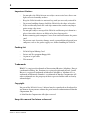 4
4
-
 5
5
-
 6
6
-
 7
7
-
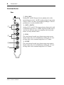 8
8
-
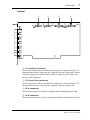 9
9
-
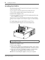 10
10
-
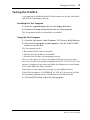 11
11
-
 12
12
-
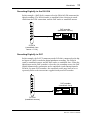 13
13
-
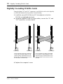 14
14
-
 15
15
-
 16
16
-
 17
17
-
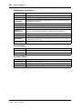 18
18
-
 19
19
-
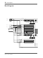 20
20
-
 21
21
-
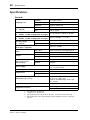 22
22
-
 23
23
-
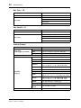 24
24
-
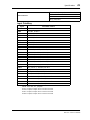 25
25
-
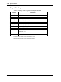 26
26
-
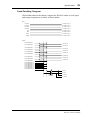 27
27
-
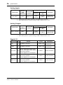 28
28
-
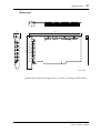 29
29
-
 30
30
-
 31
31
-
 32
32
-
 33
33
-
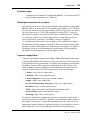 34
34
-
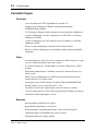 35
35
-
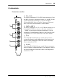 36
36
-
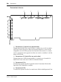 37
37
-
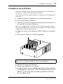 38
38
-
 39
39
-
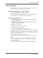 40
40
-
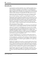 41
41
-
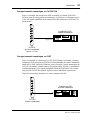 42
42
-
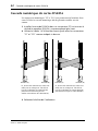 43
43
-
 44
44
-
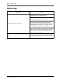 45
45
-
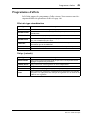 46
46
-
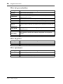 47
47
-
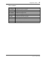 48
48
-
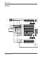 49
49
-
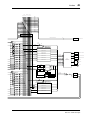 50
50
-
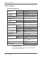 51
51
-
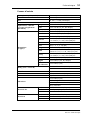 52
52
-
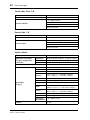 53
53
-
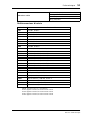 54
54
-
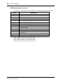 55
55
-
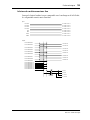 56
56
-
 57
57
-
 58
58
-
 59
59
-
 60
60
-
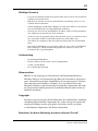 61
61
-
 62
62
-
 63
63
-
 64
64
-
 65
65
-
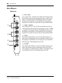 66
66
-
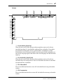 67
67
-
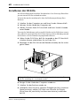 68
68
-
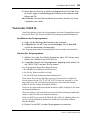 69
69
-
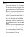 70
70
-
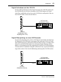 71
71
-
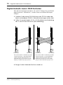 72
72
-
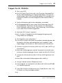 73
73
-
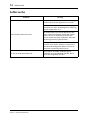 74
74
-
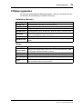 75
75
-
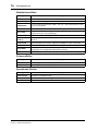 76
76
-
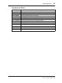 77
77
-
 78
78
-
 79
79
-
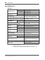 80
80
-
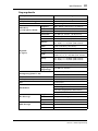 81
81
-
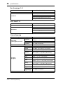 82
82
-
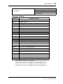 83
83
-
 84
84
-
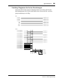 85
85
-
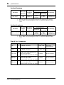 86
86
-
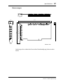 87
87
-
 88
88
-
 89
89
-
 90
90
-
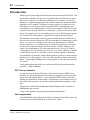 91
91
-
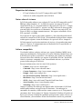 92
92
-
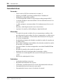 93
93
-
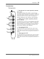 94
94
-
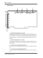 95
95
-
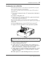 96
96
-
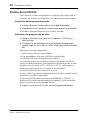 97
97
-
 98
98
-
 99
99
-
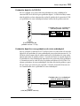 100
100
-
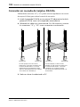 101
101
-
 102
102
-
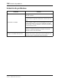 103
103
-
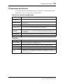 104
104
-
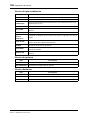 105
105
-
 106
106
-
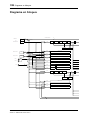 107
107
-
 108
108
-
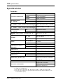 109
109
-
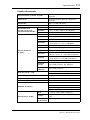 110
110
-
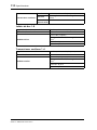 111
111
-
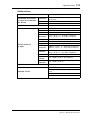 112
112
-
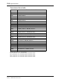 113
113
-
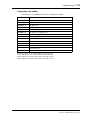 114
114
-
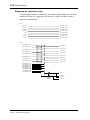 115
115
-
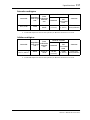 116
116
-
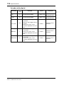 117
117
-
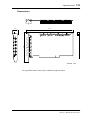 118
118
-
 119
119
-
 120
120
-
 121
121
-
 122
122
-
 123
123
-
 124
124
-
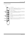 125
125
-
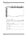 126
126
-
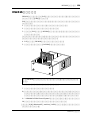 127
127
-
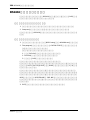 128
128
-
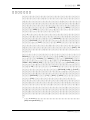 129
129
-
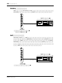 130
130
-
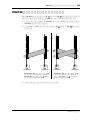 131
131
-
 132
132
-
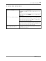 133
133
-
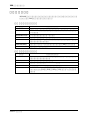 134
134
-
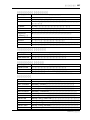 135
135
-
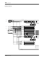 136
136
-
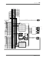 137
137
-
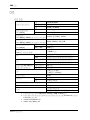 138
138
-
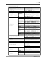 139
139
-
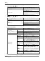 140
140
-
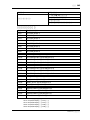 141
141
-
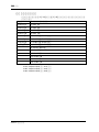 142
142
-
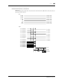 143
143
-
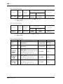 144
144
-
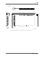 145
145
-
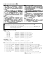 146
146
-
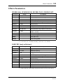 147
147
-
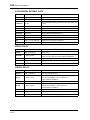 148
148
-
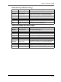 149
149
-
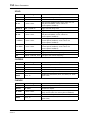 150
150
-
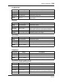 151
151
-
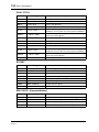 152
152
-
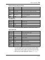 153
153
-
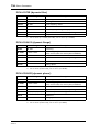 154
154
-
 155
155
-
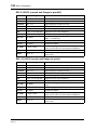 156
156
-
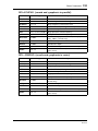 157
157
-
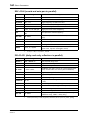 158
158
-
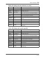 159
159
-
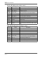 160
160
-
 161
161


in andere talen
- English: Yamaha DS2416 Owner's manual
- italiano: Yamaha DS2416 Manuale del proprietario
- русский: Yamaha DS2416 Инструкция по применению
- français: Yamaha DS2416 Le manuel du propriétaire
- español: Yamaha DS2416 El manual del propietario
- Deutsch: Yamaha DS2416 Bedienungsanleitung
- português: Yamaha DS2416 Manual do proprietário
- dansk: Yamaha DS2416 Brugervejledning
- čeština: Yamaha DS2416 Návod k obsluze
- 日本語: Yamaha DS2416 取扱説明書
- svenska: Yamaha DS2416 Bruksanvisning
- Türkçe: Yamaha DS2416 El kitabı
- polski: Yamaha DS2416 Instrukcja obsługi
- română: Yamaha DS2416 Manualul proprietarului
