
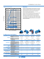
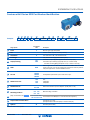
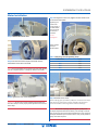
Speed Control
Made Simple!™
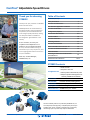
ComTrac® Adjustable Speed Drives
Installaon &
Maintenance
Manual

2ComTrac® Adjustable Speed Drives V.27 800.711.3588 • www.stober.com
ComTrac® Adjustable Speed Drives
Thank you for choosing
STOBER!
Thank you for your purchase of a STOBER
Drives ComTrac Drive!
STOBER products are constructed from
the highest quality, German-engineered
components, and manufactured to the
most stringent quality standards, making
our +80 year tradion of excellence
the recognized “gold standard" in the
industry.
As our customer, we value your
condence and sasfacon in our
product to an even higher standard.
As such, we look forward to being of
assistance to you in any way we can, and
to the ongoing performance and success
of your installaon.
Peter Feil, General Manager,
STOBER Drives, Inc.
ComTrac and MGS products are produced by STOBER Drives, Inc.
at our Maysville, Kentucky facility, an 85,000 square feet campus
including sales, service, assembly, manufacturing, and inventory
warehousing space to provide 1 day shipment naonwide!
Table of Contents
Installaon/Startup
Safety Precauons 3
ComTrac TD Performance 4
Non-Standard Applicaon Condions 4
ComTrac TD Selecon 5
Conguraons/Opons 5
Part Number Idencaon 6-9
Unit Orientaon 10
Direcon of Rotaon 10
Mounng Posions 11
ComTrac TD Installaon 12
Motor Installaon onto ComTrac TD 13
ComTrac TD Handwheel Posion 14
MGS Installaon 15
Mounng and Removal of Hollow Sha
Speed Reducers 15
Maintenance & Lubricaon 16-17
STOBER Contacts
sales@stober.com
• Send an order
• Request a sales call
• Ask for product informaon by email
• Request a product drawing that is not
currently available on the website
800 711-3588 Toll Free
606 759-5090 Customer service (working hours)
606 563-6035 24/7 emergency customer service hotline
Shipping Address
1781 Downing Drive, Maysville KY 41056
www.stober.com STOBER Drives, Inc. website

3
ComTrac® Adjustable Speed Drives V.27
800.711.3588 • www.stober.com
Installation Instructions
ComTrac® Installation and Startup Instructions
In order to obtain long life and trouble-free operaon from
your ComTrac® drive, it is essenal that proper installaon
and operang procedures be followed.
This manual includes basic direcons for mounng and start-up
of the ComTrac® drive, as well as lubricaon informaon. Failure
to follow these instrucons will void the drive’s warranty!
If you have quesons about the installaon, operaon or
maintenance of your ComTrac® drive, please contact your
local STOBER distributor for assistance.
Each drive is tested before delivery. Before installaon,
however, it is advisable to examine the unit for possible
damage which might have occurred during transit. If damage
is discovered, it should be immediately reported to the
transport agent.
If installaon is delayed aer receipt of the MGS speed
reducer, the drive should be stored in a clean, dry place
unl put into service. Long term storage requires special
procedures. If not kept in a heated, dry area, consult STOBER
Drives, Inc. for storage instrucons.
Important: If it is necessary to clean drive shas, take care to
protect the oil seals.
Cauon: Do not use any device to hammer the unit onto the
output sha during installaon since the bearing races could
be damaged.
For addional informaon or to address other quesons
regarding the installaon, operaon, maintenance or
lubricaon of the unit, visit our website or call STOBER
Technical Support.
WARNING: SAFETY FIRST!
Safety is the most important consideraon when operang
any type of drive. Through proper applicaon, safe handling
methods, and wearing appropriate clothing, you can prevent
accidents and injury to yourself and fellow workers.
The torque required by the applicaon must not exceed the
reducer torque capacity shown on the nameplate. For safety
purposes a safety coupling should be installed between the
reducer and the driven load. Otherwise, overload may cause
damage to the interior parts of the reducer which may result
in breaking the reducer housing. As a result, persons could
be injured by ying parts or splashing hot gear oil.
The shas of ComTrac® drives rotate at very high speeds and
can cut o or severely injure hands, ngers, and arms. Use
appropriate guards for shas and other rotang parts at all
mes. Follow all direcons in the service instrucon manual.
Obey all federal, state and local safety regulaons when
operang the drive.
Follow all direcons in this service instrucon manual. Obey
all federal, state and local safety regulaons when operang
the drive.
• Always be sure electrical power is o while making
electrical connecons and during installaon and
maintenance of the unit.
• Keep clothing, hands, and tools away from venlaon
openings on motors and from all rotang parts during
operaon.
• Li the drive with a double rope sling or other proper
liing equipment of adequate strength. Make sure load
is secured and balanced to prevent shiing when unit is
being moved. Liing drives by hand may be dangerous
and should be avoided.
• The intended use of liing lugs is to handle the weight of the
unit only. Never use a liing lug to li aached assemblies.
• Never operate drive at speeds higher than those shown
on the nameplate, or personal injury may result. Contact
STOBER Drives Inc., if there is any change of operang
condions from those for which the unit was originally
sold (as stamped on the nameplate). Failure to comply
could result in personal injury and or machinery damage.
• Always follow good safety pracces at all mes.

4ComTrac® Adjustable Speed Drives V.27 800.711.3588 • www.stober.com
ComTrac® Adjustable Speed Drives
ComTrac TD Performance
Complete ComTrac performance data is provided in the
ComTrac catalog available for download from our website.
Note that all performance rangs shown in this document and
in the ComTrac catalog selecon tables are based on standard
NEMA motors at 1750 RPM speed, 60 Hz operaon.
Several opons for ComTrac drives are included in the
ComTrac product catalog. In addion, the following opons
are also available:
• 50 Hz operaon for export
• Motor enclosures
For applicaon and selecon assistance for these opons and
others, contact your local STOBER distributor.
Non-Standard Application Conditions
For constant horsepower applicaons, or any of the
nonstandard applicaon condions shown below, contact
STOBER technical support.
Unusual Loading Condions:
• Heavy shock load
• High inera load
• Load reversals or overhauling loads
• More than ten starts per hour
Unusual Environmental Condions:
• High altudes – above 5000 feet
• Corrosive chemicals
• Excessively dusty or abrasive environments
• Ambient temperatures below 25° F or above 125° F
Nonstandard Motors:
• Motor frame sizes other than those shown in the tables
Nonstandard Mounng:
• Output sha up or down (V5 or V6 mounng)
Not Recommended for Mounng:
• Explosive environments of any type
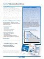
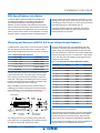
Two Ranges of Performance
A ComTrac drive generally produces constant output
torque because of its mechanical operaon, whereas
an inducon motor produces constant horsepower and
constant speed. Combined, ComTrac with an inducon
motor provide opmum ulity and economy.
As shown in the chart below, a ComTrac drive has two
operang regions.
1. Constant torque between the drive’s absolute
minimum speed and transion speed.
2. Constant horsepower between the transion speed
and maximum speed.
Since ComTrac applicaons typically require constant torque
over the enre speed range, an adequate service factor to
protect the tracon ring from damage is applied. When
selecng a ComTrac drive, it is important to choose a
unit which will not allow the cone and ring system to
be over powered by the motor. As shown in the chart, a
drive should always be selected so that the output torque
required is well below the torque capability of the cone
and the ring system.
Transion
Minimum
Maximum
Rated Torque @ Max Speed
Max Torque Capacity of Cone/Ring
Torque — Output (in.lbs.)
Speed — Output
Constant
Torque
Operang
Range
Constant
HP
Operang
Range
Torque/Speed Performance (Overhung Load)
C
o
n
s
t
a
n
t
H
P
M
o
t
o
r
O
u
t
p
u
t
(
M
a
x
)
We highly recommend you download product literature from our
website pertaining to your installaon, and to keep it with this
manual and other records on your ComTrc and MGS products
10 800.711.3588 • www.stober.com
ComTrac
®
Adjustable Speed Drives V.27
ComTrac
®
Adjustable Speed Drives
Motor Performance
The rangs shown in the ComTrac selecon tables are based
on standard NEMA motors with the following specicaons:
• 1750 RPM speed
• 60 Hz operaon
Application Matched Options
Several opons for ComTrac drives are included in this
catalog. Addionally, the following opons are also available:
• 50 Hz operaon for export
• Motor enclosures
For applicaon and selecon assistance for these opons and
others, contact your local STOBER distributor.
Non-Standard Application Conditions
For constant horsepower applicaons, or any of the
nonstandard applicaon condions shown below, contact
STOBER technical support.
Unusual Loading Condions:
• Heavy shock load
• High inera load
• Load reversals or overhauling loads
• More than ten starts per hour
Unusual Environmental Condions:
• High altudes – above 5000 feet
• Corrosive chemicals
• Excessively dusty or abrasive environments
• Ambient temperatures below 25° F or above 125° F
Nonstandard Motors:
• Motor frame sizes other than those shown in the tables
Nonstandard Mounng:
• Output sha up or down (V5 or V6 mounng)
Not Recommended for Mounng:
• Explosive environments of any type
Two Ranges of Performance
A ComTrac drive generally produces constant output
torque because of its mechanical operaon, whereas
an inducon motor produces constant horsepower and
constant speed. Combined, ComTrac with an inducon
motor provide opmum ulity and economy.
As shown in the chart below, a ComTrac drive has two
operang regions.
1. Constant torque between the drive’s absolute
minimum speed and transion speed.
2. Constant horsepower between the transion speed
and maximum speed.
Since ComTrac applicaons typically require constant torque
over the enre speed range, an adequate service factor to
protect the tracon ring from damage is applied. When
selecng a ComTrac drive, it is important to choose a
unit which will not allow the cone and ring system to
be over powered by the motor. As shown in the chart, a
drive should always be selected so that the output torque
required is well below the torque capability of the cone
and the ring system.
Transion
Minimum
Maximum
Rated Torque @ Max Speed
Max Torque Capacity of Cone/Ring
Torque — Output (in.lbs.)
Speed — Output
Constant
Torque
Operang
Range
Constant
HP
Operang
Range
Torque/Speed Performance (Overhung Load)
C
o
n
s
t
a
n
t
H
P
M
o
t
o
r
O
u
t
p
u
t
(
M
a
x
)
7
ComTrac
®
Adjustable Speed Drives V.27
800.711.3588 • www.stober.com
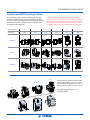
Contact Point
Motor Slide Down
Motor Slide Up
Drive Cone
Tracon Ring
Contact Point
Drive Cone
Tracon Ring
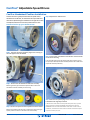
ComTrac Overview
Here’s How Simple it Is!
Turn the handwheel and the pinion moves the rack on the
motor slide up or down to adjust the output speed as lile or
as much as you want.
ComTrac
®
Operation
The ComTrac® drive is an adjustable speed tracon drive. It
operates by transfering power between a motor mounted
drive cone and a tracon ring (see illustraon below). Forced
together, the drive cone and tracon ring transmit torque
through a spring-loaded torque compensator assembly.
(NOTE: While the drive is at rest, the spring inside the torque
compensator produces a slight contact pressure between the
drive cone and tracon ring. Unlike other mechanical drives,
this minimal spring pressure allows speed changes to be
made even while the drive is stopped.)
When the drive is started, the load compensang cams move
against each other to increase pressure between the drive
cone and tracon ring. During operaon, these cams maintain
the proper amount of pressure between the drive cone and
tracon ring in proporon to the output load torque required.
Movement of the motor and drive cone are accomplished
through the use of a handwheel aached to a rack and
pinion. By turning the handwheel, the motor is easily raised
or lowered on a dust resistant motor slide.
Speed changes are made by changing the relave running
diameters of the drive cone and the tracon ring (see
illustraon at right). Lowering the motor and drive cone
posions the contact point between the cone and tracon
ring in the slower running center of the drive cone which
decreases output speed. As the motor and drive cone are
moved upward, the contact point between the cone and ring
moves to the faster running outer diameter of the drive cone
and output speed increases.
Minimum Speed
Maximum Speed
Torque Compensator Assembly
Load Compensang Cams
NEMA C-face Input
Wrench Kit
Drive Cone
Handwheel
Speed
Adjustment
Speed Adjustment Dial
Cast Iron Housing
Access Cover with Wrench Kit
Collet Clamp Ring
Fricon (Tracon) Ring
Flange Assembly
Speed Control
Made Simple!
™
ComTrac
®
Adjustable Speed Drives

5
ComTrac® Adjustable Speed Drives V.27
800.711.3588 • www.stober.com
Installation Instructions
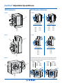
Congurations and Options TD (stand alone) TD w/C MGS TD w/F MGS TD w/K MGS
General
Input-Output Orientaon Inline Inline Inline (Oset) Right-Angle
Gearing Non-geared Concentric Helical Oset Helical Helical/Bevel
Housing Cast Iron Cast Iron Cast Iron Cast Iron
Conguraons 4 sizes 9 sizes; 2 or 3 stages 5 sizes; 2 or 3 stages 9 sizes; 2, 3 or 4
stages
Performance
Input HP (max) 1/2 to 10 1/2 to 5 1/2 to 5 1/2 to 5
Output Torque – in-lbs (max) Up to 496 Up to 59,782 in.lbs Up to 9,744 in.lbs 364 to 92,250
Output Speed (rpm) 2180 down to 311 1139 down to 8 528 down to 0.6
Speed Range 5:1 to 7:1 5:1 to 7:1 5:1 to 7:1 5* to 437
C-Face
Motor
Compability
NEMA 56C • • • •
NEMA 143/145TC • • • •
NEMA 182/184TC • • • •
Output Solid Sha (in) 5/8, 7/8 or 1-1/8 3/4 thru 2-7/8 1 thru 2-1/8 1 thru 3-5/8
Hollow Bore (in) — — 3/4 thru 2 1 thru 3-1/4
Housing/Mounng
(Contact factory for
other available opons)
Round Flange • — • —
Foot Mount — • — •
Tapped Holes — — • •
Paint/Coangs Standard Gloss (gray) • • • •
Washdown/Outdoor Service Opt Opt Opt Opt
Selection
In general, proper selecon of a ComTrac drive is as easy as
the drive is to operate: establish the maximum horsepower
required by the driven machine at maximum speed; then
select the TD Series drive that meets or exceeds that
maximum HP and speed requirement.
Note: The ComTrac drives shown are rated for constant torque
operaon – where required horsepower varies directly in
proporon to the speed of the driven machine. (Also note
that all rangs shown are based on standard NEMA C-face
motor designs with 1750 RPM input speed. Contact STOBER
technical support for selecon assistance for motor speeds
other than 1750 RPM.)
0
0
1
2
3
4
5
w/ 1 HP Motor
w/ 0.75 HP Motor
w/ 0.5 HP Motor
w/ 5 HP Motor
w/ 3 HP Motor
w/ 2 HP Motor
HP — Output Rang
4 8 12 16 20 24 28
Speed — (Output RPM x100)
TD 37
TD 27
TD 47
TD 57
w/ 1.5 HP Motor
HP/Speed Performance (Max)

6ComTrac® Adjustable Speed Drives V.27 800.711.3588 • www.stober.com
ComTrac® Adjustable Speed Drives
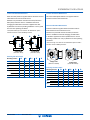
Comtrac TD Part Number Identication
1 2 3 4 5 6 7
Example: TD 47 0 F K 182 W
Design Opon
Part Number
Code Descripon
1Series TD Tracon Drive
2Size
27
37
47
57
56C input and 56C output; 143TC input and 56C output
145TC input and 143TC output
182TC input and 143TC output
184TC input and 182TC output
3Design 0Non-Geared
4Mounng Style FFlange
5MGS Speed Reducer
C
F
K
Inline
Oset Inline
RIght Angle
6Input Frame Size for NEMA Motor
(Motor ordered separately)
56
143
145
182
184
56C 1/2 or 3/4 HP input (for size TD27 only)
143TC 1 HP input (for size TD27 only)
145TC 1-1/2 or 2 HP input (for size TD37 only)
182TC 3 HP input (for size TD47 only)
184TC 5 HP input (for size TD57 only)
7Opon WWashdown/Severe Duty)
8Handwheel Locaon* L
R
Mounted on le or right side (as viewed facing output sha).
L is the standard conguraon
* Added to “notes” secon of order.

7
ComTrac® Adjustable Speed Drives V.27
800.711.3588 • www.stober.com
Installation Instructions
Comtrac with C Series MGS Part Number Identication
Examples:
1 2 3 4 5 6 7 8 9 0* !*@*#*
C 0 0 2 N 0020 TD270K 050 050 EL1 IV-L 0.750 SS W
Design Opon
Part Number
Code Descripon
1Series CConcentric helical (output and input in line/gears are all helical)
2Size 09 sizes of speed reducers (0 thru 8) with output sha diameters from
3/4 to 2-7/8”
3Generaon 0 1 0 for sizes C0 thru C5; 1 for sizes C6 thru C8
4# of Stages 2 3 Two or three stages (determined by rao)
5Housing
(Contact factory for other conguraons) NFoot mounng
6Rao 0040 Raos range from 2:1 to 276:1 (For example: 0020 = 2:1)
7TD Unit
TD270K
TD370K
TD470K
TD570K
TD Adjustable Speed Drives matched with various MGS C Series units,
sized for 1/2 to 5 HP motor input.
8NEMA Frame Size
(refer to Selecon Data tables)
050
140
180
56C
143/145TC
182/184TC
9Rated Motor HP 050
thru 500 Rated motor HP from 1/2 to 5 HP (050 = 1/2 HP; 500 = 5 HP)
0Mounng Posion*
(Refer to illustraons on page 11)
EL1 EL2
EL3 EL4
EL5 EL6
MGS mounng orientaon
!I-L II-L III-L IV-L
I-R II-R III-R IV-R TD Orientaon with MGS (IV-L is considered standard posion)
@Output Sha* Specify size (in or mm)
Specify standard carbon steel (STD) or stainless steel (SS)
#Opon* WWashdown/Severe Duty
* Add to “notes” secon of order.

8ComTrac® Adjustable Speed Drives V.27 800.711.3588 • www.stober.com
ComTrac® Adjustable Speed Drives
Comtrac with F Series MGS Part Number Identication
Design Opon
Part Number
Code Descripon
1Series FOset helical (output is oset from input; gears are all helical)
2Size 25 sizes of speed reducers (1, 2, 3, 4, 6)
3Generaon 0First generaon
4# of Stages 2 3 Two or three stages (determined by rao)
5Output/Housing
AG
AF
VF
Hollow bore output (A) with tapped holes around output (G)
Hollow bore output (A) with output ange housing (F)
Solid sha output (V) with output ange housing (F)
6Rao 0043 Raos range from 4.3:1 to 540:1 (For example: 0043 = 4.3:1)
7TD Unit
TD270K
TD370K
TD470K
TD570K
TD Adjustable Speed Drives matched with various MGS C Series units,
sized for 1/2 to 5 HP motor input.
8NEMA Frame Size
050
140
180
56C
143/145TC
182/184TC
9Rated Motor HP 050
thru 500 Rated motor HP from 1/2 to 5 HP (050 = 1/2 HP; 500 = 5 HP)
0Mounng Posion*
(Refer to illustraons on page 11)
EL1 EL2
EL3 EL4
EL5 EL6
MGS mounng orientaon
!I-L II-L III-L IV-L
I-R II-R III-R IV-R TD Orientaon with MGS (IV-L is considered standard posion)
@Output Sha or Hollow Bore* Specify size (in or mm)
Specify standard carbon steel (STD) or stainless steel (SS)
#Opon* WWashdown/Severe Duty
* Added to “notes” secon of order.
Example:
1 2 3 4 5 6 7 8 9 0* !*@*#*
F 1 0 2 AG 0043 TD270K 050 050 EL1 IV-L 0.75 STD W

9
ComTrac® Adjustable Speed Drives V.27
800.711.3588 • www.stober.com
Installation Instructions
Design Opon
Part Number
Code Descripon
1Series KModular right angle helical/bevel
2Size 2K Series: 9 sizes of speed reducers (1 thru 9)
3Generaon 00 for sizes K1 thru K4; 1 for sizes K5 thru K9
4# of Stages 2Two, three or four stage (determined by rao)
5Output/Housing
AG
VNG
Hollow bore output (A) with tapped holes around output (G)
Solid sha output with key (V) (specify side 3, 4, or double sided)
with foot mounng (NG) (specify side 1 or 5; or side 2 on K1 only)
6Rao 0040
Raos range from 4:1 to 381:1 Refer to Selecon Data tables. Note: if a slower
speed is required, units can be combined to achieve the necessary rao for
low speed applicaons. Contact STOBER Drives Inc.
7TD Unit
TD270K
TD370K
TD470K
TD570K
TD Adjustable Speed Drives 1/2 to 5 HP motor input.
8NEMA Frame Size
050
140
180
56C
143/145TC
182/184TC
9Rated Motor HP 050
thru 500 Rated motor HP from 1/2 to 5 HP (050 = 1/2 HP; 500 = 5 HP)
0Mounng Posion*
(Refer to illustraons on page 11)
EL1 EL2
EL3 EL4
EL5 EL6
MGS mounng orientaon
!I-L II-L III-L IV-L
I-R II-R III-R IV-R TD Orientaon with MGS (IV-L is considered standard posion)
@Output Sha or Hollow Bore* Specify size (in or mm)
Specify standard carbon steel (STD) or stainless steel (SS)
#Opon* WWashdown/Severe Duty
* Added to “notes” secon of order.
Example:
1 2 3 4 5 6 7 8 9 0* !*@*#*
K 2 0 2 AG 0040 TD270K 050 050 EL1 IV-L 1.25 STD W
Comtrac with K Series MGS Part Number Identication

10 ComTrac® Adjustable Speed Drives V.27 800.711.3588 • www.stober.com
ComTrac® Adjustable Speed Drives
3 Stage 4 Stage
K203 K514 K814
K303 K614 K914
K403 K714 K1014
2 Stage 3 Stage
K102 K513 K813
K202 K613 K913
K302 K713 K1013
K402
Side
4
Side
4
Side 3
Side 3
MGS Orientation MGS DIrection of Rotation
Side
3
Side
5
Side
1
Side
2
Side
4
Side
6
K Series
F Series
C Series
K Series: Output available on side 3, 4 or both. Note: With a double
output, the sha rotaon of Side 3 will be the opposite direcon of
Side 4 when viewed from Side 5.
F Series
C Series
All 2 Stage Units
F102
F202
F302
F402
F602
All 3 Stage Units
F203
F303
F403
F603
Side
3
Side
5
Side
1
Side
2
Side
4
Side
6
All 2 Stage Units
C002 C502
C102 C612
C202 C712
C302 C812
C402
All 3 Stage Units
C103 C503
C203 C613
C303 C713
C403 C813
Side
3
Side
5
Side
1
Side
2
Side
4
Side
6

11
ComTrac® Adjustable Speed Drives V.27
800.711.3588 • www.stober.com
Installation Instructions
For any MGS unit with a ComTrac TD Drive, the mounng
posion orientaon of both units are specied at the me
the unit is ordered. (The appropriate mounng posion order
code illustrated below is include in the notes secon of the
Part Number when ordering.)
Crical: It is extremely important that the unit is installed
according to the mounng posion ordered. Units are lled with
the appropriate amount of lubricaon at the factory according
to the specied mounng posion. DO NOT mount any reducer
in a posion other than the mounng posion that was order!
Comtrac and MGS Mounting Position
IV
I
II
III
C Series
F Series
K Series
L
LL
R
R
R
L
R
Note: All MGS units shown with the ComTrac TD unit in the standard “IV” posion with the handwheel on the “L” le side (as shown below.
EL4
EL3
EL2
EL1 EL6
EL5
2
1 4
3 5 6
Side Facing Down:
Mounng Posion
Orde Code:
ComTrac TD units can be mounted to the
MGS in four posions “I” thru “IV”, with
the handwheel mounted either on side “L”
(shown in blue) or side “R” (shown in gray).
Note: Mounng posion IV-L is the
standard posion.

12 ComTrac® Adjustable Speed Drives V.27 800.711.3588 • www.stober.com
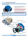
ComTrac® Adjustable Speed Drives
ComTrac TD Installation
Units with C-face input and output are designed to aach
to any speed reducer with a NEMA C-face input. Care
must be taken to follow the speed reducer manufacturer's
recommended mounng instrucons.
Note: ComTrac Series TD drives do not have mounng feet. The
drive and motor assembly is mounted on the speed reducer which
must support the reducer, ComTrac, and the motor. If there is
concern for the ability of the reducer mounng feet to support the
enre assembly, a larger speed reducer may be required.
Important: The output sha of the ComTrac drive is shipped from the factory with a protecve coang. Remove this
coang with a suitable nonammable solvent. Precauon must be taken not to allow the solvent to contact the output
sha oil seal, since damage to the seal may occur.
Torque Compensator Assembly
Load Compensang Cams
NEMA C-face Input Wrench Kit
Drive Cone
Handwheel Speed Adjustment
Speed Adjustment Dial
Cast Iron Housing
Access Cover with Wrench Kit
Collet Clamp Ring
Motor Clamp Hub
Fricon (Tracon) Ring Flange Assembly

13
ComTrac® Adjustable Speed Drives V.27
800.711.3588 • www.stober.com
Installation Instructions
Motor Installation
Step 1 Remove the access cover
Step 2 Lubricate and insert keyed motor sha into the
sloed bore of the drive cone sha
Note: For ease of installaon, secure the key to the motor sha. (Staking
near the end of the keyway or a temporary adhesive works well.)
Step 3 Tighten the four motor ange bolts
Important: Jog the motor several revoluons before ghtening
the motor clamp to assure proper posion of the drive cone on the
motor sha.
Step 4 Through the access hole, ghten the hex socket screw
on the motor clamp hub
Tightening the
screw to the
torque shown in
the table below.
The correct size
hex wrench is
provided.
Do not
overghten!
Shown without
motor for
demonstraon
Table 1 Clamp Ring Setscrew Tightening Torque
ComTrac Size in. lbs.
TD27 88.5
TD37 88.5
TD47 221
TD57 434
Step 5 Reaach access cover
When couplings, gears, sprockets or pulleys are mounted on the output
sha, be sure to mount them as close as possible to the housing to
minimize the eects of overhung loads on shas and bearings.
Cauon: Do not drive couplings, sprockets, gears or pulleys onto
the output sha with hard hammer blows, since damage to internal
gears or bearings will result. All output shas have a metric centering
thread for aachment of transmission devices. They can be pulled on
gently with a bolt and plate.

14 ComTrac® Adjustable Speed Drives V.27 800.711.3588 • www.stober.com
ComTrac® Adjustable Speed Drives
ComTrac drives are typically furnished with the speed control
handwheel on the le side, as viewed from the output sha end
of the drive. Reposioning the handwheel to the right side is easily
accomplished with the hex wrenches provided with the drive.
Procedure for Changing Handwheel Position
Step 1 Remove the three (3) plasc plugs in the housing on
the side opposite the handwheel
Step 2 Remove the handwheel and indicator assembly
Removing the two (2) socket-head capscrews which secure the
handwheel indicator assembly to the housing.
Step 3 Reverse the yellow numbered posion indicator wheel
Remove the sloed screw. (Be sure to remove the tape covering to
expose posion numbers on the other side of the wheel.)
Step 4 Replace the sloed screw
Step 5 Place pinion, handwheel and indicator on desired side
of the drive's housing
From the side where the three plasc plugs were removed, secure
the pinion/handwheel/indicator assembly with the two socket-head
capscrews removed previously.
Step 6 Relocate the plasc plugs to the holes where the
handwheel was originally mounted
Lubricate the motor slide and rack (both sides) with one (1) stroke
with a grease gun through the ngs provided in the housing.
IMPORTANT: Do not over lubricate the motor slide. Under normal
condions, maintenance of the motor slide and rack should only be
required one me per year.
ComTrac Handwheel Position Installation

15
ComTrac® Adjustable Speed Drives V.27
800.711.3588 • www.stober.com
Installation Instructions
MGS Speed Reducer Installation
In order to obtain long life and trouble-free operaon from
your MGS speed reducer, it is essenal that the following
recommended installaon and operang procedures be
followed, as well as lubricaon and maintenance instrucons.
Failure to follow these instrucons will void the drive’s warranty.
The torque required by the applicaon must not exceed the
reducer torque capacity shown on the nameplate. For safety
purposes a safety coupling should be installed between the
reducer and the driven load. Otherwise, overload may cause
damage to the interior parts of the reducer which may result
in breaking the reducer housing. As a result, persons could be
injured by ying parts or splashing hot gear oil.
If you have quesons about the installaon, operaon or
maintenance of your MGS unit, please contact your local
Stober distributor for assistance.
Mounting and Removal of MGS F & K Series Hollow Output Reducers
A STOBER hollow output reducer can be mounted from either
side. The tolerance for the hollow bore is shown in Table 1
and the sha should be toleranced to t this bore accordingly.
Table 1 Hollow Output Bore Tolerance
Bore Range Tolerance
0.39 — 0.71 +0.0007/-0.0000
0.71 — 1.18 +0.0008/-0.0000
1.18 — 1.97 +0.0010/-0.0000
1.97 — 3.15 +0.0012/-.0000
3.15 & up +0.0014/-0.0000
A keeper plate inside the bore is provided with each unit to
prevent axial movement. This keeper plate is held in place
with snap rings and can be easily removed for locaon on
either end. A spring pin in the keeper plate mounts into the
keyway of the bore and prevents rotaon. The keeper plate
center hole is tapped to t the removal bolt.
Before installaon, brush the inside of the bore with rust
inhibing grease. When mounng the unit onto the sha,
avoid hammering as this may damage the bearings. Do not
mount the reducer dry as removal may be impossible.
Keyway
Width
Keyway
Height
Mounng
Bolt
Removal Bolt
Machine Sha
with Shoulder
Length to
Keeper Plate
"B" Length
Thru Bore
"UL” Required
Length of Sha Output
Bore
The drawing above shows a mounng or xing bolt and a
removal bolt. The mounng/xing bolt should be smaller in
size than the removal bolt as detailed in Table 2.
To use the keeper plate with a mounng/xing bolt, drill
and tap the end of the sha that will be mounted into the
reducer. Insert the mounng/xing bolt through the keeper
plate and thread into the sha end. The machine sha length
should not be longer than the “UL” dimension. A sha length
of “UL” will allow the sha shoulder to pull against the face
of the bore of the reducer.
Table 2 “UL” Dimension and Removal Bolt Size (inches)
MGS Unit U Bore Ø UL Removal Bolt
F1 0.750 2.67 3/8-16
F2 1.000 3.62 1/2-13
F3 1.250 4.06 1/2-13
F4 1.500 4.49 3/4-10
F6 2.000 5.63 3/4-10
K1 1.000 3.86 1/2-13
K2 1.187 4.78 1/2-13
K3 1.375 4.92 5/8-11
K4 1.500 6.18 3/4-10
K5 2.000 6.46 3/4-10
K6 2.000 7.05 3/4-10
K7 2.375 8.43 1-8
K8 2.750 10.35 1-8
K9 3.250 11.89 1-8
Removal of Hollow Output Reducers
To dismantle the unit from the sha, remove the mounng bolt.
Thread the removal bolt into the keeper plate to press against
the sha and loosen the sha from the unit. Removal of the
reducer will be easier if the bore is greased before installaon.
See our web site (www.stober.com) for a parts breakdown of
a specic reducer or call STOBER Customer Service.

16 ComTrac® Adjustable Speed Drives V.27 800.711.3588 • www.stober.com
ComTrac® Adjustable Speed Drives
Maintenance
WARNING: Before beginning any work on the ComTrac drive
system, disconnect the power source (lock-out the motor
starter, and unload breakers, backstops, etc.). Failure to do so
may cause serious personal injury and/or machinery damage.
Note Motor Drainholes: Some motor manufacturers provide
a drain hole in the mounng face of washdown motors. Be
sure this hole is covered during washing or when the unit is
used in a wet environment.
ComTrac TD Handwheel Maintenance
For normal indoor installaons, the handwheel or ERC control
pinion and motor slide rack should be lubricated through
the grease ng every six months using NLGI No. 2 grease.
One stroke of a grease gun is sucient. When the drive is
operang under wet condions, increase the frequency of
lubricaon to once a month.
ComTrac TD Cam and Bearing Chamber Lubricaon
ComTrac TD drives require lubricant only in the cam and
bearing chamber and are shipped with the lubricant in them.
There is a sucient quanty of lubricant to allow mounng
the non-geared ComTrac Drive in any posion.
Table 1 Bearing and Cam Chamber Oil Quanty
ComTrac Size Oil Quanty (Fluid oz)
TD27 1.5
TD37 1.7
TD47 1.9
TD57 4.4
Under normal operang condions, the synthec oil in the
cam and bearing chamber does not need to be replaced. If
for any reason some quanty of lubricant is lost, remove the
rest of the lubricant from the cam and bearing chamber and
replace it with the type and quanty of oil listed below.
Table 2 Bearing and Cam Oil Manufacturers
Lubricant Manufacturer AGMA Lubricant ( No. 5EP)
Darmex 9140
Exxon Spartan 220
Mobil* Mobilgear 630
Gulf HD220
Keystone KSL-366
Lubriplate APG90
* Mobile SHC626 is used for the inial ll. If rell is necessary, any of
the above products may be used.
For installaons in the food, dairy, beverage and baking
industries, where special lubricants are required, a suitable
grease of the user’s preference should be used.
Lubricaon Maintenance for MGS Speed Reducers
With STOBER reducers very lile maintenance is required
under normal operang condions. All F Series and smaller
sizes of C and K Series units are supplied without breathers and
are lubricated for life. Breathers are provided on larger size C
and K Series units. For these units, we recommend that the
lubricaon be changed, using the appropriate lubricant shown
in the Table below, and as detailed on the following page.
Table 3 Characterisc of STOBER Standard Lubricants
Exxon
Mobilgear
XP600
Special Mist
EP220 Food
Grade
MobilGear
SHC630
An-Foaming Addives 4 4 Excellent
Corrosion Protecon 4 4 Opmum
Extreme Pressure Addives 444
Fricon and Wear
Reducing Characteriscs 4 4 Superior
Oxidaon Protecon 4 4 Enhanced
Wide Temperature Range 4
If food grade or synthec oil is requested, it will be Mobilgear
Special Mist EP220 food grade or Mobilgear SHC630 synthec.
Note: When a ComTrac Drive is aached to a speed
reducer, follow the manufacturer’s lubricaon instrucons
for the reducer mounng before start-up.
Important: All STOBER MGS C, F and K Series units used
with ComTrac Drives are shipped lled with the required
amount of lubricaon, which is dependent on the mounng
posion specied at the me of order. For example, vercal
mounng may require dierent seals, bearings, etc. so it is
very important to mount the unit in the posion for which it
was assembled. (No unit will be shipped without the mounng
posion specied by the customer.) See page 11 for details.

17
ComTrac® Adjustable Speed Drives V.27
800.711.3588 • www.stober.com
Installation Instructions
Drain Plug and Vent Locaon
Mounng Posion 1 2 * 2a * 3 4
EL1 Vent Drain
EL2 Drain Vent
EL3 Vent Drain
EL4 Drain Vent
EL5 K513-K1013 Drain Vent
K514-K1014 Drain Vent
EL6 K513-K1013 Vent Drain
K514-K1014 Vent Drain
* Posion 2a is on the opposite side of 2.
F Series Lubricaon Maintenance
All F Series MGS Speed Reducers are supplied without
breathers and are lubricated for life.
K Series Lubricaon Maintenance
K102 thru K403 are supplied without breathers and are
lubricated for life and maintenance free.
Breathers are provided on K513 thru K914, located as
shown*. STOBER recommends changing the lubricaon
in breather supplied units aer 10,000 hours for normal
operang condions or every 5,000 hours for wet operang
condions.
*K513 and larger units with the “W” Washdown opon exclude a
breather. Contact STOBER for details.
3 Stage Units
(K513 thru K1013)
4 Stage Units
(K514 thru K1014)
1
2
4
3
3
2
1
Drain Plug and Vent Locaon
Mounng Posion 1 2 * 2a * 3 5
EL1 Vent Drain
EL2 Drain Vent
EL3 Vent Drain
EL4 Drain Vent
EL5 C612-C812 Drain Vent
C613-C813 Drain Vent
EL6 Vent Drain
* Posion 2a is on the opposite side of 2.
11
2
5
4
4
3
3
2
2 Stage Units
(C612 thru C812)
3 Stage Units
(C613 thru C813)
C Series Lubricaon Maintenance
C002 thru C502/C503 are supplied without breathers and are
lubricated for life and maintenance free.
Breathers are provided on standard units C612/C613 thru
C812/C813, located as shown*. STOBER recommends
changing the lubricaon in breather supplied units aer
10,000 hours for normal operang condions or every 5,000
hours for wet operang condions.
*C612/C613 and larger units with the “W” Washdown opon
exclude a breather. Contact STOBER for details.

STOBER
1781 Downing Drive
Maysville, KY 41056
(800) 711-3588
Fax (606) 759-5045
e-mail: sales@stober.com
www.stober.com
ComTrac Installation & Maintenance Version 2018 12/18
-
 1
1
-
 2
2
-
 3
3
-
 4
4
-
 5
5
-
 6
6
-
 7
7
-
 8
8
-
 9
9
-
 10
10
-
 11
11
-
 12
12
-
 13
13
-
 14
14
-
 15
15
-
 16
16
-
 17
17
-
 18
18


