
CINEMA DSP
DOLBY
DIGITAL
DIGITAL
SURROUND
–
+
ON OFF
55
44
33
22
11
0
+
–
55
44
33
22
11
0
+
–
55
44
33
22
11
0
RL
VCR 2 CD
VCR 1
TUNER
CBL/SAT TAPE
D-TV
MD
LD
DVD
PHONOVCR 3
VIDEO AUX
PHONES BASS TREBLE
NATURAL SOUND AV AMPLIFIER
DSP-AX1
INPUT MODE
INPUT SELECTOR
VOLUME
S VIDEO VIDEO L RAUDIO
VIDEO AUX
BALANCE REC OUT/ZONE 2
SOURCE/REMOTE
BASS
EXTENSION
PROCESSOR
DIRECT
STANDBY/ON
6CH IMPUT
SET MENU
NEXT
EFFECT
PROGRAM
SPEAKERS
AB
TRANSMIT RE-NAME CLEAR
MACRO
MACROLEARN
OFF ON
SYSTEM
POWER
STANDBY
V-AUX TAPE PHONO
D-TV CBL/SAT TUNER MD CD
VCR 1 VCR 2 VCR 3 LD DVD
6CH INPUT
TITLE
ENTER
MENU
SOUND
DISPLAY
SOURCE
SELECT
SEARCH CHAPTER
%
!
!
$
*#
$
%
%
%
%
%
10KEY DSP HALL 1 HALL 2 CHURCH JAZZ CLUB
ROCK
CONCERT
ENTER-
TAINMENT
CONCERT
VIDEO 2
CONCERT
VIDEO 1
POWER REC STOP PAUSE PLAY
EX/ES
TV
THEATER
MOVIE
THEATER 2
MOVIE
THEATER 1
/DTS
SUR.
0 +10 +100
1234
5678
9101112
++ +
TV VOL
A / B / C / D / E
PRESET
TV INPUT
TV MUTE
CH
DISC
MUTE
EFFECT
VOLUME
+–
/
CHP/INDEX
–– –
DSP-AX1
Natural Sound AV Amplifier
Amplificateur Audio-Video
BG
OWNER’S MANUAL
MODE D’EMPLOI
BEDIENUNGSANLEITUNG

I
CAUTION: READ THIS BEFORE OPERATING YOUR UNIT.
1. To assure the finest performance, please read this manual
carefully. Keep it in a safe place for future reference.
2. Install this unit in a cool, dry, clean place – away from
windows, heat sources, sources of excessive vibration,
dust, moisture and cold. Avoid sources of humming
(transformers, motors). To prevent fire or electrical shock,
do not expose the unit to rain or water.
3. Never open the cabinet. If something drops into the set,
contact your dealer.
4. Do not use force on switches, controls or connection
wires. When moving the unit, first disconnect the power
plug and the wires connected to other equipment. Never
pull the wires themselves.
5. The openings on the cover assure proper ventilation of the
unit. If these openings are obstructed, the temperature
inside the unit will rise rapidly. Therefore, avoid placing
objects against these openings, and install the unit in a
well-ventilated area to prevent fire and damage.
(For Europe, UK, and China Models)
Be sure to allow a space of at least 10 cm behind, 10 cm
on both sides and 30 cm above the top panel of the unit to
prevent fire and damage.
6. The voltage used must be the same as that specified on this
unit. Using this unit with a higher voltage than specified is
dangerous and may result in fire or other accidents.
YAMAHA will not be held responsible for any damage
resulting from the use of this unit with a voltage other than
that specified.
7. Digital signals generated by this unit may interfere with
other equipment such as tuners, receivers and TVs. Move
this unit farther away from such equipment if interference
is observed.
8. Do not attempt to clean the unit with chemical solvents;
this might damage the finish. Use a clean, dry cloth.
9. Be sure to read the “Troubleshooting” section regarding
common operating errors before concluding that the unit is
faulty.
10. When not planning to use this unit for a long period of
time (e.g., a vacation), disconnect the AC power plug from
the wall outlet.
11. To prevent lightning damage, disconnect the AC power
plug and disconnect the antenna cable when there is an
electrical storm.
12. Grounding or polarization – Precautions should be taken
so that the grounding or polarization of the unit is not
defeated.
13. AC outlet
Do not connect audio equipment to the AC outlet on the
rear panel if that equipment requires more power than the
outlet is rated to provide.
This unit is not disconnected from the AC power source as long as
it is connected to the wall outlet, even if this unit itself is turned
off. This state is called the standby mode. In this state, this unit is
designed to consume a very small quantity of power.
For U.K. customers
If the socket outlets in the home are not suitable for the plug supplied
with this appliance, it should be cut off and an appropriate 3 pin plug
fitted. For details, refer to the instructions described below.
Note: The plug severed from the mains lead must be destroyed, as a plug with
bared flexible cord is hazardous if engaged in a live socket outlet.
Special Instructions for U.K. Model
IMPORTANT
THE WIRES IN MAINS LEAD ARE COLOURED IN
ACCORDANCE WITH THE FOLLOWING CODE:
Blue: NEUTRAL
Brown: LIVE
As the colours of the wires in the mains lead of this apparatus may
not correspond with the coloured markings identifying the
terminals in your plug, proceed as follows:
The wire which is coloured BLUE must be connected to the
terminal which is marked with the letter N or coloured BLACK.
The wire which is coloured BROWN must be connected to the
terminal which is marked with the letter L or coloured RED.
Making sure that neither core is connected to the earth terminal of
the three pin plug.
Manufactured under license from Dolby Laboratories. “Dolby”,
“AC-3”, “Pro Logic”, “Surround EX” and the double-D symbol are
trademarks of Dolby Laboratories.
Confidential Unpublished Works. ©1992-1997 Dolby Laboratories,
Inc. All rights reserved.
Manufactured under license from Digital Theater Systems, Inc. US
Pat. No. 5,451,942 and other world-wide patents issued and pending.
“DTS”, “DTS Digital Surround” and “DTS ES” are trademarks of
Digital Theater Systems, Inc. Copyright 1996 Digital Theater
Systems, Inc. All Rights Reserved.

1
English
Contents
Introduction 2
Features ............................................................................................................... 3
Getting Started .................................................................................................... 5
Controls and Functions ....................................................................................... 6
Preparations 12
Speaker System Configurations.................................................................. 13
Speaker Placement ............................................................................................ 14
Hookups ............................................................................................................ 15
On-Screen Displays (OSD) ............................................................................... 25
Speaker Settings ................................................................................................ 26
Speaker Output Levels ...................................................................................... 27
Basic Operation 30
Basic Playback .................................................................................................. 31
Basic Recording ................................................................................................ 35
Advanced Operation 36
SET MENU Items ............................................................................................. 37
Remote Control Features .................................................................................. 50
Adjusting the Levels of the Effect Speakers ..................................................... 63
Setting the Sleep Timer..................................................................................... 63
ZONE 2 ............................................................................................................. 64
Addtional Information 66
Digita Sound Field Processing (DSP) ............................................................... 67
Hi-Fi DSP-Sound Field Program ...................................................................... 68
CINEMA-DSP .................................................................................................. 69
CINEMA-DSP Sound Field Program ............................................................... 71
Sound Field Program Parameter Editing .......................................................... 73
Digital Sound Field Parameter Descriptions..................................................... 74
Appendix 78
Troubleshooting ................................................................................................ 79
Reference Chart for the INPUT and OUTPUT Jacks ....................................... 82
CINEMA - EQ Frequency Characteristics ....................................................... 82
Specifications .................................................................................................... 83

2
Introduction
Introduction
Features 3
Introduction ......................................................................................................... 3
Dolby Digital and Dolby Digital Surround EX .................................................. 3
DTS and DTS ES ................................................................................................ 3
Comparing Surround Technologies .................................................................... 3
Digital Sound Fields (DSP) ................................................................................ 4
Multi-function remote control............................................................................. 4
Various Input and Output Jacks .......................................................................... 4
Built-in 8-channel power amplifier..................................................................... 4
Custom installation facility ................................................................................. 4
Getting Started 5
Checking the Package Contents .......................................................................... 5
Installing Batteries in the Remote Control.......................................................... 5
Using the Remote Control .................................................................................. 5
Controls and Functions 6
Front Panel .......................................................................................................... 6
Opening and Closing the Front Panel Door ........................................................ 7
Remote Control ................................................................................................... 8
Front Panel Display........................................................................................... 10
Rear Panel ......................................................................................................... 11

3
English
Introduction
Welcome to the exciting world of digital home entertainment. The DSP-AX1 is the most complete and advanced AV amplifier
available. Though some of the more advanced features of this unit may not be familiar to you, they are easy to use. Incorporated state-
of-the-art technology such as Dolby Digital and DTS can bring the same audio experience to your home as they have brought to feature
films in quality theaters around the world. To make the listening experience even more enjoyable, the DSP-AX1 includes a number of
exclusive, digitally created listening environments known as digital sound fields. Choosing a sound field program is like transporting
yourself to such venues as an outdoor arena, an European church, or a cozy jazz club. Take some time now to read more about these
features and enjoy the new experiences the DSP-AX1 brings to your home theater.
Dolby Digital and Dolby Digital Surround EX
The DSP-AX1 is equipped with a Dolby Digital decoder which reproduces industry standard Dolby Digital surround sound for a
cinematic audio experience in your home. Dolby Digital is a 5.1 channel format because it uses five discrete channels (left and right
Main channels, Center channel, and left and right Rear channels) and a special low frequency channel (that is used only enough to merit
the “0.1” channel rating) to create incredibly realistic 360˚ surround effects. Recently, Dolby Digital Surround EX was introduced in
movie theaters as an advanced surround technology. The addition of a Rear Center channel makes front-to-back transitions more
realistic. You can enjoy the newest Dolby Digital Surround EX software with the CINEMA DSP programs in the DSP-AX1 such as
Dolby Digital/Matrix 6.1.
DTS and DTS ES
The DSP-AX1 is also equipped with a DTS decoder, which uses a 5.1 channel system to create a full surround sound environment. It
was developed as a way to replace the analog soundtracks of movies with six channels of digital sound. In comparison with Dolby
Digital, DTS uses less compression to store the sound information. The newly presented DTS ES system reproduces digital sound
similar to Dolby Digital Surround EX. The use of the Rear Center speaker along with the existing 5.1 channel speakers provides a fully
immersive cinematic audio experience.
Comparing Surround Technologies
To enjoy dynamic feature film sound at home, you should have the appropriate sound reproduction system for your home theater. The
traditional standard for home surround systems was called Dolby Surround and consisted of four channels (left and right Main channels,
a Center channel, and a Surround channel for effects). The new home theater standard is Dolby Digital and consists of 5.1 channels (left
and right Main channels, a Center channel, left and right Rear channels, and an LFE (low frequency effect) channel). The newer DTS
surround technology also makes use of a 5.1 channel system. The 6.1 channel system which adds a Rear Center channel to the 5.1
channel configuration is the latest advancement in surround sound technology, and is employed by Dolby Digital Surround EX and DTS
ES.
Features
Reproduction Channel System
4 channels
Left (L) and right (R) Main,
Center (C), and Surround (S)
channels
5.1 channels
Left (L) and right (R) Main,
Center (C), left and right Rear
(RL and RR), and Subwoofer
(SW) channels
6.1 channels
Left (L) and right (R) Main,
Center (C), left and right Rear
(RL and RR), Rear Center (RC),
and Subwoofer (SW) channels
Dolby Surround
(Pro Logic)
Dolby Digital
and DTS
Dolby Digital Surround EX
and DTS ES
L
S
CR
S
L
RL
CR
RR
SW
RC
L
RL
CR
RR
SW

4
Introduction
Features
Digital Sound Fields (DSP)
Technological advances in sound reproduction over the last 30 years have enhanced the listening experience with improved clarity,
precision, and power. However, something has been missing: the atmosphere and acoustic ambience of the public venue. Our Yamaha
engineers have extensively researched the nature of sound acoustics and the way sound reflects inside a room. We sent these engineers
to famous theaters and concert halls around the world to measure the acoustics of those venues with sophisticated microphones. The
data they collected is used to recreate these environments in digital sound fields. Some of these digital sound fields have been created
using data measured at the original venue; others have been created from combinations of data to form unique environments for specific
purposes. Some have been designed especially for music, and others especially for movies. Of course, this only solves half of the
problem. Because these engineers have no way of knowing the acoustics of your entertainment room, we have made it possible for you
to adjust the various parameters of this data to tailor each virtual venue to your taste. You can use these sound fields to enhance any
source and in combination with any of the following surround sound technologies.
CINEMA-DSP: Dolby Digital + DSP and DTS + DSP
The Dolby Digital system and DTS system show their full capability in large movie theaters, because feature film soundtracks
are designed to be reproduced in such environments. It is difficult to recreate a sound environment similar to a movie theater in
your entertainment room because of the room size, wall materials, and the number of speakers in your entertainment system.
Yamaha DSP technology makes it possible for you to enjoy nearly the same sound experience as that of a large movie theater in
your entertainment room by compensating for lack of presence and dynamics in your entertainment room with Yamaha's original
digital sound fields combined with Dolby Digital or DTS soundtracks.
Virtual CINEMA DSP and HP CINEMA DSP
Yamaha developed the Virtual CINEMA DSP algorithm which allows you to experience the virtual sound fields without
surround speakers. This makes it possible for the DSP-AX1 to produce a full surround sound catering to the number of speakers
you have. The DSP-AX1 also has an HP (Headphones) CINEMA DSP algorithm which is achieved by the crosstalk processing
applying the precise Head Related Transfer Function. You can therefore enjoy listening to the CINEMA DSP soundfields on
headphones.
Multi-function remote control
The remote control can operate other audio-video components once you program the remote control using the manufacturer code and
Learn feature.
Various Input and Output Jacks
The DSP-AX1 has various output jacks for audio and video signals as well as a digital recording output jack. Many input jacks are also
available for connection to multiple audio-video sources. All the video inputs and outputs have S-video jacks in addition to standard
composite video jacks for improved video picture quality. Component video input and output jacks are also available to deliver the
excellent video signals from DVD players and other high quality video sources. The coaxial and optical digital signal jacks (provided
for direct transmission of digital signals) automatically detect Dolby Digital, DTS, and PCM signals. A demodulator circuit is built into
the Dolby Digital RF input so you can connect it directly to the Dolby Digital RF signal output on your LD player. Additionally, there
are six audio inputs for disscrete multichannel reproduction from an external decoder.
The DSP-AX1 also comes with a monaural subwoofer jack and split subwoofer jacks which can reproduce delicate but powerful low
frequency effects.
Built-in 8-channel power amplifier
Main: 110 W + 110 W (8Ω) RMS Output Power, 0.015% THD, 20-20,000 Hz
Center: 110 W (8Ω) RMS Output Power, 0.015% THD, 20-20,000 Hz
Rear: 110 W + 110 W (8Ω) RMS Output Power, 0.015% THD, 20-20,000 Hz
Front: 35 W + 35 W (8Ω) RMS Output Power, 0.05% THD, 1 kHz
Rear Center: 110 W (8Ω) RMS Output Power, 0.015% THD, 20-20,000 Hz
Custom installation facility
You can make up a multi-room audio-video system with this unit. With this feature, you can set this unit to reproduce separate input
sources in the main room and in a second (ZONE 2) room using the supplied remote control in the second room.

5
English
Installing Batteries in the Remote Control
Insert the batteries in the correct direction by aligning the + and – marks on the batteries with the polarity illustrations (+ and –) inside the
battery compartment.
Change the batteries periodically. Do not use old batteries together with new ones.
Do not use different types of batteries (such as alkaline and manganese batteries) together. Read the packaging carefully as these different
types of batteries may have the same shape and color.
■ About Changing Batteries
As the batteries wear out, the operating range of the remote control decreases and
the TRANSMIT indicator does not flash or its light becomes dim. When you
notice any of these conditions, change all of the batteries.
Notes:
• If the remote control is without batteries for more than 20 minutes, or if worn out
batteries remain in the unit, the contents of the memory may be cleared.
If the memory is cleared, insert new batteries and reprogram any functions that may
have been cleared.
• After you insert new batteries, be sure to push RESET in the battery compartment
using a ball point pen or similar object before using the remote control. (This does not
clear the contents of the memory.)
PHONES BASS TREBLE
NATURAL SOUND AV AMPLIFIER
DSP-AX1
INPUT MODE
POWER
INPUT SELECTOR
VOLUME
S VIDEO VIDEO L RAUDIO
VIDEO AUX
CINEMA DSP
DOLBY
DIGITAL
DIGITAL
SURROUND
ON OFF
55
44
33
22
11
0
+
–
55
44
33
22
11
0
+
–
55
44
33
22
11
0
RL
VCR 2 CD
VCR 1
TUNER
CBL/SAT TAPE
D-TV
MD
LD
DVD
BALANCE
PHONOVCR 3
VIDEO AUX
REC OUT/ZONE 2
SOURCE/REMOTE
BASS
EXTENSION
PROCESSOR
DIRECT
STANDBY/ON
6CH IMPUT
SET MENU
–
+
NEXT
EFFECT
PROGRAM
SPEAKERS
AB
30 30
Remote Control
Alkaline Batteries (3) (LR6)
Getting Started
TRANSMIT RE-NAME CLEAR
MACRO
MACROLEARN
OFF ON
SYSTEM
POWER
STANDBY
V-AUX TAPE PHONO
D-TV CBL/SAT TUNER MD CD
VCR 1 VCR 2 VCR 3 LD DVD
6CH INPUT
TITLE
ENTER
MENU
SOUND
DISPLAY
SOURCE
SELECT
SEARCH CHAPTER
%
!
!
$
* #
$
%
%
%
%
%
10KEY DSP HALL 1 HALL 2 CHURCH JAZZ CLUB
ROCK
CONCERT
ENTER-
TAINMENT
CONCERT
VIDEO 2
CONCERT
VIDEO 1
POWER REC STOP PAUSE PLAY
EX/ES
TV
THEATER
MOVIE
THEATER 2
MOVIE
THEATER 1
/DTS
SUR.
0 +10 +100
1 2 3 4
5 6 7 8
9 10 11 12
+ + +
TV VOL
A / B / C / D / E
PRESET
TV INPUT
TV MUTE
CH
DISC
MUTE
EFFECT
VOLUME
+–
/
CHP/INDEX
– – –
Using the Remote Control
The remote control transmits a directional infrared beam. Be sure to aim the remote control directly at the remote control sensor on this unit
during operation. When the sensor is covered or there is a large object between the remote control and the main unit, the sensor cannot
receive signals. The sensor may not be able to receive signals properly when it is exposed to direct sunlight or a strong artificial light (such as
a fluorescent or strobe light). In this case, change the direction of the light or reposition the main unit to avoid direct lighting.
■ About handling the remote control
Handle the remote control with care.
Do not spill water or other liquids on the remote control.
Do not drop the remote control.
Do not leave or store the remote control in the following types of conditions:
• high humidity or temperature such as near a heater, stove or bath; or
• dusty places; or
• in places subject to extremely low temperatures.
Reset button
Approximately 6m (20 feet)
Checking the Package Contents
Check your package to make sure it has the following items.
FAST FORWARD
REC / PAUSE
REWIND
DECK A / DECK B
DIRECTION A/B
PLAY
STOP
Setup Section
Power Buttons
Display Window
Program/10Key Section
Others
Source Select
Operation Section
Volume Section
Programming Section
Input Section
POWER
(Preset Group) A
(Preset Group) B
(Preset Group) D
(Preset Group) E
PRESET
NUMBER 1~8
(Preset Group)
A/B/C/D/E
(Preset Group) C
PRESET + / –
POWER
STOP
INDEX
SEARCH
DISPLAY
SKIP SEARCH
+10
0
PLAY
PAUSE (YAMAHA
:
PAUSE / STOP)
CLEAR
1~9
DISC SKIP
POWER
REC PAUSE
SEARCH
DISPLAY
SKIP SEARCH
+10
0
PLAY
PAUSE
STOP
1~9
Quick Reference Card
Quick Reference Guide

6
Introduction
Controls and Functions
Front Panel
~ STANDBY/ON
Turns this unit on (On mode) and off (Standby mode). When
you turn on this unit, you will hear a click and there will be a
four to five to second delay before this unit can reproduce
sound.
In Standby mode, this unit consumes a small amount of power
so it can respond to the remote control.
Ÿ Remote Control Sensor
Receives signals from the remote control.
! Front Panel Display
Shows information about the operational status of this unit
(see page 10).
⁄ INPUT MODE
Selects the mode of input for sources that output two or more
types of signals to this unit (see page 33).
You cannot control the input mode when you select 6CH
INPUT as the input source.
@ INPUT SELECTOR
Selects the input source (DVD, LD, D-TV, CBL/SAT,
VCR 1, VCR 2, VCR 3, V-AUX, PHONO, CD, TUNER,
TAPE, MD) you want to listen to or watch.
¤ VOLUME
Controls the output level of all audio channels.
This does not affect the REC OUT level.
# PHONES
Outputs audio signals for private listening using headphones.
When you connect headphones, no signals are output to the
PREOUT jacks or the speakers.
‹ SPEAKERS A/B
When pushed in (ON), these buttons turn on the set of Main
speakers connected to the A and/or B terminals on the rear
panel.
$ BASS
Adjusts the low frequency response for the left and right Main
speaker channels.
Turn the control to the right to increase the low frequency
response and turn the control to the left to decrease the low
frequency response.
If you increase or decrease the low frequency sound to an
extreme level, the tonal quality from the Center, Front Effect,
Rear Center, and Rear speakers may not match that of the left
and right Main speakers.
› SET MENU – / +
Adjusts the settings and parameter values of SET MENU
items.
PHONES BASS TREBLE
NATURAL SOUND AV AMPLIFIER
DSP-AX1
INPUT MODE
INPUT SELECTOR
VOLUME
S VIDEO VIDEO L RAUDIO
VIDEO AUX
CINEMA DSP
DOLBY
DIGITAL
DIGITAL
SURROUND
ON OFF
55
44
33
22
11
0
+
–
55
44
33
22
11
0
+
–
55
44
33
22
11
0
RL
VCR 2 CD
VCR 1
TUNER
CBL/SAT TAPE
D-TV
MD
LD
DVD
BALANCE
PHONOVCR 3
VIDEO AUX
REC OUT/ZONE 2
SOURCE/REMOTE
BASS
EXTENSION
PROCESSOR
DIRECT
STANDBY/ON
6CH IMPUT
SET MENU
–
+
NEXT
EFFECT
PROGRAM
SPEAKERS
AB

7
English
‡ BASS EXTENSION ON/OFF
When pushed in (ON), this feature boosts the bass frequency
of the left and right main channels by +6 dB (60 Hz) while
maintaining overall tonal balance. This boost is useful if you
do not use a subwoofer.
However, this boost may not be noticeable if the main
speakers are set to “SMALL” and the bass output mode is set
to “SW.”
* PROCESSOR DIRECT ON/OFF
When pushed in (ON), BASS, TREBLE, BALANCE, and
BASS EXTENSION are bypassed, eliminating any alteration
of the original signal.
° PROGRAM /
Selects the sound field program (see page 34).
Selecting a sound field program turns on the effect.
( REC OUT/ZONE 2
Selects the source you want to direct to the audio/video
recorder and ZONE 2 outputs independent of the source you
are listening to in the main room. When set to the SOURCE/
REMOTE position, the input source is directed to all outputs.
· VIDEO AUX
Inputs audio and video signals from a portable external source
such as a video camera. To reproduce source signals from
these jacks, select V-AUX as the input source. To direct this
source to the VCR 1 output jacks, select VIDEO AUX using
REC OUT/ZONE 2.
Controls and Functions
% TREBLE
Adjusts the high frequency response for the left and right main
channels.
Turn the control to the right to increase the high frequency
response and turn the control to the left to decrease the high
frequency response.
If you increase or decrease the high frequency sound to an
extreme level, the tonal quality from the Center, Front Effect,
Rear Center, and Rear speakers may not match that of the left
and right Main speakers.
fi NEXT
Displays SET MENU items. This button works like
%
on the
remote control when using the SET MENU.
^ 6CH INPUT
Switches between 6CH INPUT mode and normal input modes.
6CH INPUT mode takes priority over the source selected with
INPUT SELECTOR.
You cannot use DSP sound field programs while using an
external decoder.
fl BALANCE
Controls the balance of the sound levels coming from the right
and left Main speaker(s). Setting this control to the center
position “0” is appropriate for most situations.
& EFFECT
Switches the effect speakers (Center, Front Effect, Rear and
Rear Center) on and off. If you turn off the output of these
speakers using EFFECT, all DTS and Dolby Digital audio
signals are directed to the Main left and right channels except
for the LFE channel.
When DTS or Dolby Digital signals are mixed, the left and
right Main channel signal levels may not match.
Opening and Closing the Front Panel Door
When you are not operating the controls behind the front panel door, close the door.
%
%

8
Introduction
ON SCREEN
LEVEL
SLEEP TEST
PARAMETER
SET MENU
%
%
TRANSMIT RE-NAME CLEAR
MACRO
MACROLEARN
OFF ON
SYSTEM
POWER
STANDBY
V-AUX TAPE PHONO
D-TV CBL/SAT TUNER MD CD
VCR 1 VCR 2 VCR 3 LD DVD
6CH INPUT
TITLE
ENTER
MENU
SOUND
DISPLAY
SOURCE
SELECT
SEARCH CHAPTER
%
!
!
$
*#
$
%
%
%
%
%
10KEY DSP HALL 1 HALL 2 CHURCH JAZZ CLUB
ROCK
CONCERT
ENTER-
TAINMENT
CONCERT
VIDEO 2
CONCERT
VIDEO 1
POWER REC STOP PAUSE PLAY
6.1/ES
TV
THEATER
MOVIE
THEATER 2
MOVIE
THEATER 1
/DTS
SUR.
0 +10 +100
1234
5678
9101112
++ +
TV VOL
A / B / C / D / E
PRESET
TV INPUT
TV MUTE
CH
DISC
MUTE
EFFECT
VOLUME
+–
/
CHP/INDEX
–– –
Controls and Functions
Remote Control
Power Buttons
Turn the power on and off.
Press SYSTEM POWER to turn on the
power and STANDBY to turn off
(Standby mode) the power to the main
unit.
Display Window
Shows the source component
that you select to control.
Program/10-Key Section
Functions as the numeric buttons or DSP
program group buttons.
Source Select
Selects the source component
without switching the input.
Setup Section
Sets speaker output levels, SET
MENU, DSP parameters, etc.
Others
Functions vary depending on your
components that are set up with the
manufacturer code.
Programming Section
Provides a selection of programming
types you can utilize to conveniently
operate your other components.
Input Section
Selects the input source.
Press an input button repeatedly to select
the input mode.
Operation Section
Provides functions such as play, stop, skip, etc.
for operating your other components.
Volume Section
Controls the volume.

9
English
Controls and Functions
~ Infrared window
Outputs infrared control signals. Aim this window at the
component you want to operate.
Ÿ CLEAR
Used for clearing functions acquired using the Learn and
Rename features, programmed macros, and preset
manufacturer codes (see pages 61, 62).
! RE-NAME
Used for changing the source name in the display window (see
page 61).
⁄ LEARN
Used for setting up the manufacturer code or programming the
functions of other remote controls (see pages 57, 58).
@ MACRO
Used to program a series of operations onto a single button
(see page 59).
¤ MACRO ON/OFF
Turns the macro function on and off.
# TRANSMIT
Flashes while the remote control is sending signals.
‹ 6CH INPUT
Switches to the 6CH INPUT mode when using an external
decoder.
$ LIGHT
Turns the light on or off.
When you press this button once, the light turns on for about
ten seconds. Press again to turn off the light.
› 10KEY/DSP
Selects the numeric button (10KEY) mode or DSP mode. You
can use the 13 buttons to select numbers or DSP programs
directly according to the position of this switch.
% DSP program group/Numeric buttons
Select DSP programs or numbers according to the position of
10KEY/DSP. (Press a button repeatedly to select a DSP
program within that group.)
fi A/B/C/D/E
Selects one of the five preset station groups.
TV operation buttons
TV INPUT switches between TV and VCR mode.
TV MUTE mutes the TV sound.
^ TV VOL +/–
Increases or decreases the TV volume level.
fl +/–
PRESET +/– selects a preset station.
CH +/– selects the next or previous channel.
DISC +/– skips to the next or previous disc.
& MUTE
Mutes the sound. Press again to restore audio output at the
previous volume level.
‡ VOLUME +/–
Increases or decreases the volume level.
* EFFECT
Switches the effect speakers (center, front, rear, and rear
center) on and off. If the output of these speakers is switched
off, all DTS and Dolby Digital audio signals are directed to the
main left and right channels except for the LFE channel.
° Cover
Slides down to show the setup buttons.
( LEVEL
Selects the effect speaker channels (center, front, rear and
subwoofer) so you can adjust their level independently. Press
this button repeatedly to select the effect speaker channel you
want to adjust, then use + or – to adjust the level.
· ON SCREEN
Selects the On-Screen Display mode for your video monitor.
) SLEEP Timer
Sets the Sleep Timer. Press repeatedly to set the amount of
time before the main unit is automatically turned off.
‚ TEST
Selects the test mode (see page 27).
_ PARAMETER/SET MENU
Selects the PARAMETER mode or SET MENU mode.
You can use the cursor
%
/
%
/ + / – buttons to adjust DSP
program parameter values or SET MENU items according to
the position of this switch.
— Cursor buttons
%
/
%
/ + / –
Selects and adjusts DSP program parameters and SET MENU
items according to the position of PARAMETER/SET
MENU.
+ RESET
Press this button after you exchange batteries or when the
remote control stops working properly. (Pressing RESET does
not clear acquired functions.)

10
Introduction
~ DTS indicator
Lights up when the built-in DTS decoder is on.
Ÿ VIRTUAL indicator
Lights up when using Virtual Cinema DSP (see page 34).
! Multi-information display
Shows the current DSP program and other information when
adjusting or changing settings.
⁄ Input source indicator
Shows the current input source with the arrow-shaped cursor.
@ DIGITAL and PRO LOGIC
indicators
Lights up according to the type of Dolby signals this unit is
reproducing.
“ DIGITAL” lights up when the built-in Dolby Digital
decoder is on.
“ PRO LOGIC” lights up when the built-in Dolby Pro Logic
Decoder is on.
Controls and Functions
Front Panel Display
DIGITAL
DSP
PCM
PRO LOGIC
SPEAKERS
AB
LD
D-TV
CBL/SAT
VCR 1
VCR 2
VCR 3
V-AUX
DVD
MD
TAPE
TUNER
CD
PHONO
VIRTUAL
SLEEP
STEREO
AUTO
TUNING
MEMORY
¤ DSP indicator
Lights up when you select a digital sound field program.
# Headphones indicator
Lights up when headphones are connected.
‹ SPEAKERS A/B indicator
Lights up according to which set of main speakers are
selected. Both indicators light up when both sets of speakers
are selected.
$ PCM indicator
Lights up when this unit is reproducing PCM (Pulse Code
Modulation) digital audio signals.
› SLEEP indicator
Lights up while the Sleep Timer is on.

11
English
Controls and Functions
~ RF (AC-3) input jack
Connect to the RF output terminal of your LD player.
Ÿ Audio equipment jacks
Refer to page 16 for hookup information.
! Video equipment jacks
Refer to page 18 for hookup information.
⁄ Speaker terminals
Refer to page 20 for hookup information.
@ AC OUTLETS
Use these outlets to supply power to your other audio/video
equipment.
¤ AC power cord
Connect to a power outlet.
# IMPEDANCE SELECTOR
Use this switch to match the amplifier output to your speaker
impedance. Turn off the power before you change the setting
of this switch (see page 22).
Rear Panel
AC OUTLETS
IMPEDANCE SELECTOR
VOLTAGE SELECTOR
MAIN
CENTER
SUB
WOOFER
6CH INPUT
SURROUND
TUNER
IN
(PLAY)
IN
(PLAY)
CD
GND
TAPE
OUT
(REC)
OUT
(REC)
MD
VCR 1
VCR 2
VCR 3
DVD
VIDEO
LD
D-TV
CBL
/SAT
IN
DVD
D-TV
CBL
/SAT
MONITOR
OUT
IN
IN
IN
IN
OUT
OUT
OUT
CD
CD
DVD
DVD
LD
LD
VCR 1
D-TV
MD
OUT
(REC)
IN
(
PLAY)
CBL
/SAT
CBL
/SAT
AUDIO
PHONO
AUDIO VIDEO
S VIDEO
COMPONENT VIDEO
PREOUT/MAIN IN
SPEAKERS
FRONT
REAR
CENTER REAR CENTER
AMAINB
PR/CRPB/CBY
FRONT
REAR
(SURROUND)
SUB
WOOFER
SPLIT
CENTER
IN
CENTER
OUT
MAIN
IN
MAIN
OUT
MONO
REAR CTR
RS-
232C
OUT
REMOTE 1
REMOTE 2
CTRL
OUT
+5V
20mA
100Ω
+
–
+
–
+
–
+
–
+
–
+
–
+
–
+
–
+
–
ZONE 2 OUT VIDEO
OUT
COAXIAL
OPTICAL
DIGITAL
RF(AC-3)
MONITOR
OUT 1
MONITOR
OUT 2
A
B
C
‹ DIGITAL OPTICAL/COAXIAL jacks
Refer to page 15 for detailed information.
$ 6CH INPUT jacks
Refer to page 24 for hookup information.
› ZONE 2 OUT/VIDEO OUT jacks
Refer to page 64 for hookup information.
% REMOTE 1 IN/OUT/REMOTE 2 IN jacks
Refer to page 64 for hookup information.
fi RS232C/CTRL OUT +5V terminals
These are control expansion terminals for commercial use.
Consult your dealer for details.
^ PRE OUT/MAIN IN jacks
Refer to page 23 for hookup information.

12
Preparations
Preparations
Speaker System Configurations 13
Eight or Seven Speaker Configuration –Full Cinema DSP– ............................ 13
Six Speaker Configuration –Hi Fi DSP– .......................................................... 13
Five Speaker Configuration –Standard 5.1 Channel–....................................... 13
Four Speaker Configuration –Minimum Requirement– ................................... 13
Speaker Placement 14
Placing the Main Speakers ................................................................................ 14
Placing the Center Speaker ............................................................................... 14
Placing the Front Effect, Rear and Rear Center Speakers ................................ 14
When You Use a Projection Screen.................................................................. 14
Placing the Subwoofers..................................................................................... 14
Hookups 15
Connecting to Digital Jacks .............................................................................. 15
About the Video Jacks ...................................................................................... 15
About the RF (AC-3) Signal Input Jack....................................................... 15
Connecting Audio Components ........................................................................ 16
Connecting Video Components ........................................................................ 18
Connecting Speakers......................................................................................... 20
Connecting External Amplifiers ....................................................................... 23
Connecting an External Decoder ...................................................................... 24
Connecting Power Supply Cords ...................................................................... 24
On-Screen Displays (OSD) 25
OSD Modes....................................................................................................... 25
Selecting the OSD Mode .................................................................................. 25
Speaker Settings 26
Speaker Output Levels 27
Before You Begin ............................................................................................. 27
Dolby Surround Test......................................................................................... 28
DSP Test ........................................................................................................... 29

13
English
( )
Speaker System Configurations
The most complete speaker configuration consists of eight speakers: the left and right Main speakers, a Center speaker, the left and right Rear
speakers, the left and right Front Effect speakers, and a Rear Center speaker. If you do not use eight speakers, you can direct the signals for
speakers that are not in your system to other speakers in your configuration. A Subwoofer can be used with any of these configurations to
produce a fuller sound.
■
Eight or Seven Speaker Configuration –Full Cinema DSP–
When you reproduce feature film software, this configuration fullly expresses the
powerful and realistic sound qualities of 70 mm multitrack audio. The dialogue is
positioned as if it were coming from directly on the screen, the sound effect is
positioned slightlly behind the screen, and the soundtrack music is positioned
even further behind the screen to express the width and depth of the overall
presentation. This configuration makes the most of this unit's capability.
The Rear Center speaker is useful for playback of Dolby Digital Surround EX or
DTS ES.
■ Six Speaker Configuration –Hi Fi DSP–
This configuration is used the most for audio playback with HiFi DSP. It does not
position the dialogue sound as well as a seven or eight speaker configuration.
However, it creates a dynamic DSP (Digital Sound Field Processor) sound field
which adds depth to the sound.
For this speaker configuration, change SET MENU item 1A. CENTER SP to
“NONE” and 1D. REAR CT SP to “NONE” (see page 37).
■ Five Speaker Configuration –Standard 5.1 Channel–
This configuration does not express the height of the sound field as well as the
seven or eight speaker configuration. However, it positions the dialogue sound as
coming directly from the screen.
For this speaker configuration, change SET MENU item 1F. FRNT EFCT SP to
“NONE” and 1D. REAR CT SP to “NONE” (see page 37).
■
Four Speaker Configuration –Minimum Requirement–
In this configuration, the Center speaker signals and Front Effect speaker signals
are directed to the left and right Main speakers.
For this speaker configuration, change SET MENU item 1A. CENTER SP to
“NONE,” item 1F. FRNT EFCT SP to “NONE,” and item 1D. REAR CT SP to
“NONE” (see page 37).
Front Effect Speakers
Front Subwoofer
Center Speaker
Main Speakers
Rear Speakers
Rear Center Speaker
Rear Subwoofer

14
Preparations
FL
L
RL
CR
FR
RR
RC
Speaker Placement
Where you place your speakers has a tremendous effect on how well your system sounds.
■ Placing the Main Speakers
Place the left and right Main speakers an equal distance from the main listening
position.
If you have a TV or video monitor in your system, the distance of each speaker
from each side of the TV or video monitor should be the same.
■ Placing the Center Speaker
If you have a TV or video monitor in your system, align the front face of the
Center speaker with the front face of the monitor. Place the speaker as close to the
monitor as possible, such as directly over or under the monitor. If you place the
speaker under the monitor, the Front Effect speakers can adjust the height of the
sound to correspond with the action on the screen (depending on the listener’s
position). If you have a projection screen in your system, place the Center speaker
under the screen. Be sure to align the speaker with the center of the screen.
■ Placing the Front Effect, Rear and Rear Center
Speakers
These speakers should be placed about 0.5~1m (1~3 feet) outside the Main
speakers and in the front of the room. They should be turned toward the main
listening position. Place the Rear speakers in the back of the room so they face the
main listening position. The Rear speakers can be placed farther apart than the
Front Effect speakers. The Front Effect and Rear speakers should be placed about
1.8m (6 feet) above the floor.
Once you begin listening to programs, continue to adjust the speaker placement
until you obtain a balanced sound from the Main speakers and the Front Effect
and Rear speakers.
■ When You Use a Projection Screen
Place the speakers as shown in the illustration.
The Main speakers should be placed about one-quarter of the way up from the
bottom of the screen.
Place the Center speaker in the center and directly under the screen. The Center
speaker provides precise dialogue localization.
When you use a projection screen with your system, the Front Effect speakers
provide better effect quality. The CINEMA-DSP sound field programs (see page
34) raise the sound from the Center speaker upward and provide natural sound
corresponding with the video images.
■ Placing the Subwoofers
Place the Front Subwoofer near the Main speakers. Turn it slightly toward the center of the room to reduce wall reflections.
If you use a Rear Subwoofer, place it behind the main listening position. The placement of the Rear Subwoofer is not critical because of
the ultralow frequencies of the sound being reproduced.
By adding a high quality Subwoofer to the speaker configurations shown on pages 21 and 22, you can enjoy more powerful and realistic
movie effects, even if your Main speakers are large.
Note:
• If you use different brands of speakers (with different tonal qualities) in your
configuration, the tone of a moving human voice and other types of sound may not
shift smoothly. We recommend that you use speakers from the same manufacturer or
speakers with the same tonal quality.
You can also adjust the output levels and equalization of your effect speakers using the
SET MENU (see page 37).
If you are using small speakers, the addition of a Subwoofer will reinforce the sound
effects of movies (see page 21).
L
C
R
1/4
1
Main
speaker
Main
speaker
TV or Video
monitor
TV or Video
monitor
Center speaker
Front Effect
speakers
Front Subwoofer
Rear Subwoofer
Rear Center
speaker
Rear speakers
Center speaker
1m 1m0.5~1m 1.5~3m 0.5~1m
(3ft) (3ft)(1~3ft) (5~15ft) (1~3ft)
Main speakers

15
English
Connecting to Digital Jacks
The DSP-AX1 has digital jacks for direct transmission of digital signals through either coaxial or fiber optic cables. You can use the digital
jacks to input PCM, DTS and Dolby Digital bitstreams. When you connect components to both the COAXIAL and OPTICAL jacks (for CD,
DVD, and CBL/SAT) priority is given to the input signals from the COAXIAL jack. All digital input jacks are acceptable for 96 kHz/24 bit
digital signals.
■ About the Dust Protection Cap
Pull out the cap from the optical jack before you connect the fiber optic cable.
Do not discard the cap. When you are not using the optical jack, be sure to put the
cap back in place. This cap protects the jack from dust.
About the Video Jacks
There are three types of video jacks. Video signals input through the VIDEO jacks are the conventional composite video signals. Video
signals input through the S VIDEO jacks are separated into luminance (Y) and color (C) video signals. The S-video signals achieve high
quality color reproduction.
Video signals input through the COMPONENT VIDEO jacks are separated into luminance (Y) and color difference (PB/CB, PR/CR) video
signals. The jacks are also separated into three for each signal. The description of the component video jacks may be different depending on
the component (e.g. Y, CB, CR / Y, PB, PR / Y, B-Y, R-Y/ etc.). Component video signals provide the best quality in picture reproduction.
Note:
• Each type of video jack works independently. Signals input through the composite
video, S-video, and component jacks are output through the corresponding composite
video, S-video, and component jacks respectively.
Caution:
• Use a commercially available S-video cable when connecting to the S VIDEO jacks,
and commercially available video cables when connecting to the COMPONENT
VIDEO jacks.
• When you are using the COMPONENT VIDEO jacks, check the details in the owner’s
manual that came with the component being connected.
About the RF (AC-3) Signal Input Jack
If your LD player has an RF (AC-3) signal output jack, connect it to the RF (AC-3) input jack on this unit. If RF (AC-3) and analog
signals are input at the same time, priority is given to the RF signals. When you want to reproduce RF (AC-3) signals, set the input mode
to “D.D. RF” using INPUT MODE.
Note:
• RF (AC-3) signals cannot be output using the REC OUT selector. When you record
sound or images from an LD player, be sure to connect the player to either the
DIGITAL OPTICAL or analog AUDIO jacks.
Caution:
• Even if you connect an LD player with an RF (AC-3) output jack to this unit, you
cannot reproduce Dolby Digital sound from all LD discs. You must playback an LD
disc encoded with Dolby Digital signals in order to take advantage of the Dolby Digital
sound.
Hookups
RF(AC-3)
LD
P
R
/C
R
P
B
/C
B
Y
Composite VIDEO terminal
S VIDEO terminal
COMPONENT VIDEO terminals

16
Preparations
Hookups
Connecting Audio Components
Before you connect any components, disconnect the power supply to all the components you plan to connect including the DSP-AX1 and
determine which jacks are for the left and right channels and for input and output.
When you connect other YAMAHA audio equipment (such as a CD player or changer, Tuner, MD deck, or tape deck), connect to terminals
with the same number labels. Yamaha applies this labelling system to all its products.
In the hookup illustrations on the following pages:
After you finish all hookups, check them again to make sure they are correct.
■ Connecting an AM/FM Tuner
1
1
Connect the left and right signal output jacks on your tuner
to the TUNER 2 L and R jacks.
■ Connecting a Turntable
1
1
Connect the left and right signal output cords to the PHONO L and
R jacks.
Note:
• These jacks are for connecting a turntable with an MM or high output MC
cartridge. If you have a turntable with a low output MC cartridge, use an inline
boosting transformer or MC-head amplifier when connecting to these jacks.
Caution:
• The GND terminal does not electrically ground the turntable. It simply reduces
noise in the signal. In some cases, you may hear less noise if you do not connect to
the GND terminal.
■ Connecting a CD Player
1
1
Connect the left and right analog signal output jacks on your CD
player to the CD 1 L and R jacks.
Notes:
• The COAXIAL CD and OPTICAL CD jacks are available for a CD player which
has coaxial or optical digital outputs.
• When you connect a CD player to both the COAXIAL CD and OPTICAL CD
jacks, priority is given to the input signals from the COAXIAL CD jack.
• The OPTICAL jacks on this unit conform to the EIA standard. If you use a fiber
optic cable that does not conform to this standard, the DSP-AX1 may not function
properly.
TUNER
IN
(
PLAY
)
CD
GND
DVD
VIDEO
LD
D-TV
CBL
/SAT
CD
DVD
LD
CBL
/SAT
AUDIO
PHONO
AUDIO VIDEO
S VIDEO
RF(AC-3)
L
R
TUNER
IN
(PLAY)
CD
GND
TAPE
OUT
(REC)
DVD
VIDEO
LD
D-TV
CBL
/SAT
IN
M
CD
CD
DVD
LD
CBL
/SAT
AUDIO
PHONO
AUDIO VIDEO
S VIDEO
COMPONENT VIDEO
PREOUT/MAI
N
P
R
/
P
B
/C
B
Y
COAXIAL
OPTICAL
RF(AC-3)
A
B
C
L
R
MAIN
TUNER
IN
(PLAY)
IN
(PLAY)
CD
GND
TAPE
OUT
(REC)
OUT
(REC)
MD
VCR 1
VCR 2
DVD
VIDEO
LD
D-TV
CBL
/SAT
IN
IN
IN
OUT
OUT
CD
CD
DVD
DVD
LD
MD
OUT
(REC)
IN
(
PLAY)
CBL
/SAT
AUDIO
PHONO
AUDIO VIDEO
S VIDEO
COMPONE
N
P
Y
OUT
REMOTE 1
COAXIAL
OPTICAL
RF(AC-3)
A
B
C
O
C
L
R
AM/FM Tuner
Audio Output
Turntable
Output
Ground
CD Player
Optical Output
Coaxial Output
Analog
Output
indicates signal direction,
indicates coaxial cables,
indicates left side analog cables,
indicates right side analog cables,
indicates optical cables; and,
indicates S-video cables.
C
O
S
L
R

17
English
■ Connecting a Tape Deck
1
1
Connect the left and right signal output jacks on your tape deck to
the TAPE 3 (PLAY) L and R jacks.
2
2
Connect the left and right signal input jacks on your tape deck to the
TAPE 4 (REC) L and R jacks.
Notes:
• You can monitor audio recordings if you connect a three-head tape deck to the
TAPE 3 (PLAY) jacks.
• When you connect a tape deck to the DSP-AX1, keep the deck’s power on while
using the DSP-AX1. If the power is off, the DSP-AX1 may distort the sound from
other equipment.
• When you record from source equipment connected to the DSP-AX1 while the
DSP-AX1’s power is off, the recorded sound may be distorted. To avoid this
problem, turn on the DSP-AX1.
■ Connecting an MD or DAT Deck
1
1
Connect the left and right analog signal output jacks on your MD or
DAT deck to the MD 3 (PLAY) L and R jacks.
2
2
Connect the left and right analog signal input jacks on your MD or
DAT deck to the MD 4 (REC) L and R jacks.
3
3
Connect the optical digital signal output jack on your MD or DAT
deck to the OPTICAL MD (PLAY) jack.
4
4
Connect the optical digital signal input jack on your MD or DAT
deck to the OPTICAL MD (REC) jack.
Note:
• When you connect your MD or DAT deck to both the analog and digital input and
output jacks, priority is given to the digital signals.
MAIN
TUNER
IN
(PLAY)
IN
(PLAY)
CD
GND
TAPE
OUT
(REC)
OUT
(REC)
MD
VCR 1
VCR 2
DVD
VIDEO
LD
D-TV
CBL
/SAT
IN
IN
IN
IN
OUT
OUT
CD
CD
DVD
DVD
LD
MD
OUT
(REC)
IN
(
PLAY)
CBL
/SAT
AUDIO
PHONO
AUDIO VIDEO
S VIDEO
COMPONENT VI
P
B
/C
B
Y
M
O
OUT
REMOTE 1
REMOTE 2
COAXIAL
OPTICAL
RF(AC-3)
A
B
C
O
L
R
O
L
R
Hookups
MAIN
SURROUND
TUNER
IN
(PLAY)
IN
(PLAY)
CD
GND
TAPE
OUT
(REC)
OUT
(REC)
MD
VCR 1
VCR 2
DVD
VIDEO
LD
D-TV
CBL
/SAT
IN
IN
IN
OUT
OUT
CD
CD
DVD
DVD
LD
LD
MD
OUT
(REC)
IN
(
PLAY)
CBL
/SAT
AUDIO
PHONO
AUDIO VIDEO
S VIDEO
COAXIAL
OPTICAL
RF(AC-3)
L
R
L
R
Tape Deck
Analog
Input
Analog
Output
MD or DAT Deck
Analog Input
Analog Output
Optical Input
Optical Output

18
Preparations
Connecting Video Components
Before you connect any components, disconnect the power supply to all the components you plan to connect including the DSP-AX1 and
determine which jacks are for the left and right channels and for input and output. After you finish all hookups, check them again to make
sure they are correct.
Note:
• If you make S-video connections to this unit, it is not necessary to make composite video connections. If both types of connections are made, this unit gives
priority to the S-video signal.
■ Connecting an LD Player
1
1
Connect the left and right audio signal output jacks on your LD
player to the LD L and R jacks.
If your LD player has an RF signal or optical digital signal outputs, you can
connect them to this unit.
Connect the RF signal output jack on your LD player to the
RF (AC-3)
LD jack.
Connect the optical digital signal output jack on your LD player to the
OPTICAL LD jack.
2
2
Connect the composite video signal output jack on your LD player to
the LD VIDEO jack.
If your LD player has an S-video output, you can connect it to this unit.
Connect the S-video signal output jack on your LD player to the LD
S VIDEO jack.
■ Connecting a TV or Digital TV
1
1
Connect the left and right analog signal output jacks on your TV to
the D-TV L and R jacks.
If your TV has an optical digital signal output, you can connect it to this
unit.
Connect the optical digital signal output jack on your TV to the OPTICAL
D-TV jack.
2
2
Connect the composite video signal output jack on your TV to the
D-TV VIDEO jack.
If your TV has an S-video output or component video output, you can
connect it to this unit.
Connect the S-video signal output jack on your TV to the D-TV S VIDEO
jack or connect the component signal output jacks on your TV to the D-TV
COMPONENT VIDEO jacks.
■ Connecting a Satellite Tuner or Cable TV Tuner
(Set Top Box)
1
1
Connect the left and right audio signal output jacks on your tuner to
the CBL/SAT L and R jacks.
If your tuner has coaxial or optical digital signal outputs, you can connect
them to this unit.
Connect the coaxial digital signal output jack on your tuner to the
COAXIAL CBL/SAT jack.
Connect the optical digital signal output jack on your tuner to the OPTICAL
CBL/SAT jack.
2
2
Connect the composite video signal output jack on your tuner to the
CBL/SAT VIDEO jack.
If your tuner has an S-video or component video output, you can connect it
to this unit. Connect the S-video signal output jack on your tuner to the
CBL/SAT S VIDEO jack or connect the component signal output jacks on
your tuner to the CBL/SAT COMPONENT VIDEO jacks.
MAIN
CENTER
SUB
WOOFER
6CH INPUT
SURROUND
TUNER
IN
(PLAY)
IN
(PLAY)
CD
GND
TAPE
OUT
(REC)
OUT
(REC)
MD
VCR 1
VCR 2
VCR 3
DVD
VIDEO
LD
D-TV
CBL
/SAT
IN
DVD
D-TV
CBL
/SAT
MONITOR
OUT
IN
IN
IN
IN
OUT
OUT
OUT
CD
CD
DVD
DVD
LD
LD
VCR 1
D-TV
MD
OUT
(REC)
IN
(
PLAY)
CBL
/SAT
CBL
/SAT
AUDIO
PHONO
AUDIO VIDEO
S VIDEO
COMPONENT VIDEO
PREOUT/MAIN IN
B
PR/CRPB/CBY
FRONT
REAR
(SURROUND)
SUB
WOOFER
SPLIT
CENTER
IN
CENTER
OUT
MAIN
IN
MAIN
OUT
MONO
REAR CTR
RB-
2320
RS
232C
OUT
REMOTE 1
REMOTE 2
CTRL
OUT
+5V
20mA
100Ω
+
–
ZONE 2 OUT VIDEO
OUT
COAXIAL
OPTICAL
DIGITAL
RF(AC-3)
MONITOR
OUT 1
MONITOR
OUT 2
A
B
C
C
S
O
L
R
Hookups
MAIN
CENTER
SUB
WOOFER
6CH INPUT
SURROUND
TUNER
IN
(PLAY)
IN
(PLAY)
CD
GND
TAPE
OUT
(REC)
OUT
(REC)
MD
VCR 1
VCR 2
VCR 3
DVD
VIDEO
LD
D-TV
CBL
/SAT
IN
DVD
D-TV
CBL
/SAT
MONITOR
OUT
IN
IN
IN
IN
OUT
OUT
OUT
CD
CD
DVD
DVD
LD
LD
VCR 1
D-TV
MD
OUT
(REC)
IN
(
PLAY)
CBL
/SAT
CBL
/SAT
AUDIO
PHONO
AUDIO VIDEO
S VIDEO
COMPONENT VIDEO
PREOUT/MAIN IN
PR/CRPB/CBY
FRONT
REAR
(SURROUND)
SUB
WOOFER
SPLIT
CENTER
IN
CENTER
OUT
MAIN
IN
MAIN
OUT
MONO
REAR CTR
RB-
2320
RS
232C
OUT
REMOTE 1
REMOTE 2
CTRL
OUT
+5V
20mA
ZONE 2 OUT VIDEO
OUT
COAXIAL
OPTICAL
DIGITAL
RF(AC-3)
MONITOR
OUT 1
MONITOR
OUT 2
100Ω
A
B
C
CC
S
O
L
R
MAIN
CENTER
SUB
WOOFER
6CH INPUT
SURROUND
TUNER
IN
(PLAY)
IN
(PLAY)
CD
GND
TAPE
OUT
(REC)
OUT
(REC)
MD
VCR 1
VCR 2
VCR 3
DVD
VIDEO
LD
D-TV
CBL
/SAT
IN
DVD
D-TV
CBL
/SAT
MONITOR
OUT
IN
IN
IN
IN
OUT
OUT
OUT
CD
CD
DVD
DVD
LD
LD
VCR 1
D-TV
MD
OUT
(REC)
IN
(
PLAY)
CBL
/SAT
CBL
/SAT
AUDIO
PHONO
AUDIO VIDEO
S VIDEO
COMPONENT VIDEO
PREOUT/MAIN IN
S
B
P
R
/C
R
P
B
/C
B
Y
FRONT
REAR
(SURROUND)
SUB
WOOFER
SPLIT
CENTER
IN
CENTER
OUT
MAIN
IN
MAIN
OUT
MONO
REAR CTR
RB-
2320
RS
232C
OUT
REMOTE 1
REMOTE 2
CTRL
OUT
+5V
20mA
100Ω
+
–
ZONE 2 OUT VIDEO
OUT
COAXIAL
OPTICAL
DIGITAL
RF(AC-3)
MONITOR
OUT 1
MONITOR
OUT 2
A
B
C
C
S
O
L
R
C
LD Player
Optical
Output
RF-Signal
Output
Analog Audio
Output
Optical
Output
Digital TV/
TV
Analog Audio Output
S-video Output
Video Output
Optical Output
Coaxial Output
Analog Audio Output
S-video Output
Component
Output
Satellite/Cable
TV Tuner
Video Output
Component
Output
S-video Output
Video Output

19
English
Hookups
■ Connecting a VCR
1
1
Connect the left and right audio signal output jacks on your VCR to
the VCR 1 IN L and R jacks.
2
2
Connect the left and right audio signal input jacks on your VCR to
the VCR 1 OUT L and R jacks.
3
3
Connect the composite video signal output jack on your VCR to the
VCR 1 VIDEO IN jack.
If your VCR has an S-video output, you can connect it to this unit.
Connect the S-video signal output jack on your VCR to the VCR 1 IN S
VIDEO jack.
4
4
Connect the composite video signal input jack on your VCR to the
VCR 1 VIDEO OUT jack.
If your VCR has an S-video input, you can connect it to this unit.
Connect the S-video signal input jack on your VCR to the VCR 1 OUT S
VIDEO jack.
Notes:
• You can connect other VCRs to the DSP-AX1 using the VCR 2 and VCR 3 jacks.
• If your VCR has an optical digital signal output jack, connect it to the OPTICAL
VCR 1 jack of this unit.
■ Connecting a DVD Player
1
1
Connect the left and right analog signal output jacks on your DVD
player to the DVD L and R jacks.
If your DVD player has coaxial or optical digital outputs, you can connect
one or both of them to this unit.
Connect the coaxial digital signal output jack on your DVD player to the
COAXIAL DVD jack.
Connect the optical digital signal output jack on your DVD player to the
OPTICAL DVD jack.
2
2
Connect the composite video signal output jack on your DVD player
to the DVD VIDEO jack.
If your DVD player has an S-video output or component video output, you
can connect it to this unit. Connect the S-video signal output jack on your
DVD player to the DVD S-VIDEO jack or connect the component signal
output jacks on your DVD player to the DVD COMPONENT VIDEO
jacks.
■ Connecting a Video Monitor
1
1
Connect the composite video signal input jack on your monitor to
MONITOR OUT 1 VIDEO jack.
If your video monitor has an S-video input, you can connect it to this unit.
Connect the S-video signal input jack on your video monitor to the
MONITOR OUT 1 S-VIDEO jack.
If your video monitor has component video signal inputs, you can connect
them to the COMPONENT VIDEO MONITOR OUT jacks.
Note:
• You can connect another monitor to this unit using the MONITOR OUT 2 jacks.
MAIN
CENTER
SUB
WOOFER
6CH INPUT
SURROUND
TUNER
IN
(PLAY)
IN
(PLAY)
CD
TAPE
OUT
(REC)
OUT
(REC)
MD
VCR 1
VCR 2
VCR 3
D-TV
CBL
/SAT
IN
D-TV
CBL
/SAT
MONITOR
OUT
IN
IN
IN
IN
OUT
OUT
OUT
CD
CD
DVD
DVD
LD
VCR 1
D-TV
MD
OUT
(REC)
IN
(
PLAY)
CBL
/SAT
CBL
/SAT
PREOUT/MAIN IN
FRONT
REAR
(SURROUND)
SUB
WOOFER
SPLIT
CENTER
IN
CENTER
OUT
MAIN
IN
MAIN
OUT
MONO
REAR CTR
RB-
2320
RS
232C
OUT
REMOTE 1
REMOTE 2
CTRL
OUT
+5V
20mA
100Ω
ZONE 2 OUT VIDEO
OUT
COAXIAL
OPTICAL
DIGITAL
MONITOR
OUT 1
MONITOR
OUT 2
B
C
S
C
MAIN
TUNER
IN
(PLAY)
IN
(PLAY)
CD
GND
TAPE
OUT
(REC)
OUT
(REC)
MD
VCR 1
VCR 2
DVD
VIDEO
LD
D-TV
CBL
/SAT
IN
DVD
D-TV
CBL
/SAT
MONITOR
OUT
IN
IN
OUT
OUT
CD
CD
DVD
DVD
LD
MD
OUT
(REC)
IN
(
PLAY)
CBL
/SAT
AUDIO
PHONO
AUDIO VIDEO
S VIDEO
COMPONENT VIDEO
PREOUT/MAIN IN
S
PR/CRPB/CBY
FRONT
REAR
(SURROUND)
SUB
WOOFER
SPLIT
MONO
OUT
REMOTE 1
REMOTE 2
COAXIAL
OPTICAL
RF(AC-3)
A
B
C
C C
O S
L
R
MAIN
CENTER
SUB
WOOFER
6CH INPUT
SURROUND
TUNER
IN
(PLAY)
IN
(PLAY)
CD
GND
TAPE
OUT
(REC)
OUT
(REC)
MD
VCR 1
VCR 2
VCR 3
DVD
VIDEO
LD
D-TV
CBL
/SAT
IN
DVD
D-TV
CBL
/SAT
MONITOR
OUT
IN
IN
IN
IN
OUT
OUT
OUT
CD
CD
DVD
DVD
LD
LD
VCR 1
D-TV
MD
OUT
(REC)
IN
(
PLAY)
CBL
/SAT
CBL
/SAT
AUDIO
PHONO
AUDIO VIDEO
S VIDEO
COMPONENT VIDEO
PREOUT/MAIN IN
PR/CRPB/CBY
FRONT
REAR
(SURROUND)
SUB
WOOFER
SPLIT
CENTER
IN
CENTER
OUT
MAIN
IN
MAIN
OUT
MONO
REAR CTR
RB-
2320
RS
232C
OUT
REMOTE 1
REMOTE 2
CTRL
OUT
+5V
20mA
100Ω
ZONE 2 OUT VIDEO
OUT
COAXIAL
OPTICAL
DIGITAL
RF(AC-3)
MONITOR
OUT 1
MONITOR
OUT 2
A
B
C
C
L
R
L
R
C
S
S
VCR
Audio Input
Audio Output
Video Input
S-video Input
S-video
Output
Analog Audio Output
Optical Output
Coaxial Output
DVD player
S-video Output
Component Output
Video Output
Video
Monitor
Video Input
S-video
Input
Component
Input
Video Output

20
Preparations
Connecting Speakers
This section explains how to connect speakers to the DSP-AX1. After you finish connecting your speakers, use the SET MENU to change
the signal output settings according to the number and size of the speakers in your configuration.
■ Using Speaker Cords
A speaker cord is actually a pair of insulated cables running side by side. One of
the cables is colored or shaped differently, perhaps with a stripe, groove or ridge.
To make sure you always connect speakers with the correct polarity, determine
the difference between the cables of your speaker cord, make a note of which
cable you plan to use for which polarity (+ and –), and always connect the speaker
cords consistently.
1
1
Strip off 9 mm (3/8 in.) of insulation from the ends of the cables.
2
2
Twist the exposed wires of the cable together to prevent short
circuits.
3
3
Loosen the terminal knob by turning it counterclockwise.
4
4
Insert only the exposed portion of the cable into the slot in the side of
the terminal, and tighten the terminal knob.
Note:
• If your speaker cords have banana plugs, tighten the terminal knob and insert the
plug into the end of the terminal. (Except for Europe and UK Models)
Caution:
• Connect the speaker cords with care to avoid creating a short circuit. If you turn on
the power and there is a short circuit, this unit may be damaged even though the
protection circuit automatically shuts off the power.
■ Connecting the Main Speakers
Before connecting any speaker cords, identify which terminals are for the right
and left channels and also the + and – polarities. If you connect speakers with the
wrong polarity (+ to –), the DSP-AX1 will not reproduce clear sound.
Connect the + and – terminals of your right and left Main speakers to
the L and R MAIN + and – terminals on this unit.
■ Connecting the Center Speaker
Connect the + terminal of your Center speaker to the CENTER +
terminal and the – terminal of your Center speaker to the CENTER –
terminal.
Hookups
AMAINB
+
–
+
–
+
–
S
PEAKERS
FRONT
REAR
CENTER REAR CENTER
+
–
+
–
+
–
+
–
+
–
+
–
BANANA PLUG
[Except for Europe and UK models]
Right Main
Speaker A
Left Main
Speaker A
Right Main
Speaker B
Left Main
Speaker B
Center Speaker

21
English
IN
IN
PREOUT/MAIN IN
FRONT
REAR
(SURROUND)
SUB
WOOFER
SPLIT
CENTER
IN
CENTER
OUT
MAIN
IN
MAIN
OUT
MONO
REAR CTR
RB-
2320
RS
232C
OUT
REMOTE 1
REMOTE 2
CTRL
OUT
+5V
20mA
100Ω
■ Connecting the Front Effect Speakers
Connect the + and – terminals of your right and left Front Effect
speakers to the L and R FRONT + and – terminals on this unit.
■ Connecting the Rear and Rear Center Speakers
1
1
Connect the + and – terminals of your right and left Rear speakers to
the L and R REAR + and – terminals on this unit.
2
2
Connect the + terminal of your Rear Center speaker to the REAR
CENTER + terminal and the – terminal of your Rear Center speaker
to REAR CENTER – terminal.
■ Connecting a Front Subwoofer
Connect the signal input jack on your subwoofer to the PRE OUT/
MAIN IN SUBWOOFER MONO jack.
By connecting two Subwoofers to the SUBWOOFER SPLIT jacks, this
unit can reproduce subtle directional changes in the low frequency sounds.
When you use two Subwoofers, connect both of them to the SUBWOOFER
SPLIT jacks using pin plugs.
Caution:
• The SUBWOOFER jacks (output) have a built-in high cut-off filter (90 Hz). When
using a powered subwoofer, set the high cut-off frequency to “MAX” on your
Subwoofer.
Hookups
SPEAKERS
FRONT
REAR
CENTER REAR CENTER
+
–
+
–
+
–
+
–
+
–
+
–
SPEAKERS
FRONT
REAR
CENTER REAR CENTER
+
–
+
–
+
–
+
–
+
–
+
–
Right Front
Effect Speaker
Left Front
Effect Speaker
Right Rear
Speaker
Left Rear
Speaker
Rear Center Speaker
Subwoofer system
Right
Subwoofer
system
Left
Subwoofer
system

22
Preparations
Hookups
■ Connecting a Rear Subwoofer
By using both Front and Rear Subwoofers, the CINEMA-DSP sound field
programs can produce realistic movie effects with powerful, dynamic sound. To
take advantage of this dynamic sound, be sure to set the 1C. REAR L/R SP item
in the SET MENU to “LARGE” (see page 37), and connect your Rear speakers
and Subwoofer as shown below.
1
1
Connect the right + input terminal on your Subwoofer to the REAR
R + terminal, and the right – input terminal on your Subwoofer to
the REAR R – terminal with speaker cords.
2
2
Connect the left + input terminal on your Subwoofer to the REAR
L + terminal, and the left – input terminal on your Subwoofer to the
REAR L – terminal with speaker cords.
3
3
Connect your Rear speakers to the output terminals on the Rear
Subwoofer.
Be sure to connect the Rear speakers to the Subwoofer with the correct
polarity.
Note:
• Adjust the speaker volume for the Subwoofer with the controls on the Subwoofers,
not on the DSP-AX1.
■ Impedance Selector switch
Select the position whose requirements your speaker system meets.
(Upper position)
Front Effect:
The impedance of each speaker must be 6Ω or higher.
Rear: The impedance of each speaker must be 4Ω or higher.
Rear Center:
The impedance of the speaker must be 4Ω or higher.
Center: The impedance of the speaker must be 4Ω or higher.
Main: If you use one pair of main speakers, the impedance of each
speaker must be 4Ω or higher.
If you use two pairs of main speakers, the impedance of each
speaker must be 8Ω or higher.
(Lower position)
Front Effect:
The impedance of each speaker must be 8Ω or higher.
Rear: The impedance of each speaker must be 8Ω or higher.
Rear Center:
The impedance of the speaker must be 8Ω or higher.
Center: The impedance of the speaker must be 8Ω or higher.
Main: If you use one pair of main speakers, the impedance of each
speaker must be 8Ω or higher.
If you use two pairs of main speakers, the impedance of each
speaker must be 16Ω or higher.
SPEAKERS
FRONT
REAR
CENTER REAR CENTER
+
–
+
–
+
–
+
–
+
–
+
–
IMPEDANCE SELECTOR
SET BEFORE POWER ON
FRONT
REAR
REAR CENTER
CENTER
MAIN A OR B
A + B
FRONT
REAR
REAR CENTER
CENTER
MAIN A OR B
A + B
WARNING
Do not change the IMPEDANCE
SELECTOR switch setting while the power
to this unit is on, otherwise this unit may be
damaged.
IF THIS UNIT FAILS TO TURN ON
WHEN THE STANDBY/ON SWITCH IS
PRESSED:
The IMPEDANCE SELECTOR switch
may not be set to either end. If so, set the
switch to either end when this unit is in the
standby mode.
(General Model)
Right Rear
Speaker
Left Rear
Speaker
Subwoofer
system

23
English
Connecting External Amplifiers
If you want to increase the power output to the speakers, or want to use another amplifier, connect an external amplifier to the PRE OUT/
MAIN IN terminals as follows.
~ MAIN jacks
MAIN OUT jacks ..... Main channel line output jacks.
The signals output through these jacks
are affected by BASS, TREBLE,
BALANCE, and BASS EXTENSION
settings.
MAIN IN jacks .......... Line input to the DSP-AX1 Main
channel amplifiers.
Ÿ CENTER jacks
CENTER OUT jack . Center channel line output jacks.
CENTER IN jack ..... Line input to the DSP-AX1 Center
channel amplifier.
! REAR CT jack
Rear Center channel line output jack.
PREOUT/MAIN IN
FRONT
REAR
(SURROUND)
SUB
WOOFER
SPLIT
CENTER
IN
CENTER
OUT
MAIN
IN
MAIN
OUT
MONO
REAR CTR
Hookups
Note:
• When RCA pin plugs are connected to the PRE OUT/MAIN IN output jacks for output to external amplifiers, the corresponding internal amplifiers
will be muted.
⁄ SUBWOOFER jacks
Subwoofers reinforce very low frequencies.
MONO ...................... Main, Center and Rear channel
frequencies below 90 Hz are output
through this jack. You can also direct
DTS and Dolby Digital LFE signals to
this output.
SPLIT ....................... The SPLIT jacks output stereo
separation for the Main and Rear
channels and a split mono signal for the
Center and LFE channels.
Adjust the volume level of the subwoofer with the control on
the subwoofer. Subwoofer volume cannot be adjusted from
this unit. Depending on the settings in SET MENU items
1. SPEAKER SET, 3A. LFE LEVEL and 4A. LFE LEVEL,
some signals may not be output from the SUBWOOFER
jacks.
@ FRONT
Front Effect channel line output jacks.
¤ REAR (SURROUND)
Rear channel line output jacks.

24
Preparations
Connecting Power Supply Cords
■ Connecting the AC Power Cord
After completing all connections, plug the AC power cord into a convenient AC
outlet.
■ AC OUTLETS
Use these to connect the power cords from your other components to this unit.
The power to the switched outlets is controlled by this unit’s STANDBY/ON
(SYSTEM POWER ON or STANDBY on the remote). These outlets will
supply power to any connected unit whenever this unit is turned on. The
maximum power (total power consumption of components) that can be connected
to AC OUTLETS is 100W.
■ VOLTAGE SELECTOR (General and China Models)
The voltage selector on the rear panel of this unit must be set for your local
voltage before plugging into the AC main supply.
Voltages are 110/120/220/240 V AC, 50/60 Hz.
AC OUTLETS
IMPEDANCE SELECTOR
VOLTAGE SELECTOR
Hookups
Connecting an External Decoder
The DSP-AX1 is equipped with six additional input jacks (left and right MAIN, CENTER, left and right SURROUND and SUBWOOFER)
for discrete multi-channel input from an external decoder, sound processor, or pre-amplifier.
Connect the output jacks on your external decoder to the 6CH
INPUT jacks.
Be sure to match the left and right outputs to the left and right input jacks for
the main and surround channels.
To listen to the sound from your external decoder, press 6CH INPUT on this
unit or the remote control.
Note:
• When you select 6CH INPUT as the input source, this unit automatically turns off
the digital sound field processor, and you cannot listen to DSP programs.
MAIN
CENTER
SUB
WOOFER
6CH INPUT
SURROUND
DVD
LD
VCR 1
D-TV
CBL
/SAT
ZONE 2 OUT VIDEO
OUT
DIGITAL
L
R
L
R
C
C
(General Model)
Subwoofer Output
External Decoder
Center Output
Main Output
Surround Output
AC Power Cord
AC OUTLETS
VOLTAGE
SELECTOR

25
English
On-Screen Displays (OSD)
You can display the operation information for this unit on a video monitor. If you display the SET MENU and DSP sound field program
parameter settings on a screen, it is much easier to see the available options and parameters than it is by reading this information on the front
panel display.
If a video source is being reproduced, the OSD is superimposed over the image.
If a video source is not being reproduced (or the power of the source equipment is off), the OSD is shown on a blue background.
OSD Modes
You can change the amount of information the OSD shows.
Full Display .............. This mode always shows the sound field program parameter settings on the
video monitor (see page 73).
Short Display ............ This mode briefly shows the same contents as the front panel display at the
bottom of the screen, then disappears.
Display Off ............... This mode briefly shows the “DISPLAY OFF” message at the bottom of the
screen, then disappears. Afterwards, no changes to operations appear on the
screen except those of the ON SCREEN.
Notes:
• When you choose the Full Display mode, INPUT SELECTOR, VOLUME and some
other types of operation information are displayed at the bottom of the screen in the
same format as the front panel display.
• The OSD signal is not output through the REC OUT Selector, and will not be recorded
with any video signal.
• The SET MENU, TEST DOLBY SUR and TEST DSP appear regardless of the OSD
mode.
Selecting the OSD Mode
1
1
When you turn on the power, the video monitor and front panel
display shows the level of the main volume for a few seconds and
then switches to show the current sound field program.
2
2
Press ON SCREEN on the remote control repeatedly to change the
display mode.
The OSD mode changes in the following order: Full Display, Short
Display, and Display Off.
Caution:
• If you choose a video input source that has equipment connected to both the S VIDEO
IN and composite VIDEO IN jacks, and both the S VIDEO OUT and composite
VIDEO OUT jacks are connected to a video monitor, the video signal is output to both
the S VIDEO OUT and VIDEO OUT jacks. However, the OSD is carried only on the
S-video signal. If no video signal is input, the OSD is carried on both the S-video and
composite video signals.
• If your video monitor is connected only to the COMPONENT VIDEO terminals of
this unit, the OSD is not shown. Make sure to connect your video monitor to the
COMPONENT VIDEO terminal and either VIDEO or S VIDEO terminals if you
would like to see the OSD.
• Playing back video software that has an anti-copy signal or video signals with a lot of
noise may produce unstable images.
■ PAL/NTSC Switch (For General and China Models)
This unit is designed for use with both the NTSC and PAL television formats. Set
this switch to the position compatible with your TV.
ON SCREEN
LEVEL
SLEEP TEST
PARAMETER
SET MENU
PAL
NTSC
Full Display
Short Display
ON SCREEN

26
Preparations
Speaker Settings
The DSP-AX1 has seven SPEAKER SET items in the SET MENU that you must set according to the number of speakers in your
configuration and their size. The following table summarizes these SPEAKER SET items, and shows the initial settings as well as other
possible settings.
If the initial settings are not appropriate for your speaker configuration, change the settings in the SET MENU (see page 37).
Summary of SPEAKER SET items 1A through 1G
Item
Selects the Center channel output mode according to the size of the Center speaker.
The possible settings are LRG (large), SML (small) and NONE.
Selects the Main channel output mode according to the size of the Main speakers.
The possible settings are LARGE and SMALL.
Selects the Rear channel output mode according to the size of the Rear speakers.
The possible settings are LRG (large), SML (small) and NONE.
Selects the Rear center channel output according to the size of the Rear Center speaker.
The possible settings are LRG (large), SML (small) and NONE.
Selects a speaker for the LFE/Bass signal output.
The possible settings are SW (subwoofer), MAIN, and BOTH.
Selects the Front Effect signal output mode for the Front Effect signals.
The possible settings are YES and NONE.
Selects the output level for the Main channel signal.
The possible settings are Normal and –10 dB.
Initial SettingDescription
1A. CENTER SP
1B. MAIN SP
1C. REAR L/R SP
1D. REAR CT SP
1E. LFE/BASS OUT
1F. FRNT EFCT SP
1G. MAIN LEVEL
LRG
LARGE
LRG
LRG
BOTH
YES
Normal

27
English
Before You Begin
1
1
Set BASS, TREBLE and BALANCE on the front panel to “0” (the
center position) and turn off BASS EXTENSION.
2
2
Sit in the main listening position and set PARAMETER/SET
MENU on the remote control to PARAMETER.
3
3
Set 10KEY/DSP on the remote control to DSP and press / DTS
SUR.
4
4
Press TEST on the remote control once or twice to select the test
you want.
• Select “TEST DOLBY SUR.” to match the output levels of the Center, Rear
Center and left and right Rear speakers to the left and right Main speakers.
• Select “TEST DSP” to match the output levels of the Front Effect speakers
to the Main speakers.
Speaker Output Levels
This section explains how to set the speaker output levels using the test tone generator. The Dolby Surround test is for balancing the output
levels of the six speakers required for surround sound systems. The DSP test is for balancing the Front Effect speakers with the Main
speakers for the DSP sound field programs.
BASS TREBLE
55
44
33
22
11
0
+
–
55
44
33
22
11
0
+
–
55
44
33
22
11
0
RL
BALANCE
10KEY DSP
PARAMETER
SET MENU

28
Preparations
Speaker Output Levels
Dolby Surround Test
Use the Dolby Surround Test to balance the output levels of speakers required for surround sound systems.
1
1
Press TEST on the remote control so “TEST DOLBY SUR.”
appears on the video monitor and front panel display.
2
2
Adjust VOLUME +/– so you can hear the test tone.
• The test tone is produced from the left Main speaker, Center speaker, right
Main speaker, right Rear speaker, Rear Center speaker and left Rear
speaker in order. The tone is produced for 2.5 seconds each time.
• You can stop the sequence temporarily by pressing
%
or
%
.
3
3
Adjust the output level of the effect speakers using the cursor – or +
buttons on the remote control so the output level coming from each
speaker is the same.
• You can increase the output levels of the effect channels (left Rear, right
Rear, Rear Center and Center) to +10 dB. If the output level of the Center,
Rear, and Rear Center speakers is lower than that from the Main speakers
even after you have increased the sound volume level of the Center, Rear,
and Rear Center speakers up to +10 dB, set the 1G. MAIN LEVEL item in
the SET MENU to “–10dB.” Setting the 1G. MAIN LEVEL item to this
setting decreases the Main speaker volume level to about one-third the
normal level. After you set the 1G. MAIN LEVEL item in the SET
MENU to “–10dB,” adjust the levels for the Center, Rear, and Rear Center
speakers again.
4
4
When you finish adjusting the output level of the Center, Rear, and
Rear Center speakers, press TEST repeatedly until the current DSP
program appears.
Note:
• The tonal quality of the speakers can be adjusted using the 7. CENTER GEQ, 8.
REAR CT GEQ, and 9. CINEMA EQ items in the SET MENU (see page 45~46).
FL
L
RL
C
RC
R
FR
RR
TEST

29
English
1
1
2
2
3
3
4
4
Speaker Output Levels
DSP Test
Adjust the output level of the Front Effect speakers while this unit is reproducing a DSP sound field program. If you do not use Front Effect
speakers, set the 1F. FRNT EFCT SP item in the SET MENU to “NONE” (see page 37), and the DSP Front Effect signals will be mixed with
the Main channel signals.
Press TEST repeatedly until “TEST DSP” appears on the video
monitor and front panel display.
Adjust VOLUME so you can hear the test tone.
• The test tone is produced alternately from the Front Effect speakers and Main
speakers. The tone is produced for 2.5 seconds each time.
Adjust the output level of the Front Effect speakers using + and – so the
output level coming from the Front Effect speakers is the same as that
of the Main speakers.
• The test tone is automatically produced from the Front Effect speakers while
you are adjusting the level.
When you finish adjusting the output level of the Front Effect speakers,
press TEST repeatedly until the current DSP program appears.
Notes:
• If you cannot hear the test tone, set VOLUME, turn off the power, and check the
speaker cords and hookups.
• The test tone can be reproduced separately from the left and right Front Effect
speakers. This is useful when you want to check the hookups to these speakers.
Press
%
to reproduce the test tone from the left speaker, and press
%
to reproduce the
tone from the right speaker. (The OSD shows which speaker is reproducing the tone.)
• You cannot adjust the output level of the left and right Front Effect speakers separately.
• You can stop the test tone’s alternation temporarily by pressing
%
or
%
.
• The tonal quality of the speakers can be adjusted using the 7. CENTER GEQ, 8. REAR
CT GEQ, and 9. CINEMA EQ items in the SET MENU (see page 45~46).
• If the sound volume of the Front Effect speakers is lower than that of the Main
speakers, even after you have increased the output level up to +10 dB, set the 1G.
MAIN LEVEL item in the SET MENU to “–10dB.” Setting the 1G. MAIN LEVEL
item to “–10dB” decreases the Main speaker output level to about one-third of the
normal level.
After you set the 1G. MAIN LEVEL item in the SET MENU to “–10dB,” repeat the
TEST DOLBY SUR. procedure on the previous page.
TEST
FL
L
RL
C
RC
R
FR
RR

30
Basic Operation
Basic Operation
Basic Playback 31
Power Control ................................................................................................... 31
Selecting a Source ............................................................................................. 32
Input Modes and Indications............................................................................. 33
Selecting a Sound Field Program...................................................................... 34
Basic Recording 35
Preparations....................................................................................................... 35

31
English
Power Control
1
1
Press STANDBY/ON (or SYSTEM POWER on the remote
control) to turn on the power.
• The front panel (and the monitor screen) shows the level of the volume for
a few seconds and then switches to show the current sound field program.
2
2
Press STANDBY/ON (or STANDBY on the remote control) to turn
off the power.
Note:
• This unit stores its current operational status in memory before the power is turned
off. By connecting a commercially available timer to this unit, you can easily
playback or record a source at any time you wish.
Basic Playback
PHONES BASS TREBLE
NATURAL SOUND AV AMPLIFIER
DSP-AX1
INPUT MODE
INPUT SELECTOR
VOLUME
S VIDEO VIDEO L RAUDIO
VIDEO AUX
CINEMA DSP
DOLBY
DIGITAL
DIGITAL
SURROUND
ON OFF
55
44
33
22
11
0
+
–
55
44
33
22
11
0
+
–
55
44
33
22
11
0
RL
VCR 2 CD
VCR 1
TUNER
CBL/SAT TAPE
D-TV
MD
LD
DVD
BALANCE
PHONOVCR 3
VIDEO AUX
REC OUT/ZONE 2
SOURCE/REMOTE
BASS
EXTENSION
PROCESSOR
DIRECT
STANDBY/ON
6CH IMPUT
SET MENU
–
+
NEXT
EFFECT
PROGRAM
SPEAKERS
AB
TRANSMIT RE-NAME CLEAR
MACRO
MACROLEARN
OFF ON
SYSTEM
POWER
STANDBY
V-AUX TAPE PHONO
D-TV CBL/SAT TUNER MD CD
VCR 1 VCR 2 VCR 3 LD DVD
6CH INPUT
TITLE
ENTER
MENU
SOUND
DISPLAY
SOURCE
SELECT
SEARCH CHAPTER
%
!
!
$
*#
$
%
%
%
%
%
10KEY DSP HALL 1 HALL 2 CHURCH JAZZ CLUB
ROCK
CONCERT
ENTER-
TAINMENT
CONCERT
VIDEO 2
CONCERT
VIDEO 1
POWER REC STOP PAUSE PLAY
6.1/ES
TV
THEATER
MOVIE
THEATER 2
MOVIE
THEATER 1
/DTS
SUR.
0 +10 +100
1234
5678
9101112
++ +
TV VOL
A / B / C / D / E
PRESET
TV INPUT
TV MUTE
CH
DISC
MUTE
EFFECT
VOLUME
+–
/
CHP/INDEX
–– –
STANDBY/ON
SYSTEM
POWER
STANDBY
STANDBY/ON
SYSTEM
POWER
STANDBY
EFFECT INPUT SELECTOR VOLUME
INPUT MODE
STANDBY/ON
STANDBY
SYSTEM
POWER
Input
buttons
VOLUME
EFFECT

32
Basic Operation
Selecting a Source
1
1
Select the source using INPUT SELECTOR, or press one of the
input buttons on the remote control.
• The current source is indicated on the front panel display with an arrow.
• The current source name and input mode appear on the front panel display
and the video monitor for a few seconds.
DVD .................................. DVD player
LD...................................... LD player
D-TV.................................. Digital TV or TV
CBL/SAT........................... Cable TV or Satellite tuner
VCR 1 ................................ Video deck 1
VCR 2 ................................ Video deck 2
VCR 3 ................................ Video deck 3
V-AUX .............................. Other A/V equipment
PHONO ............................. Turntable
CD...................................... CD player
TUNER.............................. AM/FM tuner
TAPE ................................. TAPE deck
MD..................................... MD recorder
2
2
Start playback (or select a broadcast station) on the source
equipment.
• Refer to the operation instructions for the equipment.
3
3
Adjust VOLUME (or VOLUME +/– on the remote control).
Caution:
• If the power of the equipment connected to the VCR 1, VCR 2, VCR 3, TAPE,
and MD OUT jacks is turned off, reproduced sound may be distorted or the volume
may be lowered. In these cases, turn on the equipment.
■ BGV (Back Ground Video) Function
The BGV (Back Ground Video) function allows you to combine a video signal
from a video source with a sound signal from an audio source. (For example, you
can listen to classical music while you are watching a video.)
Using the remote control, select a source from the video group, then select a
source from the audio group. Use the input buttons on the remote control to make
your selections. The BGV function does not work if you select the sources using
INPUT SELECTOR on the front panel.
INPUT SELECTOR
V-AUX TAPE PHONO
D-TV CBL/SAT TUNER MD CD
VCR 1 VCR 2 VCR 3 LD DVD
+
VOLUME
–
VOLUME
Basic Playback
LD
D-TV
CBL/SAT
VCR 1
VCR 2
VCR 3
V-AUX
DVD
MD
TAPE
TUNER
CD
PHONO
Select this
source:
To reproduce the signal
from this equipment.
The selected source

33
English
Basic Playback
Input Modes and Indications
AUTO
Dolby Digital RF
DTS
DIGITAL
ANALOG
The DSP-AX1 comes with various input jacks. If your external component is connected to more than one type of input jack, you can set the
priority of the input signal. Press INPUT MODE on the front panel or an input button (press it repeatedly) on the remote control to display or
change the input mode.
AUTO: ................. This mode is automatically selected when you turn on the power of this
unit. In this mode, the input signal is automatically selected in the
following order.
1) Dolby Digital or DTS encoded signals
2) Digital (PCM) signals
3) Analog signals
DTS:..................... In this mode, only digital input signals encoded with DTS are selected
even if other signals are input at the same time.
ANALOG: ........... In this mode, only analog input signals are selected even if digital signals
are input at the same time.
<When LD is selected as the input source>
AUTO: ................. In this mode, this unit automatically selects the signal in the following
order.
1) Dolby Digital RF encoded signals
2) DTS encoded signals
3) Digital (PCM) signals
4) Analog signals
D.D. RF:............... This unit only selects Dolby Digital RF signals.
DTS:..................... This unit only selects DTS signals.
DGTL:.................. This unit only selects digital signals input through the OPTICAL jacks.
ANALOG: ........... This unit only selects signals input through the ANALOG jacks. This unit
will not select Dolby Digital RF or DTS signals.
Notes:
• For CD, DVD, and CBL/SAT sources, if digital signals are input from both the
OPTICAL and COAXIAL terminals, the digital signal from the COAXIAL terminal is
selected.
• When the “AUTO” mode is selected, the DSP-AX1 automatically determines the type
of signal. If the DSP-AX1 detects a DTS or Dolby Digital signal, the decoder
automatically switches to the appropriate setting and reproduces 5.1 channel sound.
• When you use functions such as pause, search, or disc change while playing a disc
encoded with DTS signals, the DTS indicator flashes until the next playback starts.
• If you play a disc encoded with DTS signals and the input mode is set to “ANALOG”,
this unit reproduces the noise of an unprocessed DTS signal. When you want to play a
DTS source, be sure to connect the source to a digital input jack and set the input mode
to “AUTO” or “DTS.”
• If you switch the input mode to “ANALOG” while playing a disc encoded with DTS
signals, this unit reproduces no sound.
• For LD software that does not contain a digital soundtrack, connect the LD player to
the analog jacks and set the input mode to “AUTO” or “ANALOG.”
• The input mode resets to “AUTO” after you turn off the power. When the current input
source is D-TV, CBL/SAT, and VCR 1, the input mode resets to the one set using the
15. INPUT MODE item in the SET MENU after you turn off the power (see page 48).
• If the LD player is transmitting signals in a non-standard method, the DSP-AX1 cannot
detect the DTS or Dolby Digital signal. In this case, the decoder automatically switches
to PCM or analog.
• Some audio/video equipment, such as LD players, output different audio signals
through their analog and digital jacks. Change the input mode as necessary.

34
Basic Operation
10KEY DSP HALL 1 HALL 2 CHURCH JAZZ CLUB
ROCK
CONCERT
ENTER-
TAINMENT
CONCERT
VIDEO 2
CONCERT
VIDEO 1
6.1/ES
TV
THEATER
MOVIE
THEATER 2
MOVIE
THEATER 1
/DTS
SUR.
0 +10 +100
1234
5678
9101112
CHP/INDEX
Selecting a Sound Field Program
You can enhance your listening experience by selecting a DSP sound field program. The 24 DSP sound field programs are divided into 12
DSP program groups. For details about each program, see page 67~72.
1
1
Set 10KEY/DSP to DSP.
2
2
Press one of the DSP program group buttons (or PROGRAM
%
or
%
on the main unit) repeatedly until the DSP program you want
appears in the front panel display.
• For example, to select “Live Concert,” press HALL 2 repeatedly. You can
also select sound field programs within the current group by setting
PARAMETER/SET MENU to the PARAMETER position and pressing
the cursor + or – button.
Notes:
• If a DTS or Dolby Digital signal is input when the input mode is set to “AUTO”,
the sound field program automatically switches to the appropriate decoding
program.
• Choose a sound field program based on your listening preference, not on the name
of the program. The acoustics of your listening room affect the sound field
program. Minimize the sound reflections in your room to maximize the effect
created by the program.
• When you select an input source, the main unit automatically selects the last sound
field program used with that source.
• When you turn off the main unit, the current source and sound field program are
memorized and are automatically selected when you turn on the power again.
• When high rate 96kHz sampling 24 bit digital signals are output from source
equipment, the DSP sound field cannot operate on the source sounds. In this case,
the sounds are reproduced as normal 2-channel stereo.
■ Virtual CINEMA DSP and HP CINEMA DSP
You can experience the virtual CINEMA DSP sound field by setting the 1C. REAR L/R SP item in the SET MENU to “NONE.” The
sound field processing is changed to the Virtual CINEMA DSP mode according to the selected sound field program. Virtual CINEMA
DSP is performed using the Main speakers. You can also listen to HP (Headphone) CINEMA DSP by connecting your headphones to the
PHONES jack while the DSP sound fields are on.
■ Normal Stereo Reproduction
For normal stereo reproduction, press EFFECT to turn off the effect.
Notes:
• When you turn off the effect, no sound is reproduced from the Front Effect, Center,
Rear, and Rear Center speakers.
• If you turn off the effect while DTS or Dolby Digital signals are being reproduced, the
dynamic range of the signal is automatically compressed.
• The sound volume may be extremely reduced when you turn off the effect or if you
change SET MENU item 3B. D-RANGE to MIN. In this case turn on the effect.
Basic Playback
1
Europe Hall A
Europe Hall B
Europe Hall C
2
U.S.A. Hall D
Europe Hall E
Live Concert
Rock Concert
Roxy Theatre
Warehouse Loft
Arena
Church
Tokyo
Freiburg
Royaumont
Jazz Club
Village Gate
Village Vanguard
The Bottom Line
Entertainment
Disco
Party
Game/Amusement
Hi-Fi DSP Programs
Concert Video 1
Pop/Rock
DJ
Concert Video 2
Classical/Opera
Pavilion
TV Theater
Mono Movie
Variety/Sports
Movie Theater 1
Spectacle
Sci-Fi
Movie Theater 2
Adventure
General
/ DTS SURROUND
Normal/Matrix 6.1/ES
Enhanced/6.1/ES
CINEMA-DSP Programs
EFFECT
6.1/ES
If you want to utilize the Rear Center
speaker with a 5.1 channel program
source, press 6.1/ES. However, note
that to achieve the proper effect with the
rear center channel, Dolby Digital
Surround EX or DTS ES software
should be used.
10KEY/DSP

35
English
REC OUT/ZONE 2 allows you to record one source while viewing and/or listening to another source.
Basic Recording
Preparations
1
1
Turn on the power to the DSP-AX1 and all connected equipment.
2
2
Select the source equipment you want to record using REC OUT/
ZONE 2.
• To record the current source, set REC OUT/ZONE 2 to SOURCE/
REMOTE.
• To record a source that you do not want to reproduce, set REC OUT/
ZONE 2 to the source you want to record.
3
3
Start playback (or select a broadcast station) on the source
equipment.
4
4
Start recording on the recording equipment
• If you want to listen to another source, and REC OUT/ZONE 2 is not set
to SOURCE/REMOTE, select the source you want to reproduce with
INPUT SELECTOR and adjust the volume.
Notes:
• Do a test recording before you start an actual recording.
• When this unit’s power is off, you cannot record between other equipment
connected to this unit.
• Operating BASS and TREBLE, BASS EXTENSION, BALANCE, VOLUME,
and DSP programs do not affect the recorded signal.
Caution:
• The RF (AC-3) input signal cannot be output using REC OUT/ZONE 2.
■ Special considerations when recording DTS
software
The DTS signal is a digital bitstream. Attempting to digitally record the DTS
bitstream will result in noise being recorded. Therefore, if you want to use this
unit to record sources that have DTS signals recorded on them, the following
considerations need to be made.
For DTS encoded LDs, DVDs, and CDs:
Only 2-channel analog audio signals may be recorded as follows:
Laser Discs:
Set your Laser Disc player’s left and right outputs to the analog soundtrack.
DVDs:
Use the disc menu to set the DVD player’s mixed 2-channel left and right audio
outputs to the PCM or Dolby Digital soundtrack.
Compact Discs:
The DTS signal recorded on CDs can only be output as a digital bitstream, and
therefore cannot be recorded.
VCR 2 CD
VCR 1
TUNER
CBL/SAT TAPE
D-TV
MD
LD
DVD
PHONOVCR 3
VIDEO AUX
REC OUT/ZONE 2
SOURCE/REMOTE
STANDBY/ON

36
Advanced
Operation
Advanced Operation
SET MENU Items 37
Operating the SET MENU ................................................................................ 38
1. SPEAKER SET (1A. CENTER SP to 1G. MAIN LEVEL) ......................... 39
2. LOW FREQ. TEST....................................................................................... 42
3. DOLBY D. SET (Dolby Digital Set) ............................................................ 43
4. DTS SET ....................................................................................................... 44
5. SP DELAY TIME ......................................................................................... 44
6. AUDIO DELAY ........................................................................................... 44
7. CENTER GEQ (Center Graphic Equalizer) ................................................. 45
8. REAR CT GEQ (Rear Center Graphic Equalizer) ....................................... 45
9. CINEMA EQ ................................................................................................ 46
10. HP TONE CTRL (Headphone Tone Control) ............................................ 47
11. PARAMETER INI (Parameter Initialization) ............................................ 47
12. 6.1/ES AUTO.............................................................................................. 47
13. MEMORY GUARD ................................................................................... 48
14. CMPNT-V INPT (Component Video Input) .............................................. 48
15. INPUT MODE ............................................................................................ 48
16. INPUT RENAME ....................................................................................... 49
17. DIMMER .................................................................................................... 49
18. ZONE 2 SET ............................................................................................... 49
Remote Control Features 50
Using the Remote Control ................................................................................ 50
Each Component Control Area ......................................................................... 52
Operating a Tuner (TUNER Area) ................................................................... 52
Operating a Tape Deck (TAPE Area) ............................................................... 52
Operating a CD Player (CD Area) .................................................................... 53
Operating an MD Recorder (MD Area) ............................................................ 53
Operating an LD Player (LD Area) .................................................................. 54
Operating a DVD Player (DVD Area) .............................................................. 54
Operating a VCR (VCR 1 / VCR 2 / VCR 3 Area) .......................................... 55
Operating a TV or Digital TV (D-TV Area)..................................................... 55
Operating a Cable or Satellite TV Tuner (CBSAT Area) ................................. 56
Free Area (OPTN and PHONO Areas)............................................................. 56
Setting the Manufacturer Code in the Remote Control .................................... 57
Programming a New Remote Control Function ............................................... 58
Using the Macro Feature................................................................................... 59
Changing the Source Name in the Display Window ........................................ 61
Clearing a Learned Function or Macro ............................................................. 61
Clearing Learned Functions, Macros, Renamed Displays,
and Manufacturer Setups .................................................................................. 62
Adjusting the Levels of the Effect Speakers 63
Setting the Sleep Timer 63
ZONE 2 64
Connections....................................................................................................... 64
Remote Control in ZONE 2 .............................................................................. 65

37
English
Items
1. SPEAKER SET
1A. CENTER SP
1B. MAIN SP
1C. REAR L/R SP
1D. REAR CT SP
1E. LFE/BASS OUT
1F. FRNT EFCT SP
1G. MAIN LEVEL
2. LOW FREQ. TEST
3. DOLBY D. SET
3A. LFE LEVEL
3B. D-RANGE
4. DTS SET
4A. LFE LEVEL
5. SP DELAY TIME
6. AUDIO DELAY
7. CENTER GEQ
8. REAR CT GEQ
9. CINEMA EQ
9A. L, C, R EQ
9B. FRNT EFCT EQ
9C. REAR L/R EQ
9D. REAR CT EQ
10. HP TONE CTRL
11. PARAMETER INI
12. 6.1/ES AUTO
13. MEMORY GUARD
14. CMPNT-V INPT
15. INPUT MODE
16. INPUT RENAME
17. DIMMER
18. ZONE 2 SET
Descriptions
Selects the output mode suitable for your Center speaker.
Selects the output mode suitable for your Main speakers.
Selects the output mode suitable for your Rear speakers.
Selects the output mode suitable for your Rear Center speaker.
Selects the speakers for your LFE/BASS signal output.
Selects the output mode for your Front Effect speakers.
Selects the output level for your main channels.
Matches the Subwoofer level with the level of the other speakers.
Adjusts the output level of the LFE channel for Dolby Digital signals.
Adjusts the dynamic range for Dolby Digital signals.
Adjusts the output level of the LFE channel for DTS signals.
Adjusts the delay time for Center and Rear Center speakers.
Adjusts the delay time for all channels.
Matches the Center speaker tonal quality with the Main speakers.
Controls the tonal quality of the Rear Center speaker.
Adjusts the tonal balance of the Main and Center speakers, Front Effect speakers,
Rear speakers and Rear Center speaker separately.
Adjusts the tonal balance of the headphones.
Initializes the parameters of a group of DSP programs.
Selects the AUTO mode of Dolby Digital/Matrix 6.1and DTS ES decoding.
Locks DSP program parameters and other SET MENU settings.
Selects the equipment to be connected to the component video inputs A, B or C.
Selects the initial input mode of the sources connected to D-TV, CBL/SAT and
VCR 1.
Changes the name of the inputs.
Adjusts the brightness of the front panel display.
Selects the mode of Zone 2.
Setting (Bold as default)
LRG / SML / NONE
LARGE / SMALL
LRG / SML / NONE
LRG / SML / NONE
SW / MAIN / BOTH
YES / NONE
Normal / –10 dB
TEST TONE: OFF / ON
OUTPUT: MAIN L/R, MAIN L, CENTER,
MAIN R, R SUR.(REAR R), REAR CT,
L SUR.(REAR L), SUBWOOFER, FRONT
FREQ.: 35 Hz-250 Hz
SPEAKER: –20 dB to 0 dB
HEADPHONE: –20 dB to 0 dB
SP(SPEAKER): MAX / STD / MIN
HP(HEADPHONE): MAX / STD / MIN
SPEAKER: –10 dB to +10 dB (0 dB)
HEADPHONE: –10 dB to +10 dB (0 dB)
CENTER: 0 ms to 5 ms
REAR CNTR: 0 ms to 30 ms (3 ms)
0 ms to 99 ms
5-band: –6 dB to +6 dB (0 dB)
5-band: –6 dB to +6 dB (0 dB)
LCR, FRNT EFCT, REAR L/R, REAR CT: OFF /
ON
HIGH-
FRQ: 1 kHz to 12.7 kHz
GAIN: – 9 dB to +6 dB (–3 dB or 0 dB)
PEQ-
FRQ: 1 kHz to 12.7 kHz (8 kHz or 12.7 kHz)
GAIN: –9 dB to +6 dB (–3 dB or –4 dB)
BASS, TRBL : –6 dB to +3 dB (0 dB)
1 to 12
ON / OFF
OFF / ON
A: DVD
B: D-TV
C: CBL/SAT
D-TV: AUTO / LAST
CBL/SAT: AUTO / LAST
VCR1: AUTO / LAST
Up to eight characters.
–4 to 0
ZONE 2 OUT: FIX(fixed) / VAR.(variable)
SET MENU Items
The SET MENU consists of eighteen items including the Speaker Set, Center Graphic Equalizer and Parameter Initialization features.
Choose the appropriate item and adjust or select the values as necessary.
Notes:
• You can adjust the items in the SET MENU while reproducing a source.
• We recommend that you adjust the items in the SET MENU while using a video monitor. It is easier to see the video monitor screen than it is to see the
front panel display on this unit while adjusting SET MENU items.
Page
39
39
39
40
40
41
41
42
43
44
44
44
45
45
46
47
47
47
48
48
48
49
49
49

38
Advanced
Operation
SET MENU Items
■ General procedure for adjusting items
Some items require extra steps to change to the desired setting.
1
1
Set PARAMETER/SET MENU to SET MENU.
2
2
Press
%
or
%
(or NEXT) repeatedly to select an item, then press + or – (or SET MENU + or –) to change the setting
of that item.
• The last item you adjusted appears on the front panel display (or in the SET MENU OSD if you are using a video monitor).
• If “Press + / – Key!” appears on the display, press + or – (or SET MENU + or – ) to select an item, press
%
or
%
(or NEXT) to
select a sub item, and then press + or – (or SET MENU + or – ) to change the setting of that item.
3
3
Press
%
or
%
(or NEXT) repeatedly or a DSP program button to exit the SET MENU.
Note:
• NEXT on the main unit works the same as
%
on the remote control. It does not work as
%
.
ON SCREEN
LEVEL
SLEEP TEST
PARAMETER
SET MENU
%
%
PARAMETER
SET MENU
PHONES BASS TREBLE
NATURAL SOUND AV AMPLIFIER
DSP-AX1
INPUT MODE
POWER
INPUT SELECTOR
VOLUME
S VIDEO VIDEO L RAUDIO
VIDEO AUX
CINEMA DSP
DOLBY
DIGITAL
DIGITAL
SURROUND
ON OFF
55
44
33
22
11
0
+
–
55
44
33
22
11
0
+
–
55
44
33
22
11
0
RL
VCR 2 CD
VCR 1
TUNER
CBL/SAT TAPE
D-TV
MD
LD
DVD
BALANCE
PHONOVCR 3
VIDEO AUX
REC OUT/ZONE 2
SOURCE/REMOTE
BASS
EXTENSION
PROCESSOR
DIRECT
STANDBY/ON
6CH IMPUT
SET MENU
–
+
NEXT
EFFECT
PROGRAM
SPEAKERS
AB
+
–
#@
Operating the SET MENU
This section describes how to adjust items in the SET MENU using the remote control. To make adjustments using the controls on the main
unit, use the buttons referred to in parentheses.
+
–
#@
10KEY DSP HALL 1 HALL 2 CHURCH JAZZ CLUB
ROCK
CONCERT
ENTER-
TAINMENT
CONCERT
VIDEO 2
CONCERT
VIDEO 1
6.1/ES
TV
THEATER
MOVIE
THEATER 2
MOVIE
THEATER 1
/DTS
SUR.
0 +10 +100
1234
5678
9101112
CHP/INDEX
+
–
#@
+
–
#@
PARAMETER / SET MENU
Cursor buttons
Front Panel Display
Front Panel Display
OSD (On Screen Display)
SET MENU –/+
NEXT
or

39
English
SET MENU Items
Use this feature to select suitable output modes for your speaker configuration. You must set the output mode when you use a subwoofer.
■ 1A. CENTER SP (Center Speaker Mode)
By adding a Center speaker to your speaker configuration, the DSP-AX1 can provide good dialogue localization for many listeners and
superior synchronization of sound and images. The OSD shows a large, small or no center speaker depending on how you set this item.
The initial setting is “LRG”.
Select the “LRG” (Large) setting if you have a large Center speaker. The entire range of Center channel signals is sent
to the Center speaker.
Select the “SML” (Small) setting if you have a small Center speaker. Center channel low frequency signals of 90 Hz
and below are directed to the speakers selected with the 1E. LFE/BASS OUT item (see page 40).
Select the “NONE” setting if you do not have a Center speaker. All of the Center channel signals are directed to the
left and right Main speakers. The “NONE” position provides good dialogue localization for the person sitting in the
main listening position.
■ 1B. MAIN SP (Main Speaker Mode)
The display shows small or large Main speakers depending on how you set this item. The initial setting is “LARGE”.
Select the “LARGE” setting if you have large Main speakers. The entire range of left and right Main channel signals is
directed to the left and right Main speakers.
Select the “SMALL” setting if you have small Main speakers. The Main channel low frequency signals of 90 Hz and
below are directed to the speakers selected with the 1E. LFE/BASS OUT item (see page 40).
Note:
• When you select the “MAIN” setting for the 1E. LFE/BASS OUT item, the Main channel low frequency signals of 90 Hz and below are directed
to the Main speakers even if you select the “SMALL” setting for the Main speaker mode. In this case, the OSD shows large Main speakers.
■ 1C. REAR L/R SP (Rear Speaker Mode)
The OSD shows large, small or no Rear speakers depending on how you set this item. The initial setting is “LRG”.
Select the “LRG” setting if you have large left and right Rear speakers or if you use a Rear Subwoofer (see page 22).
The entire range of Rear channel signals is sent to the left and right Rear speakers.
Select the “SML” setting if you have small left and right Rear speakers. Rear channel low frequency signals of 90Hz
and below are directed to the speakers selected with the 1E. LFE/BASS OUT item (see page 40).
Select the “NONE” setting if you do not have Rear speakers.
• In this case, Rear Center speaker will automatically be set to “NONE” and the 1D. REAR CT SP item will be skipped.
NoneSmall
Large
Large Small
Large Small
None
1. SPEAKER SET (1A. CENTER SP to 1G. MAIN LEVEL)

40
Advanced
Operation
■ 1D. REAR CT SP (Rear Center Speaker Mode)
By adding a Rear Center speaker to your speaker configuration, the DSP-AX1 can provide more realistic front-to-back and back-to-front
transitions. The initial setting is “LRG”.
Select the “LRG” setting if you have a large Rear Center speaker. The entire range of Rear Center channel signals is
sent to the Rear Center speakers.
Select the “SML” (small) setting if you have a small Rear Center speaker. Rear Center channel low frequency signals
of 90 Hz and below are distributed to speakers selected with the 1E. LFE/BASS OUT item.
Select the “NONE” setting if you do not have a Rear Center speaker.
■ 1E. LFE/BASS OUT (Bass Out Mode)
LFE signals carry low frequency effects when this unit decodes DTS or Dolby Digital signals. Low frequency signals are defined as 90
Hz and below. The initial setting is “BOTH”.
Select the “SW” (Subwoofer) setting if you use a Subwoofer. The LFE signals are directed to the Subwoofer.
Select the “MAIN” setting if you do not use a Subwoofer. The LFE signals are directed to the Main speakers.
Select the “BOTH” setting if you use a Subwoofer and you want to mix the Main channel low frequency sound signals
with the LFE signals.
Note:
• The low frequency signals of 90Hz and below from all Main, Center, Rear and Rear Center channels are directed to the LFE channel when you
select the small speaker setting in items 1A, 1B, 1C and 1D.
SET MENU Items
Large
Small
None
Subwoofer
Main
Both

41
English
■ 1F. FRNT EFCT SP (Front Effect Speaker Mode)
The DSP-AX1 uses Front Effect speakers to localize the virtual sound sources of the sound field programs. If you do not use Front Effect
speakers, you can direct the Front Effect signals to the Main speakers.
The OSD shows small or no Front Effect speakers depending on how you set this item. The initial setting is “YES”.
Select the “YES” setting if you use Front Effect speakers.
Select the “NONE” setting if you do not use Front Effect speakers. The Front Effect signals are mixed with the Main
channels.
■ 1G. MAIN LEVEL
Change this setting if you cannot match the sound volume of the Front, Rear, and Center speakers with the Main speakers because of the
unusually high efficiency performance of the Main speakers. The initial setting is “Normal”.
Select the “Normal” setting if you can match the volume of your effect speakers with the volume of your Main
speakers using the Dolby Surround Test (page 28).
Select the “–10dB” setting if you cannot match the volume of your effect speakers with the volume of your Main
speakers using the Dolby Surround Test (page 28).
Note:
• When this unit decodes 96 kHz sampling/24 bit digital signals or 6CH INPUT is on, level adjustments in items 1A~1F are not possible.
SET MENU Items
YES
NONE
Normal
–10dB

42
Advanced
Operation
SET MENU Items
Use this feature to adjust the Subwoofer volume so it matches the volume of the other speakers in your configuration. Change the setting
using the remote control while sitting in the main listening position.
1
1
Press + or – (or SET MENU + or –) to set TEST TONE to “ON”, and adjust the volume using VOLUME + (or
VOLUME) so you can hear the tone.
2
2
Press
%
(or NEXT) repeatedly to go to OUTPUT and press + or – (or SET MENU + or –) to select the speaker you
want to compare with the Subwoofer.
• If “SUBWOOFER” is selected, test tones above 90 Hz will not be output from the Subwoofer. The test tone will not necessarily
be output from the selected speakers. The output mode of the test tone depends on the settings of the 1. SPEAKER SET items in
the SET MENU.
3
3
Press
%
(or NEXT) repeatedly to go to FREQ. and press + or – (or SET MENU + or –) to select the frequency you
want to use.
4
4
Adjust the Subwoofer volume using the controls on the Subwoofer so it matches the volume of the speaker you are
comparing it to.
Notes:
• Do not turn up the VOLUME too high.
• If no test tone is heard, turn off the power and make sure all the necessary hookups are correct.
■ About the Test Tone
The test tone is produced by the tone generator.
The tone generator produces a narrow band noise centered at a specified
frequency by the band pass filter.
You can change the center frequency from 35 Hz through 250 Hz in one-sixth
octave steps.
You can use the test tone not only for adjusting the subwoofer level, but also for
checking the low frequency characteristics of your listening room. Low frequency
sounds are especially affected by the listener’s position, speaker placement,
subwoofer polarity and other conditions.
Digital Generator
(Wide Band Noise Produced)
Band Pass Filter
2. LOW FREQ. TEST
Center freq. 35 Hz~250 Hz
NOISE
FREQ.

43
English
SET MENU Items
■ 3A. LFE LEVEL
Use this feature to adjust the output level of the LFE (low frequency effect) channel when playing back Dolby Digital encoded software.
This setting is effective only when this unit decodes Dolby Digital signals. The LFE signal carries the low frequency special effect sound
which is only added to certain scenes.
You can adjust the levels from 0 dB to –20 dB.
• Adjust the LFE levels according to the capacity of your subwoofer or headphones.
■ 3B. D-RANGE (Dynamic Range)
Use this feature to adjust the dynamic range. This setting is effective only when this unit decodes Dolby Digital signals.
Select the “MAX” setting for feature films.
Select the “STD” (Standard) setting for general use.
Select the “MIN” setting for listening to sources at extremely low volume levels.
Note:
• When D-RANGE is set to “MIN”, sound output may be faint because some Dolby Digital software is not compatible with the minimum level
dynamic range.
L-LEVEL BST
H-LEVEL CUT
0.0
0.0
1.0
1.0
Dialogue
level
Dialogue
level
Dialogue
level
MAX STD
MIN
Output Level
Output Level
Output Level
Input Level
Input Level Input Level
3. DOLBY D. SET (Dolby Digital Set)
Dialogue
level
Dialogue
level
Dialogue
level

44
Advanced
Operation
SET MENU Items
■ 4A. LFE LEVEL
Use this feature to adjust the output level of the LFE (low frequency effect) channel when playing back DTS encoded software. This
setting is effective only when this unit decodes DTS signals. The LFE signal carries the low frequency special effect sound which is only
added to certain scenes.
You can adjust the levels from –10 dB to +10 dB.
• Adjust the LFE level according to the capacity of your subwoofer or headphones.
5. SP DELAY TIME
Use this feature to adjust the delay of the Center and the Rear Center channel sounds. This feature works when this unit decodes DTS or
Dolby Digital signals. Ideally, the Center speaker and the Rear Center speaker should be the same distance from the main listening position
as the left and right Main speakers. However, in most home situations, the Center speaker or the Rear Center speaker is placed in line with
the Main speakers or the Rear speakers. By delaying the sound from the Center speaker and the Rear Center speaker, the apparent distance
from the Center speaker and the Rear Center speaker to the main listening position can be adjusted to make it seem the same as the distance
between the left and right Main speaker, and the left and right Rear speakers to the listening position. Adjusting the delay time for the Center
speaker is especially important for giving depth to the dialogue.
You can adjust the delay time from 0 ms to 5 ms for the Center speaker and from 0 ms to 30 ms for the Rear Center
speaker.
• Increasing the delay 1 ms simulates moving the speakers about 30 cm (one foot) farther away from the listening position.
6. AUDIO DELAY
Use this feature to adjust the delay time of all channel sounds, when this unit decodes DTS or Dolby Digital signals. Adjusting AUDIO
DELAY is especially important for matching the sounds to screen pictures. Initial settings is “0ms”.
You can adjust the delay time from 0ms to 99ms.
L
C
C
R
RL
RC
RC
RR
4. DTS SET
Rear Center speaker image
Center speaker image

45
English
SET MENU Items
7. CENTER GEQ (Center Graphic Equalizer)
Use this feature to adjust the built-in five band graphic equalizer so the Center speaker tone matches that of the left and right Main speakers.
You can select the 100 Hz, 300 Hz, 1 kHz, 3 kHz, or 10 kHz frequencies.
1
1
Use
%
to select a higher frequency and
%
to select a lower frequency.
2
2
Press + or – (or SET MENU + or –) to adjust the level of that frequency.
Note:
• You can monitor the Center speaker sound while adjusting this item using the Dolby Surround test tone generator. Press TEST before starting the
procedure above. “TEST DOLBY SUR.” appears, and the test tone starts alternating among the speakers. Once you begin the procedure above,
the test tone remains at the Center speaker and you can hear how the sound changes as you adjust the various frequency levels. To turn off the test
tone generator, press TEST repeatedly until the current DSP program appears (see page 28).
8. REAR CT GEQ (Rear Center Graphic Equalizer)
Use this feature to adjust the built-in five band graphic equalizer so the Rear Center speaker tone matches that of the left and right Main
speakers.
1
1
Use
%
to select a higher frequency and
%
to select a lower frequency.
2
2
Press + or – (or SET MENU + or –) to adjust the level of the selected frequency.

46
Advanced
Operation
SET MENU Items
9. CINEMA EQ
Use this feature to match the tonal quality of four groups of speakers: the Main and Center speaker group, the Front Effect speakers group,
the Rear speakers group, and the Rear Center speaker group. CINEMA-EQ consists of a high-shelving equalizer (HIGH) and a parametric
equalizer (PEQ). The high-shelving equalizer changes high frequency characteristics, and the parametric equalizer boosts or cuts any selected
frequency. The equalizer can be used for a variety of purposes, such as adjusting the tonal quality of differing types of speakers, adjusting the
tonal quality in different installation environments, or adjusting the source sound to your liking.
The CINEMA EQ characteristic charts below show the value of the CINEMA EQ factory settings for each speaker group for general
listening conditions.
If you want to change the characteristics, follow the procedure below to adjust the frequency and gain for the high-shelving equalizer (HIGH)
and parametric equalizer (PEQ). For the more detailed characteristics in different settings, see “CINEMA-EQ Frequency Characteristics” on
page 82.
1
1
Press
%
or
%
(or NEXT) repeatedly to select one of the speaker groups and press + (or SET MENU +) to select
“ON”.
2
2
Press
%
or
%
(or NEXT) repeatedly to select one of the following parameters, then press + or – (or SET MENU + or
–) to change the setting of that parameter.
• Each time you press
%
(or NEXT ), the parameter changes on the front panel display as shown above. Press the cursor
%
to go
in the reverse order.
Notes:
• When the 1F. FRNT EFCT SP item is set to “NONE”, the Front Effect signals are output from the Main speakers.
• CINEMA-EQ does not work when you press EFFECT to turn off the effect.
▲ L.C.R. Preset Value
HIGH : FRQ 12.7 kHz GAIN –3 dB
PEQ : FRQ 12.7 kHz GAIN –4 dB
PEQ
HIGH
HIGH
+
PEQ
G
A
I
N
FRQ
▲ FRONT and REAR Preset Value
HIGH : FRQ 12.7 kHz GAIN 0dB
PEQ : FRQ 8.0 kHz GAIN –3dB
+6
+3
0
–3
–6
–9
20 50 100 200 500 1k 2k 5k 10k 20k
PEQ
HIGH
G
A
I
N
FRQ

47
English
SET MENU Items
10. HP TONE CTRL (Headphone Tone Control)
Use this feature to adjust the level of bass and treble when you use your headphones. The initial Setting is 0 dB for both bass and treble.
This does not effect to the 96 kHz sampling digital signal.
Select BASS or TRBL and press + or – to change each level. You can adjust the level from –6 dB to +3 dB.
11. PARAMETER INI (Parameter Initialization)
Use this feature to initialize the parameters for each DSP program within a DSP program group. When you initialize a DSP program group,
all of the parameter values within that group revert to their initial settings.
Press the DSP program group button on the remote control for the DSP program you want to initialize.
• All of the DSP programs within the selected program group are initialized.
Repeat this step to initialize other DSP program groups.
Notes:
• The asterisk (*) mark next to a DSP program group number indicates that you have changed the parameter values in one or more DSP programs
within that group.
• The parameter values of the DSP programs do not change if you initialize a program group that does not have the asterisk (*) mark.
• When the MEMORY GUARD function is set to “ON” (see page 48), you cannot initialize any program groups.
• You cannot initialize the individual DSP programs within a group separately.
Caution:
• Once you initialize a DSP program group, you cannot have this unit revert the parameter values back to the previous settings automatically.
12. 6.1/ES AUTO
Use this feature to switch the DOLBY Digital Matrix 6.1 and DTS ES AUTO mode on or off.
Select “ON” to allow the main unit to automatically turn on the Dolby Digital Matrix 6.1 or DTS ES decoder when the
software with identification signal is detected.
Select “OFF” if you want to control the mode manually by pressing 6.1/ES on the remote.

48
Advanced
Operation
SET MENU Items
13. MEMORY GUARD
Use this feature to prevent accidental changes to DSP program parameter values and other settings on this unit.
Select “ON” to use MEMORY GUARD to protect the following features:
• DSP program parameters
• All SET MENU items
• Front, Rear, Center speaker and Subwoofer levels
• The On-Screen Display mode
Notes:
• When MEMORY GUARD is “ON”, you cannot use any of the test modes.
• When MEMORY GUARD is “ON”, you cannot select any other SET MENU item.
14. CMPNT-V INPUT (Component Video Input)
Use this feature to designate the input for each COMPONENT VIDEO terminal, A, B, and C. The initial settings are as written on the rear
panel. (Terminal A is for DVD, terminal B is for D-TV, and terminal C is for CBL/SAT.)
1
1
Select [A], [B], or [C] according to which terminal your equipment is connected to by pressing
%
or
%
.
2
2
Select the video input for your equipment by pressing + or –.
• You cannot select the same input once you have already selected it.
15. INPUT MODE
Use this feature to designate the input mode for sources connected to D-TV, CBL/SAT and VCR 1 input jacks when you turn on this unit.
Select “AUTO” to allow this unit to automatically detect the type of input signal and select the appropriate input
mode.
Select “LAST” to set this unit to automatically select the last input mode used for that source.

49
English
SET MENU Items
16. INPUT RENAME
Use this feature to change the name of the input which appears on the OSD or the front panel display.
1
1
Select the input you want to change the name of by pressing an input button (or using INPUT SELECTOR).
2
2
Press + or – to place the
^
under the space or the character you want to edit.
3
3
Press
%
or
%
to select the character you want to use and + or – to move to the next one.
• Press
%
to change the character in the following order, or press
%
to go in the reverse order.
A~Z, a space, 0~9, a space, a~z, a space, #, *, +, and so on.
• Follow the procedure above to rename other inputs.
4
4
Press + or – repeatedly to exit the INPUT RENAME mode.
17. DIMMER
You can adjust the brightness of the front panel display from –4 to 0.
18. ZONE 2 SET
Use this feature to change the volume control setting for audio output to ZONE 2.
Selecting “VAR.” allows you to control the volume output to ZONE 2 with the remote control.
Select “FIX” when you don’t want to change the volume output to ZONE 2 with the remote control.

50
Advanced
Operation
Remote Control Features
The remote control can operate the main unit as well as other Yamaha audio and video components. To control the components of other
manufacturers (or some Yamaha), you must set up the remote control with the manufacturer’s codes. This remote control also has a
sophisticated Learn feature that allows it to acquire functions from the remote controls of other components in your system (or other
household appliances) equipped with infrared remote control receivers. The Macro feature allows you to program a series of operations in
sequence onto a single button, or use the factory preset macros to operate other Yamaha components. These features make it possible for you
to reduce the number of remote control units in your entertainment room.
Notes:
• For operating distance of the remote control and notes about batteries, refer to page 5.
• For the name and function of each part and button, refer to pages 8 and 9.
• If the memory in the remote control becomes full, no further learning is possible even if there are still some programmable buttons available.
Using the Remote Control
<Main Unit Control Area>
The main unit control area is the shaded area shown below. It is
for controlling the DSP-AX1. You can use functions within this
area no matter which Component Control Area is selected.
<Component Control Area>
The component control area is the shaded area shown below. Each
component has different functions for operation buttons in the
component control area. The component, which was chosen by
pressing an input button, can be controlled and the display
window shows the corresponding name of the input.
TRANSMIT RE-NAME CLEAR
MACRO
MACROLEARN
OFF ON
SYSTEM
POWER
STANDBY
V-AUX TAPE PHONO
D-TV CBL/SAT TUNER MD CD
VCR 1 VCR 2 VCR 3 LD DVD
6CH INPUT
TITLE
ENTER
MENU
SOUND
DISPLAY
SOURCE
SELECT
SEARCH CHAPTER
%
!
!
$
*#
$
%
%
%
%
%
10KEY DSP HALL 1 HALL 2 CHURCH JAZZ CLUB
ROCK
CONCERT
ENTER-
TAINMENT
CONCERT
VIDEO 2
CONCERT
VIDEO 1
POWER REC STOP PAUSE PLAY
EX/ES
TV
THEATER
MOVIE
THEATER 2
MOVIE
THEATER 1
0 +10 +100
1234
5678
9101112
++ +
TV-VOL
A / B / C / D / E PRESET
TV INPUT
TV MUTE
CH
DISC
MUTE
EFFECT
VOLUME
+–
/
CHP/INDEX
–– –
TITLE
ENTER
MENU
SOUND
DISPLAY
SEARCH CHAPTER
%
!
!
$
*#
$
%
%
%
10KEY DSP HALL 1 HALL 2 CHURCH JAZZ CLUB
ROCK
CONCERT
ENTER-
TAINMENT
CONCERT
VIDEO 2
CONCERT
VIDEO 1
POWER REC STOP PAUSE PLAY
EX/ES
TV
THEATER
MOVIE
THEATER 2
MOVIE
THEATER 1
0 +10 +100
1234
5678
9101112
++
TV-VOL
A / B / C / D / E PRESET
TV INPUT
TV MUTE
CH
DISC
+–
/
CHP/INDEX
––
TITLE
ENTER
MENU
SOUND
DISPLAY
SEARCH CHAPTER
%
!
!
$
*#
$
%
%
%
10KEY DSP HALL 1 HALL 2 CHURCH JAZZ CLUB
ROCK
CONCERT
ENTER-
TAINMENT
CONCERT
VIDEO 2
CONCERT
VIDEO 1
POWER REC STOP PAUSE PLAY
6.1/ES
TV
THEATER
MOVIE
THEATER 2
MOVIE
THEATER 1
0 +10 +100
1234
5678
9101112
++
TV VOL
A / B / C / D / E PRESET
TV INPUT
TV MUTE
CH
DISC
+–
/
CHP/INDEX
––
ON SCREEN
LEVEL
SLEEP TEST
PARAMETER
SET MENU
%
%
TRANSMIT RE-NAME CLEAR
MACRO
MACROLEARN
OFF ON
SYSTEM
POWER
STANDBY
V-AUX TAPE PHONO
D-TV CBL/SAT TUNER MD CD
VCR 1 VCR 2 VCR 3 LD DVD
6CH INPUT
TITLE
ENTER
MENU
SOUND
DISPLAY
SOURCE
SELECT
SEARCH CHAPTER
%
!
!
$
*#
$
%
%
%
%
%
10KEY DSP HALL 1 HALL 2 CHURCH JAZZ CLUB
ROCK
CONCERT
ENTER-
TAINMENT
CONCERT
VIDEO 2
CONCERT
VIDEO 1
POWER REC STOP PAUSE PLAY
6.1/ES
TV
THEATER
MOVIE
THEATER 2
MOVIE
THEATER 1
0 +10 +100
1234
5678
9101112
++ +
TV VOL
A / B / C / D / E
PRESET
TV INPUT
TV MUTE
CH
DISC
MUTE
EFFECT
VOLUME
+–
/
CHP/INDEX
–– –
Input selector
10KEY/DSP
(DSP is selected)
Input selector
and switching
the control area
for each
component
10KEY/DSP
(10KEY is selected)
There are 14 component control areas. You can setup the manufacturer code and
program other remote control functions in each area (Cannot setup the
manufacturer code in the OPTN area). See pages 57 and 58.

51
English
Remote Control Features
■ SOURCE SELECT
You can control another component independently from the input you selected by pressing an input button.
1
1
Press SELECT
%
or
%
to choose a component and set the remote control to be used for it.
2
2
The display window will show one of the following: V-AUX, TAPE, PHONO, D-TV (digital and regular TV),
CBSAT (Cable TV/Satellite TV), TUNER, MD, CD, VCR 1, VCR 2, VCR 3, LD, DVD, Zone2, OPTN (Option).
■ About Zone2
When you make up a second audio-video room with this unit’s Zone2 system, you might want to use this remote control. Selecting
Zone2 sets the remote control to be in the Zone2 mode. See page 65 for details.
■ About OPTN
OPTN is an extra component control area to be programmed with other remote control functions. (You cannot setup the manufacturer
code in this area.) See page 56 for the programmable area.
■ Light up function
The buttons which are active and the display window light up for 10 seconds after pressing LIGHT.
SOURCE
SELECT
%
%
6CH INPUT
TITLE
ENTER
MENU
SOUND
DISPLAY
SOURCE
SELECT
SEARCH CHAPTER
%
!
!
$
*#
$
%
%
%
%
%
POWER REC STOP PAUSE PLAY
+–
/
6CH INPUT
TITLE
ENTER
MENU
SOUND
DISPLAY
SOURCE
SELECT
SEARCH CHAPTER
%
!
!
$
*#
$
%
%
%
%
%
POWER REC STOP PAUSE PLAY
+–
/
TRANSMIT RE-NAME CLEAR
MACRO
MACROLEARN
OFF ON
SYSTEM
POWER
STANDBY
V-AUX TAPE PHONO
D-TV CBL/SAT TUNER MD CD
VCR 1 VCR 2 VCR 3 LD DVD
6CH INPUT
TITLE
ENTER
MENU
SOUND
DISPLAY
SOURCE
SELECT
SEARCH CHAPTER
%
!
!
$
*#
$
%
%
%
%
%
10KEY DSP HALL 1 HALL 2 CHURCH JAZZ CLUB
POWER REC STOP PAUSE PLAY
1234
+–
/
Pressing % selects Zone2 first.
Pressing fi selects OPTN first.

52
Advanced
Operation
Remote Control Features
Each Component Control Area
The general operational buttons are shown for each area. Some of them may not function depending on the equipment you have.
■ Operating a Tuner (TUNER Area)
■ Operating a Tape Deck (TAPE Area)
SYSTEM
POWER
STANDBY
V-AUX TAPE PHONO
D-TV CBL/SAT TUNER MD CD
VCR 1 VCR 2 VCR 3 LD DVD
6CH INPUT
TITLE
ENTER
MENU
SOUND
DISPLAY
SOURCE
SELECT
SEARCH CHAPTER
%
!
!
$
*#
$
%
%
%
%
%
10KEY DSP HALL 1 HALL 2 CHURCH JAZZ CLUB
ROCK
CONCERT
ENTER-
TAINMENT
CONCERT
VIDEO 2
CONCERT
VIDEO 1
POWER REC STOP PAUSE PLAY
6.1/ES
TV
THEATER
MOVIE
THEATER 2
MOVIE
THEATER 1
0 +10 +100
1234
5678
9101112
++ +
TV VOL
A / B / C / D / E PRESET
TV INPUT
TV MUTE
CH
DISC
MUTE
EFFECT
VOLUME
+–
/
CHP/INDEX
–– –
POWER
Preset numbers 1 to 8
Preset group A/B/C/D/E
Fast forward
Rewind
REC/PAUSE
TV VOL +/–, TV INPUT, and TV
MUTE function if you have set up
the manufacturer code for the D-
TV Area.
Deck A / Deck B
Direction A / B
PRESET + / –
PLAY
STOP

53
English
Remote Control Features
■ Operating a CD Player (CD Area)
■ Operating an MD Recorder (MD Area)
SYSTEM
POWER
STANDBY
V-AUX TAPE PHONO
D-TV CBL/SAT TUNER MD CD
VCR 1 VCR 2 VCR 3 LD DVD
6CH INPUT
TITLE
ENTER
MENU
SOUND
DISPLAY
SOURCE
SELECT
SEARCH CHAPTER
%
!
!
$
*#
$
%
%
%
%
%
10KEY DSP HALL 1 HALL 2 CHURCH JAZZ CLUB
ROCK
CONCERT
ENTER-
TAINMENT
CONCERT
VIDEO 2
CONCERT
VIDEO 1
POWER REC STOP PAUSE PLAY
6.1/ES
TV
THEATER
MOVIE
THEATER 2
MOVIE
THEATER 1
0 +10 +100
1234
5678
9101112
++
+
TV VOL
A / B / C / D / E
PRESET
TV INPUT
TV MUTE
CH
DISC
MUTE
EFFECT
VOLUME
+–
/
CHP/INDEX
–– –
SYSTEM
POWER
STANDBY
V-AUX TAPE PHONO
D-TV CBL/SAT TUNER MD CD
VCR 1 VCR 2 VCR 3 LD DVD
6CH INPUT
TITLE
ENTER
MENU
SOUND
DISPLAY
SOURCE
SELECT
SEARCH CHAPTER
%
!
!
$
*#
$
%
%
%
%
%
10KEY DSP HALL 1 HALL 2 CHURCH JAZZ CLUB
ROCK
CONCERT
ENTER-
TAINMENT
CONCERT
VIDEO 2
CONCERT
VIDEO 1
POWER REC STOP PAUSE PLAY
6.1/ES
TV
THEATER
MOVIE
THEATER 2
MOVIE
THEATER 1
0 +10 +100
1234
5678
9101112
++ +
TV VOL
A / B / C / D / E PRESET
TV INPUT
TV MUTE
CH
DISC
MUTE
EFFECT
VOLUME
+–
/
CHP/INDEX
–– –
TV VOL +/–, TV INPUT, and TV
MUTE function if you have set up
the manufacturer code for the D-
TV Area.
Skip Search
PAUSE (YAMAHA : Pause / Stop)
Numeric buttons 1 to 9
Numeric button +10
Numeric button 0
DISC +/– (Disc Skip)
TV VOL +/–, TV INPUT, and TV
MUTE function if you have set up
the manufacturer code for the D-
TV Area.
REC/PAUSE
Numeric buttons 1 to 9
Numeric button +10
Numeric button 0
Skip Search
DISPLAY
SEARCH
STOP
POWER
INDEX
PLAY
CLEAR
DISPLAY
SEARCH
POWER
PLAY
PAUSE
STOP

54
Advanced
Operation
Remote Control Features
■ Operating an LD Player (LD Area)
■ Operating a DVD Player (DVD Area)
SYSTEM
POWER
STANDBY
V-AUX TAPE PHONO
D-TV CBL/SAT TUNER MD CD
VCR 1 VCR 2 VCR 3 LD DVD
6CH INPUT
TITLE
ENTER
MENU
SOUND
DISPLAY
SOURCE
SELECT
SEARCH CHAPTER
%
!
!
$
*#
$
%
%
%
%
%
10KEY DSP HALL 1 HALL 2 CHURCH JAZZ CLUB
ROCK
CONCERT
ENTER-
TAINMENT
CONCERT
VIDEO 2
CONCERT
VIDEO 1
POWER REC STOP PAUSE PLAY
6.1/ES
TV
THEATER
MOVIE
THEATER 2
MOVIE
THEATER 1
0 +10 +100
1234
5678
9101112
++ +
TV VOL
A / B / C / D / E
PRESET
TV INPUT
TV MUTE
CH
DISC
MUTE
EFFECT
VOLUME
+–
/
CHP/INDEX
–– –
SYSTEM
POWER
STANDBY
V-AUX TAPE PHONO
D-TV CBL/SAT TUNER MD CD
VCR 1 VCR 2 VCR 3 LD DVD
6CH INPUT
TITLE
ENTER
MENU
SOUND
DISPLAY
SOURCE
SELECT
SEARCH CHAPTER
%
!
!
$
*#
$
%
%
%
%
%
10KEY DSP HALL 1 HALL 2 CHURCH JAZZ CLUB
ROCK
CONCERT
ENTER-
TAINMENT
CONCERT
VIDEO 2
CONCERT
VIDEO 1
POWER REC STOP PAUSE PLAY
6.1/ES
TV
THEATER
MOVIE
THEATER 2
MOVIE
THEATER 1
0 +10 +100
1234
5678
9101112
++ +
TV VOL
A / B / C / D / E
PRESET
TV INPUT
TV MUTE
CH
DISC
MUTE
EFFECT
VOLUME
+–
/
CHP/INDEX
–– –
TV VOL +/–, TV INPUT, and TV
MUTE function if you have set up
the manufacturer code for the D-
TV Area.
Chapter / Time
CHAPTER +/– (Chapter Search)
Numeric buttons 1 to 9
Numeric button +10
Numeric button 0
Numeric buttons 1 to 9
Numeric button +10
Numeric button 0
Return
Title / Index
TV VOL +/–, TV INPUT, and TV
MUTE function if you have set up
the manufacturer code for the D-
TV Area.
Skip Search
DISPLAY
SEARCH
POWER
STOP
SOUND
PLAY
PAUSE
CLEAR
TITLE
MENU
DISPLAY
SEARCH
POWER
Menu cursor / ENTER
SOUND
PLAY
PAUSE
STOP
CLEAR
Disc Skip

55
English
Remote Control Features
■ Operating a VCR (VCR 1 / VCR 2 / VCR 3 Area)
■ Operating a TV or Digital TV (D-TV Area)
SYSTEM
POWER
STANDBY
V-AUX TAPE PHONO
D-TV CBL/SAT TUNER MD CD
VCR 1 VCR 2 VCR 3 LD DVD
6CH INPUT
TITLE
ENTER
MENU
SOUND
DISPLAY
SOURCE
SELECT
SEARCH CHAPTER
%
!
!
$
*#
$
%
%
%
%
%
10KEY DSP HALL 1 HALL 2 CHURCH JAZZ CLUB
ROCK
CONCERT
ENTER-
TAINMENT
CONCERT
VIDEO 2
CONCERT
VIDEO 1
POWER REC STOP PAUSE PLAY
6.1/ES
TV
THEATER
MOVIE
THEATER 2
MOVIE
THEATER 1
0 +10 +100
1234
5678
9101112
++ +
TV VOL
A / B / C / D / E PRESET
TV INPUT
TV MUTE
CH
DISC
MUTE
EFFECT
VOLUME
+–
/
CHP/INDEX
–– –
Rewind /
Fast Forward
TV VOL +/–, TV INPUT, and TV
MUTE function if you have set up
the manufacturer code for the D-
TV Area.
REC
(Press twice)
Numeric buttons 1 to 9
Numeric button 10 or 0
You can control your VCR,
if you have set up the code for VCR1.
Numeric buttons 1 to 9
Numeric button 10 or 0
Enter
POWER
TV / VIDEO
PLAY
PAUSE
STOP
CH +/–
DISPLAY
POWER
TV INPUT
TV VOL +/–
TV MUTE
CH +/–

56
Advanced
Operation
Remote Control Features
■ Operating a Cable or Satellite TV Tuner (CBSAT Area)
■ Free Area (OPTN and PHONO Areas)
6CH INPUT
TITLE
ENTER
MENU
SOUND
DISPLAY
SOURCE
SELECT
SEARCH CHAPTER
%
!
!
$
*#
$
%
%
%
%
%
10KEY DSP HALL 1 HALL 2 CHURCH JAZZ CLUB
ROCK
CONCERT
ENTER-
TAINMENT
CONCERT
VIDEO 2
CONCERT
VIDEO 1
POWER REC STOP PAUSE PLAY
6.1/ES
TV
THEATER
MOVIE
THEATER 2
MOVIE
THEATER 1
0 +10 +100
1234
5678
9101112
++ +
TV VOL
A / B / C / D / E
PRESET
TV INPUT
TV MUTE
CH
DISC
MUTE
EFFECT
VOLUME
+–
/
CHP/INDEX
–– –
SYSTEM
POWER
STANDBY
V-AUX TAPE PHONO
D-TV CBL/SAT TUNER MD CD
VCR 1 VCR 2 VCR 3 LD DVD
6CH INPUT
TITLE
ENTER
MENU
SOUND
DISPLAY
SOURCE
SELECT
SEARCH CHAPTER
%
!
!
$
*#
$
%
%
%
%
%
10KEY DSP HALL 1 HALL 2 CHURCH JAZZ CLUB
ROCK
CONCERT
ENTER-
TAINMENT
CONCERT
VIDEO 2
CONCERT
VIDEO 1
POWER REC STOP PAUSE PLAY
6.1/ES
TV
THEATER
MOVIE
THEATER 2
MOVIE
THEATER 1
0 +10 +100
1234
5678
9101112
++ +
TV VOL
A / B / C / D / E
PRESET
TV INPUT
TV MUTE
CH
DISC
MUTE
EFFECT
VOLUME
+–
/
CHP/INDEX
–– –
You can control your VCR,
if you have set up the code for VCR1.
Numeric buttons 1 to 9
Numeric button 0
Enter
Recall
Menu cursor / ENTER
TV VOL +/–, TV INPUT, and TV
MUTE function if you have set up
the manufacturer code for the D-
TV Area.
TV VOL +/–, TV
INPUT, and TV
MUTE function if you
have set up the
manufacturer code for
the D-TV Area.
DISPLAY
MENU
POWER
CH +/–

57
English
1
1
Select the source component you want to preset by using
the input buttons.
2
2
Press and hold LEARN for about three seconds using a
ballpoint pen or similar object.
3
3
Use
%
/
%
to select the name of your component’s
manufacturer.
• You will find the names of most audio-video manufacturers
worldwide in alphabetical order on the display window.
4
4
Press POWER (or any other button) on the remote control
while pointing it at the component to check if you have set
up the code correctly. If the component cannot be
controlled by the remote control, try entering another code
for the same manufacturer.
5
5
Press LEARN to confirm the preset.
• If you want to preset another code for another component
immediately, press ENTER and repeat steps 1 to 4.
1
1
Repeat steps 1 and 2 of the procedure in “Setting the
Manufacturer Code in the Remote Control”.
2
2
Select a Library (component category) by using
%
/
%
.
• There are 12 Libraries to set up a manufacturer code; L:TV,
L:CAB (CABLE), L:DBS, L:SAT, L:VCR, L:DVD, L:LD,
L:CD, L:MD, L:TAP (TAPE), L:TUN (TUNER), *L:AMP.
*L:AMP has three codes; YPC, DSP, and NO. “YPC” should be
selected to operate the DSP-AX1. “DSP” is for operating Yamaha
DSP amplifiers other than the DSP-AX1. “NO” is to clear the main
unit control area functions.
3
3
Repeat steps 3 and 4 of the procedure in “Setting the
Manufacturer Code in the Remote Control ”.
Remote Control Features
Setting the Manufacturer Code in the Remote Control
SYSTEM
POWER
STANDBY
V-AUX TAPE PHONO
D-TV CBL/SAT TUNER MD CD
VCR 1 VCR 2 VCR 3 LD DVD
LEARN
6CH INPUT
TITLE
ENTER
MENU
SOUND
DISPLAY
SOURCE
SELECT
SEARCH CHAPTER
POWER REC STOP PAUSE PLAY
+–
/
%
!
!
$
*#
$
%
%
%
%
%
6CH INPUT
TITLE
ENTER
MENU
SOUND
DISPLAY
SOURCE
SELECT
SEARCH CHAPTER
%
!
!
$
*#
$
%
%
%
%
%
POWER REC STOP PAUSE PLAY
+–
/
You can control other components by setting a manufacturer code. A code can be set up in each component controol area except for the
OPTN area. The Yamaha code is factory preset for DVD, LD, CD, MD, TUNER, and TAPE (Yamaha for LD, and Yamaha1 for others).
There is no factory preset code on VCR1/2/3, D-TV, CBSAT, V-AUX, and PHONO.
Note:
• If you have already programmed a remote control function to a button, the function takes priority over the set up manufacturer code’s function.
■ Controlling a different component from the source component (input) you selected
Note:
• “ERROR” appears in the display window in the following conditions: when pressing a button other than the cursor and ENTER; when pressing more than
one button at once; and when one of MACRO ON/OFF, 10KEY/DSP, PARAMETER/SET MENU is switched to another position.
flashes alternately

58
Advanced
Operation
Remote Control Features
Programming a New Remote Control Function
If you desire to program functions not included in the basic operations covered by the manufacturer code, or a manufacturer code is not
available, the following procedure needs to be performed. The possible programming area is the same as a component control area, so
buttons are programmable independently for each source component area. It is also possible to program in the main unit control area.
(Refer to page 50 for details on component control area and main unit control area.)
1
1
Place this remote control and the other remote control
about 5 to 10 cm (2 to 4 in.) apart on a flat surface so that
their infrared transmitters are aimed at each other.
2
2
Select a source component.
3
3
Press LEARN using a ball point pen or similar object.
4
4
Press and release the button where you want the new
function to be programmed.
5
5
Press and hold the button on the other remote control that
has the function you want to program into this remote
control until “OK” appears in the display window.
• “NG” appears in display window when programming is not
done correctly.
6
6
Repeat Steps 4 and 5 to program additional functions.
7
7
Press LEARN again to exit the Learn mode.
LEARN
Notes:
• If you do not press any button within 30 seconds, the learning process is canceled.
• This remote control transmits infrared rays. If the other remote control also uses infrared rays, this remote control can learn most of the other remote
control’s functions. However, you may not be able to program some special signals or extremely long transmissions. (Refer to the operation instructions for
the other remote control.) When the memory is full, “FULL” appears in the display window, and this remote control cannot acquire any more functions.
Clear unnecessary programmed functions to allow the unit to acquire new functions.
• Even if the batteries in the other remote control have enough power to transmit signals for operation, they may not have enough power to transmit signals to
this remote control.
• When the remote controls are either too close together or too far apart, you may not be able to program this remote control.
• Direct sunlight interferes with infrared rays.
• “ERROR” appears in the display window in the following conditions: when pressing more than one button at once; and when MACRO ON/OFF is
switched to another position.
TRANSMIT RE-NAME CLEAR
MACRO
MACROLEARN
OFF ON
SYSTEM
POWER
STANDBY
V-AUX TAPE PHONO
D-TV CBL/SAT TUNER MD CD
VCR 1 VCR 2 VCR 3 LD DVD
6CH INPUT
TITLE
%
%
%
TAPE
A/B
TRANSMIT RE-NAME CLEAR
MACRO
MACROLEARN
OFF ON
SYSTEM
POWER
STANDBY
V-AUX TAPE PHONO
D-TV CBL/SAT TUNER MD CD
VCR 1 VCR 2 VCR 3 LD DVD
6CH INPUT
TITLE
%
%
%
LEARN
TRANSMIT RE-NAME CLEAR
MACRO
MACROLEARN
OFF ON
SYSTEM
POWER
STANDBY
V-AUX TAPE PHONO
D-TV CBL/SAT TUNER MD CD
VCR 1 VCR 2 VCR 3 LD DVD
6CH INPUT
TITLE
%
%
%
5~10 cm (2 to 4 in.)
flashes alternately

59
English
Using the Macro Feature
The Macro feature makes it possible to perform a series of operations by pressing just one button. For example, when you want to play a CD,
normally you would turn on the components, select the CD input, and press the play button to start playback. Using the Macro feature, you
can perform all those operations by simply pressing the CD macro button. The macro buttons (the input buttons and SYSTEM POWER
ON/STANDBY) are factory preset with macro programs. You can also program your own macros (see page 60).
Remote Control Features
Macro button First Second
Third
TUNER
SYSTEM
POWER
STANDBY
TAPE
CBL/SAT
MD
VCR 1
VCR 2
VCR 3
LD
DVD
V-AUX
PHONO
D-TV
SYSTEM
POWER
STANDBY
TUNER
TAPE
CBL/SAT
MD
VCR 1
VCR 2
VCR 3
LD
DVD
V-AUX
PHONO
D-TV
POWER
/
#
PLAY
#
PLAY
#
PLAY
#
PLAY
#
PLAY
#
PLAY
#
PLAY
CD
Press a Macro button Automatically transmits signals of each button sequentially
*1 In order to turn on some Yamaha components connected to this unit, connect those components to AC OUTLETS on the rear panel.
*2 If the macro you select includes power on/off functions, the equipment may turn off if it is already on when you press the macro button. For example, if
your TV is on and you press the SYSTEM POWER macro button, the TV turns off.
Note:
• Make sure you set up the manufacturer code (See page 57) or program a function using the Learn feature (See page 58) to the remote control for your
component, or the factory preset macros do not work.
(*1)
(*2)
(D-TV Area)
(TAPE Area)
(MD Area)
(LD Area)
(DVD Area)
(VCR1 Area)
(VCR2 Area)
(VCR3 Area)
SYSTEM
POWER
#
PLAY
CD
(CD Area)

60
Advanced
Operation
1
1
Press MACRO using a ball point pen or similar object.
• If you do not initiate the procedure within 30 seconds, the
macro programming process is canceled.
2
2
Press the macro button on which you want to program the
Macro.
• If you want to change the source component, use SOURCE
SELECT
%
/
%
or the input buttons. When you use input
buttons, input is selected as a Macro step, whereas SOURCE
SELECT
%
/
%
only changes the component.
• The display window shows the button you chose for
programming the macro and the component name in
alternation.
3
3
Press the buttons of the functions that you want to include
in the macro sequence in order.
• You can set up to 10 Macro steps (10 functions).
4
4
Press MACRO again when the sequence you want to
program is complete.
• After you set 10 steps, “FULL” is displayed.
1
1
Set MACRO ON/OFF to ON.
2
2
Press a Macro button.
Notes:
• When you are finished using the Macro feature, set MACRO ON/
OFF to OFF.
• While the main unit is carrying out a macro program, the main unit
does not receive any other button’s function until the macro is
complete (the TRANSMIT indicator stops flashing).
• Continue to aim the remote control at the equipment the macro is
operating until the macro program is complete.
MACRO
Remote Control Features
Notes:
• “NG” appears in the display window when programming is not done correctly.
• “ERROR” appears in the display window in the following conditions: when pressing more than one button at once; and when MACRO ON/OFF is
switched to another position.
MACRO
SYSTEM
POWER
STANDBY
V-AUX TAPE PHONO
D-TV CBL/SAT TUNER MD CD
VCR 1 VCR 2 VCR 3 LD DVD
6CH INPUT
TITLE
ENTER
MENU
SOUND
DISPLAY
SOURCE
SELECT
SEARCH CHAPTER
%
!
!
$
*#
$
%
%
%
%
%
POWER REC STOP PAUSE PLAY
+–
/
1
2
3
SYSTEM
POWER
STANDBY
V-AUX TAPE PHONO
D-TV CBL/SAT TUNER MD CD
VCR 1 VCR 2 VCR 3 LD DVD
6CH INPUT
1
2
3
Macro buttons
flashes
alternately
indicates the number of
macrosteps you entered
flashes alternately
(ex)
MCR 1 : DVD input
MACRO ON/OFF
MCR 2 : DVD ›
MCR 3 : DVD #
■ Operating the Macro Feature
■ Programming a Macro
You can use the Macro feature to transmit many remote control commands by pressing a single button.
TRANSMIT RE-NAME CLEAR
MACRO
MACROLEARN
OFF ON
SYSTEM
POWER
STANDBY
V-AUX TAPE PHONO
D-TV CBL/SAT TUNER MD CD
VCR 1 VCR 2 VCR 3 LD DVD
6CH INPUT
TITLE
ENTER
%
%
%

61
English
Changing the Source Name in the Display Window
Remote Control Features
1
1
Select the source component you want to rename by using
the input buttons.
2
2
Press RE-NAME using a ballpoint pen or similar object.
3
3
Use the cursor buttons
%
/
%
to select a character.
• Pressing
%
changes the character in the following order:
A~Z, a~z, 0~9, space, -(hyphen).
4
4
Use the cursor buttons
%
/
%
to enter a character or more
to the next cursor postion.
5
5
Press RE-NAME to confirm renaming.
• If you want to rename another source component immediately,
press ENTER and repeat steps 1, 3 and 4.
1
1
Select the source component that you want to clear on the
window by using input buttons.
2
2
Press LEARN if you want to clear a learned function, or
press MACRO to clear a programmed macro, using a ball
point pen or similar object.
3
3
Press and hold CLEAR using a ball point pen or similar
object, and at the same time press the button from which
you want to clear the learned function or macro for about
3 seconds.
• “C:NG” appears in the display window if the operation is
unsuccessful. Should this occur, try doing step 3 again.
You can clear other learned functions and macros at this time by
continuing to hold down CLEAR and pressing the other buttons
on which those learned functions or macros are programmed.
4
4
Press LEARN again to confirm clearing a learned
function, or press MACRO again to confirm clearing a
programmed macro.
• Once you clear a learned function or macro from a button, the
button reverts to its factory preset function or macro.
Clearing a Learned Function or Macro
SYSTEM
POWER
STANDBY
V-AUX TAPE PHONO
D-TV CBL/SAT TUNER MD CD
VCR 1 VCR 2 VCR 3 LD DVD
CLEAR
MACRO
LEARN
SYSTEM
POWER
STANDBY
V-AUX TAPE PHONO
D-TV CBL/SAT TUNER MD CD
VCR 1 VCR 2 VCR 3 LD DVD
RE-NAME
SYSTEM
POWER
STANDBY
V-AUX TAPE PHONO
D-TV CBL/SAT TUNER MD CD
VCR 1 VCR 2 VCR 3 LD DVD
6CH INPUT
TITLE
ENTER
MENU
SOUND
DISPLAY
SOURCE
SELECT
SEARCH CHAPTER
%
!
!
$
*#
$
%
%
%
%
%
POWER REC STOP PAUSE PLAY
+–
/
RE-NAME
MACRO
LEARN
or
flashes alternately
flashes
alternately
While pressing

62
Advanced
Operation
1
1
Press CLEAR using a ballpoint pen or similar object.
2
2
Press
%
/
%
to select the clear mode. The mode is shown
in the window in the following order:
Clearing Learned Functions, Macros, Renamed Displays,
and Manufacturer Setups
Remote Control Features
Notes:
• If the remote control is without batteries for more than twenty minutes, or if worn out batteries remain in the unit, the contents of the memory may be
cleared.
When the memory is cleared, insert new batteries and program any acquired functions that may have been cleared.
• “ERROR” appears in the display window for the following conditions: when pressing a button other than the cursor and ENTER; when pressing more than
one button at once; and when one of MACRO ON/OFF, 10KEY/DSP, PARAMETER/SET MENU is switched to another position.
6CH INPUT
TITLE
ENTER
MENU
SOUND
DISPLAY
SOURCE
SELECT
SEARCH CHAPTER
%
!
!
$
*#
$
%
%
%
%
%
POWER REC STOP PAUSE PLAY
+–
/
CLEAR
CLEAR
CLEAR
For example, when DVD is selected as
the source component.
3
3
Press and hold CLEAR again for about 3 seconds.
• “C:NG” appears in the display window if the operation is
unsuccessful.
4
4
Press CLEAR to confirm clearing.
• Once you clear a learned function or macro from a button, the
button reverts to its factory preset function or macro.
Clears all programmed functions
including manufacturer code presets.
This returns to the factory presets.
(L: name of a component) Clears all
learning functions of the component.
Clears all learning functions of the
main unit control area (see page 50).
Clears all learning functions.
Clears all macros.
Clears all renamed displays in the
display window.

63
English
Setting the Sleep Timer
Use this feature to automatically turn off the main unit after the amount of time you set. The Sleep Timer is useful when you plan to fall
asleep while the main unit is reproducing or recording a source. The Sleep Timer also automatically turns off external components connected
to AC OUTLETS. The Sleep Timer can only be set using the remote control.
■ To set the Sleep Timer
1
1
Select a source using INPUT SELECTOR and start playback (or
select a broadcast station) on the source component.
2
2
Press SLEEP repeatedly to set the amount of time before the main
unit automatically turns off.
Each time you press SLEEP, the front panel display changes as shown
below. After a few seconds the display returns to the previous indication.
= SLEEP 120 min = SLEEP 90 min
SLEEP OFF + SLEEP 30 min + SLEEP 60 min+
■ To cancel the Sleep Timer
1
1
Press SLEEP repeatedly until “SLEEP OFF” appears in the front
panel display.
After a few seconds, the display returns to the previous indication.
Note:
• The Sleep Timer setting can also be canceled by turning off the main unit using
STANDBY on the remote control (or STANDBY/ON on the front panel) or
disconnecting the AC Power Cord from the AC outlet.
ON SCREEN
LEVEL
SLEEP TEST
PARAMETER
SET MENU
%
%
Adjusting the Levels of the Effect Speakers
ON SCREEN
LEVEL
SLEEP TEST
PARAMETER
SET MENU
%
%
You can adjust the volume level of each effect speaker (Center, Right Rear, Rear Center, Left Rear, Front Effect, and Subwoofer) while
listening to a music source.
1
1
Set PARAMETER/SET MENU to PARAMETER.
2
2
Press LEVEL to select the speaker(s) you want to adjust.
Each time you press this button the selected speaker changes and appears in
the front panel display only as follows: Center, Right Rear, Rear Center, Left
Rear, Front Effect Speakers, and Subwoofer
3
3
Adjust the speaker volume level using the + or – on the remote
control.
You can adjust the Center, Right Rear, Rear Center, Left Rear, Front Effect
Speakers from +10 dB to –10 dB.
You can adjust the Subwoofer from 0 dB down to –20 dB.
Notes:
• You cannot adjust the left and right speakers independently.
• When you adjust the speaker level using LEVEL, the settings you made using the
Dolby Surround Test and DSP Test change.
• When PARAMETER/SET MENU is set to SET MENU, you cannot adjust the
speaker level using LEVEL. However, each time you press LEVEL the current
level setting of each speaker appears. Select the speaker level you want to check
using
%
or
%
.
Center
Right Rear
Rear Center
Left Rear
Front
Subwoofer

64
Advanced
Operation
ZONE 2
You can make up a multi-room audio-video system with this unit. With this feature, you can set this unit to reproduce separate input sources
in the main room and second (Zone 2) room using the supplied remote control in the second room.
ONLY ANALOG SIGNALS ARE SENT TO THE SECOND ROOM. FOR ANY SOURCE YOU WISH TO LISTEN
TO IN THE SECOND ROOM, YOU MUST CONNECT THE ANALOG OUTPUT FROM THE SOURCE TO THE
CORRESPONDING ANALOG INPUT ON THIS UNIT.
Connections
To use the multi-room functions of this unit, you need the following additional equipment:
• An infrared signal receiver in the second room
• An infrared emitter in the main room
This emitter transmits the infrared signals from the remote control in the second room to the main room
(for example, to a CD player or LD player).
• An amplifier and speakers for the second room
• A video monitor for the second room
Notes:
• Since there are so many ways to connect and use this unit in a multi-room installation,
we recommend that you consult with a custom installation specialist for the Zone 2
connections which will best meet your requirements.
• Some Yamaha models are able to connect directly to the REMOTE 1 OUT jacks of
this unit. If you own these products, you may not need to use an infrared emitter. Up to
six Yamaha components can be connected as shown.
■ A sample of system configuration and connections
■ Special considerations when using DTS software
The DTS signal is a digital bitstream. Therefore, if you attempt to send the DTS signal to Zone 2, you will only be able to hear the digital
noise that could damage your loudspeakers.
Due to this characteristic of DTS encoded discs, the following considerations and adjustments need to be made.
For DTS encoded LDs or DVDs
Only 2-channel audio signals may be sent to Zone 2, as follows:
• Laser disc – Set your Laser Disc player’s left and right outputs to the analog sound track.
• DVD disc – Use the disc menu to set the DVD player’s mixed 2-channel left and right audio outputs to PCM or Dolby Digital.
For DTS encoded compact discs
DO NOT USE the Zone 2 feature with DTS encoded compact discs.
OUT OUT
Remote 1
OUTIN IN
This Unit
Main Room
DVD Player
(or other component)
Infrared emitter
This Unit
Second Room
Amplifier
Video monitor
Remote control
(in the Zone 2 mode)
Infrared signal receiver
REMOTE 1 OUT
VIDEO SIGNAL ZONE 2 OUT
REMOTE 1 IN
AUDIO SIGNAL ZONE 2 OUT

65
English
Remote Control in ZONE 2
In the second (Zone 2) room, the supplied remote control can be used as the Zone 2 remote control. You can select the input source and
control the component which is located in the main room directly from the second room regardless of the listening condition in the main
room.
1
1
Press SOURCE SELECT
%
to display ZONE2 in the display
window.
2
2
Use the input buttons to select the input source you want to listen to.
• The display window shows “2: name of selected input” if the remote
control is in the Zone 2 mode.
3
3
You can control the component using the Component Control Area
buttons.
Note:
• VOLUME + / – can be used to adjust the volume if you set the SET MENU item
18. ZONE2 SET, ZONE2 OUT to “VAR.” (see page 49).
DISPLAY
SOURCE
SELECT
SEAR
!
%
%
ZONE 2
SYSTEM
POWER
STANDBY
V-AUX TAPE PHONO
D-TV CBL/SAT TUNER MD CD
VCR 1 VCR 2 VCR 3 LD DVD
6CH INPUT
TITLE
ENTER
MENU
SOUND
DISPLAY
SOURCE
SELECT
SEARCH CHAPTER
%
!
!
$
*#
$
%
%
%
%
%
10KEY DSP HALL 1 HALL 2 CHURCH JAZZ CLUB
ROCK
CONCERT
ENTER-
TAINMENT
CONCERT
VIDEO 2
CONCERT
VIDEO 1
POWER REC STOP PAUSE PLAY
6.1/ES
TV
THEATER
MOVIE
THEATER 2
MOVIE
THEATER 1
0 +10 +100
1234
5678
9101112
++ +
TV VOL
A / B / C / D / E PRESET
TV INPUT
TV MUTE
CH
DISC
MUTE
EFFECT
VOLUME
+–
/
CHP/INDEX
–– –
VOLUME

66
Additional
Information
Additional Information
Digital Sound Field Processing (DSP) 67
Understanding Sound Fields ............................................................................. 67
Recreating a Sound Field .................................................................................. 67
E/R (Early Reflection) ...................................................................................... 67
4ch REV. (Four Channel Reverberation).......................................................... 67
Illustration of the Virtual Sound Sources and Echo Patterns............................ 67
Hi-Fi DSP-Sound Field Program 68
Program Group 1 : Concert Hall 1 .................................................................. 68
Program Group 2 : Concert Hall 2 .................................................................. 68
Program Group 3 : Church.............................................................................. 68
Program Group 4 : Jazz Club .......................................................................... 68
Program Group 5 : Rock Concert ................................................................... 68
Program Group 6 : Entertainment ................................................................... 68
CINEMA-DSP 69
The Sound Design of CINEMA-DSP Sound Field Programs .......................... 69
Sound Field Images of the CINEMA-DSP Programs....................................... 69
Movie Theater Programs................................................................................... 70
CINEMA-DSP Sound Field Program 71
Program Group 7 : Concert Video 1 ............................................................... 72
Program Group 8 : Concert Video 2 ............................................................... 72
Program Group 9 : TV Theater ....................................................................... 72
Program Group 10 : Movie Theater 1.............................................................. 72
Program Group 11 : Movie Theater 2.............................................................. 72
Program Group 12 : Dolby/DTS Surround ...................................................... 72
Sound Field Program Parameter Editing 73
Changing Parameter Settings ............................................................................ 73
Resetting a Parameter to the Factory Preset Value ........................................... 73
Digital Sound Field Parameter Descriptions 74
EFCT TRIM (Effect Trim) ............................................................................... 74
INIT. DLY (Initial Delay)................................................................................. 74
P. INIT. DLY (Presence Initial Delay) ............................................................. 74
RC. INIT. DLY (Rear Center Initial Delay) ..................................................... 74
S. INIT. DLY (Surround Initial Delay) ............................................................ 74
S. DLY (Surround Delay) ................................................................................. 75
ROOM SIZE ..................................................................................................... 75
RC. ROOM SIZE (Rear Center Room Size) .................................................... 76
S. ROOM SIZE (Surround Room Size)............................................................ 76
LIVENESS........................................................................................................ 76
S. LIVENESS(Surround Liveness)................................................................... 76
RC LIVENESS (Rear Center Liveness) ........................................................... 76
REV. TIME (Reverberation Time) ................................................................... 77
REV. DELAY (Reverberation Delay) .............................................................. 77
REV. LEVEL (Reverberation Level) ............................................................... 77

67
English
Digital Sound Field Processing (DSP)
Understanding Sound Fields
A sound field is defined as the “characteristic sound reflections of a particular space.” In
concert halls and other music venues, we hear early reflections and reverberations as well
as the direct sound produced by the artist(s). The variations in the early reflections and
other reverberations among the different music venues is what gives each venue its
special and recognizable sound quality.
Yamaha sent teams of sound engineers all around the world to measure the sound
reflections of famous concert halls and music venues, and collect detailed sound field
information such as the direction, strength, range, and delay time of those reflections.
Then we stored this enormous amount of data in the ROM chips of the DSP-AX1.
Recreating a Sound Field
Recreating the sound field of a concert hall or an opera house requires localizing
the virtual sound sources in your listening room. The traditional stereo system that
uses only two speakers is not capable of recreating a realistic sound field.
Yamaha’s DSP requires four effect speakers to recreate sound fields based on the
measured sound field data. The processor controls the strength and delay time of
the signals output from the four effect speakers to localize the virtual sound
sources in a full circle around the listener.
The DSP sound field programs can be classified in two types based on the sound
field processing method: programs that use early reflections only and programs
that use both early reflections and reverberation.
E/R (Early Reflection)
Each sound field is distinguished by the structure of the reflected sound. The increased processing capability of DSP technology enables
Yamaha engineers to incorporate even minute reflections with long delay times into the sound field data.
4ch REV. (Four Channel Reverberation)
This type of program consists of early reflections and high quality digital reverberation processing. Reverberation is the most important
element for recreating the sound field of a church. To recreate a realistic spatial sound image from reverberation data, Yamaha has adapted
the four-channel-output reverberation technology.
Illustration of the Virtual Sound Sources and Echo Patterns
The virtual sound sources and echo patterns for the DSP sound field programs are shown below. The illustration of the virtual sound sources
shows early reflection sound only and the illustration of the echo patterns shows both reflected sound and reverberation.
The center of these circles represent the virtual sound
source.
The size of the circle indicates the strength of the
virtual sound source.
The direct sound source
The listening position
Virtual Sound Sources
Echo Patterns
RL
FR
RR
FL
Direct sound source
Early
reflections
50~80 mSec
Reverbration

68
Additional
Information
Hi-Fi DSP-Sound Field Program
■ Europe Hall A
This is a large fan-shaped concert hall in
Munich which has approximately 2500
seats. Almost the whole interior is made
of wood. There is relatively little
reflection from the walls, and sound
spreads finely and beautifully.
■ Europe Hall B
This is a large shoe-box type concert
hall with less than 2400 seats located in
Frankfurt. This hall has a very solid,
powerful sound. The listener’s virtual
seat is in the center-right section on the
first floor.
■ Europe Hall C
A classic shoe-box type concert hall
with approximately 1700 seats. Pillars
and ornate carvings create extremely
complex reflections which produce a
very full, rich sound.
■ U.S.A. Hall D
This is a large 2600 seat concert hall in
the United States which features a fairly
traditional European design. The interior
is relatively simple, in the American
style. The middle and high frequencies
are richly and beautifully reinforced.
■ Europe Hall E
This is a large 2200 seat shoe-box type
concert hall in Amsterdam. It has a
circular stage with seats located behind
the stage.
■ Live Concert
A large round concert hall with a rich
surround effect. Pronounced reflections
from all directions emphasize the
extension of sounds. The sound field has
a great deal of presence, and your virtual
seat is near the center, close to the stage.
■ Tokyo
The acoustic environment of an ordinary
church with moderate reverberations.
The reverberation lasts 2.5 seconds. This
is ideal for reproducing church organ
and choral music.
■ Freiburg
This program recreates the acoustic
environment of a big church located in
south Germany. The reverberation delay
is very long while the early reflections
are smaller than with other sound field
programs.
■ Royaumont
This program features the sound field
created by the refectory (dining hall) of
a beautiful medieval Gothic monastery
located in Royaumont on the outskirts of
Paris.
■ Village Gate
This is the sound field at a jazz club in
New York. It is in a basement and has a
relatively spacious floor area. The
listener’s virtual seat is at the center left
of the hall.
■ Village Vanguard
A traditional jazz club in New York,
located on 7th Avenue. This room has a
low ceiling, and the “stage” is located in
a corner. This program creates an
intimate “close-to-the music” feel.
■ The Bottom Line
This is the sound field at stage front in
“The Bottom Line”, a famous New York
jazz club. The floor can seat 300 people
to the left and right in a sound field
offering a real and vibrant sound.
■ Roxy Theatre
The ideal program for lively, dynamic
rock music. The data for this program
was recorded at LA’s “hottest” rock
club. The listener’s virtual seat is at the
center-left of the hall.
■ Warehouse Loft
This program simulates a space enclosed
by concrete. An energetic sound field is
created with relatively clear reflections
from the walls.
■ Arena
A classic shoe-box type concert hall.
This program gives you long delays
between direct sounds and effect
sounds, with the extraordinarily
spacious feel of a large arena.
■ Disco
This program recreates the acoustic
environment of a lively disco in the
heart of a big city. The sound is dense
and highly concentrated. It is also
characterized by a high-energy,
“immediate” sound.
■ Party
This is a sound field suitable for
background music at parties where you
can hear the sound directly from the rear
as well, thus realizing music enjoyment
over a wide area.
■ Game/Amusement
This program adds a deep and spatial
feeling to video game sounds and is also
suitable for karaoke.
Program Group 1 : Concert Hall 1
Program Group 2 : Concert Hall 2
Program Group 3 : Church
Program Group 4 : Jazz Club
Program Group 5 : Rock Concert
Program Group 6 : Entertainment

69
English
CINEMA-DSP
The Sound Design of CINEMA-DSP Sound Field Programs
Filmmakers intend the dialog to be located right on the screen, the effect sound a little farther back, the music spread even farther back, and
the surround sound around the listener. Of course, all of these sounds must be synchronized with the images on the screen.
CINEMA-DSP is an upgraded version of YAMAHA DSP specially designed for movie soundtracks. CINEMA-DSP integrates the DTS,
Dolby Digital, and Dolby Pro Logic surround sound technologies with YAMAHA DSP sound field programs to provide the surround sound
field. It recreates the most complete movie sound design in your audio room. In CINEMA-DSP sound field programs, Yamaha’s exclusive
DSP processing is added to the front left, center, and right channels, so the listener can enjoy realistic dialogue, depth of sound, smooth
transition between sound sources, and a surround sound field that goes beyond the screen.
When a DTS or Dolby Digital signal is detected, the CINEMA-DSP sound field processor automatically chooses the most suitable sound
field program for that signal.
Sound Field Images of the CINEMA-DSP Programs
Each CINEMA-DSP program has its own type of sound field processing block. The sound field data, including the presence and surround
sound fields, are based on actual measured data. The presence and surround sound fields can be expressed in the distribution of virtual sound
sources and echo patterns. However, as these two types of sound fields are processed with complex elements such as energy balance and
mixing signal ratios, they are expressed as a sound field based on auditory perception.
Stereo input
Presence sound field
Sound source
Screen
Listening position
Listening room
Surround sound field
Reverberation
Dolby Digital or DTS input
Presence sound field
Front sound source
Screen
Listening position
Listening room
Left surround sound source
Left surround sound field
Right surround sound source
Right surround sound field
Reverberation
L SURROUND SOUND FIELD
PRESENCE SOUND FIELD
R SURROUND SOUND FIELD
AV ROOM
DIALOG
EFFECT MUSIC

70
Additional
Information
CINEMA-DSP
Movie Theater Programs
Most movie software has four-channel (left, center, right and surround) sound information encoded using Dolby Surround matrix processing
and stored on the left and right tracks. These signals are processed by the Dolby Pro Logic decoder. The Movie Theater Programs are
designed to recreate the spaciousness and delicate nuances of sound that tend to be lost in the encoding and decoding processes.
The six-channel soundtracks found on 70 mm film produce precise sound field localization and rich, deep sound without using matrix
processing. The DSP-AX1’s Movie Theater 70 mm Programs provide the same quality of sound and sound localization that six-channel
soundtracks do. The built-in Dolby Digital decoder brings the professional quality sound designed for movie theaters, into your home. With
the DSP-AX1’s Movie Theater program, you can recreate a dynamic sound that gives you the feeling of being at a public theater in your
living room using the Dolby Digital technology.
■ Dolby Pro Logic + DSP Sound Field Effect
These programs express an immense sound field and a large surround effect. They also give depth to the sound from the Main Speakers
to recreate the realistic sound of a Dolby Stereo theater.
■ Dolby Digital/DTS + DSP Sound Field Effect
These programs use Yamaha’s tri-field DSP process on each of the Dolby Digital signals for the front, left surround, and right surround
channels. This processing enables the DSP-AX1 to reproduce the immense sound field and surround expression of a Dolby Digital
equipped movie theater without sacrificing the clear separation of all channels.
■ Dolby Digital/Matrix 6.1+ DSP Sound Field Effect or DTS ES+ DSP Sound Field Effect
These programs provide the full experience of spacious surround effects with the addition of an extra Rear Center DSP sound field
created using the Rear Center channel.
Presence DSP
Sound Field
Right Surround DSP
Sound Field
Left Surround DSP
Sound Field
Presence DSP
Sound Field
Surround DSP
Sound Field

71
English
CINEMA-DSP Sound Field Program
According to the input signal format, the DSP-AX1 automatically chooses the appropriate decoder and DSP sound field pattern.
Program
Group
7
8
9
10
11
12
CONCERT
VIDEO 1
CONCERT
VIDEO 2
TV
THEATER
MOVIE
THEATER 1
MOVIE
THEATER 2
PRO LOGIC
DOLBY
DIGITAL
DTS
DIGITAL SUR
Pop/Rock
DJ
Classical/Opera
Pavilion
Mono Movie
Variety/Sports
70 mm Spectacle
70 mm Sci-Fi
70 mm Adventure
70 mm General
Normal
Enhanced
Input
Stereo
(2ch)
DOLBY DIGITAL
(5.1ch)
DTS Spectacle
DTS Sci-Fi
DTS Adventure
DTS General
Normal
Enhanced
DTS
(5.1ch)
DOLBY DIGITAL
(6.1ch)*
DTS ES
(6.1ch)*
Table of Program Names for Each Input Format
* The Matrix decoder is ON.
■ Program Groups 7~9
These are sound field programs for the audio-video sources.
■ Program Groups 10~12
Ideal for reproducing a movie program which is encoded with Dolby Surround, Dolby Digital, or DTS. When the newest movie
program encoded with Dolby Digital Surround EX or DTS ES is input, you can enjoy the full 6.1 channel reproduction using the
internal Matrix decoder.
PRO LOGIC functions when the input signal is analog or PCM audio, or encoded with Dolby Digital in two channels.
DOLBY DIGITAL functions when the input signal is encoded with Dolby Digital in more than two channels.
DTS DIGITAL SUR functions when the input signal is encoded with DTS.
Note:
• No sound wil be output from the Main speakers when a monaural source is played with sound field Program Groups 7~12.
Spectacle ES
Sci-Fi ES
Adventure ES
General ES
ES
Enhanced ES
– – – – – – – –
– – – – – – – –
– – – – – – – –
– – – – – – – –
– – – – – – – –
– – – – – – – –
– – – – – – – –
– – – – – – – –
– – – – – – – –
– – – – – – – –
– – – – – – – –
– – – – – – – –
– – – – – – – –
– – – – – – – –
– – – – – – – –
– – – – – – – –
– – – – – – – –
– – – – – – – –
– – – – – – – –
– – – – – – – –
– – – – – – – –
– – – – – – – –
– – – – – – – –
– – – – – – – –
– – – – – – – –
– – – – – – – –
– – – – – – – –
– – – – – – – –
– – – – – – – –
– – – – – – – –
– – – – – – – –
– – – – – – – –
– – – – – – – –
– – – – – – – –
– – – – – – – –
– – – – – – – –
– – – – – – – –
– – – – – – – –
– – – – – – – –
– – – – – – – –
Spectacle 6.1
Sci-Fi 6.1
Adventure 6.1
General 6.1
Matrix 6.1
Enhanced 6.1
– – – – – – – –
– – – – – – – –
– – – – – – – –
– – – – – – – –
DGTL Spectacle
DGTL Sci-Fi
DGTL Adventure
DGTL General
Normal
Enhanced

72
Additional
Information
CINEMA-DSP Sound Field Program
Program Group 9 : TV Theater
■ Mono Movie
This program is provided for reproducing monaural video
sources (such as old movies). The program produces the
optimum reverberation to create sound depth using only the
presence sound field.
■ Variety/Sports
Though the presence sound field is relatively narrow, the
surround sound field employs the sound environment of a large
concert hall. With this program, you can enjoy watching various
TV programs such as news, variety shows, music programs or
sports programs.
Program Group 10 : Movie Theater 1
■ Spectacle
This program creates the extremely wide sound field of a 70 mm
movie theater. It precisely reproduces the source sound in detail,
making both the video and the sound fields incredibly real. This
program is ideal for any kind of Dolby Surround video source
(especially large-scale movie productions).
■ Sci-Fi
This program clearly reproduces the broad and expansive
cinematic space from the soundtracks of the latest science fiction
films.
Program Group 11 : Movie Theater 2
■ Adventure
This program is ideal for precisely reproducing the sound design
of the newest 70 mm and multichannel soundtrack films. The
sound field is made to be similar to that of the newest movie
theaters, so the reverberations of the sound field itself are
restrained as much as possible.
■ General
This program is for reproducing sounds from 70 mm and
multichannel soundtrack films, and is characterized by a soft and
extensive sound field. The presence sound field is relatively
narrow. It spatially spreads all around and toward the screen,
restraining the effect of conversations without losing clarity.
Program Group 12 : Dolby/DTS Surround
■ Normal/Matrix 6.1/ES
The built-in decoder precisely reproduces sounds and sound
effects from sources. The highly efficient decoding process
improves crosstalk and channel separation and makes sound
positioning smoother and more precise.
In this program, no DSP effect is applied.
■ Enhanced/6.1/ES
This program ideally simulates the multiple surround speaker
systems of 35 mm film theaters. The Dolby Surround decoding
and the digital sound field processing create precise effects
without altering the original sound orientation. The surround
effects produced by this sound field wrap around the viewer
naturally from the back to the left and right and toward the
screen.
Program Group 7 : Concert Video 1
■ Pop/Rock
This program produces an enthusiastic atmosphere and lets you
feel as if you are at an actual jazz or rock concert.
■ DJ
The sound field makes the voice of a disc jockey sound clearer.
Program Group 8 : Concert Video 2
■ Classical/Opera
This program provides excellent vocal depth and overall clarity
by restraining excessive reverberation.
The surround sound field is relatively moderate but it reproduces
beautiful sound using data collected from a concert hall.
■ Pavilion
This program reproduces vocals clearly, letting you feel the
spaciousness of a pavilion. Reverberation, which is somewhat
delayed, reproduces the live acoustics unique to a pavilion, and
helps to make concert scenes more exciting.

73
English
You can enjoy good quality sound with the preset parameters. Although you do not have to change the initial settings, you can change some
of the parameters to better suit the input source or your listening room.
Changing Parameter Settings
1
1
Set PARAMETER/SET MENU to PARAMETER on the remote
control.
2
2
Turn on your video monitor and press ON SCREEN to select the
full display.
3
3
Select the sound field program you want to adjust.
4
4
Press
%
or
%
to select the parameter.
5
5
Press + or – to change the parameter value.
When you set the parameter to a value other than the factory preset value, an
asterisk mark appears by the parameter name on the monitor screen.
6
6
Repeat steps 3 through 5 above as necessary to change other
program parameters.
Sound Field Program Parameter Editing
Program No. Program Name
Program Type (subprogram)
Cursor Parameters
Example of the CONCERT HALL 1
Resetting a Parameter to the Factory Preset Value
■ To reset all of the parameters back to the
factory preset values
Use the SET MENU to reset all of the parameter values of all
DSP programs within the selected group to the factory preset
values (see page 47). This operation resets all of the parameter
values of all DSP programs within that group to the factory
preset values.
■ To reset some of the parameters to the
factory preset values
Select the parameter you want to reset. Then, press and hold + or
– until the value stops at the factory preset value temporarily.
(The asterisk mark by the parameter name disappears on the
video monitor.)
Notes:
• The available parameters may be displayed on more than one OSD page for some of the programs. To scroll through pages, press
%
or
%
.
• When “MEMORY GUARD!” appears on the screen, the Memory Guard function is on, and you cannot change parameter values. Turn off the Memory
Guard function using the SET MENU (see page 48).
PARAMETER
SET MENU

74
Additional
Information
Digital Sound Field Parameter Descriptions
You can adjust the values of certain digital sound field parameters so the sound fields are recreated accurately in your listening room. Not all
of the following parameters are found in every program.
EFCT TRIM (Effect Trim)
Function .................... This parameter adjusts the level of all the effect sounds within a narrow range.
Control Range ........... –3 dB - +3 dB
Description ................ Depending on the acoustics of your listening room, you may want to increase or decrease the effect level relative
to the direct sound.
INIT. DLY (Initial Delay)
Function .................... This parameter changes the apparent distance from the source sound by adjusting the delay between the direct
sound and the first reflection heard by the listener.
Control Range ........... 1 - 99 milliseconds
Description ................ The smaller the value, the closer the sound source seems to the listener. The larger the value, the farther the
apparent distance seems. For a small room, this parameter would be set to a small value, for a large room, set it to
a large value.
INIT. DLY INIT. DLY INIT. DLY
Sound Source
Sound Source
Reflection Face
Small value = 1 ms
Large value = 99 ms
Primary
Reflected Sound
Level
Level
Time Time
Time
P. INIT. DLY (Presence Initial Delay)
Function .................... This parameter adjusts the delay between the direct sound and the first reflection in the presence sound field.
Control Range ........... 1 - 99 milliseconds
Description ................ The larger the value, the later the first reflection begins.
RC. INIT. DLY (Rear Center Initial Delay)
Function .................... This parameter adjusts the delay between the direct sound and the first reflection in the rear center sound field.
Control Range ........... 1 - 49 milliseconds
Description ................ The larger the value, the later the first reflection begins.
S. INIT. DLY (Surround Initial Delay)
Function .................... This parameter adjusts the delay between the direct sound and the first reflection on the surround side of the
sound field. You can only adjust this parameter when at least two front channels and two rear channels are used.
Control Range ........... 1 - 49 milliseconds
Description ................ The larger the value, the later the first reflection begins. You can only adjust this parameter for the Dolby Digital
and DTS signals.
INIT. DLY
INIT. DLY
INIT. DLY
Reflection Face
Sound Source
Small value = 1 ms
Large value = 99 ms
Sound Source
Primary
Reflected Sound

75
English
Digital Sound Field Parameter Descriptions
S. DELAY S. INIT.
DELAY
SURROUND (LS/RS)
S. DELAY
Level
Time
S Sound Field
Direct Sound
Dolby Digital or DTS Input
Level
Time
S Sound Field
Direct Sound
Others
The surround sound field is not reproduced.
Time
Level
Time
Level
Level
Time
Sound Source
Primary
Reflected
Sound
Small
value
Large value
Small value = 0.1 Large value = 2.0
Sound Source
S. DLY (Surround Delay)
Function .................... This parameter adjusts the delay between the direct sound and the first reflection in the surround sound field.
Control Range ........... 0 - 49 milliseconds (The range depends on the signal format.)
Description ................ When Dolby Digital signals are decoded: the larger the parameter, the later the surround sound source begins.
When a non-Dolby Digital program is decoded: the larger the parameter, the later the surround sound field
begins.
No surround sound source is produced.
ROOM SIZE
Function .................... This parameter adjusts the apparent size of the surround sound field. The larger the value, the larger the surround
sound field becomes.
Control Range ........... 0.1 - 2.0
Description ................ As the sound is repeatedly reflected around a room, the larger the hall is, the longer the time between the original
reflected sound and the subsequent reflections. By controlling the time between the reflected sounds, you can
change the apparent size of the virtual venue. Changing this parameter from one to two, doubles the apparent
length of the room.
S. DELAY
S. INIT.
DELAY
S. DELAY
SURROUND (LS/RS)

76
Additional
Information
Digital Sound Field Parameter Descriptions
RC. ROOM SIZE (Rear Center Room Size)
Function .................... This parameter adjusts the apparent size of the rear center sound field.
Control Range ........... 0.1 - 2.0
Description ................ The larger the value, the more reflective the presence sound field walls become.
S. ROOM SIZE (Surround Room Size)
Function .................... This parameter adjusts the apparent size of the surround sound field.
Control Range ........... 0.1 - 2.0
Description ................ The larger the value, the larger the surround sound field becomes.
LIVENESS
Function .................... This parameter adjusts the reflectivity of the virtual walls in the hall by changing the rate at which the early
reflections decay.
Control Range ........... 0 - 10
Description ................ The early reflections of a sound source decay much faster in a room with acoustically absorbent wall surfaces
than in one which has highly reflective surfaces. A room with acoustically absorbent surfaces is referred to as
“dead,” while a room with highly reflective surfaces is referred to as “live.” The LIVENESS parameter lets you
adjust the early reflection decay rate, and thus the “liveness” of the room.
Level
Time
Source Sound
Level
Time
Level
Time
Dead
Live
Source Sound
Small Reflected
Sound
Large
Reflected Sound
Small value = 0
Large value = 10
S. LIVENESS (Surround Liveness)
Function .................... This parameter adjusts the apparent reflectivity of the virtual walls in the surround sound field.
Control Range ........... 0 - 10
Description ................ The larger the value, the more reflective the surround sound field walls become.
RC. LIVENESS (Rear Center Liveness)
Function .................... This parameter adjusts the apparent reflectivity of the virtual wall in the rear center sound field.
Control Range ........... 0 - 10
Description ................ The larger the value, the more reflective the surround sound field walls become.

77
English
Digital Sound Field Parameter Descriptions
REV. TIME (Reverberation Time)
Function .................... This parameter adjusts the amount of time it takes for the dense, subsequent reverberation sound to decay by 60
dB (at 1 kHz). This changes the apparent size of the acoustic environment over an extremely wide range.
Control Range ........... 1.0 - 5.0 seconds
Description ................ Set a longer reverberation time for “dead” sources and listening room environments and a shorter time for “live”
sources and listening room environments.
REV. DELAY (Reverberation Delay)
Function .................... This parameter adjusts the time difference between the beginning of the direct sound and the beginning of the
reverberation sound.
Control Range ........... 0 - 250 milliseconds
Description ................ The larger the value, the later the reverberation sound begins. A later reverberation sound makes you feel like you
are in a larger acoustic environment.
60 dB 60 dB 60 dB
Reverberation
Short
Reverberation
Long Reverberation
Rever-
beration
Small value = 1.0 s Large value = 5.0 s
REV. LEVEL (Reverberation Level)
Function .................... This parameter adjusts the volume of the reverberation sound.
Control Range ........... 0 - 100%
Description ................ The larger the value, the stronger the reverberation becomes.
(dB)
60dB
Level
Time
Source Sound
Reverberation
Level
Time
Source Sound
REV. TIME
REV. TIME
REV. TIME
REV.
DELAY
REV TIME
REV LEVEL
Primary Reflected Sound
Source Sound
Source Sound
Reverberation

78
Appendix
Appendix
Troubleshooting 79
Reference Chart for the INPUT and OUTPUT Jacks 82
CINEMA - EQ Frequency Characteristics 82
Specifications 83

79
English
The unit fails to turn on when
STANDBY/ON is pressed, or
returns to standby mode
suddenly soon after the power
is turned on.
Hum
No Sound or no picture
No picture
No sound is coming from one
side.
The volume level cannot be
increased very much when
adjusting VOLUME.
The sound suddenly goes off.
Plug in the power cord securely (see page
24).
Set the switch completely to either position
(depending on your speakers) while this unit
is in standby mode (see page 22).
Make sure all speaker wire connections on
this unit and on all speakers are secure and
that the wire for each connection does not
touch anything other than its respective
connection.
Connect the audio plugs securely. If the
problem persists, the cords may be defective.
Connect the grounding cord of your turntable
to the GND terminal of this unit (see page
16).
Turn up the volume.
Connect the equipment correctly. If the
problem persists, the cords may be defective.
Select the appropriate input source with
INPUT SELECTOR.
Press INPUT MODE to select another input
mode
Play a source whose signals this unit can
reproduce.
Connect this unit’s S VIDEO MONITOR OUT
terminal to the TV’s S-video input terminal or
disconnect the S-video cable from the source
equipment.
Connect all cables securely. If the problem
persists, the cords may be defective.
Adjust BALANCE.
Turn VOLUME to minimum, press MUTE to
restore audio, and adjust the volume again.
Turn on the power to the equipment.
Reset the protection circuitry by turning the
unit off and on.
Cancel the SLEEP timer function.
The power cord is not plugged in or is not
completely inserted.
IMPEDANCE SELECTOR on the rear
panel is not set correctly.
The protection circuitry has been
activated.
There is a faulty cable connection.
No connection from the turntable to the
GND terminal.
The volume is turned down.
Faulty or incorrect input or output
connection.
Incorrect input source.
This unit is set to DTS input mode.
Digital signals other than PCM audio,
Dolby Digital, or DTS encoded signals are
input to this unit by playing a CD-ROM,
etc.
The source equipment is connected to this
unit using an S-video cable, but there is
no S-video connection between this unit
and your video monitor.
There is a faulty cable connection.
BALANCE is turned all the way to one
side.
MUTE is on.
The equipment connected to the TAPE/
MD OUT jacks of this unit is turned off.
The protection circuitry has been activated
because of short circuit etc.
The SLEEP timer came on.
Troubleshooting
Refer to the chart below when the DSP-AX1 does not function properly. If the problem you are experiencing is not listed below or if the
instruction below does not help, turn the power off, disconnect the power cord, and contact your dealer or the nearest Yamaha Audio
Products Service Department.
After this unit is exposed to strong external electric shock (such as lightning and large static electricity) or you mishandle the operation of
this unit, it may not function properly. In these cases, turn the power off, unplug the power cord, plug it back in after 30 seconds, and start
operating.
Problem Possible Cause What to Do
General

80
Appendix
Troubleshooting
No sound is coming from the
Effect speakers.
No sound is coming from the
Front Effect speakers.
No sound is coming from the
Center speaker.
No sound is coming from the
Rear Effect speakers.
No sound is coming from the
Subwoofer.
Poor bass reproduction.
The volume level cannot be
increased, or sound is
distorted.
DSP parameters and some
other settings on this unit
cannot be changed.
This unit does not operate
properly.
Press EFFECT to turn on the effect sound.
Select another sound field program.
Select another sound field program.
Adjust the Front Effect speaker level (see
page 63).
Select “YES” (see page 41).
Select the appropriate mode for your Center
speaker (see page 39).
Select another sound field program.
Refer to the instructions for the source
currently playing.
Increase the right and left Rear speaker
levels (see page 63).
Select another sound field program.
Select “SW” or “BOTH” (see page 40).
Select “BOTH” (see page 40).
Select “MAIN” (see page 40).
Select the appropriate output mode for each
channel based on the size of the speakers in
your configuration (see pages 37 through
41).
Turn on the power to the equipment.
Select “OFF” (see page 48).
Disconnect the AC power cord from the
outlet, then plug it in again after about one
minute.
The effect is off.
A Dolby Surround or DTS decoding sound
field program is being used with material
not encoded with Dolby Surround or DTS.
PRO LOGIC/Normal, DOLBY DIGITAL/
Normal or DTS DIGITAL SUR./Normal of
DSP program 12 is selected.
The front level is turned to minimum.
The 1F. FRNT EFCT item in the SET
MENU is set to “NONE”.
The 1A. CENTER SP item in the SET
MENU is set to “NONE”.
One of the Hi-Fi DSP sound field
programs (1 to 6) is selected.
The input signals of a source encoded
with Dolby Digital or DTS do not include
center channel signals.
The right and left Rear speaker levels are
set to minimum.
A monaural source is played with sound
field program 12.
The 1E. LFE/BASS OUT item in the SET
MENU is set to “MAIN” when a Dolby
Digital or DTS encoded software is
played.
The 1E. LFE/BASS OUT item in the SET
MENU is set to “SW” or “MAIN” when a 2-
channel encoded software is played.
The 1E. LFE/BASS OUT item in the SET
MENU is set to “SW” or “BOTH” and your
system does not include a subwoofer.
The output mode selection for each
channel (MAIN, CENTER or REAR) in the
SET MENU does not match your speaker
configuration.
The power to the equipment connected to
the REC OUT jacks of this unit is off.
The 13. MEMORY GUARD item in the
SET MENU is set to “ON”.
The internal microcomputer has been
frozen by an external electric shock (such
as lightning or excessive static electricity)
or by a power supply with low voltage.
Problem
Possible Cause What to Do

81
English
A source cannot be recorded
by a tape deck or VCR
connected to this unit.
“CHECK SP WIRES!" appears
on the display.
There is noise from a nearby
TV or tuner.
The sound is degraded when
listening with the headphones
connected to the CD player or
cassette deck that are
connected to this unit.
“INPUT DATA ERROR”
appears on the display and no
sound is heard.
Make additional connections to the analog
jacks (see pages 16 through 19).
Make sure all speaker cables are
connected correctly.
Move this unit farther away from the affected
equipment.
Turn on the power to this unit.
Check the source, or turn off the source
equipment, then turn it on again.
The source unit is connected to this unit
using digital jacks only.
Speaker cables are short circuited.
This unit is too close to the affected
equipment.
The power to this unit is off.
A non-standard source is played back, or
the equipment playing back the source is
not operating correctly.
Problem
Possible Cause What to Do
The remote control does not
work.
The remote control does not
function properly.
The remote control
does not “learn” new functions.
(The TRANSMIT indicator does
not light up or flash.)
Continuous functions such as
volume are learned, but
operate only for a moment
before stopping.
Replace the batteries with new ones and
press RESET (see page 5).
Press RESET on the remote control (see
page 5).
The remote control will function within a
maximum range of 6 m (20 feet), no more
than 30 degrees off-axis from the front panel
(see page 5).
Change the position of this unit.
Press RESET on the remote control (see
page 5).
Replace the batteries (and press RESET on
the remote control) (see page 5).
Place the remote controls at the proper
distance (see page 58).
Learning is not possible.
Further learning is not possible without deleting
unnecessary new functions (see page 62).
Press RESET on the remote control (see
page 5).
Be sure to press and hold the function button
on the other remote control until TRANSMIT
begins flashing slowly.
The batteries are dead.
The internal microcomputer has “frozen”.
Wrong distance or angle.
Direct sunlight or lighting (such as an
inverter type of fluorescent lamp) is striking
the remote control sensor of this unit.
The internal microcomputer has “frozen”.
The batteries of this remote control and/or
the other remote control are too weak.
The distance between the two remote
controls is too far or near.
The signal coding or modulation of the
other remote control is not compatible with
this remote control.
Memory capacity is full.
The internal microcomputer has “frozen”.
The learning process is incomplete.
Problem
Possible Cause What to Do
Remote Control
Troubleshooting

82
Appendix
Reference Chart for the INPUT and OUTPUT Jacks
CINEMA - EQ Frequency Characteristics
Cinema EQ is a digital equalizer that lets you independently adjust the sound quality of each speaker.
Ο
Ο
Ο
Ο
Ο
Ο
Ο
Ο
Ο
Ο
Ο
Ο
Ο
Ο
Ο
Ο
∗3
Ο
Ο
∗4
Ο
Ο
Ο
RF
Ο
Ο
Ο
Ο
Ο
Ο
Ο
Ο
∗2
Ο
Ο
Ο
Ο
Ο
Ο
Ο
Ο
Ο Ο
Ο
Ο
Ο
Ο
Ο
Ο
Ο
Ο Ο
Ο
∗1
Ο
∗1
Ο
∗1
Ο
Ο
*1 This input can be changed to another video input by using the SET MENU. *2 Only for VCR 1
*3 SPLIT L,R, and MONO outputs *4 MAIN L,R, CENTER, FRONT L,R, REAR L,R, and REAR CENTER total 8 channels
▲ HIGH Frequency
Range GAIN +6 ~ –9 dB
G
A
I
N
FRQ
▲ PEQ Frequency
Range GAIN +6 ~ –9 dB Q 1.85 (fixed)
+6
+3
0
–3
–6
–9
20 50 100 200 500 1k 2k 5k 10k 20k
G
A
I
N
FRQ
▲ HIGH Frequency
Range FRQ 1.0 ~ 12.7 kHz
+6
+3
0
–3
–6
–9
20 50 100 200 500 1k 2k 5k 10k 20k
1.0k
1.2k
1.6k
2.0k
2.5k
3.2k
4.0k
5.0k
5.7k
6.3k
7.1k
8.0k
9.0k
10.1k
11.3k
12.7kHz
G
A
I
N
FRQ
▲ PEQ Frequency
Range FRQ 1.0 ~ 12.7 kHz Q 1.85 (fixed)
+6
+3
0
–3
–6
–9
20 50 100 200 500 1k 2k 5k 10k 20k
1.0k
1.2k
1.6k
2.0k
2.5k
3.2k
4.0k
5.0k
5.7k
6.3k
7.1k
8.0k
9.0k
10.1k
11.3k
12.7kHz
G
A
I
N
FRQ
+6
+3
0
–3
–6
–9
20 50 100 200 500 1k 2k 5k 10k 20k
G
■HIGH (High Shelving Filter): Adjusts high
frequency response smoothly. There are 16
responses affecting frequencies in the 1 to 12.7
kHz range, while gain is adjusted between +6 and
–9 dB.
■PEQ (Parametric Equalizer): Allows
smooth boost and cut at an arbitrary frequency
range. The center frequency can be in the 1 to
12.7 kHz range, with gain between +6 and –9 dB.
PHONO
CD
TUNER
TAPE
MD
DVD
LD
D-TV
CBL/SAT
VCR 1, 2, 3
V-AUX
6 CH INPUT
SUBWOOFER
ZONE 2 OUT
MONITOR OUT
SPEAKER OUT
HEADPHONES
ANALOG
AUDIO
IN
OUT
DIGITAL
COAXIAL
OPTICAL
IN OUT IN
OUT
VIDEO
COMPOSITE
S-VIDEO
COMPONENT
SIGNAL
IN OUT IN OUT IN OUT

83
English
Specifications
Audio Section
Minimum RMS Output Power per Channel
MAIN L/R, CENTER, REAR L/R/C
(20 Hz to 20 kHz, 0.015% THD, 8 ohms) ------------ 110 W
FRONT L/R (1 kHz, 0.05% THD, 8 ohms) ------------ 35 W
Maximum Power [for General and China models]
MAIN L/R, CENTER, REAR L/R/C
(1 kHz, 10% THD, 8 ohms) ---------------------------- 150 W
FRONT L/R (1 kHz, 10 %THD, 8 ohms) -------------- 45 W
Dynamic Power (IHF) [for General and China models]
MAIN L/R (8/6/4/2 ohms) -------------- 150/180/240/340 W
Dynamic Headroom [for General and China models]
MAIN L/R (8 ohms) --------------------------------------1.3 dB
DIN Standard Output Power per Channel
[for Europe and U.K. models]
MAIN L/R (1 kHz, 0.7% THD, 4 ohms) ------------- 180 W
IEC Power [for Europe and U.K. models]
MAIN L/R (1 kHz, 0.015 % THD, 8 ohms)---------- 120 W
Power Band Width
MAIN L/R (55 W, 0.04% THD, 8 ohms)
---------------------------------------------------10 Hz to 50 kHz
Damping Factor
MAIN L/R (20 Hz to 20 kHz, 8 ohms) --------- 200 or more
Input Sensitivity/Impedance (110 W/8 ohms)
CD, etc. ------------------------------------- 150 mV/47 k-ohms
PHONO MM ------------------------------- 2.5 mV/47 k-ohms
MAIN IN -----------------------------------------1 V/47 k-ohms
Output Level/Impedance
REC OUT ----------------------------------- 150 mV/600 ohms
MAIN OUT ------------------------------------- 1 V/1.2 k-ohms
SUBWOOFER [SPLIT L/R] ----------------- 2 V/1.2 k-ohms
[MONO]------------------ 4 V/1.2 k-ohms
PHONES Output ------------------------------------ 150 mV/100 ohms
Frequency Response (10 Hz to 100 kHz)
CD, etc. to MAIN L/R SP. OUT ------------------------ –3 dB
Total Harmonic Distortion (20 Hz to 20 kHz)
CD, etc. to MAIN OUT (1 V) ----------------- 0.005% or less
MAIN IN to SP OUT (55 W/8 ohms) -------- 0.005% or less
Signal to Noise Ratio (IHF-A network)
(Input shorted, EFFECT off) ------------------ 96 dB or more
Residual Noise (IHF-A network)
MAIN L/R SP. OUT --------------------------- 150 µV or less
Channel Separation (Vol –30 dB, 5.1 k-ohms terminated)
1 kHz/10 kHz ---------------------------- 70 dB/60 dB or more
Tone Control (MAIN L/R)
Bass Boost/Cut ---------------------------------±10 dB (50 Hz)
Treble Boost/Cut ----------------------------- ±10 dB (20 kHz)
Bass Extension ---------------------------------- +6 dB (60 Hz)
Video Section
Video Signal Type
[Europe and U.K. models] --------------------------------- PAL
[General and China models] ---------------------- NTSC/PAL
Composite Video Signal Level ----------------------- 1 Vp-p/75 ohms
S-Video Signal Level
Y------------------------------------------------- 1 Vp-p/75 ohms
C -------------------------------------------- 0.286 Vp-p/75 ohms
Component Video Signal Level
Y------------------------------------------------- 1 Vp-p/75 ohms
P
B/CB, PR/CR --------------------------------- 0.7 Vp-p/75 ohms
Maximum Input Level ------------------------------------------ 1.5 Vp-p
Signal to Noise Ratio ------------------------------------ 50 dB or more
Frequency Response
(MONITOR OUT) ------------------- 5 Hz to 10 MHz, –3 dB
General
Power Supply
[Europe and U.K. models] ----------------- AC 230 V, 50 Hz
[Other models] -----------AC 110/120/220/240 V, 50/60 Hz
Power Consumption----------------------------------------------- 550 W
AC Outlets (Total 100 W maximum)
[U.K. model]-------------------------------------- 1 (Switched)
[Other models] ----------------------------------- 3 (Switched)
Dimensions (W x H x D) -------------------------471 x 211 x 473 mm
(18-1/2” x 8-1/4” x 18-5/8”)
Weight ----------------------------------------------- 28 kg (61 lbs 11oz)
Accessories ----------------------------------------------- Remote control
Alkaline batteries
Quick reference guide
*Specifications are subject to change without notice.

I
ATTENTION: LISEZ CECI AVANT D’UTILISER L’APPAREIL.
1. Pour obtenir les meilleures performances, lisez
attentivement ce mode d’emploi. Conservez-le
soigneusement pour référence.
2. Installez l’appareil dans un endroit frais, sec et propre —
loin d’une fenêtre, d’une source de chaleur, d’une source
de vibration, de la poussière, de l’humidité et du froid.
Evitez la proximité des sources de ronflement
(transformateur, moteur). Pour supprimer tout risque de
secousse électrique, n’exposez pas l’appareil à la pluie ou
à l’humidité.
3. N’ouvrez pas le coffret de l’appareil. Si un objet pénètre
dans le coffret, consultez le revendeur.
4. Ne forcez pas sur les commutateurs, les commandes ou les
prises. Avant de déplacer l’appareil, débranchez la fiche du
cordon d’alimentation et les câbles le reliant aux autres
appareils. Ne tirez pas sur les câbles eux-mêmes.
5. Les ouvertures pratiquées sur le coffret assurent sa
ventilation. Quand ces ouvertures sont obstruées, la
température à l’intérieur de l’appareil s’élève rapidement.
En conséquence, prenez soin de ne rien placer contre ces
ouvertures, et veillez à ce que l’appareil soit dans un
endroit bien aéré pour limiter ainsi les risques d’incendie
ou d’anomalie de fonctionnement.
(Pour les modèles destinés à la Chine, à l’Europe et au
Royaume-Uni)
Pour supprimer tout risque d’incendie et
d’endommagement, veillez à ménager un espace de 10 cm
à l’arrière, 10 cm de chaque côté et 30 cm au-dessus de
l’appareil.)
6. La tension d’alimentation doit être la même que celle
indiquée sur l’appareil. L’alimentation de l’appareil à
partir d’une tension supérieure à celle prescrite est
dangereux et peut provoquer un incendie ou d’autres
accidents.
YAMAHA ne pourra être tenue responsable des
dommages résultant de ce que l’appareil a été alimenté à
partir d’une tension autre que celle prescrite.
7. Les signaux numériques produits par cet appareil peuvent
brouiller le fonctionnement d’un syntoniseur, d’un
récepteur ou d’un téléviseur. En ce cas, éloignez les
appareils concernés.
8. Ne nettoyez pas l’appareil avec un solvant chimique car
cela endommagerait sa finition. Utilisez un chiffon sec et
propre.
9. Avant de conclure que l’appareil présente une anomalie de
fonctionnement, lisez la section “Guide de dépannage” où
sont évoquées les erreurs les plus communes.
10. Si vous envisagez de ne pas vous servir de l’appareil
pendant une longue période, débranchez la fiche du cordon
d’alimentation au niveau de la prise secteur.
11. Pour éviter que la foudre n’endommage l’appareil, en cas
d’orage, débranchez la fiche du cordon d’alimentation et le
câble d’antenne.
12. Mise à la masse et polarité — Veillez à ce que l’appareil
soit bien relié à la masse et à ce que les polarités du
secteur soient respectées.
13. Prise secteur
Ne branchez sur la prise secteur du panneau arrière de
l’appareil, aucun autre appareil consommant plus que ce
que cette prise est capable de fournir.
Cet appareil est sous tension aussi longtemps que la fiche du
cordon d’alimentation n’est pas débranchée, y compris quand il
n’est pas en service. On dit alors qu’il est en veille. Dans cet état,
l’appareil ne consomme qu’une très faible quantité d’énergie.
Fabriqué sous licence de Dolby Laboratories. “Dolby”, “AC-3”, “Pro
Logic”, “Surround EX” et le double D sont des marques déposées par
Dolby Laboratories Licensing Corporation.
Travaux confidentiels non publiés. © 1992-1997 Dolby Laboratories,
Inc. Tous droits réservés.
Fabriqué sous licence de Digital Theater Systems, Inc. Brevet
américain n°5.451.942 et brevets mondiaux accordés ou en instance.
“DTS”, “DTS Digital Surround” et “DTS ES” sont des marques
déposées par Digital Theater Systems, Inc. Copyright 1996 Digital
Theater Systems, Inc. Tous droits réservés.

1
Français
Table des matières
Introduction 2
Particularités ....................................................................................................... 3
Pour commencer ................................................................................................. 5
Commandes et fonctions ..................................................................................... 6
Préparatifs 12
Les enceintes possibles et leur emplacement .................................................... 13
Positionnement des enceintes ........................................................................... 14
Raccordements .................................................................................................. 15
Affichage sur l’écran (OSD) ............................................................................. 25
Réglages des enceintes...................................................................................... 26
Niveau de sortie des enceintes .......................................................................... 27
Opérations de base 30
Lecture standard ................................................................................................ 31
Enregistrement standard.................................................................................... 35
Fonctionnement détaillé
36
Paramètres de SET MENU ............................................................................... 37
Fonctions du boîtier de télécommande ............................................................. 50
Réglage du niveau de sortie des enceintes chargées de reproduire les effets
sonores .............................................................................................................. 63
Réglage de la minuterie .................................................................................... 63
Zone 2 ............................................................................................................... 64
Informations complémentaires 66
Processeur numérique de champ sonore (DSP) ................................................ 67
Hi-Fi DSP-Sound Field Program ...................................................................... 68
CINEMA-DSP .................................................................................................. 69
Corrections CINEMA-DSP de champ sonore .................................................. 71
Modification des paramètres des corrections de champ sonore........................ 73
Description des paramètres des corrections de champ sonore .......................... 74
Annexes 78
Guide de dépannage .......................................................................................... 79
Tableau de référence pour les prises d’entrée (INPUT)
et de sortie (OUTPUT)...................................................................................... 82
Caractéristiques en fréquence de CINEMA-EQ ............................................... 82
Caractéristiques techniques............................................................................... 83

2
Introduction
Introduction
Particularités 3
Introduction ......................................................................................................... 3
Dolby Digital et Dolby Digital Surround EX ..................................................... 3
DTS et DTS ES ................................................................................................... 3
Comparaison entre les techniques de restitution de l’environnement sonore ..... 3
Champs sonores créés par procédé numérique (DSP) ........................................ 4
Boîtier de télécommande polyvalent .................................................................. 4
Nombreuses prises d’entrée et de sortie.............................................................. 4
Amplificateur de puissance à 8 voies.................................................................. 4
Simplicité d’installation personnalisée ............................................................... 4
Pour commencer 5
Vérification du contenu de l’emballage .............................................................. 5
Mise en place des piles dans le boîtier de télécommande................................... 5
Utilisation du boîtier de télécommande .............................................................. 5
Commandes et fonctions 6
Face avant ........................................................................................................... 6
Ouverture et fermeture du volet de la face avant ................................................ 7
Boîtier de télécommande .................................................................................... 8
Afficheur de la face avant ................................................................................. 10
Panneau arrière.................................................................................................. 11

3
Français
Introduction
Bienvenue, et bon divertissement chez vous. Le DSP-AX1 est le plus complet et le plus perfectionné de tous les amplificateurs
audiovisuels du marché. Bien que certaines des particularités de pointe de cet appareil puissent être toute nouvelles pour vous, elles n’en
demeurent pas moins d’une extrême simplicité d’emploi. Les technologies de très haut niveau, telles que Dolby Digital et DTS, dont cet
appareil est doté, peuvent vous procurer le même plaisir sonore qu’elles l’ont fait dans les salles d’exclusivité que vous avez
fréquentées. Pour que l’écoute de la musique soit encore plus agréable, le DSP-AX1, grâce à des techniques numériques élaborées, est
en mesure de recréer plusieurs environnements d’écoute que l’on nomme des champs sonores. Choisir un de ces champs sonores revient
à vous transporter dans le lieu qu’il entend simuler, que ce soit une arène, une cathédrale d’Europe ou un club de jazz bien feutré.
Prenez le temps de lire les descriptions qui suivent et tirez tout le parti possible du DSP-AX1.
Dolby Digital et Dolby Digital Surround EX
Le DSP-AX1 est pourvu du décodeur Dolby Digital qui permet la restitution du standard qu’est désormais le système Dolby Digital
grâce auquel vous pouvez avoir accès, chez vous, à une expérience sonore inédite. Dolby Digital est un système dit à “5,1” voies qui fait
appel à 5 canaux indépendants (voies principales gauche et droite, voie centrale, voies arrière gauche et droite) et à un autre canal sur
lequel ne transitent que les fréquences très graves (en raison de la limitation du spectre, ce canal ne “compte” que pour 0,1), l’ensemble
étant capable de restituer, sur 360°, des sonorités extrêmement réalistes. Plus récemment, le système Dolby Digital Surround EX a été
proposé dans les cinémas comme une technologie surround perfectionnée. L’addition d’une voie centrale arrière rend beaucoup plus
réalistes les déplacements de la source sonore de l’avant vers l’arrière et inversement. Vous pouvez profiter du tout nouveau Dolby
Digital Surround EX avec les corrections CINEMA DSP du DSP-AX1 tels que Dolby Digital/Matrix 6.1.
DTS et DTS ES
Le DSP-AX1 est également pourvu du décodeur DTS, système qui utilise lui aussi “5,1” voies pour recréer un environnement sonore
complet. Ce système a été conçu pour remplacer les pistes sonores des films par 6 voies audionumériques. DTS utilise moins de
compression que Dolby Digital et requiert donc plus d’espace pour stocker les informations sonores. Le nouveau système DTS ES
reproduit les signaux audionumériques d’une manière très semblable à Dolby Digital Surround EX. L’emploi d’une voie centrale
arrière, en plus des “5,1” voies, permet d’atteindre à une immersion complète dans les sonorités.
Comparaison entre les techniques de restitution de l’environnement sonore
Pour profiter de toutes les informations de la piste sonore d’un film, votre installation doit posséder les équipements spécifiques. Le
standard habituel pour une chaîne désirant prétendre à la restitution de toutes les informations, s’appelait Dolby Surround et comportait
4 voies (voies principales gauche et droite, voie centrale et voie réservée à la reproduction des effets sonores). Le nouveau standard pour
le cinéma à domicile, c’est Dolby Digital, un système comprenant “5,1” voies (voies principales droite et gauche, voie centrale, voie
arrière droite et gauche et voie réservée à la reproduction des fréquences très graves (LFE)). Le système DTS, plus récent encore, fait
également usage de “5,1” voies pour recomposer l’environnement sonore. Enfin, le système à “6,1” voies qui, aux 5,1 voies déjà
mentionnées en ajoute une sixième, la voie centrale arrière, est l’aboutissement des efforts constants entrepris pour proposer la
restitution sonore la plus performante; ce système est connu sous le nom de Dolby Digital Surround EX d’un part, et de DTS ES d’autre
part.
Particularités
Voies utilisées pour la
reproduction
4 voies
Voies principales gauche (L)
et droite (R), voie centrale
(C) et voie d’environnement
sonore (S)
5,1 voies
Voies principales gauche (L)
et droite (R), voie centrale
(C), voies arrière gauche et
droite (RL et RR) et enceinte
d’extrêmes graves (SW)
6,1 voies
Voies principales gauche (L)
et droite (R), voie centrale (C),
voies arrière gauche et droite
(RL et RR), voie arrière
centrale (RC) et enceinte
d’extrêmes graves (SW)
Dolby Surround
(Pro Logic)
Dolby Digital
et DTS
Dolby Digital Surround EX
et DTS ES
L
S
CR
S
L
RL
CR
RR
SW
RC
L
RL
CR
RR
SW

4
Introduction
Particularités
Champs sonores créés par procédé numérique (DSP)
Les progrès techniques de ces 30 dernières années ont largement augmenté le plaisir de l’écoute de la musique, la clarté étant améliorée,
tout comme la précision, tandis que la puissance n’est plus limitée. Toutefois, quelque chose manque dans la restitution de l’atmosphère
et de l’ambiance acoustique d’un lieu public où se produisent les musiciens. Les ingénieurs de Yamaha ont entrepris des recherches
approfondies pour déterminer la manière dont les sons se réfléchissent sur les parois d’une salle; ils ont examiné l’acoustique de théâtres
et de salles de concert du monde entier et recueilli des échantillons sonores nombreux à l’aide de microphones perfectionnés. Les
données ainsi rassemblées sont employées pour recréer, par des moyens numériques, les champs sonores de ces environnements.
Certains de ces champs ont été élaborés à partir des données recueillies sur place; d’autres sont le résultat d’associations visant à obtenir
un champ sonore remplissant certains critères. Certains conviennent parfaitement à la musique, d’autres sont mieux adaptés aux films.
Bien entendu, seule une moitié du problème se trouve résolue car les ingénieurs de Yamaha ne connaissent pas les caractéristiques de
votre salon d’écoute; et c’est pourquoi il est prévu que vous puissiez modifier la valeur de divers paramètres et donner ainsi à ces
champs les particularités que vous aimez ou qui s’harmonisent avec vos goûts, les caractéristiques de la pièce, ou la musique écoutée.
Vous pouvez employer ces champs pour rehausser n’importe quelle source, mais aussi en association avec les techniques de restitution
d’environnement sonore mentionnées ci-dessous.
CINEMA-DSP: Dolby Digital + DSP et DTS + DSP
Les systèmes Dolby Digital et DTS sont particulièrement convaincants dans les grandes salles d’exclusivité parce que les pistes
sonores des films portent des signaux qui ont été enregistrés dans le souci d’être reproduits dans un tel environnement. Il est
difficile de recréer, dans votre salon d’écoute, un environnement sonore comparable à celui d’une salle de cinéma; cela tient à de
nombreux facteurs tels que la dimension de votre pièce, les matériaux constitutifs des murs, le nombre d’enceintes. Toutefois, la
technologie DSP de Yamaha, rend possible, chez vous, une expérience sonore très proche de celle que vous avez appréciée dans
une grande salle de cinéma; en effet, Yamaha peut compenser le manque de présence et de dynamique de votre environnement
sonore, par l’emploi de corrections sonores numériques, soigneusement élaborées qui combinent leurs effets à ceux de Dolby
Digital et de DTS.
CINEMA DSP virtuel et HP CINEMA DSP
Yamaha a mis au point l’algorithme “Virtual CINEMA DSP” pour vous offrir le moyen de recréer des champs sonores, qui sont
alors virtuels, même si votre installation ne possède pas d’enceintes arrière. De cette manière, le DSP-AX1 se trouve capable de
restituer un environnement sonore complet quel que soit le nombre d’enceintes. Le DSP-AX1 possède un autre algorithme, HP
(pour Headphones, c’est-à-dire “casque”) CINEMA DSP, qui agit sur la diaphonie et, après détermination d’une fonction de
transfert, vous procure les mêmes champs CINEMA DSP lorsque vous écoutez la musique à l’aide d’un casque.
Boîtier de télécommande polyvalent
Le boîtier de télécommande fourni peut agir sur d’autres appareils de la chaîne dès lors que vous lui avez enseigné les codes
correspondants.
Nombreuses prises d’entrée et de sortie
Le DSP-AX1 est pourvu de plusieurs prises de sortie pour les signaux audiovisuels et d’une prise de sortie pour l’enregistrement
numérique. Pareillement, diverses prises d’entrée sont disponibles afin de permettre son raccordement à des sources audiovisuelles
variées. Pour que la qualité de l’image soit aussi bonne que possible, toutes les prises standard d’entrée et de sortie pour vidéo
composite sont doublées par des prises S-vidéo. Bien entendu, des prises d’entrée et de sortie pour les composantes vidéo sont
également présentes de manière à autoriser le raccordement à un lecteur de DVD ou à toute autre source vidéo de qualité similaire. Les
prises coaxiales ou optiques pour signaux numériques (destinées à la transmission directe de ces signaux) détectent la nature des
signaux: Dolby Digital, DTS ou PCM. Un circuit de démodulation suit l’entrée radiofréquence Dolby Digital de sorte que vous pouvez
relier cette entrée directement à la sortie radiofréquence Dolby Digital d’un lecteur de Laser Disc. Par ailleurs, cet appareil possède 6
entrées audio pour la reproduction des signaux fournis par un décodeur extérieur multivoie.
Enfin, le DSP-AX1 est équipé d’une prise monaurale pour enceinte d’extrêmes graves et de prises partagées pour enceinte d’extrêmes
graves de manière à disposer de sonorités très graves et très puissantes.
Amplificateur de puissance à 8 voies
Voies principales: Puissance de sortie efficace 110 W + 110 W (8Ω), DHT 0,015%, 20 - 20.000 Hz
Voie centrale: Puissance de sortie efficace 110 W (8Ω), DHT 0,015%, 20 - 20.000 Hz
Voies arrière: Puissance de sortie efficace 110 W + 110 W (8Ω), DHT 0,015%, 20 - 20.000 Hz
Voies avant: Puissance de sortie efficace 35 W + 35 W (8Ω), DHT 0,05%, 1 kHz
Voie centrale arrière: Puissance de sortie efficace 110 W (8Ω), DHT 0,015%, 20 - 20.000 Hz
Simplicité d’installation personnalisée
Cet appareil est idéal pour constituer une chaîne audiovisuelle capable de couvrir plusieurs pièces. Tandis que vous écoutez une source
dans la pièce principale, une autre personne peut écouter une autre source audio dans une autre pièce (ZONE 2) et commander le
fonctionnement de l’appareil au moyen du boîtier de télécommande fourni.

5
Français
Mise en place des piles dans le boîtier de télécommande
Introduisez les piles dans le logement en respectant les polarités + et – indiquées.
Changez les piles périodiquement. N’utilisez pas tout à la fois une pile neuve et une pile usagée.
N’utilisez pas non plus des piles de type différent (par exemple des piles alcalines et des piles au manganèse). Lisez soigneusement les
indications figurant sur les piles car elles peuvent différer tout en étant de la même taille et de la même couleur.
■ Remplacement des piles
La portée du boîtier de télécommande diminue tandis que l’énergie des piles
s’épuise et le témoin TRANSMIT ne clignote plus ou s’éclaire faiblement.
Lorsque vous constatez une situation de ce type, changez les piles.
Remarques:
• Si vous conservez le boîtier de télécommande sans pile pendant 20 minutes, ou encore
si vous laissez des piles usagées dans le boîtier de télécommande, le contenu de la
mémoire peut s’effacer.
Si cela s’est produit, introduisez des piles neuves dans le boîtier de télécommande puis
reprenez la mise en mémoire des fonctions qui ont été effacées.
• Après avoir mis en place des piles neuves et pour que le boîtier de télécommande soit
utilisable, n’oubliez pas d’appuyer sur le bouton RESET qui se trouve dans le
logement des piles; pour cela, utilisez un stylo à bille ou un instrument similaire. (Cette
opération n’efface pas le contenu de la mémoire.)
PHONES BASS TREBLE
NATURAL SOUND AV AMPLIFIER
DSP-AX1
INPUT MODE
POWER
INPUT SELECTOR
VOLUME
S VIDEO VIDEO L RAUDIO
VIDEO AUX
CINEMA DSP
DOLBY
DIGITAL
DIGITAL
SURROUND
ON OFF
55
44
33
22
11
0
+
–
55
44
33
22
11
0
+
–
55
44
33
22
11
0
RL
VCR 2 CD
VCR 1
TUNER
CBL/SAT TAPE
D-TV
MD
LD
DVD
BALANCE
PHONOVCR 3
VIDEO AUX
REC OUT/ZONE 2
SOURCE/REMOTE
BASS
EXTENSION
PROCESSOR
DIRECT
STANDBY/ON
6CH IMPUT
SET MENU
–
+
NEXT
EFFECT
PROGRAM
SPEAKERS
AB
30 30
Boîtier de télécommande
Piles alcalines (3) (LR6)
Pour commencer
TRANSMIT RE-NAME CLEAR
MACRO
MACROLEARN
OFF ON
SYSTEM
POWER
STANDBY
V-AUX TAPE PHONO
D-TV CBL/SAT TUNER MD CD
VCR 1 VCR 2 VCR 3 LD DVD
6CH INPUT
TITLE
ENTER
MENU
SOUND
DISPLAY
SOURCE
SELECT
SEARCH CHAPTER
%
!
!
$
* #
$
%
%
%
%
%
10KEY DSP HALL 1 HALL 2 CHURCH JAZZ CLUB
ROCK
CONCERT
ENTER-
TAINMENT
CONCERT
VIDEO 2
CONCERT
VIDEO 1
POWER REC STOP PAUSE PLAY
EX/ES
TV
THEATER
MOVIE
THEATER 2
MOVIE
THEATER 1
/DTS
SUR.
0 +10 +100
1 2 3 4
5 6 7 8
9 10 11 12
+ + +
TV VOL
A / B / C / D / E
PRESET
TV INPUT
TV MUTE
CH
DISC
MUTE
EFFECT
VOLUME
+–
/
CHP/INDEX
– – –
Utilisation du boîtier de télécommande
Le boîtier de télécommande émet un faisceau directif. En conséquence, pour agir sur l’appareil, veillez à ce que le boîtier soit dirigé vers le
capteur de télécommande. Si le capteur est masqué ou si un objet de grande taille empêche que le faisceau n’atteigne le capteur, le boîtier de
télécommande ne peut plus jouer son rôle. Par ailleurs, si le capteur est exposé à la lumière du soleil, ou à celle d’un éclairage puissant (par
exemple un éclairage fluorescent ou stroboscopique), son fonctionnement peut être perturbé. Dans un tel cas, modifiez la position de
l’éclairage ou changez l’emplacemenkhde l’appareil.
■ Manipulation du boîtier de télécommande
Manipulez le boîtier avec précaution.
Evitez de renverser de l’eau et tout autre liquide sur le boîtier.
Ne laissez pas tomber le boîtier de télécommande.
Ne conservez pas le boîtier de télécommande dans les conditions suivantes:
• humidité ou température élevées, par exemple à proximité d’un chauffage,
d’un four, d’un bain;
• ambiance poussiéreuse;
• températures très basses.
Bouton de
réinitialisation
Environ 6 m
Vérification du contenu de l’emballage
Vérifiez le contenu de l’emballage et assurez-vous qu’il contient les éléments suivants.
FAST FORWARD
REC / PAUSE
REWIND
DECK A / DECK B
DIRECTION A/B
PLAY
STOP
Setup Section
Power Buttons
Display Window
Program/10Key Section
Others
Source Select
Operation Section
Volume Section
Programming Section
Input Section
POWER
(Preset Group) A
(Preset Group) B
(Preset Group) D
(Preset Group) E
PRESET
NUMBER 1~8
(Preset Group)
A/B/C/D/E
(Preset Group) C
PRESET + / –
POWER
STOP
INDEX
SEARCH
DISPLAY
SKIP SEARCH
+10
0
PLAY
PAUSE (YAMAHA
:
PAUSE / STOP)
CLEAR
1~9
DISC SKIP
POWER
REC PAUSE
SEARCH
DISPLAY
SKIP SEARCH
+10
0
PLAY
PAUSE
STOP
1~9
Quick Reference Card
Guide de référence

6
Introduction
Commandes et fonctions
Face avant
PHONES BASS TREBLE
NATURAL SOUND AV AMPLIFIER
DSP-AX1
INPUT MODE
INPUT SELECTOR
VOLUME
S VIDEO VIDEO L RAUDIO
VIDEO AUX
CINEMA DSP
DOLBY
DIGITAL
DIGITAL
SURROUND
ON OFF
55
44
33
22
11
0
+
–
55
44
33
22
11
0
+
–
55
44
33
22
11
0
RL
VCR 2 CD
VCR 1
TUNER
CBL/SAT TAPE
D-TV
MD
LD
DVD
BALANCE
PHONOVCR 3
VIDEO AUX
REC OUT/ZONE 2
SOURCE/REMOTE
BASS
EXTENSION
PROCESSOR
DIRECT
STANDBY/ON
6CH IMPUT
SET MENU
–
+
NEXT
EFFECT
PROGRAM
SPEAKERS
AB
~STANDBY/ON
Utilisez cette touche pour mettre l’appareil en service
(Marche) ou en veille (Arrêt). Lorsque vous mettez l’appareil
en service, vous entendez un déclic et il s’écoule 4 à 5
secondes avant que l’appareil ne puisse émettre un son.
En veille, l’appareil consomme une faible quantité d’énergie
de manière à pouvoir répondre aux ordres de la télécommande.
Ÿ Capteur de télécommande
Il reçoit les signaux émis par le boîtier de télécommande.
! Afficheur de la face avant
Les conditions de fonctionnement de l’appareil s’affichent ici
(reportez-vous à la page 10).
⁄ INPUT MODE
Utilisez cette touche pour choisir le mode d’entrée dans le cas
de sources qui délivrent plusieurs types de signaux (reportez-
vous à la page 33).
Si vous avez choisi 6CH INPUT comme source, vous ne
pouvez pas sélectionner le mode d’entrée.
@ INPUT SELECTOR
Utilisez cette commande pour choisir la source (DVD, LD,
D-TV, CBL/SAT, VCR 1, VCR 2, VCR 3, V-AUX,
PHONO, CD, TUNER, TAPE, MD) que vous désirez écouter
ou regarder.
¤ VOLUME
Utilisez cette commande pour agir sur le niveau de sortie de
toutes les voies audio.
Cette commande est sans effet sur le niveau d’enregistrement
(REC OUT).
# PHONES
Prise de sortie des signaux destinés à un casque. Après le
branchement d’un casque, aucun signal n’est appliqué sur les
prises PREOUT ni sur les enceintes.
‹ SPEAKERS A/B
Lorsque ces touches sont enfoncées (Marche), les signaux sont
appliqués sur les enceintes principales reliées aux prises A ou
B du panneau arrière.
$ BASS
Utilisez cette commande pour régler la tonalité grave des
signaux émis par les enceintes principales.
Tournez la commande vers la droite pour augmenter le niveau
des graves; tournez la commande vers la gauche pour diminuer
le niveau des graves.
Si vous augmentez, ou diminuez, complètement les fréquences
graves, la qualité tonale de la voie centrale, de la voie avant
d’effets sonores, de la voie centrale arrière et des enceintes
arrière peut fort bien se trouver en porte à faux vis-à-vis de la
qualité tonale des sons émis par les enceintes principales
gauche et droite.
› SET MENU – / +
Utilisez cette touche pour choisir un paramètre de SET MENU
puis sa valeur.

7
Français
‡ BASS EXTENSION ON/OFF
Lorsque cette touche est enfoncée (Marche), les fréquences
graves émises par les enceintes principales gauche et droite
sont augmentées de +6 dB (60 Hz) mais l’équilibre tonal
global demeure inchangé. Ce rehaussement des graves est utile
si vous ne disposez pas d’une enceinte d’extrêmes graves.
Toutefois, sachez qu’il se peut fort bien que ce rehaussement
passe inaperçu si la valeur choisi pour le paramètre
correspondant aux enceintes principales est “SMALL” et si le
mode de sortie des fréquences graves a la valeur “SW”.
* PROCESSOR DIRECT ON/OFF
Lorsque cette touche est enfoncée (Marche), les commandes
BASS, TREBLE, BALANCE et BASS EXTENSION
deviennent sans effet; le signal original est donc reproduit sans
correction ni altération aucune.
° PROGRAM
%
/
%
Utilisez ces touches pour choisir la correction de champ
acoustique (reportez-vous à la page 34). Le fait de choisir une
correction de champ acoustique, provoque sans mis en oeuvre.
( REC OUT/ZONE 2
Utilisez cette commande pour choisir la source audiovisuelle
dont le signal doit être enregistré, ou bien la sortie vers la
deuxième pièce (ZONE 2) indépendamment de la source
écoutée dans la pièce principale. Pour la position SOURCE/
REMOTE, le signal de la source est appliqué sur toutes les
sorties.
· VIDEO AUX
Utilisez ces prises pour le branchement d’une source
audiovisuelle extérieure et éventuellement portative telle
qu’un caméscope. Pour entendre et voir les signaux appliqués
sur ces prises, choisissez V-AUX comme source. Pour envoyer
les signaux appliqués sur ces prises vers les prises de sortie
VCR 1, choisissez VIDEO AUX au moyen de la commande
REC OUT/ZONE 2.
Commandes et fonctions
Ouverture et fermeture du volet de la face avant
Quand vous ne faites pas usage des commandes placées derrière le volet de la face avant, prenez soin de fermer ce volet.
% TREBLE
Utilisez cette commande pour régler la tonalité aiguë des
signaux émis par les enceintes principales.
Tournez la commande vers la droite pour augmenter le niveau
des aigus; tournez la commande vers la gauche pour diminuer
le niveau des aigus.
Si vous augmentez, ou diminuez, complètement les fréquences
aiguës, la qualité tonale de la voie centrale, de la voie avant d’effets
sonores, de la voie centrale arrière et des enceintes arrière peut fort
bien se trouver en porte à faux vis-à-vis de la qualité tonale des
sons émis par les enceintes principales gauche et droite.
fi NEXT
Utilisez cette touche pour afficher les paramètres de SET
MENU. Après affichage de SET MENU, cette touche joue le
même rôle que la touche
%
du boîtier de télécommande.
^ 6CH INPUT
Utilisez cette touche pour choisir alternativement le mode 6CH
INPUT et les modes d’entrée standard. Le mode 6CH INPUT a la
priorité sur la source choisie au moyen de INPUT SELECTOR.
Vous ne pouvez pas utilisez une correction DSP de champ
sonore si le signal est fourni par un décodeur extérieur.
fl BALANCE
Utilisez cette commande pour équilibrer le niveau des sons
émis par les enceintes principales gauche et droite. En
principe, vous pouvez conserver cette commande sur la
position centrale “0” car elle convient à la majorité des cas.
& EFFECT
Utilisez cette touche pour mettre en service, ou hors service,
les enceintes responsables de la reproduction des effets
sonores (enceinte centrale, enceinte avant d’effets, enceintes
arrière et enceinte centrale arrière). Si vous mettez ces
enceintes hors service à l’aide de la touche EFFECT, tous les
signaux DTS et Dolby Digital sont alors dirigés vers les
enceintes principales gauche et droite, à l’exception de ceux
correspondant à la voie réservée aux fréquences très graves
(LFE).
En ce cas, les voies des signaux DTS ou Dolby Digital sont
mélangées et les niveaux des signaux émis par les enceintes
principales gauche et droite ne sont plus nécessairement
équilibrés.

8
Introduction
ON SCREEN
LEVEL
SLEEP TEST
PARAMETER
SET MENU
%
%
TRANSMIT RE-NAME CLEAR
MACRO
MACROLEARN
OFF ON
SYSTEM
POWER
STANDBY
V-AUX TAPE PHONO
D-TV CBL/SAT TUNER MD CD
VCR 1 VCR 2 VCR 3 LD DVD
6CH INPUT
TITLE
ENTER
MENU
SOUND
DISPLAY
SOURCE
SELECT
SEARCH CHAPTER
%
!
!
$
*#
$
%
%
%
%
%
10KEY DSP HALL 1 HALL 2 CHURCH JAZZ CLUB
ROCK
CONCERT
ENTER-
TAINMENT
CONCERT
VIDEO 2
CONCERT
VIDEO 1
POWER REC STOP PAUSE PLAY
6.1/ES
TV
THEATER
MOVIE
THEATER 2
MOVIE
THEATER 1
/DTS
SUR.
0 +10 +100
1234
5678
9101112
++ +
TV VOL
A / B / C / D / E
PRESET
TV INPUT
TV MUTE
CH
DISC
MUTE
EFFECT
VOLUME
+–
/
CHP/INDEX
–– –
Commandes et fonctions
Boîtier de télécommande
Afficheur
Il indique la source sur laquelle
vous agissez.
Pavé des corrections de
champ et des touches
numérotées
Ces touches permettent de choisir une
correction de champ sonore, ou de taper un
nombre.
Sélection de la
source
Utilisez ces touches pour
choisir une source sans changer
d’entrée.
Pavé des
réglages initiaux
Ces touches permettent de régler
les niveaux de sortie des
enceintes, d’afficher SET
MENU, de préciser la valeur des
paramètres DSP, etc.
Autres touches
Le rôle de ces touches dépend de
l’appareil commandé, autrement dit du
code de fabricant mis en mémoire.
Pavé de touches de
programmation
Ces touches permettent diverses
programmations qui vous seront utiles
pour agir sur d’autres appareils.
Pavé des touches
d’entrée
Utilisez ces touches pour choisir la source.
Appuyez plusieurs fois sur une touche pour
choisir le mode d’entrée.
Pavé des touches de
fonctionnement
Ces touches permettent de sélectionner les
divers modes de fonctionnement des appareils,
à savoir la lecture, l’arrêt, la recherche, etc.
Pavé des touches de
réglage du niveau
Utilisez ces touches pour régler le niveau
de sortie.
Touches d’alimentation
Utilisez ces touches pour mettre
l’appareil en service ou en veille.
Appuyez sur la touche SYSTEM
POWER pour mettre l’appareil en
service, et sur la touche STANDBY pour
le mettre en veille.

9
Français
Commandes et fonctions
fl +/–
La touche PRESET +/– permet de choisir une station dont la
fréquence est en mémoire.
La touche CH +/– permet de choisir le canal suivant ou précédant.
La touche DISC +/– permet de choisir le disque suivant ou
précédant.
& MUTE
Utilisez cette touche pour couper les sons. Appuyez une
nouvelle fois sur cette touche pour rétablir les sons.
‡ VOLUME +/–
Utilisez cette touche pour augmenter, ou diminuer, le niveau de sortie.
* EFFECT
Utilisez cette touche pour mettre en service, ou hors service, les
enceintes responsables de la reproduction des effets sonores
(enceinte centrale, enceinte avant d’effets, enceintes arrière et
enceinte centrale arrière). Si vous mettez ces enceintes hors
service à l’aide de la touche EFFECT, tous les signaux DTS et
Dolby Digital sont alors dirigés vers les enceintes principales
gauche et droite, à l’exception de ceux correspondant à la voie
réservée aux fréquences très graves (LFE).
° Couvercle
En coulissant, ce couvercle dégage les touches des réglages initiaux.
( LEVEL
Utilisez cette touche pour choisir les enceintes responsables de
la reproduction des effets sonores (enceinte centrale, enceintes
avant, enceintes arrière et enceinte d’extrêmes graves) afin de
régler leur niveau de sortie. Appuyez répétitivement sur cette
touche pour choisir la voie à régler puis effectuez le réglage au
moyen des touches + et –.
· ON SCREEN
Utilisez cette touche pour choisir le mode d’affichage sur
l’écran que doit adopter le moniteur vidéo.
) Minuterie SLEEP
Utilisez cette touche pour régler la minuterie de mise en veille.
Appuyez répétitivement sur cette touche pour choisir le temps qui
doit s’écouler avant la mise en veille automatique de l’appareil.
‚ TEST
Utilisez cette touche pour choisir le mode d’essai (reportez-
vous à la page 27).
_ PARAMETER/SET MENU
Ce commutateur permet de choisir soit le mode PARAMETER,
soit le mode SET MENU. Cela fait, les touches
%
/
%
/ + / –
vous donnent le moyen de régler la valeur d’un paramètre de
correction DSP, ou bien de sélectionner les paramètres de SET
MENU et de changer leur valeur.
— Touches de déplacement du curseur
%
/
%
/ + / –
En fonction de la position du commutateur PARAMETER/SET
MENU, ces touches vous donnent le moyen de régler la valeur
d’un paramètre de correction DSP, ou bien de sélectionner les
paramètres de SET MENU et de changer leur valeur.
+ RESET
Appuyez sur ce bouton après avoir changé les piles du boîtier
de télécommande, ou bien si ce boîtier cesse de fonctionner
correctement. (Une pression sur le bouton RESET n’efface
pas les données mises en mémoire.)
~ Fenêtre de l’émetteur infrarouge
Les signaux infrarouges de commande sont émis à travers cette
fenêtre. Dirigez cette fenêtre vers l’appareil que vous souhaitez
commander.
Ÿ CLEAR
Utilisez cette touche pour effacer les données mises en mémoire
grâce aux fonctions Apprendre et Renommer, les macros et les
codes de fabricant (reportez-vous aux pages 61 et 62).
! RE-NAME
Utilisez cette touche pour changer le nom de la source tel qu’il
apparaît sur l’afficheur (reportez-vous à la page 61).
⁄ LEARN
Utilisez cette touche pour enregistrer un code de fabricant ou
programmer le boîtier de télécommande de manière qu’il imite le
fonctionnement d’autres boîtiers (reportez-vous aux pages 57 et 58).
@ MACRO
Utilisez cette touche pour programmer l’exécution de plusieurs
ordres par action sur une seule touche (reportez-vous à la page 59).
¤ MACRO ON/OFF
Cette touche met en service, ou hors service, la fonction macro.
# TRANSMIT
Ce témoin clignote quand le boîtier de télécommande émet des
signaux.
‹ 6CH INPUT
Utilisez cette touche quand vous possédez un décodeur externe
et souhaitez adopter le mode 6CH INPUT.
$ LIGHT
Cette touche met en service, ou hors service, l’éclairage du boîtier.
La première pression sur cette touche éclaire le boîtier pendant
10 secondes environ. Une nouvelle pression éteint l’éclairage.
› 10KEY/DSP
Ce commutateur permet de choisir le rôle des touches du pavé:
touches numérotées (10KEY) ou touches de sélection (DSP).
Après avoir positionné ce commutateur comme il convient, vous
pouvez employer les 13 touches du pavé soit pour composer un
nombre soit pour choisir directement un champ sonore DSP.
% Touches des champs sonores DSP ou
touches numérotées
Selon la position du commutateur 10KEY/DSP, ces touches
permettent la sélection d’une correction DSP de champ sonore,
ou bien jouent simplement le rôle de touches numérotées.
(Appuyez répétitivement sur une touche pour choisir une
correction DSP du groupe.)
fi A/B/C/D/E
Ces touches permettent de choisir l’un des 5 groupes de
fréquences mises en mémoire.
Touches de fonctionnement pour le téléviseur
La touche TV INPUT permet de choisir le téléviseur ou le
magnétoscope.
La touche TV MUTE coupe le son du téléviseur.
^ TV VOL +/–
Utilisez ces touches pour augmenter ou diminuer le niveau de
sortie du téléviseur.

10
Introduction
~ Témoin DTS
Ce témoin s’éclaire lorsque le décodeur DTS intégré est en
service.
Ÿ Témoin VIRTUAL
Ce témoin s’éclaire quand vous employez Virtual CINEMA
DSP (reportez-vous à la page 34).
! Afficheur multifonction
La correction DSP en cours d’utilisation et d’autres
informations sont affichés ici tandis que vous effectuez les
réglages.
⁄ Indicateur de source
La flèche signal la source en cours d’utilisation.
@ Témoins DIGITAL et PRO LOGIC
Ils s’éclairent en fonction du type de signaux Dolby produits
par l’appareil.
Le témoin “ DIGITAL” s’éclaire quand le décodeur intégré
Dolby Digital est en service.
Le témoin “ PRO LOGIC” s’éclaire quand le décodeur
intégré Dolby Pro Logic est en service.
Commandes et fonctions
Afficheur de la face avant
DIGITAL
DSP
PCM
PRO LOGIC
SPEAKERS
AB
LD
D-TV
CBL/SAT
VCR 1
VCR 2
VCR 3
V-AUX
DVD
MD
TAPE
TUNER
CD
PHONO
VIRTUAL
SLEEP
STEREO
AUTO
TUNING
MEMORY
¤ Témoin DSP
Ce témoin s’éclaire quand vous choisissez une correction
numérique de champ sonore.
# Témoin de casque
Ce témoin s’éclaire quand un casque est branché.
‹ Témoin SPEAKERS A/B
Le témoin correspondant au jeu d’enceintes utilisées, s’éclaire.
Les deux témoins s’éclairent si vous utilisez les 2 jeux
d’enceintes.
$ Témoin PCM
Ce témoin s’éclaire quand les signaux reproduits sont au
format PCM (Modulation par impulsion et codage).
› Témoin SLEEP
Ce témoin s’éclaire quand la minuterie de mise en veille
fonctionne.

11
Français
Commandes et fonctions
~ Prise d’entrée RF (AC-3)
Reliez cette prise à la prise de sortie radiofréquence du lecteur
de Laser Disc.
Ÿ Prises pour les appareils audio
Pour de plus amples détails concernant les raccordements,
reportez-vous à la page 16.
! Prises pour les appareils vidéo
Pour de plus amples détails concernant les raccordements,
reportez-vous à la page 18.
⁄ Bornes d’enceintes
Pour de plus amples détails concernant les raccordements,
reportez-vous à la page 20.
@ AC OUTLETS
Utilisez ces prises pour alimenter les autres appareils audiovisuels.
¤ Cordon d’alimentation secteur
Cordon d’alimentation secteur
# IMPEDANCE SELECTOR
Utilisez ce commutateur pour adapter la sortie de
l’amplificateur à l’impédance des enceintes. Mettez l’appareil
hors tension avant de modifier la position de ce commutateur
(reportez-vous à la page 22).
Panneau arrière
AC OUTLETS
IMPEDANCE SELECTOR
VOLTAGE SELECTOR
MAIN
CENTER
SUB
WOOFER
6CH INPUT
SURROUND
TUNER
IN
(PLAY)
IN
(PLAY)
CD
GND
TAPE
OUT
(REC)
OUT
(REC)
MD
VCR 1
VCR 2
VCR 3
DVD
VIDEO
LD
D-TV
CBL
/SAT
IN
DVD
D-TV
CBL
/SAT
MONITOR
OUT
IN
IN
IN
IN
OUT
OUT
OUT
CD
CD
DVD
DVD
LD
LD
VCR 1
D-TV
MD
OUT
(REC)
IN
(
PLAY)
CBL
/SAT
CBL
/SAT
AUDIO
PHONO
AUDIO VIDEO
S VIDEO
COMPONENT VIDEO
PREOUT/MAIN IN
SPEAKERS
FRONT
REAR
CENTER REAR CENTER
AMAINB
PR/CRPB/CBY
FRONT
REAR
(SURROUND)
SUB
WOOFER
SPLIT
CENTER
IN
CENTER
OUT
MAIN
IN
MAIN
OUT
MONO
REAR CTR
RS-
232C
OUT
REMOTE 1
REMOTE 2
CTRL
OUT
+5V
20mA
100Ω
+
–
+
–
+
–
+
–
+
–
+
–
+
–
+
–
+
–
ZONE 2 OUT VIDEO
OUT
COAXIAL
OPTICAL
DIGITAL
RF(AC-3)
MONITOR
OUT 1
MONITOR
OUT 2
A
B
C
‹ Prises DIGITAL OPTICAL/COAXIAL
Pour de plus amples détails concernant les raccordements,
reportez-vous à la page 15.
$ Prises 6CH INPUT
Pour de plus amples détails concernant les raccordements,
reportez-vous à la page 24.
› Prises ZONE 2 OUT/VIDEO OUT
Pour de plus amples détails concernant les raccordements,
reportez-vous à la page 64.
% Prises REMOTE 1 IN/OUT/REMOTE 2 IN
Pour de plus amples détails concernant les raccordements,
reportez-vous à la page 64.
fi Prises RS232C/CTRL OUT +5V
Il s’agit de prises d’extension de commande qui ne sont
utilisées que pour des applications commerciales. Pour de plus
amples détails concernant cette question, consultez le
revendeur.
^ Prises PRE OUT/MAIN IN
Pour de plus amples détails concernant les raccordements,
reportez-vous à la page 23.

12
Préparatifs
Préparatifs
Les enceintes possibles et leur emplacement 13
Configuration à 7 ou 8 enceintes –Cinéma et DSP– ......................................... 13
Configuration à 6 enceintes –Hi Fi et DSP– ..................................................... 13
Configuration à 5 enceintes –Système standard à 5,1 voies– ........................... 13
Configuration à 4 enceintes –Configuration minimale– ................................... 13
Positionnement des enceintes 14
Positionnement des enceintes principales ......................................................... 14
Positionnement de l’enceinte centrale .............................................................. 14
Positionnement des enceintes avant chargées de la reproduction des effets
sonores, des enceintes arrière et de l’enceinte centrale arrière ......................... 14
Si l’installation comprend un moniteur à projection......................................... 14
Positionnement des enceintes d’extrêmes graves ............................................. 14
Raccordements 15
Raccordement des prises pour signaux numériques ......................................... 15
Prises pour les signaux vidéo ............................................................................ 15
Prise d’entrée RF (AC-3) ............................................................................. 15
Raccordement des appareils audio .................................................................... 16
Raccordement des appareils vidéo .................................................................... 18
Raccordement des enceintes ............................................................................. 20
Raccordement d’un amplificateur extérieur...................................................... 23
Raccordement d’un décodeur extérieur ............................................................ 24
Raccordement des cordons d’alimentation fournis........................................... 24
Affichage sur l’écran (OSD) 25
Modes d’affichage sur l’écran .......................................................................... 25
Choix du mode d’affichage............................................................................... 25
Réglages des enceintes 26
Niveau de sortie des enceintes 27
Avant de commencer ........................................................................................ 27
Essai Dolby Surround ....................................................................................... 28
Essai DSP.......................................................................................................... 29

13
Français
( )
Les enceintes possibles et leur emplacement
Le système d’enceinte le plus complet comprend 8 enceintes: enceintes principales gauche et droite, enceinte centrale, enceintes arrière
gauche et droite, enceintes avant gauche et droite chargées de la reproduction des effets sonores et enceinte centrale arrière. Si votre
installation ne comporte pas 8 enceintes, vous pouvez diriger vers les enceintes présentes les signaux qui étaient destinés aux enceintes
manquantes. Afin d’obtenir des sons plus riches, une enceinte d’extrêmes graves peut compléter chaque configuration proposée.
■ Configuration à 7 ou 8 enceintes –Cinéma et DSP–
Cette configuration permet la reproduction fidèle et complète de tous les éléments
enregistrés sur la piste son des films en 70 mm. Les dialogues semblent provenir
de l’écran, les effets sonores d’un point légèrement en arrière de l’écran et la
musique d’une source qui serait encore plus loin derrière l’écran; tout cela permet
de restituer l’ampleur et la profondeur de la scène. Cette configuration tire tout le
parti possible des caractéristiques de l’appareil.
L’enceinte centrale arrière est utile pour la reproduction des signaux Dolby Digital
Surround EX, ou DTS ES.
■ Configuration à 6 enceintes –Hi Fi et DSP–
Cette configuration est la plus utilisée pour la reproduction des enregistrements
haute fidélité auxquels sont ajoutées des corrections par processeur (DSP). Le
positionnement des dialogues est bon, bien qu’il ne soit pas aussi précis que dans
le cas de la configuration à 7 ou 8 enceintes. Toutefois, elle crée un champ sonore
dynamique grâce à l’intervention du processeur de signaux numériques (DSP) qui
apporte une grande profondeur aux sonorités. Pour définir cette configuration, les
paramètres 1A. CENTER SP et 1D. REAR CT SP de SET MENU doivent avoir la
valeur “NONE” (reportez-vous à la page 37).
■ Configuration à 5 enceintes –Système standard à
5,1 voies–
Cette configuration n’exprime pas la puissance et la diversité sonores aussi bien
que la configuration à 7 ou 8 enceintes. Toutefois, elle positionne bien les
dialogues au niveau de l’écran.
Pour définir cette configuration, les paramètres 1F. FRONT EFCT SP et 1D.
REAR CT SP de SET MENU doivent avoir la valeur “NONE” (reportez-vous à la
page 37).
■ Configuration à 4 enceintes –Configuration
minimale–
Dans ce cas, les signaux destinés à l’enceinte centrale et aux enceintes réservées
aux effets sonores, sont appliqués sur les enceintes principales gauche et droite.
Pour définir cette configuration, les paramètres 1A. CENTER SP, 1F. FRNT
EFCT SP et 1D. REAR CT SP de SET MENU doivent avoir la valeur “NONE”
(reportez-vous à la page 37).
Enceintes avant chargées de la
reproduction des effets sonores
Enceinte d’extrêmes
graves avant
Enceinte centrale
Enceintes principales
Enceintes arrière
Enceinte centrale arrière
Enceinte d’extrêmes graves arrière

14
Préparatifs
FL
L
RL
CR
FR
RR
RC
Positionnement des enceintes
L
C
R
1/4
1
Enceinte
principale
Enceinte
principale
Téléviseur
ou moniteur
vidéo
Téléviseur
ou moniteur
vidéo
1m 1m0.5~1m 1.5~3m 0.5~1m
(3ft) (3ft)(1~3ft) (5~15ft) (1~3ft)
Enceintes avant chargées
de la reproduction des
effets sonores
Enceinte
d’extrêmes
graves avant
Enceintes arrière
Enceinte
centrale arrière
Enceinte d’extrêmes
graves arrière
La position des enceintes joue un rôle déterminant sur la façon dont l’ensemble sonne à vos oreilles.
■ Positionnement des enceintes principales
Placez l’enceinte principale gauche et l’enceinte principale droite à égale distance
de la position d’écoute.
Si l’installation comporte un téléviseur ou un moniteur vidéo, les distances des
enceintes au téléviseur ou au moniteur doivent être identiques.
■ Positionnement de l’enceinte centrale
Si l’installation comporte un téléviseur ou un moniteur vidéo, veillez à ce que la
face avant de l’enceinte soit dans le même plan que la face avant du téléviseur ou
du moniteur. Placez l’enceinte aussi près que possible du téléviseur ou du
moniteur, c’est-à-dire soit au-dessus soit au-dessous. Si vous placez cette enceinte
sous le téléviseur ou le moniteur, les enceintes avant réservées aux effets sonores
peuvent corriger la hauteur de la source de manière qu’elle corresponde à l’image
visible sur l’écran (cela dépend de la position d’écoute). Si l’installation est dotée
d’un moniteur à projection, placez l’enceinte centrale sous l’écran. Veillez à ce
que l’enceinte soit bien au centre, dans l’axe de l’écran.
■ Positionnement des enceintes avant chargées de la
reproduction des effets sonores, des enceintes
arrière et de l’enceinte centrale arrière
Ces enceintes doivent être placées 0,5 à 1 m en dehors des enceintes principales, à
l’avant de la pièce. Elle doivent être dirigées vers la position d’écoute. Les
enceintes arrière doivent être placées à l’arrière de la pièce et orientées vers la
position d’écoute. Les enceintes arrière peuvent être beaucoup plus éloignées
l’une de l’autre que les enceintes avant chargées de la reproduction des effets
sonores. Les enceintes avant chargées de la reproduction des effets sonores et les
enceintes arrière doivent être installées à 1,8 m environ au-dessus du plancher de
la pièce.
Tout en écoutant musique ou bande sonore de film, modifiez légèrement et peu à
peu la position de chaque enceinte jusqu’à ce que vous ayez l’impression d’un
équilibre parfait entre les enceintes principales, les enceintes chargées de la
reproduction des effets sonores et les enceintes arrière.
■ Si l’installation comprend un moniteur à projection
Placez les enceintes conformément à l’illustration.
Les enceintes principales doivent être positionnées au quart de la hauteur de l’écran.
L’enceinte centrale doit être au centre et directement sous l’écran. L’enceinte
centrale joue un rôle déterminant dans la localisation des dialogues.
Si l’installation comporte un moniteur à projection, les enceintes avant chargées
de la reproduction des effets sonores donnent alors le meilleur d’elles-mêmes. Les
corrections de champ sonore CINEMA-DSP (reportez-vous à la page 34) font
monter la source sonore au-dessus de l’enceinte centrale de manière à obtenir une
situation naturelle en accord avec les images.
■ Positionnement des enceintes d’extrêmes graves
Placez l’enceinte avant d’extrêmes graves près des enceintes principales. Tournez-la légèrement vers le centre de la pièce pour réduire les
réflexions sur les murs. Si l’installation comporte une enceinte arrière d’extrêmes graves, veillez à ce qu’elle soit derrière la position
d’écoute. La position de cette enceinte n’est pas critique du fait qu’elle n’émet que des fréquences très graves.
L’addition d’une bonne enceinte d’extrêmes graves aux configurations proposées aux pages 21 et 22, permet de profiter d’effets sonores plus
réalistes, y compris dans le cas où les enceintes principales sont de grande taille.
Remarque:
• Si vous utilisez des enceintes provenant de plusieurs fabricants (et possédant des
caractéristiques tonales différentes), le ton d’une voix humaine se déplaçant peut varier
d’un point à l’autre; il peut en être de même pour d’autres sons. Nous vous conseillons
de choisir les enceintes chez le même fabricant, ou au moins des enceintes ayant les
mêmes caractéristiques tonales.
Vous pouvez régler les niveaux de sortie et l’égalisation des signaux émis par les
enceintes réservées aux effets sonores, en utilisant SET MENU (reportez-vous à la
page 37).
Si l’installation ne comporte que des enceintes de petite taille, l’addition d’une enceinte
d’extrêmes graves renforcera nettement les effets sonores des films (reportez-vous à la
page 21).
Enceinte
centrale
Enceinte
centrale
Enceintes
principales

15
Français
Raccordement des prises pour signaux numériques
Le DSP-AX1 est muni de prises assurant la transmission directe des signaux numériques vers un câble coaxial ou un câble à fibres optiques.
Vous pouvez utiliser les prises pour signaux numériques pour appliquer à l’appareil les trains binaires PCM, DTS ou Dolby Digital. Si des
appareils sont reliés aux prises COAXIAL et OPTICAL (lecteur de CD, lecteur de DVD et récepteur CBL/SAT), la priorité est donnée aux
signaux provenant de la prise COAXIAL. Toutes les prises d’entrée pour signaux numériques acceptent les signaux 96 kHz/24 bits.
■ Cache de protection contre la poussière
Retirez le cache de protection avant de brancher le connecteur du câble à fibres
optiques. Conservez soigneusement le cache que vous replacerez dans sa position
d’origine aussitôt que vous n’utiliserez plus la prise. Ce cache empêche que la
poussière ne pénètre dans la prise.
Prises pour les signaux vidéo
Il existe 3 types de prises vidéo. Les signaux vidéo appliqués sur les prises VIDEO sont des signaux composites. Les signaux appliqués sur
les prises S VIDEO sont des signaux pour lesquels la luminance (Y) et la chrominance (C) ont été séparées. Les signaux S-vidéo donnent des
images de meilleure qualité.
Les signaux appliqués sur les prises COMPONENT VIDEO sont décomposés en luminance (Y) et différence de couleur (PB/CB, PR/CR). A
chaque signal correspondent 3 prises. La description des prises varie en fonction de la composante concernée (Y, CB, CR/Y, PB, PR/Y, B-Y,
R-Y/etc.). Les composantes vidéo fournissent les images de meilleure qualité.
Remarque:
• Chaque type de prise vidéo est indépendant. Les signaux d’entrée appliqués sur les
prises pour vidéo composite, S-vidéo et composantes vidéo, sont disponibles en sortie
sur les prises pour vidéo composite, S-vidéo et composantes vidéo.
Attention:
• Pour le raccordement aux prises S VIDEO et COMPONENT VIDEO, utilisez
respectivement des câbles S-vidéo et des câbles spécialisés disponibles dans le
commerce.
• Avant d’effectuer une connexion sur les prises COMPONENT VIDEO, consultez
soigneusement le manuel qui accompagne l’appareil vidéo concerné.
Prise d’entrée RF (AC-3)
Si le lecteur de Laser Disc possède une prise de sortie RF (AC-3), reliez cette prise à la prise d’entrée RF (AC-3) de l’appareil. Si des
signaux sont appliqués sur les prises analogiques et sur la prise RF (AC-3), la priorité est donnée aux signaux radiofréquences. Pour
reproduire les signaux appliqués sur la prise RF (AC-3), choisissez “D.D. RF” au moyen de la commande INPUT MODE.
Remarque:
• Les signaux appliqués sur la prise RF (AC-3) ne peuvent pas être dirigé vers la
sortie au moyen du sélecteur REC OUT. Pour enregistrer l’image ou le son fournis par
un lecteur de Laser Disc, ce dernier doit être relié grâce aux prises DIGITAL
OPTICAL ou AUDIO (analogiques).
Attention:
• Même si le lecteur de Laser Disc est relié à cet appareil par l’intermédiaire de sa sortie
RF (AC-3), les signaux audio écoutés ne sont pas nécessairement au format Dolby
Digital. Pour cela, il faut que le disque soit effectivement gravé selon ce format.
Raccordements
RF(AC-3)
LD
PR/CRPB/CBY
Prise VIDEO composite
Prise S VIDEO
Prises COMPONENT VIDEO

16
Préparatifs
Raccordements
Raccordement des appareils audio
Avant de procéder au raccordement des appareils, débranchez la fiche du cordon d’alimentation de chacun, y compris du DSP-AX1, puis
déterminez les prises destinées à la voie gauche et celles destinées à la voie droite, et enfin les prises d’entrée et les prises de sortie.
Si vous effectuez un raccordement à un autre appareil YAMAHA (un lecteur ou un changeur de CD, un syntoniseur, une platine MD, ou une
platine à cassette), reliez les prises portant les mêmes noms. Yamaha identifie les prises de la même manière sur tous les appareils.
Dans les illustrations qui suivent:
Lorsque tous les raccordements sont terminés, procédez à une vérification globale pour vous assurer qu’ils sont corrects.
■ Raccordement d’un syntoniseur AM/FM
1
1
Reliez les prises de sortie gauche et droite du syntoniseur aux prises
TUNER 2 L et R.
■ Raccordement d’une platine de lecture
1
1
Reliez les câbles de sortie gauche et droite de la platine aux prises
PHONO L et R.
Remarque:
• Ces prises sont destinées au raccordement d’une platine de lecture équipée d’une
cellule à aimant mobile (MM) ou à bobine mobile (MC) délivrant une tension
élevée. Si la cellule à bobine mobile qui est montée sur la platine ne fournit pas une
tension élevée, utilisez un transformateur-élévateur ou un amplificateur pour cellule
MC.
Attention:
• La borne GND ne permet pas la mise à la terre de la platine de lecture. Elle assure
uniquement une réduction du bruit; il peut arriver, toutefois, que vous constatiez
moins de bruit quand cette borne n’est pas connectée.
■ Raccordement d’un lecteur de CD
1
1
Reliez les prises de sortie analogiques gauche et droite du lecteur de
CD aux prises CD 1 L et R.
Remarques:
• Les prises COAXIAL CD et OPTICAL CD peuvent être utilisées si le lecteur de
CD possède des sorties optiques ou coaxiales.
• Si vous reliez le lecteur de CD au moyen des prises COAXIAL CD et OPTICAL
CD, la priorité est donnée aux signaux appliqués sur la prise COAXIAL CD.
• Les prises OPTICAL de cet appareil sont conformes aux normes EIA. Si vous
employez une câble à fibres optiques qui ne respecte pas ces normes, le DSP-AX1
peut fort bien ne pas fonctionner convenablement.
TUNER
IN
(
PLAY
)
CD
GND
DVD
VIDEO
LD
D-TV
CBL
/SAT
CD
DVD
LD
CBL
/SAT
AUDIO
PHONO
AUDIO VIDEO
S VIDEO
RF(AC-3)
L
R
TUNER
IN
(PLAY)
CD
GND
TAPE
OUT
(REC)
DVD
VIDEO
LD
D-TV
CBL
/SAT
IN
M
CD
CD
DVD
LD
CBL
/SAT
AUDIO
PHONO
AUDIO VIDEO
S VIDEO
COMPONENT VIDEO
PREOUT/MAI
N
P
R
/
P
B
/C
B
Y
COAXIAL
OPTICAL
RF(AC-3)
A
B
C
L
R
MAIN
TUNER
IN
(PLAY)
IN
(PLAY)
CD
GND
TAPE
OUT
(REC)
OUT
(REC)
MD
VCR 1
VCR 2
DVD
VIDEO
LD
D-TV
CBL
/SAT
IN
IN
IN
OUT
OUT
CD
CD
DVD
DVD
LD
MD
OUT
(REC)
IN
(
PLAY)
CBL
/SAT
AUDIO
PHONO
AUDIO VIDEO
S VIDEO
COMPONE
N
P
Y
OUT
REMOTE 1
COAXIAL
OPTICAL
RF(AC-3)
A
B
C
O
C
L
R
Syntoniseur AM/FM
Sortie audio
Platine de
lecture
Sortie
Masse
Lecteur de CD
Sortie optique
Sortie coaxiale
Sortie
analogique
indique la direction du signal.
indique qu’il s’agit d’un câble coaxial.
indique qu’il s’agit d’un câble analogique pour la voie gauche.
indique qu’il s’agit d’un câble analogique pour la voie droite.
indique qu’il s’agit d’un câble optique.
indique qu’il s’agit d’un câble S-vidéo.
C
O
S
L
R

17
Français
■ Raccordement d’une platine à cassette
1
1
Reliez les prises de sortie gauche et droite de la platine à cassette aux
prises TAPE 3 (PLAY) L et R.
2
2
Reliez les prises d’entrée gauche et droite de la platine à cassette aux
prises TAPE 4 (REC) L et R.
Remarques:
• Si la platine que vous reliez aux prises TAPE 3 (PLAY) comporte 3 têtes, vous
pouvez écouter le signal tandis qu’il est enregistré sur la bande.
• Après avoir relié une platine à cassette au DSP-AX1, conservez la platine sous
tension quand vous utilisez le DSP-AX1. Dans le cas contraire, le DSP-AX1
pourrait déformer les sons des autres appareils.
• Si vous effectuez l’enregistrement d’un signal fourni par un appareil relié au
DSP-AX1 et si ce dernier n’est pas en service, le signal enregistré peut être
déformé. Pour éviter cela, mettez le DSP-AX1 en service.
■ Raccordement d’une platine MD ou DAT
1
1
Reliez les prises de sortie analogiques gauche et droite de la platine
MD ou DAT aux prises MD 3 (PLAY) L et R.
2
2
Reliez les prises d’entrée gauche et droite de la platine MD ou DAT
aux prises MD 4 (REC) L et R.
3
3
Reliez la prise optique de sortie des signaux numériques de la platine
MD ou DAT à la prise OPTICAL MD (PLAY).
4
4
Reliez la prise optique d’entrée des signaux numériques de la platine
MD ou DAT à la prise OPTICAL MD (REC).
Remarque:
• Si vous reliez la platine MD ou DAT aux prises d’entrée et de sortie pour les
signaux analogiques et numériques, la priorité est donnée aux signaux numériques.
MAIN
TUNER
IN
(PLAY)
IN
(PLAY)
CD
GND
TAPE
OUT
(REC)
OUT
(REC)
MD
VCR 1
VCR 2
DVD
VIDEO
LD
D-TV
CBL
/SAT
IN
IN
IN
IN
OUT
OUT
CD
CD
DVD
DVD
LD
MD
OUT
(REC)
IN
(
PLAY)
CBL
/SAT
AUDIO
PHONO
AUDIO VIDEO
S VIDEO
COMPONENT VI
P
B
/C
B
Y
M
O
OUT
REMOTE 1
REMOTE 2
COAXIAL
OPTICAL
RF(AC-3)
A
B
C
O
L
R
O
L
R
Raccordements
MAIN
SURROUND
TUNER
IN
(PLAY)
IN
(PLAY)
CD
GND
TAPE
OUT
(REC)
OUT
(REC)
MD
VCR 1
VCR 2
DVD
VIDEO
LD
D-TV
CBL
/SAT
IN
IN
IN
OUT
OUT
CD
CD
DVD
DVD
LD
LD
MD
OUT
(REC)
IN
(
PLAY)
CBL
/SAT
AUDIO
PHONO
AUDIO VIDEO
S VIDEO
COAXIAL
OPTICAL
RF(AC-3)
L
R
L
R
Platine à cassette
Entrée
analogique
Platine MD ou DAT
Entrée analogique
Entrée optique
Sortie
analogique
Sortie analogique
Sortie optique

18
Préparatifs
Raccordement des appareils vidéo
Avant de procéder au raccordement des appareils, débranchez la fiche du cordon d’alimentation de chacun, y compris du DSP-AX1, puis
déterminez les prises destinées à la voie gauche et celles destinées à la voie droite, et enfin les prises d’entrée et les prises de sortie. Lorsque
tous les raccordements sont terminés, procédez à une vérification globale pour vous assurer qu’ils sont corrects.
Remarque:
• Si vous reliez l’appareil à l’aide des prises S-vidéo, il est inutile de lui appliquer également les composantes vidéo. Si, malgré tout, vous effectuez les deux
liaisons possibles, la priorité est donnée aux signaux S-vidéo.
■ Raccordement d’un lecteur de Laser Disc
1
1
Reliez les prises de sortie audio gauche et droite du lecteur de Laser
Disc aux prises LD L et R.
Si le lecteur de Laser Disc possède une sortie radiofréquence ou une sortie
optique pour signaux numériques, vous pouvez relier les prises
correspondantes à cet appareil.
Reliez la prise de sortie radiofréquence du lecteur de Laser Disc à la prise
RF (AC-3) LD.
Reliez la prise optique de sortie pour signaux numériques du lecteur de laser
Disc à la prise OPTICAL LD.
2
2
Reliez la prise de sortie de la vidéo composite du lecteur de Laser
Disc à la prise LD VIDEO.
Si le lecteur de Laser Disc possède une sortie S-vidéo, vous pouvez utiliser
cette sortie pour effectuer la liaison avec cet appareil.
Reliez la prise de sortie S-vidéo du lecteur de Laser Disc à la prise LD
S VIDEO.
■ Raccordement d’un téléviseur standard ou
numérique
1
1
Reliez les prises de sortie analogiques gauche et droite du téléviseur
aux prises D-TV L et R.
Si le téléviseur possède une prise optique de sortie des signaux numériques,
vous pouvez utiliser cette sortie pour effectuer la liaison avec cet appareil.
Reliez la prise optique de sortie des signaux numériques du téléviseur à la
prise OPTICAL D-TV.
2
2
Reliez la prise de sortie de la vidéo composite du téléviseur à la prise
D-TV VIDEO.
Si le téléviseur possède une sortie S-vidéo ou une sortie pour les composantes
vidéo, vous pouvez utiliser ces sorties pour effectuer la liaison avec cet appareil.
Reliez la prise de sortie S-vidéo du téléviseur à la prise D-TV S VIDEO, ou
bien les prises de sortie des composantes vidéo du téléviseur aux prises
D-TV COMPONENT VIDEO.
■ Raccordement d’un syntoniseur pour émission par
satellite, ou d’un syntoniseur pour télévision par
câble (“Set Top Box”)
1
1
Reliez les prises de sortie audio gauche et droite du syntoniseur aux
prises CBL/SAT L et R.
Si le syntoniseur possède une prise coaxiale, ou une prise optique, de sortie
des signaux numériques, vous pouvez utiliser ces sorties pour effectuer la
liaison avec cet appareil.
Reliez la prise coaxiale de sortie des signaux numériques du syntoniseur à la
prise COAXIAL CBL/SAT.
Reliez la prise optique de sortie des signaux numériques du syntoniseur à la
prise OPTICAL CBL/SAT.
2
2
Reliez la prise de sortie de la vidéo composite du syntoniseur à la
prise CBL/SAT VIDEO.
Si le syntoniseur possède une sortie S-vidéo ou une sortie pour les composantes
vidéo, vous pouvez utiliser ces sorties pour effectuer la liaison avec cet appareil.
Reliez la prise de sortie S-vidéo du syntoniseur à la prise CBL/SAT S
VIDEO, ou bien les prises de sortie des composantes vidéo du syntoniseur
aux prises CBL/SAT COMPONENT VIDEO.
MAIN
CENTER
SUB
WOOFER
6CH INPUT
SURROUND
TUNER
IN
(PLAY)
IN
(PLAY)
CD
GND
TAPE
OUT
(REC)
OUT
(REC)
MD
VCR 1
VCR 2
VCR 3
DVD
VIDEO
LD
D-TV
CBL
/SAT
IN
DVD
D-TV
CBL
/SAT
MONITOR
OUT
IN
IN
IN
IN
OUT
OUT
OUT
CD
CD
DVD
DVD
LD
LD
VCR 1
D-TV
MD
OUT
(REC)
IN
(
PLAY)
CBL
/SAT
CBL
/SAT
AUDIO
PHONO
AUDIO VIDEO
S VIDEO
COMPONENT VIDEO
PREOUT/MAIN IN
B
PR/CRPB/CBY
FRONT
REAR
(SURROUND)
SUB
WOOFER
SPLIT
CENTER
IN
CENTER
OUT
MAIN
IN
MAIN
OUT
MONO
REAR CTR
RB-
2320
RS
232C
OUT
REMOTE 1
REMOTE 2
CTRL
OUT
+5V
20mA
100Ω
+
–
ZONE 2 OUT VIDEO
OUT
COAXIAL
OPTICAL
DIGITAL
RF(AC-3)
MONITOR
OUT 1
MONITOR
OUT 2
A
B
C
C
S
O
L
R
Raccordements
MAIN
CENTER
SUB
WOOFER
6CH INPUT
SURROUND
TUNER
IN
(PLAY)
IN
(PLAY)
CD
GND
TAPE
OUT
(REC)
OUT
(REC)
MD
VCR 1
VCR 2
VCR 3
DVD
VIDEO
LD
D-TV
CBL
/SAT
IN
DVD
D-TV
CBL
/SAT
MONITOR
OUT
IN
IN
IN
IN
OUT
OUT
OUT
CD
CD
DVD
DVD
LD
LD
VCR 1
D-TV
MD
OUT
(REC)
IN
(
PLAY)
CBL
/SAT
CBL
/SAT
AUDIO
PHONO
AUDIO VIDEO
S VIDEO
COMPONENT VIDEO
PREOUT/MAIN IN
PR/CRPB/CBY
FRONT
REAR
(SURROUND)
SUB
WOOFER
SPLIT
CENTER
IN
CENTER
OUT
MAIN
IN
MAIN
OUT
MONO
REAR CTR
RB-
2320
RS
232C
OUT
REMOTE 1
REMOTE 2
CTRL
OUT
+5V
20mA
ZONE 2 OUT VIDEO
OUT
COAXIAL
OPTICAL
DIGITAL
RF(AC-3)
MONITOR
OUT 1
MONITOR
OUT 2
100Ω
A
B
C
CC
S
O
L
R
MAIN
CENTER
SUB
WOOFER
6CH INPUT
SURROUND
TUNER
IN
(PLAY)
IN
(PLAY)
CD
GND
TAPE
OUT
(REC)
OUT
(REC)
MD
VCR 1
VCR 2
VCR 3
DVD
VIDEO
LD
D-TV
CBL
/SAT
IN
DVD
D-TV
CBL
/SAT
MONITOR
OUT
IN
IN
IN
IN
OUT
OUT
OUT
CD
CD
DVD
DVD
LD
LD
VCR 1
D-TV
MD
OUT
(REC)
IN
(
PLAY)
CBL
/SAT
CBL
/SAT
AUDIO
PHONO
AUDIO VIDEO
S VIDEO
COMPONENT VIDEO
PREOUT/MAIN IN
S
B
P
R
/C
R
P
B
/C
B
Y
FRONT
REAR
(SURROUND)
SUB
WOOFER
SPLIT
CENTER
IN
CENTER
OUT
MAIN
IN
MAIN
OUT
MONO
REAR CTR
RB-
2320
RS
232C
OUT
REMOTE 1
REMOTE 2
CTRL
OUT
+5V
20mA
100Ω
+
–
ZONE 2 OUT VIDEO
OUT
COAXIAL
OPTICAL
DIGITAL
RF(AC-3)
MONITOR
OUT 1
MONITOR
OUT 2
A
B
C
C
S
O
L
R
C
Lecteur de Laser Disc
Sortie
optique
Sortie
radiofréquence
Sortie audio
analogique
Sortie
optique
Téléviseur
numérique/
Téléviseur
Sortie audio analogique
Sortie S-vidéo
Sortie vidéo
Sortie optique
Sortie coaxiale
Sortie audio
analogique
Sortie S-vidéo
Sortie des
composantes
vidéo
Syntoniseur
satellite/câble
Sortie vidéo
Sortie des
composantes
vidéo
Sortie S-vidéo
Sortie vidéo

19
Français
Raccordements
■ Raccordement d’un magnétoscope
1
1
Reliez les prises de sortie audio gauche et droite du magnétoscope
aux prises VCR 1 IN L et R.
2
2
Reliez les prises d’entrée audio gauche et droite du magnétoscope
aux prises VCR 1 OUT L et R.
3
3
Reliez la prise de sortie du signal vidéo composite du magnétoscope
à la prise VCR 1 VIDEO IN.
Si le magnétoscope possède une entrée S-vidéo, vous pouvez utiliser cette
sortie pour effectuer la liaison avec cet appareil.
Reliez la prise de sortie S-vidéo du magnétoscope à la prise VCR 1 IN S
VIDEO.
4
4
Reliez la prise d’entrée du signal vidéo composite du magnétoscope
à la prise VCR 1 VIDEO OUT.
Si le magnétoscope possède une entrée S-vidéo, vous pouvez utiliser cette
sortie pour effectuer la liaison avec cet appareil.
Reliez la prise d’entrée S-vidéo du magnétoscope à la prise VCR 1 OUT S
VIDEO.
Remarques:
• Vous pouvez relier d’autres magnétoscopes au DSP-AX1 en utilisant les prises
VCR 2 et VCR 3.
• Si votre magnétoscope possède une prise de sortie optique numérique, reliez-la à la
prise OPTICAL VCR 1 de cet appareil.
■ Raccordement d’un lecteur de DVD
1
1
Reliez les prises de sortie analogiques gauche et droite du lecteur de
DVD aux prises DVD L et R.
Si le lecteur de DVD possède une prise coaxiale, ou une prise optique, de
sortie des signaux numériques, vous pouvez utiliser ces sorties pour
effectuer la liaison avec cet appareil.
Reliez la prise coaxiale de sortie des signaux numériques du lecteur de DVD
à la prise COAXIAL DVD.
Reliez la prise optique de sortie des signaux numériques du lecteur de DVD
à la prise OPTICAL DVD.
2
2
Reliez la prise de sortie de la vidéo composite du lecteur de DVD à
la prise DVD VIDEO.
Si le lecteur de DVD possède une sortie S-vidéo ou une sortie pour les
composantes vidéo, vous pouvez utiliser ces sorties pour effectuer la liaison
avec cet appareil. Reliez la prise de sortie S-vidéo du lecteur de DVD à la
prise DVD S-VIDEO, ou bien les prises de sortie des composantes vidéo du
lecteur de DVD aux prises DVD COMPONENT VIDEO.
■ Raccordement d’un moniteur vidéo
1
1
Reliez la prise d’entrée de la vidéo composite du moniteur à la prise
MONITOR OUT 1 VIDEO.
Si le moniteur possède une entrée S-vidéo, vous pouvez utiliser cette entrée
pour effectuer la liaison avec cet appareil.
Reliez la prise d’entrée S-vidéo du moniteur à la prise MONITOR OUT 1
S-VIDEO.
Si le moniteur possède des entrées pour les composantes vidéo, vous pouvez
les relier aux prises COMPONENT VIDEO MONITOR OUT.
Remarque:
• Vous pouvez également relier un autre moniteur à cet appareil grâce aux prises
MONITOR OUT 2.
MAIN
CENTER
SUB
WOOFER
6CH INPUT
SURROUND
TUNER
IN
(PLAY)
IN
(PLAY)
CD
TAPE
OUT
(REC)
OUT
(REC)
MD
VCR 1
VCR 2
VCR 3
D-TV
CBL
/SAT
IN
D-TV
CBL
/SAT
MONITOR
OUT
IN
IN
IN
IN
OUT
OUT
OUT
CD
CD
DVD
DVD
LD
VCR 1
D-TV
MD
OUT
(REC)
IN
(
PLAY)
CBL
/SAT
CBL
/SAT
PREOUT/MAIN IN
FRONT
REAR
(SURROUND)
SUB
WOOFER
SPLIT
CENTER
IN
CENTER
OUT
MAIN
IN
MAIN
OUT
MONO
REAR CTR
RB-
2320
RS
232C
OUT
REMOTE 1
REMOTE 2
CTRL
OUT
+5V
20mA
100Ω
ZONE 2 OUT VIDEO
OUT
COAXIAL
OPTICAL
DIGITAL
MONITOR
OUT 1
MONITOR
OUT 2
B
C
S
C
MAIN
TUNER
IN
(PLAY)
IN
(PLAY)
CD
GND
TAPE
OUT
(REC)
OUT
(REC)
MD
VCR 1
VCR 2
DVD
VIDEO
LD
D-TV
CBL
/SAT
IN
DVD
D-TV
CBL
/SAT
MONITOR
OUT
IN
IN
OUT
OUT
CD
CD
DVD
DVD
LD
MD
OUT
(REC)
IN
(
PLAY)
CBL
/SAT
AUDIO
PHONO
AUDIO VIDEO
S VIDEO
COMPONENT VIDEO
PREOUT/MAIN IN
S
PR/CRPB/CBY
FRONT
REAR
(SURROUND)
SUB
WOOFER
SPLIT
MONO
OUT
REMOTE 1
REMOTE 2
COAXIAL
OPTICAL
RF(AC-3)
A
B
C
C C
O S
L
R
MAIN
CENTER
SUB
WOOFER
6CH INPUT
SURROUND
TUNER
IN
(PLAY)
IN
(PLAY)
CD
GND
TAPE
OUT
(REC)
OUT
(REC)
MD
VCR 1
VCR 2
VCR 3
DVD
VIDEO
LD
D-TV
CBL
/SAT
IN
DVD
D-TV
CBL
/SAT
MONITOR
OUT
IN
IN
IN
IN
OUT
OUT
OUT
CD
CD
DVD
DVD
LD
LD
VCR 1
D-TV
MD
OUT
(REC)
IN
(
PLAY)
CBL
/SAT
CBL
/SAT
AUDIO
PHONO
AUDIO VIDEO
S VIDEO
COMPONENT VIDEO
PREOUT/MAIN IN
PR/CRPB/CBY
FRONT
REAR
(SURROUND)
SUB
WOOFER
SPLIT
CENTER
IN
CENTER
OUT
MAIN
IN
MAIN
OUT
MONO
REAR CTR
RB-
2320
RS
232C
OUT
REMOTE 1
REMOTE 2
CTRL
OUT
+5V
20mA
100Ω
ZONE 2 OUT VIDEO
OUT
COAXIAL
OPTICAL
DIGITAL
RF(AC-3)
MONITOR
OUT 1
MONITOR
OUT 2
A
B
C
C
L
R
L
R
C
S
S
Magnétoscope
Entrée audio
Sortie audio
Entrée vidéo
Entrée S-vidéo
Sortie
S-vidéo
Sortie audio analogique
Sortie optique
Sortie coaxiale
Lecteur de DVD
Sortie S-vidéo
Sortie des
composantes vidéo
Sortie vidéo
Moniteur
vidéo
Entrée vidéo
Entrée
S-vidéo
Entrée des
composantes
vidéo
Sortie vidéo

20
Préparatifs
AMAINB
+
–
+
–
+
–
S
PEAKERS
FRONT
REAR
CENTER REAR CENTER
+
–
+
–
+
–
+
–
+
–
+
–
Raccordement des enceintes
Dans cette section, nous allons aborder le raccordement des enceintes au DSP-AX1. Lorsque cette opération est terminée, faites appel à SET
MENU pour préciser les réglages de sortie des signaux en fonction du nombre et de la taille des enceintes que comporte l’installation.
■ Cordons de liaison aux enceintes
Un cordon de liaison à une enceinte comprend deux conducteurs isolés, placés
côte à côte. Un des isolants porte un signe distinctif (couleur, filet, rainure, etc.)
Pour être certain de connecter les enceintes avec la polarité appropriée,
déterminez tout d’abord quel est le signe qui distingue un des conducteurs de
l’autre puis décidez lequel des deux conducteurs doit être utilisé pour la polarité +
et lequel doit l’être pour la polarité –; enfin, effectuez toujours les raccordements
de la même manière.
1
1
Dénudez 9 mm d’isolant à l’extrémité de chaque conducteur.
2
2
Torsadez les brins mis à nu; vous éviterez ainsi les courts-circuits.
3
3
Desserrez l’écrou d’une borne en le tournant dans le sens contraire
des aiguilles d’une montre.
4
4
Introduisez la portion du conducteur mise à nu dans la fente de la
borne puis serrez l’écrou.
Remarque:
• Si le cordon de liaison possède des fiches banane, serrez l’écrou de la borne et
introduisez la fiche dans la borne (modèles autres que ceux destinés à l’Europe et
au R.-U.).
Attention:
• Reliez les cordons avec soin pour éviter tout court-circuit. Si vous mettez l’appareil
en service et si deux cordons sont en court-circuit, l’appareil peut être endommagé
même si le circuit de protection fonctionne normalement et coupe son alimentation.
■ Raccordement des enceintes principales
Avant de relier un quelconque cordon de liaison, déterminez les bornes destinées
aux voies gauche et droite, ainsi que leur polarité + et –. Si vous inversez les
polarités (+ et –) de deux enceintes, les sons produits par le DSP-AX1 et émis par
les enceintes manqueront de naturel.
Reliez les bornes + et – des enceintes principales droite et gauche
aux bornes L et R MAIN + et – de cet appareil.
■ Raccordement d’une enceinte centrale
Reliez la borne + de l’enceinte centrale à la borne CENTER + et la
borne – à la borne CENTER –.
Raccordements
Fiche banane
[Sauf Europe et R.-U.]
Enceinte
principale
droite A
Enceinte
principale
gauche B
Enceinte
principale
droite A
Enceinte
principale
gauche B
Enceinte centrale

21
Français
IN
IN
PREOUT/MAIN IN
FRONT
REAR
(SURROUND)
SUB
WOOFER
SPLIT
CENTER
IN
CENTER
OUT
MAIN
IN
MAIN
OUT
MONO
REAR CTR
RB-
2320
RS
232C
OUT
REMOTE 1
REMOTE 2
CTRL
OUT
+5V
20mA
100Ω
SPEAKERS
FRONT
REAR
CENTER REAR CENTER
+
–
+
–
+
–
+
–
+
–
+
–
SPEAKERS
FRONT
REAR
CENTER REAR CENTER
+
–
+
–
+
–
+
–
+
–
+
–
■ Raccordement des enceintes chargées de la
reproduction des effets sonores
Reliez les bornes + et – des enceintes droite et gauche chargées de la
reproduction des effets sonores aux bornes L et R FRONT + et –
de cet appareil.
■ Raccordement des enceintes arrière et de l’enceinte
centrale arrière
1
1
Reliez les bornes + et – des enceintes arrière droite et gauche aux
bornes L et R REAR + et – de cet appareil.
2
2
Reliez la borne + de l’enceinte centrale arrière à la borne REAR
CENTER + et la borne – à la borne REAR CENTER –.
■ Raccordement d’une enceinte avant d’extrêmes
graves
Reliez la prise d’entrée de l’enceinte d’extrêmes graves à la prise
PRE OUT/MAIN IN SUBWOOFER MONO.
Si vous reliez 2 enceintes d’extrêmes graves aux prises SUBWOOFER
SPLIT, vous pouvez noter de subtiles variations de direction au niveau des
fréquences les plus graves. Si l’installation comporte 2 enceintes d’extrêmes
graves, reliez-les aux prises SUBWOOFER SPLIT au moyen d’un cordon
muni de fiches.
Attention:
• Les prises SUBWOOFER (sortie) sont précédées d’un filtre coupe-haut (90 Hz).
Si vous utilisez une enceinte active d’extrêmes graves, choisissez la valeur “MAX”
pour la fréquence de coupure du filtre de l’enceinte.
Raccordements
Enceinte avant
droite chargée
de la
reproduction
des effets
sonores
Enceinte avant
gauche
chargée de la
reproduction
des effets
sonores
Enceinte arrière
droite
Enceinte arrière
gauche
Enceinte centrale
arrière
Enceinte d’extrêmes
graves
Enceinte
d’extrêmes
graves droite
Enceinte
d’extrêmes
graves gauche

22
Préparatifs
■ Raccordement d’une enceinte arrière d’extrêmes
graves
Grâce aux enceintes avant et arrière d’extrêmes graves, les corrections de champ
CINEMA-DSP peuvent reproduire, d’une manière particulièrement réaliste, les
effets sonores que porte la piste son d’un film. Si vous disposez donc d’une enceinte
arrière d’extrêmes graves, choisissez la valeur “LARGE” pour le paramètre 1C.
REAR L/R SP de SET MENU (reportez-vous à la page 37) et reliez les enceintes
arrière et l’enceinte d’extrêmes graves comme il est illustré ci-dessous.
1
1
Au moyen de cordons de liaison, reliez la borne d’entrée droite + de
l’enceinte arrière d’extrêmes graves à la borne REAR R + et la
borne d’entrée droite – de l’enceinte arrière d’extrêmes graves à la
borne REAR R –.
2
2
Au moyen de cordons de liaison, reliez la borne d’entrée gauche + de
l’enceinte arrière d’extrêmes graves à la borne REAR L + et la
borne d’entrée droite – de l’enceinte arrière d’extrêmes graves à la
borne REAR L –.
3
3
Reliez les enceintes arrière aux bornes de sorties de l’enceinte arrière
d’extrêmes graves.
Veillez à ce que le raccordement des enceintes arrière à l’enceinte
d’extrêmes graves soit effectué en respectant les polarités.
Remarque:
• Réglez le niveau de sortie de l’enceinte d’extrêmes graves au moyen des
commandes que porte cette enceinte, et non pas de celles du DSP-AX1.
■ Commutateur d’impédance
Choisissez la position du commutateur en fonction des enceintes utilisées et de
leur impédance.
(Position supérieure)
Enceintes avant chargées de la reproduction des effets sonores:
L’impédance de chaque enceinte doit être égale ou supérieure à 6Ω.
Enceintes arrière:
L’impédance de chaque enceinte doit être égale ou supérieure à 4Ω.
Enceinte centrale arrière:
L’impédance de chaque enceinte doit être égale ou supérieure à 4Ω.
Enceinte centrale:
L’impédance de chaque enceinte doit être égale ou supérieure à 4Ω.
Enceintes principales:
Si l’installation comporte une paire d’enceintes principales,
l’impédance de chaque enceinte doit être égale ou supérieure à 4Ω.
Si l’installation comporte deux paires d’enceintes principales,
l’impédance de chaque enceinte doit être égale ou supérieure à 8Ω.
(Position inférieure)
Enceintes avant chargées de la reproduction des effets sonores:
L’impédance de chaque enceinte doit être égale ou supérieure à 8Ω.
Enceintes arrière:
L’impédance de chaque enceinte doit être égale ou supérieure à 8Ω.
Enceinte centrale arrière:
L’impédance de chaque enceinte doit être égale ou supérieure à 8Ω.
Enceinte centrale:
L’impédance de chaque enceinte doit être égale ou supérieure à 8Ω.
Enceintes principales:
Si l’installation comporte une paire d’enceintes principales,
l’impédance de chaque enceinte doit être égale ou supérieure à 8Ω.
Si l’installation comporte deux paires d’enceintes principales,
l’impédance de chaque enceinte doit être égale ou supérieure à 16Ω.
SPEAKERS
FRONT
REAR
CENTER REAR CENTER
+
–
+
–
+
–
+
–
+
–
+
–
IMPEDANCE SELECTOR
SET BEFORE POWER ON
FRONT
REAR
REAR CENTER
CENTER
MAIN A OR B
A + B
FRONT
REAR
REAR CENTER
CENTER
MAIN A OR B
A + B
Avertissement
Ne modifiez pas la position du commutateur
IMPEDANCE SELECTOR tandis que
l’appareil est sous tension, faute de quoi il
serait endommagé.
SI L’APPAREIL NE SE MET PAS EN
SERVICE LORSQUE VOUS APPUYEZ
SUR L’INTERRUPTEUR STANDBY/
ON:
Le commutateur IMPEDANCE
SELECTOR ne se trouve peut-être pas sur
une des 2 positions qu’il doit occuper. En ce
cas, placez ce commutateur sur une des 2
positions tandis que l’appareil est en veille.
(Modèle standard)
Raccordements
Enceinte arrière
droite
Enceinte arrière
gauche
Enceinte
d’extrêmes
graves

23
Français
Raccordement d’un amplificateur extérieur
Si vous souhaitez que plus de puissance soit disponible pour exciter les enceintes, ou bien si vous désirez utiliser un autre amplificateur,
reliez-le aux prises PRE OUT/MAIN IN, en tenant compte de ce qui suit.
~ Prises MAIN
MAIN OUT............... Prises de sortie, au niveau ligne, pour
les enceintes principales. Les signaux
appliqués sur ces prises peuvent être
corrigés par les commandes BASS,
TREBLE, BALANCE et BASS
EXTENSION.
MAIN IN ................... Prises d’entrée, au niveau ligne, pour
les voies principales.
Ÿ Prises CENTER
CENTER OUT ........ Prises de sortie, au niveau ligne, pour la
voie centrale.
CENTER IN ............. Prise d’entrée, au niveau ligne, pour la
voie centrale.
! Prise REAR CT
Prise de sortie, au niveau ligne, pour la voie centrale arrière.
PREOUT/MAIN IN
FRONT
REAR
(SURROUND)
SUB
WOOFER
SPLIT
CENTER
IN
CENTER
OUT
MAIN
IN
MAIN
OUT
MONO
REAR CTR
Raccordements
• Si des fiches Cinch (RCA) sont branchées sur les prises de sortie PRE OUT/MAIN IN en vue d’appliquer les signaux à un amplificateur extérieur, les
voies correspondantes de la section amplification du DSP-AX1 sont hors service.
⁄ Prises SUBWOOFER
Les enceintes d’extrêmes graves renforcent les fréquences très
graves.
MONO ...................... Les fréquences inférieures à 90 Hz que
contiennent les signaux des voies
principales, centrale et arrière, sont
présents sur cette prise de sortie. Il est
également possible d’appliquer sur cette
prise les signaux très graves (LFE) des
systèmes DTS et Dolby Digital.
SPLIT ....................... Sur les prises SPLIT sont appliqués les
signaux stéréophoniques des voies
principales et arrière, ainsi qu’un signal
monophonique partagé destiné aux
voies centrales et à la voie réservée aux
fréquences très graves (LFE).
Réglez le niveau de sortie de l’enceinte d’extrêmes graves au
moyen des commandes que porte cette enceinte. Les
commandes du DSP-AX1 ne permettent pas de régler le
niveau de sortie de l’enceinte d’extrêmes graves. Selon les
valeurs que vous aurez données aux paramètres 1. SPEAKER
SET, 3A. LFE LEVEL et 4A. LFE LEVEL de SET MENU,
certains signaux ne seront pas appliqués sur les prises
SUBWOOFER.
@ FRONT
Prises de sortie, au niveau ligne, pour la voie consacrée aux
effets sonores.
¤ REAR (SURROUND)
Prises de sortie, au niveau ligne, pour les voies arrière.
Remarque:

24
Préparatifs
AC OUTLETS
IMPEDANCE SELECTOR
VOLTAGE SELECTOR
MAIN
CENTER
SUB
WOOFER
6CH INPUT
SURROUND
DVD
LD
VCR 1
D-TV
CBL
/SAT
ZONE 2 OUT VIDEO
OUT
DIGITAL
L
R
L
R
C
C
Raccordement des cordons d’alimentation fournis
■ Raccordement du cordon d’alimentation secteur
Lorsque tous les raccordements sont terminés, branchez la fiche du cordon
d’alimentation sur une prise secteur.
■ Prises secteur (AC OUTLETS)
Utilisez ces prises pour le branchement du cordon d’alimentation d’autres
appareils de la chaîne. Ces prises sont commandées par la touche STANDBY/ON
(les touches SYSTEM POWER ON ou STANDBY du boîtier de
télécommande). Quand cet appareil-ci est sous tension, ces prises sont elles-
mêmes sous tension et peuvent alimenter les appareils qui leur sont connectés. La
puissance maximale (consommation totale) que les prises AC OUTLETS peuvent
fournir est égale à 100 Watts.
■ Sélecteur de tension (VOLTAGE SELECTOR)
(Modèle standard et modèle pour la Chine)
Avant de brancher la fiche du cordon d’alimentation sur une prise secteur,
assurez-vous que le sélecteur de tension se trouve bien sur la position
correspondant à la tension du secteur.
Les tensions possibles sont 110, 120, 220 et 240 V, 50/60 Hz.
Raccordements
Raccordement d’un décodeur extérieur
Le DSP-AX1 est doté de 6 prises d’entrée supplémentaires (pour les voies MAIN gauche et droite, CENTER, SURROUND gauche et droite
et SUBWOOFER) qui peuvent être utilisées pour les signaux fournis par un décodeur, d’un processeur de signaux ou d’un préamplificateur
extérieurs multivoies.
Reliez les prises de sortie du décodeur extérieur aux prises 6CH
INPUT.
Dans le cas des voies principales et des voies pour les enceintes d’extrêmes
graves, veillez à ce que les sorties gauche et droite correspondent bien aux
entrées gauche et droite.
Pour reproduire les sons provenant du décodeur extérieur, appuyez sur la
touche 6CH INPUT de l’appareil, ou du boîtier de télécommande.
Remarque:
• Lorsque vous choisissez l’entrée 6CH INPUT, l’appareil met hors service le
processeur de signaux numériques et vous ne pouvez plus utiliser les corrections
DSP de champ sonore.
(Modèle standard)
Sortie pour enceinte
d’extrêmes graves
Décodeur extérieur
Sortie pour la
voie centrale
Sortie pour les
voies principales
Sortie pour les
voies d’ambiance
Cordon
d’alimentation
secteur
AC OUTLETS
VOLTAGE
SELECTOR

25
Français
ON SCREEN
LEVEL
SLEEP TEST
PARAMETER
SET MENU
PAL
NTSC
Affichage sur l’écran (OSD)
Vous pouvez afficher les conditions de fonctionnement de l’appareil sur un moniteur vidéo. Il est beaucoup plus facile de choisir les
paramètres et leur valeur en affichant SET MENU et les corrections DSP de champ sonore sur un écran, que de le faire sur l’afficheur de
l’appareil.
Si une source vidéo fournit un signal, les informations affichées sont superposées à celles de la source.
Si aucune source vidéo ne fournit un signal (la source vidéo n’est pas sous tension), les informations s’affichent sur un fond bleu.
Modes d’affichage sur l’écran
Vous pouvez choisir les informations que vous désirez voir affichées.
Toutes les informations
.... Dans ce cas, les valeurs des paramètres du champ sonore sont affichés sur le
moniteur vidéo (reportez-vous à la page 73).
Résumé des informations
.. Dans ce cas, les mêmes informations que celles présentées sur l’appareil
s’affichent, pendant quelques instants, à la partie inférieure de l’écran du
moniteur avant de s’effacer.
Aucune information .. Dans ce cas, le message “DISPLAY OFF” s’affiche brièvement à la partie
inférieure de l’écran. Cela fait, aucune modification de fonctionnement n’est
visible sur l’écran, sauf si cette modification concerne précisément l’affichage
sur l’écran.
Remarques:
• Quand vous choisissez le mode “Toutes les informations”, la source choisie au moyen
de INPUT SELECTOR, le réglage effectué au moyen de VOLUME et quelques
autres conditions de fonctionnement sont présentes à la partie inférieure de l’écran dans
les mêmes conditions que sur la face avant de l’appareil.
• Les signaux d’affichage sur l’écran ne sont pas présents sur la prise REC OUT et ne
sont donc pas enregistrés en même temps que le signal vidéo.
• SET MENU, TEST DOLBY SUR et TEST DSP sont visibles sont l’écran quel que soit
le mode d’affichage choisi.
Choix du mode d’affichage
1
1
Lorsque vous mettez l’appareil en service, le niveau de sortie global
est indiqué pendant quelques secondes sur le moniteur vidéo et sur
l’afficheur puis c’est au tour de la correction de champ sonore.
2
2
Appuyez répétitivement sur la touche ON SCREEN du boîtier de
télécommande pour changer le mode d’affichage.
Ce mode change comme suit: Affichage de toutes les informations,
Affichage du résumé, Aucune information affichée.
• Si vous choisissez une source vidéo reliée aux prises S VIDEO IN et VIDEO IN, et si
les prises S VIDEO OUT et VIDEO OUT sont reliées à un moniteur vidéo, le signal
vidéo est appliqué sur les prises S VIDEO OUT et VIDEO OUT. Toutefois,
l’affichage sur l’écran ne concerne que le signal S-vidéo. Si aucun signal vidéo n’est
présent, l’affichage sur l’écran concerne le signal S-vidéo mais aussi le signal vidéo
composite.
• Si le moniteur vidéo n’est relié qu’aux prises COMPONENT VIDEO de l’appareil,
l’affichage sur l’écran n’a pas lieu. Pour que l’affichage se produise, veillez à ce que le
moniteur vidéo soit relié aux prises COMPONENT VIDEO, mais aussi soit aux prises
VIDEO, soit aux prises S VIDEO.
• Lors de la lecture d’un enregistrement vidéo protégé comme la copie, ou d’un
enregistrement vidéo contenant beaucoup de bruit, les images peuvent être instables.
■ Commutateur PAL/NTSC (Modèle standard et
modèle pour la Chine)
L’appareil est conçu pour les signaux NTSC et PAL. Placez le commutateur
dont il est pourvu sur la position convenable compte tenu du standard du téléviseur.
Affichage de toutes les
informations
Affichage résumé des
informations
ON SCREEN
Attention:

26
Préparatifs
Réglages des enceintes
Lorsque le DSP-AX1 affiche SET MENU, celui-ci propose 7 paramètres pour SPEAKER SET; choisissez la valeur de chaque paramètre en
fonction de la configuration de l’installation. Le tableau ci-dessous présente ces paramètres SPEAKER SET et indique leur valeur initiale et
leurs valeurs possibles.
Si les valeurs initiales ne sont pas appropriées pour votre configuration d’enceintes, changez les paramètres de SET MENU (reportez-vous à
la page 37).
Paramètres 1A à 1G de SPEAKER SET
Paramètre
Ce paramètre permet de préciser le mode de sortie vers la voie centrale en fonction de la
taille de l’enceinte de cette voie.
Les valeurs possibles sont LRG (Grande taille), SML (Petite taille) et NONE (Pas
d’enceinte centrale).
Ce paramètre permet de préciser le mode de sortie vers les voies principales en fonction de
la taille des enceintes de ces voies.
Les valeurs possibles sont LARGE (Grande taille) et SMALL (Petite taille).
Ce paramètre permet de préciser le mode de sortie vers les voies arrière en fonction de la
taille des enceintes de ces voies.
Les valeurs possibles sont LRG (Grande taille), SML (Petite taille) et NONE (Pas
d’enceinte arrière).
Ce paramètre permet de préciser le mode de sortie vers la voie arrière centrale en fonction
de la taille de l’enceinte de cette voie.
Les valeurs possibles sont LRG (Grande taille), SML (Petite taille) et NONE (Pas
d’enceinte centrale arrière).
Ce paramètre permet de choisir les enceintes chargées de reproduire les signaux très
graves (LFE) et graves.
Les valeurs possibles sont SW (Enceinte d’extrêmes graves), MAIN (Enceintes
principales) et BOTH (Les deux types).
Ce paramètre permet de préciser si des enceintes existent pour reproduire les effets
sonores.
Les valeurs possibles sont YES (Oui) et NONE (Absence d’enceinte).
Ce paramètre permet de choisir le niveau de sortie des voies principales.
Les valeurs possibles sont Normal et –10 dB.
Valeurs initialesDescription
1A. CENTER SP
1B. MAIN SP
1C. REAR L/R SP
1D. REAR CT SP
1E. LFE/BASS OUT
1F. FRNT EFCT SP
1G. MAIN LEVEL
LRG
LARGE
LRG
LRG
BOTH
YES
Normal

27
Français
BASS TREBLE
55
44
33
22
11
0
+
–
55
44
33
22
11
0
+
–
55
44
33
22
11
0
RL
BALANCE
10KEY DSP
PARAMETER
SET MENU
Avant de commencer
1
1
Placez les commandes BASS, TREBLE et BALANCE de la face
avant sur la position “0” (position centrale) et veillez à ce que le
circuit BASS EXTENSION ne soit pas en service.
2
2
Asseyez-vous à l’emplacement d’écoute et placez le commutateur
PARAMETER/SET MENU du boîtier de télécommande sur la
position PARAMETER.
3
3
Placez le commutateur 10KEY/DSP du boîtier de télécommande sur
la position DSP puis appuyez sur la touche / DTS SUR.
4
4
Appuyez une fois ou deux fois sur la touche TEST du boîtier de
télécommande en fonction de l’essai désiré.
• Choisissez “TEST DOLBY SUR.” pour équilibrer le niveau de sortie des
enceintes des voies centrale, arrière centrale et arrière par rapport aux voies
principales gauche et droite.
• Choisissez “TEST DSP” pour équilibrer le niveau de sortie des enceintes
chargées de la reproduction des effets sonores par rapport aux enceintes
principales.
Niveau de sortie des enceintes
Dans cette section, nous allons examiner la manière de régler le niveau de sortie de chaque enceinte à l’aide du générateur de signal d’essai.
L’essai Dolby Surround est destiné à équilibrer le niveau de sortie des six enceintes qui participent à la restitution de l’environnement sonore.
L’essai DSP est destiné à équilibrer les enceintes chargées de la reproduction des effets sonores et les enceintes principales vis-à-vis des
corrections de champ sonore.

28
Préparatifs
FL
L
RL
C
RC
R
FR
RR
TEST
Niveau de sortie des enceintes
Essai Dolby Surround
Effectuez l’essai Dolby Surround pour équilibrer les enceintes qui participent à la restitution de l’environnement sonore.
1
1
Appuyez sur la touche TEST du boîtier de télécommande de
manière que “TEST DOLBY SUR.” s’affiche sur le moniteur vidéo
et sur la face avant de l’appareil.
2
2
Agissez sur la commande VOLUME +/– pour entendre le signal d’essai.
• Le signal d’essai est émis, à tour de rôle, par l’enceinte principale gauche,
l’enceinte centrale, l’enceinte principale droite, l’enceinte arrière droite,
l’enceinte centrale arrière et l’enceinte arrière gauche. Chaque émission
dure 2,5 secondes.
• Vous pouvez interrompre momentanément le cycle d’émission en appuyez
sur la touche
%
, ou sur la touche
%
.
3
3
Réglez le niveau de sortie des enceintes chargées de la reproduction
des effets sonores en agissant sur les touches de déplacement du
curseur – ou + que porte le boîtier de télécommande et de telle
manière que le niveau de sortie de chaque enceinte soit le même.
•
Vous pouvez augmenter de +10 dB le niveau de sortie des voies
responsables des effets sonores (arrière gauche, arrière droite, arrière centre
et avant centre). Si le niveau de sortie des enceintes des voies centrale,
arrière et arrière centrale est inférieur à celui des enceintes principales, y
compris après avoir accru de +10 dB le niveau de sortie des voies centrale,
arrière et arrière centrale, choisissez alors la valeur “–10dB” pour le
paramètre 1G. MAIN LEVEL de SET MENU. En adoptant cette valeur
pour le paramètre 1G. MAIN LEVEL, vous diminuez le niveau de sortie
des enceintes principales qui n’atteint plus alors qu’un tiers du niveau
normal. Après avoir choisi la valeur “–10dB” pour le paramètre 1G. MAIN
LEVEL de SET MENU, réglez une nouvelle fois le niveau de sortie des
enceintes des voies centrale, arrière et arrière centrale.
4
4
Lorsque vous avez terminé le réglage du niveau de sortie des
enceintes des voies centrale, arrière et arrière centrale, appuyez sur la
touche TEST autant de fois qu’il est nécessaire pour que s’affiche la
correction DSP actuellement en vigueur.
Remarque:
• La qualité tonale des sons émis par les enceintes peut être réglée au moyen des
paramètres 7. CENTER GEQ, 8. REAR CT GEQ et 9. CINEMA EQ de SET
MENU (reportez-vous aux pages 45 et 46).

29
Français
TEST
FL
L
RL
C
RC
R
FR
RR
Essai DSP
Réglez le niveau de sortie des enceintes chargées de la reproduction des effets sonores tandis que l’appareil produit un champ sonore DSP. Si
l’installation ne comporte pas d’enceintes chargées de la reproduction des effets sonores, choisissez la valeur “NONE” pour le paramètre 1F.
FRNT EFCT SP (reportez-vous à la page 37); les signaux responsables des effets sonores sont alors mélangés aux signaux des voies
principales.
1
1
Appuyez sur la touche TEST du boîtier de télécommande de
manière que “TEST DSP” s’affiche sur le moniteur vidéo et sur la
face avant de l’appareil.
2
2
Agissez sur la commande VOLUME pour entendre le signal d’essai.
• Le signal d’essai est émis, à tour de rôle, par les enceintes chargées de la
reproduction des effets sonores et les enceintes principales. Chaque
émission dure 2,5 secondes.
3
3
Réglez le niveau de sortie des enceintes chargées de la reproduction
des effets sonores en agissant sur les touches de déplacement du
curseur – ou + que porte le boîtier de télécommande et de telle
manière que le niveau de sortie de ces enceintes soit le même que
celui des enceintes principales.
• Pendant le réglage, le signal d’essai est émis par les enceintes chargées de
la reproduction des effets sonores.
4
4
Lorsque vous avez terminé le réglage du niveau de sortie des
enceintes chargées de la reproduction des effets sonores, appuyez sur
la touche TEST autant de fois qu’il est nécessaire pour que s’affiche
la correction DSP actuellement en vigueur.
Remarques:
• Si vous n’entendez pas le signal d’essai, réglez la commande VOLUME, mettez
l’appareil hors tension et vérifiez tous les raccordements.
• Le signal d’essai peut être émis séparément par les enceintes gauche et droite
chargées de la reproduction des effets sonores. Cette disposition est utile pour
contrôler le bon raccordement de chaque enceinte. Appuyez sur la touche
%
pour
émettre le signal d’essai à l’aide de l’enceinte gauche; appuyez sur la touche
%
pour émettre le signal d’essai à l’aide de l’enceinte droite. (Sur l’écran, s’affiche le
nom de l’enceinte émettant le signal d’essai.)
• Vous ne pouvez pas régler séparément le niveau de sortie des enceintes gauche et
droite chargées de la reproduction des effets sonores.
• Vous pouvez interrompre momentanément le cycle d’émission en appuyez sur la
touche
%
, ou sur la touche
%
.
• La qualité tonale des sons émis par les enceintes peut être réglée au moyen des
paramètres 7. CENTER GEQ, 8. REAR CT GEQ et 9. CINEMA EQ de SET
MENU (reportez-vous aux pages 45 et 46).
• Si le niveau de sortie des enceintes chargées de la reproduction des effets sonores
est inférieur à celui des enceintes principales, y compris après avoir accru de
+10 dB le niveau de sortie des voies centrale, arrière et arrière centrale, choisissez
alors la valeur “–10dB” pour le paramètre 1G. MAIN LEVEL de SET MENU. En
adoptant cette valeur pour le paramètre 1G. MAIN LEVEL, vous diminuez le
niveau de sortie des enceintes principales qui n’atteint plus alors qu’un tiers du
niveau normal.
Après avoir choisi la valeur “–10dB” pour le paramètre 1G. MAIN LEVEL de SET
MENU, reprenez une nouvelle fois l’essai “TEST DOLBY SUR.” de la page
précédente.
Niveau de sortie des enceintes

30
Opérations de base
Opérations de base
Lecture standard 31
Commande de l’alimentation ............................................................................ 31
Choix de la source............................................................................................. 32
Modes d’entrée et indications ........................................................................... 33
Choix d’une correction de champ sonore ......................................................... 34
Enregistrement standard 35
Préparatifs ......................................................................................................... 35

31
Français
Commande de l’alimentation
1
1
Appuyez sur la touche STANDBY/ON (ou sur la touche SYSTEM
POWER du boîtier de télécommande) pour mettre l’appareil en
service.
• Lorsque vous mettez l’appareil en service, le niveau de sortie global est
indiqué pendant quelques secondes sur l’afficheur (et sur le moniteur
vidéo) puis c’est au tour de la correction de champ sonore.
2
2
Appuyez sur la touche STANDBY/ON (ou sur la touche
STANDBY du boîtier de télécommande) pour mettre l’appareil en
veille.
Remarque:
• Avant que l’appareil ne soit mis en eveille, les conditions présentes de
fonctionnement sont mises en mémoire. En reliant à l’appareil un programmateur
(disponible dans le commerce), vous vous donnez le moyen d’écouter ou
d’enregistrer une source à n’importe quel moment.
Lecture standard
PHONES BASS TREBLE
NATURAL SOUND AV AMPLIFIER
DSP-AX1
INPUT MODE
INPUT SELECTOR
VOLUME
S VIDEO VIDEO L RAUDIO
VIDEO AUX
CINEMA DSP
DOLBY
DIGITAL
DIGITAL
SURROUND
ON OFF
55
44
33
22
11
0
+
–
55
44
33
22
11
0
+
–
55
44
33
22
11
0
RL
VCR 2 CD
VCR 1
TUNER
CBL/SAT TAPE
D-TV
MD
LD
DVD
BALANCE
PHONOVCR 3
VIDEO AUX
REC OUT/ZONE 2
SOURCE/REMOTE
BASS
EXTENSION
PROCESSOR
DIRECT
STANDBY/ON
6CH IMPUT
SET MENU
–
+
NEXT
EFFECT
PROGRAM
SPEAKERS
AB
TRANSMIT RE-NAME CLEAR
MACRO
MACROLEARN
OFF ON
SYSTEM
POWER
STANDBY
V-AUX TAPE PHONO
D-TV CBL/SAT TUNER MD CD
VCR 1 VCR 2 VCR 3 LD DVD
6CH INPUT
TITLE
ENTER
MENU
SOUND
DISPLAY
SOURCE
SELECT
SEARCH CHAPTER
%
!
!
$
*#
$
%
%
%
%
%
10KEY DSP HALL 1 HALL 2 CHURCH JAZZ CLUB
ROCK
CONCERT
ENTER-
TAINMENT
CONCERT
VIDEO 2
CONCERT
VIDEO 1
POWER REC STOP PAUSE PLAY
6.1/ES
TV
THEATER
MOVIE
THEATER 2
MOVIE
THEATER 1
/DTS
SUR.
0 +10 +100
1234
5678
9101112
++ +
TV VOL
A / B / C / D / E
PRESET
TV INPUT
TV MUTE
CH
DISC
MUTE
EFFECT
VOLUME
+–
/
CHP/INDEX
–– –
STANDBY/ON
SYSTEM
POWER
STANDBY
STANDBY/ON
SYSTEM
POWER
STANDBY
EFFECT INPUT SELECTOR VOLUME
INPUT MODE
STANDBY/ON
STANDBY
SYSTEM
POWER
Touches
de
sélection
d’entrée
VOLUME
EFFECT

32
Opérations de base
Choix de la source
1
1
Choisissez la source au moyen de la commande INPUT
SELECTOR, ou bien appuyez sur l’une des touches de sélection
d’entrée que porte le boîtier de télécommande.
• La source choisie est repérée sur la face avant par une flèche.
• Le nom de la source et le mode d’entrée sont indiqués pendant quelques
secondes sur l’afficheur de la face avant et sur le moniteur vidéo.
DVD .................................. Lecteur de DVD
LD...................................... Lecteur de Laser Disc
D-TV.................................. Téléviseur numérique ou téléviseur
standard
CBL/SAT........................... Télévision par câble ou par satellite
VCR 1 ................................ Platine vidéo 1
VCR 2 ................................ Platine vidéo 2
VCR 3 ................................ Platine vidéo 3
V-AUX .............................. Autre appareil audiovisuel
PHONO ............................. Platine de lecture
CD...................................... Lecteur de CD
TUNER.............................. Syntoniseur AM/FM
TAPE ................................. Platine à cassette
MD..................................... Enregistreur MD
2
2
Commandez la lecture (ou bien, choisissez une station d’émission).
• Reportez-vous au mode d’emploi qui accompagne l’appareil concerné.
3
3
Agissez sur la commande VOLUME (ou sur les touches VOLUME
+/– du boîtier de télécommande).
Attention:
• Si l’appareil relié à l’une des prises VCR 1, VCR 2, VCR 3, TAPE ou MD OUT,
est hors service, les sons peuvent être déformés, ou leur amplitude peut être réduite.
En ce cas, mettez l’appareil en service.
■ Image de fond (BGV, Back Ground Video)
La fonction BGV permet d’associer le signal vidéo fourni par une source au signal
sonore fournit par une autre source. (Par exemple, vous pouvez écouter une
oeuvre de musique classique tout en regardant les images d’un documentaire.)
Au moyen du boîtier de télécommande, choisissez une source parmi les sources
vidéo possibles; procédez pareillement pour la source audio. Les touches de
sélection d’entrée que porte le boîtier de télécommande vous permettent
d’effectuer ces sélections. La fonction BGV ne peut pas être employée si les
sources ont été choisies au moyen de la commande INPUT SELECTOR de la
face avant.
INPUT SELECTOR
V-AUX TAPE PHONO
D-TV CBL/SAT TUNER MD CD
VCR 1 VCR 2 VCR 3 LD DVD
+
VOLUME
–
VOLUME
Lecture standard
LD
D-TV
CBL/SAT
VCR 1
VCR 2
VCR 3
V-AUX
DVD
MD
TAPE
TUNER
CD
PHONO
Choisissez cette
source:
Pour écouter le signal fourni
par cet appareil.
La source choisie

33
Français
Lecture standard
Le DSP-AX1 est pourvu de plusieurs prises d’entrée. Si l’appareil extérieur est relié à plus d’une prise d’entrée, vous pouvez préciser celle
qui a la priorité. Appuyez sur la touche INPUT MODE de la face avant pour afficher ou modifier le mode d’entrée; vous pouvez procéder
pareillement avec les touches de sélection d’entrée du boîtier de télécommande (en ce cas, il vous faut peut-être appuyer plusieurs fois sur la
même touche).
AUTO: ................. C’est le mode choisi par défaut au moment où vous mettez l’appareil en
service. La sélection du signal d’entrée s’effectue automatiquement dans
l’ordre suivant.
1) Signaux Dolby Digital ou DTS
2) Signaux numériques (PCM)
3) Signaux analogiques
DTS:..................... En ce cas, seuls les signaux codés DTS sont choisis, même si d’autres
signaux sont disponibles en entrée.
ANALOG: ........... En ce cas, seuls les signaux analogiques sont choisis, même si d’autres
signaux, par exemple des signaux numériques, sont disponibles en entrée.
<Si LD est la source>
AUTO: ................. La sélection du signal d’entrée s’effectue automatiquement dans l’ordre
suivant.
1) Signaux radiofréquences codés Dolby Digital
2) Signaux codés DTS
3) Signaux numériques (PCM)
4) Signaux analogiques
D.D. RF:............... L’appareil ne choisit que les signaux radiofréquences Dolby Digital.
DTS:..................... L’appareil ne choisit que les signaux DTS.
DGTL:.................. L’appareil ne choisit que les signaux numériques appliqués sur les prises
OPTICAL.
ANALOG: ........... L’appareil ne choisit que les signaux analogiques appliqués sur les prises
ANALOG. L’appareil ne choisit ni les signaux Dolby Digital, ni les
signaux DTS.
Remarques:
• Dans le cas des sources CD, DVD et CBL/SAT et en supposant que les signaux soient
appliqués sur les prises OPTICAL et COAXIAL, c’est la prise COAXIAL qui est
choisie.
• Si vous choisissez le mode “AUTO”, le DSP-AX1 détermine automatiquement le type
de signal. Si le DSP-AX1 détecte un signal DTS, ou un signal Dolby Digital, son
décodeur se règle alors comme il convient et produit un signal sonore à 5,1 voies.
• Pendant la lecture d’un disque codé DTS, le témoin DTS clignote quand vous utilisez
des fonctions telles que la pause, la recherche ou le changement de disque.
• Si le mode choisi est “ANALOG” et si le disque est codé DTS, l’appareil produit du
bruit résultant de l’absence de traitement des signaux DTS. Pour l’écoute d’une source
DTS, assurez-vous de relier la source à une prise d’entrée pour signaux numériques et
de choisir comme mode d’entrée “AUTO” ou “DTS”.
• Si vous choisissez le mode “ANALOG”alors que l’appareil procède à la lecture d’un
disque codé DTS, aucun son n’est émis.
• Dans le cas d’une gravure sur Laser Disc ne comprenant pas une piste son numérique,
vous devez relier le lecteur de Laser Disc aux prises analogiques et choisir “AUTO” ou
“ANALOG” comme mode d’entrée.
• Le mode d’entrée “AUTO” est adopté au moment de chaque mise en veille. Dans le
cas où la source est D-TV, CBL/SAT ou VCR 1, le mode d’entrée adopté au moment
de la mise en veille est celui qui est défini par le paramètre 15. INPUT MODE de SET
MENU (reportez-vous à la page 48).
• Si le lecteur de Laser Disc fournit des signaux qui ne répondent à aucune norme, le
DSP-AX1 ne peut pas savoir s’il s’agit de signaux Dolby Digital ou de signaux DTS.
En ce cas, le décodeur suppose qu’il s’agit de signaux PCM ou analogiques.
• Certains appareils audiovisuels, c’est notamment le cas de lecteurs de Laser Disc,
fournissent sur leurs prises analogiques des signaux différents de ceux appliqués sur les
prises numériques. En ce cas, vous pouvez être conduit à changer le mode d’entrée
comme il convient.
Modes d’entrée et indications
AUTO
Dolby Digital RF
DTS
DIGITAL
ANALOG

34
Opérations de base
10KEY DSP HALL 1 HALL 2 CHURCH JAZZ CLUB
ROCK
CONCERT
ENTER-
TAINMENT
CONCERT
VIDEO 2
CONCERT
VIDEO 1
6.1/ES
TV
THEATER
MOVIE
THEATER 2
MOVIE
THEATER 1
/DTS
SUR.
0 +10 +100
1234
5678
9101112
CHP/INDEX
Choix d’une correction de champ sonore
En choisissant une correction DSP de champ sonore, vous pouvez mieux profiter encore de la musique et des dialogues. Les 24 corrections
DSP de champ sonore sont divisées en 12 groupes. Pour de plus amples détails concernant chaque correction, reportez-vous aux pages 67 à
72.
1
1
Placez le commutateur 10KEY/DSP sur la position DSP.
2
2
Appuyez répétitivement sur une des touches de groupe de correction
(ou bien sur la touche PROGRAM
%
ou
%
de l’appareil) jusqu’à ce
que la correction désirée soit indiquée dans l’afficheur.
•
Par exemple, pour choisir “Live Concert”, appuyez autant de fois que
nécessaire sur la touche HALL 2. Vous pouvez également choisir une
correction de champ sonore qui appartient au groupe sélectionné en plaçant le
commutateur PARAMETER/SET MENU sur la position PARAMETER
puis en utilisant les touches de déplacement du curseur + et –.
Remarques:
• Si des signaux DTS ou Dolby Digital sont appliqués sur l’appareil alors que le
mode d’entrée est “AUTO”, la correction de champ sonore adoptée
automatiquement dépend du décodage.
•
Choisissez une correction de champ sonore qui tienne compte de vos goûts, et n’accordez
pas beaucoup d’importance au nom. L’acoustique de votre salon d’écoute joue un rôle
vis-à-vis de la correction. Tentez de réduire autant que possible les réflexions sonores
pour que les effets créés par la correction soient maximum.
• Lorsque vous choisissez une source, l’appareil adopte automatiquement la dernière
correction de champ employée avec cette source.
•
Au moment de la mise en veille, la source et la correction de champ sonore sont
placées en mémoire et automatiquement choisies lors de la mise en service suivante.
• Si la source fournit des signaux à 96kHz et 24 bits, le DSP ne peut pas traiter des
signaux. En ce cas, les sonorités sont reproduites comme s’il s’agissait de 2 voies
stéréophoniques.
■ CINEMA DSP virtuel et HP CINEMA DSP
Vous pouvez profiter de la correction CINEMA DSP virtuel en donnant la valeur “NONE” au paramètre 1C. REAR L/R SP de SET
MENU. Le traitement du champ sonore sélectionné devient CINEMA DSP virtuel. CINEMA DSP virtuel est obtenu avec les enceintes
principales. Par ailleurs, vous pouvez disposer de la correction HP (Casque) CINEMA DSP dès lors que vous branchez un casque sur la
prise PHONES après avoir choisi une correction de champ sonore.
■ Reproduction en stéréophonie standard
Pour écouter le signal en stéréophonie, appuyez sur la touche EFFECT de
manière que les effets sonores soient supprimés.
Remarques:
• Lorsque la reproduction des effets est hors service, aucun son n’est émis par les
enceintes chargées de la reproduction des effets sonores, l’enceinte centrale, les
enceintes arrière et l’enceinte centrale arrière.
• Si vous mettez hors service les effets sonores alors que le signal est au format DTS ou
Dolby Digital, la dynamique est automatiquement comprimée.
• Si vous mettez hors service les effets sonores, le niveau de sortie peut être très faible;
cela peut se produire également si vous donnez la valeur MIN au paramètre 3B. D-
RANGE de SET MENU. En ce cas, rétablissez les effets sonores.
Lecture standard
Corrections DSP Hi-Fi
Corrections CINEMA-DSP
EFFECT
6.1/ES
Pour utiliser l’enceinte centrale arrière
avec une source 5,1 voies, appuyez sur la
touche 6.1/ES. Toutefois, pour que la
voie arrière centrale joue effectivement
son rôle, il faut que la gravure soit du
type Dolby Digital Surround EX ou DTS
ES.
10KEY/DSP
1
Europe Hall A
Europe Hall B
Europe Hall C
2
U.S.A. Hall D
Europe Hall E
Live Concert
Rock Concert
Roxy Theatre
Warehouse Loft
Arena
Church
Tokyo
Freiburg
Royaumont
Jazz Club
Village Gate
Village Vanguard
The Bottom Line
Entertainment
Disco
Party
Game/Amusement
Concert Video 1
Pop/Rock
DJ
Concert Video 2
Classical/Opera
Pavilion
TV Theater
Mono Movie
Variety/Sports
Movie Theater 1
Spectacle
Sci-Fi
Movie Theater 2
Adventure
General
/ DTS SURROUND
Normal/Matrix 6.1/ES
Enhanced/6.1/ES

35
Français
La commande REC OUT/ZONE 2 vous permet de choisir la source dont le signal doit être enregistré, tandis que vous écoutez une autre
source.
Enregistrement standard
Préparatifs
1
1
Mettez en service le DSP-AX1 et tous les appareils qui lui sont
reliés.
2
2
Au moyen de la commande REC OUT/ZONE 2, choisissez la
source dont le signal doit être enregistré.
• Pour enregistrer le signal de la source actuellement reproduite, placez la
commande REC OUT/ZONE 2 sur la position SOURCE/REMOTE.
• Pour enregistrer le signal d’une source sans l’écouter, placez la
commande REC OUT/ZONE 2 sur la position correspondant à cette
source.
3
3
Sur l’appareil source, commandez la lecture (ou choisissez une
station d’émission).
4
4
Sur l’appareil d’enregistrement, commandez l’enregistrement.
• Si vous désirez écouter une autre source et si la commande REC OUT/
ZONE 2 n’est pas placée sur la position SOURCE/REMOTE, choisissez
la source dont le signal doit être reproduit au moyen de la commande
INPUT SELECTOR puis réglez le niveau.
Remarques:
• N’effectuez pas d’essai d’enregistrement avant de commencer l’enregistrement.
• Si le DSP-AX1 est en veille, vous ne pouvez pas enregistrer les signaux d’une
source, même si elle lui est reliée.
• Les commandes BASS, TREBLE, BASS EXTENSION, BALANCE et
VOLUME, ainsi que les corrections DSP de champ sonore, sont sans effet sur les
signaux enregistrés.
Attention:
• Le signal d’entrée appliqué sur les prises RF (AC-3), ne peut pas être dirigé vers
une prise de sortie au moyen de la commande REC OUT/ZONE 2.
■ Considérations spéciales concernant les gravures
DTS
Un signal DTS est un train binaire; en conséquence, si vous tentez d’enregistrer
ce signal, vous obtiendrez un bruit. Par conséquent, si vous désirez utiliser cet
appareil pour enregistrer des signaux DTS, vous devez tenir compte de ce qui suit.
Dans le cas des Laser Disc, DVD et CD codés DTS:
Seules 2 voies audio peuvent être enregistrées, à savoir:
Laser Disc:
Réglez le lecteur de Laser Disc de manière que les signaux sonores analogiques
soient appliqués sur les sorties gauche et droite.
DVD:
Utilisez le menu du disque pour régler le lecteur de DVD de manière que les
signaux PCM ou Dolby Digital soient appliqués sur les sorties audio mélangées
gauche et droite.
CD:
Les signaux DTS enregistrés sur un CD ne peuvent être appliqués en sortie que
sous la forme d’un train binaire et il est donc impossible de les enregistrer.
VCR 2 CD
VCR 1
TUNER
CBL/SAT TAPE
D-TV
MD
LD
DVD
PHONOVCR 3
VIDEO AUX
REC OUT/ZONE 2
SOURCE/REMOTE
STANDBY/ON

36
Fonctionnement
détaillé
Fonctionnement détaillé
Paramètres de SET MENU 37
Utilisation de SET MENU ................................................................................ 38
1. SPEAKER SET (1A. CENTER SP à 1G. MAIN LEVEL) .......................... 39
2. LOW FRQ. TEST (Test des graves) ............................................................. 42
3. DOLBY D. SET (Test Dolby Digital) .......................................................... 43
4. DTS SET (Réglage DTS).............................................................................. 44
5. SP DELAY TIME (Retard des signaux d’enceinte) ..................................... 44
6. AUDIO DELAY (Retard audio) ................................................................... 44
7. CENTER GEQ (Egalisation graphique de la voie centrale) ......................... 45
8. REAR CT GEQ (Egalisation graphique de la voie arrière centrale) ............ 45
9. CINEMA EQ (Egalisation globale) .............................................................. 46
10. HP TONE CTRL (Tonalité des signaux pour le casque)............................ 47
11. PARAMETER INI (Valeurs initiales des paramètres) ............................... 47
12. 6.1/ES AUTO (Marche/arrêt 6.1/ES).......................................................... 47
13. MEMORY GUARD (Protection de la mémoire) ....................................... 48
14. CMPNT-V INPUT (Entrée des composantes vidéo) .................................. 48
15. INPUT MODE (Mode d’entrée) ................................................................. 48
16. INPUT RENAME (Changer le nom de l’entrée)........................................ 49
17. DIMMER (luminosité)................................................................................ 49
18. ZONE 2 SET (Niveau de sortie vers la seconde zone) ............................... 49
Fonctions du boîtier de télécommande 50
Utilisation du boîtier de télécommande ............................................................ 50
Sections des commandes des autres appareils .................................................. 52
Commande d’un syntoniseur (Section TUNER) .............................................. 52
Commandes d’une platine à cassette (Section TAPE)...................................... 52
Commandes de lecteur de CD (Section CD) .................................................... 53
Commande d’un enregistreur MD (Section MD) ............................................. 53
Commande d’un lecteur de Laser Disc (Section LD) ....................................... 54
Commande d’un lecteur de DVD (Section DVD) ............................................ 54
Commande de magnétoscope (Sections VCR 1, VCR 2, VCR 3).................... 55
Commande d’un téléviseur standard ou numérique (Section D-TV) ............... 55
Commande d’un syntoniseur de télévision par câble ou par satellite (Section CBSAT)....
56
Sections libres (Sections OPTN et PHONO) .................................................... 56
Enregistrement du code du fabricant dans le boîtier de télécommande............ 57
Programmation d’une nouvelle fonction de télécommande ............................. 58
Emploi des macros ............................................................................................ 59
Changement du nom de la source ..................................................................... 61
Effacement d’une fonction apprise ou d’une macro ......................................... 61
Effacement des fonctions apprises, des macros, des nouveaux noms
et des codes de fabricant ................................................................................... 62
Réglage du niveau de sortie des enceintes chargées de
reproduire les effets sonores 63
Réglage de la minuterie 63
Zone 2 64
Raccordements .................................................................................................. 64
Utilisation du boîtier de télécommande dans la zone 2 .................................... 65

37
Français
Paramètres
1. SPEAKER SET
1A. CENTER SP
1B. MAIN SP
1C. REAR L/R SP
1D. REAR CT SP
1E. LFE/BASS OUT
1F. FRNT EFCT SP
1G. MAIN LEVEL
2. LOW FREQ. TEST
3. DOLBY D. SET
3A. LFE LEVEL
3B. D-RANGE
4. DTS SET
4A. LFE LEVEL
5. SP DELAY TIME
6. AUDIO DELAY
7. CENTER GEQ
8. REAR CT GEQ
9. CINEMA EQ
9A. L, C, R EQ
9B. FRNT EFCT EQ
9C. REAR L/R EQ
9D. REAR CT EQ
10. HP TONE CTRL
11. PARAMETER INI
12. 6.1/ES AUTO
13. MEMORY GUARD
14. CMPNT-V INPT
15. INPUT MODE
16. INPUT RENAME
17. DIMMER
18. ZONE 2 SET
Description
Pour choisir l’enceinte centrale et sa taille.
Pour choisir les enceintes principales et leur taille.
Pour choisir les enceintes arrière et leur taille.
Pour choisir l’enceinte centrale arrière et sa taille.
Pour choisir les enceintes ayant la charge de reproduire les signaux très graves (LFE) et graves.
Pour préciser si les enceintes avant chargées de la reproduction des effets sonores existent ou non.
Pour régler le niveau de sortie des enceintes principales.
Pour équilibrer le niveau de l’enceinte d’extrêmes graves par rapport à celui des
autres enceintes.
Pour régler le niveau de sortie de la voie réservée aux signaux très graves composant
les signaux Dolby Digital.
Pour régler la dynamique des signaux Dolby Digital.
Pour régler le niveau de sortie de la voie réservée aux signaux très graves composant les signaux DTS.
Pour régler le retard des signaux appliqués aux enceintes centrale et arrière centrale.
Pour régler le retard de chaque voie.
Pour équilibrer la qualité tonale de l’enceinte centrale par rapport aux enceintes principales.
Pour régler la qualité de l’enceinte centrale arrière.
Pour régler séparément l’équilibre tonal des enceintes principales, de l’enceinte
centrale, des enceintes chargées de la reproduction des effets sonores, des enceintes
arrière et de l’enceinte centrale arrière.
Pour régler l’équilibre tonal du casque.
Pour initialiser les paramètres d’un groupe de corrections DSP.
Pour choisir le mode AUTO pour les décodages de Dolby Digital/Matrix 6.1 et DTS
ES.
Pour interdire toute modification de valeur des corrections DSP et autres paramètres de SET MENU.
Pour choisir l’appareil relié aux prises d’entrée vidéo A, B ou C.
Pour choisir le mode d’entrée initial des sources reliées aux prises D-TV, CBL/SAT
et VCR 1.
Pour modifier le nom d’une source.
Pour régler la luminosité de l’afficheur.
Pour préciser l’état du niveau de sortie vers la zone 2.
Valeurs possibles (valeur par défaut en caractères gras)
LRG / SML / NONE
LARGE / SMALL
LRG / SML / NONE
LRG / SML / NONE
SW / MAIN / BOTH
YES / NONE
Normal / –10 dB
TEST TONE: OFF / ON
OUTPUT: MAIN L/R, MAIN L, CENTER,
MAIN R, R SUR.(REAR R), REAR CT,
L SUR.(REAR L), SUBWOOFER, FRONT
FREQ.: 35 Hz-250 Hz
SPEAKER: –20 dB à 0 dB
HEADPHONE: –20 dB à 0 dB
SP(SPEAKER): MAX / STD / MIN
HP(HEADPHONE): MAX / STD / MIN
SPEAKER: –10 dB à +10 dB (0 dB)
HEADPHONE: –10 dB à +10 dB (0 dB)
CENTER: 0 ms à 5 ms
REAR CNTR: 0 ms à 30 ms (3 ms)
0 ms à 99 ms
5 bandes: –6 dB à +6 dB (0 dB)
5 bandes: –6 dB à +6 dB (0 dB)
LCR, FRNT EFCT, REAR L/R, REAR CT: OFF /
ON
HIGH-
FRQ: 1 kHz à 12,7 kHz
GAIN: – 9 dB à +6 dB (–3 dB ou 0 dB)
PEQ-
FRQ: 1 kHz à 12,7 kHz (8 kHz ou 12,7 kHz)
GAIN: –9 dB à +6 dB (–3 dB ou –4 dB)
BASS, TRBL: –6 dB à +3 dB (0 dB)
1 à 12
ON / OFF
OFF / ON
A: DVD
B: D-TV
C: CBL/SAT
D-TV: AUTO / LAST
CBL/SAT: AUTO / LAST
VCR1: AUTO / LAST
Maximum 8 caractères
–4 à 0
ZONE 2 OUT: FIX(Fixe) / VAR. (Variable)
Paramètres de SET MENU
SET MENU offre le choix de 18 paramètres concernant les enceintes, l’égaliseur graphique central et la manière d’initialiser l’appareil.
Choisissez un paramètre puis modifiez sa valeur selon les besoins.
Remarques:
• Vous pouvez modifiez un paramètre de SET MENU tout en écoutant une source.
• Nous vous conseillons d’agir sur les paramètres de SET MENU en vous aidant des informations affichées sur un moniteur vidéo. Il est beaucoup plus facile
de choisir les paramètres et leur valeur en affichant SET MENU sur un écran vidéo, que de le faire sur l’afficheur de l’appareil.
Page
39
39
39
40
40
41
41
42
43
44
44
44
45
45
46
47
47
47
48
48
48
49
49
49

38
Fonctionnement
détaillé
Paramètres de SET MENU
■ Méthode générale pour régler les paramètres
Certains paramètres exigent d’autres opérations pour obtenir la modification d’une valeur.
1
1
Placez le commutateur PARAMETER/SET MENU sur la position SET MENU.
2
2
Utilisez les touches
%
et
%
(ou NEXT) pour choisir le paramètre puis les touches + et – (ou SET MENU + et –)
pour modifier la valeur du paramètre.
•
Le dernier paramètre réglé est indiqué sur l’afficheur de la face avant (ou bien sur l’écran du moniteur vidéo si vous utilisez le moniteur).
• Si le message “Press + / – Key!” s’affiche, utilisez les touches + et – (ou SET MENU + et – ) pour choisir un paramètre, les
touches
%
et
%
(ou NEXT) pour choisir un paramètre secondaire et enfin les touches + et – (ou SET MENU + et – ) pour
changer la valeur.
3
3
Utilisez les touches
%
et
%
(ou NEXT) pour quitter SET MENU, ou bien appuyez sur une touche de sélection de
correction DSP.
Remarque:
• La touche NEXT de l’appareil joue le même rôle que la touche
%
du boîtier de télécommande, mais elle ne joue pas le rôle de la touche
%
.
ON SCREEN
LEVEL
SLEEP TEST
PARAMETER
SET MENU
%
%
PARAMETER
SET MENU
PHONES BASS TREBLE
NATURAL SOUND AV AMPLIFIER
DSP-AX1
INPUT MODE
POWER
INPUT SELECTOR
VOLUME
S VIDEO VIDEO L RAUDIO
VIDEO AUX
CINEMA DSP
DOLBY
DIGITAL
DIGITAL
SURROUND
ON OFF
55
44
33
22
11
0
+
–
55
44
33
22
11
0
+
–
55
44
33
22
11
0
RL
VCR 2 CD
VCR 1
TUNER
CBL/SAT TAPE
D-TV
MD
LD
DVD
BALANCE
PHONOVCR 3
VIDEO AUX
REC OUT/ZONE 2
SOURCE/REMOTE
BASS
EXTENSION
PROCESSOR
DIRECT
STANDBY/ON
6CH IMPUT
SET MENU
–
+
NEXT
EFFECT
PROGRAM
SPEAKERS
AB
+
–
#@
Utilisation de SET MENU
Dans cette section, nous aborderons la manière de changer la valeur d’un paramètre de SET MENU en utilisant le boîtier de télécommande.
Pour chaque paramètre, utilisez les touches indiquées entre parenthèses.
+
–
#@
10KEY DSP HALL 1 HALL 2 CHURCH JAZZ CLUB
ROCK
CONCERT
ENTER-
TAINMENT
CONCERT
VIDEO 2
CONCERT
VIDEO 1
6.1/ES
TV
THEATER
MOVIE
THEATER 2
MOVIE
THEATER 1
/DTS
SUR.
0 +10 +100
1234
5678
9101112
CHP/INDEX
+
–
#@
+
–
#@
PARAMETER / SET MENU
Touches de
déplacement du
curseur
Afficheur de la face avant
Face avant
Affichage sur l’écran
SET MENU –/+
NEXT
ou

39
Français
Paramètres de SET MENU
Utilisez ces paramètres pour préciser les enceintes présentes et leur taille. Vous devez indiquer le mode de sortie de l’enceinte d’extrêmes graves, si elle existe.
■ 1A. CENTER SP (Enceinte centrale)
La présence d’une enceinte centrale permet au DSP-AX1 de localiser très précisément les dialogues pour un auditoire nombreux et assure
une meilleure synchronisation de l’image et du son. L’affichage sur l’écran indique que l’enceinte centrale existe, ou n’existe pas, et dans
le premier cas, qu’elle est grande ou petite. La valeur par défaut est “LRG” (grande taille).
Choisissez la valeur “LRG” si l’enceinte centrale est de grande taille. En ce cas, toutes les fréquences de la voie
centrale sont dirigées vers l’enceinte centrale.
Choisissez la valeur “SML” si l’enceinte centrale est de petite taille. En ce cas, les fréquences de la voie centrale inférieures
à 90 Hz sont dirigées vers l’enceinte choisie au moyen du paramètre 1E. LFE/BASS OUT (reportez-vous à la page 40).
Choisissez la valeur “NONE” si l’installation ne comporte pas d’enceinte centrale. En ce cas, toutes les fréquences de
la voie centrale sont dirigées vers les enceintes principales gauche et droite. Avec la valeur “NONE”, la localisation
des dialogues n’est bonne que pour la personne assise à l’emplacement de la position d’écoute principale.
■ 1B. MAIN SP (Enceintes principales)
L’indication affichée sur l’écran montre que les enceintes principales sont de grande taille ou de petite taille, selon la valeur retenue pour
le paramètre. La valeur par défaut est “LARGE”.
Choisissez la valeur “LARGE” si les enceintes principales sont de grande taille. En ce cas, toutes les fréquences des
voies principales gauche et droite sont dirigées vers les enceintes principales gauche et droite.
Choisissez la valeur “SMALL” si les enceintes principales sont de petite taille. En ce cas, les fréquences des voies principales
inférieures à 90 Hz sont dirigées vers l’enceinte choisie au moyen du paramètre 1E. LFE/BASS OUT (reportez-vous à la page 40).
Remarque:
•
Si vous choisissez la valeur “MAIN” pour le paramètre 1E. LFE/BASS OUT, les fréquences des voies principales inférieures à 90 Hz sont dirigées vers les enceintes principales
même si la valeur du paramètre des enceintes principales est “SMALL”. En ce cas, l’indication affichée sur l’écran montre que les enceintes principales sont de grande taille.
■ 1C. REAR L/R SP (Enceintes arrière)
L’indication affichée sur l’écran montre que les enceintes arrière sont de grande taille ou de petite taille, ou bien n’existent pas, selon la
valeur retenue pour le paramètre. La valeur par défaut est “LRG”.
Choisissez la valeur “LRG” si les enceintes arrière sont de grande taille, ou encore si l’installation comprend une
enceinte arrière d’extrêmes graves (reportez-vous à la page 22). En ce cas, toutes les fréquences des voies arrière
gauche et droite sont dirigées vers les enceintes arrière gauche et droite.
Choisissez la valeur “SML” si les enceintes arrière sont de petite taille. En ce cas, les fréquences des voies arrière inférieures
à 90 Hz sont dirigées vers l’enceinte choisie au moyen du paramètre 1E. LFE/BASS OUT (reportez-vous à la page 40).
Choisissez la valeur “NONE” si l’installation ne comporte pas d’enceinte arrière.
•
En ce cas, la valeur pour le paramètre correspondant à l’enceinte centrale arrière est automatiquement “NONE” et le paramètre 1D. REAR CT SP est ignoré.
Pas d’enceintePetite taille
Grande taille
Grande taille Petite taille
Grande taille Petite taille
Pas d’enceinte
1. SPEAKER SET (1A. CENTER SP à 1G. MAIN LEVEL)

40
Fonctionnement
détaillé
■ 1D. REAR CT SP (Enceinte centrale arrière)
La présence d’une enceinte centrale arrière permet au DSP-AX1 de reproduire avec plus de réalisme les transitions sonores de l’avant
vers l’arrière et inversement. La valeur par défaut est “LRG”.
Choisissez la valeur “LRG” si l’enceinte centrale arrière est de grande taille. En ce cas, toutes les fréquences de la voie
centrale arrière sont dirigées vers l’enceinte centrale arrière.
Choisissez la valeur “SML” si l’enceinte centrale arrière est de petite taille. En ce cas, les fréquences de la voie
centrale arrière inférieures à 90 Hz sont dirigées vers l’enceinte choisie au moyen du paramètre 1E. LFE/BASS OUT.
Choisissez la valeur “NONE” si l’installation ne comporte pas d’enceinte centrale arrière.
■ 1E. LFE/BASS OUT (Manière de reproduire les graves)
Des fréquences très graves (LFE), porteuses d’effets, sont produites lors du décodage DTS ou Dolby Digital. Ces fréquences sont égales
ou inférieures à 90 Hz. La valeur initiale est “BOTH”.
Choisissez la valeur “SW” (Enceinte d’extrêmes graves) si l’installation comporte une enceinte d’extrêmes graves. En
ce cas, les fréquences très graves sont dirigées vers l’enceinte d’extrêmes graves.
Choisissez “MAIN” si l’installation ne comporte pas d’enceinte d’extrêmes graves. En ce cas les fréquences très
graves sont dirigées vers les enceintes principales.
Choisissez “BOTH” si l’installation comporte une enceinte d’extrêmes graves et si vous désirez que les fréquences
graves des voies principales soient mélangées aux fréquences très graves.
Remarque:
• Si vous choisissez la valeur “Petite taille” pour les paramètres 1A, 1B, 1C et 1D, les fréquences inférieures à 90 Hz que contiennent les voies
principales, centrale, arrière et centrale arrière, sont dirigées vers l’enceinte chargée de reproduire les fréquences très graves.
Paramètres de SET MENU
Grande taille
Petite taille
Pas d’enceinte
Enceinte d’extrêmes graves
Enceintes principales
Les deux types

41
Français
■ 1F. FRNT EFCT SP (Enceintes avant chargées de la reproduction des effets sonores)
Le DSP-AX1 fait appel à des enceintes avant chargées de la reproduction des effets sonores quand il doit localiser la source sonore
virtuelle d’une correction de champ sonore. Si l’installation ne comporte pas d’enceintes avant chargées de la reproduction des effets
sonores, vous pouvez diriger les fréquences responsables de ces effets vers les enceintes principales.
L’indication affichée sur l’écran montre que les enceintes avant chargées de la reproduction des effets sonores sont de petite taille, ou
bien n’existent pas, selon la valeur retenue pour le paramètre. La valeur par défaut est “YES”.
Choisissez la valeur “YES” si l’installation comporte des enceintes avant chargées de la reproduction des effets
sonores.
Choisissez la valeur “NONE” si l’installation ne comporte pas d’enceinte avant chargées de la reproduction des effets
sonores. En ce cas, les fréquences responsables de ces effets sont mélangées aux fréquences des voies principales.
■ 1G. MAIN LEVEL
Si le niveau de sortie des enceintes des voies centrale, arrière et arrière centrale est inférieur à celui des enceintes principales, en raison du
rendement exceptionnel de ces enceintes, modifiez la valeur de ce paramètre. La valeur initiale est “Normal”.
Choisissez la valeur “Normal” si vous pouvez équilibrer le niveau de sortie des enceintes responsables des effets
sonores par rapport aux enceintes principales en procédant à l’essai Dolby Surround (reportez-vous à la page 28).
Choisissez la valeur “–10dB” si vous ne pouvez pas équilibrer le niveau de sortie des enceintes responsables des effets
sonores par rapport aux enceintes principales en procédant à l’essai Dolby Surround (reportez-vous à la page 28).
Remarque:
• Si la source fournit des signaux à 96 kHz et 24 bits, ou encore si l’entrée 6CH INPUT est utilisée, le réglage des niveaux des paramètres 1A à 1F
n’est pas possible.
Paramètres de SET MENU
YES
NONE
Normal
–10dB

42
Fonctionnement
détaillé
Paramètres de SET MENU
Utilisez ce paramètre pour régler le niveau de sortie de l’enceinte d’extrêmes graves en fonction de celui des autres enceintes. Changez la
valeur en utilisant le boîtier de télécommande tandis que vous êtes assis à l’emplacement de la position d’écoute.
1
1
Utilisez les touches + et – (ou SET MENU + et –) pour donner la valeur “ON” à TEST TONE puis réglez le niveau
de sortie au moyen de la commande VOLUME + (ou VOLUME) jusqu’à ce que le signal d’essai soit audible.
2
2
Appuyez sur la touche
%
(ou NEXT) autant de fois qu’il est nécessaire pour atteindre “OUTPUT” puis utilisez les
touches + et – (ou SET MENU + et –) pour choisir l’enceinte dont le niveau de sortie doit être comparé à celui de
l’enceinte d’extrêmes graves.
• Si vous choisissez l’enceinte “SUBWOOFER”, les fréquences du signal d’essai supérieures à 90 Hz ne sont pas émises par
l’enceinte d’extrêmes graves. Le signal d’essai n’est pas nécessairement émis par les enceintes sélectionnées. La façon dont le
signal d’essai est émis dépend de la valeur donnée aux paramètres 1. SPEAKER SET de SET MENU.
3
3
Appuyez sur la touche
%
(ou NEXT) autant de fois qu’il est nécessaire pour atteindre FREQ. puis utilisez les touches
+ et – (ou SET MENU + et –) pour définir la fréquence.
4
4
Réglez le niveau de sortie de l’enceinte d’extrêmes graves au moyen des commandes de l’enceinte elle-même et de
manière qu’il soit équilibré par rapport à celui de l’enceinte auquel vous le comparez.
Remarques:
• Ne tournez pas la commande VOLUME à fond.
• Si vous n’entendez aucun signal d’essai, mettez les appareils hors tension puis vérifiez tous les raccordements.
■ Quelques mots concernant le signal d’essai
Le signal d’essai est produit par le générateur d’essai.
Le générateur d’essai fournit un bruit à spectre limité, centré sur la fréquence du
filtre passe-bande.
Vous pouvez changer la fréquence centrale du filtre entre 35 Hz et 250 Hz par pas
d’un sixième d’octave.
Vous avez la possibilité d’utiliser le signal d’essai non seulement pour régler le
niveau de sortie de l’enceinte d’extrêmes graves mais également pour contrôler les
caractéristiques du salon d’écoute. En effet, les fréquences graves sont très
dépendantes de la position d’écoute, du positionnement des enceintes, de la phase
de l’enceinte d’extrêmes graves et d’autres facteurs similaires.
Générateur numérique
(Il produit un bruit à large spectre)
Filtre passe-bande
2. LOW FRQ. TEST (Test des graves)
Fréquence centrale 35 Hz~250 Hz
Bruit
Fréquence

43
Français
Paramètres de SET MENU
■ 3A. LFE LEVEL
Utilisez ce paramètre pour régler le niveau de sortie de l’enceinte chargée de reproduire les fréquences très graves (LFE) lors de l’écoute
d’une gravure codée Dolby Digital. Ce réglage ne joue un rôle que si les signaux sont du type Dolby Digital. Les fréquences très graves
(LFE) sont responsables de certains effets sonores et ne sont présentes qu’avec certaines scènes.
Vous pouvez faire varier le niveau entre 0 dB et –20 dB.
• Réglez le niveau des fréquences très graves (LFE) en fonction des possibilités de l’enceinte d’extrêmes graves et du casque.
■ 3B. D-RANGE (Dynamique)
Utilisez ce paramètre pour régler l’étendue de la dynamique. Ce réglage ne joue un rôle que si les signaux sont du type Dolby Digital.
Pour les films, choisissez la valeur “MAX”.
Dans le cas général, choisissez la valeur “STD”.
Pour l’écoute à très bas niveau, choisissez “MIN”.
Remarque:
• Lorsque vous choisissez la valeur “MIN”, le niveau peut être très bas parce que certaines gravures Dolby Digital ne sont pas prévues pour une
dynamique minimale.
L-LEVEL BST
H-LEVEL CUT
0.0
0.0
1.0
1.0
Dialogue
level
Dialogue
level
Dialogue
level
MAX STD
MIN
Niveau de sortie
Niveau d’entrée
Niveau d’entrée Niveau d’entrée
3. DOLBY D. SET (Test Dolby Digital)
Niveau des
dialogues
Niveau des
dialogues
Niveau des
dialogues
Niveau de sortie
Niveau de sortie

44
Fonctionnement
détaillé
Paramètres de SET MENU
■ 4A. LFE LEVEL
Utilisez ce paramètre pour régler le niveau de sortie de l’enceinte chargée de reproduire les fréquences très graves (LFE) lors de l’écoute
d’une gravure codée DTS. Ce réglage ne joue un rôle que si les signaux sont du type DTS. Les fréquences très graves (LFE) sont
responsables de certains effets sonores et ne sont présentes qu’avec certaines scènes.
Vous pouvez faire varier le niveau entre –10 dB et +10 dB.
• Réglez le niveau des fréquences très graves (LFE) en fonction des possibilités de l’enceinte d’extrêmes graves et du casque.
5. SP DELAY TIME (Retard des signaux d’enceinte)
Utilisez ce paramètre pour régler le retard des signaux des voies centrale et centrale arrière. Ce réglage ne joue un rôle que si les signaux sont
du type DTS ou Dolby Digital. En théorie, l’enceinte centrale et l’enceinte centrale arrière devraient être à la même distance de la position
d’écoute que les enceintes principales gauche et droite. Dans la plupart des cas, l’enceinte centrale ou l’enceinte centrale arrière sont alignées
par rapport aux enceintes principales ou aux enceintes arrière. En retardant les sons émis par l’enceinte centrale ou l’enceinte centrale arrière,
vous augmentez la distance apparente qui sépare l’enceinte centrale ou l’enceinte centrale arrière de la position d’écoute pour finalement
obtenir l’impression que cette distance est la même que celle qui sépare la position d’écoute des enceintes principales gauche et droite ou des
enceintes arrière gauche et droite. Le réglage du retard appliqué aux signaux destinés à la voie centrale est très important pour les dialogues
car il leur apporte de la profondeur.
Pour l’enceinte centrale, le retard peut être compris entre 0 ms et 5 ms; pour l’enceinte centrale arrière, le retard peut
être compris entre 0 ms et 30 ms.
• Augmenter le retard d’une milliseconde revient à éloigner l’enceinte de 30 cm par rapport à la position d’écoute.
6. AUDIO DELAY (Retard audio)
Utilisez ce paramètre pour régler le retard appliqué à toutes les voies lors de la reproduction de signaux Dolby Digital ou DTS. Le réglage du
paramètre AUDIO DELAY permet la synchronisation parfaite du son et de l’image. La valeur initiale est “0ms”.
La plage de réglage varie entre 0 ms et 99 ms.
L
C
C
R
RL
RC
RC
RR
4. DTS SET (Réglage DTS)
Image de l’enceinte centrale arrière
Image de l’enceinte centrale

45
Français
Paramètres de SET MENU
7. CENTER GEQ (Egalisation graphique de la voie centrale)
Utilisez ce paramètre pour régler l’égaliseur graphique à 5 bandes de telle manière que la tonalité des sons émis par l’enceinte centrale soit en
accord avec celle des sons émis par les enceintes principales gauche et droite. Les fréquences centrales de l’égaliseur sont 100 Hz, 300 Hz,
1 kHz, 3 kHz et 10 kHz.
1
1
Utilisez la touche
%
pour choisir une autre fréquence centrale plus élevée, et la touche
%
pour choisir une autre
fréquence centrale plus basse.
2
2
Utilisez les touches + et – (ou SET MENU + et –) pour régler l’amplitude des sons à cette fréquence.
Remarque:
• Grâce au générateur de signal d’essai, vous pouvez régler ce paramètre tout en écoutant le signal émis par l’enceinte centrale. Appuyez sur la
touche TEST avant les opérations mentionnées ci-dessus. L’indication “TEST DOLBY SUR.” s’affiche et le signal d’essai est émis, à tour de
rôle, par les diverses enceintes. Au moment où vous procédez à la première des opérations ci-dessus, le signal d’essai n’est plus émis que par
l’enceinte centrale et vous pouvez alors apprécier le changement de tonalité créé par les modifications apportées à l’amplitude de chaque
fréquence centrale et de la bande associée. Pour mettre hors service le générateur de signal d’essai, appuyez sur la touche TEST autant de fois
qu’il est nécessaire pour que la correction DSP actuellement en vigueur, s’affiche (reportez-vous à la page 28).
8. REAR CT GEQ (Egalisation graphique de la voie arrière centrale)
Utilisez ce paramètre pour régler l’égaliseur graphique à 5 bandes de telle manière que la tonalité des sons émis par l’enceinte centrale arrière
soit en accord avec celle des sons émis par les enceintes principales gauche et droite.
1
1
Utilisez la touche
%
pour choisir une autre fréquence centrale plus élevée, et la touche
%
pour choisir une autre
fréquence centrale plus basse.
2
2
Utilisez les touches + et – (ou SET MENU + et –) pour régler l’amplitude des sons à cette fréquence.

46
Fonctionnement
détaillé
Paramètres de SET MENU
9. CINEMA EQ (Egalisation globale)
Utilisez ce paramètre pour harmoniser la qualité tonale de 4 groupes d’enceintes: groupe des enceintes principales et centrale, groupe des
enceintes avant chargées de la reproduction des effets sonores, groupe des enceintes arrière et groupe de l’enceinte centrale arrière.
CINEMA-EQ comprend un égaliseur haute fréquence (HIGH) et un égaliseur paramétrique (PEQ). L’égaliseur haute fréquence modifie les
caractéristiques des aigus, tandis que l’égaliseur paramétrique accentue ou atténue la fréquence choisie. L’égaliseur peut être employé pour
diverses raisons telles qu’harmoniser la qualité tonale d’enceintes qui ne sont pas du même type, régler la qualité tonale en fonction de
l’environnement acoustique, ou plus simplement corriger les sons selon vos goûts.
Les tableaux ci-dessous indiquent, pour chaque enceinte, les valeurs usine de CINEMA EQ dans le cas général.
Pour modifier les caractéristiques, procédez de la manière indiquée ci-dessous afin de changer la fréquence et le gain de l’égaliseur haute
fréquence (HIGH) et de l’égaliseur paramétrique (PEQ). Pour de plus amples détails concernant chaque réglage possible, reportez-vous à la
page 82, “Caractéristiques en fréquence de CINEMA-EQ”.
1
1
Utilisez les touches
%
et
%
(ou NEXT) autant de fois qu’il est nécessaire pour choisir le groupe d’enceintes puis
appuyez sur la touche + (ou SET MENU +) de manière à sélectionner la valeur “ON”.
2
2
Utilisez les touches
%
et
%
(ou NEXT) autant de fois qu’il est nécessaire pour choisir un des paramètres suivants puis
modifiez la valeur du paramètre sélectionné au moyen des touches + et – (ou SET MENU + et –).
• Chaque pression sur la touche
%
(ou NEXT), provoque la sélection d’un autre paramètre, ce qui est indiqué sur l’afficheur de la
manière illustrée ci-dessus. Appuyez sur la touche
%
pour sélectionner dans l’ordre inverse.
Remarques:
• Si vous avez choisi la valeur “NONE” pour le paramètre 1F. FRNT EFCT SP, les signaux responsables des effets sonores sont alors mélangés
aux signaux des voies principales.
• CINEMA-EQ cesse d’opérer quand vous appuyez sur la touche EFFECT pour mettre hors service les effets sonores.
▲ Valeur usine pour les enceintes gauche, droite et centrale
HIGH : Fréquence 12,7 kHz Gain –3 dB
PEQ : Fréquence 12,7 kHz Gain –4 dB
PEQ
HIGH
HIGH
+
PEQ
G
a
i
n
Fréquence
▲ Valeur usine pour les enceintes avant et arrière
HIGH : Fréquence 12,7 kHz Gain 0dB
PEQ : Fréquence 8,0 kHz Gain –3dB
+6
+3
0
–3
–6
–9
20 50 100 200 500 1k 2k 5k 10k 20k
PEQ
HIGH
G
a
i
n
Fréquence

47
Français
Paramètres de SET MENU
10. HP TONE CTRL (Tonalité des signaux pour le casque)
Utilisez ce paramètre pour régler l’amplitudes des graves et des aigus dirigés vers le casque. La valeur initiale est 0 dB, pour les deux
tonalités. Ce réglage n’a aucun effet sur l’échantillonnage numérique à 96 kHz.
Choisissez BASS ou TRBL puis appuyez sur + ou – pour changer l’amplitude. La plage de réglage est comprise entre
–6 dB et +3 dB.
11. PARAMETER INI (Valeurs initiales des paramètres)
Utilisez ce paramètre pour définir les valeurs initiales de chaque correction DSP au sein d’un groupe de corrections. Lors de l’initialisation
d’un groupe de corrections, la valeur de chaque paramètre du groupe retrouve le niveau initial.
Appuyez sur la touche correspondant du boîtier de télécommande au groupe de corrections DSP qui doit être initialisé.
• Toutes les corrections DSP du groupe sont initialisées.
Répétez la même opération pour initialiser un autre groupe de corrections DSP.
Remarques:
• L’astérisque (*) qui accompagne un numéro de groupe de corrections DSP, signale que vous avez changé la valeur d’un paramètre dans au moins
une correction DSP du groupe.
• La valeur des paramètres d’un groupe de corrections DSP ne change pas si vous initialisez un groupe de correction qui n’est pas accompagné par
un astérisque (*).
• Si la fonction d’interdiction de changement de valeur en mémoire (MEMORY GUARD) est en service (“ON”) (reportez-vous à la page 48), vous
ne pouvez pas initialiser les groupes de corrections.
• Vous ne pouvez pas initialiser séparément chaque correction DSP d’un groupe de corrections.
Attention:
• Après initialisation d’un groupe de corrections DSP, l’appareil ne peut pas rétablir automatiquement les valeurs précédentes.
12. 6.1/ES AUTO (Marche/arrêt 6.1/ES)
Utilisez ce paramètre pour mettre en service, ou hors service, Dolby Digital Matrix 6.1, ou DTS ES AUTO.
Choisissez la valeur “ON” si vous désirez que l’appareil mette automatiquement en service le décodeur Dolby Digital
Matrix 6.1, ou bien le décodeur DTS ES, quand le signal d’identification de l’un ou l’autre de ces formats est détecté
dans la gravure.
Choisissez la valeur “OFF” si vous désirez que la mise en service soit commandée manuellement par la touche 6.1/ES
du boîtier de télécommande.

48
Fonctionnement
détaillé
Paramètres de SET MENU
13. MEMORY GUARD (Protection de la mémoire)
Utilisez ce paramètre pour empêcher toute modification intempestive des valeurs des paramètres des corrections DSP et d’autres réglages.
Choisissez la valeur “ON” pour que les postes suivants soient protégés par MEMORY GUARD:
• Paramètres des corrections DSP
• Tous les paramètres de SET MENU
• Niveau de sortie des enceintes avant, arrière, centrale et d’extrêmes graves
• Mode d’affichage sur l’écran
Remarques:
• Quand la valeur de MEMORY GUARD est “ON”, vous ne pouvez pas utiliser un mode d’essai.
• Quand la valeur de MEMORY GUARD est “ON”, vous ne pouvez pas choisir un paramètre de SET MENU.
14. CMPNT-V INPUT (Entrée des composantes vidéo)
Utilisez ce paramètre pour préciser l’attribution des prises A, B et C de COMPONENT VIDEO. L’attribution initiale est gravée sur le
panneau arrière (la prise A est pour DVD, la prise B pour D-TV et la prise C pour CBL/SAT).
1
1
Utilisez les touches
%
et
%
pour choisir [A], [B] ou [C] selon les prises sur lesquelles l’appareil est branché.
2
2
Précisez le type de l’appareil au moyen des touches + et –.
• Vous ne pouvez pas choisir deux fois le même appareil.
15. INPUT MODE (Mode d’entrée)
Utilisez ce paramètre pour préciser la manière de traiter le signal appliqué sur les prises D-TV, CBL/SAT et VCR 1 au moment où vous
mettez l’appareil en service.
Choisissez la valeur “AUTO” si l’appareil doit détecter automatiquement le type du signal appliqué à l’entrée et
sélectionner de mode d’entrée correspondant.
Choisissez la valeur “LAST” si l’appareil doit sélectionner, pour la source concernée, le précédent mode d’entrée
employé.

49
Français
Paramètres de SET MENU
16. INPUT RENAME (Changer le nom de l’entrée)
Utilisez ce paramètre pour changer le nom de l’entrée tel qu’il s’affiche sur l’écran ou sur la face avant de l’appareil.
1
1
Sélectionnez l’entrée dont le nom doit être modifié; utilisez pour cela une touche de sélection d’entrée (ou bien la
commande INPUT SELECTOR).
2
2
Utilisez les touches + et – pour placer le curseur
^
sous le caractère à modifier.
3
3
Utilisez les touches
%
et
%
pour choisir le caractère, puis les touches + et – pour passer au caractère suivant.
• Appuyez sur la touche
%
pour changer les caractères dans l’ordre suivant, ou sur la touche
%
pour les changer dans l’ordre
inverse.
A~Z, espace, 0 à 9, espace, a à z, espace, #, *, +, et ainsi de suite.
• Procédez pareillement pour changer le nom d’une autre entrée.
4
4
Appuyez répétitivement sur la touche + ou – pour abandonner le paramètre INPUT RENAME.
17. DIMMER (luminosité)
Utilisez ce paramètre pour régler la luminosité de l’afficheur; la plage de réglage s’étend de –4 à 0.
18. ZONE 2 SET (Niveau de sortie vers la seconde zone)
Utilisez ce paramètre pour préciser l’état de la commande de niveau de sortie vers la zone 2.
Choisissez la valeur “VAR.” si vous désirez pouvoir changer le niveau de sortie vers la zone 2 à l’aide du boîtier de
télécommande.
Choisissez “FIX” si vous ne désirez pas pouvoir changer le niveau de sortie vers la zone 2 à l’aide du boîtier de
télécommande.

50
Fonctionnement
détaillé
Fonctions du boîtier de télécommande
Ce boîtier de télécommande peut agir sur l’appareil et sur d’autres équipements audiovisuels provenant de Yamaha. Dans le cas
d’équipements construits par d’autres fabricants (et parfois même de Yamaha), vous devez introduire dans le boîtier de télécommande les
codes convenables. Par ailleurs, le boîtier de télécommande possède une fonction d’apprentissage qui lui permet d’enregistrer les ordres qui
permettront la commande d’autres appareils de la chaîne (ou de certains appareils électroménagers) disposant d’un capteur de signaux
infrarouges. En, le boîtier de télécommande dispose d’une fonction de macro pour commander, au moyen d’une seule touche, une série
d’opérations définie par vos soins, ou les opérations prévues en usine. Grâce à tout cela, vous pourrez réduire le nombre de boîtiers de
télécommande qu’il vous faudra conserver dans votre salon.
Remarques:
• Pour de plus amples détails concernant la portée du boîtier de télécommande et le remplacement des piles, reportez-vous à la page 5.
• Pour la description des touches du boîtier de télécommande, reportez-vous aux pages 8 et 9.
• Si la mémoire du boîtier de télécommande est pleine, aucun apprentissage complémentaire ne peut se faire, même si des touches programmables demeurent
encore disponibles.
Utilisation du boîtier de télécommande
<Section des commandes de l’appareil>
Les touches qui agissent sur l’appareil DSP-AX1 appartiennent à
la section ombrée ci-dessous. Vous pouvez utiliser les fonctions de
cette section, quelle que soit par ailleurs la section choisie des
commandes d’un autre appareil.
<Section des commandes des autres
appareils>
La section des commandes des autres appareils est la section
ombrée ci-dessous. A chaque appareil sont affectées plusieurs
touches qui commandent des fonctions propres. L’appareil choisi
au moyen d’une touche de sélection d’entrée peut être commandé
au moyen de ces touches, tandis que le nom de l’appareil en
question est précisé sur la fenêtre d’affichage.
TRANSMIT RE-NAME CLEAR
MACRO
MACROLEARN
OFF ON
SYSTEM
POWER
STANDBY
V-AUX TAPE PHONO
D-TV CBL/SAT TUNER MD CD
VCR 1 VCR 2 VCR 3 LD DVD
6CH INPUT
TITLE
ENTER
MENU
SOUND
DISPLAY
SOURCE
SELECT
SEARCH CHAPTER
%
!
!
$
*#
$
%
%
%
%
%
10KEY DSP HALL 1 HALL 2 CHURCH JAZZ CLUB
ROCK
CONCERT
ENTER-
TAINMENT
CONCERT
VIDEO 2
CONCERT
VIDEO 1
POWER REC STOP PAUSE PLAY
EX/ES
TV
THEATER
MOVIE
THEATER 2
MOVIE
THEATER 1
0 +10 +100
1234
5678
9101112
++ +
TV-VOL
A / B / C / D / E PRESET
TV INPUT
TV MUTE
CH
DISC
MUTE
EFFECT
VOLUME
+–
/
CHP/INDEX
–– –
TITLE
ENTER
MENU
SOUND
DISPLAY
SEARCH CHAPTER
%
!
!
$
*#
$
%
%
%
10KEY DSP HALL 1 HALL 2 CHURCH JAZZ CLUB
ROCK
CONCERT
ENTER-
TAINMENT
CONCERT
VIDEO 2
CONCERT
VIDEO 1
POWER REC STOP PAUSE PLAY
EX/ES
TV
THEATER
MOVIE
THEATER 2
MOVIE
THEATER 1
0 +10 +100
1234
5678
9101112
++
TV-VOL
A / B / C / D / E PRESET
TV INPUT
TV MUTE
CH
DISC
+–
/
CHP/INDEX
––
TITLE
ENTER
MENU
SOUND
DISPLAY
SEARCH CHAPTER
%
!
!
$
*#
$
%
%
%
10KEY DSP HALL 1 HALL 2 CHURCH JAZZ CLUB
ROCK
CONCERT
ENTER-
TAINMENT
CONCERT
VIDEO 2
CONCERT
VIDEO 1
POWER REC STOP PAUSE PLAY
6.1/ES
TV
THEATER
MOVIE
THEATER 2
MOVIE
THEATER 1
0 +10 +100
1234
5678
9101112
++
TV VOL
A / B / C / D / E PRESET
TV INPUT
TV MUTE
CH
DISC
+–
/
CHP/INDEX
––
ON SCREEN
LEVEL
SLEEP TEST
PARAMETER
SET MENU
%
%
TRANSMIT RE-NAME CLEAR
MACRO
MACROLEARN
OFF ON
SYSTEM
POWER
STANDBY
V-AUX TAPE PHONO
D-TV CBL/SAT TUNER MD CD
VCR 1 VCR 2 VCR 3 LD DVD
6CH INPUT
TITLE
ENTER
MENU
SOUND
DISPLAY
SOURCE
SELECT
SEARCH CHAPTER
%
!
!
$
*#
$
%
%
%
%
%
10KEY DSP HALL 1 HALL 2 CHURCH JAZZ CLUB
ROCK
CONCERT
ENTER-
TAINMENT
CONCERT
VIDEO 2
CONCERT
VIDEO 1
POWER REC STOP PAUSE PLAY
6.1/ES
TV
THEATER
MOVIE
THEATER 2
MOVIE
THEATER 1
0 +10 +100
1234
5678
9101112
++ +
TV VOL
A / B / C / D / E
PRESET
TV INPUT
TV MUTE
CH
DISC
MUTE
EFFECT
VOLUME
+–
/
CHP/INDEX
–– –
Sélecteur
d’entrée
10KEY/DSP
(Ici, DSP est sélectionné)
Sélecteur
d’entrée et
commutateur de
section de
commande pour
chaque appareil
10KEY/DSP
(Ici, DSP est
sélectionné)
Il existe 14 sections des commandes d’autre appareil. Vous pouvez, pour chaque
section, préciser un code de fabricant et programmer des fonctions de
télécommande (toutefois, aucun code de fabricant ne peut être enregistré pour la
section OPTN). Reportez-vous aux pages 57 et 58.

51
Français
Fonctions du boîtier de télécommande
■ Sélection de la source
Vous pouvez agir à distance sur un appareil indépendamment de l’entrée choisie au moyen d’une touche de sélection d’entrée.
1
1
Utilisez les touches SELECT
%
et
%
pour choisir un appareil et régler le boîtier de télécommande de manière qu’il
puisse agir sur cet appareil.
2
2
Dans la fenêtre d’affichage, vous constatez la présence d’un des noms suivants: V-AUX, TAPE, PHONO, D-TV
(téléviseur standard ou téléviseur numérique), CBSAT (télévision par câble ou télévision par satellite), TUNER, MD,
CD, VCR 1, VCR 2, VCR 3, LD, DVD, Zone2, OPTN (Option).
■ Quelques mots sur Zone2
Si vous utilisez l’appareil pour diffuser de la musique dans une seconde pièce (Zone 2), il est probable que vous désiriez aussi employer
le boîtier de télécommande pour commander l’appareil comme il convient. En choisissez Zone 2, le boîtier de télécommande adopte le
mode de commande pour la Zone 2. Pour de plus amples détails concernant cette question, reportez-vous à la page 65.
■ Quelques mots sur OPTN
OPTN est une autre section des commandes d’appareil qui peut être programmée avec des fonctions. (Il n’est pas possible d’introduire
un code de fabricant dans cette section.) Reportez-vous à la page 56 les zones programmables.
■ Fonction d’éclairage
Lorsque vous appuyez sur la touche LIGHT, les touches capables de jouer un rôle et la fenêtre d’affichage s’éclairent pendant 10
secondes.
SOURCE
SELECT
%
%
6CH INPUT
TITLE
ENTER
MENU
SOUND
DISPLAY
SOURCE
SELECT
SEARCH CHAPTER
%
!
!
$
*#
$
%
%
%
%
%
POWER REC STOP PAUSE PLAY
+–
/
6CH INPUT
TITLE
ENTER
MENU
SOUND
DISPLAY
SOURCE
SELECT
SEARCH CHAPTER
%
!
!
$
*#
$
%
%
%
%
%
POWER REC STOP PAUSE PLAY
+–
/
TRANSMIT RE-NAME CLEAR
MACRO
MACROLEARN
OFF ON
SYSTEM
POWER
STANDBY
V-AUX TAPE PHONO
D-TV CBL/SAT TUNER MD CD
VCR 1 VCR 2 VCR 3 LD DVD
6CH INPUT
TITLE
ENTER
MENU
SOUND
DISPLAY
SOURCE
SELECT
SEARCH CHAPTER
%
!
!
$
*#
$
%
%
%
%
%
10KEY DSP HALL 1 HALL 2 CHURCH JAZZ CLUB
POWER REC STOP PAUSE PLAY
1234
+–
/
Une pression sur la touche %
sélectionne tout d’abord Zone2.
Une pression sur la touche fi
sélectionne tout d’abord OPTN.

52
Fonctionnement
détaillé
Fonctions du boîtier de télécommande
Sections des commandes des autres appareils
Les touches de fonctionnement général sont examinées pour chaque section. Certaines touches ne jouent aucun rôle vis-à-vis de quelques
appareils.
■ Commande d’un syntoniseur (Section TUNER)
■ Commandes d’une platine à cassette (Section TAPE)
SYSTEM
POWER
STANDBY
V-AUX TAPE PHONO
D-TV CBL/SAT TUNER MD CD
VCR 1 VCR 2 VCR 3 LD DVD
6CH INPUT
TITLE
ENTER
MENU
SOUND
DISPLAY
SOURCE
SELECT
SEARCH CHAPTER
%
!
!
$
*#
$
%
%
%
%
%
10KEY DSP HALL 1 HALL 2 CHURCH JAZZ CLUB
ROCK
CONCERT
ENTER-
TAINMENT
CONCERT
VIDEO 2
CONCERT
VIDEO 1
POWER REC STOP PAUSE PLAY
6.1/ES
TV
THEATER
MOVIE
THEATER 2
MOVIE
THEATER 1
0 +10 +100
1234
5678
9101112
++ +
TV VOL
A / B / C / D / E
PRESET
TV INPUT
TV MUTE
CH
DISC
MUTE
EFFECT
VOLUME
+–
/
CHP/INDEX
–– –
SYSTEM
POWER
STANDBY
V-AUX TAPE PHONO
D-TV CBL/SAT TUNER MD CD
VCR 1 VCR 2 VCR 3 LD DVD
6CH INPUT
TITLE
ENTER
MENU
SOUND
DISPLAY
SOURCE
SELECT
SEARCH CHAPTER
%
!
!
$
*#
$
%
%
%
%
%
10KEY DSP HALL 1 HALL 2 CHURCH JAZZ CLUB
ROCK
CONCERT
ENTER-
TAINMENT
CONCERT
VIDEO 2
CONCERT
VIDEO 1
POWER REC STOP PAUSE PLAY
6.1/ES
TV
THEATER
MOVIE
THEATER 2
MOVIE
THEATER 1
0 +10 +100
1234
5678
9101112
++ +
TV VOL
A / B / C / D / E PRESET
TV INPUT
TV MUTE
CH
DISC
MUTE
EFFECT
VOLUME
+–
/
CHP/INDEX
–– –
POWER
Mémoires 1 à 8 de fréquence
Groupes prédéfinis A, B, C, D et E
Avance rapide
Rebobinage
REC / PAUSE
Si un code de fabricant a été
enregistré pour l’entrée D-TV,
ces touches commandent le
niveau de sortie du téléviseur
(TV VOL +/–), l’entrée téléviseur
(TV INPUT) et le silencieux du
téléviseur (TV MUTE).
Platines A et platine B
Direction A et direction B
PRESET + / –
PLAY
STOP

53
Français
Fonctions du boîtier de télécommande
■ Commandes de lecteur de CD (Section CD)
■ Commande d’un enregistreur MD (Section MD)
SYSTEM
POWER
STANDBY
V-AUX TAPE PHONO
D-TV CBL/SAT TUNER MD CD
VCR 1 VCR 2 VCR 3 LD DVD
6CH INPUT
TITLE
ENTER
MENU
SOUND
DISPLAY
SOURCE
SELECT
SEARCH CHAPTER
%
!
!
$
*#
$
%
%
%
%
%
10KEY DSP HALL 1 HALL 2 CHURCH JAZZ CLUB
ROCK
CONCERT
ENTER-
TAINMENT
CONCERT
VIDEO 2
CONCERT
VIDEO 1
POWER REC STOP PAUSE PLAY
6.1/ES
TV
THEATER
MOVIE
THEATER 2
MOVIE
THEATER 1
0 +10 +100
1234
5678
9101112
++
+
TV VOL
A / B / C / D / E
PRESET
TV INPUT
TV MUTE
CH
DISC
MUTE
EFFECT
VOLUME
+–
/
CHP/INDEX
–– –
SYSTEM
POWER
STANDBY
V-AUX TAPE PHONO
D-TV CBL/SAT TUNER MD CD
VCR 1 VCR 2 VCR 3 LD DVD
6CH INPUT
TITLE
ENTER
MENU
SOUND
DISPLAY
SOURCE
SELECT
SEARCH CHAPTER
%
!
!
$
*#
$
%
%
%
%
%
10KEY DSP HALL 1 HALL 2 CHURCH JAZZ CLUB
ROCK
CONCERT
ENTER-
TAINMENT
CONCERT
VIDEO 2
CONCERT
VIDEO 1
POWER REC STOP PAUSE PLAY
6.1/ES
TV
THEATER
MOVIE
THEATER 2
MOVIE
THEATER 1
0 +10 +100
1234
5678
9101112
++ +
TV VOL
A / B / C / D / E PRESET
TV INPUT
TV MUTE
CH
DISC
MUTE
EFFECT
VOLUME
+–
/
CHP/INDEX
–– –
Si un code de fabricant a été
enregistré pour l’entrée D-TV, ces
touches commandent le niveau de
sortie du téléviseur (TV VOL +/–),
l’entrée téléviseur (TV INPUT) et le
silencieux du téléviseur (TV
MUTE).
Recherche
PAUSE (YAMAHA: Pause/Arrêt)
Touches numérotées 1 à 9
Touche numérotée +10
Touche numérotée 0
DISC +/– (Saut de disque)
Si un code de fabricant a été
enregistré pour l’entrée D-TV, ces
touches commandent le niveau de
sortie du téléviseur (TV VOL +/–),
l’entrée téléviseur (TV INPUT) et le
silencieux du téléviseur (TV
MUTE).
REC / PAUSE
Touches numérotées 1 à 9
Touche numérotée +10
Touche numérotée 0
Recherche
DISPLAY
SEARCH
STOP
POWER
INDEX
PLAY
CLEAR
DISPLAY
SEARCH
POWER
PLAY
PAUSE
STOP

54
Fonctionnement
détaillé
Fonctions du boîtier de télécommande
■ Commande d’un lecteur de Laser Disc (Section LD)
■ Commande d’un lecteur de DVD (Section DVD)
SYSTEM
POWER
STANDBY
V-AUX TAPE PHONO
D-TV CBL/SAT TUNER MD CD
VCR 1 VCR 2 VCR 3 LD DVD
6CH INPUT
TITLE
ENTER
MENU
SOUND
DISPLAY
SOURCE
SELECT
SEARCH CHAPTER
%
!
!
$
*#
$
%
%
%
%
%
10KEY DSP HALL 1 HALL 2 CHURCH JAZZ CLUB
ROCK
CONCERT
ENTER-
TAINMENT
CONCERT
VIDEO 2
CONCERT
VIDEO 1
POWER REC STOP PAUSE PLAY
6.1/ES
TV
THEATER
MOVIE
THEATER 2
MOVIE
THEATER 1
0 +10 +100
1234
5678
9101112
++ +
TV VOL
A / B / C / D / E
PRESET
TV INPUT
TV MUTE
CH
DISC
MUTE
EFFECT
VOLUME
+–
/
CHP/INDEX
–– –
SYSTEM
POWER
STANDBY
V-AUX TAPE PHONO
D-TV CBL/SAT TUNER MD CD
VCR 1 VCR 2 VCR 3 LD DVD
6CH INPUT
TITLE
ENTER
MENU
SOUND
DISPLAY
SOURCE
SELECT
SEARCH CHAPTER
%
!
!
$
*#
$
%
%
%
%
%
10KEY DSP HALL 1 HALL 2 CHURCH JAZZ CLUB
ROCK
CONCERT
ENTER-
TAINMENT
CONCERT
VIDEO 2
CONCERT
VIDEO 1
POWER REC STOP PAUSE PLAY
6.1/ES
TV
THEATER
MOVIE
THEATER 2
MOVIE
THEATER 1
0 +10 +100
1234
5678
9101112
++ +
TV VOL
A / B / C / D / E
PRESET
TV INPUT
TV MUTE
CH
DISC
MUTE
EFFECT
VOLUME
+–
/
CHP/INDEX
–– –
Si un code de fabricant a été
enregistré pour l’entrée D-TV, ces
touches commandent le niveau de
sortie du téléviseur (TV VOL +/–),
l’entrée téléviseur (TV INPUT) et le
silencieux du téléviseur (TV
MUTE).
Chapitre/Temps
CHAPTER +/– (Recherche de chapitre)
Touches numérotées 1 à 9
Touche numérotée +10
Touche numérotée 0
Touches numérotées 1 à 9
Touche numérotée +10
Touche numérotée 0
Retour
Titre / Index
Si un code de fabricant a été
enregistré pour l’entrée D-TV, ces
touches commandent le niveau de
sortie du téléviseur (TV VOL +/–),
l’entrée téléviseur (TV INPUT) et le
silencieux du téléviseur (TV
MUTE).
Recherche
DISPLAY
SEARCH
POWER
STOP
SOUND
PLAY
PAUSE
CLEAR
TITLE
MENU
DISPLAY
SEARCH
POWER
Curseur de menu / ENTER
SOUND
PLAY
PAUSE
STOP
CLEAR
Saut de disque

55
Français
Fonctions du boîtier de télécommande
■ Commande de magnétoscope (Sections VCR 1, VCR 2, VCR 3)
■ Commande d’un téléviseur standard ou numérique (Section D-TV)
SYSTEM
POWER
STANDBY
V-AUX TAPE PHONO
D-TV CBL/SAT TUNER MD CD
VCR 1 VCR 2 VCR 3 LD DVD
6CH INPUT
TITLE
ENTER
MENU
SOUND
DISPLAY
SOURCE
SELECT
SEARCH CHAPTER
%
!
!
$
*#
$
%
%
%
%
%
10KEY DSP HALL 1 HALL 2 CHURCH JAZZ CLUB
ROCK
CONCERT
ENTER-
TAINMENT
CONCERT
VIDEO 2
CONCERT
VIDEO 1
POWER REC STOP PAUSE PLAY
6.1/ES
TV
THEATER
MOVIE
THEATER 2
MOVIE
THEATER 1
0 +10 +100
1234
5678
9101112
++ +
TV VOL
A / B / C / D / E PRESET
TV INPUT
TV MUTE
CH
DISC
MUTE
EFFECT
VOLUME
+–
/
CHP/INDEX
–– –
Avance rapide /
Rebobinage
Si un code de fabricant a été
enregistré pour l’entrée D-TV, ces
touches commandent le niveau de
sortie du téléviseur (TV VOL +/–),
l’entrée téléviseur (TV INPUT) et le
silencieux du téléviseur (TV
MUTE).
REC
(Appuyez 2 fois)
Touches numérotées 1 à 9
Touche numérotée 10 ou 0
Vous pouvez commander le
magnétoscope si vous avez enregistré le
code pour VCR1.
Touches numérotées 1 à 9
Touche numérotée 10 ou 0
Touche de validation
POWER
TV / VIDEO
PLAY
PAUSE
STOP
CH +/–
DISPLAY
POWER
TV INPUT
TV VOL +/–
TV MUTE
CH +/–

56
Fonctionnement
détaillé
Fonctions du boîtier de télécommande
■ Commande d’un syntoniseur de télévision par câble ou par satellite (Section CBSAT)
■ Sections libres (Sections OPTN et PHONO)
6CH INPUT
TITLE
ENTER
MENU
SOUND
DISPLAY
SOURCE
SELECT
SEARCH CHAPTER
%
!
!
$
*#
$
%
%
%
%
%
10KEY DSP HALL 1 HALL 2 CHURCH JAZZ CLUB
ROCK
CONCERT
ENTER-
TAINMENT
CONCERT
VIDEO 2
CONCERT
VIDEO 1
POWER REC STOP PAUSE PLAY
6.1/ES
TV
THEATER
MOVIE
THEATER 2
MOVIE
THEATER 1
0 +10 +100
1234
5678
9101112
++ +
TV VOL
A / B / C / D / E
PRESET
TV INPUT
TV MUTE
CH
DISC
MUTE
EFFECT
VOLUME
+–
/
CHP/INDEX
–– –
SYSTEM
POWER
STANDBY
V-AUX TAPE PHONO
D-TV CBL/SAT TUNER MD CD
VCR 1 VCR 2 VCR 3 LD DVD
6CH INPUT
TITLE
ENTER
MENU
SOUND
DISPLAY
SOURCE
SELECT
SEARCH CHAPTER
%
!
!
$
*#
$
%
%
%
%
%
10KEY DSP HALL 1 HALL 2 CHURCH JAZZ CLUB
ROCK
CONCERT
ENTER-
TAINMENT
CONCERT
VIDEO 2
CONCERT
VIDEO 1
POWER REC STOP PAUSE PLAY
6.1/ES
TV
THEATER
MOVIE
THEATER 2
MOVIE
THEATER 1
0 +10 +100
1234
5678
9101112
++ +
TV VOL
A / B / C / D / E
PRESET
TV INPUT
TV MUTE
CH
DISC
MUTE
EFFECT
VOLUME
+–
/
CHP/INDEX
–– –
Vous pouvez commander le
magnétoscope si vous avez enregistré le
code pour VCR1.
Touches numérotées 1 à 9
Touche numérotée 0
Touche de validation
Rappel
Curseur de menu / ENTER
Si un code de fabricant a été
enregistré pour l’entrée D-TV, ces
touches commandent le niveau de
sortie du téléviseur (TV VOL +/–),
l’entrée téléviseur (TV INPUT) et le
silencieux du téléviseur (TV
MUTE).
Si un code de
fabricant a été
enregistré pour
l’entrée D-TV, ces
touches
commandent le
niveau de sortie du
téléviseur
(TV VOL +/–),
l’entrée téléviseur
(TV INPUT) et le
silencieux du
téléviseur (TV
MUTE).
DISPLAY
MENU
POWER
CH +/–

57
Français
1
1
Au moyen des touches d’entrée, sélectionnez l’appareil
dont le code doit être enregistré.
2
2
A l’aide de la pointe d’un stylo à bille, ou d’un objet similaire,
appuyez, pendant au moins 3 secondes, sur la touche
LEARN.
3
3
Utilisez les touches
%
et
%
pour choisir le nom du
fabricant de l’appareil.
•
Le nom de la très grande majorité de fabricants d’appareils audiovisuels
apparaît, dans l’ordre alphabétique, sur la fenêtre d’affichage.
4
4
Appuyez sur la touche
POWER
(ou toute autre touche) du
boîtier de télécommande tout en dirigeant ce boîtier vers l’appareil
de façon à vous assurer que l’ordre émis par le boîtier est bien
reconnu par l’appareil. Si l’appareil ne reconnaît pas l’ordre,
choisissez un autre code possible pour le même fabricant.
5
5
Appuyez une nouvelle fois sur la touche
LEARN
pour confirmer.
•
Si vous désirez enregistrer un autre code pour un autre appareil,
appuyez sur la touche
ENTER
puis répétez les opérations 1 à 4.
1
1
Répétez les opérations 1 et 2 du paragraphe
“Enregistrement du code du fabricant dans le boîtier de
télécommande”.
2
2
Choisissez une catégorie d’appareil au moyen des
touches
%
et
%
.
• Il existe 12 catégories de code de fabricant: L:TV, L:CAB
(CABLE), L:DBS, L:SAT, L:VCR, L:DVD, L:LD, L:CD,
L:MD, L:TAP (TAPE), L:TUN (TUNER), *L:AMP.
*L:AMP contient 3 codes YPC, DSP et NO. “YPC” doit être choisi
pour commander le DSP-AX1; “DSP” est destiné aux amplificateurs
Yamaha avec DSP autres que le DSP-AX1 et “NO” a pour objet
d’effacer les fonctions de la section de commande de cet appareil.
3
3
Répétez les opérations 3 et 4 du paragraphe
“Enregistrement du code du fabricant dans le boîtier de
télécommande”.
Fonctions du boîtier de télécommande
Enregistrement du code du fabricant dans le boîtier de télécommande
SYSTEM
POWER
STANDBY
V-AUX TAPE PHONO
D-TV CBL/SAT TUNER MD CD
VCR 1 VCR 2 VCR 3 LD DVD
LEARN
6CH INPUT
TITLE
ENTER
MENU
SOUND
DISPLAY
SOURCE
SELECT
SEARCH CHAPTER
POWER REC STOP PAUSE PLAY
+–
/
%
!
!
$
*#
$
%
%
%
%
%
6CH INPUT
TITLE
ENTER
MENU
SOUND
DISPLAY
SOURCE
SELECT
SEARCH CHAPTER
%
!
!
$
*#
$
%
%
%
%
%
POWER REC STOP PAUSE PLAY
+–
/
Vous pouvez régler d’autres appareils après avoir enregistré leur code de fabricant. A chaque section, à l’exception de la section OPTN, peut
correspondre un code de fabricant. Avant la sortie d’usine, le code de fabricant de Yamaha est mis en mémoire pour les sections DVD, LD,
CD, MD, TUNER et TAPE (code Yamaha pour LD et Yamaha1 pour les autres). Aucun code n’a été enregistré pour les sections VCR1/2/3,
D-TV, CBSAT, V-AUX et PHONO.
Remarque:
• Si vous avez déjà programmé une fonction de télécommande pour une touche donnée, la fonction a la priorité sur le code de fabricant.
■ Commande d’un appareil différent de la source (entrée) sélectionnée
Remarque:
• La mention “ERROR” apparaît dans la fenêtre d’affichage si une des conditions suivantes est satisfaite: vous appuyez sur une touche autre qu’une touche de
déplacement du curseur ou la touche ENTER; vous appuyez sur plus d’une touche à la fois; vous changez de position un des commutateurs MACRO ON/
OFF, 10KEY/DSP, PARAMETER/SET MENU.
Ces deux indications
s’affichent alternativement

58
Fonctionnement
détaillé
Fonctions du boîtier de télécommande
Programmation d’une nouvelle fonction de télécommande
Vous emploierez la méthode suivante pour programmer une fonction de télécommande qui n’existe pas parmi les fonctions disponibles pour
un fabricant donné, ou bien pour enregistrer un code de fabricant qui n’est pas présent. La section de programmation possible est la même
que la section des commandes d’appareil, ce qui veut dire que les touches de chaque section d’appareil sont programmables
indépendamment. Il est également possible de programmer les touches de la section de commande de cet appareil-ci. (Pour de plus amples
détails concernant la section des commandes de l’appareil et les sections des commandes des autres appareils, reportez-vous à la page 50.)
1
1
Placez ce boîtier de télécommande à 5 à 10 cm de l’autre
boîtier de télécommande, sur une surface plate et de
manière que les émetteurs de faisceau infrarouge se
fassent face.
2
2
Choisissez une source.
3
3
A l’aide de la pointe d’un stylo à bille, ou d’un objet
similaire, appuyez sur la touche LEARN.
4
4
Appuyez sur la touche qui doit apprendre la nouvelle
fonction puis relâchez cette touche.
5
5
Maintenez la pression d’un doigt sur la touche de l’autre
boîtier de télécommande qui contient la fonction qui doit
être apprise, jusqu’à ce que la mention “OK” apparaisse
dans la fenêtre d’affichage.
• Si la programmation échoue, la mention “NG” apparaît dans la
fenêtre d’affichage.
6
6
Répétez les opérations 4 et 5 pour programmer d’autres
fonctions.
7
7
Appuyez une nouvelle fois sur la touche LEARN pour
quitter le mode d’apprentissage.
LEARN
Remarques:
• Le processus d’apprentissage est abandonné de lui-même si vous n’appuyez sur aucune touche pendant 30 secondes.
• Ce boîtier de télécommande émet des signaux infrarouges. Si l’autre boîtier de télécommande émet également des signaux infrarouges, celui-ci peut
apprendre la plupart des fonctions de l’autre. Dans certains cas, toutefois, l’apprentissage échoue parce que les signaux sont de nature particulière ou bien
parce qu’ils durent trop longtemps. (Reportez-vous au mode d’emploi qui accompagne l’autre boîtier de télécommande.) Lorsque la mémoire est pleine, la
mention “FULL” apparaît sur la fenêtre d’affichage et ce boîtier de télécommande ne peut plus apprendre aucune fonction. En ce cas, effacez les fonctions
devenues inutiles de manière à libérer de la place pour les nouvelles.
• Les piles de l’autre boîtier de télécommande peuvent posséder assez d’énergie pour que les signaux émis agissent sur l’appareil, mais cela peut être
insuffisant pour que l’apprentissage par ce boîtier-ci de télécommande se déroule correctement.
• Si les deux boîtiers de télécommande sont trop proches, ou trop éloignés, l’apprentissage peut être impossible.
• La lumière directe du soleil perturbe la réception des signaux infrarouges.
• La mention “ERROR” apparaît dans la fenêtre d’affichage si une des conditions suivantes est satisfaite: vous appuyez sur plus d’une touche à la fois; vous
changez de position le commutateur MACRO ON/OFF.
TRANSMIT RE-NAME CLEAR
MACRO
MACROLEARN
OFF ON
SYSTEM
POWER
STANDBY
V-AUX TAPE PHONO
D-TV CBL/SAT TUNER MD CD
VCR 1 VCR 2 VCR 3 LD DVD
6CH INPUT
TITLE
%
%
%
TAPE
A/B
TRANSMIT RE-NAME CLEAR
MACRO
MACROLEARN
OFF ON
SYSTEM
POWER
STANDBY
V-AUX TAPE PHONO
D-TV CBL/SAT TUNER MD CD
VCR 1 VCR 2 VCR 3 LD DVD
6CH INPUT
TITLE
%
%
%
LEARN
TRANSMIT RE-NAME CLEAR
MACRO
MACROLEARN
OFF ON
SYSTEM
POWER
STANDBY
V-AUX TAPE PHONO
D-TV CBL/SAT TUNER MD CD
VCR 1 VCR 2 VCR 3 LD DVD
6CH INPUT
TITLE
%
%
%
5 à 10 cm
Ces deux indications
s’affichent alternativement

59
Français
Emploi des macros
Une macro est une série de commandes émises après l’action sur une seule touche. A titre d’exemple, lorsque vous désirez écouter un CD, vous mettez en service les
appareils concernés, choisissez l’entrée CD puis appuyez sur la touche de lecture pour commander la lecture. Ces opérations peuvent être réalisées, après enregistrement
d’une macro appropriée, en appuyant simplement sur la touche de macro CD. Les touches de macro (c’est-à-dire les touches de sélection d’entrée et la touche
SYSTEM POWER ON/STANDBY
) ont été programmées en usine. Toutefois, vous pouvez programmer vos propres macros (reportez-vous à la page 60).
Fonctions du boîtier de télécommande
Touche de macro
Première commande Deuxième commande
Troisième commande
TUNER
SYSTEM
POWER
STANDBY
TAPE
CBL/SAT
MD
VCR 1
VCR 2
VCR 3
LD
DVD
V-AUX
PHONO
D-TV
SYSTEM
POWER
STANDBY
TUNER
TAPE
CBL/SAT
MD
VCR 1
VCR 2
VCR 3
LD
DVD
V-AUX
PHONO
D-TV
POWER
/
#
PLAY
#
PLAY
#
PLAY
#
PLAY
#
PLAY
#
PLAY
#
PLAY
CD
Appuyez sur une touche de macro Emission automatique de la séquence de commandes
*1 Pour qu’un appareil Yamaha relié à cet appareil-ci soit mis en service le moment venu, branchez la fiche de son cordon d’alimentation sur la prise AC
OUTLETS.
*2 Si la macro comporte une commande de mise en service, il se peut que l’appareil, au contraire, se mette en veille au moment où il reçoit la macro parce
qu’il est déjà en service. A titre d’exemple, si le téléviseur est en service et si vous appuyez sur la touche SYSTEM POWER, le téléviseur se met hors
service.
Remarque:
• N’oubliez pas d’enregistrer le code de fabricant (reportez-vous à la page 57) ou de faire apprendre une fonction (reportez-vous à la page 58) de l’autre
boîtier de télécommande, faute de quoi les macros enregistrées en usine seront sans effet.
(*1)
(*2)
(Section D-TV)
(Section TAPE)
(Section MD)
(Section LD)
(Section DVD)
(Section VCR 1)
(Section VCR 2)
(Section VCR 3)
SYSTEM
POWER
#
PLAY
CD
(Section CD)

60
Fonctionnement
détaillé
1
1
A l’aide de la pointe d’un stylo à bille, ou d’un objet
similaire, appuyez sur la touche MACRO.
• Si vous ne commencez pas l’enregistrement de la macro dans
les 30 secondes qui suivent, le processus est abandonné.
2
2
Appuyez sur la touche de macro concernée.
• Pour changer la source, utilisez les touches SOURCE
SELECT
%
/
%
ou bien les touches de sélection d’entrée.
Sachez que si vous changez de source en appuyant sur une
touche de sélection d’entrée, l’action sur cette touche est
considérée comme une étape de la macro, tandis que si vous
changez de source à l’aide des touches SOURCE
SELECT
%
/
%
, l’action sur ces touches n’est pas prise en
compte.
• La touche choisie et le nom de l’appareil apparaissent
alternativement dans la fenêtre d’affichage.
3
3
Appuyez sur les touches correspondant aux diverses
fonctions devant constituer la macro.
• Une macro peut comporter 10 commandes (10 pas).
4
4
Appuyez une nouvelle fois sur la touche MACRO lorsque
la séquence des commandes composant la macro est
terminée.
• La mention “FULL” s’affiche lorsque 10 étapes ont été
enregistrées.
1
1
Placez le commutateur MACRO ON/OFF sur la position
ON.
2
2
Appuyez sur une touche de macro.
Remarques:
• Lorsque vous avez terminé l’enregistrement de la macro, replacez le
commutateur MACRO ON/OFF sur la position OFF.
• Pendant l’exécution d’une macro, l’appareil n’accepte aucune
commande autre (jusqu’à ce que le témoin TRANSMIT cesse de
clignoter).
• Dirigez le boîtier de télécommande vers l’appareil concerné par la
macro jusqu’à ce que la transmission de la macro soit terminée.
MACRO
Fonctions du boîtier de télécommande
Remarques:
• Si l’enregistrement de la macro échoue, la mention “NG” apparaît dans la fenêtre d’affichage.
• La mention “ERROR” apparaît dans la fenêtre d’affichage si une des conditions suivantes est satisfaite: vous appuyez sur plus d’une touche à la fois; vous
changez de position le commutateur MACRO ON/OFF.
MACRO
SYSTEM
POWER
STANDBY
V-AUX TAPE PHONO
D-TV CBL/SAT TUNER MD CD
VCR 1 VCR 2 VCR 3 LD DVD
6CH INPUT
TITLE
ENTER
MENU
SOUND
DISPLAY
SOURCE
SELECT
SEARCH CHAPTER
%
!
!
$
*#
$
%
%
%
%
%
POWER REC STOP PAUSE PLAY
+–
/
1
2
3
SYSTEM
POWER
STANDBY
V-AUX TAPE PHONO
D-TV CBL/SAT TUNER MD CD
VCR 1 VCR 2 VCR 3 LD DVD
6CH INPUT
1
2
3
Touches de macro
Ces deux
indications s’affichent
alternativement
Indication du nombre
d’étapes enregistrées
Ces deux indications
s’affichent alternativement
(ex)
MCR 1 : Entrée DVD
MACRO ON/OFF
MCR 2 : DVD ›
MCR 3 : DVD #
■ Création d’une macro
■ Enregistrement d’une macro
Vous pouvez faire appel à une macro pour transmettre plusieurs commandes en appuyant simplement sur une touche.
TRANSMIT RE-NAME CLEAR
MACRO
MACROLEARN
OFF ON
SYSTEM
POWER
STANDBY
V-AUX TAPE PHONO
D-TV CBL/SAT TUNER MD CD
VCR 1 VCR 2 VCR 3 LD DVD
6CH INPUT
TITLE
ENTER
%
%
%

61
Français
Changement du nom de la source
Fonctions du boîtier de télécommande
1
1
A l’aide des touches de sélection d’entrée, choisissez la
source dont le nom doit être modifié.
2
2
A l’aide de la pointe d’un stylo à bille, ou d’un objet
similaire, appuyez sur la touche RE-NAME.
3
3
Utilisez les touches
%
/
%
pour choisir un caractère.
• Appuyez sur la touche
%
pour changer les caractères dans
l’ordre suivant: A~Z, a à z, 0 à 9, espace, -(trait d’union).
4
4
Utilisez les touches
%
/
%
pour déplacer le curseur et
introduire un ou plusieurs caractères.
5
5
Appuyez sur la touche RE-NAME pour confirmer le
changement de nom.
• Si vous désirez changer le nom d’une autre source, appuyez
sur la touche ENTER puis répétez les opérations 1, 3 et 4.
1
1
A l’aide des touches de sélection d’entrée, choisissez la
source dont le nom doit être effacée.
2
2
A l’aide de la pointe d’un stylo à bille, ou d’un objet
similaire, appuyez sur la touche LEARN pour effacer une
fonction apprise ou sur la touche MACRO pour effacer
une macro.
3
3
A l’aide de la pointe d’un stylo à bille, ou d’un objet similaire,
maintenez la pression sur la touche
CLEAR
et, en même
temps, appuyez, pendant au moins 3 secondes, sur la touche
qui a servi à l’apprentissage de la fonction ou de la macro.
•
Si l’effacement échoue, la mention “C:NG” apparaît dans la
fenêtre d’affichage. En ce cas, répétez une nouvelle fois l’étape 3.
A ce moment-là, vous pouvez effacer d’autres fonctions apprises
ou d’autres macros en maintenant la pression sur la touche
CLEAR et, en même temps, en appuyant sur les autres touches
ayant servi à l’apprentissage de la fonction ou de la macro.
4
4
Appuyez une nouvelle sur la touche
LEARN
pour
confirmer l’effacement de la fonction apprise, ou sur la
touche
MACRO
pour confirmer l’effacement d’une macro.
• Après effacement d’une fonction apprise ou d’une macro, la
touche joue à nouveau le rôle qui était le sien au moment où
l’appareil a quitté l’usine.
Effacement d’une fonction apprise ou d’une macro
SYSTEM
POWER
STANDBY
V-AUX TAPE PHONO
D-TV CBL/SAT TUNER MD CD
VCR 1 VCR 2 VCR 3 LD DVD
CLEAR
MACRO
LEARN
SYSTEM
POWER
STANDBY
V-AUX TAPE PHONO
D-TV CBL/SAT TUNER MD CD
VCR 1 VCR 2 VCR 3 LD DVD
RE-NAME
SYSTEM
POWER
STANDBY
V-AUX TAPE PHONO
D-TV CBL/SAT TUNER MD CD
VCR 1 VCR 2 VCR 3 LD DVD
6CH INPUT
TITLE
ENTER
MENU
SOUND
DISPLAY
SOURCE
SELECT
SEARCH CHAPTER
%
!
!
$
*#
$
%
%
%
%
%
POWER REC STOP PAUSE PLAY
+–
/
RE-NAME
MACRO
LEARN
ou
Ces deux
indications s’affichent
alternativement
Ces deux
indications s’affichent
alternativement
Tout en appuyant sur une
de ces touches

62
Fonctionnement
détaillé
1
1
A l’aide de la pointe d’un stylo à bille, ou d’un objet
similaire, appuyez sur la touche CLEAR.
2
2
Utilisez les touches
%
/
%
pour choisir le poste concerné
par l’effacement. Les postes apparaissent dans la fenêtre
d’affichage, dans l’ordre suivant:
Effacement des fonctions apprises, des macros, des nouveaux
noms et des codes de fabricant
Fonctions du boîtier de télécommande
Remarques:
• Si vous conservez le boîtier de télécommande sans pile pendant 20 minutes, ou encore si vous laissez des piles usagées dans le boîtier de télécommande, le
contenu de la mémoire peut s’effacer.
Si cela s’est produit, introduisez des piles neuves dans le boîtier de télécommande puis reprenez la mise en mémoire des fonctions qui ont été effacées.
• La mention “ERROR” apparaît dans la fenêtre d’affichage si une des conditions suivantes est satisfaite: vous appuyez sur une touche autre qu’une touche de
déplacement du curseur ou la touche ENTER; vous appuyez sur plus d’une touche à la fois; vous changez de position un des commutateurs MACRO ON/
OFF, 10KEY/DSP et PARAMETER/SET MENU.
6CH INPUT
TITLE
ENTER
MENU
SOUND
DISPLAY
SOURCE
SELECT
SEARCH CHAPTER
%
!
!
$
*#
$
%
%
%
%
%
POWER REC STOP PAUSE PLAY
+–
/
CLEAR
CLEAR
CLEAR
Exemple du cas où le lecteur de DVD est
choisi comme source
3
3
Appuyez, pendant au moins 3 secondes, sur la touche
CLEAR.
• Si l’effacement échoue, la mention “C:NG” apparaît dans la
fenêtre d’affichage.
4
4
Appuyez sur la touche CLEAR pour confirmer
l’effacement.
• Après effacement d’une fonction apprise ou d’une macro, la
touche joue à nouveau le rôle qui était le sien au moment où
l’appareil a quitté l’usine.
Effacement de toutes les fonctions
programmées et des codes de fabricant.
Rétablissement des conditions usine.
(L: nom de l’appareil) Effacement des
fonctions apprises pour l’appareil.
Effacement des fonctions apprises par
la section des commandes de l’appareil
(reportez-vous à la page 50).
Effacement de toutes les fonctions
apprises.
Effacement de toutes les macros.
Effacement de tous les noms changés
susceptibles d’apparaître dans la
fenêtre d’affichage.

63
Français
Réglage de la minuterie
La minuterie permet de mettre automatiquement hors service l’appareil à l’expiration d’une durée donnée. La minuterie est utile pour
s’endormir au son d’une musique douce, ou avant qu’un enregistrement ne soit terminé. La minuterie met également hors service tous les
appareils reliés aux prises AC OUTLETS. Le réglage de la minuterie ne peut s’obtenir qu’au moyen du boîtier de télécommande.
■ Pour régler la minuterie
1
1
A l’aide de la commande INPUT SELECTOR, choisissez une
source puis commandez son fonctionnement (lecture ou sélection
d’une station).
2
2
Appuyez sur la touche SLEEP autant de fois qu’il est nécessaire
pour régler la durée qui doit s’écouler avant que l’appareil ne se
mette hors service.
Chaque pression sur la touche SLEEP provoque le changement de durée,
comme ci-dessous. Quelques secondes plus tard, les indications initiales
s’affichent à nouveau.
= SLEEP 120 mn = SLEEP 90 mn
ARRET + SLEEP 30 mn + SLEEP 60 mn+
■ Pour arrêter le fonctionnement de la minuterie
1
1
Appuyez sur la touche SLEEP autant de fois qu’il est nécessaire
pour afficher “SLEEP OFF”.
Quelques secondes plus tard, les indications initiales s’affichent à nouveau.
Remarque:
• Le fonctionnement de la minuterie peut aussi être arrêté en appuyant sur la touche
STANDBY du boîtier de télécommande (ou la touche STANDBY/ON de la face
avant), ou bien encore en débranchant la fiche du cordon d’alimentation au niveau
de la prise secteur.
ON SCREEN
LEVEL
SLEEP TEST
PARAMETER
SET MENU
%
%
Réglage du niveau de sortie des enceintes chargées de reproduire les effets sonores
ON SCREEN
LEVEL
SLEEP TEST
PARAMETER
SET MENU
%
%
Tandis que vous écoutez le signal d’une source, vous pouvez régler le niveau de sortie de chaque enceinte chargée de reproduire les effets
sonores (enceinte centrale, enceintes arrière droite, centrale et gauche, enceintes avant chargées de reproduire les effets sonores et enceinte
d’extrêmes graves).
1
1
Placez le commutateur PARAMETER/SET MENU sur la position
PARAMETER.
2
2
Appuyez sur la touche LEVEL puis choisissez l’enceinte dont vous
désirez régler le niveau de sortie.
Chaque pression sur cette touche provoque la sélection d’une autre enceinte
dont le nom apparaît, sur l’afficheur de la face avant, dans l’ordre suivant:
enceinte centrale, enceintes arrière droite, centrale et gauche, enceintes avant
chargées de reproduire les effets sonores et enceinte d’extrêmes graves.
3
3
Au moyen des touches + et – du boîtier de télécommande, réglez le
niveau de sortie comme il convient.
La plage de réglage du niveau de sortie de l’enceinte centrale, des enceintes
arrière droite, centrale et gauche et des enceintes avant chargées de
reproduire les effets sonores s’étend de +10 dB à –10 dB.
La plage de réglage pour l’enceinte d’extrêmes graves s’étend de 0 dB à
–
20 dB.
Remarques:
• Vous ne pouvez pas régler indépendamment l’enceinte droite et l’enceinte gauche.
•
Si vous réglez le niveau de sortie après avoir choisi une enceinte à l’aide de la touche
LEVEL
, le réglage effectué grâce à l’essai Dolby Surround ou à l’essai DSP, est modifié.
• Si le commutateur PARAMETER/SET MENU est placé sur la position SET
MENU, vous ne pouvez pas régler le niveau de sortie des enceintes en les
sélectionnant de la touche LEVEL. Toutefois, chaque pression sur la touche
LEVEL affiche le niveau présent. Choisissez l’enceinte dont vous désirez connaître
le niveau de sortie au moyen des touches
%
et
%
.
Enceinte centrale
Enceinte arrière droite
Enceinte centrale arrière
Enceinte arrière gauche
Enceintes avant pour
effets sonores
Enceinte d’extrêmes graves

64
Fonctionnement
détaillé
Zone 2
Cet appareil peut être employé pour constituer un système audiovisuel couvrant 2 pièces. La source utilisée pour la première pièce peut être
différente de celle choisie pour la seconde pièce (Zone 2) où le boîtier de télécommande peut être employé normalement.
SEULS DES SIGNAUX ANALOGIQUES SONT ENVOYÉS VERS LA SECONDE PIÈCE. POUR QU’UNE
SOURCE PUISSE ÊTRE DISPONIBLE DANS LA SECONDE PIÈCE, IL FAUT QUE LA SORTIE ANALOGIQUE
DE CETTE SOURCE SOIT RELIÉE À L’ENTRÉE ANALOGIQUE DE CET APPAREIL.
Raccordements
Pour profiter de cet appareil dans la seconde pièce, vous devez faire l’acquisition des équipements suivants:
• Un récepteur infrarouge pour la seconde pièce
• Un émetteur infrarouge pour la pièce principale
Cet émetteur retransmet à l’appareil placé dans la pièce principale, les signaux émis par le boîtier de télécommande dans la seconde pièce
(par exemple, vers un lecteur de CD ou un lecteur de LD).
• Un amplificateur et des enceintes pour la seconde pièce
• Un moniteur vidéo pour la seconde pièce
Remarques:
• Etant donné le grand nombre de configurations possibles permettant d’utiliser cet
appareil pour couvrir 2 pièces, nous vous conseillons de faire appel à un spécialiste qui
saura définir la solution la plus conforme à vos attentes.
•
Certains appareils Yamaha peuvent être reliés directement aux prises
REMOTE 1 OUT
de cet appareil. Si l’installation comprend un appareil de ce type, l’émetteur infrarouge peut
être superflu. Au total, 6 appareils Yamaha peuvent être connectés de la manière illustrée.
■ Exemple de configuration et de raccordement
■ Considérations spéciales concernant les gravures DTS
Un signal DTS est un train binaire; en conséquence, si vous appliquez ce signal à la zone 2, vous obtiendrez un bruit qui endommagera les enceintes.
En raison des caractéristiques des disques codés DTS, les points suivants doivent être pris en considération.
Dans le cas des Laser Disc et DVD codés DTS
Seules 2 voies audio peuvent être dirigées vers la seconde pièce (Zone 2), à savoir:
• Laser disc – Réglez le lecteur de Laser Disc de manière que les signaux sonores analogiques soient appliqués sur les sorties
gauche et droite.
• DVD – Utilisez le menu du disque pour régler le lecteur de DVD de manière que les signaux PCM ou Dolby Digital soient
appliqués sur les sorties audio mélangées gauche et droite.
Dans le cas des CD codés DTS
NE DIRIGEZ PAS les signaux codés DTS vers la seconde pièce (Zone 2).
OUT OUT
Télécommande 1
OUTIN IN
Cet appareil
Pièce
principale
Lecteur de DVD
(ou autre appareil)
Emetteur
infrarouge
Cet appareil
Seconde pièce
Amplificateur
Moniteur vidéo
Boîtier de télécommande
(réglé pour Zone 2)
Récepteur de signaux
infrarouges
REMOTE 1 OUT
VIDEO SIGNAL ZONE 2 OUT
REMOTE 1 IN
AUDIO SIGNAL ZONE 2 OUT

65
Français
Utilisation du boîtier de télécommande dans la zone 2
Le boîtier de télécommande fourni peut être employé dans la seconde pièce (Zone 2). Grâce à lui, vous pouvez choisir la source, placée dans
la pièce principale, et la régler, quelles que soient les conditions d’écoute dans la pièce principale.
1
1
Appuyez sur la touche SOURCE SELECT
%
jusqu’à ce que
ZONE2 apparaisse dans la fenêtre d’affichage.
2
2
Utilisez les touches de sélection d’entrée pour choisir la source que
vous désirez écouter.
• La mention “2: nom de la source” apparaît dans la fenêtre d’affichage,
dans la mesure où le boîtier de télécommande est en mode Zone 2.
3
3
Vous pouvez alors régler la source au moyen des touches de la
section des commandes d’appareil.
Remarque:
• Les touches VOLUME + / – peuvent être utilisées pour régler le niveau de sortie si
la valeur données au paramètre 18 ZONE2 SET, ZONE2 OUT de SET MENU est
“VAR.” (reportez-vous à la page 49).
DISPLAY
SOURCE
SELECT
SEAR
!
%
%
Zone 2
SYSTEM
POWER
STANDBY
V-AUX TAPE PHONO
D-TV CBL/SAT TUNER MD CD
VCR 1 VCR 2 VCR 3 LD DVD
6CH INPUT
TITLE
ENTER
MENU
SOUND
DISPLAY
SOURCE
SELECT
SEARCH CHAPTER
%
!
!
$
*#
$
%
%
%
%
%
10KEY DSP HALL 1 HALL 2 CHURCH JAZZ CLUB
ROCK
CONCERT
ENTER-
TAINMENT
CONCERT
VIDEO 2
CONCERT
VIDEO 1
POWER REC STOP PAUSE PLAY
6.1/ES
TV
THEATER
MOVIE
THEATER 2
MOVIE
THEATER 1
0 +10 +100
1234
5678
9101112
++ +
TV VOL
A / B / C / D / E PRESET
TV INPUT
TV MUTE
CH
DISC
MUTE
EFFECT
VOLUME
+–
/
CHP/INDEX
–– –
VOLUME

66
Informations
complémentaires
Informations complémentaires
Processeur numérique de champ sonore (DSP) 67
Qu’est-ce qu’un champ sonore?........................................................................ 67
Restitution d’un champ sonore ......................................................................... 67
E/R (Premières réflexions)................................................................................ 67
4ch REV. (Réverbérations à 4 voies)................................................................ 67
Illustration des sources sonores virtuelles et des échos .................................... 67
Hi-Fi DSP-Sound Field Program 68
Groupe 1 de corrections: Concert Hall 1 .......................................................... 68
Groupe 2 de corrections: Concert Hall 2 .......................................................... 68
Groupe 3 de corrections: Church ...................................................................... 68
Groupe 4 de corrections: Jazz Club .................................................................. 68
Groupe 5 de corrections: Rock Concert ............................................................ 68
Groupe 6 de corrections: Entertainment ........................................................... 68
CINEMA-DSP 69
Conception des sons de la correction de champ sonore CINEMA-DSP .......... 69
Images sonores des corrections CINEMA-DSP ............................................... 69
Corrections pour les films ................................................................................. 70
Corrections CINEMA-DSP de champ sonore 71
Groupe 7 de corrections: Concert Video 1 ....................................................... 72
Groupe 8 de corrections: Concert Video 2 ....................................................... 72
Groupe 9 de corrections: TV Theater ............................................................... 72
Groupe 10 de corrections: Movie Theater 1 ..................................................... 72
Groupe 11 de corrections: Movie Theater 2 ..................................................... 72
Groupe 12 de corrections: Dolby/DTS Surround ............................................. 72
Modification des paramètres des corrections de champ sonore
73
Modification des valeurs des paramètres .......................................................... 73
Rétablissement de la valeur usine ..................................................................... 73
Description des paramètres des corrections de champ sonore
74
EFCT TRIM (Amplitude de l’effet) ................................................................. 74
INIT. DLY (Retard initial)................................................................................ 74
P. INIT. DLY (Retard initial de présence)........................................................ 74
RC. INIT. DLY (Retard initial du champ sonore central arrière)..................... 74
S. INIT. DLY (Retard initial du son d’ambiance) ............................................ 74
S. DLY (Retard de l’ambiance) ........................................................................ 75
ROOM SIZE (Taille de la salle) ....................................................................... 75
RC. ROOM SIZE (Taille du champ sonore central arrière) ............................. 76
S. ROOM SIZE (Taille du champ sonore d’ambiance) .................................... 76
LIVENESS (Vivacité) ...................................................................................... 76
S. LIVENESS (Vivacité du champ d’ambiance) .............................................. 76
RC. LIVENESS (Vivacité du champ sonore central arrière) ........................... 76
REV. TIME (Temps de réverbération) ............................................................. 77
REV. DELAY (Retard des réverbérations) ...................................................... 77
REV. LEVEL (Niveau des réverbérations) ...................................................... 77

67
Français
Processeur numérique de champ sonore (DSP)
Qu’est-ce qu’un champ sonore?
Un champ sonore “caractérise les réflexions des sons à l’intérieur d’un volume donné”.
Dans une salle de concert et les autres lieux où se produisent les musiciens, nous
entendons les premières réflexions et les réverbérations mais aussi les sons directs émis
par l’instrument de musique. Les différences existant au niveau des premières réflexions
et des réverbérations, signent chaque salle et lui confèrent une qualité sonore propre et
reconnaissable.
Les ingénieurs de Yamaha ont examiné l’acoustique de théâtres et de salles de concert du
monde entier et recueilli des échantillons sonores nombreux. Après traitement de ces
données brutes, nos ingénieurs ont tiré les éléments qui ont été introduits dans les
mémoires du DSP-AX1.
Restitution d’un champ sonore
Restituer le champ sonore d’une salle de concert ou d’un opéra, requiert la
localisation, dans votre salon d’écoute, des sources sonores virtuelles. Le système
stéréophonique habituel faisant appel à 2 enceintes n’est pas capable de recréer un
champ sonore réaliste. Le processeur (DSP) de Yamaha exige que 4 enceintes
chargées de reproduire les effets sonores soient présentes pour recréer les champs
sonores qui ont été mesurés à l’origine. Le processeur agit sur l’amplitude et le
retard des signaux émis par les 4 enceintes chargées des effets sonores de façon
que des sources sonores virtuelles forment un cercle autour de l’auditoire.
Les corrections DSP de champ sonore peuvent être classées en 2 groupes, selon la
méthode de traitement du champ: corrections élaborées à partir des seules
premières réflexions, et corrections tenant compte tout à la fois des premières
réflexions et des réverbérations.
E/R (Premières réflexions)
Chaque champ sonore se distingue par la structure des sons réfléchis. L’énorme capacité de traitement du processeur (DSP) permet aux
ingénieurs de Yamaha d’introduire de faibles variations de réflexion et des retards importants dans les données des champs sonores.
4ch REV. (Réverbérations à 4 voies)
Ce type de correction comporte des premières réflexions et des réverbérations de haute qualité, le tout traité numériquement. Les
réverbérations sont les éléments les plus importants quand on désire reproduire le champ sonore d’une église. Pour restituer une image
sonore réaliste à partir des données de réverbération, Yamaha a adapté la technologie de réverbération à 4 voies.
Illustration des sources sonores virtuelles et des échos
Les sources sonores virtuelles et les échos produits par le DSP sont illustrés ci-dessous. Dans le cas des sources sonores virtuelles, on note la
présence des seules premières réflexions; dans le cas des échos, on voit que des réflexions et des réverbérations sont à prendre en compte.
Le centre de chaque cercle est une source sonore
virtuelle.
Le diamètre du cercle est proportionnel à l’amplitude
de la source sonore.
Source sonore directe
Position d’écoute
Sources sonores virtuelles
Echos
RL
FR
RR
FL
Source sonore directe
Premières
réflexions
50 à 80 ms
Réverbérations

68
Informations
complémentaires
Hi-Fi DSP-Sound Field Program
■ Europe Hall A
Il s’agit d’une grande salle de concert de
Munich, ayant la forme d’un éventail et
pouvant accueillir environ 2500
personnes. Presque tout l’intérieur est
tapissé de bois. Les murs réfléchissent
peu et les sons diffusent avec finesse et
beauté.
■ Europe Hall B
Il s’agit d’une salle de concert de forme
parallélépipédique qui peut accueillir
2400 personnes environ et qui se trouve
à Francfort. Cette salle produit des sons
très puissants. La position de l’auditeur
est au centre droit de l’orchestre.
■ Europe Hall C
Il s’agit aussi d’une salle de concert de
forme parallélépipédique qui peut
accueillir 1700 personnes environ. Les
colonnes et les sculptures créent des
réflexions très complexes qui produisent
des sons très amples et très riches.
■ U.S.A. Hall D
Il s’agit d’une grande salle de concert
des Etats-Unis qui peut accueillir 2600
personnes et a été conçue selon un
schéma de salle européenne. L’intérieur
est relativement dépouillé, dans le style
américain. Le médium et les aigus sont
renforcés avec richesse et beauté.
■ Europe Hall E
Il s’agit aussi d’une salle de concert de
forme parallélépipédique qui peut
accueillir 2200 personnes et se trouve à
Amsterdam. La scène est circulaire et
des sièges sont placées derrière elle.
■ Live Concert
Il s’agit d’une grande salle de concert
avec de riches effets sonores. Les
réflexions sont fortes et proviennent de
toute part, accentuant la durée des sons.
Le champ sonore est très présent et la
position virtuelle d’écoute est au centre,
près de la scène.
■ Tokyo
Il s’agit de l’environnement acoustique
d’une église ordinaire dans laquelle les
réverbérations sont modérées mais
peuvent atteindre 2,5 secondes. Ce
champ est idéal pour la musique d’église
et l’orgue.
■ Freiburg
Il s’agit de l’environnement acoustique
d’une grande église située dans le sud de
l’Allemagne. Le retard des
réverbérations est trop important, et les
premières réflexions sont moins amples
qu’avec les autres corrections de champ
sonore.
■ Royaumont
Il s’agit du champ sonore du réfectoire
de la très belle abbaye gothique de
Royaumont dans la banlieue parisienne.
■ Village Gate
Il s’agit du champ sonore d’un club de
jazz de New York. Il se trouve en sous-
sol et occupe une surface assez grande.
Le siège de l’auditeur virtuel est au
centre gauche.
■ Village Vanguard
Il s’agit d’un club de jazz traditionnel de
New York, situé sur la 7e avenue. Le
plafond est bas et la “scène” est placée
dans un angle de la pièce. La correction
crée l’impression d’être “près de la
musique”.
■ The Bottom Line
Il s’agit du champ sonore d’un fameux
club de jazz de New York, “The Bottom
Line”. Environ 300 personnes peuvent
prendre place à droite et à gauche, dans
un champ sonore très vivant.
■ Roxy Theatre
C’est la correction idéale pour la
musique de rock dynamique. Les
données ont été enregistrées dans le club
le plus “chaud” de Los Angeles. Le
siège de l’auditeur virtuel est au centre
gauche.
■ Warehouse Loft
Il s’agit du champ sonore d’un volume
fermé par du béton. Le champ est très
solide et met en valeur des réflexions
assez claires provenant des murs.
■ Arena
Il s’agit d’une salle de concert de forme
parallélépipédique. La correction donne
des retards importants entre les sons
directs et les effets sonores et simule
bien l’impression d’espace que l’on
ressent dans une arène.
■ Disco
Cette correction recrée l’environnement
acoustique d’un disco très fréquenté, en
plein coeur d’une ville. Le son est dense
et très concentré. Il est également très
solide et très “proche”.
■ Party
Il s’agit du champ sonore parfait pour
une musique d’ambiance lors d’une fête
entre amis; les sons directs peuvent être
perçus à l’arrière également, ce qui veut
dire que la zone d’écoute est assez vaste.
■ Game/Amusement
Cette correction ajoute de la profondeur
et de l’ampleur aux sons émis par les
jeux vidéo; elle convient également au
karaoké.
Groupe 1 de corrections: Concert Hall 1
Groupe 2 de corrections: Concert Hall 2
Groupe 3 de corrections: Church
Groupe 4 de corrections: Jazz Club
Groupe 5 de corrections: Rock Concert
Groupe 6 de corrections: Entertainment

69
Français
CINEMA-DSP
Conception des sons de la correction de champ sonore CINEMA-DSP
Les réalisateurs de film placent le plus souvent les dialogues au niveau de l’écran, les effets sonores légèrement derrière l’écran, la musique
plus loin derrière et les effets sonores autour de l’auditoire. Bien entendu, tous ces sons doivent être synchronisés sur les images.
CINEMA-DSP est une version perfectionnée de YAMAHA DSP qui a été élaborée spécialement pour les bandes sonores de film. CINEMA-
DSP intègre les technologies de reproduction de l’environnement acoustique DTS, Dolby Digital et Dolby Pro Logic et les corrections de
champ YAMAHA DSP, dans le dessein de simuler l’environnement sonore, et de recréer, dans votre salon, le “vrai” son du cinéma. Grâce à
un traitement DSP original, les corrections CINEMA-DSP de champ sonore ajoutent des informations aux voies gauche, centrale et droite
pour que l’auditeur puisse entendre des dialogues réalistes, et bénéficier de sons amples, avec des passages réguliers entre les sources et un
environnement qui s’étend bien au-delà de l’écran.
Lorsque l’appareil détecte la présence d’un signal DTS ou Dolby Digital, le processeur CINEMA-DSP de champ sonore adopte alors le
champ le plus approprié.
Images sonores des corrections CINEMA-DSP
Chaque correction CINEMA-DSP possède sont propre traitement de champ sonore. Les données du champ sonore, y compris les données de
présence et d’ambiance sonores, sont élaborées à partir de données mesurées. Les champs sonores de présence et d’ambiance peuvent
s’exprimer en termes de distribution des sources virtuelles et des échos. Toutefois, ces 2 types de champ sonore étant traités au niveau
d’éléments complexes tels que l’équilibre des énergies et les rapports constitutifs des mélanges, ils peuvent aussi s’exprimer comme un
champ sonore tel que perçu par l’auditoire.
Entrée stéréophonique
Entrée Dolby Digital ou DTS
Champ sonore gauche d’ambiance
Présence sonore
Champ sonore droite d’ambiance
Salon d’écoute
Dialogues
Effets sonores
Musique
Champ sonore de présence
Source sonore
Ecran
Position d’écoute
Salon d’écoute
Champ sonore d’ambiance
Réverbérations
Champ sonore de présence
Source sonore avant
Ecran
Position d’écoute
Salon d’écoute
Source sonore gauche d’ambiance
Champ sonore gauche d’ambiance
Source sonore droite d’ambiance
Champ sonore droit d’ambiance
Réverbérations

70
Informations
complémentaires
CINEMA-DSP
Corrections pour les films
La plupart des bandes sonores de film comporte 4 voies (gauche, centre, droite et environnement sonore) codées par procédé matriciel selon
le format Dolby Surround et enregistrées sur les pistes gauche et droite. Les signaux de ces pistes sont ensuite traités par le décodeur Dolby
Pro Logic. Les corrections pour les films sont conçues pour recréer l’ampleur et les nuances subtiles qui sont plus ou moins perdues lors du
codage et du décodage.
Les pistes sonores à 6 voies que portent les films en 70 mm, produisent une localisation précise du champ sonore et des sons riches et
profonds, sans faire appel à un procédé matriciel. Les corrections pour les films en 70 mm que le DSP-AX1 est capable de générer, permet
d’obtenir la même localisation et la même qualité sonore que celles des pistes à 6 voies. Le décodeur Dolby Digital intégré, vous apporte, à
domicile, la qualité sonore professionnelle que vous avez aimé à l’occasion de vos visites aux cinémas. Grâce aux corrections pour les films
que possède le DSP-AX1, vous pouvez recréer les sonorités dynamiques de Dolby Digital qui vous donnent l’impression d’assister à la
projection d’un film dans une salle d’exclusivité.
■ Dolby Pro Logic + Effets de champ sonore DSP
Ces corrections produisent un champ sonore immense avec des effets d’ambiance très amples. Elles ajoutent également de la profondeur
aux sons émis par les enceintes principales pour simuler l’atmosphère d’un cinéma où est projeté un film Dolby Stereo.
■ Dolby Digital ou DTS + Effets de champ sonore DSP
Ces corrections font appel au processeur Yamaha (DSP) à 3 champs pour modifier les signaux Dolby Digital avant, d’ambiance gauche
et d’ambiance droite. Ce traitement permet au DSP-AX1 de simuler le champ sonore immense et l’atmosphère d’un cinéma équipé d’un
système Dolby Digital, sans que cela soit au détriment de la séparation des voies.
■ Dolby Digital/Matrix 6.1 + Effets de champ sonore DSP ou DTS ES + Effets de champ
sonore DSP
Ces corrections produisent un environnement avec des effets sonores amples grâce à l’emploi d’un champ sonore central arrière obtenu
au moyen des signaux appliqués sur la voie centrale arrière.
Champ sonore
DSP de
présence
Champ sonore DSP
droit d’ambiance
Champ sonore
DSP gauche
d’ambiance
Champ sonore
DSP de
présence
Champ sonore
DSP d’ambiance

71
Français
Corrections CINEMA-DSP de champ sonore
Le DSP-AX1 choisit automatiquement, en fonction du format du signal d’entrée, le décodeur et le champ sonore DSP convenables.
Groupe
de corrections
Entrée
Stéréophonie
(2 voies)
DOLBY DIGITAL
(5,1 voies)
DTS
(5,1 voies)
DOLBY DIGITAL
(6,1 voies)*
DTS ES
(6,1 voies)*
Tableau des noms de correction pour chaque format d’entrée
* La matrice, ou le décodeur, est en service.
■ Groupes 7 à 9 de correction
Ce sont des corrections de champ sonore destinées aux sources audiovisuelles.
■ Groupes 10 à 12 de correction
Ils sont parfaits pour les films dont la bande sonore est codée Dolby Surround, Dolby Digital ou DTS. Dans le cas d’un film très récent
dont la bande sonore est codée Dolby Digital Surround EX ou DTS ES, vous pouvez profiter de la reproduction 6,1 voies grâce à la
matrice ou au décodeur.
PRO LOGIC fonctionne lorsque le signal d’entrée est analogique ou PCM, ou bien codé à l’aide de Dolby Digital mais sur 2 voies.
DOLBY DIGITAL fonctionne lorsque le signal d’entrée est codé à l’aide de Dolby Digital mais sur plus de 2 voies.
DTS DIGITAL SUR fonctionne lorsque le signal d’entrée est codé DTS.
Remarque:
• Aucun son ne sort des enceintes principales quand une source monaurale est reproduite avec les groupes de corrections de champs sonore 7-12.
7
8
9
10
11
12
CONCERT
VIDEO 1
CONCERT
VIDEO 2
TV
THEATER
MOVIE
THEATER 1
MOVIE
THEATER 2
PRO LOGIC
DOLBY
DIGITAL
DTS
DIGITAL SUR
Pop/Rock
DJ
Classical/Opera
Pavilion
Mono Movie
Variety/Sports
70 mm Spectacle
70 mm Sci-Fi
70 mm Adventure
70 mm General
Normal
Enhanced
DTS Spectacle
DTS Sci-Fi
DTS Adventure
DTS General
Normal
Enhanced
Spectacle ES
Sci-Fi ES
Adventure ES
General ES
ES
Enhanced ES
– – – – – – – –
– – – – – – – –
– – – – – – – –
– – – – – – – –
– – – – – – – –
– – – – – – – –
– – – – – – – –
– – – – – – – –
– – – – – – – –
– – – – – – – –
– – – – – – – –
– – – – – – – –
– – – – – – – –
– – – – – – – –
– – – – – – – –
– – – – – – – –
– – – – – – – –
– – – – – – – –
– – – – – – – –
– – – – – – – –
– – – – – – – –
– – – – – – – –
– – – – – – – –
– – – – – – – –
– – – – – – – –
– – – – – – – –
– – – – – – – –
– – – – – – – –
– – – – – – – –
– – – – – – – –
– – – – – – – –
– – – – – – – –
– – – – – – – –
– – – – – – – –
– – – – – – – –
– – – – – – – –
– – – – – – – –
– – – – – – – –
– – – – – – – –
– – – – – – – –
Spectacle 6.1
Sci-Fi 6.1
Adventure 6.1
General 6.1
Matrix 6.1
Enhanced 6.1
– – – – – – – –
– – – – – – – –
– – – – – – – –
– – – – – – – –
DGTL Spectacle
DGTL Sci-Fi
DGTL Adventure
DGTL General
Normal
Enhanced

72
Informations
complémentaires
Corrections CINEMA-DSP de champ sonore
Groupe 9 de corrections: TV Theater
■ Mono Movie
Cette correction est destinée à accompagner les sources vidéo en
monophonie (par exemple, les vieux films). Elle produit des
réverbérations optimales pour créer une belle profondeur de son
en utilisant seulement le champ sonore de présence.
■ Variety/Sports
Bien que le champ sonore de présence soit relativement étroit, le
champ sonore d’ambiance s’appuie sur l’environnement
acoustique d’une grande salle de concert. Avec cette correction,
vous aurez plus de plaisir encore à regarder certains programmes
télévisés tels que variétés, informations, musique et sports.
Groupe 10 de corrections: Movie Theater 1
■ Spectacle
Cette correction crée le champ sonore extrêmement large d’une
salle de cinéma où est projeté un film en 70 mm. Elle reproduit
précisément la source sonore, ce qui donne à la vidéo et aux
champs sonores un réalisme incroyable. Cette correction est
idéale dans le cas de toutes les sources vidéo Dolby Surround (et
tout particulièrement, pour les films à grand spectacle).
■ Sci-Fi
Cette correction reproduit bien l’espace large et cinématique que
les bandes sonores des derniers films de science-fiction ont tenté
de créer.
Groupe 11 de corrections: Movie Theater 2
■ Adventure
Cette correction est spécialement destinée à reproduire la bande
sonore multivoie des tout derniers film en 70 mm. Le champ
sonore vise à simuler celui des plus récentes salles d’exclusivité;
les réverbérations du champ sonore lui-même sont aussi légères
que possible.
■ General
Cette correction est prévue pour la bande sonore multivoie des
films en 70 mm; le champ sonore est doux et extensible. Le
champ de présence est relativement étroit. Il s’étend autour de
l’écran et dans sa direction de façon que les conversations soient
atténuées mais sans perte de clarté.
Groupe 12 de corrections: Dolby/DTS Surround
■ Normal/Matrix 6.1/ES
Le décodeur intégré reproduit précisément les sons et les effets
sonores des sources. Le traitement très efficace du décodeur
améliore la diaphonie et la séparation des voies et permet un
meilleur positionnement des sons, en particulier au niveau de
leur précision.
Cette correction ne fait appel à aucun effet DSP.
■ Enhanced/6.1/ES
Cette correction simule bien les champs produits par plusieurs
enceintes d’ambiance dans une salle où sont projetés des films
en 35 mm. Le décodage Dolby Surround et le traitement
numérique du champ sonore créent des effets précis sans altérer
l’orientation originale des sons. Les effets d’ambiance produits
par ce champ sonore entourent complètement l’auditoire.
Groupe 7 de corrections: Concert Video 1
■ Pop/Rock
Cette correction produit une atmosphère enthousiasmante et vous
donne l’impression d’assister à un concert de jazz ou de rock.
■ DJ
Avec cette correction, la voix du Disc Jockey semble plus claire.
Groupe 8 de corrections: Concert Video 2
■ Classical/Opera
Cette correction fournit une belle profondeur aux voix et
rehausse leur clarté car elle diminue sensiblement les
réverbérations.
Le champ sonore d’ambiance est relativement modéré mais il
produit des sons très agréables grâce aux corrections basées sur
des données recueillies en concert.
■ Pavilion
Cette correction reproduit les voix très clairement et vous donne
l’impression de bénéficier de tout l’espace d’un pavillon. Les
réverbérations sont assez retardées, et simulent bien l’acoustique
très spécifique d’un pavillon, ce qui rend encore plus attrayant la
scène du concert.

73
Français
Les valeurs des paramètres choisies en usine vous permettent de profiter d’une bonne qualité sonore. Bien que vous ne soyez pas tenu de
modifier ces valeurs, vous pouvez le faire pour que l’appareil soit plus adapté à la source, ou que la reproduction convienne mieux à votre
salon d’écoute.
Modification des valeurs des paramètres
1
1
Placez le commutateur PARAMETER/SET MENU du boîtier de
télécommande sur la position PARAMETER.
2
2
Mettez le moniteur vidéo en service, appuyez sur la touche ON
SCREEN et choisissez l’affichage complet des informations.
3
3
Sélectionnez la correction de champ sonore que vous désirez
modifier.
4
4
Utilisez les touches
%
et
%
pour choisir un paramètre.
5
5
Utilisez les touches + et – pour modifier la valeur du paramètre.
Quand vous donnez à un paramètre une valeur autre que la valeur usine, un
astérisque s’affiche sur l’écran à côté du nom du paramètre.
6
6
Le cas échéant, répétez les opérations 3 à 5 pour changer la valeur
d’autres paramètres.
Modification des paramètres des corrections de champ sonore
Numéro de
correction
Nom du groupe
de corrections
Nom de la correction
Curseur Paramètres
Exemple pour Salle de concert 1
(CONCERT HALL 1)
Rétablissement de la valeur usine
■ Rétablissement de toutes les valeurs
usine
Utilisez SET MENU pour rétablir toutes les valeurs usine des
paramètres des corrections DSP appartenant à un groupe donné
(reportez-vous à la page 47). Cette opération rétablit toutes les
valeurs usine des paramètres des corrections DSP appartenant au
groupe choisi.
■ Rétablissement de certaines valeurs
usine
Choisissez le paramètre dont la valeur usine doit être rétablie.
Maintenez la pression d’un doigt sur la touche +, ou –, jusqu’à
ce que la valeur du paramètre prenne la valeur usine. (Sur le
moniteur, l’astérisque disparaît alors.)
Remarques:
• Dans le cas de certaines corrections, les paramètres disponibles peuvent occuper plus d’une page d’affichage sur l’écran. Pour faire défiler les pages, utilisez
les touches
%
et
%
.
• Si le message “MEMORY GUARD!” s’affiche sur l’écran, vous ne pouvez pas modifier les valeurs des paramètres. Vous devez tout d’abord mettre hors
service la fonction de protection de la mémoire en utilisant pour cela SET MENU (reportez-vous à la page 48).
PARAMETER
SET MENU

74
Informations
complémentaires
Description des paramètres des corrections de champ sonore
Vous pouvez modifier la valeur de certains paramètres de façon que le champ créé convienne mieux à votre salon d’écoute. Tous les
paramètres ci-dessous n’existent pas dans chaque correction.
EFCT TRIM (Amplitude de l’effet)
Rôle ........................... Ce paramètre joue sur le niveau des effets sonores dans une plage étroite.
Plage de réglage ........ –3 dB - +3 dB
Description ................ En fonction de l’acoustique de votre salon d’écoute, vous pouvez souhaiter augmenter ou diminuer le niveau
relatif des effets par rapport aux sons directs.
INIT. DLY (Retard initial)
Rôle ........................... Ce paramètre change la distance apparente de la source sonore; cela est obtenu par modification du retard entre
les sons directs et les premières réflexions.
Plage de réglage ........ 1 à 99 millisecondes
Description ................ Plus la valeur est faible, plus la source semble proche de l’auditeur, et inversement. Si la pièce est petite, la valeur
de ce paramètre doit être faible; au contraire, si la pièce est grande, une valeur élevée peut être adoptée.
INIT. DLY INIT. DLY INIT. DLY
Sound Source
Sound Source
Reflection Face
Small value = 1 ms
Large value = 99 ms
Primary
Reflected Sound
Niveau
Niveau
Temps Temps
Temps
P. INIT. DLY (Retard initial de présence)
Rôle ........................... Ce paramètre règle le retard entre les sons directs et les premières réflexions au sein du champ sonore de
présence.
Plage de réglage ........ 1 à 99 millisecondes
Description ................ Plus la valeur est élevée, plus les premières réflexions apparaissent tardivement.
RC. INIT. DLY (Retard initial du champ sonore central arrière)
Rôle ........................... Ce paramètre règle le retard entre les sons directs et les premières réflexions au sein du champ sonore central
arrière.
Plage de réglage ........ 1 à 49 millisecondes
Description ................ Plus la valeur est élevée, plus les premières réflexions apparaissent tardivement.
S. INIT. DLY (Retard initial du son d’ambiance)
Rôle ........................... Ce paramètre règle le retard entre les sons directs et les premières réflexions au niveau de l’ambiance du champ
sonore. Vous ne pouvez agir sur ce paramètre que si qu moins 2 voies avant et 2 voies arrière sont utilisées.
Plage de réglage ........ 1 à 49 millisecondes
Description ................ Plus la valeur est élevée, plus les premières réflexions apparaissent tardivement. Vous ne pouvez régler ce
paramètre que dans le cas des signaux Dolby Digital ou DTS.
Retard initial
Retard initial
Surface
de réflexion
Source sonore
Valeur faible = 1 ms
Valeur élevée = 99 ms
Source sonore
Premières
réflexions
Retard initial

75
Français
Description des paramètres des corrections de champ sonore
S. DELAY S. INIT.
DELAY
SURROUND (LS/RS)
S. DELAY
Niveau
Temps
Champ sonore d’ambiance
Sons directs
Entrée Dolby Digital ou DTS
Niveau
Temps
Champ sonore d’ambiance
Sons directs
Autres
Le champ sonore d’ambiance n’est pas restitué.
Temps
Niveau
Temps
Niveau
Niveau
Temps
Sound Source
Premières
réflexions
Faible
valeur
Valeur élevée
Valeur faible = 0,1
Valeur élevée = 2,0
Source sonore
S. DLY (Retard de l’ambiance)
Rôle ........................... Ce paramètre règle le retard entre les sons directs et les premières réflexions au sein du champ sonore
d’ambiance.
Plage de réglage ........ 0 à 49 millisecondes (la plage dépend du format du signal).
Description ................ Dans le cas du décodage d’un signal Dolby Digital: Plus la valeur est élevée, plus la source des signaux
d’ambiance émet tardivement.
Dans le cas du décodage d’un signal autre que Dolby Digital: Plus la valeur est élevée, plus le champ sonore des
signaux d’ambiance apparaît tardivement.
Aucune source des signaux d’ambiance n’est produite.
ROOM SIZE (Taille de la salle)
Rôle ........................... Ce paramètre règle la taille apparente du champ sonore d’ambiance. Plus la valeur est élevée, plus le champ
sonore d’ambiance est vaste.
Plage de réglage ........ 0,1 - 2,0
Description ................ Plus la salle est grande, plus le temps qui sépare les premières réflexions des autres réflexions augmente. En
jouant sur ce temps, vous pouvez changer la taille apparente de la salle. En multipliant par 2 ce paramètre, vous
doublez la longueur apparente de la salle.
Retard
pour
l’ambiance
Retard
initial pour
l’ambiance
Retard
pour
l’ambiance
Ambiance (gauche, droite)

76
Informations
complémentaires
Description des paramètres des corrections de champ sonore
RC. ROOM SIZE (Taille du champ sonore central arrière)
Rôle ........................... Ce paramètre règle la taille apparente du champ sonore central arrière.
Plage de réglage ........ 0,1 - 2,0
Description ................ Plus la valeur est élevée, plus le champ sonore de présence devient réfléchissant.
S. ROOM SIZE (Taille du champ sonore d’ambiance)
Rôle ........................... Ce paramètre règle la taille apparente du champ sonore d’ambiance.
Plage de réglage ........ 0,1 - 2,0
Description ................ Plus la valeur est élevée, plus le champ sonore d’ambiance devient vaste.
LIVENESS (Vivacité)
Rôle ........................... Ce paramètre règle la réflectivité des murs virtuels de la salle, en modifiant la vitesse d’évanouissement des
premières réflexions.
Plage de réglage ........ 0 - 10
Description ................ Les premières réflexions s’évanouissent plus rapidement dans une salle dont les murs ont une surface qui absorbe
les sons, plutôt qu’une surface qui les réfléchit. Une salle dont les parois sont absorbantes est dite “sourde”, une
salle très réfléchissante peut être qualifiée de “vivante”. Le paramètre LIVENESS permet d’agir sur la vitesse
d’évanouissement des premières réflexions et donc sur la “vivacité” de la salle.
Niveau
Temps
Source sonore
Niveau
Temps
Niveau
Temps
Salle
sourde
Salle
vivante
Source sonore
Sons réfléchis de
faible amplitude
Valeur faible = 0
Valeur élevée = 10
S. LIVENESS (Vivacité du champ d’ambiance)
Rôle ........................... Ce paramètre règle la réflectivité apparente des murs virtuels de la salle vis-à-vis du champ sonore d’ambiance.
Plage de réglage ........ 0 - 10
Description ................ Plus la valeur est élevée, plus les murs du champ sonore d’ambiance sont réfléchissants.
RC. LIVENESS (Vivacité du champ sonore central arrière)
Rôle ........................... Ce paramètre règle la réflectivité apparente des murs virtuels de la salle vis-à-vis du champ sonore central arrière.
Plage de réglage ........ 0 - 10
Description ................ Plus la valeur est élevée, plus les murs du champ sonore d’ambiance sont réfléchissants.
Sons réfléchis de
forte amplitude

77
Français
Description des paramètres des corrections de champ sonore
REV. TIME (Temps de réverbération)
Rôle ........................... Ce paramètre règle le temps requis pour diminuer de 60 dB (à 1 kHz) les réverbérations denses. Cela change la
taille apparente de l’environnement acoustique sur une plage très vaste.
Plage de réglage ........ 1,0 à 5,0 secondes
Description ................ Adoptez un temps de réverbération long pour les sources et les salles d’écoute “sourdes”, et au contraire, un
temps assez bref pour les sources et les salles d’écoute “vivantes”.
REV. DELAY (Retard des réverbérations)
Rôle ........................... Ce paramètre règle la différence de temps entre le début des sons directs et le début des réverbérations.
Plage de réglage ........ 0 - 250 millisecondes
Description ................ Plus la valeur est élevée, plus les réverbérations commencent tardivement. Les réverbérations tardives sont
synonymes d’un vaste environnement sonore.
60 dB 60 dB 60 dB
Réverbération
Séverbération
brève
Réverbération
longue
Réver-
bération
Faible valeur = 1,0 s Forte valeur = 5,0 s
REV. LEVEL (Niveau des réverbérations)
Rôle ........................... Ce paramètre règle l’amplitude des réverbérations.
Plage de réglage ........ 0 - 100%
Description ................ Plus la valeur est élevée, plus les réverbérations deviennent puissantes.
(dB)
60dB
Niveau
Temps
Source sonore
Réverbération
Niveau
Temps
Source sonore
Temps de réverbération
Temps de réverbération
Temps de réverbération
Retard des
réverbérations
Temps de
réverbération
Niveau des
réverbérations
Premiéres réflexions
Source sonore
Source sonore
Réverbération

78
Annexes
Annexes
Guide de dépannage 79
Tableau de référence pour les prises d’entrée (INPUT)
et de sortie (OUTPUT) 82
Caractéristiques en fréquence de CINEMA-EQ 82
Caractéristiques techniques 83

79
Français
L’appareil ne se met pas en
service lorsque vous appuyez
sur la touche STANDBY/ON,
ou encore repasse en veille
quelques secondes après
s’être mis en service.
Ronflement
Absence de son et d’image
Absence d’image
Absence de son d’un côté
Le niveau de sortie n’augmente
pas beaucoup quand vous
agissez sur la commande
VOLUME.
Les sons s’évanouissent
brusquement.
Branchez soigneusement la fiche du cordon
d’alimentation sur une prise secteur
(reportez-vous à la page 24).
Placez ce commutateur à fond sur une position
(la position à choisir dépend de la configuration
des enceintes) alors que l’appareil est en veille
(reportez-vous à la page 22).
Assurez-vous que les cordons de liaison aux
enceintes sont bien reliés à l’appareil et aux
enceintes et qu’aucun cordon n’est en court-circuit.
Branchez soigneusement les fiches des
cordons. Si l’anomalie persiste, les cordons
sont peut-être défectueux.
Reliez un cordon de masse de la platine de
lecture à la borne GND de l’appareil
(reportez-vous à la page 16).
Augmentez le niveau de sortie.
Reliez convenablement l’appareil. Si l’anomalie
persiste, les cordons sont peut-être défectueux.
Choisissez la source qui convient au moyen
de la commande INPUT SELECTOR.
Appuyez sur la touche INPUT MODE pour
choisir un autre mode d’entrée.
Utilisez une source dont les signaux sont
compatibles avec l’appareil.
Reliez la prise S VIDEO MONITOR OUT de
l’appareil à la prise d’entrée S-vidéo du
téléviseur, ou bien débranchez le câble S-
vidéo au niveau de la source.
Branchez soigneusement les fiches des
cordons. Si l’anomalie persiste, les cordons
sont peut-être défectueux.
Réglez la commande BALANCE.
Réglez la commande VOLUME au minimum puis
appuyez sur la touche MUTE pour rétablir les
sons et réglez à nouveau le niveau de sortie.
Mettez l’appareil en service.
Réarmez le circuit de protection en mettant
l’appareil hors tension puis à nouveau sous
tension.
Mettez hors service la minuterie.
La fiche du cordon d’alimentation n’est
pas convenablement branchée, ou pas
branchée du tout.
Le commutateur IMPEDANCE
SELECTOR, sur le panneau arrière, n’est
pas convenablement placé.
Le circuit de protection a fonctionné.
Un câble n’est pas convenablement relié.
Il n’y a pas de liaison entre la platine de
lecture et la borne GND.
Le niveau de sortie est trop faible.
Les raccordements d’entrée ou de sortie
ne sont pas corrects.
La source est incorrecte.
L’appareil est réglé pour une entrée DTS.
Des signaux numériques autres que PCM,
Dolby Digital ou DTS sont appliqués sur
l’appareil par un lecteur de CD-ROM, etc.
La source est reliée à l’appareil par un
câble S-vidéo, mais l’appareil n’est pas
relié au moniteur vidéo par un câble de
même type.
Les raccordements ne sont pas corrects.
La commande BALANCE est à fond d’un côté.
Le silencieux (MUTE) est en service.
L’appareil relié aux prises TAPE/MD OUT
n’est pas en service.
Le circuit de protection a fonctionné en
raison d’un court-circuit, etc.
La minuterie d’arrêt est en
fonctionnement.
Guide de dépannage
Si vous avez le sentiment que le DSP-AX1 ne fonctionne pas convenablement, consultez le tableau ci-dessous. Si l’anomalie constatée n’est
pas mentionnée, ou encore si les actions correctives suggérées sont sans effet, mettez l’appareil en veille, débranchez la fiche du cordon
d’alimentation et prenez contact avec le revendeur ou le département des appareils audio de Yamaha.
Si l’appareil est soumis à une secousse électrique (foudre ou décharge d’électricité statique), ou si vous commettez une erreur de
fonctionnement, il peut présenter des anomalies. En ce cas, mettez l’appareil en veille, débranchez la fiche du cordon d’alimentation,
attendez environ 30 secondes puis rebranchez la fiche du cordon d’alimentation et remettez l’appareil en service.
Anomalies Causes possibles Actions correctives
Généralités

80
Annexes
Guide de dépannage
Aucun son n’est émis par les
enceintes chargées de
reproduire les effets.
Aucun son n’est émis par les
enceintes avant chargées de
reproduire les effets.
Aucun son n’est émis par
l’enceinte centrale.
Aucun son n’est émis par les
enceintes arrière chargées de
reproduire les effets.
Aucun son n’est émis par
l’enceinte d’extrêmes graves.
Médiocre reproduction des
graves.
Le niveau de sortie ne peut pas
être augmenté, ou bien les
sons sont déformés.
Les paramètres DSP et
d’autres réglages de l’appareil
ne sont pas modifiables.
L’appareil ne fonctionne pas
convenablement.
Appuyez sur la touche EFFECT de manière
à mettre en service les effets.
Choisissez une autre correction de champ
sonore.
Choisissez une autre correction de champ
sonore.
Réglez le niveau de sortie des enceintes
avant chargées de reproduire les effets
sonores (reportez-vous à la page 63).
Choisissez la valeur “YES” (reportez-vous à
la page 41).
Choisissez le mode convenable pour l’enceinte
centrale (reportez-vous à la page 39).
Choisissez une autre correction de champ
sonore.
Reportez-vous au mode d’emploi de la
source.
Augmentez le niveau de sortie de l’enceinte
gauche ou droite (reportez-vous à la page 63).
Choisissez une autre correction de champ
sonore.
Choisissez la valeur “SW” ou “BOTH”
(reportez-vous à la page 40).
Choisissez la valeur “BOTH” (reportez-vous
à la page 40).
Choisissez la valeur “MAIN” (reportez-vous à
la page 40).
Choisissez le mode convenable pour chaque
voie en tenant compte de la taille des
enceintes (reportez-vous aux pages 37 à 41).
Mettez l’appareil en service.
Choisissez “OFF” (reportez-vous à la page
48).
Débranchez la fiche du cordon d’alimentation
au niveau de la prise secteur puis
rebranchez-la une minute plus tard environ.
Les effets sont hors service.
Une correction de champ sonore Dolby Surround
ou DTS est utilisée alors que la source ne fournit
ni un signal Dolby Surround ni DTS.
Vous avez choisi PRO LOGIC/Normal,
DOLBY DIGITAL/Normal ou DTS DIGITAL
SUR./Normal pour la correction DSP 12.
Le niveau de sortie des enceintes avant
est au minimum.
La valeur du paramètre 1F. FRNT EFCT
de SET MENU est “NONE”.
La valeur du paramètre 1A. CENTER SP
de SET MENU est “NONE”.
Vous avez choisi une des corrections de
champ sonore DSP Hi-Fi (1 à 6).
Les signaux d’entrée d’une source codée
Dolby Digital ou DTS ne comportent pas
de composantes pour la voie centrale.
Le niveau de sortie des enceintes arrière
gauche et droite est réglé au minimum.
La source est monophonique et la
correction 12 est utilisée.
La valeur “MAIN” a été choisie pour le
paramètre 1E. LFE/BASS OUT de SET
MENU alors que la source fournit un
signal Dolby Digital ou DTS.
La valeur “SW”, ou “MAIN”, a été choisie
pour le paramètre 1E. LFE/BASS OUT de
SET MENU alors que la source fournit un
signal à 2 voies.
La valeur “SW”, ou “BOTH”, a été choisie
pour le paramètre 1E. LFE/BASS OUT de
SET MENU alors que l’installation ne
comporte pas d’enceinte d’extrêmes graves.
La sortie de chaque voie (MAIN, CENTER
et REAR) de SET MENU ne correspond
pas à la configuration des enceintes.
L’appareil relié aux prises REC OUT n’est
pas en service.
La valeur du paramètre 13. MEMORY
GUARD de SET MENU est “ON”.
Le microprocesseur ne fonctionne plus en
raison d’une secousse électrique (foudre
ou décharge d’électricité statique) ou
d’une baisse de tension.
Anomalies
Causes possibles Actions correctives

81
Français
Le signal de la source ne peut
pas être enregistré par la platine
à cassette ni par le
magnétoscope reliés à l’appareil.
La mention “CHECK SP
WIRES!” s’affiche sur l’écran.
Le téléviseur ou le syntoniseur
émettent du bruit.
Les sons émis par le casque
sont dégradés quand le casque
est branché sur le lecteur de
CD ou la platine à cassette
reliés à l’appareil.
La mention “INPUT DATA
ERROR” s’affiche sur l’écran et
aucun son n’est émis.
Reliez les appareils par leurs prises
analogiques (reportez-vous aux pages 16 à
19).
Assurez-vous que tous les cordons de liaison
aux enceintes sont convenablement connectés.
Eloignez cet appareil-ci de l’appareil
perturbé.
Mettez l’appareil en service.
Vérifiez la source; mettez-la hors service puis
à nouveau en service.
La source est reliée à l’appareil
uniquement par les prises pour signaux
numériques.
Les cordons de liaison aux enceintes sont
en court-circuit.
Cet appareil-ci est trop près de l’appareil
perturbé.
L’appareil n’est pas en service.
La source n’est pas compatible, ou encore
le lecteur ne fonctionne pas
convenablement.
Le boîtier de télécommande ne
fonctionne pas.
Le boîtier de télécommande ne
fonctionne pas
convenablement.
Le boîtier de télécommande
n’apprend pas les nouvelles
fonctions. (Le témoin
TRANSMIT ne s’éclaire pas ni
ne clignote.)
Certains fonctions telles que le
réglage du niveau sont apprises,
mais cessent de fonctionner au
bout de quelques instants.
Remplacez les piles par des piles neuves
puis appuyez sur le bouton RESET
(reportez-vous à la page 5).
Appuyez sur le bouton RESET du boîtier de
télécommande (reportez-vous à la page 5).
La portée du boîtier de télécommande est de
6 m et l’angle du faisceau ne doit pas
dépasser 30 degrés par rapport à l’axe du
capteur (reportez-vous à la page 5).
Changez l’emplacement de l’appareil.
Appuyez sur le bouton RESET du boîtier de
télécommande (reportez-vous à la page 5).
Remplacez les piles par des piles neuves puis
appuyez sur le bouton RESET de ce boîtier-ci
de télécommande (reportez-vous à la page 5).
Placez les 2 boîtiers de télécommande à distance
convenable (reportez-vous à la page 58).
L’apprentissage est impossible.
Un apprentissage supplémentaire n’est
possible qu’après effacement des fonctions
inutiles (reportez-vous à la page 62).
Appuyez sur le bouton RESET du boîtier de
télécommande (reportez-vous à la page 5).
N’oubliez pas de maintenir la pression d’un
doigt sur la touche de l’autre boîtier de
télécommande jusqu’à ce que le témoin
TRANSMIT commence à clignoter.
Les piles sont épuisées.
Le microprocesseur ne fonctionne plus.
La portée ou l’angle sont trop grands.
La lumière directe du soleil ou une source
lumineuse puissante (par exemple un
éclairage fluorescent) frappent le capteur
de télécommande de l’appareil.
Le microprocesseur ne fonctionne plus.
Les piles de ce boîtier de télécommande,
ou celles de l’autre boîtier, sont épuisées.
La distance entre les deux boîtiers de
télécommande est trop grande.
Les signaux émis par l’autre boîtier de
télécommande ne sont pas compatibles
avec ce boîtier-ci de télécommande.
La mémoire est pleine.
Le microprocesseur ne fonctionne plus.
L’apprentissage a été incomplet.
Boîtier de télécommande
Guide de dépannage
Anomalies
Causes possibles Actions correctives
Anomalies
Causes possibles Actions correctives

82
Annexes
Tableau de référence pour les prises d’entrée (INPUT) et de sortie (OUTPUT)
Caractéristiques en fréquence de CINEMA-EQ
Cinema EQ est un égaliseur numérique qui vous laisse ajuster de façon indépendante la qualité du son de chaque enceinte.
Ο
Ο
Ο
Ο
Ο
Ο
Ο
Ο
Ο
Ο
Ο
Ο
Ο
Ο
Ο
Ο
∗3
Ο
Ο
∗4
Ο
Ο
Ο
RF
Ο
Ο
Ο
Ο
Ο
Ο
Ο
Ο
∗2
Ο
Ο
Ο
Ο
Ο
Ο
Ο
Ο
Ο Ο
Ο
Ο
Ο
Ο
Ο
Ο
Ο
Ο Ο
Ο
∗1
Ο
∗1
Ο
∗1
Ο
Ο
*1 Cette entrée peut être changée contre une autre entrée vidéo grâce à SET MENU. *2 Uniquement pour VCR 1.
*3 Sorties SPLIT L, R et MONO. *4 MAIN L, R, CENTER, FRONT L, R, REAR L, R et REAR CENTER (8 voies au total).
▲ Aigus
Plage Gain +6 ~ –9 dB
G
a
i
n
Fréquence
▲ Fréquence de l’égaliseur paramétrique
Plage Gain +6 ~ –9 dB Q 1,85 (fixe)
+6
+3
0
–3
–6
–9
20 50 100 200 500 1k 2k 5k 10k 20k
G
a
i
n
Fréquence
▲ Aigus
Plage Fréquence 1,0 ~ 12,7 kHz
+6
+3
0
–3
–6
–9
20 50 100 200 500 1k 2k 5k 10k 20k
1.0k
1.2k
1.6k
2.0k
2.5k
3.2k
4.0k
5.0k
5.7k
6.3k
7.1k
8.0k
9.0k
10.1k
11.3k
12.7kHz
G
a
i
n
Fréquence
▲ Fréquence de l’égaliseur paramétrique
Plage fréquence 1,0 ~ 12,7 kHz Q 1,85 (fixe)
+6
+3
0
–3
–6
–9
20 50 100 200 500 1k 2k 5k 10k 20k
1.0k
1.2k
1.6k
2.0k
2.5k
3.2k
4.0k
5.0k
5.7k
6.3k
7.1k
8.0k
9.0k
10.1k
11.3k
12.7kHz
G
a
i
n
Fréquence
+6
+3
0
–3
–6
–9
20 50 100 200 500 1k 2k 5k 10k 20k
G
■HIGH (Filtre haute fréquence): Réglage
doux des aigus. Il existe 16 réponses jouant sur les
fréquences entre 1 et 12,7 kHz; le gain peut varier
entre +6 et –9 dB.
■PEQ (Egaliseur paramétrique):
Accentuation ou diminution douces d’une plage
quelconque de fréquence. La fréquence centrale
peut être comprise entre 1 et 12,7 kHz; le gain
peut varier entre +6 et –9 dB.
PHONO
CD
TUNER
TAPE
MD
DVD
LD
D-TV
CBL/SAT
VCR 1, 2, 3
V-AUX
6 CH INPUT
SUBWOOFER
ZONE 2 OUT
MONITOR OUT
SPEAKER OUT
HEADPHONES
ANALOG
AUDIO
IN
OUT
DIGITAL
COAXIAL
OPTICAL
IN OUT IN
OUT
VIDEO
COMPOSITE
S-VIDEO
COMPONENT
Signal
IN OUT IN OUT IN OUT

83
Français
Caractéristiques techniques
Section audio
Puissance minimale efficace de sortie par voie
MAIN L/R, CENTER, REAR L/R/C
(20 Hz à 20 kHz, DHT 0,015%, 8 Ohms) ------------ 110 W
FRONT L/R (1 kHz, DHT 0,05%, 8 Ohms) ----------- 35 W
Puissance maximale [Modèle standard et modèle pour la Chine]
MAIN L/R, CENTER, REAR L/R/C
(1 kHz, DHT l0%, 8 Ohms) ---------------------------- 150 W
FRONT L/R (1 kHz, DHT 10%, 8 Ohms)-------------- 45 W
Puissance dynamique (IHF) [Modèle standard et modèle pour la
Chine]
MAIN L/R (8/6/4/2 Ohms) -------------- 150/l80/240/340 W
Plage dynamique [Modèle standard et modèle pour la Chine]
MAIN L/R (8 Ohms) -------------------------------------1,3 dB
Puissance de sortie DIN par voie
[Modèles pour l’Europe et pour le R.-U.]
MAIN L/R (1 kHz, DHT 0,7%, 4 Ohms)------------- 180 W
Puissance CEI [Modèles pour l’Europe et pour le R.-U.]
MAIN L/R (1 kHz, DHT 0,015%, 8 Ohms)---------- 120 W
Largeur de bande
MAIN L/R (55 W, DHT 0,04%, 8 Ohms) --10 Hz à 50 kHz
Facteur d’amortissement
MAIN L/R (20 Hz à 20 kHz, 8 Ohms) -----------200 ou plus
Sensibilité et impédance d’entrée (110 W/8 Ohms)
CD, etc. --------------------------------------150 mV/47 kOhms
PHONO MM ------------------------------- 2,5 mV/47 kOhms
MAIN IN ----------------------------------------- 1 V/47 kOhms
Sensibilité et impédance de sortie
REC OUT -----------------------------------150 mV/600 Ohms
MAIN OUT ------------------------------------- 1 V/1,2 kOhms
SUBWOOFER [SPLIT L/R] ----------------- 2 V/1,2 kOhms
[MONO] ----------------- 4 V/1,2 kOhms
Sortie PHONES-------------------------------------- 150 mV/l00 Ohms
Réponse en fréquence (10 Hz à 100 kHz)
CD, etc. à MAIN L/R SP. OUT ------------------------- –3 dB
Distorsion harmonique totale (20 Hz à 20 kHz)
CD, etc. à MAIN OUT (1 V) -------------- 0,005% ou moins
MAIN IN à SP OUT (55 W/8 Ohms) 0,005% ou moins
Rapport signal/bruit (réseau IHF-A)
(Entrée en court-circuit, EFFECT hors) ------ 96 dB ou plus
Bruit résiduel (réseau IHF-A)
MAIN L/R SP. OUT ------------------------150 µV ou moins
Séparation entre voies (Niveau –30 dB, charge de 5,1 kOhms)
1 kHz/10 kHz -----------------------------70 dB/60 dB ou plus
Contrôle des tonalités (MAIN L/R)
Graves -------------------------------------------±10 dB (50 Hz)
Aigus------------------------------------------- ±10 dB (20 kHz)
Extension des graves --------------------------- +6 dB (60 Hz)
Section vidéo
Type de signal vidéo
[Modèles pour l’Europe et pour le R.-U.] --------------- PAL
[Modèle standard et modèle pour la Chine] ---- NTSC/PAL
Niveau du signal vidéo composite ------------------- 1 Vc-c/75 Ohms
Niveau du signal S-vidéo
Y-------------------------------------------------1 Vc-c/75 Ohms
C ------------------------------------------- 0,286 Vc-c/75 Ohms
Niveau des composantes vidéo
Y-------------------------------------------------1 Vc-c/75 Ohms
P
B/CB, PR/CR ------------------------------------------------- 0,7 Vc-c/75 Ohms
Niveau d’entrée maximum ------------------------------------- 1,5 Vc-c
Rapport signal/bruit ---------------------------------------50 dB ou plus
Réponse en fréquence
(MONITOR OUT) -------------------- 5 Hz à 10 MHz, –3 dB
Généralités
Alimentation
[Modèles pour l’Europe et pour le R.-U.]
------------------------------------------------- 230 V CA, 50 Hz
[Autres modèles] ---------110/120/220/240 V CA, 50/60 Hz
Consommation ----------------------------------------------------- 550 W
Sorties secteur (Puissance maximale 100 W)
[Modèle pour le R.-U.] -------------------------- 1 (commutée)
[Autres modèles] --------------------------------- 3 (commutée)
Dimensions (L x H x P) --------------------------471 x 211 x 473 mm
Poids ---------------------------------------------------------------- 28 kg
Accessoires ----------------------------------- Boîtier de télécommande
Piles alcalines
Guide de référence
*Les caractéristiques peuvent être modifiées sans avis préalable.

I
VORSICHT: VOR INBETRIEBNAHME DIESES GERÄTES
UNBEDINGT DIE FOLGENDEN PUNKTE DURCHLESEN.
1.
Um optimales Leistungsvermögen sicherzustellen, lesen Sie bitte diese
Anleitung aufmerksam durch. Bewahren Sie diese Anleitung danach
an einem sicheren Ort für spätere Nachschlagzwecke sorgfältig auf.
2.
Installieren Sie dieses Gerät an einem kühlen, trockenen, sauberen
Ort - entfernt von Fenstern, Wärmequellen, Vibrationen, Staub,
Feuchtigkeit und Kälte. Vermeiden Sie Brummgeräusche
erzeugende Geräte (Transformatoren, Motoren usw.) in der Nähe.
Um Feuer- und Stromschlaggefahr zu vermeiden, setzen Sie
dieses Gerät niemals Regen oder Wasser aus.
3.
Öffnen Sie niemals das Gehäuse. Falls Gegenstände in das Gerät
eindringen sollten, wenden Sie sich unverzüglich an Ihren Fachhändler.
4.
Verwenden Sie keine übermäßigen Kräfte an den Schaltern,
Reglern und Anschlussdrähten. Wenn Sie das Gerät
transportieren, trennen Sie unbedingt zuerst den Netzstecker
und die an andere Geräte angeschlossenen Drähte ab.
Ziehen Sie dabei niemals direkt an den Drähten.
5.
Die Öffnungen in der Abdeckung stellen richtige Belüftung
des Gerätes sicher. Falls diese Öffnungen abgedeckt werden,
steigt die Temperatur im Inneren des Gerätes schnell an.
Vermeiden Sie daher ein Abdecken dieser Öffnungen und
stellen Sie das Gerät an einem gut belüfteten Ort auf, um
Feuer und Beschädigung zu vermeiden.
(Modelle für Europa, Großbritannien und China)
Halten Sie unbedingt einen Abstand von mindestens 10 cm hinter dem
Gerät, 10 cm an beiden Seiten und 30 cm über der oberen Abdecktafel
des Gerätes ein, um Feuer und Beschädigung zu vermeiden.
6.
Die örtliche Netzspannung muss der am Typenschild dieses Gerätes
angegebenen Nennspannung entsprechen. Falls Sie dieses Gerät
mit einer höheren als der spezifizierten Spannung verwenden, kann
es zu gefährlichen Situationen mit Feuer- und Unfallgefahr
kommen. YAMAHA kann nicht für Schäden verantwortlich
gemacht werden, die auf die Verwendung dieses Gerätes mit einer
anderen als der vorgeschriebenen Spannung zurückzuführen sind.
7.
Die von diesem Gerät erzeugten Digitalsignale können zu
Interferenzen mit anderen Geräten wie Tunern, Receivern und
Fernsehern führen. Stellen Sie dieses Gerät möglichst entfernt von
solchen Ausrüstungen auf, wenn Interferenzen festgestellt werden.
8.
Versuchen Sie niemals ein Reinigen dieses Gerätes mit
Lösungsmittel; dies kann das Oberflächenfinish beschädigen.
Verwenden Sie einfach ein sauberes, trockenes Tuch.
9. Lesen Sie unbedingt den Abschnitt “Störungsbeseitigung”
durch, um häufige Bedienungsfehler selbst beheben zu
können, bevor Sie eine Störung des Gerätes annehmen.
10.
Wenn Sie dieses Gerät für längere Zeit nicht verwenden (z.B. während
Ihres Urlaubs), ziehen Sie den Netzstecker von der Netzdose ab.
11. Um Schäden durch Blitzschlag zu verhüten, ziehen Sie
den Netzstecker und trennen Sie das Antennenkabel ab,
wenn ein Gewitter erwartet wird.
12.
Erdung oder Polarisation
–
Sie sollte geeignete
Vorsichtsmaßnahmen treffen, sodass die Erdung und die
Polarisation dieses Gerätes nicht unwirksam gemacht werden.
13. Kaltgerätesteckdose
Schließen Sie kein Audiogerät an die Kaltgerätesteckdose an der
Rückwand dieses Gerätes an, wenn die Leistungsaufnahme des
Audiogerätes die Nennausgangsleistung dieser Steckdose übersteigt.
Dieses Gerät ist nicht vom Netz getrennt, so lange der Netzstecker
an die Netzdose angeschlossen ist, auch wenn Sie das Gerät selbst
ausschalten. Dieser Status wird als Bereitschaftsmodus bezeichnet.
In diesem Status verbraucht dieses Gerät eine sehr geringe
Strommenge.
Hergestellt unter Lizenz von Dolby Laboratories. “Dolby”, “AC-3”,
“Pro Logic”, “Surround EX” und das Doppel-D-Symbol sind
Warenzeichen von Dolby Laboratories.
Confidential Unpublished Works. ©1992-1997 Dolby Laboratories,
Inc. Alle Rechte vorbehalten.
Hergestellt unter Lizenz von Digital Theater Systems, Inc. US-Patent
Nr. 5.451.942 und andere weltweite Patente ausgegeben und
angemeldet. “DTS”, “DTS Digital Surround” und “DTS ES” sind
Warenzeichen der Digital Theater Systems, Inc. Copyright 1996
Digital Theater Systems, Inc. Alle Rechte vorbehalten.

1
Deutsch
Inhalt
Einleitung 2
Merkmale ............................................................................................................ 3
Wollen wir beginnen ........................................................................................... 5
Bedienungselemente und ihre Funktionen .......................................................... 6
Vorbereitungen 12
Konfigurationen des Lautsprechersystems ....................................................... 13
Anordnung der Lautsprecher ............................................................................ 14
Anschlüsse ........................................................................................................ 15
On-Screen-Display (OSD) ................................................................................ 25
Einstellungen der Lautsprecher......................................................................... 26
Lautsprecher-Ausgangspegel ............................................................................ 27
Grundlegende Bedienung 30
Grundlegende Wiedergabe................................................................................ 31
Grundlegende Aufnahme .................................................................................. 35
Weiterführende Bedienung 36
Posten des Einstellungsmenüs (SET MENU) ................................................... 37
Funktionen der Fernbedienung ......................................................................... 50
Einstellung der Pegel der Effekt-Lautsprecher ................................................. 63
Einstellung des Einschlaftimers ........................................................................ 63
ZONE 2 ............................................................................................................. 64
Zusätzliche Informationen
66
Digital-Sound-Feld-Processing (DSP) .............................................................. 67
HiFi DSP-Sound-Feld-Programm..................................................................... 68
CINEMA-DSP .................................................................................................. 69
CINEMA-DSP-Sound-Feld-Programm ............................................................ 71
Editieren der Parameter der Sound-Feld-Programme ....................................... 73
Beschreibungen der digitalen Sound-Feld-Parameter ...................................... 74
Anhang 78
Störungsbeseitigung .......................................................................................... 79
Referenztabelle für die INPUT- und OUTPUT-Buchsen ................................. 82
CINEMA - EQ Frequenzkennlinien ................................................................. 82
Technische Daten .............................................................................................. 83

2
Einleitung
Einleitung
Merkmale 3
Einleitung ............................................................................................................ 3
Dolby Digital und Dolby Digital Surround EX .................................................. 3
DTS und DTS ES................................................................................................ 3
Vergleich von Surround-Technologien............................................................... 3
Digitale Sound-Felder (DSP) .............................................................................. 4
Fernbedienung mit mehreren Funktionen ........................................................... 4
Verschiedene Ein- und Ausgangsbuchsen .......................................................... 4
Eingebaute 8-Kanal Endstufe (Leistungsverstärker) .......................................... 4
Installationseinrichtungen für den Kunden ......................................................... 4
Wollen wir beginnen 5
Überprüfen des Inhalts der Verpackung ............................................................. 5
Einsetzen der Batterien in die Fernbedienung .................................................... 5
Verwendung der Fernbedienung ......................................................................... 5
Bedienungselemente und ihre Funktionen 6
Fronttafel ............................................................................................................. 6
Öffnen und Schließen der Fronttafelklappe ........................................................ 7
Fernbedienung..................................................................................................... 8
Fronttafel-Display ............................................................................................. 10
Rückwand ......................................................................................................... 11

3
Deutsch
Einleitung
Willkommen in der erregenden Welt der digitalen Heimunterhaltung. Der DSP-AX1 ist der wohl vollständigste und fortschrittlichste
AV-Verstärker, der heute erhältlich ist. Obwohl Sie vielleicht mit manchen der mehr fortschrittlichen Merkmale dieses Gerätes nicht
vertraut sind, sind sie einfach zu verwenden. Modernste Technologie wie Dolby Digital und DTS können das gleiche Audio-Erlebnis in
Ihr Heim bringen, wie Sie es bereits in modernen Kinosälen und hochwertigen Theatern in aller Welt erlebt haben. Um das
Hörvergnügen weiter zu erhöhen, schließt der DSP-AX1 eine Anzahl exklusiver, digital kreierter Hörumfelder ein, die als Digitale
Sound Felder bezeichnet werden. Die Wahl eines Sound-Feld-Programms entspricht dem Erlebnis eines Besuches einer offeneren
Arena, einer europäischen Kirche oder eines gemütlichen Jazzklubs. Nehmen Sie sich etwas Zeit, um mehr über diese Merkmale
durchzulesen und genießen Sie das neue Hörgefühl, das der DSP-AX1 in Ihr Heimtheater bringt.
Dolby Digital und Dolby Digital Surround EX
Der DSP-AX1 ist mit einem Dolby Digital Decoder ausgerüstet, der den als industriellen Standard geltenden Dolby Digital Surround
Sound für ein kinematisches Audio-Erlebnis in Ihrem Heim reproduziert. Dolby Digital ist ein 5.1-Kanal-Format, da es fünf direkte
Kanäle (linke und rechte Hauptkanäle, mittleren Kanal und linke und rechte hintere Kanäle) und einen speziellen Niederfrequenz-Kanal
(der nur ausreichend verwendet wird, um den “0.1”-Kanal-Nennwert zu erfüllen) verwendet, um einen unglaublich realistischen 360°
Surround-Effekt zu generieren. Kürzlich wurde Dolby Digital Surround EX als ein fortschrittliche Surround-Technologie in
Filmtheatern eingeführt. Das Hinzufügen eines hinteren Center-Lautsprechers macht den Übergang zwischen den vorderen und hinteren
Lautsprechern noch realistischer. Sie können die neueste Dolby Digital Surround EX Software mit den CINEMA DSP Programmen in
dem DSP-AX1 genießen, wie zum Beispiel Dolby Digital/Matrix 6.1.
DTS und DTS ES
Der DSP-AX1 ist auch mit einem DTS Decoder versehen, der ein 5.1-Kanal-System verwendet, um ein vollständiges Surround-Sound-
Umfeld zu erzeugen. Er wurde als Mittel für den Ersatz der analogen Tonspuren von Filmen mit sechs Kanälen von digitalem Ton
entwickelt. Verglichen mit Dolby Digital, verwendet DTS geringere Komprimierung für die Speicherung der Sound-Informationen. Das
neu vorgestellte DTS ES System reproduziert den digitalen Sound ähnlich wie Dolby Digital Surround EX. Die Verwendung des
hinteren Center-Lautsprechers gemeinsam mit den bestehenden 5.1-Kanal-Lautsprechern führt zu einem vollständigen Eintauchen in
das kinematische Audio-Erlebnis.
Vergleich von Surround-Technologien
Um den Sound von dynamischen Kinofilmen auch in Ihrem Heim genießen zu können, sollten Sie über ein geeignetes Sound-
Reproduktionssystem für Ihr Heimtheater verfügen. Der traditionelle Standard für Heim-Surround-Systeme wurde Dolby Surround
genannt und bestand aus vier Kanälen (linke und rechte Hauptkanäle, ein mittlerer Kanal und ein Surround-Kanal für Effekte). Der neue
Standard für das Heimtheater ist Dolby Digital und besteht aus 5.1-Kanälen (den linken und rechten Hauptkanälen, einem mittleren
Kanal, den linken und rechten hinteren Kanälen sowie einem LFE-Kanal (Low Frequency Effect = Niederfrequenz-Effekt). Die neuere
DTS Surround Technologie verwendet ebenfalls ein 5.1-Kanal-System. Das 6.1-Kanal-System, bei dem ein hinterer Center-
Lautsprecher zu der 5.1-Kanal-Konfiguration hinzugefügt wurde, ist die letzte Neuerung auf dem Gebiet der Surround Sound
Technologie und wird als Dolby Digital Surround EX und DTS ES eingesetzt.
Merkmale
Reproduzierendes Kanalsystem
4 Kanäle
Linke (L) und rechte (R)
Hauptkanäle, mittlerer (C)
Kanal und Surround-Kanal
(S)
5.1 Kanäle
Linke (L) und rechte (R)
Hauptkanäle, mittlerer (C)
Kanal, linke und rechte
hintere Kanäle (RL und RR)
und Subwoofer-Kanal (SW)
6.1 Kanäle
Linke (L) und rechte (R)
Hauptkanäle, mittlerer (C)
Kanal, linke und rechte hintere
Kanäle (RL und RR), hinterer
mittlerer Kanal (RC) und
Subwoofer-Kanal (SW)
Dolby Surround
(Pro Logic)
Dolby Digital und DTS Dolby Digital Surround
EX und DTS ES
L
S
CR
S
L
RL
CR
RR
SW
RC
L
RL
CR
RR
SW

4
Einleitung
Merkmale
Digitale Sound-Felder (DSP)
Technologische Fortschritte in der Klangreproduktion über die letzten 30 Jahre haben das Hörvergnügen mit verbesserter Klarheit,
Präzision und Leistung erhöht. Etwas fehlte jedoch: Die Atmosphäre und die akustische Ambiente von öffentlichen Sälen. Unsere
Ingenieure bei Yamaha führten daher intensive Forschungsarbeiten auf dem Gebiet der Klangakustik und der Klangreflexionen in
Räumen durch. Wir sandten unsere Ingenieure in berühmte Theater und Konzerthallen rund um den Globus, um die Akustik dieser Säle
mit modernsten Mikrofonen zu messen. Die von ihnen gesammelten Daten wurden für das Kreieren dieser Umfelder in den digitalen
Sound-Feldern verwendet. Manche dieser digitalen Sound-Felder wurden auf Grund der Messungen in den genannten Sälen kreiert,
wogegen wiederum andere durch Kombination der Daten von einzigartigen Umfeldern für bestimmte Zwecke erzeugt wurden. Manche
wurden speziell für Musik konstruiert, und andere speziell für Kinofilme. Natürlich wurde damit nur die Hälfte der Probleme gelöst. Da
diese Ingenieure keine Kenntnisse über die Akustik in Ihrem Wohnraum haben können, ermöglichten wir Ihnen eine Einstellung der
verschiedenen Parameter dieser Daten maßgeschneidert für virtuell jeden Raum und jeden Geschmack. Sie können nun dieser Sound-
Felder verwenden, um jede beliebige Signalquelle zu betonen und in Kombination mit jeder der folgenden Surround-Sound-
Technologien zu verwenden.
CINEMA-DSP: Dolby Digital + DSP und DTS + DSP
Das Dolby Digital System und das DTS System zeigen ihre vollen Fähigkeiten in großen Kinosälen, da die Tonspuren der
Kinofilme für die Reproduktion in einem solchen Umfeld ausgelegt sind. Es ist schwierig, ein einem Kinosaal ähnliches
Klangumfeld in Ihrem Unterhaltungsraum zu reproduzieren, da die Größe des Raumes, das Material der Wände die Anzahl der in
Ihrer Unterhaltungsanlage usw. verwendeten Lautsprecher eine große Rolle spielen. Die DSP Technologie von Yamaha macht es
nun möglich für Sie, fast das gleiche Klangerlebnis wie in einem großen Filmtheater in Ihrem Unterhaltungsraum zu genießen,
indem die digitalen Original-Sound-Felder von Yamaha mit Dolby Digital oder DTS Tonspuren kombiniert werden.
Virtuelles CINEMA DSP und HP CINEMA DSP
Yamaha entwickelte virtuelle CINEMA DSP Algorithmen, die Sie das Erlebnis von virtuellen Sound-Feldern ohne Surround-
Lautsprecher genießen lassen. Dies ermöglicht es dem DSP-AX1, einen vollständigen Surroundklang in Abhängigkeit von den
Ihnen zur Verfügung stehenden Lautsprechern zu erzielen. Der DSP-AX1 weist auch einen HP (Headphones = Kopfhörer)
CINEMA DSP Algorithmus auf, der durch die Verarbeitung des Übersprechens unter Anlegung an die den Kopf betreffende
Übertragungsfunktion erreicht wurde. Sie können daher auch die CINEMA DSP Sound-Felder mit Kopfhörern genießen.
Fernbedienung mit mehreren Funktionen
Die Fernbedienung kann auch andere Audio/Videokomponenten steuern, sobald Sie die Fernbedienung unter Verwendung des
Herstellercodes und der Lernfunktion programmiert haben.
Verschiedene Ein- und Ausgangsbuchsen
Der DSP-AX1 verfügt über verschiedene Ausgangsbuchsen für Audio- und Videosignale sowie eine Ausgangsbuchse für
Digitalaufnahmen. Viele Eingangsbuchsen stehen ebenfalls für den Anschluss mehrerer Audio/Video-Signalquellen zur Verfügung.
Alle Video-Ein- und -Ausgänge weisen zusätzlich zu den Standard-Komponenten-Videobuchsen auch S-Video-Buchsen auf, um
verbesserte Video-Bildqualität zu gewährleisten. Komponenten-Video-Eingangs- und -Ausgangsbuchsen sind ebenfalls vorhanden, um
exzellente Videosignale von DVD-Playern und anderen hochwertigen Video-Signalquellen zu liefern. Die Koaxial- und Lichtleiter-
Digitalsignal-Buchsen (vorgesehen für direkte Übertragung von Digitalsignalen) stellen automatisch Dolby Digital, DTS und PCM-
Signale fest. Ein Demodulator-Schaltkreis ist in den Dolby Digital RF-Eingang eingebaut, sodass Sie den Dolby Digital RF-
Signalausgang direkt an Ihren LD-Player anschließen können. Zusätzlich sind sechs Audioeingänge für diskrete Muktikanal-
Reproduktion von einem externen Decoder vorhanden.
Der DSP-AX1 ist auch mit einer Mono-Subwoofer-Buchse und mit Split-Subwoofer-Buchsen ausgerüstet, die delikate aber
leistungsstarke Effekte im Niederfrequenzbereich reproduzieren können.
Eingebaute 8-Kanal Endstufe (Leistungsverstärker)
Haupt: 110 W + 110 W (8 Ohm) effekt. Ausgangsleistung, 0,015% Klirrfaktor, 20 bis 20.000 Hz
Mitte: 110 W (8 Ohm) effekt. Ausgangsleistung, 0,015% Klirrfaktor, 20 bis 20.000 Hz
Hinten: 110 W + 110 W (8 Ohm) effekt. Ausgangsleistung, 0,015% Klirrfaktor, 20 bis 20.000 Hz
Vorne: 35 W + 35 W (8 Ohm) effekt. Ausgangsleistung, 0,05% Klirrfaktor, 1 kHz
Hinten Mitte: 110 W (8 Ohm) effekt. Ausgangsleistung, 0,015% Klirrfaktor, 20 bis 20.000 Hz
Installationseinrichtungen für den Kunden
Mit diesem Gerät können Sie ein Audio/Videosystem in mehreren Räumen aufbauen. Mit diesem Merkmal können Sie dieses Gerät für
die Reproduktion separater Eingangsquellen in dem Hauptraum und in einem zweiten (ZONE 2) Raum einsetzen, indem Sie die
mitgelieferte Fernbedienung in dem zweiten Raum verwenden.

5
Deutsch
Einsetzen der Batterien in die Fernbedienung
Setzen Sie die Batterien so ein, dass die an den Batterien angebrachten Markierungen (+) und (–) mit der im Batteriefach angegebenen
Polarität (+ und –) ausgerichtet sind.
Tauschen Sie die Batterien periodisch aus. Verwenden Sie niemals alte Batterie gemeinsam mit neuen Batterien.
Verwenden Sie niemals unterschiedliche Batteriesorten (wie zum Beispiel Alkali- und Manganbatterien) gemeinsam. Lesen Sie die
Beschriftung der Verpackung der Batterien aufmerksam durch, da die unterschiedlichen Batteriesorten oft gleiche Form und Farbe
aufweisen.
■ Über das Austauschen der Batterien
Wenn die Batterien verbraucht werden, sinkt der Wirkungsbereich der
Fernbedienung ab und der TRANSMIT-Indikator blinkt nicht oder leuchtet nur
noch blass. Falls Sie eine dieser Bedingungen feststellen, tauschen Sie die
Batterien aus.
Hinweise:
• Falls Sie die Fernbedienung für länger als 20 Minuten ohne Batterien belassen, oder
die verbrauchten Batterien in der Fernbedienung verbleiben, kann der Inhalt des
Speichers gelöscht werden. Falls der Speicher gelöscht wird, setzen Sie neue Batterien
ein und Programmieren Sie erneut die gelöschten Funktionen.
• Nachdem Sie neue Batterien eingesetzt haben, drücken Sie unbedingt den RESET-
Knopf in dem Batteriefach mit einem Kugelschreiber oder einem ähnlichen
Gegenstand, bevor Sie die Fernbedienung verwenden. (Dadurch wird der Inhalt des
Speichers nicht gelöscht.)
PHONES BASS TREBLE
NATURAL SOUND AV AMPLIFIER
DSP-AX1
INPUT MODE
POWER
INPUT SELECTOR
VOLUME
S VIDEO VIDEO L RAUDIO
VIDEO AUX
CINEMA DSP
DOLBY
DIGITAL
DIGITAL
SURROUND
ON OFF
55
44
33
22
11
0
+
–
55
44
33
22
11
0
+
–
55
44
33
22
11
0
RL
VCR 2 CD
VCR 1
TUNER
CBL/SAT TAPE
D-TV
MD
LD
DVD
BALANCE
PHONOVCR 3
VIDEO AUX
REC OUT/ZONE 2
SOURCE/REMOTE
BASS
EXTENSION
PROCESSOR
DIRECT
STANDBY/ON
6CH IMPUT
SET MENU
–
+
NEXT
EFFECT
PROGRAM
SPEAKERS
AB
30 30
Fernbedienung
Alkalibatterien (3) (LR6)
Wollen wir beginnen
TRANSMIT RE-NAME CLEAR
MACRO
MACROLEARN
OFF ON
SYSTEM
POWER
STANDBY
V-AUX TAPE PHONO
D-TV CBL/SAT TUNER MD CD
VCR 1 VCR 2 VCR 3 LD DVD
6CH INPUT
TITLE
ENTER
MENU
SOUND
DISPLAY
SOURCE
SELECT
SEARCH CHAPTER
%
!
!
$
* #
$
%
%
%
%
%
10KEY DSP HALL 1 HALL 2 CHURCH JAZZ CLUB
ROCK
CONCERT
ENTER-
TAINMENT
CONCERT
VIDEO 2
CONCERT
VIDEO 1
POWER REC STOP PAUSE PLAY
EX/ES
TV
THEATER
MOVIE
THEATER 2
MOVIE
THEATER 1
/DTS
SUR.
0 +10 +100
1 2 3 4
5 6 7 8
9 10 11 12
+ + +
TV VOL
A / B / C / D / E
PRESET
TV INPUT
TV MUTE
CH
DISC
MUTE
EFFECT
VOLUME
+–
/
CHP/INDEX
– – –
Verwendung der Fernbedienung
Die Fernbedienung überträgt eine gerichtete Infrarotstrahlung. Richten Sie während der Bedienung unbedingt die Fernbedienung direkt auf
den Fernbedienungssensor an diesem Verstärker. Falls der Sensor abgedeckt ist oder sich ein großes Objekt zwischen der Fernbedienung und
diesem Verstärker befindet, kann der Sensor die Signale nicht empfangen. Der Sensor kann auch die Signale vielleicht nicht richtig
empfangen, wenn er direktem Sonnenlicht oder einem starken Kunstlicht (wie zum Beispiel einer Leuchtstoffröhre oder einer
Stroboskoplampe) ausgesetzt ist. In diesem Fall müssen Sie die Richtung des einfallenden Lichtes ändern oder den Verstärker neu aufstellen,
um direkten Lichteinfall zu vermeiden.
■ Über die Handhabung der Fernbedienung
Behandeln Sie die Fernbedienung sorgfältig.
Schütten Sie niemals Wasser oder andere Flüssigkeiten auf die Fernbedienung.
Lassen Sie die Fernbedienung nicht fallen.
Belassen oder lagern Sie die Fernbedienung niemals unter den folgenden
Bedingungen:
• Hohe Luftfeuchtigkeit oder hohe Temperatur, wie zum Beispiel in der Nähe
eines Heizgerätes, eines Herdes oder im Badezimmer; oder
• An staubigen Orten; oder
• An Orten, die extrem niedrigen Temperaturen ausgesetzt sind.
Rückstellungsknopf
Ca. 6 m
Überprüfen des Inhalts der Verpackung
Überprüfen Sie Ihre Verpackung, um sicherzustellen, dass die folgenden Artikel enthalten sind.
FAST FORWARD
REC / PAUSE
REWIND
DECK A / DECK B
DIRECTION A/B
PLAY
STOP
Setup Section
Power Buttons
Display Window
Program/10Key Section
Others
Source Select
Operation Section
Volume Section
Programming Section
Input Section
POWER
(Preset Group) A
(Preset Group) B
(Preset Group) D
(Preset Group) E
PRESET
NUMBER 1~8
(Preset Group)
A/B/C/D/E
(Preset Group) C
PRESET + / –
POWER
STOP
INDEX
SEARCH
DISPLAY
SKIP SEARCH
+10
0
PLAY
PAUSE (YAMAHA
:
PAUSE / STOP)
CLEAR
1~9
DISC SKIP
POWER
REC PAUSE
SEARCH
DISPLAY
SKIP SEARCH
+10
0
PLAY
PAUSE
STOP
1~9
Quick Reference Card
Schnellnachschlag

6
Einleitung
Bedienungselemente und ihre Funktionen
Fronttafel
~ Bereitschaft/Einschalttaste [STANDBY/
ON]
Mit dieser Taste wird der Verstärker ein- (Einschaltmodus)
oder ausgeschaltet (Bereitschaftsmodus). Wenn Sie den
Verstärker einschalten, können Sie ein Klickgeräusch
vernehmen, worauf nach einer Verzögerung von vier bis fünf
Sekunden die Klangreproduktion beginnen kann.
Im Bereitschaftsmodus verbraucht dieser Verstärker eine
geringe Strommenge, damit er auf die Fernbedienung
ansprechen kann.
Ÿ Fernbedienungssensor
Empfängt die Signale von der Fernbedienung.
! Fronttafel-Display
Zeigt die Informationen über den Betriebsstatus dieses
Verstärkers an (siehe Seite 10).
⁄ Eingangsmoduswähler [INPUT MODE]
Wählt den Modus des Eingangs für Signalquellen, die zwei
oder mehrere Arten von Signalen an diesen Verstärker
ausgeben (siehe Seite 33).
Sie können den Eingangsmodus nicht steuern, wenn Sie 6CH
INPUT als die Eingangsquelle gewählt haben.
@ Eingangswähler [INPUT SELECTOR]
Wählt die Eingangsquelle (DVD, LD, D-TV, CBL/SAT,
VCR 1, VCR 2, VCR 3, V-AUX, PHONO, CD, TUNER,
TAPE, MD), die Sie hören oder sehen möchten.
¤ Lautstärkeregler [VOLUME]
Reguliert den Ausgangspegel aller Audiokanäle.
Diese Regler beeinflusst aber den REC OUT-Pegel nicht.
PHONES BASS TREBLE
NATURAL SOUND AV AMPLIFIER
DSP-AX1
INPUT MODE
INPUT SELECTOR
VOLUME
S VIDEO VIDEO L RAUDIO
VIDEO AUX
CINEMA DSP
DOLBY
DIGITAL
DIGITAL
SURROUND
ON OFF
55
44
33
22
11
0
+
–
55
44
33
22
11
0
+
–
55
44
33
22
11
0
RL
VCR 2 CD
VCR 1
TUNER
CBL/SAT TAPE
D-TV
MD
LD
DVD
BALANCE
PHONOVCR 3
VIDEO AUX
REC OUT/ZONE 2
SOURCE/REMOTE
BASS
EXTENSION
PROCESSOR
DIRECT
STANDBY/ON
6CH IMPUT
SET MENU
–
+
NEXT
EFFECT
PROGRAM
SPEAKERS
AB
#Kopfhörerbuchse [PHONES]
Gibt die Audiosignale für ungestörtes Hörvergnügen unter
Verwendung von Kopfhörern aus. Wenn Sie Kopfhörer
anschließen, werden keine Signale an den PREOUT-Buchsen
oder an den Lautsprechern ausgegeben.
‹ Lautsprecher-Wahlschalter [SPEAKERS
A/B]
Wenn eingerastet (ON), schalten diese Tasten den Satz der an
die A und/oder B Schraubklemmen an der Rückseite
angeschlossenen Hauptlautsprecher ein.
$ Bassregler [BASS]
Stellt den niederfrequenten Frequenzgang für die linken und
rechten Hauptlautsprecherkanäle ein.
Drehen Sie den Regler nach rechts oder nach links, um den
niederfrequenten Frequenzgang zu betonen bzw.
abzuschwächen.
Falls Sie den niederfrequenten Sound auf einen extremen
Pegel anheben oder absenken, stimmt die Klangqualität von
dem Center-Lautsprecher, dem vorderen Effekt-Lautsprecher,
dem hinteren Center-Lautsprecher und den hinteren
Lautsprechern vielleicht nicht mit den linken und rechten
Hauptlautsprechern überein.
› Einstellungsmenüschalter
[SET MENU –/+]
Stellt die Einstellungen und Parameterwerte der SET MENU-
Posten ein.

7
Deutsch
Bedienungselemente und ihre Funktionen
Öffnen und Schließen der Fronttafelklappe
Wenn Sie die unter der Fronttafelklappe angeordneten Bedienungselemente nicht benötigen, schließen Sie die Klappe.
% Höhenregler [TREBLE]
Stellt den hochfrequenten Frequenzgang für die linken und rechten
Hauptkanäle ein.
Drehen Sie den Regler nach rechts oder links, um den
hochfrequenten Frequenzgang zu betonen bzw. abzuschwächen.
Falls Sie den hochfrequenten Frequenzgang auf einen extremen
Pegel anheben oder absenken, stimmt die Klangqualität des Center-
Lautsprechers, der vorderen Effekt-Lautsprecher, des hinteren
Center-Lautsprechers und der hinteren Lautsprecher vielleicht nicht
mit den linken und rechten Hauptlautsprechern überein.
fi Taste für nächsten Posten [NEXT]
Zeigt die SET MENU-Posten an. Diese Taste funktioniert wie die
%
-Taste der Fernbedienung, wenn das SET MENU verwendet wird.
^ Taste für 6-Kanal-Eingang [6CH INPUT]
Schaltet zwischen dem 6CH INPUT-Modus und den normalen
Eingangsmodi um. Der 6CH INPUT-Modus hat Vorrang über
die mittels INPUT SELECTOR-Wähler gewählte Signalquelle.
Sie können kein DSP Sound-Feld-Programm benutzen, während
ein externen Decoder verwendet wird.
fl Balanceregler [BALANCE]
Steuert die Balance des Klangpegels von den rechten und
linken Hauptlautsprecher(n). Stellen Sie diesen Regler für die
meisten Situationen in seine Mittelposition “0”.
& Effekttaste [EFFECT]
Schaltet die Effekt-Lautsprecher (Center-Lautsprecher, vordere
Effekt-Lautsprecher, hintere Lautsprecher und hinteren Center-
Lautsprecher) ein oder aus. Falls Sie den Ausgang dieser
Lautsprecher unter Verwendung der EFFECT-Taste ausschalten,
werden alle DTS und Dolby Digital Audiosignale an die linken und
rechten Hauptkanäle gerichtet, ausgenommen für den LFE-Kanal.
Wenn die DTS oder Dolby Digital Signale gemischt werden, kann
es vorkommen, dass die Signalpegel der linken und rechten
Hauptkanäle nicht übereinstimmen.
‡ Basserweiterungs-Ein/Aus-Taste
[BASS EXTENSION ON/OFF]
Wenn Sie diese Taste einrasten (ON), werden die Bassfrequenzen
der linken und rechten Hauptkanäle um +6 dB (60 Hz) betont,
während eine gesamte Klangbalance beibehalten wird. Diese
Betonung ist nützlich, wenn Sie keinen Subwoofer verwenden.
Diese Betonung ist vielleicht jedoch nicht feststellbar, wenn die
Hauptlautsprecher auf “SMALL” gestellt sind und der
Bassausgangsmodus “SW” verwendet wird.
* Prozessor-Direkt-Ein/Aus-Taste
[PROCESSOR DIRECT ON/OFF]
Wenn Sie diese Taste einrasten (ON), werden BASS,
TREBLE, BALANCE und BASS EXTENSION umgangen,
sodass das ursprüngliche Signale nicht geändert wird.
° Programm- / -Taste [PROGRAM / ]
Dient für die Wahl des Sound-Feld-Programms (siehe Seite
34). Durch die Wahl eines Sound-Feld-Programms wird der
Effekt eingeschaltet.
( Aufnahmeausgang/Zonen 2-Wähler
[REC OUT/ZONE 2]
Wählt die Signalquelle, welche Sie an die Audio/
Videorecorder- und ZONE 2-Ausgänge richten möchten,
unabhängig von der Signalquelle, die Sie im Hauptraum hören.
Wenn dieser Wähler auf die SOURCE/REMOTE-Position
gestellt ist, wird die Eingangsquelle an alle Ausgänge gerichtet.
· Video-Reservebuchsen [VIDEO AUX]
An diesen Buchsen können Sie Audio- und Videosignale von
tragbaren, externen Signalquellen eingeben, wie zum Beispiel von
einer Videokamera. Um die Quellensignale von diesen Buchsen
zu reproduzieren, wählen Sie V-AUX als die Eingangsquelle. Um
diese Quelle an die VCR 1 Ausgangsbuchsen zu richten, wählen
Sie VIDEO AUX und verwenden Sie REC OUT/ZONE 2.
%
%
%
%

8
Einleitung
ON SCREEN
LEVEL
SLEEP TEST
PARAMETER
SET MENU
%
%
TRANSMIT RE-NAME CLEAR
MACRO
MACROLEARN
OFF ON
SYSTEM
POWER
STANDBY
V-AUX TAPE PHONO
D-TV CBL/SAT TUNER MD CD
VCR 1 VCR 2 VCR 3 LD DVD
6CH INPUT
TITLE
ENTER
MENU
SOUND
DISPLAY
SOURCE
SELECT
SEARCH CHAPTER
%
!
!
$
*#
$
%
%
%
%
%
10KEY DSP HALL 1 HALL 2 CHURCH JAZZ CLUB
ROCK
CONCERT
ENTER-
TAINMENT
CONCERT
VIDEO 2
CONCERT
VIDEO 1
POWER REC STOP PAUSE PLAY
6.1/ES
TV
THEATER
MOVIE
THEATER 2
MOVIE
THEATER 1
/DTS
SUR.
0 +10 +100
1234
5678
9101112
++ +
TV VOL
A / B / C / D / E
PRESET
TV INPUT
TV MUTE
CH
DISC
MUTE
EFFECT
VOLUME
+–
/
CHP/INDEX
–– –
Bedienungselemente und ihre Funktionen
Fernbedienung
Stromtasten
Mit diesen Tasten wird die Stromversorgung
des Verstärkers ein- oder ausgeschaltet.
Drücken Sie die SYSTEM POWER- oder
die STANDBY-Taste, um die
Stromversorgung des Verstärkers ein- oder
auszuschalten (Bereitschaftsmodus).
Displayfenster
Zeigt die Quellenkomponente an, die
Sie für die Bedienung gewählt haben.
Programmwahl/
Zehnertastatur
Diese Tasten funktionieren als numerische
Tasten oder als DSP
Programmgruppentasten.
Quellenwahl
Wählt die Quellenkomponente,
ohne den Eingang umzuschalten.
Sonstige Tasten
Die Funktionen dieser Tasten variieren
in Abhängigkeit von den von Ihnen mit
dem Herstellercode eingestellten
Komponenten.
Programmierungsabschnitt
Diese Tasten bieten eine Auswahl an
Programmierungen, die Sie verwenden
können, um Ihre anderen Komponenten
bequem zu steuern.
Eingabeabschnitt
Diese Tasten wählen die Eingangsquelle.
Drücken Sie wiederholt eine Eingangstaste, um
den Eingangsmodus zu wählen.
Bedienungsabschnitt
Diese Tasten weisen Funktionen wie
Wiedergabe, Stopp, Überspringen usw. für die
Bedienung Ihrer anderen Komponenten auf.
Lautstärkeabschnitt
Diese Tasten steuern die Lautstärke.
Einstellungsabschnitt
Mit diesen Tasten werden die
Lautsprecher-Ausgangspegel, die
SET MENU-, DSP-Parameter usw.
eingestellt.

9
Deutsch
Bedienungselemente und ihre Funktionen
~ Infrarotfenster
Hier werden die Infrarot-Steuerungssignale ausgegeben.
Richten Sie dieses Fenster auf die Komponenten, die Sie
bedienen möchten.
Ÿ Löschtaste [CLEAR]
Diese Taste dient für das Löschen von Funktionen, die unter
Verwendung der Lern- und Neubenennungsfunktionen, der
programmierten Makros und der voreingestellten
Herstellercodes angeeignet wurden (siehe Seiten 61, 62).
! Neubenennungstaste [RE-NAME]
Dient für die Neubenennung der Quellenbezeichnung in dem
Displayfenster (siehe Seite 61).
⁄ Lerntaste [LEARN]
Dient für die Einstellung des Herstellercodes oder der
Programmierung der Funktionen von anderen
Fernbedienungen (siehe Seiten 57, 58).
@ Makrotaste [MACRO]
Dient für das Programmieren einer Serie von Operationen für
eine einzige Taste (siehe Seite 59).
¤ Makro-Ein/Aus-Schalter
[MACRO ON/OFF]
Schaltet die Makrofunktion ein oder aus.
# Übertragungs-Kontrollleuchte
[TRANSMIT]
Blinkt, während die Fernbedienung Signale aussendet.
‹ 6-Kanal-Eingangstaste [6CH INPUT]
Schaltet auf den 6CH INPUT-Modus, wenn ein externer
Decoder verwendet wird.
$ Beleuchtungstaste [LIGHT]
Schaltet die Beleuchtung ein oder aus.
Wenn Sie diese Taste einmal drücken, wird die Beleuchtung
für etwa zehn Sekunden eingeschaltet. Drücken Sie diese
Taste erneut, um die Beleuchtung auszuschalten.
› Wahlschalter für Zehnertastatur/DSP
Wählt den numerischen Tastenmodus (10KEY) oder den
DSP-Modus. Sie können die 13 Tasten verwenden, um
Ziffern oder DSP-Programme direkt zu wählen, abhängig von
der Position dieses Schalters.
% DSP-Programmgruppen/Zifferntasten
Wählen die DSP-Programme der Ziffern, abhängig von der
Position des 10KEY/DSP-Wahlschalters. (Drücken Sie
wiederholt eine Taste, um ein DSP-Programm innerhalb dieser
Gruppe zu wählen.)
fi A/B/C/D/E-Wahltasten [A/B/C/D/E]
Wählen eine von fünf voreingestellten Stationsgruppen.
TV-Bedienungstasten
TV INPUT schaltet zwischen TV- und VCR-Modus um.
TV MUTE schaltet den TV-Ton stumm.
^ TV-Lautstärketasten [TV VOL +/–]
Mit diesen Tasten können Sie die TV-Lautstärke erhöhen bzw.
vermindern.
fl [+/–]-Tasten
PRESET +/– wählt eine voreingestellte Station.
CH +/– wählt den nächsten oder den vorhergehenden Kanal.
DISC +/– überspringt die nächste oder vorhergehende Disc.
& Stummschalttaste [MUTE]
Schaltet den Ton stumm. Drücken Sie erneut diese Taste, um
den Audioausgang wiederum auf den vorhergehenden
Lautstärkepegel einzustellen.
‡ Lautstärketasten [VOLUME +/–]
Erhöhen oder vermindern den Lautstärkepegel.
* Effekttaste [EFFECT]
Schaltet die Effekt-Lautsprecher (Center-Lautsprecher,
vordere Lautsprecher, hintere Lautsprecher und hinteren
Center-Lautsprecher) ein oder aus. Falls der Ausgang dieser
Lautsprecher ausgeschaltet ist, werden alle DTS und Dolby
Digital Audiosignale an die linken und rechten Hauptkanäle
gerichtet, ausgenommen für den LFE-Kanal.
° Abdeckung
Kann nach unten geschoben werden, um die Einstellungstasten
zugänglich zu machen.
( Pegeltaste [LEVEL]
Wählt die Effekt-Lautsprecher (Center-Lautsprecher, vordere
Lautsprecher, hintere Lautsprecher und hinteren Center-
Lautsprecher), sodass Sie ihre Pegel unabhängig einstellen
können. Drücken Sie diese Taste wiederholt, um den Effekt-
Lautsprecherkanal zu wählen, den Sie einstellen möchten;
danach verwenden Sie die [+]- oder [–]-Taste, um den Pegel
einzustellen.
· On-Screen-Taste [ON SCREEN]
Wählt den On-Screen-Display-Modus für Ihren Videomonitor.
) Einschlaftimer [SLEEP]
Stellt den Einschlaftimer ein. Drücken Sie diese Taste
wiederholt, um die Zeitspanne einzustellen, bevor dieser
Verstärker automatisch ausgeschaltet wird.
‚ Testtaste [TEST]
Wählt den Testmodus (siehe Seite 27).
_ Parameter/Einstellungsmenü-
Wahlschalter [PARAMETER/SET MENU]
Wählt den PARAMETER-Modus oder den SET MENU-
Modus. Sie können die Cursortasten
%
/
%
/ + / – verwenden,
um die Parameterwerte der DSP-Programme oder die SET
MENU-Posten gemäß Position dieses Schalters einzustellen.
— Cursortasten
%
/
%
/ + / –
Wählen und stellen die Parameter der DSP-Programme und
die SET MENU-Posten in Abhängigkeit von der Position des
PARAMETER/SET MENU-Wahlschalters ein.
+ Rückstellungsknopf [RESET]
Drücken Sie diesen Knopf nach dem Austauschen der
Batterien oder wenn die Fernbedienung den richtigen Betrieb
einstellt. (Durch das Drücken des RESET-Knopfes werden
die angelernten Funktionen nicht gelöscht.)

10
Einleitung
Bedienungselemente und ihre Funktionen
Fronttafel-Display
DIGITAL
DSP
PCM
PRO LOGIC
SPEAKERS
AB
LD
D-TV
CBL/SAT
VCR 1
VCR 2
VCR 3
V-AUX
DVD
MD
TAPE
TUNER
CD
PHONO
VIRTUAL
SLEEP
STEREO
AUTO
TUNING
MEMORY
¤ DSP-Indikator
Leuchtet auf, wenn Sie ein digitales Sound-Feld-Programm
wählen.
# Kopfhörer-Indikator
Leuchtet auf, wenn Kopfhörer angeschlossen sind.
‹ Lautsprecher-A/B-Indikator
[SPEAKERS A/B]
Leuchtet in Abhängigkeit davon auf, welcher Satz der
Hauptlautsprecher gewählt ist. Beide Indikatoren leuchten auf,
wenn beide Sätze von Lautsprechern gewählt sind.
$ PCM-Indikator
Leuchtet auf, wenn der Verstärker digitale PCM-Audiosignale
(Pulse Code Modulation) reproduziert.
› Einschlaf-Indikator [SLEEP]
Leuchtet auf, wenn der Einschlaftimer eingeschaltet ist.
~ DTS-Indikator [dts]
Leuchtet auf, wenn der eingebaute DTS-Decoder eingeschaltet
ist.
Ÿ VIRTUAL-Indikator [VIRTUAL]
Leuchtet auf, wenn Virtual Cinema DSP verwendet wird
(siehe Seite 34).
! Multi-Informations-Display
Zeigt das gegenwärtige DSP-Programm und andere
Informationen an, wenn die Einstellungen ausgeführt oder
geändert werden.
⁄ Eingangsquellen-Indikatoren
Zeigt die gegenwärtige Eingangsquelle mit einem
pfeilförmigen Cursor an.
@ DIGITAL und PRO LOGIC
Indikatoren
Leuchtet in Abhängigkeit von dem Typ der Dolby Signale auf,
welche dieser Verstärker reproduziert.
“ DIGITAL” leuchtet auf, wenn der eingebaute Dolby
Digital Decoder eingeschaltet ist.
“ PRO LOGIC” leuchtet auf, wenn der eingebaute Dolby
Pro Logic Decoder eingeschaltet ist.

11
Deutsch
Bedienungselemente und ihre Funktionen
~ RF (AC-3) Eingangsbuchse
Verbinden Sie diese Buchse mit der RF-Ausgangsbuchse Ihres
LD-Player.
Ÿ Buchsen für Audiogeräte
Für Anschlussinformationen siehe Seite 16.
! Buchsen für Videogeräte
Für Anschlussinformationen siehe Seite 18.
⁄ Lautsprecher-Schraubklemmen
Für Anschlussinformationen siehe Seite 20.
@ Kaltgerätesteckdosen [AC OUTLETS]
Verwenden Sie diese Steckdosen für die Stromversorgung
Ihrer anderen Audio/Videogeräte.
¤ Netzkabel
Schließen Sie das Netzkabel an eine Netzdose an.
# Impedanz-Wahlschalter [IMPEDANCE
SELECTOR]
Verwenden Sie diesen Schalter, um den Verstärkerausgang an
die Impedanz Ihrer Lautsprecher anzupassen. Schalten Sie die
Stromversorgung aus, bevor Sie die Einstellung dieses
Schalters ändern (siehe Seite 22).
Rückwand
AC OUTLETS
IMPEDANCE SELECTOR
VOLTAGE SELECTOR
MAIN
CENTER
SUB
WOOFER
6CH INPUT
SURROUND
TUNER
IN
(PLAY)
IN
(PLAY)
CD
GND
TAPE
OUT
(REC)
OUT
(REC)
MD
VCR 1
VCR 2
VCR 3
DVD
VIDEO
LD
D-TV
CBL
/SAT
IN
DVD
D-TV
CBL
/SAT
MONITOR
OUT
IN
IN
IN
IN
OUT
OUT
OUT
CD
CD
DVD
DVD
LD
LD
VCR 1
D-TV
MD
OUT
(REC)
IN
(
PLAY)
CBL
/SAT
CBL
/SAT
AUDIO
PHONO
AUDIO VIDEO
S VIDEO
COMPONENT VIDEO
PREOUT/MAIN IN
SPEAKERS
FRONT
REAR
CENTER REAR CENTER
AMAINB
P
R
/C
R
P
B
/C
B
Y
FRONT
REAR
(SURROUND)
SUB
WOOFER
SPLIT
CENTER
IN
CENTER
OUT
MAIN
IN
MAIN
OUT
MONO
REAR CTR
RS-
232C
OUT
REMOTE 1
REMOTE 2
CTRL
OUT
+5V
20mA
100Ω
+
–
+
–
+
–
+
–
+
–
+
–
+
–
+
–
+
–
ZONE 2 OUT VIDEO
OUT
COAXIAL
OPTICAL
DIGITAL
RF(AC-3)
MONITOR
OUT 1
MONITOR
OUT 2
A
B
C
‹ Digital-Lichtleiter/Koaxialbuchsen
[DIGITAL OPTICAL/COAXIAL]
Für detaillierte Informationen siehe Seite 15.
$ 6-Kanal-Eingangsbuchsen [6CH INPUT]
Für Anschlussinformationen siehe Seite 24.
› Zone 2 Ausgangs/Video-
Ausgangsbuchsen [ZONE 2 OUT/VIDEO
OUT]
Für Anschlussinformationen siehe Seite 64.
% Fernbedienung 1 Ein/Ausgang/
Fernbedienung 2 Eingangsbuchsen
[REMOTE 1 IN/OUT/REMOTE 2 IN]
Für Anschlussinformationen siehe Seite 64.
fi RS232C-Schnittstelle/
Steuerungsausgang +5 V-Buchse
[RS232C/CTRL OUT +5V]
Dies sind die Anschlüsse für die Steuerungserweiterung bei
kommerzieller Verwendung. Für Einzelheiten wenden Sie sich
bitte an Ihren Fachhändler.
^ Vorverstärker-Aus-/Endstufen-
Eingangsbuchsen [PRE OUT/MAIN IN]
Für Anschlussinformationen siehe Seite 23.

12
Vorbereitungen
Vorbereitungen
Konfigurationen des Lautsprechersystems 13
Konfiguration mit acht oder sieben Lautsprechern –Full Cinema DSP– ......... 13
Konfiguration mit sechs Lautsprechern –Hi Fi DSP– ...................................... 13
Konfiguration mit fünf Lautsprechern –Standard 5.1 Channel– ...................... 13
Konfiguration mit vier Lautsprechern –Minimale Anforderung– .................... 13
Anordnung der Lautsprecher 14
Anordnen der Hauptlautsprecher ...................................................................... 14
Anordnen des Center-Lautsprechers ................................................................. 14
Anordnen der vorderen Effekt-, der hinteren Lautsprecher und des hinteren
Center-Lautsprechers .................................................................................... 14
Wenn Sie einen
Projektionsbildschirm verwenden
............................................. 14
Anordnen der Subwoofer .................................................................................. 14
Anschlüsse 15
Anschluss an die Digitalbuchsen ...................................................................... 15
Über die Videobuchsen ..................................................................................... 15
Über die RF (AC-3) Signaleingangsbuchse ................................................. 15
Anschluss von Audiokomponenten .................................................................. 16
Anschluss von Videokomponenten................................................................... 18
Anschluss der Lautsprecher .............................................................................. 20
Anschluss von externen Verstärkern ................................................................ 23
Anschluss eines externen Decoders .................................................................. 24
Anschluss der Stromversorgungskabel ............................................................. 24
On-Screen-Display (OSD) 25
OSD-Modi......................................................................................................... 25
Wahl des OSD-Modus ...................................................................................... 25
Einstellungen der Lautsprecher 26
Lautsprecher-Ausgangspegel 27
Bevor Sie beginnen ........................................................................................... 27
Dolby Surround Test......................................................................................... 28
DSP-Test ........................................................................................................... 29

13
Deutsch
( )
■ Konfiguration mit acht oder sieben Lautsprechern
–Full Cinema DSP–
Wenn Sie Kinofilm-Software reproduzieren, bietet diese Konfiguration den vollen
Ausdruck der leistungsstarken und realistischen Klangqualitäten von 70 mm Mehrspurton.
Der Dialog ist so positioniert, dass er direkt vom Bildschirm zu kommen scheint, der
Klangeffekt ist etwas hinter dem Bildschirm positioniert und die Tonspurmusik ist noch
weiter hinter dem Bildschirm positioniert, um die Breite und Tiefe der Gesamtpräsentation
auszudrücken. Diese Konfiguration nutzt die Fähigkeiten dieses Verstärkers optimal aus.
Der hintere Center-Lautsprecher ist nützlich für die Wiedergabe von Dolby
Digital Surround EX oder DTS ES.
■ Konfiguration mit sechs Lautsprechern –Hi Fi DSP–
Diese Konfiguration wird für die meisten Audio-Wiedergaben mit HiFi DSP
verwendet. Sie positioniert den Ton des Dialogs nicht so gut wie die Konfiguration
mit sieben oder acht Lautsprechern. Sie kreiert jedoch ein dynamisches DSP-Sound-
Feld (Digital-Sound-Feld-Prozessor), welches Tiefe zu dem Sound hinzufügt.
Für diese Lautsprecherkonfiguration sollten Sie den SET MENU-Posten 1A.
CENTER SP auf “NONE” und 1D. REAR CT SP auf “NONE” ändern (siehe
Seite 37).
■ Konfiguration mit fünf Lautsprechern –Standard 5.1
Channel–
Diese Konfiguration drückt die Höhe des Klangfeldes nicht so gut wie die
Konfiguration mit sieben oder acht Lautsprechern aus. Sie positioniert jedoch den
Ton des Dialogs so, dass der direkt von dem Bildschirm zu kommen scheint.
Für diese Lautsprecherkonfiguration sollten Sie den SET MENU-Posten 1F. FRNT
EFCT SP auf “NONE” und 1D. REAR CT SP auf “NONE” ändern (siehe Seite 37).
■ Konfiguration mit vier Lautsprechern –Minimale
Anforderung–
In dieser Konfiguration werden die Signale für die Center-Lautsprecher und die
vorderen Effekt-Lautsprecher an die linken und rechten Hauptlautsprecher geliefert.
Für diese Lautsprecherkonfiguration sollten Sie den SET MENU-Posten 1A.
CENTER SP auf “NONE”, den Posten 1F. FRNT EFCT SP auf “NONE” und den
Posten 1D. REAR CT SP auf “NONE” ändern (siehe Seite 37).
Konfigurationen des Lautsprechersystems
Die wohl vollständigste Lautsprecherkonfiguration besteht aus acht Lautsprechern: den linken und rechten Hauptlautsprechern, einem
Center-Lautsprecher, den linken und rechten hinteren Lautsprechern, den linken und rechten vorderen Effekt-Lautsprechern und einem
hinteren Center-Lautsprecher. Falls Sie keine acht Lautsprecher verwenden, können Sie die Signale für die nicht in Ihrem System enthaltenen
Lautsprecher an andere Lautsprecher in Ihrer Konfiguration liefern. Ein Subwoofer kann in jeder dieser Konfigurationen verwendet werden,
um einen volleren Klang zu erhalten.
Vordere Effekt-Lautsprecher
Vorderer Subwoofer
Hauptlautsprecher
Hintere Lautsprecher
Hinterer Center-Lautsprecher
Hinterer Subwoofer
Center-Lautsprecher

14
Vorbereitungen
FL
L
RL
CR
FR
RR
RC
L
C
R
1/4
1
Wo Sie Ihre Lautsprecher anordnen, hat eine kolossale Auswirkung auf den Sound Ihres Systems.
■ Anordnen der Hauptlautsprecher
Ordnen Sie die linken und rechten Hauptlautsprecher in gleichem Abstand von der
Hörposition an.
Falls Sie einen TV-oder Videomonitor in Ihrem System verwenden, sollte der
Abstand jedes Lautsprechers von jeder Seite des TV-oder Videomonitors gleich sein.
■ Anordnen des Center-Lautsprechers
Falls Sie einen TV- oder Videomonitor in Ihrem System verwenden, richten Sie
die Frontfläche des Center-Lautsprechers mit der Frontfläche des Monitors aus.
Ordnen Sie den Lautsprecher so nahe wie möglich an dem Monitor an, wie zum
Beispiel über oder unter dem Monitor. Falls Sie den Lautsprecher unter dem
Monitor anordnen, können die vorderen Effekt-Lautsprecher die Höhe des Sounds
gemäß der Aktion auf dem Bildschirm einstellen (abhängig von der Hörposition).
Falls Sie einen Projektionsbildschirm in Ihrem System verwenden, ordnen Sie den
Center-Lautsprecher unter diesem Bildschirm an. Achten Sie dabei auf genaue
Ausrichtung des Lautsprechers mit der Mitte des Bildschirms.
■
Anordnen der vorderen Effekt-, der hinteren
Lautsprecher und des hinteren Center-Lautsprechers
Diese Lautsprecher sollten etwa 0,5 bis 1,0 m außerhalb der Hauptlautsprecher
und an der Vorderseite des Raumes angeordnet werden. Sie sollten gegen die
Hörposition gerichtet werden. Bringen Sie die hinteren Lautsprecher an der
Rückseite des Raumes an, sodass sie auf die Hörposition gerichtet sind. Die
hinteren Lautsprecher können in einem größeren Abstand als die vorderen Effekt-
Lautsprecher voneinander angeordnet werden. Die vorderen Effekt-und die
hinteren Lautsprecher sollten etwa 1,8 m über dem Fußboden angeordnet werden.
Sobald Sie mit dem Hören von Programmen beginnen, stellen Sie die Anordnung
der Lautsprecher weiter ein, bis Sie einen ausgeglichenen Sound von den
Hauptlautsprechern und den vorderen Effekt-Lautsprechern sowie den hinteren
Lautsprechern erhalten.
■ Wenn Sie einen
Projektionsbildschirm verwenden
Stellen Sie die Lautsprecher gemäß Abbildung auf.
Die Hauptlautsprecher sollten etwa ein Viertel des Abstandes von der Unterseite
des Bildschirms angeordnet sein.
Bringen Sie den Center-Lautsprecher in der Mitte und direkt unter dem
Bildschirm an. Der Center-Lautsprecher lässt Sie den Dialog genau orten.
Wenn Sie einen Projektionsbildschirm in Ihrem System verwenden, erzeugen die
vorderen Effekt-Lautsprecher eine bessere Effektqualität. Die CINEMA-DSP
Sound-Feld-Programme (siehe Seite 34) heben den Sound von dem Center-
Lautsprecher nach oben an und gewährleisten einen den Videobildern
entsprechenden natürlichen Klang.
■ Anordnen der Subwoofer
Ordnen Sie den vorderen Subwoofer in der Nähe der Hauptlautsprecher an. Drehen Sie ihn etwas gegen die Mitte des Raumes, um
Reflexionen von den Wänden zu reduzieren.
Falls Sie einen hinteren Subwoofer verwenden, stellen Sie diesen hinter der Hörposition auf. Die Aufstellung des hinteren Subwoofers ist
auf Grund der reproduzierten ultratiefen Frequenzen nicht so kritisch.
Durch Hinzufügen eines hochwertigen Subwoofers zu den auf den Seiten 21 und 22 dargestellten Lautsprecherkonfigurationen können
Sie noch stärkere und realistischere Filmeffekte erzielen, auch wenn Ihre Hauptlautsprecher sehr groß sind.
Hinweis:
• Falls Sie unterschiedliche Marken von Lautsprechern (mit unterschiedlicher
Klangqualität) in Ihrer Konfiguration verwenden, kann es vorkommen, dass der Ton
von sich bewegenden menschlichen Stimmen oder anderen Tonarten nicht glatt
verschoben wird. Wir empfehlen Ihnen daher, nur Lautsprecher des gleichen
Herstellers mit der gleichen Klangqualität zu verwenden.
Sie können die Ausgangspegel und die Entzerrung Ihrer Effekt-Lautsprecher auch mit
Hilfe des SET MENU einstellen (siehe Seite 37).
Falls Sie kleine Lautsprecher verwenden, verstärkt ein zusätzlicher Subwoofer die
Klangeffekte von Spielfilmen (siehe Seite 21).
Anordnung der Lautsprecher
Hauptlaut-
sprecher
Hauptlaut-
sprecher
TV- oder
Videomonitor
Vordere Effekt-
Lautsprecher
Vorderer Subwoofer
Hinterer Subwoofer
Hinterer Center-
Lautsprecher
Hintere
Lautsprecher
Center-
Lautsprecher
1m 0.5~1m 0.5~1m
(3ft) (1~3ft) (5~15ft) (1~3ft)
TV- oder
Videomonitor
Hauptlautsprecher
1.5~3m 1m
(3ft)
Center-
Lautsprecher

15
Deutsch
RF(AC-3)
LD
P
R
/C
R
P
B
/C
B
Y
Anschluss an die Digitalbuchsen
Der DSP-AX1 verfügt über Digitalbuchsen für die direkte Übertragung von Digitalsignalen über entweder Koaxial-oder Lichtleiterkabeln.
Sie können die Digitalbuchsen für die Einspeisung von PCM, DTS und Dolby Digital Bitströmen verwenden. Falls Sie Komponenten sowohl
an die COAXIAL-als auch an die OPTICAL-Buchsen anschließen (für CD, DVD und CBL/SAT), dann wird den Signalen von der
COAXIAL-Buchse Vorrang eingeräumt. Alle digitalen Eingangsbuchsen sind für Digitalsignale mit 96 kHz/24 Bit geeignet.
■ Über die Staubschutzkappe
Ziehen Sie die Kappe aus der Lichtleiterbuchse, bevor Sie ein Lichtleiterkabel
anschließen. Bewahren Sie aber diese Kappe sorgfältig auf. Wenn Sie die
Lichtleiterbuchse nicht verwenden, bringen Sie unbedingt die Kappe wieder an.
Diese Kappe schützt die Buchse vor dem Eindringen von Staub.
Über die Videobuchsen
Es gibt drei Arten von Videobuchsen. Die durch die VIDEO-Buchse eingegebenen Videosignale sind die herkömmlichen
Bildaustastsynchron-Videosignale. Durch die S VIDEO-Buchse eingegebene Videosignale werden in Luminanz-(Y) und Chrominanz- (C)
Videosignale aufgetrennt. Die S-Videosignale erreichen bessere Qualität bei der Farbreproduktion.
Die durch die COMPONENT VIDEO-Buchsen eingegebenen Videosignale werden in die Luminanz-(Y) und Farbdifferenz-(PB/CB, PR/CR)
Videosignale aufgetrennt. Diese Buchsen sind daher separat für die drei Signale angeordnet. Die Beschriftung der Komponenten-
Videobuchsen kann in Abhängigkeit von den Komponenten (zum Beispiel Y, CB, CR / Y, PB, PR / Y, B-Y, R-Y/ usw.) unterschiedlich sein.
Die Komponenten-Videosignale sorgen für beste Qualität bei der Bildreproduktion.
Hinweis:
• Jeder Typ der Videobuchsen arbeitet unabhängig. Die durch die Bildaustastsynchron-
Video-, S-Video-und Komponenten-Videobuchsen eingegeben Signale werden durch
die entsprechenden Bildaustastsynchron-Video-, S-Video-bzw. Komponenten-
Videobuchsen ausgegeben.
Vorsicht:
• Verwenden Sie ein im Fachhandel erhältliches S-Videokabel oder im Fachhandel
erhältliche Videokabel, wenn Sie ein Gerät an die S VIDEO-Buchsen bzw. an die
COMPONENT VIDEO-Buchsen anschließen.
• Wenn Sie die COMPONENT VIDEO-Buchsen verwenden, kontrollieren Sie die
Einzelheiten in der mit der anzuschließenden Komponente mitgelieferten
Bedienungsanleitung.
Über die RF (AC-3) Signaleingangsbuchse
Falls Ihr LD-Player über eine RF (AC-3) Signalausgangsbuchse verfügt, verbinden Sie diese mit der RF (AC-3) Eingangsbuchse
dieses Verstärkers. Falls die RF (AC-3) Signale und analoge Signale gleichzeitig eingegeben werden, wird den RF-Signalen Vorrang
eingeräumt. Falls Sie RF (AC-3) Signale reproduzieren möchten, stellen Sie den Eingangsmodus unter Verwendung des INPUT MODE-
Wählers auf “D.D. RF” ein.
Hinweis:
• Die RF (AC-3) Signale können unter Verwendung des REC OUT-Wählers nicht
ausgegeben werden. Wenn Sie den Ton oder Bilder von einem LD-Player aufnehmen,
achten Sie darauf, dass der Player entweder an die DIGITAL OPTICAL-oder an die
analogen AUDIO-Buchsen angeschlossen ist.
Vorsicht:
• Auch wenn Sie einen LD-Player mit einer RF (AC-3) Ausgangsbuchse an diesen
Verstärker anschließen, können Sie den Dolby Digital Sound nicht von allen LD-Discs
reproduzieren. Sie müssen eine mit Dolby Digital Signalen codierte LD-Disc
wiedergeben, um die Vorteile des Dolby Digital Sounds genießen zu können.
Anschlüsse
Bildaustastsynchronsignal-VIDEO-Buchse
S VIDEO-Buchse
COMPONENT VIDEO-Buchse

16
Vorbereitungen
TUNER
IN
(
PLAY
)
CD
GND
DVD
VIDEO
LD
D-TV
CBL
/SAT
CD
DVD
LD
CBL
/SAT
AUDIO
PHONO
AUDIO VIDEO
S VIDEO
RF(AC-3)
L
R
TUNER
IN
(PLAY)
CD
GND
TAPE
OUT
(REC)
DVD
VIDEO
LD
D-TV
CBL
/SAT
IN
M
CD
CD
DVD
LD
CBL
/SAT
AUDIO
PHONO
AUDIO VIDEO
S VIDEO
COMPONENT VIDEO
PREOUT/MAI
N
P
R
/
P
B
/C
B
Y
COAXIAL
OPTICAL
RF(AC-3)
A
B
C
L
R
MAIN
TUNER
IN
(PLAY)
IN
(PLAY)
CD
GND
TAPE
OUT
(REC)
OUT
(REC)
MD
VCR 1
VCR 2
DVD
VIDEO
LD
D-TV
CBL
/SAT
IN
IN
IN
OUT
OUT
CD
CD
DVD
DVD
LD
MD
OUT
(REC)
IN
(
PLAY)
CBL
/SAT
AUDIO
PHONO
AUDIO VIDEO
S VIDEO
COMPONE
N
P
Y
OUT
REMOTE 1
COAXIAL
OPTICAL
RF(AC-3)
A
B
C
O
C
L
R
C
O
S
L
R
Anschlüsse
Anschluss von Audiokomponenten
Bevor Sie irgend welche Komponenten anschließen, trennen Sie die Stromversorgung alle anzuschließenden Komponenten ab, einschließlich die
des DSP-AX1, und bestimmen Sie, welche Buchsen für die linken und rechten Kanäle und für die Eingänge und Ausgänge zu verwenden sind.
Falls Sie andere YAMAHA Audiogeräte (wie zum Beispiel einen CD-Player oder CD-Wechsler, einen Tuner, ein MD-Deck oder ein
Tonbandgerät) anschließen, verbinden Sie die Buchsen mit den gleichen Beschriftungen. Yamaha verwendet dieses Beschriftungssystem für
alle ihre Produkte.
In den Anschlussdiagrammen auf den folgenden Seiten:
Nachdem Sie alle Anschlüsse ausgeführt haben, überprüfen Sie diese nochmals auf ihre Richtigkeit.
■ Anschluss an einen MW/UKW-Tuner
1
1
Schließen Sie die linken und rechten Signalausgangsbuchsen Ihres
Tuners an die TUNER 2 L und R Buchsen an.
■ Anschluss an einen Plattenspieler
1
1
Schließen Sie die linken und rechten Signalausgangskabel an die
PHONO L und R Buchsen an.
Hinweis:
• Diese Buchsen dienen für den Anschluss eines Plattenspielers mit MM-oder MC-
Tonabnehmer hohen Ausgangspegels. Falls Sie einen Plattenspieler mit MC-
Tonabnehmer niedrigen Ausgangspegels haben, verwenden Sie einen Inline-
Zusatztransformator oder einen MC-Zusatzverstärker für den Anschluss an diese
Buchsen.
Vorsicht:
• Die Erdungsklemme (GND) sorgt nicht für eine elektrische Erdung des
Plattenspielers. Sie reduziert einfach Rauschstörungen in dem Signal. In manchen
Fällen hören Sie vielleicht geringere Rauschstörungen, wenn Sie den Anschluss an
die GND-Klemme nicht ausführen.
■ Anschluss an einen CD-Player
1
1
Schließen Sie die linken und rechten analogen
Signalausgangsbuchsen Ihres CD-Players an die CD 1 L und R
Buchsen an.
Hinweise:
• Die COAXIAL CD-und OPTICAL CD-Buchsen stehen für einen CD-Player mit
Koaxial- oder Digital-Lichtleiterausgängen zur Verfügung.
• Wenn Sie einen CD-Player sowohl an die COAXIAL CD- als auch an die
OPTICAL CD-Buchsen anschließen, wird den Eingangssignalen an der COAXIAL
CD-Buchse Vorrang eingeräumt.
• Die OPTICAL-Buchsen dieses Verstärkers entsprechen dem EIA-Standard. Falls
Sie ein Lichtleiterkabel verwenden, das nicht diesem Standard entspricht, kann der
DSP-AX1 vielleicht nicht richtig funktionieren.
MW/UKW-Tuner
Audioausgang
Plattenspieler
Ausgang
Erdung
CD-Player
Lichtleiterausgang
Koaxialausgang
Analoger
Ausgang
Zeigt die Signalrichtung an.
Zeigt Koaxialkabel an.
Zeigt analoge Kabel für die linke Seite an.
Zeigt analoge Kabel für die rechte Seite an.
Zeigt Lichtleiterkabel an.
Zeigt S-Videokabel an.

17
Deutsch
MAIN
TUNER
IN
(PLAY)
IN
(PLAY)
CD
GND
TAPE
OUT
(REC)
OUT
(REC)
MD
VCR 1
VCR 2
DVD
VIDEO
LD
D-TV
CBL
/SAT
IN
IN
IN
IN
OUT
OUT
CD
CD
DVD
DVD
LD
MD
OUT
(REC)
IN
(
PLAY)
CBL
/SAT
AUDIO
PHONO
AUDIO VIDEO
S VIDEO
COMPONENT VI
P
B
/C
B
Y
M
O
OUT
REMOTE 1
REMOTE 2
COAXIAL
OPTICAL
RF(AC-3)
A
B
C
O
L
R
O
L
R
MAIN
SURROUND
TUNER
IN
(PLAY)
IN
(PLAY)
CD
GND
TAPE
OUT
(REC)
OUT
(REC)
MD
VCR 1
VCR 2
DVD
VIDEO
LD
D-TV
CBL
/SAT
IN
IN
IN
OUT
OUT
CD
CD
DVD
DVD
LD
LD
MD
OUT
(REC)
IN
(
PLAY)
CBL
/SAT
AUDIO
PHONO
AUDIO VIDEO
S VIDEO
COAXIAL
OPTICAL
RF(AC-3)
L
R
L
R
■ Anschluss eines Tonbandgerätes
1
1
Schließen Sie die linken und rechten Signalausgangsbuchsen Ihres
Tonbandgerätes an die TAPE 3 (PLAY) L und R Buchsen an.
2
2
Schließen Sie die linken und rechten Signaleingangsbuchsen Ihres
Tonbandgerätes an die TAPE 4 (REC) L und R Buchsen an.
Hinweise:
• Sie können die Audioaufnahmen überwachen, wenn Sie ein Tonbandgerät mit drei
Tonköpfen an die TAPE 3 (PLAY) Buchsen anschließen.
• Wenn Sie ein Tonbandgerät an den DSP-AX1 anschließen, lassen Sie die
Stromversorgung des Tonbandgerätes während des Betriebs des DSP-AX1
eingeschaltet. Anderenfalls kann der DSP-AX1 den Ton von anderen Geräten
verzerren.
• Wenn Sie von einer an den DSP-AX1 angeschlossenen Signalquelle aufnehmen,
während die Stromversorgung des DSP-AX1 ausgeschaltet ist, kann der
aufgezeichnete Ton verzerrt werden. Um dies zu vermeiden, schalten Sie den
DSP-AX1 ein.
■ Anschluss eines MD-oder DAT-Decks
1
1
Schließen Sie die linken und rechten analogen
Signalausgangsbuchsen Ihres MD- oder DAT-Decks an die MD 3
(PLAY) L und R Buchsen an.
2
2
Schließen Sie die linken und rechten analogen
Signaleingangsbuchsen Ihres MD- oder DAT-Decks an die MD 4
(REC) L und R Buchsen an.
3
3
Schließen Sie die Lichtleiter-Digitalsignal-Aausgangsbuchse Ihres
MD- oder DAT-Decks an die OPTICAL MD (PLAY) Buchse an.
4
4
Schließen Sie die Lichtleiter-Digitalsignal-Eingangsbuchse Ihres
MD- oder DAT-Decks an die OPTICAL MD (REC) Buchse an.
Hinweis:
• Wenn Sie Ihr MD- oder DAT-Deck sowohl an die analogen als auch an die
digitalen Eingangs-und Ausgangsbuchsen anschließen, wird den Digitalsignalen
Vorrang eingeräumt.
Anschlüsse
Tonbandgerät
Analoger Eingang
Analoger
Ausgang
MD- oder DAT-Deck
Analoger
Eingang
Analoger Ausgang
Lichtleitereingang
Lichtleiterausgang

18
Vorbereitungen
MAIN
CENTER
SUB
WOOFER
6CH INPUT
SURROUND
TUNER
IN
(PLAY)
IN
(PLAY)
CD
GND
TAPE
OUT
(REC)
OUT
(REC)
MD
VCR 1
VCR 2
VCR 3
DVD
VIDEO
LD
D-TV
CBL
/SAT
IN
DVD
D-TV
CBL
/SAT
MONITOR
OUT
IN
IN
IN
IN
OUT
OUT
OUT
CD
CD
DVD
DVD
LD
LD
VCR 1
D-TV
MD
OUT
(REC)
IN
(
PLAY)
CBL
/SAT
CBL
/SAT
AUDIO
PHONO
AUDIO VIDEO
S VIDEO
COMPONENT VIDEO
PREOUT/MAIN IN
B
PR/CRPB/CBY
FRONT
REAR
(SURROUND)
SUB
WOOFER
SPLIT
CENTER
IN
CENTER
OUT
MAIN
IN
MAIN
OUT
MONO
REAR CTR
RB-
2320
RS
232C
OUT
REMOTE 1
REMOTE 2
CTRL
OUT
+5V
20mA
100Ω
+
–
ZONE 2 OUT VIDEO
OUT
COAXIAL
OPTICAL
DIGITAL
RF(AC-3)
MONITOR
OUT 1
MONITOR
OUT 2
A
B
C
C
S
O
L
R
MAIN
CENTER
SUB
WOOFER
6CH INPUT
SURROUND
TUNER
IN
(PLAY)
IN
(PLAY)
CD
GND
TAPE
OUT
(REC)
OUT
(REC)
MD
VCR 1
VCR 2
VCR 3
DVD
VIDEO
LD
D-TV
CBL
/SAT
IN
DVD
D-TV
CBL
/SAT
MONITOR
OUT
IN
IN
IN
IN
OUT
OUT
OUT
CD
CD
DVD
DVD
LD
LD
VCR 1
D-TV
MD
OUT
(REC)
IN
(
PLAY)
CBL
/SAT
CBL
/SAT
AUDIO
PHONO
AUDIO VIDEO
S VIDEO
COMPONENT VIDEO
PREOUT/MAIN IN
PR/CRPB/CBY
FRONT
REAR
(SURROUND)
SUB
WOOFER
SPLIT
CENTER
IN
CENTER
OUT
MAIN
IN
MAIN
OUT
MONO
REAR CTR
RB-
2320
RS
232C
OUT
REMOTE 1
REMOTE 2
CTRL
OUT
+5V
20mA
ZONE 2 OUT VIDEO
OUT
COAXIAL
OPTICAL
DIGITAL
RF(AC-3)
MONITOR
OUT 1
MONITOR
OUT 2
100Ω
A
B
C
CC
S
O
L
R
MAIN
CENTER
SUB
WOOFER
6CH INPUT
SURROUND
TUNER
IN
(PLAY)
IN
(PLAY)
CD
GND
TAPE
OUT
(REC)
OUT
(REC)
MD
VCR 1
VCR 2
VCR 3
DVD
VIDEO
LD
D-TV
CBL
/SAT
IN
DVD
D-TV
CBL
/SAT
MONITOR
OUT
IN
IN
IN
IN
OUT
OUT
OUT
CD
CD
DVD
DVD
LD
LD
VCR 1
D-TV
MD
OUT
(REC)
IN
(
PLAY)
CBL
/SAT
CBL
/SAT
AUDIO
PHONO
AUDIO VIDEO
S VIDEO
COMPONENT VIDEO
PREOUT/MAIN IN
S
B
PR/CRPB/CBY
FRONT
REAR
(SURROUND)
SUB
WOOFER
SPLIT
CENTER
IN
CENTER
OUT
MAIN
IN
MAIN
OUT
MONO
REAR CTR
RB-
2320
RS
232C
OUT
REMOTE 1
REMOTE 2
CTRL
OUT
+5V
20mA
100Ω
+
–
ZONE 2 OUT VIDEO
OUT
COAXIAL
OPTICAL
DIGITAL
RF(AC-3)
MONITOR
OUT 1
MONITOR
OUT 2
A
B
C
C
S
O
L
R
C
Anschlüsse
Anschluss von Videokomponenten
Bevor Sie irgend welche Komponenten anschließen, trennen Sie die Stromversorgung alle anzuschließenden Komponenten ab, einschließlich
die des DSP-AX1, und bestimmen Sie, welche Buchsen für die linken und rechten Kanäle und für die Eingänge und Ausgänge zu verwenden
sind. Nachdem Sie alle Anschlüsse ausgeführt haben, überprüfen Sie diese nochmals auf ihre Richtigkeit.
Hinweis:
• Falls Sie S-Video-Anschlüsse an diesen Verstärker vornehmen, müssen die Bildaustastsynchronsignal-Videoanschlüsse nicht ausgeführt werden. Falls beide
Anschlüsse verwendet werden, räumt der Verstärker dem S-Videosignal Vorrang ein.
■ Anschluss eines LD-Players
1
1
Schließen Sie die linken und rechten Audiosignal-Ausgangsbuchsen
Ihres LD-Players an die LD L und R Buchsen an.
Falls Ihr LD-Player über RF-Signal- oder Lichtleiter-Digitalsignalausgänge
verfügt, können Sie diese an diesen Verstärker anschließen.
Schließen Sie die RF-Signalausgangsbuchse Ihres LD-Players an die
RF
(AC-3) LD-Buchse an.
Schließen Sie die digitale RF-Signalausgangsbuchse Ihres LD-Players an die
OPTICAL LD-Buchse an.
2
2
Schließen Sie die Bildaustastsynchron-Videosignal-Ausgangsbuchse
Ihres LD-Players an die LD VIDEO-Buchse an.
Falls Ihr LD-Player über einen S-Videoausgang verfügt, können Sie diesen
an diesen Verstärker anschließen. Schließen Sie die S-Videosignal-
Ausgangsbuchse Ihres LD-Players an die LD S VIDEO-Buchse an.
■ Anschluss eines TV’s oder Digital-TV’s
1
1
Schließen Sie die linken und rechten analogen Signalausgangsbuchsen Ihres
TV’s an die
D-TV L
und
R
Buchsen an.
Falls Ihr TV über einen digitalen Lichtleiter-Signalausgang verfügt, können
Sie diesen an diesen Verstärker anschließen.
Schließen Sie die Lichtleiter-Digitalsignal-Ausgangsbuchse Ihres TV’s an
die OPTICAL D-TV Buchse an.
2
2
Schließen Sie die Bildaustastsynchron-Videosignal-Ausgangsbuchse
Ihres TV’s an die D-TV VIDEO-Buchse an.
Falls Ihr TV über einen S-Videoausgang oder einen Komponenten-
Videoausgang verfügt, können Sie diesen an diesen Verstärker anschließen.
Schließen Sie die S-Videosignal-Ausgangsbuchse Ihres TV’s an die D-TV S
VIDEO-Buchse oder die Komponenten-Signalausgangsbuchse Ihres TV’s
an die D-TV COMPONENT VIDEO-Buchse an.
■ Anschluss eines Satelliten-Tuners oder eines
Kabel-TV-Tuners (Set Top Box)
1
1
Schließen Sie die linken und rechten Audiosignal-Ausgangsbuchsen
Ihres Tuners an die CBL/SAT L und R Buchsen an.
Falls Ihr Tuner über Koaxial- oder Lichtleiter-Digitalsignalausgänge verfügt,
können Sie diese an diesen Verstärker anschließen.
Schließen Sie die digitale Koaxial-Signalausgangsbuchse Ihres Tuners an
die COAXIAL CBL/SAT-Buchse an.
Schließen Sie die Lichtleiter-Digitalsignal-Ausgangsbuchse Ihres Tuners an
die OPTICAL CBL/SAT-Buchse an.
2
2
Schließen Sie die Bildaustastsynchron-Videosignal-Ausgangsbuchse
Ihres Tuners an die CBL/SAT VIDEO-Buchse an.
Falls Ihr Tuner über einen S-Video- oder Komponenten-Videoausgang
verfügt, können Sie diesen an diesen Verstärker anschließen. Schließen Sie
die S-Videosignal-Ausgangsbuchse Ihres Tuners an die CBL/SAT S
VIDEO-Buchse oder die Komponenten-Signalausgangsbuchsen Ihres
Tuners an die CBL/SAT COMPONENT VIDEO-Buchsen an.
LD-Player
RF-
Signalausgang
Analoger
Audioausgang
Lichtleiterausgang
Digital-TV/
TV
Analoger Audioausgang
S-Videoausgang
Videoausgang
Lichtleiterausgang
Koaxialausgang
Analoger Audioausgang
S-Videoausgang
Komponentenausgang
Satelliten/Kabel-
TV-Tuner
Videoausgang
Komponentenausgang
S-Videoausgang
Videoausgang
Lichtleiterausgang

19
Deutsch
MAIN
CENTER
SUB
WOOFER
6CH INPUT
SURROUND
TUNER
IN
(PLAY)
IN
(PLAY)
CD
TAPE
OUT
(REC)
OUT
(REC)
MD
VCR 1
VCR 2
VCR 3
D-TV
CBL
/SAT
IN
D-TV
CBL
/SAT
MONITOR
OUT
IN
IN
IN
IN
OUT
OUT
OUT
CD
CD
DVD
DVD
LD
VCR 1
D-TV
MD
OUT
(REC)
IN
(
PLAY)
CBL
/SAT
CBL
/SAT
PREOUT/MAIN IN
FRONT
REAR
(SURROUND)
SUB
WOOFER
SPLIT
CENTER
IN
CENTER
OUT
MAIN
IN
MAIN
OUT
MONO
REAR CTR
RB-
2320
RS
232C
OUT
REMOTE 1
REMOTE 2
CTRL
OUT
+5V
20mA
100Ω
ZONE 2 OUT VIDEO
OUT
COAXIAL
OPTICAL
DIGITAL
MONITOR
OUT 1
MONITOR
OUT 2
B
C
S
C
MAIN
TUNER
IN
(PLAY)
IN
(PLAY)
CD
GND
TAPE
OUT
(REC)
OUT
(REC)
MD
VCR 1
VCR 2
DVD
VIDEO
LD
D-TV
CBL
/SAT
IN
DVD
D-TV
CBL
/SAT
MONITOR
OUT
IN
IN
OUT
OUT
CD
CD
DVD
DVD
LD
MD
OUT
(REC)
IN
(
PLAY)
CBL
/SAT
AUDIO
PHONO
AUDIO VIDEO
S VIDEO
COMPONENT VIDEO
PREOUT/MAIN IN
S
PR/CRPB/CBY
FRONT
REAR
(SURROUND)
SUB
WOOFER
SPLIT
MONO
OUT
REMOTE 1
REMOTE 2
COAXIAL
OPTICAL
RF(AC-3)
A
B
C
C C
O S
L
R
MAIN
CENTER
SUB
WOOFER
6CH INPUT
SURROUND
TUNER
IN
(PLAY)
IN
(PLAY)
CD
GND
TAPE
OUT
(REC)
OUT
(REC)
MD
VCR 1
VCR 2
VCR 3
DVD
VIDEO
LD
D-TV
CBL
/SAT
IN
DVD
D-TV
CBL
/SAT
MONITOR
OUT
IN
IN
IN
IN
OUT
OUT
OUT
CD
CD
DVD
DVD
LD
LD
VCR 1
D-TV
MD
OUT
(REC)
IN
(
PLAY)
CBL
/SAT
CBL
/SAT
AUDIO
PHONO
AUDIO VIDEO
S VIDEO
COMPONENT VIDEO
PREOUT/MAIN IN
PR/CRPB/CBY
FRONT
REAR
(SURROUND)
SUB
WOOFER
SPLIT
CENTER
IN
CENTER
OUT
MAIN
IN
MAIN
OUT
MONO
REAR CTR
RB-
2320
RS
232C
OUT
REMOTE 1
REMOTE 2
CTRL
OUT
+5V
20mA
100Ω
ZONE 2 OUT VIDEO
OUT
COAXIAL
OPTICAL
DIGITAL
RF(AC-3)
MONITOR
OUT 1
MONITOR
OUT 2
A
B
C
C
L
R
L
R
C
S
S
Anschlüsse
■ Anschluss eines Videorecorders (VCR)
1
1
Schließen Sie die linken und rechten Audiosignal-Ausgangsbuchsen
Ihres Videorecorders an die VCR 1 IN L und R Buchsen an.
2
2
Schließen Sie die linken und rechten Audiosignal-Eingangsbuchsen
Ihres Videorecorders an die VCR 1 OUT L und R Buchsen an.
3
3
Schließen Sie die Bildaustastsynchron-Videosignal-Ausgangsbuchse
Ihres Videorecorders an die VCR 1 VIDEO IN-Buchse an.
Falls Ihr Videorecorder über einen S-Videoausgang verfügt, können Sie
diesen an diesen Verstärker anschließen.
Schließen Sie die S-Videosignal-Ausgangsbuchse Ihres Videorecorders an
die VCR 1 IN S VIDEO-Buchse an.
4
4
Schließen Sie die Bildaustastsynchron-Videosignal-Eingangsbuchse
Ihres Videorecorders an die VCR 1 VIDEO OUT-Buchse an.
Falls Ihr Videorecorder über einen S-Videoeingang verfügt, können Sie
diesen an diesen Verstärker anschließen.
Schließen Sie die S-Videosignal-Ausgangsbuchse Ihres Videorecorders an
die VCR 1 OUT S VIDEO-Buchse an.
Hinweise:
• Sie können andere Videorecorder an den DSP-AX1 anschließen, indem Sie die
VCR 2 und VCR 3 Buchsen verwenden.
• Falls Ihr Videorecorder über eine Lichtleiter-Digitalsignal-Ausgangsbuchse
verfügt, schließen Sie diese an die OPTICAL VCR 1 Buchse dieses Verstärkers
an.
■ Anschluss eines DVD-Players
1
1
Schließen Sie die linken und rechten Analogsignal-Ausgangsbuchsen
Ihres DVD-Players an die DVD L und R Buchsen an.
Falls Ihr DVD-Player über Koaxial- oder Lichtleiter-Digitalsignalausgänge
verfügt, können Sie einen oder beide an diesen Verstärker anschließen.
Schließen Sie die Koaxial-Digitalsignal-Ausgangsbuchse Ihres DVD-Players
an die COAXIAL DVD-Buchse an.
Schließen Sie die Lichtleiter-Digitalsignal-Ausgangsbuchse Ihres DVD-
Players an die OPTICAL DVD-Buchse an.
2
2
Schließen Sie die Bildaustastsynchron-Videosignal-Ausgangsbuchse
Ihres DVD-Players an die DVD VIDEO-Buchse an.
Falls Ihr DVD-Player über einen S-Videoausgang oder einen Komponenten-
Videoausgang verfügt, können Sie diesen an diesen Verstärker anschließen.
Schließen Sie die S-Videosignal-Ausgangsbuchse Ihres DVD-Players an die
DVD S-VIDEO-Buchse oder die Komponenten-Videosignal-
Ausgangsbuchsen Ihres DVD-Players an die DVD COMPONENT VIDEO-
Buchsen an.
■ Anschluss eines Videomonitors
1
1
Schließen Sie die Bildaustastsynchron-Videosignal-Eingangsbuchse
Ihres Monitors an die MONITOR OUT 1 VIDEO-Buchse an.
Falls Ihr Videomonitor über einen S-Videoeingang verfügt, können Sie
diesen an diesen Verstärker anschließen.
Schließen Sie die S-Videosignal-Eingangsbuchse Ihres Videomonitors an
die MONITOR OUT 1 S-VIDEO-Buchse an.
Falls Ihr Videomonitor über Komponenten-Videosignaleingänge verfügt,
können Sie diese an die COMPONENT VIDEO MONITOR OUT-Buchsen
anschließen.
Hinweis:
• Sie können einen anderen Monitor an diesen Verstärker anschließen, indem Sie die
MONITOR OUT 2 Buchsen verwenden.
Videorecorder
Audioeingang
Audioausgang
Videoeingang
S-Videoeingang
S-Videoausgang
Analoger Audioausgang
Lichtleiterausgang
Koaxialausgang
DVD-Player
S-Videoausgang
Komponentenausgang
S-Videoeingang
Komponenteneingang
Videoausgang
Videoausgang
Videomonitor
Videoeingang

20
Preparations
Anschluss der Lautsprecher
Dieser Abschnitt beschreibt, wie Sie die Lautsprecher an den DSP-AX1 anschließen können. Nachdem Sie den Anschluss Ihrer Lautsprecher
beendet haben, verwenden Sie das SET MENU, um die Einstellungen der Signalausgänge in Abhängigkeit von der Anzahl und Größe der
Lautsprecher in Ihrer Konfiguration zu ändern.
■ Verwendung von Lautsprecherkabel
Ein Lautsprecherkabel besteht eigentlich aus einem Paar isolierter Drähte, die
parallel in einem Kabel zusammengefasst sind. Einer dieser Drähte weist eine
unterschiedliche Farbe oder Form auf, vielleicht mit einem Streifen, einer
Vertiefung oder einer Rippe. Um sicherzustellen, dass Sie die Lautsprecher immer
mit der richtigen Polarität anschließen, bestimmen Sie den Unterschied zwischen
den Drähten in Ihrem Lautsprecherkabel und bringen Sie einen Anhänger an, auf
dem die Polarität des entsprechenden Drahtes angegeben ist. Danach schließen Sie
die Lautsprecherkabel mit der richtigen Polarität (+ und –) an.
1
1
Entfernen Sie etwa 9 mm der Isolierung von den Enden der Drähte.
2
2
Verdrillen Sie die freiliegenden Litzen, um Kurzschlüsse zu
vermeiden.
3
3
Lösen Sie den Knopf der Schraubklemme, indem Sie ihn gegen den
Uhrzeigersinn drehen.
4
4
Führen Sie den freiliegenden Teil des Drahtes in den Schlitz an der
Seite der Schraubklemme ein und ziehen Sie den Knopf fest.
Hinweis:
• Falls Ihre Lautsprecherkabel mit Bananenstecker ausgerüstet sind, ziehen Sie den
Knopf der Schraubklemme fest und stecken Sie den Stecker in das Ende der
Klemme (ausgenommen Modelle für Europa und Großbritannien).
Vorsicht:
• Schließen Sie die Lautsprecherkabel sorgfältig an, um Kurzschlüsse zu vermeiden.
Falls Sie die Stromversorgung einschalten und ein Schaltkreis kurzgeschlossen ist,
kann dieser Verstärker beschädigt werden, auch wenn eine Schutzschaltung die
Stromversorgung automatisch abschaltet.
■ Anschluss der Hauptlautsprecher
Bevor Sie irgend ein Lautsprecherkabel anschließen, überprüfen Sie welche
Klemmen für die rechten und linken Kanäle zu verwenden sind, um richtige
Polarität (+ und –) sicherzustellen. Falls Sie die Lautsprecher mit der falschen
Polarität (+ und –) anschließen, kann der DSP-AX1 keinen klaren Sound
reproduzieren.
Schließen Sie die positiven (+) und negativen (–) Klemmen Ihrer
rechten und linken Hauptlautsprecher an die L und R MAIN + und
– Klemmen dieses Verstärkers an.
■ Anschluss des Center-Lautsprechers
Schließen Sie die positive (+) Klemme Ihres Center-Lautsprechers
an die CENTER + Klemme und die negative (–) Klemmen Ihres
Center-Lautsprechers an die CENTER – Klemme an.
Anschlüsse
AMAINB
+
–
+
–
+
–
S
PEAKERS
FRONT
REAR
CENTER REAR CENTER
+
–
+
–
+
–
+
–
+
–
+
–
Bananenstecker
[Ausgenommen Modelle für Europa und Großbritannien]
Rechter
Hauptlautsprecher
A
Linker
Hauptlautsprecher
A
Rechter
Hauptlautsprecher
B
Linker
Hauptlautsprecher
B
Center-
Lautsprecher

21
Deutsch
IN
IN
PREOUT/MAIN IN
FRONT
REAR
(SURROUND)
SUB
WOOFER
SPLIT
CENTER
IN
CENTER
OUT
MAIN
IN
MAIN
OUT
MONO
REAR CTR
RB-
2320
RS
232C
OUT
REMOTE 1
REMOTE 2
CTRL
OUT
+5V
20mA
100Ω
■ Anschluss der vorderen Effekt-Lautsprecher
Schließen Sie die positiven (+) und negativen (–) Klemmen Ihrer
rechten und linken vorderen Effekt-Lautsprecher an die L und R
FRONT + und – Klemmen dieses Verstärkers an.
■ Anschluss der hinteren und hinteren Center-
Lautsprecher
1
1
Schließen Sie die positiven (+) und negativen (–) Klemmen Ihrer
rechten und linken hinteren Lautsprecher an die L und R REAR +
und – Klemmen dieses Verstärkers an.
2
2
Schließen Sie die positive (+) Klemme Ihres hinteren Center-
Lautsprechers an die REAR CENTER + Klemme und die negative
(–) Klemme Ihres hinteren Center-Lautsprechers an die REAR
CENTER – Klemme an.
■ Anschluss eines vorderen Subwoofers
Schließen Sie die Signaleingangsbuchse Ihres Subwoofers an die
PRE OUT/MAIN IN SUBWOOFER MONO-Buchse an.
Durch den Anschluss von zwei Subwoofern an die SUBWOOFER SPLIT-
Buchsen, kann dieser Verstärker auch winzige Richtungsänderungen im
niederfrequenten Sound reproduzieren. Wenn Sie zwei Subwoofer
verwenden, schließen Sie beide an die SUBWOOFER SPLIT-Buchsen an,
indem Sie Cinch-Stecker verwenden.
Vorsicht:
• Die SUBWOOFER-Buchsen (Ausgänge) sind mit einem eingebauten Abkappfilter
(90 Hz) ausgerüstet. Wenn ein aktiver Subwoofer verwendet wird, stellen Sie die
Abkappfrequenz an Ihrem Subwoofer auf “MAX” ein.
Anschlüsse
SPEAKERS
FRONT
REAR
CENTER REAR CENTER
+
–
+
–
+
–
+
–
+
–
+
–
SPEAKERS
FRONT
REAR
CENTER REAR CENTER
+
–
+
–
+
–
+
–
+
–
+
–
Rechter
vorderer Effekt-
Lautsprecher
Linker vorderer
Effekt-
Lautsprecher
Rechter
hinterer
Lautsprecher
Linker
hinterer
Lautsprecher
Hinterer Center-
Lautsprecher
Subwoofer-System
Rechtes
Subwoofer-
System
Linkes
Subwoofer-
System

22
Preparations
Anschlüsse
SPEAKERS
FRONT
REAR
CENTER REAR CENTER
+
–
+
–
+
–
+
–
+
–
+
–
IMPEDANCE SELECTOR
SET BEFORE POWER ON
FRONT
REAR
REAR CENTER
CENTER
MAIN A OR B
A + B
FRONT
REAR
REAR CENTER
CENTER
MAIN A OR B
A + B
■ Anschluss eines hinteren Subwoofers
Durch die Verwendung von vorderen und hinteren Subwoofern, können die
CINEMA-DSP Sound-Feld-Programme realistische Filmeffekte mit kraftvollem,
dynamischen Sound produzieren. Um die Vorteile dieses dynamischen Sounds zu
nutzen, stellen Sie unbedingt den Posten 1C. REAR L/R SP in dem SET MENU
auf “LARGE” (siehe Seite 37) und schließen Sie die hinteren Lautsprecher und
den Subwoofer gemäß Abbildung an.
1
1
Schließen Sie die rechte positive (+) Eingangsklemme Ihres
Subwoofers an die REAR R + Klemme und die rechte negative (–)
Klemme Ihres Subwoofers an die REAR R – Klemme unter
Verwendung von Lautsprecherkabeln an.
2
2
Schließen Sie die linke positive (+) Eingangsklemme Ihres
Subwoofers an die REAR L + Klemme und die linke negative (–)
Eingangsklemme Ihres Subwoofers an der REAR L – Klemme
unter Verwendung von Lautsprecherkabeln an.
3
3
Schließen Sie Ihre hinteren Lautsprecher an die Ausgangsklemmen
an dem hinteren Subwoofer an.
Achten Sie bei dem Anschluss der hinteren Lautsprecher an den Subwoofer
auf die richtige Polarität.
Hinweis:
• Stellen Sie die Lautsprecher-Lautstärke für den Subwoofer mit den Reglern an dem
Subwoofer und nicht mit den Reglern an dem DSP-AX1 ein.
■ Impedanz-Wahlschalter
Wählen Sie die Position, die den Anforderungen Ihres Lautsprechersystems
entspricht.
(Obere Position)
Vordere Effekt-Lautsprecher:
Die Impedanz jedes Lautsprechers muss 6 Ohm oder mehr betragen.
Hintere Lautsprecher:
Die Impedanz jedes Lautsprechers muss 4 Ohm oder mehr betragen.
Hinterer Center-Lautsprecher:
Die Impedanz des Lautsprechers muss 4 Ohm oder mehr betragen.
Center-Lautsprecher:
Die Impedanz des Lautsprechers muss 4 Ohm oder mehr betragen.
Hauptlautsprecher:
Falls Sie ein Paar von Hauptlautsprechern verwenden, muss die
Impedanz jedes Lautsprechers 4 Ohm oder mehr betragen.
Falls Sie zwei Paare von Hauptlautsprechern verwenden, muss
die Impedanz jedes Lautsprechers 8 Ohm oder mehr betragen.
(Untere Position)
Vordere Effekt-Lautsprecher:
Die Impedanz jedes Lautsprechers muss 8 Ohm oder mehr
betragen.
Hintere Lautsprecher:
Die Impedanz jedes Lautsprechers muss 8 Ohm oder mehr betragen.
Hinterer Center-Lautsprecher:
Die Impedanz des Lautsprechers muss 8 Ohm oder mehr betragen.
Center-Lautsprecher:
Die Impedanz des Lautsprechers muss 8 Ohm oder mehr betragen.
Hauptlautsprecher:
Falls Sie ein Paar von Hauptlautsprechern verwenden, muss die
Impedanz jedes Lautsprechers 8 Ohm oder mehr betragen.
Falls Sie zwei Paare von Hauptlautsprechern verwenden, muss
die Impedanz jedes Lautsprechers 16 Ohm oder mehr betragen.
Rechter hinterer
Lautsprecher
Linker hinterer
Lautsprecher
Subwoofer-
System
WARNUNG
Ändern Sie niemals die Einstellung des
IMPEDANCE SELECTOR-Wahlschalters,
während die Stromversorgung des
Verstärkers eingeschaltet ist, da sonst der
Verstärker beschädigt werden kann.
FALLS DIESER VERSTÄRKER DURCH
DAS DRÜCKEN DES STANDBY/ON-
SCHALTERS NICHT
EINGESCHALTET WIRD:
Der IMPEDANCE SELECTOR-
Wahlschalter ist wahrscheinlich nicht auf
eine seiner Endstellungen gestellt. Falls dies
der Fall ist, stellen Sie den Schalter auf eine
seine Endstellung ein, während der
Verstärker auf den Bereitschaftsmodus
geschaltet ist.
(Modell für allgemeine Gebiete)

23
Deutsch
Anschluss von externen Verstärkern
Falls Sie die Ausgangsleistung der Lautsprecher weiter erhöhen oder einen anderen Verstärker verwenden möchten, schließen Sie einen
externen Verstärker wie folgt an die PRE OUT/MAIN IN-Buchsen an.
~ Hauptbuchsen [MAIN]
MAIN OUT-Buchsen
... Dies sind die Hauptkanal-
Leitungsausgangsbuchsen. Die durch
diese Buchsen ausgegebenen Signale
werden von den Einstellungen der
BASS-, TREBLE-, BALANCE- und
BASS EXTENSION-Regler
beeinflusst.
MAIN IN-Buchsen .... Dies sind die Hauptkanal-
Leitungseingangsbuchsen des
Verstärkers DSP-AX1.
Ÿ Mittenbuchsen [CENTER]
CENTER OUT-Buchse
Dies ist die Leitungsausgangsbuchse
des mittleren Kanals.
CENTER IN-Buchse ..
Dies ist die Leitungseingangsbuchse
des mittleren Kanals des Verstärkers
DSP-AX1.
! Buchse für hinteren Center-Kanal
[REAR CT]
Dies ist die Leitungsausgangsbuchse des hinteren Center-
Kanals.
PREOUT/MAIN IN
FRONT
REAR
(SURROUND)
SUB
WOOFER
SPLIT
CENTER
IN
CENTER
OUT
MAIN
IN
MAIN
OUT
MONO
REAR CTR
Anschlüsse
Hinweis:
• Wenn Cinchstecker an die PRE OUT/MAIN IN-Buchsen für den Ausgang an externe Verstärker angeschlossen sind, werden die entsprechenden
internen Verstärker stummgeschaltet.
⁄ Subwoofer-Buchsen [SUBWOOFER]
Die Subwoofer sorgen für eine Betonung der sehr niedrigen
Frequenzen.
MONO ...................... Durch diese Buchse werden die
Frequenzen unter 90 Hz für den Haupt-,
Center- und hinteren Kanal ausgegeben.
Sie können auch die DTS- und Dolby
Digital LFE-Signale diesem Ausgang
zuleiten.
SPLIT ....................... Die SPLIT-Buchsen geben die
getrennten Stereosignale für die Haupt-
und hinteren Kanäle aus und trennen
das Monosignal für die Center- und
LFE-Kanäle auf.
Stellen Sie den Laustärkepegel des Subwoofers mit dem am
Subwoofer angebrachten Regler ein. Die Lautstärke des
Subwoofers kann von diesem Verstärker aus nicht eingestellt
werden. Abhängig von den SET MENU-Einstellungen für 1.
SPEAKER SET, 3A. LFE LEVEL und 4A. LFE LEVEL,
werden vielleicht manche Signale nicht von den
SUBWOOFER-Buchsen ausgegeben.
@ Buchsen für vorderen Effekt-Kanal
[FRONT]
Dies sind die Leitungsausgangsbuchsen für den vorderen
Effekt-Kanal.
¤ Buchsen für hinteren Kanal [REAR
(SURROUND)]
Dies sind die Leitungsausgangsbuchsen für den hinteren
Kanal.

24
Preparations
Anschluss der Stromversorgungskabel
■ Anschluss des Netzkabels
Nachdem Sie alle Anschlüsse beendet haben, stecken Sie den Netzstecker des
Netzkabels in eine nahe gelegene Netzdose.
■ Kaltgerätesteckdosen [AC OUTLETS]
Verwenden Sie diese Kaltgerätesteckdosen, um die Stromversorgungskabel Ihrer
anderen Komponenten an diesen Verstärker anzuschließen. Die Ausgangsleistung
der geschalteten Kaltgerätesteckdosen wird von der STANDBY/ON-Taste dieses
Verstärkers (SYSTEM POWER ON- oder STANDBY-Taste der
Fernbedienung) gesteuert. Diese Steckdosen liefern den Strom an die
angeschlossenen Geräte, sobald dieser Verstärker eingeschaltet ist. Die maximale
Ausgangsleistung alle Kaltgerätesteckdosen (AC OUTLETS) gemeinsam
(gesamte Leistungsaufnahme der angeschlossenen Komponenten) beträgt 100 W.
■ Spannungswähler [VOLTAGE SELECTOR] (Modelle
für allgemeine Gebiete und China)
Der Spannungswähler an der Rückseite dieses Verstärkers muss auf Ihre örtliche
Netzspannung eingestellt werden, bevor Sie den Verstärker an das Netz
anschließen.
Die wählbaren Netzspannungen sind 110/120/220/240 V bei 50/60 Hz.
AC OUTLETS
IMPEDANCE SELECTOR
VOLTAGE SELECTOR
Anschlüsse
Anschluss eines externen Decoders
Der DSP-AX1 ist mit sechs zusätzlichen Eingangsbuchsen (linke und rechte MAIN, CENTER, linke und rechte SURROUND und
SUBWOOFER) ausgerüstet, die für den diskreten Multikanal-Eingang von einem externen Decoder, Sound-Prozessor oder Vorverstärker
verwendet werden können.
Schließen Sie die Ausgangsbuchsen des externen Decoders an die
6CH INPUT-Buchsen an.
Achten Sie darauf, dass die linken und rechten Ausgänge an die linken und
rechten Eingangsbuchsen für die Haupt- und Surround-Kanäle
angeschlossen werden.
Um den Sound Ihres externen Decoders zu hören, drücken Sie die 6CH
INPUT-Taste an diesem Verstärker oder an der Fernbedienung.
Hinweis:
• Wenn Sie 6CH INPUT als die Eingangsquelle wählen, schaltet dieser Verstärker
den Digital-Sound-Feld-Prozessor automatisch aus, sodass Sie keine DSP-
Programme hören können.
MAIN
CENTER
SUB
WOOFER
6CH INPUT
SURROUND
DVD
LD
VCR 1
D-TV
CBL
/SAT
ZONE 2 OUT VIDEO
OUT
DIGITAL
L
R
L
R
C
C
(Modell für allgemeine Gebiete)
Subwoofer-
Ausgang
Externer Decoder
Mittlerer Ausgang
Hauptausgang
Surround-Ausgang
Netzkabel
AC OUTLETS
VOLTAGE
SELECTOR

25
Deutsch
On-Screen-Display (OSD)
Sie können die Betriebsinformationen dieses Verstärkers an einem Videomonitor anzeigen. Falls Sie die Einstellungen für die SET MENU-
und DSP-Sound-Feld-Programm-Parameter auf einem Bildschirm anzeigen, können die verfügbaren Optionen und Parameter viel leichter
gesehen werden als durch Ablesen des Fronttafel-Displays.
Falls eine Videoquelle reproduziert wird, wird das OSD dem Bild überlagert.
Falls keine Videoquelle reproduziert wird (oder wenn die Stromversorgung der Signalquelle ausgeschaltet ist), wird das OSD auf blauem
Hintergrund angezeigt.
OSD-Modi
Sie können die Menge der durch das OSD angezeigten Informationen ändern.
Vollständiges Display
.. Diese Modus zeigt immer die Einstellungen der Sound-Feld-Programm-
Parameter am Videomonitor an (siehe Seite 73).
Verkürztes Display ... Dieser Modus zeigt kurz den gleichen Inhalt wie das Fronttafel-Display an der
Unterseite des Bildschirms an, der danach verschwindet.
Display ausgeschaltet....
Dieser Modus zeigt kurz die Meldung “DISPLAY OFF” an der Unterseite des
Bildschirms an, die danach verschwindet. Anschließend erscheinen keine
Betriebsänderungen auf dem Bildschirm, mit Ausnahme der von ON
SCREEN.
Hinweise:
• Wenn Sie den vollständigen Displaymodus wählen, werden INPUT SELECTOR,
VOLUME und manche anderen Betriebsinformationen an der Unterseite des
Bildschirms im gleichen Format wie auf dem Fronttafel-Display angezeigt.
• Das OSD-Signal wird nicht durch den REC OUT-Wähler ausgegeben und wird daher
auch nicht gemeinsam mit einem Videosignal aufgezeichnet.
• Die Informationen für SET MENU, TEST DOLBY SUR und TEST DSP erscheinen
unabhängig von dem OSD-Modus.
Wahl des OSD-Modus
1
1
Wenn Sie die Stromversorgung einschalten, zeigen der
Videomonitor und das Fronttafel-Display den Pegel der
Hauptlautstärke für einige Sekunden an, worauf auf die Anzeige des
gegenwärtigen Sound-Feld-Programms umgeschaltet wird.
2
2
Drücken Sie wiederholt die ON SCREEN-Taste der Fernbedienung,
um den Displaymodus zu ändern.
Der OSD-Modus ändert in der folgenden Reihenfolge: Vollständiges
Display, Verkürztes Display und Display ausgeschaltet.
Vorsicht:
• Falls Sie eine Videoeingangsquelle wählen, die sowohl an die S VIDEO IN- als auch
an die Bildaustastsynchron-VIDEO IN-Buchsen angeschlossen ist, und sowohl die S
VIDEO OUT- als auch die Bildaustastsynchron-VIDEO OUT-Buchsen an einen
Videomonitor angeschlossen sind, wird das Videosignal sowohl an die S VIDEO
OUT- als auch an die VIDEO OUT-Buchsen ausgegeben. Das OSD wird jedoch nur
mit dem S-Vdieosignal geliefert. Falls kein Videosignal eingegeben wird, wird das
OSD sowohl mit dem S-Video- als auch mit dem Bildaustastsynchron-Videosignal
geliefert.
• Falls Ihr Videomonitor nur an die COMPONENT VIDEO-Buchsen dieses Verstärkers
angeschlossen ist, wird das OSD nicht angezeigt. Stellen Sie daher sicher, dass Ihr
Videomonitor an die COMPONENT VIDEO-Buchsen und entweder an die VIDEO-
oder S VIDEO-Buchsen angeschlossen ist, wenn Sie das OSD sehen möchten.
• Es kann zu instabilen Bildern kommen, wenn Sie Videosoftware mit
Kopierschutzsignal oder Videosignale mit vielen Rauschstörungen wiedergeben.
■ PAL/NTSC-Schalter (Modelle für allgemeine Gebiete
und China)
Dieser Verstärker ist für die Verwendung sowohl mit dem NTSC- als auch mit
dem PAL-Fernsehfomat ausgelegt. Stellen Sie diesen Schalter auf die mit Ihrem
Fernseher kompatible Position ein.
ON SCREEN
LEVEL
SLEEP TEST
PARAMETER
SET MENU
PAL
NTSC
Vollständiges Display
Verkürztes Display
ON SCREEN

26
Preparations
Einstellungen der Lautsprecher
Der DSP-AX1 weist sieben SPEAKER SET-Posten in dem SET MENU (Einstellungsmenü) auf, die Sie gemäß der Anzahl und der Größe
der Lautsprecher in Ihrer Konfiguration einstellen müssen. Die folgende Tabelle fasst diese SPEAKER SET-Posten zusammen und zeigt die
anfänglichen Einstellungen sowie andere mögliche Einstellungen an.
Falls die anfänglichen Einstellungen für Ihre Lautsprecherkonfiguration nicht geeignet sind, ändern Sie die Einstellungen in dem SET
MENU (siehe Seite 37).
Zusammenfassung der SPEAKER SET-Posten 1A bis 1G
Posten
Wählt den Ausgangsmodus des Center-Kanals in Abhängigkeit von der Größe des Center-
Lautsprechers. Die möglichen Einstellungen sind LRG (groß), SML (klein) und NONE
(keinen).
Wählt den Ausgangsmodus des Hauptkanals in Abhängigkeit von der Größe der
Hauptlautsprecher. Die möglichen Einstellungen sind LARGE (groß) und SMALL (klein).
Wählt den Ausgangsmodus des hinteren Kanals in Abhängigkeit von der Größe der
hinteren Lautsprecher. Die möglichen Einstellungen sind LRG (groß), SML (klein) und
NONE (keine).
Wählt den Ausgangsmodus des hinteren Center-Kanals in Abhängigkeit von der Größe des
hinteren Center-Lautsprechers. Die möglichen Einstellungen sind LRG (groß), SML
(klein) und NONE (kein).
Wählt einen Lautsprecher für den LFE/Bass-Signalausgang. Die möglichen Einstellungen
sind SW (Subwoofer), MAIN (Haupt) und BOTH (beide).
Wählt den Ausgangsmodus für das vordere Effektsignal in Abhängigkeit davon, ob
vorderer Effekt-Lautsprecher verwendet werden oder nicht. Die möglichen Einstellungen
sind YES (Ja) und NONE (kein).
Wählt den Ausgangspegel des Hauptkanalsignals. Die möglichen Einstellungen sind
Normal und –10 dB.
Anfängliche
Einstellung
Beschreibung
1A. CENTER SP
1B. MAIN SP
1C. REAR L/R SP
1D. REAR CT SP
1E. LFE/BASS OUT
1F. FRNT EFCT SP
1G. MAIN LEVEL
LRG
LARGE
LRG
LRG
BOTH
YES
Normal

27
Deutsch
Bevor Sie beginnen
1
1
Stellen Sie die BASS-, TREBLE- und BALANCE-Regler auf der
Fronttafel auf “0” (Mittenposition) und schalten Sie die BASS
EXTENSION-Taste aus.
2
2
Setzen Sie sich in die normale Hörposition und stellen sie den
PARAMETER/SET MENU-Wahlschalter der Fernbedienung auf
PARAMETER.
3
3
Stellen Sie den 10KEY/DSP-Wahlschalter der Fernbedienung auf
DSP und drücken Sie die / DTS SUR-Taste.
4
4
Drücken Sie die TEST-Taste der Fernbedienung einmal oder
zweimal, um den gewünschten Test zu wählen.
• Wählen Sie “TEST DOLBY SUR.”, um die Ausgangspegel des Center-
Lautsprechers, des hinteren Center-Lautsprechers und der linken und
rechten hinteren Lautsprecher mit den linken und rechten
Hauptlautsprechern auszugleichen.
• Wählen Sie “TEST DSP”, um die Ausgangspegel der vorderen Effekt-
Lautsprecher mit den Hauptlautsprechern auszugleichen.
Lautsprecher-Ausgangspegel
Dieser Abschnitt erläutert, wie Sie unter Verwendung des Testtongenerators die Lautsprecher-Ausgangspegel einstellen können. Der Dolby
Surround Test dient für die Balance der Ausgangspegel der für das Surround-Sound-System erforderlichen sechs Lautsprecher. Der DSP-
Test dient für die Balance der vorderen Effekt-Lautsprecher mit der Hauptlautsprecher für die DSP-Sound-Feld-Programme.
BASS TREBLE
55
44
33
22
11
0
+
–
55
44
33
22
11
0
+
–
55
44
33
22
11
0
RL
BALANCE
10KEY DSP
PARAMETER
SET MENU

28
Preparations
Lautsprecher-Aausgangspegel
Dolby Surround Test
Verwenden Sie den Dolby Surround Test, um die Ausgangspegel der für das Surround-Sound-System erforderlichen Lautsprecher in Balance
zu bringen.
1
1
Drücken Sie die TEST-Taste der Fernbedienung, sodass “TEST
DOLBY SUR” am Videomonitor und Fronttafel-Display erscheint.
2
2
Stellen Sie die VOLUME +/– Tasten so ein, dass Sie den Testton
hören können.
• Der Testton wird von dem linken Hauptlautsprecher, dem Center-
Lautsprecher, dem rechten Hauptlautsprecher, dem rechten hinteren
Lautsprecher, dem hinteren Center-Lautsprecher und dem linken hinteren
Lautsprecher in dieser Reihenfolge abgestrahlt. Der Ton wird für jeweils
2,5 Sekunden erzeugt.
• Sie können die Sequenz vorübergehend stoppen, indem Sie die
%
- oder
%
-Taste drücken.
3
3
Stellen Sie den Ausgangspegel der Effekt-Lautsprecher ein, indem
Sie die Cursortaste + oder – der Fernbedienung verwenden, sodass
der von jedem Lautsprecher abgestrahlte Ausgangspegel gleich ist.
• Sie können die Ausgangspegel der Effekt-Kanäle (linker hinterer
Lautsprecher, rechter hinterer Lautsprecher, hintere Center-Lautsprecher
und Center-Lautsprecher) auf bis zu +10 dB erhöhen. Falls der
Ausgangspegel des Center-Lautsprechers, der hinteren Lautsprecher und
des hinteren Center-Lautsprechers niedriger als der Ausgangspegel der
Hauptlautsprecher ist, auch nachdem Sie den Lautstärkepegel des Center-
Lautsprechers, der hinteren Lautsprecher und des hinteren Center-
Lautsprechers auf +10 dB angehoben haben, stellen Sie den Posten 1G.
MAIN LEVEL in dem SET MENU auf “–10dB” ein. Durch die
Einstellung des Postens 1G. MAIN LEVEL auf diesen Wert wird der
Lautstärkepegel der Hauptlautsprecher auf etwa ein Drittel des
Normalpegels reduziert. Nachdem Sie den Posten 1G. MAIN LEVEL in
dem SET MENU auf “–10dB” eingestellt haben, stellen Sie die Pegel des
Center-Lautsprechers, der hinteren Lautsprecher und den des hinteren
Center-Lautsprechers ein.
4
4
Wenn Sie die Einstellung der Ausgangspegel des Center-
Lautsprechers, der hinteren Lautsprecher und des hinteren Center-
Lautsprechers beendet haben, drücken Sie wiederholt die TEST-
Taste, bis das gegenwärtige DSP-Programm erscheint.
Hinweis:
• Die Klangqualität der Lautsprecher kann unter Verwendung der Posten 7. CENTER
GEQ, 8. REAR CT GEQ und 9. CINEMA EQ in dem SET MENU eingestellt
werden (siehe Seiten 45 bis 46).
FL
L
RL
C
RC
R
FR
RR
TEST

29
Deutsch
1
1
2
2
3
3
4
4
Lautsprecher-Ausgangspegel
DSP-Test
Stellen Sie den Ausgangspegel der vorderen Effekt-Lautsprecher ein, während dieser Verstärker ein DSP-Sound-Feld-Programm erzeugt.
Falls Sie keine vorderen Effekt-Lautsprecher verwenden, stellen Sie den Posten 1F. FRNT EFCT SP in dem SET MENU auf “NONE” (siehe
Seite 37), wodurch die vorderen DSP-Effektsignale mit den Signalen der Hauptkanäle gemischt werden.
Drücken Sie wiederholt die TEST-Taste, bis “TEST DSP” am
Videomonitor und Fronttafel-Display erscheint.
Stellen Sie den VOLUME-Regler so ein, dass Sie den Testton
vernehmen können.
• Der Testton wird abwechselnd von den vorderen Effekt-Lautsprechern
und den Hauptlautsprechern abgestrahlt. Der Testton wird für jeweils 2,5
Sekunden erzeugt.
Stellen Sie den Ausgangspegel der vorderen Effekt-Lautsprecher
unter Verwendung der +- und –-Tasten so ein, dass der von den
vorderen Effekt-Lautsprechern kommende Ausgangspegel gleich
dem Ausgangspegel von den Hauptlautsprechern ist.
• Der Testton wird automatisch von den vorderen Effekt-Lautsprecher
erzeugt, während Sie den Pegel einstellen.
Wenn Sie die Einstellung des Ausgangspegels der vorderen Effekt-
Lautsprecher beendet haben, drücken Sie wiederholt die TEST-
Taste, bis das gegenwärtige DSP-Programm erscheint.
Hinweise:
• Falls Sie den Testton nicht vernehmen können, stellen Sie den VOLUME-Regler
ein, schalten Sie die Stromversorgung aus und überprüfen Sie die
Lautsprecherkabel und Anschlüsse.
• Der Testton kann separat von den linken und rechten vorderen Effekt-
Lautsprechern erzeugt werden. Dies ist nützlich, wenn Sie die Anschlüsse dieser
Lautsprecher überprüfen möchten. Drücken Sie die
%
- oder
%
-Taste, um den
Testton von dem linken Lautsprecher bzw. von dem rechten Lautsprecher zu
erzeugen. (Das OSD zeigt an, welcher Lautsprecher den Testton reproduziert.)
• Sie können den Ausgangspegel der linken und rechten vorderen Effekt-
Lautsprecher nicht separat einstellen.
• Sie können das abwechselnde Ertönen des Testtons temporär stoppen, indem Sie
die
%
- oder
%
-Taste drücken.
• Die Klangqualität der Lautsprecher kann unter Verwendung der Posten 7. CENTER
GEQ, 8. REAR CT GEQ und 9. CINEMA EQ in dem SET MENU eingestellt
werden (siehe Seiten 45 bis 46).
• Falls der Soundpegel der vorderen Effekt-Lautsprecher niedriger als der der
Hauptlautsprecher ist, auch nachdem Sie den Ausgangspegel auf bis zu +10 dB
erhöht haben, stellen Sie den Posten 1G. MAIN LEVEL in dem SET MENU auf
“–10dB” ein. Durch die Einstellung des Postens 1G. MAIN LEVEL auf “–10dB”
wird der Ausgangspegel der Hauptlautsprecher auf etwa ein Drittel des
Normalpegels abgesenkt.
Nachdem Sie den Posten 1G. MAIN LEVEL in dem SET MENU auf “–10dB”
eingestellt haben, wiederholen Sie den auf der vorgehenden Seite beschriebenen
TEST DOLBY SUR. -Vorgang.
TEST
FL
L
RL
C
RC
R
FR
RR

30
Grundlegende
Bedienung
Grundlegende
Bedienung
Grundlegende Wiedergabe 31
Ein/Ausschalten der Stromversorgung ............................................................. 31
Wahl einer Signalquelle .................................................................................... 32
Eingangsmodi und Anzeigen ............................................................................ 33
Wahl eines Sound-Feld-Programms ................................................................. 34
Grundlegende Aufnahme 35
Vorbereitungen ................................................................................................. 35

31
Deutsch
Ein/Ausschalten der Stromversorgung
1
1
Drücken Sie die STANDBY/ON-Taste (oder die SYSTEM
POWER-Taste der Fernbedienung), um die Stromversorgung
einzuschalten.
• Das Fronttafel-Display (und der Monitorbildschirm) zeigt den
Lautstärkepegel für einige Sekunden an und schaltet danach auf das
gegenwärtige Sound-Feld-Programm um.
2
2
Drücken Sie die STANDBY/ON-Taste (oder die STANDBY-Taste
der Fernbedienung), um die Stromversorgung auszuschalten.
Hinweis:
• Dieser Verstärker speichert den gegenwärtigen Betriebsstatus in dem Speicher,
bevor die Stromversorgung ausgeschaltet wird. Durch den Anschluss eines im
Fachhandel erhältliches Timers an diesen Verstärker, können Sie zu jeder Zeit
einfach eine gewünschte Signalquelle wiedergeben oder aufnehmen.
Grundlegende Wiedergabe
PHONES BASS TREBLE
NATURAL SOUND AV AMPLIFIER
DSP-AX1
INPUT MODE
INPUT SELECTOR
VOLUME
S VIDEO VIDEO L RAUDIO
VIDEO AUX
CINEMA DSP
DOLBY
DIGITAL
DIGITAL
SURROUND
ON OFF
55
44
33
22
11
0
+
–
55
44
33
22
11
0
+
–
55
44
33
22
11
0
RL
VCR 2 CD
VCR 1
TUNER
CBL/SAT TAPE
D-TV
MD
LD
DVD
BALANCE
PHONOVCR 3
VIDEO AUX
REC OUT/ZONE 2
SOURCE/REMOTE
BASS
EXTENSION
PROCESSOR
DIRECT
STANDBY/ON
6CH IMPUT
SET MENU
–
+
NEXT
EFFECT
PROGRAM
SPEAKERS
AB
TRANSMIT RE-NAME CLEAR
MACRO
MACROLEARN
OFF ON
SYSTEM
POWER
STANDBY
V-AUX TAPE PHONO
D-TV CBL/SAT TUNER MD CD
VCR 1 VCR 2 VCR 3 LD DVD
6CH INPUT
TITLE
ENTER
MENU
SOUND
DISPLAY
SOURCE
SELECT
SEARCH CHAPTER
%
!
!
$
*#
$
%
%
%
%
%
10KEY DSP HALL 1 HALL 2 CHURCH JAZZ CLUB
ROCK
CONCERT
ENTER-
TAINMENT
CONCERT
VIDEO 2
CONCERT
VIDEO 1
POWER REC STOP PAUSE PLAY
6.1/ES
TV
THEATER
MOVIE
THEATER 2
MOVIE
THEATER 1
/DTS
SUR.
0 +10 +100
1234
5678
9101112
++ +
TV VOL
A / B / C / D / E
PRESET
TV INPUT
TV MUTE
CH
DISC
MUTE
EFFECT
VOLUME
+–
/
CHP/INDEX
–– –
STANDBY/ON
SYSTEM
POWER
STANDBY
STANDBY/ON
SYSTEM
POWER
STANDBY
EFFECT INPUT SELECTOR VOLUME
INPUT MODE
STANDBY/ON
STANDBY
SYSTEM
POWER
Eingabetasten
VOLUME
EFFECT

32
Grundlegende
Bedienung
Wahl einer Signalquelle
1
1
Wählen Sie die Signalquelle unter Verwendung des INPUT
SELECTOR-Wählers oder durch Drücken einer der Tasten der
Fernbedienung.
• Die gegenwärtige Signalquelle wird am Fronttafel-Display durch eine
Pfeilmarkierung angezeigt.
• Die Bezeichnung der gegenwärtigen Signalquelle und der Eingangsmodus
erscheinen für einige Sekunden am Fronttafel-Display und am
Videomonitor.
DVD .................................. DVD-Player
LD...................................... LD-Player
D-TV.................................. Digital-TV oder TV
CBL/SAT........................... Kabel-TV oder Satelliten-Tuner
VCR 1 ................................ Videodeck 1
VCR 2 ................................ Videodeck 2
VCR 3 ................................ Videodeck 3
V-AUX .............................. Anderes A/V-Gerät
PHONO ............................. Plattenspieler
CD...................................... CD-Player
TUNER.............................. MW/UKW-Tuner
TAPE ................................. Tonbandgerät (TAPE)
MD..................................... MD-Recorder
2
2
Beginnen Sie mit der Wiedergabe (oder wählen Sie einen
Rundfunksender) von der Signalquelle.
• Siehe die Bedienungsanleitung des einschlägigen Gerätes.
3
3
Stellen Sie den VOLUME-Regler (oder die VOLUME +/– Taste der
Fernbedienung) ein.
Vorsicht:
• Falls die Stromversorgung des an die VCR 1-, VCR 2-, VCR 3-, TAPE- und MD
OUT-Buchsen angeschlossenen Gerätes ausgeschaltet ist, kann der reproduzierte
Sound verzerrt sein oder die Lautstärke kann absinken. In diesem Fall schalten Sie
das entsprechende Gerät ein.
■ BGV-Funktion (Back Ground Video)
Die BGV-Funktion (Back Ground Video) lässt Sie ein Videosignal von einer
Videosignalquelle mit dem Tonsignal von einer Audiosignalquelle kombinieren.
(So können Sie zum Beispiel klassische Musik hören, während Sie ein Video
betrachten.)
Wählen Sie unter Verwendung der Fernbedienung eine Signalquelle aus der
Videogruppe und danach eine Signalquelle aus der Audiogruppe. Verwenden Sie
die Eingangstasten der Fernbedienung, um Ihre Wahl zu treffen. Die BGV-
Funktion arbeitet nicht, wenn Sie die Signalquelle unter Verwendung des auf der
Fronttafel angeordneten INPUT SELECTOR-Wählers wählen.
INPUT SELECTOR
V-AUX TAPE PHONO
D-TV CBL/SAT TUNER MD CD
VCR 1 VCR 2 VCR 3 LD DVD
+
VOLUME
–
VOLUME
Grundlegende Wiedergabe
LD
D-TV
CBL/SAT
VCR 1
VCR 2
VCR 3
V-AUX
DVD
MD
TAPE
TUNER
CD
PHONO
Die gewählte Signalquelle
Wählen Sie diese
Signalquelle:
Um das Signal von diesem
Gerät zu reproduzieren.

33
Deutsch
Grundlegende Wiedergabe
Der DSP-AX1 ist mit verschiedenen Eingangsbuchsen versehen. Falls Ihre externen Komponenten zu mehr als einem Typ von
Eingangsbuchsen angeschlossen ist, können Sie die Priorität des Eingangssignals einstellen. Drücken Sie die INPUT MODE-Taste auf der
Fronttafel oder eine Eingangstaste (wiederholt drücken) der Fernbedienung, um die Änderung im Eingangsmodus anzuzeigen.
AUTO: ................. Dieser Modus wird automatisch gewählt, wenn Sie diesen Verstärker
einschalten. In diesem Modus wird das Eingangssignal automatisch in der
folgenden Reihenfolge gewählt.
1) Dolby Digital- oder DTS-codierte Signale
2) Digitale (PCM) Signale
3) Analoge Signale
DTS:..................... In diesem Modus werden nur die mit DTS codierten digitalen
Eingangssignale gewählt, auch wenn gleichzeitig andere Signale
eingegeben werden.
ANALOG: ........... In diesem Modus werden nur analoge Eingangssignale gewählt, auch
wenn gleichzeitig andere Signale eingegeben werden.
<Wenn LD als Eingangsquelle gewählt ist>
AUTO: ................. In diesem Modus wählt dieser Verstärker automatisch die Signale in der
folgenden Reihenfolge.
1) Dolby Digital RF-codierte Signale
2) DTS-codierte Signale
3) Digitale (PCM) Signale
4) Analoge Signale
D.D. RF:............... Dieser Verstärker wählt nur Dolby Digital RF-Signale.
DTS:..................... Dieser Verstärker wählt nur DTS-Signale.
DGTL:.................. Dieser Verstärker wählt nur digitale Signaleingänge durch die OPTICAL-
Buchsen.
ANALOG: ...........
Dieser Verstärker wählt nur durch die ANALOG-Buchsen eingegebene
Signale. Dieser Verstärker wählt keine Dolby Digital RF- oder DTS-Signale.
Hinweise:
• Für CD-, DVD- und CBL/SAT-Signalquellen werden die Digitalsignale von den
COAXIAL-Buchsen gewählt, wenn die Digitalsignale sowohl an den OPTICAL- als
auch an den COAXIAL-Buchsen eingespeist werden.
• Wenn der “AUTO”-Modus gewählt ist, stellt der DSP-AX1 automatisch den Signaltyp
fest. Falls der DSP-AX1 ein DTS- oder Dolby Digital Signal feststellt, schaltet der
Decoder automatisch auf die einschlägige Einstellung um und reproduziert 5.1-Kanal-
Sound.
• Wenn Sie Funktionen wie Pause, Suchlauf oder Disc-Wechsel während der
Wiedergabe einer mit DTS-Signalen codierten Disc verwenden, blinkt der DTS-
Indikator, bis die nächste Wiedergabe beginnt.
• Falls Sie eine mit DTS-Signalen codierte Disc wiedergeben und der Eingangsmodus
auf “ANALOG” eingestellt ist, reproduziert dieser Verstärker das Rauschen eines
unverarbeiteten DTS-Signals. Wenn Sie eine DTS-Signalquelle wiedergeben möchten,
schließen Sie die Signalquelle unbedingt an eine digitale Eingangsbuchse an und
stellen Sie den Modus auf “AUTO” oder “DTS” ein.
• Falls Sie den Eingangsmodus auf “ANALOG” umschalten, während eine mit DTS-
Signalen codierte Disc wiedergegeben wird, reproduziert dieser Verstärker keinen Ton.
• Für LD-Software, die keine digitale Tonspur enthält, schließen Sie den LD-Player an
die analogen Buchsen an und stellen Sie den Eingangsmodus auf “AUTO” oder
“ANALOG” ein.
• Der Eingangsmodus schaltet auf “AUTO”, wenn Sie die Stromversorgung ausschalten.
Wenn es sich bei der gegenwärtigen Eingangsquelle um D-TV, CBL/SAT oder VCR 1
handelt, wird der Eingangsmodus auf den mit dem Posten 15. INPUT MODE in dem
SET MENU eingestellten Eingangsmodus zurückgestellt, nachdem Sie die
Stromversorgung ausschalten (siehe Seite 48).
• Falls der LD-Player die Signale mit einer nicht standardisierten Methode überträgt,
kann der DSP-AX1 die DTS- oder Dolby Digital Signale nicht feststellen. In diesem
Fall schaltet der Decoder automatisch auf PCM oder Analog um.
• Manche Audio/Videogeräte wie LD-Player geben unterschiedliche Audiosignale durch
ihre analogen und digitalen Buchsen aus. Ändern Sie in einem solchen Fall den
Eingangsmodus wie erforderlich.
Eingangsmodi und Anzeigen
AUTO
Dolby Digital RF
DTS
DIGITAL
ANALOG

34
Grundlegende
Bedienung
Wahl eines Sound-Feld-Programms
Sie können Ihr Hörvergnügen weiter erhöhen, indem Sie ein DSP-Sound-Feld-Programm wählen. Die 24 verfügbaren DSP-Sound-Feld-
Programme sind in 12 DSP-Programmgruppen unterteilt. Für Einzelheiten über jedes Programm siehe die Seiten 67 bis 72.
1
1
Stellen Sie den 10KEY/DSP-Wähler auf DSP.
2
2
Drücken Sie wiederholt eine der DSP-Programmgruppentasten (oder
PROGRAM
%
oder
%
an diesem Verstärker), bis das gewünschte
DSP-Programm am Fronttafel-Display erscheint.
• Um zum Beispiel “Live Concert” zu wählen, drücken Sie wiederholt die
HALL 2-Taste. Sie können Ihr Sound-Feld-Programm innerhalb der
gegenwärtigen Gruppe auch wählen, indem Sie den PARAMETER/SET
MENU-Wähler auf Position PARAMETER stellen und die Cursortaste +
oder – drücken.
Hinweise:
• Falls ein DTS- oder Dolby Digital Signal eingespeist wird, wenn der
Eingangsmodus auf “AUTO” gestellt ist, schaltet das Sound-Feld-Programm
automatisch auf das richtige Decodierungsprogramm um.
• Wählen Sie ein Sound-Feld-Programm gemäß Ihrer Bevorzugung, und nicht
anhand der Bezeichnung des Programms. Die Akustik Ihres Hörraums beeinflusst
das Sound-Feld-Programm. Minimieren Sie die Soundreflexionen in Ihrem Raum,
um den durch das Programm kreierten Effekt zu maximieren.
• Wenn Sie eine Eingangsquelle wählen, wählt dieser Verstärker automatisch das
zuletzt mit dieser Eingangsquelle verwendete Sound-Feld-Programm.
• Wenn Sie diesen Verstärker ausschalten, werden die gegenwärtige Signalquelle und
das gegenwärtige Sound-Feld-Programm gespeichert und wiederum automatisch
gewählt, sobald Sie die Stromversorgung erneut einschalten.
• Wenn 24-Bit Digitalsignale mit hoher Samplingrate von 96 kHz von einem
Signalquellengerät ausgegeben werden, kann das DSP-Sound-Feld nicht mit dem
Signalquellensound arbeiten. In diesem Fall wird der Sound in normalem 2-Kanal-
Stereo reproduziert.
■ Virtuelles CINEMA DSP und HP CINEMA DSP
Sie können ein virtuelles CINEMA DSP Sound-Feld erleben, indem Sie den Posten 1C. REAR L/R SP in dem SET MENU auf “NONE”
einstellen. Die Sound-Feld-Verarbeitung ändert auf den Virtual CINEMA DSP-Modus gemäß gewähltem Sound-Feld-Programm. Virtual
CINEMA DSP wird unter Verwendung der Hauptlautsprecher ausgeführt. Sie können auch das HP (Headphone = Kopfhörer) CINEMA
DSP hören, indem Sie Kopfhörer an die PHONES-Buchse anschließen, während die DSP-Sound-Felder eingeschaltet sind.
■ Normale Stereo-Reproduktion
Für die normale Stereo-Reproduktion drücken Sie die EFFECT-Taste, um den
Effekt auszuschalten.
Hinweise:
• Wenn Sie den Effekt ausschalten, wird kein Ton von den vorderen Effekt-
Lautsprechern, dem Center-Lautsprecher, den hinteren Lautsprechern und dem
hinteren Center-Lautsprecher erzeugt.
• Falls Sie den Effekt ausschalten, während DTS- oder Dolby Digital Signale
reproduziert werden, wird der Dynamikbereich des Signals automatisch komprimiert.
• Die Lautstärke kann extrem reduziert werden, wenn Sie den Effekt ausschalten oder
den Posten 3B. D-RANGE in dem SET MENU auf “MIN” ändern. In einem solchen
Fall sollten Sie den Effekt einschalten.
Grundlegende Wiedergabe
HiFi DSP-Programme
CINEMA-DSP-Programme
EFFECT
10KEY DSP HALL 1 HALL 2 CHURCH JAZZ CLUB
ROCK
CONCERT
ENTER-
TAINMENT
CONCERT
VIDEO 2
CONCERT
VIDEO 1
6.1/ES
TV
THEATER
MOVIE
THEATER 2
MOVIE
THEATER 1
/DTS
SUR.
0 +10 +100
1234
5678
9101112
CHP/INDEX
6.1/ES
Falls Sie den hinteren Center-
Lautsprecher mit einer 5.1-Kanal-
Programmquelle verwenden möchten,
drücken Sie die 6.1/ES-Taste. Achten
Sie dabei jedoch darauf, dass eine Dolby
Digital Surround EX- oder DTS ES-
Software verwendet werden sollte, um
den richtigen Effekt mit dem hinteren
Center-Kanal zu erhalten.
10KEY/DSP
1
Europe Hall A
Europe Hall B
Europe Hall C
2
U.S.A. Hall D
Europe Hall E
Live Concert
Rock Concert
Roxy Theatre
Warehouse Loft
Arena
Church
Tokyo
Freiburg
Royaumont
Jazz Club
Village Gate
Village Vanguard
The Bottom Line
Entertainment
Disco
Party
Game/Amusement
Concert Video 1
Pop/Rock
DJ
Concert Video 2
Classical/Opera
Pavilion
TV Theater
Mono Movie
Variety/Sports
Movie Theater 1
Spectacle
Sci-Fi
Movie Theater 2
Adventure
General
/ DTS SURROUND
Normal/Matrix 6.1/ES
Enhanced/6.1/ES

35
Deutsch
REC OUT/ZONE 2 gestattet Ihnen die Aufnahme einer Signalquelle, während Sie eine andere Signalquelle betrachten und/oder hören.
Grundlegende Aufnahme
Vorbereitungen
1
1
Schalten Sie die Stromversorgung des DSP-AX1 und aller
angeschlossenen Geräte ein.
2
2
Wählen Sie das Gerät der Signalquelle, die Sie unter Verwendung
von REC OUT/ZONE 2 aufnehmen möchten.
• Um die gegenwärtige Signalquelle aufzunehmen, stellen Sie den REC
OUT/ZONE 2-Wähler auf SOURCE/REMOTE.
• Um eine Signalquelle aufzunehmen, die Sie nicht reproduzieren möchten,
stellen Sie den REC OUT/ZONE 2-Wähler auf die aufzunehmende
Signalquelle ein.
3
3
Beginnen Sie mit der Wiedergabe (oder wählen Sie einen
Rundfunksender) auf dem Gerät der Signalquelle.
4
4
Beginnen Sie mit der Aufnahme auf dem Aufnahmegerät.
• Falls Sie eine andere Signalquelle hören möchten und der REC OUT/
ZONE 2-Wähler nicht auf SOURCE/REMOTE gestellt ist, wählen Sie
die zu reproduzierende Signalquelle mit dem INPUT SELECTOR-
Wähler und stellen Sie die Lautstärke ein.
Hinweise:
• Führen Sie eine Testaufnahme aus, bevor Sie mit der eigentlichen Aufnahme
beginnen.
• Wenn die Stromversorgung dieses Verstärkers ausgeschaltet ist, können Sie keine
Aufnahme zwischen den an diesen Verstärker angeschlossenen Geräten ausführen.
• Die Einstellungen des BASS- und TREBLE-Reglers, der BASS EXTENSION-
Taste, des BALANCE- und VOLUME-Reglers sowie der DSP-Programme
beeinflussen nicht das aufgezeichnete Signal.
Vorsicht:
• Das RF (AC-3) Eingangssignal kann unter Verwendung des REC OUT/ZONE 2-
Reglers nicht ausgegeben werden.
■ Spezielle Berücksichtigungen bei der Aufnahme
von DTS-Software
Das DTS-Signal ist ein digitaler Bitstrom. Ein Versuch, diesen DTS-Bitstrom
digital aufzuzeichnen, führt zu aufgezeichnetem Rauschen. Falls Sie daher diesen
Verstärker für die Aufnahme von Signalquelle verwenden, auf welchen DTS-
Signale aufgezeichnet sind, müssen die folgenden Berücksichtigungen getroffen
werden.
Für DTS-codierte LDs, DVDs und CDs:
Nur 2-Kanal-Analog-Audiosignale können wie folgt aufgezeichnet werden:
Laserdiscs:
Stellen Sie die linken und rechten Ausgänge Ihres Laserdisc-Players auf die
analoge Tonspur ein.
DVDs:
Verwenden Sie das Disc-Menü, um die gemischten linken und rechten 2-Kanal-
Audioausgänge des DVD-Players auf die PCM- oder Dolby Digital Tonspur
einzustellen.
Compactdiscs:
Das auf CDs aufgezeichnete DTS-Signal kann nur als digitaler Bitstrom
ausgegeben werden, sodass eine Aufnahme nicht möglich ist.
VCR 2 CD
VCR 1
TUNER
CBL/SAT TAPE
D-TV
MD
LD
DVD
PHONOVCR 3
VIDEO AUX
REC OUT/ZONE 2
SOURCE/REMOTE
STANDBY/ON

36
Weiterführende
Bedienung
Weiterführende
Bedienung
Posten des Einstellungsmenüs (SET MENU) 37
Bedienung des Einstellungsmenüs SET MENU ............................................... 38
1. SPEAKER SET (1A. CENTER SP bis 1G. MAIN LEVEL) ....................... 39
2. LOW FREQ. TEST (Test der niedrigen Frequenzen) .................................. 42
3. DOLBY D. SET (Dolby Digital Einstellung) ............................................... 43
4. DTS SET (DTS-Einstellung) ........................................................................ 44
5. SP DELAY TIME (Lautsprecher-Verzögerungszeit)................................... 44
6. AUDIO DELAY (Audio-Verzögerung) ....................................................... 44
7. CENTER GEQ (Center-Grafik-Entzerrer) ................................................... 45
8. REAR CT GEQ (Hinterer Center-Grafik-Entzerrer) .................................... 45
9. CINEMA EQ (Kino-Entzerrer)..................................................................... 46
10. HP TONE CTRL (Kopfhörer-Klangsteuerung).......................................... 47
11. PARAMETER INI (Parameter-Initialisierung) .......................................... 47
12. 6.1/ES AUTO.............................................................................................. 47
13. MEMORY GUARD (Speicherschutz) ....................................................... 48
14. CMPNT-V INPT (Komponenten-Videoeingang)....................................... 48
15. INPUT MODE (Eingangsmodus) ............................................................... 48
16. INPUT RENAME (Neubenennung der Eingänge) ..................................... 49
17. DIMMER (Abblendung)............................................................................. 49
18. ZONE 2 SET (Einstellung der ZONE 2-Buchsen) ..................................... 49
Funktionen der Fernbedienung 50
Verwendung der Fernbedienung ....................................................................... 50
Bedienungsbereich der einzelnen Komponenten .............................................. 52
Bedienung eines Tuners (TUNER-Bereich) ..................................................... 52
Bedienung eines Tonbandgerätes (TAPE-Bereich) .......................................... 52
Bedienung eines CD-Players (CD-Bereich) ..................................................... 53
Bedienung eines MD-Recorders (MD-Bereich) ............................................... 53
Bedienung eines LD-Players (LD-Bereich) ...................................................... 54
Bedienung eines DVD-Players (DVD-Bereich) ............................................... 54
Bedienung eines Videorecorders (VCR 1/VCR 2/VCR 3-Bereich) ................. 55
Bedienung eines TV’s oder Digital-TV’s (D-TV-Bereich) .............................. 55
Bedienung eines Kabel- oder Satelliten-TV-Tuners (CBSAT-Bereich) .......... 56
Freier Bereich (OPTN- und PHONO-Bereich)................................................. 56
Einstellung des Herstellercodes in der Fernbedienung ..................................... 57
Programmierung einer neuen Fernbedienungsfunktion .................................... 58
Verwendung der Makrofunktion....................................................................... 59
Änderung der Signalquellenbezeichnung in dem Displayfenster ..................... 61
Löschen einer erlernten Funktion oder Makro.................................................. 61
Löschen von erlernten Funktionen, Makros, neu benannten
Anzeigen und Herstellereinstellungen .............................................................. 62
Einstellung der Pegel der Effekt-Lautsprecher 63
Einstellung des Einschlaftimers 63
ZONE 2 64
Anschlüsse ........................................................................................................ 64
Fernbedienung in ZONE 2 ................................................................................ 65
Weiterführende
Bedienung

37
Deutsch
Posten
1. SPEAKER SET
1A. CENTER SP
1B. MAIN SP
1C. REAR L/R SP
1D. REAR CT SP
1E. LFE/BASS OUT
1F. FRNT EFCT SP
1G. MAIN LEVEL
2. LOW FREQ. TEST
3. DOLBY D. SET
3A. LFE LEVEL
3B. D-RANGE
4. DTS SET
4A. LFE LEVEL
5. SP DELAY TIME
6. AUDIO DELAY
7. CENTER GEQ
8. REAR CT GEQ
9. CINEMA EQ
9A. L, C, R EQ
9B. FRNT EFCT EQ
9C. REAR L/R EQ
9D. REAR CT EQ
10. HP TONE CTRL
11. PARAMETER INI
12. 6.1/ES AUTO
13. MEMORY GUARD
14. CMPNT-V INPT
15. INPUT MODE
16. INPUT RENAME
17. DIMMER
18. ZONE 2 SET
Beschreibung
Wählt den für Ihren Center-Lautsprecher geeigneten Ausgangsmodus.
Wählt den für Ihre Hauptlautsprecher geeigneten Ausgangsmodus.
Wählt den für Ihre hinteren Lautsprecher geeigneten Ausgangsmodus.
Wählt den für Ihren hinteren Center-Lautsprecher geeigneten Ausgangsmodus.
Wählt die Lautsprecher für den Ausgang Ihrer LFE/BASS-Signale.
Wählt den Ausgangsmodus für Ihre vorderen Effekt-Lautsprecher.
Wählt den Ausgangsmodus für Ihre Hauptkanäle.
Passt den Pegel des Subwoofers an den Pegel der anderen Lautsprecher an.
Stellt den Ausgangspegel des LFE-Kanals für die Dolby Digital Signale ein.
Stellt den Dynamikbereich für die Dolby Digital Signale ein.
Stellt den Ausgangspegel des LFE-Kanals für die DTS-Signale ein.
Stellt die Verzögerungszeit für den Center-Lautsprecher und den hinteren Center-
Lautsprecher ein.
Stellt die Verzögerungszeit für alle Kanäle ein.
Passt die Klangqualität des Center-Lautsprechers an die der Hauptlautsprecher an.
Steuert die Klangqualität des hinteren Center-Lautsprechers.
Stellt die Klangbalance der Hauptlautsprecher und des Center-Lautsprechers, der
vorderen Effekt-Lautsprecher, der hinteren Lautsprecher und des hinteren Center-
Lautsprechers separat ein.
Stellt die Klangbalance des Kopfhörers ein.
Initialisiert die Parameter einer Gruppe des DSP-Programms.
Wählt den AUTO-Modus der Dolby Digital/Matrix 6.1 und DTS ES-Decodierung.
Verriegelt die DSP-Programm-Parameter und andere SET MENU-Einstellungen.
Wählt das an die Komponenten-Video-Eingänge A, B oder C anzuschließende Gerät
aus.
Wählt den anfänglichen Eingangsmodus für die an die D-TV-, CBL/SAT- und
VCR 1-Buchsen angeschlossenen Signalquellen aus.
Ändert die Bezeichnung der Eingänge.
Stellt die Helligkeit des Fronttafel-Displays ein.
Wählt den Modus der Zone 2.
Einstellung (Vorgabe in Fettschrift)
LRG / SML / NONE
LARGE / SMALL
LRG / SML / NONE
LRG / SML / NONE
SW / MAIN / BOTH
YES / NONE
Normal / –10 dB
TEST TONE: OFF / ON
OUTPUT: MAIN L/R, MAIN L, CENTER,
MAIN R, R SUR.(REAR R), REAR CT,
L SUR.(REAR L), SUBWOOFER, FRONT
FREQ.: 35 Hz-250 Hz
SPEAKER: –20 dB bis 0 dB
HEADPHONE: –20 dB bis 0 dB
SP(SPEAKER): MAX / STD / MIN
HP(HEADPHONE): MAX / STD / MIN
SPEAKER: –10 dB bis +10 dB (0 dB)
HEADPHONE: –10 dB bis +10 dB (0 dB)
CENTER: 0 ms bis 5 ms
REAR CNTR: 0 ms bis 30 ms (3 ms)
0 ms bis 99 ms
5-Band: –6 dB bis +6 dB (0 dB)
5-Band: –6 dB bis +6 dB (0 dB)
LCR, FRNT EFCT, REAR L/R, REAR CT: OFF /
ON
HIGH-
FRQ: 1 kHz bis 12,7 kHz
GAIN: –9 dB bis +6 dB (–3 dB oder 0 dB)
PEQ-
FRQ: 1 kHz bis 12,7 kHz (8 kHz oder 12,7 kHz)
GAIN: –9 dB bis +6 dB (–3 dB oder –4 dB)
BASS, TRBL : –6 dB bis +3 dB (0 dB)
1 bis 12
ON / OFF
OFF / ON
A: DVD
B: D-TV
C: CBL/SAT
D-TV: AUTO / LAST
CBL/SAT: AUTO / LAST
VCR1: AUTO / LAST
Bis zu acht Zeichen.
–4 bis 0
ZONE 2 OUT: FIX (fest) / VAR. (variabel)
Posten des Einstellungsmenüs (SET MENU)
Das SET MENU besteht aus achtzehn Posten einschließlich Lautsprechereinstellung, Center-Grafik-Entzerrer und Parameter-Initialisierung.
Wählen Sie den entsprechenden Posten und stellen Sie ggf. den einschlägigen Wert ein.
Hinweise:
• Sie können die Posten in dem SET MENU einstellen, während Sie eine Signalquelle reproduzieren.
• Wir empfehlen Ihnen, die Posten in dem SET MENU unter Verwendung eines Videomonitors einzustellen. Es ist einfacher, die Anzeige am Bildschirm des
Videomonitors zu sehen als am Fronttafel-Display dieses Verstärkers, während Sie die Posten des SET MENU einstellen.
Seite
39
39
39
40
40
41
41
42
43
44
44
44
45
45
46
47
47
47
48
48
48
49
49
49

38
Weiterführende
Bedienung
Posten des Einstellungsmenüs (SET MENU)
■ Allgemeiner Vorgang für die Einstellung der Posten
Manche Posten erfordern zusätzliche Schritte, um sie auf die gewünschte Einstellung ändern zu können.
1
1
Stellen Sie den PARAMETER/SET MENU-Wähler auf SET MENU.
2
2
Drücken Sie wiederholt die
%
oder
%
(oder die NEXT-Taste), um einen Posten zu wählen, und drücken Sie danach
die + oder – Taste (oder die SET MENU + oder – Taste), um die Einstellung dieses Postens zu ändern.
• Der zuletzt von Ihnen eingestellte Posten erscheint am Fronttafel-Display (oder in dem SET MENU OSD, wenn Sie einen
Videomonitor verwenden).
• Falls “Press +/– Key!” am Display erscheint, drücken Sie die + oder – Taste (oder die SET MENU + oder – Taste), um einen
Posten zu wählen, oder drücken Sie die
%
oder
%
-Taste (oder die NEXT-Taste), um einen Unterposten zu wählen, und
betätigen Sie danach die + oder – Taste (oder die SET MENU + oder – Taste), um die Einstellung dieses Postens zu ändern.
3
3
Drücken Sie wiederholt die
%
oder
%
Taste (oder die NEXT-Taste) oder eine DSP-Programmtaste, um das SET
MENU zu verlassen.
Hinweis:
• Die NEXT-Taste dieses Verstärkers funktioniert auf die gleiche Weise wie die
%
-Taste der Fernbedienung. Sie arbeitet aber nicht als
%
-Taste.
ON SCREEN
LEVEL
SLEEP TEST
PARAMETER
SET MENU
%
%
PARAMETER
SET MENU
PHONES BASS TREBLE
NATURAL SOUND AV AMPLIFIER
DSP-AX1
INPUT MODE
POWER
INPUT SELECTOR
VOLUME
S VIDEO VIDEO L RAUDIO
VIDEO AUX
CINEMA DSP
DOLBY
DIGITAL
DIGITAL
SURROUND
ON OFF
55
44
33
22
11
0
+
–
55
44
33
22
11
0
+
–
55
44
33
22
11
0
RL
VCR 2 CD
VCR 1
TUNER
CBL/SAT TAPE
D-TV
MD
LD
DVD
BALANCE
PHONOVCR 3
VIDEO AUX
REC OUT/ZONE 2
SOURCE/REMOTE
BASS
EXTENSION
PROCESSOR
DIRECT
STANDBY/ON
6CH IMPUT
SET MENU
–
+
NEXT
EFFECT
PROGRAM
SPEAKERS
AB
+
–
#@
Bedienung des Einstellungsmenüs (SET MENU)
Dieser Abschnitt beschreibt, wie Sie die Posten in dem SET MENU unter Verwendung der Fernbedienung einstellen können. Um die
Einstellungen mit den Bedienungselementen dieses Verstärkers auszuführen, verwenden Sie die in Klammern aufgeführten Tasten.
+
–
#@
10KEY DSP HALL 1 HALL 2 CHURCH JAZZ CLUB
ROCK
CONCERT
ENTER-
TAINMENT
CONCERT
VIDEO 2
CONCERT
VIDEO 1
6.1/ES
TV
THEATER
MOVIE
THEATER 2
MOVIE
THEATER 1
/DTS
SUR.
0 +10 +100
1234
5678
9101112
CHP/INDEX
+
–
#@
+
–
#@
PARAMETER / SET MENU
Cursortasten
Fronttafel-Display
Fronttafel-Display
OSD (On-Screen-Display)
SET MENU –/+
NEXT
oder

39
Deutsch
Posten des Einstellungsmenüs (SET MENU)
Verwenden Sie diese Funktionen, um die geeigneten Ausgangsmodi für Ihre Lautsprecherkonfiguration zu wählen. Sie müssen den
Ausgangsmodus einstellen, wenn Sie einen Subwoofer verwenden.
■ 1A. CENTER SP (Center-Lautsprecher-Modus)
Durch Hinzufügen eines Center-Lautsprechers zu Ihrer Lautsprecherkonfiguration, kann der DSP-AX1 eine gute Dialogortung für viele
Hörer und eine überlegene Synchronisierung von Bild und Ton bieten. Das OSD zeigt einen großen, einen kleinen oder keinen Center-
Lautsprecher, abhängig davon, wie Sie diesen Posten einstellen. Die anfängliche Einstellung ist “LRG”.
Wählen Sie die Einstellung “LRG” (groß), wenn Sie einen großen Center-Lautsprecher verwenden. Der gesamte
Bereich der mittleren Kanalsignale wird an den Center-Lautsprecher geliefert.
Wählen Sie die Einstellung “SML” (klein), wenn Sie einen kleinen Center-Lautsprecher verwenden. Die
niederfrequenten Signale von 90 Hz und darunter des mittleren Kanals werden an den Lautsprecher geliefert, der mit
dem Posten 1E. LFE/BASS OUT (siehe Seite 40) gewählt wird.
Wählen Sie die Einstellung “NONE”, falls Sie keinen Center-Lautsprecher verwenden. Alle Signale des mittleren Kanals werden an die linken
und rechten Hauptlautsprecher geliefert. Die Position “NONE” ergibt gute Dialogortung für die in der Haupthörposition sitzende Person.
■ 1B. MAIN SP (Hauptlautsprecher-Modus)
Das Display zeigt kleine oder große Hauptlautsprecher, abhängig davon, wie Sie diesen Posten einstellen. Die anfängliche Einstellung ist “LARGE”.
Wählen Sie die Einstellung “LARGE”, wenn Sie große Hauptlautsprecher verwenden. Der gesamte Bereich der linken
und rechten Hauptkanalsignale wird an die linken und rechten Hauptlautsprecher geliefert.
Wählen Sie die Einstellung “SMALL”, wenn Sie kleine Hauptlautsprecher verwenden. Die niederfrequenten Signale von 90 Hz und
darunter der Hauptkanäle werden an die Lautsprecher geliefert, die mit dem Posten 1E. LFE/BASS OUT (siehe Seite 40) gewählt werden.
Hinweis:
•
Wenn Sie die Einstellung “MAIN” für den Posten 1E. LFE/BASS OUT wählen, werden die niederfrequenten Signale von 90 Hz und darunter der Hauptkanäle an die
Hauptlautsprecher geliefert, auch wenn Sie die Einstellung “SMALL” für den Hauptlautsprecher-Modus gewählt haben. In diesem Fall zeigt das OSD große Hauptlautsprecher an.
■ 1C. REAR L/R SP (Modus für hintere Lautsprecher)
Das OSD zeigt große, kleine oder keine hinteren Lautsprecher an, abhängig davon, wie Sie diesen Posten einstellen. Die anfängliche Einstellung ist “LRG”.
Wählen Sie die Einstellung “LRG”, wenn Sie große linke und rechte hintere Lautsprecher oder einen hinteren Subwoofer (siehe Seite 22)
verwenden. Der gesamte Bereich der Signale der hinteren Kanäle wird an die linken und rechten hinteren Lautsprecher geliefert.
Wählen Sie die Einstellung “SML”, wenn Sie kleine linke und rechte hintere Lautsprecher verwenden. Die
niederfrequenten Signale von 90 Hz und darunter der hinteren Kanäle werden an die Lautsprecher geliefert, die mit
dem Posten 1E. LFE/BASS OUT (siehe Seite 40) gewählt werden.
Wählen Sie die Einstellung “NONE”, wenn Sie keine hinteren Lautsprecher verwenden.
•
In diesem Fall wird der hintere Center-Lautsprecher automatisch auf “NONE” eingestellt und der Posten 1D. REAR CT SP wird übersprungen.
KeinKlein
Groß
Groß Klein
1. SPEAKER SET (1A. CENTER SP bis 1G. MAIN LEVEL)
KeinKlein
Groß

40
Weiterführende
Bedienung
■ 1D. REAR CT SP (Modus für hinteren Center-Lautsprecher)
Durch Hinzufügen eines hinteren Center-Lautsprechers zu Ihrer Lautsprecherkonfiguration, kann der DSP-AX1 einen noch
realistischeren Übergang von vorne nach hinten und hinten nach vorne bieten. Die anfängliche Einstellung ist “LRG”.
Wählen Sie die Einstellung “LRG”, wenn Sie einen großen hinteren Center-Lautsprecher verwenden. Der gesamte
Bereich der Signale des hinteren mittleren Kanals wird an den hinteren Center-Lautsprecher geliefert.
Wählen Sie die Einstellung “SML” (klein), wenn Sie einen kleinen hinteren Center-Lautsprecher verwenden. Die
niederfrequenten Signale von 90 Hz und darunter des hinteren mittleren Kanals werden an die Lautsprecher geliefert,
die mit dem Posten 1E. LFE/BASS OUT gewählt werden.
Wählen Sie die Einstellung “NONE”, wenn Sie keinen hinteren Center-Lautsprecher verwenden.
■ 1E. LFE/BASS OUT (Bassausgangsmodus)
Die LFE-Signale führen die niederfrequenten Effekte, wenn dieser Verstärker die DTS- oder Dolby Digital Signale decodiert. Die
niederfrequenten Signale sind als Signale von 90 Hz und darunter definiert. Die anfängliche Einstellung ist “BOTH”.
Wählen Sie die Einstellung “SW” (Subwoofer), wenn Sie einen Subwoofer verwenden. Die LFE-Signale werden an
den Subwoofer geliefert.
Wählen Sie die Einstellung “MAIN”, wenn Sie keinen Subwoofer verwenden. Die LFE-Signale werden an die
Hauptlautsprecher geliefert.
Wählen Sie die Einstellung “BOTH”, wenn Sie einen Subwoofer verwenden und die niederfrequenten Tonsignale der
Hauptkanäle mit den LFE-Signalen mischen möchten.
Hinweis:
• Die niederfrequenten Signale von 90 Hz oder darunter von allen Hauptkanälen, dem mittleren Kanal, den hinteren Kanälen und dem hinteren
mittleren Kanal werden an den LFE-Kanal geliefert, wenn Sie die Einstellung für kleine Lautsprecher in den Posten 1A, 1B, 1C und 1D wählen.
Posten des Einstellungsmenüs (SET MENU)
Subwoofer
Haupt
Beide
KeinKlein
Groß

41
Deutsch
■ 1F. FRNT EFCT SP (Modus für vordere Effekt-Lautsprecher)
Der DSP-AX1 verwendet vordere Effekt-Lautsprecher, um die virtuellen Klangquellen der Sound-Feld-Programme orten zu können.
Falls Sie keine vorderen Effekt-Lautsprecher verwenden, können Sie die vorderen Effektsignale an die Hauptlautsprecher leiten.
Das OSD zeigt kleine oder keine vorderen Effekt-Lautsprecher an, abhängig davon, wie Sie diesen Posten einstellen. Die anfängliche
Einstellung ist “YES”.
Wählen Sie die Einstellung “YES”, wenn Sie vordere Effekt-Lautsprecher verwenden.
Wählen Sie die Einstellung “NONE”, wenn Sie keine vorderen Effekt-Lautsprecher verwenden. Die vorderen
Effektsignale werden mit den Hauptkanälen gemischt.
■ 1G. MAIN LEVEL (Hauptpegel)
Ändern Sie diese Einstellung, wenn Sie die Lautstärke der vorderen Lautsprecher, der hinteren Lautsprecher und des Center-
Lautsprechers nicht an die Hauptlautsprecher angleichen können, wenn die Hauptlautsprecher ein ungewöhnlich effizientes
Leistungsvermögen aufweisen. Die anfängliche Einstellung ist “Normal”.
Wählen Sie die Einstellung “Normal”, wenn Sie die Lautstärke Ihrer Effekt-Lautsprecher mit dem Dolby Surround
Test (Seite 28) an die Lautstärke Ihrer Hauptlautsprecher anpassen können.
Wählen Sie die Einstellung “–10dB”, wenn Sie die Lautstärke Ihrer Effekt-Lautsprecher mit dem Dolby Surround Test
(Seite 28) nicht an die Lautstärke Ihrer Hauptlautsprecher anpassen können.
Hinweis:
• Wenn dieser Verstärker 24-Bit-Digitalsignale mit 96 kHz Samplingrate bei eingeschaltetem 6CH INPUT Schalter decodiert, sind die
Pegeleinstellungen in den Posten 1A bis 1F nicht möglich.
Posten des Einstellungsmenüs (SET MENU)
YES
NONE
Normal
–10dB

42
Weiterführende
Bedienung
Posten des Einstellungsmenüs (SET MENU)
Verwenden Sie diese Funktion, um die Lautstärke des Subwoofers an die Lautstärke der anderen Lautsprecher in Ihrer Konfiguration
anzupassen. Ändern Sie die Einstellung unter Verwendung der Fernbedienung, während Sie in der Haupthörposition sitzen.
1
1
Drücken Sie die + oder – Taste (oder die SET MENU + oder –Taste), um TEST TONE auf “ON” einzustellen, und
stellen Sie die Lautstärke unter Verwendung der VOLUME + Taste (oder des VOLUME-Reglers) ein, sodass Sie den
Ton hören können.
2
2
Drücken Sie wiederholt die
%
-Taste (oder die NEXT-Taste), um an OUTPUT zu gelangen, und drücken Sie die +
oder – Taste (oder die SET MENU + oder –Taste), um den Lautsprecher zu wählen, den Sie mit dem Subwoofer
vergleichen möchten.
• Falls Sie “SUBWOOFER” wählen, werden die Testtöne über 90 Hz von dem Subwoofer nicht ausgegeben. Der Testton wird
nicht notwendiger Weise von den gewählten Lautsprechern ausgegeben. Der Ausgangsmodus des Testtons hängt von der
Einstellung des Postens 1. SPEAKER SET in dem SET MENU ab.
3
3
Drücken Sie wiederholt die
%
-Taste (oder die NEXT-Taste), um an FREQ. zu gelangen, und drücken Sie die + oder
– Taste (oder die SET MENU + oder –Taste), um die zu verwendende Frequenz zu wählen.
4
4
Stellen Sie die Lautstärke des Subwoofers mit den Reglern an dem Subwoofer so ein, dass sie an die Lautstärke des
Lautsprechers angepasst ist, mit welchen Sie ihn vergleichen möchten.
Hinweise:
• Stellen Sie die Lautstärke VOLUME nicht zu hoch ein.
• Falls kein Testton vernommen werden kann, schalten Sie den Verstärker aus und achten Sie darauf, dass alle Anschlüsse richtig ausgeführt sind.
■ Über den Testton
Der Testton wird von dem Tongenerator erzeugt.
Der Tongenerator erzeugt ein schmalbandiges Rauschen, das mit Hilfe des
Bandpassfilters um die spezifizierte Frequenz konzentriert ist.
Sie können die Scheitelfrequenz von 35 Hz bis 250 Hz in Schritten von einer
sechstel Oktave ändern.
Sie können den Testton nicht nur für die Einstellung des Pegels des Subwoofers,
sondern auch für eine Kontrolle der niederfrequenten Charakteristik Ihres
Hörraums verwenden. Niederfrequente Sounds werden besonders von der
Hörposition, der Aufstellung der Lautsprecher, der Polarität des Subwoofers und
anderen Bedingungen beeinflusst.
Digitalgenerator
(erzeugt breitbandiges Rauschen)
Bandpassfilter
2. LOW FREQ. TEST (Test der niedrigen Frequenzen)
Scheitelfrequenz 35 Hz~250 Hz
Rauschen
Frequenz

43
Deutsch
Posten des Einstellungsmenüs (SET MENU)
■ 3A. LFE LEVEL (LFE-Pegel)
Verwenden Sie diese Funktion zur Einstellung des Ausgangspegels des LFE-Kanals (Low Frequency Effect = Niederfrequenter Effekt),
wenn Sie mit Dolby Digital codierte Software wiedergeben. Diese Einstellung ist nur wirksam, wenn dieser Verstärker Dolby Digital
Signale decodiert. Die LFE-Signale enthalten den niederfrequenten Sound des Spezialeffekts, der nur zu bestimmten Szenen hinzugefügt
wird.
Sie können die Pegel von 0 dB bis zu –20 dB einstellen.
• Stellen Sie die LFE-Pegel gemäß der Belastbarkeit Ihres Subwoofers oder Ihrer Kopfhörer ein.
■ 3B. D-RANGE (Dynamikbereich)
Verwenden Sie diese Funktion für die Einstellung des Dynamikbereichs. Diese Einstellung ist nur wirksam, wenn dieser Verstärker die
Dolby Digital Signale decodiert.
Wählen Sie die Einstellung “MAX” für Spielfilme.
Wählen Sie die Einstellung “STD” (Standard) für allgemeine Verwendung.
Wählen Sie die Einstellung “MIN” zum Hören von Signalquellen mit extrem niedrigem Lautstärkepegel.
Hinweis:
• Wenn D-RANGE auf “MIN” gestellt ist, kann der ausgegebene Ton sehr schwach sein, da manche Dolby Digital Software nicht kompatibel mit
dem Dynamikbereich des Minimalpegels ist.
L-LEVEL BST
H-LEVEL CUT
0.0
0.0
1.0
1.0
Dialogue
level
Dialogue
level
Dialogue
level
MAX
STD
MIN
Ausgangspegel
Ausgangspegel
Ausgangspegel
Eingangspegel
Eingangspegel
Eingangspegel
3. DOLBY D. SET (Dolby Digital Einstellung)
Dialogpegel
Dialogpegel Dialogpegel

44
Weiterführende
Bedienung
Posten des Einstellungsmenüs (SET MENU)
■ 4A. LFE LEVEL (LFE-Pegel)
Verwenden Sie diese Funktion zur Einstellung des Ausgangspegels des LFE-Kanals (Low Frequency Effect = Niederfrequenter Effekt),
wenn Sie mit DTS codierte Software wiedergeben. Diese Einstellung ist nur wirksam, wenn dieser Verstärker DTS-Signale decodiert.
Die LFE-Signale enthalten den niederfrequenten Sound des Spezialeffekts, der nur zu bestimmten Szenen hinzugefügt wird.
Sie können die Pegel von –10 dB bis zu +10 dB einstellen.
• Stellen Sie die LFE-Pegel gemäß der Belastbarkeit Ihres Subwoofers oder Ihrer Kopfhörer ein.
5. SP DELAY TIME (Lautsprecher-Verzögerungszeit)
Verwenden Sie diese Funktion zur Einstellung der Verzögerung des Sounds des Center-Lautsprechers und des hinteren Center-Lautsprechers.
Diese Funktion arbeitet, wenn dieser Verstärker DTS- oder Dolby Digital Signale decodiert. Idealer Weise sollten der Center-Lautsprecher
und der hintere Center-Lautsprecher gleichen Abstand von der Haupthörposition aufweisen, gleich wie die linken und rechten
Hauptlautsprecher. In den meisten Situationen werden jedoch der Center-Lautsprecher und der hintere Center-Lautsprecher in einer geraden
Linie mit den Hauptlautsprechern oder den hinteren Lautsprechern aufgestellt. Durch Verzögerung des Sounds von dem Center-Lautsprecher
und dem hinteren Center-Lautsprecher, kann der erscheinende Abstand vom Center-Lautsprecher und dem hinteren Center-Lautsprecher zur
Haupthörposition eingestellt werden, sodass er gleich wie der Abstand zwischen den linken und rechten Hauptlautsprechern und den linken
und rechten hinteren Lautsprechern zur Hörposition erscheint. Die Einstellung der Verzögerung für den Center-Lautsprecher ist besonders
wichtig, um dem Dialog die nötige Tiefe zu verleihen.
Sie können die Verzögerungszeit in einem Bereich von 0 ms bis 5 ms für den Center-Lautsprecher und von 0 ms bis
30 ms für den hinteren Center-Lautsprecher einstellen.
• Durch Erhöhung der Verzögerung um 1 ms wird ein zusätzlicher Abstand von etwa 30 cm entfernt von der Hörposition simuliert.
6. AUDIO DELAY (Audio-Verzögerung)
Verwenden Sie diese Funktion zur Einstellung der Verzögerungszeit des Sounds aller Kanäle, wenn dieser Verstärker DTS- oder Dolby
Digital Signale decodiert. Die Einstellung von AUDIO DELAY ist besonders wichtig, um die Sounds an die angezeigten Bilder anzupassen.
Die anfängliche Einstellung ist “0ms”.
Sie können die Verzögerungszeit in einem Bereich von 0 ms bis 99 ms einstellen.
L
C
C
R
RL
RC
RC
RR
4. DTS SET (DTS-Einstellung)
Klangbild des hinteren Center-Lautsprechers
Klangbild des Center-Lautsprechers

45
Deutsch
Posten des Einstellungsmenüs (SET MENU)
7. CENTER GEQ (Center-Grafik-Entzerrer)
Verwenden Sie diese Funktion, um die fünf Frequenzbänder des eingebauten Grafik-Entzerrers (Graphic Equalizer) so einzustellen, dass der
Ton des Center-Lautsprechers an den der linken und rechten Hauptlautsprecher angepasst wird. Sie können dabei die Frequenzen 100 Hz,
300 Hz, 1 kHz, 3 kHz oder 10 kHz wählen.
1
1
Verwenden Sie die
%
- oder
%
-Taste, um eine höhere bzw. niedrigere Frequenz zu wählen.
2
2
Drücken Sie die + oder – Taste (oder die SET MENU + oder – Taste), um den Pegel dieser Frequenz einzustellen.
Hinweis:
• Sie können den Sound des Center-Lautsprechers überwachen, während Sie diesen Posten unter Verwendung des Dolby Surround
Testtongenerators einstellen. Drücken Sie die TEST-Taste, bevor Sie mit dem obigen Vorgang beginnen. Der Schriftzug “TEST DOLBY SUR.”
erscheint, und der Testton wird abwechselnd zwischen den Lautsprechern erzeugt. Sobald Sie den obigen Vorgang begonnen haben, verbleibt der
Testton an dem Center-Lautsprecher, und Sie können hören, wie der Sound ändert, wenn Sie die verschiedenen Frequenzpegel einstellen. Um den
Testtongenerator auszuschalten, drücken Sie wiederholt die TEST-Taste, bis das gegenwärtige DSP-Programm erscheint (siehe Seite 28).
8. REAR CT GEQ (Hinterer Center-Grafik-Entzerrer)
Verwenden Sie diese Funktion zur Einstellung der fünf Frequenzbänder des eingebauten Grafik-Entzerrers (Graphic Equalizer), sodass der
Ton des hinteren Center-Lautsprechers an den der linken und rechten Hauptlautsprecher angepasst wird.
1
1
Verwenden Sie die
%
- oder
%
-Taste, um eine höhere bzw. niedrigere Frequenz zu wählen.
2
2
Drücken Sie die + oder – Taste (oder die SET MENU + oder – Taste), um den Pegel der gewählten Frequenz
einzustellen.

46
Weiterführende
Bedienung
Posten des Einstellungsmenüs (SET MENU)
9. CINEMA EQ (Kino-Entzerrer)
Verwenden Sie diese Funktion, um die Klangqualität der vier Gruppen von Lautsprechern anzupassen: die Haupt- und Center-Lautsprecher-
Gruppe, die vordere Effekt-Lautsprecher-Gruppe, die hintere Lautsprecher-Gruppe und die hintere Center-Lautsprecher-Gruppe. CINEMA-
EQ besteht aus einem Höhen-Entzerrer (HIGH) und einem parametrischen Entzerrer (PEQ). Der Höhen-Entzerrer ändert die
Höhenkennlinie, wogegen der parametrische Entzerrer die jeweils gewählte Frequenz betont oder unterdrückt. Der Entzerrer kann für viele
Zwecke verwendet werden, wie zum Beispiel für die Einstellung der Klangqualität von unterschiedlichen Lautsprechertypen, die Einstellung
der Klangqualität von unterschiedlichen Aufstellungsverhältnissen oder die Einstellung des Sounds der Signalquelle nach Ihrem Geschmack.
Das nachfolgende Diagramm der CINEMA EQ-Kennlinie zeigt die Werte der CINEMA EQ-Werkseinstellungen für jede Lautsprecher-
Gruppe für allgemeine Hörbedingungen.
Falls Sie die Kennlinie ändern möchten, befolgen Sie den Vorgang für die Einstellung der Frequenz und des Gewinns (Verstärkung) für den
Höhen-Entzerrer (HIGH) und den parametrischen Entzerrer (PEQ). Für eine detaillierter Kennlinie bei unterschiedlichen Einstellungen siehe
“CINEMA-EQ Frequenzkennlinien” auf Seite 82.
1
1
Drücken Sie wiederholt die
%
-oder
%
-Taste (oder die NEXT-Taste), um eine Lautsprecher-Gruppe zu wählen, und
drücken Sie danach die + Taste (oder die SET MENU + Taste), um “ON” zu wählen.
2
2
Drücken Sie wiederholt die
%
-oder
%
-Taste (oder die NEXT-Taste), um einen der folgenden Parameter zu wählen,
und drücken Sie danach die + oder – Taste (oder die SET MENU + oder –Taste), um die Einstellung des Parameters
zu ändern.
• Mit jedem Drücken der
%
-Taste (oder der NEXT -Taste) ändert der Parameter am Fronttafel-Display, wie es oben dargestellt ist.
Drücken Sie die
%
-Cursortaste, um die Einstellung in umgekehrter Reihenfolge auszuführen.
Hinweise:
• Wenn der Posten 1F. FRNT EFCT SP auf “NONE” eingestellt ist, werden die vorderen Effektsignale an die Hauptlautsprecher ausgegeben.
• CINEMA-EQ arbeitet nicht, wenn Sie den Effekt durch Drücken der EFFECT-Taste ausschalten.
PEQ
HIGH
HIGH
+
PEQ
Frequenz
▲ Vorderer (FRONT) und hinterer (REAR) Einstellwert
HIGH : FRQ 12.7 kHz GAIN 0dB
PEQ : FRQ 8.0 kHz GAIN –3dB
+6
+3
0
–3
–6
–9
20 50 100 200 500 1k 2k 5k 10k 20k
PEQ
HIGH
▲ L.C.R.: Voreingestellter Wert
HIGH : FRQ 12.7 kHz GAIN –3 dB
PEQ : FRQ 12.7 kHz GAIN –4dB
G
e
w
i
n
n
G
e
w
i
n
n
Frequenz

47
Deutsch
Posten des Einstellungsmenüs (SET MENU)
10. HP TONE CTRL (Kopfhörer-Klangsteuerung)
Verwenden Sie diese Funktion zur Einstellung des Pegels der Bässe und Höhen, wenn Sie Kopfhörer verwenden. Die anfängliche
Einstellung ist 0 dB sowohl für die Bässe als auch für die Höhen. Diese Funktion beeinflusst nicht das Digitalsignal der 96 kHz
Samplingfunktion.
Wählen Sie BASS (Bässe) oder TRBL (Höhen) und drücken Sie die + oder – Taste, um jeden Pegel zu ändern. Sie
können den Pegel in einem Bereich von –6 dB bis +3 dB einstellen.
11. PARAMETER INI (Parameter-Initialisierung)
Verwenden Sie diese Funktion zur Initialisierung der Parameter für jedes DSP-Programm innerhalb einer DSP-Programmgruppe. Wenn Sie
eine DSP-Programmgruppe initialisieren, kehren alle Parameterwerte innerhalb dieser Gruppe auf Ihre anfänglichen Einstellungen zurück.
Drücken Sie die Taste der DSP-Programmgruppe für das zu initialisierende Programm auf der Fernbedienung.
• Alle DSP-Programme innerhalb der gewählten Programmgruppe werden initialisiert.
Wiederholen Sie diesen Schritt, um auch andere DSP-Programmgruppen zu initialisieren.
Hinweise:
• Der Asteriskus (*) neben einer DSP-Programmgruppennummer zeigt an, dass Sie die Parameterwerte in mehr als einem DSP-Programm
innerhalb dieser Gruppe geändert haben.
• Die Parameterwerte der DSP-Programme ändert nicht, wenn Sie eine Programmgruppe ohne Asteriskus (*) initialisieren.
• Wenn die MEMORY GUARD-Funktion auf “ON” gestellt ist (siehe Seite 48), können Sie keine der Programmgruppen initialisieren.
• Sie können die individuellen DSP-Programme innerhalb einer Gruppe nicht separat initialisieren.
Vorsicht:
• Sobald Sie eine DSP-Programmgruppe initialisiert haben, können Sie diesen Verstärker nicht dazu veranlassen, diese Parameter automatisch
zurück auf die früheren Einstellungen zu setzen.
12. 6.1/ES AUTO
Verwenden Sie diese Funktion, um den DOLBY Digital Matrix 6.1- und den DTS ES AUTO-Modus ein- oder auszuschalten.
Wählen Sie “ON”, um diesem Verstärker ein automatisches Einschalten des Dolby Digital Matrix 6.1- oder des DTS
ES-Decoders zu gestatten, wenn eine Software mit Identifikationssignal festgestellt wird.
Wählen Sie “OFF”, wenn Sie den Modus manuell durch Drücken der 6.1/ES-Taste der Fernbedienung steuern
möchten.

48
Weiterführende
Bedienung
Posten des Einstellungsmenüs (SET MENU)
13. MEMORY GUARD (Speicherschutz)
Verwenden Sie diese Funktion, um versehentliche Änderung der Parameterwerte der DSP-Programme oder andere Einstellungen dieses
Verstärkers zu verhindern.
Wählen Sie “ON”, um den Speicherschutz (MEMORY GUARD) für den Schutz der folgenden Funktionen zu
verwenden.
• Parameter der DSP-Programme
• Alle Posten im SET MENU
• Pegel der vorderen Lautsprecher, der hinteren Lautsprecher, des Center-Lautsprechers und des Subwoofers
• Modus des On-Screen-Displays
Hinweise:
• Wenn MEMORY GUARD auf “ON” gestellt ist, können Sie keinen der Testmodi verwenden.
• Wenn MEMORY GUARD auf “ON” gestellt ist, können sie keinen Posten im SET MENU wählen.
14. CMPNT-V INPUT (Komponenten-Videoeingang)
Verwenden Sie diese Funktion, um den Eingang für jede COMPONENT VIDEO-Buchse mit A, B, und C zu bezeichnen. Die anfänglichen
Einstellungen zeigt die Beschriftung auf der Rückwand. (Buchse A für DVD, Buchse B für D-TV und Buchse C für CBL/SAT.)
1
1
Wählen Sie [A], [B] oder [C] durch Drücken der
%
-oder
%
-Taste, in Abhängigkeit davon, an welche Buchse das
entsprechende Gerät angeschlossen ist.
2
2
Wählen Sie den Videoeingang für dieses Gerät, indem Sie die + oder – Taste drücken.
• Sie können den gleichen Eingang nicht nochmals wählen, falls Sie ihn bereits gewählt hatten.
15. INPUT MODE (Eingangsmodus)
Verwenden Sie diese Funktion für die Bezeichnung des Eingangsmodus der an die D-TV-, CBL/SAT und VCR 1 -Eingangsbuchsen
angeschlossenen Signalquellen, wenn Sie diesen Verstärker einschalten.
Wählen Sie “AUTO”, um es dem Verstärker zu gestatten, den Typ des Eingangssignals automatisch festzustellen und
den entsprechenden Eingangsmodus zu wählen.
Wählen Sie “LAST”, um diesen Verstärker so einzustellen, dass er den zuletzt für diese Signalquelle verwendeten
Eingangsmodus wiederum automatisch wählt.

49
Deutsch
Posten des Einstellungsmenüs (SET MENU)
16. INPUT RENAME (Neubenennung der Eingänge)
Verwenden Sie diese Funktion, um die (den) im OSD am Fronttafel-Display erscheinenden Bezeichnung (Namen) des Eingangs zu ändern.
1
1
Wählen Sie den Eingang, dessen Bezeichnung Sie ändern möchten, indem Sie eine Eingangstaste drücken (oder den
INPUT SELECTOR -Wähler verwenden).
2
2
Drücken Sie die + oder – Taste, um das Symbol
^
unter die Leerstelle oder das Zeichen zu setzen, die/das Sie editieren
möchten.
3
3
Drücken Sie die
%
oder
%
-Taste, um das zu verwendende Zeichen zu wählen, und betätigen Sie die + oder – Taste,
um an das nächste Zeichen zu gelangen.
•Drücken Sie die
%
-oder
%
-Taste, um die Zeichen in der folgenden bzw. in der umgekehrten Reihenfolge zu ändern.
A~Z, Leerstelle, 0~9, Leerstelle, a~z, Leerstelle, #, *, + usw.
•Befolgen Sie den obigen Vorgang, um andere Eingänge neu zu benennen.
4
4
Drücken Sie wiederholt die + oder – Taste, um den INPUT RENAME-Modus zu verlassen.
17. DIMMER (Abblendung)
Sie können die Helligkeit des Fronttafel-Display auf –4 bis 0 einstellen.
18. ZONE 2 SET (Einstellung der ZONE 2-Buchsen)
Verwenden Sie diese Funktion, um die Einstellung der an die ZONE 2-Buchsen ausgegebenen Audiosignale zu ändern.
Wählen Sie “VAR.”, damit Sie die an die ZONE 2-Buchsen ausgegebene Lautstärke mit der Fernbedienung einstellen
können.
Wählen Sie “FIX”, wenn Sie die an den ZONE 2-Buchsen ausgegebene Lautstärke mit der Fernbedienung nicht
ändern möchten.

50
Weiterführende
Bedienung
Die Fernbedienung kann für die Steuerung dieses Verstärker und anderer Yamaha Audio- und Videokomponenten verwendet werden. Um
die Komponenten anderer Hersteller (oder manche Komponenten von Yamaha) steuern zu können, müssen Sie den Herstellercode an der
Fernbedienung einstellen. Diese Fernbedienung weist auch eine fortschrittliche Lernfunktion auf, die es ihr gestattet, die Funktionen von
Fernbedienungen anderer Komponenten in Ihrem System (oder anderer Haushaltsgeräte), die mit einem Infrarot-Empfänger für
Fernbedienungen ausgestattet sind, zu erlernen. Die Makrofunktion erlaubt Ihnen das Programmieren einer Serie von Bedienungsvorgängen
in Sequenz auf eine einzige Taste oder die Verwendung der werksseitig eingestellten Makros für die Bedienung andere Yamaha
Komponenten. Diese Funktionen ermöglichen es Ihnen, die Anzahl der in Ihrem Unterhaltungsraum verwendeten Fernbedienungen auf ein
absolutes Minimum zu reduzieren.
Hinweise:
• Für die Reichweite der Fernbedienung und Hinweise über die Batterien siehe Seite 5.
• Für die Bezeichnung und Funktion jedes Bedienungselementes siehe die Seiten 8 und 9.
• Falls der Speicher in der Fernbedienung voll wird, ist kein weiteres Lernen mehr möglich, auch wenn noch weitere programmierbare Taste zur Verfügung
stehen.
Verwendung der Fernbedienung
<Bedienungsbereich für diesen Verstärker>
Der Bedienungsbereich für diesen Verstärker ist angelegt in der
unteren Abbildung dargestellt. Sie können die Funktionen
innerhalb dieses Bereichs verwenden, unabhängig davon, welcher
Bedienungsbereich für die Komponenten gewählt ist.
<Bedienungsbereich für die Komponenten>
Der Bedienungsbereich für die Komponenten ist angelegt in der
unteren Abbildung dargestellt. Jede Komponente weist
unterschiedliche Funktionen für die Bedienungstasten in dem
Bedienungsbereich für die Komponenten auf. Die Komponenten,
die Sie durch Drücken eine Eingangstaste gewählt haben, kann
gesteuert werden, während das Displayfenster die entsprechende
Bezeichnung und den Eingang anzeigt.
TRANSMIT RE-NAME CLEAR
MACRO
MACROLEARN
OFF ON
SYSTEM
POWER
STANDBY
V-AUX TAPE PHONO
D-TV CBL/SAT TUNER MD CD
VCR 1 VCR 2 VCR 3 LD DVD
6CH INPUT
TITLE
ENTER
MENU
SOUND
DISPLAY
SOURCE
SELECT
SEARCH CHAPTER
%
!
!
$
*#
$
%
%
%
%
%
10KEY DSP HALL 1 HALL 2 CHURCH JAZZ CLUB
ROCK
CONCERT
ENTER-
TAINMENT
CONCERT
VIDEO 2
CONCERT
VIDEO 1
POWER REC STOP PAUSE PLAY
EX/ES
TV
THEATER
MOVIE
THEATER 2
MOVIE
THEATER 1
0 +10 +100
1234
5678
9101112
++ +
TV-VOL
A / B / C / D / E PRESET
TV INPUT
TV MUTE
CH
DISC
MUTE
EFFECT
VOLUME
+–
/
CHP/INDEX
–– –
TITLE
ENTER
MENU
SOUND
DISPLAY
SEARCH CHAPTER
%
!
!
$
*#
$
%
%
%
10KEY DSP HALL 1 HALL 2 CHURCH JAZZ CLUB
ROCK
CONCERT
ENTER-
TAINMENT
CONCERT
VIDEO 2
CONCERT
VIDEO 1
POWER REC STOP PAUSE PLAY
EX/ES
TV
THEATER
MOVIE
THEATER 2
MOVIE
THEATER 1
0 +10 +100
1234
5678
9101112
++
TV-VOL
A / B / C / D / E PRESET
TV INPUT
TV MUTE
CH
DISC
+–
/
CHP/INDEX
––
TITLE
ENTER
MENU
SOUND
DISPLAY
SEARCH CHAPTER
%
!
!
$
*#
$
%
%
%
10KEY DSP HALL 1 HALL 2 CHURCH JAZZ CLUB
ROCK
CONCERT
ENTER-
TAINMENT
CONCERT
VIDEO 2
CONCERT
VIDEO 1
POWER REC STOP PAUSE PLAY
6.1/ES
TV
THEATER
MOVIE
THEATER 2
MOVIE
THEATER 1
0 +10 +100
1234
5678
9101112
++
TV VOL
A / B / C / D / E PRESET
TV INPUT
TV MUTE
CH
DISC
+–
/
CHP/INDEX
––
ON SCREEN
LEVEL
SLEEP TEST
PARAMETER
SET MENU
%
%
TRANSMIT RE-NAME CLEAR
MACRO
MACROLEARN
OFF ON
SYSTEM
POWER
STANDBY
V-AUX TAPE PHONO
D-TV CBL/SAT TUNER MD CD
VCR 1 VCR 2 VCR 3 LD DVD
6CH INPUT
TITLE
ENTER
MENU
SOUND
DISPLAY
SOURCE
SELECT
SEARCH CHAPTER
%
!
!
$
*#
$
%
%
%
%
%
10KEY DSP HALL 1 HALL 2 CHURCH JAZZ CLUB
ROCK
CONCERT
ENTER-
TAINMENT
CONCERT
VIDEO 2
CONCERT
VIDEO 1
POWER REC STOP PAUSE PLAY
6.1/ES
TV
THEATER
MOVIE
THEATER 2
MOVIE
THEATER 1
0 +10 +100
1234
5678
9101112
++ +
TV VOL
A / B / C / D / E
PRESET
TV INPUT
TV MUTE
CH
DISC
MUTE
EFFECT
VOLUME
+–
/
CHP/INDEX
–– –
Eingangswähler
10KEY/DSP-
Wähler (DSP ist
gewählt)
Eingangswähler und
Umschaltung des
Bedienungsbereichs
für jede
Komponente
10KEY/DSP-
Wähler (10KEY ist
gewählt)
Die Fernbedienung weist 14 Bedienungsbereiche für die Komponenten auf. Sie
können den Herstellercode einstellen und andere Fernbedienungsfunktionen in
jedem Bereich programmieren (der Herstellercode kann aber nicht in dem OPTN-
Bereich eingestellt werden). Für Einzelheiten siehe Seiten 57 und 58.
Funktionen der Fernbedienung

51
Deutsch
■ SOURCE SELECT (Wahl der Signalquelle)
Sie können andere Komponenten unabhängig von dem Eingang steuern, den Sie durch Drücken einer Eingangstaste gewählt haben.
1
1
Drücken Sie die SELECT
%
- oder
%
-Taste, um eine Komponenten zu wählen und die Fernbedienung für diese
Komponenten einzustellen.
2
2
Das Displayfenster zeigt eine der folgenden Anzeigen an: V-AUX, TAPE, PHONO, D-TV (Digital- und Normal-TV),
CBSAT (Kabel-TV/Satelliten-TV), TUNER, MD, CD, VCR 1, VCR 2, VCR 3, LD, DVD, Zone2 oder OPTN
(Option).
■ Über Zone2 (Option)
Wenn Sie einen zweiten Audio/Video-Raum mit dem Zone2-System dieses Verstärkers einrichten, wollen Sie vielleicht diese
Fernbedienung verwenden. Durch die Wahl von Zone2 wird die Fernbedienung auf den Zone2-Modus eingestellt. Für Einzelheiten
siehe Seite 65.
■ Über OPTN (Option)
OPTN ist ein zusätzlichen Bedienungsbereich für die Komponenten, der mit anderen Fernbedienungsfunktionen programmiert werden
können. (Sie können den Herstellercode in diesem Bereich nicht einstellen.) Für den programmierbaren Bereich siehe Seite 56.
■ Beleuchtungsfunktion
Die aktiven Tasten und das Displayfenster leuchten nach dem Drücken der LIGHT-Taste für etwa 10 Sekunden auf.
SOURCE
SELECT
%
%
6CH INPUT
TITLE
ENTER
MENU
SOUND
DISPLAY
SOURCE
SELECT
SEARCH CHAPTER
%
!
!
$
*#
$
%
%
%
%
%
POWER REC STOP PAUSE PLAY
+–
/
6CH INPUT
TITLE
ENTER
MENU
SOUND
DISPLAY
SOURCE
SELECT
SEARCH CHAPTER
%
!
!
$
*#
$
%
%
%
%
%
POWER REC STOP PAUSE PLAY
+–
/
Durch Drücken der %-Taste wird zuerst Zone2 gewählt.
Durch Drücken der fi-Taste wird zuerst OPTN gewählt.
Funktionen der Fernbedienung
TRANSMIT RE-NAME CLEAR
MACRO
MACROLEARN
OFF ON
SYSTEM
POWER
STANDBY
V-AUX TAPE PHONO
D-TV CBL/SAT TUNER MD CD
VCR 1 VCR 2 VCR 3 LD DVD
6CH INPUT
TITLE
ENTER
MENU
SOUND
DISPLAY
SOURCE
SELECT
SEARCH CHAPTER
%
!
!
$
*#
$
%
%
%
%
%
10KEY DSP HALL 1 HALL 2 CHURCH JAZZ CLUB
POWER REC STOP PAUSE PLAY
1234
+–
/

52
Weiterführende
Bedienung
Bedienungsbereich der einzelnen Komponenten
Die allgemeinen Bedienungstasten sind für jeden Bereich dargestellt. Manche dieser Tasten funktionieren vielleicht nicht in Abhängigkeit
von dem von Ihnen verwendeten Gerät.
■ Bedienung eines Tuners (TUNER-Bereich)
■ Bedienung eines Tonbandgerätes (TAPE-Bereich)
SYSTEM
POWER
STANDBY
V-AUX TAPE PHONO
D-TV CBL/SAT TUNER MD CD
VCR 1 VCR 2 VCR 3 LD DVD
6CH INPUT
TITLE
ENTER
MENU
SOUND
DISPLAY
SOURCE
SELECT
SEARCH CHAPTER
%
!
!
$
*#
$
%
%
%
%
%
10KEY DSP HALL 1 HALL 2 CHURCH JAZZ CLUB
ROCK
CONCERT
ENTER-
TAINMENT
CONCERT
VIDEO 2
CONCERT
VIDEO 1
POWER REC STOP PAUSE PLAY
6.1/ES
TV
THEATER
MOVIE
THEATER 2
MOVIE
THEATER 1
0 +10 +100
1234
5678
9101112
++ +
TV VOL
A / B / C / D / E PRESET
TV INPUT
TV MUTE
CH
DISC
MUTE
EFFECT
VOLUME
+–
/
CHP/INDEX
–– –
POWER
Voreingestellten
Nummern 1 bis 8
Voreingestellte Gruppe A/B/C/D/E
Schneller Vorlauf
Rücklauf
REC / PAUSE
TV VOL +/–, TV INPUT und TV
MUTE-Funktion, wenn Sie die
Herstellercode für den D-TV-
Bereich eingestellt haben.
Deck A / Deck B
Richtung A/B
PRESET + / –
PLAY
STOP
Funktionen der Fernbedienung

53
Deutsch
■ Bedienung eines CD-Players (CD-Bereich)
■ Bedienung eines MD-Recorders (MD-Bereich)
SYSTEM
POWER
STANDBY
V-AUX TAPE PHONO
D-TV CBL/SAT TUNER MD CD
VCR 1 VCR 2 VCR 3 LD DVD
6CH INPUT
TITLE
ENTER
MENU
SOUND
DISPLAY
SOURCE
SELECT
SEARCH CHAPTER
%
!
!
$
*#
$
%
%
%
%
%
10KEY DSP HALL 1 HALL 2 CHURCH JAZZ CLUB
ROCK
CONCERT
ENTER-
TAINMENT
CONCERT
VIDEO 2
CONCERT
VIDEO 1
POWER REC STOP PAUSE PLAY
6.1/ES
TV
THEATER
MOVIE
THEATER 2
MOVIE
THEATER 1
0 +10 +100
1234
5678
9101112
++
+
TV VOL
A / B / C / D / E
PRESET
TV INPUT
TV MUTE
CH
DISC
MUTE
EFFECT
VOLUME
+–
/
CHP/INDEX
–– –
SYSTEM
POWER
STANDBY
V-AUX TAPE PHONO
D-TV CBL/SAT TUNER MD CD
VCR 1 VCR 2 VCR 3 LD DVD
6CH INPUT
TITLE
ENTER
MENU
SOUND
DISPLAY
SOURCE
SELECT
SEARCH CHAPTER
%
!
!
$
*#
$
%
%
%
%
%
10KEY DSP HALL 1 HALL 2 CHURCH JAZZ CLUB
ROCK
CONCERT
ENTER-
TAINMENT
CONCERT
VIDEO 2
CONCERT
VIDEO 1
POWER REC STOP PAUSE PLAY
6.1/ES
TV
THEATER
MOVIE
THEATER 2
MOVIE
THEATER 1
0 +10 +100
1234
5678
9101112
++ +
TV VOL
A / B / C / D / E PRESET
TV INPUT
TV MUTE
CH
DISC
MUTE
EFFECT
VOLUME
+–
/
CHP/INDEX
–– –
TV VOL +/–, TV INPUT und TV
MUTE-Funktion, wenn Sie die
Herstellercode für den D-TV-
Bereich eingestellt haben.
Sprungsuchlauf
PAUSE (YAMAHA: Pause / Stopp)
Zifferntasten 1 bis 9
Zifferntaste +10
Zifferntaste 0
DISC +/– (Disc-Sprung)
TV VOL +/–, TV INPUT und TV
MUTE-Funktion, wenn Sie die
Herstellercode für den D-TV-
Bereich eingestellt haben.
REC / PAUSE
Zifferntaste +10
Zifferntaste 0
DISPLAY
STOP
POWER
INDEX
PLAY
CLEAR
DISPLAY
SEARCH
POWER
PLAY
PAUSE
STOP
Sprungsuchlauf
Zifferntasten 1 bis 9
Funktionen der Fernbedienung

54
Weiterführende
Bedienung
■ Bedienung eines LD-Players (LD-Bereich)
■ Bedienung eines DVD-Players (DVD-Bereich)
SYSTEM
POWER
STANDBY
V-AUX TAPE PHONO
D-TV CBL/SAT TUNER MD CD
VCR 1 VCR 2 VCR 3 LD DVD
6CH INPUT
TITLE
ENTER
MENU
SOUND
DISPLAY
SOURCE
SELECT
SEARCH CHAPTER
%
!
!
$
*#
$
%
%
%
%
%
10KEY DSP HALL 1 HALL 2 CHURCH JAZZ CLUB
ROCK
CONCERT
ENTER-
TAINMENT
CONCERT
VIDEO 2
CONCERT
VIDEO 1
POWER REC STOP PAUSE PLAY
6.1/ES
TV
THEATER
MOVIE
THEATER 2
MOVIE
THEATER 1
0 +10 +100
1234
5678
9101112
++ +
TV VOL
A / B / C / D / E
PRESET
TV INPUT
TV MUTE
CH
DISC
MUTE
EFFECT
VOLUME
+–
/
CHP/INDEX
–– –
SYSTEM
POWER
STANDBY
V-AUX TAPE PHONO
D-TV CBL/SAT TUNER MD CD
VCR 1 VCR 2 VCR 3 LD DVD
6CH INPUT
TITLE
ENTER
MENU
SOUND
DISPLAY
SOURCE
SELECT
SEARCH CHAPTER
%
!
!
$
*#
$
%
%
%
%
%
10KEY DSP HALL 1 HALL 2 CHURCH JAZZ CLUB
ROCK
CONCERT
ENTER-
TAINMENT
CONCERT
VIDEO 2
CONCERT
VIDEO 1
POWER REC STOP PAUSE PLAY
6.1/ES
TV
THEATER
MOVIE
THEATER 2
MOVIE
THEATER 1
0 +10 +100
1234
5678
9101112
++ +
TV VOL
A / B / C / D / E
PRESET
TV INPUT
TV MUTE
CH
DISC
MUTE
EFFECT
VOLUME
+–
/
CHP/INDEX
–– –
TV VOL +/–, TV INPUT und TV
MUTE-Funktion, wenn Sie die
Herstellercode für den D-TV-
Bereich eingestellt haben.
Kapitel / Zeit
CHAPTER +/– (Kapitelsuche)
Zifferntasten 1 bis 9
Zifferntaste +10
Zifferntaste 0
Zifferntasten 1 bis 9
Zifferntaste +10
Zifferntaste 0
Rückkehr
Titel / Index
TV VOL +/–, TV INPUT und TV
MUTE-Funktion, wenn Sie die
Herstellercode für den D-TV-
Bereich eingestellt haben.
Sprungsuchlauf
DISPLAY
SEARCH
POWER
STOP
SOUND
PLAY
PAUSE
CLEAR
TITLE
MENU
DISPLAY
SEARCH
POWER
Menücursor / ENTER
SOUND
PLAY
PAUSE
STOP
CLEAR
Disc-Sprung
Funktionen der Fernbedienung

55
Deutsch
■ Bedienung eines Videorecorders (VCR 1/VCR 2/VCR 3-Bereich)
■ Bedienung eines TV’s oder Digital-TV’s (D-TV-Bereich)
SYSTEM
POWER
STANDBY
V-AUX TAPE PHONO
D-TV CBL/SAT TUNER MD CD
VCR 1 VCR 2 VCR 3 LD DVD
6CH INPUT
TITLE
ENTER
MENU
SOUND
DISPLAY
SOURCE
SELECT
SEARCH CHAPTER
%
!
!
$
*#
$
%
%
%
%
%
10KEY DSP HALL 1 HALL 2 CHURCH JAZZ CLUB
ROCK
CONCERT
ENTER-
TAINMENT
CONCERT
VIDEO 2
CONCERT
VIDEO 1
POWER REC STOP PAUSE PLAY
6.1/ES
TV
THEATER
MOVIE
THEATER 2
MOVIE
THEATER 1
0 +10 +100
1234
5678
9101112
++ +
TV VOL
A / B / C / D / E PRESET
TV INPUT
TV MUTE
CH
DISC
MUTE
EFFECT
VOLUME
+–
/
CHP/INDEX
–– –
Rücklauf / Schneller
Vorlauf
TV VOL +/–, TV INPUT und TV
MUTE-Funktion, wenn Sie die
Herstellercode für den D-TV-
Bereich eingestellt haben.
Zifferntasten 1 bis 9
Zifferntaste 10 oder 0
Sie können Ihren Videorecorder steuern,
wenn Sie den Code für VCR1 eingestellt
haben.
Zifferntasten 1 bis 9
Zifferntaste 10 oder 0
Eingabe
POWER
TV / VIDEO
PLAY
PAUSE
STOP
CH +/–
DISPLAY
POWER
TV INPUT
TV VOL +/–
TV MUTE
CH +/–
Aufnahme (REC)
(zweimal drücken)
Funktionen der Fernbedienung

56
Weiterführende
Bedienung
■ Bedienung eines Kabel- oder Satelliten-TV-Tuners (CBSAT-Bereich)
■ Freier Bereich (OPTN- und PHONO-Bereich)
6CH INPUT
TITLE
ENTER
MENU
SOUND
DISPLAY
SOURCE
SELECT
SEARCH CHAPTER
%
!
!
$
*#
$
%
%
%
%
%
10KEY DSP HALL 1 HALL 2 CHURCH JAZZ CLUB
ROCK
CONCERT
ENTER-
TAINMENT
CONCERT
VIDEO 2
CONCERT
VIDEO 1
POWER REC STOP PAUSE PLAY
6.1/ES
TV
THEATER
MOVIE
THEATER 2
MOVIE
THEATER 1
0 +10 +100
1234
5678
9101112
++ +
TV VOL
A / B / C / D / E
PRESET
TV INPUT
TV MUTE
CH
DISC
MUTE
EFFECT
VOLUME
+–
/
CHP/INDEX
–– –
SYSTEM
POWER
STANDBY
V-AUX TAPE PHONO
D-TV CBL/SAT TUNER MD CD
VCR 1 VCR 2 VCR 3 LD DVD
6CH INPUT
TITLE
ENTER
MENU
SOUND
DISPLAY
SOURCE
SELECT
SEARCH CHAPTER
%
!
!
$
*#
$
%
%
%
%
%
10KEY DSP HALL 1 HALL 2 CHURCH JAZZ CLUB
ROCK
CONCERT
ENTER-
TAINMENT
CONCERT
VIDEO 2
CONCERT
VIDEO 1
POWER REC STOP PAUSE PLAY
6.1/ES
TV
THEATER
MOVIE
THEATER 2
MOVIE
THEATER 1
0 +10 +100
1234
5678
9101112
++ +
TV VOL
A / B / C / D / E
PRESET
TV INPUT
TV MUTE
CH
DISC
MUTE
EFFECT
VOLUME
+–
/
CHP/INDEX
–– –
Sie können Ihren Videorecorder steuern,
wenn Sie den Code für VCR1 eingestellt
haben.
Zifferntasten 1 bis 9
Zifferntaste 0
Eingabe
Aufrufen
Menücursor / ENTER
TV VOL +/–, TV INPUT und TV
MUTE-Funktion, wenn Sie die
Herstellercode für den D-TV-
Bereich eingestellt haben.
TV VOL +/–, TV
INPUT und TV
MUTE-Funktion,
wenn Sie die
Herstellercode für den
D-TV-Bereich
eingestellt haben.
DISPLAY
MENU
POWER
CH +/–
Funktionen der Fernbedienung

57
Deutsch
1
1
Wählen Sie die voreinzustellende Komponenten der
Signalquelle unter Verwendung der Eingangstasten.
2
2
Halten Sie den LEARN-Knopf für etwa drei Sekunden
gedrückt, indem Sie einen Kugelschreiber oder einen
ähnlichen Gegenstand verwenden.
3
3
Verwenden Sie die
%
/
%
-Taste, um die Bezeichnung des
Herstellers Ihrer Komponente zu wählen.
• Sie werden die Bezeichnungen (Namen) der meisten Audio/
Video-Hersteller aus aller Welt in alphabetischer Reihenfolge
in dem Displayfenster finden.
4
4
Drücken Sie die
POWER
-Taste (oder eine beliebige andere
Taste) auf der Fernbedienung, während Sie diese auf die
Komponente richten, um zu kontrollieren, ob Sie den Code
richtig eingestellt haben. Falls die Komponente mit der
Fernbedienung nicht gesteuert werden kann, versuchen Sie
die Eingabe eines anderen Codes für den gleichen Hersteller.
5
5
Drücken Sie die LEARN-Taste, um die Voreinstellung zu
bestätigen.
•
Falls Sie unverzüglich einen weiteren Code für eine andere
Komponenten voreinstellen möchten, drücken Sie die
ENTER-
Taste und wiederholen Sie die Schritte 1 bis 4.
1
1
Wiederholen Sie die Schritte 1 und 2 unter “Einstellung
des Herstellercodes in der Fernbedienung”.
2
2
Wählen Sie ein Verzeichnis (Komponentenkategorie)
unter Verwendung der
%
/
%
-Tasten.
• Es sind 12 Verzeichnisse für die Einstellung eines
Herstellercodes vorhanden: L:TV, L:CAB (CABLE), L:DBS,
L:SAT, L:VCR, L:DVD, L:LD, L:CD, L:MD, L:TAP
(TAPE), L:TUN (TUNER), *L:AMP.
*L:AMP weist drei Codes auf: YPC, DSP und NO. Sie sollten “YPC”
für die Steuerung des DSP-AX1, “DSP” für die Steuerung von anderen
Yamaha DSP-Verstärkern als den DSP-AX1 und “NO” für die
Löschung der Steuerbereichfunktionen dieser Fernbedienung
verwenden.
3
3
Wiederholen Sie die Schritte 3 und 4 des in “Einstellung
des Herstellercodes in der Fernbedienung” beschriebenen
Vorganges.
Einstellung des Herstellercodes in der Fernbedienung
SYSTEM
POWER
STANDBY
V-AUX TAPE PHONO
D-TV CBL/SAT TUNER MD CD
VCR 1 VCR 2 VCR 3 LD DVD
LEARN
6CH INPUT
TITLE
ENTER
MENU
SOUND
DISPLAY
SOURCE
SELECT
SEARCH CHAPTER
POWER REC STOP PAUSE PLAY
+–
/
%
!
!
$
*#
$
%
%
%
%
%
6CH INPUT
TITLE
ENTER
MENU
SOUND
DISPLAY
SOURCE
SELECT
SEARCH CHAPTER
%
!
!
$
*#
$
%
%
%
%
%
POWER REC STOP PAUSE PLAY
+–
/
Sie können andere Komponenten steuern, indem Sie einen Herstellercode einstellen. Ein Code kann in jedem Bedienungsbereich für eine Komponente
eingestellt werden, mit Ausnahme für den OPTN-Bereich. Der Yamaha Code wurde werksseitig für DVD, LD, CD, MD, TUNER und TAPE voreingestellt
(Yamaha für LD und Yamaha1 für sonstige). Es sind keine werksseitig voreingestellten Codes für VCR1/2/3, D-TV, CBSAT, V-AUX und PHONO vorhanden.
Hinweis:
• Falls Sie bereits eine Taste mit einer Fernbedienungsfunktion programmiert haben, dann hat diese Funktion Vorrang über die mittels Herstellercode
eingestellte Funktion.
■
Steuerung einer anderen Komponente von der gewählten Signalquellen-Komponente (Eingang)
Hinweis:
• Der Schriftzug “ERROR” erscheint unter den folgenden Bedingungen im Displayfenster: Wenn Sie eine andere Taste als die Cursor- oder ENTER-Taste
drücken, wenn Sie gleichzeitig mehr als eine Taste drücken und wenn der MACRO ON/OFF-, 10KEY/DSP- oder PARAMETER/SET MENU-Wähler
auf eine andere Position geschaltet ist.
Blinkt
abwechselnd
Funktionen der Fernbedienung

58
Weiterführende
Bedienung
Programmierung einer neuen Fernbedienungsfunktion
Falls Sie Funktionen programmieren möchten, die nicht in den vom Herstellercode eingeschlossenen grundlegenden Bedienungsvorgängen
enthalten sind, oder falls Sie einen nicht vorhandenen Herstellercode programmieren möchten, müssen Sie die folgenden Vorgänge
ausführen. Der mögliche Programmierungsbereich ist gleich als ein Bedienungsbereich für eine Komponente, sodass die Tasten separate für
jeden Bedienungsbereich einer Signalquellenkomponente programmiert werden können. Es ist auch möglich, im Bedienungsbereich dieses
Verstärkers zu programmieren. (Für Einzelheiten über den Bedienungsbereich einer Komponente und den Bedienungsbereich dieses
Verstärkers siehe Seite 50.)
1
1
Ordnen Sie diese Fernbedienung und die andere
Fernbedienung etwa 5 bis 10 cm entfernt von einander auf
einer ebenen Fläche an, sodass ihre Infrarot-Sender auf
einander gerichtet sind.
2
2
Wählen Sie eine Signalquellenkomponente.
3
3
Drücken Sie den LEARN-Knopf mit einem
Kugelschreiber oder einem ähnlichen Gegenstand.
4
4
Drücken und geben Sie die Taste frei, für welche Sie die
neue Funktion programmieren möchten.
5
5
Halten Sie die Taste der anderen Fernbedienung gedrückt,
welche die Funktion aufweist, die Sie in diese
Fernbedienung programmieren möchten, bis “OK” in dem
Displayfenster erscheint.
• “NG” erscheint in dem Displayfenster, wenn die
Programmierung nicht richtig ausgeführt wird.
6
6
Wiederholen Sie die Schritte 4 und 5, um zusätzliche
Funktionen zu programmieren.
7
7
Drücken Sie erneut die LEARN-Taste, um den
Lernmodus zu verlassen.
LEARN
Hinweise:
• Falls Sie nicht innerhalb von 30 Sekunden eine Taste drücken, wird der Lernprozess abgebrochen.
• Die Fernbedienung überträgt eine Infrarotstrahlung. Falls die andere Fernbedienung ebenfalls eine Infrarotstrahlung verwendet, kann diese Fernbedienung
die meisten Funktionen der anderen Fernbedienung lernen. Sie können jedoch manche Spezialsignale oder extrem lange Übertragungsvorgänge vielleicht
nicht programmieren. (Siehe die Bedienungsanleitung der anderen Fernbedienung.) Wenn der Speicher voll ist, erscheint “FULL” im Displayfenster, und
diese Fernbedienung kann keine weiteren Funktionen erlernen. Löschen Sie unnötig programmierte Funktionen, damit diese Fernbedienung weitere neue
Funktionen erlernen kann.
• Auch wen die Batteriespannung der anderen Fernbedienung hoch genug ist, um die Signale für die Bedienung zu übertragen, kann sie vielleicht nicht
ausreichen, um die Signale an diese Fernbedienung zu übertragen.
• Wenn die Fernbedienungen zu nahe oder zu weit entfernt von einander angeordnet sind, können Sie diese Fernbedienung vielleicht nicht programmieren.
• Direktes Sonnenlicht beeinträchtigt die Infrarotstrahlung.
• Der Schriftzug “ERROR” erscheint unter den folgenden Bedingungen im Displayfenster: Wenn Sie mehr als eine Taste gleichzeitig drücken und wenn der
MACRO ON/OFF-Schalter auf eine andere Position geschaltet wird.
TRANSMIT RE-NAME CLEAR
MACRO
MACROLEARN
OFF ON
SYSTEM
POWER
STANDBY
V-AUX TAPE PHONO
D-TV CBL/SAT TUNER MD CD
VCR 1 VCR 2 VCR 3 LD DVD
6CH INPUT
TITLE
%
%
%
TAPE
A/B
TRANSMIT RE-NAME CLEAR
MACRO
MACROLEARN
OFF ON
SYSTEM
POWER
STANDBY
V-AUX TAPE PHONO
D-TV CBL/SAT TUNER MD CD
VCR 1 VCR 2 VCR 3 LD DVD
6CH INPUT
TITLE
%
%
%
LEARN
TRANSMIT RE-NAME CLEAR
MACRO
MACROLEARN
OFF ON
SYSTEM
POWER
STANDBY
V-AUX TAPE PHONO
D-TV CBL/SAT TUNER MD CD
VCR 1 VCR 2 VCR 3 LD DVD
6CH INPUT
TITLE
%
%
%
5 bis 10 cm
Blinkt
abwechselnd
Funktionen der Fernbedienung

59
Deutsch
Verwendung der Makrofunktion
Die Makrofunktion ermöglicht die Ausführung von einer Serie von Bedienungsvorgängen durch das Drücken nur einer Taste. Wenn Sie zum
Beispiel eine CD wiedergeben möchten, müssten Sie normalerweise die Komponenten einschalten, den CD-Eingang wählen und die
Wiedergabetaste drücken, um mit der Wiedergabe zu beginnen. Unter Verwendung der Makrofunktion können Sie alle diese
Bedienungsvorgänge durch einfaches Drücken der CD-Makrotaste ausführen. Die Makrotasten (die Eingangstasten und die SYSTEM
POWER ON/STANDBY-Taste) wurden bereits werksseitig mit Makroprogrammen voreingestellt. Sie können auch Ihre eigenen Makros
programmieren (siehe Seite 60).
Makrotaste Erstens Zweitens
Drittens
TUNER
SYSTEM
POWER
STANDBY
TAPE
CBL/SAT
MD
VCR 1
VCR 2
VCR 3
LD
DVD
V-AUX
PHONO
D-TV
SYSTEM
POWER
STANDBY
TUNER
TAPE
CBL/SAT
MD
VCR 1
VCR 2
VCR 3
LD
DVD
V-AUX
PHONO
D-TV
POWER
/
#
PLAY
#
PLAY
#
PLAY
#
PLAY
#
PLAY
#
PLAY
#
PLAY
CD
Drücken Sie eine Makrotaste Überträgt sequenziell automatisch die Signale jeder Taste
*1 Um manche an diesen Verstärker angeschlossene Yamaha Komponenten einzuschalten, schließen Sie diese Komponenten an die AC OUTLETS
(Kaltgerätesteckdosen) an der Rückwand dieses Verstärkers an.
*2
Falls eine von Ihnen gewählte Makro die Stromversorgungs-Ein/Aus-Funktion einschließt, kann das entsprechende Gerät ausgeschaltet werden (wenn bereits eingeschaltet),
wenn Sie die Makrotaste drücken. Falls zum Beispiel Ihr TV eingeschaltet ist und Sie die
SYSTEM POWER
-Makrotaste drücken, wird der TV ausgeschaltet.
Hinweis:
• Achten Sie darauf, dass Sie den Herstellercode einstellen (siehe Seite 57) oder eine Funktion unter Verwendung der Lernfunktion (siehe Seite 58) für die
Fernbedienung Ihrer Komponente programmieren, da anderenfalls die wersseitig voreingestellten Makros nicht arbeiten.
(*1)
(*2)
(D-TV-Bereich)
(TAPE-Bereich)
(MD-Bereich)
(LD-Bereich)
(DVD-Bereich)
(VCR1-Bereich)
(VCR2-Bereich)
(VCR3-Bereich)
SYSTEM
POWER
#
PLAY
CD
(CD-Bereich)
Funktionen der Fernbedienung

60
Weiterführende
Bedienung
1
1
Drücken Sie den MACRO-Knopf mit einem
Kugelschreiber oder einem ähnlichen Gegenstand.
• Falls Sie den Vorgang nicht innerhalb von 30 Sekunden
beginnen, wird der Prozess der Makroprogrammierung
abgebrochen.
2
2
Drücken Sie die Makrotaste, für die Sie die Makro
programmieren möchten.
• Falls Sie die Signalquellenkomponente ändern möchten,
verwenden Sie die SOURCE SELECT
%
/
%
-Tasten oder
die Eingangstasten. Wenn Sie die Eingangstasten benutzen,
wird der Eingang als Makroschritt gewählt, wogegen mit den
SOURCE SELECT
%
/
%
-Tasten nur die Komponente
geändert wird.
• Das Displayfenster zeigt abwechselnd die Taste, die Sie für
das Programmieren der Makro gewählt haben, und die
Bezeichnung der Komponente an.
3
3
Drücken Sie die Tasten der Funktionen in der richtigen
Reihenfolge, die Sie in die Makrosequenz einschließen
möchten.
• Sie können bis zu 10 Makroschritte (10 Funktionen)
einstellen.
4
4
Drücken Sie erneut den MACRO-Knopf, wenn Sie die zu
programmierende Sequenz beendet haben.
• Nachdem Sie 10 Schritte eingestellt haben, erscheint der
Schriftzug “FULL”.
1
1
Stellen Sie den MACRO ON/OFF-Schalter auf ON.
2
2
Drücken Sie eine Makrotaste.
Hinweise:
• Nachdem Sie die Makrofunktion verwendet haben, stellen Sie den
MACRO ON/OFF-Schalter zurück auf OFF.
• Während dieser Verstärker ein Makroprogramm ausführt, kann dieser
Verstärker keine andere Tastenfunktion empfangen, bis das
Makroprogramm beendet ist (der TRANSMIT-Indikator stellt das
Blinken ein).
• Halten Sie weiterhin die Fernbedienung auf die mittels Makro zu
steuernde Komponente gerichtet, bis das Makroprogramm beendet ist.
MACRO
Hinweise:
• “NG” erscheint im Displayfenster, wenn Sie die Programmierung nicht richtig ausführen.
• “ERROR” erscheint unter den folgenden Bedingungen im Displayfenster: Wenn Sie gleichzeitig mehr als eine Taste drücken oder wenn Sie den MACRO
ON/OFF-Schalter auf eine andere Position schalten.
MACRO
SYSTEM
POWER
STANDBY
V-AUX TAPE PHONO
D-TV CBL/SAT TUNER MD CD
VCR 1 VCR 2 VCR 3 LD DVD
6CH INPUT
TITLE
ENTER
MENU
SOUND
DISPLAY
SOURCE
SELECT
SEARCH CHAPTER
%
!
!
$
*#
$
%
%
%
%
%
POWER REC STOP PAUSE PLAY
+–
/
1
2
3
SYSTEM
POWER
STANDBY
V-AUX TAPE PHONO
D-TV CBL/SAT TUNER MD CD
VCR 1 VCR 2 VCR 3 LD DVD
6CH INPUT
1
2
3
Makrotasten
Blinkt
abwechselnd
Zeigt die Anzahl der von
Ihnen eingegebenen
Makroschritte an
Blinkt abwechselnd
(Beispiel)
MCR 1 : DVD-Eingang
MACRO ON/OFF
MCR 2 : DVD ›
MCR 3 : DVD #
■ Bedienung der Makrofunktion
■ Programmierung einer Makro
Sie können die Makrofunktion verwenden, um viele Befehle der Fernbedienung durch Drücken einer einzigen Taste zu übertragen.
TRANSMIT RE-NAME CLEAR
MACRO
MACROLEARN
OFF ON
SYSTEM
POWER
STANDBY
V-AUX TAPE PHONO
D-TV CBL/SAT TUNER MD CD
VCR 1 VCR 2 VCR 3 LD DVD
6CH INPUT
TITLE
ENTER
%
%
%
Funktionen der Fernbedienung

61
Deutsch
Änderung der Signalquellenbezeichnung in dem Displayfenster
1
1
Wählen Sie die neu zu benennende
Signalquellenkomponente, indem Sie die Eingangstasten
verwenden.
2
2
Drücken Sie den RE-NAME-Knopf mit einem
Kugelschreiber oder einem ähnlichen Gegenstand.
3
3
Verwenden Sie die
%
/
%
-Cursortasten, um ein Zeichen
zu wählen.
• Drücken Sie die
%
-Taste, um das Zeichen in der folgenden
Reihenfolge zu ändern: A~Z, a~z, 0~9, Leerstelle, -
(Bindestrich).
4
4
Verwenden Sie die
%
/
%
-Cursortasten, um ein Zeichen
einzugeben oder an die nächste Cursorposition zu
gelangen.
5
5
Drücken Sie erneut den RE-NAME-Knopf, um die
Neubenennung zu bestätigen.
• Falls Sie unverzüglich auch eine andere Komponente neu
benennen möchten, drücken Sie die ENTER-Taste und
wiederholen Sie die Schritte 1, 3 und 4.
1
1
Wählen Sie die Signalquellenkomponente, die Sie im
Displayfenster löschen möchten, indem Sie die
Eingangstasten verwenden.
2
2
Drücken Sie den LEARN-Knopf, wenn Sie eine erlernte
Funktion löschen möchten, oder den MACRO-Knopf,
wenn Sie eine programmierte Makro löschen möchten,
indem Sie einen Kugelschreiber oder einen ähnlichen
Gegenstand verwenden.
3
3
Halten Sie den CLEAR-Knopf mit einem Kugelschreiber
oder einem ähnlichen Gegenstand gedrückt und betätigen
Sie gleichzeitig die Taste, deren erlernte Funktion oder
programmierte Makro Sie löschen möchten, für etwa 3
Sekunden.
• “C:NG” erscheint im Displayfenster, wenn der Vorgang nicht
erfolgreich ist. Sollte dies eintreten, versuchen Sie erneut den
Schritt 3.
Sie können zu diesem Zeitpunkt andere erlernte Funktionen und
programmierte Makros löschen, indem Sie den CLEAR-Knopf
weiterhin gedrückt halten und die anderen Tasten mit den
erlernten Funktionen oder programmierten Makros betätigen.
4
4
Drücken Sie den LEARN-Knopf oder den MACRO-
Knopf erneut, um das Löschen der erlernten Funktion
bzw. der programmierten Makro zu bestätigen.
• Sobald Sie eine erlernte Funktion oder eine programmierte
Makro von einer Taste gelöscht haben, kehrt die Taste auf die
werksseitig voreingestellte Funktion oder Makro zurück.
Löschen einer erlernten Funktion oder Makro
SYSTEM
POWER
STANDBY
V-AUX TAPE PHONO
D-TV CBL/SAT TUNER MD CD
VCR 1 VCR 2 VCR 3 LD DVD
CLEAR
MACRO
LEARN
SYSTEM
POWER
STANDBY
V-AUX TAPE PHONO
D-TV CBL/SAT TUNER MD CD
VCR 1 VCR 2 VCR 3 LD DVD
RE-NAME
SYSTEM
POWER
STANDBY
V-AUX TAPE PHONO
D-TV CBL/SAT TUNER MD CD
VCR 1 VCR 2 VCR 3 LD DVD
6CH INPUT
TITLE
ENTER
MENU
SOUND
DISPLAY
SOURCE
SELECT
SEARCH CHAPTER
%
!
!
$
*#
$
%
%
%
%
%
POWER REC STOP PAUSE PLAY
+–
/
RE-NAME
MACRO
LEARN
oder
Blinkt abwechselnd
Blinkt
abwechselnd
Während Sie drücken
Funktionen der Fernbedienung

62
Weiterführende
Bedienung
1
1
Drücken Sie den CLEAR-Knopf mit einem
Kugelschreiber oder einem ähnlichen Gegenstand.
2
2
Drücken Sie die
%
/
%
-Tasten, um den Löschmodus zu
wählen. Der Modus wird in der folgenden Reihenfolge im
Displayfenster angezeigt:
Löschen von erlernten Funktionen, Makros, neu benannten
Anzeigen und Herstellereinstellungen
Hinweise:
• Falls Sie die Fernbedienung für länger als 20 Minuten ohne Batterien belassen, oder wenn verbrauchte Batterien in der Fernbedienung verbleiben, kann der
Inhalt des Speichers gelöscht werden.
Wenn der Speicher gelöscht wird, setzen Sie neue Batterien ein und programmieren Sie die erforderlichen Funktionen, die vielleicht gelöscht wurden.
• “ERROR” erscheint unter den folgenden Bedingungen in dem Displayfenster: Wenn Sie eine andere als die Cursortasten oder die ENTER-Taste drücken,
wenn Sie gleichzeitig mehr als eine Taste drücken oder wenn Sie den MACRO ON/OFF-, 10KEY/DSP- oder PARAMETER/SET MENU-Schalter auf
eine andere Position umschalten.
6CH INPUT
TITLE
ENTER
MENU
SOUND
DISPLAY
SOURCE
SELECT
SEARCH CHAPTER
%
!
!
$
*#
$
%
%
%
%
%
POWER REC STOP PAUSE PLAY
+–
/
CLEAR
CLEAR
CLEAR
Wenn zum Beispiel DVD als die
Signalquellenkomponente gewählt ist.
3
3
Halten Sie den CLEAR-Knopf für etwa 3 Sekunden
gedrückt.
• “C:NG” erscheint im Displayfenster, wenn der Vorgang nicht
erfolgreich war.
4
4
Drücken Sie den CLEAR-Knopf, um den Löschvorgang
zu bestätigen.
• Sobald Sie eine erlernte Funktion oder eine Makro von einer
Taste gelöscht haben, kehrt die Taste auf die werksseitig
voreingestellte Funktion oder Makro zurück.
Löscht alle programmierten Funktionen, einschließlich der
voreingestellten Herstellercodes. Dadurch wird an die
werksseitigen Voreinstellungen zurückgekehrt.
(L: Bezeichnung einer Komponente) Löscht alle erlernten
Funktionen der Komponente.
Löscht alle erlernten Funktionen des Bedienungsbereichs dieses
Verstärkers (siehe Seite 50).
Löscht alle erlernten Funktionen.
Löscht alle Makros.
Löscht alle neu benannten Anzeigen in dem Displayfenster.
Funktionen der Fernbedienung

63
Deutsch
Einstellung des Einschlaftimers
Verwenden Sie diese Funktion, um diesen Verstärker nach einer eingestellten Zeitspanne automatisch auszuschalten. Der Einschlaftimer ist
besonders nützlich, wenn Sie einschlafen möchten, während dieser Verstärker für die Wiedergabe oder Aufnahme einer Signalquelle
verwendet wird. Der Einschlaftimer schaltet auch die externen Geräte automatisch aus, die an die AC OUTLETS (Kaltgerätesteckdosen)
angeschlossen sind. Der Einschlaftimer kann nur unter Verwendung der Fernbedienung eingestellt werden.
■ Einstellen des Einschlaftimers
1
1
Wählen Sie eine Signalquelle mit dem INPUT SELECTOR-Wähler
und beginnen Sie mit der Wiedergabe (oder wählen Sie einen
Rundfunksender) von der Signalquellenkomponente.
2
2
Drücken Sie wiederholt die SLEEP-Taste, um die Zeitspanne bis
zum automatischen Ausschalten dieses Verstärkers einzustellen.
Mit jedem Drücken der SLEEP-Taste ändert die Anzeige in dem Fronttafel-
Display wie folgt. Nach einigen Sekunden kehrt das Display auf die
vorhergehende Anzeige zurück
= SLEEP 120 min. = SLEEP 90 min.
SLEEP OFF + SLEEP 30 min. + SLEEP 60 min.+
■ Freigeben des Einschlaftimers
1
1
Drücken Sie wiederholt die SLEEP-Taste, bis “SLEEP OFF” im
Fronttafel-Display erscheint.
Nach einigen Sekunden kehrt das Display auf die vorhergehende Anzeige
zurück.
Hinweis:
• Die Einstellung des Einschlaftimers kann auch freigegeben werden, indem Sie
diesen Verstärker durch Drücken der STANDBY-Taste an der Fernbedienung
(oder der STANDBY/ON-Taste auf der Fronttafel dieses Verstärkers) ausschalten
oder den Netzstecker von der Netzdose abziehen.
ON SCREEN
LEVEL
SLEEP TEST
PARAMETER
SET MENU
%
%
Einstellung der Pegel der Effekt-Lautsprecher
ON SCREEN
LEVEL
SLEEP TEST
PARAMETER
SET MENU
%
%
Sie können den Lautstärkepegel jedes Lautsprechers (Center-Lautsprecher, rechter hinterer Lautsprecher, hinterer Center-Lautsprecher, linker
hinterer Lautsprecher, vordere Effekt-Lautsprecher und Subwoofer) einstellen, während Sie eine Musikquelle hören.
1
1
Stellen Sie den PARAMETER/SET MENU-Schalter auf
PARAMETER.
2
2
Drücken Sie die LEVEL-Taste, um den (die) Lautsprecher zu
wählen, den (die) Sie einstellen möchten.
Mit jedem Drücken dieser Taste ändert der angewählte Lautsprecher und
erscheint am Fronttafel-Display wie folgt: Center-Lautsprecher, rechter
hinterer Lautsprecher, hinterer Center-Lautsprecher, linker hinterer
Lautsprecher, vordere Effekt-Lautsprecher und Subwoofer.
3
3
Stellen Sie die Lautstärkepegel des angewählten Lautsprechers unter
Verwendung der +- oder –-Taste an der Fernbedienung ein.
Sie können den Center-Lautsprecher, den rechten hinteren Lautsprecher, den
hinteren Center-Lautsprecher, den linken hinteren Lautsprecher und die
vorderen Effekt-Lautsprecher in einem Bereich von +10 dB bis –10 dB
einstellen.
Sie können auch den Subwoofer von 0 dB bis hinunter auf –20 dB einstellen.
Hinweise:
• Sie können die linken und rechten Lautsprecher nicht separat einstellen.
• Wenn Sie den Lautsprecherpegel unter Verwendung der LEVEL-Taste einstellen,
ändern auch die Einstellungen, die Sie mit dem Dolby Surround Test und dem DSP-
Test ausgeführt haben.
• Wenn Sie den PARAMETER/SET MENU-Schalter auf SET MENU stellen,
können Sie den Lautsprecherpegel nicht mit der LEVEL-Taste einstellen. Mit
jedem Drücken der LEVEL-Taste erscheint jedoch die gegenwärtige
Pegeleinstellung jedes Lautsprechers. Wählen Sie den zu kontrollierenden
Lautsprecherpegel unter Verwendung der
%
- oder
%
-Taste.
Center
Rechts hinten
Hinten Center
Links hinten
Vorne
Subwoofer

64
Weiterführende
Bedienung
Mit diesem Verstärker können Sie ein Audio/Videosystem in mehreren Räumen einrichten. Mit dieser Funktion können sie diesen Verstärker
so einstellen, dass er separate Eingangsquellen in dem Hauptraum und in dem zweiten Raum (Zone 2) reproduziert, indem die mitgelieferte
Fernbedienung in dem zweiten Raum verwendet wird.
NUR ANALOGSIGNALE WERDEN IN DEN ZWEITEN RAUM GESANDT. FÜR JEDE SIGNALQUELLE, DIE SIE
IN DEM ZWEITEN RAUM HÖREN MÖCHTEN, MÜSSEN SIE DEN ANALOGAUSGANG DER SIGNALQUELLE
AN DEN ENTSPRECHENDEN ANALOGEINGANG DIESES VERSTÄRKERS ANSCHLIESSEN.
Anschlüsse
Um die Multi-Raum-Funktion dieses Verstärkers zu verwenden, benötigen Sie die folgenden zusätzlichen Geräte:
• Einen Infrarot-Signalempfänger in dem zweiten Raum
• Einen Infrarot-Sender in dem Hauptraum
Dieser Sender überträgt die Infrarotsignale von der Fernbedienung in dem zweiten Raum an den Hauptraum
(zum Beispiel an einen CD-Player oder LD-Player).
• Einen Verstärker und Lautsprecher für den zweiten Raum
• Einen Videomonitor für den zweiten Raum
Hinweise:
• Da dieser Verstärker auf viele Arten in einer Multi-Raum-Installation angeschlossen
und verwendet werden kann, empfehlen wir Ihnen, dass Sie sich für die Anschlüsse der
Zone 2 an einen Spezialisten wenden, damit Sie auch optimale Ergebnisse erhalten.
• Manche Yamaha Modelle können direkt an die REMOTE 1 OUT-Buchsen dieses
Verstärkers angeschlossen werden. Falls Sie solche Produkte besitzen, benötigen Sie
vielleicht keinen Infrarot-Sender. Bis zu sechs Yamaha Komponenten können gemäß
Abbildung angeschlossen werden.
■ Beispiel für eine Systemkonfiguration und deren Anschlüsse
■ Spezielle Berücksichtigungen bei Verwendung von DTS-Software
Bei dem DTS-Signal handelt es sich um einen Bitstrom. Falls Sie daher ein Senden der DTS-Signale in die Zone 2 versuchen, können
Sie nur digitales Rauschen hören, das die Lautsprecher beschädigen kann.
Auf Grund dieser Charakteristik der mit DTS-codierten Discs sind die folgenden Berücksichtigungen und Einstellungen erforderlich.
Für DTS-codierte LDs oder DVDs
Nur 2-Kanal-Audiosignale können wie folgt in die Zone 2 gesandt werden:
• Laserdisc – Stellen Sie die linken und rechten Ausgänge Ihres Laserdisc-Players auf die analoge Tonspur ein.
• DVD-Disc – Verwenden Sie das Disc-Menü, um die gemischten linken und rechten 2-Kanal-Audioausgänge Ihres DVD-Players
auf PCM oder Dolby Digital einzustellen.
Für DTS-codierte CDs
VERWENDEN SIE NICHT die Zone 2 Funktion mit DTS-codierten CDs.
OUT OUT
Remote 1
OUT-BuchsenIN IN
Dieser
Verstärker
Hauptraum
Infrarot-Sender
Dieser
Verstärker
Zweiter Raum
Verstärker
Videomonitor
Fernbedienung
(im Zone 2 Modus)
Infrarot-Signalempfänger
REMOTE 1 OUT
VIDEO SIGNAL ZONE 2 OUT
REMOTE 1 IN
AUDIO SIGNAL ZONE 2 OUT
DVD-Player
(oder andere Komponenten)
ZONE 2

65
Deutsch
Fernbedienung in ZONE 2
In dem zweiten Raum (Zone 2) kann die mitgelieferte Fernbedienung als Zone 2 Fernbedienung eingesetzt werden. Sie können die
Eingangsquelle wählen und die in dem Hauptraum befindliche Komponente direkt von dem zweiten Raum aus steuern, unabhängig von den
Hörbedingungen in dem Hauptraum.
1
1
Drücken Sie die SOURCE SELECT
%
-Taste, um ZONE2 in dem
Displayfenster anzuzeigen.
2
2
Verwenden Sie die Eingangstasten, um die Eingangsquelle zu
wählen, die Sie hören möchten.
• Das Displayfenster zeigt “2: Name des gewählten Eingangs” an, wenn
sich die Fernbedienung in dem Zone 2 Modus befindet.
3
3
Sie können die Komponente unter Verwendung der Tasten des
Komponenten-Bedienungsbereichs steuern.
Hinweis:
• Sie können die VOLUME + / –-Tasten verwenden, um die Lautstärke einzustellen,
wenn Sie den Posten I8. ZONE2 SET, ZONE2 OUT im SET MENU auf “VAR.”
einstellen (siehe Seite 49).
DISPLAY
SOURCE
SELECT
SEAR
!
%
%
SYSTEM
POWER
STANDBY
V-AUX TAPE PHONO
D-TV CBL/SAT TUNER MD CD
VCR 1 VCR 2 VCR 3 LD DVD
6CH INPUT
TITLE
ENTER
MENU
SOUND
DISPLAY
SOURCE
SELECT
SEARCH CHAPTER
%
!
!
$
*#
$
%
%
%
%
%
10KEY DSP HALL 1 HALL 2 CHURCH JAZZ CLUB
ROCK
CONCERT
ENTER-
TAINMENT
CONCERT
VIDEO 2
CONCERT
VIDEO 1
POWER REC STOP PAUSE PLAY
6.1/ES
TV
THEATER
MOVIE
THEATER 2
MOVIE
THEATER 1
0 +10 +100
1234
5678
9101112
++ +
TV VOL
A / B / C / D / E PRESET
TV INPUT
TV MUTE
CH
DISC
MUTE
EFFECT
VOLUME
+–
/
CHP/INDEX
–– –
VOLUME
ZONE 2

66
Zusätzliche
Informationen
Zusätzliche Informationen
Digital-Sound-Feld-Processing (DSP) 67
Verstehen von Sound-Feldern........................................................................... 67
Wiederkreieren eines Sound-Feldes ................................................................. 67
E/R (Early Reflection = Frühzeitige Reflexion) ............................................... 67
4ch REV. (Vier-Kanal-Nachhall) ..................................................................... 67
Darstellung der virtuellen Klangquellen und der Echomuster.......................... 67
HiFi DSP-Sound-Feld-Programm 68
Programmgruppe 1: Konzerthalle 1 (Concert Hall 1)....................................... 68
Programmgruppe 2: Konzerthalle 2 (Concert Hall 2)....................................... 68
Programmgruppe 3: Kirche (Church) ............................................................... 68
Programmgruppe 4: Jazzklub (Jazz Club) ........................................................ 68
Programmgruppe 5: Rockkonzert (Rock Concert) ........................................... 68
Programmgruppe 6: Unterhaltung (Entertainment) .......................................... 68
CINEMA-DSP 69
Das Sound-Design von CINEMA-DSP-Sound-Feld-Programmen .................. 69
Sound-Feld-Bilder der CINEMA-DSP-Programme ......................................... 69
Filmtheater-Programme .................................................................................... 70
CINEMA-DSP-Sound-Feld-Programm 71
Programmgruppe 7: Konzertvideo 1 (Concert Video 1)................................... 72
Programmgruppe 8: Konzertvideo 2 (Concert Video 2)................................... 72
Programmgruppe 9: TV-Theater (TV Theater) ................................................ 72
Programmgruppe 10: Filmtheater 1 (Movie Theater 1).................................... 72
Programmgruppe 11: Filmtheater 2 (Movie Theater 2).................................... 72
Programmgruppe 12: Dolby/DTS Surround ..................................................... 72
Editieren der Parameter der Sound-Feld-Programme 73
Änderung der Parametereinstellungen .............................................................. 73
Rückstellen eines Parameters auf den werksseitig voreingestellten Wert ........ 73
Beschreibungen der digitalen Sound-Feld-Parameter 74
EFCT TRIM (Effect Trim = Effektbegrenzung) .............................................. 74
INIT. DLY (Initial Delay = Anfängliche Verzögerung)................................... 74
P. INIT. DLY (Presence Initial Delay = Anfängliche Presence-
Verzögerung) .................................................................................................... 74
RC. INIT. DLY (Rear Center Initial Delay = Anfängliche Verzögerung ........ 74
des hinteren Center-Sound-Feldes) ................................................................... 74
S. INIT. DLY (Surround Initial Delay = Anfängliche Surround-
Verzögerung) .................................................................................................... 74
S. DLY (Surround Delay = Surround-Verzögerung)........................................ 75
ROOM SIZE (Raumgröße) ............................................................................... 75
RC. ROOM SIZE (Rear Center Room Size = Hintere Center- ........................ 76
Raumgröße)....................................................................................................... 76
S. ROOM SIZE (Surround Room Size = Surround-Raumgröße)..................... 76
LIVENESS (Lebendigkeit) ............................................................................... 76
S. LIVENESS (Surround Liveness = Surround-Lebendigkeit) ........................ 76
RC. LIVENESS (Rear Center Liveness = Hintere Center-Lebendigkeit) ........ 76
REV. TIME (Reverberation Time = Widerhallzeit) ......................................... 77
REV. DELAY (Reverberation Delay = Widerhallverzögerung) ...................... 77
REV. LEVEL (Reverberation Level = Widerhallpegel)................................... 77

67
Deutsch
Digital-Sound-Feld-Processing (DSP)
Verstehen von Sound-Feldern
Ein Sound-Feld ist als “Charakteristische Soundreflexionen eines bestimmten Raumes”
definiert. In Konzerthallen und anderen Musiksälen hören wir frühzeitige Reflexionen
und Nahhall sowie den direkt von dem (den) Künstler(n) erzeugten Sound. Die
Variationen in den frühzeitigen Reflexionen und anderem Nachhall unter den
verschiedenen Musiksälen gibt jedem Saal seine spezielle und erkennbare Klangqualität.
Yamaha sandte ganze Teams von Toningenieuren in alle Welt, um die Soundreflexionen
berühmter Konzerthallen und Musiksäle zu messen und detaillierte Sound-Feld-Daten wie
Richtung, Stärke, Bereich und Verzögerungszeit dieser Reflexionen zu messen. Danach
speicherten wir diese enorme Datenmenge in den ROM-Chips des DSP-AX1 ab.
Wiederkreieren eines Sound-Feldes
Das Wiederkreieren eine Sound-Feldes einer Konzerthalle oder eines
Opernhauses erfordert eine Ortung der virtuellen Klangquellen in Ihrem Hörraum.
Das traditionelle Stereosystem, das nur zwei Lautsprecher verwendet, ist nicht in
der Lage, ein realistisches Klangfeld wieder zu kreieren. Die Digital-Sound-Feld-
Verarbeitung (DSP) von Yamaha erfordert vier Lautsprecher für das
Wiederkreieren der auf den gemessenen Felddaten beruhenden Sound-Felder. Der
Prozessor steuert die Stärke und die Verzögerungszeit der Signale, die von den
vier Lautsprechern abgestrahlt werden, um die virtuellen Klangquellen in einem
vollen Kreis rund um den Zuhörer orten zu können.
Die DSP-Sound-Feld-Programme können in zwei Typen klassifiziert werden,
abhängig von der Sound-Feld-Verarbeitungsmethode: Programme, die nur
frühzeitige Reflexionen verwenden, und Programme, welche die frühzeitigen
Reflexionen und den Nachhall verwenden.
E/R (Early Reflection = Frühzeitige Reflexion)
Jedes Sound-Feld ist durch die Struktur des reflektierten Sounds gekennzeichnet. Die erweiterte Verarbeitungsfähigkeit der DSP-
Technologie ermöglichte es den Yamaha Ingenieuren, auch winzige Reflexionen gemeinsam mit den Verzögerungszeiten in die Sound-Feld-
Daten einzuarbeiten.
4ch REV. (Vier-Kanal-Nachhall)
Dieser Typ von Programm besteht aus den frühzeitigen Reflexionen und der hochwertigen Digitalverarbeitung des Nachhalls. Der Nachhall
ist das wohl wichtigste Element für das Wiederkreieren des Sound-Feldes einer Kirche. Um realistische Klangbilder anhand der
Nachhalldaten wieder zu kreieren, verwendet Yamaha eine Nachhall-Technologie mit Vier-Kanal-Ausgang.
Darstellung der virtuellen Klangquellen und der Echomuster
Die virtuellen Klangquellen und Echomuster für die DSP-Sound-Feld-Programme sind nachfolgend dargestellt. Die Abbildung der virtuellen
Klangquellen zeigt nur die frühzeitigen Reflexionen, wogegen die Abbildung der Echomuster sowohl den reflektierten Sound als auch den
Nachhall darstellt.
Die Mitte diese Kreise stellt die virtuelle Klangquelle
dar.
Die Größe des Kreises zeigt die Stärke der virtuellen
Klangquelle an.
Die direkte Klangquelle
Die Hörposition
Virtuelle Klangquellen
Echomuster
RL
FR
RR
FL
Direkte Klangquelle
Frühzeitige
Reflexionen
50 bis 80 ms
Nachhall

68
Zusätzliche
Informationen
HiFi DSP-Sound-Feld-Programm
■
Europa-Halle (Europe Hall) A
Dies ist eine große, fächerartige
Konzerthalle in München mit etwa 2500
Sitzen. Fast die gesamte
Innenausstattung ist in Holz gehalten. Es
gibt relativ wenige Reflexionen von den
Wänden, und der Sound breitet sich fein
und schön aus.
■
Europa-Halle (Europe Hall) B
Dies ist eine große, kastenförmige
Konzerthalle mit weniger als 2400 Sitzen,
die sich in Frankfurt befindet. Diese Halle
weist einen sehr soliden, kraftvollen Klang
auf. Der virtuelle Sitze des Zuhörers
befindet sich im rechten mittleren
Abschnitt des ersten Geschosses.
■
Europa-Halle (Europe Hall) C
Eine klassische, kastenförmige
Konzerthalle mit etwa 1700 Sitzen.
Säulen und Schnitzarbeiten kreieren
extrem komplexe Reflexionen, die einen
sehr vollen und reichen Klang erzeugen.
■ USA-Halle (U.S.A. Hall) D
Diese große Konzerthalle mit 2600 Sitzen
befindet sich in den Vereinigten Staaten und
zeichnet sich durch ein traditionelles
europäisches Design aus. Die Innengestaltung
ist relativ einfach gehalten - typisch für den
amerikanischen Stil. Die mittleren und hohen
Frequenzen werden reich und schön betont.
■
Europa-Halle (Europe Hall) E
Diese große, kastenförmige
Konzerthalle mit 2200 Sitzen befindet
sich in Amsterdam. Sie weist eine
kreisförmige Bühne mit auch hinter der
Bühne angeordneten Sitzen auf.
■
Live-Konzert (Live Concert)
Eine große, runde Konzerthalle mit
reichen Klangeffekten. Starke
Reflexionen von allen Richtungen
betonen die Extension des Sounds. Das
Sound-Feld weist große Presence auf,
und Ihr virtueller Sitz befindet sich in
der Mitte, nahe an der Bühne.
■ Tokyo
Das akustische Umfeld einer
gewöhnlichen Kirche mit
verhältnismäßig schwachem Nachhall.
Der Nachhall dauert für etwa 2,5
Sekunden an. Dies ist ideal für die
Reproduktion von Kirchenorgeln und
Chorgesängen.
■ Freiburg
Diese Programm kreiert die akustische
Umwelt einer im Süden Deutschland
gelegenen Kirche. Die
Nachhallverzögerung ist sehr lang,
wogegen die frühzeitigen Reflexionen
kleiner als mit anderen Sound-Feld-
Programmen sind.
■ Royaumont
Dieses Programm zeichnet sich durch
ein Sound-Feld eines Refektoriums
(Speiseraum) eines wunderschönen
mittelalterlichen Klosters im gotischen
Stil aus, das in Royaumont einem Vorort
von Paris liegt.
■ Village Gate
Dies ist das Sound-Feld eines Jazzklubs
in New York. Er befindet sich in einem
Kellergeschoss und weist eine relativ
große Bodenfläche auf. Die virtuelle
Sitzposition des Zuhörers befindet sich
links in der Mitte der Halle.
■ Village Vanguard
Ein traditioneller Jazzklub in New York,
beheimatet in der 7th Avenue. Der
Raum weist eine niedrige Decke auf,
und die “Bühne” befindet sich in einer
Ecke. Dieses Programm kreiert ein
intimes “Nahe-zur-Musik”-Gefühl.
■ The Bottom Line
Dies ist das Sound-Feld an der Bühne in
dem berühmten New Yorker Jazzklub
“The Bottom Line”. Er bietet Platz für
etwa 300 Zuhörer an den linken und
rechten Seite, in einem Sound-Feld, das
reellen und vibranten Sound bietet.
■ Roxy Theatre
Das ideale Programm für lebendige,
dynamische Rockmusik. Die Daten für
dieses Programm wurden in dem
“heißesten” Rockklub in Los Angeles
aufgezeichnet. Der virtuelle Sitz des
Hörers befindet sich links in der Mitte
der Halle.
■
Lagerhaus-Dachgeschoss
(Warehous Loft)
Dieses Programm simuliert einen mit
Beton eingeschlossenen Raum. Ein
energiereiches Sound-Feld wird mit
relativ klaren Reflexionen von den
Wänden kreiert.
■ Arena
Eine klassische, kastenförmige
Konzerthalle. Dieses Programm bietet
Ihnen lange Verzögerungen zwischen
dem direkten Sound und den Effekten,
mit einem außergewöhnlich guten
räumlichen Gefühl einer großen Arena.
■ Disco
Dieses Programm kreiert wiederum das
akustische Umfeld einer lebensfrohen
Disco im Herzen einer Großstadt. Der
Sound ist dicht und hoch konzentriert.
Es wird auch durch einen energiereichen
“Sofort”-Sound gekennzeichnet.
■ Party
Dies ist ein für Hintergrundmusik auf
Partys geeignetes Sound-Feld, bei dem
Sie den Sound direkt von hinten hören
und damit ein Musikvergnügen über
einen großen Bereich realisieren
können.
■ Spiel/Vergnügen (Game/
Amusement)
Dieses Programm fügt ein tiefes und
räumliches Gefühl zu dem Sound von
Videospielen hinzu und ist auch für
Karaoke geeignet.
Programmgruppe 1: Konzerthalle 1 (Concert Hall 1)
Programmgruppe 2: Konzerthalle 2 (Concert Hall 2)
Programmgruppe 3: Kirche (Church)
Programmgruppe 4: Jazzklub (Jazz Club)
Programmgruppe 5: Rockkonzert (Rock Concert)
Programmgruppe 6: Unterhaltung (Entertainment)

69
Deutsch
CINEMA-DSP
Das Sound-Design von CINEMA-DSP-Sound-Feld-Programmen
In der Filmindustrie wird versucht, den Ton des Dialogs direkt von der Leinwand, die Effekte etwas weiter zurück, die Musik noch weiter
zurück und verteilt und den Surround-Sound rund um die Zuhörer abzustrahlen. Natürlich müssen alle diese Sounds mit dem Bild auf der
Leinwand (oder dem Bildschirm) synchronisiert sein.
CINEMA-DSP ist eine erweiterte Version der speziell für die Tonspuren von Kinofilmen ausgelegten YAMAHA DSP. CINEMA-DSP
integriert die DTS, Dolby Digital, und Dolby Pro Logic Surround-Sound-Technologien mit den YAMAHA DSP-Sound-Feld-Programmen,
um das Surround-Sound-Feld zu erzeugen. Es kreiert wiederum das wohl vollständigste Kinofilm-Tondesign in Ihrem Audioraum. In den
CINEMA-DSP Sound-Feld-Programmen wird die exklusive DSP-Verarbeitung von Yamaha für den vorderen linken Kanal, den mittleren
Kanal und den rechten Kanal verwendet, sodass der Zuhörer einen realistischen Dialog, eine Tiefe des Sounds, glatte Übergänge zwischen
den Klangquellen und ein über den Bildschirm hinausgehendes Surround-Sound-Feld genießen kann.
Wenn ein DTS- oder Dolby Digital Signal festgestellt wird, wählt der CINEMA-DSP Sound-Feld-Prozessor automatisch das am besten für
dieses Sound-Feld-Programm geeignete Signal.
Sound-Feld-Bilder der CINEMA-DSP-Programme
Jedes CINEMA-DSP-Programm weist seinen eigenen Typ von Sound-Feld-Verarbeitungsblock auf. Die Sound-Feld-Daten, einschließlich
der Presence- und Surround-Sound-Felder, beruhen auf tatsächlich gemessenen Werten. Die Presence- und Surround-Sound-Feld-Daten
können in der Verteilung der virtuellen Klangquellen und der Echomuster ausgedrückt werden. Da jedoch diese zwei Typen von Sound-
Feldern mit komplexen Elementen wie Energiebalance und Signalmischverhältnissen verarbeitet werden, werden sie als ein auf dem
Wahrnehmungsvermögen des Auditoriums beruhendes Sound-Feld ausgedrückt.
Stereoeingang
Presence-Sound-Feld
Klangquelle
Bildschirm
Hörposition
Hörraum
Surround-Sound-Feld
Nachhall
Dolby Digital oder DTS-Eingang
Presence-Sound-Feld
Vordere Klangquelle
Bildschirm
Hörposition
Hörraum
Linke Surround-Klangquelle
Linkes Surround-Sound-Feld
Rechte Surround-Klangquelle
Rechtes Surround-Sound-Feld
Nachhall
Linkes Surround-Sound-Feld
Presence-Sound-Feld
Rechtes Surround-Sound-Feld
AV-Raum
Dialog
Effekt Musik

70
Zusätzliche
Informationen
CINEMA-DSP
Filmtheater-Programme
Die meisten Kinofilm-Software verwendet mit Dolby Surround Matrix verarbeitete und auf den linken und rechten Spuren abgespeicherte
Sound-Informationen für vier Kanäle (linker, mittlerer, rechter und Surround-Kanal). Diese Signale werden von dem Dolby Pro Logic
Decoder verarbeitet. Die Filmtheater-Programme sind so ausgelegt, dass sie die räumlichen und delikaten Nuancen des Sounds neu kreieren
können, die während des Codierungs- und Decodierungsprozesses verloren gehen können.
Die auf 70 mm Film verwendeten Sechs-Kanal-Tonspuren erzeugen eine präzise Sound-Feld-Ortung und reichen, tiefen Sound ohne
Verwendung der Matrix-Verarbeitung. Die 70 mm Filmtheater-Programme des DSP-AX1 bieten die gleiche Klangqualität und die gleiche
Klangortung wie die Sechs-Kanal-Tonspuren. Der eingebaute Dolby Digital Decoder bringt den für Filmtheater ausgelegten professionellen
Sound in Ihr Heim. Mit dem Filmtheaterprogramm des DSP-AX1 können Sie den dynamischen Sound neu kreieren, der Ihnen unter
Verwendung der Dolby Digital Technologie das Gefühl eines öffentlichen Theaters in Ihrem Wohnraum verleiht.
■ Dolby Pro Logic + DSP-Sound-Feld-Effekt
Diese Programme drücken ein gewaltiges Sound-Feld und einen großen Surround-Effekt aus. Sie geben dem Sound auch die nötige Tiefe
von den Hauptlautsprechern, um den realistischen Sound eines Dolby Stereotheaters wiederum zu kreieren.
■ Dolby Digital/DTS + DSP-Sound-Feld-Effekt
Diese Programme verwenden den DSP-Prozess mit drei Sound-Feldern von Yamaha an jedem der Dolby Digital Signale für die
vorderen, linken Surround- und rechten Surround-Kanäle. Diese Verarbeitung ermöglicht es dem DSP-AX1, ein immenses Sound-Feld
und den Surround-Ausdruck eines mit Dolby Digital ausgerüsteten Filmtheaters neu zu kreieren, ohne die klare Trennung alle Kanäle
aufzugeben.
■ Dolby Digital/Matrix 6.1 + DSP-Sound-Feld-Effekt oder DTS ES + DSP-Sound-Feld-
Effekt
Diese Programme bieten die vollständige Erfahrung der räumlichen Surround-Effekte mit dem zusätzlich kreierten hinteren Center-DSP-
Sound-Feld, das unter Verwendung eines hinteren mittleren Kanals kreiert wird.
Presence-DSP-
Sound-Feld
Rechtes Surround-
DSP-Sound-Feld
Linkes Surround-
DSP-Sound-Feld
Presence-DSP-
Sound-Feld
Surround-DSP-
Sound-Feld

71
Deutsch
CINEMA-DSP-Sound-Feld-Programm
In Abhängigkeit von dem Format des Eingangssignals wählt der DSP-AX1 automatisch den geeigneten Decoder und das geeignete DSP-
Sound-Feld-Muster.
Tabelle der Programmbezeichnungen für jedes Eingangsformat
* Der Matrix-Decoder ist eingeschaltet.
■ Programmgruppen 7~9
Dies sind Sound-Feld-Programme für Audio/Videoquellen.
■ Programmgruppen 10~12
Ideal für die Reproduktion eines Filmprogramms, das mit Dolby Surround, Dolby Digital oder DTS codiert ist. Wenn das neueste mit
Dolby Digital Surround EX oder DTS ES codierte Filmprogramm eingegeben wird, können Sie eine vollständige 6.1-Kanal-
Reproduktion unter Verwendung des internen Matrix-Decoders genießen.
PRO LOGIC funktioniert, wenn es sich bei dem Eingangssignal um ein Analog- oder PCM-Signal oder ein in zwei Kanälen codiertes
Dolby Digital Signal handelt.
DOLBY DIGITAL funktioniert, wenn das Eingangssignal mit Dolby Digital mit mehr als zwei Kanälen codiert ist.
DTS DIGITAL SUR funktioniert, wenn das Eingangssignal mit DTS codiert ist.
Hinweis:
• Wenn eine monaurale Tonquelle mit den Sound-Feld-Programmen 7 - 12 wiedergegeben wird, liegt an den Hauptlautsprechern kein Tonsignal an.
Programmgruppe
7
8
9
10
11
12
CONCERT
VIDEO 1
CONCERT
VIDEO 2
TV
THEATER
MOVIE
THEATER 1
MOVIE
THEATER 2
PRO LOGIC
DOLBY
DIGITAL
DTS
DIGITAL SUR
Pop/Rock
DJ
Classical/Opera
Pavilion
Mono Movie
Variety/Sports
70 mm Spectacle
70 mm Sci-Fi
70 mm Adventure
70 mm General
Normal
Enhanced
Eingang
Stereo
(2-Kanal)
Dolby Digital
(5.1-Kanal)
DTS Spectacle
DTS Sci-Fi
DTS Adventure
DTS General
Normal
Enhanced
DTS
(5.1-Kanal)
Dolby Digital
(6.1-Kanal)*
DTS ES
(6.1-Kanal)*
Spectacle ES
Sci-Fi ES
Adventure ES
General ES
ES
Enhanced ES
– – – – – – – –
– – – – – – – –
– – – – – – – –
– – – – – – – –
– – – – – – – –
– – – – – – – –
– – – – – – – –
– – – – – – – –
– – – – – – – –
– – – – – – – –
– – – – – – – –
– – – – – – – –
– – – – – – – –
– – – – – – – –
– – – – – – – –
– – – – – – – –
– – – – – – – –
– – – – – – – –
– – – – – – – –
– – – – – – – –
– – – – – – – –
– – – – – – – –
– – – – – – – –
– – – – – – – –
– – – – – – – –
– – – – – – – –
– – – – – – – –
– – – – – – – –
– – – – – – – –
– – – – – – – –
– – – – – – – –
– – – – – – – –
– – – – – – – –
– – – – – – – –
– – – – – – – –
– – – – – – – –
– – – – – – – –
– – – – – – – –
– – – – – – – –
– – – – – – – –
Spectacle 6.1
Sci-Fi 6.1
Adventure 6.1
General 6.1
Matrix 6.1
Enhanced 6.1
– – – – – – – –
– – – – – – – –
– – – – – – – –
– – – – – – – –
DGTL Spectacle
DGTL Sci-Fi
DGTL Adventure
DGTL General
Normal
Enhanced

72
Zusätzliche
Informationen
CINEMA-DSP-Sound-Feld-Programm
Programmgruppe 9: TV-Theater (TV Theater)
■ Mono-Film (Mono Movie)
Dieses Programm ist für die Reproduktion einer monauralen
Videoquelle (wie zum Beispiel alte Filme) vorgesehen. Das
Programm produziert den optimalen Nachhall, um nur mit dem
Presence-Sound-Feld die nötige Klangtiefe zu kreieren.
■ Verschiedenes/Sport (Variety/Sports)
Obwohl dieses Presence-Sound-Feld relativ schmal ist,
verwendet das Surround-Sound-Feld ein Klangumfeld einer
großen Konzerthalle. Mit diesem Programm können Sie
verschiedene Fernsehprogramme wie Nachrichten, Shows und
Musik- oder Sportprogramme genießen.
Programmgruppe 10: Filmtheater 1 (Movie Theater 1)
■ Spektakel (Spectacle)
Dieses Programm kreiert ein extrem breites Klangfeld eines 70
mm Filmtheaters. Es reproduziert genau die Klangquelle in allen
Details, wodurch das Video und die Sound-Felder unglaublich
realistisch werden. Dieses Programm ist ideal für jede Dolby
Surround Videoquelle geeignet (besonders für große
Filmproduktionen).
■ Zukunftsfilme (Sci-Fi)
Dieses Programm reproduziert besonders klar den weiten und
sich ausdehnenden Raum der Tonspuren der neuesten
Zukunftsfilme.
Programmgruppe 11: Filmtheater 2 (Movie Theater 2)
■ Abenteuer (Adventure)
Dieses Programm ist ideal für die präzise Reproduktion des
Sounds der neuesten 70 mm Filme mit Mehrkanal-Tonspur
geeignet. Die Sound-Felder werden an die der modernsten
Filmtheater angeglichen, sodass der Nachhall des Sound-Feldes
selbst möglichst begrenzt wird.
■ Allgemeines (General)
Dieses Programm dient für die Reproduktion von 70 mm und
anderen Filmen mit Mehrkanal-Tonspur und zeichnet sich durch
ein weiches und ausgedehntes Sound-Feld aus. Das Presence-
Sound-Feld ist relativ schmal. Es dehnt sich räumlich rund um
und bis zu dem Bildschirm aus, wodurch der Effekt der
Konversationen eingeschränkt wird, ohne an Klarheit zu
verlieren.
Programmgruppe 12: Dolby/DTS Surround
■ Normal/Matrix 6.1/ES
Der eingebaute Decoder reproduziert genau den Sound und die
Klangeffekte von den Signalquellen. Der hoch effiziente
Decodierprozess verbesserte das Übersprechen und die
Kanaltrennung und macht die Positionierung des Sounds glatter
und genauer.
In diesem Programm wird kein DSP-Effekt angelegt.
■ Betonung/6.1/ES (Enhanced/6.1/ES)
Dieses Programm simuliert mehrere Surround-
Lautsprechersysteme von 35 mm Filmtheatern auf ideale Weise.
Die Dolby Surround Decodierung und die digitale Sound-Feld-
Verarbeitung kreieren präzise Effekte, ohne die Orientierung des
Original-Sounds zu ändern. Die von diesem Sound-Feld
erzeugten Surround-Effekte umschlingen den Betrachter auf
natürliche Weise von hinten nach links und rechts und gegen den
Bildschirm.
Programmgruppe 7: Konzertvideo 1 (Concert Video 1)
■ Pop/Rock
Dieses Programm produziert eine enthusiatische Atmosphäre
und vermittelt Ihnen das Gefühl, bei einem tatsächlichen Jazz-
oder Rockkonzert dabei zu sein.
■ Discjockey (DJ)
Dieses Sound-Feld macht die Stimme des Discjockeys noch
klarer.
Programmgruppe 8: Konzertvideo 2 (Concert Video 2)
■ Klassik/Oper (Classical/Opera)
Dieses Programm bietet exzellente Tiefe der Gesangstimme und
gesamte Klarheit durch Begrenzung von übermäßigem Nachhall.
Das Surround-Sound-Feld ist relativ schwach, reproduziert aber
den Sound anhand der in einer Konzerthalle gesammelten Daten
sehr schön.
■ Pavillon (Pavilion)
Dieses Programm reproduziert die Gesangstimme sehr klar und
lässt Sie die Räumlichkeiten eines Pavillons fühlen. Der etwas
verzögerte Nachhall reproduziert eine lebendige Akustik, die
einzigartig für einen Pavillon ist, und hilft mit, die
Konzertszenen noch erregender zu machen.

73
Deutsch
Sie können mit den voreingestellten Parametern gute Klangqualität genießen. Obwohl Sie die anfänglichen Einstellungen nicht ändert
müssen, können Sie manche der Parameter modifizieren, um besser zu der Eingangsquelle oder zu Ihrem Hörraum zu passen.
Änderung der Parametereinstellungen
1
1
Stellen Sie den PARAMETER/SET MENU-Schalter der
Fernbedienung auf PARAMETER.
2
2
Schalten Sie Ihren Videomonitor ein und drücken Sie die ON
SCREEN-Taste, um das vollständige Display zu wählen.
3
3
Wählen Sie das Sound-Feld, das Sie einstellen möchten.
4
4
Drücken Sie die
%
- oder
%
-Taste, um den entsprechenden
Parameter zu wählen.
5
5
Drücken Sie die +- oder –-Taste, um den Wert des Parameters zu
ändern.
Wenn Sie den Parameter auf einen Wert einstellen, der von dem werksseitig
eingestellten Wert abweicht, erscheint ein Asteriskus neben der Bezeichnung
des Parameters am Monitorbildschirm.
6
6
Wiederholen Sie die obigen Schritte 3 bis 5, um ggf. andere
Parameter des Programms zu ändern.
Editieren der Parameter der Sound-Feld-Programme
Programm-Nr. Programmbezeichnung
Programmtyp (Unterprogramm)
Cursor Parameter
Beispiel für Konzerthalle 1
(CONCERT HALL 1)
Rückstellen eines Parameters auf den werksseitig voreingestellten Wert
■ Rückstellen aller Parameter auf die
werksseitig voreingestellten Werte
Verwenden Sie das SET MENU, um alle Parameterwerte aller
DSP-Programme innerhalb der gewählten Gruppe auf die
werksseitig voreingestellten Werte zurückzustellen (siehe Seite
47). Diese Operation stellt alle Parameterwerte aller DSP-
Programme innerhalb dieser Gruppe auf die werksseitig
voreingestellten Werte zurück.
■ Rückstellen mancher Parameter auf die
werksseitig voreingestellten Werte
Wählen Sie den Parameter, den Sie zurückstellen möchten.
Danach halten Sie die +- oder –-Taste gedrückt, bis der Wert
vorübergehend an dem werksseitig voreingestellten Wert anhält.
(Der Asteriskus erscheint neben der Parameterbezeichnung am
Videomonitor.)
Hinweise:
• Die verfügbaren Parameter können vielleicht auf mehr als einer OSD-Seite für die gleichen Programme angezeigt werden. Um durch die Seiten zu blättern,
drücken Sie die
%
- oder
%
-Taste.
• Wenn der Schriftzug “MEMORY GUARD” am Bildschirm erscheint, ist die Speicherschutzfunktion eingeschaltet, sodass Sie die Parameterwerte nicht
ändern können. Schalten Sie die Speicherschutzfunktion unter Verwendung des SET MENU aus (siehe Seite 48).
PARAMETER
SET MENU

74
Zusätzliche
Informationen
Beschreibungen der digitalen Sound-Feld-Parameter
Sie können die Werte bestimmter digitaler Sound-Feld-Parameter so einstellen, dass die Sound-Felder in Ihrem Hörraum wiederum genau
kreiert werden. Nicht alle der folgenden Parameter sind in jedem Programm enthalten.
EFCT TRIM (Effect Trim = Effektbegrenzung)
Funktion .................... Dieser Parameter stellt den Pegel aller Effektsounds innerhalb eines schmalen Bereichs ein.
Steuerungsbereich ..... –3 dB bis +3 dB
Beschreibung ............ Abhängig von der Akustik Ihres Hörraumes, wollen Sie vielleicht den Effektpegel relativ zum direkten Sound
erhöhen oder vermindern.
INIT. DLY (Initial Delay = Anfängliche Verzögerung)
Funktion .................... Dieser Parameter ändert den wahrgenommenen Abstand von dem Quellensound, indem die Verzögerung
zwischen dem direkten Sound und der ersten vom Hörer wahrgenommenen Reflexion eingestellt wird.
Steuerungsbereich ..... 1 bis 99 Millisekunden
Beschreibung ............ Je kleiner der Wert, umso näher erscheint der Quellensound zum Hörer. Je größer der Wert, umso größer
erscheint die wahrgenommene Entfernung. Für einen kleinen oder großen Raum sollten Sie diesen Parameter auf
einen kleinen bzw. großen Wert einstellen.
INIT. DLY INIT. DLY INIT. DLY
Sound Source
Sound Source
Reflection Face
Small value = 1 ms
Large value = 99 ms
Primary
Reflected Sound
Pegel
Pegel
Zeit Zeit
Zeit
Anfängliche Verzögerung
Anfängliche Verzögerung
Anfängliche Verzögerung
Reflexionsfläche
Klangquelle
Kleiner Wert = 1 ms
Großer Wert = 99 ms
Klangquelle
Primär
reflektierter
Sound
P. INIT. DLY (Presence Initial Delay = Anfängliche Presence-Verzögerung)
Funktion ....................
Dieser Parameter stellt die Verzögerung zwischen dem direkten Sound und der ersten Reflexion in dem Presence-Sound-Feld ein.
Steuerungsbereich ..... 1 bis 99 Millisekunden
Beschreibung ............ Je größer der Wert, umso später beginnt die erste Reflexion.
RC. INIT. DLY (Rear Center Initial Delay = Anfängliche Verzögerung
des hinteren Center-Sound-Feldes)
Funktion .................... Dieser Parameter stellt die Verzögerung zwischen dem direkten Sound und der ersten Reflexion in dem hinteren
Center-Sound-Feld ein.
Steuerungsbereich ..... 1 bis 49 Millisekunden
Beschreibung ............ Je größer der Wert, umso später beginnt die erste Reflexion.
S. INIT. DLY (Surround Initial Delay = Anfängliche Surround-Verzögerung)
Funktion .................... Dieser Parameter stellt die Verzögerung zwischen dem direkten Sound und der ersten Reflexion der Surround-
Seite des Sound-Feldes ein. Sie können diesen Parameter nur dann einstellen, wenn mindestens zwei vordere
Kanäle und zwei hintere Kanäle verwendet werden.
Steuerungsbereich ..... 1 bis 49 Millisekunden
Beschreibung ............ Je größer der Wert, umso später beginnt die erste Reflexion. Sie können diesen Parameter nur für Dolby Digital
und DTS-Signale einstellen.

75
Deutsch
Beschreibungen der digitalen Sound-Feld-Parameter
S. DELAY S. INIT.
DELAY
SURROUND (LS/RS)
S. DELAY
Pegel
Zeit
Surround-Sound-Feld
Direkter Sound
Dolby Digital oder DTS-Eingang
Pegel
Zeit
Surround-Sound-Feld
Direkter Sound
Sonstiges
Das Surround-Sound-Feld wird nicht reproduziert.
Zeit
Pegel
Zeit
Pegel
Pegel
Zeit
Klangquelle
Primär
reflektierter
Sound
Kleiner
Wert
Großer Wert
Kleiner Wert = 0.1
Großer Wert = 2.0
Klangquelle
S. DLY (Surround Delay = Surround-Verzögerung)
Funktion .................... Dieser Parameter stellt die Verzögerung zwischen dem direkten Sound und der ersten Reflexion in dem
Surround-Sound-Feld ein.
Steuerungsbereich ..... 0 bis 49 Millisekunden (Der Bereich hängt von dem Digitalformat ab.)
Beschreibung ............ Wenn Dolby Digital Signale decodiert werden: Je größer der Parameter, umso später beginnt die Surround-
Klangquelle.
Wenn ein anderes als ein Dolby Digital Programm decodiert wird: Je größer der Parameter, umso später beginnt
das Surround-Sound-Feld.
Keine Surround-Klangquelle wird erzeugt.
ROOM SIZE (Raumgröße)
Funktion .................... Dieser Parameter stellt die wahrnehmbare Größe des Surround-Sound-Feldes ein. Je größer der Wert, umso
größer wird das Surround-Sound-Feld.
Steuerungsbereich ..... 0,1 bis 2,0
Beschreibung ............ Da der Sound wiederholt in einem Raum reflektiert wird, kommt es mit zunehmender Größe der Halle dazu, dass
die Zeit zwischen dem ursprüngliche reflektierten Sound und den nachfolgenden Reflexionen zunimmt. Durch
Steuerung der Zeit zwischen den reflektierten Sounds, können Sie die wahrnehmbare Größe des virtuellen Saales
ändern. Falls Sie diesen Parameter von 1 auf 2 ändern, wird die wahrzunehmende Länge des Raumes verdoppelt.
Surround-
Verzögerung
Anfängliche
Surround-
Verzögerung
Surround-
Verzögerung
SURROUND (LS/RS)

76
Zusätzliche
Informationen
Beschreibungen der digitalen Sound-Feld-Parameter
RC. ROOM SIZE (Rear Center Room Size = Hintere Center-
Raumgröße)
Funktion .................... Dieser Parameter stellt die wahrnehmbare Größe des hinteren Center-Sound-Feldes ein.
Steuerungsbereich ..... 0,1 bis 2,0
Beschreibung ............ Je größer der Wert, umso reflektierender werden die Wände des Presence-Sound-Feldes.
S. ROOM SIZE (Surround Room Size = Surround-Raumgröße)
Funktion .................... Dieser Parameter stellt die wahrnehmbare Größe des Surround-Sound-Feldes ein.
Steuerungsbereich ..... 0,1 bis 2,0
Beschreibung ............ Je größer der Wert, umso größer wird das Surround-Sound-Feld.
LIVENESS (Lebendigkeit)
Funktion .................... Dieser Parameter stellt das Reflexionsvermögen der virtuellen Wände in der Halle ein, indem die Rate des
Abklingens der frühzeitigen Reflexionen geändert wird.
Steuerungsbereich ..... 0 bis 10
Beschreibung ............ Die frühzeitigen Reflexionen einer Klangquelle klingen in einem Raum mit akustisch absorbierenden
Wandflächen viel schneller ab als in einem Raum mit stark reflektierenden Wänden. Ein Raum mit akustisch
absorbierenden Flächen wird als “tot” bezeichnet, wogegen ein Raum mit stark reflektierenden Flächen als
“lebendig” eingestuft wird. Der LIVENESS-Parameter lässt Sie die Abklingrate der frühzeitigen Reflexionen und
damit die “Lebendigkeit” des Raumes einstellen.
Pegel
Zeit
Quellensound
Pegel
Zeit
Pegel
Zeit
Tot
Lebendig
Quellensound
Stark
reflektierter Sound
Kleiner Wert = 0
Großer Wert = 10
S. LIVENESS (Surround Liveness = Surround-Lebendigkeit)
Funktion .................... Dieser Parameter stellt das wahrnehmbare Reflexionsvermögen der virtuellen Wände in dem Surround-Sound-
Feld ein.
Steuerungsbereich ..... 0 bis 10
Beschreibung ............ Je größer der Wert, umso reflektierender werden die Wände des Surround-Sound-Feldes.
RC. LIVENESS (Rear Center Liveness = Hintere Center-Lebendigkeit)
Funktion .................... Dieser Parameter stellt das wahrnehmbare Reflexionsvermögen der virtuellen Wand des hinteren Center-Sound-
Feldes ein.
Steuerungsbereich ..... 0 bis 10
Beschreibung ............ Je größer der Wert, umso reflektierender werden die Wände des Surround-Sound-Feldes.

77
Deutsch
Beschreibungen der digitalen Sound-Feld-Parameter
REV. TIME (Reverberation Time = Widerhallzeit)
Funktion .................... Dieser Parameter stellt die Zeitspanne ein, die für ein Abklingen des dichten, nachfolgenden Widerhall-Sounds
um 60 dB (bei 1 kHz) benötigt wird. Dadurch wird die wahrnehmbare Größe des akustischen Umfeldes über
einen extrem weiten Bereich geändert.
Steuerungsbereich ..... 1,0 bis 5,0 Sekunden
Beschreibung ............ Stellen Sie eine längere Widerhallzeit für “tote” Signalquellen und Hörraum-Umfelder und eine kürzere
Widerhallzeit für “lebendige” Signalquellen und Hörraum-Umfelder ein.
REV. DELAY (Reverberation Delay = Widerhallverzögerung)
Funktion .................... Dieser Parameter stellt die Zeitdifferenz zwischen dem Beginn des direkten Sounds und dem Beginn des
Widerhalls ein.
Steuerungsbereich ..... 0 bis 250 Millisekunden
Beschreibung ............ Je größer der Wert, umso später beginnt der Widerhall. Ein späterer Widerhall sorgt für ein Feld, das Ihnen den
Eindruck vermittelt, in einem größeren akustischen Umfeld zu sein.
60 dB 60 dB 60 dB
Widerhall
Kurzer Widerhall Langer Widerhall
Widerhall
Kleiner Wert = 1.0 Großer Wert = 5.0
REV. LEVEL (Reverberation Level = Widerhallpegel)
Funktion .................... Dieser Parameter stellt die Lautstärke des Widerhalls ein.
Steuerungsbereich ..... 0 bis 100%
Beschreibung ..... Je größer der Wert, umso stärker wird der Widerhall.
(dB)
60dB
Pegel
Zeit
Quellensound
Widerhall
Pegel
Zeit
Quellensound
Widerhallzeit
Widerhallzeit
Widerhallzeit
Widerhallverzögerung
Widerhallzeit
Widerhallpegel
Primär reflektierter Sound
Quellensound
Quellensound
Widerhall

78
Anhang
Anhang
Störungsbeseitigung 79
Referenztabelle für die INPUT- und OUTPUT-Buchsen 82
CINEMA - EQ Frequenzkennlinien 82
Technische Daten 83

79
Deutsch
Stecken Sie den Netzstecker richtig an (siehe Seite 24).
Stellen Sie den Schalter richtig auf eine Position (abhängig
von Ihren Lautsprechern), während sich dieser Verstärker in
dem Bereitschaftsmodus (siehe Seite 22) befindet.
Achten Sie darauf, dass alle Lautsprecherkabel richtig an
diesen Verstärker und an die Lautsprecher angeschlossen
sind und die einzelnen Drähte nur die entsprechenden
Schraubklemmen berühren.
Schließen Sie die Stecker der Audiokabel richtig an. Falls
das Problem weiterhin besteht, ist vielleicht ein Kabel defekt.
Schließen Sie das Erdungskabel Ihres Plattenspielers an die
Erdungsklemme (GND) dieses Verstärkers an (siehe Seite
16).
Stellen Sie die Lautstärke höher ein.
Schließen Sie die Komponenten richtig an.
Falls das Problem weiterhin besteht, sind vielleicht die Kabel
defekt.
Wählen Sie die entsprechenden Eingangsquelle mit dem
INPUT SELECTOR-Wähler.
Drücken Sie die INPUT MODE-Taste, um einen anderen
Eingangsmodus zu wählen.
Geben Sie eine Signalquelle wieder, deren Signale dieser
Verstärker reproduzieren kann.
Schließen Sie die S VIDEO MONITOR OUT-Buchsen dieses
Verstärkers an die S-Video-Eingangsbuchsen des
Fernsehers an oder trennen Sie das S-Videokabel von der
Signalquelle ab.
Schließen Sie alle Kabel richtig an. Falls das Problem
weiterhin besteht, sind vielleicht die Kabel defekt.
Stellen Sie den BALANCE-Regler ein.
Drehen Sie den VOLUME-Regler auf Minimum, geben Sie
die MUTE-Taste durch erneutes Drücken frei, um die
stummgeschalteten Audiosignale wieder einzuschalten, und
stellen Sie die Lautstärke wieder ein.
Schalten Sie die Stromversorgung der angeschlossenen
Komponente ein.
Stellen Sie die Schutzschaltung zurück, indem Sie diesen
Verstärker aus- und danach wieder einschalten.
Geben Sie die Funktion des SLEEP-Timers frei.
Dieser Verstärker wird nicht
eingeschaltet, wenn Sie die
STANDBY/ON-Taste drücken
oder kehrt bald nach dem
Einschalten der Stromversorgung
plötzlich in den
Bereitschaftsmodus zurück.
Brumm
Kein Ton oder kein Bild
Kein Bild
Kein Ton von einer Seite.
Der Lautstärkepegel kann mit dem
VOLUME-Regler nicht sehr viel
erhöht werden.
Der Ton verstummt plötzlich.
Der Netzstecker ist nicht oder nur teilweise in die
Netzdose eingesteckt.
Der IMPEDANCE SELECTOR-Wähler an der
Rückseite ist nicht richtig eingestellt.
Die Schutzschaltung wurde aktiviert.
Es liegt ein fehlerhafter Kabelanschluss vor.
Der Plattenspieler ist nicht an die Erdungsklemme
(GND) angeschlossen.
Die Lautstärke ist zu niedrig eingestellt.
Es liegt ein fehlerhafter oder falscher Anschluss der
Eingänge oder Ausgänge vor.
Falsche Eingangsquelle.
Dieser Verstärker ist auf den DTS-
Eingangsmodus geschaltet.
Andere als PCM-Audio-, Dolby Digital oder DTS-
codierte Digitalsignale werden durch die Wiedergabe
einer CD-ROM usw. an diesem Verstärker eingespeist.
Das Signalquellengerät ist unter Verwendung eines S-
Videokabels an diesen Verstärker angeschlossen, aber
es besteht keine S-Videoverbindung zwischen diesem
Verstärker und Ihrem Videomonitor.
Es liegt ein fehlerhafter Kabelanschluss vor.
Der BALANCE-Regler ist ganz nach einer Seite
gedreht.
Die MUTE-Taste ist eingerastet.
Die an die TAPE/MD OUT-Buchsen dieses Verstärker
angeschlossene Komponente ist ausgeschaltet.
Die Schutzschaltung wurde auf Grund eines
Kurzschlusses usw. aktiviert.
Der SLEEP-Timer wird aktiviert.
Störungsbeseitigung
Sehen Sie in der folgenden Tabelle nach, wenn der DSP-AX1 nicht richtig funktioniert. Falls das auftretende Problem in der folgenden
Tabelle nicht aufgeführt ist oder die vorgeschlagenen Abhilfen nicht helfen, schalten Sie die Stromversorgung aus und wenden Sie sich an
Ihren Fachhändler oder an einen Yamaha Kundendienst.
Nachdem dieser Verstärker einem starken elektrischen Schlag (wie zum Beispiel Blitzschlag oder hohe statische Elektrizität) ausgesetzt oder
fehlerhaft bedient wurde, funktioniert er vielleicht nicht richtig. In einem solchen Fall schalten Sie die Stromversorgung aus, ziehen Sie den
Netzstecker, stecken Sie ihn nach etwa 30 Sekunden wieder in die Steckdose und beginnen Sie erneut mit dem Betrieb.
Problem Mögliche Ursache Abhilfe
Allgemeines

80
Anhang
Der Effekt ist ausgeschaltet.
Ein Dolby Surround oder DTS-decodiertes Sound-Feld-
Programm wird mit Material verwendet, das nicht mit
Dolby Surround oder DTS codiert ist.
PRO LOGIC/Normal, DOLBY DIGITAL/Normal oder
DTS DIGITAL SUR./Normal des DSP-Programms 12 ist
gewählt.
Der vordere Pegel ist auf Minimum gestellt.
Der Posten 1F. FRNT EFCT in dem SET MENU ist auf
“NONE” gestellt.
Der Posten 1A. CENTER SP in dem SET MENU ist auf
“NONE” gestellt.
Eines der HiFi DSP-Sound-Feld-Programme (1 bis 6) ist
gewählt.
Die Eingangssignale einer mit Dolby Digital oder DTS
codierten Signalquelle schließen keine Signale für den
mittleren Kanal ein.
Die Pegel der rechten und linken hinteren Lautsprecher
sind auf Minimum gestellt.
Eine Mono-Signalquelle wird mit dem Sound-Feld-
Programm 12 wiedergegeben.
Der Posten 1E. LFE/BASS OUT in dem SET MENU ist
auf “MAIN” gestellt, wenn eine Dolby Digital oder DTS-
codierte Software wiedergegeben wird.
Der Posten 1E. LFE/BASS OUT in dem SET MENU ist
auf “SW” oder “MAIN” gestellt, wenn eine 2-Kanal
codierte Software wiedergegeben wird.
Der Posten 1E. LFE/BASS OUT in dem SET MENU ist
auf “SW” oder “BOTH” gestellt und Ihre System verfügt
nicht über einen Subwoofer.
Die Wahl des Ausgangsmodus für jeden Kanal (MAIN,
CENTER oder REAR) in dem SET MENU stimmt nicht
mit Ihrer Lautsprecherkonfiguration überein.
Die Stromversorgung der an die REC OUT-Buchsen
dieses Verstärkers angeschlossenen Komponente ist
ausgeschaltet.
Der Posten 13. MEMORY GUARD in dem SET MENU
ist auf “ON” gestellt.
Der interne Mikrocomputer wurde durch einen
elektrischen Schlag (wie zum Beispiel Blitzschlag oder
übermäßige statische Elektrizität) oder durch eine
Stromversorgung mit zu niedriger Spannung
eingefroren.
Drücken Sie die EFFECT-Taste, um den Effekt-Sound
einzuschalten.
Wählen Sie ein anderes Sound-Feld-Programm.
Wählen Sie ein anderes Sound-Feld-Programm.
Stellen Sie den Pegel der vorderen Effekt-Lautsprecher ein
(siehe Seite 63).
Wählen Sie “YES” (siehe Seite 41).
Wählen Sie den richtigen Modus für Ihren Center-
Lautsprecher (siehe Seite 39).
Wählen Sie ein anders Sound-Feld-Programm.
Beachten Sie die Bedienungsanleitung der gegenwärtig
wiedergegebenen Signalquelle.
Erhöhen Sie den Pegel der rechten und linken hinteren
Lautsprecher (siehe Seite 63).
Wählen Sie ein anderes Sound-Feld-Programm.
Wählen Sie “SW” oder “BOTH” (siehe Seite 40).
Wählen Sie “BOTH” (siehe Seite 40).
Wählen Sie “MAIN” (siehe Seite 40).
Wählen Sie den entsprechenden Ausgangsmodus für jeden
Kanal, beruhend auf der Größe der Lautsprecher und Ihrer
Konfiguration (siehe Seiten 37 bis 41).
Schalten Sie die Stromversorgung der angeschlossenen
Komponente ein.
Wählen Sie “OFF” (siehe Seite 48).
Ziehen Sie den Netzstecker von der Netzdose ab und
schließen Sie in nach etwa einer Minute wieder an.
Kein Ton kommt von den
Effekt-Lautsprechern.
Kein Ton kommt von den
vorderen Effekt-
Lautsprechern.
Kein Ton kommt von dem
Center-Lautsprecher.
Kein Ton kommt von den
hinteren Effekt-
Lautsprechern.
Kein Ton von dem
Subwoofer.
Schlechte Bassreproduktion
Der Lautstärkepegel kann
nicht erhöht werden oder der
Ton ist verzerrt.
Die DSP-Parameter und
manche anderen
Einstellungen an diesem
Verstärker können nicht
geändert werden.
Dieser Verstärker arbeitet
nicht richtig.
Störungsbeseitigung
Problem
Mögliche Ursache Abhilfe

81
Deutsch
Eine Signalquelle kann durch ein an
diesen Verstärker angeschlossenes
Tonbandgerät oder durch einen
Videorecorder nicht aufgezeichnet
werden.
“CHECK SP WIRES!” erscheint am
Display.
Es kommt zu Rauschstörungen an
einem TV oder Tuner in der Nähe.
Der Klang wird verschlechtert, wenn
mit den Kopfhörern zur Wiedergabe
eines an diesen Verstärker
angeschlossenen CD-Players oder
Cassettendecks gehört wird.
“INPUT DATA ERROR” erscheint am
Display und kein Ton kann gehört
werden.
Führen Sie zusätzliche Anschlüsse an die Analog-Buchsen
aus (siehe Seiten 16 bis 19).
Achten Sie darauf, dass alle Lautsprecherkabel richtig
angeschlossen sind.
Stellen Sie diesen Verstärker entfernt von dem betroffenen
Gerät auf.
Schalten Sie die Stromversorgung dieses Verstärkers ein.
Überprüfen Sie die Signalquelle oder schalten Sie die
Signalquelle aus und danach wieder ein.
Die Signalquelle ist nur unter Verwendung der
Digitalbuchsen an diesen Verstärker angeschlossen.
Die Lautsprecherkabel sind kurzgeschlossen.
Dieser Verstärker ist zu nahe an dem betroffenen Gerät
aufgestellt.
Die Stromversorgung dieses Verstärkers ist
ausgeschaltet.
Eine andere als eine Standard-Signalquelle wird
wiedergegeben oder das Wiedergabegerät wurde
falsch bedient.
Problem
Mögliche Ursache Abhilfe
Die Fernbedienung arbeitet nicht.
Die Fernbedienung funktioniert nicht
richtig.
Die Fernbedienung “lernt” keine
neuen Funktionen. (Der TRANSMIT-
Indikator leuchtet oder blinkt nicht.)
Kontinuierliche Funktionen wie das
Einstellen der Lautstärke werden
erlernt, arbeiten aber nur einen
Moment, bevor sie stoppen.
Setzen Sie neue Batterien ein und drücken Sie den
RESET-Knopf (siehe Seite 5).
Drücken Sie den RESET-Knopf an der Fernbedienung
(siehe Seite 5).
Die Fernbedienung funktioniert in einem maximalen
Bereich von 6 m und mit nicht mehr als 30 Grad
Abweichung von der Mittellinie der Fronttafel (siehe
Seite 5).
Ändern Sie die Position dieses Verstärkers.
Drücken Sie den RESET-Knopf an der Fernbedienung
(siehe Seite 5).
Setzen Sie neue Batterien ein (und drücken Sie den
RESET-Knopf an der Fernbedienung) (siehe Seite 5).
Ordnen Sie die Fernbedienungen im richtigen Abstand an
(siehe Seite 58).
Lernen ist nicht möglich.
Weiteres Lernen ist nicht möglich, ohne zuerst nicht
erforderliche neue Funktionen zu löschen (siehe Seite 62).
Drücken Sie den RESET-Knopf an der Fernbedienung
(siehe Seite 5).
Halten Sie die Funktionstaste an der anderen
Fernbedienung gedrückt, bis der TRANSMIT-Indikator
langsam zu blinken beginnt.
Die Batterien sind verbraucht.
Der interne Mikrocomputer ist “eingefroren”.
Falscher Abstand oder Winkel.
Direkten Sonnenlicht oder Beleuchtung (wie zum
Beispiel eine Inverter-Leuchtstofflampe) ist auf den
Fernbedienungssensor dieses Verstärkers gerichtet.
Der interne Mikrocomputer ist “eingefroren”.
Die Batterien dieser Fernbedienung und/oder der
anderen Fernbedienung sind zu schwach.
Der Abstand zwischen den beiden Fernbedienungen ist
zu groß oder zu klein.
Die Signalcodierung oder -modulation der anderen
Fernbedienung ist nicht kompatibel mit dieser
Fernbedienung.
Die Speicherkapazität ist voll.
Der interne Mikrocomputer ist “eingefroren”.
Der Lernprozess ist unvollständig.
Problem
Mögliche Ursache Abhilfe
Fernbedienung
Störungsbeseitigung

82
Anhang
Referenztabelle für die INPUT- und OUTPUT-Buchsen
CINEMA - EQ Frequenzkennlinien
Bei dem Cinema-EQ handelt es sich um einen digitalen Etzerrer (Equalizer), der Sie die Klangqualität jedes Lautsprecher separat einstellen
lässt.
Ο
Ο
Ο
Ο
Ο
Ο
Ο
Ο
Ο
Ο
Ο
Ο
Ο
Ο
Ο
Ο
∗3
Ο
Ο
∗4
Ο
Ο
Ο
RF
Ο
Ο
Ο
Ο
Ο
Ο
Ο
Ο
∗2
Ο
Ο
Ο
Ο
Ο
Ο
Ο
Ο
Ο Ο
Ο
Ο
Ο
Ο
Ο
Ο
Ο
Ο Ο
Ο
∗1
Ο
∗1
Ο
∗1
Ο
Ο
*1 Dieser Eingang kann unter Verwendung des SET MENU auf einen anderen Videoeingang geändert werden. *2 Nur für VCR 1
*3 SPLIT L-, R- und MONO-Ausgänge *4 MAIN L, R, CENTER, FRONT L, R, REAR L, R und REAR CENTER machen zusammen 8 Kanäle
■HIGH (Höhenfilter): Stellt den
Höhenfrequenzgang glatt ein. Es sind 16
Frequenzgänge vorhanden, welche die Frequenzen
in dem Bereich von 1 bis 12,7 kHz beeinflussen,
während der Gewinn (Verstärkung) zwischen +6
und –9 dB eingestellt ist.
■PEQ (Parametric Equalizer =
Parametrischer Entzerrer): Gestattet ein glattes
Abheben und Abschneiden in einem willkürlichen
Frequenzbereich. Die Scheitelfrequenz kann in dem
Bereich von 1 bis 12,7 kHz liegen, wobei der Gewinn
zwischen +6 und –9 dB beträgt.
PHONO
CD
TUNER
TAPE
MD
DVD
LD
D-TV
CBL/SAT
VCR 1, 2, 3
V-AUX
6 CH INPUT
SUBWOOFER
ZONE 2 OUT
MONITOR OUT
SPEAKER OUT
HEADPHONES
ANALOG
AUDIO
IN
OUT
DIGITAL
COAXIAL
OPTICAL
IN OUT IN
OUT
VIDEO
COMPOSITE
S-VIDEO
COMPONENT
Signal
IN OUT IN OUT IN OUT
▲ HIGH-Frequenz
Bereich Gewinn +6 bis –9 dB
G
e
w
i
n
n
Frequenz
+6
+3
0
–3
–6
–9
20 50 100 200 500 1k 2k 5k 10k 20k
G
▲ HIGH-Frequenz
Bereich Frequenz 1.0 bis 12.7 kHz
+6
+3
0
–3
–6
–9
20 50 100 200 500 1k 2k 5k 10k 20k
1.0k
1.2k
1.6k
2.0k
2.5k
3.2k
4.0k
5.0k
5.7k
6.3k
7.1k
8.0k
9.0k
10.1k
11.3k
12.7kHz
G
e
w
i
n
n
Frequenz
▲ PEQ-Frequenz
Bereich Gewinn +6 bis –9 dB Q 1,85 (fest)
+6
+3
0
–3
–6
–9
20 50 100 200 500 1k 2k 5k 10k 20k
G
e
w
i
n
n
Frequenz
▲ PEQ-Frequenz
Bereich Frequenz 1,0 bis 12,7 kHz Q 1,85 (fest)
+6
+3
0
–3
–6
–9
20 50 100 200 500 1k 2k 5k 10k 20k
1.0k
1.2k
1.6k
2.0k
2.5k
3.2k
4.0k
5.0k
5.7k
6.3k
7.1k
8.0k
9.0k
10.1k
11.3k
12.7kHz
G
e
w
i
n
n
Frequenz

83
Deutsch
Technische Daten
Videoteil
Videosignal
[Modelle für Europa und Großbritannien]--------------- PAL
[Modelle für allgemeine Gebiete und China] -- NTSC/PAL
Bildaustastsynchron-Videosignalpegel --------------- 1 Vs-s/75 Ohm
S-Videosignalpegel
Y-------------------------------------------------- 1 Vs-s/75 Ohm
C --------------------------------------------- 0,286 Vs-s/75 Ohm
Komponenten-Videosignalpegel
Y-------------------------------------------------- 1 Vs-s/75 Ohm
P
B/CB, PR/CR ---------------------------------- 0,7 Vs-s/75 Ohm
Maximaler Eingangspegel---------------------------------------1,5 Vs-s
Fremdspannungsabstand ----------------------------- 50 dB oder mehr
Frequenzgang
(MONITOR OUT) ------------------ 5 Hz bis 10 MHz, –3 dB
Allgemeines
Netzspannung und -frequenz
[Modelle für Europa und Großbritannien]---- 230 V, 50 Hz
[Andere Modelle] -------------110/120/220/240 V, 50/60 Hz
Leistungsaufnahme------------------------------------------------ 550 W
Kaltgerätesteckdosen (insgesamt max. 100 W)
[Modell für Großbritannien]-------------------- 1 (geschaltet)
[Andere Modelle] -------------------------------- 3 (geschaltet)
Abmessungen (B x H x T) -----------------------471 x 211 x 473 mm
Gewicht --------------------------------------------------------------- 28 kg
Zubehör ----------------------------------------------------Fernbedienung
Alkalibatterien
Schnellnachschlag
* Änderungen der technischen Daten ohne Vorankündigung
vorbehalten.
Audioteil
Minimale effekt. Ausgangsleistung pro Kanal
MAIN L/R, CENTER, REAR L/R/C
(20 Hz bis 20 kHz, 0,015% Klirr, 8 Ohm)------------ 110 W
FRONT L/R (1 kHz, 0,05% Klirr, 8 Ohm) ------------- 35 W
Maximale Ausgangsleistung [Modelle für allgemeine Gebiete und
China]
MAIN L/R, CENTER, REAR L/R/C
(1 kHz, 10% Klirr, 8 Ohm) ----------------------------- 150 W
FRONT L/R (1 kHz, 10% Klirr, 8 Ohm) --------------- 45 W
Dynamische Ausgangsleistung (IHF) [Modelle für allgemeine
Gebiete und China]
MAIN L/R (8/6/4/2 Ohm) -------------- 150/180/240/340 W
Dynamische Reserve [Modelle für allgemeine Gebiete und China]
MAIN L/R (8 Ohm) --------------------------------------1,3 dB
Ausgangsleistung pro Kanal nach DIN [Modelle für Europa und
Großbritannien]
MAIN L/R (1 kHz, 0,7% Klirr, 4 Ohm) -------------- 180 W
Ausgangsleistung nach IEC [Modelle für Europa und
Großbritannien]
MAIN L/R (1 kHz, 0,015% Klirr, 8 Ohm) ----------- 120 W
Leistungsbandbreite
MAIN L/R (55 W, 0,04% Klirr, 8 Ohm) -10 Hz bis 50 kHz
Dämpfungsfaktor
MAIN L/R (20 Hz bis 20 kHz, 8 Ohm) ------ 200 oder mehr
Eingangsempfindlichkeit/Impedanz (110 W/8 Ohm)
CD usw ---------------------------------------150 mV/47 kOhm
PHONO MM -------------------------------- 2,5 mV/47 kOhm
MAIN IN ------------------------------------------ 1 V/47 kOhm
Ausgangspegel/Impedanz
REC OUT ------------------------------------150 mV/600 Ohm
MAIN OUT -------------------------------------- 1 V/1,2 kOhm
SUBWOOFER [SPLIT L/R] ------------------ 2 V/1,2 kOhm
[MONO] ------------------ 4 V/1,2 kOhm
PHONES-Ausgang ------------------------------------ 50 mV/100 Ohm
Frequenzgang (10 Hz bis 100 kHz)
CD usw. an MAIN L/R SP. OUT----------------------- –3 dB
Klirrfaktor (20 Hz bis 20 kHz)
CD usw. an MAIN OUT (1 V) -------- 0,005% oder weniger
MAIN IN an SP OUT (55 W/8 Ohm) --------------------------
--------------------------------------------- 0,005% oder weniger
Fremdspannungsabstand (IHF-A Netzwerk)
(Eingang kurzgeschlossen, EFFECT ausgeschaltet)
-------------------------------------------------- 96 dB oder mehr
Restrauschen (IHF-A Netzwerk)
MAIN L/R SP. OUT -------------------- 50 µV oder weniger
Kanaltrennung (Lautstärke –30 dB, abgeschlossen mit 5,1 kOhm)
1 kHz/10 kHz ------------------------- 70 dB/60 dB oder mehr
Klangregler (MAIN L/R)
Anhebung/Absenkung der Bässe ------------±10 dB (50 Hz)
Anhebung/Absenkung der Höhen --------- ±10 dB (20 kHz)
Erweiterung der Bässe-------------------------- +6 dB (60 Hz)

V482940-1Printed in Japan
YAMAHA ELECTRONICS CORPORATION, USA 6660 ORANGETHORPE AVE., BUENA PARK, CALIF. 90620, U.S.A.
YAMAHA CANADA MUSIC LTD. 135 MILNER AVE., SCARBOROUGH, ONTARIO M1S 3R1, CANADA
YAMAHA ELECTRONIK EUROPA G.m.b.H. SIEMENSSTR. 22-34, 25462 RELLINGEN BEI HAMBURG, F.R. OF GERMANY
YAMAHA ELECTRONIQUE FRANCE S.A. RUE AMBROISE CROIZAT BP70 CROISSY-BEAUBOURG 77312 MARNE-LA-VALLEE CEDEX02, FRANCE
YAMAHA ELECTRONICS (UK) LTD. YAMAHA HOUSE, 200 RICKMANSWORTH ROAD WATFORD, HERTS WD1 7JS, ENGLAND
YAMAHA SCANDINAVIA A.B. J A WETTERGRENS GATA 1, BOX 30053, 400 43 VÄSTRA FRÖLUNDA, SWEDEN
YAMAHA MUSIC AUSTRALIA PTY, LTD. 17-33 MARKET ST., SOUTH MELBOURNE, 3205 VIC., AUSTRALIA

SYSTEM
POWER
STANDBY
V-AUX TAPE PHONO
D-TV CBL/SAT TUNER MD CD
VCR 1 VCR 2 VCR 3 LD DVD
6CH INPUT
TITLE
ENTER
MENU
SOUND
DISPLAY
SOURCE
SELECT
SEARCH CHAPTER
%
!
!
$
*#
$
%
%
%
%
%
10KEY DSP HALL 1 HALL 2 CHURCH JAZZ CLUB
ROCK
CONCERT
ENTER-
TAINMENT
CONCERT
VIDEO 2
CONCERT
VIDEO 1
POWER REC STOP PAUSE PLAY
6.1/ES
TV
THEATER
MOVIE
THEATER 2
MOVIE
THEATER 1
0 +10 +100
1234
5678
9101112
++ +
TV VOL
A / B / C / D / E PRESET
TV INPUT
TV MUTE
CH
DISC
MUTE
EFFECT
VOLUME
+–
/
CHP/INDEX
–– –
FAST FORWARD
REC / PAUSE
REWIND
DECK A / DECK B
DIRECTION A/B
PLAY
STOP
ON SCREEN
LEVEL
SLEEP TEST
PARAMETER
SET MENU
%
%
TRANSMIT RE-NAME CLEAR
MACRO
MACROLEARN
OFF ON
SYSTEM
POWER
STANDBY
V-AUX TAPE PHONO
D-TV CBL/SAT TUNER MD CD
VCR 1 VCR 2 VCR 3 LD DVD
6CH INPUT
TITLE
ENTER
MENU
SOUND
DISPLAY
SOURCE
SELECT
SEARCH CHAPTER
%
!
!
$
*#
$
%
%
%
%
%
10KEY DSP HALL 1 HALL 2 CHURCH JAZZ CLUB
ROCK
CONCERT
ENTER-
TAINMENT
CONCERT
VIDEO 2
CONCERT
VIDEO 1
POWER REC STOP PAUSE PLAY
6.1/ES
TV
THEATER
MOVIE
THEATER 2
MOVIE
THEATER 1
/DTS
SUR.
0 +10 +100
1234
5678
9101112
++ +
TV VOL
A / B / C / D / E PRESET
TV INPUT
TV MUTE
CH
DISC
MUTE
EFFECT
VOLUME
+–
/
CHP/INDEX
–– –
Setup Section
Power Buttons
Display Window
Program/10Key Section
Others
Source Select
Operation Section
Volume Section
Programming Section
Input Section
SYSTEM
POWER
STANDBY
V-AUX TAPE PHONO
D-TV CBL/SAT TUNER MD CD
VCR 1 VCR 2 VCR 3 LD DVD
6CH INPUT
TITLE
ENTER
MENU
SOUND
DISPLAY
SOURCE
SELECT
SEARCH CHAPTER
%
!
!
$
*#
$
%
%
%
%
%
10KEY DSP HALL 1 HALL 2 CHURCH JAZZ CLUB
ROCK
CONCERT
ENTER-
TAINMENT
CONCERT
VIDEO 2
CONCERT
VIDEO 1
POWER REC STOP PAUSE PLAY
6.1/ES
TV
THEATER
MOVIE
THEATER 2
MOVIE
THEATER 1
0 +10 +100
1234
5678
9101112
++ +
TV VOL
A / B / C / D / E PRESET
TV INPUT
TV MUTE
CH
DISC
MUTE
EFFECT
VOLUME
+–
/
CHP/INDEX
–– –
POWER
(Preset Group) A
(Preset Group) B
(Preset Group) D
(Preset Group) E
PRESET
NUMBER 1~8
(Preset Group)
A/B/C/D/E
(Preset Group) C
PRESET + / –
SYSTEM
POWER
STANDBY
V-AUX TAPE PHONO
D-TV CBL/SAT TUNER MD CD
VCR 1 VCR 2 VCR 3 LD DVD
6CH INPUT
TITLE
ENTER
MENU
SOUND
DISPLAY
SOURCE
SELECT
SEARCH CHAPTER
%
!
!
$
*#
$
%
%
%
%
%
10KEY DSP HALL 1 HALL 2 CHURCH JAZZ CLUB
ROCK
CONCERT
ENTER-
TAINMENT
CONCERT
VIDEO 2
CONCERT
VIDEO 1
POWER REC STOP PAUSE PLAY
6.1/ES
TV
THEATER
MOVIE
THEATER 2
MOVIE
THEATER 1
0 +10 +100
1234
5678
9101112
++
+
TV VOL
A / B / C / D / E PRESET
TV INPUT
TV MUTE
CH
DISC
MUTE
EFFECT
VOLUME
+–
/
CHP/INDEX
–– –
POWER
STOP
INDEX
SEARCH
DISPLAY
SKIP SEARCH
+10
0
PLAY
PAUSE (YAMAHA
:
PAUSE / STOP)
CLEAR
1~9
DISC SKIP
SYSTEM
POWER
STANDBY
V-AUX TAPE PHONO
D-TV CBL/SAT TUNER MD CD
VCR 1 VCR 2 VCR 3 LD DVD
6CH INPUT
TITLE
ENTER
MENU
SOUND
DISPLAY
SOURCE
SELECT
SEARCH CHAPTER
%
!
!
$
*#
$
%
%
%
%
%
10KEY DSP HALL 1 HALL 2 CHURCH JAZZ CLUB
ROCK
CONCERT
ENTER-
TAINMENT
CONCERT
VIDEO 2
CONCERT
VIDEO 1
POWER REC STOP PAUSE PLAY
6.1/ES
TV
THEATER
MOVIE
THEATER 2
MOVIE
THEATER 1
0 +10 +100
1234
5678
9101112
++ +
TV VOL
A / B / C / D / E PRESET
TV INPUT
TV MUTE
CH
DISC
MUTE
EFFECT
VOLUME
+–
/
CHP/INDEX
–– –
POWER
REC PAUSE
SEARCH
DISPLAY
SKIP SEARCH
+10
0
PLAY
PAUSE
STOP
1~9
Quick Reference Card
■ MD
■ Remote Control
■ TUNER ■ CD
■ TAPE
V483210

Quick Reference Card
SYSTEM
POWER
STANDBY
V-AUX TAPE PHONO
D-TV CBL/SAT TUNER MD CD
VCR 1 VCR 2 VCR 3 LD DVD
6CH INPUT
TITLE
ENTER
MENU
SOUND
DISPLAY
SOURCE
SELECT
SEARCH CHAPTER
%
!
!
$
*#
$
%
%
%
%
%
10KEY DSP HALL 1 HALL 2 CHURCH JAZZ CLUB
ROCK
CONCERT
ENTER-
TAINMENT
CONCERT
VIDEO 2
CONCERT
VIDEO 1
POWER REC STOP PAUSE PLAY
6.1/ES
TV
THEATER
MOVIE
THEATER 2
MOVIE
THEATER 1
0 +10 +100
1234
5678
9101112
++ +
TV VOL
A / B / C / D / E
PRESET
TV INPUT
TV MUTE
CH
DISC
MUTE
EFFECT
VOLUME
+–
/
CHP/INDEX
–– –
POWER
DISPLAY
MENU
ENTER
0
RECALL
1~9
CHANNEL + / –
MENU CURSOR /
ENTER
(*1)
(*2)
SYSTEM
POWER
STANDBY
V-AUX TAPE PHONO
D-TV CBL/SAT TUNER MD CD
VCR 1 VCR 2 VCR 3 LD DVD
6CH INPUT
TITLE
ENTER
MENU
SOUND
DISPLAY
SOURCE
SELECT
SEARCH CHAPTER
%
!
!
$
*#
$
%
%
%
%
%
10KEY DSP HALL 1 HALL 2 CHURCH JAZZ CLUB
ROCK
CONCERT
ENTER-
TAINMENT
CONCERT
VIDEO 2
CONCERT
VIDEO 1
POWER REC STOP PAUSE PLAY
6.1/ES
TV
THEATER
MOVIE
THEATER 2
MOVIE
THEATER 1
0 +10 +100
1234
5678
9101112
++ +
TV VOL
A / B / C / D / E
PRESET
TV INPUT
TV MUTE
CH
DISC
MUTE
EFFECT
VOLUME
+–
/
CHP/INDEX
–– –
POWER
TV / VIDEO
REC
(Press twice)
REWIND /
FAST FORWARD
10 or 0
PLAY
PAUSE
1~9
CHANNEL + / –
STOP
(*1)
SYSTEM
POWER
STANDBY
V-AUX TAPE PHONO
D-TV CBL/SAT TUNER MD CD
VCR 1 VCR 2 VCR 3 LD DVD
6CH INPUT
TITLE
ENTER
MENU
SOUND
DISPLAY
SOURCE
SELECT
SEARCH CHAPTER
%
!
!
$
*#
$
%
%
%
%
%
10KEY DSP HALL 1 HALL 2 CHURCH JAZZ CLUB
ROCK
CONCERT
ENTER-
TAINMENT
CONCERT
VIDEO 2
CONCERT
VIDEO 1
POWER REC STOP PAUSE PLAY
6.1/ES
TV
THEATER
MOVIE
THEATER 2
MOVIE
THEATER 1
0 +10 +100
1234
5678
9101112
++ +
TV VOL
A / B / C / D / E
PRESET
TV INPUT
TV MUTE
CH
DISC
MUTE
EFFECT
VOLUME
+–
/
CHP/INDEX
–– –
POWER
DISPLAY
ENTER
TV INPUT
TV VOLUME
TV MUTE
10 or 0
1~9
(*2)
CHANNEL + / –
SYSTEM
POWER
STANDBY
V-AUX TAPE PHONO
D-TV CBL/SAT TUNER MD CD
VCR 1 VCR 2 VCR 3 LD DVD
6CH INPUT
TITLE
ENTER
MENU
SOUND
DISPLAY
SOURCE
SELECT
SEARCH CHAPTER
%
!
!
$
*#
$
%
%
%
%
%
10KEY DSP HALL 1 HALL 2 CHURCH JAZZ CLUB
ROCK
CONCERT
ENTER-
TAINMENT
CONCERT
VIDEO 2
CONCERT
VIDEO 1
POWER REC STOP PAUSE PLAY
6.1/ES
TV
THEATER
MOVIE
THEATER 2
MOVIE
THEATER 1
0 +10 +100
1234
5678
9101112
++ +
TV VOL
A / B / C / D / E
PRESET
TV INPUT
TV MUTE
CH
DISC
MUTE
EFFECT
VOLUME
+–
/
CHP/INDEX
–– –
POWER
TITLE / INDEX
RETURN
SEARCH
DISPLAY
MENU
TITLE
SKIP SEARCH
+10
0
PLAY
SOUND
MENU CURSOR / ENTER
CLEAR
PAUSE
1~9
DISC SKIP
STOP
(*1)
SYSTEM
POWER
STANDBY
V-AUX TAPE PHONO
D-TV CBL/SAT TUNER MD CD
VCR 1 VCR 2 VCR 3 LD DVD
6CH INPUT
TITLE
ENTER
MENU
SOUND
DISPLAY
SOURCE
SELECT
SEARCH CHAPTER
%
!
!
$
*#
$
%
%
%
%
%
10KEY DSP HALL 1 HALL 2 CHURCH JAZZ CLUB
ROCK
CONCERT
ENTER-
TAINMENT
CONCERT
VIDEO 2
CONCERT
VIDEO 1
POWER REC STOP PAUSE PLAY
6.1/ES
TV
THEATER
MOVIE
THEATER 2
MOVIE
THEATER 1
0 +10 +100
1234
5678
9101112
++ +
TV VOL
A / B / C / D / E
PRESET
TV INPUT
TV MUTE
CH
DISC
MUTE
EFFECT
VOLUME
+–
/
CHP/INDEX
–– –
POWER
CHAPTER / TIME
STOP
SEARCH
DISPLAY
CHAPTER
SEARCH
+10
0
PLAY
SOUND
CLEAR
PAUSE
1~9
(*1)
■
VCR 1/VCR 2/VCR 3
■ CBSAT■ LD
■ DVD ■ D-TV
V483210
(*1) TV VOL, TV INPUT, TV MUTE function if you have setup the manufacturer code
for the D-TV Area.
(*1) TV VOL, TV INPUT, TV MUTE fonctionnent si vous avez réglé le code du
fabricant pour la zone D-TV.
(*1) TV VOL, TV INPUT und TV MUTE-Funktion, wenn Sie den Herstellercode für
den D-TV-Bereich eingestellt haben.
(*1) TV VOL, TV INPUT och TV MUTE om du har programmerat tillverkarkoden för
D-TV-området.
(*1) Funzioni TV VOL, TV INPUT, TV MUTE se avete impostato il codice del
fabbricante per l’area D-TV.
(*1) Funciones TV VOL, TV INPUT y TV MUTE si ha preparado el código del
fabricante para el área D-TV.
(*1) TV VOL, TV INPUT, TV MUTE functie als u de fabrikantencode voor de D-TV set
heeft ingevoerd.
(*1)ƒp“G–z⁄w‚g‹ D-TV ˇ ‡]'w Dfia‰s‰X¡A«h TV VOL¡BTV INPUT¡BTV MUTE
¥¥\fl ¥i¥H¤ˇ¥˛¡C
(*2) You can control your VCR if you have setup the code for VCR 1.
(*2)
Vous pouvez commander votre magnétoscope si vous avez réglé le code pour VCR 1.
(*2) Sie können Ihren Videorecorder steuern, wenn Sie den Code für VCR 1 eingestellt
haben.
(*2) Du kan styra videon om du har programmerat tillverkarkoden för VCR 1.
(*2) Se si è impostato il codice per VCR 1, si può controllare il proprio VCR.
(*2) Podrá controlar su videograbadora si ha preparado el código para VCR 1.
(*2) U kunt uw eigen videorecorder bedienen als u de code voor VCR 1 heeft ingevoerd.
(*2)ƒp“G–z⁄w‚g‹ VCR 1 ‡]'w‰s‰X¡A«h–z¥i¥H––¤ VCR¡C
Documenttranscriptie
BG DSP-AX1 Natural Sound AV Amplifier Amplificateur Audio-Video MACRO MACRO OFF POWER TRANSMIT RE-NAME STANDBY V-AUX TAPE PHONO D-TV CBL/SAT CLEAR TUNER LEARN MD CD VCR 1 VCR 2 VCR 3 ON SYSTEM LD DIGITAL CINEMA DSP DSP-AX1 SURROUND TITLE % ENTER % SOURCE INPUT SELECTOR % DISPLAY SELECT % POWER MENU 10KEY DSP ! $ REC STOP PAUSE HALL 1 HALL 2 EX/ES SET MENU EFFECT 6CH IMPUT NEXT # JAZZ CLUB 2 3 4 ENTERTAINMENT CONCERT VIDEO 1 CONCERT VIDEO 2 6 7 TV THEATER MOVIE MOVIE THEATER 1 THEATER 2 8 /DTS SUR. 10 11 12 0 +10 +100 CHP/INDEX + PLAY CHURCH 1 9 – B $ * ROCK CONCERT 5 SPEAKERS SOUND – CHAPTER + SEARCH ! / STANDBY/ON INPUT MODE % VOLUME A DVD 6CH INPUT DOLBY D I G I T A L % NATURAL SOUND AV AMPLIFIER PROGRAM A / B / C / D / E PRESET PHONES BASS 1 0 TREBLE 1 2 1 2 3 3 4 – 5 5 1 2 3 0 4 – 4 5 5 BASS PROCESSOR EXTENSION DIRECT BALANCE 1 2 3 4 + + 2 0 1 2 3 3 4 L 5 4 5 R ON OFF + REC OUT/ZONE 2 VIDEO AUX SOURCE/REMOTE LD D-TV CBL/SAT VCR 1 VCR 2 VCR 3 VIDEO AUX DVD MD TAPE TUNER CD PHONO S VIDEO VIDEO L AUDIO R TV INPUT TV VOL – + MUTE CH TV MUTE – + VOLUME EFFECT – DISC OWNER’S MANUAL MODE D’EMPLOI BEDIENUNGSANLEITUNG CAUTION: READ THIS BEFORE OPERATING YOUR UNIT. 1. To assure the finest performance, please read this manual carefully. Keep it in a safe place for future reference. 2. Install this unit in a cool, dry, clean place – away from windows, heat sources, sources of excessive vibration, dust, moisture and cold. Avoid sources of humming (transformers, motors). To prevent fire or electrical shock, do not expose the unit to rain or water. 3. Never open the cabinet. If something drops into the set, contact your dealer. 4. Do not use force on switches, controls or connection wires. When moving the unit, first disconnect the power plug and the wires connected to other equipment. Never pull the wires themselves. 5. The openings on the cover assure proper ventilation of the unit. If these openings are obstructed, the temperature inside the unit will rise rapidly. Therefore, avoid placing objects against these openings, and install the unit in a well-ventilated area to prevent fire and damage. (For Europe, UK, and China Models) Be sure to allow a space of at least 10 cm behind, 10 cm on both sides and 30 cm above the top panel of the unit to prevent fire and damage. 6. The voltage used must be the same as that specified on this unit. Using this unit with a higher voltage than specified is dangerous and may result in fire or other accidents. YAMAHA will not be held responsible for any damage resulting from the use of this unit with a voltage other than that specified. 7. Digital signals generated by this unit may interfere with other equipment such as tuners, receivers and TVs. Move this unit farther away from such equipment if interference is observed. 8. Do not attempt to clean the unit with chemical solvents; this might damage the finish. Use a clean, dry cloth. This unit is not disconnected from the AC power source as long as it is connected to the wall outlet, even if this unit itself is turned off. This state is called the standby mode. In this state, this unit is designed to consume a very small quantity of power. For U.K. customers If the socket outlets in the home are not suitable for the plug supplied with this appliance, it should be cut off and an appropriate 3 pin plug fitted. For details, refer to the instructions described below. Note: The plug severed from the mains lead must be destroyed, as a plug with bared flexible cord is hazardous if engaged in a live socket outlet. Special Instructions for U.K. Model IMPORTANT THE WIRES IN MAINS LEAD ARE COLOURED IN ACCORDANCE WITH THE FOLLOWING CODE: Blue: NEUTRAL Brown: LIVE As the colours of the wires in the mains lead of this apparatus may not correspond with the coloured markings identifying the terminals in your plug, proceed as follows: The wire which is coloured BLUE must be connected to the terminal which is marked with the letter N or coloured BLACK. The wire which is coloured BROWN must be connected to the terminal which is marked with the letter L or coloured RED. Making sure that neither core is connected to the earth terminal of the three pin plug. Manufactured under license from Dolby Laboratories. “Dolby”, “AC-3”, “Pro Logic”, “Surround EX” and the double-D symbol are trademarks of Dolby Laboratories. Confidential Unpublished Works. ©1992-1997 Dolby Laboratories, Inc. All rights reserved. 9. Be sure to read the “Troubleshooting” section regarding common operating errors before concluding that the unit is faulty. 10. When not planning to use this unit for a long period of time (e.g., a vacation), disconnect the AC power plug from the wall outlet. 11. To prevent lightning damage, disconnect the AC power plug and disconnect the antenna cable when there is an electrical storm. 12. Grounding or polarization – Precautions should be taken so that the grounding or polarization of the unit is not defeated. 13. AC outlet Do not connect audio equipment to the AC outlet on the rear panel if that equipment requires more power than the outlet is rated to provide. I Manufactured under license from Digital Theater Systems, Inc. US Pat. No. 5,451,942 and other world-wide patents issued and pending. “DTS”, “DTS Digital Surround” and “DTS ES” are trademarks of Digital Theater Systems, Inc. Copyright 1996 Digital Theater Systems, Inc. All Rights Reserved. English Contents Introduction 2 Features ............................................................................................................... 3 Getting Started .................................................................................................... 5 Controls and Functions ....................................................................................... 6 Preparations 12 Speaker System Configurations .................................................................. 13 Speaker Placement ............................................................................................ 14 Hookups ............................................................................................................ 15 On-Screen Displays (OSD) ............................................................................... 25 Speaker Settings ................................................................................................ 26 Speaker Output Levels ...................................................................................... 27 Basic Operation 30 Basic Playback .................................................................................................. 31 Basic Recording ................................................................................................ 35 Advanced Operation 36 SET MENU Items ............................................................................................. 37 Remote Control Features .................................................................................. 50 Adjusting the Levels of the Effect Speakers ..................................................... 63 Setting the Sleep Timer ..................................................................................... 63 ZONE 2 ............................................................................................................. 64 Addtional Information 66 Digita Sound Field Processing (DSP) ............................................................... 67 Hi-Fi DSP-Sound Field Program ...................................................................... 68 CINEMA-DSP .................................................................................................. 69 CINEMA-DSP Sound Field Program ............................................................... 71 Sound Field Program Parameter Editing .......................................................... 73 Digital Sound Field Parameter Descriptions ..................................................... 74 Appendix 78 Troubleshooting ................................................................................................ 79 Reference Chart for the INPUT and OUTPUT Jacks ....................................... 82 CINEMA - EQ Frequency Characteristics ....................................................... 82 Specifications .................................................................................................... 83 1 Introduction Introduction Features 3 Introduction ......................................................................................................... 3 Dolby Digital and Dolby Digital Surround EX .................................................. 3 DTS and DTS ES ................................................................................................ 3 Comparing Surround Technologies .................................................................... 3 Digital Sound Fields (DSP) ................................................................................ 4 Multi-function remote control ............................................................................. 4 Various Input and Output Jacks .......................................................................... 4 Built-in 8-channel power amplifier ..................................................................... 4 Custom installation facility ................................................................................. 4 Getting Started 5 Checking the Package Contents .......................................................................... 5 Installing Batteries in the Remote Control .......................................................... 5 Using the Remote Control .................................................................................. 5 Controls and Functions 6 Front Panel .......................................................................................................... 6 Opening and Closing the Front Panel Door ........................................................ 7 Remote Control ................................................................................................... 8 Front Panel Display ........................................................................................... 10 Rear Panel ......................................................................................................... 11 2 Features English Introduction Welcome to the exciting world of digital home entertainment. The DSP-AX1 is the most complete and advanced AV amplifier available. Though some of the more advanced features of this unit may not be familiar to you, they are easy to use. Incorporated stateof-the-art technology such as Dolby Digital and DTS can bring the same audio experience to your home as they have brought to feature films in quality theaters around the world. To make the listening experience even more enjoyable, the DSP-AX1 includes a number of exclusive, digitally created listening environments known as digital sound fields. Choosing a sound field program is like transporting yourself to such venues as an outdoor arena, an European church, or a cozy jazz club. Take some time now to read more about these features and enjoy the new experiences the DSP-AX1 brings to your home theater. Dolby Digital and Dolby Digital Surround EX The DSP-AX1 is equipped with a Dolby Digital decoder which reproduces industry standard Dolby Digital surround sound for a cinematic audio experience in your home. Dolby Digital is a 5.1 channel format because it uses five discrete channels (left and right Main channels, Center channel, and left and right Rear channels) and a special low frequency channel (that is used only enough to merit the “0.1” channel rating) to create incredibly realistic 360˚ surround effects. Recently, Dolby Digital Surround EX was introduced in movie theaters as an advanced surround technology. The addition of a Rear Center channel makes front-to-back transitions more realistic. You can enjoy the newest Dolby Digital Surround EX software with the CINEMA DSP programs in the DSP-AX1 such as Dolby Digital/Matrix 6.1. DTS and DTS ES The DSP-AX1 is also equipped with a DTS decoder, which uses a 5.1 channel system to create a full surround sound environment. It was developed as a way to replace the analog soundtracks of movies with six channels of digital sound. In comparison with Dolby Digital, DTS uses less compression to store the sound information. The newly presented DTS ES system reproduces digital sound similar to Dolby Digital Surround EX. The use of the Rear Center speaker along with the existing 5.1 channel speakers provides a fully immersive cinematic audio experience. Comparing Surround Technologies To enjoy dynamic feature film sound at home, you should have the appropriate sound reproduction system for your home theater. The traditional standard for home surround systems was called Dolby Surround and consisted of four channels (left and right Main channels, a Center channel, and a Surround channel for effects). The new home theater standard is Dolby Digital and consists of 5.1 channels (left and right Main channels, a Center channel, left and right Rear channels, and an LFE (low frequency effect) channel). The newer DTS surround technology also makes use of a 5.1 channel system. The 6.1 channel system which adds a Rear Center channel to the 5.1 channel configuration is the latest advancement in surround sound technology, and is employed by Dolby Digital Surround EX and DTS ES. L C R L C L R 5.1 channels Left (L) and right (R) Main, Left (L) and right (R) Main, Center (C), and Surround (S) Center (C), left and right Rear channels (RL and RR), and Subwoofer (SW) channels L Reproduction Channel System Dolby Digital and DTS R 4 channels L Dolby Surround (Pro Logic) RR R S S C R SW SW RC RR Dolby Digital Surround EX and DTS ES 6.1 channels Left (L) and right (R) Main, Center (C), left and right Rear (RL and RR), Rear Center (RC), and Subwoofer (SW) channels 3 Introduction Features Digital Sound Fields (DSP) Technological advances in sound reproduction over the last 30 years have enhanced the listening experience with improved clarity, precision, and power. However, something has been missing: the atmosphere and acoustic ambience of the public venue. Our Yamaha engineers have extensively researched the nature of sound acoustics and the way sound reflects inside a room. We sent these engineers to famous theaters and concert halls around the world to measure the acoustics of those venues with sophisticated microphones. The data they collected is used to recreate these environments in digital sound fields. Some of these digital sound fields have been created using data measured at the original venue; others have been created from combinations of data to form unique environments for specific purposes. Some have been designed especially for music, and others especially for movies. Of course, this only solves half of the problem. Because these engineers have no way of knowing the acoustics of your entertainment room, we have made it possible for you to adjust the various parameters of this data to tailor each virtual venue to your taste. You can use these sound fields to enhance any source and in combination with any of the following surround sound technologies. CINEMA-DSP: Dolby Digital + DSP and DTS + DSP The Dolby Digital system and DTS system show their full capability in large movie theaters, because feature film soundtracks are designed to be reproduced in such environments. It is difficult to recreate a sound environment similar to a movie theater in your entertainment room because of the room size, wall materials, and the number of speakers in your entertainment system. Yamaha DSP technology makes it possible for you to enjoy nearly the same sound experience as that of a large movie theater in your entertainment room by compensating for lack of presence and dynamics in your entertainment room with Yamaha's original digital sound fields combined with Dolby Digital or DTS soundtracks. Virtual CINEMA DSP and HP CINEMA DSP Yamaha developed the Virtual CINEMA DSP algorithm which allows you to experience the virtual sound fields without surround speakers. This makes it possible for the DSP-AX1 to produce a full surround sound catering to the number of speakers you have. The DSP-AX1 also has an HP (Headphones) CINEMA DSP algorithm which is achieved by the crosstalk processing applying the precise Head Related Transfer Function. You can therefore enjoy listening to the CINEMA DSP soundfields on headphones. Multi-function remote control The remote control can operate other audio-video components once you program the remote control using the manufacturer code and Learn feature. Various Input and Output Jacks The DSP-AX1 has various output jacks for audio and video signals as well as a digital recording output jack. Many input jacks are also available for connection to multiple audio-video sources. All the video inputs and outputs have S-video jacks in addition to standard composite video jacks for improved video picture quality. Component video input and output jacks are also available to deliver the excellent video signals from DVD players and other high quality video sources. The coaxial and optical digital signal jacks (provided for direct transmission of digital signals) automatically detect Dolby Digital, DTS, and PCM signals. A demodulator circuit is built into the Dolby Digital RF input so you can connect it directly to the Dolby Digital RF signal output on your LD player. Additionally, there are six audio inputs for disscrete multichannel reproduction from an external decoder. The DSP-AX1 also comes with a monaural subwoofer jack and split subwoofer jacks which can reproduce delicate but powerful low frequency effects. Built-in 8-channel power amplifier Main: 110 W + 110 W (8Ω) RMS Output Power, 0.015% THD, 20-20,000 Hz Center: 110 W (8Ω) RMS Output Power, 0.015% THD, 20-20,000 Hz Rear: 110 W + 110 W (8Ω) RMS Output Power, 0.015% THD, 20-20,000 Hz Front: 35 W + 35 W (8Ω) RMS Output Power, 0.05% THD, 1 kHz Rear Center: 110 W (8Ω) RMS Output Power, 0.015% THD, 20-20,000 Hz Custom installation facility You can make up a multi-room audio-video system with this unit. With this feature, you can set this unit to reproduce separate input sources in the main room and in a second (ZONE 2) room using the supplied remote control in the second room. 4 Getting Started English Checking the Package Contents Check your package to make sure it has the following items. Quick Reference Card MACRO MACRO OFF POWER TRANSMIT RE-NAME STANDBY CLEAR V-AUX LEARN TAPE PHONO D-TV CBL/SAT TUNER MD CD VCR 1 VCR 2 VCR 3 LD DVD ON SYSTEM Programming Section Power Buttons Input Section DISPLAY Display Window 6CH INPUT % SELECT POWER ! $ $ REC STOP PAUSE PLAY * / 10KEY DSP HALL 1 HALL 2 EX/ES 3 4 CONCERT VIDEO 1 CONCERT VIDEO 2 6 7 DISC SKIP Volume Section FAST FORWARD REWIND Setup Section REC / PAUSE DECK A / DECK B DISPLAY DIRECTION A/B PLAY STOP SEARCH POWER REC PAUSE SKIP SEARCH PLAY PAUSE STOP 1~9 /DTS SUR. 10 11 12 0 +10 +100 CHP/INDEX Others 8 MOVIE MOVIE THEATER 1 THEATER 2 9 +10 0 PRESET + / – # 2 ENTERTAINMENT 5 (Preset Group) D (Preset Group) C (Preset Group) A/B/C/D/E CHURCH JAZZ CLUB 1 ROCK CONCERT TV THEATER CLEAR (Preset Group) E SOUND ! SKIP SEARCH PLAY PAUSE (YAMAHA : PAUSE / STOP) 1~9 INDEX (Preset Group) A (Preset Group) B Program/10Key Section – CHAPTER + SEARCH % % % MENU DISPLAY PRESET NUMBER 1~8 ENTER SOURCE % Operation Section % TITLE SEARCH POWER STOP POWER Source Select +10 0 A / B / C / D / E PRESET + + TV INPUT TV VOL + MUTE CH TV MUTE – Alkaline Batteries (3) (LR6) VOLUME EFFECT – – DISC Quick Reference Guide Remote Control Installing Batteries in the Remote Control Insert the batteries in the correct direction by aligning the + and – marks on the batteries with the polarity illustrations (+ and –) inside the battery compartment. Change the batteries periodically. Do not use old batteries together with new ones. Do not use different types of batteries (such as alkaline and manganese batteries) together. Read the packaging carefully as these different types of batteries may have the same shape and color. ■ About Changing Batteries As the batteries wear out, the operating range of the remote control decreases and the TRANSMIT indicator does not flash or its light becomes dim. When you notice any of these conditions, change all of the batteries. Reset button Notes: • If the remote control is without batteries for more than 20 minutes, or if worn out batteries remain in the unit, the contents of the memory may be cleared. If the memory is cleared, insert new batteries and reprogram any functions that may have been cleared. • After you insert new batteries, be sure to push RESET in the battery compartment using a ball point pen or similar object before using the remote control. (This does not clear the contents of the memory.) Using the Remote Control The remote control transmits a directional infrared beam. Be sure to aim the remote control directly at the remote control sensor on this unit during operation. When the sensor is covered or there is a large object between the remote control and the main unit, the sensor cannot receive signals. The sensor may not be able to receive signals properly when it is exposed to direct sunlight or a strong artificial light (such as a fluorescent or strobe light). In this case, change the direction of the light or reposition the main unit to avoid direct lighting. ■ About handling the remote control DIGITAL NATURAL SOUND AV AMPLIFIER CINEMA DSP DSP-AX1 DOLBY D I G I T A L SURROUND VOLUME POWER INPUT SELECTOR INPUT MODE SPEAKERS A – B PHONES SET MENU + BASS 1 0 TREBLE 1 2 1 2 3 3 4 – 5 5 6CH IMPUT NEXT 0 BALANCE 1 2 1 2 3 3 4 4 + – 4 5 5 EFFECT + 2 0 4 L 5 PROGRAM BASS PROCESSOR EXTENSION DIRECT 1 2 3 3 4 5 R ON OFF REC OUT/ZONE 2 VIDEO AUX SOURCE/REMOTE LD D-TV CBL/SAT VCR 1 VCR 2 VCR 3 VIDEO AUX DVD MD TAPE TUNER CD PHONO Handle the remote control with care. Do not spill water or other liquids on the remote control. STANDBY/ON S VIDEO VIDEO L AUDIO R Do not drop the remote control. Do not leave or store the remote control in the following types of conditions: 30 30 Approximately 6m (20 feet) • high humidity or temperature such as near a heater, stove or bath; or • dusty places; or • in places subject to extremely low temperatures. 5 Controls and Functions Introduction Front Panel DIGITAL NATURAL SOUND AV AMPLIFIER CINEMA DSP DSP-AX1 DOLBY D I G I T A L SURROUND VOLUME INPUT SELECTOR STANDBY/ON INPUT MODE SPEAKERS A – B PHONES SET MENU + 1 0 TREBLE 1 2 1 2 3 3 4 – 5 5 6CH IMPUT NEXT BASS 1 2 1 2 3 3 0 4 4 + – 4 5 5 + 2 4 L 5 Turns this unit on (On mode) and off (Standby mode). When you turn on this unit, you will hear a click and there will be a four to five to second delay before this unit can reproduce sound. In Standby mode, this unit consumes a small amount of power so it can respond to the remote control. Ÿ Remote Control Sensor Receives signals from the remote control. ! Front Panel Display Shows information about the operational status of this unit (see page 10). ⁄ INPUT MODE Selects the mode of input for sources that output two or more types of signals to this unit (see page 33). You cannot control the input mode when you select 6CH INPUT as the input source. @ INPUT SELECTOR Selects the input source (DVD, LD, D-TV, CBL/SAT, VCR 1, VCR 2, VCR 3, V-AUX, PHONO, CD, TUNER, TAPE, MD) you want to listen to or watch. Controls the output level of all audio channels. This does not affect the REC OUT level. 6 0 PROGRAM BASS PROCESSOR EXTENSION DIRECT 1 2 3 ~ STANDBY/ON ¤ VOLUME EFFECT BALANCE 3 4 5 R ON OFF REC OUT/ZONE 2 VIDEO AUX SOURCE/REMOTE LD D-TV CBL/SAT VCR 1 VCR 2 VCR 3 VIDEO AUX DVD MD TAPE TUNER CD PHONO S VIDEO VIDEO L AUDIO R # PHONES Outputs audio signals for private listening using headphones. When you connect headphones, no signals are output to the PREOUT jacks or the speakers. ‹ SPEAKERS A/B When pushed in (ON), these buttons turn on the set of Main speakers connected to the A and/or B terminals on the rear panel. $ BASS Adjusts the low frequency response for the left and right Main speaker channels. Turn the control to the right to increase the low frequency response and turn the control to the left to decrease the low frequency response. If you increase or decrease the low frequency sound to an extreme level, the tonal quality from the Center, Front Effect, Rear Center, and Rear speakers may not match that of the left and right Main speakers. › SET MENU – / + Adjusts the settings and parameter values of SET MENU items. Controls and Functions English ‡ BASS EXTENSION ON/OFF Adjusts the high frequency response for the left and right main channels. Turn the control to the right to increase the high frequency response and turn the control to the left to decrease the high frequency response. If you increase or decrease the high frequency sound to an extreme level, the tonal quality from the Center, Front Effect, Rear Center, and Rear speakers may not match that of the left and right Main speakers. fi NEXT % Displays SET MENU items. This button works like remote control when using the SET MENU. on the Switches between 6CH INPUT mode and normal input modes. 6CH INPUT mode takes priority over the source selected with INPUT SELECTOR. You cannot use DSP sound field programs while using an external decoder. fl BALANCE Controls the balance of the sound levels coming from the right and left Main speaker(s). Setting this control to the center position “0” is appropriate for most situations. & EFFECT Switches the effect speakers (Center, Front Effect, Rear and Rear Center) on and off. If you turn off the output of these speakers using EFFECT, all DTS and Dolby Digital audio signals are directed to the Main left and right channels except for the LFE channel. When DTS or Dolby Digital signals are mixed, the left and right Main channel signal levels may not match. * PROCESSOR DIRECT ON/OFF When pushed in (ON), BASS, TREBLE, BALANCE, and BASS EXTENSION are bypassed, eliminating any alteration of the original signal. ° PROGRAM % ^ 6CH INPUT When pushed in (ON), this feature boosts the bass frequency of the left and right main channels by +6 dB (60 Hz) while maintaining overall tonal balance. This boost is useful if you do not use a subwoofer. However, this boost may not be noticeable if the main speakers are set to “SMALL” and the bass output mode is set to “SW.” % % TREBLE / Selects the sound field program (see page 34). Selecting a sound field program turns on the effect. ( REC OUT/ZONE 2 Selects the source you want to direct to the audio/video recorder and ZONE 2 outputs independent of the source you are listening to in the main room. When set to the SOURCE/ REMOTE position, the input source is directed to all outputs. · VIDEO AUX Inputs audio and video signals from a portable external source such as a video camera. To reproduce source signals from these jacks, select V-AUX as the input source. To direct this source to the VCR 1 output jacks, select VIDEO AUX using REC OUT/ZONE 2. Opening and Closing the Front Panel Door When you are not operating the controls behind the front panel door, close the door. 7 Controls and Functions Introduction Remote Control MACRO TRANSMIT RE-NAME CLEAR LEARN MACRO OFF ON SYSTEM Power Buttons Turn the power on and off. Press SYSTEM POWER to turn on the power and STANDBY to turn off (Standby mode) the power to the main unit. POWER STANDBY V-AUX TAPE PHONO D-TV CBL/SAT TUNER MD CD VCR 1 VCR 2 VCR 3 LD DVD Programming Section Provides a selection of programming types you can utilize to conveniently operate your other components. Input Section Selects the input source. Press an input button repeatedly to select the input mode. Display Window Source Select Selects the source component without switching the input. % ENTER % SOURCE % DISPLAY SELECT % POWER MENU ! ! $ $ REC STOP PAUSE PLAY * # JAZZ CLUB Functions as the numeric buttons or DSP program group buttons. HALL 1 HALL 2 CHURCH 1 2 3 4 ROCK CONCERT ENTERTAINMENT CONCERT VIDEO 1 CONCERT VIDEO 2 6 7 5 Program/10-Key Section 6.1/ES SOUND – CHAPTER + SEARCH / 10KEY DSP % Shows the source component that you select to control. % 6CH INPUT TITLE TV THEATER MOVIE MOVIE THEATER 1 THEATER 2 9 Provides functions such as play, stop, skip, etc. for operating your other components. 8 /DTS SUR. 10 11 12 0 +10 +100 CHP/INDEX Operation Section A / B / C / D / E PRESET + TV INPUT TV VOL Others – + MUTE CH TV MUTE – + VOLUME EFFECT – DISC Functions vary depending on your components that are set up with the manufacturer code. Controls the volume. PARAMETER ON SCREEN LEVEL % Setup Section Sets speaker output levels, SET MENU, DSP parameters, etc. 8 SLEEP TEST Volume Section % SET MENU Controls and Functions Used for clearing functions acquired using the Learn and Rename features, programmed macros, and preset manufacturer codes (see pages 61, 62). ! RE-NAME Used for changing the source name in the display window (see page 61). ⁄ LEARN Used for setting up the manufacturer code or programming the functions of other remote controls (see pages 57, 58). @ MACRO Used to program a series of operations onto a single button (see page 59). ¤ MACRO ON/OFF Turns the macro function on and off. # TRANSMIT Flashes while the remote control is sending signals. ‹ 6CH INPUT Switches to the 6CH INPUT mode when using an external decoder. $ LIGHT Turns the light on or off. When you press this button once, the light turns on for about ten seconds. Press again to turn off the light. › 10KEY/DSP Selects the numeric button (10KEY) mode or DSP mode. You can use the 13 buttons to select numbers or DSP programs directly according to the position of this switch. % DSP program group/Numeric buttons Select DSP programs or numbers according to the position of 10KEY/DSP. (Press a button repeatedly to select a DSP program within that group.) fi A/B/C/D/E Selects one of the five preset station groups. TV operation buttons TV INPUT switches between TV and VCR mode. TV MUTE mutes the TV sound. PRESET +/– selects a preset station. CH +/– selects the next or previous channel. DISC +/– skips to the next or previous disc. & MUTE Mutes the sound. Press again to restore audio output at the previous volume level. ‡ VOLUME +/– Increases or decreases the volume level. * EFFECT Switches the effect speakers (center, front, rear, and rear center) on and off. If the output of these speakers is switched off, all DTS and Dolby Digital audio signals are directed to the main left and right channels except for the LFE channel. ° Cover Slides down to show the setup buttons. ( LEVEL Selects the effect speaker channels (center, front, rear and subwoofer) so you can adjust their level independently. Press this button repeatedly to select the effect speaker channel you want to adjust, then use + or – to adjust the level. · ON SCREEN Selects the On-Screen Display mode for your video monitor. ) SLEEP Timer Sets the Sleep Timer. Press repeatedly to set the amount of time before the main unit is automatically turned off. ‚ TEST Selects the test mode (see page 27). _ PARAMETER/SET MENU Selects the PARAMETER mode or SET MENU mode. You can use the cursor % / / + / – buttons to adjust DSP program parameter values or SET MENU items according to the position of this switch. — Cursor buttons % / % Ÿ CLEAR fl +/– % Outputs infrared control signals. Aim this window at the component you want to operate. English ~ Infrared window /+/– Selects and adjusts DSP program parameters and SET MENU items according to the position of PARAMETER/SET MENU. + RESET Press this button after you exchange batteries or when the remote control stops working properly. (Pressing RESET does not clear acquired functions.) ^ TV VOL +/– Increases or decreases the TV volume level. 9 Controls and Functions Introduction Front Panel Display LD D-TV CBL/SAT VCR 1 STEREO VCR 2 AUTO VCR 3 TUNING V-AUX VIRTUAL DIGITAL PRO LOGIC DSP PCM SPEAKERS A B MEMORY ~ DTS indicator Ÿ VIRTUAL indicator Lights up when using Virtual Cinema DSP (see page 34). ! Multi-information display Shows the current DSP program and other information when adjusting or changing settings. ⁄ Input source indicator Lights up when you select a digital sound field program. # Headphones indicator Lights up when headphones are connected. ‹ SPEAKERS A/B indicator Lights up according to which set of main speakers are selected. Both indicators light up when both sets of speakers are selected. Shows the current input source with the arrow-shaped cursor. $ PCM indicator DIGITAL and indicators › SLEEP indicator PRO LOGIC Lights up according to the type of Dolby signals this unit is reproducing. “ DIGITAL” lights up when the built-in Dolby Digital decoder is on. “ PRO LOGIC” lights up when the built-in Dolby Pro Logic Decoder is on. 10 SLEEP ¤ DSP indicator Lights up when the built-in DTS decoder is on. @ DVD MD TAPE TUNER CD PHONO Lights up when this unit is reproducing PCM (Pulse Code Modulation) digital audio signals. Lights up while the Sleep Timer is on. Controls and Functions RF(AC-3) GND English Rear Panel AUDIO PHONO AUDIO VIDEO CD DVD VIDEO S VIDEO IMPEDANCE SELECTOR SPEAKERS PR/CR DVD LD B D-TV D-TV C CBL /SAT CD TUNER COMPONENT VIDEO Y PB/CB A DVD LD FRONT + + – – REAR CBL /SAT COAXIAL CBL /SAT IN (PLAY) CD IN OUT AC OUTLETS PREOUT/MAIN IN (REC) IN FRONT OUT (PLAY) – – VCR 1 IN (PLAY) + + MONITOR OUT TAPE OPTICAL MD MD OUT (REC) REAR MAIN OUT VCR 3 D-TV SUB WOOFER OUT 6CH INPUT CBL /SAT RS232C – – MONO CENTER IN IN IN SURROUND VOLTAGE SELECTOR SUB WOOFER SPLIT OUT REMOTE 2 LD + (SURROUND) REMOTE 1 VCR 2 DVD + IN IN OUT (REC) CENTER REAR CENTER B MAIN A + + + – – – REAR CTR CENTER OUT CENTER ZONE 2 OUT VCR 1 VIDEO OUT MAIN IN MONITOR OUT 1 MONITOR OUT 2 100Ω CTRL OUT +5V 20mA MAIN OUT DIGITAL ~ RF (AC-3) input jack Connect to the RF output terminal of your LD player. Ÿ Audio equipment jacks Refer to page 16 for hookup information. ! Video equipment jacks Refer to page 18 for hookup information. ⁄ Speaker terminals Refer to page 20 for hookup information. @ AC OUTLETS Use these outlets to supply power to your other audio/video equipment. ¤ AC power cord Connect to a power outlet. ‹ DIGITAL OPTICAL/COAXIAL jacks Refer to page 15 for detailed information. $ 6CH INPUT jacks Refer to page 24 for hookup information. › ZONE 2 OUT/VIDEO OUT jacks Refer to page 64 for hookup information. % REMOTE 1 IN/OUT/REMOTE 2 IN jacks Refer to page 64 for hookup information. fi RS232C/CTRL OUT +5V terminals These are control expansion terminals for commercial use. Consult your dealer for details. ^ PRE OUT/MAIN IN jacks Refer to page 23 for hookup information. # IMPEDANCE SELECTOR Use this switch to match the amplifier output to your speaker impedance. Turn off the power before you change the setting of this switch (see page 22). 11 Preparations Preparations Speaker System Configurations 13 Eight or Seven Speaker Configuration –Full Cinema DSP– ............................ 13 Six Speaker Configuration –Hi Fi DSP– .......................................................... 13 Five Speaker Configuration –Standard 5.1 Channel– ....................................... 13 Four Speaker Configuration –Minimum Requirement– ................................... 13 Speaker Placement 14 Placing the Main Speakers ................................................................................ 14 Placing the Center Speaker ............................................................................... 14 Placing the Front Effect, Rear and Rear Center Speakers ................................ 14 When You Use a Projection Screen .................................................................. 14 Placing the Subwoofers ..................................................................................... 14 Hookups 15 Connecting to Digital Jacks .............................................................................. 15 About the Video Jacks ...................................................................................... 15 About the RF (AC-3) Signal Input Jack ....................................................... 15 Connecting Audio Components ........................................................................ 16 Connecting Video Components ........................................................................ 18 Connecting Speakers ......................................................................................... 20 Connecting External Amplifiers ....................................................................... 23 Connecting an External Decoder ...................................................................... 24 Connecting Power Supply Cords ...................................................................... 24 On-Screen Displays (OSD) 25 OSD Modes ....................................................................................................... 25 Selecting the OSD Mode .................................................................................. 25 Speaker Settings 26 Speaker Output Levels 27 Before You Begin ............................................................................................. 27 Dolby Surround Test ......................................................................................... 28 DSP Test ........................................................................................................... 29 12 Speaker System Configurations Rear Speakers Front Effect Speakers Main Speakers Center Speaker Front Subwoofer Rear Center Speaker Rear Subwoofer ■ Eight or Seven Speaker Configuration –Full Cinema DSP– When you reproduce feature film software, this configuration fullly expresses the powerful and realistic sound qualities of 70 mm multitrack audio. The dialogue is positioned as if it were coming from directly on the screen, the sound effect is positioned slightlly behind the screen, and the soundtrack music is positioned even further behind the screen to express the width and depth of the overall presentation. This configuration makes the most of this unit's capability. ( ) The Rear Center speaker is useful for playback of Dolby Digital Surround EX or DTS ES. ■ Six Speaker Configuration –Hi Fi DSP– This configuration is used the most for audio playback with HiFi DSP. It does not position the dialogue sound as well as a seven or eight speaker configuration. However, it creates a dynamic DSP (Digital Sound Field Processor) sound field which adds depth to the sound. For this speaker configuration, change SET MENU item 1A. CENTER SP to “NONE” and 1D. REAR CT SP to “NONE” (see page 37). ■ Five Speaker Configuration –Standard 5.1 Channel– This configuration does not express the height of the sound field as well as the seven or eight speaker configuration. However, it positions the dialogue sound as coming directly from the screen. For this speaker configuration, change SET MENU item 1F. FRNT EFCT SP to “NONE” and 1D. REAR CT SP to “NONE” (see page 37). ■ Four Speaker Configuration –Minimum Requirement– In this configuration, the Center speaker signals and Front Effect speaker signals are directed to the left and right Main speakers. For this speaker configuration, change SET MENU item 1A. CENTER SP to “NONE,” item 1F. FRNT EFCT SP to “NONE,” and item 1D. REAR CT SP to “NONE” (see page 37). 13 English The most complete speaker configuration consists of eight speakers: the left and right Main speakers, a Center speaker, the left and right Rear speakers, the left and right Front Effect speakers, and a Rear Center speaker. If you do not use eight speakers, you can direct the signals for speakers that are not in your system to other speakers in your configuration. A Subwoofer can be used with any of these configurations to produce a fuller sound. Speaker Placement Where you place your speakers has a tremendous effect on how well your system sounds. Main speaker Main speaker TV or Video monitor ■ Placing the Main Speakers Place the left and right Main speakers an equal distance from the main listening position. If you have a TV or video monitor in your system, the distance of each speaker from each side of the TV or video monitor should be the same. ■ Placing the Center Speaker Preparations TV or Video monitor If you have a TV or video monitor in your system, align the front face of the Center speaker with the front face of the monitor. Place the speaker as close to the monitor as possible, such as directly over or under the monitor. If you place the speaker under the monitor, the Front Effect speakers can adjust the height of the sound to correspond with the action on the screen (depending on the listener’s position). If you have a projection screen in your system, place the Center speaker under the screen. Be sure to align the speaker with the center of the screen. Center speaker 1m (3ft) 0.5~1m (1~3ft) 1.5~3m (5~15ft) 0.5~1m (1~3ft) 1m (3ft) These speakers should be placed about 0.5~1m (1~3 feet) outside the Main speakers and in the front of the room. They should be turned toward the main listening position. Place the Rear speakers in the back of the room so they face the main listening position. The Rear speakers can be placed farther apart than the Front Effect speakers. The Front Effect and Rear speakers should be placed about 1.8m (6 feet) above the floor. FR FL L C R R RR L RC ■ Placing the Front Effect, Rear and Rear Center Speakers Once you begin listening to programs, continue to adjust the speaker placement until you obtain a balanced sound from the Main speakers and the Front Effect and Rear speakers. ■ When You Use a Projection Screen Place the speakers as shown in the illustration. 1 L R 1/4 The Main speakers should be placed about one-quarter of the way up from the bottom of the screen. Place the Center speaker in the center and directly under the screen. The Center speaker provides precise dialogue localization. C When you use a projection screen with your system, the Front Effect speakers provide better effect quality. The CINEMA-DSP sound field programs (see page 34) raise the sound from the Center speaker upward and provide natural sound corresponding with the video images. ■ Placing the Subwoofers Place the Front Subwoofer near the Main speakers. Turn it slightly toward the center of the room to reduce wall reflections. If you use a Rear Subwoofer, place it behind the main listening position. The placement of the Rear Subwoofer is not critical because of the ultralow frequencies of the sound being reproduced. By adding a high quality Subwoofer to the speaker configurations shown on pages 21 and 22, you can enjoy more powerful and realistic movie effects, even if your Main speakers are large. Front Effect speakers Note: Rear speakers Main speakers Center speaker Front Subwoofer Rear Center speaker Rear Subwoofer 14 • If you use different brands of speakers (with different tonal qualities) in your configuration, the tone of a moving human voice and other types of sound may not shift smoothly. We recommend that you use speakers from the same manufacturer or speakers with the same tonal quality. You can also adjust the output levels and equalization of your effect speakers using the SET MENU (see page 37). If you are using small speakers, the addition of a Subwoofer will reinforce the sound effects of movies (see page 21). Hookups The DSP-AX1 has digital jacks for direct transmission of digital signals through either coaxial or fiber optic cables. You can use the digital jacks to input PCM, DTS and Dolby Digital bitstreams. When you connect components to both the COAXIAL and OPTICAL jacks (for CD, DVD, and CBL/SAT) priority is given to the input signals from the COAXIAL jack. All digital input jacks are acceptable for 96 kHz/24 bit digital signals. ■ About the Dust Protection Cap Pull out the cap from the optical jack before you connect the fiber optic cable. Do not discard the cap. When you are not using the optical jack, be sure to put the cap back in place. This cap protects the jack from dust. About the Video Jacks There are three types of video jacks. Video signals input through the VIDEO jacks are the conventional composite video signals. Video signals input through the S VIDEO jacks are separated into luminance (Y) and color (C) video signals. The S-video signals achieve high quality color reproduction. Video signals input through the COMPONENT VIDEO jacks are separated into luminance (Y) and color difference (PB/CB, PR/CR) video signals. The jacks are also separated into three for each signal. The description of the component video jacks may be different depending on the component (e.g. Y, CB, CR / Y, PB, PR / Y, B-Y, R-Y/ etc.). Component video signals provide the best quality in picture reproduction. Composite VIDEO terminal Note: • Each type of video jack works independently. Signals input through the composite video, S-video, and component jacks are output through the corresponding composite video, S-video, and component jacks respectively. S VIDEO terminal Caution: • Use a commercially available S-video cable when connecting to the S VIDEO jacks, and commercially available video cables when connecting to the COMPONENT VIDEO jacks. COMPONENT VIDEO terminals Y About the PB/CB • When you are using the COMPONENT VIDEO jacks, check the details in the owner’s manual that came with the component being connected. PR/CR RF (AC-3) Signal Input Jack If your LD player has an RF (AC-3) signal output jack, connect it to the RF (AC-3) input jack on this unit. If RF (AC-3) and analog signals are input at the same time, priority is given to the RF signals. When you want to reproduce RF (AC-3) signals, set the input mode to “D.D. RF” using INPUT MODE. Note: RF(AC-3) LD • RF (AC-3) signals cannot be output using the REC OUT selector. When you record sound or images from an LD player, be sure to connect the player to either the DIGITAL OPTICAL or analog AUDIO jacks. Caution: • Even if you connect an LD player with an RF (AC-3) output jack to this unit, you cannot reproduce Dolby Digital sound from all LD discs. You must playback an LD disc encoded with Dolby Digital signals in order to take advantage of the Dolby Digital sound. 15 English Connecting to Digital Jacks Hookups Connecting Audio Components Before you connect any components, disconnect the power supply to all the components you plan to connect including the DSP-AX1 and determine which jacks are for the left and right channels and for input and output. When you connect other YAMAHA audio equipment (such as a CD player or changer, Tuner, MD deck, or tape deck), connect to terminals with the same number labels. Yamaha applies this labelling system to all its products. In the hookup illustrations on the following pages: indicates signal direction, indicates coaxial cables, Preparations C L indicates left side analog cables, R indicates right side analog cables, O indicates optical cables; and, S indicates S-video cables. After you finish all hookups, check them again to make sure they are correct. Audio Output L AM/FM Tuner R ■ Connecting an AM/FM Tuner 1 RF(AC-3) AUDIO PHONO GND AUDIO VIDEO LD CD CD COMPONENT VIDEO Y PB/CB DVD A LD B C DVD TUNER D-TV CBL /SAT IN (PLAY) CBL /SAT COAXIAL VIDEO S VIDEO PR/ Connect the left and right signal output jacks on your tuner to the TUNER 2 L and R jacks. M TAPE OPTICAL CD IN OUT PREOUT/MAIN (REC) ■ Connecting a Turntable Output Turntable L 1 R Ground Connect the left and right signal output cords to the PHONO L and R jacks. Note: RF(AC-3) AUDIO PHONO GND AUDIO VIDEO LD • These jacks are for connecting a turntable with an MM or high output MC cartridge. If you have a turntable with a low output MC cartridge, use an inline boosting transformer or MC-head amplifier when connecting to these jacks. VIDEO S VIDEO DVD LD CD CD Caution: D-TV TUNER DVD CBL /SAT IN CBL /SAT • The GND terminal does not electrically ground the turntable. It simply reduces noise in the signal. In some cases, you may hear less noise if you do not connect to the GND terminal. (PLAY) Optical Output CD Player Analog Output ■ Connecting a CD Player L R 1 Coaxial Output C RF(AC-3) GND LD O CD DVD CBL /SAT COAXIAL AUDIO PHONO AUDIO VIDEO VIDEO S VIDEO COMPONEN Y P DVD A LD B TUNER D-TV C IN CBL /SAT CD (PLAY) • When you connect a CD player to both the COAXIAL CD and OPTICAL CD jacks, priority is given to the input signals from the COAXIAL CD jack. TAPE OUT Notes: • The COAXIAL CD and OPTICAL CD jacks are available for a CD player which has coaxial or optical digital outputs. OPTICAL CD Connect the left and right analog signal output jacks on your CD player to the CD 1 L and R jacks. IN (REC) VCR 1 IN (PLAY) IN (PLAY) OUT MD MD OUT (REC) IN OUT IN REMOTE 1 (REC) VCR 2 DVD 16 MAIN OUT OUT • The OPTICAL jacks on this unit conform to the EIA standard. If you use a fiber optic cable that does not conform to this standard, the DSP-AX1 may not function properly. Hookups ■ Connecting a Tape Deck Analog Output Analog Input L Tape Deck L RF(AC-3) R AUDIO PHONO GND AUDIO VIDEO LD CD DVD CBL /SAT COAXIAL 1 Connect the left and right signal output jacks on your tape deck to the TAPE 3 (PLAY) L and R jacks. 2 Connect the left and right signal input jacks on your tape deck to the TAPE 4 (REC) L and R jacks. VIDEO S VIDEO DVD LD CD TUNER D-TV IN CBL /SAT (PLAY) Notes: TAPE OPTICAL CD IN OUT (REC) • You can monitor audio recordings if you connect a three-head tape deck to the TAPE 3 (PLAY) jacks. VCR 1 IN (PLAY) IN OUT (PLAY) MD MD OUT (REC) IN OUT (REC) • When you connect a tape deck to the DSP-AX1, keep the deck’s power on while using the DSP-AX1. If the power is off, the DSP-AX1 may distort the sound from other equipment. VCR 2 DVD LD English R MAIN OUT IN SURROUND • When you record from source equipment connected to the DSP-AX1 while the DSP-AX1’s power is off, the recorded sound may be distorted. To avoid this problem, turn on the DSP-AX1. ■ Connecting an MD or DAT Deck Analog Input Optical Input L MD or DAT Deck 1 Connect the left and right analog signal output jacks on your MD or DAT deck to the MD 3 (PLAY) L and R jacks. 2 Connect the left and right analog signal input jacks on your MD or DAT deck to the MD 4 (REC) L and R jacks. 3 Connect the optical digital signal output jack on your MD or DAT deck to the OPTICAL MD (PLAY) jack. 4 Connect the optical digital signal input jack on your MD or DAT deck to the OPTICAL MD (REC) jack. R L Optical Output RF(AC-3) GND LD CD DVD O R Analog Output AUDIO PHONO AUDIO VIDEO VIDEO S VIDEO COMPONENT VI Y PB/CB DVD A LD B TUNER D-TV C IN CBL /SAT CD O CBL /SAT COAXIAL (PLAY) TAPE OPTICAL CD OUT IN (REC) VCR 1 IN (PLAY) IN (PLAY) OUT MD MD OUT (REC) IN OUT IN REMOTE 1 (REC) VCR 2 DVD MAIN Note: OUT OUT REMOTE 2 IN MO • When you connect your MD or DAT deck to both the analog and digital input and output jacks, priority is given to the digital signals. 17 Hookups Connecting Video Components Before you connect any components, disconnect the power supply to all the components you plan to connect including the DSP-AX1 and determine which jacks are for the left and right channels and for input and output. After you finish all hookups, check them again to make sure they are correct. Note: • If you make S-video connections to this unit, it is not necessary to make composite video connections. If both types of connections are made, this unit gives priority to the S-video signal. S-video Output Preparations Optical Output LD Player O C ■ Connecting an LD Player Video Output L Analog Audio Output RF-Signal Output RF(AC-3) AUDIO PHONO GND AUDIO VIDEO LD CD CD C COMPONENT VIDEO Y PB/CB DVD B D-TV C TUNER D-TV IN (PLAY) CBL /SAT CBL /SAT MONITOR OUT TAPE OPTICAL IN OUT PREOUT/MAIN IN (REC) VCR 1 IN (PLAY) IN FRONT OUT (PLAY) MD MD IN OUT (REC) REAR IN OUT (SURROUND) REMOTE 1 (REC) VCR 2 MAIN DVD OUT REMOTE 2 MONO D-TV RB2320 OUT 6CH INPUT CBL /SAT CENTER IN IN IN VCR 3 SUB WOOFER 2 SUB WOOFER SPLIT OUT SURROUND LD REAR CTR CENTER OUT Connect the composite video signal output jack on your LD player to the LD VIDEO jack. CENTER ZONE 2 OUT VIDEO OUT MONITOR OUT 1 MAIN IN RS 232C MONITOR OUT 2 VCR 1 100Ω CTRL OUT +5V 20mA If your LD player has an S-video output, you can connect it to this unit. Connect the S-video signal output jack on your LD player to the LD S VIDEO jack. MAIN OUT DIGITAL ■ Connecting a TV or Digital TV Analog Audio Output Optical Output Connect the left and right audio signal output jacks on your LD player to the LD L and R jacks. If your LD player has an RF signal or optical digital signal outputs, you can connect them to this unit. RF (AC-3) Connect the RF signal output jack on your LD player to the LD jack. Connect the optical digital signal output jack on your LD player to the OPTICAL LD jack. PR/CR A LD DVD CD S DVD CBL /SAT COAXIAL VIDEO S VIDEO 1 R L Digital TV/ TV S-video Output R 1 Component Output Video Output C O RF(AC-3) AUDIO PHONO GND AUDIO VIDEO LD DVD CBL /SAT A DVD B D-TV TUNER D-TV C IN CBL /SAT CBL /SAT OPTICAL IN OUT If your TV has an optical digital signal output, you can connect it to this unit. Connect the optical digital signal output jack on your TV to the OPTICAL D-TV jack. 2 MONITOR OUT TAPE CD S PR/CR LD (PLAY) COAXIAL COMPONENT VIDEO Y PB/CB DVD CD CD VIDEO S VIDEO PREOUT/MAIN IN (REC) VCR 1 IN IN (PLAY) FRONT OUT (PLAY) Connect the left and right analog signal output jacks on your TV to the D-TV L and R jacks. Connect the composite video signal output jack on your TV to the D-TV VIDEO jack. MD MD IN OUT (REC) REAR IN OUT (SURROUND) REMOTE 1 (REC) VCR 2 MAIN DVD OUT REMOTE 2 CENTER IN VCR 3 SUB WOOFER D-TV B REAR CTR RB2320 OUT 6CH INPUT CBL /SAT If your TV has an S-video output or component video output, you can connect it to this unit. Connect the S-video signal output jack on your TV to the D-TV S VIDEO jack or connect the component signal output jacks on your TV to the D-TV COMPONENT VIDEO jacks. MONO IN IN SURROUND LD SUB WOOFER SPLIT OUT CENTER OUT + CENTER ZONE 2 OUT VIDEO OUT MONITOR OUT 1 RS 232C – CTRL OUT +5V 20mA MONITOR OUT 2 VCR 1 MAIN IN 100Ω MAIN OUT DIGITAL L ■ Connecting a Satellite Tuner or Cable TV Tuner (Set Top Box) Analog Audio Output R S-video Output Optical Output Satellite/Cable TV Tuner Coaxial Output O Component Output S Video Output RF(AC-3) GND AUDIO PHONO AUDIO VIDEO LD CD DVD CBL /SAT COAXIAL VIDEO S VIDEO COMPONENT VIDEO Y PB/CB A DVD D-TV LD B D-TV C IN CBL /SAT (PLAY) CBL /SAT MONITOR OUT TAPE OPTICAL CD IN OUT PREOUT/MAIN IN (REC) VCR 1 IN (PLAY) IN FRONT OUT (PLAY) MD MD OUT (REC) IN REAR IN OUT MAIN OUT VCR 3 D-TV SUB WOOFER 6CH INPUT CBL /SAT VCR 1 RB2320 18 CENTER IN OUT B REAR CTR CENTER OUT VIDEO OUT MONITOR OUT 1 RS 232C MONITOR OUT 2 CTRL OUT +5V 20mA MAIN IN – MAIN OUT Connect the composite video signal output jack on your tuner to the CBL/SAT VIDEO jack. + CENTER ZONE 2 OUT 100Ω DIGITAL MONO IN IN SURROUND 2 SUB WOOFER SPLIT OUT REMOTE 2 LD (SURROUND) REMOTE 1 (REC) VCR 2 DVD Connect the left and right audio signal output jacks on your tuner to the CBL/SAT L and R jacks. If your tuner has coaxial or optical digital signal outputs, you can connect them to this unit. Connect the coaxial digital signal output jack on your tuner to the COAXIAL CBL/SAT jack. Connect the optical digital signal output jack on your tuner to the OPTICAL CBL/SAT jack. S PR/CR DVD TUNER CD 1 C C If your tuner has an S-video or component video output, you can connect it to this unit. Connect the S-video signal output jack on your tuner to the CBL/SAT S VIDEO jack or connect the component signal output jacks on your tuner to the CBL/SAT COMPONENT VIDEO jacks. Hookups L Audio Input English ■ Connecting a VCR Video Input R S-video Input VCR S-video Output Audio Output R 1 Connect the left and right audio signal output jacks on your VCR to the VCR 1 IN L and R jacks. 2 Connect the left and right audio signal input jacks on your VCR to the VCR 1 OUT L and R jacks. 3 Connect the composite video signal output jack on your VCR to the VCR 1 VIDEO IN jack. L Video Output C RF(AC-3) AUDIO PHONO GND AUDIO DVD S PR/CR A DVD LD B D-TV TUNER D-TV C IN CBL /SAT CBL /SAT (PLAY) COAXIAL S COMPONENT VIDEO Y PB/CB DVD CD CD VIDEO S VIDEO VIDEO LD C CBL /SAT OPTICAL IN OUT CD If your VCR has an S-video output, you can connect it to this unit. Connect the S-video signal output jack on your VCR to the VCR 1 IN S VIDEO jack. MONITOR OUT TAPE PREOUT/MAIN IN (REC) VCR 1 IN IN (PLAY) FRONT OUT (PLAY) MD MD IN OUT (REC) REAR IN OUT VCR 2 MAIN DVD (SURROUND) REMOTE 1 (REC) OUT REMOTE 2 MONO CENTER IN IN IN SURROUND LD VCR 3 SUB WOOFER D-TV REAR CTR RB2320 OUT 6CH INPUT 4 SUB WOOFER SPLIT OUT CENTER OUT Connect the composite video signal input jack on your VCR to the VCR 1 VIDEO OUT jack. CENTER CBL /SAT ZONE 2 OUT VIDEO OUT MONITOR OUT 1 CTRL OUT +5V 20mA MONITOR OUT 2 VCR 1 100Ω If your VCR has an S-video input, you can connect it to this unit. Connect the S-video signal input jack on your VCR to the VCR 1 OUT S VIDEO jack. MAIN IN RS 232C MAIN OUT DIGITAL Notes: • You can connect other VCRs to the DSP-AX1 using the VCR 2 and VCR 3 jacks. • If your VCR has an optical digital signal output jack, connect it to the OPTICAL VCR 1 jack of this unit. Analog Audio Output L R Optical Output ■ Connecting a DVD Player S-video Output 1 Component Output DVD player O C Coaxial Output RF(AC-3) Video Output AUDIO PHONO GND AUDIO VIDEO LD CD CD COMPONENT VIDEO Y PB/CB S A DVD LD B D-TV C CBL /SAT TUNER D-TV CBL /SAT IN (PLAY) CBL /SAT MONITOR OUT TAPE OPTICAL IN OUT CD 2 PREOUT/MAIN IN (REC) VCR 1 IN (PLAY) IN FRONT OUT (PLAY) If your DVD player has coaxial or optical digital outputs, you can connect one or both of them to this unit. Connect the coaxial digital signal output jack on your DVD player to the COAXIAL DVD jack. Connect the optical digital signal output jack on your DVD player to the OPTICAL DVD jack. S PR/CR DVD DVD COAXIAL VIDEO S VIDEO C MD MD IN OUT (REC) REAR IN OUT VCR 2 DVD (SURROUND) REMOTE 1 (REC) MAIN OUT SUB WOOFER SPLIT OUT REMOTE 2 CD DVD CBL /SAT COAXIAL CD D-TV IN CBL /SAT (PLAY) CBL /SAT MONITOR OUT TAPE OPTICAL CD IN OUT ■ Connecting a Video Monitor D-TV C 1 PREOUT/MAIN IN (REC) VCR 1 IN (PLAY) IN FRONT OUT (PLAY) MD MD OUT (REC) IN REAR IN OUT MAIN OUT SUB WOOFER 6CH INPUT CBL /SAT MONO CENTER IN IN IN SURROUND VCR 3 D-TV SUB WOOFER SPLIT OUT REMOTE 2 LD (SURROUND) REMOTE 1 (REC) VCR 2 DVD RB2320 OUT REAR CTR CENTER OUT CENTER ZONE 2 OUT VCR 1 VIDEO OUT MONITOR OUT 1 RS 232C MONITOR OUT 2 100Ω CTRL OUT +5V 20mA MAIN IN MAIN OUT DIGITAL C Video Input Video Monitor Connect the composite video signal output jack on your DVD player to the DVD VIDEO jack. If your DVD player has an S-video output or component video output, you can connect it to this unit. Connect the S-video signal output jack on your DVD player to the DVD S-VIDEO jack or connect the component signal output jacks on your DVD player to the DVD COMPONENT VIDEO jacks. MONO B TUNER Connect the left and right analog signal output jacks on your DVD player to the DVD L and R jacks. S-video Input Connect the composite video signal input jack on your monitor to MONITOR OUT 1 VIDEO jack. If your video monitor has an S-video input, you can connect it to this unit. Connect the S-video signal input jack on your video monitor to the MONITOR OUT 1 S-VIDEO jack. If your video monitor has component video signal inputs, you can connect them to the COMPONENT VIDEO MONITOR OUT jacks. S Note: • You can connect another monitor to this unit using the MONITOR OUT 2 jacks. Component Input 19 Hookups Connecting Speakers This section explains how to connect speakers to the DSP-AX1. After you finish connecting your speakers, use the SET MENU to change the signal output settings according to the number and size of the speakers in your configuration. ■ Using Speaker Cords Preparations A speaker cord is actually a pair of insulated cables running side by side. One of the cables is colored or shaped differently, perhaps with a stripe, groove or ridge. To make sure you always connect speakers with the correct polarity, determine the difference between the cables of your speaker cord, make a note of which cable you plan to use for which polarity (+ and –), and always connect the speaker cords consistently. 1 Strip off 9 mm (3/8 in.) of insulation from the ends of the cables. 2 Twist the exposed wires of the cable together to prevent short circuits. 3 Loosen the terminal knob by turning it counterclockwise. 4 Insert only the exposed portion of the cable into the slot in the side of the terminal, and tighten the terminal knob. BANANA PLUG Note: [Except for Europe and UK models] • If your speaker cords have banana plugs, tighten the terminal knob and insert the plug into the end of the terminal. (Except for Europe and UK Models) Caution: Right Main Speaker A Left Main Speaker A • Connect the speaker cords with care to avoid creating a short circuit. If you turn on the power and there is a short circuit, this unit may be damaged even though the protection circuit automatically shuts off the power. ■ Connecting the Main Speakers Before connecting any speaker cords, identify which terminals are for the right and left channels and also the + and – polarities. If you connect speakers with the wrong polarity (+ to –), the DSP-AX1 will not reproduce clear sound. B MAIN A + + + – – – Right Main Speaker B Left Main Speaker B ■ Connecting the Center Speaker Center Speaker Connect the + terminal of your Center speaker to the CENTER + terminal and the – terminal of your Center speaker to the CENTER – terminal. SPEAKERS FRONT + + – – REAR + + – – + + – 20 Connect the + and – terminals of your right and left Main speakers to the L and R MAIN + and – terminals on this unit. – CENTER REAR CENTER Hookups Left Front Effect Speaker ■ Connecting the Front Effect Speakers English Right Front Effect Speaker Connect the + and – terminals of your right and left Front Effect speakers to the L and R FRONT + and – terminals on this unit. SPEAKERS FRONT + + – – REAR + + – – + + – – CENTER REAR CENTER ■ Connecting the Rear and Rear Center Speakers SPEAKERS FRONT + + – – 1 Connect the + and – terminals of your right and left Rear speakers to the L and R REAR + and – terminals on this unit. 2 Connect the + terminal of your Rear Center speaker to the REAR CENTER + terminal and the – terminal of your Rear Center speaker to REAR CENTER – terminal. REAR + + – – + + – – CENTER REAR CENTER Right Rear Speaker Left Rear Speaker Rear Center Speaker ■ Connecting a Front Subwoofer Subwoofer system Connect the signal input jack on your subwoofer to the PRE OUT/ MAIN IN SUBWOOFER MONO jack. By connecting two Subwoofers to the SUBWOOFER SPLIT jacks, this unit can reproduce subtle directional changes in the low frequency sounds. When you use two Subwoofers, connect both of them to the SUBWOOFER SPLIT jacks using pin plugs. PREOUT/MAIN IN FRONT Caution: IN REAR (SURROUND) REMOTE 1 OUT REMOTE 2 RB2320 Right Subwoofer system RS 232C 100Ω CTRL OUT +5V 20mA • The SUBWOOFER jacks (output) have a built-in high cut-off filter (90 Hz). When using a powered subwoofer, set the high cut-off frequency to “MAX” on your Subwoofer. SUB WOOFER SPLIT MONO CENTER IN IN REAR CTR CENTER OUT MAIN IN MAIN OUT Left Subwoofer system 21 Hookups Right Rear Speaker Left Rear Speaker ■ Connecting a Rear Subwoofer By using both Front and Rear Subwoofers, the CINEMA-DSP sound field programs can produce realistic movie effects with powerful, dynamic sound. To take advantage of this dynamic sound, be sure to set the 1C. REAR L/R SP item in the SET MENU to “LARGE” (see page 37), and connect your Rear speakers and Subwoofer as shown below. SPEAKERS 1 Connect the right + input terminal on your Subwoofer to the REAR R + terminal, and the right – input terminal on your Subwoofer to the REAR R – terminal with speaker cords. 2 Connect the left + input terminal on your Subwoofer to the REAR L + terminal, and the left – input terminal on your Subwoofer to the REAR L – terminal with speaker cords. 3 Connect your Rear speakers to the output terminals on the Rear Subwoofer. FRONT + + – – Preparations REAR + + – – + + – – CENTER REAR CENTER Subwoofer system Be sure to connect the Rear speakers to the Subwoofer with the correct polarity. Note: • Adjust the speaker volume for the Subwoofer with the controls on the Subwoofers, not on the DSP-AX1. ■ Impedance Selector switch Select the position whose requirements your speaker system meets. WARNING Do not change the IMPEDANCE SELECTOR switch setting while the power to this unit is on, otherwise this unit may be damaged. IF THIS UNIT FAILS TO TURN ON WHEN THE STANDBY/ON SWITCH IS PRESSED: The IMPEDANCE SELECTOR switch may not be set to either end. If so, set the switch to either end when this unit is in the standby mode. (Upper position) Front Effect: The impedance of each speaker must be 6Ω or higher. Rear: The impedance of each speaker must be 4Ω or higher. Rear Center: The impedance of the speaker must be 4Ω or higher. Center: The impedance of the speaker must be 4Ω or higher. Main: If you use one pair of main speakers, the impedance of each speaker must be 4Ω or higher. If you use two pairs of main speakers, the impedance of each speaker must be 8Ω or higher. (General Model) IMPEDANCE SELECTOR SET BEFORE POWER ON FRONT REAR REAR CENTER CENTER MAIN A OR B A+B FRONT REAR REAR CENTER CENTER MAIN A OR B A+B 22 (Lower position) Front Effect: The impedance of each speaker must be 8Ω or higher. Rear: The impedance of each speaker must be 8Ω or higher. Rear Center: The impedance of the speaker must be 8Ω or higher. Center: The impedance of the speaker must be 8Ω or higher. Main: If you use one pair of main speakers, the impedance of each speaker must be 8Ω or higher. If you use two pairs of main speakers, the impedance of each speaker must be 16Ω or higher. Hookups English Connecting External Amplifiers If you want to increase the power output to the speakers, or want to use another amplifier, connect an external amplifier to the PRE OUT/ MAIN IN terminals as follows. PREOUT/MAIN IN FRONT REAR (SURROUND) SUB WOOFER SPLIT MONO CENTER IN REAR CTR CENTER OUT MAIN IN MAIN OUT ~ MAIN jacks MAIN OUT jacks ..... Main channel line output jacks. The signals output through these jacks are affected by BASS, TREBLE, BALANCE, and BASS EXTENSION settings. MAIN IN jacks .......... Line input to the DSP-AX1 Main channel amplifiers. Ÿ CENTER jacks CENTER OUT jack . Center channel line output jacks. CENTER IN jack ..... Line input to the DSP-AX1 Center channel amplifier. ! REAR CT jack Rear Center channel line output jack. ⁄ SUBWOOFER jacks Subwoofers reinforce very low frequencies. MONO ...................... Main, Center and Rear channel frequencies below 90 Hz are output through this jack. You can also direct DTS and Dolby Digital LFE signals to this output. SPLIT ....................... The SPLIT jacks output stereo separation for the Main and Rear channels and a split mono signal for the Center and LFE channels. Adjust the volume level of the subwoofer with the control on the subwoofer. Subwoofer volume cannot be adjusted from this unit. Depending on the settings in SET MENU items 1. SPEAKER SET, 3A. LFE LEVEL and 4A. LFE LEVEL, some signals may not be output from the SUBWOOFER jacks. @ FRONT Front Effect channel line output jacks. ¤ REAR (SURROUND) Rear channel line output jacks. Note: • When RCA pin plugs are connected to the PRE OUT/MAIN IN output jacks for output to external amplifiers, the corresponding internal amplifiers will be muted. 23 Hookups Connecting an External Decoder The DSP-AX1 is equipped with six additional input jacks (left and right MAIN, CENTER, left and right SURROUND and SUBWOOFER) for discrete multi-channel input from an external decoder, sound processor, or pre-amplifier. DVD LD D-TV Connect the output jacks on your external decoder to the 6CH INPUT jacks. MAIN SURROUND Be sure to match the left and right outputs to the left and right input jacks for the main and surround channels. SUB WOOFER 6CH INPUT CBL /SAT CENTER ZONE 2 OUT VIDEO OUT To listen to the sound from your external decoder, press 6CH INPUT on this unit or the remote control. Preparations VCR 1 DIGITAL Note: L R C C L R Subwoofer Output Center Output External Decoder Main Output Surround Output • When you select 6CH INPUT as the input source, this unit automatically turns off the digital sound field processor, and you cannot listen to DSP programs. Connecting Power Supply Cords ■ Connecting the AC Power Cord (General Model) IMPEDANCE SELECTOR AC Power Cord After completing all connections, plug the AC power cord into a convenient AC outlet. ■ AC OUTLETS AC OUTLETS AC OUTLETS Use these to connect the power cords from your other components to this unit. The power to the switched outlets is controlled by this unit’s STANDBY/ON (SYSTEM POWER ON or STANDBY on the remote). These outlets will supply power to any connected unit whenever this unit is turned on. The maximum power (total power consumption of components) that can be connected to AC OUTLETS is 100W. VOLTAGE SELECTOR ■ VOLTAGE SELECTOR (General and China Models) VOLTAGE SELECTOR The voltage selector on the rear panel of this unit must be set for your local voltage before plugging into the AC main supply. Voltages are 110/120/220/240 V AC, 50/60 Hz. 24 On-Screen Displays (OSD) English You can display the operation information for this unit on a video monitor. If you display the SET MENU and DSP sound field program parameter settings on a screen, it is much easier to see the available options and parameters than it is by reading this information on the front panel display. If a video source is being reproduced, the OSD is superimposed over the image. If a video source is not being reproduced (or the power of the source equipment is off), the OSD is shown on a blue background. OSD Modes You can change the amount of information the OSD shows. Full Display .............. This mode always shows the sound field program parameter settings on the video monitor (see page 73). Short Display ............ This mode briefly shows the same contents as the front panel display at the bottom of the screen, then disappears. Display Off ............... This mode briefly shows the “DISPLAY OFF” message at the bottom of the screen, then disappears. Afterwards, no changes to operations appear on the screen except those of the ON SCREEN. Full Display Notes: • When you choose the Full Display mode, INPUT SELECTOR, VOLUME and some other types of operation information are displayed at the bottom of the screen in the same format as the front panel display. • The OSD signal is not output through the REC OUT Selector, and will not be recorded with any video signal. • The SET MENU, TEST DOLBY SUR and TEST DSP appear regardless of the OSD mode. Short Display Selecting the OSD Mode PARAMETER 1 When you turn on the power, the video monitor and front panel display shows the level of the main volume for a few seconds and then switches to show the current sound field program. 2 Press ON SCREEN on the remote control repeatedly to change the display mode. ON SCREEN LEVEL ON SCREEN SET MENU SLEEP TEST The OSD mode changes in the following order: Full Display, Short Display, and Display Off. Caution: • If you choose a video input source that has equipment connected to both the S VIDEO IN and composite VIDEO IN jacks, and both the S VIDEO OUT and composite VIDEO OUT jacks are connected to a video monitor, the video signal is output to both the S VIDEO OUT and VIDEO OUT jacks. However, the OSD is carried only on the S-video signal. If no video signal is input, the OSD is carried on both the S-video and composite video signals. • If your video monitor is connected only to the COMPONENT VIDEO terminals of this unit, the OSD is not shown. Make sure to connect your video monitor to the COMPONENT VIDEO terminal and either VIDEO or S VIDEO terminals if you would like to see the OSD. • Playing back video software that has an anti-copy signal or video signals with a lot of noise may produce unstable images. ■ PAL/NTSC Switch (For General and China Models) This unit is designed for use with both the NTSC and PAL television formats. Set this switch to the position compatible with your TV. PAL NTSC 25 Speaker Settings The DSP-AX1 has seven SPEAKER SET items in the SET MENU that you must set according to the number of speakers in your configuration and their size. The following table summarizes these SPEAKER SET items, and shows the initial settings as well as other possible settings. If the initial settings are not appropriate for your speaker configuration, change the settings in the SET MENU (see page 37). Preparations Summary of SPEAKER SET items 1A through 1G 26 Item Description Initial Setting 1A. CENTER SP Selects the Center channel output mode according to the size of the Center speaker. The possible settings are LRG (large), SML (small) and NONE. LRG 1B. MAIN SP Selects the Main channel output mode according to the size of the Main speakers. The possible settings are LARGE and SMALL. LARGE 1C. REAR L/R SP Selects the Rear channel output mode according to the size of the Rear speakers. The possible settings are LRG (large), SML (small) and NONE. LRG 1D. REAR CT SP Selects the Rear center channel output according to the size of the Rear Center speaker. The possible settings are LRG (large), SML (small) and NONE. LRG 1E. LFE/BASS OUT Selects a speaker for the LFE/Bass signal output. The possible settings are SW (subwoofer), MAIN, and BOTH. BOTH 1F. FRNT EFCT SP Selects the Front Effect signal output mode for the Front Effect signals. The possible settings are YES and NONE. YES 1G. MAIN LEVEL Selects the output level for the Main channel signal. The possible settings are Normal and –10 dB. Normal Speaker Output Levels English This section explains how to set the speaker output levels using the test tone generator. The Dolby Surround test is for balancing the output levels of the six speakers required for surround sound systems. The DSP test is for balancing the Front Effect speakers with the Main speakers for the DSP sound field programs. Before You Begin BASS 1 0 TREBLE 1 2 1 2 3 3 4 – 5 5 0 BALANCE 1 2 1 2 3 3 4 4 + – 4 5 5 + PARAMETER 2 0 1 4 L 5 1 Set BASS, TREBLE and BALANCE on the front panel to “0” (the center position) and turn off BASS EXTENSION. 2 Sit in the main listening position and set PARAMETER/SET MENU on the remote control to PARAMETER. 3 Set 10KEY/DSP on the remote control to DSP and press SUR. 4 Press TEST on the remote control once or twice to select the test you want. 2 3 3 4 5 R SET MENU 10KEY DSP / DTS • Select “TEST DOLBY SUR.” to match the output levels of the Center, Rear Center and left and right Rear speakers to the left and right Main speakers. • Select “TEST DSP” to match the output levels of the Front Effect speakers to the Main speakers. 27 Speaker Output Levels Dolby Surround Test Use the Dolby Surround Test to balance the output levels of speakers required for surround sound systems. TEST Press TEST on the remote control so “TEST DOLBY SUR.” appears on the video monitor and front panel display. 2 Adjust VOLUME +/– so you can hear the test tone. Preparations 1 L C • The test tone is produced from the left Main speaker, Center speaker, right Main speaker, right Rear speaker, Rear Center speaker and left Rear speaker in order. The tone is produced for 2.5 seconds each time. R • You can stop the sequence temporarily by pressing % or L R RC % FL FR . RR 3 Adjust the output level of the effect speakers using the cursor – or + buttons on the remote control so the output level coming from each speaker is the same. • You can increase the output levels of the effect channels (left Rear, right Rear, Rear Center and Center) to +10 dB. If the output level of the Center, Rear, and Rear Center speakers is lower than that from the Main speakers even after you have increased the sound volume level of the Center, Rear, and Rear Center speakers up to +10 dB, set the 1G. MAIN LEVEL item in the SET MENU to “–10dB.” Setting the 1G. MAIN LEVEL item to this setting decreases the Main speaker volume level to about one-third the normal level. After you set the 1G. MAIN LEVEL item in the SET MENU to “–10dB,” adjust the levels for the Center, Rear, and Rear Center speakers again. 4 When you finish adjusting the output level of the Center, Rear, and Rear Center speakers, press TEST repeatedly until the current DSP program appears. Note: • The tonal quality of the speakers can be adjusted using the 7. CENTER GEQ, 8. REAR CT GEQ, and 9. CINEMA EQ items in the SET MENU (see page 45~46). 28 Speaker Output Levels English DSP Test Adjust the output level of the Front Effect speakers while this unit is reproducing a DSP sound field program. If you do not use Front Effect speakers, set the 1F. FRNT EFCT SP item in the SET MENU to “NONE” (see page 37), and the DSP Front Effect signals will be mixed with the Main channel signals. TEST FR C L R RC 2 Adjust VOLUME so you can hear the test tone. • The test tone is produced alternately from the Front Effect speakers and Main speakers. The tone is produced for 2.5 seconds each time. R RR 3 Adjust the output level of the Front Effect speakers using + and – so the output level coming from the Front Effect speakers is the same as that of the Main speakers. • The test tone is automatically produced from the Front Effect speakers while you are adjusting the level. 4 When you finish adjusting the output level of the Front Effect speakers, press TEST repeatedly until the current DSP program appears. Notes: • If you cannot hear the test tone, set VOLUME, turn off the power, and check the speaker cords and hookups. • The test tone can be reproduced separately from the left and right Front Effect speakers. This is useful when you want to check the hookups to these speakers. Press % to reproduce the test tone from the left speaker, and press to reproduce the tone from the right speaker. (The OSD shows which speaker is reproducing the tone.) • You cannot adjust the output level of the left and right Front Effect speakers separately. • You can stop the test tone’s alternation temporarily by pressing % or % L Press TEST repeatedly until “TEST DSP” appears on the video monitor and front panel display. % FL 1 . • The tonal quality of the speakers can be adjusted using the 7. CENTER GEQ, 8. REAR CT GEQ, and 9. CINEMA EQ items in the SET MENU (see page 45~46). • If the sound volume of the Front Effect speakers is lower than that of the Main speakers, even after you have increased the output level up to +10 dB, set the 1G. MAIN LEVEL item in the SET MENU to “–10dB.” Setting the 1G. MAIN LEVEL item to “–10dB” decreases the Main speaker output level to about one-third of the normal level. After you set the 1G. MAIN LEVEL item in the SET MENU to “–10dB,” repeat the TEST DOLBY SUR. procedure on the previous page. 29 Basic Operation Basic Operation Basic Playback 31 Power Control ................................................................................................... 31 Selecting a Source ............................................................................................. 32 Input Modes and Indications ............................................................................. 33 Selecting a Sound Field Program ...................................................................... 34 Basic Recording 35 Preparations ....................................................................................................... 35 30 Basic Playback English MACRO TRANSMIT RE-NAME STANDBY SYSTEM POWER Input buttons CLEAR LEARN MACRO OFF ON STANDBY/ON EFFECT INPUT SELECTOR VOLUME SYSTEM POWER STANDBY V-AUX TAPE PHONO D-TV CBL/SAT TUNER MD CD VCR 1 VCR 2 VCR 3 LD DVD INPUT MODE DIGITAL NATURAL SOUND AV AMPLIFIER CINEMA DSP DSP-AX1 DOLBY D I G I T A L SURROUND 6CH INPUT VOLUME ENTER % SOURCE % SELECT % POWER MENU DISPLAY % % % INPUT SELECTOR TITLE STANDBY/ON INPUT MODE SOUND – CHAPTER + SEARCH ! ! $ $ REC STOP PAUSE PLAY * # CHURCH JAZZ CLUB / SPEAKERS A – B PHONES SET MENU BALANCE 0 0 1 1 2 HALL 1 HALL 2 1 2 1 2 3 4 ROCK CONCERT ENTERTAINMENT CONCERT VIDEO 1 CONCERT VIDEO 2 5 6.1/ES 6 TV THEATER 7 5 1 2 3 4 + – 4 5 5 + 2 1 2 3 4 L 5 PROGRAM 3 4 5 R ON OFF REC OUT/ZONE 2 VIDEO AUX SOURCE/REMOTE LD D-TV CBL/SAT VCR 1 VCR 2 VCR 3 VIDEO AUX DVD MD TAPE TUNER CD PHONO S VIDEO VIDEO L AUDIO R /DTS SUR. 10 11 12 0 +10 +100 CHP/INDEX 5 1 2 3 4 EFFECT BASS PROCESSOR EXTENSION DIRECT 8 MOVIE MOVIE THEATER 1 THEATER 2 9 3 4 – 6CH IMPUT NEXT TREBLE 0 3 10KEY DSP + BASS A / B / C / D / E PRESET + TV INPUT TV VOL – + TV MUTE – + MUTE CH VOLUME EFFECT VOLUME – EFFECT DISC Power Control SYSTEM POWER STANDBY 1 STANDBY/ON Press STANDBY/ON (or SYSTEM POWER on the remote control) to turn on the power. • The front panel (and the monitor screen) shows the level of the volume for a few seconds and then switches to show the current sound field program. 2 SYSTEM POWER STANDBY Press STANDBY/ON (or STANDBY on the remote control) to turn off the power. STANDBY/ON Note: • This unit stores its current operational status in memory before the power is turned off. By connecting a commercially available timer to this unit, you can easily playback or record a source at any time you wish. 31 Basic Playback Selecting a Source V-AUX TAPE PHONO D-TV CBL/SAT TUNER MD CD VCR 1 VCR 2 VCR 3 LD DVD INPUT SELECTOR 1 Select the source using INPUT SELECTOR, or press one of the input buttons on the remote control. • The current source is indicated on the front panel display with an arrow. • The current source name and input mode appear on the front panel display and the video monitor for a few seconds. The selected source DVD MD TAPE TUNER CD PHONO Basic Operation LD D-TV CBL/SAT VCR 1 VCR 2 VCR 3 V-AUX 2 Select this source: To reproduce the signal from this equipment. DVD .................................. LD ...................................... D-TV .................................. CBL/SAT ........................... VCR 1 ................................ VCR 2 ................................ VCR 3 ................................ V-AUX .............................. PHONO ............................. CD ...................................... TUNER .............................. TAPE ................................. MD ..................................... DVD player LD player Digital TV or TV Cable TV or Satellite tuner Video deck 1 Video deck 2 Video deck 3 Other A/V equipment Turntable CD player AM/FM tuner TAPE deck MD recorder Start playback (or select a broadcast station) on the source equipment. • Refer to the operation instructions for the equipment. VOLUME + VOLUME – 3 Adjust VOLUME (or VOLUME +/– on the remote control). Caution: • If the power of the equipment connected to the VCR 1, VCR 2, VCR 3, TAPE, and MD OUT jacks is turned off, reproduced sound may be distorted or the volume may be lowered. In these cases, turn on the equipment. ■ BGV (Back Ground Video) Function The BGV (Back Ground Video) function allows you to combine a video signal from a video source with a sound signal from an audio source. (For example, you can listen to classical music while you are watching a video.) Using the remote control, select a source from the video group, then select a source from the audio group. Use the input buttons on the remote control to make your selections. The BGV function does not work if you select the sources using INPUT SELECTOR on the front panel. 32 Basic Playback English Input Modes and Indications The DSP-AX1 comes with various input jacks. If your external component is connected to more than one type of input jack, you can set the priority of the input signal. Press INPUT MODE on the front panel or an input button (press it repeatedly) on the remote control to display or change the input mode. AUTO AUTO: ................. This mode is automatically selected when you turn on the power of this unit. In this mode, the input signal is automatically selected in the following order. 1) Dolby Digital or DTS encoded signals 2) Digital (PCM) signals 3) Analog signals DTS: ..................... In this mode, only digital input signals encoded with DTS are selected even if other signals are input at the same time. ANALOG: ........... In this mode, only analog input signals are selected even if digital signals are input at the same time. Dolby Digital RF <When LD is selected as the input source> AUTO: ................. In this mode, this unit automatically selects the signal in the following order. 1) Dolby Digital RF encoded signals 2) DTS encoded signals 3) Digital (PCM) signals DTS 4) Analog signals D.D. RF: ............... This unit only selects Dolby Digital RF signals. DTS: ..................... This unit only selects DTS signals. DGTL: .................. This unit only selects digital signals input through the OPTICAL jacks. DIGITAL ANALOG: ........... This unit only selects signals input through the ANALOG jacks. This unit will not select Dolby Digital RF or DTS signals. Notes: • For CD, DVD, and CBL/SAT sources, if digital signals are input from both the OPTICAL and COAXIAL terminals, the digital signal from the COAXIAL terminal is selected. • When the “AUTO” mode is selected, the DSP-AX1 automatically determines the type of signal. If the DSP-AX1 detects a DTS or Dolby Digital signal, the decoder automatically switches to the appropriate setting and reproduces 5.1 channel sound. ANALOG • When you use functions such as pause, search, or disc change while playing a disc encoded with DTS signals, the DTS indicator flashes until the next playback starts. • If you play a disc encoded with DTS signals and the input mode is set to “ANALOG”, this unit reproduces the noise of an unprocessed DTS signal. When you want to play a DTS source, be sure to connect the source to a digital input jack and set the input mode to “AUTO” or “DTS.” • If you switch the input mode to “ANALOG” while playing a disc encoded with DTS signals, this unit reproduces no sound. • For LD software that does not contain a digital soundtrack, connect the LD player to the analog jacks and set the input mode to “AUTO” or “ANALOG.” • The input mode resets to “AUTO” after you turn off the power. When the current input source is D-TV, CBL/SAT, and VCR 1, the input mode resets to the one set using the 15. INPUT MODE item in the SET MENU after you turn off the power (see page 48). • If the LD player is transmitting signals in a non-standard method, the DSP-AX1 cannot detect the DTS or Dolby Digital signal. In this case, the decoder automatically switches to PCM or analog. • Some audio/video equipment, such as LD players, output different audio signals through their analog and digital jacks. Change the input mode as necessary. 33 Basic Playback Selecting a Sound Field Program You can enhance your listening experience by selecting a DSP sound field program. The 24 DSP sound field programs are divided into 12 DSP program groups. For details about each program, see page 67~72. 10KEY DSP HALL 1 HALL 2 CHURCH JAZZ CLUB 1 2 3 4 ROCK CONCERT ENTERTAINMENT CONCERT VIDEO 1 CONCERT VIDEO 2 6 7 5 TV THEATER 6.1/ES 9 CHP/INDEX MOVIE MOVIE THEATER 1 THEATER 2 8 /DTS SUR. 10 11 12 0 +10 +100 Basic Operation 6.1/ES If you want to utilize the Rear Center speaker with a 5.1 channel program source, press 6.1/ES. However, note that to achieve the proper effect with the rear center channel, Dolby Digital Surround EX or DTS ES software should be used. 2 Press one of the DSP program group buttons (or PROGRAM on the main unit) repeatedly until the DSP program you want appears in the front panel display. % Set 10KEY/DSP to DSP. or % 10KEY/DSP 1 • For example, to select “Live Concert,” press HALL 2 repeatedly. You can also select sound field programs within the current group by setting PARAMETER/SET MENU to the PARAMETER position and pressing the cursor + or – button. Notes: • If a DTS or Dolby Digital signal is input when the input mode is set to “AUTO”, the sound field program automatically switches to the appropriate decoding program. • Choose a sound field program based on your listening preference, not on the name of the program. The acoustics of your listening room affect the sound field program. Minimize the sound reflections in your room to maximize the effect created by the program. • When you select an input source, the main unit automatically selects the last sound field program used with that source. • When you turn off the main unit, the current source and sound field program are memorized and are automatically selected when you turn on the power again. • When high rate 96kHz sampling 24 bit digital signals are output from source equipment, the DSP sound field cannot operate on the source sounds. In this case, the sounds are reproduced as normal 2-channel stereo. Hi-Fi DSP Programs 1 Europe Hall A Europe Hall B Europe Hall C 2 U.S.A. Hall D Europe Hall E Live Concert Church Jazz Club Rock Concert Entertainment Tokyo Village Gate Roxy Theatre Disco Party Freiburg Village Vanguard Warehouse Loft Royaumont The Bottom Line Arena Game/Amusement CINEMA-DSP Programs Concert Video 1 Concert Video 2 TV Theater Movie Theater 1 Movie Theater 2 Pop/Rock Classical/Opera Mono Movie Spectacle Adventure DJ Pavilion Variety/Sports Sci-Fi General / DTS SURROUND Normal/Matrix 6.1/ES Enhanced/6.1/ES ■ Virtual CINEMA DSP and HP CINEMA DSP You can experience the virtual CINEMA DSP sound field by setting the 1C. REAR L/R SP item in the SET MENU to “NONE.” The sound field processing is changed to the Virtual CINEMA DSP mode according to the selected sound field program. Virtual CINEMA DSP is performed using the Main speakers. You can also listen to HP (Headphone) CINEMA DSP by connecting your headphones to the PHONES jack while the DSP sound fields are on. EFFECT ■ Normal Stereo Reproduction For normal stereo reproduction, press EFFECT to turn off the effect. Notes: • When you turn off the effect, no sound is reproduced from the Front Effect, Center, Rear, and Rear Center speakers. • If you turn off the effect while DTS or Dolby Digital signals are being reproduced, the dynamic range of the signal is automatically compressed. • The sound volume may be extremely reduced when you turn off the effect or if you change SET MENU item 3B. D-RANGE to MIN. In this case turn on the effect. 34 Basic Recording REC OUT/ZONE 2 allows you to record one source while viewing and/or listening to another source. English Preparations 1 Turn on the power to the DSP-AX1 and all connected equipment. 2 Select the source equipment you want to record using REC OUT/ ZONE 2. STANDBY/ON REC OUT/ZONE 2 SOURCE/REMOTE LD D-TV CBL/SAT VCR 1 VCR 2 VCR 3 VIDEO AUX DVD MD TAPE TUNER CD PHONO • To record the current source, set REC OUT/ZONE 2 to SOURCE/ REMOTE. • To record a source that you do not want to reproduce, set REC OUT/ ZONE 2 to the source you want to record. 3 Start playback (or select a broadcast station) on the source equipment. 4 Start recording on the recording equipment • If you want to listen to another source, and REC OUT/ZONE 2 is not set to SOURCE/REMOTE, select the source you want to reproduce with INPUT SELECTOR and adjust the volume. Notes: • Do a test recording before you start an actual recording. • When this unit’s power is off, you cannot record between other equipment connected to this unit. • Operating BASS and TREBLE, BASS EXTENSION, BALANCE, VOLUME, and DSP programs do not affect the recorded signal. Caution: • The RF (AC-3) input signal cannot be output using REC OUT/ZONE 2. ■ Special considerations when recording DTS software The DTS signal is a digital bitstream. Attempting to digitally record the DTS bitstream will result in noise being recorded. Therefore, if you want to use this unit to record sources that have DTS signals recorded on them, the following considerations need to be made. For DTS encoded LDs, DVDs, and CDs: Only 2-channel analog audio signals may be recorded as follows: Laser Discs: Set your Laser Disc player’s left and right outputs to the analog soundtrack. DVDs: Use the disc menu to set the DVD player’s mixed 2-channel left and right audio outputs to the PCM or Dolby Digital soundtrack. Compact Discs: The DTS signal recorded on CDs can only be output as a digital bitstream, and therefore cannot be recorded. 35 Advanced Operation SET MENU Items 37 Advanced Operation Operating the SET MENU ................................................................................ 38 1. SPEAKER SET (1A. CENTER SP to 1G. MAIN LEVEL) ......................... 39 2. LOW FREQ. TEST ....................................................................................... 42 3. DOLBY D. SET (Dolby Digital Set) ............................................................ 43 4. DTS SET ....................................................................................................... 44 5. SP DELAY TIME ......................................................................................... 44 6. AUDIO DELAY ........................................................................................... 44 7. CENTER GEQ (Center Graphic Equalizer) ................................................. 45 8. REAR CT GEQ (Rear Center Graphic Equalizer) ....................................... 45 9. CINEMA EQ ................................................................................................ 46 10. HP TONE CTRL (Headphone Tone Control) ............................................ 47 11. PARAMETER INI (Parameter Initialization) ............................................ 47 12. 6.1/ES AUTO .............................................................................................. 47 13. MEMORY GUARD ................................................................................... 48 14. CMPNT-V INPT (Component Video Input) .............................................. 48 15. INPUT MODE ............................................................................................ 48 16. INPUT RENAME ....................................................................................... 49 17. DIMMER .................................................................................................... 49 18. ZONE 2 SET ............................................................................................... 49 Remote Control Features 50 Using the Remote Control ................................................................................ 50 Each Component Control Area ......................................................................... 52 Operating a Tuner (TUNER Area) ................................................................... 52 Operating a Tape Deck (TAPE Area) ............................................................... 52 Operating a CD Player (CD Area) .................................................................... 53 Operating an MD Recorder (MD Area) ............................................................ 53 Operating an LD Player (LD Area) .................................................................. 54 Operating a DVD Player (DVD Area) .............................................................. 54 Operating a VCR (VCR 1 / VCR 2 / VCR 3 Area) .......................................... 55 Operating a TV or Digital TV (D-TV Area) ..................................................... 55 Operating a Cable or Satellite TV Tuner (CBSAT Area) ................................. 56 Free Area (OPTN and PHONO Areas) ............................................................. 56 Setting the Manufacturer Code in the Remote Control .................................... 57 Programming a New Remote Control Function ............................................... 58 Using the Macro Feature ................................................................................... 59 Changing the Source Name in the Display Window ........................................ 61 Clearing a Learned Function or Macro ............................................................. 61 Clearing Learned Functions, Macros, Renamed Displays, and Manufacturer Setups .................................................................................. 62 Adjusting the Levels of the Effect Speakers 63 Setting the Sleep Timer 63 ZONE 2 64 Connections ....................................................................................................... 64 Remote Control in ZONE 2 .............................................................................. 65 36 SET MENU Items English The SET MENU consists of eighteen items including the Speaker Set, Center Graphic Equalizer and Parameter Initialization features. Choose the appropriate item and adjust or select the values as necessary. Notes: • You can adjust the items in the SET MENU while reproducing a source. • We recommend that you adjust the items in the SET MENU while using a video monitor. It is easier to see the video monitor screen than it is to see the front panel display on this unit while adjusting SET MENU items. Page Descriptions Setting (Bold as default) SPEAKER SET 1A. CENTER SP 1B. MAIN SP 1C. REAR L/R SP 1D. REAR CT SP 1E. LFE/BASS OUT 1F. FRNT EFCT SP 1G. MAIN LEVEL Selects the output mode suitable for your Center speaker. Selects the output mode suitable for your Main speakers. Selects the output mode suitable for your Rear speakers. Selects the output mode suitable for your Rear Center speaker. Selects the speakers for your LFE/BASS signal output. Selects the output mode for your Front Effect speakers. Selects the output level for your main channels. LRG / SML / NONE LARGE / SMALL LRG / SML / NONE LRG / SML / NONE SW / MAIN / BOTH YES / NONE Normal / –10 dB 39 39 39 40 40 41 41 2. LOW FREQ. TEST Matches the Subwoofer level with the level of the other speakers. TEST TONE: OFF / ON OUTPUT: MAIN L/R, MAIN L, CENTER, MAIN R, R SUR.(REAR R), REAR CT, L SUR.(REAR L), SUBWOOFER, FRONT FREQ.: 35 Hz-250 Hz 42 3. DOLBY D. SET 3A. LFE LEVEL 3B. D-RANGE SPEAKER: –20 dB to 0 dB HEADPHONE: –20 dB to 0 dB SP(SPEAKER): MAX / STD / MIN HP(HEADPHONE): MAX / STD / MIN 43 Adjusts the output level of the LFE channel for Dolby Digital signals. Adjusts the dynamic range for Dolby Digital signals. DTS SET 4A. LFE LEVEL SPEAKER: –10 dB to +10 dB (0 dB) HEADPHONE: –10 dB to +10 dB (0 dB) 44 Adjusts the output level of the LFE channel for DTS signals. 5. SP DELAY TIME Adjusts the delay time for Center and Rear Center speakers. CENTER: 0 ms to 5 ms REAR CNTR: 0 ms to 30 ms (3 ms) 44 6. AUDIO DELAY Adjusts the delay time for all channels. 0 ms to 99 ms 44 7. CENTER GEQ Matches the Center speaker tonal quality with the Main speakers. 5-band: –6 dB to +6 dB (0 dB) 45 8. REAR CT GEQ Controls the tonal quality of the Rear Center speaker. 5-band: –6 dB to +6 dB (0 dB) 45 9. CINEMA EQ 9A. L, C, R EQ LCR, FRNT EFCT, REAR L/R, REAR CT: OFF / ON 46 Items 1. 4. Adjusts the tonal balance of the Main and Center speakers, Front Effect speakers, Rear speakers and Rear Center speaker separately. HIGHFRQ: 1 kHz to 12.7 kHz GAIN: – 9 dB to +6 dB (–3 dB or 0 dB) 9B. FRNT EFCT EQ 9C. REAR L/R EQ PEQFRQ: 1 kHz to 12.7 kHz (8 kHz or 12.7 kHz) GAIN: –9 dB to +6 dB (–3 dB or –4 dB) 9D. REAR CT EQ 10. HP TONE CTRL Adjusts the tonal balance of the headphones. BASS, TRBL : –6 dB to +3 dB (0 dB) 47 11. PARAMETER INI Initializes the parameters of a group of DSP programs. 1 to 12 47 12. 6.1/ES AUTO Selects the AUTO mode of Dolby Digital/Matrix 6.1and DTS ES decoding. ON / OFF 47 13. MEMORY GUARD Locks DSP program parameters and other SET MENU settings. OFF / ON 48 14. CMPNT-V INPT Selects the equipment to be connected to the component video inputs A, B or C. A: DVD B: D-TV C: CBL/SAT 48 15. INPUT MODE Selects the initial input mode of the sources connected to D-TV, CBL/SAT and VCR 1. D-TV: AUTO / LAST CBL/SAT: AUTO / LAST VCR1: AUTO / LAST 48 16. INPUT RENAME Changes the name of the inputs. Up to eight characters. 49 17. DIMMER Adjusts the brightness of the front panel display. –4 to 0 49 18. ZONE 2 SET Selects the mode of Zone 2. ZONE 2 OUT: FIX(fixed) / VAR.(variable) 49 37 SET MENU Items Operating the SET MENU This section describes how to adjust items in the SET MENU using the remote control. To make adjustments using the controls on the main unit, use the buttons referred to in parentheses. Front Panel Display PARAMETER ON SCREEN LEVEL % SLEEP PARAMETER / SET MENU SET MENU DIGITAL NATURAL SOUND AV AMPLIFIER CINEMA DSP DSP-AX1 DOLBY D I G I T A L Cursor buttons % TEST SURROUND VOLUME POWER INPUT SELECTOR STANDBY/ON INPUT MODE SPEAKERS A – B PHONES SET MENU + 0 TREBLE 1 1 2 – 5 5 0 1 2 3 3 4 4 + – 4 5 5 EFFECT BALANCE 1 2 3 4 6CH IMPUT NEXT BASS 1 2 3 + 0 PROGRAM BASS PROCESSOR EXTENSION DIRECT 1 2 2 3 3 4 L 5 4 5 R ON OFF REC OUT/ZONE 2 VIDEO AUX SOURCE/REMOTE LD D-TV CBL/SAT VCR 1 VCR 2 VCR 3 VIDEO AUX DVD MD TAPE TUNER CD PHONO S VIDEO VIDEO L AUDIO R NEXT ■ General procedure for adjusting items SET MENU –/+ Some items require extra steps to change to the desired setting. 1 Set PARAMETER/SET MENU to SET MENU. PARAMETER SET MENU Press % or of that item. % 2 (or NEXT) repeatedly to select an item, then press + or – (or SET MENU + or –) to change the setting • The last item you adjusted appears on the front panel display (or in the SET MENU OSD if you are using a video monitor). OSD (On Screen Display) Front Panel Display @ + – @ @ + – # # + – Press % or % 3 (or NEXT) repeatedly or a DSP program button to exit the SET MENU. 10KEY DSP @ + – or HALL 1 4 CONCERT VIDEO 2 6 7 # TV THEATER MOVIE MOVIE THEATER 1 THEATER 2 % 38 8 /DTS SUR. 10 11 12 0 +10 +100 Note: • NEXT on the main unit works the same as JAZZ CLUB 3 CONCERT VIDEO 1 9 CHP/INDEX CHURCH 2 ENTERTAINMENT 5 6.1/ES HALL 2 1 ROCK CONCERT on the remote control. It does not work as % . % Advanced Operation # • If “Press + / – Key!” appears on the display, press + or – (or SET MENU + or – ) to select an item, press % or select a sub item, and then press + or – (or SET MENU + or – ) to change the setting of that item. (or NEXT) to SET MENU Items English 1. SPEAKER SET (1A. CENTER SP to 1G. MAIN LEVEL) Use this feature to select suitable output modes for your speaker configuration. You must set the output mode when you use a subwoofer. ■ 1A. CENTER SP (Center Speaker Mode) By adding a Center speaker to your speaker configuration, the DSP-AX1 can provide good dialogue localization for many listeners and superior synchronization of sound and images. The OSD shows a large, small or no center speaker depending on how you set this item. The initial setting is “LRG”. Select the “LRG” (Large) setting if you have a large Center speaker. The entire range of Center channel signals is sent to the Center speaker. Select the “SML” (Small) setting if you have a small Center speaker. Center channel low frequency signals of 90 Hz and below are directed to the speakers selected with the 1E. LFE/BASS OUT item (see page 40). Select the “NONE” setting if you do not have a Center speaker. All of the Center channel signals are directed to the left and right Main speakers. The “NONE” position provides good dialogue localization for the person sitting in the main listening position. Large Small None ■ 1B. MAIN SP (Main Speaker Mode) The display shows small or large Main speakers depending on how you set this item. The initial setting is “LARGE”. Select the “LARGE” setting if you have large Main speakers. The entire range of left and right Main channel signals is directed to the left and right Main speakers. Select the “SMALL” setting if you have small Main speakers. The Main channel low frequency signals of 90 Hz and below are directed to the speakers selected with the 1E. LFE/BASS OUT item (see page 40). Large Small Note: • When you select the “MAIN” setting for the 1E. LFE/BASS OUT item, the Main channel low frequency signals of 90 Hz and below are directed to the Main speakers even if you select the “SMALL” setting for the Main speaker mode. In this case, the OSD shows large Main speakers. ■ 1C. REAR L/R SP (Rear Speaker Mode) The OSD shows large, small or no Rear speakers depending on how you set this item. The initial setting is “LRG”. Select the “LRG” setting if you have large left and right Rear speakers or if you use a Rear Subwoofer (see page 22). The entire range of Rear channel signals is sent to the left and right Rear speakers. Select the “SML” setting if you have small left and right Rear speakers. Rear channel low frequency signals of 90Hz and below are directed to the speakers selected with the 1E. LFE/BASS OUT item (see page 40). Select the “NONE” setting if you do not have Rear speakers. • In this case, Rear Center speaker will automatically be set to “NONE” and the 1D. REAR CT SP item will be skipped. Large Small None 39 SET MENU Items ■ 1D. REAR CT SP (Rear Center Speaker Mode) By adding a Rear Center speaker to your speaker configuration, the DSP-AX1 can provide more realistic front-to-back and back-to-front transitions. The initial setting is “LRG”. Select the “LRG” setting if you have a large Rear Center speaker. The entire range of Rear Center channel signals is sent to the Rear Center speakers. Select the “SML” (small) setting if you have a small Rear Center speaker. Rear Center channel low frequency signals of 90 Hz and below are distributed to speakers selected with the 1E. LFE/BASS OUT item. Select the “NONE” setting if you do not have a Rear Center speaker. Large Small None ■ 1E. LFE/BASS OUT (Bass Out Mode) LFE signals carry low frequency effects when this unit decodes DTS or Dolby Digital signals. Low frequency signals are defined as 90 Hz and below. The initial setting is “BOTH”. Select the “SW” (Subwoofer) setting if you use a Subwoofer. The LFE signals are directed to the Subwoofer. Select the “MAIN” setting if you do not use a Subwoofer. The LFE signals are directed to the Main speakers. Select the “BOTH” setting if you use a Subwoofer and you want to mix the Main channel low frequency sound signals with the LFE signals. Advanced Operation Subwoofer 40 Main Both Note: • The low frequency signals of 90Hz and below from all Main, Center, Rear and Rear Center channels are directed to the LFE channel when you select the small speaker setting in items 1A, 1B, 1C and 1D. SET MENU Items English ■ 1F. FRNT EFCT SP (Front Effect Speaker Mode) The DSP-AX1 uses Front Effect speakers to localize the virtual sound sources of the sound field programs. If you do not use Front Effect speakers, you can direct the Front Effect signals to the Main speakers. The OSD shows small or no Front Effect speakers depending on how you set this item. The initial setting is “YES”. Select the “YES” setting if you use Front Effect speakers. Select the “NONE” setting if you do not use Front Effect speakers. The Front Effect signals are mixed with the Main channels. YES NONE ■ 1G. MAIN LEVEL Change this setting if you cannot match the sound volume of the Front, Rear, and Center speakers with the Main speakers because of the unusually high efficiency performance of the Main speakers. The initial setting is “Normal”. Select the “Normal” setting if you can match the volume of your effect speakers with the volume of your Main speakers using the Dolby Surround Test (page 28). Select the “–10dB” setting if you cannot match the volume of your effect speakers with the volume of your Main speakers using the Dolby Surround Test (page 28). Normal –10dB Note: • When this unit decodes 96 kHz sampling/24 bit digital signals or 6CH INPUT is on, level adjustments in items 1A~1F are not possible. 41 SET MENU Items 2. LOW FREQ. TEST Use this feature to adjust the Subwoofer volume so it matches the volume of the other speakers in your configuration. Change the setting using the remote control while sitting in the main listening position. 1 Press + or – (or SET MENU + or –) to set TEST TONE to “ON”, and adjust the volume using VOLUME + (or VOLUME) so you can hear the tone. 2 Press (or NEXT) repeatedly to go to OUTPUT and press + or – (or SET MENU + or –) to select the speaker you want to compare with the Subwoofer. % • If “SUBWOOFER” is selected, test tones above 90 Hz will not be output from the Subwoofer. The test tone will not necessarily be output from the selected speakers. The output mode of the test tone depends on the settings of the 1. SPEAKER SET items in the SET MENU. % 3 Press (or NEXT) repeatedly to go to FREQ. and press + or – (or SET MENU + or –) to select the frequency you want to use. 4 Adjust the Subwoofer volume using the controls on the Subwoofer so it matches the volume of the speaker you are comparing it to. Notes: • Do not turn up the VOLUME too high. Advanced Operation • If no test tone is heard, turn off the power and make sure all the necessary hookups are correct. Digital Generator (Wide Band Noise Produced) The test tone is produced by the tone generator. The tone generator produces a narrow band noise centered at a specified frequency by the band pass filter. NOISE You can change the center frequency from 35 Hz through 250 Hz in one-sixth octave steps. FREQ. Band Pass Filter Center freq. 42 ■ About the Test Tone 35 Hz~250 Hz You can use the test tone not only for adjusting the subwoofer level, but also for checking the low frequency characteristics of your listening room. Low frequency sounds are especially affected by the listener’s position, speaker placement, subwoofer polarity and other conditions. SET MENU Items English 3. DOLBY D. SET (Dolby Digital Set) ■ 3A. LFE LEVEL Use this feature to adjust the output level of the LFE (low frequency effect) channel when playing back Dolby Digital encoded software. This setting is effective only when this unit decodes Dolby Digital signals. The LFE signal carries the low frequency special effect sound which is only added to certain scenes. You can adjust the levels from 0 dB to –20 dB. • Adjust the LFE levels according to the capacity of your subwoofer or headphones. ■ 3B. D-RANGE (Dynamic Range) Use this feature to adjust the dynamic range. This setting is effective only when this unit decodes Dolby Digital signals. Select the “MAX” setting for feature films. Select the “STD” (Standard) setting for general use. Select the “MIN” setting for listening to sources at extremely low volume levels. Note: • When D-RANGE is set to “MIN”, sound output may be faint because some Dolby Digital software is not compatible with the minimum level dynamic range. MAX STD MIN Dialogue Dialogue level level 1.0 1.0 Output Level Dialogue Dialogue level level Output Level Output Level H-LEVEL CUT 0.0 Dialogue Dialogue level level 0.0 L-LEVEL BST Input Level Input Level Input Level 43 SET MENU Items 4. DTS SET ■ 4A. LFE LEVEL Use this feature to adjust the output level of the LFE (low frequency effect) channel when playing back DTS encoded software. This setting is effective only when this unit decodes DTS signals. The LFE signal carries the low frequency special effect sound which is only added to certain scenes. You can adjust the levels from –10 dB to +10 dB. • Adjust the LFE level according to the capacity of your subwoofer or headphones. 5. SP DELAY TIME Use this feature to adjust the delay of the Center and the Rear Center channel sounds. This feature works when this unit decodes DTS or Dolby Digital signals. Ideally, the Center speaker and the Rear Center speaker should be the same distance from the main listening position as the left and right Main speakers. However, in most home situations, the Center speaker or the Rear Center speaker is placed in line with the Main speakers or the Rear speakers. By delaying the sound from the Center speaker and the Rear Center speaker, the apparent distance from the Center speaker and the Rear Center speaker to the main listening position can be adjusted to make it seem the same as the distance between the left and right Main speaker, and the left and right Rear speakers to the listening position. Adjusting the delay time for the Center speaker is especially important for giving depth to the dialogue. You can adjust the delay time from 0 ms to 5 ms for the Center speaker and from 0 ms to 30 ms for the Rear Center speaker. • Increasing the delay 1 ms simulates moving the speakers about 30 cm (one foot) farther away from the listening position. Center speaker image Advanced Operation C L C R RL RC RR RC Rear Center speaker image 6. AUDIO DELAY Use this feature to adjust the delay time of all channel sounds, when this unit decodes DTS or Dolby Digital signals. Adjusting AUDIO DELAY is especially important for matching the sounds to screen pictures. Initial settings is “0ms”. You can adjust the delay time from 0ms to 99ms. 44 SET MENU Items English 7. CENTER GEQ (Center Graphic Equalizer) Use this feature to adjust the built-in five band graphic equalizer so the Center speaker tone matches that of the left and right Main speakers. You can select the 100 Hz, 300 Hz, 1 kHz, 3 kHz, or 10 kHz frequencies. to select a higher frequency and % to select a lower frequency. % 1 Use 2 Press + or – (or SET MENU + or –) to adjust the level of that frequency. Note: • You can monitor the Center speaker sound while adjusting this item using the Dolby Surround test tone generator. Press TEST before starting the procedure above. “TEST DOLBY SUR.” appears, and the test tone starts alternating among the speakers. Once you begin the procedure above, the test tone remains at the Center speaker and you can hear how the sound changes as you adjust the various frequency levels. To turn off the test tone generator, press TEST repeatedly until the current DSP program appears (see page 28). 8. REAR CT GEQ (Rear Center Graphic Equalizer) Use this feature to adjust the built-in five band graphic equalizer so the Rear Center speaker tone matches that of the left and right Main speakers. to select a higher frequency and % to select a lower frequency. % 1 Use 2 Press + or – (or SET MENU + or –) to adjust the level of the selected frequency. 45 SET MENU Items 9. CINEMA EQ Use this feature to match the tonal quality of four groups of speakers: the Main and Center speaker group, the Front Effect speakers group, the Rear speakers group, and the Rear Center speaker group. CINEMA-EQ consists of a high-shelving equalizer (HIGH) and a parametric equalizer (PEQ). The high-shelving equalizer changes high frequency characteristics, and the parametric equalizer boosts or cuts any selected frequency. The equalizer can be used for a variety of purposes, such as adjusting the tonal quality of differing types of speakers, adjusting the tonal quality in different installation environments, or adjusting the source sound to your liking. The CINEMA EQ characteristic charts below show the value of the CINEMA EQ factory settings for each speaker group for general listening conditions. ▲ FRONT and REAR Preset Value ▲ L.C.R. Preset Value HIGH PEQ : FRQ 12.7 kHz : FRQ 12.7 kHz HIGH PEQ GAIN –3 dB GAIN –4 dB : FRQ 12.7 kHz : FRQ 8.0 kHz GAIN 0dB GAIN –3dB +6 +3 G A I N PEQ HIGH HIGH + PEQ G A I N HIGH 0 PEQ –3 –6 –9 20 FRQ 50 100 200 500 1k 2k 5k 10k 20k FRQ If you want to change the characteristics, follow the procedure below to adjust the frequency and gain for the high-shelving equalizer (HIGH) and parametric equalizer (PEQ). For the more detailed characteristics in different settings, see “CINEMA-EQ Frequency Characteristics” on page 82. % 1 Press or % (or NEXT) repeatedly to select one of the speaker groups and press + (or SET MENU +) to select “ON”. 2 Press or % (or NEXT) repeatedly to select one of the following parameters, then press + or – (or SET MENU + or –) to change the setting of that parameter. Advanced Operation % % • Each time you press in the reverse order. (or NEXT ), the parameter changes on the front panel display as shown above. Press the cursor % to go Notes: • When the 1F. FRNT EFCT SP item is set to “NONE”, the Front Effect signals are output from the Main speakers. • CINEMA-EQ does not work when you press EFFECT to turn off the effect. 46 SET MENU Items English 10. HP TONE CTRL (Headphone Tone Control) Use this feature to adjust the level of bass and treble when you use your headphones. The initial Setting is 0 dB for both bass and treble. This does not effect to the 96 kHz sampling digital signal. Select BASS or TRBL and press + or – to change each level. You can adjust the level from –6 dB to +3 dB. 11. PARAMETER INI (Parameter Initialization) Use this feature to initialize the parameters for each DSP program within a DSP program group. When you initialize a DSP program group, all of the parameter values within that group revert to their initial settings. Press the DSP program group button on the remote control for the DSP program you want to initialize. • All of the DSP programs within the selected program group are initialized. Repeat this step to initialize other DSP program groups. Notes: • The asterisk (*) mark next to a DSP program group number indicates that you have changed the parameter values in one or more DSP programs within that group. • The parameter values of the DSP programs do not change if you initialize a program group that does not have the asterisk (*) mark. • When the MEMORY GUARD function is set to “ON” (see page 48), you cannot initialize any program groups. • You cannot initialize the individual DSP programs within a group separately. Caution: • Once you initialize a DSP program group, you cannot have this unit revert the parameter values back to the previous settings automatically. 12. 6.1/ES AUTO Use this feature to switch the DOLBY Digital Matrix 6.1 and DTS ES AUTO mode on or off. Select “ON” to allow the main unit to automatically turn on the Dolby Digital Matrix 6.1 or DTS ES decoder when the software with identification signal is detected. Select “OFF” if you want to control the mode manually by pressing 6.1/ES on the remote. 47 SET MENU Items 13. MEMORY GUARD Use this feature to prevent accidental changes to DSP program parameter values and other settings on this unit. Select “ON” to use MEMORY GUARD to protect the following features: • • • • DSP program parameters All SET MENU items Front, Rear, Center speaker and Subwoofer levels The On-Screen Display mode Notes: • When MEMORY GUARD is “ON”, you cannot use any of the test modes. • When MEMORY GUARD is “ON”, you cannot select any other SET MENU item. 14. CMPNT-V INPUT (Component Video Input) Use this feature to designate the input for each COMPONENT VIDEO terminal, A, B, and C. The initial settings are as written on the rear panel. (Terminal A is for DVD, terminal B is for D-TV, and terminal C is for CBL/SAT.) Select [A], [B], or [C] according to which terminal your equipment is connected to by pressing % or 2 Select the video input for your equipment by pressing + or –. % 1 . Advanced Operation • You cannot select the same input once you have already selected it. 15. INPUT MODE Use this feature to designate the input mode for sources connected to D-TV, CBL/SAT and VCR 1 input jacks when you turn on this unit. Select “AUTO” to allow this unit to automatically detect the type of input signal and select the appropriate input mode. Select “LAST” to set this unit to automatically select the last input mode used for that source. 48 SET MENU Items English 16. INPUT RENAME Use this feature to change the name of the input which appears on the OSD or the front panel display. 1 Select the input you want to change the name of by pressing an input button (or using INPUT SELECTOR). 2 Press + or – to place the ^ under the space or the character you want to edit. 3 Press % or % % • Press to select the character you want to use and + or – to move to the next one. to change the character in the following order, or press % to go in the reverse order. A~Z, a space, 0~9, a space, a~z, a space, #, *, +, and so on. • Follow the procedure above to rename other inputs. 4 Press + or – repeatedly to exit the INPUT RENAME mode. 17. DIMMER You can adjust the brightness of the front panel display from –4 to 0. 18. ZONE 2 SET Use this feature to change the volume control setting for audio output to ZONE 2. Selecting “VAR.” allows you to control the volume output to ZONE 2 with the remote control. Select “FIX” when you don’t want to change the volume output to ZONE 2 with the remote control. 49 Remote Control Features The remote control can operate the main unit as well as other Yamaha audio and video components. To control the components of other manufacturers (or some Yamaha), you must set up the remote control with the manufacturer’s codes. This remote control also has a sophisticated Learn feature that allows it to acquire functions from the remote controls of other components in your system (or other household appliances) equipped with infrared remote control receivers. The Macro feature allows you to program a series of operations in sequence onto a single button, or use the factory preset macros to operate other Yamaha components. These features make it possible for you to reduce the number of remote control units in your entertainment room. Notes: • For operating distance of the remote control and notes about batteries, refer to page 5. • For the name and function of each part and button, refer to pages 8 and 9. • If the memory in the remote control becomes full, no further learning is possible even if there are still some programmable buttons available. Using the Remote Control <Main Unit Control Area> <Component Control Area> The main unit control area is the shaded area shown below. It is for controlling the DSP-AX1. You can use functions within this area no matter which Component Control Area is selected. The component control area is the shaded area shown below. Each component has different functions for operation buttons in the component control area. The component, which was chosen by pressing an input button, can be controlled and the display window shows the corresponding name of the input. MACRO TRANSMIT RE-NAME CLEAR LEARN MACRO OFF MACRO ON TRANSMIT RE-NAME SYSTEM CLEAR LEARN MACRO OFF ON STANDBY V-AUX TAPE PHONO POWER STANDBY V-AUX TAPE PHONO D-TV CBL/SAT TUNER MD CD D-TV CBL/SAT TUNER MD CD VCR 1 VCR 2 VCR 3 LD DVD VCR 1 VCR 2 VCR 3 LD DVD TITLE % % SYSTEM POWER ENTER Input selector DISPLAY SELECT % POWER MENU 10KEY/DSP (DSP is selected) ! ! $ $ REC STOP PAUSE PLAY HALL 1 HALL 2 * # CHURCH JAZZ CLUB 1 2 3 4 ROCK CONCERT ENTERTAINMENT CONCERT VIDEO 1 CONCERT VIDEO 2 6 7 8 5 6.1/ES SOUND – CHAPTER + SEARCH / 10KEY DSP TV THEATER MOVIE MOVIE THEATER 1 THEATER 2 9 10 11 12 0 +10 +100 CHP/INDEX A / B / C / D / E PRESET + TV INPUT TV VOL – + MUTE CH TV MUTE % % % % % % % % % % % % % % – + VOLUME EFFECT – DISC 6CH INPUT %%% %%% %%% %%% % %%% %%% % %%% %%% % % ! ! $ $ ! ! $ $ ! ! $ $ ! ! $ $ ! ! $ $ ! ! $ $ ! ! $ $ ! ! $ $ ! ! $ $ ! ! $ $ ! ! $ $ /// ! ! $ $ !*** !## $ $ # * # /// * # *** ### /// *** ### /// ** ## / TITLE TITLE TITLE TITLE TITLE TITLE TITLE TITLE TITLE TITLE TITLE ENTER TITLE ENTER TITLE ENTER ENTER ENTER ENTER SOURCE ENTER ENTER ENTER ENTER ENTER MENU DISPLAY SOUND ENTER MENU DISPLAY SOUND ENTER MENU DISPLAY SOUND MENU DISPLAY SOUND MENU DISPLAY SOUND MENU DISPLAY SELECT SEARCH – –CHAPTER + + SOUND MENU DISPLAY SOUND SEARCH CHAPTER MENU DISPLAY SEARCH – –CHAPTER + + SOUND MENU DISPLAY SOUND SEARCH CHAPTER MENU DISPLAY SEARCH CHAPTER – + + SOUND MENU DISPLAY SOUND SEARCH – –CHAPTER MENU DISPLAY SEARCH + + SOUND MENU DISPLAY SOUND SEARCH –CHAPTER SEARCH CHAPTER –CHAPTER ++ SEARCH CHAPTER – SEARCH – –CHAPTER ++ POWER REC STOP PAUSE PLAY SEARCH CHAPTER POWER REC STOP PAUSE PLAY SEARCH CHAPTER – + POWER REC STOP PAUSE PLAY POWER REC STOP PAUSE PLAY POWER REC STOP PAUSE PLAY POWER REC STOP PAUSE PLAY POWER REC STOP PAUSE PLAY POWER REC STOP PAUSE PLAY POWER REC STOP PAUSE PLAY POWER REC STOP PAUSE PLAY POWER REC STOP PAUSE PLAY POWER REC STOP PAUSE PLAY POWER REC STOP PAUSE PLAY 10KEY DSP HALL 11 HALL 2 2 CHURCH JAZZ CLUB 10KEY DSP HALL CLUB 10KEY DSP HALL 1 1 HALL HALL 2 2 CHURCH CHURCH JAZZ JAZZ CLUB 10KEY DSP JAZZ CLUB 10KEY DSP HALL 1 12 HALL HALL 2 23 CHURCH CHURCH JAZZ CLUB 1 1HALL 4 10KEY DSP HALL HALL CHURCH JAZZ CLUB 4 4 JAZZ CLUB 10KEY DSP 1212 HALL 23 23 CHURCH 1 1 HALL 10KEY DSP HALL CHURCH CLUB 4 4JAZZ 10KEY DSP HALL 1212CONCERT HALL 23 23 CONCERT CHURCH CLUB 1 1HALL ROCK ENTER10KEY DSP HALL HALL CHURCH CLUB 4JAZZ ROCK CONCERT CONCERT 10KEY DSP HALL 12VIDEO HALL 23VIDEO CHURCH CLUB 1ENTER4JAZZ ROCK CONCERT CONCERT 10KEY DSP HALL 12VIDEO 23 2 CHURCH CLUB CONCERT TAINMENT 1HALL 2 CHURCH 1ENTER3 CONCERT 4JAZZ ROCK CONCERT 10KEY DSP HALL 12VIDEO CLUB CONCERT TAINMENT 1HALL 22 1ENTER2CONCERT 3 CONCERT 4JAZZ ROCK CONCERT TAINMENT 1 1 VIDEO VIDEO 1ENTER2CONCERT 3 CONCERT 4JAZZ ROCK ENTERTAINMENT VIDEO VIDEO 22 1 2 3 44 ROCK ENTERCONCERT CONCERT CONCERT TAINMENT VIDEO 1 VIDEO 5CONCERT 6 7 8 1 2 3 ROCK CONCERT CONCERT 1 18 8 VIDEO 22 5 5CONCERT 6 6TAINMENT 7 7 VIDEO 1ENTER2CONCERT 3 CONCERT 4 ROCK ENTERCONCERT TAINMENT VIDEO VIDEO ROCK ENTERCONCERT CONCERT CONCERT TAINMENT VIDEO 1 VIDEO 2 5 6 7 8 ROCK ENTERCONCERT CONCERT 1 18 8 VIDEO 22 TVTV MOVIE MOVIE 5 5CONCERT 6 6TAINMENT 7 7 VIDEO ROCK ENTERCONCERT CONCERT CONCERT TAINMENT VIDEO VIDEO MOVIE MOVIE ROCK ENTERCONCERT CONCERT 1 18 8 VIDEO 22 TVTV THEATER MOVIE MOVIE 5 5CONCERT 6 6TAINMENT EX/ES THEATER 1 1THEATER 2 2 7 7 VIDEO VIDEO VIDEO MOVIE MOVIE EX/ES THEATER TVTVTHEATER MOVIE MOVIE 5CONCERT 6TAINMENT EX/ES THEATER THEATER 1THEATER 2 2 7 7 VIDEO 1 8 8 VIDEO 2 5CONCERT 6TAINMENT EX/ES THEATER 1THEATER TVTV 5MOVIE 6MOVIE 77 88 EX/ES 9 THEATER 10 11 12 THEATER 1THEATER 2 12 5MOVIE 6MOVIE EX/ES 9 THEATER 10 11 THEATER 1THEATER 2 12 TV MOVIE MOVIE 5MOVIE 6MOVIE 7 8 EX/ES 9 THEATER 10 11 THEATER 1THEATER 2 12 TV MOVIE MOVIE EX/ES 9 THEATER 10 11 THEATER 1THEATER 2 12 MOVIE MOVIE EX/ES 9 THEATER 10 11 THEATER 1THEATER 2 12 CHP/INDEX 0 0 TVTV +10 +100 MOVIE MOVIE EX/ES 9 THEATER 10 11 THEATER THEATER 1THEATER THEATER 2 12 CHP/INDEX +10 +100 TV MOVIE MOVIE EX/ES 9 10 11 THEATER THEATER 1 THEATER 2 CHP/INDEX 00 +10 +100 EX/ES 1010 11 12 THEATER 1 11 2 12 CHP/INDEX +10 +100 6.1/ES9 9 THEATER THEATER 1THEATER THEATER 2 12 CHP/INDEX 0 +10 +100 9 THEATER 11 CHP/INDEX +100 9 9 0 0 101010+10 1111 1212 CHP/INDEX +10 +100 A /AB//BC//CD//DE/ EPRESET CHP/INDEX 0 +10 +100 9 10 +10 11 +100 12 CHP/INDEX 00 A /AB//BC//CD//DEPRESET CHP/INDEX +10 +100 /DEPRESET CHP/INDEX 00 +10 +100 A /AB//BC//C /DEPRESET CHP/INDEX +10 +100 /C /DEPRESET CHP/INDEX 0 +10 +100 A /AB//B /C /DEPRESET /B /C /DEPRESET A /A /B /C /DEPRESET PRESET /A /B /C /DE TVTV INPUT MUTE /A /B /C /DEPRESET PRESET INPUT /A / / / E PRESET TV INPUT / B / C / D / E PRESET TVTV INPUT TV-VOL CH VOLUME INPUT TV-VOL CH TV INPUT TV-VOL CH TVTV INPUT TV-VOL CH INPUT TVTV MUTE EFFECT TV-VOL CH TV INPUT MUTE TV-VOL CH TV INPUT TV MUTE TV-VOL CH TV INPUT TV MUTE TV-VOL CH TV INPUT TV MUTE TV-VOL CH TV INPUT TV MUTE TV-VOL CH TV MUTE TV-VOL CH MUTE TV-VOL CH TV MUTE TVTV VOL CH TVTV MUTE DISC MUTE DISC TVTV MUTE DISC MUTE % % % % % % % % % % % % % % SOURCE % Advanced Operation 6CH INPUT Input selector and switching the control area for each component 10KEY/DSP (10KEY is selected) +++ +++ + +++ +++ +++ +++ +++ +++ +– + – ––– ––– ––– ––– ––– – ––– ––– –– – DISC DISC DISC DISC DISC DISC DISC DISC DISC DISC PARAMETER ON SCREEN LEVEL % SLEEP TEST SET MENU % There are 14 component control areas. You can setup the manufacturer code and program other remote control functions in each area (Cannot setup the manufacturer code in the OPTN area). See pages 57 and 58. 50 Remote Control Features English ■ SOURCE SELECT You can control another component independently from the input you selected by pressing an input button. % 1 Press SELECT % or 2 The display window will show one of the following: V-AUX, TAPE, PHONO, D-TV (digital and regular TV), CBSAT (Cable TV/Satellite TV), TUNER, MD, CD, VCR 1, VCR 2, VCR 3, LD, DVD, Zone2, OPTN (Option). to choose a component and set the remote control to be used for it. SOURCE % SELECT % ■ About Zone2 When you make up a second audio-video room with this unit’s Zone2 system, you might want to use this remote control. Selecting Zone2 sets the remote control to be in the Zone2 mode. See page 65 for details. ENTER % SOURCE % SELECT % POWER DISPLAY % % % 6CH INPUT TITLE MENU SOUND – CHAPTER + SEARCH ! ! $ $ REC STOP PAUSE PLAY * # / Pressing % selects Zone2 first. ■ About OPTN OPTN is an extra component control area to be programmed with other remote control functions. (You cannot setup the manufacturer code in this area.) See page 56 for the programmable area. ENTER % SOURCE % SELECT % POWER DISPLAY % % % 6CH INPUT TITLE MENU SOUND – CHAPTER + SEARCH ! ! $ $ REC STOP PAUSE PLAY * # / Pressing fi selects OPTN first. ■ Light up function The buttons which are active and the display window light up for 10 seconds after pressing LIGHT. MACRO TRANSMIT RE-NAME CLEAR LEARN MACRO OFF ON STANDBY V-AUX TAPE PHONO D-TV CBL/SAT TUNER MD CD VCR 1 VCR 2 VCR 3 LD DVD TITLE % % SYSTEM POWER ENTER 6CH INPUT DISPLAY SELECT % POWER MENU SOUND – CHAPTER + SEARCH ! ! $ $ REC STOP PAUSE PLAY / 10KEY DSP % % SOURCE % * # HALL 1 HALL 2 CHURCH JAZZ CLUB 1 2 3 4 51 Remote Control Features Each Component Control Area The general operational buttons are shown for each area. Some of them may not function depending on the equipment you have. ■ Operating a Tuner (TUNER Area) STANDBY V-AUX TAPE PHONO D-TV CBL/SAT TUNER MD CD VCR 1 VCR 2 VCR 3 LD DVD TITLE % % SYSTEM POWER ENTER 6CH INPUT % DISPLAY SELECT ! ! $ $ REC STOP PAUSE PLAY * # JAZZ CLUB POWER / 10KEY DSP HALL 1 HALL 2 CHURCH 1 2 3 4 ROCK CONCERT ENTERTAINMENT CONCERT VIDEO 1 CONCERT VIDEO 2 5 6 7 8 TV THEATER 6.1/ES SOUND – CHAPTER + SEARCH % POWER MENU % % SOURCE Preset numbers 1 to 8 MOVIE MOVIE THEATER 1 THEATER 2 9 10 11 12 0 +10 +100 CHP/INDEX A / B / C / D / E PRESET + TV INPUT TV VOL + MUTE CH TV MUTE – + VOLUME EFFECT – PRESET + / – – DISC Advanced Operation Preset group A/B/C/D/E ■ Operating a Tape Deck (TAPE Area) STANDBY V-AUX TAPE PHONO D-TV CBL/SAT TUNER MD CD VCR 1 VCR 2 VCR 3 LD DVD TITLE % % SYSTEM POWER ENTER 6CH INPUT Fast forward Rewind % DISPLAY SELECT MENU POWER SOUND ! ! $ $ REC STOP PAUSE PLAY * # JAZZ CLUB / REC/PAUSE 10KEY DSP HALL 1 HALL 2 CHURCH 1 2 3 4 ROCK CONCERT ENTERTAINMENT CONCERT VIDEO 1 CONCERT VIDEO 2 6 7 8 5 TV THEATER 6.1/ES MOVIE MOVIE THEATER 1 THEATER 2 9 10 11 12 0 +10 +100 CHP/INDEX A / B / C / D / E PRESET + TV VOL +/–, TV INPUT, and TV MUTE function if you have set up the manufacturer code for the DTV Area. 52 TV INPUT TV VOL – + MUTE CH TV MUTE Deck A / Deck B – CHAPTER + SEARCH % % % SOURCE – DISC + VOLUME EFFECT – Direction A / B PLAY STOP Remote Control Features English ■ Operating a CD Player (CD Area) STANDBY V-AUX TAPE PHONO D-TV CBL/SAT TUNER MD CD VCR 1 VCR 2 VCR 3 LD DVD TITLE % % SYSTEM POWER ENTER 6CH INPUT DISPLAY % DISPLAY SELECT POWER ! ! $ $ REC STOP PAUSE PLAY * # JAZZ CLUB / 10KEY DSP SOUND – CHAPTER + SEARCH % SEARCH POWER STOP MENU % % SOURCE HALL 1 HALL 2 CHURCH 1 2 3 4 ROCK CONCERT ENTERTAINMENT CONCERT VIDEO 1 CONCERT VIDEO 2 5 6 7 8 TV THEATER 6.1/ES INDEX + TV INPUT 11 12 0 +10 +100 + + – Numeric button +10 Numeric button 0 MUTE CH TV MUTE CLEAR 10 A / B / C / D / E PRESET TV VOL Numeric buttons 1 to 9 MOVIE MOVIE THEATER 1 THEATER 2 9 CHP/INDEX TV VOL +/–, TV INPUT, and TV MUTE function if you have set up the manufacturer code for the DTV Area. Skip Search PLAY PAUSE (YAMAHA : Pause / Stop) VOLUME EFFECT – DISC +/– (Disc Skip) – DISC ■ Operating an MD Recorder (MD Area) SYSTEM POWER STANDBY V-AUX TAPE PHONO D-TV CBL/SAT TUNER MD CD VCR 1 VCR 2 VCR 3 LD DVD ENTER % SOURCE DISPLAY % DISPLAY SELECT POWER ! ! $ $ REC STOP PAUSE PLAY * # JAZZ CLUB / 10KEY DSP HALL 1 HALL 2 CHURCH 1 2 3 4 ROCK CONCERT ENTERTAINMENT CONCERT VIDEO 1 CONCERT VIDEO 2 5 6 7 8 TV THEATER 6.1/ES SOUND – CHAPTER + SEARCH % SEARCH POWER REC/PAUSE MENU % % % 6CH INPUT TITLE 10 11 12 0 +10 +100 CHP/INDEX TV VOL +/–, TV INPUT, and TV MUTE function if you have set up the manufacturer code for the DTV Area. TV INPUT – + MUTE CH TV MUTE Numeric buttons 1 to 9 Numeric button +10 A / B / C / D / E PRESET TV VOL PLAY PAUSE STOP MOVIE MOVIE THEATER 1 THEATER 2 9 + Skip Search – + Numeric button 0 VOLUME EFFECT – DISC 53 Remote Control Features ■ Operating an LD Player (LD Area) SYSTEM POWER STANDBY V-AUX TAPE PHONO D-TV CBL/SAT TUNER MD CD VCR 1 VCR 2 VCR 3 LD DVD ENTER % SOURCE DISPLAY % DISPLAY SELECT POWER STOP POWER ! ! $ $ REC STOP PAUSE PLAY * # JAZZ CLUB / 10KEY DSP SOUND HALL 1 HALL 2 CHURCH 1 2 3 4 ROCK CONCERT ENTERTAINMENT CONCERT VIDEO 1 CONCERT VIDEO 2 5 6 7 8 TV THEATER 6.1/ES Chapter / Time 10 11 12 0 +10 +100 CHP/INDEX A / B / C / D / E PRESET TV VOL +/–, TV INPUT, and TV MUTE function if you have set up the manufacturer code for the DTV Area. TV INPUT TV VOL + MUTE CH TV MUTE – CHAPTER +/– (Chapter Search) PLAY PAUSE Numeric buttons 1 to 9 MOVIE MOVIE THEATER 1 THEATER 2 9 + SOUND – CHAPTER + SEARCH % SEARCH MENU % % % 6CH INPUT TITLE + CLEAR Numeric button +10 Numeric button 0 VOLUME EFFECT – – DISC Advanced Operation ■ Operating a DVD Player (DVD Area) STANDBY V-AUX TAPE PHONO D-TV CBL/SAT TUNER MD CD VCR 1 VCR 2 VCR 3 LD DVD TITLE % % SYSTEM POWER ENTER 6CH INPUT TITLE % SOURCE DISPLAY % DISPLAY SELECT POWER Return POWER ! ! $ $ REC STOP PAUSE PLAY * # JAZZ CLUB / 10KEY DSP HALL 1 HALL 2 CHURCH 1 2 3 4 ROCK CONCERT ENTERTAINMENT CONCERT VIDEO 1 CONCERT VIDEO 2 5 6 7 8 TV THEATER 6.1/ES Title / Index SOUND 10 11 12 0 +10 +100 CHP/INDEX A / B / C / D / E PRESET TV VOL +/–, TV INPUT, and TV MUTE function if you have set up the manufacturer code for the DTV Area. 54 TV INPUT TV VOL – + MUTE CH TV MUTE SOUND Skip Search PLAY PAUSE STOP Numeric buttons 1 to 9 MOVIE MOVIE THEATER 1 THEATER 2 9 + Menu cursor / ENTER – CHAPTER + SEARCH % SEARCH MENU % MENU – DISC + VOLUME EFFECT – CLEAR Numeric button +10 Numeric button 0 Disc Skip Remote Control Features English ■ Operating a VCR (VCR 1 / VCR 2 / VCR 3 Area) SYSTEM POWER STANDBY V-AUX TAPE PHONO D-TV CBL/SAT TUNER MD CD VCR 1 VCR 2 VCR 3 LD DVD ENTER % SOURCE % SELECT Rewind / Fast Forward POWER REC (Press twice) MENU DISPLAY POWER ! ! $ $ REC STOP PAUSE PLAY * # JAZZ CLUB / 10KEY DSP SOUND – CHAPTER + SEARCH % % % % 6CH INPUT TITLE HALL 1 HALL 2 CHURCH 1 2 3 4 ROCK CONCERT ENTERTAINMENT CONCERT VIDEO 1 CONCERT VIDEO 2 5 6 7 8 TV THEATER 6.1/ES 10 11 12 0 +10 +100 CHP/INDEX Numeric button 10 or 0 A / B / C / D / E PRESET + TV VOL +/–, TV INPUT, and TV MUTE function if you have set up the manufacturer code for the DTV Area. + TV INPUT TV VOL – Numeric buttons 1 to 9 MOVIE MOVIE THEATER 1 THEATER 2 9 TV / VIDEO PLAY PAUSE STOP MUTE CH TV MUTE + VOLUME EFFECT – CH +/– – DISC ■ Operating a TV or Digital TV (D-TV Area) STANDBY V-AUX TAPE PHONO D-TV CBL/SAT TUNER MD CD VCR 1 VCR 2 VCR 3 LD DVD TITLE % % SYSTEM POWER ENTER 6CH INPUT DISPLAY % DISPLAY SELECT % POWER POWER MENU 6.1/ES Enter ! ! $ $ REC STOP PAUSE PLAY * # JAZZ CLUB HALL 1 HALL 2 CHURCH 1 2 3 4 ROCK CONCERT ENTERTAINMENT CONCERT VIDEO 1 CONCERT VIDEO 2 5 6 7 8 TV THEATER 10 11 12 0 +10 +100 TV VOL +/– TV INPUT TV VOL – + MUTE CH TV MUTE Numeric buttons 1 to 9 Numeric button 10 or 0 A / B / C / D / E PRESET + You can control your VCR, if you have set up the code for VCR1. MOVIE MOVIE THEATER 1 THEATER 2 9 CHP/INDEX TV INPUT SOUND – CHAPTER + SEARCH / 10KEY DSP % % SOURCE – + VOLUME EFFECT CH +/– – DISC TV MUTE 55 Remote Control Features ■ Operating a Cable or Satellite TV Tuner (CBSAT Area) SYSTEM POWER STANDBY V-AUX TAPE PHONO D-TV CBL/SAT TUNER MD CD VCR 1 VCR 2 VCR 3 LD DVD ENTER % SOURCE % DISPLAY MENU DISPLAY SELECT MENU ! $ $ REC STOP PAUSE PLAY * # JAZZ CLUB / 10KEY DSP You can control your VCR, if you have set up the code for VCR1. HALL 1 HALL 2 CHURCH 1 2 3 4 ROCK CONCERT ENTERTAINMENT CONCERT VIDEO 1 CONCERT VIDEO 2 5 6 7 8 TV THEATER 6.1/ES SOUND ! POWER POWER Menu cursor / ENTER – CHAPTER + SEARCH % % % % 6CH INPUT TITLE Enter Numeric buttons 1 to 9 MOVIE MOVIE THEATER 1 THEATER 2 9 10 11 12 0 +10 +100 CHP/INDEX Recall Numeric button 0 A / B / C / D / E PRESET + TV INPUT TV VOL TV VOL +/–, TV INPUT, and TV MUTE function if you have set up the manufacturer code for the DTV Area. + MUTE CH TV MUTE – – + CH +/– VOLUME EFFECT – DISC Advanced Operation ■ Free Area (OPTN and PHONO Areas) SYSTEM POWER STANDBY V-AUX TAPE PHONO D-TV CBL/SAT TUNER MD CD VCR 1 VCR 2 VCR 3 LD DVD % % DISPLAY SELECT MENU POWER 10KEY DSP % $ $ STOP PAUSE PLAY POWER * # / % ! $ $ REC STOP PAUSE PLAY * # JAZZ CLUB CHURCH JAZZ CLUB HALL 1 HALL 2 CHURCH 2 3 4 1 2 3 4 ROCK CONCERT ENTERTAINMENT CONCERT VIDEO 1 CONCERT VIDEO 2 ROCK CONCERT ENTERTAINMENT CONCERT VIDEO 1 CONCERT VIDEO 2 6 7 8 6 7 8 5 10 11 12 0 +10 +100 TV INPUT TV VOL + – DISC MOVIE MOVIE THEATER 1 THEATER 2 9 10 11 12 0 +10 +100 CHP/INDEX A / B / C / D / E PRESET MUTE CH TV MUTE TV THEATER 6.1/ES A / B / C / D / E PRESET 56 ! HALL 2 MOVIE MOVIE THEATER 1 THEATER 2 10KEY DSP SOUND – CHAPTER + 1 9 – % MENU HALL 1 CHP/INDEX TV VOL +/–, TV INPUT, and TV MUTE function if you have set up the manufacturer code for the D-TV Area. ENTER SEARCH % ! 5 + DISPLAY SELECT REC TV THEATER 6.1/ES SOUND ! / % SOURCE – CHAPTER + SEARCH % TITLE % ENTER SOURCE 6CH INPUT % % % 6CH INPUT TITLE EFFECT + + VOLUME TV VOL – – TV INPUT + MUTE CH TV MUTE – DISC + VOLUME EFFECT – Remote Control Features English Setting the Manufacturer Code in the Remote Control You can control other components by setting a manufacturer code. A code can be set up in each component controol area except for the OPTN area. The Yamaha code is factory preset for DVD, LD, CD, MD, TUNER, and TAPE (Yamaha for LD, and Yamaha1 for others). There is no factory preset code on VCR1/2/3, D-TV, CBSAT, V-AUX, and PHONO. SYSTEM POWER STANDBY V-AUX TAPE PHONO D-TV CBL/SAT TUNER MD CD VCR 1 VCR 2 VCR 3 LD DVD 1 Select the source component you want to preset by using the input buttons. 2 Press and hold LEARN for about three seconds using a ballpoint pen or similar object. flashes alternately LEARN % ENTER SOURCE % DISPLAY SELECT % MENU SEARCH % ! $ $ REC STOP PAUSE PLAY * # / Use % / to select the name of your component’s manufacturer. • You will find the names of most audio-video manufacturers worldwide in alphabetical order on the display window. SOUND – CHAPTER + ! POWER 3 % % % 6CH INPUT TITLE 4 Press POWER (or any other button) on the remote control while pointing it at the component to check if you have set up the code correctly. If the component cannot be controlled by the remote control, try entering another code for the same manufacturer. 5 Press LEARN to confirm the preset. • If you want to preset another code for another component immediately, press ENTER and repeat steps 1 to 4. Note: • If you have already programmed a remote control function to a button, the function takes priority over the set up manufacturer code’s function. ■ Controlling a different component from the source component (input) you selected % POWER / DISPLAY MENU SEARCH % SOUND 2 Select a Library (component category) by using – CHAPTER + ! ! $ $ REC STOP PAUSE PLAY * # % % SELECT Repeat steps 1 and 2 of the procedure in “Setting the Manufacturer Code in the Remote Control”. % ENTER SOURCE 1 % % % 6CH INPUT TITLE / . • There are 12 Libraries to set up a manufacturer code; L:TV, L:CAB (CABLE), L:DBS, L:SAT, L:VCR, L:DVD, L:LD, L:CD, L:MD, L:TAP (TAPE), L:TUN (TUNER), *L:AMP. *L:AMP has three codes; YPC, DSP, and NO. “YPC” should be selected to operate the DSP-AX1. “DSP” is for operating Yamaha DSP amplifiers other than the DSP-AX1. “NO” is to clear the main unit control area functions. 3 Repeat steps 3 and 4 of the procedure in “Setting the Manufacturer Code in the Remote Control ”. Note: • “ERROR” appears in the display window in the following conditions: when pressing a button other than the cursor and ENTER; when pressing more than one button at once; and when one of MACRO ON/OFF, 10KEY/DSP, PARAMETER/SET MENU is switched to another position. 57 Remote Control Features Programming a New Remote Control Function If you desire to program functions not included in the basic operations covered by the manufacturer code, or a manufacturer code is not available, the following procedure needs to be performed. The possible programming area is the same as a component control area, so buttons are programmable independently for each source component area. It is also possible to program in the main unit control area. (Refer to page 50 for details on component control area and main unit control area.) MD TAPE ON MACRO OFF PHONO CD DVD 6CH INPUT Select a source component. 3 Press LEARN using a ball point pen or similar object. MACRO V-AUX LD 2 LEARN STANDBY TUNER % Place this remote control and the other remote control about 5 to 10 cm (2 to 4 in.) apart on a flat surface so that their infrared transmitters are aimed at each other. CLEAR POWER CBL/SAT TITLE VCR 3 TRANSMIT RE-NAME D-TV VCR 2 SYSTEM VCR 1 % 1 % 5~10 cm (2 to 4 in.) LEARN flashes alternately STANDBY TUNER V-AUX % LD MD TAPE MACRO DVD CD PHONO OFF 5 Press and hold the button on the other remote control that has the function you want to program into this remote control until “OK” appears in the display window. LEARN ON MACRO TRANSMIT RE-NAME CLEAR A/B LEARN V-AUX Press and release the button where you want the new function to be programmed. CLEAR STANDBY MACRO TAPE % LD SYSTEM TUNER % POWER CBL/SAT TITLE VCR 3 MD D-TV VCR 2 TAPE VCR 1 ON • “NG” appears in display window when programming is not done correctly. MACRO OFF CD PHONO DVD 6CH INPUT Advanced Operation TRANSMIT RE-NAME POWER CBL/SAT TITLE VCR 3 % SYSTEM D-TV VCR 2 6CH INPUT VCR 1 % 4 % LEARN 6 Repeat Steps 4 and 5 to program additional functions. 7 Press LEARN again to exit the Learn mode. Notes: • If you do not press any button within 30 seconds, the learning process is canceled. • This remote control transmits infrared rays. If the other remote control also uses infrared rays, this remote control can learn most of the other remote control’s functions. However, you may not be able to program some special signals or extremely long transmissions. (Refer to the operation instructions for the other remote control.) When the memory is full, “FULL” appears in the display window, and this remote control cannot acquire any more functions. Clear unnecessary programmed functions to allow the unit to acquire new functions. • Even if the batteries in the other remote control have enough power to transmit signals for operation, they may not have enough power to transmit signals to this remote control. • When the remote controls are either too close together or too far apart, you may not be able to program this remote control. • Direct sunlight interferes with infrared rays. • “ERROR” appears in the display window in the following conditions: when pressing more than one button at once; and when MACRO ON/OFF is switched to another position. 58 Remote Control Features English Using the Macro Feature The Macro feature makes it possible to perform a series of operations by pressing just one button. For example, when you want to play a CD, normally you would turn on the components, select the CD input, and press the play button to start playback. Using the Macro feature, you can perform all those operations by simply pressing the CD macro button. The macro buttons (the input buttons and SYSTEM POWER ON/STANDBY) are factory preset with macro programs. You can also program your own macros (see page 60). Press a Macro button CD Automatically transmits signals of each button sequentially SYSTEM POWER CD PLAY # Macro button First Second TAPE TAPE Third PLAY # MD MD LD DVD VCR 1 VCR 2 VCR 3 POWER TUNER (VCR2 Area) PLAY # SYSTEM (VCR1 Area) PLAY # VCR 3 (DVD Area) PLAY # VCR 2 (LD Area) PLAY # VCR 1 (MD Area) PLAY # DVD (TAPE Area) PLAY # LD (CD Area) (VCR3 Area) TUNER (*1) V-AUX V-AUX PHONO PHONO D-TV D-TV CBL/SAT CBL/SAT POWER SYSTEM POWER / (D-TV Area) (*2) STANDBY STANDBY *1 In order to turn on some Yamaha components connected to this unit, connect those components to AC OUTLETS on the rear panel. *2 If the macro you select includes power on/off functions, the equipment may turn off if it is already on when you press the macro button. For example, if your TV is on and you press the SYSTEM POWER macro button, the TV turns off. Note: • Make sure you set up the manufacturer code (See page 57) or program a function using the Learn feature (See page 58) to the remote control for your component, or the factory preset macros do not work. 59 Remote Control Features ■ Operating the Macro Feature MACRO ON/OFF 1 Set MACRO ON/OFF to ON. 2 Press a Macro button. Notes: MACRO TRANSMIT RE-NAME CLEAR LEARN MACRO OFF ON • When you are finished using the Macro feature, set MACRO ON/ OFF to OFF. SYSTEM POWER STANDBY V-AUX TAPE PHONO D-TV CBL/SAT TUNER MD CD VCR 1 VCR 2 VCR 3 LD DVD Macro buttons • While the main unit is carrying out a macro program, the main unit does not receive any other button’s function until the macro is complete (the TRANSMIT indicator stops flashing). • Continue to aim the remote control at the equipment the macro is operating until the macro program is complete. % ENTER % TITLE % 6CH INPUT ■ Programming a Macro You can use the Macro feature to transmit many remote control commands by pressing a single button. 1 MACRO Press MACRO using a ball point pen or similar object. • If you do not initiate the procedure within 30 seconds, the macro programming process is canceled. SYSTEM V-AUX TAPE PHONO D-TV CBL/SAT TUNER MD CD VCR 1 VCR 2 VCR 3 LD DVD 2 flashes alternately Press the macro button on which you want to program the Macro. • If you want to change the source component, use SOURCE SELECT % / or the input buttons. When you use input buttons, input is selected as a Macro step, whereas SOURCE 6CH INPUT Advanced Operation SELECT STANDBY V-AUX TAPE D-TV CBL/SAT TUNER MD CD VCR 1 VCR 2 VCR 3 LD DVD PHONO 1 indicates the number of macrosteps you entered ENTER SOURCE % SELECT % POWER / DISPLAY MENU SEARCH % 3 Press the buttons of the functions that you want to include in the macro sequence in order. % % % 6CH INPUT TITLE only changes the component. • The display window shows the button you chose for programming the macro and the component name in alternation. SYSTEM POWER %/ % STANDBY % POWER • You can set up to 10 Macro steps (10 functions). SOUND – CHAPTER + ! ! $ $ REC STOP PAUSE PLAY * # 2 (ex) flashes alternately 3 1 MCR 1 : DVD input 2 MCR 2 : DVD › 3 MCR 3 : DVD # MACRO 4 Press MACRO again when the sequence you want to program is complete. • After you set 10 steps, “FULL” is displayed. Notes: • “NG” appears in the display window when programming is not done correctly. • “ERROR” appears in the display window in the following conditions: when pressing more than one button at once; and when MACRO ON/OFF is switched to another position. 60 Remote Control Features STANDBY V-AUX TAPE PHONO D-TV CBL/SAT TUNER MD CD VCR 1 VCR 2 VCR 3 LD DVD RE-NAME % POWER % SOUND ! ! $ $ REC STOP PAUSE PLAY * # / Use the cursor buttons % / to select a character. • Pressing changes the character in the following order: A~Z, a~z, 0~9, space, -(hyphen). – CHAPTER + SEARCH 3 RE-NAME % MENU DISPLAY Press RE-NAME using a ballpoint pen or similar object. % % SELECT 2 % ENTER SOURCE Select the source component you want to rename by using the input buttons. % % % 6CH INPUT TITLE 1 % SYSTEM POWER English Changing the Source Name in the Display Window 4 Use the cursor buttons / to the next cursor postion. 5 Press RE-NAME to confirm renaming. to enter a character or more • If you want to rename another source component immediately, press ENTER and repeat steps 1, 3 and 4. Clearing a Learned Function or Macro SYSTEM POWER STANDBY V-AUX TAPE PHONO D-TV CBL/SAT TUNER MD CD VCR 1 VCR 2 VCR 3 LD DVD MACRO 1 Select the source component that you want to clear on the window by using input buttons. 2 Press LEARN if you want to clear a learned function, or press MACRO to clear a programmed macro, using a ball point pen or similar object. or LEARN flashes alternately While pressing CLEAR 3 SYSTEM POWER STANDBY V-AUX TAPE PHONO D-TV CBL/SAT TUNER MD CD VCR 1 VCR 2 VCR 3 LD DVD MACRO LEARN Press and hold CLEAR using a ball point pen or similar object, and at the same time press the button from which you want to clear the learned function or macro for about 3 seconds. • “C:NG” appears in the display window if the operation is unsuccessful. Should this occur, try doing step 3 again. flashes alternately You can clear other learned functions and macros at this time by continuing to hold down CLEAR and pressing the other buttons on which those learned functions or macros are programmed. 4 Press LEARN again to confirm clearing a learned function, or press MACRO again to confirm clearing a programmed macro. • Once you clear a learned function or macro from a button, the button reverts to its factory preset function or macro. 61 Remote Control Features Clearing Learned Functions, Macros, Renamed Displays, and Manufacturer Setups ENTER SOURCE % SELECT % POWER DISPLAY MENU SEARCH % 2 Press % / to select the clear mode. The mode is shown in the window in the following order: SOUND – CHAPTER + ! ! $ $ REC STOP PAUSE PLAY * # / Press CLEAR using a ballpoint pen or similar object. % % % 6CH INPUT TITLE 1 % CLEAR (L: name of a component) Clears all learning functions of the component. Clears all learning functions of the main unit control area (see page 50). For example, when DVD is selected as the source component. Clears all learning functions. Clears all macros. Clears all renamed displays in the display window. Advanced Operation Clears all programmed functions including manufacturer code presets. This returns to the factory presets. CLEAR 3 Press and hold CLEAR again for about 3 seconds. • “C:NG” appears in the display window if the operation is unsuccessful. 4 CLEAR Press CLEAR to confirm clearing. • Once you clear a learned function or macro from a button, the button reverts to its factory preset function or macro. Notes: • If the remote control is without batteries for more than twenty minutes, or if worn out batteries remain in the unit, the contents of the memory may be cleared. When the memory is cleared, insert new batteries and program any acquired functions that may have been cleared. • “ERROR” appears in the display window for the following conditions: when pressing a button other than the cursor and ENTER; when pressing more than one button at once; and when one of MACRO ON/OFF, 10KEY/DSP, PARAMETER/SET MENU is switched to another position. 62 Adjusting the Levels of the Effect Speakers Center PARAMETER ON SCREEN LEVEL % SLEEP TEST 1 Set PARAMETER/SET MENU to PARAMETER. 2 Press LEVEL to select the speaker(s) you want to adjust. English You can adjust the volume level of each effect speaker (Center, Right Rear, Rear Center, Left Rear, Front Effect, and Subwoofer) while listening to a music source. SET MENU % Each time you press this button the selected speaker changes and appears in the front panel display only as follows: Center, Right Rear, Rear Center, Left Rear, Front Effect Speakers, and Subwoofer Right Rear Rear Center 3 Adjust the speaker volume level using the + or – on the remote control. You can adjust the Center, Right Rear, Rear Center, Left Rear, Front Effect Speakers from +10 dB to –10 dB. Left Rear You can adjust the Subwoofer from 0 dB down to –20 dB. Notes: • You cannot adjust the left and right speakers independently. Front • When you adjust the speaker level using LEVEL, the settings you made using the Dolby Surround Test and DSP Test change. • When PARAMETER/SET MENU is set to SET MENU, you cannot adjust the speaker level using LEVEL. However, each time you press LEVEL the current level setting of each speaker appears. Select the speaker level you want to check using % or . Subwoofer % Setting the Sleep Timer Use this feature to automatically turn off the main unit after the amount of time you set. The Sleep Timer is useful when you plan to fall asleep while the main unit is reproducing or recording a source. The Sleep Timer also automatically turns off external components connected to AC OUTLETS. The Sleep Timer can only be set using the remote control. ■ To set the Sleep Timer PARAMETER ON SCREEN LEVEL % SLEEP TEST SET MENU 1 Select a source using INPUT SELECTOR and start playback (or select a broadcast station) on the source component. 2 Press SLEEP repeatedly to set the amount of time before the main unit automatically turns off. % Each time you press SLEEP, the front panel display changes as shown below. After a few seconds the display returns to the previous indication. = SLEEP 120 min = SLEEP 90 min SLEEP OFF + SLEEP 30 min + SLEEP 60 min+ ■ To cancel the Sleep Timer 1 Press SLEEP repeatedly until “SLEEP OFF” appears in the front panel display. After a few seconds, the display returns to the previous indication. Note: • The Sleep Timer setting can also be canceled by turning off the main unit using STANDBY on the remote control (or STANDBY/ON on the front panel) or disconnecting the AC Power Cord from the AC outlet. 63 ZONE 2 You can make up a multi-room audio-video system with this unit. With this feature, you can set this unit to reproduce separate input sources in the main room and second (Zone 2) room using the supplied remote control in the second room. ONLY ANALOG SIGNALS ARE SENT TO THE SECOND ROOM. FOR ANY SOURCE YOU WISH TO LISTEN TO IN THE SECOND ROOM, YOU MUST CONNECT THE ANALOG OUTPUT FROM THE SOURCE TO THE CORRESPONDING ANALOG INPUT ON THIS UNIT. Connections To use the multi-room functions of this unit, you need the following additional equipment: • An infrared signal receiver in the second room • An infrared emitter in the main room This emitter transmits the infrared signals from the remote control in the second room to the main room (for example, to a CD player or LD player). • An amplifier and speakers for the second room • A video monitor for the second room Notes: OUT IN OUT IN • Since there are so many ways to connect and use this unit in a multi-room installation, we recommend that you consult with a custom installation specialist for the Zone 2 connections which will best meet your requirements. Remote 1 OUT This Unit • Some Yamaha models are able to connect directly to the REMOTE 1 OUT jacks of this unit. If you own these products, you may not need to use an infrared emitter. Up to six Yamaha components can be connected as shown. ■ A sample of system configuration and connections VIDEO SIGNAL ZONE 2 OUT AUDIO SIGNAL ZONE 2 OUT Second Room Advanced Operation Main Room Amplifier Video monitor DVD Player (or other component) This Unit Remote control (in the Zone 2 mode) Infrared emitter Infrared signal receiver REMOTE 1 OUT REMOTE 1 IN ■ Special considerations when using DTS software The DTS signal is a digital bitstream. Therefore, if you attempt to send the DTS signal to Zone 2, you will only be able to hear the digital noise that could damage your loudspeakers. Due to this characteristic of DTS encoded discs, the following considerations and adjustments need to be made. For DTS encoded LDs or DVDs Only 2-channel audio signals may be sent to Zone 2, as follows: • Laser disc – Set your Laser Disc player’s left and right outputs to the analog sound track. • DVD disc – Use the disc menu to set the DVD player’s mixed 2-channel left and right audio outputs to PCM or Dolby Digital. For DTS encoded compact discs DO NOT USE the Zone 2 feature with DTS encoded compact discs. 64 ZONE 2 English Remote Control in ZONE 2 In the second (Zone 2) room, the supplied remote control can be used as the Zone 2 remote control. You can select the input source and control the component which is located in the main room directly from the second room regardless of the listening condition in the main room. 1 Press SOURCE SELECT % to display ZONE2 in the display window. SOURCE % DISPLAY SELECT SEAR % ! 2 Use the input buttons to select the input source you want to listen to. • The display window shows “2: name of selected input” if the remote control is in the Zone 2 mode. SYSTEM POWER STANDBY V-AUX TAPE PHONO D-TV CBL/SAT TUNER MD CD VCR 1 VCR 2 VCR 3 LD DVD TITLE % 3 You can control the component using the Component Control Area buttons. ENTER % SOURCE % DISPLAY SELECT % POWER MENU ! ! $ $ REC STOP PAUSE PLAY * # JAZZ CLUB HALL 1 HALL 2 CHURCH 1 2 3 4 ROCK CONCERT ENTERTAINMENT CONCERT VIDEO 1 CONCERT VIDEO 2 6 7 8 5 6.1/ES SOUND – CHAPTER + SEARCH / 10KEY DSP Note: TV THEATER • VOLUME + / – can be used to adjust the volume if you set the SET MENU item 18. ZONE2 SET, ZONE2 OUT to “VAR.” (see page 49). % % 6CH INPUT MOVIE MOVIE THEATER 1 THEATER 2 9 10 11 12 0 +10 +100 CHP/INDEX A / B / C / D / E PRESET + TV INPUT TV VOL – + MUTE CH TV MUTE – + VOLUME EFFECT VOLUME – DISC 65 Additional Information Digital Sound Field Processing (DSP) 67 Understanding Sound Fields ............................................................................. 67 Recreating a Sound Field .................................................................................. 67 E/R (Early Reflection) ...................................................................................... 67 4ch REV. (Four Channel Reverberation) .......................................................... 67 Illustration of the Virtual Sound Sources and Echo Patterns ............................ 67 Hi-Fi DSP-Sound Field Program Program Group 1 Program Group 2 Program Group 3 Program Group 4 Program Group 5 Program Group 6 : : : : : : 68 Concert Hall 1 .................................................................. 68 Concert Hall 2 .................................................................. 68 Church .............................................................................. 68 Jazz Club .......................................................................... 68 Rock Concert ................................................................... 68 Entertainment ................................................................... 68 CINEMA-DSP 69 The Sound Design of CINEMA-DSP Sound Field Programs .......................... 69 Sound Field Images of the CINEMA-DSP Programs ....................................... 69 Movie Theater Programs ................................................................................... 70 CINEMA-DSP Sound Field Program 71 Program Group 7 : Concert Video 1 ............................................................... 72 Program Group 8 : Concert Video 2 ............................................................... 72 Program Group 9 : TV Theater ....................................................................... 72 Program Group 10 : Movie Theater 1 .............................................................. 72 Program Group 11 : Movie Theater 2 .............................................................. 72 Program Group 12 : Dolby/DTS Surround ...................................................... 72 Additional Information Sound Field Program Parameter Editing 73 Changing Parameter Settings ............................................................................ 73 Resetting a Parameter to the Factory Preset Value ........................................... 73 Digital Sound Field Parameter Descriptions 74 EFCT TRIM (Effect Trim) ............................................................................... 74 INIT. DLY (Initial Delay) ................................................................................. 74 P. INIT. DLY (Presence Initial Delay) ............................................................. 74 RC. INIT. DLY (Rear Center Initial Delay) ..................................................... 74 S. INIT. DLY (Surround Initial Delay) ............................................................ 74 S. DLY (Surround Delay) ................................................................................. 75 ROOM SIZE ..................................................................................................... 75 RC. ROOM SIZE (Rear Center Room Size) .................................................... 76 S. ROOM SIZE (Surround Room Size) ............................................................ 76 LIVENESS ........................................................................................................ 76 S. LIVENESS(Surround Liveness) ................................................................... 76 RC LIVENESS (Rear Center Liveness) ........................................................... 76 REV. TIME (Reverberation Time) ................................................................... 77 REV. DELAY (Reverberation Delay) .............................................................. 77 REV. LEVEL (Reverberation Level) ............................................................... 77 66 Digital Sound Field Processing (DSP) English Understanding Sound Fields A sound field is defined as the “characteristic sound reflections of a particular space.” In concert halls and other music venues, we hear early reflections and reverberations as well as the direct sound produced by the artist(s). The variations in the early reflections and other reverberations among the different music venues is what gives each venue its special and recognizable sound quality. Yamaha sent teams of sound engineers all around the world to measure the sound reflections of famous concert halls and music venues, and collect detailed sound field information such as the direction, strength, range, and delay time of those reflections. Then we stored this enormous amount of data in the ROM chips of the DSP-AX1. Recreating the sound field of a concert hall or an opera house requires localizing the virtual sound sources in your listening room. The traditional stereo system that uses only two speakers is not capable of recreating a realistic sound field. Yamaha’s DSP requires four effect speakers to recreate sound fields based on the measured sound field data. The processor controls the strength and delay time of the signals output from the four effect speakers to localize the virtual sound sources in a full circle around the listener. FR L R R The DSP sound field programs can be classified in two types based on the sound field processing method: programs that use early reflections only and programs that use both early reflections and reverberation. R FL Recreating a Sound Field E/R (Early Reflection) Each sound field is distinguished by the structure of the reflected sound. The increased processing capability of DSP technology enables Yamaha engineers to incorporate even minute reflections with long delay times into the sound field data. 4ch REV. (Four Channel Reverberation) This type of program consists of early reflections and high quality digital reverberation processing. Reverberation is the most important element for recreating the sound field of a church. To recreate a realistic spatial sound image from reverberation data, Yamaha has adapted the four-channel-output reverberation technology. Illustration of the Virtual Sound Sources and Echo Patterns The virtual sound sources and echo patterns for the DSP sound field programs are shown below. The illustration of the virtual sound sources shows early reflection sound only and the illustration of the echo patterns shows both reflected sound and reverberation. Echo Patterns Virtual Sound Sources The center of these circles represent the virtual sound source. The size of the circle indicates the strength of the virtual sound source. Direct sound source Early reflections Reverbration 50~80 mSec The direct sound source The listening position 67 Hi-Fi DSP-Sound Field Program Program Group 1 : Concert Hall 1 ■ Europe Hall A This is a large fan-shaped concert hall in Munich which has approximately 2500 seats. Almost the whole interior is made of wood. There is relatively little reflection from the walls, and sound spreads finely and beautifully. ■ Europe Hall B This is a large shoe-box type concert hall with less than 2400 seats located in Frankfurt. This hall has a very solid, powerful sound. The listener’s virtual seat is in the center-right section on the first floor. ■ Europe Hall C A classic shoe-box type concert hall with approximately 1700 seats. Pillars and ornate carvings create extremely complex reflections which produce a very full, rich sound. Program Group 2 : Concert Hall 2 ■ U.S.A. Hall D This is a large 2600 seat concert hall in the United States which features a fairly traditional European design. The interior is relatively simple, in the American style. The middle and high frequencies are richly and beautifully reinforced. ■ Europe Hall E This is a large 2200 seat shoe-box type concert hall in Amsterdam. It has a circular stage with seats located behind the stage. ■ Live Concert A large round concert hall with a rich surround effect. Pronounced reflections from all directions emphasize the extension of sounds. The sound field has a great deal of presence, and your virtual seat is near the center, close to the stage. Program Group 3 : Church ■ Tokyo The acoustic environment of an ordinary church with moderate reverberations. The reverberation lasts 2.5 seconds. This is ideal for reproducing church organ and choral music. ■ Freiburg This program recreates the acoustic environment of a big church located in south Germany. The reverberation delay is very long while the early reflections are smaller than with other sound field programs. ■ Royaumont This program features the sound field created by the refectory (dining hall) of a beautiful medieval Gothic monastery located in Royaumont on the outskirts of Paris. Program Group 4 : Jazz Club ■ Village Gate This is the sound field at a jazz club in New York. It is in a basement and has a relatively spacious floor area. The listener’s virtual seat is at the center left of the hall. ■ Village Vanguard A traditional jazz club in New York, located on 7th Avenue. This room has a low ceiling, and the “stage” is located in a corner. This program creates an intimate “close-to-the music” feel. ■ The Bottom Line This is the sound field at stage front in “The Bottom Line”, a famous New York jazz club. The floor can seat 300 people to the left and right in a sound field offering a real and vibrant sound. Program Group 5 : Rock Concert Additional Information ■ Roxy Theatre The ideal program for lively, dynamic rock music. The data for this program was recorded at LA’s “hottest” rock club. The listener’s virtual seat is at the center-left of the hall. ■ Warehouse Loft This program simulates a space enclosed by concrete. An energetic sound field is created with relatively clear reflections from the walls. ■ Arena A classic shoe-box type concert hall. This program gives you long delays between direct sounds and effect sounds, with the extraordinarily spacious feel of a large arena. Program Group 6 : Entertainment ■ Disco This program recreates the acoustic environment of a lively disco in the heart of a big city. The sound is dense and highly concentrated. It is also characterized by a high-energy, “immediate” sound. 68 ■ Party This is a sound field suitable for background music at parties where you can hear the sound directly from the rear as well, thus realizing music enjoyment over a wide area. ■ Game/Amusement This program adds a deep and spatial feeling to video game sounds and is also suitable for karaoke. CINEMA-DSP English The Sound Design of CINEMA-DSP Sound Field Programs Filmmakers intend the dialog to be located right on the screen, the effect sound a little farther back, the music spread even farther back, and the surround sound around the listener. Of course, all of these sounds must be synchronized with the images on the screen. CINEMA-DSP is an upgraded version of YAMAHA DSP specially designed for movie soundtracks. CINEMA-DSP integrates the DTS, Dolby Digital, and Dolby Pro Logic surround sound technologies with YAMAHA DSP sound field programs to provide the surround sound field. It recreates the most complete movie sound design in your audio room. In CINEMA-DSP sound field programs, Yamaha’s exclusive DSP processing is added to the front left, center, and right channels, so the listener can enjoy realistic dialogue, depth of sound, smooth transition between sound sources, and a surround sound field that goes beyond the screen. When a DTS or Dolby Digital signal is detected, the CINEMA-DSP sound field processor automatically chooses the most suitable sound field program for that signal. L SURROUND SOUND FIELD PRESENCE SOUND FIELD DIALOG EFFECT R SURROUND SOUND FIELD MUSIC AV ROOM Sound Field Images of the CINEMA-DSP Programs Each CINEMA-DSP program has its own type of sound field processing block. The sound field data, including the presence and surround sound fields, are based on actual measured data. The presence and surround sound fields can be expressed in the distribution of virtual sound sources and echo patterns. However, as these two types of sound fields are processed with complex elements such as energy balance and mixing signal ratios, they are expressed as a sound field based on auditory perception. Dolby Digital or DTS input Stereo input Presence sound field Sound source Presence sound field Front sound source Screen Screen Listening position Listening position Listening room Listening room Left surround sound source Left surround sound field Surround sound field Right surround sound source Right surround sound field Reverberation Reverberation 69 CINEMA-DSP Movie Theater Programs Most movie software has four-channel (left, center, right and surround) sound information encoded using Dolby Surround matrix processing and stored on the left and right tracks. These signals are processed by the Dolby Pro Logic decoder. The Movie Theater Programs are designed to recreate the spaciousness and delicate nuances of sound that tend to be lost in the encoding and decoding processes. The six-channel soundtracks found on 70 mm film produce precise sound field localization and rich, deep sound without using matrix processing. The DSP-AX1’s Movie Theater 70 mm Programs provide the same quality of sound and sound localization that six-channel soundtracks do. The built-in Dolby Digital decoder brings the professional quality sound designed for movie theaters, into your home. With the DSP-AX1’s Movie Theater program, you can recreate a dynamic sound that gives you the feeling of being at a public theater in your living room using the Dolby Digital technology. ■ Dolby Pro Logic + DSP Sound Field Effect These programs express an immense sound field and a large surround effect. They also give depth to the sound from the Main Speakers to recreate the realistic sound of a Dolby Stereo theater. Presence DSP Sound Field Surround DSP Sound Field ■ Dolby Digital/DTS + DSP Sound Field Effect These programs use Yamaha’s tri-field DSP process on each of the Dolby Digital signals for the front, left surround, and right surround channels. This processing enables the DSP-AX1 to reproduce the immense sound field and surround expression of a Dolby Digital equipped movie theater without sacrificing the clear separation of all channels. Additional Information Presence DSP Sound Field Left Surround DSP Sound Field Right Surround DSP Sound Field ■ Dolby Digital/Matrix 6.1+ DSP Sound Field Effect or DTS ES+ DSP Sound Field Effect These programs provide the full experience of spacious surround effects with the addition of an extra Rear Center DSP sound field created using the Rear Center channel. 70 CINEMA-DSP Sound Field Program According to the input signal format, the DSP-AX1 automatically chooses the appropriate decoder and DSP sound field pattern. English Table of Program Names for Each Input Format Input Stereo (2ch) DOLBY DIGITAL (5.1ch) DTS (5.1ch) DOLBY DIGITAL (6.1ch)* DTS ES (6.1ch)* Pop/Rock –––––––– –––––––– –––––––– –––––––– DJ –––––––– –––––––– –––––––– –––––––– Classical/Opera –––––––– –––––––– –––––––– –––––––– Pavilion –––––––– –––––––– –––––––– –––––––– Mono Movie –––––––– –––––––– –––––––– –––––––– Variety/Sports –––––––– –––––––– –––––––– –––––––– Program Group CONCERT VIDEO 1 7 CONCERT VIDEO 2 8 TV THEATER 9 MOVIE THEATER 1 10 MOVIE THEATER 2 11 PRO LOGIC 70 mm Spectacle DGTL Spectacle DTS Spectacle Spectacle 6.1 Spectacle ES 70 mm Sci-Fi DGTL Sci-Fi DTS Sci-Fi Sci-Fi 6.1 Sci-Fi ES 70 mm Adventure DGTL Adventure DTS Adventure Adventure 6.1 Adventure ES 70 mm General DGTL General DTS General General 6.1 General ES Normal –––––––– –––––––– –––––––– –––––––– Enhanced –––––––– –––––––– –––––––– –––––––– DOLBY DIGITAL 12 DTS DIGITAL SUR –––––––– Normal –––––––– Matrix 6.1 –––––––– –––––––– Enhanced –––––––– Enhanced 6.1 –––––––– –––––––– –––––––– Normal –––––––– ES –––––––– –––––––– Enhanced –––––––– Enhanced ES * The Matrix decoder is ON. ■ Program Groups 7~9 These are sound field programs for the audio-video sources. ■ Program Groups 10~12 Ideal for reproducing a movie program which is encoded with Dolby Surround, Dolby Digital, or DTS. When the newest movie program encoded with Dolby Digital Surround EX or DTS ES is input, you can enjoy the full 6.1 channel reproduction using the internal Matrix decoder. PRO LOGIC functions when the input signal is analog or PCM audio, or encoded with Dolby Digital in two channels. DOLBY DIGITAL functions when the input signal is encoded with Dolby Digital in more than two channels. DTS DIGITAL SUR functions when the input signal is encoded with DTS. Note: • No sound wil be output from the Main speakers when a monaural source is played with sound field Program Groups 7~12. 71 CINEMA-DSP Sound Field Program Program Group 7 : Concert Video 1 ■ Pop/Rock This program produces an enthusiastic atmosphere and lets you feel as if you are at an actual jazz or rock concert. ■ DJ The sound field makes the voice of a disc jockey sound clearer. Program Group 8 : Concert Video 2 ■ Classical/Opera This program provides excellent vocal depth and overall clarity by restraining excessive reverberation. The surround sound field is relatively moderate but it reproduces beautiful sound using data collected from a concert hall. ■ Pavilion This program reproduces vocals clearly, letting you feel the spaciousness of a pavilion. Reverberation, which is somewhat delayed, reproduces the live acoustics unique to a pavilion, and helps to make concert scenes more exciting. Program Group 9 : TV Theater ■ Mono Movie This program is provided for reproducing monaural video sources (such as old movies). The program produces the optimum reverberation to create sound depth using only the presence sound field. ■ Variety/Sports Though the presence sound field is relatively narrow, the surround sound field employs the sound environment of a large concert hall. With this program, you can enjoy watching various TV programs such as news, variety shows, music programs or sports programs. Program Group 10 : Movie Theater 1 ■ Spectacle This program creates the extremely wide sound field of a 70 mm movie theater. It precisely reproduces the source sound in detail, making both the video and the sound fields incredibly real. This program is ideal for any kind of Dolby Surround video source (especially large-scale movie productions). ■ Sci-Fi This program clearly reproduces the broad and expansive cinematic space from the soundtracks of the latest science fiction films. Program Group 11 : Movie Theater 2 ■ Adventure Additional Information This program is ideal for precisely reproducing the sound design of the newest 70 mm and multichannel soundtrack films. The sound field is made to be similar to that of the newest movie theaters, so the reverberations of the sound field itself are restrained as much as possible. ■ General This program is for reproducing sounds from 70 mm and multichannel soundtrack films, and is characterized by a soft and extensive sound field. The presence sound field is relatively narrow. It spatially spreads all around and toward the screen, restraining the effect of conversations without losing clarity. Program Group 12 : Dolby/DTS Surround ■ Normal/Matrix 6.1/ES The built-in decoder precisely reproduces sounds and sound effects from sources. The highly efficient decoding process improves crosstalk and channel separation and makes sound positioning smoother and more precise. In this program, no DSP effect is applied. 72 ■ Enhanced/6.1/ES This program ideally simulates the multiple surround speaker systems of 35 mm film theaters. The Dolby Surround decoding and the digital sound field processing create precise effects without altering the original sound orientation. The surround effects produced by this sound field wrap around the viewer naturally from the back to the left and right and toward the screen. Sound Field Program Parameter Editing English You can enjoy good quality sound with the preset parameters. Although you do not have to change the initial settings, you can change some of the parameters to better suit the input source or your listening room. Changing Parameter Settings 1 Set PARAMETER/SET MENU to PARAMETER on the remote control. 2 Turn on your video monitor and press ON SCREEN to select the full display. 3 Select the sound field program you want to adjust. 4 Press 5 Press + or – to change the parameter value. PARAMETER SET MENU or % to select the parameter. % When you set the parameter to a value other than the factory preset value, an asterisk mark appears by the parameter name on the monitor screen. 6 Repeat steps 3 through 5 above as necessary to change other program parameters. Program Type (subprogram) Program No. Cursor Program Name Parameters Example of the CONCERT HALL 1 Resetting a Parameter to the Factory Preset Value ■ To reset some of the parameters to the factory preset values Select the parameter you want to reset. Then, press and hold + or – until the value stops at the factory preset value temporarily. (The asterisk mark by the parameter name disappears on the video monitor.) ■ To reset all of the parameters back to the factory preset values Use the SET MENU to reset all of the parameter values of all DSP programs within the selected group to the factory preset values (see page 47). This operation resets all of the parameter values of all DSP programs within that group to the factory preset values. Notes: % • The available parameters may be displayed on more than one OSD page for some of the programs. To scroll through pages, press or % . • When “MEMORY GUARD!” appears on the screen, the Memory Guard function is on, and you cannot change parameter values. Turn off the Memory Guard function using the SET MENU (see page 48). 73 Digital Sound Field Parameter Descriptions You can adjust the values of certain digital sound field parameters so the sound fields are recreated accurately in your listening room. Not all of the following parameters are found in every program. EFCT TRIM (Effect Trim) Function .................... This parameter adjusts the level of all the effect sounds within a narrow range. Control Range ........... –3 dB - +3 dB Description ................ Depending on the acoustics of your listening room, you may want to increase or decrease the effect level relative to the direct sound. INIT. DLY (Initial Delay) Function .................... This parameter changes the apparent distance from the source sound by adjusting the delay between the direct sound and the first reflection heard by the listener. Control Range ........... 1 - 99 milliseconds Description ................ The smaller the value, the closer the sound source seems to the listener. The larger the value, the farther the apparent distance seems. For a small room, this parameter would be set to a small value, for a large room, set it to a large value. Primary Primary Reflected Sound Reflected Sound Level Level Sound Sound Source Source INIT. DLY Time INIT. DLY DLY INIT. Time INIT. INIT. DLY DLY Time Sound Source Reflection Face Face Reflection Small value = 1 ms Small value = 1 ms Large value = 99 ms Large value = 99 ms P. INIT. DLY (Presence Initial Delay) Function .................... This parameter adjusts the delay between the direct sound and the first reflection in the presence sound field. Control Range ........... 1 - 99 milliseconds Description ................ The larger the value, the later the first reflection begins. RC. INIT. DLY (Rear Center Initial Delay) Additional Information Function .................... This parameter adjusts the delay between the direct sound and the first reflection in the rear center sound field. Control Range ........... 1 - 49 milliseconds Description ................ The larger the value, the later the first reflection begins. S. INIT. DLY (Surround Initial Delay) Function .................... This parameter adjusts the delay between the direct sound and the first reflection on the surround side of the sound field. You can only adjust this parameter when at least two front channels and two rear channels are used. Control Range ........... 1 - 49 milliseconds Description ................ The larger the value, the later the first reflection begins. You can only adjust this parameter for the Dolby Digital and DTS signals. 74 Digital Sound Field Parameter Descriptions English S. DLY (Surround Delay) Function .................... This parameter adjusts the delay between the direct sound and the first reflection in the surround sound field. Control Range ........... 0 - 49 milliseconds (The range depends on the signal format.) Description ................ When Dolby Digital signals are decoded: the larger the parameter, the later the surround sound source begins. When a non-Dolby Digital program is decoded: the larger the parameter, the later the surround sound field begins. No surround sound source is produced. Others Dolby Digital or DTS Input The surround sound field is not reproduced. Direct Sound Direct Sound S. DELAY S. INIT. DELAY S Sound Field Level Level SURROUND(LS/RS) (LS/RS) SURROUND S Sound Field Time S. DELAY Time ROOM SIZE Function .................... This parameter adjusts the apparent size of the surround sound field. The larger the value, the larger the surround sound field becomes. Control Range ........... 0.1 - 2.0 Description ................ As the sound is repeatedly reflected around a room, the larger the hall is, the longer the time between the original reflected sound and the subsequent reflections. By controlling the time between the reflected sounds, you can change the apparent size of the virtual venue. Changing this parameter from one to two, doubles the apparent length of the room. Level Level Primary Reflected Sound Time Small value Time Level Sound Source Time Large value Sound Source Small value = 0.1 Large value = 2.0 75 Digital Sound Field Parameter Descriptions RC. ROOM SIZE (Rear Center Room Size) Function .................... This parameter adjusts the apparent size of the rear center sound field. Control Range ........... 0.1 - 2.0 Description ................ The larger the value, the more reflective the presence sound field walls become. S. ROOM SIZE (Surround Room Size) Function .................... This parameter adjusts the apparent size of the surround sound field. Control Range ........... 0.1 - 2.0 Description ................ The larger the value, the larger the surround sound field becomes. LIVENESS Function .................... This parameter adjusts the reflectivity of the virtual walls in the hall by changing the rate at which the early reflections decay. Control Range ........... 0 - 10 Description ................ The early reflections of a sound source decay much faster in a room with acoustically absorbent wall surfaces than in one which has highly reflective surfaces. A room with acoustically absorbent surfaces is referred to as “dead,” while a room with highly reflective surfaces is referred to as “live.” The LIVENESS parameter lets you adjust the early reflection decay rate, and thus the “liveness” of the room. Level Level Level Source Sound Live Dead Time Time Time Source Sound Small Reflected Sound Small value = 0 Large Reflected Sound Large value = 10 S. LIVENESS (Surround Liveness) Function .................... This parameter adjusts the apparent reflectivity of the virtual walls in the surround sound field. Control Range ........... 0 - 10 Additional Information Description ................ The larger the value, the more reflective the surround sound field walls become. RC. LIVENESS (Rear Center Liveness) Function .................... This parameter adjusts the apparent reflectivity of the virtual wall in the rear center sound field. Control Range ........... 0 - 10 Description ................ The larger the value, the more reflective the surround sound field walls become. 76 Digital Sound Field Parameter Descriptions English REV. TIME (Reverberation Time) Function .................... This parameter adjusts the amount of time it takes for the dense, subsequent reverberation sound to decay by 60 dB (at 1 kHz). This changes the apparent size of the acoustic environment over an extremely wide range. Control Range ........... 1.0 - 5.0 seconds Description ................ Set a longer reverberation time for “dead” sources and listening room environments and a shorter time for “live” sources and listening room environments. Source Sound Primary Reflected Sound Reverberation 60 dB 60 dB 60 dB Reverberation REV. TIME Source Sound REV. TIME Reverberation REV. TIME Short Reverberation Long Reverberation Small value = 1.0 s Large value = 5.0 s REV. DELAY (Reverberation Delay) Function .................... This parameter adjusts the time difference between the beginning of the direct sound and the beginning of the reverberation sound. Control Range ........... 0 - 250 milliseconds Level Description ................ The larger the value, the later the reverberation sound begins. A later reverberation sound makes you feel like you are in a larger acoustic environment. Source Sound (dB) 60dB Reverberation Time REV. DELAY REV TIME REV. LEVEL (Reverberation Level) Function .................... This parameter adjusts the volume of the reverberation sound. Control Range ........... 0 - 100% Level Description ................ The larger the value, the stronger the reverberation becomes. Source Sound REV LEVEL Time 77 Appendix Appendix 78 Troubleshooting 79 Reference Chart for the INPUT and OUTPUT Jacks 82 CINEMA - EQ Frequency Characteristics 82 Specifications 83 Troubleshooting English Refer to the chart below when the DSP-AX1 does not function properly. If the problem you are experiencing is not listed below or if the instruction below does not help, turn the power off, disconnect the power cord, and contact your dealer or the nearest Yamaha Audio Products Service Department. After this unit is exposed to strong external electric shock (such as lightning and large static electricity) or you mishandle the operation of this unit, it may not function properly. In these cases, turn the power off, unplug the power cord, plug it back in after 30 seconds, and start operating. General Problem Possible Cause What to Do The power cord is not plugged in or is not completely inserted. Plug in the power cord securely (see page 24). IMPEDANCE SELECTOR on the rear panel is not set correctly. Set the switch completely to either position (depending on your speakers) while this unit is in standby mode (see page 22). The protection circuitry has been activated. Make sure all speaker wire connections on this unit and on all speakers are secure and that the wire for each connection does not touch anything other than its respective connection. There is a faulty cable connection. Connect the audio plugs securely. If the problem persists, the cords may be defective. No connection from the turntable to the GND terminal. Connect the grounding cord of your turntable to the GND terminal of this unit (see page 16). The volume is turned down. Turn up the volume. Faulty or incorrect input or output connection. Connect the equipment correctly. If the problem persists, the cords may be defective. Incorrect input source. Select the appropriate input source with INPUT SELECTOR. This unit is set to DTS input mode. Press INPUT MODE to select another input mode Digital signals other than PCM audio, Dolby Digital, or DTS encoded signals are input to this unit by playing a CD-ROM, etc. Play a source whose signals this unit can reproduce. No picture The source equipment is connected to this unit using an S-video cable, but there is no S-video connection between this unit and your video monitor. Connect this unit’s S VIDEO MONITOR OUT terminal to the TV’s S-video input terminal or disconnect the S-video cable from the source equipment. No sound is coming from one side. There is a faulty cable connection. Connect all cables securely. If the problem persists, the cords may be defective. BALANCE is turned all the way to one side. Adjust BALANCE. MUTE is on. Turn VOLUME to minimum, press MUTE to restore audio, and adjust the volume again. The equipment connected to the TAPE/ MD OUT jacks of this unit is turned off. Turn on the power to the equipment. The protection circuitry has been activated because of short circuit etc. Reset the protection circuitry by turning the unit off and on. The SLEEP timer came on. Cancel the SLEEP timer function. The unit fails to turn on when STANDBY/ON is pressed, or returns to standby mode suddenly soon after the power is turned on. Hum No Sound or no picture The volume level cannot be increased very much when adjusting VOLUME. The sound suddenly goes off. 79 Troubleshooting Possible Cause What to Do The effect is off. Press EFFECT to turn on the effect sound. A Dolby Surround or DTS decoding sound field program is being used with material not encoded with Dolby Surround or DTS. Select another sound field program. PRO LOGIC/Normal, DOLBY DIGITAL/ Normal or DTS DIGITAL SUR./Normal of DSP program 12 is selected. Select another sound field program. The front level is turned to minimum. Adjust the Front Effect speaker level (see page 63). The 1F. FRNT EFCT item in the SET MENU is set to “NONE”. Select “YES” (see page 41). The 1A. CENTER SP item in the SET MENU is set to “NONE”. Select the appropriate mode for your Center speaker (see page 39). One of the Hi-Fi DSP sound field programs (1 to 6) is selected. Select another sound field program. The input signals of a source encoded with Dolby Digital or DTS do not include center channel signals. Refer to the instructions for the source currently playing. The right and left Rear speaker levels are set to minimum. Increase the right and left Rear speaker levels (see page 63). A monaural source is played with sound field program 12. Select another sound field program. The 1E. LFE/BASS OUT item in the SET MENU is set to “MAIN” when a Dolby Digital or DTS encoded software is played. Select “SW” or “BOTH” (see page 40). The 1E. LFE/BASS OUT item in the SET MENU is set to “SW” or “MAIN” when a 2channel encoded software is played. Select “BOTH” (see page 40). The 1E. LFE/BASS OUT item in the SET MENU is set to “SW” or “BOTH” and your system does not include a subwoofer. Select “MAIN” (see page 40). The output mode selection for each channel (MAIN, CENTER or REAR) in the SET MENU does not match your speaker configuration. Select the appropriate output mode for each channel based on the size of the speakers in your configuration (see pages 37 through 41). The volume level cannot be increased, or sound is distorted. The power to the equipment connected to the REC OUT jacks of this unit is off. Turn on the power to the equipment. DSP parameters and some other settings on this unit cannot be changed. The 13. MEMORY GUARD item in the SET MENU is set to “ON”. Select “OFF” (see page 48). This unit does not operate properly. The internal microcomputer has been frozen by an external electric shock (such as lightning or excessive static electricity) or by a power supply with low voltage. Disconnect the AC power cord from the outlet, then plug it in again after about one minute. Problem No sound is coming from the Effect speakers. No sound is coming from the Front Effect speakers. No sound is coming from the Center speaker. No sound is coming from the Rear Effect speakers. No sound is coming from the Subwoofer. Appendix Poor bass reproduction. 80 Troubleshooting What to Do A source cannot be recorded by a tape deck or VCR connected to this unit. The source unit is connected to this unit using digital jacks only. Make additional connections to the analog jacks (see pages 16 through 19). “CHECK SP WIRES!" appears on the display. Speaker cables are short circuited. Make sure all speaker cables are connected correctly. There is noise from a nearby TV or tuner. This unit is too close to the affected equipment. Move this unit farther away from the affected equipment. The sound is degraded when listening with the headphones connected to the CD player or cassette deck that are connected to this unit. The power to this unit is off. Turn on the power to this unit. “INPUT DATA ERROR” appears on the display and no sound is heard. A non-standard source is played back, or the equipment playing back the source is not operating correctly. Check the source, or turn off the source equipment, then turn it on again. English Possible Cause Problem Remote Control Problem The remote control does not work. The remote control does not function properly. The remote control does not “learn” new functions. (The TRANSMIT indicator does not light up or flash.) Continuous functions such as volume are learned, but operate only for a moment before stopping. Possible Cause What to Do The batteries are dead. Replace the batteries with new ones and press RESET (see page 5). The internal microcomputer has “frozen”. Press RESET on the remote control (see page 5). Wrong distance or angle. The remote control will function within a maximum range of 6 m (20 feet), no more than 30 degrees off-axis from the front panel (see page 5). Direct sunlight or lighting (such as an inverter type of fluorescent lamp) is striking the remote control sensor of this unit. Change the position of this unit. The internal microcomputer has “frozen”. Press RESET on the remote control (see page 5). The batteries of this remote control and/or the other remote control are too weak. Replace the batteries (and press RESET on the remote control) (see page 5). The distance between the two remote controls is too far or near. Place the remote controls at the proper distance (see page 58). The signal coding or modulation of the other remote control is not compatible with this remote control. Learning is not possible. Memory capacity is full. Further learning is not possible without deleting unnecessary new functions (see page 62). The internal microcomputer has “frozen”. Press RESET on the remote control (see page 5). The learning process is incomplete. Be sure to press and hold the function button on the other remote control until TRANSMIT begins flashing slowly. 81 Reference Chart for the INPUT and OUTPUT Jacks SIGNAL AUDIO ANALOG OUT IN Ο Ο Ο Ο Ο Ο Ο Ο Ο Ο Ο Ο PHONO CD TUNER TAPE MD DVD LD D-TV CBL/SAT VCR 1, 2, 3 V-AUX 6 CH INPUT SUBWOOFER ZONE 2 OUT MONITOR OUT SPEAKER OUT HEADPHONES VIDEO COMPOSITE DIGITAL OPTICAL COAXIAL IN OUT Ο Ο Ο IN OUT OUT IN OUT IN OUT Ο Ο Ο Ο Ο Ο Ο ∗2 Ο RF Ο Ο IN COMPONENT S-VIDEO Ο Ο Ο Ο Ο Ο Ο Ο Ο ∗3 Ο Ο ∗1 Ο Ο Ο Ο Ο Ο Ο Ο ΟΟ Ο ∗4 Ο Ο ∗1 Ο ∗1 ΟΟ Ο *1 This input can be changed to another video input by using the SET MENU. *2 Only for VCR 1 *3 SPLIT L,R, and MONO outputs *4 MAIN L,R, CENTER, FRONT L,R, REAR L,R, and REAR CENTER total 8 channels CINEMA - EQ Frequency Characteristics Cinema EQ is a digital equalizer that lets you independently adjust the sound quality of each speaker. ■HIGH (High Shelving Filter): Adjusts high ■PEQ (Parametric Equalizer): Allows frequency response smoothly. There are 16 responses affecting frequencies in the 1 to 12.7 kHz range, while gain is adjusted between +6 and –9 dB. smooth boost and cut at an arbitrary frequency range. The center frequency can be in the 1 to 12.7 kHz range, with gain between +6 and –9 dB. ▲ HIGH Frequency Range ▲ PEQ Frequency GAIN +6 ~ –9 dB Range +6 GAIN +6 ~ –9 dB +3 +3 GG 0 A –3 I N –6 G A I N –9 0 –3 –6 –9 20 50 100 200 500 1k 2k 5k 10k 20k 20 50 100 200 FRQ Range Appendix 0 –3 –6 Range +3 1.0k 1.2k 1.6k 2.0k 2.5k 3.2k 4.0k 5.0k 5.7k 6.3k 7.1k 8.0k 9.0k 10.1k 11.3k 12.7kHz G A I N 5k 10k 20k FRQ 1.0 ~ 12.7 kHz Q 1.85 (fixed) 0 –3 –6 1.0k 1.2k 1.6k 2.0k 2.5k 3.2k 4.0k 5.0k 5.7k 6.3k 7.1k 8.0k 9.0k 10.1k 11.3k 12.7kHz –9 50 100 200 500 FRQ 82 2k +6 –9 20 1k ▲ PEQ Frequency FRQ 1.0 ~ 12.7 kHz +6 +3 500 FRQ ▲ HIGH Frequency G A I N Q 1.85 (fixed) +6 1k 2k 5k 10k 20k 20 50 100 200 500 FRQ 1k 2k 5k 10k 20k Specifications Video Section Minimum RMS Output Power per Channel Video Signal Type MAIN L/R, CENTER, REAR L/R/C [Europe and U.K. models] --------------------------------- PAL (20 Hz to 20 kHz, 0.015% THD, 8 ohms) ------------ 110 W [General and China models] ---------------------- NTSC/PAL FRONT L/R (1 kHz, 0.05% THD, 8 ohms) ------------ 35 W Composite Video Signal Level ----------------------- 1 Vp-p/75 ohms Maximum Power [for General and China models] MAIN L/R, CENTER, REAR L/R/C (1 kHz, 10% THD, 8 ohms) ---------------------------- 150 W FRONT L/R (1 kHz, 10 %THD, 8 ohms) -------------- 45 W Dynamic Power (IHF) [for General and China models] MAIN L/R (8/6/4/2 ohms) -------------- 150/180/240/340 W Dynamic Headroom [for General and China models] MAIN L/R (8 ohms) -------------------------------------- 1.3 dB DIN Standard Output Power per Channel [for Europe and U.K. models] English Audio Section S-Video Signal Level Y ------------------------------------------------- 1 Vp-p/75 ohms C -------------------------------------------- 0.286 Vp-p/75 ohms Component Video Signal Level Y ------------------------------------------------- 1 Vp-p/75 ohms PB/CB, PR/CR --------------------------------- 0.7 Vp-p/75 ohms Maximum Input Level ------------------------------------------ 1.5 Vp-p Signal to Noise Ratio ------------------------------------ 50 dB or more Frequency Response (MONITOR OUT) ------------------- 5 Hz to 10 MHz, –3 dB MAIN L/R (1 kHz, 0.7% THD, 4 ohms) ------------- 180 W IEC Power [for Europe and U.K. models] MAIN L/R (1 kHz, 0.015 % THD, 8 ohms) ---------- 120 W Power Band Width MAIN L/R (55 W, 0.04% THD, 8 ohms) --------------------------------------------------- 10 Hz to 50 kHz Damping Factor General Power Supply [Europe and U.K. models] ----------------- AC 230 V, 50 Hz [Other models] ----------- AC 110/120/220/240 V, 50/60 Hz MAIN L/R (20 Hz to 20 kHz, 8 ohms) --------- 200 or more Input Sensitivity/Impedance (110 W/8 ohms) CD, etc. ------------------------------------- 150 mV/47 k-ohms Power Consumption ----------------------------------------------- 550 W AC Outlets (Total 100 W maximum) [U.K. model] -------------------------------------- 1 (Switched) PHONO MM ------------------------------- 2.5 mV/47 k-ohms [Other models] ----------------------------------- 3 (Switched) MAIN IN ----------------------------------------- 1 V/47 k-ohms Dimensions (W x H x D) ------------------------- 471 x 211 x 473 mm Output Level/Impedance (18-1/2” x 8-1/4” x 18-5/8”) REC OUT ----------------------------------- 150 mV/600 ohms Weight ----------------------------------------------- 28 kg (61 lbs 11oz) MAIN OUT ------------------------------------- 1 V/1.2 k-ohms Accessories ----------------------------------------------- Remote control SUBWOOFER [SPLIT L/R] ----------------- 2 V/1.2 k-ohms [MONO] ------------------ 4 V/1.2 k-ohms Alkaline batteries Quick reference guide PHONES Output ------------------------------------ 150 mV/100 ohms Frequency Response (10 Hz to 100 kHz) CD, etc. to MAIN L/R SP. OUT ------------------------ –3 dB Total Harmonic Distortion (20 Hz to 20 kHz) *Specifications are subject to change without notice. CD, etc. to MAIN OUT (1 V) ----------------- 0.005% or less MAIN IN to SP OUT (55 W/8 ohms) -------- 0.005% or less Signal to Noise Ratio (IHF-A network) (Input shorted, EFFECT off) ------------------ 96 dB or more Residual Noise (IHF-A network) MAIN L/R SP. OUT --------------------------- 150 µV or less Channel Separation (Vol –30 dB, 5.1 k-ohms terminated) 1 kHz/10 kHz ---------------------------- 70 dB/60 dB or more Tone Control (MAIN L/R) Bass Boost/Cut --------------------------------- ±10 dB (50 Hz) Treble Boost/Cut ----------------------------- ±10 dB (20 kHz) Bass Extension ---------------------------------- +6 dB (60 Hz) 83 ATTENTION: LISEZ CECI AVANT D’UTILISER L’APPAREIL. 1. Pour obtenir les meilleures performances, lisez attentivement ce mode d’emploi. Conservez-le soigneusement pour référence. 11. Pour éviter que la foudre n’endommage l’appareil, en cas d’orage, débranchez la fiche du cordon d’alimentation et le câble d’antenne. 2. Installez l’appareil dans un endroit frais, sec et propre — loin d’une fenêtre, d’une source de chaleur, d’une source de vibration, de la poussière, de l’humidité et du froid. Evitez la proximité des sources de ronflement (transformateur, moteur). Pour supprimer tout risque de secousse électrique, n’exposez pas l’appareil à la pluie ou à l’humidité. 12. Mise à la masse et polarité — Veillez à ce que l’appareil soit bien relié à la masse et à ce que les polarités du secteur soient respectées. 13. Prise secteur Ne branchez sur la prise secteur du panneau arrière de l’appareil, aucun autre appareil consommant plus que ce que cette prise est capable de fournir. 3. N’ouvrez pas le coffret de l’appareil. Si un objet pénètre dans le coffret, consultez le revendeur. 4. Ne forcez pas sur les commutateurs, les commandes ou les prises. Avant de déplacer l’appareil, débranchez la fiche du cordon d’alimentation et les câbles le reliant aux autres appareils. Ne tirez pas sur les câbles eux-mêmes. 5. Les ouvertures pratiquées sur le coffret assurent sa ventilation. Quand ces ouvertures sont obstruées, la température à l’intérieur de l’appareil s’élève rapidement. En conséquence, prenez soin de ne rien placer contre ces ouvertures, et veillez à ce que l’appareil soit dans un endroit bien aéré pour limiter ainsi les risques d’incendie ou d’anomalie de fonctionnement. (Pour les modèles destinés à la Chine, à l’Europe et au Royaume-Uni) Pour supprimer tout risque d’incendie et d’endommagement, veillez à ménager un espace de 10 cm à l’arrière, 10 cm de chaque côté et 30 cm au-dessus de l’appareil.) 6. La tension d’alimentation doit être la même que celle indiquée sur l’appareil. L’alimentation de l’appareil à partir d’une tension supérieure à celle prescrite est dangereux et peut provoquer un incendie ou d’autres accidents. YAMAHA ne pourra être tenue responsable des dommages résultant de ce que l’appareil a été alimenté à partir d’une tension autre que celle prescrite. 7. Les signaux numériques produits par cet appareil peuvent brouiller le fonctionnement d’un syntoniseur, d’un récepteur ou d’un téléviseur. En ce cas, éloignez les appareils concernés. 8. Ne nettoyez pas l’appareil avec un solvant chimique car cela endommagerait sa finition. Utilisez un chiffon sec et propre. 9. Avant de conclure que l’appareil présente une anomalie de fonctionnement, lisez la section “Guide de dépannage” où sont évoquées les erreurs les plus communes. 10. Si vous envisagez de ne pas vous servir de l’appareil pendant une longue période, débranchez la fiche du cordon d’alimentation au niveau de la prise secteur. I Cet appareil est sous tension aussi longtemps que la fiche du cordon d’alimentation n’est pas débranchée, y compris quand il n’est pas en service. On dit alors qu’il est en veille. Dans cet état, l’appareil ne consomme qu’une très faible quantité d’énergie. Fabriqué sous licence de Dolby Laboratories. “Dolby”, “AC-3”, “Pro Logic”, “Surround EX” et le double D sont des marques déposées par Dolby Laboratories Licensing Corporation. Travaux confidentiels non publiés. © 1992-1997 Dolby Laboratories, Inc. Tous droits réservés. Fabriqué sous licence de Digital Theater Systems, Inc. Brevet américain n°5.451.942 et brevets mondiaux accordés ou en instance. “DTS”, “DTS Digital Surround” et “DTS ES” sont des marques déposées par Digital Theater Systems, Inc. Copyright 1996 Digital Theater Systems, Inc. Tous droits réservés. Français Table des matières Introduction 2 Particularités ....................................................................................................... 3 Pour commencer ................................................................................................. 5 Commandes et fonctions ..................................................................................... 6 Préparatifs 12 Les enceintes possibles et leur emplacement .................................................... 13 Positionnement des enceintes ........................................................................... 14 Raccordements .................................................................................................. 15 Affichage sur l’écran (OSD) ............................................................................. 25 Réglages des enceintes ...................................................................................... 26 Niveau de sortie des enceintes .......................................................................... 27 Opérations de base 30 Lecture standard ................................................................................................ 31 Enregistrement standard .................................................................................... 35 Fonctionnement détaillé 36 Paramètres de SET MENU ............................................................................... 37 Fonctions du boîtier de télécommande ............................................................. 50 Réglage du niveau de sortie des enceintes chargées de reproduire les effets sonores .............................................................................................................. 63 Réglage de la minuterie .................................................................................... 63 Zone 2 ............................................................................................................... 64 Informations complémentaires 66 Processeur numérique de champ sonore (DSP) ................................................ 67 Hi-Fi DSP-Sound Field Program ...................................................................... 68 CINEMA-DSP .................................................................................................. 69 Corrections CINEMA-DSP de champ sonore .................................................. 71 Modification des paramètres des corrections de champ sonore ........................ 73 Description des paramètres des corrections de champ sonore .......................... 74 Annexes 78 Guide de dépannage .......................................................................................... 79 Tableau de référence pour les prises d’entrée (INPUT) et de sortie (OUTPUT) ...................................................................................... 82 Caractéristiques en fréquence de CINEMA-EQ ............................................... 82 Caractéristiques techniques ............................................................................... 83 1 Introduction Introduction Particularités 3 Introduction ......................................................................................................... 3 Dolby Digital et Dolby Digital Surround EX ..................................................... 3 DTS et DTS ES ................................................................................................... 3 Comparaison entre les techniques de restitution de l’environnement sonore ..... 3 Champs sonores créés par procédé numérique (DSP) ........................................ 4 Boîtier de télécommande polyvalent .................................................................. 4 Nombreuses prises d’entrée et de sortie .............................................................. 4 Amplificateur de puissance à 8 voies .................................................................. 4 Simplicité d’installation personnalisée ............................................................... 4 Pour commencer 5 Vérification du contenu de l’emballage .............................................................. 5 Mise en place des piles dans le boîtier de télécommande ................................... 5 Utilisation du boîtier de télécommande .............................................................. 5 Commandes et fonctions 6 Face avant ........................................................................................................... 6 Ouverture et fermeture du volet de la face avant ................................................ 7 Boîtier de télécommande .................................................................................... 8 Afficheur de la face avant ................................................................................. 10 Panneau arrière .................................................................................................. 11 2 Particularités Introduction Français Bienvenue, et bon divertissement chez vous. Le DSP-AX1 est le plus complet et le plus perfectionné de tous les amplificateurs audiovisuels du marché. Bien que certaines des particularités de pointe de cet appareil puissent être toute nouvelles pour vous, elles n’en demeurent pas moins d’une extrême simplicité d’emploi. Les technologies de très haut niveau, telles que Dolby Digital et DTS, dont cet appareil est doté, peuvent vous procurer le même plaisir sonore qu’elles l’ont fait dans les salles d’exclusivité que vous avez fréquentées. Pour que l’écoute de la musique soit encore plus agréable, le DSP-AX1, grâce à des techniques numériques élaborées, est en mesure de recréer plusieurs environnements d’écoute que l’on nomme des champs sonores. Choisir un de ces champs sonores revient à vous transporter dans le lieu qu’il entend simuler, que ce soit une arène, une cathédrale d’Europe ou un club de jazz bien feutré. Prenez le temps de lire les descriptions qui suivent et tirez tout le parti possible du DSP-AX1. Dolby Digital et Dolby Digital Surround EX Le DSP-AX1 est pourvu du décodeur Dolby Digital qui permet la restitution du standard qu’est désormais le système Dolby Digital grâce auquel vous pouvez avoir accès, chez vous, à une expérience sonore inédite. Dolby Digital est un système dit à “5,1” voies qui fait appel à 5 canaux indépendants (voies principales gauche et droite, voie centrale, voies arrière gauche et droite) et à un autre canal sur lequel ne transitent que les fréquences très graves (en raison de la limitation du spectre, ce canal ne “compte” que pour 0,1), l’ensemble étant capable de restituer, sur 360°, des sonorités extrêmement réalistes. Plus récemment, le système Dolby Digital Surround EX a été proposé dans les cinémas comme une technologie surround perfectionnée. L’addition d’une voie centrale arrière rend beaucoup plus réalistes les déplacements de la source sonore de l’avant vers l’arrière et inversement. Vous pouvez profiter du tout nouveau Dolby Digital Surround EX avec les corrections CINEMA DSP du DSP-AX1 tels que Dolby Digital/Matrix 6.1. DTS et DTS ES Le DSP-AX1 est également pourvu du décodeur DTS, système qui utilise lui aussi “5,1” voies pour recréer un environnement sonore complet. Ce système a été conçu pour remplacer les pistes sonores des films par 6 voies audionumériques. DTS utilise moins de compression que Dolby Digital et requiert donc plus d’espace pour stocker les informations sonores. Le nouveau système DTS ES reproduit les signaux audionumériques d’une manière très semblable à Dolby Digital Surround EX. L’emploi d’une voie centrale arrière, en plus des “5,1” voies, permet d’atteindre à une immersion complète dans les sonorités. Comparaison entre les techniques de restitution de l’environnement sonore Pour profiter de toutes les informations de la piste sonore d’un film, votre installation doit posséder les équipements spécifiques. Le standard habituel pour une chaîne désirant prétendre à la restitution de toutes les informations, s’appelait Dolby Surround et comportait 4 voies (voies principales gauche et droite, voie centrale et voie réservée à la reproduction des effets sonores). Le nouveau standard pour le cinéma à domicile, c’est Dolby Digital, un système comprenant “5,1” voies (voies principales droite et gauche, voie centrale, voie arrière droite et gauche et voie réservée à la reproduction des fréquences très graves (LFE)). Le système DTS, plus récent encore, fait également usage de “5,1” voies pour recomposer l’environnement sonore. Enfin, le système à “6,1” voies qui, aux 5,1 voies déjà mentionnées en ajoute une sixième, la voie centrale arrière, est l’aboutissement des efforts constants entrepris pour proposer la restitution sonore la plus performante; ce système est connu sous le nom de Dolby Digital Surround EX d’un part, et de DTS ES d’autre part. L C R L C L R L Dolby Digital et DTS R Voies utilisées pour la reproduction L Dolby Surround (Pro Logic) RR R S S C R SW SW RC RR Dolby Digital Surround EX et DTS ES 4 voies 5,1 voies 6,1 voies Voies principales gauche (L) et droite (R), voie centrale (C) et voie d’environnement sonore (S) Voies principales gauche (L) et droite (R), voie centrale (C), voies arrière gauche et droite (RL et RR) et enceinte d’extrêmes graves (SW) Voies principales gauche (L) et droite (R), voie centrale (C), voies arrière gauche et droite (RL et RR), voie arrière centrale (RC) et enceinte d’extrêmes graves (SW) 3 Introduction Particularités Champs sonores créés par procédé numérique (DSP) Les progrès techniques de ces 30 dernières années ont largement augmenté le plaisir de l’écoute de la musique, la clarté étant améliorée, tout comme la précision, tandis que la puissance n’est plus limitée. Toutefois, quelque chose manque dans la restitution de l’atmosphère et de l’ambiance acoustique d’un lieu public où se produisent les musiciens. Les ingénieurs de Yamaha ont entrepris des recherches approfondies pour déterminer la manière dont les sons se réfléchissent sur les parois d’une salle; ils ont examiné l’acoustique de théâtres et de salles de concert du monde entier et recueilli des échantillons sonores nombreux à l’aide de microphones perfectionnés. Les données ainsi rassemblées sont employées pour recréer, par des moyens numériques, les champs sonores de ces environnements. Certains de ces champs ont été élaborés à partir des données recueillies sur place; d’autres sont le résultat d’associations visant à obtenir un champ sonore remplissant certains critères. Certains conviennent parfaitement à la musique, d’autres sont mieux adaptés aux films. Bien entendu, seule une moitié du problème se trouve résolue car les ingénieurs de Yamaha ne connaissent pas les caractéristiques de votre salon d’écoute; et c’est pourquoi il est prévu que vous puissiez modifier la valeur de divers paramètres et donner ainsi à ces champs les particularités que vous aimez ou qui s’harmonisent avec vos goûts, les caractéristiques de la pièce, ou la musique écoutée. Vous pouvez employer ces champs pour rehausser n’importe quelle source, mais aussi en association avec les techniques de restitution d’environnement sonore mentionnées ci-dessous. CINEMA-DSP: Dolby Digital + DSP et DTS + DSP Les systèmes Dolby Digital et DTS sont particulièrement convaincants dans les grandes salles d’exclusivité parce que les pistes sonores des films portent des signaux qui ont été enregistrés dans le souci d’être reproduits dans un tel environnement. Il est difficile de recréer, dans votre salon d’écoute, un environnement sonore comparable à celui d’une salle de cinéma; cela tient à de nombreux facteurs tels que la dimension de votre pièce, les matériaux constitutifs des murs, le nombre d’enceintes. Toutefois, la technologie DSP de Yamaha, rend possible, chez vous, une expérience sonore très proche de celle que vous avez appréciée dans une grande salle de cinéma; en effet, Yamaha peut compenser le manque de présence et de dynamique de votre environnement sonore, par l’emploi de corrections sonores numériques, soigneusement élaborées qui combinent leurs effets à ceux de Dolby Digital et de DTS. CINEMA DSP virtuel et HP CINEMA DSP Yamaha a mis au point l’algorithme “Virtual CINEMA DSP” pour vous offrir le moyen de recréer des champs sonores, qui sont alors virtuels, même si votre installation ne possède pas d’enceintes arrière. De cette manière, le DSP-AX1 se trouve capable de restituer un environnement sonore complet quel que soit le nombre d’enceintes. Le DSP-AX1 possède un autre algorithme, HP (pour Headphones, c’est-à-dire “casque”) CINEMA DSP, qui agit sur la diaphonie et, après détermination d’une fonction de transfert, vous procure les mêmes champs CINEMA DSP lorsque vous écoutez la musique à l’aide d’un casque. Boîtier de télécommande polyvalent Le boîtier de télécommande fourni peut agir sur d’autres appareils de la chaîne dès lors que vous lui avez enseigné les codes correspondants. Nombreuses prises d’entrée et de sortie Le DSP-AX1 est pourvu de plusieurs prises de sortie pour les signaux audiovisuels et d’une prise de sortie pour l’enregistrement numérique. Pareillement, diverses prises d’entrée sont disponibles afin de permettre son raccordement à des sources audiovisuelles variées. Pour que la qualité de l’image soit aussi bonne que possible, toutes les prises standard d’entrée et de sortie pour vidéo composite sont doublées par des prises S-vidéo. Bien entendu, des prises d’entrée et de sortie pour les composantes vidéo sont également présentes de manière à autoriser le raccordement à un lecteur de DVD ou à toute autre source vidéo de qualité similaire. Les prises coaxiales ou optiques pour signaux numériques (destinées à la transmission directe de ces signaux) détectent la nature des signaux: Dolby Digital, DTS ou PCM. Un circuit de démodulation suit l’entrée radiofréquence Dolby Digital de sorte que vous pouvez relier cette entrée directement à la sortie radiofréquence Dolby Digital d’un lecteur de Laser Disc. Par ailleurs, cet appareil possède 6 entrées audio pour la reproduction des signaux fournis par un décodeur extérieur multivoie. Enfin, le DSP-AX1 est équipé d’une prise monaurale pour enceinte d’extrêmes graves et de prises partagées pour enceinte d’extrêmes graves de manière à disposer de sonorités très graves et très puissantes. Amplificateur de puissance à 8 voies Voies principales: Puissance de sortie efficace 110 W + 110 W (8Ω), DHT 0,015%, 20 - 20.000 Hz Voie centrale: Puissance de sortie efficace 110 W (8Ω), DHT 0,015%, 20 - 20.000 Hz Voies arrière: Puissance de sortie efficace 110 W + 110 W (8Ω), DHT 0,015%, 20 - 20.000 Hz Voies avant: Puissance de sortie efficace 35 W + 35 W (8Ω), DHT 0,05%, 1 kHz Voie centrale arrière: Puissance de sortie efficace 110 W (8Ω), DHT 0,015%, 20 - 20.000 Hz Simplicité d’installation personnalisée Cet appareil est idéal pour constituer une chaîne audiovisuelle capable de couvrir plusieurs pièces. Tandis que vous écoutez une source dans la pièce principale, une autre personne peut écouter une autre source audio dans une autre pièce (ZONE 2) et commander le fonctionnement de l’appareil au moyen du boîtier de télécommande fourni. 4 Pour commencer Vérification du contenu de l’emballage Vérifiez le contenu de l’emballage et assurez-vous qu’il contient les éléments suivants. Quick Reference Card MACRO MACRO OFF POWER TRANSMIT RE-NAME STANDBY V-AUX TAPE PHONO D-TV CBL/SAT CLEAR TUNER LEARN MD CD VCR 1 VCR 2 VCR 3 LD ON SYSTEM Programming Section Power Buttons DVD Input Section DISPLAY Display Window 6CH INPUT % % ENTER SEARCH POWER STOP POWER Source Select TITLE Operation Section DISPLAY SELECT % MENU POWER $ $ REC STOP PAUSE PLAY * # / HALL 1 HALL 2 1 ROCK CONCERT 3 4 CONCERT VIDEO 1 CONCERT VIDEO 2 6 7 Volume Section FAST FORWARD REWIND REC / PAUSE Setup Section DECK A / DECK B DISPLAY DIRECTION A/B PLAY STOP SEARCH POWER REC PAUSE /DTS SUR. 10 11 12 0 +10 +100 CHP/INDEX Others 8 MOVIE MOVIE THEATER 1 THEATER 2 9 DISC SKIP (Preset Group) A/B/C/D/E CHURCH JAZZ CLUB 2 ENTERTAINMENT 5 TV THEATER EX/ES +10 0 PRESET + / – Français 10KEY DSP (Preset Group) D (Preset Group) C Program/10Key Section ! CLEAR (Preset Group) E SOUND ! INDEX (Preset Group) A (Preset Group) B – CHAPTER + SEARCH % % % SKIP SEARCH PLAY PAUSE (YAMAHA : PAUSE / STOP) 1~9 PRESET NUMBER 1~8 SOURCE SKIP SEARCH PLAY PAUSE STOP 1~9 +10 0 A / B / C / D / E PRESET + TV INPUT TV VOL + + MUTE CH TV MUTE – Piles alcalines (3) (LR6) VOLUME EFFECT – – DISC Guide de référence Boîtier de télécommande Mise en place des piles dans le boîtier de télécommande Introduisez les piles dans le logement en respectant les polarités + et – indiquées. Changez les piles périodiquement. N’utilisez pas tout à la fois une pile neuve et une pile usagée. N’utilisez pas non plus des piles de type différent (par exemple des piles alcalines et des piles au manganèse). Lisez soigneusement les indications figurant sur les piles car elles peuvent différer tout en étant de la même taille et de la même couleur. ■ Remplacement des piles La portée du boîtier de télécommande diminue tandis que l’énergie des piles s’épuise et le témoin TRANSMIT ne clignote plus ou s’éclaire faiblement. Lorsque vous constatez une situation de ce type, changez les piles. Bouton de réinitialisation Remarques: • Si vous conservez le boîtier de télécommande sans pile pendant 20 minutes, ou encore si vous laissez des piles usagées dans le boîtier de télécommande, le contenu de la mémoire peut s’effacer. Si cela s’est produit, introduisez des piles neuves dans le boîtier de télécommande puis reprenez la mise en mémoire des fonctions qui ont été effacées. • Après avoir mis en place des piles neuves et pour que le boîtier de télécommande soit utilisable, n’oubliez pas d’appuyer sur le bouton RESET qui se trouve dans le logement des piles; pour cela, utilisez un stylo à bille ou un instrument similaire. (Cette opération n’efface pas le contenu de la mémoire.) Utilisation du boîtier de télécommande Le boîtier de télécommande émet un faisceau directif. En conséquence, pour agir sur l’appareil, veillez à ce que le boîtier soit dirigé vers le capteur de télécommande. Si le capteur est masqué ou si un objet de grande taille empêche que le faisceau n’atteigne le capteur, le boîtier de télécommande ne peut plus jouer son rôle. Par ailleurs, si le capteur est exposé à la lumière du soleil, ou à celle d’un éclairage puissant (par exemple un éclairage fluorescent ou stroboscopique), son fonctionnement peut être perturbé. Dans un tel cas, modifiez la position de l’éclairage ou changez l’emplacemenkhde l’appareil. ■ Manipulation du boîtier de télécommande DIGITAL NATURAL SOUND AV AMPLIFIER CINEMA DSP DSP-AX1 DOLBY D I G I T A L SURROUND VOLUME POWER INPUT SELECTOR Manipulez le boîtier avec précaution. STANDBY/ON INPUT MODE SPEAKERS A – B PHONES SET MENU + 0 TREBLE 1 1 2 3 4 – 5 5 6CH IMPUT NEXT BASS 1 2 3 0 1 2 3 4 – 4 5 5 EFFECT BALANCE 1 2 3 4 + + 2 0 4 L 5 2 3 4 5 R ON Evitez de renverser de l’eau et tout autre liquide sur le boîtier. PROGRAM BASS PROCESSOR EXTENSION DIRECT 1 3 OFF REC OUT/ZONE 2 VIDEO AUX SOURCE/REMOTE LD D-TV CBL/SAT VCR 1 VCR 2 VCR 3 VIDEO AUX DVD MD TAPE TUNER CD PHONO S VIDEO VIDEO L AUDIO R Ne laissez pas tomber le boîtier de télécommande. Ne conservez pas le boîtier de télécommande dans les conditions suivantes: 30 30 Environ 6 m • humidité ou température élevées, par exemple à proximité d’un chauffage, d’un four, d’un bain; • ambiance poussiéreuse; • températures très basses. 5 Commandes et fonctions Introduction Face avant DIGITAL NATURAL SOUND AV AMPLIFIER CINEMA DSP DSP-AX1 DOLBY D I G I T A L SURROUND VOLUME INPUT SELECTOR STANDBY/ON INPUT MODE SPEAKERS A – B PHONES SET MENU + 1 0 TREBLE 1 2 1 2 3 3 4 – 5 5 6CH IMPUT NEXT BASS 1 2 1 2 3 3 0 4 4 + – 4 5 5 + 0 2 4 L 5 Utilisez cette touche pour mettre l’appareil en service (Marche) ou en veille (Arrêt). Lorsque vous mettez l’appareil en service, vous entendez un déclic et il s’écoule 4 à 5 secondes avant que l’appareil ne puisse émettre un son. En veille, l’appareil consomme une faible quantité d’énergie de manière à pouvoir répondre aux ordres de la télécommande. Ÿ Capteur de télécommande Il reçoit les signaux émis par le boîtier de télécommande. ! Afficheur de la face avant Les conditions de fonctionnement de l’appareil s’affichent ici (reportez-vous à la page 10). ⁄ INPUT MODE Utilisez cette touche pour choisir le mode d’entrée dans le cas de sources qui délivrent plusieurs types de signaux (reportezvous à la page 33). Si vous avez choisi 6CH INPUT comme source, vous ne pouvez pas sélectionner le mode d’entrée. @ INPUT SELECTOR Utilisez cette commande pour choisir la source (DVD, LD, D-TV, CBL/SAT, VCR 1, VCR 2, VCR 3, V-AUX, PHONO, CD, TUNER, TAPE, MD) que vous désirez écouter ou regarder. ¤ VOLUME Utilisez cette commande pour agir sur le niveau de sortie de toutes les voies audio. Cette commande est sans effet sur le niveau d’enregistrement (REC OUT). PROGRAM BASS PROCESSOR EXTENSION DIRECT 1 2 3 ~ STANDBY/ON 6 EFFECT BALANCE 3 4 5 R ON OFF REC OUT/ZONE 2 VIDEO AUX SOURCE/REMOTE LD D-TV CBL/SAT VCR 1 VCR 2 VCR 3 VIDEO AUX DVD MD TAPE TUNER CD PHONO S VIDEO VIDEO L AUDIO R # PHONES Prise de sortie des signaux destinés à un casque. Après le branchement d’un casque, aucun signal n’est appliqué sur les prises PREOUT ni sur les enceintes. ‹ SPEAKERS A/B Lorsque ces touches sont enfoncées (Marche), les signaux sont appliqués sur les enceintes principales reliées aux prises A ou B du panneau arrière. $ BASS Utilisez cette commande pour régler la tonalité grave des signaux émis par les enceintes principales. Tournez la commande vers la droite pour augmenter le niveau des graves; tournez la commande vers la gauche pour diminuer le niveau des graves. Si vous augmentez, ou diminuez, complètement les fréquences graves, la qualité tonale de la voie centrale, de la voie avant d’effets sonores, de la voie centrale arrière et des enceintes arrière peut fort bien se trouver en porte à faux vis-à-vis de la qualité tonale des sons émis par les enceintes principales gauche et droite. › SET MENU – / + Utilisez cette touche pour choisir un paramètre de SET MENU puis sa valeur. Commandes et fonctions ‡ BASS EXTENSION ON/OFF fi NEXT Utilisez cette touche pour afficher les paramètres de SET MENU. Après affichage de SET MENU, cette touche joue le même rôle que la touche du boîtier de télécommande. % Utilisez cette touche pour choisir alternativement le mode 6CH INPUT et les modes d’entrée standard. Le mode 6CH INPUT a la priorité sur la source choisie au moyen de INPUT SELECTOR. Vous ne pouvez pas utilisez une correction DSP de champ sonore si le signal est fourni par un décodeur extérieur. fl BALANCE Utilisez cette commande pour équilibrer le niveau des sons émis par les enceintes principales gauche et droite. En principe, vous pouvez conserver cette commande sur la position centrale “0” car elle convient à la majorité des cas. & EFFECT Utilisez cette touche pour mettre en service, ou hors service, les enceintes responsables de la reproduction des effets sonores (enceinte centrale, enceinte avant d’effets, enceintes arrière et enceinte centrale arrière). Si vous mettez ces enceintes hors service à l’aide de la touche EFFECT, tous les signaux DTS et Dolby Digital sont alors dirigés vers les enceintes principales gauche et droite, à l’exception de ceux correspondant à la voie réservée aux fréquences très graves (LFE). En ce cas, les voies des signaux DTS ou Dolby Digital sont mélangées et les niveaux des signaux émis par les enceintes principales gauche et droite ne sont plus nécessairement équilibrés. * PROCESSOR DIRECT ON/OFF Lorsque cette touche est enfoncée (Marche), les commandes BASS, TREBLE, BALANCE et BASS EXTENSION deviennent sans effet; le signal original est donc reproduit sans correction ni altération aucune. ° PROGRAM / % ^ 6CH INPUT Lorsque cette touche est enfoncée (Marche), les fréquences graves émises par les enceintes principales gauche et droite sont augmentées de +6 dB (60 Hz) mais l’équilibre tonal global demeure inchangé. Ce rehaussement des graves est utile si vous ne disposez pas d’une enceinte d’extrêmes graves. Toutefois, sachez qu’il se peut fort bien que ce rehaussement passe inaperçu si la valeur choisi pour le paramètre correspondant aux enceintes principales est “SMALL” et si le mode de sortie des fréquences graves a la valeur “SW”. Français Utilisez cette commande pour régler la tonalité aiguë des signaux émis par les enceintes principales. Tournez la commande vers la droite pour augmenter le niveau des aigus; tournez la commande vers la gauche pour diminuer le niveau des aigus. Si vous augmentez, ou diminuez, complètement les fréquences aiguës, la qualité tonale de la voie centrale, de la voie avant d’effets sonores, de la voie centrale arrière et des enceintes arrière peut fort bien se trouver en porte à faux vis-à-vis de la qualité tonale des sons émis par les enceintes principales gauche et droite. % % TREBLE Utilisez ces touches pour choisir la correction de champ acoustique (reportez-vous à la page 34). Le fait de choisir une correction de champ acoustique, provoque sans mis en oeuvre. ( REC OUT/ZONE 2 Utilisez cette commande pour choisir la source audiovisuelle dont le signal doit être enregistré, ou bien la sortie vers la deuxième pièce (ZONE 2) indépendamment de la source écoutée dans la pièce principale. Pour la position SOURCE/ REMOTE, le signal de la source est appliqué sur toutes les sorties. · VIDEO AUX Utilisez ces prises pour le branchement d’une source audiovisuelle extérieure et éventuellement portative telle qu’un caméscope. Pour entendre et voir les signaux appliqués sur ces prises, choisissez V-AUX comme source. Pour envoyer les signaux appliqués sur ces prises vers les prises de sortie VCR 1, choisissez VIDEO AUX au moyen de la commande REC OUT/ZONE 2. Ouverture et fermeture du volet de la face avant Quand vous ne faites pas usage des commandes placées derrière le volet de la face avant, prenez soin de fermer ce volet. 7 Commandes et fonctions Introduction Boîtier de télécommande MACRO TRANSMIT RE-NAME CLEAR LEARN MACRO OFF ON SYSTEM Utilisez ces touches pour mettre l’appareil en service ou en veille. Appuyez sur la touche SYSTEM POWER pour mettre l’appareil en service, et sur la touche STANDBY pour le mettre en veille. STANDBY V-AUX TAPE PHONO D-TV CBL/SAT TUNER MD CD VCR 1 VCR 2 VCR 3 LD DVD 6CH INPUT Afficheur Sélection de la source Utilisez ces touches pour choisir une source sans changer d’entrée. Ces touches permettent de choisir une correction de champ sonore, ou de taper un nombre. % DISPLAY SELECT ENTER % % POWER MENU ! ! $ $ REC STOP PAUSE PLAY * # JAZZ CLUB / HALL 1 HALL 2 CHURCH 1 2 3 4 ROCK CONCERT ENTERTAINMENT CONCERT VIDEO 1 CONCERT VIDEO 2 6 7 5 6.1/ES TV THEATER MOVIE MOVIE THEATER 1 THEATER 2 9 11 12 0 +10 +100 TV INPUT – + MUTE CH TV MUTE – + VOLUME EFFECT – DISC % SLEEP TEST Pavé des touches de réglage du niveau Utilisez ces touches pour régler le niveau de sortie. PARAMETER 8 Ces touches permettent de sélectionner les divers modes de fonctionnement des appareils, à savoir la lecture, l’arrêt, la recherche, etc. 8 ON SCREEN LEVEL Ces touches permettent de régler les niveaux de sortie des enceintes, d’afficher SET MENU, de préciser la valeur des paramètres DSP, etc. Pavé des touches de fonctionnement A / B / C / D / E PRESET + Le rôle de ces touches dépend de l’appareil commandé, autrement dit du code de fabricant mis en mémoire. Pavé des réglages initiaux Utilisez ces touches pour choisir la source. Appuyez plusieurs fois sur une touche pour choisir le mode d’entrée. /DTS SUR. 10 CHP/INDEX Pavé des touches d’entrée SOUND – CHAPTER + SEARCH TV VOL Autres touches % SOURCE 10KEY DSP Pavé des corrections de champ et des touches numérotées TITLE Ces touches permettent diverses programmations qui vous seront utiles pour agir sur d’autres appareils. % Il indique la source sur laquelle vous agissez. % Touches d’alimentation POWER Pavé de touches de programmation % SET MENU Commandes et fonctions Ÿ CLEAR ! RE-NAME Utilisez cette touche pour changer le nom de la source tel qu’il apparaît sur l’afficheur (reportez-vous à la page 61). ⁄ LEARN Utilisez cette touche pour enregistrer un code de fabricant ou programmer le boîtier de télécommande de manière qu’il imite le fonctionnement d’autres boîtiers (reportez-vous aux pages 57 et 58). @ MACRO Utilisez cette touche pour programmer l’exécution de plusieurs ordres par action sur une seule touche (reportez-vous à la page 59). ¤ MACRO ON/OFF Cette touche met en service, ou hors service, la fonction macro. # TRANSMIT Ce témoin clignote quand le boîtier de télécommande émet des signaux. ‹ 6CH INPUT Utilisez cette touche quand vous possédez un décodeur externe et souhaitez adopter le mode 6CH INPUT. $ LIGHT Cette touche met en service, ou hors service, l’éclairage du boîtier. La première pression sur cette touche éclaire le boîtier pendant 10 secondes environ. Une nouvelle pression éteint l’éclairage. › 10KEY/DSP Ce commutateur permet de choisir le rôle des touches du pavé: touches numérotées (10KEY) ou touches de sélection (DSP). Après avoir positionné ce commutateur comme il convient, vous pouvez employer les 13 touches du pavé soit pour composer un nombre soit pour choisir directement un champ sonore DSP. % Touches des champs sonores DSP ou touches numérotées Selon la position du commutateur 10KEY/DSP, ces touches permettent la sélection d’une correction DSP de champ sonore, ou bien jouent simplement le rôle de touches numérotées. (Appuyez répétitivement sur une touche pour choisir une correction DSP du groupe.) fi A/B/C/D/E Ces touches permettent de choisir l’un des 5 groupes de fréquences mises en mémoire. Touches de fonctionnement pour le téléviseur La touche TV INPUT permet de choisir le téléviseur ou le magnétoscope. La touche TV MUTE coupe le son du téléviseur. ^ TV VOL +/– Utilisez ces touches pour augmenter ou diminuer le niveau de sortie du téléviseur. La touche PRESET +/– permet de choisir une station dont la fréquence est en mémoire. La touche CH +/– permet de choisir le canal suivant ou précédant. La touche DISC +/– permet de choisir le disque suivant ou précédant. & MUTE Français Utilisez cette touche pour effacer les données mises en mémoire grâce aux fonctions Apprendre et Renommer, les macros et les codes de fabricant (reportez-vous aux pages 61 et 62). fl +/– Utilisez cette touche pour couper les sons. Appuyez une nouvelle fois sur cette touche pour rétablir les sons. ‡ VOLUME +/– Utilisez cette touche pour augmenter, ou diminuer, le niveau de sortie. * EFFECT Utilisez cette touche pour mettre en service, ou hors service, les enceintes responsables de la reproduction des effets sonores (enceinte centrale, enceinte avant d’effets, enceintes arrière et enceinte centrale arrière). Si vous mettez ces enceintes hors service à l’aide de la touche EFFECT, tous les signaux DTS et Dolby Digital sont alors dirigés vers les enceintes principales gauche et droite, à l’exception de ceux correspondant à la voie réservée aux fréquences très graves (LFE). ° Couvercle En coulissant, ce couvercle dégage les touches des réglages initiaux. ( LEVEL Utilisez cette touche pour choisir les enceintes responsables de la reproduction des effets sonores (enceinte centrale, enceintes avant, enceintes arrière et enceinte d’extrêmes graves) afin de régler leur niveau de sortie. Appuyez répétitivement sur cette touche pour choisir la voie à régler puis effectuez le réglage au moyen des touches + et –. · ON SCREEN Utilisez cette touche pour choisir le mode d’affichage sur l’écran que doit adopter le moniteur vidéo. ) Minuterie SLEEP Utilisez cette touche pour régler la minuterie de mise en veille. Appuyez répétitivement sur cette touche pour choisir le temps qui doit s’écouler avant la mise en veille automatique de l’appareil. ‚ TEST Utilisez cette touche pour choisir le mode d’essai (reportezvous à la page 27). _ PARAMETER/SET MENU Ce commutateur permet de choisir soit le mode PARAMETER, soit le mode SET MENU. Cela fait, les touches % / / + / – vous donnent le moyen de régler la valeur d’un paramètre de correction DSP, ou bien de sélectionner les paramètres de SET MENU et de changer leur valeur. — Touches de déplacement du curseur %/ /+/– % Les signaux infrarouges de commande sont émis à travers cette fenêtre. Dirigez cette fenêtre vers l’appareil que vous souhaitez commander. % ~ Fenêtre de l’émetteur infrarouge En fonction de la position du commutateur PARAMETER/SET MENU, ces touches vous donnent le moyen de régler la valeur d’un paramètre de correction DSP, ou bien de sélectionner les paramètres de SET MENU et de changer leur valeur. + RESET Appuyez sur ce bouton après avoir changé les piles du boîtier de télécommande, ou bien si ce boîtier cesse de fonctionner correctement. (Une pression sur le bouton RESET n’efface pas les données mises en mémoire.) 9 Commandes et fonctions Introduction Afficheur de la face avant LD D-TV CBL/SAT VCR 1 STEREO VCR 2 AUTO VCR 3 TUNING V-AUX VIRTUAL DIGITAL PRO LOGIC DSP PCM SPEAKERS A B MEMORY ~ Témoin DTS Ÿ Témoin VIRTUAL ! Afficheur multifonction La correction DSP en cours d’utilisation et d’autres informations sont affichés ici tandis que vous effectuez les réglages. ⁄ Indicateur de source La flèche signal la source en cours d’utilisation. PRO LOGIC Ils s’éclairent en fonction du type de signaux Dolby produits par l’appareil. Le témoin “ DIGITAL” s’éclaire quand le décodeur intégré Dolby Digital est en service. Le témoin “ PRO LOGIC” s’éclaire quand le décodeur intégré Dolby Pro Logic est en service. 10 Ce témoin s’éclaire quand vous choisissez une correction numérique de champ sonore. # Témoin de casque Ce témoin s’éclaire quand vous employez Virtual CINEMA DSP (reportez-vous à la page 34). DIGITAL et SLEEP ¤ Témoin DSP Ce témoin s’éclaire lorsque le décodeur DTS intégré est en service. @ Témoins DVD MD TAPE TUNER CD PHONO Ce témoin s’éclaire quand un casque est branché. ‹ Témoin SPEAKERS A/B Le témoin correspondant au jeu d’enceintes utilisées, s’éclaire. Les deux témoins s’éclairent si vous utilisez les 2 jeux d’enceintes. $ Témoin PCM Ce témoin s’éclaire quand les signaux reproduits sont au format PCM (Modulation par impulsion et codage). › Témoin SLEEP Ce témoin s’éclaire quand la minuterie de mise en veille fonctionne. Commandes et fonctions Panneau arrière GND AUDIO PHONO AUDIO VIDEO CD DVD VIDEO S VIDEO CD TUNER COMPONENT VIDEO Y PB/CB IMPEDANCE SELECTOR SPEAKERS PR/CR A DVD LD B D-TV D-TV C CBL /SAT DVD LD Français RF(AC-3) FRONT + + – – REAR CBL /SAT COAXIAL CBL /SAT IN (PLAY) CD IN OUT AC OUTLETS PREOUT/MAIN IN (REC) IN FRONT OUT (PLAY) – – VCR 1 IN (PLAY) + + MONITOR OUT TAPE OPTICAL MD MD OUT (REC) REAR MAIN OUT VCR 3 D-TV SUB WOOFER OUT 6CH INPUT CBL /SAT RS232C – – MONO CENTER IN IN IN SURROUND VOLTAGE SELECTOR SUB WOOFER SPLIT OUT REMOTE 2 LD + (SURROUND) REMOTE 1 VCR 2 DVD + IN IN OUT (REC) CENTER REAR CENTER B MAIN A + + + – – – REAR CTR CENTER OUT CENTER ZONE 2 OUT VIDEO OUT MAIN IN MONITOR OUT 1 MONITOR OUT 2 VCR 1 100Ω CTRL OUT +5V 20mA MAIN OUT DIGITAL ~ Prise d’entrée RF (AC-3) Reliez cette prise à la prise de sortie radiofréquence du lecteur de Laser Disc. Ÿ Prises pour les appareils audio Pour de plus amples détails concernant les raccordements, reportez-vous à la page 16. ! Prises pour les appareils vidéo Pour de plus amples détails concernant les raccordements, reportez-vous à la page 18. ⁄ Bornes d’enceintes Pour de plus amples détails concernant les raccordements, reportez-vous à la page 20. @ AC OUTLETS Utilisez ces prises pour alimenter les autres appareils audiovisuels. ¤ Cordon d’alimentation secteur Cordon d’alimentation secteur # IMPEDANCE SELECTOR Utilisez ce commutateur pour adapter la sortie de l’amplificateur à l’impédance des enceintes. Mettez l’appareil hors tension avant de modifier la position de ce commutateur (reportez-vous à la page 22). ‹ Prises DIGITAL OPTICAL/COAXIAL Pour de plus amples détails concernant les raccordements, reportez-vous à la page 15. $ Prises 6CH INPUT Pour de plus amples détails concernant les raccordements, reportez-vous à la page 24. › Prises ZONE 2 OUT/VIDEO OUT Pour de plus amples détails concernant les raccordements, reportez-vous à la page 64. % Prises REMOTE 1 IN/OUT/REMOTE 2 IN Pour de plus amples détails concernant les raccordements, reportez-vous à la page 64. fi Prises RS232C/CTRL OUT +5V Il s’agit de prises d’extension de commande qui ne sont utilisées que pour des applications commerciales. Pour de plus amples détails concernant cette question, consultez le revendeur. ^ Prises PRE OUT/MAIN IN Pour de plus amples détails concernant les raccordements, reportez-vous à la page 23. 11 Préparatifs Préparatifs Les enceintes possibles et leur emplacement 13 Configuration à 7 ou 8 enceintes –Cinéma et DSP– ......................................... 13 Configuration à 6 enceintes –Hi Fi et DSP– ..................................................... 13 Configuration à 5 enceintes –Système standard à 5,1 voies– ........................... 13 Configuration à 4 enceintes –Configuration minimale– ................................... 13 Positionnement des enceintes 14 Positionnement des enceintes principales ......................................................... 14 Positionnement de l’enceinte centrale .............................................................. 14 Positionnement des enceintes avant chargées de la reproduction des effets sonores, des enceintes arrière et de l’enceinte centrale arrière ......................... 14 Si l’installation comprend un moniteur à projection ......................................... 14 Positionnement des enceintes d’extrêmes graves ............................................. 14 Raccordements 15 Raccordement des prises pour signaux numériques ......................................... 15 Prises pour les signaux vidéo ............................................................................ 15 Prise d’entrée RF (AC-3) ............................................................................. 15 Raccordement des appareils audio .................................................................... 16 Raccordement des appareils vidéo .................................................................... 18 Raccordement des enceintes ............................................................................. 20 Raccordement d’un amplificateur extérieur ...................................................... 23 Raccordement d’un décodeur extérieur ............................................................ 24 Raccordement des cordons d’alimentation fournis ........................................... 24 Affichage sur l’écran (OSD) 25 Modes d’affichage sur l’écran .......................................................................... 25 Choix du mode d’affichage ............................................................................... 25 Réglages des enceintes 26 Niveau de sortie des enceintes 27 Avant de commencer ........................................................................................ 27 Essai Dolby Surround ....................................................................................... 28 Essai DSP .......................................................................................................... 29 12 Les enceintes possibles et leur emplacement Le système d’enceinte le plus complet comprend 8 enceintes: enceintes principales gauche et droite, enceinte centrale, enceintes arrière gauche et droite, enceintes avant gauche et droite chargées de la reproduction des effets sonores et enceinte centrale arrière. Si votre installation ne comporte pas 8 enceintes, vous pouvez diriger vers les enceintes présentes les signaux qui étaient destinés aux enceintes manquantes. Afin d’obtenir des sons plus riches, une enceinte d’extrêmes graves peut compléter chaque configuration proposée. Enceintes avant chargées de la reproduction des effets sonores Enceintes arrière Enceintes principales Français Enceinte centrale Enceinte d’extrêmes graves avant Enceinte centrale arrière Enceinte d’extrêmes graves arrière ■ Configuration à 7 ou 8 enceintes –Cinéma et DSP– Cette configuration permet la reproduction fidèle et complète de tous les éléments enregistrés sur la piste son des films en 70 mm. Les dialogues semblent provenir de l’écran, les effets sonores d’un point légèrement en arrière de l’écran et la musique d’une source qui serait encore plus loin derrière l’écran; tout cela permet de restituer l’ampleur et la profondeur de la scène. Cette configuration tire tout le parti possible des caractéristiques de l’appareil. ( ) L’enceinte centrale arrière est utile pour la reproduction des signaux Dolby Digital Surround EX, ou DTS ES. ■ Configuration à 6 enceintes –Hi Fi et DSP– Cette configuration est la plus utilisée pour la reproduction des enregistrements haute fidélité auxquels sont ajoutées des corrections par processeur (DSP). Le positionnement des dialogues est bon, bien qu’il ne soit pas aussi précis que dans le cas de la configuration à 7 ou 8 enceintes. Toutefois, elle crée un champ sonore dynamique grâce à l’intervention du processeur de signaux numériques (DSP) qui apporte une grande profondeur aux sonorités. Pour définir cette configuration, les paramètres 1A. CENTER SP et 1D. REAR CT SP de SET MENU doivent avoir la valeur “NONE” (reportez-vous à la page 37). ■ Configuration à 5 enceintes –Système standard à 5,1 voies– Cette configuration n’exprime pas la puissance et la diversité sonores aussi bien que la configuration à 7 ou 8 enceintes. Toutefois, elle positionne bien les dialogues au niveau de l’écran. Pour définir cette configuration, les paramètres 1F. FRONT EFCT SP et 1D. REAR CT SP de SET MENU doivent avoir la valeur “NONE” (reportez-vous à la page 37). ■ Configuration à 4 enceintes –Configuration minimale– Dans ce cas, les signaux destinés à l’enceinte centrale et aux enceintes réservées aux effets sonores, sont appliqués sur les enceintes principales gauche et droite. Pour définir cette configuration, les paramètres 1A. CENTER SP, 1F. FRNT EFCT SP et 1D. REAR CT SP de SET MENU doivent avoir la valeur “NONE” (reportez-vous à la page 37). 13 Positionnement des enceintes La position des enceintes joue un rôle déterminant sur la façon dont l’ensemble sonne à vos oreilles. Téléviseur ou moniteur vidéo Enceinte principale Enceinte principale ■ Positionnement des enceintes principales Placez l’enceinte principale gauche et l’enceinte principale droite à égale distance de la position d’écoute. Si l’installation comporte un téléviseur ou un moniteur vidéo, les distances des enceintes au téléviseur ou au moniteur doivent être identiques. ■ Positionnement de l’enceinte centrale Téléviseur ou moniteur vidéo Si l’installation comporte un téléviseur ou un moniteur vidéo, veillez à ce que la face avant de l’enceinte soit dans le même plan que la face avant du téléviseur ou du moniteur. Placez l’enceinte aussi près que possible du téléviseur ou du moniteur, c’est-à-dire soit au-dessus soit au-dessous. Si vous placez cette enceinte sous le téléviseur ou le moniteur, les enceintes avant réservées aux effets sonores peuvent corriger la hauteur de la source de manière qu’elle corresponde à l’image visible sur l’écran (cela dépend de la position d’écoute). Si l’installation est dotée d’un moniteur à projection, placez l’enceinte centrale sous l’écran. Veillez à ce que l’enceinte soit bien au centre, dans l’axe de l’écran. Préparatifs Enceinte centrale 1m (3ft) 0.5~1m (1~3ft) 1.5~3m (5~15ft) 0.5~1m (1~3ft) 1m (3ft) FR FL L C R R RR L RC Ces enceintes doivent être placées 0,5 à 1 m en dehors des enceintes principales, à l’avant de la pièce. Elle doivent être dirigées vers la position d’écoute. Les enceintes arrière doivent être placées à l’arrière de la pièce et orientées vers la position d’écoute. Les enceintes arrière peuvent être beaucoup plus éloignées l’une de l’autre que les enceintes avant chargées de la reproduction des effets sonores. Les enceintes avant chargées de la reproduction des effets sonores et les enceintes arrière doivent être installées à 1,8 m environ au-dessus du plancher de la pièce. Tout en écoutant musique ou bande sonore de film, modifiez légèrement et peu à peu la position de chaque enceinte jusqu’à ce que vous ayez l’impression d’un équilibre parfait entre les enceintes principales, les enceintes chargées de la reproduction des effets sonores et les enceintes arrière. 1 L ■ Positionnement des enceintes avant chargées de la reproduction des effets sonores, des enceintes arrière et de l’enceinte centrale arrière R 1/4 ■ Si l’installation comprend un moniteur à projection Placez les enceintes conformément à l’illustration. C Les enceintes principales doivent être positionnées au quart de la hauteur de l’écran. L’enceinte centrale doit être au centre et directement sous l’écran. L’enceinte centrale joue un rôle déterminant dans la localisation des dialogues. Si l’installation comporte un moniteur à projection, les enceintes avant chargées de la reproduction des effets sonores donnent alors le meilleur d’elles-mêmes. Les corrections de champ sonore CINEMA-DSP (reportez-vous à la page 34) font monter la source sonore au-dessus de l’enceinte centrale de manière à obtenir une situation naturelle en accord avec les images. ■ Positionnement des enceintes d’extrêmes graves Placez l’enceinte avant d’extrêmes graves près des enceintes principales. Tournez-la légèrement vers le centre de la pièce pour réduire les réflexions sur les murs. Si l’installation comporte une enceinte arrière d’extrêmes graves, veillez à ce qu’elle soit derrière la position d’écoute. La position de cette enceinte n’est pas critique du fait qu’elle n’émet que des fréquences très graves. L’addition d’une bonne enceinte d’extrêmes graves aux configurations proposées aux pages 21 et 22, permet de profiter d’effets sonores plus réalistes, y compris dans le cas où les enceintes principales sont de grande taille. Enceintes avant chargées de la reproduction des effets sonores Enceintes principales Enceinte centrale Enceinte d’extrêmes graves avant 14 Remarque: Enceintes arrière Enceinte centrale arrière Enceinte d’extrêmes graves arrière • Si vous utilisez des enceintes provenant de plusieurs fabricants (et possédant des caractéristiques tonales différentes), le ton d’une voix humaine se déplaçant peut varier d’un point à l’autre; il peut en être de même pour d’autres sons. Nous vous conseillons de choisir les enceintes chez le même fabricant, ou au moins des enceintes ayant les mêmes caractéristiques tonales. Vous pouvez régler les niveaux de sortie et l’égalisation des signaux émis par les enceintes réservées aux effets sonores, en utilisant SET MENU (reportez-vous à la page 37). Si l’installation ne comporte que des enceintes de petite taille, l’addition d’une enceinte d’extrêmes graves renforcera nettement les effets sonores des films (reportez-vous à la page 21). Raccordements Raccordement des prises pour signaux numériques Le DSP-AX1 est muni de prises assurant la transmission directe des signaux numériques vers un câble coaxial ou un câble à fibres optiques. Vous pouvez utiliser les prises pour signaux numériques pour appliquer à l’appareil les trains binaires PCM, DTS ou Dolby Digital. Si des appareils sont reliés aux prises COAXIAL et OPTICAL (lecteur de CD, lecteur de DVD et récepteur CBL/SAT), la priorité est donnée aux signaux provenant de la prise COAXIAL. Toutes les prises d’entrée pour signaux numériques acceptent les signaux 96 kHz/24 bits. Français ■ Cache de protection contre la poussière Retirez le cache de protection avant de brancher le connecteur du câble à fibres optiques. Conservez soigneusement le cache que vous replacerez dans sa position d’origine aussitôt que vous n’utiliserez plus la prise. Ce cache empêche que la poussière ne pénètre dans la prise. Prises pour les signaux vidéo Il existe 3 types de prises vidéo. Les signaux vidéo appliqués sur les prises VIDEO sont des signaux composites. Les signaux appliqués sur les prises S VIDEO sont des signaux pour lesquels la luminance (Y) et la chrominance (C) ont été séparées. Les signaux S-vidéo donnent des images de meilleure qualité. Les signaux appliqués sur les prises COMPONENT VIDEO sont décomposés en luminance (Y) et différence de couleur (PB/CB, PR/CR). A chaque signal correspondent 3 prises. La description des prises varie en fonction de la composante concernée (Y, CB, CR/Y, PB, PR/Y, B-Y, R-Y/etc.). Les composantes vidéo fournissent les images de meilleure qualité. Prise VIDEO composite Remarque: • Chaque type de prise vidéo est indépendant. Les signaux d’entrée appliqués sur les prises pour vidéo composite, S-vidéo et composantes vidéo, sont disponibles en sortie sur les prises pour vidéo composite, S-vidéo et composantes vidéo. Prise S VIDEO Attention: • Pour le raccordement aux prises S VIDEO et COMPONENT VIDEO, utilisez respectivement des câbles S-vidéo et des câbles spécialisés disponibles dans le commerce. Prises COMPONENT VIDEO Y PB/CB PR/CR Prise d’entrée • Avant d’effectuer une connexion sur les prises COMPONENT VIDEO, consultez soigneusement le manuel qui accompagne l’appareil vidéo concerné. RF (AC-3) Si le lecteur de Laser Disc possède une prise de sortie RF (AC-3), reliez cette prise à la prise d’entrée RF (AC-3) de l’appareil. Si des signaux sont appliqués sur les prises analogiques et sur la prise RF (AC-3), la priorité est donnée aux signaux radiofréquences. Pour reproduire les signaux appliqués sur la prise RF (AC-3), choisissez “D.D. RF” au moyen de la commande INPUT MODE. Remarque: RF(AC-3) LD • Les signaux appliqués sur la prise RF (AC-3) ne peuvent pas être dirigé vers la sortie au moyen du sélecteur REC OUT. Pour enregistrer l’image ou le son fournis par un lecteur de Laser Disc, ce dernier doit être relié grâce aux prises DIGITAL OPTICAL ou AUDIO (analogiques). Attention: • Même si le lecteur de Laser Disc est relié à cet appareil par l’intermédiaire de sa sortie RF (AC-3), les signaux audio écoutés ne sont pas nécessairement au format Dolby Digital. Pour cela, il faut que le disque soit effectivement gravé selon ce format. 15 Raccordements Raccordement des appareils audio Avant de procéder au raccordement des appareils, débranchez la fiche du cordon d’alimentation de chacun, y compris du DSP-AX1, puis déterminez les prises destinées à la voie gauche et celles destinées à la voie droite, et enfin les prises d’entrée et les prises de sortie. Si vous effectuez un raccordement à un autre appareil YAMAHA (un lecteur ou un changeur de CD, un syntoniseur, une platine MD, ou une platine à cassette), reliez les prises portant les mêmes noms. Yamaha identifie les prises de la même manière sur tous les appareils. Dans les illustrations qui suivent: indique la direction du signal. indique qu’il s’agit d’un câble coaxial. Préparatifs C L indique qu’il s’agit d’un câble analogique pour la voie gauche. R indique qu’il s’agit d’un câble analogique pour la voie droite. O indique qu’il s’agit d’un câble optique. S indique qu’il s’agit d’un câble S-vidéo. Lorsque tous les raccordements sont terminés, procédez à une vérification globale pour vous assurer qu’ils sont corrects. Sortie audio L Syntoniseur AM/FM ■ Raccordement d’un syntoniseur AM/FM R 1 RF(AC-3) AUDIO PHONO GND AUDIO VIDEO LD CD CD COMPONENT VIDEO Y PB/CB DVD A LD B C DVD TUNER D-TV CBL /SAT IN (PLAY) CBL /SAT COAXIAL VIDEO S VIDEO PR/ Reliez les prises de sortie gauche et droite du syntoniseur aux prises TUNER 2 L et R. M TAPE OPTICAL CD IN OUT PREOUT/MAIN (REC) ■ Raccordement d’une platine de lecture Sortie Platine de lecture L 1 R Masse Reliez les câbles de sortie gauche et droite de la platine aux prises PHONO L et R. Remarque: RF(AC-3) AUDIO PHONO GND AUDIO VIDEO LD • Ces prises sont destinées au raccordement d’une platine de lecture équipée d’une cellule à aimant mobile (MM) ou à bobine mobile (MC) délivrant une tension élevée. Si la cellule à bobine mobile qui est montée sur la platine ne fournit pas une tension élevée, utilisez un transformateur-élévateur ou un amplificateur pour cellule MC. VIDEO S VIDEO DVD LD CD CD DVD TUNER D-TV CBL /SAT IN (PLAY) CBL /SAT Attention: • La borne GND ne permet pas la mise à la terre de la platine de lecture. Elle assure uniquement une réduction du bruit; il peut arriver, toutefois, que vous constatiez moins de bruit quand cette borne n’est pas connectée. Sortie analogique Sortie optique L Lecteur de CD ■ Raccordement d’un lecteur de CD R Sortie coaxiale C RF(AC-3) GND LD O AUDIO PHONO AUDIO VIDEO VIDEO S VIDEO COMPONEN Y P DVD A LD B DVD TUNER D-TV C CBL /SAT IN CBL /SAT CD COAXIAL CD (PLAY) • Les prises COAXIAL CD et OPTICAL CD peuvent être utilisées si le lecteur de CD possède des sorties optiques ou coaxiales. TAPE OUT IN (REC) VCR 1 IN (PLAY) IN (PLAY) OUT MD MD OUT (REC) IN OUT IN REMOTE 1 (REC) VCR 2 DVD 16 Reliez les prises de sortie analogiques gauche et droite du lecteur de CD aux prises CD 1 L et R. Remarques: OPTICAL CD 1 MAIN OUT OUT • Si vous reliez le lecteur de CD au moyen des prises COAXIAL CD et OPTICAL CD, la priorité est donnée aux signaux appliqués sur la prise COAXIAL CD. • Les prises OPTICAL de cet appareil sont conformes aux normes EIA. Si vous employez une câble à fibres optiques qui ne respecte pas ces normes, le DSP-AX1 peut fort bien ne pas fonctionner convenablement. Raccordements Entrée analogique Sortie analogique L R L ■ Raccordement d’une platine à cassette Platine à cassette RF(AC-3) GND R AUDIO PHONO AUDIO CD DVD 2 Reliez les prises d’entrée gauche et droite de la platine à cassette aux prises TAPE 4 (REC) L et R. LD CD DVD TUNER D-TV CBL /SAT IN (PLAY) CBL /SAT COAXIAL Reliez les prises de sortie gauche et droite de la platine à cassette aux prises TAPE 3 (PLAY) L et R. VIDEO S VIDEO VIDEO LD 1 Remarques: TAPE OPTICAL CD VCR 1 IN (PLAY) IN OUT (PLAY) MD Français • Si la platine que vous reliez aux prises TAPE 3 (PLAY) comporte 3 têtes, vous pouvez écouter le signal tandis qu’il est enregistré sur la bande. IN OUT (REC) MD OUT (REC) • Après avoir relié une platine à cassette au DSP-AX1, conservez la platine sous tension quand vous utilisez le DSP-AX1. Dans le cas contraire, le DSP-AX1 pourrait déformer les sons des autres appareils. IN OUT (REC) VCR 2 DVD LD MAIN OUT IN SURROUND • Si vous effectuez l’enregistrement d’un signal fourni par un appareil relié au DSP-AX1 et si ce dernier n’est pas en service, le signal enregistré peut être déformé. Pour éviter cela, mettez le DSP-AX1 en service. ■ Raccordement d’une platine MD ou DAT Entrée optique Entrée analogique Platine MD ou DAT L 1 Reliez les prises de sortie analogiques gauche et droite de la platine MD ou DAT aux prises MD 3 (PLAY) L et R. 2 Reliez les prises d’entrée gauche et droite de la platine MD ou DAT aux prises MD 4 (REC) L et R. 3 Reliez la prise optique de sortie des signaux numériques de la platine MD ou DAT à la prise OPTICAL MD (PLAY). 4 Reliez la prise optique d’entrée des signaux numériques de la platine MD ou DAT à la prise OPTICAL MD (REC). R L Sortie analogique Sortie optique RF(AC-3) GND LD CD O CD AUDIO PHONO AUDIO VIDEO VIDEO S VIDEO R COMPONENT VI Y PB/CB DVD A LD B C DVD TUNER D-TV CBL /SAT IN (PLAY) CBL /SAT O COAXIAL TAPE OPTICAL CD OUT IN (REC) VCR 1 IN (PLAY) IN (PLAY) OUT MD MD OUT (REC) IN OUT REMOTE 1 VCR 2 DVD MAIN Remarque: IN (REC) OUT OUT REMOTE 2 IN MO • Si vous reliez la platine MD ou DAT aux prises d’entrée et de sortie pour les signaux analogiques et numériques, la priorité est donnée aux signaux numériques. 17 Raccordements Raccordement des appareils vidéo Avant de procéder au raccordement des appareils, débranchez la fiche du cordon d’alimentation de chacun, y compris du DSP-AX1, puis déterminez les prises destinées à la voie gauche et celles destinées à la voie droite, et enfin les prises d’entrée et les prises de sortie. Lorsque tous les raccordements sont terminés, procédez à une vérification globale pour vous assurer qu’ils sont corrects. Remarque: • Si vous reliez l’appareil à l’aide des prises S-vidéo, il est inutile de lui appliquer également les composantes vidéo. Si, malgré tout, vous effectuez les deux liaisons possibles, la priorité est donnée aux signaux S-vidéo. ■ Raccordement d’un lecteur de Laser Disc Sortie S-vidéo Sortie optique Préparatifs O C 1 Sortie vidéo Lecteur de Laser Disc L RF(AC-3) AUDIO PHONO GND AUDIO VIDEO LD CD CD VIDEO S VIDEO C COMPONENT VIDEO Y PB/CB PR/CR A DVD LD B D-TV C DVD TUNER D-TV IN (PLAY) CBL /SAT CBL /SAT MONITOR OUT TAPE OPTICAL IN OUT CD Si le lecteur de Laser Disc possède une sortie radiofréquence ou une sortie optique pour signaux numériques, vous pouvez relier les prises correspondantes à cet appareil. Reliez la prise de sortie radiofréquence du lecteur de Laser Disc à la prise RF (AC-3) LD. Reliez la prise optique de sortie pour signaux numériques du lecteur de laser Disc à la prise OPTICAL LD. S DVD CBL /SAT COAXIAL R Sortie audio analogique Sortie radiofréquence PREOUT/MAIN IN (REC) VCR 1 IN (PLAY) IN FRONT OUT (PLAY) MD MD IN OUT (REC) (SURROUND) REMOTE 1 (REC) VCR 2 MAIN DVD OUT MONO VCR 3 SUB WOOFER RB2320 OUT 6CH INPUT Si le lecteur de Laser Disc possède une sortie S-vidéo, vous pouvez utiliser cette sortie pour effectuer la liaison avec cet appareil. Reliez la prise de sortie S-vidéo du lecteur de Laser Disc à la prise LD S VIDEO. REAR CTR CENTER OUT CENTER CBL /SAT ZONE 2 OUT VIDEO OUT MONITOR OUT 1 MAIN IN RS 232C MONITOR OUT 2 VCR 1 100Ω CTRL OUT +5V 20mA MAIN OUT DIGITAL ■ Raccordement d’un téléviseur standard ou numérique Sortie audio analogique Sortie optique L Téléviseur numérique/ Téléviseur Sortie des composantes vidéo C Sortie vidéo O RF(AC-3) AUDIO PHONO GND AUDIO DVD CBL /SAT COMPONENT VIDEO Y PB/CB A DVD LD B D-TV TUNER D-TV C IN CBL /SAT (PLAY) OPTICAL IN OUT CD 2 CBL /SAT MONITOR OUT TAPE VCR 1 IN Si le téléviseur possède une sortie S-vidéo ou une sortie pour les composantes vidéo, vous pouvez utiliser ces sorties pour effectuer la liaison avec cet appareil. FRONT OUT (PLAY) MD MD IN OUT (REC) REAR IN OUT (SURROUND) REMOTE 1 (REC) VCR 2 MAIN DVD OUT REMOTE 2 CENTER IN VCR 3 6CH INPUT CBL /SAT B REAR CTR RB2320 OUT Reliez la prise de sortie S-vidéo du téléviseur à la prise D-TV S VIDEO, ou bien les prises de sortie des composantes vidéo du téléviseur aux prises D-TV COMPONENT VIDEO. MONO IN IN SUB WOOFER D-TV SUB WOOFER SPLIT OUT SURROUND LD CENTER OUT + CENTER ZONE 2 OUT MONITOR OUT 1 VIDEO OUT MAIN IN RS 232C – CTRL OUT +5V 20mA MONITOR OUT 2 VCR 1 Reliez la prise de sortie de la vidéo composite du téléviseur à la prise D-TV VIDEO. PREOUT/MAIN IN (REC) IN (PLAY) Reliez les prises de sortie analogiques gauche et droite du téléviseur aux prises D-TV L et R. Si le téléviseur possède une prise optique de sortie des signaux numériques, vous pouvez utiliser cette sortie pour effectuer la liaison avec cet appareil. Reliez la prise optique de sortie des signaux numériques du téléviseur à la prise OPTICAL D-TV. S PR/CR DVD CD COAXIAL VIDEO S VIDEO VIDEO LD CD 1 Sortie S-vidéo R Reliez la prise de sortie de la vidéo composite du lecteur de Laser Disc à la prise LD VIDEO. CENTER IN IN IN SURROUND D-TV SUB WOOFER SPLIT OUT REMOTE 2 LD 2 REAR IN OUT Reliez les prises de sortie audio gauche et droite du lecteur de Laser Disc aux prises LD L et R. 100Ω MAIN OUT ■ Raccordement d’un syntoniseur pour émission par satellite, ou d’un syntoniseur pour télévision par câble (“Set Top Box”) DIGITAL Sortie audio analogique L R Syntoniseur satellite/câble Sortie coaxiale O Sortie des composantes vidéo C C Sortie vidéo RF(AC-3) GND AUDIO PHONO AUDIO VIDEO LD CD DVD CBL /SAT COAXIAL VIDEO S VIDEO COMPONENT VIDEO Y PB/CB DVD D-TV LD B TUNER D-TV C IN CBL /SAT CD (PLAY) CBL /SAT MONITOR OUT OPTICAL IN OUT S A PREOUT/MAIN IN (REC) VCR 1 IN (PLAY) IN FRONT OUT (PLAY) MD MD OUT (REC) REAR IN OUT MAIN OUT SUB WOOFER 6CH INPUT CBL /SAT VCR 1 RB2320 OUT 18 CENTER IN B REAR CTR CENTER OUT + CENTER ZONE 2 OUT VIDEO OUT MONITOR OUT 1 RS 232C MONITOR OUT 2 100Ω DIGITAL MONO IN IN SURROUND VCR 3 D-TV SUB WOOFER SPLIT OUT REMOTE 2 LD (SURROUND) REMOTE 1 VCR 2 DVD 2 IN (REC) Reliez les prises de sortie audio gauche et droite du syntoniseur aux prises CBL/SAT L et R. Si le syntoniseur possède une prise coaxiale, ou une prise optique, de sortie des signaux numériques, vous pouvez utiliser ces sorties pour effectuer la liaison avec cet appareil. Reliez la prise coaxiale de sortie des signaux numériques du syntoniseur à la prise COAXIAL CBL/SAT. Reliez la prise optique de sortie des signaux numériques du syntoniseur à la prise OPTICAL CBL/SAT. S PR/CR DVD TAPE CD 1 Sortie S-vidéo Sortie optique CTRL OUT +5V 20mA MAIN IN Reliez la prise de sortie de la vidéo composite du syntoniseur à la prise CBL/SAT VIDEO. Si le syntoniseur possède une sortie S-vidéo ou une sortie pour les composantes vidéo, vous pouvez utiliser ces sorties pour effectuer la liaison avec cet appareil. – MAIN OUT Reliez la prise de sortie S-vidéo du syntoniseur à la prise CBL/SAT S VIDEO, ou bien les prises de sortie des composantes vidéo du syntoniseur aux prises CBL/SAT COMPONENT VIDEO. Raccordements ■ Raccordement d’un magnétoscope Entrée vidéo R L Entrée audio Entrée S-vidéo Magnétoscope Sortie S-vidéo Sortie audio R 1 Reliez les prises de sortie audio gauche et droite du magnétoscope aux prises VCR 1 IN L et R. 2 Reliez les prises d’entrée audio gauche et droite du magnétoscope aux prises VCR 1 OUT L et R. 3 Reliez la prise de sortie du signal vidéo composite du magnétoscope à la prise VCR 1 VIDEO IN. L Sortie vidéo C RF(AC-3) AUDIO PHONO GND AUDIO A DVD B D-TV TUNER D-TV C IN CBL /SAT (PLAY) CBL /SAT OPTICAL IN OUT Si le magnétoscope possède une entrée S-vidéo, vous pouvez utiliser cette sortie pour effectuer la liaison avec cet appareil. Reliez la prise de sortie S-vidéo du magnétoscope à la prise VCR 1 IN S VIDEO. MONITOR OUT TAPE CD PREOUT/MAIN IN (REC) VCR 1 IN IN (PLAY) FRONT OUT (PLAY) MD MD IN OUT (REC) REAR IN OUT VCR 2 MAIN DVD (SURROUND) REMOTE 1 (REC) OUT SUB WOOFER SPLIT OUT REMOTE 2 MONO VCR 3 SUB WOOFER D-TV 6CH INPUT REAR CTR RB2320 OUT 4 CENTER IN IN IN SURROUND LD CENTER OUT CENTER CBL /SAT ZONE 2 OUT VIDEO OUT MONITOR OUT 1 MAIN IN RS 232C CTRL OUT +5V 20mA MONITOR OUT 2 VCR 1 Français DVD S PR/CR LD CBL /SAT COAXIAL S COMPONENT VIDEO Y PB/CB DVD CD CD VIDEO S VIDEO VIDEO LD C 100Ω MAIN OUT Reliez la prise d’entrée du signal vidéo composite du magnétoscope à la prise VCR 1 VIDEO OUT. Si le magnétoscope possède une entrée S-vidéo, vous pouvez utiliser cette sortie pour effectuer la liaison avec cet appareil. Reliez la prise d’entrée S-vidéo du magnétoscope à la prise VCR 1 OUT S VIDEO. DIGITAL Remarques: • Vous pouvez relier d’autres magnétoscopes au DSP-AX1 en utilisant les prises VCR 2 et VCR 3. L Sortie optique R Sortie audio analogique • Si votre magnétoscope possède une prise de sortie optique numérique, reliez-la à la prise OPTICAL VCR 1 de cet appareil. Sortie S-vidéo Sortie des composantes vidéo ■ Raccordement d’un lecteur de DVD Lecteur de DVD O C Sortie coaxiale RF(AC-3) Sortie vidéo AUDIO PHONO GND AUDIO VIDEO LD CD CD DVD CBL /SAT COAXIAL COMPONENT VIDEO Y PB/CB DVD B D-TV C CBL /SAT D-TV CBL /SAT OPTICAL IN OUT Si le lecteur de DVD possède une prise coaxiale, ou une prise optique, de sortie des signaux numériques, vous pouvez utiliser ces sorties pour effectuer la liaison avec cet appareil. Reliez la prise coaxiale de sortie des signaux numériques du lecteur de DVD à la prise COAXIAL DVD. Reliez la prise optique de sortie des signaux numériques du lecteur de DVD à la prise OPTICAL DVD. MONITOR OUT TAPE CD PREOUT/MAIN IN (REC) VCR 1 IN (PLAY) IN FRONT OUT (PLAY) MD MD IN OUT (REC) REAR IN OUT VCR 2 DVD (SURROUND) REMOTE 1 (REC) MAIN OUT SUB WOOFER SPLIT OUT REMOTE 2 MONO 2 CD DVD CBL /SAT COAXIAL CD B TUNER D-TV IN CBL /SAT (PLAY) CBL /SAT MONITOR OUT OPTICAL IN OUT Reliez la prise de sortie de la vidéo composite du lecteur de DVD à la prise DVD VIDEO. Si le lecteur de DVD possède une sortie S-vidéo ou une sortie pour les composantes vidéo, vous pouvez utiliser ces sorties pour effectuer la liaison avec cet appareil. Reliez la prise de sortie S-vidéo du lecteur de DVD à la prise DVD S-VIDEO, ou bien les prises de sortie des composantes vidéo du lecteur de DVD aux prises DVD COMPONENT VIDEO. D-TV C TAPE CD Reliez les prises de sortie analogiques gauche et droite du lecteur de DVD aux prises DVD L et R. S A LD IN 1 S PR/CR DVD TUNER (PLAY) VIDEO S VIDEO C PREOUT/MAIN IN (REC) VCR 1 IN (PLAY) IN FRONT OUT (PLAY) MD MD OUT (REC) IN REAR IN OUT VCR 2 DVD MAIN OUT SUB WOOFER 6CH INPUT CBL /SAT RB2320 OUT CENTER IN REAR CTR CENTER OUT CENTER ZONE 2 OUT VCR 1 VIDEO OUT MONITOR OUT 1 RS 232C MONITOR OUT 2 100Ω CTRL OUT +5V 20mA MAIN IN Entrée vidéo Moniteur vidéo Entrée S-vidéo 1 Reliez la prise d’entrée de la vidéo composite du moniteur à la prise MONITOR OUT 1 VIDEO. MAIN OUT DIGITAL C ■ Raccordement d’un moniteur vidéo MONO IN IN SURROUND VCR 3 D-TV SUB WOOFER SPLIT OUT REMOTE 2 LD (SURROUND) REMOTE 1 (REC) S Entrée des composantes vidéo Si le moniteur possède une entrée S-vidéo, vous pouvez utiliser cette entrée pour effectuer la liaison avec cet appareil. Reliez la prise d’entrée S-vidéo du moniteur à la prise MONITOR OUT 1 S-VIDEO. Si le moniteur possède des entrées pour les composantes vidéo, vous pouvez les relier aux prises COMPONENT VIDEO MONITOR OUT. Remarque: • Vous pouvez également relier un autre moniteur à cet appareil grâce aux prises MONITOR OUT 2. 19 Raccordements Raccordement des enceintes Dans cette section, nous allons aborder le raccordement des enceintes au DSP-AX1. Lorsque cette opération est terminée, faites appel à SET MENU pour préciser les réglages de sortie des signaux en fonction du nombre et de la taille des enceintes que comporte l’installation. ■ Cordons de liaison aux enceintes Préparatifs Un cordon de liaison à une enceinte comprend deux conducteurs isolés, placés côte à côte. Un des isolants porte un signe distinctif (couleur, filet, rainure, etc.) Pour être certain de connecter les enceintes avec la polarité appropriée, déterminez tout d’abord quel est le signe qui distingue un des conducteurs de l’autre puis décidez lequel des deux conducteurs doit être utilisé pour la polarité + et lequel doit l’être pour la polarité –; enfin, effectuez toujours les raccordements de la même manière. Fiche banane 1 Dénudez 9 mm d’isolant à l’extrémité de chaque conducteur. 2 Torsadez les brins mis à nu; vous éviterez ainsi les courts-circuits. 3 Desserrez l’écrou d’une borne en le tournant dans le sens contraire des aiguilles d’une montre. 4 Introduisez la portion du conducteur mise à nu dans la fente de la borne puis serrez l’écrou. Remarque: [Sauf Europe et R.-U.] • Si le cordon de liaison possède des fiches banane, serrez l’écrou de la borne et introduisez la fiche dans la borne (modèles autres que ceux destinés à l’Europe et au R.-U.). Attention: Enceinte principale droite A Enceinte principale gauche B • Reliez les cordons avec soin pour éviter tout court-circuit. Si vous mettez l’appareil en service et si deux cordons sont en court-circuit, l’appareil peut être endommagé même si le circuit de protection fonctionne normalement et coupe son alimentation. ■ Raccordement des enceintes principales Avant de relier un quelconque cordon de liaison, déterminez les bornes destinées aux voies gauche et droite, ainsi que leur polarité + et –. Si vous inversez les polarités (+ et –) de deux enceintes, les sons produits par le DSP-AX1 et émis par les enceintes manqueront de naturel. B MAIN A + + + – – – Enceinte principale droite A Reliez les bornes + et – des enceintes principales droite et gauche aux bornes L et R MAIN + et – de cet appareil. Enceinte principale gauche B Enceinte centrale ■ Raccordement d’une enceinte centrale SPEAKERS FRONT + + – – REAR + + – – + + – 20 – CENTER REAR CENTER Reliez la borne + de l’enceinte centrale à la borne CENTER + et la borne – à la borne CENTER –. Raccordements Enceinte avant droite chargée de la reproduction des effets sonores Enceinte avant gauche chargée de la reproduction des effets sonores ■ Raccordement des enceintes chargées de la reproduction des effets sonores Reliez les bornes + et – des enceintes droite et gauche chargées de la reproduction des effets sonores aux bornes L et R FRONT + et – de cet appareil. SPEAKERS FRONT + + – – REAR + – – + Français + + – – CENTER REAR CENTER SPEAKERS FRONT + + ■ Raccordement des enceintes arrière et de l’enceinte centrale arrière – – REAR + + – – + + – 1 Reliez les bornes + et – des enceintes arrière droite et gauche aux bornes L et R REAR + et – de cet appareil. 2 Reliez la borne + de l’enceinte centrale arrière à la borne REAR CENTER + et la borne – à la borne REAR CENTER –. – CENTER REAR CENTER Enceinte arrière droite Enceinte arrière gauche Enceinte centrale arrière Enceinte d’extrêmes graves ■ Raccordement d’une enceinte avant d’extrêmes graves Reliez la prise d’entrée de l’enceinte d’extrêmes graves à la prise PRE OUT/MAIN IN SUBWOOFER MONO. PREOUT/MAIN IN FRONT IN REAR (SURROUND) REMOTE 1 OUT REMOTE 2 SUB WOOFER SPLIT MONO CENTER IN IN RB2320 Enceinte d’extrêmes graves droite RS 232C 100Ω CTRL OUT +5V 20mA REAR CTR CENTER OUT MAIN IN MAIN OUT Enceinte d’extrêmes graves gauche Si vous reliez 2 enceintes d’extrêmes graves aux prises SUBWOOFER SPLIT, vous pouvez noter de subtiles variations de direction au niveau des fréquences les plus graves. Si l’installation comporte 2 enceintes d’extrêmes graves, reliez-les aux prises SUBWOOFER SPLIT au moyen d’un cordon muni de fiches. Attention: • Les prises SUBWOOFER (sortie) sont précédées d’un filtre coupe-haut (90 Hz). Si vous utilisez une enceinte active d’extrêmes graves, choisissez la valeur “MAX” pour la fréquence de coupure du filtre de l’enceinte. 21 Raccordements Enceinte arrière droite Enceinte arrière gauche ■ Raccordement d’une enceinte arrière d’extrêmes graves Grâce aux enceintes avant et arrière d’extrêmes graves, les corrections de champ CINEMA-DSP peuvent reproduire, d’une manière particulièrement réaliste, les effets sonores que porte la piste son d’un film. Si vous disposez donc d’une enceinte arrière d’extrêmes graves, choisissez la valeur “LARGE” pour le paramètre 1C. REAR L/R SP de SET MENU (reportez-vous à la page 37) et reliez les enceintes arrière et l’enceinte d’extrêmes graves comme il est illustré ci-dessous. SPEAKERS FRONT + + – – 1 Au moyen de cordons de liaison, reliez la borne d’entrée droite + de l’enceinte arrière d’extrêmes graves à la borne REAR R + et la borne d’entrée droite – de l’enceinte arrière d’extrêmes graves à la borne REAR R –. 2 Au moyen de cordons de liaison, reliez la borne d’entrée gauche + de l’enceinte arrière d’extrêmes graves à la borne REAR L + et la borne d’entrée droite – de l’enceinte arrière d’extrêmes graves à la borne REAR L –. 3 Reliez les enceintes arrière aux bornes de sorties de l’enceinte arrière d’extrêmes graves. Préparatifs REAR + + – – + + – – CENTER REAR CENTER Enceinte d’extrêmes graves Veillez à ce que le raccordement des enceintes arrière à l’enceinte d’extrêmes graves soit effectué en respectant les polarités. Remarque: • Réglez le niveau de sortie de l’enceinte d’extrêmes graves au moyen des commandes que porte cette enceinte, et non pas de celles du DSP-AX1. ■ Commutateur d’impédance Avertissement Ne modifiez pas la position du commutateur IMPEDANCE SELECTOR tandis que l’appareil est sous tension, faute de quoi il serait endommagé. SI L’APPAREIL NE SE MET PAS EN SERVICE LORSQUE VOUS APPUYEZ SUR L’INTERRUPTEUR STANDBY/ ON: Le commutateur IMPEDANCE SELECTOR ne se trouve peut-être pas sur une des 2 positions qu’il doit occuper. En ce cas, placez ce commutateur sur une des 2 positions tandis que l’appareil est en veille. (Modèle standard) IMPEDANCE SELECTOR SET BEFORE POWER ON Choisissez la position du commutateur en fonction des enceintes utilisées et de leur impédance. (Position supérieure) Enceintes avant chargées de la reproduction des effets sonores: L’impédance de chaque enceinte doit être égale ou supérieure à 6Ω. Enceintes arrière: L’impédance de chaque enceinte doit être égale ou supérieure à 4Ω. Enceinte centrale arrière: L’impédance de chaque enceinte doit être égale ou supérieure à 4Ω. Enceinte centrale: L’impédance de chaque enceinte doit être égale ou supérieure à 4Ω. Enceintes principales: Si l’installation comporte une paire d’enceintes principales, l’impédance de chaque enceinte doit être égale ou supérieure à 4Ω. Si l’installation comporte deux paires d’enceintes principales, l’impédance de chaque enceinte doit être égale ou supérieure à 8Ω. FRONT REAR REAR CENTER CENTER MAIN A OR B A+B FRONT REAR REAR CENTER CENTER MAIN A OR B A+B 22 (Position inférieure) Enceintes avant chargées de la reproduction des effets sonores: L’impédance de chaque enceinte doit être égale ou supérieure à 8Ω. Enceintes arrière: L’impédance de chaque enceinte doit être égale ou supérieure à 8Ω. Enceinte centrale arrière: L’impédance de chaque enceinte doit être égale ou supérieure à 8Ω. Enceinte centrale: L’impédance de chaque enceinte doit être égale ou supérieure à 8Ω. Enceintes principales: Si l’installation comporte une paire d’enceintes principales, l’impédance de chaque enceinte doit être égale ou supérieure à 8Ω. Si l’installation comporte deux paires d’enceintes principales, l’impédance de chaque enceinte doit être égale ou supérieure à 16Ω. Raccordements Raccordement d’un amplificateur extérieur Si vous souhaitez que plus de puissance soit disponible pour exciter les enceintes, ou bien si vous désirez utiliser un autre amplificateur, reliez-le aux prises PRE OUT/MAIN IN, en tenant compte de ce qui suit. PREOUT/MAIN IN FRONT Français REAR (SURROUND) SUB WOOFER SPLIT MONO CENTER IN REAR CTR CENTER OUT MAIN IN MAIN OUT ~ Prises MAIN MAIN OUT ............... Prises de sortie, au niveau ligne, pour les enceintes principales. Les signaux appliqués sur ces prises peuvent être corrigés par les commandes BASS, TREBLE, BALANCE et BASS EXTENSION. MAIN IN ................... Prises d’entrée, au niveau ligne, pour les voies principales. Ÿ Prises CENTER CENTER OUT ........ Prises de sortie, au niveau ligne, pour la voie centrale. CENTER IN ............. Prise d’entrée, au niveau ligne, pour la voie centrale. ! Prise REAR CT Prise de sortie, au niveau ligne, pour la voie centrale arrière. ⁄ Prises SUBWOOFER Les enceintes d’extrêmes graves renforcent les fréquences très graves. MONO ...................... Les fréquences inférieures à 90 Hz que contiennent les signaux des voies principales, centrale et arrière, sont présents sur cette prise de sortie. Il est également possible d’appliquer sur cette prise les signaux très graves (LFE) des systèmes DTS et Dolby Digital. SPLIT ....................... Sur les prises SPLIT sont appliqués les signaux stéréophoniques des voies principales et arrière, ainsi qu’un signal monophonique partagé destiné aux voies centrales et à la voie réservée aux fréquences très graves (LFE). Réglez le niveau de sortie de l’enceinte d’extrêmes graves au moyen des commandes que porte cette enceinte. Les commandes du DSP-AX1 ne permettent pas de régler le niveau de sortie de l’enceinte d’extrêmes graves. Selon les valeurs que vous aurez données aux paramètres 1. SPEAKER SET, 3A. LFE LEVEL et 4A. LFE LEVEL de SET MENU, certains signaux ne seront pas appliqués sur les prises SUBWOOFER. @ FRONT Prises de sortie, au niveau ligne, pour la voie consacrée aux effets sonores. ¤ REAR (SURROUND) Prises de sortie, au niveau ligne, pour les voies arrière. Remarque: • Si des fiches Cinch (RCA) sont branchées sur les prises de sortie PRE OUT/MAIN IN en vue d’appliquer les signaux à un amplificateur extérieur, les voies correspondantes de la section amplification du DSP-AX1 sont hors service. 23 Raccordements Raccordement d’un décodeur extérieur Le DSP-AX1 est doté de 6 prises d’entrée supplémentaires (pour les voies MAIN gauche et droite, CENTER, SURROUND gauche et droite et SUBWOOFER) qui peuvent être utilisées pour les signaux fournis par un décodeur, d’un processeur de signaux ou d’un préamplificateur extérieurs multivoies. DVD LD D-TV Reliez les prises de sortie du décodeur extérieur aux prises 6CH INPUT. MAIN SURROUND SUB WOOFER 6CH INPUT CBL /SAT Dans le cas des voies principales et des voies pour les enceintes d’extrêmes graves, veillez à ce que les sorties gauche et droite correspondent bien aux entrées gauche et droite. CENTER ZONE 2 OUT VIDEO OUT VCR 1 Préparatifs DIGITAL L R C C Sortie pour enceinte d’extrêmes graves L R Sortie pour la voie centrale Décodeur extérieur Sortie pour les voies d’ambiance Sortie pour les voies principales Pour reproduire les sons provenant du décodeur extérieur, appuyez sur la touche 6CH INPUT de l’appareil, ou du boîtier de télécommande. Remarque: • Lorsque vous choisissez l’entrée 6CH INPUT, l’appareil met hors service le processeur de signaux numériques et vous ne pouvez plus utiliser les corrections DSP de champ sonore. Raccordement des cordons d’alimentation fournis ■ Raccordement du cordon d’alimentation secteur (Modèle standard) IMPEDANCE SELECTOR Cordon d’alimentation secteur AC OUTLETS AC OUTLETS VOLTAGE SELECTOR VOLTAGE SELECTOR Lorsque tous les raccordements sont terminés, branchez la fiche du cordon d’alimentation sur une prise secteur. ■ Prises secteur (AC OUTLETS) Utilisez ces prises pour le branchement du cordon d’alimentation d’autres appareils de la chaîne. Ces prises sont commandées par la touche STANDBY/ON (les touches SYSTEM POWER ON ou STANDBY du boîtier de télécommande). Quand cet appareil-ci est sous tension, ces prises sont ellesmêmes sous tension et peuvent alimenter les appareils qui leur sont connectés. La puissance maximale (consommation totale) que les prises AC OUTLETS peuvent fournir est égale à 100 Watts. ■ Sélecteur de tension (VOLTAGE SELECTOR) (Modèle standard et modèle pour la Chine) Avant de brancher la fiche du cordon d’alimentation sur une prise secteur, assurez-vous que le sélecteur de tension se trouve bien sur la position correspondant à la tension du secteur. Les tensions possibles sont 110, 120, 220 et 240 V, 50/60 Hz. 24 Affichage sur l’écran (OSD) Vous pouvez afficher les conditions de fonctionnement de l’appareil sur un moniteur vidéo. Il est beaucoup plus facile de choisir les paramètres et leur valeur en affichant SET MENU et les corrections DSP de champ sonore sur un écran, que de le faire sur l’afficheur de l’appareil. Si une source vidéo fournit un signal, les informations affichées sont superposées à celles de la source. Si aucune source vidéo ne fournit un signal (la source vidéo n’est pas sous tension), les informations s’affichent sur un fond bleu. Modes d’affichage sur l’écran Français Vous pouvez choisir les informations que vous désirez voir affichées. Toutes les informations .... Dans ce cas, les valeurs des paramètres du champ sonore sont affichés sur le moniteur vidéo (reportez-vous à la page 73). Résumé des informations .. Dans ce cas, les mêmes informations que celles présentées sur l’appareil s’affichent, pendant quelques instants, à la partie inférieure de l’écran du moniteur avant de s’effacer. Affichage de toutes les informations Aucune information .. Dans ce cas, le message “DISPLAY OFF” s’affiche brièvement à la partie inférieure de l’écran. Cela fait, aucune modification de fonctionnement n’est visible sur l’écran, sauf si cette modification concerne précisément l’affichage sur l’écran. Remarques: • Quand vous choisissez le mode “Toutes les informations”, la source choisie au moyen de INPUT SELECTOR, le réglage effectué au moyen de VOLUME et quelques autres conditions de fonctionnement sont présentes à la partie inférieure de l’écran dans les mêmes conditions que sur la face avant de l’appareil. • Les signaux d’affichage sur l’écran ne sont pas présents sur la prise REC OUT et ne sont donc pas enregistrés en même temps que le signal vidéo. Affichage résumé des informations • SET MENU, TEST DOLBY SUR et TEST DSP sont visibles sont l’écran quel que soit le mode d’affichage choisi. Choix du mode d’affichage 1 Lorsque vous mettez l’appareil en service, le niveau de sortie global est indiqué pendant quelques secondes sur le moniteur vidéo et sur l’afficheur puis c’est au tour de la correction de champ sonore. 2 Appuyez répétitivement sur la touche ON SCREEN du boîtier de télécommande pour changer le mode d’affichage. PARAMETER ON SCREEN LEVEL ON SCREEN SET MENU SLEEP TEST Ce mode change comme suit: Affichage de toutes les informations, Affichage du résumé, Aucune information affichée. Attention: • Si vous choisissez une source vidéo reliée aux prises S VIDEO IN et VIDEO IN, et si les prises S VIDEO OUT et VIDEO OUT sont reliées à un moniteur vidéo, le signal vidéo est appliqué sur les prises S VIDEO OUT et VIDEO OUT. Toutefois, l’affichage sur l’écran ne concerne que le signal S-vidéo. Si aucun signal vidéo n’est présent, l’affichage sur l’écran concerne le signal S-vidéo mais aussi le signal vidéo composite. • Si le moniteur vidéo n’est relié qu’aux prises COMPONENT VIDEO de l’appareil, l’affichage sur l’écran n’a pas lieu. Pour que l’affichage se produise, veillez à ce que le moniteur vidéo soit relié aux prises COMPONENT VIDEO, mais aussi soit aux prises VIDEO, soit aux prises S VIDEO. • Lors de la lecture d’un enregistrement vidéo protégé comme la copie, ou d’un enregistrement vidéo contenant beaucoup de bruit, les images peuvent être instables. ■ Commutateur PAL/NTSC (Modèle standard et modèle pour la Chine) PAL NTSC L’appareil est conçu pour les signaux NTSC et PAL. Placez le commutateur dont il est pourvu sur la position convenable compte tenu du standard du téléviseur. 25 Réglages des enceintes Lorsque le DSP-AX1 affiche SET MENU, celui-ci propose 7 paramètres pour SPEAKER SET; choisissez la valeur de chaque paramètre en fonction de la configuration de l’installation. Le tableau ci-dessous présente ces paramètres SPEAKER SET et indique leur valeur initiale et leurs valeurs possibles. Si les valeurs initiales ne sont pas appropriées pour votre configuration d’enceintes, changez les paramètres de SET MENU (reportez-vous à la page 37). Préparatifs Paramètres 1A à 1G de SPEAKER SET 26 Paramètre Description Valeurs initiales 1A. CENTER SP Ce paramètre permet de préciser le mode de sortie vers la voie centrale en fonction de la taille de l’enceinte de cette voie. Les valeurs possibles sont LRG (Grande taille), SML (Petite taille) et NONE (Pas d’enceinte centrale). LRG 1B. MAIN SP Ce paramètre permet de préciser le mode de sortie vers les voies principales en fonction de la taille des enceintes de ces voies. Les valeurs possibles sont LARGE (Grande taille) et SMALL (Petite taille). LARGE 1C. REAR L/R SP Ce paramètre permet de préciser le mode de sortie vers les voies arrière en fonction de la taille des enceintes de ces voies. Les valeurs possibles sont LRG (Grande taille), SML (Petite taille) et NONE (Pas d’enceinte arrière). LRG 1D. REAR CT SP Ce paramètre permet de préciser le mode de sortie vers la voie arrière centrale en fonction de la taille de l’enceinte de cette voie. Les valeurs possibles sont LRG (Grande taille), SML (Petite taille) et NONE (Pas d’enceinte centrale arrière). LRG 1E. LFE/BASS OUT Ce paramètre permet de choisir les enceintes chargées de reproduire les signaux très graves (LFE) et graves. Les valeurs possibles sont SW (Enceinte d’extrêmes graves), MAIN (Enceintes principales) et BOTH (Les deux types). BOTH 1F. FRNT EFCT SP Ce paramètre permet de préciser si des enceintes existent pour reproduire les effets sonores. Les valeurs possibles sont YES (Oui) et NONE (Absence d’enceinte). YES 1G. MAIN LEVEL Ce paramètre permet de choisir le niveau de sortie des voies principales. Les valeurs possibles sont Normal et –10 dB. Normal Niveau de sortie des enceintes Dans cette section, nous allons examiner la manière de régler le niveau de sortie de chaque enceinte à l’aide du générateur de signal d’essai. L’essai Dolby Surround est destiné à équilibrer le niveau de sortie des six enceintes qui participent à la restitution de l’environnement sonore. L’essai DSP est destiné à équilibrer les enceintes chargées de la reproduction des effets sonores et les enceintes principales vis-à-vis des corrections de champ sonore. Avant de commencer BASS 1 0 TREBLE 1 1 2 3 3 4 – 5 5 0 BALANCE 1 2 1 2 3 3 4 4 + – 4 5 5 + 2 0 1 4 L 5 1 Placez les commandes BASS, TREBLE et BALANCE de la face avant sur la position “0” (position centrale) et veillez à ce que le circuit BASS EXTENSION ne soit pas en service. 2 Asseyez-vous à l’emplacement d’écoute et placez le commutateur PARAMETER/SET MENU du boîtier de télécommande sur la position PARAMETER. 3 Placez le commutateur 10KEY/DSP du boîtier de télécommande sur la position DSP puis appuyez sur la touche / DTS SUR. 4 Appuyez une fois ou deux fois sur la touche TEST du boîtier de télécommande en fonction de l’essai désiré. 2 3 3 4 5 R Français 2 PARAMETER SET MENU 10KEY DSP • Choisissez “TEST DOLBY SUR.” pour équilibrer le niveau de sortie des enceintes des voies centrale, arrière centrale et arrière par rapport aux voies principales gauche et droite. • Choisissez “TEST DSP” pour équilibrer le niveau de sortie des enceintes chargées de la reproduction des effets sonores par rapport aux enceintes principales. 27 Niveau de sortie des enceintes Essai Dolby Surround Effectuez l’essai Dolby Surround pour équilibrer les enceintes qui participent à la restitution de l’environnement sonore. TEST Appuyez sur la touche TEST du boîtier de télécommande de manière que “TEST DOLBY SUR.” s’affiche sur le moniteur vidéo et sur la face avant de l’appareil. 2 Agissez sur la commande VOLUME +/– pour entendre le signal d’essai. Préparatifs 1 FL FR L C • Le signal d’essai est émis, à tour de rôle, par l’enceinte principale gauche, l’enceinte centrale, l’enceinte principale droite, l’enceinte arrière droite, l’enceinte centrale arrière et l’enceinte arrière gauche. Chaque émission dure 2,5 secondes. R • Vous pouvez interrompre momentanément le cycle d’émission en appuyez sur la touche %, ou sur la touche . % L R RC RR 3 Réglez le niveau de sortie des enceintes chargées de la reproduction des effets sonores en agissant sur les touches de déplacement du curseur – ou + que porte le boîtier de télécommande et de telle manière que le niveau de sortie de chaque enceinte soit le même. • Vous pouvez augmenter de +10 dB le niveau de sortie des voies responsables des effets sonores (arrière gauche, arrière droite, arrière centre et avant centre). Si le niveau de sortie des enceintes des voies centrale, arrière et arrière centrale est inférieur à celui des enceintes principales, y compris après avoir accru de +10 dB le niveau de sortie des voies centrale, arrière et arrière centrale, choisissez alors la valeur “–10dB” pour le paramètre 1G. MAIN LEVEL de SET MENU. En adoptant cette valeur pour le paramètre 1G. MAIN LEVEL, vous diminuez le niveau de sortie des enceintes principales qui n’atteint plus alors qu’un tiers du niveau normal. Après avoir choisi la valeur “–10dB” pour le paramètre 1G. MAIN LEVEL de SET MENU, réglez une nouvelle fois le niveau de sortie des enceintes des voies centrale, arrière et arrière centrale. 4 Lorsque vous avez terminé le réglage du niveau de sortie des enceintes des voies centrale, arrière et arrière centrale, appuyez sur la touche TEST autant de fois qu’il est nécessaire pour que s’affiche la correction DSP actuellement en vigueur. Remarque: 28 • La qualité tonale des sons émis par les enceintes peut être réglée au moyen des paramètres 7. CENTER GEQ, 8. REAR CT GEQ et 9. CINEMA EQ de SET MENU (reportez-vous aux pages 45 et 46). Niveau de sortie des enceintes Essai DSP Réglez le niveau de sortie des enceintes chargées de la reproduction des effets sonores tandis que l’appareil produit un champ sonore DSP. Si l’installation ne comporte pas d’enceintes chargées de la reproduction des effets sonores, choisissez la valeur “NONE” pour le paramètre 1F. FRNT EFCT SP (reportez-vous à la page 37); les signaux responsables des effets sonores sont alors mélangés aux signaux des voies principales. TEST FR L R RC Agissez sur la commande VOLUME pour entendre le signal d’essai. • Le signal d’essai est émis, à tour de rôle, par les enceintes chargées de la reproduction des effets sonores et les enceintes principales. Chaque émission dure 2,5 secondes. R RR 3 Réglez le niveau de sortie des enceintes chargées de la reproduction des effets sonores en agissant sur les touches de déplacement du curseur – ou + que porte le boîtier de télécommande et de telle manière que le niveau de sortie de ces enceintes soit le même que celui des enceintes principales. • Pendant le réglage, le signal d’essai est émis par les enceintes chargées de la reproduction des effets sonores. 4 Lorsque vous avez terminé le réglage du niveau de sortie des enceintes chargées de la reproduction des effets sonores, appuyez sur la touche TEST autant de fois qu’il est nécessaire pour que s’affiche la correction DSP actuellement en vigueur. Remarques: • Si vous n’entendez pas le signal d’essai, réglez la commande VOLUME, mettez l’appareil hors tension et vérifiez tous les raccordements. • Le signal d’essai peut être émis séparément par les enceintes gauche et droite chargées de la reproduction des effets sonores. Cette disposition est utile pour contrôler le bon raccordement de chaque enceinte. Appuyez sur la touche % pour émettre le signal d’essai à l’aide de l’enceinte gauche; appuyez sur la touche pour émettre le signal d’essai à l’aide de l’enceinte droite. (Sur l’écran, s’affiche le nom de l’enceinte émettant le signal d’essai.) • Vous ne pouvez pas régler séparément le niveau de sortie des enceintes gauche et droite chargées de la reproduction des effets sonores. • Vous pouvez interrompre momentanément le cycle d’émission en appuyez sur la touche % , ou sur la touche . % C 2 % L Appuyez sur la touche TEST du boîtier de télécommande de manière que “TEST DSP” s’affiche sur le moniteur vidéo et sur la face avant de l’appareil. Français FL 1 • La qualité tonale des sons émis par les enceintes peut être réglée au moyen des paramètres 7. CENTER GEQ, 8. REAR CT GEQ et 9. CINEMA EQ de SET MENU (reportez-vous aux pages 45 et 46). • Si le niveau de sortie des enceintes chargées de la reproduction des effets sonores est inférieur à celui des enceintes principales, y compris après avoir accru de +10 dB le niveau de sortie des voies centrale, arrière et arrière centrale, choisissez alors la valeur “–10dB” pour le paramètre 1G. MAIN LEVEL de SET MENU. En adoptant cette valeur pour le paramètre 1G. MAIN LEVEL, vous diminuez le niveau de sortie des enceintes principales qui n’atteint plus alors qu’un tiers du niveau normal. Après avoir choisi la valeur “–10dB” pour le paramètre 1G. MAIN LEVEL de SET MENU, reprenez une nouvelle fois l’essai “TEST DOLBY SUR.” de la page précédente. 29 Opérations de base Opérations de base Lecture standard 31 Commande de l’alimentation ............................................................................ 31 Choix de la source ............................................................................................. 32 Modes d’entrée et indications ........................................................................... 33 Choix d’une correction de champ sonore ......................................................... 34 Enregistrement standard 35 Préparatifs ......................................................................................................... 35 30 Lecture standard MACRO TRANSMIT RE-NAME Touches de sélection d’entrée LEARN MACRO OFF ON STANDBY/ON EFFECT INPUT SELECTOR VOLUME SYSTEM POWER STANDBY V-AUX TAPE PHONO D-TV CBL/SAT TUNER MD CD VCR 1 VCR 2 VCR 3 LD DVD INPUT MODE Français SYSTEM POWER CLEAR DIGITAL NATURAL SOUND AV AMPLIFIER CINEMA DSP DSP-AX1 DOLBY D I G I T A L SURROUND 6CH INPUT VOLUME INPUT SELECTOR % ENTER % SOURCE % SELECT % POWER MENU DISPLAY % TITLE % STANDBY STANDBY/ON INPUT MODE SOUND – CHAPTER + SEARCH ! ! $ $ REC STOP PAUSE PLAY * # CHURCH JAZZ CLUB / SPEAKERS A – B PHONES SET MENU BALANCE 0 0 1 1 2 HALL 1 HALL 2 1 2 1 2 3 4 ROCK CONCERT ENTERTAINMENT CONCERT VIDEO 1 CONCERT VIDEO 2 5 6.1/ES 6 TV THEATER 7 5 1 2 3 4 + – 4 5 5 + 2 1 2 3 4 L 5 PROGRAM 3 4 5 R ON OFF REC OUT/ZONE 2 VIDEO AUX SOURCE/REMOTE LD D-TV CBL/SAT VCR 1 VCR 2 VCR 3 VIDEO AUX DVD MD TAPE TUNER CD PHONO S VIDEO VIDEO L AUDIO R /DTS SUR. 10 11 12 0 +10 +100 CHP/INDEX 5 1 2 3 4 EFFECT BASS PROCESSOR EXTENSION DIRECT 8 MOVIE MOVIE THEATER 1 THEATER 2 9 3 4 – 6CH IMPUT NEXT TREBLE 0 3 10KEY DSP + BASS A / B / C / D / E PRESET + TV INPUT TV VOL – + TV MUTE – + MUTE CH VOLUME EFFECT VOLUME – EFFECT DISC Commande de l’alimentation SYSTEM POWER STANDBY 1 STANDBY/ON Appuyez sur la touche STANDBY/ON (ou sur la touche SYSTEM POWER du boîtier de télécommande) pour mettre l’appareil en service. • Lorsque vous mettez l’appareil en service, le niveau de sortie global est indiqué pendant quelques secondes sur l’afficheur (et sur le moniteur vidéo) puis c’est au tour de la correction de champ sonore. SYSTEM POWER STANDBY/ON STANDBY 2 Appuyez sur la touche STANDBY/ON (ou sur la touche STANDBY du boîtier de télécommande) pour mettre l’appareil en veille. Remarque: • Avant que l’appareil ne soit mis en eveille, les conditions présentes de fonctionnement sont mises en mémoire. En reliant à l’appareil un programmateur (disponible dans le commerce), vous vous donnez le moyen d’écouter ou d’enregistrer une source à n’importe quel moment. 31 Lecture standard Choix de la source V-AUX TAPE PHONO D-TV CBL/SAT TUNER MD CD VCR 1 VCR 2 VCR 3 LD DVD INPUT SELECTOR 1 Choisissez la source au moyen de la commande INPUT SELECTOR, ou bien appuyez sur l’une des touches de sélection d’entrée que porte le boîtier de télécommande. • La source choisie est repérée sur la face avant par une flèche. • Le nom de la source et le mode d’entrée sont indiqués pendant quelques secondes sur l’afficheur de la face avant et sur le moniteur vidéo. La source choisie Choisissez cette source: DVD MD TAPE TUNER CD PHONO Pour écouter le signal fourni par cet appareil. DVD .................................. Lecteur de DVD LD ...................................... Lecteur de Laser Disc D-TV .................................. Téléviseur numérique ou téléviseur standard CBL/SAT ........................... Télévision par câble ou par satellite VCR 1 ................................ Platine vidéo 1 VCR 2 ................................ Platine vidéo 2 VCR 3 ................................ Platine vidéo 3 V-AUX .............................. Autre appareil audiovisuel PHONO ............................. Platine de lecture CD ...................................... Lecteur de CD TUNER .............................. Syntoniseur AM/FM TAPE ................................. Platine à cassette MD ..................................... Enregistreur MD Opérations de base LD D-TV CBL/SAT VCR 1 VCR 2 VCR 3 V-AUX 2 Commandez la lecture (ou bien, choisissez une station d’émission). • Reportez-vous au mode d’emploi qui accompagne l’appareil concerné. VOLUME + VOLUME – 3 Agissez sur la commande VOLUME (ou sur les touches VOLUME +/– du boîtier de télécommande). Attention: • Si l’appareil relié à l’une des prises VCR 1, VCR 2, VCR 3, TAPE ou MD OUT, est hors service, les sons peuvent être déformés, ou leur amplitude peut être réduite. En ce cas, mettez l’appareil en service. ■ Image de fond (BGV, Back Ground Video) La fonction BGV permet d’associer le signal vidéo fourni par une source au signal sonore fournit par une autre source. (Par exemple, vous pouvez écouter une oeuvre de musique classique tout en regardant les images d’un documentaire.) Au moyen du boîtier de télécommande, choisissez une source parmi les sources vidéo possibles; procédez pareillement pour la source audio. Les touches de sélection d’entrée que porte le boîtier de télécommande vous permettent d’effectuer ces sélections. La fonction BGV ne peut pas être employée si les sources ont été choisies au moyen de la commande INPUT SELECTOR de la face avant. 32 Lecture standard Modes d’entrée et indications Français Le DSP-AX1 est pourvu de plusieurs prises d’entrée. Si l’appareil extérieur est relié à plus d’une prise d’entrée, vous pouvez préciser celle qui a la priorité. Appuyez sur la touche INPUT MODE de la face avant pour afficher ou modifier le mode d’entrée; vous pouvez procéder pareillement avec les touches de sélection d’entrée du boîtier de télécommande (en ce cas, il vous faut peut-être appuyer plusieurs fois sur la même touche). AUTO AUTO: ................. C’est le mode choisi par défaut au moment où vous mettez l’appareil en service. La sélection du signal d’entrée s’effectue automatiquement dans l’ordre suivant. 1) Signaux Dolby Digital ou DTS 2) Signaux numériques (PCM) 3) Signaux analogiques DTS: ..................... En ce cas, seuls les signaux codés DTS sont choisis, même si d’autres signaux sont disponibles en entrée. ANALOG: ........... En ce cas, seuls les signaux analogiques sont choisis, même si d’autres signaux, par exemple des signaux numériques, sont disponibles en entrée. Dolby Digital RF <Si LD est la source> AUTO: ................. La sélection du signal d’entrée s’effectue automatiquement dans l’ordre suivant. 1) Signaux radiofréquences codés Dolby Digital 2) Signaux codés DTS DTS 3) Signaux numériques (PCM) 4) Signaux analogiques D.D. RF: ............... L’appareil ne choisit que les signaux radiofréquences Dolby Digital. DTS: ..................... L’appareil ne choisit que les signaux DTS. DIGITAL DGTL: .................. L’appareil ne choisit que les signaux numériques appliqués sur les prises OPTICAL. ANALOG: ........... L’appareil ne choisit que les signaux analogiques appliqués sur les prises ANALOG. L’appareil ne choisit ni les signaux Dolby Digital, ni les signaux DTS. Remarques: • Dans le cas des sources CD, DVD et CBL/SAT et en supposant que les signaux soient appliqués sur les prises OPTICAL et COAXIAL, c’est la prise COAXIAL qui est choisie. ANALOG • Si vous choisissez le mode “AUTO”, le DSP-AX1 détermine automatiquement le type de signal. Si le DSP-AX1 détecte un signal DTS, ou un signal Dolby Digital, son décodeur se règle alors comme il convient et produit un signal sonore à 5,1 voies. • Pendant la lecture d’un disque codé DTS, le témoin DTS clignote quand vous utilisez des fonctions telles que la pause, la recherche ou le changement de disque. • Si le mode choisi est “ANALOG” et si le disque est codé DTS, l’appareil produit du bruit résultant de l’absence de traitement des signaux DTS. Pour l’écoute d’une source DTS, assurez-vous de relier la source à une prise d’entrée pour signaux numériques et de choisir comme mode d’entrée “AUTO” ou “DTS”. • Si vous choisissez le mode “ANALOG”alors que l’appareil procède à la lecture d’un disque codé DTS, aucun son n’est émis. • Dans le cas d’une gravure sur Laser Disc ne comprenant pas une piste son numérique, vous devez relier le lecteur de Laser Disc aux prises analogiques et choisir “AUTO” ou “ANALOG” comme mode d’entrée. • Le mode d’entrée “AUTO” est adopté au moment de chaque mise en veille. Dans le cas où la source est D-TV, CBL/SAT ou VCR 1, le mode d’entrée adopté au moment de la mise en veille est celui qui est défini par le paramètre 15. INPUT MODE de SET MENU (reportez-vous à la page 48). • Si le lecteur de Laser Disc fournit des signaux qui ne répondent à aucune norme, le DSP-AX1 ne peut pas savoir s’il s’agit de signaux Dolby Digital ou de signaux DTS. En ce cas, le décodeur suppose qu’il s’agit de signaux PCM ou analogiques. • Certains appareils audiovisuels, c’est notamment le cas de lecteurs de Laser Disc, fournissent sur leurs prises analogiques des signaux différents de ceux appliqués sur les prises numériques. En ce cas, vous pouvez être conduit à changer le mode d’entrée comme il convient. 33 Lecture standard Choix d’une correction de champ sonore En choisissant une correction DSP de champ sonore, vous pouvez mieux profiter encore de la musique et des dialogues. Les 24 corrections DSP de champ sonore sont divisées en 12 groupes. Pour de plus amples détails concernant chaque correction, reportez-vous aux pages 67 à 72. Placez le commutateur 10KEY/DSP sur la position DSP. 2 Appuyez répétitivement sur une des touches de groupe de correction (ou bien sur la touche PROGRAM ou de l’appareil) jusqu’à ce que la correction désirée soit indiquée dans l’afficheur. 10KEY DSP HALL 1 HALL 2 CHURCH 1 2 3 4 ROCK CONCERT ENTERTAINMENT CONCERT VIDEO 1 CONCERT VIDEO 2 6 7 5 TV THEATER 6.1/ES 9 CHP/INDEX MOVIE MOVIE THEATER 1 THEATER 2 % 1 % 10KEY/DSP JAZZ CLUB 8 /DTS SUR. 10 11 12 0 +10 +100 • Par exemple, pour choisir “Live Concert”, appuyez autant de fois que nécessaire sur la touche HALL 2. Vous pouvez également choisir une correction de champ sonore qui appartient au groupe sélectionné en plaçant le commutateur PARAMETER/SET MENU sur la position PARAMETER puis en utilisant les touches de déplacement du curseur + et –. Remarques: • Si des signaux DTS ou Dolby Digital sont appliqués sur l’appareil alors que le mode d’entrée est “AUTO”, la correction de champ sonore adoptée automatiquement dépend du décodage. Opérations de base 6.1/ES Pour utiliser l’enceinte centrale arrière avec une source 5,1 voies, appuyez sur la touche 6.1/ES. Toutefois, pour que la voie arrière centrale joue effectivement son rôle, il faut que la gravure soit du type Dolby Digital Surround EX ou DTS ES. • Choisissez une correction de champ sonore qui tienne compte de vos goûts, et n’accordez pas beaucoup d’importance au nom. L’acoustique de votre salon d’écoute joue un rôle vis-à-vis de la correction. Tentez de réduire autant que possible les réflexions sonores pour que les effets créés par la correction soient maximum. • Lorsque vous choisissez une source, l’appareil adopte automatiquement la dernière correction de champ employée avec cette source. • Au moment de la mise en veille, la source et la correction de champ sonore sont placées en mémoire et automatiquement choisies lors de la mise en service suivante. • Si la source fournit des signaux à 96kHz et 24 bits, le DSP ne peut pas traiter des signaux. En ce cas, les sonorités sont reproduites comme s’il s’agissait de 2 voies stéréophoniques. Corrections DSP Hi-Fi 1 Europe Hall A Europe Hall B Europe Hall C 2 U.S.A. Hall D Europe Hall E Live Concert Church Jazz Club Rock Concert Entertainment Tokyo Village Gate Roxy Theatre Disco Party Freiburg Village Vanguard Warehouse Loft Royaumont The Bottom Line Arena Game/Amusement Corrections CINEMA-DSP Concert Video 1 Concert Video 2 TV Theater Movie Theater 1 Movie Theater 2 Pop/Rock Classical/Opera Mono Movie Spectacle Adventure DJ Pavilion Variety/Sports Sci-Fi General / DTS SURROUND Normal/Matrix 6.1/ES Enhanced/6.1/ES ■ CINEMA DSP virtuel et HP CINEMA DSP Vous pouvez profiter de la correction CINEMA DSP virtuel en donnant la valeur “NONE” au paramètre 1C. REAR L/R SP de SET MENU. Le traitement du champ sonore sélectionné devient CINEMA DSP virtuel. CINEMA DSP virtuel est obtenu avec les enceintes principales. Par ailleurs, vous pouvez disposer de la correction HP (Casque) CINEMA DSP dès lors que vous branchez un casque sur la prise PHONES après avoir choisi une correction de champ sonore. EFFECT ■ Reproduction en stéréophonie standard Pour écouter le signal en stéréophonie, appuyez sur la touche EFFECT de manière que les effets sonores soient supprimés. Remarques: • Lorsque la reproduction des effets est hors service, aucun son n’est émis par les enceintes chargées de la reproduction des effets sonores, l’enceinte centrale, les enceintes arrière et l’enceinte centrale arrière. • Si vous mettez hors service les effets sonores alors que le signal est au format DTS ou Dolby Digital, la dynamique est automatiquement comprimée. 34 • Si vous mettez hors service les effets sonores, le niveau de sortie peut être très faible; cela peut se produire également si vous donnez la valeur MIN au paramètre 3B. DRANGE de SET MENU. En ce cas, rétablissez les effets sonores. Enregistrement standard La commande REC OUT/ZONE 2 vous permet de choisir la source dont le signal doit être enregistré, tandis que vous écoutez une autre source. Préparatifs 1 Mettez en service le DSP-AX1 et tous les appareils qui lui sont reliés. 2 Au moyen de la commande REC OUT/ZONE 2, choisissez la source dont le signal doit être enregistré. STANDBY/ON SOURCE/REMOTE LD D-TV CBL/SAT VCR 1 VCR 2 VCR 3 VIDEO AUX DVD MD TAPE TUNER CD PHONO Français REC OUT/ZONE 2 • Pour enregistrer le signal de la source actuellement reproduite, placez la commande REC OUT/ZONE 2 sur la position SOURCE/REMOTE. • Pour enregistrer le signal d’une source sans l’écouter, placez la commande REC OUT/ZONE 2 sur la position correspondant à cette source. 3 Sur l’appareil source, commandez la lecture (ou choisissez une station d’émission). 4 Sur l’appareil d’enregistrement, commandez l’enregistrement. • Si vous désirez écouter une autre source et si la commande REC OUT/ ZONE 2 n’est pas placée sur la position SOURCE/REMOTE, choisissez la source dont le signal doit être reproduit au moyen de la commande INPUT SELECTOR puis réglez le niveau. Remarques: • N’effectuez pas d’essai d’enregistrement avant de commencer l’enregistrement. • Si le DSP-AX1 est en veille, vous ne pouvez pas enregistrer les signaux d’une source, même si elle lui est reliée. • Les commandes BASS, TREBLE, BASS EXTENSION, BALANCE et VOLUME, ainsi que les corrections DSP de champ sonore, sont sans effet sur les signaux enregistrés. Attention: • Le signal d’entrée appliqué sur les prises RF (AC-3), ne peut pas être dirigé vers une prise de sortie au moyen de la commande REC OUT/ZONE 2. ■ Considérations spéciales concernant les gravures DTS Un signal DTS est un train binaire; en conséquence, si vous tentez d’enregistrer ce signal, vous obtiendrez un bruit. Par conséquent, si vous désirez utiliser cet appareil pour enregistrer des signaux DTS, vous devez tenir compte de ce qui suit. Dans le cas des Laser Disc, DVD et CD codés DTS: Seules 2 voies audio peuvent être enregistrées, à savoir: Laser Disc: Réglez le lecteur de Laser Disc de manière que les signaux sonores analogiques soient appliqués sur les sorties gauche et droite. DVD: Utilisez le menu du disque pour régler le lecteur de DVD de manière que les signaux PCM ou Dolby Digital soient appliqués sur les sorties audio mélangées gauche et droite. CD: Les signaux DTS enregistrés sur un CD ne peuvent être appliqués en sortie que sous la forme d’un train binaire et il est donc impossible de les enregistrer. 35 Fonctionnement détaillé Fonctionnement détaillé Paramètres de SET MENU 37 Utilisation de SET MENU ................................................................................ 38 1. SPEAKER SET (1A. CENTER SP à 1G. MAIN LEVEL) .......................... 39 2. LOW FRQ. TEST (Test des graves) ............................................................. 42 3. DOLBY D. SET (Test Dolby Digital) .......................................................... 43 4. DTS SET (Réglage DTS) .............................................................................. 44 5. SP DELAY TIME (Retard des signaux d’enceinte) ..................................... 44 6. AUDIO DELAY (Retard audio) ................................................................... 44 7. CENTER GEQ (Egalisation graphique de la voie centrale) ......................... 45 8. REAR CT GEQ (Egalisation graphique de la voie arrière centrale) ............ 45 9. CINEMA EQ (Egalisation globale) .............................................................. 46 10. HP TONE CTRL (Tonalité des signaux pour le casque) ............................ 47 11. PARAMETER INI (Valeurs initiales des paramètres) ............................... 47 12. 6.1/ES AUTO (Marche/arrêt 6.1/ES) .......................................................... 47 13. MEMORY GUARD (Protection de la mémoire) ....................................... 48 14. CMPNT-V INPUT (Entrée des composantes vidéo) .................................. 48 15. INPUT MODE (Mode d’entrée) ................................................................. 48 16. INPUT RENAME (Changer le nom de l’entrée) ........................................ 49 17. DIMMER (luminosité) ................................................................................ 49 18. ZONE 2 SET (Niveau de sortie vers la seconde zone) ............................... 49 Fonctions du boîtier de télécommande 50 Utilisation du boîtier de télécommande ............................................................ 50 Sections des commandes des autres appareils .................................................. 52 Commande d’un syntoniseur (Section TUNER) .............................................. 52 Commandes d’une platine à cassette (Section TAPE) ...................................... 52 Commandes de lecteur de CD (Section CD) .................................................... 53 Commande d’un enregistreur MD (Section MD) ............................................. 53 Commande d’un lecteur de Laser Disc (Section LD) ....................................... 54 Commande d’un lecteur de DVD (Section DVD) ............................................ 54 Commande de magnétoscope (Sections VCR 1, VCR 2, VCR 3) .................... 55 Commande d’un téléviseur standard ou numérique (Section D-TV) ............... 55 Commande d’un syntoniseur de télévision par câble ou par satellite (Section CBSAT).... 56 Sections libres (Sections OPTN et PHONO) .................................................... 56 Enregistrement du code du fabricant dans le boîtier de télécommande ............ 57 Programmation d’une nouvelle fonction de télécommande ............................. 58 Emploi des macros ............................................................................................ 59 Changement du nom de la source ..................................................................... 61 Effacement d’une fonction apprise ou d’une macro ......................................... 61 Effacement des fonctions apprises, des macros, des nouveaux noms et des codes de fabricant ................................................................................... 62 Réglage du niveau de sortie des enceintes chargées de reproduire les effets sonores 63 Réglage de la minuterie 63 Zone 2 64 Raccordements .................................................................................................. 64 Utilisation du boîtier de télécommande dans la zone 2 .................................... 65 36 Paramètres de SET MENU SET MENU offre le choix de 18 paramètres concernant les enceintes, l’égaliseur graphique central et la manière d’initialiser l’appareil. Choisissez un paramètre puis modifiez sa valeur selon les besoins. Remarques: • Vous pouvez modifiez un paramètre de SET MENU tout en écoutant une source. • Nous vous conseillons d’agir sur les paramètres de SET MENU en vous aidant des informations affichées sur un moniteur vidéo. Il est beaucoup plus facile de choisir les paramètres et leur valeur en affichant SET MENU sur un écran vidéo, que de le faire sur l’afficheur de l’appareil. Valeurs possibles (valeur par défaut en caractères gras) Page Pour choisir l’enceinte centrale et sa taille. Pour choisir les enceintes principales et leur taille. Pour choisir les enceintes arrière et leur taille. Pour choisir l’enceinte centrale arrière et sa taille. Pour choisir les enceintes ayant la charge de reproduire les signaux très graves (LFE) et graves. Pour préciser si les enceintes avant chargées de la reproduction des effets sonores existent ou non. Pour régler le niveau de sortie des enceintes principales. LRG / SML / NONE LARGE / SMALL LRG / SML / NONE LRG / SML / NONE SW / MAIN / BOTH YES / NONE Normal / –10 dB 39 39 39 40 40 41 41 Pour équilibrer le niveau de l’enceinte d’extrêmes graves par rapport à celui des autres enceintes. TEST TONE: OFF / ON OUTPUT: MAIN L/R, MAIN L, CENTER, MAIN R, R SUR.(REAR R), REAR CT, L SUR.(REAR L), SUBWOOFER, FRONT FREQ.: 35 Hz-250 Hz 42 3B. D-RANGE SPEAKER: –20 dB à 0 dB HEADPHONE: –20 dB à 0 dB SP(SPEAKER): MAX / STD / MIN HP(HEADPHONE): MAX / STD / MIN 43 Pour régler le niveau de sortie de la voie réservée aux signaux très graves composant les signaux Dolby Digital. Pour régler la dynamique des signaux Dolby Digital. DTS SET 4A. LFE LEVEL SPEAKER: –10 dB à +10 dB (0 dB) HEADPHONE: –10 dB à +10 dB (0 dB) 44 Pour régler le niveau de sortie de la voie réservée aux signaux très graves composant les signaux DTS. 5. SP DELAY TIME Pour régler le retard des signaux appliqués aux enceintes centrale et arrière centrale. CENTER: 0 ms à 5 ms REAR CNTR: 0 ms à 30 ms (3 ms) 44 6. AUDIO DELAY Pour régler le retard de chaque voie. 0 ms à 99 ms 44 7. CENTER GEQ Pour équilibrer la qualité tonale de l’enceinte centrale par rapport aux enceintes principales. 5 bandes: –6 dB à +6 dB (0 dB) 45 8. REAR CT GEQ Pour régler la qualité de l’enceinte centrale arrière. 5 bandes: –6 dB à +6 dB (0 dB) 45 9. CINEMA EQ 9A. L, C, R EQ LCR, FRNT EFCT, REAR L/R, REAR CT: OFF / ON 46 1. SPEAKER SET 1A. CENTER SP 1B. MAIN SP 1C. REAR L/R SP 1D. REAR CT SP 1E. LFE/BASS OUT 1F. FRNT EFCT SP 1G. MAIN LEVEL 2. LOW FREQ. TEST 3. DOLBY D. SET 3A. LFE LEVEL 4. 9B. FRNT EFCT EQ Pour régler séparément l’équilibre tonal des enceintes principales, de l’enceinte centrale, des enceintes chargées de la reproduction des effets sonores, des enceintes arrière et de l’enceinte centrale arrière. 9C. REAR L/R EQ Français Description Paramètres HIGHFRQ: 1 kHz à 12,7 kHz GAIN: – 9 dB à +6 dB (–3 dB ou 0 dB) PEQFRQ: 1 kHz à 12,7 kHz (8 kHz ou 12,7 kHz) GAIN: –9 dB à +6 dB (–3 dB ou –4 dB) 9D. REAR CT EQ 10. HP TONE CTRL Pour régler l’équilibre tonal du casque. BASS, TRBL: –6 dB à +3 dB (0 dB) 47 11. PARAMETER INI Pour initialiser les paramètres d’un groupe de corrections DSP. 1 à 12 47 12. 6.1/ES AUTO Pour choisir le mode AUTO pour les décodages de Dolby Digital/Matrix 6.1 et DTS ES. ON / OFF 47 13. MEMORY GUARD Pour interdire toute modification de valeur des corrections DSP et autres paramètres de SET MENU. OFF / ON 48 14. CMPNT-V INPT Pour choisir l’appareil relié aux prises d’entrée vidéo A, B ou C. A: DVD B: D-TV C: CBL/SAT 48 15. INPUT MODE Pour choisir le mode d’entrée initial des sources reliées aux prises D-TV, CBL/SAT et VCR 1. D-TV: AUTO / LAST CBL/SAT: AUTO / LAST VCR1: AUTO / LAST 48 16. INPUT RENAME Pour modifier le nom d’une source. Maximum 8 caractères 49 17. DIMMER Pour régler la luminosité de l’afficheur. –4 à 0 49 18. ZONE 2 SET Pour préciser l’état du niveau de sortie vers la zone 2. ZONE 2 OUT: FIX(Fixe) / VAR. (Variable) 49 37 Paramètres de SET MENU Utilisation de SET MENU Dans cette section, nous aborderons la manière de changer la valeur d’un paramètre de SET MENU en utilisant le boîtier de télécommande. Pour chaque paramètre, utilisez les touches indiquées entre parenthèses. Afficheur de la face avant PARAMETER ON SCREEN LEVEL % SLEEP PARAMETER / SET MENU SET MENU DIGITAL NATURAL SOUND AV AMPLIFIER Touches de déplacement du curseur % TEST CINEMA DSP DSP-AX1 DOLBY D I G I T A L SURROUND VOLUME POWER INPUT SELECTOR STANDBY/ON INPUT MODE SPEAKERS A – B PHONES + SET MENU 0 TREBLE 1 5 5 1 2 3 3 4 4 + – 4 5 5 EFFECT BALANCE 1 2 3 – 0 1 2 4 6CH IMPUT NEXT BASS 1 2 3 + 0 PROGRAM BASS PROCESSOR EXTENSION DIRECT 1 2 2 3 3 4 L 5 4 5 R ON OFF REC OUT/ZONE 2 VIDEO AUX SOURCE/REMOTE LD D-TV CBL/SAT VCR 1 VCR 2 VCR 3 VIDEO AUX DVD MD TAPE TUNER CD PHONO S VIDEO VIDEO L AUDIO R NEXT ■ Méthode générale pour régler les paramètres SET MENU –/+ Certains paramètres exigent d’autres opérations pour obtenir la modification d’une valeur. 1 Placez le commutateur PARAMETER/SET MENU sur la position SET MENU. PARAMETER SET MENU Utilisez les touches % et (ou NEXT) pour choisir le paramètre puis les touches + et – (ou SET MENU + et –) pour modifier la valeur du paramètre. % 2 • Le dernier paramètre réglé est indiqué sur l’afficheur de la face avant (ou bien sur l’écran du moniteur vidéo si vous utilisez le moniteur). Affichage sur l’écran Face avant @ + – Fonctionnement détaillé # • Si le message “Press + / – Key!” s’affiche, utilisez les touches + et – (ou SET MENU + et – ) pour choisir un paramètre, les touches % et (ou NEXT) pour choisir un paramètre secondaire et enfin les touches + et – (ou SET MENU + et – ) pour changer la valeur. % @ @ + – # # + – Utilisez les touches % et correction DSP. % 3 (ou NEXT) pour quitter SET MENU, ou bien appuyez sur une touche de sélection de 10KEY DSP @ + – ou HALL 1 JAZZ CLUB 3 4 CONCERT VIDEO 1 CONCERT VIDEO 2 6 7 # TV THEATER 9 CHP/INDEX CHURCH 2 ENTERTAINMENT 5 6.1/ES HALL 2 1 ROCK CONCERT MOVIE MOVIE THEATER 1 THEATER 2 8 /DTS SUR. 10 11 12 0 +10 +100 Remarque: 38 % • La touche NEXT de l’appareil joue le même rôle que la touche du boîtier de télécommande, mais elle ne joue pas le rôle de la touche % . Paramètres de SET MENU 1. SPEAKER SET (1A. CENTER SP à 1G. MAIN LEVEL) Utilisez ces paramètres pour préciser les enceintes présentes et leur taille. Vous devez indiquer le mode de sortie de l’enceinte d’extrêmes graves, si elle existe. ■ 1A. CENTER SP (Enceinte centrale) La présence d’une enceinte centrale permet au DSP-AX1 de localiser très précisément les dialogues pour un auditoire nombreux et assure une meilleure synchronisation de l’image et du son. L’affichage sur l’écran indique que l’enceinte centrale existe, ou n’existe pas, et dans le premier cas, qu’elle est grande ou petite. La valeur par défaut est “LRG” (grande taille). Français Choisissez la valeur “LRG” si l’enceinte centrale est de grande taille. En ce cas, toutes les fréquences de la voie centrale sont dirigées vers l’enceinte centrale. Choisissez la valeur “SML” si l’enceinte centrale est de petite taille. En ce cas, les fréquences de la voie centrale inférieures à 90 Hz sont dirigées vers l’enceinte choisie au moyen du paramètre 1E. LFE/BASS OUT (reportez-vous à la page 40). Choisissez la valeur “NONE” si l’installation ne comporte pas d’enceinte centrale. En ce cas, toutes les fréquences de la voie centrale sont dirigées vers les enceintes principales gauche et droite. Avec la valeur “NONE”, la localisation des dialogues n’est bonne que pour la personne assise à l’emplacement de la position d’écoute principale. Grande taille Petite taille Pas d’enceinte ■ 1B. MAIN SP (Enceintes principales) L’indication affichée sur l’écran montre que les enceintes principales sont de grande taille ou de petite taille, selon la valeur retenue pour le paramètre. La valeur par défaut est “LARGE”. Choisissez la valeur “LARGE” si les enceintes principales sont de grande taille. En ce cas, toutes les fréquences des voies principales gauche et droite sont dirigées vers les enceintes principales gauche et droite. Choisissez la valeur “SMALL” si les enceintes principales sont de petite taille. En ce cas, les fréquences des voies principales inférieures à 90 Hz sont dirigées vers l’enceinte choisie au moyen du paramètre 1E. LFE/BASS OUT (reportez-vous à la page 40). Grande taille Petite taille Remarque: • Si vous choisissez la valeur “MAIN” pour le paramètre 1E. LFE/BASS OUT, les fréquences des voies principales inférieures à 90 Hz sont dirigées vers les enceintes principales même si la valeur du paramètre des enceintes principales est “SMALL”. En ce cas, l’indication affichée sur l’écran montre que les enceintes principales sont de grande taille. ■ 1C. REAR L/R SP (Enceintes arrière) L’indication affichée sur l’écran montre que les enceintes arrière sont de grande taille ou de petite taille, ou bien n’existent pas, selon la valeur retenue pour le paramètre. La valeur par défaut est “LRG”. Choisissez la valeur “LRG” si les enceintes arrière sont de grande taille, ou encore si l’installation comprend une enceinte arrière d’extrêmes graves (reportez-vous à la page 22). En ce cas, toutes les fréquences des voies arrière gauche et droite sont dirigées vers les enceintes arrière gauche et droite. Choisissez la valeur “SML” si les enceintes arrière sont de petite taille. En ce cas, les fréquences des voies arrière inférieures à 90 Hz sont dirigées vers l’enceinte choisie au moyen du paramètre 1E. LFE/BASS OUT (reportez-vous à la page 40). Choisissez la valeur “NONE” si l’installation ne comporte pas d’enceinte arrière. • En ce cas, la valeur pour le paramètre correspondant à l’enceinte centrale arrière est automatiquement “NONE” et le paramètre 1D. REAR CT SP est ignoré. Grande taille Petite taille Pas d’enceinte 39 Paramètres de SET MENU ■ 1D. REAR CT SP (Enceinte centrale arrière) La présence d’une enceinte centrale arrière permet au DSP-AX1 de reproduire avec plus de réalisme les transitions sonores de l’avant vers l’arrière et inversement. La valeur par défaut est “LRG”. Choisissez la valeur “LRG” si l’enceinte centrale arrière est de grande taille. En ce cas, toutes les fréquences de la voie centrale arrière sont dirigées vers l’enceinte centrale arrière. Choisissez la valeur “SML” si l’enceinte centrale arrière est de petite taille. En ce cas, les fréquences de la voie centrale arrière inférieures à 90 Hz sont dirigées vers l’enceinte choisie au moyen du paramètre 1E. LFE/BASS OUT. Choisissez la valeur “NONE” si l’installation ne comporte pas d’enceinte centrale arrière. Grande taille Petite taille Pas d’enceinte ■ 1E. LFE/BASS OUT (Manière de reproduire les graves) Des fréquences très graves (LFE), porteuses d’effets, sont produites lors du décodage DTS ou Dolby Digital. Ces fréquences sont égales ou inférieures à 90 Hz. La valeur initiale est “BOTH”. Choisissez la valeur “SW” (Enceinte d’extrêmes graves) si l’installation comporte une enceinte d’extrêmes graves. En ce cas, les fréquences très graves sont dirigées vers l’enceinte d’extrêmes graves. Choisissez “MAIN” si l’installation ne comporte pas d’enceinte d’extrêmes graves. En ce cas les fréquences très graves sont dirigées vers les enceintes principales. Choisissez “BOTH” si l’installation comporte une enceinte d’extrêmes graves et si vous désirez que les fréquences graves des voies principales soient mélangées aux fréquences très graves. Fonctionnement détaillé Enceinte d’extrêmes graves 40 Enceintes principales Les deux types Remarque: • Si vous choisissez la valeur “Petite taille” pour les paramètres 1A, 1B, 1C et 1D, les fréquences inférieures à 90 Hz que contiennent les voies principales, centrale, arrière et centrale arrière, sont dirigées vers l’enceinte chargée de reproduire les fréquences très graves. Paramètres de SET MENU ■ 1F. FRNT EFCT SP (Enceintes avant chargées de la reproduction des effets sonores) Le DSP-AX1 fait appel à des enceintes avant chargées de la reproduction des effets sonores quand il doit localiser la source sonore virtuelle d’une correction de champ sonore. Si l’installation ne comporte pas d’enceintes avant chargées de la reproduction des effets sonores, vous pouvez diriger les fréquences responsables de ces effets vers les enceintes principales. L’indication affichée sur l’écran montre que les enceintes avant chargées de la reproduction des effets sonores sont de petite taille, ou bien n’existent pas, selon la valeur retenue pour le paramètre. La valeur par défaut est “YES”. Français Choisissez la valeur “YES” si l’installation comporte des enceintes avant chargées de la reproduction des effets sonores. Choisissez la valeur “NONE” si l’installation ne comporte pas d’enceinte avant chargées de la reproduction des effets sonores. En ce cas, les fréquences responsables de ces effets sont mélangées aux fréquences des voies principales. YES NONE ■ 1G. MAIN LEVEL Si le niveau de sortie des enceintes des voies centrale, arrière et arrière centrale est inférieur à celui des enceintes principales, en raison du rendement exceptionnel de ces enceintes, modifiez la valeur de ce paramètre. La valeur initiale est “Normal”. Choisissez la valeur “Normal” si vous pouvez équilibrer le niveau de sortie des enceintes responsables des effets sonores par rapport aux enceintes principales en procédant à l’essai Dolby Surround (reportez-vous à la page 28). Choisissez la valeur “–10dB” si vous ne pouvez pas équilibrer le niveau de sortie des enceintes responsables des effets sonores par rapport aux enceintes principales en procédant à l’essai Dolby Surround (reportez-vous à la page 28). Normal –10dB Remarque: • Si la source fournit des signaux à 96 kHz et 24 bits, ou encore si l’entrée 6CH INPUT est utilisée, le réglage des niveaux des paramètres 1A à 1F n’est pas possible. 41 Paramètres de SET MENU 2. LOW FRQ. TEST (Test des graves) Utilisez ce paramètre pour régler le niveau de sortie de l’enceinte d’extrêmes graves en fonction de celui des autres enceintes. Changez la valeur en utilisant le boîtier de télécommande tandis que vous êtes assis à l’emplacement de la position d’écoute. 1 Utilisez les touches + et – (ou SET MENU + et –) pour donner la valeur “ON” à TEST TONE puis réglez le niveau de sortie au moyen de la commande VOLUME + (ou VOLUME) jusqu’à ce que le signal d’essai soit audible. 2 Appuyez sur la touche (ou NEXT) autant de fois qu’il est nécessaire pour atteindre “OUTPUT” puis utilisez les touches + et – (ou SET MENU + et –) pour choisir l’enceinte dont le niveau de sortie doit être comparé à celui de l’enceinte d’extrêmes graves. % • Si vous choisissez l’enceinte “SUBWOOFER”, les fréquences du signal d’essai supérieures à 90 Hz ne sont pas émises par l’enceinte d’extrêmes graves. Le signal d’essai n’est pas nécessairement émis par les enceintes sélectionnées. La façon dont le signal d’essai est émis dépend de la valeur donnée aux paramètres 1. SPEAKER SET de SET MENU. % 3 Appuyez sur la touche (ou NEXT) autant de fois qu’il est nécessaire pour atteindre FREQ. puis utilisez les touches + et – (ou SET MENU + et –) pour définir la fréquence. 4 Réglez le niveau de sortie de l’enceinte d’extrêmes graves au moyen des commandes de l’enceinte elle-même et de manière qu’il soit équilibré par rapport à celui de l’enceinte auquel vous le comparez. Fonctionnement détaillé Remarques: • Ne tournez pas la commande VOLUME à fond. • Si vous n’entendez aucun signal d’essai, mettez les appareils hors tension puis vérifiez tous les raccordements. Générateur numérique (Il produit un bruit à large spectre) Le signal d’essai est produit par le générateur d’essai. Le générateur d’essai fournit un bruit à spectre limité, centré sur la fréquence du filtre passe-bande. Vous pouvez changer la fréquence centrale du filtre entre 35 Hz et 250 Hz par pas d’un sixième d’octave. Bruit Fréquence Filtre passe-bande Fréquence centrale 42 ■ Quelques mots concernant le signal d’essai 35 Hz~250 Hz Vous avez la possibilité d’utiliser le signal d’essai non seulement pour régler le niveau de sortie de l’enceinte d’extrêmes graves mais également pour contrôler les caractéristiques du salon d’écoute. En effet, les fréquences graves sont très dépendantes de la position d’écoute, du positionnement des enceintes, de la phase de l’enceinte d’extrêmes graves et d’autres facteurs similaires. Paramètres de SET MENU 3. DOLBY D. SET (Test Dolby Digital) ■ 3A. LFE LEVEL Utilisez ce paramètre pour régler le niveau de sortie de l’enceinte chargée de reproduire les fréquences très graves (LFE) lors de l’écoute d’une gravure codée Dolby Digital. Ce réglage ne joue un rôle que si les signaux sont du type Dolby Digital. Les fréquences très graves (LFE) sont responsables de certains effets sonores et ne sont présentes qu’avec certaines scènes. Vous pouvez faire varier le niveau entre 0 dB et –20 dB. Français • Réglez le niveau des fréquences très graves (LFE) en fonction des possibilités de l’enceinte d’extrêmes graves et du casque. ■ 3B. D-RANGE (Dynamique) Utilisez ce paramètre pour régler l’étendue de la dynamique. Ce réglage ne joue un rôle que si les signaux sont du type Dolby Digital. Pour les films, choisissez la valeur “MAX”. Dans le cas général, choisissez la valeur “STD”. Pour l’écoute à très bas niveau, choisissez “MIN”. Remarque: • Lorsque vous choisissez la valeur “MIN”, le niveau peut être très bas parce que certaines gravures Dolby Digital ne sont pas prévues pour une dynamique minimale. Niveau d’entrée MIN H-LEVEL CUT 0.0 Niveau des Dialogue dialogues level 1.0 1.0 0.0 L-LEVEL BST Niveau d’entrée Niveau de sortie Niveau des Dialogue dialogues level STD Niveau de sortie Niveau de sortie MAX Niveau des Dialogue dialogues level Niveau d’entrée 43 Paramètres de SET MENU 4. DTS SET (Réglage DTS) ■ 4A. LFE LEVEL Utilisez ce paramètre pour régler le niveau de sortie de l’enceinte chargée de reproduire les fréquences très graves (LFE) lors de l’écoute d’une gravure codée DTS. Ce réglage ne joue un rôle que si les signaux sont du type DTS. Les fréquences très graves (LFE) sont responsables de certains effets sonores et ne sont présentes qu’avec certaines scènes. Vous pouvez faire varier le niveau entre –10 dB et +10 dB. • Réglez le niveau des fréquences très graves (LFE) en fonction des possibilités de l’enceinte d’extrêmes graves et du casque. 5. SP DELAY TIME (Retard des signaux d’enceinte) Utilisez ce paramètre pour régler le retard des signaux des voies centrale et centrale arrière. Ce réglage ne joue un rôle que si les signaux sont du type DTS ou Dolby Digital. En théorie, l’enceinte centrale et l’enceinte centrale arrière devraient être à la même distance de la position d’écoute que les enceintes principales gauche et droite. Dans la plupart des cas, l’enceinte centrale ou l’enceinte centrale arrière sont alignées par rapport aux enceintes principales ou aux enceintes arrière. En retardant les sons émis par l’enceinte centrale ou l’enceinte centrale arrière, vous augmentez la distance apparente qui sépare l’enceinte centrale ou l’enceinte centrale arrière de la position d’écoute pour finalement obtenir l’impression que cette distance est la même que celle qui sépare la position d’écoute des enceintes principales gauche et droite ou des enceintes arrière gauche et droite. Le réglage du retard appliqué aux signaux destinés à la voie centrale est très important pour les dialogues car il leur apporte de la profondeur. Pour l’enceinte centrale, le retard peut être compris entre 0 ms et 5 ms; pour l’enceinte centrale arrière, le retard peut être compris entre 0 ms et 30 ms. • Augmenter le retard d’une milliseconde revient à éloigner l’enceinte de 30 cm par rapport à la position d’écoute. Fonctionnement détaillé Image de l’enceinte centrale C L C R RL RC RR RC Image de l’enceinte centrale arrière 6. AUDIO DELAY (Retard audio) Utilisez ce paramètre pour régler le retard appliqué à toutes les voies lors de la reproduction de signaux Dolby Digital ou DTS. Le réglage du paramètre AUDIO DELAY permet la synchronisation parfaite du son et de l’image. La valeur initiale est “0ms”. La plage de réglage varie entre 0 ms et 99 ms. 44 Paramètres de SET MENU 7. CENTER GEQ (Egalisation graphique de la voie centrale) Utilisez ce paramètre pour régler l’égaliseur graphique à 5 bandes de telle manière que la tonalité des sons émis par l’enceinte centrale soit en accord avec celle des sons émis par les enceintes principales gauche et droite. Les fréquences centrales de l’égaliseur sont 100 Hz, 300 Hz, 1 kHz, 3 kHz et 10 kHz. 1 Utilisez la touche pour choisir une autre fréquence centrale plus élevée, et la touche % pour choisir une autre fréquence centrale plus basse. 2 Utilisez les touches + et – (ou SET MENU + et –) pour régler l’amplitude des sons à cette fréquence. % Français Remarque: • Grâce au générateur de signal d’essai, vous pouvez régler ce paramètre tout en écoutant le signal émis par l’enceinte centrale. Appuyez sur la touche TEST avant les opérations mentionnées ci-dessus. L’indication “TEST DOLBY SUR.” s’affiche et le signal d’essai est émis, à tour de rôle, par les diverses enceintes. Au moment où vous procédez à la première des opérations ci-dessus, le signal d’essai n’est plus émis que par l’enceinte centrale et vous pouvez alors apprécier le changement de tonalité créé par les modifications apportées à l’amplitude de chaque fréquence centrale et de la bande associée. Pour mettre hors service le générateur de signal d’essai, appuyez sur la touche TEST autant de fois qu’il est nécessaire pour que la correction DSP actuellement en vigueur, s’affiche (reportez-vous à la page 28). 8. REAR CT GEQ (Egalisation graphique de la voie arrière centrale) Utilisez ce paramètre pour régler l’égaliseur graphique à 5 bandes de telle manière que la tonalité des sons émis par l’enceinte centrale arrière soit en accord avec celle des sons émis par les enceintes principales gauche et droite. 1 Utilisez la touche pour choisir une autre fréquence centrale plus élevée, et la touche % pour choisir une autre fréquence centrale plus basse. 2 Utilisez les touches + et – (ou SET MENU + et –) pour régler l’amplitude des sons à cette fréquence. % 45 Paramètres de SET MENU 9. CINEMA EQ (Egalisation globale) Utilisez ce paramètre pour harmoniser la qualité tonale de 4 groupes d’enceintes: groupe des enceintes principales et centrale, groupe des enceintes avant chargées de la reproduction des effets sonores, groupe des enceintes arrière et groupe de l’enceinte centrale arrière. CINEMA-EQ comprend un égaliseur haute fréquence (HIGH) et un égaliseur paramétrique (PEQ). L’égaliseur haute fréquence modifie les caractéristiques des aigus, tandis que l’égaliseur paramétrique accentue ou atténue la fréquence choisie. L’égaliseur peut être employé pour diverses raisons telles qu’harmoniser la qualité tonale d’enceintes qui ne sont pas du même type, régler la qualité tonale en fonction de l’environnement acoustique, ou plus simplement corriger les sons selon vos goûts. Les tableaux ci-dessous indiquent, pour chaque enceinte, les valeurs usine de CINEMA EQ dans le cas général. ▲ Valeur usine pour les enceintes gauche, droite et centrale ▲ Valeur usine pour les enceintes avant et arrière HIGH PEQ : Fréquence 12,7 kHz : Fréquence 12,7 kHz HIGH PEQ Gain –3 dB Gain –4 dB : Fréquence 12,7 kHz : Fréquence 8,0 kHz Gain 0dB Gain –3dB +6 +3 G a i n PEQ HIGH HIGH + PEQ G a i n HIGH 0 PEQ –3 –6 –9 20 Fréquence 50 100 200 500 1k 2k 5k 10k 20k Fréquence Pour modifier les caractéristiques, procédez de la manière indiquée ci-dessous afin de changer la fréquence et le gain de l’égaliseur haute fréquence (HIGH) et de l’égaliseur paramétrique (PEQ). Pour de plus amples détails concernant chaque réglage possible, reportez-vous à la page 82, “Caractéristiques en fréquence de CINEMA-EQ”. 1 Utilisez les touches et % (ou NEXT) autant de fois qu’il est nécessaire pour choisir le groupe d’enceintes puis appuyez sur la touche + (ou SET MENU +) de manière à sélectionner la valeur “ON”. 2 Utilisez les touches et % (ou NEXT) autant de fois qu’il est nécessaire pour choisir un des paramètres suivants puis modifiez la valeur du paramètre sélectionné au moyen des touches + et – (ou SET MENU + et –). % Fonctionnement détaillé % % • Chaque pression sur la touche (ou NEXT), provoque la sélection d’un autre paramètre, ce qui est indiqué sur l’afficheur de la manière illustrée ci-dessus. Appuyez sur la touche % pour sélectionner dans l’ordre inverse. Remarques: • Si vous avez choisi la valeur “NONE” pour le paramètre 1F. FRNT EFCT SP, les signaux responsables des effets sonores sont alors mélangés aux signaux des voies principales. • CINEMA-EQ cesse d’opérer quand vous appuyez sur la touche EFFECT pour mettre hors service les effets sonores. 46 Paramètres de SET MENU 10. HP TONE CTRL (Tonalité des signaux pour le casque) Utilisez ce paramètre pour régler l’amplitudes des graves et des aigus dirigés vers le casque. La valeur initiale est 0 dB, pour les deux tonalités. Ce réglage n’a aucun effet sur l’échantillonnage numérique à 96 kHz. Choisissez BASS ou TRBL puis appuyez sur + ou – pour changer l’amplitude. La plage de réglage est comprise entre –6 dB et +3 dB. Français 11. PARAMETER INI (Valeurs initiales des paramètres) Utilisez ce paramètre pour définir les valeurs initiales de chaque correction DSP au sein d’un groupe de corrections. Lors de l’initialisation d’un groupe de corrections, la valeur de chaque paramètre du groupe retrouve le niveau initial. Appuyez sur la touche correspondant du boîtier de télécommande au groupe de corrections DSP qui doit être initialisé. • Toutes les corrections DSP du groupe sont initialisées. Répétez la même opération pour initialiser un autre groupe de corrections DSP. Remarques: • L’astérisque (*) qui accompagne un numéro de groupe de corrections DSP, signale que vous avez changé la valeur d’un paramètre dans au moins une correction DSP du groupe. • La valeur des paramètres d’un groupe de corrections DSP ne change pas si vous initialisez un groupe de correction qui n’est pas accompagné par un astérisque (*). • Si la fonction d’interdiction de changement de valeur en mémoire (MEMORY GUARD) est en service (“ON”) (reportez-vous à la page 48), vous ne pouvez pas initialiser les groupes de corrections. • Vous ne pouvez pas initialiser séparément chaque correction DSP d’un groupe de corrections. Attention: • Après initialisation d’un groupe de corrections DSP, l’appareil ne peut pas rétablir automatiquement les valeurs précédentes. 12. 6.1/ES AUTO (Marche/arrêt 6.1/ES) Utilisez ce paramètre pour mettre en service, ou hors service, Dolby Digital Matrix 6.1, ou DTS ES AUTO. Choisissez la valeur “ON” si vous désirez que l’appareil mette automatiquement en service le décodeur Dolby Digital Matrix 6.1, ou bien le décodeur DTS ES, quand le signal d’identification de l’un ou l’autre de ces formats est détecté dans la gravure. Choisissez la valeur “OFF” si vous désirez que la mise en service soit commandée manuellement par la touche 6.1/ES du boîtier de télécommande. 47 Paramètres de SET MENU 13. MEMORY GUARD (Protection de la mémoire) Utilisez ce paramètre pour empêcher toute modification intempestive des valeurs des paramètres des corrections DSP et d’autres réglages. Choisissez la valeur “ON” pour que les postes suivants soient protégés par MEMORY GUARD: • • • • Paramètres des corrections DSP Tous les paramètres de SET MENU Niveau de sortie des enceintes avant, arrière, centrale et d’extrêmes graves Mode d’affichage sur l’écran Remarques: • Quand la valeur de MEMORY GUARD est “ON”, vous ne pouvez pas utiliser un mode d’essai. • Quand la valeur de MEMORY GUARD est “ON”, vous ne pouvez pas choisir un paramètre de SET MENU. 14. CMPNT-V INPUT (Entrée des composantes vidéo) Utilisez ce paramètre pour préciser l’attribution des prises A, B et C de COMPONENT VIDEO. L’attribution initiale est gravée sur le panneau arrière (la prise A est pour DVD, la prise B pour D-TV et la prise C pour CBL/SAT). 1 Utilisez les touches % et 2 Précisez le type de l’appareil au moyen des touches + et –. pour choisir [A], [B] ou [C] selon les prises sur lesquelles l’appareil est branché. % Fonctionnement détaillé • Vous ne pouvez pas choisir deux fois le même appareil. 15. INPUT MODE (Mode d’entrée) Utilisez ce paramètre pour préciser la manière de traiter le signal appliqué sur les prises D-TV, CBL/SAT et VCR 1 au moment où vous mettez l’appareil en service. Choisissez la valeur “AUTO” si l’appareil doit détecter automatiquement le type du signal appliqué à l’entrée et sélectionner de mode d’entrée correspondant. Choisissez la valeur “LAST” si l’appareil doit sélectionner, pour la source concernée, le précédent mode d’entrée employé. 48 Paramètres de SET MENU 16. INPUT RENAME (Changer le nom de l’entrée) Utilisez ce paramètre pour changer le nom de l’entrée tel qu’il s’affiche sur l’écran ou sur la face avant de l’appareil. 1 Sélectionnez l’entrée dont le nom doit être modifié; utilisez pour cela une touche de sélection d’entrée (ou bien la commande INPUT SELECTOR). 2 Utilisez les touches + et – pour placer le curseur ^ sous le caractère à modifier. 3 Utilisez les touches % et Français % % • Appuyez sur la touche inverse. pour choisir le caractère, puis les touches + et – pour passer au caractère suivant. pour changer les caractères dans l’ordre suivant, ou sur la touche % pour les changer dans l’ordre A~Z, espace, 0 à 9, espace, a à z, espace, #, *, +, et ainsi de suite. • Procédez pareillement pour changer le nom d’une autre entrée. 4 Appuyez répétitivement sur la touche + ou – pour abandonner le paramètre INPUT RENAME. 17. DIMMER (luminosité) Utilisez ce paramètre pour régler la luminosité de l’afficheur; la plage de réglage s’étend de –4 à 0. 18. ZONE 2 SET (Niveau de sortie vers la seconde zone) Utilisez ce paramètre pour préciser l’état de la commande de niveau de sortie vers la zone 2. Choisissez la valeur “VAR.” si vous désirez pouvoir changer le niveau de sortie vers la zone 2 à l’aide du boîtier de télécommande. Choisissez “FIX” si vous ne désirez pas pouvoir changer le niveau de sortie vers la zone 2 à l’aide du boîtier de télécommande. 49 Fonctions du boîtier de télécommande Ce boîtier de télécommande peut agir sur l’appareil et sur d’autres équipements audiovisuels provenant de Yamaha. Dans le cas d’équipements construits par d’autres fabricants (et parfois même de Yamaha), vous devez introduire dans le boîtier de télécommande les codes convenables. Par ailleurs, le boîtier de télécommande possède une fonction d’apprentissage qui lui permet d’enregistrer les ordres qui permettront la commande d’autres appareils de la chaîne (ou de certains appareils électroménagers) disposant d’un capteur de signaux infrarouges. En, le boîtier de télécommande dispose d’une fonction de macro pour commander, au moyen d’une seule touche, une série d’opérations définie par vos soins, ou les opérations prévues en usine. Grâce à tout cela, vous pourrez réduire le nombre de boîtiers de télécommande qu’il vous faudra conserver dans votre salon. Remarques: • Pour de plus amples détails concernant la portée du boîtier de télécommande et le remplacement des piles, reportez-vous à la page 5. • Pour la description des touches du boîtier de télécommande, reportez-vous aux pages 8 et 9. • Si la mémoire du boîtier de télécommande est pleine, aucun apprentissage complémentaire ne peut se faire, même si des touches programmables demeurent encore disponibles. Utilisation du boîtier de télécommande <Section des commandes de l’appareil> Les touches qui agissent sur l’appareil DSP-AX1 appartiennent à la section ombrée ci-dessous. Vous pouvez utiliser les fonctions de cette section, quelle que soit par ailleurs la section choisie des commandes d’un autre appareil. <Section des commandes des autres appareils> La section des commandes des autres appareils est la section ombrée ci-dessous. A chaque appareil sont affectées plusieurs touches qui commandent des fonctions propres. L’appareil choisi au moyen d’une touche de sélection d’entrée peut être commandé au moyen de ces touches, tandis que le nom de l’appareil en question est précisé sur la fenêtre d’affichage. MACRO TRANSMIT RE-NAME CLEAR LEARN MACRO OFF MACRO ON TRANSMIT RE-NAME SYSTEM LEARN MACRO OFF ON STANDBY V-AUX TAPE PHONO POWER STANDBY V-AUX TAPE PHONO D-TV CBL/SAT TUNER MD CD D-TV CBL/SAT TUNER MD CD VCR 1 VCR 2 VCR 3 LD DVD VCR 1 VCR 2 VCR 3 LD DVD TITLE % % SYSTEM POWER ENTER % DISPLAY SELECT % POWER MENU 10KEY DSP ! ! $ $ REC STOP PAUSE PLAY * # JAZZ CLUB HALL 1 HALL 2 CHURCH 1 2 3 4 ROCK CONCERT ENTERTAINMENT CONCERT VIDEO 1 CONCERT VIDEO 2 6 7 8 5 6.1/ES SOUND – CHAPTER + SEARCH / 10KEY/DSP (Ici, DSP est sélectionné) % % SOURCE TV THEATER MOVIE MOVIE THEATER 1 THEATER 2 9 10 11 12 0 +10 +100 CHP/INDEX A / B / C / D / E PRESET + TV INPUT TV VOL – + MUTE CH TV MUTE – + VOLUME EFFECT – DISC 10KEY/DSP (Ici, DSP est sélectionné) 6CH INPUT %%% %%% %%% %%% % %%% %%% % %%% %%% % % ! ! $ $ ! ! $ $ ! ! $ $ ! ! $ $ ! ! $ $ ! ! $ $ ! ! $ $ ! ! $ $ ! ! $ $ ! ! $ $ ! ! $ $ /// ! ! $ $ !*** !## $ $ # * # /// * # * # *** ### /// *** ### /// * # / TITLE TITLE TITLE TITLE TITLE TITLE TITLE TITLE TITLE TITLE TITLE ENTER TITLE ENTER TITLE ENTER ENTER ENTER ENTER SOURCE ENTER ENTER ENTER ENTER ENTER MENU DISPLAY SOUND ENTER MENU DISPLAY SOUND ENTER MENU DISPLAY SOUND MENU DISPLAY SOUND MENU DISPLAY SOUND MENU DISPLAY SELECT SEARCH – –CHAPTER + + SOUND MENU DISPLAY SOUND SEARCH CHAPTER MENU DISPLAY SEARCH CHAPTER – + + SOUND MENU DISPLAY SOUND SEARCH – –CHAPTER MENU DISPLAY SEARCH CHAPTER + + SOUND MENU DISPLAY SOUND SEARCH – –CHAPTER MENU DISPLAY SEARCH + + SOUND MENU DISPLAY SOUND SEARCH –CHAPTER SEARCH –CHAPTER ++ SEARCH CHAPTER –CHAPTER SEARCH CHAPTER – + POWER REC STOP PAUSE PLAY SEARCH – –CHAPTER POWER REC STOP PAUSE PLAY SEARCH CHAPTER + + POWER REC STOP PAUSE PLAY POWER REC STOP PAUSE PLAY POWER REC STOP PAUSE PLAY POWER REC STOP PAUSE PLAY POWER REC STOP PAUSE PLAY POWER REC STOP PAUSE PLAY POWER REC STOP PAUSE PLAY POWER REC STOP PAUSE PLAY POWER REC STOP PAUSE PLAY POWER REC STOP PAUSE PLAY POWER REC STOP PAUSE PLAY 10KEY DSP HALL 11 HALL 2 2 CHURCH JAZZ CLUB 10KEY DSP HALL HALL CHURCH JAZZ CLUB 10KEY DSP HALL 1 HALL 2 CHURCH JAZZ CLUB 10KEY DSP 11 2 2 CHURCH CLUB 10KEY DSP HALL HALL JAZZ CLUB 1 1HALL 2 2HALL 3 3 CHURCH 4JAZZ 10KEY DSP HALL 1 HALL 2 CHURCH JAZZ CLUB 4 4 JAZZ CLUB 10KEY DSP 1 12 HALL 2 23 CHURCH 1 1 HALL 10KEY DSP HALL CHURCH CLUB 4 4JAZZ 10KEY DSP HALL 1212CONCERT HALL 23 23 CONCERT CHURCH CLUB 1 1HALL ROCK ENTER10KEY DSP HALL HALL CHURCH CLUB 4JAZZ ROCK CONCERT CONCERT 10KEY DSP HALL 12VIDEO HALL 23VIDEO CHURCH CLUB 1ENTER4JAZZ ROCK CONCERT CONCERT 10KEY DSP HALL 12VIDEO 23 2 CHURCH CLUB CONCERT TAINMENT 1HALL 2 CHURCH 1ENTER3 CONCERT 4JAZZ ROCK CONCERT 10KEY DSP HALL 12VIDEO CLUB CONCERT TAINMENT 1HALL 22 1ENTER2CONCERT 3 CONCERT 4JAZZ ROCK CONCERT TAINMENT 1 1 VIDEO VIDEO 1ENTER2CONCERT 3 CONCERT 4JAZZ ROCK TAINMENT VIDEO VIDEO 22 1ENTER2CONCERT 3 CONCERT 44 ROCK ENTERCONCERT TAINMENT VIDEO 1 VIDEO 5CONCERT 6 7 8 1 2 3 ROCK ENTERCONCERT CONCERT 1 18 8 VIDEO 22 5 5CONCERT 6 6TAINMENT 7 7 VIDEO 1 ENTER2CONCERT 3 CONCERT 4 ROCK CONCERT TAINMENT VIDEO VIDEO ROCK ENTERCONCERT CONCERT CONCERT TAINMENT VIDEO 1 VIDEO 2 5 6 7 8 ROCK ENTERCONCERT CONCERT 1 18 8 VIDEO 22 TVTV MOVIE MOVIE 5 5CONCERT 6 6TAINMENT 7 7 VIDEO ROCK ENTERCONCERT CONCERT CONCERT TAINMENT VIDEO VIDEO MOVIE MOVIE ROCK ENTERCONCERT CONCERT CONCERT TAINMENT VIDEO 1 VIDEO 2 TV MOVIE MOVIE 5 6 7 8 EX/ES THEATER 1 1THEATER 22 TVTVTHEATER MOVIE MOVIE 5 5CONCERT 6 6TAINMENT 7 VIDEO 1 8 VIDEO 2 EX/ES THEATER THEATER MOVIE MOVIE EX/ES THEATER 1THEATER 2 2 7 7 VIDEO 1 8 8 VIDEO 2 TVTVTHEATER 5CONCERT 6TAINMENT EX/ES THEATER 1THEATER 5MOVIE 6MOVIE 77 88 EX/ES 9 THEATER 10 11 12 THEATER 1THEATER 2 12 TV 5MOVIE 6MOVIE EX/ES 9 THEATER 10 11 THEATER 1THEATER 2 12 TV MOVIE MOVIE 5MOVIE 6MOVIE 7 8 EX/ES 9 THEATER 10 11 THEATER 1THEATER 2 12 TV MOVIE MOVIE EX/ES 9 THEATER 10 11 THEATER 1THEATER 2 12 MOVIE MOVIE EX/ES 9 THEATER 10 11 THEATER 1THEATER 2 12 CHP/INDEX 0 0 TVTV +10 +100 MOVIE MOVIE EX/ES 9 THEATER 10 11 THEATER THEATER 1THEATER THEATER 2 12 CHP/INDEX +10 +100 TV MOVIE MOVIE EX/ES 9 10 11 THEATER THEATER 1 2 12 CHP/INDEX 0 +10 +100 EX/ES 1010 11 THEATER 1THEATER 2 12 CHP/INDEX 00 +10 +100 6.1/ES9 9 THEATER 11 THEATER THEATER 1THEATER THEATER 2 12 CHP/INDEX +10 +100 9 10 11 CHP/INDEX +100 99 0 0 1010+10 1111 1212 CHP/INDEX +10 +100 A /AB//BC//CD//DE/ EPRESET CHP/INDEX 0 +10 +100 PRESET 9 10 +10 11 +100 12 CHP/INDEX 00 A /AB//BC//CD//DE/ EPRESET CHP/INDEX +10 +100 CHP/INDEX 00 +10 +100 A /AB//BC//CD//DEPRESET CHP/INDEX +10 +100 /DEPRESET CHP/INDEX 0 +10 +100 A /AB//BC//C /DEPRESET /C /DEPRESET A /AB//B /C /DEPRESET PRESET /B /C /DE TVTV INPUT MUTE A /A /B /C /DEPRESET PRESET INPUT /A / / / E PRESET TV INPUT / B / C / D / E PRESET TVTV INPUT TV-VOL CH VOLUME INPUT TV-VOL CH TV INPUT TV-VOL CH TVTV INPUT TV-VOL CH INPUT TVTV MUTE EFFECT TV-VOL CH TV INPUT MUTE TV-VOL CH TV INPUT TV MUTE TV-VOL CH TV INPUT TV MUTE TV-VOL CH TV INPUT TV MUTE TV-VOL CH TV INPUT TV MUTE TV-VOL CH TV MUTE TV-VOL CH MUTE TV-VOL CH TV MUTE TVTV VOL CH TVTV MUTE DISC MUTE DISC TV MUTE DISC TV MUTE % % % % % % % % % % % % % 6CH INPUT Sélecteur d’entrée et commutateur de section de commande pour chaque appareil % % % % % % % % % % % % % Fonctionnement détaillé Sélecteur d’entrée CLEAR +++ +++ + +++ +++ +++ +++ +++ +++ +– + – ––– ––– ––– – ––– ––– ––– ––– –– – DISC DISC DISC DISC DISC DISC DISC DISC DISC DISC PARAMETER ON SCREEN LEVEL % SLEEP TEST SET MENU % Il existe 14 sections des commandes d’autre appareil. Vous pouvez, pour chaque section, préciser un code de fabricant et programmer des fonctions de télécommande (toutefois, aucun code de fabricant ne peut être enregistré pour la section OPTN). Reportez-vous aux pages 57 et 58. 50 Fonctions du boîtier de télécommande ■ Sélection de la source Vous pouvez agir à distance sur un appareil indépendamment de l’entrée choisie au moyen d’une touche de sélection d’entrée. % 1 Utilisez les touches SELECT % et puisse agir sur cet appareil. 2 Dans la fenêtre d’affichage, vous constatez la présence d’un des noms suivants: V-AUX, TAPE, PHONO, D-TV (téléviseur standard ou téléviseur numérique), CBSAT (télévision par câble ou télévision par satellite), TUNER, MD, CD, VCR 1, VCR 2, VCR 3, LD, DVD, Zone2, OPTN (Option). pour choisir un appareil et régler le boîtier de télécommande de manière qu’il Français SOURCE % SELECT % ■ Quelques mots sur Zone2 Si vous utilisez l’appareil pour diffuser de la musique dans une seconde pièce (Zone 2), il est probable que vous désiriez aussi employer le boîtier de télécommande pour commander l’appareil comme il convient. En choisissez Zone 2, le boîtier de télécommande adopte le mode de commande pour la Zone 2. Pour de plus amples détails concernant cette question, reportez-vous à la page 65. ENTER % SOURCE % SELECT % POWER DISPLAY % % % 6CH INPUT TITLE MENU SOUND – CHAPTER + SEARCH ! ! $ $ REC STOP PAUSE PLAY * # / Une pression sur la touche % sélectionne tout d’abord Zone2. ■ Quelques mots sur OPTN OPTN est une autre section des commandes d’appareil qui peut être programmée avec des fonctions. (Il n’est pas possible d’introduire un code de fabricant dans cette section.) Reportez-vous à la page 56 les zones programmables. ENTER % SOURCE % SELECT % POWER DISPLAY % % % 6CH INPUT TITLE MENU SOUND – CHAPTER + SEARCH ! ! $ $ REC STOP PAUSE PLAY * # / Une pression sur la touche fi sélectionne tout d’abord OPTN. ■ Fonction d’éclairage Lorsque vous appuyez sur la touche LIGHT, les touches capables de jouer un rôle et la fenêtre d’affichage s’éclairent pendant 10 secondes. MACRO TRANSMIT RE-NAME CLEAR LEARN MACRO OFF ON STANDBY V-AUX TAPE PHONO D-TV CBL/SAT TUNER MD CD VCR 1 VCR 2 VCR 3 LD DVD TITLE % % SYSTEM POWER ENTER 6CH INPUT DISPLAY SELECT % POWER MENU SOUND – CHAPTER + SEARCH ! ! $ $ REC STOP PAUSE PLAY / 10KEY DSP % % SOURCE % * # HALL 1 HALL 2 CHURCH JAZZ CLUB 1 2 3 4 51 Fonctions du boîtier de télécommande Sections des commandes des autres appareils Les touches de fonctionnement général sont examinées pour chaque section. Certaines touches ne jouent aucun rôle vis-à-vis de quelques appareils. ■ Commande d’un syntoniseur (Section TUNER) STANDBY V-AUX TAPE PHONO D-TV CBL/SAT TUNER MD CD VCR 1 VCR 2 VCR 3 LD DVD TITLE % % SYSTEM POWER ENTER 6CH INPUT % DISPLAY SELECT % ! ! $ $ REC STOP PAUSE PLAY * # JAZZ CLUB / 10KEY DSP HALL 1 HALL 2 CHURCH 1 2 3 4 ROCK CONCERT ENTERTAINMENT CONCERT VIDEO 1 CONCERT VIDEO 2 5 6 7 8 TV THEATER 6.1/ES SOUND – CHAPTER + SEARCH POWER POWER MENU % % SOURCE Mémoires 1 à 8 de fréquence MOVIE MOVIE THEATER 1 THEATER 2 9 10 11 12 0 +10 +100 CHP/INDEX A / B / C / D / E PRESET + TV INPUT TV VOL + MUTE CH TV MUTE – + VOLUME EFFECT – PRESET + / – – Fonctionnement détaillé DISC Groupes prédéfinis A, B, C, D et E ■ Commandes d’une platine à cassette (Section TAPE) STANDBY V-AUX TAPE PHONO D-TV CBL/SAT TUNER MD CD VCR 1 VCR 2 VCR 3 LD DVD TITLE % % SYSTEM POWER ENTER 6CH INPUT Avance rapide Rebobinage % DISPLAY SELECT MENU POWER SOUND ! ! $ $ REC STOP PAUSE PLAY * # JAZZ CLUB / REC / PAUSE 10KEY DSP HALL 1 HALL 2 CHURCH 1 2 3 4 ROCK CONCERT ENTERTAINMENT CONCERT VIDEO 1 CONCERT VIDEO 2 6 7 8 5 TV THEATER 6.1/ES MOVIE MOVIE THEATER 1 THEATER 2 9 10 11 12 0 +10 +100 CHP/INDEX Si un code de fabricant a été enregistré pour l’entrée D-TV, ces touches commandent le niveau de sortie du téléviseur (TV VOL +/–), l’entrée téléviseur (TV INPUT) et le silencieux du téléviseur (TV MUTE). 52 A / B / C / D / E PRESET + TV INPUT TV VOL – + MUTE CH TV MUTE Platines A et platine B – CHAPTER + SEARCH % % % SOURCE – DISC + VOLUME EFFECT – Direction A et direction B PLAY STOP Fonctions du boîtier de télécommande ■ Commandes de lecteur de CD (Section CD) V-AUX TAPE PHONO D-TV CBL/SAT TUNER MD CD VCR 1 VCR 2 VCR 3 LD DVD TITLE % ENTER Français STANDBY % SYSTEM POWER 6CH INPUT DISPLAY % DISPLAY SELECT POWER ! ! $ $ REC STOP PAUSE PLAY * # JAZZ CLUB / 10KEY DSP SOUND – CHAPTER + SEARCH % SEARCH POWER STOP MENU % % SOURCE HALL 1 HALL 2 CHURCH 1 2 3 4 ROCK CONCERT ENTERTAINMENT CONCERT VIDEO 1 CONCERT VIDEO 2 5 6 7 8 TV THEATER 6.1/ES INDEX + TV INPUT 11 12 0 +10 +100 + + – Touche numérotée +10 Touche numérotée 0 MUTE CH TV MUTE CLEAR 10 A / B / C / D / E PRESET TV VOL Touches numérotées 1 à 9 MOVIE MOVIE THEATER 1 THEATER 2 9 CHP/INDEX Si un code de fabricant a été enregistré pour l’entrée D-TV, ces touches commandent le niveau de sortie du téléviseur (TV VOL +/–), l’entrée téléviseur (TV INPUT) et le silencieux du téléviseur (TV MUTE). Recherche PLAY PAUSE (YAMAHA: Pause/Arrêt) VOLUME EFFECT – DISC +/– (Saut de disque) – DISC ■ Commande d’un enregistreur MD (Section MD) SYSTEM POWER STANDBY V-AUX TAPE PHONO D-TV CBL/SAT TUNER MD CD VCR 1 VCR 2 VCR 3 LD DVD ENTER % SOURCE DISPLAY % DISPLAY SELECT POWER ! ! $ $ REC STOP PAUSE PLAY * # JAZZ CLUB / 10KEY DSP HALL 1 HALL 2 CHURCH 1 2 3 4 ROCK CONCERT ENTERTAINMENT CONCERT VIDEO 1 CONCERT VIDEO 2 5 6 7 8 TV THEATER 6.1/ES 10 11 12 0 +10 +100 CHP/INDEX TV INPUT TV VOL – + MUTE CH TV MUTE PLAY PAUSE STOP Touches numérotées 1 à 9 Touche numérotée +10 A / B / C / D / E PRESET + Recherche MOVIE MOVIE THEATER 1 THEATER 2 9 Si un code de fabricant a été enregistré pour l’entrée D-TV, ces touches commandent le niveau de sortie du téléviseur (TV VOL +/–), l’entrée téléviseur (TV INPUT) et le silencieux du téléviseur (TV MUTE). SOUND – CHAPTER + SEARCH % SEARCH POWER REC / PAUSE MENU % % % 6CH INPUT TITLE – + Touche numérotée 0 VOLUME EFFECT – DISC 53 Fonctions du boîtier de télécommande ■ Commande d’un lecteur de Laser Disc (Section LD) SYSTEM POWER STANDBY V-AUX TAPE PHONO D-TV CBL/SAT TUNER MD CD VCR 1 VCR 2 VCR 3 LD DVD ENTER % SOURCE DISPLAY % DISPLAY SELECT POWER STOP POWER ! ! $ $ REC STOP PAUSE PLAY * # JAZZ CLUB / 10KEY DSP SOUND HALL 1 HALL 2 CHURCH 1 2 3 4 ROCK CONCERT ENTERTAINMENT CONCERT VIDEO 1 CONCERT VIDEO 2 5 6 7 8 TV THEATER 6.1/ES Chapitre/Temps 10 11 12 0 +10 +100 CHP/INDEX A / B / C / D / E PRESET Fonctionnement détaillé Si un code de fabricant a été enregistré pour l’entrée D-TV, ces touches commandent le niveau de sortie du téléviseur (TV VOL +/–), l’entrée téléviseur (TV INPUT) et le silencieux du téléviseur (TV MUTE). TV INPUT TV VOL + MUTE CH TV MUTE – CHAPTER +/– (Recherche de chapitre) PLAY PAUSE Touches numérotées 1 à 9 MOVIE MOVIE THEATER 1 THEATER 2 9 + SOUND – CHAPTER + SEARCH % SEARCH MENU % % % 6CH INPUT TITLE + CLEAR Touche numérotée +10 Touche numérotée 0 VOLUME EFFECT – – DISC ■ Commande d’un lecteur de DVD (Section DVD) STANDBY V-AUX TAPE PHONO D-TV CBL/SAT TUNER MD CD VCR 1 VCR 2 VCR 3 LD DVD TITLE % % SYSTEM POWER ENTER 6CH INPUT TITLE % SOURCE DISPLAY % DISPLAY SELECT POWER Retour POWER ! ! $ $ REC STOP PAUSE PLAY * # JAZZ CLUB / 10KEY DSP HALL 1 HALL 2 CHURCH 1 2 3 4 ROCK CONCERT ENTERTAINMENT CONCERT VIDEO 1 CONCERT VIDEO 2 5 6 7 8 TV THEATER 6.1/ES Titre / Index SOUND 10 11 12 0 +10 +100 CHP/INDEX A / B / C / D / E PRESET Si un code de fabricant a été enregistré pour l’entrée D-TV, ces touches commandent le niveau de sortie du téléviseur (TV VOL +/–), l’entrée téléviseur (TV INPUT) et le silencieux du téléviseur (TV MUTE). 54 TV INPUT TV VOL – + MUTE CH TV MUTE SOUND Recherche PLAY PAUSE STOP Touches numérotées 1 à 9 MOVIE MOVIE THEATER 1 THEATER 2 9 + Curseur de menu / ENTER – CHAPTER + SEARCH % SEARCH MENU % MENU – DISC + VOLUME EFFECT – CLEAR Touche numérotée +10 Touche numérotée 0 Saut de disque Fonctions du boîtier de télécommande ■ Commande de magnétoscope (Sections VCR 1, VCR 2, VCR 3) SYSTEM POWER STANDBY V-AUX TAPE PHONO D-TV CBL/SAT TUNER MD CD VCR 1 VCR 2 VCR 3 LD DVD % ENTER % SOURCE % DISPLAY SELECT Avance rapide / Rebobinage POWER REC (Appuyez 2 fois) MENU POWER ! ! $ $ REC STOP PAUSE PLAY * # JAZZ CLUB / 10KEY DSP SOUND – CHAPTER + SEARCH % % % HALL 1 HALL 2 CHURCH 1 2 3 4 ROCK CONCERT ENTERTAINMENT CONCERT VIDEO 1 CONCERT VIDEO 2 5 6 7 8 TV THEATER 6.1/ES 10 11 12 0 +10 +100 CHP/INDEX Si un code de fabricant a été enregistré pour l’entrée D-TV, ces touches commandent le niveau de sortie du téléviseur (TV VOL +/–), l’entrée téléviseur (TV INPUT) et le silencieux du téléviseur (TV MUTE). TV INPUT TV VOL – + MUTE CH TV MUTE Touches numérotées 1 à 9 Touche numérotée 10 ou 0 A / B / C / D / E PRESET + PLAY PAUSE STOP MOVIE MOVIE THEATER 1 THEATER 2 9 TV / VIDEO Français 6CH INPUT TITLE + VOLUME EFFECT – CH +/– – DISC ■ Commande d’un téléviseur standard ou numérique (Section D-TV) STANDBY V-AUX TAPE PHONO D-TV CBL/SAT TUNER MD CD VCR 1 VCR 2 VCR 3 LD DVD TITLE % % SYSTEM POWER ENTER 6CH INPUT DISPLAY % DISPLAY SELECT % POWER POWER MENU 6.1/ES Touche de validation ! ! $ $ REC STOP PAUSE PLAY * # JAZZ CLUB HALL 1 HALL 2 CHURCH 1 2 3 4 ROCK CONCERT ENTERTAINMENT CONCERT VIDEO 1 CONCERT VIDEO 2 5 6 7 8 TV THEATER 10 11 12 0 +10 +100 TV VOL +/– TV INPUT TV VOL – + MUTE CH TV MUTE Touches numérotées 1 à 9 Touche numérotée 10 ou 0 A / B / C / D / E PRESET + Vous pouvez commander le magnétoscope si vous avez enregistré le code pour VCR1. MOVIE MOVIE THEATER 1 THEATER 2 9 CHP/INDEX TV INPUT SOUND – CHAPTER + SEARCH / 10KEY DSP % % SOURCE – + VOLUME EFFECT CH +/– – DISC TV MUTE 55 Fonctions du boîtier de télécommande ■ Commande d’un syntoniseur de télévision par câble ou par satellite (Section CBSAT) SYSTEM POWER STANDBY V-AUX TAPE PHONO D-TV CBL/SAT TUNER MD CD VCR 1 VCR 2 VCR 3 LD DVD ENTER % SOURCE % DISPLAY MENU DISPLAY SELECT MENU ! $ $ REC STOP PAUSE PLAY * # JAZZ CLUB / 10KEY DSP HALL 1 HALL 2 CHURCH 1 2 3 4 ROCK CONCERT ENTERTAINMENT CONCERT VIDEO 1 CONCERT VIDEO 2 5 6 7 8 TV THEATER 6.1/ES SOUND ! POWER POWER Curseur de menu / ENTER – CHAPTER + SEARCH % % % % 6CH INPUT TITLE Touche de validation Vous pouvez commander le magnétoscope si vous avez enregistré le code pour VCR1. Touches numérotées 1 à 9 MOVIE MOVIE THEATER 1 THEATER 2 9 10 11 12 0 +10 +100 CHP/INDEX Rappel Touche numérotée 0 A / B / C / D / E PRESET + Si un code de fabricant a été enregistré pour l’entrée D-TV, ces touches commandent le niveau de sortie du téléviseur (TV VOL +/–), l’entrée téléviseur (TV INPUT) et le silencieux du téléviseur (TV MUTE). TV INPUT TV VOL + MUTE CH TV MUTE – – + CH +/– VOLUME EFFECT – DISC Fonctionnement détaillé ■ Sections libres (Sections OPTN et PHONO) SYSTEM POWER STANDBY V-AUX TAPE PHONO D-TV CBL/SAT TUNER MD CD VCR 1 VCR 2 VCR 3 LD DVD % % DISPLAY SELECT MENU POWER 10KEY DSP $ $ PAUSE PLAY POWER * # / 56 % % MENU ! ! $ $ REC STOP PAUSE PLAY * # JAZZ CLUB HALL 2 CHURCH JAZZ CLUB HALL 1 HALL 2 CHURCH 1 2 3 4 1 2 3 4 ROCK CONCERT ENTERTAINMENT CONCERT VIDEO 1 CONCERT VIDEO 2 ROCK CONCERT ENTERTAINMENT CONCERT VIDEO 1 CONCERT VIDEO 2 6 7 8 6 7 8 MOVIE MOVIE THEATER 1 THEATER 2 10KEY DSP SOUND – CHAPTER + HALL 1 9 5 10 11 12 0 +10 +100 TV INPUT TV VOL + – DISC MOVIE MOVIE THEATER 1 THEATER 2 9 10 11 12 0 +10 +100 CHP/INDEX A / B / C / D / E PRESET MUTE CH TV MUTE TV THEATER 6.1/ES A / B / C / D / E PRESET – ENTER SEARCH % STOP CHP/INDEX + DISPLAY SELECT ! TV THEATER 6.1/ES % REC 5 Si un code de fabricant a été enregistré pour l’entrée D-TV, ces touches commandent le niveau de sortie du téléviseur (TV VOL +/–), l’entrée téléviseur (TV INPUT) et le silencieux du téléviseur (TV MUTE). SOUND ! / % SOURCE – CHAPTER + SEARCH % TITLE % ENTER SOURCE 6CH INPUT % % % 6CH INPUT TITLE EFFECT + + VOLUME TV VOL – – TV INPUT + MUTE CH TV MUTE – DISC + VOLUME EFFECT – Fonctions du boîtier de télécommande Enregistrement du code du fabricant dans le boîtier de télécommande Vous pouvez régler d’autres appareils après avoir enregistré leur code de fabricant. A chaque section, à l’exception de la section OPTN, peut correspondre un code de fabricant. Avant la sortie d’usine, le code de fabricant de Yamaha est mis en mémoire pour les sections DVD, LD, CD, MD, TUNER et TAPE (code Yamaha pour LD et Yamaha1 pour les autres). Aucun code n’a été enregistré pour les sections VCR1/2/3, D-TV, CBSAT, V-AUX et PHONO. SYSTEM STANDBY V-AUX TAPE PHONO D-TV CBL/SAT TUNER MD CD VCR 1 VCR 2 VCR 3 LD DVD % DISPLAY TITLE % % ENTER MENU SEARCH % ! $ $ REC STOP PAUSE PLAY * # / 3 Utilisez les touches % et fabricant de l’appareil. pour choisir le nom du • Le nom de la très grande majorité de fabricants d’appareils audiovisuels apparaît, dans l’ordre alphabétique, sur la fenêtre d’affichage. SOUND – CHAPTER + ! POWER A l’aide de la pointe d’un stylo à bille, ou d’un objet similaire, appuyez, pendant au moins 3 secondes, sur la touche LEARN. % % 2 % 6CH INPUT SELECT Au moyen des touches d’entrée, sélectionnez l’appareil dont le code doit être enregistré. Ces deux indications s’affichent alternativement LEARN SOURCE 1 Français POWER 4 Appuyez sur la touche POWER (ou toute autre touche) du boîtier de télécommande tout en dirigeant ce boîtier vers l’appareil de façon à vous assurer que l’ordre émis par le boîtier est bien reconnu par l’appareil. Si l’appareil ne reconnaît pas l’ordre, choisissez un autre code possible pour le même fabricant. 5 Appuyez une nouvelle fois sur la touche LEARN pour confirmer. • Si vous désirez enregistrer un autre code pour un autre appareil, appuyez sur la touche ENTER puis répétez les opérations 1 à 4. Remarque: • Si vous avez déjà programmé une fonction de télécommande pour une touche donnée, la fonction a la priorité sur le code de fabricant. ■ Commande d’un appareil différent de la source (entrée) sélectionnée % SELECT POWER / MENU SEARCH % 2 Choisissez une catégorie d’appareil au moyen des touches et . SOUND – CHAPTER + ! ! $ $ REC STOP PAUSE PLAY * # % % DISPLAY Répétez les opérations 1 et 2 du paragraphe “Enregistrement du code du fabricant dans le boîtier de télécommande”. % ENTER SOURCE 1 % % % 6CH INPUT TITLE • Il existe 12 catégories de code de fabricant: L:TV, L:CAB (CABLE), L:DBS, L:SAT, L:VCR, L:DVD, L:LD, L:CD, L:MD, L:TAP (TAPE), L:TUN (TUNER), *L:AMP. *L:AMP contient 3 codes YPC, DSP et NO. “YPC” doit être choisi pour commander le DSP-AX1; “DSP” est destiné aux amplificateurs Yamaha avec DSP autres que le DSP-AX1 et “NO” a pour objet d’effacer les fonctions de la section de commande de cet appareil. 3 Répétez les opérations 3 et 4 du paragraphe “Enregistrement du code du fabricant dans le boîtier de télécommande”. Remarque: • La mention “ERROR” apparaît dans la fenêtre d’affichage si une des conditions suivantes est satisfaite: vous appuyez sur une touche autre qu’une touche de déplacement du curseur ou la touche ENTER; vous appuyez sur plus d’une touche à la fois; vous changez de position un des commutateurs MACRO ON/ OFF, 10KEY/DSP, PARAMETER/SET MENU. 57 Fonctions du boîtier de télécommande Programmation d’une nouvelle fonction de télécommande Vous emploierez la méthode suivante pour programmer une fonction de télécommande qui n’existe pas parmi les fonctions disponibles pour un fabricant donné, ou bien pour enregistrer un code de fabricant qui n’est pas présent. La section de programmation possible est la même que la section des commandes d’appareil, ce qui veut dire que les touches de chaque section d’appareil sont programmables indépendamment. Il est également possible de programmer les touches de la section de commande de cet appareil-ci. (Pour de plus amples détails concernant la section des commandes de l’appareil et les sections des commandes des autres appareils, reportez-vous à la page 50.) STANDBY TUNER V-AUX % LD MD TAPE MACRO DVD CD PHONO OFF TRANSMIT RE-NAME POWER CBL/SAT TITLE VCR 3 SYSTEM D-TV VCR 2 Placez ce boîtier de télécommande à 5 à 10 cm de l’autre boîtier de télécommande, sur une surface plate et de manière que les émetteurs de faisceau infrarouge se fassent face. 2 Choisissez une source. 3 A l’aide de la pointe d’un stylo à bille, ou d’un objet similaire, appuyez sur la touche LEARN. CLEAR LEARN ON MACRO 6CH INPUT VCR 1 % 1 % 5 à 10 cm LEARN Ces deux indications s’affichent alternativement STANDBY TUNER V-AUX % LD MD TAPE MACRO DVD CD PHONO OFF Maintenez la pression d’un doigt sur la touche de l’autre boîtier de télécommande qui contient la fonction qui doit être apprise, jusqu’à ce que la mention “OK” apparaisse dans la fenêtre d’affichage. ON MACRO TRANSMIT RE-NAME CLEAR LEARN OFF ON MACRO PHONO MACRO TAPE CD 5 LEARN V-AUX A/B DVD 6CH INPUT Appuyez sur la touche qui doit apprendre la nouvelle fonction puis relâchez cette touche. CLEAR STANDBY % LD SYSTEM TUNER % POWER CBL/SAT TITLE VCR 3 MD D-TV VCR 2 TAPE VCR 1 Fonctionnement détaillé TRANSMIT RE-NAME POWER CBL/SAT TITLE VCR 3 % SYSTEM D-TV VCR 2 6CH INPUT VCR 1 % 4 % • Si la programmation échoue, la mention “NG” apparaît dans la fenêtre d’affichage. LEARN 6 Répétez les opérations 4 et 5 pour programmer d’autres fonctions. 7 Appuyez une nouvelle fois sur la touche LEARN pour quitter le mode d’apprentissage. Remarques: • Le processus d’apprentissage est abandonné de lui-même si vous n’appuyez sur aucune touche pendant 30 secondes. • Ce boîtier de télécommande émet des signaux infrarouges. Si l’autre boîtier de télécommande émet également des signaux infrarouges, celui-ci peut apprendre la plupart des fonctions de l’autre. Dans certains cas, toutefois, l’apprentissage échoue parce que les signaux sont de nature particulière ou bien parce qu’ils durent trop longtemps. (Reportez-vous au mode d’emploi qui accompagne l’autre boîtier de télécommande.) Lorsque la mémoire est pleine, la mention “FULL” apparaît sur la fenêtre d’affichage et ce boîtier de télécommande ne peut plus apprendre aucune fonction. En ce cas, effacez les fonctions devenues inutiles de manière à libérer de la place pour les nouvelles. • Les piles de l’autre boîtier de télécommande peuvent posséder assez d’énergie pour que les signaux émis agissent sur l’appareil, mais cela peut être insuffisant pour que l’apprentissage par ce boîtier-ci de télécommande se déroule correctement. • Si les deux boîtiers de télécommande sont trop proches, ou trop éloignés, l’apprentissage peut être impossible. • La lumière directe du soleil perturbe la réception des signaux infrarouges. • La mention “ERROR” apparaît dans la fenêtre d’affichage si une des conditions suivantes est satisfaite: vous appuyez sur plus d’une touche à la fois; vous changez de position le commutateur MACRO ON/OFF. 58 Fonctions du boîtier de télécommande Emploi des macros Une macro est une série de commandes émises après l’action sur une seule touche. A titre d’exemple, lorsque vous désirez écouter un CD, vous mettez en service les appareils concernés, choisissez l’entrée CD puis appuyez sur la touche de lecture pour commander la lecture. Ces opérations peuvent être réalisées, après enregistrement d’une macro appropriée, en appuyant simplement sur la touche de macro CD. Les touches de macro (c’est-à-dire les touches de sélection d’entrée et la touche SYSTEM POWER ON/STANDBY) ont été programmées en usine. Toutefois, vous pouvez programmer vos propres macros (reportez-vous à la page 60). Appuyez sur une touche de macro SYSTEM POWER CD PLAY # Touche de macro Première commande Deuxième commande TAPE TAPE MD PLAY LD DVD VCR 1 VCR 2 VCR 3 POWER TUNER (Section VCR 2) PLAY # SYSTEM (Section VCR 1) PLAY # VCR 3 (Section DVD) PLAY # VCR 2 (Section LD) PLAY # VCR 1 (Section MD) PLAY # DVD (Section TAPE) PLAY # LD (Section CD) Troisième commande # MD Français CD Emission automatique de la séquence de commandes (Section VCR 3) TUNER (*1) V-AUX V-AUX PHONO PHONO D-TV D-TV CBL/SAT CBL/SAT POWER SYSTEM POWER / (Section D-TV) (*2) STANDBY STANDBY *1 Pour qu’un appareil Yamaha relié à cet appareil-ci soit mis en service le moment venu, branchez la fiche de son cordon d’alimentation sur la prise AC OUTLETS. *2 Si la macro comporte une commande de mise en service, il se peut que l’appareil, au contraire, se mette en veille au moment où il reçoit la macro parce qu’il est déjà en service. A titre d’exemple, si le téléviseur est en service et si vous appuyez sur la touche SYSTEM POWER, le téléviseur se met hors service. Remarque: • N’oubliez pas d’enregistrer le code de fabricant (reportez-vous à la page 57) ou de faire apprendre une fonction (reportez-vous à la page 58) de l’autre boîtier de télécommande, faute de quoi les macros enregistrées en usine seront sans effet. 59 Fonctions du boîtier de télécommande ■ Création d’une macro MACRO ON/OFF MACRO TRANSMIT RE-NAME CLEAR LEARN MACRO OFF 1 Placez le commutateur MACRO ON/OFF sur la position ON. 2 Appuyez sur une touche de macro. ON Remarques: STANDBY V-AUX TAPE PHONO D-TV CBL/SAT TUNER MD CD VCR 1 VCR 2 VCR 3 LD DVD TITLE % % SYSTEM POWER ENTER • Lorsque vous avez terminé l’enregistrement de la macro, replacez le commutateur MACRO ON/OFF sur la position OFF. Touches de macro • Pendant l’exécution d’une macro, l’appareil n’accepte aucune commande autre (jusqu’à ce que le témoin TRANSMIT cesse de clignoter). 6CH INPUT • Dirigez le boîtier de télécommande vers l’appareil concerné par la macro jusqu’à ce que la transmission de la macro soit terminée. % ■ Enregistrement d’une macro Vous pouvez faire appel à une macro pour transmettre plusieurs commandes en appuyant simplement sur une touche. 1 MACRO A l’aide de la pointe d’un stylo à bille, ou d’un objet similaire, appuyez sur la touche MACRO. • Si vous ne commencez pas l’enregistrement de la macro dans les 30 secondes qui suivent, le processus est abandonné. V-AUX TAPE PHONO D-TV CBL/SAT TUNER MD CD VCR 1 VCR 2 VCR 3 LD DVD 2 Ces deux indications s’affichent alternativement Fonctionnement détaillé 6CH INPUT Appuyez sur la touche de macro concernée. • Pour changer la source, utilisez les touches SOURCE SELECT % / ou bien les touches de sélection d’entrée. Sachez que si vous changez de source en appuyant sur une touche de sélection d’entrée, l’action sur cette touche est considérée comme une étape de la macro, tandis que si vous changez de source à l’aide des touches SOURCE SELECT compte. STANDBY V-AUX TAPE D-TV CBL/SAT TUNER MD CD VCR 1 VCR 2 VCR 3 LD DVD PHONO 1 Indication du nombre d’étapes enregistrées 3 ENTER SOURCE % DISPLAY SELECT % MENU SEARCH % % % % 6CH INPUT TITLE ! $ $ REC STOP PAUSE PLAY * # / Appuyez sur les touches correspondant aux diverses fonctions devant constituer la macro. • Une macro peut comporter 10 commandes (10 pas). SOUND – CHAPTER + ! POWER , l’action sur ces touches n’est pas prise en • La touche choisie et le nom de l’appareil apparaissent alternativement dans la fenêtre d’affichage. SYSTEM POWER %/ % STANDBY % SYSTEM POWER 2 (ex) Ces deux indications s’affichent alternativement 1 MCR 1 : Entrée DVD 3 2 MCR 2 : DVD › 3 MCR 3 : DVD # MACRO 4 Appuyez une nouvelle fois sur la touche MACRO lorsque la séquence des commandes composant la macro est terminée. • La mention “FULL” s’affiche lorsque 10 étapes ont été enregistrées. Remarques: • Si l’enregistrement de la macro échoue, la mention “NG” apparaît dans la fenêtre d’affichage. • La mention “ERROR” apparaît dans la fenêtre d’affichage si une des conditions suivantes est satisfaite: vous appuyez sur plus d’une touche à la fois; vous changez de position le commutateur MACRO ON/OFF. 60 Fonctions du boîtier de télécommande Changement du nom de la source STANDBY V-AUX TAPE PHONO D-TV CBL/SAT TUNER MD CD VCR 1 VCR 2 VCR 3 LD DVD % POWER % SOUND ! ! $ $ REC STOP PAUSE PLAY * # / pour choisir un caractère. • Appuyez sur la touche pour changer les caractères dans l’ordre suivant: A~Z, a à z, 0 à 9, espace, -(trait d’union). – CHAPTER + SEARCH Utilisez les touches % / RE-NAME % MENU DISPLAY 3 % % SELECT A l’aide de la pointe d’un stylo à bille, ou d’un objet similaire, appuyez sur la touche RE-NAME. % ENTER SOURCE 2 % % % 6CH INPUT TITLE A l’aide des touches de sélection d’entrée, choisissez la source dont le nom doit être modifié. Français RE-NAME 1 % SYSTEM POWER 4 Utilisez les touches / pour déplacer le curseur et introduire un ou plusieurs caractères. 5 Appuyez sur la touche RE-NAME pour confirmer le changement de nom. • Si vous désirez changer le nom d’une autre source, appuyez sur la touche ENTER puis répétez les opérations 1, 3 et 4. Effacement d’une fonction apprise ou d’une macro SYSTEM POWER STANDBY V-AUX TAPE PHONO D-TV CBL/SAT TUNER MD CD VCR 1 VCR 2 VCR 3 LD DVD 1 A l’aide des touches de sélection d’entrée, choisissez la source dont le nom doit être effacée. 2 A l’aide de la pointe d’un stylo à bille, ou d’un objet similaire, appuyez sur la touche LEARN pour effacer une fonction apprise ou sur la touche MACRO pour effacer une macro. MACRO ou LEARN Ces deux indications s’affichent alternativement 3 Tout en appuyant sur une de ces touches CLEAR SYSTEM POWER STANDBY V-AUX TAPE PHONO D-TV CBL/SAT TUNER MD CD VCR 1 VCR 2 VCR 3 LD DVD MACRO A l’aide de la pointe d’un stylo à bille, ou d’un objet similaire, maintenez la pression sur la touche CLEAR et, en même temps, appuyez, pendant au moins 3 secondes, sur la touche qui a servi à l’apprentissage de la fonction ou de la macro. • Si l’effacement échoue, la mention “C:NG” apparaît dans la fenêtre d’affichage. En ce cas, répétez une nouvelle fois l’étape 3. Ces deux indications s’affichent alternativement A ce moment-là, vous pouvez effacer d’autres fonctions apprises ou d’autres macros en maintenant la pression sur la touche CLEAR et, en même temps, en appuyant sur les autres touches ayant servi à l’apprentissage de la fonction ou de la macro. 4 Appuyez une nouvelle sur la touche LEARN pour confirmer l’effacement de la fonction apprise, ou sur la touche MACRO pour confirmer l’effacement d’une macro. LEARN • Après effacement d’une fonction apprise ou d’une macro, la touche joue à nouveau le rôle qui était le sien au moment où l’appareil a quitté l’usine. 61 Fonctions du boîtier de télécommande Effacement des fonctions apprises, des macros, des nouveaux noms et des codes de fabricant ENTER SOURCE % SELECT % POWER DISPLAY MENU SEARCH % 2 Utilisez les touches % / pour choisir le poste concerné par l’effacement. Les postes apparaissent dans la fenêtre d’affichage, dans l’ordre suivant: SOUND – CHAPTER + ! ! $ $ REC STOP PAUSE PLAY * # / A l’aide de la pointe d’un stylo à bille, ou d’un objet similaire, appuyez sur la touche CLEAR. % % % 6CH INPUT TITLE 1 % CLEAR (L: nom de l’appareil) Effacement des fonctions apprises pour l’appareil. Effacement des fonctions apprises par la section des commandes de l’appareil (reportez-vous à la page 50). Exemple du cas où le lecteur de DVD est choisi comme source Effacement de toutes les fonctions apprises. Effacement de toutes les macros. Effacement de tous les noms changés susceptibles d’apparaître dans la fenêtre d’affichage. Fonctionnement détaillé Effacement de toutes les fonctions programmées et des codes de fabricant. Rétablissement des conditions usine. CLEAR 3 Appuyez, pendant au moins 3 secondes, sur la touche CLEAR. • Si l’effacement échoue, la mention “C:NG” apparaît dans la fenêtre d’affichage. 4 CLEAR Appuyez sur la touche CLEAR pour confirmer l’effacement. • Après effacement d’une fonction apprise ou d’une macro, la touche joue à nouveau le rôle qui était le sien au moment où l’appareil a quitté l’usine. Remarques: • Si vous conservez le boîtier de télécommande sans pile pendant 20 minutes, ou encore si vous laissez des piles usagées dans le boîtier de télécommande, le contenu de la mémoire peut s’effacer. Si cela s’est produit, introduisez des piles neuves dans le boîtier de télécommande puis reprenez la mise en mémoire des fonctions qui ont été effacées. • La mention “ERROR” apparaît dans la fenêtre d’affichage si une des conditions suivantes est satisfaite: vous appuyez sur une touche autre qu’une touche de déplacement du curseur ou la touche ENTER; vous appuyez sur plus d’une touche à la fois; vous changez de position un des commutateurs MACRO ON/ OFF, 10KEY/DSP et PARAMETER/SET MENU. 62 Réglage du niveau de sortie des enceintes chargées de reproduire les effets sonores Tandis que vous écoutez le signal d’une source, vous pouvez régler le niveau de sortie de chaque enceinte chargée de reproduire les effets sonores (enceinte centrale, enceintes arrière droite, centrale et gauche, enceintes avant chargées de reproduire les effets sonores et enceinte d’extrêmes graves). Enceinte centrale 1 Placez le commutateur PARAMETER/SET MENU sur la position PARAMETER. 2 Appuyez sur la touche LEVEL puis choisissez l’enceinte dont vous désirez régler le niveau de sortie. PARAMETER ON SCREEN LEVEL % SLEEP TEST SET MENU % Enceinte arrière droite Enceinte centrale arrière Enceinte arrière gauche Au moyen des touches + et – du boîtier de télécommande, réglez le niveau de sortie comme il convient. Enceintes avant pour effets sonores La plage de réglage du niveau de sortie de l’enceinte centrale, des enceintes arrière droite, centrale et gauche et des enceintes avant chargées de reproduire les effets sonores s’étend de +10 dB à –10 dB. 3 Français Chaque pression sur cette touche provoque la sélection d’une autre enceinte dont le nom apparaît, sur l’afficheur de la face avant, dans l’ordre suivant: enceinte centrale, enceintes arrière droite, centrale et gauche, enceintes avant chargées de reproduire les effets sonores et enceinte d’extrêmes graves. La plage de réglage pour l’enceinte d’extrêmes graves s’étend de 0 dB à –20 dB. Remarques: Enceinte d’extrêmes graves • Vous ne pouvez pas régler indépendamment l’enceinte droite et l’enceinte gauche. • Si vous réglez le niveau de sortie après avoir choisi une enceinte à l’aide de la touche LEVEL, le réglage effectué grâce à l’essai Dolby Surround ou à l’essai DSP, est modifié. • Si le commutateur PARAMETER/SET MENU est placé sur la position SET MENU, vous ne pouvez pas régler le niveau de sortie des enceintes en les sélectionnant de la touche LEVEL. Toutefois, chaque pression sur la touche LEVEL affiche le niveau présent. Choisissez l’enceinte dont vous désirez connaître le niveau de sortie au moyen des touches % et . % Réglage de la minuterie La minuterie permet de mettre automatiquement hors service l’appareil à l’expiration d’une durée donnée. La minuterie est utile pour s’endormir au son d’une musique douce, ou avant qu’un enregistrement ne soit terminé. La minuterie met également hors service tous les appareils reliés aux prises AC OUTLETS. Le réglage de la minuterie ne peut s’obtenir qu’au moyen du boîtier de télécommande. ■ Pour régler la minuterie PARAMETER ON SCREEN LEVEL % SLEEP TEST SET MENU 1 A l’aide de la commande INPUT SELECTOR, choisissez une source puis commandez son fonctionnement (lecture ou sélection d’une station). 2 Appuyez sur la touche SLEEP autant de fois qu’il est nécessaire pour régler la durée qui doit s’écouler avant que l’appareil ne se mette hors service. % Chaque pression sur la touche SLEEP provoque le changement de durée, comme ci-dessous. Quelques secondes plus tard, les indications initiales s’affichent à nouveau. = SLEEP 120 mn = SLEEP 90 mn ARRET + SLEEP 30 mn + SLEEP 60 mn+ ■ Pour arrêter le fonctionnement de la minuterie 1 Appuyez sur la touche SLEEP autant de fois qu’il est nécessaire pour afficher “SLEEP OFF”. Quelques secondes plus tard, les indications initiales s’affichent à nouveau. Remarque: • Le fonctionnement de la minuterie peut aussi être arrêté en appuyant sur la touche STANDBY du boîtier de télécommande (ou la touche STANDBY/ON de la face avant), ou bien encore en débranchant la fiche du cordon d’alimentation au niveau de la prise secteur. 63 Zone 2 Cet appareil peut être employé pour constituer un système audiovisuel couvrant 2 pièces. La source utilisée pour la première pièce peut être différente de celle choisie pour la seconde pièce (Zone 2) où le boîtier de télécommande peut être employé normalement. SEULS DES SIGNAUX ANALOGIQUES SONT ENVOYÉS VERS LA SECONDE PIÈCE. POUR QU’UNE SOURCE PUISSE ÊTRE DISPONIBLE DANS LA SECONDE PIÈCE, IL FAUT QUE LA SORTIE ANALOGIQUE DE CETTE SOURCE SOIT RELIÉE À L’ENTRÉE ANALOGIQUE DE CET APPAREIL. Raccordements Pour profiter de cet appareil dans la seconde pièce, vous devez faire l’acquisition des équipements suivants: • Un récepteur infrarouge pour la seconde pièce • Un émetteur infrarouge pour la pièce principale Cet émetteur retransmet à l’appareil placé dans la pièce principale, les signaux émis par le boîtier de télécommande dans la seconde pièce (par exemple, vers un lecteur de CD ou un lecteur de LD). • Un amplificateur et des enceintes pour la seconde pièce • Un moniteur vidéo pour la seconde pièce Remarques: OUT IN OUT IN Télécommande 1 OUT Cet appareil • Etant donné le grand nombre de configurations possibles permettant d’utiliser cet appareil pour couvrir 2 pièces, nous vous conseillons de faire appel à un spécialiste qui saura définir la solution la plus conforme à vos attentes. • Certains appareils Yamaha peuvent être reliés directement aux prises REMOTE 1 OUT de cet appareil. Si l’installation comprend un appareil de ce type, l’émetteur infrarouge peut être superflu. Au total, 6 appareils Yamaha peuvent être connectés de la manière illustrée. ■ Exemple de configuration et de raccordement VIDEO SIGNAL ZONE 2 OUT AUDIO SIGNAL ZONE 2 OUT Seconde pièce Fonctionnement détaillé Pièce principale Amplificateur Moniteur vidéo Lecteur de DVD (ou autre appareil) Cet appareil Boîtier de télécommande (réglé pour Zone 2) Emetteur infrarouge REMOTE 1 OUT Récepteur de signaux infrarouges REMOTE 1 IN ■ Considérations spéciales concernant les gravures DTS Un signal DTS est un train binaire; en conséquence, si vous appliquez ce signal à la zone 2, vous obtiendrez un bruit qui endommagera les enceintes. En raison des caractéristiques des disques codés DTS, les points suivants doivent être pris en considération. Dans le cas des Laser Disc et DVD codés DTS Seules 2 voies audio peuvent être dirigées vers la seconde pièce (Zone 2), à savoir: • Laser disc – Réglez le lecteur de Laser Disc de manière que les signaux sonores analogiques soient appliqués sur les sorties gauche et droite. • DVD – Utilisez le menu du disque pour régler le lecteur de DVD de manière que les signaux PCM ou Dolby Digital soient appliqués sur les sorties audio mélangées gauche et droite. Dans le cas des CD codés DTS NE DIRIGEZ PAS les signaux codés DTS vers la seconde pièce (Zone 2). 64 Zone 2 Utilisation du boîtier de télécommande dans la zone 2 Le boîtier de télécommande fourni peut être employé dans la seconde pièce (Zone 2). Grâce à lui, vous pouvez choisir la source, placée dans la pièce principale, et la régler, quelles que soient les conditions d’écoute dans la pièce principale. 1 Appuyez sur la touche SOURCE SELECT % jusqu’à ce que ZONE2 apparaisse dans la fenêtre d’affichage. Français SOURCE % DISPLAY SELECT SEAR % ! 2 Utilisez les touches de sélection d’entrée pour choisir la source que vous désirez écouter. • La mention “2: nom de la source” apparaît dans la fenêtre d’affichage, dans la mesure où le boîtier de télécommande est en mode Zone 2. STANDBY V-AUX TAPE PHONO D-TV CBL/SAT TUNER MD CD VCR 1 VCR 2 VCR 3 LD DVD TITLE % % SYSTEM POWER ENTER 3 Vous pouvez alors régler la source au moyen des touches de la section des commandes d’appareil. 6CH INPUT % DISPLAY SELECT % POWER MENU ! ! $ $ REC STOP PAUSE PLAY * # JAZZ CLUB HALL 1 HALL 2 CHURCH 1 2 3 4 ROCK CONCERT ENTERTAINMENT CONCERT VIDEO 1 CONCERT VIDEO 2 6 7 8 5 6.1/ES SOUND – CHAPTER + SEARCH / 10KEY DSP TV THEATER • Les touches VOLUME + / – peuvent être utilisées pour régler le niveau de sortie si la valeur données au paramètre 18 ZONE2 SET, ZONE2 OUT de SET MENU est “VAR.” (reportez-vous à la page 49). % % SOURCE Remarque: MOVIE MOVIE THEATER 1 THEATER 2 9 10 11 12 0 +10 +100 CHP/INDEX A / B / C / D / E PRESET + TV INPUT TV VOL – + MUTE CH TV MUTE – + VOLUME EFFECT VOLUME – DISC 65 Informations complémentaires Processeur numérique de champ sonore (DSP) 67 Qu’est-ce qu’un champ sonore? ........................................................................ 67 Restitution d’un champ sonore ......................................................................... 67 E/R (Premières réflexions) ................................................................................ 67 4ch REV. (Réverbérations à 4 voies) ................................................................ 67 Illustration des sources sonores virtuelles et des échos .................................... 67 Hi-Fi DSP-Sound Field Program 68 Groupe 1 de corrections: Concert Hall 1 .......................................................... 68 Groupe 2 de corrections: Concert Hall 2 .......................................................... 68 Groupe 3 de corrections: Church ...................................................................... 68 Groupe 4 de corrections: Jazz Club .................................................................. 68 Groupe 5 de corrections: Rock Concert ............................................................ 68 Groupe 6 de corrections: Entertainment ........................................................... 68 CINEMA-DSP 69 Conception des sons de la correction de champ sonore CINEMA-DSP .......... 69 Images sonores des corrections CINEMA-DSP ............................................... 69 Corrections pour les films ................................................................................. 70 Corrections CINEMA-DSP de champ sonore 71 Groupe 7 de corrections: Concert Video 1 ....................................................... 72 Groupe 8 de corrections: Concert Video 2 ....................................................... 72 Groupe 9 de corrections: TV Theater ............................................................... 72 Groupe 10 de corrections: Movie Theater 1 ..................................................... 72 Groupe 11 de corrections: Movie Theater 2 ..................................................... 72 Groupe 12 de corrections: Dolby/DTS Surround ............................................. 72 Informations complémentaires Modification des paramètres des corrections de champ sonore 73 Modification des valeurs des paramètres .......................................................... 73 Rétablissement de la valeur usine ..................................................................... 73 Description des paramètres des corrections de champ sonore 74 EFCT TRIM (Amplitude de l’effet) ................................................................. 74 INIT. DLY (Retard initial) ................................................................................ 74 P. INIT. DLY (Retard initial de présence) ........................................................ 74 RC. INIT. DLY (Retard initial du champ sonore central arrière) ..................... 74 S. INIT. DLY (Retard initial du son d’ambiance) ............................................ 74 S. DLY (Retard de l’ambiance) ........................................................................ 75 ROOM SIZE (Taille de la salle) ....................................................................... 75 RC. ROOM SIZE (Taille du champ sonore central arrière) ............................. 76 S. ROOM SIZE (Taille du champ sonore d’ambiance) .................................... 76 LIVENESS (Vivacité) ...................................................................................... 76 S. LIVENESS (Vivacité du champ d’ambiance) .............................................. 76 RC. LIVENESS (Vivacité du champ sonore central arrière) ........................... 76 REV. TIME (Temps de réverbération) ............................................................. 77 REV. DELAY (Retard des réverbérations) ...................................................... 77 REV. LEVEL (Niveau des réverbérations) ...................................................... 77 66 Processeur numérique de champ sonore (DSP) Qu’est-ce qu’un champ sonore? Français Un champ sonore “caractérise les réflexions des sons à l’intérieur d’un volume donné”. Dans une salle de concert et les autres lieux où se produisent les musiciens, nous entendons les premières réflexions et les réverbérations mais aussi les sons directs émis par l’instrument de musique. Les différences existant au niveau des premières réflexions et des réverbérations, signent chaque salle et lui confèrent une qualité sonore propre et reconnaissable. Les ingénieurs de Yamaha ont examiné l’acoustique de théâtres et de salles de concert du monde entier et recueilli des échantillons sonores nombreux. Après traitement de ces données brutes, nos ingénieurs ont tiré les éléments qui ont été introduits dans les mémoires du DSP-AX1. Restituer le champ sonore d’une salle de concert ou d’un opéra, requiert la localisation, dans votre salon d’écoute, des sources sonores virtuelles. Le système stéréophonique habituel faisant appel à 2 enceintes n’est pas capable de recréer un champ sonore réaliste. Le processeur (DSP) de Yamaha exige que 4 enceintes chargées de reproduire les effets sonores soient présentes pour recréer les champs sonores qui ont été mesurés à l’origine. Le processeur agit sur l’amplitude et le retard des signaux émis par les 4 enceintes chargées des effets sonores de façon que des sources sonores virtuelles forment un cercle autour de l’auditoire. FR L R R Les corrections DSP de champ sonore peuvent être classées en 2 groupes, selon la méthode de traitement du champ: corrections élaborées à partir des seules premières réflexions, et corrections tenant compte tout à la fois des premières réflexions et des réverbérations. R FL Restitution d’un champ sonore E/R (Premières réflexions) Chaque champ sonore se distingue par la structure des sons réfléchis. L’énorme capacité de traitement du processeur (DSP) permet aux ingénieurs de Yamaha d’introduire de faibles variations de réflexion et des retards importants dans les données des champs sonores. 4ch REV. (Réverbérations à 4 voies) Ce type de correction comporte des premières réflexions et des réverbérations de haute qualité, le tout traité numériquement. Les réverbérations sont les éléments les plus importants quand on désire reproduire le champ sonore d’une église. Pour restituer une image sonore réaliste à partir des données de réverbération, Yamaha a adapté la technologie de réverbération à 4 voies. Illustration des sources sonores virtuelles et des échos Les sources sonores virtuelles et les échos produits par le DSP sont illustrés ci-dessous. Dans le cas des sources sonores virtuelles, on note la présence des seules premières réflexions; dans le cas des échos, on voit que des réflexions et des réverbérations sont à prendre en compte. Echos Sources sonores virtuelles Le centre de chaque cercle est une source sonore virtuelle. Le diamètre du cercle est proportionnel à l’amplitude de la source sonore. Source sonore directe Premières réflexions Réverbérations 50 à 80 ms Source sonore directe Position d’écoute 67 Hi-Fi DSP-Sound Field Program Groupe 1 de corrections: Concert Hall 1 ■ Europe Hall A Il s’agit d’une grande salle de concert de Munich, ayant la forme d’un éventail et pouvant accueillir environ 2500 personnes. Presque tout l’intérieur est tapissé de bois. Les murs réfléchissent peu et les sons diffusent avec finesse et beauté. ■ Europe Hall B Il s’agit d’une salle de concert de forme parallélépipédique qui peut accueillir 2400 personnes environ et qui se trouve à Francfort. Cette salle produit des sons très puissants. La position de l’auditeur est au centre droit de l’orchestre. ■ Europe Hall C Il s’agit aussi d’une salle de concert de forme parallélépipédique qui peut accueillir 1700 personnes environ. Les colonnes et les sculptures créent des réflexions très complexes qui produisent des sons très amples et très riches. Groupe 2 de corrections: Concert Hall 2 ■ U.S.A. Hall D Il s’agit d’une grande salle de concert des Etats-Unis qui peut accueillir 2600 personnes et a été conçue selon un schéma de salle européenne. L’intérieur est relativement dépouillé, dans le style américain. Le médium et les aigus sont renforcés avec richesse et beauté. ■ Europe Hall E Il s’agit aussi d’une salle de concert de forme parallélépipédique qui peut accueillir 2200 personnes et se trouve à Amsterdam. La scène est circulaire et des sièges sont placées derrière elle. ■ Live Concert Il s’agit d’une grande salle de concert avec de riches effets sonores. Les réflexions sont fortes et proviennent de toute part, accentuant la durée des sons. Le champ sonore est très présent et la position virtuelle d’écoute est au centre, près de la scène. Groupe 3 de corrections: Church ■ Tokyo Il s’agit de l’environnement acoustique d’une église ordinaire dans laquelle les réverbérations sont modérées mais peuvent atteindre 2,5 secondes. Ce champ est idéal pour la musique d’église et l’orgue. ■ Freiburg Il s’agit de l’environnement acoustique d’une grande église située dans le sud de l’Allemagne. Le retard des réverbérations est trop important, et les premières réflexions sont moins amples qu’avec les autres corrections de champ sonore. ■ Royaumont Il s’agit du champ sonore du réfectoire de la très belle abbaye gothique de Royaumont dans la banlieue parisienne. Groupe 4 de corrections: Jazz Club ■ Village Gate Informations complémentaires Il s’agit du champ sonore d’un club de jazz de New York. Il se trouve en soussol et occupe une surface assez grande. Le siège de l’auditeur virtuel est au centre gauche. ■ Village Vanguard Il s’agit d’un club de jazz traditionnel de New York, situé sur la 7e avenue. Le plafond est bas et la “scène” est placée dans un angle de la pièce. La correction crée l’impression d’être “près de la musique”. ■ The Bottom Line Il s’agit du champ sonore d’un fameux club de jazz de New York, “The Bottom Line”. Environ 300 personnes peuvent prendre place à droite et à gauche, dans un champ sonore très vivant. Groupe 5 de corrections: Rock Concert ■ Roxy Theatre C’est la correction idéale pour la musique de rock dynamique. Les données ont été enregistrées dans le club le plus “chaud” de Los Angeles. Le siège de l’auditeur virtuel est au centre gauche. ■ Warehouse Loft Il s’agit du champ sonore d’un volume fermé par du béton. Le champ est très solide et met en valeur des réflexions assez claires provenant des murs. ■ Arena Il s’agit d’une salle de concert de forme parallélépipédique. La correction donne des retards importants entre les sons directs et les effets sonores et simule bien l’impression d’espace que l’on ressent dans une arène. Groupe 6 de corrections: Entertainment ■ Disco Cette correction recrée l’environnement acoustique d’un disco très fréquenté, en plein coeur d’une ville. Le son est dense et très concentré. Il est également très solide et très “proche”. 68 ■ Party Il s’agit du champ sonore parfait pour une musique d’ambiance lors d’une fête entre amis; les sons directs peuvent être perçus à l’arrière également, ce qui veut dire que la zone d’écoute est assez vaste. ■ Game/Amusement Cette correction ajoute de la profondeur et de l’ampleur aux sons émis par les jeux vidéo; elle convient également au karaoké. CINEMA-DSP Conception des sons de la correction de champ sonore CINEMA-DSP Français Les réalisateurs de film placent le plus souvent les dialogues au niveau de l’écran, les effets sonores légèrement derrière l’écran, la musique plus loin derrière et les effets sonores autour de l’auditoire. Bien entendu, tous ces sons doivent être synchronisés sur les images. CINEMA-DSP est une version perfectionnée de YAMAHA DSP qui a été élaborée spécialement pour les bandes sonores de film. CINEMADSP intègre les technologies de reproduction de l’environnement acoustique DTS, Dolby Digital et Dolby Pro Logic et les corrections de champ YAMAHA DSP, dans le dessein de simuler l’environnement sonore, et de recréer, dans votre salon, le “vrai” son du cinéma. Grâce à un traitement DSP original, les corrections CINEMA-DSP de champ sonore ajoutent des informations aux voies gauche, centrale et droite pour que l’auditeur puisse entendre des dialogues réalistes, et bénéficier de sons amples, avec des passages réguliers entre les sources et un environnement qui s’étend bien au-delà de l’écran. Lorsque l’appareil détecte la présence d’un signal DTS ou Dolby Digital, le processeur CINEMA-DSP de champ sonore adopte alors le champ le plus approprié. Champ sonore gauche d’ambiance Présence sonore Dialogues Effets sonores Musique Champ sonore droite d’ambiance Salon d’écoute Images sonores des corrections CINEMA-DSP Chaque correction CINEMA-DSP possède sont propre traitement de champ sonore. Les données du champ sonore, y compris les données de présence et d’ambiance sonores, sont élaborées à partir de données mesurées. Les champs sonores de présence et d’ambiance peuvent s’exprimer en termes de distribution des sources virtuelles et des échos. Toutefois, ces 2 types de champ sonore étant traités au niveau d’éléments complexes tels que l’équilibre des énergies et les rapports constitutifs des mélanges, ils peuvent aussi s’exprimer comme un champ sonore tel que perçu par l’auditoire. Entrée Dolby Digital ou DTS Entrée stéréophonique Champ sonore de présence Source sonore Champ sonore de présence Source sonore avant Ecran Ecran Position d’écoute Position d’écoute Salon d’écoute Salon d’écoute Source sonore gauche d’ambiance Champ sonore gauche d’ambiance Champ sonore d’ambiance Source sonore droite d’ambiance Champ sonore droit d’ambiance Réverbérations Réverbérations 69 CINEMA-DSP Corrections pour les films La plupart des bandes sonores de film comporte 4 voies (gauche, centre, droite et environnement sonore) codées par procédé matriciel selon le format Dolby Surround et enregistrées sur les pistes gauche et droite. Les signaux de ces pistes sont ensuite traités par le décodeur Dolby Pro Logic. Les corrections pour les films sont conçues pour recréer l’ampleur et les nuances subtiles qui sont plus ou moins perdues lors du codage et du décodage. Les pistes sonores à 6 voies que portent les films en 70 mm, produisent une localisation précise du champ sonore et des sons riches et profonds, sans faire appel à un procédé matriciel. Les corrections pour les films en 70 mm que le DSP-AX1 est capable de générer, permet d’obtenir la même localisation et la même qualité sonore que celles des pistes à 6 voies. Le décodeur Dolby Digital intégré, vous apporte, à domicile, la qualité sonore professionnelle que vous avez aimé à l’occasion de vos visites aux cinémas. Grâce aux corrections pour les films que possède le DSP-AX1, vous pouvez recréer les sonorités dynamiques de Dolby Digital qui vous donnent l’impression d’assister à la projection d’un film dans une salle d’exclusivité. ■ Dolby Pro Logic + Effets de champ sonore DSP Ces corrections produisent un champ sonore immense avec des effets d’ambiance très amples. Elles ajoutent également de la profondeur aux sons émis par les enceintes principales pour simuler l’atmosphère d’un cinéma où est projeté un film Dolby Stereo. Champ sonore DSP de présence Champ sonore DSP d’ambiance ■ Dolby Digital ou DTS + Effets de champ sonore DSP Ces corrections font appel au processeur Yamaha (DSP) à 3 champs pour modifier les signaux Dolby Digital avant, d’ambiance gauche et d’ambiance droite. Ce traitement permet au DSP-AX1 de simuler le champ sonore immense et l’atmosphère d’un cinéma équipé d’un système Dolby Digital, sans que cela soit au détriment de la séparation des voies. Informations complémentaires Champ sonore DSP de présence Champ sonore DSP gauche d’ambiance Champ sonore DSP droit d’ambiance ■ Dolby Digital/Matrix 6.1 + Effets de champ sonore DSP ou DTS ES + Effets de champ sonore DSP Ces corrections produisent un environnement avec des effets sonores amples grâce à l’emploi d’un champ sonore central arrière obtenu au moyen des signaux appliqués sur la voie centrale arrière. 70 Corrections CINEMA-DSP de champ sonore Le DSP-AX1 choisit automatiquement, en fonction du format du signal d’entrée, le décodeur et le champ sonore DSP convenables. Tableau des noms de correction pour chaque format d’entrée Entrée Stéréophonie (2 voies) DTS (5,1 voies) DOLBY DIGITAL (6,1 voies)* DTS ES (6,1 voies)* 7 8 9 10 11 CONCERT VIDEO 1 Pop/Rock –––––––– –––––––– –––––––– –––––––– DJ –––––––– –––––––– –––––––– –––––––– CONCERT VIDEO 2 Classical/Opera –––––––– –––––––– –––––––– –––––––– Pavilion –––––––– –––––––– –––––––– –––––––– TV THEATER Mono Movie –––––––– –––––––– –––––––– –––––––– Variety/Sports –––––––– –––––––– –––––––– –––––––– MOVIE THEATER 1 MOVIE THEATER 2 PRO LOGIC 12 DOLBY DIGITAL DTS DIGITAL SUR 70 mm Spectacle DGTL Spectacle DTS Spectacle Spectacle 6.1 Spectacle ES 70 mm Sci-Fi DGTL Sci-Fi DTS Sci-Fi Sci-Fi 6.1 Sci-Fi ES 70 mm Adventure DGTL Adventure DTS Adventure Adventure 6.1 Adventure ES 70 mm General DGTL General DTS General General 6.1 General ES Normal –––––––– –––––––– –––––––– –––––––– Enhanced –––––––– –––––––– –––––––– –––––––– –––––––– Normal –––––––– Matrix 6.1 –––––––– –––––––– Enhanced –––––––– Enhanced 6.1 –––––––– –––––––– –––––––– Normal –––––––– ES –––––––– –––––––– Enhanced –––––––– Enhanced ES Français DOLBY DIGITAL (5,1 voies) Groupe de corrections * La matrice, ou le décodeur, est en service. ■ Groupes 7 à 9 de correction Ce sont des corrections de champ sonore destinées aux sources audiovisuelles. ■ Groupes 10 à 12 de correction Ils sont parfaits pour les films dont la bande sonore est codée Dolby Surround, Dolby Digital ou DTS. Dans le cas d’un film très récent dont la bande sonore est codée Dolby Digital Surround EX ou DTS ES, vous pouvez profiter de la reproduction 6,1 voies grâce à la matrice ou au décodeur. PRO LOGIC fonctionne lorsque le signal d’entrée est analogique ou PCM, ou bien codé à l’aide de Dolby Digital mais sur 2 voies. DOLBY DIGITAL fonctionne lorsque le signal d’entrée est codé à l’aide de Dolby Digital mais sur plus de 2 voies. DTS DIGITAL SUR fonctionne lorsque le signal d’entrée est codé DTS. Remarque: • Aucun son ne sort des enceintes principales quand une source monaurale est reproduite avec les groupes de corrections de champs sonore 7-12. 71 Corrections CINEMA-DSP de champ sonore Groupe 7 de corrections: Concert Video 1 ■ Pop/Rock Cette correction produit une atmosphère enthousiasmante et vous donne l’impression d’assister à un concert de jazz ou de rock. ■ DJ Avec cette correction, la voix du Disc Jockey semble plus claire. Groupe 8 de corrections: Concert Video 2 ■ Classical/Opera Cette correction fournit une belle profondeur aux voix et rehausse leur clarté car elle diminue sensiblement les réverbérations. Le champ sonore d’ambiance est relativement modéré mais il produit des sons très agréables grâce aux corrections basées sur des données recueillies en concert. ■ Pavilion Cette correction reproduit les voix très clairement et vous donne l’impression de bénéficier de tout l’espace d’un pavillon. Les réverbérations sont assez retardées, et simulent bien l’acoustique très spécifique d’un pavillon, ce qui rend encore plus attrayant la scène du concert. Groupe 9 de corrections: TV Theater ■ Mono Movie Cette correction est destinée à accompagner les sources vidéo en monophonie (par exemple, les vieux films). Elle produit des réverbérations optimales pour créer une belle profondeur de son en utilisant seulement le champ sonore de présence. ■ Variety/Sports Bien que le champ sonore de présence soit relativement étroit, le champ sonore d’ambiance s’appuie sur l’environnement acoustique d’une grande salle de concert. Avec cette correction, vous aurez plus de plaisir encore à regarder certains programmes télévisés tels que variétés, informations, musique et sports. Groupe 10 de corrections: Movie Theater 1 ■ Spectacle Cette correction crée le champ sonore extrêmement large d’une salle de cinéma où est projeté un film en 70 mm. Elle reproduit précisément la source sonore, ce qui donne à la vidéo et aux champs sonores un réalisme incroyable. Cette correction est idéale dans le cas de toutes les sources vidéo Dolby Surround (et tout particulièrement, pour les films à grand spectacle). ■ Sci-Fi Cette correction reproduit bien l’espace large et cinématique que les bandes sonores des derniers films de science-fiction ont tenté de créer. Groupe 11 de corrections: Movie Theater 2 ■ Adventure Informations complémentaires Cette correction est spécialement destinée à reproduire la bande sonore multivoie des tout derniers film en 70 mm. Le champ sonore vise à simuler celui des plus récentes salles d’exclusivité; les réverbérations du champ sonore lui-même sont aussi légères que possible. ■ General Cette correction est prévue pour la bande sonore multivoie des films en 70 mm; le champ sonore est doux et extensible. Le champ de présence est relativement étroit. Il s’étend autour de l’écran et dans sa direction de façon que les conversations soient atténuées mais sans perte de clarté. Groupe 12 de corrections: Dolby/DTS Surround ■ Normal/Matrix 6.1/ES Le décodeur intégré reproduit précisément les sons et les effets sonores des sources. Le traitement très efficace du décodeur améliore la diaphonie et la séparation des voies et permet un meilleur positionnement des sons, en particulier au niveau de leur précision. Cette correction ne fait appel à aucun effet DSP. 72 ■ Enhanced/6.1/ES Cette correction simule bien les champs produits par plusieurs enceintes d’ambiance dans une salle où sont projetés des films en 35 mm. Le décodage Dolby Surround et le traitement numérique du champ sonore créent des effets précis sans altérer l’orientation originale des sons. Les effets d’ambiance produits par ce champ sonore entourent complètement l’auditoire. Modification des paramètres des corrections de champ sonore Les valeurs des paramètres choisies en usine vous permettent de profiter d’une bonne qualité sonore. Bien que vous ne soyez pas tenu de modifier ces valeurs, vous pouvez le faire pour que l’appareil soit plus adapté à la source, ou que la reproduction convienne mieux à votre salon d’écoute. Modification des valeurs des paramètres Placez le commutateur PARAMETER/SET MENU du boîtier de télécommande sur la position PARAMETER. 2 Mettez le moniteur vidéo en service, appuyez sur la touche ON SCREEN et choisissez l’affichage complet des informations. 3 Sélectionnez la correction de champ sonore que vous désirez modifier. 4 Utilisez les touches 5 Utilisez les touches + et – pour modifier la valeur du paramètre. SET MENU % PARAMETER Français 1 et % pour choisir un paramètre. Quand vous donnez à un paramètre une valeur autre que la valeur usine, un astérisque s’affiche sur l’écran à côté du nom du paramètre. 6 Nom de la correction Numéro de correction Curseur Le cas échéant, répétez les opérations 3 à 5 pour changer la valeur d’autres paramètres. Nom du groupe de corrections Paramètres Exemple pour Salle de concert 1 (CONCERT HALL 1) Rétablissement de la valeur usine ■ Rétablissement de certaines valeurs usine Choisissez le paramètre dont la valeur usine doit être rétablie. Maintenez la pression d’un doigt sur la touche +, ou –, jusqu’à ce que la valeur du paramètre prenne la valeur usine. (Sur le moniteur, l’astérisque disparaît alors.) ■ Rétablissement de toutes les valeurs usine Utilisez SET MENU pour rétablir toutes les valeurs usine des paramètres des corrections DSP appartenant à un groupe donné (reportez-vous à la page 47). Cette opération rétablit toutes les valeurs usine des paramètres des corrections DSP appartenant au groupe choisi. Remarques: • Dans le cas de certaines corrections, les paramètres disponibles peuvent occuper plus d’une page d’affichage sur l’écran. Pour faire défiler les pages, utilisez les touches et % . % • Si le message “MEMORY GUARD!” s’affiche sur l’écran, vous ne pouvez pas modifier les valeurs des paramètres. Vous devez tout d’abord mettre hors service la fonction de protection de la mémoire en utilisant pour cela SET MENU (reportez-vous à la page 48). 73 Description des paramètres des corrections de champ sonore Vous pouvez modifier la valeur de certains paramètres de façon que le champ créé convienne mieux à votre salon d’écoute. Tous les paramètres ci-dessous n’existent pas dans chaque correction. EFCT TRIM (Amplitude de l’effet) Rôle ........................... Ce paramètre joue sur le niveau des effets sonores dans une plage étroite. Plage de réglage ........ –3 dB - +3 dB Description ................ En fonction de l’acoustique de votre salon d’écoute, vous pouvez souhaiter augmenter ou diminuer le niveau relatif des effets par rapport aux sons directs. INIT. DLY (Retard initial) Rôle ........................... Ce paramètre change la distance apparente de la source sonore; cela est obtenu par modification du retard entre les sons directs et les premières réflexions. Plage de réglage ........ 1 à 99 millisecondes Description ................ Plus la valeur est faible, plus la source semble proche de l’auditeur, et inversement. Si la pièce est petite, la valeur de ce paramètre doit être faible; au contraire, si la pièce est grande, une valeur élevée peut être adoptée. Niveau Niveau Source sonore Sound Source Retard initial INIT. DLY Temps Premières Primary réflexions Sound Reflected INIT. DLY Retard initial Temps Retard initial INIT. DLY Temps SourceSource sonore Sound Surface Reflection de réflexionFace Valeur faible = 1 ms Small value = 1 ms Valeur élevée = 99 ms Large value = 99 ms P. INIT. DLY (Retard initial de présence) Rôle ........................... Ce paramètre règle le retard entre les sons directs et les premières réflexions au sein du champ sonore de présence. Plage de réglage ........ 1 à 99 millisecondes Description ................ Plus la valeur est élevée, plus les premières réflexions apparaissent tardivement. Informations complémentaires RC. INIT. DLY (Retard initial du champ sonore central arrière) Rôle ........................... Ce paramètre règle le retard entre les sons directs et les premières réflexions au sein du champ sonore central arrière. Plage de réglage ........ 1 à 49 millisecondes Description ................ Plus la valeur est élevée, plus les premières réflexions apparaissent tardivement. S. INIT. DLY (Retard initial du son d’ambiance) Rôle ........................... Ce paramètre règle le retard entre les sons directs et les premières réflexions au niveau de l’ambiance du champ sonore. Vous ne pouvez agir sur ce paramètre que si qu moins 2 voies avant et 2 voies arrière sont utilisées. Plage de réglage ........ 1 à 49 millisecondes Description ................ Plus la valeur est élevée, plus les premières réflexions apparaissent tardivement. Vous ne pouvez régler ce paramètre que dans le cas des signaux Dolby Digital ou DTS. 74 Description des paramètres des corrections de champ sonore S. DLY (Retard de l’ambiance) Rôle ........................... Ce paramètre règle le retard entre les sons directs et les premières réflexions au sein du champ sonore d’ambiance. Plage de réglage ........ 0 à 49 millisecondes (la plage dépend du format du signal). Français Description ................ Dans le cas du décodage d’un signal Dolby Digital: Plus la valeur est élevée, plus la source des signaux d’ambiance émet tardivement. Dans le cas du décodage d’un signal autre que Dolby Digital: Plus la valeur est élevée, plus le champ sonore des signaux d’ambiance apparaît tardivement. Aucune source des signaux d’ambiance n’est produite. Autres Entrée Dolby Digital ou DTS Le champ sonore d’ambiance n’est pas restitué. Sons directs Sons directs Retard S. DELAY Retard S. INIT. initial pour pour DELAY l’ambiance l’ambiance Champ sonore d’ambiance Niveau Niveau Ambiance (gauche, SURROUND (LS/RS)droite) Champ sonore d’ambiance Temps Retard S. DELAY pour l’ambiance Temps ROOM SIZE (Taille de la salle) Rôle ........................... Ce paramètre règle la taille apparente du champ sonore d’ambiance. Plus la valeur est élevée, plus le champ sonore d’ambiance est vaste. Plage de réglage ........ 0,1 - 2,0 Description ................ Plus la salle est grande, plus le temps qui sépare les premières réflexions des autres réflexions augmente. En jouant sur ce temps, vous pouvez changer la taille apparente de la salle. En multipliant par 2 ce paramètre, vous doublez la longueur apparente de la salle. Temps Faible valeur Premières réflexions Temps Niveau Niveau Niveau Sound Source Valeur élevée Temps Source sonore Valeur faible = 0,1 Valeur élevée = 2,0 75 Description des paramètres des corrections de champ sonore RC. ROOM SIZE (Taille du champ sonore central arrière) Rôle ........................... Ce paramètre règle la taille apparente du champ sonore central arrière. Plage de réglage ........ 0,1 - 2,0 Description ................ Plus la valeur est élevée, plus le champ sonore de présence devient réfléchissant. S. ROOM SIZE (Taille du champ sonore d’ambiance) Rôle ........................... Ce paramètre règle la taille apparente du champ sonore d’ambiance. Plage de réglage ........ 0,1 - 2,0 Description ................ Plus la valeur est élevée, plus le champ sonore d’ambiance devient vaste. LIVENESS (Vivacité) Rôle ........................... Ce paramètre règle la réflectivité des murs virtuels de la salle, en modifiant la vitesse d’évanouissement des premières réflexions. Plage de réglage ........ 0 - 10 Description ................ Les premières réflexions s’évanouissent plus rapidement dans une salle dont les murs ont une surface qui absorbe les sons, plutôt qu’une surface qui les réfléchit. Une salle dont les parois sont absorbantes est dite “sourde”, une salle très réfléchissante peut être qualifiée de “vivante”. Le paramètre LIVENESS permet d’agir sur la vitesse d’évanouissement des premières réflexions et donc sur la “vivacité” de la salle. Salle sourde Temps Niveau Niveau Niveau Source sonore Salle vivante Temps Temps Source sonore Sons réfléchis de faible amplitude Valeur faible = 0 Sons réfléchis de forte amplitude Valeur élevée = 10 S. LIVENESS (Vivacité du champ d’ambiance) Rôle ........................... Ce paramètre règle la réflectivité apparente des murs virtuels de la salle vis-à-vis du champ sonore d’ambiance. Plage de réglage ........ 0 - 10 Informations complémentaires Description ................ Plus la valeur est élevée, plus les murs du champ sonore d’ambiance sont réfléchissants. RC. LIVENESS (Vivacité du champ sonore central arrière) Rôle ........................... Ce paramètre règle la réflectivité apparente des murs virtuels de la salle vis-à-vis du champ sonore central arrière. Plage de réglage ........ 0 - 10 Description ................ Plus la valeur est élevée, plus les murs du champ sonore d’ambiance sont réfléchissants. 76 Description des paramètres des corrections de champ sonore REV. TIME (Temps de réverbération) Rôle ........................... Ce paramètre règle le temps requis pour diminuer de 60 dB (à 1 kHz) les réverbérations denses. Cela change la taille apparente de l’environnement acoustique sur une plage très vaste. Plage de réglage ........ 1,0 à 5,0 secondes Description ................ Adoptez un temps de réverbération long pour les sources et les salles d’écoute “sourdes”, et au contraire, un temps assez bref pour les sources et les salles d’écoute “vivantes”. Réverbération 60 dB 60 dB 60 dB Réverbération Temps de réverbération Source sonore Temps de réverbération Français Source sonore Premiéres réflexions Réverbération Temps de réverbération Séverbération brève Réverbération longue Faible valeur = 1,0 s Forte valeur = 5,0 s REV. DELAY (Retard des réverbérations) Rôle ........................... Ce paramètre règle la différence de temps entre le début des sons directs et le début des réverbérations. Plage de réglage ........ 0 - 250 millisecondes Niveau Description ................ Plus la valeur est élevée, plus les réverbérations commencent tardivement. Les réverbérations tardives sont synonymes d’un vaste environnement sonore. Source sonore (dB) 60dB Réverbération Temps Retard des réverbérations Temps de réverbération REV. LEVEL (Niveau des réverbérations) Rôle ........................... Ce paramètre règle l’amplitude des réverbérations. Plage de réglage ........ 0 - 100% Niveau Description ................ Plus la valeur est élevée, plus les réverbérations deviennent puissantes. Source sonore Niveau des réverbérations Temps 77 Annexes Annexes 78 Guide de dépannage 79 Tableau de référence pour les prises d’entrée (INPUT) et de sortie (OUTPUT) 82 Caractéristiques en fréquence de CINEMA-EQ 82 Caractéristiques techniques 83 Guide de dépannage Si vous avez le sentiment que le DSP-AX1 ne fonctionne pas convenablement, consultez le tableau ci-dessous. Si l’anomalie constatée n’est pas mentionnée, ou encore si les actions correctives suggérées sont sans effet, mettez l’appareil en veille, débranchez la fiche du cordon d’alimentation et prenez contact avec le revendeur ou le département des appareils audio de Yamaha. Si l’appareil est soumis à une secousse électrique (foudre ou décharge d’électricité statique), ou si vous commettez une erreur de fonctionnement, il peut présenter des anomalies. En ce cas, mettez l’appareil en veille, débranchez la fiche du cordon d’alimentation, attendez environ 30 secondes puis rebranchez la fiche du cordon d’alimentation et remettez l’appareil en service. Généralités Anomalies Actions correctives La fiche du cordon d’alimentation n’est pas convenablement branchée, ou pas branchée du tout. Branchez soigneusement la fiche du cordon d’alimentation sur une prise secteur (reportez-vous à la page 24). Le commutateur IMPEDANCE SELECTOR, sur le panneau arrière, n’est pas convenablement placé. Placez ce commutateur à fond sur une position (la position à choisir dépend de la configuration des enceintes) alors que l’appareil est en veille (reportez-vous à la page 22). Le circuit de protection a fonctionné. Assurez-vous que les cordons de liaison aux enceintes sont bien reliés à l’appareil et aux enceintes et qu’aucun cordon n’est en court-circuit. Un câble n’est pas convenablement relié. Branchez soigneusement les fiches des cordons. Si l’anomalie persiste, les cordons sont peut-être défectueux. Il n’y a pas de liaison entre la platine de lecture et la borne GND. Reliez un cordon de masse de la platine de lecture à la borne GND de l’appareil (reportez-vous à la page 16). Le niveau de sortie est trop faible. Augmentez le niveau de sortie. Les raccordements d’entrée ou de sortie ne sont pas corrects. Reliez convenablement l’appareil. Si l’anomalie persiste, les cordons sont peut-être défectueux. La source est incorrecte. Choisissez la source qui convient au moyen de la commande INPUT SELECTOR. L’appareil est réglé pour une entrée DTS. Appuyez sur la touche INPUT MODE pour choisir un autre mode d’entrée. Des signaux numériques autres que PCM, Dolby Digital ou DTS sont appliqués sur l’appareil par un lecteur de CD-ROM, etc. Utilisez une source dont les signaux sont compatibles avec l’appareil. Absence d’image La source est reliée à l’appareil par un câble S-vidéo, mais l’appareil n’est pas relié au moniteur vidéo par un câble de même type. Reliez la prise S VIDEO MONITOR OUT de l’appareil à la prise d’entrée S-vidéo du téléviseur, ou bien débranchez le câble Svidéo au niveau de la source. Absence de son d’un côté Les raccordements ne sont pas corrects. Branchez soigneusement les fiches des cordons. Si l’anomalie persiste, les cordons sont peut-être défectueux. La commande BALANCE est à fond d’un côté. Réglez la commande BALANCE. Le silencieux (MUTE) est en service. Réglez la commande VOLUME au minimum puis appuyez sur la touche MUTE pour rétablir les sons et réglez à nouveau le niveau de sortie. L’appareil relié aux prises TAPE/MD OUT n’est pas en service. Mettez l’appareil en service. Le circuit de protection a fonctionné en raison d’un court-circuit, etc. Réarmez le circuit de protection en mettant l’appareil hors tension puis à nouveau sous tension. La minuterie d’arrêt est en fonctionnement. Mettez hors service la minuterie. L’appareil ne se met pas en service lorsque vous appuyez sur la touche STANDBY/ON, ou encore repasse en veille quelques secondes après s’être mis en service. Ronflement Absence de son et d’image Le niveau de sortie n’augmente pas beaucoup quand vous agissez sur la commande VOLUME. Les sons s’évanouissent brusquement. Français Causes possibles 79 Guide de dépannage Causes possibles Actions correctives Les effets sont hors service. Appuyez sur la touche EFFECT de manière à mettre en service les effets. Une correction de champ sonore Dolby Surround ou DTS est utilisée alors que la source ne fournit ni un signal Dolby Surround ni DTS. Choisissez une autre correction de champ sonore. Vous avez choisi PRO LOGIC/Normal, DOLBY DIGITAL/Normal ou DTS DIGITAL SUR./Normal pour la correction DSP 12. Choisissez une autre correction de champ sonore. Le niveau de sortie des enceintes avant est au minimum. Réglez le niveau de sortie des enceintes avant chargées de reproduire les effets sonores (reportez-vous à la page 63). La valeur du paramètre 1F. FRNT EFCT de SET MENU est “NONE”. Choisissez la valeur “YES” (reportez-vous à la page 41). La valeur du paramètre 1A. CENTER SP de SET MENU est “NONE”. Choisissez le mode convenable pour l’enceinte centrale (reportez-vous à la page 39). Vous avez choisi une des corrections de champ sonore DSP Hi-Fi (1 à 6). Choisissez une autre correction de champ sonore. Les signaux d’entrée d’une source codée Dolby Digital ou DTS ne comportent pas de composantes pour la voie centrale. Reportez-vous au mode d’emploi de la source. Le niveau de sortie des enceintes arrière gauche et droite est réglé au minimum. Augmentez le niveau de sortie de l’enceinte gauche ou droite (reportez-vous à la page 63). La source est monophonique et la correction 12 est utilisée. Choisissez une autre correction de champ sonore. La valeur “MAIN” a été choisie pour le paramètre 1E. LFE/BASS OUT de SET MENU alors que la source fournit un signal Dolby Digital ou DTS. Choisissez la valeur “SW” ou “BOTH” (reportez-vous à la page 40). La valeur “SW”, ou “MAIN”, a été choisie pour le paramètre 1E. LFE/BASS OUT de SET MENU alors que la source fournit un signal à 2 voies. Choisissez la valeur “BOTH” (reportez-vous à la page 40). La valeur “SW”, ou “BOTH”, a été choisie pour le paramètre 1E. LFE/BASS OUT de SET MENU alors que l’installation ne comporte pas d’enceinte d’extrêmes graves. Choisissez la valeur “MAIN” (reportez-vous à la page 40). La sortie de chaque voie (MAIN, CENTER et REAR) de SET MENU ne correspond pas à la configuration des enceintes. Choisissez le mode convenable pour chaque voie en tenant compte de la taille des enceintes (reportez-vous aux pages 37 à 41). Le niveau de sortie ne peut pas être augmenté, ou bien les sons sont déformés. L’appareil relié aux prises REC OUT n’est pas en service. Mettez l’appareil en service. Les paramètres DSP et d’autres réglages de l’appareil ne sont pas modifiables. La valeur du paramètre 13. MEMORY GUARD de SET MENU est “ON”. Choisissez “OFF” (reportez-vous à la page 48). L’appareil ne fonctionne pas convenablement. Le microprocesseur ne fonctionne plus en raison d’une secousse électrique (foudre ou décharge d’électricité statique) ou d’une baisse de tension. Débranchez la fiche du cordon d’alimentation au niveau de la prise secteur puis rebranchez-la une minute plus tard environ. Anomalies Aucun son n’est émis par les enceintes chargées de reproduire les effets. Aucun son n’est émis par les enceintes avant chargées de reproduire les effets. Aucun son n’est émis par l’enceinte centrale. Aucun son n’est émis par les enceintes arrière chargées de reproduire les effets. Aucun son n’est émis par l’enceinte d’extrêmes graves. Annexes Médiocre reproduction des graves. 80 Guide de dépannage Actions correctives Le signal de la source ne peut pas être enregistré par la platine à cassette ni par le magnétoscope reliés à l’appareil. La source est reliée à l’appareil uniquement par les prises pour signaux numériques. Reliez les appareils par leurs prises analogiques (reportez-vous aux pages 16 à 19). La mention “CHECK SP WIRES!” s’affiche sur l’écran. Les cordons de liaison aux enceintes sont en court-circuit. Assurez-vous que tous les cordons de liaison aux enceintes sont convenablement connectés. Le téléviseur ou le syntoniseur émettent du bruit. Cet appareil-ci est trop près de l’appareil perturbé. Eloignez cet appareil-ci de l’appareil perturbé. Les sons émis par le casque sont dégradés quand le casque est branché sur le lecteur de CD ou la platine à cassette reliés à l’appareil. L’appareil n’est pas en service. Mettez l’appareil en service. La mention “INPUT DATA ERROR” s’affiche sur l’écran et aucun son n’est émis. La source n’est pas compatible, ou encore le lecteur ne fonctionne pas convenablement. Vérifiez la source; mettez-la hors service puis à nouveau en service. Français Causes possibles Anomalies Boîtier de télécommande Anomalies Le boîtier de télécommande ne fonctionne pas. Le boîtier de télécommande ne fonctionne pas convenablement. Le boîtier de télécommande n’apprend pas les nouvelles fonctions. (Le témoin TRANSMIT ne s’éclaire pas ni ne clignote.) Certains fonctions telles que le réglage du niveau sont apprises, mais cessent de fonctionner au bout de quelques instants. Causes possibles Actions correctives Les piles sont épuisées. Remplacez les piles par des piles neuves puis appuyez sur le bouton RESET (reportez-vous à la page 5). Le microprocesseur ne fonctionne plus. Appuyez sur le bouton RESET du boîtier de télécommande (reportez-vous à la page 5). La portée ou l’angle sont trop grands. La portée du boîtier de télécommande est de 6 m et l’angle du faisceau ne doit pas dépasser 30 degrés par rapport à l’axe du capteur (reportez-vous à la page 5). La lumière directe du soleil ou une source lumineuse puissante (par exemple un éclairage fluorescent) frappent le capteur de télécommande de l’appareil. Changez l’emplacement de l’appareil. Le microprocesseur ne fonctionne plus. Appuyez sur le bouton RESET du boîtier de télécommande (reportez-vous à la page 5). Les piles de ce boîtier de télécommande, ou celles de l’autre boîtier, sont épuisées. Remplacez les piles par des piles neuves puis appuyez sur le bouton RESET de ce boîtier-ci de télécommande (reportez-vous à la page 5). La distance entre les deux boîtiers de télécommande est trop grande. Placez les 2 boîtiers de télécommande à distance convenable (reportez-vous à la page 58). Les signaux émis par l’autre boîtier de télécommande ne sont pas compatibles avec ce boîtier-ci de télécommande. L’apprentissage est impossible. La mémoire est pleine. Un apprentissage supplémentaire n’est possible qu’après effacement des fonctions inutiles (reportez-vous à la page 62). Le microprocesseur ne fonctionne plus. Appuyez sur le bouton RESET du boîtier de télécommande (reportez-vous à la page 5). L’apprentissage a été incomplet. N’oubliez pas de maintenir la pression d’un doigt sur la touche de l’autre boîtier de télécommande jusqu’à ce que le témoin TRANSMIT commence à clignoter. 81 Tableau de référence pour les prises d’entrée (INPUT) et de sortie (OUTPUT) Signal AUDIO ANALOG OUT IN Ο Ο Ο Ο Ο Ο Ο Ο Ο Ο Ο Ο PHONO CD TUNER TAPE MD DVD LD D-TV CBL/SAT VCR 1, 2, 3 V-AUX 6 CH INPUT SUBWOOFER ZONE 2 OUT MONITOR OUT SPEAKER OUT HEADPHONES VIDEO COMPOSITE DIGITAL OPTICAL COAXIAL IN OUT Ο Ο Ο IN OUT OUT IN OUT IN OUT Ο Ο Ο Ο Ο Ο Ο ∗2 Ο RF Ο Ο IN COMPONENT S-VIDEO Ο Ο Ο Ο Ο Ο Ο Ο Ο ∗3 Ο Ο ∗1 Ο Ο Ο Ο Ο Ο Ο Ο ΟΟ Ο ∗4 Ο Ο ∗1 Ο ∗1 ΟΟ Ο *1 Cette entrée peut être changée contre une autre entrée vidéo grâce à SET MENU. *2 Uniquement pour VCR 1. *3 Sorties SPLIT L, R et MONO. *4 MAIN L, R, CENTER, FRONT L, R, REAR L, R et REAR CENTER (8 voies au total). Caractéristiques en fréquence de CINEMA-EQ Cinema EQ est un égaliseur numérique qui vous laisse ajuster de façon indépendante la qualité du son de chaque enceinte. ■HIGH (Filtre haute fréquence): Réglage doux des aigus. Il existe 16 réponses jouant sur les fréquences entre 1 et 12,7 kHz; le gain peut varier entre +6 et –9 dB. ▲ Aigus ■PEQ (Egaliseur paramétrique): Accentuation ou diminution douces d’une plage quelconque de fréquence. La fréquence centrale peut être comprise entre 1 et 12,7 kHz; le gain peut varier entre +6 et –9 dB. ▲ Fréquence de l’égaliseur paramétrique Plage Gain +6 ~ –9 dB Plage +6 Gain +6 ~ –9 dB +3 +3 GG 0 a –3 i n –6 G a i n –9 0 –3 –6 –9 20 50 100 200 500 1k 2k 5k 10k 20k 20 50 100 200 Fréquence Fréquence 1,0 ~ 12,7 kHz Plage –3 –6 +3 1.0k 1.2k 1.6k 2.0k 2.5k 3.2k 4.0k 5.0k 5.7k 6.3k 7.1k 8.0k 9.0k 10.1k 11.3k 12.7kHz G a i n Annexes –9 20 5k 10k 20k fréquence 1,0 ~ 12,7 kHz Q 1,85 (fixe) 0 –3 –6 1.0k 1.2k 1.6k 2.0k 2.5k 3.2k 4.0k 5.0k 5.7k 6.3k 7.1k 8.0k 9.0k 10.1k 11.3k 12.7kHz –9 50 100 200 500 1k Fréquence 82 2k +6 +6 0 1k ▲ Fréquence de l’égaliseur paramétrique Plage +3 500 Fréquence ▲ Aigus G a i n Q 1,85 (fixe) +6 2k 5k 10k 20k 20 50 100 200 500 1k Fréquence 2k 5k 10k 20k Caractéristiques techniques Section audio Section vidéo Puissance minimale efficace de sortie par voie Type de signal vidéo MAIN L/R, CENTER, REAR L/R/C [Modèles pour l’Europe et pour le R.-U.] --------------- PAL (20 Hz à 20 kHz, DHT 0,015%, 8 Ohms) ------------ 110 W [Modèle standard et modèle pour la Chine] ---- NTSC/PAL FRONT L/R (1 kHz, DHT 0,05%, 8 Ohms) ----------- 35 W Niveau du signal vidéo composite ------------------- 1 Vc-c/75 Ohms Puissance maximale [Modèle standard et modèle pour la Chine] Niveau du signal S-vidéo MAIN L/R, CENTER, REAR L/R/C Y ------------------------------------------------- 1 Vc-c/75 Ohms FRONT L/R (1 kHz, DHT 10%, 8 Ohms) -------------- 45 W C ------------------------------------------- 0,286 Vc-c/75 Ohms Niveau des composantes vidéo Puissance dynamique (IHF) [Modèle standard et modèle pour la Chine] MAIN L/R (8/6/4/2 Ohms) -------------- 150/l80/240/340 W Plage dynamique [Modèle standard et modèle pour la Chine] MAIN L/R (8 Ohms) ------------------------------------- 1,3 dB Puissance de sortie DIN par voie Français (1 kHz, DHT l0%, 8 Ohms) ---------------------------- 150 W Y ------------------------------------------------- 1 Vc-c/75 Ohms PB/CB, PR/CR ------------------------------------------------- 0,7 Vc-c/75 Ohms Niveau d’entrée maximum ------------------------------------- 1,5 Vc-c Rapport signal/bruit --------------------------------------- 50 dB ou plus Réponse en fréquence (MONITOR OUT) -------------------- 5 Hz à 10 MHz, –3 dB [Modèles pour l’Europe et pour le R.-U.] MAIN L/R (1 kHz, DHT 0,7%, 4 Ohms) ------------- 180 W Puissance CEI [Modèles pour l’Europe et pour le R.-U.] MAIN L/R (1 kHz, DHT 0,015%, 8 Ohms) ---------- 120 W Largeur de bande Généralités Alimentation MAIN L/R (55 W, DHT 0,04%, 8 Ohms) -- 10 Hz à 50 kHz [Modèles pour l’Europe et pour le R.-U.] ------------------------------------------------- 230 V CA, 50 Hz Facteur d’amortissement [Autres modèles] --------- 110/120/220/240 V CA, 50/60 Hz MAIN L/R (20 Hz à 20 kHz, 8 Ohms) ----------- 200 ou plus Sensibilité et impédance d’entrée (110 W/8 Ohms) CD, etc. -------------------------------------- 150 mV/47 kOhms Consommation ----------------------------------------------------- 550 W Sorties secteur (Puissance maximale 100 W) [Modèle pour le R.-U.] -------------------------- 1 (commutée) PHONO MM ------------------------------- 2,5 mV/47 kOhms [Autres modèles] --------------------------------- 3 (commutée) MAIN IN ----------------------------------------- 1 V/47 kOhms Sensibilité et impédance de sortie Dimensions (L x H x P) -------------------------- 471 x 211 x 473 mm REC OUT ----------------------------------- 150 mV/600 Ohms Poids MAIN OUT ------------------------------------- 1 V/1,2 kOhms Accessoires ----------------------------------- Boîtier de télécommande ---------------------------------------------------------------- 28 kg SUBWOOFER [SPLIT L/R] ----------------- 2 V/1,2 kOhms Piles alcalines [MONO] ----------------- 4 V/1,2 kOhms Guide de référence Sortie PHONES -------------------------------------- 150 mV/l00 Ohms Réponse en fréquence (10 Hz à 100 kHz) *Les caractéristiques peuvent être modifiées sans avis préalable. CD, etc. à MAIN L/R SP. OUT ------------------------- –3 dB Distorsion harmonique totale (20 Hz à 20 kHz) CD, etc. à MAIN OUT (1 V) -------------- 0,005% ou moins MAIN IN à SP OUT (55 W/8 Ohms) 0,005% ou moins Rapport signal/bruit (réseau IHF-A) (Entrée en court-circuit, EFFECT hors) ------ 96 dB ou plus Bruit résiduel (réseau IHF-A) MAIN L/R SP. OUT ------------------------ 150 µV ou moins Séparation entre voies (Niveau –30 dB, charge de 5,1 kOhms) 1 kHz/10 kHz ----------------------------- 70 dB/60 dB ou plus Contrôle des tonalités (MAIN L/R) Graves ------------------------------------------- ±10 dB (50 Hz) Aigus ------------------------------------------- ±10 dB (20 kHz) Extension des graves --------------------------- +6 dB (60 Hz) 83 VORSICHT: VOR INBETRIEBNAHME DIESES GERÄTES UNBEDINGT DIE FOLGENDEN PUNKTE DURCHLESEN. 1. Um optimales Leistungsvermögen sicherzustellen, lesen Sie bitte diese Anleitung aufmerksam durch. Bewahren Sie diese Anleitung danach an einem sicheren Ort für spätere Nachschlagzwecke sorgfältig auf. 2. Installieren Sie dieses Gerät an einem kühlen, trockenen, sauberen Ort - entfernt von Fenstern, Wärmequellen, Vibrationen, Staub, Feuchtigkeit und Kälte. Vermeiden Sie Brummgeräusche erzeugende Geräte (Transformatoren, Motoren usw.) in der Nähe. Um Feuer- und Stromschlaggefahr zu vermeiden, setzen Sie dieses Gerät niemals Regen oder Wasser aus. 3. Öffnen Sie niemals das Gehäuse. Falls Gegenstände in das Gerät eindringen sollten, wenden Sie sich unverzüglich an Ihren Fachhändler. 4. Verwenden Sie keine übermäßigen Kräfte an den Schaltern, Reglern und Anschlussdrähten. Wenn Sie das Gerät transportieren, trennen Sie unbedingt zuerst den Netzstecker und die an andere Geräte angeschlossenen Drähte ab. Ziehen Sie dabei niemals direkt an den Drähten. 5. Die Öffnungen in der Abdeckung stellen richtige Belüftung des Gerätes sicher. Falls diese Öffnungen abgedeckt werden, steigt die Temperatur im Inneren des Gerätes schnell an. Vermeiden Sie daher ein Abdecken dieser Öffnungen und stellen Sie das Gerät an einem gut belüfteten Ort auf, um Feuer und Beschädigung zu vermeiden. (Modelle für Europa, Großbritannien und China) Halten Sie unbedingt einen Abstand von mindestens 10 cm hinter dem Gerät, 10 cm an beiden Seiten und 30 cm über der oberen Abdecktafel des Gerätes ein, um Feuer und Beschädigung zu vermeiden. 6. Die örtliche Netzspannung muss der am Typenschild dieses Gerätes angegebenen Nennspannung entsprechen. Falls Sie dieses Gerät mit einer höheren als der spezifizierten Spannung verwenden, kann es zu gefährlichen Situationen mit Feuer- und Unfallgefahr kommen. YAMAHA kann nicht für Schäden verantwortlich gemacht werden, die auf die Verwendung dieses Gerätes mit einer anderen als der vorgeschriebenen Spannung zurückzuführen sind. 7. Die von diesem Gerät erzeugten Digitalsignale können zu Interferenzen mit anderen Geräten wie Tunern, Receivern und Fernsehern führen. Stellen Sie dieses Gerät möglichst entfernt von solchen Ausrüstungen auf, wenn Interferenzen festgestellt werden. 8. Versuchen Sie niemals ein Reinigen dieses Gerätes mit Lösungsmittel; dies kann das Oberflächenfinish beschädigen. Verwenden Sie einfach ein sauberes, trockenes Tuch. 9. Lesen Sie unbedingt den Abschnitt “Störungsbeseitigung” durch, um häufige Bedienungsfehler selbst beheben zu können, bevor Sie eine Störung des Gerätes annehmen. 10. Wenn Sie dieses Gerät für längere Zeit nicht verwenden (z.B. während Ihres Urlaubs), ziehen Sie den Netzstecker von der Netzdose ab. 11. Um Schäden durch Blitzschlag zu verhüten, ziehen Sie den Netzstecker und trennen Sie das Antennenkabel ab, wenn ein Gewitter erwartet wird. 12. Erdung oder Polarisation – Sie sollte geeignete Vorsichtsmaßnahmen treffen, sodass die Erdung und die Polarisation dieses Gerätes nicht unwirksam gemacht werden. I 13. Kaltgerätesteckdose Schließen Sie kein Audiogerät an die Kaltgerätesteckdose an der Rückwand dieses Gerätes an, wenn die Leistungsaufnahme des Audiogerätes die Nennausgangsleistung dieser Steckdose übersteigt. Dieses Gerät ist nicht vom Netz getrennt, so lange der Netzstecker an die Netzdose angeschlossen ist, auch wenn Sie das Gerät selbst ausschalten. Dieser Status wird als Bereitschaftsmodus bezeichnet. In diesem Status verbraucht dieses Gerät eine sehr geringe Strommenge. Hergestellt unter Lizenz von Dolby Laboratories. “Dolby”, “AC-3”, “Pro Logic”, “Surround EX” und das Doppel-D-Symbol sind Warenzeichen von Dolby Laboratories. Confidential Unpublished Works. ©1992-1997 Dolby Laboratories, Inc. Alle Rechte vorbehalten. Hergestellt unter Lizenz von Digital Theater Systems, Inc. US-Patent Nr. 5.451.942 und andere weltweite Patente ausgegeben und angemeldet. “DTS”, “DTS Digital Surround” und “DTS ES” sind Warenzeichen der Digital Theater Systems, Inc. Copyright 1996 Digital Theater Systems, Inc. Alle Rechte vorbehalten. Inhalt Deutsch Einleitung 2 Merkmale ............................................................................................................ 3 Wollen wir beginnen ........................................................................................... 5 Bedienungselemente und ihre Funktionen .......................................................... 6 Vorbereitungen 12 Konfigurationen des Lautsprechersystems ....................................................... 13 Anordnung der Lautsprecher ............................................................................ 14 Anschlüsse ........................................................................................................ 15 On-Screen-Display (OSD) ................................................................................ 25 Einstellungen der Lautsprecher ......................................................................... 26 Lautsprecher-Ausgangspegel ............................................................................ 27 Grundlegende Bedienung 30 Grundlegende Wiedergabe ................................................................................ 31 Grundlegende Aufnahme .................................................................................. 35 Weiterführende Bedienung 36 Posten des Einstellungsmenüs (SET MENU) ................................................... 37 Funktionen der Fernbedienung ......................................................................... 50 Einstellung der Pegel der Effekt-Lautsprecher ................................................. 63 Einstellung des Einschlaftimers ........................................................................ 63 ZONE 2 ............................................................................................................. 64 Zusätzliche Informationen 66 Digital-Sound-Feld-Processing (DSP) .............................................................. 67 HiFi DSP-Sound-Feld-Programm ..................................................................... 68 CINEMA-DSP .................................................................................................. 69 CINEMA-DSP-Sound-Feld-Programm ............................................................ 71 Editieren der Parameter der Sound-Feld-Programme ....................................... 73 Beschreibungen der digitalen Sound-Feld-Parameter ...................................... 74 Anhang 78 Störungsbeseitigung .......................................................................................... 79 Referenztabelle für die INPUT- und OUTPUT-Buchsen ................................. 82 CINEMA - EQ Frequenzkennlinien ................................................................. 82 Technische Daten .............................................................................................. 83 1 Einleitung Einleitung Merkmale 3 Einleitung ............................................................................................................ 3 Dolby Digital und Dolby Digital Surround EX .................................................. 3 DTS und DTS ES ................................................................................................ 3 Vergleich von Surround-Technologien ............................................................... 3 Digitale Sound-Felder (DSP) .............................................................................. 4 Fernbedienung mit mehreren Funktionen ........................................................... 4 Verschiedene Ein- und Ausgangsbuchsen .......................................................... 4 Eingebaute 8-Kanal Endstufe (Leistungsverstärker) .......................................... 4 Installationseinrichtungen für den Kunden ......................................................... 4 Wollen wir beginnen 5 Überprüfen des Inhalts der Verpackung ............................................................. 5 Einsetzen der Batterien in die Fernbedienung .................................................... 5 Verwendung der Fernbedienung ......................................................................... 5 Bedienungselemente und ihre Funktionen 6 Fronttafel ............................................................................................................. 6 Öffnen und Schließen der Fronttafelklappe ........................................................ 7 Fernbedienung ..................................................................................................... 8 Fronttafel-Display ............................................................................................. 10 Rückwand ......................................................................................................... 11 2 Merkmale Einleitung Willkommen in der erregenden Welt der digitalen Heimunterhaltung. Der DSP-AX1 ist der wohl vollständigste und fortschrittlichste AV-Verstärker, der heute erhältlich ist. Obwohl Sie vielleicht mit manchen der mehr fortschrittlichen Merkmale dieses Gerätes nicht vertraut sind, sind sie einfach zu verwenden. Modernste Technologie wie Dolby Digital und DTS können das gleiche Audio-Erlebnis in Ihr Heim bringen, wie Sie es bereits in modernen Kinosälen und hochwertigen Theatern in aller Welt erlebt haben. Um das Hörvergnügen weiter zu erhöhen, schließt der DSP-AX1 eine Anzahl exklusiver, digital kreierter Hörumfelder ein, die als Digitale Sound Felder bezeichnet werden. Die Wahl eines Sound-Feld-Programms entspricht dem Erlebnis eines Besuches einer offeneren Arena, einer europäischen Kirche oder eines gemütlichen Jazzklubs. Nehmen Sie sich etwas Zeit, um mehr über diese Merkmale durchzulesen und genießen Sie das neue Hörgefühl, das der DSP-AX1 in Ihr Heimtheater bringt. Dolby Digital und Dolby Digital Surround EX Deutsch Der DSP-AX1 ist mit einem Dolby Digital Decoder ausgerüstet, der den als industriellen Standard geltenden Dolby Digital Surround Sound für ein kinematisches Audio-Erlebnis in Ihrem Heim reproduziert. Dolby Digital ist ein 5.1-Kanal-Format, da es fünf direkte Kanäle (linke und rechte Hauptkanäle, mittleren Kanal und linke und rechte hintere Kanäle) und einen speziellen Niederfrequenz-Kanal (der nur ausreichend verwendet wird, um den “0.1”-Kanal-Nennwert zu erfüllen) verwendet, um einen unglaublich realistischen 360° Surround-Effekt zu generieren. Kürzlich wurde Dolby Digital Surround EX als ein fortschrittliche Surround-Technologie in Filmtheatern eingeführt. Das Hinzufügen eines hinteren Center-Lautsprechers macht den Übergang zwischen den vorderen und hinteren Lautsprechern noch realistischer. Sie können die neueste Dolby Digital Surround EX Software mit den CINEMA DSP Programmen in dem DSP-AX1 genießen, wie zum Beispiel Dolby Digital/Matrix 6.1. DTS und DTS ES Der DSP-AX1 ist auch mit einem DTS Decoder versehen, der ein 5.1-Kanal-System verwendet, um ein vollständiges Surround-SoundUmfeld zu erzeugen. Er wurde als Mittel für den Ersatz der analogen Tonspuren von Filmen mit sechs Kanälen von digitalem Ton entwickelt. Verglichen mit Dolby Digital, verwendet DTS geringere Komprimierung für die Speicherung der Sound-Informationen. Das neu vorgestellte DTS ES System reproduziert den digitalen Sound ähnlich wie Dolby Digital Surround EX. Die Verwendung des hinteren Center-Lautsprechers gemeinsam mit den bestehenden 5.1-Kanal-Lautsprechern führt zu einem vollständigen Eintauchen in das kinematische Audio-Erlebnis. Vergleich von Surround-Technologien Um den Sound von dynamischen Kinofilmen auch in Ihrem Heim genießen zu können, sollten Sie über ein geeignetes SoundReproduktionssystem für Ihr Heimtheater verfügen. Der traditionelle Standard für Heim-Surround-Systeme wurde Dolby Surround genannt und bestand aus vier Kanälen (linke und rechte Hauptkanäle, ein mittlerer Kanal und ein Surround-Kanal für Effekte). Der neue Standard für das Heimtheater ist Dolby Digital und besteht aus 5.1-Kanälen (den linken und rechten Hauptkanälen, einem mittleren Kanal, den linken und rechten hinteren Kanälen sowie einem LFE-Kanal (Low Frequency Effect = Niederfrequenz-Effekt). Die neuere DTS Surround Technologie verwendet ebenfalls ein 5.1-Kanal-System. Das 6.1-Kanal-System, bei dem ein hinterer CenterLautsprecher zu der 5.1-Kanal-Konfiguration hinzugefügt wurde, ist die letzte Neuerung auf dem Gebiet der Surround Sound Technologie und wird als Dolby Digital Surround EX und DTS ES eingesetzt. L C R L C L R Dolby Digital und DTS L Reproduzierendes Kanalsystem Linke (L) und rechte (R) Hauptkanäle, mittlerer (C) Kanal und Surround-Kanal (S) RR R 4 Kanäle L Dolby Surround (Pro Logic) R S S C R SW SW RC RR Dolby Digital Surround EX und DTS ES 5.1 Kanäle 6.1 Kanäle Linke (L) und rechte (R) Hauptkanäle, mittlerer (C) Kanal, linke und rechte hintere Kanäle (RL und RR) und Subwoofer-Kanal (SW) Linke (L) und rechte (R) Hauptkanäle, mittlerer (C) Kanal, linke und rechte hintere Kanäle (RL und RR), hinterer mittlerer Kanal (RC) und Subwoofer-Kanal (SW) 3 Einleitung Merkmale Digitale Sound-Felder (DSP) Technologische Fortschritte in der Klangreproduktion über die letzten 30 Jahre haben das Hörvergnügen mit verbesserter Klarheit, Präzision und Leistung erhöht. Etwas fehlte jedoch: Die Atmosphäre und die akustische Ambiente von öffentlichen Sälen. Unsere Ingenieure bei Yamaha führten daher intensive Forschungsarbeiten auf dem Gebiet der Klangakustik und der Klangreflexionen in Räumen durch. Wir sandten unsere Ingenieure in berühmte Theater und Konzerthallen rund um den Globus, um die Akustik dieser Säle mit modernsten Mikrofonen zu messen. Die von ihnen gesammelten Daten wurden für das Kreieren dieser Umfelder in den digitalen Sound-Feldern verwendet. Manche dieser digitalen Sound-Felder wurden auf Grund der Messungen in den genannten Sälen kreiert, wogegen wiederum andere durch Kombination der Daten von einzigartigen Umfeldern für bestimmte Zwecke erzeugt wurden. Manche wurden speziell für Musik konstruiert, und andere speziell für Kinofilme. Natürlich wurde damit nur die Hälfte der Probleme gelöst. Da diese Ingenieure keine Kenntnisse über die Akustik in Ihrem Wohnraum haben können, ermöglichten wir Ihnen eine Einstellung der verschiedenen Parameter dieser Daten maßgeschneidert für virtuell jeden Raum und jeden Geschmack. Sie können nun dieser SoundFelder verwenden, um jede beliebige Signalquelle zu betonen und in Kombination mit jeder der folgenden Surround-SoundTechnologien zu verwenden. CINEMA-DSP: Dolby Digital + DSP und DTS + DSP Das Dolby Digital System und das DTS System zeigen ihre vollen Fähigkeiten in großen Kinosälen, da die Tonspuren der Kinofilme für die Reproduktion in einem solchen Umfeld ausgelegt sind. Es ist schwierig, ein einem Kinosaal ähnliches Klangumfeld in Ihrem Unterhaltungsraum zu reproduzieren, da die Größe des Raumes, das Material der Wände die Anzahl der in Ihrer Unterhaltungsanlage usw. verwendeten Lautsprecher eine große Rolle spielen. Die DSP Technologie von Yamaha macht es nun möglich für Sie, fast das gleiche Klangerlebnis wie in einem großen Filmtheater in Ihrem Unterhaltungsraum zu genießen, indem die digitalen Original-Sound-Felder von Yamaha mit Dolby Digital oder DTS Tonspuren kombiniert werden. Virtuelles CINEMA DSP und HP CINEMA DSP Yamaha entwickelte virtuelle CINEMA DSP Algorithmen, die Sie das Erlebnis von virtuellen Sound-Feldern ohne SurroundLautsprecher genießen lassen. Dies ermöglicht es dem DSP-AX1, einen vollständigen Surroundklang in Abhängigkeit von den Ihnen zur Verfügung stehenden Lautsprechern zu erzielen. Der DSP-AX1 weist auch einen HP (Headphones = Kopfhörer) CINEMA DSP Algorithmus auf, der durch die Verarbeitung des Übersprechens unter Anlegung an die den Kopf betreffende Übertragungsfunktion erreicht wurde. Sie können daher auch die CINEMA DSP Sound-Felder mit Kopfhörern genießen. Fernbedienung mit mehreren Funktionen Die Fernbedienung kann auch andere Audio/Videokomponenten steuern, sobald Sie die Fernbedienung unter Verwendung des Herstellercodes und der Lernfunktion programmiert haben. Verschiedene Ein- und Ausgangsbuchsen Der DSP-AX1 verfügt über verschiedene Ausgangsbuchsen für Audio- und Videosignale sowie eine Ausgangsbuchse für Digitalaufnahmen. Viele Eingangsbuchsen stehen ebenfalls für den Anschluss mehrerer Audio/Video-Signalquellen zur Verfügung. Alle Video-Ein- und -Ausgänge weisen zusätzlich zu den Standard-Komponenten-Videobuchsen auch S-Video-Buchsen auf, um verbesserte Video-Bildqualität zu gewährleisten. Komponenten-Video-Eingangs- und -Ausgangsbuchsen sind ebenfalls vorhanden, um exzellente Videosignale von DVD-Playern und anderen hochwertigen Video-Signalquellen zu liefern. Die Koaxial- und LichtleiterDigitalsignal-Buchsen (vorgesehen für direkte Übertragung von Digitalsignalen) stellen automatisch Dolby Digital, DTS und PCMSignale fest. Ein Demodulator-Schaltkreis ist in den Dolby Digital RF-Eingang eingebaut, sodass Sie den Dolby Digital RFSignalausgang direkt an Ihren LD-Player anschließen können. Zusätzlich sind sechs Audioeingänge für diskrete MuktikanalReproduktion von einem externen Decoder vorhanden. Der DSP-AX1 ist auch mit einer Mono-Subwoofer-Buchse und mit Split-Subwoofer-Buchsen ausgerüstet, die delikate aber leistungsstarke Effekte im Niederfrequenzbereich reproduzieren können. Eingebaute 8-Kanal Endstufe (Leistungsverstärker) Haupt: 110 W + 110 W (8 Ohm) effekt. Ausgangsleistung, 0,015% Klirrfaktor, 20 bis 20.000 Hz Mitte: 110 W (8 Ohm) effekt. Ausgangsleistung, 0,015% Klirrfaktor, 20 bis 20.000 Hz Hinten: 110 W + 110 W (8 Ohm) effekt. Ausgangsleistung, 0,015% Klirrfaktor, 20 bis 20.000 Hz Vorne: 35 W + 35 W (8 Ohm) effekt. Ausgangsleistung, 0,05% Klirrfaktor, 1 kHz Hinten Mitte: 110 W (8 Ohm) effekt. Ausgangsleistung, 0,015% Klirrfaktor, 20 bis 20.000 Hz Installationseinrichtungen für den Kunden Mit diesem Gerät können Sie ein Audio/Videosystem in mehreren Räumen aufbauen. Mit diesem Merkmal können Sie dieses Gerät für die Reproduktion separater Eingangsquellen in dem Hauptraum und in einem zweiten (ZONE 2) Raum einsetzen, indem Sie die mitgelieferte Fernbedienung in dem zweiten Raum verwenden. 4 Wollen wir beginnen Überprüfen des Inhalts der Verpackung Überprüfen Sie Ihre Verpackung, um sicherzustellen, dass die folgenden Artikel enthalten sind. OFF STANDBY V-AUX TAPE PHONO D-TV CBL/SAT TUNER MD CD VCR 1 VCR 2 VCR 3 LD DVD TITLE % % MACRO MACRO POWER TRANSMIT RE-NAME CLEAR LEARN ENTER ON Quick Reference Card SYSTEM Programming Section Power Buttons Input Section 6CH INPUT SELECT MENU ! ! $ $ REC STOP PAUSE PLAY * # POWER / 10KEY DSP HALL 1 HALL 2 1 ROCK CONCERT 2 3 4 CONCERT VIDEO 1 CONCERT VIDEO 2 6 7 CLEAR (Preset Group) E (Preset Group) B (Preset Group) D (Preset Group) C +10 0 PRESET + / – DISC SKIP Program/10Key Section (Preset Group) A/B/C/D/E Others 8 MOVIE MOVIE THEATER 1 THEATER 2 9 SKIP SEARCH PLAY PAUSE (YAMAHA : PAUSE / STOP) 1~9 INDEX (Preset Group) A Volume Section CHURCH JAZZ CLUB ENTERTAINMENT 5 TV THEATER EX/ES FAST FORWARD /DTS SUR. 10 11 12 0 +10 +100 CHP/INDEX SEARCH POWER STOP Operation Section SOUND – CHAPTER + SEARCH % DISPLAY POWER Source Select % DISPLAY PRESET NUMBER 1~8 % SOURCE % Display Window REWIND Setup Section REC / PAUSE DECK A / DECK B DISPLAY DIRECTION A/B PLAY STOP SEARCH POWER REC PAUSE SKIP SEARCH PLAY PAUSE STOP 1~9 A / B / C / D / E PRESET + TV INPUT TV VOL + + MUTE CH TV MUTE – Alkalibatterien (3) (LR6) VOLUME EFFECT – – +10 0 DISC Schnellnachschlag Fernbedienung Deutsch Einsetzen der Batterien in die Fernbedienung Setzen Sie die Batterien so ein, dass die an den Batterien angebrachten Markierungen (+) und (–) mit der im Batteriefach angegebenen Polarität (+ und –) ausgerichtet sind. Tauschen Sie die Batterien periodisch aus. Verwenden Sie niemals alte Batterie gemeinsam mit neuen Batterien. Verwenden Sie niemals unterschiedliche Batteriesorten (wie zum Beispiel Alkali- und Manganbatterien) gemeinsam. Lesen Sie die Beschriftung der Verpackung der Batterien aufmerksam durch, da die unterschiedlichen Batteriesorten oft gleiche Form und Farbe aufweisen. ■ Über das Austauschen der Batterien Rückstellungsknopf Wenn die Batterien verbraucht werden, sinkt der Wirkungsbereich der Fernbedienung ab und der TRANSMIT-Indikator blinkt nicht oder leuchtet nur noch blass. Falls Sie eine dieser Bedingungen feststellen, tauschen Sie die Batterien aus. Hinweise: • Falls Sie die Fernbedienung für länger als 20 Minuten ohne Batterien belassen, oder die verbrauchten Batterien in der Fernbedienung verbleiben, kann der Inhalt des Speichers gelöscht werden. Falls der Speicher gelöscht wird, setzen Sie neue Batterien ein und Programmieren Sie erneut die gelöschten Funktionen. • Nachdem Sie neue Batterien eingesetzt haben, drücken Sie unbedingt den RESETKnopf in dem Batteriefach mit einem Kugelschreiber oder einem ähnlichen Gegenstand, bevor Sie die Fernbedienung verwenden. (Dadurch wird der Inhalt des Speichers nicht gelöscht.) Verwendung der Fernbedienung Die Fernbedienung überträgt eine gerichtete Infrarotstrahlung. Richten Sie während der Bedienung unbedingt die Fernbedienung direkt auf den Fernbedienungssensor an diesem Verstärker. Falls der Sensor abgedeckt ist oder sich ein großes Objekt zwischen der Fernbedienung und diesem Verstärker befindet, kann der Sensor die Signale nicht empfangen. Der Sensor kann auch die Signale vielleicht nicht richtig empfangen, wenn er direktem Sonnenlicht oder einem starken Kunstlicht (wie zum Beispiel einer Leuchtstoffröhre oder einer Stroboskoplampe) ausgesetzt ist. In diesem Fall müssen Sie die Richtung des einfallenden Lichtes ändern oder den Verstärker neu aufstellen, um direkten Lichteinfall zu vermeiden. ■ Über die Handhabung der Fernbedienung DIGITAL NATURAL SOUND AV AMPLIFIER CINEMA DSP DSP-AX1 DOLBY D I G I T A L SURROUND VOLUME POWER INPUT SELECTOR INPUT MODE SPEAKERS A – B PHONES SET MENU BALANCE 0 0 1 1 2 1 2 3 4 30 6CH IMPUT NEXT TREBLE 0 3 – + BASS 5 5 1 2 3 4 – 30 1 2 3 4 + 4 5 5 + 2 EFFECT 1 2 3 4 L 5 PROGRAM BASS PROCESSOR EXTENSION DIRECT 3 4 5 R ON OFF REC OUT/ZONE 2 VIDEO AUX SOURCE/REMOTE LD D-TV CBL/SAT VCR 1 VCR 2 VCR 3 VIDEO AUX DVD MD TAPE TUNER CD PHONO Behandeln Sie die Fernbedienung sorgfältig. Schütten Sie niemals Wasser oder andere Flüssigkeiten auf die Fernbedienung. STANDBY/ON S VIDEO VIDEO L AUDIO R Lassen Sie die Fernbedienung nicht fallen. Belassen oder lagern Sie die Fernbedienung niemals unter den folgenden Bedingungen: Ca. 6 m • Hohe Luftfeuchtigkeit oder hohe Temperatur, wie zum Beispiel in der Nähe eines Heizgerätes, eines Herdes oder im Badezimmer; oder • An staubigen Orten; oder • An Orten, die extrem niedrigen Temperaturen ausgesetzt sind. 5 Bedienungselemente und ihre Funktionen Einleitung Fronttafel DIGITAL NATURAL SOUND AV AMPLIFIER CINEMA DSP DSP-AX1 DOLBY D I G I T A L SURROUND VOLUME INPUT SELECTOR STANDBY/ON INPUT MODE SPEAKERS A – B PHONES SET MENU + 1 0 TREBLE 1 2 1 2 3 3 4 – 5 5 6CH IMPUT NEXT BASS 1 2 1 2 3 3 0 4 4 + – 4 5 5 + 2 4 L 5 Mit dieser Taste wird der Verstärker ein- (Einschaltmodus) oder ausgeschaltet (Bereitschaftsmodus). Wenn Sie den Verstärker einschalten, können Sie ein Klickgeräusch vernehmen, worauf nach einer Verzögerung von vier bis fünf Sekunden die Klangreproduktion beginnen kann. Im Bereitschaftsmodus verbraucht dieser Verstärker eine geringe Strommenge, damit er auf die Fernbedienung ansprechen kann. Ÿ Fernbedienungssensor Empfängt die Signale von der Fernbedienung. ! Fronttafel-Display Zeigt die Informationen über den Betriebsstatus dieses Verstärkers an (siehe Seite 10). ⁄ Eingangsmoduswähler [INPUT MODE] Wählt den Modus des Eingangs für Signalquellen, die zwei oder mehrere Arten von Signalen an diesen Verstärker ausgeben (siehe Seite 33). Sie können den Eingangsmodus nicht steuern, wenn Sie 6CH INPUT als die Eingangsquelle gewählt haben. @ Eingangswähler [INPUT SELECTOR] Wählt die Eingangsquelle (DVD, LD, D-TV, CBL/SAT, VCR 1, VCR 2, VCR 3, V-AUX, PHONO, CD, TUNER, TAPE, MD), die Sie hören oder sehen möchten. ¤ Lautstärkeregler [VOLUME] Reguliert den Ausgangspegel aller Audiokanäle. Diese Regler beeinflusst aber den REC OUT-Pegel nicht. 0 PROGRAM BASS PROCESSOR EXTENSION DIRECT 1 2 3 ~ Bereitschaft/Einschalttaste [STANDBY/ ON] 6 EFFECT BALANCE 3 4 5 R ON OFF REC OUT/ZONE 2 VIDEO AUX SOURCE/REMOTE LD D-TV CBL/SAT VCR 1 VCR 2 VCR 3 VIDEO AUX DVD MD TAPE TUNER CD PHONO S VIDEO VIDEO L AUDIO R # Kopfhörerbuchse [PHONES] Gibt die Audiosignale für ungestörtes Hörvergnügen unter Verwendung von Kopfhörern aus. Wenn Sie Kopfhörer anschließen, werden keine Signale an den PREOUT-Buchsen oder an den Lautsprechern ausgegeben. ‹ Lautsprecher-Wahlschalter [SPEAKERS A/B] Wenn eingerastet (ON), schalten diese Tasten den Satz der an die A und/oder B Schraubklemmen an der Rückseite angeschlossenen Hauptlautsprecher ein. $ Bassregler [BASS] Stellt den niederfrequenten Frequenzgang für die linken und rechten Hauptlautsprecherkanäle ein. Drehen Sie den Regler nach rechts oder nach links, um den niederfrequenten Frequenzgang zu betonen bzw. abzuschwächen. Falls Sie den niederfrequenten Sound auf einen extremen Pegel anheben oder absenken, stimmt die Klangqualität von dem Center-Lautsprecher, dem vorderen Effekt-Lautsprecher, dem hinteren Center-Lautsprecher und den hinteren Lautsprechern vielleicht nicht mit den linken und rechten Hauptlautsprechern überein. › Einstellungsmenüschalter [SET MENU –/+] Stellt die Einstellungen und Parameterwerte der SET MENUPosten ein. Bedienungselemente und ihre Funktionen fi Taste für nächsten Posten [NEXT] % ^ Taste für 6-Kanal-Eingang [6CH INPUT] Steuert die Balance des Klangpegels von den rechten und linken Hauptlautsprecher(n). Stellen Sie diesen Regler für die meisten Situationen in seine Mittelposition “0”. & Effekttaste [EFFECT] Schaltet die Effekt-Lautsprecher (Center-Lautsprecher, vordere Effekt-Lautsprecher, hintere Lautsprecher und hinteren CenterLautsprecher) ein oder aus. Falls Sie den Ausgang dieser Lautsprecher unter Verwendung der EFFECT-Taste ausschalten, werden alle DTS und Dolby Digital Audiosignale an die linken und rechten Hauptkanäle gerichtet, ausgenommen für den LFE-Kanal. Wenn die DTS oder Dolby Digital Signale gemischt werden, kann es vorkommen, dass die Signalpegel der linken und rechten Hauptkanäle nicht übereinstimmen. Wenn Sie diese Taste einrasten (ON), werden BASS, TREBLE, BALANCE und BASS EXTENSION umgangen, sodass das ursprüngliche Signale nicht geändert wird. ° Programm- / -Taste [PROGRAM / ] % fl Balanceregler [BALANCE] * Prozessor-Direkt-Ein/Aus-Taste [PROCESSOR DIRECT ON/OFF] % Schaltet zwischen dem 6CH INPUT-Modus und den normalen Eingangsmodi um. Der 6CH INPUT-Modus hat Vorrang über die mittels INPUT SELECTOR-Wähler gewählte Signalquelle. Sie können kein DSP Sound-Feld-Programm benutzen, während ein externen Decoder verwendet wird. Wenn Sie diese Taste einrasten (ON), werden die Bassfrequenzen der linken und rechten Hauptkanäle um +6 dB (60 Hz) betont, während eine gesamte Klangbalance beibehalten wird. Diese Betonung ist nützlich, wenn Sie keinen Subwoofer verwenden. Diese Betonung ist vielleicht jedoch nicht feststellbar, wenn die Hauptlautsprecher auf “SMALL” gestellt sind und der Bassausgangsmodus “SW” verwendet wird. Deutsch Zeigt die SET MENU-Posten an. Diese Taste funktioniert wie die -Taste der Fernbedienung, wenn das SET MENU verwendet wird. ‡ Basserweiterungs-Ein/Aus-Taste [BASS EXTENSION ON/OFF] % Stellt den hochfrequenten Frequenzgang für die linken und rechten Hauptkanäle ein. Drehen Sie den Regler nach rechts oder links, um den hochfrequenten Frequenzgang zu betonen bzw. abzuschwächen. Falls Sie den hochfrequenten Frequenzgang auf einen extremen Pegel anheben oder absenken, stimmt die Klangqualität des CenterLautsprechers, der vorderen Effekt-Lautsprecher, des hinteren Center-Lautsprechers und der hinteren Lautsprecher vielleicht nicht mit den linken und rechten Hauptlautsprechern überein. % % Höhenregler [TREBLE] Dient für die Wahl des Sound-Feld-Programms (siehe Seite 34). Durch die Wahl eines Sound-Feld-Programms wird der Effekt eingeschaltet. ( Aufnahmeausgang/Zonen 2-Wähler [REC OUT/ZONE 2] Wählt die Signalquelle, welche Sie an die Audio/ Videorecorder- und ZONE 2-Ausgänge richten möchten, unabhängig von der Signalquelle, die Sie im Hauptraum hören. Wenn dieser Wähler auf die SOURCE/REMOTE-Position gestellt ist, wird die Eingangsquelle an alle Ausgänge gerichtet. · Video-Reservebuchsen [VIDEO AUX] An diesen Buchsen können Sie Audio- und Videosignale von tragbaren, externen Signalquellen eingeben, wie zum Beispiel von einer Videokamera. Um die Quellensignale von diesen Buchsen zu reproduzieren, wählen Sie V-AUX als die Eingangsquelle. Um diese Quelle an die VCR 1 Ausgangsbuchsen zu richten, wählen Sie VIDEO AUX und verwenden Sie REC OUT/ZONE 2. Öffnen und Schließen der Fronttafelklappe Wenn Sie die unter der Fronttafelklappe angeordneten Bedienungselemente nicht benötigen, schließen Sie die Klappe. 7 Bedienungselemente und ihre Funktionen Einleitung Fernbedienung MACRO TRANSMIT RE-NAME CLEAR LEARN MACRO OFF ON SYSTEM Mit diesen Tasten wird die Stromversorgung des Verstärkers ein- oder ausgeschaltet. Drücken Sie die SYSTEM POWER- oder die STANDBY-Taste, um die Stromversorgung des Verstärkers ein- oder auszuschalten (Bereitschaftsmodus). STANDBY V-AUX TAPE PHONO D-TV CBL/SAT TUNER MD CD VCR 1 VCR 2 VCR 3 LD DVD TITLE % ENTER % SOURCE % DISPLAY SELECT % POWER MENU Programmwahl/ Zehnertastatur ! ! $ $ REC STOP PAUSE PLAY * # JAZZ CLUB Diese Tasten funktionieren als numerische Tasten oder als DSP Programmgruppentasten. HALL 1 HALL 2 CHURCH 1 2 3 4 ROCK CONCERT ENTERTAINMENT CONCERT VIDEO 1 CONCERT VIDEO 2 6 7 5 6.1/ES TV THEATER MOVIE MOVIE THEATER 1 THEATER 2 9 TV INPUT 8 11 12 0 +10 +100 – + MUTE CH TV MUTE – + VOLUME EFFECT – DISC Die Funktionen dieser Tasten variieren in Abhängigkeit von den von Ihnen mit dem Herstellercode eingestellten Komponenten. PARAMETER 8 % SLEEP TEST Lautstärkeabschnitt Diese Tasten steuern die Lautstärke. ON SCREEN LEVEL Mit diesen Tasten werden die Lautsprecher-Ausgangspegel, die SET MENU-, DSP-Parameter usw. eingestellt. Diese Tasten weisen Funktionen wie Wiedergabe, Stopp, Überspringen usw. für die Bedienung Ihrer anderen Komponenten auf. A / B / C / D / E PRESET TV VOL Einstellungsabschnitt Bedienungsabschnitt /DTS SUR. 10 CHP/INDEX + Sonstige Tasten SOUND – CHAPTER + SEARCH / 10KEY DSP % Zeigt die Quellenkomponente an, die Sie für die Bedienung gewählt haben. Wählt die Quellenkomponente, ohne den Eingang umzuschalten. Diese Tasten wählen die Eingangsquelle. Drücken Sie wiederholt eine Eingangstaste, um den Eingangsmodus zu wählen. 6CH INPUT Displayfenster Quellenwahl Diese Tasten bieten eine Auswahl an Programmierungen, die Sie verwenden können, um Ihre anderen Komponenten bequem zu steuern. Eingabeabschnitt % Stromtasten POWER Programmierungsabschnitt % SET MENU Bedienungselemente und ihre Funktionen Ÿ Löschtaste [CLEAR] Diese Taste dient für das Löschen von Funktionen, die unter Verwendung der Lern- und Neubenennungsfunktionen, der programmierten Makros und der voreingestellten Herstellercodes angeeignet wurden (siehe Seiten 61, 62). ! Neubenennungstaste [RE-NAME] Dient für die Neubenennung der Quellenbezeichnung in dem Displayfenster (siehe Seite 61). ⁄ Lerntaste [LEARN] @ Makrotaste [MACRO] Dient für das Programmieren einer Serie von Operationen für eine einzige Taste (siehe Seite 59). ¤ Makro-Ein/Aus-Schalter [MACRO ON/OFF] Schaltet die Makrofunktion ein oder aus. # Übertragungs-Kontrollleuchte [TRANSMIT] Blinkt, während die Fernbedienung Signale aussendet. ‹ 6-Kanal-Eingangstaste [6CH INPUT] Schaltet auf den 6CH INPUT-Modus, wenn ein externer Decoder verwendet wird. $ Beleuchtungstaste [LIGHT] Schaltet die Beleuchtung ein oder aus. Wenn Sie diese Taste einmal drücken, wird die Beleuchtung für etwa zehn Sekunden eingeschaltet. Drücken Sie diese Taste erneut, um die Beleuchtung auszuschalten. › Wahlschalter für Zehnertastatur/DSP Wählt den numerischen Tastenmodus (10KEY) oder den DSP-Modus. Sie können die 13 Tasten verwenden, um Ziffern oder DSP-Programme direkt zu wählen, abhängig von der Position dieses Schalters. % DSP-Programmgruppen/Zifferntasten Wählen die DSP-Programme der Ziffern, abhängig von der Position des 10KEY/DSP-Wahlschalters. (Drücken Sie wiederholt eine Taste, um ein DSP-Programm innerhalb dieser Gruppe zu wählen.) fi A/B/C/D/E-Wahltasten [A/B/C/D/E] Wählen eine von fünf voreingestellten Stationsgruppen. TV-Bedienungstasten TV INPUT schaltet zwischen TV- und VCR-Modus um. TV MUTE schaltet den TV-Ton stumm. ^ TV-Lautstärketasten [TV VOL +/–] Mit diesen Tasten können Sie die TV-Lautstärke erhöhen bzw. vermindern. PRESET +/– wählt eine voreingestellte Station. CH +/– wählt den nächsten oder den vorhergehenden Kanal. DISC +/– überspringt die nächste oder vorhergehende Disc. & Stummschalttaste [MUTE] Schaltet den Ton stumm. Drücken Sie erneut diese Taste, um den Audioausgang wiederum auf den vorhergehenden Lautstärkepegel einzustellen. ‡ Lautstärketasten [VOLUME +/–] Erhöhen oder vermindern den Lautstärkepegel. * Effekttaste [EFFECT] Schaltet die Effekt-Lautsprecher (Center-Lautsprecher, vordere Lautsprecher, hintere Lautsprecher und hinteren Center-Lautsprecher) ein oder aus. Falls der Ausgang dieser Lautsprecher ausgeschaltet ist, werden alle DTS und Dolby Digital Audiosignale an die linken und rechten Hauptkanäle gerichtet, ausgenommen für den LFE-Kanal. Deutsch Dient für die Einstellung des Herstellercodes oder der Programmierung der Funktionen von anderen Fernbedienungen (siehe Seiten 57, 58). fl [+/–]-Tasten ° Abdeckung Kann nach unten geschoben werden, um die Einstellungstasten zugänglich zu machen. ( Pegeltaste [LEVEL] Wählt die Effekt-Lautsprecher (Center-Lautsprecher, vordere Lautsprecher, hintere Lautsprecher und hinteren CenterLautsprecher), sodass Sie ihre Pegel unabhängig einstellen können. Drücken Sie diese Taste wiederholt, um den EffektLautsprecherkanal zu wählen, den Sie einstellen möchten; danach verwenden Sie die [+]- oder [–]-Taste, um den Pegel einzustellen. · On-Screen-Taste [ON SCREEN] Wählt den On-Screen-Display-Modus für Ihren Videomonitor. ) Einschlaftimer [SLEEP] Stellt den Einschlaftimer ein. Drücken Sie diese Taste wiederholt, um die Zeitspanne einzustellen, bevor dieser Verstärker automatisch ausgeschaltet wird. ‚ Testtaste [TEST] Wählt den Testmodus (siehe Seite 27). _ Parameter/EinstellungsmenüWahlschalter [PARAMETER/SET MENU] Wählt den PARAMETER-Modus oder den SET MENUModus. Sie können die Cursortasten % / / + / – verwenden, um die Parameterwerte der DSP-Programme oder die SET MENU-Posten gemäß Position dieses Schalters einzustellen. — Cursortasten % / % Hier werden die Infrarot-Steuerungssignale ausgegeben. Richten Sie dieses Fenster auf die Komponenten, die Sie bedienen möchten. % ~ Infrarotfenster /+/– Wählen und stellen die Parameter der DSP-Programme und die SET MENU-Posten in Abhängigkeit von der Position des PARAMETER/SET MENU-Wahlschalters ein. + Rückstellungsknopf [RESET] Drücken Sie diesen Knopf nach dem Austauschen der Batterien oder wenn die Fernbedienung den richtigen Betrieb einstellt. (Durch das Drücken des RESET-Knopfes werden die angelernten Funktionen nicht gelöscht.) 9 Bedienungselemente und ihre Funktionen Einleitung Fronttafel-Display LD D-TV CBL/SAT VCR 1 STEREO VCR 2 AUTO VCR 3 TUNING V-AUX VIRTUAL DIGITAL PRO LOGIC DSP PCM SPEAKERS A B MEMORY ~ DTS-Indikator [dts] Leuchtet auf, wenn der eingebaute DTS-Decoder eingeschaltet ist. Ÿ VIRTUAL-Indikator [VIRTUAL] Leuchtet auf, wenn Virtual Cinema DSP verwendet wird (siehe Seite 34). ! Multi-Informations-Display Zeigt das gegenwärtige DSP-Programm und andere Informationen an, wenn die Einstellungen ausgeführt oder geändert werden. ⁄ Eingangsquellen-Indikatoren Zeigt die gegenwärtige Eingangsquelle mit einem pfeilförmigen Cursor an. @ DIGITAL und Indikatoren PRO LOGIC Leuchtet in Abhängigkeit von dem Typ der Dolby Signale auf, welche dieser Verstärker reproduziert. “ DIGITAL” leuchtet auf, wenn der eingebaute Dolby Digital Decoder eingeschaltet ist. “ PRO LOGIC” leuchtet auf, wenn der eingebaute Dolby Pro Logic Decoder eingeschaltet ist. 10 DVD MD TAPE TUNER CD PHONO SLEEP ¤ DSP-Indikator Leuchtet auf, wenn Sie ein digitales Sound-Feld-Programm wählen. # Kopfhörer-Indikator Leuchtet auf, wenn Kopfhörer angeschlossen sind. ‹ Lautsprecher-A/B-Indikator [SPEAKERS A/B] Leuchtet in Abhängigkeit davon auf, welcher Satz der Hauptlautsprecher gewählt ist. Beide Indikatoren leuchten auf, wenn beide Sätze von Lautsprechern gewählt sind. $ PCM-Indikator Leuchtet auf, wenn der Verstärker digitale PCM-Audiosignale (Pulse Code Modulation) reproduziert. › Einschlaf-Indikator [SLEEP] Leuchtet auf, wenn der Einschlaftimer eingeschaltet ist. Bedienungselemente und ihre Funktionen Rückwand RF(AC-3) GND AUDIO PHONO AUDIO VIDEO CD DVD VIDEO S VIDEO COMPONENT VIDEO Y PB/CB A DVD LD B D-TV TUNER D-TV C CBL /SAT IN CBL /SAT CD IMPEDANCE SELECTOR SPEAKERS PR/CR DVD LD FRONT + + – – REAR CBL /SAT COAXIAL (PLAY) OPTICAL CD IN OUT AC OUTLETS PREOUT/MAIN IN (REC) Deutsch IN FRONT OUT (PLAY) – – VCR 1 IN (PLAY) + + MONITOR OUT TAPE MD MD OUT (REC) REAR MAIN OUT REMOTE 2 LD VCR 3 D-TV SUB WOOFER 6CH INPUT CBL /SAT VCR 1 RS232C OUT – – MONO CENTER IN IN IN VOLTAGE SELECTOR SUB WOOFER SPLIT OUT SURROUND + (SURROUND) REMOTE 1 VCR 2 DVD + IN IN OUT (REC) CENTER REAR CENTER B MAIN A + + + – – – REAR CTR CENTER OUT CENTER ZONE 2 OUT VIDEO OUT MAIN IN MONITOR OUT 1 MONITOR OUT 2 100Ω CTRL OUT +5V 20mA MAIN OUT DIGITAL ~ RF (AC-3) Eingangsbuchse Verbinden Sie diese Buchse mit der RF-Ausgangsbuchse Ihres LD-Player. Ÿ Buchsen für Audiogeräte Für Anschlussinformationen siehe Seite 16. ! Buchsen für Videogeräte Für Anschlussinformationen siehe Seite 18. ⁄ Lautsprecher-Schraubklemmen Für Anschlussinformationen siehe Seite 20. @ Kaltgerätesteckdosen [AC OUTLETS] Verwenden Sie diese Steckdosen für die Stromversorgung Ihrer anderen Audio/Videogeräte. ¤ Netzkabel Schließen Sie das Netzkabel an eine Netzdose an. # Impedanz-Wahlschalter [IMPEDANCE SELECTOR] Verwenden Sie diesen Schalter, um den Verstärkerausgang an die Impedanz Ihrer Lautsprecher anzupassen. Schalten Sie die Stromversorgung aus, bevor Sie die Einstellung dieses Schalters ändern (siehe Seite 22). ‹ Digital-Lichtleiter/Koaxialbuchsen [DIGITAL OPTICAL/COAXIAL] Für detaillierte Informationen siehe Seite 15. $ 6-Kanal-Eingangsbuchsen [6CH INPUT] Für Anschlussinformationen siehe Seite 24. › Zone 2 Ausgangs/VideoAusgangsbuchsen [ZONE 2 OUT/VIDEO OUT] Für Anschlussinformationen siehe Seite 64. % Fernbedienung 1 Ein/Ausgang/ Fernbedienung 2 Eingangsbuchsen [REMOTE 1 IN/OUT/REMOTE 2 IN] Für Anschlussinformationen siehe Seite 64. fi RS232C-Schnittstelle/ Steuerungsausgang +5 V-Buchse [RS232C/CTRL OUT +5V] Dies sind die Anschlüsse für die Steuerungserweiterung bei kommerzieller Verwendung. Für Einzelheiten wenden Sie sich bitte an Ihren Fachhändler. ^ Vorverstärker-Aus-/EndstufenEingangsbuchsen [PRE OUT/MAIN IN] Für Anschlussinformationen siehe Seite 23. 11 Vorbereitungen Vorbereitungen Konfigurationen des Lautsprechersystems 13 Konfiguration mit acht oder sieben Lautsprechern –Full Cinema DSP– ......... 13 Konfiguration mit sechs Lautsprechern –Hi Fi DSP– ...................................... 13 Konfiguration mit fünf Lautsprechern –Standard 5.1 Channel– ...................... 13 Konfiguration mit vier Lautsprechern –Minimale Anforderung– .................... 13 Anordnung der Lautsprecher 14 Anordnen der Hauptlautsprecher ...................................................................... 14 Anordnen des Center-Lautsprechers ................................................................. 14 Anordnen der vorderen Effekt-, der hinteren Lautsprecher und des hinteren Center-Lautsprechers .................................................................................... 14 Wenn Sie einen Projektionsbildschirm verwenden ............................................. 14 Anordnen der Subwoofer .................................................................................. 14 Anschlüsse 15 Anschluss an die Digitalbuchsen ...................................................................... 15 Über die Videobuchsen ..................................................................................... 15 Über die RF (AC-3) Signaleingangsbuchse ................................................. 15 Anschluss von Audiokomponenten .................................................................. 16 Anschluss von Videokomponenten ................................................................... 18 Anschluss der Lautsprecher .............................................................................. 20 Anschluss von externen Verstärkern ................................................................ 23 Anschluss eines externen Decoders .................................................................. 24 Anschluss der Stromversorgungskabel ............................................................. 24 On-Screen-Display (OSD) 25 OSD-Modi ......................................................................................................... 25 Wahl des OSD-Modus ...................................................................................... 25 Einstellungen der Lautsprecher 26 Lautsprecher-Ausgangspegel 27 Bevor Sie beginnen ........................................................................................... 27 Dolby Surround Test ......................................................................................... 28 DSP-Test ........................................................................................................... 29 12 Konfigurationen des Lautsprechersystems Die wohl vollständigste Lautsprecherkonfiguration besteht aus acht Lautsprechern: den linken und rechten Hauptlautsprechern, einem Center-Lautsprecher, den linken und rechten hinteren Lautsprechern, den linken und rechten vorderen Effekt-Lautsprechern und einem hinteren Center-Lautsprecher. Falls Sie keine acht Lautsprecher verwenden, können Sie die Signale für die nicht in Ihrem System enthaltenen Lautsprecher an andere Lautsprecher in Ihrer Konfiguration liefern. Ein Subwoofer kann in jeder dieser Konfigurationen verwendet werden, um einen volleren Klang zu erhalten. Hintere Lautsprecher Vordere Effekt-Lautsprecher Hauptlautsprecher Center-Lautsprecher Deutsch Vorderer Subwoofer Hinterer Center-Lautsprecher Hinterer Subwoofer ■ Konfiguration mit acht oder sieben Lautsprechern –Full Cinema DSP– ( ) Wenn Sie Kinofilm-Software reproduzieren, bietet diese Konfiguration den vollen Ausdruck der leistungsstarken und realistischen Klangqualitäten von 70 mm Mehrspurton. Der Dialog ist so positioniert, dass er direkt vom Bildschirm zu kommen scheint, der Klangeffekt ist etwas hinter dem Bildschirm positioniert und die Tonspurmusik ist noch weiter hinter dem Bildschirm positioniert, um die Breite und Tiefe der Gesamtpräsentation auszudrücken. Diese Konfiguration nutzt die Fähigkeiten dieses Verstärkers optimal aus. Der hintere Center-Lautsprecher ist nützlich für die Wiedergabe von Dolby Digital Surround EX oder DTS ES. ■ Konfiguration mit sechs Lautsprechern –Hi Fi DSP– Diese Konfiguration wird für die meisten Audio-Wiedergaben mit HiFi DSP verwendet. Sie positioniert den Ton des Dialogs nicht so gut wie die Konfiguration mit sieben oder acht Lautsprechern. Sie kreiert jedoch ein dynamisches DSP-SoundFeld (Digital-Sound-Feld-Prozessor), welches Tiefe zu dem Sound hinzufügt. Für diese Lautsprecherkonfiguration sollten Sie den SET MENU-Posten 1A. CENTER SP auf “NONE” und 1D. REAR CT SP auf “NONE” ändern (siehe Seite 37). ■ Konfiguration mit fünf Lautsprechern –Standard 5.1 Channel– Diese Konfiguration drückt die Höhe des Klangfeldes nicht so gut wie die Konfiguration mit sieben oder acht Lautsprechern aus. Sie positioniert jedoch den Ton des Dialogs so, dass der direkt von dem Bildschirm zu kommen scheint. Für diese Lautsprecherkonfiguration sollten Sie den SET MENU-Posten 1F. FRNT EFCT SP auf “NONE” und 1D. REAR CT SP auf “NONE” ändern (siehe Seite 37). ■ Konfiguration mit vier Lautsprechern –Minimale Anforderung– In dieser Konfiguration werden die Signale für die Center-Lautsprecher und die vorderen Effekt-Lautsprecher an die linken und rechten Hauptlautsprecher geliefert. Für diese Lautsprecherkonfiguration sollten Sie den SET MENU-Posten 1A. CENTER SP auf “NONE”, den Posten 1F. FRNT EFCT SP auf “NONE” und den Posten 1D. REAR CT SP auf “NONE” ändern (siehe Seite 37). 13 Anordnung der Lautsprecher Wo Sie Ihre Lautsprecher anordnen, hat eine kolossale Auswirkung auf den Sound Ihres Systems. ■ Anordnen der Hauptlautsprecher Hauptlautsprecher TV- oder Videomonitor Hauptlautsprecher Ordnen Sie die linken und rechten Hauptlautsprecher in gleichem Abstand von der Hörposition an. Falls Sie einen TV-oder Videomonitor in Ihrem System verwenden, sollte der Abstand jedes Lautsprechers von jeder Seite des TV-oder Videomonitors gleich sein. ■ Anordnen des Center-Lautsprechers Vorbereitungen TV- oder Videomonitor Falls Sie einen TV- oder Videomonitor in Ihrem System verwenden, richten Sie die Frontfläche des Center-Lautsprechers mit der Frontfläche des Monitors aus. Ordnen Sie den Lautsprecher so nahe wie möglich an dem Monitor an, wie zum Beispiel über oder unter dem Monitor. Falls Sie den Lautsprecher unter dem Monitor anordnen, können die vorderen Effekt-Lautsprecher die Höhe des Sounds gemäß der Aktion auf dem Bildschirm einstellen (abhängig von der Hörposition). Falls Sie einen Projektionsbildschirm in Ihrem System verwenden, ordnen Sie den Center-Lautsprecher unter diesem Bildschirm an. Achten Sie dabei auf genaue Ausrichtung des Lautsprechers mit der Mitte des Bildschirms. CenterLautsprecher 1m (3ft) 0.5~1m (1~3ft) 1.5~3m (5~15ft) 0.5~1m (1~3ft) 1m (3ft) ■ Anordnen der vorderen Effekt-, der hinteren Lautsprecher und des hinteren Center-Lautsprechers Diese Lautsprecher sollten etwa 0,5 bis 1,0 m außerhalb der Hauptlautsprecher und an der Vorderseite des Raumes angeordnet werden. Sie sollten gegen die Hörposition gerichtet werden. Bringen Sie die hinteren Lautsprecher an der Rückseite des Raumes an, sodass sie auf die Hörposition gerichtet sind. Die hinteren Lautsprecher können in einem größeren Abstand als die vorderen EffektLautsprecher voneinander angeordnet werden. Die vorderen Effekt-und die hinteren Lautsprecher sollten etwa 1,8 m über dem Fußboden angeordnet werden. FR FL L C R R RC L Sobald Sie mit dem Hören von Programmen beginnen, stellen Sie die Anordnung der Lautsprecher weiter ein, bis Sie einen ausgeglichenen Sound von den Hauptlautsprechern und den vorderen Effekt-Lautsprechern sowie den hinteren Lautsprechern erhalten. RR ■ Wenn Sie einen Projektionsbildschirm verwenden Stellen Sie die Lautsprecher gemäß Abbildung auf. Die Hauptlautsprecher sollten etwa ein Viertel des Abstandes von der Unterseite des Bildschirms angeordnet sein. Bringen Sie den Center-Lautsprecher in der Mitte und direkt unter dem Bildschirm an. Der Center-Lautsprecher lässt Sie den Dialog genau orten. 1 L R 1/4 Wenn Sie einen Projektionsbildschirm in Ihrem System verwenden, erzeugen die vorderen Effekt-Lautsprecher eine bessere Effektqualität. Die CINEMA-DSP Sound-Feld-Programme (siehe Seite 34) heben den Sound von dem CenterLautsprecher nach oben an und gewährleisten einen den Videobildern entsprechenden natürlichen Klang. C ■ Anordnen der Subwoofer Ordnen Sie den vorderen Subwoofer in der Nähe der Hauptlautsprecher an. Drehen Sie ihn etwas gegen die Mitte des Raumes, um Reflexionen von den Wänden zu reduzieren. Falls Sie einen hinteren Subwoofer verwenden, stellen Sie diesen hinter der Hörposition auf. Die Aufstellung des hinteren Subwoofers ist auf Grund der reproduzierten ultratiefen Frequenzen nicht so kritisch. Durch Hinzufügen eines hochwertigen Subwoofers zu den auf den Seiten 21 und 22 dargestellten Lautsprecherkonfigurationen können Sie noch stärkere und realistischere Filmeffekte erzielen, auch wenn Ihre Hauptlautsprecher sehr groß sind. Hintere Lautsprecher Vordere EffektLautsprecher Hauptlautsprecher CenterLautsprecher Vorderer Subwoofer 14 Hinterer CenterLautsprecher Hinterer Subwoofer Hinweis: • Falls Sie unterschiedliche Marken von Lautsprechern (mit unterschiedlicher Klangqualität) in Ihrer Konfiguration verwenden, kann es vorkommen, dass der Ton von sich bewegenden menschlichen Stimmen oder anderen Tonarten nicht glatt verschoben wird. Wir empfehlen Ihnen daher, nur Lautsprecher des gleichen Herstellers mit der gleichen Klangqualität zu verwenden. Sie können die Ausgangspegel und die Entzerrung Ihrer Effekt-Lautsprecher auch mit Hilfe des SET MENU einstellen (siehe Seite 37). Falls Sie kleine Lautsprecher verwenden, verstärkt ein zusätzlicher Subwoofer die Klangeffekte von Spielfilmen (siehe Seite 21). Anschlüsse Anschluss an die Digitalbuchsen Der DSP-AX1 verfügt über Digitalbuchsen für die direkte Übertragung von Digitalsignalen über entweder Koaxial-oder Lichtleiterkabeln. Sie können die Digitalbuchsen für die Einspeisung von PCM, DTS und Dolby Digital Bitströmen verwenden. Falls Sie Komponenten sowohl an die COAXIAL-als auch an die OPTICAL-Buchsen anschließen (für CD, DVD und CBL/SAT), dann wird den Signalen von der COAXIAL-Buchse Vorrang eingeräumt. Alle digitalen Eingangsbuchsen sind für Digitalsignale mit 96 kHz/24 Bit geeignet. ■ Über die Staubschutzkappe Ziehen Sie die Kappe aus der Lichtleiterbuchse, bevor Sie ein Lichtleiterkabel anschließen. Bewahren Sie aber diese Kappe sorgfältig auf. Wenn Sie die Lichtleiterbuchse nicht verwenden, bringen Sie unbedingt die Kappe wieder an. Diese Kappe schützt die Buchse vor dem Eindringen von Staub. Deutsch Über die Videobuchsen Es gibt drei Arten von Videobuchsen. Die durch die VIDEO-Buchse eingegebenen Videosignale sind die herkömmlichen Bildaustastsynchron-Videosignale. Durch die S VIDEO-Buchse eingegebene Videosignale werden in Luminanz-(Y) und Chrominanz- (C) Videosignale aufgetrennt. Die S-Videosignale erreichen bessere Qualität bei der Farbreproduktion. Die durch die COMPONENT VIDEO-Buchsen eingegebenen Videosignale werden in die Luminanz-(Y) und Farbdifferenz-(PB/CB, PR/CR) Videosignale aufgetrennt. Diese Buchsen sind daher separat für die drei Signale angeordnet. Die Beschriftung der KomponentenVideobuchsen kann in Abhängigkeit von den Komponenten (zum Beispiel Y, CB, CR / Y, PB, PR / Y, B-Y, R-Y/ usw.) unterschiedlich sein. Die Komponenten-Videosignale sorgen für beste Qualität bei der Bildreproduktion. Bildaustastsynchronsignal-VIDEO-Buchse S VIDEO-Buchse Hinweis: • Jeder Typ der Videobuchsen arbeitet unabhängig. Die durch die BildaustastsynchronVideo-, S-Video-und Komponenten-Videobuchsen eingegeben Signale werden durch die entsprechenden Bildaustastsynchron-Video-, S-Video-bzw. KomponentenVideobuchsen ausgegeben. Vorsicht: COMPONENT VIDEO-Buchse Y Über die PB/CB PR/CR • Verwenden Sie ein im Fachhandel erhältliches S-Videokabel oder im Fachhandel erhältliche Videokabel, wenn Sie ein Gerät an die S VIDEO-Buchsen bzw. an die COMPONENT VIDEO-Buchsen anschließen. • Wenn Sie die COMPONENT VIDEO-Buchsen verwenden, kontrollieren Sie die Einzelheiten in der mit der anzuschließenden Komponente mitgelieferten Bedienungsanleitung. RF (AC-3) Signaleingangsbuchse Falls Ihr LD-Player über eine RF (AC-3) Signalausgangsbuchse verfügt, verbinden Sie diese mit der RF (AC-3) Eingangsbuchse dieses Verstärkers. Falls die RF (AC-3) Signale und analoge Signale gleichzeitig eingegeben werden, wird den RF-Signalen Vorrang eingeräumt. Falls Sie RF (AC-3) Signale reproduzieren möchten, stellen Sie den Eingangsmodus unter Verwendung des INPUT MODEWählers auf “D.D. RF” ein. Hinweis: RF(AC-3) LD • Die RF (AC-3) Signale können unter Verwendung des REC OUT-Wählers nicht ausgegeben werden. Wenn Sie den Ton oder Bilder von einem LD-Player aufnehmen, achten Sie darauf, dass der Player entweder an die DIGITAL OPTICAL-oder an die analogen AUDIO-Buchsen angeschlossen ist. Vorsicht: • Auch wenn Sie einen LD-Player mit einer RF (AC-3) Ausgangsbuchse an diesen Verstärker anschließen, können Sie den Dolby Digital Sound nicht von allen LD-Discs reproduzieren. Sie müssen eine mit Dolby Digital Signalen codierte LD-Disc wiedergeben, um die Vorteile des Dolby Digital Sounds genießen zu können. 15 Anschlüsse Anschluss von Audiokomponenten Bevor Sie irgend welche Komponenten anschließen, trennen Sie die Stromversorgung alle anzuschließenden Komponenten ab, einschließlich die des DSP-AX1, und bestimmen Sie, welche Buchsen für die linken und rechten Kanäle und für die Eingänge und Ausgänge zu verwenden sind. Falls Sie andere YAMAHA Audiogeräte (wie zum Beispiel einen CD-Player oder CD-Wechsler, einen Tuner, ein MD-Deck oder ein Tonbandgerät) anschließen, verbinden Sie die Buchsen mit den gleichen Beschriftungen. Yamaha verwendet dieses Beschriftungssystem für alle ihre Produkte. In den Anschlussdiagrammen auf den folgenden Seiten: Zeigt die Signalrichtung an. Zeigt Koaxialkabel an. Vorbereitungen C L Zeigt analoge Kabel für die linke Seite an. R Zeigt analoge Kabel für die rechte Seite an. O Zeigt Lichtleiterkabel an. S Zeigt S-Videokabel an. Nachdem Sie alle Anschlüsse ausgeführt haben, überprüfen Sie diese nochmals auf ihre Richtigkeit. Audioausgang L MW/UKW-Tuner ■ Anschluss an einen MW/UKW-Tuner R 1 RF(AC-3) AUDIO PHONO GND AUDIO VIDEO LD CD CD COMPONENT VIDEO Y PB/CB DVD A LD B C DVD TUNER D-TV CBL /SAT IN (PLAY) CBL /SAT COAXIAL VIDEO S VIDEO PR/ Schließen Sie die linken und rechten Signalausgangsbuchsen Ihres Tuners an die TUNER 2 L und R Buchsen an. M TAPE OPTICAL CD IN OUT PREOUT/MAIN (REC) ■ Anschluss an einen Plattenspieler Ausgang L R Plattenspieler Erdung 1 Schließen Sie die linken und rechten Signalausgangskabel an die PHONO L und R Buchsen an. Hinweis: RF(AC-3) AUDIO PHONO GND AUDIO VIDEO LD • Diese Buchsen dienen für den Anschluss eines Plattenspielers mit MM-oder MCTonabnehmer hohen Ausgangspegels. Falls Sie einen Plattenspieler mit MCTonabnehmer niedrigen Ausgangspegels haben, verwenden Sie einen InlineZusatztransformator oder einen MC-Zusatzverstärker für den Anschluss an diese Buchsen. VIDEO S VIDEO DVD LD CD CD DVD TUNER D-TV CBL /SAT IN (PLAY) CBL /SAT Vorsicht: • Die Erdungsklemme (GND) sorgt nicht für eine elektrische Erdung des Plattenspielers. Sie reduziert einfach Rauschstörungen in dem Signal. In manchen Fällen hören Sie vielleicht geringere Rauschstörungen, wenn Sie den Anschluss an die GND-Klemme nicht ausführen. Lichtleiterausgang CD-Player Analoger Ausgang ■ Anschluss an einen CD-Player L R Koaxialausgang C 1 RF(AC-3) GND LD O CD DVD CBL /SAT COAXIAL AUDIO PHONO AUDIO VIDEO VIDEO S VIDEO COMPONEN Y P DVD A LD B TUNER D-TV C IN CBL /SAT CD (PLAY) Hinweise: • Die COAXIAL CD-und OPTICAL CD-Buchsen stehen für einen CD-Player mit Koaxial- oder Digital-Lichtleiterausgängen zur Verfügung. TAPE OPTICAL CD OUT IN (REC) VCR 1 IN (PLAY) IN (PLAY) OUT MD MD OUT (REC) IN OUT IN REMOTE 1 (REC) VCR 2 DVD 16 MAIN OUT Schließen Sie die linken und rechten analogen Signalausgangsbuchsen Ihres CD-Players an die CD 1 L und R Buchsen an. OUT • Wenn Sie einen CD-Player sowohl an die COAXIAL CD- als auch an die OPTICAL CD-Buchsen anschließen, wird den Eingangssignalen an der COAXIAL CD-Buchse Vorrang eingeräumt. • Die OPTICAL-Buchsen dieses Verstärkers entsprechen dem EIA-Standard. Falls Sie ein Lichtleiterkabel verwenden, das nicht diesem Standard entspricht, kann der DSP-AX1 vielleicht nicht richtig funktionieren. Anschlüsse Analoger Ausgang Analoger Eingang ■ Anschluss eines Tonbandgerätes L R Tonbandgerät L RF(AC-3) GND R AUDIO PHONO AUDIO VIDEO LD CD DVD CBL /SAT COAXIAL 1 Schließen Sie die linken und rechten Signalausgangsbuchsen Ihres Tonbandgerätes an die TAPE 3 (PLAY) L und R Buchsen an. 2 Schließen Sie die linken und rechten Signaleingangsbuchsen Ihres Tonbandgerätes an die TAPE 4 (REC) L und R Buchsen an. VIDEO S VIDEO DVD LD CD TUNER D-TV IN CBL /SAT (PLAY) Hinweise: TAPE OPTICAL CD IN OUT (REC) • Sie können die Audioaufnahmen überwachen, wenn Sie ein Tonbandgerät mit drei Tonköpfen an die TAPE 3 (PLAY) Buchsen anschließen. VCR 1 IN (PLAY) IN OUT (PLAY) MD MD OUT (REC) IN OUT (REC) • Wenn Sie ein Tonbandgerät an den DSP-AX1 anschließen, lassen Sie die Stromversorgung des Tonbandgerätes während des Betriebs des DSP-AX1 eingeschaltet. Anderenfalls kann der DSP-AX1 den Ton von anderen Geräten verzerren. VCR 2 DVD LD MAIN OUT IN SURROUND • Wenn Sie von einer an den DSP-AX1 angeschlossenen Signalquelle aufnehmen, während die Stromversorgung des DSP-AX1 ausgeschaltet ist, kann der aufgezeichnete Ton verzerrt werden. Um dies zu vermeiden, schalten Sie den DSP-AX1 ein. ■ Anschluss eines MD-oder DAT-Decks L MD- oder DAT-Deck R L Lichtleiterausgang RF(AC-3) CD O R Analoger Ausgang GND LD CD AUDIO PHONO AUDIO VIDEO VIDEO S VIDEO A LD B C DVD TUNER CBL /SAT IN (PLAY) CBL /SAT 1 Schließen Sie die linken und rechten analogen Signalausgangsbuchsen Ihres MD- oder DAT-Decks an die MD 3 (PLAY) L und R Buchsen an. 2 Schließen Sie die linken und rechten analogen Signaleingangsbuchsen Ihres MD- oder DAT-Decks an die MD 4 (REC) L und R Buchsen an. 3 Schließen Sie die Lichtleiter-Digitalsignal-Aausgangsbuchse Ihres MD- oder DAT-Decks an die OPTICAL MD (PLAY) Buchse an. 4 Schließen Sie die Lichtleiter-Digitalsignal-Eingangsbuchse Ihres MD- oder DAT-Decks an die OPTICAL MD (REC) Buchse an. COMPONENT VI Y PB/CB DVD D-TV O COAXIAL Deutsch Analoger Eingang Lichtleitereingang TAPE OPTICAL CD OUT IN (REC) VCR 1 IN (PLAY) IN (PLAY) OUT MD MD OUT (REC) IN OUT IN REMOTE 1 (REC) VCR 2 DVD MAIN OUT OUT REMOTE 2 IN MO Hinweis: • Wenn Sie Ihr MD- oder DAT-Deck sowohl an die analogen als auch an die digitalen Eingangs-und Ausgangsbuchsen anschließen, wird den Digitalsignalen Vorrang eingeräumt. 17 Anschlüsse Anschluss von Videokomponenten Bevor Sie irgend welche Komponenten anschließen, trennen Sie die Stromversorgung alle anzuschließenden Komponenten ab, einschließlich die des DSP-AX1, und bestimmen Sie, welche Buchsen für die linken und rechten Kanäle und für die Eingänge und Ausgänge zu verwenden sind. Nachdem Sie alle Anschlüsse ausgeführt haben, überprüfen Sie diese nochmals auf ihre Richtigkeit. Hinweis: • Falls Sie S-Video-Anschlüsse an diesen Verstärker vornehmen, müssen die Bildaustastsynchronsignal-Videoanschlüsse nicht ausgeführt werden. Falls beide Anschlüsse verwendet werden, räumt der Verstärker dem S-Videosignal Vorrang ein. S-Videoausgang Vorbereitungen Lichtleiterausgang ■ Anschluss eines LD-Players Videoausgang LD-Player 1 L R C O RFSignalausgang RF(AC-3) Analoger Audioausgang AUDIO PHONO GND AUDIO VIDEO LD VIDEO S VIDEO COMPONENT VIDEO Y PB/CB DVD D-TV LD B D-TV C CBL /SAT IN (PLAY) CBL /SAT CD CBL /SAT MONITOR OUT TAPE OPTICAL IN OUT CD PREOUT/MAIN IN (REC) VCR 1 IN (PLAY) IN FRONT OUT (PLAY) Schließen Sie die linken und rechten Audiosignal-Ausgangsbuchsen Ihres LD-Players an die LD L und R Buchsen an. Falls Ihr LD-Player über RF-Signal- oder Lichtleiter-Digitalsignalausgänge verfügt, können Sie diese an diesen Verstärker anschließen. Schließen Sie die RF-Signalausgangsbuchse Ihres LD-Players an die RF (AC-3) LD-Buchse an. Schließen Sie die digitale RF-Signalausgangsbuchse Ihres LD-Players an die OPTICAL LD-Buchse an. PR/CR A TUNER COAXIAL S DVD DVD CD C MD MD IN OUT (REC) REAR IN OUT VCR 2 MAIN DVD OUT REMOTE 2 MONO SUB WOOFER RB2320 OUT 6CH INPUT CBL /SAT CENTER IN IN IN VCR 3 D-TV SUB WOOFER SPLIT OUT SURROUND LD 2 (SURROUND) REMOTE 1 (REC) REAR CTR CENTER OUT Falls Ihr LD-Player über einen S-Videoausgang verfügt, können Sie diesen an diesen Verstärker anschließen. Schließen Sie die S-VideosignalAusgangsbuchse Ihres LD-Players an die LD S VIDEO-Buchse an. CENTER ZONE 2 OUT VIDEO OUT MONITOR OUT 1 MAIN IN RS 232C CTRL OUT +5V 20mA MONITOR OUT 2 VCR 1 100Ω Schließen Sie die Bildaustastsynchron-Videosignal-Ausgangsbuchse Ihres LD-Players an die LD VIDEO-Buchse an. MAIN OUT DIGITAL ■ Anschluss eines TV’s oder Digital-TV’s Analoger Audioausgang 1 L S-Videoausgang R Lichtleiterausgang Digital-TV/ TV Komponentenausgang Videoausgang C O RF(AC-3) AUDIO PHONO GND AUDIO DVD CBL /SAT DVD B D-TV TUNER D-TV C IN CBL /SAT OPTICAL IN OUT 2 CBL /SAT MONITOR OUT TAPE CD Falls Ihr TV über einen digitalen Lichtleiter-Signalausgang verfügt, können Sie diesen an diesen Verstärker anschließen. Schließen Sie die Lichtleiter-Digitalsignal-Ausgangsbuchse Ihres TV’s an die OPTICAL D-TV Buchse an. S PR/CR A LD (PLAY) COAXIAL COMPONENT VIDEO Y PB/CB DVD CD CD VIDEO S VIDEO VIDEO LD Schließen Sie die linken und rechten analogen Signalausgangsbuchsen Ihres TV’s an die D-TV L und R Buchsen an. Schließen Sie die Bildaustastsynchron-Videosignal-Ausgangsbuchse Ihres TV’s an die D-TV VIDEO-Buchse an. PREOUT/MAIN IN (REC) VCR 1 IN IN (PLAY) Falls Ihr TV über einen S-Videoausgang oder einen KomponentenVideoausgang verfügt, können Sie diesen an diesen Verstärker anschließen. FRONT OUT (PLAY) MD MD IN OUT (REC) REAR IN OUT VCR 2 MAIN DVD (SURROUND) REMOTE 1 (REC) OUT REMOTE 2 MONO VCR 3 SUB WOOFER D-TV CBL /SAT RB2320 OUT 6CH INPUT CENTER IN IN IN SURROUND LD SUB WOOFER SPLIT OUT Schließen Sie die S-Videosignal-Ausgangsbuchse Ihres TV’s an die D-TV S VIDEO-Buchse oder die Komponenten-Signalausgangsbuchse Ihres TV’s an die D-TV COMPONENT VIDEO-Buchse an. B REAR CTR CENTER OUT + CENTER ZONE 2 OUT VIDEO OUT MONITOR OUT 1 RS 232C – CTRL OUT +5V 20mA MONITOR OUT 2 VCR 1 MAIN IN 100Ω MAIN OUT DIGITAL L Analoger Audioausgang ■ Anschluss eines Satelliten-Tuners oder eines Kabel-TV-Tuners (Set Top Box) R S-Videoausgang Satelliten/Kabel- Komponentenausgang TV-Tuner Koaxialausgang Videoausgang Lichtleiterausgang O C 1 Schließen Sie die linken und rechten Audiosignal-Ausgangsbuchsen Ihres Tuners an die CBL/SAT L und R Buchsen an. C RF(AC-3) GND AUDIO PHONO AUDIO VIDEO LD CD DVD CBL /SAT COAXIAL VIDEO S VIDEO COMPONENT VIDEO Y PB/CB A DVD LD B D-TV TUNER D-TV C IN CBL /SAT (PLAY) CBL /SAT MONITOR OUT TAPE OPTICAL CD IN OUT Falls Ihr Tuner über Koaxial- oder Lichtleiter-Digitalsignalausgänge verfügt, können Sie diese an diesen Verstärker anschließen. Schließen Sie die digitale Koaxial-Signalausgangsbuchse Ihres Tuners an die COAXIAL CBL/SAT-Buchse an. Schließen Sie die Lichtleiter-Digitalsignal-Ausgangsbuchse Ihres Tuners an die OPTICAL CBL/SAT-Buchse an. S PR/CR DVD CD S PREOUT/MAIN IN (REC) VCR 1 IN (PLAY) IN FRONT OUT (PLAY) 2 MD MD OUT (REC) IN REAR IN OUT VCR 2 DVD MAIN OUT SUB WOOFER 6CH INPUT CBL /SAT VCR 1 RB2320 OUT VIDEO OUT MONITOR OUT 1 RS 232C MONITOR OUT 2 100Ω DIGITAL 18 CENTER IN B REAR CTR CENTER OUT + CENTER ZONE 2 OUT CTRL OUT +5V 20mA Schließen Sie die Bildaustastsynchron-Videosignal-Ausgangsbuchse Ihres Tuners an die CBL/SAT VIDEO-Buchse an. MONO IN IN SURROUND VCR 3 D-TV SUB WOOFER SPLIT OUT REMOTE 2 LD (SURROUND) REMOTE 1 (REC) MAIN IN – MAIN OUT Falls Ihr Tuner über einen S-Video- oder Komponenten-Videoausgang verfügt, können Sie diesen an diesen Verstärker anschließen. Schließen Sie die S-Videosignal-Ausgangsbuchse Ihres Tuners an die CBL/SAT S VIDEO-Buchse oder die Komponenten-Signalausgangsbuchsen Ihres Tuners an die CBL/SAT COMPONENT VIDEO-Buchsen an. Anschlüsse ■ Anschluss eines Videorecorders (VCR) Videoeingang R L Audioeingang S-Videoeingang Videorecorder Audioausgang 1 Schließen Sie die linken und rechten Audiosignal-Ausgangsbuchsen Ihres Videorecorders an die VCR 1 IN L und R Buchsen an. 2 Schließen Sie die linken und rechten Audiosignal-Eingangsbuchsen Ihres Videorecorders an die VCR 1 OUT L und R Buchsen an. 3 Schließen Sie die Bildaustastsynchron-Videosignal-Ausgangsbuchse Ihres Videorecorders an die VCR 1 VIDEO IN-Buchse an. S-Videoausgang R L Videoausgang C RF(AC-3) AUDIO PHONO GND AUDIO VIDEO LD DVD S PR/CR A DVD LD B D-TV TUNER D-TV C IN CBL /SAT CBL /SAT (PLAY) COAXIAL S COMPONENT VIDEO Y PB/CB DVD CD CD VIDEO S VIDEO C CBL /SAT OPTICAL IN OUT CD Falls Ihr Videorecorder über einen S-Videoausgang verfügt, können Sie diesen an diesen Verstärker anschließen. Schließen Sie die S-Videosignal-Ausgangsbuchse Ihres Videorecorders an die VCR 1 IN S VIDEO-Buchse an. MONITOR OUT TAPE PREOUT/MAIN IN (REC) VCR 1 IN IN (PLAY) FRONT OUT (PLAY) MD MD IN OUT (REC) REAR IN OUT VCR 2 MAIN DVD (SURROUND) REMOTE 1 (REC) OUT SUB WOOFER SPLIT OUT REMOTE 2 MONO VCR 3 SUB WOOFER D-TV 6CH INPUT REAR CTR RB2320 OUT 4 CENTER IN IN IN SURROUND LD CENTER OUT CENTER CBL /SAT ZONE 2 OUT VIDEO OUT MONITOR OUT 1 RS 232C CTRL OUT +5V 20mA MONITOR OUT 2 VCR 1 MAIN IN 100Ω MAIN OUT Schließen Sie die Bildaustastsynchron-Videosignal-Eingangsbuchse Ihres Videorecorders an die VCR 1 VIDEO OUT-Buchse an. Deutsch Falls Ihr Videorecorder über einen S-Videoeingang verfügt, können Sie diesen an diesen Verstärker anschließen. Schließen Sie die S-Videosignal-Ausgangsbuchse Ihres Videorecorders an die VCR 1 OUT S VIDEO-Buchse an. DIGITAL Hinweise: • Sie können andere Videorecorder an den DSP-AX1 anschließen, indem Sie die VCR 2 und VCR 3 Buchsen verwenden. • Falls Ihr Videorecorder über eine Lichtleiter-Digitalsignal-Ausgangsbuchse verfügt, schließen Sie diese an die OPTICAL VCR 1 Buchse dieses Verstärkers an. ■ Anschluss eines DVD-Players Analoger Audioausgang L 1 Komponentenausgang R Lichtleiterausgang S-Videoausgang Schließen Sie die linken und rechten Analogsignal-Ausgangsbuchsen Ihres DVD-Players an die DVD L und R Buchsen an. DVD-Player O C Koaxialausgang RF(AC-3) AUDIO PHONO GND Videoausgang AUDIO VIDEO VIDEO S VIDEO COMPONENT VIDEO Y PB/CB C S PR/CR LD DVD A DVD CD LD B D-TV TUNER D-TV C IN CBL /SAT CD DVD CBL /SAT COAXIAL (PLAY) CBL /SAT MONITOR OUT TAPE OPTICAL IN OUT CD 2 PREOUT/MAIN IN (REC) VCR 1 IN (PLAY) IN FRONT OUT (PLAY) Falls Ihr DVD-Player über Koaxial- oder Lichtleiter-Digitalsignalausgänge verfügt, können Sie einen oder beide an diesen Verstärker anschließen. Schließen Sie die Koaxial-Digitalsignal-Ausgangsbuchse Ihres DVD-Players an die COAXIAL DVD-Buchse an. Schließen Sie die Lichtleiter-Digitalsignal-Ausgangsbuchse Ihres DVDPlayers an die OPTICAL DVD-Buchse an. S MD MD IN OUT (REC) REAR IN OUT (SURROUND) REMOTE 1 (REC) VCR 2 DVD MAIN OUT DVD CBL /SAT COAXIAL CD D-TV TUNER MONO B D-TV C CBL /SAT CBL /SAT IN (PLAY) IN OUT ■ Anschluss eines Videomonitors MONITOR OUT TAPE OPTICAL CD PREOUT/MAIN IN (REC) VCR 1 IN (PLAY) IN FRONT OUT (PLAY) Falls Ihr DVD-Player über einen S-Videoausgang oder einen KomponentenVideoausgang verfügt, können Sie diesen an diesen Verstärker anschließen. Schließen Sie die S-Videosignal-Ausgangsbuchse Ihres DVD-Players an die DVD S-VIDEO-Buchse oder die Komponenten-VideosignalAusgangsbuchsen Ihres DVD-Players an die DVD COMPONENT VIDEOBuchsen an. SUB WOOFER SPLIT OUT REMOTE 2 CD Schließen Sie die Bildaustastsynchron-Videosignal-Ausgangsbuchse Ihres DVD-Players an die DVD VIDEO-Buchse an. 1 Schließen Sie die Bildaustastsynchron-Videosignal-Eingangsbuchse Ihres Monitors an die MONITOR OUT 1 VIDEO-Buchse an. MD MD OUT (REC) IN REAR IN OUT VCR 2 DVD MAIN OUT SUB WOOFER 6CH INPUT CBL /SAT MONO CENTER IN IN IN SURROUND VCR 3 D-TV SUB WOOFER SPLIT OUT REMOTE 2 LD (SURROUND) REMOTE 1 (REC) RB2320 OUT REAR CTR CENTER OUT CENTER ZONE 2 OUT VCR 1 VIDEO OUT MONITOR OUT 1 RS 232C MONITOR OUT 2 100Ω CTRL OUT +5V 20mA MAIN IN MAIN OUT DIGITAL C Videoeingang S-Videoeingang S Videomonitor Falls Ihr Videomonitor über einen S-Videoeingang verfügt, können Sie diesen an diesen Verstärker anschließen. Schließen Sie die S-Videosignal-Eingangsbuchse Ihres Videomonitors an die MONITOR OUT 1 S-VIDEO-Buchse an. Falls Ihr Videomonitor über Komponenten-Videosignaleingänge verfügt, können Sie diese an die COMPONENT VIDEO MONITOR OUT-Buchsen anschließen. Hinweis: Komponenteneingang • Sie können einen anderen Monitor an diesen Verstärker anschließen, indem Sie die MONITOR OUT 2 Buchsen verwenden. 19 Anschlüsse Anschluss der Lautsprecher Dieser Abschnitt beschreibt, wie Sie die Lautsprecher an den DSP-AX1 anschließen können. Nachdem Sie den Anschluss Ihrer Lautsprecher beendet haben, verwenden Sie das SET MENU, um die Einstellungen der Signalausgänge in Abhängigkeit von der Anzahl und Größe der Lautsprecher in Ihrer Konfiguration zu ändern. ■ Verwendung von Lautsprecherkabel Preparations Ein Lautsprecherkabel besteht eigentlich aus einem Paar isolierter Drähte, die parallel in einem Kabel zusammengefasst sind. Einer dieser Drähte weist eine unterschiedliche Farbe oder Form auf, vielleicht mit einem Streifen, einer Vertiefung oder einer Rippe. Um sicherzustellen, dass Sie die Lautsprecher immer mit der richtigen Polarität anschließen, bestimmen Sie den Unterschied zwischen den Drähten in Ihrem Lautsprecherkabel und bringen Sie einen Anhänger an, auf dem die Polarität des entsprechenden Drahtes angegeben ist. Danach schließen Sie die Lautsprecherkabel mit der richtigen Polarität (+ und –) an. Bananenstecker [Ausgenommen Modelle für Europa und Großbritannien] 1 Entfernen Sie etwa 9 mm der Isolierung von den Enden der Drähte. 2 Verdrillen Sie die freiliegenden Litzen, um Kurzschlüsse zu vermeiden. 3 Lösen Sie den Knopf der Schraubklemme, indem Sie ihn gegen den Uhrzeigersinn drehen. 4 Führen Sie den freiliegenden Teil des Drahtes in den Schlitz an der Seite der Schraubklemme ein und ziehen Sie den Knopf fest. Hinweis: Rechter Hauptlautsprecher A Linker Hauptlautsprecher A • Falls Ihre Lautsprecherkabel mit Bananenstecker ausgerüstet sind, ziehen Sie den Knopf der Schraubklemme fest und stecken Sie den Stecker in das Ende der Klemme (ausgenommen Modelle für Europa und Großbritannien). Vorsicht: • Schließen Sie die Lautsprecherkabel sorgfältig an, um Kurzschlüsse zu vermeiden. Falls Sie die Stromversorgung einschalten und ein Schaltkreis kurzgeschlossen ist, kann dieser Verstärker beschädigt werden, auch wenn eine Schutzschaltung die Stromversorgung automatisch abschaltet. ■ Anschluss der Hauptlautsprecher B MAIN A + + + – – – Bevor Sie irgend ein Lautsprecherkabel anschließen, überprüfen Sie welche Klemmen für die rechten und linken Kanäle zu verwenden sind, um richtige Polarität (+ und –) sicherzustellen. Falls Sie die Lautsprecher mit der falschen Polarität (+ und –) anschließen, kann der DSP-AX1 keinen klaren Sound reproduzieren. Schließen Sie die positiven (+) und negativen (–) Klemmen Ihrer rechten und linken Hauptlautsprecher an die L und R MAIN + und – Klemmen dieses Verstärkers an. Rechter Linker Hauptlautsprecher Hauptlautsprecher B B CenterLautsprecher ■ Anschluss des Center-Lautsprechers SPEAKERS FRONT + + – – REAR + + – – + + – 20 – CENTER REAR CENTER Schließen Sie die positive (+) Klemme Ihres Center-Lautsprechers an die CENTER + Klemme und die negative (–) Klemmen Ihres Center-Lautsprechers an die CENTER – Klemme an. Anschlüsse Rechter vorderer EffektLautsprecher Linker vorderer EffektLautsprecher ■ Anschluss der vorderen Effekt-Lautsprecher Schließen Sie die positiven (+) und negativen (–) Klemmen Ihrer rechten und linken vorderen Effekt-Lautsprecher an die L und R FRONT + und – Klemmen dieses Verstärkers an. SPEAKERS FRONT + + – – REAR + + – – + + – – CENTER REAR CENTER ■ Anschluss der hinteren und hinteren CenterLautsprecher SPEAKERS FRONT + + Deutsch – – REAR + + – – + 1 Schließen Sie die positiven (+) und negativen (–) Klemmen Ihrer rechten und linken hinteren Lautsprecher an die L und R REAR + und – Klemmen dieses Verstärkers an. 2 Schließen Sie die positive (+) Klemme Ihres hinteren CenterLautsprechers an die REAR CENTER + Klemme und die negative (–) Klemme Ihres hinteren Center-Lautsprechers an die REAR CENTER – Klemme an. + – – CENTER REAR CENTER Rechter hinterer Lautsprecher Linker hinterer Lautsprecher Hinterer CenterLautsprecher ■ Anschluss eines vorderen Subwoofers Subwoofer-System Schließen Sie die Signaleingangsbuchse Ihres Subwoofers an die PRE OUT/MAIN IN SUBWOOFER MONO-Buchse an. Durch den Anschluss von zwei Subwoofern an die SUBWOOFER SPLITBuchsen, kann dieser Verstärker auch winzige Richtungsänderungen im niederfrequenten Sound reproduzieren. Wenn Sie zwei Subwoofer verwenden, schließen Sie beide an die SUBWOOFER SPLIT-Buchsen an, indem Sie Cinch-Stecker verwenden. PREOUT/MAIN IN FRONT IN REAR (SURROUND) REMOTE 1 OUT REMOTE 2 SUB WOOFER SPLIT Rechtes SubwooferSystem RS 232C 100Ω CTRL OUT +5V 20mA Vorsicht: MONO CENTER IN IN RB2320 REAR CTR CENTER OUT MAIN IN MAIN OUT Linkes SubwooferSystem • Die SUBWOOFER-Buchsen (Ausgänge) sind mit einem eingebauten Abkappfilter (90 Hz) ausgerüstet. Wenn ein aktiver Subwoofer verwendet wird, stellen Sie die Abkappfrequenz an Ihrem Subwoofer auf “MAX” ein. 21 Anschlüsse Rechter hinterer Lautsprecher Linker hinterer Lautsprecher ■ Anschluss eines hinteren Subwoofers Durch die Verwendung von vorderen und hinteren Subwoofern, können die CINEMA-DSP Sound-Feld-Programme realistische Filmeffekte mit kraftvollem, dynamischen Sound produzieren. Um die Vorteile dieses dynamischen Sounds zu nutzen, stellen Sie unbedingt den Posten 1C. REAR L/R SP in dem SET MENU auf “LARGE” (siehe Seite 37) und schließen Sie die hinteren Lautsprecher und den Subwoofer gemäß Abbildung an. SPEAKERS FRONT + + 1 Schließen Sie die rechte positive (+) Eingangsklemme Ihres Subwoofers an die REAR R + Klemme und die rechte negative (–) Klemme Ihres Subwoofers an die REAR R – Klemme unter Verwendung von Lautsprecherkabeln an. 2 Schließen Sie die linke positive (+) Eingangsklemme Ihres Subwoofers an die REAR L + Klemme und die linke negative (–) Eingangsklemme Ihres Subwoofers an der REAR L – Klemme unter Verwendung von Lautsprecherkabeln an. 3 Schließen Sie Ihre hinteren Lautsprecher an die Ausgangsklemmen an dem hinteren Subwoofer an. – – Preparations REAR + + – – + + – – CENTER REAR CENTER SubwooferSystem Achten Sie bei dem Anschluss der hinteren Lautsprecher an den Subwoofer auf die richtige Polarität. Hinweis: • Stellen Sie die Lautsprecher-Lautstärke für den Subwoofer mit den Reglern an dem Subwoofer und nicht mit den Reglern an dem DSP-AX1 ein. WARNUNG Ändern Sie niemals die Einstellung des IMPEDANCE SELECTOR-Wahlschalters, während die Stromversorgung des Verstärkers eingeschaltet ist, da sonst der Verstärker beschädigt werden kann. FALLS DIESER VERSTÄRKER DURCH DAS DRÜCKEN DES STANDBY/ONSCHALTERS NICHT EINGESCHALTET WIRD: Der IMPEDANCE SELECTORWahlschalter ist wahrscheinlich nicht auf eine seiner Endstellungen gestellt. Falls dies der Fall ist, stellen Sie den Schalter auf eine seine Endstellung ein, während der Verstärker auf den Bereitschaftsmodus geschaltet ist. (Modell für allgemeine Gebiete) IMPEDANCE SELECTOR SET BEFORE POWER ON FRONT REAR REAR CENTER CENTER MAIN A OR B A+B ■ Impedanz-Wahlschalter Wählen Sie die Position, die den Anforderungen Ihres Lautsprechersystems entspricht. (Obere Position) Vordere Effekt-Lautsprecher: Die Impedanz jedes Lautsprechers muss 6 Ohm oder mehr betragen. Hintere Lautsprecher: Die Impedanz jedes Lautsprechers muss 4 Ohm oder mehr betragen. Hinterer Center-Lautsprecher: Die Impedanz des Lautsprechers muss 4 Ohm oder mehr betragen. Center-Lautsprecher: Die Impedanz des Lautsprechers muss 4 Ohm oder mehr betragen. Hauptlautsprecher: Falls Sie ein Paar von Hauptlautsprechern verwenden, muss die Impedanz jedes Lautsprechers 4 Ohm oder mehr betragen. Falls Sie zwei Paare von Hauptlautsprechern verwenden, muss die Impedanz jedes Lautsprechers 8 Ohm oder mehr betragen. FRONT REAR REAR CENTER CENTER MAIN A OR B A+B 22 (Untere Position) Vordere Effekt-Lautsprecher: Die Impedanz jedes Lautsprechers muss 8 Ohm oder mehr betragen. Hintere Lautsprecher: Die Impedanz jedes Lautsprechers muss 8 Ohm oder mehr betragen. Hinterer Center-Lautsprecher: Die Impedanz des Lautsprechers muss 8 Ohm oder mehr betragen. Center-Lautsprecher: Die Impedanz des Lautsprechers muss 8 Ohm oder mehr betragen. Hauptlautsprecher: Falls Sie ein Paar von Hauptlautsprechern verwenden, muss die Impedanz jedes Lautsprechers 8 Ohm oder mehr betragen. Falls Sie zwei Paare von Hauptlautsprechern verwenden, muss die Impedanz jedes Lautsprechers 16 Ohm oder mehr betragen. Anschlüsse Anschluss von externen Verstärkern Falls Sie die Ausgangsleistung der Lautsprecher weiter erhöhen oder einen anderen Verstärker verwenden möchten, schließen Sie einen externen Verstärker wie folgt an die PRE OUT/MAIN IN-Buchsen an. PREOUT/MAIN IN FRONT REAR (SURROUND) SUB WOOFER SPLIT MONO CENTER IN REAR CTR CENTER OUT MAIN IN MAIN OUT Deutsch ~ Hauptbuchsen [MAIN] MAIN OUT-Buchsen ... Dies sind die HauptkanalLeitungsausgangsbuchsen. Die durch diese Buchsen ausgegebenen Signale werden von den Einstellungen der BASS-, TREBLE-, BALANCE- und BASS EXTENSION-Regler beeinflusst. MAIN IN-Buchsen .... Dies sind die HauptkanalLeitungseingangsbuchsen des Verstärkers DSP-AX1. Ÿ Mittenbuchsen [CENTER] CENTER OUT-Buchse Dies ist die Leitungsausgangsbuchse des mittleren Kanals. CENTER IN-Buchse .. Dies ist die Leitungseingangsbuchse des mittleren Kanals des Verstärkers DSP-AX1. ! Buchse für hinteren Center-Kanal [REAR CT] Dies ist die Leitungsausgangsbuchse des hinteren CenterKanals. ⁄ Subwoofer-Buchsen [SUBWOOFER] Die Subwoofer sorgen für eine Betonung der sehr niedrigen Frequenzen. MONO ...................... Durch diese Buchse werden die Frequenzen unter 90 Hz für den Haupt-, Center- und hinteren Kanal ausgegeben. Sie können auch die DTS- und Dolby Digital LFE-Signale diesem Ausgang zuleiten. SPLIT ....................... Die SPLIT-Buchsen geben die getrennten Stereosignale für die Hauptund hinteren Kanäle aus und trennen das Monosignal für die Center- und LFE-Kanäle auf. Stellen Sie den Laustärkepegel des Subwoofers mit dem am Subwoofer angebrachten Regler ein. Die Lautstärke des Subwoofers kann von diesem Verstärker aus nicht eingestellt werden. Abhängig von den SET MENU-Einstellungen für 1. SPEAKER SET, 3A. LFE LEVEL und 4A. LFE LEVEL, werden vielleicht manche Signale nicht von den SUBWOOFER-Buchsen ausgegeben. @ Buchsen für vorderen Effekt-Kanal [FRONT] Dies sind die Leitungsausgangsbuchsen für den vorderen Effekt-Kanal. ¤ Buchsen für hinteren Kanal [REAR (SURROUND)] Dies sind die Leitungsausgangsbuchsen für den hinteren Kanal. Hinweis: • Wenn Cinchstecker an die PRE OUT/MAIN IN-Buchsen für den Ausgang an externe Verstärker angeschlossen sind, werden die entsprechenden internen Verstärker stummgeschaltet. 23 Anschlüsse Anschluss eines externen Decoders Der DSP-AX1 ist mit sechs zusätzlichen Eingangsbuchsen (linke und rechte MAIN, CENTER, linke und rechte SURROUND und SUBWOOFER) ausgerüstet, die für den diskreten Multikanal-Eingang von einem externen Decoder, Sound-Prozessor oder Vorverstärker verwendet werden können. DVD LD D-TV Schließen Sie die Ausgangsbuchsen des externen Decoders an die 6CH INPUT-Buchsen an. MAIN SURROUND SUB WOOFER 6CH INPUT CBL /SAT Achten Sie darauf, dass die linken und rechten Ausgänge an die linken und rechten Eingangsbuchsen für die Haupt- und Surround-Kanäle angeschlossen werden. CENTER ZONE 2 OUT VIDEO OUT Preparations VCR 1 DIGITAL L R C C SubwooferAusgang L R Mittlerer Ausgang Externer Decoder Surround-Ausgang Hauptausgang Um den Sound Ihres externen Decoders zu hören, drücken Sie die 6CH INPUT-Taste an diesem Verstärker oder an der Fernbedienung. Hinweis: • Wenn Sie 6CH INPUT als die Eingangsquelle wählen, schaltet dieser Verstärker den Digital-Sound-Feld-Prozessor automatisch aus, sodass Sie keine DSPProgramme hören können. Anschluss der Stromversorgungskabel (Modell für allgemeine Gebiete) IMPEDANCE SELECTOR Netzkabel ■ Anschluss des Netzkabels Nachdem Sie alle Anschlüsse beendet haben, stecken Sie den Netzstecker des Netzkabels in eine nahe gelegene Netzdose. ■ Kaltgerätesteckdosen [AC OUTLETS] AC OUTLETS AC OUTLETS VOLTAGE SELECTOR VOLTAGE SELECTOR Verwenden Sie diese Kaltgerätesteckdosen, um die Stromversorgungskabel Ihrer anderen Komponenten an diesen Verstärker anzuschließen. Die Ausgangsleistung der geschalteten Kaltgerätesteckdosen wird von der STANDBY/ON-Taste dieses Verstärkers (SYSTEM POWER ON- oder STANDBY-Taste der Fernbedienung) gesteuert. Diese Steckdosen liefern den Strom an die angeschlossenen Geräte, sobald dieser Verstärker eingeschaltet ist. Die maximale Ausgangsleistung alle Kaltgerätesteckdosen (AC OUTLETS) gemeinsam (gesamte Leistungsaufnahme der angeschlossenen Komponenten) beträgt 100 W. ■ Spannungswähler [VOLTAGE SELECTOR] (Modelle für allgemeine Gebiete und China) Der Spannungswähler an der Rückseite dieses Verstärkers muss auf Ihre örtliche Netzspannung eingestellt werden, bevor Sie den Verstärker an das Netz anschließen. Die wählbaren Netzspannungen sind 110/120/220/240 V bei 50/60 Hz. 24 On-Screen-Display (OSD) Sie können die Betriebsinformationen dieses Verstärkers an einem Videomonitor anzeigen. Falls Sie die Einstellungen für die SET MENUund DSP-Sound-Feld-Programm-Parameter auf einem Bildschirm anzeigen, können die verfügbaren Optionen und Parameter viel leichter gesehen werden als durch Ablesen des Fronttafel-Displays. Falls eine Videoquelle reproduziert wird, wird das OSD dem Bild überlagert. Falls keine Videoquelle reproduziert wird (oder wenn die Stromversorgung der Signalquelle ausgeschaltet ist), wird das OSD auf blauem Hintergrund angezeigt. OSD-Modi Sie können die Menge der durch das OSD angezeigten Informationen ändern. Vollständiges Display .. Diese Modus zeigt immer die Einstellungen der Sound-Feld-ProgrammParameter am Videomonitor an (siehe Seite 73). Verkürztes Display ... Dieser Modus zeigt kurz den gleichen Inhalt wie das Fronttafel-Display an der Unterseite des Bildschirms an, der danach verschwindet. Deutsch Vollständiges Display Display ausgeschaltet .... Dieser Modus zeigt kurz die Meldung “DISPLAY OFF” an der Unterseite des Bildschirms an, die danach verschwindet. Anschließend erscheinen keine Betriebsänderungen auf dem Bildschirm, mit Ausnahme der von ON SCREEN. Hinweise: • Wenn Sie den vollständigen Displaymodus wählen, werden INPUT SELECTOR, VOLUME und manche anderen Betriebsinformationen an der Unterseite des Bildschirms im gleichen Format wie auf dem Fronttafel-Display angezeigt. • Das OSD-Signal wird nicht durch den REC OUT-Wähler ausgegeben und wird daher auch nicht gemeinsam mit einem Videosignal aufgezeichnet. Verkürztes Display • Die Informationen für SET MENU, TEST DOLBY SUR und TEST DSP erscheinen unabhängig von dem OSD-Modus. Wahl des OSD-Modus 1 Wenn Sie die Stromversorgung einschalten, zeigen der Videomonitor und das Fronttafel-Display den Pegel der Hauptlautstärke für einige Sekunden an, worauf auf die Anzeige des gegenwärtigen Sound-Feld-Programms umgeschaltet wird. 2 Drücken Sie wiederholt die ON SCREEN-Taste der Fernbedienung, um den Displaymodus zu ändern. PARAMETER ON SCREEN LEVEL ON SCREEN SET MENU SLEEP TEST Der OSD-Modus ändert in der folgenden Reihenfolge: Vollständiges Display, Verkürztes Display und Display ausgeschaltet. Vorsicht: • Falls Sie eine Videoeingangsquelle wählen, die sowohl an die S VIDEO IN- als auch an die Bildaustastsynchron-VIDEO IN-Buchsen angeschlossen ist, und sowohl die S VIDEO OUT- als auch die Bildaustastsynchron-VIDEO OUT-Buchsen an einen Videomonitor angeschlossen sind, wird das Videosignal sowohl an die S VIDEO OUT- als auch an die VIDEO OUT-Buchsen ausgegeben. Das OSD wird jedoch nur mit dem S-Vdieosignal geliefert. Falls kein Videosignal eingegeben wird, wird das OSD sowohl mit dem S-Video- als auch mit dem Bildaustastsynchron-Videosignal geliefert. • Falls Ihr Videomonitor nur an die COMPONENT VIDEO-Buchsen dieses Verstärkers angeschlossen ist, wird das OSD nicht angezeigt. Stellen Sie daher sicher, dass Ihr Videomonitor an die COMPONENT VIDEO-Buchsen und entweder an die VIDEOoder S VIDEO-Buchsen angeschlossen ist, wenn Sie das OSD sehen möchten. • Es kann zu instabilen Bildern kommen, wenn Sie Videosoftware mit Kopierschutzsignal oder Videosignale mit vielen Rauschstörungen wiedergeben. ■ PAL/NTSC-Schalter (Modelle für allgemeine Gebiete und China) Dieser Verstärker ist für die Verwendung sowohl mit dem NTSC- als auch mit dem PAL-Fernsehfomat ausgelegt. Stellen Sie diesen Schalter auf die mit Ihrem Fernseher kompatible Position ein. PAL NTSC 25 Einstellungen der Lautsprecher Der DSP-AX1 weist sieben SPEAKER SET-Posten in dem SET MENU (Einstellungsmenü) auf, die Sie gemäß der Anzahl und der Größe der Lautsprecher in Ihrer Konfiguration einstellen müssen. Die folgende Tabelle fasst diese SPEAKER SET-Posten zusammen und zeigt die anfänglichen Einstellungen sowie andere mögliche Einstellungen an. Falls die anfänglichen Einstellungen für Ihre Lautsprecherkonfiguration nicht geeignet sind, ändern Sie die Einstellungen in dem SET MENU (siehe Seite 37). Preparations Zusammenfassung der SPEAKER SET-Posten 1A bis 1G 26 Anfängliche Einstellung Posten Beschreibung 1A. CENTER SP Wählt den Ausgangsmodus des Center-Kanals in Abhängigkeit von der Größe des CenterLautsprechers. Die möglichen Einstellungen sind LRG (groß), SML (klein) und NONE (keinen). LRG 1B. MAIN SP Wählt den Ausgangsmodus des Hauptkanals in Abhängigkeit von der Größe der Hauptlautsprecher. Die möglichen Einstellungen sind LARGE (groß) und SMALL (klein). LARGE 1C. REAR L/R SP Wählt den Ausgangsmodus des hinteren Kanals in Abhängigkeit von der Größe der hinteren Lautsprecher. Die möglichen Einstellungen sind LRG (groß), SML (klein) und NONE (keine). LRG 1D. REAR CT SP Wählt den Ausgangsmodus des hinteren Center-Kanals in Abhängigkeit von der Größe des hinteren Center-Lautsprechers. Die möglichen Einstellungen sind LRG (groß), SML (klein) und NONE (kein). LRG 1E. LFE/BASS OUT Wählt einen Lautsprecher für den LFE/Bass-Signalausgang. Die möglichen Einstellungen sind SW (Subwoofer), MAIN (Haupt) und BOTH (beide). BOTH 1F. FRNT EFCT SP Wählt den Ausgangsmodus für das vordere Effektsignal in Abhängigkeit davon, ob vorderer Effekt-Lautsprecher verwendet werden oder nicht. Die möglichen Einstellungen sind YES (Ja) und NONE (kein). YES 1G. MAIN LEVEL Wählt den Ausgangspegel des Hauptkanalsignals. Die möglichen Einstellungen sind Normal und –10 dB. Normal Lautsprecher-Ausgangspegel Dieser Abschnitt erläutert, wie Sie unter Verwendung des Testtongenerators die Lautsprecher-Ausgangspegel einstellen können. Der Dolby Surround Test dient für die Balance der Ausgangspegel der für das Surround-Sound-System erforderlichen sechs Lautsprecher. Der DSPTest dient für die Balance der vorderen Effekt-Lautsprecher mit der Hauptlautsprecher für die DSP-Sound-Feld-Programme. Bevor Sie beginnen BASS 1 0 TREBLE 1 2 1 2 3 3 4 – 5 5 0 BALANCE 1 2 1 2 3 3 4 4 + – 4 5 5 + 2 0 1 4 L 5 1 Stellen Sie die BASS-, TREBLE- und BALANCE-Regler auf der Fronttafel auf “0” (Mittenposition) und schalten Sie die BASS EXTENSION-Taste aus. 2 Setzen Sie sich in die normale Hörposition und stellen sie den PARAMETER/SET MENU-Wahlschalter der Fernbedienung auf PARAMETER. 3 Stellen Sie den 10KEY/DSP-Wahlschalter der Fernbedienung auf DSP und drücken Sie die / DTS SUR-Taste. 4 Drücken Sie die TEST-Taste der Fernbedienung einmal oder zweimal, um den gewünschten Test zu wählen. 2 3 3 4 5 R PARAMETER SET MENU 10KEY DSP Deutsch • Wählen Sie “TEST DOLBY SUR.”, um die Ausgangspegel des CenterLautsprechers, des hinteren Center-Lautsprechers und der linken und rechten hinteren Lautsprecher mit den linken und rechten Hauptlautsprechern auszugleichen. • Wählen Sie “TEST DSP”, um die Ausgangspegel der vorderen EffektLautsprecher mit den Hauptlautsprechern auszugleichen. 27 Lautsprecher-Aausgangspegel Dolby Surround Test Verwenden Sie den Dolby Surround Test, um die Ausgangspegel der für das Surround-Sound-System erforderlichen Lautsprecher in Balance zu bringen. TEST Drücken Sie die TEST-Taste der Fernbedienung, sodass “TEST DOLBY SUR” am Videomonitor und Fronttafel-Display erscheint. 2 Stellen Sie die VOLUME +/– Tasten so ein, dass Sie den Testton hören können. Preparations 1 FL • Der Testton wird von dem linken Hauptlautsprecher, dem CenterLautsprecher, dem rechten Hauptlautsprecher, dem rechten hinteren Lautsprecher, dem hinteren Center-Lautsprecher und dem linken hinteren Lautsprecher in dieser Reihenfolge abgestrahlt. Der Ton wird für jeweils 2,5 Sekunden erzeugt. FR L C R • Sie können die Sequenz vorübergehend stoppen, indem Sie die %- oder -Taste drücken. % 3 L R RC RR Stellen Sie den Ausgangspegel der Effekt-Lautsprecher ein, indem Sie die Cursortaste + oder – der Fernbedienung verwenden, sodass der von jedem Lautsprecher abgestrahlte Ausgangspegel gleich ist. • Sie können die Ausgangspegel der Effekt-Kanäle (linker hinterer Lautsprecher, rechter hinterer Lautsprecher, hintere Center-Lautsprecher und Center-Lautsprecher) auf bis zu +10 dB erhöhen. Falls der Ausgangspegel des Center-Lautsprechers, der hinteren Lautsprecher und des hinteren Center-Lautsprechers niedriger als der Ausgangspegel der Hauptlautsprecher ist, auch nachdem Sie den Lautstärkepegel des CenterLautsprechers, der hinteren Lautsprecher und des hinteren CenterLautsprechers auf +10 dB angehoben haben, stellen Sie den Posten 1G. MAIN LEVEL in dem SET MENU auf “–10dB” ein. Durch die Einstellung des Postens 1G. MAIN LEVEL auf diesen Wert wird der Lautstärkepegel der Hauptlautsprecher auf etwa ein Drittel des Normalpegels reduziert. Nachdem Sie den Posten 1G. MAIN LEVEL in dem SET MENU auf “–10dB” eingestellt haben, stellen Sie die Pegel des Center-Lautsprechers, der hinteren Lautsprecher und den des hinteren Center-Lautsprechers ein. 4 Wenn Sie die Einstellung der Ausgangspegel des CenterLautsprechers, der hinteren Lautsprecher und des hinteren CenterLautsprechers beendet haben, drücken Sie wiederholt die TESTTaste, bis das gegenwärtige DSP-Programm erscheint. Hinweis: 28 • Die Klangqualität der Lautsprecher kann unter Verwendung der Posten 7. CENTER GEQ, 8. REAR CT GEQ und 9. CINEMA EQ in dem SET MENU eingestellt werden (siehe Seiten 45 bis 46). Lautsprecher-Ausgangspegel DSP-Test Stellen Sie den Ausgangspegel der vorderen Effekt-Lautsprecher ein, während dieser Verstärker ein DSP-Sound-Feld-Programm erzeugt. Falls Sie keine vorderen Effekt-Lautsprecher verwenden, stellen Sie den Posten 1F. FRNT EFCT SP in dem SET MENU auf “NONE” (siehe Seite 37), wodurch die vorderen DSP-Effektsignale mit den Signalen der Hauptkanäle gemischt werden. TEST Drücken Sie wiederholt die TEST-Taste, bis “TEST DSP” am Videomonitor und Fronttafel-Display erscheint. 2 Stellen Sie den VOLUME-Regler so ein, dass Sie den Testton vernehmen können. FR C • Der Testton wird abwechselnd von den vorderen Effekt-Lautsprechern und den Hauptlautsprechern abgestrahlt. Der Testton wird für jeweils 2,5 Sekunden erzeugt. Deutsch L R RC R RR 3 Stellen Sie den Ausgangspegel der vorderen Effekt-Lautsprecher unter Verwendung der +- und –-Tasten so ein, dass der von den vorderen Effekt-Lautsprechern kommende Ausgangspegel gleich dem Ausgangspegel von den Hauptlautsprechern ist. • Der Testton wird automatisch von den vorderen Effekt-Lautsprecher erzeugt, während Sie den Pegel einstellen. 4 Wenn Sie die Einstellung des Ausgangspegels der vorderen EffektLautsprecher beendet haben, drücken Sie wiederholt die TESTTaste, bis das gegenwärtige DSP-Programm erscheint. Hinweise: • Falls Sie den Testton nicht vernehmen können, stellen Sie den VOLUME-Regler ein, schalten Sie die Stromversorgung aus und überprüfen Sie die Lautsprecherkabel und Anschlüsse. • Der Testton kann separat von den linken und rechten vorderen EffektLautsprechern erzeugt werden. Dies ist nützlich, wenn Sie die Anschlüsse dieser Lautsprecher überprüfen möchten. Drücken Sie die % - oder -Taste, um den Testton von dem linken Lautsprecher bzw. von dem rechten Lautsprecher zu erzeugen. (Das OSD zeigt an, welcher Lautsprecher den Testton reproduziert.) • Sie können den Ausgangspegel der linken und rechten vorderen EffektLautsprecher nicht separat einstellen. • Sie können das abwechselnde Ertönen des Testtons temporär stoppen, indem Sie die % - oder -Taste drücken. % L % FL 1 • Die Klangqualität der Lautsprecher kann unter Verwendung der Posten 7. CENTER GEQ, 8. REAR CT GEQ und 9. CINEMA EQ in dem SET MENU eingestellt werden (siehe Seiten 45 bis 46). • Falls der Soundpegel der vorderen Effekt-Lautsprecher niedriger als der der Hauptlautsprecher ist, auch nachdem Sie den Ausgangspegel auf bis zu +10 dB erhöht haben, stellen Sie den Posten 1G. MAIN LEVEL in dem SET MENU auf “–10dB” ein. Durch die Einstellung des Postens 1G. MAIN LEVEL auf “–10dB” wird der Ausgangspegel der Hauptlautsprecher auf etwa ein Drittel des Normalpegels abgesenkt. Nachdem Sie den Posten 1G. MAIN LEVEL in dem SET MENU auf “–10dB” eingestellt haben, wiederholen Sie den auf der vorgehenden Seite beschriebenen TEST DOLBY SUR. -Vorgang. 29 Grundlegende Bedienung Grundlegende Bedienung Grundlegende Wiedergabe 31 Ein/Ausschalten der Stromversorgung ............................................................. 31 Wahl einer Signalquelle .................................................................................... 32 Eingangsmodi und Anzeigen ............................................................................ 33 Wahl eines Sound-Feld-Programms ................................................................. 34 Grundlegende Aufnahme 35 Vorbereitungen ................................................................................................. 35 30 Grundlegende Wiedergabe MACRO TRANSMIT RE-NAME STANDBY SYSTEM POWER Eingabetasten CLEAR LEARN MACRO OFF ON STANDBY/ON EFFECT INPUT SELECTOR VOLUME SYSTEM POWER STANDBY V-AUX TAPE PHONO D-TV CBL/SAT TUNER MD CD VCR 1 VCR 2 VCR 3 LD DVD INPUT MODE DIGITAL NATURAL SOUND AV AMPLIFIER CINEMA DSP DSP-AX1 DOLBY D I G I T A L SURROUND 6CH INPUT VOLUME ENTER % SOURCE % SELECT % POWER MENU DISPLAY % % % INPUT SELECTOR TITLE STANDBY/ON INPUT MODE SOUND – CHAPTER + SEARCH ! $ $ REC STOP PAUSE PLAY * # CHURCH JAZZ CLUB / SPEAKERS A – B PHONES SET MENU BALANCE 0 0 1 1 2 HALL 1 HALL 2 1 2 1 2 3 4 ROCK CONCERT ENTERTAINMENT CONCERT VIDEO 1 CONCERT VIDEO 2 5 6.1/ES 6 TV THEATER 7 5 1 2 3 4 + – 4 5 5 + 2 1 2 3 4 L 5 PROGRAM 3 4 5 R ON OFF REC OUT/ZONE 2 VIDEO AUX SOURCE/REMOTE LD D-TV CBL/SAT VCR 1 VCR 2 VCR 3 VIDEO AUX DVD MD TAPE TUNER CD PHONO S VIDEO VIDEO L AUDIO R /DTS SUR. 10 11 12 0 +10 +100 CHP/INDEX 5 1 2 3 4 EFFECT BASS PROCESSOR EXTENSION DIRECT 8 MOVIE MOVIE THEATER 1 THEATER 2 9 3 4 – 6CH IMPUT NEXT TREBLE 0 3 10KEY DSP + BASS Deutsch ! A / B / C / D / E PRESET + TV INPUT TV VOL – + TV MUTE – + MUTE CH VOLUME EFFECT VOLUME – EFFECT DISC Ein/Ausschalten der Stromversorgung SYSTEM POWER STANDBY 1 STANDBY/ON Drücken Sie die STANDBY/ON-Taste (oder die SYSTEM POWER-Taste der Fernbedienung), um die Stromversorgung einzuschalten. • Das Fronttafel-Display (und der Monitorbildschirm) zeigt den Lautstärkepegel für einige Sekunden an und schaltet danach auf das gegenwärtige Sound-Feld-Programm um. SYSTEM POWER STANDBY/ON STANDBY 2 Drücken Sie die STANDBY/ON-Taste (oder die STANDBY-Taste der Fernbedienung), um die Stromversorgung auszuschalten. Hinweis: • Dieser Verstärker speichert den gegenwärtigen Betriebsstatus in dem Speicher, bevor die Stromversorgung ausgeschaltet wird. Durch den Anschluss eines im Fachhandel erhältliches Timers an diesen Verstärker, können Sie zu jeder Zeit einfach eine gewünschte Signalquelle wiedergeben oder aufnehmen. 31 Grundlegende Wiedergabe Wahl einer Signalquelle V-AUX TAPE PHONO D-TV CBL/SAT TUNER MD CD VCR 1 VCR 2 VCR 3 LD DVD INPUT SELECTOR 1 Wählen Sie die Signalquelle unter Verwendung des INPUT SELECTOR-Wählers oder durch Drücken einer der Tasten der Fernbedienung. • Die gegenwärtige Signalquelle wird am Fronttafel-Display durch eine Pfeilmarkierung angezeigt. • Die Bezeichnung der gegenwärtigen Signalquelle und der Eingangsmodus erscheinen für einige Sekunden am Fronttafel-Display und am Videomonitor. Die gewählte Signalquelle DVD MD TAPE TUNER CD PHONO Grundlegende Bedienung LD D-TV CBL/SAT VCR 1 VCR 2 VCR 3 V-AUX 2 VOLUME + Wählen Sie diese Signalquelle: Um das Signal von diesem Gerät zu reproduzieren. DVD .................................. LD ...................................... D-TV .................................. CBL/SAT ........................... VCR 1 ................................ VCR 2 ................................ VCR 3 ................................ V-AUX .............................. PHONO ............................. CD ...................................... TUNER .............................. TAPE ................................. MD ..................................... DVD-Player LD-Player Digital-TV oder TV Kabel-TV oder Satelliten-Tuner Videodeck 1 Videodeck 2 Videodeck 3 Anderes A/V-Gerät Plattenspieler CD-Player MW/UKW-Tuner Tonbandgerät (TAPE) MD-Recorder Beginnen Sie mit der Wiedergabe (oder wählen Sie einen Rundfunksender) von der Signalquelle. • Siehe die Bedienungsanleitung des einschlägigen Gerätes. VOLUME – 3 Stellen Sie den VOLUME-Regler (oder die VOLUME +/– Taste der Fernbedienung) ein. Vorsicht: • Falls die Stromversorgung des an die VCR 1-, VCR 2-, VCR 3-, TAPE- und MD OUT-Buchsen angeschlossenen Gerätes ausgeschaltet ist, kann der reproduzierte Sound verzerrt sein oder die Lautstärke kann absinken. In diesem Fall schalten Sie das entsprechende Gerät ein. ■ BGV-Funktion (Back Ground Video) Die BGV-Funktion (Back Ground Video) lässt Sie ein Videosignal von einer Videosignalquelle mit dem Tonsignal von einer Audiosignalquelle kombinieren. (So können Sie zum Beispiel klassische Musik hören, während Sie ein Video betrachten.) Wählen Sie unter Verwendung der Fernbedienung eine Signalquelle aus der Videogruppe und danach eine Signalquelle aus der Audiogruppe. Verwenden Sie die Eingangstasten der Fernbedienung, um Ihre Wahl zu treffen. Die BGVFunktion arbeitet nicht, wenn Sie die Signalquelle unter Verwendung des auf der Fronttafel angeordneten INPUT SELECTOR-Wählers wählen. 32 Grundlegende Wiedergabe Eingangsmodi und Anzeigen Der DSP-AX1 ist mit verschiedenen Eingangsbuchsen versehen. Falls Ihre externen Komponenten zu mehr als einem Typ von Eingangsbuchsen angeschlossen ist, können Sie die Priorität des Eingangssignals einstellen. Drücken Sie die INPUT MODE-Taste auf der Fronttafel oder eine Eingangstaste (wiederholt drücken) der Fernbedienung, um die Änderung im Eingangsmodus anzuzeigen. AUTO AUTO: ................. Dieser Modus wird automatisch gewählt, wenn Sie diesen Verstärker einschalten. In diesem Modus wird das Eingangssignal automatisch in der folgenden Reihenfolge gewählt. 1) Dolby Digital- oder DTS-codierte Signale 2) Digitale (PCM) Signale 3) Analoge Signale DTS: ..................... In diesem Modus werden nur die mit DTS codierten digitalen Eingangssignale gewählt, auch wenn gleichzeitig andere Signale eingegeben werden. Dolby Digital RF Deutsch ANALOG: ........... In diesem Modus werden nur analoge Eingangssignale gewählt, auch wenn gleichzeitig andere Signale eingegeben werden. <Wenn LD als Eingangsquelle gewählt ist> AUTO: ................. In diesem Modus wählt dieser Verstärker automatisch die Signale in der folgenden Reihenfolge. 1) Dolby Digital RF-codierte Signale 2) DTS-codierte Signale DTS 3) Digitale (PCM) Signale 4) Analoge Signale D.D. RF: ............... Dieser Verstärker wählt nur Dolby Digital RF-Signale. DTS: ..................... Dieser Verstärker wählt nur DTS-Signale. DIGITAL DGTL: .................. Dieser Verstärker wählt nur digitale Signaleingänge durch die OPTICALBuchsen. ANALOG: ........... Dieser Verstärker wählt nur durch die ANALOG-Buchsen eingegebene Signale. Dieser Verstärker wählt keine Dolby Digital RF- oder DTS-Signale. Hinweise: • Für CD-, DVD- und CBL/SAT-Signalquellen werden die Digitalsignale von den COAXIAL-Buchsen gewählt, wenn die Digitalsignale sowohl an den OPTICAL- als auch an den COAXIAL-Buchsen eingespeist werden. ANALOG • Wenn der “AUTO”-Modus gewählt ist, stellt der DSP-AX1 automatisch den Signaltyp fest. Falls der DSP-AX1 ein DTS- oder Dolby Digital Signal feststellt, schaltet der Decoder automatisch auf die einschlägige Einstellung um und reproduziert 5.1-KanalSound. • Wenn Sie Funktionen wie Pause, Suchlauf oder Disc-Wechsel während der Wiedergabe einer mit DTS-Signalen codierten Disc verwenden, blinkt der DTSIndikator, bis die nächste Wiedergabe beginnt. • Falls Sie eine mit DTS-Signalen codierte Disc wiedergeben und der Eingangsmodus auf “ANALOG” eingestellt ist, reproduziert dieser Verstärker das Rauschen eines unverarbeiteten DTS-Signals. Wenn Sie eine DTS-Signalquelle wiedergeben möchten, schließen Sie die Signalquelle unbedingt an eine digitale Eingangsbuchse an und stellen Sie den Modus auf “AUTO” oder “DTS” ein. • Falls Sie den Eingangsmodus auf “ANALOG” umschalten, während eine mit DTSSignalen codierte Disc wiedergegeben wird, reproduziert dieser Verstärker keinen Ton. • Für LD-Software, die keine digitale Tonspur enthält, schließen Sie den LD-Player an die analogen Buchsen an und stellen Sie den Eingangsmodus auf “AUTO” oder “ANALOG” ein. • Der Eingangsmodus schaltet auf “AUTO”, wenn Sie die Stromversorgung ausschalten. Wenn es sich bei der gegenwärtigen Eingangsquelle um D-TV, CBL/SAT oder VCR 1 handelt, wird der Eingangsmodus auf den mit dem Posten 15. INPUT MODE in dem SET MENU eingestellten Eingangsmodus zurückgestellt, nachdem Sie die Stromversorgung ausschalten (siehe Seite 48). • Falls der LD-Player die Signale mit einer nicht standardisierten Methode überträgt, kann der DSP-AX1 die DTS- oder Dolby Digital Signale nicht feststellen. In diesem Fall schaltet der Decoder automatisch auf PCM oder Analog um. • Manche Audio/Videogeräte wie LD-Player geben unterschiedliche Audiosignale durch ihre analogen und digitalen Buchsen aus. Ändern Sie in einem solchen Fall den Eingangsmodus wie erforderlich. 33 Grundlegende Wiedergabe Wahl eines Sound-Feld-Programms Sie können Ihr Hörvergnügen weiter erhöhen, indem Sie ein DSP-Sound-Feld-Programm wählen. Die 24 verfügbaren DSP-Sound-FeldProgramme sind in 12 DSP-Programmgruppen unterteilt. Für Einzelheiten über jedes Programm siehe die Seiten 67 bis 72. Stellen Sie den 10KEY/DSP-Wähler auf DSP. 2 Drücken Sie wiederholt eine der DSP-Programmgruppentasten (oder PROGRAM oder an diesem Verstärker), bis das gewünschte DSP-Programm am Fronttafel-Display erscheint. 10KEY DSP HALL 1 HALL 2 CHURCH 1 2 3 4 ROCK CONCERT ENTERTAINMENT CONCERT VIDEO 1 CONCERT VIDEO 2 6 7 5 TV THEATER 6.1/ES 9 CHP/INDEX MOVIE MOVIE THEATER 1 THEATER 2 JAZZ CLUB 8 /DTS SUR. 10 11 12 0 +10 +100 % 1 % 10KEY/DSP • Um zum Beispiel “Live Concert” zu wählen, drücken Sie wiederholt die HALL 2-Taste. Sie können Ihr Sound-Feld-Programm innerhalb der gegenwärtigen Gruppe auch wählen, indem Sie den PARAMETER/SET MENU-Wähler auf Position PARAMETER stellen und die Cursortaste + oder – drücken. Hinweise: • Falls ein DTS- oder Dolby Digital Signal eingespeist wird, wenn der Eingangsmodus auf “AUTO” gestellt ist, schaltet das Sound-Feld-Programm automatisch auf das richtige Decodierungsprogramm um. Grundlegende Bedienung 6.1/ES Falls Sie den hinteren CenterLautsprecher mit einer 5.1-KanalProgrammquelle verwenden möchten, drücken Sie die 6.1/ES-Taste. Achten Sie dabei jedoch darauf, dass eine Dolby Digital Surround EX- oder DTS ESSoftware verwendet werden sollte, um den richtigen Effekt mit dem hinteren Center-Kanal zu erhalten. • Wählen Sie ein Sound-Feld-Programm gemäß Ihrer Bevorzugung, und nicht anhand der Bezeichnung des Programms. Die Akustik Ihres Hörraums beeinflusst das Sound-Feld-Programm. Minimieren Sie die Soundreflexionen in Ihrem Raum, um den durch das Programm kreierten Effekt zu maximieren. • Wenn Sie eine Eingangsquelle wählen, wählt dieser Verstärker automatisch das zuletzt mit dieser Eingangsquelle verwendete Sound-Feld-Programm. • Wenn Sie diesen Verstärker ausschalten, werden die gegenwärtige Signalquelle und das gegenwärtige Sound-Feld-Programm gespeichert und wiederum automatisch gewählt, sobald Sie die Stromversorgung erneut einschalten. • Wenn 24-Bit Digitalsignale mit hoher Samplingrate von 96 kHz von einem Signalquellengerät ausgegeben werden, kann das DSP-Sound-Feld nicht mit dem Signalquellensound arbeiten. In diesem Fall wird der Sound in normalem 2-KanalStereo reproduziert. HiFi DSP-Programme 1 Europe Hall A Europe Hall B Europe Hall C 2 U.S.A. Hall D Europe Hall E Live Concert Church Jazz Club Rock Concert Entertainment Tokyo Village Gate Roxy Theatre Disco Party Freiburg Village Vanguard Warehouse Loft Royaumont The Bottom Line Arena Game/Amusement CINEMA-DSP-Programme Concert Video 1 Concert Video 2 TV Theater Movie Theater 1 Movie Theater 2 Pop/Rock Classical/Opera Mono Movie Spectacle Adventure DJ Pavilion Variety/Sports Sci-Fi General / DTS SURROUND Normal/Matrix 6.1/ES Enhanced/6.1/ES ■ Virtuelles CINEMA DSP und HP CINEMA DSP Sie können ein virtuelles CINEMA DSP Sound-Feld erleben, indem Sie den Posten 1C. REAR L/R SP in dem SET MENU auf “NONE” einstellen. Die Sound-Feld-Verarbeitung ändert auf den Virtual CINEMA DSP-Modus gemäß gewähltem Sound-Feld-Programm. Virtual CINEMA DSP wird unter Verwendung der Hauptlautsprecher ausgeführt. Sie können auch das HP (Headphone = Kopfhörer) CINEMA DSP hören, indem Sie Kopfhörer an die PHONES-Buchse anschließen, während die DSP-Sound-Felder eingeschaltet sind. EFFECT ■ Normale Stereo-Reproduktion Für die normale Stereo-Reproduktion drücken Sie die EFFECT-Taste, um den Effekt auszuschalten. Hinweise: • Wenn Sie den Effekt ausschalten, wird kein Ton von den vorderen EffektLautsprechern, dem Center-Lautsprecher, den hinteren Lautsprechern und dem hinteren Center-Lautsprecher erzeugt. • Falls Sie den Effekt ausschalten, während DTS- oder Dolby Digital Signale reproduziert werden, wird der Dynamikbereich des Signals automatisch komprimiert. 34 • Die Lautstärke kann extrem reduziert werden, wenn Sie den Effekt ausschalten oder den Posten 3B. D-RANGE in dem SET MENU auf “MIN” ändern. In einem solchen Fall sollten Sie den Effekt einschalten. Grundlegende Aufnahme REC OUT/ZONE 2 gestattet Ihnen die Aufnahme einer Signalquelle, während Sie eine andere Signalquelle betrachten und/oder hören. Vorbereitungen 1 Schalten Sie die Stromversorgung des DSP-AX1 und aller angeschlossenen Geräte ein. 2 Wählen Sie das Gerät der Signalquelle, die Sie unter Verwendung von REC OUT/ZONE 2 aufnehmen möchten. STANDBY/ON REC OUT/ZONE 2 SOURCE/REMOTE LD D-TV CBL/SAT VCR 1 VCR 2 VCR 3 VIDEO AUX DVD MD TAPE TUNER CD PHONO • Um die gegenwärtige Signalquelle aufzunehmen, stellen Sie den REC OUT/ZONE 2-Wähler auf SOURCE/REMOTE. • Um eine Signalquelle aufzunehmen, die Sie nicht reproduzieren möchten, stellen Sie den REC OUT/ZONE 2-Wähler auf die aufzunehmende Signalquelle ein. Beginnen Sie mit der Wiedergabe (oder wählen Sie einen Rundfunksender) auf dem Gerät der Signalquelle. 4 Beginnen Sie mit der Aufnahme auf dem Aufnahmegerät. Deutsch 3 • Falls Sie eine andere Signalquelle hören möchten und der REC OUT/ ZONE 2-Wähler nicht auf SOURCE/REMOTE gestellt ist, wählen Sie die zu reproduzierende Signalquelle mit dem INPUT SELECTORWähler und stellen Sie die Lautstärke ein. Hinweise: • Führen Sie eine Testaufnahme aus, bevor Sie mit der eigentlichen Aufnahme beginnen. • Wenn die Stromversorgung dieses Verstärkers ausgeschaltet ist, können Sie keine Aufnahme zwischen den an diesen Verstärker angeschlossenen Geräten ausführen. • Die Einstellungen des BASS- und TREBLE-Reglers, der BASS EXTENSIONTaste, des BALANCE- und VOLUME-Reglers sowie der DSP-Programme beeinflussen nicht das aufgezeichnete Signal. Vorsicht: • Das RF (AC-3) Eingangssignal kann unter Verwendung des REC OUT/ZONE 2Reglers nicht ausgegeben werden. ■ Spezielle Berücksichtigungen bei der Aufnahme von DTS-Software Das DTS-Signal ist ein digitaler Bitstrom. Ein Versuch, diesen DTS-Bitstrom digital aufzuzeichnen, führt zu aufgezeichnetem Rauschen. Falls Sie daher diesen Verstärker für die Aufnahme von Signalquelle verwenden, auf welchen DTSSignale aufgezeichnet sind, müssen die folgenden Berücksichtigungen getroffen werden. Für DTS-codierte LDs, DVDs und CDs: Nur 2-Kanal-Analog-Audiosignale können wie folgt aufgezeichnet werden: Laserdiscs: Stellen Sie die linken und rechten Ausgänge Ihres Laserdisc-Players auf die analoge Tonspur ein. DVDs: Verwenden Sie das Disc-Menü, um die gemischten linken und rechten 2-KanalAudioausgänge des DVD-Players auf die PCM- oder Dolby Digital Tonspur einzustellen. Compactdiscs: Das auf CDs aufgezeichnete DTS-Signal kann nur als digitaler Bitstrom ausgegeben werden, sodass eine Aufnahme nicht möglich ist. 35 Weiterführende Bedienung Weiterführende Bedienung Posten des Einstellungsmenüs (SET MENU) 37 Bedienung des Einstellungsmenüs SET MENU ............................................... 38 1. SPEAKER SET (1A. CENTER SP bis 1G. MAIN LEVEL) ....................... 39 2. LOW FREQ. TEST (Test der niedrigen Frequenzen) .................................. 42 3. DOLBY D. SET (Dolby Digital Einstellung) ............................................... 43 4. DTS SET (DTS-Einstellung) ........................................................................ 44 5. SP DELAY TIME (Lautsprecher-Verzögerungszeit) ................................... 44 6. AUDIO DELAY (Audio-Verzögerung) ....................................................... 44 7. CENTER GEQ (Center-Grafik-Entzerrer) ................................................... 45 8. REAR CT GEQ (Hinterer Center-Grafik-Entzerrer) .................................... 45 9. CINEMA EQ (Kino-Entzerrer) ..................................................................... 46 10. HP TONE CTRL (Kopfhörer-Klangsteuerung) .......................................... 47 11. PARAMETER INI (Parameter-Initialisierung) .......................................... 47 12. 6.1/ES AUTO .............................................................................................. 47 13. MEMORY GUARD (Speicherschutz) ....................................................... 48 14. CMPNT-V INPT (Komponenten-Videoeingang) ....................................... 48 15. INPUT MODE (Eingangsmodus) ............................................................... 48 16. INPUT RENAME (Neubenennung der Eingänge) ..................................... 49 17. DIMMER (Abblendung) ............................................................................. 49 18. ZONE 2 SET (Einstellung der ZONE 2-Buchsen) ..................................... 49 Funktionen der Fernbedienung 50 Verwendung der Fernbedienung ....................................................................... 50 Bedienungsbereich der einzelnen Komponenten .............................................. 52 Bedienung eines Tuners (TUNER-Bereich) ..................................................... 52 Bedienung eines Tonbandgerätes (TAPE-Bereich) .......................................... 52 Bedienung eines CD-Players (CD-Bereich) ..................................................... 53 Bedienung eines MD-Recorders (MD-Bereich) ............................................... 53 Bedienung eines LD-Players (LD-Bereich) ...................................................... 54 Bedienung eines DVD-Players (DVD-Bereich) ............................................... 54 Bedienung eines Videorecorders (VCR 1/VCR 2/VCR 3-Bereich) ................. 55 Bedienung eines TV’s oder Digital-TV’s (D-TV-Bereich) .............................. 55 Bedienung eines Kabel- oder Satelliten-TV-Tuners (CBSAT-Bereich) .......... 56 Freier Bereich (OPTN- und PHONO-Bereich) ................................................. 56 Einstellung des Herstellercodes in der Fernbedienung ..................................... 57 Programmierung einer neuen Fernbedienungsfunktion .................................... 58 Verwendung der Makrofunktion ....................................................................... 59 Änderung der Signalquellenbezeichnung in dem Displayfenster ..................... 61 Löschen einer erlernten Funktion oder Makro .................................................. 61 Löschen von erlernten Funktionen, Makros, neu benannten Anzeigen und Herstellereinstellungen .............................................................. 62 Einstellung der Pegel der Effekt-Lautsprecher 63 Einstellung des Einschlaftimers 63 ZONE 2 64 Anschlüsse ........................................................................................................ 64 Fernbedienung in ZONE 2 ................................................................................ 65 36 Posten des Einstellungsmenüs (SET MENU) Das SET MENU besteht aus achtzehn Posten einschließlich Lautsprechereinstellung, Center-Grafik-Entzerrer und Parameter-Initialisierung. Wählen Sie den entsprechenden Posten und stellen Sie ggf. den einschlägigen Wert ein. Hinweise: • Sie können die Posten in dem SET MENU einstellen, während Sie eine Signalquelle reproduzieren. • Wir empfehlen Ihnen, die Posten in dem SET MENU unter Verwendung eines Videomonitors einzustellen. Es ist einfacher, die Anzeige am Bildschirm des Videomonitors zu sehen als am Fronttafel-Display dieses Verstärkers, während Sie die Posten des SET MENU einstellen. Seite Einstellung (Vorgabe in Fettschrift) SPEAKER SET 1A. CENTER SP 1B. MAIN SP 1C. REAR L/R SP 1D. REAR CT SP 1E. LFE/BASS OUT 1F. FRNT EFCT SP 1G. MAIN LEVEL Wählt den für Ihren Center-Lautsprecher geeigneten Ausgangsmodus. Wählt den für Ihre Hauptlautsprecher geeigneten Ausgangsmodus. Wählt den für Ihre hinteren Lautsprecher geeigneten Ausgangsmodus. Wählt den für Ihren hinteren Center-Lautsprecher geeigneten Ausgangsmodus. Wählt die Lautsprecher für den Ausgang Ihrer LFE/BASS-Signale. Wählt den Ausgangsmodus für Ihre vorderen Effekt-Lautsprecher. Wählt den Ausgangsmodus für Ihre Hauptkanäle. LRG / SML / NONE LARGE / SMALL LRG / SML / NONE LRG / SML / NONE SW / MAIN / BOTH YES / NONE Normal / –10 dB 39 39 39 40 40 41 41 2. LOW FREQ. TEST Passt den Pegel des Subwoofers an den Pegel der anderen Lautsprecher an. TEST TONE: OFF / ON OUTPUT: MAIN L/R, MAIN L, CENTER, MAIN R, R SUR.(REAR R), REAR CT, L SUR.(REAR L), SUBWOOFER, FRONT FREQ.: 35 Hz-250 Hz 42 3. DOLBY D. SET 3A. LFE LEVEL 3B. D-RANGE SPEAKER: –20 dB bis 0 dB HEADPHONE: –20 dB bis 0 dB SP(SPEAKER): MAX / STD / MIN HP(HEADPHONE): MAX / STD / MIN 43 Stellt den Ausgangspegel des LFE-Kanals für die Dolby Digital Signale ein. Stellt den Dynamikbereich für die Dolby Digital Signale ein. DTS SET 4A. LFE LEVEL SPEAKER: –10 dB bis +10 dB (0 dB) HEADPHONE: –10 dB bis +10 dB (0 dB) 44 Stellt den Ausgangspegel des LFE-Kanals für die DTS-Signale ein. 1. 4. 5. SP DELAY TIME Stellt die Verzögerungszeit für den Center-Lautsprecher und den hinteren CenterLautsprecher ein. CENTER: 0 ms bis 5 ms REAR CNTR: 0 ms bis 30 ms (3 ms) 44 6. AUDIO DELAY Stellt die Verzögerungszeit für alle Kanäle ein. 0 ms bis 99 ms 44 7. CENTER GEQ Passt die Klangqualität des Center-Lautsprechers an die der Hauptlautsprecher an. 5-Band: –6 dB bis +6 dB (0 dB) 45 8. REAR CT GEQ Steuert die Klangqualität des hinteren Center-Lautsprechers. 5-Band: –6 dB bis +6 dB (0 dB) 45 9. CINEMA EQ 9A. L, C, R EQ LCR, FRNT EFCT, REAR L/R, REAR CT: OFF / ON 46 9B. FRNT EFCT EQ Stellt die Klangbalance der Hauptlautsprecher und des Center-Lautsprechers, der vorderen Effekt-Lautsprecher, der hinteren Lautsprecher und des hinteren CenterLautsprechers separat ein. 9C. REAR L/R EQ Deutsch Beschreibung Posten HIGHFRQ: 1 kHz bis 12,7 kHz GAIN: –9 dB bis +6 dB (–3 dB oder 0 dB) PEQFRQ: 1 kHz bis 12,7 kHz (8 kHz oder 12,7 kHz) GAIN: –9 dB bis +6 dB (–3 dB oder –4 dB) 9D. REAR CT EQ 10. HP TONE CTRL Stellt die Klangbalance des Kopfhörers ein. BASS, TRBL : –6 dB bis +3 dB (0 dB) 47 11. PARAMETER INI Initialisiert die Parameter einer Gruppe des DSP-Programms. 1 bis 12 47 12. 6.1/ES AUTO Wählt den AUTO-Modus der Dolby Digital/Matrix 6.1 und DTS ES-Decodierung. ON / OFF 47 13. MEMORY GUARD Verriegelt die DSP-Programm-Parameter und andere SET MENU-Einstellungen. OFF / ON 48 14. CMPNT-V INPT Wählt das an die Komponenten-Video-Eingänge A, B oder C anzuschließende Gerät aus. A: DVD B: D-TV C: CBL/SAT 48 15. INPUT MODE Wählt den anfänglichen Eingangsmodus für die an die D-TV-, CBL/SAT- und VCR 1-Buchsen angeschlossenen Signalquellen aus. D-TV: AUTO / LAST CBL/SAT: AUTO / LAST VCR1: AUTO / LAST 48 16. INPUT RENAME Ändert die Bezeichnung der Eingänge. Bis zu acht Zeichen. 49 17. DIMMER Stellt die Helligkeit des Fronttafel-Displays ein. –4 bis 0 49 18. ZONE 2 SET Wählt den Modus der Zone 2. ZONE 2 OUT: FIX (fest) / VAR. (variabel) 49 37 Posten des Einstellungsmenüs (SET MENU) Bedienung des Einstellungsmenüs (SET MENU) Dieser Abschnitt beschreibt, wie Sie die Posten in dem SET MENU unter Verwendung der Fernbedienung einstellen können. Um die Einstellungen mit den Bedienungselementen dieses Verstärkers auszuführen, verwenden Sie die in Klammern aufgeführten Tasten. Fronttafel-Display PARAMETER ON SCREEN LEVEL % SLEEP PARAMETER / SET MENU SET MENU Cursortasten % TEST DIGITAL NATURAL SOUND AV AMPLIFIER CINEMA DSP DSP-AX1 DOLBY D I G I T A L SURROUND VOLUME POWER INPUT SELECTOR STANDBY/ON INPUT MODE SPEAKERS A – B PHONES SET MENU + 0 TREBLE 1 1 2 3 4 – 5 5 6CH IMPUT NEXT BASS 1 2 3 0 1 2 3 4 4 + – 4 5 5 EFFECT BALANCE 1 2 3 + 0 PROGRAM BASS PROCESSOR EXTENSION DIRECT 1 2 2 3 3 4 L 5 4 5 R ON OFF REC OUT/ZONE 2 VIDEO AUX SOURCE/REMOTE LD D-TV CBL/SAT VCR 1 VCR 2 VCR 3 VIDEO AUX DVD MD TAPE TUNER CD PHONO S VIDEO VIDEO L AUDIO R NEXT SET MENU –/+ ■ Allgemeiner Vorgang für die Einstellung der Posten Manche Posten erfordern zusätzliche Schritte, um sie auf die gewünschte Einstellung ändern zu können. 1 Stellen Sie den PARAMETER/SET MENU-Wähler auf SET MENU. PARAMETER SET MENU Drücken Sie wiederholt die % oder (oder die NEXT-Taste), um einen Posten zu wählen, und drücken Sie danach die + oder – Taste (oder die SET MENU + oder – Taste), um die Einstellung dieses Postens zu ändern. % 2 • Der zuletzt von Ihnen eingestellte Posten erscheint am Fronttafel-Display (oder in dem SET MENU OSD, wenn Sie einen Videomonitor verwenden). OSD (On-Screen-Display) @ Weiterführende Bedienung Fronttafel-Display + – # • Falls “Press +/– Key!” am Display erscheint, drücken Sie die + oder – Taste (oder die SET MENU + oder – Taste), um einen Posten zu wählen, oder drücken Sie die % oder -Taste (oder die NEXT-Taste), um einen Unterposten zu wählen, und betätigen Sie danach die + oder – Taste (oder die SET MENU + oder – Taste), um die Einstellung dieses Postens zu ändern. % @ @ + – # # + – Drücken Sie wiederholt die % oder MENU zu verlassen. % 3 Taste (oder die NEXT-Taste) oder eine DSP-Programmtaste, um das SET 10KEY DSP @ + – oder HALL 1 HALL 2 CHURCH 1 2 3 4 ROCK CONCERT ENTERTAINMENT CONCERT VIDEO 1 CONCERT VIDEO 2 6 7 # 5 6.1/ES TV THEATER 9 CHP/INDEX MOVIE MOVIE THEATER 1 THEATER 2 JAZZ CLUB 8 /DTS SUR. 10 11 12 0 +10 +100 Hinweis: 38 % • Die NEXT-Taste dieses Verstärkers funktioniert auf die gleiche Weise wie die -Taste der Fernbedienung. Sie arbeitet aber nicht als % -Taste. Posten des Einstellungsmenüs (SET MENU) 1. SPEAKER SET (1A. CENTER SP bis 1G. MAIN LEVEL) Verwenden Sie diese Funktionen, um die geeigneten Ausgangsmodi für Ihre Lautsprecherkonfiguration zu wählen. Sie müssen den Ausgangsmodus einstellen, wenn Sie einen Subwoofer verwenden. ■ 1A. CENTER SP (Center-Lautsprecher-Modus) Durch Hinzufügen eines Center-Lautsprechers zu Ihrer Lautsprecherkonfiguration, kann der DSP-AX1 eine gute Dialogortung für viele Hörer und eine überlegene Synchronisierung von Bild und Ton bieten. Das OSD zeigt einen großen, einen kleinen oder keinen CenterLautsprecher, abhängig davon, wie Sie diesen Posten einstellen. Die anfängliche Einstellung ist “LRG”. Wählen Sie die Einstellung “LRG” (groß), wenn Sie einen großen Center-Lautsprecher verwenden. Der gesamte Bereich der mittleren Kanalsignale wird an den Center-Lautsprecher geliefert. Wählen Sie die Einstellung “SML” (klein), wenn Sie einen kleinen Center-Lautsprecher verwenden. Die niederfrequenten Signale von 90 Hz und darunter des mittleren Kanals werden an den Lautsprecher geliefert, der mit dem Posten 1E. LFE/BASS OUT (siehe Seite 40) gewählt wird. Groß Klein Deutsch Wählen Sie die Einstellung “NONE”, falls Sie keinen Center-Lautsprecher verwenden. Alle Signale des mittleren Kanals werden an die linken und rechten Hauptlautsprecher geliefert. Die Position “NONE” ergibt gute Dialogortung für die in der Haupthörposition sitzende Person. Kein ■ 1B. MAIN SP (Hauptlautsprecher-Modus) Das Display zeigt kleine oder große Hauptlautsprecher, abhängig davon, wie Sie diesen Posten einstellen. Die anfängliche Einstellung ist “LARGE”. Wählen Sie die Einstellung “LARGE”, wenn Sie große Hauptlautsprecher verwenden. Der gesamte Bereich der linken und rechten Hauptkanalsignale wird an die linken und rechten Hauptlautsprecher geliefert. Wählen Sie die Einstellung “SMALL”, wenn Sie kleine Hauptlautsprecher verwenden. Die niederfrequenten Signale von 90 Hz und darunter der Hauptkanäle werden an die Lautsprecher geliefert, die mit dem Posten 1E. LFE/BASS OUT (siehe Seite 40) gewählt werden. Groß Klein Hinweis: • Wenn Sie die Einstellung “MAIN” für den Posten 1E. LFE/BASS OUT wählen, werden die niederfrequenten Signale von 90 Hz und darunter der Hauptkanäle an die Hauptlautsprecher geliefert, auch wenn Sie die Einstellung “SMALL” für den Hauptlautsprecher-Modus gewählt haben. In diesem Fall zeigt das OSD große Hauptlautsprecher an. ■ 1C. REAR L/R SP (Modus für hintere Lautsprecher) Das OSD zeigt große, kleine oder keine hinteren Lautsprecher an, abhängig davon, wie Sie diesen Posten einstellen. Die anfängliche Einstellung ist “LRG”. Wählen Sie die Einstellung “LRG”, wenn Sie große linke und rechte hintere Lautsprecher oder einen hinteren Subwoofer (siehe Seite 22) verwenden. Der gesamte Bereich der Signale der hinteren Kanäle wird an die linken und rechten hinteren Lautsprecher geliefert. Wählen Sie die Einstellung “SML”, wenn Sie kleine linke und rechte hintere Lautsprecher verwenden. Die niederfrequenten Signale von 90 Hz und darunter der hinteren Kanäle werden an die Lautsprecher geliefert, die mit dem Posten 1E. LFE/BASS OUT (siehe Seite 40) gewählt werden. Wählen Sie die Einstellung “NONE”, wenn Sie keine hinteren Lautsprecher verwenden. • In diesem Fall wird der hintere Center-Lautsprecher automatisch auf “NONE” eingestellt und der Posten 1D. REAR CT SP wird übersprungen. Groß Klein Kein 39 Posten des Einstellungsmenüs (SET MENU) ■ 1D. REAR CT SP (Modus für hinteren Center-Lautsprecher) Durch Hinzufügen eines hinteren Center-Lautsprechers zu Ihrer Lautsprecherkonfiguration, kann der DSP-AX1 einen noch realistischeren Übergang von vorne nach hinten und hinten nach vorne bieten. Die anfängliche Einstellung ist “LRG”. Wählen Sie die Einstellung “LRG”, wenn Sie einen großen hinteren Center-Lautsprecher verwenden. Der gesamte Bereich der Signale des hinteren mittleren Kanals wird an den hinteren Center-Lautsprecher geliefert. Wählen Sie die Einstellung “SML” (klein), wenn Sie einen kleinen hinteren Center-Lautsprecher verwenden. Die niederfrequenten Signale von 90 Hz und darunter des hinteren mittleren Kanals werden an die Lautsprecher geliefert, die mit dem Posten 1E. LFE/BASS OUT gewählt werden. Wählen Sie die Einstellung “NONE”, wenn Sie keinen hinteren Center-Lautsprecher verwenden. Groß Klein Kein ■ 1E. LFE/BASS OUT (Bassausgangsmodus) Die LFE-Signale führen die niederfrequenten Effekte, wenn dieser Verstärker die DTS- oder Dolby Digital Signale decodiert. Die niederfrequenten Signale sind als Signale von 90 Hz und darunter definiert. Die anfängliche Einstellung ist “BOTH”. Wählen Sie die Einstellung “SW” (Subwoofer), wenn Sie einen Subwoofer verwenden. Die LFE-Signale werden an den Subwoofer geliefert. Wählen Sie die Einstellung “MAIN”, wenn Sie keinen Subwoofer verwenden. Die LFE-Signale werden an die Hauptlautsprecher geliefert. Wählen Sie die Einstellung “BOTH”, wenn Sie einen Subwoofer verwenden und die niederfrequenten Tonsignale der Hauptkanäle mit den LFE-Signalen mischen möchten. Weiterführende Bedienung Subwoofer Haupt Beide Hinweis: • Die niederfrequenten Signale von 90 Hz oder darunter von allen Hauptkanälen, dem mittleren Kanal, den hinteren Kanälen und dem hinteren mittleren Kanal werden an den LFE-Kanal geliefert, wenn Sie die Einstellung für kleine Lautsprecher in den Posten 1A, 1B, 1C und 1D wählen. 40 Posten des Einstellungsmenüs (SET MENU) ■ 1F. FRNT EFCT SP (Modus für vordere Effekt-Lautsprecher) Der DSP-AX1 verwendet vordere Effekt-Lautsprecher, um die virtuellen Klangquellen der Sound-Feld-Programme orten zu können. Falls Sie keine vorderen Effekt-Lautsprecher verwenden, können Sie die vorderen Effektsignale an die Hauptlautsprecher leiten. Das OSD zeigt kleine oder keine vorderen Effekt-Lautsprecher an, abhängig davon, wie Sie diesen Posten einstellen. Die anfängliche Einstellung ist “YES”. Wählen Sie die Einstellung “YES”, wenn Sie vordere Effekt-Lautsprecher verwenden. Wählen Sie die Einstellung “NONE”, wenn Sie keine vorderen Effekt-Lautsprecher verwenden. Die vorderen Effektsignale werden mit den Hauptkanälen gemischt. YES NONE Deutsch ■ 1G. MAIN LEVEL (Hauptpegel) Ändern Sie diese Einstellung, wenn Sie die Lautstärke der vorderen Lautsprecher, der hinteren Lautsprecher und des CenterLautsprechers nicht an die Hauptlautsprecher angleichen können, wenn die Hauptlautsprecher ein ungewöhnlich effizientes Leistungsvermögen aufweisen. Die anfängliche Einstellung ist “Normal”. Wählen Sie die Einstellung “Normal”, wenn Sie die Lautstärke Ihrer Effekt-Lautsprecher mit dem Dolby Surround Test (Seite 28) an die Lautstärke Ihrer Hauptlautsprecher anpassen können. Wählen Sie die Einstellung “–10dB”, wenn Sie die Lautstärke Ihrer Effekt-Lautsprecher mit dem Dolby Surround Test (Seite 28) nicht an die Lautstärke Ihrer Hauptlautsprecher anpassen können. Normal –10dB Hinweis: • Wenn dieser Verstärker 24-Bit-Digitalsignale mit 96 kHz Samplingrate bei eingeschaltetem 6CH INPUT Schalter decodiert, sind die Pegeleinstellungen in den Posten 1A bis 1F nicht möglich. 41 Posten des Einstellungsmenüs (SET MENU) 2. LOW FREQ. TEST (Test der niedrigen Frequenzen) Verwenden Sie diese Funktion, um die Lautstärke des Subwoofers an die Lautstärke der anderen Lautsprecher in Ihrer Konfiguration anzupassen. Ändern Sie die Einstellung unter Verwendung der Fernbedienung, während Sie in der Haupthörposition sitzen. 1 Drücken Sie die + oder – Taste (oder die SET MENU + oder –Taste), um TEST TONE auf “ON” einzustellen, und stellen Sie die Lautstärke unter Verwendung der VOLUME + Taste (oder des VOLUME-Reglers) ein, sodass Sie den Ton hören können. 2 Drücken Sie wiederholt die -Taste (oder die NEXT-Taste), um an OUTPUT zu gelangen, und drücken Sie die + oder – Taste (oder die SET MENU + oder –Taste), um den Lautsprecher zu wählen, den Sie mit dem Subwoofer vergleichen möchten. % • Falls Sie “SUBWOOFER” wählen, werden die Testtöne über 90 Hz von dem Subwoofer nicht ausgegeben. Der Testton wird nicht notwendiger Weise von den gewählten Lautsprechern ausgegeben. Der Ausgangsmodus des Testtons hängt von der Einstellung des Postens 1. SPEAKER SET in dem SET MENU ab. % 3 Drücken Sie wiederholt die -Taste (oder die NEXT-Taste), um an FREQ. zu gelangen, und drücken Sie die + oder – Taste (oder die SET MENU + oder –Taste), um die zu verwendende Frequenz zu wählen. 4 Stellen Sie die Lautstärke des Subwoofers mit den Reglern an dem Subwoofer so ein, dass sie an die Lautstärke des Lautsprechers angepasst ist, mit welchen Sie ihn vergleichen möchten. Weiterführende Bedienung Hinweise: • Stellen Sie die Lautstärke VOLUME nicht zu hoch ein. • Falls kein Testton vernommen werden kann, schalten Sie den Verstärker aus und achten Sie darauf, dass alle Anschlüsse richtig ausgeführt sind. Digitalgenerator (erzeugt breitbandiges Rauschen) ■ Über den Testton Der Testton wird von dem Tongenerator erzeugt. Der Tongenerator erzeugt ein schmalbandiges Rauschen, das mit Hilfe des Bandpassfilters um die spezifizierte Frequenz konzentriert ist. Rauschen Sie können die Scheitelfrequenz von 35 Hz bis 250 Hz in Schritten von einer sechstel Oktave ändern. Frequenz Bandpassfilter Scheitelfrequenz 42 35 Hz~250 Hz Sie können den Testton nicht nur für die Einstellung des Pegels des Subwoofers, sondern auch für eine Kontrolle der niederfrequenten Charakteristik Ihres Hörraums verwenden. Niederfrequente Sounds werden besonders von der Hörposition, der Aufstellung der Lautsprecher, der Polarität des Subwoofers und anderen Bedingungen beeinflusst. Posten des Einstellungsmenüs (SET MENU) 3. DOLBY D. SET (Dolby Digital Einstellung) ■ 3A. LFE LEVEL (LFE-Pegel) Verwenden Sie diese Funktion zur Einstellung des Ausgangspegels des LFE-Kanals (Low Frequency Effect = Niederfrequenter Effekt), wenn Sie mit Dolby Digital codierte Software wiedergeben. Diese Einstellung ist nur wirksam, wenn dieser Verstärker Dolby Digital Signale decodiert. Die LFE-Signale enthalten den niederfrequenten Sound des Spezialeffekts, der nur zu bestimmten Szenen hinzugefügt wird. Sie können die Pegel von 0 dB bis zu –20 dB einstellen. • Stellen Sie die LFE-Pegel gemäß der Belastbarkeit Ihres Subwoofers oder Ihrer Kopfhörer ein. Deutsch ■ 3B. D-RANGE (Dynamikbereich) Verwenden Sie diese Funktion für die Einstellung des Dynamikbereichs. Diese Einstellung ist nur wirksam, wenn dieser Verstärker die Dolby Digital Signale decodiert. Wählen Sie die Einstellung “MAX” für Spielfilme. Wählen Sie die Einstellung “STD” (Standard) für allgemeine Verwendung. Wählen Sie die Einstellung “MIN” zum Hören von Signalquellen mit extrem niedrigem Lautstärkepegel. Hinweis: • Wenn D-RANGE auf “MIN” gestellt ist, kann der ausgegebene Ton sehr schwach sein, da manche Dolby Digital Software nicht kompatibel mit dem Dynamikbereich des Minimalpegels ist. STD MIN Dialogpegel Dialogue level Eingangspegel Dialogue Dialogpegel level 1.0 1.0 0.0 L-LEVEL BST Eingangspegel Ausgangspegel H-LEVEL CUT 0.0 Ausgangspegel Ausgangspegel MAX Dialogue Dialogpegel level Eingangspegel 43 Posten des Einstellungsmenüs (SET MENU) 4. DTS SET (DTS-Einstellung) ■ 4A. LFE LEVEL (LFE-Pegel) Verwenden Sie diese Funktion zur Einstellung des Ausgangspegels des LFE-Kanals (Low Frequency Effect = Niederfrequenter Effekt), wenn Sie mit DTS codierte Software wiedergeben. Diese Einstellung ist nur wirksam, wenn dieser Verstärker DTS-Signale decodiert. Die LFE-Signale enthalten den niederfrequenten Sound des Spezialeffekts, der nur zu bestimmten Szenen hinzugefügt wird. Sie können die Pegel von –10 dB bis zu +10 dB einstellen. • Stellen Sie die LFE-Pegel gemäß der Belastbarkeit Ihres Subwoofers oder Ihrer Kopfhörer ein. 5. SP DELAY TIME (Lautsprecher-Verzögerungszeit) Verwenden Sie diese Funktion zur Einstellung der Verzögerung des Sounds des Center-Lautsprechers und des hinteren Center-Lautsprechers. Diese Funktion arbeitet, wenn dieser Verstärker DTS- oder Dolby Digital Signale decodiert. Idealer Weise sollten der Center-Lautsprecher und der hintere Center-Lautsprecher gleichen Abstand von der Haupthörposition aufweisen, gleich wie die linken und rechten Hauptlautsprecher. In den meisten Situationen werden jedoch der Center-Lautsprecher und der hintere Center-Lautsprecher in einer geraden Linie mit den Hauptlautsprechern oder den hinteren Lautsprechern aufgestellt. Durch Verzögerung des Sounds von dem Center-Lautsprecher und dem hinteren Center-Lautsprecher, kann der erscheinende Abstand vom Center-Lautsprecher und dem hinteren Center-Lautsprecher zur Haupthörposition eingestellt werden, sodass er gleich wie der Abstand zwischen den linken und rechten Hauptlautsprechern und den linken und rechten hinteren Lautsprechern zur Hörposition erscheint. Die Einstellung der Verzögerung für den Center-Lautsprecher ist besonders wichtig, um dem Dialog die nötige Tiefe zu verleihen. Sie können die Verzögerungszeit in einem Bereich von 0 ms bis 5 ms für den Center-Lautsprecher und von 0 ms bis 30 ms für den hinteren Center-Lautsprecher einstellen. Weiterführende Bedienung • Durch Erhöhung der Verzögerung um 1 ms wird ein zusätzlicher Abstand von etwa 30 cm entfernt von der Hörposition simuliert. Klangbild des Center-Lautsprechers C L C R RL RC RR RC Klangbild des hinteren Center-Lautsprechers 6. AUDIO DELAY (Audio-Verzögerung) Verwenden Sie diese Funktion zur Einstellung der Verzögerungszeit des Sounds aller Kanäle, wenn dieser Verstärker DTS- oder Dolby Digital Signale decodiert. Die Einstellung von AUDIO DELAY ist besonders wichtig, um die Sounds an die angezeigten Bilder anzupassen. Die anfängliche Einstellung ist “0ms”. Sie können die Verzögerungszeit in einem Bereich von 0 ms bis 99 ms einstellen. 44 Posten des Einstellungsmenüs (SET MENU) 7. CENTER GEQ (Center-Grafik-Entzerrer) Verwenden Sie diese Funktion, um die fünf Frequenzbänder des eingebauten Grafik-Entzerrers (Graphic Equalizer) so einzustellen, dass der Ton des Center-Lautsprechers an den der linken und rechten Hauptlautsprecher angepasst wird. Sie können dabei die Frequenzen 100 Hz, 300 Hz, 1 kHz, 3 kHz oder 10 kHz wählen. - oder % -Taste, um eine höhere bzw. niedrigere Frequenz zu wählen. % 1 Verwenden Sie die 2 Drücken Sie die + oder – Taste (oder die SET MENU + oder – Taste), um den Pegel dieser Frequenz einzustellen. Hinweis: 8. REAR CT GEQ (Hinterer Center-Grafik-Entzerrer) Verwenden Sie diese Funktion zur Einstellung der fünf Frequenzbänder des eingebauten Grafik-Entzerrers (Graphic Equalizer), sodass der Ton des hinteren Center-Lautsprechers an den der linken und rechten Hauptlautsprecher angepasst wird. - oder % -Taste, um eine höhere bzw. niedrigere Frequenz zu wählen. % 1 Verwenden Sie die 2 Drücken Sie die + oder – Taste (oder die SET MENU + oder – Taste), um den Pegel der gewählten Frequenz einzustellen. 45 Deutsch • Sie können den Sound des Center-Lautsprechers überwachen, während Sie diesen Posten unter Verwendung des Dolby Surround Testtongenerators einstellen. Drücken Sie die TEST-Taste, bevor Sie mit dem obigen Vorgang beginnen. Der Schriftzug “TEST DOLBY SUR.” erscheint, und der Testton wird abwechselnd zwischen den Lautsprechern erzeugt. Sobald Sie den obigen Vorgang begonnen haben, verbleibt der Testton an dem Center-Lautsprecher, und Sie können hören, wie der Sound ändert, wenn Sie die verschiedenen Frequenzpegel einstellen. Um den Testtongenerator auszuschalten, drücken Sie wiederholt die TEST-Taste, bis das gegenwärtige DSP-Programm erscheint (siehe Seite 28). Posten des Einstellungsmenüs (SET MENU) 9. CINEMA EQ (Kino-Entzerrer) Verwenden Sie diese Funktion, um die Klangqualität der vier Gruppen von Lautsprechern anzupassen: die Haupt- und Center-LautsprecherGruppe, die vordere Effekt-Lautsprecher-Gruppe, die hintere Lautsprecher-Gruppe und die hintere Center-Lautsprecher-Gruppe. CINEMAEQ besteht aus einem Höhen-Entzerrer (HIGH) und einem parametrischen Entzerrer (PEQ). Der Höhen-Entzerrer ändert die Höhenkennlinie, wogegen der parametrische Entzerrer die jeweils gewählte Frequenz betont oder unterdrückt. Der Entzerrer kann für viele Zwecke verwendet werden, wie zum Beispiel für die Einstellung der Klangqualität von unterschiedlichen Lautsprechertypen, die Einstellung der Klangqualität von unterschiedlichen Aufstellungsverhältnissen oder die Einstellung des Sounds der Signalquelle nach Ihrem Geschmack. Das nachfolgende Diagramm der CINEMA EQ-Kennlinie zeigt die Werte der CINEMA EQ-Werkseinstellungen für jede LautsprecherGruppe für allgemeine Hörbedingungen. ▲ L.C.R.: Voreingestellter Wert HIGH PEQ : FRQ 12.7 kHz : FRQ 12.7 kHz ▲ Vorderer (FRONT) und hinterer (REAR) Einstellwert GAIN –3 dB GAIN –4dB HIGH PEQ : FRQ 12.7 kHz : FRQ 8.0 kHz GAIN 0dB GAIN –3dB +6 G e w i n n PEQ HIGH HIGH + PEQ G e w i n n +3 HIGH 0 PEQ –3 –6 –9 20 50 100 200 Frequenz 500 1k 2k 5k 10k 20k Frequenz 1 Drücken Sie wiederholt die -oder% -Taste (oder die NEXT-Taste), um eine Lautsprecher-Gruppe zu wählen, und drücken Sie danach die + Taste (oder die SET MENU + Taste), um “ON” zu wählen. 2 Drücken Sie wiederholt die -oder% -Taste (oder die NEXT-Taste), um einen der folgenden Parameter zu wählen, und drücken Sie danach die + oder – Taste (oder die SET MENU + oder –Taste), um die Einstellung des Parameters zu ändern. % % • Mit jedem Drücken der % Weiterführende Bedienung Falls Sie die Kennlinie ändern möchten, befolgen Sie den Vorgang für die Einstellung der Frequenz und des Gewinns (Verstärkung) für den Höhen-Entzerrer (HIGH) und den parametrischen Entzerrer (PEQ). Für eine detaillierter Kennlinie bei unterschiedlichen Einstellungen siehe “CINEMA-EQ Frequenzkennlinien” auf Seite 82. -Taste (oder der NEXT -Taste) ändert der Parameter am Fronttafel-Display, wie es oben dargestellt ist. Drücken Sie die % -Cursortaste, um die Einstellung in umgekehrter Reihenfolge auszuführen. Hinweise: • Wenn der Posten 1F. FRNT EFCT SP auf “NONE” eingestellt ist, werden die vorderen Effektsignale an die Hauptlautsprecher ausgegeben. • CINEMA-EQ arbeitet nicht, wenn Sie den Effekt durch Drücken der EFFECT-Taste ausschalten. 46 Posten des Einstellungsmenüs (SET MENU) 10. HP TONE CTRL (Kopfhörer-Klangsteuerung) Verwenden Sie diese Funktion zur Einstellung des Pegels der Bässe und Höhen, wenn Sie Kopfhörer verwenden. Die anfängliche Einstellung ist 0 dB sowohl für die Bässe als auch für die Höhen. Diese Funktion beeinflusst nicht das Digitalsignal der 96 kHz Samplingfunktion. Wählen Sie BASS (Bässe) oder TRBL (Höhen) und drücken Sie die + oder – Taste, um jeden Pegel zu ändern. Sie können den Pegel in einem Bereich von –6 dB bis +3 dB einstellen. 11. PARAMETER INI (Parameter-Initialisierung) Deutsch Verwenden Sie diese Funktion zur Initialisierung der Parameter für jedes DSP-Programm innerhalb einer DSP-Programmgruppe. Wenn Sie eine DSP-Programmgruppe initialisieren, kehren alle Parameterwerte innerhalb dieser Gruppe auf Ihre anfänglichen Einstellungen zurück. Drücken Sie die Taste der DSP-Programmgruppe für das zu initialisierende Programm auf der Fernbedienung. • Alle DSP-Programme innerhalb der gewählten Programmgruppe werden initialisiert. Wiederholen Sie diesen Schritt, um auch andere DSP-Programmgruppen zu initialisieren. Hinweise: • Der Asteriskus (*) neben einer DSP-Programmgruppennummer zeigt an, dass Sie die Parameterwerte in mehr als einem DSP-Programm innerhalb dieser Gruppe geändert haben. • Die Parameterwerte der DSP-Programme ändert nicht, wenn Sie eine Programmgruppe ohne Asteriskus (*) initialisieren. • Wenn die MEMORY GUARD-Funktion auf “ON” gestellt ist (siehe Seite 48), können Sie keine der Programmgruppen initialisieren. • Sie können die individuellen DSP-Programme innerhalb einer Gruppe nicht separat initialisieren. Vorsicht: • Sobald Sie eine DSP-Programmgruppe initialisiert haben, können Sie diesen Verstärker nicht dazu veranlassen, diese Parameter automatisch zurück auf die früheren Einstellungen zu setzen. 12. 6.1/ES AUTO Verwenden Sie diese Funktion, um den DOLBY Digital Matrix 6.1- und den DTS ES AUTO-Modus ein- oder auszuschalten. Wählen Sie “ON”, um diesem Verstärker ein automatisches Einschalten des Dolby Digital Matrix 6.1- oder des DTS ES-Decoders zu gestatten, wenn eine Software mit Identifikationssignal festgestellt wird. Wählen Sie “OFF”, wenn Sie den Modus manuell durch Drücken der 6.1/ES-Taste der Fernbedienung steuern möchten. 47 Posten des Einstellungsmenüs (SET MENU) 13. MEMORY GUARD (Speicherschutz) Verwenden Sie diese Funktion, um versehentliche Änderung der Parameterwerte der DSP-Programme oder andere Einstellungen dieses Verstärkers zu verhindern. Wählen Sie “ON”, um den Speicherschutz (MEMORY GUARD) für den Schutz der folgenden Funktionen zu verwenden. • • • • Parameter der DSP-Programme Alle Posten im SET MENU Pegel der vorderen Lautsprecher, der hinteren Lautsprecher, des Center-Lautsprechers und des Subwoofers Modus des On-Screen-Displays Hinweise: • Wenn MEMORY GUARD auf “ON” gestellt ist, können Sie keinen der Testmodi verwenden. • Wenn MEMORY GUARD auf “ON” gestellt ist, können sie keinen Posten im SET MENU wählen. 14. CMPNT-V INPUT (Komponenten-Videoeingang) Verwenden Sie diese Funktion, um den Eingang für jede COMPONENT VIDEO-Buchse mit A, B, und C zu bezeichnen. Die anfänglichen Einstellungen zeigt die Beschriftung auf der Rückwand. (Buchse A für DVD, Buchse B für D-TV und Buchse C für CBL/SAT.) 1 Wählen Sie [A], [B] oder [C] durch Drücken der % -oder entsprechende Gerät angeschlossen ist. 2 Wählen Sie den Videoeingang für dieses Gerät, indem Sie die + oder – Taste drücken. -Taste, in Abhängigkeit davon, an welche Buchse das % Weiterführende Bedienung • Sie können den gleichen Eingang nicht nochmals wählen, falls Sie ihn bereits gewählt hatten. 15. INPUT MODE (Eingangsmodus) Verwenden Sie diese Funktion für die Bezeichnung des Eingangsmodus der an die D-TV-, CBL/SAT und VCR 1 -Eingangsbuchsen angeschlossenen Signalquellen, wenn Sie diesen Verstärker einschalten. Wählen Sie “AUTO”, um es dem Verstärker zu gestatten, den Typ des Eingangssignals automatisch festzustellen und den entsprechenden Eingangsmodus zu wählen. Wählen Sie “LAST”, um diesen Verstärker so einzustellen, dass er den zuletzt für diese Signalquelle verwendeten Eingangsmodus wiederum automatisch wählt. 48 Posten des Einstellungsmenüs (SET MENU) 16. INPUT RENAME (Neubenennung der Eingänge) Verwenden Sie diese Funktion, um die (den) im OSD am Fronttafel-Display erscheinenden Bezeichnung (Namen) des Eingangs zu ändern. 1 Wählen Sie den Eingang, dessen Bezeichnung Sie ändern möchten, indem Sie eine Eingangstaste drücken (oder den INPUT SELECTOR -Wähler verwenden). 2 Drücken Sie die + oder – Taste, um das Symbol ^ unter die Leerstelle oder das Zeichen zu setzen, die/das Sie editieren möchten. 3 Drücken Sie die % oder -Taste, um das zu verwendende Zeichen zu wählen, und betätigen Sie die + oder – Taste, um an das nächste Zeichen zu gelangen. % % •Drücken Sie die -oder % -Taste, um die Zeichen in der folgenden bzw. in der umgekehrten Reihenfolge zu ändern. A~Z, Leerstelle, 0~9, Leerstelle, a~z, Leerstelle, #, *, + usw. •Befolgen Sie den obigen Vorgang, um andere Eingänge neu zu benennen. 4 Drücken Sie wiederholt die + oder – Taste, um den INPUT RENAME-Modus zu verlassen. Deutsch 17. DIMMER (Abblendung) Sie können die Helligkeit des Fronttafel-Display auf –4 bis 0 einstellen. 18. ZONE 2 SET (Einstellung der ZONE 2-Buchsen) Verwenden Sie diese Funktion, um die Einstellung der an die ZONE 2-Buchsen ausgegebenen Audiosignale zu ändern. Wählen Sie “VAR.”, damit Sie die an die ZONE 2-Buchsen ausgegebene Lautstärke mit der Fernbedienung einstellen können. Wählen Sie “FIX”, wenn Sie die an den ZONE 2-Buchsen ausgegebene Lautstärke mit der Fernbedienung nicht ändern möchten. 49 Funktionen der Fernbedienung Die Fernbedienung kann für die Steuerung dieses Verstärker und anderer Yamaha Audio- und Videokomponenten verwendet werden. Um die Komponenten anderer Hersteller (oder manche Komponenten von Yamaha) steuern zu können, müssen Sie den Herstellercode an der Fernbedienung einstellen. Diese Fernbedienung weist auch eine fortschrittliche Lernfunktion auf, die es ihr gestattet, die Funktionen von Fernbedienungen anderer Komponenten in Ihrem System (oder anderer Haushaltsgeräte), die mit einem Infrarot-Empfänger für Fernbedienungen ausgestattet sind, zu erlernen. Die Makrofunktion erlaubt Ihnen das Programmieren einer Serie von Bedienungsvorgängen in Sequenz auf eine einzige Taste oder die Verwendung der werksseitig eingestellten Makros für die Bedienung andere Yamaha Komponenten. Diese Funktionen ermöglichen es Ihnen, die Anzahl der in Ihrem Unterhaltungsraum verwendeten Fernbedienungen auf ein absolutes Minimum zu reduzieren. Hinweise: • Für die Reichweite der Fernbedienung und Hinweise über die Batterien siehe Seite 5. • Für die Bezeichnung und Funktion jedes Bedienungselementes siehe die Seiten 8 und 9. • Falls der Speicher in der Fernbedienung voll wird, ist kein weiteres Lernen mehr möglich, auch wenn noch weitere programmierbare Taste zur Verfügung stehen. Verwendung der Fernbedienung <Bedienungsbereich für diesen Verstärker> <Bedienungsbereich für die Komponenten> Der Bedienungsbereich für diesen Verstärker ist angelegt in der unteren Abbildung dargestellt. Sie können die Funktionen innerhalb dieses Bereichs verwenden, unabhängig davon, welcher Bedienungsbereich für die Komponenten gewählt ist. Der Bedienungsbereich für die Komponenten ist angelegt in der unteren Abbildung dargestellt. Jede Komponente weist unterschiedliche Funktionen für die Bedienungstasten in dem Bedienungsbereich für die Komponenten auf. Die Komponenten, die Sie durch Drücken eine Eingangstaste gewählt haben, kann gesteuert werden, während das Displayfenster die entsprechende Bezeichnung und den Eingang anzeigt. MACRO TRANSMIT RE-NAME CLEAR LEARN MACRO OFF MACRO ON TRANSMIT RE-NAME SYSTEM CLEAR LEARN MACRO OFF ON POWER STANDBY V-AUX TAPE PHONO POWER STANDBY V-AUX TAPE PHONO D-TV CBL/SAT TUNER MD CD D-TV CBL/SAT TUNER MD CD VCR 1 VCR 2 VCR 3 LD DVD VCR 1 VCR 2 VCR 3 LD DVD TITLE % % SYSTEM ENTER 6CH INPUT DISPLAY % POWER MENU ! ! $ $ REC STOP PAUSE PLAY * # CHURCH JAZZ CLUB / 10KEY DSP 10KEY/DSPWähler (DSP ist gewählt) HALL 1 HALL 2 1 2 3 4 ROCK CONCERT ENTERTAINMENT CONCERT VIDEO 1 CONCERT VIDEO 2 6 7 8 5 6.1/ES SOUND – CHAPTER + SEARCH TV THEATER MOVIE MOVIE THEATER 1 THEATER 2 9 10 11 12 0 +10 +100 CHP/INDEX A / B / C / D / E PRESET + TV INPUT TV VOL – + MUTE CH TV MUTE – + VOLUME EFFECT – DISC 6CH INPUT %%% %%% %%% %%% % %%% %%% % %%% %%% % % ! ! $ $ ! ! $ $ ! ! $ $ ! ! $ $ ! ! $ $ ! ! $ $ ! ! $ $ ! ! $ $ ! ! $ $ ! ! $ $ ! ! $ $ /// ! ! $ $ !*** !## $ $ # * # /// * # *** ### /// *** ### /// ** ## / TITLE TITLE TITLE TITLE TITLE TITLE TITLE TITLE TITLE TITLE TITLE ENTER TITLE ENTER TITLE ENTER ENTER ENTER ENTER SOURCE ENTER ENTER ENTER ENTER ENTER MENU DISPLAY SOUND ENTER MENU DISPLAY SOUND ENTER MENU DISPLAY SOUND MENU DISPLAY SOUND MENU DISPLAY SOUND MENU DISPLAY SELECT SEARCH CHAPTER – + + SOUND MENU DISPLAY SOUND SEARCH CHAPTER – MENU DISPLAY SEARCH – –CHAPTER + + SOUND MENU DISPLAY SOUND SEARCH CHAPTER MENU DISPLAY SEARCH – –CHAPTER + + SOUND MENU DISPLAY SOUND SEARCH CHAPTER MENU DISPLAY SEARCH CHAPTER – + + SOUND MENU DISPLAY SOUND SEARCH – –CHAPTER SEARCH CHAPTER ++ SEARCH CHAPTER – SEARCH – –CHAPTER + POWER REC STOP PAUSE PLAY SEARCH CHAPTER POWER REC STOP PAUSE PLAY SEARCH – CHAPTER + + POWER REC STOP PAUSE PLAY POWER REC STOP PAUSE PLAY POWER REC STOP PAUSE PLAY POWER REC STOP PAUSE PLAY POWER REC STOP PAUSE PLAY POWER REC STOP PAUSE PLAY POWER REC STOP PAUSE PLAY POWER REC STOP PAUSE PLAY POWER REC STOP PAUSE PLAY POWER REC STOP PAUSE PLAY POWER REC STOP PAUSE PLAY 10KEY DSP HALL 11 HALL 2 2 CHURCH JAZZ CLUB 10KEY DSP HALL JAZZ CLUB 10KEY DSP HALL 1 1 HALL HALL 2 2 CHURCH CHURCH JAZZ CLUB 10KEY DSP HALL HALL CHURCH JAZZ CLUB 10KEY DSP HALL 1 HALL 2 CHURCH JAZZ CLUB 1 1 HALL 12 2 HALL 23 3 CHURCH 4 4 JAZZ CLUB 10KEY DSP 10KEY DSP 1 12 HALL 2 23 CHURCH JAZZ CLUB 1 1 HALL 4 10KEY DSP HALL HALL CHURCH JAZZ CLUB 4 4 JAZZ CLUB 10KEY DSP HALL 1212CONCERT HALL 23 23 CONCERT CHURCH 1 1ENTERROCK 10KEY DSP HALL HALL CHURCH CLUB 4 4JAZZ ROCK CONCERT CONCERT 10KEY DSP HALL 12VIDEO HALL 23VIDEO CHURCH CLUB 1ENTERROCK CONCERT CONCERT 10KEY DSP HALL 12VIDEO 23 2 CHURCH CLUB CONCERT TAINMENT 1HALL 2 CHURCH 1ENTER3 CONCERT 4JAZZ ROCK CONCERT 10KEY DSP HALL 12VIDEO CLUB CONCERT TAINMENT 1HALL 22 1ENTER2CONCERT 3 CONCERT 4JAZZ ROCK CONCERT TAINMENT 1 1 VIDEO VIDEO 1ENTER2CONCERT 3 CONCERT 4JAZZ ROCK VIDEO 22 1ENTER2CONCERT 3 CONCERT 44 ROCK VIDEO 1 18 8 VIDEO 5CONCERT 6TAINMENT 7 7VIDEO 1ENTER2CONCERT 3 CONCERT ROCK ENTERTAINMENT VIDEO VIDEO 22 5CONCERT 6TAINMENT 1 2 3 4 ROCK ENTERCONCERT CONCERT CONCERT TAINMENT VIDEO 1 VIDEO 5CONCERT 6 7 8 ROCK ENTERCONCERT CONCERT 1 18 8 VIDEO 22 6 6TAINMENT 7 7 VIDEO ROCK ENTERCONCERT CONCERT CONCERT TAINMENT VIDEO VIDEO TVTV 5 5CONCERT MOVIE MOVIE ROCK ENTERCONCERT CONCERT CONCERT TAINMENT VIDEO 1 VIDEO 2 MOVIE MOVIE 5 6 7 8 CONCERT CONCERT 1 18 8 VIDEO 22 TVTV THEATER MOVIE MOVIE 5 5CONCERT 6 6TAINMENT 7 VIDEO EX/ES THEATER 1 ROCK 2ENTERVIDEO MOVIE MOVIE EX/ES THEATER 1THEATER 2 2 7 7 VIDEO TVTVTHEATER MOVIE MOVIE 5CONCERT 6TAINMENT EX/ES THEATER THEATER 1THEATER 5CONCERT 6TAINMENT 7 7VIDEO 1 8 8 8VIDEO 2 EX/ES THEATER 1THEATER 2 12 TVTV 5MOVIE 6MOVIE EX/ES 9 THEATER 10 11 THEATER 1THEATER 2 12 5MOVIE 6MOVIE 77 88 EX/ES 9 THEATER 10 11 THEATER 1THEATER 2 12 TV MOVIE MOVIE 5MOVIE 6MOVIE EX/ES 9 THEATER 10 11 THEATER 1THEATER 2 12 TV MOVIE MOVIE EX/ES 9 THEATER 10 11 THEATER 1THEATER 2 12 MOVIE MOVIE EX/ES 9 THEATER 10 11 THEATER THEATER 1THEATER THEATER 2 12 CHP/INDEX 0 0 TVTV +10 +100 MOVIE MOVIE EX/ES 9 10 11 THEATER THEATER 1 THEATER 2 CHP/INDEX +10 +100 MOVIE MOVIE EX/ES 9 THEATER 11 12 THEATER 1 11 2 12 CHP/INDEX 0 0 TV1010 +10 +100 EX/ES THEATER 1THEATER 2 12 CHP/INDEX +10 +100 6.1/ES9 9 THEATER 10 11 THEATER 1THEATER THEATER 2 12 CHP/INDEX 0 +10 +100 9 THEATER 11 CHP/INDEX +100 9 9 0 0 101010+10 1111 1212 CHP/INDEX +10 +100 A /AB//BC//CD//DE/ EPRESET CHP/INDEX 9 00 10 +10 11+100 12 CHP/INDEX +10 +100 A /AB//BC//CD//DEPRESET CHP/INDEX 00 +10 +100 /DEPRESET CHP/INDEX +10 +100 A /AB//BC//C /DEPRESET PRESET CHP/INDEX 0 +10 +100 / / E PRESET CHP/INDEX 0 +10 +100 A /AB//BC//CD//DE/ EPRESET A /AB//BC//CD//DEPRESET PRESET /DE PRESET TVTV INPUT MUTE A /AB//BC//C / E PRESET INPUT TVTV INPUT A / B //CD//DE/ EPRESET PRESET INPUT TV-VOL CH VOLUME TV INPUT TV-VOL CH TV INPUT TV-VOL CH TV INPUT TV-VOL CH TV INPUT TVTV MUTE EFFECT TV-VOL CH TV INPUT MUTE TV-VOL CH TV INPUT TV MUTE TV-VOL CH TV INPUT TV MUTE TV-VOL CH TV INPUT TV MUTE TV-VOL CH TV INPUT TVTV MUTE TV-VOL CH MUTE TV-VOL CH MUTE TV-VOL CH TV MUTE TVTV VOL CH TV MUTE DISC TV MUTE DISC TV MUTE DISC TV MUTE % % % % % % % % % % % % % % SELECT % % SOURCE Eingangswähler und Umschaltung des Bedienungsbereichs für jede Komponente % % % % % % % % % % % % % Weiterführende Bedienung Eingangswähler 10KEY/DSPWähler (10KEY ist gewählt) +++ +++ + +++ +++ +++ +++ +++ +++ +– + – ––– ––– ––– ––– ––– ––– ––– ––– – DISC DISC DISC DISC DISC DISC DISC DISC DISC DISC PARAMETER ON SCREEN LEVEL % SLEEP TEST SET MENU % Die Fernbedienung weist 14 Bedienungsbereiche für die Komponenten auf. Sie können den Herstellercode einstellen und andere Fernbedienungsfunktionen in jedem Bereich programmieren (der Herstellercode kann aber nicht in dem OPTNBereich eingestellt werden). Für Einzelheiten siehe Seiten 57 und 58. 50 Funktionen der Fernbedienung ■ SOURCE SELECT (Wahl der Signalquelle) Sie können andere Komponenten unabhängig von dem Eingang steuern, den Sie durch Drücken einer Eingangstaste gewählt haben. % 1 Drücken Sie die SELECT % - oder Komponenten einzustellen. 2 Das Displayfenster zeigt eine der folgenden Anzeigen an: V-AUX, TAPE, PHONO, D-TV (Digital- und Normal-TV), CBSAT (Kabel-TV/Satelliten-TV), TUNER, MD, CD, VCR 1, VCR 2, VCR 3, LD, DVD, Zone2 oder OPTN (Option). -Taste, um eine Komponenten zu wählen und die Fernbedienung für diese SOURCE % SELECT % Deutsch ■ Über Zone2 (Option) Wenn Sie einen zweiten Audio/Video-Raum mit dem Zone2-System dieses Verstärkers einrichten, wollen Sie vielleicht diese Fernbedienung verwenden. Durch die Wahl von Zone2 wird die Fernbedienung auf den Zone2-Modus eingestellt. Für Einzelheiten siehe Seite 65. ENTER % SOURCE % SELECT % POWER DISPLAY % % % 6CH INPUT TITLE MENU SOUND – CHAPTER + SEARCH ! ! $ $ REC STOP PAUSE PLAY * # / Durch Drücken der %-Taste wird zuerst Zone2 gewählt. ■ Über OPTN (Option) OPTN ist ein zusätzlichen Bedienungsbereich für die Komponenten, der mit anderen Fernbedienungsfunktionen programmiert werden können. (Sie können den Herstellercode in diesem Bereich nicht einstellen.) Für den programmierbaren Bereich siehe Seite 56. ENTER % SOURCE % SELECT % POWER DISPLAY % % % 6CH INPUT TITLE MENU SOUND – CHAPTER + SEARCH ! ! $ $ REC STOP PAUSE PLAY * # / Durch Drücken der fi-Taste wird zuerst OPTN gewählt. ■ Beleuchtungsfunktion Die aktiven Tasten und das Displayfenster leuchten nach dem Drücken der LIGHT-Taste für etwa 10 Sekunden auf. MACRO TRANSMIT RE-NAME CLEAR LEARN MACRO OFF ON STANDBY V-AUX TAPE PHONO D-TV CBL/SAT TUNER MD CD VCR 1 VCR 2 VCR 3 LD DVD TITLE % % SYSTEM POWER ENTER 6CH INPUT DISPLAY SELECT % POWER MENU SOUND – CHAPTER + SEARCH ! ! $ $ REC STOP PAUSE PLAY / 10KEY DSP % % SOURCE % * # HALL 1 HALL 2 CHURCH JAZZ CLUB 1 2 3 4 51 Funktionen der Fernbedienung Bedienungsbereich der einzelnen Komponenten Die allgemeinen Bedienungstasten sind für jeden Bereich dargestellt. Manche dieser Tasten funktionieren vielleicht nicht in Abhängigkeit von dem von Ihnen verwendeten Gerät. ■ Bedienung eines Tuners (TUNER-Bereich) SYSTEM POWER STANDBY V-AUX TAPE PHONO D-TV CBL/SAT TUNER MD CD VCR 1 VCR 2 VCR 3 LD DVD ENTER % SOURCE % DISPLAY SELECT ! $ $ REC STOP PAUSE PLAY * # JAZZ CLUB / 10KEY DSP HALL 1 HALL 2 CHURCH 1 2 3 4 ROCK CONCERT ENTERTAINMENT CONCERT VIDEO 1 CONCERT VIDEO 2 5 6 7 8 TV THEATER 6.1/ES SOUND – CHAPTER + ! POWER POWER MENU SEARCH % % % % 6CH INPUT TITLE Voreingestellten Nummern 1 bis 8 MOVIE MOVIE THEATER 1 THEATER 2 9 10 11 12 0 +10 +100 CHP/INDEX A / B / C / D / E PRESET + TV INPUT TV VOL + TV MUTE – + MUTE CH VOLUME EFFECT – PRESET + / – – Weiterführende Bedienung DISC Voreingestellte Gruppe A/B/C/D/E ■ Bedienung eines Tonbandgerätes (TAPE-Bereich) SYSTEM POWER STANDBY V-AUX TAPE PHONO D-TV CBL/SAT TUNER MD CD VCR 1 VCR 2 VCR 3 LD DVD ENTER % SOURCE Schneller Vorlauf Rücklauf % DISPLAY SELECT MENU POWER SOUND ! ! $ $ REC STOP PAUSE PLAY * # JAZZ CLUB / REC / PAUSE 10KEY DSP HALL 1 HALL 2 CHURCH 1 2 3 4 ROCK CONCERT ENTERTAINMENT CONCERT VIDEO 1 CONCERT VIDEO 2 6 7 8 5 TV THEATER 6.1/ES MOVIE MOVIE THEATER 1 THEATER 2 9 10 11 12 0 +10 +100 CHP/INDEX A / B / C / D / E PRESET + TV VOL +/–, TV INPUT und TV MUTE-Funktion, wenn Sie die Herstellercode für den D-TVBereich eingestellt haben. 52 TV INPUT TV VOL – + MUTE CH TV MUTE Deck A / Deck B – CHAPTER + SEARCH % % % % 6CH INPUT TITLE – DISC + VOLUME EFFECT – Richtung A/B PLAY STOP Funktionen der Fernbedienung ■ Bedienung eines CD-Players (CD-Bereich) STANDBY V-AUX TAPE PHONO D-TV CBL/SAT TUNER MD CD VCR 1 VCR 2 VCR 3 LD DVD TITLE % % SYSTEM POWER ENTER 6CH INPUT DISPLAY % DISPLAY SELECT ! ! $ $ REC STOP PAUSE PLAY * # JAZZ CLUB / 10KEY DSP HALL 1 HALL 2 CHURCH 1 2 3 4 ROCK CONCERT ENTERTAINMENT CONCERT VIDEO 1 CONCERT VIDEO 2 5 6 7 8 TV THEATER 6.1/ES INDEX 11 12 0 +10 +100 + A / B / C / D / E PRESET TV INPUT TV VOL + – Zifferntaste +10 Zifferntaste 0 MUTE CH TV MUTE Zifferntasten 1 bis 9 CLEAR 10 CHP/INDEX TV VOL +/–, TV INPUT und TV MUTE-Funktion, wenn Sie die Herstellercode für den D-TVBereich eingestellt haben. Sprungsuchlauf PLAY PAUSE (YAMAHA: Pause / Stopp) MOVIE MOVIE THEATER 1 THEATER 2 9 + Deutsch POWER SOUND – CHAPTER + SEARCH % POWER STOP MENU % % SOURCE VOLUME EFFECT – DISC +/– (Disc-Sprung) – DISC ■ Bedienung eines MD-Recorders (MD-Bereich) SYSTEM POWER STANDBY V-AUX TAPE PHONO D-TV CBL/SAT TUNER MD CD VCR 1 VCR 2 VCR 3 LD DVD ENTER % SOURCE DISPLAY % DISPLAY SELECT POWER ! ! $ $ REC STOP PAUSE PLAY * # JAZZ CLUB / 10KEY DSP HALL 1 HALL 2 CHURCH 1 2 3 4 ROCK CONCERT ENTERTAINMENT CONCERT VIDEO 1 CONCERT VIDEO 2 5 6 7 8 TV THEATER 6.1/ES SOUND – CHAPTER + SEARCH % SEARCH POWER REC / PAUSE MENU % % % 6CH INPUT TITLE 10 11 12 0 +10 +100 CHP/INDEX Zifferntaste +10 A / B / C / D / E PRESET TV VOL +/–, TV INPUT und TV MUTE-Funktion, wenn Sie die Herstellercode für den D-TVBereich eingestellt haben. TV INPUT TV VOL – + MUTE CH TV MUTE Zifferntasten 1 bis 9 MOVIE MOVIE THEATER 1 THEATER 2 9 + Sprungsuchlauf PLAY PAUSE STOP – + Zifferntaste 0 VOLUME EFFECT – DISC 53 Funktionen der Fernbedienung ■ Bedienung eines LD-Players (LD-Bereich) SYSTEM POWER STANDBY V-AUX TAPE PHONO D-TV CBL/SAT TUNER MD CD VCR 1 VCR 2 VCR 3 LD DVD ENTER % SOURCE DISPLAY % DISPLAY SELECT POWER STOP POWER ! ! $ $ REC STOP PAUSE PLAY * # JAZZ CLUB / 10KEY DSP SOUND HALL 1 HALL 2 CHURCH 1 2 3 4 ROCK CONCERT ENTERTAINMENT CONCERT VIDEO 1 CONCERT VIDEO 2 5 6 7 8 TV THEATER 6.1/ES Kapitel / Zeit 10 11 12 0 +10 +100 CHP/INDEX A / B / C / D / E PRESET Weiterführende Bedienung TV VOL +/–, TV INPUT und TV MUTE-Funktion, wenn Sie die Herstellercode für den D-TVBereich eingestellt haben. TV INPUT TV VOL + MUTE CH TV MUTE – CHAPTER +/– (Kapitelsuche) PLAY PAUSE Zifferntasten 1 bis 9 MOVIE MOVIE THEATER 1 THEATER 2 9 + SOUND – CHAPTER + SEARCH % SEARCH MENU % % % 6CH INPUT TITLE + CLEAR Zifferntaste +10 Zifferntaste 0 VOLUME EFFECT – – DISC ■ Bedienung eines DVD-Players (DVD-Bereich) STANDBY V-AUX TAPE PHONO D-TV CBL/SAT TUNER MD CD VCR 1 VCR 2 VCR 3 LD DVD TITLE % % SYSTEM POWER ENTER 6CH INPUT TITLE % SOURCE DISPLAY % DISPLAY SELECT POWER Rückkehr POWER ! ! $ $ REC STOP PAUSE PLAY * # JAZZ CLUB / 10KEY DSP HALL 1 HALL 2 CHURCH 1 2 3 4 ROCK CONCERT ENTERTAINMENT CONCERT VIDEO 1 CONCERT VIDEO 2 5 6 7 8 TV THEATER 6.1/ES Titel / Index SOUND 10 11 12 0 +10 +100 CHP/INDEX A / B / C / D / E PRESET TV VOL +/–, TV INPUT und TV MUTE-Funktion, wenn Sie die Herstellercode für den D-TVBereich eingestellt haben. 54 TV INPUT TV VOL – + MUTE CH TV MUTE SOUND Sprungsuchlauf PLAY PAUSE STOP Zifferntasten 1 bis 9 MOVIE MOVIE THEATER 1 THEATER 2 9 + Menücursor / ENTER – CHAPTER + SEARCH % SEARCH MENU % MENU – DISC + VOLUME EFFECT – CLEAR Zifferntaste +10 Zifferntaste 0 Disc-Sprung Funktionen der Fernbedienung ■ Bedienung eines Videorecorders (VCR 1/VCR 2/VCR 3-Bereich) SYSTEM POWER STANDBY V-AUX TAPE PHONO D-TV CBL/SAT TUNER MD CD VCR 1 VCR 2 VCR 3 LD DVD ENTER % SOURCE % DISPLAY SELECT Rücklauf / Schneller Vorlauf POWER ! ! $ $ REC STOP PAUSE PLAY * # JAZZ CLUB / 10KEY DSP SOUND – CHAPTER + SEARCH % HALL 1 HALL 2 CHURCH 1 2 3 4 ROCK CONCERT ENTERTAINMENT CONCERT VIDEO 1 CONCERT VIDEO 2 5 6 7 8 TV THEATER 6.1/ES 10 11 12 0 +10 +100 CHP/INDEX Zifferntaste 10 oder 0 A / B / C / D / E PRESET + TV VOL +/–, TV INPUT und TV MUTE-Funktion, wenn Sie die Herstellercode für den D-TVBereich eingestellt haben. TV INPUT TV VOL – + MUTE CH TV MUTE Zifferntasten 1 bis 9 MOVIE MOVIE THEATER 1 THEATER 2 9 TV / VIDEO PLAY PAUSE STOP Deutsch POWER Aufnahme (REC) (zweimal drücken) MENU % % % 6CH INPUT TITLE + VOLUME EFFECT – CH +/– – DISC ■ Bedienung eines TV’s oder Digital-TV’s (D-TV-Bereich) STANDBY V-AUX TAPE PHONO D-TV CBL/SAT TUNER MD CD VCR 1 VCR 2 VCR 3 LD DVD TITLE % % SYSTEM POWER ENTER 6CH INPUT DISPLAY % DISPLAY SELECT % POWER POWER MENU 6.1/ES Eingabe ! ! $ $ REC STOP PAUSE PLAY * # JAZZ CLUB HALL 1 HALL 2 CHURCH 1 2 3 4 ROCK CONCERT ENTERTAINMENT CONCERT VIDEO 1 CONCERT VIDEO 2 5 6 7 8 TV THEATER 10 11 12 0 +10 +100 TV VOL +/– TV INPUT TV VOL – + MUTE CH TV MUTE Zifferntasten 1 bis 9 Zifferntaste 10 oder 0 A / B / C / D / E PRESET + Sie können Ihren Videorecorder steuern, wenn Sie den Code für VCR1 eingestellt haben. MOVIE MOVIE THEATER 1 THEATER 2 9 CHP/INDEX TV INPUT SOUND – CHAPTER + SEARCH / 10KEY DSP % % SOURCE – + VOLUME EFFECT CH +/– – DISC TV MUTE 55 Funktionen der Fernbedienung ■ Bedienung eines Kabel- oder Satelliten-TV-Tuners (CBSAT-Bereich) SYSTEM POWER STANDBY V-AUX TAPE PHONO D-TV CBL/SAT TUNER MD CD VCR 1 VCR 2 VCR 3 LD DVD ENTER % SOURCE % DISPLAY MENU DISPLAY SELECT MENU ! $ $ REC STOP PAUSE PLAY * # JAZZ CLUB / 10KEY DSP HALL 1 HALL 2 CHURCH 1 2 3 4 ROCK CONCERT ENTERTAINMENT CONCERT VIDEO 1 CONCERT VIDEO 2 5 6 7 8 TV THEATER 6.1/ES SOUND ! POWER POWER Menücursor / ENTER – CHAPTER + SEARCH % % % % 6CH INPUT TITLE Eingabe Sie können Ihren Videorecorder steuern, wenn Sie den Code für VCR1 eingestellt haben. Zifferntasten 1 bis 9 MOVIE MOVIE THEATER 1 THEATER 2 9 10 11 12 0 +10 +100 CHP/INDEX Aufrufen Zifferntaste 0 A / B / C / D / E PRESET + TV INPUT TV VOL TV VOL +/–, TV INPUT und TV MUTE-Funktion, wenn Sie die Herstellercode für den D-TVBereich eingestellt haben. + MUTE CH TV MUTE – – + CH +/– VOLUME EFFECT – DISC Weiterführende Bedienung ■ Freier Bereich (OPTN- und PHONO-Bereich) SYSTEM POWER STANDBY V-AUX TAPE PHONO D-TV CBL/SAT TUNER MD CD VCR 1 VCR 2 VCR 3 LD DVD % % DISPLAY SELECT MENU POWER 10KEY DSP % $ $ STOP PAUSE PLAY POWER * # / % ! $ $ REC STOP PAUSE PLAY * # JAZZ CLUB CHURCH JAZZ CLUB HALL 1 HALL 2 CHURCH 2 3 4 1 2 3 4 ROCK CONCERT ENTERTAINMENT CONCERT VIDEO 1 CONCERT VIDEO 2 ROCK CONCERT ENTERTAINMENT CONCERT VIDEO 1 CONCERT VIDEO 2 6 7 8 6 7 8 5 10 11 12 0 +10 +100 TV INPUT TV VOL + – DISC MOVIE MOVIE THEATER 1 THEATER 2 9 10 11 12 0 +10 +100 CHP/INDEX A / B / C / D / E PRESET MUTE CH TV MUTE TV THEATER 6.1/ES A / B / C / D / E PRESET 56 ! HALL 2 MOVIE MOVIE THEATER 1 THEATER 2 10KEY DSP SOUND – CHAPTER + 1 9 – % MENU HALL 1 CHP/INDEX TV VOL +/–, TV INPUT und TV MUTE-Funktion, wenn Sie die Herstellercode für den D-TV-Bereich eingestellt haben. ENTER SEARCH % ! 5 + DISPLAY SELECT REC TV THEATER 6.1/ES SOUND ! / % SOURCE – CHAPTER + SEARCH % TITLE % ENTER SOURCE 6CH INPUT % % % 6CH INPUT TITLE EFFECT + + VOLUME TV VOL – – TV INPUT + MUTE CH TV MUTE – DISC + VOLUME EFFECT – Funktionen der Fernbedienung Einstellung des Herstellercodes in der Fernbedienung Sie können andere Komponenten steuern, indem Sie einen Herstellercode einstellen. Ein Code kann in jedem Bedienungsbereich für eine Komponente eingestellt werden, mit Ausnahme für den OPTN-Bereich. Der Yamaha Code wurde werksseitig für DVD, LD, CD, MD, TUNER und TAPE voreingestellt (Yamaha für LD und Yamaha1 für sonstige). Es sind keine werksseitig voreingestellten Codes für VCR1/2/3, D-TV, CBSAT, V-AUX und PHONO vorhanden. SYSTEM POWER STANDBY V-AUX TAPE PHONO D-TV CBL/SAT TUNER MD CD VCR 1 VCR 2 VCR 3 LD DVD 1 Wählen Sie die voreinzustellende Komponenten der Signalquelle unter Verwendung der Eingangstasten. 2 Halten Sie den LEARN-Knopf für etwa drei Sekunden gedrückt, indem Sie einen Kugelschreiber oder einen ähnlichen Gegenstand verwenden. 3 Verwenden Sie die % / -Taste, um die Bezeichnung des Herstellers Ihrer Komponente zu wählen. Blinkt abwechselnd % LEARN Deutsch ENTER SOURCE % DISPLAY SELECT % MENU SEARCH % SOUND – CHAPTER + ! ! $ $ REC STOP PAUSE PLAY * # POWER / • Sie werden die Bezeichnungen (Namen) der meisten Audio/ Video-Hersteller aus aller Welt in alphabetischer Reihenfolge in dem Displayfenster finden. % % % 6CH INPUT TITLE 4 Drücken Sie die POWER-Taste (oder eine beliebige andere Taste) auf der Fernbedienung, während Sie diese auf die Komponente richten, um zu kontrollieren, ob Sie den Code richtig eingestellt haben. Falls die Komponente mit der Fernbedienung nicht gesteuert werden kann, versuchen Sie die Eingabe eines anderen Codes für den gleichen Hersteller. 5 Drücken Sie die LEARN-Taste, um die Voreinstellung zu bestätigen. • Falls Sie unverzüglich einen weiteren Code für eine andere Komponenten voreinstellen möchten, drücken Sie die ENTERTaste und wiederholen Sie die Schritte 1 bis 4. Hinweis: • Falls Sie bereits eine Taste mit einer Fernbedienungsfunktion programmiert haben, dann hat diese Funktion Vorrang über die mittels Herstellercode eingestellte Funktion. ■ Steuerung einer anderen Komponente von der gewählten Signalquellen-Komponente (Eingang) % POWER / DISPLAY MENU SEARCH % SOUND 2 Wählen Sie ein Verzeichnis (Komponentenkategorie) unter Verwendung der / -Tasten. – CHAPTER + ! ! $ $ REC STOP PAUSE PLAY * # % % SELECT Wiederholen Sie die Schritte 1 und 2 unter “Einstellung des Herstellercodes in der Fernbedienung”. % ENTER SOURCE 1 % % % 6CH INPUT TITLE • Es sind 12 Verzeichnisse für die Einstellung eines Herstellercodes vorhanden: L:TV, L:CAB (CABLE), L:DBS, L:SAT, L:VCR, L:DVD, L:LD, L:CD, L:MD, L:TAP (TAPE), L:TUN (TUNER), *L:AMP. *L:AMP weist drei Codes auf: YPC, DSP und NO. Sie sollten “YPC” für die Steuerung des DSP-AX1, “DSP” für die Steuerung von anderen Yamaha DSP-Verstärkern als den DSP-AX1 und “NO” für die Löschung der Steuerbereichfunktionen dieser Fernbedienung verwenden. 3 Wiederholen Sie die Schritte 3 und 4 des in “Einstellung des Herstellercodes in der Fernbedienung” beschriebenen Vorganges. Hinweis: • Der Schriftzug “ERROR” erscheint unter den folgenden Bedingungen im Displayfenster: Wenn Sie eine andere Taste als die Cursor- oder ENTER-Taste drücken, wenn Sie gleichzeitig mehr als eine Taste drücken und wenn der MACRO ON/OFF-, 10KEY/DSP- oder PARAMETER/SET MENU-Wähler auf eine andere Position geschaltet ist. 57 Funktionen der Fernbedienung Programmierung einer neuen Fernbedienungsfunktion Falls Sie Funktionen programmieren möchten, die nicht in den vom Herstellercode eingeschlossenen grundlegenden Bedienungsvorgängen enthalten sind, oder falls Sie einen nicht vorhandenen Herstellercode programmieren möchten, müssen Sie die folgenden Vorgänge ausführen. Der mögliche Programmierungsbereich ist gleich als ein Bedienungsbereich für eine Komponente, sodass die Tasten separate für jeden Bedienungsbereich einer Signalquellenkomponente programmiert werden können. Es ist auch möglich, im Bedienungsbereich dieses Verstärkers zu programmieren. (Für Einzelheiten über den Bedienungsbereich einer Komponente und den Bedienungsbereich dieses Verstärkers siehe Seite 50.) STANDBY TUNER V-AUX % LD MD TAPE MACRO DVD CD PHONO OFF TRANSMIT RE-NAME POWER CBL/SAT TITLE VCR 3 SYSTEM D-TV VCR 2 Ordnen Sie diese Fernbedienung und die andere Fernbedienung etwa 5 bis 10 cm entfernt von einander auf einer ebenen Fläche an, sodass ihre Infrarot-Sender auf einander gerichtet sind. 2 Wählen Sie eine Signalquellenkomponente. 3 Drücken Sie den LEARN-Knopf mit einem Kugelschreiber oder einem ähnlichen Gegenstand. 4 Drücken und geben Sie die Taste frei, für welche Sie die neue Funktion programmieren möchten. 5 Halten Sie die Taste der anderen Fernbedienung gedrückt, welche die Funktion aufweist, die Sie in diese Fernbedienung programmieren möchten, bis “OK” in dem Displayfenster erscheint. CLEAR LEARN ON MACRO 6CH INPUT VCR 1 % 1 % 5 bis 10 cm LEARN Blinkt abwechselnd STANDBY TUNER V-AUX % LD MD TAPE MACRO DVD CD PHONO OFF CLEAR LEARN ON MACRO TRANSMIT RE-NAME LEARN V-AUX A/B CLEAR STANDBY ON OFF MACRO MACRO CD PHONO DVD 6CH INPUT TAPE % LD SYSTEM TUNER % POWER CBL/SAT TITLE VCR 3 MD D-TV VCR 2 TAPE VCR 1 Weiterführende Bedienung TRANSMIT RE-NAME POWER CBL/SAT TITLE VCR 3 % SYSTEM D-TV VCR 2 6CH INPUT VCR 1 % % • “NG” erscheint in dem Displayfenster, wenn die Programmierung nicht richtig ausgeführt wird. LEARN 6 Wiederholen Sie die Schritte 4 und 5, um zusätzliche Funktionen zu programmieren. 7 Drücken Sie erneut die LEARN-Taste, um den Lernmodus zu verlassen. Hinweise: • Falls Sie nicht innerhalb von 30 Sekunden eine Taste drücken, wird der Lernprozess abgebrochen. • Die Fernbedienung überträgt eine Infrarotstrahlung. Falls die andere Fernbedienung ebenfalls eine Infrarotstrahlung verwendet, kann diese Fernbedienung die meisten Funktionen der anderen Fernbedienung lernen. Sie können jedoch manche Spezialsignale oder extrem lange Übertragungsvorgänge vielleicht nicht programmieren. (Siehe die Bedienungsanleitung der anderen Fernbedienung.) Wenn der Speicher voll ist, erscheint “FULL” im Displayfenster, und diese Fernbedienung kann keine weiteren Funktionen erlernen. Löschen Sie unnötig programmierte Funktionen, damit diese Fernbedienung weitere neue Funktionen erlernen kann. • Auch wen die Batteriespannung der anderen Fernbedienung hoch genug ist, um die Signale für die Bedienung zu übertragen, kann sie vielleicht nicht ausreichen, um die Signale an diese Fernbedienung zu übertragen. • Wenn die Fernbedienungen zu nahe oder zu weit entfernt von einander angeordnet sind, können Sie diese Fernbedienung vielleicht nicht programmieren. • Direktes Sonnenlicht beeinträchtigt die Infrarotstrahlung. • Der Schriftzug “ERROR” erscheint unter den folgenden Bedingungen im Displayfenster: Wenn Sie mehr als eine Taste gleichzeitig drücken und wenn der MACRO ON/OFF-Schalter auf eine andere Position geschaltet wird. 58 Funktionen der Fernbedienung Verwendung der Makrofunktion Die Makrofunktion ermöglicht die Ausführung von einer Serie von Bedienungsvorgängen durch das Drücken nur einer Taste. Wenn Sie zum Beispiel eine CD wiedergeben möchten, müssten Sie normalerweise die Komponenten einschalten, den CD-Eingang wählen und die Wiedergabetaste drücken, um mit der Wiedergabe zu beginnen. Unter Verwendung der Makrofunktion können Sie alle diese Bedienungsvorgänge durch einfaches Drücken der CD-Makrotaste ausführen. Die Makrotasten (die Eingangstasten und die SYSTEM POWER ON/STANDBY-Taste) wurden bereits werksseitig mit Makroprogrammen voreingestellt. Sie können auch Ihre eigenen Makros programmieren (siehe Seite 60). Drücken Sie eine Makrotaste CD Überträgt sequenziell automatisch die Signale jeder Taste SYSTEM POWER CD PLAY # (CD-Bereich) Makrotaste Erstens Zweitens TAPE PLAY # MD MD LD DVD VCR 1 VCR 2 VCR 3 POWER TUNER (VCR2-Bereich) PLAY # SYSTEM (VCR1-Bereich) PLAY # VCR 3 (DVD-Bereich) PLAY # VCR 2 (LD-Bereich) PLAY # VCR 1 (MD-Bereich) PLAY # DVD (TAPE-Bereich) PLAY # LD Deutsch TAPE Drittens (VCR3-Bereich) TUNER (*1) V-AUX V-AUX PHONO PHONO D-TV D-TV CBL/SAT CBL/SAT POWER SYSTEM POWER / (D-TV-Bereich) (*2) STANDBY STANDBY *1 Um manche an diesen Verstärker angeschlossene Yamaha Komponenten einzuschalten, schließen Sie diese Komponenten an die AC OUTLETS (Kaltgerätesteckdosen) an der Rückwand dieses Verstärkers an. *2 Falls eine von Ihnen gewählte Makro die Stromversorgungs-Ein/Aus-Funktion einschließt, kann das entsprechende Gerät ausgeschaltet werden (wenn bereits eingeschaltet), wenn Sie die Makrotaste drücken. Falls zum Beispiel Ihr TV eingeschaltet ist und Sie die SYSTEM POWER-Makrotaste drücken, wird der TV ausgeschaltet. Hinweis: • Achten Sie darauf, dass Sie den Herstellercode einstellen (siehe Seite 57) oder eine Funktion unter Verwendung der Lernfunktion (siehe Seite 58) für die Fernbedienung Ihrer Komponente programmieren, da anderenfalls die wersseitig voreingestellten Makros nicht arbeiten. 59 Funktionen der Fernbedienung ■ Bedienung der Makrofunktion MACRO ON/OFF 1 Stellen Sie den MACRO ON/OFF-Schalter auf ON. 2 Drücken Sie eine Makrotaste. Hinweise: MACRO TRANSMIT RE-NAME CLEAR LEARN MACRO OFF ON • Nachdem Sie die Makrofunktion verwendet haben, stellen Sie den MACRO ON/OFF-Schalter zurück auf OFF. STANDBY V-AUX TAPE PHONO D-TV CBL/SAT TUNER MD CD VCR 1 VCR 2 VCR 3 LD DVD TITLE % % SYSTEM POWER ENTER Makrotasten • Während dieser Verstärker ein Makroprogramm ausführt, kann dieser Verstärker keine andere Tastenfunktion empfangen, bis das Makroprogramm beendet ist (der TRANSMIT-Indikator stellt das Blinken ein). • Halten Sie weiterhin die Fernbedienung auf die mittels Makro zu steuernde Komponente gerichtet, bis das Makroprogramm beendet ist. 6CH INPUT % ■ Programmierung einer Makro Sie können die Makrofunktion verwenden, um viele Befehle der Fernbedienung durch Drücken einer einzigen Taste zu übertragen. 1 MACRO • Falls Sie den Vorgang nicht innerhalb von 30 Sekunden beginnen, wird der Prozess der Makroprogrammierung abgebrochen. SYSTEM POWER STANDBY V-AUX TAPE PHONO D-TV CBL/SAT TUNER MD CD VCR 1 VCR 2 VCR 3 LD DVD Drücken Sie den MACRO-Knopf mit einem Kugelschreiber oder einem ähnlichen Gegenstand. Blinkt abwechselnd 2 Drücken Sie die Makrotaste, für die Sie die Makro programmieren möchten. • Falls Sie die Signalquellenkomponente ändern möchten, 6CH INPUT % SOURCE SELECT % / geändert wird. SYSTEM POWER STANDBY V-AUX TAPE PHONO D-TV CBL/SAT TUNER MD CD VCR 1 VCR 2 VCR 3 LD DVD 1 % ENTER SOURCE % SELECT % POWER / DISPLAY MENU SEARCH % -Tasten nur die Komponente • Das Displayfenster zeigt abwechselnd die Taste, die Sie für das Programmieren der Makro gewählt haben, und die Bezeichnung der Komponente an. Zeigt die Anzahl der von Ihnen eingegebenen Makroschritte an % TITLE % 6CH INPUT % Weiterführende Bedienung verwenden Sie die SOURCE SELECT % / -Tasten oder die Eingangstasten. Wenn Sie die Eingangstasten benutzen, wird der Eingang als Makroschritt gewählt, wogegen mit den SOUND – CHAPTER + ! ! $ $ REC STOP PAUSE PLAY * # 2 Blinkt abwechselnd 3 3 Drücken Sie die Tasten der Funktionen in der richtigen Reihenfolge, die Sie in die Makrosequenz einschließen möchten. • Sie können bis zu 10 Makroschritte (10 Funktionen) einstellen. (Beispiel) 1 MCR 1 : DVD-Eingang MACRO 2 MCR 2 : DVD › 3 MCR 3 : DVD # 4 Drücken Sie erneut den MACRO-Knopf, wenn Sie die zu programmierende Sequenz beendet haben. • Nachdem Sie 10 Schritte eingestellt haben, erscheint der Schriftzug “FULL”. Hinweise: • “NG” erscheint im Displayfenster, wenn Sie die Programmierung nicht richtig ausführen. • “ERROR” erscheint unter den folgenden Bedingungen im Displayfenster: Wenn Sie gleichzeitig mehr als eine Taste drücken oder wenn Sie den MACRO ON/OFF-Schalter auf eine andere Position schalten. 60 Funktionen der Fernbedienung Änderung der Signalquellenbezeichnung in dem Displayfenster V-AUX TAPE PHONO D-TV CBL/SAT TUNER MD CD VCR 1 VCR 2 VCR 3 LD DVD 1 Wählen Sie die neu zu benennende Signalquellenkomponente, indem Sie die Eingangstasten verwenden. 2 Drücken Sie den RE-NAME-Knopf mit einem Kugelschreiber oder einem ähnlichen Gegenstand. 3 Verwenden Sie die % / zu wählen. RE-NAME % ENTER % MENU DISPLAY SELECT POWER SOUND 4 Verwenden Sie die / -Cursortasten, um ein Zeichen einzugeben oder an die nächste Cursorposition zu gelangen. ! ! $ $ REC STOP PAUSE PLAY * # / 5 Drücken Sie erneut den RE-NAME-Knopf, um die Neubenennung zu bestätigen. RE-NAME Deutsch % % – CHAPTER + SEARCH % SOURCE • Drücken Sie die -Taste, um das Zeichen in der folgenden Reihenfolge zu ändern: A~Z, a~z, 0~9, Leerstelle, (Bindestrich). % % % 6CH INPUT TITLE -Cursortasten, um ein Zeichen % STANDBY % SYSTEM POWER • Falls Sie unverzüglich auch eine andere Komponente neu benennen möchten, drücken Sie die ENTER-Taste und wiederholen Sie die Schritte 1, 3 und 4. Löschen einer erlernten Funktion oder Makro SYSTEM POWER STANDBY V-AUX TAPE PHONO D-TV CBL/SAT TUNER MD CD VCR 1 VCR 2 VCR 3 LD DVD MACRO 1 Wählen Sie die Signalquellenkomponente, die Sie im Displayfenster löschen möchten, indem Sie die Eingangstasten verwenden. 2 Drücken Sie den LEARN-Knopf, wenn Sie eine erlernte Funktion löschen möchten, oder den MACRO-Knopf, wenn Sie eine programmierte Makro löschen möchten, indem Sie einen Kugelschreiber oder einen ähnlichen Gegenstand verwenden. oder LEARN Blinkt abwechselnd 3 Während Sie drücken CLEAR • “C:NG” erscheint im Displayfenster, wenn der Vorgang nicht erfolgreich ist. Sollte dies eintreten, versuchen Sie erneut den Schritt 3. SYSTEM POWER STANDBY V-AUX TAPE PHONO D-TV CBL/SAT TUNER MD CD VCR 1 VCR 2 VCR 3 LD DVD Halten Sie den CLEAR-Knopf mit einem Kugelschreiber oder einem ähnlichen Gegenstand gedrückt und betätigen Sie gleichzeitig die Taste, deren erlernte Funktion oder programmierte Makro Sie löschen möchten, für etwa 3 Sekunden. Blinkt abwechselnd Sie können zu diesem Zeitpunkt andere erlernte Funktionen und programmierte Makros löschen, indem Sie den CLEAR-Knopf weiterhin gedrückt halten und die anderen Tasten mit den erlernten Funktionen oder programmierten Makros betätigen. MACRO 4 LEARN Drücken Sie den LEARN-Knopf oder den MACROKnopf erneut, um das Löschen der erlernten Funktion bzw. der programmierten Makro zu bestätigen. • Sobald Sie eine erlernte Funktion oder eine programmierte Makro von einer Taste gelöscht haben, kehrt die Taste auf die werksseitig voreingestellte Funktion oder Makro zurück. 61 Funktionen der Fernbedienung Löschen von erlernten Funktionen, Makros, neu benannten Anzeigen und Herstellereinstellungen 1 Drücken Sie den CLEAR-Knopf mit einem Kugelschreiber oder einem ähnlichen Gegenstand. 2 Drücken Sie die % / -Tasten, um den Löschmodus zu wählen. Der Modus wird in der folgenden Reihenfolge im Displayfenster angezeigt: ENTER SOURCE % SELECT % POWER DISPLAY MENU SEARCH % % % % 6CH INPUT TITLE SOUND – CHAPTER + ! ! $ $ REC STOP PAUSE PLAY * # / % CLEAR (L: Bezeichnung einer Komponente) Löscht alle erlernten Funktionen der Komponente. Wenn zum Beispiel DVD als die Signalquellenkomponente gewählt ist. Löscht alle erlernten Funktionen des Bedienungsbereichs dieses Verstärkers (siehe Seite 50). Löscht alle erlernten Funktionen. Löscht alle Makros. Weiterführende Bedienung Löscht alle neu benannten Anzeigen in dem Displayfenster. Löscht alle programmierten Funktionen, einschließlich der voreingestellten Herstellercodes. Dadurch wird an die werksseitigen Voreinstellungen zurückgekehrt. CLEAR 3 Halten Sie den CLEAR-Knopf für etwa 3 Sekunden gedrückt. • “C:NG” erscheint im Displayfenster, wenn der Vorgang nicht erfolgreich war. CLEAR 4 Drücken Sie den CLEAR-Knopf, um den Löschvorgang zu bestätigen. • Sobald Sie eine erlernte Funktion oder eine Makro von einer Taste gelöscht haben, kehrt die Taste auf die werksseitig voreingestellte Funktion oder Makro zurück. Hinweise: • Falls Sie die Fernbedienung für länger als 20 Minuten ohne Batterien belassen, oder wenn verbrauchte Batterien in der Fernbedienung verbleiben, kann der Inhalt des Speichers gelöscht werden. Wenn der Speicher gelöscht wird, setzen Sie neue Batterien ein und programmieren Sie die erforderlichen Funktionen, die vielleicht gelöscht wurden. • “ERROR” erscheint unter den folgenden Bedingungen in dem Displayfenster: Wenn Sie eine andere als die Cursortasten oder die ENTER-Taste drücken, wenn Sie gleichzeitig mehr als eine Taste drücken oder wenn Sie den MACRO ON/OFF-, 10KEY/DSP- oder PARAMETER/SET MENU-Schalter auf eine andere Position umschalten. 62 Einstellung der Pegel der Effekt-Lautsprecher Sie können den Lautstärkepegel jedes Lautsprechers (Center-Lautsprecher, rechter hinterer Lautsprecher, hinterer Center-Lautsprecher, linker hinterer Lautsprecher, vordere Effekt-Lautsprecher und Subwoofer) einstellen, während Sie eine Musikquelle hören. Center 1 Stellen Sie den PARAMETER/SET MENU-Schalter auf PARAMETER. 2 Drücken Sie die LEVEL-Taste, um den (die) Lautsprecher zu wählen, den (die) Sie einstellen möchten. PARAMETER ON SCREEN LEVEL % SLEEP TEST SET MENU % Rechts hinten Mit jedem Drücken dieser Taste ändert der angewählte Lautsprecher und erscheint am Fronttafel-Display wie folgt: Center-Lautsprecher, rechter hinterer Lautsprecher, hinterer Center-Lautsprecher, linker hinterer Lautsprecher, vordere Effekt-Lautsprecher und Subwoofer. Hinten Center 3 Links hinten Stellen Sie die Lautstärkepegel des angewählten Lautsprechers unter Verwendung der +- oder –-Taste an der Fernbedienung ein. Sie können den Center-Lautsprecher, den rechten hinteren Lautsprecher, den hinteren Center-Lautsprecher, den linken hinteren Lautsprecher und die vorderen Effekt-Lautsprecher in einem Bereich von +10 dB bis –10 dB einstellen. Vorne Hinweise: Subwoofer • Sie können die linken und rechten Lautsprecher nicht separat einstellen. • Wenn Sie den Lautsprecherpegel unter Verwendung der LEVEL-Taste einstellen, ändern auch die Einstellungen, die Sie mit dem Dolby Surround Test und dem DSPTest ausgeführt haben. • Wenn Sie den PARAMETER/SET MENU-Schalter auf SET MENU stellen, können Sie den Lautsprecherpegel nicht mit der LEVEL-Taste einstellen. Mit jedem Drücken der LEVEL-Taste erscheint jedoch die gegenwärtige Pegeleinstellung jedes Lautsprechers. Wählen Sie den zu kontrollierenden Lautsprecherpegel unter Verwendung der % - oder -Taste. % Einstellung des Einschlaftimers Verwenden Sie diese Funktion, um diesen Verstärker nach einer eingestellten Zeitspanne automatisch auszuschalten. Der Einschlaftimer ist besonders nützlich, wenn Sie einschlafen möchten, während dieser Verstärker für die Wiedergabe oder Aufnahme einer Signalquelle verwendet wird. Der Einschlaftimer schaltet auch die externen Geräte automatisch aus, die an die AC OUTLETS (Kaltgerätesteckdosen) angeschlossen sind. Der Einschlaftimer kann nur unter Verwendung der Fernbedienung eingestellt werden. ■ Einstellen des Einschlaftimers PARAMETER ON SCREEN LEVEL % SLEEP TEST SET MENU 1 Wählen Sie eine Signalquelle mit dem INPUT SELECTOR-Wähler und beginnen Sie mit der Wiedergabe (oder wählen Sie einen Rundfunksender) von der Signalquellenkomponente. 2 Drücken Sie wiederholt die SLEEP-Taste, um die Zeitspanne bis zum automatischen Ausschalten dieses Verstärkers einzustellen. % Mit jedem Drücken der SLEEP-Taste ändert die Anzeige in dem FronttafelDisplay wie folgt. Nach einigen Sekunden kehrt das Display auf die vorhergehende Anzeige zurück = SLEEP 120 min. = SLEEP 90 min. SLEEP OFF + SLEEP 30 min. + SLEEP 60 min.+ ■ Freigeben des Einschlaftimers 1 Drücken Sie wiederholt die SLEEP-Taste, bis “SLEEP OFF” im Fronttafel-Display erscheint. Nach einigen Sekunden kehrt das Display auf die vorhergehende Anzeige zurück. Hinweis: • Die Einstellung des Einschlaftimers kann auch freigegeben werden, indem Sie diesen Verstärker durch Drücken der STANDBY-Taste an der Fernbedienung (oder der STANDBY/ON-Taste auf der Fronttafel dieses Verstärkers) ausschalten oder den Netzstecker von der Netzdose abziehen. 63 Deutsch Sie können auch den Subwoofer von 0 dB bis hinunter auf –20 dB einstellen. ZONE 2 Mit diesem Verstärker können Sie ein Audio/Videosystem in mehreren Räumen einrichten. Mit dieser Funktion können sie diesen Verstärker so einstellen, dass er separate Eingangsquellen in dem Hauptraum und in dem zweiten Raum (Zone 2) reproduziert, indem die mitgelieferte Fernbedienung in dem zweiten Raum verwendet wird. NUR ANALOGSIGNALE WERDEN IN DEN ZWEITEN RAUM GESANDT. FÜR JEDE SIGNALQUELLE, DIE SIE IN DEM ZWEITEN RAUM HÖREN MÖCHTEN, MÜSSEN SIE DEN ANALOGAUSGANG DER SIGNALQUELLE AN DEN ENTSPRECHENDEN ANALOGEINGANG DIESES VERSTÄRKERS ANSCHLIESSEN. Anschlüsse Um die Multi-Raum-Funktion dieses Verstärkers zu verwenden, benötigen Sie die folgenden zusätzlichen Geräte: • Einen Infrarot-Signalempfänger in dem zweiten Raum • Einen Infrarot-Sender in dem Hauptraum Dieser Sender überträgt die Infrarotsignale von der Fernbedienung in dem zweiten Raum an den Hauptraum (zum Beispiel an einen CD-Player oder LD-Player). • Einen Verstärker und Lautsprecher für den zweiten Raum • Einen Videomonitor für den zweiten Raum Hinweise: OUT IN OUT IN Remote 1 OUT-Buchsen Dieser Verstärker • Da dieser Verstärker auf viele Arten in einer Multi-Raum-Installation angeschlossen und verwendet werden kann, empfehlen wir Ihnen, dass Sie sich für die Anschlüsse der Zone 2 an einen Spezialisten wenden, damit Sie auch optimale Ergebnisse erhalten. • Manche Yamaha Modelle können direkt an die REMOTE 1 OUT-Buchsen dieses Verstärkers angeschlossen werden. Falls Sie solche Produkte besitzen, benötigen Sie vielleicht keinen Infrarot-Sender. Bis zu sechs Yamaha Komponenten können gemäß Abbildung angeschlossen werden. ■ Beispiel für eine Systemkonfiguration und deren Anschlüsse VIDEO SIGNAL ZONE 2 OUT Weiterführende Bedienung AUDIO SIGNAL ZONE 2 OUT Hauptraum Zweiter Raum Verstärker Videomonitor DVD-Player (oder andere Komponenten) Dieser Verstärker Fernbedienung (im Zone 2 Modus) Infrarot-Sender Infrarot-Signalempfänger REMOTE 1 OUT REMOTE 1 IN ■ Spezielle Berücksichtigungen bei Verwendung von DTS-Software Bei dem DTS-Signal handelt es sich um einen Bitstrom. Falls Sie daher ein Senden der DTS-Signale in die Zone 2 versuchen, können Sie nur digitales Rauschen hören, das die Lautsprecher beschädigen kann. Auf Grund dieser Charakteristik der mit DTS-codierten Discs sind die folgenden Berücksichtigungen und Einstellungen erforderlich. Für DTS-codierte LDs oder DVDs Nur 2-Kanal-Audiosignale können wie folgt in die Zone 2 gesandt werden: • Laserdisc – Stellen Sie die linken und rechten Ausgänge Ihres Laserdisc-Players auf die analoge Tonspur ein. • DVD-Disc – Verwenden Sie das Disc-Menü, um die gemischten linken und rechten 2-Kanal-Audioausgänge Ihres DVD-Players auf PCM oder Dolby Digital einzustellen. Für DTS-codierte CDs 64 VERWENDEN SIE NICHT die Zone 2 Funktion mit DTS-codierten CDs. ZONE 2 Fernbedienung in ZONE 2 In dem zweiten Raum (Zone 2) kann die mitgelieferte Fernbedienung als Zone 2 Fernbedienung eingesetzt werden. Sie können die Eingangsquelle wählen und die in dem Hauptraum befindliche Komponente direkt von dem zweiten Raum aus steuern, unabhängig von den Hörbedingungen in dem Hauptraum. 1 Drücken Sie die SOURCE SELECT % -Taste, um ZONE2 in dem Displayfenster anzuzeigen. SOURCE % DISPLAY SELECT SEAR % ! 2 Verwenden Sie die Eingangstasten, um die Eingangsquelle zu wählen, die Sie hören möchten. STANDBY V-AUX TAPE PHONO D-TV CBL/SAT TUNER MD CD VCR 1 VCR 2 VCR 3 LD DVD TITLE % % ENTER Deutsch • Das Displayfenster zeigt “2: Name des gewählten Eingangs” an, wenn sich die Fernbedienung in dem Zone 2 Modus befindet. SYSTEM POWER 3 Sie können die Komponente unter Verwendung der Tasten des Komponenten-Bedienungsbereichs steuern. 6CH INPUT Hinweis: DISPLAY SELECT % POWER MENU ! ! $ $ REC STOP PAUSE PLAY * # JAZZ CLUB HALL 1 HALL 2 CHURCH 1 2 3 4 ROCK CONCERT ENTERTAINMENT CONCERT VIDEO 1 CONCERT VIDEO 2 6 7 8 5 6.1/ES SOUND – CHAPTER + SEARCH / 10KEY DSP % % SOURCE % TV THEATER • Sie können die VOLUME + / –-Tasten verwenden, um die Lautstärke einzustellen, wenn Sie den Posten I8. ZONE2 SET, ZONE2 OUT im SET MENU auf “VAR.” einstellen (siehe Seite 49). MOVIE MOVIE THEATER 1 THEATER 2 9 10 11 12 0 +10 +100 CHP/INDEX A / B / C / D / E PRESET + TV INPUT TV VOL – + MUTE CH TV MUTE – + VOLUME EFFECT VOLUME – DISC 65 Zusätzliche Informationen Digital-Sound-Feld-Processing (DSP) 67 Verstehen von Sound-Feldern ........................................................................... 67 Wiederkreieren eines Sound-Feldes ................................................................. 67 E/R (Early Reflection = Frühzeitige Reflexion) ............................................... 67 4ch REV. (Vier-Kanal-Nachhall) ..................................................................... 67 Darstellung der virtuellen Klangquellen und der Echomuster .......................... 67 HiFi DSP-Sound-Feld-Programm 68 Programmgruppe 1: Konzerthalle 1 (Concert Hall 1) ....................................... 68 Programmgruppe 2: Konzerthalle 2 (Concert Hall 2) ....................................... 68 Programmgruppe 3: Kirche (Church) ............................................................... 68 Programmgruppe 4: Jazzklub (Jazz Club) ........................................................ 68 Programmgruppe 5: Rockkonzert (Rock Concert) ........................................... 68 Programmgruppe 6: Unterhaltung (Entertainment) .......................................... 68 CINEMA-DSP 69 Das Sound-Design von CINEMA-DSP-Sound-Feld-Programmen .................. 69 Sound-Feld-Bilder der CINEMA-DSP-Programme ......................................... 69 Filmtheater-Programme .................................................................................... 70 CINEMA-DSP-Sound-Feld-Programm 71 Programmgruppe 7: Konzertvideo 1 (Concert Video 1) ................................... 72 Programmgruppe 8: Konzertvideo 2 (Concert Video 2) ................................... 72 Programmgruppe 9: TV-Theater (TV Theater) ................................................ 72 Programmgruppe 10: Filmtheater 1 (Movie Theater 1) .................................... 72 Programmgruppe 11: Filmtheater 2 (Movie Theater 2) .................................... 72 Programmgruppe 12: Dolby/DTS Surround ..................................................... 72 Editieren der Parameter der Sound-Feld-Programme 73 Änderung der Parametereinstellungen .............................................................. 73 Rückstellen eines Parameters auf den werksseitig voreingestellten Wert ........ 73 Zusätzliche Informationen Beschreibungen der digitalen Sound-Feld-Parameter 74 EFCT TRIM (Effect Trim = Effektbegrenzung) .............................................. 74 INIT. DLY (Initial Delay = Anfängliche Verzögerung) ................................... 74 P. INIT. DLY (Presence Initial Delay = Anfängliche PresenceVerzögerung) .................................................................................................... 74 RC. INIT. DLY (Rear Center Initial Delay = Anfängliche Verzögerung ........ 74 des hinteren Center-Sound-Feldes) ................................................................... 74 S. INIT. DLY (Surround Initial Delay = Anfängliche SurroundVerzögerung) .................................................................................................... 74 S. DLY (Surround Delay = Surround-Verzögerung) ........................................ 75 ROOM SIZE (Raumgröße) ............................................................................... 75 RC. ROOM SIZE (Rear Center Room Size = Hintere Center- ........................ 76 Raumgröße) ....................................................................................................... 76 S. ROOM SIZE (Surround Room Size = Surround-Raumgröße) ..................... 76 LIVENESS (Lebendigkeit) ............................................................................... 76 S. LIVENESS (Surround Liveness = Surround-Lebendigkeit) ........................ 76 RC. LIVENESS (Rear Center Liveness = Hintere Center-Lebendigkeit) ........ 76 REV. TIME (Reverberation Time = Widerhallzeit) ......................................... 77 REV. DELAY (Reverberation Delay = Widerhallverzögerung) ...................... 77 REV. LEVEL (Reverberation Level = Widerhallpegel) ................................... 77 66 Digital-Sound-Feld-Processing (DSP) Verstehen von Sound-Feldern Ein Sound-Feld ist als “Charakteristische Soundreflexionen eines bestimmten Raumes” definiert. In Konzerthallen und anderen Musiksälen hören wir frühzeitige Reflexionen und Nahhall sowie den direkt von dem (den) Künstler(n) erzeugten Sound. Die Variationen in den frühzeitigen Reflexionen und anderem Nachhall unter den verschiedenen Musiksälen gibt jedem Saal seine spezielle und erkennbare Klangqualität. Yamaha sandte ganze Teams von Toningenieuren in alle Welt, um die Soundreflexionen berühmter Konzerthallen und Musiksäle zu messen und detaillierte Sound-Feld-Daten wie Richtung, Stärke, Bereich und Verzögerungszeit dieser Reflexionen zu messen. Danach speicherten wir diese enorme Datenmenge in den ROM-Chips des DSP-AX1 ab. Deutsch Das Wiederkreieren eine Sound-Feldes einer Konzerthalle oder eines Opernhauses erfordert eine Ortung der virtuellen Klangquellen in Ihrem Hörraum. Das traditionelle Stereosystem, das nur zwei Lautsprecher verwendet, ist nicht in der Lage, ein realistisches Klangfeld wieder zu kreieren. Die Digital-Sound-FeldVerarbeitung (DSP) von Yamaha erfordert vier Lautsprecher für das Wiederkreieren der auf den gemessenen Felddaten beruhenden Sound-Felder. Der Prozessor steuert die Stärke und die Verzögerungszeit der Signale, die von den vier Lautsprechern abgestrahlt werden, um die virtuellen Klangquellen in einem vollen Kreis rund um den Zuhörer orten zu können. FR L R R Die DSP-Sound-Feld-Programme können in zwei Typen klassifiziert werden, abhängig von der Sound-Feld-Verarbeitungsmethode: Programme, die nur frühzeitige Reflexionen verwenden, und Programme, welche die frühzeitigen Reflexionen und den Nachhall verwenden. R FL Wiederkreieren eines Sound-Feldes E/R (Early Reflection = Frühzeitige Reflexion) Jedes Sound-Feld ist durch die Struktur des reflektierten Sounds gekennzeichnet. Die erweiterte Verarbeitungsfähigkeit der DSPTechnologie ermöglichte es den Yamaha Ingenieuren, auch winzige Reflexionen gemeinsam mit den Verzögerungszeiten in die Sound-FeldDaten einzuarbeiten. 4ch REV. (Vier-Kanal-Nachhall) Dieser Typ von Programm besteht aus den frühzeitigen Reflexionen und der hochwertigen Digitalverarbeitung des Nachhalls. Der Nachhall ist das wohl wichtigste Element für das Wiederkreieren des Sound-Feldes einer Kirche. Um realistische Klangbilder anhand der Nachhalldaten wieder zu kreieren, verwendet Yamaha eine Nachhall-Technologie mit Vier-Kanal-Ausgang. Darstellung der virtuellen Klangquellen und der Echomuster Die virtuellen Klangquellen und Echomuster für die DSP-Sound-Feld-Programme sind nachfolgend dargestellt. Die Abbildung der virtuellen Klangquellen zeigt nur die frühzeitigen Reflexionen, wogegen die Abbildung der Echomuster sowohl den reflektierten Sound als auch den Nachhall darstellt. Echomuster Virtuelle Klangquellen Die Mitte diese Kreise stellt die virtuelle Klangquelle dar. Die Größe des Kreises zeigt die Stärke der virtuellen Klangquelle an. Direkte Klangquelle Frühzeitige Reflexionen Nachhall 50 bis 80 ms Die direkte Klangquelle Die Hörposition 67 HiFi DSP-Sound-Feld-Programm Programmgruppe 1: Konzerthalle 1 (Concert Hall 1) ■ Europa-Halle (Europe Hall) A ■ Europa-Halle (Europe Hall) B Dies ist eine große, fächerartige Konzerthalle in München mit etwa 2500 Sitzen. Fast die gesamte Innenausstattung ist in Holz gehalten. Es gibt relativ wenige Reflexionen von den Wänden, und der Sound breitet sich fein und schön aus. Dies ist eine große, kastenförmige Konzerthalle mit weniger als 2400 Sitzen, die sich in Frankfurt befindet. Diese Halle weist einen sehr soliden, kraftvollen Klang auf. Der virtuelle Sitze des Zuhörers befindet sich im rechten mittleren Abschnitt des ersten Geschosses. ■ Europa-Halle (Europe Hall) C Eine klassische, kastenförmige Konzerthalle mit etwa 1700 Sitzen. Säulen und Schnitzarbeiten kreieren extrem komplexe Reflexionen, die einen sehr vollen und reichen Klang erzeugen. Programmgruppe 2: Konzerthalle 2 (Concert Hall 2) ■ USA-Halle (U.S.A. Hall) D Diese große Konzerthalle mit 2600 Sitzen befindet sich in den Vereinigten Staaten und zeichnet sich durch ein traditionelles europäisches Design aus. Die Innengestaltung ist relativ einfach gehalten - typisch für den amerikanischen Stil. Die mittleren und hohen Frequenzen werden reich und schön betont. ■ Europa-Halle (Europe Hall) E Diese große, kastenförmige Konzerthalle mit 2200 Sitzen befindet sich in Amsterdam. Sie weist eine kreisförmige Bühne mit auch hinter der Bühne angeordneten Sitzen auf. ■ Live-Konzert (Live Concert) Eine große, runde Konzerthalle mit reichen Klangeffekten. Starke Reflexionen von allen Richtungen betonen die Extension des Sounds. Das Sound-Feld weist große Presence auf, und Ihr virtueller Sitz befindet sich in der Mitte, nahe an der Bühne. Programmgruppe 3: Kirche (Church) ■ Tokyo Das akustische Umfeld einer gewöhnlichen Kirche mit verhältnismäßig schwachem Nachhall. Der Nachhall dauert für etwa 2,5 Sekunden an. Dies ist ideal für die Reproduktion von Kirchenorgeln und Chorgesängen. ■ Freiburg Diese Programm kreiert die akustische Umwelt einer im Süden Deutschland gelegenen Kirche. Die Nachhallverzögerung ist sehr lang, wogegen die frühzeitigen Reflexionen kleiner als mit anderen Sound-FeldProgrammen sind. ■ Royaumont Dieses Programm zeichnet sich durch ein Sound-Feld eines Refektoriums (Speiseraum) eines wunderschönen mittelalterlichen Klosters im gotischen Stil aus, das in Royaumont einem Vorort von Paris liegt. Programmgruppe 4: Jazzklub (Jazz Club) ■ Village Gate Dies ist das Sound-Feld eines Jazzklubs in New York. Er befindet sich in einem Kellergeschoss und weist eine relativ große Bodenfläche auf. Die virtuelle Sitzposition des Zuhörers befindet sich links in der Mitte der Halle. ■ Village Vanguard Ein traditioneller Jazzklub in New York, beheimatet in der 7th Avenue. Der Raum weist eine niedrige Decke auf, und die “Bühne” befindet sich in einer Ecke. Dieses Programm kreiert ein intimes “Nahe-zur-Musik”-Gefühl. ■ The Bottom Line Dies ist das Sound-Feld an der Bühne in dem berühmten New Yorker Jazzklub “The Bottom Line”. Er bietet Platz für etwa 300 Zuhörer an den linken und rechten Seite, in einem Sound-Feld, das reellen und vibranten Sound bietet. Zusätzliche Informationen Programmgruppe 5: Rockkonzert (Rock Concert) ■ Roxy Theatre Das ideale Programm für lebendige, dynamische Rockmusik. Die Daten für dieses Programm wurden in dem “heißesten” Rockklub in Los Angeles aufgezeichnet. Der virtuelle Sitz des Hörers befindet sich links in der Mitte der Halle. ■ Lagerhaus-Dachgeschoss (Warehous Loft) Dieses Programm simuliert einen mit Beton eingeschlossenen Raum. Ein energiereiches Sound-Feld wird mit relativ klaren Reflexionen von den Wänden kreiert. ■ Arena Eine klassische, kastenförmige Konzerthalle. Dieses Programm bietet Ihnen lange Verzögerungen zwischen dem direkten Sound und den Effekten, mit einem außergewöhnlich guten räumlichen Gefühl einer großen Arena. Programmgruppe 6: Unterhaltung (Entertainment) ■ Disco 68 Dieses Programm kreiert wiederum das akustische Umfeld einer lebensfrohen Disco im Herzen einer Großstadt. Der Sound ist dicht und hoch konzentriert. Es wird auch durch einen energiereichen “Sofort”-Sound gekennzeichnet. ■ Party Dies ist ein für Hintergrundmusik auf Partys geeignetes Sound-Feld, bei dem Sie den Sound direkt von hinten hören und damit ein Musikvergnügen über einen großen Bereich realisieren können. ■ Spiel/Vergnügen (Game/ Amusement) Dieses Programm fügt ein tiefes und räumliches Gefühl zu dem Sound von Videospielen hinzu und ist auch für Karaoke geeignet. CINEMA-DSP Das Sound-Design von CINEMA-DSP-Sound-Feld-Programmen In der Filmindustrie wird versucht, den Ton des Dialogs direkt von der Leinwand, die Effekte etwas weiter zurück, die Musik noch weiter zurück und verteilt und den Surround-Sound rund um die Zuhörer abzustrahlen. Natürlich müssen alle diese Sounds mit dem Bild auf der Leinwand (oder dem Bildschirm) synchronisiert sein. CINEMA-DSP ist eine erweiterte Version der speziell für die Tonspuren von Kinofilmen ausgelegten YAMAHA DSP. CINEMA-DSP integriert die DTS, Dolby Digital, und Dolby Pro Logic Surround-Sound-Technologien mit den YAMAHA DSP-Sound-Feld-Programmen, um das Surround-Sound-Feld zu erzeugen. Es kreiert wiederum das wohl vollständigste Kinofilm-Tondesign in Ihrem Audioraum. In den CINEMA-DSP Sound-Feld-Programmen wird die exklusive DSP-Verarbeitung von Yamaha für den vorderen linken Kanal, den mittleren Kanal und den rechten Kanal verwendet, sodass der Zuhörer einen realistischen Dialog, eine Tiefe des Sounds, glatte Übergänge zwischen den Klangquellen und ein über den Bildschirm hinausgehendes Surround-Sound-Feld genießen kann. Wenn ein DTS- oder Dolby Digital Signal festgestellt wird, wählt der CINEMA-DSP Sound-Feld-Prozessor automatisch das am besten für dieses Sound-Feld-Programm geeignete Signal. Linkes Surround-Sound-Feld Presence-Sound-Feld Rechtes Surround-Sound-Feld Deutsch Effekt Dialog Musik AV-Raum Sound-Feld-Bilder der CINEMA-DSP-Programme Jedes CINEMA-DSP-Programm weist seinen eigenen Typ von Sound-Feld-Verarbeitungsblock auf. Die Sound-Feld-Daten, einschließlich der Presence- und Surround-Sound-Felder, beruhen auf tatsächlich gemessenen Werten. Die Presence- und Surround-Sound-Feld-Daten können in der Verteilung der virtuellen Klangquellen und der Echomuster ausgedrückt werden. Da jedoch diese zwei Typen von SoundFeldern mit komplexen Elementen wie Energiebalance und Signalmischverhältnissen verarbeitet werden, werden sie als ein auf dem Wahrnehmungsvermögen des Auditoriums beruhendes Sound-Feld ausgedrückt. Stereoeingang Presence-Sound-Feld Klangquelle Dolby Digital oder DTS-Eingang Presence-Sound-Feld Vordere Klangquelle Bildschirm Bildschirm Hörposition Hörposition Hörraum Hörraum Linke Surround-Klangquelle Linkes Surround-Sound-Feld Surround-Sound-Feld Nachhall Rechte Surround-Klangquelle Rechtes Surround-Sound-Feld Nachhall 69 CINEMA-DSP Filmtheater-Programme Die meisten Kinofilm-Software verwendet mit Dolby Surround Matrix verarbeitete und auf den linken und rechten Spuren abgespeicherte Sound-Informationen für vier Kanäle (linker, mittlerer, rechter und Surround-Kanal). Diese Signale werden von dem Dolby Pro Logic Decoder verarbeitet. Die Filmtheater-Programme sind so ausgelegt, dass sie die räumlichen und delikaten Nuancen des Sounds neu kreieren können, die während des Codierungs- und Decodierungsprozesses verloren gehen können. Die auf 70 mm Film verwendeten Sechs-Kanal-Tonspuren erzeugen eine präzise Sound-Feld-Ortung und reichen, tiefen Sound ohne Verwendung der Matrix-Verarbeitung. Die 70 mm Filmtheater-Programme des DSP-AX1 bieten die gleiche Klangqualität und die gleiche Klangortung wie die Sechs-Kanal-Tonspuren. Der eingebaute Dolby Digital Decoder bringt den für Filmtheater ausgelegten professionellen Sound in Ihr Heim. Mit dem Filmtheaterprogramm des DSP-AX1 können Sie den dynamischen Sound neu kreieren, der Ihnen unter Verwendung der Dolby Digital Technologie das Gefühl eines öffentlichen Theaters in Ihrem Wohnraum verleiht. ■ Dolby Pro Logic + DSP-Sound-Feld-Effekt Diese Programme drücken ein gewaltiges Sound-Feld und einen großen Surround-Effekt aus. Sie geben dem Sound auch die nötige Tiefe von den Hauptlautsprechern, um den realistischen Sound eines Dolby Stereotheaters wiederum zu kreieren. Presence-DSPSound-Feld Surround-DSPSound-Feld ■ Dolby Digital/DTS + DSP-Sound-Feld-Effekt Diese Programme verwenden den DSP-Prozess mit drei Sound-Feldern von Yamaha an jedem der Dolby Digital Signale für die vorderen, linken Surround- und rechten Surround-Kanäle. Diese Verarbeitung ermöglicht es dem DSP-AX1, ein immenses Sound-Feld und den Surround-Ausdruck eines mit Dolby Digital ausgerüsteten Filmtheaters neu zu kreieren, ohne die klare Trennung alle Kanäle aufzugeben. Zusätzliche Informationen Presence-DSPSound-Feld Linkes SurroundDSP-Sound-Feld Rechtes SurroundDSP-Sound-Feld ■ Dolby Digital/Matrix 6.1 + DSP-Sound-Feld-Effekt oder DTS ES + DSP-Sound-FeldEffekt Diese Programme bieten die vollständige Erfahrung der räumlichen Surround-Effekte mit dem zusätzlich kreierten hinteren Center-DSPSound-Feld, das unter Verwendung eines hinteren mittleren Kanals kreiert wird. 70 CINEMA-DSP-Sound-Feld-Programm In Abhängigkeit von dem Format des Eingangssignals wählt der DSP-AX1 automatisch den geeigneten Decoder und das geeignete DSPSound-Feld-Muster. Tabelle der Programmbezeichnungen für jedes Eingangsformat Eingang Stereo (2-Kanal) DTS (5.1-Kanal) Dolby Digital (6.1-Kanal)* DTS ES (6.1-Kanal)* 7 8 9 10 11 CONCERT VIDEO 1 Pop/Rock –––––––– –––––––– –––––––– –––––––– DJ –––––––– –––––––– –––––––– –––––––– CONCERT VIDEO 2 Classical/Opera –––––––– –––––––– –––––––– –––––––– Pavilion –––––––– –––––––– –––––––– –––––––– TV THEATER Mono Movie –––––––– –––––––– –––––––– –––––––– Variety/Sports –––––––– –––––––– –––––––– –––––––– MOVIE THEATER 1 MOVIE THEATER 2 PRO LOGIC DOLBY DIGITAL 12 DTS DIGITAL SUR 70 mm Spectacle DGTL Spectacle DTS Spectacle Spectacle 6.1 Spectacle ES 70 mm Sci-Fi DGTL Sci-Fi DTS Sci-Fi Sci-Fi 6.1 Sci-Fi ES 70 mm Adventure DGTL Adventure DTS Adventure Adventure 6.1 Adventure ES 70 mm General DGTL General DTS General General 6.1 General ES Normal –––––––– –––––––– –––––––– –––––––– Enhanced –––––––– –––––––– –––––––– –––––––– –––––––– Normal –––––––– Matrix 6.1 –––––––– –––––––– Enhanced –––––––– Enhanced 6.1 –––––––– –––––––– –––––––– Normal –––––––– ES –––––––– –––––––– Enhanced –––––––– Enhanced ES Deutsch Dolby Digital (5.1-Kanal) Programmgruppe * Der Matrix-Decoder ist eingeschaltet. ■ Programmgruppen 7~9 Dies sind Sound-Feld-Programme für Audio/Videoquellen. ■ Programmgruppen 10~12 Ideal für die Reproduktion eines Filmprogramms, das mit Dolby Surround, Dolby Digital oder DTS codiert ist. Wenn das neueste mit Dolby Digital Surround EX oder DTS ES codierte Filmprogramm eingegeben wird, können Sie eine vollständige 6.1-KanalReproduktion unter Verwendung des internen Matrix-Decoders genießen. PRO LOGIC funktioniert, wenn es sich bei dem Eingangssignal um ein Analog- oder PCM-Signal oder ein in zwei Kanälen codiertes Dolby Digital Signal handelt. DOLBY DIGITAL funktioniert, wenn das Eingangssignal mit Dolby Digital mit mehr als zwei Kanälen codiert ist. DTS DIGITAL SUR funktioniert, wenn das Eingangssignal mit DTS codiert ist. Hinweis: • Wenn eine monaurale Tonquelle mit den Sound-Feld-Programmen 7 - 12 wiedergegeben wird, liegt an den Hauptlautsprechern kein Tonsignal an. 71 CINEMA-DSP-Sound-Feld-Programm Programmgruppe 7: Konzertvideo 1 (Concert Video 1) ■ Pop/Rock Dieses Programm produziert eine enthusiatische Atmosphäre und vermittelt Ihnen das Gefühl, bei einem tatsächlichen Jazzoder Rockkonzert dabei zu sein. ■ Discjockey (DJ) Dieses Sound-Feld macht die Stimme des Discjockeys noch klarer. Programmgruppe 8: Konzertvideo 2 (Concert Video 2) ■ Klassik/Oper (Classical/Opera) Dieses Programm bietet exzellente Tiefe der Gesangstimme und gesamte Klarheit durch Begrenzung von übermäßigem Nachhall. Das Surround-Sound-Feld ist relativ schwach, reproduziert aber den Sound anhand der in einer Konzerthalle gesammelten Daten sehr schön. ■ Pavillon (Pavilion) Dieses Programm reproduziert die Gesangstimme sehr klar und lässt Sie die Räumlichkeiten eines Pavillons fühlen. Der etwas verzögerte Nachhall reproduziert eine lebendige Akustik, die einzigartig für einen Pavillon ist, und hilft mit, die Konzertszenen noch erregender zu machen. Programmgruppe 9: TV-Theater (TV Theater) ■ Mono-Film (Mono Movie) Dieses Programm ist für die Reproduktion einer monauralen Videoquelle (wie zum Beispiel alte Filme) vorgesehen. Das Programm produziert den optimalen Nachhall, um nur mit dem Presence-Sound-Feld die nötige Klangtiefe zu kreieren. ■ Verschiedenes/Sport (Variety/Sports) Obwohl dieses Presence-Sound-Feld relativ schmal ist, verwendet das Surround-Sound-Feld ein Klangumfeld einer großen Konzerthalle. Mit diesem Programm können Sie verschiedene Fernsehprogramme wie Nachrichten, Shows und Musik- oder Sportprogramme genießen. Programmgruppe 10: Filmtheater 1 (Movie Theater 1) ■ Spektakel (Spectacle) Dieses Programm kreiert ein extrem breites Klangfeld eines 70 mm Filmtheaters. Es reproduziert genau die Klangquelle in allen Details, wodurch das Video und die Sound-Felder unglaublich realistisch werden. Dieses Programm ist ideal für jede Dolby Surround Videoquelle geeignet (besonders für große Filmproduktionen). ■ Zukunftsfilme (Sci-Fi) Dieses Programm reproduziert besonders klar den weiten und sich ausdehnenden Raum der Tonspuren der neuesten Zukunftsfilme. Programmgruppe 11: Filmtheater 2 (Movie Theater 2) ■ Abenteuer (Adventure) Zusätzliche Informationen Dieses Programm ist ideal für die präzise Reproduktion des Sounds der neuesten 70 mm Filme mit Mehrkanal-Tonspur geeignet. Die Sound-Felder werden an die der modernsten Filmtheater angeglichen, sodass der Nachhall des Sound-Feldes selbst möglichst begrenzt wird. ■ Allgemeines (General) Dieses Programm dient für die Reproduktion von 70 mm und anderen Filmen mit Mehrkanal-Tonspur und zeichnet sich durch ein weiches und ausgedehntes Sound-Feld aus. Das PresenceSound-Feld ist relativ schmal. Es dehnt sich räumlich rund um und bis zu dem Bildschirm aus, wodurch der Effekt der Konversationen eingeschränkt wird, ohne an Klarheit zu verlieren. Programmgruppe 12: Dolby/DTS Surround ■ Normal/Matrix 6.1/ES Der eingebaute Decoder reproduziert genau den Sound und die Klangeffekte von den Signalquellen. Der hoch effiziente Decodierprozess verbesserte das Übersprechen und die Kanaltrennung und macht die Positionierung des Sounds glatter und genauer. In diesem Programm wird kein DSP-Effekt angelegt. 72 ■ Betonung/6.1/ES (Enhanced/6.1/ES) Dieses Programm simuliert mehrere SurroundLautsprechersysteme von 35 mm Filmtheatern auf ideale Weise. Die Dolby Surround Decodierung und die digitale Sound-FeldVerarbeitung kreieren präzise Effekte, ohne die Orientierung des Original-Sounds zu ändern. Die von diesem Sound-Feld erzeugten Surround-Effekte umschlingen den Betrachter auf natürliche Weise von hinten nach links und rechts und gegen den Bildschirm. Editieren der Parameter der Sound-Feld-Programme Sie können mit den voreingestellten Parametern gute Klangqualität genießen. Obwohl Sie die anfänglichen Einstellungen nicht ändert müssen, können Sie manche der Parameter modifizieren, um besser zu der Eingangsquelle oder zu Ihrem Hörraum zu passen. Änderung der Parametereinstellungen 1 Stellen Sie den PARAMETER/SET MENU-Schalter der Fernbedienung auf PARAMETER. 2 Schalten Sie Ihren Videomonitor ein und drücken Sie die ON SCREEN-Taste, um das vollständige Display zu wählen. 3 Wählen Sie das Sound-Feld, das Sie einstellen möchten. 4 Drücken Sie die - oder % -Taste, um den entsprechenden Parameter zu wählen. 5 Drücken Sie die +- oder –-Taste, um den Wert des Parameters zu ändern. PARAMETER SET MENU % Programmtyp (Unterprogramm) Programm-Nr. Cursor 6 Deutsch Wenn Sie den Parameter auf einen Wert einstellen, der von dem werksseitig eingestellten Wert abweicht, erscheint ein Asteriskus neben der Bezeichnung des Parameters am Monitorbildschirm. Wiederholen Sie die obigen Schritte 3 bis 5, um ggf. andere Parameter des Programms zu ändern. Programmbezeichnung Parameter Beispiel für Konzerthalle 1 (CONCERT HALL 1) Rückstellen eines Parameters auf den werksseitig voreingestellten Wert ■ Rückstellen mancher Parameter auf die werksseitig voreingestellten Werte Wählen Sie den Parameter, den Sie zurückstellen möchten. Danach halten Sie die +- oder –-Taste gedrückt, bis der Wert vorübergehend an dem werksseitig voreingestellten Wert anhält. (Der Asteriskus erscheint neben der Parameterbezeichnung am Videomonitor.) ■ Rückstellen aller Parameter auf die werksseitig voreingestellten Werte Verwenden Sie das SET MENU, um alle Parameterwerte aller DSP-Programme innerhalb der gewählten Gruppe auf die werksseitig voreingestellten Werte zurückzustellen (siehe Seite 47). Diese Operation stellt alle Parameterwerte aller DSPProgramme innerhalb dieser Gruppe auf die werksseitig voreingestellten Werte zurück. Hinweise: • Die verfügbaren Parameter können vielleicht auf mehr als einer OSD-Seite für die gleichen Programme angezeigt werden. Um durch die Seiten zu blättern, drücken Sie die - oder % -Taste. % • Wenn der Schriftzug “MEMORY GUARD” am Bildschirm erscheint, ist die Speicherschutzfunktion eingeschaltet, sodass Sie die Parameterwerte nicht ändern können. Schalten Sie die Speicherschutzfunktion unter Verwendung des SET MENU aus (siehe Seite 48). 73 Beschreibungen der digitalen Sound-Feld-Parameter Sie können die Werte bestimmter digitaler Sound-Feld-Parameter so einstellen, dass die Sound-Felder in Ihrem Hörraum wiederum genau kreiert werden. Nicht alle der folgenden Parameter sind in jedem Programm enthalten. EFCT TRIM (Effect Trim = Effektbegrenzung) Funktion .................... Dieser Parameter stellt den Pegel aller Effektsounds innerhalb eines schmalen Bereichs ein. Steuerungsbereich ..... –3 dB bis +3 dB Beschreibung ............ Abhängig von der Akustik Ihres Hörraumes, wollen Sie vielleicht den Effektpegel relativ zum direkten Sound erhöhen oder vermindern. INIT. DLY (Initial Delay = Anfängliche Verzögerung) Funktion .................... Dieser Parameter ändert den wahrgenommenen Abstand von dem Quellensound, indem die Verzögerung zwischen dem direkten Sound und der ersten vom Hörer wahrgenommenen Reflexion eingestellt wird. Steuerungsbereich ..... 1 bis 99 Millisekunden Beschreibung ............ Je kleiner der Wert, umso näher erscheint der Quellensound zum Hörer. Je größer der Wert, umso größer erscheint die wahrgenommene Entfernung. Für einen kleinen oder großen Raum sollten Sie diesen Parameter auf einen kleinen bzw. großen Wert einstellen. Pegel Pegel Klangquelle Sound Source Zeit INIT. DLYVerzögerung Anfängliche Primär Primary reflektierter Reflected Sound Sound Zeit INIT. DLYVerzögerung Anfängliche Zeit INIT. DLYVerzögerung Anfängliche Klangquelle Sound Source Reflection Face Reflexionsfläche Kleiner Wert = 1 ms Small value = 1 ms Großer Wert = 99 ms Large value = 99 ms P. INIT. DLY (Presence Initial Delay = Anfängliche Presence-Verzögerung) Funktion .................... Dieser Parameter stellt die Verzögerung zwischen dem direkten Sound und der ersten Reflexion in dem Presence-Sound-Feld ein. Steuerungsbereich ..... 1 bis 99 Millisekunden Beschreibung ............ Je größer der Wert, umso später beginnt die erste Reflexion. Zusätzliche Informationen RC. INIT. DLY (Rear Center Initial Delay = Anfängliche Verzögerung des hinteren Center-Sound-Feldes) Funktion .................... Dieser Parameter stellt die Verzögerung zwischen dem direkten Sound und der ersten Reflexion in dem hinteren Center-Sound-Feld ein. Steuerungsbereich ..... 1 bis 49 Millisekunden Beschreibung ............ Je größer der Wert, umso später beginnt die erste Reflexion. S. INIT. DLY (Surround Initial Delay = Anfängliche Surround-Verzögerung) Funktion .................... Dieser Parameter stellt die Verzögerung zwischen dem direkten Sound und der ersten Reflexion der SurroundSeite des Sound-Feldes ein. Sie können diesen Parameter nur dann einstellen, wenn mindestens zwei vordere Kanäle und zwei hintere Kanäle verwendet werden. Steuerungsbereich ..... 1 bis 49 Millisekunden Beschreibung ............ Je größer der Wert, umso später beginnt die erste Reflexion. Sie können diesen Parameter nur für Dolby Digital und DTS-Signale einstellen. 74 Beschreibungen der digitalen Sound-Feld-Parameter S. DLY (Surround Delay = Surround-Verzögerung) Funktion .................... Dieser Parameter stellt die Verzögerung zwischen dem direkten Sound und der ersten Reflexion in dem Surround-Sound-Feld ein. Steuerungsbereich ..... 0 bis 49 Millisekunden (Der Bereich hängt von dem Digitalformat ab.) Beschreibung ............ Wenn Dolby Digital Signale decodiert werden: Je größer der Parameter, umso später beginnt die SurroundKlangquelle. Wenn ein anderes als ein Dolby Digital Programm decodiert wird: Je größer der Parameter, umso später beginnt das Surround-Sound-Feld. Keine Surround-Klangquelle wird erzeugt. Sonstiges Dolby Digital oder DTS-Eingang Das Surround-Sound-Feld wird nicht reproduziert. Direkter Sound Direkter Sound SurroundS. DELAY Anfängliche S. INIT. Verzögerung SurroundDELAY Verzögerung Pegel Surround-Sound-Feld Zeit SurroundS. DELAY Verzögerung Deutsch Pegel SURROUND(LS/RS) (LS/RS) SURROUND Surround-Sound-Feld Zeit ROOM SIZE (Raumgröße) Funktion .................... Dieser Parameter stellt die wahrnehmbare Größe des Surround-Sound-Feldes ein. Je größer der Wert, umso größer wird das Surround-Sound-Feld. Steuerungsbereich ..... 0,1 bis 2,0 Beschreibung ............ Da der Sound wiederholt in einem Raum reflektiert wird, kommt es mit zunehmender Größe der Halle dazu, dass die Zeit zwischen dem ursprüngliche reflektierten Sound und den nachfolgenden Reflexionen zunimmt. Durch Steuerung der Zeit zwischen den reflektierten Sounds, können Sie die wahrnehmbare Größe des virtuellen Saales ändern. Falls Sie diesen Parameter von 1 auf 2 ändern, wird die wahrzunehmende Länge des Raumes verdoppelt. Pegel Pegel Primär reflektierter Sound Zeit Kleiner Wert Zeit Pegel Klangquelle Zeit Großer Wert Klangquelle Kleiner Wert = 0.1 Großer Wert = 2.0 75 Beschreibungen der digitalen Sound-Feld-Parameter RC. ROOM SIZE (Rear Center Room Size = Hintere CenterRaumgröße) Funktion .................... Dieser Parameter stellt die wahrnehmbare Größe des hinteren Center-Sound-Feldes ein. Steuerungsbereich ..... 0,1 bis 2,0 Beschreibung ............ Je größer der Wert, umso reflektierender werden die Wände des Presence-Sound-Feldes. S. ROOM SIZE (Surround Room Size = Surround-Raumgröße) Funktion .................... Dieser Parameter stellt die wahrnehmbare Größe des Surround-Sound-Feldes ein. Steuerungsbereich ..... 0,1 bis 2,0 Beschreibung ............ Je größer der Wert, umso größer wird das Surround-Sound-Feld. LIVENESS (Lebendigkeit) Funktion .................... Dieser Parameter stellt das Reflexionsvermögen der virtuellen Wände in der Halle ein, indem die Rate des Abklingens der frühzeitigen Reflexionen geändert wird. Steuerungsbereich ..... 0 bis 10 Beschreibung ............ Die frühzeitigen Reflexionen einer Klangquelle klingen in einem Raum mit akustisch absorbierenden Wandflächen viel schneller ab als in einem Raum mit stark reflektierenden Wänden. Ein Raum mit akustisch absorbierenden Flächen wird als “tot” bezeichnet, wogegen ein Raum mit stark reflektierenden Flächen als “lebendig” eingestuft wird. Der LIVENESS-Parameter lässt Sie die Abklingrate der frühzeitigen Reflexionen und damit die “Lebendigkeit” des Raumes einstellen. Pegel Pegel Pegel Quellensound Lebendig Tot Zeit Zeit Zeit Quellensound Stark reflektierter Sound Kleiner Wert = 0 Großer Wert = 10 S. LIVENESS (Surround Liveness = Surround-Lebendigkeit) Zusätzliche Informationen Funktion .................... Dieser Parameter stellt das wahrnehmbare Reflexionsvermögen der virtuellen Wände in dem Surround-SoundFeld ein. Steuerungsbereich ..... 0 bis 10 Beschreibung ............ Je größer der Wert, umso reflektierender werden die Wände des Surround-Sound-Feldes. RC. LIVENESS (Rear Center Liveness = Hintere Center-Lebendigkeit) Funktion .................... Dieser Parameter stellt das wahrnehmbare Reflexionsvermögen der virtuellen Wand des hinteren Center-SoundFeldes ein. Steuerungsbereich ..... 0 bis 10 Beschreibung ............ Je größer der Wert, umso reflektierender werden die Wände des Surround-Sound-Feldes. 76 Beschreibungen der digitalen Sound-Feld-Parameter REV. TIME (Reverberation Time = Widerhallzeit) Funktion .................... Dieser Parameter stellt die Zeitspanne ein, die für ein Abklingen des dichten, nachfolgenden Widerhall-Sounds um 60 dB (bei 1 kHz) benötigt wird. Dadurch wird die wahrnehmbare Größe des akustischen Umfeldes über einen extrem weiten Bereich geändert. Steuerungsbereich ..... 1,0 bis 5,0 Sekunden Beschreibung ............ Stellen Sie eine längere Widerhallzeit für “tote” Signalquellen und Hörraum-Umfelder und eine kürzere Widerhallzeit für “lebendige” Signalquellen und Hörraum-Umfelder ein. Quellensound Primär reflektierter Sound Widerhall 60 dB 60 dB 60 dB Widerhall Widerhallzeit Quellensound Widerhallzeit Widerhall Widerhallzeit Kurzer Widerhall Langer Widerhall Deutsch Kleiner Wert = 1.0 Großer Wert = 5.0 REV. DELAY (Reverberation Delay = Widerhallverzögerung) Funktion .................... Dieser Parameter stellt die Zeitdifferenz zwischen dem Beginn des direkten Sounds und dem Beginn des Widerhalls ein. Steuerungsbereich ..... 0 bis 250 Millisekunden Pegel Beschreibung ............ Je größer der Wert, umso später beginnt der Widerhall. Ein späterer Widerhall sorgt für ein Feld, das Ihnen den Eindruck vermittelt, in einem größeren akustischen Umfeld zu sein. Quellensound (dB) 60dB Widerhall Zeit Widerhallverzögerung Widerhallzeit REV. LEVEL (Reverberation Level = Widerhallpegel) Funktion .................... Dieser Parameter stellt die Lautstärke des Widerhalls ein. Steuerungsbereich ..... 0 bis 100% Pegel Beschreibung ..... Je größer der Wert, umso stärker wird der Widerhall. Quellensound Widerhallpegel Zeit 77 Anhang Anhang 78 Störungsbeseitigung 79 Referenztabelle für die INPUT- und OUTPUT-Buchsen 82 CINEMA - EQ Frequenzkennlinien 82 Technische Daten 83 Störungsbeseitigung Sehen Sie in der folgenden Tabelle nach, wenn der DSP-AX1 nicht richtig funktioniert. Falls das auftretende Problem in der folgenden Tabelle nicht aufgeführt ist oder die vorgeschlagenen Abhilfen nicht helfen, schalten Sie die Stromversorgung aus und wenden Sie sich an Ihren Fachhändler oder an einen Yamaha Kundendienst. Nachdem dieser Verstärker einem starken elektrischen Schlag (wie zum Beispiel Blitzschlag oder hohe statische Elektrizität) ausgesetzt oder fehlerhaft bedient wurde, funktioniert er vielleicht nicht richtig. In einem solchen Fall schalten Sie die Stromversorgung aus, ziehen Sie den Netzstecker, stecken Sie ihn nach etwa 30 Sekunden wieder in die Steckdose und beginnen Sie erneut mit dem Betrieb. Allgemeines Problem Dieser Verstärker wird nicht eingeschaltet, wenn Sie die STANDBY/ON-Taste drücken oder kehrt bald nach dem Einschalten der Stromversorgung plötzlich in den Bereitschaftsmodus zurück. Kein Ton oder kein Bild Abhilfe Der Netzstecker ist nicht oder nur teilweise in die Netzdose eingesteckt. Stecken Sie den Netzstecker richtig an (siehe Seite 24). Der IMPEDANCE SELECTOR-Wähler an der Rückseite ist nicht richtig eingestellt. Stellen Sie den Schalter richtig auf eine Position (abhängig von Ihren Lautsprechern), während sich dieser Verstärker in dem Bereitschaftsmodus (siehe Seite 22) befindet. Die Schutzschaltung wurde aktiviert. Achten Sie darauf, dass alle Lautsprecherkabel richtig an diesen Verstärker und an die Lautsprecher angeschlossen sind und die einzelnen Drähte nur die entsprechenden Schraubklemmen berühren. Es liegt ein fehlerhafter Kabelanschluss vor. Schließen Sie die Stecker der Audiokabel richtig an. Falls das Problem weiterhin besteht, ist vielleicht ein Kabel defekt. Der Plattenspieler ist nicht an die Erdungsklemme (GND) angeschlossen. Schließen Sie das Erdungskabel Ihres Plattenspielers an die Erdungsklemme (GND) dieses Verstärkers an (siehe Seite 16). Die Lautstärke ist zu niedrig eingestellt. Stellen Sie die Lautstärke höher ein. Es liegt ein fehlerhafter oder falscher Anschluss der Eingänge oder Ausgänge vor. Schließen Sie die Komponenten richtig an. Falls das Problem weiterhin besteht, sind vielleicht die Kabel defekt. Falsche Eingangsquelle. Wählen Sie die entsprechenden Eingangsquelle mit dem INPUT SELECTOR-Wähler. Dieser Verstärker ist auf den DTSEingangsmodus geschaltet. Drücken Sie die INPUT MODE-Taste, um einen anderen Eingangsmodus zu wählen. Deutsch Brumm Mögliche Ursache Geben Sie eine Signalquelle wieder, deren Signale dieser Andere als PCM-Audio-, Dolby Digital oder DTSVerstärker reproduzieren kann. codierte Digitalsignale werden durch die Wiedergabe einer CD-ROM usw. an diesem Verstärker eingespeist. Kein Bild Das Signalquellengerät ist unter Verwendung eines SVideokabels an diesen Verstärker angeschlossen, aber es besteht keine S-Videoverbindung zwischen diesem Verstärker und Ihrem Videomonitor. Schließen Sie die S VIDEO MONITOR OUT-Buchsen dieses Verstärkers an die S-Video-Eingangsbuchsen des Fernsehers an oder trennen Sie das S-Videokabel von der Signalquelle ab. Kein Ton von einer Seite. Es liegt ein fehlerhafter Kabelanschluss vor. Schließen Sie alle Kabel richtig an. Falls das Problem weiterhin besteht, sind vielleicht die Kabel defekt. Der BALANCE-Regler ist ganz nach einer Seite gedreht. Stellen Sie den BALANCE-Regler ein. Die MUTE-Taste ist eingerastet. Drehen Sie den VOLUME-Regler auf Minimum, geben Sie die MUTE-Taste durch erneutes Drücken frei, um die stummgeschalteten Audiosignale wieder einzuschalten, und stellen Sie die Lautstärke wieder ein. Die an die TAPE/MD OUT-Buchsen dieses Verstärker angeschlossene Komponente ist ausgeschaltet. Schalten Sie die Stromversorgung der angeschlossenen Komponente ein. Die Schutzschaltung wurde auf Grund eines Kurzschlusses usw. aktiviert. Stellen Sie die Schutzschaltung zurück, indem Sie diesen Verstärker aus- und danach wieder einschalten. Der SLEEP-Timer wird aktiviert. Geben Sie die Funktion des SLEEP-Timers frei. Der Lautstärkepegel kann mit dem VOLUME-Regler nicht sehr viel erhöht werden. Der Ton verstummt plötzlich. 79 Störungsbeseitigung Problem Kein Ton kommt von den Effekt-Lautsprechern. Mögliche Ursache Abhilfe Der Effekt ist ausgeschaltet. Drücken Sie die EFFECT-Taste, um den Effekt-Sound einzuschalten. Ein Dolby Surround oder DTS-decodiertes Sound-Feld- Wählen Sie ein anderes Sound-Feld-Programm. Programm wird mit Material verwendet, das nicht mit Dolby Surround oder DTS codiert ist. Kein Ton kommt von den vorderen EffektLautsprechern. Kein Ton kommt von dem Center-Lautsprecher. PRO LOGIC/Normal, DOLBY DIGITAL/Normal oder Wählen Sie ein anderes Sound-Feld-Programm. DTS DIGITAL SUR./Normal des DSP-Programms 12 ist gewählt. Der vordere Pegel ist auf Minimum gestellt. Stellen Sie den Pegel der vorderen Effekt-Lautsprecher ein (siehe Seite 63). Der Posten 1F. FRNT EFCT in dem SET MENU ist auf “NONE” gestellt. Wählen Sie “YES” (siehe Seite 41). Der Posten 1A. CENTER SP in dem SET MENU ist auf Wählen Sie den richtigen Modus für Ihren Center“NONE” gestellt. Lautsprecher (siehe Seite 39). Eines der HiFi DSP-Sound-Feld-Programme (1 bis 6) ist Wählen Sie ein anders Sound-Feld-Programm. gewählt. Die Eingangssignale einer mit Dolby Digital oder DTS codierten Signalquelle schließen keine Signale für den mittleren Kanal ein. Kein Ton kommt von den hinteren EffektLautsprechern. Wählen Sie ein anderes Sound-Feld-Programm. Der Posten 1E. LFE/BASS OUT in dem SET MENU ist auf “MAIN” gestellt, wenn eine Dolby Digital oder DTScodierte Software wiedergegeben wird. Wählen Sie “SW” oder “BOTH” (siehe Seite 40). Der Posten 1E. LFE/BASS OUT in dem SET MENU ist auf “SW” oder “MAIN” gestellt, wenn eine 2-Kanal codierte Software wiedergegeben wird. Wählen Sie “BOTH” (siehe Seite 40). Der Posten 1E. LFE/BASS OUT in dem SET MENU ist auf “SW” oder “BOTH” gestellt und Ihre System verfügt nicht über einen Subwoofer. Wählen Sie “MAIN” (siehe Seite 40). Die Wahl des Ausgangsmodus für jeden Kanal (MAIN, CENTER oder REAR) in dem SET MENU stimmt nicht mit Ihrer Lautsprecherkonfiguration überein. Wählen Sie den entsprechenden Ausgangsmodus für jeden Kanal, beruhend auf der Größe der Lautsprecher und Ihrer Konfiguration (siehe Seiten 37 bis 41). Der Lautstärkepegel kann nicht erhöht werden oder der Ton ist verzerrt. Die Stromversorgung der an die REC OUT-Buchsen dieses Verstärkers angeschlossenen Komponente ist ausgeschaltet. Schalten Sie die Stromversorgung der angeschlossenen Komponente ein. Die DSP-Parameter und manche anderen Einstellungen an diesem Verstärker können nicht geändert werden. Der Posten 13. MEMORY GUARD in dem SET MENU ist auf “ON” gestellt. Wählen Sie “OFF” (siehe Seite 48). Dieser Verstärker arbeitet nicht richtig. Der interne Mikrocomputer wurde durch einen elektrischen Schlag (wie zum Beispiel Blitzschlag oder übermäßige statische Elektrizität) oder durch eine Stromversorgung mit zu niedriger Spannung eingefroren. Ziehen Sie den Netzstecker von der Netzdose ab und schließen Sie in nach etwa einer Minute wieder an. Schlechte Bassreproduktion Anhang Die Pegel der rechten und linken hinteren Lautsprecher Erhöhen Sie den Pegel der rechten und linken hinteren sind auf Minimum gestellt. Lautsprecher (siehe Seite 63). Eine Mono-Signalquelle wird mit dem Sound-FeldProgramm 12 wiedergegeben. Kein Ton von dem Subwoofer. 80 Beachten Sie die Bedienungsanleitung der gegenwärtig wiedergegebenen Signalquelle. Störungsbeseitigung Mögliche Ursache Abhilfe Eine Signalquelle kann durch ein an diesen Verstärker angeschlossenes Tonbandgerät oder durch einen Videorecorder nicht aufgezeichnet werden. Die Signalquelle ist nur unter Verwendung der Digitalbuchsen an diesen Verstärker angeschlossen. Führen Sie zusätzliche Anschlüsse an die Analog-Buchsen aus (siehe Seiten 16 bis 19). “CHECK SP WIRES!” erscheint am Display. Die Lautsprecherkabel sind kurzgeschlossen. Achten Sie darauf, dass alle Lautsprecherkabel richtig angeschlossen sind. Es kommt zu Rauschstörungen an einem TV oder Tuner in der Nähe. Dieser Verstärker ist zu nahe an dem betroffenen Gerät Stellen Sie diesen Verstärker entfernt von dem betroffenen Gerät auf. aufgestellt. Der Klang wird verschlechtert, wenn mit den Kopfhörern zur Wiedergabe eines an diesen Verstärker angeschlossenen CD-Players oder Cassettendecks gehört wird. Die Stromversorgung dieses Verstärkers ist ausgeschaltet. Problem Deutsch “INPUT DATA ERROR” erscheint am Eine andere als eine Standard-Signalquelle wird wiedergegeben oder das Wiedergabegerät wurde Display und kein Ton kann gehört falsch bedient. werden. Schalten Sie die Stromversorgung dieses Verstärkers ein. Überprüfen Sie die Signalquelle oder schalten Sie die Signalquelle aus und danach wieder ein. Fernbedienung Problem Die Fernbedienung arbeitet nicht. Die Fernbedienung funktioniert nicht richtig. Mögliche Ursache Abhilfe Die Batterien sind verbraucht. Setzen Sie neue Batterien ein und drücken Sie den RESET-Knopf (siehe Seite 5). Der interne Mikrocomputer ist “eingefroren”. Drücken Sie den RESET-Knopf an der Fernbedienung (siehe Seite 5). Falscher Abstand oder Winkel. Die Fernbedienung funktioniert in einem maximalen Bereich von 6 m und mit nicht mehr als 30 Grad Abweichung von der Mittellinie der Fronttafel (siehe Seite 5). Direkten Sonnenlicht oder Beleuchtung (wie zum Beispiel eine Inverter-Leuchtstofflampe) ist auf den Fernbedienungssensor dieses Verstärkers gerichtet. Ändern Sie die Position dieses Verstärkers. Der interne Mikrocomputer ist “eingefroren”. Drücken Sie den RESET-Knopf an der Fernbedienung (siehe Seite 5). Die Batterien dieser Fernbedienung und/oder der Die Fernbedienung “lernt” keine neuen Funktionen. (Der TRANSMIT- anderen Fernbedienung sind zu schwach. Indikator leuchtet oder blinkt nicht.) Der Abstand zwischen den beiden Fernbedienungen ist zu groß oder zu klein. Kontinuierliche Funktionen wie das Einstellen der Lautstärke werden erlernt, arbeiten aber nur einen Moment, bevor sie stoppen. Setzen Sie neue Batterien ein (und drücken Sie den RESET-Knopf an der Fernbedienung) (siehe Seite 5). Ordnen Sie die Fernbedienungen im richtigen Abstand an (siehe Seite 58). Die Signalcodierung oder -modulation der anderen Fernbedienung ist nicht kompatibel mit dieser Fernbedienung. Lernen ist nicht möglich. Die Speicherkapazität ist voll. Weiteres Lernen ist nicht möglich, ohne zuerst nicht erforderliche neue Funktionen zu löschen (siehe Seite 62). Der interne Mikrocomputer ist “eingefroren”. Drücken Sie den RESET-Knopf an der Fernbedienung (siehe Seite 5). Der Lernprozess ist unvollständig. Halten Sie die Funktionstaste an der anderen Fernbedienung gedrückt, bis der TRANSMIT-Indikator langsam zu blinken beginnt. 81 Referenztabelle für die INPUT- und OUTPUT-Buchsen Signal AUDIO ANALOG OUT IN Ο Ο Ο Ο Ο Ο Ο Ο Ο Ο Ο Ο PHONO CD TUNER TAPE MD DVD LD D-TV CBL/SAT VCR 1, 2, 3 V-AUX 6 CH INPUT SUBWOOFER ZONE 2 OUT MONITOR OUT SPEAKER OUT HEADPHONES VIDEO COMPOSITE DIGITAL OPTICAL COAXIAL IN OUT Ο Ο Ο IN OUT OUT IN OUT IN OUT Ο Ο Ο Ο Ο Ο Ο ∗2 Ο RF Ο Ο IN COMPONENT S-VIDEO Ο Ο Ο Ο Ο Ο Ο Ο Ο ∗3 Ο Ο ∗1 Ο Ο Ο Ο Ο Ο Ο Ο ΟΟ Ο ∗4 Ο Ο ∗1 Ο ∗1 ΟΟ Ο *1 Dieser Eingang kann unter Verwendung des SET MENU auf einen anderen Videoeingang geändert werden. *2 Nur für VCR 1 *3 SPLIT L-, R- und MONO-Ausgänge *4 MAIN L, R, CENTER, FRONT L, R, REAR L, R und REAR CENTER machen zusammen 8 Kanäle CINEMA - EQ Frequenzkennlinien Bei dem Cinema-EQ handelt es sich um einen digitalen Etzerrer (Equalizer), der Sie die Klangqualität jedes Lautsprecher separat einstellen lässt. ■HIGH (Höhenfilter): Stellt den Höhenfrequenzgang glatt ein. Es sind 16 Frequenzgänge vorhanden, welche die Frequenzen in dem Bereich von 1 bis 12,7 kHz beeinflussen, während der Gewinn (Verstärkung) zwischen +6 und –9 dB eingestellt ist. Abheben und Abschneiden in einem willkürlichen Frequenzbereich. Die Scheitelfrequenz kann in dem Bereich von 1 bis 12,7 kHz liegen, wobei der Gewinn zwischen +6 und –9 dB beträgt. ▲ PEQ-Frequenz ▲ HIGH-Frequenz Bereich ■PEQ (Parametric Equalizer = Parametrischer Entzerrer): Gestattet ein glattes Gewinn +6 bis –9 dB Bereich +6 Gewinn +6 bis –9 dB Q 1,85 (fest) +6 G +3 eG 0 w i –3 n –6 n G e w i n n –9 +3 0 –3 –6 –9 20 50 100 200 500 1k 2k 5k 10k 20k 20 50 100 200 Frequenz ▲ HIGH-Frequenz Bereich 500 1k 2k 5k 10k 20k Frequenz ▲ PEQ-Frequenz Frequenz 1.0 bis 12.7 kHz Bereich Frequenz 1,0 bis 12,7 kHz Q 1,85 (fest) +6 +6 Anhang G e w i n n +3 0 –3 –6 G e w i n n 1.0k 1.2k 1.6k 2.0k 2.5k 3.2k 4.0k 5.0k 5.7k 6.3k 7.1k 8.0k 9.0k 10.1k 11.3k 12.7kHz +3 0 –3 –6 –9 20 50 100 200 500 1k 2k 5k 10k 20k –9 20 Frequenz 82 1.0k 1.2k 1.6k 2.0k 2.5k 3.2k 4.0k 5.0k 5.7k 6.3k 7.1k 8.0k 9.0k 10.1k 11.3k 12.7kHz 50 100 200 500 1k 2k Frequenz 5k 10k 20k Technische Daten Audioteil Videoteil Minimale effekt. Ausgangsleistung pro Kanal Videosignal MAIN L/R, CENTER, REAR L/R/C [Modelle für Europa und Großbritannien] --------------- PAL (20 Hz bis 20 kHz, 0,015% Klirr, 8 Ohm) ------------ 110 W [Modelle für allgemeine Gebiete und China] -- NTSC/PAL FRONT L/R (1 kHz, 0,05% Klirr, 8 Ohm) ------------- 35 W Bildaustastsynchron-Videosignalpegel --------------- 1 Vs-s/75 Ohm Maximale Ausgangsleistung [Modelle für allgemeine Gebiete und China] MAIN L/R, CENTER, REAR L/R/C (1 kHz, 10% Klirr, 8 Ohm) ----------------------------- 150 W FRONT L/R (1 kHz, 10% Klirr, 8 Ohm) --------------- 45 W Dynamische Ausgangsleistung (IHF) [Modelle für allgemeine Gebiete und China] MAIN L/R (8/6/4/2 Ohm) -------------- 150/180/240/340 W Dynamische Reserve [Modelle für allgemeine Gebiete und China] MAIN L/R (8 Ohm) -------------------------------------- 1,3 dB Y -------------------------------------------------- 1 Vs-s/75 Ohm C --------------------------------------------- 0,286 Vs-s/75 Ohm Komponenten-Videosignalpegel Y -------------------------------------------------- 1 Vs-s/75 Ohm PB/CB, PR/CR ---------------------------------- 0,7 Vs-s/75 Ohm Maximaler Eingangspegel --------------------------------------- 1,5 Vs-s Fremdspannungsabstand ----------------------------- 50 dB oder mehr Frequenzgang (MONITOR OUT) ------------------ 5 Hz bis 10 MHz, –3 dB Deutsch Ausgangsleistung pro Kanal nach DIN [Modelle für Europa und Großbritannien] S-Videosignalpegel MAIN L/R (1 kHz, 0,7% Klirr, 4 Ohm) -------------- 180 W Ausgangsleistung nach IEC [Modelle für Europa und Großbritannien] MAIN L/R (1 kHz, 0,015% Klirr, 8 Ohm) ----------- 120 W Allgemeines Netzspannung und -frequenz [Modelle für Europa und Großbritannien] ---- 230 V, 50 Hz Leistungsbandbreite MAIN L/R (55 W, 0,04% Klirr, 8 Ohm) - 10 Hz bis 50 kHz [Andere Modelle] ------------- 110/120/220/240 V, 50/60 Hz Leistungsaufnahme ------------------------------------------------ 550 W Dämpfungsfaktor MAIN L/R (20 Hz bis 20 kHz, 8 Ohm) ------ 200 oder mehr Eingangsempfindlichkeit/Impedanz (110 W/8 Ohm) Kaltgerätesteckdosen (insgesamt max. 100 W) [Modell für Großbritannien] -------------------- 1 (geschaltet) CD usw --------------------------------------- 150 mV/47 kOhm [Andere Modelle] -------------------------------- 3 (geschaltet) PHONO MM -------------------------------- 2,5 mV/47 kOhm Abmessungen (B x H x T) ----------------------- 471 x 211 x 473 mm MAIN IN ------------------------------------------ 1 V/47 kOhm Gewicht --------------------------------------------------------------- 28 kg Zubehör ---------------------------------------------------- Fernbedienung Ausgangspegel/Impedanz REC OUT ------------------------------------ 150 mV/600 Ohm Alkalibatterien MAIN OUT -------------------------------------- 1 V/1,2 kOhm Schnellnachschlag SUBWOOFER [SPLIT L/R] ------------------ 2 V/1,2 kOhm [MONO] ------------------ 4 V/1,2 kOhm PHONES-Ausgang ------------------------------------ 50 mV/100 Ohm Frequenzgang (10 Hz bis 100 kHz) CD usw. an MAIN L/R SP. OUT ----------------------- –3 dB * Änderungen der technischen Daten ohne Vorankündigung vorbehalten. Klirrfaktor (20 Hz bis 20 kHz) CD usw. an MAIN OUT (1 V) -------- 0,005% oder weniger MAIN IN an SP OUT (55 W/8 Ohm) ---------------------------------------------------------------------- 0,005% oder weniger Fremdspannungsabstand (IHF-A Netzwerk) (Eingang kurzgeschlossen, EFFECT ausgeschaltet) -------------------------------------------------- 96 dB oder mehr Restrauschen (IHF-A Netzwerk) MAIN L/R SP. OUT -------------------- 50 µV oder weniger Kanaltrennung (Lautstärke –30 dB, abgeschlossen mit 5,1 kOhm) 1 kHz/10 kHz ------------------------- 70 dB/60 dB oder mehr Klangregler (MAIN L/R) Anhebung/Absenkung der Bässe ------------ ±10 dB (50 Hz) Anhebung/Absenkung der Höhen --------- ±10 dB (20 kHz) Erweiterung der Bässe -------------------------- +6 dB (60 Hz) 83 YAMAHA YAMAHA YAMAHA YAMAHA YAMAHA YAMAHA YAMAHA ELECTRONICS CORPORATION, USA 6660 ORANGETHORPE AVE., BUENA PARK, CALIF. 90620, U.S.A. CANADA MUSIC LTD. 135 MILNER AVE., SCARBOROUGH, ONTARIO M1S 3R1, CANADA ELECTRONIK EUROPA G.m.b.H. SIEMENSSTR. 22-34, 25462 RELLINGEN BEI HAMBURG, F.R. OF GERMANY ELECTRONIQUE FRANCE S.A. RUE AMBROISE CROIZAT BP70 CROISSY-BEAUBOURG 77312 MARNE-LA-VALLEE CEDEX02, FRANCE ELECTRONICS (UK) LTD. YAMAHA HOUSE, 200 RICKMANSWORTH ROAD WATFORD, HERTS WD1 7JS, ENGLAND SCANDINAVIA A.B. J A WETTERGRENS GATA 1, BOX 30053, 400 43 VÄSTRA FRÖLUNDA, SWEDEN MUSIC AUSTRALIA PTY, LTD. 17-33 MARKET ST., SOUTH MELBOURNE, 3205 VIC., AUSTRALIA Printed in Japan V482940-1 Quick Reference Card ■ Remote Control ■ TUNER ■ CD SYSTEM CLEAR LEARN MACRO OFF ON TAPE PHONO POWER STANDBY V-AUX TAPE D-TV CBL/SAT TUNER MD CD D-TV CBL/SAT TUNER MD CD DVD VCR 1 VCR 2 VCR 3 LD DVD TITLE % ENTER VCR 1 POWER STANDBY V-AUX TAPE PHONO D-TV CBL/SAT TUNER MD CD VCR 2 LD TITLE % ENTER DVD % SOURCE % 6CH INPUT Display Window % Source Select ENTER % SOURCE % DISPLAY SELECT % POWER MENU REC ! $ STOP / $ PAUSE PLAY * # HALL 1 HALL 2 CHURCH JAZZ CLUB 1 2 3 4 ROCK CONCERT ENTERTAINMENT CONCERT VIDEO 1 CONCERT VIDEO 2 6 7 5 Program/10Key Section 6.1/ES TV THEATER MOVIE MOVIE THEATER 1 THEATER 2 9 Operation Section $ PAUSE PLAY * # CHURCH JAZZ CLUB 10KEY DSP 11 12 +10 +100 2 3 4 ENTERTAINMENT CONCERT VIDEO 1 CONCERT VIDEO 2 6 7 8 TV THEATER 9 (Preset Group) B – +100 + TV INPUT TV VOL MUTE CH TV MUTE – + VOLUME EFFECT – $ REC STOP PAUSE PLAY * # CHURCH JAZZ CLUB / 10KEY DSP HALL 1 (Preset Group) E MUTE 2 3 4 ENTERTAINMENT CONCERT VIDEO 1 CONCERT VIDEO 2 6 7 8 5 TV THEATER INDEX (Preset Group) D (Preset Group) C 9 PRESET + / – TV INPUT TV VOL – 12 +10 +100 + + MUTE VOLUME EFFECT – +10 0 DISC SKIP – DISC (Preset Group) A/B/C/D/E ■ TAPE Volume Section 11 0 CH TV MUTE – 1~9 CLEAR 10 A / B / C / D / E PRESET + SKIP SEARCH PLAY PAUSE (YAMAHA : PAUSE / STOP) MOVIE MOVIE THEATER 1 THEATER 2 CHP/INDEX – + VOLUME EFFECT HALL 2 1 ROCK CONCERT DISC CH TV MUTE 12 +10 $ ■ MD SYSTEM SYSTEM POWER STANDBY V-AUX TAPE PHONO POWER STANDBY V-AUX TAPE PHONO D-TV CBL/SAT TUNER MD CD D-TV CBL/SAT TUNER MD CD VCR 1 VCR 2 VCR 3 LD DVD VCR 1 VCR 2 VCR 3 LD DVD TITLE % TITLE % ENTER % Others – 11 0 ! POWER PRESET NUMBER 1~8 SOUND – CHAPTER + ! % TV INPUT TV VOL + SEARCH POWER STOP MENU SEARCH 6.1/ES 10 A / B / C / D / E PRESET + DISPLAY % MOVIE MOVIE THEATER 1 THEATER 2 CHP/INDEX A / B / C / D / E PRESET + HALL 2 1 ROCK CONCERT (Preset Group) A 8 0 HALL 1 5 /DTS SUR. 10 CHP/INDEX $ STOP / 6.1/ES 10KEY DSP ! REC % SELECT SOUND – CHAPTER + SEARCH ! ! POWER % SOURCE DISPLAY SOUND – CHAPTER + SEARCH % POWER MENU DISPLAY SELECT % % TITLE 6CH INPUT % VCR 3 LD % VCR 2 VCR 3 6CH INPUT Input Section VCR 1 PHONO Programming Section SYSTEM Power Buttons V-AUX % MACRO TRANSMIT RE-NAME STANDBY % SYSTEM POWER ENTER DISC 6CH INPUT PARAMETER REWIND ON SCREEN LEVEL Setup Section % SLEEP TEST % % DISPLAY SELECT MENU POWER ! ! $ $ REC STOP PAUSE PLAY * # CHURCH JAZZ CLUB / SET MENU SOUND REC / PAUSE 10KEY DSP HALL 1 DISPLAY HALL 2 % DIRECTION A/B PLAY STOP SEARCH POWER REC PAUSE POWER ! $ $ REC STOP PAUSE PLAY * # CHURCH JAZZ CLUB / 10KEY DSP SOUND – CHAPTER + ! HALL 1 HALL 2 2 3 4 1 2 3 4 ENTERTAINMENT CONCERT VIDEO 1 CONCERT VIDEO 2 ROCK CONCERT ENTERTAINMENT CONCERT VIDEO 1 CONCERT VIDEO 2 5 6 7 8 5 6 7 8 MOVIE MOVIE THEATER 1 THEATER 2 9 TV INPUT 11 12 0 +10 +100 TV VOL + MUTE – DISC EFFECT + + VOLUME TV VOL – – TV INPUT 10 11 12 0 +10 +100 + MUTE CH TV MUTE SKIP SEARCH PLAY PAUSE STOP 1~9 MOVIE MOVIE THEATER 1 THEATER 2 9 CHP/INDEX A / B / C / D / E PRESET CH TV MUTE TV THEATER 6.1/ES 10 A / B / C / D / E PRESET – % MENU SEARCH % 1 CHP/INDEX + DISPLAY SELECT ROCK CONCERT TV THEATER 6.1/ES DECK A / DECK B – CHAPTER + SEARCH % SOURCE % FAST FORWARD % % SOURCE 6CH INPUT – + +10 0 VOLUME EFFECT – DISC V483210 Quick Reference Card ■ LD ■ VCR 1/VCR 2/VCR 3 V-AUX TAPE PHONO POWER STANDBY V-AUX TAPE PHONO POWER STANDBY V-AUX TAPE D-TV CBL/SAT TUNER MD CD D-TV CBL/SAT TUNER MD CD D-TV CBL/SAT TUNER MD CD VCR 1 VCR 2 VCR 3 LD DVD VCR 1 VCR 2 VCR 3 LD DVD VCR 1 VCR 2 VCR 3 LD DVD TITLE % TITLE % TITLE % % ENTER % ENTER % SYSTEM STANDBY ENTER 6CH INPUT 6CH INPUT SELECT ! ! $ $ REC STOP PAUSE PLAY * # CHURCH JAZZ CLUB POWER / 10KEY DSP HALL 1 HALL 2 1 2 3 4 ROCK CONCERT ENTERTAINMENT CONCERT VIDEO 1 CONCERT VIDEO 2 6 7 8 5 TV THEATER 6.1/ES CHAPTER / TIME 9 (*1) TV INPUT 11 12 0 +10 +100 TV VOL + MUTE CH TV MUTE – SELECT CHAPTER SEARCH PLAY PAUSE REWIND / FAST FORWARD POWER REC (Press twice) + MENU ! ! $ $ REC STOP PAUSE PLAY * # CHURCH JAZZ CLUB / 10KEY DSP HALL 1 HALL 2 1 2 3 4 ROCK CONCERT ENTERTAINMENT CONCERT VIDEO 1 CONCERT VIDEO 2 6 7 8 5 TV THEATER CLEAR TV / VIDEO 9 +10 0 (*1) TV VOL – – TV INPUT 11 12 0 +10 +100 MUTE CH TV MUTE ■ DVD V-AUX TAPE PHONO POWER STANDBY V-AUX TAPE PHONO D-TV CBL/SAT TUNER MD CD D-TV CBL/SAT TUNER MD CD VCR 1 VCR 2 VCR 3 LD DVD VCR 1 VCR 2 VCR 3 LD DVD TITLE % TITLE % % ENTER % ENTER POWER ! ! $ $ REC STOP PAUSE PLAY * # CHURCH JAZZ CLUB / 10KEY DSP HALL 1 6.1/ES TITLE / INDEX HALL 2 1 2 3 4 ROCK CONCERT ENTERTAINMENT CONCERT VIDEO 1 CONCERT VIDEO 2 5 6 7 8 TV THEATER 9 + TV INPUT 11 12 0 +10 +100 – + MUTE CH TV MUTE DISPLAY – + VOLUME EFFECT % DISPLAY SELECT % SKIP SEARCH PLAY PAUSE STOP POWER POWER % 10KEY DSP 1~9 CLEAR ENTER +10 0 TV INPUT DISC SKIP TV VOLUME MENU ! $ $ REC STOP PAUSE PLAY HALL 2 – # CHURCH JAZZ CLUB 1 2 3 4 ENTERTAINMENT CONCERT VIDEO 1 CONCERT VIDEO 2 5 6 7 8 TV THEATER MOVIE MOVIE THEATER 1 THEATER 2 9 10 11 12 0 +10 +100 A / B / C / D / E PRESET + TV INPUT TV VOL – + MUTE CH TV MUTE – DISC TV MUTE * ROCK CONCERT CHP/INDEX DISC SOUND ! HALL 1 HALL 2 # CHURCH JAZZ CLUB 1 2 3 4 ROCK CONCERT ENTERTAINMENT CONCERT VIDEO 1 CONCERT VIDEO 2 6 7 8 TV INPUT TV VOL 10 11 12 0 +10 +100 + MUTE CH TV MUTE (*2) 1~9 MOVIE MOVIE THEATER 1 THEATER 2 9 – – CHAPTER + SEARCH / 6.1/ES 10 A / B / C / D / E PRESET TV VOL SOUND MOVIE MOVIE THEATER 1 THEATER 2 CHP/INDEX (*1) MENU CURSOR / ENTER – CHAPTER + SEARCH % CHANNEL + / – (*1) 6CH INPUT SOURCE SOUND HALL 1 * A / B / C / D / E PRESET + % SELECT SEARCH POWER RETURN % MENU % DISPLAY DISPLAY PLAY CHP/INDEX SYSTEM STANDBY SOURCE $ PAUSE TV THEATER ENTER – POWER % $ STOP – + VOLUME EFFECT RECALL 0 CHANNEL + / – – DISC 6CH INPUT MENU – CHAPTER + ! REC / 10KEY DSP MENU CURSOR / ENTER SOUND ! 5 ■ D-TV SYSTEM POWER MENU SEARCH % 1~9 DISC DISC TITLE PLAY PAUSE STOP + VOLUME EFFECT – SELECT 10 or 0 + DISPLAY 6.1/ES 10 A / B / C / D / E PRESET + % POWER MOVIE MOVIE THEATER 1 THEATER 2 CHP/INDEX % SOURCE DISPLAY MENU SOUND – CHAPTER + SEARCH % POWER 1~9 VOLUME EFFECT – DISPLAY 6.1/ES 10 A / B / C / D / E PRESET + % SOUND MOVIE MOVIE THEATER 1 THEATER 2 CHP/INDEX % SOURCE SOUND – CHAPTER + SEARCH % SEARCH POWER STOP MENU % DISPLAY PHONO 6CH INPUT % % % % SOURCE DISPLAY ■ CBSAT SYSTEM SYSTEM POWER + VOLUME EFFECT – (*2) (*1) TV VOL, TV INPUT, TV MUTE function if you have setup the manufacturer code for the D-TV Area. (*1) TV VOL, TV INPUT, TV MUTE fonctionnent si vous avez réglé le code du fabricant pour la zone D-TV. (*1) TV VOL, TV INPUT und TV MUTE-Funktion, wenn Sie den Herstellercode für den D-TV-Bereich eingestellt haben. (*1) TV VOL, TV INPUT och TV MUTE om du har programmerat tillverkarkoden för D-TV-området. (*1) Funzioni TV VOL, TV INPUT, TV MUTE se avete impostato il codice del fabbricante per l’area D-TV. (*1) Funciones TV VOL, TV INPUT y TV MUTE si ha preparado el código del fabricante para el área D-TV. (*1) TV VOL, TV INPUT, TV MUTE functie als u de fabrikantencode voor de D-TV set heeft ingevoerd. (*1)ƒp“G–z⁄w‚g‹D-TV ˇ ‡]'w Dfia‰s‰X¡A«h TV VOL¡BTV INPUT¡BTV MUTE ¥¥\fl ¥i¥H¤ˇ¥˛¡C 1~9 (*2) You can control your VCR if you have setup the code for VCR 1. (*2) Vous pouvez commander votre magnétoscope si vous avez réglé le code pour VCR 1. (*2) Sie können Ihren Videorecorder steuern, wenn Sie den Code für VCR 1 eingestellt 10 or 0 haben. (*2) Du kan styra videon om du har programmerat tillverkarkoden för VCR 1. CHANNEL + / – (*2) Se si è impostato il codice per VCR 1, si può controllare il proprio VCR. (*2) Podrá controlar su videograbadora si ha preparado el código para VCR 1. (*2) U kunt uw eigen videorecorder bedienen als u de code voor VCR 1 heeft ingevoerd. (*2)ƒp“G–z⁄w‚g‹VCR 1‡]'w‰s‰X¡A«h–z¥i¥H––¤ VCR¡C V483210-
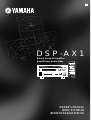 1
1
-
 2
2
-
 3
3
-
 4
4
-
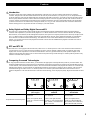 5
5
-
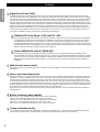 6
6
-
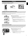 7
7
-
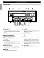 8
8
-
 9
9
-
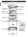 10
10
-
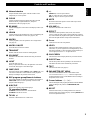 11
11
-
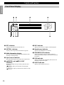 12
12
-
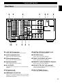 13
13
-
 14
14
-
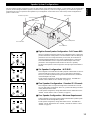 15
15
-
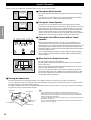 16
16
-
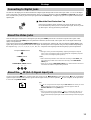 17
17
-
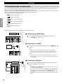 18
18
-
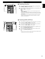 19
19
-
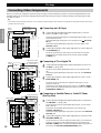 20
20
-
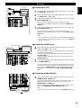 21
21
-
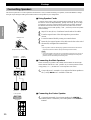 22
22
-
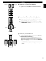 23
23
-
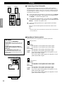 24
24
-
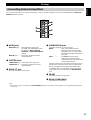 25
25
-
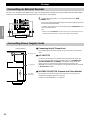 26
26
-
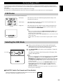 27
27
-
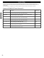 28
28
-
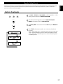 29
29
-
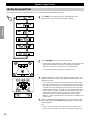 30
30
-
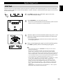 31
31
-
 32
32
-
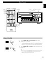 33
33
-
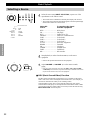 34
34
-
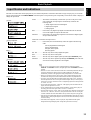 35
35
-
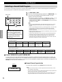 36
36
-
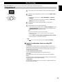 37
37
-
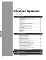 38
38
-
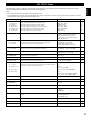 39
39
-
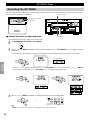 40
40
-
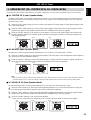 41
41
-
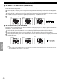 42
42
-
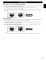 43
43
-
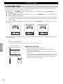 44
44
-
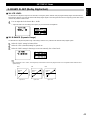 45
45
-
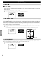 46
46
-
 47
47
-
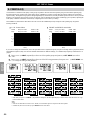 48
48
-
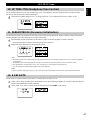 49
49
-
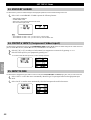 50
50
-
 51
51
-
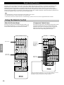 52
52
-
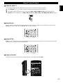 53
53
-
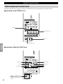 54
54
-
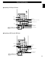 55
55
-
 56
56
-
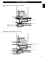 57
57
-
 58
58
-
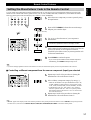 59
59
-
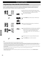 60
60
-
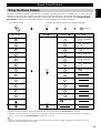 61
61
-
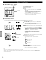 62
62
-
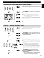 63
63
-
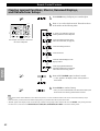 64
64
-
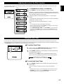 65
65
-
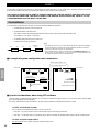 66
66
-
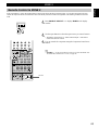 67
67
-
 68
68
-
 69
69
-
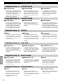 70
70
-
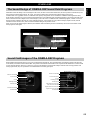 71
71
-
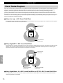 72
72
-
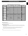 73
73
-
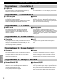 74
74
-
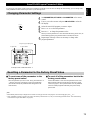 75
75
-
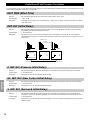 76
76
-
 77
77
-
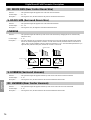 78
78
-
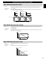 79
79
-
 80
80
-
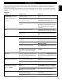 81
81
-
 82
82
-
 83
83
-
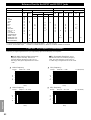 84
84
-
 85
85
-
 86
86
-
 87
87
-
 88
88
-
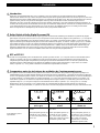 89
89
-
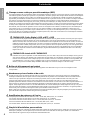 90
90
-
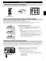 91
91
-
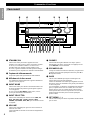 92
92
-
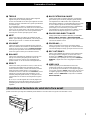 93
93
-
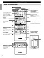 94
94
-
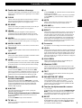 95
95
-
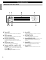 96
96
-
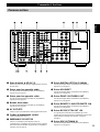 97
97
-
 98
98
-
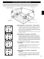 99
99
-
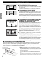 100
100
-
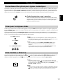 101
101
-
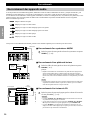 102
102
-
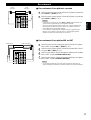 103
103
-
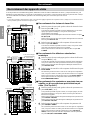 104
104
-
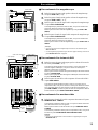 105
105
-
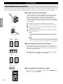 106
106
-
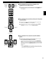 107
107
-
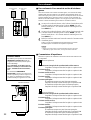 108
108
-
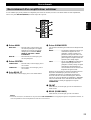 109
109
-
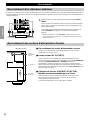 110
110
-
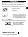 111
111
-
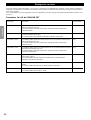 112
112
-
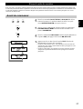 113
113
-
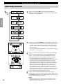 114
114
-
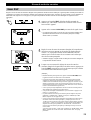 115
115
-
 116
116
-
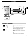 117
117
-
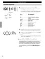 118
118
-
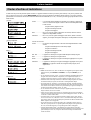 119
119
-
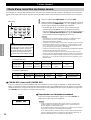 120
120
-
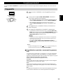 121
121
-
 122
122
-
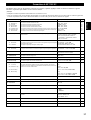 123
123
-
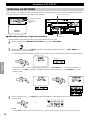 124
124
-
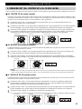 125
125
-
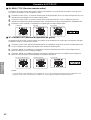 126
126
-
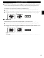 127
127
-
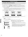 128
128
-
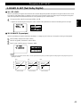 129
129
-
 130
130
-
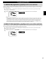 131
131
-
 132
132
-
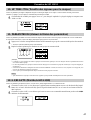 133
133
-
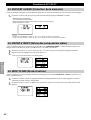 134
134
-
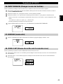 135
135
-
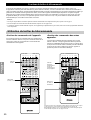 136
136
-
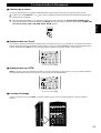 137
137
-
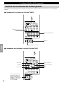 138
138
-
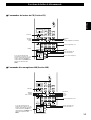 139
139
-
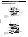 140
140
-
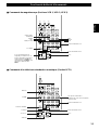 141
141
-
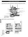 142
142
-
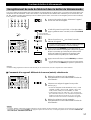 143
143
-
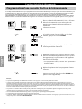 144
144
-
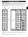 145
145
-
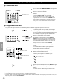 146
146
-
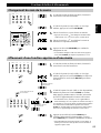 147
147
-
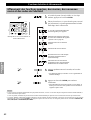 148
148
-
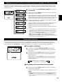 149
149
-
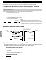 150
150
-
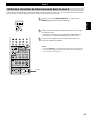 151
151
-
 152
152
-
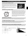 153
153
-
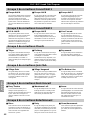 154
154
-
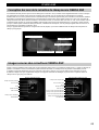 155
155
-
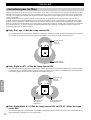 156
156
-
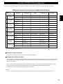 157
157
-
 158
158
-
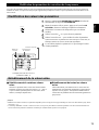 159
159
-
 160
160
-
 161
161
-
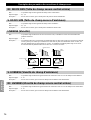 162
162
-
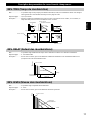 163
163
-
 164
164
-
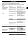 165
165
-
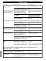 166
166
-
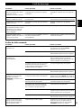 167
167
-
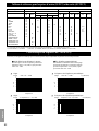 168
168
-
 169
169
-
 170
170
-
 171
171
-
 172
172
-
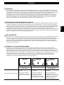 173
173
-
 174
174
-
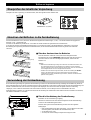 175
175
-
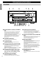 176
176
-
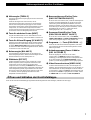 177
177
-
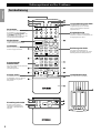 178
178
-
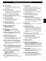 179
179
-
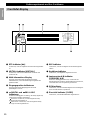 180
180
-
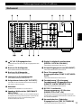 181
181
-
 182
182
-
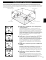 183
183
-
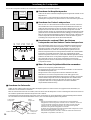 184
184
-
 185
185
-
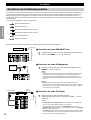 186
186
-
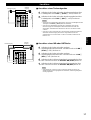 187
187
-
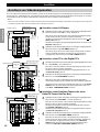 188
188
-
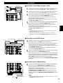 189
189
-
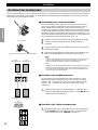 190
190
-
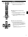 191
191
-
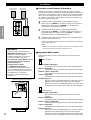 192
192
-
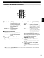 193
193
-
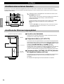 194
194
-
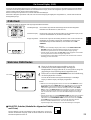 195
195
-
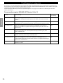 196
196
-
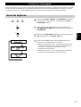 197
197
-
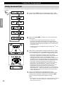 198
198
-
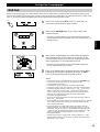 199
199
-
 200
200
-
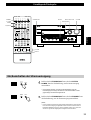 201
201
-
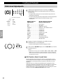 202
202
-
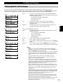 203
203
-
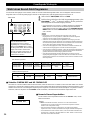 204
204
-
 205
205
-
 206
206
-
 207
207
-
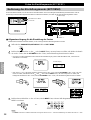 208
208
-
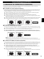 209
209
-
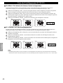 210
210
-
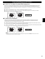 211
211
-
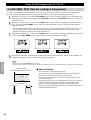 212
212
-
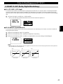 213
213
-
 214
214
-
 215
215
-
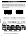 216
216
-
 217
217
-
 218
218
-
 219
219
-
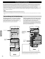 220
220
-
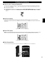 221
221
-
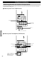 222
222
-
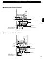 223
223
-
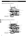 224
224
-
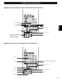 225
225
-
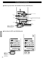 226
226
-
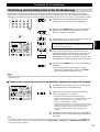 227
227
-
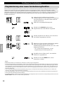 228
228
-
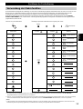 229
229
-
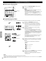 230
230
-
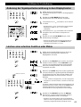 231
231
-
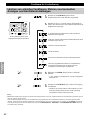 232
232
-
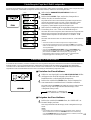 233
233
-
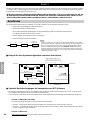 234
234
-
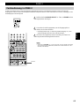 235
235
-
 236
236
-
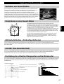 237
237
-
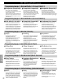 238
238
-
 239
239
-
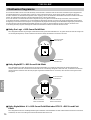 240
240
-
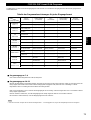 241
241
-
 242
242
-
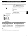 243
243
-
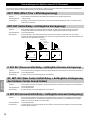 244
244
-
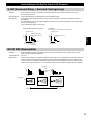 245
245
-
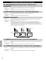 246
246
-
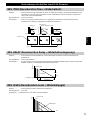 247
247
-
 248
248
-
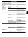 249
249
-
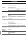 250
250
-
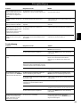 251
251
-
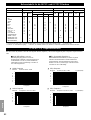 252
252
-
 253
253
-
 254
254
-
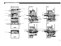 255
255
-
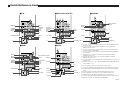 256
256


in andere talen
- English: Yamaha DSP-AX1 Owner's manual
- italiano: Yamaha DSP-AX1 Manuale del proprietario
- français: Yamaha DSP-AX1 Le manuel du propriétaire
- Deutsch: Yamaha DSP-AX1 Bedienungsanleitung
- dansk: Yamaha DSP-AX1 Brugervejledning
- suomi: Yamaha DSP-AX1 Omistajan opas
- svenska: Yamaha DSP-AX1 Bruksanvisning
- Türkçe: Yamaha DSP-AX1 El kitabı
- română: Yamaha DSP-AX1 Manualul proprietarului