
INSTALLATION MANUAL
(ENGLISH) (TRANSLATED VERSION)
SBGuidance Auto
CNH IntelliSteer (Steer Ready)
016-8000-086EN Rev. A

SBGuidance I Rev. A I IntelliSteer
Pag 2/22 I SBG-IntelliSteer-IM-EN-Rev. A
Preface
This installation manual is intended for persons responsible for installing a SBGuidance Auto set on a CNH
Intellisteer (GPS Ready) tractor. The manual contains important instructions that should be complied with
when commissioning, operating and servicing the SBGuidance system.
This manual has been compiled with the utmost care. SBG Precision Farming assumes no responsibility for
any errors or omissions in this document.
Any comments or questions can be sent to service-eu@ravenind.com
SBG Precision Farming or any of its suppliers will accept no liability for physical or material damage
caused whilst using the SBGuidance system.
The installed SBG system produces less than 70dB (A) noise.
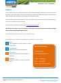
This user guide uses a number of concepts for extra attention to a few things.
Hint!:
Gives suggestions to make it easier to perform
certain tasks
Pay attention!:
Alerts the user for potential problems.
Be careful!:
Indicates that the device may possibly be
damaged.
Warning!:
Indicates that there is a danger of personal
injury.

SBGuidance I Rev. A I IntelliSteer
Pag 3/22 I SBG-IntelliSteer-IM-EN-Rev. A
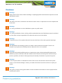
Disclaimer
Warning!:
Always switch off the tractor before installing or repairing hydraulic and electrical components of the
SBGuidance system.
Warning!:
The safety instructions contained in the manuals of the tractor or implements must be complied with
at all times.
Warning!:
It is strictly prohibited to use the SBGuidance system on public roads.
Warning!:
It is strictly prohibited to leave a driving vehicle unattended when the SBGuidance system is switched
on. The driver is always responsible for the direction and course of the vehicle.
Warning!:
To prevent injury or fire, replace defective fuses only with fuses of the same type and amperage.
Warning!:
The SBGuidance the operating system is not able to detect and avoid obstacles. If there is an
obstacle in your path, you will always need to take action for it to be avoided.
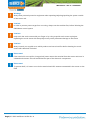
Warning!:
Only allow authorized/qualified persons to operate the system. Authorized/qualified persons are
defined as: persons who have read and understood the manual, have been given instructions by a
product specialist, and who are both physically and mentally fit and able to operate the system.
Warning!
In case of system failure or breakdown switch of the tractor and disconnect the electrical power
source to avoid further damage. Contact your dealer for further instructions on how to repair your
system.
Warning!
The system contains moving parts! Make sure the immediate environment is clear of people before
operating the system.

SBGuidance I Rev. A I IntelliSteer
Pag 4/22 I SBG-IntelliSteer-IM-EN-Rev. A
Warning!
Always wear personal protective equipment when operating/adjusting/repairing the system outside
of the tractor cab.
Caution!:
In order to prevent power surges from occurring, always start the machine first, before initiating the
SBGuidance control system.
Caution!:
Only touch the touch-screen with your finger or by using a special touch-screen stylus/pen.
Operating the touch-screen with sharp objects may cause permanent damage to the screen.
Caution!:
Always consult your supplier as to which products are best suited first before cleaning the touch-
screen with chemicals or alcohol.
Please note!
If the terminal is not used for a long period, better remove the terminal from the tractor and store in
a heated environment. This will extend the life span of the electronic components.
Please note!
To prevent theft, it is better to not let the terminal and GPS-antenna unattended in the tractor on the
field.

SBGuidance I Rev. A I IntelliSteer
Pag 5/22 I SBG-IntelliSteer-IM-EN-Rev. A
Contents
Preface ........................................................................................................................................................................................................... 2
Disclaimer ..................................................................................................................................................................................................... 3
Contents ....................................................................................................................................................................................................... 5
1. Compontents overview ................................................................................................................................................................ 6
1.1. Overview of electrical components .............................................................................................................................. 6
1.2. Overview of mechanical components ........................................................................................................................... 7
2. Tractor kit build up ........................................................................................................................................................................ 8
3. Mounting harness .......................................................................................................................................................................... 9
3.1. CAN Basic harness ................................................................................................................................................................ 9
3.2. CAN Implement Ready (IR) harness .............................................................................................................................. 9
3.3. Mount harnesses ................................................................................................................................................................... 9
4. Mounting GPS- en radio/gsm- antenna ............................................................................................................................ 14
4.1. Mount CNH GPS-antenna bracket ............................................................................................................................... 14
4.2. Mount standard GPS-antenna bracket ....................................................................................................................... 14
4.3. Montage radio-antenne ................................................................................................................................................... 16
4.4. Montage GSM- en SlingShot GPS-antennes ........................................................................................................... 17
5. Mounting DynamIQ .................................................................................................................................................................... 18
6. Mounting terminal ...................................................................................................................................................................... 19
7. Setup in CANTool ........................................................................................................................................................................ 20
8. Setup software (SBGuidance) .................................................................................................................................................. 22

SBGuidance I Rev. A I IntelliSteer
Pag 6/22 I SBG-IntelliSteer-IM-EN-Rev. A
1. Compontents overview
1.1. Overview of electrical components
#
Type Number:
Description:
1
11158000240
HRNS, STU, NH INTELLISTEER
2
SBG13711
Harness chassis (hydraulics)
3
11158000228
HRNS, IN-CAB, DYNAMIQ
4-1
11158000064
HRNS, IN-CAB, TERMINAL, VIPER4
4-2
11158000129
HRNS, IN-CAB, TERMINAL, GEOSTR
5
11158000141
HRNS, POWER, BASIC
5
11158000060
HRNS, POWER, IMPLEMENT READY
6
14084002131
Implement socket (IBBC)
7-1
11178000313
KIT, RADIO ANTENNA TRC, MAGNET
7-2
11218000003
ANTENNA, 4G/3G UMTS LAIRD 3.5M
7-3
10638000015
ANTENNA, PATCH, 4.5M
8
1115800011(0/1/2)
CBL, ANT. 3 / 4.5 / 6M, TNC-N
9
11158000226
HRNS, WAS, 5M
10
10638000087
STU, TRACTOR
11
10630173862
DynamIQ ISO - Tractor
12
11158000151
HRNS, WAS SPY, NH STR
1
5
8
7-1
2
10
12
6
9
3
4-2
11
7-2
4-1
7-3

SBGuidance I Rev. A I IntelliSteer
Pag 7/22 I SBG-IntelliSteer-IM-EN-Rev. A
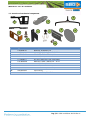
1.2. Overview of mechanical components
#
Type Number:
Description:
1
11078000125
BRACKET, DYNAMIQ, V4
2
11078000081
BRACKET, GPS/RADIO ANT GENERIC
3
11078000121
BRACKET, GPS ANTENNA, NH
4
11078000006
BRACKET, IBBC, IR
5
11178000311
KIT, BOLT AND NUT UNC, ANTENNA
6
11078000082
BRACKET, RAM, CAB NH/JD – A PO
7
11030001040
MOUNT, 1" RAIL, RAM D
8
11078000006
BRACKET, MANIFOLD V3, STU
9
11078000131
MOUNTINGPLATE, ANTENNA, ROOF
10
14074001024
TNC Dummy
-
11178000341
KIT, MOUNTING, TRACTOR
1
2
7
8
4
5
6
3
9
10

SBGuidance I Rev. A I IntelliSteer
Pag 8/22 I SBG-IntelliSteer-IM-EN-Rev. A
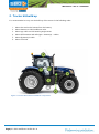
2. Tractor kit build up
It is recommended to carry out the build up of the tractor in the following order:
1. Mount the entire wire harness from the battery
2. Mount harness on CNH Intellisteer valve.
3. Mount spy cable on CNH steering angle sensor
4. Mount GPS antenna and radio/gsm- antenna(s) + cables
5. Mount DynamIQ in cabin
6. Mount Terminal
2
1
5
4
6
Figure 1 Overview New Holland IntelliSteer components
3

SBGuidance I Rev. A I IntelliSteer
Pag 9/22 I SBG-IntelliSteer-IM-EN-Rev. A
3. Mounting harness
There is a choise between a CAN Basic harness or a
Implement Ready (IR) harness at SBG.
3.1. CAN Basic harness
The Basic harness can only be used for tractor steering.
If the tractor is mounted with this harness there is no
possibilty to use the tractor for implement steering
(TWIN, plough).
3.2. CAN Implement Ready (IR) harness
The Implement Ready harness ensures that the tractor
can be used for tractor and implement steering.
Mounting the implement is possible through the IBBC-
connector. The harness is mounted from the battery to
the IBBC-connector at the back side of the tractor.
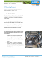
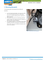
3.3. Mount harnesses
The CAN basic harness and the CAN Implement harness
are divided in the following harnesses (ranked in order
from the battery):
1. Power harness: This harness comes from the
battery and goes to the rear axle along the
chassis, wrapped in a hard casing. A Basic
harness goes from the battery directly to the
chassis harness (and not to the rear axle of the
tractor)
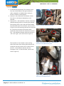
2. Chassis harness: is a branch to the Steering
Controller (STU). Mount the STU somewhere
nearby the Case/New Holland steering valve. On
top of the motor is the best place, just below the
hood. (Figuur 2).
Figuur 2 Locatie van de STU boven op de motor.

SBGuidance I Rev. A I IntelliSteer
Pag 10/22 I SBG-IntelliSteer-IM-EN-Rev. A
3. In-Cab harness (DynamIQ): This harness comes
from the chassis harness and goes inside the
cabin, wrapped in a braided sleeve casing. A
branch is made to the DynamIQ.
4. Harness in-cab (Terminal): This harness comes
from the In-Cab harness (DynamIQ) to the
terminal.
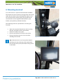
5. Harness STU – NH IntelliSteer: Find the Case/New
Holland steering valve for mounting this harness.
The steering valve is just under the hood nearby
the cabin and close to the orbitrol. (see red circle
in Figure 3) On this steering valve are two Deutsch
DT-connectors mounted. Disconnect these
connectors and connect the connectors from the
STU – NH intellisteer harness with the inscription
‘’left’’ and ‘’right’’. (see red circles in Figure 4)
The lockvalve is also located on the steering
valve. Disconnect the excisting CNH Deutsch DT-
connector also and connect the connector from
the STU – NH intellisteer harness with the
inscription ‘’lock’’ on the lockvalve. (see the red
circle in Figure 5)
Figure 5 Connection of the STU – NH intellisteer
harness on the CNH lock valve
Figure 3 Location CNH steering valve
Figure 4 Connection of the STU – NH intellisteer
harness on the CNH steering valve

SBGuidance I Rev. A I IntelliSteer
Pag 11/22 I SBG-IntelliSteer-IM-EN-Rev. A
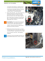
On the side of the exhaust is a pressure sensor
mounted on the CNH steering valve (Figure 6).
Connect the 3-pole Delphi connector of the STU
– NH Intellisteer harness with inscription
‘’pressure sensor’’ on the steering valve.
5. Harness CNH STR WHS – Spy: First disconnect the
excisting connection of the CNH steer angle
sensor. This connection is located on the right
side of the tractor next to the radiator (Figure 7).
Then connect the two connectors of the NH STR
WHS – Spy harness between the excisting CNH
wheel angle sensor. (Figure 7)
Pay attention!: Do not connect the connectors of
the NH STR WHS – Spy harness on the dummy
connector which is also located nearby the
radiator. Connect the connectors of the harness
between the excisiting connection.
6. Wheel sensor cable: The next step is to connect
the wheel angle sensor cable (5m) (SBG11901-08)
to the NH STR WHS – Spy harness with the wheel
sensor connector of the STU – NH intellisteer
connector.
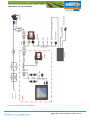
A schematic overview of the SBG CAN-harness on a
CNH Intellisteer Ready tractor is shown in Figure 8.
Figure 7 Connection of the STU – NH intellisteer
harness to the wheel angle sensor.
Figure 6 Connection of the STU – NH intellisteer
harness on the CNH pressure sensor

SBGuidance I Rev. A I IntelliSteer
Pag 12/22 I SBG-IntelliSteer-IM-EN-Rev. A
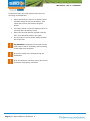
Furthermore there are some general instructions for
mounting an SBG harness:
Mount the harness, if there is no battery switch
installed, always directly on the battery. That
means the positive (red) and the negative
(black).
If a battery switch is used, the harness has to be
mounted after the battery switch.
Mount the terminal harness together with the
GPS- and radio/GSM-cable in one jamb.
Use tie-wraps to mount all the cables vibration
and scrape free.
Pay attention!: Important to mount the harness
at all times at last on the battery after mounting
all the cables and controllers!
Be sure the cables won’t damage during the
installation!
Push all connectors until they snap to be sure the
connectors are properly connected!

SBGuidance I Rev. A I IntelliSteer
Pag 13/22 I SBG-IntelliSteer-IM-EN-Rev. A
Figure 8 Systemoverview CNH IntelliSteer.

SBGuidance I Rev. A I IntelliSteer
Pag 14/22 I SBG-IntelliSteer-IM-EN-Rev. A
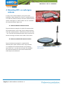
4. Mounting GPS- en radio/gsm-
antenna
In many cases a New Holland or Case tractor with
Intellisteer (New Holland TSA, T6 en T7-models and Case
CVX, MXU en PUMA-models) a CNH GPS-antenna bracket
can be used (Figure 9). Other models can use a standard
GPS-antenna bracket (Figure 10).
4.1. Mount CNH GPS-antenna bracket
Figure 9 shows an example of a CNH GPS-antenna (with
two Laird antenna’s in this case). This kit always include a
CNH GPS-antenna bracket, a GPS dummy and a UNC bolt
+ nut. The CNH GPS-antenna bracket can be mounted on
the two excisting roof bolts on the cabin of the tractor.
4.2. Mount standard GPS-antenna bracket
Figure 10 shows an example of a standard GPS-
antenna (with a radio-antenna in this case) mounted
on a standard GPS-antenna bracket. A GPS-dummy
and a UNC bolt + nut are also mounted. The standard
GPS-antenna bracked can be mounted with double
sided tape on the cabinroof.
Figuur 10 Standaard GPS-antenne bracket + UNC
bout en moer.
Figure 9 CNH GPS-antenna bracket.

SBGuidance I Rev. A I IntelliSteer
Pag 15/22 I SBG-IntelliSteer-IM-EN-Rev. A
For mounting a GPS-antenna a few general instructions
are applicable:
Mount the GPS-antenna at least 60 cm in front of
the rear axle.
Mount the GPS-antenna in the middle of the
tractor.
Mount the GPS-antenna on the supplied UNC
bolt.
Mount the TNC-dummy on the GPS-antenna
bracket (Error! Reference source not found.).
When a Geostar terminal is used, the side of the
biggest connector (N-connector) has to go inside
the cabin. At Viper 4 terminals there is no
difference between the connectors of the antenna
cable.
Mount the GPS-antennacable properly so it can’t
be damaged. Hide the cables in the cabin lining.
Mount the GPS antenna cables in a way water can
not flow down into the cabin.

SBGuidance I Rev. A I IntelliSteer
Pag 16/22 I SBG-IntelliSteer-IM-EN-Rev. A
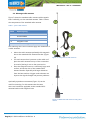
4.3. Montage radio-antenne
Figure 7 shows the standard radio-antenna with magnetic
base. Preferably, use the standard antenna. Table 1 shows
the components of the standard radio antenna.
The following terms and conditions apply the installation of
a radio-antenna:
Mount the radio-antenna preferably with magnetic
bas on the standard GPS-antenna bracket. (Figure
10)
If a steel construction is present on the cabin roof
place the radio-antenna on top of the constrution
in stead of placing it next to the construction.
Place the magnetic base on a sufficiently large steel
surface, at least the size of the standard GPS
antenna bracket. Especially with larger distances
from the base station, a bigger steel substrate can
improve the signal strenght and prevent problems.
Optionally a panelmount antenna (Figure 12) can be
used fot mounting. For this antenna are the same
terms and conditions applyable as the standard GPS-
antenna bracket with magnetic base.
Teken
Omschrijving
1
Radio-antenna
2
Antennacable
3
Connector to terminal
4.1
Magnetic base
4.2
Panel-mount (optional)
Table 1: parts radio antenna
1
4.1
3
2
4.2
Figure 11 Components radio-antenne.
Figure 12 Mounted radio-antenna with panel
mount

SBGuidance I Rev. A I IntelliSteer
Pag 17/22 I SBG-IntelliSteer-IM-EN-Rev. A
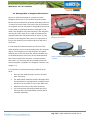
4.4. Montage GSM- en SlingShot GPS-antennes
Figure 13 shows an example of a proper mounted
SlingShot antenna kit on a CNH GPS-antenna bracket.
Mount the two GSM (Laird) antennas preferably minimum
1,0 meter from each other. The base of the GPS-antennas
are magnetic and can be placed in longitudinal (front/rear
on the cabin) or transversal direction (left/right on the
cabin). The SlingShot GPS patch antenna is also magnetic
and can be mount easily on the CNH GPS-antenna (for
example behind the GPS antenna like in Figure 13). The
position of the SlingShot GPS patch is not important as
long as the antenna is mounted on the roof and with a
clear view.
If a universal GPS-antenna bracket is used one of the
GSM-antenna’s can be mounted behind the GPS-antenna.
(Figure 14) Preferably mount the SlingShot GPS patch
antenna also on the universal GPS-antenna bracket next
to the GSM-antenna. In this way the two GSM antennas
has to be mounted also minimum 1.0 meter between
each other. For mounting the second GSM-antenna an
extra metal plate is supplied in a SlingShot tractorkit. (see
chapter 1.2)
It is important to meet the following conditions at all
times:
Place the two GSM antenna’s at least 1.0 meter
from each other.
The GPRS/UMTS-antenna’s and the SlingShot GPS
patch antenna are equipped with a magnetic base
and has to be mounted on top of the cabin roof.
Antenna’s must have a clear view all around.
Use a metal plate with double sided tape if the
GPS-antenna’s and GPRS/UMTS antenna will be
mounted separately.
Figuur 14 GPS-antenne bracket samen met een GSM
-antenne.
Figuur 13 CNH GPS-antenne bracket samen met een
SlingShot antennekit.

SBGuidance I Rev. A I IntelliSteer
Pag 18/22 I SBG-IntelliSteer-IM-EN-Rev. A
5. Mounting DynamIQ
The following orders are presented for mounting the
DynamIQ:
ount the DynamIQ preferably on the right side of the
seat. Use the standard DynamIQ mounting plate
(Figure 14). Use M8 connecting nuts to extend the
bolts of the seat.
The DynamIQ may only be mounted lying (with the
sticker upwards) The connectors may be oriented in 4
directions (0, 90, 180, 270 degrees)
The standard installation of a DynamIQ is lying (sticker
upwards) and with the connectors to the back of the
tractor. (like in Figure 15) A different orientation must
be set in the software!
Figure 15 DynamIQ on mountingplate.

SBGuidance I Rev. A I IntelliSteer
Pag 19/22 I SBG-IntelliSteer-IM-EN-Rev. A
6. Mounting terminal
For a CNH tractor is a special terminal bracket available.
This bracket can be mounted on the right front side of the
cabin with two bolts in the excisiting holes (Figure 16). If
the customer wants another place the terminal can be
mounted with an also supplied RAM-D/RAM-C pipe
bracket. (and possibly a selfmade bracket)
The following orders are presented for mounting the
Terminal:
Mount the terminal vibration free with a strong
bracket. (preferably with a CNH bracket)
Hide all te cables in one jamb.
Be sure the terminal is focused on the driver.
Be sure the driver has got a clear view after
installing the terminal.
Tip: fit the terminal in such a way that it doesn’t
take away the view of the top of the right fender,
but also the inside of the front wheel to the ground
is still visible.
Figure 16 CNH Terminal bracket.
Figure 17 Terminal mounted on A-jamb

SBGuidance I Rev. A I IntelliSteer
Pag 20/22 I SBG-IntelliSteer-IM-EN-Rev. A
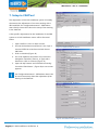
7. Setup in CANTool
The adjustment of the CNH Intellisteer system is broadly
the same as the adjustment of a tractor steering with a
SBG manifold. See Configurationmanual – SBGuidance
Auto CAN for instructions about the setup of the steering
in the CANTool.
A few specific adjustments for the installation of the SBG
system on a CNH Intellisteer tractor will be discussed
below:
1. Open CANTool 1.29 or a newer version
2. Choose the hardware manufacturer. At a Viper 4
choose VIPER4. At a GeoStar terminal choose
SBG-CAN
3. Click on Initialize (Figure 18)
4. Go to tab MyDevice and select at Pre-selection
Navigation Controller (Tractor), at Type select
Navtronics. Click on Connect (Figure 19)
5. Open tab My Partners and click Add at Steering
Controller’’SBGuidance’’. (Figure 20) A new screen
appears.
See Configurationmanual – SBGuidance Auto CAN
for more instructions about the adjustment of the
steering in the CANTool.
Figure 18 CANTool tab Hardware.
Figure 19 CANTool tab MyDevice.
Figuur 20 CANTool tab MyPartners.

SBGuidance I Rev. A I IntelliSteer
Pag 21/22 I SBG-IntelliSteer-IM-EN-Rev. A
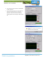
6. Go to tab Steer Sensor and select ‘’SauerDanfoss’’
at Type. (Figure 21)
7. Go to tab Steering (Figure 22). Select PWM Lim.
Disabled. A warning message is displayed
(Figure23). Click Yes. Then, set the maximum
steering speed for left and right to 100%. (Figure
22)
Figure 21 Configurate Steer Sensor.
Figure 23 Warning message for set up maximum
steering speed.
Figure 22 Configurate maximale stuursnelheden.

SBGuidance I Rev. A I IntelliSteer
Pag 22/22 I SBG-IntelliSteer-IM-EN-Rev. A
8. Setup software (SBGuidance)
Add a machine profile to the Loader and enter a distinct
machine name.
Important: Follow the instructions in
Configurationmanual – SBGuidance Auto CAN to
adjust SBGuidance Configurator, creating profiles
and calibrating the DynamIQ.
-
 1
1
-
 2
2
-
 3
3
-
 4
4
-
 5
5
-
 6
6
-
 7
7
-
 8
8
-
 9
9
-
 10
10
-
 11
11
-
 12
12
-
 13
13
-
 14
14
-
 15
15
-
 16
16
-
 17
17
-
 18
18
-
 19
19
-
 20
20
-
 21
21
-
 22
22


