Blaupunkt amsterdam tcm 127 de handleiding
- Type
- de handleiding

- 1 -
8 622 400 963
Radio / Cassette
Sicherheitshinweise
Dieses Erzeugis darf nur von einer Blaupunkt
autorisierten Fachwerkstatt eingebaut werden.
Vor Einbau Ihres Autoradios die Einbau- und
Anschlußvorschriften lesen.
Für die Dauer der Montage und des Anschlusses
ist der Minuspol der Batterie abzuklemmen.
Hierbei sind die Sicherheitshinweise des Kfz-
Herstellers (Airbag, Alarmanlagen, Bordcomputer,
Wegfahrsperren) zu beachten.
Beim Bohren von Löchern darauf achten, daß
keine Fahrzeugteile (Batterie, Kabel, Sicherungska-
sten) beschädigt werden.
Der Querschnitt des Pluskabels darf 2,5 mm
2
nicht
unterschreiten. Das Gerät ist mit einer Sicherung,
10 A flink, abgesichert.
Das Seitenteil des Autoradios wird im
Betrieb sehr heiß.
Es ist darauf zu achten, daß keine Kabel
am Gehäuse anliegen.
In einigen Fahrzeugen liegt ein 20poliger Stecker
im Einbauschacht. Dieser Stecker darf nicht am
Autoradio angeschlossen werden.
In Audi/VW Fahrzeugen darf der fahrzeugseitige
8polige +/- Stecker nicht direkt an Blaupunkt Auto-
radios angeschlossen werden, da sonst der Dauer-
plus gegen Masse kurzgeschlossen wird und eine
Leiterbahn im Radio aufbrennt.
Einbauanleitung
Fitting instructions
Instructions de montage
Istruzioni di montaggio
Inbouwinstrukties
Monteringsanvisning
Instrucciones de montaje
Instruções de montagem
Amsterdam TCM 127
PIN 2
Mitgelieferte Montage- und Anschlußteile

- 2 -
Verlegen der Kabel
Hinweis! Bei Fahrzeugen mit elektronisch geregelten ABS-
System ist sicherzustellen, daß alle Anschluß-kabel und
die externe Antenne auf der dem ABS-Modul entgegenge-
setzten Seite verlegt werden. Damit werden mögliche Stö-
rungen minimiert.
Mögliche Störungen des ABS -Systems
Unter bestimmten Bedingungen kann der Betrieb des Radio-
phones im Fahrzeug Störungen bei elektronisch geregelten
Brems- und Sicherheitssystemen hervorrufen. Obwohl das
Gerät alle gültigen Vorschriften zur Abstrahlung von Hochfre-
quenzen erfüllt ist die über die Antenne abgestrahlte HF-Lei-
stung für den Betrieb des Telefons unerläßlich und kann ohne
Funktionseinschränkung nicht reduziert werden.
Daher müssen alle elektronischen Regelsysteme im Fahrzeug
den strengen EMV-Normen entsprechen. In vielen Fällen bleibt
ein Nicht-einhalten dieser Normen solange unbemerkt, bis das
Gerät in der Nähe einer Sendeantenne betrieben wird.
Aus diesem Grund sollten elektronisch geregelte ABS- und
Sicherheitssysteme bei unterschiedlichen Geschwindigkeiten
sehr sorgfältig auf mögliche Betriebsstörungen untersucht
werden.
Überprüfen des ABS-Systems
Die Prüfung erfolgt in 8 Einzelschritten, um alle Störgrößen
abdecken zu können. Störungen des elektronischen ABS-Sy-
stems können in der Regel auf verschiedene Weise erkannt
werden, z.B. durch die Fahrzeugbeleuchtung, untypische Au-
diogeräusche, spürbare Änderungen in der ABS-Leistung u.s.w.
1. Bei stehenden Fahrzeug mit nicht eingelegtem Gang,
hoher Leerlaufdrehzahl und ohne Bremsbetätigung ein
Telefongespräch führen.
2. Punkt 1 mit Betätigung der Bremse wiederholen.
3. Bei stehenden Fahrzeug und ausreichenden Platz in Fahrt-
richtung einen Vorwärtsgang einlegen Kupplung kommen
lassen bis das Fahrzeug allmählich anfährt. Nun die Brem-
se leicht betätigen, so daß das Fahrzeug stillsteht. Dabei ein
Telefongespräch führen und sicherstellen, daß keine Funk-
tionsstörungen auftreten (möglicherweise benötigen Sie
dabei die Hilfe einer weiteren Person.)
4. Bremse lösen und das Fahrzeug mit einer Ge- schwindig-
keit von ca. 25-40 km/h fahren. Dabei Anruf entgegenneh-
men.
5. Bremse so betätigen, daß die Bremsleuchten scheinen und
dabei einen Anruf entgegennehmen.
6. Bei einer Geschwindigkeit von ca. 25-40 km/h leichte wie-
derholte Bremsbetätigungen vornehmen und dabei einen
Anruf entgegennehmen.
Hinweis! Auch mit ABS-System ist es bei einer Vollbrem-
sung möglich,daß der Fahrer die Kontrolle über das Fahr-
zeug bei einer Vollbremsung verliert. Bitte beachten Sie
dies bei der Durchführung der folgenden Prüfungen.
7. Vollbremsung des Fahrzeugs aus einer Geschwin-
digkeit von ca. 30 km/h und dabei Anruf entgegen-
nehmen.
8. Treten bei Punkt 7 keine Störungen auf, Test mit ei-
ner Geschwindigkeit von 50 km/h wiederholen.
Hinweis! Treten bei keiner der o.g. Prüfungen Störungen
auf, so scheint das Gerät einwandfrei zu funktionieren.
Das Fahrzeug kann an den Kunden freigegeben werden.
Sind jedoch Störungen am Bremsverhalten erkennbar, muß
die Prüfung sofort abgebrochen und das Radiophone aus dem
Fahrzeug ausgebaut werden. Wenden Sie sich bitte in diesem
Fall umgehend an den Kundendienst des Fahrzeugherstellers.
8 622 400 963

- 3 -
Anschluß
11
11
1 Zur Ausschöpfung der vollen Autoradio-Ausgangsleistung und zur
Vermeidung von elektrischen Fehlanschlüssen bei fahrzeugseitigen
ISO-Steckern, ist es empfehlenswert den Kfz-spezifischen Plus- /
Minusanschluß bei diesem Autoradio nicht zu verwenden.
2 2
2 2
2 Fehlanschlüsse können grundsätzlich bei Verwendung Kfz-spezi-
fische Blaupunkt-Adapterkabel vermieden werden, aber !
3 3
3 3
3 aufgrund zu geringer Kabelquerschnitte im Fahrzeug ist zusätzlich
zum Kfz-spezifischen Blaupunkt-Adapterkabel für den Plus- / Minus-
anschluß das Anschlußkabel 7 607 884 093 zu verwenden.
Unbedingt Fig 4, 5 beachten.
Hinweise für vorgerüstete Fahrzeuge, z.Z. Audi/VW, Mercedes,
Ford, Honda, Porsche
Ist der Radioanschluß im Auto bereits werkseitig mit einer 10 A -
Sicherung abgesichert, so wird nur noch das fahrzeug-spezifische
Adapterkabel zum Anschluß benötigt.
Bei Verwendung kfz.- spezifischer Adapterkabel ist der radioseitige
Stecker abzuschneiden und mit Anschlußkabel 7 607 884 093 zu
verbinden.
Vorteil: die fahrzeugseitige Verkabelung wird hierbei nicht beschädigt.
Plusanschluß
Dauerpluskabel am Kfz-spezifischen Blaupunkt-Adapterkabel abschnei-
den, mit Anschlußkabelkabel 7 607 884 093 verbinden und direkt am
Pluspol der Batterie anklemmen.
Minusanschluß
Minuskabel nicht am Minuspol der Batterie anklemmen.
Minuskabel am Kfz-spezifischen Blaupunkt-Adapterkabel abschnei-
den, mit Anschlußkabelkabel 7 607 884 093 verbinden und Minuskabel
zu einem geeigneten Massepunkt verlegen z.B. Karosserieschraube,
Karosserieblech und entsprechend Massepunkt kürzen ,
(keine Leitungsringe bilden).
Antenneneinbau
Antenneneinbau und Anschluß siehe Antenneneinbauanleitung
Hinweis: Die Telefonantennenleitung darf nicht in die Nähe der
Lautsprecherleitungen verlegt werden.
Autoradioeinbauvorbereitung
Das Autoradio wird in den vom Fahrzeughersteller vorgesehenen
Autoradioausschnitt eingebaut. Autoradioausschnitt freilegen (Ablage-
fach oder Blindblende ausclipsen) oder Autoradioausschnitt auf
182 x 53 mm ausarbeiten.
Für Fahrzeuge mit abweichender Einbausituation liefert Blaupunkt für
die gängigsten Fahrzeuge fahrzeugspezifische Einbausätze für 50 mm
Geräte.
Prüfen Sie daher, welche Einbausituation im Fahrzeug vorliegt, und
verwenden Sie zum Einbau gegebenenfalls einen fahrzeugspezifischen
Einbausatz, z. B. Audi A3/A4/A6/A8: 7 608 021 474.
Hinweis:
Die zum Lieferumfang dieses Autoradios gehörende Halterung ermög-
licht den Einbau in Fahrzeugen mit DIN-Autoradioausschnitt von
182 x 53 mm, 165 mm Einbauraum und einer Instrumententafeldicke im
Bereich der Befestigungslaschen von 1 - 20 mm, siehe Fig. 1.
Hinter den Autoradioausschnitt fassen und prüfen, welche Befestigungs-
laschen der Halterung umgebogen werden können.
Hinweis: Möglichst alle Befestigunglaschen umbiegen.
Halterung in den Ausschnitt einsetzen und die Befestigungslaschen mit
einem Schraubendreher umbiegen, siehe Fig. 1, 2.
Anschluß
Anschlußhinweise ..................................................................... Fig. 4
Plus-/Minus-Anschluß mit Kfz.spezifische Adapterkabel .......... Fig. 5
Plus-/Minus-Anschluß mit Anschlußkabel 7 607 884 093......... Fig. 5a
Equalizer- oder Amplifieranschluß, (CINCH) ............................ Fig. 6
Das Steuerkabel nicht an Klemme 15 (Plus geschaltet) oder Klemme 30
(Dauerplus) anschließen,maximale Belastung <150 mA.
Lautsprecheranschluß 4 AL (4 Ω/35 W) .................................... Fig. 7
LF = links vorn, RF = rechts vorn, LR = links hinten, RR = rechts hinten.
Anschluß mit Freisprechmicrofon ............................................. Fig. 8
Anschluß mit Telefonhörer (Handset 7 607 570 512) .............. Fig. 9
Anschluß CD-Player CDC-A06 /072 ......................................... Fig.10
Anschluß IR-Fernbedienung RCT-07 ....................................... Fig.11
Anschluß CD-Player CDC-A05/071 ......................................... Fig. 12
Anschluß CD-Player CDC-F05 ................................................ Fig. 13
Fahrzeugseitiger Halterahmen oder Fernbedienungen
Bei Fahrzeugen, die fahrzeugseitig mit einem Halterahmen ausgerüstet
sind (z.Z. Opel), muß die fahrzeugseitige Halterung ausgebaut und
Adapterkabel verwendet werden. Fahrzeugseitige Autoradio-Fernbe-
dienungen (z.B. im Lenkrad), Amplifier oder Changeranschluß haben an
Blaupunkt Autoradios keine Funktion.
Autoradioeinbau
Autoradio von vorn in die Halterung einsetzen und einschieben, bis die
seitlichen Rastfedern rechts und links arretieren (deutliches Knacken
hörbar).
Autoradioausbau
Bügel links und rechts in die vorhandenen Löcher der Blende stecken
und so weit eindrücken, bis deutliches Knacken zu hören ist (seitliche
Federn entriegelt).
Gerät an den beiden Bügeln herausziehen, siehe Fig. 3.
Hinweis: Eingerastete Bügel können nur nach Herausziehen
des Gerätes entfernt werden.
Änderungen vorbehalten!
D
Autoradioanschluß
ISO-Stecker Fahrzeugseitig
Autoradioanschluß
mit Adapterkabel
Autoradioanschluß
mit Adapter- und Anschlußkabel
Fig. 2Fig. 1
Illustrationen
53
182
165
8 601 310 742
1-20
8 600 460 050
8 601 310 742
Fig. 3
8 601 910 002
2
2
1
1
8 601 910 002
2
3
1
5A
+12V/Kl15
+12V
per.+12V
5A
+12V/Kl15
+12V
per.+12V
+12V / Kl15
+12V
per.+12V
1
5
A
1
2
V
5A
per.+12V
7 607 884 093
Der Führungsbolzen wird mit oder ohne Distanzstück auf das
Schraubgewinde der Geräterückwand gesteckt.
8 622 400 963

- 4 -
Anschlußhinweise, Fig. 4
Masseanschluß (Ground)
Massekabel nicht am Minuspol der Batterie anklemmen.
Massekabel zu einem geeigneten Massepunkt verlegen
(Karosserieschraube, Karosserieblech) und entsprechend
Massepunkt kürzen. Massekabel abisolieren und Krallen-
kabelschuh anschlagen (ggf. nachlöten). Kontaktfläche des
Massepunktes metallisch blank kratzen und mit Graphitfett
einfetten (wichtig für gute Masseverbindung).
Massekabel anschrauben.
Pluskabelanschluß (ACC + 12 V)
(Ignition)
+12V
Wird das Pluskabel am Sicherungshalter Kl.15
(Plus über Zündschloß geschaltet) hinter der Sicherung
angeschlossen, so ist das Ein- und Ausschalten des Autora-
dios über Zündung möglich. Außerdem schaltet das Gerät zum
Schutz der Batterie automatisch nach einer Stunde aus.
" Zündtimer 00 " .Die Stunden-Logik wird nicht aktiviert, wenn
Dauerplus (Kl.30) angeschlossen wird.
Dauerplusanschluß (Battery + 12 V)
per. +12V
Fahrzeugseitiges Pluskabel nicht anschließen.
Pluskabel (rot) mit starkem Querschnitt (2,5 mm
2
) zur Batterie
verlegen (Kabel nicht unmittelbar an Kabelbäumen verlegen).
Sicherungshalter zur Absicherung des Pluskabels anschlie-
ßen und am Pluspol der Batterie anklemmen (ggf. Loch in
Spritzwand bohren und entsprechend Kabeldurchführung ver-
wenden). Entstördrossel vor dem Einbau in Schaumstoff pak-
ken.
Steuerkabel (Power Antenna +)
+12V
Das Steuerkabel ist der geschaltete Plusausgang für
externe Komponenten z.B.: Motorantenne,
maximale Belastung <150 mA.
Das Steuerkabel nicht an Klemme 15 (Plus geschaltet) oder
Klemme 30 (Dauerplus) anschließen.
Beleuchtungsanschluß (Illumination)
Beleuchtungsanschluß für Fahrzeuge mit regelbarer
Instrumentenbeleuchtung (plusgeregelt).
Externer Alarm
nur bei Zündung aus!
Anschluß an PIN 2 nur über ein zeitverzögertes Relais
(maximale Belastung < 100mA). Dauer = 5 Klingeltöne
8 622 400 963
braun / Masse
rot / Plus geschaltet
rot / Dauerplus
grün/gelb / Steuerkabel Antenne
orange / Beleuchtung
< 1s
1
2
345
10A
10A
+12V
+
1
2
3
10A
Kl. 15
Kl.30
12V
10A
Kl.30
1
2
V
15A
10A
per +12V
PIN 2
10A
8 604 492 320

- 5 -
Fig. 5a
Fig. 5
Fig.6
mit Adapterkabel und Anschlußkabel
with adapter and connection wiring
adaptateur et le câble de raccordement
con cavo di adattamento e cavo di allacciamento
met adapterkabel en aansluitkabel
med adapterkabelkabe och anslutningskabel
con el cable adaptador y cable de conexión
com cabo de adaptação e cabo de ligação
3
Adapterkabel, adapterwiring
adaptateur, cavo di adattamento
adapterkabel, adapterkabelkabe
el cable adaptador, cabo de adaptação
Anschlußkabel, connection wiring câble de raccordement, câble de
raccordement, aansluitkabel anslutningskabel, cable de conexión
cabo de ligação
7 607 884 093
br braun, brown, marron, marrone, bruin, brun, marrón, castanho
rt rot, red, rouge, rosso, rood, röd, rojo, vermelho
ge/gn gelb/grün, yello/green, jaune/vert, giallo/verde, geel/groen, gul/grön, amarillo/verde, amarelo/verde
or orange, orange, orange, arancio, oranje, orangefärgad, naranja, cor de laranja
gelb/yello/jaune
giallo/geel/gul
amarillo/Amarelo
per.+12V
+12V
per.+12V
+12V
Fig. 4
!
5A
15A
1
2
V
2
1
3
+12V
per.+12V
+12V
7 607 884 093
br
ge/gn
or
rt
rt
15A
Kl. 15
1
2
V
Kl. 30
per.+12V
+
Fig. 4
!
10A
Ext. Alarm

- 6 -
Fig. 7
LF
RF
LR
RR
LR
RR
RF
LF
10A
7 607 882 090
10A
LR
RR
RF
LF
RR
RF
LF
LR
+
-
+
-
+
-
+
-
8 604 390 087
Die Ersatzteile (8 ... ... ...) sind über den zentralen Ersatzteilversand (VKD3), Ulmer Straße, 30880 Laatzen 1, zu beziehen. / Spare parts (8 ... ... ...) are obtained via central parts dispatch: (VKD3),
Ulmer Straße, 30880 Laatzen 1. / Pour la fourniture des pièces de rechange (8 ... ... ...), s’adresser au centre des pièces détachées, (VKD3), Ulmer Straße, 30880 Laatzen 1.
8 604 390 087
oder/or/ou
Fig. 9
Fig. 8
10
10
10
10
2
1
3

- 7 -
Fig.12
Fig.13
Fig.10
Fig.11
CDC A05
A071
Power/Bus 5m
7 607 889 093
10
10
7 607 647 093
7 607 884 093
2
1
3
+12V
per.+12V
+12V
15A
12V
10
10
7 607 889 093
Opto 5m
7 607 647 093
7 607 884 093
2
1
3
CDC F05
bl
rt
Changer
Interface
rt
br
+12V
+12V
+12V
per.+12V
+12V
15A
12V
Power/Bus 5m
8 619 000 200 5m
1
2
+12V/ kl15
per.+12V
+12V
rt
10
10
15A
12V
br
3A
CDC A06
A072
10
10
CDC

- 8 -

- 9 -
8 622 400 963
Fitting instructions
Instructions de montage
Istruzioni di montaggio
Inbouwinstrukties
Monteringsanvisning
Instrucciones de montaje
Instruções de montagem
Amsterdam TCM 127
GB Safety notes
Before starting to mount your car radio, read the mounting and connection
instructions carefully.
Disconnect the vehicle battery’s negative terminal before making connections.
Be sure to observe the safety notes of the automobile manufacturer (airbags, alarm
systems, on-board computers, immobilisers).
Before drilling holes, look to see what is on the other side - making holes into the
battery, wiring looms or fuse box is not recommended!
The positive lead used must have a cross-section of at least 2.5 mm
2
. The set is
protected by a quick-acting 10 A fuse.
During operation of the unit, the set’s side wall may heat up considerably.
Be sure to keep all wires away from hot parts of the housing.
In some vehicles you will find a 20-pin connector pre-fitted in the dashboard’s
installation space. This connector must not be used for connecting the car radio!
In vehicles manufactured by Audi and VW, the 8-pin positive/negative connector
provided in the car must not be connected to a Blaupunkt radio directly! Otherwise
the permanent +12 V line will be short-circuited to ground, leading to serious
damage of the radio’s internal circuitry (burn-out of printed conductor).
F Indications de sécurité
Veuillez lire les instructions de montage et de raccordement avant de monter votre
autoradio.
Débrancher le pôle négatif de la batterie pendant les opérations de montage et de
branchement.
Prendre note des indications de sécurité du fabricant du véhicule (airbag, alarmes,
ordinateur de bord, dispositifs de blocage des roues).
En perçant des trous, veiller à ce que les éléments du véhicule (batterie, câble,
boîte à fusibles) ne soient pas endommagés.
La section du câble positif ne doit pas être inférieure à 2,5 mm.
L’appareil est protégé par un coupe-circuit à action instantanée de 10 A.
La partie latérale de l’autoradio s’échauffe énormément pendant le service de
l’appareil.
Veiller à ce qu’aucun câble ne se trouve sur le boîtier.
Dans certains véhicules une fiche à 20 pôles se trouve dans le compartiment. Ne
pas connecter cette fiche à l’autoradio.
Dans des véhicules Audi/VW, la fiche à 8 pôles prévue dans le véhicule ne doit pas
être connectée directement aux autoradios Blaupunkt; sinon le plus permanent
donnerait court-circuit à la masse et une piste conductive brûlerait dans l’autoradio.
I Note di sicurezza
Prima di effettuare il montaggio della vostra autoradio leggete le istruzioni di
allacciamento.
Per tutta la durata delle operazioni di montaggio e di allacciamento il polo
negativo della batteria deve rimanere distaccato.
Quando si effettua questo intervento bisogna attenersi alle note di sicurezza del
fabbricante d’auto (airbag, impianto di allarme, computer di bordo, bloccaggio di
avvio).
Quando si trapano fori bisogna fare attenzione a non danneggiare nessun
elemento di veicolo (batteria, cavo, scatola dei fusibili).
La sezione del cavo positivo non deve essere inferiore ai 2,5 mm
2
.
L’apparecchio è dotato di un fusibile, 10 A rapido.
Lateralmente la radio si riscalda molto durante l’esercizio.
Bisogna fare attenzione a non far passare dei cavi lungo l’involucro della radio.
In alcuni veicoli è predisposta una spina a 20 poli nel vano di montaggio.
Questa spina non si deve allacciare all’autoradio.
Nelle vetture Audi/VW la spina +/- ad 8 poli non si deve allacciare direttamente
all’autoradio Blaupunkt, altrimenti il polo positivo permanente entrerebbe in
corto circuito con la massa e così si brucerebbe un tratto di conduttura nella
radio.
NL Veiligheidsaanwijzingen
Lees voor het inbouwen van de radio de aanwijzingen voor de inbouw en de
aansluiting.
Tijdens de montage en de aansluiting moet de minpool van de accu worden
ontkoppeld.
Hierbij moeten de veiligheidsvoorschriften van de autofabrikant (airbag,
alarminstallaties, boordcomputer, wegrijbeveiliging) in acht worden genomen.
Let er bij het boren van gaten op dat geen onderdelen van de auto (accu, kabels,
zekeringskasten) beschadigd worden.
De doorsnee van de pluskabel mag niet minder bedragen dan 2,5 mm
2
. Het
apparaat is gezekerd met een zekering van 10A, snel.
Het zijgedeelte van de autoradio wordt tijdens het gebruik zeer heet.
Er moet op worden gelet dat er geen kabels tegen de kast liggen.
Bij enkele autotypes ligt een 20-polige stekker in de inbouwopening. Deze stekker
mag niet op de autoradio worden aangesloten.
Bij auto’s van de merken Audi en VW mag de achtpolige +/-stekker aan de zijde van
de auto niet direct op Blaupunkt-autoradio’s worden aangesloten. Anders wordt
namelijk de continue pluspool kortgesloten met de massa en brandt in de radio een
verbinding door.
S Säkerhetsföreskrifter
Läs noga monterings- och inkopplingsinformationen innan du monterar bilstereon.
Under monterings- och inkopplingstiden skall bilbatteriets minuspol vara lossad.
Beakta biltillverkarens säkerhetsanvisningar (airbag, alarmanläggning, färddator,
startspärr).
Var noga med att inga delar i bilen (batteri, ledningar, säkringshållare) skadas vid
borrning av hål.
Plusledningens area får ej vara mindre än 2,5 mm
2
. Apparaten är avsäkrad med en
10 A snabb säkring.
Bilstereons hölje blir under drift mycket varmt.
Det är därför viktigt att se till att inga kablar ligger emot höljet.
I vissa bilar finnes en 26-polig kontakt i radiouttaget. Denna får ej anslutas direkt
till bilstereon. Använd adapterkabel eller se till att stiftanslutningen blir den rätta.
Eventuella ledningar på stiften 1, 2 och 3 i spänningskontakten måste avlägsnas
från kontaktblocket.
I Audi/VW-bilar får den 8-poliga spänningskontakten ej anslutas direkt till Blaupunkt
bilstereon. Om detta görs brinner en ledningsbana i bilstereon. Använd adapterkabel
eller modifiera bilens spänningskontakt så att stiftanslutningen blir den rätta.
Eventuella leningar på stiften 1,2 och 3 måste avlägsnas från kontakten.
E Instrucciones de montaje
Observaciones de seguridad
Antes de instalar su nuevo equipo, sírvase de leer detenidamente las instrucciones
de montaje y de conexión.
Desconecte el terminal negativo de la batería del vehículo antes de hacer las
conexiones.
Observe las informaciones de seguridad del fabricante del vehículo (con respecto
a airbags, sistema de alarma, ordenador de a bordo, inmovilizador).
Antes de taladrar agujeros, asegúrese de no dañar ningunas partes del vehículo
(batería, cableado, caja de fusibles).
La sección transversal del cable positivo utilizado debe ser de 2.5 mm
2
por lo
menos. El equipo está protegido mediante un fusible de 10 A de acción rápida.
Durante la operación del equipo, la parte lateral de la radio puede calentarse
considerablemente.
Cerciórese de que ninguno de los cables esté en contacto directo con la caja del
autorradio.
En algunos vehículos se encuentra un conector de 20 polos dentro del
compartimiento de instalación del tablero de instrumentos. ¡Este enchufe no debe
utilizarse para efectuar la conexión!
En los modelos de Audi y VW, el conector positivo/negativo de 8 polos provisto no
debe enchufarse directamente en los autorradios Blaupunkt. De lo contrario, la
línea de +12 V permanente se pone en cortocircuito a tierra, lo que dañará
gravemente el autorradio (se quemará un conductor impreso).
P Instruções de segurança
Antes da montagem do seu auto-rádio, ler as instruções de montagem e de
ligação.
Durante o tempo da montagem e da ligação, desapertar o terminal do borne
negativo da bateria.
Seguir as instruções de segurança do construtor do veículo (airbag, sistemas
anti-roubo, computadores de bordo, sistemas imobilizadores).
Na furagem de buracos, dar atenção a não danificar quaisquer peças do
veículo (bateria, cabos, caixa de fusíveis).
O diâmetro do cabo positivo não deve ser inferior a 2,5 mm
2
. O aparelho está
protegido através de um fusível 10 A de acção rápida.
A parte lateral do auto-rádio atinge durante o funcionamento temperaturas
altas.
Dar atenção a que os cabos não fiquem próximos da caixa.
Em alguns veículos, um conector de 20 pinos encontra-se no interior do
compartimento de montagem. Este conector não deve ser ligado ao auto-rádio.
Nos veículos da Audi/VW, o conector +/- de 8 pinos instalado nestes veículos
não deve ser ligado directamente aos auto-rádios da Blaupunkt, caso contrário
o borne continuamente positivo contra massa é curto-circuitado e no rádio
queima-se uma via condutora.
Supplied Mounting Hardware - Materiel de montage fourni - Ferretería de montaje suministrada - Componenti di fissaggio comprese
nella fornitura - Meegeleverde montagematerialen - Medföljande monteringsdetaljer - Elementos de fixação fornecidos.
PIN 2

- 10 -
This product must be installed by an authorised Bosch
serviceworkshop only.
Cable Routing
IMPORTANT In vehicles equipped with electronically controlled anti-
lock braking systems, route all cables on the opposite side of the vehicle
from the braking modular box. This will reduce any possible interference
from the car kit.
• Mount the external antenna on the opposite side of the vehicle, to
that which the braking modular box is located.
• Route all cables on the opposite side of the vehicle from the braking
modulator box.
Possible Interference With Anti-Lock Braking Systems
Performance of electronically controlled brake and/or guidance systems
can, under certain conditions, be subject to interference by radio
telephone operation. Although the radio meets or exceeds all RF
emission requirements, the RF power emitted from the antenna cannot
be eliminated without seriously affecting the radio’s operation. All
automotive control systems have to meet stringent EMI specifications,
but a defective control system may go undetected until it becomes
necessary to operate in the proximity of a transmitting antenna.
Therefore, electronically controlled brake an/or guidance systems should
be checked very carefully and at different speeds for any sign of
abnormal operation. See Section 4 for further information on performance
verification.
Checking Anti-Skid Braking Systems
The test procedure is divided into eight different checks in order to cover
various types of interference. Disturbance of an electronic anti-skid
braking system can usually be detected in several different ways: e.g.,
the lights, irregular audible sounds, notice able changes in the braking
system’s performance, etc.
1. With the car stationary in neutral, the engine running at fast idle, and
your foot off the brake pedal, make a phone call.
2. Repeat the previous check but with your foot on the brake pedal.
3. With the car stationary, and with at least several car lengths of clear
area in front of the vehicle, engage a forward gear. Bring the clutch up
to the biting point whilst preventing forward motion by applying gentle
pressure to the brake pedal. Help may be required to achieve the
above. Make a call and ensure no malfunctions are observed.
4. With your foot off the brake pedal and driving at a moderate speed of
15 to 25 mph (24 to 40 km/hour), have the phone called.
5. With your foot exerting slight pressure in the brake pedal, enough to
turn on the brake lights, have the phone called.
6. While making moderate deceleration stops from 25 to 30 mph (40 to
48 km/hour), have the phone called.
CAUTION Severe disruption of the electronic anti-skid braking system
may cause loss of control of the vehicle while performing the following
test.
7. While making an ‘emergency’ type stop from 20 mph (32 km/our),
have the phone called.
8. If no interference occurs, repeat check 7 doing an ‘emergency’ type
stop from 30 mph (48 km/hour).
IMPORTANT If no malfunctions are observed while performing any of
the previous tests, it can be assumed that no apparent problems exist
and the vehicle can be released to the customer. However, if any of the
tests cause a brake malfunction, any further tests should be stopped, and
the phone removed from the vehicle immediately. Then contact the
vehicle manufacturer’s service department as soon as possible to seek
further advise.

- 11 -
GB
Connection
1
In order to take advantage of the full car radio output and to avoid
incorrect electrical connections with ISO plugs in the vehicle, it is
advisable not to use the vehicle-specific positive/negative connection
for this car radio.
2 You can avoid making incorrect connections by using the vehicle-
specific Blaupunkt adapter wiring, but !
3 Due to the limited cross-section of the wiring in the vehicle, it is
necessary to use the connection cable 7 607 884 093 in addition to
the vehicle-specific Blaupunkt adapter wiring for the positive/
negative connection.
Be sure to observe Fig. 4, 5
Advantage: The vehicle’s wiring system is not damaged.
Observation for pre-fitted vehicles, e.g. Audi/VW, Mercedes, Ford,
Honda, Porsche
If the vehicle has already been equipped with a 10 A fuse for radio
connection at the factory, then the vehicle-specific adapter cable is
required for hook-up only.
Advantage: The vehicle’s wiring system is not damaged.
Positive connection
Cut the permanent +12 volts line from the vehicle-specific Blaupunkt
adapter wiring, join it with connection cable 7 607 884 093 and connect
it directly to the positive terminal of the battery.
Negative connection
Do not connect the negative line to the negative terminal of the battery.
Cut the negative line from the vehicle-specific Blaupunkt adapter wiring,
join it with connection cable 7 607 884 093 and lay the negative line to
a suitable ground, such as a chassis screw, the chassis itself or
corresponding grounds (do not roll up the wiring).
Preparing for the installation of the car radio
The car radio is designed to be installed in the car radio compartment
provided by the vehicle manufacturer. Open the car radio compartment
(remove the shelf or panel by unclipping it) or adjust the size of the car
radio compartment to measure 182 x 53 mm.
For vehicles with deviating installation compartments, Blaupunkt offers
installation kits for 50 mm radio units for the most popular vehicle models.
Check the installation situation in the vehicle and, if necessary, use one
of the special installation kits for specific vehicle models,
e.g. Audi A4/A6/A8: 7 608 021 473
Note:
The mounting bracket included with this car radio is designed for
installation in vehicles with a standard DIN installation compartment
measuring 182 x 53 mm, 165 installation depth and an instrument panel
thickness of approximately 1 to 20 mm in the area of the tab fasteners,
see Fig. 1.
Reach behind the car radio compartment and check to see which tab
fasteners can be bent for the mounting bracket.
Note: Try to be sure to bend all of the tabs.
Place the mounting bracket in the compartment and bend over the tabs
with the help of a screwdriver, see Fig. 1, 2.
Connection, see page 4 or 5 or 6
Connection instructions............................................................... Fig. 4
Positive/negative connection with vehicle-specific
adapter cable .............................................................................. Fig. 5
Positive/negative connection with connection line
7 607 884 093 ........................................................................... Fig. 5a
Equalizer or amplifier connection, (CINCH) ................................ Fig. 6
Do not connect the control wire to terminal 15 (+12 V switched) or
terminal 30 (permanent +12 V), maximum load < 150 mA.
Connection of 4 loudspeakers (4/35 W)...................................... Fig. 7
LF = left front, RF = right front, LR = left rear, RR = right rear.
Connection of free speach microphon ........................................ Fig. 8
Connection of hand set ............................................................... Fig. 9
CD player connection CDC-A06 / 072 ...................................... Fig. 10
Connection of IR remote control RCT-07.................................. Fig. 11
Use the connection cable attached to the remote control.
If necessary, also use cables 7 607 647 093 and 7 607 648 000.
CD player connection CDC-A05 / 071 ...................................... Fig. 12
CD player connection CDC-F05 ............................................... Fig. 13
Connection in vehicles with QuickOut or remote control
In vehicles equipped with a QuickOut (currently Opel), the QuickOut unit
must be removed and the adapter cable used.A car radio remote control
(e.g. on steering wheel), amplifier or CD changer installed by the car
manufacturer is not operable in combination with a Blaupunkt car radio.
Installing the car radio
Place the car radio in the front of the mounting bracket and push it in until
the side springs snap into position on the left and the right (you will hear
an audible click).
Removing the car radio
Insert the handles into the holes in the panel on the left and right of the
radio and push them in until you hear a distinct click (unlocks side
springs).
Pull the unit out using both handles, see Fig. 3
Note: Handles which have snapped into place can only be
removed after you have pulled the radio out of the
compartment.
DNC (masking of driving noises)
For a description of the equaliser setting and the DNC calibration
process (masking of driving noises) please refer to the owner's manual.
This information is subject to change without notice!
Car radio connection
ISO plug in the vehicle
Car radio connection
with adapter wiring
Car radio connection
with adapter and connection wiring
8 622 400 963
8 601 910 002
2
2
1
1
Fig. 2
Fig. 3
Fig. 1
Illustrations
53
182
165
8 601 310 742
1-20
2
3
1
5A
+12V/Kl15
+12V
per.+12V
5A
+12V/Kl15
+12V
per.+12V
+12V / Kl15
+12V
per.+12V
15A
12V
5A
per.+12V
7 607 884 093
Fix the guide pin with or without spacer on the stud at
the car radio rear side.

- 12 -
Connection notes, fig. 4
Negative connection (Ground)
Do not connect the negative line to the negative terminal of the
battery. Lay the negative line to a suitable ground, such as a
chassis screw or the chassis itself. Cut the ground line as
necessary. Then strip the insulation and attach a cable lug
(solder if necessary). Remove the paint of the ground contact
surface and treat with graphite grease (important for a good
ground connection).Screw ground line.
Positive connection +12 V switched (ACC +12 V)
(Ignition)
+12V
When connecting the positive line to terminal 15 of the fuse
box (+12 V via ignition) behind the fuse, it will be possible to
turn the system on and off via the ignition. Also, the unit will
automatically switch off after one hour of playback time to
avoid that the battery goes flat. This hour logic will not be
activated when connecting the permanent
+12 V line (terminal 30).
Permanent +12 V connection
(Battery +12 V)
per. +12V
Do not connect the vehicle’s positive line !
Lay the red positive wire with a 2.5 mm2 cross section to the
battery (do not route close to vehicle harnesses). Connect the
fuse box to protect the positive line and hook up to the
positive terminal of the battery. If necessary, drill a hole into
the splash wall and use a cable duct as required.When
mounting the anti-interference choke coil, wrap in foamed
plastic.
Control wire (Power Antenna +)
+12V
The control wire is the switched positive output for external
pieces of equipment such as a power antenna, maximum load
< 150 mA.
Do not connect the control wire to terminal
15 (+12 V switched) or terminal 30 (permanent +12 V).
Lighting connection (Illumination)
Lighting connection for vehicles with adjustable dashboard
lighting (plus-controlled).
External Alarm
only by ignition off
connection to pin 2 only via time-delayed relay
maximum load < 100 mA. Duration = 5 ringing tones
red / + switched
red / permanent
brown / ground
yello/green / motor antenna
8 622 400 963
orange / Illumination
10A
10A
+12V
+
1
2
3
10A
Kl. 15
Kl.30
12V
10A
K
l.3
0
1
2
V
15A
10A
per +12V
PIN 2
10A
8 604 492 320
< 1s
12345

- 13 -
Cet appareil ne doit être monté que par un atelier spécial
autorisé par Bosch.
Pose des câbles
Remarque! Dans des véhicules à système ABS électroniquement réglé,
assurer que les câbles soient posés au côté opposé au module ABS pour
réduire au maximum d’éventuelles perturbations
• Monter l’antenne externe au côté opposé au module ABS.
• Poser tous les câbles de connexion au côté opposé au module ABS.
Perturbations éventuelles du système ABS
Dans certaines conditions le fonctionnement d’un radiotéléphone risque
de causer des perturbations dans des systèmes de sécurité et de
freinage à réglage électronique. Bien que le radiotéléphone satisfait à
toutes les exigences concernant l’émission de hautes fréquences, la
puissance H.F. émise par l’antenne est indispensable pour le
fonctionnement du téléphone et ne peut pas être réduit sans subir des
restrictions de fonctionnement. Pour cette raison, tous les systèmes de
réglage dans le véhicule doivent satisfaire aux normes EM1. Souvent le
non-respect de ces normes passe inaperçu jusqu’à ce que l’appareil
fonctionne à proximité d’une antenne de transmission.
Il conviendrait donc de vérfier les systèmes de sécurité et des systèmes
ABS à réglage électronique sur d’éventuelles perturbations à des
vitesses différentes.
Vérification du système ABS
La vérification s’effectue en 8 étapes afin de pouvoir identifier toutes les
perturbations possibles. Les perturbations causées par le système
électronique ABS peuvent être identifiées de différentes manières, p.ex.
par l’éclairage du véhicule, des bruits audio non typiques, des modifications
sensibles de la puissance ABS etc.
1. Mener une conversation téléphone à l’arrêt du véhicule, ne pas
laisser la vitesse en prise, à une haute vitesse à vide et sans
actionnement du frein.
2. Répéter le point 1 avec actionnement du frein.
3. A l’arrêt du véhicule mettre une vitesse en prise, embrayer jusqu’à
ce que le véhicule démarre. Actionner le frein légèrement, de sorte
que le véhicule s’arrête. Tenir une conversation téléphonique et
assurer qu’il n’y ait pas de perturbations de fonctionnement (le cás
échéant vous avez besoin de l’assistance de quelqu’un).
4. Desserrer le frein et rouler à une vitesse d’environ 25-40 km/h.
Recevoir l’appel téléphonique.
5. Actionner le frein de sorte que les feux d’arrêt s’allument et recevoir
un appel téléphonique.
6. Actionner le frein de nouveau légèrement à une vitesse de 25-40 km/
h et recevoir des appels téléphoniques.
REMARQUE! Même si le véhicule est équipé du système ABS, il se peut
que le conducteur perde le contôle de son voiture à un freinage total. En
tenir compte à la réalisation des vérifications suivantes:
7. Freinage total du véhicule à une vitesse d’environ 30 km/h et recevoir
un appel en même temps.
8. Si les perturbations ne se produisent plus, répéter le test à une
vitesse de 50 km/h.
REMARQUE! Si aucune perturbation ne s’est produite, le poste fonctionne

- 14 -
Branchement
1 Pour utiliser complètement la puissance de sortie de l’autoradio et
afin d’éviter des branchements électriques incorrects en cas de
connecteurs ISO prévus dans le véhicule, il est recommandé de ne
pas utiliser la connexion positive/négative spécifique au véhicule
pour cette autoradio.
2 Des branchements incorrects sont généralement évités par
l’utilisation des câbles adaptateurs Blaupunkt spécifiques au
véhicule, mais !
3 en vue des sections de câbles trop petites dans le véhicule, il faut
utiliser le câble de raccordement 7 607 884 093 pour le branchement
positif/négatif en plus du câble adaptateur Blaupunkt spécifique au
véhicule.
Veuillez en tout cas prendre note des fig. 4, 5.
Avantage: le câblage prévu dans le véhicule n’est pas endommagé.
Branchement positif
Couper le câble plus permanent au câble adaptateur Blaupunkt spécifique
au véhicule, le relier avec le câble de raccordement 7 607 884 093 et
brancher directement au pôle positif de la batterie.
Branchement négatif
Ne pas brancher le câble négatif au pôle négatif de la batterie.
Couper le câble négatif au câble adaptateur Blaupunkt spécifique au
véhicule, le relier avec le câble de raccordement 7 607 884 093 et poser
le câble négatif à un point de masse approprié, p.ex. vis ou tôle de
carrosserie et couper le point de masse de manière appropriée (ne pas
réaliser des anneaux de câbles).
Préparation du montage de l’autoradio
L’autoradio est monté dans la découpe prévue par le fabricant du
véhicule.
Dégager la découpe d’autoradio (déclipser le vide-poches ou le cache
factice) ou réaliser une découpe d’autoradio de 182 x 53 mm.
Pour des véhicules à situation de montage différente, Blaupunkt fournit
des jeux de montage pour des appareils de 50 mm à monter dans les
véhicules les plus courants.
Veuillez donc vérifier la situation de montage du véhicule et utiliser
le cas échéant un jeu de montage spécifique au véhicule, p.ex. Audi
A4/A6/A8: 7 608 0214 73.
Note:
Le support livré avec l’autoradio permet le montage dans des véhicules
d’une découpe d’autoradio DIN de 182 x 53 mm, de 165 mm d’espace
de montage et d’une épaisseur du tableau de bord de 1 à 20 mm dans
la zone des colliers de fixation, voir fig. 1.
Saisir derrière la découpe d’autoradio et vérifier lesquels des colliers
de fixation peuvent être pliés.
Note: si possible, plier tous les colliers de fixation.
Insérer le support dans la découpe et plier les colliers de fixation à
l’aide d’un tournevis, voir fig. 1, 2.
Branchement voir page 4 ou 5 ou 6
Conseils de branchement ............................................................Fig. 4
Branchement positif/négatif avec le câble adaptateur spécifique
au véhicule ...................................................................................Fig. 5
Branchement positif/négatif avec le câble de raccordement
7 607 884 093 ............................................................................Fig. 5a
Branchement de l’égaliseur ou de l’amplificateur, (CINCH).......Fig. 6
Ne pas connecter le câble de commande à la borne 15 (plus commuté)
ou à la borne 30 (plus permanent), charge maximum < 150 mA.
Branchement du haut-parleur 4 AL (4 ohms/35 watts) ................Fig. 7
LF = Av. gauche, RF= Av. droite, LR = Arr. gauche, RR = Arr. droite
Branchement de lecteur CD, CDC-A06 .......................................Fig. 8
Raccordement de la télécommande IR RC-06 ............................Fig. 9
Utiliser le câble de raccordement livré avec la télécommande IR.
le cas échéant, le câble de raccordement 7 607 647 093 et 7 607 648 000.
Branchement de lecteur CD, CDC-A05 .....................................Fig. 10
Branchement de lecteur CD, CDC-F05 .....................................Fig. 11
Branchement avec le tiroir extractible prévu dans le véhicule
Dans les véhicules pourvus d’un tiroir extractible (p.ex. Opel), démonter
le tiroir et utiliser le câble adaptateur.
Montage de l’autoradio
Insérer l’autoradio par devant dans le support et pousser à fond jusqu’à
ce
que les ressorts latéraux à cran d’arrêt à droite et à gauche s’arrêtent
(clic distinct audible).
Démontage de l’autoradio
Insérer l’étrier à gauche et à droite dans les trous prévus dans le cache
et enfoncer jusqu’à ce qu’un clic distinct soit audible (ressorts latéraux
déverrouillés).
Retirer le poste sur les deux étriers, voir fig. 3.
Note: les étriers verrouillés ne peuvent être enlevés qu’après
avoir retiré le poste.
DNC (masquage du bruit de roulement)
Le réglage de l'egaliseur et l'étalonnage DNC (masquage du bruit de
roulement) sont décrits dans le mode d'emploi.
Sous réserve de modifications!
Branchement de l’autoradio
avec le connecteur ISO prévu dans le véhicule
Branchement de l’autoradio
avec le câble adaptateur
Branchement de l’autoradio avec le câble
adaptateur et le câble de raccordement
F
Ilustraciones
8 601 910 002
2
2
1
1
Fig. 2
Fig. 3
Fig. 1
53
182
165
8 601 310 742
1-20
8 622 400 942
2
3
1
5A
+12V/Kl15
+12V
per.+12V
5A
+12V/Kl15
+12V
per.+12V
+12V / Kl15
+12V
per.+12V
15A
12
V
5A
per.+12V
7 607 884 093

- 15 -
Conseils de raccordement, fig. 4
Connexion à la masse (Ground)
Ne pas connecter le câble de mise à la masse au pôle négatif
de la batterie. Poser le câble de mise à la masse à un point
masse approprié (vis ou tôle de carrosserie) et couper le
point masse conformément. Dénuder le câble de mise à la
masse et fixer la cosse de câble à crampons (le cas échéant
ressouder). Gratter la surface de contact du point masse et
graisser avec de la graisse de graphite (important pour
assurer une bonne connexion à la masse).
Visser le câble de mise à la masse.
Connexion du câble positif (ACC +12 V)
(Ignition)
+12V
Lorsque le câble positif est connecté au porte-fusible borne
15 (plus commuté par la serrure de contact) derrière le
fusible, l’autoradio peut être mis en et hors service par
l’allumage. Par ailleurs, le poste se met automatiquement
hors service au bout d’une heure pour préserver la batterie.
La logique d’heure n’est pas activée en cas de connexion de
plus permanent (borne 30).
Connexion de plus permanent
(Battery +12 V)
per. +12V
Ne pas connecter le câble positif prévu dans le véhicule.
Poser le câble positif (rouge) d’une section importante (2,5
mm
2
) vers la batterie (ne pas poser le câble à proximité
immédiate des faisceaux de câbles). Connecter le porte-
fusible pour protéger le câble positif et le connecter au pôle
positif de la batterie (le cas échéant percer un trou dans le
tablier d’auvent et utiliser le passe-câble).Pour le montage,
emballer la bobine de choc en produit alvéolaire.
Câble de commande
(Power Antenna +)
+12V
Le câble de commande est la sortie positive commutée pour
des composants externes, p.ex. antenne de moteur, charge
maximum < 150 mA.Ne pas connecter le câble de commande
à la borne 15 (plus
commuté) ou à la borne 30 (plus permanent).
Conexion d’illumination (Illumination)
Conexion d’illumination pour des véhicules à illumination du
tableau de bord réglable (réglé par positif).
marron / Masse
rouge / Alimentation
rouge / + permanent
jaune/vert / Antenne électrique
orange / Illumination
10A
10A
+12V
+
1
2
3
10A
Kl. 15
Kl.30
12V
10A
K
l.30
1
2
V
15A
10A
per +12V
PIN 2
10A
8 604 492 320

- 16 -

- 17 -
Allacciamento
1 Al fine di sfruttare per intero la potenza di uscita dell'autoradio ed
al fine di evitare errori di allacciamento nel caso di spine ISO in
dotazione di veicolo, per questa autoradio è consigliabile non
impiegare gli allacciamenti positivo/negativo tipici per le autovetture.
1 n linea di principio si possono evitare errori di allacciamento
impiegando gli appositi cavi di adattamento Blaupunkt concepiti per
le auto, però:
1 poiché risulta troppo ridotta la sezione dei cavi di autovettura, oltre
ad usare l'apposito cavo di adattamento della Blaupunkt, per
l'allacciamento positivo/negativo bisogna impiegare in aggiunta
anche il cavo di allacciamento 7 607 884 093.
E' assolutamente necessario osservare quanto riportato sul Fig. 4 e 5.
Vantaggio: in questo modo non si danneggia la cablatura dell’autovettura.
Allacciamento positivo
Tagliate il cavo positivo permanente del cavo di adattamento Blaupunkt,
concepito appositamente per autovetture, collegatelo con il cavo di
allacciamento 7 607 884 093 ed attaccatelo direttamente al polo positivo
della batteria.
Allacciamento negativo
Non attaccare il cavo negativo al polo negativo della batteria.
Tagliate il cavo negativo del cavo di adattamento Blaupunkt, concepito
appositamente per autovetture, collegatelo con il cavo di allacciamento
7 607 884 093 e fissate il cavo negativo su un adatto punto di massa, che
può essere una vite di carrozzeria, una lamiera di carrozzeria ed
accorciatelo opportunamente in corrispondenza del punto di massa (che
non si formino spirali).
La radio si monta nel vano appositamente previsto dal costruttore
dell'autovettura. Togliete il coperchio (estraete dai fermagli il coperchio
o sportellino di chiusura) o allargate il vano di autoradio fino a 182 x 53
mm.
Per le autovetture non dotate dei previsti vani standard per l'autoradio la
Blaupunkt fornisce set di montaggio per apparecchi da 50 mm, adattabili
alla maggior parte delle autovetture.
Verificate perciò quale è lo stato del vano per radio nella vostra autovettura
ed in caso di necessità procuratevi per il montaggio il set specifico di
modello d'auto, p. es. Audi A4/A6/A8: 7 608 0214 74.
Avviso:
Assieme a questa autoradio viene fornito anche un supporto, che
permette di effettuare il montaggio in autovetture con apertura per
autoradio a norme DIN di dimensione 182 x 53 mm e profondità di 165
mm e con uno spessore di piastrina degli strumenti di 1 - 20 mm in zona
biscottini di fissaggio, come da Fig. 1.
Inserendo la mano dietro l’apertura di autoradio controllate quali biscottini
di fissaggio si possono piegare.
Avviso: piegate possibilmente tutti i biscottini di fissaggio.
Inserite il supporto nel vano e piegate i biscottini di fissaggio con un
cacciavite, vedasi Fig. 1 e 2.
Allacciamento dell'autoradio
spina ISO in dotazione di veicolo
Allacciamento dell'autoradio
con cavo di adattamento
Allacciamento dell'autoradio
con cavo di adattamento e cavo di allacciamento
Allacciamento vedi pagina 4 o 5 o 6
Illustrazione di allacciamento .......................................................Fig. 4
Allacciamento positivo/negativo con cavo di adattamento
specifico per autovetture ..............................................................Fig. 5
Allacciamento positivo/negativo con cavo di allacciamento
7 607 884 093 ............................................................................Fig. 5a
Allacciamento di equalizzatore o amplificatore, (Cinch) ..............Fig. 6
Non allacciare il cavo per comandi al morsetto 15 (inserito positivo) o al
morsetto 30 (positivo permanente), carico massimo < 150 mA.
Allacciamento di altoparlanti 4 AL (4 / 35 W) ..............................Fig. 7
LF=davanti a sinistra, RF=davanti a destra,LR=dietro a sinistra, RR=dietro
a destra.
Allacciamento lettore CD, CDC-A06 ............................................Fig. 8
Allacciamento telecomando IR RC-06 .........................................Fig. 9
Fate uso del cavo di allacciamento accluso al telecomando IR.
eventualmente con i cavi di allacciamento 7 607 647 093 e 7 607 648 000.
Allacciamento lettore CD, CDC-A05 ..........................................Fig. 10
Allacciamento lettore CD, CDC-F05 ..........................................Fig. 11
Allacciamento con il QuickOut in dotazione di autoveicolo
Nel caso di autovetture dotate di QuickOut (attualmente Opel), bisogna
smontare il QuickOut di cui l'autovettura è dotata ed impiegare un cavo
di adattamento.
Montaggio dell'autoradio
Inserite l'autoradio dalla parte anteriore del supporto e spingetela in
dentro, fino a quando scattano le molle di arresto (si sente chiaramente
il clic).
Smontaggio dell'autoradio
Inserite le staffe a destra ed a sinistra negli appositi fori del pannello,
spingendole fino a quando si sente chiaramente un clic (le molle laterali
sbloccano).
Estraete l'apparecchio tirando verso di sé entrambe le staffe, come da
Fig. 3.
Avviso: Le staffe inserite a scatto si possono togliere via solo dopo aver
estratto del tutto l’apparecchio.
Note: les étriers verrouillés ne peuvent être enlevés qu’après avoir
retiré le poste.
DNC (schermatura dei rumori di corsa)
Le regolazioni di equalizzatore e di misurazione DNC (schermatura dei
rumori di corsa) vengono descritte nelle istruzioni duso.
Sous réserve de modifications!
I
Illustrazioni
8 601 910 002
2
2
1
1
Fig. 2
Fig. 3
Fig. 1
53
182
165
8 601 310 742
1-20
2
3
1
5A
+12V/Kl15
+12V
per.+12V
5A
+12V/Kl15
+12V
per.+12V
+12V / Kl15
+12V
per.+12V
15A
12
V
5A
per.+12V
7 607 884 093

- 18 -
Istruzioni di montaggio, Fig.
Allacciamento a massa (Ground)
Non attaccare il cavo di massa al polo negativo della batteria.
Fissate il cavo di massa su un adatto punto di massa (vite di
carrozzeria, lamiera di carrozzeria) ed accorciate
opportunamente il cavo in corrispondenza del punto di massa.
Isolate il cavo di massa e fissate il capocorda a graffa
(eventualmente saldare). Raschiate la superficie di contatto
del punto di massa fino a renderla metallicamente lucida ed
ingrassatela con grasso grafitico (importante per un buon
collegamento a massa).Fissate il cavo di massa con una vite.
Allacciamento cavo positivo (ACC + 12 V)
(Ignition)
+12V
Quando il cavo positivo viene allacciato al supporto dei
fusibili, morsetto 15 (positivo inserito tramite blocchetto di
accensione), dietro il fusibile, allora l'autoradio si può
accendere e spegnere tramite l'accensione del motore d’auto.
Inoltre, l'apparecchio si spegna automaticamente dopo un'ora,
per evitare così un maggiore consumo di batteria.
La logica dell'ora non viene attivata quando viene allacciato
il cavo positivo permanente (morsetto 30).
Allacciamento del cavo positivo permanente
(Battery + 12 V)
per. +12V
Non allacciare in cavo positivo in dotazione di autovettura.
Posate il cavo positivo (rosso) con sezione maggiore (2,5
mm) verso la batteria (non posate il cavo direttamente in
prossimità dei pettini di cavo). Allacciate il supporto dei fusibili
a protezione del cavo positivo e collegate ai morsetti sul polo
positivo della batteria (eventualmente forate il cruscotto ed
usate un corrispondente passacavo).Quando effettuate il
montaggio impaccate la bobina di induttanza in espanso
Cavo per comandi (Power Antenna +)
+12V
Il cavo per comandi è l'uscita positiva per componenti esterni,
p. es. antenna a motore, carico massimo < 150 mA.
Non allacciare il cavo per comandi al morsetto 15 (inserito
positivo) o al morsetto 30 (positivo permanente).
Contatto di illuminazione (Illumination)
Contatto per vettura con l’illuminazione regolabile della
strumentazione di bordo (regolazione sul positivo).
marrone / massa
rosso / + inserito
rosso / + permanente
giallo/verde / antenna elettrica
arancio / Illumination
10A
10A
+12V
+
1
2
3
10A
Kl. 15
Kl.30
12V
10A
Kl.30
1
2
V
15A
10A
per +12V
PIN 2
10A
8 604 492 320

- 19 -

- 20 -
Aansluiting
1 Om het volledige vermogen van de autoradio-uitgang te kunnen b
benutten en om foutieve aansluiting met ISO-stekkers aan de zijde
van de auto te voorkomen, is het aan te bevelen de voertuig-
specifieke plus-/min-aansluiting bij deze autoradio niet te gebruiken.
2 Foutieve aansluiting kan in principe worden voorkomen door gebruik
van voertuig-specifieke Blaupunkt-adapterkabels, echter:
3 Vanwege te geringe doorsneden van de kabels in de auto moet
naast de voertuig-specifieke Blaupunkt-adapterkabels de
aansluitkabel 7 607 884 093 worden gebruikt voor de plus-/min-
aansluiting.
Aanwijzingen bij de aansluiting fig. 4,5
Voordeel: de bekabeling van de auto wordt hierbij niet beschadigd.
Plusaansluiting
Snijd de kabel voor de continue plusaansluiting aan de voertuig-specifieke
Blaupunkt-adapterkabel af, verbind deze met de aansluitkabel 7 607 884
093 en klem deze direct aan de pluspool van de accu.
Minaansluiting
Klem de minkabel niet aan de minpool van de accu. Snijd de kabel voor
de continue minaansluiting aan de voertuig-specifieke Blaupunkt-
adapterkabel af, verbind deze met de aansluitkabel 7 607 884 093 en leg
deze aan een geschikt massapunt, bv. carrosserieschroeven,
carrosseriestaal, en verbind ze op de juiste wijze met de massa (laat
geen circuit ontstaan).
Voorbereiding voor de inbouw van de autoradio
De autoradio wordt ingebouwd in de door de autofabrikant
uitgespaarde autoradio-opening. Maak de opening vrij (verwijder het
aflegvak of de blinde afdekking) of vervaardig een autoradio-opening
van 182 x 53 mm.
Voor auto’s met een afwijkende inbouwsituatie levert Blaupunkt voor
de meest gangbare types voertuig-specifieke inbouwsets voor 50mm-
apparaten.
Controleer hierom van welke inbouwsituatie in de auto sprake is en
gebruik voor de inbouw evt. een specifieke inbouwset. Bv. Audi A4/
A6/A8: 7 608 0214 73.
Let op:
De met deze autoradio meegeleverde houder maakt inbouw mogelijk
in auto’s met DIN-inbouwopening van 182 x 53 mm, 165 mm
inbouwdiepte en een dikte van het dashboard bij de
bevestigingsstrips van 1 - 20 mm, zie fig. 1.
Voel achter de opening om te controleren welke bevestigingsstrips
kunnen worden omgebogen. Tip: buig indien mogelijk alle
bevestigingsstrips om. Plaats de houder in de inbouwopening en buig
de bevestigingsstrips om met een schroevendraaier, zie fig. 1, 2.
Autoradio-aansluiting
ISO-stekker aan de zijde van de auto
Autoradio-aansluiting
met adapterkabel
Autoradio-aansluiting
met adapter- en aansluitkabel
Aansluiting zie blad 4 of 5 of 6
Aanwijzingen bij de aansluiting .................................................... fig. 4
Plus-/minaansluiting met voertuig-specifieke adapterkabel ......... fig. 5
Plus-/minaansluiting met aansluitkabel 7 607 884 093.............. fig. 5a
Aansluiting van equalizer of versterker, (cinch) ........................... fig. 6
Sluit de kabel niet aan op klem 15 (geschakelde pluspool) of klem 30
(continue pluspool), maximale belasting < 150 mA.
Luidsprekeraansluiting 4 AL 4Ω/35W .......................................... fig. 7
LF=links voor, RF=rechts voor, LR=links achter, RR=rechts achter.
Aansluiting cd-speler, CDC-A06 ................................................. fig. 8
Aansluiting IR-afstandbediening RC-06 ...................................... Fig. 9
Gebruik de bij de IR-afstandbediening meegeleverde aansluitkabel.
evt. met aansluitkabel 7 607 647 093 en 7 607 648 000.
Aansluiting cd-speler, CDC-A05 ............................................... fig. 10
Aansluiting cd-speler, CDC-F05 ............................................... fig. 11
Aansluiting met QuickOut aan de zijde van de auto
Bij auto’s die aan de zijde van de auto met QuickOut zijn uitgerust
(momenteel Opel), moet de QuickOut worden verwijderd en moet de
adapterkabel worden gebruikt.
Inbouw van de autoradio
Plaats de radio van voren in de houder en schuif deze in de opening,
totdat de arreteerveren aan de zijkanten arreteren (duidelijke klik
hoorbaar).
Uitbouw van de autoradio
Steek de beugels links en rechts in de aanwezige gaten in het front en
druk deze er zover in, tot een duidelijke klik te horen is (zijveren
ontgrendeld). Trek het apparaat er aan de beide beugels uit, zie fig. 3.
Let op: de vastgeklikte beugels kunnen alleen worden
verwijderd nadat de radio uit de opening verwijderd is.
DNC (maskering van de rijgeluiden)
De instelling van de equalizer en de DNC-aanpassing (maskering van de
rijgeluiden) is beschreven in de gebruiksaanwijzing.
Wijzigingen voorbehouden!
NL
Illustrationer
8 601 910 002
2
2
1
1
Fig. 2
Fig. 3
Fig. 1
53
182
165
8 601 310 742
1-20
2
3
1
5A
+12V/Kl15
+12V
per.+12V
5A
+12V/Kl15
+12V
per.+12V
+12V / Kl15
+12V
per.+12V
1
5
A
1
2
V
5A
per.+12V
7 607 884 093

- 21 -
Aanwijzingen voor de aansluiting, fig. 4
Aansluiting aan de massa (Ground)
Klem de massakabel niet aan de minpool van de accu. Leg de
massakabel naar een geschikt massapunt (carrosserieschroef,
carrosseriestaal) en verbind deze op de juiste wijze met de
massa. Verwijder de isolatie van de massakabel en monteer
een kabelschoen (evt. na-oliën). Schraap het
oppervlaktemetaal van het massapunt blank en vet het in met
grafietvet (belangrijk voor goede massaverbinding). Schroef
de massakabel vast.
Aansluiting van de pluskabel (ACC + 12V)
(Ignition)
+12V
Wanneer de pluskabel wordt aangesloten op de
zekeringhouder KL 15 (plus geschakeld via contactslot) ach-
ter de zekering, kan de radio via het contactslot worden in- en
uitgeschakeld. Bovendien schakelt het apparaat zichzelf, ter
bescherming van de accu, na een uur automatisch uit. De
uursschakeling wordt niet geactiveerd wanneer de continue
pluspool (KL 30) wordt aangesloten
Aansluiting van de continue pluspool
(Battery + 12V)
per. +12V
Sluit de pluskabel van de auto niet aan. Leg een pluskabel
(rood) met een zware diameter (2,5 mm2) naar de accu (leg
de kabel niet direct in een kabelbundel). Sluit de zekeringhouder
ter zekering van de pluskabel aan en klem deze aan de
pluspool van de accu (boor evt. een gat in het spatbord en voer
de kabel hierdoor).Verpak de smoorspoel bij het inbouwen in
schuimstof.
Stuurkabel (Power antenna +)
+12V
De stuurkabel vormt de geschakelde plusuitgang voor exter-
ne componenten, bv. motorantenne, maximale belasting
< 150 mA.Sluit de kabel niet aan op klem 15 (geschakelde
pluspool) of klem 30 (continue pluspool).
Aansluiting voor verlichting (Illumination)
Aansluiting voor verlichting bij voertuigen met regelbare
dashboard-verlichting (plus-geregeld).
bruin / massa
rood / + ingeschakeld
rood / + permanent
oranje / Illumination
8 622 400 942
10A
10A
+12V
+
1
2
3
10A
Kl. 15
Kl.30
12V
10A
K
l.30
1
2
V
15A
10A
per +12V
PIN 2
10A
8 604 492 320
geel/groen / elektrische antenne

- 22 -

- 23 -
Anslutning
1 För att utnyttja bilradio-uteffekten helt och för att undvika elektriska
felkopplingar av fordonets fabriksmonterade ISO-kontakter, så är
det att rekommendera att inte använda den fordonsspecifika
plus-/minusanslutningen till denna bilradio.
2 Felkopplingar kan i princip undvikas vid användning av
fordonsspecifika Blaupunkt-adapterkablar, men!
3 på grund av för små kabelareor i fordonet ska man förutom den
fordonsspecifika Blaupunkt-adapterkabeln använda
anslutningskabel 7 607 884 093 för plus-/minusanslutningen.
Beakta ovillkorligen fig 4, 5.
Fördel: Bilens kablage behöver ej klippas.
Plusanslutning
Kapa direktpluskabeln på den fordonsspecifika Blaupunkt-adapterkabeln,
förbind den med anslutningskabel 7 607 884 093 och kläm fast den direkt
vid batteriets pluspol.
Minusanslutning
Kläm inte fast minuskabeln vid batteriets minuspol.
Kapa minuskabeln på den fordonsspecifika Blaupunkt-adapterkabeln,
förbind den med anslutningskabel 7 607 884 093 och lägg minuskabeln
till ett lämpligt godsställe, exemplevis karosseriskruv, karosseriplåt, och
förkorta i förhållande till godsstället (bilda inga ledningsringar).
Förberedelse för monteringen av bilradion
Bilradion monteras i det bilradiourtag som fordonstillverkaren avsett för
detta ändamål. Gör bilradiourtaget fritt (lossa clipsfastsatt förvaringsfack
eller blindpanel) eller utforma ett bilradiourtag på 182 x 53 mm.
För fordon med avvikande monteringsmöjligheter levererar Blaupunkt -
till de vanligaste fordonen - fordonsspecifika installationssatser för 50
mm apparater.
Kontrollera därför vilka monteringsförhållanden som föreligger för fordonet
i fråga och använd en fordonsspecifik monteringssats vid behov, t ex
Audi A4/A6/A8: 7 608 0214 73.
Hänvisningar
Den hållare som ingår i leveransen av denna bilradio möjliggör montering
i fordon med DIN-bilradiourtag på 182 x 53 mm, 165 mm
monteringsutrymme och en instrumentbrädestjocklek vid fästtungorna
på 1 - 20 mm, se fig 1.
Känn efter bakom bilradiourtaget och kontrollera vilka av hållarens
fästtungor som kan böjas in.
Hänvisning: Böj helst in alla fästtungorna.
Bilradioanslutning
Fabriksmonterad ISO-kontakt på fordonet
Bilradioanslutning
med adapterkabel
Bilradioanslutning
med adapter- och anslutningskabel
Sätt i hållaren i urtaget och böj in fästtungorna med en skuvmejsel, se fig
1, 2.
Anslutning se sida 4 eller 5 eller 6
Hänvisningar för anslutning ........................................................ fig. 4
Plus-/minusanslutning med fordonsspecifik adapterkabel .......... fig. 5
Plus-/minusanslutning med anslutningskabel 7 607 884 093 ..... fig.5a
Anslutning för equalizer eller förstärkare, (Cinch) ....................... fig. 6
Anslut inte styrkabeln till klämma 15 (kopplad plus) eller klämma 30
(direktplus), maximal belastning < 150 mA.
Högtalaranslutning 4 AL (4 ohm / 35 W)..................................... fig. 7
LF=vänster fram, RF=häger fram, LR=vänster bak, RR= höger bak.
Anslutning CD-spelare, CDC-A06................................................ fig.8
Anslutning av IR-fjärrkontroll RC-06 ............................................ fig. 9
Använd de anslutningskablar som medföljer. Ev. tillsammans med
bilspecifik anslutningskabel t ex 7 607 647 093 och 7 607 648 000.
Anslutning CD-spelare, CDC-A05.............................................. fig.10
Anslutning CD-spelare, CDC-F05 .............................................. fig.11
Anslutning med fabriksmonterad QuickOut på fordonet
På de fordon, som redan är utrustade med fabriksmonterad OuickOut
(t ex Opel), måste denna demonteras från fordonet och adaperkabeln
användas.
Montering av bilradion
Sätt i bilradion framifrån i hållaren och skjut in den, tills hållfjädrarna på
sidorna till höger och till vänster arreteras (det hörs tydligt att det knäpper
till).
Demontering av bilradion
Stick in byglarna till vänster och till höger i de hål som finns i panelen och
tryck in dem så långt att det tydligt hörs att det knäpper till (fjädrarna på
sidorna är lossade).
Dra ur apparaten med hjälp av de båda byglarna, se fig 3.
Observera: Ihakade byglar kan endast avlägsnas efter det att
apparaten dragits ut.
DNC (bullermaskeringen)
Inställningen av equalizern och DNC-inmätningen (bullermaskeringen)
beskrins närmare i bruksanvisningen.
Ändringar förbehålles!
S
Afbeeldingen
8 601 910 002
2
2
1
1
Fig. 2
Fig. 3
Fig. 1
53
182
165
8 601 310 742
1-20
8 622 400 942
2
3
1
5A
+12V/Kl15
+12V
per.+12V
5A
+12V/Kl15
+12V
per.+12V
+12V / Kl15
+12V
per.+12V
1
5
A
1
2
V
5A
per.+12V
7 607 884 093

- 24 -
brun / chassie
röd / + permanent
röd / + via tändlås
gul/grön / elektr.antenn
8 622 400942
Hänvisningar för anslutning, fig 4
Godsledning (Ground)
Kläm inte fast godsledningen vid batteriets minuspol.
Lägg godsledningen till ett lämpligt godsställe (karosseriskruv,
karosseriplåt) och förkorta i förhållande till godsstället.
Avisolera godsledningen och sätt fast en kabelsko med klor
(ev fastlödning). Skrapa godsställets kontaktyta metalliskt
blank och smörj in den med grafitfett (viktigt för en bra
godsförbindning). Skruva fast godslednin
Pluskabelanslutning (ACC + 12 V)
(ignition)
+12V
Om pluskabeln ansluts till säkringshållaren Kl. 15 (plus över
tändningslås) bakom säkringen, så är det möjligt att sätta på
och stänga av bilradion över tändningen. För att skydda
batteriet slår apparaten dessutom automatiskt ifrån efter en
timme.Tidslogiken aktiveras inte när direktplus (Kl. 30) ansluts.
Direktplusanslutning (Battery + 12 V)
per. +12V
Anslut inte fordonets fabriksmonterade pluskabel.
Lägg pluskabeln (röd) med stor area (2,5 mm
2
) till
batteriet. (Lägg inte kabeln direkt till kabelträd.) Anslut
säkringshållaren för säkring av pluskabeln och kläm fast
vid batteriets pluspol (borra ev hål i monteringsbrädet och
använd motsvarande kabelgenomföring).Packa in
drosseln i skumgummi vid monteringen.
Styrkabel (Power Antenna +)
+12V
Styrkabeln är den kopplade plusutgången för externa
komponenter, t ex motorantenn, maximal belastning < 150
mA.
Anslut inte styrkabeln till klämma 15 (kopplad plus) eller
klämma 30 (direktplus).
Anslutning för instrumentbelysning
(Illumination)
Anslutning för bilens reglerbara instrumentbelysning
(plusreglerad).
10A
10A
+12V
+
1
2
3
10A
Kl. 15
Kl.30
12V
10A
Kl.30
1
2
V
15A
10A
per +12V
PIN 2
10A
8 604 492 320
orange / Illumination

- 25 -

- 26 -
E
Conexión
1 A fin de agotar la potencia de salida del autorradio completamente
y evitar conexiones falsas utilizando el conector ISO del vehículo,
le recomendamos no emplear la conexión positiva/negativa
específica del vehículo para este autorradio.
2 En principio, será posible evitar las conexiones falsas empleando
los cables adaptadores específicos de Blaupunkt, ¡pero!
3 debido a las secciones transversales insuficientes en el vehículo
hay que utilizar, adicionalmente al cable adaptador de Blaupunkt
específico del vehículo, un cable de conexión 7 607 884 093 para
efectuar la conexión positiva/negativa.
Observe necesariamente las figuras 4 y 5.
Ventaja: No se daña el alambrado del vehículo.
Conexión positiva
Separar el alambre de +12 V permanente del cable adaptador específico
Blaupunkt, fijarlo al cable de conexión 7 607 884 093 y conectarlo
directamente al terminal positivo de la batería.
Conexión negativa
No conectar el cable negativo al terminal negativo de la batería.
Separar el alambre negativo del cable adaptador específico de Blau-
punkt, fijarlo al cable de conexión 7 607 884 093 y tenderlo a una pieza
de metal del vehículo que esté puesta a tierra, p. ej. un tornillo o una
superficie no pintada de la carrocería, y cortarlo como necesario. No
enrollar el cable.
Preparación de instalación
El autorradio es instalado en la abertura correspondiente provista del
fabricante dentro del tablero de instrumentos. Desmontar la placa frontal
de la abertura. Las dimensiones deben ser de 182 x 53 mm. Elaborar la
abertura si necesario.
Para los vehículos con otra situación de montaje Blaupunkt ofrece una
selección de juegos de instalación específicos para los equipos de 50
mm.
Asegurarse de la situación de montaje que se presenta en el vehículo
correspondiente y, dado el caso, usar uno de los juegos de instalación
específicos, p. ej. para Audi A4/A6/A8: 7 608 021 473.
Observación:
La caja de montaje suministrado con este autorradio facilita la instalación
del equipo en vehículos con una abertura de autorradio DIN de 182 x 53
mm, una profundidad de instalación de 165 mm y un espesor del tablero
de instrumentos de 1 - 20 mm en la zona de las lengüetas de fijación
(véase fig. 1).
Verificar cuales de las lengüetas de fijación de la caja pueden ser
dobladas.
Nota: Si posible, doblar todas las lengüetas para mantener la caja
firmemente en posición.
Instalar la caja en la abertura y doblar las lengüetas utilizando un
destornillador, véase fig. 1 y 2.
Conexión ver pagína 4 o 5 o 6
Conexión positiva/negativa con cable adaptador específico .......Fig. 5
Conexión positiva/negativa con cable de conexión
7 607 884 093 ............................................................................Fig. 5a
Conexión de un ecualizador o amplificador,(Cinch) ....................Fig. 6
No conectar el alambre de control al terminal 15 (+12 V conectado) o
terminal 30 (+ 12 V permanente), carga máxima < 150 mA.
Conexión de 4 altavoces (4 W/35 W) ..........................................Fig. 7
LF=delante izquierdo, RF=delante derecho, LR=detrás izquierdo,
RR=deteás derecho.
Conexión de un cambiadiscos, CDC-A06...................................Fig. 8
Conexión del mando a distancia por infrarrojos, RC-06 ..............Fig. 9
Usar el cable de conexión suministrado con el mando a distancia.
Si necesario, emplear también cables 7 607 647 093 y 7 607 648 000.
Conexión de un cambiadiscos, CDC-A05..................................Fig.10
Conexión de un cambiadiscos, CDC-F05.................................Fig. 11
Conexión con soporte fijador QuickOut
Para los vehículos equipados con un soporte fijador QuickOut (p. ej.
Opel), desmontar el soporte del vehículo y usar un cable adaptador.
Instalación del autorradio
Insertar por delante el autorradio en la caja y introducir hasta que se
enclaven los muelles de retención (se escucha un chasquido distinto).
Desmontaje del autorradio
Introducir apretando las llaves de desmontaje en los agujeros provistos
en la placa frontal hasta que se enclaven. Se escucha un chasquido
distinto y los muelles de retención son desenclavados.
Retirar el equipo con las llaves como se muestra en la fig. 3.
Observación: Las llaves enclavados sólo pueden ser removidas
después de haber retirado el autorradio.
DNC (enmascaramiento de los ruidos de marcha)
Para una descripción del ajuste del ecualizador y la regulación de DNC
(enmascaramiento de los ruidos de marcha) sírvase leer las instrucciones
de manejo.
¡Modificaciones reservadas!
Conexión del autorradio
con el conector ISO del vehículo
Conexión del autorradio
con el cable adaptador
Conexión del autorradio
con el cable adaptador y cable de conexión
Ilustraçoes
8 601 910 002
2
2
1
1
Fig. 2
Fig. 3
Fig. 1
53
182
165
8 601 310 742
1-20
8 622 400 942
2
3
1
5A
+12V/Kl15
+12V
per.+12V
5A
+12V/Kl15
+12V
per.+12V
+12V / Kl15
+12V
per.+12V
1
5
A
1
2
V
5A
per.+12V
7 607 884 093

- 27 -
Notas de conexión, fig. 4
Conexión negativa (Ground)
No conectar el cable negativo al terminal negativo de la
batería. Tender el cable a una pieza de metal del vehículo que
esté puesta a tierra (p. ej. tornillo o superficie del chasis).
Cortarlo como necesario. Desnudar el aislamiento del alambre
y fijar un terminal de cable (soldar si necesario). A continuación
rascar la pintura de la superficie de contacto del punto de tierra
y engrasar con grasa grafitada (importante para un buena
conexión a tierra). Atornillar el cable negativo.
Conexión positiva +12 V conectado
(ACC +12 V) (Ignition)
+12V
Al conectar el alambre positivo al terminal 15 del bloque
portafusible (+ 12 V conectado a través del encendido) detrás
del fusible, será posible encender y apagar el autorradio con
el encendido del vehículo. Además, el equipo se apagará
automáticamente después de una hora para proteger la batería.
Esta lógica de hora quedará desactivada si está conectado el
alambre de la alimentación permanente (terminal 30).
Conexión de la alimentación de +12 V permanente
(Battery +12 V)
per. +12V
¡No conectar el alambre positivo del vehículo!
Tender el alambre rojo positivo con una sección transversal de
2.5 mm2 a la batería (no colocarlo cerca de mazos). Conectar
el bloque portafusible para proteger la línea positiva y fijarlo al
terminal positivo de la batería. Si necesario, taladrar una
abertura en el panel contra salpicaduras y usar un conducto de
cable como requerido.Al montar la bobina de choque
antiparásita, envolver en plástico celular.
Alambre de control (Power Antena +)
+12V
El alambre de control proporciona la salida positiva conectada
para componentes externos como p. ej. una antena motorizada,
carga máxima < 150 mA.
No conectar el alambre de control al terminal 15 (+12 V
conectado) o terminal 30 (+ 12 V permanente).
Conexión de iluminación (Illumination)
Conexión de iluminación para vehículos con iluminación
regulable del tablero de instrumentos (regulado con positivo).
moreno / masa
rojo / + conectado
rojo / + permanente
naranjo / Illumination
amarillo/verde / antena automática
10A
10A
+12V
+
1
2
3
10A
Kl. 15
Kl.30
12V
10A
K
l.30
1
2
V
15A
10A
per +12V
PIN 2
10A
8 604 492 320

- 28 -

- 29 -
P
Ligação de auto-rádio
Ficha ISO do automóvel
Ligação de auto-rádio
com cabo de adaptação
Ligação
1 Para aproveitar a completa potência de saída do auto-rádio e para
evitar erros nas ligações eléctricas das fichas ISO do automóvel, é
recomendável não utilizar a ligação específica para automóveis
positivo/negativo para ligar este auto-rádio.
2 Erros de ligação podem geralmente ser evitados utilizando um cabo
de adaptação Blaupunkt especial para automóveis, mas!
3 devido à diâmetros de cabos muito estreitos no automóvel, deve
ser utilizado, além do cabo de adaptação Blaupunkt especial para
automóveis, o cabo de ligação positivo/negativo 7 607 884 093.
É imprescindível observar as fig. 4, 5.
Vantagem: a cablagem do automóvel não é danificada.
Ligação positiva
Cortar o cabo de positivo permanente no cabo de adaptação Blaupunkt
específico para automóveis, ligar com o cabo de ligação 7 607 884 093
e prender directamente ao pólo positivo da bateria.
Ligação negativa
Não prender o cabo ne“gativo ao pólo negativo da bateria. Cortar o cabo
negativo no cabo de adaptação Blaupunkt específico para automóveis,
ligar com o cabo de ligação 7 607 884 093 e instalar o cabo negativo até
um ponto de massa apropriado, p. ex. parafuso de carroçaria, chapa de
carroçaria e encurtar de acordo com o ponto de massa (não formar
voltas com o cabo).
O auto-rádio é montado no compartimento de auto-rádio previsto pelo
fabricante do automóvel. Descobrir o compartimento de auto-rádio
(retirar o compartimento de depósito ou a cobertura) ou recortar uma
abertura para auto-rádio de 182 x 53 mm. Para automóveis com
diferente situação de montagem, a Blaupunkt oferece jogos de montagem
específico para automóveis, para aparelhos de 50 mm, para a montagem
na maioria do modelos de veículos. Controle portanto qual a situação de
montagem no automóvel, e se necessário utilize um jogo de montagem
específico para automóveis, p. ex. Audi A4/A6/A8: 7 608 0214 73.
Indicação:
O suporte fornecido com este auto-rádio possibilita a montagem em
automóveis com uma abertura de auto-rádio DIN de 182 x 53 mm, 165
mm de espaço de montagem e uma espessura de painel de instrumentos
de 1 - 20 mm na área das talas de fixação, veja fig. 1. Apalpar por detrás
Ligação de auto-rádio
com cabo de adaptação e cabo de ligação
da abertura de auto-rádio e controlar quais as talas de fixação do
suporte podem ser dobradas. Indicação: Se possível deve-se dobrar
todas as talas de fixação. Introduzir o suporte na abertura e dobrar as
talas de fixação com uma chave de fenda, veja fig. 1, 2.
Ligação ver pãgína 4 ou 5 ou 6
Indicações de ligação ................................................................Fig. 4
Ligação positivo/negativo com cabo de adaptação específico
para automóveis ........................................................................Fig. 5
Ligação positivo/negativo com cabo de ligação 7 607 884 093.Fig. 5a
Ligação de equalizador ou amplificador, (Cinch).......................Fig. 6
Não ligar o cabo de comando ao borne 15 (positivo ligado) ou borne 30
(positivo permanente), com carga máx. < 150 mA.
Ligação de altifalante 4 AL (4 Ω/35 W) ......................................Fig. 7
Ligação do CD-Player, CDC-A06 .............................................Fig. 8
Ligação do telecomando por infravermelhos RC-06..................Fig. 9
Utilize o cabo de ligação que vem juntamente com o telecomando por
infravermelhos. Eventualmente, com o cabo de ligação 7 607 647 093
e 7 607 648 000.
Ligação do CD-Player, CDC-A05 ............................................Fig. 10
Ligação do CD-Player, CDC-F05.............................................Fig. 11
Ligação com o QuickOut do automóvel
No caso de automóveis equipados com QuickOut (no presente Opel), o
QuickOut do automóvel deve ser desmontado e deve ser utilizado o cabo
de adaptação.
Montagem do auto-rádio
Introduzir o auto-rádio no suporte pelo lado da frente, até que as molas
laterais travem (um nítido som de encaixe).
Desmontagem do auto-rádio
Introduzir a alça nos orifícios existentes no lado direito e esquerdo da
cobertura e premir, até escutar um nítido som de encaixe (as molas
laterais destravam). Puxar o aparelho pelas duas alças, veja fig. 3.
Indicação:Alças encaixadas só podem ser retiradas depois
queo aparelho estiver fora.
DNC (encobrir os ruídos de rodagem)
O ajuste do equalizador e da medição DNC (encobrir os ruídos de
rodagem) está descrito na instrução de serviço.
Sob reserva de alterações!
Ilustrações
8 601 910 002
2
2
1
1
Fig. 2
Fig. 3
Fig. 1
53
182
165
8 601 310 742
1-20
2
3
1
5A
+12V/Kl15
+12V
per.+12V
5A
+12V/Kl15
+12V
per.+12V
+12V / Kl15
+12V
per.+12V
1
5
A
1
2
V
5A
per.+12V
7 607 884 093

- 30 -
dicações de ligação, fig. 4
Liga
ção de massa (Ground)
Não conectar o cabo de massa ao pólo negativo da bateria.
Instalar o cabo de massa até um ponto de massa apropriado,
(parafuso de carroçaria, chapa de carroçaria) e encurtar de
acordo com o ponto de massa. Isolar o cabo de massa e fixar
o terminal de cabos com garras (se necessário soldar). Lixar
a superfície de contacto do ponto de massa até ficar em metal
polido e lubrificar com gordura de grafita (importante para
uma boa ligação de massa).
Ligação do cabo positivo (ACC + 12 V)
(ignição)
+12V
Ligando o cabo positivo ao suporte de segurança borne 15
(positivo ligado através da ignição) atrás do fusível, é possível
ligar e desligar o auto-rádio através da ignição. Além disto, o
aparelho desliga-se automaticamente após uma hora, como
protecção da bateria. A lógica de hora não é activada, quando
o positivo permanente (borne 30) está conectado.
Ligação de positivo permanente
(Battery + 12 V)
per. +12V
Não ligar o cabo positivo do automóvel. Instalar o cabo
positivo (vermelho) com largo diâmetro (2,5 mm2) até a
bateria (não instalar o cabo directamente à cablagens pré-
formadas). Ligar o interruptor de segurança como segurança
do cabo positivo e prender ao pólo positivo da bateria (se
necessário fazer um buraco na parede inferior frontal e
utilizar como passagem de cabo).É necessário embalar a
bobina de choque em material alveolar.
Cabo de comando (Power Antenna +)
+12V
O cabo de comando é a saída positiva ligada para
componentes externos, como p. ex.. Antena de motor, carga
máx. < 150 mA. Não ligar o cabo de comando ao borne 15
(positivo ligado) ou borne
30 (positivo permanente).
Ligação da iluminação (Illumination)
Ligação da iluminação para veculos com iluminação regulàvel
do painel de instrumentos (regulado com positivo).
Castanho / Massa
Vermelho / + permanente
Vermelho / Alimentação
Amarelo/verde / Antena electrónica
orange / Illumination
10A
10A
+12V
+
1
2
3
10A
Kl. 15
Kl.30
12V
10A
Kl.30
1
2
V
15A
10A
per +12V
PIN 2
10A
8 604 492 320
Documenttranscriptie
Radio / Cassette Amsterdam TCM 127 Einbauanleitung Fitting instructions Instructions de montage Istruzioni di montaggio Inbouwinstrukties Monteringsanvisning Instrucciones de montaje Instruções de montagem 8 622 400 963 Sicherheitshinweise Dieses Erzeugis darf nur von einer Blaupunkt autorisierten Fachwerkstatt eingebaut werden. Vor Einbau Ihres Autoradios die Einbau- und Anschlußvorschriften lesen. Das Seitenteil des Autoradios wird im Betrieb sehr heiß. Für die Dauer der Montage und des Anschlusses ist der Minuspol der Batterie abzuklemmen. Es ist darauf zu achten, daß keine Kabel am Gehäuse anliegen. Hierbei sind die Sicherheitshinweise des KfzHerstellers (Airbag, Alarmanlagen, Bordcomputer, Wegfahrsperren) zu beachten. In einigen Fahrzeugen liegt ein 20poliger Stecker im Einbauschacht. Dieser Stecker darf nicht am Autoradio angeschlossen werden. Beim Bohren von Löchern darauf achten, daß keine Fahrzeugteile (Batterie, Kabel, Sicherungskasten) beschädigt werden. Der Querschnitt des Pluskabels darf 2,5 mm2 nicht unterschreiten. Das Gerät ist mit einer Sicherung, 10 A flink, abgesichert. In Audi/VW Fahrzeugen darf der fahrzeugseitige 8polige +/- Stecker nicht direkt an Blaupunkt Autoradios angeschlossen werden, da sonst der Dauerplus gegen Masse kurzgeschlossen wird und eine Leiterbahn im Radio aufbrennt. N Mitgelieferte Montage- und Anschlußteile -1- PI 2 Verlegen der Kabel Hinweis! Bei Fahrzeugen mit elektronisch geregelten ABSSystem ist sicherzustellen, daß alle Anschluß-kabel und die externe Antenne auf der dem ABS-Modul entgegengesetzten Seite verlegt werden. Damit werden mögliche Störungen minimiert. 3. Bei stehenden Fahrzeug und ausreichenden Platz in Fahrtrichtung einen Vorwärtsgang einlegen Kupplung kommen lassen bis das Fahrzeug allmählich anfährt. Nun die Bremse leicht betätigen, so daß das Fahrzeug stillsteht. Dabei ein Telefongespräch führen und sicherstellen, daß keine Funktionsstörungen auftreten (möglicherweise benötigen Sie dabei die Hilfe einer weiteren Person.) 4. Bremse lösen und das Fahrzeug mit einer Ge- schwindigkeit von ca. 25-40 km/h fahren. Dabei Anruf entgegennehmen. 5. Bremse so betätigen, daß die Bremsleuchten scheinen und dabei einen Anruf entgegennehmen. 6. Bei einer Geschwindigkeit von ca. 25-40 km/h leichte wiederholte Bremsbetätigungen vornehmen und dabei einen Anruf entgegennehmen. Mögliche Störungen des ABS -Systems Unter bestimmten Bedingungen kann der Betrieb des Radiophones im Fahrzeug Störungen bei elektronisch geregelten Brems- und Sicherheitssystemen hervorrufen. Obwohl das Gerät alle gültigen Vorschriften zur Abstrahlung von Hochfrequenzen erfüllt ist die über die Antenne abgestrahlte HF-Leistung für den Betrieb des Telefons unerläßlich und kann ohne Funktionseinschränkung nicht reduziert werden. Daher müssen alle elektronischen Regelsysteme im Fahrzeug den strengen EMV-Normen entsprechen. In vielen Fällen bleibt ein Nicht-einhalten dieser Normen solange unbemerkt, bis das Gerät in der Nähe einer Sendeantenne betrieben wird. Aus diesem Grund sollten elektronisch geregelte ABS- und Sicherheitssysteme bei unterschiedlichen Geschwindigkeiten sehr sorgfältig auf mögliche Betriebsstörungen untersucht werden. Überprüfen des ABS-Systems Die Prüfung erfolgt in 8 Einzelschritten, um alle Störgrößen abdecken zu können. Störungen des elektronischen ABS-Systems können in der Regel auf verschiedene Weise erkannt werden, z.B. durch die Fahrzeugbeleuchtung, untypische Audiogeräusche, spürbare Änderungen in der ABS-Leistung u.s.w. 1. Bei stehenden Fahrzeug mit nicht eingelegtem Gang, hoher Leerlaufdrehzahl und ohne Bremsbetätigung ein Telefongespräch führen. 2. Punkt 1 mit Betätigung der Bremse wiederholen. Hinweis! Auch mit ABS-System ist es bei einer Vollbremsung möglich,daß der Fahrer die Kontrolle über das Fahrzeug bei einer Vollbremsung verliert. Bitte beachten Sie dies bei der Durchführung der folgenden Prüfungen. 7. Vollbremsung des Fahrzeugs aus einer Geschwindigkeit von ca. 30 km/h und dabei Anruf entgegennehmen. 8. Treten bei Punkt 7 keine Störungen auf, Test mit einer Geschwindigkeit von 50 km/h wiederholen. Hinweis! Treten bei keiner der o.g. Prüfungen Störungen auf, so scheint das Gerät einwandfrei zu funktionieren. Das Fahrzeug kann an den Kunden freigegeben werden. Sind jedoch Störungen am Bremsverhalten erkennbar, muß die Prüfung sofort abgebrochen und das Radiophone aus dem Fahrzeug ausgebaut werden. Wenden Sie sich bitte in diesem Fall umgehend an den Kundendienst des Fahrzeugherstellers. 8 622 400 963 -2- Autoradioanschluß mit Adapterkabel Autoradioanschluß mit Adapter- und Anschlußkabel 5A Autoradioanschluß ISO-Stecker Fahrzeugseitig 5A +12V / Kl15 per.+12V 5A +12V per.+12V +12V per.+12V +12V per.+12V 7 607 884 093 +12V/Kl15 1 2 15A 3 +12V/Kl15 12V D Anschluß 1 Zur Ausschöpfung der vollen Autoradio-Ausgangsleistung und zur Vermeidung von elektrischen Fehlanschlüssen bei fahrzeugseitigen ISO-Steckern, ist es empfehlenswert den Kfz-spezifischen Plus- / Minusanschluß bei diesem Autoradio nicht zu verwenden. 2 Fehlanschlüsse können grundsätzlich bei Verwendung Kfz-spezifische Blaupunkt-Adapterkabel vermieden werden, aber ! 3 aufgrund zu geringer Kabelquerschnitte im Fahrzeug ist zusätzlich zum Kfz-spezifischen Blaupunkt-Adapterkabel für den Plus- / Minusanschluß das Anschlußkabel 7 607 884 093 zu verwenden. Unbedingt Fig 4, 5 beachten. Hinweise für vorgerüstete Fahrzeuge, z.Z. Audi/VW, Mercedes, Ford, Honda, Porsche Ist der Radioanschluß im Auto bereits werkseitig mit einer 10 A Sicherung abgesichert, so wird nur noch das fahrzeug-spezifische Adapterkabel zum Anschluß benötigt. verwenden Sie zum Einbau gegebenenfalls einen fahrzeugspezifischen Einbausatz, z. B. Audi A3/A4/A6/A8: 7 608 021 474. Hinweis: Die zum Lieferumfang dieses Autoradios gehörende Halterung ermöglicht den Einbau in Fahrzeugen mit DIN-Autoradioausschnitt von 182 x 53 mm, 165 mm Einbauraum und einer Instrumententafeldicke im Bereich der Befestigungslaschen von 1 - 20 mm, siehe Fig. 1. Hinter den Autoradioausschnitt fassen und prüfen, welche Befestigungslaschen der Halterung umgebogen werden können. Hinweis: Möglichst alle Befestigunglaschen umbiegen. Halterung in den Ausschnitt einsetzen und die Befestigungslaschen mit einem Schraubendreher umbiegen, siehe Fig. 1, 2. Anschluß Vorteil: die fahrzeugseitige Verkabelung wird hierbei nicht beschädigt. Anschlußhinweise ..................................................................... Fig. 4 Plus-/Minus-Anschluß mit Kfz.spezifische Adapterkabel .......... Fig. 5 Plus-/Minus-Anschluß mit Anschlußkabel 7 607 884 093 ......... Fig. 5a Equalizer- oder Amplifieranschluß, (CINCH) ............................ Fig. 6 Das Steuerkabel nicht an Klemme 15 (Plus geschaltet) oder Klemme 30 (Dauerplus) anschließen,maximale Belastung <150 mA. Lautsprecheranschluß 4 AL (4 Ω/35 W) .................................... Fig. 7 Plusanschluß LF = links vorn, RF = rechts vorn, LR = links hinten, RR = rechts hinten. Dauerpluskabel am Kfz-spezifischen Blaupunkt-Adapterkabel abschneiden, mit Anschlußkabelkabel 7 607 884 093 verbinden und direkt am Pluspol der Batterie anklemmen. Minusanschluß Anschluß Anschluß Anschluß Anschluß Minuskabel nicht am Minuspol der Batterie anklemmen. Minuskabel am Kfz-spezifischen Blaupunkt-Adapterkabel abschneiden, mit Anschlußkabelkabel 7 607 884 093 verbinden und Minuskabel zu einem geeigneten Massepunkt verlegen z.B. Karosserieschraube, Karosserieblech und entsprechend Massepunkt kürzen , (keine Leitungsringe bilden). Antenneneinbau Anschluß CD-Player CDC-A05/071 ......................................... Fig. 12 Anschluß CD-Player CDC-F05 ................................................ Fig. 13 Bei Verwendung kfz.- spezifischer Adapterkabel ist der radioseitige Stecker abzuschneiden und mit Anschlußkabel 7 607 884 093 zu verbinden. Antenneneinbau und Anschluß siehe Antenneneinbauanleitung Hinweis: Die Telefonantennenleitung darf nicht in die Nähe der Lautsprecherleitungen verlegt werden. Autoradioeinbauvorbereitung Das Autoradio wird in den vom Fahrzeughersteller vorgesehenen Autoradioausschnitt eingebaut. Autoradioausschnitt freilegen (Ablagefach oder Blindblende ausclipsen) oder Autoradioausschnitt auf 182 x 53 mm ausarbeiten. Für Fahrzeuge mit abweichender Einbausituation liefert Blaupunkt für die gängigsten Fahrzeuge fahrzeugspezifische Einbausätze für 50 mm Geräte. Prüfen Sie daher, welche Einbausituation im Fahrzeug vorliegt, und Illustrationen mit Freisprechmicrofon ............................................. Fig. 8 mit Telefonhörer (Handset 7 607 570 512) .............. Fig. 9 CD-Player CDC-A06 /072 ......................................... Fig.10 IR-Fernbedienung RCT-07 ....................................... Fig.11 Fahrzeugseitiger Halterahmen oder Fernbedienungen Bei Fahrzeugen, die fahrzeugseitig mit einem Halterahmen ausgerüstet sind (z.Z. Opel), muß die fahrzeugseitige Halterung ausgebaut und Adapterkabel verwendet werden. Fahrzeugseitige Autoradio-Fernbedienungen (z.B. im Lenkrad), Amplifier oder Changeranschluß haben an Blaupunkt Autoradios keine Funktion. Autoradioeinbau Autoradio von vorn in die Halterung einsetzen und einschieben, bis die seitlichen Rastfedern rechts und links arretieren (deutliches Knacken hörbar). Autoradioausbau Bügel links und rechts in die vorhandenen Löcher der Blende stecken und so weit eindrücken, bis deutliches Knacken zu hören ist (seitliche Federn entriegelt). Gerät an den beiden Bügeln herausziehen, siehe Fig. 3. Hinweis: Eingerastete Bügel können nur nach Herausziehen des Gerätes entfernt werden. Änderungen vorbehalten! Der Führungsbolzen wird mit oder ohne Distanzstück auf das 8 601910 910 002 8 601 002 Schraubgewinde der Geräterückwand gesteckt. 1 8 601 310 742 2 8 601 310 742 1 182 2 165 53 Fig. 3 1-20 8 600 460 050 Fig. 2 Fig. 1 -3- 8 622 400 963 10A Anschlußhinweise, Fig. 4 Masseanschluß (Ground) Massekabel nicht am Minuspol der Batterie anklemmen. Massekabel zu einem geeigneten Massepunkt verlegen (Karosserieschraube, Karosserieblech) und entsprechend Massepunkt kürzen. Massekabel abisolieren und Krallenkabelschuh anschlagen (ggf. nachlöten). Kontaktfläche des Massepunktes metallisch blank kratzen und mit Graphitfett einfetten (wichtig für gute Masseverbindung). Massekabel anschrauben. 10A braun / Masse Pluskabelanschluß (ACC + 12 V) (Ignition) +12V Kl. 15 Wird das Pluskabel am Sicherungshalter Kl.15 (Plus über Zündschloß geschaltet) hinter der Sicherung angeschlossen, so ist das Ein- und Ausschalten des Autoradios über Zündung möglich. Außerdem schaltet das Gerät zum Schutz der Batterie automatisch nach einer Stunde aus. " Zündtimer 00 " .Die Stunden-Logik wird nicht aktiviert, wenn Dauerplus (Kl.30) angeschlossen wird. Kl.30 rot / Plus geschaltet 10A 12V Dauerplusanschluß (Battery + 12 V) per. +12V per +12V Fahrzeugseitiges Pluskabel nicht anschließen. Kl.30 2 Pluskabel (rot) mit starkem Querschnitt (2,5 mm ) zur Batterie verlegen (Kabel nicht unmittelbar an Kabelbäumen verlegen). Sicherungshalter zur Absicherung des Pluskabels anschließen und am Pluspol der Batterie anklemmen (ggf. Loch in Spritzwand bohren und entsprechend Kabeldurchführung verwenden). Entstördrossel vor dem Einbau in Schaumstoff pakken. rot / Dauerplus 15A 10A 12V +12V Steuerkabel (Power Antenna +) Das Steuerkabel ist der geschaltete Plusausgang für externe Komponenten z.B.: Motorantenne, maximale Belastung <150 mA. Das Steuerkabel nicht an Klemme 15 (Plus geschaltet) oder Klemme 30 (Dauerplus) anschließen. +12V 10A grün/gelb / Steuerkabel Antenne 1 2 3 Beleuchtungsanschluß (Illumination) + Beleuchtungsanschluß für Fahrzeuge mit regelbarer Instrumentenbeleuchtung (plusgeregelt). orange / Beleuchtung Externer Alarm 1 < 1s 2 3 4 5 10A nur bei Zündung aus! Anschluß an PIN 2 nur über ein zeitverzögertes Relais (maximale Belastung < 100mA). Dauer = 5 Klingeltöne PIN 2 8 604 492 320 8 622 400 963 -4- mit Adapterkabel und Anschlußkabel with adapter and connection wiring adaptateur et le câble de raccordement con cavo di adattamento e cavo di allacciamento met adapterkabel en aansluitkabel med adapterkabelkabe och anslutningskabel con el cable adaptador y cable de conexión com cabo de adaptação e cabo de ligação Adapterkabel, adapterwiring adaptateur, cavo di adattamento adapterkabel, adapterkabelkabe el cable adaptador, cabo de adaptação 5A 3 ! Fig. 4 +12V +12V per.+12V per.+12V 15A 12V Anschlußkabel, connection wiring câble de raccordement, câble de raccordement, aansluitkabel anslutningskabel, cable de conexión cabo de ligação 7 607 884 093 10A Fig. 5 ! Fig. 4 Ext. Alarm Kl. 15 7 607 884 093 +12V br +12V Kl. 30 rt ge /gn or per.+12V 1 rt 2 3 15A per.+12V 12V + Fig. 5a br braun, brown, marron, marrone, bruin, brun, marrón, castanho rt rot, red, rouge, rosso, rood, röd, rojo, vermelho ge/gn gelb/grün, yello/green, jaune/vert, giallo/verde, geel/groen, gul/grön, amarillo/verde, amarelo/verde or orange, orange, orange, arancio, oranje, orangefärgad, naranja, cor de laranja gelb/yello/jaune giallo/geel/gul amarillo/Amarelo Fig.6 -5- 087 10A 88 604 390 390 087 604 LR 10A F LF RR R + + + + - RF RR LF LR 7 607 882 090 LF RF LR RR oder/or/ou RF RR LF LR Fig. 7 10 10 Fig. 8 2 1 10 10 Fig. 9 3 Die Ersatzteile (8 ... ... ...) sind über den zentralen Ersatzteilversand (VKD3), Ulmer Straße, 30880 Laatzen 1, zu beziehen. / Spare parts (8 ... ... ...) are obtained via central parts dispatch: (VKD3), Ulmer Straße, 30880 Laatzen 1. / Pour la fourniture des pièces de rechange (8 ... ... ...), s’adresser au centre des pièces détachées, (VKD3), Ulmer Straße, 30880 Laatzen 1. -6- 2 1 10 10 CDC A06 A072 8 619 0 00 200 3A br 5m rt Fig.10 +12V/ kl15 +12V per.+12V 15A 12V Fig.11 10 10 CDC Power/Bus 5m CDC A05 A071 7 607 889 093 10 10 7 607 64 7 093 1 2 3 Fig.12 +12V +12V 15A per.+12V 12V 7 607 884 093 Power/Bus 5m CDC F05 rt brrt +12V bl 10 10 Opto 5m 7 607 889 093 +12V Changer Interface 7 607 64 7 093 1 2 3 Fig.13 +12V +12V 15A per.+12V 12V 7 607 884 093 -7- -8- Fitting instructions Instructions de montage Istruzioni di montaggio Inbouwinstrukties Monteringsanvisning Instrucciones de montaje Instruções de montagem GB Safety notes Before starting to mount your car radio, read the mounting and connection instructions carefully. Disconnect the vehicle battery’s negative terminal before making connections. Be sure to observe the safety notes of the automobile manufacturer (airbags, alarm systems, on-board computers, immobilisers). Before drilling holes, look to see what is on the other side - making holes into the battery, wiring looms or fuse box is not recommended! The positive lead used must have a cross-section of at least 2.5 mm2. The set is protected by a quick-acting 10 A fuse. During operation of the unit, the set’s side wall may heat up considerably. Be sure to keep all wires away from hot parts of the housing. In some vehicles you will find a 20-pin connector pre-fitted in the dashboard’s installation space. This connector must not be used for connecting the car radio! In vehicles manufactured by Audi and VW, the 8-pin positive/negative connector provided in the car must not be connected to a Blaupunkt radio directly! Otherwise the permanent +12 V line will be short-circuited to ground, leading to serious damage of the radio’s internal circuitry (burn-out of printed conductor). F Indications de sécurité Veuillez lire les instructions de montage et de raccordement avant de monter votre autoradio. Débrancher le pôle négatif de la batterie pendant les opérations de montage et de branchement. Prendre note des indications de sécurité du fabricant du véhicule (airbag, alarmes, ordinateur de bord, dispositifs de blocage des roues). En perçant des trous, veiller à ce que les éléments du véhicule (batterie, câble, boîte à fusibles) ne soient pas endommagés. La section du câble positif ne doit pas être inférieure à 2,5 mm. L’appareil est protégé par un coupe-circuit à action instantanée de 10 A. La partie latérale de l’autoradio s’échauffe énormément pendant le service de l’appareil. Veiller à ce qu’aucun câble ne se trouve sur le boîtier. Dans certains véhicules une fiche à 20 pôles se trouve dans le compartiment. Ne pas connecter cette fiche à l’autoradio. Dans des véhicules Audi/VW, la fiche à 8 pôles prévue dans le véhicule ne doit pas être connectée directement aux autoradios Blaupunkt; sinon le plus permanent donnerait court-circuit à la masse et une piste conductive brûlerait dans l’autoradio. I Note di sicurezza Prima di effettuare il montaggio della vostra autoradio leggete le istruzioni di allacciamento. Per tutta la durata delle operazioni di montaggio e di allacciamento il polo negativo della batteria deve rimanere distaccato. Quando si effettua questo intervento bisogna attenersi alle note di sicurezza del fabbricante d’auto (airbag, impianto di allarme, computer di bordo, bloccaggio di avvio). Quando si trapano fori bisogna fare attenzione a non danneggiare nessun elemento di veicolo (batteria, cavo, scatola dei fusibili). La sezione del cavo positivo non deve essere inferiore ai 2,5 mm2. L’apparecchio è dotato di un fusibile, 10 A rapido. Lateralmente la radio si riscalda molto durante l’esercizio. Bisogna fare attenzione a non far passare dei cavi lungo l’involucro della radio. In alcuni veicoli è predisposta una spina a 20 poli nel vano di montaggio. Questa spina non si deve allacciare all’autoradio. Nelle vetture Audi/VW la spina +/- ad 8 poli non si deve allacciare direttamente all’autoradio Blaupunkt, altrimenti il polo positivo permanente entrerebbe in corto circuito con la massa e così si brucerebbe un tratto di conduttura nella radio. NL Veiligheidsaanwijzingen Lees voor het inbouwen van de radio de aanwijzingen voor de inbouw en de aansluiting. Tijdens de montage en de aansluiting moet de minpool van de accu worden ontkoppeld. Hierbij moeten de veiligheidsvoorschriften van de autofabrikant (airbag, alarminstallaties, boordcomputer, wegrijbeveiliging) in acht worden genomen. Let er bij het boren van gaten op dat geen onderdelen van de auto (accu, kabels, zekeringskasten) beschadigd worden. De doorsnee van de pluskabel mag niet minder bedragen dan 2,5 mm2. Het apparaat is gezekerd met een zekering van 10A, snel. Amsterdam TCM 127 8 622 400 963 Het zijgedeelte van de autoradio wordt tijdens het gebruik zeer heet. Er moet op worden gelet dat er geen kabels tegen de kast liggen. Bij enkele autotypes ligt een 20-polige stekker in de inbouwopening. Deze stekker mag niet op de autoradio worden aangesloten. Bij auto’s van de merken Audi en VW mag de achtpolige +/-stekker aan de zijde van de auto niet direct op Blaupunkt-autoradio’s worden aangesloten. Anders wordt namelijk de continue pluspool kortgesloten met de massa en brandt in de radio een verbinding door. S Säkerhetsföreskrifter Läs noga monterings- och inkopplingsinformationen innan du monterar bilstereon. Under monterings- och inkopplingstiden skall bilbatteriets minuspol vara lossad. Beakta biltillverkarens säkerhetsanvisningar (airbag, alarmanläggning, färddator, startspärr). Var noga med att inga delar i bilen (batteri, ledningar, säkringshållare) skadas vid borrning av hål. Plusledningens area får ej vara mindre än 2,5 mm2. Apparaten är avsäkrad med en 10 A snabb säkring. Bilstereons hölje blir under drift mycket varmt. Det är därför viktigt att se till att inga kablar ligger emot höljet. I vissa bilar finnes en 26-polig kontakt i radiouttaget. Denna får ej anslutas direkt till bilstereon. Använd adapterkabel eller se till att stiftanslutningen blir den rätta. Eventuella ledningar på stiften 1, 2 och 3 i spänningskontakten måste avlägsnas från kontaktblocket. I Audi/VW-bilar får den 8-poliga spänningskontakten ej anslutas direkt till Blaupunkt bilstereon. Om detta görs brinner en ledningsbana i bilstereon. Använd adapterkabel eller modifiera bilens spänningskontakt så att stiftanslutningen blir den rätta. Eventuella leningar på stiften 1,2 och 3 måste avlägsnas från kontakten. E Instrucciones de montaje Observaciones de seguridad Antes de instalar su nuevo equipo, sírvase de leer detenidamente las instrucciones de montaje y de conexión. Desconecte el terminal negativo de la batería del vehículo antes de hacer las conexiones. Observe las informaciones de seguridad del fabricante del vehículo (con respecto a airbags, sistema de alarma, ordenador de a bordo, inmovilizador). Antes de taladrar agujeros, asegúrese de no dañar ningunas partes del vehículo (batería, cableado, caja de fusibles). La sección transversal del cable positivo utilizado debe ser de 2.5 mm2 por lo menos. El equipo está protegido mediante un fusible de 10 A de acción rápida. Durante la operación del equipo, la parte lateral de la radio puede calentarse considerablemente. Cerciórese de que ninguno de los cables esté en contacto directo con la caja del autorradio. En algunos vehículos se encuentra un conector de 20 polos dentro del compartimiento de instalación del tablero de instrumentos. ¡Este enchufe no debe utilizarse para efectuar la conexión! En los modelos de Audi y VW, el conector positivo/negativo de 8 polos provisto no debe enchufarse directamente en los autorradios Blaupunkt. De lo contrario, la línea de +12 V permanente se pone en cortocircuito a tierra, lo que dañará gravemente el autorradio (se quemará un conductor impreso). P Instruções de segurança Antes da montagem do seu auto-rádio, ler as instruções de montagem e de ligação. Durante o tempo da montagem e da ligação, desapertar o terminal do borne negativo da bateria. Seguir as instruções de segurança do construtor do veículo (airbag, sistemas anti-roubo, computadores de bordo, sistemas imobilizadores). Na furagem de buracos, dar atenção a não danificar quaisquer peças do veículo (bateria, cabos, caixa de fusíveis). O diâmetro do cabo positivo não deve ser inferior a 2,5 mm2. O aparelho está protegido através de um fusível 10 A de acção rápida. A parte lateral do auto-rádio atinge durante o funcionamento temperaturas altas. Dar atenção a que os cabos não fiquem próximos da caixa. Em alguns veículos, um conector de 20 pinos encontra-se no interior do compartimento de montagem. Este conector não deve ser ligado ao auto-rádio. Nos veículos da Audi/VW, o conector +/- de 8 pinos instalado nestes veículos não deve ser ligado directamente aos auto-rádios da Blaupunkt, caso contrário o borne continuamente positivo contra massa é curto-circuitado e no rádio queima-se uma via condutora. Supplied Mounting Hardware - Materiel de montage fourni - Ferretería de montaje suministrada - Componenti di fissaggio comprese nella fornitura - Meegeleverde montagematerialen - Medföljande monteringsdetaljer - Elementos de fixação fornecidos. N PI -9- 2 This product must be installed by an authorised Bosch serviceworkshop only. 2. Repeat the previous check but with your foot on the brake pedal. Cable Routing IMPORTANT In vehicles equipped with electronically controlled antilock braking systems, route all cables on the opposite side of the vehicle from the braking modular box. This will reduce any possible interference from the car kit. • Mount the external antenna on the opposite side of the vehicle, to that which the braking modular box is located. • Route all cables on the opposite side of the vehicle from the braking modulator box. Possible Interference With Anti-Lock Braking Systems Performance of electronically controlled brake and/or guidance systems can, under certain conditions, be subject to interference by radio telephone operation. Although the radio meets or exceeds all RF emission requirements, the RF power emitted from the antenna cannot be eliminated without seriously affecting the radio’s operation. All automotive control systems have to meet stringent EMI specifications, but a defective control system may go undetected until it becomes necessary to operate in the proximity of a transmitting antenna. Therefore, electronically controlled brake an/or guidance systems should be checked very carefully and at different speeds for any sign of abnormal operation. See Section 4 for further information on performance verification. 3. With the car stationary, and with at least several car lengths of clear area in front of the vehicle, engage a forward gear. Bring the clutch up to the biting point whilst preventing forward motion by applying gentle pressure to the brake pedal. Help may be required to achieve the above. Make a call and ensure no malfunctions are observed. 4. With your foot off the brake pedal and driving at a moderate speed of 15 to 25 mph (24 to 40 km/hour), have the phone called. 5. With your foot exerting slight pressure in the brake pedal, enough to turn on the brake lights, have the phone called. 6. While making moderate deceleration stops from 25 to 30 mph (40 to 48 km/hour), have the phone called. CAUTION Severe disruption of the electronic anti-skid braking system may cause loss of control of the vehicle while performing the following test. 7. While making an ‘emergency’ type stop from 20 mph (32 km/our), have the phone called. Checking Anti-Skid Braking Systems The test procedure is divided into eight different checks in order to cover various types of interference. Disturbance of an electronic anti-skid braking system can usually be detected in several different ways: e.g., the lights, irregular audible sounds, notice able changes in the braking system’s performance, etc. 1. With the car stationary in neutral, the engine running at fast idle, and your foot off the brake pedal, make a phone call. 8. If no interference occurs, repeat check 7 doing an ‘emergency’ type stop from 30 mph (48 km/hour). IMPORTANT If no malfunctions are observed while performing any of the previous tests, it can be assumed that no apparent problems exist and the vehicle can be released to the customer. However, if any of the tests cause a brake malfunction, any further tests should be stopped, and the phone removed from the vehicle immediately. Then contact the vehicle manufacturer’s service department as soon as possible to seek further advise. - 10 - Car radio connection Car radio connection ISO plug in the vehicle with adapter wiring with adapter and connection wiring 5A Car radio connection 5A +12V / Kl15 per.+12V 5A +12V per.+12V +12V per.+12V +12V per.+12V 7 607 884 093 +12V/Kl15 1 2 Connection 15A 3 +12V/Kl15 12V GB 1 In order to take advantage of the full car radio output and to avoid incorrect electrical connections with ISO plugs in the vehicle, it is advisable not to use the vehicle-specific positive/negative connection for this car radio. 2 You can avoid making incorrect connections by using the vehiclespecific Blaupunkt adapter wiring, but ! 3 Due to the limited cross-section of the wiring in the vehicle, it is necessary to use the connection cable 7 607 884 093 in addition to the vehicle-specific Blaupunkt adapter wiring for the positive/ negative connection. Be sure to observe Fig. 4, 5 Advantage: The vehicle’s wiring system is not damaged. Observation for pre-fitted vehicles, e.g. Audi/VW, Mercedes, Ford, Honda, Porsche If the vehicle has already been equipped with a 10 A fuse for radio connection at the factory, then the vehicle-specific adapter cable is required for hook-up only. Advantage: The vehicle’s wiring system is not damaged. Positive connection Cut the permanent +12 volts line from the vehicle-specific Blaupunkt adapter wiring, join it with connection cable 7 607 884 093 and connect it directly to the positive terminal of the battery. Negative connection Do not connect the negative line to the negative terminal of the battery. Cut the negative line from the vehicle-specific Blaupunkt adapter wiring, join it with connection cable 7 607 884 093 and lay the negative line to a suitable ground, such as a chassis screw, the chassis itself or corresponding grounds (do not roll up the wiring). Preparing for the installation of the car radio The car radio is designed to be installed in the car radio compartment provided by the vehicle manufacturer. Open the car radio compartment (remove the shelf or panel by unclipping it) or adjust the size of the car radio compartment to measure 182 x 53 mm. For vehicles with deviating installation compartments, Blaupunkt offers installation kits for 50 mm radio units for the most popular vehicle models. Check the installation situation in the vehicle and, if necessary, use one of the special installation kits for specific vehicle models, e.g. Audi A4/A6/A8: 7 608 021 473 Note: The mounting bracket included with this car radio is designed for installation in vehicles with a standard DIN installation compartment measuring 182 x 53 mm, 165 installation depth and an instrument panel thickness of approximately 1 to 20 mm in the area of the tab fasteners, see Fig. 1. Reach behind the car radio compartment and check to see which tab fasteners can be bent for the mounting bracket. Note: Try to be sure to bend all of the tabs. Place the mounting bracket in the compartment and bend over the tabs with the help of a screwdriver, see Fig. 1, 2. Connection, see page 4 or 5 or 6 Connection instructions ............................................................... Fig. 4 Positive/negative connection with vehicle-specific adapter cable .............................................................................. Fig. 5 Positive/negative connection with connection line 7 607 884 093 ........................................................................... Fig. 5a Equalizer or amplifier connection, (CINCH) ................................ Fig. 6 Do not connect the control wire to terminal 15 (+12 V switched) or terminal 30 (permanent +12 V), maximum load < 150 mA. Connection of 4 loudspeakers (4/35 W) ...................................... Fig. 7 LF = left front, RF = right front, LR = left rear, RR = right rear. Connection of free speach microphon ........................................ Fig. 8 Connection of hand set ............................................................... Fig. 9 CD player connection CDC-A06 / 072 ...................................... Fig. 10 Connection of IR remote control RCT-07 .................................. Fig. 11 Use the connection cable attached to the remote control. If necessary, also use cables 7 607 647 093 and 7 607 648 000. CD player connection CDC-A05 / 071 ...................................... Fig. 12 CD player connection CDC-F05 ............................................... Fig. 13 Connection in vehicles with QuickOut or remote control In vehicles equipped with a QuickOut (currently Opel), the QuickOut unit must be removed and the adapter cable used.A car radio remote control (e.g. on steering wheel), amplifier or CD changer installed by the car manufacturer is not operable in combination with a Blaupunkt car radio. Installing the car radio Place the car radio in the front of the mounting bracket and push it in until the side springs snap into position on the left and the right (you will hear an audible click). Removing the car radio Insert the handles into the holes in the panel on the left and right of the radio and push them in until you hear a distinct click (unlocks side springs). Pull the unit out using both handles, see Fig. 3 Note: Handles which have snapped into place can only be removed after you have pulled the radio out of the compartment. DNC (masking of driving noises) For a description of the equaliser setting and the DNC calibration process (masking of driving noises) please refer to the owner's manual. This information is subject to change without notice! Illustrations Fix the guide pin with or without spacer on the stud at the car radio rear side. 8 601 910 002 8 601 310 742 182 165 53 1 2 1 2 1-20 Fig. 3 Fig. 1 Fig. 2 8 622 400 963 - 11 - 10A Connection notes, fig. 4 Negative connection (Ground) Do not connect the negative line to the negative terminal of the battery. Lay the negative line to a suitable ground, such as a chassis screw or the chassis itself. Cut the ground line as necessary. Then strip the insulation and attach a cable lug (solder if necessary). Remove the paint of the ground contact surface and treat with graphite grease (important for a good ground connection).Screw ground line. brown / ground (Ignition) 10A Positive connection +12 V switched (ACC +12 V) +12V When connecting the positive line to terminal 15 of the fuse box (+12 V via ignition) behind the fuse, it will be possible to turn the system on and off via the ignition. Also, the unit will automatically switch off after one hour of playback time to avoid that the battery goes flat. This hour logic will not be activated when connecting the permanent +12 V line (terminal 30). Kl. 15 Kl.30 red / + switched 12V 10A Permanent +12 V connection per. +12V (Battery +12 V) Do not connect the vehicle’s positive line ! Lay the red positive wire with a 2.5 mm2 cross section to the battery (do not route close to vehicle harnesses). Connect the fuse box to protect the positive line and hook up to the positive terminal of the battery. If necessary, drill a hole into the splash wall and use a cable duct as required.When mounting the anti-interference choke coil, wrap in foamed plastic. per +12V Kl.30 15A red / permanent 10A 12V Control wire (Power Antenna +) +12V The control wire is the switched positive output for external pieces of equipment such as a power antenna, maximum load < 150 mA. Do not connect the control wire to terminal 15 (+12 V switched) or terminal 30 (permanent +12 V). +12V 10A yello/green / motor antenna 1 2 3 Lighting connection (Illumination) Lighting connection for vehicles with adjustable dashboard lighting (plus-controlled). + orange / Illumination 1 < 1s 2 3 4 5 10A External Alarm only by ignition off connection to pin 2 only via time-delayed relay maximum load < 100 mA. Duration = 5 ringing tones PIN 2 8 604 492 320 8 622 400 963 - 12 - Cet appareil ne doit être monté que par un atelier spécial autorisé par Bosch. Pose des câbles Remarque! Dans des véhicules à système ABS électroniquement réglé, assurer que les câbles soient posés au côté opposé au module ABS pour réduire au maximum d’éventuelles perturbations 1. Mener une conversation téléphone à l’arrêt du véhicule, ne pas laisser la vitesse en prise, à une haute vitesse à vide et sans actionnement du frein. 2. Répéter le point 1 avec actionnement du frein. • • Monter l’antenne externe au côté opposé au module ABS. Poser tous les câbles de connexion au côté opposé au module ABS. Perturbations éventuelles du système ABS Dans certaines conditions le fonctionnement d’un radiotéléphone risque de causer des perturbations dans des systèmes de sécurité et de freinage à réglage électronique. Bien que le radiotéléphone satisfait à toutes les exigences concernant l’émission de hautes fréquences, la puissance H.F. émise par l’antenne est indispensable pour le fonctionnement du téléphone et ne peut pas être réduit sans subir des restrictions de fonctionnement. Pour cette raison, tous les systèmes de réglage dans le véhicule doivent satisfaire aux normes EM1. Souvent le non-respect de ces normes passe inaperçu jusqu’à ce que l’appareil fonctionne à proximité d’une antenne de transmission. Il conviendrait donc de vérfier les systèmes de sécurité et des systèmes ABS à réglage électronique sur d’éventuelles perturbations à des vitesses différentes. Vérification du système ABS La vérification s’effectue en 8 étapes afin de pouvoir identifier toutes les perturbations possibles. Les perturbations causées par le système électronique ABS peuvent être identifiées de différentes manières, p.ex. par l’éclairage du véhicule, des bruits audio non typiques, des modifications sensibles de la puissance ABS etc. 3. A l’arrêt du véhicule mettre une vitesse en prise, embrayer jusqu’à ce que le véhicule démarre. Actionner le frein légèrement, de sorte que le véhicule s’arrête. Tenir une conversation téléphonique et assurer qu’il n’y ait pas de perturbations de fonctionnement (le cás échéant vous avez besoin de l’assistance de quelqu’un). 4. Desserrer le frein et rouler à une vitesse d’environ 25-40 km/h. Recevoir l’appel téléphonique. 5. Actionner le frein de sorte que les feux d’arrêt s’allument et recevoir un appel téléphonique. 6. Actionner le frein de nouveau légèrement à une vitesse de 25-40 km/ h et recevoir des appels téléphoniques. REMARQUE! Même si le véhicule est équipé du système ABS, il se peut que le conducteur perde le contôle de son voiture à un freinage total. En tenir compte à la réalisation des vérifications suivantes: 7. Freinage total du véhicule à une vitesse d’environ 30 km/h et recevoir un appel en même temps. 8. Si les perturbations ne se produisent plus, répéter le test à une vitesse de 50 km/h. REMARQUE! Si aucune perturbation ne s’est produite, le poste fonctionne - 13 - Branchement de l’autoradio Branchement de l’autoradio avec le câble avec le connecteur ISO prévu dans le véhicule avec le câble adaptateur adaptateur et le câble de raccordement 5A Branchement de l’autoradio 5A +12V / Kl15 per.+12V 5A +12V per.+12V +12V per.+12V +12V per.+12V 7 607 884 093 +12V/Kl15 1 2 Branchement 1 Pour utiliser complètement la puissance de sortie de l’autoradio et afin d’éviter des branchements électriques incorrects en cas de connecteurs ISO prévus dans le véhicule, il est recommandé de ne pas utiliser la connexion positive/négative spécifique au véhicule pour cette autoradio. 2 Des branchements incorrects sont généralement évités par l’utilisation des câbles adaptateurs Blaupunkt spécifiques au véhicule, mais ! 3 en vue des sections de câbles trop petites dans le véhicule, il faut utiliser le câble de raccordement 7 607 884 093 pour le branchement positif/négatif en plus du câble adaptateur Blaupunkt spécifique au véhicule. Veuillez en tout cas prendre note des fig. 4, 5. Avantage: le câblage prévu dans le véhicule n’est pas endommagé. Branchement positif Ne pas brancher le câble négatif au pôle négatif de la batterie. Couper le câble négatif au câble adaptateur Blaupunkt spécifique au véhicule, le relier avec le câble de raccordement 7 607 884 093 et poser le câble négatif à un point de masse approprié, p.ex. vis ou tôle de carrosserie et couper le point de masse de manière appropriée (ne pas réaliser des anneaux de câbles). Préparation du montage de l’autoradio L’autoradio est monté dans la découpe prévue par le fabricant du véhicule. Dégager la découpe d’autoradio (déclipser le vide-poches ou le cache factice) ou réaliser une découpe d’autoradio de 182 x 53 mm. Pour des véhicules à situation de montage différente, Blaupunkt fournit des jeux de montage pour des appareils de 50 mm à monter dans les véhicules les plus courants. Veuillez donc vérifier la situation de montage du véhicule et utiliser le cas échéant un jeu de montage spécifique au véhicule, p.ex. Audi A4/A6/A8: 7 608 0214 73. Note: Le support livré avec l’autoradio permet le montage dans des véhicules d’une découpe d’autoradio DIN de 182 x 53 mm, de 165 mm d’espace de montage et d’une épaisseur du tableau de bord de 1 à 20 mm dans la zone des colliers de fixation, voir fig. 1. Saisir derrière la découpe d’autoradio et vérifier lesquels des colliers de fixation peuvent être pliés. 182 165 53 12V F Note: si possible, plier tous les colliers de fixation. Insérer le support dans la découpe et plier les colliers de fixation à l’aide d’un tournevis, voir fig. 1, 2. Branchement voir page 4 ou 5 ou 6 Conseils de branchement ............................................................ Fig. 4 Branchement positif/négatif avec le câble adaptateur spécifique au véhicule ................................................................................... Fig. 5 Branchement positif/négatif avec le câble de raccordement 7 607 884 093 ............................................................................ Fig. 5a Branchement de l’égaliseur ou de l’amplificateur, (CINCH) ....... Fig. 6 Ne pas connecter le câble de commande à la borne 15 (plus commuté) ou à la borne 30 (plus permanent), charge maximum < 150 mA. Branchement du haut-parleur 4 AL (4 ohms/35 watts) ................ Fig. 7 LF = Av. gauche, RF= Av. droite, LR = Arr. gauche, RR = Arr. droite Branchement de lecteur CD, CDC-A06 ....................................... Fig. 8 Couper le câble plus permanent au câble adaptateur Blaupunkt spécifique au véhicule, le relier avec le câble de raccordement 7 607 884 093 et brancher directement au pôle positif de la batterie. Branchement négatif 8 601 310 742 15A 3 +12V/Kl15 Raccordement de la télécommande IR RC-06 ............................ Fig. 9 Utiliser le câble de raccordement livré avec la télécommande IR. le cas échéant, le câble de raccordement 7 607 647 093 et 7 607 648 000. Branchement de lecteur CD, CDC-A05 ..................................... Fig. 10 Branchement de lecteur CD, CDC-F05 ..................................... Fig. 11 Branchement avec le tiroir extractible prévu dans le véhicule Dans les véhicules pourvus d’un tiroir extractible (p.ex. Opel), démonter le tiroir et utiliser le câble adaptateur. Montage de l’autoradio Insérer l’autoradio par devant dans le support et pousser à fond jusqu’à ce que les ressorts latéraux à cran d’arrêt à droite et à gauche s’arrêtent (clic distinct audible). Démontage de l’autoradio Insérer l’étrier à gauche et à droite dans les trous prévus dans le cache et enfoncer jusqu’à ce qu’un clic distinct soit audible (ressorts latéraux déverrouillés). Retirer le poste sur les deux étriers, voir fig. 3. Note: les étriers verrouillés ne peuvent être enlevés qu’après avoir retiré le poste. DNC (masquage du bruit de roulement) Le réglage de l'egaliseur et l'étalonnage DNC (masquage du bruit de roulement) sont décrits dans le mode d'emploi. Sous réserve de modifications! Ilustraciones 8 601 910 002 1 2 1 1-20 2 Fig. 3 8 622 400 942 Fig. 1 Fig. 2 - 14 - Conseils de raccordement, fig. 4 10A Connexion à la masse (Ground) Ne pas connecter le câble de mise à la masse au pôle négatif de la batterie. Poser le câble de mise à la masse à un point masse approprié (vis ou tôle de carrosserie) et couper le point masse conformément. Dénuder le câble de mise à la masse et fixer la cosse de câble à crampons (le cas échéant ressouder). Gratter la surface de contact du point masse et graisser avec de la graisse de graphite (important pour assurer une bonne connexion à la masse). Visser le câble de mise à la masse. 10A marron / Masse Connexion du câble positif (ACC +12 V) +12V (Ignition) Lorsque le câble positif est connecté au porte-fusible borne 15 (plus commuté par la serrure de contact) derrière le fusible, l’autoradio peut être mis en et hors service par l’allumage. Par ailleurs, le poste se met automatiquement hors service au bout d’une heure pour préserver la batterie. La logique d’heure n’est pas activée en cas de connexion de plus permanent (borne 30). Kl. 15 Kl.30 12V 10A rouge / Alimentation Connexion de plus permanent (Battery +12 V) per. +12V per +12V Ne pas connecter le câble positif prévu dans le véhicule. Poser le câble positif (rouge) d’une section importante (2,5 mm2) vers la batterie (ne pas poser le câble à proximité immédiate des faisceaux de câbles). Connecter le portefusible pour protéger le câble positif et le connecter au pôle positif de la batterie (le cas échéant percer un trou dans le tablier d’auvent et utiliser le passe-câble).Pour le montage, emballer la bobine de choc en produit alvéolaire. Kl.30 15A 12V 10A rouge / + permanent Câble de commande +12V (Power Antenna +) Le câble de commande est la sortie positive commutée pour des composants externes, p.ex. antenne de moteur, charge maximum < 150 mA.Ne pas connecter le câble de commande à la borne 15 (plus commuté) ou à la borne 30 (plus permanent). 10A +12V 1 2 3 Conexion d’illumination (Illumination) jaune/vert / Antenne électrique Conexion d’illumination pour des véhicules à illumination du tableau de bord réglable (réglé par positif). 10A + PIN 2 orange / Illumination 8 604 492 320 - 15 - - 16 - Allacciamento dell'autoradio Allacciamento dell'autoradio spina ISO in dotazione di veicolo con cavo di adattamento con cavo di adattamento e cavo di allacciamento 5A Allacciamento dell'autoradio 5A +12V / Kl15 per.+12V 5A +12V per.+12V +12V per.+12V +12V per.+12V 7 607 884 093 +12V/Kl15 1 2 15A 3 +12V/Kl15 12V I Allacciamento 1 Al fine di sfruttare per intero la potenza di uscita dell'autoradio ed al fine di evitare errori di allacciamento nel caso di spine ISO in dotazione di veicolo, per questa autoradio è consigliabile non impiegare gli allacciamenti positivo/negativo tipici per le autovetture. 1 n linea di principio si possono evitare errori di allacciamento impiegando gli appositi cavi di adattamento Blaupunkt concepiti per le auto, però: 1 poiché risulta troppo ridotta la sezione dei cavi di autovettura, oltre ad usare l'apposito cavo di adattamento della Blaupunkt, per l'allacciamento positivo/negativo bisogna impiegare in aggiunta anche il cavo di allacciamento 7 607 884 093. E' assolutamente necessario osservare quanto riportato sul Fig. 4 e 5. Vantaggio: in questo modo non si danneggia la cablatura dell’autovettura. Allacciamento positivo Tagliate il cavo positivo permanente del cavo di adattamento Blaupunkt, concepito appositamente per autovetture, collegatelo con il cavo di allacciamento 7 607 884 093 ed attaccatelo direttamente al polo positivo della batteria. Allacciamento negativo Non attaccare il cavo negativo al polo negativo della batteria. Tagliate il cavo negativo del cavo di adattamento Blaupunkt, concepito appositamente per autovetture, collegatelo con il cavo di allacciamento 7 607 884 093 e fissate il cavo negativo su un adatto punto di massa, che può essere una vite di carrozzeria, una lamiera di carrozzeria ed accorciatelo opportunamente in corrispondenza del punto di massa (che non si formino spirali). La radio si monta nel vano appositamente previsto dal costruttore dell'autovettura. Togliete il coperchio (estraete dai fermagli il coperchio o sportellino di chiusura) o allargate il vano di autoradio fino a 182 x 53 mm. Per le autovetture non dotate dei previsti vani standard per l'autoradio la Blaupunkt fornisce set di montaggio per apparecchi da 50 mm, adattabili alla maggior parte delle autovetture. Verificate perciò quale è lo stato del vano per radio nella vostra autovettura ed in caso di necessità procuratevi per il montaggio il set specifico di modello d'auto, p. es. Audi A4/A6/A8: 7 608 0214 74. Avviso: Assieme a questa autoradio viene fornito anche un supporto, che permette di effettuare il montaggio in autovetture con apertura per autoradio a norme DIN di dimensione 182 x 53 mm e profondità di 165 mm e con uno spessore di piastrina degli strumenti di 1 - 20 mm in zona biscottini di fissaggio, come da Fig. 1. Inserendo la mano dietro l’apertura di autoradio controllate quali biscottini di fissaggio si possono piegare. Avviso: piegate possibilmente tutti i biscottini di fissaggio. Inserite il supporto nel vano e piegate i biscottini di fissaggio con un cacciavite, vedasi Fig. 1 e 2. Allacciamento vedi pagina 4 o 5 o 6 Illustrazione di allacciamento ....................................................... Fig. 4 Allacciamento positivo/negativo con cavo di adattamento specifico per autovetture .............................................................. Fig. 5 Allacciamento positivo/negativo con cavo di allacciamento 7 607 884 093 ............................................................................ Fig. 5a Allacciamento di equalizzatore o amplificatore, (Cinch) .............. Fig. 6 Non allacciare il cavo per comandi al morsetto 15 (inserito positivo) o al morsetto 30 (positivo permanente), carico massimo < 150 mA. Allacciamento di altoparlanti 4 AL (4 / 35 W) .............................. Fig. 7 LF=davanti a sinistra, RF=davanti a destra,LR=dietro a sinistra, RR=dietro a destra. Allacciamento lettore CD, CDC-A06 ............................................ Fig. 8 Allacciamento telecomando IR RC-06 ......................................... Fig. 9 Fate uso del cavo di allacciamento accluso al telecomando IR. eventualmente con i cavi di allacciamento 7 607 647 093 e 7 607 648 000. Allacciamento lettore CD, CDC-A05 .......................................... Fig. 10 Allacciamento lettore CD, CDC-F05 .......................................... Fig. 11 Allacciamento con il QuickOut in dotazione di autoveicolo Nel caso di autovetture dotate di QuickOut (attualmente Opel), bisogna smontare il QuickOut di cui l'autovettura è dotata ed impiegare un cavo di adattamento. Montaggio dell'autoradio Inserite l'autoradio dalla parte anteriore del supporto e spingetela in dentro, fino a quando scattano le molle di arresto (si sente chiaramente il clic). Smontaggio dell'autoradio Inserite le staffe a destra ed a sinistra negli appositi fori del pannello, spingendole fino a quando si sente chiaramente un clic (le molle laterali sbloccano). Estraete l'apparecchio tirando verso di sé entrambe le staffe, come da Fig. 3. Avviso: Le staffe inserite a scatto si possono togliere via solo dopo aver estratto del tutto l’apparecchio. Note: les étriers verrouillés ne peuvent être enlevés qu’après avoir retiré le poste. DNC (schermatura dei rumori di corsa) Le regolazioni di equalizzatore e di misurazione DNC (schermatura dei rumori di corsa) vengono descritte nelle istruzioni duso. Sous réserve de modifications! Illustrazioni 8 601 310 742 8 601 910 002 182 165 53 1 2 1 2 1-20 Fig. 3 Fig. 1 Fig. 2 - 17 - Istruzioni di montaggio, Fig. 10A Allacciamento a massa (Ground) Non attaccare il cavo di massa al polo negativo della batteria. Fissate il cavo di massa su un adatto punto di massa (vite di carrozzeria, lamiera di carrozzeria) ed accorciate opportunamente il cavo in corrispondenza del punto di massa. Isolate il cavo di massa e fissate il capocorda a graffa (eventualmente saldare). Raschiate la superficie di contatto del punto di massa fino a renderla metallicamente lucida ed ingrassatela con grasso grafitico (importante per un buon collegamento a massa).Fissate il cavo di massa con una vite. marrone / massa 10A Allacciamento cavo positivo (ACC + 12 V) +12V (Ignition) Quando il cavo positivo viene allacciato al supporto dei fusibili, morsetto 15 (positivo inserito tramite blocchetto di accensione), dietro il fusibile, allora l'autoradio si può accendere e spegnere tramite l'accensione del motore d’auto. Inoltre, l'apparecchio si spegna automaticamente dopo un'ora, per evitare così un maggiore consumo di batteria. La logica dell'ora non viene attivata quando viene allacciato il cavo positivo permanente (morsetto 30). Kl. 15 Kl.30 rosso / + inserito 12V 10A Allacciamento del cavo positivo permanente per. +12V (Battery + 12 V) Non allacciare in cavo positivo in dotazione di autovettura. Posate il cavo positivo (rosso) con sezione maggiore (2,5 mm) verso la batteria (non posate il cavo direttamente in prossimità dei pettini di cavo). Allacciate il supporto dei fusibili a protezione del cavo positivo e collegate ai morsetti sul polo positivo della batteria (eventualmente forate il cruscotto ed usate un corrispondente passacavo).Quando effettuate il montaggio impaccate la bobina di induttanza in espanso per +12V Kl.30 15A rosso / + permanente 10A 12V +12V Cavo per comandi (Power Antenna +) Il cavo per comandi è l'uscita positiva per componenti esterni, p. es. antenna a motore, carico massimo < 150 mA. Non allacciare il cavo per comandi al morsetto 15 (inserito positivo) o al morsetto 30 (positivo permanente). +12V 10A giallo/verde / antenna elettrica 1 2 3 Contatto di illuminazione (Illumination) Contatto per vettura con l’illuminazione regolabile della strumentazione di bordo (regolazione sul positivo). + 10A arancio / Illumination PIN 2 8 604 492 320 - 18 - - 19 - Autoradio-aansluiting Autoradio-aansluiting ISO-stekker aan de zijde van de auto met adapterkabel met adapter- en aansluitkabel 5A Autoradio-aansluiting 5A +12V / Kl15 per.+12V 5A +12V per.+12V +12V per.+12V +12V per.+12V 7 607 884 093 +12V/Kl15 1 2 15A 3 +12V/Kl15 12V NL Aansluiting 1 Om het volledige vermogen van de autoradio-uitgang te kunnen b benutten en om foutieve aansluiting met ISO-stekkers aan de zijde van de auto te voorkomen, is het aan te bevelen de voertuigspecifieke plus-/min-aansluiting bij deze autoradio niet te gebruiken. Aansluiting zie blad 4 of 5 of 6 2 Foutieve aansluiting kan in principe worden voorkomen door gebruik van voertuig-specifieke Blaupunkt-adapterkabels, echter: Plus-/minaansluiting met aansluitkabel 7 607 884 093 .............. fig. 5a 3 Vanwege te geringe doorsneden van de kabels in de auto moet naast de voertuig-specifieke Blaupunkt-adapterkabels de aansluitkabel 7 607 884 093 worden gebruikt voor de plus-/minaansluiting. Sluit de kabel niet aan op klem 15 (geschakelde pluspool) of klem 30 (continue pluspool), maximale belasting < 150 mA. Aanwijzingen bij de aansluiting fig. 4,5 Aanwijzingen bij de aansluiting .................................................... fig. 4 Plus-/minaansluiting met voertuig-specifieke adapterkabel ......... fig. 5 Aansluiting van equalizer of versterker, (cinch) ........................... fig. 6 Luidsprekeraansluiting 4 AL 4Ω/35W .......................................... fig. 7 LF=links voor, RF=rechts voor, LR=links achter, RR=rechts achter. Aansluiting cd-speler, CDC-A06 ................................................. fig. 8 Voordeel: de bekabeling van de auto wordt hierbij niet beschadigd. Aansluiting IR-afstandbediening RC-06 ...................................... Fig. 9 Plusaansluiting Snijd de kabel voor de continue plusaansluiting aan de voertuig-specifieke Blaupunkt-adapterkabel af, verbind deze met de aansluitkabel 7 607 884 093 en klem deze direct aan de pluspool van de accu. Gebruik de bij de IR-afstandbediening meegeleverde aansluitkabel. evt. met aansluitkabel 7 607 647 093 en 7 607 648 000. Aansluiting cd-speler, CDC-A05 ............................................... fig. 10 Aansluiting cd-speler, CDC-F05 ............................................... fig. 11 Minaansluiting Klem de minkabel niet aan de minpool van de accu. Snijd de kabel voor de continue minaansluiting aan de voertuig-specifieke Blaupunktadapterkabel af, verbind deze met de aansluitkabel 7 607 884 093 en leg deze aan een geschikt massapunt, bv. carrosserieschroeven, carrosseriestaal, en verbind ze op de juiste wijze met de massa (laat geen circuit ontstaan). Aansluiting met QuickOut aan de zijde van de auto Voorbereiding voor de inbouw van de autoradio De autoradio wordt ingebouwd in de door de autofabrikant uitgespaarde autoradio-opening. Maak de opening vrij (verwijder het aflegvak of de blinde afdekking) of vervaardig een autoradio-opening van 182 x 53 mm. Voor auto’s met een afwijkende inbouwsituatie levert Blaupunkt voor de meest gangbare types voertuig-specifieke inbouwsets voor 50mmapparaten. Controleer hierom van welke inbouwsituatie in de auto sprake is en gebruik voor de inbouw evt. een specifieke inbouwset. Bv. Audi A4/ A6/A8: 7 608 0214 73. Let op: De met deze autoradio meegeleverde houder maakt inbouw mogelijk in auto’s met DIN-inbouwopening van 182 x 53 mm, 165 mm inbouwdiepte en een dikte van het dashboard bij de bevestigingsstrips van 1 - 20 mm, zie fig. 1. Voel achter de opening om te controleren welke bevestigingsstrips kunnen worden omgebogen. Tip: buig indien mogelijk alle bevestigingsstrips om. Plaats de houder in de inbouwopening en buig de bevestigingsstrips om met een schroevendraaier, zie fig. 1, 2. Plaats de radio van voren in de houder en schuif deze in de opening, totdat de arreteerveren aan de zijkanten arreteren (duidelijke klik hoorbaar). Bij auto’s die aan de zijde van de auto met QuickOut zijn uitgerust (momenteel Opel), moet de QuickOut worden verwijderd en moet de adapterkabel worden gebruikt. Inbouw van de autoradio Uitbouw van de autoradio Steek de beugels links en rechts in de aanwezige gaten in het front en druk deze er zover in, tot een duidelijke klik te horen is (zijveren ontgrendeld). Trek het apparaat er aan de beide beugels uit, zie fig. 3. Let op: de vastgeklikte beugels kunnen alleen worden verwijderd nadat de radio uit de opening verwijderd is. DNC (maskering van de rijgeluiden) De instelling van de equalizer en de DNC-aanpassing (maskering van de rijgeluiden) is beschreven in de gebruiksaanwijzing. Wijzigingen voorbehouden! Illustrationer 8 601 310 742 182 165 53 8 601 910 002 1 2 1 2 1-20 Fig. 3 Fig. 1 Fig. 2 - 20 - Aanwijzingen voor de aansluiting, fig. 4 10A Aansluiting aan de massa (Ground) Klem de massakabel niet aan de minpool van de accu. Leg de massakabel naar een geschikt massapunt (carrosserieschroef, carrosseriestaal) en verbind deze op de juiste wijze met de massa. Verwijder de isolatie van de massakabel en monteer een kabelschoen (evt. na-oliën). Schraap het oppervlaktemetaal van het massapunt blank en vet het in met grafietvet (belangrijk voor goede massaverbinding). Schroef de massakabel vast. bruin / massa Aansluiting van de pluskabel (ACC + 12V) +12V 10A (Ignition) Wanneer de pluskabel wordt aangesloten op de zekeringhouder KL 15 (plus geschakeld via contactslot) achter de zekering, kan de radio via het contactslot worden in- en uitgeschakeld. Bovendien schakelt het apparaat zichzelf, ter bescherming van de accu, na een uur automatisch uit. De uursschakeling wordt niet geactiveerd wanneer de continue pluspool (KL 30) wordt aangesloten Kl. 15 Kl.30 rood / + ingeschakeld 12V Aansluiting van de continue pluspool per. +12V 10A (Battery + 12V) Sluit de pluskabel van de auto niet aan. Leg een pluskabel (rood) met een zware diameter (2,5 mm2) naar de accu (leg de kabel niet direct in een kabelbundel). Sluit de zekeringhouder ter zekering van de pluskabel aan en klem deze aan de pluspool van de accu (boor evt. een gat in het spatbord en voer de kabel hierdoor).Verpak de smoorspoel bij het inbouwen in schuimstof. per +12V Kl.30 15A rood / + permanent 12V +12V 10A Stuurkabel (Power antenna +) De stuurkabel vormt de geschakelde plusuitgang voor externe componenten, bv. motorantenne, maximale belasting < 150 mA.Sluit de kabel niet aan op klem 15 (geschakelde pluspool) of klem 30 (continue pluspool). 10A geel/groen / elektrische antenne 1 +12V 2 3 Aansluiting voor verlichting (Illumination) Aansluiting voor verlichting bij voertuigen met regelbare dashboard-verlichting (plus-geregeld). + 10A oranje / Illumination PIN 2 8 604 492 320 8 622 400 942 - 21 - - 22 - Bilradioanslutning Bilradioanslutning Fabriksmonterad ISO-kontakt på fordonet med adapterkabel med adapter- och anslutningskabel 5A Bilradioanslutning 5A +12V / Kl15 per.+12V 5A +12V per.+12V +12V per.+12V +12V per.+12V 7 607 884 093 +12V/Kl15 1 2 12V S Anslutning 1 För att utnyttja bilradio-uteffekten helt och för att undvika elektriska felkopplingar av fordonets fabriksmonterade ISO-kontakter, så är det att rekommendera att inte använda den fordonsspecifika plus-/minusanslutningen till denna bilradio. 2 Felkopplingar kan i princip undvikas vid användning av fordonsspecifika Blaupunkt-adapterkablar, men! 3 15A 3 +12V/Kl15 på grund av för små kabelareor i fordonet ska man förutom den fordonsspecifika Blaupunkt-adapterkabeln använda anslutningskabel 7 607 884 093 för plus-/minusanslutningen. Beakta ovillkorligen fig 4, 5. Sätt i hållaren i urtaget och böj in fästtungorna med en skuvmejsel, se fig 1, 2. Anslutning se sida 4 eller 5 eller 6 Hänvisningar för anslutning ........................................................ fig. 4 Plus-/minusanslutning med fordonsspecifik adapterkabel .......... fig. 5 Plus-/minusanslutning med anslutningskabel 7 607 884 093 ..... fig.5a Anslutning för equalizer eller förstärkare, (Cinch) ....................... fig. 6 Anslut inte styrkabeln till klämma 15 (kopplad plus) eller klämma 30 (direktplus), maximal belastning < 150 mA. Fördel: Bilens kablage behöver ej klippas. Plusanslutning Högtalaranslutning 4 AL (4 ohm / 35 W) ..................................... fig. 7 Kapa direktpluskabeln på den fordonsspecifika Blaupunkt-adapterkabeln, förbind den med anslutningskabel 7 607 884 093 och kläm fast den direkt vid batteriets pluspol. Anslutning CD-spelare, CDC-A06 ................................................ fig.8 LF=vänster fram, RF=häger fram, LR=vänster bak, RR= höger bak. Minusanslutning Kläm inte fast minuskabeln vid batteriets minuspol. Kapa minuskabeln på den fordonsspecifika Blaupunkt-adapterkabeln, förbind den med anslutningskabel 7 607 884 093 och lägg minuskabeln till ett lämpligt godsställe, exemplevis karosseriskruv, karosseriplåt, och förkorta i förhållande till godsstället (bilda inga ledningsringar). Anslutning av IR-fjärrkontroll RC-06 ............................................ fig. 9 Använd de anslutningskablar som medföljer. Ev. tillsammans med bilspecifik anslutningskabel t ex 7 607 647 093 och 7 607 648 000. Anslutning CD-spelare, CDC-A05 .............................................. fig.10 Anslutning CD-spelare, CDC-F05 .............................................. fig.11 Anslutning med fabriksmonterad QuickOut på fordonet På de fordon, som redan är utrustade med fabriksmonterad OuickOut Förberedelse för monteringen av bilradion Bilradion monteras i det bilradiourtag som fordonstillverkaren avsett för detta ändamål. Gör bilradiourtaget fritt (lossa clipsfastsatt förvaringsfack eller blindpanel) eller utforma ett bilradiourtag på 182 x 53 mm. För fordon med avvikande monteringsmöjligheter levererar Blaupunkt till de vanligaste fordonen - fordonsspecifika installationssatser för 50 mm apparater. (t ex Opel), måste denna demonteras från fordonet och adaperkabeln användas. Montering av bilradion Sätt i bilradion framifrån i hållaren och skjut in den, tills hållfjädrarna på sidorna till höger och till vänster arreteras (det hörs tydligt att det knäpper till). Demontering av bilradion Kontrollera därför vilka monteringsförhållanden som föreligger för fordonet i fråga och använd en fordonsspecifik monteringssats vid behov, t ex Audi A4/A6/A8: 7 608 0214 73. Stick in byglarna till vänster och till höger i de hål som finns i panelen och tryck in dem så långt att det tydligt hörs att det knäpper till (fjädrarna på sidorna är lossade). Hänvisningar Dra ur apparaten med hjälp av de båda byglarna, se fig 3. Den hållare som ingår i leveransen av denna bilradio möjliggör montering i fordon med DIN-bilradiourtag på 182 x 53 mm, 165 mm monteringsutrymme och en instrumentbrädestjocklek vid fästtungorna på 1 - 20 mm, se fig 1. Observera: Ihakade byglar kan endast avlägsnas efter det att apparaten dragits ut. Känn efter bakom bilradiourtaget och kontrollera vilka av hållarens fästtungor som kan böjas in. Hänvisning: Böj helst in alla fästtungorna. DNC (bullermaskeringen) Inställningen av equalizern och DNC-inmätningen (bullermaskeringen) beskrins närmare i bruksanvisningen. Ändringar förbehålles! Afbeeldingen 8 601 310 742 182 165 53 8 601 910 002 1 2 1 2 1-20 Fig. 3 8 622 400 942 Fig. 1 Fig. 2 - 23 - Hänvisningar för anslutning, fig 4 10A Godsledning (Ground) Kläm inte fast godsledningen vid batteriets minuspol. Lägg godsledningen till ett lämpligt godsställe (karosseriskruv, karosseriplåt) och förkorta i förhållande till godsstället. Avisolera godsledningen och sätt fast en kabelsko med klor (ev fastlödning). Skrapa godsställets kontaktyta metalliskt blank och smörj in den med grafitfett (viktigt för en bra godsförbindning). Skruva fast godslednin brun / chassie (ignition) 10A Pluskabelanslutning (ACC + 12 V) +12V Om pluskabeln ansluts till säkringshållaren Kl. 15 (plus över tändningslås) bakom säkringen, så är det möjligt att sätta på och stänga av bilradion över tändningen. För att skydda batteriet slår apparaten dessutom automatiskt ifrån efter en timme.Tidslogiken aktiveras inte när direktplus (Kl. 30) ansluts. Kl. 15 Kl.30 röd / + via tändlås 12V per. +12V 10A Direktplusanslutning (Battery + 12 V) Anslut inte fordonets fabriksmonterade pluskabel. Lägg pluskabeln (röd) med stor area (2,5 mm2) till batteriet. (Lägg inte kabeln direkt till kabelträd.) Anslut säkringshållaren för säkring av pluskabeln och kläm fast vid batteriets pluspol (borra ev hål i monteringsbrädet och använd motsvarande kabelgenomföring).Packa in drosseln i skumgummi vid monteringen. per +12V Kl.30 15A röd / + permanent Styrkabel (Power Antenna +) 10A 12V +12V Styrkabeln är den kopplade plusutgången för externa komponenter, t ex motorantenn, maximal belastning < 150 mA. Anslut inte styrkabeln till klämma 15 (kopplad plus) eller klämma 30 (direktplus). +12V gul/grön / elektr.antenn 10A Anslutning för instrumentbelysning (Illumination) 1 2 3 Anslutning för bilens reglerbara instrumentbelysning (plusreglerad). + 10A orange / Illumination PIN 2 8 604 492 320 8 622 400942 - 24 - - 25 - Conexión del autorradio Conexión del autorradio con el conector ISO del vehículo con el cable adaptador con el cable adaptador y cable de conexión 5A Conexión del autorradio 5A +12V / Kl15 per.+12V 5A +12V per.+12V +12V per.+12V +12V per.+12V 7 607 884 093 +12V/Kl15 1 2 15A 3 +12V/Kl15 12V E Conexión 1 A fin de agotar la potencia de salida del autorradio completamente y evitar conexiones falsas utilizando el conector ISO del vehículo, le recomendamos no emplear la conexión positiva/negativa específica del vehículo para este autorradio. 2 En principio, será posible evitar las conexiones falsas empleando los cables adaptadores específicos de Blaupunkt, ¡pero! 3 debido a las secciones transversales insuficientes en el vehículo hay que utilizar, adicionalmente al cable adaptador de Blaupunkt específico del vehículo, un cable de conexión 7 607 884 093 para efectuar la conexión positiva/negativa. Observe necesariamente las figuras 4 y 5. Ventaja: No se daña el alambrado del vehículo. Conexión positiva Separar el alambre de +12 V permanente del cable adaptador específico Blaupunkt, fijarlo al cable de conexión 7 607 884 093 y conectarlo directamente al terminal positivo de la batería. Conexión negativa No conectar el cable negativo al terminal negativo de la batería. Separar el alambre negativo del cable adaptador específico de Blaupunkt, fijarlo al cable de conexión 7 607 884 093 y tenderlo a una pieza de metal del vehículo que esté puesta a tierra, p. ej. un tornillo o una superficie no pintada de la carrocería, y cortarlo como necesario. No enrollar el cable. Preparación de instalación El autorradio es instalado en la abertura correspondiente provista del fabricante dentro del tablero de instrumentos. Desmontar la placa frontal de la abertura. Las dimensiones deben ser de 182 x 53 mm. Elaborar la abertura si necesario. Para los vehículos con otra situación de montaje Blaupunkt ofrece una selección de juegos de instalación específicos para los equipos de 50 mm. Asegurarse de la situación de montaje que se presenta en el vehículo correspondiente y, dado el caso, usar uno de los juegos de instalación específicos, p. ej. para Audi A4/A6/A8: 7 608 021 473. Observación: La caja de montaje suministrado con este autorradio facilita la instalación del equipo en vehículos con una abertura de autorradio DIN de 182 x 53 mm, una profundidad de instalación de 165 mm y un espesor del tablero de instrumentos de 1 - 20 mm en la zona de las lengüetas de fijación (véase fig. 1). Verificar cuales de las lengüetas de fijación de la caja pueden ser dobladas. Nota: Si posible, doblar todas las lengüetas para mantener la caja firmemente en posición. Instalar la caja en la abertura y doblar las lengüetas utilizando un destornillador, véase fig. 1 y 2. Conexión ver pagína 4 o 5 o 6 Conexión positiva/negativa con cable adaptador específico ....... Fig. 5 Conexión positiva/negativa con cable de conexión 7 607 884 093 ............................................................................ Fig. 5a Conexión de un ecualizador o amplificador,(Cinch) .................... Fig. 6 No conectar el alambre de control al terminal 15 (+12 V conectado) o terminal 30 (+ 12 V permanente), carga máxima < 150 mA. Conexión de 4 altavoces (4 W/35 W) .......................................... Fig. 7 LF=delante izquierdo, RF=delante derecho, LR=detrás izquierdo, RR=deteás derecho. Conexión de un cambiadiscos, CDC-A06 ................................... Fig. 8 Conexión del mando a distancia por infrarrojos, RC-06 .............. Fig. 9 Usar el cable de conexión suministrado con el mando a distancia. Si necesario, emplear también cables 7 607 647 093 y 7 607 648 000. Conexión de un cambiadiscos, CDC-A05 .................................. Fig.10 Conexión de un cambiadiscos, CDC-F05 ................................. Fig. 11 Conexión con soporte fijador QuickOut Para los vehículos equipados con un soporte fijador QuickOut (p. ej. Opel), desmontar el soporte del vehículo y usar un cable adaptador. Instalación del autorradio Insertar por delante el autorradio en la caja y introducir hasta que se enclaven los muelles de retención (se escucha un chasquido distinto). Desmontaje del autorradio Introducir apretando las llaves de desmontaje en los agujeros provistos en la placa frontal hasta que se enclaven. Se escucha un chasquido distinto y los muelles de retención son desenclavados. Retirar el equipo con las llaves como se muestra en la fig. 3. Observación: Las llaves enclavados sólo pueden ser removidas después de haber retirado el autorradio. DNC (enmascaramiento de los ruidos de marcha) Para una descripción del ajuste del ecualizador y la regulación de DNC (enmascaramiento de los ruidos de marcha) sírvase leer las instrucciones de manejo. ¡Modificaciones reservadas! Ilustraçoes 8 601 310 742 182 165 53 8 601 910 002 1 2 1 2 1-20 Fig. 3 8 622 400 942 Fig. 1 Fig. 2 - 26 - Notas de conexión, fig. 4 10A Conexión negativa (Ground) No conectar el cable negativo al terminal negativo de la batería. Tender el cable a una pieza de metal del vehículo que esté puesta a tierra (p. ej. tornillo o superficie del chasis). Cortarlo como necesario. Desnudar el aislamiento del alambre y fijar un terminal de cable (soldar si necesario). A continuación rascar la pintura de la superficie de contacto del punto de tierra y engrasar con grasa grafitada (importante para un buena conexión a tierra). Atornillar el cable negativo. 10A moreno / masa Conexión positiva +12 V conectado (ACC +12 V) (Ignition) +12V Al conectar el alambre positivo al terminal 15 del bloque portafusible (+ 12 V conectado a través del encendido) detrás del fusible, será posible encender y apagar el autorradio con el encendido del vehículo. Además, el equipo se apagará automáticamente después de una hora para proteger la batería. Esta lógica de hora quedará desactivada si está conectado el alambre de la alimentación permanente (terminal 30). Kl. 15 Kl.30 rojo / + conectado 12V (Battery +12 V) 10A Conexión de la alimentación de +12 V permanente per. +12V ¡No conectar el alambre positivo del vehículo! Tender el alambre rojo positivo con una sección transversal de 2.5 mm2 a la batería (no colocarlo cerca de mazos). Conectar el bloque portafusible para proteger la línea positiva y fijarlo al terminal positivo de la batería. Si necesario, taladrar una abertura en el panel contra salpicaduras y usar un conducto de cable como requerido.Al montar la bobina de choque antiparásita, envolver en plástico celular. per +12V Kl.30 15A rojo / + permanente 10A 12V Alambre de control (Power Antena +) +12V El alambre de control proporciona la salida positiva conectada para componentes externos como p. ej. una antena motorizada, carga máxima < 150 mA. No conectar el alambre de control al terminal 15 (+12 V conectado) o terminal 30 (+ 12 V permanente). +12V 10A amarillo/verde / antena automática 1 Conexión de iluminación (Illumination) 2 3 Conexión de iluminación para vehículos con iluminación regulable del tablero de instrumentos (regulado con positivo). + 10A naranjo / Illumination PIN 2 8 604 492 320 - 27 - - 28 - Ligação de auto-rádio com cabo de adaptação e cabo de ligação Ligação de auto-rádio com cabo de adaptação 5A Ligação de auto-rádio Ficha ISO do automóvel 5A +12V / Kl15 per.+12V 5A +12V per.+12V +12V per.+12V +12V per.+12V 7 607 884 093 +12V/Kl15 1 2 15A 3 +12V/Kl15 12V P Ligação 1 Para aproveitar a completa potência de saída do auto-rádio e para evitar erros nas ligações eléctricas das fichas ISO do automóvel, é recomendável não utilizar a ligação específica para automóveis positivo/negativo para ligar este auto-rádio. 2 Erros de ligação podem geralmente ser evitados utilizando um cabo de adaptação Blaupunkt especial para automóveis, mas! 3 devido à diâmetros de cabos muito estreitos no automóvel, deve ser utilizado, além do cabo de adaptação Blaupunkt especial para automóveis, o cabo de ligação positivo/negativo 7 607 884 093. É imprescindível observar as fig. 4, 5. Vantagem: a cablagem do automóvel não é danificada. Ligação positiva Cortar o cabo de positivo permanente no cabo de adaptação Blaupunkt específico para automóveis, ligar com o cabo de ligação 7 607 884 093 e prender directamente ao pólo positivo da bateria. Ligação negativa Não prender o cabo ne“gativo ao pólo negativo da bateria. Cortar o cabo negativo no cabo de adaptação Blaupunkt específico para automóveis, ligar com o cabo de ligação 7 607 884 093 e instalar o cabo negativo até um ponto de massa apropriado, p. ex. parafuso de carroçaria, chapa de carroçaria e encurtar de acordo com o ponto de massa (não formar voltas com o cabo). O auto-rádio é montado no compartimento de auto-rádio previsto pelo fabricante do automóvel. Descobrir o compartimento de auto-rádio (retirar o compartimento de depósito ou a cobertura) ou recortar uma abertura para auto-rádio de 182 x 53 mm. Para automóveis com diferente situação de montagem, a Blaupunkt oferece jogos de montagem específico para automóveis, para aparelhos de 50 mm, para a montagem na maioria do modelos de veículos. Controle portanto qual a situação de montagem no automóvel, e se necessário utilize um jogo de montagem específico para automóveis, p. ex. Audi A4/A6/A8: 7 608 0214 73. Indicação: O suporte fornecido com este auto-rádio possibilita a montagem em automóveis com uma abertura de auto-rádio DIN de 182 x 53 mm, 165 mm de espaço de montagem e uma espessura de painel de instrumentos de 1 - 20 mm na área das talas de fixação, veja fig. 1. Apalpar por detrás da abertura de auto-rádio e controlar quais as talas de fixação do suporte podem ser dobradas. Indicação: Se possível deve-se dobrar todas as talas de fixação. Introduzir o suporte na abertura e dobrar as talas de fixação com uma chave de fenda, veja fig. 1, 2. Ligação ver pãgína 4 ou 5 ou 6 Indicações de ligação ................................................................ Fig. 4 Ligação positivo/negativo com cabo de adaptação específico para automóveis ........................................................................ Fig. 5 Ligação positivo/negativo com cabo de ligação 7 607 884 093 . Fig. 5a Ligação de equalizador ou amplificador, (Cinch) ....................... Fig. 6 Não ligar o cabo de comando ao borne 15 (positivo ligado) ou borne 30 (positivo permanente), com carga máx. < 150 mA. Ligação de altifalante 4 AL (4 Ω/35 W) ...................................... Fig. 7 Ligação do CD-Player, CDC-A06 ............................................. Fig. 8 Ligação do telecomando por infravermelhos RC-06 .................. Fig. 9 Utilize o cabo de ligação que vem juntamente com o telecomando por infravermelhos. Eventualmente, com o cabo de ligação 7 607 647 093 e 7 607 648 000. Ligação do CD-Player, CDC-A05 ............................................ Fig. 10 Ligação do CD-Player, CDC-F05 ............................................. Fig. 11 Ligação com o QuickOut do automóvel No caso de automóveis equipados com QuickOut (no presente Opel), o QuickOut do automóvel deve ser desmontado e deve ser utilizado o cabo de adaptação. Montagem do auto-rádio Introduzir o auto-rádio no suporte pelo lado da frente, até que as molas laterais travem (um nítido som de encaixe). Desmontagem do auto-rádio Introduzir a alça nos orifícios existentes no lado direito e esquerdo da cobertura e premir, até escutar um nítido som de encaixe (as molas laterais destravam). Puxar o aparelho pelas duas alças, veja fig. 3. Indicação:Alças encaixadas só podem ser retiradas depois queo aparelho estiver fora. DNC (encobrir os ruídos de rodagem) O ajuste do equalizador e da medição DNC (encobrir os ruídos de rodagem) está descrito na instrução de serviço. Sob reserva de alterações! Ilustrações 8 601 310 742 182 8 601 910 002 165 53 1 2 1 2 1-20 Fig. 3 Fig. 1 Fig. 2 - 29 - dicações de ligação, fig. 4 10A Liga ção de massa (Ground) Não conectar o cabo de massa ao pólo negativo da bateria. Instalar o cabo de massa até um ponto de massa apropriado, (parafuso de carroçaria, chapa de carroçaria) e encurtar de acordo com o ponto de massa. Isolar o cabo de massa e fixar o terminal de cabos com garras (se necessário soldar). Lixar a superfície de contacto do ponto de massa até ficar em metal polido e lubrificar com gordura de grafita (importante para uma boa ligação de massa). 10A Castanho / Massa Ligação do cabo positivo (ACC + 12 V) (ignição) +12V Ligando o cabo positivo ao suporte de segurança borne 15 (positivo ligado através da ignição) atrás do fusível, é possível ligar e desligar o auto-rádio através da ignição. Além disto, o aparelho desliga-se automaticamente após uma hora, como protecção da bateria. A lógica de hora não é activada, quando o positivo permanente (borne 30) está conectado. Kl. 15 Kl.30 Vermelho / Alimentação 12V (Battery + 12 V) 10A Ligação de positivo permanente per. +12V Não ligar o cabo positivo do automóvel. Instalar o cabo positivo (vermelho) com largo diâmetro (2,5 mm2) até a bateria (não instalar o cabo directamente à cablagens préformadas). Ligar o interruptor de segurança como segurança do cabo positivo e prender ao pólo positivo da bateria (se necessário fazer um buraco na parede inferior frontal e utilizar como passagem de cabo).É necessário embalar a bobina de choque em material alveolar. per +12V Kl.30 15A Vermelho / + permanente 10A 12V Cabo de comando (Power Antenna +) +12V O cabo de comando é a saída positiva ligada para componentes externos, como p. ex.. Antena de motor, carga máx. < 150 mA. Não ligar o cabo de comando ao borne 15 (positivo ligado) ou borne +12V Amarelo/verde / Antena electrónica 10A 30 (positivo permanente). 1 2 3 Ligação da iluminação (Illumination) Ligação da iluminação para veculos com iluminação regulàvel do painel de instrumentos (regulado com positivo). + 10A orange / Illumination PIN 2 8 604 492 320 - 30 --
 1
1
-
 2
2
-
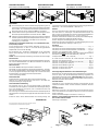 3
3
-
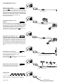 4
4
-
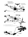 5
5
-
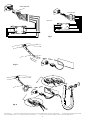 6
6
-
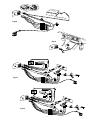 7
7
-
 8
8
-
 9
9
-
 10
10
-
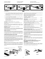 11
11
-
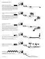 12
12
-
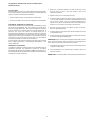 13
13
-
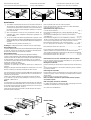 14
14
-
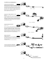 15
15
-
 16
16
-
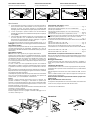 17
17
-
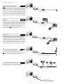 18
18
-
 19
19
-
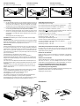 20
20
-
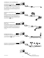 21
21
-
 22
22
-
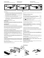 23
23
-
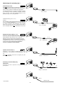 24
24
-
 25
25
-
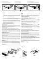 26
26
-
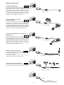 27
27
-
 28
28
-
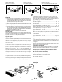 29
29
-
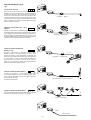 30
30


Blaupunkt amsterdam tcm 127 de handleiding
- Type
- de handleiding
in andere talen
- English: Blaupunkt amsterdam tcm 127 Owner's manual
- italiano: Blaupunkt amsterdam tcm 127 Manuale del proprietario
- français: Blaupunkt amsterdam tcm 127 Le manuel du propriétaire
- español: Blaupunkt amsterdam tcm 127 El manual del propietario
- Deutsch: Blaupunkt amsterdam tcm 127 Bedienungsanleitung
- português: Blaupunkt amsterdam tcm 127 Manual do proprietário
- svenska: Blaupunkt amsterdam tcm 127 Bruksanvisning
Gerelateerde papieren
-
Blaupunkt DUESSELDORF RCM 127 de handleiding
-
Blaupunkt CASABLANCA RCM85 FOR de handleiding
-
-
-
-
-
-
-
-