ROBLIN ATRIUM MURALE de handleiding
- Categorie
- Afzuigkappen
- Type
- de handleiding

NOTICE D’INSTALLATION ET D’UTILISATION
INSTRUCTIONS FOR INSTALLATION AND DIRECTIONS FOR USE
MONTAGE- UND GEBRAUCHSANWEISUNG
LIBRETTO DI ISTRUZIONI
INSTRUCCIONES DE I
NSTALACION E UTILIZACION
MONTAGE- EN GEBRUIKSHANDLEIDING
ATRIUM Murale

F SOMMAIRE
RACCORDEMENT ÉLECTRIQUE
CONSEILS D’INSTALLATIONS
POSE DE L’APPAREIL
FONCTIONNEMENT
CONSEILS D’UTILISATIONS
ENTRETIEN
GARANTIE ET SERVICE APRÈS-VENTE
REMARQUES
D INHALT
NETZANsCHLUSS
MONTAGEHILFEN
MONTAGE DES GERÄTES
BETRIEB DES GERÄTES
NUTZUNG
WARTUNG UND REINIGUNG
GARANTIE UND KUNDENDIENST
WICHTIGE HINVEISE
E SUMARIO
CONEXION ELECTRICA
CONSEJOS DE INSTALACION
INSTALACION DEL APARATO
FUNCIONAMIENTO
CONSEJOS DE UTILIZACION
MANTENIMIENTO
GARANTIA Y ASSISTENCIA TECNICA
NOTA
GB CONTENTS
ELECTRICAL WIRING
INSTALLATION ADVICE
FITTING THE APPLIANCE
OPERATION
USEFUL HINTS
MAINTENANCE
GUARANTEE AND AFTER-SALES-SERVICES
REMARKS
I CONTENUTI
COLLEGAMENTO ELETTRICO
CONSIGLI DI INSTALLAZIONE
POSA DELL’ APPARECCHIO
FUNZIONAMENTO
CONSIGLI DI UTILIZZO
MANUTENZIONE
GARANZIA ED ASSISTENZA TECNICA
NOTE
NL INHOUD
ELECTRISCHE BEDRADING
MONTAGE AANWIJZING
AANSLUITEN VAN HET APPARAAT
FUNKTIONEREN
GEBRUIKSADVIES
ONDERHOUD
AFTER SALES SERVICE
OPMERKINGEN

1
F
Nous vous remercions de la conance que vous nous avez accordée en choisissant un appareil de la
gamme ROBLIN.
Celui-ci a fait l’objet de toute notre attention dans sa conception et sa réalisation.
An qu’il vous donne entière satisfaction, nous vous recommandons de lire avec attention cette notice qui
vous expliquera comment l’installer, l’utiliser et l’entretenir dans les meilleures conditions.
La présente notice d’emploi vaut pour plusieurs versions de l’appareil. Elle peut contenir des descriptions
d’accessoires ne gurant pas dans votre appareil.
1 RACCORDEMENT ÉLECTRIQUE.
• La hotte est équipée d’un cordon d’alimentation de type HO5VVF 3 x 0,75 mm² comportant une
che normalisée 10/16 A avec système de mise à la terre.
Mode de protection : classe I. Tension d’alimentation : 220-240 V mono - 50Hz / 220 V - 60Hz.
Vérier que la tension du secteur est identique aux valeurs indiquées sur la plaque signalétique à
l’intérieur de la hotte
• Si la hotte est raccordée directement sur le réseau sans sa che, un interrupteur omnipolaire avec
une ouverture de contact de 3 mm doit être installé avant la hotte. Le l de terre (Jaune / vert) ne doit
pas être interrompu par cet interrupteur.
2 CONSEILS D’INSTALLATION.
• Pour un fonctionnement idéal, nous vous conseillons une plage de hauteur de pose qui se situe de
0,65 m à 0,70 m au-dessus du plan de cuisson. Toutefois, il est formellement interdit d’installer toute
hotte ou groupe d’aspiration à une distance inférieure à 0,65 m du plan de travail (risque d’inammation
des ltres). La fumée doit monter naturellement vers la zone de captation.
• Respecter le diamètre de sortie de l’appareil : la hotte ne doit en aucun cas être raccordée à un
conduit de ventilation mécanique contrôlée (V.M.C.).
• Lorsqu’on évacue l’air vicié dans un conduit d’évacuation, veiller à ce que celui-ci ne soit pas déjà
exploité à véhiculer des gaz ou fumées provenant d’appareils alimentés par une énergie autre qu’élec-
trique.
• Positionner le plan de cuisson au plus près de l’évacuation et éviter la formation de coudes sur la
gaine, an de réduire au maximum les pertes de charges.
• Dans tous les cas d’installation, veiller au bon renouvellement d’air de la cuisine. Penser à ef-
fectuer une ou des entrées d’air par une grille de section égale ou supérieure au diamètre du tuyau
d’évacuation, an de ne pas mettre la cuisine en dépression.
• Prévoir une aération sufsante lorsqu’un appareil de cuisson ou autre utilise simultanément l’air
ambiant de la pièce où est installée la hotte.
• La dépression maximum crée dans la pièce doit être inférieur à 0.04 mbar, ce qui évite un retour de
gaz de combustion.
• L’appareil doit être positionné de telle façon que la che d’alimentation soit accessible.
• Cet appareil ne doit pas être utilisé par des personnes (y compris les enfants) ayant des capacités
psychiques, sensorielles ou mentales réduites, ni par des personnes n’ayant pas l’expérience et la
connaissance de ce type d’appareils, à moins d’être sous le contrôle et la formation de personnes res-
ponsables de leur sécurité.

2
F
Les enfants doivent être surveillés pour s’assurer qu’ils ne jouent pas avec l’appareil.
3 POSE DE L’APPAREIL.
Montage et raccordement doivent être réalisés par un installateur* qualié.
(*) Le non-respect de cette condition entraîne la suppression de la garantie du constructeur et
tout recours en cas d’accident.
Attention: prendre bien soin d’employer les chevilles adaptées au support, se renseigner au près
des fabricants, effectuer un scellement si nécessaire. La société décline toute responsabilité en
cas d’accrochage défectueux dû au perçage et chevillage.
1) Tracer sur la paroi une verticale jusqu’au plafond à l’emplacement de la hotte au centre de la zone
prévue pour le montage de la hotte (Fig.1 & 2, rep. 1). Cette ligne sert pour aligner verticalement les
différentes parties.
2) Positionner le support de conduit (Fig. 1 & 2, Rep. 2), centré sur la verticale à 1 à 2 mm du plafond
ou de la limite supérieure et marquer sur la paroi les deux alésages du support. Effectuer sur la paroi
deux trous avec un foret Ø 8 mm. Fixer le support de conduit (Rep. 2) à l’aide des vis (12a) 4.2 x 44,4
et des chevilles fournies.Puis positionner et xer comme indiqué Fig. 2 le second support (Rep. 2) pour
une hauteur standard de haut de conduit de 450 mm.
3) Dénir la position des trous de xation Fig. 1 & 2, Rep. 1:
Marquer un point sur la ligne verticale à une distance du plan de cuisson de :
d = 945 min (mesure sans crédence).
d = hauteur crédence + 295 mm (mesure avec crédence).
La hauteur H est la hauteur minimum en mm du plan de cuisson au bas de la hotte (Rep. 3).
Tracer sur le point marqué une ligne horizontale parallèle au plan de cuisson. Effectuer sur la paroi les
deux trous 1 avec un foret Ø 8 mm . Insérer les chevilles et visser les vis 4.2 x 44,4 fournies en laissant
un espace de 5-6 mm nécessaire pour l’accrochage du corps de la hotte (Fig. 3a). Il sera possible d’ef-
fectuer de petits ajustages au moyen des vis de réglage de la hotte (Voir Montage du corps de la hotte).
La hotte peut avoir une excursion maximum de 16 mm.
Crédence (Option) : La hauteur de la hotte par rapport au plan de cuisson est déterminée, dans ce
cas par la hauteur de la crédence Rep B et par l’éventuel dosseret du plan de travail. La crédence doit
être montée avant le corps de la hotte et si l’on désire la xer contre le mur tant en haut qu’en bas, il est
nécessaire de la positionner à la juste hauteur. Etant donné qu’il s’agit d’une opération compliquée, elle
doit être effectuée exclusivement par l’installateur de la cuisine ou par du personnel compétent connais-
sant toutes les dimensions nales des meubles.
4) Montage du corps de la hotte : Avant d’entreprendre l’installation, il est nécessaire de régler les
étriers du support en tournant dans le sens des aiguilles d’une montre les vis de réglage Vr jusqu’en n
de course (Fig. 3b). Accrocher le corps (Rep. 5) sur les deux vis 1 précédemment installées (Fig. 3a).
Mettre la hotte de niveau en tournant les vis de réglage Vr et compléter le serrage des vis 1.
5) Raccordement
• Pour la version Evacuation Extérieure :
a- Mettre en place le clapet anti-retour (Rep. 8) sur la sortie de l'appareil (Rep. 6) et raccorder le tuyau
exible (Fig. 5) à l’évacuation extérieure et la sortie de l’appareil (Rep. 6). Fixer l’ensemble à l’aide de
colliers ou de ruban adhésif appropriés.
b- Enlever les ltres à graisse et s'assurer que le connecteur du cable d'alimentation soit bien branché
dans la prise du moteur (Fig. 4).Raccorder électriquement la hotte (Voir paragraphe Raccordement
Electrique) et vérier le bon fonctionnement de l’éclairage, du moteur et du changement des vitesses
d’aspiration.
c- Conduit supérieur : Elargir légèrement les 2 bords latéraux (Fig.5, Rep. 7a) et les accrocher derrière
les support (Rep. 2), refermer jusqu'à la butée. Fixer latéralement aux support (Rep. 2) à l'aide des 4
vis (12c) 2.9 x 9.5 fournies.
d- Conduit inférieur : Elargir légèrement les 2 bords latéraux (Fig.5, Rep. 7b) et les accrocher entre le
conduit supérieur et la paroi; refermer jusqu'à la butée. xer latéralement la partie inférieur au corps de
la hotte à l'aide des 2 vis (12c) 2.9 x 9.5 fournies.
• Pour la version Recyclage:

3
F
a- Fixer le support (Rep.4) du déecteur sur la xation du haut de conduit, le déecteur est xé avec les
mêmes vis que le support de haut de conduit (Fig.7, rep. 2). Inserer latéralement les rallonges raccord
(Rep.G) sur le déecteur (Rep. R). S'assurer que la sortie des rallonges raccord se trouve au niveau
des ouies du conduit aussi bien en horizontal qu'en vertical.
b- Installer un tuyau de diamètre approprié (Non fourni) entre la sortie de l’appareil et à l’entrée du
déecteur. Fixer l’ensemble à l’aide de colliers ou de ruban adhésif appropriés.
c- Enlever les ltres à graisse et s'assurer que le connecteur du cable d'alimentation soit bien branché
dans la prise du moteur (Fig. 4). Raccorder électriquement la hotte (Voir paragraphe Raccordement
Electrique) et vérier le bon fonctionnement de l’éclairage, du moteur et du changement des vitesses
d’aspiration.
d- Enlever les ltres métalliques et placer la cartouches à charbon actif dans son logement en exerçant
une pression sur les languettes A (Fig. 8).
e- Conduit supérieur : Elargir légèrement les 2 bords latéraux (Fig.7, Rep. 7a) et les accrocher derrière
les support (Rep. 2), refermer jusqu'à la butée. Fixer latéralement aux support (Rep. 2) à l'aide des 4
vis (12c) 2.9 x 9.5 fournies.
f- Conduit inférieur : Elargir légèrement les 2 bords latéraux (Fig.7, Rep. 7b) et les accrocher entre le
conduit supérieur et la paroi; refermer jusqu'à la butée. xer latéralement la partie inférieur au corps de
la hotte à l'aide des 2 vis (12c) 2.9 x 9.5 fournies.
4 FONCTIONNEMENT
a) Conguration
Evacuation extérieure ou recyclage :
Votre hotte est programmée pour fonctionner en mode évacuation extérieure. Si vous souhaitez l’utiliser en
mode recyclage, vous devez impérativement la congurer suivant la procédure suivante :
Mise en recyclage ( l’air est ltré puis renvoyé dans la cuisine) :
Moteur et éclairage éteints, appuyer sur la touche (+) jusqu’aux clignotements des 5 leds :
Deux clignotements des 5 leds indiquent l’enregistrement de la mise en recyclage.
Retour en mode évacuation ( L’air est ltré puis évacué à l’extérieur de l’habitation):
Moteur et éclairage éteints, appuyer sur la touche (+) jusqu’aux clignotements des 5 leds :
Un clignotement des 5 leds indiquera l’enregistrement de la mise en évacuation extérieure.
b) Fonctions de base :
Eclairage :
Mise en marche en appuyant sur la touche 1 (lumière). La led 1 visualise l’état de l’éclairage
Moteur :
Mise en marche en appuyant sur la touche 2 (moteur). Il est possible de modier le débit d’aspiration de
la hotte à l’aide des touches vitesse + et vitesse – , en gardant la touche enfoncée jusqu’à l’obtention de
la vitesse désirée. Le niveau de vitesse est visualisé par les leds 2, 3, 4 qui s’allument au fur et à mesure
de l’accroissement de la vitesse :
Led 2 = niveau minimum
Led 2 et 3 = niveau intermédiaire
Led 2, 3 et 4 = niveau élevé
Un débit d’aspiration maximal peut être obtenu directement en appuyant sur la touche vitesse intensive

4
(5 ).F
c) Fonctions complémentaires :
• Vitesse intensive temporisée
Pour obtenir une bonne efcacité d’évacuation, nous vous conseillons en début de cuisson une période de
fonctionnement en position intensive. Elle créera un ux d’air permettant de capter les premières fumées
ou vapeurs dès leur apparition. Pour cette fonction il convient de suivre la procédure suivante :
- Mettre le moteur en marche (touche 2), puis sélectionner à l’aide des touches (+) et (-) la vitesse souhaitée
pendant la cuisson.
- Appuyer sur la touche 5 (vitesse intensive). Cette fonction peut être arrêtée en appuyant à nouveau sur
la touche 5.
Temporisation de 5 minutes de l’arrêt de la vitesse intensive:
Par défaut cette fonction n’est pas activée.
Pour accéder à la programmation de cette fonction, la lumière doit être éteinte et le moteur arrêté.
Appuyer sur la touche réglage vitesse (-) :
Un clignotement des Leds 2, 3, et 4 = fonction désactivée.
Deux clignotements des Leds 2, 3, et 4 = fonction activée.
Il est possible d’arrêter manuellement la vitesse intensive avant le délai de 5 minutes en appuyant à nouveau
sur la touche 5 (Vitesse intensive).
Pendant cette temporisation de 5 minutes, l’indication de saturation ltres est désactivée.
Si un arrêt différé de la hotte est programmé, la vitesse intensive commandée manuellement ou temporisée
sera désactivée par cet arrêt différé après 5, 10 ou 15 minutes. Il est possible d’arrêter manuellement la vitesse
intensive avant l’arrêt différé de la hotte en appuyant à nouveau sur la touche 5 (Vitesse intensive).
• Arrêt différé :
Cette fonction permet, après l’arrêt de la cuisson, d’évacuer les dernières fumées et odeurs résiduelles
et en n de cuisson, d'arrêter totalement la hotte (moteur + éclairage).
Pour accéder à la programmation de ce réglage la lumière doit être éteinte et le moteur arrêté.
Appuyer sur la touche vitesse intensive 5 :
- 2 clignotements des leds 1 & 5 conrmeront l’enregistrement de l’arrêt après 5 minutes.
- 3 clignotements des leds 1 & 5 conrmeront l’enregistrement de l’arrêt après 10 minutes.
- 4 clignotements des leds 1 & 5 conrmeront l’enregistrement de l’arrêt après 15 minutes.
- 1 seul clignotement des leds 1 & 5 conrmera la suppression de la fonction arrêt différé.
La hotte peut ensuite être mise en marche sur la vitesse choisie. Le clignotement des leds 2, 3, 4 (suivant
la vitesse initialement prévue) indiquera que la fonction arrêt différé est bien programmée :
- 1 clignotement = arrêt après 5 minutes
- 2 clignotements = arrêt après 10 minutes
- 3 clignotements = arrêt après 15 minutes
• Indication de saturation des ltres métalliques :
Après 200 heures de fonctionnement 1 bref clignotement de la Led 1 indique qu’il faut nettoyer les
ltres métalliques (voir paragraphe entretien)
Pour accéder à la remise à zéro de la fonction indiquant la saturation des ltres, la lumière doit être
éteinte et le moteur arrêté.
Appuyer sur la touche (+) pendant 3 à 4 secondes. Le clignotement des Leds 1, 2, 3, 4, et 5 conrme la
remise à zéro.
• Indication de saturation des ltres charbon :
Après 400 heures de fonctionnement 2 brefs clignotements de la Led 1 indique qu’il faut remplacer
les ltres charbon et nettoyer à nouveau les ltres métalliques.
Pour activer la fonction Indication de saturation ltre charbon, la lumière doit être éteinte et le moteur
arrêté. Appuyer sur la touche (+) pendant 10 secondes.
1 clignotement des Leds 1, 2, 3, 4, et 5 = fonction désactivée.
2 clignotements des Leds 1, 2, 3, 4, et 5 = fonction activée.
La méthode de remplacement de la cartouche est indiquée au paragraphe 3 (Recyclage)
F

5
• Conguration réception télécommande :
Votre hotte est programmée pour fonctionner sans réception télécommande. Si vous souhaitez l’utiliser avec
la télécommande, vous devez impérativement la congurer suivant la procédure suivante :
Moteur et éclairage éteints, appuyer sur la touche 1 (éclairage) jusqu’au clignotement de la led 1 :
Deux clignotements de la led 1 indiquent que la télécommande est activée.
Un clignotement de la led 1 indique que la télécommande est désactivée.
Attention, la télécommande doit être équipée de piles alcalines standards : LR003-AAA, 1.5V comme
décrit Fig. 9. Ces piles devraient assurer un usage optimum de longue durée et doivent être positionnées
correctement, elles peuvent exploser si elles sont endommagées ou exposées à la chaleur. Ne pas les
jeter dans le feu. An de préserver l’environnement, merci de déposer ces piles dans un conteneur
approprié.
5 CONSEILS D’UTILISATION.
• Pour obtenir une efcacité maximum d’absorption des fumées ou des vapeurs, faire fonctionner
l’appareil 5 minutes environ avant et après la cuisson des aliments; La première vitesse est conseillée
pour les cuissons à feu doux et pour les sauces. La deuxième pour les cuissons soutenues, grillades et
friteuses. La troisième est indiquée pour les cuissons à forte émanation de graisses et vapeur.
• IMPORTANT . NE JAMAIS FLAMBER DE METS AU DESSOUS DE L’APPAREIL
Ne laissez jamais de ammes libres sous la hotte en fonctionnement.
• Les fritures nécessitent une surveillance permanente, l’huile surchauffée pouvant s’enammer.
6 ENTRETIEN.
Déconnecter le câble d’alimentation pour toute intervention électrique.
L’appareil a été conçu pour faciliter au maximum les opérations d’entretien, synonyme de bon fonction-
nement et rendement de l’appareil dans le temps.
• Nettoyage des ltres métalliques.
Il est indispensable de procéder à un NETTOYAGE PÉRIODIQUE de ces ltres à la main (avec un déter-
gent liquide à l’eau tiède et rinçage) ou au lave- vaisselle (tous les deux mois environ pour une utilisation
normale).
• Carrosserie.
Nettoyer régulièrement celle-ci en utilisant des produits détergents, non abrasifs et une éponge légèrement
humide. N’utilisez jamais d’éponges ou de chiffons trempés
N’introduisez aucun objet, ni les mains dans l’ouverture servant à l’évacuation de l’air
• Conduit d’évacuation.
Vérier tous les 6 mois le bon écoulement de l’air vicié.
Observer les prescriptions réglementaires locales concernant l’évacuation de l’air vicié.
• Éclairage.
Avant toute intervention sur l’appareil, mettre l’interrupteur d’allumage des lampes en position éteinte.
Ne pas dépasser la puissance prescrite et ne pas changer de type de lampe.
7 GARANTIE ET SERVICE APRÈS-VENTE.
• En cas d’anomalie de fonctionnement, prévenez votre installateur qui devra vérier l’appareil et son
raccordement.
• Dans le cas où un composant électrique viendrait à être endommagé, celui-ci ne peut être remplacé
que par un atelier de réparation reconnu par le fabricant, car des outils spéciaux sont nécessaires.
F

6
F
• Débrancher complètement l’appareil.
• Exigez toujours l’utilisation de pièces de rechange d’origine. La non observation de cette prescription
peut compromettre la sécurité de l’appareil.
• Lors de la commande de pièces détachées, rappeler le numéro de l’appareil inscrit sur la plaque
signalétique située à l’intérieur de la hotte.
• Seule la facture d’achat de l’appareil fera foi pour l’application de la garantie contractuelle.
Cette garantie ne couvre pas les consommables comme :
- L’éclairage : lampes incandescentes, halogènes ...
- Les ltres.
8 REMARQUES.
Cet équipement est conforme à la norme européenne sur la basse tension 2006/95/CE relative à la
sécurité électrique et aux normes européennes: 2004/108/CE relative à la compatibilité électromagnétique
et 93/68 relative au marquage CE.
Lorsque ce symbole
d’une poubelle à roue barrée est attaché à un produit, cela signie que le
produit est couvert par la Directive Européenne 2002/96/EC. Votre produit est conçu et fabriqué avec
des matériaux et des composants de haute qualité, qui peuvent être recyclés et utilisés de nouveau.
Veuillez vous informer du système local de séparation des déchets électriques et électroniques. Veuillez
agir selon les règles locales et ne pas jeter vos produits usagés avec les déchets domestiques usuels.
Jeter correctement votre produit usagé aidera à prévenir les conséquences négatives potentielles contre
l’environnement et la santé humaine.

7
GB
Thank you for buying a Roblin product which has been manufactured to the highest quality standards
to meet your requirements.
We recommend you carefully read this booklet in which you will nd instructions for installation, hints for
use and maintenance.
The Instructions for Use apply to several versions of this appliance. Accordingly, you may nd descrip-
tions of individual features that do not apply to your specic appliance.
1 ELECTRICAL
• This cooker hood is tted with a 3-core mains cable with a standard 10/16A earthed plug.
• Alternatively the hood can be connected to the mains supply via a double-pole switch having 3mm
minimum contact gap on each pole.
• Before connecting to the mains supply ensure that the mains voltage corresponds to the voltage on
the rating plate inside the cooker hood.
• Technical Specication: Voltage 220-240 V, single phase ~ 50 Hz / 220 V - 60Hz.
2 INSTALLATION ADVICE
• Ensure the cooker hood is tted in compliance with the recommended xing heights.
• To ensure the safe operation of this cooker hood, we recommend that the hood should not be tted
below 65cm (for electric) or (70cm for gas) the measurements taken from the surface of the cooking
appliance to the underside of the cooker hood.
• It is a possible re risk if the hood is not sited as recommended.
• To ensure the best results, the cooking fumes should be able to rise naturally towards the inlet grilles
on the underside of the cooker hood and the cooker hood should be positioned away from doors and
windows, which will create turbulence.
• Ducting
• If the room where the hood is to be used contains a fuel-burning appliance such as a central heating
boiler then its ue must be of the room sealed or balanced ue type.
• If other types of ue or appliances are tted ensure that there is an adequate supply of fresh air to
the room. Ensure the kitchen is tted with an airbrick, which should have a cross-sectional measurement
equivalent to the diameter of the ducting being tted, if not larger.
• The ducting system for this cooker hood must not be connected to any existing ventilation system,
which is being used for any other purposes or to a mechanically controlled ventilation ducting.
• The ducting used must be made from re retardant materials and the correct diameter must be used,
as incorrect sized ducting will affect the performance of this cooker hood.
• When the cooker hood is used in conjunction with other appliances supplied with energy other than
electricity, the negative pressure in the room must not exceed 0.04 mbar to prevent the fumes from
combustion being drawn back into the room.
• The appliance is for domestic use only and should not be operated by children or people who are
inrm without supervision.
• This appliance must be positioned so that the wall socket is accessible.
• This appliance is not intended for use by persons (including children) with reduced physical, sensory
or mental capabilities, or lack of experience and knowledge, unless they have been given supervision or
instruction concerning use of the appliance by a person responsible for their safety.
Children should be supervised to ensure that they do not play with the appliance.
3 FITTING
Any permanent electrical installation must comply with the latest regulations concerning this type of instal-
lation and a qualied electrician must carry out the work. Non-compliance could cause serious accidents
or injury and would deem the manufacturers guarantee null and void.
IMPORTANT - The wires in this mains lead are coloured in accordance with the following code :

8
GB
green / yellow : earth blue : neutral brown : live
As the colours of the wires in the mains lead of this appliance may not correspond with the coloured
markings identifying the terminals in your plug, proceed as follows.
- The wire which is coloured green and yellow must be connected to the terminal in the plug which is
marked with the letter E or by the earth symbol
or coloured green or green and yellow.
- The wire which is coloured blue must be connected to the terminal which is marked with the letter N
or coloured black.
- The wire which is coloured brown must be connected to the terminal which is marked with the letter
L or coloured red.
ATTENTION: Do not forget to use adequate plugs to the support brackets. Enquire after the manu-
facturers. Do an embedding if necessary. The manufacturer accepts no responsibility in case of a
faulty hanging due to the drilling and the setting up of plugs.
1) Draw a vertical line onto the wall from the centre of the cooking appliance up to the ceilling, using a
spirit level and a marker pen as illustrated in Fig. 1 & 2 - item 1. This is to ensure the correct align-
ment of the chimney hood.
2) Place one of the brackets item 2 on the wall about 1 or 2 mm from the ceiling or from the upper limit,
aligning its centre (notches) on the vertical line. Mark the two eyelet holes of the bracket onto the
wall. Place the other bracket item 2 on the wall, aligning it with the vertical line, at a distance X=450
mm measured as in Fig. 2 equal to the height of the upper chimney stack item 7a provided with the
hood. The X measurement may have different values, according to the available heights of the upper
chimney stack. Drill the holes for the 2 xing brackets using an 8 mm masonry bit. Fix the chimney
brackets item 2 using the 4.2 x 44.4 mm screws and rawl plugs supplied.
3) Drilling xing holes 1 (Fig. 1 & 2):
Mark a point on the vertical line at a distance from the cooking appliances of:
d = 945 mm (Measurement without splashback).
d = height of the splashback + 295 mm (Measurement with splashback).
The distance H is the minimum height in mm from the cooking appliances to the bottom edge item 3 of
the front panel of the hood.
At the point marked, draw a horizontal line parallel to the cooking appliances. Drill two holes 1 in the wall
using an 8 mm drill bit and insert the rawl plugs and screws into the holes 1 (4.2 x 44.4 screws). Fix
the screws, leaving a space of 5-6 mm required to hook up the canopy (Fig. 3a). Small adjustments
can be made using the hood adjustment screws (see Fitting the canopy). The hood should have a
maximum excursion of 16 mm.
Splashback (optional): When a splashback is to be tted, the distance between the hood and the cooking
appliances will be determined by the height of the splashback item B and whether or not there is
a raised back on the worktop. The splashback is to be installed before installing the canopy. If the
splashback is to be xed to the wall using both the top and bottom xing holes, Care must be taken
to ensure that the splashback is tted at the correct height before xing the base units or at least the
worktop covering them. As this is a complex operation, it should only be undertaken by the technician
installing the kitchen units or by a competent person who knows the nal dimensions of the units.
4) Fixing the canopy: Before starting to x the canopy it will be necessary to adjust the support brackets
by turning the adjustment screws Vr in a clockwise direction until their reach their limit (Fig.3b). Hook
the canopy onto the two size 4.2 x 44.4 screws 1 tted as described above (Fig.3a). Level the hood
by turning the adjustment screws and then locking the screws 1.
5) Ducting:
The hood is more effective when used in the extraction mode (ducted to the outside). When the cooker
hood is ducted to the outside, charcoal lters are not required.The ducting used must be 150 mm (6
INS), rigid circular pipe and must be manufactured from re retardant material, produced to BS.476
or DIN 4102-B1. Wherever possible use rigid circular pipe which has a smooth interior, rather than
the expanding concertina type ducting.
Maximum length of ducting run:

9
GB
- 4 metres with 1 x 90° bend.
- 3 metres with 2 x 90° bends.
- 2 metres with 3 x 90° bends.
The above assumes our 150 mm (6 INS) ducting is being installed. Please note ducting components and
ducting kits are optional accessories and have to be ordered, they are not automatically supplied
with the chimney hood.
IN THE EXTRACTION MODE:
a. Place the anti-backow ats item 8 over the round outlet item 6 and connect the ducting 150mm (6
INS) over the round outlet item 6 on top of the canopy and secure the connections with appropriate
clamping rings or adhesive tape (Fig. 5).
b. Remove the grease lters (see paragraph Maintenance) being sure that the connector of the mains
cable is correctly inserted in the socket placed on the side of the fan. Before tting the chimney to
the canopy make the electrical connection as described in the section titled ELECTRICAL. When
the electrical connection has been made, test the lights and the fan motor.
c. Upper chimney stack
•Slightly widen the two sides of the upper chimney stack (Fig.5 - Item 7a) and hook them behind the
brackets item 2 making sure that they are well seated.
•Secure the sides to the brackets using the 4 screws 12c (2,9 x 9,5) supplied.
d. Lower chimney stack
•Slightly widen the two sides of the chimney stack (Fig. 5 - Item 7b) and hook them between the upper
chimey stack and the wall, making sure that they are well seated.
•Fix the lower part laterally to the hood body using the 2 screws 12c (2,9 x 9,5) supplied.
IN THE RECIRCULATION MODE:
a. Fit the recirculation spigot bracket item 4 onto the upper chimney wall bracket using the same xing
screws (Fig.7 - item 2). Put the spigot item R into the spigot bracket item 4• Insert the connection
extension pieces laterally item G in the spigot. Make sure that the outlet of the extension pieces
item G is horizontally and vertically aligned with the chimney outlets.
b. Connect the ducting 150mm (6 INS) not provided between motors item 6 and the recirculation spigot
and secure the connections with appropriate clamping rings or adhesive tape.
c. Remove the grease lters (see paragraph Maintenance) being sure that the connector of the feeding
cable is correctly inserted in the socket placed on the side of the fan. Before tting the chimney to
the canopy make the electrical connection as described in the section titled ELECTRICAL. When
the electrical connection has been made, test the lights and the fan motor.
d. Remove the metal grease lters and insert the charcoal lter into the base of the motor housing and
secure the lter with two metal securing straps item A as illustrated in Fig. 8.
e. Upper chimney stack
•Slightly widen the two sides of the upper chimney stack (Fig.7 - Item 7a) and hook them behind the
brackets item 2 making sure that they are well seated.
•Secure the sides to the brackets using the 4 screws 12c (2,9 x 9,5) supplied.
f. Lower chimney stack
•Slightly widen the two sides of the chimney stack (Fig. 7 - Item 7b) and hook them between the upper
chimey stack and the wall, making sure that they are well seated.
•Fix the lower part laterally to the hood body using the 2 screws 12c (2,9 x 9,5) supplied.

10
4 OPERATION
A - EXTRACTION OR RECYCLING :Your cooker hood is supplied in the extraction mode. To use the cooker
hood in the recycling mode re-programme the hood as follows:
Starting in the recycling mode (the contaminated air passes into the hood through the grease lters and
the purifying activated charcoal lter and back out into the kitchen through grilles).
Press the ‘+’ button (while the motor and lights are switched ‘OFF’) until the ve LED lights will ash twice
to indicate conrmation that the cooker hood is in the recycling mode.
Reverting to the extraction mode (The cooker hood is ducted to the outside).
Press the ‘+’ button (while the motor and lights are switched ‘OFF’) until the ve LED lights will ash once
to indicate conrmation that the cooker hood is in the extraction mode.
GB
B - BASIC INSTRUCTIONS
Lighting
Press LED button 1 to switch ‘ON’ the lights and the LED will illuminate to conrm the lights are switched
‘ON’.
Motor
Press LED button 2 to switch ‘ON’ the fan motor (and adjust the speed of the fan motor by pressing the
LED button ‘+’ and ‘-‘) and the LED lights 2, 3 and 4 will illuminate. The fan speed will be increased if
constant pressure is kept on the (+) button.
LED 2 : Minimum speed - cooking with one pan or simmering
LED 2 & 3 : Medium speed - normal cooking with up to 4 pans
LED 2, 3 & 4 : Maximum speed - frying and cooking foods with strong odours
Press LED button 5 to obtain the boost position for maximum effect and the LED will illuminate to conrm
fan is switched ‘ON’.
C - COMPLEMENTARY INSTRUCTIONS
• Boost speed :
To obtain the best performance it is advisable to switch ‘ON’ the cooker hood a few minutes (in the boost
setting) before you start cooking. To program the complementary function, proceed as follows:
- Press LED button 2 to switch ‘ON’ the fan motor and adjust the speed of the fan by pressing the LED
button ‘+’ and ‘-‘. You should keep applying pressure to the ‘+’ and ‘-‘ button until the required speed is
selected.
- Press LED button 5 (boost speed) to switch ‘ON’ the fan motor in the boost setting. Press LED button 5
to switch ‘OFF’ the boost setting immediately.
It is advisable too that you should leave it running in the boost setting for approximately 5 minutes after
nishing.
• Pre-set stop of the boost speed :
A pre-set stop after 5 minutes of the boost speed is available.
Your cooker hood is supplied with a deactivated pre-set stop of the boost speed. To use the cooker hood
GB

11
with a pre-set stop of the boost speed re-programme the hood as follows:
The lights and the fan motor should be switched ‘OFF’ to set the timer.
Push the LED button ‘-’ until the LED lights will ash :
One ash of the LED lights 2,3, and 4 = function is switched ‘OFF’.
Two ashes of the LED lights 2,3, and 4 = function is switched ‘ON’.
While the 5 minutes timer is running, It is available to stop immediately the boost speed by pressing the
led button 5.
While the 5 minutes timer is running, the indication of saturation of the lters is switched ‘OFF’.
If a pre-set stop for the hood is switched ‘ON’ and the 5 minutes timer is still running, the boost speed will
be switched ‘OFF’ together with the pre-set stop for the hood after the count down of 5, 10 or 15 minutes.
It is available to stop the boost speed before the count down of the preset stop of the hood by pressing
the led button 5.
• Pre-set stop for the hood :
This function allows you to program the cooker hood to automatically stop cooking after a pre-set period.
The lights and the fan motor should be switched ‘OFF’ to set the timer.
Proceed by repeatedly pressing the LED button 5 (Boost speed):
Two ashes of the LED button 1 & 5 = 5 minutes delay.
Three ashes of the LED button 1 & 5 = 10 minutes delay.
Four ashes of the LED button 1 & 5 = 15 minutes delay.
One ash of the LED button indicates the function is switched ‘OFF’.
You can switch the cooker hood ‘ON’ and adjust the speed. The LED buttons 2, 3 and 4 will ash to
indicate the fan motor is switched ‘ON’ and which speed has been selected.
One ash = stop after 15 minutes.
Two ashes = stop after 10 minutes.
Three ashes = stop after 15 minutes.
• Indication of saturation of the metal grease lters :
After 200 hours use, one quick ash of the LED 1 will indicate that you must clean the metal grease
lters. (See chapter on ‘Maintenance’).
To reset the 200 hours timer back to zero requires the motor and lights must be switched ‘OFF’; then and
proceed as follows:
Press the LED button ‘+’ for 3 to 4 seconds and the LED lights 1,2,3, 4 and 5 will ash to conrm the
programme has been reset to zero.
8GB
• Indication of saturation of the active charcoal lter :
After 400 hours use, two quick ash of the LED 1 will indicate that you must replace the active charcoal
lter and clean the metal grease lters. (See chapter on ‘Maintenance’).
To reset the 400-hour timer the motor and lights must be switched ‘OFF’.
Push the LED button ‘+’ for 10 seconds.
One ash of the LED lights 1,2,3,4 and 5 = function is switched ‘OFF’.
Two ashes of the LED lights 1,2,3,4 and 5 = function is switched ‘ON’.
Instructions for replacing the active charcoal lter are given in the chapter on ‘Recycling’.
• Pre-set remote control handset
Your cooker hood is supplied with a deactivated remote control receiver. To use the cooker hood with a
remote control re-programme the hood as follows:
Press the LED button (Lighting) ‘1’ while the motor and lights are switched ‘OFF’, until the LED lights 1 will
ash to conrm the programme has been activated :
One ash of the LED lights 1 = function is switched ‘OFF’.
Two ashes of the LED lights 1 = function is switched ‘ON’.
Caution, the remote control handset must be tted with standard LR03-AAA size 1.5V zinc-carbon alkaline
batteries as illustrated Fig. 9. These batteries should give a long life and constant discharge throughout their
GB

12
life. These batteries must be disposed of properly and could explode if damaged or exposed to heat.
Do not dispose of on re. Dispose of batteries in the appropriate sort container to protect the environ-
ment.
• Setup Process
Modication: How to adjust the internal microprocessor data to suit the type of motor tted to this
appliance and the supply frequency of 50 or 60 Hz..
1 - Disconnect the cooker hood from the mains supply.
2 - Push the button 0/1 MOTOR.
3 - Reconnect the mains supply while pushing the button 0/1 MOTOR for at least 2 seconds.
4 - Release the button 0/1 MOTOR (the Leds ash for about 3 seconds : capacity’s conrmation SETUP
PROCESS).
5 - While the LED is ashing select the motor type used while pushing one of the 5 buttons in accordance
with the following:
BUTTON 0/1 Light : Motor EBM PRO 220-240 V AC 50 Hz / 220 V AC 60 Hz.
BUTTON 0/1 Motor : Motor FABER 8/28 e 8/50 220-240 V AC 50 Hz / 220 V AC 60 Hz.
BUTTON Speed ( - ) : Motor EBM MISTRAL 220-240 V AC 50 Hz / 220 V AC 60 Hz.
BUTTON Speed (+ ) : Motor EBM PRO 220-240 V AC 50 Hz / 220 V AC 60 Hz.
BUTTON Intensive speed : Motor FABER K40-K50 220-240 V AC 50 Hz / 220 V AC 60 Hz.
N.B. : If you have not selected a motor type while the LED is ashing the microprocessor will automatically
select the default motor EBM PRO 220 - 240 V AC 50 Hz / 220 V AC 60 Hz.
5 USEFUL HINTS
• To obtain the best performance we recommend you to switch ‘ON’ the cooker hood a few minutes (in
the boost setting) before you start cooking and you should leave it running for approximately 15 minutes
after nishing.
• IMPORTANT: NEVER DO FLAMBÉ COOKING UNDER THIS COOKER HOOD
• Do not leave frying pans unattended during use as over-heated fat and oil might catch re.
• Do not leave naked ames under this cooker hood.
• Switch ‘OFF’ the electric and gas before removing pots and pans.
• Ensure heating areas on your hotplate are covered with pots and pans when using the hotplate
and cooker hood simultaneously.
6 MAINTENANCE
Before carrying out any maintenance or cleaning isolate the cooker hood from the mains supply.
The cooker hood must be kept clean; a build up of fat or grease may cause a re hazard.
Casing
• Wipe the cooker hood frequently with a clean cloth, which has been immersed in warm water contain-
ing a mild detergent and wrung out.
• Never use excessive amounts of water when cleaning particularly around the control panel.
• Never use scouring pads or abrasive cleaners.
• Always wear protective gloves when cleaning the cooker hood.
Metal Grease Filters : The metal grease lters absorb grease and dust during cooking in order to keep
clean the cooker hood inside. The grease lters should be cleaned once a month or more frequently if
the hood is used for more than 3 hours per day.
GB

13
To remove and replace the metal grease lters
• Remove the metal grease lters one at a time by releasing the catches on the lters; the lters can
now be removed.
• The metal grease lters should be washed, by hand, in mild soapy water or in a dishwasher.
• Allow to dry before replacing.
Active Charcoal Filter : The charcoal lter cannot be cleaned. The lter should be replaced at least
every three months or more frequently if the hood is used for more than three hours per day.
To remove and replace the lter
• Remove the metal grease lters.
• Press against the two retaining clips, which hold the charcoal lter in place and this will allow the lter
to drop down and be removed.
• Clean the surrounding area and metal grease lters as directed above.
• Insert the replacement lter and ensure the two retaining clips are correctly located.
• Replace the metal grease lters.
Extraction tube : Check every 6 months that the dirty air is being extracted correctly. Comply with local
rules and regulations with regard to the extraction of ventilated air.
Lighting : If the lamp fails to function check to ensure it is tted correctly into the holder. If lamp failure
has occurred then it should be replaced with identical replacement.
Do not replace with any other type of lamp and do not t a lamp with a higher rating.
7 GUARANTEE AND AFTER SALES SERVICE
• In the event of any malfunction or anomaly, notify your tter who will have to check the ap-
pliance and its connection.
• In the event of damage to the mains supply cable, this can only be replaced by at approved repair
centre appointed by the manufacturer who will have the required tools and equipment to carry out any
repairs properly. Repairs carried out by other persons will invalidate the guarantee.
• Use only genuine spare parts. Should these warnings fail to be observed it could affect the safety of
your cooker hood.
• When ordering spare parts quote the model number and serial number written on the rating plate,
which is found on the casing behind the grease lters inside the hood.
• Proof of purchase will be required when requesting service. Therefore, please have your receipt
available when requesting service as this constitutes the date from which your guarantee commenced.
This Guarantee does not cover :
- Damage or calls resulting from transportation, improper use or neglect, the replacement of any light
bulbs or lters or removable parts of glass or plastic.
These items are considered to be consumable under the terms of this guarantee.
8 REMARKS
This appliance complies with European regulations on low voltages Directive 2006/95/CE on electrical
safety, and with the following European regulations: Directive 2004/108/CE on electromagnetic compat-
ibility and Directive 93/68 on EC marking.
When this crossed-out wheeled bin symbol
is attached to a product it means the product is cov-
ered by the European directive 2002/96/EC.Your product is designed and manufactured with high quality
materials and components, which can be recycled and reused.Please inform yourself about the local
separate collection system for electrical and electronic product. Please act according to your local rules
and do not dispose of your old products with your normal household waste. The correct disposal of your
old product will help prevent potential negative consequences for the environment and human health.
GB

14
D
Wir danken Ihnen für Ihre Kaufentscheidung und das Vertrauen, welches Sie mit dem Kauf dieses Ro-
blin-Produktes bewiesen haben.
Dieses Gerät wurde mit einem hohen Maß an Kreativität entwickelt und mit
größter Sorgfalt gefertigt.
Um volle Zufriedenheit mit Leistung und Funktion dieser Dunstesse zu erlangen und zu erhalten, emp-
fehlen wir dringend, sowohl die Montage-anweisung sorgfältig zu beachten und danach zu arbeiten als
auch die “ Gebrauchs- und Wartungshinweise ” aufmerksam zu lesen und anzuwenden.
Diese Gebrauchsanleitung gilt für mehrere Geräte-Ausführungen. Es ist möglich,
dass einzelne Ausstattungsmerkmale beschrieben sind, die nicht auf Ihr Gerät zutreffen.
1 NETZANCHLUSS
• Die Dunstabzugshaube ist mit einer Anschlußleitung der Art HO5VVF 3 x 0,75 mm
2
, die einen
Schutzstecker 10 / 16 A enthält, ausgestattet. Das entspricht Schutzklasse 1.
Nennspannung : 220 - 240 V - Wechselstrom : 50 Hz / 220 V - 60 Hz.
• Es ist sicherzustellen, daß die Netzspannung den Anschlußwerten auf dem Typenschild im Inneren
der Dunstesse entspricht.
• Beim Anschluß der Dunstesse an das Wechselstromnetz ist ein zweipoliger Schalter mit einem
Öffnungsweg von wenigstens 3 mm für jeden Pol zwischenzuschalten.
2 MONTAGEHILFEN
• Die Mindest- und Höchstabstände zwischen der Dunstesse und der Kochäche sind zu berück-
sichtigen. Wir empfehlen Ihnen einen Abstand von 0,65 m bis 0,70 m über der Kochäche einzuhalten,
um einen optimalen Betrieb des Gerätes zu gewährleisten. Jedoch ist es streng verboten, Dunstessen
oder Einbaugeräte mit einem Abstand, der niedriger als 0,65 m von der Kochäche ist, einzubauen
(Entzündungsgefahr der Filter). Beachten Sie die richtige Ableitung der Kochschwaden (Luftzug kann
Turbulenzen verursachen).
• Der Außendurchmesser am Gebläseabgang des Gerätes ist für die Wahl des Abluft-Rohrsystems zu
berücksichtigen : Die Dunstesse darf keinesfalls an eine Entlüftungsleitung mit Unterdruck angeschlossen
werden. Die Abluft darf nicht in einen Schornstein geleitet werden, der für die Abgase von Koch- oder
Heiz-Geräten, (Kohle-, Öl-, oder Gas-Öfen oder -Herde) benutzt wird.
• Die Kochstelle (und damit auch die Dunstesse) so planen und installieren, daß möglichst kurze
Wege für eventuelle Abluft-Rohrleitungen erreicht werden. (so wenige Umlenkungen [90°-Bögen] wie
möglich! Keine Querschnittsverengungen!
• Die gute Erneuerung der Luft in der Küche ist zu beachten. Denken Sie daran, einen oder mehrere
Lufteintritte durch eine Öffnung, die den gleichen Durchmesser hat wie die Abluftleitung, vorzusehen.
• Sorgen Sie für eine ausreichende Zuluft, wenn ein Koch- oder anderes Gerät die Luft des Raumes,
in dem die Dunstesse eingebaut ist, gleichzeitig verwendet. Ein gefahrloser Betrieb ist möglich, wenn
bei gleichzeitigem Betrieb von Dunstesse und Feuerstätte im Raum ein Unterdruck von höchstens 0.04
mbar erreicht wird und ein Rücksaugen der Feuerstättenabgase vermieden wird.
Das Gerät muß so installiert werden, daß der Geräte-Stecker leicht erreichbar ist.
• Dieses Gerät darf nicht von Personen, auch Kindern, mit verminderten psychischen, senso-
rischen und geistigern Fähigkeiten, oder von Personen ohne Erfahrung und Kenntnisse benutzt werden,
sofern sie nicht von für ihre Sicherheit verantwortlichen Personen beaufsichtigt und beim Gebrauch des
Geräts angeleitet werden.
Kinder dürfen sich nicht unbeaufsichtigt in der Nähe des Geräts aufhalten und auf keinen Fall mit dem
Gerät spielen.
3 MONTAGE DES GERÄTES
Montage und Anschluß müssen von einem qualizierten Installateur* durchgeführt werden.
(*) Wenn diese Bedingung nicht eingehalten wird, wird die Garantie des Herstellers, sowie jeder
Anspruch im Falle eines Unfalles aufgehoben.

15
D
Achtung ! Bitte beachten Sie bei der Montage das Gewicht der kompletten Dunstesse. Die Tragfä-
higkeit der Decke oder alternativ der Trägerplatte für diese Zugbelastung muss vor der Montage
geprüft und gegebenenfalls durch die Anbringung von geeigneten Befestigungs-oder Stabilisie-
rungselementen hergestellt werden. Kann eine hinreichende Tragfähigkeit nicht sichergestellt
werden, ist von einer Montage abzusehen.
1) An der Wand eine vertikale Linie 1 (Abb. 1 & 2) bis zur Decke zeichnen (in der Mitte des Bereiches,
indem die Haube montiert werden soll), die dem vertikalen Ausrichten der Einzelteile dient.
2) Einen der beiden Bügel 2 (Abb. 1 & 2) cirka 1 oder 2 mm von der Decke oder der oberen Begren-
zung an die Wand legen und seinen Mittelpunkt (Einschnitte) auf die vertikale Linie ausrichten. Die
beiden ösenförmigen Bohrlöcher des Bügels an der Wand markieren. Den zweiten Bügel 2 an die
Wand legen und auf die vertikale Linie ausrichten, wobei ein Abstand 450 mm (siehe Abb.2) ein-
zuhalten ist, der dem oberen mit gelieferten Kaminhalbrohr 7a entspricht. Die Quote X = 450 mm
variiert je nach Länge des jeweiligen Kaminhalbrohres. Den jeweiligen Mittelpunkt der ösenförmigen
Bohrlöcher des Bügels an der Wand markieren.
3) Festlegung der Fixierlöcher 1 (Abb. 1& 2):
Einen Punkt auf der vertikalen Linie kennzeichnen, der folgenden Abstand zur Kochmulde aufweist:
d = min. 945 (Maß ohne Rückwand).
d =Rückwandhöhe + 295 mm (Maß mit Rückwand).
Das Maß H ist die Mindesthöhe in mm von der Kochmulde zur unteren Frontkante 3.
Beim markierten Punkt eine horizontale Linie aufzeichnen, die parallel zur Kochmulde verläuft. Mit einem
Bohrer Ø8 mm zwei Löcher 1 in die Wand bohren (Abb.3a) und die Dübelbzw. die Feststellschrauben bei
den Bohrungen 1 anbringen (Schrauben zu 4,2 x44,4). Beim Anziehen der Schrauben einen Freiraum
von 5-6 mm belassen, der zum Einhaken des Haubenkörpers notwendig ist. Geringfügige Änderungen
können mit Hilfe der Stellschrauben der Haube (siehe Montage des Haubenkörpers) erfolgen. Die maxi-
male Haubenweg beträgt 16 mm.
Rückwand (Optional): Der Abstand der Haube von der Kochmulde wird in diesem Fall von der Höhe der
Rückwand B und des eventuell anzubringenden Aufsatzes an der Arbeitsplatte bestimmt. Die Rückwand
wird vor Montage des Haubenkörpers angebracht; will man die Rückwandoben und unten mit der Wand
verschrauben, muss sie auf die gewünschte Höhe ausgerichtet werden, bevor der Unterschrank oder die
Arbeitsplatte montiert wird. Da es sich hierbei um einen relativ komplizierten Vorgang handelt, sollte er
nur vom Küchenmontagepersonal oder von fachlich geschulten Personen, die die Endmasse der Möbel
genau kennen, durchgeführt werden.
4) Montage des Haubenkörpers bevor mit der Installation begonnen wird, müssen die Haltebügel Vr re-
guliert werden,indem man die Stellschrauben bis zum Anschlag im Uhrzeigersinn dreht (Abb.3b):
a)Die Haube bei den beiden zuvor angebrachten Schrauben 1 (4,2 x 44,4) einhaken (Abb.3a).
b)Die Haube mit Hilfe der Stellschrauben ausrichten und die Schrauben festziehen.
5) Anschluss für Abluft- oder Umluftbetrieb:
• Abluftbetrieb
a- Die Rückstauklappe (Pos .8) am Gerätsausgang anbringen (Pos. 6). Der Schlauch an den Ge-
rätsausgang anbringen (Abb. 5, - Pos. 6) und dann an den Gerätsausgang anschliessen. Beim
Anschluss die Ringe und den passenden Kleber benutzen.
b- Entfernen Sie die Fettlter (s. Abschnitt „Wartung“) und versichern Sie sich, daß die Kabelverbindung
in die Steckdose des Gebläses einwandfrei eingesteckt wird (Abb. 4). Das Gerät ans Wechsel-
stromnetz anschliessen (siehe Abschnitt Netzanschluss) und den guten Betrieb der Beleuchtung,
des Motors und die Veränderung der Gebläseleistung prüfen.
c- Oberer Kaminteil: Die beiden seitlichen Schenkel leicht (Abb. 5 - Pos. 7a) auseinanderbiegen, hinter
den Bügeln 2 einhängen und bis zum Anschlag wiederschließen. Bei den Bügeln 2 mit Hilfe der 4
mitgelieferten Schrauben 12c xieren. Überprüfen, ob die Verlängerungen mit den entsprechenden
Kaminstützen übereinstimmen.
d- Unterer Kaminteil: Die beiden seitlichen Schenkel des Kaminteils leicht (Abb. 5 - Pos. 7b) aus-
einanderbiegen, zwischen dem oberen Kaminteil und der Wand einhängen und bis zum Anschlag

16
D
wieder schließen. Den unteren Teil seitlich am Haubenkörper mit 2 der mitgelieferten Schrauben
12c xieren.
• Umluftbetrieb
a- Den Umluftadapter R an den Oberkamin hängen, der Umluftadapter wird mit den gleichen Schrauben
als die Schrauben für Oberkaminstutze(Ab. 7- Pos. 2) befestigt. Die Verlängerungen Pos. G beim
Anschluss Pos. R •seitlich einfügen.••Überprüfen, ob die Verlängerungen Pos. G mit den entsprechen
den Kaminstützen sowohl horizontal wie auch vertikal übereinstimmen.
b- Ein Verbindungsrohr mit anpassenden Durchmesser (nicht beigefügt) an die Lufteintritt der Um-
luftadapter und an den Gebläseausgang (Pos.6) anschliessen. Beim Anschluss die Ringe und den
passenden Kleber benutzen.
c- Entfernen Sie die Fettlter (s. Abschnitt „Wartung“) und versichern Sie sich, daß die Kabelverbindung
in die Steckdosedes Gebläses einwandfrei eingesteckt wird (Abb. 4). Den Netzanschluss der Haube
vollziehen (siehe Abschnitt Netzanschluss) und den guten Betrieb der Beleuchtung, des Motors
sowie als die Veränderung der Gebläseleistung prüfen.
d- Die Metal-Fettlter abnehmen. Die Stütze der Aktivkohle-Filter befestigen und einen Druck auf die
Dörner A (Abb.8) ausüben, um die Aktivkohle-Filterkassette aufzustellen.
e- Oberer Kaminteil: Die beiden seitlichen Schenkel leicht (Abb. 7- Pos. 7a) auseinanderbiegen, hinter
den Bügeln 2 einhängen und bis zum Anschlag wiederschließen. Bei den Bügeln 2 mit Hilfe der 4
mitgelieferten Schrauben 12c xieren. Überprüfen, ob die Verlängerungen mit den entsprechenden
Kaminstützen übereinstimmen.
f- Unterer Kaminteil: Die beiden seitlichen Schenkel des Kaminteils leicht (Abb. 7 - Pos. 7b) aus-
einanderbiegen, zwischen dem oberen Kaminteil und der Wand einhängen und bis zum Anschlag
wieder schließen. Den unteren Teil seitlich am Haubenkörper mit 2 der mitgelieferten Schrauben
12c xieren.
4 BETRIEB DES GERATES
A ) Ausführung
Abluft- oder Umluftbetrieb
Die Elektronikschaltung der Dunstesse ist für Abluftbetrieb programmiert. Um die Esse für Umluftbetrieb
einzustellen bitte folgende Schritte ausführen :
Umluftbetrieb: (die verschmutzte Luft wird gereinigt und dann wieder in den Raum zurückgeführt.)
Motor und Beleuchtung müssen abgeschaltet sein. Auf den Bedienknopf (+) bis zum Blinken aller 5 LEDs
drücken:
Zwei Blinken aller 5 LEDs zeigen an: Funktion Umluftbetrieb = EIN
Zurück in Abluftbetrieb: (die verschmutzte Luft wird gereinigt und dann aus dem Haus geführt).
Motor und Beleuchtung müssen abgeschaltet sein. Auf den Bedienknopf (+) bis zum Blinken aller 5 LEDs
drücken:
Zwei Blinken aller 5 LEDs zeigen an: Funktion Abluftbetrieb = EIN
B ) Grundsätzliche Funktionen :
Beleuchtung : Wird durch Druck auf die Schaltertaste 1 (Licht) eingeschaltet. Die LED 1 zeigt den
Zustand der Beleuchtung an.

17
Gebläse : Wird durch Druck auf die Schaltertaste 2 (Gebläse) eingeschaltet. Die Gebläse-Leistung
kann mittels der >>Stufe: Schaltertaste + << und der >>Stufe: Schaltertaste - <<, durch kurzzeitigen
oder andauernden Druck auf die entsprechenden Schaltertasten modiziert werden, bis die gewünschte
Stufe erreicht ist. Die sogenannten >>MINIMUM<<, MEDIUM<< und >>MAXIMUM<< Stufen werden
durch die LED’s 2, 3, 4, die im Verhältnis zur Veränderung der Gebläseleistung leuchten, angezeigt :
Led 2 = MINIMUM
Led 2 und 3 = MEDIUM
Led 2, 3 und 4 = MAXIMUM
Die sogenannte >>INTENSIV-Stufe<< kann direkt durch Druck auf die Schaltertaste >>INTENSIV-MAX<<
(5), erreicht werden. Die Laufdauer der Intensivstufe kann durch ein Zeitglied limitiert werden.
12D
C) Zusätzliche Funktionen
Die Intensivstufe :
Zu einer wirksameren Abluft zu kommen, beraten wir Sie am Kochsanfang die Intensivstufe augenblick-
lich zu benutzen.
Sie wird einen Luftuss schaffen, der, die ersten erscheinenden Kochschwaden oder Dämpfe anzusau-
gen, erlaubt.
Für diese Funktion bitte folgendes vorgehen:
- Den Motor einschalten (Schaltertaste 2), dann während des Koches mit Hilfe von den Schalter-
tasten (+) und (-) die gewünschte Stufe auswählen.
- Auf die Taste 5 drücken (Intensiv-Stufe). Diese Funktion kann wieder beim Drücken auf die
Schaltertaste 5 ausschalten werden.
Die 5 Minuten-Nachlaufautomatikfunktion zur Intensivstufeausschaltung :
In der Abwesendheit von dieser Funktion ist sie nicht aktiv.
Um Zugang zur Programmierstufe dieser Funktion zu erhalten, müssen Beleuchtung und Motor ausschal-
ten sein.
Auf die Schaltertaste Stufe (-) :
„ 1 mal „ Blinken der LED 2, 3 und 4 zeigen die „Aus“ Funktion an.
„ 2 mal „ Blinken der LED 2, 3 und 4 zeigen die „Ein“ Funktion an.
Es ist möglich beim Wiederdrücken auf die Schaltertaste 5 (Intensivstufe) vor der 5 Minuten Frist mit der
Hand die Intensivstufe auszuschalten.
Während der 5 Minuten lang Nachlaufautomatik ist die Funktion der Filtersättigungsanzeige ausgeschal-
tet.
Wenn die Nachlaufautomatik der Haube programmiert ist, wird die gesteuerten mit der Hand oder auto-
matisch Intensivstufe durch diese Nachlaufautomatik nach 5, 10 oder 15 Minuten ausgeschaltet sein. Vor
der Nachlaufautomatik der Haube wird es möglich beim Wiederdrücken auf die Schaltertaste 5 (Intensiv-
stufe) sein, die gesteuerten mit der Hand Intensivstufe auszuschalten.
Abschaltautomatik für Gebläse - Nachlauf :
Diese Funktion ermöglicht nach Beendigung des eigentlichen Kochvorganges das zeitlich begrenzte
Absaugen (Nachlaufzeit) der letzten Kochschwaden, um danach automatisch Gebläse und Beleuchtung
auszuschalten.
Um Zugang zur Programmierstufe dieser Funktion zu erhalten müssen Beleuchtung und Motor am
Bedienungspult ausgeschaltet sein. Die Esse muß aber am Stromnetz angeschlossen sein. Ein -
bzw. mehrmaliges Betätigen die Schaltertaste der „Intensiv Stufe“ verändert die Nachlaufzeit nach
folgendem Schema:
„1 mal“ Blinken der LED 1 und 5 zeigen die „Aus“ - Funktion an.
„2 mal“ Blinken der LED 1 und 5 zeigen „5 Minuten Nachlauf „ an.
„3 mal“ Blinken der LED 1 und 5 zeigen „10 Minuten Nachlauf „ an.
„4 mal“ Blinken der LED 1 und 5 zeigen die „15 Minuten Nachlauf „ an.
Nach dem Programmieren schalten Sie das Gerät bitte ein. Stellen Sie die gewünschte Gebläse - Leis-
tung ein. Indikation der programmierten Nachlaufzeit erfolgt durch Blinken von LED 2, 3 + 4 gemäß
folgendem Schema:
LED 2, 3 und 4 blinken nicht wenn die Funktion „Abschaltautomatik“ nicht aktiviert ist.
LED 2, 3 und 4 blinken „1 mal“ wenn 5 Minuten Nachlaufzeit programmiert ist.
LED 2, 3 und 4 blinken „2 mal“ wenn 10 Minuten Nachlaufzeit programmiert ist.
D

18
LED 2, 3 und 4 blinken „3 mal“ wenn 15 Minuten Nachlaufzeit programmiert ist.
Fettlter – Sättigungsanzeige :
Nach 200 Stunden Betriebszeit der Esse wird durch „kurzes Blinken“ der LED 1 angezeigt, daß die
Fettlter gesättigt sind.( Siehe Wartungsabschnitt ).
Nach dem Reinigen der Fettlter erfolgt „ Reset „ auf „Null „ nach folgendem Schema:
Motor und Beleuchtung müssen abgeschaltet sein. Die Schaltertaste (+) ca. 3 - 4 Sekunden
gedrückt halten. Das kurze Aueuchten aller fünf LED‘s zeigt den erfolgreichen „Reset“ dieser
Funktion auf „Null“ an.
Aktivkohlelter-Sättigungsanzeige :
Nach 400 Stunden Betriebszeit der Esse wird durch „zweimaliges kurzes Blinken“ von LED 1 der Hin-
weis zum Erneuern der Aktivkohlelter gegeben. Nach dem Einlegen neuer Aktivkohlelter erfolgt
der“Reset auf Null“ nach folgendem Schema:
Motor und Beleuchtung müssen abgeschaltet sein. Den Bedienknopf (+) ca. 10 Sekunden gedrückt
halten.
„2 mal“ Blinken aller 5 LEDs zeigt an: Funktion = EIN.
„1 mal“ Blinken aller 5 LEDs zeigt an: Funktion = AUS.
Erneuerung der Aktivkohlelter (Siehe Abschnitt 3)
Programmierung der Inbetriebsetzung der Fernbedienung :
Ihre Haube wird ohne Inbetriebsetzung der Fernbedienung programmiert.
Wenn Sie die Fernbedienung benützen möchten, müssen Sie die Haube imperativ wie folgt programmie-
ren:
Motor und Beleuchtung müssen abgeschaltet sein. Auf den Bedienknopf 1 (Beleuchtung) bis zum Blin-
ken der LED 1 drücken:
Zwei Blinken der LED 1 zeigen an = Funktion Fernbedienung = EIN
Ein Blinken der LED 1 zeigt an = Funktion Fernbedienung = AUS
Vorsicht ! Die Fernbedienung muss mit Zink-Kohle Alkali-Batterien im Standard-Format LR03-AAA zu
1.5 V, wie in Fig. 9 angezeigt ausstatten sein. Die Batterie müssten eine dauerhaft optimale Benutzung
garantieren.
Diese Batterie müssen richtig einstecken sein, und mögen zerspringen, wenn sie beschädigt sind oder in
der Hitze liegen.
Nicht ins Feuer werfen ! Um die Umwelt zu schützen, bitte diese Batterien in einen geeigneten Contai-
ner abladen.
5 NUTZUNG
• Um ein optimales Absaugen der Kochschwaden zu erzielen, wird empfohlen, das Gerät vor dem
Kochen einzuschalten und nach dem Kochen noch einige Zeit nachlaufen zu lassen. Für die Speisen,
die wenig Dampf entwickeln, verwenden Sie vorzugsweise die kleine Geschwindigkeit.
• WICHTIG : NIEMALS UNTER DEM GERÄT FLAMBIEREN.
Niemals eine große Flamme bei eingeschalteter Dunstesse unbedeckt lassen.
Wenn der Topf weggenommen wird, ist die Flamme abzuschalten oder für einen kurzen Zeitraum auf
kleinste Stellung zu drehen, trotzdem aber unbedingt im Auge zu behalten.
Frittiergeräte, die unter der Dunstesse betrieben werden, sind während der gesamtem Betriebsdauer zu
beaufsichtigen: überhitztes Öl kann sich entzünden und die Haube in Brand setzen.
6 WARTUNG UND REINIGUNG
Vor jedem Eingriff im Gerät immer den Netzstecker ziehen, oder die Sicherung herausdrehen bzw. die
Stromzufuhr unterbrechen.
D

19
Bei dem Einbau des Gerätes wurde besonders die Wartungs-Freundlichkeit berücksichtigt.
• Herausnehmen des Metalllters :
Es ist unerläßlich, diese Filter REGELMÄßIG falls notwendig auch in kurzen Intervallen, mit der Hand
(lauwarmes Wasser mit Waschmittel und Spülen) oder in der Geschirrspülmaschine zu REINIGEN. Diese
Maßnahmen vermindern die Brandgefahr (starke Fettrückstände sind leicht brennbar).
• Gehäuse.
Keine nassen Tücher für die Reinigung der Oberächen der Dunstesse verwenden. Es sollen nur milde
Reinigungsmittel und leicht feuchte Tücher verwendet werden. Keine Gegenstände in die Luftaustritts-
öffnung stecken. Nicht in die Luftaustrittsöffnung greifen.
• Abluftleitung:
Kontrollieren Sie von Zeit zu Zeit, daß der Luftkanal nicht verstopft ist. Diese Prüfung muß halbjährlich
durchgeführt werden. Die behördlichen Anforderungen, für die Ableitung der Abluft, sind zu berück-
sichtigen.
• Beleuchtung:
Bei Leuchtmittel-Wechsel in jedem Fall den Schalter der Beleuchtung ausschalten.
Die Art des Leuchtmittels nicht wechseln. Leistung nicht überschreiten.
7 GARANTIE UND KUNDENDIEST
• Bei Versagen des Gerätes benachrichtigen Sie Ihren Installateur, der das Gerät und seine Instal-
lation überprüfen wird.
• Wenn die Geräte-Zuleitung beschädigt wurde, darf diese nur von einer Reparaturwerkstatt
ersetzt werden, die vom Hersteller anerkannt ist, weil Sonderwerkzeuge nötig sind. Haube komplett
abschalten.
• Stets nur Original-Ersatzteile verwenden.
• Sollte diese Vorschrift nicht eingehalten werden, könnte die Sicherheit des Gerätes beeinträchtigt
werden. Außerdem erlischt die Garantie.
• Bei der Bestellung von Ersatzteilen geben Sie bitte die Nummer des Gerätes, die sich auf dem
Typenschild hinter dem Gehäuse bendet, an.
• Für die Anwendung der vertraglicher Garantie wird nur die Einkaufsrechnung des Gerätes ver-
bindlich anerkannt. Von der Garantieleistung ausgenommen sind:
- Die Beleuchtung : Klassik - und Halogenbeleuchtung
- Die Filter (Die Filter sind als Verbrauchsgüter anzusehen).
8 WICHTIGE HINWEISE
Dieses Gerät entspricht den europäischen Niederspannungsrichtlinien 2006/95/EWG zur elektrischen
Sicherheit, den europäischen Richtlinien 2004108/EWG zur elektromagnetischen Verträglichkeit und den
Richtlinien 93/68/EWG zur CE Kennzeichnung.
Das Symbol auf dem Produkt oder seiner Verpackung weist darauf hin, dass dieses Produkt nicht
als normaler Haushaltsabfall zu behandeln ist, sondern an einem Sammelpunkt für das Recycling von
elektrischen oder elektronischen Geräten abgegeben werden muss. Durch Ihren Beitrag zum korrekten
Entsorgen dieses Produktes schützen Sie die Umwelt und die Gesundheit Ihrer Mitmenschen. Umwelt
und Gesundheit werden durch falsches Entsorgen gefährdet. Weitere Informationen über das Recycling
dieses Produktes erhalten Sie von Ihrer kommunalen Behörde, den örtlichen Müllentsorgungsunterneh-
men oder von Ihrem Fachhändler.
D

20
I
La ringraziamo per la ducia accordataci nell’aver scelto un prodotto della gamma ROBLIN.
Questo apparecchio è stato studiato e realizzato con la massima cura, secondo i più alti criteri di
qualità.
Le raccomandiamo di leggere attentamente questo opuscolo, nel quale troverà le istruzioni per
installare, utilizzare e conservare al meglio il suo apparecchio ed ottenere dal suo acquisto il massimo
dei beneci.
Questo libretto di istruzioni per l’uso è previsto per più versioni dell’ apparec-chio. É possibile che siano
descritti singoli particolari della dotazione, che non riguardano il Vostro apparecchio.
1 COLLEGAMENTO ELETTRICO
• La cappa é dotata di un cavo di alimentazione di tipo HOSVVF 3x 0,75 mm² e comporta una
spina normalizzata 10/16 A, con sistema di terra .
Protezione : classe 1. Tensione di alimentazione : 220 - 240 V mono - 50 Hz / 220 V - 60 Hz.
Vericare che la tensione di rete sia identica ai valori indicati sull’etichetta all’interno della cappa.
• Se la cappa é collegata direttamente all’impianto elettrico senza la sua spina, è necessario istallare
prima della cappa un interruttore omnipolare con un’apertura di contatto di 3 mm. senza interrompere
illo della terra (giallo/verde).
2 CONSIGLI DI INSTALLAZIONE
• Per un funzionamento ideale, vi consigliamo un’altezza di posa situata entro 0,65 m e 0,70 m al
di sopra del piano di cottura. Tuttavia, é formalmente vietata l’istallazione di qualsiasi cappa o gruppo
aspirante ad una distanza inferiore a 0,65 m dal piano di cottura (rischio di incendio dei ltri). I fumi devono
salire naturalmente verso la zona aspirante (attenzione alla correnti d’aria che potrebbero provocare delle
turbolenze).
• Rispettare il diametro di uscita dell’apparecchio : la cappa non deve in alcun caso essere collegata
ad un condotto di ventilazione meccanica controllata (V.M.C.).
• Qualora l’aria viziata fosse scaricata in un condotto d’evacuazione, vericare che quest’ultimo non
sia già utilizzato per evacuare gas o fumi provenienti da apparecchi alimentati da un’energia diversa da
quella elettrica.
• Posizionare il piano di cottura in corrispondenza della zona di evacuazione della cappa ed evitare
la posa di gomiti che ne potrebbero ridurre la potenza.
• In tutti i casi di istallazione, fare attenzione al ricambio d’aria della cucina. Istallare una o più griglie
d’aerazione di misura uguale o superiore al diametro del tubo di evacuazione per evitare di mettere il
locale in depressione.
• Prevedere un’aerazione sufficiente qualora un apparecchio di cottura o altro utilizzi
simultaneamente l’aria dell’ambiente in cui é situata la cappa. La depressione massima creata nel locale
deve essere inferiore a 0,04 mbar per evitare un ritorno di gas di combustione.
• L’apparecchio deve essere posizionato in modo che la spina sia accessibile.
• Questo apparecchio non deve essere utilizzato da persone (bambini inclusi) con ridotte capacità
psichiche, sensoriali o mentali, oppure da persone senza esperienza e conoscenza, a meno che non
siano controllati o istruiti all’uso dell’apparecchio da persone responsabili della loro sicurezza.
I bambini devono essere supervisionati per assicurarsi che non giochino con l’apparecchio.
3 POSA DELL’ APPARECCHIO
Il montaggio ed il collegamento devono esere realizzati da un istallatore qualicato *.
(*) Il non rispetto di questa condizione provocherà l’annullamento della garanzia del costruttore e tutti i
ricorsi in caso di incidente.
Attenzione: usare dei tasselli adatti al supporto, informarsi presso i fabbricanti, effettuare una
sigillatura se necessario. La società declina ogni responsabilità in caso di agganciatura difettosa

21
I
dovuta alla perforazione ed al ssaggio.
1) Tracciare Sulla parete una linea verticale no al softto, al centro della zona prevista per il montag-
gio della cappa (Fig. 1 & 2 , Rif. 1); questa operazione serve ad effettuare l’allineamento verticale
delle diverse parti della cappa.
2) Appoggiare una delle staffe (2) sulla parete a circa 1 o 2 mm dal softto o dal limite superiore, alline-
ando il suo centro (intagli) sulla linea verticale. Segnare sulla parete i due fori asolati della staffa. Forare
la parete con una punta Ø 8 mm e ssare le staffe (2) usando i tasselli e le viti 4,2 x 44,4 in dotazione.
Appoggiare l’altra staffa (2) sulla parete, allineandola alla linea verticale, ad una distanza 450 mm misu-
rata come in Fig. 2, pari all’altezza del camino superiore (7a) in dotazione alla cappa.La quota X = 450
mm può avere valori differenti, secondo le varie altezze disponibili del caminosuperiore.
3) Realizzazione fori di ssaggio 1:
Segnare un punto sulla linea verticale ad una distanza dal piano di cottura di:
d = 945 min (misura senza fondale).
d = altezza fondale + 295 mm (misura con fondale). La misura H é l’altezza minima in mm dal piano di
cottura al bordo inferiore della cappa (Rif. 3).
Tracciare sul punto segnato una linea orizzontale parallela al piano di cottura. Effettuare sulla parete
due fori 1 con una punta Ø8 mm (Fig. 3a), ed inserire i tasselli e le viti di ssaggio nei fori 1 (viti da 4,2 x
44,4). Fissare le viti lasciando una spazio di 5-6 mm necessario per l’aggancio del corpo cappa. Piccoli
aggiustamenti saranno possibili tramite le viti di regolazione della cappa (vedi Montaggio del corpo
cappa). La cappa può avere una escursione massima di 16 mm.
• Fondale (opzionale): L’altezza della cappa dal piano di cottura è determinata, in questo caso, dall’al-
tezza del fondale B e dalla eventuale alzatina del piano di lavoro. Il fondale va montato prima di mon-
tare il corpo cappa, e, se si desidera ssarlo contro la parete sia nella parte superiore che nella parte
inferiore, è necessario montarlo alla giusta altezza, prima del montaggio delle basi o almeno del relativo
piano superiore. Essendo questa operazione complessa, va effettuata esclusivamente dall’installatore
della cucina o da personale competente che conosca tutte le dimensioni nali dei mobili.
4) Montaggio del corpo cappa : Prima di iniziare l’installazione é necessario regolare le staffe di sup-
porto (Vr), ruotando in senso orario le viti di regolazione no a ne corsa (Fig. 3b). Agganciare la cappa
in corrispondenza delle due viti 1 precedentemente installate (Fig. 3a). Livellare la cappa ruotando le
viti di regolazione (Vr) e completare il serraggio delle viti 1.
5) Connessione
• Per installazione in versione evacuazione esterna
a- Mettere la valvola di non ritorno (Rif. 8) sull’uscita dell’apparecchio (Rif. 6) e collegare le tubazioni
d’evacuazione alla uscite dei motori (Fig. 5 - Rif. 6). Fissare l’assieme tramite collari o nastro adesivo
appropriati.
b- Rimuovere i Filtri antigrasso (vedi par. “Manutenzione”) e assicurarsi che il connettore del Cavo di
alimentazione sia correttamente inserito nella presa dell’Aspiratore (Fig. 4). Inserire le spine elettriche
(vedi paragrafo collegamento elettrico). Vericare il corretto funzionamento di illuminazione, accensione
del motore, cambio delle velocità.
c- Camino superiore: Allargare leggermente le due falde laterali del camino (Fig. 5 - Rif. 7a), aggan-
ciarle dietro le Staffe (2) e richiuderle no a battuta. Fissare lateralmente alle Staffe con 4 Viti 12c (2,9
x 9,5) in dotazione. Assicurarsi che l’uscita delle Prolunghe Raccordo risulti in corrispondenza delle
bocchette del Camino.
d- Camino inferiore: Allargare leggermente le due falde laterali del Camino (Fig. 5 - Rif. 7b), agganciar-
le tra il Camino superiore e la parete e richiuderle no a battuta. Fissare lateralmente la parte inferiore
al Corpo Cappa, con 2 Viti 12c (2,9 x 9,5) in dotazione.
• Per installazione in versione ltrante
a- Fissare il supporto Rif. 4 del deettore al supporto del camino. Il supporto del deettore è ssato con
le stesse viti del supporto del camino superiore (Fig. 7 - Rif. 2). Inserire il Raccordo (R) nella Staffa di
Sostegno Rif. 4. Inserire lateralmente le Prolunghe Raccordo (G) sul Raccordo (R). Assicurarsi che
l’uscita delle Prolunghe Raccordo G risulti in corrispondenza delle bocchette del Camino sia in orizzon-
tale che in verticale.
b- Collegare Il tubo di diametro appropriato (non fornito) e raccordarlo all’uscita dell’apparecchio ed
all’entrata del deettore. Fissare l’assieme tramite collari o nastro adesivo appropriati.

22
I
c- Rimuovere i Filtri antigrasso (vedi par. “Manutenzione”) e assicurarsi che il connettore del Cavo di
alimentazione sia correttamente inserito nella presa dell’Aspiratore (Fig. 4). Inserire le spine elettriche
(vedi paragrafo collegamento elettrico). Vericare il corretto funzionamento di illuminazione, accensione
del motore, cambio delle velocità.
d- Togliere i ltri metallici e posizionare le cartucce a carbone attivo negli appositi alloggiamenti, eserci-
tando una pressione sulle linguette A (Fig. 4).
e- Camino superiore: Allargare leggermente le due falde laterali del camino (Fig. 7 - Rif. 7a), aggan-
ciarle dietro le Staffe (2) e richiuderle no a battuta. Fissare lateralmente alle Staffe con 4 Viti 12c (2,9
x 9,5) in dotazione. Assicurarsi che l’uscita delle Prolunghe Raccordo risulti in corrispondenza delle
bocchette del Camino.
f- Camino inferiore: Allargare leggermente le due falde laterali del Camino (Fig. 7 - Rif. 7b), agganciarle
tra il Camino superiore e la parete e richiuderle no a battuta. Fissare lateralmente la parte inferiore al
Corpo Cappa, con 2 Viti 12c (2,9 x 9,5) in dotazione.
4 FUNZIONAMENTO
A) CONFIGURAZIONE
Evacuazione esterna o riciclo :
La vostra cappa é programmata per funzionare con sistema di evacuazone esterna. Se desiderate
utilizzarla con sistema ltrante, dovete imperativamente riprogrammarla seguendo la procedura
sottoindicata :
Messa in funzione del sistema ltrante (L’aria viene ltrata dalla cappa e riemessa nella cucina) :
Con motore et luci spenti, tenere premuto il tasto (+) no al lampeggio delle 5 led :
Due lampeggi dei 5 Leds confermano la registrazione della messa in funzione del sistema ltrante.
Ritorno al sistema evacuazione esterna (L’aria viene ltrata dalla cappa ed evacuata all’esterno
dell’abitazione) :
Con motore et luci spenti, tenere premuto il tasto (+) no al lampeggio delle 5 led :
Un lampeggio dei 5 Leds confermerà la registrazione della messa in funzione del sistema in evacuazione
esterna.
B) FUNZIONI DI BASE :
Illuminazione (accensione) : Premere il tasto 1 (luci). Il Led 1 permette di visualizzare il funzionamento
delle luci.
Motore (accensione) : Premere il tasto 2 (motore). E’ possibile modicare la portata d’aspirazione
della cappa tenendo premuto il tasto velocità + o velocità -, no ad ottenere la velocità desiderata. Il
livello di velocità é visualizzabile tramite i Leds 2, 3, 4 i quali si accendono progressivamente con
l’aumentare della velocità :
Led 2 = livello minimo
Leds 2 e 3 = livello intermedio
Leds 2, 3 e 4 = livello alto
La portata di aspirazione massima puo’ essere direttamente ottenuta premendo il tasto velocità intensiva
(5 ).
C) FUNZIONI COMPLEMENTARI :
Temporizzazione arresto della velocità intensiva dopo 5 minuti :
Per difetto questa funzione non è attivata.
Per accedere alla programmazione di questa funzione le luci ed il motore devono essere spenti.

23
Premere il tasto (-) :
Un lampeggio delle led 2, 3 e 4 indica che la funzione è disattivata.
Due lampeggi delle led 2, 3 et 4 indicano che la funzione è attivata.
E’ possibile interrompere manualmente la velocità intensiva prima dello scadere dei 5 minuti premendo il
tasto 5 (velocità intensiva).
Durante la temporizzazione, l’indicazione di saturazione dei ltri è disattivata.
Se si programma un arresto differito della cappa, la velocità intensiva manuale o temporizzata sarà disat-
tivata da questo arresto differito dopo 5, 10 o 15 minuti. E’ possibile interrompere manualmente la velocità
intensiva prima dell’arresto differito della cappa premendo di nuovo il tasto 5 (velocità intensiva).
Arresto differito della cappa :
Questa funzione permette, dopo aver terminato la cottura, di evacuare fumi ed odori residui.
A cottura terminata, spegnere totalmente la cappa (motore e luci).
Per accedere alla programmazione di questa funzione, le luci ed il motore della cappa devono essere
spenti.
Premere il tasto velocità intensiva 5 :
- 2 lampeggi dei leds 1 e 5 confermeranno la registrazione dell’arresto automatico dopo 5 minuti.
- 3 lampeggi dei Leds 1 e 5 confermeranno la registrazione dell’arresto automatico dopo 10 minuti.
- 4 lampeggi dei Leds 1 e 5 confermeranno la registrazione dell’arresto automatico dopo 15 minuti.
- 1 solo lampeggio dei Leds 1 e 5 confermerà la disattivazione della funzione arresto differito.
Si potrà in seguito far funzionare la cappa alla velocità desiderata. Il lampeggio dei Leds 2, 3, 4 (a
seconda della velocità prevista inizialmente) indicherà che la funzione di arresto differito é effettivamente
programmata :
- 1 lampeggio = arresto automatico dopo 5 minuti
- 2 lampeggi = arresto automatico dopo 10 minuti
- 3 lampeggi = arresto automatico dopo 15 minuti
Indicatore di saturazione dei ltri metallici :
Dopo 200 ore di funzionamento della cappa, un breve lampeggio del Led 1 indicherà che é necessario
procedere alla pulizia dei ltri metallici (vedi paragrafo manutenzione).
Per accedere all’azzeramento del contatore, luci e motore devono essere spenti.
Premere il tasto (+) per 3-4 secondi. Il lampeggio dei Leds 1, 2, 3, 4 e 5 conferma l’azzeramento del
contatore.
Indicatore di saturazione dei ltri al carbone attivo :
Dopo 400 ore di funzionamento della cappa, 2 brevi lampeggi del Led 1 indicano che é necessario
sostituire i ltri a carbone attivo e pulire di nuovo i ltri metallici.
Per attivare questa funzione, luci e motore devono essere spenti.
Premere il tasto (+) per 10 secondi.
1 lampeggio dei Leds 1, 2, 3, 4 e 5 = funzione disattivata.
2 lampeggi dei Leds 1, 2, 3, 4 e 5 = funzione attivata.
Il procedimento di sostituzione della cartuccia al carbone attivo é indicato al paragrafo 3 (Sistema lr-
trante)
Congurazione per ricezione telecomando :
La vostra cappa è programmata per funzionare senza il telecomando. Se desiderate utilizzarla con il
telecomando, occorrerà imperativamente congurarla tramite la seguente procedura :
Con motore e luci spenti, tener premuto il tasto 1 (luci) no al lampeggio della led 1
Due lampeggi della led 1 : telecomando attivato.
Un lampeggio della led 1 : telecomando disattivato.
Questo apparecchio può essere comandato elettronicamente attraverso un telecomando. È importante
utilizzare per il telecomando pile alcaline zinco-carbone da 1.5V del tipo standard LR03-AAA. Queste pile
garantiscono lunga durata ed una curva di scarica costante durante tutto il tempo di vita, mantenendo
costanti le prestazioni del telecomando no alla scarica completa Fig. 9.
Non riporre il telecomando in prossimità di fonti di calore.
I

24
Non disperdere le pile nell’ambiente, depositarle negli appositi contenitori.
5 CONSIGLI DI UTILIZZO
• Per ottenere il massimo dell’efcacia per quanto riguarda l’assorbimento dei fumi o del vapore,
mettere in funzione l’apparecchio prima e dopo la cottura degli alimenti ; per le preparazioni che producono
poco vapore, utilizzare di preferenza le velocità più basse.
• IMPORTANTE : NON CUCINARE MAI PIATTI ALLA FIAMMA SOTTO LA CAPPA.
Non lasciate mai amme libere sotto una cappa funzionante. Spegnere la amma o ridurla al minimo per
un tempo ridotto e sotto sorveglianza.
• Se cucinate delle fritture, abbiate cura di farlo con attenzione costante : l’olio surriscaldato
potrebbe inammarsi.
6 MANUTENZIONE
Staccare il cavo di alimentazione prima di qualsiasi intervento elettrico.
L’apparecchio é stato pensato per facilitare al massimo le operazioni di manutenzione, sinonimo di buon
funzionamento e rendimento nel tempo.
• Pulizia dei ltri metallici.
E’ necessario procedere ad una PULIZIA PERIODICA dei ltri a mano (con un detergente liquido diluito
in acqua tiepida e risciacquo) oppure in lavastoviglie , con una frequenza che dipenderà dall’utilizzo, per
evitare i rischi di incendio.
• Struttura esterna.
Pulire regolarmente la parte esterna utilizzando dei detergenti non abrasivi ed una spugna leggeremente
umida. Non utilizzare mai spugne o panni bagnati.
Non introdurre alcun oggetto e tanto meno le mani nell’apertura d’evacuazione dell’aria.
• Condotto d’evacuazione.
Vericare ogni 6 mesi la buona evacuazione dell’aria viziata.
Rispettare le norme nazionali vigenti relative all’evacuazione dell’aria viziata.
• Illuminazione.
Prima di effettuare qualsiasi intervento sull’apparecchio, mettere l’interruttore di accensione delle lampade
in posizione spenta.
Non superare la potenza prescritta e non cambiare tipo di lampada.
7 GARANZIA ED ASSISTENZA TECNICA
• In caso di anomalia di funzionamento, avvisare il vostro istallatore il quale dovrà vericare
l’apparecchio ed il suo collegamento. Nel caso in cui il cavo fosse danneggiato, dovrà essere sostituito
esclusivamente da un centro di riparazione consigliato dal fabbricante, poiché la riparazione prevede
l’utilizzo di attrezzature apposite.
• Staccare la spina dell’apparecchio.
• Esigete sempre l’utilizzo di pezzi di ricambio originali in quanto il non rispetto di questa prescrizione
potrebbe compromettere la sicurezza dell’apparecchio e metterebbe ne al contratto di garanzia.
• Per ordinare i pezzi di ricambio, indicare il numero dell’apparecchio che si trova sull’etichetta
segnaletica.
• Solo la fattura d’acquisto farà fede ai ni dell’applicazione della garanzia contrattuale.
Questa garanzia non copre: - L’illuminazione : lampade ad incandescenza, alogene.
- I ltri.
In quanto sono considerati come materiali di consumo.
I

25
8 NOTE
Quest’apparecchio é conforme alla norma europea sulla bassa tensione 2006/95/CE relativaalla sicurezza
elettrica e alle norme europee: 2004/108/CE relativa alla compatibilità elettromagnetica e C.E.E. 93/68
relativa alla marcatura CE.
Quando ad un prodotto è attaccato il simbolo
del bidone con le ruote segnato da una croce,
signica che il prodotto è tutelato dalla Directiva Europea 2003/96/EC. Questo prodotto è stato progettato
e fabbricato con materiali e componenti di alta qualità, che posssono esere riciclati e riutilizzati.Si prega di
informarsi in merito al sistema locale di raccolta differenziata per i prodotti elettrici ed elettronici.Rispettare
le norme locali in vigore e non smaltire i prodotti vecchi nei normali riuti domestici. Il correto smaltimento
del prodotto aiuta ad evitare possibili conseguenze negative per la salute dell’ambiente e dell’uomo.
I

26
Le agradecemos la conancia que nos participan ustedes elegiendo un aparato de la gama Roblin quien
fue el objeto de toda nuestra atención en su concepción y realisación.
Para que les de entera satisfacción, les aconsejamos ustedes leer con atención esta noticia que les
explicara ustedes como instalarle, utilisarle y mantenerle en las mejores condiciones.
Esta noticia de instrucciones esta utilizada para varios aparatos. Puede contener descripciones de
accessorios no utilizados en su proprio aparato.
1 CONEXION ELECTRICA
• La campana esta dotada de un cable de alimentación del tipo HOSVVF 3x 0,75 mm² y permite un
cable de conexión normalizada 10/16 A, con conexión a tierra.
Protección : clase 1. Tensión de alimentación : 220-240 V mono - 50 Hz / 220 v - 60 Hz.
Vericar que la tensión de la red sea idéntica a los valores indicados en la etiqueta que se encuentra
dentro de la campana.
• Si la campana esta conectada directamente a la instalación eléctrica sin su cable de conexión, será
necesario instalar antes que la campana, un interruptor omnipolar con una abertura de contacto de 3
mm. sin interrumpir la toma a tierra (amarillo/verde).
2 CONSEJOS DE INSTALACION
• Para un perfecto funcionamiento, es aconsejable una distancia de instalación entre 0,65 m y
0,70 m de la base de la campana al plano de cocción. Con todo esto, esta formalmente prohibida la
instalación de cualquier campana o grupo de aspiración a una distancia inferior a 0,65 m del plano de
cocción ( entonces existiría riesgo de incendio del ltro). Los humos deben salir libremente por la zona
de aspiración (atención a la corriente de aire, la cual puede provocar turbulencias).
• Respetar el diámetro de salida del aparato : la campana no debe en ningún caso ser instalada a
un conducto de ventilación mecánica controlada (V.M.C.).
• En caso de que el aire viciado fuese conducido por un conducto de evacuación, hay que vericar
que dicho conducto no corresponda a tuberías de evacuación de humos causados por combustión.
• Colocar el plano de cocción teniendo en cuenta la zona de evacuación de la campana, y evitar la
instalación de ángulos que podrían reducir la potencia de la misma.
• En cualquier instalación hay que prestar atención al recambio del aire de la cocina. Instalar uno
o mas rejillas de aireación de medida igual o superior al diámetro del tubo de evacuación para evitar
depresiones en la habitación.
• Si en la cocina se usan tanto la campana como otros aparatos no accionados con energía eléc-
trica (por ejemplo aparatos a gas), se debera proceder a una ventilación suciente del ambiente. La
depresión máxima creada en la habitación debe ser inferior a 0,04 mbar para evitar un retorno del gas
de combustión.
• El aparato debe estar colocado de tal forma que el cable de conexión sea accesible.
• Este aparato no debe ser utilizado por personas (asi como las niños) cuyas capacitades psíquicas,
E

27
E
sensoriales o mentales estan reducidas, ni por personas que no tienen la experiencia o el conocimiento
de este tipo de aparatos a menos de estar bajo el control y la formación de personas responsables de
ella securidad.
Las niños deben ser cuidados para asegurarse que no juegan con el aparato.
3 INSTALACION DEL APARATO
La instalación y conexión debe ser realizada por un instalador autorizado *.
(*) No respetar dicha condición llevara a la anulación de la garantía del fabricante y de todos los
recursos en caso de accidente.
Cuidado : Tener cuida utilizar las clavijas adaptadas al soporte, informarse con los fabricantes,
si es necesario hacer un sellado. La sociedad abandona toda responsabilidad en caso de jación
defectuosa debe a la perforación y unión con espigas de madera.
1) Marcar en la pared una linea vertical hasta el techo en el centro de la zona donde vamos a colocar
la campana (Fig. 1 & 2, Rep. 1); sirve para alinear verticalmente las diferentes partes de esta.
2) Colocar una de las placas (Fig. 1 & 2, Rep.2) en la pared a uno o dos mm del techo o del límite
superior, alineándo su centro en la línea vertical. Marcar en la pared los dos agujeros con forma
de ojal . Colocar la otra placa 2 en la pared, alineándola con la línea vertical, a una distancia 450
mm come se indica en la Fig.2 igual a la altura de la chimenea superior 7a. La cota X = 450 mm
puede tener valores diferentes, según la altura de la chimenea superior. Marcar en la pared los
centros de los agujeros con forma de ojal de las placas. Fijar los soportes de la chimenea (Fig 1 &
2 - Rep 2) con los tornillos (12a) 4,2 x 44,4 y los soportes suministrados.
3) Realización agujeros de sujeción (Fig. 1 & 2, Rep. 1):
Marcar un punto en la línea vertical a una distancia del plano de cocción de :
d = 945 min. (sin panel)
d = altura del panelò + 295 mm (con panel).
La medida H corresponde a la altura mínima en mm desde el plano de cocción hasta el borde inferior
del frontal (Rep. 3).
Trazar en el punto señalado un línea horizontal paralela al plano de cocción. Efectuar en la pared los
dos agujeros 1 con una broca de Ø 8 mm (Fig.3a), y colocar los tacos y tornillos de sujeción en
los agujeros 1 (tornillos (12a) de 4,2 x 44,4).Sujetar los tornillos dejando un espacio de 5-6 mm
necesario para poder enganchar el cuerpo de la campana. Se pueden realizar pequeños ajustes
mediante los tornillos de regulación de la campana (Ver Colocación del cuerpo de la campana). La
campana puedetener una excursión máxima de 16 mm.
Panel (opcional): La altura a la que debe colocarse la campana sobre el plano de cocción esta
determinada,en este caso, por la altura del panel B y de la eventual elevación del plano de la base.
El panel se coloca antes de colocar el cuerpo de la campana, y, si se desea sujetarlo a la pared
en la parte inferior y superior, es necesario montarlo, a la debida altura, antes de montar la base
o por lo menos de su plano superior. Dado que es una operación compleja, debera ser realizada
por quien monte la cocina o por personal competente que conozca todas las dimensiones nales
de los muebles.
4) Colocación del cuerpo de la campana: Antes de iniciar a colocar la campana hay que regular las
placas de sujeción Vr girando hasta el tope en el sentido de las agujas del reloj los tornillos de re-
gulación (Fig.3b): Enganchar la campana con los dos tornillos 1 de 4,2x44,4 que hemos colocado
anteriormente (Fig.3a). Nivelar la campana girando los tornillos de regulación y apretar el resto de

28
E
los tornillos.
5) Conexión aspirante o ltrante
•Conexión aspirante:
a- Poner en sitio la valvula anti rechazo ( Rep.8) en la salida del aparato ( Rep.6) y instalar el tubo exible
(Fig. 5) de la evacuación externa y la salida del aparato (Rep. 6). Fijar todo junto con abrazaderas
o con cinta adhesiva apropriadas.
b- Conectar las enchufes.
c- Ensanchar ligeramente las faldas laterales de la chimenea (Fig. 5 - Rep. 7a) y engancharlas detras
de las placas 2 dejandolas volver a su posición inicial. Sujetar la chimenea (7a) a las placas Rep.
2 con cuatro tornillos 12c incluidos 2,9 x 9,5. Colocar de forma similar la chimenea (7b) entre la
chimenea (7a) y la campana Rep. 5.
•Conexión ltrante:
a- Fijar el soporte Rep. 4 del deector con el soporte de la chimenea (Fig. 7). El aire ltrado vuelve a
ser introducido en el ambiente a través de las rejillas laterales situadas en la chimenea superior 7a.
Unir un tubo a la salida redonda del difusor, apretando hacia abajo y colocar de la misma manera el
empalme R (asegurarse de que en el empalme R estén colocadas las dos prolungaciones ltrantes
G). Asegurarse de que la altura de las piezas montadas R+G corresponda a la altura de la salida
de la chimenea (Fig. 7).
b- Conectar la tuberia suministrada con los tubos de los difusores. En caso de necesidad, recortar la
tuberia a la longitud deseada y conectarla a los tubos del motor ( Fig. 7). Fijar todo junto con abra-
zaderas o con cinta apropriadas.
c- Conectar las enchufes.
d- Colocar los cartuchos de carbón activo en los alojamientos preparados para dicho n, y que están
situados dentro de los ltros metálicos (Fig. 8).
e- Ensanchar ligeramente las faldas laterales de la chimenea (Fig. 7 - Rep. 7a) y engancharlas detras
de las placas 2 dejandolas volver a su posición inicial. Sujetar la chimenea (7a) a las placas Rep.
2 con cuatro tornillos 12c incluidos 2,9 x 9,5. Colocar de forma similar la chimenea (7b) entre la
chimenea (7a) y la campana Rep. 5.
4 FUNCIONAMIENTO
A) CONFIGURACIÓN
Evacuación exterior o de reciclaje:
Su campana está programada para funcionar con evacuación de humos exterior. Si usted preere cam-
biarla a modo de reciclaje, deberá imperativamente congurarla siguiendo estos pasos:
Puesto a modo de reciclaje : (el aire esta ltrado antes devolver en la cocina) :
Motor y luz apagados, apretar el botón (+) hasta el parpardeo de los 5 LEDS :
Dos parpadeos de los 5 LEDS indicará la memorización de la puesta en marcha del modo reciclaje.
Retorno a modo de evacuación : (el aire esta ltrado antes su evacuación al exterior de la vivienda.) :
Motor y luz apagados, apretar el botón (+) hasta el parpardeo de los 5 LEDS :

29
E
Un parpadeo de los 5 LEDS indicará la memorización de la puesta en marcha del modo evacuación
exterior.
B) FUNCIONES DE BASE
Alumbrado: Su puesta en marcha se efectúa apretando el botón 1 (luz). El LED 1 mostrará si el alum-
brado está o no en marcha.
Motor: Su puesta en marcha se efectúa apretando el botón 2 (motor). Existe la posibilidad de modicar
la aspiración de la campana con la ayuda de los botones de velocidad + y velocidad -, apretando sobre el
botón elegido hasta que la velocidad alcanzada sea la deseada. El nivel de velocidad se visualiza a
través de los LEDS 2, 3, 4 que se encienden al mismo tiempo que van pasando las velocidades:
LED 2 = NIVEL MÍNIMO
LED 2 Y 3 = NIVEL INTERMEDIO
LED 2, 3 Y 4 = NIVEL MÁXIMO
La aspiración máxima puede obtenerse también apretando directamente el botón de velocidad máxima
(5).
C) FUNCIONES COMPLEMENTARIAS
VELOCIDAD INTENSIVA :
Para obtener una buena ecacia de evacuación de humos, aconsejamos programar al inicio de la coc-
ción un periodo de tiempo en posición máxima. Se creará un ujo de aire permitiendo captar los primeros
humos o vapores en el inicio de su aparición. Para programar esta función es conveniente seguir los
siguientes pasos :
- Poner el motor en marcha (botón 2) y selectionar con los botones (+) y (-) la velocidad deseada durante
el tiempo de cocción. Apretar el botón 5 (velocidad maxima). Esta función puede estar detenida apre-
tando de nuevo en el botón 5.
Parada retardada de 5 minutas de la velocidad intensiva :
En rebeldía esta función no esta activada.
Para proceder a la programación de dicho adjuste, el motor y la luz deberan estar totalmente apagados.
Apretar en el botón arreglo de la velocidad (-) :
1 solo parpadeo de los LEDS 2,3, y 4 conrmarán la activación de la función.
2 parpadeos de los LEDS 2,3 y 4 conrmarán la desactivación de la función.
Es posible detener manualmente la velocidad intensiva antes el plazo de 5 minutas apretando de nuevo
en el botón 5 (Velocidad intensiva).
Durante esta parada retardada de 5 minutas, la indicación de saturación de los ltros esta desactivada.
Si una parada retardada de la campana esta programada, la velociadad intensiva mandada manualmen-
te o en temporisada sera desactivada por esta parada retardada despues 5, 10 o 15 minutas.
Es posible detener manualmante la velocidad intensiva antes la parada retardada de la campana apre-
tandode nuevo en el botón 5 (Velocidad Intensiva).
PARADA RETARDADA :
Esta función permite, después de nalizar la cocción, evacuar los últimos humos y olores residuales.
Al nal de cada cocción, parar totalmente la campana (motor y luz).
Para proceder a la programación de dicho ajuste, el motor y la luz deberán estar totalmente apagados.
Apretar el botón máxima velocidad 5:
- 2 parpadeos de los LEDS 1 & 5 conrmarán la memorización de la parada pasados los 5 minutos.
- 3 parpadeos de los LEDS 1 & 5 conrmarán la memorización de la parada pasados los 10 minutos.
- 4 parpadeos de los LEDS 1 & 5 conrmarán la memorización de la parada pasados los 15 minutos.
- 1 solo parpadeo de los LEDS 1 & 5 conrmará la anulación de la función de la parada retardada.
La campana puede entonces colocarse en la posición de la velocidad deseada. El parpadeo de los
LEDS 2, 3, 4 (dependiendo de la velocidad inicial prevista) indicará que la función de parada retardada
ha estado bien programada:
- 1 parpadeo = parada pasados 5 minutos.
- 2 parpadeos = parada pasados 10 minutos.
- 3 parpadeos = parada pasados 15 minutos.

30
E
INDICACIÓN DE SATURACIÓN DE LOS FILTROS METÁLICOS :
Al cabo de 200 horas de funcionamiento un breve parpadeo del LED 1 indicará que los ltros metálicos
deben limpiarse (ver párrafo de mantenimiento).
Para acceder a la puesta a cero de la función de aviso de saturación de ltros, la luz deberá estar apa-
gada y el motor parado.
Apretar el botón (+) durante 3 ó 4 segundos. El parpadeo de los LEDS 2, 3, 4 y 5 conrmará la puesta a
cero.
INDICACIÓN DE SATURACIÓN DE LOS FILTROS DE CARBÓN :
Al cabo de 400 horas de funcionamiento, 2 breves parpadeos del LED 1 indicarán que debe reemplazar
los ltros de carbón y limpiar de nuevo los metálicos.
Para activar la función de indicación de saturación de los ltros de carbón, la luz tendrá que estar apa-
gada y el motor parado. Apretar el botón (+) durante 10 segundos:
1 parpadeo de los LEDS 1, 2, 3, 4, y 5 = función desactivada.
2 parpadeos de los LEDS 1, 2, 3, 4, y 5 = función activada.
El método para cambiar el cartucho está indicado en el párrafo 3 (Reciclaje).
CONFIGURACIÓN DEL PONIENDO EN MARCHA DE LA TELEMANDA :
Su campana está programada para funccionar sin recepción telemanda.
Si desea usted utilisarla con la telemanda, es necesario congurar la campana siguiendo estos pasos :
Motor y luz apagados , apretar el botón 1 (luz) hasta el parpadeo de la LED 1 :
Dos parpadeos de la LED 1 indicará la activación de la telemanda.
Un parpadeo de la LED 1 indicará la desactivación de la telemanda.
Es necessario equipar el telemendo con las pilas estandares LR03-AAA dimensión 1.5 V zinc-carbono
alcalinas como indicado g 9.Estas pilas deberían asegurar un uso óptimo de larga duración. Estas pilas
deben estar posicionadas corectamente y pueden estallar en caso de exposición al calor.
No echar en el fuego. A n de preservar el medio ambiente, le agradecemos descargar estas pilas en
un contenedor apropriado.
5 CONSEJOS DE UTILIZACIÓN
• Para obtener una ecacia máxima de aspiración de humos o vapores, ponga en marcha la campana
5 minutos antes y después de la cocción de los alimentos. La primera velocidad la aconsejamos para las
cocciones a fuego lento y para salsas. La segunda para las cocciones más largas, parrilladas y fritos.
La tercera está indicada para las cocciones con una gran emanación de grasa y vapor.
• IMPORTANTE – JAMÁS FLAMBEAR NINGÚN ALIMENTO BAJO LA CAMPANA.
No dejar jamás los fogones prendidos (llama viva) mientras la campana esté encendida.
• Los fritos necesitan una vigilancia permanente, el aceite recalentado podría producir llama.
6 MANTENIMIENTO
Desconectar el cable de alimentación de la campana para proceder a cualquier intervención técnica.
La campana ha sido concebida de manera a facilitar al máximo las operaciones de mantenimiento ,
sinónimo de buen funcionamiento y rendimiento de la campana en el tiempo.
. Limpieza de los ltros metálicos
Es indispensable proceder a una LIMPIEZA REGULAR de los ltros a mano (con un detergente líquido
con agua templada y aclarado) o en el lavavajillas (cada dos meses, más o menos, para una utilización
normal).
. Carcasa

31
Limpiar regularmente la carcasa utilizando detergentes no abrasivos y una esponja ligeramente húmeda.
No utilice jamás esponjas o trapos empapados.
No introduzca ningún objeto, ni las manos, en la apertura para la evacuación del aire.
. Conducto de evacuación
Vericar cada 6 meses el buen ujo del aire viciado.
Observar las prescripciones reglamentarias locales sobre la evacuación del aire viciado.
. Alumbrado
Antes de cualquier intervención en la campana, ponga el interruptor de encendido de luces en posición
apagado.
No superar la potencia indicada y no cambiar el tipo de lámpara.
7 GARANTIA Y ASISTENCIA TECNICA
• En caso de anomalías en su funcionamiento, avisar a su instalador el cual deberá vericar el aparato
y su instalación. En el caso de que el cable estuviera dañado, deberá ser sustituido únicamente por un
centro de reparaciones autorizado por el fabricante, puesto que las reparaciones prevén la utilización
de componentes propios.
• Soltar el cable de conexión del aparato.
• Exigir siempre la utilización de piezas de recambio originales, máxime cuando el no respeto a esta
armación podrá comprometer la seguridad del aparato y poner n al contrato de la garantía.
• Para pedir las piezas de recambio, indicar el numero del aparato que se encuentra en la etiqueta
indicada.
• Sera necesaria la factura de compra para la aplicación de la garantia.
Dicha garantia no cubre :
- La iluminación: lámparas a la incandescencia, halógenas.
- Los ltros.
En cuanto que son considerados como materiales de consumo.
8 NOTA
Este aparato esta en conformidad con la norma europea en relación con baja tensión 2006/95/CE de
la securidad electrica y a las normas europeas 2004/108/CE en relatión con la compatibilad electroma-
gnetica y C.E.E 93/68 en relación con la marcación CE.
Cuando vea este símbolo
de una papelera con ruedas tachada junto a un producto, esto signica
que el producto está bajo la Directiva Europea 2002/96/EC.Su producto ha sido diseñado y fabricado con
materiales y componentes de alta calidad, que pueden ser reciclados y reutilizados. Deberá informarse
sobre el sistema de reciclaje local separado para productos eléctricos y electrónicos.Siga las normas
locales y no se deshaga de los productos usados tirándolos en la basura normal de su hogar. El reciclaje
correcto de su producto usado ayudará a evitar consecuencias negativas para el medio ambiente y la
salud de las personas.
E

32
Wij danken U voor de goede keuze en het vertrouwen dat U ons, Roblin specialist op het gebied van
afzuigkappen geeft, om in de toekomst met een afzuigkap uit het gamma Roblin te werken.
Wij raden U aan om alvorens U de Roblin afzuigkap in werking zet deze handleiding aandachtig te
lezen.
Deze gebruiksaanwijzing geldt voor verschillende uitvoeringen van het apparaat. Het is mogelijk dat er
een aantal kenmerken worden beschreven die niet van toepassing zijn op uw apparaat.
1 ELECTRISCHE BEDRADING
• De afzuigkap is voorzien van een HO5VVF 3 x 0,75 mm aansluitkabel met een standaard 10/16
amp. geaarde stekker. Bescherming: klasse 1. Netspanning: 220 - 240 V. Wisselstroom: 50 Hz / 220 V
- 60 Hz.
• Voordat het apparaat op het electriciteitsnet wordt aangesloten, dient u zich ervan te overtuigen dat
de netspanning overeenkomt met de netspanning vermeld op het typeplaatje van de afzuigkap.
• Bij het aansluiten van de afzuigkap op het electriciteitsnet, is een 2-polige wisselstroomschakelaar
met een minimum opening van 3 mm. tussen de polen toegestaan. tussen de polen toegestaan.
2 MONTAGE AANWIJZING
• Respecteer de minimum en maximum installatiehoogte. Om verzekerd te zijn van een juist func-
tioneren van het apparaat, dient een installatiehoogte gerespecteerd te worden van 65 cm. tot 70 cm.
vanaf de kookplaat. Opgepast: het is absoluut verboden om een afzuigkap, of inbouwlterunit te
installeren op een installatiehoogte die minder is dan 65 cm. vanaf de kookplaat, vanwege het
gevaar dat de lters vlam zouden kunnen vatten. De kookdamp moet uit zichzelf naar het lter toe stijgen.
Voorkom tocht, aangezien tocht luchtturbulentie kan veroorzaken.
• Het is van groot belang dat de afvoerdiameter in acht wordt genomen. Een apparaat met motor
mag nooit worden aangesloten op een centraal ventilatiesysteem!
• De kookdampen mogen niet door een afvoerbuis geleid worden, welke al gebruikt wordt voor de
afvoer van lucht of gassen, die afkomstig zijn van apparaten die op een andere vorm van energie lopen
dan electriciteit.
• Plaats de kookplaat zo recht mogelijk onder de afzuigkap en maak het aantal bochten in de afvoer
zo gering mogelijk. Op deze wijze wordt de meest effectieve afzuiging bereikt.
• Zorg bij het installeren van een afzuigkap altijd dat de lucht in de ruimte regelmatig vernieuwd wordt.
Bedenk daarbij dat er 1 of meerder luchtingangen aanwezig moeten zijn die dezelfde diameter hebben
als de afvoerbuis, zodat de ruimte niet geheel wordt leeggezogen.
• Voldoende ventilatie is noodzakelijk, zeker indien er meerdere apparaten op hetzelfde moment de
aanwezige lucht uit de ruimte halen waar ook de afzuigkap hangt.
• Indien de afzuigkap wordt gebruikt in een ruimte waar ook andere apparaten, aangesloten op andere
energiebronnen dan electriciteit aanwezig zijn, mag de negatieve druk in de ruimte niet boven 0,04 mbar
komen, Dit om gasverbranding te voorkomen.
• Het apparaat dient zo geïnstalleerd te zijn dat de stroomtoevoer kan worden afgesloten, indien
noodzakelijk.
• Dit apparaat mag niet worden gebruikt door personen (inclusief kinderen) met beperkte psychische,
sensorische en geestelijke vermogens, of door personen zonder ervaring en kennis, tenzij ze onder toe-
zicht staan of worden geïnstrueerd over het gebruik van het apparaat door personen die verantwoordelijk
zijn voor hun veiligheid.
Kinderen moeten worden gecontroleerd om er zeker van te zijn dat ze niet met het apparaat spelen.
3 INSTALLATIE VAN HET APPARAAT
Montage en installatie dienen door een bevoegd* vakman te gebeuren.
NL

33
(*) Het niet respecteren van deze voorwaarde houd in dat de garantie en de verantwoordelijkheid
van de fabrikant vervalt.
Let op! Zorg dat u pluggen gebruikt die geschikt zijn voor het type wand. Vraag advies aan de
fabrikant. Indien nodig vastmetselen. Wij zijn niet aansprakelijk in geval van defecte bevestiging
veroorzaakt door de in de muur gemaakte boorgaten en de gebruikte pluggen.
1) Teken een verticale lijn op de wand tot het plafond, midden in het gebied waarin de wasemkap moet
worden gemonteerd (Fig. 1 & 2 - Rep. 1); deze lijn dient voor de verticale uitlijning van de diverse
onderdelen.
2) Zet één van de beugels 2 tegen de wand op ongeveer 1-2 mm van het plafond of van de bovenkant
(Fig. 1 & 2 - Rep. 2), en lijn het midden ervan (inkepingen) uit op de verticale lijn. Teken de twee
gaten van de uitsparingen van de beugel op de wand. Zet de andere beugel 2 tegen de wand, en
lijn hem uit met de verticale lijn op een afstand 450 mm die gemeten wordt zoals op Afb. 2 , en gelijk
is aan de hoogte van het bovenste schouwelement 7a dat bij de wasemkap geleverd is. De maat
X = 450 mm kan verschillen, afhankelijk van de diverse hoogten waarin het bovenste schouwele-
ment leverbaar is. Teken de middelpunten van de gaten van de uitsparingen van de beugel op de
wand.
3) Realisatie van de bevestigingsgaten Fig. 1 & 2, Rep. 1:
Teken een punt op de verticale lijn op een afstand tot de kookplaat van:
d =945 min (maat zonder spatscherm).
d =hoogte spatscherm +295 mm (maat met spatscherm).
De maat H is de minimum hoogte in mm van de kookplaat tot de onderkant van het frontpaneel. Trek
op het getekende punt een horizontale lijn die parallel loopt aan de kookplaat. Maak twee gaten 1
in de muur met een boorpunt van Ø8 mm (Afb. 3a , en steek de pluggen en bevestigingsgaten in
de gaten 1 (schroeven van 4,2 x 44,4). Bevestig de schroeven en laat een ruimte van 5-6 mm vrij,
die nodig is voor het vasthaken van de wasemkap. Kleine bijstellingen zijn mogelijk met de stels-
chroeven van de wasemkap (zie Montage van de wasemkap). De wasemkap mag een maximale
uitslag hebben van 16 mm.
Spatscherm (optie): De hoogte van de wasemkap boven de kookplaat wordt in dit geval bepaald door de
hoogte van het spatscherm B en van de eventuele opstaande rand van het blad van de onderkastjes.
Het spatscherm moet worden gemonteerd alvorens de wasemkap te monteren en als u hem zowel
aan de boven- als onderkant wilt vastzetten aan de muur, moet hij op de juiste hoogte worden gemon-
teerd alvorens de onderkastjes of tenminste het desbetreffende bovenblad te plaatsen. Aangezien
dit een complexe handeling is, mag zij uitsluitend worden uitgevoerd door de keukeninstallateur of
door bekwame vakmensen die alle uiteindelijke maten van de meubels kennen.
4) Montage van de wasemkap: Alvorens de installatie te beginnen moeten de steunbeugels Vr worden
ingesteld, door de stelschroeven met de klok meet te draaien tot ze niet verder kunnen (Fig. 3b).
Haak de wasemkap vast ter hoogte van de twee schroeven 1 van 4,2 x 44,4 die tevorenaangebracht
zijn (Fig. 3a). Hang de wasemkap waterpas door de stelschroeven te draaien en span de schroeven
volledig.
5) Aansluiting in de afzuigende of lterende versie :
Aansluiting voor afzuiging
a- Plaats de terugslagklep (8) op de uitgang van het apparaat (6) en de wasemkap kan worden ver-
bonden met de externe leidingen door middel van eenstarre of buigzame leiding Ø 150 mm Fig.
5 - Rep. 6.
b- Verwijder de vetlters (zie par. «Onderhoud») en verzeker u ervan dat de stekker van de voedingskabel
goed in de contactdoos van de afzuigkap is gestoken Fig. 4. Voordat de schachten op de afzuigkap
worden bevestigd, dienen eerst de elektrische verbindingen te worden geïnstalleerd, zoals oms-
chreven in het hoofdstuk ELEKTRICITEIT. Wanneer de elektrische verbindingen zijn gemaakt moet
de verlichting en de motoren worden getest.
c- Bovenstuk van de schouw : De twee zijplaten enigszins openen Fig. 5 - Rep. 7a, ze vasthakenachter
NL

34
de beugels 2 en ze weer zo ver mogelijksluiten. Aan de zijkant aan de beugel bevestigen met de 4
bijgeleverde schroeven (12c) 2,9 x 9,5.
d- Onderstuk van de schouw : De twee zijplaten van de schouw enigszins openen Fig. 5 - Rep. 7b, ze vas-
thaken tussen het bovenstuk van de schouw en de wand en ze weer zo ver mogelijk sluiten. Bevestig
het onderstuk aan de zijkanten aan de wasemkap met 2 van de bijgeleverde schroeven12c.
Aansluiting voor ltering
a- Installeer het verbindingsstuk 4 in de draagbeugel 2. Verzeker u ervan dat de uitlaat van de verlengs-
tukken van het verbindingsstuk G zowel horizontaal als verticaal correspondeert met de mondstukken
van de schouw.
b- Sluit het 150 mm. afvoerkanaal tussen de motor en de kanaalsplitser aan, zoals aangegeven in Fig.
7 en borg deze met afvoerkanaal klemmen, of zelfklevend tape.
c- Verwijder de vetlters (zie par. «Onderhoud») en verzeker u ervan dat de stekker van de voedings-
kabel goed in de contactdoos van de afzuigkap is gestoken Fig. 4. Voordat de schachten op de
afzuigkap worden bevestigd, dienen eerst de elektrische verbindingen te worden geïnstalleerd, zoals
omschreven in het hoofdstuk ELEKTRICITEIT. Wanneer de elektrische verbindingen zijn gemaakt
moet de verlichting en de motoren worden getest.
d- Plaats de charbon lters doormiddel van de tap A (Fig. 8).
e- Bovenstuk van de schouw : De twee zijplaten enigszins openen Fig. 7 - Rep. 7a, ze vasthakenachter
de beugels 2 en ze weer zo ver mogelijksluiten. Aan de zijkant aan de beugel bevestigen met de 4
bijgeleverde schroeven (12c) 2,9 x 9,5.
f- Onderstuk van de schouw : De twee zijplaten van de schouw enigszins openen Fig.7 - Rep. 7b, ze vas-
thaken tussen het bovenstuk van de schouw en de wand en ze weer zo ver mogelijk sluiten. Bevestig
het onderstuk aan de zijkanten aan de wasemkap met 2 van de bijgeleverde schroeven12c.
4 BEDIENIEG
A) CONFIGURATIE
Uitgang naar buiten of recyclage
Standaard is uw afzuigkap geprogrammeerd om zijn afvoer naar buiten te hebben, wenst U deze op
recyclage te zetten dient U dit te programmeren.
Starten van recirculatie (de vervuilde lucht wordt door de schouw gevoerd via de vetlters en de koolstof-
lters en komt terug in de keuken door de roosters in de schacht).
Druk op de “+” toets (de motor en de verlichting zijn uitgeschakeld- ‘OFF’) totdat de 5 ledjes twee keer
knipperen om te bevestigen dat de wasemschouw gebruiksklaar is voor recirculatie.
Omzetten naar afzuiging (de wasemschouw is geschikt voor luchtafvoer naar buiten).
Druk op de “+” toets (de motor en de verlichting zijn uitgeschakeld - ‘OFF’) totdat de 5 ledjes één keer
knipperen om te bevestigen dat de wasemschouw gebruiksklaar is voor afvoer naar buiten.
B) BASISFUNCTIES
Verlichting : Zet de verlichting aan door op toets 1 te drukken
Motor : Zet de kap in dienst door op toets 2 te drukken, met behulp van de – en + toets regelt U het
NL

35
NL
afzuigvermogen van de afzuigkap.
Door één van deze toetsen ingedrukt te houden zal de afzuigkap meer of minder vermogen krijgen.
Led 2 = minimum afzuigvermogen ( bij weinig rook & damp)
Led 2 & 3 = normaal afzuigvermogen
Led 2 & 3 & 4 = hoog afzuigvermogen ( bij veel rook & damp)
Door op toets 5 te drukken zet U de afzuigkap in de intensief stand, het volle vermogen wordt nu gebruikt.
C) BIJKOMENDE FUNCTIES
Intensief stand
Voor het beste effect geldt het advies de schouw enkele minuten vóór het koken in te schakelen (in de
intensief stand). Om deze extra functie te gebruiken, kunt u het volgende doen:
- Toets led 2 “aan” om de motor aan te zetten en verander de snelheid door de + of de – te toet-
sen, totdat de gewenste snelheid is bereikt..
- Toets led 5 voor het activeren van de intensief stand en toets 5 nogmaals om de stand direct uit
te schakelen.
Het advies geldt, dat de intensief stand tot ongeveer 5 minuten na het koken aan moet staan.
Automatisch uitschakelen.
Automatisch uitschakelen van de intensief stand na 5 minuten is mogelijk.
De wasemschouw is uitgerust met deze functie, maar is nog niet ingesteld. Om dit in te stellen, kunt u het
volgende doen: De verlichting en de motor moeten uitgeschakeld zijn. Druk op de – toets totdat de leds
knipperen.
- 1 keer knipperen van led 2, 3 en 4 = de functie staat uit.
- 2 keer knipperen van led 2, 3 en 4 = de functie staat aan.
Terwijl de timer van 5 minuten loopt, kan de intensief stand direct worden uitgeschakeld door led 5 in
te drukken. Terwijl de timer van 5 minuten loopt, is de lterindicator uitgeschakeld. Als de functie Auto-
matisch uitschakelen is geactiveerd, en de 5-minuten timer is nog steeds ingeschakeld, zal de intensief
stand uitschakelen samen met de automatische uitschakelfunctie.
Nalooptijd :
Deze functie laat U toe om, nadat het koken gedaan is, de laatste resterende dampen en geuren in de
keuken af te voeren. Bij het beëindigen van het koken zet U de afzuigkap af. Om het naloop pro-
gramma aan te zetten moet de motor afstaan en de verlichting aan.
Druk op de intensief toets 5
- 2 oplichtingen van leds 1 & 5 bevestigingen een nalooptijd van 5 min.
- 3 oplichtingen van leds 1 & 5 bevestigingen een nalooptijd van 10 min.
- 4 oplichtingen van leds 1 & 5 bevestigingen een nalooptijd van 15 min.
- 1 oplichtingen van leds 1 & 5 bevestigingen de annulatie van deze functie
Indicatie verzadiging van de metaal lters :
Na ongeveer 200 uren gebruik zal er een Led 1 kort oplichten om aan te geven
Dat de metaal lters dienen gereinigd te worden. ( zie onderhoud)
Om deze functie terug te resetten laat U het licht branden en moet de motor afstaan
Druk vervolgens op de + toets gedurende 3 à 4 seconden. Het oplichten van de led 1, 2, 3, 4 & 5 bevesti-
gen het op nul zetten van deze functie.
Indicatie verzadiging van de carbon lters :
Na ongeveer 400 uren gebruik zal er een Led 1 kort 2 maal oplichten om aan te geven dat de carbon
lters
dienen vervangen te worden.
Om deze functie terug te resetten laat U het licht branden en moet de motor afstaan
Druk vervolgens op de + toets gedurende 10 seconden.
Voor vervanging van de carbon lters (zie recyclage)
leds 1, 2, 3, 4 & 5 lichten 1 maal op = functie niet meer in dienst.
leds 1, 2, 3, 4 & 5 lichten 2 maal op = functie is in dienst.

36
NL
Instellingen voor gebruik van afstandbediening :
De wasemschouw is uitgevoerd met een sensor voor een afstandbediening. Om deze mogelijkheid in te
stellen, kan de functie worden geactiveerd:
Door led ‘1’ (verlichting) in te drukken terwijl de motor en de verlichting uit staan, totdat led 1 knippert, dit
geeft aan dat de functie in werking is.
Eén keer knipperen van led 1 betekent functie staat uit - ‘OFF’.
Twee keer knipperen van led 1 betekent functie aan –‘ON’.
Let op! De afstandbediening werkt op standaard LR03-AAA 1.5 volt zink-alkaline batterijen zoals aan-
gegeven in guur 9. Deze batterijen zorgen voor een goede stroomvoorziening gedurende het gebruik
van de afstandbediening. De batterijen moeten op de juiste wijze worden vernietigd en nooit worden
blootgesteld aan hitte.
Nooit in het vuur gooien. Zorg voor het milieu en deponeer de batterijen in de chemobak.
5 GEBRUIKSADVIES
• Om een optimale afzuiging van de kookdampen te realiseren is het aan te bevelen om het apparaat
voor het koken in te schakelen en enige tijd aan te laten nadat het eten bereid is. Voor voedsel dat weinig
damp ontwikkelt, is een lagere afzuigsnelheid voldoende.
• Zeer belangrijk : ambeer nooit een gerecht onder de afzuigkap!
Bij het gebruik van een gaskookplaat en een in werking zijnde afzuigkap, mogen de branders nooit
branden zonder dat deze afgedekt worden door een pan. Schakel het gas uit, of zet het op de laagste
stand wanneer de pan verwijderd wordt.
• Frituurpannen dienen altijd onder toezicht gehouden te worden, aangezien oververhit vet tot brand
kan leiden in de afzuigkap.
6 ONDERHOUD
Schakel de stroomtoevoer altijd uit indien er onderhoud aan wordt gepleegd.
Het apparaat is op een dermate manier ontworpen dat het schoonmaken ervan op zeer eenvoudige wijze
kan worden uitgevoerd, waardoor het langer mee gaat.
• Verwijderen van de lters:
De lters dienen regelmatig gereinigd te worden in overeenstemming met het gebruik. Ze kunnen
handmatig worden schoongemaakt d.m.v. een warm sopje waarin de lters worden gespoeld, of in de
afwasmachine. Deze maatregel voorkomt het gevaar van brand.
• Behuizing:
Gebruik geen natte doeken om de behuizing te reinigen. Het gebruik van een milde zeep in combinatie
met een vochtige doek wordt aangeraden.
Steek geen handen of andere objecten in de luchtinlaat.
• Afvoerkanaal:
Controleer ieder half jaar of het afvoerkanaal niet verstopt is conform de lokale regels t.a.v. luchtafvoe-
rkanalen.
• Verlichting:
Voordat eventuele reparatiewerkzaamheden aan het appararaat mogen worden uitgevoerd, dient de
lichtschakelaar te worden uitgeschakeld.
Gebruik geen sterkere lampen en verander niet van type.
7
AFTER SALES SERVICE
• In het geval dat de afzuigkap niet goed functioneert, dient u uw installateur te raadplegen. Deze
kan de aansluitingen van het apparaat controleren.

37
• Indien de stroomkabel beschadigd is, kan deze uitsluitend worden vervangen door een erkende
installateur, aangezien speciaal gereedschap vereist is.
• Schakel in ieder geval de stroomtoevoer af.
• Indien u onderdelen wilt bestellen dient het nummer van het apparaat vermeld te worden. Dit nummer
bevindt zich op het identicatieplaatje dat op de afzuigkap geplaatst is.
• Om aanspraak op de fabrieksgarantie te maken, dient de aankoopnota overlegd te worden.
• De garantie termijn gaat in op datum van uw factuur. Hou deze steeds bij de hand bij eventuele
service.
Onze garantie dekt geen vervanging van :
- lampen, halogeenspots
- lters
8
OPMERKINGEN
Dit apparaat voldoet aan de Europese Laagspanningsrichtlijn 2006/95/EEG inzake de elektrische
veiligheid en aan de Europese normen 2004/108/EEG inzake de elektromagnetische compatibiliteit en
93/68/EEG inzake de CE markering.
Wanneer het symbool
van een doorstreepte vuilnisemmer op wielen op een product is
bevestigd,betekent dit dat het product conform is de Europese Richtlijn 2002/96/EC.Uw apparaat werd
ontworpen met en vervaardigd uit onderdelen en materialen van superieure kwaliteit, die gerecycleerd
en opnieuw gebruikt kunnen worden. Gelieve u te informeren in verband met het plaatselijke inzame-
lingsysteem voor elektrische en elektronische apparaten. Gelieve u te houden aan de plaatselijke regle-
mentering en apparaten niet met het gewone huisvuil mee te geven.Door afgedankte apparaten op een
correcte manier weg te werpen help u mogelijke negatieve gevolgen voor het milieu en de gezondheid
te voorkomen.
NL

Page 1/1
MAJ (UPDATE) :12/12/07
220 - 60Hz
ATRIUM Murale
depuis : Janvier 2008
( From)
Light-Blue
Brown
Green-Yellow
M
350 W
220 - 240 V 50Hz
ECLAIRAGE HALOGENE
HALOGEN LIGHTING
HALOGEN BELEUCHTUNG
2 x 40 W - 230 V - G9
AZUR - AZUR - AZUR BLAU
BLACK - NOIR- SCHWARZ
BLUE - BLEU - BLAU
BROWN - BRUN - BRAUN
GREEN YELLOW - VERT JAUNE - GRÜN GELB
GREY - GRIS - GRAU
LIGHT BLUE - BLEU CLAIR - HELL BLAU
PINK - ROSE - ROSA
PURPLE - MAUVE - MALVER FARBIG
WHITE - BLANC - WEISS
YELLOW - JAUNE - GELB
10 µF
400 V
Green-Yellow
M
M
N
L LF
3S_ Atrium_M_60_90_120_V2008-01
Black
White
Brown
Blue
Pink
Purple
MULTI-FLACH KABEL
LIMANDE COMMANDE
FLAT CABLE
Black
Grey
White
Azur
Brown
Yellow
ELEKTRONISCHE STEUERUNG
BOITIER COMMANDE
PUSH BUTTON PANEL
FERNBEDIENUNG
RECEPTEUR INFRAROUGE
REMOTE CONTROL

UK ELECTRICAL CONNECTION
ELECTRICAL REQUIREMENTS
Any permanent electrical installation must comply
with the latest I.E.E. Regulations and local Electricity
Board regulations. For your own safety this should be
undertaken by a qualified electrician e.g. your local
Electricity Board, or a contractor who is on the roll of
the National Inspection Council for Electrical
Installation Contracting (NICEIC).
ELECTRICAL CONNECTION
Before connecting to the mains supply ensure that
the mains voltage corresponds to the voltage on the
rating plate inside the cooker hood.
This appliance is fitted with a 2 core mains cable and
must be permanently connected to the electricity supply
via a double-pole switch having 3mm minimum contact
gap on each pole. A Switched Fuse Connection Unit
to BS.1363 Part 4, fitted with a 3 Amp fuse, is a
recommended mains suppl
y connection accessory to
ensure compliance with the Safety
Requirements
applicable to fixed wiring instructions.
The wires in this mains
lead are coloured in
accordance with the
following code:
Blue Neutral
Brown Live
As the colours of the wires
in the mains lead of this
appliance may not
correspond with the
coloured markings
identifying the terminals in
your connection unit,
proceed as follows:-
The wire which is coloured blue must be connected
to the terminal which is marked with the letter ‘N’ or
coloured black.
The wire which
is coloured brown must be connected
to the te
rminal which is marked with the letter ‘L’ or
coloured red.
39
Green-Yellow Earth
CH
Fiche de sécurité class 1, 250 V~ 10A
2 poles + terre.
Stecker der Schutzklasse 1, 250 V~ 10A
Zweipolig mit Schutzkontakt (Erde).
Spira di sicurezza classe 1, 250 V~ 10A
2 poli + terra
SEV 1011, SN416534-2, CH-Typ 12

Composants
Components
Bauelemente
Componenti
Componentes
Onderdelen
22
55
7a7a
7b7b
40
N
OTICE
D’INSTALLATION ET D’UTILISATION
INSTRUCTI
ONS
F
OR IN
ST
ALLATIONAND D IREC
TION
S FOR USE
MONTAGE- UND GEBRAUCHSANW
EIS
UNG
LIBRETTO DI ISTRUZ
IONI
INSTRUCCIONES DE I
NSTALACION E UTIL
IZ
ACION
MONTAGE- EN GEBRUIKSHANDLEIDING
ATRIUM Murale
44
28

41
6406019 (900)
Crédence
Splaschback
Rückwand
Fondale
Credencia
Rugwandpaneel
OPTION
OPTIONAL
OPTIONAL
OPZIONALE
OPCIONAL
OPTIE
B
ACCESSOIRES ACCESSORI
ACCESSORIES ACCESORIA
ZUBEHÖRE ACCESSOIRES
6406018 (600)
x 2 (600)
x 3 (900)
x 4 (1200)
6406020 (1200)
598 - 898 - 1198
13MC075

300 265
126
81
63
41
530
41
5
min. - max.1005776
530
R1058
598
898
150
30
256
108
ATRIUM Murale 900 Verre & Inox
300 265
536
min. - max. 1005
776
40
81
63
41
126
500
698 / 898 / 1198
R1058
108
150
30
256
ATRIUM Murale 600, 900 &1200
650 min.
650 min.

2
232
mm 056 inim H
61
11
7a
7b
1
6
2
2
3
5
2
1
2
460
22222222
1
2
232
mm 056 inim H
61
11
7a
7b
1
6
2
2
3
5
2
1
1
30
232
mm 056 inim H
61
11
7a
7b
1
6
2
2
3
5
2
1
1
549
592
30
232
mm 056 inim H
61
11
7a
7b
1
6
2
2
3
5
2
1
1
30
232
mm 056 inim H
61
11
7a
7b
1
6
2
2
3
5
2
1
1
30
232
mm 056 inim H
61
11
7a
7b
1
6
2
2
3
5
2
1
1
549
592
30
232
mm 056 inim H
61
11
7a
7b
1
6
2
2
3
5
2
1
1
30
232
mm 056 inim H
61
11
7a
7b
1
6
2
2
3
5
2
1
1
3 43
232
mm 056 inim H
61
11
7a
7b
1
6
2
2
3
5
2
1
1
549
592

44
3
+
+
+
3a
3b
Vr
Vr
12a

45
7b
7a
4
5

Halogen Beleuchtung
Halogen Lighting
Eclairage halogène
Alogene Luci
Alógenas Luz
Halogeen Verlichting
2 x 40 W - 230 V
46
6

47
7
8
A
2
49 5
460
7b
7a
4
R
G

48
9
2
LR03 / AAA / 1,5V
1

3498
Modèle
Model
Modell
Modello
Modelo
Model
Plaque Signalétique de la hotte
Rating plate of the cookerhood
Typenschild im Inneren der Dunstesse
Etichetta all'interno della cappa
Etiqueta de la campana
Typeplaatje van de afzuigkap
Numéro de série
Serial number
Seriennummer
Numero di serie
Numero de serie
Serienummer
49
Modèle
Model
Modell
Modello
Modelo
Model
Plaque Signalétique de la hotte
Rating plate of the cookerhood
Typenschild im Inneren der Dunstesse
Etichetta all'interno della cappa
Etiqueta de la campana
Typeplaatje van de afzuigkap
Numéro de série
Serial number
Seriennummer
Numero di serie
Numero de serie
Serienummer

20NO195 - 100610
FRANKE France S.A.S.
25 Rue des Rosiers - Sainte Cécile
B. P. 56
50800 VILLEDIEU-LES-POËLES - France
Tél. 02 33 91 26 50 - Fax 02 33 51 54 79 - e-mail : com.france@roblin.fr
For outside France : Tel. +33 (0)2 33 91 26 57 - Fax. : +33 (0)2 33 51 54 79
e-mail : com.expor[email protected]
Documenttranscriptie
ATRIUM Murale NOTICE D’INSTALLATION ET D’UTILISATION INSTRUCTIONS FOR INSTALLATION AND DIRECTIONS FOR USE MONTAGE- UND GEBRAUCHSANWEISUNG LIBRETTO DI ISTRUZIONI INSTRUCCIONES DE INSTALACION E UTILIZACION MONTAGE- EN GEBRUIKSHANDLEIDING F SOMMAIRE GB CONTENTS RACCORDEMENT ÉLECTRIQUE ELECTRICAL WIRING CONSEILS D’INSTALLATIONS INSTALLATION ADVICE POSE DE L’APPAREIL FITTING THE APPLIANCE FONCTIONNEMENT OPERATION CONSEILS D’UTILISATIONS USEFUL HINTS ENTRETIEN MAINTENANCE GARANTIE ET SERVICE APRÈS-VENTE GUARANTEE AND AFTER-SALES-SERVICES REMARQUES REMARKS D I INHALT CONTENUTI NETZANsCHLUSS COLLEGAMENTO ELETTRICO MONTAGEHILFEN CONSIGLI DI INSTALLAZIONE MONTAGE DES GERÄTES POSA DELL’ APPARECCHIO BETRIEB DES GERÄTES FUNZIONAMENTO NUTZUNG CONSIGLI DI UTILIZZO WARTUNG UND REINIGUNG MANUTENZIONE GARANTIE UND KUNDENDIENST GARANZIA ED ASSISTENZA TECNICA WICHTIGE HINVEISE NOTE E NL SUMARIO INHOUD CONEXION ELECTRICA ELECTRISCHE BEDRADING CONSEJOS DE INSTALACION MONTAGE AANWIJZING INSTALACION DEL APARATO AANSLUITEN VAN HET APPARAAT FUNCIONAMIENTO FUNKTIONEREN CONSEJOS DE UTILIZACION GEBRUIKSADVIES MANTENIMIENTO ONDERHOUD GARANTIA Y ASSISTENCIA TECNICA AFTER SALES SERVICE NOTA OPMERKINGEN F Nous vous remercions de la confiance que vous nous avez accordée en choisissant un appareil de la gamme ROBLIN. Celui-ci a fait l’objet de toute notre attention dans sa conception et sa réalisation. Afin qu’il vous donne entière satisfaction, nous vous recommandons de lire avec attention cette notice qui vous expliquera comment l’installer, l’utiliser et l’entretenir dans les meilleures conditions. La présente notice d’emploi vaut pour plusieurs versions de l’appareil. Elle peut contenir des descriptions d’accessoires ne figurant pas dans votre appareil. 1 RACCORDEMENT ÉLECTRIQUE. • La hotte est équipée d’un cordon d’alimentation de type HO5VVF 3 x 0,75 mm² comportant une fiche normalisée 10/16 A avec système de mise à la terre. Mode de protection : classe I. Tension d’alimentation : 220-240 V mono - 50Hz / 220 V - 60Hz. Vérifier que la tension du secteur est identique aux valeurs indiquées sur la plaque signalétique à l’intérieur de la hotte • Si la hotte est raccordée directement sur le réseau sans sa fiche, un interrupteur omnipolaire avec une ouverture de contact de 3 mm doit être installé avant la hotte. Le fil de terre (Jaune / vert) ne doit pas être interrompu par cet interrupteur. 2 CONSEILS D’INSTALLATION. • Pour un fonctionnement idéal, nous vous conseillons une plage de hauteur de pose qui se situe de 0,65 m à 0,70 m au-dessus du plan de cuisson. Toutefois, il est formellement interdit d’installer toute hotte ou groupe d’aspiration à une distance inférieure à 0,65 m du plan de travail (risque d’inflammation des filtres). La fumée doit monter naturellement vers la zone de captation. • Respecter le diamètre de sortie de l’appareil : la hotte ne doit en aucun cas être raccordée à un conduit de ventilation mécanique contrôlée (V.M.C.). • Lorsqu’on évacue l’air vicié dans un conduit d’évacuation, veiller à ce que celui-ci ne soit pas déjà exploité à véhiculer des gaz ou fumées provenant d’appareils alimentés par une énergie autre qu’électrique. • Positionner le plan de cuisson au plus près de l’évacuation et éviter la formation de coudes sur la gaine, afin de réduire au maximum les pertes de charges. • Dans tous les cas d’installation, veiller au bon renouvellement d’air de la cuisine. Penser à effectuer une ou des entrées d’air par une grille de section égale ou supérieure au diamètre du tuyau d’évacuation, afin de ne pas mettre la cuisine en dépression. • Prévoir une aération suffisante lorsqu’un appareil de cuisson ou autre utilise simultanément l’air ambiant de la pièce où est installée la hotte. • La dépression maximum crée dans la pièce doit être inférieur à 0.04 mbar, ce qui évite un retour de gaz de combustion. • L’appareil doit être positionné de telle façon que la fiche d’alimentation soit accessible. • Cet appareil ne doit pas être utilisé par des personnes (y compris les enfants) ayant des capacités psychiques, sensorielles ou mentales réduites, ni par des personnes n’ayant pas l’expérience et la connaissance de ce type d’appareils, à moins d’être sous le contrôle et la formation de personnes responsables de leur sécurité. 1 F Les enfants doivent être surveillés pour s’assurer qu’ils ne jouent pas avec l’appareil. 3 POSE DE L’APPAREIL. Montage et raccordement doivent être réalisés par un installateur* qualifié. (*) Le non-respect de cette condition entraîne la suppression de la garantie du constructeur et tout recours en cas d’accident. Attention: prendre bien soin d’employer les chevilles adaptées au support, se renseigner au près des fabricants, effectuer un scellement si nécessaire. La société décline toute responsabilité en cas d’accrochage défectueux dû au perçage et chevillage. 1) Tracer sur la paroi une verticale jusqu’au plafond à l’emplacement de la hotte au centre de la zone prévue pour le montage de la hotte (Fig.1 & 2, rep. 1). Cette ligne sert pour aligner verticalement les différentes parties. 2) Positionner le support de conduit (Fig. 1 & 2, Rep. 2), centré sur la verticale à 1 à 2 mm du plafond ou de la limite supérieure et marquer sur la paroi les deux alésages du support. Effectuer sur la paroi deux trous avec un foret Ø 8 mm. Fixer le support de conduit (Rep. 2) à l’aide des vis (12a) 4.2 x 44,4 et des chevilles fournies.Puis positionner et fixer comme indiqué Fig. 2 le second support (Rep. 2) pour une hauteur standard de haut de conduit de 450 mm. 3) Définir la position des trous de fixation Fig. 1 & 2, Rep. 1: Marquer un point sur la ligne verticale à une distance du plan de cuisson de : d = 945 min (mesure sans crédence). d = hauteur crédence + 295 mm (mesure avec crédence). La hauteur H est la hauteur minimum en mm du plan de cuisson au bas de la hotte (Rep. 3). Tracer sur le point marqué une ligne horizontale parallèle au plan de cuisson. Effectuer sur la paroi les deux trous 1 avec un foret Ø 8 mm . Insérer les chevilles et visser les vis 4.2 x 44,4 fournies en laissant un espace de 5-6 mm nécessaire pour l’accrochage du corps de la hotte (Fig. 3a). Il sera possible d’effectuer de petits ajustages au moyen des vis de réglage de la hotte (Voir Montage du corps de la hotte). La hotte peut avoir une excursion maximum de 16 mm. Crédence (Option) : La hauteur de la hotte par rapport au plan de cuisson est déterminée, dans ce cas par la hauteur de la crédence Rep B et par l’éventuel dosseret du plan de travail. La crédence doit être montée avant le corps de la hotte et si l’on désire la fixer contre le mur tant en haut qu’en bas, il est nécessaire de la positionner à la juste hauteur. Etant donné qu’il s’agit d’une opération compliquée, elle doit être effectuée exclusivement par l’installateur de la cuisine ou par du personnel compétent connaissant toutes les dimensions finales des meubles. 4) Montage du corps de la hotte : Avant d’entreprendre l’installation, il est nécessaire de régler les étriers du support en tournant dans le sens des aiguilles d’une montre les vis de réglage Vr jusqu’en fin de course (Fig. 3b). Accrocher le corps (Rep. 5) sur les deux vis 1 précédemment installées (Fig. 3a). Mettre la hotte de niveau en tournant les vis de réglage Vr et compléter le serrage des vis 1. 5) Raccordement • Pour la version Evacuation Extérieure : a- Mettre en place le clapet anti-retour (Rep. 8) sur la sortie de l'appareil (Rep. 6) et raccorder le tuyau flexible (Fig. 5) à l’évacuation extérieure et la sortie de l’appareil (Rep. 6). Fixer l’ensemble à l’aide de colliers ou de ruban adhésif appropriés. b- Enlever les filtres à graisse et s'assurer que le connecteur du cable d'alimentation soit bien branché dans la prise du moteur (Fig. 4).Raccorder électriquement la hotte (Voir paragraphe Raccordement Electrique) et vérifier le bon fonctionnement de l’éclairage, du moteur et du changement des vitesses d’aspiration. c- Conduit supérieur : Elargir légèrement les 2 bords latéraux (Fig.5, Rep. 7a) et les accrocher derrière les support (Rep. 2), refermer jusqu'à la butée. Fixer latéralement aux support (Rep. 2) à l'aide des 4 vis (12c) 2.9 x 9.5 fournies. d- Conduit inférieur : Elargir légèrement les 2 bords latéraux (Fig.5, Rep. 7b) et les accrocher entre le conduit supérieur et la paroi; refermer jusqu'à la butée. fixer latéralement la partie inférieur au corps de la hotte à l'aide des 2 vis (12c) 2.9 x 9.5 fournies. • Pour la version Recyclage: 2 F a- Fixer le support (Rep.4) du déflecteur sur la fixation du haut de conduit, le déflecteur est fixé avec les mêmes vis que le support de haut de conduit (Fig.7, rep. 2). Inserer latéralement les rallonges raccord (Rep.G) sur le déflecteur (Rep. R). S'assurer que la sortie des rallonges raccord se trouve au niveau des ouies du conduit aussi bien en horizontal qu'en vertical. b- Installer un tuyau de diamètre approprié (Non fourni) entre la sortie de l’appareil et à l’entrée du déflecteur. Fixer l’ensemble à l’aide de colliers ou de ruban adhésif appropriés. c- Enlever les filtres à graisse et s'assurer que le connecteur du cable d'alimentation soit bien branché dans la prise du moteur (Fig. 4). Raccorder électriquement la hotte (Voir paragraphe Raccordement Electrique) et vérifier le bon fonctionnement de l’éclairage, du moteur et du changement des vitesses d’aspiration. d- Enlever les filtres métalliques et placer la cartouches à charbon actif dans son logement en exerçant une pression sur les languettes A (Fig. 8). e- Conduit supérieur : Elargir légèrement les 2 bords latéraux (Fig.7, Rep. 7a) et les accrocher derrière les support (Rep. 2), refermer jusqu'à la butée. Fixer latéralement aux support (Rep. 2) à l'aide des 4 vis (12c) 2.9 x 9.5 fournies. f- Conduit inférieur : Elargir légèrement les 2 bords latéraux (Fig.7, Rep. 7b) et les accrocher entre le conduit supérieur et la paroi; refermer jusqu'à la butée. fixer latéralement la partie inférieur au corps de la hotte à l'aide des 2 vis (12c) 2.9 x 9.5 fournies. 4 FONCTIONNEMENT a) Configuration Evacuation extérieure ou recyclage : Votre hotte est programmée pour fonctionner en mode évacuation extérieure. Si vous souhaitez l’utiliser en mode recyclage, vous devez impérativement la configurer suivant la procédure suivante : Mise en recyclage ( l’air est filtré puis renvoyé dans la cuisine) : Moteur et éclairage éteints, appuyer sur la touche (+) jusqu’aux clignotements des 5 leds : Deux clignotements des 5 leds indiquent l’enregistrement de la mise en recyclage. Retour en mode évacuation ( L’air est filtré puis évacué à l’extérieur de l’habitation): Moteur et éclairage éteints, appuyer sur la touche (+) jusqu’aux clignotements des 5 leds : Un clignotement des 5 leds indiquera l’enregistrement de la mise en évacuation extérieure. b) Fonctions de base : Eclairage : Mise en marche en appuyant sur la touche 1 (lumière). La led 1 visualise l’état de l’éclairage Moteur : Mise en marche en appuyant sur la touche 2 (moteur). Il est possible de modifier le débit d’aspiration de la hotte à l’aide des touches vitesse + et vitesse – , en gardant la touche enfoncée jusqu’à l’obtention de la vitesse désirée. Le niveau de vitesse est visualisé par les leds 2, 3, 4 qui s’allument au fur et à mesure de l’accroissement de la vitesse : Led 2 = niveau minimum Led 2 et 3 = niveau intermédiaire Led 2, 3 et 4 = niveau élevé Un débit d’aspiration maximal peut être obtenu directement en appuyant sur la touche vitesse intensive 3 F (5 ).F c) Fonctions complémentaires : • Vitesse intensive temporisée Pour obtenir une bonne efficacité d’évacuation, nous vous conseillons en début de cuisson une période de fonctionnement en position intensive. Elle créera un flux d’air permettant de capter les premières fumées ou vapeurs dès leur apparition. Pour cette fonction il convient de suivre la procédure suivante : - Mettre le moteur en marche (touche 2), puis sélectionner à l’aide des touches (+) et (-) la vitesse souhaitée pendant la cuisson. - Appuyer sur la touche 5 (vitesse intensive). Cette fonction peut être arrêtée en appuyant à nouveau sur la touche 5. Temporisation de 5 minutes de l’arrêt de la vitesse intensive: Par défaut cette fonction n’est pas activée. Pour accéder à la programmation de cette fonction, la lumière doit être éteinte et le moteur arrêté. Appuyer sur la touche réglage vitesse (-) : Un clignotement des Leds 2, 3, et 4 = fonction désactivée. Deux clignotements des Leds 2, 3, et 4 = fonction activée. Il est possible d’arrêter manuellement la vitesse intensive avant le délai de 5 minutes en appuyant à nouveau sur la touche 5 (Vitesse intensive). Pendant cette temporisation de 5 minutes, l’indication de saturation filtres est désactivée. Si un arrêt différé de la hotte est programmé, la vitesse intensive commandée manuellement ou temporisée sera désactivée par cet arrêt différé après 5, 10 ou 15 minutes. Il est possible d’arrêter manuellement la vitesse intensive avant l’arrêt différé de la hotte en appuyant à nouveau sur la touche 5 (Vitesse intensive). • Arrêt différé : Cette fonction permet, après l’arrêt de la cuisson, d’évacuer les dernières fumées et odeurs résiduelles et en fin de cuisson, d'arrêter totalement la hotte (moteur + éclairage). Pour accéder à la programmation de ce réglage la lumière doit être éteinte et le moteur arrêté. Appuyer sur la touche vitesse intensive 5 : - 2 clignotements des leds 1 & 5 confirmeront l’enregistrement de l’arrêt après 5 minutes. - 3 clignotements des leds 1 & 5 confirmeront l’enregistrement de l’arrêt après 10 minutes. - 4 clignotements des leds 1 & 5 confirmeront l’enregistrement de l’arrêt après 15 minutes. - 1 seul clignotement des leds 1 & 5 confirmera la suppression de la fonction arrêt différé. La hotte peut ensuite être mise en marche sur la vitesse choisie. Le clignotement des leds 2, 3, 4 (suivant la vitesse initialement prévue) indiquera que la fonction arrêt différé est bien programmée : - 1 clignotement = arrêt après 5 minutes - 2 clignotements = arrêt après 10 minutes - 3 clignotements = arrêt après 15 minutes • Indication de saturation des filtres métalliques : Après 200 heures de fonctionnement 1 bref clignotement de la Led 1 indique qu’il faut nettoyer les filtres métalliques (voir paragraphe entretien) Pour accéder à la remise à zéro de la fonction indiquant la saturation des filtres, la lumière doit être éteinte et le moteur arrêté. Appuyer sur la touche (+) pendant 3 à 4 secondes. Le clignotement des Leds 1, 2, 3, 4, et 5 confirme la remise à zéro. • Indication de saturation des filtres charbon : Après 400 heures de fonctionnement 2 brefs clignotements de la Led 1 indique qu’il faut remplacer les filtres charbon et nettoyer à nouveau les filtres métalliques. Pour activer la fonction Indication de saturation filtre charbon, la lumière doit être éteinte et le moteur arrêté. Appuyer sur la touche (+) pendant 10 secondes. 1 clignotement des Leds 1, 2, 3, 4, et 5 = fonction désactivée. 2 clignotements des Leds 1, 2, 3, 4, et 5 = fonction activée. La méthode de remplacement de la cartouche est indiquée au paragraphe 3 (Recyclage) 4 F • Configuration réception télécommande : Votre hotte est programmée pour fonctionner sans réception télécommande. Si vous souhaitez l’utiliser avec la télécommande, vous devez impérativement la configurer suivant la procédure suivante : Moteur et éclairage éteints, appuyer sur la touche 1 (éclairage) jusqu’au clignotement de la led 1 : Deux clignotements de la led 1 indiquent que la télécommande est activée. Un clignotement de la led 1 indique que la télécommande est désactivée. Attention, la télécommande doit être équipée de piles alcalines standards : LR003-AAA, 1.5V comme décrit Fig. 9. Ces piles devraient assurer un usage optimum de longue durée et doivent être positionnées correctement, elles peuvent exploser si elles sont endommagées ou exposées à la chaleur. Ne pas les jeter dans le feu. Afin de préserver l’environnement, merci de déposer ces piles dans un conteneur approprié. 5 CONSEILS D’UTILISATION. • Pour obtenir une efficacité maximum d’absorption des fumées ou des vapeurs, faire fonctionner l’appareil 5 minutes environ avant et après la cuisson des aliments; La première vitesse est conseillée pour les cuissons à feu doux et pour les sauces. La deuxième pour les cuissons soutenues, grillades et friteuses. La troisième est indiquée pour les cuissons à forte émanation de graisses et vapeur. • IMPORTANT . NE JAMAIS FLAMBER DE METS AU DESSOUS DE L’APPAREIL Ne laissez jamais de flammes libres sous la hotte en fonctionnement. • 6 Les fritures nécessitent une surveillance permanente, l’huile surchauffée pouvant s’enflammer. ENTRETIEN. Déconnecter le câble d’alimentation pour toute intervention électrique. L’appareil a été conçu pour faciliter au maximum les opérations d’entretien, synonyme de bon fonctionnement et rendement de l’appareil dans le temps. • Nettoyage des filtres métalliques. Il est indispensable de procéder à un NETTOYAGE PÉRIODIQUE de ces filtres à la main (avec un détergent liquide à l’eau tiède et rinçage) ou au lave- vaisselle (tous les deux mois environ pour une utilisation normale). • Carrosserie. Nettoyer régulièrement celle-ci en utilisant des produits détergents, non abrasifs et une éponge légèrement humide. N’utilisez jamais d’éponges ou de chiffons trempés N’introduisez aucun objet, ni les mains dans l’ouverture servant à l’évacuation de l’air • Conduit d’évacuation. Vérifier tous les 6 mois le bon écoulement de l’air vicié. Observer les prescriptions réglementaires locales concernant l’évacuation de l’air vicié. • Éclairage. Avant toute intervention sur l’appareil, mettre l’interrupteur d’allumage des lampes en position éteinte. Ne pas dépasser la puissance prescrite et ne pas changer de type de lampe. 7 GARANTIE ET SERVICE APRÈS-VENTE. • En cas d’anomalie de fonctionnement, prévenez votre installateur qui devra vérifier l’appareil et son raccordement. • Dans le cas où un composant électrique viendrait à être endommagé, celui-ci ne peut être remplacé que par un atelier de réparation reconnu par le fabricant, car des outils spéciaux sont nécessaires. 5 F • Débrancher complètement l’appareil. • Exigez toujours l’utilisation de pièces de rechange d’origine. La non observation de cette prescription peut compromettre la sécurité de l’appareil. • Lors de la commande de pièces détachées, rappeler le numéro de l’appareil inscrit sur la plaque signalétique située à l’intérieur de la hotte. • Seule la facture d’achat de l’appareil fera foi pour l’application de la garantie contractuelle. Cette garantie ne couvre pas les consommables comme : - L’éclairage : lampes incandescentes, halogènes ... - Les filtres. 8 REMARQUES. Cet équipement est conforme à la norme européenne sur la basse tension 2006/95/CE relative à la sécurité électrique et aux normes européennes: 2004/108/CE relative à la compatibilité électromagnétique et 93/68 relative au marquage CE. Lorsque ce symbole d’une poubelle à roue barrée est attaché à un produit, cela signifie que le produit est couvert par la Directive Européenne 2002/96/EC. Votre produit est conçu et fabriqué avec des matériaux et des composants de haute qualité, qui peuvent être recyclés et utilisés de nouveau. Veuillez vous informer du système local de séparation des déchets électriques et électroniques. Veuillez agir selon les règles locales et ne pas jeter vos produits usagés avec les déchets domestiques usuels. Jeter correctement votre produit usagé aidera à prévenir les conséquences négatives potentielles contre l’environnement et la santé humaine. 6 GB Thank you for buying a Roblin product which has been manufactured to the highest quality standards to meet your requirements. We recommend you carefully read this booklet in which you will find instructions for installation, hints for use and maintenance. The Instructions for Use apply to several versions of this appliance. Accordingly, you may find descriptions of individual features that do not apply to your specific appliance. 1 ELECTRICAL • This cooker hood is fitted with a 3-core mains cable with a standard 10/16A earthed plug. • Alternatively the hood can be connected to the mains supply via a double-pole switch having 3mm minimum contact gap on each pole. • Before connecting to the mains supply ensure that the mains voltage corresponds to the voltage on the rating plate inside the cooker hood. • Technical Specification: Voltage 220-240 V, single phase ~ 50 Hz / 220 V - 60Hz. 2 INSTALLATION ADVICE • Ensure the cooker hood is fitted in compliance with the recommended fixing heights. • To ensure the safe operation of this cooker hood, we recommend that the hood should not be fitted below 65cm (for electric) or (70cm for gas) the measurements taken from the surface of the cooking appliance to the underside of the cooker hood. • It is a possible fire risk if the hood is not sited as recommended. • To ensure the best results, the cooking fumes should be able to rise naturally towards the inlet grilles on the underside of the cooker hood and the cooker hood should be positioned away from doors and windows, which will create turbulence. • Ducting • If the room where the hood is to be used contains a fuel-burning appliance such as a central heating boiler then its flue must be of the room sealed or balanced flue type. • If other types of flue or appliances are fitted ensure that there is an adequate supply of fresh air to the room. Ensure the kitchen is fitted with an airbrick, which should have a cross-sectional measurement equivalent to the diameter of the ducting being fitted, if not larger. • The ducting system for this cooker hood must not be connected to any existing ventilation system, which is being used for any other purposes or to a mechanically controlled ventilation ducting. • The ducting used must be made from fire retardant materials and the correct diameter must be used, as incorrect sized ducting will affect the performance of this cooker hood. • When the cooker hood is used in conjunction with other appliances supplied with energy other than electricity, the negative pressure in the room must not exceed 0.04 mbar to prevent the fumes from combustion being drawn back into the room. • The appliance is for domestic use only and should not be operated by children or people who are infirm without supervision. • This appliance must be positioned so that the wall socket is accessible. • This appliance is not intended for use by persons (including children) with reduced physical, sensory or mental capabilities, or lack of experience and knowledge, unless they have been given supervision or instruction concerning use of the appliance by a person responsible for their safety. Children should be supervised to ensure that they do not play with the appliance. 3 FITTING Any permanent electrical installation must comply with the latest regulations concerning this type of installation and a qualified electrician must carry out the work. Non-compliance could cause serious accidents or injury and would deem the manufacturers guarantee null and void. IMPORTANT - The wires in this mains lead are coloured in accordance with the following code : 7 GB green / yellow : earth blue : neutral brown : live As the colours of the wires in the mains lead of this appliance may not correspond with the coloured markings identifying the terminals in your plug, proceed as follows. - The wire which is coloured green and yellow must be connected to the terminal in the plug which is or coloured green or green and yellow. marked with the letter E or by the earth symbol - The wire which is coloured blue must be connected to the terminal which is marked with the letter N or coloured black. - The wire which is coloured brown must be connected to the terminal which is marked with the letter L or coloured red. ATTENTION: Do not forget to use adequate plugs to the support brackets. Enquire after the manufacturers. Do an embedding if necessary. The manufacturer accepts no responsibility in case of a faulty hanging due to the drilling and the setting up of plugs. 1) Draw a vertical line onto the wall from the centre of the cooking appliance up to the ceilling, using a spirit level and a marker pen as illustrated in Fig. 1 & 2 - item 1. This is to ensure the correct alignment of the chimney hood. 2) Place one of the brackets item 2 on the wall about 1 or 2 mm from the ceiling or from the upper limit, aligning its centre (notches) on the vertical line. Mark the two eyelet holes of the bracket onto the wall. Place the other bracket item 2 on the wall, aligning it with the vertical line, at a distance X=450 mm measured as in Fig. 2 equal to the height of the upper chimney stack item 7a provided with the hood. The X measurement may have different values, according to the available heights of the upper chimney stack. Drill the holes for the 2 fixing brackets using an 8 mm masonry bit. Fix the chimney brackets item 2 using the 4.2 x 44.4 mm screws and rawl plugs supplied. 3) Drilling fixing holes 1 (Fig. 1 & 2): Mark a point on the vertical line at a distance from the cooking appliances of: d = 945 mm (Measurement without splashback). d = height of the splashback + 295 mm (Measurement with splashback). The distance H is the minimum height in mm from the cooking appliances to the bottom edge item 3 of the front panel of the hood. At the point marked, draw a horizontal line parallel to the cooking appliances. Drill two holes 1 in the wall using an 8 mm drill bit and insert the rawl plugs and screws into the holes 1 (4.2 x 44.4 screws). Fix the screws, leaving a space of 5-6 mm required to hook up the canopy (Fig. 3a). Small adjustments can be made using the hood adjustment screws (see Fitting the canopy). The hood should have a maximum excursion of 16 mm. Splashback (optional): When a splashback is to be fitted, the distance between the hood and the cooking appliances will be determined by the height of the splashback item B and whether or not there is a raised back on the worktop. The splashback is to be installed before installing the canopy. If the splashback is to be fixed to the wall using both the top and bottom fixing holes, Care must be taken to ensure that the splashback is fitted at the correct height before fixing the base units or at least the worktop covering them. As this is a complex operation, it should only be undertaken by the technician installing the kitchen units or by a competent person who knows the final dimensions of the units. 4) Fixing the canopy: Before starting to fix the canopy it will be necessary to adjust the support brackets by turning the adjustment screws Vr in a clockwise direction until their reach their limit (Fig.3b). Hook the canopy onto the two size 4.2 x 44.4 screws 1 fitted as described above (Fig.3a). Level the hood by turning the adjustment screws and then locking the screws 1. 5) Ducting: The hood is more effective when used in the extraction mode (ducted to the outside). When the cooker hood is ducted to the outside, charcoal filters are not required.The ducting used must be 150 mm (6 INS), rigid circular pipe and must be manufactured from fire retardant material, produced to BS.476 or DIN 4102-B1. Wherever possible use rigid circular pipe which has a smooth interior, rather than the expanding concertina type ducting. Maximum length of ducting run: 8 GB - 4 metres with 1 x 90° bend. - 3 metres with 2 x 90° bends. - 2 metres with 3 x 90° bends. The above assumes our 150 mm (6 INS) ducting is being installed. Please note ducting components and ducting kits are optional accessories and have to be ordered, they are not automatically supplied with the chimney hood. IN THE EXTRACTION MODE: a. Place the anti-backflow flats item 8 over the round outlet item 6 and connect the ducting 150mm (6 INS) over the round outlet item 6 on top of the canopy and secure the connections with appropriate clamping rings or adhesive tape (Fig. 5). b. Remove the grease filters (see paragraph Maintenance) being sure that the connector of the mains cable is correctly inserted in the socket placed on the side of the fan. Before fitting the chimney to the canopy make the electrical connection as described in the section titled ELECTRICAL. When the electrical connection has been made, test the lights and the fan motor. c. Upper chimney stack •Slightly widen the two sides of the upper chimney stack (Fig.5 - Item 7a) and hook them behind the brackets item 2 making sure that they are well seated. •Secure the sides to the brackets using the 4 screws 12c (2,9 x 9,5) supplied. d. Lower chimney stack •Slightly widen the two sides of the chimney stack (Fig. 5 - Item 7b) and hook them between the upper chimey stack and the wall, making sure that they are well seated. •Fix the lower part laterally to the hood body using the 2 screws 12c (2,9 x 9,5) supplied. IN THE RECIRCULATION MODE: a. Fit the recirculation spigot bracket item 4 onto the upper chimney wall bracket using the same fixing screws (Fig.7 - item 2). Put the spigot item R into the spigot bracket item 4• Insert the connection extension pieces laterally item G in the spigot. Make sure that the outlet of the extension pieces item G is horizontally and vertically aligned with the chimney outlets. b. Connect the ducting 150mm (6 INS) not provided between motors item 6 and the recirculation spigot and secure the connections with appropriate clamping rings or adhesive tape. c. Remove the grease filters (see paragraph Maintenance) being sure that the connector of the feeding cable is correctly inserted in the socket placed on the side of the fan. Before fitting the chimney to the canopy make the electrical connection as described in the section titled ELECTRICAL. When the electrical connection has been made, test the lights and the fan motor. d. Remove the metal grease filters and insert the charcoal filter into the base of the motor housing and secure the filter with two metal securing straps item A as illustrated in Fig. 8. e. Upper chimney stack •Slightly widen the two sides of the upper chimney stack (Fig.7 - Item 7a) and hook them behind the brackets item 2 making sure that they are well seated. •Secure the sides to the brackets using the 4 screws 12c (2,9 x 9,5) supplied. f. Lower chimney stack •Slightly widen the two sides of the chimney stack (Fig. 7 - Item 7b) and hook them between the upper chimey stack and the wall, making sure that they are well seated. •Fix the lower part laterally to the hood body using the 2 screws 12c (2,9 x 9,5) supplied. 9 GB 4 OPERATION A - EXTRACTION OR RECYCLING :Your cooker hood is supplied in the extraction mode. To use the cooker hood in the recycling mode re-programme the hood as follows: Starting in the recycling mode (the contaminated air passes into the hood through the grease filters and the purifying activated charcoal filter and back out into the kitchen through grilles). Press the ‘+’ button (while the motor and lights are switched ‘OFF’) until the five LED lights will flash twice to indicate confirmation that the cooker hood is in the recycling mode. Reverting to the extraction mode (The cooker hood is ducted to the outside). Press the ‘+’ button (while the motor and lights are switched ‘OFF’) until the five LED lights will flash once to indicate confirmation that the cooker hood is in the extraction mode. GB B - BASIC INSTRUCTIONS Lighting Press LED button 1 to switch ‘ON’ the lights and the LED will illuminate to confirm the lights are switched ‘ON’. Motor Press LED button 2 to switch ‘ON’ the fan motor (and adjust the speed of the fan motor by pressing the LED button ‘+’ and ‘-‘) and the LED lights 2, 3 and 4 will illuminate. The fan speed will be increased if constant pressure is kept on the (+) button. LED 2 : Minimum speed - cooking with one pan or simmering LED 2 & 3 : Medium speed - normal cooking with up to 4 pans LED 2, 3 & 4 : Maximum speed - frying and cooking foods with strong odours Press LED button 5 to obtain the boost position for maximum effect and the LED will illuminate to confirm fan is switched ‘ON’. C - COMPLEMENTARY INSTRUCTIONS • Boost speed : To obtain the best performance it is advisable to switch ‘ON’ the cooker hood a few minutes (in the boost setting) before you start cooking. To program the complementary function, proceed as follows: - Press LED button 2 to switch ‘ON’ the fan motor and adjust the speed of the fan by pressing the LED button ‘+’ and ‘-‘. You should keep applying pressure to the ‘+’ and ‘-‘ button until the required speed is selected. - Press LED button 5 (boost speed) to switch ‘ON’ the fan motor in the boost setting. Press LED button 5 to switch ‘OFF’ the boost setting immediately. It is advisable too that you should leave it running in the boost setting for approximately 5 minutes after finishing. • Pre-set stop of the boost speed : A pre-set stop after 5 minutes of the boost speed is available. Your cooker hood is supplied with a deactivated pre-set stop of the boost speed. To use the cooker hood 10 GB with a pre-set stop of the boost speed re-programme the hood as follows: The lights and the fan motor should be switched ‘OFF’ to set the timer. Push the LED button ‘-’ until the LED lights will flash : One flash of the LED lights 2,3, and 4 = function is switched ‘OFF’. Two flashes of the LED lights 2,3, and 4 = function is switched ‘ON’. While the 5 minutes timer is running, It is available to stop immediately the boost speed by pressing the led button 5. While the 5 minutes timer is running, the indication of saturation of the filters is switched ‘OFF’. If a pre-set stop for the hood is switched ‘ON’ and the 5 minutes timer is still running, the boost speed will be switched ‘OFF’ together with the pre-set stop for the hood after the count down of 5, 10 or 15 minutes. It is available to stop the boost speed before the count down of the preset stop of the hood by pressing the led button 5. • Pre-set stop for the hood : This function allows you to program the cooker hood to automatically stop cooking after a pre-set period. The lights and the fan motor should be switched ‘OFF’ to set the timer. Proceed by repeatedly pressing the LED button 5 (Boost speed): Two flashes of the LED button 1 & 5 = 5 minutes delay. Three flashes of the LED button 1 & 5 = 10 minutes delay. Four flashes of the LED button 1 & 5 = 15 minutes delay. One flash of the LED button indicates the function is switched ‘OFF’. You can switch the cooker hood ‘ON’ and adjust the speed. The LED buttons 2, 3 and 4 will flash to indicate the fan motor is switched ‘ON’ and which speed has been selected. One flash = stop after 15 minutes. Two flashes = stop after 10 minutes. Three flashes = stop after 15 minutes. • Indication of saturation of the metal grease filters : After 200 hours use, one quick flash of the LED 1 will indicate that you must clean the metal grease filters. (See chapter on ‘Maintenance’). To reset the 200 hours timer back to zero requires the motor and lights must be switched ‘OFF’; then and proceed as follows: Press the LED button ‘+’ for 3 to 4 seconds and the LED lights 1,2,3, 4 and 5 will flash to confirm the programme has been reset to zero. 8GB • Indication of saturation of the active charcoal filter : After 400 hours use, two quick flash of the LED 1 will indicate that you must replace the active charcoal filter and clean the metal grease filters. (See chapter on ‘Maintenance’). To reset the 400-hour timer the motor and lights must be switched ‘OFF’. Push the LED button ‘+’ for 10 seconds. One flash of the LED lights 1,2,3,4 and 5 = function is switched ‘OFF’. Two flashes of the LED lights 1,2,3,4 and 5 = function is switched ‘ON’. Instructions for replacing the active charcoal filter are given in the chapter on ‘Recycling’. • Pre-set remote control handset Your cooker hood is supplied with a deactivated remote control receiver. To use the cooker hood with a remote control re-programme the hood as follows: Press the LED button (Lighting) ‘1’ while the motor and lights are switched ‘OFF’, until the LED lights 1 will flash to confirm the programme has been activated : One flash of the LED lights 1 = function is switched ‘OFF’. Two flashes of the LED lights 1 = function is switched ‘ON’. Caution, the remote control handset must be fitted with standard LR03-AAA size 1.5V zinc-carbon alkaline batteries as illustrated Fig. 9. These batteries should give a long life and constant discharge throughout their 11 GB life. These batteries must be disposed of properly and could explode if damaged or exposed to heat. Do not dispose of on fire. Dispose of batteries in the appropriate sort container to protect the environment. • Setup Process Modification: How to adjust the internal microprocessor data to suit the type of motor fitted to this appliance and the supply frequency of 50 or 60 Hz.. 1 - Disconnect the cooker hood from the mains supply. 2 - Push the button 0/1 MOTOR. 3 - Reconnect the mains supply while pushing the button 0/1 MOTOR for at least 2 seconds. 4 - Release the button 0/1 MOTOR (the Leds flash for about 3 seconds : capacity’s confirmation SETUP PROCESS). 5 - While the LED is flashing select the motor type used while pushing one of the 5 buttons in accordance with the following: BUTTON 0/1 Light : Motor EBM PRO 220-240 V AC 50 Hz / 220 V AC 60 Hz. BUTTON 0/1 Motor : Motor FABER 8/28 e 8/50 220-240 V AC 50 Hz / 220 V AC 60 Hz. BUTTON Speed ( - ) : Motor EBM MISTRAL 220-240 V AC 50 Hz / 220 V AC 60 Hz. BUTTON Speed (+ ) : Motor EBM PRO 220-240 V AC 50 Hz / 220 V AC 60 Hz. BUTTON Intensive speed : Motor FABER K40-K50 220-240 V AC 50 Hz / 220 V AC 60 Hz. N.B. : If you have not selected a motor type while the LED is flashing the microprocessor will automatically select the default motor EBM PRO 220 - 240 V AC 50 Hz / 220 V AC 60 Hz. 5 USEFUL HINTS • To obtain the best performance we recommend you to switch ‘ON’ the cooker hood a few minutes (in the boost setting) before you start cooking and you should leave it running for approximately 15 minutes after finishing. • IMPORTANT: NEVER DO FLAMBÉ COOKING UNDER THIS COOKER HOOD • Do not leave frying pans unattended during use as over-heated fat and oil might catch fire. • Do not leave naked flames under this cooker hood. • Switch ‘OFF’ the electric and gas before removing pots and pans. • Ensure heating areas on your hotplate are covered with pots and pans when using the hotplate and cooker hood simultaneously. 6 MAINTENANCE Before carrying out any maintenance or cleaning isolate the cooker hood from the mains supply. The cooker hood must be kept clean; a build up of fat or grease may cause a fire hazard. Casing • Wipe the cooker hood frequently with a clean cloth, which has been immersed in warm water containing a mild detergent and wrung out. • Never use excessive amounts of water when cleaning particularly around the control panel. • Never use scouring pads or abrasive cleaners. • Always wear protective gloves when cleaning the cooker hood. Metal Grease Filters : The metal grease filters absorb grease and dust during cooking in order to keep clean the cooker hood inside. The grease filters should be cleaned once a month or more frequently if the hood is used for more than 3 hours per day. 12 GB To remove and replace the metal grease filters • Remove the metal grease filters one at a time by releasing the catches on the filters; the filters can now be removed. • The metal grease filters should be washed, by hand, in mild soapy water or in a dishwasher. • Allow to dry before replacing. Active Charcoal Filter : The charcoal filter cannot be cleaned. The filter should be replaced at least every three months or more frequently if the hood is used for more than three hours per day. To remove and replace the filter • Remove the metal grease filters. • Press against the two retaining clips, which hold the charcoal filter in place and this will allow the filter to drop down and be removed. • Clean the surrounding area and metal grease filters as directed above. • Insert the replacement filter and ensure the two retaining clips are correctly located. • Replace the metal grease filters. Extraction tube : Check every 6 months that the dirty air is being extracted correctly. Comply with local rules and regulations with regard to the extraction of ventilated air. Lighting : If the lamp fails to function check to ensure it is fitted correctly into the holder. If lamp failure has occurred then it should be replaced with identical replacement. Do not replace with any other type of lamp and do not fit a lamp with a higher rating. 7 GUARANTEE AND AFTER SALES SERVICE • In the event of any malfunction or anomaly, notify your fitter who will have to check the appliance and its connection. • In the event of damage to the mains supply cable, this can only be replaced by at approved repair centre appointed by the manufacturer who will have the required tools and equipment to carry out any repairs properly. Repairs carried out by other persons will invalidate the guarantee. • Use only genuine spare parts. Should these warnings fail to be observed it could affect the safety of your cooker hood. • When ordering spare parts quote the model number and serial number written on the rating plate, which is found on the casing behind the grease filters inside the hood. • Proof of purchase will be required when requesting service. Therefore, please have your receipt available when requesting service as this constitutes the date from which your guarantee commenced. This Guarantee does not cover : - Damage or calls resulting from transportation, improper use or neglect, the replacement of any light bulbs or filters or removable parts of glass or plastic. These items are considered to be consumable under the terms of this guarantee. 8 REMARKS This appliance complies with European regulations on low voltages Directive 2006/95/CE on electrical safety, and with the following European regulations: Directive 2004/108/CE on electromagnetic compatibility and Directive 93/68 on EC marking. When this crossed-out wheeled bin symbol is attached to a product it means the product is covered by the European directive 2002/96/EC.Your product is designed and manufactured with high quality materials and components, which can be recycled and reused.Please inform yourself about the local separate collection system for electrical and electronic product. Please act according to your local rules and do not dispose of your old products with your normal household waste. The correct disposal of your old product will help prevent potential negative consequences for the environment and human health. 13 D Wir danken Ihnen für Ihre Kaufentscheidung und das Vertrauen, welches Sie mit dem Kauf dieses Roblin-Produktes bewiesen haben. Dieses Gerät wurde mit einem hohen Maß an Kreativität entwickelt und mit größter Sorgfalt gefertigt. Um volle Zufriedenheit mit Leistung und Funktion dieser Dunstesse zu erlangen und zu erhalten, empfehlen wir dringend, sowohl die Montage-anweisung sorgfältig zu beachten und danach zu arbeiten als auch die “ Gebrauchs- und Wartungshinweise ” aufmerksam zu lesen und anzuwenden. Diese Gebrauchsanleitung gilt für mehrere Geräte-Ausführungen. Es ist möglich, dass einzelne Ausstattungsmerkmale beschrieben sind, die nicht auf Ihr Gerät zutreffen. 1 NETZANCHLUSS • Die Dunstabzugshaube ist mit einer Anschlußleitung der Art HO5VVF 3 x 0,75 mm2, die einen Schutzstecker 10 / 16 A enthält, ausgestattet. Das entspricht Schutzklasse 1. Nennspannung : 220 - 240 V - Wechselstrom : 50 Hz / 220 V - 60 Hz. • Es ist sicherzustellen, daß die Netzspannung den Anschlußwerten auf dem Typenschild im Inneren der Dunstesse entspricht. • Beim Anschluß der Dunstesse an das Wechselstromnetz ist ein zweipoliger Schalter mit einem Öffnungsweg von wenigstens 3 mm für jeden Pol zwischenzuschalten. 2 MONTAGEHILFEN • Die Mindest- und Höchstabstände zwischen der Dunstesse und der Kochfläche sind zu berücksichtigen. Wir empfehlen Ihnen einen Abstand von 0,65 m bis 0,70 m über der Kochfläche einzuhalten, um einen optimalen Betrieb des Gerätes zu gewährleisten. Jedoch ist es streng verboten, Dunstessen oder Einbaugeräte mit einem Abstand, der niedriger als 0,65 m von der Kochfläche ist, einzubauen (Entzündungsgefahr der Filter). Beachten Sie die richtige Ableitung der Kochschwaden (Luftzug kann Turbulenzen verursachen). • Der Außendurchmesser am Gebläseabgang des Gerätes ist für die Wahl des Abluft-Rohrsystems zu berücksichtigen : Die Dunstesse darf keinesfalls an eine Entlüftungsleitung mit Unterdruck angeschlossen werden. Die Abluft darf nicht in einen Schornstein geleitet werden, der für die Abgase von Koch- oder Heiz-Geräten, (Kohle-, Öl-, oder Gas-Öfen oder -Herde) benutzt wird. • Die Kochstelle (und damit auch die Dunstesse) so planen und installieren, daß möglichst kurze Wege für eventuelle Abluft-Rohrleitungen erreicht werden. (so wenige Umlenkungen [90°-Bögen] wie möglich! Keine Querschnittsverengungen! • Die gute Erneuerung der Luft in der Küche ist zu beachten. Denken Sie daran, einen oder mehrere Lufteintritte durch eine Öffnung, die den gleichen Durchmesser hat wie die Abluftleitung, vorzusehen. • Sorgen Sie für eine ausreichende Zuluft, wenn ein Koch- oder anderes Gerät die Luft des Raumes, in dem die Dunstesse eingebaut ist, gleichzeitig verwendet. Ein gefahrloser Betrieb ist möglich, wenn bei gleichzeitigem Betrieb von Dunstesse und Feuerstätte im Raum ein Unterdruck von höchstens 0.04 mbar erreicht wird und ein Rücksaugen der Feuerstättenabgase vermieden wird. Das Gerät muß so installiert werden, daß der Geräte-Stecker leicht erreichbar ist. • Dieses Gerät darf nicht von Personen, auch Kindern, mit verminderten psychischen, sensorischen und geistigern Fähigkeiten, oder von Personen ohne Erfahrung und Kenntnisse benutzt werden, sofern sie nicht von für ihre Sicherheit verantwortlichen Personen beaufsichtigt und beim Gebrauch des Geräts angeleitet werden. Kinder dürfen sich nicht unbeaufsichtigt in der Nähe des Geräts aufhalten und auf keinen Fall mit dem Gerät spielen. 3 MONTAGE DES GERÄTES Montage und Anschluß müssen von einem qualifizierten Installateur* durchgeführt werden. (*) Wenn diese Bedingung nicht eingehalten wird, wird die Garantie des Herstellers, sowie jeder Anspruch im Falle eines Unfalles aufgehoben. 14 D Achtung ! Bitte beachten Sie bei der Montage das Gewicht der kompletten Dunstesse. Die Tragfähigkeit der Decke oder alternativ der Trägerplatte für diese Zugbelastung muss vor der Montage geprüft und gegebenenfalls durch die Anbringung von geeigneten Befestigungs-oder Stabilisierungselementen hergestellt werden. Kann eine hinreichende Tragfähigkeit nicht sichergestellt werden, ist von einer Montage abzusehen. 1) An der Wand eine vertikale Linie 1 (Abb. 1 & 2) bis zur Decke zeichnen (in der Mitte des Bereiches, indem die Haube montiert werden soll), die dem vertikalen Ausrichten der Einzelteile dient. 2) Einen der beiden Bügel 2 (Abb. 1 & 2) cirka 1 oder 2 mm von der Decke oder der oberen Begrenzung an die Wand legen und seinen Mittelpunkt (Einschnitte) auf die vertikale Linie ausrichten. Die beiden ösenförmigen Bohrlöcher des Bügels an der Wand markieren. Den zweiten Bügel 2 an die Wand legen und auf die vertikale Linie ausrichten, wobei ein Abstand 450 mm (siehe Abb.2) einzuhalten ist, der dem oberen mit gelieferten Kaminhalbrohr 7a entspricht. Die Quote X = 450 mm variiert je nach Länge des jeweiligen Kaminhalbrohres. Den jeweiligen Mittelpunkt der ösenförmigen Bohrlöcher des Bügels an der Wand markieren. 3) Festlegung der Fixierlöcher 1 (Abb. 1& 2): Einen Punkt auf der vertikalen Linie kennzeichnen, der folgenden Abstand zur Kochmulde aufweist: d = min. 945 (Maß ohne Rückwand). d =Rückwandhöhe + 295 mm (Maß mit Rückwand). Das Maß H ist die Mindesthöhe in mm von der Kochmulde zur unteren Frontkante 3. Beim markierten Punkt eine horizontale Linie aufzeichnen, die parallel zur Kochmulde verläuft. Mit einem Bohrer Ø8 mm zwei Löcher 1 in die Wand bohren (Abb.3a) und die Dübelbzw. die Feststellschrauben bei den Bohrungen 1 anbringen (Schrauben zu 4,2 x44,4). Beim Anziehen der Schrauben einen Freiraum von 5-6 mm belassen, der zum Einhaken des Haubenkörpers notwendig ist. Geringfügige Änderungen können mit Hilfe der Stellschrauben der Haube (siehe Montage des Haubenkörpers) erfolgen. Die maximale Haubenweg beträgt 16 mm. Rückwand (Optional): Der Abstand der Haube von der Kochmulde wird in diesem Fall von der Höhe der Rückwand B und des eventuell anzubringenden Aufsatzes an der Arbeitsplatte bestimmt. Die Rückwand wird vor Montage des Haubenkörpers angebracht; will man die Rückwandoben und unten mit der Wand verschrauben, muss sie auf die gewünschte Höhe ausgerichtet werden, bevor der Unterschrank oder die Arbeitsplatte montiert wird. Da es sich hierbei um einen relativ komplizierten Vorgang handelt, sollte er nur vom Küchenmontagepersonal oder von fachlich geschulten Personen, die die Endmasse der Möbel genau kennen, durchgeführt werden. 4) Montage des Haubenkörpers bevor mit der Installation begonnen wird, müssen die Haltebügel Vr reguliert werden,indem man die Stellschrauben bis zum Anschlag im Uhrzeigersinn dreht (Abb.3b): a)Die Haube bei den beiden zuvor angebrachten Schrauben 1 (4,2 x 44,4) einhaken (Abb.3a). b)Die Haube mit Hilfe der Stellschrauben ausrichten und die Schrauben festziehen. 5) Anschluss für Abluft- oder Umluftbetrieb: • Abluftbetrieb a- Die Rückstauklappe (Pos .8) am Gerätsausgang anbringen (Pos. 6). Der Schlauch an den Gerätsausgang anbringen (Abb. 5, - Pos. 6) und dann an den Gerätsausgang anschliessen. Beim Anschluss die Ringe und den passenden Kleber benutzen. b- Entfernen Sie die Fettfilter (s. Abschnitt „Wartung“) und versichern Sie sich, daß die Kabelverbindung in die Steckdose des Gebläses einwandfrei eingesteckt wird (Abb. 4). Das Gerät ans Wechselstromnetz anschliessen (siehe Abschnitt Netzanschluss) und den guten Betrieb der Beleuchtung, des Motors und die Veränderung der Gebläseleistung prüfen. c- Oberer Kaminteil: Die beiden seitlichen Schenkel leicht (Abb. 5 - Pos. 7a) auseinanderbiegen, hinter den Bügeln 2 einhängen und bis zum Anschlag wiederschließen. Bei den Bügeln 2 mit Hilfe der 4 mitgelieferten Schrauben 12c fixieren. Überprüfen, ob die Verlängerungen mit den entsprechenden Kaminstützen übereinstimmen. d- Unterer Kaminteil: Die beiden seitlichen Schenkel des Kaminteils leicht (Abb. 5 - Pos. 7b) auseinanderbiegen, zwischen dem oberen Kaminteil und der Wand einhängen und bis zum Anschlag 15 D wieder schließen. Den unteren Teil seitlich am Haubenkörper mit 2 der mitgelieferten Schrauben 12c fixieren. • Umluftbetrieb a- Den Umluftadapter R an den Oberkamin hängen, der Umluftadapter wird mit den gleichen Schrauben als die Schrauben für Oberkaminstutze (Ab. 7- Pos. 2) befestigt. Die Verlängerungen Pos. G beim Anschluss Pos. R •seitlich einfügen.••Überprüfen, ob die Verlängerungen Pos. G mit den entsprechen den Kaminstützen sowohl horizontal wie auch vertikal übereinstimmen. b- Ein Verbindungsrohr mit anpassenden Durchmesser (nicht beigefügt) an die Lufteintritt der Umluftadapter und an den Gebläseausgang (Pos.6) anschliessen. Beim Anschluss die Ringe und den passenden Kleber benutzen. c- Entfernen Sie die Fettfilter (s. Abschnitt „Wartung“) und versichern Sie sich, daß die Kabelverbindung in die Steckdosedes Gebläses einwandfrei eingesteckt wird (Abb. 4). Den Netzanschluss der Haube vollziehen (siehe Abschnitt Netzanschluss) und den guten Betrieb der Beleuchtung, des Motors sowie als die Veränderung der Gebläseleistung prüfen. d- Die Metal-Fettfilter abnehmen. Die Stütze der Aktivkohle-Filter befestigen und einen Druck auf die Dörner A (Abb.8) ausüben, um die Aktivkohle-Filterkassette aufzustellen. e- Oberer Kaminteil: Die beiden seitlichen Schenkel leicht (Abb. 7- Pos. 7a) auseinanderbiegen, hinter den Bügeln 2 einhängen und bis zum Anschlag wiederschließen. Bei den Bügeln 2 mit Hilfe der 4 mitgelieferten Schrauben 12c fixieren. Überprüfen, ob die Verlängerungen mit den entsprechenden Kaminstützen übereinstimmen. fUnterer Kaminteil: Die beiden seitlichen Schenkel des Kaminteils leicht (Abb. 7 - Pos. 7b) auseinanderbiegen, zwischen dem oberen Kaminteil und der Wand einhängen und bis zum Anschlag wieder schließen. Den unteren Teil seitlich am Haubenkörper mit 2 der mitgelieferten Schrauben 12c fixieren. 4 BETRIEB DES GERATES A ) Ausführung Abluft- oder Umluftbetrieb Die Elektronikschaltung der Dunstesse ist für Abluftbetrieb programmiert. Um die Esse für Umluftbetrieb einzustellen bitte folgende Schritte ausführen : Umluftbetrieb: (die verschmutzte Luft wird gereinigt und dann wieder in den Raum zurückgeführt.) Motor und Beleuchtung müssen abgeschaltet sein. Auf den Bedienknopf (+) bis zum Blinken aller 5 LEDs drücken: Zwei Blinken aller 5 LEDs zeigen an: Funktion Umluftbetrieb = EIN Zurück in Abluftbetrieb: (die verschmutzte Luft wird gereinigt und dann aus dem Haus geführt). Motor und Beleuchtung müssen abgeschaltet sein. Auf den Bedienknopf (+) bis zum Blinken aller 5 LEDs drücken: Zwei Blinken aller 5 LEDs zeigen an: Funktion Abluftbetrieb = EIN B ) Grundsätzliche Funktionen : Beleuchtung : Wird durch Druck auf die Schaltertaste 1 (Licht) eingeschaltet. Die LED 1 zeigt den Zustand der Beleuchtung an. 16 D Gebläse : Wird durch Druck auf die Schaltertaste 2 (Gebläse) eingeschaltet. Die Gebläse-Leistung kann mittels der >>Stufe: Schaltertaste + << und der >>Stufe: Schaltertaste - <<, durch kurzzeitigen oder andauernden Druck auf die entsprechenden Schaltertasten modifiziert werden, bis die gewünschte Stufe erreicht ist. Die sogenannten >>MINIMUM<<, MEDIUM<< und >>MAXIMUM<< Stufen werden durch die LED’s 2, 3, 4, die im Verhältnis zur Veränderung der Gebläseleistung leuchten, angezeigt : Led 2 = MINIMUM Led 2 und 3 = MEDIUM Led 2, 3 und 4 = MAXIMUM Die sogenannte >>INTENSIV-Stufe<< kann direkt durch Druck auf die Schaltertaste >>INTENSIV-MAX<< (5), erreicht werden. Die Laufdauer der Intensivstufe kann durch ein Zeitglied limitiert werden. 12D C) Zusätzliche Funktionen Die Intensivstufe : Zu einer wirksameren Abluft zu kommen, beraten wir Sie am Kochsanfang die Intensivstufe augenblicklich zu benutzen. Sie wird einen Luftfluss schaffen, der, die ersten erscheinenden Kochschwaden oder Dämpfe anzusaugen, erlaubt. Für diese Funktion bitte folgendes vorgehen: Den Motor einschalten (Schaltertaste 2), dann während des Koches mit Hilfe von den Schaltertasten (+) und (-) die gewünschte Stufe auswählen. Auf die Taste 5 drücken (Intensiv-Stufe). Diese Funktion kann wieder beim Drücken auf die Schaltertaste 5 ausschalten werden. Die 5 Minuten-Nachlaufautomatikfunktion zur Intensivstufeausschaltung : In der Abwesendheit von dieser Funktion ist sie nicht aktiv. Um Zugang zur Programmierstufe dieser Funktion zu erhalten, müssen Beleuchtung und Motor ausschalten sein. Auf die Schaltertaste Stufe (-) : „ 1 mal „ Blinken der LED 2, 3 und 4 zeigen die „Aus“ Funktion an. „ 2 mal „ Blinken der LED 2, 3 und 4 zeigen die „Ein“ Funktion an. Es ist möglich beim Wiederdrücken auf die Schaltertaste 5 (Intensivstufe) vor der 5 Minuten Frist mit der Hand die Intensivstufe auszuschalten. Während der 5 Minuten lang Nachlaufautomatik ist die Funktion der Filtersättigungsanzeige ausgeschaltet. Wenn die Nachlaufautomatik der Haube programmiert ist, wird die gesteuerten mit der Hand oder automatisch Intensivstufe durch diese Nachlaufautomatik nach 5, 10 oder 15 Minuten ausgeschaltet sein. Vor der Nachlaufautomatik der Haube wird es möglich beim Wiederdrücken auf die Schaltertaste 5 (Intensivstufe) sein, die gesteuerten mit der Hand Intensivstufe auszuschalten. Abschaltautomatik für Gebläse - Nachlauf : Diese Funktion ermöglicht nach Beendigung des eigentlichen Kochvorganges das zeitlich begrenzte Absaugen (Nachlaufzeit) der letzten Kochschwaden, um danach automatisch Gebläse und Beleuchtung auszuschalten. Um Zugang zur Programmierstufe dieser Funktion zu erhalten müssen Beleuchtung und Motor am Bedienungspult ausgeschaltet sein. Die Esse muß aber am Stromnetz angeschlossen sein. Ein bzw. mehrmaliges Betätigen die Schaltertaste der „Intensiv Stufe“ verändert die Nachlaufzeit nach folgendem Schema: „1 mal“ Blinken der LED 1 und 5 zeigen die „Aus“ - Funktion an. „2 mal“ Blinken der LED 1 und 5 zeigen „5 Minuten Nachlauf „ an. „3 mal“ Blinken der LED 1 und 5 zeigen „10 Minuten Nachlauf „ an. „4 mal“ Blinken der LED 1 und 5 zeigen die „15 Minuten Nachlauf „ an. Nach dem Programmieren schalten Sie das Gerät bitte ein. Stellen Sie die gewünschte Gebläse - Leistung ein. Indikation der programmierten Nachlaufzeit erfolgt durch Blinken von LED 2, 3 + 4 gemäß folgendem Schema: LED 2, 3 und 4 blinken nicht wenn die Funktion „Abschaltautomatik“ nicht aktiviert ist. LED 2, 3 und 4 blinken „1 mal“ wenn 5 Minuten Nachlaufzeit programmiert ist. LED 2, 3 und 4 blinken „2 mal“ wenn 10 Minuten Nachlaufzeit programmiert ist. 17 D LED 2, 3 und 4 blinken „3 mal“ wenn 15 Minuten Nachlaufzeit programmiert ist. Fettfilter – Sättigungsanzeige : Nach 200 Stunden Betriebszeit der Esse wird durch „kurzes Blinken“ der LED 1 angezeigt, daß die Fettfilter gesättigt sind.( Siehe Wartungsabschnitt ). Nach dem Reinigen der Fettfilter erfolgt „ Reset „ auf „Null „ nach folgendem Schema: Motor und Beleuchtung müssen abgeschaltet sein. Die Schaltertaste (+) ca. 3 - 4 Sekunden gedrückt halten. Das kurze Aufleuchten aller fünf LED‘s zeigt den erfolgreichen „Reset“ dieser Funktion auf „Null“ an. Aktivkohlefilter-Sättigungsanzeige : Nach 400 Stunden Betriebszeit der Esse wird durch „zweimaliges kurzes Blinken“ von LED 1 der Hinweis zum Erneuern der Aktivkohlefilter gegeben. Nach dem Einlegen neuer Aktivkohlefilter erfolgt der“Reset auf Null“ nach folgendem Schema: Motor und Beleuchtung müssen abgeschaltet sein. Den Bedienknopf (+) ca. 10 Sekunden gedrückt halten. „2 mal“ Blinken aller 5 LEDs zeigt an: Funktion = EIN. „1 mal“ Blinken aller 5 LEDs zeigt an: Funktion = AUS. Erneuerung der Aktivkohlefilter (Siehe Abschnitt 3) Programmierung der Inbetriebsetzung der Fernbedienung : Ihre Haube wird ohne Inbetriebsetzung der Fernbedienung programmiert. Wenn Sie die Fernbedienung benützen möchten, müssen Sie die Haube imperativ wie folgt programmieren: Motor und Beleuchtung müssen abgeschaltet sein. Auf den Bedienknopf 1 (Beleuchtung) bis zum Blinken der LED 1 drücken: Zwei Blinken der LED 1 zeigen an = Funktion Fernbedienung = EIN Ein Blinken der LED 1 zeigt an = Funktion Fernbedienung = AUS Vorsicht ! Die Fernbedienung muss mit Zink-Kohle Alkali-Batterien im Standard-Format LR03-AAA zu 1.5 V, wie in Fig. 9 angezeigt ausstatten sein. Die Batterie müssten eine dauerhaft optimale Benutzung garantieren. Diese Batterie müssen richtig einstecken sein, und mögen zerspringen, wenn sie beschädigt sind oder in der Hitze liegen. Nicht ins Feuer werfen ! Um die Umwelt zu schützen, bitte diese Batterien in einen geeigneten Container abladen. 5 NUTZUNG • Um ein optimales Absaugen der Kochschwaden zu erzielen, wird empfohlen, das Gerät vor dem Kochen einzuschalten und nach dem Kochen noch einige Zeit nachlaufen zu lassen. Für die Speisen, die wenig Dampf entwickeln, verwenden Sie vorzugsweise die kleine Geschwindigkeit. • WICHTIG : NIEMALS UNTER DEM GERÄT FLAMBIEREN. Niemals eine große Flamme bei eingeschalteter Dunstesse unbedeckt lassen. Wenn der Topf weggenommen wird, ist die Flamme abzuschalten oder für einen kurzen Zeitraum auf kleinste Stellung zu drehen, trotzdem aber unbedingt im Auge zu behalten. Frittiergeräte, die unter der Dunstesse betrieben werden, sind während der gesamtem Betriebsdauer zu beaufsichtigen: überhitztes Öl kann sich entzünden und die Haube in Brand setzen. 6 WARTUNG UND REINIGUNG Vor jedem Eingriff im Gerät immer den Netzstecker ziehen, oder die Sicherung herausdrehen bzw. die Stromzufuhr unterbrechen. 18 D Bei dem Einbau des Gerätes wurde besonders die Wartungs-Freundlichkeit berücksichtigt. • Herausnehmen des Metallfilters : Es ist unerläßlich, diese Filter REGELMÄßIG falls notwendig auch in kurzen Intervallen, mit der Hand (lauwarmes Wasser mit Waschmittel und Spülen) oder in der Geschirrspülmaschine zu REINIGEN. Diese Maßnahmen vermindern die Brandgefahr (starke Fettrückstände sind leicht brennbar). • Gehäuse. Keine nassen Tücher für die Reinigung der Oberflächen der Dunstesse verwenden. Es sollen nur milde Reinigungsmittel und leicht feuchte Tücher verwendet werden. Keine Gegenstände in die Luftaustrittsöffnung stecken. Nicht in die Luftaustrittsöffnung greifen. • Abluftleitung: Kontrollieren Sie von Zeit zu Zeit, daß der Luftkanal nicht verstopft ist. Diese Prüfung muß halbjährlich durchgeführt werden. Die behördlichen Anforderungen, für die Ableitung der Abluft, sind zu berücksichtigen. • Beleuchtung: Bei Leuchtmittel-Wechsel in jedem Fall den Schalter der Beleuchtung ausschalten. Die Art des Leuchtmittels nicht wechseln. Leistung nicht überschreiten. 7 GARANTIE UND KUNDENDIEST • Bei Versagen des Gerätes benachrichtigen Sie Ihren Installateur, der das Gerät und seine Installation überprüfen wird. • Wenn die Geräte-Zuleitung beschädigt wurde, darf diese nur von einer Reparaturwerkstatt ersetzt werden, die vom Hersteller anerkannt ist, weil Sonderwerkzeuge nötig sind. Haube komplett abschalten. • Stets nur Original-Ersatzteile verwenden. • Sollte diese Vorschrift nicht eingehalten werden, könnte die Sicherheit des Gerätes beeinträchtigt werden. Außerdem erlischt die Garantie. • Bei der Bestellung von Ersatzteilen geben Sie bitte die Nummer des Gerätes, die sich auf dem Typenschild hinter dem Gehäuse befindet, an. • Für die Anwendung der vertraglicher Garantie wird nur die Einkaufsrechnung des Gerätes verbindlich anerkannt. Von der Garantieleistung ausgenommen sind: Die Beleuchtung : Klassik - und Halogenbeleuchtung Die Filter (Die Filter sind als Verbrauchsgüter anzusehen). 8 WICHTIGE HINWEISE Dieses Gerät entspricht den europäischen Niederspannungsrichtlinien 2006/95/EWG zur elektrischen Sicherheit, den europäischen Richtlinien 2004108/EWG zur elektromagnetischen Verträglichkeit und den Richtlinien 93/68/EWG zur CE Kennzeichnung. auf dem Produkt oder seiner Verpackung weist darauf hin, dass dieses Produkt nicht Das Symbol als normaler Haushaltsabfall zu behandeln ist, sondern an einem Sammelpunkt für das Recycling von elektrischen oder elektronischen Geräten abgegeben werden muss. Durch Ihren Beitrag zum korrekten Entsorgen dieses Produktes schützen Sie die Umwelt und die Gesundheit Ihrer Mitmenschen. Umwelt und Gesundheit werden durch falsches Entsorgen gefährdet. Weitere Informationen über das Recycling dieses Produktes erhalten Sie von Ihrer kommunalen Behörde, den örtlichen Müllentsorgungsunternehmen oder von Ihrem Fachhändler. 19 I La ringraziamo per la fiducia accordataci nell’aver scelto un prodotto della gamma ROBLIN. Questo apparecchio è stato studiato e realizzato con la massima cura, secondo i più alti criteri di qualità. Le raccomandiamo di leggere attentamente questo opuscolo, nel quale troverà le istruzioni per installare, utilizzare e conservare al meglio il suo apparecchio ed ottenere dal suo acquisto il massimo dei benefici. Questo libretto di istruzioni per l’uso è previsto per più versioni dell’ apparec-chio. É possibile che siano descritti singoli particolari della dotazione, che non riguardano il Vostro apparecchio. 1 COLLEGAMENTO ELETTRICO • La cappa é dotata di un cavo di alimentazione di tipo HOSVVF 3x 0,75 mm² e comporta una spina normalizzata 10/16 A, con sistema di terra . Protezione : classe 1. Tensione di alimentazione : 220 - 240 V mono - 50 Hz / 220 V - 60 Hz. Verificare che la tensione di rete sia identica ai valori indicati sull’etichetta all’interno della cappa. • Se la cappa é collegata direttamente all’impianto elettrico senza la sua spina, è necessario istallare prima della cappa un interruttore omnipolare con un’apertura di contatto di 3 mm. senza interrompere ilfilo della terra (giallo/verde). 2 CONSIGLI DI INSTALLAZIONE • Per un funzionamento ideale, vi consigliamo un’altezza di posa situata entro 0,65 m e 0,70 m al di sopra del piano di cottura. Tuttavia, é formalmente vietata l’istallazione di qualsiasi cappa o gruppo aspirante ad una distanza inferiore a 0,65 m dal piano di cottura (rischio di incendio dei filtri). I fumi devono salire naturalmente verso la zona aspirante (attenzione alla correnti d’aria che potrebbero provocare delle turbolenze). • Rispettare il diametro di uscita dell’apparecchio : la cappa non deve in alcun caso essere collegata ad un condotto di ventilazione meccanica controllata (V.M.C.). • Qualora l’aria viziata fosse scaricata in un condotto d’evacuazione, verificare che quest’ultimo non sia già utilizzato per evacuare gas o fumi provenienti da apparecchi alimentati da un’energia diversa da quella elettrica. • Posizionare il piano di cottura in corrispondenza della zona di evacuazione della cappa ed evitare la posa di gomiti che ne potrebbero ridurre la potenza. • In tutti i casi di istallazione, fare attenzione al ricambio d’aria della cucina. Istallare una o più griglie d’aerazione di misura uguale o superiore al diametro del tubo di evacuazione per evitare di mettere il locale in depressione. • Prevedere un’aerazione sufficiente qualora un apparecchio di cottura o altro utilizzi simultaneamente l’aria dell’ambiente in cui é situata la cappa. La depressione massima creata nel locale deve essere inferiore a 0,04 mbar per evitare un ritorno di gas di combustione. • L’apparecchio deve essere posizionato in modo che la spina sia accessibile. • Questo apparecchio non deve essere utilizzato da persone (bambini inclusi) con ridotte capacità psichiche, sensoriali o mentali, oppure da persone senza esperienza e conoscenza, a meno che non siano controllati o istruiti all’uso dell’apparecchio da persone responsabili della loro sicurezza. I bambini devono essere supervisionati per assicurarsi che non giochino con l’apparecchio. 3 POSA DELL’ APPARECCHIO Il montaggio ed il collegamento devono esere realizzati da un istallatore qualificato *. (*) Il non rispetto di questa condizione provocherà l’annullamento della garanzia del costruttore e tutti i ricorsi in caso di incidente. Attenzione: usare dei tasselli adatti al supporto, informarsi presso i fabbricanti, effettuare una sigillatura se necessario. La società declina ogni responsabilità in caso di agganciatura difettosa 20 I dovuta alla perforazione ed al fissaggio. 1) Tracciare Sulla parete una linea verticale fino al soffitto, al centro della zona prevista per il montaggio della cappa (Fig. 1 & 2 , Rif. 1); questa operazione serve ad effettuare l’allineamento verticale delle diverse parti della cappa. 2) Appoggiare una delle staffe (2) sulla parete a circa 1 o 2 mm dal soffitto o dal limite superiore, allineando il suo centro (intagli) sulla linea verticale. Segnare sulla parete i due fori asolati della staffa. Forare la parete con una punta Ø 8 mm e fissare le staffe (2) usando i tasselli e le viti 4,2 x 44,4 in dotazione. Appoggiare l’altra staffa (2) sulla parete, allineandola alla linea verticale, ad una distanza 450 mm misurata come in Fig. 2, pari all’altezza del camino superiore (7a) in dotazione alla cappa.La quota X = 450 mm può avere valori differenti, secondo le varie altezze disponibili del caminosuperiore. 3) Realizzazione fori di fissaggio 1: Segnare un punto sulla linea verticale ad una distanza dal piano di cottura di: d = 945 min (misura senza fondale). d = altezza fondale + 295 mm (misura con fondale). La misura H é l’altezza minima in mm dal piano di cottura al bordo inferiore della cappa (Rif. 3). Tracciare sul punto segnato una linea orizzontale parallela al piano di cottura. Effettuare sulla parete due fori 1 con una punta Ø8 mm (Fig. 3a), ed inserire i tasselli e le viti di fissaggio nei fori 1 (viti da 4,2 x 44,4). Fissare le viti lasciando una spazio di 5-6 mm necessario per l’aggancio del corpo cappa. Piccoli aggiustamenti saranno possibili tramite le viti di regolazione della cappa (vedi Montaggio del corpo cappa). La cappa può avere una escursione massima di 16 mm. • Fondale (opzionale): L’altezza della cappa dal piano di cottura è determinata, in questo caso, dall’altezza del fondale B e dalla eventuale alzatina del piano di lavoro. Il fondale va montato prima di montare il corpo cappa, e, se si desidera fissarlo contro la parete sia nella parte superiore che nella parte inferiore, è necessario montarlo alla giusta altezza, prima del montaggio delle basi o almeno del relativo piano superiore. Essendo questa operazione complessa, va effettuata esclusivamente dall’installatore della cucina o da personale competente che conosca tutte le dimensioni finali dei mobili. 4) Montaggio del corpo cappa : Prima di iniziare l’installazione é necessario regolare le staffe di supporto (Vr), ruotando in senso orario le viti di regolazione fino a fine corsa (Fig. 3b). Agganciare la cappa in corrispondenza delle due viti 1 precedentemente installate (Fig. 3a). Livellare la cappa ruotando le viti di regolazione (Vr) e completare il serraggio delle viti 1. 5) Connessione • Per installazione in versione evacuazione esterna a- Mettere la valvola di non ritorno (Rif. 8) sull’uscita dell’apparecchio (Rif. 6) e collegare le tubazioni d’evacuazione alla uscite dei motori (Fig. 5 - Rif. 6). Fissare l’assieme tramite collari o nastro adesivo appropriati. b- Rimuovere i Filtri antigrasso (vedi par. “Manutenzione”) e assicurarsi che il connettore del Cavo di alimentazione sia correttamente inserito nella presa dell’Aspiratore (Fig. 4). Inserire le spine elettriche (vedi paragrafo collegamento elettrico). Verificare il corretto funzionamento di illuminazione, accensione del motore, cambio delle velocità. c- Camino superiore: Allargare leggermente le due falde laterali del camino (Fig. 5 - Rif. 7a), agganciarle dietro le Staffe (2) e richiuderle fino a battuta. Fissare lateralmente alle Staffe con 4 Viti 12c (2,9 x 9,5) in dotazione. Assicurarsi che l’uscita delle Prolunghe Raccordo risulti in corrispondenza delle bocchette del Camino. d- Camino inferiore: Allargare leggermente le due falde laterali del Camino (Fig. 5 - Rif. 7b), agganciarle tra il Camino superiore e la parete e richiuderle fino a battuta. Fissare lateralmente la parte inferiore al Corpo Cappa, con 2 Viti 12c (2,9 x 9,5) in dotazione. • Per installazione in versione filtrante a- Fissare il supporto Rif. 4 del deflettore al supporto del camino. Il supporto del deflettore è fissato con le stesse viti del supporto del camino superiore (Fig. 7 - Rif. 2). Inserire il Raccordo (R) nella Staffa di Sostegno Rif. 4. Inserire lateralmente le Prolunghe Raccordo (G) sul Raccordo (R). Assicurarsi che l’uscita delle Prolunghe Raccordo G risulti in corrispondenza delle bocchette del Camino sia in orizzontale che in verticale. b- Collegare Il tubo di diametro appropriato (non fornito) e raccordarlo all’uscita dell’apparecchio ed all’entrata del deflettore. Fissare l’assieme tramite collari o nastro adesivo appropriati. 21 I c- Rimuovere i Filtri antigrasso (vedi par. “Manutenzione”) e assicurarsi che il connettore del Cavo di alimentazione sia correttamente inserito nella presa dell’Aspiratore (Fig. 4). Inserire le spine elettriche (vedi paragrafo collegamento elettrico). Verificare il corretto funzionamento di illuminazione, accensione del motore, cambio delle velocità. d- Togliere i filtri metallici e posizionare le cartucce a carbone attivo negli appositi alloggiamenti, esercitando una pressione sulle linguette A (Fig. 4). e- Camino superiore: Allargare leggermente le due falde laterali del camino (Fig. 7 - Rif. 7a), agganciarle dietro le Staffe (2) e richiuderle fino a battuta. Fissare lateralmente alle Staffe con 4 Viti 12c (2,9 x 9,5) in dotazione. Assicurarsi che l’uscita delle Prolunghe Raccordo risulti in corrispondenza delle bocchette del Camino. f- Camino inferiore: Allargare leggermente le due falde laterali del Camino (Fig. 7 - Rif. 7b), agganciarle tra il Camino superiore e la parete e richiuderle fino a battuta. Fissare lateralmente la parte inferiore al Corpo Cappa, con 2 Viti 12c (2,9 x 9,5) in dotazione. 4 FUNZIONAMENTO A) CONFIGURAZIONE Evacuazione esterna o riciclo : La vostra cappa é programmata per funzionare con sistema di evacuazone esterna. Se desiderate utilizzarla con sistema filtrante, dovete imperativamente riprogrammarla seguendo la procedura sottoindicata : Messa in funzione del sistema filtrante (L’aria viene filtrata dalla cappa e riemessa nella cucina) : Con motore et luci spenti, tenere premuto il tasto (+) fino al lampeggio delle 5 led : Due lampeggi dei 5 Leds confermano la registrazione della messa in funzione del sistema filtrante. Ritorno al sistema evacuazione esterna (L’aria viene filtrata dalla cappa ed evacuata all’esterno dell’abitazione) : Con motore et luci spenti, tenere premuto il tasto (+) fino al lampeggio delle 5 led : Un lampeggio dei 5 Leds confermerà la registrazione della messa in funzione del sistema in evacuazione esterna. B) FUNZIONI DI BASE : Illuminazione (accensione) : Premere il tasto 1 (luci). Il Led 1 permette di visualizzare il funzionamento delle luci. Motore (accensione) : Premere il tasto 2 (motore). E’ possibile modificare la portata d’aspirazione della cappa tenendo premuto il tasto velocità + o velocità -, fino ad ottenere la velocità desiderata. Il livello di velocità é visualizzabile tramite i Leds 2, 3, 4 i quali si accendono progressivamente con l’aumentare della velocità : Led 2 = livello minimo Leds 2 e 3 = livello intermedio Leds 2, 3 e 4 = livello alto La portata di aspirazione massima puo’ essere direttamente ottenuta premendo il tasto velocità intensiva (5 ). C) FUNZIONI COMPLEMENTARI : Temporizzazione arresto della velocità intensiva dopo 5 minuti : Per difetto questa funzione non è attivata. Per accedere alla programmazione di questa funzione le luci ed il motore devono essere spenti. 22 I Premere il tasto (-) : Un lampeggio delle led 2, 3 e 4 indica che la funzione è disattivata. Due lampeggi delle led 2, 3 et 4 indicano che la funzione è attivata. E’ possibile interrompere manualmente la velocità intensiva prima dello scadere dei 5 minuti premendo il tasto 5 (velocità intensiva). Durante la temporizzazione, l’indicazione di saturazione dei filtri è disattivata. Se si programma un arresto differito della cappa, la velocità intensiva manuale o temporizzata sarà disattivata da questo arresto differito dopo 5, 10 o 15 minuti. E’ possibile interrompere manualmente la velocità intensiva prima dell’arresto differito della cappa premendo di nuovo il tasto 5 (velocità intensiva). Arresto differito della cappa : Questa funzione permette, dopo aver terminato la cottura, di evacuare fumi ed odori residui. A cottura terminata, spegnere totalmente la cappa (motore e luci). Per accedere alla programmazione di questa funzione, le luci ed il motore della cappa devono essere spenti. Premere il tasto velocità intensiva 5 : - 2 lampeggi dei leds 1 e 5 confermeranno la registrazione dell’arresto automatico dopo 5 minuti. - 3 lampeggi dei Leds 1 e 5 confermeranno la registrazione dell’arresto automatico dopo 10 minuti. - 4 lampeggi dei Leds 1 e 5 confermeranno la registrazione dell’arresto automatico dopo 15 minuti. - 1 solo lampeggio dei Leds 1 e 5 confermerà la disattivazione della funzione arresto differito. Si potrà in seguito far funzionare la cappa alla velocità desiderata. Il lampeggio dei Leds 2, 3, 4 (a seconda della velocità prevista inizialmente) indicherà che la funzione di arresto differito é effettivamente programmata : - 1 lampeggio = arresto automatico dopo 5 minuti - 2 lampeggi = arresto automatico dopo 10 minuti - 3 lampeggi = arresto automatico dopo 15 minuti Indicatore di saturazione dei filtri metallici : Dopo 200 ore di funzionamento della cappa, un breve lampeggio del Led 1 indicherà che é necessario procedere alla pulizia dei filtri metallici (vedi paragrafo manutenzione). Per accedere all’azzeramento del contatore, luci e motore devono essere spenti. Premere il tasto (+) per 3-4 secondi. Il lampeggio dei Leds 1, 2, 3, 4 e 5 conferma l’azzeramento del contatore. Indicatore di saturazione dei filtri al carbone attivo : Dopo 400 ore di funzionamento della cappa, 2 brevi lampeggi del Led 1 indicano che é necessario sostituire i filtri a carbone attivo e pulire di nuovo i filtri metallici. Per attivare questa funzione, luci e motore devono essere spenti. Premere il tasto (+) per 10 secondi. 1 lampeggio dei Leds 1, 2, 3, 4 e 5 = funzione disattivata. 2 lampeggi dei Leds 1, 2, 3, 4 e 5 = funzione attivata. Il procedimento di sostituzione della cartuccia al carbone attivo é indicato al paragrafo 3 (Sistema filrtrante) Configurazione per ricezione telecomando : La vostra cappa è programmata per funzionare senza il telecomando. Se desiderate utilizzarla con il telecomando, occorrerà imperativamente configurarla tramite la seguente procedura : Con motore e luci spenti, tener premuto il tasto 1 (luci) fino al lampeggio della led 1 Due lampeggi della led 1 : telecomando attivato. Un lampeggio della led 1 : telecomando disattivato. Questo apparecchio può essere comandato elettronicamente attraverso un telecomando. È importante utilizzare per il telecomando pile alcaline zinco-carbone da 1.5V del tipo standard LR03-AAA. Queste pile garantiscono lunga durata ed una curva di scarica costante durante tutto il tempo di vita, mantenendo costanti le prestazioni del telecomando fino alla scarica completa Fig. 9. Non riporre il telecomando in prossimità di fonti di calore. 23 I Non disperdere le pile nell’ambiente, depositarle negli appositi contenitori. 5 CONSIGLI DI UTILIZZO • Per ottenere il massimo dell’efficacia per quanto riguarda l’assorbimento dei fumi o del vapore, mettere in funzione l’apparecchio prima e dopo la cottura degli alimenti ; per le preparazioni che producono poco vapore, utilizzare di preferenza le velocità più basse. • IMPORTANTE : NON CUCINARE MAI PIATTI ALLA FIAMMA SOTTO LA CAPPA. Non lasciate mai fiamme libere sotto una cappa funzionante. Spegnere la fiamma o ridurla al minimo per un tempo ridotto e sotto sorveglianza. • Se cucinate delle fritture, abbiate cura di farlo con attenzione costante : l’olio surriscaldato potrebbe infiammarsi. 6 MANUTENZIONE Staccare il cavo di alimentazione prima di qualsiasi intervento elettrico. L’apparecchio é stato pensato per facilitare al massimo le operazioni di manutenzione, sinonimo di buon funzionamento e rendimento nel tempo. • Pulizia dei filtri metallici. E’ necessario procedere ad una PULIZIA PERIODICA dei filtri a mano (con un detergente liquido diluito in acqua tiepida e risciacquo) oppure in lavastoviglie , con una frequenza che dipenderà dall’utilizzo, per evitare i rischi di incendio. • Struttura esterna. Pulire regolarmente la parte esterna utilizzando dei detergenti non abrasivi ed una spugna leggeremente umida. Non utilizzare mai spugne o panni bagnati. Non introdurre alcun oggetto e tanto meno le mani nell’apertura d’evacuazione dell’aria. • Condotto d’evacuazione. Verificare ogni 6 mesi la buona evacuazione dell’aria viziata. Rispettare le norme nazionali vigenti relative all’evacuazione dell’aria viziata. • Illuminazione. Prima di effettuare qualsiasi intervento sull’apparecchio, mettere l’interruttore di accensione delle lampade in posizione spenta. Non superare la potenza prescritta e non cambiare tipo di lampada. 7 GARANZIA ED ASSISTENZA TECNICA • In caso di anomalia di funzionamento, avvisare il vostro istallatore il quale dovrà verificare l’apparecchio ed il suo collegamento. Nel caso in cui il cavo fosse danneggiato, dovrà essere sostituito esclusivamente da un centro di riparazione consigliato dal fabbricante, poiché la riparazione prevede l’utilizzo di attrezzature apposite. • Staccare la spina dell’apparecchio. • Esigete sempre l’utilizzo di pezzi di ricambio originali in quanto il non rispetto di questa prescrizione potrebbe compromettere la sicurezza dell’apparecchio e metterebbe fine al contratto di garanzia. • Per ordinare i pezzi di ricambio, indicare il numero dell’apparecchio che si trova sull’etichetta segnaletica. • Solo la fattura d’acquisto farà fede ai fini dell’applicazione della garanzia contrattuale. Questa garanzia non copre: L’illuminazione : lampade ad incandescenza, alogene. I filtri. In quanto sono considerati come materiali di consumo. 24 I 8 NOTE Quest’apparecchio é conforme alla norma europea sulla bassa tensione 2006/95/CE relativaalla sicurezza elettrica e alle norme europee: 2004/108/CE relativa alla compatibilità elettromagnetica e C.E.E. 93/68 relativa alla marcatura CE. Quando ad un prodotto è attaccato il simbolo del bidone con le ruote segnato da una croce, significa che il prodotto è tutelato dalla Directiva Europea 2003/96/EC. Questo prodotto è stato progettato e fabbricato con materiali e componenti di alta qualità, che posssono esere riciclati e riutilizzati.Si prega di informarsi in merito al sistema locale di raccolta differenziata per i prodotti elettrici ed elettronici.Rispettare le norme locali in vigore e non smaltire i prodotti vecchi nei normali rifiuti domestici. Il correto smaltimento del prodotto aiuta ad evitare possibili conseguenze negative per la salute dell’ambiente e dell’uomo. 25 E Le agradecemos la confiancia que nos participan ustedes elegiendo un aparato de la gama Roblin quien fue el objeto de toda nuestra atención en su concepción y realisación. Para que les de entera satisfacción, les aconsejamos ustedes leer con atención esta noticia que les explicara ustedes como instalarle, utilisarle y mantenerle en las mejores condiciones. Esta noticia de instrucciones esta utilizada para varios aparatos. Puede contener descripciones de accessorios no utilizados en su proprio aparato. 1 • CONEXION ELECTRICA La campana esta dotada de un cable de alimentación del tipo HOSVVF 3x 0,75 mm² y permite un cable de conexión normalizada 10/16 A, con conexión a tierra. Protección : clase 1. Tensión de alimentación : 220-240 V mono - 50 Hz / 220 v - 60 Hz. Verificar que la tensión de la red sea idéntica a los valores indicados en la etiqueta que se encuentra dentro de la campana. • Si la campana esta conectada directamente a la instalación eléctrica sin su cable de conexión, será necesario instalar antes que la campana, un interruptor omnipolar con una abertura de contacto de 3 mm. sin interrumpir la toma a tierra (amarillo/verde). 2 • CONSEJOS DE INSTALACION Para un perfecto funcionamiento, es aconsejable una distancia de instalación entre 0,65 m y 0,70 m de la base de la campana al plano de cocción. Con todo esto, esta formalmente prohibida la instalación de cualquier campana o grupo de aspiración a una distancia inferior a 0,65 m del plano de cocción ( entonces existiría riesgo de incendio del filtro). Los humos deben salir libremente por la zona de aspiración (atención a la corriente de aire, la cual puede provocar turbulencias). • Respetar el diámetro de salida del aparato : la campana no debe en ningún caso ser instalada a un conducto de ventilación mecánica controlada (V.M.C.). • En caso de que el aire viciado fuese conducido por un conducto de evacuación, hay que verificar que dicho conducto no corresponda a tuberías de evacuación de humos causados por combustión. • Colocar el plano de cocción teniendo en cuenta la zona de evacuación de la campana, y evitar la instalación de ángulos que podrían reducir la potencia de la misma. • En cualquier instalación hay que prestar atención al recambio del aire de la cocina. Instalar uno o mas rejillas de aireación de medida igual o superior al diámetro del tubo de evacuación para evitar depresiones en la habitación. • Si en la cocina se usan tanto la campana como otros aparatos no accionados con energía eléc- trica (por ejemplo aparatos a gas), se debera proceder a una ventilación suficiente del ambiente. La depresión máxima creada en la habitación debe ser inferior a 0,04 mbar para evitar un retorno del gas de combustión. • El aparato debe estar colocado de tal forma que el cable de conexión sea accesible. • Este aparato no debe ser utilizado por personas (asi como las niños) cuyas capacitades psíquicas, 26 E sensoriales o mentales estan reducidas, ni por personas que no tienen la experiencia o el conocimiento de este tipo de aparatos a menos de estar bajo el control y la formación de personas responsables de ella securidad. Las niños deben ser cuidados para asegurarse que no juegan con el aparato. 3 INSTALACION DEL APARATO La instalación y conexión debe ser realizada por un instalador autorizado *. (*) No respetar dicha condición llevara a la anulación de la garantía del fabricante y de todos los recursos en caso de accidente. Cuidado : Tener cuida utilizar las clavijas adaptadas al soporte, informarse con los fabricantes, si es necesario hacer un sellado. La sociedad abandona toda responsabilidad en caso de fijación defectuosa debe a la perforación y unión con espigas de madera. 1) Marcar en la pared una linea vertical hasta el techo en el centro de la zona donde vamos a colocar la campana (Fig. 1 & 2, Rep. 1); sirve para alinear verticalmente las diferentes partes de esta. 2) Colocar una de las placas (Fig. 1 & 2, Rep.2) en la pared a uno o dos mm del techo o del límite superior, alineándo su centro en la línea vertical. Marcar en la pared los dos agujeros con forma de ojal . Colocar la otra placa 2 en la pared, alineándola con la línea vertical, a una distancia 450 mm come se indica en la Fig.2 igual a la altura de la chimenea superior 7a. La cota X = 450 mm puede tener valores diferentes, según la altura de la chimenea superior. Marcar en la pared los centros de los agujeros con forma de ojal de las placas. Fijar los soportes de la chimenea (Fig 1 & 2 - Rep 2) con los tornillos (12a) 4,2 x 44,4 y los soportes suministrados. 3) Realización agujeros de sujeción (Fig. 1 & 2, Rep. 1): Marcar un punto en la línea vertical a una distancia del plano de cocción de : d = 945 min. (sin panel) d = altura del panelò + 295 mm (con panel). La medida H corresponde a la altura mínima en mm desde el plano de cocción hasta el borde inferior del frontal (Rep. 3). Trazar en el punto señalado un línea horizontal paralela al plano de cocción. Efectuar en la pared los dos agujeros 1 con una broca de Ø 8 mm (Fig.3a), y colocar los tacos y tornillos de sujeción en los agujeros 1 (tornillos (12a) de 4,2 x 44,4).Sujetar los tornillos dejando un espacio de 5-6 mm necesario para poder enganchar el cuerpo de la campana. Se pueden realizar pequeños ajustes mediante los tornillos de regulación de la campana (Ver Colocación del cuerpo de la campana). La campana puedetener una excursión máxima de 16 mm. Panel (opcional): La altura a la que debe colocarse la campana sobre el plano de cocción esta determinada,en este caso, por la altura del panel B y de la eventual elevación del plano de la base. El panel se coloca antes de colocar el cuerpo de la campana, y, si se desea sujetarlo a la pared en la parte inferior y superior, es necesario montarlo, a la debida altura, antes de montar la base o por lo menos de su plano superior. Dado que es una operación compleja, debera ser realizada por quien monte la cocina o por personal competente que conozca todas las dimensiones finales de los muebles. 4) Colocación del cuerpo de la campana: Antes de iniciar a colocar la campana hay que regular las placas de sujeción Vr girando hasta el tope en el sentido de las agujas del reloj los tornillos de regulación (Fig.3b): Enganchar la campana con los dos tornillos 1 de 4,2x44,4 que hemos colocado anteriormente (Fig.3a). Nivelar la campana girando los tornillos de regulación y apretar el resto de 27 E los tornillos. 5) Conexión aspirante o filtrante •Conexión aspirante: a- Poner en sitio la valvula anti rechazo ( Rep.8) en la salida del aparato ( Rep.6) y instalar el tubo flexible (Fig. 5) de la evacuación externa y la salida del aparato (Rep. 6). Fijar todo junto con abrazaderas o con cinta adhesiva apropriadas. b- Conectar las enchufes. c- Ensanchar ligeramente las faldas laterales de la chimenea (Fig. 5 - Rep. 7a) y engancharlas detras de las placas 2 dejandolas volver a su posición inicial. Sujetar la chimenea (7a) a las placas Rep. 2 con cuatro tornillos 12c incluidos 2,9 x 9,5. Colocar de forma similar la chimenea (7b) entre la chimenea (7a) y la campana Rep. 5. •Conexión filtrante: a- Fijar el soporte Rep. 4 del deflector con el soporte de la chimenea (Fig. 7). El aire filtrado vuelve a ser introducido en el ambiente a través de las rejillas laterales situadas en la chimenea superior 7a. Unir un tubo a la salida redonda del difusor, apretando hacia abajo y colocar de la misma manera el empalme R (asegurarse de que en el empalme R estén colocadas las dos prolungaciones filtrantes G). Asegurarse de que la altura de las piezas montadas R+G corresponda a la altura de la salida de la chimenea (Fig. 7). b- Conectar la tuberia suministrada con los tubos de los difusores. En caso de necesidad, recortar la tuberia a la longitud deseada y conectarla a los tubos del motor ( Fig. 7). Fijar todo junto con abrazaderas o con cinta apropriadas. c- Conectar las enchufes. d- Colocar los cartuchos de carbón activo en los alojamientos preparados para dicho fin, y que están situados dentro de los filtros metálicos (Fig. 8). e- Ensanchar ligeramente las faldas laterales de la chimenea (Fig. 7 - Rep. 7a) y engancharlas detras de las placas 2 dejandolas volver a su posición inicial. Sujetar la chimenea (7a) a las placas Rep. 2 con cuatro tornillos 12c incluidos 2,9 x 9,5. Colocar de forma similar la chimenea (7b) entre la chimenea (7a) y la campana Rep. 5. 4 FUNCIONAMIENTO A) CONFIGURACIÓN Evacuación exterior o de reciclaje: Su campana está programada para funcionar con evacuación de humos exterior. Si usted prefiere cambiarla a modo de reciclaje, deberá imperativamente configurarla siguiendo estos pasos: Puesto a modo de reciclaje : (el aire esta filtrado antes devolver en la cocina) : Motor y luz apagados, apretar el botón (+) hasta el parpardeo de los 5 LEDS : Dos parpadeos de los 5 LEDS indicará la memorización de la puesta en marcha del modo reciclaje. Retorno a modo de evacuación : (el aire esta filtrado antes su evacuación al exterior de la vivienda.) : Motor y luz apagados, apretar el botón (+) hasta el parpardeo de los 5 LEDS : 28 E Un parpadeo de los 5 LEDS indicará la memorización de la puesta en marcha del modo evacuación exterior. B) FUNCIONES DE BASE Alumbrado: Su puesta en marcha se efectúa apretando el botón 1 (luz). El LED 1 mostrará si el alumbrado está o no en marcha. Motor: Su puesta en marcha se efectúa apretando el botón 2 (motor). Existe la posibilidad de modificar la aspiración de la campana con la ayuda de los botones de velocidad + y velocidad -, apretando sobre el botón elegido hasta que la velocidad alcanzada sea la deseada. El nivel de velocidad se visualiza a través de los LEDS 2, 3, 4 que se encienden al mismo tiempo que van pasando las velocidades: LED 2 = NIVEL MÍNIMO LED 2 Y 3 = NIVEL INTERMEDIO LED 2, 3 Y 4 = NIVEL MÁXIMO La aspiración máxima puede obtenerse también apretando directamente el botón de velocidad máxima (5). C) FUNCIONES COMPLEMENTARIAS VELOCIDAD INTENSIVA : Para obtener una buena eficacia de evacuación de humos, aconsejamos programar al inicio de la cocción un periodo de tiempo en posición máxima. Se creará un flujo de aire permitiendo captar los primeros humos o vapores en el inicio de su aparición. Para programar esta función es conveniente seguir los siguientes pasos : - Poner el motor en marcha (botón 2) y selectionar con los botones (+) y (-) la velocidad deseada durante el tiempo de cocción. Apretar el botón 5 (velocidad maxima). Esta función puede estar detenida apretando de nuevo en el botón 5. Parada retardada de 5 minutas de la velocidad intensiva : En rebeldía esta función no esta activada. Para proceder a la programación de dicho adjuste, el motor y la luz deberan estar totalmente apagados. Apretar en el botón arreglo de la velocidad (-) : 1 solo parpadeo de los LEDS 2,3, y 4 confirmarán la activación de la función. 2 parpadeos de los LEDS 2,3 y 4 confirmarán la desactivación de la función. Es posible detener manualmente la velocidad intensiva antes el plazo de 5 minutas apretando de nuevo en el botón 5 (Velocidad intensiva). Durante esta parada retardada de 5 minutas, la indicación de saturación de los filtros esta desactivada. Si una parada retardada de la campana esta programada, la velociadad intensiva mandada manualmente o en temporisada sera desactivada por esta parada retardada despues 5, 10 o 15 minutas. Es posible detener manualmante la velocidad intensiva antes la parada retardada de la campana apretandode nuevo en el botón 5 (Velocidad Intensiva). PARADA RETARDADA : Esta función permite, después de finalizar la cocción, evacuar los últimos humos y olores residuales. Al final de cada cocción, parar totalmente la campana (motor y luz). Para proceder a la programación de dicho ajuste, el motor y la luz deberán estar totalmente apagados. Apretar el botón máxima velocidad 5: - 2 parpadeos de los LEDS 1 & 5 confirmarán la memorización de la parada pasados los 5 minutos. - 3 parpadeos de los LEDS 1 & 5 confirmarán la memorización de la parada pasados los 10 minutos. - 4 parpadeos de los LEDS 1 & 5 confirmarán la memorización de la parada pasados los 15 minutos. - 1 solo parpadeo de los LEDS 1 & 5 confirmará la anulación de la función de la parada retardada. La campana puede entonces colocarse en la posición de la velocidad deseada. El parpadeo de los LEDS 2, 3, 4 (dependiendo de la velocidad inicial prevista) indicará que la función de parada retardada ha estado bien programada: - 1 parpadeo = parada pasados 5 minutos. - 2 parpadeos = parada pasados 10 minutos. - 3 parpadeos = parada pasados 15 minutos. 29 E INDICACIÓN DE SATURACIÓN DE LOS FILTROS METÁLICOS : Al cabo de 200 horas de funcionamiento un breve parpadeo del LED 1 indicará que los filtros metálicos deben limpiarse (ver párrafo de mantenimiento). Para acceder a la puesta a cero de la función de aviso de saturación de filtros, la luz deberá estar apagada y el motor parado. Apretar el botón (+) durante 3 ó 4 segundos. El parpadeo de los LEDS 2, 3, 4 y 5 confirmará la puesta a cero. INDICACIÓN DE SATURACIÓN DE LOS FILTROS DE CARBÓN : Al cabo de 400 horas de funcionamiento, 2 breves parpadeos del LED 1 indicarán que debe reemplazar los filtros de carbón y limpiar de nuevo los metálicos. Para activar la función de indicación de saturación de los filtros de carbón, la luz tendrá que estar apagada y el motor parado. Apretar el botón (+) durante 10 segundos: 1 parpadeo de los LEDS 1, 2, 3, 4, y 5 = función desactivada. 2 parpadeos de los LEDS 1, 2, 3, 4, y 5 = función activada. El método para cambiar el cartucho está indicado en el párrafo 3 (Reciclaje). CONFIGURACIÓN DEL PONIENDO EN MARCHA DE LA TELEMANDA : Su campana está programada para funccionar sin recepción telemanda. Si desea usted utilisarla con la telemanda, es necesario configurar la campana siguiendo estos pasos : Motor y luz apagados , apretar el botón 1 (luz) hasta el parpadeo de la LED 1 : Dos parpadeos de la LED 1 indicará la activación de la telemanda. Un parpadeo de la LED 1 indicará la desactivación de la telemanda. Es necessario equipar el telemendo con las pilas estandares LR03-AAA dimensión 1.5 V zinc-carbono alcalinas como indicado fig 9.Estas pilas deberían asegurar un uso óptimo de larga duración. Estas pilas deben estar posicionadas corectamente y pueden estallar en caso de exposición al calor. No echar en el fuego. A fin de preservar el medio ambiente, le agradecemos descargar estas pilas en un contenedor apropriado. 5 • CONSEJOS DE UTILIZACIÓN Para obtener una eficacia máxima de aspiración de humos o vapores, ponga en marcha la campana 5 minutos antes y después de la cocción de los alimentos. La primera velocidad la aconsejamos para las cocciones a fuego lento y para salsas. La segunda para las cocciones más largas, parrilladas y fritos. La tercera está indicada para las cocciones con una gran emanación de grasa y vapor. • IMPORTANTE – JAMÁS FLAMBEAR NINGÚN ALIMENTO BAJO LA CAMPANA. No dejar jamás los fogones prendidos (llama viva) mientras la campana esté encendida. • Los fritos necesitan una vigilancia permanente, el aceite recalentado podría producir llama. 6 MANTENIMIENTO Desconectar el cable de alimentación de la campana para proceder a cualquier intervención técnica. La campana ha sido concebida de manera a facilitar al máximo las operaciones de mantenimiento , sinónimo de buen funcionamiento y rendimiento de la campana en el tiempo. . Limpieza de los filtros metálicos Es indispensable proceder a una LIMPIEZA REGULAR de los filtros a mano (con un detergente líquido con agua templada y aclarado) o en el lavavajillas (cada dos meses, más o menos, para una utilización normal). . 30 Carcasa E Limpiar regularmente la carcasa utilizando detergentes no abrasivos y una esponja ligeramente húmeda. No utilice jamás esponjas o trapos empapados. No introduzca ningún objeto, ni las manos, en la apertura para la evacuación del aire. . Conducto de evacuación Verificar cada 6 meses el buen flujo del aire viciado. Observar las prescripciones reglamentarias locales sobre la evacuación del aire viciado. . Alumbrado Antes de cualquier intervención en la campana, ponga el interruptor de encendido de luces en posición apagado. No superar la potencia indicada y no cambiar el tipo de lámpara. 7 • GARANTIA Y ASISTENCIA TECNICA En caso de anomalías en su funcionamiento, avisar a su instalador el cual deberá verificar el aparato y su instalación. En el caso de que el cable estuviera dañado, deberá ser sustituido únicamente por un centro de reparaciones autorizado por el fabricante, puesto que las reparaciones prevén la utilización de componentes propios. • Soltar el cable de conexión del aparato. • Exigir siempre la utilización de piezas de recambio originales, máxime cuando el no respeto a esta afirmación podrá comprometer la seguridad del aparato y poner fin al contrato de la garantía. • Para pedir las piezas de recambio, indicar el numero del aparato que se encuentra en la etiqueta indicada. • Sera necesaria la factura de compra para la aplicación de la garantia. Dicha garantia no cubre : - La iluminación: lámparas a la incandescencia, halógenas. - Los filtros. En cuanto que son considerados como materiales de consumo. 8 NOTA Este aparato esta en conformidad con la norma europea en relación con baja tensión 2006/95/CE de la securidad electrica y a las normas europeas 2004/108/CE en relatión con la compatibilad electromagnetica y C.E.E 93/68 en relación con la marcación CE. Cuando vea este símbolo de una papelera con ruedas tachada junto a un producto, esto significa que el producto está bajo la Directiva Europea 2002/96/EC.Su producto ha sido diseñado y fabricado con materiales y componentes de alta calidad, que pueden ser reciclados y reutilizados. Deberá informarse sobre el sistema de reciclaje local separado para productos eléctricos y electrónicos.Siga las normas locales y no se deshaga de los productos usados tirándolos en la basura normal de su hogar. El reciclaje correcto de su producto usado ayudará a evitar consecuencias negativas para el medio ambiente y la salud de las personas. 31 NL Wij danken U voor de goede keuze en het vertrouwen dat U ons, Roblin specialist op het gebied van afzuigkappen geeft, om in de toekomst met een afzuigkap uit het gamma Roblin te werken. Wij raden U aan om alvorens U de Roblin afzuigkap in werking zet deze handleiding aandachtig te lezen. Deze gebruiksaanwijzing geldt voor verschillende uitvoeringen van het apparaat. Het is mogelijk dat er een aantal kenmerken worden beschreven die niet van toepassing zijn op uw apparaat. 1 ELECTRISCHE BEDRADING • De afzuigkap is voorzien van een HO5VVF 3 x 0,75 mm aansluitkabel met een standaard 10/16 amp. geaarde stekker. Bescherming: klasse 1. Netspanning: 220 - 240 V. Wisselstroom: 50 Hz / 220 V - 60 Hz. • Voordat het apparaat op het electriciteitsnet wordt aangesloten, dient u zich ervan te overtuigen dat de netspanning overeenkomt met de netspanning vermeld op het typeplaatje van de afzuigkap. • Bij het aansluiten van de afzuigkap op het electriciteitsnet, is een 2-polige wisselstroomschakelaar met een minimum opening van 3 mm. tussen de polen toegestaan. tussen de polen toegestaan. 2 • MONTAGE AANWIJZING Respecteer de minimum en maximum installatiehoogte. Om verzekerd te zijn van een juist func- tioneren van het apparaat, dient een installatiehoogte gerespecteerd te worden van 65 cm. tot 70 cm. vanaf de kookplaat. Opgepast: het is absoluut verboden om een afzuigkap, of inbouwfilterunit te installeren op een installatiehoogte die minder is dan 65 cm. vanaf de kookplaat, vanwege het gevaar dat de filters vlam zouden kunnen vatten. De kookdamp moet uit zichzelf naar het filter toe stijgen. Voorkom tocht, aangezien tocht luchtturbulentie kan veroorzaken. • Het is van groot belang dat de afvoerdiameter in acht wordt genomen. Een apparaat met motor mag nooit worden aangesloten op een centraal ventilatiesysteem! • De kookdampen mogen niet door een afvoerbuis geleid worden, welke al gebruikt wordt voor de afvoer van lucht of gassen, die afkomstig zijn van apparaten die op een andere vorm van energie lopen dan electriciteit. • Plaats de kookplaat zo recht mogelijk onder de afzuigkap en maak het aantal bochten in de afvoer zo gering mogelijk. Op deze wijze wordt de meest effectieve afzuiging bereikt. • Zorg bij het installeren van een afzuigkap altijd dat de lucht in de ruimte regelmatig vernieuwd wordt. Bedenk daarbij dat er 1 of meerder luchtingangen aanwezig moeten zijn die dezelfde diameter hebben als de afvoerbuis, zodat de ruimte niet geheel wordt leeggezogen. • Voldoende ventilatie is noodzakelijk, zeker indien er meerdere apparaten op hetzelfde moment de aanwezige lucht uit de ruimte halen waar ook de afzuigkap hangt. • Indien de afzuigkap wordt gebruikt in een ruimte waar ook andere apparaten, aangesloten op andere energiebronnen dan electriciteit aanwezig zijn, mag de negatieve druk in de ruimte niet boven 0,04 mbar komen, Dit om gasverbranding te voorkomen. • Het apparaat dient zo geïnstalleerd te zijn dat de stroomtoevoer kan worden afgesloten, indien noodzakelijk. • Dit apparaat mag niet worden gebruikt door personen (inclusief kinderen) met beperkte psychische, sensorische en geestelijke vermogens, of door personen zonder ervaring en kennis, tenzij ze onder toezicht staan of worden geïnstrueerd over het gebruik van het apparaat door personen die verantwoordelijk zijn voor hun veiligheid. Kinderen moeten worden gecontroleerd om er zeker van te zijn dat ze niet met het apparaat spelen. 3 INSTALLATIE VAN HET APPARAAT Montage en installatie dienen door een bevoegd* vakman te gebeuren. 32 NL (*) Het niet respecteren van deze voorwaarde houd in dat de garantie en de verantwoordelijkheid van de fabrikant vervalt. Let op! Zorg dat u pluggen gebruikt die geschikt zijn voor het type wand. Vraag advies aan de fabrikant. Indien nodig vastmetselen. Wij zijn niet aansprakelijk in geval van defecte bevestiging veroorzaakt door de in de muur gemaakte boorgaten en de gebruikte pluggen. 1) Teken een verticale lijn op de wand tot het plafond, midden in het gebied waarin de wasemkap moet worden gemonteerd (Fig. 1 & 2 - Rep. 1); deze lijn dient voor de verticale uitlijning van de diverse onderdelen. 2) Zet één van de beugels 2 tegen de wand op ongeveer 1-2 mm van het plafond of van de bovenkant (Fig. 1 & 2 - Rep. 2), en lijn het midden ervan (inkepingen) uit op de verticale lijn. Teken de twee gaten van de uitsparingen van de beugel op de wand. Zet de andere beugel 2 tegen de wand, en lijn hem uit met de verticale lijn op een afstand 450 mm die gemeten wordt zoals op Afb. 2 , en gelijk is aan de hoogte van het bovenste schouwelement 7a dat bij de wasemkap geleverd is. De maat X = 450 mm kan verschillen, afhankelijk van de diverse hoogten waarin het bovenste schouwelement leverbaar is. Teken de middelpunten van de gaten van de uitsparingen van de beugel op de wand. 3) Realisatie van de bevestigingsgaten Fig. 1 & 2, Rep. 1: Teken een punt op de verticale lijn op een afstand tot de kookplaat van: d =945 min (maat zonder spatscherm). d =hoogte spatscherm +295 mm (maat met spatscherm). De maat H is de minimum hoogte in mm van de kookplaat tot de onderkant van het frontpaneel. Trek op het getekende punt een horizontale lijn die parallel loopt aan de kookplaat. Maak twee gaten 1 in de muur met een boorpunt van Ø8 mm (Afb. 3a , en steek de pluggen en bevestigingsgaten in de gaten 1 (schroeven van 4,2 x 44,4). Bevestig de schroeven en laat een ruimte van 5-6 mm vrij, die nodig is voor het vasthaken van de wasemkap. Kleine bijstellingen zijn mogelijk met de stelschroeven van de wasemkap (zie Montage van de wasemkap). De wasemkap mag een maximale uitslag hebben van 16 mm. Spatscherm (optie): De hoogte van de wasemkap boven de kookplaat wordt in dit geval bepaald door de hoogte van het spatscherm B en van de eventuele opstaande rand van het blad van de onderkastjes. Het spatscherm moet worden gemonteerd alvorens de wasemkap te monteren en als u hem zowel aan de boven- als onderkant wilt vastzetten aan de muur, moet hij op de juiste hoogte worden gemonteerd alvorens de onderkastjes of tenminste het desbetreffende bovenblad te plaatsen. Aangezien dit een complexe handeling is, mag zij uitsluitend worden uitgevoerd door de keukeninstallateur of door bekwame vakmensen die alle uiteindelijke maten van de meubels kennen. 4) Montage van de wasemkap: Alvorens de installatie te beginnen moeten de steunbeugels Vr worden ingesteld, door de stelschroeven met de klok meet te draaien tot ze niet verder kunnen (Fig. 3b). Haak de wasemkap vast ter hoogte van de twee schroeven 1 van 4,2 x 44,4 die tevorenaangebracht zijn (Fig. 3a). Hang de wasemkap waterpas door de stelschroeven te draaien en span de schroeven volledig. 5) Aansluiting in de afzuigende of filterende versie : Aansluiting voor afzuiging a- Plaats de terugslagklep (8) op de uitgang van het apparaat (6) en de wasemkap kan worden verbonden met de externe leidingen door middel van eenstarre of buigzame leiding Ø 150 mm Fig. 5 - Rep. 6. b- Verwijder de vetfilters (zie par. «Onderhoud») en verzeker u ervan dat de stekker van de voedingskabel goed in de contactdoos van de afzuigkap is gestoken Fig. 4. Voordat de schachten op de afzuigkap worden bevestigd, dienen eerst de elektrische verbindingen te worden geïnstalleerd, zoals omschreven in het hoofdstuk ELEKTRICITEIT. Wanneer de elektrische verbindingen zijn gemaakt moet de verlichting en de motoren worden getest. c- Bovenstuk van de schouw : De twee zijplaten enigszins openen Fig. 5 - Rep. 7a, ze vasthakenachter 33 NL de beugels 2 en ze weer zo ver mogelijksluiten. Aan de zijkant aan de beugel bevestigen met de 4 bijgeleverde schroeven (12c) 2,9 x 9,5. d- Onderstuk van de schouw : De twee zijplaten van de schouw enigszins openen Fig. 5 - Rep. 7b, ze vasthaken tussen het bovenstuk van de schouw en de wand en ze weer zo ver mogelijk sluiten. Bevestig het onderstuk aan de zijkanten aan de wasemkap met 2 van de bijgeleverde schroeven12c. Aansluiting voor filtering a- Installeer het verbindingsstuk 4 in de draagbeugel 2. Verzeker u ervan dat de uitlaat van de verlengstukken van het verbindingsstuk G zowel horizontaal als verticaal correspondeert met de mondstukken van de schouw. b- Sluit het 150 mm. afvoerkanaal tussen de motor en de kanaalsplitser aan, zoals aangegeven in Fig. 7 en borg deze met afvoerkanaal klemmen, of zelfklevend tape. c- Verwijder de vetfilters (zie par. «Onderhoud») en verzeker u ervan dat de stekker van de voedingskabel goed in de contactdoos van de afzuigkap is gestoken Fig. 4. Voordat de schachten op de afzuigkap worden bevestigd, dienen eerst de elektrische verbindingen te worden geïnstalleerd, zoals omschreven in het hoofdstuk ELEKTRICITEIT. Wanneer de elektrische verbindingen zijn gemaakt moet de verlichting en de motoren worden getest. d- Plaats de charbon filters doormiddel van de tap A (Fig. 8). e- Bovenstuk van de schouw : De twee zijplaten enigszins openen Fig. 7 - Rep. 7a, ze vasthakenachter de beugels 2 en ze weer zo ver mogelijksluiten. Aan de zijkant aan de beugel bevestigen met de 4 bijgeleverde schroeven (12c) 2,9 x 9,5. f- Onderstuk van de schouw : De twee zijplaten van de schouw enigszins openen Fig.7 - Rep. 7b, ze vasthaken tussen het bovenstuk van de schouw en de wand en ze weer zo ver mogelijk sluiten. Bevestig het onderstuk aan de zijkanten aan de wasemkap met 2 van de bijgeleverde schroeven12c. 4 BEDIENIEG A) CONFIGURATIE Uitgang naar buiten of recyclage Standaard is uw afzuigkap geprogrammeerd om zijn afvoer naar buiten te hebben, wenst U deze op recyclage te zetten dient U dit te programmeren. Starten van recirculatie (de vervuilde lucht wordt door de schouw gevoerd via de vetfilters en de koolstoffilters en komt terug in de keuken door de roosters in de schacht). Druk op de “+” toets (de motor en de verlichting zijn uitgeschakeld- ‘OFF’) totdat de 5 ledjes twee keer knipperen om te bevestigen dat de wasemschouw gebruiksklaar is voor recirculatie. Omzetten naar afzuiging (de wasemschouw is geschikt voor luchtafvoer naar buiten). Druk op de “+” toets (de motor en de verlichting zijn uitgeschakeld - ‘OFF’) totdat de 5 ledjes één keer knipperen om te bevestigen dat de wasemschouw gebruiksklaar is voor afvoer naar buiten. B) BASISFUNCTIES Verlichting : Zet de verlichting aan door op toets 1 te drukken Motor : Zet de kap in dienst door op toets 2 te drukken, met behulp van de – en + toets regelt U het 34 NL afzuigvermogen van de afzuigkap. Door één van deze toetsen ingedrukt te houden zal de afzuigkap meer of minder vermogen krijgen. Led 2 = minimum afzuigvermogen ( bij weinig rook & damp) Led 2 & 3 = normaal afzuigvermogen Led 2 & 3 & 4 = hoog afzuigvermogen ( bij veel rook & damp) Door op toets 5 te drukken zet U de afzuigkap in de intensief stand, het volle vermogen wordt nu gebruikt. C) BIJKOMENDE FUNCTIES Intensief stand Voor het beste effect geldt het advies de schouw enkele minuten vóór het koken in te schakelen (in de intensief stand). Om deze extra functie te gebruiken, kunt u het volgende doen: Toets led 2 “aan” om de motor aan te zetten en verander de snelheid door de + of de – te toetsen, totdat de gewenste snelheid is bereikt.. Toets led 5 voor het activeren van de intensief stand en toets 5 nogmaals om de stand direct uit te schakelen. Het advies geldt, dat de intensief stand tot ongeveer 5 minuten na het koken aan moet staan. Automatisch uitschakelen. Automatisch uitschakelen van de intensief stand na 5 minuten is mogelijk. De wasemschouw is uitgerust met deze functie, maar is nog niet ingesteld. Om dit in te stellen, kunt u het volgende doen: De verlichting en de motor moeten uitgeschakeld zijn. Druk op de – toets totdat de leds knipperen. 1 keer knipperen van led 2, 3 en 4 = de functie staat uit. 2 keer knipperen van led 2, 3 en 4 = de functie staat aan. Terwijl de timer van 5 minuten loopt, kan de intensief stand direct worden uitgeschakeld door led 5 in te drukken. Terwijl de timer van 5 minuten loopt, is de filterindicator uitgeschakeld. Als de functie Automatisch uitschakelen is geactiveerd, en de 5-minuten timer is nog steeds ingeschakeld, zal de intensief stand uitschakelen samen met de automatische uitschakelfunctie. Nalooptijd : Deze functie laat U toe om, nadat het koken gedaan is, de laatste resterende dampen en geuren in de keuken af te voeren. Bij het beëindigen van het koken zet U de afzuigkap af. Om het naloop programma aan te zetten moet de motor afstaan en de verlichting aan. Druk op de intensief toets 5 - 2 oplichtingen van leds 1 & 5 bevestigingen een nalooptijd van 5 min. - 3 oplichtingen van leds 1 & 5 bevestigingen een nalooptijd van 10 min. - 4 oplichtingen van leds 1 & 5 bevestigingen een nalooptijd van 15 min. - 1 oplichtingen van leds 1 & 5 bevestigingen de annulatie van deze functie Indicatie verzadiging van de metaal filters : Na ongeveer 200 uren gebruik zal er een Led 1 kort oplichten om aan te geven Dat de metaal filters dienen gereinigd te worden. ( zie onderhoud) Om deze functie terug te resetten laat U het licht branden en moet de motor afstaan Druk vervolgens op de + toets gedurende 3 à 4 seconden. Het oplichten van de led 1, 2, 3, 4 & 5 bevestigen het op nul zetten van deze functie. Indicatie verzadiging van de carbon filters : Na ongeveer 400 uren gebruik zal er een Led 1 kort 2 maal oplichten om aan te geven dat de carbon filters dienen vervangen te worden. Om deze functie terug te resetten laat U het licht branden en moet de motor afstaan Druk vervolgens op de + toets gedurende 10 seconden. Voor vervanging van de carbon filters (zie recyclage) leds 1, 2, 3, 4 & 5 lichten 1 maal op = functie niet meer in dienst. leds 1, 2, 3, 4 & 5 lichten 2 maal op = functie is in dienst. 35 NL Instellingen voor gebruik van afstandbediening : De wasemschouw is uitgevoerd met een sensor voor een afstandbediening. Om deze mogelijkheid in te stellen, kan de functie worden geactiveerd: Door led ‘1’ (verlichting) in te drukken terwijl de motor en de verlichting uit staan, totdat led 1 knippert, dit geeft aan dat de functie in werking is. Eén keer knipperen van led 1 betekent functie staat uit - ‘OFF’. Twee keer knipperen van led 1 betekent functie aan –‘ON’. Let op! De afstandbediening werkt op standaard LR03-AAA 1.5 volt zink-alkaline batterijen zoals aangegeven in figuur 9. Deze batterijen zorgen voor een goede stroomvoorziening gedurende het gebruik van de afstandbediening. De batterijen moeten op de juiste wijze worden vernietigd en nooit worden blootgesteld aan hitte. Nooit in het vuur gooien. Zorg voor het milieu en deponeer de batterijen in de chemobak. 5 • GEBRUIKSADVIES Om een optimale afzuiging van de kookdampen te realiseren is het aan te bevelen om het apparaat voor het koken in te schakelen en enige tijd aan te laten nadat het eten bereid is. Voor voedsel dat weinig damp ontwikkelt, is een lagere afzuigsnelheid voldoende. • Zeer belangrijk : flambeer nooit een gerecht onder de afzuigkap! Bij het gebruik van een gaskookplaat en een in werking zijnde afzuigkap, mogen de branders nooit branden zonder dat deze afgedekt worden door een pan. Schakel het gas uit, of zet het op de laagste stand wanneer de pan verwijderd wordt. • Frituurpannen dienen altijd onder toezicht gehouden te worden, aangezien oververhit vet tot brand kan leiden in de afzuigkap. 6 ONDERHOUD Schakel de stroomtoevoer altijd uit indien er onderhoud aan wordt gepleegd. Het apparaat is op een dermate manier ontworpen dat het schoonmaken ervan op zeer eenvoudige wijze kan worden uitgevoerd, waardoor het langer mee gaat. • Verwijderen van de filters: De filters dienen regelmatig gereinigd te worden in overeenstemming met het gebruik. Ze kunnen handmatig worden schoongemaakt d.m.v. een warm sopje waarin de filters worden gespoeld, of in de afwasmachine. Deze maatregel voorkomt het gevaar van brand. • Behuizing: Gebruik geen natte doeken om de behuizing te reinigen. Het gebruik van een milde zeep in combinatie met een vochtige doek wordt aangeraden. Steek geen handen of andere objecten in de luchtinlaat. • Afvoerkanaal: Controleer ieder half jaar of het afvoerkanaal niet verstopt is conform de lokale regels t.a.v. luchtafvoerkanalen. • Verlichting: Voordat eventuele reparatiewerkzaamheden aan het appararaat mogen worden uitgevoerd, dient de lichtschakelaar te worden uitgeschakeld. Gebruik geen sterkere lampen en verander niet van type. 7 • AFTER SALES SERVICE In het geval dat de afzuigkap niet goed functioneert, dient u uw installateur te raadplegen. Deze kan de aansluitingen van het apparaat controleren. 36 NL • Indien de stroomkabel beschadigd is, kan deze uitsluitend worden vervangen door een erkende installateur, aangezien speciaal gereedschap vereist is. • Schakel in ieder geval de stroomtoevoer af. • Indien u onderdelen wilt bestellen dient het nummer van het apparaat vermeld te worden. Dit nummer bevindt zich op het identificatieplaatje dat op de afzuigkap geplaatst is. • Om aanspraak op de fabrieksgarantie te maken, dient de aankoopnota overlegd te worden. • De garantie termijn gaat in op datum van uw factuur. Hou deze steeds bij de hand bij eventuele service. Onze garantie dekt geen vervanging van : - lampen, halogeenspots - filters 8 OPMERKINGEN Dit apparaat voldoet aan de Europese Laagspanningsrichtlijn 2006/95/EEG inzake de elektrische veiligheid en aan de Europese normen 2004/108/EEG inzake de elektromagnetische compatibiliteit en 93/68/EEG inzake de CE markering. Wanneer het symbool van een doorstreepte vuilnisemmer op wielen op een product is bevestigd,betekent dit dat het product conform is de Europese Richtlijn 2002/96/EC.Uw apparaat werd ontworpen met en vervaardigd uit onderdelen en materialen van superieure kwaliteit, die gerecycleerd en opnieuw gebruikt kunnen worden. Gelieve u te informeren in verband met het plaatselijke inzamelingsysteem voor elektrische en elektronische apparaten. Gelieve u te houden aan de plaatselijke reglementering en apparaten niet met het gewone huisvuil mee te geven.Door afgedankte apparaten op een correcte manier weg te werpen help u mogelijke negatieve gevolgen voor het milieu en de gezondheid te voorkomen. 37 Purple Pink L M ECLAIRAGE HALOGENE HALOGEN LIGHTING HALOGEN BELEUCHTUNG 2 x 40 W - 230 V - G9 Blue White Brown Black M L F N 10 µF 400 V Green-Yellow 220 - 60Hz FERNBEDIENUNG RECEPTEUR INFRAROUGE REMOTE CONTROL M 350 W 220 - 240 V 50Hz ELEKTRONISCHE STEUERUNG BOITIER COMMANDE PUSH BUTTON PANEL AZUR - AZUR - AZUR BLAU BLACK - NOIR- SCHWARZ BLUE - BLEU - BLAU BROWN - BRUN - BRAUN GREEN YELLOW - VERT JAUNE - GRÜN GELB GREY - GRIS - GRAU LIGHT BLUE - BLEU CLAIR - HELL BLAU PINK - ROSE - ROSA PURPLE - MAUVE - MALVER FARBIG WHITE - BLANC - WEISS YELLOW - JAUNE - GELB MULTI-FLACH KABEL LIMANDE COMMANDE FLAT CABLE Yellow Black Grey White Azur Brown Light-Blue Brown Green-Yellow ATRIUM Murale depuis : Janvier 2008 ( From) 3S_ Atrium_M_60_90_120_V2008-01 MAJ (UPDATE) :12/ 12/0 7 Page 1/1 UK ELECTRICAL CONNECTION ELECTRICAL REQUIREMENTS Any permanent electrical installation must comply with the latest I.E.E. Regulations and local Electricity Board regulations. For your own safety this should be undertaken by a qualified electrician e.g. your local Electricity Board, or a contractor who is on the roll of the National Inspection Council for Electrical Installation Contracting (NICEIC). ELECTRICAL CONNECTION Before connecting to the mains supply ensure that the mains voltage corresponds to the voltage on the rating plate inside the cooker hood. This appliance is fitted with a 2 core mains cable and must be permanently connected to the electricity supply via a double-pole switch having 3mm minimum contact gap on each pole. A Switched Fuse Connection Unit to BS.1363 Part 4, fitted with a 3 Amp fuse, is a recommended mains supply connection accessory to ensure compliance with the Safety Requirements applicable to fixed wiring instructions. The wires in this mains lead are coloured in accordance with the following code: Green-Yellow Earth Blue Neutral Brown Live As the colours of the wires in the mains lead of this appliance may not correspond with the coloured markings identifying the terminals in your connection unit, proceed as follows:The wire which is coloured blue must be connected to the terminal which is marked with the letter ‘N’ or coloured black. The wire which is coloured brown must be connected to the terminal which is marked with the letter ‘L’ or coloured red. CH Fiche de sécurité class 1, 250 V~ 10A 2 poles + terre. Stecker der Schutzklasse 1, 250 V~ 10A Zweipolig mit Schutzkontakt (Erde). Spira di sicurezza classe 1, 250 V~ 10A 2 poli + terra SEV 1011, SN416534-2, CH-Typ 12 39 Composants Components Bauelemente Componenti Componentes Onderdelen 4 2 7a 7b IN ST RU CT MO IN NO IO CC NT NE S E- EN 5 AT LIB IO AG E FO AG E- RU MO TIC NS NT ST R RIU D’ IN UN RE DE ST GE BR M M IN ST AL LA ST TIO AL N LA ET GE TIO D’ N BR UT AN AU ILI D DI SA CH DI IS TIO RE SA TR CT N NW UZ IO EI IO AC NS SU NI IO FO NG N R E HA US UT ND E ILI LE ZA ID CI IN ON G D TT O IN ura le AL UI KS 8 2 40 ACCESSOIRES ACCESSORIES ZUBEHÖRE x 2 (600) x 3 (900) x 4 (1200) ACCESSORI ACCESORIA ACCESSOIRES 13MC075 OPTION OPTIONAL OPTIONAL OPZIONALE OPCIONAL OPTIE 8 - 1198 598 - 89 B 6406018 (600) 6406019 (900) 6406020 (1200) Crédence Splaschback Rückwand Fondale Credencia Rugwandpaneel 41 530 256 63 126 530 108 650 min. 598 898 81 41 min. 776 - max.1005 265 150 41 5 30 300 R1058 ATRIUM Murale 900 Verre & Inox 40 256 536 150 81 41 265 min. 776 - max. 1005 30 300 63 126 R1058 500 650 min. 108 698 / 898 / 1198 ATRIUM Murale 600, 900 &1200 1 1 2 2 7a 7b 6 232 1 295 16 1 H mini 650 mm 5 3 460 2 2 945 1 3 43 22 30 3 12a + + + 3a Vr Vr 3b 44 4 5 7a 7b 45 6 Halogen Beleuchtung Halogen Lighting Eclairage halogène Alogene Luci Alógenas Luz Halogeen Verlichting 2 x 40 W - 230 V 46 4 460 7 945 2 G 7a R 7b 8 A 47 9 LR03 / AAA / 1,5V 1 2 48 Plaque Signalétique de la hotte Rating plate of the cookerhood Typenschild im Inneren der Dunstesse Etichetta all'interno della cappa Etiqueta de la campana Typeplaatje van de afzuigkap Modèle Model Modell Modello Modelo Model Numéro de série Serial number Seriennummer Numero di serie Numero de serie Serienummer 3498 49 FRANKE France S.A.S. 25 Rue des Rosiers - Sainte Cécile B. P. 56 50800 VILLEDIEU-LES-POËLES - France Tél. 02 33 91 26 50 - Fax 02 33 51 54 79 - e-mail : [email protected] For outside France : Tel. +33 (0)2 33 91 26 57 - Fax. : +33 (0)2 33 51 54 79 e-mail : [email protected] 20NO195 - 100610-
 1
1
-
 2
2
-
 3
3
-
 4
4
-
 5
5
-
 6
6
-
 7
7
-
 8
8
-
 9
9
-
 10
10
-
 11
11
-
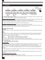 12
12
-
 13
13
-
 14
14
-
 15
15
-
 16
16
-
 17
17
-
 18
18
-
 19
19
-
 20
20
-
 21
21
-
 22
22
-
 23
23
-
 24
24
-
 25
25
-
 26
26
-
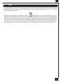 27
27
-
 28
28
-
 29
29
-
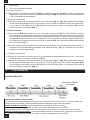 30
30
-
 31
31
-
 32
32
-
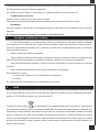 33
33
-
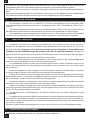 34
34
-
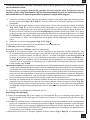 35
35
-
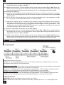 36
36
-
 37
37
-
 38
38
-
 39
39
-
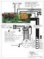 40
40
-
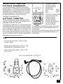 41
41
-
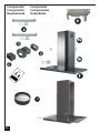 42
42
-
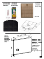 43
43
-
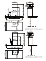 44
44
-
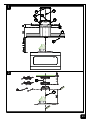 45
45
-
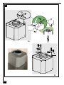 46
46
-
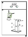 47
47
-
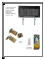 48
48
-
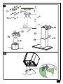 49
49
-
 50
50
-
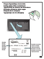 51
51
-
 52
52


ROBLIN ATRIUM MURALE de handleiding
- Categorie
- Afzuigkappen
- Type
- de handleiding
in andere talen
Gerelateerde papieren
-
ROBLIN Premium de handleiding
-
-
ROBLIN LOTUS M900IKOS M900 BLCIKOS M900 INOX de handleiding
-
-
-
-
-
-
-