
2
4
1
3
564
7
× 2
× 2
Installation
Précautions
•Choisir soigneusement l’emplacement
de l’installation afin que l’appareil ne
gêne pas la conduite normale du
véhicule.
•Lorsque le panneau avant est ouvert,
une partie de celui-ci ressort au bas de
l’appareil. Lorsque vous installez
l’appareil, veillez à ce que cette partie
du panneau avant ne soit pas gênée
dans sa position ouverte (par le
cendrier par exemple).
•Eviter d’installer l’appareil dans un
endroit exposé à des températures
élevées, comme en plein soleil ou à
proximité d’une bouche d’air chaud,
ou à de la poussière, saleté ou
vibrations violentes.
•Pour garantir un montage sûr,
n’utiliser que le matériel fourni.
Réglage de l’angle de montage
Ajuster l’inclinaison à un angle inférieur
à 60°.
Installation
Vorsichtsmaßnahmen
•Wählen Sie den Einbauort sorgfältig so
aus, daß das Gerät beim Fahren nicht
hinderlich ist.
•Wenn die Frontplatte geöffnet wird,
steht sie etwas nach unten über.
Achten Sie beim Einbauen des Geräts
darauf, daß für den in geöffneter
Position überstehenden Teil der
Frontplatte genug Platz ist, die
Frontplatte also zum Beispiel nicht an
den Aschenbecher stößt.
•Bauen Sie das Gerät so ein, daß es
keinen hohen Temperaturen (keinem
direkten Sonnenlicht, keiner Warmluft
von der Heizung), keinem Staub,
keinem Schmutz und keinen starken
Vibrationen ausgesetzt ist.
•Für eine sichere Befestigung
verwenden Sie stets nur die
mitgelieferten Montageteile.
Hinweis zum Montagewinkel
Das Gerät sollte in einem Winkel von
weniger als 60° montiert werden.
Montage
Voorzorgsmaatregelen
•Kies de installatieplaats zorgvuldig
zodat het toestel de bestuurder niet
hindert tijdens het rijden.
•Als het voorpaneel is geopend, steekt
een gedeelte ervan uit het toestel. Bij
de installatie van het toestel dient u
erop toe te zien dat dit gedeelte van
het voorpaneel in geopende stand niet
wordt gehinderd (door de asbak
bijvoorbeeld).
•Installeer het apparaat niet op plaatsen
waar het blootgesteld wordt aan hoge
temperaturen, b.v. in direct zonlicht of
bij de warme luchtstroom van de
autoverwarming, aan sterke trillingen,
of waar het in contact komt met veel
stof of vuil.
•Gebruik voor het veilig en stevig
monteren van het apparaat uitsluitend
de bijgeleverde montage-onderdelen.
Maximale montagehoek
Installeer het apparaat nooit onder een
hoek van meer dan 60° met het
horizontale vlak.
Installazione
Precauzioni
•Scegliere con attenzione la posizione
per l’installazione in modo che
l’apparecchio non interferisca con le
operazioni di guida del conducente.
•Quando il pannello anteriore è aperto,
parte di esso si estende verso il basso.
Quando si installa l’apparecchio,
assicurarsi che non vi siano ostacoli,
quali il portacenere, che interferiscano
con questa parte del pannello anteriore.
•Evitare di installare l’apparecchio dove
sia soggetto ad alte temperature, come
alla luce solare diretta o al getto di aria
calda dell’impianto di riscaldamento o
dove possa essere soggetto a polvere,
sporco e vibrazioni eccessive.
•Usare solo il materiale di montaggio in
dotazione per un’installazione stabile e
sicura.
Regolazione dell’angolo di
montaggio
Regolare l’angolo di montaggio in modo
che sia inferiore a 60°.
Installation dans le
tableau de bord
Installation im
Armaturenbrett
Montage in het dashboard Installazione nel cruscotto
1 2 3
Fire wall
Paroi ignifuge
Motorraumtrennwand
Brandschot
Parete tagliafiamma
Dashboard
Tableau de bord
Armaturenbrett
Dashboard
Cruscotto
Bend these claws outward for a
tight fit, if necessary.
Plier ces griffes pour assurer une prise
correcte si nécessaire.
Falls erforderlich, diese Klammern für
einen sicheren Halt hochbiegen.
Indien nodig kunt u deze lipjes ombuigen
voor een steviger bevestiging.
Piegare questi morsetti per
un‘installazione più sicura, se necessario.
1
4
Guida alla risoluzione dei problemi
Quanto segue servirà a risolvere la maggior parte dei problemi che possono sorgere. Prima di passare
in rassegna la lista sottoriportata, fare riferimento alle procedure d’uso e di collegamento.
Causa
I conduttori non corrispondono con il connettore di
alimentazione accessoria della macchina
correttamente.
La macchina non ha una posizione ACC.
L’antenna elettrica non dispone della scatola a relè.
Problema
•Le stazioni memorizzate e l’ora corretta vengono
cancellate.
•Il fusibile è saltato.
•Quando la chiave di accensione è nelle posizioni
ON, ACC e OFF, si produce un rumore.
•Non arriva corrente all’apparecchio.
•La corrente arriva di continuo all’apparecchio.
L’antenna non si allunga.
Dépannage
Les contrôles suivants vous permettront de résoudre la majorité des problèmes que vous pourriez
rencontrer avec cet appareil. Avant de passer cette liste de contrôles en revue, vérifiez les procédures
de raccordement et d’utilisation.
Cause
Les fils ne correspondent pas précisément avec le
connecteur d’alimentation pour accessoires de la
voiture.
La voiture n’est pas dotée d’une position ACC.
L’antenne électrique ne comporte pas de boîtier
de relais.
Problème
•Les stations mémorisées et l’heure correcte sont
effacées.
•Le fusible a grillé.
•Génère des parasites lorsque la clé de contact se
trouve sur les positions ON, ACC et OFF.
•L’alimentation ne parvient pas à l’appareil.
•L’appareil est alimenté en continu.
L’antenne électrique ne se déploie pas.
Problemen verhelpen
Aan de hand van de volgende controles kan u de meeste problemen oplossen die zich met dit toestel
kunnen voordoen. Voordat u deze checklist overloopt, controleert u best de aansluitings- en
werkingsprocedures.
Oorzaak
De kabels passen niet precies op de
accessoirevoeding van de wagen.
De wagen heeft geen ACC stand.
De elektrische antenne heeft geen relaiskast.
Probleem
•De voorinstelzenders en het juiste uur zijn gewist.
•De zekering is gesprongen.
•Ruisvorming wanneer de contactsleutel in de
stand ON, ACC en OFF staat.
•Het toestel wordt niet van stroom voorzien.
•Het toestel wordt permanent van stroom voorzien.
De elektrische antenne schuift niet uit.
Störungsbehebung
Mit Hilfe der folgenden Checkliste werden Sie die meisten Probleme beheben können, die beim
Anschließen des Geräts auftreten können. Bevor Sie jedoch versuchen, ein Problem anhand der
Checkliste zu lösen, sehen Sie zuerst nach, ob Sie das Gerät korrekt angeschlossen und bedient haben.
Ursache
Die Leitungen wurden nicht korrekt an die
Zubehörstromversorgung des Fahrzeugs
angeschlossen.
Bei dem Fahrzeug gibt es keine Zubehörposition
(ACC).
Die Motorantenne ist nicht mit einem Relaiskästchen
ausgestattet.
Problem
•Voreingestellte Sender und die Uhrzeit wurden
gelöscht.
•Die Sicherung brennt durch.
•Es ist ein Geräusch zu hören, wenn sich der
Zündschlüsel in den Positionen ON, ACC und
OFF befindet.
•Das Gerät wird nicht mit Strom versorgt.
•Das Gerät wird ständig mit Strom versorgt.
Die Motorantenne läßt sich nicht ausfahren.
5
7
7
5
5
7
Installation/Connections
Installation/Connexions
Installation/Anschluß
Montage/Aansluitingen
Installazione/Collegamenti
FM/MW/LW
Compact Disc
Player
CDX-M610
Sony Corporation © 2001 Printed in Korea
3-231-361-11 (1)
123
Parts list
Liste des composants
Teileliste
Onderdelenlijst
Elenco dei componenti
The numbers in the list are keyed to those in the instructions.
Les numéros de l’illustration correspondent à ceux des instructions.
Die Nummern in der Liste sind dieselben wie im Erläuterungstext.
De nummers in de afbeelding verwijzen naar die in de montage-aanwijzingen.
I numeri nella lista corrispondono a quelli riportati nelle istruzioni.
8
Caution
Cautionary notice for handling the bracket 1.
Handle the bracket carefully to avoid injuring
your fingers.
Attention
Remarque importante pour la manipulation du
support 1.
Manipulez précautionneusement le support pour
éviter de vous blesser aux doigts.
Vorsicht
Sicherheitshinweis zum Umgang mit der
Halterung 1.
Seien Sie beim Umgang mit der Halterung
vorsichtig, damit Sie sich nicht die Hände
verletzen.
Voorzichtig
Spring voorzichtig om met de beugel 1.
Houd de beugel voorzichtig vast zodat u uw
vingers niet verwondt.
Attenzione
Avvertenza sulla manipolazione della staffa 1.
Maneggiare la staffa con cautela per evitare di
ferirsi le mani.
Touche de réinitialisation
Quand l’installation et les connexions sont
terminées, appuyer sur la touche de
réinitialisation avec un stylo à bille, etc.
Rücksetztaste
Nach der Installation und dem Anschluß muß
die Rücksetztaste mit einem Kugelschreiber o. ä.
gedrückt werden.
Terugsteltoets
Druk, nadat u het apparaat heeft geïnstalleerd en
de aansluitingen heeft gemaakt, met een balpen
of een ander puntig voorwerp op de
terugsteltoets.
Tasto di azzeramento
Dopo avere terminato l’installazione e i
collegamenti, assicurarsi di premere il tasto di
azzeramento con la punta di una penna a sfera,
ecc.
BUS
AUDIO IN
BUS
CONTROL IN
AB
CD/MD changer
Changeur de CD/MD
CD/MD-Wechsler
CD/MD-wisselaar
Cambia CD/MD
Power amplifier
Amplificateur de puissance
Endverstärker
Eindversterker
Amplificatore di potenza
Front speaker
Haut-parleur avant
Frontlautsprecher
Voorluidspreker
Diffusori anteriori
Rear speaker
Haut-parleur arrière
Hecklautsprecher
Achterluidspreker
Diffusori posteriori
Source selector*
Sélecteur de source*
Signalquellenwähler*
Geluidsbronkiezer*
Selettore di fonte*
BUS CONTROL IN
BUS AUDIO IN
Schéma de connexion
Appareils utilisés dans les
illustrations (non fournis)
Anschlußdiagramm Aansluitschema Schema di collegamento
In Abbildungen dargestellte Geräte
(nicht mitgeliefert)
Apparatuur gebruikt voor
illustratiedoeleinden
(niet meegeleverd)
Apparecchiatura utilizzata nelle
illustrazioni (non in dotazione)
AUDIO OUT
FRONT
AUDIO OUT
REAR
C
D
BUS AUDIO IN
BUS CONTROL IN
BUS CONTROL IN
AUDIO OUT REAR
When connecting a digital equalizer pre-amplifier (XDP-210EQ, XDP-4000X)
• Use an optional exterior amplifier. The built-in amplifier of this unit can not be used in this case. For details, refer to
the Installation/Connections manual XDP-210EQ, XDP-4000X.
• For details about the connection, refer to the Instllation/Connections manual XDP-210EQ, XDP-4000X. (not supplied)
Lorsque vous raccordez un préamplificateur égaliseur numérique (XDP-210EQ, XDP-4000X)
• Utilisez un amplificateur extérieur optionnel. L’amplificateur intégré dans cet appareil ne peut être utilisé dans ce
cas. Pour plus de détails, reportez-vous au mode d’emploi Installation/Connexions XDP-210EQ, XDP-4000X.
• Pour plus de détails concernant le raccordement, reportez-vous au mode d’emploi Installation/Connexions
XDP-210EQ, XDP-4000X. (non fourni)
Beim Anschließen eines digitalen Equalizer-Vorverstärkers (XDP-210EQ, XDP-4000X)
• Verwenden Sie einen gesondert erhältlichen, externen Verstärker. Den integrierten Verstärker dieses Gerät können
Sie in diesem Fall nicht benutzen. Näheres finden Sie in der Installations-/Anschlußanleitung zum XDP-210EQ,
XDP-4000X.
• Weitere Informationen zum Anschluß finden Sie in der Installations-/Anschlußanleitung zum XDP-210EQ, XDP-
4000X (nicht mitgeliefert).
Als u een digitale equalizer voorversterker aansluit (XDP-210EQ, XDP-4000X)
• Gebruik een optionele externe versterker. De ingebouwde versterker van dit toestel kunt u in dit geval niet
gebruiken. Voor meer details over de aansluiting, zie de handleiding Montage/Aansluitingen XDP-210EQ,
XDP-4000X.
• Voor meer details over de aansluiting, zie de handleiding Montage/Aansluitingen XDP-210EQ, XDP-4000X. (niet
meegeleverd)
Se è collegato un preamplificatore a equalizzatore digitale (XDP-210EQ, XDP-4000X)
• Utilizzare un amplificatore esterno opzionale. In questo caso non può essere utilizzato l’amplificatore incorporato
di questo apparecchio. Per ulteriori informazioni, fare riferimento al manuale relativo all’installazione e ai
collegamenti di XDP-210EQ, XDP-4000X.
• Per ulteriori informazioni sui collegamenti, fare riferimento al manuale relativo all’installazione e ai collegamenti di
XDP-210EQ, XDP-4000X (non in dotazione).
Digital equalizer pre-
amplifier
Préamplificateur égaliseur
numérique
Digitaler Equalizer-
Vorverstärker
Digitale equalizer voor-
versterker
Preamplificatore a
equalizzatore digitale
XDP-210EQ*, XDP-4000X*
DAB tuner unit
Syntoniseur DAB
DAB-Tunereinheit
DAB tuner
Sintonizzatore DAB
XT-100DAB*
Dans le cas du raccordement de deux
changeurs de CD/MD ou plus, le sélecteur
de source XA-C30 (optionnel) est
indispensable.
Per collegare due o più cambia CD/MD, si
deve utilizzare il selettore di fonte XA-C30
(opzionale).
Om twee of meer CD/MD-wisselaars aan te
sluiten, hebt u de geluidsbronkiezer XA-C30
(optioneel) nodig.
Zum Anschließen von zwei oder mehr
CD/MD-Wechslern wird der gesondert
erhältliche Signalquellenwähler XA-C30
benötigt.
9
Remarque
Pour prévenir tout dysfonctionnement,
installez-le uniquement à l’aide des vis
fournies 5.
Hinweis
Um Fehlfunktionen zu vermeiden,
verwenden Sie zum Einbauen des Geräts
nur die mitgelieferten Schrauben 5.
Opmerking
Installeer het toestel uitsluitend met de
meegeleverde schroeven 5 om te
vermijden dat de werking wordt verstoord.
Nota
Per evitare problemi di funzionamento,
installare solo utilizzando le viti in dotazione
5.
Extended portion of the front panel.
Partie proéminente du panneau avant.
Überstehender Teil der Frontplatte.
Uitstekend gedeelte van het voorpaneel.
Parte del pannello anteriore estesa verso il basso.
8.5 mm
15.5 mm
With the UP marking up
Avec l’inscription UP vers le haut
Mit der Markierung UP nach oben
Met UP naar boven gericht
Con il contrassegno UP rivolto verso l'alto
* not supplied
non fournis
nicht mitgeliefert
niet meegeleverd
non in dotazione
* not supplied
non fournis
nicht mitgeliefert
niet meegeleverd
non in dotazione
* not supplied
non fournis
nicht mitgeliefert
niet meegeleverd
non in dotazione
Use the release key 9 for dismounting the unit
when you cannot completely open the front
panel due to a blown fuse (see the Operating
Instructions manual for details). Be careful not
to lose the release key.
Utilisez la clé de dégagement 9 pour démonter
l’appareil si vous ne pouvez pas ouvrir
complètement le panneau frontal après qu’un
fusible ait grillé (reportez-vous au mode
d’emploi pour obtenir plus d’informations à ce
sujet). Veillez à ne pas perdre cette clé!
Verwenden Sie den Löseschlüssel 9 zum
Ausbauen des Geräts, wenn sich die Frontplatte
aufgrund einer durchgebrannten Sicherung
nicht abnehmen läßt. Weitere Einzelheiten
finden Sie in der Bedienungsanleitung. Heben
Sie den Löseschlüssel sorgfältig auf, damit er
nicht verlorengeht.
Maak het toestel los met behulp van de
vrijmaaksleutel 9 wanneer u het frontpaneel
niet volledig kunt openen wegens een
gesprongen zekering (raadpleeg de
gebruiksaanwijzing voor details). Let op dat u
de vrijmaaksleutel niet verliest.
Se non è possibile aprire completamente il
pannello anteriore a causa di un fusibile
bruciato, utilizzare la chiavetta di sbloccaggio 9
per smontare l’apparecchio (per maggiori
dettagli, vedere il manuale delle istruzioni per
l’uso). Fare attenzione a non smarrire la
chiavetta di smontaggio.
Fonctionnement de l’appareil
Cet appareil requiert un code de sécurité.
Vous devez saisir correctement le signal du code
de sécurité.
Pour obtenir plus d’informations sur la saisie du
signal, reportez-vous à l’insert jaune.
Conservez cette feuille. Vous pourrez en avoir
besoin dans l’avenir.
Hinweis zum Betrieb dieses Geräts
Für dieses Gerät ist ein Sicherheitscode
erforderlich.
Sie müssen das Sicherheitscodesignal korrekt
eingeben.
Informationen zum Eingeben des Signals finden
Sie auf der mitgelieferten gelben Beilage.
Bewahren Sie dieses Blatt zum späteren
Nachschlagen auf.
Bediening van het toestel
Dit toestel werkt met een beveiligingscode
U dient eerst het correcte beveiligingscodesignaal
in te voeren.
Meer informatie hieromtrent vindt u op het gele
inlegblad.
Bewaar dit voor eventuele naslag.
Funzionamento dell’apparecchio
Il presente apparecchio necessita di un codice di
sicurezza.
È necessario inserire il segnale del codice di
sicurezza in modo corretto.
Per ulteriori informazioni sulle modalità di
inserimento del segnale, fare riferimento
all’inserto giallo in dotazione.
Conservare il presente opuscolo per riferimenti
futuri.
Troubleshooting guide
The following check will assist in the correction of most problems which you may encounter with
your unit. Before going through the check list below, refer to the connection and operating
procedures.
Cause
Leads are not matched correctly with the car’s
accessory power connector.
The car doesn’t have an ACC position.
The power aerial does not have a relay box.
Problem
•Memorised stations and correct time are erased.
•The fuse has blown.
•Makes noise when the ignition key is the ON, ACC and
OFF positions.
•No power is being supplied to the unit.
•The power is continuously supplied to the unit.
The power aerial does not extend.
Reset button
When the installation and connections are
completed, be sure to press the reset button with
a ballpoint pen, etc.
On operating the this unit
This unit needs a security code.
You must input the security code signal correctly.
For information on how to input the signal, refer
to the supplied yellow insert for details.
Keep this sheet for future reference.
Installation
Precautions
•Choose the installation location
carefully so that the unit will not
interfere with normal driving
operations.
•When the front panel is open, a
portion of it will extend down from the
unit. When you install the unit, make
sure that this portion of the front panel
is not obstructed in its open position
(by the ashtray, for example).
•Avoid installing the unit in areas
subject to dust, dirt, excessive
vibration, or high temperature, such as
in direct sunlight or near heater ducts.
•Use only the supplied mounting
hardware for a safe and secure
installation.
Mounting angle adjustment
Adjust the mounting angle to less than
60°.
Installation in the
dashboard
Note
To prevent malfunction, install only with
the supplied screws 5.
Connection diagram
Equipment used in illustrations
(not supplied)
For connecting two or more CD/MD
changers, the source selector XA-C30
(optional) is necessary.
Nota
Assicurarsi di collegare il cavo di terra prima
di collegare l’apparecchio all’amplificatore.
Opmerking
Sluit eerst de massakabel aan alvorens de
versterker aan te sluiten.
Hinweis
Schließen Sie unbedingt zuerst das
Massekabel an, bevor Sie den Verstärker
anschließen.
Remarque
Raccordez d’abord le fil de masse avant de
connecter l’amplificateur.
Note
Be sure to connect the earth cord before
connecting the amplifier.

6
AMP REM
AUDIO OUT FRONT
BUS
CONTROL IN
AUDIO OUT REAR
REMOTE IN
8
Yellow
Jaune
Gelb
Geel
Giallo
Yellow
Jaune
Gelb
Geel
Giallo
ATT
Max. supply current 0.3 A
Courant max. fourni 0,3 A
max. Versorgungsstrom 0,3 A
Max. voedingsstroom 0,3 A
Alimentazione massima fornita 0,3 A
to the interface cable of a car telephone
vers le cordon de liaison d’un téléphone de voiture
an Schnittstellenkabel eines Autotelefons
naar het interface-snoer van een autotelefoon
al cavo interfaccia di un telefono per auto
to a car’s speaker connector
vers un connecteur de haut-parleur de la voiture
an Lautsprecheranschluß des Fahrzeugs
naar een luidsprekeraansluiting van de auto
a un connettore del diffusore per auto
Light blue
Bleu ciel
Hellblau
Hemelsblauw
Azzurro
Blue/white striped
Rayé bleu/blanc
Blau-weiß gestreift
Blauw/wit gestreept
A strisce blu e bianche
from car aerial*
1
de l’antenne de la voiture*
1
von Autoantenne*
1
van een auto-antenne*
1
dall’antenna dell’auto*
1
Yellow
Jaune
Gelb
Geel
Giallo
Blue
Bleu
Blau
Blauw
Blu
Orange/
White
Rayé orange/
blanc
Orange-weiß
gestreift
Oranje/wit
gestreept
Arancione/
bianco
continuous power supply
alimentation continue
permanente Stromversorgung
continu voeding
alimentazione continua
power aerial control
antenne électrique
Motorantennensteuerung
automatische antenne
comando dell’antenna elettrica
switched illumination power
supply
alimentation de l’éclairage
commuté
geschaltete
Beleuchtungsstromversorgung
geschakelde verlichting
stroomvoorziening
alimentazione a illuminazione
commutata
1
2
3
4
Speaker, Rear, Right
haut-parleur, arrière, droit
Lautsprecher hinten rechts
Luidspreker, achter, rechts
Diffusore, posteriore, destro
Speaker, Rear, Right
haut-parleur, arrière, droit
Lautsprecher hinten rechts
Luidspreker, achter, rechts
Diffusore, posteriore, destro
Speaker, Front, Right
haut-parleur, avant, droit
Lautsprecher vorne rechts
Luidspreker, voor, rechts
Diffusore, anteriore, destro
Speaker, Front, Right
haut-parleur, avant, droit
Lautsprecher vorne rechts
Luidspreker, voor, rechts
Diffusore, anteriore, destro
5
6
7
8
Speaker, Front, Left
haut-parleur, avant, gauche
Lautsprecher vorne links
Luidspreker, voor, links
Diffusore, anteriore, sinistro
Speaker, Front, Left
haut-parleur, avant, gauche
Lautsprecher vorne links
Luidspreker, voor, links
Diffusore, anteriore, sinistro
Speaker, Rear, Left
haut-parleur, arrière, gauche
Lautsprecher hinten links
Luidspreker, achter, links
Diffusore, posteriore, sinistro
Speaker, Rear, Left
haut-parleur, arrière, gauche
Lautsprecher hinten links
Luidspreker, achter, links
Diffusore, posteriore, sinistro
Purple
Mauve
Violett
Paars
Viola
Negative polarity positions 2, 4, 6, and 8 have striped cords.
Les positions de polarité négative 2, 4, 6 et 8 sont dotées de cordons rayés.
An den negativ gepolten Positionen (2, 4, 6 und 8) befinden sich gestreifte Adern.
De negatieve posities 2, 4, 6 en 8 hebben gestreepte kabels.
Le posizioni a polarità negativa 2, 4, 6 e 8 hanno cavi rigati.
Green
Vert
Grün
Groen
Verde
White
Blanc
Weiß
Wit
Bianco
Grey
Gris
Grau
Grijs
Grigio
+
–
+
–
+
–
+
–
Esempi di collegamento
*
1
Nota per il collegamento dell’antenna
Se l’antenna della macchina è di tipo
ISO (International Organization
Standardization), utilizzare l’adattatore
6 in dotazione per collegarla.
Collegare prima l’antenna della
macchina all’adattatore in dotazione,
quindi collegarla alla presa
dell’antenna dell’apparecchio
principale.
*
2
Cavo a piedini RCA (non in dotazione)
Voorbeeldaansluitingen
*
1
Opmerking bij de antenne-aansluiting
Indien uw wagen is uitgerust met een
antenne van het type ISO (International
Organisation for Standardization), moet
u die aansluiten met behulp van de
meegeleverde adaptor 6.
Sluit eerst de auto-antenne aan op de
meegeleverde adaptor en vervolgens de
antennestekker op het hoofdtoestel.
*
2
Tulpstekkersnoer (niet bijgeleverd)
Anschlußbeispiel
*
1
Hinweis zum Anschließen der Antenne
Wenn Ihre Fahrzeugantenne der ISO-Norm
(ISO = International Organization for
Standardization - Internationale
Normungsgemeinschaft) entspricht,
schließen Sie sie mit Hilfe des
mitgelieferten Adapters 6 an.
Verbinden Sie zuerst die Fahrzeugantenne
mit dem mitgelieferten Adapter, und
verbinden Sie diesen dann mit der
Antennenbuchse des Hauptgeräts.
*
2
Cinchkabel (nicht mitgeliefert)
Exemple de raccordement
*
1
Remarque sur le raccordement de
l’antenne
Si votre antenne de voiture est de type
ISO (organisation internationale de
normalisation), utilisez l’adaptateur
fourni 6 pour la raccorder.
Raccordez d’abord l’antenne de voiture à
l’adaptateur fourni et, ensuite, à la prise
d’antenne de l’appareil principal.
*
2
Cordon à broche RCA (non fourni)
Source selector (not
supplied)
Sélecteur de source
(non fourni)
Signalquellenwähler
(nicht mitgeliefert)
Geluidsbronkiezer
(niet bijgeleverd)
Selettore di fonte
(non in dotazione)
XA-C30
Schéma de connexion
d’alimentation
Le connecteur d’alimentation auxiliaire
peut varier suivant le type de voiture.
Vérifiez le schéma du connecteur
d’alimentation auxiliaire de votre
voiture pour vous assurer que les
connexions correspondent. Il en existe
trois types de base (illustrés ci-dessous).
Il se peut que vous deviez commuter la
position du fil rouge et jaune du cordon
d’alimentation de l’autoradio.
Après avoir établi les connexions et
commuté correctement les fils
d’alimentation, raccordez l’appareil à
l’alimentation de la voiture. Si vous avez
des questions ou des difficultés à propos
de cet appareil qui ne sont pas abordées
dans le présent mode d’emploi,
consultez votre revendeur automobile.
Stromanschlußdiagramm
Der Hilfsstromanschluß kann je nach
Fahrzeugtyp unterschiedlich sein. Sehen
Sie im Hilfsstromanschlußdiagramm für
Ihr Fahrzeug nach, wie die Verbindung
ordnungsgemäß vorgenommen werden
muß. Es gibt, wie unten abgebildet, drei
grundlegende Typen.
Sie müssen möglicherweise die rote und
gelbe Leitung des
Stromversorgungskabels der
Autostereoanlage vertauschen.
Stellen Sie die Anschlüsse her, schließen
Sie die geschalteten
Stromversorgungsleitungen richtig an,
und verbinden Sie dann das Gerät mit
der Stromversorgung Ihres Fahrzeugs.
Wenn beim Anschließen des Geräts
Fragen oder Probleme auftreten, die in
dieser Bedienungsanleitung nicht
erläutert werden, wenden Sie sich bitte
an den Autohändler.
Voedingsaansluitschema
De hulpvoedingsaansluiting kan
verschillen naargelang van de wagen.
Controleer het voedingsaansluitschema
dat bij dit toestel wordt geleverd om te
zien of de aansluitingen kloppen. Er zijn
drie basistypes (zie illustratie hieronder).
Het is mogelijk dat u de rode en gele
draad van de voedingskabel van de
autoradio moet omwisselen.
Als de aansluitingen en geschakelde
voedingskabels kloppen, sluit u het
toestel aan op de voeding van de wagen.
Indien u nog vragen of problemen hebt
in verband met het aansluiten van het
toestel die niet in deze handleiding
vermeld staan, raadpleeg dan de
autodealer.
Diagramma dei
collegamenti di
alimentazione
Il connettore di alimentazione ausiliaria
può variare a seconda della macchina.
Controllare il diagramma del
connettore di alimentazione ausiliaria
della macchina per essere sicuri che le
connessioni corrispondano
correttamente. Vi sono tre tipi di base
(illustrazione sotto). Potrà essere
necessario cambiare le posizioni dei
conduttori rosso e giallo nel cavo di
alimentazione dello stereo della
macchina. Dopo aver fatto
corrispondere le connessioni e i cavi di
alimentazione commutata, collegare
l’apparecchio all’alimentazione della
macchina. Se si hanno domande o se
sorgono problemi che non sono stati
trattati nel manuale nel collegare
l’apparecchio, contattare
l’autoconcessionario.
Auxiliary power connector
Connecteur d’alimentation auxiliaire
Hilfsstromanschluß
Hulpvoedingsaansluiting
Connettore di alimentazione ausiliare
4
7
Yellow
Jaune
Gelb
Geel
Giallo
Red
Rouge
Rot
Rood
Rosso
continuous power supply
alimentation continue
permanente Stromversorgung
continu voeding
alimentazione continua
switched power supply
alimentation commutée
geschaltete Stromversorgung
geschakelde voeding
alimentazione commutata
Supplied to XA-C30
Fourni avec le XA-C30
Mit dem XA-C30 geliefert
Geleverd met de XA-C30
In dotazione con il modello XA-C30
7
8
4
5
6
the car without ACC position
Voiture sans position ACC
Fahrzeug ohne Zubehörposition (ACC)
Wagen zonder ACC stand
la macchina senza posizione ACC
4
7
Yellow
Jaune
Gelb
Geel
Giallo
Red
Rouge
Rot
Rood
Rosso
switched power supply
alimentation commutée
geschaltete Stromversorgung
geschakelde voeding
alimentazione commutata
continuous power supply
alimentation continue
permanente Stromversorgung
continu voeding
alimentazione continua
Red
Rouge
Rot
Rood
Rosso
Black
Noir
Schwarz
Zwart
Nero
switched power supply
alimentation commutée
geschaltete Stromversorgung
geschakelde voeding
alimentazione commutata
earth
masse
Masse
aarding
terra
Positions 1, 2 and 3 do not have pins.
Les positions 1, 2 et 3 ne comportent pas de
broches.
An Position 1, 2 und 3 befinden sich keine
Stifte.
De posities 1, 2 en 3 hebben geen pins.
Le posizioni 1, 2 e 3 non hanno piedini.
Red
Rouge
Rot
Rood
Rosso
Supplied to the CD/MD changer
Fourni avec le changeur de CD/MD
Mit dem CD/MD-Wechsler geliefert
Geleverd met de CD/MD-wisselaar
In dotazione con il cambia CD/MD
Rotary commander RM-X4S (not supplied)
Satellite de commande RM-X4S (non fourni)
Joystick RM-X4S (nicht mitgeliefert)
Bedieningssatelliet RM-X4S (niet bijgeleverd)
Telecomando a rotazione RM-X4S (non in dotazione)
*
2
Fuse (10 A)
Fusible (10 A)
Sicherung (10 A)
Zekering (10 A)
Fusibile (10 A)
to a car’s auxiliary power connector
vers un connecteur d’alimentation auxiliaire de la voiture
an Hilfsstromanschluß des Fahrzeugs
naar een hulpvoedingsaansluiting van de auto
a un connettore di alimentazione ausiliare per auto
Yellow
Jaune
Gelb
Geel
Giallo
Yellow
Jaune
Gelb
Geel
Giallo
Red
Rouge
Rot
Rood
Rosso
Red
Rouge
Rot
Rood
Rosso
Red
Rouge
Rot
Rood
Rosso
Red
Rouge
Rot
Rood
Rosso
Yellow
Jaune
Gelb
Geel
Giallo
Yellow
Jaune
Gelb
Geel
Giallo
Red
Rouge
Rot
Rood
Rosso
WARNING
Auxiliary power connectors may vary depending
on the car. Be sure to check the power connection
diagram. Improper connections may damage your
car. If the supplied power connecting cord can not
be used with your car, consult your nearest Sony
dealer.
AVERTISSEMENT
Les connecteurs d’alimentation auxiliaire peuvent
varier suivant le type de voiture. Vérifiez le schéma
de connexion d’alimentation fourni avec l’appareil.
Un raccordement incorrect risque d’occasionner des
dommages à votre voiture. Si le cordon
d’alimentation fourni ne peut être utilisé avec
votre voiture, consultez votre revendeur Sony.
VORSICHT
Die Hilfsstromanschlüsse können je nach
Fahrzeugtyp unterschiedlich sein. Sehen Sie im
Stromanschlußdiagramm für Ihr Fahrzeug nach,
wie die Verbindungen ordnungsgemäß
vorgenommen werden müssen.
Fehlerhafte Verbindungen können zu Schäden an
Ihrem Fahrzeug führen. Wenn das mitgelieferte
Stromversorgungskabel nicht für den Einsatz in
Ihrem Fahrzeug geeignet ist, wenden Sie sich bitte
an lhren Sony-Händler.
OPGELET
De hulpvoedingsaansluitingen kunnen verschillen
naargelang van de wagen.
Controleer het voedingsaansluitschema dat bij dit
toestel wordt geleverd. Onjuiste aansluiting kan uw
wagen schade toebrengen.
Indien de meegeleverde stroomaansluitingskabel
voor uw wagen niet bruikbaar is, raadpleeg dan uw
dichtstbijzijnde Sony-dealer.
ATTENZIONE
Il connettore di alimentazione ausiliare può variare a
seconda del tipo di macchina. Controllare il foglio
con lo schema di collegamento in dotazione con
l’apparecchio, collegamenti non corretti potrebbero
danneggiare la macchina.
Se il cavo di collegamento dell’alimentazione in
dotazione non può essere utilizzato con l’auto,
consultare il rivenditore Sony più vicino.
Connexions
Précautions
•Cet appareil est conçu pour
fonctionner sur courant continu de 12
V avec masse négative.
•Veiller à ne pas coincer de fils entre
une vis et la carrosserie de la voiture
ou cet appareil ou encore entre des
pièces mobiles comme les glissières
des sièges, etc.
•Brancher le cordon d’alimentation 8
sur l’appareil et les haut-parleurs
avant de le brancher sur le connecteur
d’alimentation auxiliaire.
•Rassembler tous les fils de terre en
un point de masse commun.
•Brancher le câble jaune à un circuit
libre de la voiture dont la capacité
nominale est supérieure à la capacité
du fusible de l’appareil. Si vous
branchez cet appareil en série avec
d’autres composants stéréo, le circuit
de la voiture auquel ils sont raccordés
doit afficher une capacité nominale
supérieure à la somme des capacités
individuelles de chaque composant.
S’il n’y a pas de circuits de voiture
affichant une capacité égale à la
capacité du fusible de l’appareil,
brancher l’appareil directement à la
batterie. Si aucun circuit de voiture
n’est disponible pour connecter cet
appareil, brancher l’appareil à un
circuit de voiture supérieur à la
capacité du fusible de l’appareil de
telle sorte que si l’appareil grille son
fusible, aucun autre circuit ne soit
coupé.
Anschluß
Vorsicht
•Dieses Gerät ist ausschließlich für den
Betrieb bei 12 V Gleichstrom (negative
Erdung) bestimmt.
•Achten Sie darauf, keine Kabel
zwischen einer Schraube und der
Karosserie oder diesem Gerät oder
zwischen beweglichen Teilen wie den
Sitzschienen usw. einzuklemmen.
•Verbinden Sie das
Stromversorgungskabel 8 mit dem
Gerät und den Lautsprechern, bevor
Sie es mit dem Hilfsstromanschluß
verbinden.
•Schließen Sie alle Erdungskabel an
einen gemeinsamen Massepunkt an.
•Schließen Sie das gelbe Kabel an einen
freien Autostromkreis mit höherer
Leistung als der der Gerätesicherung
an. Wenn Sie dieses Gerät zusammen
mit anderen Stereokomponenten
anschließen, muß der Autostromkreis,
an den die Geräte angeschlossen sind,
eine höhere Leistung aufweisen als die
Summe der Sicherungen der einzelnen
Komponenten. Wenn kein
Autostromkreis eine so hohe Leistung
aufweist wie die Sicherung des Geräts,
schließen Sie das Gerät direkt an die
Batterie an. Wenn kein Autostromkreis
zum Anschließen dieses Geräts frei ist,
schließen Sie das Gerät an einen
Autostromkreis mit höherer Leistung
als der der Gerätesicherung an, und
zwar so, daß keine anderen
Stromkreise unterbrochen werden,
wenn die Sicherung durchbrennen
sollte.
Aansluitingen
Let op!
•Dit apparaat is ontworpen voor
gebruik op gelijkstroom van een 12
Volts auto-accu, negatief geaard.
•Zorg ervoor dat er geen snoeren
geklemd zitten tussen een schroef en
het koetswerk, het toestel of
bewegende onderdelen zoals de
zetelrail, enz.
•Sluit het netsnoer 8 aan op het toestel
en de luidsprekers vooraleer u het op
de hulpvoedingsaansluiting aansluit.
•Sluit alle aarddraden op een
gemeenschappelijk aardpunt aan.
•Sluit het gele snoer aan op een vrij
autocircuit met een capaciteit die hoger
ligt dan die van de toestelzekering. Als
u dit toestel in serie schakelt met
andere audiocomponenten, moet de
capaciteit van het autocircuit waarop
ze zijn aangesloten hoger zijn dan de
som van de zekeringcapaciteit van elke
component afzonderlijk. Als er geen
autocircuits een even hoge capaciteit
hebben als de toestelzekering, moet het
toestel rechtstreeks worden
aangesloten op de accu. Als er geen
autocircuits beschikbaar zijn om dit
toestel aan te sluiten, moet u het toestel
aansluiten op een autocircuit met een
hogere capaciteit dan die van de
toestelzekering. Indien de
toestelzekering dan doorbrandt,
worden geen andere circuits
onderbroken.
Collegamenti
Attenzione
•Questo apparecchio è stato progettato
per l’uso solo a 12 V CC con massa
negativa.
•Fare attenzione che i cavi non
rimangano impigliati tra la vite e la
carrozzeria della macchina,
nell’apparecchio o tra le parti mobili
della macchina, come le guide di
scorrimento del sedile, ecc.
•Collegare il cavo di collegamento
dell’alimentazione 8 all’apparecchio e
ai diffusori prima di collegarlo al
connettore di alimentazione ausiliare.
•Portare tutti i cavi di massa a un
punto di massa comune.
•Collegare il cavo giallo a un circuito
libero della macchina con potenza
nominale superiore a quella del
fusibile dell’apparecchio. Se si collega
questo apparecchio in serie con altri
componenti stereo, il circuito della
macchina a cui sono collegati deve
avere una potenza nominale superiore
alla somma della potenza nominale dei
fusibili di ogni apparecchio. Se i
circuiti della macchina non hanno
potenza nominale superiore a quella
dei fusibili, collegare l’apparecchio
direttamente alla batteria. Se non si
hanno a disposizione circuiti della
macchina per collegare l’apparecchio,
collegare l’apparecchio a un circuito
della macchina con potenza nominale
superiore a quella del fusibile
dell’apparecchio in modo tale che, se il
fusibile dell’apparecchio salta, gli altri
circuiti non verranno tagliati fuori.
Remarques sur l’exemple
de connexion
Remarques sur les fils de contrôle
• Le fil de commande (bleu) de l’antenne
électrique assure une alimentation de
+12 V CC lorsque vous mettez le
syntoniseur sous tension ou lorsque vous
activez la fonction AF (fréquence
secondaire) ou TA (informations
routières).
• Une antenne électrique sans boîtier de
relais ne peut pas être utilisée avec cet
appareil.
• Si votre voiture est équipée d’une
antenne FM/PO/GO intégrée dans la vitre
arrière/latérale, il est nécessaire de
raccorder le fil de commande de l’antenne
électrique (bleu) ou le fil d’entrée
d’alimentation des accessoires (rouge) de
l’amplificateur d’antenne existant. Pour
plus de détails, consultez votre revendeur.
Avertissement
Si vous disposez d’une antenne électrique
sans boîtier de relais, le branchement de cet
appareil au moyen du cordon
d’alimentation fourni 8 risque
d’endommager l’antenne.
Connexion pour la conservation de la
mémoire
Lorsque le fil d’entrée d’alimentation jaune
est connecté, le circuit de la mémoire est
alimenté en permanence même si la clé de
contact est sur la position d’arrêt.
Remarques sur la connexion des haut-
parleurs
• Avant de raccorder les haut-parleurs,
mettre l’appareil hors tension.
• Utiliser des haut-parleurs ayant une
impédance de 4 à 8 ohms et une capacité
adéquate sous peine de les endommager.
• Ne pas raccorder les bornes du système de
haut-parleurs au châssis de la voiture et
ne pas connecter les bornes du haut-
parleur droit à celles du haut-parleur
gauche.
• Ne pas tenter de raccorder les haut-
parleurs en parallèle.
• Ne pas connecter d’enceintes acoustiques
actives (avec amplificateurs intégrés) aux
bornes d’enceinte de cet appareil, pour
éviter d’endommager les enceintes.
Veiller à raccorder des enceintes passives.
Hinweise zum
Anschlußbeispiel
Hinweise zu den Steuerleitungen
• Die Motorantennen-Steuerleitung (blau)
liefert + 12 V Gleichstrom, wenn Sie den
Tuner einschalten oder die AF-
(Alternativfrequenzsuche) oder die TA-
Funktion (Verkehrsdurchsagen) aktivieren.
• Es kann nur eine Motorantenne mit
Relaiskästchen angeschlossen werden.
• Wenn das Fahrzeug mit einer in der Heck-/
Seitenfensterscheibe integrierten UKW-/
MW-/LW-Antenne ausgestattet ist, müssen
Sie die Motorantennen-Steuerleitung
(blau) oder die
Zubehörstromversorgungsleitung (rot) an
den Stromversorgungsanschluß des
vorhandenen Antennenverstärkers
anschließen. Näheres dazu erfahren Sie
bei Ihrem Händler.
Warnung
Wenn Sie eine Motorantenne ohne
Relaiskästchen verwenden, kann durch
Anschließen dieses Geräts mit dem
mitgelieferten Stromversorgungskabel 8
die Antenne beschädigt werden.
Stromversorgung des Speichers
Wenn die gelbe Stromversorgungsleitung
angeschlossen ist, wird der Speicher stets
(auch bei ausgeschalteter Zündung) mit
Strom versorgt.
Hinweise zum Lautsprecheranschluß
• Schalten Sie das Gerät aus, bevor Sie die
Lautsprecher anschließen.
• Verwenden Sie Lautsprecher mit einer
Impedanz zwischen 4 und 8 Ohm und
ausreichender Belastbarkeit. Ansonsten
können die Lautsprecher beschädigt
werden.
• Verbinden Sie die Lautsprecheranschlüsse
nicht mit der Autokarosserie, und
verbinden Sie auch nicht die Anschlüsse
des rechten mit denen des linken
Lautsprechers.
• Versuchen Sie nicht, Lautsprecher parallel
anzuschließen.
• An die Lautsprecheranschlüsse dieses
Geräts dürfen nur Passivlautsprecher
angeschlossen werden. Schließen Sie keine
Aktivlautsprecher (Lautsprecher mit
eingebauten Verstärkern) an, da diese
sonst beschädigt werden können.
Opmerkingen bij
aansluitingsvoorbeeld
Opmerking betreffende de aansluitsnoeren
• De voedingskabel (blauw) van de
elektrisch bediende antenne levert +12V
gelijkstroom wanneer u de tuner
aanschakelt of de functie AF (Alternative
Frequency) of TA (Traffic Announcement)
activeert.
• Met dit apparaat is het niet mogelijk een
automatische antenne zonder relaishuis
te gebruiken.
• Indien uw auto is voorzien van een
ingebouwde FM/MW/LW-antenne in de
achter-/zijruit, moet de
antennebedieningskabel (blauw) of de
hulpvoedingskabel (rood) worden
aangesloten op de voedingsaansluiting
van de bestaande antenneversterker.
Raadpleeg uw dealer voor meer details.
Opgelet
Indien u een elektrische antenne heeft
zonder relaiskast, kan het aansluiten van
deze eenheid met het bijgeleverde netsnoer
8 de antenne beschadigen.
Instandhouden van het geheugen
Zolang de gele stroomdraad is aangesloten,
blijft de stroomvoorziening van het
geheugen intact, ook wanneer het contact
van de auto wordt uitgeschakeld.
Opmerkingen betreffende het aansluiten
van de luidsprekers
• Zorg dat het apparaat is uitgeschakeld,
alvorens de luidsprekers aan te sluiten.
• Gebruik luidsprekers met een impedantie
van 4 tot 8 Ohm en let op dat die het
vermogen van de versterker kunnen
verwerken. Als dit wordt verzuimd,
kunnen de luidsprekers ernstig
beschadigd raken.
• Verbind in geen geval de aansluitingen
van de luidsprekers met het chassis van de
auto en sluit de aansluitingen van de
rechter en linker luidspreker niet op
elkaar aan.
• Probeer nooit de luidsprekers parallel aan
te sluiten.
• Sluit geen actieve luidsprekers (met
ingebouwde versterkers) aan op de
luidspreker-aansluiting van dit apparaat.
Dit zal leiden tot beschadiging van de
actieve luidsprekers. Sluit dus altijd
uitsluitend luidsprekers zonder
ingebouwde versterker aan.
Note sugli esempi di
collegamento
Note sui cavi di controllo
• Il cavo di controllo dell’antenna elettrica
(blu) fornisce corrente continua +12 V CC
quando si accende il sintonizzatore o
quando si attiva la funzione AF
(frequenza alternativa) o TA (notiziario sul
traffico).
• Non è possibile usare un’antenna elettrica
senza scatola a relè con questo
apparecchio.
• Se l’auto è dotata di un’antenna FM/MW/
LW incorporata nel vetro posteriore/
laterale, è necessario collegare il cavo di
controllo per l’antenna elettrica (blu) o il
cavo per l’ingresso dell’alimentazione
accessorio (rosso) al terminale di
alimentazione del preamplificatore
dell’antenna esistente. Per ulteriori
informazioni, consultare il proprio
rivenditore.
Avvertenza
Quando si collega l’apparecchio con il cavo
di alimentazione in dotazione 8, si
potrebbe danneggiare l’antenna elettrica se
questa non ha la scatola di relè.
Collegamento per la conservazione della
memoria
Quando il cavo di ingresso alimentazione
giallo è collegato, viene sempre fornita
alimentazione al circuito di memoria anche
quando la chiavetta di accensione è spenta.
Note sul collegamento dei diffusori
• Prima di collegare i diffusori spegnere
l’apparecchio.
• Usare diffusori di impedenza compresa tra
4 e 8 ohm e con capacità di potenza
adeguata, altrimenti i diffusori
potrebbero venire danneggiati.
• Non collegare i terminali del sistema
diffusori al telaio dell’auto e non
collegare i terminali del diffusore destro a
quelli del diffusore sinistro.
• Non collegare i diffusori in parallelo.
• Non collegare alcun diffusore attivo (con
amplificatore incorporato) ai terminali dei
diffusori dell’apparecchio perché si
potrebbero danneggiare i diffusori attivi.
Assicurarsi di collegare diffusori passivi a
questi terminali.
Insert with the cord upwards.
Insérez avec le câble vers le haut.
Mit dem Kabel nach oben einsetzen!
Inbrengen met het snoer naar boven
Inserire con il cavo rivolto verso l’alto
BUS AUDIO IN
Avertissement en cas
d’installation dans une
voiture dont le contact ne
comporte pas de position
ACC (accessoires)
Appuyez sur la touche (OFF) de
l’appareil pendant deux secondes
pour désactiver l’affichage de
l’horloge après avoir coupé le moteur.
Si vous n’appuyez que brièvement sur
(OFF), l’affichage de l’horloge ne
disparaît pas, ce qui provoque la
décharge de la batterie.
Warnhinweis zur
Installation des Geräts in
einem Auto mit
Zündschloß ohne
Zubehörposition ACC oder
I
Drücken Sie am Gerät unbedingt zwei
Sekunden lang (OFF), um die
Uhrzeitanzeige auszuschalten,
nachdem Sie den Motor ausgeschaltet
haben.
Wenn Sie (OFF) nur kurz drücken, wird
die Uhrzeitanzeige nicht ausgeschaltet,
und der Autobatterie wird Strom
entzogen.
Opgelet bij het monteren
in een auto waarvan het
contactslot geen ACC
(accessory) stand heeft
Druk (OFF) op het toestel gedurende
twee seconden in om de
klokweergave uit te schakelen na het
afzetten van de motor.
Indien u slechts even op (OFF) drukt,
verdwijnt de tijdindicatie niet waardoor
de batterij uitgeput raakt.
Informazioni importanti
per quando si effettua
l’installazione su un’auto
sprovvista della posizione
ACC sull’interruttore di
accensione
Assicurarsi di premere (OFF)
sull’apparecchio per due secondi per
spegnere il display dell’orologio dopo
che il motore è stato spento.
Se si preme (OFF) solo per un attimo, il
display dell’orologio non si spegne
causando in questo modo lo
scaricamento della batteria.
Connection example
*
1
Note for the aerial connecting
If your car aerial is an ISO (International
Organisation for Standardisation) type,
use the supplied adaptor 6 to connect it.
First connect the car aerial to the supplied
adaptor, then connect it to the aerial jack
of the master unit.
*
2
RCA pin cord (not supplied)
Power connection diagram
Auxiliary power connector may vary
depending on the car. Check your car’s
auxiliary power connector diagram to
make sure the connections match
correctly. There are three basic types
(illustrated below). You may need to
switch the positions of the red and
yellow leads in the car stereo’s power
connecting cord.
After matching the connections and
switched power supply leads correctly,
connect the unit to the car’s power
supply. If you have any questions and
problems connecting your unit that are
not covered in this manual, please
consult the car dealer.
Connections
Cautions
•This unit is designed for negative earth
12 V DC operation only.
•Be careful not to pinch any wires
between the screw and the body of the
car, or this unit, or between any
moving parts such as the seat railing,
etc.
•Connect the power connecting cord 8
to the unit and speakers before
connecting it to the auxiliary power
connector.
•Run all earth wires to a common
earth point.
•Connect the yellow cord to a free car
circuit rated higher than the unit’s fuse
rating. If you connect this unit in
combination with other stereo
components, the car circuit they are
connected to must be rated higher than
the sum of the individual components’
fuse rating. If there are no car circuits
rated as high as the unit’s fuse rating,
connect the unit directly to the battery.
If no car circuits are available for
connecting this unit, connect the unit
to a car circuit rated higher than the
unit’s fuse rating in such a way that if
the unit blows its fuse, no other circuits
will be cut off.
Warning when installing in
a car without ACC
(accessory) position on the
ignition key switch
Be sure to press (OFF) on the unit for
two seconds to turn off the clock
display after turning off the engine.
When you press (OFF) only
momentarily, the clock display does not
turn off and this causes battery wear.
Notes of connection
example
Notes on the control leads
• The power aerial control lead (blue)
supplies +12 V DC when you turn on the
tuner or when you activate the AF
(Alternative Frequency), TA (Traffic
Announcement) function.
• A power aerial without a relay box cannot
be used with this unit.
• When your car has built-in FM/MW/LW
aerial in the rear/side glass, it is necessary
to connect the power aerial control lead
(blue) or the accessory power input lead
(red) to the power terminal of the existing
aerial booster. For details, consult your
dealer.
Warning
If you have a power aerial without a relay
box, connecting this unit with the supplied
power connecting cord 8 may damage the
aerial.
Memory hold connection
When the yellow power input lead is
connected, power will always be supplied to
the memory circuit even when the ignition
switch is turned off.
Notes on speaker connection
• Before connecting the speakers, turn the
unit off.
• Use speakers with an impedance of 4 to 8
ohms, and with adequate power handling
capacities. Otherwise, the speakers may be
damaged.
• Do not connect the terminals of the
speaker system to the car chassis, and do
not connect the terminals of the right
speaker with those of the left speaker.
• Do not attempt to connect the speakers in
parallel.
• Do not connect any active speakers (with
built-in amplifiers) to the speaker
terminals of the unit. Doing so may
damage the active speakers. Therefore, be
sure to connect passive speakers to these
terminals.
Documenttranscriptie
Installation Installation Installation Montage Installazione The following check will assist in the correction of most problems which you may encounter with your unit. Before going through the check list below, refer to the connection and operating procedures. Precautions Précautions Vorsichtsmaßnahmen Voorzorgsmaatregelen Precauzioni •Choose the installation location carefully so that the unit will not interfere with normal driving operations. •When the front panel is open, a portion of it will extend down from the unit. When you install the unit, make sure that this portion of the front panel is not obstructed in its open position (by the ashtray, for example). •Avoid installing the unit in areas subject to dust, dirt, excessive vibration, or high temperature, such as in direct sunlight or near heater ducts. •Use only the supplied mounting hardware for a safe and secure installation. Mounting angle adjustment •Choisir soigneusement l’emplacement de l’installation afin que l’appareil ne gêne pas la conduite normale du véhicule. •Lorsque le panneau avant est ouvert, une partie de celui-ci ressort au bas de l’appareil. Lorsque vous installez l’appareil, veillez à ce que cette partie du panneau avant ne soit pas gênée dans sa position ouverte (par le cendrier par exemple). •Eviter d’installer l’appareil dans un endroit exposé à des températures élevées, comme en plein soleil ou à proximité d’une bouche d’air chaud, ou à de la poussière, saleté ou vibrations violentes. •Pour garantir un montage sûr, n’utiliser que le matériel fourni. Réglage de l’angle de montage • Kies de installatieplaats zorgvuldig zodat het toestel de bestuurder niet hindert tijdens het rijden. • Als het voorpaneel is geopend, steekt een gedeelte ervan uit het toestel. Bij de installatie van het toestel dient u erop toe te zien dat dit gedeelte van het voorpaneel in geopende stand niet wordt gehinderd (door de asbak bijvoorbeeld). • Installeer het apparaat niet op plaatsen waar het blootgesteld wordt aan hoge temperaturen, b.v. in direct zonlicht of bij de warme luchtstroom van de autoverwarming, aan sterke trillingen, of waar het in contact komt met veel stof of vuil. • Gebruik voor het veilig en stevig monteren van het apparaat uitsluitend de bijgeleverde montage-onderdelen. •Scegliere con attenzione la posizione per l’installazione in modo che l’apparecchio non interferisca con le operazioni di guida del conducente. •Quando il pannello anteriore è aperto, parte di esso si estende verso il basso. Quando si installa l’apparecchio, assicurarsi che non vi siano ostacoli, quali il portacenere, che interferiscano con questa parte del pannello anteriore. •Evitare di installare l’apparecchio dove sia soggetto ad alte temperature, come alla luce solare diretta o al getto di aria calda dell’impianto di riscaldamento o dove possa essere soggetto a polvere, sporco e vibrazioni eccessive. •Usare solo il materiale di montaggio in dotazione per un’installazione stabile e sicura. Adjust the mounting angle to less than 60°. •Wählen Sie den Einbauort sorgfältig so aus, daß das Gerät beim Fahren nicht hinderlich ist. •Wenn die Frontplatte geöffnet wird, steht sie etwas nach unten über. Achten Sie beim Einbauen des Geräts darauf, daß für den in geöffneter Position überstehenden Teil der Frontplatte genug Platz ist, die Frontplatte also zum Beispiel nicht an den Aschenbecher stößt. •Bauen Sie das Gerät so ein, daß es keinen hohen Temperaturen (keinem direkten Sonnenlicht, keiner Warmluft von der Heizung), keinem Staub, keinem Schmutz und keinen starken Vibrationen ausgesetzt ist. •Für eine sichere Befestigung verwenden Sie stets nur die mitgelieferten Montageteile. Hinweis zum Montagewinkel Maximale montagehoek Das Gerät sollte in einem Winkel von weniger als 60° montiert werden. Installeer het apparaat nooit onder een hoek van meer dan 60° met het horizontale vlak. Ajuster l’inclinaison à un angle inférieur à 60°. Regolazione dell’angolo di montaggio Regolare l’angolo di montaggio in modo che sia inferiore a 60°. 8.5 mm Extended portion of the front panel. Partie proéminente du panneau avant. Überstehender Teil der Frontplatte. Uitstekend gedeelte van het voorpaneel. Parte del pannello anteriore estesa verso il basso. Installation dans le tableau de bord 1 2 Problem Cause • Memorised stations and correct time are erased. • The fuse has blown. • Makes noise when the ignition key is the ON, ACC and OFF positions. Leads are not matched correctly with the car’s accessory power connector. • No power is being supplied to the unit. • The power is continuously supplied to the unit. The car doesn’t have an ACC position. The power aerial does not extend. The power aerial does not have a relay box. FM/MW/LW Compact Disc Player Installation/Connections Dépannage Installation/Connexions Les contrôles suivants vous permettront de résoudre la majorité des problèmes que vous pourriez rencontrer avec cet appareil. Avant de passer cette liste de contrôles en revue, vérifiez les procédures de raccordement et d’utilisation. Installation/Anschluß Problème Cause Montage/Aansluitingen • Les stations mémorisées et l’heure correcte sont effacées. • Le fusible a grillé. • Génère des parasites lorsque la clé de contact se trouve sur les positions ON, ACC et OFF. Les fils ne correspondent pas précisément avec le connecteur d’alimentation pour accessoires de la voiture. Installazione/Collegamenti • L’alimentation ne parvient pas à l’appareil. • L’appareil est alimenté en continu. La voiture n’est pas dotée d’une position ACC. L’antenne électrique ne se déploie pas. L’antenne électrique ne comporte pas de boîtier de relais. Störungsbehebung Mit Hilfe der folgenden Checkliste werden Sie die meisten Probleme beheben können, die beim Anschließen des Geräts auftreten können. Bevor Sie jedoch versuchen, ein Problem anhand der Checkliste zu lösen, sehen Sie zuerst nach, ob Sie das Gerät korrekt angeschlossen und bedient haben. 15.5 mm Installation in the dashboard 3-231-361-11 (1) Troubleshooting guide Installation im Armaturenbrett Montage in het dashboard 3 4 Installazione nel cruscotto Fire wall Paroi ignifuge Motorraumtrennwand Brandschot Parete tagliafiamma Dashboard Tableau de bord Armaturenbrett Dashboard Cruscotto Problem Ursache • Voreingestellte Sender und die Uhrzeit wurden gelöscht. • Die Sicherung brennt durch. • Es ist ein Geräusch zu hören, wenn sich der Zündschlüsel in den Positionen ON, ACC und OFF befindet. Die Leitungen wurden nicht korrekt an die Zubehörstromversorgung des Fahrzeugs angeschlossen. • Das Gerät wird nicht mit Strom versorgt. • Das Gerät wird ständig mit Strom versorgt. Bei dem Fahrzeug gibt es keine Zubehörposition (ACC). CDX-M610 Die Motorantenne läßt sich nicht ausfahren. Die Motorantenne ist nicht mit einem Relaiskästchen ausgestattet. Sony Corporation © 2001 Printed in Korea 1 Bend these claws outward for a tight fit, if necessary. Plier ces griffes pour assurer une prise correcte si nécessaire. Falls erforderlich, diese Klammern für einen sicheren Halt hochbiegen. Indien nodig kunt u deze lipjes ombuigen voor een steviger bevestiging. Piegare questi morsetti per un‘installazione più sicura, se necessario. 1 Note To prevent malfunction, install only with the supplied screws 5. Remarque Pour prévenir tout dysfonctionnement, installez-le uniquement à l’aide des vis fournies 5. 5 5 Problemen verhelpen 4 7 Aan de hand van de volgende controles kan u de meeste problemen oplossen die zich met dit toestel kunnen voordoen. Voordat u deze checklist overloopt, controleert u best de aansluitings- en werkingsprocedures. 2 7 7 With the UP marking up Avec l’inscription UP vers le haut Mit der Markierung UP nach oben Met UP naar boven gericht Con il contrassegno UP rivolto verso l'alto 5 Hinweis Um Fehlfunktionen zu vermeiden, verwenden Sie zum Einbauen des Geräts nur die mitgelieferten Schrauben 5. Opmerking Installeer het toestel uitsluitend met de meegeleverde schroeven 5 om te vermijden dat de werking wordt verstoord. 3 Nota Per evitare problemi di funzionamento, installare solo utilizzando le viti in dotazione 5. Probleem Oorzaak • De voorinstelzenders en het juiste uur zijn gewist. • De zekering is gesprongen. • Ruisvorming wanneer de contactsleutel in de stand ON, ACC en OFF staat. De kabels passen niet precies op de accessoirevoeding van de wagen. • Het toestel wordt niet van stroom voorzien. • Het toestel wordt permanent van stroom voorzien. De wagen heeft geen ACC stand. De elektrische antenne schuift niet uit. De elektrische antenne heeft geen relaiskast. Parts list Liste des composants Teileliste Onderdelenlijst Elenco dei componenti The numbers in the list are keyed to those in the instructions. Les numéros de l’illustration correspondent à ceux des instructions. Die Nummern in der Liste sind dieselben wie im Erläuterungstext. De nummers in de afbeelding verwijzen naar die in de montage-aanwijzingen. I numeri nella lista corrispondono a quelli riportati nelle istruzioni. 1 2 3 4 5 6 Guida alla risoluzione dei problemi Quanto segue servirà a risolvere la maggior parte dei problemi che possono sorgere. Prima di passare in rassegna la lista sottoriportata, fare riferimento alle procedure d’uso e di collegamento. Problema Causa • Le stazioni memorizzate e l’ora corretta vengono cancellate. • Il fusibile è saltato. • Quando la chiave di accensione è nelle posizioni ON, ACC e OFF, si produce un rumore. I conduttori non corrispondono con il connettore di alimentazione accessoria della macchina correttamente. • Non arriva corrente all’apparecchio. • La corrente arriva di continuo all’apparecchio. La macchina non ha una posizione ACC. L’antenna non si allunga. L’antenna elettrica non dispone della scatola a relè. ×2 7 8 9 ×2 Use the release key 9 for dismounting the unit when you cannot completely open the front panel due to a blown fuse (see the Operating Instructions manual for details). Be careful not to lose the release key. Connection diagram Equipment used in illustrations (not supplied) Schéma de connexion Anschlußdiagramm Aansluitschema Schema di collegamento Appareils utilisés dans les illustrations (non fournis) In Abbildungen dargestellte Geräte (nicht mitgeliefert) Apparatuur gebruikt voor illustratiedoeleinden (niet meegeleverd) Apparecchiatura utilizzata nelle illustrazioni (non in dotazione) Rear speaker Haut-parleur arrière Hecklautsprecher Achterluidspreker Diffusori posteriori Front speaker Haut-parleur avant Frontlautsprecher Voorluidspreker Diffusori anteriori Dans le cas du raccordement de deux changeurs de CD/MD ou plus, le sélecteur de source XA-C30 (optionnel) est indispensable. For connecting two or more CD/MD changers, the source selector XA-C30 (optional) is necessary. A CD/MD changer Changeur de CD/MD CD/MD-Wechsler CD/MD-wisselaar Cambia CD/MD Power amplifier Amplificateur de puissance Endverstärker Eindversterker Amplificatore di potenza Zum Anschließen von zwei oder mehr CD/MD-Wechslern wird der gesondert erhältliche Signalquellenwähler XA-C30 benötigt. Om twee of meer CD/MD-wisselaars aan te sluiten, hebt u de geluidsbronkiezer XA-C30 (optioneel) nodig. Utilisez la clé de dégagement 9 pour démonter l’appareil si vous ne pouvez pas ouvrir complètement le panneau frontal après qu’un fusible ait grillé (reportez-vous au mode d’emploi pour obtenir plus d’informations à ce sujet). Veillez à ne pas perdre cette clé! Verwenden Sie den Löseschlüssel 9 zum Ausbauen des Geräts, wenn sich die Frontplatte aufgrund einer durchgebrannten Sicherung nicht abnehmen läßt. Weitere Einzelheiten finden Sie in der Bedienungsanleitung. Heben Sie den Löseschlüssel sorgfältig auf, damit er nicht verlorengeht. Per collegare due o più cambia CD/MD, si deve utilizzare il selettore di fonte XA-C30 (opzionale). B BUS AUDIO IN BUS AUDIO IN BUS CONTROL IN AUDIO OUT FRONT Source selector* Sélecteur de source* Signalquellenwähler* Geluidsbronkiezer* Selettore di fonte* C BUS AUDIO IN BUS CONTROL IN DAB tuner unit Syntoniseur DAB DAB-Tunereinheit DAB tuner Sintonizzatore DAB XT-100DAB* * not supplied non fournis nicht mitgeliefert niet meegeleverd non in dotazione Druk, nadat u het apparaat heeft geïnstalleerd en de aansluitingen heeft gemaakt, met een balpen of een ander puntig voorwerp op de terugsteltoets. Touche de réinitialisation Tasto di azzeramento Quand l’installation et les connexions sont terminées, appuyer sur la touche de réinitialisation avec un stylo à bille, etc. Dopo avere terminato l’installazione e i collegamenti, assicurarsi di premere il tasto di azzeramento con la punta di una penna a sfera, ecc. Nach der Installation und dem Anschluß muß die Rücksetztaste mit einem Kugelschreiber o. ä. gedrückt werden. * not supplied non fournis nicht mitgeliefert niet meegeleverd non in dotazione BUS CONTROL IN Digital equalizer preamplifier Préamplificateur égaliseur numérique Digitaler EqualizerVorverstärker Digitale equalizer voorversterker Preamplificatore a equalizzatore digitale XDP-210EQ*, XDP-4000X* Lorsque vous raccordez un préamplificateur égaliseur numérique (XDP-210EQ, XDP-4000X) • Utilisez un amplificateur extérieur optionnel. L’amplificateur intégré dans cet appareil ne peut être utilisé dans ce cas. Pour plus de détails, reportez-vous au mode d’emploi Installation/Connexions XDP-210EQ, XDP-4000X. • Pour plus de détails concernant le raccordement, reportez-vous au mode d’emploi Installation/Connexions XDP-210EQ, XDP-4000X. (non fourni) Beim Anschließen eines digitalen Equalizer-Vorverstärkers (XDP-210EQ, XDP-4000X) • Verwenden Sie einen gesondert erhältlichen, externen Verstärker. Den integrierten Verstärker dieses Gerät können Sie in diesem Fall nicht benutzen. Näheres finden Sie in der Installations-/Anschlußanleitung zum XDP-210EQ, XDP-4000X. • Weitere Informationen zum Anschluß finden Sie in der Installations-/Anschlußanleitung zum XDP-210EQ, XDP4000X (nicht mitgeliefert). Als u een digitale equalizer voorversterker aansluit (XDP-210EQ, XDP-4000X) • Gebruik een optionele externe versterker. De ingebouwde versterker van dit toestel kunt u in dit geval niet gebruiken. Voor meer details over de aansluiting, zie de handleiding Montage/Aansluitingen XDP-210EQ, XDP-4000X. • Voor meer details over de aansluiting, zie de handleiding Montage/Aansluitingen XDP-210EQ, XDP-4000X. (niet meegeleverd) Se è collegato un preamplificatore a equalizzatore digitale (XDP-210EQ, XDP-4000X) • Utilizzare un amplificatore esterno opzionale. In questo caso non può essere utilizzato l’amplificatore incorporato di questo apparecchio. Per ulteriori informazioni, fare riferimento al manuale relativo all’installazione e ai collegamenti di XDP-210EQ, XDP-4000X. • Per ulteriori informazioni sui collegamenti, fare riferimento al manuale relativo all’installazione e ai collegamenti di XDP-210EQ, XDP-4000X (non in dotazione). * not supplied non fournis nicht mitgeliefert niet meegeleverd non in dotazione Note Be sure to connect the earth cord before connecting the amplifier. When the installation and connections are completed, be sure to press the reset button with a ballpoint pen, etc. Rücksetztaste D AUDIO OUT REAR Terugsteltoets AUDIO OUT REAR When connecting a digital equalizer pre-amplifier (XDP-210EQ, XDP-4000X) • Use an optional exterior amplifier. The built-in amplifier of this unit can not be used in this case. For details, refer to the Installation/Connections manual XDP-210EQ, XDP-4000X. • For details about the connection, refer to the Instllation/Connections manual XDP-210EQ, XDP-4000X. (not supplied) BUS CONTROL IN Reset button Remarque Raccordez d’abord le fil de masse avant de connecter l’amplificateur. Hinweis Schließen Sie unbedingt zuerst das Massekabel an, bevor Sie den Verstärker anschließen. Opmerking Sluit eerst de massakabel aan alvorens de versterker aan te sluiten. Nota Assicurarsi di collegare il cavo di terra prima di collegare l’apparecchio all’amplificatore. On operating the this unit Bediening van het toestel This unit needs a security code. You must input the security code signal correctly. For information on how to input the signal, refer to the supplied yellow insert for details. Keep this sheet for future reference. Dit toestel werkt met een beveiligingscode U dient eerst het correcte beveiligingscodesignaal in te voeren. Meer informatie hieromtrent vindt u op het gele inlegblad. Bewaar dit voor eventuele naslag. Fonctionnement de l’appareil Cet appareil requiert un code de sécurité. Vous devez saisir correctement le signal du code de sécurité. Pour obtenir plus d’informations sur la saisie du signal, reportez-vous à l’insert jaune. Conservez cette feuille. Vous pourrez en avoir besoin dans l’avenir. Hinweis zum Betrieb dieses Geräts Für dieses Gerät ist ein Sicherheitscode erforderlich. Sie müssen das Sicherheitscodesignal korrekt eingeben. Informationen zum Eingeben des Signals finden Sie auf der mitgelieferten gelben Beilage. Bewahren Sie dieses Blatt zum späteren Nachschlagen auf. Funzionamento dell’apparecchio Il presente apparecchio necessita di un codice di sicurezza. È necessario inserire il segnale del codice di sicurezza in modo corretto. Per ulteriori informazioni sulle modalità di inserimento del segnale, fare riferimento all’inserto giallo in dotazione. Conservare il presente opuscolo per riferimenti futuri. Maak het toestel los met behulp van de vrijmaaksleutel 9 wanneer u het frontpaneel niet volledig kunt openen wegens een gesprongen zekering (raadpleeg de gebruiksaanwijzing voor details). Let op dat u de vrijmaaksleutel niet verliest. Se non è possibile aprire completamente il pannello anteriore a causa di un fusibile bruciato, utilizzare la chiavetta di sbloccaggio 9 per smontare l’apparecchio (per maggiori dettagli, vedere il manuale delle istruzioni per l’uso). Fare attenzione a non smarrire la chiavetta di smontaggio. Caution Voorzichtig Cautionary notice for handling the bracket 1. Handle the bracket carefully to avoid injuring your fingers. Spring voorzichtig om met de beugel 1. Houd de beugel voorzichtig vast zodat u uw vingers niet verwondt. Attention Attenzione Remarque importante pour la manipulation du support 1. Manipulez précautionneusement le support pour éviter de vous blesser aux doigts. Avvertenza sulla manipolazione della staffa 1. Maneggiare la staffa con cautela per evitare di ferirsi le mani. Vorsicht Sicherheitshinweis zum Umgang mit der Halterung 1. Seien Sie beim Umgang mit der Halterung vorsichtig, damit Sie sich nicht die Hände verletzen. Connections Connexions Anschluß Aansluitingen Collegamenti Cautions Précautions Vorsicht Let op! Attenzione •This unit is designed for negative earth 12 V DC operation only. •Be careful not to pinch any wires between the screw and the body of the car, or this unit, or between any moving parts such as the seat railing, etc. •Connect the power connecting cord 8 to the unit and speakers before connecting it to the auxiliary power connector. •Run all earth wires to a common earth point. •Connect the yellow cord to a free car circuit rated higher than the unit’s fuse rating. If you connect this unit in combination with other stereo components, the car circuit they are connected to must be rated higher than the sum of the individual components’ fuse rating. If there are no car circuits rated as high as the unit’s fuse rating, connect the unit directly to the battery. If no car circuits are available for connecting this unit, connect the unit to a car circuit rated higher than the unit’s fuse rating in such a way that if the unit blows its fuse, no other circuits will be cut off. •Cet appareil est conçu pour fonctionner sur courant continu de 12 V avec masse négative. •Veiller à ne pas coincer de fils entre une vis et la carrosserie de la voiture ou cet appareil ou encore entre des pièces mobiles comme les glissières des sièges, etc. •Brancher le cordon d’alimentation 8 sur l’appareil et les haut-parleurs avant de le brancher sur le connecteur d’alimentation auxiliaire. •Rassembler tous les fils de terre en un point de masse commun. •Brancher le câble jaune à un circuit libre de la voiture dont la capacité nominale est supérieure à la capacité du fusible de l’appareil. Si vous branchez cet appareil en série avec d’autres composants stéréo, le circuit de la voiture auquel ils sont raccordés doit afficher une capacité nominale supérieure à la somme des capacités individuelles de chaque composant. S’il n’y a pas de circuits de voiture affichant une capacité égale à la capacité du fusible de l’appareil, brancher l’appareil directement à la batterie. Si aucun circuit de voiture n’est disponible pour connecter cet appareil, brancher l’appareil à un circuit de voiture supérieur à la capacité du fusible de l’appareil de telle sorte que si l’appareil grille son fusible, aucun autre circuit ne soit coupé. •Dieses Gerät ist ausschließlich für den Betrieb bei 12 V Gleichstrom (negative Erdung) bestimmt. •Achten Sie darauf, keine Kabel zwischen einer Schraube und der Karosserie oder diesem Gerät oder zwischen beweglichen Teilen wie den Sitzschienen usw. einzuklemmen. •Verbinden Sie das Stromversorgungskabel 8 mit dem Gerät und den Lautsprechern, bevor Sie es mit dem Hilfsstromanschluß verbinden. •Schließen Sie alle Erdungskabel an einen gemeinsamen Massepunkt an. •Schließen Sie das gelbe Kabel an einen freien Autostromkreis mit höherer Leistung als der der Gerätesicherung an. Wenn Sie dieses Gerät zusammen mit anderen Stereokomponenten anschließen, muß der Autostromkreis, an den die Geräte angeschlossen sind, eine höhere Leistung aufweisen als die Summe der Sicherungen der einzelnen Komponenten. Wenn kein Autostromkreis eine so hohe Leistung aufweist wie die Sicherung des Geräts, schließen Sie das Gerät direkt an die Batterie an. Wenn kein Autostromkreis zum Anschließen dieses Geräts frei ist, schließen Sie das Gerät an einen Autostromkreis mit höherer Leistung als der der Gerätesicherung an, und zwar so, daß keine anderen Stromkreise unterbrochen werden, wenn die Sicherung durchbrennen sollte. •Dit apparaat is ontworpen voor gebruik op gelijkstroom van een 12 Volts auto-accu, negatief geaard. •Zorg ervoor dat er geen snoeren geklemd zitten tussen een schroef en het koetswerk, het toestel of bewegende onderdelen zoals de zetelrail, enz. •Sluit het netsnoer 8 aan op het toestel en de luidsprekers vooraleer u het op de hulpvoedingsaansluiting aansluit. •Sluit alle aarddraden op een gemeenschappelijk aardpunt aan. •Sluit het gele snoer aan op een vrij autocircuit met een capaciteit die hoger ligt dan die van de toestelzekering. Als u dit toestel in serie schakelt met andere audiocomponenten, moet de capaciteit van het autocircuit waarop ze zijn aangesloten hoger zijn dan de som van de zekeringcapaciteit van elke component afzonderlijk. Als er geen autocircuits een even hoge capaciteit hebben als de toestelzekering, moet het toestel rechtstreeks worden aangesloten op de accu. Als er geen autocircuits beschikbaar zijn om dit toestel aan te sluiten, moet u het toestel aansluiten op een autocircuit met een hogere capaciteit dan die van de toestelzekering. Indien de toestelzekering dan doorbrandt, worden geen andere circuits onderbroken. •Questo apparecchio è stato progettato per l’uso solo a 12 V CC con massa negativa. •Fare attenzione che i cavi non rimangano impigliati tra la vite e la carrozzeria della macchina, nell’apparecchio o tra le parti mobili della macchina, come le guide di scorrimento del sedile, ecc. •Collegare il cavo di collegamento dell’alimentazione 8 all’apparecchio e ai diffusori prima di collegarlo al connettore di alimentazione ausiliare. •Portare tutti i cavi di massa a un punto di massa comune. •Collegare il cavo giallo a un circuito libero della macchina con potenza nominale superiore a quella del fusibile dell’apparecchio. Se si collega questo apparecchio in serie con altri componenti stereo, il circuito della macchina a cui sono collegati deve avere una potenza nominale superiore alla somma della potenza nominale dei fusibili di ogni apparecchio. Se i circuiti della macchina non hanno potenza nominale superiore a quella dei fusibili, collegare l’apparecchio direttamente alla batteria. Se non si hanno a disposizione circuiti della macchina per collegare l’apparecchio, collegare l’apparecchio a un circuito della macchina con potenza nominale superiore a quella del fusibile dell’apparecchio in modo tale che, se il fusibile dell’apparecchio salta, gli altri circuiti non verranno tagliati fuori. Connection example 1 * Note for the aerial connecting If your car aerial is an ISO (International Organisation for Standardisation) type, use the supplied adaptor 6 to connect it. First connect the car aerial to the supplied adaptor, then connect it to the aerial jack of the master unit. 2 * RCA pin cord (not supplied) Exemple de raccordement Anschlußbeispiel Voorbeeldaansluitingen Esempi di collegamento *1 Remarque sur le raccordement de l’antenne Si votre antenne de voiture est de type ISO (organisation internationale de normalisation), utilisez l’adaptateur fourni 6 pour la raccorder. Raccordez d’abord l’antenne de voiture à l’adaptateur fourni et, ensuite, à la prise d’antenne de l’appareil principal. 2 * Cordon à broche RCA (non fourni) *1 Hinweis zum Anschließen der Antenne Wenn Ihre Fahrzeugantenne der ISO-Norm (ISO = International Organization for Standardization - Internationale Normungsgemeinschaft) entspricht, schließen Sie sie mit Hilfe des mitgelieferten Adapters 6 an. Verbinden Sie zuerst die Fahrzeugantenne mit dem mitgelieferten Adapter, und verbinden Sie diesen dann mit der Antennenbuchse des Hauptgeräts. 2 * Cinchkabel (nicht mitgeliefert) *1 Opmerking bij de antenne-aansluiting Indien uw wagen is uitgerust met een antenne van het type ISO (International Organisation for Standardization), moet u die aansluiten met behulp van de meegeleverde adaptor 6. Sluit eerst de auto-antenne aan op de meegeleverde adaptor en vervolgens de antennestekker op het hoofdtoestel. 2 * Tulpstekkersnoer (niet bijgeleverd) *1 Nota per il collegamento dell’antenna Se l’antenna della macchina è di tipo ISO (International Organization Standardization), utilizzare l’adattatore 6 in dotazione per collegarla. Collegare prima l’antenna della macchina all’adattatore in dotazione, quindi collegarla alla presa dell’antenna dell’apparecchio principale. 2 * Cavo a piedini RCA (non in dotazione) *2 Source selector (not supplied) Sélecteur de source (non fourni) Signalquellenwähler (nicht mitgeliefert) Geluidsbronkiezer (niet bijgeleverd) Selettore di fonte (non in dotazione) XA-C30 Supplied to XA-C30 Fourni avec le XA-C30 Mit dem XA-C30 geliefert Geleverd met de XA-C30 In dotazione con il modello XA-C30 from car aerial*1 de l’antenne de la voiture*1 von Autoantenne*1 van een auto-antenne*1 dall’antenna dell’auto*1 6 BUS AUDIO IN AUDIO OUT FRONT 8 Be sure to press (OFF) on the unit for two seconds to turn off the clock display after turning off the engine. When you press (OFF) only momentarily, the clock display does not turn off and this causes battery wear. Avertissement en cas d’installation dans une voiture dont le contact ne comporte pas de position ACC (accessoires) Appuyez sur la touche (OFF) de l’appareil pendant deux secondes pour désactiver l’affichage de l’horloge après avoir coupé le moteur. Si vous n’appuyez que brièvement sur (OFF), l’affichage de l’horloge ne disparaît pas, ce qui provoque la décharge de la batterie. Warnhinweis zur Installation des Geräts in einem Auto mit Zündschloß ohne Zubehörposition ACC oder I Drücken Sie am Gerät unbedingt zwei Sekunden lang (OFF), um die Uhrzeitanzeige auszuschalten, nachdem Sie den Motor ausgeschaltet haben. Wenn Sie (OFF) nur kurz drücken, wird die Uhrzeitanzeige nicht ausgeschaltet, und der Autobatterie wird Strom entzogen. Opgelet bij het monteren in een auto waarvan het contactslot geen ACC (accessory) stand heeft Druk (OFF) op het toestel gedurende twee seconden in om de klokweergave uit te schakelen na het afzetten van de motor. Indien u slechts even op (OFF) drukt, verdwijnt de tijdindicatie niet waardoor de batterij uitgeput raakt. Informazioni importanti per quando si effettua l’installazione su un’auto sprovvista della posizione ACC sull’interruttore di accensione Assicurarsi di premere (OFF) sull’apparecchio per due secondi per spegnere il display dell’orologio dopo che il motore è stato spento. Se si preme (OFF) solo per un attimo, il display dell’orologio non si spegne causando in questo modo lo scaricamento della batteria. Notes of connection example Remarques sur l’exemple de connexion Hinweise zum Anschlußbeispiel Opmerkingen bij aansluitingsvoorbeeld Note sugli esempi di collegamento Notes on the control leads • The power aerial control lead (blue) supplies +12 V DC when you turn on the tuner or when you activate the AF (Alternative Frequency), TA (Traffic Announcement) function. • A power aerial without a relay box cannot be used with this unit. • When your car has built-in FM/MW/LW aerial in the rear/side glass, it is necessary to connect the power aerial control lead (blue) or the accessory power input lead (red) to the power terminal of the existing aerial booster. For details, consult your dealer. Remarques sur les fils de contrôle • Le fil de commande (bleu) de l’antenne électrique assure une alimentation de +12 V CC lorsque vous mettez le syntoniseur sous tension ou lorsque vous activez la fonction AF (fréquence secondaire) ou TA (informations routières). • Une antenne électrique sans boîtier de relais ne peut pas être utilisée avec cet appareil. • Si votre voiture est équipée d’une antenne FM/PO/GO intégrée dans la vitre arrière/latérale, il est nécessaire de raccorder le fil de commande de l’antenne électrique (bleu) ou le fil d’entrée d’alimentation des accessoires (rouge) de l’amplificateur d’antenne existant. Pour plus de détails, consultez votre revendeur. Hinweise zu den Steuerleitungen • Die Motorantennen-Steuerleitung (blau) liefert + 12 V Gleichstrom, wenn Sie den Tuner einschalten oder die AF(Alternativfrequenzsuche) oder die TAFunktion (Verkehrsdurchsagen) aktivieren. • Es kann nur eine Motorantenne mit Relaiskästchen angeschlossen werden. • Wenn das Fahrzeug mit einer in der Heck-/ Seitenfensterscheibe integrierten UKW-/ MW-/LW-Antenne ausgestattet ist, müssen Sie die Motorantennen-Steuerleitung (blau) oder die Zubehörstromversorgungsleitung (rot) an den Stromversorgungsanschluß des vorhandenen Antennenverstärkers anschließen. Näheres dazu erfahren Sie bei Ihrem Händler. Opmerking betreffende de aansluitsnoeren • De voedingskabel (blauw) van de elektrisch bediende antenne levert +12V gelijkstroom wanneer u de tuner aanschakelt of de functie AF (Alternative Frequency) of TA (Traffic Announcement) activeert. • Met dit apparaat is het niet mogelijk een automatische antenne zonder relaishuis te gebruiken. • Indien uw auto is voorzien van een ingebouwde FM/MW/LW-antenne in de achter-/zijruit, moet de antennebedieningskabel (blauw) of de hulpvoedingskabel (rood) worden aangesloten op de voedingsaansluiting van de bestaande antenneversterker. Raadpleeg uw dealer voor meer details. Warnung Wenn Sie eine Motorantenne ohne Relaiskästchen verwenden, kann durch Anschließen dieses Geräts mit dem mitgelieferten Stromversorgungskabel 8 die Antenne beschädigt werden. Opgelet Indien u een elektrische antenne heeft zonder relaiskast, kan het aansluiten van deze eenheid met het bijgeleverde netsnoer 8 de antenne beschadigen. Note sui cavi di controllo • Il cavo di controllo dell’antenna elettrica (blu) fornisce corrente continua +12 V CC quando si accende il sintonizzatore o quando si attiva la funzione AF (frequenza alternativa) o TA (notiziario sul traffico). • Non è possibile usare un’antenna elettrica senza scatola a relè con questo apparecchio. • Se l’auto è dotata di un’antenna FM/MW/ LW incorporata nel vetro posteriore/ laterale, è necessario collegare il cavo di controllo per l’antenna elettrica (blu) o il cavo per l’ingresso dell’alimentazione accessorio (rosso) al terminale di alimentazione del preamplificatore dell’antenna esistente. Per ulteriori informazioni, consultare il proprio rivenditore. Warning If you have a power aerial without a relay box, connecting this unit with the supplied power connecting cord 8 may damage the aerial. Memory hold connection When the yellow power input lead is connected, power will always be supplied to the memory circuit even when the ignition switch is turned off. Notes on speaker connection • Before connecting the speakers, turn the unit off. • Use speakers with an impedance of 4 to 8 ohms, and with adequate power handling capacities. Otherwise, the speakers may be damaged. • Do not connect the terminals of the speaker system to the car chassis, and do not connect the terminals of the right speaker with those of the left speaker. • Do not attempt to connect the speakers in parallel. • Do not connect any active speakers (with built-in amplifiers) to the speaker terminals of the unit. Doing so may damage the active speakers. Therefore, be sure to connect passive speakers to these terminals. Avertissement Si vous disposez d’une antenne électrique sans boîtier de relais, le branchement de cet appareil au moyen du cordon d’alimentation fourni 8 risque d’endommager l’antenne. Connexion pour la conservation de la mémoire Lorsque le fil d’entrée d’alimentation jaune est connecté, le circuit de la mémoire est alimenté en permanence même si la clé de contact est sur la position d’arrêt. Remarques sur la connexion des hautparleurs • Avant de raccorder les haut-parleurs, mettre l’appareil hors tension. • Utiliser des haut-parleurs ayant une impédance de 4 à 8 ohms et une capacité adéquate sous peine de les endommager. • Ne pas raccorder les bornes du système de haut-parleurs au châssis de la voiture et ne pas connecter les bornes du hautparleur droit à celles du haut-parleur gauche. • Ne pas tenter de raccorder les hautparleurs en parallèle. • Ne pas connecter d’enceintes acoustiques actives (avec amplificateurs intégrés) aux bornes d’enceinte de cet appareil, pour éviter d’endommager les enceintes. Veiller à raccorder des enceintes passives. Stromversorgung des Speichers Wenn die gelbe Stromversorgungsleitung angeschlossen ist, wird der Speicher stets (auch bei ausgeschalteter Zündung) mit Strom versorgt. Hinweise zum Lautsprecheranschluß • Schalten Sie das Gerät aus, bevor Sie die Lautsprecher anschließen. • Verwenden Sie Lautsprecher mit einer Impedanz zwischen 4 und 8 Ohm und ausreichender Belastbarkeit. Ansonsten können die Lautsprecher beschädigt werden. • Verbinden Sie die Lautsprecheranschlüsse nicht mit der Autokarosserie, und verbinden Sie auch nicht die Anschlüsse des rechten mit denen des linken Lautsprechers. • Versuchen Sie nicht, Lautsprecher parallel anzuschließen. • An die Lautsprecheranschlüsse dieses Geräts dürfen nur Passivlautsprecher angeschlossen werden. Schließen Sie keine Aktivlautsprecher (Lautsprecher mit eingebauten Verstärkern) an, da diese sonst beschädigt werden können. Instandhouden van het geheugen Zolang de gele stroomdraad is aangesloten, blijft de stroomvoorziening van het geheugen intact, ook wanneer het contact van de auto wordt uitgeschakeld. Opmerkingen betreffende het aansluiten van de luidsprekers • Zorg dat het apparaat is uitgeschakeld, alvorens de luidsprekers aan te sluiten. • Gebruik luidsprekers met een impedantie van 4 tot 8 Ohm en let op dat die het vermogen van de versterker kunnen verwerken. Als dit wordt verzuimd, kunnen de luidsprekers ernstig beschadigd raken. • Verbind in geen geval de aansluitingen van de luidsprekers met het chassis van de auto en sluit de aansluitingen van de rechter en linker luidspreker niet op elkaar aan. • Probeer nooit de luidsprekers parallel aan te sluiten. • Sluit geen actieve luidsprekers (met ingebouwde versterkers) aan op de luidspreker-aansluiting van dit apparaat. Dit zal leiden tot beschadiging van de actieve luidsprekers. Sluit dus altijd uitsluitend luidsprekers zonder ingebouwde versterker aan. Avvertenza Quando si collega l’apparecchio con il cavo di alimentazione in dotazione 8, si potrebbe danneggiare l’antenna elettrica se questa non ha la scatola di relè. Collegamento per la conservazione della memoria Quando il cavo di ingresso alimentazione giallo è collegato, viene sempre fornita alimentazione al circuito di memoria anche quando la chiavetta di accensione è spenta. Note sul collegamento dei diffusori • Prima di collegare i diffusori spegnere l’apparecchio. • Usare diffusori di impedenza compresa tra 4 e 8 ohm e con capacità di potenza adeguata, altrimenti i diffusori potrebbero venire danneggiati. • Non collegare i terminali del sistema diffusori al telaio dell’auto e non collegare i terminali del diffusore destro a quelli del diffusore sinistro. • Non collegare i diffusori in parallelo. • Non collegare alcun diffusore attivo (con amplificatore incorporato) ai terminali dei diffusori dell’apparecchio perché si potrebbero danneggiare i diffusori attivi. Assicurarsi di collegare diffusori passivi a questi terminali. Blue/white striped Rayé bleu/blanc Blau-weiß gestreift Blauw/wit gestreept A strisce blu e bianche AMP REM Max. supply current 0.3 A Courant max. fourni 0,3 A max. Versorgungsstrom 0,3 A Max. voedingsstroom 0,3 A Alimentazione massima fornita 0,3 A to the interface cable of a car telephone vers le cordon de liaison d’un téléphone de voiture an Schnittstellenkabel eines Autotelefons naar het interface-snoer van een autotelefoon al cavo interfaccia di un telefono per auto Light blue Bleu ciel Hellblau Hemelsblauw Azzurro ATT BUS CONTROL IN Purple Mauve Violett Paars Viola 2 3 4 Grey Gris Grau Grijs Grigio Insert with the cord upwards. Insérez avec le câble vers le haut. Mit dem Kabel nach oben einsetzen! Inbrengen met het snoer naar boven Inserire con il cavo rivolto verso l’alto Fuse (10 A) Fusible (10 A) Sicherung (10 A) Zekering (10 A) Fusibile (10 A) WARNING OPGELET Auxiliary power connectors may vary depending on the car. Be sure to check the power connection diagram. Improper connections may damage your car. If the supplied power connecting cord can not be used with your car, consult your nearest Sony dealer. De hulpvoedingsaansluitingen kunnen verschillen naargelang van de wagen. Controleer het voedingsaansluitschema dat bij dit toestel wordt geleverd. Onjuiste aansluiting kan uw wagen schade toebrengen. Indien de meegeleverde stroomaansluitingskabel voor uw wagen niet bruikbaar is, raadpleeg dan uw dichtstbijzijnde Sony-dealer. AVERTISSEMENT Les connecteurs d’alimentation auxiliaire peuvent varier suivant le type de voiture. Vérifiez le schéma de connexion d’alimentation fourni avec l’appareil. Un raccordement incorrect risque d’occasionner des dommages à votre voiture. Si le cordon d’alimentation fourni ne peut être utilisé avec votre voiture, consultez votre revendeur Sony. VORSICHT Die Hilfsstromanschlüsse können je nach Fahrzeugtyp unterschiedlich sein. Sehen Sie im Stromanschlußdiagramm für Ihr Fahrzeug nach, wie die Verbindungen ordnungsgemäß vorgenommen werden müssen. Fehlerhafte Verbindungen können zu Schäden an Ihrem Fahrzeug führen. Wenn das mitgelieferte Stromversorgungskabel nicht für den Einsatz in Ihrem Fahrzeug geeignet ist, wenden Sie sich bitte an lhren Sony-Händler. ATTENZIONE Il connettore di alimentazione ausiliare può variare a seconda del tipo di macchina. Controllare il foglio con lo schema di collegamento in dotazione con l’apparecchio, collegamenti non corretti potrebbero danneggiare la macchina. Se il cavo di collegamento dell’alimentazione in dotazione non può essere utilizzato con l’auto, consultare il rivenditore Sony più vicino. to a car’s auxiliary power connector vers un connecteur d’alimentation auxiliaire de la voiture an Hilfsstromanschluß des Fahrzeugs naar een hulpvoedingsaansluiting van de auto a un connettore di alimentazione ausiliare per auto to a car’s speaker connector vers un connecteur de haut-parleur de la voiture an Lautsprecheranschluß des Fahrzeugs naar een luidsprekeraansluiting van de auto a un connettore del diffusore per auto 1 Rotary commander RM-X4S (not supplied) Satellite de commande RM-X4S (non fourni) Joystick RM-X4S (nicht mitgeliefert) Bedieningssatelliet RM-X4S (niet bijgeleverd) Telecomando a rotazione RM-X4S (non in dotazione) REMOTE IN AUDIO OUT REAR Warning when installing in a car without ACC (accessory) position on the ignition key switch Supplied to the CD/MD changer Fourni avec le changeur de CD/MD Mit dem CD/MD-Wechsler geliefert Geleverd met de CD/MD-wisselaar In dotazione con il cambia CD/MD + Speaker, Rear, Right haut-parleur, arrière, droit Lautsprecher hinten rechts Luidspreker, achter, rechts Diffusore, posteriore, destro – Speaker, Rear, Right haut-parleur, arrière, droit Lautsprecher hinten rechts Luidspreker, achter, rechts Diffusore, posteriore, destro + Speaker, Front, Right haut-parleur, avant, droit Lautsprecher vorne rechts Luidspreker, voor, rechts Diffusore, anteriore, destro – Speaker, Front, Right haut-parleur, avant, droit Lautsprecher vorne rechts Luidspreker, voor, rechts Diffusore, anteriore, destro 5 White Blanc Weiß Wit Bianco 6 7 Green Vert Grün Groen Verde 8 + Speaker, Front, Left haut-parleur, avant, gauche Lautsprecher vorne links Luidspreker, voor, links Diffusore, anteriore, sinistro – Speaker, Front, Left haut-parleur, avant, gauche Lautsprecher vorne links Luidspreker, voor, links Diffusore, anteriore, sinistro + Speaker, Rear, Left haut-parleur, arrière, gauche Lautsprecher hinten links Luidspreker, achter, links Diffusore, posteriore, sinistro – Speaker, Rear, Left haut-parleur, arrière, gauche Lautsprecher hinten links Luidspreker, achter, links Diffusore, posteriore, sinistro 4 5 Yellow Jaune Gelb Geel Giallo continuous power supply alimentation continue permanente Stromversorgung continu voeding alimentazione continua Blue Bleu Blau Blauw Blu power aerial control antenne électrique Motorantennensteuerung automatische antenne comando dell’antenna elettrica Orange/ White Rayé orange/ blanc 6 Orange-weiß gestreift Oranje/wit gestreept Arancione/ bianco 7 Red Rouge Rot Rood Rosso switched power supply alimentation commutée geschaltete Stromversorgung geschakelde voeding alimentazione commutata 8 Black Noir Schwarz Zwart Nero earth masse Masse aarding terra switched illumination power supply alimentation de l’éclairage commuté geschaltete Beleuchtungsstromversorgung geschakelde verlichting stroomvoorziening alimentazione a illuminazione commutata Positions 1, 2 and 3 do not have pins. Les positions 1, 2 et 3 ne comportent pas de broches. An Position 1, 2 und 3 befinden sich keine Stifte. De posities 1, 2 en 3 hebben geen pins. Le posizioni 1, 2 e 3 non hanno piedini. Negative polarity positions 2, 4, 6, and 8 have striped cords. Les positions de polarité négative 2, 4, 6 et 8 sont dotées de cordons rayés. An den negativ gepolten Positionen (2, 4, 6 und 8) befinden sich gestreifte Adern. De negatieve posities 2, 4, 6 en 8 hebben gestreepte kabels. Le posizioni a polarità negativa 2, 4, 6 e 8 hanno cavi rigati. Power connection diagram Auxiliary power connector may vary depending on the car. Check your car’s auxiliary power connector diagram to make sure the connections match correctly. There are three basic types (illustrated below). You may need to switch the positions of the red and yellow leads in the car stereo’s power connecting cord. After matching the connections and switched power supply leads correctly, connect the unit to the car’s power supply. If you have any questions and problems connecting your unit that are not covered in this manual, please consult the car dealer. Schéma de connexion d’alimentation Le connecteur d’alimentation auxiliaire peut varier suivant le type de voiture. Vérifiez le schéma du connecteur d’alimentation auxiliaire de votre voiture pour vous assurer que les connexions correspondent. Il en existe trois types de base (illustrés ci-dessous). Il se peut que vous deviez commuter la position du fil rouge et jaune du cordon d’alimentation de l’autoradio. Après avoir établi les connexions et commuté correctement les fils d’alimentation, raccordez l’appareil à l’alimentation de la voiture. Si vous avez des questions ou des difficultés à propos de cet appareil qui ne sont pas abordées dans le présent mode d’emploi, consultez votre revendeur automobile. Stromanschlußdiagramm Voedingsaansluitschema Der Hilfsstromanschluß kann je nach Fahrzeugtyp unterschiedlich sein. Sehen Sie im Hilfsstromanschlußdiagramm für Ihr Fahrzeug nach, wie die Verbindung ordnungsgemäß vorgenommen werden muß. Es gibt, wie unten abgebildet, drei grundlegende Typen. Sie müssen möglicherweise die rote und gelbe Leitung des Stromversorgungskabels der Autostereoanlage vertauschen. Stellen Sie die Anschlüsse her, schließen Sie die geschalteten Stromversorgungsleitungen richtig an, und verbinden Sie dann das Gerät mit der Stromversorgung Ihres Fahrzeugs. Wenn beim Anschließen des Geräts Fragen oder Probleme auftreten, die in dieser Bedienungsanleitung nicht erläutert werden, wenden Sie sich bitte an den Autohändler. De hulpvoedingsaansluiting kan verschillen naargelang van de wagen. Controleer het voedingsaansluitschema dat bij dit toestel wordt geleverd om te zien of de aansluitingen kloppen. Er zijn drie basistypes (zie illustratie hieronder). Het is mogelijk dat u de rode en gele draad van de voedingskabel van de autoradio moet omwisselen. Als de aansluitingen en geschakelde voedingskabels kloppen, sluit u het toestel aan op de voeding van de wagen. Indien u nog vragen of problemen hebt in verband met het aansluiten van het toestel die niet in deze handleiding vermeld staan, raadpleeg dan de autodealer. Red Rouge Rot Rood Rosso Red Rouge Rot Rood Rosso 4 Auxiliary power connector Connecteur d’alimentation auxiliaire Hilfsstromanschluß Hulpvoedingsaansluiting Connettore di alimentazione ausiliare 7 Yellow Jaune Gelb Geel Giallo Red Rouge Rot Rood Rosso Red Rouge Rot Rood Rosso 4 7 Yellow Jaune Gelb Geel Giallo Yellow Jaune Gelb Geel Giallo Yellow Jaune Gelb Geel Giallo switched power supply alimentation commutée geschaltete Stromversorgung geschakelde voeding alimentazione commutata Red Rouge Rot Rood Rosso continuous power supply alimentation continue permanente Stromversorgung continu voeding alimentazione continua Red Rouge Rot Rood Rosso Yellow Jaune Gelb Geel Giallo Diagramma dei collegamenti di alimentazione Il connettore di alimentazione ausiliaria può variare a seconda della macchina. Controllare il diagramma del connettore di alimentazione ausiliaria della macchina per essere sicuri che le connessioni corrispondano correttamente. Vi sono tre tipi di base (illustrazione sotto). Potrà essere necessario cambiare le posizioni dei conduttori rosso e giallo nel cavo di alimentazione dello stereo della macchina. Dopo aver fatto corrispondere le connessioni e i cavi di alimentazione commutata, collegare l’apparecchio all’alimentazione della macchina. Se si hanno domande o se sorgono problemi che non sono stati trattati nel manuale nel collegare l’apparecchio, contattare l’autoconcessionario. Yellow Jaune Gelb Geel Giallo continuous power supply alimentation continue permanente Stromversorgung continu voeding alimentazione continua Red Rouge Rot Rood Rosso switched power supply alimentation commutée geschaltete Stromversorgung geschakelde voeding alimentazione commutata Red Rouge Rot Rood Rosso the car without ACC position Voiture sans position ACC Fahrzeug ohne Zubehörposition (ACC) Wagen zonder ACC stand la macchina senza posizione ACC Yellow Jaune Gelb Geel Giallo Yellow Jaune Gelb Geel Giallo-
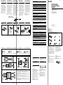 1
1
-
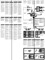 2
2


in andere talen
- English: Sony CDX-M610 Installation guide
- italiano: Sony CDX-M610 Guida d'installazione
- français: Sony CDX-M610 Guide d'installation
- Deutsch: Sony CDX-M610 Installationsanleitung