
Bedienungsanleitung
celexon Deckeneinbauleinwand
Motor Professional Plus
Vielen Dank für den Kauf dieses Produkts.
Für eine optimale Leistung und Sicherheit lesen Sie diese Anweisungen bitte sorgfältig
durch, bevor Sie dieses Produkt anschließen oder betreiben. Bitte bewahren Sie diese
Anleitung für eine spätere Verwendung auf.
Version: 32422_031

1
Diese Bedienungsanleitung dient dazu, Sie mit der Funktionsweise dieses Produktes
vertraut zu machen. Bewahren Sie diese Anleitung daher gut auf, damit Sie jederzeit
darauf zugreifen können.
• Bitte beachten Sie vor der Montage das beiliegende Datenblatt mit weiteren Sicher-
heits- und Verwendungshinweisen.
• Beginnen Sie nicht mit der Montage, bevor Sie die komplette Bedienungsanleitung
gelesen und diese verstanden haben.
• Führen Sie die Installation mit einer weiteren Person durch um eine sichere Montage
zu gewährleisten.
• Entnehmen die das Produkt der Verpackung und entfernen alle Verpackungsmateri-
alien. Achten Sie darauf, dass sich kein Verpackungsmaterial am oder im Produkt be-
ndet Sollten Sie Verpackungsbeschädigungen feststellen, prüfen Sie zusätzlich ob
Beschädigungen am Produkt zu nden sind. Sollten Sie äußerliche Beschädigungen
an dem Gerät oder unerwartete oder unübliche Funktionsweisen feststellen, darf
das Produkt nicht weiter genutzt werden. Kontaktieren Sie umgehend den Händler,
bei dem Sie das Produkt gekauft haben oder celexon direkt (Web: www.celexon.de,
Mail: info@celexon.de) für weitere Informationen.
• Um einen störungsfreien Betrieb sicherzustellen, darf das Produkt ausschließlich in
Innenbereichen eingesetzt werden, es ist NICHT zur Nutzung im Freien geeignet.
• Die Nutzung des Geräts und Zubehörteile ist Kindern unter 16 Jahren verboten.
• Sorgen Sie dafür, dass keine Kinder mit den Geräten spielen oder sich ohne Aufsicht
in der Nähe aufhalten.
• Ein Umbauen oder Verändern des Produktes beeinträchtigt die Produktsicherheit.
• Achtung Verletzungsgefahr! Öffnen Sie das Produkt niemals eigenmächtig. Führen
Sie Reparaturen nie selbst aus!
• Verwenden Sie das Produkt nicht in der Nähe von austretendem Gas, Wasser oder in
• staubiger Umgebung.
• Behandeln Sie das Produkt sorgfältig. Es kann durch Stöße, Schläge oder Fall aus
bereits geringer Höhe beschädigt werden.
• Halten Sie das Produkt fern von Feuchtigkeit und Hitze..
• Tauchen Sie das Produkt niemals in Wasser oder andere Flüssigkeiten.
• Verwenden Sie das Produkt nur in seiner bestimmungsgemäßen Art und Weise. Eine
anderweitige Verwendung kann zu Beschädigungen am Produkt oder in dessen Um-
gebung führen.
• Ziehen Sie die Schrauben fest, aber überdrehen diese nicht. Ein zu feste Anziehen
WARNHINWEISE

2
(z.B. Durch Verwendung eines Akkuschraubendrehers) kann Schäden verursachen
und den sicheren Halt der Leinwand beeinträchtigen.
• Hängende Lasten müssen mindestens zweimal jährlich auf Festigkeit und Tragfähig-
keit geprüft werden.
• Kinder sollten nicht unbeaufsichtigt die Leinwand nutzen, bzw. darunter spielen.
• Achtung Verletzungsgefahr! Das Gerät schließt bündig und fest im eingefahrenen
Zustand – halten Sie Finger, Hände oder andere Kleinteile von der Öffnung fern.
• Alle Zuleitungen und Kabel dürfen nicht zusätzlich belastet werden und müssen so
verlegt werden, dass diese nicht beschädigt oder gequetscht werden.
• Bei Nichtbeachtung obiger Anweisungen kann es zu Personenschäden und
Beschädigungen des Produktes oder Geräten die daran angeschlossen
sind kommen. Auch kann bei fehlerhafter Installation oder Verwendung die
Garantie erlöschen.
• Wenn Sie beim Verwenden des Produktes unsicher sind, kontaktieren Sie
Fachpersonal, Ihren Händler oder celexon direkt (Web: www.celexon.de,
Mail: info@celexon.de).
• Technische Änderungen und Irrtümer vorbehalten.
Der Hersteller übernimmt keine Verantwortung für Sachschäden oder Personenschäden,
wenn die Leinwand außerhalb der empfohlenen Spezikationen verwendet wird, oder
bei unsachgemäßer Installation. Verwenden Sie diese Leinwand nicht in der Nähe von
Heizungen oder Klimaanlagen. Montieren Sie das Produkt ebenfalls nicht in direktem
Sonnenlicht oder vor einem Fenster. Aufgrund der temperaturempndlichen PVC Ober-
äche kann es zu nachhaltiger Beschädigung des Projektionstuchs kommen.
Wir empfehlen Ihnen, nach der Lieferung ca. 2 Stunden mit der Montage zu warten. So
kann sich die Leinwand akklimatisieren; besonders wenn die Leinwand von kalter in eine
warme Umgebung .oder umgekehrt gebracht wird
Bitte vermeiden Sie jegliche Flecken auf der Tuchoberäche. Diese könnten sich mög-
licherweise nicht mehr entfernen lassen.
Die Positionen der Endpunkte sind bereits werksseitig optimal eingestellt und sollten
nicht verändert werden. Gerade bei Motor-Leinwänden sollte immer die gesamte Tuch-
länge verwendet werden, um die beste Planlage zu gewährleisten. Eine Justierung um
wenige cm der Endabschaltpunkte sollte nur von Personen mit Fachkenntnissen und
in Rücksprache mit dem Hersteller erfolgen. Eine Fehlerhafte Einstellung kann zu einer
Beschädigung der Projektionsäche führen.

3
TECHNISCHE DATEN
Die Angaben in diesem Dokument können ohne vorherige Ankündigung durch
den Hersteller geändert werden. Änderungen werden jeweils in den folgenden
Versionen dieses Handbuchs ergänzt. Irrtümer ausgeschlossen.
PFLEGEHINWEIS
Reinigen Sie die Leinwand NIEMALS mit Alkohol oder anderen Reinigungsmit-
teln, die Lösungsmittel enthalten. Benutzen Sie nur ein weiches und sauberes
Tuch. Mit einer milden Seifenlauge (max. 5%) kann gegebenenfalls Schmutz
von der Oberäche entfernt werden. Vermeiden Sie unbedingt den Kontakt
mit spitzen oder scharfen Gegenständen. Diese könnten das Projektionstuch
nachhaltig beschädigen. Weitere Hinweise entnehmen Sie den beiliegenden
Leinwandhinweisen.
Spannung: 220 V ~ 240 V, 50 Hz
Verbrauch: 130 W (MAX)
0,4 W (Standby)
Steuerung: Kabelschalter bzw. optional erhältliche
Steuersysteme
HAFTUNGSAUSSCHLUSS

4
LIEFERUMFANG
INSTALLATIONSHINWEIS
Bitte prüfen Sie vor der Installation, ob alle oben aufgeführten Teile enthalten
sind! Sollten Teile fehlen, kontaktieren Sie den Händler, bei welchem Sie das
Produkt gekauft haben und warten mit der Installation auf Vollständigkeit.
Installieren Sie die Leinwand an einer für alle Betrachter komplett sichtbaren
Position! Die optimale Installationshöhe entspricht der Position der Betrachter
mittig zur Leinwand bei ausgefahrenem Tuch: Augenhöhe = unteres Drittel der
Bildäche.
1x Leinwand
4 x Gewindestange (D)
2 x Montagewinkel (A)
4 x Metalldübel (E)
2 x Revisionsabdeckung (B)
1 x Innensechskantschlüssel
5mm (F)
1x Innensechkantinbus (C)
1 x Innensechskantschlüssel
8mm (L)
MONTAGE
Entnehmen Sie das Deckenausschnittsmaß bitte folgender Liste und schaffen
Sie einen entsprechenenden Ausschnitt in Ihrer abgehängten Decke.
SCHRITT 1: DECKENAUSSCHNITT
Breite
Sichtäche
Länge
Deckenausschnitt
Breite
Deckenausschnitt
160 cm 202 cm 11 cm
180 cm 222 cm 11 cm
200 cm 244 cm 11 cm
220 cm 264 cm 11 cm
240 cm 284 cm 11 cm
280 cm 329 cm 13,5 cm
300 cm 349 cm 13,5 cm

5
Zur Sicherheit können Sie das Ausschnitts-
maß wie folgt kontrollieren:
Messen Sie die Länge “L1” sowie die Tiefe
“CD” des Leinwandgehäuses wie in den bei-
den Abbildungen zu erkennen. Zur Länge “L1”
addieren Sie 190 mm, von der Breite “CD” zie-
hen Sie 25 mm ab.
CH

6
Artikelbe-
zeichnung
(B x H)
Ab-
messung
(L1)
Ab-
messung
(L2)
Ab-
mes-
sung
(L3)
Breite
Fallstab
(L4)
Gehäuse-
abmessungen
(OlxCHxCD)
Deckenaus-
schnittsmaß
160x160 cm 182,6 cm 186,6 cm 9,4 cm 172,2 cm 206,6x10,3x13,6 cm 201,6x11,1 cm
180x180 cm 202,6 cm 206,6 cm 9,4 cm 192,2 cm 226,6x10,3x13,6 cm 221,6x11,1 cm
200x200 cm 224,6 cm 228,6 cm 9,4 cm 214,2 cm 248,6x10,3x13,6 cm 243,6x11,1 cm
220x220 cm 244,6 cm 248,6 cm 9,4 cm 234,2 cm 268,6 x10,3x13,6 cm 263,6x11,1cm
240x240 cm 264,6 cm 268,6 cm 9,4 cm 254,2 cm 288,6x10,3x13,6 cm 283,6x11,1 cm
280x280 cm 309,8 cm 313,8 cm 9,4 cm 296,3 cm 312,4x12,7x16,0 cm 328,8x13,5 cm
160x120 cm 182,6 cm 186,6 cm 9,4 cm 172,2 cm 206,6x10,3x13,6 cm 201,6x11,1 cm
180x135 cm 202,6 cm 206,6 cm 9,4 cm 192,2 cm 226,6x10,3x13,6 cm 221,6x11,1 cm
200x150 cm 224,6 cm 228,6 cm 9,4 cm 214,2 cm 248,6x10,3x13,6 cm 234,6x11,1 cm
220x165 cm 244,6 cm 248,6 cm 9,4 cm 234,2 cm 268,6x10,3x13,6 cm 263,6x11,1 cm
240x280 cm 264,6 cm 268,6 cm 9,4 cm 254,2 cm 288,6x10,3x13,6 cm 283,6x11,1 cm
280x210 cm 309,8 cm 313,8 cm 9,4 cm 296,3 cm 312,4x12,7x16,0 cm 328,8x13,5 cm
300x225 cm 329,8 cm 333,8 cm 9,4 cm 316,3 cm 339,5x12,7x16,0 cm 348,8x13,5 cm
160x90 cm 182,6 cm 186,6 cm 9,4 cm 172,2 cm 206,6x10,3x13,6 cm 201,6x11,1 cm
180x102 cm 202,6 cm 206,6 cm 9,4 cm 192,2 cm 226,6x10,3x13,6 cm 221,6x11,1 cm
200x113 cm 224,6 cm 228,6 cm 9,4 cm 214,2 cm 248,6x10,3x13,6 cm 243,6x11,1 cm
220x124 cm 244,6 cm 248,6 cm 9,4 cm 234,2 cm 268,6x10,3x13,6 cm 263,6x11,1 cm
240x135 cm 264,6 cm 268,6 cm 9,4 cm 254,2 cm 288,6x10,3x13,6 cm 283,6x11,1 cm
280x158 cm 309,8 cm 313,8 cm 9,4 cm 296,3 cm 312,4x12,7x16,0 cm 328,8x13,5 cm
300x169 cm 329,8 cm 333,8 cm 9,4 cm 316,3 cm 339,5x12,7x16,0 cm 348,8x13,5 cm
160x110 cm 182,6 cm 186,6 cm 9,4 cm 172,2 cm 206,6x10,3x13,6 cm 201,6x11,1 cm
180x112 cm 202,6 cm 206,6 cm 9,4 cm 192,2 cm 226,6x10,3x13,6 cm 221,6x11,1 cm
200x125 cm 224,6 cm 228,6 cm 9,4 cm 214,2 cm 248,6x10,3x13,6 cm 243,6x11,1 cm
220x137 cm 244,6 cm 248,6 cm 9,4 cm 234,2 cm 268,6x10,3x13,6 cm 263,6x11,1 cm
240x150 cm 264,6 cm 268,6 cm 9,4 cm 254,2 cm 288,6x10,3x13,6 cm 283,6x11,1 cm
280x175 cm 309,8 cm 313,8 cm 9,4 cm 296,3 cm 312,4x12,7x16,0 cm 328,8x13,5 cm
300x187 cm 329,8 cm 333,8 cm 9,4 cm 316,3 cm 339,5x12,7x16,0 cm 348,8x13,5cm

7
SCHRITT 2: LEINWAND VORBEREITEN
SCHRITT 3: VORBOHREN
Bohren Sie vier Löcher in Ihre tragende (Beton-)decke und führen die Metall-
dübel (E) ein. Der Abstand zwischen den Bohrungen sollte L+40mm x 94mm
betragen.
Nutzen Sie gegebenenfalls andere Dübel und Schrauben, passend zu Ihrer
baulichen Gegebenheit. Befestigen Sie nun die vier Montagewinkel (A) an Ihre
Decke. Achten Sie unbedingt auf einen festen und sicheren Halt der Winkel
um eine sichere und dauerhafte Installation der Leinwand zu gewährleisten.
Montieren Sie anschließend die zwei Gewindestangen (D) an die Montagewin-
kel und drehen jeweils eine Sechskantmutter über die Höhe der abgehängten
Decke. Ggf. müssen die Gewindestangen bauseitig für Ihr benötigtes Abhang-
maß gekürzt werden.
Lösen Sie die Schrauben der Montage-
platte oberhalb des Leinwandgehäu-
ses.
Schieben Sie die Montageplatten zu
den Enden des Gehäuses und zie-
hen die Schrauben wieder fest an.
Bitte achten Sie darauf, dass die
Bohrungen für die Gewindestangen
nicht durch das Gehäuse verdeckt
werden.

8
Führen Sie das Leinwand-
gehäuse in die ausgeschnit-
tene Deckenöffnung ein.
Achten Sie darauf, dass die
vier Gewindestangen in die
Löcher der Montageplatten
geführt werden. Drehen Sie
nun auf jeder Gewindestan-
ge eine Sechskantmutter,
um die Leinwand zu sichern.
SCHRITT 4: MONTAGE DECKE
Bringen Sie die Leinwand
nun mit Hilfe der Sechskant-
muttern in eine waagerech-
te Lage und verschließen
damit die Deckenausspa-
rung. Nutzen Sie eine Was-
serwaage, um die Leinwand
auszurichten.
Abgehängte
Decke
Sechskant-
mutter
Gewinde-
stangen

9
Befestigen Sie abschließend die Revisionsabdeckungen (B) seitlich an dem
Leinwandgehäuse. Zum Demontieren dieser, ziehen Sie die Abdeckungen vor-
sichtig nach unten und vom Gehäuse weg.
BEDIENUNG
SCHRITT 1: SICHERHEITSKONTROLLE
Stecken Sie den Stecker in die Steckdose (auf korrekte Spannung achten). Das
Kabel darf nicht auf heiße Flächen oder gespannt verlegt werden. Bei Nutzung
einer Verlängerung, achten Sie auf die korrekte Spezikation. Der Kabelschalter
kann im Weiteren durch ein Infrarot- oder Funksteuer-Set von celexon ersetzt
werden. Deren Anschluss muss von Elektro-fachkundigem Personal erfolgen.
STEUERUNG ÜBER DEN KABALSCHALTER
SCHRITT 2: LEINWAND AUSFAHREN (FIG. 2)
Schieben Sie den Schalter nach unten.
Die Leinwand fährt aus und stoppt au-
tomatisch am eingestellten Endpunkt.
Achten Sie darauf, dass keine Gegen-
stände oder Personen den Ausfahrweg
der Leinwand behindern.

10
SCHRITT 3: LEINWAND EINFAHREN (FIG. 3)
Schieben Sie den Schalter nach oben.
Die Leinwand fährt ein und stoppt au-
tomatisch am Gehäuse bzw. dem ein-
gestellten oberen Endpunkt. Achten
Sie darauf, dass keine Gegenstände
oder Personen den Einfahrweg der
Leinwand behindern.
SCHRITT 4: LEINWAND STOPPEN
Um die Leinwand manuell zu stoppen, schieben Sie den Schalter in die mittle-
re Position.
Die Einstellung der Stopp-Punkte ist möglich. Bitte fordern Sie für diesen Vorgang die Anleitung bei
Ihrem Fachhändler oder direkt über www.celexon.de an.

11
Hersteller: celexon Europe GmbH
Adresse: Gutenbergstraße 2, 48282 Emsdetten, DE
Produktname: celexon Deckeneinbauleinwand Motor Professional Plus
Produkte, die mit dem CE-Zeichen gekennzeichnet sind, entsprechen
allen Anforderungen der entsprechenden EU-Direktiven. Die EU-Konfor-
mitätserklärung kann unter folgender Adresse heruntergeladen werden:
www.celexon.de/zertikate
INFORMATION ZUR EU KONFORMITÄT
Das Symbol weist auf die getrennte Rücknahme elektrischer und elektro-
nischer Geräte in EU-Ländern hin. Bitte werfen Sie das Gerät nicht in den
Hausmüll. Informieren Sie sich über das in Ihrem Land gültige Rücknah-
mesystem und wenden Sie sich bei Fragen zum Entsorgungsprozess an
Ihre Kommune oder Ihre örtliche Wert-und Schadstoffsammelstelle.

Operating instructions
Celexon Ceiling Recessed Electric
Professional Plus
Thank you for purchasing this product.
For optimum performance and safety, please read these instructions carefully
before connecting or operating this product. Please retain these instructions for future
reference.
Version: 32422_061

1
The purpose of these operating instructions is to familiarise you with the operation of
this product. Therefore, keep these instructions in a safe place so that you can refer to
it at any time.
• Before installation, please refer to the enclosed data sheet for further safety and use
instructions.
• Do not begin installation until you have read and understood the complete
operating instructions.
• Carry out the installation with another person to ensure safe installation.
• Remove the product from its packaging and remove all packaging material. Make
sure that there is no packaging material on or in the product. If you notice any
damage to the packaging, also check whether there is any damage to the pro-
duct. If you notice any external damage to the unit or any unexpected or unusual
functioning, the product must not be used any further. Immediately contact the
dealer from whom you purchased the product or celexon directly (Web:
www.celexon.co.uk, Mail: info@celexon.co.uk) for further information.
• To ensure trouble-free operation, the product may only be used indoors. It is NOT
suitable for outdoor use.
• The use of the appliance and accessories is forbidden to children under 16 years of
age.
• Ensure that no children play with the appliance or are in the vicinity without
supervision.
• Conversion or modication of the product impairs product safety.
• Caution: Risk of injury! Never open the product without authorisation. Never carry
out repair yourself!
• Do not use the product near gas or water appliances or in a dusty environment.
• Handle the product with care. It can be damaged by knocks, blows or falling from
even a small height.
• Keep the product away from moisture and heat.
• Never immerse the product in water or other liquids.
• Use the product only in its intended manner. Use for any other purpose may damage
the product or its surroundings.
• Tighten the screws, but do not overtighten them. Overtightening the screws (e.g.
by using a cordless screwdriver) can cause damage and affect the secure hold of
the screen.
WARNINGS

2
• Suspended loads must be checked for strength and load-bearing capacity at least
twice a year.
• Children should not use the screen or play under it unsupervised.
• Caution: Risk of injury! The unit closes ush and rmly in its retracted state, keep
ngers, hands or other small parts away from the opening.
• All supply lines and cables must not be subjected to additional loads and must be
laid in such a way that they are not damaged or crushed.
• Failure to observe the above instructions may result in personal injury and damage
to the product or equipment connected to it. Incorrect installation or use may also
invalidate the warranty.
• If you are unsure about the use of the product, please contact specialist personnel,
your dealer or celexon directly (Web: www.celexon.co.uk, Mail: info@celexon.co.uk).
• Technical changes and errors expected
The manufacturer accepts no responsibility for damage to property or personal injury,
if the screen is used outside the recommended specications, or in the event of improper
installation. Do not use this screen in the vicinity of heaters or air conditioners. Also,
do not mount the product in direct sunlight or in front of a window. Due to the tempe-
rature-sensitive PVC surface, the projection screen fabric may be permanently damaged.
We recommend that you wait approx. 2 hours after delivery before installing the projecti-
on screen. This way you will allow the screen to acclimatise, especially when moving from
a cold to a warm environment (or vice versa).
Please avoid any stains on the surface of the screen. These may not be able to be re-
moved.
The positions of the end points are already optimally set at the factory and should
not be changed. Especially with electric screens, the entire length of the fabric should
always be used in order to achieve the best atness. An adjustment of a few cm of the
end points should only be made by persons with specialist knowledge and in consulta-
tion with the manufacturer. Incorrect adjustment can result in damage to the projection
surface.

3
TECHNICAL DATA
DISCLAIMER
The information in this document is subject to change without notice by the
manufacturer. Changes will be added to subsequent versions of this manual.
Errors expected.
CARE INSTRUCTIONS
NEVER clean the screen with alcohol or other cleaning agents containing
solvents. Use only a soft and clean cloth. If necessary, dirt can be removed from
the surface with a mild soap solution (max. 5%). It is essential to avoid contact
with pointed or sharp objects. These could permanently damage the projecti-
on screen fabric. Further instructions can be found in the enclosed projection
screen instructions.
Voltage: 220 V ~ 240 V, 50 Hz
Consumption: 130 W (MAX)
0,4 W (Standby)
Control: Cable switch or optionally available
control systems

4
IN THE BOX
INSTALLATION NOTES
Before installation, please check that all the parts listed above are included! If
parts are missing, contact the dealer from whom you purchased the product
and wait for the parts to arrive before completing the installation.
Install the screen in a position that is fully visible to all viewers! The optimum
installation height corresponds to the position of the viewers in the centre
of the screen with the screen fabric extended: eye level = lower third of the
screen surface.
1 x Screen
4 x Threaded rods (D)
2 x Mounting bracket (A)
4 x Metal dowels (E)
2 x Inspection cover (B)
1 x Allen key 5mm (F)
1 x Allen key (C)
1 x Allen key 8mm (L)
INSTALLATION
Please take the ceiling cut-out dimension from the following list and create a
corresponding cut-out in your suspended ceiling.
STEP 1: CEILING CUT-OUT
Viewing area
of screen
Length of Ceiling
cut-out
Width of Ceiling
cut-out
202 cm 11 cm
180 cm 222 cm 11 cm
200 cm 244 cm 11 cm
220 cm 264 cm 11 cm
240 cm 284 cm 11 cm
280 cm 329 cm 13,5 cm
300 cm 349 cm 13,5 cm

5
To be on the safe side, you can also check the
cut-out dimensions as follows
Measure the length „L1“ as well as the depth
„CD“ of the screen housing as shown in the
illustrations. Add 190mm to the length „L1”
and subtract 25mm from the width „CD“.
CH

6
Article
description
(B x H)
Dimen-
sion
(L1)
Dimen-
sion
(L2)
Dimen-
sion
(L3)
Width
dowel bar
(L4)
Housing
dimensions
(OlxCHxCD)
Ceiling cut-
out dimension
160x160 cm 182,6 cm 186,6 cm 9,4 cm 172,2 cm 206,6x10,3x13,6 cm 201,6x11,1 cm
180x180 cm 202,6 cm 206,6 cm 9,4 cm 192,2 cm 226,6x10,3x13,6 cm 221,6x11,1 cm
200x200 cm 224,6 cm 228,6 cm 9,4 cm 214,2 cm 248,6x10,3x13,6 cm 243,6x11,1 cm
220x220 cm 244,6 cm 248,6 cm 9,4 cm 234,2 cm 268,6 x10,3x13,6 cm 263,6x11,1cm
240x240 cm 264,6 cm 268,6 cm 9,4 cm 254,2 cm 288,6x10,3x13,6 cm 283,6x11,1 cm
280x280 cm 309,8 cm 313,8 cm 9,4 cm 296,3 cm 312,4x12,7x16,0 cm 328,8x13,5 cm
160x120 cm 182,6 cm 186,6 cm 9,4 cm 172,2 cm 206,6x10,3x13,6 cm 201,6x11,1 cm
180x135 cm 202,6 cm 206,6 cm 9,4 cm 192,2 cm 226,6x10,3x13,6 cm 221,6x11,1 cm
200x150 cm 224,6 cm 228,6 cm 9,4 cm 214,2 cm 248,6x10,3x13,6 cm 234,6x11,1 cm
220x165 cm 244,6 cm 248,6 cm 9,4 cm 234,2 cm 268,6x10,3x13,6 cm 263,6x11,1 cm
240x280 cm 264,6 cm 268,6 cm 9,4 cm 254,2 cm 288,6x10,3x13,6 cm 283,6x11,1 cm
280x210 cm 309,8 cm 313,8 cm 9,4 cm 296,3 cm 312,4x12,7x16,0 cm 328,8x13,5 cm
300x225 cm 329,8 cm 333,8 cm 9,4 cm 316,3 cm 339,5x12,7x16,0 cm 348,8x13,5 cm
160x90 cm 182,6 cm 186,6 cm 9,4 cm 172,2 cm 206,6x10,3x13,6 cm 201,6x11,1 cm
180x102 cm 202,6 cm 206,6 cm 9,4 cm 192,2 cm 226,6x10,3x13,6 cm 221,6x11,1 cm
200x113 cm 224,6 cm 228,6 cm 9,4 cm 214,2 cm 248,6x10,3x13,6 cm 243,6x11,1 cm
220x124 cm 244,6 cm 248,6 cm 9,4 cm 234,2 cm 268,6x10,3x13,6 cm 263,6x11,1 cm
240x135 cm 264,6 cm 268,6 cm 9,4 cm 254,2 cm 288,6x10,3x13,6 cm 283,6x11,1 cm
280x158 cm 309,8 cm 313,8 cm 9,4 cm 296,3 cm 312,4x12,7x16,0 cm 328,8x13,5 cm
300x169 cm 329,8 cm 333,8 cm 9,4 cm 316,3 cm 339,5x12,7x16,0 cm 348,8x13,5 cm
160x110 cm 182,6 cm 186,6 cm 9,4 cm 172,2 cm 206,6x10,3x13,6 cm 201,6x11,1 cm
180x112 cm 202,6 cm 206,6 cm 9,4 cm 192,2 cm 226,6x10,3x13,6 cm 221,6x11,1 cm
200x125 cm 224,6 cm 228,6 cm 9,4 cm 214,2 cm 248,6x10,3x13,6 cm 243,6x11,1 cm
220x137 cm 244,6 cm 248,6 cm 9,4 cm 234,2 cm 268,6x10,3x13,6 cm 263,6x11,1 cm
240x150 cm 264,6 cm 268,6 cm 9,4 cm 254,2 cm 288,6x10,3x13,6 cm 283,6x11,1 cm
280x175 cm 309,8 cm 313,8 cm 9,4 cm 296,3 cm 312,4x12,7x16,0 cm 328,8x13,5 cm
300x187 cm 329,8 cm 333,8 cm 9,4 cm 316,3 cm 339,5x12,7x16,0 cm 348,8x13,5cm

7
STEP 2: PREPARE THE SCREEN
Loosen the screws of the mounting
plate above the screen housing. Slide
the mounting plates to the ends of the
housing and tighten the screws.
Please make sure that the holes for the
threaded rods are not blocked by the
housing.
STEP 3: PREDRILLING
Drill four holes in your load-bearing (concrete) ceiling and insert the metal do-
wels (E).The distance between the holes should be L+ 40mm x 94mm.
If necessary, use other dowels and screws to suit your structural conditions.
Now attach the four mounting brackets (A) to your ceiling. Make sure that the
brackets are held rmly and securely to ensure a safe and long-lasting instal-
lation of the screen.
Then attach the threaded rods (D) to the mounting brackets and screw one
hexagon nut over each to the height of the suspended ceiling. If necessary, the
threaded rods must be shortened by the user to suit the dimensions required.

8
Insert the screen into the
cut-out opening in the cei-
ling. Make sure that the four
threaded rods go through
the holes in the mounting
plates.
Now turn a hexagon nut on
each threaded rod to secure
the screen.
STEP 4: MOUNTING THE SCREEN
Now correct the position
of the screen with the help
of the hexagonal nuts to
ensure a totally horizontal
position in the ceiling. Use a
spirit level to ensure perfect
alignment of the screen.
Suspended
Ceiling
Hexagonal
nut
Threaded rods

9
Finally, attach the inspection covers (B) to the side of the screen housing. To
remove them, pull the covers down and away from the housing.
OPERATION
STEP 1: SAFETY CHECK
Insert the plug into the socket (ensure correct voltage). The cable must not
be laid on hot surfaces or stretched. When using an extension make sure it
has the correct specication. The wall control box must be mounted with the
cable outlet on the underside. The cable switch can be replaced by an infrared
or radio control set from celexon. These must be connected by qualied elec-
tricians.
CONTROL VIA THE CABLE SWITCH
STEP 2: EXTEND THE SCREEN (FIG. 2)
Slide the switch down. The screen ex-
tends and stops automatically at the
set end point.
Make sure that no objects or persons
obstruct the extension of the screen.

10
STEP 3: RETRACT THE SCREEN (FIG. 3)
Slide the switch upwards. The screen
retracts and stops automatically at
the housing or the upper end point.
Make sure that no objects or persons
obstruct the retraction path of the of
the screen.
STEP 4: STOP THE SCREEN
To stop the screen manually, slide the switch to the centre position.
To stop the screen manually, slide the switch to the centre position.It is possible to set the stop
points. Please request the instructions for this procedure from your specialist dealer or directly via
www.celexon.com

11
Manufacturer: celexon Europe GmbH
Address: Gutenbergstraße 2, 48282 Emsdetten, DE
Product name: celexon Ceiling Recessed Electric Professional Plus
Products that are marked with the CE mark meet all requirements of the relevant
EU directives. The EU declaration of conformity can be downloaded from the
following address: www.celexon.de/zertikate
INFORMATION ON EU CONFORMITY
The symbol indicates the separate collection of electrical and electronic
devices in EU countries. Please do not throw the device into household
waste. Find out about the return system applicable in your country and
contact your local authority or your local waste and pollutant collection
point if you have any questions about the disposal process

12
Manufacturer: celexon Europe GmbH
Address: Gutenbergstraße 2, 48282 Emsdetten, DE
Product name: celexon Ceiling Recessed Electric Professional Plus
Products that are marked with the UKCA mark meet all requirements of the
relevant UK directives. The UK declaration of conformity can be downloaded
from the following address: www.celexon.de/zertikate
INFORMATION ON UK CONFORMITY
The symbol indicates the separate collection of electrical and electronic
devices in EU countries. Please do not throw the device into household
waste. Find out about the return system applicable in your country and
contact your local authority or your local waste and pollutant collection
point if you have any questions about the disposal process

Manuel d’utilisation
Écran encastrable au plafond
celexon Motorisé PRO Plus
Nous vous remercions d’avoir acheté cet article.
Pour des performances et une sécurité optimales, veuillez lire attentivement ces
instructions avant d’installer ou d’utiliser ce produit. Veuillez conserver ce manuel pour
une utilisation ultérieure.
Version: 32422_081

1
Ce mode d’emploi a pour but de vous familiariser avec le fonctionnement de ce produit.
Conservez donc soigneusement ce manuel an de pouvoir y accéder à tout moment.
• Avant de procéder au montage, veuillez consulter la che technique jointe contenant
d’autres consignes de sécurité et d’utilisation.
• Ne commencez pas le montage avant d’avoir lu et compris l’intégralité du mode
d’emploi.
• Effectuez l’installation avec une autre personne an de garantir un montage sûr.
• Retirez le produit de son emballage et enlevez tous les matériaux d’emballage.
Veillez à ce qu’aucun matériau d’emballage ne se trouve sur ou dans le produit.
Si vous constatez des dommages sur l’emballage, vériez également si le produit
est endommagé. Si vous constatez des dommages extérieurs sur le produit ou un
fonctionnement inattendu ou inhabituel, l’écran ne doit plus être utilisé. Contactez
immédiatement le revendeur chez qui vous avez acheté le produit ou directement
le fabricant celexon (Web : www.celexon.fr, Mail : info@celexon.fr) pour plus
d’informations.
• Pour garantir un fonctionnement sans problème, le produit doit être utilisé
exclusivement à l’intérieur, il n’est PAS adapté à une utilisation en extérieur.
• L’utilisation de l’appareil et de ses accessoires est interdite aux enfants de moins de
16 ans.
• Veillez à ce que les enfants ne jouent pas avec le produit et ne se trouvent pas à
proximité sans surveillance. Les personnes ne doivent pas se tenir sous le produit
(charges suspendues).
• Toute transformation ou modication du produit est interdite et porte atteinte à la
sécurité du produit !
• Attention au risque de blessure ! Ne démontez jamais le produit de votre propre
chef. N’effectuez jamais de réparations vous-même !
• Ce produit ne doit être utilisé que dans son état d’origine, non modié et non
endommagé.
• N’utilisez pas le produit à proximité d’appareils à gaz ou à eau ou dans un
environnement poussiéreux.
• Manipulez le produit avec soin. Il peut être endommagé par des chocs, des coups ou
des chutes, même de faible hauteur.
• Gardez le produit à l’abri de l’humidité et de la chaleur.
• Ne plongez jamais le produit dans l’eau ou dans d’autres liquides.
• N’utilisez le produit que de la manière pour laquelle il a été conçu. Toute autre
AVERTISSEMENTS

2
utilisation peut entraîner des blessures corporelles, des dommages au produit ou à
son environnement.
• Lorsque vous serrez les vis, ne les serrez pas trop. Un serrage excessif (par exemple
à l’aide d’une visseuse électrique) peut entraîner des dommages et compromettre
la bonne tenue de l’écran.
• Les charges suspendues doivent être contrôlées au moins deux fois par an pour
vérier leur solidité et leur capacité de charge. Faites particulièrement attention aux
capuchons latéraux. Ceux-ci ne doivent pas être endommagés ou ssurés, sinon le
produit doit être immédiatement démonté, car la charge est entièrement supportée
par les capuchons !
• Attention au risque de blessure ! L’écran se ferme à eur du carter et fermement
en position remontée - tenez vos doigts, vos mains ou d’autres petits objets à l’écart
de l’ouverture.
• Tous les ls et câbles d’alimentation ne doivent pas être soumis à une charge
supplémentaire et doivent être installés de manière à ne pas être endommagés,
écrasés ou pliés.
• Le non-respect des instructions ci-dessus peut entraîner des dommages corporels
et endommager le produit ou les appareils qui y sont raccordés. La garantie peut
également être annulée en cas d’installation ou d’utilisation incorrecte.
• Si vous avez des doutes sur l’utilisation du produit, contactez le personnel spécialisé,
votre revendeur ou le fabricant celexon directement (Web : www.celexon.fr, mail :
info@celexon.fr).
• Sous réserve de modications techniques et d’erreurs.
Le fabricant décline toute responsabilité en cas de dommages matériels ou corporels
si l’écran est utilisé en dehors des spécications recommandées ou s’il n’est pas installé
correctement. N’utilisez pas cet écran à proximité d’un chauffage ou d’un climatiseur.
N’installez pas non plus le produit à la lumière directe du soleil ou devant une fenêtre.
En raison de la surface en PVC sensible à la température, la toile de projection peut être
endommagée de manière durable.
Nous vous recommandons d’attendre environ 2 heures après la livraison avant de
procéder au montage. Cela permet à la toile de s’acclimater ; en particulier lorsque la
toile est déplacée d’un environnement froid à un environnement chaud (ou inversement).
Veuillez éviter de faire des tâches sur la surface de la toile. Celles-ci pourraient ne plus
pouvoir être enlevées. Remontez toujours la toile après chaque utilisation.
Les positions des points de butée sont déjà réglées de manière optimale en usine et

3
DONNÉES TECHNIQUES
Les informations contenues dans ce document peuvent être modiées sans
préavis par le fabricant. Les modications seront toujours ajoutées dans les
versions suivantes de ce manuel. Toute erreur est exclue.
CONSEIL D’ENTRETIEN
Ne nettoyez JAMAIS la toile avec de l’alcool ou d’autres produits de nettoyage
contenant des solvants. Utilisez uniquement un chiffon doux et propre. Une
solution savonneuse douce (max. 5%) peut éventuellement éliminer la saleté
de la surface. Évitez absolument tout contact avec des objets pointus ou
tranchants. Ceux-ci pourraient endommager durablement la toile de projection.
Pour de plus amples informations, veuillez consulter les instructions relatives
à l’écran.
Tension : 220 V ~ 240 V, 50 Hz
Consommation : 130 W (MAX)
0,4 W (en veille)
Commande : Interrupteur à câble ou
systèmes de commande
disponibles en option
AVIS DE NON-RESPONSABILITÉ
ne doivent pas être modiées. Pour les écrans motorisés en particulier, il convient de
toujours utiliser toute la longueur de la toile an de garantir la meilleure planéité. Un
réglage de quelques centimètres des points de butée naux ne devrait être effectué
que par des personnes ayant des connaissances spécialisées et en concertation avec le
fabricant. Un mauvais réglage peut endommager l’écran de projection.

4
CONTENU DE LA LIVRAISON
CONSEIL D’INSTALLATION
Avant l’installation, veuillez vérier si toutes les pièces mentionnées ci-dessus
sont incluses ! S’il manque des pièces, contactez le revendeur chez qui vous
avez acheté le produit et attendez que l’installation soit complète.
Installez l’écran à un endroit bien visible pour tous les spectateurs ! La hauteur
d’installation optimale correspond à la position des spectateurs assis lorsque la
toile est déployée : hauteur des yeux = tiers inférieur de la surface de l’image.
1x écran de projection
4 x tiges letée (D)
2 x équerres de montage
(A)
4 x chevilles métalliques (E)
2 x trappes d’accès (B)
1 x clé Allen à six pans creux
5mm (F)
1x clé à six pans creux
(C)
1 x clé Allen à six pans creux
8mm (L)
INSTALLATION
Veuillez prendre les dimensions de la découpe au plafond selon la liste suivante
et effectuer la découpe aux dimensions correspondantes dans votre faux-
plafond.
ÉTAPE 1 : DÉCOUPE DU PLAFOND
Largeur Surface
visible
Longueur Découpe
du plafond
Largeur Découpe
du plafond
160 cm 202 cm 11 cm
180 cm 222 cm 11 cm
200 cm 244 cm 11 cm
220 cm 264 cm 11 cm
240 cm 284 cm 11 cm
280 cm 329 cm 13,5 cm
300 cm 349 cm 13,5 cm

5
Pour plus de sécurité, vous pouvez contrôler
les dimensions de la découpe comme suit :
Mesurez la longueur „L1“ ainsi que la
profondeur „CD“ du carter de l’écran comme
indiqué sur les deux illustrations. Ajoutez 190
mm à la longueur „L1“ et déduisez 25 mm de
la largeur „CD“.
CH

6
Désignation
de l’article
(L x H)
Dimension
(L1)
Dimension
(L2)
Dimension
(L3)
Largeur
de la barre
de lestage
(L4)
Dimensions du
carter (OlxCHxCD)
Dimension de
la découpe au
plafond
160x160 cm 182,6 cm 186,6 cm 9,4 cm 172,2 cm 206,6x10,3x13,6 cm 201,6x11,1 cm
180x180 cm 202,6 cm 206,6 cm 9,4 cm 192,2 cm 226,6x10,3x13,6 cm 221,6x11,1 cm
200x200 cm 224,6 cm 228,6 cm 9,4 cm 214,2 cm 248,6x10,3x13,6 cm 243,6x11,1 cm
220x220 cm 244,6 cm 248,6 cm 9,4 cm 234,2 cm 268,6 x10,3x13,6 cm 263,6x11,1cm
240x240 cm 264,6 cm 268,6 cm 9,4 cm 254,2 cm 288,6x10,3x13,6 cm 283,6x11,1 cm
280x280 cm 309,8 cm 313,8 cm 9,4 cm 296,3 cm 312,4x12,7x16,0 cm 328,8x13,5 cm
160x120 cm 182,6 cm 186,6 cm 9,4 cm 172,2 cm 206,6x10,3x13,6 cm 201,6x11,1 cm
180x135 cm 202,6 cm 206,6 cm 9,4 cm 192,2 cm 226,6x10,3x13,6 cm 221,6x11,1 cm
200x150 cm 224,6 cm 228,6 cm 9,4 cm 214,2 cm 248,6x10,3x13,6 cm 234,6x11,1 cm
220x165 cm 244,6 cm 248,6 cm 9,4 cm 234,2 cm 268,6x10,3x13,6 cm 263,6x11,1 cm
240x280 cm 264,6 cm 268,6 cm 9,4 cm 254,2 cm 288,6x10,3x13,6 cm 283,6x11,1 cm
280x210 cm 309,8 cm 313,8 cm 9,4 cm 296,3 cm 312,4x12,7x16,0 cm 328,8x13,5 cm
300x225 cm 329,8 cm 333,8 cm 9,4 cm 316,3 cm 339,5x12,7x16,0 cm 348,8x13,5 cm
160x90 cm 182,6 cm 186,6 cm 9,4 cm 172,2 cm 206,6x10,3x13,6 cm 201,6x11,1 cm
180x102 cm 202,6 cm 206,6 cm 9,4 cm 192,2 cm 226,6x10,3x13,6 cm 221,6x11,1 cm
200x113 cm 224,6 cm 228,6 cm 9,4 cm 214,2 cm 248,6x10,3x13,6 cm 243,6x11,1 cm
220x124 cm 244,6 cm 248,6 cm 9,4 cm 234,2 cm 268,6x10,3x13,6 cm 263,6x11,1 cm
240x135 cm 264,6 cm 268,6 cm 9,4 cm 254,2 cm 288,6x10,3x13,6 cm 283,6x11,1 cm
280x158 cm 309,8 cm 313,8 cm 9,4 cm 296,3 cm 312,4x12,7x16,0 cm 328,8x13,5 cm
300x169 cm 329,8 cm 333,8 cm 9,4 cm 316,3 cm 339,5x12,7x16,0 cm 348,8x13,5 cm
160x110 cm 182,6 cm 186,6 cm 9,4 cm 172,2 cm 206,6x10,3x13,6 cm 201,6x11,1 cm
180x112 cm 202,6 cm 206,6 cm 9,4 cm 192,2 cm 226,6x10,3x13,6 cm 221,6x11,1 cm
200x125 cm 224,6 cm 228,6 cm 9,4 cm 214,2 cm 248,6x10,3x13,6 cm 243,6x11,1 cm
220x137 cm 244,6 cm 248,6 cm 9,4 cm 234,2 cm 268,6x10,3x13,6 cm 263,6x11,1 cm
240x150 cm 264,6 cm 268,6 cm 9,4 cm 254,2 cm 288,6x10,3x13,6 cm 283,6x11,1 cm
280x175 cm 309,8 cm 313,8 cm 9,4 cm 296,3 cm 312,4x12,7x16,0 cm 328,8x13,5 cm
300x187 cm 329,8 cm 333,8 cm 9,4 cm 316,3 cm 339,5x12,7x16,0 cm 348,8x13,5cm

7
ÉTAPE 2 : PRÉPARER L’ÉCRAN
ÉTAPE 3 : PRÉ-PERÇAGE
Percez quatre trous dans votre plafond porteur (en béton) et insérez les
chevilles métalliques (E). La distance entre les trous doit être de L+40mm x
94mm.
Utilisez éventuellement d’autres chevilles et vis en fonction de votre plafond.
Fixez maintenant les quatre équerres de montage (A) à votre plafond. Veillez
impérativement à ce que les équerres soient bien xées pour garantir une
installation sûre et durable de l’écran.
Montez ensuite les deux tiges letées (D) sur les équerres de montage et
vissez chaque fois un écrou hexagonal sur la hauteur du plafond suspendu.
Le cas échéant, les tiges letées doivent être raccourcies par le client pour
correspondre à la dimension de suspension dont vous avez besoin.
Desserrez les vis de la plaque de
montage au-dessus du carter de
l’écran.
Faites glisser les plaques de montage
vers les extrémités du carter et
resserrez les vis.
Veillez à ce que les trous pour les tiges
letées ne soient pas recouverts par le
carter.

8
Insérez le carter de l’écran
dans l’ouverture découpée
dans le faux-plafond.
Veillez à ce que les quatre
tiges letées soient
introduites dans les trous
des plaques de montage.
Tournez ensuite un écrou
hexagonal sur chaque tige
letée pour xer l’écran.
ÉTAPE 4 : MONTAGE PLAFOND
Placez maintenant l’écran
à l’horizontale à l’aide des
écrous hexagonaux et
fermez ainsi l’ouverture du
plafond. Utilisez un niveau à
bulle pour aligner l’écran.
Faux-plafond
Écrou
hexagonal
Tiges letées

9
Pour nir, xez les trappes d’accès (B) sur le côté du carter de l’écran. Pour les
démonter, tirez doucement les couvercles vers le bas et éloignez-les du carter.
FONCTIONNEMENT
ÉTAPE 1 : CONTRÔLE DE SÉCURITÉ
Branchez la che dans la prise de courant (veillez à ce que la tension soit
correcte). Le câble ne doit pas être posé sur des surfaces chaudes ou être tendu.
Si vous utilisez une rallonge, veillez à ce qu’elle soit correctement spéciée.
L’interrupteur sur câble peut être remplacé par un kit de commande infrarouge
ou radio-fréquence de celexon. Leur raccordement doit être effectué par un
électricien ou personnel qualié.
COMMANDE PAR L’INTERRUPTEUR FILAIRE
ÉTAPE 2 : DESCENDRE LA TOILE (FIG. 2)
Poussez l’interrupteur vers le bas.
L’écran se déploie et s’arrête
automatiquement au point nal déni.
Veillez à ce qu‘aucun objet ou personne
ne gêne la descente de l’écran.

10
ÉTAPE 3 : REMONTER LA TOILE (FIG. 3)
Poussez l’interrupteur vers le haut.
L’écran remonte et s’arrête
automatiquement au niveau du carter
ou du point de butée supérieur réglé.
Veillez à ce qu’aucun objet ou personne
ne gêne la remontée de l’écran.
ÉTAPE 4 : ARRÊTER LA TOILE
Pour arrêter manuellement l’écran, faites glisser l’interrupteur en position
centrale.
Il est possible de régler les points de butée. Pour cette opération, veuillez demander les instructions
à votre revendeur ou directement à www.celexon.fr.

11
Fabricant : celexon Europe GmbH
Adresse : Gutenbergstraße 2, 48282 Emsdetten, DE
Nom du produit : Écran encastrable au plafond celexon Motorisé PRO Plus
Les produits portant le marquage CE sont conformes à toutes les exigences des
directives européennes correspondantes. La déclaration de conformité UE peut
être téléchargée à l‘adresse suivante : www.celexon.de/zertikate
DÉCLARATION DE CONFORMITÉ À L’U.E.
Ce symbole indique que les appareils électriques et électroniques
sont repris séparément dans les pays de l’UE. Veuillez ne pas jeter
l’appareil avec les ordures ménagères. Informez-vous sur le système
de collecte en vigueur dans votre pays et adressez-vous à votre com-
mune ou à votre centre de collecte local pour toute question relative
au processus de mise à disposition.

Manual de usuario
celexon pantalla empotrable
motor Professional Plus
Gracias por comprar este producto.
Para un rendimiento y seguridad óptima, lea atentamente estas instrucciones antes de
conectar o utilizar este producto. Conserve estas instrucciones para futuras consultas.
Version: 32422_031

1
Este manual de instrucciones está destinado a familiarizarle con el funcionamiento de
este producto. Por lo tanto, guarde estas instrucciones en un lugar seguro para poder
acceder a ellas en cualquier momento.
• Antes del montaje, consulte la hoja de datos adjunta con más instrucciones de se-
guridad y uso.
• No inicie la instalación hasta que haya leído y comprendido todo el manual de ins-
trucciones.
• Realice la instalación con otra persona para garantizar una instalación segura.
• Saque el producto de su embalaje y retire todos los materiales de embalaje.
Asegúrese de que no haya material de embalaje sobre o dentro del producto. Si
observa algún daño en el embalaje, compruebe también si hay algún daño en el
producto. Si observa algún daño externo en la unidad o un funcionamiento inespe-
rado o inusual, no siga utilizando el producto. Póngase inmediatamente en con-
tacto con el distribuidor al que compró el producto o directamente con celexon:
www.celexon.es; info@celexon.es para obtener más información.
• Para garantizar un funcionamiento sin problemas, el producto sólo puede utilizarse
en interiores, NO es apto para su uso en exteriores.
• El uso del aparato y sus accesorios está prohibido a los menores de 16 años.
• Asegúrese de que ningún niño juegue con el equipo o esté en las proximidades sin
supervisión.
• La modicación o alteración del producto comprometerá la seguridad del mismo.
Precaución: ¡Riesgo de lesiones! No abra nunca el producto sin autorización. Nunca
realice las reparaciones usted mismo.
• No utilice el producto cerca de aparatos de gas o de agua ni en ambientes
polvorientos.
• Manipule el producto con cuidado. Puede dañarse a causa de los golpes, o caídas,
incluso desde una pequeña altura.
• Mantenga el producto alejado de la humedad y el calor.
• Nunca sumerja el producto en agua u otros líquidos.
• Utilice el producto sólo de la manera prevista. Cualquier otro uso puede causar
daños al producto o a su entorno.
• Apriete los tornillos pero no los apriete en exceso. Un apriete excesivo, por ejem-
plo, con un destornillador inalámbrico, puede causar daños y afectar a la sujeción
segura de la pantalla.
ADVERTENCIAS

2
• La resistencia y la capacidad para soportar cargas suspendidas deben comprobarse
al menos dos veces al año.
• Los niños no deben utilizar la pantalla ni jugar bajo ella sin supervisión. Precaución:
¡Riesgo de lesiones! La unidad se cierra al ras y con rmeza cuando se retrae, man-
tenga los dedos, las manos u otras partes pequeñas lejos de la abertura.
• Todos los conductos y cables de alimentación no deben estar sometidos a cargas
adicionales y deben colocarse de forma que no se dañen o aplasten.
• Si no se siguen las instrucciones anteriores, pueden producirse lesiones personales
y daños en el producto o en los equipos conectados a él. Además, una instalación o
uso incorrecto puede invalidar la garantía.
• Si tiene dudas sobre el uso del producto, póngase en contacto con personal
cualicado, con su distribuidor o directamente con celexon: www.celexon.es;
info@celexon.es.
• Se reservan cambios y errores técnicos.
El fabricante no acepta ninguna responsabilidad por daños materiales o personales si la
pantalla se utiliza fuera de las especicaciones recomendadas, o si se instala incorrecta-
mente. No utilice esta pantalla cerca de calefactores o aires acondicionados. Tampoco
instale el producto a la luz directa del sol o frente a una ventana. Debido a la supercie
de PVC sensible a la temperatura, pueden producirse daños permanentes en la super-
cie de la pantalla de proyección.
Le recomendamos que espere unas 2 horas después de la entrega antes de instalar la
pantalla de proyección. Esto permitirá que la pantalla se aclimate, especialmente cuando
se traslade de un entorno frío a uno cálido (o viceversa).
Por favor, evite cualquier mancha en la supercie del lienzo. Es posible que no se puedan
eliminar.
Las posiciones de los puntos nales ya vienen ajustadas de fábrica de forma óptima y no
deben modicarse. Especialmente en el caso de las lonas motorizadas, se debe utilizar
siempre toda la longitud de la tela para garantizar la mejor planicidad. El ajuste de unos
pocos centímetros de los puntos de parada nal sólo debe ser realizado por personas
con conocimientos especializados y en consulta con el fabricante. Un ajuste incorrecto
puede provocar daños en la pantalla de proyección.

3
DATOS TÉCNICOS
DESCARGO DE RESPONSABILIDAD
La información de este documento puede ser modicada por el fabricante sin
previo aviso. Los cambios se añadirán a las versiones posteriores de este ma-
nual. Excepto los errores.
INSTRUCCIONES DE CUIDADO
NUNCA limpie la lona con alcohol u otros productos de limpieza que con-
tengan disolventes. Utilice sólo un paño suave y limpio. Se puede utilizar una
solución jabonosa suave (máx. 5%) para eliminar la suciedad de la supercie.
Evite el contacto con objetos alados o puntiagudos. Esto podría dañar per-
manentemente el tejido de la pantalla de proyección. Para más información,
consulte las instrucciones de la pantalla de proyección adjuntas.
Tensión: 220 V ~ 240 V, 50 Hz
Consumo: 130 W (MAX)
0,4 W (en espera)
Control: Interruptor por cable u opcional
sistemas de control

4
CONTENIDO DE LA ENTREGA
NOTA DE INSTALACIÓN
Antes de la instalación, compruebe si se incluyen todas las piezas indicadas
anteriormente. Si faltan piezas, póngase en contacto con el distribuidor al que
compró el producto y espere a que se complete la instalación.
Instale la pantalla en una posición completamente visible para todos los
espectadores. La altura óptima de instalación corresponde a la posición de los
espectadores en el centro de la pantalla con la tela extendida: nivel de los ojos
= tercio inferior de la supercie de la pantalla.
1x Pantalla de proyección
4 x Varilla roscada (D)
2 x Soporte de montaje (A)
4 x Taco metálico (E)
2 x Cubierta de revisión (B)
1 x Llave Allen 5mm (F)
1x Llave hexagonal (C)
1 x Llave Allen 8mm (L)
MONTAJE
Por favor, tome la dimensión del recorte del techo de la siguiente lista y cree el
recorte correspondiente en su techo suspendido.
PASO 1: RECORTE DEL TECHO
Anchura de la supercie
visible
Longitud del recorte de
techo
Anchura del recorte de
techo
160 cm 202 cm 11 cm
180 cm 222 cm 11 cm
200 cm 244 cm 11 cm
220 cm 264 cm 11 cm
240 cm 284 cm 11 cm
280 cm 329 cm 13,5 cm
300 cm 349 cm 13,5 cm

5
Para estar seguro, también puede comprobar
la dimensión del recorte de la siguiente
manera
Mida la longitud „L1“ así como la profundidad
„CD“ de la carcasa de la pantalla como se
muestra en las dos ilustraciones. Añada
190mm a la longitud „L1“ y reste 25 mm a la
anchura „CD“.
CH

6
Descripción
del artículo
(ancho x
alto)
Dimensión
(L1)
Dimensión
(L2)
Dimensión
(L3)
Anchura de
la barra de
contrapeso
(L4)
Dimensiones de la
carcasa
(OlxCHxCD)
Dimensión de
la sección del
techo
160x160 cm 182,6 cm 186,6 cm 9,4 cm 172,2 cm 206,6x10,3x13,6 cm 201,6x11,1 cm
180x180 cm 202,6 cm 206,6 cm 9,4 cm 192,2 cm 226,6x10,3x13,6 cm 221,6x11,1 cm
200x200
cm 224,6 cm 228,6 cm 9,4 cm 214,2 cm 248,6x10,3x13,6 cm 243,6x11,1 cm
220x220
cm 244,6 cm 248,6 cm 9,4 cm 234,2 cm 268,6 x10,3x13,6
cm 263,6x11,1cm
240x240
cm 264,6 cm 268,6 cm 9,4 cm 254,2 cm 288,6x10,3x13,6 cm 283,6x11,1 cm
280x280
cm 309,8 cm 313,8 cm 9,4 cm 296,3 cm 312,4x12,7x16,0 cm 328,8x13,5
cm
160x120 cm 182,6 cm 186,6 cm 9,4 cm 172,2 cm 206,6x10,3x13,6 cm 201,6x11,1 cm
180x135 cm 202,6 cm 206,6 cm 9,4 cm 192,2 cm 226,6x10,3x13,6 cm 221,6x11,1 cm
200x150
cm 224,6 cm 228,6 cm 9,4 cm 214,2 cm 248,6x10,3x13,6 cm 234,6x11,1 cm
220x165 cm 244,6 cm 248,6 cm 9,4 cm 234,2 cm 268,6x10,3x13,6 cm 263,6x11,1 cm
240x280
cm 264,6 cm 268,6 cm 9,4 cm 254,2 cm 288,6x10,3x13,6 cm 283,6x11,1 cm
280x210 cm 309,8 cm 313,8 cm 9,4 cm 296,3 cm 312,4x12,7x16,0 cm 328,8x13,5
cm
300x225
cm 329,8 cm 333,8 cm 9,4 cm 316,3 cm 339,5x12,7x16,0 cm 348,8x13,5
cm
160x90 cm 182,6 cm 186,6 cm 9,4 cm 172,2 cm 206,6x10,3x13,6 cm 201,6x11,1 cm
180x102 cm 202,6 cm 206,6 cm 9,4 cm 192,2 cm 226,6x10,3x13,6 cm 221,6x11,1 cm
200x113 cm 224,6 cm 228,6 cm 9,4 cm 214,2 cm 248,6x10,3x13,6 cm 243,6x11,1 cm
220x124 cm 244,6 cm 248,6 cm 9,4 cm 234,2 cm 268,6x10,3x13,6 cm 263,6x11,1 cm
240x135 cm 264,6 cm 268,6 cm 9,4 cm 254,2 cm 288,6x10,3x13,6 cm 283,6x11,1 cm
280x158 cm 309,8 cm 313,8 cm 9,4 cm 296,3 cm 312,4x12,7x16,0 cm 328,8x13,5
cm
300x169
cm 329,8 cm 333,8 cm 9,4 cm 316,3 cm 339,5x12,7x16,0 cm 348,8x13,5
cm
160x110 cm 182,6 cm 186,6 cm 9,4 cm 172,2 cm 206,6x10,3x13,6 cm 201,6x11,1 cm
180x112 cm 202,6 cm 206,6 cm 9,4 cm 192,2 cm 226,6x10,3x13,6 cm 221,6x11,1 cm
200x125 cm 224,6 cm 228,6 cm 9,4 cm 214,2 cm 248,6x10,3x13,6 cm 243,6x11,1 cm
220x137 cm 244,6 cm 248,6 cm 9,4 cm 234,2 cm 268,6x10,3x13,6 cm 263,6x11,1 cm
240x150 cm 264,6 cm 268,6 cm 9,4 cm 254,2 cm 288,6x10,3x13,6 cm 283,6x11,1 cm
280x175 cm 309,8 cm 313,8 cm 9,4 cm 296,3 cm 312,4x12,7x16,0 cm 328,8x13,5
cm
300x187 cm 329,8 cm 333,8 cm 9,4 cm 316,3 cm 339,5x12,7x16,0 cm 348,8x13,5cm

7
PASO 2: PREPARAR EL LIENZO
Aoje los tornillos de la placa de
montaje por encima de la carcasa de la
pantalla.
Deslice las placas de montaje hacia los
extremos de la caja y vuelva a apretar
los tornillos.
Asegúrese de que los oricios para las
varillas roscadas no estén cubiertos
por la carcasa.
PASO 3: PRE-PERFORACIÓN
Taladre cuatro agujeros en su techo de carga (de hormigón) e inserte los tacos
metálicos (E). La distancia entre los agujeros debe ser L+40mm x 94mm.
Si es necesario, utilice otros tacos y tornillos que se adapten a sus
condiciones estructurales. Ahora je los cuatro soportes de montaje (A)
a su techo. Asegúrese de que los soportes están rmemente sujetos para
garantizar una instalación segura y duradera de la pantalla.
A continuación, monte las dos varillas roscadas (D) en los soportes de montaje
y gire una tuerca hexagonal cada una sobre la altura del techo suspendido. Si
es necesario, las varillas roscadas deben acortarse in situ para la dimensión de
suspensión que se desee.

8
Introduzca la carcasa de
la pantalla en el hueco del
techo recortado.
Asegúrese de que las cuatro
varillas roscadas se
introducen en los oricios
de las placas de montaje.
Ahora gire una tuerca
hexagonal en cada varilla
roscada para asegurar la
pantalla.
Ahora ponga la pantalla
en posición horizontal con
la ayuda de las tuercas
hexagonales y cierre con
ella el hueco del techo.
Utilice un nivel de burbuja
para alinear la pantalla.
PASO 4: MONTAJE DEL TECHO
Techo
suspendido
Tuerca
hexagonal
Varillas
roscadas

9
Por último, coloque las tapas de inspección (B) en el lateral de la carcasa
de la pantalla. Para retirarlas, tire con cuidado de las cubiertas hacia abajo y
sepárelas de la carcasa.
FUNCIONAMIENTO
PASO 1: CONTROL DE SEGURIDAD
Inserte el enchufe en la toma de corriente (asegúrese de que el voltaje es el
correcto). El cable no debe colocarse sobre supercies calientes ni estirarse.
Si se utiliza una extensión, asegúrese de que tiene la especicación correcta.
El interruptor de cable puede ser sustituido por un conjunto de control de
infrarrojos o de radio de celexon. Estas deben ser conectadas por electricistas
cualicados.
CONTROL A TRAVÉS DEL INTERRUPTOR DEL CABLE
PASO 2: EXTENDER EL LIENZO (FIG. 2)
Deslice el interruptor hacia abajo.
La pantalla se extiende y se detiene
automáticamente en el punto nal
jado.
Asegúrese de que ningún objeto o
persona obstruya la trayectoria de
extensión de la pantalla.

10
PASO 3: RETRAER EL LIENZO (FIG. 3)
Deslice el interruptor hacia arriba.
La pantalla se retrae y se detiene
automáticamente en la carcasa o en el
punto nal superior ajustado. Asegúrese
de que ningún objeto o persona
obstruya la trayectoria de retracción de
la pantalla.
PASO 4: DETENER EL LIENZO
Para detener la pantalla manualmente, deslice el interruptor a la posición
central.
Es posible jar los puntos de parada. Solicite las instrucciones para este procedimiento a su
distribuidor especializado o directamente a través de www.celexon.es.

11
Fabricante: celexon Europe GmbH
Dirección: Gutenbergstraße 2, 48282 Emsdetten, DE
Nombre del producto: celexon pantalla empotrable motor Professional Plus
Los productos que llevan la marca CE cumplen todos los requisitos de las direc-
tivas comunitarias pertinentes. La declaración de conformidad de la UE puede
descargarse en la siguiente dirección: www.celexon.de/zertikate
INFORMACIÓN SOBRE LA CONFORMIDAD DE LA UE
El símbolo indica la recogida selectiva de aparatos eléctricos y
electrónicos en los países de la UE. Por favor, no tire el aparato en los
residuos domésticos. Infórmese sobre el sistema de reciclado aplicable en
su país y póngase en contacto con las autoridades locales o con el punto
de recogida de residuos peligrosos y de reciclaje de su localidad si tiene
alguna duda sobre el proceso de eliminación.

Manuale d´uso
celexon motor Professional Plus
da incasso
Gentile Cliente, celexon la ringrazia per l´acquisto di questo prodotto.
Prima di utilizzare lo schermo leggere attentamente le istruzioni e conservare il manuale
dopo la consultazione.
Version: 32422_031

1
Questo manuale d´istruzioni ha lo scopo di familiarizzare con il funzionamento di questo
prodotto. Si consiglia di conservare questo manuale in un luogo sicuro in modo da po-
terlo consultare in qualsiasi momento.
• Leggere attentamente questo manuale prima di procedere all‘installazione e conser-
varlo per eventuali consultazioni future.
• Per un utilizzo corretto e sicuro, si consideri che il presente schermo è concepito
esclusivamente per un utilizzo interno.
• Tenere lo schermo fuori dalla portata dei bambini di età inferiore ai 16 anni. Non las-
ciare bambini nei pressi dello schermo senza supervisione di un adulto. Non giocare
in prossimità dello schermo.
• L´installazione dello schermo deve essere effettuata con l´aiuto di una seconda per-
sona.
• Per una maggiore praticità e sicurezza, installare lo schermo con l‘aiuto di un‘altra
persona.
• Per non compromettere il funzionamento dello schermo stringere saldamente le viti
durante l‘installazione ma senza forzare (evitare l‘uso di cacciaviti elettrici a batte-
ria).
• Ricordiamo che occorre vericare la tenuta e la stabilità dei carichi sospesi almeno
due volte l´anno.
• Si prega di utilizzare lo schermo in modo idoneo, un uso improprio può causare
danni a persone o cose.
• Effettuare l‘installazione su superci regolari ed, in caso di pareti, portanti in mura-
tura o cemento.
• ATTENZIONE: Tenere le mani e/o le dita lontani dallo schermo durante la sua
apertura/chiusura.
• Qualora si riscontrassero danni esterni all´imballo, si prega di vericare che non ci si-
ano danni al prodotto. In caso di danni al prodotto o malfunzionamento dello stesso,
non utilizzare lo schermo. Contattare immediatamente il venditore dello schermo o
celexon Europe GmbH all´indirizzo info@celexon.it
• Tenere lontano lo schermo da fonti di calore ed umidità.
• Non immergere il prodotto in acqua o in altri liquidi.
• La mancata osservazione delle indicazioni sopracitate puó causare danni a persone,
allo schermo o ai dispositivi ad esso collegati. La garanzia non copre danni dovuti
ad un‘installazione o ad un uso non idonei.
• In caso di dubbi sull‘utilizzo del prodotto, rivolgersi direttamente o celexon Europe
AVVERTENZE

2
GmbH (info@celexon.it) o a installatori specializzati.
• Le informazioni presenti all´interno di questo manuale possono subire modiche
senza alcun preavviso. Versioni successive del presente manuale possono dunque
contenere correzioni/aggiunte.
Il produttore non si assume alcuna responsabilità per danni a persone o cose in caso di
utilizzo scorretto dello schermo o errata installazione.
Non utilizzare lo schermo in prossimità di fonti di calore o climatizzatori. Non esporre
lo schermo alla luce solare diretta o davanti ad una nestra per evitare danni perma-
nenti alla supercie di proiezione. A causa della supercie in PVC sensibile alla tempera-
tura, la supercie dello schermo di proiezione potrebbe subire danni permanenti.
Si consiglia di attendere circa 2 ore dal momento della consegna prima di installare lo
schermo per consentire l’acclimatamento della tela, soprattutto in caso di trasporto da
un ambiente freddo ad uno più caldo.
Evitare di sporcare la tela da proiezione: la rimozione di eventuali macchie potrebbe
risultare impossibile.
I punti di arresto della tela sono preimpostati e non devono essere modicati. Una lieve
regolazione dei punti di arresto deve essere effettuata da personale qualicato e in ac-
cordo con il produttore. Un’errata regolazione dei punti di arresto può provocare danni
permanenti allo schermo.

3
SPECIFICHE TECNICHE
Le informazioni contenute in questo documento sono soggette a modiche
senza preavviso da parte del produttore. Le modiche saranno apportate nelle
versioni successive di questo manuale. Il produttore non garantisce o assicura
la garanzia della correttezza delle informazioni contenute in questo documen-
to.
INDICAZIONI SULLA CURA DEL PRODOTTO
Pulire la supercie dello schermo da asciutta solo con un panno morbido. Non
utilizzare MAI alcool o altri detergenti contenenti solventi. La rimozione del-
le impurità dalla supercie di proiezione può essere effettuata tramite acqua
saponata neutra. Evitare il contatto con oggetti appuntiti o aflati che pot-
rebbero provocare danni irreversibili alla supercie di proiezione. Per ulteriori
istruzioni, consultare le istruzioni allegate.
Tensione: 220 V ~ 240 V, 50 Hz
Consumo: 130 W (MAX)
0,4 W (Standby)
Comando: interruttore a parete oppure radiofre
quenza disponibile separatamente
ESCLUSIONE DI RESPONSABILITÀ

4
CONTENUTO DELLA FORNITURA
MODALITÀ DI INSTALLAZIONE
Prima di installare lo schermo, vericare la presenza nella fornitura di tutti i
pezzi sotto riportati e controllare che ogni componente sia privo di graf o di-
fetti! In caso di mancanza di alcuni pezzi, prima di procedere con l‘installazione,
contattare il venditore.
Installare lo schermo in una posizione completamente visibile a tutti gli spetta-
tori! L‘altezza ottimale di installazione corrisponde alla posizione degli spetta-
tori in centro dello schermo con il telo esteso: livello degli occhi = terzo inferi-
ore della supercie dello schermo.
1x schermo
4 x Barre lettate (D)
2 x Angolari di montaggiol
(A)
4 x Tasselli in metallo (E)
2 x Coperture laterali (B)
1 x Brugola 5mm (F)
1x Attrezzo per la
regolazione dei punti di
stop (C)
1 x Brugola 8mm (L)
MONTAGGIO DELLO SCHERMO
Ricavare le dimensioni dell´incavo da effettuare dalla tabella di cui sotto. Ef-
fettuare nel controsoftto l´incavo necessario all´installazione dello schermo.
STEP 1: PREPARARE L´INCAVO NEL SOFFITTO
Larghezza supercie
visible
Lunghezza incavo
controsotto
Larghezza incavo
controsotto
160 cm 202 cm 11 cm
180 cm 222 cm 11 cm
200 cm 244 cm 11 cm
220 cm 264 cm 11 cm
240 cm 284 cm 11 cm
280 cm 329 cm 13,5 cm
300 cm 349 cm 13,5 cm

5
In alternativa è possibile ricavare la dimen-
sione dell´incavo da effettuare nel seguente
modo:
misurare la lunghezza „L1“ e la profondità
„CD“ del cassonetto dello schermo, come in-
dicato nelle immagini. Alla lunghezza „L1“ ag-
giungere 190 mm, alla larghezza „CD“ sottrar-
re 25 mm.
CH

6
Dimensioni
schermo
(B x H)
Misure
(L1)
Misure
(L2)
Misure
(L3)
Larghezza
Fallstab
(L4)
Dimensioni
cassonetto
(OlxCHxCD)
Incavo softto
160x160 cm 182,6 cm 186,6 cm 9,4 cm 172,2 cm 206,6x10,3x13,6 cm 201,6x11,1 cm
180x180 cm 202,6 cm 206,6 cm 9,4 cm 192,2 cm 226,6x10,3x13,6 cm 221,6x11,1 cm
200x200 cm 224,6 cm 228,6 cm 9,4 cm 214,2 cm 248,6x10,3x13,6 cm 243,6x11,1 cm
220x220 cm 244,6 cm 248,6 cm 9,4 cm 234,2 cm 268,6 x10,3x13,6 cm 263,6x11,1cm
240x240 cm 264,6 cm 268,6 cm 9,4 cm 254,2 cm 288,6x10,3x13,6 cm 283,6x11,1 cm
280x280 cm 309,8 cm 313,8 cm 9,4 cm 296,3 cm 312,4x12,7x16,0 cm 328,8x13,5 cm
160x120 cm 182,6 cm 186,6 cm 9,4 cm 172,2 cm 206,6x10,3x13,6 cm 201,6x11,1 cm
180x135 cm 202,6 cm 206,6 cm 9,4 cm 192,2 cm 226,6x10,3x13,6 cm 221,6x11,1 cm
200x150 cm 224,6 cm 228,6 cm 9,4 cm 214,2 cm 248,6x10,3x13,6 cm 234,6x11,1 cm
220x165 cm 244,6 cm 248,6 cm 9,4 cm 234,2 cm 268,6x10,3x13,6 cm 263,6x11,1 cm
240x280 cm 264,6 cm 268,6 cm 9,4 cm 254,2 cm 288,6x10,3x13,6 cm 283,6x11,1 cm
280x210 cm 309,8 cm 313,8 cm 9,4 cm 296,3 cm 312,4x12,7x16,0 cm 328,8x13,5 cm
300x225 cm 329,8 cm 333,8 cm 9,4 cm 316,3 cm 339,5x12,7x16,0 cm 348,8x13,5 cm
160x90 cm 182,6 cm 186,6 cm 9,4 cm 172,2 cm 206,6x10,3x13,6 cm 201,6x11,1 cm
180x102 cm 202,6 cm 206,6 cm 9,4 cm 192,2 cm 226,6x10,3x13,6 cm 221,6x11,1 cm
200x113 cm 224,6 cm 228,6 cm 9,4 cm 214,2 cm 248,6x10,3x13,6 cm 243,6x11,1 cm
220x124 cm 244,6 cm 248,6 cm 9,4 cm 234,2 cm 268,6x10,3x13,6 cm 263,6x11,1 cm
240x135 cm 264,6 cm 268,6 cm 9,4 cm 254,2 cm 288,6x10,3x13,6 cm 283,6x11,1 cm
280x158 cm 309,8 cm 313,8 cm 9,4 cm 296,3 cm 312,4x12,7x16,0 cm 328,8x13,5 cm
300x169 cm 329,8 cm 333,8 cm 9,4 cm 316,3 cm 339,5x12,7x16,0 cm 348,8x13,5 cm
160x110 cm 182,6 cm 186,6 cm 9,4 cm 172,2 cm 206,6x10,3x13,6 cm 201,6x11,1 cm
180x112 cm 202,6 cm 206,6 cm 9,4 cm 192,2 cm 226,6x10,3x13,6 cm 221,6x11,1 cm
200x125 cm 224,6 cm 228,6 cm 9,4 cm 214,2 cm 248,6x10,3x13,6 cm 243,6x11,1 cm
220x137 cm 244,6 cm 248,6 cm 9,4 cm 234,2 cm 268,6x10,3x13,6 cm 263,6x11,1 cm
240x150 cm 264,6 cm 268,6 cm 9,4 cm 254,2 cm 288,6x10,3x13,6 cm 283,6x11,1 cm
280x175 cm 309,8 cm 313,8 cm 9,4 cm 296,3 cm 312,4x12,7x16,0 cm 328,8x13,5 cm
300x187 cm 329,8 cm 333,8 cm 9,4 cm 316,3 cm 339,5x12,7x16,0 cm 348,8x13,5 cm

7
STEP 2: PREPARARE LO SCHERMO
STEP 3: EFFETTUARE I FORI
Effettuare 4 fori nel softto portante (in cemento) ed inserire i tasselli in metal-
lo (E). La distanza tra i fori dovrebbe essere di L+40 mm x 94 mm.
Utilizzare eventualmente altri tasselli e viti adatti alla struttura portante in do-
tazione.
Fissare i 4 angolari di montaggio (A) al softto. Accertarsi di una tenuta stabile
e sicura degli angolari in modo tale da garantire un‘installazione sicura e dure-
vole dello schermo.
Successivamente ssare le due barre lettate (D) agli angolari di montaggio
e serrare su ogni barra lettata un dado esagonale ad un´altezza maggiore
rispetto al controsoftto come nella gura 3.
Allentare le viti delle piastre di montag-
gio poste sul lato superiore del casso-
netto.
Far scorrere le piastre di montaggio
verso le estremità del cassonetto e
stringere le viti nuovamente come da
Figura 2. Far attenzione che i fori per le
barre lettate non vengano coperte dal
cassonetto

8
Inserire il cassonetto dello
schermo nell‘incavo prece-
dentemente creato.
Accertarsi che le 4 barre -
lettate siano inserite nei fori
delle piastre di montaggio.
Serrare su ogni barra -
lettata un dado esagonale
in modo tale da ssare lo
schermo.
FASE 4: INSTALLAZIONE A SOFFITTO
Posizionare lo schermo in
orizzontale con l´aiuto dei
dadi esagonali e chiudere
l´incavo.
Utilizzare una livella in modo
da installare correttamente
lo schermo.
Controsoftto
Dado
esagonale
Barre lettate

9
Fissare inne le coperture laterali (B) alle estremità del cassonetto. Per smon-
tarle, tirare le coperture verso il basso no a separarle dal cassonetto.
L´installazione ora è conclusa.
AZIONAMENTO
STEP 1: CONTROLLO DI SICUREZZA
Collegare il cavo all´alimentazione (assicurarsi che la tensione sia corretta).
Non posare il cavo su superci calde o sotto tensione. Quando si usa un‘es-
tensione, assicurarsi che le speciche siano corrette. La scatola di comando a
muro deve essere montata con l‘uscita dei cavi verso il basso.
AZIONAMENTO DEL TELO
DALLA SCATOLA DI COMANDO A PARETE
STEP 2: FAR SCENDERE IL TELO (FIG. 2)
Premere il pulsante con la freccia rivol-
ta verso il basso. Lo schermo scende e
si ferma automaticamente al punto di
arresto preimpostato. Assicurarsi che
nessun oggetto o persona ostruisca lo
schermo durante la discesa.

10
STEP 3: FAR RISALIRE IL TELO (FIG.3)
Premere il pulsante con la freccia ri-
volta verso l´alto. Il telo risale no a
rientrare nel cassonetto, fermandosi
automaticamente al punto di arresto
preimpostato. Assicurarsi che nessun
oggetto o persona ostruisca lo scher-
mo durante la risalita.
STEP 4: FERMARE LA RISALITA/
DISCESA DEL TELO NEL PUNTO DESIDERATO
Per fermare la tela nella posizione desiderata, è sufciente premere il pulsante
centrale alle due frecce.
È possibile regolare i punti di arresto. Richiedete le istruzioni per questa procedura al vostro
rivenditore specializzato o direttamente su www.celexon.it.

11
Produttore: celexon Europe GmbH
Indirizzo: Gutenbergstraße 2, 48282 Emsdetten, DE
Nome del prodotto: celexon schermo motorizzato Professional Plus da incasso
I prodotti contrassegnati dal marchio CE sono confor-
mi a tutti i requisiti delle direttive UE corrispondenti. La dichiara-
zione di conformità UE può essere richiesta al seguente indirizzo:
www.celexon.de/zertikate
DICHIARAZIONE DI CONFORMITÀ EU
Il simbolo fa riferimento al corretto smaltimento delle apparecchia-
ture elettriche nei Paesi EU. Non smaltire il prodotto tra i riuti dome-
stici. Informarsi sulle modalità di smaltimento valide nel proprio Paese
e per ulteriori chiarimenti rivolgersi al comune di residenza o al centro
di raccolta riuti competente.

Instrukcja obsługi
Ekran projekcyjny pod zabudowę
sutową celexon Motor
Professional Plus
Dziękujemy za zakup tego produktu.
Aby zapewnić optymalne działanie i bezpieczeństwo, przed podłączeniem lub obsługą
tego produktu należy uważnie przeczytać niniejsze instrukcje. Prosimy o zachowanie
niniejszej instrukcji do wykorzystania w przyszłości.
Wersja: 32422_031

1
Niniejsza instrukcja obsługi ma na celu zapoznanie użytkownika z działaniem
produktu. Niniejszą instrukcję przechowywać w bezpiecznym miejscu, aby mieć do niej
dostęp w dowolnym momencie.
• Przed podjęciem montażu należy zapoznać się z załączoną kartą danych zawierają-
cą dalsze wskazówki dotyczące bezpieczeństwa i użytkowania.
• Przed podjęciem montażu należy przeczytać ze zrozumieniem całą instrukcję ob-
sługi.
• Instalację należy wykonywać z drugą osobą, aby zapewnić bezpieczny montaż.
• Rozpakować produkt i usunąć wszystkie materiały opakowaniowe. Upewnić się, czy
w produkcie lub na nim nie ma materiałów opakowaniowych. W przypadku stwier-
dzenia uszkodzeń opakowania należy również sprawdzić, czy nie jest uszkodzony
produkt. Jeśli widoczne są zewnętrzne uszkodzenia urządzenia lub w przypadku
stwierdzenia niespodziewanego lub nietypowego sposobu działania nie wolno da-
lej używać produktu. Należy bezzwłocznie skontaktować się ze sprzedawcą, u któ-
rego nabyto produkt lub bezpośrednio z rmą celexon (Internet: www.celexon.pl,
e-mail: info@celexon.pl), aby uzyskać więcej informacji.
• Aby zapewnić bezawaryjną pracę, produkt może być używany wyłącznie w po-
mieszczeniach. Produkt NIE nadaje się do użytku na wolnym powietrzu.
• Dzieciom poniżej 16 roku życia zabrania się używania urządzenia i akcesoriów.
• Upewnić się, czy dzieci nie bawią się urządzeniami ani nie przebywają w pobliżu
bez nadzoru.
• Przebudowa lub modykowanie produktu ma negatywny wpływ na jego bezpie-
czeństwo.
• Uwaga, ryzyko obrażeń ciała! Nigdy nie otwierać produktu samodzielnie. Nigdy
nie przeprowadzać napraw samodzielnie!
• Nie używać produktu w pobliżu wyciekającego gazu, wody lub w
• zapylonym otoczeniu.
• Z produktem obchodzić się ostrożnie. Może zostać uszkodzony przez wstrząsy, ude-
rzenia lub upadek nawet z niewielkiej wysokości.
• Produkt należy chronić przed wilgocią i wysoką temperaturą.
• Nigdy nie zanurzać produktu w wodzie lub innych płynach.
• Używać produktu wyłącznie zgodnie z jego przeznaczeniem. Każde inne użycie
może prowadzić do uszkodzenia produktu lub jego otoczenia.
• Dokręcić śruby, ale ich nie przekręcić. Zbyt mocne dokręcenie (np. za pomocą wkrę-
tarki akumulatorowej) może spowodować uszkodzenie i wpłynąć negatywnie na
WSKAZÓWKI OSTRZEGAWCZE

2
bezpieczne zamocowanie ekranu projekcyjnego.
• Obciążenia podwieszane należy sprawdzać pod kątem wytrzymałości i nośności co
najmniej dwa razy w roku.
• Dzieci nie powinny korzystać z ekranu projekcyjnego bez nadzoru ani bawić się pod
nim.
• Uwaga, ryzyko obrażeń ciała! Urządzenie zamyka się równo i szczelnie po schowa-
niu – trzymać palce, dłonie lub inne drobne elementy z dala od otworu.
• Wszelkie przewody zasilające i kable nie mogą być dodatkowo obciążone i muszą
być ułożone w taki sposób, aby nie zostały uszkodzone lub zgniecione.
• Niezastosowanie się do powyższych instrukcji może spowodować obrażenia
ciała oraz uszkodzenie produktu lub podłączonych do niego urządzeń. Niewła-
ściwa instalacja lub użytkowanie może również doprowadzić do wygaśnięcia
gwarancji.
• Jeśli nie ma pewności w odniesieniu do korzystania z produk-
tu, skontaktować się z wykwalikowanym personelem, sprzedaw-
cą lub bezpośrednio z rmą celexon (Internet: www.celexon.pl,
e-mail: info@celexon.pl).
• Zastrzega się możliwość zmian technicznych i błędów.
Producent nie ponosi odpowiedzialności za szkody materialne lub obrażenia ciała, jeśli
ekran projekcyjny będzie używany niezgodnie z zalecanymi specykacjami lub jeśli jest
nieprawidłowo zainstalowany. Nie używać ekranu projekcyjnego w pobliżu grzejników
lub klimatyzatorów. Nie należy również montować produktu w miejscu narażonym na
bezpośrednie działania światła słonecznego lub przed oknem. Ze względu na wraż-
liwą na temperaturę powierzchnię PCW może dojść do trwałego uszkodzenia tkaniny
projekcyjnej.
Zalecamy odczekanie ok. 2 godzin po dostawie przed rozpoczęciem montażu. Pozwala
to na aklimatyzację ekranu projekcyjnego; zwłaszcza gdy jest on przenoszony z zimnego
do ciepłego otoczenia lub odwrotnie.
Unikać wszelkich plam na powierzchni tkaniny. Ich usunięcie może być niemożliwe.
Pozycje punktów krańcowych są optymalnie ustawione fabrycznie i nie należy ich
zmieniać. W szczególności w przypadku ekranów projekcyjnych z silnikiem należy za-
wsze używać całej długości tkaniny, aby zapewnić najlepszą pozycję płaską. Kilkucenty-
metrowa korekta punktów wyłączników krańcowych powinna być wykonywana wyłącz-
nie przez osoby posiadające specjalistyczną wiedzę i w porozumieniu z producentem.
Nieprawidłowe ustawienie może spowodować uszkodzenie powierzchni projekcyjnej.

3
DANE TECHNICZNE
Informacje zawarte w tym dokumencie mogą ulec zmianie bez uprzedniego
powiadomienia ze strony producenta. Zmiany będą dodawane do kolejnych
wersji niniejszej instrukcji. Wyklucza się pomyłki.
WSKAZÓWKA DOTYCZĄCA PIELĘGNACJI
NIGDY nie czyścić ekranu projekcyjnego alkoholem lub innymi środkami
czyszczącymi zawierającymi rozpuszczalniki. Używać tylko miękkiej i czystej
szmatki. W razie potrzeby zanieczyszczenia można usunąć z powierzchni ła-
godnym roztworem mydła (maks. 5%). Należy bezwzględnie unikać kontaktu
ze spiczastymi lub ostrymi przedmiotami. Mogą one trwale uszkodzić tkaninę
projekcyjną. Dalsze wskazówki można znaleźć w załączonych wskazówkach
dotyczących ekranu projekcyjnego.
Napięcie: 220 V ~ 240 V, 50 Hz
Zużycie: 130 W (MAKS.)
0,4 W (Standby)
Sterowanie: przełącznik kablowy lub opcjonalnie do-
stępne systemy sterowania
WYŁĄCZENIE ODPOWIEDZIALNOŚCI

4
ZAKRES DOSTAWY
WSKAZÓWKA DOTYCZĄCA INSTALACJI
Przed instalacją sprawdzić, czy wszystkie wymienione powyżej części są do-
łączone do zestawu! Jeśli brakuje jakichkolwiek części, skontaktować się ze
sprzedawcą, u którego nabyto produkt i wstrzymać instalację do momentu
uzyskania wszystkich części.
Zainstalować ekran projekcyjny w miejscu w pełni widocznym dla wszystkich
widzów! Optymalna wysokość instalacji odpowiada pozycji widza znajdujące-
go się centralnie względem ekranu projekcyjnego z rozciągniętą tkaniną: Wy-
sokość oczu = dolna jedna trzecia obszaru obrazu.
1x ekran projekcyjny
4 x pręty gwintowane (D)
2 x kątowniki montażowe
(A)
4 x kołki metalowe (E)
2 x pokrywa rewizyjna (B)
1 x klucz imbusowy 5 mm
(F)
1x klucz imbusowy (C)
1 x klucz imbusowy 8 mm
(L)
MONTAŻ
Wymiary wycięcia w sucie podano na poniższej liście. Wykonać odpowiednie
wycięcie w sucie podwieszanym.
KROK 1: WYCIĘCIE W SUFICIE
Szerokość
Pole widzenia
Długość
Wycięcie w sucie
Szerokość
Wycięcie w sucie
160 cm 202 cm 11 cm
180 cm 222 cm 11 cm
200 cm 244 cm 11 cm
220 cm 264 cm 11 cm
240 cm 284 cm 11 cm
280 cm 329 cm 13,5 cm
300 cm 349 cm 13,5 cm

5
Dla pewności można sprawdzić wymiary wy-
cięcia w następujący sposób:
Zmierzyć długość „L1” i głębokość „CD” obu-
dowy ekranu projekcyjnego, jak pokazano na
dwóch rysunkach. Dodać 190 mm do długo-
ści „L1” i odjąć 25 mm od szerokości „CD”.
CH

6
Nazwa
artykułu
(szer. x wys.)
Wymiar
(L1)
Wymiar
(L2)
Wymiar
(L3)
Szerokość
Drążek
opuszcza-
nia
(L4)
Wymiary
obudowy
(OlxCHxCD)
Wymiary
wycięcia w
sucie
160 x 160 cm 182,6 cm 186,6 cm 9,4 cm 172,2 cm 206,6 x 10,3 x 13,6 cm 201,6 x 11,1 cm
180 x 180 cm 202,6 cm 206,6 cm 9,4 cm 192,2 cm 226,6 x 10,3 x 13,6 cm 221,6 x 11,1 cm
200 x 200 cm 224,6 cm 228,6 cm 9,4 cm 214,2 cm 248,6 x 10,3 x 13,6 cm 243,6 x 11,1 cm
220 x 220 cm 244,6 cm 248,6 cm 9,4 cm 234,2 cm 268,6 x 10,3 x 13,6 cm 263,6 x 11,1 cm
240 x 240 cm 264,6 cm 268,6 cm 9,4 cm 254,2 cm 288,6 x 10,3 x 13,6 cm 283,6 x 11,1 cm
280 x 280 cm 309,8 cm 313,8 cm 9,4 cm 296,3 cm 312,4 x 12,7 x 16,0 cm 328,8 x 13,5 cm
160 x 120 cm 182,6 cm 186,6 cm 9,4 cm 172,2 cm 206,6 x 10,3 x 13,6 cm 201,6 x 11,1 cm
180 x 135 cm 202,6 cm 206,6 cm 9,4 cm 192,2 cm 226,6 x 10,3 x 13,6 cm 221,6 x 11,1 cm
200 x 150 cm 224,6 cm 228,6 cm 9,4 cm 214,2 cm 248,6 x 10,3 x 13,6 cm 234,6 x 11,1 cm
220 x 165 cm 244,6 cm 248,6 cm 9,4 cm 234,2 cm 268,6 x 10,3 x 13,6 cm 263,6 x 11,1 cm
240 x 280 cm 264,6 cm 268,6 cm 9,4 cm 254,2 cm 288,6 x 10,3 x 13,6 cm 283,6 x 11,1 cm
280 x 210 cm 309,8 cm 313,8 cm 9,4 cm 296,3 cm 312,4 x 12,7 x 16,0 cm 328,8 x 13,5 cm
300 x 225 cm 329,8 cm 333,8 cm 9,4 cm 316,3 cm 339,5 x 12,7 x 16,0 cm 348,8 x 13,5 cm
160 x 90 cm 182,6 cm 186,6 cm 9,4 cm 172,2 cm 206,6 x 10,3 x 13,6 cm 201,6 x 11,1 cm
180 x 102 cm 202,6 cm 206,6 cm 9,4 cm 192,2 cm 226,6 x 10,3 x 13,6 cm 221,6 x 11,1 cm
200 x 113 cm 224,6 cm 228,6 cm 9,4 cm 214,2 cm 248,6 x 10,3 x 13,6 cm 243,6 x 11,1 cm
220 x 124 cm 244,6 cm 248,6 cm 9,4 cm 234,2 cm 268,6 x 10,3 x 13,6 cm 263,6 x 11,1 cm
240 x 135 cm 264,6 cm 268,6 cm 9,4 cm 254,2 cm 288,6 x 10,3 x 13,6 cm 283,6 x 11,1 cm
280 x 158 cm 309,8 cm 313,8 cm 9,4 cm 296,3 cm 312,4 x 12,7 x 16,0 cm 328,8 x 13,5 cm
300 x 169 cm 329,8 cm 333,8 cm 9,4 cm 316,3 cm 339,5 x 12,7 x 16,0 cm 348,8 x 13,5 cm
160 x 110 cm 182,6 cm 186,6 cm 9,4 cm 172,2 cm 206,6 x 10,3 x 13,6 cm 201,6 x 11,1 cm
180 x 112 cm 202,6 cm 206,6 cm 9,4 cm 192,2 cm 226,6 x 10,3 x 13,6 cm 221,6 x 11,1 cm
200 x 125 cm 224,6 cm 228,6 cm 9,4 cm 214,2 cm 248,6 x 10,3 x 13,6 cm 243,6 x 11,1 cm
220 x 137 cm 244,6 cm 248,6 cm 9,4 cm 234,2 cm 268,6 x 10,3 x 13,6 cm 263,6 x 11,1 cm
240 x 150 cm 264,6 cm 268,6 cm 9,4 cm 254,2 cm 288,6 x 10,3 x 13,6 cm 283,6 x 11,1 cm
280 x 175 cm 309,8 cm 313,8 cm 9,4 cm 296,3 cm 312,4 x 12,7 x 16,0 cm 328,8 x 13,5 cm
300 x 187 cm 329,8 cm 333,8 cm 9,4 cm 316,3 cm 339,5 x 12,7 x 16,0 cm 348,8 x 13,5 cm

7
KROK 2: PRZYGOTOWANIE EKRANU PROJEKCYJNEGO
KROK 3: NAWIERCENIE OTWORÓW
Wywiercić cztery otwory w sucie nośnym (betonowym) i włożyć w nie me-
talowe kołki (E). Odległość między otworami powinna wynosić L+40 mm x 94
mm.
W razie potrzeby użyć innych kołków i śrub, które odpowiadają warunkom
konstrukcyjnym. Następnie przymocować cztery kątowniki montażowe (A) do
sutu. Należy się koniecznie upewnić, że kątowniki są mocno i pewnie zamo-
cowane, aby zapewnić bezpieczną i trwałą instalację ekranu projekcyjnego.
Następnie zamontować dwa pręty gwintowane (D) na kątownikach monta-
żowych i przykręcić każdorazowo nakrętkę sześciokątną na całej wysokości
sutu podwieszanego. W razie potrzeby pręty gwintowane należy skrócić na
miejscu do wymaganego wymiaru zawieszenia.
Poluzować śruby płyty montażowej
nad obudową ekranu projekcyjnego.
Wsunąć płyty montażowe na koń-
ce obudowy i ponownie dokrę-
cić śruby. Należy zwrócić uwa-
gę na to, aby otwory na pręty
gwintowane nie były zasłonięte przez
obudowę.

8
Włożyć obudowę ekranu
projekcyjnego do wyciętego
otworu w sucie. Upewnić
się, że cztery pręty gwinto-
wane są włożone w otwory
w płytach montażowych.
Następnie obrócić nakręt-
kę sześciokątną na każdym
pręcie gwintowanym, aby
zabezpieczyć ekran projek-
cyjny.
KROK 4: MONTAŻ NA SUFICIE
Następnie ustawić ekran
projekcyjny w pozycji po-
ziomej za pomocą nakrętek
sześciokątnych i użyć ich
do zamknięcia wycięcia w
sucie. Użyć poziomicy, aby
wypoziomować ekran pro-
jekcyjny.
Sut podwie-
szany
Nakrętka
sześciokątna
Pręty
gwintowane

9
Na koniec zamocować pokrywy rewizyjne (B) z boku obudowy ekranu projek-
cyjnego. Aby ją zdemontować, delikatnie pociągnąć pokrywy w dół i zdjąć z
obudowy.
OBSŁUGA
KROK 1: KONTROLA BEZPIECZEŃSTWA
Podłączyć wtyczkę do gniazdka (upewnić się, że napięcie jest prawidłowe).
Kabel nie może być układany na gorących powierzchniach ani instalowany
w naprężonym stanie. W przypadku użycia przedłużacza należy się upewnić,
czy specykacja jest poprawna. Przełącznik kablowy można również zastąpić
zestawem do sterowania na podczerwień lub radiowym rmy celexon. Muszą
być one podłączone przez wykwalikowanych elektryków.
STEROWANIE ZA POMOCĄ PRZEŁĄCZNIKA KABLOWEGO
KROK 2: WYSUWANIE EKRANU PROJEKCYJNEGO (RYS. 2)
Przesunąć przełącznik w dół. Ekran
projekcyjny wysuwa się i zatrzymuje
automatycznie w ustawionym punk-
cie krańcowym. Upewnić się, czy żad-
ne przedmioty ani ludzie nie blokują
ścieżki wysuwania ekranu projekcyjne-
go.

10
KROK 3: CHOWANIE EKRANU PROJEKCYJNEGO (RYS. 3)
Przesunąć przełącznik w górę.
Ekran projekcyjny chowa się i automa-
tycznie zatrzymuje w obudowie lub
ustawionym górnym punkcie krańco-
wym. Upewnić się, czy żadne przed-
mioty ani ludzie nie blokują ścieżki
wsuwania ekranu projekcyjnego.
KROK 4: ZATRZYMYWANIE EKRANU PROJEKCYJNEGO
Aby ręcznie zatrzymać ekran projekcyjny, przesunąć przełącznik do pozycji
środkowej.
Możliwe jest ustawienie punktów zatrzymania. Instrukcje dotyczące tego procesu można uzyskać u
sprzedawcy specjalistycznego lub bezpośrednio na stronie www.celexon.de.

11
Producent: celexon Europe GmbH
Adres: Gutenbergstraße 2, 48282 Emsdetten, DE
Nazwa produktu: Ekran projekcyjny pod zabudowę sutową celexon Motor
Professional Plus
Produkty oznaczone znakiem CE spełniają wszelkie wymagania odpowied-
nich dyrektyw UE. Deklarację zgodności UE można pobrać pod adresem:
www.celexon.de/zertikate
INFORMACJA O ZGODNOŚCI Z PRZEPISAMI UE
Symbol oznacza, że w krajach UE urządzenia elektryczne i elektroniczne
są odbierane osobno. Prosimy nie wyrzucać urządzenia do odpadów do-
mowych. Należy pozyskać informacje o systemie odbioru obowiązującym
w danym kraju i skontaktować się z władzami lokalnymi lub lokalnym
punktem recyklingu i zbiórki zanieczyszczeń, jeśli istnieją jakiekolwiek
pytania dotyczące procesu utylizacji.

Handleiding
celexon plafondinbouwscherm
Motor Professional Plus
Hartelijk dank voor uw aankoop van dit product.
Voor optimale prestaties en veiligheid moet u deze aanwijzingen zorgvuldig doorlezen
voordat u dit product aansluit of gebruikt. Bewaar deze handleiding voor later gebruik.
Versie: 32422_031

1
Deze handleiding is bedoeld om u vertrouwd te maken met de werking
van dit product. Bewaar deze handleiding daarom goed, zodat u deze altijd kunt raad-
plegen.
• Neem voor de montage het bijgevoegde gegevensblad met verdere veiligheids- en
gebruiksaanwijzingen in acht.
• Begin niet met de montage voordat u de volledige handleiding hebt doorgelezen
en begrepen.
• Voer de installatie met een tweede persoon uit om een veilige montage te waar-
borgen.
• Haal het product uit de verpakking en verwijder alle verpakkingsmaterialen. Let
erop dat zich geen verpakkingsmateriaal aan of in het product bevindt. Mocht u
beschadigingen aan de verpakking constateren, moet u ook controleren of het pro-
duct beschadigd is. Mocht u beschadigingen aan de buitenkant van het apparaat
of een onverwachte of ongebruikelijke werking constateren, mag het product niet
verder worden gebruikt. Neem voor meer informatie onmiddellijk contact op met
de dealer waarbij u het product hebt gekocht of rechtstreeks met celexon (internet:
www.celexon.nl, e-mail: info@celexon.nl).
• Om te zorgen voor storingsvrij gebruik mag het product uitsluitend binnenshuis
worden gebruikt. Het product is NIET geschikt voor gebruik in de buitenlucht.
• Het gebruik van het apparaat en de accessoires is verboden voor kinderen jonger
dan 16 jaar.
• Zorg ervoor dat kinderen niet met het apparaat spelen of zich zonder toezicht in de
buurt van het apparaat bevinden.
• Ombouwen of veranderen van het product beïnvloedt de productveiligheid.
• Let op, letselgevaar! Open het product nooit eigenmachtig. Voer nooit zelf repa-
raties uit!
• Gebruik het product niet in de buurt van uittredend gas, water of in
• een stofge omgeving.
• Behandel het product zorgvuldig. Het apparaat kan door stoten, schokken of vallen
(al vanaf geringe hoogte) beschadigd raken.
• Houd het product uit de buurt van vocht en hitte.
• Dompel het product nooit in water of andere vloeistoffen.
• Gebruik het product alleen waarvoor het bedoeld is. Afwijkend gebruik kan leiden
tot beschadigingen van het product of in de omgeving van het product.
• Draai de schroeven vast, maar draai ze niet te strak aan. Te strak aandraaien (bijv.
WAARSCHUWINGEN

2
door gebruik van een accuboormachine) kan schade veroorzaken en de veilige hou-
vast van het scherm beïnvloeden.
• Hangende lasten moeten minimaal twee keer per jaar op vastheid en draagvermo-
gen worden gecontroleerd.
• Kinderen mogen niet zonder toezicht het scherm gebruiken resp. eronder spelen.
• Let op, letselgevaar! Het apparaat sluit vlak en stevig in de ingeschoven toestand
- houd vingers, handen of andere kleine voorwerpen uit de buurt van de opening.
• Alle toevoerleidingen en kabels mogen niet aanvullend worden belast en moeten zo
worden gelegd dat ze niet beschadigd of geplet worden.
• Bij niet-inachtneming van bovenstaande aanwijzingen kun-
nen letsel en beschadigingen van het product of daaraan aange-
sloten apparaten ontstaan. Bij foutieve installatie of gebruik kan de
garantie ook komen te vervallen.
• Als u twijfelt bij het gebruik van het product, neem dan contact op met vak-
personeel, uw dealer of rechtstreeks met celexon (internet: www.celexon.nl,
e-mail: info@celexon.nl).
• Technische wijzigingen en fouten zijn voorbehouden.
De fabrikant is niet aansprakelijk voor materiële schade of letsel als het scherm buiten
de aanbevolen specicaties wordt gebruikt of bij ondeskundige installatie. Gebruik dit
scherm niet in de buurt van verwarmingen of airco's. Monteer het product eveneens
niet in direct zonlicht of voor een raam. Vanwege het temperatuurgevoelige oppervlak
van pvc kan blijvende beschadiging van het projectiedoek ontstaan.
Wij adviseren om na levering ca. 2 uur met de montage te wachten. Zo kan het scherm
acclimatiseren; vooral als het scherm van een koude naar een warme omgeving (of om-
gekeerd) wordt gebracht.
Vermijd vlekken op het doekoppervlak. Deze kunnen mogelijk niet meer verwijderd
worden.
De posities van de eindpunten zijn al af fabriek optimaal ingesteld en mogen niet ver-
anderd worden. Juist bij motorschermen moet altijd de gehele doeklengte worden ge-
bruikt om de beste vlakke positie te waarborgen. Een afstelling van enkele cm van de
einduitschakelpunten mag alleen door personen met vakkennis en in overleg met de
fabrikant worden uitgevoerd. Een foutieve instelling kan leiden tot beschadiging van het
projectieoppervlak.

3
TECHNISCHE GEGEVENS
De informatie in dit document kan zonder voorafgaande kennisgeving door de
fabrikant worden gewijzigd. Wijzigingen worden telkens in de volgende versies
van dit handboek aangevuld. Fouten voorbehouden.
VERZORGINGSAANWIJZING
Reinig het scherm NOOIT met alcohol of andere reinigingsmiddelen die op-
losmiddel bevatten. Gebruik alleen een zachte en schone doek. Met een mild
zeepsopje (max. 5%) kan eventueel vuil van het oppervlak worden verwijderd.
Vermijd beslist het contact met puntige of scherpe voorwerpen. Deze kunnen
het projectiedoek blijvend beschadigen. Meer aanwijzingen staan in de bijge-
voegde aanwijzingen voor het scherm.
Spanning: 220 V ~ 240 V, 50 Hz
Verbruik: 130 W (MAX)
0,4 W (stand-by)
Besturing: Kabelschakelaar resp. optioneel
verkrijgbare besturingssystemen
UITSLUITING VAN AANSPRAKELIJKHEID

4
LEVERINGSOMVANG
INSTALLATIE-AANWIJZING
Controleer voor de installatie of alle boven vermelde onderdelen aanwezig zijn!
Als er onderdelen ontbreken, neem dan contact op met de dealer waarbij u het
product hebt gekocht en wacht u met de installatie tot alles aanwezig is.
Installeer het scherm op een positie die voor alle kijkers volledig zichtbaar is!
De optimale installatiehoogte komt overeen met de positie van de kijkers ten
opzichte van het midden van het scherm bij uitgeschoven doek: Ooghoogte =
onderste derde deel van het beeldoppervlak.
1x scherm
4 x schroefdraadstang (D)
2 x montagehoek (A)
4 x metalen plug (E)
2 x revisieafdekking (B)
1 x inbussleutel 5mm (F)
1x inbus (C)
1 x inbussleutel 8mm (L)
MONTAGE
Bepaal de plafonduitsparingsafmeting aan de hand van de volgende lijst en
maak een overeenkomstige uitsparing in uw verlaagde plafond.
STAP 1: PLAFONDUITSPARING
Breedte
Kijkvlak
Lengte
Plafonduitsparing
Breedte
Plafonduitsparing
160 cm 202 cm 11 cm
180 cm 222 cm 11 cm
200 cm 244 cm 11 cm
220 cm 264 cm 11 cm
240 cm 284 cm 11 cm
280 cm 329 cm 13,5 cm
300 cm 349 cm 13,5 cm

5
Voor de zekerheid kunt u de uitsparingsafme-
ting als volgt controleren:
Meet de lengte 'L1' en de diepte 'CD' van de
schermbehuizing zoals te zien op de beide af-
beeldingen. Bij de lengte 'L1' telt u 190 cm op,
van de breedte 'CD' trekt u 25 mm af.
CH

6
Artikel-
aanduiding
(B x H)
Af-
meting
(L1)
Af-
meting
(L2)
Af-
meting
(L3)
Breedte
Onderbalk
(L4)
Behuizings-
afmetingen
(OlxCHxCD)
Afmeting
plafonduit-
sparing
160x160 cm 182,6 cm 186,6 cm 9,4 cm 172,2 cm 206,6x10,3x13,6 cm 201,6x11,1 cm
180x180 cm 202,6 cm 206,6 cm 9,4 cm 192,2 cm 226,6x10,3x13,6 cm 221,6x11,1 cm
200x200 cm 224,6 cm 228,6 cm 9,4 cm 214,2 cm 248,6x10,3x13,6 cm 243,6x11,1 cm
220x220 cm 244,6 cm 248,6 cm 9,4 cm 234,2 cm 268,6 x10,3x13,6 cm 263,6x11,1 cm
240x240 cm 264,6 cm 268,6 cm 9,4 cm 254,2 cm 288,6x10,3x13,6 cm 283,6x11,1 cm
280x280 cm 309,8 cm 313,8 cm 9,4 cm 296,3 cm 312,4x12,7x16,0 cm 328,8x13,5 cm
160x120 cm 182,6 cm 186,6 cm 9,4 cm 172,2 cm 206,6x10,3x13,6 cm 201,6x11,1 cm
180x135 cm 202,6 cm 206,6 cm 9,4 cm 192,2 cm 226,6x10,3x13,6 cm 221,6x11,1 cm
200x150 cm 224,6 cm 228,6 cm 9,4 cm 214,2 cm 248,6x10,3x13,6 cm 234,6x11,1 cm
220x165 cm 244,6 cm 248,6 cm 9,4 cm 234,2 cm 268,6x10,3x13,6 cm 263,6x11,1 cm
240x280 cm 264,6 cm 268,6 cm 9,4 cm 254,2 cm 288,6x10,3x13,6 cm 283,6x11,1 cm
280x210 cm 309,8 cm 313,8 cm 9,4 cm 296,3 cm 312,4x12,7x16,0 cm 328,8x13,5 cm
300x225 cm 329,8 cm 333,8 cm 9,4 cm 316,3 cm 339,5x12,7x16,0 cm 348,8x13,5 cm
160x90 cm 182,6 cm 186,6 cm 9,4 cm 172,2 cm 206,6x10,3x13,6 cm 201,6x11,1 cm
180x102 cm 202,6 cm 206,6 cm 9,4 cm 192,2 cm 226,6x10,3x13,6 cm 221,6x11,1 cm
200x113 cm 224,6 cm 228,6 cm 9,4 cm 214,2 cm 248,6x10,3x13,6 cm 243,6x11,1 cm
220x124 cm 244,6 cm 248,6 cm 9,4 cm 234,2 cm 268,6x10,3x13,6 cm 263,6x11,1 cm
240x135 cm 264,6 cm 268,6 cm 9,4 cm 254,2 cm 288,6x10,3x13,6 cm 283,6x11,1 cm
280x158 cm 309,8 cm 313,8 cm 9,4 cm 296,3 cm 312,4x12,7x16,0 cm 328,8x13,5 cm
300x169 cm 329,8 cm 333,8 cm 9,4 cm 316,3 cm 339,5x12,7x16,0 cm 348,8x13,5 cm
160x110 cm 182,6 cm 186,6 cm 9,4 cm 172,2 cm 206,6x10,3x13,6 cm 201,6x11,1 cm
180x112 cm 202,6 cm 206,6 cm 9,4 cm 192,2 cm 226,6x10,3x13,6 cm 221,6x11,1 cm
200x125 cm 224,6 cm 228,6 cm 9,4 cm 214,2 cm 248,6x10,3x13,6 cm 243,6x11,1 cm
220x137 cm 244,6 cm 248,6 cm 9,4 cm 234,2 cm 268,6x10,3x13,6 cm 263,6x11,1 cm
240x150 cm 264,6 cm 268,6 cm 9,4 cm 254,2 cm 288,6x10,3x13,6 cm 283,6x11,1 cm
280x175 cm 309,8 cm 313,8 cm 9,4 cm 296,3 cm 312,4x12,7x16,0 cm 328,8x13,5 cm
300x187 cm 329,8 cm 333,8 cm 9,4 cm 316,3 cm 339,5x12,7x16,0 cm 348,8x13,5 cm

7
STAP 2: SCHERM VOORBEREIDEN
STAP 3: VOORBOREN
Boor vier gaten in uw dragende (betonnen) plafond en breng de metalen plug-
gen (E) in. De afstand tussen de boorgaten moet L+40 mm x 94 mm bedragen.
Gebruik eventueel andere pluggen en schroeven die passen bij uw bouwkundi-
ge omstandigheden. Bevestig nu de vier montagehoeken (A) aan uw plafond.
Let beslist op een vaste en veilige houvast van de hoeken om een veilige en
permanente installatie van het scherm te waarborgen. Monteer vervolgens de
twee schroefdraadstangen (D) aan de montagehoeken en draai telkens een
zeskantmoer boven de hoogte van het verlaagde plafond. De schroefdraad-
stangen moeten evt. ter plekke voor uw benodigde verlaagde afmeting wor-
den ingekort.
Maak de schroeven van de montage-
plaat boven de schermbehuizing los.
Schuif de montageplaten tot de uit-
eindes van de behuizing en draai de
schroeven weer goed aan. Let erop dat
de boorgaten voor de schroefdraad-
stangen niet door de behuizing worden
afgedekt.

8
Breng het scherm in de pla-
fonduitsparing. Let erop
dat de vier schroefdraad-
stangen in de gaten van
de montageplaten worden
gebracht. Draai nu op elke
schroefdraadstang een zes-
kantmoer om het scherm te
borgen.
STAP 4: MONTAGE PLAFOND
Breng het scherm nu met
behulp van de zeskant-
moeren in een horizontale
positie en sluit daarmee de
plafonduitsparing af. Ge-
bruik een waterpas om het
scherm uit te lijnen.
Verlaagd
plafond
Zeskantmoer
Schroefdraad-
stangen

9
Bevestig ten slotte de revisieafdekkingen (B) aan de zijkant op de scherm-
behuizing. Om deze te demonteren, trekt u de afdekkingen voorzichtig naar
beneden en van de behuizing weg.
BEDIENING
STAP 1: VEILIGHEIDSCONTROLE
Steek de stekker in het stopcontact (letten op correcte spanning). De kabel
mag niet op hete oppervlakken of gespannen worden gelegd. Bij gebruik van
een verlenging moet u op de correcte specicatie letten. De kabelschakelaar
kan verder door een infrarood- of draadloze besturingsset van celexon worden
vervangen. De aansluiting daarvan moet door elektrotechnisch vakpersoneel
worden uitgevoerd.
BESTURING VIA DE KABELSCHAKELAAR
STAP 2: SCHERM UITSCHUIVEN (AFB. 2)
Schuif de schakelaar naar beneden. Het
scherm wordt uitgeschoven en stopt
automatisch op het ingestelde eind-
punt. Let erop dat geen voorwerpen
of personen de uitschuifweg van het
scherm hinderen.

10
STAP 3: SCHERM INSCHUIVEN (AFB. 3)
Schuif de schakelaar naar boven.
Het scherm wordt ingeschoven en
stopt automatisch bij de behuizing
resp. op het ingestelde bovenste eind-
punt. Let erop dat geen voorwerpen
of personen de inschuifweg van het
scherm hinderen.
STAP 4: SCHERM STOPPEN
Om het scherm handmatig te stoppen, schuift u de schakelaar in de middel-
ste stand.
De instelling van de stoppunten is mogelijk. Vraag voor deze procedure de handleiding bij uw dealer
of direct via www.celexon.nl aan.

11
Fabrikant: celexon Europe GmbH
Adres: Gutenbergstraße 2, 48282 Emsdetten, DE
Productnaam: celexon plafondinbouwscherm Motor Professional Plus
Producten die met het CE-teken zijn aangeduid, voldoen aan
alle eisen van de overeenkomstige EU-richtlijnen. De EU-confor-
miteitsverklaring kan op het volgende adres worden gedownload:
www.celexon.de/zertikate
INFORMATIE OVER EU-CONFORMITEIT
Het symbool wijst op de gescheiden inzameling van elektrische en
elektronische apparaten in EU-landen. Verwijder het apparaat niet met
het huishoudelijk afval. Informeer uzelf over het in uw land geldende
inzamelingssysteem en neem bij vragen over het verwijderingsproces
contact op met uw gemeente of uw plaatselijke inzamelpunt.

Bruksanvisning
celexon motordriven takinfälld
projektorduk Professional Plus
Tack för att du har köpt denna produkt.
För optimal prestanda och säkerhet, läs dessa instruktioner noggrant innan du ansluter
eller använder produkten. Spara också dessa instruktioner för framtida referens.
Version: 32422_031

1
Syftet med denna bruksanvisning är att göra dig bekant med användningen av denna
produkt. Förvara därför dessa anvisningar på ett säkert ställe, för att kunna hänvisa till
dem när som helst.
• Före installationen bör du läsa det bifogade databladet med ytterligare säkerhets-
och användningsinstruktioner.
• Börja inte med monteringen förrän du har läst och förstått hela bruksanvisningen.
• Utför installationen tillsammans med en annan person för att garantera en säker
montering.
• Ta ut produkten ur förpackningen och ta bort allt förpackningsmaterial. Kontrollera
att det inte nns något förpackningsmaterial på eller i produkten. Om du märker
att förpackningen är skadad, kontrollera också om produkten är skadad. Om du
märker någon yttre skada på enheten eller oväntad eller ovanlig funktion, fortsätt
inte att använda produkten. Kontakta omedelbart den återförsäljare som du köpte
produkten av eller celexon direkt (webb: www.celexon.se, e-post: info@celexon.se)
för ytterligare information.
• För att säkerställa en problemfri drift får produkten endast användas inomhus, den
är INTE lämplig för utomhusbruk.
• Det är förbjudet för barn under 16 år att använda prdukten och tillbehören.
• Se till att inga barn leker med produkten eller vistas i närheten av den utan överva-
kning.
• Om produkten modieras eller förändras äventyras produktsäkerheten.
• OBS! Öppna aldrig produkten utan tillstånd. Utför aldrig reparationer själv.
• Använd inte produkten i närheten av gas- eller vattenapparater eller i dammiga
miljöer.
• Hantera produkten med försiktighet. Den kan skadas av stötar, slag eller fall från en
låg höjd.
• Håll produkten borta från fukt och värme.
• Doppa aldrig produkten i vatten eller andra vätskor.
• Använd produkten endast på det sätt som den är avsedd för. All annan användning
kan leda till personskador, skador på produkten eller dess omgivning.
• Dra åt skruvarna, men inte för hårt. Om du drar åt för hårt (t.ex. med en sladdlös
skruvmejsel) kan det orsaka skador och påverka dukens säkra fäste.
• Upphängda laster måste kontrolleras minst två gånger om året med avseende på
hållfasthet och bärförmåga.
• Barn får inte använda duken eller leka under den utan uppsikt.
OBSERVERA

2
• OBS! Enheten stängs jämnt och tätt när den är indragen - håll ngrar, händer eller
andra smådelar borta från öppningen.
• Alla ledningar och kablar får inte utsättas för ytterligare belastning och måste för-
läggas på ett sådant sätt att de inte skadas eller krossas.
• Om du inte följer ovanstående instruktioner kan det leda till personskador och ska-
dor på produkten eller utrustning som är ansluten till den. Felaktig installation eller
användning kan också leda till att garantin upphör att gälla.
• Om du är osäker på hur produkten ska användas, kontakta kvalicerad personal, din
återförsäljare eller celexon direkt (webb: www.celexon.se, e-post: info@celexon.se).
• Tekniska ändringar och fel förbehålles.
Tillverkaren tar inget ansvar för skador på egendom eller personskador om duken an-
vänds utanför de rekommenderade specikationerna eller om den är felaktigt installerad.
Använd inte duken i närheten av värmare eller luftkonditioneringsapparater. Montera
inte heller produkten i direkt solljus eller framför ett fönster. På grund av den tempera-
turkänsliga PVC-ytan kan permanenta skador uppstå på projektordukens yta.
Vi rekommenderar att du väntar ca 2 timmar efter leverans innan du installerar duken.
Detta gör att duken kan acklimatisera sig, särskilt när duken yttas från en kall till en
varm miljö (eller tvärtom).
Undvik att smutsa ner tygets yta. Det kan vara svårt att få den ren igen. Dra alltid tillbaka
projektorduken efter varje användning.
Slutpunkternas positioner är redan optimalt inställda i fabriken och ska inte ändras.
Särskilt när det gäller motoriserade dukar bör man alltid använda hela tygets längd för
att få bästa möjliga planhet. Justering med några centimeter av de slutliga punkterna
får endast utföras av personer med specialistkunskaper och i samråd med tillverkaren.
Felaktig justering kan skada projektorduken.

3
TEKNISK INFORMATION
ANSVARSFRISKRIVNING
Informationen i detta dokument kan ändras av tillverkaren utan förhandsbes-
ked. Ändringar kommer att läggas till i senare versioner av denna handbok. Fel
förbehållna.
SKÖTSELRÅD
Rengör ALDRIG duken med alkohol eller andra rengöringsmedel som innehål-
ler lösningsmedel. Använd endast en mjuk och ren trasa. Vid behov kan smuts
avlägsnas från ytan med en mild tvållösning (max. 5 %). Undvik kontakt med
vassa eller spetsiga föremål. Det kan skada projektorduken permanent. För
ytterligare anvisningar hänvisas till de medföljande anvisningarna för projek-
torduken.
Spänning: 100V ~ 120V, 60Hz
220V ~ 240V, 50Hz
Förbrukning: 130W (MAX)
0,4 Watt (Standby)
Styrning: Kabelomkopplare eller som tillval
kontrollsystem

4
LEVERANSENS OMFATTNING
MONTERINGSANVISNING
Kontrollera före installationen så att alla delar som anges ovan ingår! Om
delar saknas, kontakta återförsäljaren som du köpte produkten av och vänta
med monteringen.
Installera duken på en plats som är helt synlig för alla tittare! Den optimala
höjden för montering motsvarar tittarnas position när duken är utdragen:
ögonhöjd = nedre tredjedelen av dukens yta.
1x Projektorduk
4 x Gängad stång(D)
2 x Monteringsfäste (A)
4 x Metallplugg (E)
2 x Inspektionslucka(B)
1 x Insexnyckel 5mm (F)
1x Insexmejsel (C)
1 x Insexnyckel 8mm (L)
MONTERING
Ta ut måttet på en takutskärning från följande lista och skapa en motsvarande
utskärning i ditt undertak.
STEG 1: TAKUTSKÄRNING
Bredd
Synlig yta
Längd
Takutskärning
Bredd
Takutskärning
160 cm 202 cm 11 cm
180 cm 222 cm 11 cm
200 cm 244 cm 11 cm
220 cm 264 cm 11 cm
240 cm 284 cm 11 cm
280 cm 329 cm 13,5 cm
300 cm 349 cm 13,5 cm

5
För att vara på den säkra sidan kan du kont-
rollera storleken på utskärningen på följande
sätt:
Mät längden „L1“ och djupet. „CD“ på projek-
tordukens hölje enligt bilden. Addera sedan
190 mm till längden “L1” och dra av 25 mm på
bredden “CD”.

6
Artikelbes-
krivning
(B x H)
Mått (L1) Mått
(L2)
Mått
(L3)
Bredd
nedre drop
bar
(L4)
Höljemått
(OlxCHxCD)
Mått för ta-
kutskärning
160x160 cm 182,6 cm 186,6 cm 9,4 cm 172,2 cm 206,6x10,3x13,6 cm 201,6x11,1 cm
180x180 cm 202,6 cm 206,6 cm 9,4 cm 192,2 cm 226,6x10,3x13,6 cm 221,6x11,1 cm
200x200 cm 224,6 cm 228,6 cm 9,4 cm 214,2 cm 248,6x10,3x13,6 cm 243,6x11,1 cm
220x220 cm 244,6 cm 248,6 cm 9,4 cm 234,2 cm 268,6 x10,3x13,6 cm 263,6x11,1cm
240x240 cm 264,6 cm 268,6 cm 9,4 cm 254,2 cm 288,6x10,3x13,6 cm 283,6x11,1 cm
280x280 cm 309,8 cm 313,8 cm 9,4 cm 296,3 cm 312,4x12,7x16,0 cm 328,8x13,5 cm
160x120 cm 182,6 cm 186,6 cm 9,4 cm 172,2 cm 206,6x10,3x13,6 cm 201,6x11,1 cm
180x135 cm 202,6 cm 206,6 cm 9,4 cm 192,2 cm 226,6x10,3x13,6 cm 221,6x11,1 cm
200x150 cm 224,6 cm 228,6 cm 9,4 cm 214,2 cm 248,6x10,3x13,6 cm 234,6x11,1 cm
220x165 cm 244,6 cm 248,6 cm 9,4 cm 234,2 cm 268,6x10,3x13,6 cm 263,6x11,1 cm
240x280 cm 264,6 cm 268,6 cm 9,4 cm 254,2 cm 288,6x10,3x13,6 cm 283,6x11,1 cm
280x210 cm 309,8 cm 313,8 cm 9,4 cm 296,3 cm 312,4x12,7x16,0 cm 328,8x13,5 cm
300x225 cm 329,8 cm 333,8 cm 9,4 cm 316,3 cm 339,5x12,7x16,0 cm 348,8x13,5 cm
160x90 cm 182,6 cm 186,6 cm 9,4 cm 172,2 cm 206,6x10,3x13,6 cm 201,6x11,1 cm
180x102 cm 202,6 cm 206,6 cm 9,4 cm 192,2 cm 226,6x10,3x13,6 cm 221,6x11,1 cm
200x113 cm 224,6 cm 228,6 cm 9,4 cm 214,2 cm 248,6x10,3x13,6 cm 243,6x11,1 cm
220x124 cm 244,6 cm 248,6 cm 9,4 cm 234,2 cm 268,6x10,3x13,6 cm 263,6x11,1 cm
240x135 cm 264,6 cm 268,6 cm 9,4 cm 254,2 cm 288,6x10,3x13,6 cm 283,6x11,1 cm
280x158 cm 309,8 cm 313,8 cm 9,4 cm 296,3 cm 312,4x12,7x16,0 cm 328,8x13,5 cm
300x169 cm 329,8 cm 333,8 cm 9,4 cm 316,3 cm 339,5x12,7x16,0 cm 348,8x13,5 cm
160x110 cm 182,6 cm 186,6 cm 9,4 cm 172,2 cm 206,6x10,3x13,6 cm 201,6x11,1 cm
180x112 cm 202,6 cm 206,6 cm 9,4 cm 192,2 cm 226,6x10,3x13,6 cm 221,6x11,1 cm
200x125 cm 224,6 cm 228,6 cm 9,4 cm 214,2 cm 248,6x10,3x13,6 cm 243,6x11,1 cm
220x137 cm 244,6 cm 248,6 cm 9,4 cm 234,2 cm 268,6x10,3x13,6 cm 263,6x11,1 cm
240x150 cm 264,6 cm 268,6 cm 9,4 cm 254,2 cm 288,6x10,3x13,6 cm 283,6x11,1 cm
280x175 cm 309,8 cm 313,8 cm 9,4 cm 296,3 cm 312,4x12,7x16,0 cm 328,8x13,5 cm
300x187 cm 329,8 cm 333,8 cm 9,4 cm 316,3 cm 339,5x12,7x16,0 cm 348,8x13,5cm

7
STEG 2: FÖRBEREDA DUKEN
Lossa skruvarna på monteringsplattan
ovanför höljet.
Skjut monteringsplattorna till höljets
ändar och dra åt skruvarna igen. Se
till att hålen för de gängade stängerna
inte täcks av höljet.
STEG 3: FÖRBORRNING
Borra fyra hål i det bärande taket (betong) och sätt in metallpluggarna (E).
Avståndet mellan hålen ska vara L+40mm x 94mm.
Använd vid behov andra pluggar och skruvar för att anpassa dem till de struk-
turella förhållandena. Fäst nu de fyra monteringsfästena (A) i taket. Se till att
fästena är ordentligt och säkert fastsatta för att garantera en säker och lång-
varig installation av duken. Sätt sedan fast de två gängade stavarna (D) på
monteringsfästena och skruva fast alla och vrid en sexkantmutter vardera över
höjden på det upphängda taket. Vid behov måste de gängade stängerna för-
kortas på plats för att passa den önskade lutningen.

8
Sätt in höljet i den utskurna
taköppningen. Se till att de
fyra gängstängerna sitter i
hålen i monteringsplattorna.
Vrid nu en sexkantmutter på
varje gängstång för att säk-
ra duken.
STEG 4: MONTERING I TAKET
För nu duken till ett horison-
tellt läge med hjälp av de
sexkantiga muttrarna och
stäng på så sätt takluckan.
Använd ett vattenpass för
att justera duken.
Undertak
Sekskant-
mutter
Gängad
stång

9
Sätt slutligen fast Inspektionslucka (B) på sidan av höljet. För att ta bort dem
drar du försiktigt ner skydden från höljet.
DRIFT
STEG 1: SÄKERHETSKONTROLL
Sätt in kontakten i uttaget (se till att spänningen är korrekt). Lägg inte kabeln
på varma ytor eller under spänning. När du använder en förlängning ska du
se till att speci kationen är korrekt. Kabelbrytaren kan ersättas med en inf-
raröd- eller radiostyrningsset från celexon. Dessa måste anslutas av kvali cera-
de elektriker.
STYRNING VIA KABELOMKOPPLAREN
STEG 2: DRA NER PROJEKTORDUKEN (FIG. 2)
Tryck på piltangenten som pekar ne-
dåt. Duken åker ner och stannar auto-
matiskt vid den inställda slutpunkten.
Se till att inga föremål eller personer
hindrar dukens väg.

10
STEG 3: KÖR UPP PROJEKTORDUKEN (FIG. 3)
Tryck på piltangenten som pekar uppåt.
Duken dras in och stannar automatiskt
vid höljet eller den inställda övre slut-
punkten. Se till att inga föremål eller
personer hindrar dukens väg.
STEG 4: STOPPA PROJEKTORDUKEN
Om du vill stoppa duken manuellt trycker du på stoppknappen mellan pilarna.
Det är möjligt att justera stopppunkterna. Begär anvisningar för detta förfarande från din återförsäl-
jare eller direkt via www.celexon.de.

11
Tillverkare: celexon Europe GmbH
Adress: Gutenbergstraße 2, 48282 Emsdetten, DE
Produktnamn: celexon motordriven takinfälld projektorduk Professional
Plus
Produkter som är märkta med CE-märket uppfyller alla krav i de relevanta EU-di-
rektiven. EU-försäkran om överensstämmelse kan laddas ner från följande ad-
ress: www.celexon.de/zertikate
INFORMATION OM EU-ÖVERENSSTÄMMELSE
Symbolen visar att elektrisk och elektronisk utrustning samlas in
separat i EU-länderna. Släng inte apparaten i hushållsavfallet. Ta reda
på vilket återtagningssystem som gäller i ditt land och kontakta din
lokala myndighet eller din lokala mottagningsplats för återvinning
och farligt avfall om du har några frågor om avfallshanteringen.
-
 1
1
-
 2
2
-
 3
3
-
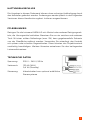 4
4
-
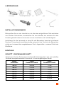 5
5
-
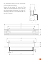 6
6
-
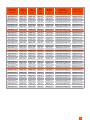 7
7
-
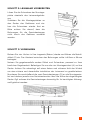 8
8
-
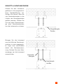 9
9
-
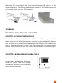 10
10
-
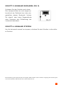 11
11
-
 12
12
-
 13
13
-
 14
14
-
 15
15
-
 16
16
-
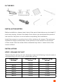 17
17
-
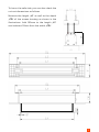 18
18
-
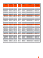 19
19
-
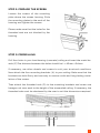 20
20
-
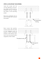 21
21
-
 22
22
-
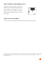 23
23
-
 24
24
-
 25
25
-
 26
26
-
 27
27
-
 28
28
-
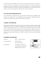 29
29
-
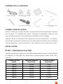 30
30
-
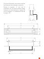 31
31
-
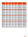 32
32
-
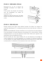 33
33
-
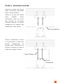 34
34
-
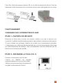 35
35
-
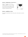 36
36
-
 37
37
-
 38
38
-
 39
39
-
 40
40
-
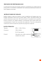 41
41
-
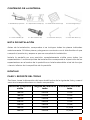 42
42
-
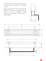 43
43
-
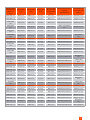 44
44
-
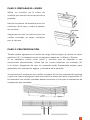 45
45
-
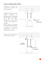 46
46
-
 47
47
-
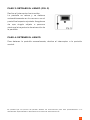 48
48
-
 49
49
-
 50
50
-
 51
51
-
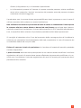 52
52
-
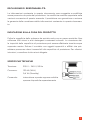 53
53
-
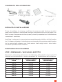 54
54
-
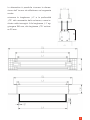 55
55
-
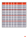 56
56
-
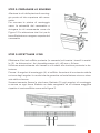 57
57
-
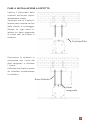 58
58
-
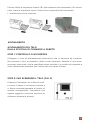 59
59
-
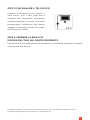 60
60
-
 61
61
-
 62
62
-
 63
63
-
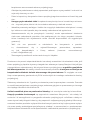 64
64
-
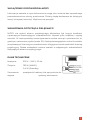 65
65
-
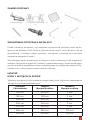 66
66
-
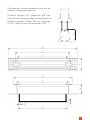 67
67
-
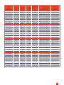 68
68
-
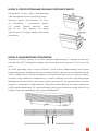 69
69
-
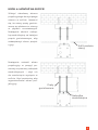 70
70
-
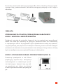 71
71
-
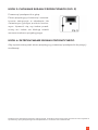 72
72
-
 73
73
-
 74
74
-
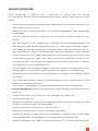 75
75
-
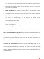 76
76
-
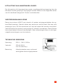 77
77
-
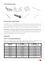 78
78
-
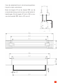 79
79
-
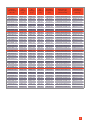 80
80
-
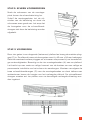 81
81
-
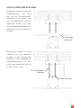 82
82
-
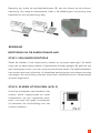 83
83
-
 84
84
-
 85
85
-
 86
86
-
 87
87
-
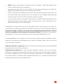 88
88
-
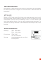 89
89
-
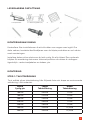 90
90
-
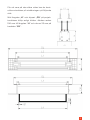 91
91
-
 92
92
-
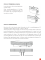 93
93
-
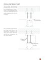 94
94
-
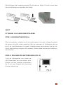 95
95
-
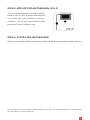 96
96
-
 97
97


Celexon Ceiling Recessed Electric Professional Plus 300 x 187 cm de handleiding
- Type
- de handleiding
- Deze handleiding is ook geschikt voor
in andere talen
- italiano: Celexon Ceiling Recessed Electric Professional Plus 300 x 187 cm Manuale del proprietario
- français: Celexon Ceiling Recessed Electric Professional Plus 300 x 187 cm Le manuel du propriétaire
- Deutsch: Celexon Ceiling Recessed Electric Professional Plus 300 x 187 cm Bedienungsanleitung
- polski: Celexon Ceiling Recessed Electric Professional Plus 300 x 187 cm Instrukcja obsługi
Gerelateerde papieren
-
Celexon Professional Mini Screen 61 x 46cm de handleiding
-
-
-
-
-
-
-
-
-