
Instruction manual
Gebruiksaanwijzing
Manuel d’utilisation
Bedienungsanleitung
Elektrolokomotive BR 103 RailAdventure mit Sound

2
Lieber PIKO Gartenbahn Freund,
Wir freuen uns, dass Sie sich für eine
Spur G Lokomotive aus dem Hause
PIKO entschieden haben. Wie alle PIKO
Modelle, ist auch diese Lok von unseren
Mitarbeitern mit viel Liebe zum Detail
konstruiert, sorgfältig zusammengebaut
und während der Entwicklung intensiv
getestet worden, um Ihnen maximalen
Fahrspaß und viel Freude mit der Lok zu
garantieren.
Passend zu Ihrer Lok bieten wir eine
ganze Reihe von Wagen- und
Gebäudemodellen sowie attraktives
Zubehör für Ihre Gartenbahn-Anlage an.
Schauen Sie für weitere Informationen
einfach mal in unseren ausführlichen
PIKO G Katalog, in den PIKO Webshop
unter www.piko-shop.de oder beim
Fachhändler Ihres Vertrauens vorbei
und überzeugen Sie sich von unserem
umfangreichen Sortiment.
Sollten Sie Verbesserungsvorschläge
oder positive Kritik zu Ihren
PIKO Modellen haben, können Sie
uns Ihre Eindrücke per E-Mail an
per Fax +49 3675/8972-50 oder
per Post an
PIKO Spielwaren GmbH,
Lutherstraße 30,
96515 Sonneberg/Thüringen mitteilen
oder die Sozialen Medien nutzen, um
mit uns in Kontakt zu treten.
Herzlichen Dank für Ihren Kauf und viel
Spaß mit Ihrer PIKO Spur G BR 103.
Ihr PIKO Team
Das Vorbild
Die sechsachsigen Elektrolokomotiven
der Baureihe 103 galten bei der
Deutschen Bundesbahn über
viele Jahre als das Flaggschiff im
schweren Reisezugverkehr und stellen
eine der beliebtesten deutschen
Lokomotivbaureihen dar. Die DB
setzte vier Vorserienmuster als
Schnellfahrlokomotive ab 1965 ein, bis
1974 gingen insgesamt zusätzlich 145
Serienlokomotiven in Betrieb. Mit einer
Dauerleistung von 7.440 kW
(10.116 PS) zählen die 103er immer
noch zu den stärksten einteiligen
Lokomotiven.
Die ersten Serienlokomotiven
wurden mit Scherenstromabnehmern
ausgeliefert, ab 1976 kamen
Einholmstromabnehmer SBS65 zum
Einsatz. Darüber hinaus verloren die
Maschinen ihre Schürzen und erhielten
Puffer ohne Verkleidung. Mit ihrem
eleganten und zeitlosen Design prägten
die edlen Renner über viele Jahre den
hochwertigen Reiseverkehr und wurden
schon zu ihrer Regeleinsatzzeit zu
Kultobjekten. Ab 1997 wurden die 103
nach und nach bis 2003 ausgemustert
und durch die neue Baureihe 101
ersetzt. Mehrere Loks sind museal
erhalten.
Das Modell
Das PIKO Modell ist trotz seiner
Detailtreue sehr robust und zugkräftig.
Es eignet sich für drinnen und draußen,
denn durch die Verwendung von
speziellen Kunststoffen ist es wetterfest
und somit auch im Freien einsetzbar.
Dennoch wird der Liebhaber keine
Details vermissen.
Technik
• Zwei 7-polige, kugelgelagerte Bühler-
Motoren, spritzwassergeschützt
• Vier Achsen angetrieben
• Stromabnahme von acht Rädern mit-
tels Radschleifer
• Zusätzlich vier federnd gelagerte
Schleifkontakte direkt auf der Schiene
• Eingebaute Gewichte zur Erhöhung
der Zugkraft
• Beleuchtetes LED-Dreilichtsignal mit
der Fahrtrichtung wechselnd weiß/rot
• Für den Einbau der Führerstands- und
Maschinenraumbeleuchtung #36017
vorbereitet
• für den Einbau des
Stromabnehmerantriebs # 36145
vorbereitet
• Inklusive Digitaldecoder und Sound
mit großem Lautsprecher
• Bügelkupplung kompatibel mit dem
LGB-System
• Zusatzgewichte #36320 nachrüstbar
• Länge: 721 mm
• Gewicht: ca. 4.200 g
Details
• Detailliertes Gehäuse mit vielen
vorbildgerechten Gravuren
• Separat eingesetzte Front- und
Seitenscheiben
• Separat eingebaute Inneneinrichtung
mit Lokführer
• Stromabnehmer aus Metall
• Teile aus speziellem Kunststoff für den
Outdoor Gartenbetrieb
• Vorbildgerechte Lackierung
• Vorbildgerechte und komplette
Beschriftung
Empfehlungen
Minimaler Radius
Die Lok kann auf Gleisen mit einem
empfohlenen minimalen Radius von 600
mm (23.62‘’) laufen. Bitte beachten Sie,
dass ein längerer Betrieb auf Kurven
mit kleineren Radien zu einem stark
erhöhten Verschleiß der Lokomotive und
der Schienen führt.

3
Erstbetrieb Ihrer Lok
Entnahme des Modells
Entnehmen Sie das Modell bitte
vorsichtig aus der Styroporverpackung,
damit die Anbauteile wie Handstangen
usw. nicht beschädigt werden.
Erstbetrieb
Wir empfehlen, die Lok jeweils ca.
30 min je Fahrtrichtung ohne Belastung
einfahren zu lassen, damit das Modell
einen optimalen Rundlauf und eine gute
Zugkraft erhält.
Bitte beachten Sie, dass der
einwandfreie Lauf der Lok nur mit
sauberen Schienen und Rädern
gewährleistet ist.
Technische Angaben
Nennspannung
Das Modell wird innerhalb eines
Spannungsbereiches von 0 bis 24 V
betrieben.
Stromversorgung
Die Lokomotive benötigt Trafos oder
Fahrregler, welche mindestens 2 A
liefern. Verwenden Sie nur zugelassene
und einwandfrei arbeitende Trafos oder
Fahrregler.
Antrieb
Das Modell besitzt zwei durchzugs-
kräftige Bühler-Motoren, welche jeweils
über robuste Getriebe vier Achsen
antreiben.
Beleuchtung
Funktionsfähiges Dreilicht-Spitzensignal
mittels weiß/roten LEDs, mit der
Fahrtrichtung wechselnd.
Digital Decoder inklusive
Das Modell ist werkseitig mit dem PIKO
SmartDecoder 4.1 ausgerüstet. Die Lok
kann sowohl analog als auch Digital
genutzt werden.
Sound inklusive
Das Modell ist werkseitig mit dem
Soundmodul #36229 und einem
Lautsprecher ausgerüstet.
In Kombination mit dem verbauten
DigitalDecoder 4.1 von PIKO ist
dieser Sound sowohl analog (nur
Motorsound) als auch digital
verwendbar.
Wartung/Pflege
Schmieren
Bitte geben Sie nach ca. 25 Betriebs-
stunden nach Lösen der Getriebe-böden
jeweils eine kleine erbsengroße Menge
säurefreies und harzfreies Fett auf
die Zahnräder. (siehe Schmierplan,
Montageanleitung)
Reinigen
Reinigen Sie die Lok nach längerem
Gartenaufenthalt mit einem milden
Reinigungsmittel und einem fusselfreien
Microfasertuch oder einem weichen
Pinsel.
Tauchen Sie auf keinen Fall die
komplette Lok zum Reinigen in eine
Lösung.
Verschleißteile:
Schienenschleifer und Radsatzkontakte
sind Verschleißteile! Diese sollten nach
ca. 500 Betriebsstunden getauscht
werden!
Achtung!
Bitte beachten Sie, dass bedingt
durch den Fahrbetrieb ein Abrieb
an den mechanischen Teilen (Räder,
Schleifer usw.) entstehen kann,
welcher Verunreinigungen auf
Teppichen oder anderen Materialien
entstehen lässt.
Austretendes Fett/Öl mit einem Tuch
abwischen. Bei Schäden übernimmt
die PIKO Spielwaren GmbH keinerlei
Haftung.
Achtung: Wichtige
Sicherheitshinweise
• Transformator regelmäßig auf Schäden
an Kabeln, Steckern, Gehäuse und
anderen Teilen überprüfen!
• Bei einem Schaden darf der
Transformator bis zur vollständigen
Reparatur nicht mehr verwendet
werden!
• Lokomotive an nicht mehr als eine
Energiequelle anschließen!
• Kein Spielzeug. Nicht für Kinder unter
14 Jahren geeignet wegen funktions-
und modellbedingter scharfer Kanten
und Spitzen.
• Lokomotive nur mit einem
zugelassenen Transformator mit
Kennzeichnung betreiben!
• Der Transformator ist kein Spielzeug!
• Vor der Reinigung, die Lok vom
Transformator trennen!
• Drähte nicht in die Steckdose
einführen!

4
Dear PIKO garden railway
friend,
We are pleased that you have chosen
a G scale locomotive from PIKO. Like
all PIKO models, this locomotive has
been designed by our employees with
great attention to detail, carefully
assembled and intensively tested
during development to guarantee you
maximum driving pleasure and a lot of
fun with the locomotive.
To match your locomotive, we offer a
whole range of car and building models
as well as attractive accessories for
your garden railway layout. For more
information, simply take a look at our
detailed PIKO G catalog, the PIKO web
shop at www.piko-shop.de, or visit your
local dealer and convince yourself of our
extensive range.
If you have any suggestions for
improvement or positive criticism about
your PIKO models, you can send us your
feedback by e-mail to [email protected],
by fax +49 3675/8972-50 or by mail to
PIKO Spielwaren GmbH,
Lutherstraße 30,
96515 Sonneberg/Thuringia, or use the
social networks to get in touch with us.
Thank you for your purchase and have
fun with your PIKO G scale BR 103.
Your PIKO Team
The Prototype
The six-axle electric locomotives of the
class 103 were considered for many
years the flagship in heavy passenger
traffic by the German Federal Railroad.
They are deemed
one of the most popular German
locomotive series. The DB started in
1965 to use a pilot lot of 4 engines as
high-speed locomotives. Through 1974,
an additional 145 production
series locomotives were ordered and
put into service. With a continuous
output of 7,440 kw (9,980 hp), the
BR 103 locos are still considered to
be among the most powerful single-
unit locomotives. The first series
locomotives were delivered with scissors
pantographs. From 1976 on, single-arm
type SBS65 pantographs were used. In
addition, over the years, the machines
lost their skirting and received buffers
without covers. With
their elegant and timeless design, these
noble racehorses shaped German high-
speed passenger service for many years
and were already cult objects while in
regular service.
Starting in 1997, the 103s were
gradually phased out. By 2003 they
were replaced by the new class BR 101.
Several locomotives are preserved and
operational.
The Model
The PIKO model is very sturdy and
has a high haulage capacity in spite
of its attention to detail. It is suitable
inside and outside, because special
plastics make this model weatherproof.
However, locomotive enthusiasts will
love the faithful replications of all
original details.
Technical Features
• Two powerful ball-bearing 7-pole
motors, protected from moisture
• Gearing on 4 axles through a powerful
motor
• 8 wheels are equipped with wheel
wipers for electrical pickup.
• 4 additional sliding pickup shoes
ride directly on the rails for reliable
electrical pickup
• Heavy weights concealed inside the
body for added pulling power and
reliability.
• Upgradeable with additional weights
#36320
• LED-lighted lanterns on each end
change according to the direction of
travel white/red
• Prepared for installation of the drivers
cab / engine room light
• Including digital decoder and sound
with large speaker
• prepared for installation of the
current collector drive # 36145
•
Standard hook and loop couplers are
compatible with most G-Scale trains
• Additional weights #36320
retrofittable
• Length: 721 mm
• weight: approx. 4,200 g
Details
• Feature different and accurate
individual engravings
• Separately applied front windshield
and front and side windows
• Detailed cab interior with driver figure
• Pantograph made of metal
• UV- and weather-resistant materials
for years of outdoor garden railway
service
• Authentic color schem
• Authentic and comprehensive
lettering and decoration
Precautions and Recommendations
Minimum Radius
The locomotive can run on track with
a minimum recommended radius of
600 mm (23.62‘’). Naturally, extended
operation on small radius curves
leads to greatly increased wear of the
locomotive and track.

5
Getting Started: Initial Operation
Unpacking the Model
Remove the styrofoam packaging
extremely carefully to prevent damaging
accessories and attached parts such as
handrails etc.
Initial Operation
We recommend letting the locomotive
run without a train for 30 minutes
in both directions, to properly break
it in. This will help achieve optimal
performance and longevity for the
locomotive. Of course, your model
should only be run on smooth and
perfectly clean tracks with reliable
electrical contact to all track sections.
Technical Data
Power Supply
The model should only be operated on
a pure, filtered DC power supply of 0
to 24 volts, with a capacity of at least
2 Amp and a fast-acting fuse or circuit
breaker to protect against short circuits.
Do not use a power supply which is not
in safe and perfect working condition.
(See “Digital Decoder” section for
operation on digital power.)
Mechanism
The model has two powerful Bühler
motors, each driving four axles via
robust gearboxes.
Lighting
The model is equipped with automatic
directional headlights, using white/red
LEDs for a realistic appearance. The
“front” lights are illuminated according
to the travel direction.
Digital decoder included
The model is factory equipped with the
PIKO SmartDecoder 4.1. The locomotive
can be used both analog and digital.
Sound included
The model is factory equipped with the
sound module #36229 and a speaker.
In combination with the installed
PIKO DigitalDecoder 4.1, this sound
can be used both analog and digital.
Maintenance
Lubrication
After each 25 hours of operation, and
after any long periods of storage, please
lubricate the locomotive‘s gears with a
sparing amount of plastic-compatible,
non-hardening grease. Remove the
gearbox bottom cover and be careful
to keep the front and rear wheelsets
aligned with each other. Be sure to
securely retighten the gearbox bottom
cover screws.
Cleaning
If cleaning is necessary, use only a mild
cleaning agent (such as soap and water)
and gentle action with a soft non-
abrasive cloth or brush. Never immerse
the loco in liquid or “flood” any internal
parts!
Wheel Wipers and pick-Up shoes
should be changed after 500 hours of
operation.
Please Note! Damage to Carpets and
Other Surfaces: Normal operation of the
locomotive causes wear of mechanical
parts (wheels, electrical pickups etc.). This
produces carbonized dust, grease and
oil, which can permanently stain carpets,
wood floors and other materials. It is
the user’s responsibility to take proper
precautions against this damage. Wipe
any grease or oil from the track rails
with a clean soft cloth. PIKO Spielwaren
GmbH, as well as its representatives,
distributors and retailers, assume no
liability for any such damage.
Please Note!
Important Safety Precautions
• Check the power supply regularly for
any damage or problems.
• Do not use a malfunctioning or
damaged power supply!
• This model must only be operated
with one power source per circuit!
• This product is not a toy, not suitable
for personnel under 14 years of age.
This product has small parts, sharp
parts, and moving parts.
• This model must only be operated
with a safety-assured power supply
with the identification!
• The power supply is not a toy!
• Disconnect the model from the power
supply before cleaning or servicing!
• Do not insert the track power
connecting wires into household
“mains” voltage outlets.

6
Cher adepte du Chemin de Fer de
Jardin PIKO,
Nous vous remercions d’avoir choisi
une locomotive échelle G PIKO. Comme
tous les modèles PIKO, cette locomotive
a été conçue par nous avec un grand
souci du détail, assemblée avec soin
et testée intensivement pendant le
développement pour vous garantir un
plaisir de conduite maximal et beaucoup
de satisfaction.
Pour votre locomotive, nous vous
proposons toute une gamme de
modèles de voitures et de bâtiments
ainsi que des accessoires attrayants
pour votre réseau de jardin. Pour
plus d›informations, il vous suffit de
consulter notre catalogue détaillé
PIKO G, la boutique en ligne
PIKO sur www.piko-shop.de, ou de vous
rendre chez votre revendeur local pour
découvrir notre vaste gamme.
Si vous avez des suggestions
d‘amélioration ou des critiques
constructives concernant vos modèles
PIKO, vous pouvez nous contacter par
e-mail à [email protected], par fax au
+49 3675/8972-50 ou par courrier à
PIKO Spielwaren GmbH,
Lutherstraße 30,
96515 Sonneberg/Thuringe, ou utiliser
les médias sociaux pour nous contacter.
Merci encore pour votre achat et nous
vous souhaitons de bons moments avec
votre PIKO BR 103 échelle G.
Votre équipe PIKO
Le Modèle réél
Pendant de nombreuses années, les
locomotives électriques à six essieux
de la classe 103 ont été considérées
par la Deutsche Bundesbahn comme
le fleuron du trafic ferroviaire lourd de
voyageurs et représentent l‘une des
séries de locomotives allemandes les
plus populaires. C‘est en 1965 que la
DB a mise en service quatre locomotives
de pré-série comme locomotives à
grande vitesse et jusqu‘en 1974 c‘est
145 locomotives supplémentaires qui
étaient ren service. Avec une puissance
continue de 7 440 kW (10 116 ch), les
103 sont toujours parmi les locomotives
monobloc les plus puissantes.
Les premières locomotives de série
ont été livrées avec des pantographes
à ciseaux, à partir de 1976 les
pantographes unijambistes SBS65
ont été utilisés. De plus, les machines
ont perdu leurs tabliers et ont reçu
des tampons sans carénage. Avec
leur design élégant et intemporel, les
nobles bolides ont façonné pendant de
nombreuses années le trafic de voyage
de haute qualité et sont devenues des
locomotives cultes dès leur utilisation
régulière. A partir de 1997, les 103
ont été progressivement retirés du
service jusqu‘en 2003 et remplacés
par la nouvelle série 101. Plusieurs
locomotives sont conservées.
Le Modèle réduit
Malgré la fidélité du détail, le modèle
PIKO est très robuste et attrayant. Il
convient à l’intérieur et à l’extérieur, car
l’utilisation de plastiques spéciaux le
rend résistant aux intempéries et peut
donc également être utilisé à l’extérieur.
Néanmoins, l’amateur se réjouira de la
quantité des détails.
Techniques
• Deux moteurs Bühler à 7 pôles, sur
roulement à billes, protégés contre les
projections d›eau
• Quatre essieux moteurs
• Captage du courant sur les huit roues
à l’aide de frotteurs
• Quatre contacts de rail
supplémentaires montés sur ressort
• Poids intégrés pour augmenter la force
de traction
• Eclairage frontal LED changeant avec
sens de marche blanc/rouge alterné
• Préparé pour l’installation de
l‘éclairage de la cabine et de la salle
des machines #36017
• préparé pour l›installation du
lecteur collecteur de courant
# 36145
• Décodeur numérique et sonore avec
grand haut-parleur inclus
• Des poids supplémentaires, #36320,
peuvent être montés ultérieurement
• Longueur: 721 mm
• Poids: env. 4200 g
Détails
• Caisse détaillée avec de nombreuses
gravures prototypiques
• Fenêtres avant et latérales insérées
séparément
• Equipement intérieur installé
séparément avec conducteur de
locomotive
• Pantographe en métal
• Pièces en plastique spécial pour
l’usage extérieur
• Exécution parfaite de la peinture.
• Marquage complet et réaliste.
Rayon minimal
La locomotive peut roulée sur un rayon
minimal de 600 mm (23,62 inch).
Veuillez prendre note que l’utilisation
sur des petits rayons augmente l’usure
anormale de la locomotive et des rails.

7
Première mise en service de votre
locomotive
Sortie de l’emballage
Sortez le modèle délicatement de
l’emballage en polystyréne afin que les
pièces rapportées mains – montoires ne
soient pas endommagées
Mise en service
Nous vous recommandons de faire
rouler la locomotive pendant 30 minutes
dans chaque sens, sans charge, afin
d’obtenir un fonctionnement optimal
et une bonne puissance de traction.
Veuillez noter qu’un fonctionnement
sans faille du modèle n’est garanti
que sur des rails propres.
Caractéristiques techniques
Tension nominale
Le modèle fonctionne sous tension de
0-24 V CC.
Consommation de courant
Le modèle a besoin d’un transformateur
ou variateur de vitesse qui délivre
au minimum 2 A. N’utilisez que des
transformateurs ou des variateurs
autorisés et en bon état.
Moteur
Le modèle est équipé de deux
puissants moteurs Bühler, dont
chacun entraîne quatre essieux par
l'intermédiaire de robustes boîtes
de vitesses.
Eclairage
Le modèle possède un éclairage LED
blanc/rouge changeant suivant le sens
de la marche.
Décodeur numérique inclus
Le modèle est équipé d‘usine avec le
SmartDecodeur PIKO 4.1. La locomotive
peut être utilisée aussi bien en
analogique qu'en numérique.
Son inclus
Le modèle est équipé d‘usine avec le
module sonore #36229 et d'un haut-
parleur.
En combinaison avec le décodeur
numérique PIKO 4.1 installé, ce
son peut être utilisé aussi bien en
analogique qu'en numérique.
Entretien
Graissage
Il est recommandé de graisser
les engrenages toutes les 25 h
de fonctionnement en démontant
les carters.
Appliquez une noisette de graisse
exempte d’acide et de résine sur les
roues dentées. (voir plan de graissage
sur le manuel d’utilisation).
Nettoyage
Après une utilisation prolongée à
l’extérieur, nettoyez votre locomotive
avec un produit de nettoyage doux et
un torchon micro fibre. Ne trempez
en aucun cas la locomotive complète
dans une quelconque solution pour la
nettoyer.
Changez les contacts de rails et les
contacts d’essieux toutes les 500 h de
fonctionnement.
Attention:
Veuillez noter que dû au
fonctionnement une usure peut
apparaître aux roues, frotteurs,
qui pourrait salir tapis ou autres
matériels.
Veuillez nettoyer les résidus de
graisse/huile avec un chiffon. Piko
n’assume aucune responsabilité
pour les dommages causés.
Attention:
Conseils de sécurité importants
• Inspectez régulièrement le
transformateur afin de déceler
d‘éventuels dommages au câble, prise
et boîtier.
• En cas d‘endommagement, faite
réparer le transformateur avant une
nouvelle utilisation!
• La locomotive doit être raccordée à
une seule source d‘énergie!
• Ne convient pas aux enfants de
moins de 14 ans. Présence de petits
éléments susceptibles d‘être avalés.
• Seul les transformateurs dotées du
logo sont autorisés!
• Le transformateur n‘est pas un jouet!
• Toujours séparer la locomotive du
transformateur pour procéder au
nettoyage!
• Il est interdit d’insérer les fils de
connexion dans une prise électrique!

8
Beste PIKO G-spoor liefhebber,
Het verheugt ons dat u heeft gekozen
voor een G-spoor locomotief van het
merk PIKO. Net als alle PIKO modellen,
is ook deze loc met veel aandacht
voor detail door onze medewerkers
ontworpen, zorgvuldig gemonteerd en
tijdens de ontwikkeling grondig getest
om u te verzekeren van maximaal plezier
en rijgenot met de locomotief.
Passend bij uw loc biedt ons
assortiment een hele reeks wagens,
rijtuigen, modellen van gebouwen en
aantrekkelijke accessoires voor uw
G-spoor modelspoorbaan. Kijk voor meer
informatie in onze gedetailleerde PIKO
G catalogus, in de PIKO webshop www.
piko-shop.de of bij uw vertrouwde dealer
en overtuig uzelf van ons omvangrijke
assortiment.
Als u suggesties of positieve kritiek
op uw PIKO modellen heeft, dan
kunt u ons uw berichten per e-mail sturen
naar [email protected],
per fax +49 3675/8972-50 of
per post naar PIKO GmbH,
Luther Straße 30,
D-96515 Sonneberg / Thüringen,
Duitsland. Ook kunt u gebruik maken
van de sociale media om contact met
ons op te nemen. In alle gevallen s.v.p.
communiceren in de Duitse of Engelse
taal.
Hartelijk dank u voor uw aankoop
en veel plezier met uw PIKO G-Spoor
BR 103.
Uw PIKO team
Het voorbeeld
De zes-assige elektrische locomotieven
van de serie 103 waren jarenlang
het vlaggeschip van het zware
personenverkeer bij de Deutsche
Bundesbahn en vertegenwoordigen
één van de meest populaire Duitse
locomotiefseries. De DB nam vanaf
1965 vier prototypes in gebruik als hoge
snelheidslocomotief. Tot 1974 werden
vervolgens in totaal nog 145 serie-
locomotieven in dienst gesteld. Met een
continu vermogen van 7,440 kW (10.116
PK) gelden de 103‘n nog steeds als de
meest krachtige ongelede locomotieven.
De eerste serie-locomotieven
werden afgeleverd met tweebeen-
stroomafnemers, vanaf 1976 werden
echter éénbeen stroomafnemers type
SBS65 gemonteerd. Bovendien verloren
de machines hun schortplaten en
kregen zij buffers zonder bekleding.
Met hun elegante en tijdloze ontwerp
domineerden de fraaie machines
gedurende vele jaren het hoogwaardige
reisverkeer. Zij groeiden reeds tijdens
hun reguliere inzet uit tot cult objecten.
In de periode 1997 tot 2003 werden de
103’n geleidelijk buiten dienst gesteld
en vervangen door de nieuwe serie
101. Meerdere locomotieven zijn als
museumloc bewaard.
Het model
Ondanks de werkelijkheidsgetrouwe
detaillering is het PIKO model zeer
robuust en krachtig. Het is geschikt
voor binnen en buiten. Vanwege het
gebruik van speciale kunststoffen is het
weerbestendig en kan worden gebruikt
in de buitenlucht. Ondanks dat, zal de
liefhebber geen enkel detail missen.
Techniek
• Twee 7-polige, kogelgelagerde Bühler-
motoren, spatwaterbestendig
• Vier assen aangedreven
• Stroomafname van acht wielen via
wielcontactslepers
• Daarnaast vier verend opgehangen
sleepcontacten, direct op de rails
• Ingebouwde gewichten ter verhoging
van de trekkracht
• Driepunts LED-verlichting, wit/rood
wisselend met de rijrichting
• Voorbereid voor de inbouw
van verlichtingsset #36017 in
de machinistencabine en de
machineruimte
• voorbereid voor de installatie van
de huidige collectoraandrijving
# 36145
• Inclusief digitale decoder en sound
met een grote luidspreker
• Beugelkoppeling compatibel met het
LGB-systeem
• Extra gewicht #36320 kan worden
ingebouwd
• Lengte: 721 mm
• Gewicht: ca. 4.200 g
Detaillering
• Detailrijke behuizing met veel
werkelijkheidsgetrouwe gravures
• Los ingezette front- en zijruiten
• Los ingebouwd interieur met machinist
• Stroomafnemers van metaal
• Alle onderdelen van speciaal kunststof
voor het gebruik in de buitenlucht
• Werkelijkheidsgetrouwe kleurstelling
• Werkelijkheidsgetrouwe en complete
opschriften
Minimum boogstraal
De locomotief kan een minimum
boogstraal berijden van 600 mm
(23.62 inch). Het is echter wel zo, dat
regelmatig gebruik op kleine bogen
tot overmatige slijtage leidt aan de
locomotief en de rails.

9
In gebruikname van uw loc
Uitpakken van het model
Neemt u het model na het openen svp
voorzichtig uit de styroporverpakking,
zodat alle losse delen, zoals handgrepen
etc. niet worden beschadigd.
In gebruikname
Wij adviseren om de loc onbelast ca. 30
minuten naar iedere rijrichting te laten
rijden, zodat het model optimaal wordt
ingereden en een goede trekkracht
ontwikkelt.
Wij wijzen u erop, dat goede
rij-eigenschappen van de loc
uitsluitend gegarandeerd zijn op
schone rails.
Technische verklaringen
Nominale spanning
De bedrijfsspanning van het model is
0 tot 24 Volt DC.
Stroomverzorging:
Het model heeft een trafo of rijregelaar
nodig, die minimaal 2 A levert. Gebruikt
u svp uitsluitend trafo’s of rijregelaars
die aan deze eis voldoen en die geen
mankementen vertonen.
Aandrijving:
Het model is voorzien van twee
krachtige Bühler-motoren, die via
robuuste tandwielkasten vier assen
aandrijven.
Verlichting:
Het model is voorzien van een
rijrichtingsafhankelijke driepunts wit/
rood frontverlichting, dwz dat in de
rijrichting vooruit de frontverlichting
brandt.
Inclusief digitale decoder:
Het model is af fabriek voorzien van de
PIKO SmartDecoder 4.1. De locomotief
kan zowel analoog als digitaal worden
gebruikt.
Inclusief sound:
Het model is af fabriek voorzien van
de soundmodule # 36229 en een
luidspreker.
In combinatie met de ingebouwde
digitale decoder 4.1 van PIKO is
deze sound zowel analoog als
digitaal te gebruiken.
Onderhoud
Smeren:
Na elke 25 bedrijfsuren zéér kleine
hoeveelheden zuurvrij en harsvrij
vet op de tandwielen doen. (zie het
smeerschema, montagehandleiding)
Reinigen:
De loc dient na langdurig tuinbedrijf
uitsluitend gereinigd te worden met een
mild reinigings-middel en een vezelvrije
doek en/of een zachte kwast. Doop
de complete loc in géén geval in een
oplossing.
Wissel na elke 500 bedrijfsuren de
railsleepcontacten en de wielcontacten.
Attentie:
Let u er svp op, dat er door het
rijden slijtage aan de mechanische
delen (wielen, contactslepers,
etc.) kan ontstaan, welke ertoe
kan leiden dat er verontreiniging
wordt veroorzaakt aan tapijt en
andere materialen. Gelekt vet of
olie met een zachte doek afvegen.
Bij hierdoor veroorzaakte schade
is PIKO Spielwaren GmbH op geen
enkele wijze verantwoordelijk.
Let op:
Belangrijke veiligheidsvoorschriften
• De transformator dient regelmatig
op beschadigingen of defecten
gecontroleerd te worden!
• In geval van een beschadiging of
defect mag de transformator niet
langer gebruikt worden, totdat deze
gerepareerd is!
• De transformator mag uitsluitend
middels één energiebron gebruikt
worden!
• Niet geschikt voor kinderen onder de
14 jaar omdat dit model funktionele
scherpe kanten en punten bezit.
• Het locomotief uitsluitend gebruiken
met met de volgende kenmerken
!
• De transformator is géén speelgoed!
• Vóór het reinigen, de transformator
loskoppelen van de netspanning en
het locomotief!
• De verbindingsdraden mogen niet in
het stopcontact worden gestoken!

10
E
A
A
A
A
E
E
EE
E
C
C
C
CE
E
E
MONTAGEANLEITUNG
Service instructions
Manuel d’utilisation
Gebruiksaanwijzing
Handstangen
Handrails
Poignées
Handgrepen
#36017
#36017
#36017
#36017
optional: #36017 Führerstands-/
Maschinenraumbeleuchtung
nicht enthalten
siehe S. 15
Cab light not included
see page 15
optional: #36017 Führerstands-/
Maschinenraumbeleuchtung
nicht enthalten
siehe S. 15
cab light not included
see page 15
Symbolbild
Modellvariante kann von Abbildung abweichen.
Model variant may differ from illustration.

11
C
C
C
C
C
C
C
C
CC
C
C
C
C
C
C
AA
AA
PIKO 36320
wahlweise
optional

12
C
C
C
C
C
C
A
A
Bitte verwenden Sie PIKO Schmierfett, Art.-Nr. 36216
Please use PIKO grease, #36216
Fetten
Grease
Graisse
Smeren
C
C
C
AA
C
C
Haftreifenwechsel
Change the traction tyres
Remplacer bandages
Wisselen antislipbanden
A = 2,2 x 7
C = 3,0 x 10
E = 3,0 x 6
C EA
Schrauben / Screws
Vis / Schroeven
M 1:1

13
rot
red
weiß
white
blau
blue
Motor MotorGleis / Track
grau
gray
Gleis / Track
schwarz
black
permanent
Rücklicht „rot“ FS 2
taillight „red“ driver's cab 2
gelb-schwarz /
yellow-black
Sound-Modul
sound-module
Rücklicht „rot“ FS 1
taillight „red“ driver's cab 1
grün-weiß /
green-white
Führerstandsbeleuchtung 2 *
light drivers´s cab 2
orange-schwarz /
orange-black
Führerstandsbeleuchtung 1 *
light drivers´s cab 1
braun-weiß /
brown-white
LED
braun
hinten
back
brown
LED
gelb
vorne
front
yellow
Beleuchtung Dachhaube*
Lighting roof cab
rot-weiß
red-white
SUSI
Schnittstelle
interface
ANSCHLUSSSCHEMA DIGITAL
Wiring scheme · Schema de câblage · Bedradingsschema
A
C
C
C
C
C
C
C
C
Sound Modul
sound-module
Decoder
decoder
Lautsprecher
loud-speaker
EINBAUANLEITUNG · ASSEMBLY INSTRUCTION
DECODER & SOUND
*
optional: #36017 Führerstands-/Maschinenraumbeleuchtung /
Cab light
gesamt 4x benötigt /
total 4 pcs required

14
KABELANSCHLUSS-SCHEMA - VERTEILERPLATTE
Wiring scheme · Schema de câblage · Bedradingsschema
ih
n
e
f
m
b
a
FS2
drivers
cab 2
FS1
drivers
cab 1
1 2 3 4 5 6 7 8 9 10 11 12 13 14 15 16 17 18 19 20
OUTPUT OUTPUT OUTPUT OUTPUT
INPUT
INPUT
A1 A2 A3 A4 A5 A6 SK1 SK2 GND FS 1 FS 2
Funktionen / functions
Licht
Führerstand 2
Drivers Cab 2
Führerstand 1
Drivers Cab 1
universal
FS 1
econ
FS 2
econ
OUTP.OUTP.OUTP.OUTP.OUTP.OUTP.
Motor/Gleis
ba
n
e
c
f
d
k
j
i
h
g
l
m
Verteilerplatte
(siehe Seite 15)
Plug board
(see page 15)

15
j
k
l
FS 1
drivers cab 1
FS
2
drivers cab
2
*
1 2 3 4 5 6 7 8 9 10 11 12 13 14 15 16 17 18 19 20
OUTPUT OUTPUT OUTPUT OUTPUT
INPUT
INPUT
A1 A2 A3 A4 A5 A6 SK1 SK2 GND FS 1 FS 2
Funktionen / functions
Licht
Führerstand 2
Drivers Cab 2
Führerstand 1
Drivers Cab 1
universal
FS 1
econ
FS 2
econ
OUTP.OUTP.OUTP.OUTP.OUTP.OUTP.
Motor/Gleis
BELEGUNG VERTEILERPLATTE
Plug board · plaque conducteur · printplaat
ZUBEHÖR BELEUCHTUNG
accessories lighting
LED-LEITERPLATTE - FÜHRERSTAND
LED-PCB - drivers cab
Belegung:
1 permanent +
2 Licht vorne
3 Licht hinten
5 nicht belegt
6 Gleis 1
7 Gleis 2
8 Motor +
9 Motor –
11 nicht belegt
12 A5 Licht Maschinenraum*
13 A4 Licht Führerstand 2 *
14 A3 Licht Führerstand 1 *
15 A2 Rücklicht FS1
16 A1 Rücklicht FS2
18 nicht belegt
Kabelfarben:
Grau Gleiskontakt 1
Weiß Gleiskontakt 2
Blau Motorkontakt 1 +
Rot Motorkontakt 2
Schwarz permanent +
(gemeinsames +)
Gelb Licht vorne LED
Braun Licht hinten LED
Grün nicht belegt
Lila nicht belegt
Braun-Schwarz nicht belegt
Grün-Weiß A1
Gelb-Schwarz A2
Orange-Schwarz A3
Braun-Weiß A4
Rot-Weiß A5
* Zubehör
Configuration:
1 permanent +
2 Frontlight
3 Backlight
5 N/A
6 Track 1
7 Track 2
8 Motor +
9 Motor –
11 N/A
12 A5 Light engine room*
13 A4 Light drivers cab 2*
14 A3 Light drivers cab 1*
15 A2 Taillight drivers cab 1
16 A1 Taillight drivers cab 2
18 N/A
Cable colors:
Gray Track contact 1
White Track contact 2
Blue Motor contact 1 +
Red Motor contact 2
Black permanent +
(common+)
Yellow Frontlight LED
Brown Backlight LED
Green N/A
P urple N/A
Brown-Black N/A
Green-White A1
Yellow-Black A2
Orange-Black A3
Brown-White A4
Red-White A5
* accessories
*
#36017
HI
KL

16
PIKO SmartDecoder 4.1 G, Lokdecoder für Großbahnen
Anleitungen zum Digital-Betrieb
HINWEIS: Die ausführliche Bedienungs-
anleitung der PIKO SmartDecoder 4.1 G
finden Sie in unserem Webshop als PDF
auf der Seite des jeweiligen Artikels.
Dort werden alle Möglichkeiten Ihres
neuen PIKO SmartDecoder 4.1 G umfas-
send beschrieben.
1. Beschreibung
Dieser PIKO SmartDecoder 4.1 G ist ein
kompakter, sehr leistungsfähiger Multiproto-
kolldecoder für Fahrzeuge der Spurweite G.
Er kann in DCC-, mfx®- und Motorola- Digi-
talsystemen verwendet werden und fährt
ebenfalls im Analogmodus mit Gleich- oder
Wechselspannung. Die jeweilige Betriebsart
wird automatisch erkannt.
Der lastgeregelte Decoder arbeitet mit
einer Frequenz von 18,75 kHz und eignet
sich dadurch für Gleichstrom- und Glo-
ckenankermotoren bis zu einer dauernden
Stromaufnahme von 5 A. Kurzzeitig höhere
Motorströme werden gut toleriert. Der PIKO
SmartDecoder 4.1 G ist RailCom®, sowie
RailCom Plus® fähig und beherrscht sowohl
das ABCBremsen als auch die ABC-Lang-
samfahrt.
Die Einstellung der Motorkennlinie erfolgt
über die minimale, mittlere und maximale
Geschwindigkeit (einfache Kennlinie), oder
über die erweiterte Fahrstufenkennlinie mit
Einzeleinstellungen für 28 Fahrstufen.
Der Decoder verfügt über zwei fahrtrich-
tungsabhängige Beleuchtungsausgänge,
sowie über elf zusätzliche Sonderfunktions-
ausgänge, von denen drei mit Logikpegel
ausgeführt sind. Weiter stehen am Decoder
vier Servoanschlüsse für Modellbauservos
zur Verfügung. Der Rangiergang mit gedehn-
tem Langsamfahrbereich und die drei mög-
lichen Anfahr-, Bremsverzögerungen können
über Funktionstasten geschaltet werden. Ein
großer Energiespeicher zum unterbrechungs-
freien Fahrgenuss rundet die vielfältigen
Möglichkeiten dieses Decoders ab.
2. Einbau des PIKO SmartDecoder 4.1 G
Sie können den Decoder mit den entspre-
chenden Schrauben wie im „Anschluss-
schema Digital” gezeigt, in Ihrem Fahrzeug
befestigen.
Beachten Sie beim Einbau, dass Sie mit den
Schraubenköpfen keine Kabel einklemmen
oder beschädigen. Achten Sie bei der Plat-
zierung des Bausteins im Fahrzeug darauf,
dass nirgendwo eine leitende Verbindung
entsteht.
3. Anschluss des
PIKO SmartDecoder 4.1 G
Bauen Sie den Decoder sorgfältig nach den
Anschlussplänen in dieser Bedienungsan-
leitung in die Lok ein. Überprüfen Sie den
korrekten Einbau mit einem Durchgangsprü-
fer oder einem Ohmmeter. Stellen Sie sicher,
dass auch nach Schließen der Lok keine
Kurzschlüsse entstehen können und keine
Kabel eingeklemmt werden.
Der Decoder ist generell gegen Kurzschlüsse
oder Überlastung gesichert. Werden jedoch
beim Einbau Kabel vertauscht oder Kabel
verschiedener Funktionen (z.B. Radsatz und
Motor) kurzgeschlossen, kann diese Siche-
rung nicht wirken und der Decoder wird zer-
stört. Für Decoder, die durch unsachgemäße
Behandlung beschädigt wurden, entfällt der
Garantieanspruch.
Die erste Inbetriebnahme sollte auf dem
Programmiergleis bei aufgerufenem Pro-
grammiermodus der Zentrale erfolgen.
Beim Lesen oder Programmieren fließen
in der Regel sehr kleine Ströme, die den
Decoder im Falle eines Kurzschlusses nicht
beschädigen.
Ein Kurzschluss zerstört den Baustein
und eventuell die Elektronik der Lok!
Sonderfunktionen A1bisA8
Die Sonderfunktionsausgänge A1bisA8
des Decoders befinden sich auf der unte-
ren Schraubklemmleiste des Decoders
(Anschlussschema digital). Die dort
anschließbaren Verbraucher werden gemein-
sam über die Klemme U+ mit Spannung
versorgt.
Detaillierte Informationen zu allen Anschlüs-
sen finden Sie in der ausführlichen Bedie-
nungsanleitung.
SUSI Schnittstelle
An die SUSI Schnittstelle des PIKO Smart-
Decoder 4.1 G können entweder ein PIKO
Sound-Modul mit SUSI, oder ein geeigneter
Funktionsdecoder, angeschlossen werden.
Welche CV für die jeweilige Anwendung zu
programmieren ist, entnehmen Sie bitte der
ausführlichen Bedienungsanleitung.
In der Werkseinstellung gibt der Decoder
an der SUSI Schnittstelle Daten für ein PIKO
Sound-Modul aus.
4. Inbetriebnahme des Decoders
(Auslieferungszustand)
Am Steuergerät die Adresse 3 eingeben. Der
PIKO SmartDecoder 4.1 G fährt, je nachdem
mit welchem Datenformat er angesprochen
wurde, im DCC-Betrieb mit 28 Fahrstufen
oder im Motorola-Betrieb. Beim Einsatz
einer RailCom Plus® fähigen Digitalzentrale,
oder bei einer mfx®-fähigen Digitalzentrale
meldet sich der Decoder automatisch an
und kann sofort bedient werden. Wird der
Decoder auf konventionellen, analog betrie-
benen Anlagen eingesetzt, so kann er mit
einem Gleich- oder Wechselstromfahrgerät
gesteuert werden. Die Betriebsart wird
vom PIKO SmartDecoder 4.1 G automatisch
erkannt.
HINWEIS: Im Gleichspannungsbetrieb wird
Ihr Fahrzeug erst bei höherer Spannung
(Fahrregler weiter aufgedreht) anfahren, als
Sie es eventuell im Betrieb mit analogen
Fahrzeugen gewohnt waren.
Bitte beachten Sie, dass ein störungsfreier
Betrieb mit elektronischen Fahrreglern
(PWM-Betrieb) wegen der Vielzahl der am
Markt erhältlichen, oft instabilen Systeme,
nicht garantiert werden kann.
Funktionsausgänge im Analogbetrieb
Es ist möglich, den Decoder so einzustellen,
dass auch im Analogbetrieb die Funkti-
onstasten F0 - F12, so wie sie im Function
Mapping zugewiesen sind, eingeschaltet
sein können. Dazu müssen zuvor mit einer
Digitalzentrale die CVs 13 & 14 program-
miert werden.
Die entsprechenden Werte können der

17
CV-Tabelle der ausführlichen Bedienungs-
anleitung entnommen werden. Ab Werk ist
die Lichtfunktion F0 eingeschaltet.
Motorola
Um mit Motorola-Zentralen die Funktionen
F1 - F12 erreichen zu können, verfügt der
Decoder über 3 Motorola Adressen.
Konfigurations-CVs
Neben der Decoderadresse sind die Konfi-
gurations-CVs eines Lokdecoders sicherlich
die wichtigsten CVs. Diese sind beim PIKO
SmartDecoder 4.1 G die CVs 29, 50 und
51. Eine Konfigurations-CV beinhaltet im
Regelfall verschiedene Grundeinstellun-
gen eines Decoders, wie zum Beispiel die
Fahrtrichtungsumkehrung. Berechnungsbei-
spiele hierzu finden Sie in der ausführlichen
Bedienungsanleitung.
RailCom®, RailCom Plus®
Im Decoder kann über das Bit 3 der CV29
RailCom® ein-, oder ausgeschaltet werden.
Ist RailCom Plus® eingeschaltet, so meldet
sich der Decoder an einer RailCom Plus®
fähigen Zentrale (z.B. PIKO SmartControl)
mit seinem Loksymbol, Decodernamen und
seinen Sonderfunktionssymbolen auto-
matisch an. Durch diese RailCom Plus®
Technik müssen also keine Lokdaten in der
Zentrale hinterlegt und keine Lokadressen
in den Decoder programmiert werden.
mfx®
Der PIKO SmartDecoder 4.1 G beherrscht
das mfx® Datenformat. Ist die verwendete
Digitalzentrale mfx® fähig, so meldet
sich der Decoder mit seinem Loksymbol,
Decodernamen und seinen maximal 20
Sonderfunktionssymbolen automatisch an.
Durch diese mfx® Technik müssen also
keine Lokdaten in der Zentrale hinterlegt
und keine Lokadressen in den Decoder pro-
grammiert werden.
Bremsverhalten
Der Decoder versteht folgende Bremstech-
niken:
• DCC-Bremsgenerator
• Märklin Bremsstrecke (Bremsen mit ana-
loger Gleichspannung)
• ABC-Bremsen
Der Decoder kann das Fahrzeug mit zwei
verschiedenen, einstellbaren Bremswegen
Zentimeter genau anhalten.
Detaillierte Informationen zum Thema
„Bremsverhalten“ finden Sie in der aus-
führlichen Bedienungsanleitung.
5. Funktionsausgänge
Eine umfassende Darstellung aller Möglich-
keiten der Funktionsausgänge finden Sie in
der ausführlichen Bedienungsanleitung.
Einfaches und erweitertes Function
Mapping
Im einfachen Function Mapping können
die Zuordnungen der Schaltaufgaben wie
Beleuchtung, Sonderfunktionsausgänge,
Rangiergang und schaltbare Anfahr-,
Bremsverzögerung den Funktionstasten F0
bis 12 der Digitalzentrale frei zugeordnet
werden. Nähere Informationen finden Sie
in der CV-Tabelle am Ende dieser Anleitung,
sowie in der ausführlichen Bedienungsan-
leitung.
Rauchgeneratorsteuerung
An den Ausgängen A1 bis A8 kann ein
Rauchgenerator angeschlossen werden,
der vom Decoder lastabhängig angesteuert
wird.
Steuerung einer elektrischen Kupplung
Elektrische Kupplungen bestehen aus feins-
ten Kupferdrahtwicklungen. Diese reagieren
in der Regel empfindlich auf dauerhaften
Stromfluss, weil sie dadurch relativ heiß
werden. Der Decoder kann bei entspre-
chenden Einstellungen dafür sorgen, dass
die Funktionsausgänge nach einer einstell-
baren Zeit selbstständig abschalten, ohne
dass dazu die Funktionstaste ausgeschaltet
werden muss.
Rangiertango, automatische Entkupp-
lungsfahrt
Ist die elektrische Kupplung aktiviert, kann
ein Rangiertango eingerichtet werden.
Die Funktionsweise eines Rangiertangos:
1. Lok fährt für eine einstellbare Zeit ent-
gegen der momentanen Fahrtrichtung
(Andrücken)
2. Lok hält an und schaltet die Fahrtrich-
tung um
3. Entkupplungsvorgang, anschließend
entfernt sich die Lok für eine einstell-
bare Zeit vom entkuppelten Fahrzeug
(Abrücken)
4. Lok hält an und hat wieder die ursprüng-
liche Fahrtrichtung.
Informationen zum erweiterten Function
Mapping entnehmen Sie bitte der ausführ-
lichen Bedienungsanleitung.
Servosteuerung
Der Decoder ermöglicht die Ansteuerung
von bis zu vier Servomotoren über die
jeweiligen Steckplätze. Weitere Informatio-
nen entnehmen Sie bitte der ausführlichen
Bedienungsanleitung.
Rücksetzen auf Werkseinstellung
(Reset)
ACHTUNG! Bei einem Reset des
Decoders werden alle ab Werk pro-
grammierten, spezifischen Einstellun-
gen überschrieben! Bitte führen Sie
einen Reset deshalb nur in wirklich
dringenden Notfällen durch. Sollten Sie
dennoch einen Reset durchführen, kön-
nen ab Werk programmierte Funktio-
nen eventuell nicht mehr funktionieren
und Sie müssen unter Umständen das
individuelle FunctionMapping (siehe
FAQ) neu programmieren!
Um den Decoder wieder in Werkseinstel-
lung zu bringen, können in der DCC-Pro-
grammierung die CV8, in der Motorola-Pro-
grammierung die CV59 genutzt werden.
Um nach einem Reset nicht alle verfügba-
ren Bereiche neu beschreiben zu müssen,
kann entschieden werden, welche Bereiche
in Werkseinstellung gebracht werden sol-
len. Um die Grundfunktionen des Decoders
wieder herzustellen, programmieren Sie in
die Reset-CV (8 oder 59) den Wert 1.
Informationen zum erweiterten Reset ent-
nehmen Sie bitte der ausführlichen Bedie-
nungsanleitung.

18
CV Beschreibung Bereich Wert*
1 Adresse der Lok
DCC: 1 - 127
Motorola: 1 - 80
3
2 Minimale Geschwindigkeit (ändern, bis die Lok bei Fahrstufe 1 gerade fährt) 1 - 63 1
3Anfahrverzögerung
1 bedeutet, alle 5 ms wird die aktuelle interne Geschwindigkeit um 1 erhöht.
Beträgt die interne maximale Geschwindigkeit z.B. 200 (CV 5 = 50 oder CV 94 = 200), dann beträgt die Anfahrzeit von 0 auf Vmax 1 Sekunde 0-255 15
4 Bremsverzögerung (Zeitfaktor wie CV 3) 0-255 15
5 Maximale Geschwindigkeit (muss größer als CV 2 sein) 1 - 63 48
6 Mittlere Geschwindigkeit (muss größer als CV 2 und kleiner als CV 5 sein) 1 - 63 16
7 Softwareversion (Der verwendete Prozessor kann upgedatet werden) - unterschiedl.
8 Herstellerkennung Decoderreset, Werte wie in CV 59
verschieden
162
17
18
Lange Lokadresse
17 = Höherwertiges Byte
18 = Niederwertiges Byte
1 - 9999
192 - 231
0 - 255
2000
199
208
29
Konfiguration nach DCC-Norm
Bit 0=0 Normale Fahrtrichtung
Bit 0=1 Entgegengesetzte Fahrtrichtung
Bit 1=0 14 Fahrstufen
Bit 1=1 28 Fahrstufen
Bit 2=0 Nur Digitalbetrieb
Bit 2=1 Automatische Analog-/Digitalumschaltung
Bit 3=0 RailCom® ausgeschaltet
Bit 3=1 RailCom® eingeschaltet
Bit 4=0 Fahrstufenkennlinie aus CV 2, 5 und 6 benutzen
Bit 4=1 Fahrstufenkennlinie aus CV 67 - 94 benutzen
Bit 5=0 Kurze Adresse (CV 1)
Bit 5=1 Lange Adresse (CV 17/18)
0-63 14
30 Fehlerspeicher für Funktionsausgänge, Motor und Temperaturüberwachung
1 = Fehler Fkt.-Ausgänge, 2 = Fehler Motor, 4 = Temperaturüberschreitung 0-7 0
33-46 Einfaches Function Mapping
Zuordnung der Funktionsausgänge zu den CVs
CV 33 Lichtfunktionstaste (F0) bei Vorwärtsfahrt
CV 34 Lichtfunktionstaste (F0) bei Rückwärtsfahrt
CV 35 Funktionstaste F1
CV 36 Funktionstaste F2
CV 37 Funktionstaste F3
CV 38 Funktionstaste F4
CV 39 Funktionstaste F5
CV 40 Funktionstaste F6
CV 41 Funktionstaste F7
CV 42 Funktionstaste F8
CV 43 Funktionstaste F9
CV 44 Funktionstaste F10
CV 45 Funktionstaste F11
CV 46 Funktionstaste F12
Belegung der einzelnen Bits (bei CV100/101 Bit x = 0, Standard)
Bit 0 Lichtausgang vorn
Bit 1 Lichtausgang hinten
Bit 2 Funktionsausgang A1
Bit 3 Funktionsausgang A2
Bit 4 Funktionsausgang A3
Bit 5 Funktionsausgang A4
Bit 6 Rangiergang
Bit 7 Anfahr-/Bremsverzögerung
0-255
1
2
4
8
16
32
64
128
1
2
4
8
16
32
32
64
128
64
128
0
0
0
59
Reset auf die Werkseinstellung (auch über CV8 möglich)
1 = CV 0 - 256, sowie CV257 - 512 (RailCom® Bank 7)
2 = CV 257 - 512 (RailCom Plus® Banken 5 & 6)
3 = CV 257 - 512 (erweitertes Function Mapping Banken 1 & 2)
4 = CV 257 - 512 (PWM-Modulation Funktionsausgänge Banken 3 & 4)
0 - 4 0

19
NOTE: Detailed information on the
PIKO SmartDecoder 4.1 G is available
as a PDF fi le on our Webshop under
the respective item number. The file con-
tains a full description of all functions
and operating possibilities for the new
SmartDecoder 4.1 G.
Description
The PIKO SmartDecoder 4.1 G decoder is
a powerful and compact multiprotocol
decoder for G scale locos, that can be used
with standard DCC, Selectrix, and Motorola
digital systems as well as in DC or AC analog
mode. It automatically detects the operating
system in use. This load regulated decoder
operates on an 18.75 kHz frequency and
are designed for standard DC motors as
well as bell-shaped armature motors (i.e.
Faulhaber, Maxon, Escap) that draw up to
1.2 A. Temporarily higher current levels up to
2 A are easily tolerated. The decoder is both
RailCom® and RailCom Plus®-ready and
recognizes ABC automatic stop sections and
ABC reduced speed sections.
The motor voltage can be controlled either
by a simple three-step motor speed curve,
with minimum, midpoint and maximum
voltage settings, or by a user-loadable speed
curve, with 28 individually-set speed steps.
The decoder provides two directional
lighting outputs, as well as seven additional
special function outputs. Slow-speed switch-
ing mode, with extended slow-speed range,
along with three accelleration and braking
rates, can be controlled via function keys.
Installing the PIKO SmartDecoder 4.1 G
The decoder may be mounted with the
screws provided.
Make sure that there is no short circuit
caused by the mounting screws. When you
install the decoder, make sure that there are
no conductive connections anywhere inside
the vehicle.
Connection of the
PIKO SmartDecoder 4.1 G
Install the decoder carefully according to
the connection plan in this manual. Use an
ohmmeter to check whether the installation
is correct. Check for crossed wires and short
circuits before and after reinstalling the
shell.
The decoder is protected against shorts and
overload. However, if during the installation
cables are reversed or if shorts occur be-
tween functions (e.g. wheel set and motor),
the protection will not work anymore and
the decoder will be damaged. We disclaim
all responsibility and guarantee in case of
misuse or damage of the decoder.
Place the model on your programming track
with programming mode activated on your
DCC system. During programming or when
reading the model’s DCC address, a small
amount of current will fl ow through the
model, which does not affect the decoder;
even in the event of a short circuit.
A short circuit in the area of the motor,
lighting, pick-up wiper, or wheelsets can
destroy the decoder and electronics of
the model!
Special functions A1 bis A8
The special function outputs A1 to A8 of
the decoder are placed on the right screw
terminal of the decoder (wiring scheme
digital). The power consumers connected to
this terminal will be provided with current
by the U+ terminal. You can find detailed
information about all connections in the
detailed instruction manual.
SUSI interface
At the SUSI interface of the PIKO SmartDe-
coder 4.1 G you can either use a PIKO sound
module with SUSI or a suitable single-func-
tion decoder.
You can fi nd which CV should be pro-
grammed for its respective function output
in the operating instructions. The decoder is
factory set to send data to the PIKO sound
module via the SUSI interface.
First-time use of the decoder (state of
delivery)
Enter address 3 on your DCC control system.
Depending on your DCC system‘s data
format, the decoder will operate using 28
speed steps or in Motorola mode. When
using a RailCom Plus®-enabled DCC system
or with an mfx®-capable DCC system, the
decoder is recognized and can be operated
immediately. If the decoder is used on a con-
ventional analog layout, it can be controlled
with a DC or AC power pack. The decoder
will automatically detect the layout’s oper-
ating mode.
Note: In DC analog mode, your model will
only start at a higher voltage than what you
may accustomed to when operating analog
models. You will need to turn the throttle up
for the model to start operating.
Function outputs in analog mode
It is possible to program the decoder so
that function keys F0 - F12 (as they are
assigned in the function mapping) can also
be activated in analog mode. To do this, CVs
13 & 14 must first be programmed with a
DCC central control unit. The corresponding
values can be found in the CV table of the
detailed operating instructions. The light
function F0 is factory-set to “on.”
Motorola
The decoder has 3 Motorola addresses to
activate functions F1 - F12 on a Motoro-
la-format DCC system.
Configuration CVs
In addition to the decoder address, the
indexed CVs of a locomotive decoder are the
most important CVs. These are the CVs 29,
50 and 51 in the PIKO SmartDecoder 4.1G.
As a rule, an indexed CV contains various
basic settings of a decoder, such as reversing
the direction of travel. CV calculation exam-
ples can be found in the detailed operating
instructions.
RailCom®, RailCom Plus®
will be automatically recognized by a Rail-
Com Plus®-enabled DCC control system (i.e.
PIKO SmartControl) and a locomotive icon,
decoder name, and its special function icons
will appear on the control system’s screen.
With RailCom Plus® technology, no locomo-
tive data has to be stored in the DCC central
PIKO SmartDecoder 4.1 G, Multiprotocol loco decoder for G scale locomotives

20
control unit and no locomotive addresses
have to be programmed into the decoder.
mfx®
The PIKO SmartDecoder 4.1 G is specifically
made for the mfx® data format. If your
DCC control system uses the mfx® format,
then the decoder is automatically recog-
nized and is assigned its locomotive
symbol, decoder address, and its special
function symbols. With mfx® technology,
no locomotive data has to be stored in the
DCC central control unit and no locomotive
addresses have to be programmed into the
decoder.
Braking
The decoder understands the following
braking methods:
• DCC braking function
• Märklin braking section (brakes with
analog DC voltage)
• ABC (Automatic Brake Control) braking
section
The decoder can stop the model with
two adjustable braking distances that are
accurate down to the centimeter. More
information on „braking behavior“ can be
found in the detailed operating instructions.
Function outputs
A comprehensive description of all options
related to the function outputs can be
found in the detailed operating instructions.
Simple and extended function mapping
With simple function mapping, adjust-
able functions like lighting, special function
outputs, switching (shunting) mode, and
acceleration and braking can be freely
assigned to function keys F0 to F12 of the
DCC central control unit. For more informa-
tion, refer to the CV table at the end of this
manual, as well as the detailed user guide.
Smoke generator control
A smoke generator can be connected to
outputs A1 to A7 which are load-sensitive
and react to the model’s speed.Electric
coupler control
PIKO electric couplers are operated by tiny
copper wire resistance wires which heat up
when the decoder sends current through
them. The heat causes the wires to expand,
causing the coupler hook to move to the
uncoupled position. The model can then
back away from the car. The model’s de-
coder can be programmed to automatically
shut off current to the coupler mechanism
after a certain time period, without need to
press another key.
Switching (shunting) scenario, remote
coupling/uncoupling
If your layout has remote electric un-
couplers installed, you can program the
locomotive decoder to perform a switching
scenario like the following:
1) The locomotive runs in one direction for a
certain distance.
2) The locomotive stops and reverses
direction.
3) The locomotive uncouples and moves
back from the uncoupled car for a certain
distance.
4) The locomotive stops, and resumes
switching.
For information on extended function
mapping, refer to the detailed operating
instructions.
Servo control
The decoder can control up to four servo
motors via outputs. Further information
can be found in the detailed operating
instructions.
Factory reset
CAUTION! When the decoder is reset,
all factory settings are erased! Only
perform a reset if it is absolutely neces-
sary. If you nonetheless have
to reset the decoder remember that
functions programmed at the factory
may no longer function and you must
reprogram the individual Function
Mapping (see FAQ)
To restore the decoder back to factory
settings, use CV8 for DCC programming and
CV59 in Motorola programming. To avoid
having to re-enter all programming after a
reset, you can select beforehand which ar-
eas of the decoder programming should be
reset to factory values. To restore the basic
functions of the decoder, enter a value of
1 in the Reset CV (8 or 59). Information on
extended reset can be found in the detailed
operating instructions.
Märklin and mfx® are registered trade-
marks of Gebr. Märklin & Cie. GmbH, Göp-
pingen Motorola is a registered trademark
of Motorola Inc. Tempe, (Phoenix) Arizona /
USA RailCom® and RailComPlus® is a reg-
istered trademark of Lenz Elektronik GmbH
Service:
Internet: www.piko.de
E-Mail:info@piko.de Hotline:
Tuesday + Thursday 16-18 Uhr
In the event of a defective decoder, please
return the decoder module to PIKO along
with proof of purchase, the decoder address,
and a short description of the problem.
Warranty Statement
Each decoder module is fully tested before
shipment. Nevertheless, should a malfunc-
tion occur within the 2-year warranty peri-
od, we will repair the module free of charge
on presentation of the proof of purchase.
This warranty is voided if the unit has been
damaged by improper use. Please note that,
according to the German Electromagnetic
Compatibility Law (EMV Gesetz), the decod-
er module may only be used inside models
bearing the CE mark.
Product subject to changes. All rights
reserved. Printed 05/2019. Copy and dupli-
cation of this text are permissible only with
the permission of the publisher.

21
CV Description Area Value*
1Locomotive address
DCC: 1 - 127
Motorola: 1 - 80
3
2Minimum speed (the speed from 0 until the locomotive is running at speed step 1) 1 - 63 1
3Acceleration delay
1 means every 5 milliseconds the actual motor speed is increased by 1. If the maximum motor speed is 200 (CV 5 = 50 or CV 94 = 200), then the acceleration rate from 0 to
maximum speed is 1 second 0-255 15
4Braking rate (time factor like CV 3) 0-255 15
5Maximum speed (must be greater than CV 2) 1 - 63 48
6Average speed (must be greater than CV 2 and less than CV 5) 1 - 63 16
7Software version (The processor can be updated) - differently
8Manufacturer identification decoder reset, values like CV 59
different
162
17
18
Long locomotive address
17 = higher value Byte
18 = lower value Byte
1 - 9999
192 - 231
0 - 255
2000
199
208
29
DCC standard configuration
Bit 0=0 Normal direction of travel
Bit 0=1 Opposite direction of travel
Bit 1=0 14 Speed steps
Bit 1=1 28 Speed steps
Bit 2=0 DCC-only mode
Bit 2=1 Automatic analog/digital recognition
Bit 3=0 RailCom® turned off
Bit 3=1 RailCom® turned on
Bit 4=0 Speed steps over CV 2, 5, and 6
Bit 4=1 Use the characteristic curve from CV 67 - 94
Bit 5=0 Short address (CV1)
Bit 5=1 Long address (CV 17/18)
0-63 14
30 Error codes for function outputs, motor, and temperature monitoring:
1 = fault function outputs, 2 = fault motor, 4 = overheating 0-7 0
33-46
Easy function mapping
Assignment of function outputs to CVs
CV 33 Lighting function key (F0) when moving forward
CV 34 Light function key (F0) when in reverse
CV 35 Function key F1
CV 36 Function key F2
CV 37 Function key F3
CV 38 Function key F4
CV 39 Function key F5
CV 40 Function key F6
CV 41 Function key F7
CV 42 Function key F8
CV 43 Function key F9
CV 44 Function key F10
CV 45 Function key F11
CV 46 Function key F12
Assignment of individual bits (with CV100 / 101 bit x = 0, standard)
Bit 0 Front light output
Bit 1 Rear light output
Bit 2 Function output A1
Bit 3 Function output A2
Bit 4 Function output A3
Bit 5 Function output A4
Bit 6 Switching (Shunting)
Bit 7 Acceleration / deceleration
0-255
1
2
4
8
16
32
64
128
1
2
4
8
16
32
32
64
128
64
128
0
0
0
59
Resetting to factory settings (also possible via CV8)
1 = CV 0 - 256, as well as CV257 - 512 (RailCom® Bank 7)
2 = CV 257 - 512 (RailCom Plus® Banks 5 & 6)
3 = CV 257 - 512 (extended function mapping banks 1 & 2)
4 = CV 257 - 512 (modulation function outputs banks 3 & 4)
0 - 4 0

22
1. Eigenschaften
• Intelligente Soundsteuerung mit 480 Sekunden
Soundspeicher
• Hochauflösender Sound: 22050Hz Samplerate, 12bit
• Leistungsfähige, digitale Endstufe für 8 Ohm
Lautsprecher
• Generiert das Fahrgeräusch der Lok,
Bremsenquietschen und Zufallsgeräusche im Stand
wie z.B. Zusatzaggregate
• Speziell auf das Gehäuse abgestimmter Sound für
satten Klang
• Gleichzeitige Wiedergabe über 8 unabhängige
Soundkanäle
• Zusätzlich schaltbare Geräusche wie z.B. Glocke,
Pfeife, Entkupplergeräusch, usw.
• Function Mapping bis f 28
• Zufallsgeräusche schaltbar
• Mit Smart-Start-Funktion: Das Soundmodul stoppt
beim Anfahren den Lokdecoder solange, bis das
Anfahren des Fahrzeugs synchron zum Fahrgeräusch
stattfindet.
• Getrennt einstellbare Lautstärke für alle
Soundereignisse
• Stummschaltung mit Ein- und Ausblendfunktion
• Lautstärkeregelung in 4 Stufen über Funktionstaste
• Analogbetrieb, mit Anlass- und Abstellgeräusch
unter Verwendung geeigneter Lokdecoder
2. Beschreibung
Das Soundmodul der PIKO BR 103 gibt originalgetreue
Geräusche der Vorbildlokomotive wieder.
Das PIKO Sound - Modul ist ein Zusatzmodul zum
Lokdecoder, welcher mit einer SUSI-Schnittstelle
ausgerüstet ist.
Durch die intelligente Soundsteuerung werden
die wiedergegebenen Geräusche an die jeweilige
Fahrsituation angepasst.
Soll die Lok anfahren, so stoppt das Soundmodul per
Lokdecoder den Motor solange, bis das Anfahren
des Fahrzeugs synchron zum Sound stattfindet.
Wird die Lok angehalten, ertönt das Quietschen der
Zugbremse. Im Stand werden zufällig verschiedene
Betriebsgeräusche der Lok wiedergegeben wie z.B.
Lüfter oder ähnliches. Diese Zufallsgeräusche sind
auch per Sonderfunktionstaste schaltbar. Durch die
4-Kanal Technik können das Fahrgeräusch der Lok
und 3 weitere lokspezifische Geräusche gleichzeitig
per Sonderfunktionstaste zugeschaltet werden.
Hierbei handelt es sich je nach Loktyp um Pfeife,
Horn, Glocke, Türwarnton oder auch selbst aufge-
nommene Geräusche. Die Zusatzgeräusche können
außerdem in der Tonlänge variiert werden - kurzes
Einschalten ergibt z.B. einen kurzen Pfiff, ein länge-
rer Einschaltimpuls ergibt einen längeren Pfeifton.
Diese Zusatzgeräusche sind über die Funktionstasten
f0 - f28 abrufbar. Fährt die Lok aus dem sichtbaren
Bereich einer Modellbahnanlage heraus, z.B. in den
Schattenbahnhof, so kann mit der Funktion «Ton aus»
per Sonderfunktionstaste der gesamte Loksound weich
ausgeblendet und bei Wiedererscheinen der Lok,
angepasst an die momentane Fahrsituation, langsam
wieder eingeblendet werden. Nahezu alle Sounds
sindgetrennt voneinander in der Lautstärke per
CV-Programmierung einstellbar.
In Verbindung mit entsprechend geeigneten
Lokdecodern können die PIKO Sound - Module im
Analogbetrieb mit Motorsound eingesetzt werden.
3. Einbau eines Soundmoduls
SUSI-Schnittstelle
Stecken Sie den SUSI-Stecker in die SUSI- Buchse Ihres
Decoders. Das Soundmodul wird vom Decoder mit
Spannung und Daten versorgt.
Lautsprecher
Bauen Sie den Lautsprecher in die vorgesehene Laut-
sprecheraufnahme in der Lok ein.
Befestigung des Soundmoduls im Fahrzeug
Benutzen Sie das beiliegende Klebepad, um das
Soundmodul an einer geeigneten Stelle in der Lok zu
befestigen. Das Klebepad schützt das Soundmodul vor
leitenden Verbindungen und hält es sicher in seiner
Lage fest.
Bitte beachten Sie, dass nach dem EMV-Gesetz der
Baustein nur in Fahrzeugen betrieben werden darf, die
das CE-Zeichen tragen.
Inbetriebnahme
Achten Sie bei der Platzierung des Bausteins im Fahr-
zeug darauf, dass nirgendwo eine leitende Verbindung
entsteht! Stellen Sie sicher, dass auch nach Schließen
der Lok keine Kurzschlüsse entstehen können und
keine Kabel eingeklemmt werden.
Ein Kurzschluss zerstört den Baustein und
eventuell die Elektronik der Lok!
4. Ein- und Ausschalten der Sounds
Die einzelnen Geräusche können per Sonderfunktions-
tasten von der Digitalzentrale ein- und ausgeschaltet
werden. Die Zuordnung der Geräusche zu den Son-
derfunktionstasten kann über die CVs 900 - 931 der
SUSI-Bank 8 (CV1021 = 8) geändert werden.
Im Auslieferungszustand gilt die in der Tabelle ange-
gebene Zuordnung*.
Lautstärke
Die Gesamtlautstärke des PIKO G Sound-Moduls kann
in der SUSI-Bank 2 (CV 1021 = 2) über die CV 900
geändert werden. Dazu wird also zunächst die CV
1021 auf den Wert 2 programmiert und anschließend
die CV 900 auf den Wert der gewünschten Lautstärke.
Die einzelnen Sounds des Sounddecoders sind in
sogenannten Slots abgelegt, von denen je nach Loktyp
bis zu 32 Stück vorhanden sind. Die Lautstärke der
einzelnen Sounds kann über die CVs 900 - 931 in
der SUSI-Bank 4 (CV 1021 = 4) eingestellt werden.
Dazu wird also zunächst die CV 1021 auf den Wert 4
programmiert und anschließend die zum jeweiligen
Sound gehörende CV (900 - 931) auf den Wert der
gewünschten Lautstärke. Alle Einstellungen sind ab
Werk für PIKO Lokdecoder und für dieses Lokmodell
voreingestellt, können aber problemlos an andere
Fahrzeuge angepasst werden. Alle Einstellmöglich-
keiten entnehmen Sie bitte der ausführlichen Bedie-
nungsanleitung.
5. Programmierung
Die Grundlage aller Einstellungsmöglichkeiten des
Decoders bilden die Configurations-Variablen (CV’s)
gemäß der DCC Norm. Das Soundmodul kann über
Lokdecoder programmiert werden. Bei der Program-
mierung über Lokdecoder sind alle Verfahren möglich,
die der Lokdecoder zur Verfügung stellt.
Programmierung mit DCC-Geräten
Benutzen Sie das Programmiermenü Ihrer DCC
Zentrale, um das Soundmodul, sofern es an einen
PIKO Decoder angeschlossen ist, per CV direkt Pro-
grammierung auszulesen und zu programmieren.
Sollte mit Ihrer Zentrale das Programmieren dieser
hohen CVs nicht möglich sein, so nutzen Sie bitte die
Hauptgleisprogrammierung (POM) Ihrer DCC-Zentrale.
Die genaue Vorgehensweise entnehmen Sie bitte dem
Handbuch der verwendeten Zentrale.
PIKO G Sound-Modul mit Lautsprecher für Dampflok BR 103 Sound-Modul mit Lautsprecher für alle Lokdecoder mit SUSI-Schnittstelle
Zuordnung der Funktionstasten
F0 Licht F11 Luftpresser F21 Tür auf/zu
F1 Sound an/aus F12 Hilfsluftpresser F22 Sanden
F2 Horn kurz F13 Speisepumpe F23 Kurvenquietschen
F3 Horn lang F14 Handbremse F24 Schienenstöße
F4 Führerstand Licht 1 F15 Kuppeln F25 Maschinenraumtür auf/zu
F5 Führerstand Licht 2 F16 Druckluft ablassen F26 Fenster auf/zu
F6 Maschinenraumbeleuchtung F17 Lüfter manuell F27
Lautstärkeregelung stufenweise
F8 Rangiergang / Lüfter aus F18 Schleuderschutz F28
Tunnelmodus, Keine Geräuschausgabe
F9 Panto manuell auf/ab F19 Funk
F10 Schaffnerpfiff F20 SiFa

23
1. Characteristics
• Intelligent Sound control with 480 second Sound
buffer
• High-resolution Sound: 22050Hz Samplerate, 12bit
• Efficient output final stage for 8 Ohm loud speaker
• Generates the operating sounds of the locomotive,
brake squeal and random noises while stationary
e.g. auxiliary aggregates
• Sound is specially adjusted to the body of the
locomotive for best resonance
• Simultaneous rendition of 8 independent sound
channels
• Additional adjustable sounds like e.g. whistle, bell,
uncoupling sound, door warning signal, or own
custom sounds
• Function Mapping up to f 28
• Switchable random sounds
• With smart start function: The Sound module stops
the locomotive decoder, when starting until the
vehicle’s engine synchronize with the sound.
• Separate adjustable volume for almost all sound
events (only DS4)
• Muting with fade in and out function
• Analogue operation with start-up and shut-down
noises, when used with a suitable decoder
2. Description
The PIKO BR 103 sound modules deliver faithful
sounds like those in the original locomotives. With the
intelligent Sound control the reproduced sounds are
matched to particular operating situation.
The PIKO Sound Module plugs into the SUSI interface
of the locomotive decoder.
The intelligent sound control adapts the reproduced
sounds to the respective driving situation.
If the locomotive is to start, the sound module stops
the motor via locomotive decoder until the vehicle
starts synchronously to the sound. If the locomotive
is stopped, the squealing of the train brake sounds.
When the locomotive is at a standstill, various
operating sounds of the locomotive are played
randomly, such as fans or the like. These random
sounds are also switchable by special function key.
Due to the 4-channel technology, the driving noise of
the locomotive and 3 other locomotive-specific noises
can be switched on simultaneously via special function
key. Depending on the type of locomotive, these
can be whistles, horns, bells, door warning sounds,
or sounds recorded by the locomotive itself. The
additional sounds can also be varied in tone length -
e.g. a short switch-on pulse results in a short whistle,
a longer switch-on pulse results in a longer whistling
tone. These additional sounds can be called up via the
function keys f0 - f28. If the locomotive moves out of
the visible area of a model railway layout, e.g. into the
staging yard, the entire locomotive sound can be softly
faded out with the function “Sound off” via special
function key and slowly faded in again when the
locomotive reappears, adapted to the current driving
situation. Almost all sounds are separately adjustable
in volume by CV programming.
In conjunction with suitable locomotive decoders, the
PIKO sound modules can be used in analog operation
with motor sound.
3. Installing a Sound Module
SUSI interface
Insert the SUSI plug into the SUSI socket of your
decoder. The sound module is supplied with power
and data from the decoder.
Loudspeaker
Install the speaker in the intended opening at the
bottom of the locomotive.
Fastening the Sound module into the Vehicle
Using the double sided adhesive pad provided, affix
the decoder to the desired location in the locomotive.
The adhesive pad protects the decoder from coming
in contact with conducting surfaces and holds it in
place. Please note that according to the EMV laws the
component may only be operated in vehicles that carry
the CE symbol.
Start-up
Double check the correct installation with a
continuity tester or an Ohmmeter.
When placing the device make sure it does not come
into contact with any conducting surfaces in the
vehicle. Also ensure that a shot circuit cannot occur
when the locomotive is close, and that the wire is
not cinched.
A short circuit can destroy the component and
eventually the locomotive electronics!
4. Switching the Sound on and off
Individual sounds can be turned on and off with
special function keys on the digital center. Assignment
of sounds to the function key is done with CVs 900 -
931 of the SUSI bank 8 (CV1021 = 8). When delivered
the sounds are assigned as shown in the Table.*
Volume
The total volume of the PIKO G sound module can
be changed in the SUSI bank 2 (CV 1021 = 2) via CV
900. Therefore, first the CV 1021 is programmed to
the value 2 and then the CV 900 to the value of the
desired volume.
The individual sounds of the sound decoder are stored
in so-called slots, of which up to 32 are available
depending on the type of locomotive. The volume of
the individual sounds can be adjusted via the CVs 900
- 931 in the SUSI bank 4 (CV 1021 = 4). Therefore,
first the CV 1021 is programmed to the value 4 and
then the CV belonging to the respective sound (900 -
931) to the value of the desired volume.
All settings are factory pre-set for PIKO locomotive
decoders and for this locomotive model, but can be
easily adapted to other vehicles.
Further information can be found in the detailed
operating instructions.
5. Programming
In the factory default state all decoder options are
changed using configuration variables (CVs) according
to the DCC Stopard. The sound module can be
programmed with SUSIkomm software and Sound
Loading Adapter, or via the locomotive decoder. The
decoders can be programmed by an Intellibox, DCC
Centre and Motorola Centre. With other makes of
locomotive decoder follow the instructions for that
decoder.
Programming with DCC devices
Use the programming menu of your DCC command
station to read and program the sound module,
if it is connected to a PIKO decoder, by CV direct
programming. If programming of these high CVs is not
possible with your command station, please use the
main track programming (POM) of your DCC command
station. For the exact procedure please refer to the
manual of the used command station.
Märklin und mfx® sind eingetragene Warenzeichen der
Gebr. Märklin & Cie. GmbH, Göppingen
Motorola ist ein eingetragenes Warenzeichen der Motorola
Inc. Tempe-Phoenix (Arizona/USA)
RailCom® und RailCom Plus® sind eingetragene Waren-
zeichen der Lenz Elektronik GmbH
F0 Light F11 Air compressor F21 Door open/close
F1 Sound on/off F12 Auxiliary air compressor F22 Sanding
F2 Horn short F13 Feed pump F23 Curve squeal
F3 Horn long F14 Handbrake F24 Rail shocks
F4 Driver‘s cab light 1 F15 Coupling F25
Engine room door open/closed
F5 Driver‘s cab light 2 F16 Release compressed air F26 Window open/close
F6 Engine room light F17 Fan manual F27 Volume control stepwise
F8 Shunting gear / fan off F18 Anti-skid protection F28
Tunnel mode, no sound output
F9 Panto manual up/down F19 Radio
F10 Conductor whistle F20 SiFa
PIKO Sound module with loudspeaker for ”BR 103” The Sound module with loudspeaker for all loco decoders with SUSI Interface
Function assignments

PIKO SERVICE
PIKO Spielwaren GmbH
Lutherstraße 30 · 96515 Sonneberg,
Germany
Tel.: +49 36 75 89 72 55
e-mail: [email protected]
www.piko.de
©PIKO 2021/37442-90-7000
0-24 V
Australien
PAMAK Hobbies
40 Great Southern Road
AU - Bargo2574 / N.S.W.
Tel.: +61-2-46842727
e-mail: [email protected]
www.pamakhobbies.com
P.R. China & Hong Kong
DongGuan AMR Hobby &
Art Distribution Ltd.
Xintang Road, ChaoLang
Industrial Estate, ChaShan Town
523392 DongGuan City/ P.R. China
Tel.: 0769-81866863
Fax: 0769-81866861
e-mail: [email protected]
www.piko.cn
Finnland
ModellExpress Oy
Sydäntie 12 B 10
01400 Vantaa / Finland / Suomi
Tel.: +358405954233
e-mail: [email protected]
Frankreich
Belgien, Luxemburg
T2M SAS
Techniques Modernes du Modelisme
BP 30006 - Zone Industrielle
F - 57381 Faulquemont Cedex
Tel.: 0033-387292520
Fax: 0033387943722
e-mail: [email protected]
www.t2m-train.fr
Großbritannien
Gaugemaster Controls Ltd.
Gaugemaster House, Ford Road
GB - Arundel, West Sussex BN18 OBN
Tel.: 01903 - 884321
Fax: 01903 - 884377
e-mail: [email protected]
www.gaugemaster.com/piko
Italien
EMMEMODELS SRL /
PIKO Spielwaren GmbH
Via Brianza 10
I - 20843 VERANO BRIANZA MB
Tel.: 0039 0362 90 65 40
e-mail: [email protected]
www.emmemodels.it
www.piko.de
Mexiko
CORPORATIVO VIVE
S.A. de C.V. / Thiers 176 Esq.
Leibnitz. Col. Anzurez
Mexico D.F. 11590
Tel.: 055-52509215
Fax: 055-43340173
e-mail:
www.vivemodelismo.com
Niederlande
Scaletrading /
PIKO Spielwaren GmbH
Gabriël Metsustraat 10
NL - 7312 PS Apeldoorn
Tel.: +31-6-22993404 (GSM)
Fax: +31-55-8438549
e-mail: [email protected]
www.scaletrading.nl
www.piko.de
Österreich
PIKO Spielwaren GmbH
Lutherstraße 30
D - 96515 Sonneberg, Germany
Tel.: +49 3675 89 72 42
Fax: +49 3675 89 72 50
e-mail: [email protected]
www.piko.de
Polen
PIKO Polska sp. z o.o.
ul. Poziomkowa 19B2
81-589 Gdynia
Mobil: +48 500 366 553
e-mail: info@piko-polska.pl
www.piko-polska.pl
Rumänien
MINIMODEL Teh SRL
Calea Grivitei Nr 204A
RO - 010755 Bucuresti
Tel.: 021 - 2241273
Fax: 021 - 318167258
e-mail:[email protected]
Russland
OOO „PIKO RUS“
Dmitrovskoe shossee 100, B 2
127247 Moscow / Russia
Tel. 007-977 994 24 10
e-mail: info@piko-rus.com
www.piko-rus.com
Russland
Joint Stock Company “ST”
Svobody Str. 35, office 20
125362, Moskau
Tel.: +7 495-973-18-60
Tel.: +7 495-798-67-10
e-mail: [email protected]
www.pikorussia.ru
www.TrainModels.ru
Schweiz
ARWICO AG
Brühlstrasse 10
CH - 4107 Ettingen
Tel.: 061 - 722 12 22
e-mail: [email protected]
www.arwico.ch
Slowakische Republik
HT model
Na letisko 49
SK-05801 Poprad
Tel.: ++421 52 7768212
Fax: ++421 52 7768408
www.htmodel.sk
Spanien
Trenes Aguilo
Vía Augusta 7
E - 08950 Esplugues de Llobregat
Tel.: 00 - 34 - 93 - 499 05 29
Fax: 00 - 34 - 93 - 394 09 35
e-mail:
www.trenes-aguilo.com
Tschechien
NEXES INTERNATIONAL
Osadní 12a
CZ - 170 00 Praha 7
Tel.: 00420 233 372 482
e-mail: [email protected]
www.pikomodely.cz
Türkei
UGUR AKMAN - HOBBYTIME
Turan Günes Bulvari
Hilal Mah. 716 Sokak N° 5/A
TR - Cankaya - Ankara
Tel.: 0312 - 438 4031
Fax: 0312 - 438 0381
e-mail: [email protected]
www.hobbytime.com.tr
Ungarn
Modell & Hobby Kft.
Lehel u. 62
H - 1135 Budapest
Tel.: 01 - 2370743
Fax: 01 - 2370744
e-mail: [email protected]
www.modell.hu
USA & Kanada
PIKO America LLC
4610 Alvarado Canyon Rd., Suite 5
San Diego CA 92120
Tel.: 619 - 280-2800
Toll-Free: 1-877-678-4449
Fax: 619 - 280-2843
e-mail: [email protected]
www.piko-america.com
-
 1
1
-
 2
2
-
 3
3
-
 4
4
-
 5
5
-
 6
6
-
 7
7
-
 8
8
-
 9
9
-
 10
10
-
 11
11
-
 12
12
-
 13
13
-
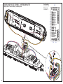 14
14
-
 15
15
-
 16
16
-
 17
17
-
 18
18
-
 19
19
-
 20
20
-
 21
21
-
 22
22
-
 23
23
-
 24
24


in andere talen
- English: PIKO 37442 Owner's manual
- français: PIKO 37442 Le manuel du propriétaire
- Deutsch: PIKO 37442 Bedienungsanleitung