AEG X66453BVO Handleiding
- Categorie
- Afzuigkappen
- Type
- Handleiding
Deze handleiding is ook geschikt voor

X66453MVO
X69453MVO
X66453BVO
X69453BVO
Libretto Istruzioni
User Manual
Mode D'emploi
Bedienungsanleitung
Gebruiksaanwijzing
Manual De Instrucciones
Manual De Instruções
Kullanim Kilavuzu
IT
EN
FR
DE
NL
ES
PT
TR
CAPPA
COOKER HOOD
HOTTE DE CUISINE
DUNSTABZUGSHAUBE
AFZUIGKAP
CAMPANA
EXAUSTOR
OCAK DAVLUMBAZ
3
10
17
24
31
38
45
52
Downloaded from www.vandenborre.be

Downloaded from www.vandenborre.be

PER RISULTATI PERFETTI
Grazie per aver scelto di acquistare questo prodotto AEG. Lo
abbiamo creato per fornirvi prestazioni impeccabili per molti
anni, grazie a tecnologie innovative che vi semplificheranno
la vita - funzioni che non troverete sui normali elettrodo-
mestici. Vi invitiamo di dedicare qualche minuto alla lettura
per sapere come trarre il massimo dal vostro elettrodomesti-
co.
ACCESSORI E PRODOTTI DI CONSUMO
All'interno del webshop AEG troverete tutto ciò che vi ser-
ve per fare in modo che i vostri elettrodomestici AEG siano
sempre perfettamente puliti e funzionanti. Non mancano
inoltre una vasta gamma di accessori studiati e realizzati
conformemente agli elevati standard qualitativi che vi aspet-
tate: pentole, scolaposate, portabottiglie e sacchi biancheria
delicati...
Visit the webshop at:
www.aeg-electrolux.com/shop
Downloaded from www.vandenborre.be

IT - CONSIGLI E SUGGERIMENTI/CARATTERISTICHE
4
IT - CONSIGLI E SUGGERIMENTI - Questo libretto di istruzioni per l'uso è previsto per più versioni dell' apparecchio. É possibile che siano descritti singoli
particolari della dotazione, che non riguardano il Vostro apparecchio. Il produttore declina qualsiasi responsabilità per danni dovuti ad installazione non corretta
o non conforme alle regole dell’arte. La distanza minima di sicurezza tra il Piano di cottura e la Cappa deve essere di 650 mm. Verifi care che la tensione di rete
corrisponda a quella riportata nella targhetta posta all’interno della Cappa. Per Apparecchi in Classe I
a
accertarsi che l’impianto elettrico domestico garantisca un
corretto scarico a terra. Collegare la Cappa all’uscita dell’aria aspirata con tubazione di diametro pari o superiore a 120 mm. Il percorso della tubazione deve essere
il più breve possibile. Non collegare la Cappa a condotti di scarico dei fumi prodotti da combustione (caldaie, caminetti, ecc.). Nel caso in cui nella stanza vengano
utilizzati sia la Cappa che apparecchi non azionati da energia elettrica (ad esempio apparecchi utilizzatori di gas), si deve provvedere ad una aerazione suffi ciente
dell’ambiente. Se la cucina ne fosse sprovvista, praticare un’apertura che comunichi con l’esterno, per garantire il richiamo d’aria pulita. La Cappa è stata progettata
esclusivamente per uso domestico, per abbattere gli odori della cucina. Non fare mai uso improprio della Cappa. Non lasciare fi amme libere a forte intensità sotto la
Cappa in funzione. Regolare sempre le fi amme in modo da evitare una evidente fuoriuscita laterale delle stesse rispetto al fondo delle pentole. Controllare le friggitrici
durante l’uso: l’olio surriscaldato potrebbe infi ammarsi. Non preparare alimenti fl ambè sotto la cappa da cucina; pericolo d'incendio. Questo apparecchio non deve
essere utilizzato da persone (bambini inclusi) con ridotte capacità psichiche, sensoriali o mentali, oppure da persone senza esperienza e conoscenza, a meno che
non siano controllati o istruiti all’uso dell’apparecchio da persone responsabili della loro sicurezza. I bambini devono essere supervisionati per assicurarsi che non
giochino con l’apparecchio. Prima di procedere a qualsiasi operazione di manutenzione, disinserire la Cappa togliendo la spina elettrica o spegnendo l’interruttore
generale. Effettuare una scrupolosa e tempestiva manutenzione dei Filtri secondo gli intervalli consigliati (Rischio di incendio), Filtri antigrasso Z Sono lavabili anche
in lavastoviglie, e necessitano di essere lavati ogni 2 mesi circa di utilizzo o più frequentemente, per un uso particolarmente intenso - Filtri antiodore al Carbone attivo
W Il Filtro antiodore al Carbone attivo non è lavabile e non è rigenerabile, va sostituito ogni 4 mesi circa di utilizzo o più frequentemente, per un uso particolarmente
intenso. Per la pulizia delle superfi ci della Cappa è suffi ciente utilizzare un panno umido e detersivo liquido neutro. Il simbolo
sul prodotto o sulla confezione
indica che il prodotto non deve essere considerato come un normale rifi uto domestico, ma deve essere portato nel punto di raccolta appropriato per il riciclaggio di
apparecchiature elettriche ed elettroniche. Provvedendo a smaltire questo prodotto in modo appropriato, si contribuisce a evitare potenziali conseguenze negative
per l’ambiente e per la salute, che potrebbero derivare da uno smaltimento inadeguato del prodotto. Per informazioni più dettagliate sul riciclaggio di questo prodotto,
contattare l’uffi cio comunale, il servizio locale di smaltimento rifi uti o il negozio in cui è stato acquistato il prodotto.
Collegare la Cappa all’Alimentazione di Rete interponendo un Interruttore bipolare con apertura dei contatti di almeno 3 mm.
Attenzione: Prima di installare la Cappa, togliere le pellicole di protezione (bianca e trasparente).
CARATTERISTICHE
Ingombro
Downloaded from www.vandenborre.be

IT - CONSIGLI E SUGGERIMENTI/CARATTERISTICHE
5
Componenti
Rif. Q.tà Componenti di Prodotto
1 1 Corpo Cappa completo di: Comandi,
Luce, Gruppo Ventilatore, Filtri
8 1 Griglia direzionata Uscita Aria
9 1 Flangia di Riduzione ø 150-120 mm
10 1 Flangia ø 150 con valvola di non ri-
torno
16 1 Coperchio filtrante
Rif. Q.tà Componenti di Installazione
11 2 Tasselli
11a 2 Tasselli SB 12/10
12a 2 Viti 4,2 x 44,4
12c 4 Viti 2,9 x 6,5
12d 2 Viti 2,9 x 9,5
Q.tà Documentazione
1 Libretto Istruzioni
1
11
12a
9
11a
16
12c
12d
8
10
Downloaded from www.vandenborre.be

IT - INSTALLAZIONE
6
INSTALLAZIONE
Foratura Parete e Fissaggio Staffe
Tracciare sulla Parete:
• una linea Verticale fino al soffitto o al limite superiore, al centro della zona prevista per il
montaggio della Cappa;
• una linea Orizzontale a 1004 mm min. sopra il Piano di Cottura.
• Segnare un punto (1) sulla linea orizzontale a 247 mm alla destra della linea verticale di rife-
rimento.
• Ripetere questa operazione dalla parte opposta, verificandone il livellamento.
• Segnare come indicato, un punto di riferimento (2) a 210 mm dalla linea Verticale di riferi-
mento, e 482 mm sopra il Piano di Cottura.
• Ripetere questa operazione dalla parte opposta, verificandone il livellamento.
• Forare ø 12 mm i punti (1) segnati.
• Forare ø 8 mm i punti (2) segnati.
• Inserire i tasselli con staffa 11a nei fori (1) e avvitare.
• Inserire il tassello 11 nei fori (2).
Per installazione con camino decorativo: (Opzionale)
• Appoggiare come indicato la Staffa 7.2.1 a 1-2 mm dal soffitto o dal limite superiore, alline-
ando il suo centro (intagli) sulla linea Verticale di riferimento.
• Segnare i centri dei Fori della Staffa.
• Appoggiare come indicato la Staffa 7.2.1 a X mm sotto la prima staffa (X = altezza Camino
Superiore in dotazione), allineando il suo centro (intagli) sulla linea Verticale di riferimento.
• Segnare i centri dei Fori della Staffa.
• Forare ø 8 mm i punti segnati.
• Inserire i tasselli 11 nei fori.
• Fissare le Staffe utilizzando le Viti 12a (4,2 x 44,4) in dotazione.
11a
1
1
22
210
11
12a
247 247
1004
482
400
210
X
1÷2
7.2.1
Downloaded from www.vandenborre.be

IT - INSTALLAZIONE
7
MONTAGGIO CORPO CAPPA
• Aprire il pannello aspirante superiore e bloccarlo
sulla sinistra con l’astina al corpo Cappa affinché
non si richiuda.
• Sbloccare togliendo il perno di fissaggio sulla sinistra
il pannello aspirante inferiore ed aprirlo.
• Togliere i Filtri Antigrasso agendo sulle apposite
maniglie.
• Regolare le due viti Vr, delle staffe 11a, ad inizio
corsa.
• Agganciare il corpo cappa alle 2 staffe 11a.
• Dall’interno del corpo cappa agire sulle Viti Vr per
livellare il Corpo Cappa.
• Avvitare le viti di sicurezza 11.
• Richiudere i pannelli aspiranti.
CONNESSIONI
USCITA ARIA VERSIONE ASPIRANTE
Per installazione in Versione Aspirante collegare la
Cappa alla tubazione di uscita per mezzo di un tubo
rigido o flessibile di ø150 o 120 mm, la cui scelta è
la-sciata all'installatore.
Collegamento tubo ø 150
• Inserire la Flangia ø 150 10 sull’Uscita del Corpo
Cappa.
• Fissare il tubo con adeguate fascette stringitubo.
Il materiale occorrente non è in dotazione.
Collegamento tubo ø 120
• Per collegamento con tubo ø120 mm, inserire
la Flangia di riduzione 9 sulla flangia ø 150 10
prece-dentemente installata.
• Fissare il tubo con adeguate fascette stringitubo.
Il materiale occorrente non è in dotazione.
• In ambedue i casi, togliere eventuali Filtri Antiodore
al Carbone attivo.
USCITA ARIA VERSIONE FILTRANTE
• Avvitare il coperchio filtrante sull’uscita aria, uti-
lizzando quattro viti 12c (2,9 x 6,5).
• Fissare la Griglia direzionata 8 sull’uscita dell’aria
riciclata con 2 Viti 12d (2,9 x 9,5) in dotazione.
ø 120
ø 150
10
10
9
Vr
11
11a
16
12c
12d
8
Downloaded from www.vandenborre.be

IT - INSTALLAZIONE
8
CONNESSIONE ELETTRICA
• Collegare la Cappa all’Alimentazione di Rete
interponendo un Interruttore bipolare con
apertura dei contatti di almeno 3 mm.
• Rimuovere i Filtri antigrasso (vedi par. “Ma-
nutenzione”) e assicurarsi che il connettore
del Cavo di alimentazione sia correttamente
inserito nella presa dell’Aspiratore
Downloaded from www.vandenborre.be

IT - USO
9
Tasto Funzione Led
A
Accende e spegne l’impianto di illuminazione.
Premuto per 5 Secondi a Cappa spenta e senza allarmi filtri in
corso effettua:
Attivazione dell’allarme saturazione Filtri al Carbone Attivo.
Disattivazione dell’allarme saturazione Filtri al Carbone Attivo.
Acceso o Spento.
2 Lampeggi Led tasto H.
1 Lampeggio Led tasto H.
B
Spegne il Motore.
Se premuto per 5 Secondi a Cappa spenta Attiva la modalità
Blocco Tastiera.
Si disattiva premendo il tasto per 5 Secondi.
Acceso o Spento.
Tutti i Led Lampeggiano 2 Volte e durante il
Blocco Tastiera i Led ese-guono una sequenza
di accensione.
Tutti i Led Lampeggiano 1 Volta
C
Attiva la prima velocità. Acceso.
D
Attiva la seconda velocità. Acceso.
E
Attiva la terza velocità. Acceso.
F
Attiva la velocità intensiva da qualsiasi velocità o da motore
spento, tale velocità è temporizzata a 5 minuti, al termine
del tempo il sistema ritorna alla velocità precedentemente
impostata. Adatta a fronteggiare le massime emissioni di fumi
di cottura.
Si Disattiva premendo il Tasto o Spegnendo il Motore.
Acceso.
G
Attiva lo spegnimento automatico ritardato del Motore e
dell’Impianto di Illuminazione di 15 minuti.
Adatto per completare l’eliminazione di odori residui, si disattiva
premendo il tasto o spegnendo il motore.
Premuto per 5 Secondi a Cappa spenta(Motore+Luci) e senza
allarmi filtri in corso effettua:
Attivazione del Telecomando.
Disattivazione del Telecomando.
Acceso.
2 Lampeggi Led tasto C + B
1 Lampeggi Led tasto C + B
H
Effettua il Reset dell’allarme saturazione Filtri premendo il Tasto
per circa 2 Secondi a Cappa Spenta.
Dopo 100 ore di Funzionamento il Led è Acceso
Fisso per segnalare la saturazione dei Filtri
Metallici.
Dopo 200 ore di Funzionamento il Led Lam-
peggia per segnalare la saturazione dei Filtri al
Carbone Attivo.
A
B
C D
E
F
G H
USO
Downloaded from www.vandenborre.be

FOR PERFECT RESULTS
Thank you for choosing this AEG product. We have created
it to give you impeccable performance for many years, with
innovative technologies that help make life simpler – fea-
tures you might not find on ordinary appliances. Please
spend a few minutes reading to get the very best from it.
ACCESSORIES AND CONSUMABLES
In the AEG webshop, you’ll find everything you need to keep
all your AEG appliances looking spotless and working per-
fectly. Along with a wide range of accessories designed and
built to the high quality standards you would expect, from
specialist cookware to cutlery baskets, from bottle holders to
delicate laundry bags…
Visit the webshop at:
www.aeg-electrolux.com/shop
Downloaded from www.vandenborre.be

EN - RECOMMENDATIONS AND SUGGESTIONS/CHARACTERISTICS
11
EN - RECOMMENDATIONS AND SUGGESTIONS - The Instructions for Use apply to several versions of this appliance. Accordingly, you may fi nd descrip-
tions of individual features that do not apply to your specifi c appliance. The manufacturer will not be held liable for any damages resulting from incorrect or improper
installation. The minimum safety distance between the cooker top and the extractor hood is 650 mm. Check that the mains voltage corresponds to that indicated on
the rating plate fi xed to the inside of the hood. For Class I appliances, check that the domestic power supply guarantees adequate earthing. Connect the extractor to
the exhaust fl ue through a pipe of minimum diameter 120 mm. The route of the fl ue must be as short as possible. Do not connect the extractor hood to exhaust ducts
carrying combustion fumes (boilers, fi replaces, etc.). If the extractor is used in conjunction with non electrical appliances (e.g. gas burning appliances), a suffi cient
degree of aeration must be guaranteed in the room in order to prevent the backfl ow of exhaust gas. The kitchen must have an opening communicating directly with
the open air in order to guarantee the entry of clean air. The extractor hood has been designed exclusively for domestic use to eliminate kitchen smells. Never use
the hood for purposes other than for which it has been designed. Never leave high naked fl ames under the hood when it is in operation. Adjust the fl ame intensity
to direct it onto the bottom of the pan only, making sure that it does not engulf the sides. Deep fat fryers must be continuously monitored during use: overheated oil
can burst into fl ames. Do not fl ambè under the range hood; risk of fi re This appliance is not intended for use by persons (including children) with reduced physical,
sensory or mental capabilities, or lack of experience and knowledge, unless they have been given supervision or instruction concerning use of the appliance by a
person responsible for their safety. Children should be supervised to ensure that they do not play with the appliance. Switch off or unplug the appliance from the
mains supply before carrying out any maintenance work.Clean and/or replace the Filters after the specifi ed time period (Fire hazard), Grease fi lters Z The fi lters must
be cleaned every 2 months of operation, or more frequently for particularly heavy usage, and can be washed in a dishwasher. - Activated charcoal fi lter W These
fi lters are not washable and cannot be regenerated, and must be replaced approximately every 4 months of operation, or more frequently with heavy usage. Clean the
hood using a damp cloth and a neutral liquid detergent. The symbol
on the product or on its packaging indicates that this product may not be treated as household
waste. Instead it shall be handed over to the applicable collection point for the recycling of electrical and electronic equipment. By ensuring this product is disposed
of correctly, you will help prevent potential negative consequences for the environment and human health, which could otherwise be caused by inappropriate waste
handling of this product. For more detailed information about recycling of this product, please contact your local city offi ce, your household waste disposal service or
the shop where you purchased the product.
Connect the hood to the mains through a two-pole switch having a contact gap of at least 3 mm.
Warning: Before installing the Hood, remove the protective fi lms (white and transparent).
CHARACTERISTICS
Dimensions
Downloaded from www.vandenborre.be

EN - RECOMMENDATIONS AND SUGGESTIONS/CHARACTERISTICS
12
Components
Ref. Q.ty Product Components
1 1 Hood Body, complete with: Controls,
Light, Blower, Filters
8 1 Directional Air Outlet grille
9 1 Reducer Flange ø 150-120 mm
10 1 Dumper
16 1 Filter cover
Ref. Q.ty Installation Components
11 2 Wall Plugs
11a 2 Wall Plugs SB 12/10
12a 2 Screws 4,2 x 44,4
12c 4 Screws 2,9 x 6,5
12d 2 Screws 2,9 x 9,5
Q.ty Documentation
1 Instruction Manual
1
11
12a
9
11a
16
12c
12d
8
10
Downloaded from www.vandenborre.be

EN - INSTALLATION
13
INSTALLATION
Wall drilling and bracket fixing
As a first step, proceed with the following drawings:
• a vertical line up to the ceiling or up to the upper limit, at the centre of the area in which the
hood is to be fitted;
• a horizontal line at a minimum 1004 mm above the cooker top.
• Mark a point (1) on the horizontal line, 247 mm to the right of the vertical reference line.
• Repeat this operation on the other side, checking that the two marks are levelled.
• Mark a reference point (2) as indicated at 210 mm from the vertical reference line and 482
mm above the cooker top.
• Repeat this operation on the other side, checking that the two marks are levelled.
• Drill at the marked points (1), using a ø 12 mm drill bit.
• Drill at the marked points (2) using a ø 8 mm drill bit.
• Insert the bracket plugs 11a into the holes (1) and tighten the screws.
• Insert plug 11 into holes (2).
To install a decorative chimney ( optional )
• Place bracket 7.2.1 on the wall, about 1-2 mm from the ceiling or from the upper limit,
aligning the centre (notch) with the vertical reference line.
• Mark the wall at the centres of the bracket holes.
• Place the bracket 7.2.1 on the wall at X mm below the first bracket (X = height of the upper
chimney section), aligning the centre (notch) with the vertical line.
• Mark the wall at the centres of the bracket holes.
• Drill ø 8 mm holes at all the marked centre points.
• Insert the wall plugs 11 in the holes.
• Fix the brackets using the 12a screws (4,2 x 44,4) supplied with the hood.
11a
1
1
22
210
11
12a
247 247
1004
482
400
210
X
1÷2
7.2.1
Downloaded from www.vandenborre.be

EN - INSTALLATION
14
FITTING THE HOOD BODY
• Open the top suction panel and fasten it to the
hood body on the left using the pin, so that it
does not close again.
• Unlock the lower suction panel by removing the
fixing pin on the left, and open it.
• Remove the Metal grease filters using the handles
provided.
• Adjust the two screws Vr, in the brackets 11a, so
that they are at the start of their travel.
• Hook the hood body to the two brackets 11a.
• From the inside of the hood body, turn screws Vr
to level the hood body itself.
• Fasten the safety screws 11.
• Close the suction panels.
CONNECTIONS
DUCTED VERSION AIR EXHAUST SYSTEM
When installing the ducted version, connect the hood
to the chimney using either a flexible or rigid pipe
ø 150 or 120mm, the choice of which is left to the
installer.
To install a ø 150 pipe
• To install the dumper 10
• Fix the pipe in position using sufficient pipe clamps
(not supplied).
To install a ø 120 pipe
• To install a ø 120 mm air exhaust connection,
insert the reducer flange 9 on the dumper 10.
• Fix the pipe in position using sufficient pipe clamps
(not supplied).
• Remove any activated charcoal filters.
RECIRCULATION VERSION AIR OUTLET
.
• Screw the filter cover onto the air outlet, using
four screws 12c (2.9 x 12.5).
• Fix the directional grille 8 on the recirculation air
outlet using the 2 screws 12d (2,9 x 9,5) pro-
vided.
ø 120
ø 150
10
10
9
Vr
11
11a
16
12c
12d
8
Downloaded from www.vandenborre.be

EN - INSTALLATION
15
ELECTRICAL CONNECTION
• Connect the hood to the mains through a
two-pole switch having a contact gap of at
least 3 mm.
• Remove the grease filters (see paragraph
Maintenance) being sure that the connector
of the feeding cable is correctly inserted in
the socket placed on the side of the fan.
Downloaded from www.vandenborre.be

EN - USE
16
A
B
C D
E
F
G H
USE
Button Function Led
A
Turns the Lighting System on and off.
If pressed and held for 5 seconds with the hood turned off and
no alarm, do:
Enables the Activated Charcoal Filter Alarm.
Disables the Activated Charcoal Filter Alarm.
On or Off
2 Flashes Led buttom H
1 Flash Led buttom H
B
Turns the Motor on and off.
Enables Keyboard Lock mode if pressed and held for 5 seconds.
It is disabled by pressing the button for 5 seconds.
On or Off
All the Leds flash twice and during Keyboard
Lock the Leds light up in sequence.
All the Leds flash once.
C
Activates speed one. On.
D
Activates speed two. On.
E
Activates speed three. On.
F
Activates intensive speed from any other speed, including motor
off. This speed is timed to run for 5 minutes, after which the
system will return to the speed that was previously set. Suitable
to deal with se-vere cooking fumes.
It is deactivated by pressing the button or turning the motor off.
On.
G
Activates delayed automatic shutdown of the motor and the
lighting system after 15 minuts.
Suitable to complete the elimination of residual odours, it is
deactivated by press-ing the button of turning the motor off.
If pressed and held for 5 seconds with the hood and lightturned
off and no alarm, do:
Enables the Remote control.
Disables the Remote control.
On.
2 Flashes Led buttom C + B
1 Flash Led buttom C + B
H
Performs a Reset of the Filter saturation alarm when the button
is pressed for ap-proximately 2 seconds with the hood turned
off.
After 100 hours operation the Led lights up
continuously to indicate saturation of the
Metal Grease Filters.
After 200 hours operation the Led flashes to
indicate saturation of the Activated Charcoal
Filters.
Downloaded from www.vandenborre.be

POUR DES RÉSULTATS PARFAITS
Merci d'avoir choisi ce produit AEG. Nous l'avons créé
pour vous offrir la meilleure performance pour une lon-
gue durée, avec des technologies innovantes qui vous
simplifient la vie - autant de caractéristiques que vous
ne trouverez pas sûrement pas sur d'autres appareils.
Veuillez prendre quelques instants pour lire cette notice
afin d'utiliser au mieux votre appareil.
ACCESSOIRES ET CONSOMMABLES
Dans la boutique en ligne d'AEG, vous trouverez tout ce
qu'il vous faut pour que vos appareils AEG fonctionnent
parfaitement. Sans oublier une vaste gamme d'accessoi-
res conçus et fabriqués selon les critères de qualité les
plus élevés qui soient, des articles de cuisine spécialisés
aux range-couverts, des porte-bouteilles aux sacs à linge
délicats...
Visit the webshop at:
www.aeg-electrolux.com/shop
Downloaded from www.vandenborre.be

FR - CONSEILS ET SUGGESTIONS/CARACTERISTIQUES
18
FR - CONSEILS ET SUGGESTIONS - La présente notice d’emploi vaut pour plusieurs versions de l’appareil. Elle peut contenir des descriptions d’accessoires
ne fi gurant pas dans votre appareil. Le fabricant décline toute responsabilité en cas de dommage dû à une installation non correcte ou non conforme aux règles
de l’art. La distance minimale de sécurité entre le plan de cuisson et la hotte doit être de 650 mm au moins. Vérifi er que la tension du secteur correspond à la
valeur qui fi gure sur la plaquette apposée à l’intérieur de la hotte. Pour les Appareils appartenant à l
a
Ière Classe, veiller à ce que la mise à la terre de l’installation
électrique domestique ait été effectuée conformément aux normes en vigueur. Connecter la hotte à la sortie d’air aspiré à l’aide d’une tuyauterie d’un diamètre égal
ou supérieur à 120 mm. Le parcours de la tuyauterie doit être le plus court possible. Ne pas connecter la hotte à des conduites d’évacuation de fumées issues
d’une combustion tel que (Chaudière, cheminée, etc…). Si vous utilisez des appareils qui ne fonctionnent pas à l’électricité dans la pièce ou est installée la hotte
(par exemple: des appareils fonctionnant au gaz), vous devez prévoir une aération suffi sante du milieu. Si la cuisine en est dépourvue, pratiquez une ouverture qui
communique avec l’extérieur pour garantir l’infi ltration de l’air pur. La hotte a été conçue exclusivement pour l’usage domestique, dans le but d’éliminer les odeurs
de la cuisine. Ne jamais utiliser abusivement la hotte. Ne pas laisser les fl ammes libres à forte intensité quand la hotte est en service. Toujours régler les fl ammes
de manière à éviter toute sortie latérale de ces dernières par rapport au fond des marmites. Contrôler les friteuses lors de l’utilisation car l’huile surchauffée pourrait
s’enfl ammer. Ne pas préparer d’aliments fl ambés sous la hotte de cuisine : risque d’incendie Cet appareil ne doit pas être utilisé par des personnes (y compris
les enfants) ayant des capacités psychiques, sensorielles ou mentales réduites, ni par des personnes n’ayant pas l’expérience et la connaissance de ce type
d’appareils, à moins d’être sous le contrôle et la formation de personnes responsables de leur sécurité. Les enfants doivent être surveillés pour s’assurer qu’ils
ne jouent pas avec l’appareil. Avant de procéder à toute opération d’entretien, retirer la hotte en retirant la fi che ou en actionnant l’interrupteur général. Effectuer
un entretien scrupuleux et en temps dû des Filtres, à la cadence conseillée (Risque d’incendie), Filtres anti-graisse Z Lavables au lave-vaisselle, ils doivent être
lavés environ tous les 2 mois d’emploi ou plus fréquemment en cas d’emploi particulièrement intense. - Filtre anti-odeur W Il ne sont pas lavables ni régénérables,
il faut les remplacer au moins tous les 4 mois d’emploi ou plus fréquemment en cas d’emploi particulièrement intense. Pour le nettoyage des surfaces de la hotte,
il suffi t d’utiliser un chiffon humide et détersif liquide neutre. Le symbole
sur le produit ou son emballage indique que ce produit ne peut être traité comme
déchet ménager. Il doit plutôt être remis au point de ramassage concerné, se chargeant du recyclage du matériel électrique et électronique. En vous assurant que
ce produit est éliminé correctement, vous favorisez la prévention des conséquences négatives pour l’environnement et la santé humaine qui, sinon, seraient le
résultat d’un traitement inapproprié des déchets de ce produit. Pour obtenir plus de détails sur le recyclage de ce produit, veuillez prendre contact avec le bureau
muni-cipal de votre région, votre service d’élimination des déchets ménagers ou le magasin où vous avez acheté le produit.
Brancher la hotte sur le secteur en interposant un interrupteur bipolaire avec ouverture des contacts d’au moins 3 mm.
Attention : Retirez les fi lms de protection (blanc et transparent) avant d’installer la hotte.
CARACTERISTIQUES
Encombrement
Downloaded from www.vandenborre.be

FR - CONSEILS ET SUGGESTIONS/CARACTERISTIQUES
19
Composants
Réf. Q.té Composants de Produit
1 1 Corps Hotte équipé de:Comandes, Lu-
mière, Groupe Ventilateur, Filtres
8 1 Grille orientée Sortie de l’Air
9 1 Flasque de Réduction ø 150-120 mm
10 1 Buse avec clapet ø150
16 1 Couvercle filtrant
Réf. Q.té Composants pour l ’installation
11 2 Chevilles
11a 2 Chevilles SB 12/10
12a 2 Vis 4,2 x 44,4
12c 4 Vis 2,9 x 6,5
12d 2 Vis 2,9 x 9,5
Q.té Documentation
1 Manuel d’instructions
1
11
12a
9
11a
16
12c
12d
8
10
Downloaded from www.vandenborre.be

FR - INSTALLATION
20
INSTALLATION
Perçage de la paroi et fixation des supports
Tracer sur la paroi :
• une ligne verticale jusqu’au plafond ou à la limite supérieure, au centre de la zone prévue
pour le montage de la hotte ;
• une ligne horizontale à 1004 mm au-dessus du plan de cuisson.
• Marquer un point (1) sur la ligne horizontale à 247 mm à droite de la ligne verticale de réfé-
rence.
• Répéter cette opération de l’autre côté et vérifier la mise à niveau.
• Marquer comme indiqué, un point de référence (2) à 210 mm de la ligne verticale de réfé-
rence et 482 mm au-dessus du plan de cuisson.
• Répéter cette opération de l’autre côté et vérifier la mise à niveau.
• Percer les points marqués (1) avec une mèche de ø 12 mm.
• Percer les points marqués (2) avec une mèche de ø 8 mm.
• Mettre les chevilles avec le support 11a dans les trous (1) et visser.
• Insérer les chevilles 11 dans les trous (2).
Pour installation avec cheminée décorative : (Option)
• Poser le support 7.2.1 comme indiqué, à 1-2 mm du plafond ou de la limite supérieure, en
alignant le centre (encoches) sur la ligne verticale de référence.
• Marquer les centres des trous du support.
• Faire reposer le support 7.2.1, comme indiqué, à X mm en dessous du premier support (X =
hauteur de la partie supérieure fournie), en alignant le centre (encoches) sur la ligne verticale
de référence.
• Marquer les centres des trous du support.
• Percer les points marqués avec une mèche de ø 8 mm.
• Insérer les chevilles 11 dans les trous.
• Fixer les supports à l’aide des vis 12a (4,2 x 44,4) fournies.
11a
1
1
22
210
11
12a
247 247
1004
482
400
210
X
1÷2
7.2.1
Downloaded from www.vandenborre.be

FR - INSTALLATION
21
MONTAGE DU CORPS DE HOTTE
• Ouvrir le panneau aspirant supérieur et le bloquer
sur la gauche, à l’aide de la tige, au corps de hotte
jusqu’à ce qu’il se referme.
• En retirant le pivot de fixation sur la gauche, dé-
bloquer le panneau aspirant inférieur et l’ouvrir.
• Retirer les filtres à graisse en intervenant sur les
poignées appropriées.
• Régler les deux vis Vr, des brides 11a, en début
de course.
• Accrocher le corps de hotte aux 2 équerres 11a.
• Intervenir sur les vis Vr en passant par l’intérieur
du corps de hotte pour en régler le niveau.
• Visser les vis de sécurité 11.
• Refermer les panneaux aspirants.
BRANCHEMENTS
SORTIE AIR VERSION ASPIRANTE
En cas d’installation en version aspirante, brancher
la hotte à la tuyauterie de sortie via un tube rigide
ou flexible de ø 150 ou 120 mm, au choix de l’ins-
tallateur.
Branchement avec un tube de ø150
• Insérer la buse avec clapet 10.
• Fixer le tube par des colliers appropriés. Le matériau
nécessaire n’est pas fourni.
Branchement avec un tube de ø120
• Insérer le flasque de réduction 9 sur la buse avec
clapet 10.
• Fixer le tube par des colliers appropriés. Le matériau
nécessaire n’est pas fourni.
• Retirer les éventuels filtres anti-odeur au charbon
actif.
SORTIE AIR VERSION FILTRANTE
• Visser le couvercle filtrant sur la sortie de l’air, en
utilisant les quatre vis 12c (2,9 x 6,5).
• Fixer la Grille orientée 8 sur la sortie de l’air recy-
clé à l’aide de 2 Vis 12d (2,9 x 9,5) fournies avec
l’appareil.
ø 120
ø 150
10
10
9
Vr
11
11a
16
12c
12d
8
Downloaded from www.vandenborre.be

FR - INSTALLATION
22
BRANCHEMENT ELECTRIQUE
• Brancher la hotte sur le secteur en interpo-
sant un interrupteur bipolaire avec ouver-
ture des contacts d’au moins 3 mm.
• Enlever les filtres à graisse (voir § "Entre-
tien") et s'assurer que le connecteur du
câble d'alimentation soit bien branché dans
la prise du diffuseur.
Downloaded from www.vandenborre.be

FR - UTILISATION
23
Touche Fonction Led
A
Allume et éteint le système d’éclairage.
Appuyée pendant 5 secondes, lorsque la hotte est éteinte et
sans alarmes filtres en cours, elle effectue:
Activation de l’alarme de saturation filtres à charbon actif.
Désactivation de l’alarme de saturation filtres à charbon actif.
Allumée ou éteinte.
2 clignotements led touche H.
1 clignotement led touche H.
B
Coupe le moteur.
Appuyer pendant 5 secondes, la hotte étant éteinte, pour activer
le mode de verrouillage du clavier.
Pour la désactiver, appuyer sur la touche pendant 5 secondes.
Allumée ou éteinte.
Toutes les leds clignotent deux fois et durant
le Verrouillage clavier, les leds effectuent une
séquence de branchement.
Toutes les leds clignotent 1 fois.
C
Active la première vitesse. Allumée.
D
Active la deuxième vitesse. Allumée.
E
Active la troisième vitesse. Allumée.
F
Active la vitesse Intensive à partir de n’importe quelle vitesse,
même lorsque le moteur est éteint. Cette vitesse est réglée pour
une durée de 5 minutes, après quoi le système retourne à la
vitesse précédemment réglée. Fonction indiquée pour faire face
aux pointes d’émission de fumées de cuisson.Pour la désactiver,
appuyer sur la touche ou éteindre le moteur.
Allumée.
G
Active l’extinction automatique retardée du moteur et du
système d’éclairage de 15 minutes.Adaptée pour compléter
l’élimination des odeurs résiduelles, pour la débrancher, appuyer
sur la touche ou éteindre le moteur.
Appuyée pendant 5 secondes lorsque la hotte est éteinte (Mo-
teur+ Éclairage) et sans alarmes filtres en cours, elle effectue :
Activation de la télécommande.
Désactivation de la télécommande.
Allumée.
2 clignotements led touche C + B.
1 clignotement led touche C + B.
H
Effectue la Réinitialisation de l’alarme de saturation des filtres
en appuyant sur la touche pendant environ 2 secondes, lorsque
la hotte est éteinte.
Après 100 heures de fonctionnement, la led
est allumée fixe pour signaler la saturation
des filtres métalliques.
Après 200 heures de fonctionnement, la led
clignote pour signaler la saturation des filtres
à charbon actif.
A
B
C D
E
F
G H
UTILISATION
Downloaded from www.vandenborre.be

FÜR PERFEKTE ERGEBNISSE
Danke, dass Sie sich für dieses AEG Produkt entschieden
haben. Wir haben es geschaffen, damit Sie viele Jahre
von seiner ausgezeichneten Leistung und den innovativen
Technologien, die Ihnen das Leben erleichtern, profitieren
können. Es ist mit Funktionen ausgestattet, die in gewöhn-
lichen Geräten nicht vorhanden sind. Nehmen Sie sich ein
paar Minuten Zeit zum Lesen, um seine Vorzüge kennen zu
lernen.
ZUBEHÖR UND VERBRAUCHSMATERIALIEN
Im AEG Webshop finden Sie alles, was Sie für ein makello-
ses Aussehen und perfektes Funktionieren Ihrer AEG Geräte
benötigen. Wir bieten auch ein umfangreiches Zubehörsor-
timent, das Ihre höchsten Qualitätsansprüche erfüllt, vom
Profi-Kochgeschirr bis zu Besteckkörben, von Flaschenhaltern
bis hin zu Wäschebeuteln für empfindliche Wäsche...
Visit the webshop at:
www.aeg-electrolux.com/shop
Downloaded from www.vandenborre.be

DE - EMPFEHLUNGEN UND HINWEISE/CHARAKTERISTIKEN
25
DE - EMPFEHLUNGEN UND HINWEISE - Diese Gebrauchsanleitung gilt für mehrere Geräte-Ausführungen. Es ist möglich, dass einzelne Ausstattungs-
merkmale beschrieben sind, die nicht auf Ihr Gerät zu-treffen. Der Hersteller haftet nicht für Schäden, die auf eine fehlerhafte und unsachgemäße Montage
zurückzuführen sind. Der minimale Sicherheitsabstand zwischen Kochmulde und Haube muss 650 mm betragen. Prüfen, ob die Netzspannung mit dem Wert auf
dem im Haubeninneren angebrach-ten Schild übereinstimmt. Bei Geräten der Klasse I ist sicherzustellen, dass die elektrische Anlage des Wohn-hauses über eine
vorschriftsmäßige Erdung verfügt. Das Anschlussrohr der Haube zur Luftaustrittsöffnung muss einen Durchmesser von 120 mm oder darüber aufweisen. Der Rohr-
verlauf muss so kurz wie möglich sein. Die Haube darf an keine Entlüftungsschächte angeschlossen werden, in die Verbrennungsgase (Heizkessel, Kamine usw.)
geleitet werden. Werden im Raum außer der Dunstabzugshaube andere, nicht elektrisch betriebene (z.B. gasbetriebene) Geräte verwendet, muss für eine aus-
reichende Belüftung ge-sorgt werden. Sollte die Küche diesbezüglich nicht entsprechen, ist an einer Aus-senwand eine Öffnung anzubringen, die Frischluftzufuhr
gewährleistet. Die Dunstabzugshaube ist ausschließlich zum Einsatz im privaten Haushalt und zur Beseitigung von Küchengerüchen vorgesehen. Unsachgemäßer
Einsatz der Haube ist zu unterlassen. Große Flammen bei eingeschalteter Haube niemals unbedeckt lassen. Die Intensivität der Flamme ist so zu regulieren, dass
sie den Topfboden nicht über-ragt. Frittiergeräte müssen während des Gebrauchs stets beaufsichtigt werden: überhitz-tes Öl kann sich entzünden. Keine fl ambier-
ten Speisen unter der Abzugshaube zubereiten: Brandgefahr. Dieses Gerät darf nicht von Personen, auch Kindern, mit verminderten psychischen, sensorischen
und geistigern Fähigkeiten, oder von Personen ohne Erfahrung und Kenntnisse benutzt werden, sofern sie nicht von für ihre Sicherheit verantwortlichen Personen
beaufsichtigt und beim Gebrauch des Geräts angeleitet werden. Kinder dürfen sich nicht unbeaufsichtigt in der Nähe des Geräts aufhalten und auf keinen Fall mit
dem Gerät spielen. Bevor Wartungsarbeiten durchgeführt werden, muss die Stromzufuhr zur Haube un-terbrochen werden, indem der Stecker gezogen oder der
Hauptschalter abgeschal-tet wird. Bei der Filterwartung müssen die vom Hersteller empfohlenen Zeiträume zum Austau-schen der Filter genauestens eingehalten
werden (Brandgefahr), Fettfi lter Z Sie müssen nach 2-monatigem Betrieb bzw. bei starkem Einsatz auch häufi ger gereinigt werden, was im Geschirrspüler möglich
ist. - Geruchsfi lter W Sie können weder gewaschen noch wiederverwendet werden und sind alle 4 Betriebsmonate bzw. bei starkem Einsatz auch häufi ger aus-
zutauschen. Zur Reinigung der Haubenfl ächen Wir empfehlen ein feuchtes Tuch und ein mildes Flüssigreinigungsmittel. Das Symbol
auf dem Produkt oder
seiner Verpackung weist darauf hin, dass dieses Produkt nicht als normaler Haushaltsabfall zu behandeln ist, sondern an einem Sammelpunkt für das Recyc-ling
von elektrischen und elektronischen Geräten abgegeben werden muss. Durch Ihren Beitrag zum korrekten Entsorgen dieses Produkts schützen Sie die Umwelt
und die Gesundheit Ihrer Mitmen-schen. Umwelt und Gesundheit werden durch falsches Entsorgen gefährdet. Weitere Informationen über das Recycling dieses
Produkts erhalten Sie von Ihrem Rathaus, Ihrer Müllabfuhr oder dem Ge-schäft, in dem Sie das Produkt gekauft haben.
Bei Anschluss der Haube an das Stromnetz muss ein zweipoliger Schalter mit einem Öffnungsweg von mindestens 3 mm zwischengeschaltet werden.
Achtung: Bevor die Haube installiert wird, die Schutzfolien (weiß und transparent) abziehen.
CHARAKTERISTIKEN
Platzbedarf
Downloaded from www.vandenborre.be

DE - EMPFEHLUNGEN UND HINWEISE/CHARAKTERISTIKEN
26
Komponenten
Pos. St. Produktkomponenten
1 1 Haubenkörper mit Schaltern,
Beleuchtung, Gebläse-gruppe, Filter
8 1 Luftleitgitter Luftaustritt
9 1 Reduzierflansch ø 150-120 mm
10 1 Flansch mit Ruckstauklappe ø150
16 1 Filterdeckel
Pos. St. Montagekomponenten
11 2 Dübel 1
1a 2 Dübel SB 12/10
12a 2 Schrauben 4,2 x 44,4
12c 4 Schrauben 2,9 x 6,5
12d 2 Schrauben 2,9 x 9,5
St. Dokumentation
1 Bedienungsanleitung
1
11
12a
9
11a
16
12c
12d
8
10
Downloaded from www.vandenborre.be

DE - MONTAGE
27
11a
1
1
22
210
11
12a
247 247
1004
482
400
210
X
1÷2
7.2.1
MONTAGE
Bohren der Befestigungslöcher und Fixieren der Befestigungsbügel
An der Wand anzeichnen:
• eine senkrechte Linie bis zur Decke oder zum oberen Rand in der Mitte des Installationsbereichs
der Haube,
• eine waagrechte Linie mindestens 1004 mm oberhalb der Kochmulde.
• 247 mm rechts von der senkrechten Bezugslinie einen Punkt (1) auf der waagrechten Linie kenn-
zeichnen.
• Diesen Vorgang an der gegenüberliegenden Seite wiederholen und die Ausrichtung überprüfen.
• Wie angegeben 210 mm rechts von der senkrechten Bezugslinie und 482 mm oberhalb der Koch-
mulde einen Punkt (2) kennzeichnen.
• Diesen Vorgang an der gegenüberliegenden Seite wiederholen und die Ausrichtung überprüfen.
• Die gekennzeichneten Punkte (1) mit einem Bohrer ø 12 mm bohren.
• Die gekennzeichneten Punkte (2) mit einem Bohrer ø 8 mm bohren.
• Die Dübel mit dem Bügel 11a in die Bohrungen (1) einfügen und festschrauben.
• Den Dübel 11 in die Bohrungen (2) einfügen.Zur
Montage der haube mit Dekorkamin (option)
• Den Bügel 7.2.1 wie angegeben 1-2 mm unterhalb der Decke oder der oberen Begrenzung anle-
gen und seinen Mittelpunkt (Einschnitte) an der senkrechten Bezugslinie ausrichten.
• Die Mitte der Löcher des Bügels kennzeichnen.
• Den Bügel 7.2.1 wie angegeben X mm unterhalb des ersten Bügels (X = Höhe des mitgelieferten
oberen Kaminteils) anlegen und seinen Mittelpunkt (Einschnitte) an der senkrechten Bezugslinie
ausrichten.
• Die Mitte der Löcher des Bügels kennzeichnen.
• Die gekennzeichneten Punkte mit einem Bohrer ø 8 mm bohren.
• Die Dübel 11 in die Bohrungen einfügen.
• Die Bügel mit den mitgelieferten Schrauben 12a (4,2 x 44,4) fixieren.
• Die Bügel mit den mitgelieferten Schrauben 12a (4,2 x 44,4) befestigen.
Downloaded from www.vandenborre.be

DE - MONTAGE
28
MONTAGE DES HAUBENKÖRPERS
• Das obere Saugpaneel öffnen und an der linken Seite
mit der Stange am Haubenkörper fixieren, damit es
nicht wieder zuklappt.
• Den Befestigungszapfen an der linken Seite des
unteren Saugpaneels entfernen und das Paneel
öffnen.
• Die Fettfilter an den speziellen Griffen herauszie-
hen.
• Die beiden Schrauben Vr der Bügel 11a auf den
Hubbeginn regulieren.
• Den Haubenkörper an den 2 Bügeln 11a einhaken.
• Vom Haubeninneren her den Haubenkörper mit Hilfe
der Schrauben Vr ausrichten.
• Die Sicherheitsschrauben 11 einschrauben.
• Die Absaugpaneele wieder verschließen.
ANSCHLÜSSE
ANSCHLUSS IN ABLUFTVERSION
Bei Abluftbetrieb kann die Haube vom Installateur wa-
hlweise mittels Rohr oder Schlauch (ø150 oder 120mm)
an die Außenrohrleitung angeschlossen werden.
Anschlussrohres ø 150
• Den Flansch mit Ruckstauklappe 10 anbringen.
• Das Rohr mit geeigneten Rohrschellen fixieren.Das
hierzu erforderliche Material wird nicht mitgelie-
fert.
Anschlussrohres ø 120
• Bei Verwendung eines Anschlussrohres ø 120 den
Reduzierflansch 9 am Flansch mit Ruckstauklappe
10 anbringen.
• Das Rohr mit geeigneten Rohrschellen fixieren.Das
hierzu erforderliche Material wird nicht mitgelie-
fert.
• Eventuell vorhandene Aktivkohlefilter entnehmen.
ANSCHLUSS DER UMLUFTVERSION
.
• Den Filterdeckel am Luftausgang mit den vier Schrau-
ben 12c (2,9 x 6,5) fixieren.
• Das Luftleitgitter 8 mit Hilfe von 2 der mitgelie-
ferten Schrauben 12d (2,9 x 9,5) beim Austritt der
rückzuführenden Luft fixieren.
ø 120
ø 150
10
10
9
Vr
11
11a
16
12c
12d
8
Downloaded from www.vandenborre.be

DE - MONTAGE
29
ELEKTROANSCHLUSS
• Bei Anschluss der Haube an das Stromnetz
muss ein zweipoliger Schalter mit einem
Öffnungsweg von mindestens 3 mm zwi-
schengeschaltet werden.
• Entfernen Sie die Fettfilter (s. Abschnitt
„Wartung“) und versichern Sie sich, daß
die Kabelverbindung in die Steckdose des
Gebläses einwandfrei eingesteckt wird.
Downloaded from www.vandenborre.be

DE - BEDIENUNG
30
Taste Funktion LED
A
Schaltet die Beleuchtung ein oder aus.
Durch 5 Sekunden langes Drücken bei abgestellter Abzugshau-
be und ohne Sättigungsalarm des Aktivkohlefil-ters erfolgt:
Aktivierung des Sättigungsalarms des Aktivkohlefilters.
Deaktivierung des Sättigungsalarms des Aktivkohlefilters.
Ein- oder ausgeschalte
2 Mal Blinken taste H.
1 Mal Blinken taste H .
B
Stellt den Motor ab.
Aktiviert bei 5 Sekunden langem Drücken bei abgestellter
Abzugshaube den Modus Tastatursperre.
Wird durch 5 Sekunden langes Drücken der Taste deakti-viert.
Ein- oder ausgeschaltet.
Alle LEDs blinken 2 Mal und während der Tastatur-
sperre führen die LEDs eine Reihe von Einschalt-
vorgängen durch.
Alle LEDs blinken 1 Mal.
C
Schaltet die erste Geschwindigkeitsstufe ein. Eingeschaltet
D
Schaltet die zweite Geschwindigkeitsstufe ein. Eingeschaltet
E
Schaltet die dritte Geschwindigkeitsstufe ein. Eingeschaltet
F
Aktiviert von jeder Geschwindigkeit aus, auch bei abge-
stelltem Motor, die Intensivgeschwindigkeit, die auf 5 Minuten
zeitgeregelt ist. Nach Ablauf dieser Zeit kehrt das System zu
der zuvor eingestellten Geschwindigkeit zu-rück. Für die Besei-
tigung von sehr intensiven Kochdüns-ten geeignet.
Wird durch Betätigen der Taste oder Abstellen des Motors
deaktiviert.
Eingeschaltet
G
Aktiviert das um 15’ verzögerte automatische Abstellen des
Motors und der Beleuchtung. Zur Beseitigung von Rest-
gerüchen geeignet; wird durch Betätigen der Taste oder
Abstellen des Motors deaktiviert.
Durch 5 Sekunden langes Drücken bei abgestellter Abzugshau-
be (Motor + Beleuchtung) und ohne Sättigungs-alarm des
Aktivkohlefilters erfolgt:
Aktivierung der Fernbedienung.
Deaktivierung der Fernbedienung.
Eingeschaltet
2 Mal Blinken Taste C + B
1 Mal Blinken Taste C + B
H
Führt durch ca. 2 Sekunden langes Drücken der Taste bei
abgestellter Abzugshaube ein Reset des Filtersättigungs-alarms
aus.
Nach 100 Betriebsstunden zeigt die blei-bend ein-
geschaltete LED die Sättigung der Metallfilter an.
Nach 200 Betriebsstunden zeigt die blin-kende LED
die Sättigung der Aktivkohlefil-ter an.
A
B
C D
E
F
G H
BEDIENUNG
Downloaded from www.vandenborre.be

VOOR PERFECTE RESULTATEN
Bedankt dat u voor dit AEG product heeft gekozen.
Dit apparaat is ontworpen om vele jaren uitstekend te
presteren, met innovatieve technologieën die het leven
gemakkelijker helpen maken – functies die gewone ap-
paraten wellicht niet hebben. Neem een paar minuten de
tijd om het door te lezen zodat u er optimaal van kunt
profiteren.
ACCESSOIRES EN VERBRUIKSARTIKELEN
In de AEG webshop vindt u alles wat u nodig heeft om
al uw apparaten van AEG mooi te houden en perfect te
laten functioneren. Ook vindt u hier een groot aantal ac-
cessoires die zijn ontworpen en gebouwd volgens de hoge
kwaliteitsnormen die u verwacht, van speciaal kookgerei
tot bestekmandjes en van flessenhouders tot waszakken…
Visit the webshop at:
www.aeg-electrolux.com/shop
Downloaded from www.vandenborre.be

NL - ADVIEZEN EN SUGGESTIES/EIGENSCHAPPEN
32
EIGENSCHAPPEN
Buitenafmetingen
NL - ADVIEZEN EN SUGGESTIES - Deze gebruiksaanwijzing geldt voor verschillende uitvoeringen van het apparaat. Het is mogelijk dat er een aantal
kenmerken worden beschreven die niet van toe-passing zijn op uw apparaat. De fabrikant aanvaardt geen enkele aansprakelijkheid voor schade die voortkomt uit
onjuiste of niet overeenkomstig de regels der kunst uitgevoerde installaties. De minimale veiligheidsafstand tussen de kookplaat en de wasemkap bedraagt 650
mm. Controleer of de netspanning correspondeert met de spanning die aangegeven is op het plaatje aan de binnenkant van de wasemkap. Voor apparaten van
klasse I dient u zich ervan te verzekeren dat het elektriciteitsnet in uw huis over een goede aarding beschikt. Verbind de wasemkap met de luchtuitlaat door middel
van een leiding met een diameter van 120 mm of groter. De leiding moet een zo kort mogelijke route afl eg-gen. Sluit de wasemkap niet aan op afvoerpijpen van
rook die geproduceerd is door verbranding (verwarmingsketels, open haarden etc.). Als er in het vertrek zowel de wasemkap als apparaten die niet op elektriciteit
wer-ken (bijvoorbeeld gasapparaten) worden gebruikt, moet ervoor worden gezorgd dat het vertrek voldoende geventileerd wordt. Indien de keuken geen gat in de
buiten-muur heeft om de aanvoer van schone lucht te garanderen, dient dit gemaakt te worden. De wasemkap is uitsluitend ontworpen voor huishoudelijk gebruik,
voor het elimine-ren van kookgeuren. Gebruik de kap nooit op oneigenlijke wijze. Laat geen hoog brandende branders onbedekt onder de wasemkap terwijl deze
in werking is. Regel de vlammen altijd zo dat ze niet langs de pannen omhoogkomen. Controleer frituurpannen tijdens het gebruik: de oververhitte olie zou vlam
kunnen vatten. Er mag niet onder de afzuigkap gefl ambeerd worden; brandgevaar Dit apparaat mag niet worden gebruikt door personen (inclusief kinderen) met
be-perkte psychische, sensorische en geestelijke vermogens, of door personen zonder ervaring en kennis, tenzij ze onder toezicht staan of worden geïnstrueerd
over het gebruik van het apparaat door personen die verantwoordelijk zijn voor hun veilig-heid. Kinderen moeten worden gecontroleerd om er zeker van te zijn dat
ze niet met het apparaat spelen. Alvorens onderhoudswerkzaamheden uit te voeren, moet de wasemkap uitgescha-keld worden door de stekker uit het stopcontact
te halen of de hoofdschakelaar om te zetten. Voer het onderhoud van de fi lters altijd tijdig en nauwgezet uit,volgens de aanbevo-len intervallen (Brandgevaar),
Vetfi lters Z De fi lters moeten eens in de 2 maanden of, bij bijzonder intensief gebruik, vaker gereinigd worden, en kunnen ook in de vaatwasmachine worden
gewassen - Geurfi lter W De fi lters kunnen niet gewassen en niet geregenereerd worden en dienen bij gebruik van de kap tenminste eens in de 4 maanden of, bij
bijzonder intensief gebruik, vaker te worden vervangen. Om de oppervlakken van de kap schoon te maken is het voldoende een vochtige doek en een neutraal
reinigingsmiddel te gebruiken. Het symbool
op het product of op de verpakking wijst erop dat dit product niet als huishoudafval mag worden behandeld. Het
moet echter naar een plaats worden gebracht waar elektrische en elektronische apparatuur wordt gerecycled. Als u ervoor zorgt dat dit product op de correcte
manier wordt verwijderd, voorkomt u mogelijk voor mens en milieu negatieve gevolgen die zich zouden kunnen voordoen in geval van verkeerde afvalbehandeling.
Voor meer details in verband met het recyclen van dit product, neemt u het best contact op met de gemeentelijke instanties, het bedrijf of de dienst belast met de
verwijdering van huishoudafval of de winkel waar u het product hebt gekocht.
Sluit de wasemkap aan op de netspanning met een tweepolige schakelaar ertussen met een opening tussen de contacten van tenminste 3 mm.
Let op: verwijder de (witte en doorzichtige) beschermfolie alvorens de afzuigkap te installeren.
Downloaded from www.vandenborre.be

NL - ADVIEZEN EN SUGGESTIES/EIGENSCHAPPEN
33
Onderdelen
Ref. Productonderdelen
1 1 Wasemkap compleet met:
Bedieningen, Licht, Ventilatorgroep,
Filters
8 1 Richtingrooster luchtuitlaat
9 1 Reductieflens ø 150-120 mm
10 1 Toom met Klep ø 150
16 1 Filterdeksel
Ref. Installatieonderdelen
11 2 Pluggen
11a 2 Pluggen SB 12/10
12a 2 Schroeven 4,2 x 44,4
12c 4 Schroeven 2,9 x 9,5
12d 2 Schroeven 2,9 x 9,5
Documentatie
1 Gebruiksaanwijzing
1
11
12a
9
11a
16
12c
12d
8
10
Downloaded from www.vandenborre.be

NL - INSTALLATIE
34
INSTALLATIE
Boren in de wand en bevestigen van de beugels
Teken op de wand:
• Een verticale lijn tot het plafond of tot de bovenste grens in het midden van de zone waar de afzuigkap
moet worden gemonteerd;
• Een horizontale lijn op min. 1004 mm afstand van het kookvlak.
• Teken een punt (1) op de horizontale lijn op 247 mm rechts van de verticale referentielijn.
• Herhaal deze handeling aan de andere kant en controleer de uitlijning.
• Teken, zoals aangegeven, een referentiepunt (2) op 210 mm afstand van de verticale referentielijn en
482 mm boven het kookvlak.
• Herhaal deze handeling aan de andere kant en controleer de uitlijning.
• Boor gaten van ø 12 mm op de plaats van de getekende punten (1).
• Boor gaten van ø 8 mm op de plaats van de getekende punten (2).
• Plaats de pluggen met de beugel 11a in de gaten (1) en draai ze aan.
• Plaats de plug 11 in de gaten (2).
Voor de installatie met decoratieve schouw: (optie)
• Plaats de beugel 7.2.1 op 1-2 mm afstand van het plafond of van de bovenste grens, zoals aangegeven,
en lijn er het midden (inkepingen) van uit op de verticale referentielijn.
• Kruis het midden van de gaten van de beugel aan.
• Plaats de beugel 7.2.1 X mm onder de eerste beugel (X = hoogte standaard bijgeleverde bovenste
schouw), zoals aangegeven, en lijn er het midden (inkepingen) van uit op de verticale referentielijn.
• Kruis het midden van de gaten van de beugel aan.
• Boor gaten van ø 8 mm op de plaats van de aangekruiste punten.
• Plaats de pluggen 11 in de gaten.
• Bevestig de beugels met de bijgeleverde schroeven 12a (4,2 x 44,4).
11a
1
1
22
210
11
12a
247 247
1004
482
400
210
X
1÷2
7.2.1
Downloaded from www.vandenborre.be

NL - INSTALLATIE
35
MONTAGE VAN DE AFZUIGKAP
• Open het bovenste afzuigpaneel en vergrendel het aan
de linkerzijde aan de afzuigkap met de stang, zodat
hij niet dicht gaat.
• Ontgrendel het onderste afzuigpaneel door de beves-
tigingspen aan de linkerkant te verwijderen en open
het.
• Verwijder de vetfilters met behulp van de handgre-
pen.
• Stel de twee schroeven Vr van de beugels 11a op het
begin van de aanslag.
• Haak de afzuigkap aan de 2 beugels 11a.
• Draai vanuit de binnenkant van de afzuigkap aan de
schroeven Vr om de behuizing van de afzuigkap uit
te lijnen.
• Draai de veiligheidsschroeven 11 aan.
• Sluit de afzuigpanelen weer.
LUCHTUITLAAT AFZUIGVERSIE
Bij installatie in afzuigversie, moet u de wasemkap met
de uitlaatleiding verbinden door middel van een starre
of buigzame leiding van ø 150 of 120 mm, naar keuze
van de installateur.
Leiding van ø150
• De Toom met Klep 10 worden aangebracht.
• Zet de leiding vast met geschikt leidingklemmen.Het
benodigde materiaal wordt niet bij de wasemkap gele-
verd.
Leiding van ø120
• Voor verbinding met een leiding van ø120 mm, moet
de reductieflens 9 op de Toom met Klep 10 worden
aangebracht.
• Zet de leiding vast met geschikt leidingklemmen.
Het benodigde materiaal wordt niet bij de wasemkap
geleverd.
• Verwijder de eventuele geurfilters met actieve koolstof.
LUCHTUITLAAT FILTERVERSIE
.
• Bevestig het filterdeksel op de luchtuitgang met behulp
van de vier schroeven 12c (2,9 x 6,5).
• Bevestig het richtingsrooster 8 op de uitlaat van
de gerecirculeerde lucht met 2 van de bijgeleverde
schroeven 12d (2,9 x 9,5).
ø 120
ø 150
10
10
9
Vr
11
11a
16
12c
12d
8
Downloaded from www.vandenborre.be

NL - INSTALLATIE
36
ELEKTRISCHE AANSLUITING
• Sluit de wasemkap aan op de netspanning met een
tweepolige schakelaar ertussen met een opening
tussen de contacten van tenminste 3 mm.
• Verwijder de vetfilters (zie par. "Onderhoud") en ver-
zeker u ervan dat de stekker van de voedingskabel
goed in de contactdoos van de afzuigkap is gesto-
ken.
Downloaded from www.vandenborre.be

NL - GEBRUIK
37
Toets Functie Led
A
Schakelt de verlichtingsinstallatie in en uit.
Als deze toets bij uitgeschakelde afzuigkap en zonder actieve
filteralarmen gedurende 5 seconden wordt ingedrukt, gebeurt
het volgende:
inschakeling van het alarm verzadiging actieve koolstoffilters.
uitschakeling van het alarm verzadiging actieve koolstoffilters.
Aan of uit.
2 maal knipperen led toets H.
1 maal knipperen led toets H.
B
Zet de motor uit.
Als deze toets bij uitgeschakelde afzuigkap 5 seconden inge-
drukt wordt gehouden, wordt de toetsenblokkering geactiveerd.
De functie wordt uitgeschakeld door de toets 5 seconden in te
drukken.
Aan of uit.
Alle leds knipperen 2 maal en tijdens de
toetsenblokkering gaan de leds één voor één
branden.
Alle leds knipperen één keer.
C
Schakelt de eerste snelheid in. Aan.
D
Schakelt de tweede snelheid in. Aan.
E
Schakelt de derde snelheid in. Aan.
F
Activeert de hoogste snelheid vanuit elke snelheidsstand of
vanuit de uitgeschakelde stand van de motor. Deze snelheid
wordt 5 minuten aangehouden en daarna keert het systeem
terug naar de eerder ingestelde snelheid. Geschikt voor het op-
vangen van de maximale uitstoot van kookdampen.Deze functie
kan worden uitgeschakeld door op de toets te drukken of door
de motor uit te zetten.
Aan.
G
Activeert de vertraagde automatische uitschakeling van de
motor en van de verlichting met 15 minuten. Deze functie is
geschikt om restgeuren volledig te verwijderen en kan worden
uitgeschakeld met een druk op de toets of door de motor uit
te zetten.
Als deze toets bij uitgeschakelde afzuigkap (motor + verlichting)
en zonder actieve filteralarmen gedurende 5 seconden wordt
ingedrukt, gebeurt het volgende:inschakeling van de afstandsbe-
diening. uitschakeling van de afstandsbediening.
Aan.
2 maal knipperen led toets C + B
1 maal knipperen led toets C + B
H
Reset het alarm van de verzadiging van de filters door onge-
veer 2 seconden bij uitgeschakelde afzuigkap op de toets te
drukken.
Na 100 bedrijfsuren gaat de led voortdurend
branden om de verzadiging van de metalen
filters te signaleren.
Na 200 bedrijfsuren gaat de led knipperen om
de verzadiging van de actieve koolstoffilters te
signaleren.
A
B
C D
E
F
G H
GEBRUIK
Downloaded from www.vandenborre.be

PARA OBTENER RESULTADOS PERFECTOS
Gracias por escoger este producto AEG. Este artículo ha
sido creado para ofrecer un rendimiento impecable durante
muchos años, con innovadoras tecnologías que facilitarán
su vida y prestaciones que probablemente no encuentre
en electrodomésticos corrientes. Por favor, dedique algunos
minutos a la lectura para disfrutar de todas sus ventajas.
ACCESORIOS Y CONSUMIBLES
En la página web de AEG, encontrará todo lo necesario para
la perfecta limpieza y funcionamiento de todos sus electro-
domésticos AEG. Junto con una amplia gama de accesorios
diseñados y fabricados conforme a los elevados estándares
de calidad característicos de la marca, desde utensilios de
cocina especializados a cestos de cubiertos, desde portabote-
llas a bolsas para el lavado de prendas delicadas...
Visit the webshop at:
www.aeg-electrolux.com/shop
Downloaded from www.vandenborre.be

ES - CONSEJOS Y SUGERENCIAS/CARACTERÍSTICAS
39
CARACTERÍSTICAS
Dimensiones
ES - CONSEJOS Y SUGERENCIAS - Las presentes instrucciones de servicio son válidas para diferentes modelos de aparato; por ello puede ser posible que se
describan detalles y características de equipamiento que no concuerden íntegramente con las de su aparato concreto. El fabricante declina cualquier responsabilidad
debida a los daños provocados por una instalación incorrecta o no conforme con las reglas. La distancia mínima de seguridad entre la encimera y la campana debe
ser de 650mm. Comprobar que la tensión de red corresponda a la indicada en la placa situada en el interior de la campana. Para los aparatos de 1ª clase asegurarse
de que la instalación eléctrica domésti-ca posea una toma de tierra efi caz. Conectar la campana a la salida del aire de aspiración mediante un tubo de 120mm de
diámetro como mínimo. El recorrido del tubo debe ser lo más corto posible. No conectar la campana a tubos de descarga de humos producidos por combus-tión
(calderas, chimeneas, etc.). En el caso que en la cocina se utilice de manera silmultánea la campana y otros aparatos no eléctricos (por ejemplo aparatos de gas),
debe existir un sistema de ventilación sufi ciente para todo el ambiente. Si la cocina no posee un orifi cio que comunique con el exterior, hay que realizarlo para
garantizar el recambio del aire. La campana ha sido concebida exclusivamente para un uso doméstico, para eliminar los olores de la cocina. No utilizarla de manera
inadecuada. No dejar llamas libres de fuerte intensidad mientras la campana esté funcionan-do. Regular siempre las llamas de manera que éstas no sobresalgan
lateralmente con respecto al fondo de las ollas. Controlar las freídoras durante su uso: el aceite muy caliente se puede infl amar. No preparar alimentos fl ambè debajo
de la campana de la cocina; peligro de incendio Este aparato no tiene que ser utilizado por personas (niños incluídos) con capa-cidades psíquicas, sensoriales o
mentales reducidas, o bien por personas sin experiencia y conocimientos en la materia, a menos que no lo hagan bajo el con-trol, o instruídos, por personas res-
ponsables de su seguridad. Controlar que los niños no jueguen con el aparato. Antes de efectuar cualquier operación de mantenimiento, desenchufar la campa-na
de la red eléctrica o apagar el interruptor general. Efectuar un mantenimiento escrupuloso e inmediato de los fi ltros, según los in-tervalos de tiempo aconsejados
(riesgo de incendio), Filtros antigrasa Z Se pueden lavar en el lavavajillas y requieren un lavado cada 2 meses aproximadamente o más a menudo si su uso es muy
intenso. - Filtros antiolor W No se pueden lavar ni regenerar, se deben cambiar cada 4 meses o más a menudo si su uso es muy intenso. Para limpiar las superfi cies
de la campana es sufi ciente utilizar un trapo mojado y detergente líquido neutro. El símbolo
en el producto o en su embalaje indica que este producto no se
puede tratar como desperdicios normales del hogar. Este producto se debe entregar al punto de recolección de equipos eléctricos y electrónicos para reciclaje. Al
asegurarse de que este producto se des-eche correctamente, usted ayudará a evitar posibles consecuencias negativas para el ambiente y la salud pública, lo cual
podría ocurrir si este producto no se manipula de forma adecuada. Para obtener información más detallada sobre el reciclaje de este producto, póngase en contac-to
con la administración de su ciudad, con su servicio de desechos del hogar o con la tienda donde compró el producto.
Conectar la campana a la red de alimentación eléctrica instalando un interruptor bipolar con apertura de los contactos de 3 mm como mínimo
Atención: Antes de instalar la campana, quitar las películas de protección (blanca y transparente).
Downloaded from www.vandenborre.be

ES - CONSEJOS Y SUGERENCIAS/CARACTERÍSTICAS
40
Componentes
Ref. Cant. Componentes del producto
1 1 Cuerpo campana dotado con: man-
dos, luz, grupo de ventilación, filtros.
8 1 Rejilla de dirección de salida del aire
9 1 Brida de reducción ø 150-120 mm
10 1 Arandela con válvula ø 150
16 1 Tapa filtrante
Ref. Cant. Componentes de Instalación
11 2 Tarugos
11a 2 Tarugos SB 12/10
12a 2 Tornillos 4,2 x 44,4
12c 4 Tornillos 2,9 x 6,5
12d 2 Tornillos 2,9 x 9,5
Cant. Documentación
1 Manual de instrucciones
1
11
12a
9
11a
16
12c
12d
8
10
Downloaded from www.vandenborre.be

ES - INSTALACIÓN
41
INSTALACIÓN
Perforación pared y Fijación bridas
Trazar en la pared:.
• una línea Vertical hasta el techo o al límite superior, al centro de la zona prevista para el
montaje de la campana;
• una línea Horizontal a 1004 mm min. sobre el Plano de Cocción.
• Marcar un punto (1) sobre la línea horizontal a 247 mm a la derecha de la línea vertical de
referencia.
• Repetir esta operación por la parte opuesta, verificando su nivelación.
• Marcar como se indica, un punto de referencia (2) a 210 mm desde la línea vertical de refe-
rencia, y 482 mm sobre el plano de cocción.
• Repetir esta operación por la parte opuesta, verificando su nivelación.
• Perforar ø 12 mm los puntos (1) marcados.
• Perforar ø 8 mm los puntos (2) marcados.
• Introducir los tacos con bridas 11a en los orificios (1) y atornillar.
• Introducir los tacos 11 en los orificios (2).
Para instalación con chimenea decorativa: (Opcional)
• Apoyar como se indica la brida 7.2.1 a 1-2 mm del techo o del límite superior, alineando su
centro (muescas) en la línea vertical de referencia.
• Marcar los centros de los orificios de la brida.
• Apoyar como se indica la brida 7.2.1 a X mm debajo de la primera brida (X= altura chimenea
superior en dotación), alineando su centro (muescas) en la línea vertical de referencia.
• Marcar los centros de los orificios de la brida.
• Perforar ø 8 mm los puntos marcados.
• Introducir los tacos 11 en los orificios.
• Fijar las bridas utilizando los 2 tornillos 12a (4,2 x 44,4) en dotación.
11a
1
1
22
210
11
12a
247 247
1004
482
400
210
X
1÷2
7.2.1
Downloaded from www.vandenborre.be

ES - INSTALACIÓN
42
MONTAJE CUERPO CAMPANA
• Abrir el panel aspirante superior y bloquearlo en
la izquierda con la barra al cuerpo de la campana
para que no se cierre.
• Desbloquear quitando el perno de fijación en la
iz-quierda el panel aspirante inferior y abrirlo.
• Quitar los filtros antigrasa operando en las manijas
específicas.
• Regular los dos tornillos Vr, de las bridas 11a al
inicio de la carrera.
• Enganchar el cuerpo de la campana a las 2 bridas
11a.
• Desde el interior del cuerpo de la campana operar
en los tornillos Vr para nivelar el cuerpo de la
campana.
• Atornillar los tornillos de seguridad 11.
• Cerrar los paneles aspirantes.
SALIDA DEL AIRE VERSION ASPIRANTE
Para instalar la campana en versión aspirante conec-
tarla a la tubería de salida mediante un tubo rígido
ó flexible de 150 ó 120 mm, cuya elección se deja
al instalador.
Conexión mediante tubo de Ø 150
• Insertar la arandela Ø 150 10 en la salida del cuerpo
de la campana.
• Sujetar el tubo con unas fajillas. El material necesa-
rio no está incluído en la dotación.
Conexión mediante tubo de Ø 120
• Para conectarla mediante un tubo de Ø 120 mm,
insertar la arandela de reducción 9 en la arandela Ø
150 10 que hemos colocado antes.
• Sujetar el tubo con unas fajillas. El material necesa-
rio no está incluído en la dotación.
• En los dos casos, quitar el filtro antiolor al cabón
activado si estubiera colocado.
SALIDA DEL AIRE VERSIÓN FILTRANTE
.
• Atornillar la tapa filtrante en la salida del aire,
usando cuatro tornillos 12c (2,9 x 6,5).
• Fijar la rejilla de dirección 8 en la salida del aire
reciclado mediante los 2 tornillos 12d (2,9 x 9,5)
en dotación.
ø 120
ø 150
10
10
9
Vr
11
11a
16
12c
12d
8
Downloaded from www.vandenborre.be

ES - INSTALACIÓN
43
CONEXIÓN ELÉCTRICA
• Conectar la campana a la red de alimentación eléc-
trica instalando un interruptor bipolar con apertura
de los contactos de 3 mm como mínimo.
• Quitar los Filtros antigrasa y asegurase de que el co-
nector del Cable de acometida esté colocado correc-
tamente en el enchufe del Aspirador.
Downloaded from www.vandenborre.be

ES - USO
44
Tecla Función Led
A
Enciende y apaga la instalación de iluminación.
Presionada por 5 segundos con la campana apagada y sin alarmas
filtros en curso efectúa:
Activación de la alarma de saturación filtros al carbono activo.
Desactivación de la alarma de saturación filtros al carbono activo.
Encendido o Apagado.
2 parpadeos Led tecla H
1 parpadeo Led tecla H
B
Apaga el motor
Si se presiona por 5 segundos con la campana apagada activa la
modalidad bloqueo del teclado.
Se desactiva presionando la tecla por 5 segundos.
Encendido o apagado.
Todos los leds parpadean 2 veces y durante
el bloqueo del teclado los leds ejecutan una
secuencia de encendido.
Todos los leds parpadean 1 vez.
C
Activa la primera velocidad Encendido.
D
Activa la segunda velocidad. Encendido.
E
Activa la tercera velocidad Encendido.
F
Activa la velocidad Intensiva desde cualquier velocidad o desde
motor apagado, dicha velocidad está temporizada en 5 minutos,
al final del tiempo el sistema regresa a la velocidad implementada
precedentemente.
Adecuada a enfrentar las máximas emisiones de humos de
cocción.
Se desactiva presionando la tecla o apagando el motor.
Encendido.
G
Activa el apagado automático retrasado del motor y de la instala-
ción de Iluminación en 15 minutos.
Adecuada para completar la eliminación de olores residuales, se
desactiva presionando la tecla o apagando el motor.
Presionada por 5 segundos con la campana apagada (motor
+luces) y sin alarmas filtros en curso efectúa:
Activación del telemando
Desactivación del telemando
Encendido.
2 parpadeos Led tecla C+B
1 parpadeo Led tecla C+B
H
Efectúa el Reset de la alarma saturación filtros presionando la
tecla por aproximadamente 2 segundos con la campana apagada.
Después de 100 horas de funcionamiento
el led está encendido fijo para señalar la
saturación de los filtros metálicos.
Después de 200 horas de funcionamiento el
led parpadea para señalar la saturación de
los filtros al carbono activo.
A
B
C D
E
F
G H
USO
Downloaded from www.vandenborre.be

PARA RESULTADOS PERFEITOS
Obrigado por escolher este produto AEG. Criámo-lo para
lhe oferecer um desempenho impecável durante vários
anos, com tecnologias inovadoras que tornam a sua vida
mais fácil – funcionalidades que poderá não encontrar
em aparelhos convencionais. Continue a ler durante al-
guns minutos para tirar o máximo partido do produto.
ACESSÓRIOS E CONSUMÍVEIS
Na loja web AEG, encontrará tudo aquilo de que neces-
sita para manter os seus aparelhos AEG imaculados e a
funcionarem na perfeição. A par de uma vasta gama de
acessórios projectados e concebidos de acordo com os pa-
drões de elevada qualidade que esperaria, de utensílios de
cozinha especializados a cestos de talheres, de suportes
para garrafas a delicados sacos para roupa...
Visit the webshop at:
www.aeg-electrolux.com/shop
Downloaded from www.vandenborre.be

PT - CONSELHOS E SUGESTÕES/CARACTERÍSTICAS
46
CARACTERÍSTICAS
Dimensões
PT - CONSELHOS E SUGESTÕES - Estas instruções de serviço aplicam-se a vários modelos de aparelhos. É por isso, possível que se encontrem descritas
várias características de equi-pamento que não dizem respeito ao seu aparelho. O fabricante declina toda e qualquer responsabilidade pelos danos decorrentes de
uma instalação não correcta ou feita não em conformidade com as normas da boa técnica. A distância mínima de segurança entre a placa de cozedura e o exaustor
deve ser de 650 mm. Verifi que se a tensão da rede coincide com a indicada na placa de característi-cas aplicada no interior do exaustor. Para os aparelhos de Classe
Ia, certifi que-se de que a instalação doméstica ga-ranta uma descarga correcta à terra. Ligue o exaustor à saída do ar aspirado utilizando um tubo de diâmetro igual
ou superior a 120 mm. O percurso do tubo deve ser o mais breve possível. Não ligue o exaustor a tubos de descarga de fumaça produzida porcombustão (caldeiras,
lareiras, etc...). Caso no mesmo local sejam utilizados quer o exaustor, quer aparelhos não acci-onados pela corrente eléctrica (por exemplo, aparelhos alimentados
a gás), será preciso providenciar uma ventilação sufi ciente do aposento. Se a cozinha não possuir uma abertura que comunique com o exterior, providencie a sua
realiza-ção para garantir a entrada de ar limpo. O exaustor foi projectado para ser utilizado exclusivamente em ambientes do-mésticos, sendo a sua fi nalidade a de
reduzir os odores de cozedura. Não utilize o aparelho de maneira imprópria. As chamas de forte intensidade não devem fi car descobertas enquanto o exaus-tor
estiver a funcionar. Regule sempre as chamas de maneira que não sobressaiam do fundo das pane-las. Mantenha as frigideiras sob controlo durante o uso: o óleo
excessivamente aquecido pode infl amar-se. No prepare alimentos fl amejados sob o exaustor. Perigo de incêndio! Este aparelho não deve ser utilizado por pessoas
(incluindo crianças) diminuídas psíquica, sensorial ou mentalmente nem por indivíduos sem experiência e co-nhecimento, salvo se vigiados ou instruídos para
utilização do aparelho por pes-soas responsáveis pela respectiva segurança. As crianças devem ser vigiadas no sentido de assegurar que não brinquem com o
aparelho. Antes de efectuar qualquer operação de manutenção, desligue o exaustor tiran-do a fi cha da tomada de corrente ou desligando o interruptor geral. Faça
uma manutenção atenta e rápida dos fi ltros, respeitando os intervalos aconselhados (risco de incêndio), Filtros antigordura Z Podem ser lavados em máquinas de
lavar louça. A operação de lavagem deve ser feita de 2 em 2 meses de utilização, aproximadamente; com maior frequência se o aparelho for utilizado com muita
intensidade.- Filtro anti-odor W Não pode ser lavado e não é regenerável, devendo ser substituído de 4 em 4 meses de utilização ou com maior frequência, se o
aparelho for utilizado com muita intensidade. Para limpar as superfícies do exaustor, é sufi ciente utilizar um pano húmido e de-tergente líquido neutro. O símbolo
no produto ou na embalagem indica que este produto não pode ser tratado como lixo doméstico. Em vez disso, deve ser entregue ao centro de recolha selectiva para
a re-ciclagem de equipamento eléctrico e electrónico. Ao garantir uma eliminação adequada deste produto, irá ajudar a evitar eventuais consequências negativas
para o meio ambiente e para a saúde pública, que, de outra forma, poderiam ser provocadas por um tratamento incorrecto do produto. Para obter informações
mais pormenorizadas sobre a reciclagem deste produto, con-tacte os serviços municipalizados locais, o centro de recolha selectiva da sua área de residência ou o
estabelecimento onde adquiriu o produto.
Ligue o exaustor à rede de alimentação eléctrica intercalando um interruptor bipolar com abertura mínima entre os contactos de 3 mm.
Atenção: Antes de instalar o exaustor, retire as películas de protecção (branca e transparente).
Downloaded from www.vandenborre.be

PT - CONSELHOS E SUGESTÕES/CARACTERÍSTICAS
47
Componentes
Ref. Qtd. Componentes do produto
1 1 Corpo do exaustor equipado com:
comandos, iluminação, grupo
ventilador e filtros
8 1 Grade direccionada de saída do ar
9 1 Flange de redução ø 150-120 mm
10 1 Flange ø 150 cm válvula de não
retorno
16 1 Tampa filtrante
Ref. Qtd. Componentes de instalação
11 2 Buchas
11a 2 Buchas SB 12/10
12a 2 Parafusos 4,2 x 44,4
12c 4 Parafusos 2,9 x 6,5
12d 2 Parafusos 2,9 x 9,5
Qtd. Documentação
1 Livro de instruções
1
11
12a
9
11a
16
12c
12d
8
10
Downloaded from www.vandenborre.be

PT - INSTALAÇÃO
48
INSTALAÇÃO
Perfuração da parede e fixação dos suportes
Marque na parede:
• Uma linha vertical até ao tecto ou ao limite superior, a meio da zona prevista para a montagem do
exaustor;
• Uma linha horizontal, pelo menos, 1004 mm acima da placa do fogão.
• Marque um ponto (1) sobre a linha horizontal, 247 mm à direita da linha de referência vertical.
• Repita a operação do lado oposto, verificando a nivelação.
• Marque um ponto de referência (2) como indicado, a 210 mm de distância da linha de referência verti-
cal e 482 mm acima da placa do fogão.
• Repita a operação do lado oposto, verificando a nivelação.
• Com uma broca de ø 12 mm, fure os pontos (1) marcados.
• Com uma broca de ø 8 mm, fure os pontos (2) marcados.
• Introduza as buchas com suporte 11a nos furos (1) e aperte.
• Introduza a bucha 11 nos furos (2).
Para instalação com chaminé decorativa: (Opcional)
• Apoie o suporte 7.2.1 como indicado, a 1-2 mm de distância do tecto ou do limite superior,
alinhando o centro deste (entalhes) sobre a linha de referência vertical.
• Marque os centros dos furos do suporte.
• Apoie o suporte 7.2.1 como indicado, X mm abaixo do primeiro suporte (X = altura da chami-
né superior fornecida), alinhando o centro deste (entalhes) sobre a linha de referência vertical.
• Marque os centros dos furos do suporte.
• Com uma broca de Ø 8 mm, fure os pontos marcados.
• Introduza as buchas 11 nos furos.
• Fixe os suportes, utilizando os parafusos 12a (4,2 x 44,4) fornecidos de série.
11a
1
1
22
210
11
12a
247 247
1004
482
400
210
X
1÷2
7.2.1
Downloaded from www.vandenborre.be

PT - INSTALAÇÃO
49
MONTAGEM DO CORPO DO EXAUSTOR
• Abra o painel de aspiração superior e, com a haste,
bloqueie-o do lado esquerdo ao corpo do exaustor
de modo que não se feche.
• Desbloqueie o painel de aspiração inferior, remo-
vendo o perno de fixação do lado esquerdo, e
abra-o.
• Retire os filtros antigordura, operando nos maní-
pulos próprios.
• Ajuste os dois parafusos Vr dos suportes 11a, no
início da respectiva excursão.
• Prenda o corpo do exaustor aos dois suportes
11a.
• Trabalhando da parte interior do corpo do exaustor,
ajuste os parafusos Vr, para nivelar o corpo do
exaustor.
• Aperte os parafusos de segurança 11.
• Feche de novo os painéis de aspiração.
SISTEMA DE EXAUSTÃO DO AR VERSÃO COM
CONDUTA
Quando instalar a versão com conduta, ligue o extrac-
tor à chaminé utilizando um tubo flexível ou um tubo
rígido de ø 150 ou 120 mm, sendo a escolha deixada
ao critério do responsável pela instalação.
• Para instalar o registo de tiragem 10.
• Para instalar uma ligação de exaustão de ar de ø 120
mm, introduza a flange redutora 9 no registo de ti-
ragem 10.
• Fixe o tubo na posição correcta utilizando grampos
para tubos em quantidade suficiente (não forneci-
dos).
• Retire quaisquer filtros de carvão activado que este-
jam instalados.
SAÍDA DO AR PARA A VERSÃO FILTRANTE
.
• Enrosque a tampa filtrante na saída de ar, utilizando
quatro parafusos 12c (2,9 x 6,5).
• Fixe a grade direccionada 8 na saída do ar reciclado
com 2 parafusos 12d (2,9 x 9,5) fornecidos com o
aparelho.
ø 120
ø 150
10
10
9
Vr
11
11a
16
12c
12d
8
Downloaded from www.vandenborre.be

PT - INSTALAÇÃO
50
LIGAÇÃO ELÉCTRICA
• Ligue o extractor à alimentação utilizando um inter-
ruptor de dois pólos com uma folga de contacto de
pelo menos 3 mm.
• Retire os filtros contra gordura (ver parágrafo da
Manutenção) certificando-se de que o conector do
cabo de alimentação está correctamente instalado na
tomada existente do lado do ventilador
Downloaded from www.vandenborre.be

PT - UTILIZAÇÃO
51
Tecla Função Led
A
Liga e desliga o sistema de iluminação.
Se for pressionado durante 5 segundos com o exaustor desligado
e sem os alarmes dos filtros activos, provocará:
Activação do alarme de saturação dos filtros de carvão activo.
Desactivação do alarme de saturação dos filtros de carvão activo.
Aceso ou apagado.
2 piscadelas do Led da tecla H.
1 piscadela do Led da tecla H.
B
Desliga o motor.
Se for pressionado durante 5 segundos com o esausto desligado,
activará o modo
Bloquear teclado.Desactivar-se-á pressionando a tecla 5 segundos.
Aceso ou apagado.
Todos os leds piscam 2 vezes e durante o
bloqueio do teclado os leds acender-se-ão e
apagar-se-ão todos, um por um, sucessiva-
mente.
Todos os leds piscam uma vez
C
Activa a velocidade I. Aceso.
D
Activa a velocidade II. Aceso.
E
Activa a velocidade III. Aceso.
F
Activa a velocidade intensiva, seja qual for a velocidade com que
o motor estiver a funcionar, ou mesmo parado.
Esta velocidade funciona durante um determinado período de
tempo limitado, 5 minutos, decorrido o qual o sistema regressa à
velocidade definida anteriormente.
É indicaca para condições de máxima emissão de fumos de coze-
dura.Desactivar-se-á, pressionando novamente a tecla ou o motor.
Aceso.
G
Activa o desligamento automático, em diferido, do motor e do
sistema de iluminação que,deste modo, se realizará 15 minutos
mais tarde.Esta função é indicada para completar a eliminação
dos odores residuais. Pode ser desactivada pressionando a tecla
respectiva ou desligando o motor.
Se for pressionado durante 5 segundos com o exaustor desligado
(motor e luzes) e sem os alarmes dos filtros activos, provocará:
Activação do telecomando.
Desactivação do telecomando.
Aceso.
2 piscadelas do led das teclas C + B
1 piscadela do led das teclas C + B
H
Se for pressionada com o exaustor desligado, durante cerca de 2
segundos, fará o Reset do alarme de saturação dos filtros.
Após 100 horas de funcionamento, o led fica
aceso fixo, para sinalizar a saturação dos filtros
de metal.
Após 200 horas de funcionamento o led pisca,
para sinalizar a saturação dos filtros de carvão
activo.
A
B
C D
E
F
G H
UTILIZAÇÃO
Downloaded from www.vandenborre.be

MÜKEMMEL SONUÇLAR İÇİN
Bu AEG ürününü seçtiğiniz için teşekkür ederiz. Bu ürünü,
sıradan cihazlarda bulamayacağınız hayatı kolaylaştıran özel-
likler ve yenilikçi teknolojiler kullanarak, size uzun yıllar üstün
performans vermesi için tasarladık. Lütfen, cihazınızdan en
iyi şekilde yararlanabilmek için birkaç dakikanızı ayırarak bu
belgeyi okuyun.
AKSESUARLAR VE SARF MALZEMELERİ
AEG Internet mağazasında tüm AEG cihazlarınızı mükemmel
durumda ve temiz kullanmanıza yardımcı olacak herşeyi bu-
labilirsiniz. Beklentilerinize uygun yüksek kalite standartlarında
tasarlanan ve üretilen çok çeşitli aksesuarların yanı sıra, uz-
manların kullandığı pişirme kaplarından çatal-bıçak sepetlerine,
şişe tutuculardan narin çamaşır torbalarına kadar herşey...
Visit the webshop at:
www.aeg-electrolux.com/shop
Downloaded from www.vandenborre.be

TR - TAVSIYELER VE ÖNERILER/ÖZELLIKLER
53
ÖZELLIKLER
Boyutlar
TR - TAVSIYELER VE ÖNERILER - Bu kullanma talimatι birden fazla cihaz modeli için geçerlidir. Cihazιnιza uymayan bazι donanιm özellikleri tarif edilmiş olabilir.
Yalnιş veya eksik montajdan doğan herhangi bir zararιn sorumluluğu üreticiye ait değildir. Davlumbaz ile pişirici cihazιn ocak kιsmι arasιndaki minimum güvenlik
mesafesi 650 mm.dir. Besleme voltajιnιn, davlumbaz içerisine yerleştirilen bilgi etiketinde belirtilenle aynι olup olmadιğιnι kontrol edin. Sιnιf I elektrikli aletleri için, güç
kaynağιnιn yeterli topraklamayι sağlayιp sağlamadιğιnι kontrol edin. Minimum 120 mm çapιnda bir boru yoluyla davlumbazι çιkιş bacasιna bağlayιn. Baca bağlantιsι
mümkün oldu- ğunca kιsa olmalιdιr. Davlumbaz borusunu yanιcι duman taşιyan baca deliğine (buhar ka-zanι, şömine, vb.) bağlamayιn. Davlumbazιn elektrikle
çalιşmayan aletlerle (örneğin; gazlι cihazlar) bağιntιlι olarak kullanιlmamasι halinde çιkιş gazιnιn geri tepmesini önlemek amacιyla odada yeterli bir havalandιrma
sağlanmalιdιr
. Te-miz hava girişini temin etmek için mutfakta doğrudan dιşarιya açιlan bir açιklιk bulunmalιdιr. Davlumbaz mutfaktaki kokularιn emilmesi amacιyla
evlerde kullanιm için tasarlanmιştιr.Ticari ve endüstriyel amaçlar için kullanmayιnιz. Davlumbazι tasarlandιğι amaçlarιn dιşιnda kesinlikle kullanmayιnιz. Davlumbaz
çalιşιrken altιnda kesinlikle yüksek çιplak ateş bιrakmayιn. Alev
yoğunluğunu doğrudan tencerenin altιnda kalacak şekilde ayarlayιn, kenarlarιnι sarmadιğιndan emin
olun. Yağda kιzartma tavalarιnι kullanιrken sürekli olarak takip edin: fazla ιsιnan yağ tutuşabilir. Kapağın altında kıvılcımdan kaçının, yangın riski Bu alet, güvenlikle-
rinden sorumlu kişiler tarafından kontrol edilmedik-leri veya eğitilmedikleri sürece; fi ziksel, duyumsal ve zihinsel kapasi-tesinde kısıtlama olan (çocuklar dahil) veya
aleti kullanma tecrübesi ve bilgisi olmayan kişiler tarafından kullanılamaz. Bebeklerin, aletle oynamadıklarından emin olmak için kontrol edilmeli gerekir. Herhangi bir
bakιm işlemini gerçekleştirmeden önce davlumbazι kapatιn veya fi şini çιkarιn. Filtreleri belirtilen zamanlarda temizleyin ve / veya değiştirin(Y
angın riski), Yağ tutucu
fi ltreler Z Bu fi ltreler bulaşık makinasında da yıkanabilir ve normal kullanıldıklarında iki ayda bir, yoğun kullanım halinde ise daha sıkça yıkanmalarıı gereklidir - Aktif
karbonlu koku giderici fi ltreler W Aktif karbonlu koku giderici fi ltre yıkanmaz ve rejenere edilmez, normal kullanımda yaklaşık 4 ayda bir, yoğun kullanımda daha sıkça
değiştirilmesi gerekir.. Cihazι nemli bir bez ve nötr bir sιvι deterjan kullanarak temizleyin. Ürün veya paketi üzerindeki
sembolü, bu ürünün normal bir evsel atık
olarak görülmemesi ve bu tip elektrikli veya elektronik cihazların atıldığı dönüşümlü toplama noktalarına terkedilmesi gerektiğine işaret eder. Bu ürünü gerektiği gibi
elimine etme kurallarına uyarsanız çevre ve insan sağlığı üzerindeki olumsuz etkilerini bertaraf etmeye katkı sağlamış olursunuz. Bu ürünün geri dönüşüm koşulları
hakkında daha ayrıntılı bilgi için hudutları içinde bulunduğunuz belediyenin ilgili diaresine, atık yoketme servisine veya ürünün satıcısına danışınız.
Davlumbazı şebeke cereyanına bağlarken aray temas aralığı en az 3 mm olan çift kutuplu bir elektrik anahtarı koyunuz.
Dikkat: Davlumbazın kurulumundan önce, koruyucu kılıfı çıkarınız (beyaz ve şef
faf).
Downloaded from www.vandenborre.be

TR - TAVSIYELER VE ÖNERILER/ÖZELLIKLER
54
Parçalar
Ref. Miktar Ürün Aksamı
1 1 Davlumbaz gövdesi bütünü: Kumandalar,
Işık, Vantilatör Grubu, Filtreler
8 1 Hava Çıkışına Yönlendirilmiş Izgara
9 1 Redüksiyon fl anşı ø 150-120 mm
10 1 ø 150 fl anşlı çek vana
16 1 Filtre edici kapak
Ref. Miktar Kurulum Aksamı
11 2 Bağlantı Parçaları
11a 2 Bağlantı Parçaları SB 12/10
12a 2 Vida 4,2 x 44,4
12c 4 Vida 2,9 x 6,5
12d 2 Vida 2,9 x 9,5
Miktar Dokümantasyon
1 Kullanım Kitapçığı
1
11
12a
9
11a
16
12c
12d
8
10
Downloaded from www.vandenborre.be

TR - MONTAJ
55
MONTAJ
Kenarların Delinmesi ve Askıların Sabitlenmesi
Kenar üzerinde çizin:
• Davlumbazın montajı için öngörülen bölgenin ortasında, tavan veya en uç yüksekliğe kadar dikey
bir çizgi;
• Pişirme düzleminin min. 1.004 mm üstünde yatay bir çizgi.
• Referans dikey çizginin 247 mm sağında yatay çizgi üzerine bir nokta (1) işaretleyin.
• Bu işlemi, hizayı sağlayarak karşı tarafta da tekrarlayın.
• Belirtildiği şekilde, referans dikey çizginin 210 mm, ve pişirme düzleminin 482 mm üstüne bir refe-
rans nokta (2) işaretleyin.
• Bu işlemi, hizayı sağlayarak karşı tarafta da tekrarlayın.
• İşaretli noktaları (1) ø 12 mm delin.
• İşaretli noktaları (2) ø 8 mm delin.
• 11a askılı bağlantı parçalarını deliklere (1) yerleştirin ve vidalayın.
• 11 no.lu dübeli deliklere (2) yerleştirin.
Dekoratif baca montajı için: (İsteğe Bağlı)
• Askı 7.2.1’i belirtilen şekilde, ortasını (çentik) referans dikey çizgiye hizalayarak, tavan veya en uç
yükseklikten 1-2 mm’ye dayayın.
• Askı deliklerinin ortalarını işaretleyin.
• Askı 7.2.1’i şekilde gösterildiği şekilde, ortasını (çentik) referans dikey çizgiye hizalayarak ilk askı-
nın altına X mm’de dayandırın (X = donanımdaki Üst Baca yüksekliği).
• Askı deliklerinin ortalarını işaretleyin.
• İşaretli noktaları ø 8 mm delin.
• 11 no.lu dübelleri deliklere yerleştirin.
• Askıları, donanımdaki 12a (4,2 x 44,4) vidalarını kullanarak sabitleyin.
11a
1
1
22
210
11
12a
247 247
1004
482
400
210
X
1÷2
7.2.1
Downloaded from www.vandenborre.be

TR - MONTAJ
56
DAVLUMBAZ GÖVDESİNİN MONTAJI
• Davlumbazın emme panelini açın ve tekrar kapanma-
ması için sol ön taraftaki kolu gövdeye sabitleyin.
• Emme panelinin sol altındaki sabitleme pimini çıkar-
tarak kilidini sökün ve açın.
• Yağ önleyici Filtreleri uygun kulpları tutarak çıkartın.
• İşlem öncesi 11a askılarının iki Vr vidasını ayarla-
yın.
• Davlumbaz gövdesini 2 11a askısına takın.
• Davlumbaz gövdesi içinden, Davlumbaz gövdesini
hizalamak için Vr vidalarla oynayın.
• Güvenlik vidaları 11 i vidalayın.
• Emme panelleri kapatın.
ANSCHLUSS IN ABLUFTVERSION
Bei Abluftbetrieb kann die Haube vom Installateur wahl-
weise mittels Rohr oder Schlauch (ø150 oder 120mm) an
die Außenrohrleitung angeschlossen werden.
Anschlussrohres ø 150
• Den Flansch mit Ruckstauklappe 10 anbringen.
• Das Rohr mit geeigneten Rohrschellen fi xieren.Das
hierzu erforderliche Material wird nicht mitgeliefert.
Anschlussrohres ø 120
• Bei Verwendung eines Anschlussrohres ø 120 den
Reduzierfl ansch 9 am Flansch mit Ruckstauklappe 10
anbringen.
• Das Rohr mit geeigneten Rohrschellen fi xieren.Das
hierzu erforderliche Material wird nicht mitgeliefert.
• Eventuell vorhandene Aktivkohlefi lter
entnehmen.
FİLTRELİ VERSİYON HAVA ÇIKIŞI
.
• Hava çıkışı üzerindeki fi ltre kapağını dört adet 12c
(2,9 x 6,5) vidasını kullanarak vidalayın.
• Verilen iki adet 12d (2,9 x 9,5) vidası ile devirdaim
edilen hava çıkış istikamet ayarlı ızgarasını tespit
edin.
ø 120
ø 150
10
10
9
Vr
11
11a
16
12c
12d
8
Downloaded from www.vandenborre.be

TR - MONTAJ
57
ELEKTRİK BAĞLANTISI
• Davlumbazı şebeke cereyanına bağlarken
aray temas aralığı en az 3 mm olan çift
kutuplu bir elektrik anahtarı koyunuz.
• Yağ tutucu fi ltreleri çıkarınız (bakınız "Bakım"
paragrafı) ve besleme kablosu soketinin as-
piratör prizine iyice takılmış olduğundan emin
olunuz.
Downloaded from www.vandenborre.be

TR - KULLANIM
58
Tuşİşlev Led
A
Işığı açar ve kapatır.
Davlumbaz kapalı durumdayken ve fi ltre alarmı etkin değilken 5
saniye kadar basılı tutulduğunda:Aktif Karbon Filtresinin doygunluk
alarmını etkinleştirir.
Aktif Karbon Filtresinin doygunluk alarmını devre dışı bırakır.
Açık ya da Kapalı
H tuşu 2 kez yanıp söner
H tuşu 1 kez yanıp söner
B
Motoru durdurur.
5 saniye basılı tutulduğunda Davlumbazın Klavye Blok Etme
Modunu etkinleştirir.
Tuşa 5 saniye basılarak devreden çıkartılır.
Açık ya da Kapalı
Tüm Ledler iki kez yanıp söner ve Klavye Blok
Etme Modu esnasında Ledler sırayla yanmaya
başlar.
Tüm ledler bir kez yanıp söner
C
Hız biri etkinleştirir
Açık.
D
Hız ikiyi etkinleştirir Açık.
E
Hız üçü etkinleştirir Açık.
F
Motor kapalıyken de, herhangi bir hızdan yoğun hıza geçer, bu
hız 5 dakika zaman ayarlıdır, bu sürenin bitmesiyle sistem daha
önceden ayarlanan hıza geri döner. Pişirme anındaki dumanın fazla
yayılmasını engellemek için uygundur.Tuşa basarak veya Motoru
kapatarak devre dışı bırakılır.
Açık.
G
Motorun ve 15 dakika gecikmeli olarak Aydınlatmanın otomatik
olarak söndürülmesini etkinleştirir.
Geri kalan kokuların yok edilmesi için uygundur, motoru kapatmak
veya düğmeye basmak sureti ile devre dışı bırakılır.
Davlumbaz (Motor+Işıklar) kapalı durumdayken ve fi ltre
alarmı etkin
değilken 5 saniye kadar basılı tutulduğunda:
Telekumanda etkinleştirilir.
Telekumanda devreden çıkarılır.
Açık.
C + B tuşu 2 kez yanıp söner
C + B tuşu 1 kez yanıp söner
H
Tuşa yaklaşık 2 saniye basılarak Filtre doygunluk alarmı resetlenir. 100 Çalışma saati sonunda, Metal Filtrelerin
doygunluğunu belirten damla sembolü görüntülenir.
200 Çalışma saati sonunda, Aktif Karbonlu Filtrele-
rin doygunluğunu belirten Led yanıp söner.
A
B
C D
E
F
G H
KULLANIM
Downloaded from www.vandenborre.be

Downloaded from www.vandenborre.be

www.aeg-electrolux.com/shop
436005002_08 - 110404
Downloaded from www.vandenborre.be
-
 1
1
-
 2
2
-
 3
3
-
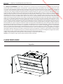 4
4
-
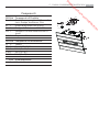 5
5
-
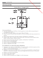 6
6
-
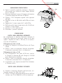 7
7
-
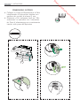 8
8
-
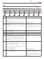 9
9
-
 10
10
-
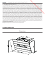 11
11
-
 12
12
-
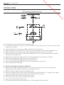 13
13
-
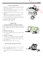 14
14
-
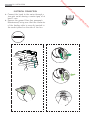 15
15
-
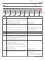 16
16
-
 17
17
-
 18
18
-
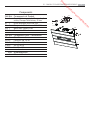 19
19
-
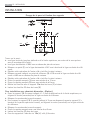 20
20
-
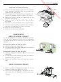 21
21
-
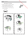 22
22
-
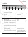 23
23
-
 24
24
-
 25
25
-
 26
26
-
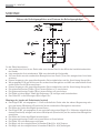 27
27
-
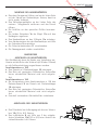 28
28
-
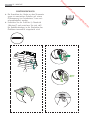 29
29
-
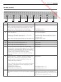 30
30
-
 31
31
-
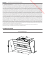 32
32
-
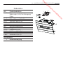 33
33
-
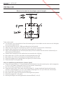 34
34
-
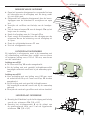 35
35
-
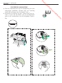 36
36
-
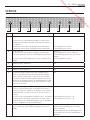 37
37
-
 38
38
-
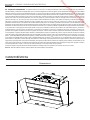 39
39
-
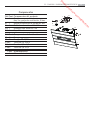 40
40
-
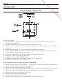 41
41
-
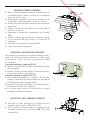 42
42
-
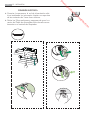 43
43
-
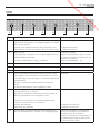 44
44
-
 45
45
-
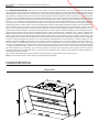 46
46
-
 47
47
-
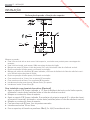 48
48
-
 49
49
-
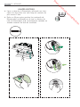 50
50
-
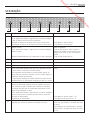 51
51
-
 52
52
-
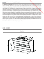 53
53
-
 54
54
-
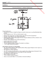 55
55
-
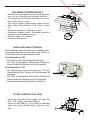 56
56
-
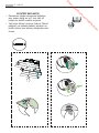 57
57
-
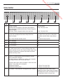 58
58
-
 59
59
-
 60
60


AEG X66453BVO Handleiding
- Categorie
- Afzuigkappen
- Type
- Handleiding
- Deze handleiding is ook geschikt voor
in andere talen
- English: AEG X66453BVO User manual
- italiano: AEG X66453BVO Manuale utente
- français: AEG X66453BVO Manuel utilisateur
- español: AEG X66453BVO Manual de usuario
- Deutsch: AEG X66453BVO Benutzerhandbuch
- português: AEG X66453BVO Manual do usuário
- Türkçe: AEG X66453BVO Kullanım kılavuzu