Yamaha LS9 Handleiding
- Categorie
- Audio-equalizers
- Type
- Handleiding
Deze handleiding is ook geschikt voor

LS9 Editor Owner’s Manual
1
Special Notices
•The software and this owner’s manual are the exclu-
sive copyrights of Yamaha Corporation.
•Copying of the software or reproduction of this
manual in whole or in part by any means is expressly
forbidden without the written consent of the manu-
facturer.
•Copying of the commercially available music
sequence data and/or digital audio files is strictly
prohibited except for your personal use.
•Yamaha makes no representations or warranties
with regard to the use of the software and documen-
tation and cannot be held responsible for the results
of the use of this manual and the software.
•The screen displays as illustrated in this owner’s
manual are for instructional purposes, and may
appear somewhat different from the screens which
appear on your computer.
•Future upgrades of application and system software
and any changes in specifications and functions will
be announced separately.
•Windows is a registered trademark of Microsoft
Corporation in the U.S. and other countries.
•Apple, Mac and Macintosh are trademarks of Apple
Inc., registered in the U.S. and other countries.
•The company names and product names in this
Owner’s Manual are the trademarks or registered
trademarks of their respective companies.
❏
Yamaha Pro Audio Global Site
http://www.yamahaproaudio.com/
Contents
Getting Started ......................................... 2
Master window ....................................... 10
Overview window ................................... 13
Custom Fader Layer window .................. 24
Selected Channel window....................... 26
Library window ....................................... 45
Patch Editor window............................... 48
Rack window ........................................... 52
Meter window ......................................... 61
Group/Link window ................................ 64
Scene window ......................................... 67
Custom Fader Layer Setup window ........ 74
User Defined Keys Setup window........... 75
Keyboard Shortcuts................................. 76
Appendix ................................................. 77
*Specifications and descriptions in this owner’s manual are
for information purposes only. Yamaha Corp. reserves the
right to change or modify products or specifications at any
time without prior notice.
LS9 Editor
LS9 Editor
LS9 Editor
Owner’s Manual
Owner’s Manual
Owner’s Manual
Description of menus and buttons
In the event that menu and button names on a Windows
system are different from those on a Mac, this manual
uses the Windows menu and button names followed by the
Mac menu and button names in parentheses.

LS9 Editor Owner’s Manual
2
Overview of LS9 Editor
LS9 Editor enables you to remotely control the Yamaha LS9 mixing console and to save the parameter settings on
your computer. To use LS9 Editor, you must first perform the following operations:
1 Start and configure Studio Manager.
2 Start and configure LS9 Editor.
3 Synchronize LS9 Editor with your LS9 console (
➥
p.8).
For more information on using Studio Manager, refer to the Studio Manager Owner’s Manual.
Configuring LS9 Editor
You must configure the following settings for each open Editor.
• Before you make the following settings, you must make settings for the DME-N Network Driver (Windows)
or the Network-MIDI Driver (Mac) and select the MIDI port in the Setup window of Studio Manager.
•To open an editor, double-click the icon for the desired editor in the Studio Manager window.
❏
System Setup
To open the System Setup window, choose [System Setup] from the [File] menu.
Be sure to specify the Input port and Output port.
A
Input port/Output port
From the ports you specified in Studio Man-
ager, select the ports that the editor will use
to communicate with the LS9 console.
B
Fast Sync
This allows synchronization to be speed up,
reducing the time required. This check box
enables/disables this function. You should
disable this if synchronization errors occur
while this functions enabled.
C
Window Control from Console
Allows the LS9 Editor windows to be opened
and closed remotely using the USER
DEFINED KEYS of the LS9 console. The
check box enables/disables these operations.
D
Level Meter
By disabling the meter function you can reduce the processing load caused by screen drawing and communica-
tion. This check box enables/disables the level meter function.
E
Confirmation
These check boxes specify whether a confirmation dialog box will be displayed when you store (Store Confirma-
tion), recall (Recall Confirmation), patch (Patch Confirmation), or patch in a way that would affect an existing
patch (Steal Patch Confirmation).
F
Administrator Password
Enter the Administrator password that was specified on the LS9 console. If this password is not entered correctly,
it will not be possible to synchronize from LS9 Editor to the LS9 console.
Getting Started
NOTE
NOTE
NOTE
2
5
6
3
4
1

LS9 Editor Owner’s Manual
3
❏
Mixer Setup
To open the Mixer Setup window, choose [Mixer Setup] from the [File] menu.
A
ModelSelect
Here you can specify the model of LS9 console. This is set automatically when the Editor synchronizes with the
LS9 console.
B
Mix Bus Setup
Here you can make settings relating to the MIX buses.
Signal Type:
This specifies whether each two adjacent odd-numbered/even-numbered MIX buses will be used
as MONO x2 or STEREO.
Bus Type/Pre Fader Send Point:
Specifies whether the Send Point of each two adjacent odd-numbered/
even-numbered MIX buses will be VARI (PRE EQ), VARI (PRE FADER), or FIXED.
Pan Link:
This is valid only when the Signal Type is STEREO and the BUS TYPE is VARI; when enabled, the
PAN setting sent to the stereo MIX bus will be linked with the PAN to the STEREO bus.
C
Matrix Bus Setup
Here you can make settings relating to the MATRIX buses.
Signal Type:
This specifies whether each two adjacent odd-numbered/even-numbered MATRIX buses will be
used as MONO x2 or STEREO.
1
2
3

LS9 Editor Owner’s Manual
4
❏
Creating a user key
To open the Create User Key window, choose [Create User Key] from the [File] menu.
This creates a user key (with “.L9U” file name extension) that can be read from a USB storage device by the LS9
console to automatically set user-specific parameters.
A
User Name
Specify the name of the user. You can enter up to eight single-byte characters of alphabet and numerals.
B
Comment
Enter a comment for each user. You can enter up to thirty-two single-byte alphanumeric characters.
C
Password
Enter a password that will be used when this user key is read by the LS9 console. You can enter up to eight single-
byte alphanumeric characters. Uppercase and lowercase are distinguished.
D
Re-Enter Password
Enter the password once again as a safeguard against mistaken entry.
E
POWER USER
Specify whether this user is a power user. Power users can use the LS9 console to create or edit a user authentica-
tion key with a specified user level.
F
Administrator Password
Enter the Administrator password that was specified on the LS9 console. This is not required if no Administrator
password has been specified on the LS9 console, but if this password is incorrect you will be asked to enter it when
the user key is read.
G
ACCESS PERMISSION
In this area, specify the parameters that this user will be allowed to operate.
2 465
1
3
7
8
9
J
K
L
N
O P
M

LS9 Editor Owner’s Manual
5
H
CH OPERATION
INPUT, ST IN, MIX, MATRIX, ST/MONO:
Select the channels whose parameters will be operable.
HA:
Change the operating privileges for the head amp gain and phantom power of the selected channels.
PROCESSING:
Change the operating privileges for overall signal processing parameters (except for fader
and [ON] key) of the selected channel. For the specific parameters included in PROCESSING, refer to the
appendix of the LS9 owner’s manual.
FADER/ON:
Change the operating privileges for the pan/balance, fader, channel on, send on/off, and send
level of the selected channels.
Set All:
Turn on HA, PROCESSING, and FADER/ON for all channels.
Clear All:
Turn off HA, PROCESSING, and FADER/ON for all channels.
Set by One Click:
If this button is on, HA, PROCESSING, and FADER/ON will all be turned on when you
select a channel. If all are already on, all will be turned off.
I
SCENE LIST
STORE/SORT:
Change the operating privileges for scene store and sort operations.
RECALL:
Change the operating privileges for scene recall operations.
J
LIBRARY LIST
STORE/CLEAR:
Change the operating privileges for library store and clear operations.
RECALL:
Change the operating privileges for library recall operations.
K
FILE LOAD
USER SETUP:
Change the operating privileges for loading user-defined keys and preferences when loading a
file.
SYSTEM SETUP MONITOR SETUP:
Change the operating privileges for loading system setup and moni-
tor setup settings when loading a file.
CURRENT SCENE:
Change the operating privileges for loading the current scene when loading a file.
SCENE LIST:
Change the operating privileges for loading the scene list when loading a file.
LIBRARY LIST:
Change the operating privileges for loading the library list when loading a file.
L
CURRENT SCENE
INPUT PATCH:
Change the operating privileges for input patch operations.
INPUT NAME:
Change the privileges for editing the input names.
OUTPUT PATCH:
Change the operating privileges for output patching.
OUTPUT NAME:
Change the privileges for editing the output names.
BUS SETUP:
Change the operating privileges for buses.
RACK:
Change the operating privileges for rack operations.
MUTE GROUP ASSIGN:
Change the privileges for assigning mute groups.
MUTE GROUP MASTER: Change the operating privileges for enabling/disabling mute groups.
M MONITOR SETUP
OSCILLATOR: Change the operating privileges for oscillator settings.
TALKBACK: Change the operating privileges for talkback settings.
N SYSTEM SETUP
MIXER SETUP: Change the privileges for making mixer setup settings.
OUTPORT SETUP: Change the privileges for making outport setup settings.
MIDI: Change the privileges for making MIDI settings.
O Create
Creates the user key.
P Cancel
Closes the window.

LS9 Editor Owner’s Manual
6
Working with Sessions
All of your console’s mix settings in LS9 Editor, including Scene and library data, are called Sessions.
The following table describes how to handle Sessions.
When you save a session in the window of an editor, the settings of only that editor will be saved in a file. Session files
saved by LS9 Editor have a filename extension of “.YSE”. Files in which only the LS9 console data is saved (filename
extension “.L9A”) can also be handled, allowing you to use a USB storage device to exchange data with the LS9 con-
sole.
If you save a Session in the Studio Manager window, all selected Editor settings are saved in a file with a file extension
of “.YSM.”
Undo/Redo Function
In LS9 Editor, you can cancel the latest operation (Undo) and also cancel the cancellation of the latest operation
(Redo). If you perform an Undo operation twice in a row, you can cancel the two most-recent operations. If you per-
form an Undo operation three times in a row, you can cancel the three most-recent operations. In this way, you can
cancel multiple recent operations. The following table describes how to use the Undo/Redo function.
Please note, however, that after you perform one of the following operations, you cannot successfully undo or redo
any previous operation:
•Operations on the LS9 console
• Quitting Studio Manager
•Synchronizing with the LS9 console
•Session operations
You cannot Undo or Redo the following operations:
• Edits in the Setup window
• Synchronization
• Opening and closing the windows
• Resizing or moving the windows
There are certain other operations that cannot be undone, depending on the function.
For library or scene operations, Undo/Redo applies only to the single most recent operation. You cannot
undo any operations prior to this. Undo/Redo in these windows is available only using the [UNDO] button
within the respective window. Even if you perform a scene recall from the Master window, you cannot use
a shortcut or menu operation to undo the recall.
Creating a new Session Choose [New Session] from the [File] menu.
Opening a previously saved Session Choose [Open Session] from the [File] menu.
Saving the current Session Choose [Save Session] from the [File] menu.
Saving the current Session with a new name Choose [Save Session As...] from the [File] menu.
Undo Choose [Undo] from the [Edit] menu.
Redo Choose [Redo] from the [Edit] menu.
NOTE
NOTE

LS9 Editor Owner’s Manual
7
Window operations
You can select and open each window from the [Win-
dows] menu. For the Overview window and Rack win-
dow, use the sub-menu to select the channels or library
you want to see.
You can choose Tile or Cascade to arrange the windows within the editor.
In the Library window or Scene window, click the tabs
located at the top of the window to switch between
pages.
● Cascade
● Tile

LS9 Editor Owner’s Manual
8
Synchronizing LS9 Editor
When LS9 Editor starts up, the parameter settings on the console and the parameter settings in LS9 Editor may be
different. Therefore, you must first match the parameter settings on the console with those in LS9 Editor. This oper-
ation is called “synchronization.” Follow the steps below to synchronize LS9 Editor.
1 Select [Synchronization], then [Re-synchronize].
The following window opens.
2 Select whether you want to transfer your settings to LS9 Edi-
tor, or vice versa.
At this time, the All Libs option determines whether or not Scene and
Library data is synchronized.
PC ➔ Console: Tr ansfers the current parameter settings in LS9 Editor to your console.
Console ➔ PC: Tr ansfers the current parameter settings of your console to the LS9 Editor.
3 Click [OK].
Do not operate the console while synchronization is in progress.
• If you use the “Total Recall” function in Studio Manager, all selected Editors in Studio Manager are synchronized
with the corresponding devices.
• If you synchronize using PC -> Console, and the console contains data that is set to “read-only,” a dialog box will ask
you whether you want to copy the read-only data to LS9 Editor.
If this data is not copied, console data that is set to read-only status will not be synchronized.
Offline Edit Function
If you do not want to synchronize your console with LS9 Editor, select [Offline Edit] from the [Synchronization]
menu. To apply your off-line edits to your console, select [Re-Synchronize] from the [Synchronization] with the PC
-> Console option to synchronize the console with LS9 Editor.
The Offline Edit function is also activated when you click the [ONLINE]/[OFFLINE] button in the Sync window.
Some effect parameters in the console change their displayed values depending on the sampling fre-
quency. If you switch LS9 Editor from OFFLINE to ONLINE, displayed parameter values may change
because LS9 Editor loads the sampling frequency from the console and updates the display.
Basic operation of controllers
You can operate the controllers in the following ways.
❏ Knobs
•Drag
•Click, and then use the up/down/left/right cursor keys
•Click, and then use the PageUp/PageDown keys (greater change than the cursor keys)
•Click, and then Home sets to far left
•Click, and then End sets to far right
• <Ctrl>(< >)+click sets to default value
For send knobs etc., sets to –∞ regardless of the default value.
• <Ctrl>(< >)+<Shift>+click sets to nominal
For send knobs etc., sets to nominal regardless of the default value.
NOTE
NOTE

LS9 Editor Owner’s Manual
9
❏ Faders
•Drag
•Click, and then use the up/down cursor keys (or left/right cursor keys for horizontal faders)
•Click, and then use the PageUp/PageDown keys (greater change than the cursor keys)
•Click, and then Home sets to maximum value
•Click, and then End sets to minimum value
• <Ctrl>(< >)+click sets to default value
For channel faders etc., sets to –∞ regardless of the default value.
• <Ctrl>(< >)+<Shift>+click sets to nominal
For channel faders etc.,sets to nominal regardless of the default value.
❏ Numerical displays only
•Click and drag up/down
•Click, and then use the up/down cursor keys
•Click, and then use the PageUp/PageDown keys (greater change than the cursor keys)
•Click, and then Home sets to maximum value
•Click, and then End sets to minimum value
• <Ctrl>(< >)+click sets to default value
❏ Bar graphs
•Drag
• <Ctrl>(< >)+click sets to –∞
• <Ctrl>(< >)+<Shift>+click sets to nominal

LS9 Editor Owner’s Manual
10
In the Master window you can synchronize settings with the LS9 console, recall scenes, and access the Overview win-
dow. To open this window, choose [Master] from the [Windows] menu, or assign [LS9 EDITOR CONTROL]-[MAS-
TER] to a USER DEFINED KEY on the LS9 console, and execute that function.
❏ CHANNEL SELECT
This indicates the number and name of the channel to which your operations will apply. To
switch channels, you can either click the [SELECT] button and choose from the list that
appears, or you can click the left/right arrow-shaped channel select buttons. You can use
the channel name text box to edit the name.
This is linked with the [SEL] keys on the LS9 itself.
You can change the icon by right-clicking (<control> key + clicking) it, or change the back-
ground color by left-clicking.
The background color you specify here will also be the background color for the channel
name in the Overview window.
❏ SYNC
This indicates the status of connection and synchronization between LS9 Editor and the LS9.
A [ONLINE]/[OFFLINE] button
The ONLINE/OFFLINE status will alternate each time you click this button.
This has the same function as [Synchronization] menu ➔[Offline Edit]. (➥ p.8)
This indicator is shown when LS9 Editor is correctly connected
to the LS9 itself. In this state, the parameters of LS9 Editor and
the LS9 itself are linked.
This indicator is shown when LS9 Editor and the LS9 itself are
not connected, or when there is a problem with the connection,
or when Offline Edit is selected. In this state, the parameters of
LS9 Editor and the LS9 itself are not linked.
Master window
1 2

LS9 Editor Owner’s Manual
11
B [RE SYNC] button
Clicking this button opens the Synchronization dialog box.
This has the same function as [Synchronization] menu ➔ [Re-Synchronize]. (➥ p.8)
❏ SCENE MEMORY
Here you can view the currently-recalled scene, and recall or store scenes.
A Scene number display
Indicates the number of the scene that is selected for store or recall.
BProtect indicator
A lock icon is shown for scene memories that are protected. Read-only scene memories
are indicated by “R” displayed.
CEdit indicator
The edit indicator will light when you edit the parameters after recalling a scene.
D [STORE] button
This button stores the current scene into the number shown by the scene number dis-
play (
1).
E [▲]/[▼] buttons
These buttons increment or decrement the number shown in the scene number display
(
1). The scene number display (1) will blink until you actually store or recall, and
while blinking will not match the scene number indicated on the LS9.
F [RECALL] button
This button recalls the scene of the number shown in the scene number display (1).
❏ Layer Keys
These keys open the respective Overview window.
These are not linked with the layer section on the LS9’s panel.
A [1-16] button
Opens the INPUT CH 1–16 window.
B [17-32] button
Opens the INPUT CH 17–32 window.
C [33-48] button
Opens the INPUT CH 33–48 window.
This is available only if you’re editing offline and have selected LS9-32 in the Model
Select field of the Mixer Setup screen, or if you’re editing online with the LS9-32 con-
nected.
D [49-64] button
Opens the INPUT CH 49–64 window.
This is available only if you’re editing offline and have selected LS9-32 in the Model
Select field of the Mixer Setup screen, or if you’re editing online with the LS9-32 con-
nected.
E [MIX] button
Opens the MIX window.
F [MATRIX] button
Opens the MATRIX window.
G [STEREO] button
Opens the STEREO/MONO window.
1
4
3
5
6
2
1
5
9
2
6
3
J K 8
477
NOTE

LS9 Editor Owner’s Manual
12
H [ST IN] button
Opens the STEREO IN window.
I [1-16] button
Opens the Custom Fader Layer (INPUT CH) CH 1–16 window.
J [17-32] button
Opens the Custom Fader Layer (INPUT CH) CH 17–32 window.
This is available only if you’re editing offline and have selected LS9-32 in the Model
Select field of the Mixer Setup screen, or if you’e editing online with the LS9-32 con-
nected.
K [ST IN] button
Opens the Custom Fader Layer (ST IN) window.

LS9 Editor Owner’s Manual
13
INPUT CH window
This window displays the mix parameters of INPUT CH 1–16, 17–32, 33–48
(*),
or 49–64
(*).
The parameters shown
in the window can be selected from the [View] menu or the menu that appears when you right-click (<control> key
+ click) in the window.
You can access this window in the following ways.
● From the [Windows] menu, choose [Overview] and select CH1-16/CH17-32/33-48
(*)
/49-64
(*)
●
Use the layer keys in the Master window to turn on the [1-16] button / [17-32] button / [33-48] button
(*)
/ [49-64] button
(*)
●
On the LS9 itself, assign one of the USER DEFINED KEYS to [CH1-16]/[CH17-32]/[CH33-48]
(*)
/[CH49-64]
(*)
in
[OVERVIEW] of [LS9 EDITOR CONTROL], and execute the function
(*)
INPUT CH 33-48, 49-64 can be viewed only if LS9-32 is selected in the Model Select field of the Mixer Setup window when editing
offline, or when editing online with the LS9-32.
A Input patch
Click here to select the input source that will be assigned to the INPUT CH, from the
following choices.
(*)
INPUT jacks 17-32 and slot 2 can be viewed only if you’re editing offline and have selected LS9-32 in
the Model Select field of the Mixer Setup screen, or if you’re editing online with the LS9-32.
B HA GAIN
Drag the knob in the screen to adjust the gain of the internal head amp or of the exter-
nal head amp (AD8HR) patched to the INPUT CH.
C 48V
Switches on/off the phantom power (+48V) of the internal head amp or of the external
head amp (AD8HR) patched to the INPUT CH.
NONE No assignment
IN 1–IN32
(*)
INPUT jacks 1–32
(*)
SLOT1-1...SLOT1-16,
SLOT2-1
(*)
...SLOT2-16
(*)
Input channels of an I/O card installed in a slot
2TR IN L, 2TR IN R L/R channels of the 2TR DIN jack
PB OUT L, PB OUT R L/R channels of USB memory recorder output
RACK1A, RACK1B...
RACK5L(A)...RACK8R(B)
L/R outputs of Rack 1–8
Overview window
1
2
3

LS9 Editor Owner’s Manual
14
D Ø (Phase)
Inverts the phase of the signal after AD conversion.
E HPF (High Pass Filter)
Switches the high pass filter on/off. You can drag the numeric value up or down to edit
the cutoff frequency.
F INS (Insert)
Enables/disables the insert-in. (INPUT CH 1–32 only)
G D. OUT (Direct out)
Enables/disables the direct output.
H EQ (Equalizer)
Switches the EQ on/off. The graph immediately below the button shows the approxi-
mate response of the EQ. You can drag within the graph to edit the response of the EQ.
To reset the EQ to flat response, hold down the <Ctrl>(< >) key of your computer
keyboard and click the graph (The HPF setting will remain).
I DYN1/DYN2 (Dynamics 1/Dynamics 2)
Turns the two dynamics processors on/off.
If Gate is assigned (Dynamics 1 only), the status of the gate is shown immediately below
the button.
If something other than Gate is assigned, a GR meter is shown immediately below the
button, and the amount of gain reduction is shown while this is on.
The type for each dynamics processor can be selected in the Selected Channel window.
J MIX SEND
The bar graphs located immediately below the button
show the send level of the signals sent from the INPUT
CH to VARI type MIX buses. You can also drag the bar
graph to left or right to set the send level. While you
drag the bar graph, the send level is shown in the
numerical display area for PAN/TO STEREO MONO
(
K).
You can set the minimum value (–∞ dB) by holding
down the <Ctrl>(< >) key of your computer key-
board and clicking the bar graph, or set the nominal
value (0.00 dB) by holding down the <Ctrl>(< >)
key and <Shift> key and clicking the bar graph.
The bar graph display will change according to the
send position (pre/post) and on/off status of the signal
sent from the INPUT CH to the MIX buses.
To switch a send on/off, click the channel number
located at the left of the bar graph.
For FIXED-type MIX buses, the bar graph is
fixed at nominal level (0 dB), and only the on/
off status is shown.
Gate status
indication
On/off status On On On Off
Open/closed
status
Closed Open Open —
Remarks
Gain reduction amount
is 30 dB or more
Gain reduction
amount is 0–30 dB
Gain reduction
amount is 0 dB
—
L
M
N
P
O
Q
K
J
4
6
7
8
5
9
• Pre/on (green)
• Pre/off (green)
• Post/on (yellow)
• Post/off (yellow)
NOTE

LS9 Editor Owner’s Manual
15
K PAN/TO STEREO MONO
The PAN knob adjusts the panning of the signal that is sent from the INPUT CH to the
STEREO bus L/R channels (or the L/C/R channels). You can set this to the center value
by holding down the <Ctrl>(< >) key of your computer keyboard and clicking this
knob.
The [ST] button is an on/off switch for the signal that is sent from the INPUT CH to
the STEREO bus.
The [M(C)] button is an on/off switch for the signal that is sent from the INPUT CH to
the MONO bus.
If LCR MODE is selected in the Selected Channel window, the [LCR] button will appear
instead of the [ST] button and [M(C)] button, and the [LCR] button will be an on/off
switch for the signal that is sent from the INPUT CH to the LCR bus.
L SEL (Select)
Selects the INPUT CH for which you want to perform operations. This is linked with
the INPUT section [SEL] keys on the LS9’s panel.
M CUE
This button cue-monitors the signal of the INPUT CH. This is linked with the INPUT
section [CUE] keys on the LS9’s panel.
N ON
Switches the INPUT CH on/off. This is linked with the INPUT section [ON] keys on
the LS9’s panel.
O Fader
Adjusts the input level of the INPUT CH. When the LS9 itself is in other than SENDS
ON FADER mode, this is linked with the INPUT section faders of the LS9’s panel.
The current fader value is shown in the numerical box located immediately below the
fader.
You can set this to the minimum value (–∞ dB) by holding down the <Ctrl>(< >) key
of your computer keyboard and clicking the fader knob, or set it to the nominal value
(0.00 dB) by holding down the <Ctrl>(< >) key and <Shift> key and clicking the
fader knob.
The numbers and alpha-
betical letters at the right
of the fader indicate the
mute groups to which
that channel belongs, and
show the Recall Safe and
Mute Safe status of the
channel.
P Channel number
This is the number of the INPUT CH. You can open the Selected Channel window for
this channel by double-clicking this number. If you hold down the <Ctrl>(< >) key
of your computer keyboard and double-click this, the Selected Channel window will
open as an additional view.
Q Channel name
This is a text box that displays the channel name. You can also edit the channel name in
this text box.
The background color will be the same as the background color of the icon in the chan-
nel select area of the Selected Channel window.
L
M
N
P
O
Q
K
The numbers of mute groups to which this
channel belongs are shown in red.
If this channel is set to Recall Safe, the R
character is shown in green.
If this channel is set to Mute Safe, the M char-
acter is shown in green.

LS9 Editor Owner’s Manual
16
ST IN window
In this window you can view and edit the mix parameters of ST IN CH 1–4. The parameters shown in the window
can be selected from the [View] menu or the menu that appears when you right-click (<control> key + click) in the
window.
You can access this window in the following ways.
● From the [Windows] menu, choose [Overview] and then choose “ST IN”
● Use the layer keys in the Master window to turn on the [ST IN] button
● On the LS9 console, assign a USER DEFINED KEY to [LS9 EDITOR CONTROL]-[OVERVIEW]-[ST IN], and execute it
A INPUT PATCH
This selects the input source assigned to the ST IN CH. The input sources that can be
selected are the same as the INPUT CH.
B HA GAIN
Drag the knob in the screen to adjust the gain of the internal head amp or of the exter-
nal head amp (AD8HR) patched to the ST IN CH.
C 48V
Switches on/off the phantom power (+48V) of the internal head amp or of the external
head amp (AD8HR) patched to the ST IN CH.
D Ø (Phase)
Inverts the phase of the signal after AD conversion.
E HPF (High Pass Filter)
Switches the high pass filter on/off. You can drag the numeric value up or down to edit
the cutoff frequency.
F EQ (Equalizer)
Switches the EQ on/off (the L/R settings are linked). This is the same as the equalizer for
INPUT CH (➥ p.14).
6
1
2
5
3
4

LS9 Editor Owner’s Manual
17
G DYN1/DYN2 (Dynamics 1//Dynamics 2)
These buttons switch the two dynamics processors on/off. This is the same as the
dynamics 1/dynamics 2 for INPUT CH (➥ p.14).
H MIX SEND
This is the same as the mix send for INPUT CH (➥ p.14).
I BALANCE
The BALANCE knob adjusts the balance of the signal that is sent from the ST IN CH to
the STEREO bus L/R channels (or the L/C/R channels). Other than the BALANCE
knob, this is the same as PAN/TO STEREO MONO for an INPUT CH (➥ p.15).
J SEL (Select)
Selects the ST IN CH for which you want to perform operations. (L and R can be
selected separately.) This is linked with the ST IN section [SEL] keys on the LS9’s panel.
K CUE
This button cue-monitors the signal of the ST IN CH (L/R are linked). This is linked
with the ST IN section [CUE] keys on the LS9’s panel.
L ON
Switches the ST IN CH on/off (the L/R settings are linked). This is linked with the ST
IN section CH [ON] keys on the LS9’s panel.
M Fader
Adjusts the input level of the ST IN CH. When the LS9 itself is in other than SENDS ON
FADER mode, this is linked with the INPUT section faders of the LS9’s panel.
The current fader value is shown in the numerical box located immediately below the
fader. This is the same as the fader for INPUT CH (➥ p.15).
N Channel number
This is the number of the ST IN CH. You can double-click this number to open the
Selected Channel window for this channel. If you hold down the <Ctrl>(< >) key of
your computer keyboard and double-click this, the Selected Channel window will open
as an additional view.
O Channel name
This is a text box that displays the channel name. You can also edit the channel name in
this text box.
The background color will be the same as the background color of the icon in the chan-
nel select area of the Selected Channel window.
J
K
L
7
8
9
N
M
O

LS9 Editor Owner’s Manual
18
MIX window
In this window you can view and edit the parameters of MIX channels 1–16. The parameters shown in the window
can be selected from the [View] menu or the menu that appears when you right-click (<control> key + click) in the
window.
You can access this window in the following ways.
● From the [Windows] menu, choose [Overview] and then choose “MIX”
● Use the layer keys in the Master window to turn on the [MIX] button
● On the LS9 console, assign a USER DEFINED KEY to [LS9 EDITOR CONTROL]-[OVERVIEW]-[MIX], and execute it
A OUTPUT PATCH
Click here to select the output port that will be assigned to the MIX channel, from the
following choices.
(*) OMNI jacks 9–16 and SLOT2 can be viewed only if you’re editing offline and have selected LS9-32 in
the Model Select field of the Mixer Setup screen, or if you’re editing online with the LS9-32 connected.
If multiple patches have been made, only the first port is shown.
If you change the patching in this window, the port that had been assigned until then
will be cancelled, and only the newly selected port will be assigned.
B EQ (Equalizer)
Switches the EQ on/off. This is the same as the equalizer for INPUT CH (➥ p.14).
C DYN1(Dynamics 1)
Switches the dynamics processor on/off. This is the same as the dynamics 2 for INPUT
CH (➥ p.14).
D INS (Insert)
Enables/disables the insert-in.
OMNI1–OMNI16
(*)
OMNI jacks 1–16
(*)
SLOT1-1...SLOT1-16,
SLOT2-1
(*)
...SLOT2-16
(*)
Output channels of an I/O card installed in a slot
RACK1A, RACK1B...
RACK5L(A)...RACK8R(B)
L/R outputs of Rack 1–8
2TR OUT L, 2TR OUT R L/R channels of the 2TR OUT DIGITAL jack
REC IN L, REC IN R L/R channels of the USB memory recorder input
1
2
3
4

LS9 Editor Owner’s Manual
19
E MATRIX SEND
These bar graphs indicate the send levels of the signals sent from the
MIX channel to MATRIX 1–8 bus. You can also adjust the send lev-
els by dragging a bar graph to left or right. While you drag the bar
graph, the send level is shown in the numerical display area for
PAN/BALANCE (
6).
You can set the minimum value (–∞ dB) by holding down the
<Ctrl>(< >) key of your computer keyboard and clicking the bar
graph, or set the nominal value (0.00 dB) by holding down the
<Ctrl>(< >) key and <Shift> key and clicking the bar graph.
The bar graph display will change as follows according to the send position (pre/post)
and on/off status of the signal sent from the MIX channel to the MATRIX buses.
To switch a send on/off, click the channel number located at the left of the bar graph.
F PAN/BALANCE
The PAN knob adjusts the panning of the signal that is sent from the mix channel to the
STEREO bus L/R channels (or the L/C/R channels). You can set this to the center value
by holding down the <Ctrl>(< >) key of your computer keyboard and clicking this
knob. If assigned as a stereo bus, this adjusts the balance of the odd-numbered channel
and even-numbered channel. The stereo bus setting can be made in Mix Bus Setup of
the Mixer Setup screen.
The [ST] button is an on/off switch for the signal that is sent from the mix channel to
the STEREO bus.
The [MONO] button is an on/off switch for the signal that is sent from the mix channel
to the MONO bus.
If LCR MODE is selected in the Selected Channel window, the [LCR] button will
appear instead of the [ST] button and [MONO] button, and the [LCR] button will be
an on/off switch for the signal that is sent from the mix channel to the LCR bus.
G VARI/FIXED
Indicates the type (VARI or FIXED) of the currently selected MIX bus. This parameter
can be switched in Mix Bus Setup of the Mixer Setup screen.
H SEL (Select)
Selects the MIX channel for which you want to make settings.
I CUE
This button cue-monitors the signal of the MIX channel.
J ON
Switches the MIX channel on/off.
K Fader
Adjusts the output level of the
MIX channel. The current fader
value is shown in the numeric box
immediately below the fader. You
can set this to the minimum value
(–∞ dB) by holding down the
<Ctrl>(< >) key of your com-
puter keyboard and clicking the
fader knob, or set it to the nominal
value (0.00 dB) by holding down
the <Ctrl>(< >) key and <Shift>
key and clicking the fader knob.
The numbers and alphabetical letters at the right of the fader indicate the mute groups to
which that channel belongs, and show the Recall Safe and Mute Safe status of the channel.
L Channel number
Indicates the number of the MIX channel. You can double-click this number to open
the Selected Channel window for this channel. If you hold down the <Ctrl>(< >) key
of your computer keyboard and double-click this, the Selected Channel window will
open as an additional view.
M Channel name
This is a text box that displays the channel name. You can also edit the channel name in
this text box.
The background color will be the same as the background color of the icon in the chan-
nel select area of the Selected Channel window.
6
5
8
9
J
L
M
7
K
• Pre/on (green))
• Pre/off (green)
• Post/on (yellow)
• Post/off (yellow)
The numbers of mute groups to
which this channel belongs are
shown in red.
If this channel is set to Recall Safe,
the R character is shown in green.
If this channel is set to Mute Safe,
the M character is shown in green.

LS9 Editor Owner’s Manual
20
MATRIX window
In this window you can view and edit the parameters of MATRIX channels 1–8. The parameters shown in the win-
dow can be selected from the [View] menu or the menu that appears when you right-click (<control> key + click) in
the window.
You can access this window in the following ways.
● From the [Windows] menu, choose [Overview] and then choose “MATRIX”
● Use the layer keys in the Master window to turn on the [MTRX] button
● On the LS9 console, assign a USER DEFINED KEY to [LS9 EDITOR CONTROL]-[OVERVIEW]-[MATRIX], and execute
it

LS9 Editor Owner’s Manual
21
A OUTPUT PATCH
This selects the output port assigned to the MATRIX channel. The output ports that
can be selected are the same as for MIX (➥ p.18).
B MIX (send levels from MIX channels)
Here you can view and edit the send levels of the signals sent from the MIX channels to
the MATRIX bus. The method of operation and the meaning of the display are the same
as in (
5) MATRIX SEND in the MIX window (➥ p.19).
C STEREO (Send levels from the STEREO channels to the MATRIX
bus)
Here you can view and edit the send levels of the signals sent from the STEREO chan-
nels to the MATRIX bus. While you drag the bar graph, the send level is shown in the
numerical display area immediately below. The method of operation and the meaning
of the display are the same as for (
5) MATRIX SEND in the MIX window (➥ p.19).
D EQ (Equalizer)
Switches the EQ on/off. The graph immediately below the button shows the approxi-
mate response of the EQ. This is the same as the equalizer for INPUT CH (➥ p.14).
E DYN1(Dynamics 1)
Switches the dynamics processor on/off. This is the same as the dynamics 2 for INPUT
CH (➥ p.14).
F INS (Insert)
Enables/disables the insert-in.
G SEL (Select)
Selects the MATRIX channel for which you want to make settings.
H CUE
This button cue-monitors the signal of the MATRIX channel.
I ON
This switches the MATRIX channel on/off.
J Fader
This adjusts the output level of the MATRIX channel. The current fader value is shown
in the numeric box immediately below the fader.
The numbers and alphabetical letters at the right of the fader indicate the mute groups
to which that channel belongs, and show the Recall Safe and Mute Safe status of the
channel. (For the significance of the numbers and alphabetical letters, see ➥ p.19).
K Channel number
Indicates the number of the MATRIX channel. You can double-click this number to
open the Selected Channel window for this channel. If you hold down the
<Ctrl>(< >) key of your computer keyboard and double-click this, the Selected
Channel window will open as an additional view.
L Channel name
This text box shows the channel name. You can edit the channel name within this text
box.
The background color will be the same as the background color of the icon in the chan-
nel select area of the Selected Channel window.
5
6
7
8
9
K
L
4
2
1
3
J

LS9 Editor Owner’s Manual
22
STEREO/MONO window
In this window you can view and edit the parameters of the STEREO and MONO channels. The parameters shown
in the window can be selected from the [View] menu or the menu that appears when you right-click (<control> key
+ click) in the window.
You can access this window in the following ways.
● From the [Windows] menu, choose [Overview] and then choose “STEREO/MONO”
● Use the layer keys in the Master window to turn on the [STEREO] button
● On the LS9 console, assign a USER DEFINED KEY to [LS9 EDITOR CONTROL]-[OVERVIEW]-[ST/MONO], and exe-
cute it
A OUTPUT PATCH
This selects the output port assigned to the STEREO/MONO channel. The output
ports that can be selected are the same as for MIX (➥ p.18).
B EQ (Equalizer)
Switches the EQ on/off (the L/R settings are linked). This is the same as the equalizer for
INPUT CH (➥ p.14).
C DYN1(Dynamics 1)
Switches the dynamics processor on/off. This is the same as the dynamics 2 for INPUT
CH (➥ p.14).
D INS (Insert)
Enables/disables the insert-in. (The L/R settings are linked.)
E MATRIX SEND
Here you can view and edit the send levels of the signals sent from the STEREO/MONO
channel to MATRIX 1–8 bus. The method of operation and the meaning of the display
are the same as for MATRIX in the MIX window (➥ p.19).
2
1
4
5
3

LS9 Editor Owner’s Manual
23
F BALANCE
Adjusts the left/right balance of the STEREO channel.
G SEL (Select)
Selects the channel for which you want to make settings. (You can specify L and R inde-
pendently.) This is linked with the STEREO/MONO MASTER section [SEL] keys on
the LS9’s panel.
H CUE
This button cue-monitors the signal of the STEREO/MONO channel. This is linked
with the STEREO/MONO MASTER section [CUE] keys on the LS9’s panel.
I ON
This switches the STEREO/MONO channel on/off. This is linked with the STEREO/
MONO MASTER section [ON] keys on the LS9’s panel.
J Fader
Adjusts the output level of the STEREO/MONO channel. This is linked with the STE-
REO/MONO MASTER section faders of the LS9’s panel.
The current fader value is shown in the numeric box immediately below the fader.
The numbers and alphabetical letters at the right of the fader indicate the mute groups
to which that channel belongs, and show the Recall Safe and Mute Safe status of the
channel. (For the significance of the numbers and alphabetical letters, see ➥ p.19).
K Channel number
This is the channel number (ST or M). You can double-click this number to open the
Selected Channel window for this channel. If you hold down the <Ctrl>(< >) key of
your computer keyboard and double-click this, the Selected Channel window will open
as an additional view.
L Channel name
This text box shows the channel name. You can edit the channel name within this text
box.
The background color will be the same as the background color of the icon in the chan-
nel select area of the Selected Channel window.
7
8
9
J
L
K
6

LS9 Editor Owner’s Manual
24
The Custom Fader Layer allows you to create a freely selected combination of the LS9’s internal channels for each
user key. For details on operating each type of channel, refer to the Overview window for that channel.
In the initial state when the Editor has never been synchronized with the LS9 console, this window will
show the Administrator settings. However when you synchronize, this window will be displayed according
to the user level of the console.
Custom Fader Layer window
This window lets you view and edit the mix parameters for Custom Fader Layer CH 1–16 and 17–32
(*)
. The parame-
ters shown in this window can be selected from the [View] menu or from the menu that appears when you right-
click in the window.
You can display this window in either of the following ways.
● From the [Windows] menu, choose [Overview] and then choose “Custom Fader Layer (CH1-16)”/“Custom Fader Layer
(CH17-32)”
(*)
●
In the Master window, turn the Layer Keys CUSTOM [1-16] button/[17-32] button
(*)
on
(*)
Custom Fader Layer CH 17-32 can be displayed only if you’re editing offline and have selected LS9-32 in the Model Select field of the
Mixer Setup window, or if you are editing online with the LS9-32 connected.
Select the channels that you want to assign to the Custom Fader Layer (INPUT CH). You can also
make these settings in the “Custom Fader Layer Setup window.”
Custom Fader Layer window
NOTE

LS9 Editor Owner’s Manual
25
Custom Fader Layer ST IN window
This window lets you view and edit the mix parameters for Custom Fader Layer ST IN CH 1–4
(*)
. The parameters
shown in this window can be selected from the [View] menu or from the menu that appears when you right-click
(<control> key + click) in the window.
Yo can display this window in either of the following ways.
● From the [Windows] menu, choose [Overview] and then choose “Custom Fader Layer ST IN”
● In the Master window, turn the Layer Keys STEREO IN [CUSTOM] button on
(*)
Custom Fader Layer ST IN 3/4 can be displayed only if you’re editing offline and have selected LS9-32 in the Model Select field of the
Mixer Setup window, or if you’re editing online with the LS9-32 connected.
Select the ST IN CH that you want to assign to the Custom Fader Layer (ST IN). You
can also make these settings in the “Custom Fader Layer Setup window.”

LS9 Editor Owner’s Manual
26
Here you can set the parameters of the currently selected input channel (INPUT CH 1–64, ST IN CH 1–4) or output
channel (MIX channels 1–16, MATRIX channels 1–8, STEREO/MONO channels).
You can access this window in the following ways.
● From the [Windows] menu, choose [Selected Channel] and select “MAIN VIEW”
● Double-click the channel number in one of the Overview windows
● On the LS9 console, assign a USER DEFINED KEY to [LS9 EDITOR CONTROL]-[SELECTED CHANNEL], and execute
it
By choosing [Selected Channel] from the [Windows] menu and then selecting “ADDITIONAL VIEW,” you
can view a window for a channel that is not selected. This ADDITIONAL VIEW is not linked with [SEL] key
operations on the panel of the LS9.
The type of parameters that can be edited in this window depends on the type of the currently selected channel. The
parameters of the Selected Channel window are explained below, in the order of input channels (input channels 1–
64, ST IN CH 1–4), MIX channels, MATRIX channels, and STEREO/MONO channels.
If an input channel is selected
Selected Channel window
NOTE
● INPUT CH window

LS9 Editor Owner’s Manual
27
Unless otherwise specified, the parameters explained below are common to INPUT CH 1–48 and ST IN
CH 1–4.
❏ CHANNEL SELECT (Channel selection)
A SELECT (Channel selection)
This shows the ID and name of the channel selected for operations. To switch channels, use the SELECT button
or the triangle buttons at left and right. The channel selected in the Main View is linked with the [SEL] keys in the
INPUT section of the LS9’s panel. You can right-click (<control> key + click) the icon and select a different icon,
or left-click it and select the background color. You can also edit the channel name in the text box.
B INPUT PATCH
Selects the input source assigned to the input channel (for the selectable input sources, ➥ p.13).
● ST IN CH window
NOTE
1 2

LS9 Editor Owner’s Manual
28
❏ MIX SEND
A MIX send level
This adjusts the send level of the signal sent from the input channel to VARI-type MIX bus. The current value is
shown in the numerical box immediately below.
B PRE (Pre/Post)
This selects PRE or POST as the point from which the signal is sent from the input channel to the MIX bus. The
point will be PRE POINT when this is on, and POST FADER when this is off. The PRE POINT setting can be
specified in the Mixer Setup screen.
C ON (MIX send on/off)
This is an on/off switch for the signal sent from the input channel to the MIX bus.
• If MIX buses are being used in stereo, the odd-numbered knob will be PAN.
• If the FIXED type is selected for the MIX bus, only the ON button is valid.
• The stereo/mono setting and the VARI type / FIXED type setting can be made in the
Mixer Setup screen.
❏ HA GAIN/Ø/HPF
A HA (HA Gain)
Adjusts the gain of the internal head amp or of the external head amp (AD8HR) patched to the input channel.
The current value is shown in the numerical box below the knob. You can set this to the default value (+10 dB) by
holding down the <Ctrl>(< >) key and clicking the knob. You can also use the [48V] button to switch phantom
power on/off.
B Ø (Phase)
Inverts the phase of the signal after AD conversion.
C HPF (High Pass Filter)
Use the [ON] button at the right to switch the high-pass filter on/off. You can use the knob at left to adjust the
cutoff frequency. The current value is shown in the numerical box below the knob. An indication of “H” will
appear on the EQ graph of the equalizer.
3
1
2
HINT
Knob of odd-num-
bered side
1 32

LS9 Editor Owner’s Manual
29
❏ TO STEREO/MONO
Here you can specify how the signal will be sent from the input channel to the STEREO bus / MONO bus.
MODE
• ST/MONO button
When this button is on, the signal will be sent to the STEREO L/R bus and independently to the MONO bus.
• LCR button
When this button is on, the signal will be sent to the L/C/R buses which work in conjunction with each other.
PAN (BALANCE for ST IN)
Adjusts the panning of the signal sent from the input channel to the STEREO bus L/R
channels. You can set this to the center position by holding down the <Ctrl>(< >) key
of the computer keyboard and clicking the knob. This is linked with the [PAN] encoder in
the SELECTED CHANNEL section of the LS9 panel.
ST Switches the signal sent from the input channel to the STEREO bus on/off.
M(C) Switches the signal sent from the input channel to the MONO bus on/off.
PAN (BALANCE for ST IN)
Adjusts the panning of the signal that is sent from the input channel to each of the L/C/
R channels. You can set this to the center position by holding down the <Ctrl>(< >)
key of the computer keyboard and clicking the knob. This is linked with the [PAN]
encoder in the SELECTED CHANNEL section of the LS9 panel.
LCR Switches the signal sent from the input channel to the L/C/R bus on/off.
CSR (Center Side Ratio)
Adjusts the proportion of the CENTER channel level relative to the STEREO bus L/R in
a range of 0–100%.
[INPUT CH 1–48] [ST IN CH 1–4]
[INPUT CH 1–48] [ST IN CH 1–4]

LS9 Editor Owner’s Manual
30
❏ EQUALIZER
A LIBRARY
Accesses the INPUT EQ page of the LIBRARY window.
B ON
Switches the EQ on/off.
C EQ graph
Indicates the response for the EQ of the currently selected channel. To reset the EQ to flat response, hold down
the <Ctrl>(< >) key of your computer keyboard and click the graph (The HPF setting will remain).
D Q
E FREQUENCY
F GAIN
These knobs adjust the Q, center frequency, and boost/cut amount for the four bands LOW, LO-MID, HI-MID,
and HIGH.
G HIGH shelving
If this button is on, the HIGH EQ will be switched to a shelving type (the Q knob of the HIGH EQ will disap-
pear).
H LPF (Low Pass Filter)
If this button is on, the HIGH EQ will function as a low pass filter. The Q knob of the HIGH EQ will disappear,
and the GAIN knob will act as the low pass filter on/off switch.
I LOW shelving
If this button is on, the LOW EQ will be switched to a shelving type (the Q knob of the LOW EQ will disappear).
J TYPE I/TYPE II (EQ type)
Selects either TYPE I (the same algorithm as on previous Yamaha digital mixers) or TYPE II (a newly developed
algorithm) as the EQ type.
K ATT (Attenuation)
Adjusts the amount of attenuation/gain.
4
7
8
9
21
3
6
5
K
J

LS9 Editor Owner’s Manual
31
❏ DYNAMICS1/2
You can select one of the following types for each of the two dynamics processors.
If GATE/DUCKING is selected
A TYPE
Indicates the type of the currently selected gate. You can click here to select the type.
B LIBRARY
This button accesses the dynamics library. Clicking this button will open the DYNAMICS page of the LIBRARY
window.
C ON
This button switches the gate on/off.
D Response curve
Indicates the response for the gate of the currently selected channel.
E GR meter
This meter indicates the amount of gain reduction.
F THRESHOLD (Threshold level)
Specifies the level at which the gate will open and close. The gate will open when the key-in signal exceeds this
level, and will close when the signal falls below this level.
G RANGE
Specifies the amount by which the signal is attenuated while the gate is closed.
H DECAY
Specifies the time over which the gate will close after the hold time has elapsed.
I ATTACK
Specifies the time from when the key-in signal exceeds the threshold level until the gate opens.
J HOLD
Specifies the time that the gate will remain open after the key-in signal falls below the threshold.
DYNAMICS1: GATE, DUCKING, EXPANDER, COMPRESSOR
DYNAMICS2: COMPRESSOR, COMPANDER-H, COMPANDER-S, DE-ESSER
L
4
J
7
8
6
9
K
1 235
M

LS9 Editor Owner’s Manual
32
K KEY IN SOURCE
Click this to select one of the following signals to use as the key-in source.
L CUE
This button cue-monitors the currently selected key-in signal. This is not shown in the ADDITIONAL VIEW.
M KEY IN FILTER
Select the type of filter applied to the selected key-in signal; HPF (high pass filter), BPF (band pass filter), or LPF
(low pass filter). The ON/OFF button switches the filter on/off.
If you’ve selected BPF, use the two knobs to adjust the band pass frequency and Q. If you’ve selected HPF or LPF,
use the knob to adjust the cutoff frequency.
If COMPRESSOR is selected
A TYPE
Indicates the type of the currently selected compressor.
B LIBRARY
This button accesses the dynamics library. Clicking this button will open the DYNAMICS page of the LIBRARY
window.
C ON
This button switches the compressor on/off.
D Response curve
Indicates the response for the compressor of the currently selected channel.
E GR meter
This meter indicates the amount of gain reduction produced by the compressor.
F THRESHOLD
Specifies the threshold level at which the compressor will operate. The input signal will start being compressed
when the key-in signal exceeds this level; compression will be removed when the signal falls below this level.
G RATIO
Specifies the ratio at which the input signal will be compressed when the key-in signal exceeds the threshold.
SELF PRE EQ The pre-EQ signal of the currently selected input channel
SELF POST EQ The post-EQ signal of the currently selected input channel
MIX OUT 13–16
The output signal of the corresponding MIX channel immediately before the output
attenuation
CH 1–64 POST EQ The post-EQ signal of the corresponding input channel (however, you can only choose
channels belonging to the same group, within the nine groups CH1–8, CH9–16, CH17–
24, CH25–32, CH33–40, CH41–48, CH49–56, CH57–64 and STIN1L–STIN4R).
STIN1L–STIN4R POST EQ
1
4
J
7
8
6
9
K
2 3
5
L

LS9 Editor Owner’s Manual
33
H KNEE
Specifies the sharpness at which the output level will change. You can select from HARD or 1–5.
I ATTACK
Specifies the time from when the key-in signal exceeds the threshold level until the signal starts being compressed.
J GAIN
Adjusts the gain of the signal after it has passed through the compressor.
K RELEASE
Specifies the time from when the key-in signal falls below the threshold level until compression is removed.
L KEY IN SOURCE
Click this to select the key-in signal that you want to use.
The choices are the same as for GATE.
If COMPANDER-H, COMPANDER-S is selected
A TYPE
Indicates the type of the currently selected compressor. You can click here to select the type.
B LIBRARY
This button accesses the dynamics library. Clicking this button will open the DYNAMICS page of the LIBRARY
window.
C ON
This button switches the compressor on/off.
D Response curve
Indicates the response for the compander of the currently selected channel.
E GR meter
This meter indicates the amount of gain reduction produced by the compressor.
F THRESHOLD
Specifies the threshold level at which the compressor will operate. The input signal will start being compressed
when the key-in signal exceeds this level; compression will be removed when the signal falls below this level.
G RATIO
Specifies the ratio at which the input signal will be compressed when the key-in signal exceeds the threshold.
H WIDTH
Specifies the width between the threshold level of the compressor (THRESHOLD) and the threshold level of the
expander. The expander effect will apply to levels below THRESHOLD + WIDTH.
1
4
L
2 35
J
7
8
6
9
K

LS9 Editor Owner’s Manual
34
I ATTACK
Specifies the time from when the key-in signal exceeds the threshold level until the signal starts being compressed.
J GAIN
Adjusts the gain of the signal after it has passed through the compressor.
K RELEASE
Specifies the time from when the key-in signal falls below the threshold level until compression is removed.
L KEY IN SOURCE
Click this to select the key-in signal that you want to use.
The choices are the same as for GATE.
If DE-ESSER is selected
A TYPE
This indicates that De-Esser is the currently selected type.
B LIBRARY
This button accesses the dynamics library. Clicking this button will open the DYNAMICS page of the LIBRARY
window.
C ON
This button switches the de-esser on/off.
D Response curve
Indicates the response for the de-esser of the currently selected channel.
E GR meter
This meter indicates the amount of gain reduction produced by the de-esser.
F THRESHOLD
Specifies the threshold level at which the de-esser will operate. The input signal will start being compressed when
the key-in signal exceeds this level; compression will be removed when the signal falls below this level.
G FREQ. (Minimum frequency)
Specifies the minimum frequency at which the key-in signal will activate the de-esser.
H KEY IN SOURCE
This indicates the key-in signal that will be used. It is fixed at SELF POST EQ.
1
4
7
6
8
2 35

LS9 Editor Owner’s Manual
35
❏ INSERT (INPUT CH 1–32 only)
A ON
Enables/disables insert-in/out.
B OUT (Insert out)
Click this to select the output port that will be assigned to insert-out, from the following choices.
(*)
SLOT2 can be displayed only if you’re editing offline and have selected LS9-32 in the Model Select field of the Mixer Setup window,
or if you are editing online with the LS9-32 connected.
C IN (Insert in)
Click this to select the input port that will be assigned to insert-in, from the following choices.
(*)
SLOT2 can be displayed only if you’re editing offline and have selected LS9-32 in the Model Select field of the Mixer Setup window,
or if you are editing online with the LS9-32 connected.
D POINT (Insert point)
Selects the position at which insert-in/out will be patched. Choose from PRE EQ, PRE FADER, or POST ON.
❏ DIRECT OUT (except for ST IN CH)
A ON
Tur ns the direct output on/off.
B DIRECT OUT GAIN
Adjusts the gain of the direct output. The current value is shown in the numerical box below the knob. You can set
this to the nominal value (0.0 dB) by holding down the <Ctrl>(< >) key and clicking the knob.
C DIRECT OUT PORT
Click this to select one of the following output ports as the one used for direct out.
NONE No assignment
SLOT1-1...SLOT1-16, SLOT2-1
(*)
...SLOT2-16
(*)
Output channels of an I/O card installed in a slot
RACK1A, RACK1B...RACK5L(A)...RACK8R(B) L/R inputs of Rack 1–8
NONE No assignment
SLOT1-1...SLOT1-16, SLOT2-1
(*)
...SLOT2-16
(*)
Input channels of an I/O card installed in a slot
RACK1A, RACK1B...RACK5L(A)...RACK8R(B) L/R outputs of Rack 1–8
NONE No assignment
OMINI1–OMNI16
(*)
OMNI jacks 1–16
(*)
SLOT1-1...SLOT1-16, SLOT2-1
(*)
...SLOT2-16
(*)
Output channels of an I/O card installed in a slot
2TR DOUT L, 2TR DOUT R L/R channels of the 2 TR OUT DIGITAL jack
1
2 3 4
1
2 3 4

LS9 Editor Owner’s Manual
36
(*)
OMNI jacks 9–16 and SLOT2 can be displayed only if you’re editing offline and have selected LS9-32 in the Model Select field of the
Mixer Setup window, or if you are editing online with the LS9-32 connected.
D DIRECT OUT POINT
Select either PRE HPF, PRE EQ, or PRE FADER as the location at which direct out will be patched.
❏ RECALL SAFE/MUTE SAFE
These enable/disable Recall Safe and Mute Safe for the channel.
❏ MUTE GROUP
A MUTE GROUP
Selects the mute group (1–8) to which that channel belongs.
❏ Fader
A ON
Switches the input channel on/off. This is linked with the INPUT section CH [ON] keys
on the LS9’s panel.
B Fader
Adjusts the input level of the input channel. This is linked with the INPUT section fad-
ers of the LS9’s panel. A meter indicating the signal level is shown at the right of the
fader, and the current value is shown in the numerical box immediately below. You can
set this to the minimum value (–∞ dB) by holding down the <Ctrl>(< >) key of your
computer keyboard and clicking the fader knob, or set it to the nominal value (0.00 dB)
by holding down the <Ctrl>(< >) key and <Shift> key and clicking the fader knob.
C CUE
This button cue-monitors the signal of the input channel. This is linked with the
INPUT section [CUE] keys on the LS9’s panel.
REC IN L, REC IN R L/R channels of the USB memory recorder input
1
1
2
3

LS9 Editor Owner’s Manual
37
If a MIX channel is selected
❏ CHANNEL SELECT (Channel selection)
A SELECT (Channel selection)
Except for the fact that your editing applies to a MIX channel, this is
the same as the channel selection for an input channel (➥ p.27).
B OUTPUT PATCH
This selects the output port that will be assigned to the MIX chan-
nel. (For the output ports that can be selected (➥ p.18).
If multiple patches have been made, only the first port is shown.
If you change the patching in this window, the port that had been
assigned until then will be cancelled, and only the newly selected
port will be assigned.
❏ TO MATRIX
A MATRIX send level
This adjusts the send level of the signal sent from the MIX channel to the MATRIX
buses.
B ON (MATRIX send on/off)
This is an on/off switch for the signal sent from the MIX channel to the MATRIX bus.
C POINT (Send point)
Select either PRE or POST as the position from which the signal is sent from the MIX
channel to the MATRIX bus. PRE POINT is selected if this is on, or POST FADER is
selected if this is off. The PRE POINT setting can be made in the Mixer Setup screen.
• If you are using MATRIX buses in stereo, the knob for the
odd-numbered bus will be PAN.
• The stereo/mono status can be specified in the Mixer
Setup screen.
1 2
2
1
3
HINT
Knob of odd-
numbered side

LS9 Editor Owner’s Manual
38
❏ TO STEREO/MONO
Here you can specify how the signal will be sent from the MIX channel to the STEREO bus / MONO bus.
MODE
• ST/MONO button
When this button is on, the signal will be sent to the STEREO bus and independently to the MONO bus.
• LCR button
When this button is on, the signal will be sent to the L/C/R buses which work in conjunction with each other.
PAN
Adjusts the panning of the signal sent from the MIX channel to the STEREO bus L/R chan-
nels. You can set this to the center position by holding down the <Ctrl>(< >) key of the
computer keyboard and clicking the knob. This is linked with the [PAN] encoder in the
SELECTED CHANNEL section of the LS9 panel. If the selected MIX bus is used as a ste-
reo bus, the odd-numbered channel is fixed at L63 and the even-numbered channel fixed at
R63.
ST Switches the signal sent from the MIX channel to the STEREO bus on/off.
MONO Switches the signal sent from the MIX channel to the MONO bus on/off.
BALANCE
This is shown only if the selected MIX bus is assigned as a stereo bus. It adjusts the left/
right volume balance of the stereo bus. You can set this to the center position by holding
down the <Ctrl>(< >) key of the computer keyboard and clicking the knob.
PAN
Adjusts the panning of the signal that is sent from the MIX channel to each of the L/C/R
channels. You can set this to the center position by holding down the <Ctrl>(< >) key of
the computer keyboard and clicking the knob. This is linked with the [PAN] encoder in the
SELECTED CHANNEL section of the LS9 panel. If the selected MIX bus is used as a ste-
reo bus, the odd-numbered channel is fixed at L63 and the even-numbered channel fixed at
R63.
BALANCE
This is shown only if the selected MIX bus is assigned as a stereo bus. It adjusts the left/
right volume balance of the stereo bus. You can set this to the center position by holding
down the <Ctrl>(< >) key of the computer keyboard and clicking the knob.
CSR (Center Side Ratio)
Adjusts the proportion of the CENTER channel level relative to the STEREO bus L/R in a
range of 0–100%.

LS9 Editor Owner’s Manual
39
❏ EQUALIZER
A LIBRARY
Accesses the OUTPUT EQ page of the LIBRARY window.
B ON
Switches the EQ on/off.
C EQ graph
Indicates the response for the EQ of the currently selected channel. To reset the EQ to flat response, hold down
the <Ctrl>(< >) key of your computer keyboard and click the graph.
D Q
E FREQUENCY
F GAIN
These knobs adjust the Q, center frequency, and boost/cut amount for the four bands LOW, LO-MID, HI-MID,
and HIGH.
G HIGH shelving
If this button is on, the HIGH EQ will be switched to a shelving type (the Q knob of the HIGH EQ will disappear).
H LPF (Low Pass Filter)
If this button is on, the HIGH EQ will function as a low pass filter. The Q knob of the HIGH EQ will disappear,
and the GAIN knob will act as the low pass filter on/off switch.
I (LOW shelving)
If this button is on, the LOW EQ will be switched to a shelving type (the Q knob of the LOW EQ will disappear).
J HPF (High Pass Filter)
If this button is on, the LOW EQ will function as a high pass filter EQ. The Q knob of the LOW EQ will disappear,
and the GAIN knob will act as the high pass filter on/off switch.
K TYPE I/TYPE II (EQ type)
Selects either TYPE I (the algorithm used by previous digital mixers) or TYPE II (a newly developed algorithm) as
the EQ type.
L ATT (Attenuation)
Adjusts the amount of attenuation/gain.
6
21
3
5
L
4
7
9
8
K
J

LS9 Editor Owner’s Manual
40
❏ DYNAMICS1
Except for the fact that the available types are COMPRESSOR, EXPANDER, COMPAND H and COMPAND S,
and that you can select more than one signal as the key-in signal, this is the same as the dynamics for input chan-
nels (➥ p.32).
❏ INSERT
Except for the fact that the insert points that can be selected are different, this is the same as for the insert settings
of an input channel (➥ p.35).
❏ RECALL SAFE/MUTE SAFE
These are the same as the Recall Safe and Mute Safe functions for input channels.
❏ MUTE GROUP
Selects the mute group (1–8) to which the MIX channel belongs.
❏ Pan/Fader
A ON
Switches the MIX channel on/off.
B Fader
Adjusts the output level of the MIX channel. A meter indicating the signal level is
shown at the right of the fader, and the current value is shown in the numerical box
immediately below. You can set this to the minimum value (–∞ dB) by holding down
the <Ctrl>(< >) key of your computer keyboard and clicking the fader knob, or set it
to the nominal value (0.00 dB) by holding down the <Ctrl>(< >) key and <Shift> key
and clicking the fader knob.
C CUE
This button cue-monitors the signal of the MIX channel.
1
2
3

LS9 Editor Owner’s Manual
41
If a MATRIX channel is selected
❏ CHANNEL SELECT (Channel selection)
Except for the fact that your editing applies to a MATRIX channel, this is the same as the channel selection for a
MIX channel (➥ p.37).
❏ FROM MIX, ST/MONO
A FROM MIX, ST/MONO send level
These adjust the send levels of the signals sent from the VARI type MIX buses or STEREO/MONO buses to the
MATRIX bus. The current value is shown in the numerical box immediately below.
• PRE/POST
These select either PRE or POST as the position from which the signal is sent from the MIX buses or STEREO/
MONO buses to the MATRIX bus. PRE POINT is selected if this is on, or POST FADER is selected if this is off.
B ON(FROM MIX, ST/MONO send on/off)
These are on/off switches for the signal sent from the MIX buses or STEREO/MONO buses to the MATRIX bus.
• If MIX buses and MATRIX buses are being used in stereo, the
odd-numbered knob will be PAN.
• If the FIXED type is selected for the MIX bus, only the ON but-
ton is valid.
• The stereo/mono setting and the VARI type / FIXED type setting can be made in the Mixer Setup screen.
HINT
PAN (odd-numbered side)

LS9 Editor Owner’s Manual
42
❏ BALANCE
This is shown only if the selected MATRIX bus is being used as stereo. It adjusts the left/right volume balance of
the stereo signal. You can set this to the center value by holding down the <Ctrl>(< >) key of your computer
keyboard and clicking this knob.
❏ EQUALIZER
This is the same as for the equalizer of a MIX channel (➥ p.39).
❏ DYNAMICS1
Except for the fact that the available types are COMPRESSOR, EXPANDER, COMPAND H and COMPAND S,
and that you can select more than one signal as the key-in signal, this is the same as the dynamics for input chan-
nels (➥ p.31).
❏ INSERT
Except for the fact that the insert points that can be selected are different, this is the same as for the insert settings
of an input channel (➥ p.35).
❏ RECALL SAFE/MUTE SAFE
These are the same as the RECALL SAFE/MUTE SAFE of a MIX channel (➥ p.40).
❏ MUTE GROUP
These are the same as the MUTE GROUP of a MIX channel (➥ p.40).
❏ Fader
A ON
This switches the MATRIX channel on/off.
B Fader
This adjusts the output level of the MATRIX channel. A meter indicating the signal level
is shown at the right of the fader, and the current value is shown in the numerical box
immediately below. You can set this to the minimum value (–∞ dB) by holding down
the <Ctrl>(< >) key of your computer keyboard and clicking the fader knob, or set it
to the nominal value (0.00 dB) by holding down the <Ctrl>(< >) key and <Shift> key
and clicking the fader knob.
C CUE
This button cue-monitors the signal of the MATRIX channel.
1
2
3


LS9 Editor Owner’s Manual
44
❏ TO MATRIX
These are the same as the TO MATRIX of a MIX channel (➥ p.37).
❏ BALANCE (except for MONO channel)
This adjusts the left/right volume balance in the STEREO bus. You can set this to the center value by holding
down the <Ctrl>(< >) key of your computer keyboard and clicking this knob.
❏ EQUALIZER
This is the same as the equalizer settings of a MIX channel (➥ p.39).
❏ DYNAMICS1
Except for the fact that the available types are COMPRESSOR, EXPANDER, COMPAND H and COMPAND S,
and that you can select more than one signal as the key-in signal, this is the same as the dynamics for input chan-
nels (➥ p.31).
❏ INSERT
Except for the fact that the insert points that can be selected are different, this is the same as for the insert settings
of an input channel (➥ p.35).
❏ RECALL SAFE/MUTE SAFE
These are the same as the RECALL SAFE/MUTE SAFE of a MIX channel (➥ p.40).
❏ MUTE GROUP
These are the same as the MUTE GROUP of a MIX channel (➥ p.40).
❏ Fader
A ON
This switches the STEREO/MONO channel on/off. This is
linked with the STEREO/MONO MASTER section [ON]
keys on the LS9’s panel.
B Fader
Adjusts the output level of the STEREO/MONO channel.
This is linked with the STEREO/MONO MASTER section
faders of the LS9’s panel. A meter indicating the signal level is
shown at the right of the fader, and the current value is
shown in the numerical box immediately below.
CCUE
This button cue-monitors the signal of the STEREO/MONO
channel. This is linked with the STEREO/MONO MASTER
section [CUE] keys on the LS9’s panel.
1
2
3
1
2
3
STEREO MONO

LS9 Editor Owner’s Manual
45
Here you can edit the LS9’s various libraries. You can also load library files that were saved on a drive of your com-
puter, edit the order or title of library items, recall the desired library data, or copy desired library data to a library
within the LS9.
This window is divided into DYNAMICS, INPUT EQ, OUTPUT EQ, EFFECT, and GEQ pages; to switch pages, click
the tabs located at the top of the window.
To display this window, choose [LIBRARY] from the [Windows] menu, and select either “DYNAMICS,” “INPUT
EQ,” “OUTPUT EQ,” “EFFECT,” or “GEQ.”
A OPEN (Open a file)
Opens a library file located on a drive of your computer. Use this when you want to edit library data that you’ve
saved on a USB storage device.
B CLOSE (Close a file)
Closes the currently-open library file.
C SAVE
Saves the currently-open library file on a drive of your computer. Use this to re-save an edited library on a USB
storage device, or to create a backup on the hard disk of your computer.
D SAVE AS (Save under a different name)
Saves the currently-open library file under a different name on a drive of your computer.
E File name
Indicates the file name of the currently-open library.
Library window
5
1 2 3 4

LS9 Editor Owner’s Manual
46
F FILE
This list shows the contents of the data in the library file you opened using the OPEN button (1). The list
includes the following items.
G No. (Number)
This column indicates the number of each item in the library.
H TITLE
This column indicates the title assigned to each library item. You can also double-click this area and edit the title.
I READ ONLY
Read-only data is indicated by an “R” in this column. It cannot be overwritten, nor can its title be edited.
J TYPE
This column indicates the effect type.
In the case of dynamics, there is also an indication of the dynamics processor(s) of this channel into which each
library item can be recalled. Only library items with an indication of “1” can be recalled to DYNAMICS 1, and
only library items with an indication of “2” can be recalled to DYNAMICS 2. Data for which neither “1” or “2” is
shown cannot be recalled to that channel.
For EQ, this indicates TYPEI or TYPEII.
K DYNAMICS (DYNAMICS page only)
Select which of the two dynamics processors will be subject to the Store or Recall operation.
L RACK No. (Rack selection) (Effect/GEQ page only)
Select which rack will be subject to the Store or Recall operation.
HQ Pitch and Freeze cannot be recalled to an effect module mounted in Rack 6 or Rack 8.
M INTERNAL DATA
This area shows the LS9’s scene memory contents. The items displayed are the same as in the FILE list (6).
As desired, you can copy single or multiple data between the FILE list and the INTERNAL DATA list, and copy or
move them to a different location within a list.
N
O
P
Q
78 9J
M
6
K
L
(DYNAMICS page only)
(Effect/GEQ page only)
NOTE

LS9 Editor Owner’s Manual
47
To do this, use the following methods to select the data that you want to copy or move.
•To select the single data
Click the line containing the desired data.
•To select multiple consecutive data
Click the first data to select it; then hold down the <Shift> key and
click the last data.
•To select multiple non-consecutive data
Click the first data; then hold down the <Ctrl>(< >) key and click
each of the remaining data.
When you have selected the data that you want to move or copy, drag them to the desired location in the other list
(if you’re copying between lists) or in the same list (if you’re copying/moving within the same list).
•To copy data (overwriting the destination)
Drag the copy-source data to the desired line in the other list or to
another line in the same list. At this time, a ® symbol will appear at
the right of the data number.
When you drop the data in this state, a dialog box will appear, asking
you to confirm the Save operation. If you click the OK button, the
copy-source data will be overwritten onto the copy-destination data,
and the copy-source data will remain unchanged. (If the copy-source
selection contains multiple data, the data will be overwritten onto
consecutive data starting at that data.)
•To move data
Within the same list, you can move the selected data to another loca-
tion to rearrange the order of the data in the list. To do this, drag the
selected data to a location between two other lines in the same list. At
this time, a symbol will appear between the lines.
When you release the mouse button in this state, the selected data will
move to that location, and the data numbers will also change accord-
ingly. (If the move-source selection contains multiple data, those data
will be inserted consecutively at the location you specify.)
•You cannot copy the InitialData of the GEQ library.
• Read-only data cannot be moved.
N STORE
Stores the current settings to the data item that is selected in the list.
O RECALL
Recalls the data item that is selected in the list.
P CLEAR
Clears the data item(s) selected in the list. (when data is deleted, the title field will be blank)
Q UNDO
Cancels the last-performed library recall, store, copy, or move operation.
You can click this repeatedly to repeat Undo and Redo.
NOTE

LS9 Editor Owner’s Manual
48
Here you can assign the input/output port for each channel, its direct output, and its insert-in/out.
This window is divided into INPUT PATCH, OUTPUT PATCH, INPUT INSERT PATCH, OUTPUT INSERT PATCH,
DIRECT OUT PATCH, and PATCH LIST pages. To switch pages, click the tabs shown in the upper part of the window.
To display this window, choose [PATCH Editor] from the [Windows] menu, and select either “INPUT PATCH,”
“OUTPUT PATCH,” “INPUT INSERT PATCH,” “OUTPUT INSERT PATCH,” “DIRECT OUT PATCH,” or “PATCH
LIST.”
INPUT PATCH page
Here you can select the input port that is assigned to the input of each input channel.
❏ PRESET
Initializes the patching in this page.
❏ CLEAR ALL
Clears all patching in this page.
Patch Editor window

LS9 Editor Owner’s Manual
49
OUTPUT PATCH page
Here you can select the input port that is assigned to the output of each output channel.
INPUT INSERT PATCH page
Here you can assign input/output ports to the insert-in/out of each input channel. Select the output port in the left
side of the screen, and the input port in the right side of the screen.
Output port selection Input port selection

LS9 Editor Owner’s Manual
50
OUTPUT INSERT PATCH page
Here you can assign input/output ports to the insert-in/out of each output channel. Select the output port in the left
side of the screen, and the input port in the right side of the screen.
DIRECT OUTPUT PATCH page
Here you can select the output port that will directly output each input channel.
Output port selection Input port selection

LS9 Editor Owner’s Manual
51
PATCH LIST page
Here you can view and edit the input patch and output patch settings.
A Input channel number
B Input channel name
This is the number and name of the input channel. You can click the channel name box to edit the name in this
page.
C Input port
This shows the input port assigned to the input channel. You can click this box and choose the input port from
the popup menu that appears.
D Output channel number
E Output channel name
This is the number and name of the output channel. You can click the channel name box to edit the name in this
page.
F Output port
This shows the output port assigned to the output channel. You can click this box and choose the output port
from the popup menu that appears.
1 2 3 4 5 6

LS9 Editor Owner’s Manual
52
Here you can make settings for GEQ, effects, and external head amps.
This window is divided into GEQ/EFFECT and EXTERNAL HA pages; to switch pages, click the tabs located at the
top of the window.
GEQ/EFFECT page
Rack window
1 2 3 4 5
6

LS9 Editor Owner’s Manual
53
A Mount
Select a GEQ module or effect module for mounting in the rack, from the following choices.
B Input patch
Select the input port(s) that will be assigned to the rack, from the following choices.
(*)
Selectable only for effect modules.
This is not shown if nothing is mounted in the rack.
C Module graphic
This area shows a graphic of the GEQ module or effect module that is currently assigned to the rack, and the
parameters of that module. You cannot edit the parameters in this screen.
Double-click this to open the module editor for that rack unit.
By holding down the <Ctrl>(< >) key of your computer keyboard and double-clicking this, you can open mul-
tiple rack module editors. For these additional editors, the rack select buttons are not linked with the RACK
popup window of the LS9-32 itself.
D Input meter/Output meter
These indicate the level of the signals being input and output from the rack.
E Output patch
Select the output port(s) that will be assigned to the rack, from the following choices.
(*1)
INPUT CH 33–64 can be displayed only if you’re editing offline and have selected LS9-32 in the Model Select field of the Mixer Setup
window, or if you are editing online with the LS9-32 connected.
(*2)
Selectable only for effect modules.
F ON, BYPASS
This switches the GEQ module or effect module between active and bypassed states.
A GEQ module is active when the ON button is lit.
An effect module is active when the BYPASS button is dark.
BLANK No assignment
31 Band GEQ 31-band 1-in/1-out graphic equalizer
Flex15GEQ
2-in/2-out graphic equalizer that allows any fifteen of the 31
bands to be controlled
EFFECT Internal effect (only for RACK 5–8)
NONE No assignment
MIX1–16
(*)
MIX channel 1–16
MATRIX1-– 8
(*)
MATRIX channel 1–8
ST L, ST R, MONO(C)
(*)
STEREO channel L/R, MONO channel
INS CH 1–32 INPUT CH 1–32 insert out
INS MIX 1–16 MIX channel 1–16 insert out
INS MATRIX1–8 MATRIX channel 1–8 insert out
INS ST L, INS ST R, INS
MONO(C)
Insert-out of STEREO channel L/R or the MONO channel
NONE No assignment
IN CH 1–64
(*1)(*2)
INPUT jacks 1–64
(*1)
STIN1L-STIN4R
(*2)
L/R channels of ST IN jacks 1–4
INS CH 1–32
INPUT CH 1–32 insert in
INS MIX 1–16 MIX channel 1–16 insert in
INS MTRX1–INS MTRX8 MATRIX channel 1–8 insert in
INS ST L, INS ST R, INS
MONO(C)
Insert-in of STEREO channel L/R or the MONO channel

LS9 Editor Owner’s Manual
54
Rack module editor — GEQ window
In this window you can select the insertion destination of GEQ, and edit the parameters.
A Rack No. (Rack selection)
Select the rack module that you want to control.
B LIBRARY
This button accesses the GEQ library. Clicking this button
will open the GEQ page of the LIBRARY window.
● 31 Band GEQ
● Flex15GEQ
1
2

LS9 Editor Owner’s Manual
55
CInput patch
Click the CHANNEL field, and choose one of the following as the signal route that will
be patched to the input channel(s) of the currently selected GEQ module. This is linked
with
5 Output Patch
(*)
Displayed only, and cannot be selected.
The channel name is shown in the boxes immediately below.
D Input meter
This indicates the level of the signal that is being input to the currently selected GEQ
module.
E Output patch
Click the CHANNEL field, and choose one of the following as the signal route that will
be patched to the output channel(s) of the currently selected GEQ module. This is
linked with
3 Input Patch.
(*1)
INPUT CH 33–64 can be displayed only if you’re editing offline and have selected LS9-32 in the Model
Select field of the Mixer Setup window, or if you are editing online with the LS9-32 connected.
(*2)
Displayed only, and cannot be selected.
The channel name is shown in the boxes immediately below.
F Output meter
This indicates the level of the signal that is being output to the currently selected GEQ
module.
NONE No assignment
MIX1–16
(*)
MIX channel 1–16
MATRIX1-–8
(*)
MATRIX channel 1–8
ST L, ST R, MONO(C)
(*)
STEREO channel L/R, MONO channel
INS CH 1–32 INPUT CH 1–32 insert out
INS MIX 1–16 MIX channel 1–16 insert out
INS MATRIX1–8 MATRIX channel 1–8 insert out
INS ST L, INS ST R, INS MONO(C)
Insert-out of STEREO channel L/R or the MONO chan-
nel
NONE No assignment
IN CH 1–64
(*1)(*2)
INPUT jacks 1-64
(*1)
STIN1L-STIN4R
(*2)
L/R channels of ST IN jacks 1–4
INS CH 1–32 INPUTCH 1–32 insert in
INS MIX 1–16 MIX channel 1–16 insert in
MATRIX INSERT1–8 MATRIX channel 1–8 insert in
INS ST L, INS ST R, INS MONO(C)
Insert-
in
of STEREO channel L/R or the MONO channel
3 4
6
5

LS9 Editor Owner’s Manual
56
G ON (GEQ on/off)
Switches the currently selected GEQ module on/off.
H LINK
This button links the settings of two adjacent odd-numbered/even-numbered 31-band GEQ modules, or the
group A and group B settings of a Flex 15 GEQ. When you click this button, a window will ask you for confirma-
tion. Click the buttons for the modules you want to use as the parameter copy-source and copy-destination. If
you click the RESET BOTH button, the parameters of both modules will be reset to the default state.
I GEQ graph
This graph shows the response of the currently selected GEQ module.
J GEQ faders
These faders cut/boost the frequency bands of the GEQ module. The value of each fader is shown in the numeri-
cal box below it. Hold down the <Ctrl>(< >) key and click to set the value to 0.00 dB.
K EQ FLAT
This button resets all GEQ faders to the 0 dB position.
L AVAILABLE BANDS (number of operable bands) (Flex 15 GEQ only
For a Flex 15 GEQ, you can operate any fifteen of the thirty-one bands. This numerical display box shows the
remaining number of bands that can be operated. If you have operated fifteen bands, this number will be zero,
and you won’t be able to operate any additional bands. If you want to operate another band in this state, you’ll
need to return a previously-operated band back to the 0 dB position.
7
J
K
8
9
● 31 Band GEQ
K
8
7
L
J
● Flex15GEQ

LS9 Editor Owner’s Manual
57
Rack module editor — Effect window
For details on the dedicated GUI screen, refer to the appendix.
Here you can select the effect type for an internal effect, edit the parameters, and specify the input/output patching.
NOTE

LS9 Editor Owner’s Manual
58
ARack No. (Rack selection)
Here you can select the rack that you want to operate. Only
5–8 can be used with effect modules; 1–4 are only for GEQ
modules.
B BYPASS
This button temporarily bypasses the effect. Inactive when
using a GEQ module.
C CUE
This button cue-monitors the output of the currently selected
effect. Inactive when using a GEQ module.
D EFFECT NAME
Indicates the title of the currently selected effect.
E EFFECT TYPE
Indicates the currently selected effect type. You can also switch the effect type from this window. To do so, click
the text box, and select the desired effect type from the popup menu that appears.
F LIBRARY
This button accesses the effect library. Clicking this button will open the EFFECT page of the LIBRARY window.
GInput patch
Click the L CHANNEL or R CHANNEL area, and choose one of the
following as the signal route that will be patched to the L/R input chan-
nels of the internal effect.
(*)
Selectable only for effect modules.
The channel name is shown in the boxes immediately below.
H Input meter
Indicates the level of the signal being input to the internal effect.
I Output patch
Click the L CHANNEL or R CHANNEL area, and choose one of the following as the signal route that will be
patched to the L/R output channels of the internal effect.
(*1)
INPUT CH 33–64 can be displayed only if you’re editing offline and have selected LS9-32 in the Model Select field of the Mixer Setup
window, or if you are editing online with the LS9-32 connected.
(*2)
Selectable only for effect modules.
The channel name is shown in the boxes immediately below.
NONE No assignment
MIX 1–16
(*)
MIX channel 1–16
MATRIX1–8
(*)
MATRIX channel 1–8
ST L, ST R, MONO(C)
(*)
STEREO channel L/R, MONO channel
INS CH 1–32 INPUT CH 1–32 insert in
INS MIX 1–16 MIX channel 1–16 insert in
INS MATRIX1–8 MATRIX channel 1–8 insert in
INS ST L, INS ST R, INS
MONO(C)
Insert-in of STEREO channel L/R or the MONO
channel
NONE No assignment
CH 1–64
(*1)(*2)
INPUT CH 1–64
(*1)
STIN1L–STIN4R
(*2)
ST IN CH 1–4 (L/R)
INS CH 1–32 INPUT CH 1–32 insert out
INS MIX 1–16 MIX channel 1–16 insert out
MATRIX INSERT1–8 MATRIX channel 1–8 insert out
INS ST L, INS ST R, INS MONO(C) Insert-out of STEREO channel L/R or the MONO channel
4
21 3
6
5
8
J
K
7
9

LS9 Editor Owner’s Manual
59
J Output meter
Indicates the level of the signal being output from the internal effect.
K Parameter display select button
If “046 REV-X HALL” or any subsequent effect is selected as the effect type, this switches between the standard
parameter screen and the dedicated GUI screen.
For details on the dedicated GUI screens, refer to the appendix.
L MIX BALANCE
Adjusts the balance of the effect sound relative to the original sound. 0 (%) outputs
only the original sound, and 100 (%) outputs only the effect sound.
M TEMPO
If a tempo-type or modulation-type effect is selected, this allows you to adjust time-
related parameters such as DELAY (delay time) and FREQ. (modulation speed).
To set the value of the TEMPO parameter, you can either input the BPM (Beats Per
Minute) in the numerical box, or repeatedly click the TAP TEMPO button at the
desired tempo.
If the MIDI CLK button is on, the TEMPO parameter value will synchronize to the
MIDI timing clock being received from the MIDI port.
N SOLO
If “044 M.BAND DYNA” or “045 M.BAND COMP” are selected as the effect type, these
buttons allow you to monitor only the specified band from the three bands HIGH,
MID, and LOW.
OGR meter
If “044 M.BAND DYNA” or “045 M.BAND COMP” are selected as the effect type, this
indicates the gain reduction amount for the H (HIGH), M (MID), and L (LOW) bands.
P PLAY/REC (Play/Record) buttons
If “042 FREEZE” is selected as the effect type, you can use these buttons to record and play back the signal being
input to the effect.
Q Effect parameters
This area shows the effect parameters and knobs for the currently selected effect type.
L
M
N
O
P Q

LS9 Editor Owner’s Manual
60
EXTERNAL HA page
A maximum of two head amp devices can be connected to the LS9-16, and a maximum of four can be
connected to the LS9-32. #3 and #4 are displayed only if you’re editing offline and have selected LS9-32 in
the Model Select field of the Mixer Setup window, or if you are editing online with the LS9-32 connected.
A External HA name
This shows the model name and ID number of the currently connected external head amp device.
B GAIN
This specifies the gain for each channel. The current value is shown in the box below.
C 48V
This switches the phantom power (+48V) on/off for each channel.
D HPF (High Pass Filter)
This switches the HPF on/off for each channel.
E +48V MASTER
If an AD8HR is connected, this indicates the on/off status of the master phantom power supply.
F Slots/Channels
Here you can select the slots/channels to which the audio outputs of the external head amp device are connected.
(*)
SLOT2 is displayed only if you’re editing offline and have selected LS9-32 in the Model Select field of the Mixer Setup window, or if
you are editing online with the LS9-32 connected.
NONE
SLOT1 1-8
SLOT1 9-16
SLOT2 1-8
(*)
SLOT2 9-16
(*)
NOTE
1 32 4 5 6

LS9 Editor Owner’s Manual
61
This window shows the signal levels of each section in the LS9, letting you check for the presence of signals and
whether an overload is occurring.
This window is divided into INPUT METER, OUTPUT METER and Custom Fader Layer Meter; to switch pages,
click the tabs located at the top of the window.
In order to view the LS9’s signal levels in the Meter window, make sure that LS9 Editor and the LS9 itself
are synchronized.
INPUT METER page
A METERING POINT
Select one of the following as the point where metering will occur.
PRE HPF, PRE FADER, POST ON
B PEAK HOLD
Switches peak hold on/off.
C Meters
These peak level meters show the input level of each channel. The current fader value is shown in the box below.
If clipping occurs at any one of the detection points in the channel, the ∑ segment will light.
Meter window
NOTE
1 2
3

LS9 Editor Owner’s Manual
62
OUTPUT METER page
A METERING POINT
Select one of the following as the point where metering will occur.
PRE EQ, PRE FADER, POST ON
B PEAK HOLD
This is the same as in the INPUT METER page.
C Meters
This is the same as in the INPUT METER page.
1 2
3

LS9 Editor Owner’s Manual
63
CUSTOM FADER LAYER METER page
A METERING POINT
This selects the point at which the signal levels will be displayed. You can choose from the following metering
points for input channels and for output channels.
IN: PRE HPF, PRE FADER, POST ON
OUT: PRE EQ, PRE FADER, POST ON
B PEAK HOLD
This is the same function as in the INPUT METER page.
C Meters
These are peak level meters that show the input level of each channel. The box below shows the current fader
value, and the box below that shows the ID of the assigned channel.
If clipping occurs at even one of the multiple detection points in each channel, the
∑ segment will light.
1 2
3

LS9 Editor Owner’s Manual
64
In this window you can select the channels that will be assigned to each mute group. This window is divided into two
pages; the MUTE GROUP ASSIGN page and CHANNEL LINK page.
MUTE GROUP ASSIGN page
Here you can specify the channels that will be assigned to mute groups 1–8. The upper part of the screen lets you
assign input channels to mute groups, and the lower part of the screen lets you assign output channels to mute
groups.
A Mute group
This area shows the mute group number.
B MUTE MASTER
These buttons enable/disable each input channel or output channel mute group.
Group/Link window
1 2 543

LS9 Editor Owner’s Manual
65
C Grid
This grid lets you assign channels (horizontal rows) to mute groups (vertical columns). Currently-patched grids
are indicated by a symbol. To enable or disable an assignment, click the desired grid.
D MUTE SAFE ON
These buttons switch Mute Safe on/off for each channel. Channels for which this button is on will be excluded
from mute groups.
E CLEAR
These buttons clear all input channels and output channels assigned to the corresponding mute group. When you
click one of these buttons a window will appear, asking you to confirm the operation. To execute the Clear opera-
tion, click the OK button.
CHANNEL LINK page
By linking two or more input channels, you can control the parameters of these channels simultaneously.
1
2
3
4

LS9 Editor Owner’s Manual
66
A Link buttons
Here you can select the link group (A–Z, a–h) to which each input channel will be assigned. If you don’t want an
input channel to be linked, select NONE. You can assign up to 32
(*)
groups for INPUT CH 1–64, and up to two
groups for ST IN CH.
(*)
During offline editing when LS9-16 is selected in the Model Select field of the Mixer Setup window, or during online editing with
the LS9-16 connected, up to sixteen groups can be assigned for INPUT CH 1–32, and you’ll be able to choose from link groups A–R.
B CLEAR ALL
Clears the link settings for all channels.
C LINK PARAMETER
Here you can select the parameters that will be linked for operation.
D SEND PARAMETER
Specify the link status for each MIX SEND bus.
HA Head amp gain and phantom power settings
EQ Equalizer settings
DYNAMICS1 Dynamics 1 settings
DYNAMICS2 Dynamics 2 settings
MIX ON MIX SEND on/off
MIX SEND Send amount from input channel to MIX bus
FADER Fader level value
CH ON Input channel module output on/off

LS9 Editor Owner’s Manual
67
Here you can manage scene memories, and make various settings related to scene recall operations.
This window is divided into SCENE MEMORY, RECALL SAFE, and FADE TIME pages. To switch pages, click the
tabs shown in the upper part of the window.
SCENE MEMORY page
Here you can edit the LS9’s scene memories. You can also load scene library files from a USB storage device or from a
drive of your computer, and edit them. In this case, you can re-save all scenes to a file after editing, recall just a
desired scene, or copy a desired scene to the scene memory of the LS9 itself.
A File name
Indicates the file name of the currently-open
scene library.
B OPEN (Open a file)
Opens a scene library file located on a drive of
your computer.
C CLOSE (Close a file)
Closes the currently-open scene library file.
D SAVE
Saves the currently-open scene library file on a
drive of your computer.
E SAVE AS (Save as a different
name)
Saves the currently-open scene library file under
a different name on a drive of your computer.
Scene window
1 2 3 4 5
6

LS9 Editor Owner’s Manual
68
F FILE
This area lists the scenes in the file you opened using the OPEN button (2). The list includes the following items.
To view items that are not currently shown, scroll the list to the right.
G No.
This is the scene number.
H TITLE
This is the scene title. You can also double-click this area and edit the title.
I PROTECT
This indicates whether protect is on or off for each scene. This area displays a lock icon for protected scenes; these
scenes cannot be overwritten, nor their title edited. Read-only scenes are indicated by “R” displayed in this col-
umn.
J COMMENT
This column shows the comment assigned to each scene. You can also double-click this column and edit the com-
ment.
K FOCUS
From the following list, choose the parameters that will be recalled by a Scene Recall. If you select ALL, the other
buttons will be unavailable. Multiple selections are allowed for buttons other than ALL.
(*)
Can be selected only if OUT is selected
L TIME STAMP
Indicates the time at which the scene was last stored, in the format of month/day/year/hours/minutes/seconds.
This column is only for display, and cannot be edited.
M FADING
This switches the Fade function on/off for each scene.
For more about Fade function settings, refer to the FADE TIME page.
ALL All the settings of the scene will be recalled
RACK GEQ and internal effect settings will be recalled
HA Internal head amp and external head amp settings will be recalled
IN PATCH Input patch settings will be recalled
OUT PATCH Output patch settings will be recalled
IN
Input channels (INPUT, ST IN, DCA) settings will be recalled except for head
amp settings
OUT Output channel (MIX, MATRIX, STEREO/MONO) settings will be recalled
WITH SEND
(*)
Send settings to the output channels will be recalled
HINT
7 8 9 J LK M

LS9 Editor Owner’s Manual
69
N INTERNAL DATA
This area shows the LS9’s scene memory contents. The items displayed are the same as in the FILE list (6).
As desired, you can copy single or multiple scenes between the FILE list and the INTERNAL DATA list, and copy
or move them to a different location within a list.
O STORE
Stores the current settings to the scene that is selected in the list.
P RECALL
Recalls the settings of the scene selected in the list.
Q CLEAR
Clears the scene(s) selected in the list. (the title of the cleared scene will revert to a blank)
R UNDO
Cancels the last-performed scene recall, store, copy, or move operation.
S PROTECT
Tur ns on the Protect setting for the scene(s) selected in the list.
O
P
Q
R
S
N

LS9 Editor Owner’s Manual
70
RECALL SAFE page
Here you can make settings for the Recall Safe function that excludes only specific channels from recall operations of
all scenes.
A INPUT SAFE PARAMETERS
In this area you can view and edit the Recall Safe settings for all
input channels and ST IN CH. This area contains the following
items.
B SAFE ON/OFF
These are on/off buttons that select the channels to be excluded
from recall operations.
C Parameter matrix grid
Here you can select the parameters to be excluded from recall oper-
ations. If the ALL button is on, all parameters will be excluded.
D SET ALL
These buttons turn on all buttons for all input channels or ST IN
CH, or for the corresponding parameter.
E CLEAR ALL
These buttons turn off all buttons for all input channels or ST IN
CH, or for the corresponding parameter.
123
45

LS9 Editor Owner’s Manual
71
F OUTPUT SAFE PARAMETERS
In this area you can view and edit the Recall Safe settings for all output channels. The items in this area are the
same as in the Input Safe Parameters area (
1).
G GLOBAL RECALL SAFE
In this area you can view and edit the Recall Safe settings for patching, and racks.
H INPUT PATCH
This on/off button specifies whether INPUT PATCH settings will be excluded from recall operations.
I INPUT NAME
This on/off button specifies whether the channel names of input channels will be excluded from recall operations.
J OUTPUT NAME
This on/off button specifies whether the channel names of output channels will be excluded from recall opera-
tions.
K OUTPUT PATCH
This on/off button specifies whether OUTPUT PATCH settings will be excluded from recall operations.
L RACK
This on/off button specifies whether RACK settings will be excluded from recall operations.
M SET ALL
This button switches on all buttons for parameters 8–12.
N CLEAR ALL
This button switches off all buttons for parameters 8–12.
6 7
8
9
J
K
L
M
N

LS9 Editor Owner’s Manual
72
FADE TIME page
Here you can make settings for the Fade Time function which adjusts the time over which fader and pan will reach
their new values when a scene is recalled. Since the Fade function settings are independent for each scene, you must
recall the desired scene before you make these settings.
A INPUT CHANNEL FADING ENABLE
These on/off buttons select the input channels that will be excluded from recall operations.
B SET ALL
This button switches on the buttons of all input channels.
C CLEAR ALL
This button switches off the buttons of all input channels.
1
2
3

LS9 Editor Owner’s Manual
73
D OUTPUT CHANNEL FADING ENABLE
These are on/off buttons that select the output channels that will be excluded from recall operations.
E SET ALL
This button switches on the buttons of all output channels.
F CLEAR ALL
This button switches off the buttons of all output channels.
G FADING ENABLE
This button enables/disables the Fade function for the faders of the current scene.
H FADE TIME
Drag this knob in the screen to adjust the fade time. The current value is shown in the numerical box immediately
below.
78
4
5
6

LS9 Editor Owner’s Manual
74
The Custom Fader Layer allows you to freely combine the LS9’s internal channels in a custom layer for each user
level. The Custom Fader Layer Setup window lets you edit these Custom Fader Layer settings.
CH 17–32 and ST IN 3/4 are displayed only if you’re editing offline and have selected LS9-32 in the Model
Select field of the Mixer Setup window, or if you are editing online with the LS9-32 connected.
❏ Current User
This shows the name of the current user of the LS9 console. In the initial state in which the Editor has never been
synchronized with the LS9 console, this will be Administrator. In LS9 Editor, operations can always be performed
with Administrator privileges, and the Administrator's settings will always be saved in the user authentication key.
❏ Edit User Select
Select the user level that will be displayed and edited in the Custom Fader Layer Setup window.
In the initial state, you can select either Administrator or Guest.
If the Editor is synchronized with an LS9 console that is authenticated with a user authentication key saved on a USB
storage device, then you can select either Administrator, Guest, or Ext.User.
The Overview window shows the settings of the current user.
Only the settings for Administrator and Guest are saved in the session file.
❏ Channel ID
Here you can select the channels that will be assigned to the channel strip of the Custom Fader Layer.
❏ CLEAR ALL
This returns the settings to an initialized state in which nothing has been assigned.
Custom Fader Layer Setup window
NOTE
NOTE
NOTE

LS9 Editor Owner’s Manual
75
INPUT CH 33–64 are displayed only if you’re editing offline and have selected LS9-32 in the Model Select
field of the Mixer Setup window, or if you are editing online with the LS9-32 connected.
❏ Current User
This shows the name of the current user of the LS9 console. In the initial state in which the Editor has never been
synchronized with the LS9 console, this will be Administrator. In LS9 Editor, operations can always be performed
with Administrator privileges, and the Administrator's settings will always be saved in the user authentication key.
❏ Edit User Select
Select the user level that will be displayed and edited in the User Defined Keys Setup window.
In the initial state, you can select either Administrator or Guest.
If the Editor is synchronized with an LS9 console that is authenticated with a user authentication key saved on a USB
storage device, then you can select either Administrator, Guest, or Ext.User.
Only the settings for Administrator and Guest are saved in the session file.
❏ Function name
Here you can select the function or parameters that will be assigned to each user-defined key.
When you click the button, the Parameter List dialog box will appear.
For details on the parameters you can assign, refer to the “LS9-16/32 Owner’s Manual.”
User Defined Keys Setup window
NOTE
NOTE

LS9 Editor Owner’s Manual
76
(*)
Displayed only if you’re editing off-line with LS9-32 selected for Model Select in the Mixer Setup screen, or if you’re editing on-line
with the LS9-32 connected.
(**) Modify or cancel the shortcut assignment for the Universal Access Zoom function, or use the number key <8>.
Menu Action
Key operation
Windows Mac
File menu
Creates a new Session Ctrl+N +N
Opens a previously saved Session Ctrl+O +O
Saves the current Session Ctrl+S +S
Edit menu
Undo Ctrl+Z +Z
Redo Ctrl+Y +Y
Windows menu
Closes the active window Ctrl+W +W
Closes all windows Ctrl+Alt+W +Option+W
Tiles all windows Ctrl+T +T
Cascades all windows Ctrl+Alt+T +Option+T
Opens the Master window Ctrl+1 +1
Opens the INPUT CH (CH1-16) window Ctrl+Alt+1 +Option+1
Opens the INPUT CH (CH17-32) window Ctrl+Alt+2 +Option+2
Opens the INPUT CH (CH33-48) window
(*)
Ctrl+Alt+3 +Option+3
Opens the INPUT CH (CH49-64) window
(*)
Ctrl+Alt+4 +Option+4
Opens the ST IN window Ctrl+Alt+5 +Option+5
Opens the MIX window Ctrl+Alt+6 +Option+6
Opens the MATRIX window Ctrl+Alt+7 +Option+7
Opens the STEREO/MONO window Ctrl+Alt+8 +Option+8
(**)
Opens the Selected Channel window Ctrl+3 +3
Opens the Library window Ctrl+4 +4
Opens the Patch Editor window Ctrl+5 +5
Opens the Rack window Ctrl+6 +6
Opens the Meter window Ctrl+7 +7
Opens the Group/Link window Ctrl+8 +8
Opens the Scene window Ctrl+9 +9
Synchronization menu
Opens the Re-Synchronize window Ctrl+0 +0
Library window or
SCENE MEMORY page
of the Scene window
Selects consecutive multiple items (memories) Shift+click Shift+click
Selects non-consecutive multiple items (memories) Ctrl+click +click
Selects all memories in a section Ctrl+A +A
Keyboard Shortcuts

LS9 Editor Owner’s Manual
77
REV-X HALL/REV-X ROOM/REV-X PLATE
❏ Part Names and Functions
A EFFECT NAME
The effects name appears here.
B [OPEN/CLOSE]
Click here to open or close the parameter window.
C [Reverb Time]
Duration of time until the reverberation attenuates and stops. Higher values extend the reverberation.
Drag the icon to change the value.
The range is from 0.3s through 30.0s. However, the range varies depending on the Room Size setting.
D [Initial Delay]
Duration of time between sound input and the start of reverberation. Higher values delay the start of reverbera-
tion.
Drag the icon to change the value.
The range is from 0.0ms through 125.0ms.
E [Decay]
Shape of reverberation envelope. Reverberation characteristics are determined by the value.
Drag the icon to change the value.
The range is from 0 through 53.
Appendix
1
2
3
4
5
6
7
8
9
J
K
L
3
4
5
6
7
8
M
N
O
TU
P
Q
RS
N
N
9
J
K
L
NOTE
NOTE
NOTE

LS9 Editor Owner’s Manual
78
F [Room Size]
Size of space. Higher values simulate larger spaces.
This value is linked with the Reverb Time value. When you change this value, the Reverb Time value changes.
Drag the icon to change the value.
The range is from 0 through 28.
G [Diffusion]
Density and spread of reverberation. Higher values increase the density and enhance the spread.
Drag the icon to change the value.
The range is from 0 through 10.
H [HPF]
This filter cuts the low frequency range of the reverberation. The range below the frequency specified by this value
is cut. This filter does not affect the original source sound.
Drag the icon to change the value.
The range is Thru to 8.00kHz.
I [LPF]
This filter cuts the high frequency range of the reverberation. The range above the frequency specified by this
value is cut. This filter does not affect the original source sound.
Drag the icon to change the value.
The range is 1.00kHz to Thru.
J [Hi Ratio]
Length of reverberation in the high frequency range. The reverberation duration of the high frequency range is
expressed as a ratio relative to Reverb Time.
Drag the icon to change the value.
The range is from 0.1 through 1.0.
K [Lo Ratio]
Length of reverberation in the low frequency range. The reverberation duration of the low frequency range is
expressed as a ratio relative to Reverb Time.
Drag the icon to change the value.
The range is from 0.1 through 1.4.
L [Low Freq]
Frequency value that serves as the basis for the Lo Ratio value. The frequency band below this value is affected by
the Lo Ratio parameter setting.
Drag the icon to change the value.
The range is from 22.0Hz through 18.0kHz.
2
3
4
5
6
7
8
9
J
K
L
NOTE
NOTE
NOTE
NOTE
NOTE
NOTE
NOTE

LS9 Editor Owner’s Manual
79
M Filter Frequency Response Curve
The curve changes depending on the HPF and LPF values.
N Reverberation images
These images represent the high-range (10kHz), mid-range (1kHz), and low-range (100Hz) reverberation. These
images change shape depending on the parameter values. The vertical axis represents the level; the horizontal axis
represents reverb time; the shape represents the envelope.
O Reverb time curve
This curve represents the high-range (10kHz), mid-range (1kHz), and low-range (100Hz) reverb time.
The curve changes depending on the Reverb Time, Hi Ratio, and Lo Ratio parameter values.
P [Auto Zoom] button
Click the button to automatically adjust the time axis (horizontal axis).
Q Time Axis Set button
Use this button to specify the time duration (in seconds) as displayed by the time axis (horizontal axis).
R [] (Zoom Out) button
Click this button to increase the time value (in seconds) as displayed by the time axis (horizontal axis).
As a result, the display zooms out on the horizontal axis.
S [] (Zoom In) button
Click this button to decrease the time value (in seconds) as displayed by the time axis (horizontal axis).
As a result, the display zooms in on the horizontal axis.
T [OUTPUT] meter
This indicates the output level of the effect.
U [MIX] slider
These controls enable you to adjust the mix balance of the dry and wet (effect) sounds.
When the balance is 0%, only the dry sound is output. When the balance is 100%, only the wet sound is output.
The range is from 0 through 100%.
7
8
M
N
O
N
N
J
K
L
P
Q
R S
6
T
U
R S
NOTE

80
C.S.G., Pro Audio Division
© 2006-2011 Yamaha Corporation
110IP-C0
B
BYPASS .......................................... 53
C
CHANNEL LINK page .................. 65
CLEAR ................................ 47, 65, 69
CLEAR ALL .......48, 70, 71, 72, 73, 74
CLOSE ...................................... 45, 67
Controllers ....................................... 8
CUSTOM FADER LAYER METER
page .................................. 63
Custom Fader Layer
Setup window ................. 74
Custom Fader Layer window ........ 24
Custom Fader Layer ST IN
window ......................... 25
D
DIRECT OUTPUT PATCH
page .................................. 50
E
EXTERNAL HA page .................... 60
F
FADE TIME ................................... 73
FADE TIME page ........................... 72
FADING ......................................... 68
FADING ENABLE ......................... 73
FILE ................................................ 68
FOCUS ........................................... 68
G
GEQ/EFFECT page ........................ 52
GLOBAL RECALL SAFE ............... 71
Group/Link window ...................... 64
CHANNEL LINK page ............ 65
MUTE GROUP ASSIGN
page ............................... 64
I
INPUT CH window ....................... 13
INPUT CHANNEL FADING
ENABLE .......................... 72
INPUT INSERT PATCH page ...... 49
INPUT METER page ..................... 61
INPUT PATCH page ..................... 48
INPUT SAFE PARAMETERS ....... 70
INTERNAL DATA ........................ 69
K
Keyboard Shortcuts ....................... 76
L
Library window ............................. 45
M
Master window .............................. 10
MATRIX window .......................... 20
Meter window ................................ 61
CUSTOM FADER LAYER
METER page ................ 63
INPUT METER page ............... 61
OUTPUT METER page ........... 62
MIX window .................................. 18
MUTE GROUP ASSIGN page ...... 64
O
Offline Edit ...................................... 8
OPEN ........................................45, 67
OUTPUT CHANNEL FADING
ENABLE .......................... 73
OUTPUT INSERT PATCH
page ................................. 50
OUTPUT METER page ................ 62
OUTPUT PATCH page ................ 49
OUTPUT SAFE PARAMETERS
.... 71
Overview window .......................... 13
P
Patch Editor window ..................... 48
DIRECT OUTPUT PATCH
page ............................... 50
INPUT INSERT PATCH
page ............................... 49
INPUT PATCH page ............... 48
OUTPUT INSERT PATCH
page ............................... 50
OUTPUT PATCH page ........... 49
PATCH LIST page ................... 51
PATCH LIST page ......................... 51
PROTECT .................................68, 69
R
Rack window ................................. 52
EXTERNAL HA page .............. 60
GEQ/EFFECT page .................. 52
Rack module editor —
Effect window .............. 57
Rack module editor —
GEQ window ................ 54
RECALL ......................................... 69
RECALL SAFE page ....................... 70
Redo ................................................. 6
REV-X ............................................ 77
S
SAFE ...............................................70
SAVE .........................................45, 67
SAVE AS ...................................45, 67
Save as a different name ...........67
Save under a different name ....45
SCENE MEMORY page .................67
Scene window .................................67
FADE TIME page .....................72
RECALL SAFE page .................70
SCENE MEMORY page ...........67
Selected Channel window ..............26
BALANCE ...........................42, 44
Channel selection .....................27
DIRECT OUT ...........................35
DYNAMICS ..............................31
EQUALIZER .......................30, 39
Fader ....................... 36, 40, 42, 44
FROM MIX, ST/MONO ..........41
HA GAIN/Ø/HPF ....................28
input channel ............................26
INSERT .....................................35
MATRIX channel .....................41
MIX channel .............................37
MIX SEND ................................28
MUTE GROUP ..................36, 40
Pan ............................................40
RECALL SAFE/MUTE SAFE
... 36
STEREO/MONO channel ........43
To MATRIX ..............................37
TO STEREO/MONO .........29, 38
Sessions .............................................6
SET ALL ........................ 70, 71, 72, 73
Setup .................................................2
Console .......................................3
System .........................................2
ST IN window ................................16
STEREO/MONO window .............22
STORE ............................................69
Synchronization ...............................8
Synchronize ......................................8
T
TIME STAMP ................................68
U
Undo ...........................................6, 69
User Defined Keys
Setup window ..................75
USER KEY ........................................4
Index
-
 1
1
-
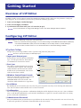 2
2
-
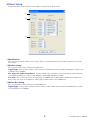 3
3
-
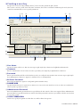 4
4
-
 5
5
-
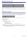 6
6
-
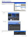 7
7
-
 8
8
-
 9
9
-
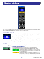 10
10
-
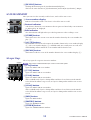 11
11
-
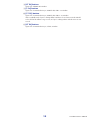 12
12
-
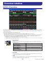 13
13
-
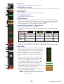 14
14
-
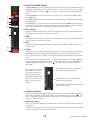 15
15
-
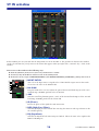 16
16
-
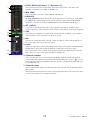 17
17
-
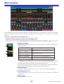 18
18
-
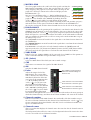 19
19
-
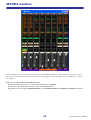 20
20
-
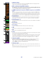 21
21
-
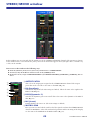 22
22
-
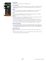 23
23
-
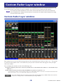 24
24
-
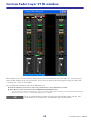 25
25
-
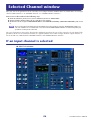 26
26
-
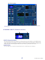 27
27
-
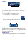 28
28
-
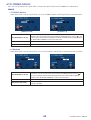 29
29
-
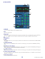 30
30
-
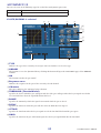 31
31
-
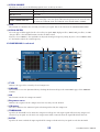 32
32
-
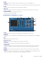 33
33
-
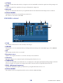 34
34
-
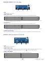 35
35
-
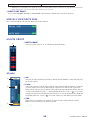 36
36
-
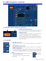 37
37
-
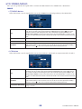 38
38
-
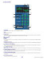 39
39
-
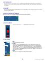 40
40
-
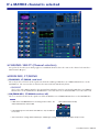 41
41
-
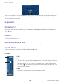 42
42
-
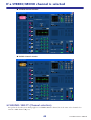 43
43
-
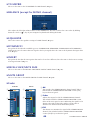 44
44
-
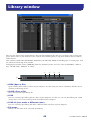 45
45
-
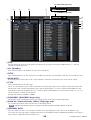 46
46
-
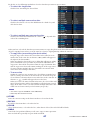 47
47
-
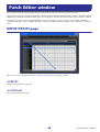 48
48
-
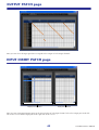 49
49
-
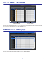 50
50
-
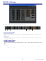 51
51
-
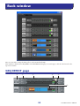 52
52
-
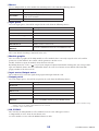 53
53
-
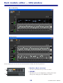 54
54
-
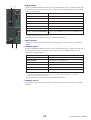 55
55
-
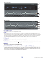 56
56
-
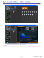 57
57
-
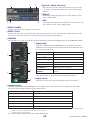 58
58
-
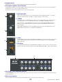 59
59
-
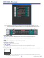 60
60
-
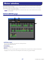 61
61
-
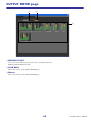 62
62
-
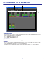 63
63
-
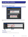 64
64
-
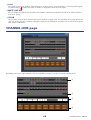 65
65
-
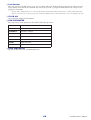 66
66
-
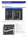 67
67
-
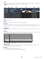 68
68
-
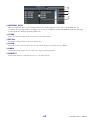 69
69
-
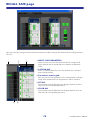 70
70
-
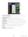 71
71
-
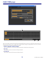 72
72
-
 73
73
-
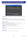 74
74
-
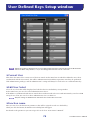 75
75
-
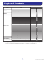 76
76
-
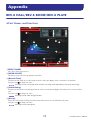 77
77
-
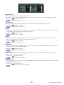 78
78
-
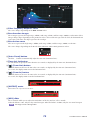 79
79
-
 80
80


Yamaha LS9 Handleiding
- Categorie
- Audio-equalizers
- Type
- Handleiding
- Deze handleiding is ook geschikt voor
in andere talen
- English: Yamaha LS9 User manual
- italiano: Yamaha LS9 Manuale utente
- русский: Yamaha LS9 Руководство пользователя
- français: Yamaha LS9 Manuel utilisateur
- español: Yamaha LS9 Manual de usuario
- Deutsch: Yamaha LS9 Benutzerhandbuch
- português: Yamaha LS9 Manual do usuário
- dansk: Yamaha LS9 Brugermanual
- suomi: Yamaha LS9 Ohjekirja
- čeština: Yamaha LS9 Uživatelský manuál
- svenska: Yamaha LS9 Användarmanual
- Türkçe: Yamaha LS9 Kullanım kılavuzu
- polski: Yamaha LS9 Instrukcja obsługi
- română: Yamaha LS9 Manual de utilizare