Yamaha CP5 Handleiding
- Categorie
- Digitale piano's
- Type
- Handleiding
Deze handleiding is ook geschikt voor

1 CP5 /CP50 Reference Manual
Yamaha Corp. reserves the right to update or modify this manual at any time without prior notice.
The most up-to-date version is freely available for download from the following web page.
http://www.yamaha.co.jp/manual/
Contents
Reference Guides ..........................................................................................2
Using this Reference Manual ........................................................................2
Internal Design of the CP5 & CP50 3
Principal Components ...................................................................................3
Tone Generator .............................................................................................4
Song Setting Area .......................................................................................10
Controller ....................................................................................................11
Reference 12
Left & Right Parts ........................................................................................12
Song Setting Area .......................................................................................35
TRACK Part .................................................................................................39
MIC INPUT Part (CP5 only) .........................................................................40
Settings for All Parts ....................................................................................42
Settings for All Performances ......................................................................43
Appendix 54
MIDI .............................................................................................................54
Reference Manual

2 CP5/CP50 Reference Manual
Reference Guides
Reference Guides
Your CP5 or CP50 stage piano comes with three different reference guides — the Owner’s Manual, the Reference Manual
(this document), and the Data List. While the Owner’s Manual is packaged together with the stage piano as a hardcopy
booklet, this Reference Manual and the Data List are provided as pdf documents on the bundled CD-ROM.
Owner’s Manual (hardcopy booklet)
The Owner’s Manual describes how to set up your CP5 or CP50 and how to perform basic operations.
Reference Manual (this pdf document)
This Reference Manual describes the internal design of your CP5 or CP50 and the various parameters that can be
adjusted and set.
Data List (pdf document)
The Data List document provides a list of all CP5 or CP50 presets (or Performances); a breakdown of the types of Modu-
lation Effect and Power-Amplifier / Compressor
*
blocks available for selection; a list of the parameters that can be set for
each of these blocks; and MIDI-related reference material. (
*
: CP5 only)
Using this Reference Manual
The first page of the section Internal Design of the CP5 & CP50 contains a block diagram illustrating the vari-
ous components of your stage piano’s sound production system, and by clicking any of the arrows within
this diagram, you can conveniently jump to a description of the corresponding component.
Using the tabs along the right side of each page from the Reference section, you can easily access details
regarding the parts making up each Performance and the various setting areas opened by pressing buttons
on the control panel. These tabs also serve as a useful means of quickly getting to grips with the internal
design of your CP5 or CP50 and with how the various setting areas and control-panel buttons are related to
each other. Furthermore, you can also click on the Internal Design of the CP5 & CP50 and Appendix tabs at
the top and bottom of the list to jump to the corresponding sections.
You can click on any page number from the Table of Contents or within descriptive text to jump to the corre-
sponding page.
By clicking on items or topics you would like to read about from the Bookmarks index on the left of the main
pdf display window, you can jump to the corresponding page. (Click the Bookmarks tab in the top-left corner
to open this index if it is not already displayed.)
For information on a specific topic, function, or feature, select Find or Search from the Adobe Reader Edit
menu and enter a keyword to locate the related information anywhere within this document.
NOTE The most-recent version of Adobe Reader can be downloaded from the following web page.
http://www.adobe.com/products/reader/
NOTE The names and positions of menu items may vary depending on the version of Adobe Reader being used.
Information
• The illustrations and LCD screens as shown in this manual are for instructional purposes only, and may appear
somewhat different from those on your instrument.
• The company names and product names in this manual are the trademarks or registered trademarks of their
respective companies.

3 CP5/CP50 Reference Manual
Internal Design of the CP5 & CP50
Principal Components
The internal design of your CP5 or CP50 is divided into three main sections — namely, the Tone Generator, the Song Set-
ting area, and the Controller.
CP5/CP50
MIDI IN
Controller
MIDI OUT
Tone Generator Song Setting Area
User Songs
Preset Drum Patterns
Audio record
and play
Wave
USB flash-memory device
Performances
LEFT1/LEFT RIGHT1/RIGHT
LEFT2
*
RIGHT2
*
TRACK
MIC INPUT
*
Reverb
block
Master
Compressor
block
Master
Equalizer
block
MIC INPUT
*
*
: Components available on CP5 only.
Click from the diagram to jump to the corresponding page.
MIDI record
and play
Audio output

4 CP5/CP50 Reference Manual
Internal Design of the CP5 & CP50 > Tone Generator
Tone Generator
Your stage piano's Tone Generator produces sounds based on performance data that you create by playing the key-
board, operating the sequencer, and using various controllers. In specific terms, the Tone Generator is made up of Per-
formances, a Master Compressor block, and a Master Equalizer block. The term “Performance” is used to describe a
single preset that allows a number of voices to be produced together.
Meanwhile, the Master Compressor block and the Master Equalizer block are used to adjust the dynamics and tone of
the sounds produced by individual Performances. Master Compressor and Master Equalizer settings are stored sepa-
rately from Performances; therefore, they affect the stage piano as a whole and can be adjusted to perfectly match the
environment in which it is being played. The basic flow of signals between these components is as follows.
Each Performance comprises a number of different parts and a Reverb block. As shown below, CP5 Performances con-
tain six different parts, while CP50 Performances have three. Furthermore, the types of sound that can be handled vary
from part to part. For more information on parts, see page 5.
CP5 Parts
• Left and right parts: LEFT1, LEFT2, RIGHT1, and RIGHT2
• TRACK part
• MIC INPUT part
CP50 Parts
• Left and right parts: LEFT and RIGHT
• TRACK part
The sound of each Performance is completed by applying a common reverb effect to the sound of each of the selected
parts. As a final step, furthermore, the sound of the stage piano itself can be perfectly matched to its playing environment
by setting the Master Compressor and Master Equalizer blocks, which affect all Performances in the same way.
Performance
LEFT1/LEFT
LEFT2
*
RIGHT1/RIGHT
RIGHT2
*
TRACK
MIC INPUT
*
Parts
Reverb
block
Master
Compressor
block
Master
Equalizer
block
*
:The LEFT2, RIGHT2, and MIC INPUT parts are available
on the CP5 only.

5 CP5/CP50 Reference Manual
Internal Design of the CP5 & CP50 > Tone Generator
Left & Right Parts
The left and right parts that make up each Performance respond to your playing of the keyboard or to MIDI input and use
the built-in Tone Generator to produce the appropriate sounds in response. The CP5 has four such parts — LEFT1,
LEFT2, RIGHT1, and RIGHT2 — while the CP50 has two — LEFT and RIGHT. Regardless of the number available, you
can freely arrange these parts in a layered configuration or a split configuration for left and right hands to best suit your
playing style. When layering parts, overlapping playing sections are defined by setting note limits for each (page 32).
When splitting parts, meanwhile, a split point is set (page 31) so that notes to the left and right of that point can be played
using the left and right parts, respectively. Layering and splitting can be setup using the Split parameter (page 31) from
the Common Settings area.
Each CP5 part is subdivided into four distinct blocks known as the Voice block, the Pre-Amplifier block, the Modulation
Effect block, and the Power-Amplifier / Compressor block. In the CP50, meanwhile, three blocks are used for each part
— namely, the Voice block, the Pre-Amplifier block, and the Modulation Effect block.
In these blocks, we have recreated the unique sounds not only of acoustic pianos and classic electric pianos, but also of
a wide range of effect units, amplifiers, and other devices commonly used with each in actual performance and record-
ing settings. Using the Piano Customize function to freely assemble blocks, you can both replicate standard vintage set-
tings and also create original hardware combinations that would never be possible in the real world. Furthermore, your
CP5 or CP50 also comes complete with many other voices such as strings and guitars, and these can be combined with
piano voices to produce unique, exciting sounds.
Each Performance allows the sounds produced by its various parts to be sent through the common Reverb block for fin-
ishing. In addition, Performances also contain a Common Settings area that allows a name, a keyboard mode, and con-
troller parameters to be set for each. These common settings can be used to make final adjustments to the individual
Performances that you create.
Meanwhile, your CP5 or CP50 is pre-loaded with an impressive selection of Preset Performances, specially created by
artfully combining the above-described parts and blocks to produce just the right sounds. Finally, the Master Compres-
sor and Master Equalizer blocks, which affect all Performances in the same way, can be used to ensure that the sound of
your stage piano is always perfectly matched to its playing environment.
Layered parts
LEFT1 or LEFT
LEFT2
*
RIGHT1 or RIGHT
RIGHT2
*
Split parts
Split point
RIGHT1 or RIGHT LEFT1 or LEFT
RIGHT2
*
LEFT2
*
*
Parts available on CP5 only.
Parts
Voice
block
Pre-Amplifier
block
Modulation
Effect block
Power-Amplifier /
Compressor block
*
*
Only CP5 parts feature a Power-Amplifier / Compressor block.

6 CP5/CP50 Reference Manual
Internal Design of the CP5 & CP50 > Tone Generator
Roles of Blocks & Common Settings Area
The roles of each of the blocks and the Common Settings area that make up CP5 and CP50 parts are as follows.
Voice Block
The Voice block is used to specify the type of musical-instrument sound that will be produced for the corresponding part
by the Tone Generator. Using a range of advanced sound-synthesis techniques, your CP5 or CP50 can faithfully repro-
duce the unique sonic characteristics of a broad spectrum of acoustic pianos and classic electric pianos. In addition to
piano sounds, furthermore, Voice blocks also offer a selection of other types of musical instruments, such as strings, gui-
tar, and bass, and these are conveniently arranged into different instrument categories. For more information regarding
piano voices (as selected from the PIANO and E.PIANO categories), refer to Voice Block (page 12) from the Reference
section below. For more information regarding other instrument categories and voices, refer to the Data List pdf docu-
ment.
Pre-Amplifier Block
The Pre-Amplifier block is used to set pre-amplifier parameters and to make other adjustments uniquely affecting piano
voices. As such, this block is available only when a piano voice has been selected (from the PIANO or E.PIANO cate-
gory). In addition to pre-amplifiers actually used with various types of pianos in live performance settings, the Pre-Ampli-
fier block also replicates many other parameters perfectly configured for the enhancement of piano sounds. Whenever
you select a voice from the PIANO or E.PIANO category within the Voice block, a specific set of parameters for that par-
ticular voice will be made available in the Pre-Amplifier block. For details on Pre-Amplifier block parameters, see Pre-
Amplifier Block (page 13) from the Reference section below.
Modulation Effect Block
Within each Modulation Effect block, you will find a versatile collection of modulation-type effects that are indispensable
to piano sound design for stage and recording environments. Positioned immediately after the Voice and Pre-Amplifier
blocks for the corresponding part, this block processes to the raw instrument sound. Whenever a non-piano voice is
selected within the Voice block, furthermore, the Modulation Effect block functions as an insertion effect. Using Modula-
tion Effect blocks, individual parts can be processed with different effects, each of which features a number of freely-
adjustable parameters. For details on the types of modulation effect available for use and the corresponding parameters,
see Modulation Effect Block (page 15) from the Reference section below.
Power-Amplifier / Compressor Block (CP5 only)
For further shaping of voices, the Power-Amplifier / Compressor block contained within each CP5 part can be used to
select either a power amplifier or a compressor, each of which is modeled with remarkable levels of precision. Positioned
immediately after the part’s Modulation Effect block, this block adjusts the overall tone. Whenever a non-piano voice is
selected within the Voice block, furthermore, the Power-Amplifier / Compressor block functions as an insert-type effect.
Using Power-Amplifier / Compressor blocks, individual parts can be processed with different effects, each of which fea-
tures a number of freely-adjustable parameters. For details on the types of power-amplifier and the compressor available
for use and the corresponding parameters, see Power-Amplifier / Compressor Block (page 25) from the Reference sec-
tion below.
Common Settings Area
The Common Settings area is used to assign names to your Performances, to specify a keyboard mode for the left and
right parts, and to setup controllers. If you wish to use your CP5 or CP50 as a master keyboard for controlling other MIDI
devices, the relevant settings are made here. For details on Common Settings area parameters, see Common (page 31)
from the Reference section below.

7 CP5/CP50 Reference Manual
Internal Design of the CP5 & CP50 > Tone Generator
TRACK Part
Each CP5 or CP50 Performance can also contain a backing track for playing back as an accompaniment to your key-
board performances. Three different types of backing track can be selected — namely, Preset Drum Patterns, User
Songs, and Wave files. Whenever you select a Preset Drum Pattern or a Wave file located on a USB flash-memory
device, the TRACK part can be used to set its volume, pan, and reverb send level. For more details on these parameters,
see TRACK Part (page 39) from the Reference section below.
MIC INPUT Part (CP5 only)
With the CP5, a microphone can be plugged into the MIC INPUT connector so that you can conveniently sing along as
you play. Each CP5 Performance features a MIC INPUT part that can be used to adjust the volume, pan, and effect set-
tings for the audio input via this connector. Furthermore, this audio can also be processed using a noise gate, compres-
sor, equalizer, and insertion effect. For more details, see MIC INPUT Part (page 40) from the Reference section below.
Reverb Block
The Reverb block on your CP5 or CP50 provides a host of exquisite reverb algorithms originally developed by Yamaha
for use in professional-audio applications. This block allows a common reverb effect to be applied to all parts from the
current Performance, and each features a number of freely configurable parameters. For details on the types of reverb
effect available for use and the corresponding parameters, see Reverb (page 42) from the Reference section below.
Makeup of Performance Memories
Your CP5 or CP50 can store Performances in three main memory areas — namely, the Preset Performance memory, the
User Performance memory, and an External Performance memory. The specific roles of each of these memory areas are
described below.
Preset Performance Memory
Accessed using the [PRE] button, the Preset Performance memory is used to hold the Performance presets that come
ready-made with your CP5 or CP50. This memory area contains three individual memory banks — PRE1, PRE2, and
PRE3. Each time you press the [PRE] button, a different Preset Performance memory bank will be selected. Four memory
groups (A, B, C, and D) are contained within each memory bank, and each one of these groups can hold ten Perfor-
mances. Press one of the group buttons [A] to [D] followed by one of the number buttons [1] to [10] to choose the corre-
sponding Performance from the currently selected External Performance memory bank. In order that they will always be
available for use, Preset Performances cannot be overwritten with other Performances that you have modified or created.
As such, the Preset Performance memory is read-only.
NOTE Performance 1 from Group A within the PRE1 memory bank will always be selected when you press the [PRE] button while
holding down the [EXIT] button.
NOTE For a list of all Preset Performances, see the Data List pdf document.
User Performance Memory
Accessed using the [USER] button, the User Performance memory is used to store original Performances that you have
created. This memory area contains three individual memory banks — USR1, USR2, and USR3. Each time you press the
[USER] button, a different User Performance memory bank will be selected. Four memory groups (A, B, C, and D) are
contained within each memory bank, and each one of these groups can hold ten Performances. Press one of the group
buttons [A] to [D] followed by one of the number buttons [1] to [10] to choose the corresponding Performance from the
currently selected User Performance memory bank. In the stage piano's default condition, the User Performance mem-
ory contains exactly the same content as the Preset Performance memory.
MIC INPUT Part
MIC INPUT Insertion EffectNoise Gate Compressor EQ

8 CP5/CP50 Reference Manual
Internal Design of the CP5 & CP50 > Tone Generator
NOTICE
If you overwrite a Performance in the User Performance memory, it will be permanently deleted. In order to avoid loosing
irreplaceable data, therefore, you should take special care when selecting where to store newly-created Performances.
NOTE Performance 1 from Group A within the USR1 memory bank will always be selected when you press the [USER] button while
holding down the [EXIT] button.
External Performance Memory
Accessed using the [EXT] button, an External Performance memory is read into your CP5 or CP50 from a plugged-in
USB flash-memory device. This memory area can be used to store original Performances that you have created, and it
contains three individual memory banks — EXT1, EXT2, and EXT3. Each time you press the [EXT] button, a different
External Performance memory bank will be selected. Four memory groups (A, B, C, and D) are contained within each
memory bank, and each one of these groups can hold ten Performances. Press one of the group buttons [A] to [D] fol-
lowed by one of the number buttons [1] to [10] to choose the corresponding Performance from the currently selected
External Performance memory bank. In order to use an External Performance memory stored on a USB flash-memory
device, the memory device must be plugged into your CP5 or CP50, and the stage piano must have loaded the corre-
sponding data into a dedicated section of its internal memory (DRAM).
NOTE Performance 1 from Group A within the EXT1 memory bank will always be selected when you press the [EXT] button while
holding down the [EXIT] button.
Preset Performance Memory User Performance Memory
Group A
PRE1 bank PRE2 bank PRE3 bank
Group B
PRE1 bank
Performance
Numbers 1 to 10
Group A
Performance
Numbers 1 to 10
Group A
Performance
Numbers 1 to 10
Group B
Performance
Numbers 1 to 10
Group B
Performance
Numbers 1 to 10
Group B
Performance
Numbers 1 to 10
Group C
Performance
Numbers 1 to 10
Group C
Performance
Numbers 1 to 10
Group C
Performance
Numbers 1 to 10
Group D
Performance
Numbers 1 to 10
Group D
Performance
Numbers 1 to 10
Group D
Performance
Numbers 1 to 10
PRE1 bank USR2 bank USR3 bankUSR1 bank
Group A
Performance
Numbers 1 to 10
Group A
Performance
Numbers 1 to 10
Group A
Performance
Numbers 1 to 10
Group B
Performance
Numbers 1 to 10
Group B
Performance
Numbers 1 to 10
Performance
Numbers 1 to 10
Group C
Performance
Numbers 1 to 10
Group C
Performance
Numbers 1 to 10
Group C
Performance
Numbers 1 to 10
Group D
Performance
Numbers 1 to 10
Group D
Performance
Numbers 1 to 10
Group D
Performance
Numbers 1 to 10
External Performance Memory
Group B
EXT2 bank EXT3 bank EXT1 bank
Group A
Performance
Numbers 1 to 10
Group A
Performance
Numbers 1 to 10
Group A
Performance
Numbers 1 to 10
Group B
Performance
Numbers 1 to 10
Group B
Performance
Numbers 1 to 10
Performance
Numbers 1 to 10
Group C
Performance
Numbers 1 to 10
Group C
Performance
Numbers 1 to 10
Group C
Performance
Numbers 1 to 10
Group D
Performance
Numbers 1 to 10
Group D
Performance
Numbers 1 to 10
Group D
Performance
Numbers 1 to 10

9 CP5/CP50 Reference Manual
Internal Design of the CP5 & CP50 > Tone Generator
HINT
Using External Performance Memories
In order to save Performances in an External Performance memory or to use an External Performance memory from a USB
flash-memory device, the USB flash-memory device in question must be plugged into your CP5 or CP50. When you do so,
the stage piano will behave in a number of different ways depending on whether or not it already contains an External
Performance memory and when the USB flash-memory device was last plugged in. Each of these actions is described
below.
Root directory does not contain an External Performance memory:
As soon as you plug in a USB flash-memory device, your stage piano will check its root directory for an External
Performance memory. If none exists, it will create one in the form of a file named EXTBANK.C5E or EXTBANK.C6E.
Root directory contains an External Performance memory:
If an External Performance memory already exists in the root directory of the USB flash-memory device, the action taken will
— as described below — depend on whether or not that specific memory device was previously plugged in and removed
after you turned on the stage piano.
• Not previously plugged in after turning on the stage piano:
If the USB flash-memory device is being plugged in for the first time after turning on your CP5 or CP50, the data from its
External Performance memory will be automatically loaded into a dedicated section of the instrument's internal memory
(DRAM).
NOTE If a different USB flash-memory device has already been plugged in and removed after turning on the stage piano, the
instrument will operate in line with the description from Previously plugged in after turning on the stage piano (below).
NOTICE
Whenever an External Performance memory from a USB flash-memory device is loaded into the stage piano, all External
Performance memory data from the DRAM and data in the Edit Buffer will be overwritten. Before plugging in a USB flash-
memory device, therefore, be sure to store any important External Performances residing in the DRAM and any
Performances located within the Edit Buffer and containing unsaved modifications.
• Previously plugged in after turning on the stage piano:
Whenever you plug in a USB flash-memory device that has already been plugged in and removed at least once after
turning on the stage piano, you will be asked whether or not its External Performance memory should be loaded. If the
External Performance memory currently loaded into the stage piano contains irreplaceable Performances with unsaved
modifications, be sure to press Knob 3 (NO [PUSH]) at this time.

10 CP5/CP50 Reference Manual
Internal Design of the CP5 & CP50 > Song Setting Area
Song Setting Area
The Song Setting area is used to record and play MIDI sequences and audio files for use as Performance backing
tracks. MIDI sequences can take the form of built-in Preset Drum Patterns (playback only) or User Songs that you can
both record and play. Meanwhile, the Song Setting area’s audio functions allow you to record Wave files to a USB flash-
memory device and to play back Wave files previously stored on such a device.
Recording MIDI & Audio Data
Recording of User Songs and Wave files is carried out using the Record screen (page 37). In the case of User Songs,
you record your keyboard performance as MIDI data, and this can be played back using the sound created by the cur-
rent Performance’s left and right parts. When creating Wave files for direct storage as audio data on a USB flash-memory
device, meanwhile, you can record your keyboard performance together with the Preset Drum Pattern or User Song set
as the backing track. It should be noted that Preset Drum Patterns cannot be re-recorded as MIDI data on the stage
piano, and that recorded MIDI data cannot be stored as Preset Drum Patterns.
Playing MIDI & Audio Data
For each Performance, you can choose a single Preset Drum Pattern, User Song, or Wave file for playback as a backing
track, and this selection is made on the Song Setting screen (page 35). The actual part(s) that will be used for playback
will depend on the type of backing track that you select. Preset Drum Patterns and Wave files are handled by the TRACK
part (page 7) from the Tone Generator’s currently-selected Performance, and within this part, you can set the backing
track’s volume, pan, and effect send level.
Preset Drum Patterns are MIDI sequences that play built-in drum kit sounds totally unrelated to the voices selected for
the Performance’s left and right parts; therefore, they will always play back using the drum kit sounds selected on the
Song Setting screen, regardless of left and right part settings. User Songs, on the other hand, are handled by left and
right parts (page 5), and for this reason, the sound that they produce will be affected by these parts’ voice and effect set-
tings. As these MIDI sequences are recorded using the sound of the left and right parts, they function perfectly as back-
ing tracks for the corresponding Performance.
Song Setting Area
MIDI record
and play
User Songs
Preset Drum
Patterns
Audio record
and play
Wave
USB flash-memory device
Tone Generator
Performances
Reverb
block
Master
Compressor
block
Master
Equalizer
block
Audio output
*
Parts available on CP5 only.
LEFT1/LEFT RIGHT1/RIGHT
LEFT2
*
RIGHT2
*
TRACK
MIC INPUT*

11 CP5/CP50 Reference Manual
Internal Design of the CP5 & CP50 > Controller
Controller
Your stage piano’s Controller consists of the keyboard, pitch bend wheel, knobs, foot pedals, and other input devices
used while playing. It is important to bear in mind that the keyboard itself does not generate any sound; instead, it sends
note, velocity, and other performance-related signals to a tone generator, which then produces sounds in response. In
the same way, the other Controller devices also send signals to the tone generator whenever they are operated. Specifi-
cally speaking, the signals produced and sent by the keyboard and other devices are MIDI messages, and therefore,
they can also be sent to other MIDI devices or a computer via the MIDI OUT connector or the USB TO HOST port. Please
note, however, that data produced by the knobs is not output from the instrument in this way.

Internal Design of the CP5 & CP50
Reference
Left & Right Parts
[VOICE]
[PRE-AMP]
[MOD-FX]
[PWR-AMP] (CP5 only)
[LEFT1]/[LEFT2]/[RIGHT1]/
[RIGHT2] (CP5)
[LEFT]/[RIGHT] (CP50)
[COMMON]
Song Setting Area
[SONG SETTING]
[RECORD]
TRACK Part
[TRACK]
MIC INPUT Part
[MIC INPUT] (CP5 only)
Settings for All Parts
[REVERB]
Settings for All Performances
[MASTER COMPRESSOR]
[UTILITY]
[FILE]
Appendix
12 CP5/CP50 Reference Manual
Reference
This section provides a detailed description of the parameters used to configure your CP5 or CP50.
Left & Right Parts
The following describes the parameters that can be set for left and right parts on a block-by-block
basis. These descriptions apply to the LEFT1, LEFT2, RIGHT1, and RIGHT2 parts on the CP5, and
to the LEFT and RIGHT parts on the CP50.
Voice Block
The Voice block is used to set a basic sound for the currently selected part.
Configuring Voice Parameters
Voices on your CP5 or CP50 are arranged into a number of different categories based on instru-
ment type or sound characteristics (i.e., piano, guitar, bass, etc.). For the purpose of explanation,
this section will introduce the voices from the PIANO and E.PIANO (electric piano) categories as
typical examples of the voices available on your stage piano. For details regarding all categories
and voices, refer to the Data List pdf document.
Edit Sequence Press the [VOICE] button Turn Knob 1 and Knob 2 or press buttons [1] to [10]
Voice name Description
PIANO Category
CF Grand* The CF Grand piano has a straightforward sound, making it suitable for practically all musical
genres. Featuring a broad dynamic range, this piano type provides for highly expressive perfor-
mances.
S6 Grand*
(CP5 only)
In contrast to the two CF-series pianos, the S6 Grand has a more compact, woody sound. Allowing
you to play with both warmth and power, it is ideal for a diverse range of musical genres.
E. PIANO Category
CP80* Reproducing the classic sound of the Yamaha CP80 Electric Grand Piano, the CP80 piano type can
also be used to recreate an unique “Eighties” feel by boosting the high frequencies with the accom-
panying pre-amplifier.
CP88* The CP88 piano and accompanying pre-amplifier deliver a nostalgia-laden sound distinctive of the
Yamaha CP80 Electric Grand Piano, particularly in the mid-frequency range.
71Rd I
(CP5 only)
The 71Rd I is the earliest-sounding of the CP5's Rd-series electric pianos. With the soft attack and
fast decay distinctive of felt hammers, it produces a mellow, hollow tone.
73Rd I
(CP5 only)
The 73Rd I piano replicates an electric piano with rubber-topped hammers, and compared to the
71 Rd I, it has a slightly brighter, more sustained tone. Overall, this Rd-series piano produces a
dark, heavy sound.
75Rd I The 75Rd I piano reproduces the bright, sustained sound of an electric piano featuring high-perfor-
mance versions of tines, pickups, and other sound-generating components.
78Rd II
(CP5 only)
Replicating the effect of plastic hammers and a high-fidelity, integrated-circuit pre-amplifier, the
78Rd II boasts the brightest sound of the Rd series.
Dyno
(CP5 only)
The Dyno piano type significantly boosts the high-frequency range of the 78Rd II to give a sparkling
“Eighties” sound.
69Wr In contrast to the Rd piano types provided by the CP5 or CP50. the 69Wr is characterized by a gen-
tle attack and fast decay. Furthermore, this piano type features a tight dynamic range.
77Wr Rounding off the vintage electric piano lineup of CP5 or CP50, the 77Wr piano type features a stron-
ger attack and more brilliant overall tone than the 69Wr.
DX Legend The DX Legend reproduces the indispensable vintage sound of the DX electric piano, which
remains a classic even to this day.

Internal Design of the CP5 & CP50
Reference
Left & Right Parts
[VOICE]
[PRE-AMP]
[MOD-FX]
[PWR-AMP] (CP5 only)
[LEFT1]/[LEFT2]/[RIGHT1]/
[RIGHT2] (CP5)
[LEFT]/[RIGHT] (CP50)
[COMMON]
Song Setting Area
[SONG SETTING]
[RECORD]
TRACK Part
[TRACK]
MIC INPUT Part
[MIC INPUT] (CP5 only)
Settings for All Parts
[REVERB]
Settings for All Performances
[MASTER COMPRESSOR]
[UTILITY]
[FILE]
Appendix
13 CP5/CP50 Reference Manual
NOTE Piano types marked with an asterisk (*) can have their tuning adjusted by setting the TunCrv parameter (Tuning Curve)
to “stretch” (page 44).
Pre-Amplifier Block
The Pre-Amplifier block has an effect on the sound only when a voice from the PIANO or E.PIANO
category has been selected for the part in question. In such a case, furthermore, a unique set of
parameters specifically for the selected type of piano will be made available in this block.
Configuring Pre-Amplifier Block Parameters
Pre-Amplifier block parameters are chosen automatically based on the type of piano voice selected
so that the sound of that voice can be perfectly adjusted. For this reason, the parameters displayed
will vary from voice to voice. In the following table, you will find a description of all of this block’s
parameters in alphabetic order.
DX Woody With its rich, woody body, the DX Woody voice delivers a mellower electric-piano sound.
DX FTine Recreating a classic voice from the DX electric piano, the DX FTine shows off the characteristic
attack sound of this instrument.
DX 7 II With the body portion of the sound changing in response to how you play, the DX 7 II will allow you
to experience the wonderful richness of expression for which the DX electric piano was renowned.
DX Mellow The DX Mellow voice is gentle and well suited to ballads; however, powerful playing will still pro-
duce a much harder sound.
DX Crisp Although relatively full-bodied, the DX Crisp remains highly present within an ensemble thanks to its
unique attack sound.
Edit Sequence
Press and hold the [PRE-AMP] button (for at least one second) Navigate to the
required page using the [ PAGE] and [PAGE ] buttons Turn Knobs 1 to 3
On-screen name
(and full name)
Associated voices Description
B Bass CP80, CP88, 71Rd I,
73Rd I, 75Rd I, 78Rd II,
Dyno, 69Wr, and 77Wr
This parameter is used to adjust the volume of the
low-frequency component.
Brill. (Brilliance) CP80 and CP88 This parameter is used to adjust the brightness of
the sounds produced.
D DampReso
(Damper Resonance
Level)
CF Grand and S6 Grand This parameter is used in combination with a con-
nected Sustain pedal to recreate the sound of
strings resonating in response to pressing of an
acoustic piano's damper pedal. In specific terms,
the DampReso parameter sets the depth of this
resonance.
Setting values: -16 to +16
Decay (Decay Time) All piano voices This parameter is used to adjust how fast a note
decays while the key is being held down.
Setting values: -16 to +16
NOTE The same setting can be made using the
EGDcy parameter (page 29) from the Part
Setting screen.
Depth (Vibrato Depth) 71Rd I, 73Rd I, 75Rd I,
78Rd II, 69Wr, and 77Wr
This parameter is used to adjust the depth of the
pre-amplifier vibrato.
G Gain (Input Gain) All voices from E.PIANO
category
This parameter is used to adjust the volume of the
signal input into the Pre-Amplifier block.
Voice name Description

Internal Design of the CP5 & CP50
Reference
Left & Right Parts
[VOICE]
[PRE-AMP]
[MOD-FX]
[PWR-AMP] (CP5 only)
[LEFT1]/[LEFT2]/[RIGHT1]/
[RIGHT2] (CP5)
[LEFT]/[RIGHT] (CP50)
[COMMON]
Song Setting Area
[SONG SETTING]
[RECORD]
TRACK Part
[TRACK]
MIC INPUT Part
[MIC INPUT] (CP5 only)
Settings for All Parts
[REVERB]
Settings for All Performances
[MASTER COMPRESSOR]
[UTILITY]
[FILE]
Appendix
14 CP5/CP50 Reference Manual
NOTE Output from the Pre-Amplifier block will be muted briefly whenever one of the following tone-control parameters is
modified.
• CP80 or CP88 pre-amplifier: Bass, Middle, Treble, or Brill
• 71Rd I, 73Rd I, or 75Rd I pre-amplifier: Bass
• 78Rd II pre-amplifier: Tre b l e
• Dyno pre-amplifier: Bass or Overtone
H Hammer
(Hammer Stiffness)
CP5 only — CF Grand,
S6 Grand, CP80, CP88,
71Rd I, 73Rd I, 75Rd I,
78Rd II, Dyno, 69Wr, and
77Wr
This parameter is used to adjust the apparent soft-
ness or hardness of the piano sound in much the
same way as if softer or harder hammers were
used to strike the strings. It is available on the CP5
only.
Setting values: Soft2, Soft1, Normal, Hard1, and
Hard2
High DX Legend, DX Woody,
DX FTine, DX 7 II,
DX Mellow, and DX Crisp
This parameter is used to adjust the volume of the
high-frequency component.
HighMid (High Middle) DX Legend, DX Woody,
DX FTine, DX 7 II,
DX Mellow, and DX Crisp
This parameter is used to adjust the volume of the
high-middle frequency component.
K Key-off
(Key-off Noise Level)
CF Grand, S6 Grand,
CP80, CP88, 71Rd I, 73Rd
I, 75Rd I, 78Rd II, Dyno,
69Wr, and 77Wr
This parameter is used to recreate the sound of
dampers pressing against the strings when you
remove your fingers from the keyboard. In specific
terms, the Key-off parameter sets the volume of
this key-off noise.
Setting values: -16 to +16
L Low DX Legend, DX Woody,
DX FTine, DX 7 II,
DX Mellow, and DX Crisp
This parameter is used to adjust the volume of the
low-frequency component.
LowMid (Low middle) DX Legend, DX Woody,
DX FTine, DX 7 II,
DX Mellow, and DX Crisp
This parameter is used to adjust the volume of the
low-middle frequency component.
M Middle CP80 and CP88 This parameter is used to adjust the volume of the
mid-frequency component.
MidBoost (Mid Boost) 69Wr and 77Wr This parameter is used to adjust the volume of the
mid-frequency component.
N Normal Dyno This parameter is used to adjust the volume of the
mid-frequency component.
O Overtone Dyno This parameter is used to adjust the volume of the
high-frequency component.
R Release (Release Time) All piano voices This parameter is used to adjust how fast a note
decays after the key is released.
Setting values: -16 to +16
NOTE The same setting can be made using the
EGRel parameter (page 29) from the Part
Setting screen.
S Speed (Vibrato Speed) 71Rd I, 73Rd I, 75Rd I,
and 78Rd II
This parameter is used to adjust the speed of the
pre-amplifier vibrato.
StrkPos (Striking Position) 71Rd I, 73Rd II, 75Rd I,
78Rd II, Dyno, 69Wr, and
77Wr
This parameter is used to replicate the effect of
changing the position at which the resonators are
struck by the hammers.
Setting values: Top3 to Top1, Default, or Rear1 to
Rear3
T Tre bl e CP80, CP88, 71Rd I,
73Rd , 75Rd I, 78Rd II,
69Wr, and 77Wr
This parameter is used to adjust the volume of the
high-frequency component.
V Volume All voices from E.PIANO
category
This parameter is used to adjust the output vol-
ume. If set to 100 or greater when 71Rd I, 73Rd I,
75Rd I, 78Rd II, Dyno, 69Wr, or 77Wr has been set
as the part's voice, drive will also be added to the
sound.
On-screen name
(and full name)
Associated voices Description

Internal Design of the CP5 & CP50
Reference
Left & Right Parts
[VOICE]
[PRE-AMP]
[MOD-FX]
[PWR-AMP] (CP5 only)
[LEFT1]/[LEFT2]/[RIGHT1]/
[RIGHT2] (CP5)
[LEFT]/[RIGHT] (CP50)
[COMMON]
Song Setting Area
[SONG SETTING]
[RECORD]
TRACK Part
[TRACK]
MIC INPUT Part
[MIC INPUT] (CP5 only)
Settings for All Parts
[REVERB]
Settings for All Performances
[MASTER COMPRESSOR]
[UTILITY]
[FILE]
Appendix
15 CP5/CP50 Reference Manual
Modulation Effect Block
Using a Modulation Effect block, an audio effect can be applied to the part’s voice in order to mod-
ify its spatial characteristics.
Selecting Modulation Effect Block Types
The following tables identify and describe the different types of effect that can be selected in each
Modulation Effect block. If you have selected a voice from the PIANO or E.PIANO category for the
current part, this block’s selection page will give priority to a group of effects specially designed for
piano voices (i.e., the modulation effects). A range of additional general-purpose effects can also
be selected from the block’s Other group. Meanwhile, if you have selected a non-piano voice, all of
these effects
— including those primarily for piano voices — will be available for selection by cate-
gory as insertion effects.
For PIANO and E.PIANO voices:
Edit Sequence
Press and hold the [MOD-FX] button (for at least one second) Navigate to Page 1
using the [
PAGE] button if necessary Turn Knobs 1 to 3
On-screen name
(and full name)
Description
SmallPha (Small Phaser) Small Phaser operates like a vintage phaser, applying a unique sweeping effect.
Max90 Max90 emulates a vintage phaser, producing a more traditional-sounding effect.
Max100 Another vintage-type phaser, Max100 can modify the sound in a number of differ-
ent ways based on its Mode parameter setting.
Flanger The Flanger effect reproduces the sound of a vintage flanger.
TouchWah (Touch Wah) Touch Wah produces a classic filter-sweep effect in response to how hard or soft
the keyboard is played.
PedalWah (Pedal Wah) Another classic filter-sweep effect, Pedal Wah is operated using a pedal or
another controller. In order to use this effect, it is necessary to specify which con-
troller is to be used, and this can be done by selecting the controller on Page 4 of
the Common Settings screen (page 34) and setting “MdEffect” as its destination.
Chorus The Chorus effect applies a standard chorus.
D Chorus D Chorus produces a chorus effect that is more natural sounding, softer, and
wider.
816Cho (816Chorus) Famous for combining eight DX7s in a single rack unit, Yamaha's TX816 featured
a thick, detuned chorus sound that is reproduced here by the 816Chorus modula-
tion effect.
Sympho (Symphonic) Symphonic uses multi-stage modulation to produce a wider-sounding chorus.
Other The Other group contains general-purpose effects that are suitable for use with
voices other than those from the PIANO and E.PIANO categories. Within this
group, you can select from a wide range of effects in a number of different catego-
ries. See the table on the following page for more details regarding these catego-
ries and effects.
Selected modulation effect

Internal Design of the CP5 & CP50
Reference
Left & Right Parts
[VOICE]
[PRE-AMP]
[MOD-FX]
[PWR-AMP] (CP5 only)
[LEFT1]/[LEFT2]/[RIGHT1]/
[RIGHT2] (CP5)
[LEFT]/[RIGHT] (CP50)
[COMMON]
Song Setting Area
[SONG SETTING]
[RECORD]
TRACK Part
[TRACK]
MIC INPUT Part
[MIC INPUT] (CP5 only)
Settings for All Parts
[REVERB]
Settings for All Performances
[MASTER COMPRESSOR]
[UTILITY]
[FILE]
Appendix
16 CP5/CP50 Reference Manual
After selecting Other as the modulation effect type, you will be able to use Knobs 2 and 3 to choose
effect categories and individual effects. The following table identifies and describes the different
types of effect that are available for selection within the Other group.
On-screen name
(and full name)
Description
Effect category: Delay (DLY)
CrsDly (Cross Delay) Cross Delay contains two individual delays with cross-over feedback to produce a
sound that swirls between the left and right channels.
T-CrsDly (Tempo Cross Delay) Tempo Cross Delay processes sound in the same way as Cross Delay, but allows
the delay times to be synchronized with the playback tempo.
T-DlyMono
(Tempo Delay Mono)
Tempo Delay Mono is a monaural delay effect that allows the delay time to be syn-
chronized with the playback tempo.
T-DlySt (Tempo Delay Stereo) Tempo Delay Stereo is a stereo delay effect that allows the delay time to be syn-
chronized with the playback tempo.
DlyLR (Delay LR) Delay LR features a pair of left and right feedback-type delays.
DlyLCR (Delay LCR) Delay LCR features three individual delays, one each for the left, center, and right.
DlyLR(St) (Delay LR (Stereo)) Delay LR (Stereo) processes sound in the same way as Delay LR but has fully inde-
pendent left and right channels.
Effect category: Chorus (CHO)
G Cho (G Chorus) G Chorus produces a rich, deep chorus with complex modulation.
2Mod (2 Modulator) 2 Modulator is a chorus effect allowing pitch and amplitude modulation to be
adjusted for a more natural, spacious tone.
SPX Cho (SPX Chorus) The SPX Chorus effect enhances modulation and spaciousness using a three-
phase LFO.
Ensemble (Ensemble Detune) Ensemble Detune adds a slightly pitch-shifted sound to produce a modulation-free
chorus.
Effect category: Flanger (FLG)
ClscFlg (Classic Flanger) As its name suggests, Classic Flanger produces a conventional flanger effect.
T-Flg (Tempo Flanger) Tempo Flanger features an LFO that can be synchronized with the playback tempo.
DynaFlg (Dynamic Flanger) The Dynamic Flanger effect can control its delay modulation in real time based on
the level of the input signal.
Effect category: Phaser (PHA)
T-Pha (Tempo Phaser) Tempo Phaser features an LFO that can be synchronized with the playback tempo.
DynaPha (Dynamic Phaser) The Dynamic Phaser effect can control its phase shift in real time based on the
level of the input signal.
Effect category: Tremolo & Rotary (T&R)
AutoPan (Auto Pan) Auto Pan is an effect that cyclically moves the sound between left and right in the
stereo field.
Tremolo Tremolo is used to cyclically modulate the volume of the input signal.
Rotary (Rotary Speaker) Rotary Speaker simulates the unique sound of a classic rotary-type speaker.
Effect category Effect name

Internal Design of the CP5 & CP50
Reference
Left & Right Parts
[VOICE]
[PRE-AMP]
[MOD-FX]
[PWR-AMP] (CP5 only)
[LEFT1]/[LEFT2]/[RIGHT1]/
[RIGHT2] (CP5)
[LEFT]/[RIGHT] (CP50)
[COMMON]
Song Setting Area
[SONG SETTING]
[RECORD]
TRACK Part
[TRACK]
MIC INPUT Part
[MIC INPUT] (CP5 only)
Settings for All Parts
[REVERB]
Settings for All Performances
[MASTER COMPRESSOR]
[UTILITY]
[FILE]
Appendix
17 CP5/CP50 Reference Manual
Effect category: Distortion (DST)
AmpSim1 (Amp Simulator 1) Amp Simulator 1 replicates the sound produced by guitar amplifiers.
AmpSim2 (Amp Simulator 2) Amp Simulator 2 replicates the sound produced by guitar amplifiers.
CmpDst
(Compressor-Distortion)
Compressor & Distortion combines compression and distortion effects.
CmpDst+
(Compression-Distortion-
Delay)
The Compression-Distortion-Delay effect combines compression, distortion, and
delay effects.
Effect category: Compressor (CMP)
ClscCmp
(Classic Compressor)
Relatively fast-acting, the Classic Compressor effect is well suited to solo perfor-
mances.
MCmp
(Multiband Compressor)
Multiband Compressor can be used to apply compression independently in three
specific frequency bands.
Effect category: Lo-fi (L-F)
Lo-Fi Lo-Fi is used to creatively degrade the audio quality of the incoming signal.
Noisy The Noisy effect can be used to intentionally add noise to the input signal.
D-Turn (Digital Turntable) Digital Turntable adds the noise, clicks, and pops characteristic of old analog
records.
Effect category: Tech (TEC)
RingMod (Ring Modulator) Ring Modulator gives the input signal a more metallic sounding character.
DynaRing
(Dynamic Ring Modulator)
The Dynamic Ring Modulator effect can control its oscillator frequency in real time
based on the level of the input signal.
DynaFlt (Dynamic Filter) Dynamic Filter can control its filter cutoff frequency in real time based on the level
of the input signal.
Auto Syn (Auto Synth) The Auto Syn effect uses delay and modulation to make the input signal sound as if
it was produced using a synthesizer.
Isoltr (Isolator) Isolator uses powerful filters to control the volume of individual frequency bands.
TechMod (Tech Modulation) The Tech Modulation effect applies a special type of modulation to the input signal.
Effect category: Misc (MSC)
EQ501 (EQ 501) EQ 501 is a five-band equalizer utilizing Yamaha’s Virtual Circuitry Modeling (VCM)
technology.
Enhans (Harmonic Enhancer) Harmonic Enhancer adds higher-order harmonics to enhance a sound’s presence.
TalkMod (Talking Modulator) The Talking Modulator effect adds a vowel-type formant to the input signal.
PchChg (Pitch Change) As its name suggests, Pitch Change can modify the pitch of the input signal.
ER (Early Reflections) Early Reflections is a type of reverb effect that replicates the sound of the input sig-
nal being reflected once or twice off a simulated room’s hard surfaces without the
subsequent full reverberation.
On-screen name
(and full name)
Description

Internal Design of the CP5 & CP50
Reference
Left & Right Parts
[VOICE]
[PRE-AMP]
[MOD-FX]
[PWR-AMP] (CP5 only)
[LEFT1]/[LEFT2]/[RIGHT1]/
[RIGHT2] (CP5)
[LEFT]/[RIGHT] (CP50)
[COMMON]
Song Setting Area
[SONG SETTING]
[RECORD]
TRACK Part
[TRACK]
MIC INPUT Part
[MIC INPUT] (CP5 only)
Settings for All Parts
[REVERB]
Settings for All Performances
[MASTER COMPRESSOR]
[UTILITY]
[FILE]
Appendix
18 CP5/CP50 Reference Manual
For non-piano voices:
In the case of non-piano voices, effects can be selected from the categories that make up the Other
group as described above. In addition, the modulation effects, which are primarily for PIANO and
E.PIANO voices, are grouped together in the MOD category. For more details regarding these
effects, see For PIANO and E.PIANO voices (page 15). All effects for non-piano voices function as
insertion effects.
Configuring Modulation Effect Block Parameters
Each Modulation Block effect is configured using a different set of parameters, which adjust the
sound of the effect in various ways. The following tables will describe the functions of each of these
parameters in alphabetic order, first for the modulation effects (specially designed for PIANO and
E.PIANO voices) and then for the effects from the Other group.
NOTE For more details on the specific parameters associated with each different type of effect, see the Modulation Effect
parameter list in the Data List pdf document.
Parameters for modulation effects
Edit Sequence
Press and hold the [MOD FX] button (for at least one second) Navigate to the second
and subsequent pages using the [
PAGE] and [PAGE ] buttons Turn Knobs 1 to 3
On-screen name
(and full name)
Associated effects Description
B Bottom Touch Wah and Pedal Wah This parameter is used to set the lowest point
in the filter's sweep range.
C Color Small Phaser This parameter is used to adjust the way in
which the phaser sweeps.
D Delay Symphonic This parameter is used to set an offset for the
modulation delay time.
Depth Flanger, Chorus, 816Chorus, and
Symphonic
This parameter is used to adjust the depth of
modulation.
Drive Small Phaser and Max90 This parameter is used to set the phaser's
input level.
Touch Wah and Pedal Wah This parameter is used to adjust the way in
which the sound distorts.
F Feedback Flanger and 816Chorus This parameter is used adjust the degree to
which output from the effect is fed back into
its input.
M Manual Flanger This parameter is used to set the offset value
for delay modulation.
Mix Flanger, Chorus, 816Chorus, and
Symphonic
This parameter is used to adjust the volume
of the wet sound (i.e., the sound produced by
the effect).
Mode Max100 This parameter is used to select the phaser
mode.
P PdlCtrl
(Pedal Control)
Pedal Wah This parameter is used to set the cutoff fre-
quency for the wah filter.
Phase 816Chorus This parameter is used to set the phase offset
for the chorus effect.
Effect category
Effect name

Internal Design of the CP5 & CP50
Reference
Left & Right Parts
[VOICE]
[PRE-AMP]
[MOD-FX]
[PWR-AMP] (CP5 only)
[LEFT1]/[LEFT2]/[RIGHT1]/
[RIGHT2] (CP5)
[LEFT]/[RIGHT] (CP50)
[COMMON]
Song Setting Area
[SONG SETTING]
[RECORD]
TRACK Part
[TRACK]
MIC INPUT Part
[MIC INPUT] (CP5 only)
Settings for All Parts
[REVERB]
Settings for All Performances
[MASTER COMPRESSOR]
[UTILITY]
[FILE]
Appendix
19 CP5/CP50 Reference Manual
Parameters for Other effects
R Rate Small Phaser This parameter is used to adjust the modula-
tion speed.
Reso
(Resonance Offset)
Touch Wah and Pedal Wah This parameter is used to set the resonance
offset value.
S Sens. (Sensitivity) Touch Wah This parameter is used to adjust how sensi-
tive the filter-sweep effect is to playing veloc-
ity.
Speed Max90, Max100, Flanger, Chorus,
816Chorus, and Symphonic
This parameter is used to adjust the modula-
tion speed.
T To p Touch Wah and Pedal Wah This parameter is used to set the highest
point in the filter's sweep range.
Ty pe Max90 This parameter is used to select the phaser
type.
D Chorus This parameter is used to select the chorus
type.
On-screen name
(and full name)
Description
A AEG Phase This parameter is used to offset the AEG phase.
AM Depth This parameter is used to set the depth of amplitude modulation.
AM Inverse R This parameter is used to adjust the phase of the right channel’s amplitude modulation.
AM Speed This parameter is used to adjust the speed of amplitude modulation.
AM Wave This parameter is used to select a waveform for amplitude modulation.
AMP Type This parameter is used to set the type of amplifier to be simulated.
Analog Feel This parameter is used to add the sonic characteristics of an analog flanger to the effect
sound.
Attack This parameter is used to set the amount of time that elapses between arrival of an input
signal and activation of the compressor.
Attack Time This parameter is used to adjust the envelope follower’s attack time.
B Bit Assign This parameter is used to set the way in which the Word Length setting affects the input
signal.
C Click Density This parameter is used to adjust the frequency of clicks added to the input signal.
Click Level This parameter is used to adjust the volume of clicks added to the input signal.
Common Release Affecting all three compression bands, this parameter is used to set the amount of time
that elapses until the sound is no longer being compressed.
Compress This parameter is used to set the input-signal level at which the compressor starts to
process the sound (i.e., the threshold).
D Decay This parameter is used to control the way in which the reverb sound decays.
Delay Level C This parameter is used to set the delay volume for the center channel.
Delay Mix This parameter is used to set the delay volume in cases where multiple effects are
applied.
Delay Offset This parameter is used to set an offset for the modulation delay time.
Delay Time This parameter is used to set the delay time as a note value or absolute time.
Delay Time C, L, R These parameters are used to set delay times for the center, left, and right channels.
Delay Time L>R This parameter is used to set the time that elapses between input of sound via the left
channel and output via the right channel.
Delay Time Ofst R This parameter is used to set the delay time for the right channel as an offset.
On-screen name
(and full name)
Associated effects Description

Internal Design of the CP5 & CP50
Reference
Left & Right Parts
[VOICE]
[PRE-AMP]
[MOD-FX]
[PWR-AMP] (CP5 only)
[LEFT1]/[LEFT2]/[RIGHT1]/
[RIGHT2] (CP5)
[LEFT]/[RIGHT] (CP50)
[COMMON]
Song Setting Area
[SONG SETTING]
[RECORD]
TRACK Part
[TRACK]
MIC INPUT Part
[MIC INPUT] (CP5 only)
Settings for All Parts
[REVERB]
Settings for All Performances
[MASTER COMPRESSOR]
[UTILITY]
[FILE]
Appendix
20 CP5/CP50 Reference Manual
D Delay Time R>L This parameter is used to set the time that elapses between input of sound via the right
channel and output via the left channel.
Density Reverb effects: This parameter is used to set the reverb density.
Early Reflections: This parameter is used to set the density of early reflections.
Depth This parameter is used to set the depth of the simulated room.
Detune This parameter is used to set the degree to which pitches are detuned.
Device This parameter is used to select one of a number of devices that distort the sound in dif-
ferent ways.
Diffusion This parameter is used to adjust the spaciousness of the sound produced.
Direction This parameter is used to set the direction of envelope-follower modulation.
Divide Freq High This parameter is used to set the mid-to-high frequency when splitting the sound into
three bands.
Divide Freq Low This parameter is used to set the low-to-mid frequency when splitting the sound into
three bands.
Drive Distortion effects, Noisy, and Slice: This parameter is used to adjust the way in which the
sound distorts.
Miscellaneous effects: This parameter is used to set the degree to which the effect is
applied.
Drive Horn This parameter is used to set the depth of modulation produced through rotation of the
high-frequency horn.
Drive Rotor This parameter is used to set the depth of modulation produced through rotation of the
low-frequency rotor.
Dry Level This parameter is used to adjust the volume of the dry sound (i.e., the unprocessed
sound).
Dry LPF Cutoff
Frequency
This parameter is used to set the cutoff frequency for the low pass filter applied to the
dry sound.
Dry Mix Level This parameter is used to adjust the volume of the dry sound (i.e., the unprocessed
sound).
Dry Send to Noise This parameter is used to adjust how much of the dry signal is sent to the noise effect.
Dry/Wet Balance This parameter is used to set the balance between the dry sound and the wet sound
(i.e., the sound produced by the effect).
Dyna Level Offset This parameter is used to set an offset for adjusting the level of the envelope follower’s
output.
Dyna Threshold
Level
This parameter is used to set the minimum level at which the envelope follower affects
the input signal.
E Edge This parameter is used to specify a curve that determines how the sound is distorted.
Emphasis This parameter is used to change the high-frequency characteristics of the processed
sound.
EQ Frequency This parameter is used to set the EQ frequency.
EQ Gain This parameter is used to set how much the EQ will boost or cut the sound at the corre-
sponding frequency.
EQ High Frequency This parameter is used to set the center frequency of the high-frequency EQ band.
EQ High Gain This parameter is used to set the amount by which the high-frequency EQ band is
boosted or cut.
EQ Low Frequency This parameter is used to set the center frequency of the low-frequency EQ band.
EQ Low Gain This parameter is used to set the amount by which the low-frequency EQ band is
boosted or cut.
EQ Mid Frequency This parameter is used to set the center frequency of the mid-frequency EQ band.
EQ Mid Gain This parameter is used to set the amount by which the mid-frequency EQ band is
boosted or cut.
On-screen name
(and full name)
Description

Internal Design of the CP5 & CP50
Reference
Left & Right Parts
[VOICE]
[PRE-AMP]
[MOD-FX]
[PWR-AMP] (CP5 only)
[LEFT1]/[LEFT2]/[RIGHT1]/
[RIGHT2] (CP5)
[LEFT]/[RIGHT] (CP50)
[COMMON]
Song Setting Area
[SONG SETTING]
[RECORD]
TRACK Part
[TRACK]
MIC INPUT Part
[MIC INPUT] (CP5 only)
Settings for All Parts
[REVERB]
Settings for All Performances
[MASTER COMPRESSOR]
[UTILITY]
[FILE]
Appendix
21 CP5/CP50 Reference Manual
E
EQ Mid Width This parameter is used to set the width of the mid-frequency EQ band.
EQ Width This parameter is used to set the width of the mid-frequency EQ band.
ER/Rev Balance This parameter is used to set the relative volumes of early reflections and reverberation.
F F/R Depth This parameter is used to set the front-to-rear pan depth (and has an effect only when
Pan Direction is set to “Lturn” or “Rturn”).
FB Hi Damp Ofst R This parameter is used to set the decay level for right-channel high frequencies as an
offset.
FB Level Ofst R This parameter is used to set the right-channel feedback level as an offset.
Feedback High
Damp
This parameter is used to set the rate of decay for feedback high frequencies (with
smaller values representing faster decay speeds).
Feedback Level Reverb effects and Early Reflections: This parameter is used to set the feedback level
for the initial delay sound.
Delay effects, Chorus effects, Flanger effects, Tech effects, and Compression-Distortion-
Delay: This parameter is used to set how much of the delay sound is fed back into the
effect’s input (with negative values indicating that its phase is inverted).
Tempo Phaser and Dynamic Phaser: This parameter is used to set how much of the
phaser output is fed back into the effect’s input (with negative values indicating that its
phase is inverted).
Feedback Level 1, 2 These parameters are used to set the feedback level for the first and second delay
sounds.
Feedback Time This parameter is used to set the feedback delay time.
Feedback Time 1,
2, L, R
These parameters are used to set the delay time for feedback delay 1, feedback delay
2, the left feedback delay, and the right feedback delay.
Filter Type Lo-Fi: This parameter is used to select a tonal characteristic.
Dynamic Filter: This parameter is used to select a filter type.
Fine 1, 2 These parameters are used to fine tune the first and second pitch settings.
H Height This parameter is used to set the height of the simulated room.
High Attack This parameter is used to set the amount of time that elapses before compression is fully
applied in the high-frequency band.
High Gain This parameter is used to set the output level of the high-frequency band.
High Level This parameter is used to set the high-frequency level.
High Mute This parameter is used to activate and deactivate high-frequency muting.
High Ratio REV-X Hall and REV-X Room: This parameter is used to adjust the high-frequency com-
ponent.
Multiband Compressor: This parameter is used to set the compression ratio for the high-
frequency band.
High Threshold This parameter is used to set the input-signal level at which the compressor starts to
process the sound in the high-frequency band.
Horn Speed Fast This parameter is used to set the speed of rotation of the high-frequency horn at the
“fast” setting.
Horn Speed SLow This parameter is used to set the speed of rotation of the high-frequency horn at the
“slow” setting.
I Initial Delay This parameter is used to set the amount of time that elapses before early reflections are
produced.
Initial Delay 1, 2 These parameters are used to set the amount of time that elapses before the first and
second early reflections are produced.
Initial Delay Lch,
Rch
These parameters are used to set the amount of time that elapses before the left and
right early reflections are produced.
Input Mode This parameter is used to switch between mono and stereo input.
Input Select This parameter is used to select an input channel.
On-screen name
(and full name)
Description

Internal Design of the CP5 & CP50
Reference
Left & Right Parts
[VOICE]
[PRE-AMP]
[MOD-FX]
[PWR-AMP] (CP5 only)
[LEFT1]/[LEFT2]/[RIGHT1]/
[RIGHT2] (CP5)
[LEFT]/[RIGHT] (CP50)
[COMMON]
Song Setting Area
[SONG SETTING]
[RECORD]
TRACK Part
[TRACK]
MIC INPUT Part
[MIC INPUT] (CP5 only)
Settings for All Parts
[REVERB]
Settings for All Performances
[MASTER COMPRESSOR]
[UTILITY]
[FILE]
Appendix
22 CP5/CP50 Reference Manual
L L/R Depth This parameter is used to set the depth of the left-right panning effect.
L/R Diffusion This parameter is used to set the difference between left and right delay times in order to
produce a more spacious sound.
Lag This parameter is used to set a time lag for delay times specified in terms of note
lengths.
LFO Depth SPX Chorus, Classic Flanger, and Ring Modulator:
This parameter is used to set the depth of modulation.
Tempo Phaser: This parameter is used to set the depth of phase modulation.
LFO Phase
Difference
This parameter is used to set the left-right phase difference between modulation wave-
forms (where a setting of 64 represents zero degrees or no phase difference).
LFO Speed Chorus effects, Flanger effects, Tremolo, and Ring Modulator:
This parameter is used to set the modulation frequency.
Tempo Flanger and Tempo Phaser: This parameter is used to set the modulation speed
in terms of note lengths.
Auto Pan: This parameter is used to set the auto-pan frequency.
LFO Wave Flanger effects and Ring Modulator: This parameter is used to select a modulation
waveform.
Auto Pan: This parameter is used to set the panning curve.
Liveness This parameter is used to set the way in which early reflections decay.
Low Attack This parameter is used to set the amount of time that elapses before compression is fully
applied in the low-frequency band.
Low Gain This parameter is used to set the output level of the low-frequency band.
Low Level This parameter is used to set the low-frequency level.
Low Mute This parameter is used to activate and deactivate low-frequency muting.
Low Ratio REV-X Hall and REV-X Room:
This parameter is used to adjust the low-frequency component.
Multiband Compressor: This parameter is used to set the compression ratio for the low-
frequency band.
Low Threshold This parameter is used to set the input-signal level at which the compressor starts to
process the sound in the low-frequency band.
LPF Resonance This parameter is used to set the resonance of the input signal’s low-pass filter.
M Mic L-R Angle This parameter is used to set the left-right inclination of the microphone used to capture
the speaker's output.
Mid Attack This parameter is used to set the amount of time that elapses before compression is fully
applied in the mid-frequency band.
Mid Gain This parameter is used to set the output level of the mid-frequency band.
Mid Level This parameter is used to set the mid-frequency level.
Mid Mute This parameter is used to activate and deactivate mid-frequency muting.
Mid Ratio This parameter is used to set the compression ratio for the mid-frequency band.
Mid Threshold This parameter is used to set the input-signal level at which the compressor starts to
process the sound in the mid-frequency band.
Mix Level This parameter is used to set how much of the effect sound is mixed back into the dry
sound.
Mod Depth This parameter is used to set the depth of modulation.
Mod Depth Ofst R This parameter is used to set the modulation depth for the right channel as an offset.
Mod Feedback This parameter is used to set the amount of the output signal that is fed back to the mod-
ulation.
Mod Gain This parameter is used to adjust the modulation gain level.
On-screen name
(and full name)
Description

Internal Design of the CP5 & CP50
Reference
Left & Right Parts
[VOICE]
[PRE-AMP]
[MOD-FX]
[PWR-AMP] (CP5 only)
[LEFT1]/[LEFT2]/[RIGHT1]/
[RIGHT2] (CP5)
[LEFT]/[RIGHT] (CP50)
[COMMON]
Song Setting Area
[SONG SETTING]
[RECORD]
TRACK Part
[TRACK]
MIC INPUT Part
[MIC INPUT] (CP5 only)
Settings for All Parts
[REVERB]
Settings for All Performances
[MASTER COMPRESSOR]
[UTILITY]
[FILE]
Appendix
23 CP5/CP50 Reference Manual
M Mod LPF Cutoff
Frequency
This parameter is used to set the cutoff frequency for the low pass filter applied to the
modulated sound.
Mod LPF
Resonance
This parameter is used to set the resonance of the modulated sound’s low-pass filter.
Mod Mix Balance Noisy: This parameter is used to set the mix balance for the modulated element.
Tech Modulation: This parameter is used to adjust the volume of the modulated sound.
Mod Speed This parameter is used to adjust the speed of modulation.
Mod Wave Type This parameter is used to select the modulation waveform.
Modulation Phase This parameter is used to set the left-right phase difference between modulation wave-
forms.
Move Speed This parameter is used to set the amount of time that elapses until the sound set using
the Vowel parameter is produced.
N Noise Level This parameter is used to adjust the noise level.
Noise LPF Cutoff
Frequency
This parameter is used to set the cutoff frequency for the low pass filter applied to noise.
Noise LPF Q This parameter is used to set the resonance of the low pass filter applied to noise.
Noise Mod Depth This parameter is used to set the depth of noise modulation.
Noise Mod Speed This parameter is used to set the speed of noise modulation.
Noise Tone This parameter is used to adjust how the noise sounds.
O On/Off Switch This parameter is used to activate and deactivate the isolator in order that changes in
the tone can be rapidly produced.
OSC Frequency
Coarse
This parameter is used to set the frequency of modulation of the input waveform.
OSC Frequency
Fine
This parameter is used to fine tune the frequency of modulation of the input waveform.
Output Gain These parameters are used to set the level of the sound output by the effect.
Output Level
Output Level 1, 2 These parameters are used to set the levels of the sounds output by the first and second
effects.
Over Drive This parameter is used to adjust the way in which the sound distorts.
P Pan 1, 2 These parameters are used to adjust the first and second pan settings.
Pan Direction This parameter is used to select an auto-pan type.
Phase Shift Offset This parameter is used to set the offset value for phase modulation.
Pitch 1, 2 These parameters are used to adjust the first and second pitch settings in semitone
units.
PM Depth This parameter is used to set the depth of pitch modulation.
Pre Mod HPF Cutoff
Frequency
This parameter is used to set the cutoff frequency for the pre-modulation high-pass filter.
Pre-LPF Cutoff
Frequency
This parameter is used to set the cutoff frequency for the low-pass filter.
Pre-LPF
Resonance
This parameter is used to set the resonance of the input signal’s low-pass filter.
Presence Often seen on guitar amplifiers and the like, this parameter is used to control the high-
frequency band.
R Ratio This parameter is used to set the compression ratio.
Release This parameter is used to set the amount of time over which the compressor stops com-
pressing the sound.
Release Curve This parameter is used to select a release curve for the envelope follower.
Release Time This parameter is used to adjust the envelope follower’s release time.
On-screen name
(and full name)
Description

Internal Design of the CP5 & CP50
Reference
Left & Right Parts
[VOICE]
[PRE-AMP]
[MOD-FX]
[PWR-AMP] (CP5 only)
[LEFT1]/[LEFT2]/[RIGHT1]/
[RIGHT2] (CP5)
[LEFT]/[RIGHT] (CP50)
[COMMON]
Song Setting Area
[SONG SETTING]
[RECORD]
TRACK Part
[TRACK]
MIC INPUT Part
[MIC INPUT] (CP5 only)
Settings for All Parts
[REVERB]
Settings for All Performances
[MASTER COMPRESSOR]
[UTILITY]
[FILE]
Appendix
24 CP5/CP50 Reference Manual
R
Resonance This parameter is used to set the resonance of the filter.
Reverb Delay This parameter is used to set the interval between early reflections and subsequent full
reverberation.
Reverb Time This parameter is used to set how long it takes for the reverb sound to fade to silence.
Room Size This parameter is used to set the size of the simulated room in which the instrument is
being played.
Rotor Speed Fast This parameter is used to set the speed of rotation of the low-frequency rotor at the “fast”
setting.
Rotor Speed Slow This parameter is used to set the speed of rotation of the low-frequency rotor at the
“slow” setting.
Rotor/Horn Balance This parameter is used to set the relative volumes of the high-frequency horn and the
low-frequency rotor.
S Sampling Freq.
Control
This parameter is used to set the sampling frequency.
Sensitivity Dynamic Flanger, Dynamic Phaser, and Tech effects: This parameter is used to set how
sensitive the modulation is to changes in the input level.
VCM Touch Wah: This parameter is used to set how sensitive the wah filter is to changes
in the input level.
Slow-Fast Time of
Horn
This parameter is used to set how long it takes for the high-frequency horn to switch
between fast and slow rotation speeds.
Slow-Fast Time of
Rotor
This parameter is used to set how long it takes for the low-frequency rotor to switch
between fast and slow rotation speeds.
Space Type This parameter is used to select the type of space simulation to be applied.
Speaker Type This parameter is used to select the type of speaker to be simulated.
Speed Control This parameter is used to set the rotation speed as “fast” or “slow”.
Spread This parameter is used to set how wide the effect's output sounds.
Stage This parameter is used to set the number of phase-shifter steps.
T Threshold This parameter is used to set the input-signal level at which the effect starts to process
the sound.
Ty pe This parameter is used to select a reflected-sound type.
V Vowel This parameter is used to select a vowel type.
W Wall Vary This parameter is used to specify the type of wall in the simulated room (with higher val-
ues producing more diffuse reflections).
Width This parameter is used to set the width of the simulated room.
Word Length This parameter is used to set the resolution of the distorted signal (i.e., how coarse the
output sounds).
On-screen name
(and full name)
Description

Internal Design of the CP5 & CP50
Reference
Left & Right Parts
[VOICE]
[PRE-AMP]
[MOD-FX]
[PWR-AMP] (CP5 only)
[LEFT1]/[LEFT2]/[RIGHT1]/
[RIGHT2] (CP5)
[LEFT]/[RIGHT] (CP50)
[COMMON]
Song Setting Area
[SONG SETTING]
[RECORD]
TRACK Part
[TRACK]
MIC INPUT Part
[MIC INPUT] (CP5 only)
Settings for All Parts
[REVERB]
Settings for All Performances
[MASTER COMPRESSOR]
[UTILITY]
[FILE]
Appendix
25 CP5/CP50 Reference Manual
Power-Amplifier / Compressor Block (CP5 only)
Using the Power-Amplifier / Compressor block, you can choose either a faithful recreation of one of
many power amplifiers used with electric pianos or a compressor to further enhance the sound cre-
ated by the currently-selected part's Voice and Modulation Effect blocks. This block is available on
the CP5 only.
Selecting Power-Amplifier / Compressor Block Types
The following table identifies and describes the different power amplifier / compressor types avail-
able within the Power-Amplifier / Compressor block. If you have selected a voice from the PIANO or
E.PIANO category for the current part, this block’s selection page will give priority to power amplifi-
ers and a compressor specially designed for piano voices. Furthermore, a range of general-pur-
pose effects can also be selected from the block’s Other group. Meanwhile, if you have selected a
non-piano voice, the power amplifiers, the compressor, and all other effects will be available for
selection as insertion effects.
For PIANO and E.PIANO voices:
Edit Sequence
Press and hold the [PWR-AMP] button (for at least one second) Navigate to Page 1
using the [
PAGE] button if necessary Turn Knobs 1 to 3
On-screen name
(and full name)
Description
71Rd I (PowerAmp 71Rd I) PowerAmp 71Rd I is ideal for enhancing the acoustic nuances of electric pianos.
73Rd I (PowerAmp 73Rd I) Also intended for use with electric pianos, the 73Rd I power-amp/speaker combi-
nation produces a more spacious tone.
75Rd I (PowerAmp 75Rd I) PowerAmp 75Rd I is an electric-piano power amplifier that realizes a powerful, all-
engulfing tone.
78Rd II (PowerAmp 78Rd II) Particularly well suited to chorus-type effects, the 78Rd II power-amp/speaker
combination is characterized by a clear, highly-present tone.
69Wr (PowerAmp 69Wr) The 69Wr power amplifier enhances low-end punch while enriching the overall
electric-piano sound.
77Wr (Power Amp 77Wr) A higher degree of presence can be added to electric piano voices using the
77Wr power amplifier.
Clean (Clean Amp) Modeling an ideal power amplifier, Clean Amp boosts sounds evenly across the
entire frequency spectrum.
Comp376 (Compressor 376) Compressor 376 is a vintage-type compressor that can be used to control the
dynamics of your piano sounds.
Other The Other group contains general-purpose effects that are suitable for use with
voices other than those from the PIANO and E.PIANO categories. Within this
group, you can select from a wide range of effects in a number of different catego-
ries. These categories and effects are identical to those from the Modulation Effect
block, and more details can be obtained from the table on page 16.
Selected power-amplifier / compressor type

Internal Design of the CP5 & CP50
Reference
Left & Right Parts
[VOICE]
[PRE-AMP]
[MOD-FX]
[PWR-AMP] (CP5 only)
[LEFT1]/[LEFT2]/[RIGHT1]/
[RIGHT2] (CP5)
[LEFT]/[RIGHT] (CP50)
[COMMON]
Song Setting Area
[SONG SETTING]
[RECORD]
TRACK Part
[TRACK]
MIC INPUT Part
[MIC INPUT] (CP5 only)
Settings for All Parts
[REVERB]
Settings for All Performances
[MASTER COMPRESSOR]
[UTILITY]
[FILE]
Appendix
26 CP5/CP50 Reference Manual
For non-piano voices:
In the case of non-piano voices, effects are selected from the categories that make up the Other
group as described above. In addition, the power amplifiers and the compressor designed for
PIANO and E.PIANO voices are grouped together in the PWR category. See For PIANO and
E.PIANO voices (page 25) for more details on these. All effects for non-piano voices function as
insertion effects.
Configuring Power-Amplifier / Compressor Block Parameters
Each power-amplifier / compressor type is configured using a different set of parameters, which
adjust the sound produced by the block in various ways. All parameters for the power amplifiers
and the compressor specially designed for PIANO and E.PIANO voices are described in alphabetic
order in the following table. The effects from the Other group are identical to those from the Modula-
tion Effect block, and details on their parameters can be obtained from the table on page 19.
NOTE For more details on the specific parameters associated with each different type of effect, see the Power-Amplifier /
Compressor parameter list in the Data List pdf document.
Power-Amplifier & Compressor Parameters
Edit Sequence
Press and hold the [PWR-AMP] button (for at least one second) Navigate to the
second and subsequent pages using the [ PAGE] and [PAGE ] buttons Turn Knobs
1 to 3
On-screen name
(and full name)
Associated effects Description
A Attack Compressor 376 This parameter is used to set the amount of time
that elapses between arrival of an input signal and
activation of the compressor.
D Drive Compressor 376 This parameter is used to adjust the degree to
which compression is applied.
L LineBal
(Line Balance)
PowerAmp 71Rd I/73Rd I/
75Rd I/78Rd II/69Wr/77Wr
This parameter is used to adjust the balance
between the speaker output (S) and line output (L).
O Output PowerAmp 71Rd I/73Rd I/
75Rd I/78Rd II/69Wr/77Wr,
Compressor 376, and Clean
Amp
This parameter is used to set the output level.
R Ratio Compressor 376 This parameter is used to set the compression
ratio.
Release Compressor 376 This parameter is used to set the amount of time
over which the compressor stops compressing the
sound.
Effect category
Effect name

Internal Design of the CP5 & CP50
Reference
Left & Right Parts
[VOICE]
[PRE-AMP]
[MOD-FX]
[PWR-AMP] (CP5 only)
[LEFT1]/[LEFT2]/[RIGHT1]/
[RIGHT2] (CP5)
[LEFT]/[RIGHT] (CP50)
[COMMON]
Song Setting Area
[SONG SETTING]
[RECORD]
TRACK Part
[TRACK]
MIC INPUT Part
[MIC INPUT] (CP5 only)
Settings for All Parts
[REVERB]
Settings for All Performances
[MASTER COMPRESSOR]
[UTILITY]
[FILE]
Appendix
27 CP5/CP50 Reference Manual
Other Settings for Left & Right
This section describes how to set volume, panning, note limits, and other parameters for left and
right parts. The Part Setting screen is shown on page 11.
Edit Sequence
Press and hold (for at least one second) the [LEFT 1], [LEFT 2], [RIGHT 1], or [RIGHT 2]
button (CP5), or the [LEFT] or [RIGHT] button (CP50)
Navigate to the required page
using the [ PAGE] and [PAGE ] buttons Turn or press Knobs 1 to 3
Page
On-screen name
(and full name)
Description
1 Volume This parameter is used to adjust the part’s output level.
Setting values: 0 to 127
Pan This parameter is used to adjust the part’s stereo panning.
Setting values: L63 (far left) to C (center) to R63 (far right)
RevSend (Reverb Send) This parameter is used to set how much of the part’s output signal is sent to
the Reverb block. Higher values produce a more pronounced reverb
sound.
Setting values: 0 to 127
2 NoteSht (Note Shift) This parameter is used to adjust the part’s pitch in steps of one semitone.
Setting values: -24 to +24 (semitones)
Detune This parameter is used to fine tune the part’s pitch in steps of 0.1 Hertz.
Setting values: -12.8 to +12.7 (Hz)
PBRange
(Pitch Bend Range)
This parameter is used to set the degree to which the Pitch Bend wheel
changes the pitch of the current part in steps of one semitone. With a set-
ting of 12, for example, the Pitch Bend wheel can change the pitch
between -12 (i.e., one octave down) and +12 (i.e., one octave up).
Setting values: 0 to 12
3 TuningNo.
(Micro Tuning Number)
This parameter is used to select a musical tuning system. In total, your CP5
or CP50 can replicate seven tuning systems. While the Equal Temperament
tuning system has now become standard for pianos, a wide number of
other systems were developed over the years before it was adopted, and
these systems invariably paved the way for the birth of new musical styles.
By selecting a different tuning system, you can play tunes from the corre-
sponding styles of music and enjoy their unique nuances.
Setting values:
00 Equal Temp (Equal Temperament)
The range of pitches in each octave is divided equally into twelve parts,
with each half-step evenly spaced in pitch. Today, this is by far the most
popular tuning system for pianos.
01 PureMaj (Pure Major)
02 PureMin (Pure Minor)
These two tuning systems preserve the pure mathematical intervals of each
scale, especially for triad chords (root, third, fifth). These characteristics are
best heard in vocal harmonies — such as choirs and a cappella singing.
03 Pythag (Pythagorean)
This scale was devised by the famous Greek philosopher, Pythagoras, and
is created from a series of perfect fifths, which are collapsed into a single
octave. The thirds in this tuning are not so smooth, but the fourths and fifths
are beautiful and suitable for certain leads.
04 MeanTn (Mean Tone)
This scale was created as an improvement on the Pythagorean scale by
making the major third interval sound smoother. It was especially popular
from the latter part of the 16th century to the end of the 18th century, with
Handel being one of its most notable users.

Internal Design of the CP5 & CP50
Reference
Left & Right Parts
[VOICE]
[PRE-AMP]
[MOD-FX]
[PWR-AMP] (CP5 only)
[LEFT1]/[LEFT2]/[RIGHT1]/
[RIGHT2] (CP5)
[LEFT]/[RIGHT] (CP50)
[COMMON]
Song Setting Area
[SONG SETTING]
[RECORD]
TRACK Part
[TRACK]
MIC INPUT Part
[MIC INPUT] (CP5 only)
Settings for All Parts
[REVERB]
Settings for All Performances
[MASTER COMPRESSOR]
[UTILITY]
[FILE]
Appendix
28 CP5/CP50 Reference Manual
3 TuningNo.
(Micro Tuning Number)
05 Werckmeist (Werckmeister)
06 Kirnberger
The Werckmeister and Kirnberger scales improve the mean-tone and
Pythagorean scales by combining them in different ways. Both are uniquely
characterized by the way in which modulation can change the nuances of
individual songs. Often applied during the time of Bach and Beethoven,
they are used today to reproduce the music of that era on harpsichords.
TunRoot
(Micro Tuning Root)
This parameter is used to select the root note for the part’s tuning system.
No setting is required in the case of certain tuning systems.
Setting values: C to B
4 PrtMode (Part Mode) This parameter is used to specify the part’s playing mode.
Setting values: mono (monophonic) or poly (polyphonic)
mono
Only one note will be sounded at any time, regardless of how many keys are
played. For many instrument sounds (such as bass and synth lead), this allows a
more natural and smoother sounding legato performance than “poly”.
poly
Multiple notes and chords can be played.
VelDpt
(Velocity Sensitivity Depth)
This parameter is used to define how the velocity with which the keys are
played affects the MIDI velocities actually sent from the current part. As
shown in the graph below, the larger the value set, the greater the degree
to which MIDI velocities vary in response to changes in the playing velocity
(i.e., the steeper the slope of the graph). If a value of 0 is set, the MIDI
velocities are totally unaffected by different playing velocities, resulting in a
response similar to that of an organ, where playing strength has practically
no effect on the sound produced.
Setting values: 0 to 127
VelOfs
(Velocity Sensitivity Offset)
This parameter is used to raise or lower all MIDI velocities sent from the
current part. As shown in the graphs, 64 is subtracted from the value set
here to determine the actual amount by which the MIDI velocities are
adjusted. That said, however, if the resultant MIDI velocity is less than 1, a
value of 1 is set; similarly, if the resultant MIDI velocity is greater than 127, a
value of 127 is set.
Setting values: 0 to 127
Page
On-screen name
(and full name)
Description
127
0
127
When VelOfs (below) is 64:
VelDpt = 64
VelDpt = 127
VelDpt = 32
VelDpt = 0
Actual velocity output
(to tone generators)
Played velocity
127
012764
127
64
127
0
12764
127
0
When VelDpt (above) is 64
and VelOfs is 32:
Actual
velocity
output
(to tone
generators)
Played velocity
When VelDpt is 64
and VelOfs is 96:
When VelDpt is 64
and VelOfs is 64:
Played velocity
Actual
velocity
output
(to tone
generators)
Played velocity
Actual
velocity
output
(to tone
generators)

Internal Design of the CP5 & CP50
Reference
Left & Right Parts
[VOICE]
[PRE-AMP]
[MOD-FX]
[PWR-AMP] (CP5 only)
[LEFT1]/[LEFT2]/[RIGHT1]/
[RIGHT2] (CP5)
[LEFT]/[RIGHT] (CP50)
[COMMON]
Song Setting Area
[SONG SETTING]
[RECORD]
TRACK Part
[TRACK]
MIC INPUT Part
[MIC INPUT] (CP5 only)
Settings for All Parts
[REVERB]
Settings for All Performances
[MASTER COMPRESSOR]
[UTILITY]
[FILE]
Appendix
29 CP5/CP50 Reference Manual
5 PortaSw
(Portamento Switch)
This parameter is used to turn the portamento effect on or off for the current
part.
Setting values: on or off
Time (Portamento Time) This parameter is used to set the amount of time it takes for portamento
pitch sweeps with the current part.
Setting values: 0 to 127
Mode (Portamento Mode) This parameter is used to specify how the current part’s playing style will
affect the way in which portamento is applied.
Setting values: fingr (Finger mode) or full (Full mode)
fingr
Portamento is only applied when you play legato (i.e., playing the next note
before releasing the previous one).
full
Portamento is applied to all notes.
6 F.Cutof (Filter Cutoff) The term “cutoff frequency” is used to describe the center frequency at
which a filter cuts unwanted frequencies. By setting the cutoff frequency,
you can change the way in which the filter affects the sound of the part.
This parameter is used to increase or decrease the cutoff frequency relative
to that set for the current part.
Setting values: -64 to +0 to +63
F.Reso (Filter Resonance) This parameter is used to increase or decrease the filter resonance relative
to that set for the current part.
Setting values: -64 to +0 to +63
7 EGAtk (AEG Attack Time)
EGDcy (AEG Decay Time)
EGRel (AEG Release
Time)
These parameters are used to adjust the attack, decay, and release times
for the part’s amplitude envelope generator. The higher the value set, the
longer it will take for the amplitude to reach the next level (i.e., the slower
the change in volume).
Setting values: -16 to +16
EGAtk (AEG Attack Time)
Sets the amount of time it takes for the amplitude to reach its maximum
level after a key is played.
EGDcy (AEG Decay Time)
Sets the amount of time it takes for the amplitude to drop to the decay level
after reaching its maximum.
EGRel (AEG Release Time)
Sets the amount of time it takes for the amplitude to drop to zero after the
key is released.
NOTE The EGDcy and EGRel settings can also be adjusted using the Decay
and Release parameters (page 13) from the Pre-Amplifier block.
8 NoteLimit (Note Limits) These parameters are used to define a keyboard section for the current
part. Specifically, Knob 1 is used to set the lowest note in the section; Knob
2 is used to set the highest.
Setting values: C-2 to G8
Page
On-screen name
(and full name)
Description
0
Decay
level
Amplitude
Attack
level
Decay
time
Release
time
Attack
time
Key played (Note On) Key released (Note Off)
Time

Internal Design of the CP5 & CP50
Reference
Left & Right Parts
[VOICE]
[PRE-AMP]
[MOD-FX]
[PWR-AMP] (CP5 only)
[LEFT1]/[LEFT2]/[RIGHT1]/
[RIGHT2] (CP5)
[LEFT]/[RIGHT] (CP50)
[COMMON]
Song Setting Area
[SONG SETTING]
[RECORD]
TRACK Part
[TRACK]
MIC INPUT Part
[MIC INPUT] (CP5 only)
Settings for All Parts
[REVERB]
Settings for All Performances
[MASTER COMPRESSOR]
[UTILITY]
[FILE]
Appendix
30 CP5/CP50 Reference Manual
9 RcvCC
(Receive Control Change)
RcvPB
(Receive Pitch Bend)
These parameters are used to turn on or off the receipt of Control Change
and other MIDI messages by the current part.
Setting values: on or off
NOTE When RcvCC is set to “off”, all other control-change receive parameters
(with the exception of RcvPB) will become unavailable.
0 (10) CP5 parts:
RcvFC1 (Receive Foot
Controller 1)
RcvFC2 (Receive Foot
Controller 2)
RcvFS (Receive
Assignable Foot Switch)
CP50 parts:
RcvFC (Receive Foot
Controller)
RcvFS (Receive
Assignable Foot Switch)
A (11) RcvSus
(Receive Sustain Pedal)
RcvVol
(Receive Volume)
RcvPan
(Receive Pan)
Page
On-screen name
(and full name)
Description

Internal Design of the CP5 & CP50
Reference
Left & Right Parts
[VOICE]
[PRE-AMP]
[MOD-FX]
[PWR-AMP] (CP5 only)
[LEFT1]/[LEFT2]/[RIGHT1]/
[RIGHT2] (CP5)
[LEFT]/[RIGHT] (CP50)
[COMMON]
Song Setting Area
[SONG SETTING]
[RECORD]
TRACK Part
[TRACK]
MIC INPUT Part
[MIC INPUT] (CP5 only)
Settings for All Parts
[REVERB]
Settings for All Performances
[MASTER COMPRESSOR]
[UTILITY]
[FILE]
Appendix
31 CP5/CP50 Reference Manual
Common Settings Area
The Common Settings area is used to set parameters affecting all left and right parts in the current
Performance. The Common Settings screen extends over five individual pages.
Setting Performance Names & Playing Modes (Pages 1 and 2)
Edit Sequence
Press the [COMMON] button Navigate to Page 1 or 2 using the [ PAGE] and
[PAGE
] buttons Turn or press Knobs 1 and 2
Page On-screen name Description
1 Name Names can be up to 10 characters in length, and details on how they are
set can be found in the Basic Operations section of the Owner’s Manual
booklet.
Cursor Knob 1 can be turned to move the cursor within the Name field.
Data Knob 2 can be turned to change the character at the current cursor posi-
tion.
Setting values:
• Lower case letters ................. abcdefghijklmnopqrstuvwxyz
• Upper case letters ................. ABCDEFGHIJKLMNOPQRSTUVWXYZ
• Numbers and symbols .......... 0123456789!”#$%&'()*+,-./:;<=>?@[\]^_`{|}~
2 Split This parameter is used to specify whether or not the keyboard will be split
into upper and lower sections, overriding the individual parts’ NoteLimit set-
tings. When set to “on”, the Performance’s left and right parts are assigned
to sections above and below the key set using the Point parameter. When
Split is set to “off”, meanwhile, the individual parts’ NoteLimit settings (page
29) will apply.
Setting values: on or off
Point (Split Point) This parameter is used to set the point (or key) at which the keyboard is
split between left and right parts.
Setting values: C-2 to G8
ZoneEdit Press Knob 3 to open the Zone Edit screen (page 32).

Internal Design of the CP5 & CP50
Reference
Left & Right Parts
[VOICE]
[PRE-AMP]
[MOD-FX]
[PWR-AMP] (CP5 only)
[LEFT1]/[LEFT2]/[RIGHT1]/
[RIGHT2] (CP5)
[LEFT]/[RIGHT] (CP50)
[COMMON]
Song Setting Area
[SONG SETTING]
[RECORD]
TRACK Part
[TRACK]
MIC INPUT Part
[MIC INPUT] (CP5 only)
Settings for All Parts
[REVERB]
Settings for All Performances
[MASTER COMPRESSOR]
[UTILITY]
[FILE]
Appendix
32 CP5/CP50 Reference Manual
Zone Edit Screen
Settings are made on the Zone Edit screen when your CP5 or CP50 is to be used as a master key-
board. By setting the ZoneSw parameter to “on”, you can split the keyboard into a maximum of four
zones, and if these zones are then assigned to the built-in Tone Generator and external musical
devices, it will be possible to play them all from the stage piano’s keyboard. To access the Zone
Edit screen, press Knob 3 (ZoneEdit [PUSH]) from Page 2 of the Common Settings screen.
Edit Sequence
Press the [COMMON] button Navigate to Page 2 using the [ PAGE] and [PAGE ]
buttons Press Knob 3 (ZoneEdit [PUSH])
Page
On-screen name
(and full name)
Description
All
pages
Zone This parameter is used to select the zone to be edited. As Page 1 affects all
zones, however, this parameter’s setting is displayed as “COMMON” on that page.
Setting values: zone1, zone2, zone3, or zone4
1 ZoneSw
(Zone Switch)
This parameter is used to turn on and off splitting of the keyboard into four distinct
zones.
2 Ta rge t This parameter is used to select a destination for control signals from the current
zone.
Setting values: off .........The current zone will be disabled.
TG.........The current zone will control the built-in Tone Generator.
MIDI......The current zone will control another musical device
connected to the stage piano.
both ......The current zone will control both the built-in Tone Gen-
erator and another musical device connected to the
stage piano.
TransCh
(Transmit Channel)
This parameter is used to select a MIDI transmit channel for control signals from
the current zone. A setting may be made only when Target is set to “MIDI” or
“both”.
Setting values: 1 to 16
3 Octave This parameter is used to transpose the current zone in units of one octave.
Setting values: -3 to +0 to +3
Trnsps (Transpose) This parameter is used to transpose the current zone in units of one semitone.
Setting values: -11 to +0 to +11 (semitones)
4 NoteLimit
(Note Limits)
These parameters are used to define a keyboard section for the current zone.
Specifically, Knob 2 is used to set the lowest note; Knob 3, the highest.
Setting values: C-2 to G8
5 MIDIBankSel
(MIDI Bank Select)
Set by turning Knobs 2 and 3, these parameters can be used to specify bank
select MSB, bank select LSB, and program change values to be sent to the corre-
sponding external musical device as MIDI messages. In this way, you can select a
sound to be played by the current zone. It should be noted that the actual sounds
produced will depend on the type of musical device being used. Meanwhile, if
these parameters are set to “off”, no bank select MSB, bank select LSB, or pro-
gram change values will be send as MIDI messages from the zone in question.
Setting values: MIDIBankSel...... off, 0 to 127
MIDIPgmChg..... off, 1 to 128
6 MIDIPgmChg
(MIDI Program
Change)
7 Volume This parameter is used to adjust the volume of the current zone.
Setting values: 0 to 127
Pan This parameter is used to adjust the stereo panning of the current zone.
Setting values: L63 to C to R63

Internal Design of the CP5 & CP50
Reference
Left & Right Parts
[VOICE]
[PRE-AMP]
[MOD-FX]
[PWR-AMP] (CP5 only)
[LEFT1]/[LEFT2]/[RIGHT1]/
[RIGHT2] (CP5)
[LEFT]/[RIGHT] (CP50)
[COMMON]
Song Setting Area
[SONG SETTING]
[RECORD]
TRACK Part
[TRACK]
MIC INPUT Part
[MIC INPUT] (CP5 only)
Settings for All Parts
[REVERB]
Settings for All Performances
[MASTER COMPRESSOR]
[UTILITY]
[FILE]
Appendix
33 CP5/CP50 Reference Manual
8
CP5 zones:
TxFC1
(Transmit Foot
Controller 1)
TxFC2
(Transmit Foot
Controller 2)
CP50 zones:
TxFC
(Transmit Foot
Controller)
These parameters are used to turn on or off the transmission of MIDI messages
generated by Foot Controller 1, Foot Controller 2, Sustain pedal, the assignable
foot switch, and the Pitch Bend wheel from the current zone.
Setting values: on or off
9 TxSus
(Transmit Sustain
Pedal)
TxFS
(Transmit Foot
Switch)
0 (10) TxPB
(Transmit Pitch
Bend Wheel)
Page
On-screen name
(and full name)
Description

Internal Design of the CP5 & CP50
Reference
Left & Right Parts
[VOICE]
[PRE-AMP]
[MOD-FX]
[PWR-AMP] (CP5 only)
[LEFT1]/[LEFT2]/[RIGHT1]/
[RIGHT2] (CP5)
[LEFT]/[RIGHT] (CP50)
[COMMON]
Song Setting Area
[SONG SETTING]
[RECORD]
TRACK Part
[TRACK]
MIC INPUT Part
[MIC INPUT] (CP5 only)
Settings for All Parts
[REVERB]
Settings for All Performances
[MASTER COMPRESSOR]
[UTILITY]
[FILE]
Appendix
34 CP5/CP50 Reference Manual
Setting Controllers (Pages 3 to 5)
Edit Sequence
Press the [COMMON] button Navigate to Page 3, 4, or 5 using the [ PAGE] and
[PAGE
] buttons Turn Knobs 1 to 3
Page
On-screen name
(and full name)
Description
Pages
3 to 5
Source This parameter is used to select the controller to be edited.
Setting values:
CP5 Performances:
PB (Pitch Bend wheel), FC1 (Foot Controller 1), FC2 (Foot Controller 2),
FS (assignable foot switch)
CP50 Performances:
PB (Pitch Bend wheel), FC (Foot Controller), FS (assignable foot switch)
FC1 or FC2 (CP5) / FC (CP50)
Foot controller(s) connected to the FOOT CONTROLLER jack(s)
FS
Foot switch connected to the ASSIGNABLE jack
3
CP5:
L1Dest (LEFT1 Destination)
L2Dest (LEFT2 Destination)
CP50:
LDest (LEFT Destination)
These parameters are used to assign the controllers selected using
Source with a function for the corresponding part.
Setting values: As follows.
NOTE If “modFx” is selected as a destination with Source set to “PB”,
“FC1”, “FC2”, or “FC”, you can then use the corresponding
controller to adjust one of the parameters from the Modulation
Effect block up or down with respect to the current setting. For
details on the actual parameter that will be assigned, see the
Modulation Effect block's parameter list in the Data List pdf
document. Specifically, the parameter marked
in the Control field
will be assigned to the controller.
NOTE If Source is set to “FS”, the function assigned as the destination can
be turned on and off by pressing the controller in question. If the
destination is specified as “vibrato”, “modFx”, or “pwrAmp”,
pressing the controller will have the same effect as pressing the
[PRE-AMP], [MOD-FX], or [PWR-AMP] button. For details on how
this will affect the sound, refer to the Quick Guide section from the
Owner’s Manual booklet.
4
CP5:
R1Dest (RIGHT1 Destination)
R2Dest (RIGHT2 Destination)
CP50:
RDest (RIGHT Destination)
5 Mode (Switch Mode) This parameter is available only when Source has been set to “FS”. It is
used to specify whether the controller in question will operate as a
latch-type or momentary-type switch. Latch-type switches remain on or
off after being operated, while momentary-type switches remain on only
while they are being operated.
Setting values: momentary or latch
Source Destination
PB (Pitch Bend) off or modFx (modulation
effect)
FC1 or FC2 (CP5 Foot Control-
ler 1 or 2) / FC (CP50 Foot
Controller)
off, volume, or modFx
FS (assignable foot switch) off, vibrato, modFx, or
pwrAmp (CP5 only)

Internal Design of the CP5 & CP50
Reference
Left & Right Parts
[VOICE]
[PRE-AMP]
[MOD-FX]
[PWR-AMP] (CP5 only)
[LEFT1]/[LEFT2]/[RIGHT1]/
[RIGHT2] (CP5)
[LEFT]/[RIGHT] (CP50)
[COMMON]
Song Setting Area
[SONG SETTING]
[RECORD]
TRACK Part
[TRACK]
MIC INPUT Part
[MIC INPUT] (CP5 only)
Settings for All Parts
[REVERB]
Settings for All Performances
[MASTER COMPRESSOR]
[UTILITY]
[FILE]
Appendix
35 CP5/CP50 Reference Manual
Song Setting Area
The Song Setting area is used to configure tracks used to provide backing to your performances.
The Song Setting screen displayed by pressing the [SONG SETTING] button will be covered first of
all, and this will be followed by a description of the Record screen, which is accessed using the
[REC] button.
Song Setting Screen
This section describes the selection of a backing track, setting of a tempo, and other similar opera-
tions performed via the Song Setting screen, which contains three pages.
Edit Sequence
Press the [SONG SETTING] button Navigate to the required page using the [ PAGE]
and [PAGE ] buttons Turn or press Knobs 1 to 3
Page
On-screen name
(and full name)
Description
1 Ty pe This parameter is used to indicate the type of data to be used as the backing
track.
Setting values: PreDrum (Preset Drum Pattern), UsrSong (User Song), or Wave
(Wave file)
NOTE For more details regarding these setting values, refer to page 3 of Internal
Design of the CP5 & CP50.
When Typ e is set to “PreDrum”:
Turn Knob 2 to switch between “Phrase” and “Kit” as the type of setting to be
made. If you choose “Phrase”, you will be able to select a drum phrase number
using Knob 3. Meanwhile, if you choose “Kit”, you will be able to select a drum
kit (i.e., a set of drum sounds) using Knob 3. The name of the selected phrase
or kit will be shown at the top-right of the display.
When Ty pe is set to “UsrSong”:
Turn Knob 3 to select a User Song number. The name of the selected User
Song will be shown at the top-right of the display.
When Typ e is set to “Wave”:
Turn Knob 3 to select a Wave file from the root directory of the USB flash-mem-
ory device plugged into your CP5 or CP50.
For setting Number
Name of selected drum phrase or drum kit
Name of selected User Song
Number
File name

Internal Design of the CP5 & CP50
Reference
Left & Right Parts
[VOICE]
[PRE-AMP]
[MOD-FX]
[PWR-AMP] (CP5 only)
[LEFT1]/[LEFT2]/[RIGHT1]/
[RIGHT2] (CP5)
[LEFT]/[RIGHT] (CP50)
[COMMON]
Song Setting Area
[SONG SETTING]
[RECORD]
TRACK Part
[TRACK]
MIC INPUT Part
[MIC INPUT] (CP5 only)
Settings for All Parts
[REVERB]
Settings for All Performances
[MASTER COMPRESSOR]
[UTILITY]
[FILE]
Appendix
36 CP5/CP50 Reference Manual
2 Te mp o This parameter is used to select the playback tempo for the backing track and
metronome. The tempo can also be adjusted using the Temp o parameter from
the Record screen (page 37).
Setting values: 30 to 300
NOTE To synchronize the backing-track tempo with that of an external MIDI device
or DAW application, set the MIDISyn parameter (page 46) from Page 6 of
the Utility screen to “ext” or “auto”. When “ext” is selected or when “auto” is
selected and MIDI Clock messages are being received from an external
source, the tempo will be displayed as “ext” and modification will not be
possible.
Beat This parameter is used to set a time signature for the backing track and metro-
nome. The time signature can also be adjusted using the Beat parameter from
the Record screen (page 37).
Setting values: 1/4 to 16/4, 1/8 to 16/8, 1/16 to 16/16
3 StartKey This parameter is used to set a note that can be played either to start playback
of the selected backing track or to start recording. Hold down the [ ] (Stop)
button and press the [ / ] (Play / Pause) button to set playback or recording
to Standby condition. In this condition, the Key-on Start function will start play-
back or recording whenever the key corresponding to the note set here is
played. If you select “all”, any key can be played to start playback or recording.
Setting values: C-2 to G8 or all
AutoKeyOn This parameter is used to control whether or not Standby condition for backing
track playback using the Key-on Start function will be activated automatically
whenever the current Performance is selected. Whenever you select a Perfor-
mance having this parameter set to “on”, the lamp to the top-left of the [ / ]
(Play / Pause) button will start to flash and playback can then be started by
playing the key set using the StartKey parameter.
Setting values: off or on
4 Rename Press Knob 1 to open the Rename screen and modify the name of the selected
backing-track data. Renaming is only possible when you have set Type from
Page 1 to “UsrSong” or “Wave”. On this screen, you can turn Knob 1 (Cursor) to
move the cursor within the displayed name. Then, using Knob 2 (Data), you can
change the character at the cursor position. When you have finished renaming
the data, press the [ENTER] button to return to Page 3 of the Song Setting
screen. Alternatively, you can press the [EXIT] button to return without renaming
the data.
NOTE If you have selected a Wave file recorded using your CP5 or CP50, be sure
to leave the 7th and 8th characters in the file name – namely, } and { –
unchanged. If these characters were to be modified, the replay volume on
your stage piano would become extremely low as a result.
CAUTION
If you have selected a Wave file that was not recorded using your CP5 or
CP50, be sure not to add } and { as the 7th and 8th characters of the file
name. Failure to observe this precaution could lead to extremely high vol-
umes upon playback (as the output level is increased automatically when-
ever these characters are in the positions indicated).
Delete Knob 2 can be pressed on this page to delete unneeded backing data. When
you do so, you will be asked to confirm that you wish to proceed with deletion.
Deletion is only possible when you have set Type from Page 1 to “UsrSong” or
“Wave”. To delete the data, press either Knob 1 (YES [PUSH]) or the [ENTER]
button. To cancel the deletion process, press either Knob 3 (NO [PUSH]) or the
[EXIT] button.
4 MemInfo
(Memory Information)
Press Knob 3 to call up a screen providing information on the Sequence Mem-
ory — a specific area of memory used to store User Songs. The items shown on
this screen are as follows.
Free This field displays the amount of free space in the Sequence Memory.
The free memory is also displayed as a percentage of the area’s overall
capacity.
Total This field displays the total size of the Sequence Memory.
Page
On-screen name
(and full name)
Description

Internal Design of the CP5 & CP50
Reference
Left & Right Parts
[VOICE]
[PRE-AMP]
[MOD-FX]
[PWR-AMP] (CP5 only)
[LEFT1]/[LEFT2]/[RIGHT1]/
[RIGHT2] (CP5)
[LEFT]/[RIGHT] (CP50)
[COMMON]
Song Setting Area
[SONG SETTING]
[RECORD]
TRACK Part
[TRACK]
MIC INPUT Part
[MIC INPUT] (CP5 only)
Settings for All Parts
[REVERB]
Settings for All Performances
[MASTER COMPRESSOR]
[UTILITY]
[FILE]
Appendix
37 CP5/CP50 Reference Manual
Record Screen
The Record screen allows you to record User Songs or Wave files for use as backing tracks, and it
contains four individual pages.
Edit Sequence
Press the [RECORD] button Navigate to the required page using the [ PAGE] and
[PAGE
] buttons Turn or press Knobs 1 to 3
Page
On-screen name
(and full name)
Description
1 Rec (Recording Type) Modified using Knob 1, this parameter specifies the type of data to be
recorded. Select “Song” to record your performance as a User Song, or select
“Wave” to record it as a Wave file on a USB flash-memory device plugged into
the stage piano.
Setting values: Song (User Song) or Wave (Wave file)
Song
If Type has been set to “UsrSong” on the Song Setting screen (page 35), indicating
that a User Song is to be used as the backing track, the User Song selected on that
screen will be used to record your performance data. Alternatively, if Type has been
set to “PreDrum” or “Wave”, indicating that a Preset Drum Pattern or Wave file is to be
used as the backing track, an empty User Song will be automatically selected for
recording of your performance data. If, however, no empty User Songs are available,
a message will be displayed to notify you of this. In order to proceed with recording in
such a case, you will first of all need to delete an unneeded User Song via the Song
Setting screen (page 35).
Wave
When this option is selected, your performance will be stored as a Wave file on a USB
flash-memory device plugged into the stage piano, and an unused name will be auto-
matically chosen for that file.
Name This parameter is available only when Rec is set to “Wave”. In such a case,
press Knob 3 to open the Name screen and specify a new name for the Wave
file to be recorded. On this screen, you can turn Knob 1 (Cursor) to move the
cursor within the displayed name. Then, using Knob 2 (Data), you can change
the character at the cursor position. Wave file names can contain upper case
letters, numbers, and symbols. When you have finished specifying a name,
press the [ENTER] button to return to Page 1 of the Record screen. If a Wave
file with the same name already exists on the USB flash-memory device
plugged into your CP5 or CP50, an error message will be displayed when you
try to start recording. In such a case, specify a different name and press the
[ENTER] button once again. To return to the Record screen without specifying a
new name, press the [EXIT] button.
Name screen
NOTE
Whenever Wave files are being recorded on your CP5 or CP50, the
characters } and { are automatically added to the file name at the 7th and
8th positions, and they cannot be changed on this screen. Although names
can be edited after recording, these two characters should not be removed.
When compared with the volume of performances on the keyboard, the
volume of Wave files recorded on the stage piano is extremely low;
accordingly, the playback level is automatically increased for Wave files with
} and { characters in the positions indicated in order to maintain a good
balance between keyboard and playback levels.

Internal Design of the CP5 & CP50
Reference
Left & Right Parts
[VOICE]
[PRE-AMP]
[MOD-FX]
[PWR-AMP] (CP5 only)
[LEFT1]/[LEFT2]/[RIGHT1]/
[RIGHT2] (CP5)
[LEFT]/[RIGHT] (CP50)
[COMMON]
Song Setting Area
[SONG SETTING]
[RECORD]
TRACK Part
[TRACK]
MIC INPUT Part
[MIC INPUT] (CP5 only)
Settings for All Parts
[REVERB]
Settings for All Performances
[MASTER COMPRESSOR]
[UTILITY]
[FILE]
Appendix
38 CP5/CP50 Reference Manual
2 Mode This parameter is used to select a recording mode. It is not available, however,
when Rec has been set to “Wave”.
Setting values: replace or overdub
replace
Any data contained within the User Song selected for recording will be overwritten
with your new performance data.
overdub
Your new performance data will be added to any data contained within the User Song
selected for recording.
Meas (Measure) This parameter is used to select the start point for recording. It is not available,
however, when Rec has been set to “Wave”.
Setting values: 001 to 999
NOTE If you have selected a User Song already containing data for recording, the
Meas parameter can be set to any measure up to the last one containing
data.
3 Te mp o This parameter is used to select the playback tempo for the backing track and
metronome. When Rec has been set to “Song”, this tempo will be used for play-
back after recording. The tempo can also be adjusted using the Te m po param-
eter from the Song Setting screen (page 35).
Setting values: 30 to 300
NOTE To synchronize the backing-track tempo with that of an external MIDI device
or DAW application, set the MIDISyn parameter (page 46) from Page 6 of
the Utility screen to “ext” or “auto”. When “ext” is selected or when “auto” is
selected and MIDI Clock messages are being received from an external
source, the tempo will be displayed as “ext” and modification will not be
possible.
Beat This parameter is used to set a time signature for the backing track and metro-
nome. The time signature can also be adjusted using the Beat parameter from
the Song Setting screen (page 35).
Setting values: 1/4 to 16/4, 1/8 to 16/8, 1/16 to 16/16
Click This parameter is used to turn the metronome on and off. The same setting can
be made using the Click parameter from Page 7 of the Utility screen.
Setting values: on or off
4 RecCount This parameter is used to turn count-in at the start of recording on or off. The
same setting can be made using the RecCnt parameter from Page 7 of the Util-
ity screen.
Setting values: on or off
Undo This parameter becomes available whenever recordings have been made, and
it allows you to undo the most recent. When you press Knob 3 to undo a record-
ing, you will be asked to confirm that you wish to proceed. To do so, press
either Knob 1 (YES [PUSH]) or the [ENTER] button. To cancel the undo process,
press either Knob 3 (NO [PUSH]) or the [EXIT] button. It should be noted that
this parameter will not become available when Rec has been set to “Wave”.
Page
On-screen name
(and full name)
Description

Internal Design of the CP5 & CP50
Reference
Left & Right Parts
[VOICE]
[PRE-AMP]
[MOD-FX]
[PWR-AMP] (CP5 only)
[LEFT1]/[LEFT2]/[RIGHT1]/
[RIGHT2] (CP5)
[LEFT]/[RIGHT] (CP50)
[COMMON]
Song Setting Area
[SONG SETTING]
[RECORD]
TRACK Part
[TRACK]
MIC INPUT Part
[MIC INPUT] (CP5 only)
Settings for All Parts
[REVERB]
Settings for All Performances
[MASTER COMPRESSOR]
[UTILITY]
[FILE]
Appendix
39 CP5/CP50 Reference Manual
TRACK Part
Whenever a Preset Drum Pattern or a Wave file has been selected as the Performance’s backing
track, the corresponding data will be assigned to the TRACK part. The following provides a detailed
description of the parameters used to configure this part.
Edit Sequence Press and hold the [TRACK] button (for at least one second) Turn Knobs 1 to 3
On-screen name
(and full name)
Description
Volume This parameter is used to adjust the part’s output level. It can also be set at any
time using the [TRACK] knob on the control panel.
Setting values: 0 to 127
Pan This parameter is used to adjust the part’s stereo panning. It is available only when
a Preset Drum Pattern has been selected for use as the backing track.
Setting values: L63 (far left) to C (center) to R63 (far right)
RevSend (Reverb Send) This parameter is used to set how much of the part’s output signal is sent to the
Reverb block. Higher values produce a more pronounced reverb sound. It is avail-
able only when a Preset Drum Pattern has been selected for use as the backing
track.
Setting values: 0 to 127

Internal Design of the CP5 & CP50
Reference
Left & Right Parts
[VOICE]
[PRE-AMP]
[MOD-FX]
[PWR-AMP] (CP5 only)
[LEFT1]/[LEFT2]/[RIGHT1]/
[RIGHT2] (CP5)
[LEFT]/[RIGHT] (CP50)
[COMMON]
Song Setting Area
[SONG SETTING]
[RECORD]
TRACK Part
[TRACK]
MIC INPUT Part
[MIC INPUT] (CP5 only)
Settings for All Parts
[REVERB]
Settings for All Performances
[MASTER COMPRESSOR]
[UTILITY]
[FILE]
Appendix
40 CP5/CP50 Reference Manual
MIC INPUT Part (CP5 only)
This section provides a detailed description of the parameters used to configure the CP5’s MIC
INPUT part. The setting screen for this part contains two pages.
Mic Effects Screen
From the Mic Effects screen, you can set parameters affecting the compressor, noise gate, and EQ
that act on audio signals input via the MIC INPUT jack. This screen contains a total of seven pages.
Edit Sequence
Press and hold the [MIC INPUT] button (for at least one second) Navigate to the
required page using the [ PAGE] and [PAGE ] buttons Turn or press Knobs 1 to 3
Page
On-screen name
(and full name)
Description
1 Volume This parameter is used to adjust the part’s output level. It can also be set at any
time using the [MIC INPUT] knob on the control panel.
Setting values: 0 to 127
Pan This parameter is used to adjust the part’s stereo panning.
Setting values: L63 (far left) to C (center) to R63 (far right)
RevSend (Reverb
Send)
This parameter is used to set how much of the part’s output signal is sent to the
Reverb block. Higher values produce a more pronounced reverb sound.
Setting values: 0 to 127
2 MicFx (Mic Effects) By pressing Knob 1 on this page, you can open the Mic Effects screen (see
below) in order to configure the compressor, noise gate, and EQ that act on the
microphone input.
MicIns (Mic Insert
Effect)
By pressing Knob 2 on this page, you can open the Mic Insert Effect screen
(page 41) in order to select and configure an insertion effect for the microphone
input.
Edit Sequence
Press and hold the [MIC INPUT] button (for at least one second) Navigate to Page 2
using the [PAGE ] button Press Knob 1 Navigate to the required page using the
[
PAGE] and [PAGE ] buttons Turn Knobs 1 to 3
Page
On-screen name
(and full name)
Description
1 NoiseSw
(Noise Gate Switch)
This parameter is used to turn on or off the noise gate for microphone input signals.
Setting values: on or off
CompSw
(Compressor Switch)
This parameter is used to turn on or off the compression of microphone input sig-
nals.
Setting values: on or off
2 NoisAtk
(Noise Gate Attack)
This parameter is used to set the amount of time that elapses between arrival of an
input signal and activation of the noise gate.
Setting values: 1ms to 40ms
NoisRel
(Noise Gate
Release)
This parameter is used to set the amount of time over which the noise gate stops
silencing the input signal.
Setting values: 10ms to 680ms
NoisTh
(Noise Threshold)
This parameter is used to set the level at which the noise gate starts silencing the
input signal.
Setting values: -73dB to -30dB
3 CompAtk
(Compressor Attack)
This parameter is used to set the amount of time that elapses between arrival of an
input signal and activation of the compressor.
Setting values: 1ms to 40ms
CompRel
(Compressor
Release)
This parameter is used to set the amount of time over which the compressor stops
compressing the sound.
Setting values: 10ms to 680ms

Internal Design of the CP5 & CP50
Reference
Left & Right Parts
[VOICE]
[PRE-AMP]
[MOD-FX]
[PWR-AMP] (CP5 only)
[LEFT1]/[LEFT2]/[RIGHT1]/
[RIGHT2] (CP5)
[LEFT]/[RIGHT] (CP50)
[COMMON]
Song Setting Area
[SONG SETTING]
[RECORD]
TRACK Part
[TRACK]
MIC INPUT Part
[MIC INPUT] (CP5 only)
Settings for All Parts
[REVERB]
Settings for All Performances
[MASTER COMPRESSOR]
[UTILITY]
[FILE]
Appendix
41 CP5/CP50 Reference Manual
Mic Insert Effect Screen
From the Mic Insert Effect screen, you can select and configure an insertion effect to process audio
signals input via the MIC INPUT jack. Depending on the effect selected, this screen can contain up
to six pages.
3 CompTh
(Compressor
Threshold)
This parameter is used to set the input level at which the compressor starts com-
pressing the sound.
Setting values: -48dB to -6dB
4 CompRat
(Compression Ratio)
This parameter is used to set the compression ratio.
Setting values: 1.0 to 20.0
CompOut
(Compressor Output
Level)
This parameter is used to adjust the compressor’s output level.
Setting values: 0 to 127
5 L.Freq
(Low Frequency)
This parameter is used to set a low-band frequency for boosting or cutting of the
sound.
Setting values: 32Hz to 2.0kHz
L.Gain (Low Gain) This parameter is used to set the degree to which low-band frequencies will be
boosted or cut.
Setting values: -12dB to +12dB
6 M.Freq
(Mid Frequency)
This parameter is used to set a mid-band frequency around which the sound will
be boosted or cut.
Setting values: 100Hz to 10.0kHz
M.Gain (Mid Gain) This parameter is used to set the degree to which mid-band frequencies will be
boosted or cut.
Setting values: -12dB to +12dB
M.Width (Mid Width) This parameter is used to set the width of the mid-frequency EQ band.
Setting values: 0.1 to 12.0
7 H.Freq
(High Frequency)
This parameter is used to set a high-band frequency for boosting or cutting of the
sound.
Setting values: 500Hz to 16.0kHz
H.Gain (High Gain) This parameter is used to set the degree to which high-band frequencies will be
boosted or cut.
Setting values: -12dB to +12dB
Edit Sequence
Press and hold the [MIC INPUT] button (for at least one second) Navigate to Page 2
using the [PAGE
] button or [2] button Press Knob 2 Navigate to the required
page using the [
PAGE] and [PAGE ] buttons Turn Knobs 1 to 3
Page
On-screen name
(and full name)
Description
1 MicInsType
(Mic Insert Effect
Ty pe )
This parameter is used to select a category and effect type for the MIC INPUT
part’s audio signals. These categories and effects are identical to those from the
Modulation Effect block’s Other group, and more details can be obtained from the
table on page 16.
2 to 6 Effect parameters The parameters presented on Page 2 onward will depend on the MicInsType set-
tings. For more details, see Parameters for non-piano voice effects (page 19).
Page
On-screen name
(and full name)
Description

Internal Design of the CP5 & CP50
Reference
Left & Right Parts
[VOICE]
[PRE-AMP]
[MOD-FX]
[PWR-AMP] (CP5 only)
[LEFT1]/[LEFT2]/[RIGHT1]/
[RIGHT2] (CP5)
[LEFT]/[RIGHT] (CP50)
[COMMON]
Song Setting Area
[SONG SETTING]
[RECORD]
TRACK Part
[TRACK]
MIC INPUT Part
[MIC INPUT] (CP5 only)
Settings for All Parts
[REVERB]
Settings for All Performances
[MASTER COMPRESSOR]
[UTILITY]
[FILE]
Appendix
42 CP5/CP50 Reference Manual
Settings for All Parts
Reverb Block
This section describes the parameters used to configure the reverb effect that is applied to all of the
parts from each of your stage piano’s Performances. Settings for these parameters are made via
the Reverb screen, which contains two pages.
Edit Sequence
Press and hold the [REVERB] button (for at least one second) Navigate to the
required page using the [ PAGE] and [PAGE ] buttons Turn Knobs 1 to 3
Page
On-screen name
(and full name)
Description
1 RevType
(Reverb Type)
This parameter is used to select the type of reverb to be applied.
Setting values: RichHall, RichPlt, RichRoom, WoodRoom, Room1, Room2,
Stage1, or Stage2
RichHall (Rich Hall)
Emulation of hall acoustics with a rich, deep reverb sound.
RichPlt (Rich Plate)
Emulation of a rich, sustained plate reverb sound.
RichRoom
(Rich Room)
Emulation of room acoustics with a gentle reverb sound.
WoodRoom
(Woody Room)
Emulation of room acoustics with a warm reverb sound.
Room1
Emulation of room acoustics with a crisp reverb sound.
Room2
Emulation of room acoustics with a deeper reverb sound.
Stage1
Emulation of stage acoustics with a wide, sustained reverb
sound.
Stage2
Emulation of the reverb typical of a smaller stage.
2 RevTime
(Reverb Time)
This parameter is used to set how long it takes in seconds for the reverb sound to
fade to silence.
Setting values: WoodRoom ......................0.3s to 10.0s
Other reverb types...........0.3s to 30.0s
HPF (High-pass
Filter Cutoff)
This parameter is used to set the cutoff frequency for the Reverb block's high-pass
filter.
Setting values: 20Hz to 8.0kHz
FBHiDamp
(Feedback High
Damping)
This parameter is used to adjust the brightness’ of the reverb sound. At higher set-
tings, it takes longer for the high-frequency component to decay, producing a
brighter overall reverb sound. This parameter is not displayed on-screen when
RevType has been set to “WoodRoom”.
Setting values: 0.1 to 1.0

Internal Design of the CP5 & CP50
Reference
Left & Right Parts
[VOICE]
[PRE-AMP]
[MOD-FX]
[PWR-AMP] (CP5 only)
[LEFT1]/[LEFT2]/[RIGHT1]/
[RIGHT2] (CP5)
[LEFT]/[RIGHT] (CP50)
[COMMON]
Song Setting Area
[SONG SETTING]
[RECORD]
TRACK Part
[TRACK]
MIC INPUT Part
[MIC INPUT] (CP5 only)
Settings for All Parts
[REVERB]
Settings for All Performances
[MASTER COMPRESSOR]
[UTILITY]
[FILE]
Appendix
43 CP5/CP50 Reference Manual
Settings for All Performances
Master Compressor Block
This section describes the parameters used to configure the compressor applied to all of the Per-
formances on your CP5 or CP50. These settings are made via the Master Compressor screen,
which contains seven pages.
Edit Sequence
[Press and hold the [MASTER COMPRESSOR] button (for at least one second)
Navigate to the required page using the [ PAGE] and [PAGE ] buttons Turn Knobs
1 to 3
Page
On-screen name
(and full name)
Description
1 LowTh
(Low Threshold)
This parameter is used to set the input-signal level at which the compressor starts
to process the sound in the low-frequency band.
Setting values: -54dB to -6dB
LowAtk (Low Attack) This parameter is used to set the amount of time that elapses between arrival of an
input signal and activation of compression in the low-frequency band.
Setting values: 1ms to 200ms
2 LowRat (Low Ratio) This parameter is used to set the compression ratio for the low-frequency band.
Setting values: 1.0 to 20.0
LowGain (Low Gain) This parameter is used to set the output level of the low-frequency band.
Setting values: -∞ to +18dB
3 MidTh
(Mid Threshold)
This parameter is used to set the input-signal level at which the compressor starts
to process the sound in the mid-frequency band.
Setting values: -54dB to -6dB
MidAtk (Mid Attack) This parameter is used to set the amount of time that elapses between arrival of an
input signal and activation of compression in the mid-frequency band.
Setting values: 1ms to 200ms
4 MidRat (Mid Ratio) This parameter is used to set the compression ratio for the mid-frequency band.
Setting values: 1.0 to 20.0
MidGain (Mid Gain) This parameter is used to set the output level of the mid-frequency band.
Setting values: -∞ to +18dB
5 HiTh
(High Threshold)
This parameter is used to set the input-signal level at which the compressor starts
to process the sound in the high-frequency band.
Setting values: -54dB to -6dB
HiAtk (High Attack) This parameter is used to set the amount of time that elapses between arrival of an
input signal and activation of compression in the high-frequency band.
Setting values: 1ms to 200ms
6 HiRat (High Ratio) This parameter is used to set the compression ratio for the high-frequency band.
Setting values: 1.0 to 20.0
HiGain (High Gain) This parameter is used to set the output level of the high-frequency band.
Setting values: -∞ to +18dB
7 DivFrqL
(Dividing Frequency
Low)
This parameter is used to set the low-to-mid frequency when splitting the sound
into three bands.
Setting values: 16Hz to 20kHz
DivFrqH
(Dividing Frequency
High)
This parameter is used to set the mid-to-high frequency when splitting the sound
into three bands.
Setting values: 16Hz to 20kHz
CmnRel
(Common Release)
Affecting all three compression bands, this parameter is used to set the amount of
time that elapses until the sound is no longer being compressed.
Setting values: 10ms to 3000ms

Internal Design of the CP5 & CP50
Reference
Left & Right Parts
[VOICE]
[PRE-AMP]
[MOD-FX]
[PWR-AMP] (CP5 only)
[LEFT1]/[LEFT2]/[RIGHT1]/
[RIGHT2] (CP5)
[LEFT]/[RIGHT] (CP50)
[COMMON]
Song Setting Area
[SONG SETTING]
[RECORD]
TRACK Part
[TRACK]
MIC INPUT Part
[MIC INPUT] (CP5 only)
Settings for All Parts
[REVERB]
Settings for All Performances
[MASTER COMPRESSOR]
[UTILITY]
[FILE]
Appendix
44 CP5/CP50 Reference Manual
Utility Area
This section describes the utility parameters that affect the entire CP5 or CP50 system. Settings for
these parameters are made via the Utility screen, which contains thirteen pages.
Edit Sequence
Press the [UTILITY] button Navigate to the required page using the [ PAGE] and
[PAGE
] buttons Turn or press Knobs 1 to 3
Page
On-screen name
(and full name)
Description
1 MasterTune
(Master Tuning)
This parameter is used to adjust the tuning of all sounds produced by the stage
piano's built-in Tone Generator in units of one cent.
NOTE The CP5 or CP50 default tuning is 440 Hz for A3, and 4 cents are roughly
equivalent to 1 Hz.
Setting values: -102.4 to +102.3 (cents)
2 VelCr v
(Velocity Curve)
This parameter is used to select a curve for determining how the actual velocities will
be generated and transmitted according to the strength with which you play notes on
the keyboard.
Setting values: norm (Normal), soft, hard, wide, or fixed
norm
(Normal)
The Normal curve produces velocities in direct proportion to the strength
of your keyboard playing.
soft
The Soft curve makes it easier to produce high velocities across the
entire keyboard.
hard
The Hard curve makes it more difficult to produce high velocities across
the entire keyboard.
wide
The Wide curve accentuates your playing strength by producing lower
velocities in response to softer playing and louder velocities in response
to harder playing. As such, you can use this setting to expand the
dynamic range of your performances.
fixed
The Fixed curve can be used to send a fixed velocity to the Tone Gener-
ator regardless of how hard or soft you play the keyboard. When
selected, you can adjust FixdLvl using Knob 2 to set the actual velocity
to be sent between 1 and 127.
FixdLvl (Fixed
Level)
This parameter is available only when VelCrv has been set to “fixed”. Regardless of
the actual strength of playing, velocities at this level will be sent for all keys played.
Setting values: 1 to 127
TunCrv (Tuning
Curve)
This parameter is used to select one of two tuning characteristics for the entire key-
board.
Setting values: flat or stretch
flat
With the Flat curve, the frequency (in Hertz) doubles for each octave
increment between keys across the entire keyboard.
stretch
The Stretch curve models the characteristic response of an acoustic
piano. When compared with the Flat curve, lower keys are tuned slightly
flatter; higher keys, slightly sharper.
NOTE Not all piano voices are affected by the “stretch” setting. For more details, refer to
the PIANO and E.PIANO voice lists (page 12).
3 SusPedal (Sustain
Pedal)
This parameter is used to indicate the type of foot controller plugged into the SUS-
TAIN foot-switch jack on the rear panel.
Setting values: FC3(HalfOn), FC3(HalfOff), or FC4/5
FC3(HalfOn)
Choose this setting when using the bundled FC3 foot controller for half-
damper playing.
FC3(HalfOff)
Choose this setting when using the bundled FC3 foot controller but not
the half-damper playing technique.
FC4/5
Choose this setting when using an optional FC4 or FC5 foot controller.

Internal Design of the CP5 & CP50
Reference
Left & Right Parts
[VOICE]
[PRE-AMP]
[MOD-FX]
[PWR-AMP] (CP5 only)
[LEFT1]/[LEFT2]/[RIGHT1]/
[RIGHT2] (CP5)
[LEFT]/[RIGHT] (CP50)
[COMMON]
Song Setting Area
[SONG SETTING]
[RECORD]
TRACK Part
[TRACK]
MIC INPUT Part
[MIC INPUT] (CP5 only)
Settings for All Parts
[REVERB]
Settings for All Performances
[MASTER COMPRESSOR]
[UTILITY]
[FILE]
Appendix
45 CP5/CP50 Reference Manual
4 CtrlAsn
(Controller Assign)
This parameter is used to select the controller to be assigned.
Setting values:
For the CP5
FC1 (Foot Controller 1), FC2 (Foot Controller 2), or FS (assignable foot switch)
For the CP50
FC (Foot Controller) or FS (assignable foot switch)
FC1 or FC2
(CP5) / FC
(CP50)
Foot controller connected to the corresponding FOOT CONTROLLER
jack
FS
Foot switch connected to the ASSIGNABLE jack
CtrlNo
(Control Number)
This parameter is used to specify a control change number for the controller
selected using CtrlAsn.
Setting values:
If CtrlAsn is set to “FC1”, “FC2”, or “FC”
00 (off), or 01 to 95
If CtrlAsn is set to “FS”
00 (off), 01 to 95, 98 (Ply/Stop), 99 (PcInc), or 100 (PcDec)
5 RcvCh
(Receive Channel)
This parameter is used to set the channel on which to receive MIDI messages.
Setting values: 1 to 16, omni, or off
omni
Messages will be received on all MIDI channels.
TxCh
(Transmit Channel)
This parameter is used to set the channel on which to transmit MIDI messages pro-
duced by playing the keyboard and operating controllers.
Setting values: 1 to 16, or off
NOTE If the ZoneSw parameter from the Common Settings area’s Zone Edit screen is set
to “on”, the TxCh parameter will have no effect and MIDI messages will be
transmitted in line with that screen’s TransCh settings (page 32).
LocalSw (Local
Control Switch)
This parameter is used to turn local control on and off. When “off” is selected, the
stage piano's built-in Tone Generator is essentially disconnected from the keyboard
and controllers, and no sound will be produced in response to playing of the key-
board. The stage piano does, however, continue to transmit MIDI messages when
LocalSw has been set to “off”, and the Tone Generator will continue to produce
sound in response to MIDI messages received from external devices.
Setting values: on or off
6 DevNo.
(Device Number)
This parameter is used to set a MIDI device number for your CP5 or CP50. In order to
successfully exchange Bulk Dump data, parameter changes, or other system exclu-
sive messages, this number must match the Device Number of the external MIDI
device.
Setting values: 1 to 16, all, or off
all
System exclusive messages for all MIDI device numbers will be
received. Meanwhile, data will be transmitted from the stage piano using
Device Number 1.
off
No exchange of Bulk Dump data, parameter settings, or other system
exclusive messages with other devices will be possible. In addition, an
error message may be displayed if you attempt to perform such an oper-
ation.
In/Out
(MIDI In/Out)
This parameter is used to specify the interface to be used for exchanging MIDI mes-
sages.
Setting values: MIDI or USB
MIDI
The MIDI connectors will be used.
USB
The USB TO HOST port will be used.
NOTE It is not possible to exchange MIDI messages via the MIDI connectors and the
USB TO HOST port at the same time. Be sure, therefore, to set this parameter
correctly in accordance with your equipment setup.
Page
On-screen name
(and full name)
Description

Internal Design of the CP5 & CP50
Reference
Left & Right Parts
[VOICE]
[PRE-AMP]
[MOD-FX]
[PWR-AMP] (CP5 only)
[LEFT1]/[LEFT2]/[RIGHT1]/
[RIGHT2] (CP5)
[LEFT]/[RIGHT] (CP50)
[COMMON]
Song Setting Area
[SONG SETTING]
[RECORD]
TRACK Part
[TRACK]
MIC INPUT Part
[MIC INPUT] (CP5 only)
Settings for All Parts
[REVERB]
Settings for All Performances
[MASTER COMPRESSOR]
[UTILITY]
[FILE]
Appendix
46 CP5/CP50 Reference Manual
6 MIDISyn (MIDI
Synchronization)
This parameter is used to specify whether playback of User Songs or Preset Drum
Patterns on your CP5 or CP50 is to be synchronized with the built-in clock or with an
external clock from a connected MIDI device.
Setting values: int (internal), ext (external), or auto
int (Internal)
Playback will be synchronized with the built-in clock. Use this setting
when your CP5 or CP50 is to be used alone or as the master clock
source for other equipment.
ext (External)
Playback will be synchronized with an external clock on another MIDI
device. Use this setting when the external MIDI device is to be used as
master. In such a case, be sure to setup the external MIDI device to
transmit MIDI Clock messages to the stage piano.
auto
MIDI Clock messages received from an external device will be priori-
tized over the stage piano’s current tempo. In other words, playback will
be synchronized to MIDI Clock messages whenever they are received,
and the internal tempo will be used in all other cases. This setting is use-
ful when you wish to alternate between synchronization with the external
and built-in clocks (by turning the former on and off).
7 TrnsRcvSw
(Transmit &
Receive Switch)
This parameter is used to specify whether Bank Select and Program Change MIDI
messages are to be exchanged between the stage piano and external MIDI devices.
Setting values: off, bank (Bank Select), pgm (Program Change), bank&pgm (Bank
Select & Program Change)
off
Neither Bank Select nor Program Change MIDI messages will be trans-
mitted and received.
bank
(Bank Select)
Bank Select MIDI messages will be transmitted and received, but Pro-
gram Change MIDI messages will not.
pgm
(Program
Change)
Program Change MIDI messages will be transmitted and received, but
Bank Select MIDI messages will not.
bank&pgm
(Bank Select
& Program
Change)
Both Bank Select and Program Change MIDI messages will be transmit-
ted and received.
Click This parameter is used to turn the metronome on and off. The same operation can be
performed using the Click parameter from Page 3 of the Record screen (page 37).
Setting values: on or off
RecCnt
(Record Count-in)
This parameter is used to turn count-in at the start of recording on or off. The same
setting can be made using the RecCnt parameter from Page 4 of the Record screen.
Setting values: on or off
8 MIDIClock
(MIDI Clock)
This parameter is used to enable (“on”) or disable (“off”) the sending of MIDI Clock
messages (i.e., F8 Timing Clock) via the MIDI OUT connector.
Setting values: on or off
MIDICtrl
(MIDI Control)
This parameter is used to specify whether or not System Realtime messages (i.e., FA
Start, FB Continue, and FC Stop) will be sent and received via MIDI.
Setting values: off, in, out, in/out
off .........System Realtime messages are neither sent nor received.
in ..........System Realtime messages are received but not sent.
out ........System Realtime messages are sent but not received.
in/out.....System Realtime messages are sent and received.
9,
0 (10)
MEQ (Master
Equalizer Band)
This parameter is used to select the master-equalizer frequency band to be set.
Setting values:
For the CP5
Low, LowMid, Mid, HighMid, or High
For the CP50
Low, Mid, or High
Page
On-screen name
(and full name)
Description

Internal Design of the CP5 & CP50
Reference
Left & Right Parts
[VOICE]
[PRE-AMP]
[MOD-FX]
[PWR-AMP] (CP5 only)
[LEFT1]/[LEFT2]/[RIGHT1]/
[RIGHT2] (CP5)
[LEFT]/[RIGHT] (CP50)
[COMMON]
Song Setting Area
[SONG SETTING]
[RECORD]
TRACK Part
[TRACK]
MIC INPUT Part
[MIC INPUT] (CP5 only)
Settings for All Parts
[REVERB]
Settings for All Performances
[MASTER COMPRESSOR]
[UTILITY]
[FILE]
Appendix
47 CP5/CP50 Reference Manual
9 Shape This parameter is used to specify whether shelving or peaking equalization is to be
applied within the two end bands — namely, Low and High. It is available only when
MEQ has been set to “Low” or “High”.
Setting values: shelv (Shelving EQ), peak (Peaking EQ)
shelv
Signals at all frequencies either above (“High”) or below (“Low”) the specified frequency
will be uniformly boosted or cut.
peak
Signals within a band of frequencies around the specified frequency will be boosted or cut
in a localized fashion.
Gain This parameter is used to specify how much signal levels in the vicinity of the fre-
quency set using the Freq parameter will be boosted or cut. Gain levels for the indi-
vidual frequency bands can also be set using the [MASTER EQUALIZER] knobs on
the control panel.
Setting values: -12dB to +12dB
0 (10) Freq (Frequency) This parameter is used to set the central frequency around which levels will be cut or
boosted.
Setting values:
Low
When Shape is set to “shelv”: 32Hz to 2.0kHz
When Shape is set to “peak”: 63Hz to 2.0kHz
LowMid, Mid, and HighMid
100Hz to 10.0kHz
High
500Hz to 16.0kHz
Q (Resonance) This parameter is used to create a range of different frequency-curve characteristics
in the vicinity of the frequency set using the Freq parameter. If you set a large value,
a narrower band of frequencies will be boosted or cut, and the tone will change
markedly around the center frequency. If you set a smaller value, a wider band of fre-
quencies will be boosted or cut, and the tone will change more gradually around the
center frequency.
Setting values: 0.1 to 12.0
NOTE The Q parameter is unavailable for the Low and High bands when their respective
Shape parameters have been set to “shelv”.
Page
On-screen name
(and full name)
Description
–
+
0
–
+
0
EQ Low
EQ High
Frequency
Frequency
Gain
Frequency
Frequency
Gain
–
+
0
Frequency
Frequency
Gain
–
+
0
0.1
12.0
Frequency
Frequency

Internal Design of the CP5 & CP50
Reference
Left & Right Parts
[VOICE]
[PRE-AMP]
[MOD-FX]
[PWR-AMP] (CP5 only)
[LEFT1]/[LEFT2]/[RIGHT1]/
[RIGHT2] (CP5)
[LEFT]/[RIGHT] (CP50)
[COMMON]
Song Setting Area
[SONG SETTING]
[RECORD]
TRACK Part
[TRACK]
MIC INPUT Part
[MIC INPUT] (CP5 only)
Settings for All Parts
[REVERB]
Settings for All Performances
[MASTER COMPRESSOR]
[UTILITY]
[FILE]
Appendix
48 CP5/CP50 Reference Manual
A (11) Bright (Brightness) This parameter is used to set the brightness of the stage piano’s display.
Setting values: 1 to 4 (brightest)
NOTE The brightness can also be reduced by holding down the [UTILITY] button and
pressing the [ PAGE] button, and it can be increased by holding down the
[UTILITY] button and pressing the [PAGE ] button.
AutoLoad This parameter is used to turn on or off automatic loading of an All file (page 51) from
the plugged-in USB flash-memory device when the stage piano is turned on. In order
to use this function, the name of the All file for automatic loading must be set to either
“AUTOLOAD.C5A” (CP5) or “AUTOLOAD.C6A” (CP50). Furthermore, the auto-load
file must be saved to the root directory of a USB flash-memory device, and that
device must be plugged into your stage piano before it is turned on.
Setting values: on or off
B (12) StartUp This parameter is used to select the Performance to be automatically selected when
you turn on your CP5 or CP50.
Setting values:
PRE1: A01 to D10, PRE2: A01 to D10, PRE3: A01 to D10
USR1: A01 to D10, USR2: A01 to D10, USR3: A01 to D10
EXT1: A01 to D10, EXT2: A01 to D10, EXT3: A01 to D10
C (13) BulkDmp Using the Bulk Dump function, all data for the currently-selected Performance can
be sent to a computer or external MIDI device in the form of MIDI system exclusive
data (i.e., bulk data). Press Knob 1 to perform a Bulk Dump. When asked to confirm
that you wish to proceed, press Knob 1 (YES [PUSH]) or the [ENTER] button to do
so. Alternatively, if you do not wish to proceed, press Knob 3 (NO [PUSH]) or the
[EXIT] button.
NOTE In order to utilize the Bulk Dump function, the DevNo. parameter (page 45) must
be used to set the stage piano's device number correctly. For more details on
Bulk Dump procedures, refer to the Owner’s Manual booklet.
FactSet
(Factory Reset)
The Factory Set function can be used to restore the stage piano’s User Memory to its
initial condition. Press Knob 2 to perform a Factory Reset. When asked to confirm
that you wish to proceed, press Knob 1 (YES [PUSH]) or the [ENTER] button to do
so. Alternatively, if you do not wish to proceed, press Knob 3 (NO [PUSH]) or the
[EXIT] button.
NOTICE
Whenever the Factory Set function is used to restore initial settings, all Performance
data, all User Songs, and system settings (i.e., from the Utility area, the Master
Compressor block, and the Transpose area, etc.) within User Memory will be reset to
the default condition. Care should, therefore, be taken to avoid overwriting
irreplaceable data. Furthermore, it is wise to regularly create backup copies of
important Performance data and system settings on a USB flash-memory device,
computer, or the like.
Page
On-screen name
(and full name)
Description

Internal Design of the CP5 & CP50
Reference
Left & Right Parts
[VOICE]
[PRE-AMP]
[MOD-FX]
[PWR-AMP] (CP5 only)
[LEFT1]/[LEFT2]/[RIGHT1]/
[RIGHT2] (CP5)
[LEFT]/[RIGHT] (CP50)
[COMMON]
Song Setting Area
[SONG SETTING]
[RECORD]
TRACK Part
[TRACK]
MIC INPUT Part
[MIC INPUT] (CP5 only)
Settings for All Parts
[REVERB]
Settings for All Performances
[MASTER COMPRESSOR]
[UTILITY]
[FILE]
Appendix
49 CP5/CP50 Reference Manual
File Area
Using the File area, you can perform a range of file management operations such as saving the
entire content of the stage piano’s User Memory on a USB flash-memory device and restoring data
previously saved on this type of device. The File screen contains two pages, and its functions are
described below.
Edit Sequence
Press the [FILE] button Navigate to the required page using the [ PAGE] and
[PAGE
] buttons Turn or press Knobs 1 to 3
Page
On-screen name
(and full name)
Description
1 Save This function is used to create files containing CP5 or CP50 data within the root
directory of the plugged-in USB flash-memory device. The Save screen can be
opened by pressing Knob 1. See page 50 for details regarding the content of this
screen.
Load This function is used to read files containing CP5 or CP50 data from the root direc-
tory of the plugged-in USB flash-memory device. The Load screen can be opened
by pressing Knob 2. See page 51 for details regarding the content of this screen.
NOTICE
Whenever data is loaded from a USB flash-memory device, all data at the specified
destination will be overwritten. It is wise, therefore, to regularly create backup
copies of important Performances on a USB flash-memory device or the like.
Rename This function is used to rename the All file on the plugged-in USB flash-memory
device. The Rename screen can be opened by pressing Knob 3. See page 53 for
details regarding the content of this screen.
2 Delete This function is used to delete the All file from the plugged-in USB flash-memory
device. The Delete screen can be opened by pressing Knob 1. See page 53 for
details regarding the content of this screen.
Format This function is used to format the plugged-in USB flash-memory device, initializing
the entire content of its memory. Press Knob 2 to perform a Format operation.
When asked to confirm that you wish to proceed, press Knob 1 (YES [PUSH]) or
the [ENTER] button to do so. Alternatively, if you do not wish to proceed, press
Knob 3 (NO [PUSH]) or the [EXIT] button to return to Page 2 of the File screen.
NOTICE
When a USB flash-memory device is formatted, all data saved on it will be
permanently erased. Before formatting a memory device, therefore, ensure that it
contains no irreplaceable data.
MemInfo
(Memory Info)
This function is used to confirm how much free space is available on the plugged-
in USB flash-memory device. When you press Knob 3, the following details will be
displayed.
Free
This value indicates the amount of free space currently available on the USB flash-
memory device plugged into your CP5 or CP50. The free memory is also displayed
as a percentage of the device's overall capacity.
Total
This value indicates the total memory capacity of the USB flash-memory device
plugged into your CP5 or CP50.

Internal Design of the CP5 & CP50
Reference
Left & Right Parts
[VOICE]
[PRE-AMP]
[MOD-FX]
[PWR-AMP] (CP5 only)
[LEFT1]/[LEFT2]/[RIGHT1]/
[RIGHT2] (CP5)
[LEFT]/[RIGHT] (CP50)
[COMMON]
Song Setting Area
[SONG SETTING]
[RECORD]
TRACK Part
[TRACK]
MIC INPUT Part
[MIC INPUT] (CP5 only)
Settings for All Parts
[REVERB]
Settings for All Performances
[MASTER COMPRESSOR]
[UTILITY]
[FILE]
Appendix
50 CP5/CP50 Reference Manual
Save
The parameters to be set on the Save screen are as follows.
If Ty p e has been set to “All”:
If Ty p e has been set to “Ext”:
On-screen
name
(and full name)
Description
Type This parameter is used to specify the type of file to be saved on the USB flash-memory device.
When you have specified the appropriate type, press the [ENTER] button to proceed. To return
to Page 1 of the File screen without saving data, press the [EXIT] button.
Setting values: All, Ext (External), or SMF (Standard MIDI File)
All
All User Performance memory data, all User Songs, and system settings (i.e., from the Utility
area, the Master Equalizer block, and the Transpose area, etc.) will be saved as a single file.
The extension .C5A is used for CP5 data; the extension .C6A, for CP50 data. The External
Performance memory is not part of the User Memory and will not, therefore, be included in
this file.
Ext
All External Performance memory data will be saved as a single file. CP5 data will be given
the file name EXTBANK.C5E; CP50 data, the filename EXTBANK.C6E.
SMF
The selected User Song will be saved as a MIDI file with the extension .MID.
On-screen name
(and full name)
Description
Name This parameter is used to specify a name for the All file to be saved. You can
turn Knob 1 (Cursor) to move the cursor within the displayed name. Then, using
Knob 2 (Data), you can change the character at the cursor position. The name
of an All file can contain upper case letters, numbers, and symbols. After you
have finished naming the file, press the [ENTER] button. When asked to confirm
that you wish to proceed, press either Knob 1 (YES [PUSH]) or the [ENTER] but-
ton to save the data, or press either Knob 3 (NO [PUSH]) or the [EXIT] button to
return to the Name screen.

Internal Design of the CP5 & CP50
Reference
Left & Right Parts
[VOICE]
[PRE-AMP]
[MOD-FX]
[PWR-AMP] (CP5 only)
[LEFT1]/[LEFT2]/[RIGHT1]/
[RIGHT2] (CP5)
[LEFT]/[RIGHT] (CP50)
[COMMON]
Song Setting Area
[SONG SETTING]
[RECORD]
TRACK Part
[TRACK]
MIC INPUT Part
[MIC INPUT] (CP5 only)
Settings for All Parts
[REVERB]
Settings for All Performances
[MASTER COMPRESSOR]
[UTILITY]
[FILE]
Appendix
51 CP5/CP50 Reference Manual
If Ty p e has been set to “SMF”:
Load
The parameters to be set on the Load screen are as follows.
On-screen name
(and full name)
Description
Name The name of the External Performance data file is displayed in the Name field.
This will always be “EXTBANK” and cannot be changed. When you press the
[ENTER] button, you will be asked to confirm that you wish to proceed. Press
either Knob 1 (YES [PUSH]) or the [ENTER] button to save the data, or press
either Knob 3 (NO [PUSH]) or the [EXIT] button to return to the Name screen.
NOTE Each USB flash-memory device can contain just one External Performance
memory file (i.e., EXTBANK.C5E for the CP5 or EXTBANK.C6E for the
CP50).
On-screen name
(and full name)
Description
Src (Source) Turn Knob 1 to select the User Song to be saved. Note that this screen will only
be displayed if User Song data has been recorded. Press the [ENTER] button
to proceed to the screen for naming the User Song to be saved. Alternatively,
you can press the [EXIT] button to return to the Type screen.
Name This parameter is used to specify a file name for the User Song to be saved.
You can turn Knob 1 (Cursor) to move the cursor within the displayed name.
Then, using Knob 2 (Data), you can change the character at the cursor posi-
tion. User Song names can contain upper case letters, numbers, and symbols.
After you have finished naming the file, press the [ENTER] button. When asked
to confirm that you wish to proceed, press either Knob 1 (YES [PUSH]) or the
[ENTER] button to save the data, or press either Knob 3 (NO [PUSH]) or the
[EXIT] button to return to the Name screen.
On-screen name
(and full name)
Description
Type This parameter is used to specify the type of file to be loaded into your CP5 or CP50. When
you have selected the required type, press the [ENTER] button. Alternatively, you can press
the [EXIT] button to return to Page 1 of the File screen. If no files of the specified type are pres-
ent in the root directory of the USB flash-memory device plugged into your CP5 or CP50, it will
not be possible to proceed to the next page using the [ENTER] button.
Setting values: All, Perf (Performance), Ext (External), or SMF (Standard MIDI File)
All
Data from the specified file* will be loaded into the stage piano’s User Memory, overwriting
everything except the External Performance data. (*: CP5 data has the extension .C5A;
CP50 data, the extension .C6A.)

Internal Design of the CP5 & CP50
Reference
Left & Right Parts
[VOICE]
[PRE-AMP]
[MOD-FX]
[PWR-AMP] (CP5 only)
[LEFT1]/[LEFT2]/[RIGHT1]/
[RIGHT2] (CP5)
[LEFT]/[RIGHT] (CP50)
[COMMON]
Song Setting Area
[SONG SETTING]
[RECORD]
TRACK Part
[TRACK]
MIC INPUT Part
[MIC INPUT] (CP5 only)
Settings for All Parts
[REVERB]
Settings for All Performances
[MASTER COMPRESSOR]
[UTILITY]
[FILE]
Appendix
52 CP5/CP50 Reference Manual
If Ty p e has been set to “Perf”:
Type Perf
A single performance from the specified file* will be loaded into the stage piano’s User
Memory, overwriting the User Performance selected using the Dst parameter (below).
(*: CP5 data has the extension .C5A; CP50 data, the extension .C6A.)
Ext
An entire External Performance memory* will be loaded into the stage piano.
(*: CP5 data is named “EXTBANK.C5E”; CP50 data is named “EXTBANK.C6E”.)
SMF
A standard MIDI file, which has the extension .MID, will be loaded into the stage piano.
File This parameter is used to select the file to be loaded. Whenever Type has been specified as
“Ext”, it will be set to “001[EXTBANK]”.
When you have selected the required file, press the [ENTER] button. If “All” or “Ext” has been
set for Type, you will be asked to confirm that you wish to proceed with loading. Press either
Knob 1 (YES [PUSH]) or the [ENTER] button to do so. Alternatively, if you have selected “Perf”
or “SMF”, follow the procedure described below to load the required data. To return to the File
page without loading any data, press either Knob 3 (NO [PUSH]) or the [EXIT] button.
On-screen name
(and full name)
Description
Src (Source) These parameters are used to specify a single Performance to be loaded from the
selected file. Specify a User Performance memory bank (USR1 to USR3) using
Knob 1, and specify a group (A to D) and number (01 to 10) using Knob 2. Further-
more, you can also select “all” for the group and number using Knob 2, indicating
that all Performances from the User Performance memory bank specified using
Knob 1 will be loaded. Press the [ENTER] button to proceed to a page allowing a
destination to be selected for the loaded data. Alternatively, you can press the
[EXIT] button to return to the File page.
Dst (Destination) These parameters are used to select the User Performance to hold the loaded
data. Specify a User Performance memory bank (USR1 to USR3) using Knob 1,
and specify a group (A to D) and number (01 to 10) using Knob 2. If “all” has been
selected for Src above, this parameter will also be set to “all”, meaning that data
will be loaded into all Performances from the User Performance memory bank
selected with Knob 1. After you have specified a destination, press the [ENTER]
button. When asked to confirm that you wish to proceed, press either Knob 1 (YES
[PUSH]) or the [ENTER] button to load the data, or press either Knob 3 (NO
[PUSH]) or the [EXIT] button to return to the Dst page.
On-screen name
(and full name)
Description

Internal Design of the CP5 & CP50
Reference
Left & Right Parts
[VOICE]
[PRE-AMP]
[MOD-FX]
[PWR-AMP] (CP5 only)
[LEFT1]/[LEFT2]/[RIGHT1]/
[RIGHT2] (CP5)
[LEFT]/[RIGHT] (CP50)
[COMMON]
Song Setting Area
[SONG SETTING]
[RECORD]
TRACK Part
[TRACK]
MIC INPUT Part
[MIC INPUT] (CP5 only)
Settings for All Parts
[REVERB]
Settings for All Performances
[MASTER COMPRESSOR]
[UTILITY]
[FILE]
Appendix
53 CP5/CP50 Reference Manual
If Ty p e has been set to “SMF”:
Rename
The parameters to be set on the Rename screen are as follows.
Delete
The parameters to be set on the Delete screen are as follows.
On-screen name
(and full name)
Description
Dst (Destination) This parameter is used to select a User Song number (1 to 128) to hold the loaded
data.
On-screen name
(and full name)
Description
Type This field displays the type of file to be renamed. Only All files can be remained, and therefore,
this setting cannot be changed. Press the [ENTER] button to proceed to the next page. To
return to Page 1 of the File screen without renaming data, press the [EXIT] button. If no All file
is present in the root directory of the USB flash-memory device plugged into your CP5 or
CP50, it will not be possible to proceed to the next page using the [ENTER] button.
File This parameter is used to select the file to be renamed.
When you have selected the required file, press the [ENTER] button. To return to the File page
without loading any data, press either Knob 3 (NO [PUSH]) or the [EXIT] button.
Name This parameter is used to specify a new name for the selected file. You can turn Knob 1 (Cur-
sor) to move the cursor within the displayed name. Then, using Knob 2 (Data), you can
change the character at the cursor position. File names can contain upper case letters, num-
bers, and symbols. When you have specified a new name, press the [ENTER] button to com-
plete the renaming process. Alternatively, you can press the [EXIT] button to return to the File
page.
On-screen name
(and full name)
Description
Type This field displays the type of file to be deleted. Only All files can be deleted, and therefore,
this setting cannot be changed. To proceed to the next page, press the [ENTER] button. Alter-
natively, you can press the [EXIT] button to return to Page 2 of the File screen. If no All file is
present in the root directory of the USB flash-memory device plugged into your CP5 or CP50,
it will not be possible to proceed to the next page using the [ENTER] button.
File This parameter is used to select the file to be deleted.
When you press the [ENTER] button, you will be asked to confirm that you wish to proceed.
Press either Knob 1 (YES [PUSH]) or the [ENTER] button to delete the data, or press either
Knob 3 (NO [PUSH]) or the [EXIT] button to return to the File page.

54 CP5/CP50 Reference Manual
Appendix > MIDI
Appendix
MIDI
Musical Instrument Digital Interface (MIDI) is a global standard designed to allow performance, voice, and other data to
be transferred between musical instruments As such, data communication is assured even between musical instruments
and equipment from different manufacturers.
In addition to data generated by playing the keyboard or selecting a Performance, a wide range of other information
types — such as tempo and instrument controls — can also be exchanged via MIDI. Using the powerful functionality
provided by this technology, therefore, you can not only play other instruments using your CP5 or CP50 keyboard and
controllers, but you can also change pan and reverb settings for each part and adjust audio effect settings. In fact,
practically all of the parameters that can be set using the CP5 or CP50 control panel can also be remotely controlled from
another MIDI device.
In this section, data and values will be displayed in binary, decimal, and hexadecimal formats. In order to indicate
hexadecimal values, an “H” is displayed at the beginning of the data line or after the values themselves. Furthermore, “n”
is used to represent an arbitrary integer (or whole number).
MIDI Channels
Any item of MIDI performance data can be transmitted
and received on one of sixteen MIDI channels. Therefore,
performance data for up to sixteen different instrument
parts can be simultaneously exchanged over a single
MIDI cable.
MIDI channels are very similar in nature to TV channels,
in that each TV station transmits its broadcasts on a spe-
cific channel. Your TV, for example, receives many differ-
ent programs at the same time from different TV stations,
and you select which program to watch by choosing the
corresponding channel.
In much the same way, multiple transmitting devices in a
MIDI system can each be set to send data on a separate
channel (i.e., a MIDI Transmit channel), which link with
the system’s receiving devices via MIDI cables. If a
receiving device’s MIDI channel (i.e., a MIDI Receive
channel) matches a MIDI Transmit channel, the receiving
device will produce sound according to the data sent by
the corresponding transmitting device. For details
regarding MIDI Transmit and MIDI Receive channels, see
page 45 of the Reference section.
Supported MIDI Message Types
Broadly speaking, MIDI messages can be divided into
two groups — channel messages and system messages.
A description of each different type of channel message
and system message supported by the CP5 or CP50 is
provided below. Further details can be found in the MIDI
Data Format and MIDI Implementation Chart sections of
the Data List booklet.
Channel Messages
MIDI channel messages contain performance-related
information, and each one is sent on a specific MIDI
channel.
Note On & Note Off
Note On and Note Off messages are generated when a
keyboard is played. Specifically, a Note On message is
produced when a key is pressed; a Note Off message,
when it is released. Each of these messages contains a
specific note number corresponding to the key that was
pressed, in addition to a velocity value indicating how
hard the key was struck.
MIDI note numbers range from 0 (C -2) to 127 (G8), with
middle C (C3) represented by 60. Velocity values, which
are contained within Note On messages only, range from
1 to 127.
1
2
2
Weather Report
News
News
MIDI cable
CP5 or CP50
MIDI keyboard or synthesizer
(such as the MOTIF XS)

55 CP5/CP50 Reference Manual
Appendix > MIDI
Control Change
MIDI Control Change messages are used to control
volume, stereo panning, and many other parameters, and
as shown below, each message type has its own unique
control number.
Bank Select MSB (Control No. 0)
Bank Select LSB (Control No. 32)
Bank Select MSB and LSB messages are used to remotely
select a memory bank from another MIDI device. The actual
bank to be selected is determined by combining the MSB and
LSB values. In terms of the CP5 or CP50, a Performance bank
can be set using the LSB value. Any selection will not, however,
become effective until the next Program Change message is
received. Whenever selecting a Performance from a new
memory bank in this way, therefore, it is good practice to send a
Bank Select MSB message, a Bank Select LSB message, and a
Program Change message together in this order. For more
details on memory banks and Performances, see the Data List
booklet.
Bank Entry MSB (Control No. 6)
Bank Entry LSB (Control No. 38)
Bank Entry MSB and LSB messages are used to set the
parameter selected using RPN MSB and RPN LSB messages
(see below). The actual value to be set is determined by
combining the MSB and LSB values.
Main Volume (Control No. 7)
Main Volume messages can be used to adjust the volume of
each part. Setting a value of 127 produces maximum volume,
while 0 silences the part in question. These messages can be
useful when adjusting the relative volumes of each part.
Pan (Control No. 10)
Pan messages can be used to adjust the stereo panning of each
part. Setting a value of 127 moves the sound fully to the right,
while 0 moves it to the far left and 64 places it in the middle of
the stereo field.
Expression (Control No. 11)
Expression messages can be used to change the level of
expression or intonation of each part. Setting a value of 127
produces maximum volume, while 0 silences the part in
question. These messages can be useful when you wish to
adjust the volume to add expression during performances.
Hold 1 (Control No. 64)
Hold 1 messages can be used to modify the sound of notes in
the same way as a piano’s Sustain pedal. Setting a value
between 64 and 127 turns sustain on, while values between 0
and 63 turn it off. When turned on, notes will sustain longer than
normal after the corresponding Note Off message is received.
Sostenuto (Control No. 66)
Sostenuto messages can be used to modify the sound of notes
in the same way as a piano’s Sostenuto pedal. Setting a value
between 64 and 127 turns sostenuto on, while values between 0
and 63 turn it off. If sostenuto is turned on while the note
generated by a specific Note On message is playing, it will be
sustained longer until the corresponding Note Off message is
received.
Soft (Control No. 67)
Soft messages can be used to modify the sound of notes in the
same way as a piano’s Soft pedal. Setting a value between 64
and 127 turns soft on, reducing the volume and slightly softening
the timbre; meanwhile, values between 0 and 63 turn it off.
Release Time (Control No. 72)
Release Time messages can be used to adjust the AEG release
time for each part. Values of 0 to 127 correspond to offset values
of -64 to +63, which are used to reduce or increase the release
time accordingly.
Decay Time (Control No. 75)
Decay Time messages can be used to adjust the AEG decay
time for each part. Setting values of 0 to 127 correspond to offset
values of -64 to +63, which are used to reduce or increase the
decay time accordingly. The larger the value, the longer it takes
for the sound to decay after the initial attack.
Effect 1 Depth (reverb send level) (Control No. 91)
Effect 1 Depth messages can be used to adjust a reverb effect’s
send level.
Data Increment (Control No. 96)
Data Decrement (Control No. 97)
Data Increment and Data Decrement messages can be used to
increment and decrement pitch bend sensitivity, fine tune, or
coarse tune in steps of 1 (assuming that the parameter to be
adjusted has been set in advance using RPN messages (see
below)).
RPN LSB (registered parameter number LSB)
(Control No. 100)
RPN MSB (registered parameter number MSB)
(Control No. 101)
RPN LSB and MSB messages are used primarily to facilitate the
setting of offset values for pitch bend sensitivity, tuning, and
other part parameters. In specific terms, the parameter to be
modified is first selected using these messages, and the above-
mentioned Data Increment and Data Decrement messages are
then used to change the parameter setting. It should be noted
that, once an RPN has been set, all subsequent data entry
messages on the same channel will affect the selected
parameter. After setting a parameter based on these messages,
therefore, it is wise to set the RPN to Null (7FH, 7FH) in order to
avoid unexpected changes. Your CP5 or CP50 supports
selection of the following parameters using RPN LSB and MSB
messages.
RPN MSB RPN LSB Parameter name
00H 00H Pitch Bend Sensitivity
7FH 7FH RPN Null

56 CP5/CP50 Reference Manual
Appendix > MIDI
Channel Mode Messages
All Sound Off (Control No. 120)
All Sound Off messages are used to silence all sounds being
generated by both parts. Note that the status of channel
messages such as Hold 1 and Sostenuto is maintained in such a
case.
Reset All Controllers (Control No. 121)
A Reset All Controllers message is used to return each of the
following controllers to their default values.
All Notes Off (Controller No.123)
An All Notes Off message is used to turn off all notes for each
part. If, however, Hold 1 or Sostenuto is turned on at this time,
notes will continue to play until these controllers are turned off.
Omni Mode Off (Control No.124)
Omni Mode Off messages have the same effect as an All Notes
Off message. In addition, this message also sets the
instrument’s receive channel to 1.
Omni Mode On (Control No. 125)
Omni Mode On messages have the same effect as an All Notes
Off message. In addition, this message also sets the
instrument’s receive channel to “omni”.
Program Change
MIDI Program Change messages are used to select
different Performances. When combined with Bank
Select MSB and LSB messages, furthermore, it is
possible to select Performances from any of the
instrument’s memory banks via MIDI.
For more details on memory banks and Performances,
see the Data List booklet.
NOTE Program change numbers (0 to 127) are one less than the
corresponding number in the Data List document. To select
program No. 16, for example, you would need to send a message
with program change number 15.
Pitch Bend
Pitch Bend messages are continuous controller
messages that allow the pitch of designated notes to be
raised or lowered by a specified amount over a specified
duration.
System Messages
Rather than being associated with a specific channel,
MIDI system messages are used for synchronization of
devices and other behavior of the instrument as a whole.
System Exclusive Messages
Used to perform bulk data dumps and to change
parameters, MIDI system exclusive messages contain a
device number, allowing them to operate as if on a
unique MIDI channel. In order for this type of message to
be exchanged between devices, both the sending and
receiving devices must be set to the same device
number. Using system exclusive messages, you can
control practically every parameter on the CP5 or CP50
from another MIDI device.
System Realtime Messages
Active Sensing (FEH)
Active Sensing is a type of MIDI message used to prevent
unexpected results in cases where a MIDI cable is disconnected
or damaged while the instrument is being played. Upon the
receipt of an Active Sensing message, the CP5 or CP50 will
begin to monitor the status of connected MIDI cables. If no MIDI
data is received over the next 300 ms, the instrument will
conclude that a problem has occurred with a MIDI cable, and in
response, it will act as if an All Notes Off message and a Reset
All Controllers message had been received.
Timing Clock (F8H)
Timing Clock messages are transmitted with a fixed interval (i.e.,
24 times per 1/4 note) to synchronize connected MIDI
instruments. To specify whether to use the stage piano’s internal
clock or clock signals received via MIDI, press the [UTILITY]
button followed by the [6] button, and then set the MIDISyn
parameter as required.
2nd byte 3rd byte Message
120 0 All Sound Off
121 0 Reset All Controllers
123 0 All Notes Off
Controller Default value
Pitch Bend 0 (center)
Expression 127 (maximum)
Hold 1 0 (off)
Sostenuto 0 (off)
Soft 0 (off)
RPN Number not specified; internal data will not
be changed.

57 CP5/CP50 Reference Manual
Yamaha Web Site (English only)
http://www.yamahasynth.com/
Yamaha Manual Library
http://www.yamaha.co.jp/manual/
U.R.G., Pro Audio & Digital Instrument Division, Yamaha Corporation
© 2010 Yamaha Corporation
MW-B0
Documenttranscriptie
Ref e r e n c e M a n u a l Contents Reference Guides ..........................................................................................2 Using this Reference Manual ........................................................................2 Internal Design of the CP5 & CP50 3 Principal Components ...................................................................................3 Tone Generator .............................................................................................4 Song Setting Area .......................................................................................10 Controller ....................................................................................................11 Reference 12 Left & Right Parts ........................................................................................12 Song Setting Area .......................................................................................35 TRACK Part .................................................................................................39 MIC INPUT Part (CP5 only) .........................................................................40 Settings for All Parts ....................................................................................42 Settings for All Performances ......................................................................43 Appendix 54 MIDI .............................................................................................................54 Yamaha Corp. reserves the right to update or modify this manual at any time without prior notice. The most up-to-date version is freely available for download from the following web page. http://www.yamaha.co.jp/manual/ 1 CP5 /CP50 Reference Manual Reference Guides Reference Guides Your CP5 or CP50 stage piano comes with three different reference guides — the Owner’s Manual, the Reference Manual (this document), and the Data List. While the Owner’s Manual is packaged together with the stage piano as a hardcopy booklet, this Reference Manual and the Data List are provided as pdf documents on the bundled CD-ROM. Owner’s Manual (hardcopy booklet) The Owner’s Manual describes how to set up your CP5 or CP50 and how to perform basic operations. Reference Manual (this pdf document) This Reference Manual describes the internal design of your CP5 or CP50 and the various parameters that can be adjusted and set. Data List (pdf document) The Data List document provides a list of all CP5 or CP50 presets (or Performances); a breakdown of the types of Modulation Effect and Power-Amplifier / Compressor* blocks available for selection; a list of the parameters that can be set for each of these blocks; and MIDI-related reference material. (*: CP5 only) Using this Reference Manual The first page of the section Internal Design of the CP5 & CP50 contains a block diagram illustrating the various components of your stage piano’s sound production system, and by clicking any of the arrows within this diagram, you can conveniently jump to a description of the corresponding component. Using the tabs along the right side of each page from the Reference section, you can easily access details regarding the parts making up each Performance and the various setting areas opened by pressing buttons on the control panel. These tabs also serve as a useful means of quickly getting to grips with the internal design of your CP5 or CP50 and with how the various setting areas and control-panel buttons are related to each other. Furthermore, you can also click on the Internal Design of the CP5 & CP50 and Appendix tabs at the top and bottom of the list to jump to the corresponding sections. You can click on any page number from the Table of Contents or within descriptive text to jump to the corresponding page. By clicking on items or topics you would like to read about from the Bookmarks index on the left of the main pdf display window, you can jump to the corresponding page. (Click the Bookmarks tab in the top-left corner to open this index if it is not already displayed.) For information on a specific topic, function, or feature, select Find or Search from the Adobe Reader Edit menu and enter a keyword to locate the related information anywhere within this document. NOTE The most-recent version of Adobe Reader can be downloaded from the following web page. http://www.adobe.com/products/reader/ NOTE The names and positions of menu items may vary depending on the version of Adobe Reader being used. Information • The illustrations and LCD screens as shown in this manual are for instructional purposes only, and may appear somewhat different from those on your instrument. • The company names and product names in this manual are the trademarks or registered trademarks of their respective companies. 2 CP5/CP50 Reference Manual Internal Design of the CP5 & CP50 Principal Components The internal design of your CP5 or CP50 is divided into three main sections — namely, the Tone Generator, the Song Setting area, and the Controller. MIDI OUT MIDI IN CP5/CP50 Controller Song Setting Area Tone Generator Performances MIDI record and play LEFT1/LEFT RIGHT1/RIGHT LEFT2* RIGHT2* Preset Drum Patterns TRACK Audio record and play Master Compressor block Reverb block MIC INPUT* Master Equalizer block Audio output User Songs Wave MIC INPUT* *: Components available on CP5 only. USB flash-memory device Click 3 CP5/CP50 Reference Manual from the diagram to jump to the corresponding page. Internal Design of the CP5 & CP50 > Tone Generator Tone Generator Your stage piano's Tone Generator produces sounds based on performance data that you create by playing the keyboard, operating the sequencer, and using various controllers. In specific terms, the Tone Generator is made up of Performances, a Master Compressor block, and a Master Equalizer block. The term “Performance” is used to describe a single preset that allows a number of voices to be produced together. Meanwhile, the Master Compressor block and the Master Equalizer block are used to adjust the dynamics and tone of the sounds produced by individual Performances. Master Compressor and Master Equalizer settings are stored separately from Performances; therefore, they affect the stage piano as a whole and can be adjusted to perfectly match the environment in which it is being played. The basic flow of signals between these components is as follows. Performance LEFT1/LEFT Parts LEFT2* RIGHT1/RIGHT Master Compressor block RIGHT2* Master Equalizer block TRACK MIC INPUT* Reverb block *:The LEFT2, RIGHT2, and MIC INPUT parts are available on the CP5 only. Each Performance comprises a number of different parts and a Reverb block. As shown below, CP5 Performances contain six different parts, while CP50 Performances have three. Furthermore, the types of sound that can be handled vary from part to part. For more information on parts, see page 5. CP5 Parts • Left and right parts: LEFT1, LEFT2, RIGHT1, and RIGHT2 • TRACK part • MIC INPUT part CP50 Parts • Left and right parts: LEFT and RIGHT • TRACK part The sound of each Performance is completed by applying a common reverb effect to the sound of each of the selected parts. As a final step, furthermore, the sound of the stage piano itself can be perfectly matched to its playing environment by setting the Master Compressor and Master Equalizer blocks, which affect all Performances in the same way. 4 CP5/CP50 Reference Manual Internal Design of the CP5 & CP50 > Tone Generator Left & Right Parts The left and right parts that make up each Performance respond to your playing of the keyboard or to MIDI input and use the built-in Tone Generator to produce the appropriate sounds in response. The CP5 has four such parts — LEFT1, LEFT2, RIGHT1, and RIGHT2 — while the CP50 has two — LEFT and RIGHT. Regardless of the number available, you can freely arrange these parts in a layered configuration or a split configuration for left and right hands to best suit your playing style. When layering parts, overlapping playing sections are defined by setting note limits for each (page 32). When splitting parts, meanwhile, a split point is set (page 31) so that notes to the left and right of that point can be played using the left and right parts, respectively. Layering and splitting can be setup using the Split parameter (page 31) from the Common Settings area. Layered parts Split parts LEFT1 or LEFT Split point LEFT2* RIGHT1 or RIGHT LEFT1 or LEFT RIGHT1 or RIGHT RIGHT2* LEFT2* RIGHT2* * Parts available on CP5 only. Each CP5 part is subdivided into four distinct blocks known as the Voice block, the Pre-Amplifier block, the Modulation Effect block, and the Power-Amplifier / Compressor block. In the CP50, meanwhile, three blocks are used for each part — namely, the Voice block, the Pre-Amplifier block, and the Modulation Effect block. Parts Voice block Pre-Amplifier block Modulation Effect block Power-Amplifier / Compressor block* * Only CP5 parts feature a Power-Amplifier / Compressor block. In these blocks, we have recreated the unique sounds not only of acoustic pianos and classic electric pianos, but also of a wide range of effect units, amplifiers, and other devices commonly used with each in actual performance and recording settings. Using the Piano Customize function to freely assemble blocks, you can both replicate standard vintage settings and also create original hardware combinations that would never be possible in the real world. Furthermore, your CP5 or CP50 also comes complete with many other voices such as strings and guitars, and these can be combined with piano voices to produce unique, exciting sounds. Each Performance allows the sounds produced by its various parts to be sent through the common Reverb block for finishing. In addition, Performances also contain a Common Settings area that allows a name, a keyboard mode, and controller parameters to be set for each. These common settings can be used to make final adjustments to the individual Performances that you create. Meanwhile, your CP5 or CP50 is pre-loaded with an impressive selection of Preset Performances, specially created by artfully combining the above-described parts and blocks to produce just the right sounds. Finally, the Master Compressor and Master Equalizer blocks, which affect all Performances in the same way, can be used to ensure that the sound of your stage piano is always perfectly matched to its playing environment. 5 CP5/CP50 Reference Manual Internal Design of the CP5 & CP50 > Tone Generator Roles of Blocks & Common Settings Area The roles of each of the blocks and the Common Settings area that make up CP5 and CP50 parts are as follows. Voice Block The Voice block is used to specify the type of musical-instrument sound that will be produced for the corresponding part by the Tone Generator. Using a range of advanced sound-synthesis techniques, your CP5 or CP50 can faithfully reproduce the unique sonic characteristics of a broad spectrum of acoustic pianos and classic electric pianos. In addition to piano sounds, furthermore, Voice blocks also offer a selection of other types of musical instruments, such as strings, guitar, and bass, and these are conveniently arranged into different instrument categories. For more information regarding piano voices (as selected from the PIANO and E.PIANO categories), refer to Voice Block (page 12) from the Reference section below. For more information regarding other instrument categories and voices, refer to the Data List pdf document. Pre-Amplifier Block The Pre-Amplifier block is used to set pre-amplifier parameters and to make other adjustments uniquely affecting piano voices. As such, this block is available only when a piano voice has been selected (from the PIANO or E.PIANO category). In addition to pre-amplifiers actually used with various types of pianos in live performance settings, the Pre-Amplifier block also replicates many other parameters perfectly configured for the enhancement of piano sounds. Whenever you select a voice from the PIANO or E.PIANO category within the Voice block, a specific set of parameters for that particular voice will be made available in the Pre-Amplifier block. For details on Pre-Amplifier block parameters, see PreAmplifier Block (page 13) from the Reference section below. Modulation Effect Block Within each Modulation Effect block, you will find a versatile collection of modulation-type effects that are indispensable to piano sound design for stage and recording environments. Positioned immediately after the Voice and Pre-Amplifier blocks for the corresponding part, this block processes to the raw instrument sound. Whenever a non-piano voice is selected within the Voice block, furthermore, the Modulation Effect block functions as an insertion effect. Using Modulation Effect blocks, individual parts can be processed with different effects, each of which features a number of freelyadjustable parameters. For details on the types of modulation effect available for use and the corresponding parameters, see Modulation Effect Block (page 15) from the Reference section below. Power-Amplifier / Compressor Block (CP5 only) For further shaping of voices, the Power-Amplifier / Compressor block contained within each CP5 part can be used to select either a power amplifier or a compressor, each of which is modeled with remarkable levels of precision. Positioned immediately after the part’s Modulation Effect block, this block adjusts the overall tone. Whenever a non-piano voice is selected within the Voice block, furthermore, the Power-Amplifier / Compressor block functions as an insert-type effect. Using Power-Amplifier / Compressor blocks, individual parts can be processed with different effects, each of which features a number of freely-adjustable parameters. For details on the types of power-amplifier and the compressor available for use and the corresponding parameters, see Power-Amplifier / Compressor Block (page 25) from the Reference section below. Common Settings Area The Common Settings area is used to assign names to your Performances, to specify a keyboard mode for the left and right parts, and to setup controllers. If you wish to use your CP5 or CP50 as a master keyboard for controlling other MIDI devices, the relevant settings are made here. For details on Common Settings area parameters, see Common (page 31) from the Reference section below. 6 CP5/CP50 Reference Manual Internal Design of the CP5 & CP50 > Tone Generator TRACK Part Each CP5 or CP50 Performance can also contain a backing track for playing back as an accompaniment to your keyboard performances. Three different types of backing track can be selected — namely, Preset Drum Patterns, User Songs, and Wave files. Whenever you select a Preset Drum Pattern or a Wave file located on a USB flash-memory device, the TRACK part can be used to set its volume, pan, and reverb send level. For more details on these parameters, see TRACK Part (page 39) from the Reference section below. MIC INPUT Part (CP5 only) With the CP5, a microphone can be plugged into the MIC INPUT connector so that you can conveniently sing along as you play. Each CP5 Performance features a MIC INPUT part that can be used to adjust the volume, pan, and effect settings for the audio input via this connector. Furthermore, this audio can also be processed using a noise gate, compressor, equalizer, and insertion effect. For more details, see MIC INPUT Part (page 40) from the Reference section below. MIC INPUT Part MIC INPUT Noise Gate Compressor EQ Insertion Effect Reverb Block The Reverb block on your CP5 or CP50 provides a host of exquisite reverb algorithms originally developed by Yamaha for use in professional-audio applications. This block allows a common reverb effect to be applied to all parts from the current Performance, and each features a number of freely configurable parameters. For details on the types of reverb effect available for use and the corresponding parameters, see Reverb (page 42) from the Reference section below. Makeup of Performance Memories Your CP5 or CP50 can store Performances in three main memory areas — namely, the Preset Performance memory, the User Performance memory, and an External Performance memory. The specific roles of each of these memory areas are described below. Preset Performance Memory Accessed using the [PRE] button, the Preset Performance memory is used to hold the Performance presets that come ready-made with your CP5 or CP50. This memory area contains three individual memory banks — PRE1, PRE2, and PRE3. Each time you press the [PRE] button, a different Preset Performance memory bank will be selected. Four memory groups (A, B, C, and D) are contained within each memory bank, and each one of these groups can hold ten Performances. Press one of the group buttons [A] to [D] followed by one of the number buttons [1] to [10] to choose the corresponding Performance from the currently selected External Performance memory bank. In order that they will always be available for use, Preset Performances cannot be overwritten with other Performances that you have modified or created. As such, the Preset Performance memory is read-only. NOTE Performance 1 from Group A within the PRE1 memory bank will always be selected when you press the [PRE] button while holding down the [EXIT] button. NOTE For a list of all Preset Performances, see the Data List pdf document. User Performance Memory Accessed using the [USER] button, the User Performance memory is used to store original Performances that you have created. This memory area contains three individual memory banks — USR1, USR2, and USR3. Each time you press the [USER] button, a different User Performance memory bank will be selected. Four memory groups (A, B, C, and D) are contained within each memory bank, and each one of these groups can hold ten Performances. Press one of the group buttons [A] to [D] followed by one of the number buttons [1] to [10] to choose the corresponding Performance from the currently selected User Performance memory bank. In the stage piano's default condition, the User Performance memory contains exactly the same content as the Preset Performance memory. 7 CP5/CP50 Reference Manual Internal Design of the CP5 & CP50 > Tone Generator NOTICE If you overwrite a Performance in the User Performance memory, it will be permanently deleted. In order to avoid loosing irreplaceable data, therefore, you should take special care when selecting where to store newly-created Performances. NOTE Performance 1 from Group A within the USR1 memory bank will always be selected when you press the [USER] button while holding down the [EXIT] button. External Performance Memory Accessed using the [EXT] button, an External Performance memory is read into your CP5 or CP50 from a plugged-in USB flash-memory device. This memory area can be used to store original Performances that you have created, and it contains three individual memory banks — EXT1, EXT2, and EXT3. Each time you press the [EXT] button, a different External Performance memory bank will be selected. Four memory groups (A, B, C, and D) are contained within each memory bank, and each one of these groups can hold ten Performances. Press one of the group buttons [A] to [D] followed by one of the number buttons [1] to [10] to choose the corresponding Performance from the currently selected External Performance memory bank. In order to use an External Performance memory stored on a USB flash-memory device, the memory device must be plugged into your CP5 or CP50, and the stage piano must have loaded the corresponding data into a dedicated section of its internal memory (DRAM). NOTE Performance 1 from Group A within the EXT1 memory bank will always be selected when you press the [EXT] button while holding down the [EXIT] button. Preset Performance Memory User Performance Memory PRE1 bank PRE2 bank PRE3 bank USR1 bank USR2 bank Group A Group A Group A Group A Group A Performance Performance Performance Performance Numbers 1 to 10 Numbers 1 to 10 Numbers 1 to 10 Numbers 1 to 10 Group B Group B Group B Group B Performance Performance Performance Performance Numbers 1 to 10 Numbers 1 to 10 Numbers 1 to 10 Numbers 1 to 10 Performance Numbers 1 to 10 Group B Performance Numbers 1 to 10 USR3 bank Group A Performance Numbers 1 to 10 Group B Performance Numbers 1 to 10 Group C Group C Group C Group C Group C Group C Performance Performance Performance Performance Performance Performance Numbers 1 to 10 Numbers 1 to 10 Numbers 1 to 10 Numbers 1 to 10 Numbers 1 to 10 Group D Group D Group D Group D Group D Group D Performance Performance Performance Performance Performance Performance Numbers 1 to 10 Numbers 1 to 10 Numbers 1 to 10 Numbers 1 to 10 Numbers 1 to 10 Numbers 1 to 10 Numbers 1 to 10 External Performance Memory EXT1 bank EXT2 bank Group A Group A Performance Numbers 1 to 10 Numbers 1 to 10 Group B Group B Performance Numbers 1 to 10 Numbers 1 to 10 Numbers 1 to 10 Group B Performance Numbers 1 to 10 Group C Group C Group C Performance Performance Numbers 1 to 10 Numbers 1 to 10 Group D Group D Group D Performance Performance Performance Numbers 1 to 10 CP5/CP50 Reference Manual Performance Group A Performance Performance Numbers 1 to 10 8 Performance EXT3 bank Numbers 1 to 10 Numbers 1 to 10 Internal Design of the CP5 & CP50 > Tone Generator HINT Using External Performance Memories In order to save Performances in an External Performance memory or to use an External Performance memory from a USB flash-memory device, the USB flash-memory device in question must be plugged into your CP5 or CP50. When you do so, the stage piano will behave in a number of different ways depending on whether or not it already contains an External Performance memory and when the USB flash-memory device was last plugged in. Each of these actions is described below. Root directory does not contain an External Performance memory: As soon as you plug in a USB flash-memory device, your stage piano will check its root directory for an External Performance memory. If none exists, it will create one in the form of a file named EXTBANK.C5E or EXTBANK.C6E. << << Making external memory... >> >> Root directory contains an External Performance memory: If an External Performance memory already exists in the root directory of the USB flash-memory device, the action taken will — as described below — depend on whether or not that specific memory device was previously plugged in and removed after you turned on the stage piano. • Not previously plugged in after turning on the stage piano: If the USB flash-memory device is being plugged in for the first time after turning on your CP5 or CP50, the data from its External Performance memory will be automatically loaded into a dedicated section of the instrument's internal memory (DRAM). << Loading... << [EXIT] to cancel. >> >> NOTE If a different USB flash-memory device has already been plugged in and removed after turning on the stage piano, the instrument will operate in line with the description from Previously plugged in after turning on the stage piano (below). NOTICE Whenever an External Performance memory from a USB flash-memory device is loaded into the stage piano, all External Performance memory data from the DRAM and data in the Edit Buffer will be overwritten. Before plugging in a USB flashmemory device, therefore, be sure to store any important External Performances residing in the DRAM and any Performances located within the Edit Buffer and containing unsaved modifications. • Previously plugged in after turning on the stage piano: Whenever you plug in a USB flash-memory device that has already been plugged in and removed at least once after turning on the stage piano, you will be asked whether or not its External Performance memory should be loaded. If the External Performance memory currently loaded into the stage piano contains irreplaceable Performances with unsaved modifications, be sure to press Knob 3 (NO [PUSH]) at this time. << Load?(EXT perf) >> <<YES[PUSH] NO[PUSH]>> 9 CP5/CP50 Reference Manual Internal Design of the CP5 & CP50 > Song Setting Area Song Setting Area The Song Setting area is used to record and play MIDI sequences and audio files for use as Performance backing tracks. MIDI sequences can take the form of built-in Preset Drum Patterns (playback only) or User Songs that you can both record and play. Meanwhile, the Song Setting area’s audio functions allow you to record Wave files to a USB flashmemory device and to play back Wave files previously stored on such a device. Song Setting Area Tone Generator Performances MIDI record and play LEFT1/LEFT RIGHT1/RIGHT LEFT2* RIGHT2* User Songs Preset Drum Patterns TRACK Reverb block Master Compressor block Master Equalizer block MIC INPUT* Audio record and play Wave * Parts available on CP5 only. Audio output USB flash-memory device Recording MIDI & Audio Data Recording of User Songs and Wave files is carried out using the Record screen (page 37). In the case of User Songs, you record your keyboard performance as MIDI data, and this can be played back using the sound created by the current Performance’s left and right parts. When creating Wave files for direct storage as audio data on a USB flash-memory device, meanwhile, you can record your keyboard performance together with the Preset Drum Pattern or User Song set as the backing track. It should be noted that Preset Drum Patterns cannot be re-recorded as MIDI data on the stage piano, and that recorded MIDI data cannot be stored as Preset Drum Patterns. Playing MIDI & Audio Data For each Performance, you can choose a single Preset Drum Pattern, User Song, or Wave file for playback as a backing track, and this selection is made on the Song Setting screen (page 35). The actual part(s) that will be used for playback will depend on the type of backing track that you select. Preset Drum Patterns and Wave files are handled by the TRACK part (page 7) from the Tone Generator’s currently-selected Performance, and within this part, you can set the backing track’s volume, pan, and effect send level. Preset Drum Patterns are MIDI sequences that play built-in drum kit sounds totally unrelated to the voices selected for the Performance’s left and right parts; therefore, they will always play back using the drum kit sounds selected on the Song Setting screen, regardless of left and right part settings. User Songs, on the other hand, are handled by left and right parts (page 5), and for this reason, the sound that they produce will be affected by these parts’ voice and effect settings. As these MIDI sequences are recorded using the sound of the left and right parts, they function perfectly as backing tracks for the corresponding Performance. 10 CP5/CP50 Reference Manual Internal Design of the CP5 & CP50 > Controller Controller Your stage piano’s Controller consists of the keyboard, pitch bend wheel, knobs, foot pedals, and other input devices used while playing. It is important to bear in mind that the keyboard itself does not generate any sound; instead, it sends note, velocity, and other performance-related signals to a tone generator, which then produces sounds in response. In the same way, the other Controller devices also send signals to the tone generator whenever they are operated. Specifically speaking, the signals produced and sent by the keyboard and other devices are MIDI messages, and therefore, they can also be sent to other MIDI devices or a computer via the MIDI OUT connector or the USB TO HOST port. Please note, however, that data produced by the knobs is not output from the instrument in this way. 11 CP5/CP50 Reference Manual Reference Internal Design of the CP5 & CP50 This section provides a detailed description of the parameters used to configure your CP5 or CP50. Reference Left & Right Parts Left & Right Parts R [VOICE] The following describes the parameters that can be set for left and right parts on a block-by-block basis. These descriptions apply to the LEFT1, LEFT2, RIGHT1, and RIGHT2 parts on the CP5, and to the LEFT and RIGHT parts on the CP50. R [PRE-AMP] R [MOD-FX] R [PWR-AMP] (CP5 only) R [LEFT1]/[LEFT2]/[RIGHT1]/ [RIGHT2] (CP5) [LEFT]/[RIGHT] (CP50) Voice Block The Voice block is used to set a basic sound for the currently selected part. R [COMMON] Song Setting Area Configuring Voice Parameters R [SONG SETTING] R [RECORD] Press the [VOICE] button Turn Knob 1 and Knob 2 or press buttons [1] to [10] Edit Sequence Voices on your CP5 or CP50 are arranged into a number of different categories based on instrument type or sound characteristics (i.e., piano, guitar, bass, etc.). For the purpose of explanation, this section will introduce the voices from the PIANO and E.PIANO (electric piano) categories as typical examples of the voices available on your stage piano. For details regarding all categories and voices, refer to the Data List pdf document. TRACK Part R [TRACK] MIC INPUT Part R [MIC INPUT] (CP5 only) Settings for All Parts R [REVERB] Voice name Description R [MASTER COMPRESSOR] PIANO Category CF Grand* S6 Grand* (CP5 only) The CF Grand piano has a straightforward sound, making it suitable for practically all musical genres. Featuring a broad dynamic range, this piano type provides for highly expressive performances. In contrast to the two CF-series pianos, the S6 Grand has a more compact, woody sound. Allowing you to play with both warmth and power, it is ideal for a diverse range of musical genres. E. PIANO Category 12 Settings for All Performances CP80* Reproducing the classic sound of the Yamaha CP80 Electric Grand Piano, the CP80 piano type can also be used to recreate an unique “Eighties” feel by boosting the high frequencies with the accompanying pre-amplifier. CP88* The CP88 piano and accompanying pre-amplifier deliver a nostalgia-laden sound distinctive of the Yamaha CP80 Electric Grand Piano, particularly in the mid-frequency range. 71Rd I (CP5 only) The 71Rd I is the earliest-sounding of the CP5's Rd-series electric pianos. With the soft attack and fast decay distinctive of felt hammers, it produces a mellow, hollow tone. 73Rd I (CP5 only) The 73Rd I piano replicates an electric piano with rubber-topped hammers, and compared to the 71 Rd I, it has a slightly brighter, more sustained tone. Overall, this Rd-series piano produces a dark, heavy sound. 75Rd I The 75Rd I piano reproduces the bright, sustained sound of an electric piano featuring high-performance versions of tines, pickups, and other sound-generating components. 78Rd II (CP5 only) Replicating the effect of plastic hammers and a high-fidelity, integrated-circuit pre-amplifier, the 78Rd II boasts the brightest sound of the Rd series. Dyno (CP5 only) The Dyno piano type significantly boosts the high-frequency range of the 78Rd II to give a sparkling 69Wr In contrast to the Rd piano types provided by the CP5 or CP50. the 69Wr is characterized by a gentle attack and fast decay. Furthermore, this piano type features a tight dynamic range. 77Wr Rounding off the vintage electric piano lineup of CP5 or CP50, the 77Wr piano type features a stronger attack and more brilliant overall tone than the 69Wr. DX Legend The DX Legend reproduces the indispensable vintage sound of the DX electric piano, which remains a classic even to this day. “Eighties” sound. CP5/CP50 Reference Manual R [UTILITY] R [FILE] Appendix Voice name Description Internal Design of the CP5 & CP50 DX Woody With its rich, woody body, the DX Woody voice delivers a mellower electric-piano sound. DX FTine Recreating a classic voice from the DX electric piano, the DX FTine shows off the characteristic attack sound of this instrument. DX 7 II With the body portion of the sound changing in response to how you play, the DX 7 II will allow you to experience the wonderful richness of expression for which the DX electric piano was renowned. DX Mellow The DX Mellow voice is gentle and well suited to ballads; however, powerful playing will still produce a much harder sound. DX Crisp Although relatively full-bodied, the DX Crisp remains highly present within an ensemble thanks to its unique attack sound. NOTE Piano types marked with an asterisk (*) can have their tuning adjusted by setting the TunCrv parameter (Tuning Curve) to “stretch” (page 44). Reference Left & Right Parts R [VOICE] R [PRE-AMP] R [MOD-FX] R [PWR-AMP] (CP5 only) R [LEFT1]/[LEFT2]/[RIGHT1]/ [RIGHT2] (CP5) [LEFT]/[RIGHT] (CP50) R [COMMON] Song Setting Area Pre-Amplifier Block R [SONG SETTING] The Pre-Amplifier block has an effect on the sound only when a voice from the PIANO or E.PIANO category has been selected for the part in question. In such a case, furthermore, a unique set of parameters specifically for the selected type of piano will be made available in this block. R [RECORD] TRACK Part R [TRACK] Configuring Pre-Amplifier Block Parameters MIC INPUT Part R [MIC INPUT] (CP5 only) Edit Sequence Press and hold the [PRE-AMP] button (for at least one second) Navigate to the required page using the [L PAGE] and [PAGE R] buttons Turn Knobs 1 to 3 Settings for All Parts R [REVERB] Pre-Amplifier block parameters are chosen automatically based on the type of piano voice selected so that the sound of that voice can be perfectly adjusted. For this reason, the parameters displayed will vary from voice to voice. In the following table, you will find a description of all of this block’s parameters in alphabetic order. Settings for All Performances R [MASTER COMPRESSOR] R [UTILITY] R [FILE] On-screen name (and full name) B D Associated voices Description Bass CP80, CP88, 71Rd I, 73Rd I, 75Rd I, 78Rd II, Dyno, 69Wr, and 77Wr This parameter is used to adjust the volume of the low-frequency component. Brill. (Brilliance) CP80 and CP88 This parameter is used to adjust the brightness of the sounds produced. DampReso (Damper Resonance Level) CF Grand and S6 Grand This parameter is used in combination with a connected Sustain pedal to recreate the sound of strings resonating in response to pressing of an acoustic piano's damper pedal. In specific terms, the DampReso parameter sets the depth of this resonance. Setting values: -16 to +16 Decay (Decay Time) All piano voices This parameter is used to adjust how fast a note decays while the key is being held down. Setting values: -16 to +16 NOTE The same setting can be made using the EGDcy parameter (page 29) from the Part Setting screen. G 13 Depth (Vibrato Depth) 71Rd I, 73Rd I, 75Rd I, 78Rd II, 69Wr, and 77Wr This parameter is used to adjust the depth of the pre-amplifier vibrato. Gain (Input Gain) All voices from E.PIANO category This parameter is used to adjust the volume of the signal input into the Pre-Amplifier block. CP5/CP50 Reference Manual Appendix On-screen name (and full name) H Hammer (Hammer Stiffness) CP5 only — CF Grand, S6 Grand, CP80, CP88, 71Rd I, 73Rd I, 75Rd I, 78Rd II, Dyno, 69Wr, and 77Wr Description This parameter is used to adjust the apparent softness or hardness of the piano sound in much the same way as if softer or harder hammers were used to strike the strings. It is available on the CP5 only. Setting values: Soft2, Soft1, Normal, Hard1, and Hard2 DX Legend, DX Woody, DX FTine, DX 7 II, DX Mellow, and DX Crisp This parameter is used to adjust the volume of the high-frequency component. HighMid (High Middle) DX Legend, DX Woody, DX FTine, DX 7 II, DX Mellow, and DX Crisp This parameter is used to adjust the volume of the high-middle frequency component. Key-off (Key-off Noise Level) CF Grand, S6 Grand, CP80, CP88, 71Rd I, 73Rd I, 75Rd I, 78Rd II, Dyno, 69Wr, and 77Wr This parameter is used to recreate the sound of dampers pressing against the strings when you remove your fingers from the keyboard. In specific terms, the Key-off parameter sets the volume of this key-off noise. Setting values: -16 to +16 High K Associated voices Internal Design of the CP5 & CP50 Reference Left & Right Parts R [VOICE] R [PRE-AMP] R [MOD-FX] R [PWR-AMP] (CP5 only) R [LEFT1]/[LEFT2]/[RIGHT1]/ [RIGHT2] (CP5) [LEFT]/[RIGHT] (CP50) R [COMMON] Song Setting Area R [SONG SETTING] R [RECORD] TRACK Part L DX Legend, DX Woody, DX FTine, DX 7 II, DX Mellow, and DX Crisp This parameter is used to adjust the volume of the low-frequency component. DX Legend, DX Woody, DX FTine, DX 7 II, DX Mellow, and DX Crisp This parameter is used to adjust the volume of the low-middle frequency component. Middle CP80 and CP88 This parameter is used to adjust the volume of the mid-frequency component. MidBoost (Mid Boost) 69Wr and 77Wr This parameter is used to adjust the volume of the mid-frequency component. Normal Dyno This parameter is used to adjust the volume of the mid-frequency component. Low LowMid (Low middle) M N MIC INPUT Part Overtone Dyno This parameter is used to adjust the volume of the high-frequency component. R Release (Release Time) All piano voices This parameter is used to adjust how fast a note decays after the key is released. Setting values: -16 to +16 NOTE The same setting can be made using the EGRel parameter (page 29) from the Part Setting screen. Speed (Vibrato Speed) 71Rd I, 73Rd I, 75Rd I, and 78Rd II This parameter is used to adjust the speed of the pre-amplifier vibrato. StrkPos (Striking Position) 71Rd I, 73Rd II, 75Rd I, 78Rd II, Dyno, 69Wr, and 77Wr This parameter is used to replicate the effect of changing the position at which the resonators are struck by the hammers. Setting values: Top3 to Top1, Default, or Rear1 to Rear3 T Treble CP80, CP88, 71Rd I, 73Rd , 75Rd I, 78Rd II, 69Wr, and 77Wr This parameter is used to adjust the volume of the high-frequency component. V Volume All voices from E.PIANO category This parameter is used to adjust the output volume. If set to 100 or greater when 71Rd I, 73Rd I, 75Rd I, 78Rd II, Dyno, 69Wr, or 77Wr has been set as the part's voice, drive will also be added to the sound. NOTE Output from the Pre-Amplifier block will be muted briefly whenever one of the following tone-control parameters is modified. • CP80 or CP88 pre-amplifier: Bass, Middle, Treble, or Brill • 71Rd I, 73Rd I, or 75Rd I pre-amplifier: Bass • 78Rd II pre-amplifier: Treble • Dyno pre-amplifier: Bass or Overtone 14 CP5/CP50 Reference Manual R [MIC INPUT] (CP5 only) Settings for All Parts O S R [TRACK] R [REVERB] Settings for All Performances R [MASTER COMPRESSOR] R [UTILITY] R [FILE] Appendix Modulation Effect Block Using a Modulation Effect block, an audio effect can be applied to the part’s voice in order to modify its spatial characteristics. Internal Design of the CP5 & CP50 Reference Left & Right Parts Selecting Modulation Effect Block Types Edit Sequence R [VOICE] Press and hold the [MOD-FX] button (for at least one second) Navigate to Page 1 using the [L PAGE] button if necessary Turn Knobs 1 to 3 The following tables identify and describe the different types of effect that can be selected in each Modulation Effect block. If you have selected a voice from the PIANO or E.PIANO category for the current part, this block’s selection page will give priority to a group of effects specially designed for piano voices (i.e., the modulation effects). A range of additional general-purpose effects can also be selected from the block’s Other group. Meanwhile, if you have selected a non-piano voice, all of these effects — including those primarily for piano voices — will be available for selection by category as insertion effects. R [PRE-AMP] R [MOD-FX] R [PWR-AMP] (CP5 only) R [LEFT1]/[LEFT2]/[RIGHT1]/ [RIGHT2] (CP5) [LEFT]/[RIGHT] (CP50) R [COMMON] Song Setting Area R [SONG SETTING] R [RECORD] For PIANO and E.PIANO voices: TRACK Part R [TRACK] Selected modulation effect ModFxType SmallPha E MIC INPUT Part R [MIC INPUT] (CP5 only) Settings for All Parts R [REVERB] On-screen name (and full name) 15 Description SmallPha (Small Phaser) Small Phaser operates like a vintage phaser, applying a unique sweeping effect. Max90 Max90 emulates a vintage phaser, producing a more traditional-sounding effect. Max100 Another vintage-type phaser, Max100 can modify the sound in a number of different ways based on its Mode parameter setting. Flanger The Flanger effect reproduces the sound of a vintage flanger. TouchWah (Touch Wah) Touch Wah produces a classic filter-sweep effect in response to how hard or soft the keyboard is played. PedalWah (Pedal Wah) Another classic filter-sweep effect, Pedal Wah is operated using a pedal or another controller. In order to use this effect, it is necessary to specify which controller is to be used, and this can be done by selecting the controller on Page 4 of the Common Settings screen (page 34) and setting “MdEffect” as its destination. Chorus The Chorus effect applies a standard chorus. D Chorus D Chorus produces a chorus effect that is more natural sounding, softer, and wider. 816Cho (816Chorus) Famous for combining eight DX7s in a single rack unit, Yamaha's TX816 featured a thick, detuned chorus sound that is reproduced here by the 816Chorus modulation effect. Sympho (Symphonic) Symphonic uses multi-stage modulation to produce a wider-sounding chorus. Other The Other group contains general-purpose effects that are suitable for use with voices other than those from the PIANO and E.PIANO categories. Within this group, you can select from a wide range of effects in a number of different categories. See the table on the following page for more details regarding these categories and effects. CP5/CP50 Reference Manual Settings for All Performances R [MASTER COMPRESSOR] R [UTILITY] R [FILE] Appendix After selecting Other as the modulation effect type, you will be able to use Knobs 2 and 3 to choose effect categories and individual effects. The following table identifies and describes the different types of effect that are available for selection within the Other group. Effect category Internal Design of the CP5 & CP50 Reference Effect name Left & Right Parts ModFxType other > DLY > CrsDly E R [VOICE] R [PRE-AMP] R [MOD-FX] R [PWR-AMP] (CP5 only) On-screen name (and full name) Description R [LEFT1]/[LEFT2]/[RIGHT1]/ [RIGHT2] (CP5) [LEFT]/[RIGHT] (CP50) Effect category: Delay (DLY) R [COMMON] CrsDly (Cross Delay) Cross Delay contains two individual delays with cross-over feedback to produce a sound that swirls between the left and right channels. T-CrsDly (Tempo Cross Delay) Tempo Cross Delay processes sound in the same way as Cross Delay, but allows the delay times to be synchronized with the playback tempo. T-DlyMono (Tempo Delay Mono) Tempo Delay Mono is a monaural delay effect that allows the delay time to be synchronized with the playback tempo. T-DlySt (Tempo Delay Stereo) Tempo Delay Stereo is a stereo delay effect that allows the delay time to be synchronized with the playback tempo. DlyLR (Delay LR) Delay LR features a pair of left and right feedback-type delays. DlyLCR (Delay LCR) Delay LCR features three individual delays, one each for the left, center, and right. DlyLR(St) (Delay LR (Stereo)) Delay LR (Stereo) processes sound in the same way as Delay LR but has fully independent left and right channels. Song Setting Area R [SONG SETTING] R [RECORD] TRACK Part R [TRACK] Effect category: Chorus (CHO) G Cho (G Chorus) G Chorus produces a rich, deep chorus with complex modulation. 2Mod (2 Modulator) 2 Modulator is a chorus effect allowing pitch and amplitude modulation to be adjusted for a more natural, spacious tone. SPX Cho (SPX Chorus) The SPX Chorus effect enhances modulation and spaciousness using a threephase LFO. Ensemble (Ensemble Detune) Ensemble Detune adds a slightly pitch-shifted sound to produce a modulation-free chorus. Effect category: Flanger (FLG) ClscFlg (Classic Flanger) As its name suggests, Classic Flanger produces a conventional flanger effect. T-Flg (Tempo Flanger) Tempo Flanger features an LFO that can be synchronized with the playback tempo. DynaFlg (Dynamic Flanger) The Dynamic Flanger effect can control its delay modulation in real time based on the level of the input signal. Effect category: Phaser (PHA) T-Pha (Tempo Phaser) Tempo Phaser features an LFO that can be synchronized with the playback tempo. DynaPha (Dynamic Phaser) The Dynamic Phaser effect can control its phase shift in real time based on the level of the input signal. Effect category: Tremolo & Rotary (T&R) 16 AutoPan (Auto Pan) Auto Pan is an effect that cyclically moves the sound between left and right in the stereo field. Tremolo Tremolo is used to cyclically modulate the volume of the input signal. Rotary (Rotary Speaker) Rotary Speaker simulates the unique sound of a classic rotary-type speaker. CP5/CP50 Reference Manual MIC INPUT Part R [MIC INPUT] (CP5 only) Settings for All Parts R [REVERB] Settings for All Performances R [MASTER COMPRESSOR] R [UTILITY] R [FILE] Appendix On-screen name (and full name) Description Internal Design of the CP5 & CP50 Effect category: Distortion (DST) Reference AmpSim1 (Amp Simulator 1) Amp Simulator 1 replicates the sound produced by guitar amplifiers. AmpSim2 (Amp Simulator 2) Amp Simulator 2 replicates the sound produced by guitar amplifiers. CmpDst (Compressor-Distortion) Compressor & Distortion combines compression and distortion effects. CmpDst+ (Compression-DistortionDelay) The Compression-Distortion-Delay effect combines compression, distortion, and delay effects. Left & Right Parts R [VOICE] R [PRE-AMP] Effect category: Compressor (CMP) ClscCmp (Classic Compressor) Relatively fast-acting, the Classic Compressor effect is well suited to solo performances. MCmp (Multiband Compressor) Multiband Compressor can be used to apply compression independently in three specific frequency bands. R [PWR-AMP] (CP5 only) R [LEFT1]/[LEFT2]/[RIGHT1]/ [RIGHT2] (CP5) [LEFT]/[RIGHT] (CP50) R [COMMON] Song Setting Area R [SONG SETTING] R [RECORD] Effect category: Lo-fi (L-F) Lo-Fi Lo-Fi is used to creatively degrade the audio quality of the incoming signal. Noisy The Noisy effect can be used to intentionally add noise to the input signal. D-Turn (Digital Turntable) Digital Turntable adds the noise, clicks, and pops characteristic of old analog records. TRACK Part R [TRACK] MIC INPUT Part R [MIC INPUT] (CP5 only) Settings for All Parts Effect category: Tech (TEC) RingMod (Ring Modulator) Ring Modulator gives the input signal a more metallic sounding character. DynaRing (Dynamic Ring Modulator) The Dynamic Ring Modulator effect can control its oscillator frequency in real time based on the level of the input signal. DynaFlt (Dynamic Filter) Dynamic Filter can control its filter cutoff frequency in real time based on the level of the input signal. Auto Syn (Auto Synth) The Auto Syn effect uses delay and modulation to make the input signal sound as if it was produced using a synthesizer. Isoltr (Isolator) Isolator uses powerful filters to control the volume of individual frequency bands. TechMod (Tech Modulation) The Tech Modulation effect applies a special type of modulation to the input signal. Effect category: Misc (MSC) 17 R [MOD-FX] EQ501 (EQ 501) EQ 501 is a five-band equalizer utilizing Yamaha’s Virtual Circuitry Modeling (VCM) technology. Enhans (Harmonic Enhancer) Harmonic Enhancer adds higher-order harmonics to enhance a sound’s presence. TalkMod (Talking Modulator) The Talking Modulator effect adds a vowel-type formant to the input signal. PchChg (Pitch Change) As its name suggests, Pitch Change can modify the pitch of the input signal. ER (Early Reflections) Early Reflections is a type of reverb effect that replicates the sound of the input signal being reflected once or twice off a simulated room’s hard surfaces without the subsequent full reverberation. CP5/CP50 Reference Manual R [REVERB] Settings for All Performances R [MASTER COMPRESSOR] R [UTILITY] R [FILE] Appendix For non-piano voices: Internal Design of the CP5 & CP50 Effect category Ins1Type MOD > SmallPha E Reference Left & Right Parts Effect name R [VOICE] In the case of non-piano voices, effects can be selected from the categories that make up the Other group as described above. In addition, the modulation effects, which are primarily for PIANO and E.PIANO voices, are grouped together in the MOD category. For more details regarding these effects, see For PIANO and E.PIANO voices (page 15). All effects for non-piano voices function as insertion effects. R [PRE-AMP] R [MOD-FX] R [PWR-AMP] (CP5 only) R [LEFT1]/[LEFT2]/[RIGHT1]/ [RIGHT2] (CP5) [LEFT]/[RIGHT] (CP50) R [COMMON] Configuring Modulation Effect Block Parameters Song Setting Area R [SONG SETTING] Edit Sequence Press and hold the [MOD FX] button (for at least one second) Navigate to the second and subsequent pages using the [L PAGE] and [PAGE R] buttons Turn Knobs 1 to 3 R [RECORD] TRACK Part Each Modulation Block effect is configured using a different set of parameters, which adjust the sound of the effect in various ways. The following tables will describe the functions of each of these parameters in alphabetic order, first for the modulation effects (specially designed for PIANO and E.PIANO voices) and then for the effects from the Other group. MIC INPUT Part NOTE For more details on the specific parameters associated with each different type of effect, see the Modulation Effect Settings for All Parts parameter list in the Data List pdf document. R [TRACK] R [MIC INPUT] (CP5 only) R [REVERB] Settings for All Performances Parameters for modulation effects On-screen name (and full name) Description R [UTILITY] R [FILE] B Bottom Touch Wah and Pedal Wah This parameter is used to set the lowest point in the filter's sweep range. C Color Small Phaser This parameter is used to adjust the way in which the phaser sweeps. D Delay Symphonic This parameter is used to set an offset for the modulation delay time. Depth Flanger, Chorus, 816Chorus, and Symphonic This parameter is used to adjust the depth of modulation. Drive Small Phaser and Max90 This parameter is used to set the phaser's input level. Touch Wah and Pedal Wah This parameter is used to adjust the way in which the sound distorts. F Feedback Flanger and 816Chorus This parameter is used adjust the degree to which output from the effect is fed back into its input. M Manual Flanger This parameter is used to set the offset value for delay modulation. Mix Flanger, Chorus, 816Chorus, and Symphonic This parameter is used to adjust the volume of the wet sound (i.e., the sound produced by the effect). Mode Max100 This parameter is used to select the phaser mode. PdlCtrl (Pedal Control) Pedal Wah This parameter is used to set the cutoff frequency for the wah filter. Phase 816Chorus This parameter is used to set the phase offset for the chorus effect. P 18 Associated effects R [MASTER COMPRESSOR] CP5/CP50 Reference Manual Appendix On-screen name (and full name) R S T Associated effects Description Rate Small Phaser This parameter is used to adjust the modulation speed. Reso (Resonance Offset) Touch Wah and Pedal Wah This parameter is used to set the resonance offset value. Sens. (Sensitivity) Touch Wah This parameter is used to adjust how sensitive the filter-sweep effect is to playing velocity. Internal Design of the CP5 & CP50 Reference Left & Right Parts R [VOICE] R [PRE-AMP] R [MOD-FX] Speed Max90, Max100, Flanger, Chorus, 816Chorus, and Symphonic This parameter is used to adjust the modulation speed. R [PWR-AMP] (CP5 only) Top Touch Wah and Pedal Wah This parameter is used to set the highest point in the filter's sweep range. R [LEFT1]/[LEFT2]/[RIGHT1]/ [RIGHT2] (CP5) [LEFT]/[RIGHT] (CP50) Type Max90 This parameter is used to select the phaser type. D Chorus This parameter is used to select the chorus type. R [COMMON] Song Setting Area R [SONG SETTING] R [RECORD] TRACK Part Parameters for Other effects MIC INPUT Part On-screen name (and full name) A Description R [MIC INPUT] (CP5 only) AEG Phase This parameter is used to offset the AEG phase. AM Depth This parameter is used to set the depth of amplitude modulation. AM Inverse R This parameter is used to adjust the phase of the right channel’s amplitude modulation. AM Speed This parameter is used to adjust the speed of amplitude modulation. R [MASTER COMPRESSOR] AM Wave This parameter is used to select a waveform for amplitude modulation. R [UTILITY] AMP Type This parameter is used to set the type of amplifier to be simulated. R [FILE] Analog Feel This parameter is used to add the sonic characteristics of an analog flanger to the effect sound. Attack This parameter is used to set the amount of time that elapses between arrival of an input signal and activation of the compressor. Attack Time This parameter is used to adjust the envelope follower’s attack time. B Bit Assign This parameter is used to set the way in which the Word Length setting affects the input signal. C Click Density This parameter is used to adjust the frequency of clicks added to the input signal. Click Level This parameter is used to adjust the volume of clicks added to the input signal. Common Release Affecting all three compression bands, this parameter is used to set the amount of time that elapses until the sound is no longer being compressed. Compress This parameter is used to set the input-signal level at which the compressor starts to process the sound (i.e., the threshold). Decay This parameter is used to control the way in which the reverb sound decays. Delay Level C This parameter is used to set the delay volume for the center channel. Delay Mix This parameter is used to set the delay volume in cases where multiple effects are applied. Delay Offset This parameter is used to set an offset for the modulation delay time. Delay Time This parameter is used to set the delay time as a note value or absolute time. Delay Time C, L, R These parameters are used to set delay times for the center, left, and right channels. Delay Time L>R This parameter is used to set the time that elapses between input of sound via the left channel and output via the right channel. Delay Time Ofst R This parameter is used to set the delay time for the right channel as an offset. D 19 R [TRACK] CP5/CP50 Reference Manual Settings for All Parts R [REVERB] Settings for All Performances Appendix On-screen name (and full name) D Description Internal Design of the CP5 & CP50 Delay Time R>L This parameter is used to set the time that elapses between input of sound via the right channel and output via the left channel. Reference Density Reverb effects: This parameter is used to set the reverb density. Left & Right Parts Early Reflections: This parameter is used to set the density of early reflections. R [VOICE] Depth This parameter is used to set the depth of the simulated room. R [PRE-AMP] Detune This parameter is used to set the degree to which pitches are detuned. R [MOD-FX] Device This parameter is used to select one of a number of devices that distort the sound in different ways. R [PWR-AMP] (CP5 only) Diffusion This parameter is used to adjust the spaciousness of the sound produced. R [LEFT1]/[LEFT2]/[RIGHT1]/ [RIGHT2] (CP5) [LEFT]/[RIGHT] (CP50) Direction This parameter is used to set the direction of envelope-follower modulation. Divide Freq High This parameter is used to set the mid-to-high frequency when splitting the sound into three bands. Divide Freq Low This parameter is used to set the low-to-mid frequency when splitting the sound into three bands. Drive Distortion effects, Noisy, and Slice: This parameter is used to adjust the way in which the sound distorts. R [COMMON] Song Setting Area R [SONG SETTING] R [RECORD] TRACK Part R [TRACK] Miscellaneous effects: This parameter is used to set the degree to which the effect is applied. Drive Horn This parameter is used to set the depth of modulation produced through rotation of the high-frequency horn. Drive Rotor This parameter is used to set the depth of modulation produced through rotation of the low-frequency rotor. Dry Level This parameter is used to adjust the volume of the dry sound (i.e., the unprocessed sound). MIC INPUT Part R [MIC INPUT] (CP5 only) Settings for All Parts R [REVERB] Settings for All Performances E 20 Dry LPF Cutoff Frequency This parameter is used to set the cutoff frequency for the low pass filter applied to the dry sound. Dry Mix Level This parameter is used to adjust the volume of the dry sound (i.e., the unprocessed sound). Dry Send to Noise This parameter is used to adjust how much of the dry signal is sent to the noise effect. Dry/Wet Balance This parameter is used to set the balance between the dry sound and the wet sound (i.e., the sound produced by the effect). Dyna Level Offset This parameter is used to set an offset for adjusting the level of the envelope follower’s output. Dyna Threshold Level This parameter is used to set the minimum level at which the envelope follower affects the input signal. Edge This parameter is used to specify a curve that determines how the sound is distorted. Emphasis This parameter is used to change the high-frequency characteristics of the processed sound. EQ Frequency This parameter is used to set the EQ frequency. EQ Gain This parameter is used to set how much the EQ will boost or cut the sound at the corresponding frequency. EQ High Frequency This parameter is used to set the center frequency of the high-frequency EQ band. EQ High Gain This parameter is used to set the amount by which the high-frequency EQ band is boosted or cut. EQ Low Frequency This parameter is used to set the center frequency of the low-frequency EQ band. EQ Low Gain This parameter is used to set the amount by which the low-frequency EQ band is boosted or cut. EQ Mid Frequency This parameter is used to set the center frequency of the mid-frequency EQ band. EQ Mid Gain This parameter is used to set the amount by which the mid-frequency EQ band is boosted or cut. CP5/CP50 Reference Manual R [MASTER COMPRESSOR] R [UTILITY] R [FILE] Appendix On-screen name (and full name) E F Description Internal Design of the CP5 & CP50 EQ Mid Width This parameter is used to set the width of the mid-frequency EQ band. EQ Width This parameter is used to set the width of the mid-frequency EQ band. Reference ER/Rev Balance This parameter is used to set the relative volumes of early reflections and reverberation. Left & Right Parts F/R Depth This parameter is used to set the front-to-rear pan depth (and has an effect only when Pan Direction is set to “Lturn” or “Rturn”). FB Hi Damp Ofst R This parameter is used to set the decay level for right-channel high frequencies as an offset. FB Level Ofst R This parameter is used to set the right-channel feedback level as an offset. Feedback High Damp This parameter is used to set the rate of decay for feedback high frequencies (with smaller values representing faster decay speeds). Feedback Level Reverb effects and Early Reflections: This parameter is used to set the feedback level for the initial delay sound. R [VOICE] R [PRE-AMP] R [MOD-FX] R [PWR-AMP] (CP5 only) Delay effects, Chorus effects, Flanger effects, Tech effects, and Compression-DistortionDelay: This parameter is used to set how much of the delay sound is fed back into the effect’s input (with negative values indicating that its phase is inverted). Tempo Phaser and Dynamic Phaser: This parameter is used to set how much of the phaser output is fed back into the effect’s input (with negative values indicating that its phase is inverted). Feedback Level 1, 2 These parameters are used to set the feedback level for the first and second delay sounds. Feedback Time This parameter is used to set the feedback delay time. Feedback Time 1, 2, L, R These parameters are used to set the delay time for feedback delay 1, feedback delay 2, the left feedback delay, and the right feedback delay. Filter Type Lo-Fi: This parameter is used to select a tonal characteristic. Dynamic Filter: This parameter is used to select a filter type. H Fine 1, 2 These parameters are used to fine tune the first and second pitch settings. Height This parameter is used to set the height of the simulated room. High Attack This parameter is used to set the amount of time that elapses before compression is fully applied in the high-frequency band. High Gain This parameter is used to set the output level of the high-frequency band. High Level This parameter is used to set the high-frequency level. High Mute This parameter is used to activate and deactivate high-frequency muting. High Ratio REV-X Hall and REV-X Room: This parameter is used to adjust the high-frequency component. Multiband Compressor: This parameter is used to set the compression ratio for the highfrequency band. I 21 High Threshold This parameter is used to set the input-signal level at which the compressor starts to process the sound in the high-frequency band. Horn Speed Fast This parameter is used to set the speed of rotation of the high-frequency horn at the “fast” setting. Horn Speed SLow This parameter is used to set the speed of rotation of the high-frequency horn at the “slow” setting. Initial Delay This parameter is used to set the amount of time that elapses before early reflections are produced. Initial Delay 1, 2 These parameters are used to set the amount of time that elapses before the first and second early reflections are produced. Initial Delay Lch, Rch These parameters are used to set the amount of time that elapses before the left and right early reflections are produced. Input Mode This parameter is used to switch between mono and stereo input. Input Select This parameter is used to select an input channel. CP5/CP50 Reference Manual R [LEFT1]/[LEFT2]/[RIGHT1]/ [RIGHT2] (CP5) [LEFT]/[RIGHT] (CP50) R [COMMON] Song Setting Area R [SONG SETTING] R [RECORD] TRACK Part R [TRACK] MIC INPUT Part R [MIC INPUT] (CP5 only) Settings for All Parts R [REVERB] Settings for All Performances R [MASTER COMPRESSOR] R [UTILITY] R [FILE] Appendix On-screen name (and full name) L Description L/R Depth This parameter is used to set the depth of the left-right panning effect. L/R Diffusion This parameter is used to set the difference between left and right delay times in order to produce a more spacious sound. Lag This parameter is used to set a time lag for delay times specified in terms of note lengths. LFO Depth SPX Chorus, Classic Flanger, and Ring Modulator: This parameter is used to set the depth of modulation. Internal Design of the CP5 & CP50 Reference Left & Right Parts R [VOICE] R [PRE-AMP] R [MOD-FX] Tempo Phaser: This parameter is used to set the depth of phase modulation. R [PWR-AMP] (CP5 only) LFO Phase Difference This parameter is used to set the left-right phase difference between modulation waveforms (where a setting of 64 represents zero degrees or no phase difference). R [LEFT1]/[LEFT2]/[RIGHT1]/ [RIGHT2] (CP5) [LEFT]/[RIGHT] (CP50) LFO Speed Chorus effects, Flanger effects, Tremolo, and Ring Modulator: This parameter is used to set the modulation frequency. R [COMMON] Tempo Flanger and Tempo Phaser: This parameter is used to set the modulation speed in terms of note lengths. Auto Pan: This parameter is used to set the auto-pan frequency. LFO Wave Flanger effects and Ring Modulator: This parameter is used to select a modulation waveform. Auto Pan: This parameter is used to set the panning curve. Liveness This parameter is used to set the way in which early reflections decay. Low Attack This parameter is used to set the amount of time that elapses before compression is fully applied in the low-frequency band. Low Gain This parameter is used to set the output level of the low-frequency band. Low Level This parameter is used to set the low-frequency level. Low Mute This parameter is used to activate and deactivate low-frequency muting. Low Ratio REV-X Hall and REV-X Room: This parameter is used to adjust the low-frequency component. Song Setting Area R [SONG SETTING] R [RECORD] TRACK Part R [TRACK] MIC INPUT Part R [MIC INPUT] (CP5 only) Settings for All Parts R [REVERB] Settings for All Performances R [MASTER COMPRESSOR] R [UTILITY] Multiband Compressor: This parameter is used to set the compression ratio for the lowfrequency band. M 22 Low Threshold This parameter is used to set the input-signal level at which the compressor starts to process the sound in the low-frequency band. LPF Resonance This parameter is used to set the resonance of the input signal’s low-pass filter. Mic L-R Angle This parameter is used to set the left-right inclination of the microphone used to capture the speaker's output. Mid Attack This parameter is used to set the amount of time that elapses before compression is fully applied in the mid-frequency band. Mid Gain This parameter is used to set the output level of the mid-frequency band. Mid Level This parameter is used to set the mid-frequency level. Mid Mute This parameter is used to activate and deactivate mid-frequency muting. Mid Ratio This parameter is used to set the compression ratio for the mid-frequency band. Mid Threshold This parameter is used to set the input-signal level at which the compressor starts to process the sound in the mid-frequency band. Mix Level This parameter is used to set how much of the effect sound is mixed back into the dry sound. Mod Depth This parameter is used to set the depth of modulation. Mod Depth Ofst R This parameter is used to set the modulation depth for the right channel as an offset. Mod Feedback This parameter is used to set the amount of the output signal that is fed back to the modulation. Mod Gain This parameter is used to adjust the modulation gain level. CP5/CP50 Reference Manual R [FILE] Appendix On-screen name (and full name) M Description Internal Design of the CP5 & CP50 Mod LPF Cutoff Frequency This parameter is used to set the cutoff frequency for the low pass filter applied to the modulated sound. Reference Mod LPF Resonance This parameter is used to set the resonance of the modulated sound’s low-pass filter. Left & Right Parts Mod Mix Balance Noisy: This parameter is used to set the mix balance for the modulated element. Tech Modulation: This parameter is used to adjust the volume of the modulated sound. R [VOICE] R [PRE-AMP] R [MOD-FX] Mod Speed This parameter is used to adjust the speed of modulation. Mod Wave Type This parameter is used to select the modulation waveform. Modulation Phase This parameter is used to set the left-right phase difference between modulation waveforms. Move Speed This parameter is used to set the amount of time that elapses until the sound set using the Vowel parameter is produced. Noise Level This parameter is used to adjust the noise level. Noise LPF Cutoff Frequency This parameter is used to set the cutoff frequency for the low pass filter applied to noise. R [PWR-AMP] (CP5 only) N R [LEFT1]/[LEFT2]/[RIGHT1]/ [RIGHT2] (CP5) [LEFT]/[RIGHT] (CP50) R [COMMON] Song Setting Area R [SONG SETTING] R [RECORD] TRACK Part Noise LPF Q This parameter is used to set the resonance of the low pass filter applied to noise. Noise Mod Depth This parameter is used to set the depth of noise modulation. Noise Mod Speed This parameter is used to set the speed of noise modulation. Noise Tone This parameter is used to adjust how the noise sounds. On/Off Switch This parameter is used to activate and deactivate the isolator in order that changes in the tone can be rapidly produced. OSC Frequency Coarse This parameter is used to set the frequency of modulation of the input waveform. OSC Frequency Fine This parameter is used to fine tune the frequency of modulation of the input waveform. Output Gain These parameters are used to set the level of the sound output by the effect. R [TRACK] MIC INPUT Part O R [MIC INPUT] (CP5 only) Settings for All Parts R [REVERB] Settings for All Performances R [MASTER COMPRESSOR] R [UTILITY] R [FILE] Output Level P R 23 Appendix Output Level 1, 2 These parameters are used to set the levels of the sounds output by the first and second effects. Over Drive This parameter is used to adjust the way in which the sound distorts. Pan 1, 2 These parameters are used to adjust the first and second pan settings. Pan Direction This parameter is used to select an auto-pan type. Phase Shift Offset This parameter is used to set the offset value for phase modulation. Pitch 1, 2 These parameters are used to adjust the first and second pitch settings in semitone units. PM Depth This parameter is used to set the depth of pitch modulation. Pre Mod HPF Cutoff Frequency This parameter is used to set the cutoff frequency for the pre-modulation high-pass filter. Pre-LPF Cutoff Frequency This parameter is used to set the cutoff frequency for the low-pass filter. Pre-LPF Resonance This parameter is used to set the resonance of the input signal’s low-pass filter. Presence Often seen on guitar amplifiers and the like, this parameter is used to control the highfrequency band. Ratio This parameter is used to set the compression ratio. Release This parameter is used to set the amount of time over which the compressor stops compressing the sound. Release Curve This parameter is used to select a release curve for the envelope follower. Release Time This parameter is used to adjust the envelope follower’s release time. CP5/CP50 Reference Manual On-screen name (and full name) R Description Internal Design of the CP5 & CP50 Resonance This parameter is used to set the resonance of the filter. Reverb Delay This parameter is used to set the interval between early reflections and subsequent full reverberation. Reverb Time This parameter is used to set how long it takes for the reverb sound to fade to silence. R [VOICE] Room Size This parameter is used to set the size of the simulated room in which the instrument is being played. R [PRE-AMP] Rotor Speed Fast This parameter is used to set the speed of rotation of the low-frequency rotor at the “fast” setting. R [PWR-AMP] (CP5 only) Rotor Speed Slow This parameter is used to set the speed of rotation of the low-frequency rotor at the “slow” setting. R [LEFT1]/[LEFT2]/[RIGHT1]/ [RIGHT2] (CP5) [LEFT]/[RIGHT] (CP50) Rotor/Horn Balance This parameter is used to set the relative volumes of the high-frequency horn and the low-frequency rotor. R [COMMON] Sampling Freq. Control This parameter is used to set the sampling frequency. Sensitivity Dynamic Flanger, Dynamic Phaser, and Tech effects: This parameter is used to set how sensitive the modulation is to changes in the input level. Reference Left & Right Parts R [MOD-FX] S R [SONG SETTING] VCM Touch Wah: This parameter is used to set how sensitive the wah filter is to changes in the input level. Slow-Fast Time of Horn This parameter is used to set how long it takes for the high-frequency horn to switch between fast and slow rotation speeds. Slow-Fast Time of Rotor This parameter is used to set how long it takes for the low-frequency rotor to switch between fast and slow rotation speeds. Space Type This parameter is used to select the type of space simulation to be applied. Speaker Type This parameter is used to select the type of speaker to be simulated. Speed Control This parameter is used to set the rotation speed as “fast” or “slow”. Spread This parameter is used to set how wide the effect's output sounds. Stage This parameter is used to set the number of phase-shifter steps. Threshold This parameter is used to set the input-signal level at which the effect starts to process the sound. Type This parameter is used to select a reflected-sound type. V Vowel This parameter is used to select a vowel type. W Wall Vary This parameter is used to specify the type of wall in the simulated room (with higher values producing more diffuse reflections). Width This parameter is used to set the width of the simulated room. Word Length This parameter is used to set the resolution of the distorted signal (i.e., how coarse the output sounds). T 24 Song Setting Area CP5/CP50 Reference Manual R [RECORD] TRACK Part R [TRACK] MIC INPUT Part R [MIC INPUT] (CP5 only) Settings for All Parts R [REVERB] Settings for All Performances R [MASTER COMPRESSOR] R [UTILITY] R [FILE] Appendix Power-Amplifier / Compressor Block (CP5 only) Using the Power-Amplifier / Compressor block, you can choose either a faithful recreation of one of many power amplifiers used with electric pianos or a compressor to further enhance the sound created by the currently-selected part's Voice and Modulation Effect blocks. This block is available on the CP5 only. Internal Design of the CP5 & CP50 Reference Left & Right Parts R [VOICE] Selecting Power-Amplifier / Compressor Block Types R [PRE-AMP] R [MOD-FX] Edit Sequence Press and hold the [PWR-AMP] button (for at least one second) Navigate to Page 1 using the [L PAGE] button if necessary Turn Knobs 1 to 3 The following table identifies and describes the different power amplifier / compressor types available within the Power-Amplifier / Compressor block. If you have selected a voice from the PIANO or E.PIANO category for the current part, this block’s selection page will give priority to power amplifiers and a compressor specially designed for piano voices. Furthermore, a range of general-purpose effects can also be selected from the block’s Other group. Meanwhile, if you have selected a non-piano voice, the power amplifiers, the compressor, and all other effects will be available for selection as insertion effects. R [PWR-AMP] (CP5 only) R [LEFT1]/[LEFT2]/[RIGHT1]/ [RIGHT2] (CP5) [LEFT]/[RIGHT] (CP50) R [COMMON] Song Setting Area R [SONG SETTING] R [RECORD] TRACK Part R [TRACK] For PIANO and E.PIANO voices: MIC INPUT Part R [MIC INPUT] (CP5 only) Selected power-amplifier / compressor type PwrAmpType 71Rd I E Settings for All Parts R [REVERB] Settings for All Performances R [MASTER COMPRESSOR] On-screen name (and full name) Description R [UTILITY] 71Rd I (PowerAmp 71Rd I) PowerAmp 71Rd I is ideal for enhancing the acoustic nuances of electric pianos. 73Rd I (PowerAmp 73Rd I) Also intended for use with electric pianos, the 73Rd I power-amp/speaker combination produces a more spacious tone. 75Rd I (PowerAmp 75Rd I) PowerAmp 75Rd I is an electric-piano power amplifier that realizes a powerful, allengulfing tone. 78Rd II (PowerAmp 78Rd II) Particularly well suited to chorus-type effects, the 78Rd II power-amp/speaker combination is characterized by a clear, highly-present tone. 69Wr (PowerAmp 69Wr) The 69Wr power amplifier enhances low-end punch while enriching the overall electric-piano sound. 77Wr (Power Amp 77Wr) A higher degree of presence can be added to electric piano voices using the 77Wr power amplifier. Clean (Clean Amp) Modeling an ideal power amplifier, Clean Amp boosts sounds evenly across the entire frequency spectrum. Comp376 (Compressor 376) Compressor 376 is a vintage-type compressor that can be used to control the dynamics of your piano sounds. Other The Other group contains general-purpose effects that are suitable for use with voices other than those from the PIANO and E.PIANO categories. Within this group, you can select from a wide range of effects in a number of different categories. These categories and effects are identical to those from the Modulation Effect block, and more details can be obtained from the table on page 16. R [FILE] Appendix 25 CP5/CP50 Reference Manual For non-piano voices: Internal Design of the CP5 & CP50 Effect category Ins2Type PWR > 71Rd I E Reference Left & Right Parts Effect name R [VOICE] In the case of non-piano voices, effects are selected from the categories that make up the Other group as described above. In addition, the power amplifiers and the compressor designed for PIANO and E.PIANO voices are grouped together in the PWR category. See For PIANO and E.PIANO voices (page 25) for more details on these. All effects for non-piano voices function as insertion effects. R [PRE-AMP] R [MOD-FX] R [PWR-AMP] (CP5 only) R [LEFT1]/[LEFT2]/[RIGHT1]/ [RIGHT2] (CP5) [LEFT]/[RIGHT] (CP50) R [COMMON] Configuring Power-Amplifier / Compressor Block Parameters Song Setting Area R [SONG SETTING] Edit Sequence Press and hold the [PWR-AMP] button (for at least one second) Navigate to the second and subsequent pages using the [L PAGE] and [PAGE R] buttons Turn Knobs 1 to 3 Each power-amplifier / compressor type is configured using a different set of parameters, which adjust the sound produced by the block in various ways. All parameters for the power amplifiers and the compressor specially designed for PIANO and E.PIANO voices are described in alphabetic order in the following table. The effects from the Other group are identical to those from the Modulation Effect block, and details on their parameters can be obtained from the table on page 19. NOTE For more details on the specific parameters associated with each different type of effect, see the Power-Amplifier / R [RECORD] TRACK Part R [TRACK] MIC INPUT Part R [MIC INPUT] (CP5 only) Settings for All Parts R [REVERB] Settings for All Performances Compressor parameter list in the Data List pdf document. R [MASTER COMPRESSOR] Power-Amplifier & Compressor Parameters On-screen name (and full name) 26 R [UTILITY] R [FILE] Associated effects Description A Attack Compressor 376 This parameter is used to set the amount of time that elapses between arrival of an input signal and activation of the compressor. D Drive Compressor 376 This parameter is used to adjust the degree to which compression is applied. L LineBal (Line Balance) PowerAmp 71Rd I/73Rd I/ 75Rd I/78Rd II/69Wr/77Wr This parameter is used to adjust the balance between the speaker output (S) and line output (L). O Output PowerAmp 71Rd I/73Rd I/ 75Rd I/78Rd II/69Wr/77Wr, Compressor 376, and Clean Amp This parameter is used to set the output level. R Ratio Compressor 376 This parameter is used to set the compression ratio. Release Compressor 376 This parameter is used to set the amount of time over which the compressor stops compressing the sound. CP5/CP50 Reference Manual Appendix Other Settings for Left & Right This section describes how to set volume, panning, note limits, and other parameters for left and right parts. The Part Setting screen is shown on page 11. Internal Design of the CP5 & CP50 Reference Edit Sequence Press and hold (for at least one second) the [LEFT 1], [LEFT 2], [RIGHT 1], or [RIGHT 2] button (CP5), or the [LEFT] or [RIGHT] button (CP50) Navigate to the required page using the [L PAGE] and [PAGE R] buttons Turn or press Knobs 1 to 3 Left & Right Parts R [VOICE] R [PRE-AMP] On-screen name (and full name) Page 1 2 3 R [MOD-FX] Description Volume This parameter is used to adjust the part’s output level. Setting values: 0 to 127 R [LEFT1]/[LEFT2]/[RIGHT1]/ [RIGHT2] (CP5) [LEFT]/[RIGHT] (CP50) Pan This parameter is used to adjust the part’s stereo panning. Setting values: L63 (far left) to C (center) to R63 (far right) R [COMMON] RevSend (Reverb Send) This parameter is used to set how much of the part’s output signal is sent to the Reverb block. Higher values produce a more pronounced reverb sound. Setting values: 0 to 127 NoteSht (Note Shift) This parameter is used to adjust the part’s pitch in steps of one semitone. Setting values: -24 to +24 (semitones) Detune This parameter is used to fine tune the part’s pitch in steps of 0.1 Hertz. Setting values: -12.8 to +12.7 (Hz) PBRange (Pitch Bend Range) This parameter is used to set the degree to which the Pitch Bend wheel changes the pitch of the current part in steps of one semitone. With a setting of 12, for example, the Pitch Bend wheel can change the pitch between -12 (i.e., one octave down) and +12 (i.e., one octave up). Setting values: 0 to 12 TuningNo. (Micro Tuning Number) This parameter is used to select a musical tuning system. In total, your CP5 or CP50 can replicate seven tuning systems. While the Equal Temperament tuning system has now become standard for pianos, a wide number of other systems were developed over the years before it was adopted, and these systems invariably paved the way for the birth of new musical styles. By selecting a different tuning system, you can play tunes from the corresponding styles of music and enjoy their unique nuances. Setting values: 00 Equal Temp (Equal Temperament) The range of pitches in each octave is divided equally into twelve parts, with each half-step evenly spaced in pitch. Today, this is by far the most popular tuning system for pianos. 01 PureMaj (Pure Major) 02 PureMin (Pure Minor) These two tuning systems preserve the pure mathematical intervals of each scale, especially for triad chords (root, third, fifth). These characteristics are best heard in vocal harmonies — such as choirs and a cappella singing. 03 Pythag (Pythagorean) This scale was devised by the famous Greek philosopher, Pythagoras, and is created from a series of perfect fifths, which are collapsed into a single octave. The thirds in this tuning are not so smooth, but the fourths and fifths are beautiful and suitable for certain leads. 04 MeanTn (Mean Tone) This scale was created as an improvement on the Pythagorean scale by making the major third interval sound smoother. It was especially popular from the latter part of the 16th century to the end of the 18th century, with Handel being one of its most notable users. 27 R [PWR-AMP] (CP5 only) CP5/CP50 Reference Manual Song Setting Area R [SONG SETTING] R [RECORD] TRACK Part R [TRACK] MIC INPUT Part R [MIC INPUT] (CP5 only) Settings for All Parts R [REVERB] Settings for All Performances R [MASTER COMPRESSOR] R [UTILITY] R [FILE] Appendix Page 3 On-screen name (and full name) TuningNo. (Micro Tuning Number) TunRoot (Micro Tuning Root) 4 PrtMode (Part Mode) Description Internal Design of the CP5 & CP50 05 Werckmeist (Werckmeister) 06 Kirnberger The Werckmeister and Kirnberger scales improve the mean-tone and Pythagorean scales by combining them in different ways. Both are uniquely characterized by the way in which modulation can change the nuances of individual songs. Often applied during the time of Bach and Beethoven, they are used today to reproduce the music of that era on harpsichords. This parameter is used to select the root note for the part’s tuning system. No setting is required in the case of certain tuning systems. Setting values: C to B Left & Right Parts R [VOICE] R [PRE-AMP] R [MOD-FX] R [PWR-AMP] (CP5 only) R [LEFT1]/[LEFT2]/[RIGHT1]/ [RIGHT2] (CP5) [LEFT]/[RIGHT] (CP50) This parameter is used to specify the part’s playing mode. Setting values: mono (monophonic) or poly (polyphonic) mono Only one note will be sounded at any time, regardless of how many keys are played. For many instrument sounds (such as bass and synth lead), this allows a more natural and smoother sounding legato performance than “poly”. R [COMMON] Song Setting Area R [SONG SETTING] poly Multiple notes and chords can be played. VelDpt (Velocity Sensitivity Depth) Reference R [RECORD] This parameter is used to define how the velocity with which the keys are played affects the MIDI velocities actually sent from the current part. As shown in the graph below, the larger the value set, the greater the degree to which MIDI velocities vary in response to changes in the playing velocity (i.e., the steeper the slope of the graph). If a value of 0 is set, the MIDI velocities are totally unaffected by different playing velocities, resulting in a response similar to that of an organ, where playing strength has practically no effect on the sound produced. Setting values: 0 to 127 TRACK Part R [TRACK] MIC INPUT Part R [MIC INPUT] (CP5 only) Settings for All Parts R [REVERB] When VelOfs (below) is 64: VelDpt = 127 Settings for All Performances VelDpt = 64 127 R [MASTER COMPRESSOR] R [UTILITY] Actual velocity output (to tone generators) VelDpt = 32 0 Played velocity VelOfs (Velocity Sensitivity Offset) 127 Appendix When VelDpt is 64 and VelOfs is 96: 127 127 Actual velocity output (to tone generators) Actual velocity output (to tone generators) 0 64 127 Played velocity 127 Actual velocity output (to tone generators) 0 64 Played velocity 0 64 Played velocity When VelDpt is 64 and VelOfs is 64: CP5/CP50 Reference Manual VelDpt = 0 This parameter is used to raise or lower all MIDI velocities sent from the current part. As shown in the graphs, 64 is subtracted from the value set here to determine the actual amount by which the MIDI velocities are adjusted. That said, however, if the resultant MIDI velocity is less than 1, a value of 1 is set; similarly, if the resultant MIDI velocity is greater than 127, a value of 127 is set. Setting values: 0 to 127 When VelDpt (above) is 64 and VelOfs is 32: 28 R [FILE] 127 127 Page 5 On-screen name (and full name) Description Internal Design of the CP5 & CP50 PortaSw (Portamento Switch) This parameter is used to turn the portamento effect on or off for the current part. Setting values: on or off Time (Portamento Time) This parameter is used to set the amount of time it takes for portamento pitch sweeps with the current part. Setting values: 0 to 127 Reference Left & Right Parts Mode (Portamento Mode) F.Cutof (Filter Cutoff) R [PRE-AMP] This parameter is used to specify how the current part’s playing style will affect the way in which portamento is applied. Setting values: fingr (Finger mode) or full (Full mode) R [MOD-FX] fingr Portamento is only applied when you play legato (i.e., playing the next note before releasing the previous one). R [LEFT1]/[LEFT2]/[RIGHT1]/ [RIGHT2] (CP5) [LEFT]/[RIGHT] (CP50) full R [COMMON] Portamento is applied to all notes. 6 R [VOICE] The term “cutoff frequency” is used to describe the center frequency at which a filter cuts unwanted frequencies. By setting the cutoff frequency, you can change the way in which the filter affects the sound of the part. This parameter is used to increase or decrease the cutoff frequency relative to that set for the current part. Setting values: -64 to +0 to +63 R [PWR-AMP] (CP5 only) Song Setting Area R [SONG SETTING] R [RECORD] TRACK Part R [TRACK] F.Reso (Filter Resonance) 7 EGAtk (AEG Attack Time) EGDcy (AEG Decay Time) EGRel (AEG Release Time) This parameter is used to increase or decrease the filter resonance relative to that set for the current part. Setting values: -64 to +0 to +63 These parameters are used to adjust the attack, decay, and release times for the part’s amplitude envelope generator. The higher the value set, the longer it will take for the amplitude to reach the next level (i.e., the slower the change in volume). Setting values: -16 to +16 MIC INPUT Part R [MIC INPUT] (CP5 only) Settings for All Parts R [REVERB] Settings for All Performances R [MASTER COMPRESSOR] EGAtk (AEG Attack Time) Sets the amount of time it takes for the amplitude to reach its maximum level after a key is played. EGDcy (AEG Decay Time) Sets the amount of time it takes for the amplitude to drop to the decay level after reaching its maximum. EGRel (AEG Release Time) Sets the amount of time it takes for the amplitude to drop to zero after the key is released. Amplitude Attack level Decay level 0 Attack time Key played (Note On) Decay time Release time Time Key released (Note Off) NOTE The EGDcy and EGRel settings can also be adjusted using the Decay and Release parameters (page 13) from the Pre-Amplifier block. 8 29 NoteLimit (Note Limits) CP5/CP50 Reference Manual These parameters are used to define a keyboard section for the current part. Specifically, Knob 1 is used to set the lowest note in the section; Knob 2 is used to set the highest. Setting values: C-2 to G8 R [UTILITY] R [FILE] Appendix Page 9 0 (10) On-screen name (and full name) RcvCC (Receive Control Change) RcvPB (Receive Pitch Bend) CP5 parts: RcvFC1 (Receive Foot Controller 1) RcvFC2 (Receive Foot Controller 2) RcvFS (Receive Assignable Foot Switch) CP50 parts: RcvFC (Receive Foot Controller) RcvFS (Receive Assignable Foot Switch) Description These parameters are used to turn on or off the receipt of Control Change and other MIDI messages by the current part. Setting values: on or off NOTE When RcvCC is set to “off”, all other control-change receive parameters (with the exception of RcvPB) will become unavailable. Internal Design of the CP5 & CP50 Reference Left & Right Parts R [VOICE] R [PRE-AMP] R [MOD-FX] R [PWR-AMP] (CP5 only) R [LEFT1]/[LEFT2]/[RIGHT1]/ [RIGHT2] (CP5) [LEFT]/[RIGHT] (CP50) R [COMMON] Song Setting Area R [SONG SETTING] A (11) RcvSus (Receive Sustain Pedal) RcvVol (Receive Volume) RcvPan (Receive Pan) R [RECORD] TRACK Part R [TRACK] MIC INPUT Part R [MIC INPUT] (CP5 only) Settings for All Parts R [REVERB] Settings for All Performances R [MASTER COMPRESSOR] R [UTILITY] R [FILE] Appendix 30 CP5/CP50 Reference Manual Common Settings Area The Common Settings area is used to set parameters affecting all left and right parts in the current Performance. The Common Settings screen extends over five individual pages. Internal Design of the CP5 & CP50 Reference Setting Performance Names & Playing Modes (Pages 1 and 2) Edit Sequence Press the [COMMON] button Navigate to Page 1 or 2 using the [L PAGE] and [PAGE R] buttons Turn or press Knobs 1 and 2 Left & Right Parts R [VOICE] R [PRE-AMP] R [MOD-FX] R [PWR-AMP] (CP5 only) Page 1 On-screen name Name Description Names can be up to 10 characters in length, and details on how they are set can be found in the Basic Operations section of the Owner’s Manual booklet. R [LEFT1]/[LEFT2]/[RIGHT1]/ [RIGHT2] (CP5) [LEFT]/[RIGHT] (CP50) R [COMMON] Song Setting Area Cursor Knob 1 can be turned to move the cursor within the Name field. Data Knob 2 can be turned to change the character at the current cursor position. Setting values: • Lower case letters ................. abcdefghijklmnopqrstuvwxyz • Upper case letters ................. ABCDEFGHIJKLMNOPQRSTUVWXYZ • Numbers and symbols .......... 0123456789!”#$%&'()*+,-./:;<=>?@[\]^_`{|}~ 2 Split Point (Split Point) ZoneEdit This parameter is used to specify whether or not the keyboard will be split into upper and lower sections, overriding the individual parts’ NoteLimit settings. When set to “on”, the Performance’s left and right parts are assigned to sections above and below the key set using the Point parameter. When Split is set to “off”, meanwhile, the individual parts’ NoteLimit settings (page 29) will apply. Setting values: on or off This parameter is used to set the point (or key) at which the keyboard is split between left and right parts. Setting values: C-2 to G8 R [SONG SETTING] R [RECORD] TRACK Part R [TRACK] MIC INPUT Part R [MIC INPUT] (CP5 only) Settings for All Parts R [REVERB] Settings for All Performances R [MASTER COMPRESSOR] R [UTILITY] R [FILE] Press Knob 3 to open the Zone Edit screen (page 32). Appendix 31 CP5/CP50 Reference Manual Zone Edit Screen Settings are made on the Zone Edit screen when your CP5 or CP50 is to be used as a master keyboard. By setting the ZoneSw parameter to “on”, you can split the keyboard into a maximum of four zones, and if these zones are then assigned to the built-in Tone Generator and external musical devices, it will be possible to play them all from the stage piano’s keyboard. To access the Zone Edit screen, press Knob 3 (ZoneEdit [PUSH]) from Page 2 of the Common Settings screen. Internal Design of the CP5 & CP50 Reference Left & Right Parts R [VOICE] R [PRE-AMP] Edit Sequence Press the [COMMON] button Navigate to Page 2 using the [L PAGE] and [PAGE R] buttons Press Knob 3 (ZoneEdit [PUSH]) R [MOD-FX] R [PWR-AMP] (CP5 only) Page All pages 1 2 On-screen name (and full name) Zone ZoneSw (Zone Switch) Target Description This parameter is used to select the zone to be edited. As Page 1 affects all zones, however, this parameter’s setting is displayed as “COMMON” on that page. Setting values: zone1, zone2, zone3, or zone4 This parameter is used to turn on and off splitting of the keyboard into four distinct zones. This parameter is used to select a destination for control signals from the current zone. Setting values: off ......... The current zone will be disabled. TG......... The current zone will control the built-in Tone Generator. MIDI...... The current zone will control another musical device connected to the stage piano. both ...... The current zone will control both the built-in Tone Generator and another musical device connected to the stage piano. R [LEFT1]/[LEFT2]/[RIGHT1]/ [RIGHT2] (CP5) [LEFT]/[RIGHT] (CP50) R [COMMON] Song Setting Area R [SONG SETTING] R [RECORD] TRACK Part R [TRACK] MIC INPUT Part R [MIC INPUT] (CP5 only) Settings for All Parts R [REVERB] Settings for All Performances TransCh (Transmit Channel) 3 32 This parameter is used to select a MIDI transmit channel for control signals from the current zone. A setting may be made only when Target is set to “MIDI” or “both”. Setting values: 1 to 16 Octave This parameter is used to transpose the current zone in units of one octave. Setting values: -3 to +0 to +3 Trnsps (Transpose) This parameter is used to transpose the current zone in units of one semitone. Setting values: -11 to +0 to +11 (semitones) 4 NoteLimit (Note Limits) These parameters are used to define a keyboard section for the current zone. Specifically, Knob 2 is used to set the lowest note; Knob 3, the highest. Setting values: C-2 to G8 5 MIDIBankSel (MIDI Bank Select) 6 MIDIPgmChg (MIDI Program Change) Set by turning Knobs 2 and 3, these parameters can be used to specify bank select MSB, bank select LSB, and program change values to be sent to the corresponding external musical device as MIDI messages. In this way, you can select a sound to be played by the current zone. It should be noted that the actual sounds produced will depend on the type of musical device being used. Meanwhile, if these parameters are set to “off”, no bank select MSB, bank select LSB, or program change values will be send as MIDI messages from the zone in question. Setting values: MIDIBankSel...... off, 0 to 127 MIDIPgmChg..... off, 1 to 128 7 Volume This parameter is used to adjust the volume of the current zone. Setting values: 0 to 127 Pan This parameter is used to adjust the stereo panning of the current zone. Setting values: L63 to C to R63 CP5/CP50 Reference Manual R [MASTER COMPRESSOR] R [UTILITY] R [FILE] Appendix Page 8 On-screen name (and full name) CP5 zones: TxFC1 (Transmit Foot Controller 1) TxFC2 (Transmit Foot Controller 2) Description These parameters are used to turn on or off the transmission of MIDI messages generated by Foot Controller 1, Foot Controller 2, Sustain pedal, the assignable foot switch, and the Pitch Bend wheel from the current zone. Setting values: on or off CP50 zones: TxFC (Transmit Foot Controller) 9 0 (10) TxSus (Transmit Sustain Pedal) TxFS (Transmit Foot Switch) TxPB (Transmit Pitch Bend Wheel) Internal Design of the CP5 & CP50 Reference Left & Right Parts R [VOICE] R [PRE-AMP] R [MOD-FX] R [PWR-AMP] (CP5 only) R [LEFT1]/[LEFT2]/[RIGHT1]/ [RIGHT2] (CP5) [LEFT]/[RIGHT] (CP50) R [COMMON] Song Setting Area R [SONG SETTING] R [RECORD] TRACK Part R [TRACK] MIC INPUT Part R [MIC INPUT] (CP5 only) Settings for All Parts R [REVERB] Settings for All Performances R [MASTER COMPRESSOR] R [UTILITY] R [FILE] Appendix 33 CP5/CP50 Reference Manual Setting Controllers (Pages 3 to 5) Internal Design of the CP5 & CP50 Press the [COMMON] button Navigate to Page 3, 4, or 5 using the [L PAGE] and [PAGE R] buttons Turn Knobs 1 to 3 Edit Sequence Reference Left & Right Parts On-screen name (and full name) Page Pages 3 to 5 Source Description R [PRE-AMP] This parameter is used to select the controller to be edited. Setting values: CP5 Performances: PB (Pitch Bend wheel), FC1 (Foot Controller 1), FC2 (Foot Controller 2), FS (assignable foot switch) CP50 Performances: PB (Pitch Bend wheel), FC (Foot Controller), FS (assignable foot switch) FC1 or FC2 (CP5) / FC (CP50) Foot controller(s) connected to the FOOT CONTROLLER jack(s) FS Foot switch connected to the ASSIGNABLE jack 3 CP5: L1Dest (LEFT1 Destination) L2Dest (LEFT2 Destination) R [VOICE] These parameters are used to assign the controllers selected using Source with a function for the corresponding part. Setting values: As follows. R [MOD-FX] R [PWR-AMP] (CP5 only) R [LEFT1]/[LEFT2]/[RIGHT1]/ [RIGHT2] (CP5) [LEFT]/[RIGHT] (CP50) R [COMMON] Song Setting Area R [SONG SETTING] R [RECORD] TRACK Part R [TRACK] MIC INPUT Part CP50: 4 LDest (LEFT Destination) Source Destination CP5: PB (Pitch Bend) off or modFx (modulation effect) FC1 or FC2 (CP5 Foot Controller 1 or 2) / FC (CP50 Foot Controller) off, volume, or modFx FS (assignable foot switch) off, vibrato, modFx, or pwrAmp (CP5 only) R1Dest (RIGHT1 Destination) R2Dest (RIGHT2 Destination) CP50: RDest (RIGHT Destination) Settings for All Performances R [MASTER COMPRESSOR] “FC1”, “FC2”, or “FC”, you can then use the corresponding controller to adjust one of the parameters from the Modulation Effect block up or down with respect to the current setting. For details on the actual parameter that will be assigned, see the Modulation Effect block's parameter list in the Data List pdf document. Specifically, the parameter marked in the Control field will be assigned to the controller. NOTE If Source is set to “FS”, the function assigned as the destination can be turned on and off by pressing the controller in question. If the destination is specified as “vibrato”, “modFx”, or “pwrAmp”, pressing the controller will have the same effect as pressing the [PRE-AMP], [MOD-FX], or [PWR-AMP] button. For details on how this will affect the sound, refer to the Quick Guide section from the Owner’s Manual booklet. 34 Mode (Switch Mode) CP5/CP50 Reference Manual Settings for All Parts R [REVERB] NOTE If “modFx” is selected as a destination with Source set to “PB”, 5 R [MIC INPUT] (CP5 only) This parameter is available only when Source has been set to “FS”. It is used to specify whether the controller in question will operate as a latch-type or momentary-type switch. Latch-type switches remain on or off after being operated, while momentary-type switches remain on only while they are being operated. Setting values: momentary or latch R [UTILITY] R [FILE] Appendix Song Setting Area Internal Design of the CP5 & CP50 The Song Setting area is used to configure tracks used to provide backing to your performances. The Song Setting screen displayed by pressing the [SONG SETTING] button will be covered first of all, and this will be followed by a description of the Record screen, which is accessed using the [REC] button. Reference Left & Right Parts R [VOICE] R [PRE-AMP] Song Setting Screen This section describes the selection of a backing track, setting of a tempo, and other similar operations performed via the Song Setting screen, which contains three pages. Edit Sequence Press the [SONG SETTING] button Navigate to the required page using the [L PAGE] and [PAGE R] buttons Turn or press Knobs 1 to 3 R [MOD-FX] R [PWR-AMP] (CP5 only) R [LEFT1]/[LEFT2]/[RIGHT1]/ [RIGHT2] (CP5) [LEFT]/[RIGHT] (CP50) R [COMMON] Song Setting Area Page 1 On-screen name (and full name) Type Description R [SONG SETTING] This parameter is used to indicate the type of data to be used as the backing track. Setting values: PreDrum (Preset Drum Pattern), UsrSong (User Song), or Wave (Wave file) NOTE For more details regarding these setting values, refer to page 3 of Internal Design of the CP5 & CP50. R [RECORD] TRACK Part R [TRACK] MIC INPUT Part R [MIC INPUT] (CP5 only) Settings for All Parts When Type is set to “PreDrum”: Name of selected drum phrase or drum kit R [REVERB] Settings for All Performances Type [8Beat ]E PreDrum Phrase 001 R [MASTER COMPRESSOR] R [UTILITY] R [FILE] For setting Number Turn Knob 2 to switch between “Phrase” and “Kit” as the type of setting to be made. If you choose “Phrase”, you will be able to select a drum phrase number using Knob 3. Meanwhile, if you choose “Kit”, you will be able to select a drum kit (i.e., a set of drum sounds) using Knob 3. The name of the selected phrase or kit will be shown at the top-right of the display. When Type is set to “UsrSong”: Name of selected User Song Type UsrSong [UsrSong001]E 001 Number Turn Knob 3 to select a User Song number. The name of the selected User Song will be shown at the top-right of the display. When Type is set to “Wave”: Type Wave E [Wave001 ] File name Turn Knob 3 to select a Wave file from the root directory of the USB flash-memory device plugged into your CP5 or CP50. 35 CP5/CP50 Reference Manual Appendix Page 2 On-screen name (and full name) Tempo Description This parameter is used to select the playback tempo for the backing track and metronome. The tempo can also be adjusted using the Tempo parameter from the Record screen (page 37). Setting values: 30 to 300 NOTE To synchronize the backing-track tempo with that of an external MIDI device or DAW application, set the MIDISyn parameter (page 46) from Page 6 of the Utility screen to “ext” or “auto”. When “ext” is selected or when “auto” is selected and MIDI Clock messages are being received from an external source, the tempo will be displayed as “ext” and modification will not be possible. 3 Beat This parameter is used to set a time signature for the backing track and metronome. The time signature can also be adjusted using the Beat parameter from the Record screen (page 37). Setting values: 1/4 to 16/4, 1/8 to 16/8, 1/16 to 16/16 StartKey This parameter is used to set a note that can be played either to start playback of the selected backing track or to start recording. Hold down the [J] (Stop) button and press the [R/K] (Play / Pause) button to set playback or recording to Standby condition. In this condition, the Key-on Start function will start playback or recording whenever the key corresponding to the note set here is played. If you select “all”, any key can be played to start playback or recording. Setting values: C-2 to G8 or all AutoKeyOn This parameter is used to control whether or not Standby condition for backing track playback using the Key-on Start function will be activated automatically whenever the current Performance is selected. Whenever you select a Performance having this parameter set to “on”, the lamp to the top-left of the [R/K] (Play / Pause) button will start to flash and playback can then be started by playing the key set using the StartKey parameter. Setting values: off or on Internal Design of the CP5 & CP50 Reference Left & Right Parts R [VOICE] R [PRE-AMP] R [MOD-FX] R [PWR-AMP] (CP5 only) R [LEFT1]/[LEFT2]/[RIGHT1]/ [RIGHT2] (CP5) [LEFT]/[RIGHT] (CP50) R [COMMON] Song Setting Area R [SONG SETTING] R [RECORD] TRACK Part R [TRACK] MIC INPUT Part R [MIC INPUT] (CP5 only) Settings for All Parts R [REVERB] Settings for All Performances 4 Rename Press Knob 1 to open the Rename screen and modify the name of the selected backing-track data. Renaming is only possible when you have set Type from Page 1 to “UsrSong” or “Wave”. On this screen, you can turn Knob 1 (Cursor) to move the cursor within the displayed name. Then, using Knob 2 (Data), you can change the character at the cursor position. When you have finished renaming the data, press the [ENTER] button to return to Page 3 of the Song Setting screen. Alternatively, you can press the [EXIT] button to return without renaming the data. NOTE If you have selected a Wave file recorded using your CP5 or CP50, be sure to leave the 7th and 8th characters in the file name – namely, } and { – unchanged. If these characters were to be modified, the replay volume on your stage piano would become extremely low as a result. CAUTION If you have selected a Wave file that was not recorded using your CP5 or CP50, be sure not to add } and { as the 7th and 8th characters of the file name. Failure to observe this precaution could lead to extremely high volumes upon playback (as the output level is increased automatically whenever these characters are in the positions indicated). 4 36 Delete Knob 2 can be pressed on this page to delete unneeded backing data. When you do so, you will be asked to confirm that you wish to proceed with deletion. Deletion is only possible when you have set Type from Page 1 to “UsrSong” or “Wave”. To delete the data, press either Knob 1 (YES [PUSH]) or the [ENTER] button. To cancel the deletion process, press either Knob 3 (NO [PUSH]) or the [EXIT] button. MemInfo (Memory Information) Press Knob 3 to call up a screen providing information on the Sequence Memory — a specific area of memory used to store User Songs. The items shown on this screen are as follows. Free This field displays the amount of free space in the Sequence Memory. The free memory is also displayed as a percentage of the area’s overall capacity. Total This field displays the total size of the Sequence Memory. CP5/CP50 Reference Manual R [MASTER COMPRESSOR] R [UTILITY] R [FILE] Appendix Record Screen The Record screen allows you to record User Songs or Wave files for use as backing tracks, and it contains four individual pages. Internal Design of the CP5 & CP50 Reference Edit Sequence Press the [RECORD] button Navigate to the required page using the [L PAGE] and [PAGE R] buttons Turn or press Knobs 1 to 3 Left & Right Parts R [VOICE] R [PRE-AMP] Page On-screen name (and full name) 1 Rec (Recording Type) Description R [MOD-FX] Modified using Knob 1, this parameter specifies the type of data to be recorded. Select “Song” to record your performance as a User Song, or select “Wave” to record it as a Wave file on a USB flash-memory device plugged into the stage piano. Setting values: Song (User Song) or Wave (Wave file) Song If Type has been set to “UsrSong” on the Song Setting screen (page 35), indicating that a User Song is to be used as the backing track, the User Song selected on that screen will be used to record your performance data. Alternatively, if Type has been set to “PreDrum” or “Wave”, indicating that a Preset Drum Pattern or Wave file is to be used as the backing track, an empty User Song will be automatically selected for recording of your performance data. If, however, no empty User Songs are available, a message will be displayed to notify you of this. In order to proceed with recording in such a case, you will first of all need to delete an unneeded User Song via the Song Setting screen (page 35). Wave When this option is selected, your performance will be stored as a Wave file on a USB flash-memory device plugged into the stage piano, and an unused name will be automatically chosen for that file. Name This parameter is available only when Rec is set to “Wave”. In such a case, press Knob 3 to open the Name screen and specify a new name for the Wave file to be recorded. On this screen, you can turn Knob 1 (Cursor) to move the cursor within the displayed name. Then, using Knob 2 (Data), you can change the character at the cursor position. Wave file names can contain upper case letters, numbers, and symbols. When you have finished specifying a name, press the [ENTER] button to return to Page 1 of the Record screen. If a Wave file with the same name already exists on the USB flash-memory device plugged into your CP5 or CP50, an error message will be displayed when you try to start recording. In such a case, specify a different name and press the [ENTER] button once again. To return to the Record screen without specifying a new name, press the [EXIT] button. Name screen Name=[WAVE001 ] (Cursor) (Data) E NOTE Whenever Wave files are being recorded on your CP5 or CP50, the characters } and { are automatically added to the file name at the 7th and 8th positions, and they cannot be changed on this screen. Although names can be edited after recording, these two characters should not be removed. When compared with the volume of performances on the keyboard, the volume of Wave files recorded on the stage piano is extremely low; accordingly, the playback level is automatically increased for Wave files with } and { characters in the positions indicated in order to maintain a good balance between keyboard and playback levels. 37 CP5/CP50 Reference Manual R [PWR-AMP] (CP5 only) R [LEFT1]/[LEFT2]/[RIGHT1]/ [RIGHT2] (CP5) [LEFT]/[RIGHT] (CP50) R [COMMON] Song Setting Area R [SONG SETTING] R [RECORD] TRACK Part R [TRACK] MIC INPUT Part R [MIC INPUT] (CP5 only) Settings for All Parts R [REVERB] Settings for All Performances R [MASTER COMPRESSOR] R [UTILITY] R [FILE] Appendix Page 2 On-screen name (and full name) Mode Description This parameter is used to select a recording mode. It is not available, however, when Rec has been set to “Wave”. Setting values: replace or overdub Any data contained within the User Song selected for recording will be overwritten with your new performance data. R [VOICE] overdub R [PRE-AMP] Your new performance data will be added to any data contained within the User Song selected for recording. R [MOD-FX] This parameter is used to select the start point for recording. It is not available, however, when Rec has been set to “Wave”. Setting values: 001 to 999 NOTE If you have selected a User Song already containing data for recording, the Meas parameter can be set to any measure up to the last one containing data. 3 Tempo This parameter is used to select the playback tempo for the backing track and metronome. When Rec has been set to “Song”, this tempo will be used for playback after recording. The tempo can also be adjusted using the Tempo parameter from the Song Setting screen (page 35). Setting values: 30 to 300 NOTE To synchronize the backing-track tempo with that of an external MIDI device or DAW application, set the MIDISyn parameter (page 46) from Page 6 of the Utility screen to “ext” or “auto”. When “ext” is selected or when “auto” is selected and MIDI Clock messages are being received from an external source, the tempo will be displayed as “ext” and modification will not be possible. Beat Click 4 RecCount Undo 38 Reference Left & Right Parts replace Meas (Measure) Internal Design of the CP5 & CP50 This parameter is used to set a time signature for the backing track and metronome. The time signature can also be adjusted using the Beat parameter from the Song Setting screen (page 35). Setting values: 1/4 to 16/4, 1/8 to 16/8, 1/16 to 16/16 This parameter is used to turn the metronome on and off. The same setting can be made using the Click parameter from Page 7 of the Utility screen. Setting values: on or off This parameter is used to turn count-in at the start of recording on or off. The same setting can be made using the RecCnt parameter from Page 7 of the Utility screen. Setting values: on or off This parameter becomes available whenever recordings have been made, and it allows you to undo the most recent. When you press Knob 3 to undo a recording, you will be asked to confirm that you wish to proceed. To do so, press either Knob 1 (YES [PUSH]) or the [ENTER] button. To cancel the undo process, press either Knob 3 (NO [PUSH]) or the [EXIT] button. It should be noted that this parameter will not become available when Rec has been set to “Wave”. CP5/CP50 Reference Manual R [PWR-AMP] (CP5 only) R [LEFT1]/[LEFT2]/[RIGHT1]/ [RIGHT2] (CP5) [LEFT]/[RIGHT] (CP50) R [COMMON] Song Setting Area R [SONG SETTING] R [RECORD] TRACK Part R [TRACK] MIC INPUT Part R [MIC INPUT] (CP5 only) Settings for All Parts R [REVERB] Settings for All Performances R [MASTER COMPRESSOR] R [UTILITY] R [FILE] Appendix TRACK Part Internal Design of the CP5 & CP50 Whenever a Preset Drum Pattern or a Wave file has been selected as the Performance’s backing track, the corresponding data will be assigned to the TRACK part. The following provides a detailed description of the parameters used to configure this part. Reference Left & Right Parts Edit Sequence Press and hold the [TRACK] button (for at least one second) Turn Knobs 1 to 3 R [VOICE] R [PRE-AMP] On-screen name (and full name) Description R [PWR-AMP] (CP5 only) Volume This parameter is used to adjust the part’s output level. It can also be set at any time using the [TRACK] knob on the control panel. Setting values: 0 to 127 Pan This parameter is used to adjust the part’s stereo panning. It is available only when a Preset Drum Pattern has been selected for use as the backing track. Setting values: L63 (far left) to C (center) to R63 (far right) RevSend (Reverb Send) R [MOD-FX] This parameter is used to set how much of the part’s output signal is sent to the Reverb block. Higher values produce a more pronounced reverb sound. It is available only when a Preset Drum Pattern has been selected for use as the backing track. Setting values: 0 to 127 R [LEFT1]/[LEFT2]/[RIGHT1]/ [RIGHT2] (CP5) [LEFT]/[RIGHT] (CP50) R [COMMON] Song Setting Area R [SONG SETTING] R [RECORD] TRACK Part R [TRACK] MIC INPUT Part R [MIC INPUT] (CP5 only) Settings for All Parts R [REVERB] Settings for All Performances R [MASTER COMPRESSOR] R [UTILITY] R [FILE] Appendix 39 CP5/CP50 Reference Manual MIC INPUT Part (CP5 only) Internal Design of the CP5 & CP50 This section provides a detailed description of the parameters used to configure the CP5’s MIC INPUT part. The setting screen for this part contains two pages. Reference Edit Sequence Press and hold the [MIC INPUT] button (for at least one second) Navigate to the required page using the [L PAGE] and [PAGE R] buttons Turn or press Knobs 1 to 3 Left & Right Parts R [VOICE] R [PRE-AMP] Page 1 2 On-screen name (and full name) Description R [MOD-FX] R [PWR-AMP] (CP5 only) Volume This parameter is used to adjust the part’s output level. It can also be set at any time using the [MIC INPUT] knob on the control panel. Setting values: 0 to 127 Pan This parameter is used to adjust the part’s stereo panning. Setting values: L63 (far left) to C (center) to R63 (far right) RevSend (Reverb Send) This parameter is used to set how much of the part’s output signal is sent to the Reverb block. Higher values produce a more pronounced reverb sound. Setting values: 0 to 127 MicFx (Mic Effects) By pressing Knob 1 on this page, you can open the Mic Effects screen (see below) in order to configure the compressor, noise gate, and EQ that act on the microphone input. TRACK Part By pressing Knob 2 on this page, you can open the Mic Insert Effect screen (page 41) in order to select and configure an insertion effect for the microphone input. MIC INPUT Part MicIns (Mic Insert Effect) R [LEFT1]/[LEFT2]/[RIGHT1]/ [RIGHT2] (CP5) [LEFT]/[RIGHT] (CP50) R [COMMON] Song Setting Area R [SONG SETTING] R [RECORD] R [TRACK] R [MIC INPUT] (CP5 only) Settings for All Parts R [REVERB] Mic Effects Screen Settings for All Performances R [MASTER COMPRESSOR] From the Mic Effects screen, you can set parameters affecting the compressor, noise gate, and EQ that act on audio signals input via the MIC INPUT jack. This screen contains a total of seven pages. R [UTILITY] R [FILE] Edit Sequence Page 1 2 3 40 Press and hold the [MIC INPUT] button (for at least one second) Navigate to Page 2 using the [PAGE R] button Press Knob 1 Navigate to the required page using the [L PAGE] and [PAGE R] buttons Turn Knobs 1 to 3 On-screen name (and full name) Description NoiseSw (Noise Gate Switch) This parameter is used to turn on or off the noise gate for microphone input signals. Setting values: on or off CompSw (Compressor Switch) This parameter is used to turn on or off the compression of microphone input signals. Setting values: on or off NoisAtk (Noise Gate Attack) This parameter is used to set the amount of time that elapses between arrival of an input signal and activation of the noise gate. Setting values: 1ms to 40ms NoisRel (Noise Gate Release) This parameter is used to set the amount of time over which the noise gate stops silencing the input signal. Setting values: 10ms to 680ms NoisTh (Noise Threshold) This parameter is used to set the level at which the noise gate starts silencing the input signal. Setting values: -73dB to -30dB CompAtk (Compressor Attack) This parameter is used to set the amount of time that elapses between arrival of an input signal and activation of the compressor. Setting values: 1ms to 40ms CompRel (Compressor Release) This parameter is used to set the amount of time over which the compressor stops compressing the sound. Setting values: 10ms to 680ms CP5/CP50 Reference Manual Appendix Page 3 On-screen name (and full name) Description CompTh (Compressor Threshold) This parameter is used to set the input level at which the compressor starts compressing the sound. Setting values: -48dB to -6dB CompRat (Compression Ratio) This parameter is used to set the compression ratio. Setting values: 1.0 to 20.0 CompOut (Compressor Output Level) This parameter is used to adjust the compressor’s output level. Setting values: 0 to 127 L.Freq (Low Frequency) This parameter is used to set a low-band frequency for boosting or cutting of the sound. Setting values: 32Hz to 2.0kHz L.Gain (Low Gain) This parameter is used to set the degree to which low-band frequencies will be boosted or cut. Setting values: -12dB to +12dB Internal Design of the CP5 & CP50 Reference Left & Right Parts 4 5 6 M.Freq (Mid Frequency) M.Gain (Mid Gain) 7 This parameter is used to set a mid-band frequency around which the sound will be boosted or cut. Setting values: 100Hz to 10.0kHz This parameter is used to set the degree to which mid-band frequencies will be boosted or cut. Setting values: -12dB to +12dB M.Width (Mid Width) This parameter is used to set the width of the mid-frequency EQ band. Setting values: 0.1 to 12.0 H.Freq (High Frequency) This parameter is used to set a high-band frequency for boosting or cutting of the sound. Setting values: 500Hz to 16.0kHz H.Gain (High Gain) This parameter is used to set the degree to which high-band frequencies will be boosted or cut. Setting values: -12dB to +12dB R [VOICE] R [PRE-AMP] R [MOD-FX] R [PWR-AMP] (CP5 only) R [LEFT1]/[LEFT2]/[RIGHT1]/ [RIGHT2] (CP5) [LEFT]/[RIGHT] (CP50) R [COMMON] Song Setting Area R [SONG SETTING] R [RECORD] TRACK Part R [TRACK] MIC INPUT Part R [MIC INPUT] (CP5 only) Settings for All Parts R [REVERB] Settings for All Performances R [MASTER COMPRESSOR] R [UTILITY] R [FILE] Mic Insert Effect Screen Appendix From the Mic Insert Effect screen, you can select and configure an insertion effect to process audio signals input via the MIC INPUT jack. Depending on the effect selected, this screen can contain up to six pages. Edit Sequence Page 41 Press and hold the [MIC INPUT] button (for at least one second) Navigate to Page 2 using the [PAGE R] button or [2] button Press Knob 2 Navigate to the required page using the [L PAGE] and [PAGE R] buttons Turn Knobs 1 to 3 On-screen name (and full name) Description 1 MicInsType (Mic Insert Effect Type) This parameter is used to select a category and effect type for the MIC INPUT part’s audio signals. These categories and effects are identical to those from the Modulation Effect block’s Other group, and more details can be obtained from the table on page 16. 2 to 6 Effect parameters The parameters presented on Page 2 onward will depend on the MicInsType settings. For more details, see Parameters for non-piano voice effects (page 19). CP5/CP50 Reference Manual Settings for All Parts Internal Design of the CP5 & CP50 Reverb Block This section describes the parameters used to configure the reverb effect that is applied to all of the parts from each of your stage piano’s Performances. Settings for these parameters are made via the Reverb screen, which contains two pages. Reference Left & Right Parts R [VOICE] R [PRE-AMP] Edit Sequence Press and hold the [REVERB] button (for at least one second) Navigate to the required page using the [L PAGE] and [PAGE R] buttons Turn Knobs 1 to 3 R [MOD-FX] R [PWR-AMP] (CP5 only) Page 1 2 42 On-screen name (and full name) RevType (Reverb Type) Description This parameter is used to select the type of reverb to be applied. Setting values: RichHall, RichPlt, RichRoom, WoodRoom, Room1, Room2, Stage1, or Stage2 RichHall (Rich Hall) Emulation of hall acoustics with a rich, deep reverb sound. RichPlt (Rich Plate) Emulation of a rich, sustained plate reverb sound. RichRoom (Rich Room) Emulation of room acoustics with a gentle reverb sound. WoodRoom (Woody Room) Emulation of room acoustics with a warm reverb sound. Room1 Emulation of room acoustics with a crisp reverb sound. Room2 Emulation of room acoustics with a deeper reverb sound. Stage1 Emulation of stage acoustics with a wide, sustained reverb sound. Stage2 Emulation of the reverb typical of a smaller stage. R [COMMON] Song Setting Area R [SONG SETTING] R [RECORD] TRACK Part R [TRACK] MIC INPUT Part R [MIC INPUT] (CP5 only) RevTime (Reverb Time) This parameter is used to set how long it takes in seconds for the reverb sound to fade to silence. Setting values: WoodRoom ......................0.3s to 10.0s Other reverb types...........0.3s to 30.0s HPF (High-pass Filter Cutoff) This parameter is used to set the cutoff frequency for the Reverb block's high-pass filter. Setting values: 20Hz to 8.0kHz FBHiDamp (Feedback High Damping) This parameter is used to adjust the brightness’ of the reverb sound. At higher settings, it takes longer for the high-frequency component to decay, producing a brighter overall reverb sound. This parameter is not displayed on-screen when RevType has been set to “WoodRoom”. Setting values: 0.1 to 1.0 CP5/CP50 Reference Manual R [LEFT1]/[LEFT2]/[RIGHT1]/ [RIGHT2] (CP5) [LEFT]/[RIGHT] (CP50) Settings for All Parts R [REVERB] Settings for All Performances R [MASTER COMPRESSOR] R [UTILITY] R [FILE] Appendix Settings for All Performances Master Compressor Block This section describes the parameters used to configure the compressor applied to all of the Performances on your CP5 or CP50. These settings are made via the Master Compressor screen, which contains seven pages. Internal Design of the CP5 & CP50 Reference Left & Right Parts R [VOICE] R [PRE-AMP] Edit Sequence Page 1 2 3 4 5 6 7 43 [Press and hold the [MASTER COMPRESSOR] button (for at least one second) Navigate to the required page using the [L PAGE] and [PAGE R] buttons Turn Knobs 1 to 3 R [MOD-FX] R [PWR-AMP] (CP5 only) R [LEFT1]/[LEFT2]/[RIGHT1]/ [RIGHT2] (CP5) [LEFT]/[RIGHT] (CP50) On-screen name (and full name) Description R [COMMON] LowTh (Low Threshold) This parameter is used to set the input-signal level at which the compressor starts to process the sound in the low-frequency band. Setting values: -54dB to -6dB LowAtk (Low Attack) This parameter is used to set the amount of time that elapses between arrival of an input signal and activation of compression in the low-frequency band. Setting values: 1ms to 200ms TRACK Part LowRat (Low Ratio) This parameter is used to set the compression ratio for the low-frequency band. Setting values: 1.0 to 20.0 MIC INPUT Part LowGain (Low Gain) This parameter is used to set the output level of the low-frequency band. Setting values: -∞ to +18dB MidTh (Mid Threshold) This parameter is used to set the input-signal level at which the compressor starts to process the sound in the mid-frequency band. Setting values: -54dB to -6dB MidAtk (Mid Attack) This parameter is used to set the amount of time that elapses between arrival of an input signal and activation of compression in the mid-frequency band. Setting values: 1ms to 200ms MidRat (Mid Ratio) This parameter is used to set the compression ratio for the mid-frequency band. Setting values: 1.0 to 20.0 MidGain (Mid Gain) This parameter is used to set the output level of the mid-frequency band. Setting values: -∞ to +18dB HiTh (High Threshold) This parameter is used to set the input-signal level at which the compressor starts to process the sound in the high-frequency band. Setting values: -54dB to -6dB HiAtk (High Attack) This parameter is used to set the amount of time that elapses between arrival of an input signal and activation of compression in the high-frequency band. Setting values: 1ms to 200ms HiRat (High Ratio) This parameter is used to set the compression ratio for the high-frequency band. Setting values: 1.0 to 20.0 HiGain (High Gain) This parameter is used to set the output level of the high-frequency band. Setting values: -∞ to +18dB DivFrqL (Dividing Frequency Low) This parameter is used to set the low-to-mid frequency when splitting the sound into three bands. Setting values: 16Hz to 20kHz DivFrqH (Dividing Frequency High) This parameter is used to set the mid-to-high frequency when splitting the sound into three bands. Setting values: 16Hz to 20kHz CmnRel (Common Release) Affecting all three compression bands, this parameter is used to set the amount of time that elapses until the sound is no longer being compressed. Setting values: 10ms to 3000ms CP5/CP50 Reference Manual Song Setting Area R [SONG SETTING] R [RECORD] R [TRACK] R [MIC INPUT] (CP5 only) Settings for All Parts R [REVERB] Settings for All Performances R [MASTER COMPRESSOR] R [UTILITY] R [FILE] Appendix Utility Area This section describes the utility parameters that affect the entire CP5 or CP50 system. Settings for these parameters are made via the Utility screen, which contains thirteen pages. Internal Design of the CP5 & CP50 Reference Edit Sequence Press the [UTILITY] button Navigate to the required page using the [L PAGE] and [PAGE R] buttons Turn or press Knobs 1 to 3 Left & Right Parts R [VOICE] R [PRE-AMP] Page 1 On-screen name (and full name) MasterTune (Master Tuning) Description This parameter is used to adjust the tuning of all sounds produced by the stage piano's built-in Tone Generator in units of one cent. NOTE The CP5 or CP50 default tuning is 440 Hz for A3, and 4 cents are roughly equivalent to 1 Hz. Setting values: -102.4 to +102.3 (cents) 2 VelCrv (Velocity Curve) R [COMMON] norm (Normal) The Normal curve produces velocities in direct proportion to the strength of your keyboard playing. TRACK Part soft The Soft curve makes it easier to produce high velocities across the entire keyboard. hard The Hard curve makes it more difficult to produce high velocities across the entire keyboard. wide The Wide curve accentuates your playing strength by producing lower velocities in response to softer playing and louder velocities in response to harder playing. As such, you can use this setting to expand the dynamic range of your performances. The Fixed curve can be used to send a fixed velocity to the Tone Generator regardless of how hard or soft you play the keyboard. When selected, you can adjust FixdLvl using Knob 2 to set the actual velocity to be sent between 1 and 127. This parameter is available only when VelCrv has been set to “fixed”. Regardless of the actual strength of playing, velocities at this level will be sent for all keys played. Setting values: 1 to 127 TunCrv (Tuning Curve) This parameter is used to select one of two tuning characteristics for the entire keyboard. Setting values: flat or stretch flat With the Flat curve, the frequency (in Hertz) doubles for each octave increment between keys across the entire keyboard. stretch The Stretch curve models the characteristic response of an acoustic piano. When compared with the Flat curve, lower keys are tuned slightly flatter; higher keys, slightly sharper. NOTE Not all piano voices are affected by the “stretch” setting. For more details, refer to the PIANO and E.PIANO voice lists (page 12). 44 R [LEFT1]/[LEFT2]/[RIGHT1]/ [RIGHT2] (CP5) [LEFT]/[RIGHT] (CP50) Song Setting Area FixdLvl (Fixed Level) SusPedal (Sustain Pedal) R [PWR-AMP] (CP5 only) This parameter is used to select a curve for determining how the actual velocities will be generated and transmitted according to the strength with which you play notes on the keyboard. Setting values: norm (Normal), soft, hard, wide, or fixed fixed 3 R [MOD-FX] This parameter is used to indicate the type of foot controller plugged into the SUSTAIN foot-switch jack on the rear panel. Setting values: FC3(HalfOn), FC3(HalfOff), or FC4/5 FC3(HalfOn) Choose this setting when using the bundled FC3 foot controller for halfdamper playing. FC3(HalfOff) Choose this setting when using the bundled FC3 foot controller but not the half-damper playing technique. FC4/5 Choose this setting when using an optional FC4 or FC5 foot controller. CP5/CP50 Reference Manual R [SONG SETTING] R [RECORD] R [TRACK] MIC INPUT Part R [MIC INPUT] (CP5 only) Settings for All Parts R [REVERB] Settings for All Performances R [MASTER COMPRESSOR] R [UTILITY] R [FILE] Appendix Page 4 On-screen name (and full name) CtrlAsn (Controller Assign) Description Internal Design of the CP5 & CP50 This parameter is used to select the controller to be assigned. Setting values: For the CP5 Reference FC1 (Foot Controller 1), FC2 (Foot Controller 2), or FS (assignable foot switch) Left & Right Parts For the CP50 R [VOICE] FC (Foot Controller) or FS (assignable foot switch) R [PRE-AMP] CtrlNo (Control Number) FC1 or FC2 (CP5) / FC (CP50) Foot controller connected to the corresponding FOOT CONTROLLER jack FS Foot switch connected to the ASSIGNABLE jack R [MOD-FX] R [PWR-AMP] (CP5 only) This parameter is used to specify a control change number for the controller selected using CtrlAsn. Setting values: If CtrlAsn is set to “FC1”, “FC2”, or “FC” R [LEFT1]/[LEFT2]/[RIGHT1]/ [RIGHT2] (CP5) [LEFT]/[RIGHT] (CP50) R [COMMON] Song Setting Area 00 (off), or 01 to 95 If CtrlAsn is set to “FS” 00 (off), 01 to 95, 98 (Ply/Stop), 99 (PcInc), or 100 (PcDec) 5 RcvCh (Receive Channel) This parameter is used to set the channel on which to receive MIDI messages. Setting values: 1 to 16, omni, or off R [SONG SETTING] R [RECORD] TRACK Part R [TRACK] omni Messages will be received on all MIDI channels. MIC INPUT Part TxCh (Transmit Channel) This parameter is used to set the channel on which to transmit MIDI messages produced by playing the keyboard and operating controllers. Setting values: 1 to 16, or off NOTE If the ZoneSw parameter from the Common Settings area’s Zone Edit screen is set to “on”, the TxCh parameter will have no effect and MIDI messages will be transmitted in line with that screen’s TransCh settings (page 32). LocalSw (Local Control Switch) 6 DevNo. (Device Number) In/Out (MIDI In/Out) This parameter is used to turn local control on and off. When “off” is selected, the stage piano's built-in Tone Generator is essentially disconnected from the keyboard and controllers, and no sound will be produced in response to playing of the keyboard. The stage piano does, however, continue to transmit MIDI messages when LocalSw has been set to “off”, and the Tone Generator will continue to produce sound in response to MIDI messages received from external devices. Setting values: on or off This parameter is used to set a MIDI device number for your CP5 or CP50. In order to successfully exchange Bulk Dump data, parameter changes, or other system exclusive messages, this number must match the Device Number of the external MIDI device. Setting values: 1 to 16, all, or off all System exclusive messages for all MIDI device numbers will be received. Meanwhile, data will be transmitted from the stage piano using Device Number 1. off No exchange of Bulk Dump data, parameter settings, or other system exclusive messages with other devices will be possible. In addition, an error message may be displayed if you attempt to perform such an operation. This parameter is used to specify the interface to be used for exchanging MIDI messages. Setting values: MIDI or USB MIDI The MIDI connectors will be used. USB The USB TO HOST port will be used. NOTE It is not possible to exchange MIDI messages via the MIDI connectors and the USB TO HOST port at the same time. Be sure, therefore, to set this parameter correctly in accordance with your equipment setup. 45 CP5/CP50 Reference Manual R [MIC INPUT] (CP5 only) Settings for All Parts R [REVERB] Settings for All Performances R [MASTER COMPRESSOR] R [UTILITY] R [FILE] Appendix Page 6 On-screen name (and full name) MIDISyn (MIDI Synchronization) Description This parameter is used to specify whether playback of User Songs or Preset Drum Patterns on your CP5 or CP50 is to be synchronized with the built-in clock or with an external clock from a connected MIDI device. Setting values: int (internal), ext (external), or auto int (Internal) ext (External) auto 7 TrnsRcvSw (Transmit & Receive Switch) Playback will be synchronized with the built-in clock. Use this setting when your CP5 or CP50 is to be used alone or as the master clock source for other equipment. Playback will be synchronized with an external clock on another MIDI device. Use this setting when the external MIDI device is to be used as master. In such a case, be sure to setup the external MIDI device to transmit MIDI Clock messages to the stage piano. MIDI Clock messages received from an external device will be prioritized over the stage piano’s current tempo. In other words, playback will be synchronized to MIDI Clock messages whenever they are received, and the internal tempo will be used in all other cases. This setting is useful when you wish to alternate between synchronization with the external and built-in clocks (by turning the former on and off). Internal Design of the CP5 & CP50 Reference Left & Right Parts R [VOICE] R [PRE-AMP] R [MOD-FX] R [PWR-AMP] (CP5 only) R [LEFT1]/[LEFT2]/[RIGHT1]/ [RIGHT2] (CP5) [LEFT]/[RIGHT] (CP50) R [COMMON] Song Setting Area R [SONG SETTING] This parameter is used to specify whether Bank Select and Program Change MIDI messages are to be exchanged between the stage piano and external MIDI devices. Setting values: off, bank (Bank Select), pgm (Program Change), bank&pgm (Bank Select & Program Change) TRACK Part off Neither Bank Select nor Program Change MIDI messages will be transmitted and received. MIC INPUT Part bank (Bank Select) Bank Select MIDI messages will be transmitted and received, but Program Change MIDI messages will not. pgm (Program Change) Program Change MIDI messages will be transmitted and received, but Bank Select MIDI messages will not. bank&pgm (Bank Select & Program Change) Both Bank Select and Program Change MIDI messages will be transmitted and received. R [RECORD] R [TRACK] R [MIC INPUT] (CP5 only) Settings for All Parts R [REVERB] Settings for All Performances R [MASTER COMPRESSOR] Click 8 This parameter is used to turn the metronome on and off. The same operation can be performed using the Click parameter from Page 3 of the Record screen (page 37). Setting values: on or off RecCnt (Record Count-in) This parameter is used to turn count-in at the start of recording on or off. The same setting can be made using the RecCnt parameter from Page 4 of the Record screen. Setting values: on or off MIDIClock (MIDI Clock) This parameter is used to enable (“on”) or disable (“off”) the sending of MIDI Clock messages (i.e., F8 Timing Clock) via the MIDI OUT connector. Setting values: on or off MIDICtrl (MIDI Control) This parameter is used to specify whether or not System Realtime messages (i.e., FA Start, FB Continue, and FC Stop) will be sent and received via MIDI. Setting values: off, in, out, in/out off .........System Realtime messages are neither sent nor received. in ..........System Realtime messages are received but not sent. out ........System Realtime messages are sent but not received. in/out .....System Realtime messages are sent and received. 9, 0 (10) 46 MEQ (Master Equalizer Band) This parameter is used to select the master-equalizer frequency band to be set. Setting values: For the CP5 Low, LowMid, Mid, HighMid, or High For the CP50 Low, Mid, or High CP5/CP50 Reference Manual R [UTILITY] R [FILE] Appendix Page 9 On-screen name (and full name) Shape Description Internal Design of the CP5 & CP50 This parameter is used to specify whether shelving or peaking equalization is to be applied within the two end bands — namely, Low and High. It is available only when MEQ has been set to “Low” or “High”. Setting values: shelv (Shelving EQ), peak (Peaking EQ) shelv Signals at all frequencies either above (“High”) or below (“Low”) the specified frequency will be uniformly boosted or cut. Gain Frequency + 0 Gain + Frequency 0 – Frequency Left & Right Parts R [VOICE] R [PRE-AMP] R [MOD-FX] EQ High EQ Low Reference R [PWR-AMP] (CP5 only) R [LEFT1]/[LEFT2]/[RIGHT1]/ [RIGHT2] (CP5) [LEFT]/[RIGHT] (CP50) R [COMMON] – Frequency Song Setting Area peak Signals within a band of frequencies around the specified frequency will be boosted or cut in a localized fashion. + Gain Frequency R [SONG SETTING] R [RECORD] TRACK Part R [TRACK] 0 Frequency MIC INPUT Part R [MIC INPUT] (CP5 only) – Settings for All Parts Gain 0 (10) Freq (Frequency) This parameter is used to specify how much signal levels in the vicinity of the frequency set using the Freq parameter will be boosted or cut. Gain levels for the individual frequency bands can also be set using the [MASTER EQUALIZER] knobs on the control panel. Setting values: -12dB to +12dB This parameter is used to set the central frequency around which levels will be cut or boosted. Setting values: Low When Shape is set to “shelv”: 32Hz to 2.0kHz When Shape is set to “peak”: 63Hz to 2.0kHz 100Hz to 10.0kHz High 500Hz to 16.0kHz This parameter is used to create a range of different frequency-curve characteristics in the vicinity of the frequency set using the Freq parameter. If you set a large value, a narrower band of frequencies will be boosted or cut, and the tone will change markedly around the center frequency. If you set a smaller value, a wider band of frequencies will be boosted or cut, and the tone will change more gradually around the center frequency. Setting values: 0.1 to 12.0 + 0.1 12.0 0 Frequency – Frequency NOTE The Q parameter is unavailable for the Low and High bands when their respective Shape parameters have been set to “shelv”. 47 CP5/CP50 Reference Manual Settings for All Performances R [MASTER COMPRESSOR] R [UTILITY] R [FILE] Appendix LowMid, Mid, and HighMid Q (Resonance) R [REVERB] Page On-screen name (and full name) A (11) Bright (Brightness) Description This parameter is used to set the brightness of the stage piano’s display. Setting values: 1 to 4 (brightest) NOTE The brightness can also be reduced by holding down the [UTILITY] button and pressing the [L PAGE] button, and it can be increased by holding down the [UTILITY] button and pressing the [PAGE R] button. AutoLoad B (12) StartUp This parameter is used to turn on or off automatic loading of an All file (page 51) from the plugged-in USB flash-memory device when the stage piano is turned on. In order to use this function, the name of the All file for automatic loading must be set to either “AUTOLOAD.C5A” (CP5) or “AUTOLOAD.C6A” (CP50). Furthermore, the auto-load file must be saved to the root directory of a USB flash-memory device, and that device must be plugged into your stage piano before it is turned on. Setting values: on or off This parameter is used to select the Performance to be automatically selected when you turn on your CP5 or CP50. Setting values: PRE1: A01 to D10, PRE2: A01 to D10, PRE3: A01 to D10 USR1: A01 to D10, USR2: A01 to D10, USR3: A01 to D10 EXT1: A01 to D10, EXT2: A01 to D10, EXT3: A01 to D10 C (13) BulkDmp Reference Left & Right Parts R [VOICE] R [PRE-AMP] R [MOD-FX] R [PWR-AMP] (CP5 only) R [LEFT1]/[LEFT2]/[RIGHT1]/ [RIGHT2] (CP5) [LEFT]/[RIGHT] (CP50) R [COMMON] Song Setting Area R [SONG SETTING] R [RECORD] Using the Bulk Dump function, all data for the currently-selected Performance can be sent to a computer or external MIDI device in the form of MIDI system exclusive data (i.e., bulk data). Press Knob 1 to perform a Bulk Dump. When asked to confirm that you wish to proceed, press Knob 1 (YES [PUSH]) or the [ENTER] button to do so. Alternatively, if you do not wish to proceed, press Knob 3 (NO [PUSH]) or the [EXIT] button. TRACK Part NOTE In order to utilize the Bulk Dump function, the DevNo. parameter (page 45) must Settings for All Parts be used to set the stage piano's device number correctly. For more details on Bulk Dump procedures, refer to the Owner’s Manual booklet. FactSet (Factory Reset) Internal Design of the CP5 & CP50 The Factory Set function can be used to restore the stage piano’s User Memory to its initial condition. Press Knob 2 to perform a Factory Reset. When asked to confirm that you wish to proceed, press Knob 1 (YES [PUSH]) or the [ENTER] button to do so. Alternatively, if you do not wish to proceed, press Knob 3 (NO [PUSH]) or the [EXIT] button. R [TRACK] MIC INPUT Part R [MIC INPUT] (CP5 only) R [REVERB] Settings for All Performances R [MASTER COMPRESSOR] R [UTILITY] R [FILE] NOTICE Whenever the Factory Set function is used to restore initial settings, all Performance data, all User Songs, and system settings (i.e., from the Utility area, the Master Compressor block, and the Transpose area, etc.) within User Memory will be reset to the default condition. Care should, therefore, be taken to avoid overwriting irreplaceable data. Furthermore, it is wise to regularly create backup copies of important Performance data and system settings on a USB flash-memory device, computer, or the like. 48 CP5/CP50 Reference Manual Appendix File Area Using the File area, you can perform a range of file management operations such as saving the entire content of the stage piano’s User Memory on a USB flash-memory device and restoring data previously saved on this type of device. The File screen contains two pages, and its functions are described below. Edit Sequence Press the [FILE] button Navigate to the required page using the [L PAGE] and [PAGE R] buttons Turn or press Knobs 1 to 3 Internal Design of the CP5 & CP50 Reference Left & Right Parts R [VOICE] R [PRE-AMP] R [MOD-FX] Page 1 R [PWR-AMP] (CP5 only) On-screen name (and full name) Save Load Description This function is used to create files containing CP5 or CP50 data within the root directory of the plugged-in USB flash-memory device. The Save screen can be opened by pressing Knob 1. See page 50 for details regarding the content of this screen. This function is used to read files containing CP5 or CP50 data from the root directory of the plugged-in USB flash-memory device. The Load screen can be opened by pressing Knob 2. See page 51 for details regarding the content of this screen. NOTICE Whenever data is loaded from a USB flash-memory device, all data at the specified destination will be overwritten. It is wise, therefore, to regularly create backup copies of important Performances on a USB flash-memory device or the like. Rename 2 Delete Format This function is used to rename the All file on the plugged-in USB flash-memory device. The Rename screen can be opened by pressing Knob 3. See page 53 for details regarding the content of this screen. This function is used to delete the All file from the plugged-in USB flash-memory device. The Delete screen can be opened by pressing Knob 1. See page 53 for details regarding the content of this screen. This function is used to format the plugged-in USB flash-memory device, initializing the entire content of its memory. Press Knob 2 to perform a Format operation. When asked to confirm that you wish to proceed, press Knob 1 (YES [PUSH]) or the [ENTER] button to do so. Alternatively, if you do not wish to proceed, press Knob 3 (NO [PUSH]) or the [EXIT] button to return to Page 2 of the File screen. NOTICE When a USB flash-memory device is formatted, all data saved on it will be permanently erased. Before formatting a memory device, therefore, ensure that it contains no irreplaceable data. MemInfo (Memory Info) This function is used to confirm how much free space is available on the pluggedin USB flash-memory device. When you press Knob 3, the following details will be displayed. Free This value indicates the amount of free space currently available on the USB flashmemory device plugged into your CP5 or CP50. The free memory is also displayed as a percentage of the device's overall capacity. Total This value indicates the total memory capacity of the USB flash-memory device plugged into your CP5 or CP50. 49 CP5/CP50 Reference Manual R [LEFT1]/[LEFT2]/[RIGHT1]/ [RIGHT2] (CP5) [LEFT]/[RIGHT] (CP50) R [COMMON] Song Setting Area R [SONG SETTING] R [RECORD] TRACK Part R [TRACK] MIC INPUT Part R [MIC INPUT] (CP5 only) Settings for All Parts R [REVERB] Settings for All Performances R [MASTER COMPRESSOR] R [UTILITY] R [FILE] Appendix Save Internal Design of the CP5 & CP50 The parameters to be set on the Save screen are as follows. On-screen name (and full name) Description Reference Left & Right Parts This parameter is used to specify the type of file to be saved on the USB flash-memory device. When you have specified the appropriate type, press the [ENTER] button to proceed. To return to Page 1 of the File screen without saving data, press the [EXIT] button. Setting values: All, Ext (External), or SMF (Standard MIDI File) Type R [VOICE] R [PRE-AMP] R [MOD-FX] All All User Performance memory data, all User Songs, and system settings (i.e., from the Utility area, the Master Equalizer block, and the Transpose area, etc.) will be saved as a single file. The extension .C5A is used for CP5 data; the extension .C6A, for CP50 data. The External Performance memory is not part of the User Memory and will not, therefore, be included in this file. Ext All External Performance memory data will be saved as a single file. CP5 data will be given the file name EXTBANK.C5E; CP50 data, the filename EXTBANK.C6E. SMF The selected User Song will be saved as a MIDI file with the extension .MID. R [PWR-AMP] (CP5 only) R [LEFT1]/[LEFT2]/[RIGHT1]/ [RIGHT2] (CP5) [LEFT]/[RIGHT] (CP50) R [COMMON] Song Setting Area R [SONG SETTING] R [RECORD] If Type has been set to “All”: TRACK Part Name=[aaaaaaaa] (Cursor) (Data) EXITU ENTERD R [TRACK] MIC INPUT Part R [MIC INPUT] (CP5 only) Settings for All Parts R [REVERB] << Are you sure? >> <<YES[PUSH] NO[PUSH]>> Settings for All Performances R [MASTER COMPRESSOR] R [UTILITY] On-screen name (and full name) Name Description This parameter is used to specify a name for the All file to be saved. You can turn Knob 1 (Cursor) to move the cursor within the displayed name. Then, using Knob 2 (Data), you can change the character at the cursor position. The name of an All file can contain upper case letters, numbers, and symbols. After you have finished naming the file, press the [ENTER] button. When asked to confirm that you wish to proceed, press either Knob 1 (YES [PUSH]) or the [ENTER] button to save the data, or press either Knob 3 (NO [PUSH]) or the [EXIT] button to return to the Name screen. If Type has been set to “Ext”: Name=[EXTBANK ] (Cursor) (Data) EXITU ENTERD << Are you sure? >> <<YES[PUSH] NO[PUSH]>> 50 CP5/CP50 Reference Manual R [FILE] Appendix On-screen name (and full name) Description The name of the External Performance data file is displayed in the Name field. This will always be “EXTBANK” and cannot be changed. When you press the [ENTER] button, you will be asked to confirm that you wish to proceed. Press either Knob 1 (YES [PUSH]) or the [ENTER] button to save the data, or press either Knob 3 (NO [PUSH]) or the [EXIT] button to return to the Name screen. Name NOTE Each USB flash-memory device can contain just one External Performance memory file (i.e., EXTBANK.C5E for the CP5 or EXTBANK.C6E for the CP50). Internal Design of the CP5 & CP50 Reference Left & Right Parts R [VOICE] R [PRE-AMP] R [MOD-FX] R [PWR-AMP] (CP5 only) If Type has been set to “SMF”: R [LEFT1]/[LEFT2]/[RIGHT1]/ [RIGHT2] (CP5) [LEFT]/[RIGHT] (CP50) Src 001[UserSong01] EXITU ENTERD R [COMMON] Song Setting Area R [SONG SETTING] R [RECORD] TRACK Part Name=[aaaaaaaa] (Cursor) (Data) EXITU ENTERD R [TRACK] MIC INPUT Part R [MIC INPUT] (CP5 only) Settings for All Parts R [REVERB] << Are you sure? >> <<YES[PUSH] NO[PUSH]>> Settings for All Performances R [MASTER COMPRESSOR] R [UTILITY] On-screen name (and full name) Src (Source) Description Turn Knob 1 to select the User Song to be saved. Note that this screen will only be displayed if User Song data has been recorded. Press the [ENTER] button to proceed to the screen for naming the User Song to be saved. Alternatively, you can press the [EXIT] button to return to the Type screen. This parameter is used to specify a file name for the User Song to be saved. You can turn Knob 1 (Cursor) to move the cursor within the displayed name. Then, using Knob 2 (Data), you can change the character at the cursor position. User Song names can contain upper case letters, numbers, and symbols. After you have finished naming the file, press the [ENTER] button. When asked to confirm that you wish to proceed, press either Knob 1 (YES [PUSH]) or the [ENTER] button to save the data, or press either Knob 3 (NO [PUSH]) or the [EXIT] button to return to the Name screen. Name Load The parameters to be set on the Load screen are as follows. On-screen name (and full name) Type Description This parameter is used to specify the type of file to be loaded into your CP5 or CP50. When you have selected the required type, press the [ENTER] button. Alternatively, you can press the [EXIT] button to return to Page 1 of the File screen. If no files of the specified type are present in the root directory of the USB flash-memory device plugged into your CP5 or CP50, it will not be possible to proceed to the next page using the [ENTER] button. Setting values: All, Perf (Performance), Ext (External), or SMF (Standard MIDI File) All 51 Data from the specified file* will be loaded into the stage piano’s User Memory, overwriting everything except the External Performance data. (*: CP5 data has the extension .C5A; CP50 data, the extension .C6A.) CP5/CP50 Reference Manual R [FILE] Appendix On-screen name (and full name) Type File Description Perf Internal Design of the CP5 & CP50 A single performance from the specified file* will be loaded into the stage piano’s User Memory, overwriting the User Performance selected using the Dst parameter (below). (*: CP5 data has the extension .C5A; CP50 data, the extension .C6A.) Ext An entire External Performance memory* will be loaded into the stage piano. (*: CP5 data is named “EXTBANK.C5E”; CP50 data is named “EXTBANK.C6E”.) SMF A standard MIDI file, which has the extension .MID, will be loaded into the stage piano. This parameter is used to select the file to be loaded. Whenever Type has been specified as “Ext”, it will be set to “001[EXTBANK]”. Reference Left & Right Parts R [VOICE] R [PRE-AMP] R [MOD-FX] R [PWR-AMP] (CP5 only) File 001[aaaaaaaa] EXITU ENTERD When you have selected the required file, press the [ENTER] button. If “All” or “Ext” has been set for Type, you will be asked to confirm that you wish to proceed with loading. Press either Knob 1 (YES [PUSH]) or the [ENTER] button to do so. Alternatively, if you have selected “Perf” or “SMF”, follow the procedure described below to load the required data. To return to the File page without loading any data, press either Knob 3 (NO [PUSH]) or the [EXIT] button. R [LEFT1]/[LEFT2]/[RIGHT1]/ [RIGHT2] (CP5) [LEFT]/[RIGHT] (CP50) R [COMMON] Song Setting Area R [SONG SETTING] R [RECORD] If Type has been set to “Perf”: TRACK Part Src EXITU USR1:A01[UserPerf1 ]D R [TRACK] MIC INPUT Part R [MIC INPUT] (CP5 only) Settings for All Parts R [REVERB] Settings for All Performances Dst EXITU USR1:A02[UserPerf2 ]D R [MASTER COMPRESSOR] R [UTILITY] R [FILE] Appendix << Are you sure? >> <<YES[PUSH] NO[PUSH]>> On-screen name (and full name) 52 Description Src (Source) These parameters are used to specify a single Performance to be loaded from the selected file. Specify a User Performance memory bank (USR1 to USR3) using Knob 1, and specify a group (A to D) and number (01 to 10) using Knob 2. Furthermore, you can also select “all” for the group and number using Knob 2, indicating that all Performances from the User Performance memory bank specified using Knob 1 will be loaded. Press the [ENTER] button to proceed to a page allowing a destination to be selected for the loaded data. Alternatively, you can press the [EXIT] button to return to the File page. Dst (Destination) These parameters are used to select the User Performance to hold the loaded data. Specify a User Performance memory bank (USR1 to USR3) using Knob 1, and specify a group (A to D) and number (01 to 10) using Knob 2. If “all” has been selected for Src above, this parameter will also be set to “all”, meaning that data will be loaded into all Performances from the User Performance memory bank selected with Knob 1. After you have specified a destination, press the [ENTER] button. When asked to confirm that you wish to proceed, press either Knob 1 (YES [PUSH]) or the [ENTER] button to load the data, or press either Knob 3 (NO [PUSH]) or the [EXIT] button to return to the Dst page. CP5/CP50 Reference Manual If Type has been set to “SMF”: Internal Design of the CP5 & CP50 Dst 001[aaaaaaaa] EXITU ENTERD Reference Left & Right Parts R [VOICE] R [PRE-AMP] << Are you sure? >> <<YES[PUSH] NO[PUSH]>> On-screen name (and full name) Dst (Destination) Description R [MOD-FX] R [PWR-AMP] (CP5 only) R [LEFT1]/[LEFT2]/[RIGHT1]/ [RIGHT2] (CP5) [LEFT]/[RIGHT] (CP50) R [COMMON] This parameter is used to select a User Song number (1 to 128) to hold the loaded data. Song Setting Area R [SONG SETTING] R [RECORD] Rename TRACK Part The parameters to be set on the Rename screen are as follows. R [TRACK] On-screen name (and full name) Type Description MIC INPUT Part This field displays the type of file to be renamed. Only All files can be remained, and therefore, this setting cannot be changed. Press the [ENTER] button to proceed to the next page. To return to Page 1 of the File screen without renaming data, press the [EXIT] button. If no All file is present in the root directory of the USB flash-memory device plugged into your CP5 or CP50, it will not be possible to proceed to the next page using the [ENTER] button. This parameter is used to select the file to be renamed. File File 001[aaaaaaa] EXIT U ENTER D This parameter is used to specify a new name for the selected file. You can turn Knob 1 (Cursor) to move the cursor within the displayed name. Then, using Knob 2 (Data), you can change the character at the cursor position. File names can contain upper case letters, numbers, and symbols. When you have specified a new name, press the [ENTER] button to complete the renaming process. Alternatively, you can press the [EXIT] button to return to the File page. Delete The parameters to be set on the Delete screen are as follows. On-screen name (and full name) Description Type This field displays the type of file to be deleted. Only All files can be deleted, and therefore, this setting cannot be changed. To proceed to the next page, press the [ENTER] button. Alternatively, you can press the [EXIT] button to return to Page 2 of the File screen. If no All file is present in the root directory of the USB flash-memory device plugged into your CP5 or CP50, it will not be possible to proceed to the next page using the [ENTER] button. File This parameter is used to select the file to be deleted. File 001[aaaaaaaa] EXITU ENTERD When you press the [ENTER] button, you will be asked to confirm that you wish to proceed. Press either Knob 1 (YES [PUSH]) or the [ENTER] button to delete the data, or press either Knob 3 (NO [PUSH]) or the [EXIT] button to return to the File page. 53 CP5/CP50 Reference Manual Settings for All Parts R [REVERB] Settings for All Performances R [MASTER COMPRESSOR] When you have selected the required file, press the [ENTER] button. To return to the File page without loading any data, press either Knob 3 (NO [PUSH]) or the [EXIT] button. Name R [MIC INPUT] (CP5 only) R [UTILITY] R [FILE] Appendix Appendix > MIDI Appendix MIDI Musical Instrument Digital Interface (MIDI) is a global standard designed to allow performance, voice, and other data to be transferred between musical instruments As such, data communication is assured even between musical instruments and equipment from different manufacturers. In addition to data generated by playing the keyboard or selecting a Performance, a wide range of other information types — such as tempo and instrument controls — can also be exchanged via MIDI. Using the powerful functionality provided by this technology, therefore, you can not only play other instruments using your CP5 or CP50 keyboard and controllers, but you can also change pan and reverb settings for each part and adjust audio effect settings. In fact, practically all of the parameters that can be set using the CP5 or CP50 control panel can also be remotely controlled from another MIDI device. In this section, data and values will be displayed in binary, decimal, and hexadecimal formats. In order to indicate hexadecimal values, an “H” is displayed at the beginning of the data line or after the values themselves. Furthermore, “n” is used to represent an arbitrary integer (or whole number). MIDI Channels MIDI cable Any item of MIDI performance data can be transmitted and received on one of sixteen MIDI channels. Therefore, performance data for up to sixteen different instrument parts can be simultaneously exchanged over a single MIDI cable. MIDI channels are very similar in nature to TV channels, in that each TV station transmits its broadcasts on a specific channel. Your TV, for example, receives many different programs at the same time from different TV stations, and you select which program to watch by choosing the corresponding channel. Weather Report News 1 In much the same way, multiple transmitting devices in a MIDI system can each be set to send data on a separate channel (i.e., a MIDI Transmit channel), which link with the system’s receiving devices via MIDI cables. If a receiving device’s MIDI channel (i.e., a MIDI Receive channel) matches a MIDI Transmit channel, the receiving device will produce sound according to the data sent by the corresponding transmitting device. For details regarding MIDI Transmit and MIDI Receive channels, see page 45 of the Reference section. CP5/CP50 Reference Manual MIDI keyboard or synthesizer (such as the MOTIF XS) Supported MIDI Message Types Broadly speaking, MIDI messages can be divided into two groups — channel messages and system messages. A description of each different type of channel message and system message supported by the CP5 or CP50 is provided below. Further details can be found in the MIDI Data Format and MIDI Implementation Chart sections of the Data List booklet. 2 News 2 54 CP5 or CP50 Channel Messages MIDI channel messages contain performance-related information, and each one is sent on a specific MIDI channel. Note On & Note Off Note On and Note Off messages are generated when a keyboard is played. Specifically, a Note On message is produced when a key is pressed; a Note Off message, when it is released. Each of these messages contains a specific note number corresponding to the key that was pressed, in addition to a velocity value indicating how hard the key was struck. MIDI note numbers range from 0 (C -2) to 127 (G8), with middle C (C3) represented by 60. Velocity values, which are contained within Note On messages only, range from 1 to 127. Appendix > MIDI Control Change MIDI Control Change messages are used to control volume, stereo panning, and many other parameters, and as shown below, each message type has its own unique control number. Bank Select MSB (Control No. 0) Bank Select LSB (Control No. 32) Bank Select MSB and LSB messages are used to remotely select a memory bank from another MIDI device. The actual bank to be selected is determined by combining the MSB and LSB values. In terms of the CP5 or CP50, a Performance bank can be set using the LSB value. Any selection will not, however, become effective until the next Program Change message is received. Whenever selecting a Performance from a new memory bank in this way, therefore, it is good practice to send a Bank Select MSB message, a Bank Select LSB message, and a Program Change message together in this order. For more details on memory banks and Performances, see the Data List booklet. Bank Entry MSB (Control No. 6) Bank Entry LSB (Control No. 38) Bank Entry MSB and LSB messages are used to set the parameter selected using RPN MSB and RPN LSB messages (see below). The actual value to be set is determined by combining the MSB and LSB values. Main Volume (Control No. 7) Main Volume messages can be used to adjust the volume of each part. Setting a value of 127 produces maximum volume, while 0 silences the part in question. These messages can be useful when adjusting the relative volumes of each part. Pan (Control No. 10) Pan messages can be used to adjust the stereo panning of each part. Setting a value of 127 moves the sound fully to the right, while 0 moves it to the far left and 64 places it in the middle of the stereo field. Expression (Control No. 11) Expression messages can be used to change the level of expression or intonation of each part. Setting a value of 127 produces maximum volume, while 0 silences the part in question. These messages can be useful when you wish to adjust the volume to add expression during performances. Hold 1 (Control No. 64) Hold 1 messages can be used to modify the sound of notes in the same way as a piano’s Sustain pedal. Setting a value between 64 and 127 turns sustain on, while values between 0 and 63 turn it off. When turned on, notes will sustain longer than normal after the corresponding Note Off message is received. Sostenuto (Control No. 66) Sostenuto messages can be used to modify the sound of notes in the same way as a piano’s Sostenuto pedal. Setting a value between 64 and 127 turns sostenuto on, while values between 0 and 63 turn it off. If sostenuto is turned on while the note generated by a specific Note On message is playing, it will be sustained longer until the corresponding Note Off message is received. 55 CP5/CP50 Reference Manual Soft (Control No. 67) Soft messages can be used to modify the sound of notes in the same way as a piano’s Soft pedal. Setting a value between 64 and 127 turns soft on, reducing the volume and slightly softening the timbre; meanwhile, values between 0 and 63 turn it off. Release Time (Control No. 72) Release Time messages can be used to adjust the AEG release time for each part. Values of 0 to 127 correspond to offset values of -64 to +63, which are used to reduce or increase the release time accordingly. Decay Time (Control No. 75) Decay Time messages can be used to adjust the AEG decay time for each part. Setting values of 0 to 127 correspond to offset values of -64 to +63, which are used to reduce or increase the decay time accordingly. The larger the value, the longer it takes for the sound to decay after the initial attack. Effect 1 Depth (reverb send level) (Control No. 91) Effect 1 Depth messages can be used to adjust a reverb effect’s send level. Data Increment (Control No. 96) Data Decrement (Control No. 97) Data Increment and Data Decrement messages can be used to increment and decrement pitch bend sensitivity, fine tune, or coarse tune in steps of 1 (assuming that the parameter to be adjusted has been set in advance using RPN messages (see below)). RPN LSB (registered parameter number LSB) (Control No. 100) RPN MSB (registered parameter number MSB) (Control No. 101) RPN LSB and MSB messages are used primarily to facilitate the setting of offset values for pitch bend sensitivity, tuning, and other part parameters. In specific terms, the parameter to be modified is first selected using these messages, and the abovementioned Data Increment and Data Decrement messages are then used to change the parameter setting. It should be noted that, once an RPN has been set, all subsequent data entry messages on the same channel will affect the selected parameter. After setting a parameter based on these messages, therefore, it is wise to set the RPN to Null (7FH, 7FH) in order to avoid unexpected changes. Your CP5 or CP50 supports selection of the following parameters using RPN LSB and MSB messages. RPN MSB RPN LSB Parameter name 00H 00H Pitch Bend Sensitivity 7FH 7FH RPN Null Appendix > MIDI Channel Mode Messages System Messages 2nd byte 3rd byte Message 120 0 All Sound Off 121 0 Reset All Controllers 123 0 All Notes Off All Sound Off (Control No. 120) All Sound Off messages are used to silence all sounds being generated by both parts. Note that the status of channel messages such as Hold 1 and Sostenuto is maintained in such a case. Reset All Controllers (Control No. 121) A Reset All Controllers message is used to return each of the following controllers to their default values. Controller Default value Pitch Bend 0 (center) Expression 127 (maximum) Hold 1 0 (off) Sostenuto 0 (off) Soft 0 (off) RPN Number not specified; internal data will not be changed. System Exclusive Messages Used to perform bulk data dumps and to change parameters, MIDI system exclusive messages contain a device number, allowing them to operate as if on a unique MIDI channel. In order for this type of message to be exchanged between devices, both the sending and receiving devices must be set to the same device number. Using system exclusive messages, you can control practically every parameter on the CP5 or CP50 from another MIDI device. System Realtime Messages Active Sensing (FEH) Active Sensing is a type of MIDI message used to prevent unexpected results in cases where a MIDI cable is disconnected or damaged while the instrument is being played. Upon the receipt of an Active Sensing message, the CP5 or CP50 will begin to monitor the status of connected MIDI cables. If no MIDI data is received over the next 300 ms, the instrument will conclude that a problem has occurred with a MIDI cable, and in response, it will act as if an All Notes Off message and a Reset All Controllers message had been received. All Notes Off (Controller No.123) Timing Clock (F8H) An All Notes Off message is used to turn off all notes for each part. If, however, Hold 1 or Sostenuto is turned on at this time, notes will continue to play until these controllers are turned off. Timing Clock messages are transmitted with a fixed interval (i.e., 24 times per 1/4 note) to synchronize connected MIDI instruments. To specify whether to use the stage piano’s internal clock or clock signals received via MIDI, press the [UTILITY] button followed by the [6] button, and then set the MIDISyn parameter as required. Omni Mode Off (Control No.124) Omni Mode Off messages have the same effect as an All Notes Off message. In addition, this message also sets the instrument’s receive channel to 1. Omni Mode On (Control No. 125) Omni Mode On messages have the same effect as an All Notes Off message. In addition, this message also sets the instrument’s receive channel to “omni”. Program Change MIDI Program Change messages are used to select different Performances. When combined with Bank Select MSB and LSB messages, furthermore, it is possible to select Performances from any of the instrument’s memory banks via MIDI. For more details on memory banks and Performances, see the Data List booklet. NOTE Program change numbers (0 to 127) are one less than the corresponding number in the Data List document. To select program No. 16, for example, you would need to send a message with program change number 15. Pitch Bend Pitch Bend messages are continuous controller messages that allow the pitch of designated notes to be raised or lowered by a specified amount over a specified duration. 56 Rather than being associated with a specific channel, MIDI system messages are used for synchronization of devices and other behavior of the instrument as a whole. CP5/CP50 Reference Manual Yamaha Web Site (English only) http://www.yamahasynth.com/ Yamaha Manual Library http://www.yamaha.co.jp/manual/ U.R.G., Pro Audio & Digital Instrument Division, Yamaha Corporation © 2010 Yamaha Corporation 57 CP5/CP50 Reference Manual MW-B0-
 1
1
-
 2
2
-
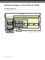 3
3
-
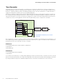 4
4
-
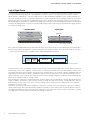 5
5
-
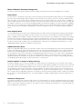 6
6
-
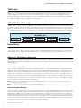 7
7
-
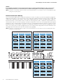 8
8
-
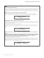 9
9
-
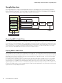 10
10
-
 11
11
-
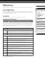 12
12
-
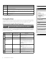 13
13
-
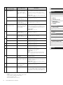 14
14
-
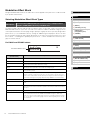 15
15
-
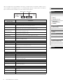 16
16
-
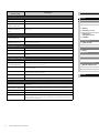 17
17
-
 18
18
-
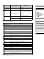 19
19
-
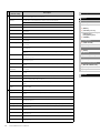 20
20
-
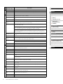 21
21
-
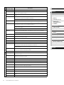 22
22
-
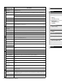 23
23
-
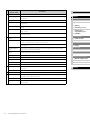 24
24
-
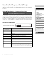 25
25
-
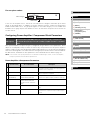 26
26
-
 27
27
-
 28
28
-
 29
29
-
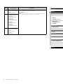 30
30
-
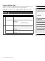 31
31
-
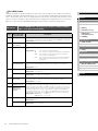 32
32
-
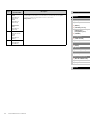 33
33
-
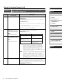 34
34
-
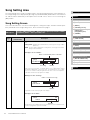 35
35
-
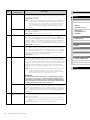 36
36
-
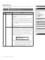 37
37
-
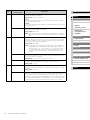 38
38
-
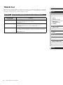 39
39
-
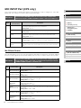 40
40
-
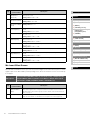 41
41
-
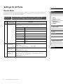 42
42
-
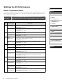 43
43
-
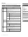 44
44
-
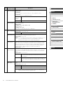 45
45
-
 46
46
-
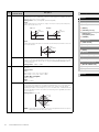 47
47
-
 48
48
-
 49
49
-
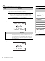 50
50
-
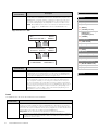 51
51
-
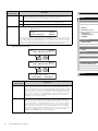 52
52
-
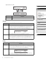 53
53
-
 54
54
-
 55
55
-
 56
56
-
 57
57


Yamaha CP5 Handleiding
- Categorie
- Digitale piano's
- Type
- Handleiding
- Deze handleiding is ook geschikt voor
in andere talen
- English: Yamaha CP5 User manual
- italiano: Yamaha CP5 Manuale utente
- русский: Yamaha CP5 Руководство пользователя
- français: Yamaha CP5 Manuel utilisateur
- español: Yamaha CP5 Manual de usuario
- Deutsch: Yamaha CP5 Benutzerhandbuch
- português: Yamaha CP5 Manual do usuário
- dansk: Yamaha CP5 Brugermanual
- suomi: Yamaha CP5 Ohjekirja
- čeština: Yamaha CP5 Uživatelský manuál
- svenska: Yamaha CP5 Användarmanual
- Türkçe: Yamaha CP5 Kullanım kılavuzu
- polski: Yamaha CP5 Instrukcja obsługi
- română: Yamaha CP5 Manual de utilizare