
Montage- und Betriebsanleitung
Montage- en
bedieningshandleiding
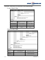
KEMA 02ATEX2106 X
Bitte zur künftigen Verwendung aufbewahren
Bewaar deze montage- en
bedieningshandleiding voor toekomstig
gebruik
UTN...EX
Rev. 01 – 16.06.2015 based on Rev. 4 – 22.12.2009


EG-Baumusterprüfbescheinigung
EC-Type Examination Certificate
MBUTNEX.doc

MBUTNEX.doc

MBUTNEX.doc

MBUTNEX.doc

MBUTNEX.doc

MBUTNEX.doc

MBUTNEX.doc
Nederlands ........................................................................................................................................................................ 1
Verklaring van de tekens ................................................................................................................................................. 1
Veiligheidsaanwijzingen .................................................................................................................................................. 1
Gevaar! .......................................................................................................................................................................... 2
Gebruik en toepassingsgebied ....................................................................................................................................... 2
Let op ! ............................................................................................................................................................................... 2
Opbouw en beschrijving van de werking .................................................................................................................. 2
Verwijdering van de transportverpakking en transportbeveiligingen .................................................................... 2
Installatie en ingebruikneming van de UTN...EX in het explosiegebied ................................................................... 3
Inbouw van analyseapparaten op de UTN...EX in het explosiegebied ................................................................. 4
Inbouwvoorbeeld (sensor MG... ) ............................................................................................................................... 4
Aantal aanbevolen bevestigingsbeugels of klembanden ................................................................................... 4
Inbouwvoorbeeld MRA (montage van de magneetschakelaar op magneetrollen – niveau-indicator) ............. 5
Inbouwvoorbeeld MNAV (montage van de magneetschakelaar op houderstang) .................................................5
Onderhoud .................................................................................................................................................................... 6
Informatie!.......................................................................................................................................................................... 6
Probleemoplossing ....................................................................................................................................................... 6
Typecode UTN...EX ......................................................................................................................................................... 7
Typecode niveau-indicator van de KSR-overtank .................................................................................................... 7
Typesleutel KSR-cilindervlotter ..........................................................................................................................................8
Typesleutel / uitvoering KSR vlottertype V. ........................................................................................................... 8
Typesleutel / uitvoering KSR-cilindervlotter ................................................................................................................9
Beschermingswijze ................................................................................................................................................................ 10
UTN temperatuurgegevens ........................................................................................................................................... 10
Drukgegevens ................................................................................................................................................................. 10
English ............................................................................................................................................................................. 11
Symbol legend ................................................................................................................................................................ 11
Safety Information .......................................................................................................................................................... 11
Danger! ........................................................................................................................................................................ 12
Application and field of use ........................................................................................................................................... 12
Attention ! ........................................................................................................................................................................ 12
Structure and functional description .............................................................................................................................. 12
Removal of transport packaging and transport safety devices ............................................................................ 12
Installation and putting into operation of the UTN…EX Top Mounted Level Indicator in explosion risk areas 13
Installation of signal processing and display devices on the UTN…EX Top Mounted Level Indicator in
explosion risk areas ................................................................................................................................................... 14
Example of mounting ( Level Sensor MG... ) .......................................................................................................... 14
Number of recommended mounting brackets or tightening straps .................................................................. 14
Example of installation-mounting the magnetic switch on the magnetic roller display ..................................... 15
Example of installation MNAV (mounting of magnetic switch on a retainer rod) ............................................... 15
Maintenance ....................................................................................................................................................................... 16
Important! ........................................................................................................................................................................ 16
Error Search ................................................................................................................................................................ 16
Type Code UTN...EX ..................................................................................................................................................... 17
Type Code KSR- Top Mounted Level Indicator ..................................................................................................... 17
Type Code KSR- Spherical floats ............................................................................................................................ 18
Type Code / Design KSR Float Type V. .............................................................................................................. 18
Type Code / Design KSR- Cylindrical floats ....................................................................................................... 19
Ignition protection ........................................................................................................................................................... 20
UTN Temperatures ........................................................................................................................................................ 20
Pressure .......................................................................................................................................................................... 20
KSR KUEBLER AG Adresse ........................................................................................................................................ 21


1 / 21
MBUTNEX.doc
Nederlands
De volgende symbolen worden in deze bedieningshandleiding gebruikt:
Waarschuwing
Aanwijzingen voor de correcte montage en het gebruik van de
niveau-indicator van de KSR-overtank overeenkomstig de
bestemming. Het niet in acht nemen van deze aanwijzingen
kan storingen of beschadigingen van de contactbeveiligingen
tot gevolg hebben.
Gevarenaanduiding
Het niet in acht nemen van gevarenaanduidingen kan lichamelijke
en/of materiële schade tot gevolg hebben.
Informatie
Gegevens en informatie over de juiste toepassing van de
niveau-indicator van de KSR-overtank.
Veiligheidsaanwijzingen
Lees eerst deze handleiding alvorens u de niveau-indicator van de KSR-overtank
begint te
installeren en te gebruiken.
Deze handleiding is bedoeld voor vakmensen die verantwoordelijk zijn voor de inbouw en de
installatie.
Tijdens het gebruik moeten de relevante veiligheidsvoorschriften in acht worden genomen.
Ongeoorloofde wijzigingen of ongeoorloofd gebruik hebben het verlies van de garantie en de
wettelijke aansprakelijkheid tot gevolg.
Gebruik de niveau-indicator van de KSR-overtank
niet in de onmiddellijke nabijheid van de
ferromagnetische omgeving
(afstand min. 50 mm) of sterke elektromagnetische velden (afstand
min. 1m).
Er moeten maatregelen worden genomen om te garanderen dat er bij het optreden van een defect
wordt voorkomen dat er gevaren voor personen en voorwerpen kunnen ontstaan.
De niveau-indicator van de KSR-overtank mag niet worden blootgesteld aan hoge mechanische
belastingen.

MBUTNEX.doc
2 / 21
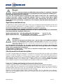
Gevaar!
Bij werkzaamheden aan tanks bestaat er gevaar voor vergiftiging of verstikking.
Werkzaamheden mogen uitsluitend worden uitgevoerd met passende
persoonlijke beschermingsmiddelen (bijv. ademhalingsbeschermingsmiddelen,
beschermende kleding enz.).
De niveau-indicator van de KSR-overtank kan onder druk staan. Eventueel bevindt zich een
heet, giftig, bijtend of explosief medium in de UTN...Ex. Er bestaat gevaar voor
verwondingen door naar buiten spuitende vloeistoffen, brandwonden aan handen, armen,
voeten en gezicht alsmede corrosies, vergiftigingen of explosies. Voor het openen moet
eerst de spanning van de bak worden gehaald.
Gebruik en toepassingsgebied
De niveau-indicator van de KSR-overtank is als explosieveilig bedrijfsmiddel, binnen de
werkingssfeer van de EG-richtlijn 94/9/EG, toegestaan voor het gebruik op explosiegevaarlijke
plaatsen.
De niveau-indicator voldoet aan de eisen voor mechanische bedrijfsmiddelen voor
explosiegevaarlijke plaatsen.
Neem de technische gegevens in deze handleiding in acht.
Neem de montage- en bedieningshandleidingen van de inbouwonderdelen (sensors,
magneetschakelaars enz.) in acht.
Beschermingswijze UTN ... EX zonder magneetrolindicator: II 1 G c T1...T6
Beschermingswijze UTN ... EX met magneetrolindicator: II 1/2 G c T1...T6
vlotter; UTN...EX-bak; magneetsysteem zone 0 / magneetrolindicator zone 1
Let op!
De niveau-indicators mogen uitsluitend worden gebruikt met inachtneming van de
maximale waarden voor druk en temperatuur als vermeld op het typeplaatje. Een
overschrijding van de parameters kan storingen of beschadigingen en persoonlijke of materiële
schade tot gevolg hebben.
Alle materialen die in contact komen met het medium van de UTN...EX moeten bestendig zijn tegen
het te controleren medium. De op het typeplaatje vermelde maximale waarden moeten in acht worden
genomen om een ongestoorde werking te garanderen.
Bij temperaturen boven 60 C° moet op flenzen, buizen, behuizingen enz. een waarschuwing
worden aangebracht die waarschuwt voor de gevaren van verbrandingen.
Opbouw en beschrijving van de werking
De niveau-indicator van de KSR-overtank bestaat uit een standbuis, een vlotter met
geleidingsstaaf en een magneetsysteem. De montage vindt plaats op de bak door middel van
procesaansluitingen (flens, schroefdraad). Het ferrietmagneetsysteem, dat via een
geleidingsstaaf verbonden is met de vlotter, zorgt voor een contactloze overdracht van het door de
vlotter geregistreerde vloeistofniveau aan de op de standbuis gemonteerde KSR magneetrol-
indicator, niveau-sensor, magneetschakelaar / niveauschakelaar of andere
II 2G EEx / II 1G EEx
apparaten overeenkomstig de ATEX-richtijn (94/9/EG).
Verwijdering van de transportverpakking en de transportbeveiligingen
Haal de niveau-indicator UTN ... EX voorzichtig uit de transportverpakking.
Neem de aanwijzingen op de transportverpakking in acht en verwijder eerst alle
transportbeveiligingen voordat u de niveau-indicator UTN ... EX uit de transportverpakking haalt.
Haal de
niveau-indicator UTN ... EX nooit met geweld uit de verpakking!
Verwijder eerst alle veiligheidsbanden van de vlotter alvorens u begint met het inbouwen van de
niveau-indicator UTN ... EX. Zorg ervoor dat alle onderdelen uit de verpakking verwijderd zijn en
de vlotter zich vrij kan bewegen.

3 / 21
MBUTNEX.doc
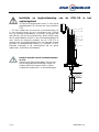
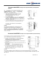
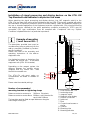
Installatie en ingebruikneming van de UTN...EX in het
explosiegebied
Schroef de meegeleverde vlotter (7) vast op de
geleidingsstaaf (6).
Monteer de niveau-indicator
UTN
... EX door middel van de voorziene procesaansluiting (5)
in
een verticale positie op de te controleren bak. Gebruik
voor de montage borgmiddelen, schroeven, borgringen die
geschikt zijn voor de procesaansluiting. Neem bij de keuze
van de borgmiddelen de druk en de corrosiebestendigheid in
acht. Neem de maximale waarden van de UTN...EX in
verband met de explosieveiligheid en het beoogde gebruik
alsmede de desbetreffende wetten en richtlijnen in acht.
Bijzonder belangrijk is de inachtneming van de daarin
opgenomen
"bijzondere voorwaarden".
Neem de waarden van de aandraaimomenten
in acht.
Gebruik geschikte borgmiddelen.
Zorg ervoor
dat het borgmateriaal bestendig is tegen het
medium alsook de dampen ervan en de te
verwachten temperatuur- en drukbelastingen.
Fig. 1
1
2
3
8
4
5
6
Eintauchtiefe
Depth of Immersion
Dompeldiepte
7

MBUTNEX.doc
4 / 21
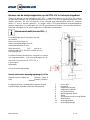
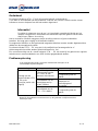
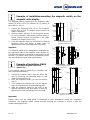
Inbouw van de analyseapparaten op de UTN...EX in het explosiegebied
Tijdens de inbouw van de indicatoren (bijv.: MG..., magneetschakelaar) op de UTN...EX moeten
de maximale waarden van de veldvoorziening en de UTN ...EX voor de explosieveiligheid in acht
worden genomen. De voor het gebruik of het beoogde doel toepasselijke wetten of richtlijnen
dienen in acht te worden genomen. Er mogen enkel ATEX-gecertificeerde analyseapparaten
worden aangesloten. De certificaten van het EG-typeonderzoek moeten in acht worden genomen.
Bijzonder belangrijk zijn de daarin opgenomen "bijzondere voorwaarden".
Inbouwvoorbeeld (sensor
MG... )
1
De onderhavige beschrijving dient slechts
ter indicatie
.
Neem ook de montage- en
bedieningshandleidingen van de
aanbouwonderdelen in acht.
Maak de sensor
MG...
vast op de
basiseenheid (UTN...EX) door middel van een
bevestigingsklem.
De afstand tussen positiesensor
(magneet) en sensor MG...buis
mag - afhankelijk van
het magneetsysteem - niet meer bedragen dan 8 mm.
Het boren of lassen van de UTN...EX is
in geen geval
toegestaan.
Let op de materiaalparingen.
Aantal aanbevolen bevestigingsbeugels of klembanden
Afstand naar het midden tot 1000mm 2 klem
Afstand naar het midden vanaf 1000mm 1
klem extra per 1000mm of een deel
daarvan
De beugels dienen over de gehele lengte van de buis
in gelijkmatige afstanden te worden aangebracht.
1 sensor MG...
2 klemband
3 magneetschakelaar
4 magneetrol-indiactor
5 procesaansluiting
6 geleidingsstang vlotter
7 vlotter
8 cilinderkopschroef of vergelijkbaar
9 afstandsstuk
10 bevestigingsklem
11 bevestigingsbeugel
1
3
m
a
g
n
e
e
t
s

5 / 21
MBUTNEX.doc
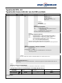
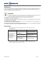
Inbouwvoorbeeld MRA (montage van de magneetschakelaar op de magneetrol-
indicator)
De
bevestiging van de magneetschakelaar op de
-
magneetrol-indicator
(4)
van de
niveau-
indicator van de
KSR-
overtank (6) gebeurt door
middel van schuifbouten (afb. 1)
1.
Maak de bevestigingsschroeven (1) op de
magneetschakelaar door middel van een
binnenzeskantsleutel SW 3 mm om
ca. 1 omdraaiing los.
2.
Schuif de schuifbout(en) (2) in de geleidingsgroef
(3) van de magneetrol-indicator (4) van boven of
onder erin. (Let op de positie van de kabelwartel of
de stekker volgens afb.)
3.
Schuif de magneetschakelaar tot de hoogte van het
gewenste schakelpunt en bevestig deze door de
Montage
magneetschakelaar type-
index M, ME, MST, MT
schroeven vast te draaien (het schakelpunt
is gemarkeerd).
Let op!
De magneetschakelaar MA is ontworpen voor de
inbouw aan de rechterkant van de ma
gneetrol-
indicator (4)
. Bij de montage aan de linkerkant
wordt de schakelfunctie omgedraaid. De schakelaar
moet omgekeerd gemonteerd worden (typeplaatje
staat op zijn kop).
Montage magneetschakelaar
type-index MA
Inbouwvoorbeeld MNAV (montage van de magneetschakelaar op de houderstang)
De bevestiging van deze magneetschakelaar vindt plaats
op een afzonderlijk aangebrachte houderstang.
1.
Verwijder de houderstang (1) door de bevestings-
schroeven (2) los te maken en verwijder de
houderklemmen (3) van de UTN...EX .
2.
Schuif de magneetschakelaar
(4)
op de houderstang
(1)
naar boven.
3.
Maak de houderstang (1) weer vast op de UTN...EX (5)
door middel
van beugels (3) en bevestigingsschroeven.
4.
Schuif de magneetschakelaar tot de hoogte van
het gewenste schakelpunt en maak deze vast
door de schroeven (6) vast te draaien (het
schakelpunt is gekenmerkt).
Let op!
Montage
magneetschakelaar type-
index MS, MV, MVT, MEx
Let er bij de montage op dat de kabelinvoer naar onder beneden gekeerd is. Om een veilige
schakelfunctie te garanderen, moet de behuizing van de magneetschakelaar verbonden zijn met
de UTN...EX

MBUTNEX.doc
6 / 21
Onderhoud
De niveau-indicatoren UTN ... EX zijn bij normaal gebruik onderhoudsvrij.
Toch dient er als onderdeel van de periodieke controles een visuele controle van de niveau-
indicatoren en een drukproef van de bak worden uitgevoerd.
Informatie!
De vlotter is ontworpen voor de op het typeplaatje vermelde dichtheid van het
medium.
Het gebruik in vloeistoffen met een ander specifiek gewicht veroorzaakt
afwijkingen tijdens de meting.
Het te controleren medium mag geen sterke vervuiling vertonen of grove onderdelen
bevatten.
Het mag geen neiging tot kristallisatie hebben.
De magneetrol-indicator en de ingebouwde magneetschakelaar moeten worden afgestemd door
middel van de meegeleverde vlotter
De niveau-indicator UTN ... EX mag niet in de nabijheid van ferromagnetische of
elektromagnetische velden worden gebruikt (afstand min. 1m).
Een correcte werking van de niveau-indicator UTN ... EX kan enkel bij het gebruik van originele
toebehoren en reserveonderdelen van KSR Kuebler gegarandeerd worden.
Probleemoplossing
In de volgende tabel vindt u de meest voorkomende storingen en de
noodzakelijke tegenmaatregelen.
Storing
Oorzaak
Maatregel
Montage van de
niveau-indicator UTN
... EX op de
voorziene positie niet
mogelijk
Schroefdraadgrootte
of flensgrootte van de
TN...EX en de bak
stemmen niet overeen
Ombouw van de bak
Terugzending naar de
fabriek
Schroefdraad van de
bevestigingsmof op
de bak is defect
Schroefdraad
aanpassen of
bevestigingsmof
vervangen
Schroefdraad van de
UTN ... EX is defect
Terugzending naar de
fabriek
Neem bij alle problemen contact met ons op. Wij proberen u altijd met raad en
daad bij te staan.

7 / 21
MBUTNEX.doc
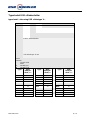
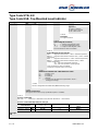
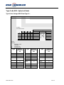
Typesleutel UTN...EX
Typesleutel niveau-indicator van de KSR-overtank
Basistyp
e
Code 1
Code 2
Code 3
Code 4
Code 5
Code 6
Code 7
Code
8
UTN-
25/ 16/ C-
MG-
L.../M...-
V/60,3x.
2-
MRA-
1/M../2-
ZVSS250-
EX
Vergunningen *2
EX ATEX vergunning
EX DNV ATEX en DNV EX GL
ATEX en GL
Code 8
Vlottertype
Zie typesleutel vlotter
Code 6
Optie magneetschakelaar
1/...
= aantal stuks van de BGU
../M../...
= magneetschakelaar - zie typesleutel toebehoor
– magneetschakelaar.
.../.../1
= kabellengte BGU
(gegevens enkel
beschikbaar indien optie van toepassing) *1
Code 5
Uitvoering magneetrol-indicator
MRA = magneetrol-indicator ( < 180°C mediumtemperatuur) MNAV =
magneetrol-indicator roestvrij staal* ( < 180°C mediumtemp.)
MRK = magneetrol-indicator ( > 180°C mediumtemp.) MNKV =
magneetrol-indicator roestvrij staal* ( > 180°C mediumtemp.)
/SG
met scala (aluminium gegraveerd),
/VSG met scala (roestvrij staal gegraveerd)
(gegevens enkel beschikbaar indien optie van toepassing)
*Er kunnen enkel magneetschakelaars van het type BGUV worden gemonteerd.
Code 4
Materiaal en standbuis - diameter x wanddikte
V/...
= roestvrij staal
HC/...
= Hastelloy C
HB/...
=
Hastelloy B
T/...
= titaan
/.... = bypassbuis - diameter x wanddikte (Bij 60/70 =
uitvoering met
verwarmingsmantel)
Code 3
L= max. lengte van vlotter en vlotterbuis / M= h.o.h.-afstand (proceszone)
Code 2
Optie niveausensor enz. *1
MG = met niveausensor zie typesleutel toebehoor - niveausensor (gegevens enkel beschikbaar indien optie van
toepassing)
Code 1
Uitvoering van de procesaansluitingen
DN.../PN.../...=
flens (D = nominale afmeting van de flens/PN= nominale druk/...= flensvorm)
van toepassing kommen procesaansluitingen conform DIN, ANSI, BS, API, JIS
Schroefdraad- of
lasaansluiting
met mof M
met mof N
Sleutel schroefdraadgrootte
of diameter
Voorbeeld
Steun conform DIN
G
M of N
.....“
GM 1“
Steun conform NPT
NPT
M of N
.....“
NPTN 1“
Basistype UTN

MBUTNEX.doc
8 / 21
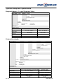
Typesleutel KSR-cilindervlotter
typesleutel / uitvoering KSR vlottertype V...
Code 1
Code 2
V
52
Code 2 vlotterdiameter
* alle afmetingen in mm
Code 1
materiaal
V roestvrij staal
T titaan
HC Hastelloy HC
HB Hastelloy HB
Type
Max.
bedrijfs-
druk [bar]
Type
Max.
bedrijfs-
druk[bar]
Type
Max.
bedrijfs-
druk [bar]
V44
16
T62
25
HB44
16
V52
40
T80
25
HB52
40
V62
32
T98
25
HB62
32
V80
25
T105
25
HB80
25
V98
25
HC44
16
HB98
25
V105
25
HC52
40
HB105
25
T44
16
HC62
32
T52
25
HC80
25
T52/0,6
40
HC98
25
T52/0,8
40
HC105
25

9 / 21
MBUTNEX.doc
Typesleutel / uitvoering KSR-cilindervlotter uitvoering met balgen;
P = max. 20 bar of 16 bar
Basistype
Code 1
Code 2
Code 3
Z
V
Code 1:
SS
Code 2:
250
Code 3
vlotterlengte in mm =
100
– 400
balgvlotter
vlottermateriaal
V
vlottermateriaal roestvrij staal (20 bar)
T
vlottermateriaal titaan (16 bar)
Basistype:
clindervlotter
Materiaal
Roestvrij staal 1.4571 (met
balgen)
Titaan 3.7035 (met
balgen)
Bedrijfstemperatuur
-40 °C tot + 400 °C
-40 °C tot + 400 °C
Bedrijfsdruk
max. 20 bar
max. 16 bar
Testdruk
max. 30 bar
max. 24 bar
Diameter
50 mm
50 mm
Uitvoering zonder balgen
Basistype
Code 1
Code 2
Code 3
Code 4
Code 5
Code 6
Code 7
Z
V
Code 1:
S
Code 2:
250/
16/
Code 4
60/
Code 5
1000
Code 6
...
Code 7
magneetsysteem
dichtheid in kg/m³
temperatuur in °C
bedrijfsdruk in bar
Code 3
vlotterlengte in mm =
100 -
400
gladde cilindervlotter
vlottermateriaal
V
vlottermateriaal roestvrij staal
T
vlottermateriaal titaan
HC vlottermateriaal Hastelloy HC
HB vlottermateriaal Hastelloy HB
Basistype:
cilindervlotter
Materiaal
Materiaal roestvrij staal/ Hastelloy
HC/ Hastelloy HB
Materiaal titaan 3.7035
Bedrijfstemperatuur
-40 °C tot + 400 °C
-40 °C tot + 400 °C
Bedrijfsdruk
20 bar - 40 bar
16 bar - 100 bar
temperatuurafhankelijk
k
Testdruk
30 bar – 60 bar
24 bar – 150 bar

MBUTNEX.doc
10 /
21
Diameter
50 mm
50 mm

MBUTNEX.doc
10 / 21
Beschermingswijze
Beschermingswijze UTN ... EX zonder magneetrol-indicator: II 1 G c
T1...T6
Beschermingswijze UTN ... EX met magneetrol-indicator: II 1/2
G c T1...T6
Vlotter en bypassbuis zone 0 / magneetrol-indicator zone 1
UTN temperatuurgegevens
De maximale waarden voor nominale druk en temperatuur als vermeld op het
typeplaatje mogen niet worden overschreden.
Temperatuur
- klasse
Maximale proces-
temperatuur
UTN...EX
Maximale proces-
temperatuur -
Omgevings-
temperatuur
Maximale omgevings-
temperatuur op de
analyse-apparaten
MRA
MRAN
MNAV
MRK
MNKV
T1
320°C
≤ 320°C
- 50... + 80°C
Neem de maximale
omgevingstemperatuur
van de ingebouwde
analyseapparaten
analyse in acht. Deze
mogen in geen geval
worden overschreden.
T2
240°C
≤ 180°C
≤ 240°C
T3
160°C
≤ 160°C
≤ 160°C
T4
108°C
≤ 108°C
≤ 108°C
T5
80°C
≤ 80°C
≤ 80°C
T6
68°C
≤ 68°C
≤ 68°C
- 50... + 68°C
Drukgegevens
Maximale bedrijfsdruk
Testdruk conform AD regelgeving 2000
Min. – max. temperatuurbereik
Alleen wanneer UTN...EX
geproduceerd is conform DGRL
97/23/EG (bedrijfsdruk boven 0,5 bar).

11 / 21
MBUTNEX.doc
English
Symbol legend
The following symbols are used in these operating instructions:
Warning
Instructions on correct installation and proper operation of the
KSR Top Mounted Level Indicator (UTN…EX) Failing to comply
with these instructions can lead to malfunction of or damage to the
switch.
Precaution
Instructions which must be complied with to avoid injury or
property damage or loss of the type approval.
Information
Facts and information concerning proper operation of the Level
Sensors NMG… or MG…
Safety Information
Read these instructions before installing the UTN…EX and putting them into operation.
These instructions are intended for the specialists in charge of mounting, installation and setup.
Comply with the relevant safety regulations when using the equipment.
Unauthorized access and impermissible use of the equipment will result in the loss of guarantee
and liability protection.
Do not install in ferromagnetic surroundings (minimum distance: 50 mm).or the immediate vicinity of
strong electromagnetic fields. (minimum distance: 1 m).
Measures must be taken to prevent risks to persons and property in the event of a defect in the
UTN…EX.
UTN…EX must not be exposed to heavy mechanical loads.


MBUTNEX.doc
12 / 21
Danger!
There is a risk of poisoning or suffocation when working in containers. Relevant
personal protection measures (e.g. respiratory devices, protective clothing, etc.)
must be taken before work is carried out.
The UTN…EX container may be pressurised. The interior of the UTN…EX container may
contain a hot, toxic, caustic or explosive medium. There is a risk of injury due to liquid
spraying out of the container, burns on the hands, arms, feet and face as well as caustic
burns, intoxication (poisoning) or explosion. The container must be depressurised prior to
opening it.
Application and field of use
An approval has been issued for the UTN...EX for use as explosion-protected equipment within the
scope of application defined by EC Guideline 94/9/EC in hazardous areas. They comply with the
specifications regulating use of mechanical equipment in explosion risk areas.
The technical data in these operating instructions must be complied with.
See the installation and operating instructions for the accessory fittings and instruments
(level transmitter MG, magnetic switch, etc.).
Ignition protection UTN ... EX without Magnetic roller display: II 1 G c T1...T6
Ignition protection UTN ... EX with Magnetic roller display: II 1/2 G c T1...T6
Float and chamber Zone 0 / Magnetic roller display Zone 1
Attention !
The KSR Top Mounted Level Indicator (UTN…EX) may only be used within the maximum
pressure and temperature levels listed on the type plate. Exceeding these parametric
levels may result in malfunction or destruction of the UTN…EX as well as to personal injury
and property damage.
All of the materials used for the UTN…EX guide rod and float must be resistant to the medium the
level of which is to be monitored. The maximum values listed on the type plate must be complied
with to ensure operation free of malfunction.
At temperatures exceeding 60°C, a sign must be attached to flanges, pipes, casing, etc. clearly
warning of the risk of burn injuries.
Structure and functional description
The KSR Top Mounted Level Indicator is mounted on the top of the tank by means of a suitable
process connection (flange or thread). It consists of a chamber and a float with guide rod and
magnetic system attached to it. The permanent magnet system, connected by guide rod with the
float, transfers the amount of liquid via the magnetic system in the chamber, contactlessly to the
KSR Magnetic Rollers,. Level Sensors (MG...), Magnetic Switches or other II 2G EEx / II 1G EEx
ATEX (94/9/EG) directive corresponding devices installed outside at the chamber
Removal of transport packaging and transport safety devices
Carefully remove the UTN…EX Top Mounted Level Indicator from the transport packaging.
Please comply with the instructions on the shipping packaging and remove all transport retention
elements before taking out UTN…EX Top Mounted Level Indicator. Never exert force to remove
the UTN…EX Top Mounted Level Indicator from the package!
Remove any float retainer bands before installing the UTN…EX Top Mounted Level Indicator.
Make sure all packaging elements have been removed and that the guide rod can move freely
within the chamber.

13 / 21
MBUTNEX.doc
Installation and putting into operation of the UTN…EX Top
Mounted Level Indicator in explosion risk areas
Screw any loosely enclosed floats (7) onto the
guide
rod
(6).
Mount
the
UTN…EX
Top
Mounted Level Indicator on the tank to be monitored using
the mounting flange (5) provided. Use properly fitting
gaskets, bolts, washers and nuts for installation. Make sure
the gaskets used are corrosion-proof as required. Comply
with the limit values stipulated for the UTN…EX Top
Mounted Level Indicator for reasons of explosion protection
and within the framework of the intended use of the device
and the applicable laws and regulations (proof of inherent
safety). Compliance with any "Special Conditions" stipulated
in such laws or regulations is of particular importance.
Please comply with the maximum torque
ratings of the bolts / screws used when
tightening them down.
Use suitable gaskets. Make sure the gasket
material is resistant to the medium and its vapours as well
as to the expected temperature and pressure loads.
Fig. 1
1
2
3
8
4
5
6
Eintauchtiefe
Depth of Immersion
Profondeur d´immersion
7

MBUTNEX.doc
14 / 21
Installation of signal processing and display devices on the UTN…EX
Top Mounted Level Indicator in explosion risk areas
When attaching the signal processing and display devices (e.g. MG magnetic switch) to the
UTN…EX, the upper limit values of the field device and the UTN…EX must be complied with within
the framework of explosion protection (proof of inherent safety). Laws and guidelines applying to
the use or intended application of the equipment must be complied with. Only signal processing
and display device certified for the given application conditions according to ATEX may be
connected. EEC type certifications must be complied with. Compliance with any "Special
Conditions" stipulated therein is of particular importance.
Example of mounting
1
( Level Sensor MG... )
The description provided here must be
90
considered as being a guide only for the
3
add-on possibility provided by location-
8
specific conditions.
Please also refer to the assembly and
operating instructions of the add-on
4
equipment units
M
Use tightening straps or fastening clips
to fasten the Sensor MG... to the base
equipment unit (UTN…EX chamber)
Depending on the magnet system, the
distance between the position sensor
(magnet) and the Sensor MG... tube
should not exceed 8 mm.
8
The UTN...EX unit must under no
9
circumstances be drilled or welded on
10
directly.
11
Please note the material pairings.
Number of recommended
mounting brackets or tightening straps
Distance centre-to-centre up to 1000mm 2 brackets
Distance centre-to-centre above 1000mm add 1 bracket for
each initial 1000mm
The brackets must be fitted at equal distances along the
entire length of the pipe.
120
5
6
L=...
7
1
Level Sensor MG...EX
2
tensioning straps
3
magnetic switch
4
Magnetic roller display
5
process connection
6
guide rod
7
float
8
Cheese-head screws or
similar
9
Spacers
10
Mounting clips
11
Mounting brackets
2

15 / 21
MBUTNEX.doc
Example of installation-mounting the magnetic switch on the
magnetic roller display
The magnetic switch is attached to the magnetic roller
display (4) of the UTN..EX indicator (6) by means of
4
tenon blocks. (Fig. 1) 3
1.
Loosen the fastening bolts (1) on the magnetic
switch with an SW 3 hexagon socket wrench by
1
about 1 revolution.
2.
Insert the tenon block(s) (2) into the guide groove
(3) on the magnetic roller display (4) from above or
5
below. (Please observe the position of the cable
threading or plug as per the Fig.)
3.
Push the magnetic switch to the level of the desired
switching point and fasten it down there by
tightening the bolts (switching point is marked).
Important!
4
3
The magnetic switch MA is designed for installation on
1
the right-hand side of the magnetic roller display (4).
The switching function is reversed by mounting it on the
5
left side. The switch must then be mounted the other
way around (with the type plate upside down).
1
6
Montage Magnetschalter
Typindex M, ME, MST, MT
6
4
Schaltpunkt
2
2
2
Example of installation MNAV
(mounting of magnetic switch on a
retainer rod)
This magnetic switch is attached to a retainer rod
3
that is mounted separately.
1.
Remove the retainer rod (1) from the UTN…EX
rack by loosening the fastening bolts (2) and
removing the brackets (3).
2.
Push the magnetic switch (4) onto the retainer
rod (1).
3.
Then reattach the retainer rod (1) to the bypass
tube (5) using brackets (3) and fastening bolts.
4.
Slide the magnetic switch to the level of the
desired switching point and fasten it down by
tightening the bolts (switching point is marked).
Important!
Montage Magnetschalter
Typindex MA
2
3
5
5
2
4
4
6
1 1
Montage Magnetschalter
Typindex MS, MV, MVT, MEx
Please make sure the cable gland is positioned to point downwards during the installation
procedure. The magnetic switch casing must be touching the chamber to ensure a safe and
reliable switching function.
4

MBUTNEX.doc
16 / 21
Maintenance
UTN…EX Top Mounted Level Indicator require no maintenance if used as intended. However, they
must be subjected to a visual inspection within the framework of regular general inspections and
must be included in container pressure tests.
Important!
The float is designed for the medium density level indicated on the type plate. Use in
fluids with a different specific gravity results in measurement deviations.
The medium to be monitored should not contain any soiling or coarse particles.
It should also not tend to crystallize out.
The magnetic roller display and attached magnetic switch must be positioned and set using the
enclosed float prior to installation.
The UTN…EX Top Mounted Level Indicator must not be installed near strong magnetic or
electromagnetic fields (at least 1 m away).
Correct functioning of the UTN…EX Top Mounted Level Indicator can only be guaranteed if original
KSR Kuebler accessories and replacement parts are used.
Error Search
The following table lists the most frequent causes of error and the necessary
countermeasures
Error
Cause
Countermeasure
KSR Top Mounted
Level Indicator
UTN…EX cannot be
attached at the
intended position on
the container
Thread or flange
dimensions of UTN...EX
do not agree
Reworking of container
Send back to factory
Thread of mounting plug
on container defective
Reworking of the thread or
replacement of the
attachment muff
Bolt threading on
UTN…EX defective
Send back to factory
Please give us a call in case of any difficulties. We will do everything we can to
provide you with the required advice and help.

17 / 21
MBUTNEX.doc
Type Code UTN...EX
Type Code KSR- Top Mounted Level Indicator
Basic type
Code 1
Code 2
Code 3
Code 4
Code 5
Code 6
Code 7
Code 8
UTN-
25/ 16/ C-
MG-
L.../M...-
V/60,3x.2-
MRA-
1/M../2-
ZVSS250-
EX
approval *2
EX ATEX Certificates
EX DNV ATEX and DNV
EX GL ATEX and GL
Code 8
Float type
See Type Code Float
Code 6
Option Magnetic Switches,
1/...
= quantity of the Magnetic switch
../M../...
= see Typcode Magnetic switch
.../.../1
= Length of Cable Magnetic switch
(Only specification if option is available)
Code 5
Option Magnetic Roller Indicator
MRA = Magnetic Roller Indicator ( < 180°C ambient temperature)
MNAV = Magnetic Roller Indicator Stainless steel ( < 180°C ambient
temperature)
MRK = Magnetic Roller Indicator *( > 180°C ambient temperature)
MNKV = Magnetic Roller Indicator Stainless steell *( > 180°C
ambient temperature )
/SG
with Scale (Aluminium engraved),
/VSG with Scale (Stainless steel engraved)
(Only specification if option is available)
*Only BGUV magnetic switch can be used.
Code 4
Material and Chamber OD x Wall thickness in mm
V/...
= Stainless steel
HC/...
= Hastelloy C
HB/...
= Hastelloy B
T/...
= Titanium
/.... = Chamber OD x Wall thickness (Ispecification 60/70 =
heating jacket design)
Code 3
L= max. length float and float tube / M= Measuring range
Code 2
Option Level Sensor
see Typcode Level Sensor (Only specification if option is available)
Code 1
Process connection
DN.../PN.../...=
Flansche (D = Nennweite Flansches/PN= Nenndruck/...= Flanschform)
Process connection DIN, ANSI, BS, API, JIS
Gewinde- oder
Schweißstutzen
female M
male N
size
for example
Thread acc. to DIN
G
M or N
.....“
GM 1“
Thread acc. to NPT
NPT
M or N
.....“
NPTN 1“
Basic type
UTN

MBUTNEX.doc
18 / 21
Type Code KSR- Spherical floats
Type Code / Design KSR Float Type V...
Code 1
Code 2
V
52
Code 2
Float OD in mm
* all dimensions in mm
Code 1
Material
V Stainless steel
T Titanium
HC Hastelloy HC
HB Hastelloy HB
Type
Nominal
pressure in
bar
Type
Nominal
pressure in
bar
Type
Nominal
pressure in
bar
V44
16
T62
25
HB44
16
V52
40
T80
25
HB52
40
V62
32
T98
25
HB62
32
V80
25
T105
25
HB80
25
V98
25
HC44
16
HB98
25
V105
25
HC52
40
HB105
25
T44
16
HC62
32
T52
25
HC80
25
T52/0,6
40
HC98
25
T52/0,8
40
HC105
25
Old float type code
44
Form
A*
B*
Basic type
Material
Version
Z
44
52
S
See type
code
material
K
52
K
52
52
S
62
K
62
61
S
A
80
K
80
76
S
B
98
K
98
96
S
C
105
K
105
103
S
D

19 / 21
MBUTNEX.doc
Type Code / Design KSR- Cylindrical floats
Design with beads ; P = max. 20 bar bzw. 16 bar
Design without beads
Basic type
Code 1
Code 2
Code 3
Code 4
Code 5
Code 6
Code 7
Z
V
Code 1:
S
Code 2:
250/
16/
Code 4
60/
Code 5
1000
Code 6
...
Code 7
magnet system
density in kg/m³
temperature in °C
Nominal pressure in bar
Code 3
Float length in mm
100 - 400
Design without beads
Material
V
Stainless steel
T
Titanium
HC Hastelloy HC
HB Hastelloy HB
Basic type:
Cylindrical floats
Material
Stainless steel/ Hastelloy HC/ Hastelloy HB
Titanium 3.7035
Max. nominal
temperature
-40 °C to + 400 °C
-40 °C to + 400 °C
Max. nominal pressure
20 bar - 40 bar
16 bar - 100 bar
according to temperature
Test pressure
30 bar – 60 bar
24 bar – 150 bar
Diameter
50 mm
50 mm
Basic type
Code 1
Code 2
Code 3
Z
V
Code 1:
SS
Code 2:
250
Code 3
Float length in mm
Design with beads
Material
V
Stainless steel max. 20bar
T
Titanium
max. 16 bar
Basic type
Cylindrical floats
Material
Stainless steell 1.4571 (with beads)
Titan 3.7035 (with beads)
Max. nominal
temperature
-40 °C to + 400 °C
-40 °C to + 400 °C
Max. nominal
pressure
max. 20 bar
max. 16 bar
Test pressure
max.. 30 bar
max. 24 bar
Diameter
50 mm
50 mm

20 / 21
MBUTNEX.doc
Ignition protection
Ignition protection UTN ... EX without Magnetic roller display: II 1 G c T1...T6
Ignition protection UTN ... EX with Magnetic roller display : II 1/2 G c T1...T6
Float and chamber zone 0 / Magnetic roller display zone 1
UTN Temperatures
The maximum nominal pressure and temperature values listed on the type plate must
not be exceeded.
Temperatur
e class
Maximum process
- temperature
UTN...EX
Maximum process -
temperature
Ambient
temperature
Maximum ambient
temperature at
processing and
display equipment
MRA
MRAN
MNAV
MRK
MNKV
T1
320°C
≤ 320°C
- 50... + 80°C
See Mounting and
Operating instruction -
Description
of
processing and display
devices
T2
240°C
≤ 180°C
≤ 240°C
T3
160°C
≤ 160°C
≤ 160°C
T4
108°C
≤ 108°C
≤ 108°C
T5
80°C
≤ 80°C
≤ 80°C
T6
68°C
≤ 68°C
≤ 68°C
- 50... + 68°C
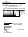
Pressure
Nominal pressure in bar
test pressure acc. to AD regulation 2000
minimum - maximum temperature range
Only if the UTN…EX is made in
accordance with PED 97/23/EEC
(operating pressuring > 0.5 bar).
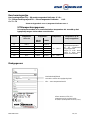
UTN-
-EX
Chamber Mat. :
PS. :
PT. :
TS.
:
S. G. :
Float :
Tag No. :
Serial No. :
KEMA 02ATEX2106 X
II 1 G c T1...T6 or
II 1/2 G c T1...T6
0637
Niveau-Messtechnik AG
D-69439 Zwingenberg

MBUTNEX.doc
20 / 21
KSR KUEBLER Niveau-Messtechnik AG
Heinrich-Kuebler-Platz 1
D-69439 Zwingenberg am Neckar
Tel:[+49] 06263 870
Fax:[+49] 06263/87-99
e-Mail: info@ksr-kuebler.com
www.ksr-kuebler.com
KSR KUEBLER AG Adressen
9
3
3
Vlottercode oud
44
Vorm
A*
B*
Basistype
Materiaal
Uitvoering
Z
44
52
S
Zie
type-
sleutel
materia
al
K
52
K
52
52
S
62
K
62
61
S
A
80
K
80
76
S
B
98
K
98
96
S
C
K
105
103
S
D
UTN-
-EX
Chamber Mat. :
PS. :
PT. :
TS.
:
S
.
G
.
:
F
l
o
a
t
:
T
a
g
N
o
.
:
Serial No. :
K
E
M
A
0
2
A
T
E
X
2
1
0
6
X
I
I
1
G
c
T
1
.
.
.
T
6
o
r
II 1/2
G c
T1...
T6
0637
Niveau-
Messtechnik AG
D-69439
Zwingenberg
Old float type code
44
Form
A*
B*
Basic type
Material
Version
Z
44
52
S
See type
code
material
K
52
K
52
52
S
62
K
62
61
S
A
80
K
80
76
S
B
98
K
98
96
S
C
105
K
105
103
S
D
Basic type
Code 1
Code 2
Code 3
Z
V
Code 1:
SS
Code 2:
250
Code 3
Float length in mm
Design with beads
Material
V
Stainless steel max. 20bar
T
Titanium
max. 16 bar
Basic type
Cylindrical floats
Material
Stainless steell 1.4571 (with beads)
Titan 3.7035 (with beads)
Max. nominal
temperature
-40 °C to + 400 °C
-40 °C to + 400 °C
Max. nominal
pressure
max. 20 bar
max. 16 bar
Test pressure
max.. 30 bar
max. 24 bar
Diameter
50 mm
50 mm
UTN-
-EX
Chamber Mat. :
PS. :
PT. :
TS.
:
S
.
G
.
:
F
l
o
a
t
:
T
a
g
N
o
.
:
Serial No. :
K
E
M
A
0
2
A
T
E
X
2
1
0
6
X
I
I
1
G
c
T
1
.
.
.
T
6
o
r
II 1/2
G c
T1...
T6
0637
Niveau-
Messtechnik AG
D-69439
Zwingenberg
-
 1
1
-
 2
2
-
 3
3
-
 4
4
-
 5
5
-
 6
6
-
 7
7
-
 8
8
-
 9
9
-
 10
10
-
 11
11
-
 12
12
-
 13
13
-
 14
14
-
 15
15
-
 16
16
-
 17
17
-
 18
18
-
 19
19
-
 20
20
-
 21
21
-
 22
22
-
 23
23
-
 24
24
-
 25
25
-
 26
26
-
 27
27
-
 28
28
-
 29
29
-
 30
30
-
 31
31
-
 32
32
-
 33
33


in andere talen
- English: WIKA UTN Operating instructions
Andere documenten
-
Samsung 460UTN Handleiding
-
Daikin FWEC1 de handleiding
-
Shimano SL-A351 Service Instructions
-
Philips GP520BLKX1 Handleiding
-
Shimano FD-4503 Service Instructions
-
-
Roland MDS-6SL de handleiding
-
TOA TS-900 Handleiding
-
Electrolux EHC30001X Handleiding
-
Kenmore 767.8692 Handleiding