
www.plymovent.com
EN Installation and user manual
NL Installatie- en gebruikershandleiding
DE Installations- und Betriebsanleitung
FR Manuel d’installation et d’utilisation
ES Manual de instalación y de manejo
SE Installations- och användarmanual
RO Manualul utilizatorului
RO Alimentatorpiatrădevar
SE Kalkstenmatar
ES Alimentadordepiedracaliza
FR Dispositifd’alimentationencalcaire
DE Precoatieranlage
NL Kalksteendoseerinstallatie
EN Limestonefeeder
OILSHIELD

0507061600/010713/DOilShield 1
EN – OrigiNal iNstructiON
All rights reserved. The information given in this document has been collected for the general convenience of our clients. It has been based on general data pertaining to construction material
properties and working methods known to us at the time of issue of the document and is therefore subject at any time to change or amendment and the right to change or amend is hereby expressly
reserved. The instructions in this publication only serve as a guideline for installation, use, maintenance and repair of the product mentioned on the cover page of this document. This publication is to
be used for the standard model of the product of the type given on the cover page. Thus the manufacturer cannot be held responsible for any damage resulting from the application of this publication
to the version actually delivered to you. This publication has been written with great care. However, the manufacturer cannot be held responsible, either for any errors occurring in this publication or
for their consequences.
Nl – VErtaliNg VaN DE OOrsprONkElijkE gEbruiksaaNwijziNg
Alle rechten voorbehouden. De in deze handleiding verstrekte informatie is gebaseerd op algemene gegevens aangaande de ons ten tijde van verschijnen bekende constructies, materiaaleigenschappen
en werkmethoden, zodat wijzingen worden voorbehouden. Om deze reden dienen de gegeven instructies slechts als richtlijn voor het installeren, gebruiken, onderhouden en repareren van het op de
voorzijde van dit document vermelde product. Deze handleiding is geldig voor het product in de standaard uitvoering. De fabrikant kan derhalve niet aansprakelijk worden gesteld voor eventuele schade
voortvloeiend uit de van de standaard uitvoering afwijkende specicaties van het aan u geleverde product. Deze handleiding is met alle mogelijke zorg samengesteld, maar de fabrikant kan geen
verantwoording op zich nemen voor eventuele fouten in deze handleiding of voor de gevolgen daarvan.
DE – ÜbErsEtzuNg DEr OrigiNalbEtriEbsaNlEituNg
Alle Rechte vorbehalten. Die in dieser Anleitung enthaltenen Informationen basieren auf allgemeinen Daten bezüglich der Konstruktion, der Materialeigenschaften und der Arbeitsmethoden, die uns zur
Zeit der Veröffentlichung bekannt waren; Änderungen werden somit vorbehalten. Aus diesem Grunde dienen die gegebenen Vorschriften nur als Leitfaden für das Installieren, Benutzen, Warten und
Reparieren des auf der Vorderseite dieser Anleitung angegebenen Produktes. Diese Ausgabe gilt für die Standardausführung des Produktes. Der Hersteller haftet daher nicht für eventuelle Schäden,
die sich aus der Anwendung dieser Ausgabe auf Ihr von der Standardausführung abweichendes Produkt ergeben. Diese Ausgabe wurde mit größter Sorgfalt zusammengestellt. Der Hersteller haftet
jedoch nicht für eventuelle Fehler in dieser Ausgabe oder für daraus resultierende Folgen.
Fr – traDuctiON DE la NOticE OrigiNalE
Tous droits réservés. Le présent manuel a été mis au point à partir de données relatives à la construction, aux caractéristiques des matériaux et aux méthodes de production dont nous étions au
courant à la parution du manuel. Le manuel est donc sujet à modication à tout moment et nous nous réservons explicitement le droit à une telle modication. Pour la même raison, ce manuel servira
simplement de guide à l’installation, l’emploi, l’entretien et la réparation du produit gurant en première page de couverture de ce document. Le présent manuel s’applique au modèle standard du
produit. Par conséquent, le fabricant n’est pas responsable pour les dommages éventuels découlant de l’application de ce document aux modèles non standard des produits livrés. Nous avons apporté
tous nos soins à la rédaction de ce manuel, mais le fabricant ne peut pas accepter la responsabilité pour les erreurs éventuelles ni pour les dommages qui en découlent.
Es – traDuccióN DEl MaNual OrigiNal
Todos los derechos reservados. La información proporcionada en este documento se ha recopilado para el interés general de nuestros clientes. Se ha basado en datos generales referentes a las
propiedades del material de construcción y los métodos de trabajo que conocemos en el momento de la publicación del documento y, por consiguiente, están sujetos en cualquier momento a cambios o
correcciones, por lo que por la presente nos reservamos el derecho a hacer cambios o correcciones. Las instrucciones de esta publicación sólo sirven como pauta para la instalación, uso,
mantenimiento y reparación del producto mencionado en la portada de este documento. Esta publicación se deberá usar para el modelo estándar del producto de la clase indicada en la portada. Por
tanto, no se podrá responsabilizar al fabricante de ningún daño derivado de la utilización de esta publicación en la versión que se le ha entregado a Ud. Esta publicación se ha escrito con sumo cuidado.
Sin embargo, no se podrá responsabilizar al fabricante ni por los errores que haya en esta publicación ni por sus consecuencias.
sE – ÖVErsättNiNg aV bruksaNVisNiNg i OrigiNal
Alla rättigheter förbehålles. Informationen som ges i detta dokument har sammanställts av allmänna, praktiska skäl för våra kunder. Den bygger på allmänna data som är relaterade till
konstruktionsmaterialegenskaper och arbetsmetoder som är kända för oss vid tidpunkten för utgåvan av dokumentet och de kan därför när som helst förändras eller kompletteras och vi förbehåller
oss härmed uttryckligen rätten att ändra eller komplettera dem. Instruktionerna i denna publikation tjänar endast som riktlinjer för installation, användning, underhåll och reparation av produkten som
nämns på omslaget av detta dokument. Denna publikation skall användas för standardmodellen av produkten av typen som anges på omslagssidan. Därför kan tillverkaren inte hållas ansvarig för
eventuella skador som blir följden av tillämpning av denna publikation på versionen som faktiskt levererats till er. Denna publikation har skrivits med stor aktsamhet. Emellertid kan tillverkaren inte
hållas ansvarig, varken för eventuella fel som nns i denna publikation eller för deras konsekvenser.
rO – Traducere insTrucţiuni originale
Toate drepturile rezervate. Informaţiile din acest document au fost redactate pentru uzul general al clienţilor noştri. Ele se bazează pe date standard, legate de proprietățile materialelor de fabricație şi
metodele de lucru, existente la momentul redactării documentului. Astfel, documentul poate modicat oricând, rma având dreptul de schimbare sau corectare a datelor. Instrucţiunile din acest
document reprezintă doar o referinţă, în scopul instalării, utilizării, întreţinerii şi reparaţiilor produsului menţionat pe coperta acestui document. Această publicaţie trebuie folosită pentru modelul
standard al tipului de produs oferit pe copertă. Astfel, producătorul nu este responsabil pentru nicio defecţiune apărută ca urmare a aplicării informaţiilor din acest document pentru alte versiuni de
produse procurate. Acest document a fost redactat cu mare atenţie. Producătorul însă nu este responsabil pentru nicio eroare apărută în document sau ca o consecinţă a acestuia.

0507061600/010713/DOilShield 2
ENGLISH Page NEDERLANDS Pag. DEUTSCH Seite
Preface 3Voorwoord 18 Vorwort 33
1. Introduction 31. Inleiding 18 1. Einleitung 33
2. Productdescription 42. Productbeschrijving 19 2. Produktbeschreibung 34
3. Safety 53. Veiligheid 20 3. Sicherheitsvorschriften 35
4. Installation 64. Installatie 21 4. Installation 36
5. Use 12 5. Gebruik 27 5. Betrieb 42
6. Maintenance 14 6. Onderhoud 30 6. Wartung 45
7. Troubleshooting 15 7. Verhelpenvanstoringen 30 7. Fehlerbehebung 46
8. Spareparts 16 8. Reserveonderdelen 32 8. Ersatzteile 47
9. Electricaldiagram 16 9. Elektrischschema 32 9. Schaltplan 47
10. Disposal 17 10. Afdanken 32 10. Entsorgung 47
CEdeclaration 17 CE-verklaring 32 EG-Konformitätserklärung 47
FRANÇAIS Page ESPAÑOL Pág. SVENSKA Sida
Avant-propos 35 Preámbulo 65 Förord 81
1. Introduction 35 1. Introducción 65 1. Introduktion 81
2. Descriptiondeproduit 50 2. Descripcióndelproduct 66 2. Produktbeskrivning 82
3. Instructionsdesécurité 51 3. Normativasdeseguridad 67 3. Säkerhetsinformation 83
4. Installation 52 4. Instalación 68 4. Installation 84
5. Utilisation 59 5. Uso 75 5. Användning 90
6. Entretien 61 6. Mantenimiento 77 6. Underhåll 92
7. Réparationdespannes 62 7. Subsanacióndefallos 78 7. Felsökning 93
8. Piècesdétachées 63 8. Piezasderecambio 79 8. Reservdelar 94
9. Schémaélectrique 64 9. Esquemaeléctrico 65 9. Elschema 94
10. Mettreaurancart 64 10. Desechar 80 10. Omhändertagandeav
förbrukningsvaror
94
DéclarationdeConformité 64 DéclarationdeConformité 80 Försäkranom
överensstämmelse
95
Pag.
Prefaţă 96
1. Introducere 96
2. Descriereprodus 97
3. Măsuridesiguranţă 98
4. Instalare 99
5. Utilizare 105
6. Întreţinere 108
7. Problemeapăruteîn
funcţionare
108
8. Piesedeschimb 110
9. Schiţaelectrică 110
10. Aruncare 110
DeclaraţieEC 110
TABLE OF CONTENTS

0507061600/010713/DOilShield EN-3
PREFACE
Using this manual
Thismanualisintendedtobeusedasaworkofreferencefor
professional,welltrainedandauthoriseduserstobeableto
safelyinstall,use,maintainandrepairtheproductmentioned
onthecoverofthisdocument.
Pictograms and symbols
Thefollowingpictogramsandsymbolsareusedinthismanual:
TIP
Suggestionsandrecommendationstosimplify
carryingouttasksandactions.
ATTENTION!
Aremarkwithadditionalinformationfortheuser.A
remarkbringspossibleproblemstotheuser’s
attention.
CAUTION!
Procedures,ifnotcarriedoutwiththenecessary
caution,coulddamagetheproduct,theworkshopor
theenvironment.
WARNING!
Procedureswhich,ifnotcarriedoutwiththe
necessarycaution,maydamagetheproductor
causeseriouspersonalinjury.
WARNING!
Firehazard!Importantwarningtopreventre.
WARNING!
Denotesriskofelectricshock.
WARNING!
UsePersonalProtectiveEquipment(PPE)toavoid
injury.Thisalsoappliestopersonswhoenterthe
workarea.
Text indicators
Listingsindicatedby“-”(hyphen)concernenumerations.
Listingsindicatedby“•”(bulletpoint)describestepsto
perform.
Service and technical support
Forinformationaboutspecicadjustments,maintenanceor
repairjobswhicharenotdealtwithinthismanual,please
contactthesupplieroftheproduct.Hewillalwaysbewillingto
helpyou.Makesurethatyouhavethefollowingspecications
athand:
- productname
- serialnumber
Thesedatacanbefoundontheidenticationplate.
1 INTRODUCTION
1.1
Theidenticationplatecontains,amongotherthings,the
followingdata:
- productname
- serialnumber
- supplyvoltageandfrequency
- powerconsumption
1.2 General description
TheOilShieldisalimestonedosingsystemtobeinstalled
betweenSparkShield(spark arrester)andMDBltersystem.
Theintegratedlimestonereservoirisrelledfromthetop.Two
agitatormechanismsandascrewconveyor,drivenbythree
separatemotors,arrangetransportationanddosingofthe
limestone.Thecontrolboxisincorporatedinsidethefront
door.
Thelimestonefeedercomeswithanadditionalboosterfanto
bemountedtothemainduct.
1.3 Product combinations
TheOilShieldispartofPlymovent’sSHIELDresafety
solutionsforprevention,detectionandsuppressionofre.
Refertotheavailableapplicationdatasheetfor
possibleproductcombinations.
TheOilShieldisinstalledincombinationwithanMDB1lter
systemandcanbeused:
- asstand-aloneunit
- connectedtoaSystemControlPanel(preferredway)
CombinationwithSCSltersystemonrequest.
WARNING!
IftheOilShieldisusedasstand-aloneunit,the
safetyfeaturethatswitchesofftheentirefan/lter
systemincertaincases(refertosection2.2)will
becomevoid.
InthismanualweassumetheOilShieldisconnectedtoa
SystemControlPanel.
1.4 Options and accessories
Thefollowingproductscanbeobtainedasanoptionand/or
accessory:
- externallighttower
1.5
Weight
- OilShield(net;without
limestone)
- boosterfan+fansupport
- 172kg(379lbs)
- 27kg(60lbs)
Contentslimestonereservoir 70litres/18.5gallon(equalsto75
kg/165lbsoflimestone)
Limestonealarmlevel <25kg(55lbs)
Limestonequality
Carbonatecontent >95%
Specications Minimum
Fineness:
Residueona200μmsieve
(ISO787/7)
Topcut(d98%)
Meanparticlesize(d50%)
-0,05%
-110 µm
-13 µm
-0,1%
-190 µm
-26 µm
General product data:
Packedbulkdensity
(ISO787/11)
Oilabsorption(ISO787/5)
- 1,5g/ml
- 10g/100g
- 1,6g/ml
- 11g/100g
Limestone not included; to be
sourced locally. Refer to Fig. I on
page 111 for detailed information
about recommended particle size
distribution.
If the specied limestone quality is not
obtainable, please forward a specication
sheet of the available limestone to your
supplier to determine if this meets the
requirements for use in the OilShield.
Limestoneconsumption default:12,5gperltercartridgeper
hour
Builtinaccordancewith - IEC60204
- UL508A
Protectionclasscontrolbox - IP55
- NEMAType1
Soundlevel:
- OilShield
- boosterfan
- 64dB(A)
- 69dB(A)
1. Types:MDB-4toMDB-48.Combinationwithlargerltersystemsonrequest.

0507061600/010713/DOilShield EN-4
Availableconnectionvoltages - 400V/3ph/50Hz
- 480V/3ph/60Hz(ULcertied)
- 600V/3ph/60Hz(ULcertied)
Motorpower: (50and60Hz) Current
- upper(agitator)
- middle(agitator)
- lower(screwconveyor)
- boosterfan
- 250W
- 375W
- 90W
- 750W
-¹/³HP
- ½HP
- ⅛HP
- 1HP
-0,72 A
-1,11 A
-0,52 A
Distancetomainduct max.10m
Requiredairowinduct min.9m/s
Refertotheavailableproductdatasheetfor
detailedproductspecications.
1.6 Dimensions
RefertoFig.IIonpage111.
1.7 Ambient conditions
Min.operatingtemperature 5°C(41°F)
Nom.operatingtemperature 20°C(68°F)
Max.operatingtemperature 40°C(104°F)
Max.relativehumidity 80%
1.8
Themanufacturercannotbeheldliableforanytransportation
damageafterdeliveryofthemachine.Alwayshandlethe
machineandtheaccompanyingoptionsand/oraccessories,if
any,withcare.
CAUTION!
Forsafetyreasons,itisrecommendedtousea
fork-lifttruckorpallettrucktolifttheOilShield from
thepalletandplaceitatitsnalposition.Donot
slidetheunitfromthepallettoavoidproduct
damage.
Extendtheadjustingfeetfarenough(45-80
mm/1.8-3.2in.)tomaketheunitportablebya
pallettruckorfork-lifttruckfore.g.service
purposes.
2 PRODUCT DESCRIPTION
2.1 Components
Theproductconsistsofthefollowingmaincomponentsand
elements:
Fig. 2.1
A Boosterfan
B Fansupport
C Limestoneoutletduct
D Limestonerelllid
E Limestonereservoir
F Agitatormechanism
G Screwconveyor
H Topcover
I Controlbox(insidedoor)
Fig.2.1
Sheet in Control Box
DETAIL B
SCALE 1 : 5
Test switch
A
B
A
J
K
L
B C D E F G H I
H
I
C
D
E
F
G
A
B
Maincomponentsandelements
2.2 Operation
Bynegativepressure,smallamountsoflimestonepowderare
extractedinthelterinletduct,whereitmixeswithoily
weldingfume.Thisreducesreriskintheconnectedlter
systemduetosparksorspontaneouscombustion.Atthesame
timeitenhancesthelifespanoftheltercartridges.
Thelimestonefeedercontainstwodifferentagitator
mechanismstoavoidthelimestoneinthereservoirfrom
archingandratholing2.Theamountoflimestonethatisused
bythesystemisdosedbyatimecontrolledscrewconveyor.
Tocreateare-safesituationatalltimes,thelimestonedosing
systemonlyoperateswhenthefollowingconditionshavebeen
fullled:
- presenceoflimestoneinreservoir
- limestonerelllidisclosed
- negativepressure
Ifoneoftheconditionsislacking:
- theagitatormechanismsandthescrewconveyorwill
immediatelystopturning
- ifconnectedtoaSystemControlPanel:theentirefan/lter
systemwillbeautomaticallyswitchedoffafterapreset
time3.
WARNING!
IncasetheOilShieldisinstalledasstand-aloneunit
withoutSystemControlPanel,theconnectedlter
systemisabletorunwithoutadditionoflimestone.
Thiscanleadtoarehazardoussituation.
2.2.1 Booster fan
Theseparateboosterfanguaranteestherequiredairowto
transportthelimestonethroughtheverticalductinany
circumstance.Itrunssimultaneouslywiththeagitator
mechanismsandthescrewconveyor,plusoneminutebefore
andafter.Itwillalsostartrunningduringlimestonerell.
Incaseofacloggedlimestonepipeorduct,theboosterfan
willruncontinuouslyduringmax.30minutestoclearthe
limestoneblockage.Whentheboosterfanisunabletosolve
2. RefertoFig.IIIonpage111
3. Limestonereservoirempty:after45minutesnetrunningtime
Limestonerelllidopen:after60minutes
Nonegativepressure:after1-2minutes

0507061600/010713/DOilShield EN-5
theblockageautonomouslywithinthisperiod,theentirefan/
ltersystemwillbeswitchedoff4.
3 SAFETY
General
Themanufacturerdoesnotacceptanyliabilityfordamageto
theproductorpersonalinjurycausedbyignoringofthesafety
instructionsinthismanual,orbynegligenceduring
installation,use,maintenance,andrepairoftheproduct
mentionedonthecoverofthisdocumentandany
correspondingaccessories.
Specicworkingconditionsorusedaccessoriesmayrequire
additionalsafetyinstructions.Immediatelycontactyour
supplierifyoudetectapotentialdangerwhenusingthe
product.
regulations.
User manual
- Everyoneworkingonorwiththeproduct,mustbefamiliar
withthecontentsofthismanualandmuststrictlyobserve
theinstructionstherein.Themanagementshouldinstructthe
personnelinaccordancewiththemanualandobserveall
instructionsanddirectionsgiven.
- Donotchangetheorderofthestepstoperform.
- Alwayskeepthemanualwiththeproduct.
present)
- Thepictograms,warningandinstructionsattachedtothe
productarepartofthesafetyfeatures.Theymustnotbe
coveredorremovedandmustbepresentandlegibleduring
theentirelifeoftheproduct.
- Immediatelyreplaceorrepairdamagedorillegible
pictograms,warningsandinstructions.
Users
- Theuseofthisproductisexclusivelyreservedtowell
authorised,trainedandqualiedusers.Temporarypersonnel
andpersonnelintrainingcanonlyusetheproductunder
supervisionandresponsibilityofskilledengineers.
- Usecommonsense.Stayalertandkeepyourattentionto
yourwork.Donotusetheproductwhenyouareunderthe
inuenceofdrugs,alcoholormedicine.
- Theproductisnottobeusedbychildrenorpersonswith
reducedphysical,sensoryormentalcapabilities,orlackof
experienceandknowledge,unlesstheyhavebeengiven
supervisionorinstruction.
- Childrenmustbesupervisednottoplaywiththeproduct.
Intended use5
Theproducthasbeendesignedexclusivelyaslimestonedosing
system.Usingtheproductforotherpurposesisconsidered
contrarytoitsintendeduse.Themanufactureracceptsno
liabilityforanydamageorinjuryresultingfromsuchuse.The
producthasbeenbuiltinaccordancewithstate-of-the-art
standardsandrecognisedsafetyregulations.Onlyusethis
productwhenintechnicallyperfectconditioninaccordance
withitsintendeduseandtheinstructionsexplainedintheuser
manual.
4. IfconnectedtoaSystemControlPanel
5. “Intendeduse”asexplainedinEN-ISO12100-1istheuseforwhichthe
technicalproductissuitedasspeciedbythemanufacturer,inclusiveofhis
directionsinthesalesbrochure.Incaseofdoubtitistheusewhichcanbe
deducedfromtheconstruction,themodelandthefunctionofthetechnical
productwhichisconsiderednormaluse.Operatingthemachinewithinthe
limitsofitsintendedusealsoinvolvesobservingtheinstructionsintheuser
manual.
Thespecicationsgiveninthismanualmustnotbealtered.
Modicationof(partsof)theproductisnotallowed.
Product combinations
Iftheproductisusedincombinationwithotherproductsor
machines,thesafetyinstructionsinthedocumentationof
theseproductsalsoapply.
Installation
- Theinstallationofthisproductisexclusivelyreservedtowell
authorised,trainedandqualiedengineers.
- Electricconnectiontobeexecutedinaccordancewithlocal
requirements.EnsurecompliancewiththeEMCregulatory
arrangements.
- Duringinstallation,alwaysusePersonalProtective
Equipment(PPE)toavoidinjury.Thisalsoappliesforpersons
whoentertheworkareaduringinstallation.
- Usesufcientclimbinggearandsafetyguardswhenworking
onahigherlevelthan2metres(localrestrictionsmay
apply).
- Donotinstalltheproductinfrontofentrancesandexits
whichmustbeusedforemergencyservices.
- Ifnotplacedontheoor,makesurethatthesupportsystem
isstrongenoughtocarrytheproduct.
- Makesurethattheworkshop,inthevicinityoftheproduct,
containssufcientapprovedreextinguishers.
Use
- Inspecttheproductandcheckitfordamage.Verifythe
functioningofthesafetyfeatures.
- Checktheworkingenvironment.Donotallowunauthorised
personstoentertheworkingenvironment.
- Protecttheproductagainstwaterandhumidity.
- Makesurethattheroomisalwayssufcientlyventilated;
thisappliesespeciallytoconnedspaces.
WARNING!
Do notusetheproducttoapplyprecoatmaterialto
theltercartridgesoftheconnectedltersystem.
Service, maintenance and repairs
- Observethemaintenanceintervalsgiveninthismanual.
Overduemaintenancecanleadtohighcostsforrepairand
revisionsandcanrendertheguaranteenullandvoid.
- Duringservice,maintenanceandrepairjobs,alwaysuse
PersonalProtectiveEquipment(PPE)toavoidinjury.This
alsoappliesforpersonswhoentertheworkarea.
- Alwaysusetools,materials,lubricantsandservice
techniqueswhichhavebeenapprovedbythemanufacturer.
Donotuseworntoolsanddonotleaveanytoolsinoronthe
product.
- Safetyfeatureswhichhavebeenremovedforservice,
maintenanceorrepairs,mustbeputbackimmediatelyafter
nishingthesejobsanditmustbecheckedthattheystill
functionproperly.
- Usesufcientclimbinggearandsafetyguardswhenworking
onahigherlevelthan2metres(localrestrictionsmay
apply).
- Ensuretheworkspaceiswellilluminated.
ATTENTION!
Service,maintenanceandrepairsshouldonlybe
performedinaccordancewithdirectiveTRGS560by
authorised,qualiedandtrainedpersons(skilled)
usingappropriateworkpractices.
WARNING!
Beforecarryingoutservice,maintenanceand/or
repairjobs,fullydisconnectthemachinefromthe
mains.

0507061600/010713/DOilShield EN-6
WARNING!
Alwayswearfacemaskandglovesduringservice,
maintenanceandrepairs.
WARNING!
Donotreachintotheinletofthelimestonereservoir
topreventseriouspersonalinjury.
4 INSTALLATION
4.1 Positioning
TheOilShieldmustbeplacedbetweentheSparkShield(spark
arrester)andtheMDBltersystem.Makesurethatitisplaced
onastableandhorizontalbase.
ItisrecommendedtopositiontheOilShieldclosetothelter
system(approx.2m/6.5ft),tolimittheaccumulationof
limestoneinthemainduct.
CAUTION!
Donotblockthegridsattherightsideoftheunit.
Allowatleast100mm(4in.)spacetoavoidmotor
overheating.
RefertoFig.IVonpage112forinstallation
guidelines.
MakesurethattheOilShieldremainseasy
accessibletorellthelimestonereservoir.
4.1.1 Restrictions
- AvoidanybendsintheverticalductbetweentheOilShield
andthemainduct.
- Inviewofrelloflimestone,itisrecommendednottoplace
theunitonaplatformbutontheoor.
-Do notpositiontheunitwhereitisexposedtovibrationsor
shocks.
- Exceptforaslidingvalve,donotmountanycomponentsin
thelimestone-containingairowbetweentheboosterfan
andtheltersystem.Thisgoese.g.forpressure
transmittersandsensorsbutalsoforextractionarms.
4.2 Tools and requirements
Thefollowingtoolsandrequirementsareneededtoinstallthe
product:
- liftingequipment(e.g.fork-lifttruck,pallettruck)
- level
- verticalduct:ductØ63mm(2.5in.)(seamlessductor
spiraloduct)(betweenOilShieldandmainduct);refertoFig.
VIonpage113fortherequiredductlength
- saddlepieceØ160mmforductconnection
- ductsupportmaterialformainductandfansupport
(specicationofboltstobeused:refertoFig.4.1D+E)
- additionalnut(2)tottheboltsmentionedabove
- (cordless)drill
- wrench13(toopen/closecontrolbox)
- hotairgun
Connectionwires+plugs:
- 4G1.5mm²(14AWG)withneopreneoutershield(mains
cord)6
- 4G1.5mm²(14AWG)withneopreneoutershield(between
OilShieldandboosterfan)
- 2x0.5mm²(20AWG)withPVCoutershield;90°C
(194°F)/300V(betweenOilShieldandSystemControlPanel)
- 2x0.5mm²(20AWG)withPVCoutershield;90°C
(194°F)/300V(betweenOilShieldandexternalpressure
switch)
- mainsplug
6. OilShield 60Hz:thisconnectionwireisalreadyincludedandinstalleddueto
ULrequirements
Incaseofoptionalexternallighttower:
- connectionwire4x0.5mm²(20AWG)withPVCouter
shield;90°C(194°F)/300V(fromOilShieldtolighttower)
4.3 Unpacking
Checkthattheproductiscomplete.Theproductconsistsof
threepackagesandshouldcontain:
Package1:
- fansupportincl.earthwire
- inletadapter
- vibrationdamper(4)
- boltM8(4)
- washer(4)
- pressureswitch
- PVCpressuretube1000mm(40in.)incl.ductmounting
material
- cableglandM20x1.5
- cableglandPG11
- nut
- hoseØ160mm(6.3in.)
- hoseclamp(2)
- self-tappingscrew(3)
Package2:
- boosterfan
Package3:
- limestonefeeder
- mainswitchhousing,including2screws
- transparenthose500mm(20in.),innerØ50mm(2in.)
- heatshrinktubing150mm(6in.)
- hoseclamp
-key
- protectionbracket
Ifpartsaremissingordamaged,contactyoursupplier.
4.4 Installation
RefertoFig.VIonpage113forpositionoflimestonefeeder
withrespecttothemainduct.
4.4.1 Fan support
Thefansupportisusedfor:
- mountingoftheboosterfantothemainduct
- mountingoftheexternalpressureswitch
Fig. 4.1
• DrillaholeØ160mm(6.3in.)(B1+B2)inthemainduct.
• Mounttheductsupportmaterial(C).Takethesizeofthe
bolts(ref.D+E)intoaccount,sincetheywillbeusedto
attachthefansupport.
• Mountthesaddlepiece(A)tothemainduct.

0507061600/010713/DOilShield EN-7
A
B
C
D
F
E
D
A
E
B1
B2
C (x2)
B Ø160mm Ø6.3in.
Dmin.10mm min.0.4in.
E max.M8
Fig.4.1 Mountingofductsupport+saddlepiece
Fig. 4.2
• Mountthepressureswitch(A)onthebottomofthefan
supportusingthettingcablegland(C).
• Mounttheothercablegland(B)directlyonthebottomof
thefansupport.
Fig.4.2
A
C
B
Mountingofexternalpressureswitch
Thefansupportcanbemountedintwoways:
- bycablesattachedtothefoureyebolts
- bythreadedrodsinsertedthroughtheholesnexttotheeye
bolts
Fig. 4.3
• Mountthefansupportinoneofthepossibleways;
- usingtheeyebolts(A),or
- usingthreadedrods(B)
WARNING!
Makesuretoinstallthefansupportinalevel
positiontoavoidimbalanceoftheboosterfan.
Fig.4.3
mount cable gland (2x)
with nut and
pressure switch
A (x4)
B (x4)
A (x2)
B (x2)
Mountingoffansupport
Topreventthefansupportfrommoving,itmustbefastened
tothemainduct.Forthispurpose,theupperrimisequipped
withtwoslotsfordirectconnectiontotheductsupports.
Fig. 4.4
• Slidethefansupportoverthebolts(A)oftheduct
supports(seealsoFig.4.1C).
• Fastenitusinganadditionalnut(B).
Fig.4.4
mount cable gland (2x)
with nut and
pressure switch
A (x4)
B (x4)
A (x2)
B (x2)
Fasteningoffansupport
4.4.2 Booster fan
Fig. 4.5
• MountthehoseØ160mm(6.3in.)(B)tothefanusinga
hoseclamp(A).
• Slidetheotherhoseclamp(C)overthehosewithout
fasteningit.
• Mounttheinletadapter(E)tothefaninlet(F)usingthe
suppliedvibrationdampers(D).

0507061600/010713/DOilShield EN-8
Fig.4.5
D (x4)
E
A
B
C
F
A
B
A (x4)
B (x4)
B
A
Mountingofhoseandinletadapter
Fig. 4.6
• Mountthefaninsidethefansupportusingthesupplied
boltsM8(B)withwashers(A).
Fig.4.6
D (x4)
E
A
B
C
F
A
B
A (x4)
B (x4)
B
A
Mountingoffantofansupport
Fig. 4.7
• Attachthehosetothesaddlepiece(B)usingthehose
clamp(A).
Fig.4.7
D (x4)
E
A
B
C
F
A
B
A (x4)
B (x4)
B
A
Mountingofhosetosaddlepiece
Wire connection
Theboosterfanmustbeearthedbythepre-installedearth
wire.Boththeboosterfanandtheexternalpressureswitch
mustbewired.
Fig. 4.8
• Loosenonesideoftheearthwire(A).
• Fastentheearthwiretotheboosterfan(B)usingthe
screwfromthepreviousstep.
• Feedaconnectionwire(C)throughthecableglandatthe
bottomofthefansupportandmountittotheboosterfan.
• Feedaconnectionwire(D)throughthecableglandofthe
pressureswitch.
Refertoparagraph4.2forspecicationof
connectionwires.
Fig.4.8
B
A
C
D
Mountingofearthwireandconnectionwires
Fig. 4.9
• Mounttheconnectionwire(ref.Fig.4.8D)asNO(normally
open)tothepressureswitch:connection2+3(A).
• Setthepressureswitchat0.5 mbar(B).

0507061600/010713/DOilShield EN-9
Fig.4.9
1
2
3
0.5
A
B
Externalpressureswitch
ATTENTION!
Localregulationsmayrequireanadditionalmain
switchtoturnofftheboosterfanincaseofservice,
maintenanceorrepair.
PVC pressure tube
Thelimestonefeederisprovidedwithanintegratedpressure
switch.Anexternalpressureswitchhasbeenmountedinside
thefansupport(ref.Fig.4.2).APVCpressuretubemustbe
connectedbetweentheexternalpressureswitchandthemain
duct.
RefertoFig.VIIonpage113forthecorrectmounting
positionofthepressuretube.
ATTENTION!
Toavoidmalfunction,makesurethatthepressure
tubeismounted:
- outsidethelimestoneow,atmin.500mm(20
in.)distancefromthepressureswitch
-on topofthemainduct
Fig. 4.10
• Connectthepressuretube(C)to–(‘minus’)ofthe
externalpressureswitch(D).
• DrillaholeØ8mm(0.3in.)(A)ontopofthemainduct.
• Connecttheothersideofthepressuretubetothemain
ductusingthesuppliedductmountingmaterial(B).
AIRFLOW
AIRFLOW
min. 500mm
C
D
B
A
AØ8mm Ø0.3in.
Fig.4.10Mountingofpressuretube
4.4.3 Limestone feeder
• Mountthemainswitchhousingusingthe2screws.
• Placetheunitatanappropriateposition.
• Ifnecessary:usetheadjustingfeettomakeitlevel.To
stabilizetheunit,thenutsrightundertheunitmustbe
securitytightened.
Thesuppliedprotectionbracketmustbeinstalledforsafety
reasons.
WARNING!
Neglectingtoinstalltheprotectionbracketcanlead
toseriouspersonalinjury.
Toinstalltheprotectionbracket,proceedasfollows.
Fig. 4.11
• Fullyopenthelimestonerelllid(A).
• Puttheprotectionbracketundertherelllid(B).
• Attachtheprotectionbrackettotheslits(C).
• Closetherelllid.
Fig.4.11
1
A
C
2
B
Position the grid under
the sliding valve but
above the top plate and
rotate counterclockwise
to original position
Pull open the sliding
valve completely
Hook the grid in the
openings on the
rail ends.
Close the sliding valve
completely
Rotate grid 90 degree
clockwise
Push
Mountingofprotectionbracket

0507061600/010713/DOilShield EN-10
4.4.4 Vertical duct
RefertoFig.VIIIonpage113forthecorrectmounting
positionandrequiredductlength.
Toinstalltheverticalduct,proceedasfollows.
Fig. 4.12
• Drill3holesØ4mm(0.16in.)intheverticalduct
accordingtoFig.IXonpage114.
• Connecttheverticalduct(B)totheinletadapter(C)using
3self-tappingscrews(A).
Fig.4.12
H
montage van leiding aan Oilshield ongewijzigd
A
B
D
C (x3)
A (x3)
B
C
Mountingofverticalducttoinletadapter
Fig. 4.13
• Placethetransparenthose(D)overthelimestoneoutlet
(F).
• Fastenitusingthehoseclamp(E).
• Connectthetransparenthosewiththeverticalductusing
theheatshrinktubing(C).Useahotairgun(A)toletit
shrinkandmakeitairtight.
Fig.4.13
A
B
A
B
C
D
E
DETAIL A
SCALE 1 : 5
1. Stick the grid under the cover
2. Hook cover in designated gabs
Fig 4.1
1.
2.
C
B
A
D
E
F
C
B
A
D
Mountingofverticalduct
ATTENTION!
Do notinstallanydamperintheverticalductto
avoidmalfunctioningofthepressuresensors.
4.5 Electric connection
CAUTION!
Electricconnectiontobeexecutedinaccordance
withlocalrequirements.Ensurecompliancewiththe
EMCregulatoryarrangements.
WARNING!
Makesurethatthemachineissuitablefor
connectiontothelocalmains.Youcannd
informationabouttheconnectionvoltageand
frequencyontheidenticationplate.
TheOilShieldisnotwired7.Tolaytheinternalwiring,itis
recommendedtodemounttherightsidepanelrst.
Todemounttherightsidepanel,proceedasfollows.
Fig. 4.14
• Loosenthescrews(A)attherearoftheunit.
• Slidethesidepanel(B)backwards.
Fig.4.14
A (x3)
B
1
1
21
Disassemblyofsidepanel
ThebackpaneloftheOilShieldisttedwithvecableglands
forwiringpurposes.
Fig. 4.15
A Mainscord
B Lighttower(option)
C Pressureswitch
D SystemControlPanel
E Boosterfan
Fig.4.15
A
B
A
B
C
D
E
DETAIL A
SCALE 1 : 5
1. Stick the grid under the cover
2. Hook cover in designated gabs
Fig 4.1
1.
2.
C
B
A
D
E
F
C
B
A
D
Cableglandsattherear
CableglandsAandE,aswellasB,CandD,canbe
mutuallyexchanged.
Astickerinsidethedoorofthecontrolboxshowsthe
connectionstobemade(refertoFig.Vonpage112).
7. OilShield 60Hz:theconnectionwireisalreadyinstalledduetoUL
requirements

0507061600/010713/DOilShield EN-11
ATTENTION!
ConnectionoftheOilShieldwiththeSystemControl
Panel(Fig.4.15D)arrangestheinteractionwiththe
entireextractionsystem(refertosection1.3)andis
highlyrecommendedtoachievethehighestlevelof
resafety.
TowiretheOilShield,proceedasfollows.
Whentheoptionallighttowermustbeinstalledas
well,includeitswireinthebundleofcables.For
furthermountinginstructionsofthelighttowerrefer
tosection4.5.2.
• Feedthecablesthroughtherelativecableglands.
• LeadthecablestothefrontoftheOilShieldthroughthe
cabletrunksonthebottomoftheunit.
• Connectthecablesinthecontrolboxinaccordancewith
thestickerinsidethedoor.
• Fastenthecableglands.
• Mounttherightsidepanel.
• Mountanappropriateplugtothemainscord.
• ConnecttheOilShieldtothemains.
Thetestbutton(zieFig.5.1L)isusedtocheckthatallLEDs
functionproperlyandthatallmotors arerunning.Thetest
proceduretakes5seconds.
Totesttheunit,proceedasfollows.
CAUTION!
Toavoidescapeoflimestone,itisrecommendedto
carryoutthetestprocedureprior toprogramming
thePLC.Inthiscasenolimestonedosingtakes
place.
Iftestedafterwards,thetestbuttonwillonly
functionwhenthefanoftheconnectedltersystem
isrunning(turnonSystemControlPanel).
WARNING!
Keepawayfromallmovingpartsinsidetheunitto
preventseriouspersonalinjury.
• Makesurethatthelimestonerelllidisclosed.
• Makesurethatthefanoftheconnectedltersystemis
running(SystemControlPanelon).
• OpenthedooroftheOilShield.
• Pressthetestbutton.
• CheckLEDsandrunningofallthreemotors.
Finallythedirectionofrotationofallthreemotorsmustbe
checked.Forthispurposethemountingplatebehindthe
motorsisprovidedwiththreearrowsindicatingthecorrect
directionofeachindividualmotor.
• Pressthetestbutton.
• Checkthedirectionofrotationofallthreemotors.
• Ifnecessary:inverttheconnectionofthephases.
4.5.1 Booster fan
Theboosterfangetsitspowersupplythroughthelimestone
feeder.
Thetestbutton(ref.Fig.5.1L)canbeusedtocheckthe
directionofrotationofthemotor.
• Makesurethatthefanoftheconnectedltersystemis
running(SystemControlPanelon).
• Pressthetestbutton.
• Checkthedirectionofrotationofthemotor.Forthis
purposetheboosterfancontainsanarrowindicatingthe
prescribeddirectionofrotation.
• Ifnecessary:inverttheconnectionofthephases.
4.5.2 Light tower (option)
Anexternallighttowercanbeinstalledasanadditional
warningdevice.Itmustbeclearlyvisiblefromadistance.
Toinstallthelighttower,proceedasfollows.
• Ifmountedafterwards:disconnecttheOilShield from the
mains.
• Mountthelighttoweratanappropriateposition.
• LeadthecabletothefrontoftheOilShieldthroughthe
cablethroughsinsidetheunit.
• Connectthecableinthecontrolboxinaccordancewiththe
stickerinsidethedoor.
• Fastenthecablegland.
4.6 Functioning and setting
Theamountoflimestonedependsonthesizeoftheconnected
ltersystem.Thisisarrangedbyatimecontrolledscrew
conveyor.Theapplicabletimesettingsmustbeprogrammedin
thePLCwhichislocatedinthecontrolboxinsidethefront
door.
Thedefaultlimestonedosingquantityisbasedona
relativelyhighamountofoilintheextracted
weldingfume.Tosavelimestone-ortooptimize
safetyinextremeheavyapplications-,itis
recommendedtone-tunethedosingsettingafter
1-2monthsofoperation.Afterananalysisofa
limestonesamplefromthedustbinoftheMDByou
willreceiveanadviceabouttheoptimalsettingin
yourspecicsituation.Forthispurposecontactyour
supplier.
DependingonthetypeofOilShieldyouareusing,theunitis
equippedwitheitheraSiemens or Allen-BradleyPLC.
Toprogramtheamountoflimestone,proceedasfollows.
Fig. 4.16
• CheckthetypeofPLC.
• IncaseofaPLCtypeSiemens Logo!,proceedwith
section4.6.1.
• IncaseofaPLCtypeAllen-Bradley Micro830,proceed
withsection4.6.2.
SiemensLogo! Allen-BradleyMicro830
Fig.4.16PLCtype
WARNING!
ThePLCmustbeprogrammedatalltimes.Non
programmingmeansnomixtureoflimestonewith
theoilyweldingfumeandwillleadtoare
hazardoussituation.
4.6.1 PLC: Siemens Logo!
This means
MDBcnfg: MDB0000 nolimestonedosingatall
MainsHz: 50 suitablefor50Hzmains
frequency

0507061600/010713/DOilShield EN-12
ToprogramthePLC,proceedasfollows.
• DeterminethetypeofMDBltersystem.Thisisindicated
bythenumberofltercartridges.
• Press ESConPLC.
• Press q or ptoselect“SetParam”.
• Press OK.
• Press q or ptoselect“MDBcnfg”block.
• Press OK.
• Press t or utomovecursorpositiontoparameter“B”.
• Press q or ptochangethevaluetothenumberoflter
cartridges.
• Press OK.
• Checkifparameter“B”displaysthecorrectnumberoflter
cartridges
• Press ESC (2x).
Ifthelocalmainsfrequencyis50Hz,thefollowinginstructions
arenotapplicable.Tomakethelimestonefeedersuitablefor
60Hzmainsfrequency,proceedasfollows.
• Press ESConPLC.
• Press q or ptoselect“SetParam”.
• Press OK.
• Press q or ptoselect“MainsHz”block.
• Press OK.
• Press t or utomovecursorpositiontoparameter“B”.
• Press q or ptochangethevalueto60.
• Press OK.
• Press ESC (2x).
4.6.2 PLC: Allen-Bradley Micro830
Fig. 4.17
ThePLCmustbeprogrammedbyturningthesmallscrewson
the“trimpot”module(A)insuchaway,thattheindicatorsare
onandoffinaccordancewiththecorrespondingbinarycode8.
- Relevantscrews:0and1.
- Relevantindicators:16,17,18and19.
Turnthescrew(s)slowlyandpreciselytoachieve
thedesiredsetting.
Fig.4.17
+++
++
+
0 1 2
3 4 5
+++
++
+
0 1 2
3 4 5
16 17 18 19
A
16 17 18 19
OUT
PLCAllen-Bradley
ToprogramthePLC,proceedasfollows.
• DeterminethetypeofMDBltersystem.Thisisindicated
bythenumberofltercartridges.
• Programthebinarycodeinaccordancewiththetable
below.
8. Abinarycodeisawayofrepresentingtextorcomputerprocessorinstructions
bytheuseofthebinarynumbersystem’stwo-binarydigits0and1.
Toprogram:
- rangeMDB-4toMDB-30:turnscrew0
- rangeMDB-32toMDB-48:turnscrew0toitsendand
proceedwithscrew1
MDB Binary
code Indicator
16 17 18 19
40001 off off off on
6-8 0010 off off on off
12 0011 off off on on
16 0100 off on off off
20 0101 off on off on
24 0110 off on on off
28 0111 off on on on
30-32 1000 on off off off
36 1001 on off off on
40 1010 on off on off
44 1011 on off on on
48 1100 on on off off
52 1101 on on off on
56 1110 on on on off
60-64 1111 on on on on
5 USE
5.1 Control panel
Thecontrolpanelcontainsthefollowingcontrolsand
indicators:
A Poweron(white)
B Limestonedosingactive(green)
C Limestonedosing-turbo(yellow)
D Failure/attention(red)(+orangeLEDE/F/G/H/I)
E Filluplimestone(orange)
F Closerelllid(orange)
G Limestonepipeclogged(orange)
H Callserviceengineer(orange)
I System/fanoff(orange)
J Mainswitch
K Key
Insidedoor:
L Testbutton
Fig.5.1
Sheet in Control Box
DETAIL B
SCALE 1 : 5
Test switch
A
B
A
J
K
L
B C D E F G H I
H
I
C
D
E
F
G
A
B
Controls

0507061600/010713/DOilShield EN-13
5.1.1 Light tower (option)
Theexternallighttowerisequippedwiththreewarninglights:
Fig. 5.2
A red :alarm(=Fig.5.1D)
B yellow :lluplimestone(=Fig.5.1E)
C green :limestonedosingactive(=Fig.5.1B)
Fig.5.2
A
B
C
Lighttower
5.2 Use
Exceptforthemainswitch,theOilShieldhasnoon/offswitch.
Asamatteroffact,itfunctionsautomaticallybynegative
pressureassoonastheconnectedextractionsystemisinuse.
Innormalcircumstances,itisrecommendedtoleavethemain
switchonatalltimes.ThestatusoftheOilShieldismonitored
bytheconnectedSystemControlPanel.
WARNING!
IncasetheOilShieldisusedasstand-aloneunit
therewillbenowarningifthemainswitchisoff.
5.2.1 Initial use
BeforetherstusetheOilShieldmustbelledupwith
limestone.Refertosection1.5fortherequiredlimestone
quality.
Tollthelimestonereservoir,proceedasfollows.
WARNING!
UsePersonalProtectiveEquipment(PPE)toavoid
injury.Thisalsoappliestopersonswhoenterthe
workarea.
WARNING!
Whenllinglimestone,makesurethatthefanof
theconnectedextractionsystemisrunningto
activaterimextraction.
Fig. X on page 114.
• Turnonthemainswitch(ref.Fig.5.1J)oftheOilShield.
• Fullyopenthelimestonerelllid(A).
• Placea25kglimestonebagonthetopcover.
• Cutopenthelowersideofthebag(B).
• Slowlyliftthebagtoaverticalpositionandemptyit.
• Gentlyrollupthebagfromthetopandthrowitaway(C).
• Repeattheaboveprocedurewithtwomore25kgbagsof
limestone.
• Closetherelllid(D).
WARNING!
Preventanyobjecttofallinthelimestonereservoir.
Shouldthishappen,itmustberemoved
immediatelytopreventdamagetotheagitator
mechanismsand/orscrewconveyor.
Attachtheknifeyouareusingtoapieceofropeor
wristbandtopreventitfromfallinginthelimestone
reservoir.
5.2.2 Daily use
ThestatusoftheOilShield,includingtheconnectedextraction
system,isindicatedonthecontrolpanel.Refertothetable
belowtolearnthestatusandtherequiredaction,ifnecessary.
Status Problem Required action
OilShield in operation;
underpressure OK
OilShield in operation;
limestone level low;
>REFILL LIMESTONE
Limestone reservoir empty;
system o
>REFILL LIMESTONE
Rell lid open;
no lime dosing;
system running
>CLOSE REFILL LID
Rell lid open;
no lime dosing;
system o
>CLOSE REFILL LID
Limestone pipe clogged -
activated by internal pressure
switch;
no lime dosing;
system o
>CHECK LIMESTONE PIPE
No underpressure;
no lime dosing;
system o
>CALL SERVICE ENGINEER
o
on
blinking
1
2
3
4
5
6
7
3 sec.
System failure, -activated
by thermal protection-;
no lime dosing;
system o
>CALL SERVICE ENGINEER
8
System/fan running
No limestone dosing
> PLC not prgrammed
0
System/fan o
OilShield standby
- System/fan
running
-No limestone
dosing
duetoPLCnot
beingprogrammed
•ProgramPLC 4.6
OilShield in operation;
underpressure OK
OilShield in operation;
limestone level low;
>REFILL LIMESTONE
Limestone reservoir empty;
system o
>REFILL LIMESTONE
Rell lid open;
no lime dosing;
system running
>CLOSE REFILL LID
Rell lid open;
no lime dosing;
system o
>CLOSE REFILL LID
Limestone pipe clogged -
activated by internal pressure
switch;
no lime dosing;
system o
>CHECK LIMESTONE PIPE
No underpressure;
no lime dosing;
system o
>CALL SERVICE ENGINEER
o
on
blinking
1
2
3
4
5
6
7
3 sec.
System failure, -activated
by thermal protection-;
no lime dosing;
system o
>CALL SERVICE ENGINEER
8
System/fan running
No limestone dosing
> PLC not prgrammed
0
System/fan o
OilShield standby
- System/fan
- OilShield
standby
Noproblem;no
negativepressure
duetosystem/fan
being
•StartSystem
Control Panel
(auto start)/
fan
-
OilShield in operation;
underpressure OK
OilShield in operation;
limestone level low;
>REFILL LIMESTONE
Limestone reservoir empty;
system o
>REFILL LIMESTONE
Rell lid open;
no lime dosing;
system running
>CLOSE REFILL LID
Rell lid open;
no lime dosing;
system o
>CLOSE REFILL LID
Limestone pipe clogged -
activated by internal pressure
switch;
no lime dosing;
system o
>CHECK LIMESTONE PIPE
No underpressure;
no lime dosing;
system o
>CALL SERVICE ENGINEER
o
on
blinking
1
2
3
4
5
6
7
3 sec.
System failure, -activated
by thermal protection-;
no lime dosing;
system o
>CALL SERVICE ENGINEER
8
System/fan running
No limestone dosing
> PLC not prgrammed
0
System/fan o
OilShield standby
- System/fan
running
-Limestone
dosingactive
Noproblem;
negativepressure
OK
- -
OilShield in operation;
underpressure OK
OilShield in operation;
limestone level low;
>REFILL LIMESTONE
Limestone reservoir empty;
system o
>REFILL LIMESTONE
Rell lid open;
no lime dosing;
system running
>CLOSE REFILL LID
Rell lid open;
no lime dosing;
system o
>CLOSE REFILL LID
Limestone pipe clogged -
activated by internal pressure
switch;
no lime dosing;
system o
>CHECK LIMESTONE PIPE
No underpressure;
no lime dosing;
system o
>CALL SERVICE ENGINEER
o
on
blinking
1
2
3
4
5
6
7
3 sec.
System failure, -activated
by thermal protection-;
no lime dosing;
system o
>CALL SERVICE ENGINEER
8
System/fan running
No limestone dosing
> PLC not prgrammed
0
System/fan o
OilShield standby
- System/fan
running
-Limestone
dosingactive
Limestonelevellow •Relllimestone 6.1.1
OilShield in operation;
underpressure OK
OilShield in operation;
limestone level low;
>REFILL LIMESTONE
Limestone reservoir empty;
system o
>REFILL LIMESTONE
Rell lid open;
no lime dosing;
system running
>CLOSE REFILL LID
Rell lid open;
no lime dosing;
system o
>CLOSE REFILL LID
Limestone pipe clogged -
activated by internal pressure
switch;
no lime dosing;
system o
>CHECK LIMESTONE PIPE
No underpressure;
no lime dosing;
system o
>CALL SERVICE ENGINEER
o
on
blinking
1
2
3
4
5
6
7
3 sec.
System failure, -activated
by thermal protection-;
no lime dosing;
system o
>CALL SERVICE ENGINEER
8
System/fan running
No limestone dosing
> PLC not prgrammed
0
System/fan o
OilShield standby
- System/fan
-No limestone
dosing
Limestonereservoir
empty
•Relllimestone
•RestartSystem
Control Panel
(auto start)/
fan
7.1.1
OilShield in operation;
underpressure OK
OilShield in operation;
limestone level low;
>REFILL LIMESTONE
Limestone reservoir empty;
system o
>REFILL LIMESTONE
Rell lid open;
no lime dosing;
system running
>CLOSE REFILL LID
Rell lid open;
no lime dosing;
system o
>CLOSE REFILL LID
Limestone pipe clogged -
activated by internal pressure
switch;
no lime dosing;
system o
>CHECK LIMESTONE PIPE
No underpressure;
no lime dosing;
system o
>CALL SERVICE ENGINEER
o
on
blinking
1
2
3
4
5
6
7
3 sec.
System failure, -activated
by thermal protection-;
no lime dosing;
system o
>CALL SERVICE ENGINEER
8
System/fan running
No limestone dosing
> PLC not prgrammed
0
System/fan o
OilShield standby
- System/fan
running
-No limestone
dosing
Relllidopen •Closerelllid -

0507061600/010713/DOilShield EN-14
Status Problem Required action
OilShield in operation;
underpressure OK
OilShield in operation;
limestone level low;
>REFILL LIMESTONE
Limestone reservoir empty;
system o
>REFILL LIMESTONE
Rell lid open;
no lime dosing;
system running
>CLOSE REFILL LID
Rell lid open;
no lime dosing;
system o
>CLOSE REFILL LID
Limestone pipe clogged -
activated by internal pressure
switch;
no lime dosing;
system o
>CHECK LIMESTONE PIPE
No underpressure;
no lime dosing;
system o
>CALL SERVICE ENGINEER
o
on
blinking
1
2
3
4
5
6
7
3 sec.
System failure, -activated
by thermal protection-;
no lime dosing;
system o
>CALL SERVICE ENGINEER
8
System/fan running
No limestone dosing
> PLC not prgrammed
0
System/fan o
OilShield standby
- System/fan
-No limestone
dosing
Relllidhasbeen
openduring60
minutes
•Closerelllid
•RestartSystem
Control Panel
(auto start)/
fan
7.1.2
OilShield in operation;
underpressure OK
OilShield in operation;
limestone level low;
>REFILL LIMESTONE
Limestone reservoir empty;
system o
>REFILL LIMESTONE
Rell lid open;
no lime dosing;
system running
>CLOSE REFILL LID
Rell lid open;
no lime dosing;
system o
>CLOSE REFILL LID
Limestone pipe clogged -
activated by internal pressure
switch;
no lime dosing;
system o
>CHECK LIMESTONE PIPE
No underpressure;
no lime dosing;
system o
>CALL SERVICE ENGINEER
o
on
blinking
1
2
3
4
5
6
7
3 sec.
System failure, -activated
by thermal protection-;
no lime dosing;
system o
>CALL SERVICE ENGINEER
8
System/fan running
No limestone dosing
> PLC not prgrammed
0
System/fan o
OilShield standby
- System/fan
-No limestone
dosing
Limestone pipe
clogged
•Check/empty
limestone pipe
•RestartSystem
Control Panel
(auto start)/
fan
7.1.3
OilShield in operation;
underpressure OK
OilShield in operation;
limestone level low;
>REFILL LIMESTONE
Limestone reservoir empty;
system o
>REFILL LIMESTONE
Rell lid open;
no lime dosing;
system running
>CLOSE REFILL LID
Rell lid open;
no lime dosing;
system o
>CLOSE REFILL LID
Limestone pipe clogged -
activated by internal pressure
switch;
no lime dosing;
system o
>CHECK LIMESTONE PIPE
No underpressure;
no lime dosing;
system o
>CALL SERVICE ENGINEER
o
on
blinking
1
2
3
4
5
6
7
3 sec.
System failure, -activated
by thermal protection-;
no lime dosing;
system o
>CALL SERVICE ENGINEER
8
System/fan running
No limestone dosing
> PLC not prgrammed
0
System/fan o
OilShield standby
- System/fan
-No limestone
dosing
Nonegative
pressure
•StartSystem
Control Panel
(auto start)/
fan
7.1.4
Malfunctionof
externalpressure
switchdueto:
•loose/broken
connectionwire
•Check/repair
connectionwire
•loose/damaged
pressuretube
•Fasten/replace
pressuretube
•cloggedpressure
tube
•Clean/replace
pressuretube
•faultypressure
switch
•Replacepressure
switch
•wrongsetting •Correctsettingto
0.5mbar
Fig.
4.9B
•inverted
connectionof
tubes
•Changeconnection
oftubes
Fig.
4.10C
OilShield in operation;
underpressure OK
OilShield in operation;
limestone level low;
>REFILL LIMESTONE
Limestone reservoir empty;
system o
>REFILL LIMESTONE
Rell lid open;
no lime dosing;
system running
>CLOSE REFILL LID
Rell lid open;
no lime dosing;
system o
>CLOSE REFILL LID
Limestone pipe clogged -
activated by internal pressure
switch;
no lime dosing;
system o
>CHECK LIMESTONE PIPE
No underpressure;
no lime dosing;
system o
>CALL SERVICE ENGINEER
o
on
blinking
1
2
3
4
5
6
7
3 sec.
System failure, -activated
by thermal protection-;
no lime dosing;
system o
>CALL SERVICE ENGINEER
8
System/fan running
No limestone dosing
> PLC not prgrammed
0
System/fan o
OilShield standby
- System/fan
-No limestone
dosing
Motorfailureof:
•one of the
internal motors
•boosterfan
•Callservice
engineer
7.1.5
5.2.3 Turbo
Toenhancesafety,itispossibletoprovidenewltercartridges
withaninitiallayeroflimestonebyusingtheturbobutton.
Thisbuttonactivates100%limestonedosingduringapreset
time,dependingonthesizeoftheltersystem.
• Press turbobuttonuntilLEDislit.
OilShield in operation;
underpressure OK
OilShield in operation;
limestone level low;
>REFILL LIMESTONE
Limestone reservoir empty;
system o
>REFILL LIMESTONE
Rell lid open;
no lime dosing;
system running
>CLOSE REFILL LID
Rell lid open;
no lime dosing;
system o
>CLOSE REFILL LID
Limestone pipe clogged -
activated by internal pressure
switch;
no lime dosing;
system o
>CHECK LIMESTONE PIPE
No underpressure;
no lime dosing;
system o
>CALL SERVICE ENGINEER
o
on
blinking
1
2
3
4
5
6
7
3 sec.
System failure, -activated
by thermal protection-;
no lime dosing;
system o
>CALL SERVICE ENGINEER
8
System/fan running
No limestone dosing
> PLC not prgrammed
0
System/fan o
OilShield standby
The100%limestonedosingnowstartsandwillstop
automatically.Thisprocedurecanbeinterruptedbypressing
the turbobuttonagainduring3seconds.
WARNING!
Do notusetheturbobuttontoapplyprecoat
materialtotheltercartridgesoftheconnected
ltersystem.
Itisnotpossibletousetheturbobuttonwhenone
oftheorangeLEDsislit.Theindicatedproblem
mustbesettledrst;refertosection5.2.2.
6 MAINTENANCE
6.1 Periodic maintenance
Theproducthasbeendesignedtofunctionwithoutproblems
foralongtimewithaminimumofmaintenance.Itis
recommendedtothoroughlyinspectandcleanthecomplete
productonceeveryyear.Forthispurposecontactyour
supplier.
Themaintenanceactivitiesinthetablebelowarestrictly
reservedforwelltrainedandauthorizedservicepersonnel.
WARNING!
Alwaysfullydisconnectthemachinefromthe
mainsbeforecarryingoutmaintenancejobsas
mentionedbelow.Firstreadthemaintenance
regulationsatthebeginningofthismanual.
Component Action Frequency:
every X
months
OilShield
Loweragitator
mechanism+
screwconveyor
Checksealingforlimestone
leakage.Replacesealingif
necessary.Contactyoursupplier.
X=12
Lubricatesealings.
RefertoFig.XIonpage115.
X=12
GAMMAsealof
upperagitator
mechanism
Checkforlimestoneleakage.
Replaceifnecessary.
Contactyoursupplier.
X=12
Sealingmaterial Checkfordamage.Replaceif
necessary.
X=12
HoseØ160mm
(6.3in.)
Checkfordamage.Replaceif
necessary.
X=12
General
Mainduct Cleaninside. X=12
ThePLCtypeSiemens Logo!9(ref.Fig.4.16)containsan
operationhourcounter,whichregistersthenetlimestone
dosingtime.Thisfeaturecane.g.beusedtoregisterand
managemaintenanceintervals.
9. Locatedinsidethefrontdoorofthecontrolbox

0507061600/010713/DOilShield EN-15
Toread outtheoperationhourcounter,proceedasfollows.
• Press ESConPLC.
• Press q or ptoselect“SetParam”.
• Press OK.
• Press q or ptoselect“RHcount2”block.
• Readouttheoperationhourcounter(hoursandminutes).
• Press ESC (2x).
Toresettheoperationhourcounter,proceedasfollows.
• Press ESConPLC.
• Press q or ptoselect“SetParam”.
• Press OK.
• Press q or ptoselect“RHreset”block.
• Press OK.
• Press t or utomovecursorpositiontoparameter“B”.
• Press q or ptochangethevalueto00001.
• Press OK.
• Press q or ptochangethevalueto00000.
• Press ESC (2x).
ThePLCtypeAllen-Bradley Micro830doesnotcontainan
operationhourcounter.
Duetothehighrelativedensityoflimestone,itis
recommendedtoemptythedustbinofthe
connectedltersystemmoreoftenthanusual.
6.1.1 Limestone level low
Theindicatorlimestone level lowisactivatedwhen
approx.25kg(55lbs)oflimestoneisleftinthereservoir.The
limestonereservoirhasacapacityof70litres(18.5gallon),
whichequalsto75kg(165lbs)oflimestone.
Toenabledust-freelimestonerell,theOilShieldisprovided
witharimextractiondevicewhichislocatedunderthetop
cover.Assoonasthelimestonerelllidisopened,theagitator
mechanismsaswellasthescrewconveyorwillstopturning
andtherimextractionisactivated.Forthisreason,thefanof
theconnectedextractionsystemmustalwaysberunning
duringlimestonerell.
WARNING!
UsePersonalProtectiveEquipment(PPE)toavoid
injury.Thisalsoappliestopersonswhoenterthe
workarea.
WARNING!
Whenllinglimestone,makesurethatthefanof
theconnectedextractionsystemisrunningto
activaterimextraction.
Torelllimestone,proceedasfollows.
Fig. X on page 114.
• Fullyopenthelimestonerelllid(A).
• Placea25kglimestonebagonthetopcover.
• Cutopenthelowersideofthebag(B).
• Slowlyliftthebagtoaverticalpositionandemptyit.
• Gentlyrollupthebagfromthetopandthrowitaway(C).
• Repeattheaboveprocedurewithanother25kgbagof
limestone.
• Closetherelllid(D).
WARNING!
Preventanyobjecttofallinthelimestonereservoir.
Shouldthishappen,itmustberemoved
immediatelytopreventdamagetotheagitator
mechanismsand/orscrewconveyor.
Attachtheknifeyouareusingtoapieceofropeor
wristbandtopreventitfromfallinginthelimestone
reservoir.
7 TROUBLESHOOTING
IftheOilShielddoesnotfunction(correctly),consultthe
indicatorsonthecontrolpaneltondoutthecauseofthe
problem.Refertothetableinsection5.2.2toseeifyoucan
remedytheerroryourself.Shouldthisnotbepossible,contact
yoursupplier.
Fortroubleshootingoftheboosterfan,refertosection7.2.
7.1 OilShield
7.1.1 Limestone reservoir empty
Whenthelimestonereservoirisempty,theentiresystemwill
beautomaticallyswitchedoff10.
WARNING!
UsePersonalProtectiveEquipment(PPE)toavoid
injury.Thisalsoappliestopersonswhoenterthe
workarea.
Tostartupagain,proceedasfollows.
• RestartSystemControlPanel(auto start).
• Followprocedureasdescribedinsection6.1.1.The
maximumamountoflimestoneis75kg(165lbs).
7.1.2 Rell lid has been open during 60 minutes
Forsafetyreasons,theagitatormechanismsaswellasthe
screwconveyorwillstopturningassoonasthelimestonerell
lidisopened.Thismeansnolimestonedosingtakesplace.The
entiresystemwillbeswitchedoff10whenthelimestonerelllid
hasremainedopenduring60minutes.
Tostartupagain,proceedasfollows.
• Closetherelllid(ref.Fig.X-Donpage114).
• RestartSystemControlPanel(auto start).
7.1.3 Limestone pipe clogged
Whenthelimestonepipeisclogged,theentiresystemis
automaticallyswitchedoff10.
Tosolveacloggedlimestonepipe,proceedasfollows.
• Makesurethatthefanoftheconnectedltersystemis
running(SystemControlPanelon).
• Openthelimestonerelllidforseveralsecondsandcloseit
again.
• Repeatifnecessary(max.3times).
Byopeningtherelllidtheairowdrivenbytheboosterfanis
increased.Byclosingit,thelimestoneobstructionmightbe
solvedbytheairjetthuscreated.
Whentheabove-mentionedproceduredoesnotsolvethe
obstruction,proceedasfollows.
WARNING!
UsePersonalProtectiveEquipment(PPE)toavoid
injury.Thisalsoappliestopersonswhoenterthe
workarea.
Useacontainerorsimilartocapturereleased
limestone.
10. IfconnectedtoaSystemControlPanel

0507061600/010713/DOilShield EN-16
Fig. 7.1
• DemountthebackpaneloftheOilShield(B).
• Demountthehosesandcap(C)andshakethemout.
• Tapontheverticalduct(A)toreleaseleftlimestone,ifany.
• Mountthedemountedpartsinreverseorder.
• RestartSystemControlPanel(auto start).
Fig.7.1
Tubing
Screws
Lime level
Indicator
Inspection Cap
B
A
C
Limestonepiping
Storethelimestoneinadryplacetoavoiditfrom
clotting,possiblyleadingtoahigherservice
frequency.
7.1.4 No negative pressure
Iftheindicatorcontinuestolitevenafterturningonthe
connectedfan,checkthepressureswitches.
7.1.5 Motor failure
Amotorfailureisoftencausedandactivatedbythethermal
protectionofoneoftheinternalmotorsortheboosterfanand
mustbesolvedbyanauthorisedserviceengineer.
7.2
Symptom Problem Possible cause Solution
Motordoes
notstart.
Fandoesnot
function.
Nomains
voltage.
Checkthemains
voltage.
Connectionwire
defective.
Repairorreplace
connectionwire.
Loosecontacts. Repairthe
contacts.
Motordefective. Repairorreplace
themotor.
Motormakes
ahumming
sound,but
doesnotrun.
Fandoesnot
function.
Motoruses2
phasesinstead
of3.
Repairthephase
connection.
Motorstops
auto-
matically.
Fandoesnot
function.
Motordefective. Repairorreplace
themotor.
Symptom Problem Possible cause Solution
Poorsuction. Fandoes
notfunction
properly.
Inverted
directionof
rotation of the
motor.
Changethe
direction
ofrotation.
Motordefective. Repairorreplace
themotor.
Fanpolluted. Cleanthefan.
Vibrationsin
thefan.
Fannot
steady.
Imbalancein
thefan.
Cleanthefan.
Fandoesnot
startupon
pressing
TESTbutton.
Notesting
possible.
Nonegative
pressurein
system.
Turnonthefan
oftheconnected
ltersystem
(SystemControl
Panel on).
8 SPARE PARTS
Thefollowingsparepartsareavailablefortheproduct(referto
explodedviewFig.XIIonpage116).
Article no. Description
OilShield
0000100668 Fuse2A5x20mm(UL)
0000101034 Microbatchfeeder
0000102373 PLCAllen-BradleyMicro830(excl.“trimpot”module)
0018070100 Feederscrewformicrobatchfeeder
0000101095 Thermalrelay0,24-0,4A
Ref.
electrical
diagram3
0040900400 Thermalrelay0,6A
0040900410 Thermalrelay1A
0040900420 Thermalrelay1,6A
0000101075 Thermalrelay2,4A
0040900430 Contactforthermalrelay
0040900440 Fuse-lowvoltageDCpowersupply-1A
0326740010 DCpowersupply
0328040060 Mainswitch32A(UL)
0328050270 Leveldetector
0328050280 Coverswitch-actuator
0328050290 Coverswitch-sensor
0328280000 Differentialpressureswitch0,5-4bar
0328292060 PLCexpansionmodule
0615060180 Agitatorseal
0701600190 Protectionbracket
0705072220 CoverspacersØ12x25mm
0801020100 Slidingcoverguide
0805053080 Covershockadsorber
0806013040 Doorkey
9760004010 Transparenthose2,75m
9760004020 Adjustablefootincl.mountingmaterial
9820040120 PLCSiemensLogo!includingsoftware
9870080350 Fuse380/480/600V-0,5A
onrequest1Gearbox
onrequest2Bearing
0000100958 ServicekitGAMMAseal not shown
0401102030 Sealingring
0708020140 Aluminiumfanwheel50Hz
0708020150 Aluminiumfanwheel60Hz
9820080040 Sealingset
7905220040 Boosterfan;400V/3ph/50Hz
7905222040 Boosterfan;400V/3ph/60Hz
0000101076 Boosterfan;600V/3ph/60Hz
9 ELECTRICAL DIAGRAM
Refertotheseparatelysuppliedelectricaldiagram.

0507061600/010713/DOilShield EN-17
10 DISPOSAL
Afterlifeoftheproduct,disposeitofinaccordancewith
federal,stateorlocalregulations.
CE DECLARATION
We,PlymoventManufacturingB.V.,Wezelkoog11,1822BL
Alkmaar,theNetherlands,herewithdeclare,onourown
responsibility,thattheproduct(s):
-OilShield
whichthisdeclarationrefersto,is/areinaccordancewiththe
conditionsofthefollowingDirectives:
- MachineDirective2006/42EC
- EMC2004/108EC
- LVD2006/95EC
Alkmaar,theNetherlands,1July2013
Ir.F.Coehoorn
VicePresidentResearch&Development

0507061600/010713/DOilShield NL-18
VOORWOORD
Gebruik van deze handleiding
Dezehandleidingisbedoeldalsnaslagwerkwaarmee
professionele,geschooldeendaartoebevoegdegebruikershet
aandevoorzijdevanditdocumentvermeldeproductopveilige
wijzekunneninstalleren,gebruiken,onderhoudenen
repareren.
Pictogrammen en symbolen
Indezehandleidingwordendevolgendepictogrammenen
symbolengebruikt:
TIP
Suggestiesenadviezenomdebetreffendetakenof
handelingengemakkelijkertekunnenuitvoeren.
LET OP!
Eenopmerkingmetaanvullendeinformatievoorde
gebruiker.Eenopmerkingmaaktdegebruikerattent
opmogelijkeproblemen.
VOORZICHTIG!
Proceduresdie-wanneerzenietmetdenodige
voorzichtigheidwordenuitgevoerd-schadeaanhet
product,deomgevingofhetmilieutotgevolg
kunnenhebben.
WAARSCHUWING!
Proceduresdie-wanneerzenietmetdenodige
voorzichtigheidwordenuitgevoerd-ernstigeschade
aanhetproductoflichamelijkletseltotgevolg
kunnenhebben.
WAARSCHUWING!
Brandgevaar!Belangrijkewaarschuwingter
voorkomingvanbrand.
WAARSCHUWING!
Gevaarvoorelektrischespanning.
WAARSCHUWING!
Draagpersoonlijkebeschermingsmiddelen(PBM)ter
voorkomingvanletsel.Ditgeldtookvoorpersonen
dieinhetwerkgebiedaanwezigzijn.
Tekstaanduidingen
Tekstaangegevenmeteen“-”(koppelteken)betrefteen
opsomming.
Tekstaangegevenmeteen“•”(bulletpoint)beschrijftdete
verrichtenstappen.
Service en technische ondersteuning
Voorinformatiebetreffendespeciekeafstellingen,
onderhouds-ofreparatiewerkzaamhedendiebuitenhetbestek
vandezehandleidingvallen,gelievecontactoptenemenmet
deleveranciervanhetproduct.Dezeisaltijdbereidute
helpen.Zorgervoordatudevolgendegegevensbijdehand
heeft:
- productnaam
- serienummer
Dezegegevensvindtuophetidenticatieplaatje.
1 INLEIDING
1.1
Hetidenticatieplaatjebevato.a.devolgendegegevens:
- productnaam
- serienummer
- aansluitspanningenfrequentie
- vermogen
1.2 Algemene beschrijving
De OilShieldiseenkalksteendoseerinstallatiediewordt
gemonteerdtussendeSparkShield(vonkenvanger) en een
MDB-ltersysteem.Hetgeïntegreerdekalksteenreservoirwordt
vanafdebovenkantbijgevuld.Tweeroerwerkeneneen
transportschroef,aangedrevendoordrieapartemotoren,
zorgenvoortransportendoseringvandekalksteen.De
controleboxisingebouwdaandebinnenkantvandedeur.
Dekalksteendoseerinstallatiewordtgeleverdmeteenaparte
hulpventilatordieaandehoofdleidingwordtgemonteerd.
1.3 Productcombinaties
DeOilShieldmaaktdeeluitvanPlymoventsresafety
solutionsvoorbrandpreventie,-detectieen-onderdrukking.
Ziehetbeschikbareapplicatiebladvoormogelijke
productcombinaties.
De OilShieldwordtgeïnstalleerdincombinatiemeteen
MDB1-ltersysteemenkanwordengebruikt:
- alsstand-aloneunit
- aangeslotenopeenSystemControlPanel
(systeembedieningspaneel)(aanbevolenmanier)
CombinatiemeteenSCS-ltersysteemopaanvraag.
WAARSCHUWING!
AlsdeOilShieldwordtgebruiktalsstand-aloneunit,
functioneertdeveiligheidsvoorzieningdiein
bepaaldegevallen(zieparagraaf2.2)hetgehele
systeemuitschakelt,niet.
IndezehandleidinggaanweervanuitdatdeOilShield op een
SystemControlPanelwordtaangesloten.
1.4 Opties en accessoires
Voorhetproductzijndevolgendeoptiesenaccessoires
beschikbaar:
- externesignaalzuil
1.5
Gewicht
- OilShield(netto;zonder
kalksteen)
- hulpventilator+
montagesteun
- 172kg
- 27kg
Inhoudkalksteenreservoir 70liter(komtovereenmet75kg
kalksteen)
Kalksteenalarmniveau <25kg
Kalksteenkwaliteit
Carbonaatgehalte >95%
Specicaties Minimum Voorkeur
Fijnheid:
Residuopeen200μmzeef
(ISO787/7)
Max.(d98%)
Gemiddeldedeeltjesgrootte
(d50%)
-0,05%
-110 µm
-13 µm
-0,1%
-190 µm
-26 µm
Algemene productgegevens:
Volumedichtheid
(ISO787/11)
Olie-absorptie(ISO787/5)
- 1,5g/ml
- 10g/100g
- 1,6g/ml
- 11g/100g
Kalksteen niet inbegrepen. Zie
Fig. I op pagina 111 voor details
over de geadviseerde
deeltjesgrootteverdeling.
Wanneer de geadviseerde kalksteenkwaliteit
niet verkrijgbaar is, stuur dan een
specicatieblad van de beschikbare
kalksteen naar uw leverancier om te
beoordelen of de kwaliteit geschikt is voor
gebruik in de OilShield.
1. Types:MDB-4totMDB-48.Combinatiemetgrotereltersystemenop
aanvraag.

0507061600/010713/DOilShield NL-19
Kalksteenverbruik standaardinstelling:12,5gper
lterpatroonperuur
Bouwwijzein
overeenstemmingmet
- IEC60204
- UL508A
Beschermingsklasse
besturingskast
- IP55
- NEMAType1
Geluidsniveau:
- OilShield
- hulpventilator
- 64dB(A)
- 69dB(A)
Beschikbare
aansluitspanningen
- 400V/3ph/50Hz
- 480V/3ph/60Hz(ULgecerticeerd)
- 600V/3ph/60Hz(ULgecerticeerd)
Motorvermogen: (50en60Hz) Stroom:
- bovenste(roerwerk)
- middelste(roerwerk)
- onderste(transportschroef)
- hulpventilator
- 250W
- 375W
- 90W
- 750W
-0,72 A
-1,11 A
-0,52 A
Afstandtothoofdleiding max.10m
Vereisteluchtstroomin
leidingwerk
min.9m/s
Ziehetbeschikbareproductinformatiebladvoor
gedetailleerdeproductspecicaties.
1.6
ZieFig.IIoppagina111.
1.7 Omgevingscondities
Min.bedrijfstemperatuur 5°C
Nom.bedrijfstemperatuur 20°C
Max.bedrijfstemperatuur 40°C
Max.relatievevochtigheid 80%
1.8 Transport van de machine
Defabrikantkanopgeenenkelewijzeverantwoordelijk
wordengesteldvoortransportschadenaaevering.Gaaltijd
voorzichtigmetdemachineendeeventuelebijbehorende
optiesen/ofaccessoiresom.
VOORZICHTIG!
Omveiligheidsredenenwordtaanbevolenomde
OilShieldmetbehulpvaneenheftruckof
palletwagenvandepallettetillenenopde
uiteindelijkeplaatstezetten.deunitniet
vandepalletaf.Ditkanschadeaanhetproduct
veroorzaken.
Draaidestelvoetenvergenoeguit(45-80mm)
zodatdeunitvoorbv.onderhoudswerkzaamheden
meteenpalletwagenofheftruckverplaatstkan
worden.
2 PRODUCTBESCHRIJVING
2.1 Componenten
Hetproductbestaatuitdevolgendehoofdcomponentenen
-elementen:
Fig. 2.1
A Hulpventilator
B Montagesteun
C Kalksteentoevoerbuis
D Schuifklepvoorhetbijvullenvankalksteen
E Kalksteenreservoir
F Roerwerk
G Transportschroef
H Bovendeksel
I Besturingskast(binnenkantdeur)
Fig.2.1
Sheet in Control Box
DETAIL B
SCALE 1 : 5
Test switch
A
B
A
J
K
L
B C D E F G H I
H
I
C
D
E
F
G
A
B
Hoofdcomponentenen-elementen
2.2 Werking
Doormiddelvannegatievedrukwordenkleinehoeveelheden
kalksteenpoederindeaanzuigleidingvanhetltersysteem
gezogen,waarhetzichmengtmetdeoliehoudendelasrook.
Ditverlaagthetrisicovanbrandinhetaangesloten
ltersysteemdoorvonkenofspontaneontbranding.
Tegelijkertijdwordtdelterstandtijdverlengd.
Deunitbevattweeverschillenderoerwerkentervoorkoming
vanbrug-entunnelvorming2inhetkalksteenreservoir.De
hoeveelheidkalksteendiedoorhetsysteemwordtgebruikt,
wordtgedoseerddooreentijdgestuurdetransportschroef.
Omteallentijdeeenveiligesituatietecreëren,zalde
kalklsteendoseerinstallatieuitsluitendinwerkingtreden
wanneeraandevolgendevoorwaardenisvoldaan:
- aanwezigheidvankalksteeninhetreservoir
- schuifklepisdicht
- negatievedruk
Wanneereenvandevoorwaardenontbreekt:
- zullenderoerwerkenendetransportschroefonmiddellijk
ophoudenmetdraaien
- mitsaangeslotenopeenSystemControlPanel,zalhet
gehelesysteemnaeenvoorafingesteldetijd3automatisch
wordenuitgeschakeld.
WAARSCHUWING!
WanneerdeOilShieldnietopeenSystemControl
Panelisaangeslotenenalsstand-aloneunitwordt
gebruikt,ishetmogelijkdathetaangesloten
afzuigsysteemdraaitzondertoevoegingvan
kalksteen.Ditkantoteenbrandgevaarlijkesituatie
leiden.
2.2.1 Hulpventilator
Dehulpventilatorzorgtinalleomstandighedenvoorvoldoende
onderdrukomdekalksteendoordevertikaleleidingomhoog
tebrengen.Dehulpventilatordraaitgelijkmetderoerwerken,
pluséénminuutvoor-ennadraaitijd.Dehulpventilatordraait
2. ZieFig.IIIoppagina111
3. Kalksteenreservoirleeg:na45minutennettodraaitijd
Schuifklepopen:na60minuten
Geennegatievedruk:na1-2minuten

0507061600/010713/DOilShield NL-20
ookwanneerdeschuifklepgeopendisvoorhetbijvullenvan
kalksteen.
Wanneerdekalksteenslangofdevertikaleleidingverstoptis,
zaldehulpventilatormax.30minutenonafgebrokendraaien
omdekalksteenblokkadeopteheffen.Wanneerdatnietlukt,
wordthetgeheleafzuigsysteemautomatischuitgeschakeld4.
3 VEILIGHEID
Algemeen
Defabrikantaanvaardtgeenenkeleaansprakelijkheidvoor
schadeofletselveroorzaaktdoorhetniet(strikt)nalevenvan
deveiligheidsvoorschriftenen-instructiesindezehandleiding,
danweldooronachtzaamheidtijdensinstallatie,gebruik,
onderhoudenreparatievanhetopdevoorzijdevandit
documentvermeldeproductendeeventuelebijbehorende
accessoires.
Afhankelijkvandespeciekewerkomstandighedenof
gebruikteaccessoireskunnenaanvullende
veiligheidsinstructiesnodigzijn.Neems.v.p.directcontactop
metuwleverancierindienubijhetgebruikvanhetproduct
eenpotentieelgevaarhebtgeconstateerd.
De gebruiker van het product is te allen tijde volledig
-richtlijnen die van toepassing zijn.
Gebruikershandleiding
- Eeniederdieaanofmethetproductwerkt,dientvande
inhoudvandezehandleidingopdehoogtetezijnende
instructiesdaarinnauwgezetoptevolgen.Debedrijfsleiding
dienthetpersoneelaandehandvandehandleidingte
onderrichtenenallevoorschriftenenaanwijzingeninachtte
nemen.
- Wijzignooitdevolgordevandeteverrichtenhandelingen.
- Bewaardehandleidingsteedsindenabijheidvanhet
product.
Pictogrammen en instructies op het product (indien
- Ophetproductaangebrachtepictogrammen,
waarschuwingeneninstructiesmakendeeluitvande
getroffenveiligheidsvoorzieningen.Zemogennietworden
afgedektofverwijderdendienengedurendedegehele
levensduurvanhetproductaanwezigenleesbaartezijn.
- Vervangofherstelonmiddellijkonleesbaargewordenof
beschadigdepictogrammen,waarschuwingeneninstructies.
Gebruikers
- Gebruikvanhetproductisuitsluitendvoorbehoudenaan
daartoeopgeleideenbevoegdegebruikers.Tijdelijke
werkkrachtenenpersoneninopleidingmogenhetproduct
uitsluitendondertoezichtenverantwoordingvanvaklui
gebruiken.
- Gebruikuwgezondverstand.Blijfvoortdurendoplettenen
houduwaandachtbijhetwerk.Gebruikhetproductnietals
uonderinvloedbentvandrugs,alcoholofmedicijnen.
- Hetproductmagnietwordengebruiktdoorkinderenof
personenmetbeperktefysieke,zintuiglijkeofmentale
vermogens,tenzijondertoezichtofinstructie.
- Kinderenmoetenondertoezichtstaanomtevoorkomendat
zemethetproductgaanspelen.
4. MitsaangeslostenopeenSystemControlPanel
Gebruik volgens bestemming5
Hetproductisuitsluitendontworpenals
kalksteendoseerinstallatie.Elkanderofverdergaandgebruik
geldtnietalsconformdebestemming.Voorschadeofletsel
dathiervanhetgevolgis,aanvaardtdefabrikantgeenenkele
aansprakelijkheid.Hetproductisinovereenstemmingmetde
vigerendenormenenrichtlijnen.Gebruikhetproduct
uitsluitendintechnischperfecteconditie,conformde
hierbovenbeschrevenbestemming.
Deindezehandleidingvermeldespecicatiesmogenniet
wordengewijzigd.
Modicatievan(onderdelenvan)hetproductisniet
toegestaan.
Productcombinaties
Indienhetproductwordtgebruiktincombinatiemetandere
productenofmachines,zijneveneensdeindedocumentatie
vandezeproductenopgenomenveiligheidsvoorschriftenvan
toepassing.
Installatie
- Installatievanhetproductisuitsluitendvoorbehoudenaan
daartoeopgeleideenbevoegdeinstallateurs.
- Elektrischeaansluitingdienttegeschiedenin
overeenstemmingmetdeterplaatsegeldendevoorschriften.
ZorgvoornalevingvandeEMC-voorschriften.
- Draagtijdensinstallatiealtijdpersoonlijke
beschermingsmiddelen(PBM)tervoorkomingvanletsel.Dit
geldtookvoorpersonendietijdensinstallatieinhet
werkgebiedaanwezigzijn.
- Gebruikbijwerkzaamhedenhogerdan2metergoedgekeurd
klimmateriaalvoorwerkenopdedesbetreffendehoogte
(houdrekeningmeteventuelelokalevoorschriften).
- Installeerhetproductnooitvoorin-,uit-endoorgangendie
zijnbedoeldvoorhulpdiensten.
- Alshetproductnietopdevloerwordtgeplaatst,zorgerdan
voordathetondersteunendesysteemsterkgenoegisom
hetproducttedragen.
- Zorgervoordatopdewerkplek,indenabijheidvanhet
product,voldoendegoedgekeurdebrandblussersaanwezig
zijn.
Gebruik
- Inspecteerhetproductencontroleerhetopbeschadigingen.
Verieerdewerkingvandeveiligheidsvoorzieningen.
- Controleerdewerkomgeving.Laatonbevoegdennietinde
werkomgevingtoe.
- Beschermhetproducttegenwaterofvocht.
- Zorgaltijdvoorvoldoendeventilatie,metnameinkleine
ruimten.
WAARSCHUWING!
Gebruikhetproductnietomprecoataante
brengenopdelterpatronenvanhetaangesloten
ltersysteem.
Service, onderhoud en reparatie
- Respecteerdeindezehandleidinggegeven
onderhoudsintervallen.Achterstalligonderhoudkanleiden
tothogekostenvoorreparatiesenrevisiesenkan
aansprakenopgarantiedoenvervallen.
- Draagtijdensservice-,onderhouds-en
reparatiewerkzaamhedenaltijdpersoonlijke
5. “Gebruikvolgensbestemming”zoalsvastgelegdindeEN-ISO12100-1ishet
gebruikwaarvoorhettechnischproductvolgensdeopgavevandefabrikant
-inclusiefdiensaanwijzingenindeverkoopbrochure-geschiktis.Bijtwijfelis
dathetgebruikdatuitdeconstructie,uitvoeringenfunctievanhetproductals
gebruikelijknaarvorenkomt.Tothetgebruikvolgensbestemmingbehoortook
hetinachtnemenvandeinstructiesindegebruikershandleiding.

0507061600/010713/DOilShield NL-21
beschermingsmiddelen(PBM)tervoorkomingvanletsel.Dit
geldtookvoorpersonendietijdensinstallatieinhet
werkgebiedaanwezigzijn.
- Gebruikaltijddoordefabrikantgoedgekeurde
gereedschappen,onderdelen,materialenenservice-
technieken.Gebruiknooitversletengereedschapenlaat
geengereedschapinofophetproductachter.
- Veiligheidsvoorzieningendietenbehoevevanservice,
onderhoudofreparatiezijnverwijderd,moetennadeze
werkzaamhedenonmiddellijkwordengemonteerdenop
correctfunctionerenwordengecontroleerd.
- Gebruikbijwerkzaamhedenhogerdan2metergoedgekeurd
klimmateriaalvoorwerkenopdedesbetreffendehoogte
(houdrekeningmeteventuelelokalevoorschriften).
- Zorgvoorvoldoendeverlichting.
LET OP!
Service,onderhoudenreparatiemagalleenworden
uitgevoerdconformderichtlijnTRGS560door
daartoebevoegd,gekwaliceerdengetraind
personeel,datgebruikmaaktvandejuiste
werkmethoden.
WAARSCHUWING!
Alvorensservice-,onderhouds-en/of
reparatiewerkzaamhedenuittevoeren:
WAARSCHUWING!
Draagaltijdeenstofmaskerenhandschoenenbij
service-,onderhouds-enreparatiewerkzaamheden.
WAARSCHUWING!
Steeknooiteenhandofarminhet
kalksteenreservoir.Ditkanleidentoternstig
lichamelijkletsel.
4 INSTALLATIE
4.1 Positionering
De OilShieldmoettussendeSparkShield(vonkenvanger) en
hetMDB-ltersysteemwordengeplaatst.Zorgervoordatde
OilShieldopeenstabieleenhorizontaleondergrondstaat.
HetverdientaanbevelingomdeOilShielddichtbijhet
ltersysteemteplaatsen(±2m)omopeenhopingvan
kalksteenindehoofdleidingtebeperken.
VOORZICHTIG!
Blokkeerderoostersaanderechterzijdevande
unitniet.Zorgvooreenruimtevantenminste100
mmomoververhittingvandemotortevoorkomen.
ZieFig.IVoppagina112forvoor
installatierichtlijnen.
ZorgervoordatdeOilShieldgemakkelijkbereikbaar
blijftomhetkalksteenreservoirbijtekunnenvullen.
4.1.1 Beperkingen
- VoorkombochtenindevertikaleleidingtussendeOilShield
endehoofdleiding.
- Hetverdientaanbevelingomdeunitopdevloerteplaatsen
ennietopeenplatform,zodatkalksteengemakkelijkkan
wordenbijgevuld.
- Zetdeunitnietopplaatsenwaardezeisblootgesteldaan
trillingenofschokken.
- Monteer-metuitzonderingvaneeneventueleschuifklep-
gééncomponentenindekalksteenhoudendeluchtstroom
tussendehulpventilatorenhetltersysteem.Ditgeldtbv.
voordrukoverbrengersensensoren,maarookvoor
afzuigarmen.
4.2 Gereedschappen en benodigdheden
Omhetproductteinstalleren,zijndevolgende
gereedschappenenbenodigdhedennodig:
- hefmateriaal(bv.heftruckofpalletwagen)
-waterpas
- vertikaleleiding:buisØ63mm(gladofspiralo)(tussen
OilShieldenhoofdleiding);zieFig.VIoppagina113voor
debenodigdelengte
- zadelstukØ160mmvoorkanaalaansluiting
- materiaalterondersteuningvanhetleidingwerkende
montagesteun(specicatievandebenodigdebouten:zie
Fig.4.1D+E)
- extramoer(2),passendopbovengenoemdebouten
- (accu-)boormachine
- steeksleutel13(voorhetopen/sluitenvande
besturingskast)
- heteluchtpistool
Aansluitkabels+stekkers:
- 4G1.5mm²metneopreenbuitenmantel(netsnoer)6
- 4G1.5mm²metneopreenbuitenmantel(tussenOilShield en
hulpventilator)
- 2x0.5mm²metPVCbuitenmantel;90°C/300V(tussen
OilShieldenSystemControlPanel)
- 2x0.5mm²metPVCbuitenmantel;90°C/300V(tussen
OilShieldenexternedrukschakelaar)
-stekker
Inhetgevalvaneenoptioneleexternesignaalzuil:
- aansluitkabel4x0.5mm²metPVCbuitenmantel;
90°C/300V(vanOilShieldnaarexternesignaalzuil)
4.3 Uitpakken
Controleerofhetproductcompleetis.Hetproductbestaatuit
driedozenmetdevolgendeinhoud:
Verpakking1:
- montagesteunincl.aardedraad
- inlaatadapter
- trillingsdemper(4)
- boutM8(4)
- sluitring(4)
- drukschakelaar
- PVCdrukslang1000mm,incl.bevestigingsmateriaal
- wartelM20x1.5
- wartelPG11
-moer
- slangØ160mm
- slangklem(2)
- zelftapschroef(3)
Verpakking2:
- hulpventilator
Verpakking3:
- kalksteendoseerinstallatie
- behuizinghoofdschakelaar,incl.2schroeven
- doorzichtigeslang500mm,binnenØ50mm
- krimpkous150mm
- slangklem
- sleutel
- beschermbeugel
Indieneronderdelenontbrekenofbeschadigdzijn,neemdan
contactopmetuwleverancier.
4.4 Installatie
ZieFig.VIoppagina113depositievande
kalksteendoseerinstallatietenopzichtevandehoofdleiding.
6. OilShield 60Hz:dezeaansluitkabelisreedsinbegrepenengemonteerd
vanwegeUL-eisen

0507061600/010713/DOilShield NL-22
4.4.1 Montagesteun
Demontagesteunwordtgebruiktvoor:
- montagevandehulpventilatoraandehoofdleiding
- montagevandeexternedrukschakelaar
Fig. 4.1
• BooreengatØ160mm(B1+B2)indehoofdleiding.
• Monteerhetmateriaalterondersteuningvanhet
leidingwerk(C).Houdrekeningmetdemaatvandebouten
(zieD+E);dezewordengebruiktomdemontagesteunaan
tebevestigen.
• Monteerhetzadelstuk(A)aandehoofdleiding.
A
B
C
D
F
E
D
A
E
B1
B2
C (x2)
B Ø160mm Ø6.3in.
Dmin.10mm min.0.4in.
E max.M8
Fig.4.1 Ondersteuningvanhetleidingwerk+montagevanhet
zadelstuk
Fig. 4.2
• Monteerdedrukschakelaar(A)aandemontagesteunmet
behulpvaneenwartel(C).
• Monteerdeanderewartel(B)direktaandemontagesteun.
Fig.4.2
A
C
B
Montagevandeexternedrukschakelaar
Demontagesteunkanoptweemanierenwordenbevestigd:
- doormiddelvankabelsaandevieroogbouten
- doormiddelvandraadstangendoordegatennaastde
oogbouten
Fig. 4.3
• Bevestigdemontagesteunopeenvandemogelijke
manieren;
- metbehulpvankabelsaandeoogbouten(A);of
- metbehulpvanstraadstangen(B)
WAARSCHUWING!
Zorgervoordatdemontagesteunwaterpashangt
omonbalansindehulpventilatortevoorkomen.
Fig.4.3
mount cable gland (2x)
with nut and
pressure switch
A (x4)
B (x4)
A (x2)
B (x2)
Ophangingvandemontagesteun
Omdemontagesteuntexeren,moetdezeaande
hoofdleidingwordenvastgemaakt.Hiertoeisdebovenrandvan
demontagesteunvoorzienvantweesleuvenvoordirecte
bevestigingaandeophangingvanhetleidingwerk.
Fig. 4.4
• Schuifdemontagesteunoverdebouten(A)vande
ophangingvanhetleidingwerk(zieookFig.4.1C).
• Zetdemontagesteunvastmeteenextramoer(B).
Fig.4.4
mount cable gland (2x)
with nut and
pressure switch
A (x4)
B (x4)
A (x2)
B (x2)
Vastmakenvandemontagesteun
4.4.2 Hulpventilator
Fig. 4.5
• MonteerdeslangØ160mm(B)aandeventilatormet
behulpvaneenslangklem(A).
• Schuifdeandereslangklem(C)losoverdeslang.
• Monteerdeinlaatadapter(E)aandeventilatormetbehulp
vandetrillingsdempers(D).

0507061600/010713/DOilShield NL-23
Fig.4.5
D (x4)
E
A
B
C
F
A
B
A (x4)
B (x4)
B
A
Montagevandeslangeninlaatadapter
Fig. 4.6
• Monteerdeventilatoraanmontagesteunmetbehulpvan
deboutenM8(B)endesluitringen(A).
Fig.4.6
D (x4)
E
A
B
C
F
A
B
A (x4)
B (x4)
B
A
Montagevandeventilatoraandemontagesteun
Fig. 4.7
• Bevestigdeslangaanhetzadelstuk(B)metbehulpvande
slangklem(A).
Fig.4.7
D (x4)
E
A
B
C
F
A
B
A (x4)
B (x4)
B
A
Montagevandeslangaanhetzadelstuk
Bedrading
Dehulpventilatormoetwordengeaardmetbehulpvande
voorgemonteerdeaardedraad.Zoweldehulpventilatoralsde
externedrukschakelaarmoetenwordenbedraad.
Fig. 4.8
• Maakéénkantvandeaardedraad(A)los.
• Bevestigdeaardedraadaandehulpventilator(B)met
behulpvandeschroefuitdevorigestap.
• Voereenaansluitkabel(C)doordewartelinde
montagesteunenbevestigdezeaandehulpventilator.
• Vooreenaansluitkabel(D)doordewartelvande
drukschakelaar.
Zieparagraaf4.2voorspecicatiesvande
aansluitkabels.
Fig.4.8
B
A
C
D
Montagevandeaardedraadendeaansluitkabels
Fig. 4.9
• Bevestigdeaansluitkabel(zieFig.4.8D)alsmaakcontact
(NO)aandedrukschakelaar:aansluiting2+3(A).
• Steldedrukschakelaarinop0.5 mbar(B).

0507061600/010713/DOilShield NL-24
Fig.4.9
1
2
3
0.5
A
B
Externedrukschakelaar
LET OP!
Hetismogelijkdatdelokaleregelgevingde
montagevaneenextrahoofdschakelaar
voorschrijft,omdehulpventilatoringevalvan
service,onderhoudofreparatietekunnen
uitschakelen.
PVC drukslang
Dekalksteendoseerinstallatieisvoorzienvaneen
geïntegreerdedrukschakelaar.Eenexternedrukschakelaaris
aandemontagesteungemonteerd(zieFig.4.2).Tussende
externedrukschakelaarenhethoofdleidingwerkmoeteenPVC
drukslangwordengemonteerd.
ZieFig.VIIoppagina113voordejuistepositievande
drukslang.
LET OP!
Omproblementevoorkomen,zorgervoordatde
drukslangwordtgemonteerd:
- buitendekalksteenstroom,opmin.500mm
afstandvandedrukschakelaar
- aandebovenkantvandehoofdleiding
Fig. 4.10
• Sluitdedrukslang(C)aanopde–(‘min’)vandeexterne
drukschakelaar(D).
• BooreengatØ8mm(A)aandebovenkantvande
hoofdleiding.
• Sluitdeanderekantvandedrukslangmetbehulpvanhet
meegeleverdebevestigingsmateriaal(B)aanopde
hoofdleiding.
AIRFLOW
AIRFLOW
min. 500mm
C
D
B
A
AØ8mm Ø0.3in.
Fig.4.10Montagevandedrukslang
4.4.3 Kalksteendoseerinstallatie
• Monteerdebehuizingvandehoofdschakelaarmetbehulp
vande2schroeven.
• Plaatsdeunitopeengeschiktepositie.
• Indiennoodzakelijk:gebruikdestelvoetenomdeOilShield
waterpastezetten.Omdeunittestabiliseren,moetende
moerenonderdeunitstevigwordenaangedraaid.
Demeegeleverdebeschermbeugelmoetomveiligheidsredenen
wordengeïnstalleerd.
WAARSCHUWING!
Hetweglatenvandebeschermbeugelkanleidentot
ernstiglichamelijkletsel.
Monteerdebeschermbeugelalsvolgt.
Fig. 4.11
• Opendeschuifklep(A)volledig.
• Steekdebeschermbeugelonderdeschuifklep(B).
• Bevestigdebeschermbeugelindesleuven(C).
• Sluitdeschuifklep.
Fig.4.11
1
A
C
2
B
Position the grid under
the sliding valve but
above the top plate and
rotate counterclockwise
to original position
Pull open the sliding
valve completely
Hook the grid in the
openings on the
rail ends.
Close the sliding valve
completely
Rotate grid 90 degree
clockwise
Push
Montagevandebeschermbeugel

0507061600/010713/DOilShield NL-25
4.4.4 Vertikale leiding
ZieFig.VIIIoppagina113voordejuistemontagepositieen
debenodigdeleidinglengte.
Monteerdevertikaleleidingalsvolgt.
Fig. 4.12
• Boor3gatenØ4mmindevertikaleleidingvolgensFig.IX
oppagina114.
• Sluitdevertikaleleiding(B)aanopdeinlaatadapter(C)
metbehulpvan3zelftapschroeven(A).
Fig.4.12
H
montage van leiding aan Oilshield ongewijzigd
A
B
D
C (x3)
A (x3)
B
C
Montagevandevertikaleleidingaandeinlaatadapter
Fig. 4.13
• Plaatsdetransparanteslang(D)overdekalksteenuitlaat
(F).
• Maakdeslangvastmetdeslangklem(E).
• Sluitdetransparanteslangaanopdevertikaleleidingmet
behulpvandekrimpkous(C).Gebruikeenheteluchtpistool
(A)omdeverbindingluchtdichttemaken.
Fig.4.13
A
B
A
B
C
D
E
DETAIL A
SCALE 1 : 5
1. Stick the grid under the cover
2. Hook cover in designated gabs
Fig 4.1
1.
2.
C
B
A
D
E
F
C
B
A
D
Bevestigingvandevertikaleleiding
LET OP!
Installeernooiteenafsluitklepindevertikale
leiding.Ditkanleidentotproblemenmetde
werkingvandedruksensoren.
4.5 Elektrische aansluiting
VOORZICHTIG!
Elektrischeaansluitingdienttegeschiedenin
overeenstemmingmetdeterplaatsegeldende
voorschriften.Zorgvoornalevingvande
EMC-voorschriften.
WAARSCHUWING!
Controleerofdedemachinegeschiktisvoor
aansluitingophetplaatselijkenet.Gegevensmet
betrekkingtotdeaansluitspanningenfrequentie
vindtuophetbetreffendeidenticatieplaatje.
De OilShieldisnietbedraad7.Hetaanleggenvandeinterne
bedradingwordtvergemakkelijktalshetrechterzijpaneel
wordtgedemonteerd.
Demonteerhetrechterzijpaneelalsvolgt.
Fig. 4.14
• Draaideschroevenaandeachterzijdevandeunit(A)los.
• Schuifhetzijpaneel(B)naarachteren.
Fig.4.14
A (x3)
B
1
1
21
Demontagevanhetzijpaneel
HetachterpaneelvandeOilShieldisvoorzienvanvijfwartels
voordebedrading.
Fig. 4.15
A Netsnoer
B Signaalzuil(optie)
C Drukschakelaar
D SystemControlPanel
E Hulpventilator
Fig.4.15
A
B
A
B
C
D
E
DETAIL A
SCALE 1 : 5
1. Stick the grid under the cover
2. Hook cover in designated gabs
Fig 4.1
1.
2.
C
B
A
D
E
F
C
B
A
D
Wartelsaandeachterkant
WartelsAenE,alsmedeB,CenD,kunnen
onderlingwordenuitgewisseld.
Eenstickeraandebinnenzijdevandebesturingskastgeeft
aanwelkeaansluitingenmoetenwordengemaakt(zieFig.V
oppagina112).
7. OilShield 60Hz:deaansluitkabelisreedsgemonteerdvanwegeUL-eisen

0507061600/010713/DOilShield NL-26
LET OP!
AansluitingvandeOilShieldophetSystemControl
Panel(Fig.4.15D)zorgtvoorinteractiemethet
geheleafzuigsysteem(zieparagraaf1.3)enwordt
tenzeersteaanbevolenomhethoogste
brandveiligheidsniveautotstandtebrengen.
BedraaddeOilShieldalsvolgt.
Wanneerookdeoptionelesignaalzuilmoetworden
aangesloten,neemdebedradinghiervandangelijk
mee.Zieparagraaf4.5.1voorverderemontage-
instructiesvandesignaalzuil.
• Voerdekabelsdoordebetreffendewartels.
• VoerdekabelsnaardevoorkantvandeOilShieldviade
kabelgootopdebodemvandeunit.
• Sluitdekabelsindebesturingskastaanvolgensdesticker
binnenindedeur.
• Draaidewartelsvast.
• Monteerhetrechterzijpaneel.
• Monteereengeschiktestekkeraanhetnetsnoer.
• SluitdeOilShieldaanophetelektriciteitsnet.
Detestknop(zieFig.5.1L)wordtgebruiktomtecontrolerenof
alleLED’sgoedfunctionerenenofallemotorencorrect
werken.Detestprocedureduurt5seconden.
Testdeunitalsvolgt.
VOORZICHTIG!
Omtevoorkomendaterkalksteenontsnapt,wordt
aanbevolenomdetestprocedureuittevoeren
voordatdePLCisgeprogrammeerd.Inditgeval
vindternamelijkgeenkalksteendoseringplaats.
WanneerdePLCalisgeprogrammeerd,zalde
testknopalleenfunctionerenalshetaangesloten
afzuigsysteemdraait(SystemControlPanelaan).
WAARSCHUWING!
Blijfuitdebuurtvanallebewegendedelenbinnen
indeunitomernstiglichamelijkletselte
voorkomen.
• Zorgervoordatdeschuifklepdichtis.
• Zorgervoordathetaangeslotenafzuigsysteemdraait
(SystemControlPanelaan).
• OpendedeurvandeOilShield.
• Drukopdetestknop.
• ControleerdeLED’sendewerkingvanalledriemotoren.
Totslotmoetdedraairichtingvanalledriemotorenworden
gecontroleerd.Hiertoeisdemontageplaatachterdemotoren
voorzienvandriepijlendiedejuistedraairichtingaangeven.
• Controleerdedraairichtingvanalledriemotoren.
• Wijzigindiennodigdefasenaansluiting.
4.5.1 Hulpventilator
Dehulpventilatorwordtelektrischgevoedvanuitde
kalksteendoseerinstallatie.
Detestknop(zieFig.5.1L)kanwordengebruiktomde
motordraairichtingtecontroleren.
• Zorgervoordathetaangeslotenafzuigsysteemdraait
(SystemControlPanelaan).
• Drukopdetestknop.
• Controleerdedraairichtingvandemotor.Hiertoeisde
hulpventilatorvoorzienvaneenpijldiejejuiste
draairichtingaangeeft.
• Wijzigindiennodigdefasenaansluiting.
4.5.2 Signaalzuil (optie)
Eenexternesignaalzuilkanwordengeïnstalleerdalsextra
waarschuwingsinrichting.Dezemoetvanafeenafstand
duidelijkzichtbaarzijn.
Installeerdesignaalzuilalsvolgt.
• Indienachteraftemonteren:schakeldeOilShielduiten
ontkoppeldezevanhetnet.
• Monteerdesignaalzuilopeengeschiktepositie.
• VoerdekabelnaardevoorkantvandeOilShieldviade
kabelgootopdebodemvandeunit.
• Sluitdekabelindebesturingskastaanvolgensdesticker
binnenindedeur.
• Draaidewartelvast.
4.6 Werking en inregeling
Dehoeveelheidkalksteenhangtafvandegroottevanhet
aangeslotenltersysteem.Ditwordtgeregelddooreen
tijdgestuurdetransportschroef.Devantoepassingzijnde
tijdinstellingenmoetenwordengeprogrammeerdindePLCdie
zichindebesturingskastbinnenindedeuraandevoorkant
bevindt.
Destandaardkalksteendoseerhoeveelheidis
gebaseerdopeenrelatiefhoogoliegehalteinde
afgezogenlasrook.Omkalksteentebesparen-of
omdeveiligheidteoptimaliserenbijextreemzware
toepassingen-,wordtaanbevolenomde
doseerinstelling1-2maandennaingebruiknamete
netunen.Naanalysevaneenkalksteenmonsteruit
destoftonvandeMDB,ontvangtueenadviesover
deoptimaleinstellinginuwspeciekesituatie.
Neemhiervoorcontactopmetuwleverancier.
Deunitis,afhankelijkvanhettypeOilShielddatuheeft,
uitgerustmeteenPLCvanSiemens of Allen-Bradley.
Programmeerdekalksteendoseringalsvolgt.
Fig. 4.16
• ControleerhettypePLC.
• IngevalvaneenPLCtypeSiemens Logo!:gaverdermet
paragraaf4.6.1.
• IngevalvaneenPLCtypeAllen-Bradley Micro830:ga
verdermetparagraaf4.6.2.
SiemensLogo! Allen-BradleyMicro830
Fig.4.16PLCtype
WAARSCHUWING!
DePLCmoetteallentijdewordengeprogrammeerd.
WanneerdePLCnietisgeprogrammeerd,vindter
geenmengingvankalksteenmetdeoliehoudende
lasrookplaats.Ditleidttoteenbrandgevaarlijke
situatie.

0507061600/010713/DOilShield NL-27
4.6.1 PLC: Siemens Logo!
Standaard
instelling
Dit betekent
MDBcnfg: MDB0000 géénkalksteendosering
MainsHz: 50 geschiktvoor50Hz
netfrequentie
ProgrammeerdePLCalsvolgt.
• BepaalhettypeMDB-ltersysteem.Ditwordtaangegeven
doorhetaantallterpatronen.
• DrukopESCopPLC.
• Drukopq of pom“SetParam”teselecteren.
• DrukopOK.
• Drukopq of pom“MDBcnfg”teselecteren.
• DrukopOK.
• Drukopt of uomdecursornaarparameter“B”te
verplaatsen.
• Drukopq of pomdewaardenaarhetaantal
lterpatronentewijzigen.
• DrukopOK.
• Controleerofparameter“B”hetjuistaantallterpatronen
aangeeftzonder extra nullen.
• DrukopESC (2x).
Wanneerdelokalenetfrequentie50Hzis,zijndevolgende
instructiesnietvantoepassing.Maakde
kalksteendoseerinstallatiealsvolgtgeschiktvoor60Hz
netfrequentie.
• DrukopESCopPLC.
• Drukopq of pom“SetParam”teselecteren.
• DrukopOK.
• Drukopq of pom“MainsHz”teselecteren.
• DrukopOK.
• Drukopt of uomdecursornaarparameter“B”te
verplaatsen.
• Drukopq of pomdewaardenaar60tewijzigen.
• DrukopOK.
• DrukopESC (2x).
4.6.2 PLC: Allen-Bradley Micro830
Fig. 4.17
DePLCmoetwordengeprogrammeerddoordeschroefjesop
de“trimpot”-module(A)dusdanigtedraaiendatde
indicatoreningeschakeldenuitgeschakeldzijnin
overeenstemmingmetdecorresponderendebinairecode8.
- Relevanteschroefjes:0en1.
- Relevanteindicatoren:16,17,18en19.
Draaihet/deschroefje(s)langzaamenprecies
totdatdegewensteinstellingwordtbereikt.
8. Eenbinairecodeiseenmanieromtekstofinstructiesvaneen
computerprocessorweertegevenmetbehulpvandetwee-binairecijfers0en
1vanhetbinairenummersysteem.
Fig.4.17
+++
++
+
0 1 2
3 4 5
+++
++
+
0 1 2
3 4 5
16 17 18 19
A
16 17 18 19
OUT
PLCAllen-Bradley
ProgrammeerdePLCalsvolgt.
• BepaalhettypeMDB-ltersysteem.Ditwordtaangegeven
doorhetaantallterpatronen.
• Programmeerdebinairecodevolgensdeonderstaande
tabel.
Programmeerdecodealsvolgt:
- serieMDB-4totMDD-30:draaischroefje0
- serieMDB-32totMDB-48:draaischoefje0totheteinden
gavervolgensdoormetschroefje1
MDB Binaire
code Indicator
16 17 18 19
40001 uit uit uit aan
6-8 0010 uit uit aan uit
12 0011 uit uit aan aan
16 0100 uit aan uit uit
20 0101 uit aan uit aan
24 0110 uit aan aan uit
28 0111 uit aan aan aan
30-32 1000 aan uit uit uit
36 1001 aan uit uit aan
40 1010 aan uit aan uit
44 1011 aan uit aan aan
48 1100 aan aan uit uit
52 1101 aan aan uit aan
56 1110 aan aan aan uit
60-64 1111 aan aan aan aan
5 GEBRUIK
5.1 Bedieningspaneel
Hetbedieningspaneelisvoorzienvandevolgende
bedieningsorganenenindicatoren:
A Bedrijfsgereed(wit)
B Kalksteentoevoeractief(groen)
C Kalksteentoevoer-turbo(geel)
D Storing/attentie(rood)(+oranjeLEDE/F/G/H/I)
E Vulkalksteenbij(oranje)
F Sluitschuifklep(oranje)
G Kalksteenslangverstopt(oranje)
H Belservicemonteur(oranje)
I Systeem/ventilatorstaatuit(oranje)

0507061600/010713/DOilShield NL-28
J Hoofdschakelaar
K Sleutel
Binnenkantdeur:
L Testknop
Fig.5.1
Sheet in Control Box
DETAIL B
SCALE 1 : 5
Test switch
A
B
A
J
K
L
B C D E F G H I
H
I
C
D
E
F
G
A
B
Bediening
5.1.1 Signaalzuil (optie)
Deexternesignaalzuilisvoorzienvandrie
waarschuwingslampen:
Fig. 5.2
A rood :alarm(=Fig.5.1D)
B geel :vulkalksteenbij(=Fig.5.1E)
C groen :kalksteentoevoeractief(=Fig.5.1B)
Fig.5.2
A
B
C
Signaalzuil
5.2 Gebruik
BehalvedehoofdschakelaarheeftdeOilShieldgeenaan-/
uitschakelaar.Deunitfunctioneertinfeiteautomatischop
basisvannegatievedrukzodrahetaangeslotenafzuigsysteem
ingebruikis.
Ondernormaleomstandighedenverdienthetaanbevelingom
dehoofdschakelaaraltijdingeschakeldtehouden.Destatus
vandeOilShieldwordtbewaaktdoorhetaangeslotenSystem
ControlPanel.
WAARSCHUWING!
AlsdeOilShieldwordtgebruiktalseenstand-alone
unit,zalergéénwaarschuwingzijnalsde
hoofdschakelaarisuitgeschakeld.
5.2.1 Eerste gebruik
De OilShieldmoetwordengevuldmetkalksteenvoordatdeze
deeerstekeeringebruikwordtgenomen.Zieparagraaf1.5
voordevereistekalksteenkwaliteit.
Vulhetkalksteenreservoiralsvolgt.
WAARSCHUWING!
Draagpersoonlijkebeschermingsmiddelen(PBM)ter
voorkomingvanletsel.Ditgeldtookvoorpersonen
dieinhetwerkgebiedaanwezigzijn.
WAARSCHUWING!
Zorgtijdenshetvullenvanhetkalksteenreservoir
datdeventilatorvanhetaangeslotenafzuigsysteem
draait.Hierdoorwordtbijhetopenenvande
schuifklepderandafzuiginggeactiveerd.
Fig. X op pagina 114.
• SchakeldehoofdschakelaarvandeOilShieldin(zieFig.
5.1J).
• Opendeschuifklep(A)volledig.
• Plaatseenkalksteenzakvan25kgbovenopdeunit.
• Snijdeonderkantvandezakopen(B).
• Tildezaklangzaamomhoognaareenvertikalepositieen
leegdezak.
• Roldezakvanafdebovenkantopengooidezeweg(C).
• Herhaaldebovenstaandeproceduremetnogeenstwee
zakkenkalksteenvan25kg.
• Sluitdeschuifklep(D).
WAARSCHUWING!
Voorkomdatervoorwerpeninhet
kalksteenreservoirvallen.Alsditgebeurt,danmoet
hetvoorwerpdirectwordenverwijderdomte
voorkomendatderoerwerkenen/ofde
transportschroefbeschadigdraakt.
Bevestighetdoorugebruiktemesaaneenkoordof
polsbandomtevoorkomendathetinhet
kalksteenreservoirvalt.
5.2.2 Dagelijks gebruik
DestatusvandeOilShield,inclusiefhetaangesloten
afzuigsysteem,wordtaangegevenophetbedieningspaneel.
Zieonderstaandetabelvoorinformatieoverdestatusen,
indiennodig,devereisteactie.
Status Probleem Benodigde actie
OilShield in operation;
underpressure OK
OilShield in operation;
limestone level low;
>REFILL LIMESTONE
Limestone reservoir empty;
system o
>REFILL LIMESTONE
Rell lid open;
no lime dosing;
system running
>CLOSE REFILL LID
Rell lid open;
no lime dosing;
system o
>CLOSE REFILL LID
Limestone pipe clogged -
activated by internal pressure
switch;
no lime dosing;
system o
>CHECK LIMESTONE PIPE
No underpressure;
no lime dosing;
system o
>CALL SERVICE ENGINEER
o
on
blinking
1
2
3
4
5
6
7
3 sec.
System failure, -activated
by thermal protection-;
no lime dosing;
system o
>CALL SERVICE ENGINEER
8
System/fan running
No limestone dosing
> PLC not prgrammed
0
System/fan o
OilShield standby
- Systeem/
ventilator
draait
-Geen
kalksteen-
toevoer
Onveilige situatie
omdatdePLCniet
isgeprogrammeerd.
•Programmeerde
PLC.
4.6
OilShield in operation;
underpressure OK
OilShield in operation;
limestone level low;
>REFILL LIMESTONE
Limestone reservoir empty;
system o
>REFILL LIMESTONE
Rell lid open;
no lime dosing;
system running
>CLOSE REFILL LID
Rell lid open;
no lime dosing;
system o
>CLOSE REFILL LID
Limestone pipe clogged -
activated by internal pressure
switch;
no lime dosing;
system o
>CHECK LIMESTONE PIPE
No underpressure;
no lime dosing;
system o
>CALL SERVICE ENGINEER
o
on
blinking
1
2
3
4
5
6
7
3 sec.
System failure, -activated
by thermal protection-;
no lime dosing;
system o
>CALL SERVICE ENGINEER
8
System/fan running
No limestone dosing
> PLC not prgrammed
0
System/fan o
OilShield standby
- Systeem/
ventilatoruit
- OilShield
stand-by
Geenprobleem;
geennegatieve
drukomdathet
afzuigsysteemuit
is.
•StartSystem
Control Panel
(automatisch)/
ventilator
-

0507061600/010713/DOilShield NL-29
Status Probleem Benodigde actie
OilShield in operation;
underpressure OK
OilShield in operation;
limestone level low;
>REFILL LIMESTONE
Limestone reservoir empty;
system o
>REFILL LIMESTONE
Rell lid open;
no lime dosing;
system running
>CLOSE REFILL LID
Rell lid open;
no lime dosing;
system o
>CLOSE REFILL LID
Limestone pipe clogged -
activated by internal pressure
switch;
no lime dosing;
system o
>CHECK LIMESTONE PIPE
No underpressure;
no lime dosing;
system o
>CALL SERVICE ENGINEER
o
on
blinking
1
2
3
4
5
6
7
3 sec.
System failure, -activated
by thermal protection-;
no lime dosing;
system o
>CALL SERVICE ENGINEER
8
System/fan running
No limestone dosing
> PLC not prgrammed
0
System/fan o
OilShield standby
- Systeem/
ventilator
draait
- Kalksteen-
toevoeractief
Geenprobleem;
negatievedrukOK
- -
OilShield in operation;
underpressure OK
OilShield in operation;
limestone level low;
>REFILL LIMESTONE
Limestone reservoir empty;
system o
>REFILL LIMESTONE
Rell lid open;
no lime dosing;
system running
>CLOSE REFILL LID
Rell lid open;
no lime dosing;
system o
>CLOSE REFILL LID
Limestone pipe clogged -
activated by internal pressure
switch;
no lime dosing;
system o
>CHECK LIMESTONE PIPE
No underpressure;
no lime dosing;
system o
>CALL SERVICE ENGINEER
o
on
blinking
1
2
3
4
5
6
7
3 sec.
System failure, -activated
by thermal protection-;
no lime dosing;
system o
>CALL SERVICE ENGINEER
8
System/fan running
No limestone dosing
> PLC not prgrammed
0
System/fan o
OilShield standby
- Systeem/
ventilator
draait
- Kalksteen-
toevoeractief
Kalksteenniveau
laag
•Vulkalksteenbij 6.1.1
OilShield in operation;
underpressure OK
OilShield in operation;
limestone level low;
>REFILL LIMESTONE
Limestone reservoir empty;
system o
>REFILL LIMESTONE
Rell lid open;
no lime dosing;
system running
>CLOSE REFILL LID
Rell lid open;
no lime dosing;
system o
>CLOSE REFILL LID
Limestone pipe clogged -
activated by internal pressure
switch;
no lime dosing;
system o
>CHECK LIMESTONE PIPE
No underpressure;
no lime dosing;
system o
>CALL SERVICE ENGINEER
o
on
blinking
1
2
3
4
5
6
7
3 sec.
System failure, -activated
by thermal protection-;
no lime dosing;
system o
>CALL SERVICE ENGINEER
8
System/fan running
No limestone dosing
> PLC not prgrammed
0
System/fan o
OilShield standby
- Systeem/
ventilatoruit
-Geen
kalksteen-
toevoer
Kalksteenreservoir
leeg
•Vulkalksteenbij
•HerstartSystem
Control Panel
(automatisch)/
ventilator
7.1.1
OilShield in operation;
underpressure OK
OilShield in operation;
limestone level low;
>REFILL LIMESTONE
Limestone reservoir empty;
system o
>REFILL LIMESTONE
Rell lid open;
no lime dosing;
system running
>CLOSE REFILL LID
Rell lid open;
no lime dosing;
system o
>CLOSE REFILL LID
Limestone pipe clogged -
activated by internal pressure
switch;
no lime dosing;
system o
>CHECK LIMESTONE PIPE
No underpressure;
no lime dosing;
system o
>CALL SERVICE ENGINEER
o
on
blinking
1
2
3
4
5
6
7
3 sec.
System failure, -activated
by thermal protection-;
no lime dosing;
system o
>CALL SERVICE ENGINEER
8
System/fan running
No limestone dosing
> PLC not prgrammed
0
System/fan o
OilShield standby
- Systeem/
ventilator
draait
-Geen
kalksteen-
toevoer
Schuifklepopen •Sluitschuifklep -
OilShield in operation;
underpressure OK
OilShield in operation;
limestone level low;
>REFILL LIMESTONE
Limestone reservoir empty;
system o
>REFILL LIMESTONE
Rell lid open;
no lime dosing;
system running
>CLOSE REFILL LID
Rell lid open;
no lime dosing;
system o
>CLOSE REFILL LID
Limestone pipe clogged -
activated by internal pressure
switch;
no lime dosing;
system o
>CHECK LIMESTONE PIPE
No underpressure;
no lime dosing;
system o
>CALL SERVICE ENGINEER
o
on
blinking
1
2
3
4
5
6
7
3 sec.
System failure, -activated
by thermal protection-;
no lime dosing;
system o
>CALL SERVICE ENGINEER
8
System/fan running
No limestone dosing
> PLC not prgrammed
0
System/fan o
OilShield standby
- Systeem/
ventilatoruit
-Geen
kalksteen-
toevoer
Schuifklepheeft
gedurende60
minuten
opengestaan
•Sluitschuifklep
•HerstartSystem
Control Panel
(automatisch)/
ventilator
7.1.2
OilShield in operation;
underpressure OK
OilShield in operation;
limestone level low;
>REFILL LIMESTONE
Limestone reservoir empty;
system o
>REFILL LIMESTONE
Rell lid open;
no lime dosing;
system running
>CLOSE REFILL LID
Rell lid open;
no lime dosing;
system o
>CLOSE REFILL LID
Limestone pipe clogged -
activated by internal pressure
switch;
no lime dosing;
system o
>CHECK LIMESTONE PIPE
No underpressure;
no lime dosing;
system o
>CALL SERVICE ENGINEER
o
on
blinking
1
2
3
4
5
6
7
3 sec.
System failure, -activated
by thermal protection-;
no lime dosing;
system o
>CALL SERVICE ENGINEER
8
System/fan running
No limestone dosing
> PLC not prgrammed
0
System/fan o
OilShield standby
- Systeem/
ventilatoruit
-Geen
kalksteen-
toevoer
Kalksteentoevoer-
buisverstopt
•Controleer/leeg
kalksteentoevoer-
buis
•HerstartSystem
Control Panel
(automatisch) /
ventilator
7.1.3
Status Probleem Benodigde actie
OilShield in operation;
underpressure OK
OilShield in operation;
limestone level low;
>REFILL LIMESTONE
Limestone reservoir empty;
system o
>REFILL LIMESTONE
Rell lid open;
no lime dosing;
system running
>CLOSE REFILL LID
Rell lid open;
no lime dosing;
system o
>CLOSE REFILL LID
Limestone pipe clogged -
activated by internal pressure
switch;
no lime dosing;
system o
>CHECK LIMESTONE PIPE
No underpressure;
no lime dosing;
system o
>CALL SERVICE ENGINEER
o
on
blinking
1
2
3
4
5
6
7
3 sec.
System failure, -activated
by thermal protection-;
no lime dosing;
system o
>CALL SERVICE ENGINEER
8
System/fan running
No limestone dosing
> PLC not prgrammed
0
System/fan o
OilShield standby
- Systeem/
ventilatoruit
-Geen
kalksteen-
toevoer
Geennegatieve
druk
•StartSystem
Control Panel
(automatisch)/
ventilator
7.1.4
Malfunctionof
externalpressure
switchdueto:
•aansluitkabellos/
gebroken
•Controleer/repareer
aansluitkabel
•drukslanglos/
beschadigd
•Bevestig/vervang
drukslang
•drukslang
verstopt
•Reinig/vervang
drukslang
•drukschakelaar
defect
•Vervang
drukschakelaar
•foutieveinstelling •Steldrukschakelaar
inop0.5mbar0.5
mbar
Fig.
4.9B
•aansluiting
drukslangen
omgedraaid
•Wijzigaansluiting
vandedrukslangen
Fig.
4.10C
OilShield in operation;
underpressure OK
OilShield in operation;
limestone level low;
>REFILL LIMESTONE
Limestone reservoir empty;
system o
>REFILL LIMESTONE
Rell lid open;
no lime dosing;
system running
>CLOSE REFILL LID
Rell lid open;
no lime dosing;
system o
>CLOSE REFILL LID
Limestone pipe clogged -
activated by internal pressure
switch;
no lime dosing;
system o
>CHECK LIMESTONE PIPE
No underpressure;
no lime dosing;
system o
>CALL SERVICE ENGINEER
o
on
blinking
1
2
3
4
5
6
7
3 sec.
System failure, -activated
by thermal protection-;
no lime dosing;
system o
>CALL SERVICE ENGINEER
8
System/fan running
No limestone dosing
> PLC not prgrammed
0
System/fan o
OilShield standby
- Systeem/
ventilatoruit
-Geen
kalksteen-
toevoer
Motorstoringvan:
•eenvande
interne motors
•hulpventilator
•Belservicemonteur 7.1.5
5.2.3 Turbo
Omdeveiligheidtevergroten,ishetmogelijkommetgebruik
vandeturbo-knopnieuwelterpatronentevoorzienvaneen
eerstekalksteenlaag.Dezeknopactiveerteen
kalksteendoseringvan100%,afhankelijkvandegroottevan
hetltersysteem.
• Drukopdeturbo-knoptotdatdeLEDbrandt.
OilShield in operation;
underpressure OK
OilShield in operation;
limestone level low;
>REFILL LIMESTONE
Limestone reservoir empty;
system o
>REFILL LIMESTONE
Rell lid open;
no lime dosing;
system running
>CLOSE REFILL LID
Rell lid open;
no lime dosing;
system o
>CLOSE REFILL LID
Limestone pipe clogged -
activated by internal pressure
switch;
no lime dosing;
system o
>CHECK LIMESTONE PIPE
No underpressure;
no lime dosing;
system o
>CALL SERVICE ENGINEER
o
on
blinking
1
2
3
4
5
6
7
3 sec.
System failure, -activated
by thermal protection-;
no lime dosing;
system o
>CALL SERVICE ENGINEER
8
System/fan running
No limestone dosing
> PLC not prgrammed
0
System/fan o
OilShield standby
Dekalksteendoseringvan100%wordtgestartenstopt
automatischnadevoorafingesteldetijd.Dezeprocedurekan
wordenonderbrokendoorgedurende3secondenopnieuwde
turbo-knopintedrukken.
WAARSCHUWING!
Gebruikdeturbo-knopnietomprecoat-materiaal
aantebrengenopdelterpatronenvanhet
aangeslotenltersysteem.
Hetisnietmogelijkomdeturbo-knoptegebruiken
alséénvandeoranjeLED’sbrandt.Eerstmoethet
aangegevenprobleemwordenopgelost;zie
paragraaf5.2.2.

0507061600/010713/DOilShield NL-30
6 ONDERHOUD
6.1 Periodiek onderhoud
Hetproductiszoontworpendathetlangetijdenmet
minimaalonderhoudprobleemlooskanfunctioneren.Het
verdientaanbevelingomhetvolledigeproductelkjaargrondig
teinspecterenentereinigen.Neemhiervoorcontactopmet
uwleverancier.
Deonderhoudswerkzaamhedeninonderstaandetabelzijn
striktvoorbehoudenaangetraindenbevoegd
onderhoudspersoneel.
WAARSCHUWING!
Schakeldemachinealtijduitenontkoppeldezevan
hetnetalvorensonderstaandewerkzaamhedenuit
tevoeren.Leeseerstdeonderhoudsvoorschriften
vooraanindezehandleiding.
Onderdeel Actie Frequentie:
elke X
maanden
OilShield
Onderste
roerwerk+
transportschroef
Controleerdeafdichtingop
kalksteenlekkage.Vervangindien
nodigdeafdichting.Neemhiertoe
contactopmetuwleverancier.
X=12
Smeerdeafdichtingen.
ZieFig.XIoppagina115.
X=12
GAMMAsealvan
hetbovenste
roerwerk
Controleeropkalksteenlekkage.
Indiennodigvervangen.
Neemhiertoecontactopmetuw
leverancier.
X=12
Hulpventilator
Afdichtings-
materiaal
Controleeropbeschadigingen.
Indiennodigvervangen.
X=12
SlangØ160mm
(6.3in.)
Controleeropbeschadigingen.
Indiennodigvervangen.
X=12
Algemeen
Hoofdleiding Reinigdebinnenkant X=12
DePLCtypeSiemens Logo!9(zieFig.4.7)bevateen
bedrijfsurenteller,diedenettokalksteendoseertijdregistreert.
Debedrijfsurentellerkanbv.wordengebruiktomde
onderhoudsintervallenbijtehoudenenteregelen.
Leesdebedrijfsurentelleralsvolgtuit.
• DrukopESCopPLC.
• Drukopq of pom“SetParam”teselecteren.
• DrukopOK.
• Drukopq of pom“RHcount2”teselecteren.
• Leesdebedrijfsurentelleruit(urenenminuten).
• DrukopESC (2x).
Resetdebedrijfsurentelleralsvolgt.
• DrukopESCopPLC.
• Drukopq of pom“SetParam”teselecteren.
• DrukopOK.
• Drukopq of pom“RHreset”teselecteren.
• DrukopOK.
• Drukopt of uomdecursornaarparameter“B”te
verplaatsen.
• Drukopq of pomdewaardenaar00001tewijzigen.
• DrukopOK.
• Drukopq of pomdewaardenaar00000tewijzigen.
• DrukopESC (2x).
9. Dezebevindtzichindebesturingkastaandebinnenkantvandedeur
DePLCtypeAllen-Bradley Micro830bevatgeen
bedrijfsurenteller.
Leegdestoftonvanhetaangeslotenltersysteem
vakerdangebruikelijkinverbandmetdehoge
soortelijkemassavankalksteen.
6.1.1 Kalksteenniveau laag
Deindicatorkalksteenniveau laagwordtgeactiveerd
wanneerinhetreservoircirca25kgkalksteenresteert.Het
kalksteenreservoirheefteencapaciteitvan70liter,wat
overeenkomtmet75kgkalksteen.
Omkalksteenstofvrijtekunnenbijvullen,isdeOilShieldonder
hetbovendekseluitgerustmetrandafzuiging.Zodrade
schuifklepwordtgeopend,wordenzowelderoerwerkenalsde
transportschroefstopgezetenderandafzuiginggeactiveerd.
Omdezeredenmoetdeventilatorvanhetaangesloten
afzuigsysteemtijdenshetbijvullenvandekalksteenaltijdin
bedrijfzijn.
WAARSCHUWING!
Draagpersoonlijkebeschermingsmiddelen(PBM)ter
voorkomingvanletsel.Ditgeldtookvoorpersonen
dieinhetwerkgebiedaanwezigzijn.
WAARSCHUWING!
Alskalksteenwordtbijgevuld,zorgerdanvoordat
deventilatoraanstaatomrandafzuigingte
activeren.
Vulhetkalksteenreservoiralsvolgtbij.
Fig. X op pagina 114.
• Opendeschuifklep(A)volledig.
• Plaatseenkalksteenzakvan25kgbovenopdeunit.
• Snijdeonderkantvandezakopen(B).
• Tildezaklangzaamomhoognaareenvertikalepositieen
leegdezak.
• Roldezakvanafdebovenkantopengooidezeweg(C).
• Herhaaldebovenstaandeproceduremetnogeenzak
kalksteenvan25kg.
• Sluitdeschuifklep(D)
WAARSCHUWING!
Voorkomdatervoorwerpeninhet
kalksteenreservoirvallen.Alsditgebeurt,danmoet
hetvoorwerpdirectwordenverwijderdomte
voorkomendatderoerwerkenen/ofde
transportschroefbeschadigdraakt.
Bevestighetdoorugebruiktemesaaneenkoordof
polsbandomtevoorkomendathetinhet
kalksteenreservoirvalt.
7 VERHELPEN VAN STORINGEN
WanneerdeOilShieldniet(correct)functioneert,raadpleeg
dandeindicatorenophetbedieningspaneelvoordeoorzaak
vanhetprobleem.Ziedetabelinparagraaf5.2.2omtezien
ofuhetprobleemzelfkuntverhelpen.Isditniethetgeval,
neemdancontactopmetuwleverancier.
Voorhetverhelpenvanstoringenaandehulpventilator,zie
paragraaf7.2.

0507061600/010713/DOilShield NL-31
7.1 OilShield
7.1.1 Kalksteenreservoir leeg
Alshetkalksteenreservoirleegis,wordthetgehelesysteem
automatischuitgeschakeld10.
WAARSCHUWING!
Draagpersoonlijkebeschermingsmiddelen(PBM)ter
voorkomingvanletsel.Ditgeldtookvoorpersonen
dieinhetwerkgebiedaanwezigzijn.
Herstarthetsysteemalsvolgt.
• HerstarthetSystemControlPanel(automatisch).
• Voerdeprocedureuitzoalsisbeschreveninparagraaf
6.1.1.Demaximalehoeveelheidkalksteenis75kg.
7.1.2 Schuifklep heeft gedurende 60 minuten
opengestaan
Omveiligheidsredenenwordenzowelderoerwerkenalsde
transportschroefstopgezetzodradeschuifklepvoorhet
bijvullenvankalksteenwordtgeopend.Dithoudtindater
geenkalksteentoevoerplaatsvindt.Hetgehelesysteemwordt
uitgeschakeld10wanneerdeschuifklepgedurende60minuten
heeftopengestaan.
Herstarthetsysteemalsvolgt.
• Sluitdeschuifklep(zieFig.X-Doppagina114).
• HerstarthetSystemControlPanel(automatisch).
7.1.3 Kalksteenslang verstopt
Wanneerdekalksteenslangverstoptis,wordthetgehele
systeemautomatischuitgeschakeld10.
Loseenverstoptekalksteenslangalsvolgtop.
• Zorgervoordathetaangeslotenafzuigsysteemdraait
(SystemControlPanelaan).
• Opendeschuifklepgedurendeenkelesecondenensluit
dezevervolgensweer.
• Indiennodigherhalen(max.3keer).
Doorhetopenenvandeschuifklepwordtdedoorde
hulpventilatoraangedrevenluchtstroomverhoogd.Wanneerde
schuifklepweerwordtgesloten,kandeverstoppingdoorde
luchtpulsdiedaardoorontstaat,wordenopgelost.
Wanneerdebovenstaandeproceduredeverstoppingniet
oplost,volgdandeonderstaandeinstructie.
WAARSCHUWING!
Draagpersoonlijkebeschermingsmiddelen(PBM)ter
voorkomingvanletsel.Ditgeldtookvoorpersonen
dieinhetwerkgebiedaanwezigzijn.
Gebruikeencontainerofietsdergelijksomde
vrijgekomenkalksteenoptevangen.
Fig. 7.1
• DemonteerhetachterpaneelvandeOilShield(B).
• Demonteerdeslangenendop(C)enschuddezeuit.
• Tiktegendevertikaleleiding(A)omachtergebleven
kalksteen,indienaanwezig,lostekrijgen.
• Monteerdegedemonteerdeonderdeleninomgekeerde
volgorde.
• HerstartSystemControlpanel(automatisch).
10. MitsaangeslostenopeenSystemControlPanel
Fig.7.1
Tubing
Screws
Lime level
Indicator
Inspection Cap
B
A
C
Kalksteenslang
Bewaardekalksteenopeendrogeplaatsopomte
voorkomendatdezesamenklontert.Gebruikvan
vochtigkalksteenkanleidentoteenhogere
onderhoudsfrequentie.
7.1.4 Geen negatieve druk
Alsdeindicatorblijftbrandennadatdeaangeslotenventilator
isingeschakeld,controleerdandedrukschakelaars.
7.1.5 Motorstoring
Eenmotorstoringwordtvaakveroorzaaktengeactiveerddoor
dethermischebeveiligingvaneenvandeinternemotorenof
vandehulpventilatorenmoetwordenverholpendooreen
bevoegdeonderhoudstechnicus.
7.2 Hulpventilator
Signalering Probleem Mogelijke
oorzaak
Oplossing
Motorstart
niet.
Ventilator
werktniet.
Geen
netspanning.
Controleerde
netspanning.
Netsnoerdefect. Repareerof
vervanghet
netsnoer.
Lossecontacten. Herstelde
contacten.
Motordefect. Repareerof
vervangde
motor.
Motormaakt
een
brommend
geluid,maar
draaitniet.
Ventilator
werktniet.
Motorgebruikt2
fasen in plaats
van3.
Herstelde
fase-aansluiting.
Motorstop
uitzichzelf.
Ventilator
werktniet.
Motordefect. Repareerof
vervangde
motor.

0507061600/010713/DOilShield NL-32
Signalering Probleem Mogelijke
oorzaak
Oplossing
Onvoldoende
afzuig-
capaciteit.
Machine
werkt niet
naar
behoren.
Motor-
draairichting
verkeerd
Wijzigde
draairichting.
Motordefect. Repareerof
vervangde
motor.
Ventilator
vervuild.
Reinigde
ventilator.
Trillingenin
deventilator.
Ventilator
instabiel.
Onbalansinde
ventilator.
Reinigde
ventilator.
Ventilator
startnietbij
hetindrukken
vande
TEST-knop.
Testenniet
mogelijk.
Geennegatieve
drukinhet
systeem.
Schakelde
ventilatorvanhet
aangesloten
afzuigsysteemin.
(SystemControl
Panel aan).
8 RESERVEONDERDELEN
Voorhetproductzijndevolgendereserveonderdelen
verkrijgbaar(zieexplodedviewFig.XIIoppagina116).
Artikelnr. Omschrijving
OilShield
0000100668 Zekering2A5x20mm(UL)
0000101034 Microbatchfeeder
0000102373 PLCAllen-BradleyMicro830(excl.“trimpot”module)
0018070100 Transportschroefvoormicrobatchfeeder
0000101095 Thermischrelais0,24-0,4A Ref. electrical
diagram3
(zie elektrisch
schema)
0040900400 Thermischrelais0,6A
0040900410 Thermischrelais1A
0040900420 Thermischrelais1,6A
0000101075 Thermischrelais2,4A
0040900430 Contactvoorthermischrelais
0040900440 Zekering-DC-laagspanningsvoeding-1A
0326740010 DClaagspanningsvoeding
0328040060 Hoofdschakelaar32A(UL)
0328050270 Niveaudetector
0328050280 Schakelaarbovendeksel-actuator
0328050290 Schakelaarbovendeksel-sensor
0328280000 Drukverschilschakelaar0,5-4bar
0328292060 PLC-uitbreidingsmodule
0340000110 Zekering-laagspanning-2A
0615060180 Roerwerkafdichting
0701600190 Afdekrooster
0705072220 AfstandhoudersØ12x25mmvoorbovendeksel
0801020100 Geleiderbovendeksel
0805053080 Trillingsdemperbovendeksel
0806013040 Deursleutel
9760004010 Doorzichtigeslang2,75m
9760004020 Stelvoetincl.montagemateriaal
9820040120 PLCSiemensLogo!incl.software
9870080350 Zekering380/480/600V-0,5A
onrequest1Tandwielkast op aanvraag
onrequest2Lagers op aanvraag
0000100958 ServicekitGAMMAseal niet afgebeeld
Hulpventilator
0401102030 Afdichtingsring
0708020140 Aluminiumventilatorwiel50Hz
0708020150 Aluminiumventilatorwiel60Hz
9820080040 Afdichtingsset
7905220040 Hulpventilator;400V/3ph/50Hz
7905222040 Hulpventilator;400V/3ph/60Hz
0000101076 Hulpventilator;600V/3ph/60Hz
9 ELEKTRISCH SCHEMA
Ziehetseparaatbijgevoegdeelektrischschema.
10 AFDANKEN
Voerhetproductnaheteindevandelevensduurafconform
delokaalgeldendevoorschriftenen/ofrichtlijnen.
CE-VERKLARING
EG-verklaring van overeenstemming
Wij,PlymoventManufacturingB.V.,Wezelkoog11,1822BL
Alkmaar,Nederland,verklarengeheelondereigen
verantwoordelijkheiddathetproduct/deproducten:
-OilShield
waaropdezeverklaringbetrekkingheeft,inovereenstemming
is/zijnmetdebepalingenvandevolgenderichtlijn(en):
- Machinerichtlijn2006/42EC
- EMC2004/108EC
- laagspanningsrichtlijnLVD2006/95EC
Alkmaar,Nederland,1juli2013
Ir.F.Coehoorn
VicePresidentResearch&Development

0507061600/010713/DOilShield DE-33
VORWORT
Über diese Anleitung
DieseAnleitungwurdealsNachschlagewerkfürprofessionelle,
geschulteundbefugteBedienergeschrieben.Siekönnenmit
dieserAnleitungdasvornaufdiesemDokumentaufgeführte
Produktsicherinstallieren,bedienen,wartenundreparieren.
Piktogramme und Symbole
IndieserAnleitungwerdenfolgendePiktogrammeund
Symboleverwendet:
HINWEIS
VorschlägeundTipps,wiesichdiebetreffenden
AufgabenoderHandlungeneinfacherausführen
lassen.
ACHTUNG!
EineBemerkungmitzusätzlicherInformationfür
denGebraucher.EineBemerkungmachtden
GebraucheraufmöglicheProblemeaufmerksam.
VORSICHT!
Verfahren,die-wennsienichtmitdererforderlichen
Umsichtausgeführtwerden-SchadenamProdukt,
anderUmgebungoderanderUmweltanrichten
können.
WARNUNG!
Verfahren,die-wennsienichtmitdererforderlichen
Umsichtausgeführtwerden-ernstenSchadenam
ProduktanrichtenoderzuVerletzungenführen
können.
WARNUNG!
Feuergefahr!WichtigeWarnungzurVermeidungvon
Feuer.
WARNUNG!
GefahrvorelektrischerSpannung!
WARNUNG!
VerwendenSiedievorgeschriebenenpersönlichen
Schutzausrüstungen(PSA)umVerletzungen
vorzubeugen.DiesgiltauchfürPersonen,dieden
Arbeitsbereichbetreten.
Textzeiger
MiteinemBindestrich(“-”)verseheneAuistungenbeziehen
sichaufAufzählungen.
MiteinemAufzählungspunkt(“•”)verseheneAuistungen
hingegenbeschreibenauszuführendeSchritte.
Kundendienst und technischer Unterstützung
FürInformationenzubestimmtenEinstellungen,Wartungs-
oderReparaturarbeiten,dienichtindieserAnleitungbehandelt
werden,wendenSiesichbitteanIhrenHändler.Eristgern
bereit,Ihnenzuhelfen.HaltenSieindiesemFallfolgende
Angabenbereit:
- Produktname
- Seriennummer
DieseAngabenndenSieaufdemTypenschild.
1 EINLEITUNG
1.1
DasTypenschildenthältu.a.folgendeDaten:
- Produktname
- Seriennummer
- AnschlussspannungundFrequenz
- Leistung
1.2 Allgemeine Beschreibung
Der OilShieldisteineDosiereinheitfürPrecoatiermittelfürdie
MontagezwischenSparkShield(Funkenfänger)undMDB-
Filtersystem.DerintegriertePrecoatiermittelbehälterwirdvon
derOberseitenachgefüllt.TransportundDosierungdes
PrecoatiermittelsübernehmenzweiRührwerkeundeine
Förderschnecke,dievondreiseparatenMotorenangetrieben
werden.DerSteuerkastenbendetsichinderFronttür.
DiePrecoatieranlageistmiteinemZusatzventilator
ausgerüstet,deranderHauptrohrleitungmontiertwird.
1.3 Produktkombinationen
DerOilShieldistTeilderBrandschutzlösungenvonPlymovent
zurBrandprävention,BrandmeldungundBrandbekämpfung.
SiehedasverfügbareAnwendungsdatenblattfür
möglicheProduktkombinationen.
Der OilShieldwirdinKombinationmiteinemMDB1-
Filtersysteminstalliertundlässtsichwiefolgteinsetzen:
- alseigenständigeAnlage
- angeschlossenaneinSystemControlPanel
(Systemkontrollpaneel)(bevorzugteLösung)
KombinationmitSCS-FilteranlageaufAnfrage.
WARNUNG!
BeiEinsatzdesOilShieldsalseigenständigeAnlage
entfälltdieSicherheitseinrichtungzurAbschaltung
derGesamtanlage(sieheAbschnitt2.2)in
bestimmtenBetriebssituationen.
DieseBetriebsanleitunggehtvomAnschlussdesOilShields an
einSystemControlPanelaus.
1.4 Optionen und Zubehör
DiefolgendenProduktesindalsOptionund/oderZubehör
erhältlich:
- externeLichtsäule
1.5 Technische Daten
Gewicht
- OilShield(netto;ohne
Precotiermittel)
- Zusatzventilator+
Ventilatorhalterung
- 172kg
- 27kg
Inhaltvon
Precoatiermittelbehälter
70Liter(entspricht75kg
Precoatiermittel)
Alarmwert
Precoatiermittel-Füllstand
<25kg
Precoatiermittelqualität
Karbonatgehalt >95%
Spezikationen Minimum Vorzug
Mahlfeinheit:
RückständeinSiebmit
Maschenweitevon200μm
(ISO787/7)
Oberseitegeschnitten(d98%)
Mittelgröße(d50%)
-0,05%
-110 µm
-13 µm
-0,1%
-190 µm
-26 µm
Allgemeine Produktdaten:
Schüttdichte(verpackt)
(ISO787/11)
Ölaufnahme(ISO787/5)
- 1,5g/ml
- 10g/100g
- 1,6g/ml
- 11g/100g
Precoatiermittel nicht mit
inbegriffen; ist örtlich zu beziehen.
Für weitere Infos zur empfohlenen
Partikelgrößenverteilung siehe
Fig. I auf Seite 111 .
Steht die spezizierte Precoatiermittel-
qualität nicht zur Verfügung, dann stellt Ihr
Lieferant anhand des Datenblatts des
erhältlichen Precoatiermittels dessen
Eignung für OilShield fest.
1. Modelle:MDB-4bisMDB-48.KombinationmitgrößerenFiltersystemenauf
Anfrage.

0507061600/010713/DOilShield DE-34
Precoatiermittel-
Verbrauchswerte
Standardeinstellung:12,5gpro
FilterpatroneproStunde
Gebautgemäß - IEC60204
- UL508A
SchutzklasseSteuerkasten - IP55
- NEMATyp1
Schallpegel:
- OilShield
- Zusatzventilator
- 64dB(A)
- 69dB(A)
Verfügbare
Anschlussspannungen
- 400V/3ph/50Hz
- 480V/3ph/60Hz(ULzertiziert)
- 600V/3ph/60Hz(ULzertiziert)
Motorleistung: (50und60Hz) Strom:
- obererMotor(Rührwerk)
- mittlererMotor(Rührwerk)
- untererMotor
(Förderschnecke)
- Zusatzventilator
- 250W
- 375W
- 90W
- 750W
-0,72 A
-1,11 A
-0,52 A
Abstandzur
Hauptrohrleitung
max.10m
Luftvolumenstromin
Hauptrohrleitung
min.9m/s
SiehedasverfügbarenProduktdatenblattfür
detaillierteProduktspezikationen.
1.6 Abmessungen
SieheFig.IIaufSeite111.
1.7 Umgebungsbedingungen
Min.Betriebstemperatur 5°C
Nom.Betriebstemperatur 20°C
Max.Betriebstemperatur 40°C
Max.relativeFeuchtigkeit 80%
1.8 Transport der Maschine
DerHerstellerkannaufkeinerleiWeisehaftbargemacht
werdenfürTransportschadennachAblieferung.GehenSie
immervorsichtigmitderMaschineund/odereventuellen
dazugehörigenOptionenbzw.Zubehörum.
VORSICHT!
AusSicherheitsgründenwirdempfohlen,den
OilShieldmiteinemGabelstaplerbzw.
GabelhubwagenvonderPalettezuhebenundan
derendgültigenEinbaupositionaufzustellen.Um
SchädenamProduktzuvermeiden,Anlagenicht
vonderPaletteherunterschieben!
Stellfüßeweitgenugherausschrauben(45-80mm),
damitdieAnlagezuServicezweckenmiteinem
Gabelhubwagenbzw.Gabelstapleraufgenommen
werdenkann.
2 PRODUKTBESCHREIBUNG
2.1 Bestandteile
DasProduktbestehtausfolgendenHauptbestandteilenund
-Elementen:
Fig. 2.1
A Zusatzventilator
B Ventilator-Halterung
A Precoatiermittelrohr
B Precoatiermittel-Nachfülldeckel
C Precoatiermittelbehälter
D Rührwerk
E Förderschnecke
F ObereAbdeckung
G Steuerkasten(Türinnenseite)
Fig.2.1
Sheet in Control Box
DETAIL B
SCALE 1 : 5
Test switch
A
B
A
J
K
L
B C D E F G H I
H
I
C
D
E
F
G
A
B
Hauptbestandteileund-Elemente
2.2
DurchnegativenDruckwerdenkleineMengen
PrecoatiermittelpulverindasFilter-Einlassrohreingesaugt,wo
essichmitdemölhaltigenSchweißrauchvermischt.Hierdurch
wirddasBrandrisikoinfolgevonFunkeneintragoder
SelbstentzündungimangeschlossenenFiltersystemreduziert.
GleichzeitigwirddadurchdieLebensdauerderFilterpatronen
erweitert.
DasPrecoatiersystementhältzweiverschiedeneRührwerke,
dieBrücken-undSchachtbildung2desimBehälterbendlichen
Precoatiermittelsverhindert.Einezeitgesteuerte
FörderschneckedosiertdievomSystembenötigte
Precoatiermittelmenge.
UmjederzeitBrandsicherheitsicherzustellen,istdas
Precoatiermittel-DosiersystemnurbeiErfüllungfolgender
Bedingungenaktiv:
- BefüllungdesBehältersmitPrecoatiermittel
- geschlossenerPrecoatiermittel-Nachfülldeckel
- negativerDruck
IsteinederfolgendenBedingungennichterfüllt,dann:
- stellenRührwerkeundFörderschneckesofortihrenBetrieb
ein
- beiAnschlussaneinSystemControlPanel:diegesamte
Absauganlagewirdautomatischnacheinervoreingestellten
Zeit3abgeschaltet.
WARNUNG!
WirddenOilShieldalseigenständigeAnlageohne
SystemControlPanelinstalliert,dannfunktioniert
dasangeschlosseneFiltersystemauchohneZusatz
vonPrecoatiermittel.Dieskannzueinemerhöhten
Brandrisikoführen!
2.2.1 Zusatzventilator
DerseparateZusatzventilatorstelltunterallenUmständen
einenTransportdesPrecoatiermittelsdurchdasVertikalrohr
2. SieheFig.IIIaufSeite111
3. LeererPrecoatiermittelbehälter:nach45MinutennettoLaufzeit
GeöffneterPrecoatiermittel-Nachfülldeckel:nach60Minuten
KeinnegativerDruckvorhanden:nach1-2Minuten

0507061600/010713/DOilShield DE-35
sicher.DerZusatzventilatorwirdgleichzeitigmitRührwerkund
Förderschneckebetrieben,läuftjedoch1mineheranund
schaltetnachderenStillstanderstnach1minab.Der
ZusatzventilatorläuftauchwährendderNachfüllungvon
Precotiermittel.
BeiverstopftemPrecoatiermittelrohrerfolgteinmax.30
minütigerDauerbetriebdesZusatzventilators,umdieBlockage
zubeseitigen.WirddieBlockagenichtinnerhalbdieses
Zeitraumsselbsttätigbeseitigt,dannschaltetdiegesamte
Absauganlageab4.
3 SICHERHEITSVORSCHRIFTEN
Allgemeines
DerHerstellerhaftetinkeinerWeisefürSchadenoder
Verletzungen,diedurchdienicht(genaue)Einhaltungder
Sicherheitsvorschriftenund-anweisungenindieserAnleitung
bzw.durchNachlässigkeitwährendderInstallation,
Bedienung,WartungundReparaturdesvornaufdiesem
DokumentaufgeführtenProduktsundeventuellemZubehör
entstehen.
AbhängigvondenspezischenArbeitsbedingungenunddem
benutztenZubehörsindmöglicherweiseergänzende
Sicherheitsanweisungenerforderlich.SolltenSiebeider
BenutzungdesProduktseinemöglicheGefahrenquelle
entdecken,dannwendenSiesichbitteanIhrenHändler.
Der Bediener des Produkts trägt immer die vollständige
Bedienungsanleitung
- Jeder,deranodermitdemProduktarbeitet,mussdenInhalt
dieserAnleitungkennen,unddiedarinaufgeführten
Anweisungengenaubefolgen.DieGeschäftsleitungmussdas
PersonalanHandderAnleitungeinweisenundalle
VorschriftenundAnweisungenbeachten.
- NievonderReihenfolgederauszuführendenHandlungen
abweichen.
- DieAnleitungimmerinderNähedesProduktsaufbewahren.
- AufdemProduktangebrachtePiktogramme,Warnungenund
Anweisungengehörenzudengetroffenen
Sicherheitsvorrichtungen.Siedürfennichtabgedecktoder
entferntwerdenundmüssenwährenddergesamten
LebensdauerdesProduktsvorhandenunddeutlichzulesen
sein.
- UnleserlichgewordeneoderbeschädigtePiktogramme,
WarnungenundAnweisungenunverzüglichauswechselnoder
reparieren.
Bediener
- DieBedienungdesProduktsistentsprechendgeschultenund
befugtenBedienernvorbehalten.Vorübergehende
ArbeitskräfteundAuszubildendedürfendasProdukt
ausschließlichunterAufsichtundVerantwortungvon
Fachkräftenbedienen.
- SeienSieimmeraufmerksamundbleibenSiemitder
AufmerksamkeitbeiderArbeit.BedienenSiedasProdukt
nie,wennSieunterdemEinußvonDrogen,Alkoholoder
Medikamentenstehen.
- DasProduktistnichtdafürbestimmt,durchPersonenmit
eingeschränktenphysischen,sensorischenodergeistigen
FähigkeitenodermangelsErfahrungund/odermangels
Wissensbenutztzuwerden,esseidennsiewerden
beaufsichtigtodererhaltenAnweisungen.
- Kindersolltenbeaufsichtigtwerden,damitdiesenichtmit
demProduktspielen.
4. BeiAnschlussaneinSystemControlPanel
5
DasProduktwurdeausschließlichalsDosiereinheitfür
Precoatiermittelentworfen.Jedeandereoderdarüber
hinausgehendeBenutzunggiltnichtalsbestimmungsgemäß.
FürdarausresultierendenSchadenoderVerletzungenhaftet
derHerstellerinkeinerWeise.DasProduktentsprichtden
geltendenNormenundRichtlinien.DasProduktist
ausschließlichintechnischeinwandfreiemZustandundgemäß
derobenaufgeführtenBestimmungzubenutzen.
Technische Daten
DieindieserAnleitungaufgeführtenDatendürfennicht
geändertwerden.
Änderungen
ÄnderungenamProduktoderanTeilendesProduktssindnicht
zulässig.
Produktkombinationen
WenndasProduktzusammenmitanderenProduktenonder
Maschinenverwendetwird,geltenauchdieinder
DokumentationdieserProdukteenthaltenen
Sicherheitsvorschriften.
Installation
- DieInstallationdesProduktsistentsprechendgeschulten
undbefugtenBedienernvorbehalten.
- DerelektrischeAnschlussmussgemäßdenörtlichgültigen
Anforderungenerfolgen.BeachtenSiedabeiauchdie
EMV-Richtlinien.
- VerwendenSiewährendderInstallationstetsdie
vorgeschriebenenpersönlichenSchutzausrüstungen(PSA)
umVerletzungenvorzubeugen.DiesgiltauchfürPersonen,
diewährendderMontageoderWartungdenArbeitsbereich
betreten.
- BeiArbeitenaufHöhengrößerals2Metergeeignete
KletterausrüstungundSchutzvorrichtungenverwenden!
(möglicherweisegeltenörtlicheEinschränkungen)
- DasProduktnievorEin-,Aus-oderDurchgängen
installieren,diefürRettungsdiensteu.a.zugänglichsein
müssen.
- BeiandererAufstellartalsaufdemBodenmussdas
TragesystemstarkgenugfürdieAufnahmedesProdukts
sein.
- SorgenSiedafür,dassamArbeitsplatzinderNähedes
ProduktszugelasseneFeuerlöschgeräteinausreichenderZahl
vorhanden.
Gebrauch
- InspizierenSiedasProduktundüberprüfenSieesauf
etwaigeBeschädigungen.ÜberprüfenSiedie
ordnungsgemäßeFunktionderSchutzeinrichtungen.
- ÜberprüfenSiedenArbeitsbereich.HaltenSieUnbefugteaus
demArbeitsbereichfern.
- SchützenSiedasProduktvorWasseroderFeuchtigkeit.
- SorgenSieimmerfürausreichendeBelüftung,insbesondere
inkleinenRäumen.
WARNUNG!
GerätnichtzurBefüllungderFilterpatronendes
angeschlossenenFiltersystemsmitdazugeeignetem
Precoatiermittelverwenden!
Service, Wartung und Reparaturen
- BeachtenSiedieangegebenWartungsintervallen.Überfällige
WartungkannzuhohenKostenfürReparaturenund
5. Die“bestimmungsgemäßeVerwendung”gemäßderEN-ISO12100-1istdie
Verwendung,fürdiedastechnischeProduktgemäßdenAngabendes
Herstellers-einschließlichseinerAnweisungeninderVerkaufsbroschüre-
geeignetist.InZweifelsfällenistdiesdieVerwendung,diesichausder
Konstruktion,derAusführungundderFunktiondesProduktsalsüblichableiten
läßt.ZurbestimmungsgemäßenVerwendunggehörtauchdieEinhaltungder
AnweisungeninderBedienungsanleitung.

0507061600/010713/DOilShield DE-36
RevisionenführenundkanndenGarantieanspruchnichtig
machen.
- VerwendenSiewährendService-,Wartung-und
Reparaturarbeitenstetsdievorgeschriebenenpersönlichen
Schutzausrüstungen(PSA)umVerletzungenvorzubeugen.
DiesgiltauchfürPersonen,diedenArbeitsbereichbetreten.
- VerwendenSieimmervomHerstellerzugelassenesWerkzeug
undMaterialsowiezugelasseneErsatzteile,Schmiermittel
undServicetechniken.VerwendenSienieabgenutztes
WerkzeugundlassenSiekeinWerkzeugimoderaufdem
Gerätzurück.
- Schutzeinrichtungen,diezuService-,Wartungs-oder
Reparaturzweckenentferntwurden,müssennachdiesen
Arbeitenunverzüglichwiedermontiertundaufihre
ordnungsgemäßeFunktionüberprüftwerden.
- BeiArbeitenaufHöhengrößerals2Metergeeignete
KletterausrüstungundSchutzvorrichtungenverwenden!
(möglicherweisegeltenörtlicheEinschränkungen).
- AufausreichendeAusleuchtungdesArbeitsbereichesachten!
ACHTUNG!
Service,Wartungs-undReparaturarbeitenmüssen
entsprechendRichtlinieTRGS560vonautorisierten,
ausgebildetenundqualiziertenFachkräftenunter
AnwendungentsprechenderArbeitstechniken
durchgeführtwerden.
WARNUNG!
BevorSiemitService-,Wartungund
ReparaturarbeitenbeginnendieMaschine
ausschaltenundvomNetzabkoppeln
WARNUNG!
ImmerStaubmaskeundSchutzhandschuhetragen
beiService-,Wartungs-undReparaturarbeiten.
WARNUNG!
GefahrschwererVerletzungen!Niemalsinden
Precoatiermittelbehältergreifen!
4 INSTALLATION
4.1 Positionierung
Der OilShieldmusszwischenSparkShield(Funkenfänger)und
demMDB-Filtersysteminstalliertwerden.Gerätausschließlich
aufeinemstabilenundebenenUntergrundaufstellen.
Eswirdempfohlen,denOilShieldinNähedesFiltersystems
(ca.2mAbstand)zuinstallieren,umdieAnsammlungvon
PrecoatiermittelinderHauptrohrleitungzuverhindern.
VORSICHT!
NichtdieanderrechtenGeräteseitebendlichen
Gitterblockieren!Mind.100mmPlatzlassen,um
eineÜberhitzungdesMotorszuvermeiden!
FürInstallationsanweisungensieheFig.IVaufSeite
112.
ZugangzumOilShieldfreihalten,um
Precoatiermittelbehälterbefüllenzukönnen.
4.1.1 Beschränkungen
- VertikalrohrzwischenOilShieldundHauptrohrleitungfreivon
Bögenhalten.
- GerätinHinblickaufdasNachfüllennichtaufeinemPodest,
sondernmöglichstaufdemBodenabstellen.
- GerätnichtanOrteninstallieren,andenenesSchwingungen
oderStößenausgesetztist.
- ZwischenZusatzventilatorundFiltersystemdürfenmit
AusnahmeeinesAbsperrschiebers
Komponentenmontiertwerden!Diesbetrifftauch
Druckgeberbzw.DrucksensorensowieAbsaugarme.
4.2 Benötigte Werkzeuge und Materialien
SiebenötigenfolgendeWerkzeugeundMaterialienfürdie
InstallationdesProdukts:
- Hebevorrichtung(z.B.Gabelstapler,Gabelhubwagen)
- Wasserwaage
- Vertikalrohr:RohrØ63mm(glattesoderSpiralrohr)
(zwischenOilShieldundHauptrohrleitung);sieheFig.VIauf
Seite113fürdiebenötigteRohrlänge
- SattelstückØ160mmfürRohranschluss
- BefestigungsmaterialfürHauptrohrleitungundVentilator-
Halterung(einzusetzendeSchraubengrößen:sieheFig.
4.1D+E)
- zusätzlicheMutter(2)zurBefestigungobenaufgeführter
Schraubbolzen
- BohrmaschineoderAkkuschrauber
- Gabelschlüssel13(zumÖffnen/SchließendesSteuerkastens)
- Heißluftgebläse
Anschlusskabel+Stecker:
- 4G1,5mm²+PEmitNeoprenmantel(Netzkabel)6
- 4G1.5mm²+PEmitNeoprenmantel(zwischenOilShieldund
Zusatzventilator)
- 2x0,5mm²mitPVC-Mantel;90°C/300V(zwischenOilShield
undSystemControlPanel)
- 2x0,5mm²mitPVC-Mantel;90°C/300V(zwischen
OilShieldundexternemDruckschalter)
- Netzstecker
BeiInstallationeineroptionalenexternenLichtsäule:
- Anschlusskabel4x0,5mm²mitPVC-Mantel;90°C/300V
(zwischenOilShieldundLichtsäule)
4.3 Auspacken
ÜberprüfenSie,obdasProduktvollständigist.DasProdukt
bestehtausdreiPaketenmitfolgendenKomponenten:
Paket1:
- Ventilator-Halterungincl.Erdungskabel
- Einlass-Adapter
- Schwingungsdämpfer(4)
- BefestigungsschraubeM8(4)
- Unterlegscheibe(4)
- Druckschalter
- PVCDruckrohr1000mm,incl.Rohranschlussmaterial
- KabelverschraubungM20x1.5
- KabelverschraubungPG11
- Mutter
- SchlauchØ160mm
- Schlauchklemme(2)
- Blechschraube(3)
Paket2:
- Zusatzventilator
Paket 3:
- Precoatieranlage
- GehäuseHauptschalter,incl.2Schrauben
- Transparentschlauch,500mm,Ø50mm
- Schrumpfschlauch150mm
- Schlauchklemme
- Schlüssel
- Schutzbügel
FallsTeiledesInhaltsfehlenoderbeschädigtsind,wendenSie
sichbitteanIhrenHändler.
4.4 Installation
FürdasVerhältnisvonHauptrohrleitungundMontageposition
derPrecotieranlagesieheFig.VIaufSeite113.
6. OilShield 60Hz:dieserAnschlusskabelistschoneinbegriffenundinstalliert
wegenUL-Anforderungen

0507061600/010713/DOilShield DE-37
4.4.1 Ventilator-Halterung
DieVentilator-HalterungdientfolgendemZwecken:
- BefestigungdesZusatzventilatorsanderHauptrohrleitung
- BefestigungdesexternenDruckschalters
Fig. 4.1
• LochvonØ160mm(B1+B2)indieHauptrohrleitung
bohren.
• Befestigungsmaterial(C)fürRohrleitungmontieren.Größe
derSchraubbolzen(D+E)berücksichtigen,dadiesefür
dieMontagederVentilator-Halterungbenötigtwerden.
• Sattelstück(A)anHauptrohrleitungmontieren.
A
B
C
D
F
E
D
A
E
B1
B2
C (x2)
B Ø160mm Ø6.3in.
Dmin.10mm min.0.4in.
E max.M8
Fig.4.1 MontagevonRohrleitungsbefestigungsmaterial+Sattelstück
Fig. 4.2
• Druckschalter(A)mitpassenderKabelverschraubung(C)
anderUnterseitederVentilator-Halterungmontieren.
• DieandereKabelverschraubung(B)direktander
Ventilator-Halterungmontieren.
Fig.4.2
A
C
B
MontagedesexternenDruckschalters
DieMontagederVentilator-HalterungkannaufzweierleiArt
erfolgen:
- mittelsandenvierRingschraubenbefestigterKabel
- mittelsGewindestangen,diedurchdieandenRingschrauben
bendlichenLöchereingeführtwerden
Fig. 4.3
• Ventilator-HalterungmiteinerderbeidenMethoden
montieren;
- entwedermittelsderRingschrauben(A),oder
- mittelsGewindestangen(B)
WARNUNG!
Ventilator-HalterungbeiderMontagegerade
ausrichten,damitkeineUnwuchtdes
Zusatzventilatorsentsteht!
Fig.4.3
mount cable gland (2x)
with nut and
pressure switch
A (x4)
B (x4)
A (x2)
B (x2)
MontagederVentilator-Halterung
DamitdieVentilator-HalterungkeinBewegungsspielhat,muss
dieseanderHauptrohrleitungbefestigtsein.ZudiesemZweck
besitztdieOberkantefüreinendirektenAnschlussandas
RohrleitungsbefestigungsmaterialzweiSchlitze.
Fig. 4.4
• Ventilator-HalterungüberdieSchraubbolzen(A)des
Befestigungsmaterialsschieben(sieheauchFig.4.1C).
• MitHilfeeinerzusätzlichenMutter(B)befestigen.
Fig.4.4
mount cable gland (2x)
with nut and
pressure switch
A (x4)
B (x4)
A (x2)
B (x2)
BefestigungderVentilator-Halterung
4.4.2 Zusatzventilator
Fig. 4.5
• SchlauchØ160mm(B)miteinerSchlauchklemme(A)am
Ventilatorbefestigen.
• DieandereSchlauchklemme(C)überdenSchlauch
schieben,jedochnichtbefestigen.
• MitdenmitgeliefertenSchwingungsdämpfern(D)den
Einlass-Adapter(E)amVentilatoreinlass(F)montieren.

0507061600/010713/DOilShield DE-38
Fig.4.5
D (x4)
E
A
B
C
F
A
B
A (x4)
B (x4)
B
A
BefestigungvonSchlauchundEinlass-Adapter
Fig. 4.6
• VentilatormitdenmitgeliefertenM8-Schrauben(B)und
Unterlegscheiben(A)inderVentilator-Halterung
befestigen.
Fig.4.6
D (x4)
E
A
B
C
F
A
B
A (x4)
B (x4)
B
A
MontagevonVentilatoranVentilator-Halterung
Fig. 4.7
• SchlauchmittelsSchlauchklemme(A)amSattelstück(B)
befestigen.
Fig.4.7
D (x4)
E
A
B
C
F
A
B
A (x4)
B (x4)
B
A
MontagedesSchlauchsamSattelstück
Verkabelung
DerZusatzventilatormussmitdemvorinstallierten
Erdungskabelgeerdetwerden.Darüberhinaussind
ZusatzventilatorundexternerDruckschalterzuverkabeln.
Fig. 4.8
• DieeineSeitederErdungsleitung(A)lösen.
• DasErdungskabelmitdenebenfreigesetztenSchrauben
amZusatzventilator(B)anschließen.
• Anschlusskabel(C)durchdieanderUnterseiteder
Ventilator-HalterungbendlicheKabelverschraubungführen
undamZusatzventilatoranschließen.
• DasandereAnschlusskabel(D)durchdie
KabelverschraubungdesDruckschaltersführen.
SieheAbschnitt4.2enthältdieentsprechenden
SpezikationenderAnschlusskabel.
Fig.4.8
B
A
C
D
MontagevonErdungskabelundAnschlusskabeln
Fig. 4.9
• Anschlusskabel(sieheFig.4.8D)desDruckschalters(siehe
Abb.4.8)alsArbeitskontakt(NO)andieAnschlüsse2+3
(A)anschließen.
• Druckschalterauf0,5 mbar(B)einstellen.

0507061600/010713/DOilShield DE-39
Fig.4.9
1
2
3
0.5
A
B
ExternerDruckschalter
ACHTUNG!
ÖrtlicheVorschriftenkönnteneinenzusätzlichen
HauptschalterfürdenZusatzventilatorerfordern,
umihnwährendService-,Wartung-und
Reparaturarbeitenauszuschalten.
PVC Druckrohr
DiePrecotieranlageistmiteinemintegriertenDruckschalter
ausgestattet.InderVentilator-Halterungisteinexterner
Druckschaltereingebaut(sieheFig.4.2).Zwischenexternem
DruckschalterundHauptrohreitungmusseinPVCDruckrohr
angeschlossenwerden.
FürdiekorrekteBefestigungspositiondesDruckrohrssiehe
Fig.VIIaufSeite113.
ACHTUNG!
UmFehlfunktionenzuvermeiden,mussdas
Druckrohrwiefolgtbefestigtsein:
- außerhalbdesPrecoatiermittelstromsundmit500
mmAbstandzumDruckschalter
- aufderOberseitederHauptrohrleitung
Fig. 4.10
• Druckrohr(C)andenmit– („Minus“)gekennzeichneten
AnschlussdesexternenDruckschalters(D)anschließen.
• LochvonØ8mmindieOberseitederHauptrohrleitung
bohren.
• DieandereSeitedesDruckrohrsmitdemmitgelieferten
Befestigungsmaterial(B)anderHauptrohrleitung
anschließen.
AIRFLOW
AIRFLOW
min. 500mm
C
D
B
A
AØ8mm Ø0.3in.
Fig.4.10MontagedesDruckrohrs
4.4.3 Precoatieranlage
• Hauptschaltergehäusemitden2Schraubenbefestigen.
• AnlageaneinergeeignetenPositionaufstellen.
• BeiBedarf:AnlagemitdenStellfüßeninWaageausrichten.
ZurStabilisierungdiedirektunterderAnlagebendlichen
Mutternfestziehen.
AusSicherheitsgründenmussdermitgelieferteSchutzbügel
montiertwerden.
WARNUNG!
OhneSchutzbügelkönnenUnfällemiternsthaften
Verletzungenauftreten!
ZurMontagedesSchutzbügelswiefolgtverfahren.
Fig. 4.11
• Precoatiermittel-Nachfülldeckel(A)ganzöffnen.
• SchutzbügelunterNachfülldeckel(B)positionieren.
• SchutzbügelandenSchlitzen(C)befestigen.
• Nachfülldeckelschließen.
Fig.4.11
1
A
C
2
B
Position the grid under
the sliding valve but
above the top plate and
rotate counterclockwise
to original position
Pull open the sliding
valve completely
Hook the grid in the
openings on the
rail ends.
Close the sliding valve
completely
Rotate grid 90 degree
clockwise
Push
MontagedesSchutzbügels

0507061600/010713/DOilShield DE-40
4.4.4 Vertikalrohr
FürdiekorrekteBefestigungspositionunddiebenötigte
Rohrlänge,sieheFig.VIIIaufSeite113.
ZurBefestigungdesVertikalrohrswiefolgtverfahren.
Fig. 4.12
• GemäßFig.IXaufSeite114dreiLöcher(Ø4mm)indas
Vertikalrohrbohren.
• DasVertikalrohr(B)mit3Blechschrauben(A)amEinlass-
Adapter(C)anschließen.
Fig.4.12
H
montage van leiding aan Oilshield ongewijzigd
A
B
D
C (x3)
A (x3)
B
C
MontagevonVertikalrohranEinlass-Adapter
Fig. 4.13
• Transparentschlauch(D)überPrecoatiermittel-Ausblasrohr
(F)ziehen.
• MitSchlauchklemme(E)befestigen.
• TransparentschlauchundVertikalrohrmit
Schrumpfschlauch(C)miteinanderverbinden.
SchrumpfschlauchmitHeißluftpistole(A)luftdicht
befestigen.
Fig.4.13
A
B
A
B
C
D
E
DETAIL A
SCALE 1 : 5
1. Stick the grid under the cover
2. Hook cover in designated gabs
Fig 4.1
1.
2.
C
B
A
D
E
F
C
B
A
D
Vertikalrohrmontage
ACHTUNG!
KeineRegelventileimVertikalrohrinstallieren,um
FehlfunktionenderDrucksensorenauszuschließen.
4.5 Elektrischer Anschluss
VORSICHT!
DerelektrischeAnschlussmussgemäßdenörtlich
gültigenAnforderungenerfolgen.BeachtenSie
dabeiauchdieEMV-Richtlinien.
WARNUNG!
ÜberzeugenSiesichdavon,dassdieMaschinezum
AnschlussandasörtlicheNetzgeeignetist.
AngabenzurAnschlussspannungundFrequenz
ndenSieaufdemTypenschild.
Der OilShieldenthältkeineVerkabelung7.FüreineVerlegung
derinternenVerdrahtungwirdeineDemontagederrechten
Seitenwandempfohlen.
FüreineDemontagederrechtenSeitenwandwiefolgt
verfahren.
Fig. 4.14
• DieanderRückseitederAnlagebendlichenSchrauben
(A)lösen.
• Seitenwand(B)nachhintenschieben.
Fig.4.14
A (x3)
B
1
1
21
DemontagederSeitenwand
Die OilShield-RückwandistfürdieVerdrahtungmitfünf
Kabelverschraubungenausgerüstet.
Fig. 4.15
A Netzkabel
B Lichtsäule(Option)
C Druckschalter
D SystemControlPanel(Systemkontrollpaneel)
E Zusatzventilator
Fig.4.15
A
B
A
B
C
D
E
DETAIL A
SCALE 1 : 5
1. Stick the grid under the cover
2. Hook cover in designated gabs
Fig 4.1
1.
2.
C
B
A
D
E
F
C
B
A
D
RückseitigeKabelverschraubungen
KabelverschraubungenAundE,wieauchB,Cund
D,könnengegenseitiggetauschtwerden.
7. OilShield 60Hz:derAnschlusskabelistschoninstalliertwegen
UL-Anforderungen

0507061600/010713/DOilShield DE-41
EininderSteuerkastentürbendlicherAufklebererläutertdie
herzustellendenLeitungsverbindungen(sieheFig.VaufSeite
112).
ACHTUNG!
DerAnschlussvonOilShieldaneinSystemControl
Panel(Fig.4.15D)ermöglichteinen
zusammenhängendenBetriebdesgesamten
Absaugsystems(sieheAbschnitt1.3)undwird
empfohlen,umeinenhöchstenGradan
Brandsicherheitzuerreichen.
FürdieVerdrahtungdesOilShieldswiefolgtverfahren.
BeiInstallationderoptionalenLichtsäulederen
ZuleitungzusammenmitdemKabelstrangder
Anlageverlegen!FürweitereAnweisungenzur
BefestigungderLichtsäulesieheAbschnitt4.5.1.
• KabeldurchdieentsprechendenKabelverschraubungen
durchführen.
• KabeldurchdieanderGeräteunterseitebendlichen
KabelkanälezurOilShield-Vorderseiteverlegen.
• KabelgemäßdeminderSteuerkastentürbendlichen
AufkleberamSteuerkastenanschließen.
• Kabelverschraubungenfestdrehen.
• RechteSeitenwandbefestigen.
• NetzkabelmiteinemgeeignetenSteckerversehen.
• OilShieldanNetzspannunganschließen.
MitderTest-TasteFig.5.1L)wirddieFunktionallerLEDsund
allerMotorenüberprüft.DiePrüfprozedurdauert5s.
ZumTestenderAnlagewiefolgtverfahren.
VORSICHT!
UmeinEntweichenvonPrecoatiermittelzu
vermeiden,empfehlenwirdasAusführender
Prüfprozedurnochvor Programmierung der SPS.
EsndetdannkeinePrecoatiermitteldosierungstatt.
BeieinemTestnachderProgrammierung
funktioniertdiePrüftastelediglichbei
eingeschaltetemVentilatordesangeschlossenen
Filtersystems(SystemControlPanelein).
WARNUNG!
ErnsthafteVerletzungsgefahr!NiemalsinNähevon
beweglichenTeileninderAnlagegelangen!
• Sicherstellen,dassderNachfülldeckelgeschlossenist.
• Sicherstellen,dassderVentilatordesangeschlossenen
Filtersystemseingeschaltetist(SystemControlPanelein).
• OilShield-Türöffnen.
• Test-Tastebetätigen.
• FunktionderLEDsundallerdreiMotorenüberprüfen.
ZumSchlußmußdierichtigeDrehrichtungallerdreiMotoren
überprüftwerden.HierfürbendensichanderMontageplatte
aufderdieMotorenmontiertsinddreiRichtungspfeile,diedie
richtigeVentilatordrehrichtungjedesMotorsanzeigen.
• DrehrichtungallerdreiMotorenüberprüfen.
• Fallserforderlich:denPhasenanschlussumdrehen.
4.5.1 Zusatzventilator
DerZusatzventilatorwirdvonderPrecoatieranlagemit
Spannungversorgt.
MitderTest-Taste(sieheFig.5.1L)kanndieMotordrehrichtung
überprüftwerden.
• Sicherstellen,dassderVentilatordesangeschlossenen
Filtersystemseingeschaltetist(SystemControlPanelein).
• Test-Tastebetätigen.
• Motordrehrichtungüberprüfen.Hierfürbendetsicham
ZusatzventilatoreinRichtungspfeil,derdierichtige
Ventilatordrehrichtunganzeigt.
• Fallserforderlich:denPhasenanschlussumdrehen.
4.5.2 Lichtsäule (Option)
AlszusätzlicheWarneinrichtungkanneineexterneLichtsäule
installiertwerden,dieselbstausderEntfernunggutsichtbar
seinmuss.
ZurMontagederLichtsäulewiefolgtverfahren.
• BeinachträglicherMontage:OilShieldvonder
Netzspannungtrennen.
• LichtsäuleaneinergeeignetenStellemontieren.
• DaszurVorderseitevonOilShieldführendeKabeldurch
denimGerätbendlichenKabelkanalführen.
• KabelgemäßdeminderSteuerkastentürbendlichen
AufkleberamSteuerkastentüranschließen.
• Kabelverschraubungfestdrehen.
4.6
DieMengedesPrecoatiermittelshängtvonderGrößedes
angeschlossenenFiltersystemsabundwirdübereine
zeitgesteuerteFörderschneckezugeführt.Dieentsprechenden
ZeiteinstellungenwerdeninderimSteuerkastenderVordertür
bendlichenSPSprogrammiert.
DiestandardmäßigabgegebenePrecoatiermittel-
Dosiermengebasiertaufeinemimabgesaugten
SchweißrauchenthaltenenrelativhohenÖlanteil.
UmPrecoatiermittelzusparenbzw.umbei
schwerbelastetenAnwendungendieSicherheitzu
erhöhen,wirdnach1bis2-monatigemBetriebeine
NeueinstellungderDosiermengeempfohlen.Nach
AnalysevoneinerausdemMDB-Staubbehälter
entnommenenProbeempfehlenwirIhneneineauf
IhrespezischeSituationzutreffendeoptimale
Dosiermengeneinstellung.NehmenSiehierfür
KontaktzuIhremLieferantenauf.
JenachAusführungistderOilShieldentwedermiteinerSPS
vonSiemensodervonAllen-Bradleyausgestattet.
FürdieProgrammierungderPrecoatiermittelmengewiefolgt
verfahren.
Fig. 4.6
• Zuerstermitteln,welchesSPS-Modellvorhandenist.
• BeieinerSiemens Logo!-SPSmitAbschnitt4.6.1
fortfahren.
• BeieinerAllen-Bradley-SPShingegenmitAbschnitt4.6.2
fortfahren.
SiemensLogo! Allen-BradleyMicro830
Fig.4.16SPS-Typ

0507061600/010713/DOilShield DE-42
WARNUNG!
DieSPSmussungedingtprogrammiertwerden.
WenndieSPSnichtprogrammiertwurde,ndetgar
keineMischungdesPrecotiermittelsmitdem
ölhaltigenSchweißrauchstatt.Dieskannzueinem
erhöhtenBrandrisikoführen!
4.6.1 SPS: Siemens Logo!
Standard-
einstellung
Dies bedeutet
MDBcnfg: MDB0000 keinePrecotiermittel-/
Dosierung
MainsHz: 50 geeignetfür50Hz
Netzfrequenz
FürdieProgrammierungderSPSwiefolgtverfahren.
Typ des MDB-Systems
• TypdesMDB-Filtersystemsermitteln.DerTypergibtsich
ausderAnzahlderFilterpatronen.
• TasteESCaufSPS.
• Tasteqoderpdrückenum“SetParam”zuwählen.
• TasteOK.
• Tasteqoderpbetätigenum“MDBcnfg”Blockzuwählen.
• TasteOK.
• Tastetoderubetätigen,umdieCursorzuParameter“B”
zuverändern.
• Tasteqoderpbetätigen,umdenWertaufdieAnzahlder
Filterpatronenabzuändern.
TasteOK.
• ÜberprüfenSie,obParameter“B“diekorrekteAnzahlder
Filterpatronenohne zusätzliche Nullenanzeigt.
• TasteESC (2x).
BeträgtdieNetzfrequenz50Hz,sindfolgendeAnweisungen
nichtzutreffend.UmdiePrecotieranlagefüreinen60-Hz-
Betriebvorzubereiten,wiefolgtvorgehen.
• TasteESCaufSPS.
• Tasteqoderpdrückenum“SetParam”zuwählen.
• TasteOK.
• Tasteqoderpbetätigenum“MainsHz”Blockzuwählen.
• TasteOK.
• Tastetoderubetätigen,umdieCursorzuParameter“B”
zuverändern.
• Tasteqoderpbetätigen,umdenWertzu60zu
verändern.
• TasteOK.
• TasteESC (2x).
4.6.2 SPS: Allen-Bradley Micro830
Fig. 4.17
DieSPSwirdüberDrehungenderkleinenSchraubendes
“Trimpot”-Moduls(A)programmiert.DieAnzeigensind
entsprechenddemBinärcode8an-bzw.ausgeschaltet.
- RelevanteSchrauben:0und1.
- RelevanteAnzeigen:16,17,18und19.
Schraube(n)langsamundpräzisedrehen,um
gewünschteEinstellungzuerhalten.
8. EinBinärcodestelltTextbzw.ComputerbefehlemittelsderZiffern0und1des
binärenZahlensystemsdar.
Fig.4.17
+++
++
+
0 1 2
3 4 5
+++
++
+
0 1 2
3 4 5
16 17 18 19
A
16 17 18 19
OUT
SPSAllen-Bradley
FürdieProgrammierungderSPSwiefolgtverfahren.
• TypdesMDB-Filtersystemsermitteln.DerTypergibtsich
ausderAnzahlderFilterpatronen.
• BinärcodegemäßuntenstehenderTabelleprogrammieren.
ZumProgrammierenderProduktreihe:
- MDB-4bisMDB-30:Schraube0drehen
- MDB-32bisMDB-48:Schraube0biszumAnschlagdrehen
undmitSchraube1fortfahren
MDB Binär-
code Anzeige
16 17 18 19
40001 aus aus aus ein
6-8 0010 aus aus ein aus
12 0011 aus aus ein ein
16 0100 aus ein aus aus
20 0101 aus ein aus ein
24 0110 aus ein ein aus
28 0111 aus ein ein ein
30-32 1000 ein aus aus aus
36 1001 ein aus aus ein
40 1010 ein aus ein aus
44 1011 ein aus ein ein
48 1100 ein ein aus aus
52 1101 ein ein aus ein
56 1110 ein ein ein aus
60-64 1111 ein ein ein ein
5 BETRIEB
5.1
DerSteuerkastenumfaßtfolgendeBedienelementeund
Anzeigevorrichtungen:
A Stromversorgungein(weiß)
B Precoatiermittel-Dosierungaktiv(grün)
C TurbodosierungPrecoatiermittel(gelb)
D Ausfall/Warnung(rot)(+orangeLEDE/F/G/H/I)
E Precoatiermittelhinzufügen(orange)
F Nachfülldeckelschließen(orange)
G Precoatiermittelrohristverstopft(orange)
H Servicetechnikerbenachrichtigen(orange)
I System/VentilatorAUS(orange)
J Hauptschalter

0507061600/010713/DOilShield DE-43
K Schlüssel
Türinnenseite:
L Test-Taste
Fig.5.1
Sheet in Control Box
DETAIL B
SCALE 1 : 5
Test switch
A
B
A
J
K
L
B C D E F G H I
H
I
C
D
E
F
G
A
B
Bedienung
5.1.1 Lichtsäule (Option)
DieexterneLichtsäuleverfügtüberdreiWarnleuchten:
Fig. 5.2
A rot :Alarm(=Fig.5.1D)
B gelb :Precoatiermittelhinzufügen(=Fig.5.1E)
C grün :Precoatiermittel-Dosierungaktiv(=Fig.5.1B)
Fig.5.2
A
B
C
Lichtsäule
5.2 Gebrauch
VomHauptschalterabgesehen,istderOilShieldnichtmit
einemEin-/Ausschalterausgestattet.DerBetrieberfolgt
jedochautomatischübereineUnterdrucksteuerung,sobald
dasangeschlosseneAbsaugsysteminBetriebist.
UnternormalenBetriebsumständenwirdempfohlen,den
Hauptschalterjederzeiteingeschaltetzulassen.Der
BetriebsstatusdesOilShieldswirdvomangeschlossenen
SystemControlPanelangezeigt.
WARNUNG!
BeiEinsatzdesOilShieldsalseigenständigeAnlage
erfolgtbeiabgeschaltetemHauptschalterkeine
Warnung.
5.2.1 Erstgebrauch
Der OilShieldmussvordemerstenEinsatzmitPrecoatiermittel
befülltwerden.Angabenzurerforderlichen
PrecoatiermittelqualitätenthältAbschnitt1.5.
FüreineBefüllungdesPrecoatiermittelbehälterswiefolgt
verfahren.
WARNUNG!
VerwendenSiedievorgeschriebenenpersönlichen
Schutzausrüstungen(PSA)umVerletzungen
vorzubeugen.DiesgiltauchfürPersonen,dieden
Arbeitsbereichbetreten.
WARNUNG!
BeiBefüllungmitPrecoatiermittelmussder
VentilatordesangeschlossenenAbsaugsystemsin
Betriebsein,damitdieRahmenabsaugungaktivist.
Fig. X auf Seite 114.
• HauptschaltervonOilShield(sieheFig.5.1J)einschalten.
• Precoatiermittel-Nachfülldeckel(A)ganzöffnen.
• EinenSackmit25kgPrecoatiermittelaufderoberen
Abdeckungabstellen.
• Sackunterseite(B)aufschlitzen.
• Sacklangsamanhebenunddabeientleeren.
• SackvorsichtigvonderSackoberseiteaufrollen(C)und
entsorgen.
• ObenbeschriebeneSchritteerneutmitzweiweiteren25
kg-SäckenPrecoatiermittelausführen.
• Nachfülldeckel(D)schließen.
WARNUNG!
Daraufachten,dasskeineFremdkörperinden
Precoatiermittelbehälterfallen!Fallsdoch,
Fremdkörpersofortbeseitigen,umSchädenan
Rührwerkund/oderFörderschneckezuverhindern!
DasverwendeteMessermiteinemBandsichern,
damitesnichtindenPrecoatiermittelbehälterfallen
kann.
5.2.2 Täglicher Betrieb
DasBedienfeldzeigtdenBetriebsstatusdesOilShields
einschließlichdesangeschlossenenAbsaugsystemsan.
UntenstehendeTabelleenthälteineAuistungder
Betriebszuständeundderggf.erforderlichenMaßnahmen.
Betriebs-
status
Problem
Maßnahme
OilShield in operation;
underpressure OK
OilShield in operation;
limestone level low;
>REFILL LIMESTONE
Limestone reservoir empty;
system o
>REFILL LIMESTONE
Rell lid open;
no lime dosing;
system running
>CLOSE REFILL LID
Rell lid open;
no lime dosing;
system o
>CLOSE REFILL LID
Limestone pipe clogged -
activated by internal pressure
switch;
no lime dosing;
system o
>CHECK LIMESTONE PIPE
No underpressure;
no lime dosing;
system o
>CALL SERVICE ENGINEER
o
on
blinking
1
2
3
4
5
6
7
3 sec.
System failure, -activated
by thermal protection-;
no lime dosing;
system o
>CALL SERVICE ENGINEER
8
System/fan running
No limestone dosing
> PLC not prgrammed
0
System/fan o
OilShield standby
- Systembzw.
Ventilator in
Betrieb
-Keine
Precotier-
mittel-
Dosierung
Unsichere
Situationaufgrund
einerunpro-
grammiertenSPS
•SPSprogrammieren 4.6

0507061600/010713/DOilShield DE-44
Betriebs-
status
Problem
Maßnahme
OilShield in operation;
underpressure OK
OilShield in operation;
limestone level low;
>REFILL LIMESTONE
Limestone reservoir empty;
system o
>REFILL LIMESTONE
Rell lid open;
no lime dosing;
system running
>CLOSE REFILL LID
Rell lid open;
no lime dosing;
system o
>CLOSE REFILL LID
Limestone pipe clogged -
activated by internal pressure
switch;
no lime dosing;
system o
>CHECK LIMESTONE PIPE
No underpressure;
no lime dosing;
system o
>CALL SERVICE ENGINEER
o
on
blinking
1
2
3
4
5
6
7
3 sec.
System failure, -activated
by thermal protection-;
no lime dosing;
system o
>CALL SERVICE ENGINEER
8
System/fan running
No limestone dosing
> PLC not prgrammed
0
System/fan o
OilShield standby
- System/
Ventilator
aus
- OilShield
standby
KeinProblem
vorhanden;kein
negativerDruck
weilSystem/
Ventilator
ausgeschaltetsind
•SystemControl
Panel starten
(automatik)/
Ventilator
-
OilShield in operation;
underpressure OK
OilShield in operation;
limestone level low;
>REFILL LIMESTONE
Limestone reservoir empty;
system o
>REFILL LIMESTONE
Rell lid open;
no lime dosing;
system running
>CLOSE REFILL LID
Rell lid open;
no lime dosing;
system o
>CLOSE REFILL LID
Limestone pipe clogged -
activated by internal pressure
switch;
no lime dosing;
system o
>CHECK LIMESTONE PIPE
No underpressure;
no lime dosing;
system o
>CALL SERVICE ENGINEER
o
on
blinking
1
2
3
4
5
6
7
3 sec.
System failure, -activated
by thermal protection-;
no lime dosing;
system o
>CALL SERVICE ENGINEER
8
System/fan running
No limestone dosing
> PLC not prgrammed
0
System/fan o
OilShield standby
- Systembzw.
Ventilator in
Betrieb
- Precotier-
mittel-
Dosierung
aktiv
KeinProblem
vorhanden;
negativerDruckOK
- -
OilShield in operation;
underpressure OK
OilShield in operation;
limestone level low;
>REFILL LIMESTONE
Limestone reservoir empty;
system o
>REFILL LIMESTONE
Rell lid open;
no lime dosing;
system running
>CLOSE REFILL LID
Rell lid open;
no lime dosing;
system o
>CLOSE REFILL LID
Limestone pipe clogged -
activated by internal pressure
switch;
no lime dosing;
system o
>CHECK LIMESTONE PIPE
No underpressure;
no lime dosing;
system o
>CALL SERVICE ENGINEER
o
on
blinking
1
2
3
4
5
6
7
3 sec.
System failure, -activated
by thermal protection-;
no lime dosing;
system o
>CALL SERVICE ENGINEER
8
System/fan running
No limestone dosing
> PLC not prgrammed
0
System/fan o
OilShield standby
- Systembzw.
Ventilator in
Betrieb
- Precotier-
mittel-
Dosierung
aktiv
Precoatiermittel-
Füllstandgering
•Precoatiermittel
nachfüllen
6.1.1
OilShield in operation;
underpressure OK
OilShield in operation;
limestone level low;
>REFILL LIMESTONE
Limestone reservoir empty;
system o
>REFILL LIMESTONE
Rell lid open;
no lime dosing;
system running
>CLOSE REFILL LID
Rell lid open;
no lime dosing;
system o
>CLOSE REFILL LID
Limestone pipe clogged -
activated by internal pressure
switch;
no lime dosing;
system o
>CHECK LIMESTONE PIPE
No underpressure;
no lime dosing;
system o
>CALL SERVICE ENGINEER
o
on
blinking
1
2
3
4
5
6
7
3 sec.
System failure, -activated
by thermal protection-;
no lime dosing;
system o
>CALL SERVICE ENGINEER
8
System/fan running
No limestone dosing
> PLC not prgrammed
0
System/fan o
OilShield standby
- System/
Ventilator aus
-Keine
Precotier-
mittel-
Dosierung
Precoatiermittel-
behälteristleer
•Precoatiermittel
nachfüllen
•SystemControl
Panelneustarten
(automatik)/
Ventilator
7.1.1
OilShield in operation;
underpressure OK
OilShield in operation;
limestone level low;
>REFILL LIMESTONE
Limestone reservoir empty;
system o
>REFILL LIMESTONE
Rell lid open;
no lime dosing;
system running
>CLOSE REFILL LID
Rell lid open;
no lime dosing;
system o
>CLOSE REFILL LID
Limestone pipe clogged -
activated by internal pressure
switch;
no lime dosing;
system o
>CHECK LIMESTONE PIPE
No underpressure;
no lime dosing;
system o
>CALL SERVICE ENGINEER
o
on
blinking
1
2
3
4
5
6
7
3 sec.
System failure, -activated
by thermal protection-;
no lime dosing;
system o
>CALL SERVICE ENGINEER
8
System/fan running
No limestone dosing
> PLC not prgrammed
0
System/fan o
OilShield standby
- Systembzw.
Ventilator in
Betrieb
-Keine
Precotier-
mittel-
Dosierung
Nachfülldeckelist
geöffnet
•Nachfülldeckel
schließen
-
OilShield in operation;
underpressure OK
OilShield in operation;
limestone level low;
>REFILL LIMESTONE
Limestone reservoir empty;
system o
>REFILL LIMESTONE
Rell lid open;
no lime dosing;
system running
>CLOSE REFILL LID
Rell lid open;
no lime dosing;
system o
>CLOSE REFILL LID
Limestone pipe clogged -
activated by internal pressure
switch;
no lime dosing;
system o
>CHECK LIMESTONE PIPE
No underpressure;
no lime dosing;
system o
>CALL SERVICE ENGINEER
o
on
blinking
1
2
3
4
5
6
7
3 sec.
System failure, -activated
by thermal protection-;
no lime dosing;
system o
>CALL SERVICE ENGINEER
8
System/fan running
No limestone dosing
> PLC not prgrammed
0
System/fan o
OilShield standby
- System/
Ventilator aus
-Keine
Precotier-
mittel-
Dosierung
Nachfülldeckel
bereitsseit60
Minutengeöffnet
•Nachfülldeckel
schließen
•SystemControl
Panelneustarten
(automatik)/
Ventilator
7.1.2
Betriebs-
status
Problem
Maßnahme
OilShield in operation;
underpressure OK
OilShield in operation;
limestone level low;
>REFILL LIMESTONE
Limestone reservoir empty;
system o
>REFILL LIMESTONE
Rell lid open;
no lime dosing;
system running
>CLOSE REFILL LID
Rell lid open;
no lime dosing;
system o
>CLOSE REFILL LID
Limestone pipe clogged -
activated by internal pressure
switch;
no lime dosing;
system o
>CHECK LIMESTONE PIPE
No underpressure;
no lime dosing;
system o
>CALL SERVICE ENGINEER
o
on
blinking
1
2
3
4
5
6
7
3 sec.
System failure, -activated
by thermal protection-;
no lime dosing;
system o
>CALL SERVICE ENGINEER
8
System/fan running
No limestone dosing
> PLC not prgrammed
0
System/fan o
OilShield standby
- System/
Ventilator aus
-Keine
Precotier-
mittel-
Dosierung
Precoatiermittelrohr
istverstopft
•Precoatiermittelrohr
überprüfen/leeren
•SystemControl
Panelneustarten
(automatik)/
Ventilator
7.1.3
OilShield in operation;
underpressure OK
OilShield in operation;
limestone level low;
>REFILL LIMESTONE
Limestone reservoir empty;
system o
>REFILL LIMESTONE
Rell lid open;
no lime dosing;
system running
>CLOSE REFILL LID
Rell lid open;
no lime dosing;
system o
>CLOSE REFILL LID
Limestone pipe clogged -
activated by internal pressure
switch;
no lime dosing;
system o
>CHECK LIMESTONE PIPE
No underpressure;
no lime dosing;
system o
>CALL SERVICE ENGINEER
o
on
blinking
1
2
3
4
5
6
7
3 sec.
System failure, -activated
by thermal protection-;
no lime dosing;
system o
>CALL SERVICE ENGINEER
8
System/fan running
No limestone dosing
> PLC not prgrammed
0
System/fan o
OilShield standby
- System/
Ventilator aus
-Keine
Precotier-
mittel-
Dosierung
Keinnegativer
Druck
•SystemControl
Panel starten
(automatik)/
Ventilator
7.1.4
Fehlfunktiondes
externen
Druckschalters
aufgrund:
•loses/defektes
Anschlusskabel
•Anschlusskabel
überprüfen/
reparieren
•loses/
beschädigtes
Druckrohr
•Druckrohr
befestigen/ersetzen
•Druckrohrist
verstopft
•Druckrohrreinigen/
ersetzen
•defekter
Druckschalter
•Druckschalter
austauschen
•Fehleinstellung •KorrekteEinstellung
beträgt0,5mbar
Fig.
4.9B
•Rohranschlüsse
sindvertauscht
•Rohranschlüsse
korrektanschließen
Fig.
4.10C
OilShield in operation;
underpressure OK
OilShield in operation;
limestone level low;
>REFILL LIMESTONE
Limestone reservoir empty;
system o
>REFILL LIMESTONE
Rell lid open;
no lime dosing;
system running
>CLOSE REFILL LID
Rell lid open;
no lime dosing;
system o
>CLOSE REFILL LID
Limestone pipe clogged -
activated by internal pressure
switch;
no lime dosing;
system o
>CHECK LIMESTONE PIPE
No underpressure;
no lime dosing;
system o
>CALL SERVICE ENGINEER
o
on
blinking
1
2
3
4
5
6
7
3 sec.
System failure, -activated
by thermal protection-;
no lime dosing;
system o
>CALL SERVICE ENGINEER
8
System/fan running
No limestone dosing
> PLC not prgrammed
0
System/fan o
OilShield standby
- System/
Ventilator aus
-Keine
Precotier-
mittel-
Dosierung
Motorstörungvon:
•einemder
internenMotoren
•dem
Zusatzventilator
•Servicetechniker
benachrichtigen
7.1.5
5.2.3 Turbo
UmdieSicherheitzuerhöhen,könnenneueFilterpatronenmit
einerAnfangsbefüllunganPrecoatiermitteleingesetztundüber
dieTurbotasteaktiviertwerden.DieTurbotasteaktiviert
währendeinervoreingestelltenZeitjenachgrößeder
FilteranlageeinePrecoatiermitteldosierungvon100%.
• Turbotastebetätigen,bisLEDaueuchtet.
OilShield in operation;
underpressure OK
OilShield in operation;
limestone level low;
>REFILL LIMESTONE
Limestone reservoir empty;
system o
>REFILL LIMESTONE
Rell lid open;
no lime dosing;
system running
>CLOSE REFILL LID
Rell lid open;
no lime dosing;
system o
>CLOSE REFILL LID
Limestone pipe clogged -
activated by internal pressure
switch;
no lime dosing;
system o
>CHECK LIMESTONE PIPE
No underpressure;
no lime dosing;
system o
>CALL SERVICE ENGINEER
o
on
blinking
1
2
3
4
5
6
7
3 sec.
System failure, -activated
by thermal protection-;
no lime dosing;
system o
>CALL SERVICE ENGINEER
8
System/fan running
No limestone dosing
> PLC not prgrammed
0
System/fan o
OilShield standby

0507061600/010713/DOilShield DE-45
DieDosierungmit100%Dosierleistungwirdjetztgestartet
undstopptautomatisch.DieseProzedurkannunterbrochen
werden,wenndieTurbotasteerneutmind.3slangbetätigt
wird.
WARNUNG!
TurbotastenichtzurBefüllungderFilterpatronen
desangeschlossenenFiltersystemsmit
Precoatiermittelverwenden!
turbo-Tasteistinaktiv,wenneineder
orangefarbenenLEDsaueuchtet.Zuerstdas
dadurchangezeigteProblembeseitigen,siehe
Abschnitt5.2.2.
6 WARTUNG
6.1 Regelmäßige Wartung
DasProduktwurdesoentworfen,dassesbeiminimalem
Wartungsaufwandlangfristigstörungsfreifunktioniert.Eswird
einejährlichegründlicheInspektionundReinigungdes
gesamtenProduktsempfohlen.WendenSiesichzudiesem
ZweckanIhrenHändler.
DieWartungarbeiteninderfolgendenTabellesind
entsprechendausgebildetenundbefugtenServicetechnikern
vorbehalten.
WARNUNG!
DieMaschineimmerausschaltenundvomNetz
abkoppeln,bevorSiemitdenfolgenden
Wartungsarbeitenbeginnen.Zunächstdie
WartungsanweisungenvornindieserAnleitung
lesen.
Komponent Tätigkeit Frequenz:
alle X
Monate
OilShield
UnteresRührwerk
+Förderschnecke
AbdichtungaufPrecoatier-
mittellecküberprüfen.Falls
erforderlichaustauschen.Wenden
SiesichanIhrenHändler.
X=12
Abdichtungenschmieren.
SieheFig.XIaufSeite115.
X=12
GAMMARingvom
oberenRührwerk
AufPrecoatier-mittelleck
überprüfen.Fallserforderlich
austauschen.WendenSiesichan
IhrenHändler.
X=12
Zusatzventilator
Abdichtung AufBeschädigungkontrollieren.
Fallserforderlichaustauschen.
X=12
SchlauchØ160
mm
AufBeschädigungkontrollieren.
Fallserforderlichaustauschen.
X=12
Generell
Hauptrohrleitung DasInnerereinigen. X=12
Die Siemens Logo!9-SPS(sieheFig.4.16)verfügtübereinen
Betriebsstundenzähler,derdieeffektiveDosierzeitdes
Precoatiermitteldosiererszählt.DiesesMerkmaleignetsich
z.B.zurBestimmungderWartungsintervalle.
ZumAuslesendesBetriebsstundenzählerswiefolgt
verfahren.
• TasteESCaufSPS.
• Tasteqoderpdrückenum“SetParam”zuwählen.
• TasteOK.
• Tasteqoderpbetätigenum“RHcount2”Blockzu
wählen.
9. BendetsichinderSteuerkasten(Türinnenseite)
• JetztdieStundenundMinutendesBetriebsstundenzählers
ablesen.
• TasteESC (2x).
ZumRücksetzendesBetriebsstundenzählerswiefolgt
verfahren.
• TasteESCaufSPS.
• Tasteqoderpdrückenum“SetParam”zuwählen.
• TasteOK.
• Tasteqoderpbetätigenum“RHreset”Blockzuwählen.
• TasteOK.
• Tastetoderubetätigen,umdieCursorzuParameter“B”
zuverändern.
• Tasteqoderpbetätigen,umdenWertzu00001zu
verändern.
• TasteOK.
• Tasteqoderpbetätigen,umdenWertzu00000zu
verändern.
• TasteESC (2x).
Die Allen-Bradley Micro830-SPSenthältkeinen
Betriebsstundenzähler.
AufgrundderrelativhohenDichtedes
PrecoatiermittelsdenStaubbehälterdes
angeschlossenenFiltersystemsöftersalsüblich
leeren.
6.1.1 Precoatiermittel-Füllstand gering
Bendensichnurnoch25kgPrecoatiermittelimBehälter,wird
dieAnzeigeprecoatiermittel-füllstand geringaktiviert.
DerPrecoatiermittelbehälterbesitzteinFassungsvermögen
von70Litern=entsprechend75kgPrecoatiermittel.
FüreinestaubfreiePrecoatiermittel-Nachfüllungistder
OilShieldmiteinerunterderoberenAbdeckungbendlichen
Rahmenabsaugungausgestattet.SobaldderNachfülldeckel
geöffnetist,beendenRührwerkeundFörderschneckeihren
BetriebunddieRahmenabsaugungwirdaktiviert.Ausdiesem
GrundmusswährendderNachfüllungderVentilatordes
angeschlossenenAbsaugsystemseingeschaltetbleiben.
WARNUNG!
VerwendenSiedievorgeschriebenenpersönlichen
Schutzausrüstungen(PSA)umVerletzungen
vorzubeugen.DiesgiltauchfürPersonen,dieden
Arbeitsbereichbetreten.
WARNUNG!
BeieinerNachfüllungdesPrecoatiermittelsdarauf
achten,dassderVentilatorinBetriebist,damitdie
Rahmenabsaugungaktiviertwird.
UmPrecoatiermittelmengenachzufüllen,wiefolgtverfahren.
Fig. X auf Seite 114.
• Precoatiermittel-Nachfülldeckel(A)ganzöffnen.
• EinenSackmit25kgPrecoatiermittelaufderoberen
Abdeckungabstellen.
• Sackunterseite(B)aufschlitzen.
• Sacklangsamanhebenunddabeientleeren.
• SackvorsichtigvonderSackoberseiteaufrollen(C)und
entsorgen.
• ObenbeschriebeneSchrittemiteinemweiteren25kg-Sack
Precoatiermittelwiederholen.
• Nachfülldeckel(D)schließen.
WARNUNG!
Daraufachten,dasskeineFremdkörperinden
Precoatiermittelbehälterfallen!Fallsdoch,
Fremdkörpersofortbeseitigen,umSchädenan
Rührwerkund/oderFörderschneckezuverhindern!

0507061600/010713/DOilShield DE-46
DasverwendeteMessermiteinemBandsichern,
damitesnichtindenPrecoatiermittelbehälterfallen
kann.
7 FEHLERBEHEBUNG
WennderOilShieldnichtodernichtordnungsgemäß
funktioniert,dannkönnenSiedieaufdemBedienfeld
bendlichenAnzeigenüberprüfen,umdieUrsachedes
Problemszuermitteln.DieinAbschnitt5.2.2bendliche
TabelleenthältAngabendamitSiedieStörungselbst
beseitigenkönnen.WenndiesnichtderFallist,wendenSie
sichbitteanIhrenHändler.
FürFehlerbehebungdesZusatzventilators,sieheAbschnitt7.2.
7.1 OilShield
7.1.1 Precoatiermittelbehälter ist leer
BeileeremPrecoatiermittelbehälterwirddasgesamteSystem
automatischausgeschaltet10.
WARNUNG!
VerwendenSiedievorgeschriebenenpersönlichen
Schutzausrüstungen(PSA)umVerletzungen
vorzubeugen.DiesgiltauchfürPersonen,dieden
Arbeitsbereichbetreten.
FüreinenNeustartwiefolgtverfahren.
• SystemControlPanelneustarten(automatik)
• DieAnweisungenlautAbschnitt6.1.1befolgen.Die
maximalePrecoatiermittelmengebeträgt75kg.
7.1.2 Nachfülldeckel bereits seit 60 Minuten geöffnet
AusSicherheitsgründenwerdenRührwerkeund
FörderschneckebeiÖffnendesNachfülldeckelssofort
gestoppt.EsndetdannkeinePrecoatiermitteldosierungmehr
statt.BleibtderNachfülldeckel60min.langgeöffnet,dann
schaltetdasgesamteSystemab10.
FüreinenNeustartwiefolgtverfahren.
• Nachfülldeckelschließen(sieheFig.X-DaufSeite114).
• SystemControlPanelneustarten(automatik)
7.1.3 Precoatiermittelrohr ist verstopft
IstdasPrecoatiermittelrohrverstopft,wirddasgesamte
Systemautomatischabgeschaltet10.
UmeinverstopftesPrecoatiermittelrohrzubefreien,wiefolgt
verfahren.
• Sicherstellen,dassderVentilatordesangeschlossenen
Filtersystemseingeschaltetist(SystemControlPanelein).
• Precoatiermittel-NachfülldeckeleinigeSekundenlang
öffnenundanschließendwiederverschließen.
• Fallserforderlichwiederholen(max.3mal).
DasÖffnendesNachfülldeckelserhöhtdenvom
ZusatzventilatorerzeugtenLuftstrom.DasSchließendes
DeckelskanndiePrecoatiermittelverstopfungdurchden
dadurcherzeugtenLuftstrahlbeseitigen.
KanndasobenbeschriebeneVerfahrendieVerstopfungnicht
beseitigen,wiefolgtverfahren.
10. BeiAnschlussaneinSystemControlPanel
WARNUNG!
VerwendenSiedievorgeschriebenenpersönlichen
Schutzausrüstungen(PSA)umVerletzungen
vorzubeugen.DiesgiltauchfürPersonen,dieden
Arbeitsbereichbetreten.
FreigesetztesPrecoatiermittelmiteinemgeeigneten
Behälterauffangen.
Fig. 7.1
• RückwandvonOilShield(B)demontieren.
• SchläucheundDeckel(C)demontierenundausschütteln.
• AufdasVertikalrohr(A)klopfen,umetwaige
Precoatiermittelresteherauszulösen.
• DemontierteKomponenteninumgekehrterReihenfolge
wiederzusammenbauen.
• SystemControlPanelneustarten(automatik)
Fig.7.1
Tubing
Screws
Lime level
Indicator
Inspection Cap
B
A
C
Precoatiermittelrohr
PrecoatiermittelaneinemtrockenenOrtlagern,um
eineVerklumpungzuvermeiden,dieeinehöhere
Servicefrequenzerforderlichmacht.
7.1.4 Kein negativer Druck
Druckschalterüberprüfen,wenndieAnzeigeselbstnach
AnschaltendesangeschlossenenVentilatorsweiterhin
aueuchtet.
7.1.5 Motorstörung
MotorstörungenwerdenoftmalsvomThermoschutzeinesder
internenMotorenoderdesZusatzventilatorsausgelöstund
müssenvoneinemautorisiertenServicetechnikerbehoben
werden.

0507061600/010713/DOilShield DE-47
7.2 Zusatzventilator
Störung Problem Mögliche
Ursache
Lösung
Motorspringt
nichtan.
Ventilator
funktioniert
nicht.
Keine
Netzspannung.
Netzspannung
kontrollieren.
Netzkabel
defekt.
Netzkabel
reparierenoder
austauschen.
Kontaktegelöst. Die Kontakte
reparieren.
Motordefekt. Motorreparieren
oder
austauschen.
Motor
brummt,
aberläuft
nicht.
Ventilator
funktioniert
nicht.
Motorbenutzt2
Phasenstatt3.
Den
Phasenanschluss
reparieren.
Motorhält
von
selbstan.
Ventilator
funktioniert
nicht.
Motordefekt. Motorreparieren
oder
austauschen.
Unzurei-
chende
Absaug-
leistung.
Ventilator
funktioniert
nichtgut.
Motor-
drehrichtung
verkehrt.
Motor-
drehrichtung
ändern.
Motordefekt. Motorreparieren
oder
austauschen.
Ventilator
verschmutzt.
Ventilator
reinigen.
Schwingun-
genim
Ventilator.
Ventilator
nichtstabil.
Unwuchtim
Ventilator.
Ventilator
reinigen.
Ventilator
startetnicht
beiBetätigen
der
Test-Taste.
Prüfungkann
nicht
ausgeführt
werden.
Keinnegativer
DruckimSystem.
Den Ventilator
des
angeschlossenen
Filtersystems
einschalten
(SystemControl
Panel ein)
8 ERSATZTEILE
DienachfolgendenErsatzteilesindfürdasProdukterhältlich
(sieheExplosionszeichnungFig.XIIaufSeite116).
Artikelnr. Beschreibung
OilShield
0000100668 Sicherung2A5x20mm(UL)
0000101034 Zuführschnecken-Dosiersystem
0000102373 SPSAllen-BradleyMicro830(ohne“Trimpot”-Modul)
0018070100 ZuführschneckefürDosiersystem
0000101095 ThermischesRelais0,24-0,4A
Ref. electrical
diagram3
(siehe Schaltplan)
0040900400 ThermischesRelais0,6A
0040900410 ThermischesRelais1A
0040900420 ThermischesRelais1,6A
0000101075 ThermischesRelais2,4A
0040900430 KontaktfürthermischesRelais
0040900440 Sicherung-DCNiederspannungsversorgung
0326740010 DCNiederspannungsversorgung
0328040060 Hauptschalter32A(UL)
0328050270 Füllstandssensor
0328050280 Deckelschalter-Aktuator
0328050290 Deckelschalter-Sensor
0328280000 Differenzdruckschalter0,5-4bar
0328292060 PLCexpansionmoduleSPS-Erweiterungsmodul
0340000110 Sicherung-Niederspannung-2A
0615060180 Rührwerkabdichtung
0701600190 Deckelgitter
0705072220 Deckel-DistanzstückeØ12x25mm
Artikelnr. Beschreibung
0801020100 Schiebedeckelführung
0805053080 StoßdämpferfürDeckel
0806013040 Türschlüssel
9760004010 Transparentschlauch2,75m
9760004020 Stellfußincl.Befestigungsmaterial
9820040120 SPSSiemensLogo!incl.Software
9870080350 Sicherung380/480/600V-0,5A
onrequest1Getriebe auf Anfrage
onrequest2Wälzlager auf Anfrage
0000100958 ServicesatzGAMMARing nicht abgebildet
Zusatzventilator
0401102030 Abdichtungsring
0708020140 AluminiumVentilatorrad50Hz
0708020150 AluminiumVentilatorrad60Hz
9820080040 Abdichtungssatz
7905220040 Zusatzventilator;400V/3ph/50Hz
7905222040 Zusatzventilator;400V/3ph/60Hz
0000101076 Zusatzventilator;600V/3ph/60Hz
9 SCHALTPLAN
SiehedenseparatbeigefügtenSchaltplan.
10 ENTSORGUNG
DasProduktamEndederGebrauchsdauergemäßdenörtlich
geltendenVorschriftenund/oderRichtlinienentsorgen.
EG-KONFORMITÄTSERKLÄRUNG
Wir,PlymoventManufacturingB.V.,Wezelkoog11,1822BL
Alkmaar,dieNiederlande,erklärenhiermiteigenverantwortlich
dassdasProdukt/dieProdukte:
-OilShield
woraufsichdieseErklärungbezieht,hergestelltist/sindgemäß
derBestimmungenderfolgendenRichtlinien:
- RichtliniefürMaschinen2006/42EC
- EMC2004/108EC
- NiederspannungsrichtlinieLVD2006/95EC
Alkmaar,dieNiederlande,den1.Juli2013
Ir.F.Coehoorn
VicePresidentResearch&Development

0507061600/010713/DOilShield DE-48

0507061600/010713/DOilShield FR-49
AVANT-PROPOS
Utilisation du manuel
Leprésentmanuelservirad’ouvragederéférencequi
permettraauxutilisateursprofessionnels,instruitsetautorisés
encesens,d’installer,utiliser,entreteniretréparerentoute
sécuritéleproduitgurantenpremièrepagedecouverturede
cedocument.
Pictogrammes et symboles
Danscemanuel,ilestfaitusagedespictogrammeset
symbolessuivants:
CONSEIL
Suggestionsetconseilsenvuedefaciliter
l’exécutiondesdiverstravauxoumanipulations.
ATTENTION!
Remarqueaveccomplémentd’informationpour
l’utilisateur.Remarqueattirantl’attentionde
l’utilisateursurd’éventuelsproblèmes.
AVERTISSEMENT!
Procéduresqui,àdéfautd’êtreexécutéesavecles
précautionsnécessaires,peuventoccasionner
l’endommagementduproduit,del’atelieroude
l’environnement.
MISE EN GARDE!
Procéduresqui,àdéfautd’êtreexécutéesavecles
précautionsnécessaires,peuventoccasionnerun
endommagementsévèreduproduitouunelésion
corporelle.
MISE EN GARDE!
Risquedefeu!Avertissementimportantpourla
préventiondesincendies.
MISE EN GARDE!
Risquedetensionélectrique.
WARNING!
Utilisezleséquipementsdeprotectionindividuelle
(EPI)and’éviterlesblessures.Cecivaut
égalementpourlespersonnesquisontprésentes
danslazonedetravail.
Indicateurs de texte
Leslistesdésignéespar“-”(traitd’union)concernentles
énumérations.
Leslistesdésignéespar“•”(puce)concernentlesétapesà
suivre.
Service et assistance technique
Pourtouteinformationconcernantdesréglagesspéciques,
destravauxd’entretienetderéparationquisortentducadre
decemanuel,veuillezprendrecontactaveclefournisseurdu
produit.Cefournisseuresttoujoursdisposéàvousaider.
Assurez-vousquevousdisposezdesdonnéessuivantes:
- nomduproduit
- numérodesérie
Voustrouverezcesdonnéessurlaplaqued’identication.
1 INTRODUCTION
1.1
Laplaqued’identicationcomportelesdonnéessuivantes:
- nomduproduit
- numérodesérie
- tensiond’alimentationetfréquence
- puissance
1.2 Description générale
L’unitéOilShieldestunsystèmededosagedecalcaireà
monter entre le SparkShield(pare-étincelles)etunsystème
deltrationMDB.Leremplissageduréservoirdecalcaire
intégrésefaitparledessus.Letransportetledosagedu
calcairesontassuréspardeuxagitateursetunconvoyeuràvis
pilotéspartroismoteursindépendants.Leboîtierélectrique
estmontédanslaporteavant.
Ledispositifd’alimentationencalcaireestdotéd’unventilateur
d’appointsupplémentaireàmonterauconduitprincipal.
1.3 Combinaisons des produits
L’unitéOilShieldfaitpartiedessolutionsdesécuritéde
Plymoventpourprévenir,détecteretéliminerlesincendies.
Veuillezconsulterlachetechniqueduproduitpour
ensavoirplussurlescombinaisonsdisponibles.
L’unitéOilShieldestinstallécombinéàunsystèmedeltration
MDB1etpeutêtreutilisé:
- entantqu’unitéindépendante
- raccordéàunSystemControlPanel(tableaudecommande
dusystème)(depréférence)
CombinaisonaveclesystèmedeltrationSCSsurdemande.
MISE EN GARDE!
SivousutilisezOilShieldenunitéindépendante,le
dispositifdesécuritéarrêtantlesystème
d’aspirationetdeltrationdanscertainscas(voir
section2.2)nefonctionnerapas.
Noussupposons,danscemanuel,quel’unitéOilShield est
raccordéeàSystemControlPanel.
1.4 Options et accessoires
Lesproduitssuivantssontdisponiblessousformed’optionet/
oud’accessoire:
- colonnelumineuseexterne
1.5
Poids
- OilShield(net;sans
calcaire)
- ventilateurd’appoint+
supportventilateur
- 172kg(379lbs)
- 27kg(60lbs)
Contenanceduréservoir
calcaire
70litres/18.5gallon(soit75kg/165
lbsdecalcaire)
Niveaud’alarmeducalcaire <25kg(55lbs)
Qualitéducalcaire
Teneurencarbonate >95%
Spécications Minimum
Finesse :
Résidusurlamaille200μm
(ISO787/7)
Dessuscoupé(d98%)
Taillemoyenne(d50%)
-0,05%
-110 µm
-13 µm
-0,1%
-190 µm
-26 µm
Données générales du
produit :
Densitévractassé
(ISO787/11)
Absorptiond’huile
(ISO787/5)
- 1,5g/ml
- 10g/100g
- 1,6g/ml
- 11g/100g
Calcaire non compris ; à acquérir
localement. Voir la Fig. I sur la
page 111 pour plus de détails sur
la distribution granulométrique
recommandée.
Si vous ne pouvez obtenir la qualité de
calcaire spéciée, veuillez faire parvenir une
che technique du calcaire à votre
fournisseur an de déterminer s’il répond
aux exigences d’utilisation d’OilShield.
1. Types:MDB-4àMDB-48.Combinaisonsavecdessystèmesdeltrationplus
grandssurdemande.

0507061600/010713/DOilShield FR-50
Consommationdecalcaire réglagepardéfaut:12,5gpar
cartoucheltranteparheure
Construitselon - IEC60204
- UL508A
Classedeprotectiondu
coffretélectrique
- IP55
- NEMAtype1
Niveausonore:
- OilShield
- ventilateurd’appoint
- 64dB(A)
- 69dB(A)
Tensionsd’alimentation
disponibles
- 400V/3ph/50Hz
- 480V/3ph/60Hz(certié
conformémentàlanormeUL)
- 600V/3ph/60Hz(certié
conformémentàlanormeUL)
Puissancemoteur: (50et60Hz) Courant:
- (agitateur)supérieur
- (agitateur)central
- bas(convoyeuràvis)
- ventilateurd’appoint
- 250W
- 375W
- 90W
- 750W
-¹/³HP
- ½HP
- ⅛HP
- 1HP
-0,72 A
-1,11 A
-0,52 A
Distanceparrapportau
conduitprincipal
max.10m(33ft)
Débitd’airrequisdansle
conduit
min.9m/s(30ft/s)
Consultezleschesdespécicationsdisponibles
pourlesspécicationsdeproduitdétaillées.
1.6 Dimensions
VoirFig.IIsurlapage111.
1.7 Conditions ambiantes
Températuredefonctionnementmin. 5°C(41°F)
Températuredefonctionnementnom. 20°C(68°F)
Températuredefonctionnementmax. 40°C(104°F)
Humiditérelativemax. 80%
1.8 Transport de la machine
Lefabricantnepeutêtretenupourresponsabledes
dommagesdetransportaprèslivraisondelamachine.
Manipuleztoujoursavecprécautionlamachineetlesoptions
et/ouaccessoiresl’accompagnants.
AVERTISSEMENT!
Pourdesraisonsdesécurité,nousvous
recommandonsdeleverl’unitéOilShielddela
paletteetdelamettreenpositionàl’aided’un
chariotélévateuràfourcheoud’unchariotà
palettes.Nelaissezpasl’unitéglisserdelapalette
and’éviterdel’endommager.
Sortezsufsammentlespiedsréglabes(45-80
mm/1.8-3.2pouce)pourpermettreletransportde
l’unitéparuntranspaletteouunchariotélévateur,
pourlamaintenance,p.ex.
2 DESCRIPTION DE PRODUIT
2.1 Composants
Leproduitsecomposedescomposantsetélémentsprincipaux
suivants:
Fig. 2.1
A Ventilateurd’appoint
B Supportventilateur
C Tuyaudesortieducalcaire
D Couverclederemplissageencalcaire
E Réservoircalcaire
F Mécanismed’agitation
G Convoyeuràvis
H Capotsupérieur
I Boîtierélectrique(porteintérieure)
Fig.2.1
Sheet in Control Box
DETAIL B
SCALE 1 : 5
Test switch
A
B
A
J
K
L
B C D E F G H I
H
I
C
D
E
F
G
A
B
Composantsetélémentsprincipaux
2.2 Fonctionnement
Parpressionnégative,defaiblesquantitésdecalcaireen
poudresontextraitesversleconduitd’entréedultreoùelle
semélangeàlafuméedesoudurehuileuse.Lerisque
d’incendie,dûàdesétincellesouàunecombustionspontanée,
estalorsréduitdanslesystèmedeltrationraccordé.Il
augmenteégalementladuréedeviedescartouchesltrantes.
Ledispositifd’alimentationencalcaireestéquipédedeux
mécanismesd’agitationdistinctsempêchantaucalcairede
s’agglomérerdansleréservoir(formationdepontsoutroude
rat2).Unconvoyeuràvisàcommandetemporelledosela
quantitédecalcairenécessaireausystème.
And’assurerentouttempsunesituationsécuriséecontreles
incendies,lesystèmededosagedecalcairenefonctionneque
silesconditionssuivantessontremplies:
- présencedecalcairedansleréservoir
- lecouverclederemplissageencalcaireestfermé
- pressionnégative
Encasdemanquedel’unedecesconditions:
- lesmécanismesd’agitationetleconvoyeuràviss’arrêteront
immédiatement
- encasderaccordementàunSystemControlPanel:le
systèmed’aspirationetdeltrationestarrêtéaprèsundélai
déni3.
MISE EN GARDE!
Lorsquel’unitéOilShieldestinstalléeentant
qu’unitéindépendantesansSystemControlPanel,
lesystèmedeltrationraccordépeutfonctionner
sansajoutdecalcaire.Cecipeutprovoquerune
situationàrisqued’incendie.
2.2.1 Ventilateur d’appoint
Leventilateurd’appointsupplémentaireassureledébitd’air
nécessaire,danstouteslessituations,autransportducalcaire
2. VoirFig.IIIsurlapage111
3. Réservoircalcairevide:après45minutestempsderotationnet
Couverclederemplissageencalcaireouvert:après60minutes
Pasdepressionnégative:après1-2minutes

0507061600/010713/DOilShield FR-51
dansleconduitvertical.Ilfonctionneenmêmetempsqueles
mécanismesd’agitationetleconvoyeuràvisainsiqu’une
minuteavantetuneminuteaprès.Ildémarreégalementdès
quelatrappederemplissageducalcaireestouverte.
Encasdeblocagedansleexibleouconduitdecalcaire,le
ventilateurd’appointfonctionneencontinupendantunedurée
maximumde30minutespouréliminerleblocagedecalcaire.
Sileventilateurd’appointneparvientpasàrésoudrele
blocageseulpendantcettepériode,lesystèmed’aspirationet
deltrationestmisàl’arrêt4.
3 INSTRUCTIONS DE SÉCURITÉ
Généralités
Lefabricantdéclinetouteresponsabilitéencasdedommage
oudelésioncorporellerésultantdelanonobservation(stricte)
desconsignesdesécuritéetdesinstructionsdecemanuel,ou
denégligencedurantl’installation,l’entretienetlaréparation
duproduitgurantenpremièrepagedecouverturedece
documentetdeséventuelsaccessoirescorrespondants.
Enfonctiondesconditionsdetravailspéciquesoudes
accessoiresemployés,ilestpossiblequedesconsignesde
sécuritécomplémentairess’imposent.Veuillezprendre
immédiatementcontactavecvotrefournisseursivous
constatezunrisquepotentiellorsd’emploiduproduit.
L’utilisateur du produit est en tout temps entièrement
responsable du respect des consignes et directives de
sécurité locales en vigueur. Respectez donc toutes les
consignes et directives applicables.
Manuel opérateur
- Toutepersonnequitravaillesurouavecleproduitesttenue
deprendreconnaissancedecemanueletd’enobserver
scrupuleusementlesinstructions.Ladirectiondel’entreprise
doitinstruirelepersonnelsurlabasedumanueletde
prendreenconsidérationtouteslesinstructionset
indications.
- Nemodiezjamaisl’ordredesopérationsàeffectuer.
- Conservezlemanuelconstammentàproximitéduproduit.
Pictogrammes et instructions sur le produit (s’ils
sont présents)
- Pictogrammes,misesengardeetinstructionsapposéssurle
produitfontpartieintégrantedesdispositifsdesécurité.Ils
nedoiventêtrenirecouvertnienlevésetdoiventêtre
présentsetlisiblesduranttoutelavieduproduit.
- Pictogrammes,misesengardeetinstructionsillisiblesou
endommagésdoiventêtreimmédiatementchangésou
réparés.
Opérateurs
- L’utilisationduproduitestréservéeexclusivementaux
opérateursinstruitsetautorisésencesens.Intérimaireset
personnesenformationnedoiventutiliserleproduitque
souslasupervisionetlaresponsabilitéd’unprofessionnel.
- Faitesusagedevotrebonsens.Soyezconstammentvigilant
etconcentrez-voussurvotretravail.N’utilisezpasleproduit
sivousêtesfatiguésousousl’inuencededrogues,d’alcool
oudemédicaments.
- Lamachinen’estpasconçuepourêtreutiliséepardes
enfantsoudespersonnesayantdescapacitésphysiques,
sensoriellesoumentalesréduites,ouunmanque
d’expérienceetdeconnaissance,sicespersonnesnesont
passurveilléesoun’ontpasreçudesinstructions.
- Surveillerlesenfantsanqu’ilsnejouentpasavecla
machine.
4. EncasderaccordementàunSystemControlPanel
5
Ceproduitaétéexclusivementconçucommedispositif
d’alimentationencalcaire.Toutautreusageestconsidéré
commenonconformeàladestinationduproduit.Lefabricant
déclinetouteresponsabilitéencasdedommageoudelésion
corporellerésultantdecetautreusage.Leproduitesten
conformitéaveclesnormesetdirectivesenvigueur.Utilisezle
produituniquements’ilsetrouveenparfaitétattechnique,
conformémentàladestinationsus-décrite.
Lesspécicationsindiquéesdanscemanuelnedoiventpas
êtremodiées.
Lamodicationduproduitoudescomposantsn’estpas
autorisée.
Combinaisons de produit
Sileproduitestutiliséencombinaisonavecd’autresproduits
oumachinesmentionnés,voirégalementladocumentationde
cesproduitspourprendreconnaissancedesinstructionsde
sécuritéques’yappliquent.
Installation
- L’installationduproduitestréservéeexclusivementaux
opérateursinstruitsetautorisésencesens.
- Laconnexionélectriquedoitêtreeffectuéeenaccordavec
lesexigenceslocales.Assurez-vousdelaconformitéaux
dispositionsdesrèglementsCEM.
- Utiliseztoujours,pendantl’installation,leséquipementsde
protectionindividuelle(EPI)and’éviterlesblessures.Ceci
vautégalementpourlespersonnespénétrantdanslazone
detravailpendantl’installation.
- Utiliserdumatérieldegrimpeetdesdispositifsdeprotection
adaptéssivoustravaillezàunehauteurdeplusde2mètres
(ilsepeutquedesrestrictionslocaless’appliquent).
- N’installezjamaisleproduitdevantlesentrées,sorties,et
passagesdestinésauxservicesdesecours.
- Sivousneleplacezpasausol,assurez-vousquelesupport
utiliséestassezsolidepoursupporterleproduit.
- Assurez-vousdelaprésenced’unnombresufsant
d’extincteurshomologuésdansl’atelier,àproximitédu
produit.
Utilisation
- Inspectezleproduitetassurez-vousqu’iln’estpas
endommagé.Vériezlefonctionnementcorrectdes
dispositifsdesécurité.
- Contrôlezlazonedetravail.Interdisezl’accèsdecettezone
auxpersonnesnonautorisées.
- Protégezleproduitcontrel’eauetl’humidité.
- Assureztoujoursuneaérationsufsante,notammentdans
lespetitslocaux.
MISE EN GARDE!
N’utilisezpasleproduitpourappliquerun
revêtementauxcartouchesltrantesdusystèmede
ltrationraccordé.
Service, entretien et réparations
- Respectezlecalendrierd’entretienindiquédanscemanuel.
Unretarddanslestravauxd’entretienpeutsetraduirepar
descoûtsélevésderéparationsetderévisionsetpeutmême
entraînerl’annulationdelagarantie.
- Utiliseztoujours,pendantlestravauxdeservice,d’entretien
etderéparation,leséquipementsdeprotectionindividuelle
5. “Emploiconformeàladestination”telarrêtédanslanormeEN-ISO12100-1
estl’usagepourlequelleproduittechniqueestappropriéd’aprèsla
spécicationdufabricant-inclusivementsesindicationsdanslabrochurede
vente.Encasdedoute,c’estl’usagequel’onpeutnormalementdéduiredela
construction,dumodèleetdelafonctionduproduit.L’emploiconformeàla
destinationsupposeégalementlerespectdesinstructionsdumanuel
opérateur.

0507061600/010713/DOilShield FR-52
(EPI)and’éviterlesblessures.Cecivautégalementpour
lespersonnespénétrantdanslazonedetravailpendant
l’installation.
- Utiliseztoujoursdesoutils,pièces,matériaux,lubriantset
techniquesd’entretienetderéparationapprouvésparle
fabricant.Évitezl’usagedesoutilsusésetveillezànelaisser
traîneraucunoutildansousurleproduit.
- Lesdispositifsdesécuritéretirésànsdeservice,
d’entretienouderéparation,doiventêtreremisenplace
immédiatementaprèsl’achèvementdestravauxconcernés,
aprèsquoileurfonctionnementdoitêtrecontrôlé.
- Utiliserdumatérieldegrimpeetdesdispositifsdeprotection
adaptéssivoustravaillezàunehauteurdeplusde2mètres
(ilsepeutquedesrestrictionslocaless’appliquent).
- Assurezunbonéclairagedupostedetravail.
ATTENTION!
Leservice,l’entretienetlesréparationsdoiventêtre
effectuésuniquementselondirectiveTRGS560par
despersonnesagréées,qualiéesetexpertes
utilisantdesméthodesdetravailappropriées.
MISE EN GARDE!
Débranchezlamachineavantd’entreprendreles
travauxdeservice,d’entretienet/ouderéparation
MISE EN GARDE!
Porteztoujoursunmasqueàpoussièreetdesgants
pendantlestravauxdeservice,d’entretienetde
réparation.
MISE EN GARDE!
And’éviterdevousblesser,nemettezjamaisles
mainsàl’entréeduréservoircalcaire.
4 INSTALLATION
4.1 Positionnement
Placerl’unitéOilShield entre le SparkShield(pare-étincelles) et
lesystèmedeltrationMDB.Assurez-vousqu’ilestplacésur
unebasestableethorizontale.
Nousvousconseillonsdeplacerl’unitéOilShieldàproximitédu
systèmedeltration(approx.2m/6.5ft),pourlimiter
l’accumulationdecalcairedansleconduitcentral.
AVERTISSEMENT!
Nebloquezpaslesgrillesàdroitedel’unité.
Assurezunespaced’aumoins100mm(4pouce)
pourévitertoutesurchauffedumoteur.
Voirlesinstructionsd’installationdeFig.IVsurla
page112.
Assurez-vousquel’unitéOilShieldestaccessible
pourleremplissageduréservoircalcaire.
4.1.1 Restrictions
- Eviterdeplierleconduitverticalentrel’unitéOilShield et le
conduitprincipal.
- Nousvousconseillons,pourpermettreleremplissageen
calcaire,denepasplacerl’unitéenhauteur,maisausol.
- Neplacezpasl’unitélàoùelleseraitsoumiseàdes
vibrationsoudeschocs.
- Saufpourlesvannesguillotine,nemontezaucun
composantdansleuxd’aircontenantducalcaire,entrele
ventilateurd’appointetlesystèmedeltration.Cecivaut
nonseulementpourlestransmetteursdepressionetles
capteursmaiségalementpourlesbrasd’extraction.
4.2 Outils et outillage
Lesoutilsetl’outillagesuivantssontnécessairespourinstaller
leproduit:
- équipementdelevage(p.e.chariotélévateur,transpalette)
- niveau
- conduitvertical:conduitØ63mm(2.5pouce)(entrel’unité
OilShieldetleconduitprincipal);voirlaFig.VIsurlapage
113pourlalongueurdeconduitnécessaire
- selledecollierØ160mmpourleraccordementduconduit
- matérieldesupportpourleconduitprincipaletlesupport
ventilateur(spécicationsdesboulonsàutiliser:voirlaFig.
4.1D+E)
- écrousupplémentaire(2)pourxerlesboulonsmentionnés
ci-dessus
- perceuse(sansl)
- cléplate13(pourouvrir/fermerleboîtierélectrique)
- pistoletd’airchaud
Câblesderaccordement+ches:
- 4G1.5mm²(14AWG)avecenveloppeexterneennéoprène
(câbled’alimentation)6
- 4G1.5mm²(14AWG)avecenveloppeexterneennéoprène
(entrel’unitéOilShieldetleventilateurd’appoint)
- 2x0.5mm²(20AWG)avecenveloppeexterneenPVC;
90°C(194°F)/300V(entrel’unitéOilShieldetleSystem
ControlPanel)
- 2x0.5mm²(20AWG)avecenveloppeexterneenPVC;
90°C(194°F)/300V(entrel’unitéOilShield et le pressostat
externe)
- che
Encasdecolonnelumineuseexterne,enoption:
- câblederaccordement4x0.5mm²(20AWG)avec
enveloppeexterneenPVC;90°C(194°F)/300V(del’unité
OilShieldàlacolonnelumineuse)
4.3 Déballage
Contrôlezsileproduitestcomplet.Leproduitestlivréentrois
paquetsetdoitcontenir:
Paquet1:
- supportventilateur,ldeterreinclus
- adaptateurd’entrée
- amortisseurdevibrations(4)
- boulonM8(4)
- rondelle(4)
-pressostat
- tubedepressionenPVCde1000mm(40pouce)avecle
matérieldemontageauconduit
- presse-étoupedecâbleM20x1.5
- presse-étoupedecâblePG11
- écrou
- exibleØ160mm(6.3pouce)
- collierdeserrage(2)
- visauto-taraudeuse(3)
Paquet2:
- ventilateurd’appoint
Paquet3:
- dispositifd’alimentationencalcaire
- logementdel’interrupteurprincipal,2visinclus
- exibletransparent500mm(20pouce),Øintérieur50mm
(2pouce)
- gainethermorétractable150mm(6pouce)
- collierdeserrage
- clé
- supportdeprotection
Sidesélémentsmanquentousontendommagés,prenez
contactavecvotrefournisseur.
6. OilShield 60Hz:cecâblederaccordementestdéjàinclusetinstalléàcause
desexigencesUL

0507061600/010713/DOilShield FR-53
4.4 Installation
VoirlaFig.VIsurlapage113pourlapositiondudispositif
d’alimentationencalcaireparrapportauconduitprincipal.
4.4.1 Support ventilateur
Lesupportduventilateurestdestinéà:
- monterleventilateurd’appointauconduitprincipal
- monterlepressostatexterne
Fig. 4.1
• PerceruntroudeØ160mm(6.3pouce)(B1+B2)dansle
conduitprincipal.
• Monterlematérieldesupportdeconduit(C).Prendreen
compteladimensiondesboulons(voirD+E)carils
servirontàxerlesupportventilateur.
• Monterlaselledecollier(A)auconduitprincipal.
A
B
C
D
F
E
D
A
E
B1
B2
C (x2)
B Ø160mm Ø6.3pouce
Dmin.10mm min.0.4pouce
E max.M8
Fig.4.1 Montagedusupportdeconduit+selledecollier
Fig. 4.2
• Monterlepressostat(A)surledessusdusupport
ventilateuràl’aidedupresse-étoupedecâblefourni(C).
• Monterl’autrepresse-étoupedecâble(B)directementsur
ledessusdusupportventilateur.
Fig.4.2
A
C
B
Montagedupressostatexterne
Vouspouvezmonterlesupportventilateurdedeuxfaçons:
- àl’aidedescâblesxésauxquatreboulonsàœil
- àl’aidedetigesletéesinséréesparlestrousàcôtédes
boulonsàœil
Fig. 4.3
• Monterlesupportventilateursuivantl’unedesdeux
façons;
- àl’aidedesboulonsàœil(A),ou
- àl’aidedetigesletées(B)
MISE EN GARDE!
S’assurezquelesupportventilateurestdeniveau
and’évitertoutdéséquilibreduventilateur
d’appoint.
Fig.4.3
mount cable gland (2x)
with nut and
pressure switch
A (x4)
B (x4)
A (x2)
B (x2)
Montagedusupportventilateur
Fixerlesupportventilateurauconduitprincipalanqu’ilne
puissepasbouger.Lagainesupérieureestdotée,àceteffet,
dedeuxfentespourleraccordementdirectauxsupportsde
conduit.
Fig. 4.4
• Glisserlesupportventilateurpardessuslesboulons(A)
dessupportsdeconduit(voirégalementlaFig.4.1C).
• Lexeràl’aided’unécrousupplémentaire(B).
Fig.4.4
mount cable gland (2x)
with nut and
pressure switch
A (x4)
B (x4)
A (x2)
B (x2)
Fixationdusupportventilateur
4.4.2 Ventilateur d’appoint
Fig. 4.5
• MonterleexibleØ160mm(6.3pouce)(B)auventilateur
àl’aided’uncollierdeserrage(A).
• Glisserl’autrecollierdeserrage(C)surleexiblesansle
serrer.
• Monterl’adaptateurd’entrée(E)surl’entréeduventilateur
(F)àl’aidedesamortisseursdevibrationfournis(D).

0507061600/010713/DOilShield FR-54
Fig.4.5
D (x4)
E
A
B
C
F
A
B
A (x4)
B (x4)
B
A
Montageduexibleetdel’adaptateurd’entrée
Fig. 4.6
• Monterleventilateurdanslesupportventilateuràl’aide
desboulonsM8(B)fournisetderondelles(A).
Fig.4.6
D (x4)
E
A
B
C
F
A
B
A (x4)
B (x4)
B
A
Montageduventilateursurlesupportventilateur
Fig. 4.7
• Fixerleexibleàlaselledecollier(B)àl’aideducollierde
serrage(A).
Fig.4.7
D (x4)
E
A
B
C
F
A
B
A (x4)
B (x4)
B
A
Montageduexibleàlaselledecollier
Raccordement câblé
Leventilateurd’appointdoitêtrereliéàlaterreàl’aided’unl
deterreinstalléaupréalable.Leventilateurd’appointetle
pressostatexternedoiventêtrecâblés.
Fig. 4.8
• Desserrerl’unedesextrémitésduldeterre(A).
• Fixerleldeterreauventilateurd’appoint(B)àl’aidede
lavisdel’étapeprécédente.
• Passeruncâblederaccordement(C)àtraversdupresse-
étoupesurledessusdusupportduventilateuretlemonter
surleventilateurd’appoint.
• Passeruncâblederaccordement(D)àtraverslepresse-
étoupedupressostat.
Voirauparagraphe4.2lesspécicationsdescâbles
deraccordement.
Fig.4.8
B
A
C
D
Montageduldeterreetdescâblesderaccordement
Fig. 4.9
• terlecâblederaccordement(voirlaFig.4.8D)entantque
NO(normalementouvert)surlepressostat:connexion
2+3(A).
• Réglerlepressostatà0.5 mbar(B).

0507061600/010713/DOilShield FR-55
Fig.4.9
1
2
3
0.5
A
B
Pressostatexterne
ATTENTION!
Lesréglementationslocalespeuventimposerun
commutateursupplémentairepourpouvoirarrêter
leventilateurd’appointpourl’entretien,la
maintenanceoularéparation.
Tube de pression en PVC
Ledispositifd’alimentationencalcaireestéquipéd’un
pressostatintégré.Unpressostatexterneestmontédansle
supportventilateur(voirlaFig.4.2).Untubedepressionen
PVCdoitêtremontéentrelepressostatexterneetleconduit
principal.
Voirlabonnepositiondemontagedutubedepression,voirla
Fig.VIIsurlapage113.
ATTENTION!
S’assurezpourassurerunfonctionnementcorrect
queletubedepressionestmonté:
- horsduuxdecalcaire,àaumoins500mm(20
pouce)dedistancedupressostat
- surlehautduconduitprincipal
Fig. 4.10
• Raccorderletubedepression(C)au–(‘moins’)du
pressostatexterne(D).
• PerceruntroudeØ8mm(0,3pouce)(A)surlehautdu
conduitprincipal.
• Raccorderl’autrecôtédutubedepressionauconduit
principalàl’aidedumatérieldemontagedeconduitfourni
(B).
AIRFLOW
AIRFLOW
min. 500mm
C
D
B
A
AØ8mm Ø0.3pouce
Fig.4.10Montagedutubedepression
4.4.3 Dispositif d’alimentation en calcaire
• Monterlelogementdel’interrupteurprincipalàl’aidede2
vis.
• Placezl’unitédansunepositionadaptée.
• Sinécessaire:utilisezlespiedsréglabespourlamettrede
niveau.Pourstabiliserl’unité,serrezaucouplelesécrousà
droitesousl’unité.
Lesupportdeprotectionfournidoitêtreinstallépourdes
raisonsdesécurité.
MISE EN GARDE!
Lanoninstallationdusupportdeprotectionpeut
entraînerdesblessuresgraves.
Pourmonterlesupportdeprotection,procédezcommesuit.
Fig. 4.11
• Ouvrezcomplètementlecouverclederemplissageen
calcaire(A).
• Passezlesupportdeprotectionsouslecouverclede
remplissage(B).
• Fixezlesupportdeprotectionauxfentes(C).
• Fermezlecouverclederemplissage.

0507061600/010713/DOilShield FR-56
Fig.4.11
1
A
C
2
B
Position the grid under
the sliding valve but
above the top plate and
rotate counterclockwise
to original position
Pull open the sliding
valve completely
Hook the grid in the
openings on the
rail ends.
Close the sliding valve
completely
Rotate grid 90 degree
clockwise
Push
Montagedusupportdeprotection
4.4.4 Conduit vertical
Voirlabonnepositiondemontageetlalongueurdeconduit
nécessairevoirlaFig.VIIIsurlapage113.
Pourmonterleconduitverticalprocédezcommesuit.
Fig. 4.12
• Percer3trousdeØ4mm(0.16pouce)dansleconduit
verticalconformémentàlaFig.IXsurlapage114.
• Raccorderleconduitvertical(B)àl’adaptateurd’entrée(C)
àl’aidede3visauto-taraudeuses(A).
Fig.4.12
H
montage van leiding aan Oilshield ongewijzigd
A
B
D
C (x3)
A (x3)
B
C
Montageduconduitverticalsurl’adaptateurd’entrée
Fig. 4.13
• Placezleexibletransparent(D)au-dessusdelasortiedu
calcaire(F).
• Fixez-leàl’aided’uncollierdeserrage(E).
• Raccordezleexibletransparentauconduitverticalàl’aide
delagainethermorétractable(C).Utilisezunpistoletd’air
chaud(A)pourlerendreétancheàl’air.
Fig.4.13
A
B
A
B
C
D
E
DETAIL A
SCALE 1 : 5
1. Stick the grid under the cover
2. Hook cover in designated gabs
Fig 4.1
1.
2.
C
B
A
D
E
F
C
B
A
D
Montageduconduitvertical
ATTENTION!
N’installezpasd’unclapetderéglagedansle
conduitverticaland’évitertoutdysfonctionnement
descapteursdepression.
4.5 Raccordement électrique
ATTENTION!
Laconnexionélectriquedoitêtreeffectuéeen
accordaveclesexigenceslocales.Assurez-vousde
laconformitéauxdispositionsdesrèglementsCEM.
MISE EN GARDE!
Assurez-vousquelamachinepeutêtrebranchéesur
leréseaulocal.Lesdonnéessurlatension
d’alimentationetlafréquencegurentsurlaplaque
d’identication.
L’unitéOilShieldn’estpascâblée7.Nousvousconseillonsde
démonterd’abordlepanneaudroitpoureffectuerlecâblage
interne.
Pourdémonterlepanneaudroitprocédezcommesuit.
Fig. 4.14
• Desserrezlesvis(A)àl’arrièredel’unité.
• Glissezlepanneaulatéral(B)versl’arrière.
7. OilShield 60Hz:lecâblederaccordementestdéjàinstalléàcausedes
exigencesUL

0507061600/010713/DOilShield FR-57
Fig.4.14
A (x3)
B
1
1
21
Désassemblagedupanneaulatéral
Lepanneauarrièredel’unitéOilShieldestdotédecinq
presse-étoupespourlecâblage.
Fig. 4.15
A Câbled’alimentation
B Colonnelumineuse(option)
C Pressostat
D SystemControlPanel(tableaudecommandedusystème
E Ventilateurd’appoint
Fig.4.15
A
B
A
B
C
D
E
DETAIL A
SCALE 1 : 5
1. Stick the grid under the cover
2. Hook cover in designated gabs
Fig 4.1
1.
2.
C
B
A
D
E
F
C
B
A
D
Presse-étoupesàl’arrière
Lespresse-étoupesAetE,aussiqueB,CetD
peuventêtreintervertis.
Uneétiquettesituéedanslaporteduboîtierélectriquevous
indiquelesraccordementspossibles(voirFig.Vsurlapage
112).
ATTENTION!
Leraccordementdel’unitéOilShieldauSystem
ControlPanel(Fig.4.15D)permetl’interactionavec
toutlesystèmed’extraction(voirpoint1.3)etest
recommandépourunniveaudesécuritéplusélevé.
Pourcâblerl’unitéOilShieldprocédezcommesuit.
Pourinstallerégalementlacolonnelumineuse,en
option,ajoutezsoncâbledanslefaisceau.Voirpoint
4.5.1.,pourplusd’instructionsdemontagedela
colonnelumineuse.
• Passezlescâblesdanslespresse-étoupescorrespondants.
• Guidezlescâblesversl’avantdel’unitéOilShield, par les
caniveauxsituésenbasdel’unité.
• Raccordezlescâblesdansleboîtierélectriqueensuivant
lesindicationsdel’étiquettedanslaporte.
• Fixezlespresse-étoupes.
• Montezlepanneaulatéraldroit.
• Montezunepriseadaptéeaucâbled’alimentation.
• Raccordezl’unitéOilShieldausecteur.
Leboutontest(voirFig.5.1L)estutilisépourvérierlebon
fonctionnementdetouteslesDELetdetouslesmoteurs.La
procéduredetestprend5secondes.
Pourtesterl’unitéprocédezcommesuit.
AVERTISSEMENT!
Nousvousrecommandons,pourévitertoutefuite
decalcaire,d’effectuerlaprocéduredetestavant
deprogrammerl’API.Iln’yaalorspasdedosage
decalcaire.
Encasdetestultérieur,leboutondetestne
fonctionnequelorsqueleventilateurdusystèmede
ltrationraccordéestenservice(mis en service le
SystemControlPanel).
MISE EN GARDE!
Tenez-vouséloignédetouteslespiècesen
mouvementdansl’unitépouréviterdegraves
blessures.
• S’assurezquelecouverclederemplissagedecalcaireest
fermé.
• S’assurezqueleventilateurdusystèmedeltration
raccordéestenfonctionnement(SystemControlPanelen
service).
• Ouvrezlaportedel’unitéOilShield.
• Appuyezsurleboutontest.
• VériezlebonfonctionnementdesDELetdestrois
moteurs.
Ennlesensderotationdestroismoteursdoitêtrevérié.La
plaquedemontageplacéederrièrelesmoteursestdotée,à
ceteffet,detroisèchesindiquantlebonsensderotationde
chaquemoteur.
• Vériezlesensderotationdestroismoteurs.
• Sinécessaire:changezlebranchementdesphases.
4.5.1 Ventilateur d’appoint
Leventilateurd’appointestalimentéenénergieparle
dispositifd’alimentationencalcaire.
Leboutondetest(voirFig.5.1L)peutêtreutilisépourvérier
lesensderotationdumoteur.
• S’assurezqueleventilateurdusystèmedeltration
raccordéestenfonctionnement(SystemControlPanelen
service).
• Appuyezsurleboutondetest.
• Vérierlesensderotationdumoteur.Leventilateur
d’appointestdoté,àceteffet,d’uneècheindiquantle
sensderotationprescrit.
• Sinécessaire:changezlebranchementdesphases.
4.5.2 Colonne lumineuse (option)
Unecolonnelumineuseexternepeutêtreinstalléeentantque
dispositifd’avertissementsupplémentaire.Elledoitêtrevisible
àbonnedistance.
Pourmonterlacolonnelumineuse,procédezcommesuit.
• Encasdemontageultérieur:déconnectezl’unitéOilShield
ducourantprincipal.
• Placezlacolonnelumineusedansunepositionadaptée.

0507061600/010713/DOilShield FR-58
• Guidezlecâbleversl’avantdel’unitéOilShield par les
caniveauxdansl’unité.
• Raccordezlecâbledansleboîtierélectriqueensuivantles
indicationsdel’étiquettedanslaporte.
• Fixezlepresse-étoupe.
4.6 Fonctionnement et réglage
Levolumedecalcairedépenddesdimensionsdusystèmede
ltrationraccordé.Vouspouvezlerégleràl’aided’un
convoyeuràvisàcontrôledetemps.Vousdevezprogrammer
lebonréglagedetempsdansl’APIsituédansleboîtier
électriquedanslaporteavant.
Laquantitédedosagedecalcairepardéfautsebase
surunequantitérelativementélevéed’huiledansla
fuméedesoudureextraite.Pouréconomiserdu
calcaire-ouoptimiserlasécuritédansles
applicationstrèslourdes-,nousvousconseillons
d’effectuerunréglagendudosageaprès1-2mois
deservice.Vousrecevrez,aprèsl’analysed’un
échantillondecalcairedubacàpoussièreduMDB,
desconseilssurleréglageidéaldansvotre
situation.Veuillez,pourcefaire,contactervotre
fournisseur.
L’unitéOilShieldestéquipée,suivantsonmodèle,d’unAPI
SiemensouAllen-Bradley.
Pourprogrammerlevolumedecalcaireprocédezcommesuit.
Fig. 4.16
• Vériezletyped’API.
• S’ils’agitd’unAPIdetypeSiemens Logo!,veuillezsuivre
lepoint4.6.1.
• S’ils’agitd’unAPIdetypeAllen-Bradley Micro830,
veuillezsuivrelepoint4.6.2.
SiemensLogo! Allen-BradleyMicro830
Fig.4.16Typed’API
MISE EN GARDE!
L’APIdoitdetoutefaçonêtreprogrammé.S’iln’est
pasprogrammé,lecalcaireneserapasmélangéà
lafuméehuileusedesoudureetpourraprovoquer
unrisqued’incendie.
4.6.1 API: Siemens Logo!
MDBcnfg: MDB0000 aucundosagedecalcairedu
tout
MainsHz: 50 adaptépourunefréquence
dusecteurde50Hz
Pourprogrammerl’APIprocédezcommesuit.
• DéterminezletypedesystèmedeltrationMDB.Ilest
déterminéparlenombredecartouchesltrantes.
• PressezESCsurl’API.
• Appuyezsurqouppoursélectionner“SetParam”.
• PressezOK.
• Appuyezsurqouppoursélectionnerlebloc“MDBcnfg”.
• PressezOK.
• Appuyezsurtouudéplacerlecurseurauparamètre“B”.
• Appuyezsurqoupmodierlavaleurenfonctiondu
nombredecartouchesltrantes.
• PressezOK.
• Vériezsileparamètre“B”afchelenombrecorrectde
cartouchesltrantessans zéros supplémentaires.
• PressezESC (2x).
Fréquence du secteur
Silafréquencedusecteurlocaleestde50Hz,lesinstructions
suivantesnesontpasapplicables.Pouradapterledispositif
d’alimentationencalcaireàunefréquencedusecteurde
60Hz,procédezcommesuit.
• PressezESCsurl’API.
• Appuyezsurqouppoursélectionner“SetParam”.
• PressezOK.
• Appuyezsurqouppoursélectionnerlebloc“MainsHz”.
• PressezOK.
• Appuyezsurtouupourmodierlapositionducurseur
auparamètre“B”.
• Appuyezsurqouppourmodierlavaleurà60.
• PressezOK.
• PressezESC (2x).
4.6.2 API: Allen-Bradley Micro830
Fig. 4.17
Vousdevezprogrammesl’APIentournantlespetitesvissurle
module“trimpot”(A)demanièreàcequelesindicateurs
soientenserviceethorsservicesuivantlecodebinaire
correspondant8.
- Visimportantes:0et1.
- Indicateursimportants:16,17,18et19.
Tournezla(les)vislentementetprécisémentpour
obtenirleréglagesouhaité.
Fig.4.17
+++
++
+
0 1 2
3 4 5
+++
++
+
0 1 2
3 4 5
16 17 18 19
A
16 17 18 19
OUT
APIAllen-Bradley
Pourprogrammerl’APIprocédezcommesuit.
• DéterminezletypedesystèmedeltrationMDB.Ilest
déterminéparlenombredecartouchesltrantes.
• Programmezlecodebinairesuivantletableauci-dessous.
Aprogrammer:
- plagedeMDB-4deMDB-30:tournezlavis0
- plagedeMDB-32deMDB-48:tournezlavis0jusqu’en
butée,puisréglezaveclavis1
8. Uncodebinaireestunefaçondereprésenterdutexteoudesinstructionsde
processeurd’ordinateuràl’aidedescaractères0and1dusystèmebinaire.

0507061600/010713/DOilShield FR-59
MDB Code
binaire Indicateur
16 17 18 19
40001 éteint éteint éteint allume
6-8 0010 éteint éteint allume éteint
12 0011 éteint éteint allume allume
16 0100 éteint allume éteint éteint
20 0101 éteint allume éteint allume
24 0110 éteint allume allume éteint
28 0111 éteint allume allume allume
30-32 1000 allume éteint éteint éteint
36 1001 allume éteint éteint allume
40 1010 allume éteint allume éteint
44 1011 allume éteint allume allume
48 1100 allume allume éteint éteint
52 1101 allume allume éteint allume
56 1110 allume allume allume éteint
60-64 1111 allume allume allume allume
5 UTILISATION
5.1 Tableau de commande
Letableaudecommandeestmunidesfunctionsetindicateurs
suivantes:
A Soustension(blanc)
B Dosagedecalcaire(vert)
C Dosagedecalcaire-turbo(jaune)
D Défaut/attention(rouge)(+DELorangeE/F/G/H/I)
E Remplirencalcaire(orange)
F Fermerlecouverclederemplissage(orange)
G Conduitdecalcairecolmaté(orange)
H Appelerl’agentd’entretien(orange)
I Système/ventilateuràl’arrêt(orange)
J Interrupteurprincipal
K Clé
Intérieurdelaporte:
L Boutontest
Fig.5.1
Sheet in Control Box
DETAIL B
SCALE 1 : 5
Test switch
A
B
A
J
K
L
B C D E F G H I
H
I
C
D
E
F
G
A
B
Commande
5.1.1 Colonne lumineuse (option)
Lacolonnelumineuseexterneestdotéedetroislampes
d’avertissement:
Fig. 5.2
A rouge :alarme(=Fig.5.1D)
B jaune :remplirencalcaire(=Fig.5.1E)
C vert :dosagedecalcaire(=Fig.5.1B)
Fig.5.2
A
B
C
Colonnelumineuse
5.2 Utilisation
L’unitéOilShieldnedisposepasdecommutateurmarche/arrêt
àpartl’interrupteurprincipal.Ilsemetautomatiquementen
serviceencasdesous-pressionsilesystèmed’extraction
raccordéestenfonctionnement.
Danslesconditionsnormales,nousvousconseillonsdelaisser
lecommutateurprincipaltoujoursenpositionmarche.L’état
del’unitéOilShieldestpilotéparleSystemControlPanel
raccordé.
MISE EN GARDE!
Sivousutilisezl’unitéOilShieldentantqu’unité
indépendante,vousn’aurezpasd’avertissementsi
lecommutateurprincipalestàl’arrêt.
5.2.1 Utilisation initiale
Avantd’utiliserl’unitéOilShield,vousdevezlaremplirde
calcaire.Voiraupoint1.5laquantiténécessairedecalcaire.
Pourremplirleréservoircalcaireprocédezcommesuit.
MISE EN GARDE!
Utilisezleséquipementsdeprotectionindividuelle
(EPI)and’éviterlesblessures.Cecivaut
égalementpourlespersonnesquisontprésentes
danslazonedetravail.
MISE EN GARDE!
Assurez-vous,lorsduremplissageencalcaire,que
leventilateurdusystèmed’extractionraccordéest
enservicepouractiverl’extractionsouslerebord.
Fig. X sur la page 114.
• Branchezl’interrupteurprincipal(voirFig.5.1J)del’unité
OilShield.
• Ouvrezcomplètementlecouverclederemplissageen
calcaire(A).
• Placezunsacde25kgdecalcairesurlecouvercle
supérieur.
• Découpezlapartiebassedusac(B).
• Soulevezlentementlesacenpositionverticaleetvidez-le.
• Roulezlesacparlehautetjetez-le(C).
• Répétezlaprocédureci-dessusavecdeuxsacs
supplémentairesde25kgdecalcaire.
• Fermezlecouverclederemplissage(D).

0507061600/010713/DOilShield FR-60
MISE EN GARDE!
Empêchezlachuted’objetsdansleréservoirde
calcaire.Encasdechuted’objet,enlevez-le
immédiatementandenepasendommagerles
mécanismesd’agitationni/ouleconvoyeuràvis.
Attachezlecouteauquevousutilisezàunecordeou
bandedepoignéeavantd’éviterqu’illechutedans
leréservoirdecalcaire.
5.2.2 Utilisation quotidienne
Vousvoyezl’étatdel’unitéOilShieldetdusystème
d’extractionraccordésurletableaudecommande.Veuillez
consulterletableauci-dessouspourconnaîtrelesdifférents
étatsetéventuellesactionsàréaliser.
Etat Problème Action nécessaire
OilShield in operation;
underpressure OK
OilShield in operation;
limestone level low;
>REFILL LIMESTONE
Limestone reservoir empty;
system o
>REFILL LIMESTONE
Rell lid open;
no lime dosing;
system running
>CLOSE REFILL LID
Rell lid open;
no lime dosing;
system o
>CLOSE REFILL LID
Limestone pipe clogged -
activated by internal pressure
switch;
no lime dosing;
system o
>CHECK LIMESTONE PIPE
No underpressure;
no lime dosing;
system o
>CALL SERVICE ENGINEER
o
on
blinking
1
2
3
4
5
6
7
3 sec.
System failure, -activated
by thermal protection-;
no lime dosing;
system o
>CALL SERVICE ENGINEER
8
System/fan running
No limestone dosing
> PLC not prgrammed
0
System/fan o
OilShield standby
- Système/
ventilateuren
service
-Pasde
dosagede
calcaire
Situation non
sécurisée par
manquede
programmationde
l’API
•Programmezl’API 4.6
OilShield in operation;
underpressure OK
OilShield in operation;
limestone level low;
>REFILL LIMESTONE
Limestone reservoir empty;
system o
>REFILL LIMESTONE
Rell lid open;
no lime dosing;
system running
>CLOSE REFILL LID
Rell lid open;
no lime dosing;
system o
>CLOSE REFILL LID
Limestone pipe clogged -
activated by internal pressure
switch;
no lime dosing;
system o
>CHECK LIMESTONE PIPE
No underpressure;
no lime dosing;
system o
>CALL SERVICE ENGINEER
o
on
blinking
1
2
3
4
5
6
7
3 sec.
System failure, -activated
by thermal protection-;
no lime dosing;
system o
>CALL SERVICE ENGINEER
8
System/fan running
No limestone dosing
> PLC not prgrammed
0
System/fan o
OilShield standby
- Système/
ventilateur
l’arrêt
- OilShielden
veille
Aucunproblème;
aucunepression
négativecarle
système/ventilateur
estsurarrêt
•Démarrezle
SystemControl
Panel(marche
auto)/ventilateur
-
OilShield in operation;
underpressure OK
OilShield in operation;
limestone level low;
>REFILL LIMESTONE
Limestone reservoir empty;
system o
>REFILL LIMESTONE
Rell lid open;
no lime dosing;
system running
>CLOSE REFILL LID
Rell lid open;
no lime dosing;
system o
>CLOSE REFILL LID
Limestone pipe clogged -
activated by internal pressure
switch;
no lime dosing;
system o
>CHECK LIMESTONE PIPE
No underpressure;
no lime dosing;
system o
>CALL SERVICE ENGINEER
o
on
blinking
1
2
3
4
5
6
7
3 sec.
System failure, -activated
by thermal protection-;
no lime dosing;
system o
>CALL SERVICE ENGINEER
8
System/fan running
No limestone dosing
> PLC not prgrammed
0
System/fan o
OilShield standby
- Système/
ventilateuren
service
- Dosagede
calcaireen
marche
Aucunproblème;
pressionnégative
OK
- -
OilShield in operation;
underpressure OK
OilShield in operation;
limestone level low;
>REFILL LIMESTONE
Limestone reservoir empty;
system o
>REFILL LIMESTONE
Rell lid open;
no lime dosing;
system running
>CLOSE REFILL LID
Rell lid open;
no lime dosing;
system o
>CLOSE REFILL LID
Limestone pipe clogged -
activated by internal pressure
switch;
no lime dosing;
system o
>CHECK LIMESTONE PIPE
No underpressure;
no lime dosing;
system o
>CALL SERVICE ENGINEER
o
on
blinking
1
2
3
4
5
6
7
3 sec.
System failure, -activated
by thermal protection-;
no lime dosing;
system o
>CALL SERVICE ENGINEER
8
System/fan running
No limestone dosing
> PLC not prgrammed
0
System/fan o
OilShield standby
- Système/
ventilateuren
service
- Dosagede
calcaireen
marche
Niveaudecalcaire
bas
•Remplissezde
calcaire
6.1.1
OilShield in operation;
underpressure OK
OilShield in operation;
limestone level low;
>REFILL LIMESTONE
Limestone reservoir empty;
system o
>REFILL LIMESTONE
Rell lid open;
no lime dosing;
system running
>CLOSE REFILL LID
Rell lid open;
no lime dosing;
system o
>CLOSE REFILL LID
Limestone pipe clogged -
activated by internal pressure
switch;
no lime dosing;
system o
>CHECK LIMESTONE PIPE
No underpressure;
no lime dosing;
system o
>CALL SERVICE ENGINEER
o
on
blinking
1
2
3
4
5
6
7
3 sec.
System failure, -activated
by thermal protection-;
no lime dosing;
system o
>CALL SERVICE ENGINEER
8
System/fan running
No limestone dosing
> PLC not prgrammed
0
System/fan o
OilShield standby
- Système/
ventilateur
l’arrêt
-Pasde
dosagede
calcaire
Réservoirde
calcairevide
•Remplissezde
calcaire
•Redémarrezle
SystemControl
Panel(marche
auto)/ventilateur
7.1.1
Etat Problème Action nécessaire
OilShield in operation;
underpressure OK
OilShield in operation;
limestone level low;
>REFILL LIMESTONE
Limestone reservoir empty;
system o
>REFILL LIMESTONE
Rell lid open;
no lime dosing;
system running
>CLOSE REFILL LID
Rell lid open;
no lime dosing;
system o
>CLOSE REFILL LID
Limestone pipe clogged -
activated by internal pressure
switch;
no lime dosing;
system o
>CHECK LIMESTONE PIPE
No underpressure;
no lime dosing;
system o
>CALL SERVICE ENGINEER
o
on
blinking
1
2
3
4
5
6
7
3 sec.
System failure, -activated
by thermal protection-;
no lime dosing;
system o
>CALL SERVICE ENGINEER
8
System/fan running
No limestone dosing
> PLC not prgrammed
0
System/fan o
OilShield standby
- Système/
ventilateuren
service
-Pasde
dosagede
calcaire
Couverclede
remplissageouvert
•Fermezlecouvercle
deremplissage
-
OilShield in operation;
underpressure OK
OilShield in operation;
limestone level low;
>REFILL LIMESTONE
Limestone reservoir empty;
system o
>REFILL LIMESTONE
Rell lid open;
no lime dosing;
system running
>CLOSE REFILL LID
Rell lid open;
no lime dosing;
system o
>CLOSE REFILL LID
Limestone pipe clogged -
activated by internal pressure
switch;
no lime dosing;
system o
>CHECK LIMESTONE PIPE
No underpressure;
no lime dosing;
system o
>CALL SERVICE ENGINEER
o
on
blinking
1
2
3
4
5
6
7
3 sec.
System failure, -activated
by thermal protection-;
no lime dosing;
system o
>CALL SERVICE ENGINEER
8
System/fan running
No limestone dosing
> PLC not prgrammed
0
System/fan o
OilShield standby
- Système/
ventilateur
l’arrêt
-Pasde
dosagede
calcaire
Lecouverclede
remplissageest
resté60minutes
ouvert
•Fermezlecouvercle
deremplissage
•Redémarrezle
SystemControl
Panel(marche
auto)/ventilateur
7.1.2
OilShield in operation;
underpressure OK
OilShield in operation;
limestone level low;
>REFILL LIMESTONE
Limestone reservoir empty;
system o
>REFILL LIMESTONE
Rell lid open;
no lime dosing;
system running
>CLOSE REFILL LID
Rell lid open;
no lime dosing;
system o
>CLOSE REFILL LID
Limestone pipe clogged -
activated by internal pressure
switch;
no lime dosing;
system o
>CHECK LIMESTONE PIPE
No underpressure;
no lime dosing;
system o
>CALL SERVICE ENGINEER
o
on
blinking
1
2
3
4
5
6
7
3 sec.
System failure, -activated
by thermal protection-;
no lime dosing;
system o
>CALL SERVICE ENGINEER
8
System/fan running
No limestone dosing
> PLC not prgrammed
0
System/fan o
OilShield standby
- Système/
ventilateur
l’arrêt
-Pasde
dosagede
calcaire
Conduitdecalcaire
colmaté
•Vérier/viderle
conduitdecalcaire
•Redémarrezle
SystemControl
Panel(marche
auto)/ventilateur
7.1.3
OilShield in operation;
underpressure OK
OilShield in operation;
limestone level low;
>REFILL LIMESTONE
Limestone reservoir empty;
system o
>REFILL LIMESTONE
Rell lid open;
no lime dosing;
system running
>CLOSE REFILL LID
Rell lid open;
no lime dosing;
system o
>CLOSE REFILL LID
Limestone pipe clogged -
activated by internal pressure
switch;
no lime dosing;
system o
>CHECK LIMESTONE PIPE
No underpressure;
no lime dosing;
system o
>CALL SERVICE ENGINEER
o
on
blinking
1
2
3
4
5
6
7
3 sec.
System failure, -activated
by thermal protection-;
no lime dosing;
system o
>CALL SERVICE ENGINEER
8
System/fan running
No limestone dosing
> PLC not prgrammed
0
System/fan o
OilShield standby
- Système/
ventilateur
l’arrêt
-Pasde
dosagede
calcaire
Aucunepression
négative
•Démarrezle
SystemControl
Panel(marche
auto)/ventilateur
7.1.4
Dysfonctionnement
dupressostat
externeduà:
•câblede
raccordement
desserré/cassé
•Vériez/réparezle
câblede
raccordement
•tubedepression
desserré/
endommagé
•Fixez/remplacezle
tubedepression
•tubedepression
bouché
•Nettoyez/remplacez
letubedepression
•pressostat
défectueux
•Remplacezle
pressostat
•mauvaisréglage •Corrigezleréglage
à0.5mbar
Fig.
4.9B
•raccordementdes
tubesinversé
•Modiezle
raccordementdes
tubes
Fig.
4.10C

0507061600/010713/DOilShield FR-61
Etat Problème Action nécessaire
OilShield in operation;
underpressure OK
OilShield in operation;
limestone level low;
>REFILL LIMESTONE
Limestone reservoir empty;
system o
>REFILL LIMESTONE
Rell lid open;
no lime dosing;
system running
>CLOSE REFILL LID
Rell lid open;
no lime dosing;
system o
>CLOSE REFILL LID
Limestone pipe clogged -
activated by internal pressure
switch;
no lime dosing;
system o
>CHECK LIMESTONE PIPE
No underpressure;
no lime dosing;
system o
>CALL SERVICE ENGINEER
o
on
blinking
1
2
3
4
5
6
7
3 sec.
System failure, -activated
by thermal protection-;
no lime dosing;
system o
>CALL SERVICE ENGINEER
8
System/fan running
No limestone dosing
> PLC not prgrammed
0
System/fan o
OilShield standby
- Système/
ventilateur
l’arrêt
-Pasde
dosagede
calcaire
Défautmoteur:
•del’undes
moteursinternes
•duventilateur
d’appoint
•Appelerl’agent
d’entretien
7.1.5
5.2.3 Turbo
Vouspouvez,envued’améliorerlasécurité,fournirde
nouvellescartouchesdeltrationaveclapremièrecouchede
calcaire,àl’aideduboutonturbo.Ceboutonactive100%du
dosagedecalcairependantuneduréepréréglée,suivantla
tailledusystèmedeltration.
• Appuyezsurleboutonturbojusqu’àl’allumagedelaLED.
OilShield in operation;
underpressure OK
OilShield in operation;
limestone level low;
>REFILL LIMESTONE
Limestone reservoir empty;
system o
>REFILL LIMESTONE
Rell lid open;
no lime dosing;
system running
>CLOSE REFILL LID
Rell lid open;
no lime dosing;
system o
>CLOSE REFILL LID
Limestone pipe clogged -
activated by internal pressure
switch;
no lime dosing;
system o
>CHECK LIMESTONE PIPE
No underpressure;
no lime dosing;
system o
>CALL SERVICE ENGINEER
o
on
blinking
1
2
3
4
5
6
7
3 sec.
System failure, -activated
by thermal protection-;
no lime dosing;
system o
>CALL SERVICE ENGINEER
8
System/fan running
No limestone dosing
> PLC not prgrammed
0
System/fan o
OilShield standby
Ledosageà100%ducalcairedémarremaintenantet
s’arrêteraautomatiquement.Vouspouvezinterromprela
procédureenappuyantdenouveausurleboutonturbo
pendant3secondes.
MISE EN GARDE!
N’utilisezpasleboutonturbopourappliquerun
revêtementprecoatauxcartouchesltrantesdu
systèmedeltrationraccordé.
Leboutonturbonepeutêtreactionnélorsqu’une
desLEDorangeestallumée.Leproblèmeindiqué
doitd’abordêtrerésolu;voirsection5.2.2.
6 ENTRETIEN
6.1 Entretien périodique
Leproduitaétéconçupourunfonctionnementdelongue
duréeavecunminimumdemaintenance.Nousvous
conseillonsuneinspectionetunnettoyagecompletannueldu
produit.Veuillez,pourcefaire,contactervotrefournisseur.
Lesactivitésdemaintenancelistéesdansletableauci-dessous
doiventêtreeffectuéesparunpersonnelforméethabilité.
MISE EN GARDE!
Débrancheztoujourslamachineavant
d’entreprendrelestravauxd’entretiendécrits
ci-après.Lisezpréalablementlesinstructions
d’entretiendonnéesaudébutdecemanuel.
Composant Opération Fréquence:
chaque X
mois
OilShield
Mécanisme
d’agitationbas+
convoyeuràvis
Vériezl’absencedefuitede
calcairesurl’étanchéité.
Remplacezl’étanchéitési
nécessaire.Prenezcontactavec
votrefournisseur.
X=12
Lubriezl’étanchéité.
VoirFig.XIsurlapage115.
X=12
JointGAMMAdu
mécanisme
d’agitation
supérieur
Vériezl’absencedefuitede
calcaire.Remplacezsinécessaire.
Prenezcontactavecvotre
fournisseur.
X=12
Ventilateur d’appoint
Matériel
d’étanchéité
Vériezsiiln’estpas
endommagé.Remplacezsi
nécessaire.
X=12
TuyauØ160mm
(6.3pouce)
Vériezsiiln’estpas
endommagé.Remplacezsi
nécessaire.
X=12
Général
Conduitprincipal Nettoyezl’intérieur. X=12
L’APIdetypeSiemens Logo!9(voirFig.4.7)estéquipéd’un
compteurd’heuresdeservicequienregistreletempsnetde
dosagedecalcaire.Cedispositifpeutégalementservirà
enregistreretgérerlesintervallesdemaintenance.
Pourreleverlecompteurd’heuresdeservice,procédez
commesuit.
• PressezESCsurl’API.
• Appuyezsurqouppoursélectionner“SetParam”.
• PressezOK.
• Appuyezsurqouppoursélectionnerlebloc“RHcount
2”.
• Relevezlecompteurd’heuresdeservice(heureset
minutes).
• PressezESC (2x).
Pourréinitialiserlecompteurd’heuresdeservice,procédez
commesuit.
• PressezESCsurl’API.
• Appuyezsurqouppoursélectionner“SetParam”.
• PressezOK.
• Appuyezsurqouppoursélectionnerlebloc“RHreset”.
• PressezOK.
• Appuyezsurtouudéplacerlecurseurauparamètre“B”.
• Appuyezsurq or ppourmodierlavaleurà00001.
• PressezOK.
• Appuyezsurq or ppourmodierlavaleurà00000.
• PressezESC (2x).
L’APIdetypeAllen-Bradley Micro830 n’est paséquipéde
compteurd’heuresdeservice.
Lecalcaireétantrelativementdense,videzlebacà
poussièredusystèmedeltrationraccordéplus
souventqued’habitude.
6.1.1 Niveau de calcaire bas
L’indicateurniveau de calcaire basestactivélorsqu’ilreste
environ25kg(55lbs)decalcairedansleréservoir.Le
réservoirdecalcaireaunecapacitéde70litres(18.5gallon),
équivalentsà75kg(165lbs)decalcaire.
Pourremplirlecalcairesansprovoquerdepoussière,l’unité
OilShieldestdotéed’undispositifd’extractionsouslerebord
situésouslecouverclesupérieur.Dèsquelecouverclede
9. Placédanslaporteavantduboîtierélectrique

0507061600/010713/DOilShield FR-62
remplissagedecalcaireestouvert,lesmécanismesd’agitation
etleconvoyeuràviss’arrêtentetl’extractionsouslerebord
estactivée.C’estpourquoivousdeveztoujourslaisserle
ventilateurdusystèmed’extractionraccordéenservicelorsdu
remplissageencalcaire.
MISE EN GARDE!
Utilisezleséquipementsdeprotectionindividuelle
(EPI)and’éviterlesblessures.Cecivaut
égalementpourlespersonnesquisontprésentes
danslazonedetravail.
MISE EN GARDE!
Assurez-vous,lorsduremplissageencalcaire,que
leventilateurfonctionneetpeutactiverl’extraction
souslerebord.
Pourremplirencalcaireprocédezcommesuit.
Fig. X sur la page 114.
• Ouvrezcomplètementlecouverclederemplissageen
calcaire(A).
• Placezunsacde25kgdecalcairesurlecouvercle
supérieur.
• Découpezlapartiebassedusac(B).
• Soulevezlentementlesacenpositionverticaleetvidez-le.
• Roulezlesacparlehautetjetez-le(C).
• Répétezlaprocédureci-dessusavecunsacsupplémentaire
de25kgdecalcaire.
• Fermezlecouverclederemplissage(D).
MISE EN GARDE!
Empêchezlachuted’objetsdansleréservoirde
calcaire.Encasdechuted’objet,enlevez-le
immédiatementandenepasendommagerles
mécanismesd’agitationni/ouleconvoyeuràvis.
Attachezlecouteauquevousutilisezàunecordeou
bandedepoignéeavantd’éviterqu’illechutedans
leréservoirdecalcaire.
7 RÉPARATION DES PANNES
Sil’unitéOilShieldnefonctionnepas(correctement),consultez
lesindicationsdutableaudecommandepourtrouvercomment
solutionnerleproblème.Consultezletableaudupoint5.2.2
pourvoirsivouspouvezremédiervous-mêmeauproblème.Si
cen’estpaslecas,contactezvotrefournisseur.
Pourlaréparationdespannesduventilateurd’appoint,voirle
section7.2.
7.1 OilShield
7.1.1 Réservoir de calcaire vide
Lorsqueleréservoirdecalcaireestvide,toutlesystèmeest
interrompuautomatiquement10.
MISE EN GARDE!
Utilisezleséquipementsdeprotectionindividuelle
(EPI)and’éviterlesblessures.Cecivaut
égalementpourlespersonnesquisontprésentes
danslazonedetravail.
Pourredémarrerprocédezcommesuit.
• RedémarrezleSystemControlPanel(marche auto)
• Suivezlaprocéduredécriteaupoint6.1.1.Levolume
maximaldecalcaireestde75kg(165lbs).
10. EncasderaccordementàunSystemControlPanel
7.1.2 Le couvercle de remplissage est resté 60
minutes ouvert
Pourdesraisonsdesécurité,lesmécanismesd’agitationetle
convoyeuràviss’arrêtentdèsquelecouverclederemplissage
encalcaireestouvert.Iln’yaalorspasdedosagedecalcaire.
Toutlesystèmeestarrêté10lorsd’uneouvertureducouvercle
deremplissageencalcairedeplusde60minutes.
Pourredémarrerprocédezcommesuit.
• Fermezlecouverclederemplissage(voirFig.X-Dsurla
page114).
• RedémarrezleSystemControlPanel(marche auto)
7.1.3 Conduit de calcaire colmaté
Lorsqueleconduitdecalcaireestbouché,toutlesystèmeest
interrompuautomatiquement10.
Pourdépannerunconduitdecalcairebouchéprocédezcomme
suit.
• S’assurezqueleventilateurdusystèmedeltration
raccordéestenfonctionnement(SystemControlPanelen
service).
• Ouvrezlecouverclederemplissageencalcairependant
quelquessecondes,puislerefermer.
• Répétezsinécessaire(3foismax.).
L’ouvertureducouverclederemplissageaugmenteleuxd’air
pilotéparleventilateurd’appoint.Lorsdesonfermeture,
l’obstructiondecalcairepeutêtreévacuéeparlesoufed’air
créé.
Silaprocéduresusmentionnéenerésoutpasl’obstruction,
procédezcommesuit.
MISE EN GARDE!
Utilisezleséquipementsdeprotectionindividuelle
(EPI)and’éviterlesblessures.Cecivaut
égalementpourlespersonnesquisontprésentes
danslazonedetravail.
Utilisezunconteneurouautrerécipientpour
rattraperlalecalcairelibéré.
Fig. 7.1
• Démontezlepanneauarrièredel’unitéOilShield(B).
• Démontezlesexiblesetlecapot(C)etsecouez-les.
• Frappezleconduitvertical(A)pourlibérerlecalcaire
restant,lecaséchéant.
• Remontezlespartiesdémontéesensensinverse.
• RedémarrezleSystemControlPanel(marche auto)

0507061600/010713/DOilShield FR-63
Fig.7.1
Tubing
Screws
Lime level
Indicator
Inspection Cap
B
A
C
Conduitdecalcaire
Stockezlecalcairedansunendroitsecanqu’elle
nes’agglomèrepas,cequinécessiteraitun
entretienplusfréquent.
7.1.4 Aucune pression négative
Sil’indicateurcontinueàallumeraprèsavoirbranchéle
ventilateurraccordé,vériezlespressostats.
7.1.5 Défaut moteur
Lesdéfautsmoteurssontsouventdusàlaprotection
thermiquedel’undesmoteursinternesouduventilateur
d’appoint,ilsdoiventêtrealorsréparéspardesdépanneurs
autorisés.
7.2 Ventilateur d’appoint
Signalisa-
tion
Problème Cause possible Remède
Lemoteurne
démarrepas.
Leventilateur
nefonctionne
pas.
Absencede
courantsecteur.
Contrôlezla
tension
dusecteur.
Câble
d’alimentation
défectueux.
Réparezou
changez
lecâble
d’alimentation.
Fauxcontacts. Réparezles
contacts.
Moteur
défectueux.
Réparezou
changez
lemoteur.
Lemoteur
rone,mais
netourne
pas.
Leventilateur
nefonctionne
pas.
Lemoteurutilise
2phasesaulieu
de3.
Réparezla
connexionde
phase.
Lemoteur
s’arrêtede
lui-même.
Leventilateur
nefonctionne
pas.
Moteur
défectueux.
Réparezou
changez
lemoteur.
Signalisa-
tion
Problème Cause possible Remède
Capacité
d’aspiration
insufsante.
Leventilateur
nefonctionne
pascorrecte-
ment.
Lesensde
rotationdu
moteurest
incorrect.
Modiezlesens
derotation.
Moteur
défectueux.
Réparezou
changez
lemoteur.
Ventilateur
encrassé.
Nettoyezle
ventilateur.
Vibrations
dansle
ventilateur.
Ventilateur
instable.
Déséquilibredans
leventilateur.
Nettoyezle
ventilateur.
Leventilateur
nedémarra
pasparappui
surlebouton
test.
Le test est
impossible.
Aucunepression
négativedansle
système
Démarrezle
ventilateurdu
systèmede
ltrationraccordé
(marche auto
surSystem
ControlPanel).
8 PIÈCES DÉTACHÉES
Lespiècesdétachéessuivantessontdisponiblespourleproduit
(voirlavueéclatéeFig.XIIsurlapage116).
No. article Description
OilShield
0000100668 Fusible2A5x20mm(UL)
0000101034 Microdoseur
0000102373 APIAllen-BradleyMicro830(sansmodule“trimpot”)
0018070100 Visd’alimentationdumicrodoseur
0000101095 Relaisthermique0,24-0,4A Ref. electrical
diagram3
(voir le schéma
électrique)
0040900400 Relaisthermique0,6A
0040900410 Relaisthermique1A
0040900420 Relaisthermique1,6A
0000101075 Relaisthermique2,4A
0040900430 Contactpourrelaisthermique
0040900440 Fusible-alimentationélectriquebassetensionCC-1A
0326740010 AlimentationélectriquebassetensionCC
0328040060 Interrupteurprincipal32A(UL)
0328050270 Détecteurdeniveau
0328050280 Commutateurducouvercle-actionneur
0328050290 Commutateurducouvercle-détecteur
0328280000 Commutateurdepressiondifférentielles0,5-4bar
0328292060 Moduled’extensionAPI
0340000110 Fusible-bassetension-2A
0615060180 Jointmécanismed’agitation
0701600190 Grilleducouvercle
0705072220 EntretoisescouvercleØ12x25mm
0801020100 Guidageducouverclecoulissant
0805053080 Absorbeurdechocscouvercle
0806013040 Clépourlaporte
9760004010 Flexibletransparent2,75m
9760004020 Piedréglable,matériauxdexationinclus
9820040120 APISiemensLogo!aveclogiciel
9870080350 Fusible380/480/600V-0,5A
onrequest1Boîteàengrenage sur demande
onrequest2Palier sur demande
0000100958 KitservicejointGAMMA non montré
Ventilateur d’appoint
0401102030 Rondelled’étanchéité
0708020140 Rouedeventilateuraluminium50Hz
0708020150 Rouedeventilateuraluminium60Hz
9820080040 Jeud’étanchéité
7905220040 Ventilateurd’appoint;400V/3ph/50Hz
7905222040 Ventilateurd’appoint;400V/3ph/60Hz

0507061600/010713/DOilShield FR-64
No. article Description
0000101076 Ventilateurd’appoint;600V/3ph/60Hz
9 SCHÉMA ÉLECTRIQUE
Reportez-vousauschémaélectriquefourniséparément.
10 METTRE AU RANCART
Àl’issuedesaduréedevie,débarrassez-vousduproduit
conformémentàlaréglementationet/oudirectiveslocalesen
vigueur.
DÉCLARATION DE CONFORMITÉ
Nous,soussignés,PlymoventManufacturingB.V.,Wezelkoog
11,1822BLAlkmaar,Pays-Bas,déclaronsquela/les
machine(s)désignée(s)ci-après:
-OilShield
àlaquelle/lesquelleslaprésentedéclarationserapporte,est/
sontconforme(s)auxdispositionsdelaoudesDirectives
suivantes:
- DirectiveMachines2006/42EC
- EMC2004/108EC
- DirectivebassetensionLVD2006/95EC
Alkmaar,Pays-Bas,le1erjuillet2013
Ir.F.Coehoorn
VicePresidentResearch&Development

0507061600/010713/DOilShield ES-65
PREÁMBULO
Acerca de este manual manual
Estemanualseeditóenconceptodedocumentodereferencia
parausuariosprofesionales,cualicadosydebidamente
autorizados.Utilizandodichomanualpodráinstalar,hacer
funcionar,manteneryreparardeunaformaseguraelproducto
queseindicaenlacubierta.
Pictogramas y símbolos
Enelpresentemanualguranlossiguientespictogramasy
símbolos:
CONSEJO
Sugerenciaseindicacionesacercadelamanerade
realizarconmayorfacilidadlastareasyactuaciones
quesedescriben.
¡ATENCIÓN!
Comentariosobreinformaciónadicionalparael
usuario.Elcomentarioalertaalusuariodeposibles
problemas.
¡CUIDADO!
Adviertesobreoperacioneslascuales,encasode
noejecutarseconeldebidocuidado,puedencausar
algúndesperfectoenelproducto,dañosenel
entornooperjudicarelmedioambiente.
¡ADVERTENCIA!
Adviertesobreoperacioneslascuales,encasode
noejecutarseconeldebidocuidado,pueden
conduciraseriosdesperfectosenelproductoy
lesionaralaspersonas.
¡ADVERTENCIA!
¡Peligrodeincendio!Advertenciaimportantepara
evitarincendios.
¡ADVERTENCIA!
¡Peligrodedescargaseléctricas!
¡ADVERTENCIA!
Usesiempreequipodeprotecciónpersonal(PPE)
paraevitardaños.Estotambiénesaplicablepara
personasqueaccedanalazonadetrabajo.
Indicadores de texto
Loslistadosindicadosmedianteun“-”(guión)sereerena
enumeraciones.
Loslistadosindicadosmedianteun“•”(punto)sereerena
pasosquehayllevaracabo.
Servicio posventa
Conrelaciónadeterminadosajustes,tareasdemantenimiento
yreparacionesquenosetratanenelpresentemanual,se
ruegadirigirsealproveedordelproducto.Conmuchogustole
facilitaránlainformacióndeseada.Dadoelcaso,seruega
tenerpreparadoslossiguientesdatos:
- denominacióndelproducto
- númerodeserie
Estosdatosguranenlaplacadecaracterísticas.
1 INTRODUCCIÓN
1.1
Laplacadecaracterísticascontienelossiguientesdatos:
- denominacióndelproducto
- númerodeserie
- tensióndeconexiónyfrecuencia
- potencia
1.2
ElOilShieldesunsistemadedosicacióndepiedracalizaa
instalar entre el SparkShield(parachispas)yunsistemade
ltraciónMDB.Eldepósitodepiedracalizaintegradoserellena
desdelapartesuperior.Dosmecanismosagitadoresyun
transportadordetornillo,accionadosportresmotores
separados,seencargandeltransporteyladosicacióndela
piedracaliza.Lacajadecontrolsehaincorporadodentrodela
puertadelantera.
Elalimentadordepiedracalizadisponedeunventiladorde
refuerzoadicionalamontarenelconductoprincipal.
1.3
ElOilShieldespartedelConceptodeSeguridadAnti-incendios
dePlymoventparaprevenir,detectaryapagarincendios.
Consultelachatécnicadeaplicacióndisponible
paraposiblescombinacionesdeproductos.
ElOilShieldseinstalaencombinaciónconunsistemade
ltraciónMDB1ysepuedeusar:
- comounidadautónoma
- conectadoaunSystemControlPanel(paneldecontroldel
sistema)(formapreferente)
LacombinaciónconunsistemadeltraciónSCSesapetición.
¡ADVERTENCIA!
Si el OilShieldseusacomounidadautónoma,se
anularálafuncióndeseguridadqueapagatodoel
sistemadeaspiraciónendeterminadoscasos
(consultelasección2.2).
EnestemanualdamosporsupuestoqueelOilShield está
conectadoaunpaneldecontroldelsistema.
1.4 Opciones y accesorios
Losproductossiguientespuedenobtenersecomoopcióno
accesorio:
- colonnaluminosaexterna
1.5 Datos técnicos
Peso
- OilShield(neto;sinpiedra
caliza)
- ventiladorderefuerzo+
soportedelventilador
- 172kg(379lbs)
- 27kg(60lbs)
Contenidodeldepósitode
piedracaliza
70litres/18.5gallone(equivalentea
75kg/165lbsdepiedracaliza)
Niveldealarmadepiedra
caliza
<25kg(55lbs)
Calidaddelapiedracaliza
Contenidodecarbonato >95%
Especicaciones Mínimo
Finura:
Residuoenelacoplamiento
200μm(ISO787/7)
Latapacortó(d98%)
Tamañomalo(d50%)
-0,05%
-110 µm
-13 µm
-0,1%
-190 µm
-26 µm
Datos generales del producto:
Densidadagranelembalada
(ISO787/11)
Absorcióndeaceite
(ISO787/5)
- 1,5g/ml
- 10g/100g
- 1,6g/ml
- 11g/100g
1. Tipos:MDB-4aMDB-48.Silosolicita,sepuedecombinarconsistemasde
ltraciónmásgrandes.

0507061600/010713/DOilShield ES-66
Piedra caliza no incluida; hay que
adquirirla localmente. Consulte la
Fig. I de la página 111 para
obtener información detallada
sobre la distribución recomendada
del tamaño de las partículas.
Si no se puede obtener la calidad de piedra
caliza especicada, envíe una cha de
especicación de la piedra caliza disponible
a su proveedor para determinar si cumple
los requisitos de uso del OilShield.
Consumodepiedracaliza conguraciónpredeterminada:12,5g
porcartuchodeltroporhora
Construidosegún - IEC60204
- UL508A
Clasedeproteccióndelacaja
decontroleléctrico
- IP55
- protecciónNEMAclase1
Nivelderuido:
- OilShield
- ventiladorderefuerzo
- 64dB(A)
- 69dB(A)
Tensionesdealimentación
disponibles
- 400V/3ph/50Hz
- 480V/3ph/60Hz(UL)
- 600V/3ph/60Hz(UL)
Potenciadelmotor: (50y60Hz) Corriente:
- superior(agitador)
- medio(agitador)
- inferior(transportadorde
tornillo)
- ventiladorderefuerzo
- 250W
- 375W
- 90W
- 750W
-¹/³HP
- ½HP
- ⅛HP
- 1HP
-0,72 A
-1,11 A
-0,52 A
Distanciaaconductoprincipal 30m(33ft)máx.
Flujodeairerequeridoen
conducto
9m/s(30ft/s)mín.
Consultelaschastécnicasdisponiblesparaobtener
especicacionesdetalladas.
1.6 Dimensiones
VéaseFig.IIenlapágina111.
1.7 Condiciones de entorno
Temperaturamínimadeservicio 5°C(41°F)
Temperaturanominaldeservicio 20°C(68°F)
Temperaturamáximadeservicio 40°C(104°F)
Humedadrelativadelairemáxima 80%
1.8 Transporte de la máquina
Elfabricantenoaceptaresponsabilidadalgunapordañosde
transporteposterioresalaentregadelamáquina.Manipule
siempreconcuidadolamáquinaylasopcionesy/olos
accesoriosadjuntos.
¡CUIDADO!
Porrazonesdeseguridad,serecomiendausaruna
carretillaelevadoradehorquillaounacarretillapara
palletsparalevantarelOilShielddelpallety
colocarloensuposiciónnal.Nodeslicelaunidad
delpalletparaevitarquesedañeelproducto.
Extiendalospiesajustableslosuciente(45-80
mm/1,8-3,2pulg.)paraquesepuedatransportarla
unidadmedianteunacarretillaparapalletsouna
carretillaelevadoradehorquillaparatrabajoscomo,
porejemplo,mantenimiento.
2 DESCRIPCIÓN DEL PRODUCT
2.1 Componentes
Elproductoconsisteenlossiguientescomponentesy
elementosprincipales:
Fig. 2.1
A Ventiladorderefuerzo
B Soportedelventilador
C Conductodesalidadepiedracaliza
D Tapadellenadodepiedracaliza
E Depósitodepiedracaliza
F Mecanismodemezclado
G Transportadordetornillo
H Cubiertasuperior
I Cajadecontrol(puertainterior)
Fig.2.1
Sheet in Control Box
DETAIL B
SCALE 1 : 5
Test switch
A
B
A
J
K
L
B C D E F G H I
H
I
C
D
E
F
G
A
B
Componentesyelementosprincipales
2.2 Funcionamiento
Mediantepresiónnegativa,seaspiranpequeñascantidadesde
piedracalizaenpolvoalconductodeentradadelltro,donde
semezclaconloshumosdesoldaduraaceitosos.Estoreduce
elriesgodeincendioenelsistemadeltraciónconectado
provocadoporchispasocombustiónespontánea.Almismo
tiempoaumentalavidaútildeloscartuchosdeltro.
Elalimentadordepiedracalizacontienedosmecanismosde
mezcladodiferentesparaevitarquelapiedracalizaenpolvo
sequedeapelmazada2enlapartesuperiordeldepósito.La
cantidaddepiedracalizaqueusaelsistemasedosica
medianteuntransportadordetornillocontroladoportiempo.
Paracrearentodomomentounasituaciónapruebade
incendios,elsistemadedosicacióndepiedracalizasolo
funcionarácuandosehayancumplidolassiguientes
condiciones:
- presenciadepiedracalizaeneldepósito
- latapadellenadodepiedracalizaestácerrada
- presiónnegativa
Sinosedaunadelascondiciones:
- losmecanismosdelagitadoryeltransportadordetornillo
dejarándegirarinmediatamente
- siestáconectadoaunpaneldecontroldelsistema:todoel
sistemadeaspiraciónseapagaráautomáticamentedespués
deuntiempopredeterminado3.
2. VéaseFig.IIIenlapágina111
3. Depósitodepiedracalizavacío:despuésde45minutosdefuncionamiento
neto
Tapadellenadodepiedracalizaabierta:despuésde60minutos
Nohaypresiónnegativa:despuésde1-2minutos

0507061600/010713/DOilShield ES-67
¡ADVERTENCIA!
EncasodequeelOilShieldseinstalecomounidad
autónomasinSystemControlPanel,elsistemade
ltraciónconectadopodráfuncionarsinquesele
añadapiedracaliza.Estopuedeprovocaruna
situaciónconriesgodeincendio.
2.2.1 Ventilador de refuerzo
Elventiladorderefuerzoseparadogarantizaelujodeaire
requeridoparatransportarlapiedracalizaatravésdel
conductoverticalencualquiercircunstancia.Funciona
simultáneamenteconlosmecanismosdemezcladoyel
transportadordetornillo,másunminutoantesydespués.
Tambiénempezaráafuncionarcuandoseabralatapapara
rellenareldepósitodepiedracaliza.
Encasodequeeltubooconductodepiedracalizaesté
obstruido,elventiladorderefuerzofuncionarácontinuamente
durantemáx.30minutosparaeliminarelatascodepiedra
caliza.Cuandoelventiladorderefuerzonopuedasolucionarel
atascoporsímismodentrodeeseperiodo,seapagarátodoel
sistemadeaspiración4.
3 NORMATIVAS DE SEGURIDAD
Generalidades
Elfabricantenoseresponsabilizadeningúnmododelos
dañosolesionesquesepuedanproduciracausadel
incumplimiento(exacto)delasnormativaseinstruccionesen
materiadeseguridadquesedanenelpresentemanual,así
comoencasosdenegligenciadurantelainstalación,el
manejo,elmantenimientoylareparacióndelproductoode
losposiblesaccesoriosquesedescribenenelpresente
documento.
Puederesultarnecesario,enfuncióndelascondicionesde
trabajoespecícas,laedicióndenormasdeseguridad
complementarias.Enelcasodedetectarse,duranteelusodel
producto,posiblesfuentesdepeligro,seruegaponerseen
contactoconelproveedordelproducto.
El usuario del producto tiene en todo momento la plena
responsabilidad del cumplimiento de las normativas y
directivas que en materia de seguridad puedan regir
localmente. Se tienen que cumplir siempre las
disposiciones y normas de seguridad en vigor.
Instrucciones de uso
- Todapersonaqueutiliceelproductodebeestarfamiliarizada
conelcontenidodelaspresentesinstruccionesydebe
cumpliralpiedelaletralasindicacionesqueenlasmismas
sedan.LaDireccióndelaempresaasumelaobligaciónde
instruiralpersonalbasándoseendichasinstrucciones,así
comodecumplirtodaslasnormaseinstrucciones.
- Elusuarionodebealterarenningúnmomentoelordende
lasactuacionesquesetienenquerealizar.
- Estasinstruccionessedebenguardarsiempreenlas
proximidadesdelproducto.
Pictogramas e indicaciones en el propio producto
(donde existan)
- Lospictogramas,advertenciaseinstruccionesquesedanen
elpropioproductoformanpartedelosdispositivosde
seguridadinstalados.Nodebensercubiertosoeliminadosy
debenestarclaramentelegiblesdurantetodalavidaútildel
equipo.
- Lospictogramas,advertenciaseinstruccionesquesehayan
hechoilegiblessetendránquereemplazaroreparar
inmediatamente.
4. SiestáconectadoaunSystemControlPanel
Operarios
- Elmanejodelequipoqueaquísedescribequedareservado
alpersonaldebidamentecualicadoyautorizado.Los
empleadostemporales,asícomolosaprendicesuotras
personasenformación,sólopuedenmanejarelequipobajo
lasupervisiónyresponsabilidaddepersonalexperto.
- Utilicesusentidocomún.Estéatentoyprestemucha
atenciónasutrabajo.Nomanejeelproductonuncaen
estadodeembriaguezotrasingerirmedicamentos.
- Lamáquinanodebeserusadaporniñosnipersonascon
capacidadesfísicas,sensorialesomentalesreducidas,ocon
faltadeexperienciayconocimientos,amenosquereciban
supervisiónoinstrucciones.
- Losniñosdebensersupervisadosparaevitarquejueguen
conlamáquina.
5
Elproductosehadiseñadoexclusivamentecomoalimentador
depiedracaliza.Todousodistintooquevayamásalládeesta
nalidadseráconsideradocomousoindebido.Elfabricante
declinatodaresponsabilidaddelosdañosolesionesquese
puedanproduciracausadetalusoindebido.Elproducto
correspondealasnormasydirectivasenvigorydebe
utilizarseexclusivamenteenestadotécnicamentecorrectoy
conarregloasunalidadtalycomosehaindicadoarriba.
Datos técnicos
Losdatosqueguranenelpresentemanualnodebenser
modicados.
Nosepermitenmodicacionesocambiosdelequipoode
componentesdelmismo.
Combinaciones de productos
Cuandoseutilizaelproductoencombinaciónconotros
equiposomáquinas,rigenalavezlasinstruccionesde
seguridadincluidasenlosdocumentosrelacionadoscondichos
productos.
- Lainstalacióndelequipoqueaquísedescribequeda
reservadaalpersonaldebidamentecualicadoyautorizado.
- Laconexióneléctricasedeberállevaracaboconformealas
normaslocales.Asegúresedequesecumplalanormativa
sobrecompatibilidadelectromagnética(CEM).
- Durantelainstalación,usesiempreequipodeprotección
personal(PPE)paraevitardaños.Estotambiénesaplicable
parapersonasqueaccedanalazonadetrabajodurantela
instalación.
- Useequipodeascensoyproteccionesdeseguridad
sucientescuandotrabajeaunaalturasuperiora2metros
(puedequeseapliquenrestriccioneslocales).
- Noinstaleelproductonuncadelantedepasosdeentradao
salidaquetienenquepermaneceraccesiblesparaservicios
desalvamentoosimilares.
- Sisecolocaenelsuelo,asegúresedequeelsistemade
soportesealosucientementefuertecomoparasoportarlos
productos.
- Asegúresedequedispone,ensulugardetrabajo,del
númeronecesariodeaparatosanti-incendiodebidamente
homologados.
5. La“utilizacióndebida”segúnladenicióndeEN-ISO12100-1eslautilización
paralacualelproductotécnicoesadecuadoenvirtuddelasindicacionesdel
fabricante,inclusivelasindicacionesdeésteenelfolletodeventa.Encasos
arbitrarios,setratadelautilizaciónquesepuedederivarcomousualenvirtud
delaconstrucción,laejecuciónylafuncióndelproductoencuestión.Eluso
debidoincluyeademáselcumplimientodelasinstruccionesenelmanualde
servicioolasinstruccionesdeuso.

0507061600/010713/DOilShield ES-68
Uso
- Inspeccioneelproductocuidadosamenteycompruebela
inexistenciadedaños.Veriqueademáselfuncionamiento
correctodelosdispositivosdeprotección.
- Compruebelazonadetrabajoymantengaalejadadel
mismoatodapersonanoautorizada.
- Protejaelproductofrentealahumedadyelagua.
- Asegureentodomomentounabuenaventilación,en
especialendependenciasdetamañoreducido.
¡ADVERTENCIA!
Nouseelproductoparaaplicarmaterialde
recubrimientoaloscartuchosdeltrodelsistema
deltraciónconectado.
Servicio, mantenimiento y reparaciones
- Observelosintervalosdemantenimientoproporcionadosen
estemanual.Losretrasosenelmantenimientopueden
provocarelevadoscostesdereparaciónyrevisionesy
puedenhacerqueseinvalidelagarantía.
- Durantelostrabajosdeservicio,mantenimientoy
reparación,usesiempreequipodeprotecciónpersonal(PPE)
paraevitardaños.Estotambiénesaplicableparapersonas
queaccedanalazonadetrabajodurantelainstalación.
- Utiliceentodomomentoherramientasymateriales
homologadosporelfabricante,asícomorepuestos,técnicas
deservicio,ylubricanteshomologados.Noutilicenunca
herramientasdesgastadasypresteatenciónanoolvidar
herramientasenelproductotrasrealizartareasde
mantenimiento.
- Losdispositivosdeprotecciónquesedesmontanconeln
derealizartareasdeservicio,mantenimientoyreparación
debenmontarsedenuevounavezterminadasdichastareas
ytienenquecomprobarserespectoasuperfecto
funcionamiento.
- Useequipodeascensoyproteccionesdeseguridad
sucientescuandotrabajeaunaalturasuperiora2metros
(puedequeseapliquenrestriccioneslocales).
- Asegúresedequelazonadetrabajoestébieniluminada.
¡ATENCIÓN!
Servicio,mantenimientoylasreparacionesdeben
serrealizadasexclusivamentesegúnladirectiva
TRGS560porpersonasautorizadas,cualicadasy
preparadas(capacitadas)queusenlasprácticasde
trabajoadecuadas.
¡ADVERTENCIA!
Antesdeprocederalaejecucióndelostrabajosde
servicio,mantenimientooreparación:desconectela
máquinaydesenchúfeladelared.
¡ADVERTENCIA!
Utilicesiempremáscaraantipolvoyguantes
durantelostrabajosdeservicio,mantenimientoy
reparación.
¡ADVERTENCIA!
Nometanuncalamanoenlaentradadeldepósito
depiedracalizaparaevitarunalesiónfísicagrave.
4 INSTALACIÓN
4.1 Posicionamiento
ElOilShielddedebecolocarentreelSparkShield(parachispas)
yelsistemadeltraciónMDB.Asegúresedequeestácolocado
sobreunabaseestableyhorizontal.
SerecomiendacolocarelOilShieldcercadelsistemade
ltración(aunos2m/6,5pies),paraquenoseacumule
demasiadapiedracalizaenelconductocentral.
¡CUIDADO!
Nobloqueelasrejillasdellateralderechodela
unidad.Dejealmenos100mm(4pulg.)deespacio
paraevitarqueelmotorsesobrecaliente.
ConsultelaFig.IVdelapágina112paraverlas
directricesdeinstalación.
Asegúresedequesepuedeaccederfácilmenteal
OilShieldpararellenareldepósitodepiedracaliza.
4.1.1 Restricciones
- Evitecualquiercurvaenelconductoverticalentreel
OilShieldyelconductoprincipal.
- Convistasarellenardepiedracaliza,serecomiendano
colocarlaunidadenunaplataforma,sinoenelsuelo.
-Nocoloquelaunidadenunlugardondeestéexpuestaa
vibracionesoimpactos.
- Exceptolaválvuladeguillotina,nomonteningún
componenteenelujodeairequecontengapiedracaliza
entreelventiladorderefuerzoyelsistemadeltración.Esto
esaplicableporejemploatransmisoresdepresióny
sensores,perotambiénabrazosdeaspiración.
4.2 Herramientas y avíos
Senecesitanlassiguientesherramientasyrequisitospara
instalarelproducto:
- equipodeelevación(p.e.carretillaelevadora,transpaleta)
- nivel
- conductovertical:conductoØ63mm(2,5pulg.)(lisoo
espiral)(delOilShieldalconductoprincipal);consultelaFig.
VIdelapágina113paraverlalongituddeconducto
requerida
- piezadeinjertoØ160mmparaconexióndeconducto
- materialdesoportedeconductoparaconductoprincipaly
soportedelventilador(especicacióndelospernosautilizar:
consultelaFig.4.1D+E)
- tuercaadicional(2)parajarlospernoscitados
anteriormente
- trapano(senzali)
- llave13(paraabrir/cerrarlacajadecontrol)
- pistoladeairecaliente
Cablesdeconexión+enchufes:
- 4G1,5mm²(14AWG)conrecubrimientoexternode
neopreno(cabledered)6
- 4G1,5mm²(14AWG)conrecubrimientoexternode
neopreno(entreelOilShieldyelventiladorderefuerzo)
- 2x0,5mm²(20AWG)conrecubrimientoexternodePVC;
90°C(194°F)/300V(entreelOilShieldyelpaneldecontrol
delsistema)
- 2x0,5mm²(20AWG)conrecubrimientoexternodePVC;
90°C(194°F)/300V(entreelOilShieldyelpresostato
externo)
- enchufedered
Encasodeluzdelatorredelaseñalexternaopcional:
- cabledeconexión4x0,5mm²(20AWG)conrecubrimiento
externodePVC;90°C(194°F)/300V(delOilShieldalaluzde
latorredelaseñal)
4.3 Desembalaje
Compruebelaintegridaddelproductosuministrado.El
productoconstadetrespaquetesquedebencontener:
Paquete1:
- soportedelventilador,incl.cabledetomadetierra
- adaptadordeentrada
- amortiguadordevibraciones(4)
- pernoM8(4)
6. OilShield 60Hz:estecabledeconexiónyaestáincluidoeinstaladodebidoa
losrequisitosdeUL

0507061600/010713/DOilShield ES-69
- arandela(4)
-presostato
- tubodepresióndePVCde1000mm(40pulg.),incl.
materialdemontajedeltubo
- prensaestopaM20x1.5
- prensaestopaPG11
- tuerca
- mangueraØ160mm(6.3pulg.)
- abrazadera(2)
Paquete2:
- ventiladorderefuerzo
Paquete3:
- alimentadordepiedracaliza
- cajadelinterruptorprincipal,2tornillosincl.
- mangueratransparentede500mm(20pulg.),interiorØ50
mm(2pulg.)
- tubotermorretráctil150mm(6pulg.)
- abrazadera
- llave
- soportedeprotección
Enelcasodequefalteoestédañadoalgunodeestos
elementos,seruegadirigirsealproveedor.
4.4
ConsultelaFig.VIdelapágina113paraverlaposicióndel
alimentadordepiedracalizaconrespectoalconducto
principal.
4.4.1 Soporte del ventilador
Elsoportedelventiladorseusapara:
- montarelventiladorderefuerzoenelconductoprincipal
- montarelpresostatoexterno
Fig. 4.1
• TaladreunoriciodeØ160mm(6,3pulg.)(B1+B2)enel
conductoprincipal.
• Monteelmaterialdesoportedelconducto(C).Tengaen
cuentaeltamañodelospernos(véaseD+E),yaquese
usaránparaacoplarelsoportedelventilador.
• Montelapiezadeinjerto(A)enelconductoprincipal.
A
B
C
D
F
E
D
A
E
B1
B2
C (x2)
B Ø160mm Ø6.3pulg.
Dmin.10mm min.0.4pulg.
E max.M8
Fig.4.1 Montajedelsoportedelconducto+piezadeinjerto
Fig. 4.2
• Monteelpresostato(A)enlaparteinferiordelsoportedel
ventiladorusandoelprensaestopaadecuado(C).
• Monteelotroprensaestopa(B)directamenteenlaparte
inferiordelsoportedelventilador.
Fig.4.2
A
C
B
Montajedelpresostatoexterno
Elsoportedelventiladorsepuedemontardedosmaneras:
- mediantecablesacopladosaloscuatropernosdeojo
- mediantevarillasroscadasinsertadasatravésdelosoricios
juntoalospernosdeojo
Fig. 4.3
• Monteelsoportedelventiladordeunadelasmaneras
posibles;
- usandopernosdeojo(A),o
- usandovarillasroscadas(B)
¡ADVERTENCIA!
Asegúresedemontarelsoportedelventiladoren
unaposiciónhorizontalparaqueelventiladorde
refuerzonosedesequilibre.
Fig.4.3
mount cable gland (2x)
with nut and
pressure switch
A (x4)
B (x4)
A (x2)
B (x2)
Montajedelsoportedelventilador
Paraevitarqueelsoportedelventiladorsemueva,sedeberá
jaralconductoprincipal.Paraello,elbordesuperiorestá
equipadocondosranurasparaunaconexióndirectaalos
soportesdelconducto.
Fig. 4.4
• Desliceelsoportedelventiladorsobrelospernos(A)delos
soportesdelconducto(véasetambiénFig.4.1C).
• Fíjeloconunatuercaadicional(B).

0507061600/010713/DOilShield ES-70
Fig.4.4
mount cable gland (2x)
with nut and
pressure switch
A (x4)
B (x4)
A (x2)
B (x2)
Fijacióndelsoportedelventilador
4.4.2 Ventilador de refuerzo
Fig. 4.5
• MontelamangueradeØ160mm(6,3pulg.)(B)enel
ventiladorconunaabrazadera(A).
• Deslicelaotraabrazadera(C)sobrelamanguerasin
apretarla.
• Monteeladaptadordeentrada(E)alaentradadel
ventilador(F)conlosamortiguadoresdevibraciones
suministrados(D).
Fig.4.5
D (x4)
E
A
B
C
F
A
B
A (x4)
B (x4)
B
A
Montajedelamanguerayeladaptadordeentrada
Fig. 4.6
• Monteelventiladordentrodelsoporteusandolospernos
suministradosM8(B)conarandelas(A).
Fig.4.6
D (x4)
E
A
B
C
F
A
B
A (x4)
B (x4)
B
A
Montajedelventiladorenelsoporte
Fig. 4.7
• Acoplelamangueraalapiezadeinjerto(B)conla
abrazadera(D).
Fig.4.7
D (x4)
E
A
B
C
F
A
B
A (x4)
B (x4)
B
A
Montajedelamangueraenlapiezadeinjerto
Elventiladorderefuerzosedebeconectaratierramedianteel
cabledetomadetierrapreinstalado.Tantoelventiladorde
refuerzocomoelpresostatoexternosedebencablear.
Fig. 4.8
• Aojeunladodecabledetomadetierra(A).
• Fijeelcabledetomadetierraalventiladorderefuerzo(B)
usandoeltornillodelpasoanterior.
• Introduzcauncabledeconexión(C)atravésdel
prensaestopasenlaparteinferiordelsoportedel
ventiladorycolóqueloenelventiladorderefuerzo.
• Coloqueuncabledeconexión(D)atravésdel
prensaestopasdelpresostato.
Consulteelapartado4.2paralaespecicaciónde
loscablesdeconexión.

0507061600/010713/DOilShield ES-71
Fig.4.8
B
A
C
D
B
A
C
D
Montajedelcabledetomadetierraydeloscablesde
conexión
Fig. 4.9
• Coloqueelcabledeconexión(véaseFig.4.8D)comoNO
(normalmenteabierto)enelpresostato:conexión2+3(A).
• Ajusteelpresostatoa0,5 mbar(B).
Fig.4.9
1
2
3
0.5
A
B
Presostatoexterior
¡ATENCIÓN!
Lasnormaslocalespuedenrequeriruninterruptor
principaladicionalparaapagarelventiladorde
refuerzoencasodequeserealiceunservicio,
mantenimientooreparación.
Elalimentadordepiedracalizaestáprovistodeunpresostato
integrado.Sehamontadounpresostatoexternodentrodel
soportedelventilador(véaseFig.4.2).Untubodepresiónde
PVCsedebeconectarentreelpresostatoexterioryel
conductoprincipal.
ConsultelaFig.VIIdelapágina113paraverlaposiciónde
montajecorrectadeltubodepresión.
¡ATENCIÓN!
Paraevitaraverías,asegúresedequeeltubode
presiónsehamontado:
- fueradelujodepiedracaliza,amín.500mm
(20pulg.)dedistanciadelpresostato
-encimadelconductoprincipal
Fig. 4.10
• Conecteeltubodepresión(C)al–(“menos”)del
presostatoexterno(D).
• TaladreunoriciodeØ8mm(0,3pulg.)(A)encimadel
conductoprincipal.
• Conectelaotrapartedeltubodepresiónalconducto
principalusandoelmaterialdemontajedelconducto
suministrado(B).
AIRFLOW
AIRFLOW
min. 500mm
C
D
B
A
AØ8mm Ø0.3pulg.
Fig.4.10Montajedeltubodepresión
4.4.3 Alimentador de piedra caliza
• Montelacajadelinterruptorprincipalusandolos2
tornillos.
• Coloquelaunidadenunaposiciónapropiada.
• Siesnecesario:uselospiesajustablesparaqueesté
horizontal.Paraestabilizarlaunidad,lastuercasjusto
debajodelaunidaddeberánestarapretadascontotal
seguridad.
Elsoportedeprotecciónsuministradosedeberáinstalarpor
razonesdeseguridad.
¡ADVERTENCIA!
Sinoseinstalaelsoportedeprotección,sepueden
producirlesionesfísicasgraves.
Paramontarelsoportedeprotección,procedadelasiguente
manera.
Fig. 4.11
• Abratotalmentelatapadellenadodepiedracaliza(A).
• Pongaelsoportedeproteccióndebajodelatapadellenado
(B).
• Acopleelsoportedeprotecciónenlashendiduras(C).
• Cierrelatapadellenado.

0507061600/010713/DOilShield ES-72
Fig.4.11
1
A
C
2
B
Position the grid under
the sliding valve but
above the top plate and
rotate counterclockwise
to original position
Pull open the sliding
valve completely
Hook the grid in the
openings on the
rail ends.
Close the sliding valve
completely
Rotate grid 90 degree
clockwise
Push
Montajedelsoportedeprotección
4.4.4 Conducto vertical
ConsultelaFig.VIIIdelapágina113paraverlaposiciónde
montajecorrectaylalongituddeconductorequerida.
Paramontarelconductovertical,procedadelasiguiente
manera.
Fig. 4.12
• TaladretresoriciosdeØ4mm(0,16pulg.)enel
conductoverticalconformealaFig.IXdelapágina114.
• Acopleelconductovertical(B)aladaptadordeentrada(C)
usando3tornillosautojables(A).
Fig.4.12
H
montage van leiding aan Oilshield ongewijzigd
A
B
D
C (x3)
A (x3)
B
C
Montajedelconductoverticalaladaptadordeentrada
Fig. 4.13
• Coloquelamangueratransparente(D)sobrelasalidade
piedracaliza(F).
• Fíjelaconlaabrazadera(E).
• Conectelamangueratransparenteconelconductovertical
usandoeltubotermorretráctil(C).Useunapistoladeaire
caliente(A)paradejarlohermético.
Fig.4.13
A
B
A
B
C
D
E
DETAIL A
SCALE 1 : 5
1. Stick the grid under the cover
2. Hook cover in designated gabs
Fig 4.1
1.
2.
C
B
A
D
E
F
C
B
A
D
Montajedelconductovertical
¡ATENCIÓN!
Noinstaleningunaválvulaenelconductovertical
paraevitarqueseaveríenlossensoresdepresión.
• Monteelpresostatoenelconductoprincipal.
4.5
¡CUIDADO!
Laconexióneléctricasedeberállevaracabo
conformealasnormaslocales.Asegúresedequese
cumplalanormativasobrecompatibilidad
electromagnética(CEM).
¡ADVERTENCIA!
Asegúresedequelamáquinaestápreparadapara
laconexiónalaredlocal.Laplacadecaracterísticas
contienedatosacercadelatensióndeconexiónyla
frecuencia.
ElOilShieldnoestácableado7.Paraponerloscablesinternos,
serecomiendadesmontarprimeroelpanellateralderecho.
Paradesmontarelpanellateralderecho,procedadela
siguientemanera.
Fig. 4.14
• Aojelostornillos(A)delapartetraseradelaunidad.
• Deslicehaciaatráselpanellateral(B).
7. OilShield 60Hz:elcabledeconexiónyaestáinstaladodebidoalosrequisitos
deUL

0507061600/010713/DOilShield ES-73
Fig.4.14
A (x3)
B
1
1
21
Desmontajedelpanellateral
ElpaneltraserodelOilShieldestáequipadoconcinco
prensaestopasparalasconexionesdecables.
Fig. 4.15
A Cableeléctrico
B Luzdelatorredelaseñal(opción)
C Presostato
D SystemControlPanel(paneldecontroldelsistema)
E Ventiladorderefuerzo
Fig.4.15
A
B
A
B
C
D
E
DETAIL A
SCALE 1 : 5
1. Stick the grid under the cover
2. Hook cover in designated gabs
Fig 4.1
1.
2.
C
B
A
D
E
F
C
B
A
D
Prensaestopas en la parte trasera
LosprensaestopasAyE,asícomoB,CyDse
puedenintercambiarentresí.
Unadhesivoenelinteriordelapuertadelacajadecontrol
muestralasconexionesquehayquehacer(consultelaFig.V
delapágina112).
¡ATENCIÓN!
LaconexióndelOilShieldconelpaneldecontroldel
sistema(Fig.4.15D)disponelainteraccióncontodo
elsistemadeaspiración(consultelasección1.3)y
serecomiendavivamenteparalograrelmáximo
niveldeseguridadanti-incendios.
ParaconectarelOilShield,procedadelasiguientemanera.
Cuandotambiénhayaqueinstalarlaluzdelatorre
delaseñalopcional,incluyasucableenelmazode
cables.Parainstruccionesdemontajemás
detalladasdelaluzdelatorredelaseñal,consulte
lasección4.5.1.
• Alimenteloscablesatravésdelosprensaestopas
correspondientes.
• GuíeloscablesalapartedelanteradelOilShieldatravés
deloscanalesparacablesdelaparteinferiordelaunidad.
• Conecteloscablesdelacajadecontrolconformeal
adhesivodentrodelapuerta.
• Aprietelosprensaestopas.
• Monteelpanellateralderecho.
• Coloqueunenchufeadecuadoparaelcabledered.
• ConecteelOilShieldalared.
Elbotóndeprueba(véaseFig.5.1L)seusaparacomprobar
quetodoslosLEDfuncionancorrectamenteyquetodoslos
motoresestánenmarcha.Elprocedimientodeprueba
requiere5segundos.
Paraprobarlaunidad,procedadelasiguientemanera.
¡CUIDADO!
Paraevitarunafugadepiedracaliza,serecomienda
llevaracaboelprocedimientodepruebaantes de
programarelPLC.Enestecaso,nosedosicará
piedracaliza.
Sisepruebaposteriormente,elbotóndeprueba
solofuncionarácuandoestéfuncionandoel
ventiladordelsistemadeltraciónconectado
(conectarpaneldecontroldelsistema).
¡ADVERTENCIA!
Manténgaseapartadodetodaslaspiezasmóvilesde
dentrodelaunidadparaevitargraveslesiones
físicas.
• Asegúresedequelatapadellenadodepiedracalizaestá
cerrada.
• Asegúresedequeelventiladordelsistemadeltración
conectadoestáfuncionando(paneldecontroldelsistema
encendido).
• AbralapuertadelOilShield.
• Pulseelbotóndeprueba.
• CompruebelosLEDyelfuncionamientodelostres
motores.
Finalmente,sedebecomprobarladireccióndegirodelostres
motores.Paraello,laplacadesujecióndetrásdelosmotores
estáprovistadetresechasqueindicanladireccióncorrecta
decadamotorindividual.
• Compruebeladireccióndegirodelostresmotores.
• Siesnecesario:inviertalaconexióndelasfases.
4.5.1 Ventilador de refuerzo
Elventiladorderefuerzoobtienelaalimentacióndecorrientea
travésdelalimentadordepiedracaliza.
Elbotóndeprueba(véaseFig.5.1L)sepuedeusarpara
comprobarladireccióndegirodelmotor.
• Asegúresedequeelventiladordelsistemadeltración
conectadoestáfuncionando(paneldecontroldelsistema
encendido).
• Pulseelbotóndeprueba.
• Compruebeladireccióndegirodelmotor.Paraello,el
ventiladorderefuerzocontieneunaechaqueindicala
direccióndegiroprescrita.
• Siesnecesario:inviertalaconexióndelasfases.
4.5.2 Luz de la torre de la señal (opción)
Sepuedeinstalarunaluzdelatorredelaseñalexternacomo
dispositivodeadvertenciaadicional.Sedebeverclaramente
desdeladistancia.
Paramontarlaluzdelatorre,procedadelasiguentemanera.

0507061600/010713/DOilShield ES-74
• Sisemontaposteriormente:desconecteelOilShielddela
red.
• Montelaluzdelatorredelaseñalenunaposición
apropiada.
• GuíeelcablealapartedelanteradelOilShieldatravésde
loscanalesparacablesdentrodelaunidad.
• Conecteelcabledelacajadecontrolconformealadhesivo
dentrodelapuerta.
• Aprieteelprensaestopas.
4.6 Funcionamiento y ajuste
Lacantidaddepiedracalizadependedeltamañodelsistema
deltraciónconectado.Estoseajustamedianteun
transportadordetornillocontroladoportiempo.Losajustesde
tiempoaplicablessedeberánprogramarenelPLC,quese
encuentraenlacajadecontroldentrodelapuertadelantera.
Lacantidadpredeterminadadedosicaciónde
piedracalizasebasaenunacantidadrelativamente
altadeaceiteenloshumosdesoldaduraaspirados.
Paraahorrarpiedracaliza-oparaoptimizarla
seguridadenaplicacionesextremadamente
pesadas-,serecomienzaajustarconprecisiónla
dosicacióndespuésde1-2mesesde
funcionamiento.Despuésdeanalizarunamuestra
depiedracalizadeldepósitodepolvodelMDB,sele
recomendarácuáleselajusteóptimoensu
situaciónespecíca.Paraello,póngaseencontacto
consuproveedor.
DependiendodeltipodeOilShieldqueestéusando,launidad
estaráequipadaconunPLCSiemens o Allen-Bradley.
Paraprogramarlacantidaddepiedracaliza,procedadela
siguientemanera.
Fig. 4.6
• CompruebeeltipodePLC.
• EncasodeunPLCtipoSiemens Logo!,procedaconla
sección4.6.1.
• EncasodeunPLCtipoAllen-Bradley Micro830,proceda
conlasección4.6.2.
SiemensLogo! Allen-BradleyMicro830
Fig.4.16TipodePLC
¡ADVERTENCIA!
ElPLCdebeestarprogramadoabsolutamente.Sino
seprograma,nosemezclarápiedracalizaconlos
humosdesoldaduraaceitosos,loqueprovocaráuna
situacióndepeligrodeincendio.
4.6.1 PLC: Siemens Logo!
MDBcnfg: MDB0000 nosedosicapiedracalizaen
absoluto
MainsHz: 50 idóneoparafrecuenciade
corrientederedde50Hz
ParaprogramarelPLC,procedadelasiguientemanera.
Tipo de sistema MDB
• DetermineeltipodesistemadeltraciónMDB.Éstese
indicamedianteelnúmerodecartuchosdeltro.
• PulseESCenelPLC.
• Pulseq o pparaseleccionar“SetParam”.
• PulseOK.
• Pulseq o pparaseleccionarelbloque“MDBcnfg”.
• PulseOK.
• Pulset o uparamoverlaposicióndelcursoralparámetro
“B”.
• Pulseq o pparacambiarelvaloralnúmerodecartuchos
deltro.
• PulseOK.
• Compruebesielparámetro“B”muestraelnúmerocorrecto
decartuchosdeltrosin ceros adicionales.
• PulseESC (2x).
Frecuencia de la red
Silafrecuenciadelacorrientederedlocales50Hz,las
siguientesinstruccionesnosonaplicables.Paraqueel
alimentadordepiedracalizaseaidóneoparaunafrecuenciade
corrientederedde60Hz,procedadelasiguientemanera.
• PulseESCenelPLC.
• Pulseq o pparaseleccionar“SetParam”.
• PulseOK.
• Pulseq o pparaseleccionarelbloque“MainsHz”.
• PulseOK.
• Pulset o uparamoverlaposicióndelcursoralparámetro
“B”.
• Pulseq o pparacambiarelvalora60.
• PulseOK.
• PulseESC (2x).
4.6.2 PLC: Allen-Bradley Micro830
Fig. 4.17
ElPLCsedebeprogramargirandolostornillospequeñosdel
módulo“trimpot”(A)detalmaneraquelosindicadoresestén
encendidosyapagadosconformealcódigobinario
correspondiente8.
- Tornillosrelevantes:0y1.
- Indicadoresrelevantes:16,17,18y19.
Gireel/lostornillo(s)lentamenteyconprecisión
paralograrlaconguracióndeseada.
Fig.4.17
+++
++
+
0 1 2
3 4 5
+++
++
+
0 1 2
3 4 5
16 17 18 19
A
16 17 18 19
OUT
PLCAllen-Bradley
8. Uncódigobinarioesunaformaderepresentartextooinstruccionesdel
procesadordelordenadormedianteelusodelosdígitosbinarios0y1de
sistemasdenúmerosbinarios.

0507061600/010713/DOilShield ES-75
ParaprogramarelPLC,procedadelasiguientemanera.
• DetermineeltipodesistemadeltraciónMDB.Éstese
indicamedianteelnúmerodecartuchosdeltro.
• Programeelcódigobinarioconformealasiguientetabla.
Paraprogramar:
- ámbitoMDB-4aMDB-30:giretornillo0
- ámbitoMDB-32aMDB-48:gireeltornillo0hastaelnaly
sigaconeltornillo1
MDB
binario Indicador
16 17 18 19
40001 apagado apagado apagado encend.
6-8 0010 apagado apagado encend. apagado
12 0011 apagado apagado encend. encend.
16 0100 apagado encend. apagado apagado
20 0101 apagado encend. apagado encend.
24 0110 apagado encend. encend. apagado
28 0111 apagado encend. encend. encend.
30-32 1000 encend. apagado apagado apagado
36 1001 encend. apagado apagado encend.
40 1010 encend. apagado encend. apagado
44 1011 encend. apagado encend. encend.
48 1100 encend. encend. apagado apagado
52 1101 encend. encend. apagado encend.
56 1110 encend. encend. encend. apagado
60-64 1111 encend. encend. encend. encend.
5 USO
5.1 Panel de mandos
Elpaneldemandoscontienelossiguientescontrolese
indicadores:
A Tensióneléctricaon(blanco)
B Dosicacióndepiedracaliza(verde)
C Dosicacióndepiedracaliza-turbo(amarillo)
D Fallo/atención(rojo)(+LEDnaranjaE/F/G/H/I)
E Llenardepiedracaliza(naranja)
F Cerrartapadellenado(naranja)
G Conductodepiedracalizaatascado(naranja)
H Llamaraltécnicodeservicio(naranja)
I Sistema/ventiladorapagado(naranja)
J Interruptorprincipal
K Llave
Interiorpuerta:
L Botóndeprueba
Fig.5.1
Sheet in Control Box
DETAIL B
SCALE 1 : 5
Test switch
A
B
A
J
K
L
B C D E F G H I
H
I
C
D
E
F
G
A
B
Manejo
5.1.1 Luz de la torre de la señal (opción)
Laluzdelatorredelaseñalexternaestáequipadacontres
lucesdeadvertencia:
Fig. 5.2
A rojo :alarma(=Fig.5.1D)
B amarillo:llenardepiedracaliza(=Fig.5.1E)
C verde :dosicacióndepiedracaliza(=Fig.5.1B)
Fig.5.2
A
B
C
Luzdelatorredelaseñal
5.2 Uso
Exceptoparaelinterruptorprincipal,elOilShieldnotieneun
interruptormarcha/parada.Dehecho,funciona
automáticamenteporpresiónnegativaencuantoelsistemade
aspiraciónconectadoestéenuso.
Encircunstanciasnormales,serecomiendadejarencendido
elinterruptorprincipalentodomomento.Elestadodel
OilShieldlovigilaelpaneldecontroldelsistemaconectado.
¡ADVERTENCIA!
EncasodequeelOilShieldseusecomounidad
autónoma,nohabráadvertenciaalgunasiel
interruptorprincipalestáapagado.
5.2.1 Uso inicial
Antesdequeseuseporprimeravez,elOilShieldsedeberá
llenardepiedracaliza.Consultelasección1.5paralacalidad
depiedracalizarequerida.
Parallenareldepósitodepiedracaliza,procedadelasiguiente
manera.

0507061600/010713/DOilShield ES-76
¡ADVERTENCIA!
Usesiempreequipodeprotecciónpersonal(PPE)
paraevitardaños.Estotambiénesaplicablepara
personasqueaccedanalazonadetrabajo.
¡ADVERTENCIA!
Cuandollenedepiedracaliza,asegúresedeque
estáfuncionandoelventiladordelsistemade
aspiraciónconectadoparaactivarlaaspiraciónenel
borde.
Fig. X en el página 114.
• Enciendaelinterruptorprincipal(ref.Fig.5.1J)del
OilShield.
• Abratotalmentelatapadellenadodepiedracaliza(A).
• Coloqueunabolsadepiedracalizade25kgenlacubierta
superior.
• Abralaparteinferiordelabolsa(B).
• Levantelentamentelabolsaaunaposiciónverticaly
vacíela.
• Enrollesuavementelabolsadesdearribaydeséchela(C).
• Repitaelprocedimientoanteriorcondosbolsasmásde25
kgdepiedracaliza.
• Cierrelatapadellenado(D).
¡ADVERTENCIA!
Evitequecaigacualquierobjetoeneldepósitode
piedracaliza.Encasodequeocurriera,lodeberá
quitardeinmediatoparaevitardañosenlos
mecanismosdelagitadory/oeltransportadorde
tornillo.
Sujeteelcuchilloqueestáusandoauntrozode
cuerdaocorreaparaimpedirquesecaigaenel
depósitodepiedracaliza.
5.2.2 Uso diario
ElestadodelOilShield,incluidoelsistemadeaspiración
conectado,seindicaenelpaneldecontrol.Consultela
siguientetablaparaconocerelestadoylaacciónrequerida,si
esnecesario.
Estado Problema
OilShield in operation;
underpressure OK
OilShield in operation;
limestone level low;
>REFILL LIMESTONE
Limestone reservoir empty;
system o
>REFILL LIMESTONE
Rell lid open;
no lime dosing;
system running
>CLOSE REFILL LID
Rell lid open;
no lime dosing;
system o
>CLOSE REFILL LID
Limestone pipe clogged -
activated by internal pressure
switch;
no lime dosing;
system o
>CHECK LIMESTONE PIPE
No underpressure;
no lime dosing;
system o
>CALL SERVICE ENGINEER
o
on
blinking
1
2
3
4
5
6
7
3 sec.
System failure, -activated
by thermal protection-;
no lime dosing;
system o
>CALL SERVICE ENGINEER
8
System/fan running
No limestone dosing
> PLC not prgrammed
0
System/fan o
OilShield standby
-Sistema/
ventiladoren
marcha
-Nosedosica
piedracaliza
seguraporqueel
PLC no está
programado
•ProgrameelPLC 4.6
OilShield in operation;
underpressure OK
OilShield in operation;
limestone level low;
>REFILL LIMESTONE
Limestone reservoir empty;
system o
>REFILL LIMESTONE
Rell lid open;
no lime dosing;
system running
>CLOSE REFILL LID
Rell lid open;
no lime dosing;
system o
>CLOSE REFILL LID
Limestone pipe clogged -
activated by internal pressure
switch;
no lime dosing;
system o
>CHECK LIMESTONE PIPE
No underpressure;
no lime dosing;
system o
>CALL SERVICE ENGINEER
o
on
blinking
1
2
3
4
5
6
7
3 sec.
System failure, -activated
by thermal protection-;
no lime dosing;
system o
>CALL SERVICE ENGINEER
8
System/fan running
No limestone dosing
> PLC not prgrammed
0
System/fan o
OilShield standby
-Sistema/
ventilador
apagado
- OilShielden
espera
Nohayproblemas;
nohaypresión
negativadebidoa
queelsistemade
aspiraciónestá
apagado
•EnciendaelSystem
Control Panel
(arranque
automático)/
ventilador
-
Estado Problema
OilShield in operation;
underpressure OK
OilShield in operation;
limestone level low;
>REFILL LIMESTONE
Limestone reservoir empty;
system o
>REFILL LIMESTONE
Rell lid open;
no lime dosing;
system running
>CLOSE REFILL LID
Rell lid open;
no lime dosing;
system o
>CLOSE REFILL LID
Limestone pipe clogged -
activated by internal pressure
switch;
no lime dosing;
system o
>CHECK LIMESTONE PIPE
No underpressure;
no lime dosing;
system o
>CALL SERVICE ENGINEER
o
on
blinking
1
2
3
4
5
6
7
3 sec.
System failure, -activated
by thermal protection-;
no lime dosing;
system o
>CALL SERVICE ENGINEER
8
System/fan running
No limestone dosing
> PLC not prgrammed
0
System/fan o
OilShield standby
-Sistema/
ventiladoren
marcha
- Dosicación
depiedra
caliza
funciona
Nohayproblemas;
presiónnegativa
bien
- -
OilShield in operation;
underpressure OK
OilShield in operation;
limestone level low;
>REFILL LIMESTONE
Limestone reservoir empty;
system o
>REFILL LIMESTONE
Rell lid open;
no lime dosing;
system running
>CLOSE REFILL LID
Rell lid open;
no lime dosing;
system o
>CLOSE REFILL LID
Limestone pipe clogged -
activated by internal pressure
switch;
no lime dosing;
system o
>CHECK LIMESTONE PIPE
No underpressure;
no lime dosing;
system o
>CALL SERVICE ENGINEER
o
on
blinking
1
2
3
4
5
6
7
3 sec.
System failure, -activated
by thermal protection-;
no lime dosing;
system o
>CALL SERVICE ENGINEER
8
System/fan running
No limestone dosing
> PLC not prgrammed
0
System/fan o
OilShield standby
-Sistema/
ventiladoren
marcha
- Dosicación
depiedra
caliza
funciona
Niveldepiedra
calizabajo
•Llenedepiedra
caliza
6.1.1
OilShield in operation;
underpressure OK
OilShield in operation;
limestone level low;
>REFILL LIMESTONE
Limestone reservoir empty;
system o
>REFILL LIMESTONE
Rell lid open;
no lime dosing;
system running
>CLOSE REFILL LID
Rell lid open;
no lime dosing;
system o
>CLOSE REFILL LID
Limestone pipe clogged -
activated by internal pressure
switch;
no lime dosing;
system o
>CHECK LIMESTONE PIPE
No underpressure;
no lime dosing;
system o
>CALL SERVICE ENGINEER
o
on
blinking
1
2
3
4
5
6
7
3 sec.
System failure, -activated
by thermal protection-;
no lime dosing;
system o
>CALL SERVICE ENGINEER
8
System/fan running
No limestone dosing
> PLC not prgrammed
0
System/fan o
OilShield standby
-Sistema/
ventilador
apagado
-Nosedosica
piedracaliza
Depósitodepiedra
calizavacío
•Llenedepiedra
caliza
•Vuelvaaencender
elSystemControl
Panel(arranque
automático)/
ventilador
7.1.1
OilShield in operation;
underpressure OK
OilShield in operation;
limestone level low;
>REFILL LIMESTONE
Limestone reservoir empty;
system o
>REFILL LIMESTONE
Rell lid open;
no lime dosing;
system running
>CLOSE REFILL LID
Rell lid open;
no lime dosing;
system o
>CLOSE REFILL LID
Limestone pipe clogged -
activated by internal pressure
switch;
no lime dosing;
system o
>CHECK LIMESTONE PIPE
No underpressure;
no lime dosing;
system o
>CALL SERVICE ENGINEER
o
on
blinking
1
2
3
4
5
6
7
3 sec.
System failure, -activated
by thermal protection-;
no lime dosing;
system o
>CALL SERVICE ENGINEER
8
System/fan running
No limestone dosing
> PLC not prgrammed
0
System/fan o
OilShield standby
-Sistema/
ventiladoren
marcha
-Nosedosica
piedracaliza
Tapadellenado
abierta
•Cerrartapade
llenado
-
OilShield in operation;
underpressure OK
OilShield in operation;
limestone level low;
>REFILL LIMESTONE
Limestone reservoir empty;
system o
>REFILL LIMESTONE
Rell lid open;
no lime dosing;
system running
>CLOSE REFILL LID
Rell lid open;
no lime dosing;
system o
>CLOSE REFILL LID
Limestone pipe clogged -
activated by internal pressure
switch;
no lime dosing;
system o
>CHECK LIMESTONE PIPE
No underpressure;
no lime dosing;
system o
>CALL SERVICE ENGINEER
o
on
blinking
1
2
3
4
5
6
7
3 sec.
System failure, -activated
by thermal protection-;
no lime dosing;
system o
>CALL SERVICE ENGINEER
8
System/fan running
No limestone dosing
> PLC not prgrammed
0
System/fan o
OilShield standby
-Sistema/
ventilador
apagado
-Nosedosica
piedracaliza
Latapadellenado
llevaabierta60
minutos
•Cerrartapade
llenado
•Vuelvaaencender
elSystemControl
Panel(arranque
automático)/
ventilador
7.1.2

0507061600/010713/DOilShield ES-77
Estado Problema
OilShield in operation;
underpressure OK
OilShield in operation;
limestone level low;
>REFILL LIMESTONE
Limestone reservoir empty;
system o
>REFILL LIMESTONE
Rell lid open;
no lime dosing;
system running
>CLOSE REFILL LID
Rell lid open;
no lime dosing;
system o
>CLOSE REFILL LID
Limestone pipe clogged -
activated by internal pressure
switch;
no lime dosing;
system o
>CHECK LIMESTONE PIPE
No underpressure;
no lime dosing;
system o
>CALL SERVICE ENGINEER
o
on
blinking
1
2
3
4
5
6
7
3 sec.
System failure, -activated
by thermal protection-;
no lime dosing;
system o
>CALL SERVICE ENGINEER
8
System/fan running
No limestone dosing
> PLC not prgrammed
0
System/fan o
OilShield standby
-Sistema/
ventilador
apagado
-Nosedosica
piedracaliza
Conductodepiedra
calizaatascado
•Compruebe/vacíeel
tubodepiedra
caliza
•Vuelvaaencender
elSystemControl
Panel(arranque
automático)/
ventilador
7.1.3
OilShield in operation;
underpressure OK
OilShield in operation;
limestone level low;
>REFILL LIMESTONE
Limestone reservoir empty;
system o
>REFILL LIMESTONE
Rell lid open;
no lime dosing;
system running
>CLOSE REFILL LID
Rell lid open;
no lime dosing;
system o
>CLOSE REFILL LID
Limestone pipe clogged -
activated by internal pressure
switch;
no lime dosing;
system o
>CHECK LIMESTONE PIPE
No underpressure;
no lime dosing;
system o
>CALL SERVICE ENGINEER
o
on
blinking
1
2
3
4
5
6
7
3 sec.
System failure, -activated
by thermal protection-;
no lime dosing;
system o
>CALL SERVICE ENGINEER
8
System/fan running
No limestone dosing
> PLC not prgrammed
0
System/fan o
OilShield standby
-Sistema/
ventilador
apagado
-Nosedosica
piedracaliza
Nohaypresión
negativa
•EnciendaelSystem
Control Panel
(arranque
automático)/
ventilador
7.1.4
Averíadel
presostatoexterno
debidoa:
•cabledeconexión
suelto/roto
•Compruebe/repare
cabledeconexión
•tubodepresión
suelto/dañado
•Apriete/sustituya
tubodepresión
•tubodepresión
atascado
•Limpie/sustituya
tubodepresión
•presostato
averiado
•Sustituya
presostato
•ajusteerróneo •Corrijaelajustea
0,5mbar(véase
Fig.4.9B)
•conexiónde
tubosinvertida
•Cambieconexión
detubos(véase
Fig.4.9C)
OilShield in operation;
underpressure OK
OilShield in operation;
limestone level low;
>REFILL LIMESTONE
Limestone reservoir empty;
system o
>REFILL LIMESTONE
Rell lid open;
no lime dosing;
system running
>CLOSE REFILL LID
Rell lid open;
no lime dosing;
system o
>CLOSE REFILL LID
Limestone pipe clogged -
activated by internal pressure
switch;
no lime dosing;
system o
>CHECK LIMESTONE PIPE
No underpressure;
no lime dosing;
system o
>CALL SERVICE ENGINEER
o
on
blinking
1
2
3
4
5
6
7
3 sec.
System failure, -activated
by thermal protection-;
no lime dosing;
system o
>CALL SERVICE ENGINEER
8
System/fan running
No limestone dosing
> PLC not prgrammed
0
System/fan o
OilShield standby
-Sistema/
ventilador
apagado
-Nosedosica
piedracaliza
Avería:
•deunodelos
motores internos
•delventiladorde
refuerzo
•Llamaraltécnicode
servicio
7.1.5
5.2.3 Turbo
Paraaumentarlaseguridad,sepuededaraloscartuchosde
ltrounacapainicialdepiedracalizausandoelbotónturbo.
Estebotónactivaladosicacióndepiedracalizaal100%
duranteuntiempopredeterminadodependiendodeltamaño
delltro.
• PulseelbotónturbohastaqueelLEDestéencendido.
OilShield in operation;
underpressure OK
OilShield in operation;
limestone level low;
>REFILL LIMESTONE
Limestone reservoir empty;
system o
>REFILL LIMESTONE
Rell lid open;
no lime dosing;
system running
>CLOSE REFILL LID
Rell lid open;
no lime dosing;
system o
>CLOSE REFILL LID
Limestone pipe clogged -
activated by internal pressure
switch;
no lime dosing;
system o
>CHECK LIMESTONE PIPE
No underpressure;
no lime dosing;
system o
>CALL SERVICE ENGINEER
o
on
blinking
1
2
3
4
5
6
7
3 sec.
System failure, -activated
by thermal protection-;
no lime dosing;
system o
>CALL SERVICE ENGINEER
8
System/fan running
No limestone dosing
> PLC not prgrammed
0
System/fan o
OilShield standby
Ahoraseiniciaráladosicacióndepiedracalizaal100%yse
detendráautomáticamente.Esteprocedimientosepuede
interrumpirvolviendoapulsarelbotónturbodurante3
segundos.
¡ADVERTENCIA!
Nouseelbotónturboparaaplicarmaterialde
recubrimientoaloscartuchosdeltrodelsistema
deltraciónconectado.
Nosepuedeusarelbotónturbocuandoesté
encendidounodelosLEDnaranjas.Primerohay
quesolucionarelproblemaindicado;consultela
sección5.2.2.
6 MANTENIMIENTO
6.1 Mantenimiento regular
Elproductosehadiseñadoparaquefuncionesinproblemas
duranteunperiodolargodetiempoconunmínimode
mantenimiento.Serecomiendainspeccionarafondoylimpiar
todoelproductounavezalaño.Paraello,póngaseen
contactoconsuproveedor.
Lasactividadesdemantenimientodelasiguientetablaestán
reservadasestrictamenteapersonaldeservicioautorizadoy
conunaformaciónadecuada.
¡ADVERTENCIA!
Antesdeprocederalaejecucióndelastareasque
sedescribenacontinuación,desconecte siempre la
máquinaydesenchúfeladelared.Leaprimerolas
instruccionesdemantenimientocontenidasenla
partedelanteradelpresentemanual.
Componente Tarea Frecuencia:
cada X
meses
OilShield
Mecanismode
mezcladoinferior
+transportador
detornillo
Compruebeelselladoparafugas
depiedracaliza.Sustitúyalosies
necesario.Póngaseencontacto
consuproveedor.
X=12
Lubriqueelsellado.
VéaseFig.XIenpágina115.
X=12
JuntaGAMMAdel
mecanismode
mezclado
superior
Compruebefugadepiedracaliza.
Sustitúyalosiesnecesario.
Póngaseencontactoconsu
proveedor.
X=12
Materialde
sellado
Comprueberespectoadaños.
Sustitúyalosiesnecesario.
X=12
MangueraØ160
mm(6.3pulg.)
Comprueberespectoadaños.
Sustitúyalosiesnecesario.
X=12
General
Conductocentral Limpieelinterior. X=12
ElPLCmodeloSiemens Logo!9(véaseFig.4.7)contieneun
contadordehorasdefuncionamientoqueregistraeltiempo
netodedosicacióndepiedracaliza.Estafunciónsepuede
usarporejemplopararegistrarygestionarlosintervalosde
mantenimiento.
Para leerelcontadordehorasdefuncionamiento,procedade
lasiguientemanera.
• PulseESCenelPLC.
• Pulseq o pparaseleccionar“SetParam”.
• PulseOK.
• Pulseq o pparaseleccionarelbloque“RHcount2”.
9. Ubicadodentrodelapuertadelanteradelacajadecontrol

0507061600/010713/DOilShield ES-78
• Leaelcontadordehorasdefuncionamiento(horasy
minutos).
• PulseESC (2x).
Para reiniciarelcontadordehorasdefuncionamiento,
procedadelasiguientemanera.
• PulseESCenelPLC.
• Pulseq o pparaseleccionar“SetParam”.
• PulseOK.
• Pulseq o pparaseleccionarelbloque“RHreset”.
• PulseOK.
• Pulset o uparamoverlaposicióndelcursoralparámetro
“B”.
• Pulseq o pparacambiarelvalora00001.
• PulseOK.
• Pulseq o pparacambiarelvalora00000.
• PulseESC (2x).
ElPLCmodeloAllen-Bradley Micro830 nocontieneun
contadordehorasdefuncionamiento.
Debidoaladensidadrelativamentealtadelapiedra
caliza,vacíeeldepósitodepolvodelsistema
ltraciónconectadoconmásfrecuenciadelo
normal.
6.1.1 Nivel de piedra caliza bajo
Elindicadornivel de piedra caliza bajoseactivacuando
quedanunos25kg(55lbs)depiedracalizaeneldepósito.
Éstetieneunacapacidadde70litros(18,5galones),loque
supone75kg(165lbs)depiedracaliza.
Parapoderlollenardepiedracalizasinqueseformepolvo,el
OilShieldestáequipadoconundispositivodeaspiraciónenel
bordequeseencuentradebajodelacubiertasuperior.En
cuandosehayaabiertolatapadellenadodepiedracaliza,los
mecanismosdelagitadoryeltransportadordetornillodejarán
defuncionaryseactivarálaaspiraciónenelborde.Poresta
razón,elventiladordelsistemadeaspiraciónconectado
deberáestarfuncionandosiempreduranteelllenadodepiedra
caliza.
¡ADVERTENCIA!
Usesiempreequipodeprotecciónpersonal(PPE)
paraevitardaños.Estotambiénesaplicablepara
personasqueaccedanalazonadetrabajo.
¡ADVERTENCIA!
Cuandollenedepiedracaliza,asegúresedequeel
ventiladorestáfuncionandoparaactivarla
aspiraciónenelborde.
Parallenardepiedracaliza,procedadelasiguientemanera.
Fig. X en la página 114.
• Fullyopenthelimestonerelllid(A).
• Abratotalmentelatapadellenadodepiedracaliza(A).
• Coloqueunabolsadepiedracalizade25kgenlacubierta
superior.
• Abralaparteinferiordelabolsa(B).
• Levantelentamentelabolsaaunaposiciónverticaly
vacíela.
• Enrollesuavementelabolsadesdearribaydeséchela(C).
• Repitaelprocedimientoanteriorconotrabolsade25kgde
piedracaliza.
• Cierrelatapadellenado(D).
¡ADVERTENCIA!
Evitequecaigacualquierobjetoeneldepósitode
piedracaliza.Encasodequeocurriera,lodeberá
quitardeinmediatoparaevitardañosenlos
mecanismosdelagitadory/oeltransportadorde
tornillo.
Sujeteelcuchilloqueestáusandoauntrozode
cuerdaocorreaparaimpedirquesecaigaenel
depósitodepiedracaliza.
7 SUBSANACIÓN DE FALLOS
Si el OilShieldnofuncionaseonolohicieradeformacorrecta,
consultelosindicadoresdelpaneldecontrolparaaveriguarla
causadelproblema.Consultelatabladelasección5.2.2para
versipuedesolucionarelproblemaUd.mismo.Encaso
contrario,seruegadirigirseasuproveedor.
Parasubsanacióndefallosdelventiladorderefuerzo,consulte
lasección7.2.
7.1 OilShield
7.1.1 Depósito de piedra caliza vacío
Cuandoeldepósitodepiedracalizaestévacío,todoelsistema
seapagaráautomáticamente10.
¡ADVERTENCIA!
Usesiempreequipodeprotecciónpersonal(PPE)
paraevitardaños.Estotambiénesaplicablepara
personasqueaccedanalazonadetrabajo.
Paravolverloaencender,procedadelasiguientemanera.
• Vuelvaaencenderelpaneldecontroldelsistema
(arranque automático).
• Sigaelprocedimientodescritoenlasección6.1.1.La
cantidadmáximadepiedracalizaesde75kg(165lbs).
7.1.2 La tapa de llenado lleva abierta 60 minutos
Porrazonesdeseguridad,losmecanismosdelagitadoryel
transportadordetornillodejarándefuncionarencuantose
abralatapadellenadodepiedracaliza,porloqueéstanose
dosicará.Todoelsistemaseapagará10cuandolatapade
llenadodepiedracalizahayapermanecidoabierta60minutos.
Paravolverloaencender,procedadelasiguientemanera.
• Cierrelatapadellenado(véaseFig.X-Denpágina114).
• Vuelvaaencenderelpaneldecontroldelsistema
(arranque automático).
7.1.3 Conducto de piedra caliza atascado
Cuandoeltubodepiedracalizaestéatascado,todoelsistema
seapagaráautomáticamente10.
Paradesatascaruntubodepiedracaliza,procedadela
siguientemanera.
• Asegúresedequeelventiladordelsistemadeltración
conectadoestáfuncionando(paneldecontroldelsistema
encendido).
• Abralatapadellenadodepiedracalizadurantevarios
segundosyvuelvaacerrarla.
• Repítalosiesnecesario(máx.3veces).
Alabrirlatapadellenado,seaumentaelujodeaire
impulsadoporelventiladorderefuerzo.Alcerrarla,puedeque
sehayasolucionadolaobstruccióndepiedracalizagraciasel
chorrodeairecreadodeesamanera.
Cuandoelprocedimientoindicadonosolucionelaobstrucción,
procedadelasiguientemanera.
10. SiestáconectadoaunSystemControlPanel

0507061600/010713/DOilShield ES-79
¡ADVERTENCIA!
Usesiempreequipodeprotecciónpersonal(PPE)
paraevitardaños.Estotambiénesaplicablepara
personasqueaccedanalazonadetrabajo.
Useuncontenedoroalgosimilarpararecogerla
piedracalizaquesalga.
Fig. 7.1
• DesmonteelpaneltraserodelOilShield(B).
• Desmontelasmanguerasylatapaysacúdalas.
• Déungolpecitoenelconductovertical(A)paraliberarla
piedracalizaquequede,siesquequedaalgo.
• Montelaspiezasdesmontadasenelordeninverso.
• VuelvaaencenderelSystemControlPanel(arranque
automático).
Fig.7.1
Tubing
Screws
Lime level
Indicator
Inspection Cap
B
A
C
Tubodepiedracaliza
Guardelapiedracalizaenunlugarsecoparaevitar
queseapelmace,loquepuedehacerquese
requieraunmantenimientomáshabitual.
7.1.4 No hay presión negativa
Sielindicadorcontinúaencendiéndoseinclusodespuésde
encenderelventilador,compruebelospresostatos.
7.1.5 Fallo del motor
Unfallodelmotorescausadoyactivadoporlaprotección
térmicadeunodelosmotoresinternosoelventiladorde
refuerzoylodeberáarreglaruntécnicodeservicioautorizado.
7.2
Señal Problema Posible causa
Elmotorno
arranca.
Elventilador
nofunciona.
Nohaytensión
delared
eléctrica.
Reviselatensión
delared
eléctrica.
Elcableeléctrico
estádefectuoso.
Repareelcable
eléctricoo
sustitúyalo.
Contactos
sueltos.
Reparelos
contactos.
Elmotorestá
defectuoso.
Repareelmotor
obien
sustitúyalo.
Elmotor
zumbapero
no se pone
en
marcha.
Elventilador
nofunciona.
Elmotorutiliza
sólodosfases.
Reparela
conexión
delasfases.
Elmotorse
detieneporsí
mismo.
Elventilador
nofunciona.
Elmotorestá
defectuoso.
Repareelmotor
obien
sustitúyalo.
El
rendimiento
dela
aspiraciónes
insuciente.
Elventilador
nofunciona
correcta-
mente.
Sentidode
rotacióndel
motor
incorrecto
Inviertala
conexión
delasfases.
Elmotorestá
defectuoso.
Repareelmotor
obien
sustitúyalo.
Elventilador
estásucio.
Limpie el
ventilador.
Elventilador
vibra
excesiva-
mente.
Ventilador
inestable.
Elventilador
está
desequilibrado.
Limpie el
ventilador.
Elventilador
noarrancaal
pulsarel
botónde
prueba.
Nosepuede
haceruna
prueba.
Nohaypresión
negativaenel
sistema.
Enciendael
ventiladordel
sistemade
ltración
conectado
(SystemControl
Panelencendido).
8 PIEZAS DE RECAMBIO
Laspiezasderecambiosiguientesestándisponiblesparael
producto(véaselavistadedespieceFig.XIIenlapágina
116).
Núm. art.
OilShield
0000100668 Fusible2A5x20mm(UL)
0000101034 Microalimentadordelotes
0000102373 PLCAllen-BradleyMicro830(sinmódulo“trimpot”)
0018070100 Tornillodealimentadorparamicroalimentadorde
lotes
0000101095 Relétérmico0,24-0,4A
Ref. electrical diagram3
(véase el esquema
eléctrico)
0040900400 Relétérmico0,6A
0040900410 Relétérmico1A
0040900420 Relétérmico1,6A
0000101075 Relétérmico2,4A
0040900430 Contactoporrelétérmico
0040900440 Fusible-alimentacióndeCCdebajatensión-1A
0326740010 AlimentacióndeCCdebajatensión
0328040060 Interruptorprincipal32A(UL)
0328050270 Detectordenivel
0328050280 Interruptorcubierta-accionador
0328050290 Interruptorcubierta-sensor
0328280000 Presostatodiferencial0,5-4bar

0507061600/010713/DOilShield ES-80
Núm. art.
0328292060 MódulodeexpansiónPLC
0340000110 Fusible-bajatensión-2A
0615060180 Juntadeagitador
0701600190 Rejilladecubierta
0705072220 EspaciadoresdecubiertaØ12x25mm
0801020100 Guíadeslizantedecubierta
0805053080 Amortiguadordecubierta
0806013040 Llaveporpuerta
9760004010 Mangueratransparente2,75m
9760004020 Pieajustable,materialdejaciónincl.
9820040120 PLCSiemensLogo!consoftware
9870080350 Fusible380/480/600V-0,5A
onrequest1Cajadeengranajes a petición
onrequest2Cojinete a petición
0000100958 KitdeserviciojuntaGAMMA no demostrado
0401102030 Arandeladesellado
0708020140 Ruedadeventiladordealuminio50Hz
0708020150 Ruedadeventiladordealuminio60Hz
9820080040 Juegodesellado
7905220040 Ventiladorderefuerzo;400V/3ph/50Hz
7905222040 Ventiladorderefuerzo;400V/3ph/60Hz
0000101076 Ventiladorderefuerzo;600V/3ph/60Hz
9 ESQUEMA ELÉCTRICO
Consulteelesquemaeléctricoofrecidoporseparado.
10 DESECHAR
Cuandoelproductolleguealnaldesuvidaútil,deséchelo
conformealasleyesodirectriceslocalesadecuadas.
DECLARACIÓN CE
Losabajormantes,PlymoventManufacturingB.V.,Wezelkoog
11,1822BLAlkmaar,PaísesBajos,declaran,bajosuexclusiva
responsabilidad,queelproducto/losproductos:
-OilShield
es/sonconformealasdisposicionesdelasDirectivas:
- Directivademáquinas2006/42EC
- Compatibilidadelectromagnética2004/108EC
- DirectivadebajatensiónLVD2006/95EC
Alkmaar,PaísesBajos,el1dejulio2013
Ir.F.Coehoorn
VicePresidentResearch&Development

0507061600/010713/DOilShield SE-81
FÖRORD
Användning av manualen
Dennamanualäravseddattanvändassomreferensmaterial
förprofessionella,utbildadeochauktoriseradeanvändare,för
attdesäkertskakunnainstallera,använda,underhållaoch
repareraproduktensomnämnspåframsidanavdetta
dokument.
Piktogram och symboler
Följandepiktogramochsymboleranvändsidennamanual:
TIPS
Förslagochrekommendationerförattenklareutföra
uppgifterochåtgärder.
OBSERVERA!
Enanmärkningmedytterligareinformationför
användaren.Enanmärkningsomfäster
användarensuppmärksamhetpåmöjligaproblem.
FÖRSIKTIGHET!
Procedurer,somomdeejutförsmednödvändig
varsamhet,kanskadaprodukten,verkstadeneller
miljön.
VARNING!
Procedurersom,omdeinteutförsmednödvändig
försiktighet,kanskadaproduktenellerorsaka
allvarligpersonskada.
VARNING!
Brandrisk!Viktigvarningförattförhindrabrand.
VARNING!
Betyderriskförelfara.
VARNING!
Användpersonligskyddsutrustning(PSU)föratt
undvikaskador.Dettagällerävenandrapersoner
sombeträderarbetsområdet.
Textindikatorer
Listorindikerademed“-”(bindestreck)avseruppräkningar.
Listorindikerademed“•”(listpunkter)beskriverstegatt
utföra.
Service och teknisk support
Förinformationomspecikajusteringar,underhålls-eller
reparationsjobbsomintebeskrivsidennamanual,kontakta
produktleverantören.Deståralltidredoatthjälpaer.Setillatt
niharföljandespecikationertillhands:
- produktnamn
- serienummer
Dessadatannspåidentieringsplåten.
1 INTRODUKTION
1.1
Identieringsplåteninnehåller,blandannat,följandedata:
- produktnamn
- serienummer
- matningsspänningochfrekvens
- strömförbrukning
1.2 General description
OilShieldärettkalkstensdoseringssystemsominstalleras
mellan SparkShield(gnistfångaren)ochMDB-ltersystemet.
Deninbyggdakalkstensbehållarenfyllspåuppifrån.Två
omrörarmekanismerochenmatarskruv,drivnaavtreseparata
motorer,sörjerförmatningenochdoseringenavkalkstenen.
Kontrollskåpetärinbyggtinutiframdörren.
Kalkstensmatarenärförseddmedenextrahjälpäktsomska
monteraspåhuvudkanalen.
1.3 Produktkombinationer
OilShieldärendelavPlymoventsbrandsäkerhetslösningarför
attförhindra,detekteraochdämpabranden.
Setillgängligaapplikationsdatabladförmöjliga
produktkombinationer.
OilShieldinstallerasikombinationmedettMDB1-ltersystem
ochkananvändas:
- somfriståendeenhet
- anslutentillensystemkontrollpanel(rekommenderatsätt)
KombinationmedSCS-ltersystempåbegäran.
VARNING!
Om OilShieldanvändssomfriståendeenhet
kommersäkerhetsfunktionensomstängeravhela
äkt/ltersystemetivissafall(seavsnitt2.2)attbli
inaktiv.
IdennamanualantarviattOilShieldäranslutentillen
systemkontrollpanel(SystemControlPanel).
1.4 Tillval och tillbehör
Följandeprodukterkanfåssomtillvaloch/ellertillbehör:
- externtljustorn
1.5
Vikt
- OilShield(netto;utan
kalksten)
- hjälpäkt+äktstöd
- 172kg
- 27kg
Innehållkalkstensbehållare 70liter(motsvarar75kgkalksten)
Larmnivåförkalksten <25kg
Kalkstenskvalitet
Karbonathalt >95%
Specikationer Minimum Önskat
Finhet:
Restpå200μmsikt
(ISO787/7)
Toppsnitt(d98%)
Genomsnittligpartikelstorlek
(d50%)
-0,05%
-110 µm
-13 µm
-0,1%
-190 µm
-26 µm
Allmänna produktdata:
Packadbulkdensitet
(ISO787/11)
Oljeabsorption(ISO787/5)
- 1,5g/ml
- 10g/100g
- 1,6g/ml
- 11g/100g
Kalksten medföljer ej, ska
tillhandahållas lokalt. Se Fig. I på
sidan 111 för närmare
information om rekommenderad
spridning partikelstorlek.
Om den angivna kvaliteten kalksten inte
nns tillgänglig, var god överlämna ett
specikationsblad för den tillgängliga
kalkstenen till din leverantör för att
fastställa om denna uppfyller kraven för
bruk i OilShield.
Kalkstensförbrukning standardinställning:12,5gper
lterpatronpertimme
Byggtienlighetmed - IEC60204
- UL508A
Kapslingsklasskontrollskåp - IP55
- NEMA-klassningtyp1
Ljudnivå:
- OilShield
- hjälpäkt
- 64dB(A)
- 69dB(A)
Tillgänglig
anslutningsspänning
- 400V/3ph/50Hz
- 480V/3ph/60Hz(UL)
- 600V/3ph/60Hz(UL)
1. Typer:MDB-4tillMDB-48.Kombinationmedstörreltersystempåbegäran.

0507061600/010713/DOilShield SE-82
Motoreffekt:
- övre(omrörare)
- mitten(omrörare)
- nedre(matarskruv)
- hjälpäkt
(50och60Hz)
- 250W
- 375W
- 90W
- 750W
Ström:
-0,72 A
-1,11 A
-0,52 A
Avståndtillhuvudkanal max.10m
Obligatorisktluftödei
kanalen
min.9m/s
Sedettillgängligadatabladetfördetaljerade
produktspecikationer.
1.6 Dimensioner
SeFig.IIpåsidan111.
1.7
Min.driftstemperatur 5°C
Nom.driftstemperatur 20°C
Max.driftstemperatur 40°C
Relativfuktighet 80%
1.8 Transport av maskinen
Tillverkarenkanintehållasansvarigförtransportskadorefter
leveransenavmaskinen.Hanteraalltidmaskinenochde
medföljandetillvalenoch/ellertillbehören,omsådananns,
försiktigt.
FÖRSIKTIGHET!
Avsäkerhetsskälrekommenderasattanvändaen
gaffeltruckellerpalltruckförattlyftaavOilShield-
enhetenfrånpallenochställadenpåönskadplats.
Förattundvikaskadapåprodukten,skjutinteav
enhetenfrånpallen.
Skjututjusteringsfötternatillräckligtlångt(45-80
mm)förattgöraenhetenportabelmedenpalltruck
ellergaffeltruckfört.ex.servicesyften.
2 PRODUKTBESKRIVNING
2.1 Komponenter
Produktenbeståravföljandehuvudkomponenteroch
-element:
Fig. 2.1
A Hjälpäkt
B Fläktstöd
C Kalkstensutloppskanal
D Påfyllningslockförkalksten
E Kalkstensbehållare
F Omrörarmekanism
G Matarskruv
H Övrepanel
I Kontrollskåp(inutidörren)
Fig.2.1
Sheet in Control Box
DETAIL B
SCALE 1 : 5
Test switch
A
B
A
J
K
L
B C D E F G H I
H
I
C
D
E
F
G
A
B
Huvudkomponenteroch-element
2.2 Funktion
Genomnegativttryckkansmåmängderkalkstenspulversugas
iniltretsinloppskanal,därdetblandasmedoljigsvetsrök.
Dettaminskarbrandriskenidetanslutnaltersystemettill
följdavgnistorellersjälvantändning.Samtidigtförlängs
livslängdenpålterpatronerna.
Kalkstensmatareninnehållertvåolikaomrörarmekanismerför
attundvikaattkalkstenenibehållarensedimenteras2.
Mängdenkalkstensomanvändsavsystemetdoserasaven
tidsstyrdmatarskruv.
Föratthaettbrandsäkertlägehelatidenfungerar
kalkstensdoseringssystemetendastnärföljandevillkorär
uppfyllda:
- förekomstavkalkstenibehållaren
- påfyllningslocketförkalkstenenärstängt
- negativttryck
Omnågotavvillkorenejäruppfyllt:
- omrörarmekanismernaochmatarskruvenupphöromedelbart
att rotera
- omanslutettillensystemkontrollpanel:helaäkt/
ltersystemetstängsautomatisktavefterenförinställd
tidsperiod3.
WARNING!
IdenhändelseOilShieldärinstalleradsom
friståendeenhetutansystemkontrollpanel,kandet
anslutnaltersystemetkörasutantillsatsav
kalksten.Dettakanledatillenbrandfarligsituation.
2.2.1 Hjälpäkt
Denseparatahjälpäktengaranteraretttillräckligtluftödeför
attunderallaomständighetertransporterakalkstenengenom
denvertikalakanalen.Denlöpersamtidigtmed
omrörarmekanismernaochtransportskruven,plusenminut
föreochefterdessa.Denbörjarävenlöpanärpåfyllnadslocket
förkalkstenöppnas.
Omenkalkstensledningellerkanalärtäppt,löperhjälpäkten
kontinuerligtundermax.30minuterförattrensaundan
2. SeFig.IIIpåsidan111
3. Kalkstensbehållaretomefter45minuternettolöptid
Påfyllningslocketförkalkstenöppet:efter60minuter
Ingetnegativttryck:efter1-2minuter

0507061600/010713/DOilShield SE-83
kalkhindret.Omhjälpäktenintesjälvständigtkanlösa
blockeringeninomdennaperiod,kommerhelaäkt/
ltersystemetattstängasav4.
3 SÄKERHETSINFORMATION
Allmänt
Tillverkarentaringetskadeansvarförskadapåprodukteneller
personskadasomorsakatsgenomunderlåtenhetattfölja
säkerhetsinstruktionernaidennamanual,ellergenom
oaktsamhetunderinstallation,användning,underhålloch
reparationavproduktensomnämnspåomslagettilldetta
dokumentochmotsvarandetillbehör.Specika
arbetsförhållandenellerdeanvändatillbehörenkankräva
ytterligaresäkerhetsinstruktioner.Kontaktaomedelbarter
leverantöromniupptäckerenpotentiellfaravidanvändning
avprodukten.
bestämmelserna. Observera alla tillämpliga
säkerhetsinstruktioner och bestämmelser.
Bruksanvisning
- Allasomarbetarpåellermedsystemet,måstevarabekanta
medinnehålletidennamanualochmåstestriktföljaalla
instruktionerhäri.Ledningenskallinstruerapersonaleni
enlighetmedmanualenochföljaallainstruktioneroch
anvisningarsomges.
- Bytaldrigordningenpåstegensomskautföras.
- Hållalltidmanualentillsammansmedsystemet.
Piktogram och instruktioner på produkten (om
- Piktogram,varningarochinstruktionersomäranbringadepå
produkternaärendelavsäkerhetsanordningarna.Defår
intetäckasöverelleravlägsnasochmåstennaskvaroch
varaläsligaunderproduktenshelalivslängd.
- Ersättellerrepareraomedelbartskadadeelleroläsliga
symboler,varningarochinstruktioner.
Användare
- Användningenavdettasystemärreserveradexklusivtför
godkända,utbildadeochkompetentaanvändare.Temporär
personalochpersonaliutbildningfårendastanvända
produktenunderövervakningochansvaravkvalicerade
tekniker.
- Systemetfårinteanvändasavbarnellerpersonermed
nedsattafysiska,sensoriskaellermentalaförmågor,eller
bristpåerfarenhetochkunskap,såvidadeintestårunder
övervakningellerharfåttinstruktioner.
- Produktenfårinteanvändasavbarnellerpersonermed
nedsattafysiska,sensoriskaellermentalaförmågor,eller
bristpåerfarenhetochkunskap,såvidadeintestårunder
övervakningellerharfåttinstruktioner.
- Barnmåsteövervakassåattdeintelekermedsystemet.
Avsett användning5
Produktenharutvecklatsenbartsom
kalkstensdoseringssystem.Attanvändaproduktenförandra
syftenansessomistridmedavseddanvändning.Tillverkaren
taringetansvarförnågonsakskadaellerpersonskadasomär
följdenavsådananvändning.Produktenharbyggtsi
överensstämmelsemedultramodernastandarderocherkända
4. Omanslutettillensystemkontrollpanel
5. “Avseddanvändning”enligtförklaringiEN-ISO12100-1ärdenanvändningför
vilkendentekniskaproduktenärlämpadenligtspecikationfråntillverkaren,
inklusivedennesinstruktioneriförsäljningsbroschyren.Vidtveksamhetärdet
denanvändningsomkanhärledasfrånkonstruktionen,modellenoch
funktionenpådentekniskaproduktensomansessomnormalanvändning.
Attanvändamaskineninomgränsernafördenavseddaanvändningen
inbegriperävenattföljainstruktionernaianvändarmanualen.
säkerhetsföreskrifter.Användendastdennaproduktnärdenär
iteknisktperfektskick,ienlighetmeddessavsedda
användningochdeinstruktionersomgesianvändarmanualen.
Specikationernasomangesidennainstallationsmanualfår
inteförändrats.
Modieringav(delarav)produktenärintetillåtet.
Produktkombinationer
Omproduktenanvändsikombinationmedandraprodukter
ellermaskiner,gällerocksåsäkerhetsinstruktionernai
dokumentationentilldessaprodukter.
Installation
- Installationenavdennaproduktärreserveradenbartförväl
auktoriserade,utbildadeochbehörigatekniker.
- El-anslutningmåsteanslutasenligtlokalaföreskrifter.
SäkerställattdetöverensstämmermedEMCföreskrifter.
- Underinstallationen,användalltidpersonlig
skyddsutrustning(PSU)förattundvikaskador.Dettagäller
ävenförpersonersombeträderarbetsområdetunder
installationen.
- Användnödvändigklätterutrustningoch
säkerhetsanordningarnärduarbetarpåenhögrenivåän2
meter(lokalarestriktionerkannnas).
- Installeraaldrigproduktenframförentréerochutgångarsom
måsteanvändasvidnödsituationer.
- Omproduktenintestårpågolvet,säkerställattdenbärande
strukturenärkraftignogattbärauppprodukten.
- Setillattverkstadeninärhetenavprodukten,innehåller
tillräckligtantalgodkändabrandsläckare.
Användning
- Inspekteraproduktenochkontrolleradenmedavseendepå
skada.Bekräftasäkerhetsfunktionernasfunktion.
- Kontrolleraarbetsmiljön.Låtinteobehörigapersonerbeträda
arbetsområdet.
- Skyddaproduktenmotvattenochfukt.
- Setillattrummetalltidärordentligtventilerat;dettagäller
särskiltförtrångautrymmen.
VARNING!
Användinteproduktenförattappliceraettinitialt
materialskiktpålterpatronernapådetanslutna
ltersystemet.
Service, underhåll och reparationer
- Observethemaintenanceintervalsgiveninthismanual.
Observeraunderhållsintervallensomangesidennamanual.
Uteblivetunderhållkanledatillhögakostnaderför
reparationochrevisionerochkangöragarantinogiltig.
- Underservice,underhållochreparationsjobb,användalltid
personligskyddsutrustning(PSU)förattundvikaskador.
Dettagällerävenförpersonersombeträderarbetsområdet.
- Användalltidverktyg,material,smörjmedeloch
serviceteknikersomhargodkäntsavtillverkaren.Använd
aldrigslitnaverktygochlämnainteverktygiellerpå
produkten.
- Säkerhetsanordningarsomharavlägsnatsförservice,
underhållellerreparationer,måstesättastillbakaomedelbart
efterattdessajobbslutförtsochdetmåstekontrollerasatt
defortfarandefungerarordentligt.
- Användnödvändigklätterutrustningoch
säkerhetsanordningarnärduarbetarpåenhögrenivåän2
meter(lokalarestriktionerkannnas).
- Säkerställattarbetsplatsenärvälupplyst.

0507061600/010713/DOilShield SE-84
OBSERVERA!
Service,underhållochreparationerskallendast
utförasienlighetmeddirektivTRGS560av
godkända,behörigaochutbildadepersonersomär
skickligaianvändalämpligaarbetsmetoder.
VARNING!
Innanmanutförservice,underhålloch/eller
reparationsjobb:kopplaheltfrånmaskinenfrån
nätet.
VARNING!
Bäralltidansiktsmaskochhandskarunderservice,
underhållochreparationer.
VARNING!
Sträckaldriginkroppsdelarikalkstensbehållaren
förattundvikaallvarligakroppsskador.
4 INSTALLATION
4.1 Placering
OilShield-enhetenmåsteplacerasmellanSparkShield
(gnistfångare)ochMDB-ltersystemet.Setillattdenplaceras
påettstabiltochhorisontelltunderlag.
DetrekommenderasattpositioneraOilShieldnära
ltersystemet(ca.2m,förattbegränsaackumulationenav
kalkstenidencentralakanalen.
FÖRSIKTIGHET!
Blockeraintegallrenpåhögrasidanavenheten.Se
tillatthaåtminstone100mmfrigångföratt
undvikaattmotornöverhettas.
SEFig.IVpåsidan112forinstallationsriktlinjer.
Se till att OilShieldalltidäråtkomligförattfyllapå
kalkstensbehållaren.
4.1.1 Begränsningar
- UndvikkrökaridevertikalakanalernamellanOilShieldoch
huvudkanalen.
- Förattförenklapåfyllningavkalkstenrekommenderasdet
attinteplaceraenhetenpåenplattformutanpågolvet.
- Placerainteenhetendärdenärexponeradförvibrationer
ellerstötar.
- Förutomettskjutspjällfåringakomponentermonterasidet
kalkbärandeluftödetmellanhjälpäktenochltersystemet.
Dettagällert.ex.förtryckgivareochsensorer,menävenför
utsugningsarmar.
4.2 Verktyg och krav
Följandeverktygochförhållandenärnödvändigaföratt
installeraprodukten:
- lyftutrustning(t.ex.gaffeltruck,palltruck)
- vattenpass
- vertikalkanal:kanalØ63mm(slätochspiralo)(mellan
OilShieldochhuvudkanalen);seFig.VIpåsidan113för
denerfordradekanallängden
- sadelstyckeØ160mmförkanalanslutning
- stödmaterialförhuvudkanalenochäktstöd(specikation
förerfordradebultar:seFig.4.1D+E)
- extramutter(2)förmonteringavovannämndabultar
- (sladdlös)borrmaskin
- nyckel13(förattöppna/stängakontrollskåp)
- varmluftspistol
Anslutningsledningar+kontaktdon:
- 4G1.5mm²medytterskärmineopren(nätsladd)6
6. OilShield 60Hz:anslutningsledningingårochinstalleraspågrundavUL-krav
- 4G1.5mm²medytterskärmineopren(mellanOilShieldoch
hjälpäkt)
- 2x0,5mm²medytterskärmiPVC;90°C/300V(mellan
OilShieldochsystemkontrollpanel)
- 2x0,5mm²medytterskärmiPVC;90°C/300V(mellan
OilShieldochexterntryckbrytare)
- nätkontaktdon
Ihändelseavvalbartexterntljustorn:
- anslutningsledning4x0,5mm²medytterskärmiPVC;
90°C/300V(frånOilShieldtillljustorn)
4.3 Uppackning
Kontrolleraattproduktenärkomplett.Produktenbeståravtre
paketsomskainnehålla:
Paket1:
- äktstödinkl.jordledare
- inloppsadapter
- vibrationsdämpare(4)
- bultarM8(4)
- brickor(4)
- tryckbrytare
- PVCtryckledning1000mminkl.monteringsmaterial
- kabelförskruvningM20x1.5
- kabelförskruvningPG11
- mutter
- slangØ160mm
- slangklämma(2)
- självgängandeskruv(3)
Paket2:
- hjälpäkt
Paket3:
-kalkstenmatar
- huvudbrytarhölje,inkl.2skruvar
- transparentslang500mm,inreØ50mm
- värmekrympslang150mm
- slangklämma
-nyckel
- skyddsfäste
Omdelarsaknasellerärskadade,kontaktaleverantören.
4.4 Installation
SeFig.VIpåsid.113förkalkstensmatarenspositioni
förhållandetillhuvudkanalen.
4.4.1 Fläktstöd
Fläktstödetanvändsför:
- monteringavhjälpäktenpåhuvudkanalen
- monteringavdenexternatryckomkopplaren
Fig. 4.1
• BorraetthålØ160mm(B1+B2)ihuvudkanalen.
• Monterakanalensstödmaterial(C).Iakttagbultarnas
format(seD+E),eftersomdessakommerattanvändasför
attmonteraäktstödet.
• Monterasadelstycket(A)påhuvudkanalen.

0507061600/010713/DOilShield SE-85
A
B
C
D
F
E
D
A
E
B1
B2
C (x2)
B Ø160mm Ø6.3in.
Dmin.10mm min.0.4in.
E max.M8
Fig.4.1 Monteringkanalstöd+sadelstycke
Fig. 4.2
• Monteratryckomkopplaren(A)påundersidanaväktstödet
medbrukavdenpassandekabelpackningen(C).
• Monteradenandrakabelpackningen(B)direktpå
undersidanaväktstödet.
Fig.4.2
A
C
B
Monteringexterntryckomkopplare
Fläktstödetkanmonteraspåtvåsätt:
- medkablartilldefyraskruvöglorna
- medgängstavargenomhålenbredvidskruvöglorna
Fig. 4.3
• Monteraäktstödetmedenavdemöjligametoderna;
- medskruvöglorna(A),eller
- medgängstavar(B)
VARNING!
Setillattdumonteraräktstödethorisontelltföratt
undvikaatthjälpäktenkommerurbalans.
Fig.4.3
mount cable gland (2x)
with nut and
pressure switch
A (x4)
B (x4)
A (x2)
B (x2)
Monteringäktstöd
Förattundvikaattäktstödetrubbasskadetfästasvid
huvudkanalen.Fördettaändamålärdenövrekantenförsedd
medtvåspringorfördirektkopplingtillkanalstöden.
Fig. 4.4
• Skjutäktstödetöverkanalstödensbultar(A)(seävenFig.
4.1C).
• Sättfastdetmedenextramutter(B).
Fig.4.4
mount cable gland (2x)
with nut and
pressure switch
A (x4)
B (x4)
A (x2)
B (x2)
Fastsättningäktstöd
4.4.2 Hjälpäkt
Fig. 4.5
• MonteraslangenØ160mm(B)vidäktenmeden
slangklämma(A).
• Skjutdenandraslangklämman(C)överslangenutanatt
draåtden.
• Monterainloppsadaptern(E)påäktensinlopp(F)medde
medföljandevibrationsdämparna(D).

0507061600/010713/DOilShield SE-86
Fig.4.5
D (x4)
E
A
B
C
F
A
B
A (x4)
B (x4)
B
A
Monteringslangochinloppsadapter
Fig. 4.6
• Monteraäkteniäktstödetmeddemedföljandebultarna
M8(B)medbrickor(A).
Fig.4.6
D (x4)
E
A
B
C
F
A
B
A (x4)
B (x4)
B
A
Monteringaväktenpåäktstödet
Fig. 4.7
• Monteraslangenpåsadelstycket(B)medslangklämman
(A).
Fig.4.7
D (x4)
E
A
B
C
F
A
B
A (x4)
B (x4)
B
A
Monteringavslangenpåsadelstycket
Ledaranslutning
Hjälpäktenmåstejordasmeddenförmonterade
jordledningen.Bådehjälpäktenochdenexterna
tryckomkopplarenskakopplas.
Fig. 4.8
• Lossadenenaändanavjordledaren(A).
• Fästjordledarenvidhjälpäkten(B)medhjälpavskruven
fråndetföregåendesteget.
• Dragenkopplingskabel(C)genomkabelpackningeni
äktstödetsbottenochfästdenvidhjälpäkten.
• Dragenkopplingskabel(D)genomtryckomkopplarens
kabelpackning.
Separagraf4.2förkopplingskablarnas
specikationer.
Fig.4.8
B
A
C
D
B
A
C
D
Monteringjordledareochkopplingskablar
Fig. 4.9
• Monterakopplingskabeln(seFig.4.8D)somNO(normalt
öppen)påtryckomkopplaren:kontakter2+3(A).
• Ställintryckomkopplarenpå0.5 mbar(B).

0507061600/010713/DOilShield SE-87
Fig.4.9
1
2
3
0.5
A
B
Externtryckomkopplare
OBSERVERA!
Lokalabestämmelserkanföreskrivaenextra
huvudströmbrytareföravstängningavhjälpäkten
vidskötsel,underhållochreparation.
PVC tryckledning
Kalkstensmatarenärförseddmedeninbyggd
tryckomkopplare.Enexterntryckomkopplareharmonterats
inutiäktstödet(seFig.4.2).EntryckledningavPVCska
anslutasmellandenexternatryckomkopplarenoch
huvudkanalen.
SetoFig.VIIpåsid.113förrättmonteringspositionför
tryckledningen.
OBSERVERA!
Seförattundvikastörningartillatttryckledningen
monteras:
- utanförkalködet,påminst500mmavståndfrån
tryckkanalen
-ovanpåhuvudkanalen
Fig. 4.10
• Ansluttryckledningen(C)till–(’minus’)pådenexterna
tryckomkopplaren(D).
• BorraetthålØ8mm(A)ihuvudkanalensovansida.
• Ansluttryckledningensandraändatillhuvudkanalen
medhjälpavdetmedföljandemonteringsmaterialet
(B).
AIRFLOW
AIRFLOW
min. 500mm
C
D
B
A
AØ8mm Ø0.3in.
Fig.4.10Monteringtryckledning
4.4.3 Kalkstenmatar
• Monterahuvudbrytarhöljetmedde2skruvarna.
• Placeraenhetenilämpligposition.
• Omnödvändigt:användjusteringsfötternaförattställa
denvågrätt.Förattstabiliseraenheten,måstemuttrarna
precisunderenhetendrasåtordentligt.
Detmedföljandeskyddsfästetmåsteinstallerasav
säkerhetsskäl.
VARNING!
Underlåtenhetattinstalleraskyddsfästetkanleda
tillallvarligapersonskador.
Förattmonteraskyddsfästet,görenligtföljande.
Fig. 4.11
• Öppnaheltpåfyllningslocketförkalkstenen(A).
• Placeraskyddsfästetunderpåfyllningslocket(B).
• Fästskyddsfästettillslitsarna(C).
• Stängpåfyllningslocket.
Fig.4.11
1
A
C
2
B
Position the grid under
the sliding valve but
above the top plate and
rotate counterclockwise
to original position
Pull open the sliding
valve completely
Hook the grid in the
openings on the
rail ends.
Close the sliding valve
completely
Rotate grid 90 degree
clockwise
Push
Monteringavskyddsfäste

0507061600/010713/DOilShield SE-88
4.4.4 Vertikal kanal
SeFig.VIIIpåsidan113förkorrektmonteringslägeochden
erfordradekanallängden.
Förattmonteradenvertikalakanalen,görenligtföljande.
Fig. 4.12
• Borra3hålØ4mmidenvertikalakanalenenligtFig.IX
påsid.114.
• Anslutdenvertikalakanalen(B)tillinloppsadapter(C)med
3självgängandeskruvar(A).
Fig.4.12
H
montage van leiding aan Oilshield ongewijzigd
A
B
D
C (x3)
A (x3)
B
C
Monteringavdenvertikalakanalenvidäktstödet
Fig. 4.13
• Placeradentransparentaslangen(D)över
kalkstensutloppet(F).
• Fästdenmedslangklämman(E).
• Anslutdentransparentaslangenmeddenvertikalakanalen
medhjälpavvärmekrympslang(C).Använden
varmluftspistol(A)förattgöraskarvenlufttät.
Fig.4.13
A
B
A
B
C
D
E
DETAIL A
SCALE 1 : 5
1. Stick the grid under the cover
2. Hook cover in designated gabs
Fig 4.1
1.
2.
C
B
A
D
E
F
C
B
A
D
Monteringavvertikalkanal
OBSERVERA!
Installeraintespjällidenvertikalakanalenföratt
undvikaatttrycksensorernafungerarfelaktigt.
4.5 Elektrisk anslutning
FÖRSIKTIGHET!
El-anslutningmåsteanslutasenligtlokala
föreskrifter.Säkerställattdetöverensstämmermed
EMCföreskrifter.
VARNING!
Setillattmaskinenärlämpligattanslutatilldet
lokalaelnätet.Duhittarinformationom
matningsspänningochfrekvenspå
identieringsplåten.
OilShieldenärinteansluten7.Förattdradeinterna
ledningarna,rekommenderasdetattdemonteradenhögra
sidopanelenförst.
Förattdemonteradenhögrasidopanelen,görenligtföljande.
Fig. 4.14
• Lossaskruvarna(A)påbaksidanavenheten.
• Skjutsidopanelen(B)bakåt.
Fig.4.14
A (x3)
B
1
1
21
Demonteringavsidopanelen
DenbakrepanelenpåOilShield-enhetenärutrustadmedfem
kabelförskruvningarförattkunnadraledningargenom.
Fig. 4.15
A Anslutningskabelkraft
B Ljustorn(tillbehör)
C Tryckbrytare
D SystemControlPanel(systemkontrollpanel)
E Hjälpäkt
Fig.4.15
A
B
A
B
C
D
E
DETAIL A
SCALE 1 : 5
1. Stick the grid under the cover
2. Hook cover in designated gabs
Fig 4.1
1.
2.
C
B
A
D
E
F
C
B
A
D
Kabelförskruvningarbaktill
KabelförskruvningarAochE,liksomB,CochD,är
sinsemellanutbytbara.
Ettklistermärkeinutikontrollskåpsdörrenvisarhur
anslutningarskallgöras(seFig.Vpåsidan112).
7. OilShield 60Hz:anslutningsledninginstalleraspågrundavUL-krav

0507061600/010713/DOilShield SE-89
OBSERVERA!
AnslutningavOilShieldmedsystemkontrollpanelen
(Fig.4.15D)sköterinteraktionenmedhela
utsugssystemet(seavsnitt1.3)ochrekommenderas
starktförattfåhögstanivåpåbrandsäkerheten.
FörattanslutaOilShield,görenligtföljande.
Närdetvalbaraljustornetocksåmåsteinstalleras,
tameddessledningikabelknippet.Förytterligare
monteringsinstruktionerförljustornet,seavsnitt
4.5.1.
• Stickinkablarnaiderespektivekabelförskruvningarna.
• LedkablarnatillfrontenavOilShieldgenomkabelknippena
nedtillpåenheten.
• Anslutkablarnaikontrollskåpetienlighetmeddekalenpå
insidanavdörren.
• Fästkabelförskruvningarna.
• Monteradenhögrasidopanelen.
• Monteraettlämpligtkontaktdonpånätkabeln.
• AnslutOilShieldtillelnätet.
Test-knappen(seFig.5.1L)användsförattkontrolleraattalla
lysdioderfungerarordentligtochattallamotorerkörs.
Testprocedurendröjer5sekunder.
Föratttestaenheten,görenligtföljande.
FÖRSIKTIGHET!
Förattundvikaattkalkstenslipperut,
rekommenderarviatttestprocedurenutförsinnan
PLCprogrammeras.Isåfallskeringen
kalkstensdosering.
Omtestetutförsefteråt,fungerartestknappen
endastmedandetanslutnaltersystemetsäkt
löper(kopplatillsystemkontrollpanel).
VARNING!
Hållbortafrånallarörligadelarinutienhetenföratt
förhindraallvarligapersonskador.
• Kontrolleraattpåfyllnadslocketförkalkstenärstängt.
• Kontrolleraattdetanslutnaltersystemetsäktlöper
(systemkontrollpaneltill).
• ÖppnadörrentillOilShield.
• Tryckpåtest-knappen.
• Kontrolleralysdiodernaochdriftenpåallatremotorerna.
Slutligenmåsterotationsriktningenpåallatremotorerna
kontrolleras.Fördettaändamålärmonteringsplåtenbakom
motorernaförseddmedtrepilar,somangerrättvridriktning
förvarjeenskildmotor.
• Kontrollerarotationsriktningenpåallatremotorerna.
• Omnödvändigt:kastaomfasanslutningarna.
4.5.1 Hjälpäkt
Hjälpäktenerhållersinströmviakalkstensmataren.
Testknappen(seFig.5.1L)kananvändastillattkontrollera
motornsvridriktning.
• Kontrolleraattdetanslutnaltersystemetsäktlöper
(systemkontrollpaneltill).
• Tryckpåtest-knappen.
• Kontrolleramotornsvridriktning.Fördettaändamålär
hjälpäktenförseddmedenpilsomangerdenkorrekta
vridriktningen.
• Vidbehov:växlaomfasernasanslutning.
4.5.2 Ljustorn (tillbehör)
Ettexterntljustornkaninstallerassomenytterligare
varningsanordning.Detmåstevaratydligtsynligtpåavstånd.
Förattinstalleraljustornet,görenligtföljande.
• Videftermontering:frånskiljOilShieldfrånnätet.
• Monteraljustornetienlämpligposition.
• DrakabelntillfrontenavOilShieldgenomkabelrännorna
inutienheten.
• Anslutkabelnikontrollskåpetienlighetmeddekalenpå
insidanavdörren.
• Fästkabelförskruvningen.
4.6 Funktion och inställning
Mängdenkalkstenberorpåstorlekenpådetanslutna
ltersystemet.Dettareglerasgenomentidsstyrdmatarskruv.
DerespektivetidsinställningarnamåsteprogrammerasiPLC:n
somsitterikontrollskåpetinutiframdörren.
Standardvärdetförkalkstenensdoseringsmängdär
baseratpåenrelativthögoljehalthosdenutsugna
svetsångan.Förattsparakalksten-ellerfören
optimalsäkerhetvidextremtkrävande
tillämpningar-,rekommenderarviattninställa
doseringsvärdetefter1-2månadersdrift.Efter
analyseringavettkalkstensprovfrånMDB:s
avfallsbehållare,erhållerduenrekommendationför
denoptimalainställningenidinspecikasituation.
Kontaktadinleverantörfördetta.
BeroendepåtypenavOilShieldsomanvändsärenheten
utrustadmedantingenenSiemens-ellerAllen-Bradley-PLC.
Förattprogrammeramängdenkalksten,görenligtföljande.
Fig. 4.6
• KontrolleratypenavPLC.
• IhändelseavenPLCavtypSiemens Logo!,fortsätttill
avsnitt4.6.1.
• IhändelseavenPLCavtypAllen-Bradley Micro830,
fortsätttillavsnitt4.6.2.
SiemensLogo! Allen-BradleyMicro830
Fig.4.16PLC-typ
VARNING!
PLCmåstealltidvaraprogrammerad.Utan
programmeringkommeringenkalkstenattblandas
idenoljehaltigasvetsångan,vilketledertillen
brandfarligsituation.
4.6.1 PLC: Siemens Logo!
Standardinställning Detta betyder
MDBcnfg: MDB0000 ingenkalkdoseringalls
MainsHz: 50 lämpadför50Hznätfrekvens
FörattprogrammeraPLC:n,görenligtföljande.

0507061600/010713/DOilShield SE-90
Typ av MDB-system
• FastställtypenavMDB-ltersystemet.Dettaindikerasmed
hjälpavantaletlterpatroner.
• TryckESCpåPLC:n.
• Tryckpåq eller pförattvälja“SetParam”.
• TryckpåOK.
• Tryckpåq eller pförattväljablocket”MDBcnfg”.
• TryckpåOK.
• Tryckpåt eller uförattyttamarkörentillparametern
”B”.
• Tryckpåq eller pförattändravärdettillantalet
lterpatroner.
• TryckpåOK.
• Kontrolleraattparametern”B”visarrättantallterpatroner
utan några extra nollor.
• TryckpåESC (2x).
Omdenlokalanätfrekvensenär50Hz,gällerinteföljande
anvisningar.Görsåhärförattgöradinkalkstensmatare
lämpadför60Hznätfrekvens.
• TryckESCpåPLC:n.
• Tryckpåq eller pförattvälja“SetParam”.
• TryckpåOK.
• Tryckpåq eller pförattväljablocket”MainzHz”.
• TryckpåOK.
• Tryckpåt eller uförattyttamarkörentillparametern
”B”.
• Tryckpåq eller pförattändravärdettill60.
• TryckpåOK.
• TryckpåESC (2x).
4.6.2 PLC: Allen-Bradley Micro830
Fig. 4.17
PLC:nmåsteprogrammerasgenomattvridapådesmå
skruvarnapå“trimpot”-modulen(A)påettsådantsättatt
indikatorernaslåspåochavienlighetmeddenmotsvarande
binärakoden8.
- Relevantaskruvar:0och1
- Relevantaindikatorer:16,17,18och19.
Vridskruven(-arna)långsamtochexaktföratt
åstadkommaönskadinställning.
Fig.4.17
+++
++
+
0 1 2
3 4 5
+++
++
+
0 1 2
3 4 5
16 17 18 19
A
16 17 18 19
OUT
PLCAllen-Bradley
FörattprogrammeraPLC:n,görenligtföljande.
• FastställtypenavMDB-ltersystemet.Dettaindikerasmed
hjälpavantaletlterpatroner.
• Programmeradenbinärakodenienlighetmedtabellen
nedan.
8. Enbinärkodärettsättattrepresenteratextellerdatorprocessorinstruktioner
genomattanvändadetbinäratalsystemetstvåsiffror0och1.
Förattprogrammera:
- intervallMDB-4tillMDB-30:vridskruven0
- intervallMDB-32tillMDB-48:vridskruven0tilländlägetoch
fortsättmedskruv1
MDB Binär
kod Indikator
16 17 18 19
40001 av av av på
6-8 0010 av av på av
12 0011 av av på på
16 0100 av på av av
20 0101 av på av på
24 0110 av på på av
28 0111 av på på på
30-32 1000 på av av av
36 1001 på av av på
40 1010 på av på av
44 1011 på av på på
48 1100 på på av av
52 1101 på på av på
56 1110 på på på av
60-64 1111 på på på på
5 ANVÄNDNING
5.1 Kontrollpanel
Kontrollpaneleninnehållerföljandekontrollerochindikatorer:
A Påslagning(vit)
B Kalkstensdosering(grön)
C Kalkstensdosering-turbo(gul)
D Fel/varning(röt)(+orangelysdiodE/F/G/H/I)
E Fyllpåmedkalksten(orange)
F Stängpåfyllningslock(orange)
G Kalkstensrörigentäppt(orange)
H Ringservicetekniker(orange)
I System/äktav(orange)
J Huvudbrytare
K Nyckel
Inutidörr:
L Test-knapp
Fig.5.1
Sheet in Control Box
DETAIL B
SCALE 1 : 5
Test switch
A
B
A
J
K
L
B C D E F G H I
H
I
C
D
E
F
G
A
B
Kontroll

0507061600/010713/DOilShield SE-91
5.1.1 Ljustorn (tillbehör)
Detexternaljustornetärutrustatmedtrevarningslampor:
Fig. 5.2
A röt :alarm(=Fig.5.1D)
B gul :fyllpåmedkalksten(=Fig.5.1E)
C grön :kalkstensdosering(=Fig.5.1B)
Fig.5.2
A
B
C
Användning
5.2 Use
Förutomhuvudbrytaren,harOilShieldingenpå/av-knapp.Den
fungerarnämligenautomatisktvidnegativttrycknärhelstdet
anslutnautsugssystemetäridrift.
Undernormalaomständigheter,rekommenderasattlämna
huvudbrytarenpåhelatiden.Statusenpå OilShieldövervakas
meddenanslutnasystemkontrollpanelen.
VARNING!
IdenhändelseOilShieldanvändssomfristående
enhetutfärdasingenvarningomhuvudbrytarenär
avtängd.
5.2.1 Initial användning
FöreförstaanvändningenmåsteOilShieldfyllaspåmed
kalksten.Seavsnitt1.5förerforderligkalkstenskvalitet.
Förattfyllapåkalkstensbehållaren,görenligtföljande.
VARNING!
Användpersonligskyddsutrustning(PSU)föratt
undvikaskador.Dettagällerävenandrapersoner
sombeträderarbetsområdet.
VARNING!
Närdufyllerpåkalkstensetillattäktenpådet
anslutnautsugssystemetäridriftförattaktivera
kantutsug.
Fig. X på sidan 114.
• Sättpåhuvudbrytaren(seFig.5.1J)påOilShield.
• Öppnaheltpåfyllningslocketförkalkstenen(A).
• Placeraen25kgkalkstenssäckpådetövrehöljet.
• Skäruppdennedresidanavsäcken(B).
• Lyftlångsamtsäckentillenvertikalpositionochtömden.
• Rullaförsiktigtihopsäckenuppifrånochkastaden(C).
• Repeteraovanståendeprocedurmedytterligaretvå25kg
säckarmedkalksten.
• Stängpåfyllningslocket(D).
VARNING!
Förhindraattföremålfallerneri
kalkstensbehållaren.Skulledettahända,måstedet
avlägsnasomedelbartförattförhindraskadapå
omrörarmekanismernaoch/ellermatarskruven.
Fästknivenduanvändertillenlinaellerett
handledsbandförattförhindraattdenfallerneri
kalkstensbehållaren.
5.2.2 Daglig användning
StatusenförOilShield,inklusivefördetanslutna
utsugssystemet,indikeraspåkontrollpanelen.Setabellen
nedanförattfåredapåstatusochev.nödvändigaåtgärder.
Status Problem Nödvändig åtgärd Se
OilShield in operation;
underpressure OK
OilShield in operation;
limestone level low;
>REFILL LIMESTONE
Limestone reservoir empty;
system o
>REFILL LIMESTONE
Rell lid open;
no lime dosing;
system running
>CLOSE REFILL LID
Rell lid open;
no lime dosing;
system o
>CLOSE REFILL LID
Limestone pipe clogged -
activated by internal pressure
switch;
no lime dosing;
system o
>CHECK LIMESTONE PIPE
No underpressure;
no lime dosing;
system o
>CALL SERVICE ENGINEER
o
on
blinking
1
2
3
4
5
6
7
3 sec.
System failure, -activated
by thermal protection-;
no lime dosing;
system o
>CALL SERVICE ENGINEER
8
System/fan running
No limestone dosing
> PLC not prgrammed
0
System/fan o
OilShield standby
- Systemet/
äktengår
-Ingen
kalkstens-
dosering
Farlig situation
därförattPLCinte
ärprogrammerad
•ProgrammeraPLC 4.6
OilShield in operation;
underpressure OK
OilShield in operation;
limestone level low;
>REFILL LIMESTONE
Limestone reservoir empty;
system o
>REFILL LIMESTONE
Rell lid open;
no lime dosing;
system running
>CLOSE REFILL LID
Rell lid open;
no lime dosing;
system o
>CLOSE REFILL LID
Limestone pipe clogged -
activated by internal pressure
switch;
no lime dosing;
system o
>CHECK LIMESTONE PIPE
No underpressure;
no lime dosing;
system o
>CALL SERVICE ENGINEER
o
on
blinking
1
2
3
4
5
6
7
3 sec.
System failure, -activated
by thermal protection-;
no lime dosing;
system o
>CALL SERVICE ENGINEER
8
System/fan running
No limestone dosing
> PLC not prgrammed
0
System/fan o
OilShield standby
- System/äkt
av
- OilShield
standby
Ingetproblem;
ingetnegativttryck
därförattsystemet/
äktenstår
•Startsystem-
kontrollpanelen
(auto start)/
äkten
-
OilShield in operation;
underpressure OK
OilShield in operation;
limestone level low;
>REFILL LIMESTONE
Limestone reservoir empty;
system o
>REFILL LIMESTONE
Rell lid open;
no lime dosing;
system running
>CLOSE REFILL LID
Rell lid open;
no lime dosing;
system o
>CLOSE REFILL LID
Limestone pipe clogged -
activated by internal pressure
switch;
no lime dosing;
system o
>CHECK LIMESTONE PIPE
No underpressure;
no lime dosing;
system o
>CALL SERVICE ENGINEER
o
on
blinking
1
2
3
4
5
6
7
3 sec.
System failure, -activated
by thermal protection-;
no lime dosing;
system o
>CALL SERVICE ENGINEER
8
System/fan running
No limestone dosing
> PLC not prgrammed
0
System/fan o
OilShield standby
- Systemet/
äktengår
- Kalkstens-
doseringaktiv
Ingetproblem;
negativttryckOK
- -
OilShield in operation;
underpressure OK
OilShield in operation;
limestone level low;
>REFILL LIMESTONE
Limestone reservoir empty;
system o
>REFILL LIMESTONE
Rell lid open;
no lime dosing;
system running
>CLOSE REFILL LID
Rell lid open;
no lime dosing;
system o
>CLOSE REFILL LID
Limestone pipe clogged -
activated by internal pressure
switch;
no lime dosing;
system o
>CHECK LIMESTONE PIPE
No underpressure;
no lime dosing;
system o
>CALL SERVICE ENGINEER
o
on
blinking
1
2
3
4
5
6
7
3 sec.
System failure, -activated
by thermal protection-;
no lime dosing;
system o
>CALL SERVICE ENGINEER
8
System/fan running
No limestone dosing
> PLC not prgrammed
0
System/fan o
OilShield standby
- Systemet/
äktengår
- Kalkstens-
doseringaktiv
Kalkstensnivålåg •Fyllpåmed
kalksten
6.1.1
OilShield in operation;
underpressure OK
OilShield in operation;
limestone level low;
>REFILL LIMESTONE
Limestone reservoir empty;
system o
>REFILL LIMESTONE
Rell lid open;
no lime dosing;
system running
>CLOSE REFILL LID
Rell lid open;
no lime dosing;
system o
>CLOSE REFILL LID
Limestone pipe clogged -
activated by internal pressure
switch;
no lime dosing;
system o
>CHECK LIMESTONE PIPE
No underpressure;
no lime dosing;
system o
>CALL SERVICE ENGINEER
o
on
blinking
1
2
3
4
5
6
7
3 sec.
System failure, -activated
by thermal protection-;
no lime dosing;
system o
>CALL SERVICE ENGINEER
8
System/fan running
No limestone dosing
> PLC not prgrammed
0
System/fan o
OilShield standby
- System/äkt
av
-Ingen
kalkstens-
dosering
Kalkstensbehållare
tom
•Fyllpåmed
kalksten
•Starta om
systemkontroll-
panelen(auto
start)/äkten
7.1.1
OilShield in operation;
underpressure OK
OilShield in operation;
limestone level low;
>REFILL LIMESTONE
Limestone reservoir empty;
system o
>REFILL LIMESTONE
Rell lid open;
no lime dosing;
system running
>CLOSE REFILL LID
Rell lid open;
no lime dosing;
system o
>CLOSE REFILL LID
Limestone pipe clogged -
activated by internal pressure
switch;
no lime dosing;
system o
>CHECK LIMESTONE PIPE
No underpressure;
no lime dosing;
system o
>CALL SERVICE ENGINEER
o
on
blinking
1
2
3
4
5
6
7
3 sec.
System failure, -activated
by thermal protection-;
no lime dosing;
system o
>CALL SERVICE ENGINEER
8
System/fan running
No limestone dosing
> PLC not prgrammed
0
System/fan o
OilShield standby
- Systemet/
äktengår
-Ingen
kalkstens-
dosering
Öppna
påfyllningslock
•Stäng
påfyllningslock
-

0507061600/010713/DOilShield SE-92
Status Problem Nödvändig åtgärd Se
OilShield in operation;
underpressure OK
OilShield in operation;
limestone level low;
>REFILL LIMESTONE
Limestone reservoir empty;
system o
>REFILL LIMESTONE
Rell lid open;
no lime dosing;
system running
>CLOSE REFILL LID
Rell lid open;
no lime dosing;
system o
>CLOSE REFILL LID
Limestone pipe clogged -
activated by internal pressure
switch;
no lime dosing;
system o
>CHECK LIMESTONE PIPE
No underpressure;
no lime dosing;
system o
>CALL SERVICE ENGINEER
o
on
blinking
1
2
3
4
5
6
7
3 sec.
System failure, -activated
by thermal protection-;
no lime dosing;
system o
>CALL SERVICE ENGINEER
8
System/fan running
No limestone dosing
> PLC not prgrammed
0
System/fan o
OilShield standby
- System/äkt
av
-Ingen
kalkstens-
dosering
Påfyllningslocket
harvaritöppet
under60minuter
•Stäng
påfyllningslock
•Starta om
systemkontroll-
panelen(auto
start)/äkten
7.1.2
OilShield in operation;
underpressure OK
OilShield in operation;
limestone level low;
>REFILL LIMESTONE
Limestone reservoir empty;
system o
>REFILL LIMESTONE
Rell lid open;
no lime dosing;
system running
>CLOSE REFILL LID
Rell lid open;
no lime dosing;
system o
>CLOSE REFILL LID
Limestone pipe clogged -
activated by internal pressure
switch;
no lime dosing;
system o
>CHECK LIMESTONE PIPE
No underpressure;
no lime dosing;
system o
>CALL SERVICE ENGINEER
o
on
blinking
1
2
3
4
5
6
7
3 sec.
System failure, -activated
by thermal protection-;
no lime dosing;
system o
>CALL SERVICE ENGINEER
8
System/fan running
No limestone dosing
> PLC not prgrammed
0
System/fan o
OilShield standby
- System/äkt
av
-Ingen
kalkstens-
dosering
Kalkstensrör
igentäppt
•Kontrollera/töm
kalkstensrör
•Starta om
systemkontroll-
panelen(auto
start)/äkten
7.1.3
OilShield in operation;
underpressure OK
OilShield in operation;
limestone level low;
>REFILL LIMESTONE
Limestone reservoir empty;
system o
>REFILL LIMESTONE
Rell lid open;
no lime dosing;
system running
>CLOSE REFILL LID
Rell lid open;
no lime dosing;
system o
>CLOSE REFILL LID
Limestone pipe clogged -
activated by internal pressure
switch;
no lime dosing;
system o
>CHECK LIMESTONE PIPE
No underpressure;
no lime dosing;
system o
>CALL SERVICE ENGINEER
o
on
blinking
1
2
3
4
5
6
7
3 sec.
System failure, -activated
by thermal protection-;
no lime dosing;
system o
>CALL SERVICE ENGINEER
8
System/fan running
No limestone dosing
> PLC not prgrammed
0
System/fan o
OilShield standby
- System/äkt
av
-Ingen
kalkstens-
dosering
Ingetnegativttryck •Startsystem-
kontrollpanelen
(auto start)/
äkten
7.1.4
Störningiextern
tryckomkopplaretill
följdav:
•lös/brusten
anslutningskabel
•Syna/reparera
anslutningskabeln
•lös/skadad
tryckledning
•Sättfast/bytut
tryckledningen
•täppttryckledning •Rengör/bytut
tryckledningen
•fel i
tryckomkopplaren
•Bytut
tryckomkopplaren
•felinställning •Korrigera
inställningentill0.5
mbar
Fig.
4.9B
•omvänd
anslutningav
ledningarna
•Ändraledningarnas
anslutning
Fig.
4.10C
OilShield in operation;
underpressure OK
OilShield in operation;
limestone level low;
>REFILL LIMESTONE
Limestone reservoir empty;
system o
>REFILL LIMESTONE
Rell lid open;
no lime dosing;
system running
>CLOSE REFILL LID
Rell lid open;
no lime dosing;
system o
>CLOSE REFILL LID
Limestone pipe clogged -
activated by internal pressure
switch;
no lime dosing;
system o
>CHECK LIMESTONE PIPE
No underpressure;
no lime dosing;
system o
>CALL SERVICE ENGINEER
o
on
blinking
1
2
3
4
5
6
7
3 sec.
System failure, -activated
by thermal protection-;
no lime dosing;
system o
>CALL SERVICE ENGINEER
8
System/fan running
No limestone dosing
> PLC not prgrammed
0
System/fan o
OilShield standby
- System/äkt
av
-Ingen
kalkstens-
dosering
Motorfeli:
•eninvändig
motor
•hjälpäkt
•Ringservicetekniker 7.1.5
5.2.3 Turbo
Förattförbättrasäkerhetenkanmanpådenya
lterpatronernaappliceraettinitialtlageravkalkstenmed
hjälpavturbo-knappen.Dennaknappaktiverar100%
kalkstensdoseringunderenförinställdtid,beroendepå
lterformatet.
• Tryckpåturbo-knappentillslysdiodentänds.
OilShield in operation;
underpressure OK
OilShield in operation;
limestone level low;
>REFILL LIMESTONE
Limestone reservoir empty;
system o
>REFILL LIMESTONE
Rell lid open;
no lime dosing;
system running
>CLOSE REFILL LID
Rell lid open;
no lime dosing;
system o
>CLOSE REFILL LID
Limestone pipe clogged -
activated by internal pressure
switch;
no lime dosing;
system o
>CHECK LIMESTONE PIPE
No underpressure;
no lime dosing;
system o
>CALL SERVICE ENGINEER
o
on
blinking
1
2
3
4
5
6
7
3 sec.
System failure, -activated
by thermal protection-;
no lime dosing;
system o
>CALL SERVICE ENGINEER
8
System/fan running
No limestone dosing
> PLC not prgrammed
0
System/fan o
OilShield standby
100%kalkstensdoseringbörjarnuochstoppasautomatiskt.
Dennaprocedurkanavbrytasgenomatttryckapåturbo-
knappenigeni3sekunder.
VARNING!
Användinte turbo-knappenförattappliceraett
initialtmaterialskiktpålterpatronernapådet
anslutnaltersystemet.
turbo-knappenkaninteanvändasomenavde
orangalysdiodernalyser.Förstmåstedetangivna
problemetåtgärdas;seavsnitt5.2.2.
6 UNDERHÅLL
6.1 Periodiskt underhåll
Produktenharutvecklatsförattfungerautanproblemunder
långtidmedettminimumavunderhåll.Detrekommenderas
attordentligtinspekteraochrengörahelaproduktenengång
perår.Kontaktaerleverantörfördetta.
Underhållsaktiviteternaitabellennedanärstriktreserverade
förutbildadochauktoriseradservicepersonal.
VARNING!
Frånskiljalltidmaskinenheltfrånnätetinnandu
utförunderhållsjobbenenligtovan.Läsförst
underhållsbestämmelsernaibörjanidennamanual.
Komponent Åtgärd Frekvens:
var X:e
månad
OilShield
Undreomrörar-
mekanism+
matarskruv
Synatätningenpåkalkläckage.
Bytutomnödvändigt.
Kontaktaleverantören.
X=12
Smörjtätningarna.
SeFig.XIpåsidan115.
X=12
GAMMA-tätning
övre
omrörar-
mekanism
Synapåkalkläckage.Bytutom
nödvändigt.
Kontaktaleverantören.
X=12
Tätningsmaterial Synapåskada.Bytutom
nödvändigt.
X=12
SlangØ160mm Synapåskada.Bytutom
nödvändigt.
X=12
Allmänt
Huvudkanalen Rengörinsidan. X=12
PLC-typenSiemens Logo!9(seFig.4.7)innehålleren
driftstimräknaresomregistrerarnettotidenfördoseringav
kalksten.Dennafunktionkant.ex.användastillattregistrera
ochskötaunderhållsintervallen.
Görsåhärförattavläsadriftstimräknaren.
• TryckESCpåPLC:n.
• Tryckpåq eller pförattvälja“SetParam”.
• TryckpåOK.
• Tryckpåq eller pförattväljablocket”RHcount2”.
• Avläsdriftstimräknaren(timmarochminuter).
9. Placeradpåinsidanavkontrollskåpetsframdörr

0507061600/010713/DOilShield SE-93
• TryckpåESC (2x).
Görsåhärförattåterställadriftstimräknaren.
• TryckESCpåPLC:n.
• Tryckpåq eller pförattvälja“SetParam”.
• TryckpåOK.
• Tryckpåq eller pförattväljablocket”RHreset”.
• TryckpåOK.
• Tryckpåt eller uförattyttamarkörentillparametern
”B”.
• Tryckpåq eller pförattändravärdettill00001.
• TryckpåOK.
• Tryckpåq eller pförattändravärdettill00000.
• TryckpåESC (2x).
PLC-typenAllen-Bradley Micro830 har intenågon
driftstimräknare.
Tillföljdavdenrelativthögadensitetenpåkalksten,
börsoptunnantilldetanslutnaltersystemet
tömmasoftareänvanligt.
6.1.1 Kalkstensnivå låg
Indikatorförkalkstensnivå lågaktiverasnärca.25kg
kalkstennnskvaribehållaren.Kalkstensbehållarenharen
kapacitetpå70liter,vilketmotsvarar75kgkalksten.
Förattmöjliggöradammfrikalkstenspåfyllning,ärOilShield
försettmedenkantutsuganordningsomärplaceradunder
toppkåpan.Såsnartpåfyllningslocketförkalkstenöppnas,
slutaromrörarmekanismernaochmatarskruvenroteraoch
kantutsugetaktiveras.Därförmåsteäktenpådetanslutna
utsugssystemetalltidgånärkalkstenfyllspå.
VARNING!
Användpersonligskyddsutrustning(PSU)föratt
undvikaskador.Dettagällerävenandrapersoner
sombeträderarbetsområdet.
VARNING!
Vidpåfyllningavkalksten,setillattäktengårför
attaktiverakantutsuget.
Förattfyllapåkalksten,görenligtföljande.
Fig. X på sidan 114.
• Öppnaheltpåfyllningslocketförkalkstenen(A).
• Placeraen25kgkalkstenssäckpådetövrehöljet.
• Skäruppdennedresidanavsäcken(B).
• Lyftlångsamtsäckentillenvertikalpositionochtömden.
• Rullaförsiktigtihopsäckenuppifrånochkastaden(C).
• Repeteraovanståendeprocedurmedytterligareen25kg
säckmedkalksten.
• Stängpåfyllningslocket(D).
VARNING!
Förhindraattföremålfallerneri
kalkstensbehållaren.Skulledettahända,måstedet
avlägsnasomedelbartförattförhindraskadapå
omrörarmekanismernaoch/ellermatarskruven.
Fästknivenduanvändertillenlinaellerett
handledsbandförattförhindraattdenfallerneri
kalkstensbehållaren.
7 FELSÖKNING
Om OilShieldintefungerarsomdenska,seindikatorernapå
kontrollpanelenförattfåredapåorsakentillproblemet.Se
tabelleniavsnitt5.2.2förattseomdusjälvkanåtgärdafelet.
Skulledettaintevaramöjligt,kontaktaleverantören.
Seavsnitt7.2förfelsökninghoshjälpäkten.
7.1 OilShield
7.1.1 Kalkstensbehållare tom
Närkalkstensbehållarenärtom,kommerhelasystemet
automatisktattstängasav10.
WARNING!
Användpersonligskyddsutrustning(PSU)föratt
undvikaskador.Dettagällerävenandrapersoner
sombeträderarbetsområdet.
Förattstartauppigen,görenligtföljande.
• Startaomsystemkontrollpanelen(auto start)
• Följprocedurensombeskrivitsiavsnitt6.1.1.Den
maximalamängdenkalkstenär75kg.
7.1.2 Påfyllningslocket har varit öppet under 60
minuter
Avsäkerhetsskälkommeromrörarmekanismernasamt
matarskruvenattslutaroterasåsnartpåfyllningslocketför
kalkstenöppnas.Dettabetyderattingenkalkstensdosering
sker.Helasystemetkommerattstängasav10när
påfyllningslocketförkalkstenenharvaritöppeti60minuter.
Förattstartauppigen,görenligtföljande.
• Stängpåfyllningslocket(seFig.X-Dpåsidan114).
• Startaomsystemkontrollpanelen(auto start)
7.1.3 Kalkstensrör igentäppt
Närkalkstensröretärigentäppt,stängshelasystemet
automatisktav10.
Förattåtgärdaettigentäpptkalkstensrör,görenligtföljande.
• Kontrolleraattdetanslutnaltersystemetsäktlöper
(systemkontrollpaneltill).
• Öppnafyllnadslocketförkalkstenundernågrasekunder
ochstängdetigen.
• Upprepavidbehov(max.3gånger).
Genomattöppnapåfyllnadslocketökasluftödetsomdrivsav
hjälpäkten.Närdetstängsigenkankalkhindretlösgörasav
luftstrålensomdärigenomuppstår.
Whentheabove-mentioneproceduredoesnotsolvethe
obstruction,proceedasfollows.
VARNING!
Användpersonligskyddsutrustning(PSU)föratt
undvikaskador.Dettagällerävenandrapersoner
sombeträderarbetsområdet.
Användenbehållareavnågotslagförattfångaupp
utsläpptkalksten.
Fig. 7.1
• Demontera OilShields(B)bakrepanel.
• Demonteraslangarnaochlocken(C)ochskakaurdem.
• Knackapådenvertikalakanalen(A)förattfrigöra
kvarliggandekalksteniförekommandefall.
• Monteradedemonteradedelarnaiomvändordning.
• Startaomsystemkontrollpanelen(auto-start).
10. Omanslutettillensystemkontrollpanel

0507061600/010713/DOilShield SE-94
Fig.7.1
Tubing
Screws
Lime level
Indicator
Inspection Cap
B
A
C
Kalkstensrör
Förvarakalkstenenpåentorrplatsförattundvika
attdenklumparsig,vilketannarseventuelltkan
orsakaenhögreservicefrekvens.
7.1.4 Inget negativt tryck
Omindikatornfortsätterattlysaävenefterpåslagningavden
anslutnaäkten,kontrolleratryckbrytaren.
7.1.5 Motorfel
Ettmotorfelorsakasochutlösesoftaavdettermiskaskyddet
påenavdeinvändigamotorernaellerhjälpäktenochmåste
åtgärdasavenbefogadservicetekniker.
7.2
Symptom Problem Möjlig orsak Lösning
Motorn
startarinte.
Fläkten
fungerarinte.
Ingen
nätspänning.
Kontrollera
nätspänningen.
Anslutnings-
kabelndefekt.
Repareraellerbyt
ut
anslutnings-
kabeln.
Lösakontakter. Reparera
kontakterna.
Motorndefekt. Repareraellerbyt
utmotorn.
Motornavger
ettsurrande
ljud,men
löperinte.
Fläkten
fungerarinte.
Motornanvänder
2faseristället
för3.
Reparera
fasanslutningen.
Motorn
stannar
automatiskt.
Fläkten
fungerarinte.
Motorndefekt. Repareraellerbyt
utmotorn.
Dålig
sugeffekt.
Fläkten
fungerarinte
ordentligt.
Motornroterari
omvändriktning.
Ändra
rotations-
riktningen.
Motorndefekt. Repareraellerbyt
utmotorn.
Fläkten
nedsmutsad.
Rengöräkten.
Vibrationeri
äkten.
Fläktenej
stadig.
Fläktenur
balans.
Rengöräkten.
Symptom Problem Möjlig orsak Lösning
Fläkten
startar inte
när
testknappen
trycksin.
Ingen
testning
möjlig.
Ingetnegativt
tryckisystemet.
Kopplatilldet
anslutna
ltersystemets
äkt(system-
kontrollpanel
till).
8 RESERVDELAR
Följandereservdelarnnstillgängligaförprodukten(se
sprängskissFig.XIIpåsidan116).
Artikelnr. Beskrivning
OilShield
0000100668 Säkring2A5x20mm(UL)
0000101034 Mikrosatsmatare
0000102373 PLCAllen-BradleyMicro830(exkl.“trimpot”-modulen)
0018070100 Matarskruvförmikrosatsmatare
0000101095 Termisktrelä0,24-0,4A
Se electrical
diagram3
(se elschema)
0040900400 Termisktrelä0,6A
0040900410 Termisktrelä1A
0040900420 Termisktrelä1,6A
0000101075 Termisktrelä2,4A
0040900430 Kontaktförtermisktrelä
0040900440 Säkring-DC-strömförsörjninglågspänning-1A
0326740010 Likströmsförsörjning
0328040060 Huvudbrytare32A(UL)
0328050270 Nivådetektor
0328050280 Höljesbrytare–ställdon
0328050290 Höljesbrytare–sensor
0328280000 Differentialtryckbrytare0,5-4bar
0328292060 PLC-expansionsmodul
0340000110 Säkring-lågspänning-2A
0615060180 Omrörartätning
0701600190 Höljesgaller
0705072220 HöljesbrickorØ12x25mm
0801020100 Skjuthöljesstyrning
0805053080 Höljesstötdämpare
0806013040 Lucknyckel
9760004010 Transparentslang2,75m
9760004020 Justerbarfotinkl.monteringsmateriel
9820040120 PLCSiemensLogo!inklusivemjukvara
9870080350 Säkring380/480/600V-0,5A
onrequest1Växellåda på begäran
onrequest2Lager på begäran
0000100958 ServicesatsGAMMA-tätning visas ej
0401102030 Packning
0708020140 Fläkthjulavaluminium50Hz
0708020150 Fläkthjulavaluminium60Hz
9820080040 Tätningssats
7905220040 Hjälpäkt;400V/3ph/50Hz
7905222040 Hjälpäkt;400V/3ph/60Hz
0000101076 Hjälpäkt;600V/3ph/60Hz
9 ELSCHEMA
Sedetseparattillhandahållnakopplingsschemat.
10 OMHÄNDERTAGANDE AV FÖRBRUKNINGSVAROR
Efterattproduktentjänatut,omhändertadenienlighetmed
nationellaellerlokalabestämmelser.

0507061600/010713/DOilShield SE-95
FÖRSÄKRAN OM ÖVERENSSTÄMMELSE
Vi,PlymoventManufacturingB.V.,Wezelkoog11,1822BL
Alkmaar,Nederländerna,intygarhärmed,påegetansvar,att
produkten(-rna):
-OilShield
vilketdennadeklarationsyftarpå,ärienlighetmedvillkoreni
följandedirektiv:
- Maskindirektivet2006/42EC
- EMC2004/108EC
- LVD2006/95EC
Alkmaar,theNetherlands,1-7-2013
Ir.F.Coehoorn
VicePresidentResearch&Development

0507061600/010713/DOilShield RO-96
Utilizare manual
Acestmanualesteredactatcaolucraredereferinţăpentru
utilizatoriiprofesionişti,instruiţişiautorizaţi,învederea
instalării,folosirii,întreţineriişireparăriiînsiguranţăa
produsuluimenţionatpecopertaacestuidocument.
Următoareleimaginişisimbolurisuntfolositeînacestmanual:
RECOMANDARE
Sugestiişirecomandăripentrusimplicarea
operaţiilorşiacţiunilor.
Onotăcuinformaţiiadiţionalepentruutilizator.O
notăpoateaduceînatenţiautilizatoruluiposibile
probleme.
Proceduri,caredacănusuntrealizatecuatenţie,
potdefectaprodusul,atelierulsauspaţiul
înconjurător.
AVERTIZARE!
Proceduri,caredacănusuntrealizatecuatenţie,
potdefectaprodusul,atelierulsaudetermina
accidentegraveumane.
AVERTIZARE!
Pericoldeincendiu!Avertizareimportantăpentru
prevenireaincendiilor.
AVERTIZARE!
Indicărisculdeelectrocutare.
AVERTIZARE!
FolosiţiEchipamentulPersonaldeProtecţie(PPE)în
vedereaevităriiaccidentelor.Acestlucruestevalabil
şipentrupersoanelecareintrăînzonadelucru.
Marcaje texte
Listelemarcatecu“-”(cratimă)indicăenumerările.
Listelemarcatecu“•”(puncte)indicăpaşiideurmat.
Pentruinformaţiilegatedeanumitereglaje,întreţineresau
reparaţiicarenusuntprezentateînacestmanual,vărugămsă
contactaţifurnizorulprodusului.Elvăvaajutaîntotdeauna.
Asiguraţi-văcăaveţiurmătoareledetaliilaîndemână:
- numeleprodusului
-seria
Acestedatepotgăsitepeplăcuţanominală.
1 INTRODUCERE
1.1
Plăcuţanominalăconţine,printrealteinformaţii,următoarele
date:
- numeleprodusului
-seria
- tensiuneadealimentareşifrecvenţa
- consumuldeputere
1.2
OilShieldreprezintăunsistemdedozajalpietreidevar,ceva
instalatîntreSparkShield(stingătoruldescântei)şisistemul
deltrareMDB.Rezervorulintegratdepiatrădevareste
reumplutdesus.Transportulşidozajulpietreidevarsunt
controlatedecătredouămecanismedeamestecareşiun
sistemdetransportelicoidal,acţionatedetreimotoare
individuale.Cutiadecontrolesteîncorporatăînuşafrontală.
Alimentatorulpietreidevaresteprevăzutcuunventilator
suplimentarpentruamplicator,pentrumontareînconducta
principală.
1.3
OilShieldesteocomponentăasoluţiilordesiguranţăîmpotriva
incendiilorPlymovent’sSHIELD,pentruprevenirea,detectarea
şioprireaincendiilor.
Citiţișelecuspecicațiiprevăzutepentru
combinațiileposibiledeproduse.
SistemulOilShieldesteinstalatîmpreunăcuunsistemde
ltrareMDB1şipoatefolosit:
- caunitateindependentă
- conectatălaunPanoudeControlalSistemului(depreferat)
ÎncombinaţiecusistemdeltrareSCS,lacerere.
AVERTIZARE!
DacăOilShieldestefolositcaunitateindependentă,
caracteristicadesiguranţăcareopreşteîntregul
sistemdeextracţieînanumitecazuri(citiţicap.2.2)
sevaanula.
Înacestmanual,seconsiderăcăOilShieldesteconectatla
PanouldeControlalSistemului.
1.4
Următoareleprodusepotobținuteopționalși/sauca
accesorii:
- reectorînaltdelumină
1.5
Masă
- OilShield(netă;fărăpiatră
devar)
- ventilatorpentru
amplicator+suport
pentruventilator
- 172kg
- 27kg
Conţinutrezervordepiatră
devar
70litri(echivalentula75kgdepiatră
devar)
Nivelalarmăpiatrădevar <25kg
Calitatepiatrădevar
Conţinutdecarbon >95%
Specicaţii Minim
Precizie:
Reziduuripesitade200μm
(ISO787/7)
Limităsuperioară(d98%)
Dimensiunemediea
particulelor(d50%)
-0,05%
-110 µm
-13 µm
-0,1%
-190 µm
-26 µm
Date standard produs:
Greutatespecicăaparentă
(ISO787/11)
Absorbţieulei(ISO787/5)
- 1,5g/ml
- 10g/100g
- 1,6g/ml
- 11g/100g
Piatra de var nu este inclusă; se
furnizează local. Pentru mai multe
informaţii detaliate legate de
distribuţia recomandată a
dimensiunii particulelor, vedeţi Fig.
I de la pagina 111.
În cazul în care nu poate obţinută
calitatea prestabilită a pietrei de var, vă
rugăm să transmiteţi tabelul cu specicaţiile
tehnice ale pietrei de var disponibile
furnizorului dumneavoastră, pentru a stabili
dacă acestea sunt compatibile cu cerinţele
de utilizare ale OilShield.
Consumdepiatrădevar prestabilit:12,5gpecartuşdeltru,
peoră
Construitînconformitatecu - IEC60204
- UL508A
1. Tipuri:MDB-4pânălaMDB-48.Încombinaţiecusistememarideltrare,la
cerere.

0507061600/010713/DOilShield RO-97
Clasadeprotecţieacutieide
control
- IP55
- NEMATip1
Nivelsunet:
- OilShield
- ventilatorpentru
amplicator
- 64dB(A)
- 69dB(A)
Tensiunideconectare
accesibile
- 400V/3ph/50Hz
- 480V/3ph/60Hz(UL)
- 600V/3ph/60Hz(UL)
Putereamotorului:
- superior(amestecare)
- mijloc(amestecare)
- inferior(transportor
elicoidal)
- ventilatorpentru
amplicator
(50şi60Hz)
- 250W
- 375W
- 90W
- 750W
Curent:
-0,72 A
-1,11 A
-0,52 A
Distanţalaconducta
principală
max.10m
Curentdeaernecesarîn
conductă
min.9m/s
Pentrumaimultespecicaţiialeprodusului,citiţi
şa(ele)disponibilecudateleprodusului.
1.6 Dimensiuni
VedeţiFig.Idelapagina111.
1.7
Temperaturaminimădeoperare 5°C
Temperaturanominalădeoperare 20°C
Temperaturamaximădeoperare 40°C
Umiditatearelativămaximă 80%
1.8 Transport echipament
Producătorulnuesteresponsabildeniciodefecţiuneapărutăîn
timpultransportului,dupălivrareamaşinii.Manevraţi
întotdeaunacugrijămaşinaşicomponenteleşi/sauaccesoriile,
dacăexistă.
Dinmotivedesiguranţă,vărecomandămsăfolosiţi
elevatorulcufurcăsauelevatorulcuplatformă
pentruridicareaunităţiiOilShielddepepaletşi
aşezarealuipepoziţianală.Pentruaevita
distrugereaprodusului,vărugămsănudeplasaţi
unitateadepepalet.
Extindeţistanduriledereglajatâtcâtestenecesar
(45-80mm)pentruadeplasaunitateacuo
platformămobilăsauunelevatorfurcă,deex.
pentruservice.
2 DESCRIERE PRODUS
2.1 Componente
Produsulesterealizatdinurmătoarelecomponenteşielemente
principale:
Fig. 2.1
A Ventilatorpentruamplicator
B Suportpentruventilator
C Conductadeieşireapietreidevar
D Capacreumplerecupiatrădevar
E Rezervordepiatrădevar
F Mecanismdeamestecare
G Transportorelicoidal
H Capacsuperior
I Cutiedecontrol(uşăinterioară)
Fig.2.1
Sheet in Control Box
DETAIL B
SCALE 1 : 5
Test switch
A
B
A
J
K
L
B C D E F G H I
H
I
C
D
E
F
G
A
B
Componenteprincipale
2.2
Princontrapresiune,cantităţimicidepudrădepiatrădevar
suntextraseînconductadeintrarealtrului,undesunt
amestecatecuacărădesudurăcuulei.Aceastareduceriscul
deapariţieaincediilorînsistemulconectatdeltrare,ca
urmareaapariţieiscânteilorsauacombustieispontane.În
acelaşitimp,eaprelungeşteduratadeviaţăacartuşelor
ltrului.
Alimentatoruldepiatrădevarconţinedouătipuride
mecanismedeamestecare,pentruevitareaformăriibolţilor
saugăurilordepiatrădevarînrezervor2.Cantitateadepiatră
devarfolositădesistemestedozatăcuajutorulunui
transportorelicoidalcucronometru.
Învedereacreeriiunuimediupermanentdesiguranţă
împotrivaincendiilor,sistemuldedozarealpietreidevarva
funcţionadoarînurmătoarelecondiţii:
- existăpiatrădevarînrezervor
- capaculdereumplerecupiatrădevaresteînchis
- existăcontrapresiune
Dacănusuntîndepliniteurmătoarelecondiţii:
- mecanismeledeamestecareşitransportorulelicoidalse
oprescimediatdinrotaţie
- dacăsunteţiconectatlaPanouldeControlalSistemului:
întregulsistemdeextracţiesevaopriautomatdupăuntimp
prestabilit3.
AVERTIZARE!
ÎncazulîncareprodusulOilShieldesteinstalatca
unitateindependentăfărăPanouldeControlal
Sistemului,sistemulconectatdeltrarepoate
funcţionaşifărăalimentarecupiatrădevar.Acest
lucrupoatedeclanşaunincendiupericulos.
2.2.1 Ventilator pentru amplicator
Ventilatorulseparatpentruamplicatorasigurăuxuldeaer
necesarpentrutransportulpietreidevarprinconducta
verticală,înoricecondiţiidelucru.Funcţioneazăsimultancu
mecanismeledeamestecareşitransportorulelicoidal,plusun
2. VedeţiFig.IIdelapagina111.
3. Rezervoruldepiatrădevarestegol:după45deminutetimpefectivde
funcţionare
Capaculdereumplerecupiatrădevarestedeschis:după60deminute
Nuexistăsubpresiune:după1-2minute

0507061600/010713/DOilShield RO-98
minutînainteşidupă.Porneştefuncţionareaşiatuncicând
capaculdereumplerecupiatrădevarestedeschis.
Încazulîmbâcsiriitubuluisauconducteidepiatrădevar,
ventilatorulpentruamplicatorvafuncţionacontinuutimpde
max.30minutepentruaeliminablocajulcupiatrădevar.
Cândventilatorulpentruamplicatornupoatecurăţablocajul
singurînaceastăperioadădetimp,întregulsistemdeextracţie
sevaopri4.
3
Producătorulnuesteresponsabilpentruniciodefecţiunea
produsuluisauaccidentareapersonaluluiapărutăcaurmarea
ignorăriiinstrucţiunilordesiguranţădinacestmanual,saudin
neglijenţăîntimpulinstalării,utilizării,întreţinerii,şireparării
produsuluimenţionatpecopertaacestuidocumentşialtor
accesoriiaferente.
Anumitecondiţiidelucrusauaccesoriiutilizatepotnecesita
instrucţiunisuplimentaredesiguranţă.Contactaţiimediat
furnizoruldacădetectaţiunpericolposibilîntimpulutilizării
produsului.
Utilizatorul produsului este întotdeauna direct
Manualul utilizatorului
- Oricinelucreazăpesaucuacestsistemtrebuiesăcunoască
acestmanualşisărespectecustricteţeinstrucţiunileincluse.
Managementultrebuiesăinstruiascăpersonalulconform
acestuimanualşisărespectetoateinstrucţiunileşi
recomandărileoferite.
- Numodicaţiniciodatăordineapaşiloroperaţiilor.
- Păstraţiîntotdeaunamanualulîmpreunăcusistemul.
- Etichetelecuimagini,avertizărişiinstrucţiuniataşate
produselorfacpartedincaracteristiciledesiguranţă.Elenu
trebuieacoperitesauîndepărtateşitrebuiesăexisteşisăe
lizibilepetotparcursulvieţiiproduselor.
- Înlocuiţiimediatsaureparaţietichetelecuimagini,avertizări
şiinstrucţiunidegradatesauindescifrabile.
Utilizatori
- Operareaacestuisistemesteexclusivrezervatăutilizatorilor
autorizaţi,instruiţişicalicaţi.Personalultemporarşicelîn
probe,poateutilizasistemuldoarsubsupraveghere,
aându-seînresponsabilitateainginerilorspecializaţi.
- Folosiţisimţuldumneavoastrăpractic.Fiţiatenţişi
concentraţi-vălaloculdemuncă.Nufolosiţiprodusuldacă
sunteţisubinuenţadrogurilor,alcooluluisau
medicamentelor.
- Produsulnutrebuieutilizatdecătrecopiiisaupersoanelecu
capacităţizice,senzorialesaumentalereduse,saufără
experienţăşicunoştiinţesuciente,înafaracazuluiîncare
suntsupravegheaţisauinstruiţi.
- Copiiitrebuiesăesupravegheaţisănusejoacecu
sistemul.
Domeniu de utilizare5
Produsulafostproiectatexclusivcasistemdedozareapietrei
devar.Utilizareasistemuluiînaltescopuriesteconsideratăo
4. DacăesteconectatlaunPanoudeControlalSistemului
5. “Domeniuldeutilizare”,aşacumestedenitînEN-ISO12100-1,reprezintă
scopulpentrucareunprodustehnicestepotrivit,conformspecicaţiilor
producătorului,inclusivarecomandărilordinbroşuradevânzări.Încazulîn
careaveţineclarităţi,domeniuldeutilizarereprezintăscopuldedusdin
construcţia,modelulşifuncţiuneaprodusuluitehnic,consideratcaindo
utilizarenormală.Operareasistemuluiînlimitelepentrucareafostproiectat
implicăşirespectareainstrucţiunilordinmanualulutilizatorului.
abateredelautilizareapentrucareafostproiectat.
Producătorulnuesteresponsabilpentruniciodefecţiunesau
accidentrezultatînurmaacestuitipdeutilizare.Produsula
fostconstruitconformstandardelormoderneşirespectă
reglementăriledesiguranţă.Folosiţiacestsistemdoarîn
condiţiitehniceperfecte,conformscopuluioriginalşia
instrucţiunilordetaliateînmanualulutilizatorului.
Specicațiileoferiteînacestmanualnutrebuiemodicate.
Modicarea(componentelor)produsuluinuestepermisă.
Dacăprodusulestefolositîmpreunăcualteprodusesau
echipamente,trebuierespectateinstrucţiuniledesiguranţădin
documentaţiaacestorproduse.
Instalare
- Instalareaacestorproduseesteexclusivrezervatăinginerilor
autorizaţi,instruiţişicalicaţi.
- Conexiunileelectricetrebuierealizateînconcordanţăcu
cerinţelelocale.RespectaţicerinţelereglementărilorEMC.
- Întimpulinstalării,învedereaevităriiaccidentelor,folosiţi
întotdeaunaEchipamentulPersonaldeProtecţie(PPE).Acest
lucruseaplicăşipersoanelorcarepătrundînzonadelucru,
întimpulinstalării.
- Folosiţiechipamentesucientedeurcareşiprotecţiide
siguranţăîntimpullucruluilaînălţimimaimaride2metri
(potexistaşirestricţiilocaleaplicabile).
- Nuinstalaţiniciodatăniciunprodusînfaţaintrărilorşi
ieşirilorcepotreprezentacăideurgenţă.
- Dacănuesteaşezatpepodea,asiguraţi-văcăsistemulde
sprijinestedestuldesolidpentrususţinereaprodusului.
- Asiguraţi-văcăspaţiuldemuncădinjurulsistemuluiconţine
sucientestingătoaredefocaprobate.
Utilizare
- Vericațiprodusulsănuedefect.Vericațifuncționarea
caracteristicilordesiguranţă.
- Vericaţimediuldelucru.Nupermitețipătrunderea
persoanelorneautorizateînspațiudelucru.
- Protejațiprodusulîmpotrivaapeişiumidității.
- Asiguraţi-văcăspațiulesteîntotdeaunaaerisitsucient;
acestlucruestevalabilînspecialîncamereleizolate.
AVERTIZARE!
Nufolosiţiprodusulpentrupre-acoperireacu
materialacartuşelorltruluisistemuluiconectatde
ltrare.
- Respectaţiintervaleledeîntreţinereoferiteînacestmanual.
Perioadeledepăşitepotdeterminacosturimaricureparaţiile,
alarmefalsedeincendiişirevizii,şipotanulagaranţia.
- Întimpuloperaţiilordeservice,întreţinereşireparaţii,
folosiţiîntotdeaunaEchipamentulPersonaldeProtecţie
(PPE),casăevitaţiaccidentele.Acestlucruseaplicăşi
persoanelorcarepătrundînzonadelucru.
- Folosiţiîntotdeaunaunelte,materiale,lubrianţişitehnicide
serviceaprobatedeproducător.Nufolosiţiniciodatăunelte
uzateşinulăsaţiniciounealtăînsaupeprodus.
- Componenteledesiguranţădestinateoperațiilordeservice,
întreţineresaureparaţii,trebuierexateimediatdupă
nalizareaacestoroperaţii,şitrebuievericatesă
funcţionezecorect.
- Folosiţiechipamentesucientedeurcareşiprotecţiide
siguranţăîntimpullucruluilaînălţimimaimaride2metri
(potexistaşirestricţiilocaleaplicabile).
- Asiguraţi-văcăspaţiuldelucruesteiluminatsucient.

0507061600/010713/DOilShield RO-99
Operațiiledeservice,întreţinereşireparaţiitrebuie
realizatedoarînconformitatecudirectivaTRGS
560,decătrepersonalul(instruit)autorizat,calicat
şipregătitînprocedurilecorectedelucru.
AVERTIZARE!
Înaintedeaarealizaactivităţideservice,
întreţinereşi/saureparaţii:decuplaţicomplet
maşinadelasursadealimentare.
AVERTIZARE!
Purtațiîntotdeaunaprotecțiadefațăşimănușileîn
timpuloperațiilordeservice,întreţinereşireparaţii.
AVERTIZARE!
Învedereapreveniriiaccidentelorgraveumane,vă
rugăsănuatingeţiniciodatăinteriorulrezervorului
depiatrădevar.
4 INSTALARE
4.1
OilShieldtrebuiepoziţionatîntreSparkShield(stingătorulde
scântei)şisistemuldeltrareMDB.Asiguraţi-văcăeste
poziţionatpeosuprafaţăstabilăşiorizontală.
SerecomandăpoziţionareaOilShieldlângăsistemuldeltrare
(aprox.2m),pentrulimitareaacumulăriipietreidevarîn
conductacentrală.
Nublocaţisiteledinparteadreaptăaunităţii.Lăsaţi
celpuţin100mmspaţiu,pentruaevita
supraîncălzireamotorului.
Pentruinstrucţiunideinstalare,consultaţiFig.IIIde
lapagina112.
Asiguraţi-văcăOilShieldrămâneaccesibilpentru
reumplerearezervoruluidepiatrădevar.
4.1.1 Restricţii
- EvitaţiîndoireaconducteiverticaleîntreOilShieldşiconducta
principală.
- Pentrureumplereacupiatrădevar,nuserecomandă
amplasareaunităţiipeplatforme,cidirectpepodea.
-Nuamplasaţiunitateaînzonecuvibraţiisauposibileloviri.
- Cuexcepţiauneisupapedeglisare,numontaţinicio
componentăînuxuldeaercupiatrădevar,între
ventilatorulpentruamplicatorşisistemuldeltrare.Acest
lucruestevalabildeexemplupentrumultiplicatorulde
presiuneşisenzori,darşipentrubraţeleextractoare.
4.2
Pentruinstalareaprodusului,suntnecesareurmătoareleunelte
şifuncţiuni:
- echipamentderidicare(deex.căruciorelevator,platformă
mobilă)
- nivel
- echipamentderidicare
- conductăverticală:conductăØ63mm(netedă/spirală)(de
la OilShieldlaconductaprincipală);pentrulungimea
necesarăaconductei,vedeţiFig.VIdelapagina113
- garniturădeØ160mmpentrulegareaconductei
- materialdelegăturăpentruconductaprincipalăşisuportul
deventilator(specicaţiitehnicealeşuruburilorfolosite:
vedeţiFig.4.1D+E)
- piuliţăsuplimentară(2)pentruxareaşuruburilor
menţionatemaisus
- burghiu(fărăr)
- cheiede13(pentrudeschiderea/închidereacutieidecontrol)
- pistolcuaererbinte
Cablurideconexiune+ştechere:
- 4G1,5mm²cuacoperireexterioarădeneopren(cablude
alimentare)6
- 4G1,5mm²cuacoperireexterioarădeneopren(dela
OilShieldpentruventilatorulamplicatorului)
- 2x0,5mm²cuacoperireexterioarădinPVC;90°C/300V(de
la OilShieldlaPanouldeControlalSistemului)
- 2x0,5mm²cuacoperireexterioarădinPVC;90°C/300V(de
la OilShieldlaîntrerupătordepresiuneextern)
- prizădealimentare
Încazulunuireectoropţionalexterndelumină:
- cabludeconexiune4x0,5mm²cuacoperireexterioarădin
PVC;90°C/300V(delaOilShieldlareector)
4.3 Despachetare
Vericaţidacăavețitoatecomponenteleprodusului.Produsul
esteprevăzutcutreicutiicaretrebuiesăconţină:
Cutia1:
- suportpentruventilatorcucablucuîmpământare
- adaptordeintrare
- amortizorvibraţii(4)
- şurubM8(4)
- şaibă(4)
- întrerupătordepresiune
- tubdepresiunedinPVCde1000mmincluzândmaterialulde
montarealconductei
- garniturădeetanşareacabluluiM20x1.5
- garniturădeetanşareacabluluiPG11
- piuliţă
- furtundeØ160mm
- colierfurtun(2)
- şuruburiautoletante(3)
Cutia2:
- ventilatorpentruamplicator
Cutia3:
- alimentatordepiatrădevar
- carcasăîntrerupătorprincipal,incl.2şuruburi
- furtuntransparentde500mm,diametruinteriorØ50mm
- conductătermocontractabilăde150mm
- colierfurtun
- cheie
- consolădeprotecţie
Dacălipsesccomponentesausuntdefecte,contactaţi
furnizorul.
4.4 Instalare
CitiţiFig.VIdelapagina113pentruinstrucţiuniledexarea
alimentatoruluipietreidevarlaconductaprincipală.
4.4.1 Suport pentru ventilator
Suportulventilatoruluiesteutilpentru:
- montareaventilatoruluipentruamplicatorlaconducta
principală
- montareaîntrerupătoruluidepresiuneextern
Fig. 4.1
• RealizaţiunoriciudeØ160mm(B1+B2)înconducta
principală.
• Montaţimaterialuldesprijinalconductei(C).Ţineţicontde
dimensiuneaşuruburilor(ref.D+E),pentrucăacesteavor
folositelaxareasuportuluiventilatorului.
• Montaţigarnitura(A)peconductaprincipală.
6. OilShield 60Hz:cabludeconexiuneinclusșiinstalatcaurmareacerințelorUL

0507061600/010713/DOilShield RO-100
A
B
C
D
F
E
D
A
E
B1
B2
C (x2)
B Ø160mm Ø6.3in.
Dmin.10mm min.0.4in.
E max.M8
Fig.4.1 Montaresuportconductă+garnitură
Fig. 4.2
• Montaţiîntrerupătoruldepresiune(A)labazasuportului
ventilatoruluifolosindgarnituradeetanşareacablului(C).
• Montaţicealaltăgarniturădeetanşareacablului(B)direct
labazasuportuluiventilatorului.
Fig.4.2
A
C
B
Montareîntrerupătordepresiuneextern
Suportulventilatoruluipoatemontatîndouămoduri::
- cucablurixateîncelepatruşuruburicuureche
- printijeletateintroduseprinoriciiledelângăşuruburilecu
ureche
Fig. 4.3
• Montaţisuportulventilatoruluiînunuldinmodurile
posibile;
- folosindşuruburilecuureche(A),sau
- folosindtijeleletate(B)
AVERTIZARE!
Asiguraţi-văcăaţimontatsuportulventilatorului
într-opoziţieorizontală,învedereaevitării
dezechilibrăriiventilatoruluipentruamplicator.
Fig.4.3
mount cable gland (2x)
with nut and
pressure switch
A (x4)
B (x4)
A (x2)
B (x2)
Montaresuportventilator
Învedereapreveniriimişcăriisuportuluiventilatorului,el
trebuiestrânspeconductaprincipală.Înacestscop,braţul
superioresteprevăzutcudouăfantepentrucuplareadirectăla
suporţiiconductei..
Fig. 4.4
• Glisaţisuportulventilatoruluipesteşuruburile(A)suporţilor
conductei(vedeţişiFig.4.1C).
• Strângeţi-lfolosindopiuliţăsuplimentară(B).
Fig.4.4
mount cable gland (2x)
with nut and
pressure switch
A (x4)
B (x4)
A (x2)
B (x2)
Strângeresuportventilator
4.4.2 Ventilator pentru amplicator
Fig. 4.5
• MontaţifurtunuldeØ160mm(B)peventilatorfolosindun
colierdefurtun(A).
• Glisaţicelălaltcolierdefurtun(C)pestefurtun,fărăsă
strângeţi.
• Montaţiadaptoruldeintrare(E)laintrareaventilatorului
(F)folosindamortizoareledevibraţiiprevăzute(D).

0507061600/010713/DOilShield RO-101
Fig.4.5
D (x4)
E
A
B
C
F
A
B
A (x4)
B (x4)
B
A
Montarefurtunşiadaptordeintrare
Fig. 4.6
• Montaţiventilatorulîninteriorulsuportuluiventilatorului
folosindşuruburileprevăzuteM8(B)cuşaibe(A).
Fig.4.6
D (x4)
E
A
B
C
F
A
B
A (x4)
B (x4)
B
A
Montareventilatorpesuportulventilatorului
Fig. 4.7
• Fixaţifurtunullagarnitura(B)folosindcolieruldefurtun
(A).
Fig.4.7
D (x4)
E
A
B
C
F
A
B
A (x4)
B (x4)
B
A
Montarefurtunpegarnitură
Cablare
Ventilatorulpentruamplicatortrebuiesăaibăîmpământare
princablulpre-instalatcuîmpământare.Trebuiecablateşi
ventilatorulpentruamplicatorşiîntrerupătoruldepresiune.
Fig. 4.8
• Slăbiţiuncapătalcabluluideîmpământare(A).
• Strângeţicabluldeîmpământarelaventilatorulpentru
amplicator(B)folosindşurubuldelapasulanterior.
• Treceţiuncabludeconectare(C)pringarniturade
etanşareacabluluilabazasuportuluiventilatoruluişi
xaţi-llaventilatorulpentruamplicator.
• Montaţiuncabludeconectare(D)pringarniturade
etanşareacabluluiîntrerupătoruluidepresiune.
Citiţiparagraful4.2pentruspecicaţiiletehniceale
cablurilordeconectare.
Fig.4.8
B
A
C
D
B
A
C
D
Montarecablucuîmpământareșicablurideconectare
Fig. 4.9
• Montaţicabluldeconectare(vedeţiFig.4.8D)pepoziţia
NU(poziţiestandarddeschis)laîntrerupătoruldepresiune:
conexiune2+3(A).
• Fixaţiîntrerupătoruldepresiunelavaloarea0,5 mbar(B).

0507061600/010713/DOilShield RO-102
Fig.4.9
1
2
3
0.5
A
B
întrerupătordepresiuneextern
Reglementărilelocalepotspecicanecesitateaunui
comutatorprincipalsuplimentarpentruoprirea
ventilatoruluipentruamplicatorîncazdeservice,
întreţineresaureparaţii.
Tub de presiune din PVC
Alimentatorulpietreidevaresteprevăzutcuunîntrerupător
depresiuneintegrat.Unîntrerupătordepresiuneafost
montatîninteriorulsuportuluiventilatorului(vedeţiFig.4.2).
UntubdepresiunedinPVCtrebuieconectatîntre
întrerupătorulîntrerupătordepresiuneexternşiconducta
principală.
VedeţiFig.VIIdelapagina113pentrupoziţiacorectăde
montareatubuluidepresiune.
Pentruaevitadefecţiunile,asiguraţi-văcătubulde
presiuneestemontat:
- înafarauxuluidepiatrădevar,lamin.500mm
distanţădeîntrerupătordepresiune
-deasupraconducteiprincipale
Fig. 4.10
• Conectaţitubuldepresiune(C)la–(‘minus’)
întrerupătoruluidepresiuneextern(D).
• RealizaţiunoriciudeØ8mm(A)înparteadesusa
conducteiprincipale.
• Conectaţicealaltăparteatubuluidepresiunela
conductaprincipalăfolosindmaterialulprevăzutde
montarealconductei(B).
AIRFLOW
AIRFLOW
min. 500mm
C
D
B
A
AØ8mm Ø0.3in.
Fig.4.10Montaretubdepresiune
4.4.3 Alimentator de piatră de var
• Montaţicarcasaîntrerupătoruluiprincipalsuajutorulcelor
2şuruburi.
• Amplasaţiunitateapepoziţiacorespunzătoare.
• Dacăestenecesar:folosiţistanduriledereglajpentru
echilibrare.Pentrustabilizareaunităţii,trebuiestrânse
foartebinepiuliţeledesubunitate.
Consoladeprotecţiedisponibilătrebuieinstalatăpentru
siguranţă.
AVERTIZARE!
Încazcontrar,neinstalareaconsoleipoate
determinaaccidentegraveumane.
Casămontaţiconsoladeprotecţie,procedaţiastfel.
Fig. 4.11
• Deschideţicompletcapaculdereumplerecupiatrădevar
(A).
• Aşezaţiconsoladeprotecţiesubcapaculdereumplere(B).
• Ataşaţiconsoladeprotecţiepecaneluri(C).
• Închideţicapaculdereumplere.
Fig.4.11
1
A
C
2
B
Position the grid under
the sliding valve but
above the top plate and
rotate counterclockwise
to original position
Pull open the sliding
valve completely
Hook the grid in the
openings on the
rail ends.
Close the sliding valve
completely
Rotate grid 90 degree
clockwise
Push
Montareaconsoleideprotecţie

0507061600/010713/DOilShield RO-103
4.4.4 Conductă verticală
ConsultaţiFig.Vdelapagina113pentrupoziţiacorectăde
montareşilungimeanecesarăaconductei.
Pentrumontareaconducteiverticale,procedaţiastfel.
Fig. 4.12
• Realizaţi3oriciideØ4mmînconductaverticală
urmărindFig.IXdelapagina114.
• Conectaţiconductaverticală(B)laadaptoruldeintrare(C)
folosind3şuruburiautoletante(A).
Fig.4.12
H
montage van leiding aan Oilshield ongewijzigd
A
B
D
C (x3)
A (x3)
B
C
Montareconductăverticalălasuportulventilatorului
Fig. 4.13
• Fixaţifurtunultransparent(D)pesteoriciuldeieşireal
pietreidevar(F).
• Închideţicuajutorulcolieruluidefurtun(E).
• Conectaţifurtunultransparentlaconductaverticalăcu
ajutorulconducteitermoretractabile(C).Pentruetanşare,
folosiţiunpistoldetermo-comprimare(A).
Fig.4.13
A
B
A
B
C
D
E
DETAIL A
SCALE 1 : 5
1. Stick the grid under the cover
2. Hook cover in designated gabs
Fig 4.1
1.
2.
C
B
A
D
E
F
C
B
A
D
Montareconductăverticală
Pentruevitareaproblemelordefuncţionarea
senzorilorpneumatici,nuinstalaţiniciunregistrude
ventilaţieînconductaverticală.
4.5
Conexiunileelectricetrebuierealizateîn
concordanţăcucerinţelelocale.Respectaţicerinţele
reglementărilorEMC.
AVERTIZARE!
Asiguraţi-văcămașinapoateconectatălasursa
localădecurent.Putețiobținemaimulteinformații
legatedetensiuneşifrecvențăpeplăcuţanominală.
OilShieldnuestecablat7.Pentrucablareainternă,se
recomandăînprimulrânddemontareapanouluidinpartea
dreaptă.
Pentrudemontareapanouluidindreapta,procedaţiastfel.
Fig. 4.14
• Desfaceţişuruburile(A)dinspateleunităţii.
• Glisaţipanoullateral(B)sprespate.
Fig.4.14
A (x3)
B
1
1
21
Dezasamblarepanoulateral
PanouldorsalalOilShieldestexatcucincipresgarnituri
pentrucabluînscopulcablării.
Fig. 4.15
A Cabludealimentare
B Reectorînalt(opţional)
C Întrerupătordepresiune
D PanoudeControlalSistemului
E Ventilatorpentruamplicator
Fig.4.15
A
B
A
B
C
D
E
DETAIL A
SCALE 1 : 5
1. Stick the grid under the cover
2. Hook cover in designated gabs
Fig 4.1
1.
2.
C
B
A
D
E
F
C
B
A
D
Presgarniturilecablului,înspate
PresgarniturileAşiE,precumşiB,CşiDpot
interschimbabile.
Etichetadininterioruluşiicutieidecontrolindicăconexiunile
derealizat(consultaţiFig.IVdelapagina112).
7. OilShield 60Hz:cabludeconexiuneinstalatcaurmareacerințelorUL

0507061600/010713/DOilShield RO-104
ConectareaOilShieldlaPanouldeControlal
Sistemului(Fig.4.5D)realizeazălegăturacu
întregulsistemdeextracţie(citiţicap.1.3)şiesteîn
specialrecomandatînvedereaasigurăriiunuinivel
înaltdesecuritateîmpotrivaincendiilor.
PentrucablareaOilShield,procedaţiastfel.
Cândreectorulopţionaltrebuieinstalat,introduceţi
rulînmănunchiuldecabluri.Pentrumaimulte
informaţiilegatedeinstrucţiuniledemontareale
reectorului,vărugămsăcitiţicap.4.5.1.
• Introduceţicablurileprinpresgarniturilecablului
corespunzător.
• OrientaţicablurileînainteaOilShieldprincanaluldecabluri
delabazaunităţii.
• Conectaţicablurileîncutiadecontrol,conformeticheteidin
interioruluşii.
• Strângeţipresgarniturile.
• Montaţipanouldindreapta.
• Montaţiunştechercorespunzătorcabluluidealimentare.
• ConectaţiOilShieldlasursadealimentare.
Butonuldetestare(vedeţiFig.5.1L)estefolositpentru
vericareafuncţionăriituturorLED-urilorşiamotoarelor.
Proceduradetestaredurează5secunde.
Pentruatestaunitatea,procedaţiastfel.
Pentruevitareapierderiipietreidevar,se
recomandădesfăşurareaproceduriidetestare
înainteaprogramăriiPLC.Înacestcaz,nuse
realizeazăniciundozajalpietreidevar.
Dacătestareasefacemaitârziu,butonuldetestare
vafuncţionadoarcândestepornitventilatorul
sistemuluideltrare(PanouldeControlal
Sistemului).
AVERTIZARE!
Păstraţidistanţafaţădecomponentelemovibiledin
interiorulunităţii,învedereapreveniriiaccidentelor
graveumane.
• Asiguraţi-văcăesteînchiscapaculdereumplerealpietrei
devar.
• Asiguraţi-văcăventilatorulsistemuluideltrareconectat
funcţionează(PanouldeControlalSistemuluiestepornit).
• DeschideţiuşaOilShield.
• Apăsaţibutonuldetestare.
• VericaţifuncţionareaLED-urilorşiacelortreimotoare.
Apoivericaţisensulderotaţiealcelortreimotoare.Pentru
aceasta,plăcuţademontaredinspatelemotoareloreste
prevăzutăcutreisăgeţiindicândsensulcorectalecărui
motor.
• Vericaţisensulderotaţiealcelortreimotoare.
• Dacăestenecesar:inversaţiconexiuneafazelor.
4.5.1 Ventilator pentru amplicator
Ventilatorulpentruamplicatorsealimenteazăprinunitatea
OilShield.
Butonuldetestare(vedeţiFig.5.1L)poatefolositpentru
vericareasensuluiderotaţiealmotorului.
• Asiguraţi-văcăventilatorulsistemuluideltrareconectat
funcţionează(PanouldeControlalSistemuluiestepornit).
• Apăsaţibutonuldetestare.
• Vericaţisensulderotaţiealmotorului.Pentruaceasta,
ventilatorulpentruamplicatorareprevăzutăosăgeată
indicândsensulprestabilitderotaţie.
• Dacăestenecesar:inversaţiconexiuneafazelor.
4.5.2 Reector înalt (opţional)
Cadispozitivadiţionaldeavertizare,puteţiinstalaunreector
înaltdelumină.Eltrebuiesăevizibildeladistanţă.
Pentruinstalareareectorului,procedaţiastfel.
• Dacăestemontatmaitârziu:decuplaţiOilShielddela
sursadealimentare.
• Montaţireectorulpepoziţiacorespunzătoare.
• DirijaţicablulînfaţaOilShieldprincanaluldecabluri,în
interiorulunităţii.
• Conectaţicablulîncutiadecontrol,conformeticheteidin
interioruluşii.
• Strângeţipresgarnitura.
4.6
Cantitateadepiatrădevardepindededimensiuneasistemului
conectatdeltrare.Acestaesterealizatcuajutorulunui
transportorelicoidalcucronometru.Setăriledetimpaplicabile
trebuieprogramateînPLCaatîncutiadecontroldin
interioruluşiifrontale.
Cantitateadozatăprestabilităapietreidevareste
calculatăfuncţiedecantitatearelativmaredeulei
dinvaporiidesudurăextraşi.Pentruaeconomisi
piatradevar-sauaoptimizaniveluldesiguranţăîn
condiţiiextremdediciledelucru,-,serecomandă
redozareanădupă1-2lunidefuncţionare.După
analizareaeşantionuluidepiatrădevardincoşulde
prafalMDB,veţiprimiorecomandarelegatăde
setareaoptimăconformcondiţiilordumneavoastră
delucru.Pentruaceasta,contactaţifurnizorul
dumneavoastră.
FuncţiedetipulOilShieldpecareîlfolosiţi,unitateaeste
prevăzutăecuunsistemSiemens,ecuAllen-BradleyPLC.
Pentruprogramareacantităţiidepiatrădevar,procedaţiastfel.
Fig. 4.16
• VericaţitipulPLC.
• ÎncazulunuiPLCdetipSiemens Logo!,procedaţicaîn
cap.4.6.1.
• ÎncazulunuiPLCdetipAllen-Bradley Micro830,
procedaţicalacap.4.6.2.
SiemensLogo! Allen-BradleyMicro830
Fig.4.16TipPLC
AVERTIZARE!
UnitateaPLCtrebuieprogramatătottimpul.Dacă
nuesteprogramată,nuvaexistaniciunamestecde
piatrădevarcuvaporiidesudurăcuulei,apărând
astfelunriscpericulosdeincendiu.

0507061600/010713/DOilShield RO-105
4.6.1 PLC: Siemens Logo!
MDBcnfg: MDB0000 fărăniciundozajdepiatrăde
var
MainsHz: 50 corespunzătorfrecvenţei
surseidealimentarede50Hz
PentruprogramarePLC,procedaţiastfel.
Tipul sistemului MDB
• StabiliţitipulsistemuluideltrareMDB.Acestaesteindicat
denumărulcartuşelordeltrare.
• ApăsaţiESClaPLC.
• Apăsaţiqsaupcasăselectaţi“SetParam”.
• ApăsaţiOK.
• Apăsaţiqsauppentruselectareablocului“MDBcnfg”.
• ApăsaţiOK.
• Apăsaţitsauucasădeplasaţicursorulpeparametrul“B”.
• Apăsaţiqsaupcasămodicaţivaloareanumăruluide
cartuşedeltru.
• ApăsaţiOK.
• Vericaţidacăparametrul“B”aşeazănumărulcorectde
cartuşedeltru
• ApăsaţiESC (2x).
Dacăfrecvenţasurseidealimentareeste50Hz,nusemai
aplicăurmătoareleinstrucţiuni.PentruadaptareaOilShield la
frecvenţasurseidealimentarede60Hz,procedaţiastfel.
• ApăsaţiESClaPLC.
• Apăsaţiqsaupcasăselectaţi“SetParam”.
• ApăsaţiOK.
• Apăsaţiqsauppentruselectareablocului“MainzHz”.
• ApăsaţiOK.
• Apăsaţitsauucasădeplasaţicursorulpeparametrul“B”.
• Apăsaţiqsaupcasămodicaţivaloareala60.
• ApăsaţiOK.
• ApăsaţiESC (2x).
4.6.2 PLC: Allen-Bradley Micro830
Fig. 4.17
PLCtrebuieprogramatrotindşuruburilemicialemodulului
“trimpot”(A)astfelîncât,indicatoriiaparşidispar,conform
coduluibinarcorespunzător8.
- Şuruburilenecesare:0şi1.
- Indicatoridebază:16,17,18şi19.
Rotiţişurubul(urile)uşorşicuatenţie,casăxaţi
corect.
8. Uncodbinaresteometodădereprezentareatextuluisauainstrucţiunilorde
procesarealecomputeruluicuajutorulsistemuluibinarbi-digital0şi1..
Fig.4.17
+++
++
+
0 1 2
3 4 5
+++
++
+
0 1 2
3 4 5
16 17 18 19
A
16 17 18 19
OUT
PLCAllen-Bradley
PentruprogramarePLC,procedaţiastfel.
• StabiliţitipulsistemuluideltrareMDB.Acestaesteindicat
denumărulcartuşelordeltrare.
• Programaţicodulbinar,funcţiedetabeluldemaijos.
Pentruprogramare:
- gamaMDB-4laMDB-30:rotiţişurubul0
- gamaMDB-32laMDB-48:rotiţişurubul0pânălacapătşi
apoicontinuaţicuşurubul1
MDB Cod
binar Indicator
16 17 18 19
40001 oprire oprire oprire pornire
6-8 0010 oprire oprire pornire oprire
12 0011 oprire oprire pornire pornire
16 0100 oprire pornire oprire oprire
20 0101 oprire pornire oprire pornire
24 0110 oprire pornire pornire oprire
28 0111 oprire pornire pornire pornire
30-32 1000 pornire oprire oprire oprire
36 1001 pornire oprire oprire pornire
40 1010 pornire oprire pornire oprire
44 1011 pornire oprire pornire pornire
48 1100 pornire pornire oprire oprire
52 1101 pornire pornire oprire pornire
56 1110 pornire pornire pornire oprire
60-64 1111 pornire pornire pornire pornire
5 UTILIZARE
5.1 Panou de control
Panouldecontrolconţineurmătoarelebutoanedecontrolşi
indicatori:
A Pornire(alb)
B Dozarepiatrădevar(verde)
C Dozarepiatrădevar+turbo(galben)
D Eroare/atenţionare(roşu)(+portocaliuLEDE/F/G/H/I)
E Umplerepiatrădevar(portocaliu)
F Închiderecapacreumplere(portocaliu)
G Îmbâcsireconductăpiatrădevar(portocaliu)
H Apelareinginerservice(portocaliu)
I Ventilatoroprit(portocaliu)
J Întrerupătorprincipal

0507061600/010713/DOilShield RO-106
K Cheie
Uşăinterioară:
L Butondetestare
Fig.5.1
Sheet in Control Box
DETAIL B
SCALE 1 : 5
Test switch
A
B
A
J
K
L
B C D E F G H I
H
I
C
D
E
F
G
A
B
Butoanedecontrol
5.1.1 Reector înalt (opţional)
Reectorulînaltexterioresteprevăzutcutreiluminide
avertizare:
Fig. 5.2
A roşu :alarmă(=Fig.5.1D)
B galben :umplerepiatrădevar(=Fig.5.1E)
C verde :dozarepiatrădevar(=Fig.5.1B)
Fig.5.2
A
B
C
Reectorînalt
5.2 Utilizare
Cuexcepţiaîntrerupătoruluiprincipal,OilShieldnuare
comutatorpornire/oprire.Defapt,elfuncţioneazăautomatcu
contrapresiuneatuncicândsistemulconectatdeextracţieeste
înfuncţiune.
Înmodnormal,serecomandălăsareaîntrerupătorului
principalpornittottimpul.StareasistemuluiOilShield este
monitorizatădecătrePanouldeControlalSistemuluiconectat.
AVERTIZARE!
ÎncazulîncareOilShieldestefolositcaunitate
independentă,nuaparenicioavertizaredacă
întrerupătorulprincipalesteoprit.
5.2.1 Prima utilizare
Înaintedeprimautilizare,OilShieldtrebuieumplutcupiatră
devar.Citiţicap.1.5pentrucalitateanecesarăapietreidevar.
Casăumpleţirezervoruldepiatrădevar,procedaţiastfel.
AVERTIZARE!
FolosiţiEchipamentulPersonaldeProtecţie(PPE)în
vedereaevităriiaccidentelor.Acestlucruestevalabil
şipentrupersoanelecareintrăînzonadelucru.
AVERTIZARE!
Cândumpleţicupiatrădevar,asiguraţi-văcă
ventilatorulsistemuluiconectatdeextracţie
funcţionează,casăactivaţievacuareacrustei.
Fig. X de la pagina 114.
• Porniţiîntrerupătorulprincipal(vedeţiFig.5.1J)al
OilShield.
• Deschideţicompletcapaculdereumplerecupiatrădevar
(A).
• Introduceţiunsacde25kgdepiatrădevarîncapaculde
sus.
• Tăiaţiparteadejosasacului(B).
• Ridicaţiuşorsaculpepoziţieverticalăşigoliţi-l.
• Înfăşuraţiuşorsaculdelavârfşiaruncaţi-l(C).
• Repetaţiprocedurademaisuscuîncădoisacide25kgcu
piatrădevar.
• Închideţicapaculdereumplere(D).
AVERTIZARE!
Evitaţicădereaobiectelorînrezervoruldepiatrăde
var.Dacătotuşiacestlucruseîntâmplă,trebuiesă
lescoateţiimediat,casăpreveniţidefectarea
mecanismelordeamestecareşi/saua
transportoruluielicoidal.
Prindeţicuţitulpecare-lfolosiţideobucatăde
frânghiesauobandăelastică,casăpreveniţi
cădereaecstuiaînrezervoruldepiatrădevar.
5.2.2 Utilizare zilnică
StareasistemuluiOilShield,inclusivasistemuluiconectatde
extracţie,esteindicatăpepanouldecontrol.Citiţitabelulde
maijoscasăvericaţistareaşioperaţianecesară,dacăeste
cazul.
Stare sistem
OilShield in operation;
underpressure OK
OilShield in operation;
limestone level low;
>REFILL LIMESTONE
Limestone reservoir empty;
system o
>REFILL LIMESTONE
Rell lid open;
no lime dosing;
system running
>CLOSE REFILL LID
Rell lid open;
no lime dosing;
system o
>CLOSE REFILL LID
Limestone pipe clogged -
activated by internal pressure
switch;
no lime dosing;
system o
>CHECK LIMESTONE PIPE
No underpressure;
no lime dosing;
system o
>CALL SERVICE ENGINEER
o
on
blinking
1
2
3
4
5
6
7
3 sec.
System failure, -activated
by thermal protection-;
no lime dosing;
system o
>CALL SERVICE ENGINEER
8
System/fan running
No limestone dosing
> PLC not prgrammed
0
System/fan o
OilShield standby
-Sistem/
ventilatorîn
funcţionare
-dosajde
piatrădevar
datorită
neprogramăriiPLC
•ProgramaţiPLC 4.6
OilShield in operation;
underpressure OK
OilShield in operation;
limestone level low;
>REFILL LIMESTONE
Limestone reservoir empty;
system o
>REFILL LIMESTONE
Rell lid open;
no lime dosing;
system running
>CLOSE REFILL LID
Rell lid open;
no lime dosing;
system o
>CLOSE REFILL LID
Limestone pipe clogged -
activated by internal pressure
switch;
no lime dosing;
system o
>CHECK LIMESTONE PIPE
No underpressure;
no lime dosing;
system o
>CALL SERVICE ENGINEER
o
on
blinking
1
2
3
4
5
6
7
3 sec.
System failure, -activated
by thermal protection-;
no lime dosing;
system o
>CALL SERVICE ENGINEER
8
System/fan running
No limestone dosing
> PLC not prgrammed
0
System/fan o
OilShield standby
-Sistem/
ventilator
oprit
- OilShieldîn
opţiunea
standby
Nicioproblemă;nu
existăpresiune
negativăpentrucă
sistemul/
ventilatoruleste
oprit
•PorniţiPanoulde
Control al
Sistemului(auto
start)/ventilator
-

0507061600/010713/DOilShield RO-107
Stare sistem
OilShield in operation;
underpressure OK
OilShield in operation;
limestone level low;
>REFILL LIMESTONE
Limestone reservoir empty;
system o
>REFILL LIMESTONE
Rell lid open;
no lime dosing;
system running
>CLOSE REFILL LID
Rell lid open;
no lime dosing;
system o
>CLOSE REFILL LID
Limestone pipe clogged -
activated by internal pressure
switch;
no lime dosing;
system o
>CHECK LIMESTONE PIPE
No underpressure;
no lime dosing;
system o
>CALL SERVICE ENGINEER
o
on
blinking
1
2
3
4
5
6
7
3 sec.
System failure, -activated
by thermal protection-;
no lime dosing;
system o
>CALL SERVICE ENGINEER
8
System/fan running
No limestone dosing
> PLC not prgrammed
0
System/fan o
OilShield standby
-Sistem/
ventilatorîn
funcţionare
- Dozarepiatră
devar
Nicioproblemă;
contrapresiuneOK
- -
OilShield in operation;
underpressure OK
OilShield in operation;
limestone level low;
>REFILL LIMESTONE
Limestone reservoir empty;
system o
>REFILL LIMESTONE
Rell lid open;
no lime dosing;
system running
>CLOSE REFILL LID
Rell lid open;
no lime dosing;
system o
>CLOSE REFILL LID
Limestone pipe clogged -
activated by internal pressure
switch;
no lime dosing;
system o
>CHECK LIMESTONE PIPE
No underpressure;
no lime dosing;
system o
>CALL SERVICE ENGINEER
o
on
blinking
1
2
3
4
5
6
7
3 sec.
System failure, -activated
by thermal protection-;
no lime dosing;
system o
>CALL SERVICE ENGINEER
8
System/fan running
No limestone dosing
> PLC not prgrammed
0
System/fan o
OilShield standby
-Sistem/
ventilatorîn
funcţionare
- Dozarepiatră
devar
Nivelscăzutde
piatrădevar
•Reumplerecu
piatrădevar
6.1.1
OilShield in operation;
underpressure OK
OilShield in operation;
limestone level low;
>REFILL LIMESTONE
Limestone reservoir empty;
system o
>REFILL LIMESTONE
Rell lid open;
no lime dosing;
system running
>CLOSE REFILL LID
Rell lid open;
no lime dosing;
system o
>CLOSE REFILL LID
Limestone pipe clogged -
activated by internal pressure
switch;
no lime dosing;
system o
>CHECK LIMESTONE PIPE
No underpressure;
no lime dosing;
system o
>CALL SERVICE ENGINEER
o
on
blinking
1
2
3
4
5
6
7
3 sec.
System failure, -activated
by thermal protection-;
no lime dosing;
system o
>CALL SERVICE ENGINEER
8
System/fan running
No limestone dosing
> PLC not prgrammed
0
System/fan o
OilShield standby
-Sistem/
ventilator
oprit
-dosajde
piatrădevar
Rezervorgolde
piatrădevar
•Reumplerecu
piatrădevar
•ReporniţiPanoulde
Control al
Sistemului(auto
start)/ventilator
7.1.1
OilShield in operation;
underpressure OK
OilShield in operation;
limestone level low;
>REFILL LIMESTONE
Limestone reservoir empty;
system o
>REFILL LIMESTONE
Rell lid open;
no lime dosing;
system running
>CLOSE REFILL LID
Rell lid open;
no lime dosing;
system o
>CLOSE REFILL LID
Limestone pipe clogged -
activated by internal pressure
switch;
no lime dosing;
system o
>CHECK LIMESTONE PIPE
No underpressure;
no lime dosing;
system o
>CALL SERVICE ENGINEER
o
on
blinking
1
2
3
4
5
6
7
3 sec.
System failure, -activated
by thermal protection-;
no lime dosing;
system o
>CALL SERVICE ENGINEER
8
System/fan running
No limestone dosing
> PLC not prgrammed
0
System/fan o
OilShield standby
-Sistem/
ventilatorîn
funcţionare
-dosajde
piatrădevar
Capaculde
reumpleredeschis
•Închideţicapaculde
reumplere
-
OilShield in operation;
underpressure OK
OilShield in operation;
limestone level low;
>REFILL LIMESTONE
Limestone reservoir empty;
system o
>REFILL LIMESTONE
Rell lid open;
no lime dosing;
system running
>CLOSE REFILL LID
Rell lid open;
no lime dosing;
system o
>CLOSE REFILL LID
Limestone pipe clogged -
activated by internal pressure
switch;
no lime dosing;
system o
>CHECK LIMESTONE PIPE
No underpressure;
no lime dosing;
system o
>CALL SERVICE ENGINEER
o
on
blinking
1
2
3
4
5
6
7
3 sec.
System failure, -activated
by thermal protection-;
no lime dosing;
system o
>CALL SERVICE ENGINEER
8
System/fan running
No limestone dosing
> PLC not prgrammed
0
System/fan o
OilShield standby
-Sistem/
ventilator
oprit
-dosajde
piatrădevar
Capaculde
reumplereafost
deschistimpde60
deminute
•Închideţicapaculde
reumplere
•ReporniţiPanoulde
Control al
Sistemului(auto
start)/ventilator
7.1.2
OilShield in operation;
underpressure OK
OilShield in operation;
limestone level low;
>REFILL LIMESTONE
Limestone reservoir empty;
system o
>REFILL LIMESTONE
Rell lid open;
no lime dosing;
system running
>CLOSE REFILL LID
Rell lid open;
no lime dosing;
system o
>CLOSE REFILL LID
Limestone pipe clogged -
activated by internal pressure
switch;
no lime dosing;
system o
>CHECK LIMESTONE PIPE
No underpressure;
no lime dosing;
system o
>CALL SERVICE ENGINEER
o
on
blinking
1
2
3
4
5
6
7
3 sec.
System failure, -activated
by thermal protection-;
no lime dosing;
system o
>CALL SERVICE ENGINEER
8
System/fan running
No limestone dosing
> PLC not prgrammed
0
System/fan o
OilShield standby
-Sistem/
ventilator
oprit
-dosajde
piatrădevar
Conductadepiatră
devarîmbâcsită
•Vericaţi/goliţi
conductadepiatră
devar
•ReporniţiPanoulde
Control al
Sistemului(auto
start)/ventilator
7.1.3
Stare sistem
OilShield in operation;
underpressure OK
OilShield in operation;
limestone level low;
>REFILL LIMESTONE
Limestone reservoir empty;
system o
>REFILL LIMESTONE
Rell lid open;
no lime dosing;
system running
>CLOSE REFILL LID
Rell lid open;
no lime dosing;
system o
>CLOSE REFILL LID
Limestone pipe clogged -
activated by internal pressure
switch;
no lime dosing;
system o
>CHECK LIMESTONE PIPE
No underpressure;
no lime dosing;
system o
>CALL SERVICE ENGINEER
o
on
blinking
1
2
3
4
5
6
7
3 sec.
System failure, -activated
by thermal protection-;
no lime dosing;
system o
>CALL SERVICE ENGINEER
8
System/fan running
No limestone dosing
> PLC not prgrammed
0
System/fan o
OilShield standby
-Sistem/
ventilator
oprit
-dosajde
piatrădevar
Fărăcontrapresiune •PorniţiPanoulde
Control al
Sistemului(auto
start)/ventilator
7.1.4
Defecţiunea
întrerupătoruluide
presiunedatorită:
•slăbirii/ruperii
cabluluide
conectare
•Vericaţi/reparaţi
cabluldeconectare
•slăbirii/defectării
tubuluide
presiune
•Strângeţi/înlocuiţi
tubuldepresiune
•tubuluide
presiuneîmbâcsit
•Curăţaţi/înlocuiţi
tubuldepresiune
•întrerupătorului
depresiune
defect
•Înlocuiţi
întrerupătoruldede
presiune
•setăriiincorecte •Setarecorectăla
valoarea0,5mbar
(citiţiFig.4.9B)
•conexiunii
inversatea
tuburilor
•Schimbaţi
conexiunea
tuburilor(citiţiFig.
4.10C)
OilShield in operation;
underpressure OK
OilShield in operation;
limestone level low;
>REFILL LIMESTONE
Limestone reservoir empty;
system o
>REFILL LIMESTONE
Rell lid open;
no lime dosing;
system running
>CLOSE REFILL LID
Rell lid open;
no lime dosing;
system o
>CLOSE REFILL LID
Limestone pipe clogged -
activated by internal pressure
switch;
no lime dosing;
system o
>CHECK LIMESTONE PIPE
No underpressure;
no lime dosing;
system o
>CALL SERVICE ENGINEER
o
on
blinking
1
2
3
4
5
6
7
3 sec.
System failure, -activated
by thermal protection-;
no lime dosing;
system o
>CALL SERVICE ENGINEER
8
System/fan running
No limestone dosing
> PLC not prgrammed
0
System/fan o
OilShield standby
-Sistem/
ventilator
oprit
-dosajde
piatrădevar
Defecţiunea:
•unuiadin
motoarele interne
•ventilatorpentru
amplicator
•Apelaţiinginerulde
service
7.1.5
5.2.3 Turbo
Pentruîmbunătăţireasiguranţei,puteţiobţinecartuşenoide
ltrucuunstratiniţialdepiatrădevar,folosindbutonul
turbo.Acestbutonactivează100%dozareapietreidevarîn
timpulperioadeiprestabilite,funcţiededimensiunealtrului.
• ApăsaţibutonulturbopânăcândseaprindeLED-ul.
OilShield in operation;
underpressure OK
OilShield in operation;
limestone level low;
>REFILL LIMESTONE
Limestone reservoir empty;
system o
>REFILL LIMESTONE
Rell lid open;
no lime dosing;
system running
>CLOSE REFILL LID
Rell lid open;
no lime dosing;
system o
>CLOSE REFILL LID
Limestone pipe clogged -
activated by internal pressure
switch;
no lime dosing;
system o
>CHECK LIMESTONE PIPE
No underpressure;
no lime dosing;
system o
>CALL SERVICE ENGINEER
o
on
blinking
1
2
3
4
5
6
7
3 sec.
System failure, -activated
by thermal protection-;
no lime dosing;
system o
>CALL SERVICE ENGINEER
8
System/fan running
No limestone dosing
> PLC not prgrammed
0
System/fan o
OilShield standby
Dozarea100%apietreidevarporneşteacumşisevaopri
automatdupăperioadaprestabilită.Aceastăprocedurăpoate
întreruptăapăsânddinnoubutonulturbotimpde3secunde.
AVERTIZARE!
Nufolosiţibutonulturbopentruaplicarea
materialuluidepre-acoperirepecartuşeledeltru
alesistemuluiconectatdeltrare.
Nuesteposibilăutilizareabutonuluiturbocând
unuldinLED-urileportocaliiesteaprins.Problema
aşatătrebuiemaiîntâirezolvată;citiţi5.2.2.

0507061600/010713/DOilShield RO-108
6
6.1
Produsulafostproiectatpentruafuncţionafărăprobleme
pentruoperioadălungădetimp,cuunminimdeîntreţinere.
Serecomandăvericareacompletăşicurăţareaîntregului
produsodatăpean.Pentruaceasta,contactaţifurnizoruldvs.
Operaţiiledeîntreţineredintabeluldemaijossuntrealizate
doardepersonalulinstruitşiautorizatdeservice.
AVERTIZARE!
totalîntotdeaunamaşinadelasursade
curentînaintederelizareaoperaţiilordeîntreţinere,
conforminstrucţiunilordemaijos.Citiţimaiîntâi
regulamentuldeîntreţineredelaînceputulacestui
manual.
luni
OilShield
Coborâţi
mecanismulde
amestecare+
transportorul
elicoidal
Vericaţielementuldeetanşare,
sănuexistescurgeridepiatrăde
var.Înlocuiţielementulde
etanşaredacăestenecesar.
Contactaţifurnizorul.
X=12
Ungeţielementeledeetanşare.
VedeţiFig.XIdelapagina115.
X=12
EtanşareGAMMA
amecanismului
deamestecare
superior
Vericaţisănuexistescurgeride
piatrădevar.Înlocuiţidacăeste
necesar.
Contactaţifurnizorul.
X=12
Suport pentru ventilator
Materialde
etanşare
Vericaţisănuexistedefecţiuni.
Înlocuiţidacăestenecesar.
X=12
FurtundeØ160
mm
Vericaţisănuexistedefecţiuni.
Înlocuiţidacăestenecesar.
X=12
Generale
Conducta
principală
Curăţaţiinteriorul. X=12
PLCdetipSiemens Logo!9(vedeţiFig.4.7)incluzândun
contororardeoperare,ceînregistreazătimpulefectivdedozaj
alpietreidevar.Aceastăcaracteristicăpoateutilizatăde
exemplulaînregistrareaşicontrolulintervalelordeîntreţinere.
Pentru citireacontoruluiorardeoperare,procedaţiastfel.
• ApăsaţiESClaPLC.
• Apăsaţiqsaupcasăselectaţi“SetParam”.
• ApăsaţiOK.
• Apăsaţiqsauppentruselectareablocului“RHcount2”.
• Citiţicontorulorardeoperare(oreşiminute).
• ApăsaţiESC (2x).
Pentruresetareacontoruluiorardeoperare,procedaţiastfel.
• ApăsaţiESClaPLC.
• Apăsaţiqsaupcasăselectaţi“SetParam”.
• ApăsaţiOK.
• Apăsaţiqsauppentruselectareablocului“RHreset”.
• ApăsaţiOK.
• Apăsaţitsauucasădeplasaţicursorulpeparametrul“B”.
• Apăsaţiqsauppentruamodicavaloareala00001.
• ApăsaţiOK.
• Apăsaţiqsauppentruamodicavaloareala00000.
• ApăsaţiESC (2x).
PLCdetipAllen-Bradley Micro830 nuincludecontorulorar
deoperare.
9. Poziţionatîninterioruluşiifrontaleacutieidecontrol
Deoarecedensitateapietreidevaresterelativ
înaltă,goliţicoşuldeprafalsistemuluiconectat
centraldeltraremaidesdecâtdeobicei.
6.1.1 Nivel scăzut de piatră de var
Indicatorulnivelului scăzut de piatră de varesteactivat
atuncicândînrezervormaisuntaprox.25kgdepiatrădevar.
Rezervoruldepiatrădevarareocapacitatede70litri,
echivalentăcu75kgdepiatrădevar.
Pentruasigurareareumpleriicupiatrădevarfărăpraf,
OilShieldesteprevăzutcuundispozitivdeeliminareacrustei,
aatsubcapaculsuperior.Cândcapaculdereumplerecu
piatrădevarestedeschis,mecanismeledeamestecare,
precumşitransportorulelicoidalsevoropridinrotaţieşi
extracţiacrusteiesteactivată.Pentruaceasta,ventilatorul
conectatalsistemuluideextracţietrebuiesăfuncţioneze
întotdeaunaîntimpulreumpleriicupiatrădevar.
AVERTIZARE!
FolosiţiEchipamentulPersonaldeProtecţie(PPE)în
vedereaevităriiaccidentelor.Acestlucruestevalabil
şipentrupersoanelecareintrăînzonadelucru.
AVERTIZARE!
Cândreumpleţicupiatrădevar,asiguraţi-văcă
ventilatorulestefuncţional,casăactivaţiextragerea
crustei.
Pentrureumplereacupiatrădevar,procedaţiastfel.
Fig. X de la pagina 114.
• Deschideţicompletcapaculdereumplerecupiatrădevar
(A).
• Introduceţiunsacde25kgdepiatrădevarîncapaculde
sus.
• Tăiaţiparteadejosasacului(B).
• Ridicaţiuşorsaculpepoziţieverticalăşigoliţi-l.
• Înfăşuraţiuşorsaculdelavârfşiaruncaţi-l(C).
• Repetaţiprocedurademaisuscuunaltsacde25kgcu
piatrădevar.
• Închideţicapaculdereumplere(D).
AVERTIZARE!
Evitaţicădereaobiectelorînrezervoruldepiatrăde
var.Dacătotuşiacestlucruseîntâmplă,trebuiesă
lescoateţiimediat,casăpreveniţidefectarea
mecanismelordeamestecareşi/saua
transportoruluielicoidal.
Prindeţicuţitulpecare-lfolosiţideobucatăde
frânghiesauobandăelastică,casăpreveniţi
cădereaecstuiaînrezervoruldepiatrădevar.
7
DacăOilShieldnufuncţionează(corect),consultaţiindicatorii
panouluidecontrol,pentruaaacauzaproblemei.Citiţi
tabeluldincap.5.2.2pentruaselectapersonalmetodade
rezolvareaerorii.Dacăacestlucrunuesteposibil,contactaţi
furnizorul.
Pentruprobemedefuncţionarealeventilatoruluipentru
amplicator,citiţicapitolul7.2.

0507061600/010713/DOilShield RO-109
7.1 OilShield
7.1.1 Rezervor gol de piatră de var
Cândrezervoruldepiatrădevarestegolit,întregulsistemva
opritautomat10.
AVERTIZARE!
FolosiţiEchipamentulPersonaldeProtecţie(PPE)în
vedereaevităriiaccidentelor.Acestlucruestevalabil
şipentrupersoanelecareintrăînzonadelucru.
Casăreporniţi,procedaţiastfel.
• ReporniţiPanouldeControlalSistemului(auto start)
• Respectaţiproceduradescrisălacap.6.1.1.Cantitatea
maximădepiatrădevarestede75kg.
7.1.2 Capacul de reumplere a fost deschis timp de 60
de minute
Dinmotivedesiguranţă,mecanismeledeamestecare,precum
şitransportorulelicoidalsevoropridinrotaţieatuncicând
capaculdereumplerecupiatrădevarestedeschis.Aceasta
înseamnăcănuarelocniciundozajdepiatrădevar.Întregul
sistemvaoprit10cândcapaculdereumplerecupiatrădevar
arămasdeschistimpde60deminute.
Casăreporniţi,procedaţiastfel.
• Închideţicapaculdereumplere(vedeţiFig.X-Ddela
pagina114).
• ReporniţiPanouldeControlalSistemului(auto start)
7.1.3 Conducta de piatră de var îmbâcsită
Cândconductadepiatrădevaresteîmbâcsită,întregulsistem
esteopritautomat10.
Pentruacurăţaconductaîmbâcsitădepiatrădevar,procedaţi
astfel.
• Asiguraţi-văcăventilatorulsistemuluideltrareconectat
funcţionează(PanouldeControlalSistemuluiestepornit).
• Deschideţicapaculdereumplerealpietreidevarpentru
câtevasecundeşiînchideţi-llaloc.
• Repetaţidacăestenecesar(max.de3ori).
Curentuldeaerantrenatdeventilatorulamplicatoruluieste
intensicatprindeschidereacapaculuidereumplere.
Închizându-l,blocajulpietreidevarpoaterezolvatcujetul
deaerastfelcreat.
Cândprocedurademaisusnurezolvăblocajul,procedaţi
astfel.
AVERTIZARE!
FolosiţiEchipamentulPersonaldeProtecţie(PPE)în
vedereaevităriiaccidentelor.Acestlucruestevalabil
şipentrupersoanelecareintrăînzonadelucru.
Folosiţiuncontainersauunvasasemănătorpentru
astrângepiatradevarvărsat.
Fig. 7.1
• DemontaţipanouldorsalalOilShield(B).
• Demontaţifurtuneleşicapacul(C)şiapoiscuturaţi-leîn
afară.
• Loviţiuşorconductaverticală(A)casăscoateţipiatrade
varrămasă,dacăecazul.
• Montaţicomponenteledesfăcuteînordineinversă.
• ReporniţiPanouldeControlalSistemului(auto start).
10. DacăesteconectatlaunPanoudeControlalSistemului
Fig.7.1
Tubing
Screws
Lime level
Indicator
Inspection Cap
B
A
C
Instalaţieconductepiatrădevar
Depozitaţipiatradevarîntr-unlocuscat,învederea
evităriiîmbâcsirii,cepoateconducelaofrecvenţă
maredeservice.
7.1.4 Fără contrapresiune
Dacăindicatorulcontinuăsăeaprinschiarşidupăpornirea
ventilatoruluiconectat,vericaţiîntrerupătoareledepresiune.
7.1.5 Eroare a motorului
Oeroareamotoruluiestedeseorideterminatăşideclanşatăde
oprotecţietermicăaunuiadinmotoareleinternesaudecătre
ventilatorulamplicatoruluişitrebuierezolvatădecătreun
inginerautorizatdeservice.
7.2
Motorulnu
porneşte.
Ventilatorul
nu
funcţionează.
Nuestetensiune
delasursă.
Vericaţi
tensiuneasursei.
Cablude
conectaredefect.
Reparaţisau
înlocuiţi
cablulde
conectare.
Contacteslăbite. Reparaţi
contactele.
Motordefect. Reparaţisau
înlocuiţimotorul.
Motorul
scoateun
zgomotde
fond,darnu
funcţionează.
Ventilatorul
nu
funcţionează.
Motorulfoloseşte
2fazeînlocde3.
Reparaţi
conexiuneafazei.
Motorulse
opreşte
automat.
Ventilatorul
nu
funcţionează.
Motordefect. Reparaţisau
înlocuiţimotorul.
Admisie
slabă.
Ventilatorul
nu
funcţionează
corect.
Sensinversatde
rotaţiea
motorului.
Schimbaţisensul
derotaţie.
Motordefect. Reparaţisau
înlocuiţimotorul.
Ventilatoruleste
murdar.
Curăţaţi
ventilatorul.

0507061600/010713/DOilShield RO-110
Vibraţiiîn
ventilator.
Ventilatorul
nuestexat
bine.
Dezechilibruîn
ventilator.
Curăţaţi
ventilatorul.
Ventilatorul
nuporneşte
laapăsarea
butonuluide
testare.
Testareanu
esteposibilă.
Nuexistă
presiunenegativă
însistem.
Porniţi
ventilatorul
sistemuluide
ltrareconectat
(Panoulde
Control al
Sistemuluieste
pornit).
8 PIESE DE SCHIMB
Următoarelepiesedeschimbsuntdisponibilepentruacest
produs(citiţischiţaexplodatăFig.Xdelapagina116).
Articol nr. Descriere
OilShield
0000100668 Fuse2A5x20mm(UL)
0000101034 Microalimentatorpentrudozare
0000102373 PLCAllen-BradleyMicro830(fărămodule“trimpot”)
0018070100 Şurubalimentatorpentrumicroalimentatorulde
dozare
0000101095 Releutermic0,24-0,4A Ref. electrical
diagram3
(citiţi schiţele
electrice)
0040900400 Releutermic0,6A
0040900410 Releutermic1A
0040900420 Releutermic1,6A
0000101075 Releutermic2,4A
0040900430 Contactpentrureleultermic
0040900440 Siguranţă-sursădeputeredetensiunejoasădeCC
-1A
0326740010 SursădealimentarelaCC
0328040060 Întrerupătorprincipal32A(UL)
0328050270 Indicatordenivel
0328050280 Comutatorcapac-acţionare
0328050290 Comutatorcapac-senzor
0328280000 Întrerupătordepresiunediferenţială0,5-4bar
0328292060 ModuldedeschiderePLC
0340000110 Siguranţă-tensiunejoasă-2A
0615060180 Etanşaresistemdeamestecare
0701600190 Grilajcapac
0705072220 DistanţierecapacØ12x25mm
0801020100 Ghidajdealunecareacapacului
0805053080 Amortizorşocuricapac
0806013040 Cheieuşă
9760004010 Furtuntransparent2,75m
9760004020 Piciorreglabil,incluzândmaterialuldemontare
9820040120 PLCSiemensLogo!cusoftware
9870080350 Siguranţăde380/480/600V-0,5A
onrequest1Cutiedeviteze la cerere
onrequest2Rulment la cerere
0000100958 Reparaţielementeledeetanşare
GAMMAalepachetului
nu este aşat
0401102030 Ineldeetanşeitate
0708020140 Roatădinaluminiuaventilatorului50Hz
0708020150 Roatădinaluminiuaventilatorului60Hz
9820080040 Pachetetanşare
7905220040 Ventilatorpentruamplicator;400V/3ph/50Hz
7905222040 Ventilatorpentruamplicator;400V/3ph/60Hz
0000101076 Ventilatorpentruamplicator;600V/3ph/60Hz
9
Citiţischiţeleelectricefurnizateseparat.
10 ARUNCARE
Dupănalizareadurateideviaţăaproduselor,aruncaţi-leîn
concordanţăcureglementărilenaţionale,regionalesaulocale.
FirmaPlymoventManufacturingB.V.,Wezelkoog11,1822BL
Alkmaar,Olanda,declarăpepropriarăspunderecă
produsul(ele):
-OilShield
lacaresereferăaceastădeclaraţie,este/suntînconformitate
cureglementărileurmătoarelorDirective:
- DirectivapentruEchipamente2006/42EC
- EMC2004/108EC
- LVD2006/95EC
Alkmaar,Olanda,1-7-2013
Ir.F.Coehoorn
VicePreşedinteCercetare&Dezvoltare

Fig.I (1.5)
EN Particlesizedistributionoflimestone
A=minimum
X=particlesizeinmicrons(µm)
Y=%byweightnerthan
NL Deeltjesgrootteverdelingvankalksteen
A=minimum
B = voorkeur
X=deeltjesgrootteinmicron(µm)
Y=Gewichtsanteilin%kleinerals
DE PartikelgrößenverteilungvonPrecotiermittel
A=Minimum
B = Vorzug
X=PartikeldurchmesserinMikron(µm)
Y=Gewichtsanteilin%kleinerals
FR Distributiongranulométriquedecalcaire
A=minimum
X=dimensionparticulaireenmicrons(µm)
Y=%parpoidsinférieurà
ES Distribucióndeltamañodepartículadepiedracaliza
A=mínimo
X=tamañodelaspartículasenmícron(µm)
Y=%porpesomásnoque
SE Spridningavkalkstenenspartikelstorlek
A=minimum
B = önskat
X=partikelstorlekimikron(µm)
Y=viktsprocentnareän
RO Distribuţiedimensiuneparticuledepiatrădevar
A=minim
X=dimensiuneparticuleînmicroni(µm)
Y=%amaseimainedecât
A
0
20
40
60
80
100
1101001000
0
20
40
60
80
100
1101001000
X
X
Y
Y
B
0
20
40
60
80
100
1101001000
0
20
40
60
80
100
1101001000
X
X
Y
Y
Fig.II (1.6)
EN Dimensions B*=opendoor
NL Afmetingen B*=opendeur
DE Abmessungen B*=offeneTür
FR Dimensions B*=porteouverte
ES Dimensiones B*=puertaabierta
SE Dimensioner B*=öppendör
RO Dimensiuni B*=uşădeschisă
mm inch
A 560 22.0
B* 660 26.0
C 1055 41.5
D 750 29.5
Fig.III (2.2)
EN Arching Ratholing
NL Brugvorming Tunnelvorming
DE Brückenbildung Schachtbildung
FR Formationdeponts Trouderat(adhérenceen
formedebeigne)
ES Arqueado Formacióndeunhueco
SE Bryggbildning Hålbildning
RO Formarebolte Formareadâncituri
AB
C
D
0507061610/010713/CLimestoneFeeder 111

Fig.IV (4.1)
EN Installationguidelines D=slidingvalve
NL Installatierichtlijnen D=schuifklep
DE Installationsanweisungen D=Absperrschieber
FR Instructionsd’installation D=vanneguillotine
ES Directricesdeinstalación D=válvuladeguillotina
SE Installationsriktlinjer D=skjutspjäll
RO Instrucţiunideinstalare D=supapădeglisare
Y
X
B
D
C
A
90°
X
A A
H
A1-3m 3-10ft
B max.10m max.33ft
Cmin.100mm min.4in.
Fig.V (4.3)
EN Electricconnection
NL Elektrischeaansluiting
DE ElektrischerAnschluss
FR Raccordementélectrique
ES Collegamentoelettrico
SE Elektriskanslutning
RO Conexiuneelectrică
FUSES
OPTIONAL
CHECK FAN
ROTATION
DIRECTION
EXTERNAL
PRESSURE
SWITCH
EXTERNAL
BOOSTER
FAN
LIGHT
TOWER
SYSTEM
CONTROL
PANEL
CC 0.5A
600V
T 2A
250V
5x20 mm
T 1A
250V
5x20 mm
2x 1x 1x
F1
5F3 5F3.1 5U6
EXTERNAL CONNECTIONS
CONNECTION BLOCK X3
THERMAL
OVERLOAD 4F16
2 3
8 9
RD
YL
GN
21 18 19 20
GREEN
common
YELLOW
ORANGE
RED
1
14 15
2
0507061610/010713/CLimestoneFeeder 112

Fig.VI (4.4,4.4.3)
EN Positionoflimestonefeederwithrespecttothemain
duct
NL Positievandekalksteendoseerinstallatietenopzichte
vandehoofdleiding
DE DasVerhältnisvonHauptrohrleitungund
MontagepositionderPrecotieranlage
FR Lapositiondudispositifd’alimentationencalcairepar
rapportauconduitprincipal.
ES Laposicióndelalimentadordepiedracalizacon
respectoalconductoprincipal
SE Kalkstensmatarenspositioniförhållandetill
huvudkanalen.
RO Poziţiaalimentatoruluipietreidevarfaţădeconducta
principală
A
B
C
D
F
E
D
A
E
B1
B2
C (x2)
Amax.10m max.33ft
B119 mm 4.7in.
C 474 mm 18.7in.
D 261 mm 10.3in.
E Ø160mm Ø6.3in.
F317 mm 12.5in.
Fig.VII (4.4.2)
EN PositionPVCpressuretubeinmainduct
NL PositiePVCdrukslanginhoofdleiding
DE EinbauortdesPVCDruckrohrsimRohrleitungssystem
FR LapositiondutubedepressionenPVCdansle
conduit
ES LaposicióndeltubodepresióndePVCenelconducto
SE PVC-tryckledningenspositionikanalen
RO PoziţiatubuluidepresiunedinPVCînconductă
Y
X
B
D
C
A
90°
X
A A
H
Amin.500mm min.20in.
Fig.VIII (4.4.3)
EN Verticalduct;ductlength=H-/-200mm(7.9in.)
NL Vertikaleleiding;leidinglengte=H-/-200mm
DE Vertikalrohr;Rohrlänge=H-/-200mm
FR Conduitvertical;longueurdeconduit =
H-/-200mm(7.9in.)
ES Conductovertical;longituddeconducto=
H-/-200mm(7.9in.)
SE Vertikalkanal;kanallängd=H-/-200mm
RO Conductăverticală;conductălungime=
H-/-200mm
Y
X
B
D
C
A
90°
X
A A
H
0507061610/010713/CLimestoneFeeder 113

Fig.IX (4.4.3)
H
montage van leiding aan Oilshield ongewijzigd
A
B
D
C (x3)
A (x3)
B
C
AØ63mm Ø2.5in.
B120° 120°
CØ4mm Ø0.16in.
D 25 mm 1in.
Fig.X (6.1.1,7.1)
EN Relloflimestone
NL Bijvullenvankalksteen
DE Precoatiermittelnachfüllen
FR Remplissageencalcaire
ES Llenadodepiedracaliza
SE Fyllapåkalksten
RO Reumplerecupiatrădevar
A
Cut open one side of the bag
so the lime can drop out
Lift the limebag to a vertical
position to empty the bag
when you think the bag is
empty, Curl the bag from
the top
When the oilshield is full, remove
the bag and close the lid
informatie
2
1
B
Cut open one side of the bag
so the lime can drop out
Lift the limebag to a vertical
position to empty the bag
when you think the bag is
empty, Curl the bag from
the top
When the oilshield is full, remove
the bag and close the lid
informatie
2
1
C
Cut open one side of the bag
so the lime can drop out
Lift the limebag to a vertical
position to empty the bag
when you think the bag is
empty, Curl the bag from
the top
When the oilshield is full, remove
the bag and close the lid
informatie
2
1
D
Cut open one side of the bag
so the lime can drop out
Lift the limebag to a vertical
position to empty the bag
when you think the bag is
empty, Curl the bag from
the top
When the oilshield is full, remove
the bag and close the lid
informatie
2
1
0507061610/010713/CLimestoneFeeder 114

Fig.XI (6.1)
EN Typeofgrease: lubricantpaste(e.g.:Castrol
–OptimolPasteWhiteT) ES Tipode
lubricante: pastalubricante(p.e.:Castrol
–OptimolPasteWhiteT)
Greasenipple
- B:
- C:
typeDIN71412
- loweragitatormechanism
- screwconveyor
Engrasador
- B:
- C:
tipoDIN71412
- mecanismodemezcladoinferior
- transportadordetornillo
Dosing: max.2pushes Dosicación: máx.2pulsaciones
• Lubricatebothgreasenipples(B+C)usingan
appropriategreasegun(A).
• Lubriqueambosengrasadores(B+C)usandouna
pistoladeengraseadecuada(A).
NL Type
smeermiddel: smeerpasta(bv.:Castrol–Optimol
PasteWhiteT) SE Typavfett: smörjpasta(t.ex.:Castrol–Optimol
PasteWhiteT)
Vetnippel
- B:
- C:
typeDIN71412
- ondersteroerwerk
- transportschroef
Smörjnippel
- B:
- C:
typDIN71412
- undreomrörarmekanism
- matarskruv
Dosering: max.2xpompen Dosering: max.2tryck
• Smeerbeidevetnippels(B+C)metbehulpvaneen
geschiktevetspuit(A).
• Smörjbådasmörjkopparna(B+C)medenlämpad
fettspruta(A).
DE Schmiermittel-
typ Schmierpaste(z.B.:Castrol–
OptimolPasteWhiteT) RO Tiplubriant: pastălubriantă(deexemplu:
Castrol–OptimolPasteWhiteT)
Schmiernippel
- B:
- C:
TypDIN71412
- unteresRührwerk
- Förderschnecke
Duzăde
lubriere
- B:
- C:
tipDIN71412
- coborâţimecanismulde
amestecare
- transportorulelicoidal
Dosierung: max.2Dosierstöße
• MiteinergeeignetenFettpresse(A)beide
Schmiernippel(B+C)schmieren.
Dozare: max.2presări
FR Typede
lubriant: pâtelubriante(p.e.:Castrol
–OptimolPasteWhiteT) • Ungeţiambeleduzedelubriere(B+C)folosindo
pompăcorespunzătoaredelubriere(A).
Tétonde
graissage
- B:
- C:
typeDIN71412
- mécanismed’agitationbas
- convoyeuràvis
Dosage: 2pousséesmax.
• Lubriezlesdeuxtétonsdegraissage(B+C)à
l’aided’unpistoletàgraisseadapté(A).
C
B
1-2
A
0507061610/010713/CLimestoneFeeder 115

Fig.XII (8)
EN Explodedview
NL Explodedview
DE Explosionszeichnung
FR Vueéclatée
ES Vistadedespiece
SE Sprängskiss
RO Schiţăexplodată
0701600190
0805053080
0801020100
0705072220
0615060180
0328050280
0328050290
9760004020
on request¹
0328050270
0328280000
0328040060
9760004010
0806013040
ref. electrical diagram³
ref. electrical diagram³
ref. electrical diagram³
ref. electrical diagram³
9820040120
A
A
B
C²
C¹
B
C¹ C²
9870080350
0328292060
0040900430
0000100668
0040900440
0326740010
0000102373
0000101034
on request²
0018070100
PLC: Siemens Logo! PLC: Allen-Bradley
Micro830
0507061610/010713/CLimestoneFeeder 116

www.plymovent.com
05070610610/011112/ALimestoneFeeder
-
 1
1
-
 2
2
-
 3
3
-
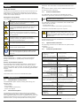 4
4
-
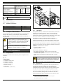 5
5
-
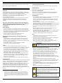 6
6
-
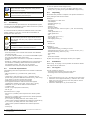 7
7
-
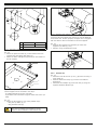 8
8
-
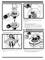 9
9
-
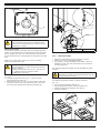 10
10
-
 11
11
-
 12
12
-
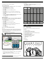 13
13
-
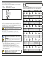 14
14
-
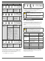 15
15
-
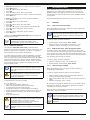 16
16
-
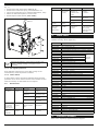 17
17
-
 18
18
-
 19
19
-
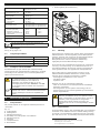 20
20
-
 21
21
-
 22
22
-
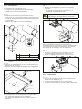 23
23
-
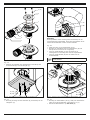 24
24
-
 25
25
-
 26
26
-
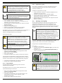 27
27
-
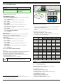 28
28
-
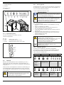 29
29
-
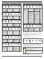 30
30
-
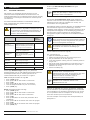 31
31
-
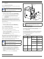 32
32
-
 33
33
-
 34
34
-
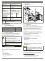 35
35
-
 36
36
-
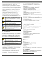 37
37
-
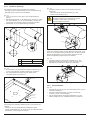 38
38
-
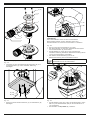 39
39
-
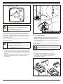 40
40
-
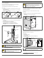 41
41
-
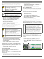 42
42
-
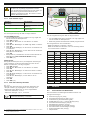 43
43
-
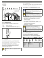 44
44
-
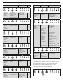 45
45
-
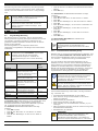 46
46
-
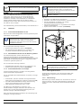 47
47
-
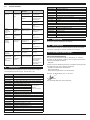 48
48
-
 49
49
-
 50
50
-
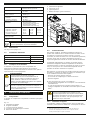 51
51
-
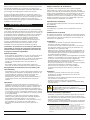 52
52
-
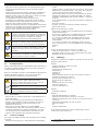 53
53
-
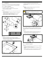 54
54
-
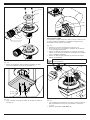 55
55
-
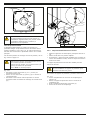 56
56
-
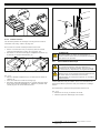 57
57
-
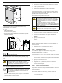 58
58
-
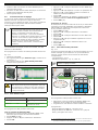 59
59
-
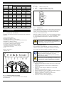 60
60
-
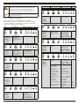 61
61
-
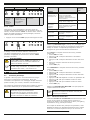 62
62
-
 63
63
-
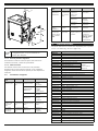 64
64
-
 65
65
-
 66
66
-
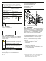 67
67
-
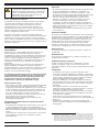 68
68
-
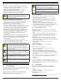 69
69
-
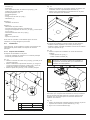 70
70
-
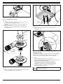 71
71
-
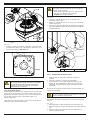 72
72
-
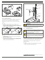 73
73
-
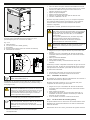 74
74
-
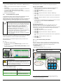 75
75
-
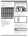 76
76
-
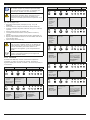 77
77
-
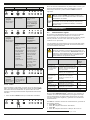 78
78
-
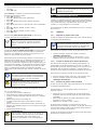 79
79
-
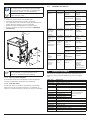 80
80
-
 81
81
-
 82
82
-
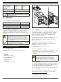 83
83
-
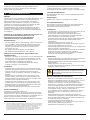 84
84
-
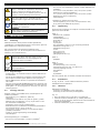 85
85
-
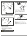 86
86
-
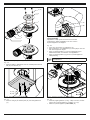 87
87
-
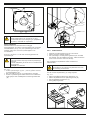 88
88
-
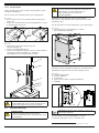 89
89
-
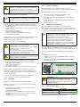 90
90
-
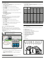 91
91
-
 92
92
-
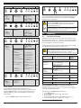 93
93
-
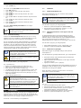 94
94
-
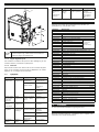 95
95
-
 96
96
-
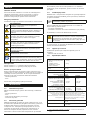 97
97
-
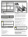 98
98
-
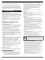 99
99
-
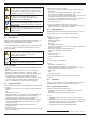 100
100
-
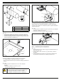 101
101
-
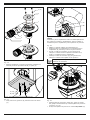 102
102
-
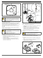 103
103
-
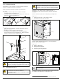 104
104
-
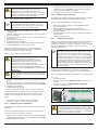 105
105
-
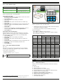 106
106
-
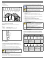 107
107
-
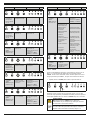 108
108
-
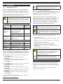 109
109
-
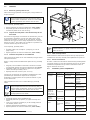 110
110
-
 111
111
-
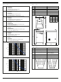 112
112
-
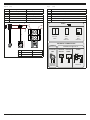 113
113
-
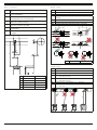 114
114
-
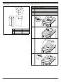 115
115
-
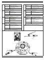 116
116
-
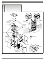 117
117
-
 118
118


in andere talen
Andere documenten
-
BORETTI BARISTA de handleiding
-
 Ghibli & Wirbel S-Team 6 Use And Maintenance
-
 Ghibli & Wirbel S-TEAM 10 VH Use And Maintenance
-
ACV Glass 2014 de handleiding
-
ACV Glass 2017 de handleiding
-
ARIETE 4164 Steam mop 10 in 1 Handleiding
-
Ferm GRM1002 - FHR 100 de handleiding
-
Smeg md1 Data papier
-
 Victoria & Albert Bath VB-AMT-60-NO Installatie gids
-
Amica PI6514TFD Handleiding


